US12138487B2 - Pulsed acoustic wave dermal clearing system and method - Google Patents
Pulsed acoustic wave dermal clearing system and methodDownload PDFInfo
- Publication number
- US12138487B2 US12138487B2US16/087,976US201716087976AUS12138487B2US 12138487 B2US12138487 B2US 12138487B2US 201716087976 AUS201716087976 AUS 201716087976AUS 12138487 B2US12138487 B2US 12138487B2
- Authority
- US
- United States
- Prior art keywords
- tissue
- vacuoles
- laser
- directing
- intradermal
- Prior art date
- Legal status (The legal status is an assumption and is not a legal conclusion. Google has not performed a legal analysis and makes no representation as to the accuracy of the status listed.)
- Active, expires
Links
Images


Classifications
- A—HUMAN NECESSITIES
- A61—MEDICAL OR VETERINARY SCIENCE; HYGIENE
- A61N—ELECTROTHERAPY; MAGNETOTHERAPY; RADIATION THERAPY; ULTRASOUND THERAPY
- A61N7/00—Ultrasound therapy
- A—HUMAN NECESSITIES
- A61—MEDICAL OR VETERINARY SCIENCE; HYGIENE
- A61B—DIAGNOSIS; SURGERY; IDENTIFICATION
- A61B17/00—Surgical instruments, devices or methods
- A61B17/22—Implements for squeezing-off ulcers or the like on inner organs of the body; Implements for scraping-out cavities of body organs, e.g. bones; for invasive removal or destruction of calculus using mechanical vibrations; for removing obstructions in blood vessels, not otherwise provided for
- A61B17/225—Implements for squeezing-off ulcers or the like on inner organs of the body; Implements for scraping-out cavities of body organs, e.g. bones; for invasive removal or destruction of calculus using mechanical vibrations; for removing obstructions in blood vessels, not otherwise provided for for extracorporeal shock wave lithotripsy [ESWL], e.g. by using ultrasonic waves
- A—HUMAN NECESSITIES
- A61—MEDICAL OR VETERINARY SCIENCE; HYGIENE
- A61B—DIAGNOSIS; SURGERY; IDENTIFICATION
- A61B18/00—Surgical instruments, devices or methods for transferring non-mechanical forms of energy to or from the body
- A61B18/18—Surgical instruments, devices or methods for transferring non-mechanical forms of energy to or from the body by applying electromagnetic radiation, e.g. microwaves
- A61B18/20—Surgical instruments, devices or methods for transferring non-mechanical forms of energy to or from the body by applying electromagnetic radiation, e.g. microwaves using laser
- A61B18/203—Surgical instruments, devices or methods for transferring non-mechanical forms of energy to or from the body by applying electromagnetic radiation, e.g. microwaves using laser applying laser energy to the outside of the body
- A—HUMAN NECESSITIES
- A61—MEDICAL OR VETERINARY SCIENCE; HYGIENE
- A61N—ELECTROTHERAPY; MAGNETOTHERAPY; RADIATION THERAPY; ULTRASOUND THERAPY
- A61N5/00—Radiation therapy
- A61N5/06—Radiation therapy using light
- A61N5/0613—Apparatus adapted for a specific treatment
- A61N5/0616—Skin treatment other than tanning
- A—HUMAN NECESSITIES
- A61—MEDICAL OR VETERINARY SCIENCE; HYGIENE
- A61N—ELECTROTHERAPY; MAGNETOTHERAPY; RADIATION THERAPY; ULTRASOUND THERAPY
- A61N5/00—Radiation therapy
- A61N5/06—Radiation therapy using light
- A61N5/067—Radiation therapy using light using laser light
- A—HUMAN NECESSITIES
- A61—MEDICAL OR VETERINARY SCIENCE; HYGIENE
- A61N—ELECTROTHERAPY; MAGNETOTHERAPY; RADIATION THERAPY; ULTRASOUND THERAPY
- A61N7/00—Ultrasound therapy
- A61N7/02—Localised ultrasound hyperthermia
- A—HUMAN NECESSITIES
- A61—MEDICAL OR VETERINARY SCIENCE; HYGIENE
- A61B—DIAGNOSIS; SURGERY; IDENTIFICATION
- A61B17/00—Surgical instruments, devices or methods
- A61B2017/00017—Electrical control of surgical instruments
- A61B2017/00137—Details of operation mode
- A61B2017/00154—Details of operation mode pulsed
- A—HUMAN NECESSITIES
- A61—MEDICAL OR VETERINARY SCIENCE; HYGIENE
- A61B—DIAGNOSIS; SURGERY; IDENTIFICATION
- A61B17/00—Surgical instruments, devices or methods
- A61B2017/00743—Type of operation; Specification of treatment sites
- A61B2017/00747—Dermatology
- A—HUMAN NECESSITIES
- A61—MEDICAL OR VETERINARY SCIENCE; HYGIENE
- A61B—DIAGNOSIS; SURGERY; IDENTIFICATION
- A61B17/00—Surgical instruments, devices or methods
- A61B2017/00743—Type of operation; Specification of treatment sites
- A61B2017/00747—Dermatology
- A61B2017/00756—Port wine stains
- A—HUMAN NECESSITIES
- A61—MEDICAL OR VETERINARY SCIENCE; HYGIENE
- A61B—DIAGNOSIS; SURGERY; IDENTIFICATION
- A61B17/00—Surgical instruments, devices or methods
- A61B2017/00743—Type of operation; Specification of treatment sites
- A61B2017/00747—Dermatology
- A61B2017/00761—Removing layer of skin tissue, e.g. wrinkles, scars or cancerous tissue
- A—HUMAN NECESSITIES
- A61—MEDICAL OR VETERINARY SCIENCE; HYGIENE
- A61B—DIAGNOSIS; SURGERY; IDENTIFICATION
- A61B17/00—Surgical instruments, devices or methods
- A61B2017/00743—Type of operation; Specification of treatment sites
- A61B2017/00747—Dermatology
- A61B2017/00769—Tattoo removal
- A—HUMAN NECESSITIES
- A61—MEDICAL OR VETERINARY SCIENCE; HYGIENE
- A61B—DIAGNOSIS; SURGERY; IDENTIFICATION
- A61B18/00—Surgical instruments, devices or methods for transferring non-mechanical forms of energy to or from the body
- A61B2018/00315—Surgical instruments, devices or methods for transferring non-mechanical forms of energy to or from the body for treatment of particular body parts
- A61B2018/00452—Skin
- A61B2018/00458—Deeper parts of the skin, e.g. treatment of vascular disorders or port wine stains
- A—HUMAN NECESSITIES
- A61—MEDICAL OR VETERINARY SCIENCE; HYGIENE
- A61B—DIAGNOSIS; SURGERY; IDENTIFICATION
- A61B18/00—Surgical instruments, devices or methods for transferring non-mechanical forms of energy to or from the body
- A61B2018/00315—Surgical instruments, devices or methods for transferring non-mechanical forms of energy to or from the body for treatment of particular body parts
- A61B2018/00452—Skin
- A61B2018/0047—Upper parts of the skin, e.g. skin peeling or treatment of wrinkles
- A—HUMAN NECESSITIES
- A61—MEDICAL OR VETERINARY SCIENCE; HYGIENE
- A61B—DIAGNOSIS; SURGERY; IDENTIFICATION
- A61B18/00—Surgical instruments, devices or methods for transferring non-mechanical forms of energy to or from the body
- A61B2018/00315—Surgical instruments, devices or methods for transferring non-mechanical forms of energy to or from the body for treatment of particular body parts
- A61B2018/00452—Skin
- A61B2018/00476—Hair follicles
- A—HUMAN NECESSITIES
- A61—MEDICAL OR VETERINARY SCIENCE; HYGIENE
- A61N—ELECTROTHERAPY; MAGNETOTHERAPY; RADIATION THERAPY; ULTRASOUND THERAPY
- A61N5/00—Radiation therapy
- A61N5/06—Radiation therapy using light
- A61N2005/0626—Monitoring, verifying, controlling systems and methods
- A—HUMAN NECESSITIES
- A61—MEDICAL OR VETERINARY SCIENCE; HYGIENE
- A61N—ELECTROTHERAPY; MAGNETOTHERAPY; RADIATION THERAPY; ULTRASOUND THERAPY
- A61N7/00—Ultrasound therapy
- A61N2007/0004—Applications of ultrasound therapy
- A61N2007/0034—Skin treatment
- A—HUMAN NECESSITIES
- A61—MEDICAL OR VETERINARY SCIENCE; HYGIENE
- A61N—ELECTROTHERAPY; MAGNETOTHERAPY; RADIATION THERAPY; ULTRASOUND THERAPY
- A61N7/00—Ultrasound therapy
- A61N2007/0047—Ultrasound therapy interstitial
- A—HUMAN NECESSITIES
- A61—MEDICAL OR VETERINARY SCIENCE; HYGIENE
- A61N—ELECTROTHERAPY; MAGNETOTHERAPY; RADIATION THERAPY; ULTRASOUND THERAPY
- A61N7/00—Ultrasound therapy
- A61N2007/0056—Beam shaping elements
- A—HUMAN NECESSITIES
- A61—MEDICAL OR VETERINARY SCIENCE; HYGIENE
- A61N—ELECTROTHERAPY; MAGNETOTHERAPY; RADIATION THERAPY; ULTRASOUND THERAPY
- A61N7/00—Ultrasound therapy
- A61N2007/0056—Beam shaping elements
- A61N2007/0069—Reflectors
- A—HUMAN NECESSITIES
- A61—MEDICAL OR VETERINARY SCIENCE; HYGIENE
- A61N—ELECTROTHERAPY; MAGNETOTHERAPY; RADIATION THERAPY; ULTRASOUND THERAPY
- A61N7/00—Ultrasound therapy
- A61N2007/0086—Beam steering
Definitions
- Embodiments of the present inventionrelate generally to therapeutic uses of shock waves. More particularly, but not by way of limitation, embodiments of the present invention relate to an apparatus for generating therapeutic shock waves (shock waves with therapeutic uses) for use in a dermal clearing system and applications of same.
- shock waveor “shockwave” is generally used to refer to an acoustic phenomenon (e.g., resulting from an explosion or lightning) that creates a sudden and intense change in pressure. These intense pressure changes can produce strong waves of energy that can travel through elastic media such as air, water, human soft tissue, or certain solid substances such as bone, and/or can induce an inelastic response in such elastic media.
- Methods for creating shock waves for therapeutic usesinclude: (1) electrohydraulic, or spark gap (EH); (2) electromagnetic, or EMSE; and (3) piezoelectric. Each is based upon its own unique physical principles.
- U.S. patent application Ser. No. 13/574,228(a national-stage application of PCT/US20 11/021692, which published as WO 2011/091 020), by one of the present inventors, discloses a device for producing shock waves at a high pulse rate using a transducer. That device includes an acoustic-wave generator configured to emit acoustic waves having at least one frequency between 1 MHz and 1000 MHz; a shockwave housing coupled to the acoustic-wave generator; and a shockwave medium disposed in the shockwave housing; where the apparatus is configured such that if the acoustic-wave generator emits acoustic waves then at least some portion of the acoustic waves will travel through the shockwave medium and form shock waves.
- That devicecan be actuated to form shock waves configured to cause particles within a patient to rupture one or more cells of the patient, and the shock waves can be directed to cells of a patient such that the shock waves cause particles to rupture one or more of the cells.
- This acoustic-transducer devicecan produce high powered shockwaves at high frequencies or pulse rates.
- EH systemscan include an electrohydraulic (EH) wave generator.
- EH systemscan generally deliver similar levels of energy as other methods, but may be configured to deliver that energy over a broader area, and therefore deliver a greater amount of shock wave energy to targeted tissue over a shorter period of time.
- EH systemsgenerally incorporate an electrode (i.e., a spark plug) to initiate a shock wave.
- an electrodei.e., a spark plug
- high energy shock wavesare generated when electricity is applied to an electrode immersed in treated water contained in an enclosure. When the electrical charge is fired, a small amount of water is vaporized at the tip of the electrode and the rapid, nearly instantaneous, expansion of the vaporized water creates a shock wave that propagates outward through the liquid water.
- the wateris contained in an ellipsoid enclosure.
- the shock wavemay ricochet from the sides of the ellipsoid enclosure and converge at a focal point that coincides with the location of the area to be treated.
- U.S. Pat. No. 7,189,209(the '209 Patent) describes a method of treating pathological conditions associated with bone and musculoskeletal environments and soft tissues by applying acoustic shock waves.
- the '209 Patentdescribes that shockwaves induce localized trauma and cellular apotosis therein, including micro-fractures, as well as to induce osteoblastic responses such as cellular recruitment, stimulate formation of molecular bone, cartilage, tendon, fascia, and soft tissue morphogens and growth factors, and to induce vascular neoangiogenesis.
- the '209 Patentclaims several specific implementations of its method.
- the '209 Patentclaims a method of treating a diabetic foot ulcer or a pressure sore, comprising: locating a site or suspected site of the diabetic foot ulcer or pressure sore in a human patient; generating acoustic shock waves; focusing the acoustic shock waves throughout the located site; and applying more than 500 to about 2500 acoustic shock waves per treatment to the located site to induce micro-injury and increased vascularization thereby inducing or accelerating healing.
- the '209 Patentdiscloses a frequency range of approximately 0.5-4 Hz, and application of about 300 to 2500 or about 500 to 8,000 acoustic shock waves per treatment site, which can result in a treatment duration for each treatment site and/or a “total time per treatment” for all sites that is inconveniently large.
- the '209 Patentdiscloses total times per treatment for different examples ranging from 20 minutes to 3 hours.
- U.S. Pat. No. 5,529,572includes another example of the use of electro-hydraulically generated shockwaves to produce therapeutic effect on tissues.
- the '572 Patentdescribes a method of increasing the density and strength of bone (to treat osteoporosis), comprising subjecting said bone to substantially planar, collimated compressional shock waves having a substantially constant intensity as a function of distance from a shock wave source, and wherein said collimated shock waves are applied to the bone at an intensity of 50-500 atmospheres.
- the '572 Patentdescribes the application of unfocussed shock waves to produce dynamic repetitive loading of the bone to increase mean bone density, and thereby strengthen bone against fracture.
- the unfocussed shock wavespreferably are applied over a relatively large surface of the bone to be treated, for example to cover an area of from 10 to 150 cm 2 .
- the intensity of the shock wavesmay be from 50-500 atmospheres.
- Each shock waveis of duration of a few microseconds, as in a conventional lithotripter, and is preferably applied at a frequency of 1-10 shock waves per second for a period of 5-30 minutes in each treatment. The number of treatments depends on the particular patient.”
- U.S. patent application Ser. No. 10/415,293(the '293 Application), which is also published as US 2004/0006288, discloses another embodiment of the use of EH-generated shockwaves to provide a therapeutic effect on tissues.
- the '293 Applicationdiscloses a device, system, and method for the generation of therapeutic acoustic shock waves for at least partially separating a deposit from a vascular structure.
- the '293 Applicationdescribes that the device can produce shockwaves at a pulse rate of about 50 to about 500 pulses per minute (i.e., 0.83 to 8.33 Hz) with a number of pulses per treatment site (in terms of per length of vascular unit being treated) from about 100 to about 5,000 per 1 cm 2 .
- Soft tissuesmay transition from elastic to viscous behavior for pulse rates (PRs) between 1 Hz and 10 Hz.
- PRspulse rates
- potential damage to tissue from shockwaves at pulse rates between 1 Hz and 10 Hzis unpredictable when typical lithotripsy power levels are used.
- the prior artteaches slower pulse rates and large total times per treatment (TTPT).
- EH shockwave systemsgenerally deliver pulse rates of less than 10 Hz and require large total times per treatment (TTPT) (e.g., TTPT periods of minutes or even hours for even a single treatment site).
- TTPTtotal times per treatment
- shockwavesWhile long treatment times may be acceptable for extracorporeal shockwave lithotripsy, the use of shockwaves to provide non-lithotripsy therapeutic effects on tissue in the medical setting is less than optimal if not impractical.
- the cost of treatmentoften increases with the time needed to administer a treatment (e.g., due to the labor, facilities and other resource costs allocated to the administration of the treatment).
- the duration of providing treatment to the patientbecomes unbearable for the patient receiving, and healthcare staff providing, the treatment.
- fibroblast cellshave both elastic and viscous characteristics, and thus are viscoelastic materials. Unlike most conventional materials, cells are highly nonlinear with their elastic modulus depending on the degree of applied or internal stress. (Kasza, 2007) [6].
- fibroblast cellscan be modeled as a gel having a cross-linked actin network that show a transition from a linear regime to power law strain stiffening.
- laser-based skin treatmentIn a another area of therapeutic medicine, the use of laser-based skin treatment has been used in tattoo removal, laser skin resurfacing, laser removal of birthmarks, laser removal of skin lesions, laser hair transplants or removal, laser scar removal, and a host of other various procedures.
- the body's natural reaction to each of these treatmentspresent challenges to the efficacy of the treatment.
- a tattooed areato a laser output currently creates a “whitening” condition within the treatment area that tends to reduce the effectiveness of subsequent laser exposures.
- a “whitening” reactiontypically occurs.
- the immediate whitening reactionis a result of the generation of vacuoles due to rapid heating or energy transfer associated with laser exposure to the tattoo pigment particle.
- the dermal vacuoles associated with whiteningresult in the attenuation or scattering of laser light resulting in loss of the lasers effectiveness after the initial treatment.
- the dermal vacuolesremain in the skin for a period of time limiting the effectiveness of subsequent laser exposures in the same session
- Laser generated dermal vacuolesare generally located at the epidermis-dermis boundary and around individual pigment particle clusters.
- vacuoles located at the epidermis-dermis boundaryare thought to be produced by localized heating from the laser light absorption by melanin in the epidermis.
- the vacuoles located around the pigment particle agglomerationsare believed to be a direct result of the rapid heating from the laser light absorption of the pigment particle aggregation within the dermis.
- Post-laser whitening reactionmay fade over about twenty minutes or more following the last laser exposure. Such fading may be evidenced by the resolution of the superficial vacuoles caused by the dissipation and absorption of vacuole contents, including gas, over time.
- Whiteningis problematic at least in part because the presence of dermal vacuoles in the treatment area caused by the first laser pass may attenuate or weaken the delivery of light in one or more subsequent laser passes. For example, light impinging on vacuoles may scatter in multiple directions, including away from the treatment area. Thus, vacuole presence reduces laser therapy effectiveness.
- PFDis a liquid that is a colorless, inert compound with low surface tension and insoluble in blood and water.
- PFDhas very poor dermal penetration. As a result it is used extensively in cosmetics.
- PFDis good at reducing whitening that is caused by vacuoles located superficially (e.g., epidermal-dermal boundary).
- vacuoles that surround and shield the previously treated intradermal pigment particlesare not affected.
- PFDprovides benefits in reducing the appearance of whitening, it only provides limited benefit in improving the effectiveness of repeated laser treatments to the tattoo site.
- Embodiments of the present methods, apparatuses, and systemscan be configured to provide dermal clearing by dispersing and/or eliminating dermal vacuoles located superficially and/or deeper in the dermis (e.g. adjacent to pigment particle agglomerations), as well as vacuoles in the epidermis.
- the present methods, apparatuses, and systemscan thereby enable more effective repeated laser treatments over the same treatment area in quick succession.
- Some embodiments of the present methodscomprise: identifying the location of tissue containing vacuoles; coupling an acoustic wave generator to the tissue containing the vacuoles; and directing pulsed acoustic waves from the acoustic wave generator into the tissue containing the vacuoles.
- the tissue containing vacuoleshas previously been treated with a laser.
- Some embodiments of the present methodsfurther comprise: treating the skin containing vacuoles with a laser after directing pulsed acoustic waves from the acoustic wave generator into the tissue containing the vacuoles.
- the skinis treated with an acoustic wave generator for between about 0.1 minute and about 10 minutes.
- the laser treatmentcomprises applying a laser with a pulse duration of between about 1 nanosecond and about 1 microsecond to the targeted skin.
- the lasercomprises a Q-switched laser or a pico-second laser.
- the laser treatmentcomprises tattoo removal, laser skin resurfacing, laser removal of birthmarks, laser removal of skin lesions, laser hair transplants, laser scar removal, laser-assisted hair reduction, laser removal of vascular lesions, laser lip lightening, and/or laser treatment of melisma.
- Some embodiments of the present methodsfurther comprise: treating the skin containing vacuoles with a laser after directing pulsed acoustic waves from the acoustic wave generator into the tissue containing the vacuoles; and repeating directing and treating in alternating fashion for at least 2 iterations in a single treatment session.
- treating the skin containing vacuoles with a laseris performed within 10 minutes of directing the pulsed acoustic waves.
- at least two subsequent iterations of directing the pulsed acoustic wavesare performed within 10 minutes or less.
- Some embodiments of the present systemscomprise: a pulsed acoustic wave generator configured to generate pulsed acoustic waves and direct the generated waves to skin to clear epidermal and intradermal vacuoles.
- the generated acoustic waveshave a frequency between about 700 KHz and about 100 Mhz.
- the generated acoustic waveshave a pulse duration between about 1 nanosecond and about 1 microsecond.
- the generated acoustic waveshave a pulse rate between about 10 Hz and about 1 KHz.
- the Mechanical Index MI of the generated wavesis between about 0.15 to about 1.9.
- the pulsed acoustic wave generatorincludes a rapid pulse electrohydraulic shockwave generator that comprises: a housing defining a chamber and a shockwave outlet; a medium disposed in the chamber; a plurality of electrodes and capacitors configured to be disposed in the chamber to define one or more spark gaps; and a pulse-generation system configured to apply voltage pulses to the plurality of electrodes and capacitors in the chamber.
- a rapid pulse electrohydraulic shockwave generatorthat comprises: a housing defining a chamber and a shockwave outlet; a medium disposed in the chamber; a plurality of electrodes and capacitors configured to be disposed in the chamber to define one or more spark gaps; and a pulse-generation system configured to apply voltage pulses to the plurality of electrodes and capacitors in the chamber.
- the pulsed acoustic wave generatoris configured to generate the acoustic waves in pulses at a rate of between about 10 Hz and about 5 MHz.
- the pulsed acoustic wave generatorincludes a megasonic wave generator.
- the megasonic wave generatoris configured to produce pulsed acoustic waves with a frequency between about 700 KHz and about 20 Mhz.
- the megasonic wave generatoris configured to produce pulsed acoustic waves with a pulse duration between about 1 nanosecond and about 1 microsecond.
- the megasonic wave generatoris configured to produce pulsed acoustic waves with a pulse rate between about 10 Hz and about 1 KHz.
- the power of the megasonic wave generatoris set so that the Mechanical Index (MI) is between about 0.15 to 1.8.
- MIMechanical Index
- the rapid pulse electrohydraulic generatoris set so that the peak pressure output is between about 0.8 MPa and 20 MPa
- Coupledis defined as connected, although not necessarily directly, and not necessarily mechanically; two items that are “coupled” may be unitary with each other.
- the terms “a” and “an”are defined as one or more unless this disclosure explicitly requires otherwise.
- the term “substantially”is defined as largely but not necessarily wholly what is specified (and includes what is specified; e.g., substantially 90 degrees includes 90 degrees and substantially parallel includes parallel), as understood by a person of ordinary skill in the art. In any disclosed embodiment, the terms “substantially,” “approximately,” and “about” may be substituted with “within [a percentage] of” what is specified, where the percentage includes 0.1, 1, 5, and 10 percent
- a structuree.g., a component of an apparatus
- a structurethat is configured in a certain way is configured in at least that way, but it can also be configured in other ways than those specifically described.
- any embodiment of any of the present systems, apparatuses, and methodscan consist of or consist essentially of—rather than comprise/include/contain/have—any of the described steps, elements, and/or features.
- the term “consisting of” or “consisting essentially of”can be substituted for any of the open-ended linking verbs recited above, in order to change the scope of a given claim from what it would otherwise be using the open-ended linking verb.
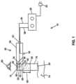
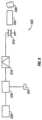
- FIG. 1depicts a block diagram of a first embodiment of the present electro-hydraulic (EH) shockwave generating systems.
- EHelectro-hydraulic
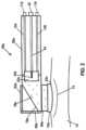
- FIG. 2depicts a cross-sectional side view of a handheld probe for some embodiments of the present EH shockwave generating systems.
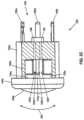
- FIG. 2 Adepicts a cross-sectional side view of a first embodiment of a removable spark head usable with embodiments of the present handheld probes, such as the one of FIG. 2 .
- FIG. 2 Bdepicts a cutaway side view of a second embodiment of a removable spark head usable with embodiments of the present handheld probes, such as the one of FIG. 2 .
- FIG. 2 Cdepicts a cutaway side view of a third embodiment of a removable spark head usable with embodiments of the present handheld probes, such as the one of FIG. 2 .
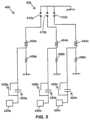
- FIG. 3 A- 3 Bdepict a timing diagrams of one example of the timed application of energy cycles or voltage pulses in the system of FIG. 1 and/or the handheld probe of FIG. 2 .
- FIG. 4depicts a waveform that can be emitted by system of FIG. 1 and/or the handheld probe of FIG. 2 into target tissue.
- FIG. 5depicts a schematic diagram of one embodiment of a multi-gap pulse-generation system for use in or with some embodiments of the present systems.
- FIG. 6depicts a block diagram of an embodiment of a radio-frequency (RF) powered acoustic ablation system.
- RFradio-frequency
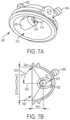
- FIGS. 7 A- 7 Bdepict perspective and cross-sectional views of a first prototyped spark chamber housing.
- FIG. 8depicts a cross-sectional view of a second prototyped embodiment of spark chamber housing.
- FIG. 9depicts a schematic diagram of an electric circuit for a prototyped pulse-generation system.
- FIG. 10depicts a conceptual flowchart of one embodiment of the present methods.
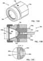
- FIG. 11depicts an exploded perspective view of a further prototyped embodiment of the present probes having a spark head or module.
- FIGS. 12 A and 12 Bdepict parts of the assembly of the probe of FIG. 11 .
- FIGS. 13 A and 13 Bdepict perspective and side cross-sectional views, respectively, of the probe of FIG. 11 .
- FIG. 13 Cdepicts an enlarged side cross-sectional view of a spark gap of the probe of FIG. 11 .
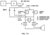
- FIG. 14depicts a schematic diagram of a second embodiment of an electric circuit for a prototyped pulse-generation system.
- FIG. 15depicts a cross-sectional view of an ultrasound generator probe.
- FIG. 16depicts a histological image of skin containing blue tattoo pigment that has had a single laser treatment.
- FIG. 17depicts a histological image of skin containing black tattoo pigment that has had three rounds of laser treatment (application of the laser three times).
- FIG. 18depicts a histological image of skin containing black tattoo pigment that has been treated with three applications of laser treatment followed by rapid pulse shockwaves.
- FIG. 19depicts a histological image of skin illustrating the size of intradermal vacuoles.
- Certain embodiments of the present systems and apparatusesare configured to generate high-frequency shock waves in a predictable and consistent manner.
- the generated EH shock wavescan be used in medical and/or aesthetic therapeutic applications (e.g., when directed at and/or delivered to target tissue of a patient).
- medical and/or aesthetic therapeutic applicationsin which the present systems can be used are disclosed in: (1) U.S. patent application Ser. No. 13/574,228, published as US 2013/0046207; (2) U.S. patent application Ser. No. 13/547,995, published as, published as US 2013/0018287; (3) U.S. patent application Ser. No.
- the EH shock waves generated by the present systemscan be configured to impose sufficient mechanical stress to rupture cells of the target tissue (e.g., through membrane-degradation damage).
- the cellsWhen targeted cells (cells of target tissue) are exposed to the generated high-pulse rate shockwaves, the cells experience sharp gradients of mechanical stress due to the spatial heterogeneity parameters of the cells, such as density and shear elasticity modulus of the different components of the cell.
- dense and/or inelastic components inside a cellundergo greater mechanical stress when subjected to shock waves as compared to lighter components.
- acceleration of higher-density particles or components within the cellular structure exposed to the impact frontis typically very large.
- the impact on lower-density biological structures making up the cell structure when exposed to such a large gradient of pressureis significantly reduced because the elasticity of the lower-density biological structures allows them to generally act as low-compliance material.
- the difference in mechanical stressresults in movement of the dense and/or inelastic components within the cell.
- Equation (1)if the ball radius (R) is about 10 ⁇ m and the difference between the densities of the balls is 0.1 ⁇ 0 , and results in a stress force, F/( ⁇ R 2 )m of 10 9 dyne/cm 2 . This is sufficient to rupture a cell membrane.
- the embodiments of the present apparatusesgenerate shock waves in a controlled manner that can be used to cause targeted damage to certain cells, which have medical and/or aesthetic therapeutic applications that are discussed further below.
- shock wavescause the cell membranes to fail by a progressive (i.e., accumulated) shearing mechanism.
- compression by shock wavescauses minimal, if any, damage to membranes.
- Microscopic focusing and defocusing of the shock wave as it passes through the heterogeneous mediacan result in shock wave strengthening or weakening locally that result in an increase in local shearing. Relative shearing motion of the cell membrane occurs on the scale of the heterogeneities of the cellular structure.
- shock wavesstrike a region of heterogeneities (e.g., cells containing particles)
- the particle motion that is out of phase with the incoming wavesgenerates cell disruptive energy transfer (e.g., shear stress).
- cell disruptive energy transfere.g., shear stress
- the out of phase motioncauses microscopic damage to the cell membrane that can progressively grow into cell membrane failure with additional successive accumulation of shear stress.
- the progressive shearing mechanism of repeated exposure to shock wavescan be considered dynamic fatigue of the cell membranes. Damage from dynamic fatigue is dependent on three factors: (1) applied stress or strain, (2) the rate at which the strain is applied, and (3) accumulated number of strain cycles. These three factors can be manipulated to cause a cell with heterogeneities to experience catastrophic cell membrane failure as compared to a relatively more homogeneities at a particular applied strain, strain rate, and strain cycles.
- the manipulation of the factorscan be done by providing EH shock waves of certain properties, such as the number of shock waves, the amount of time between each shock wave, and the strength of the applied shock waves. As discussed above, if there is enough time between shock waves for the tissue to relax to its unstrained state, the cells will become more resistant to failure. As such, in an embodiment for an EH system, shock waves at a pulse rate greater than 5 Hz and greater than 100 Hz and greater than 1 MHz are delivered to the targeted cellular structures to achieve dynamic fatigue of the tissue and not allow the tissue time to relax.
- a third possible theoryis that the EH shock waves cause a combination of effects of direct movement of the particles contained in the cellular structure and dynamic fatigue that rupture the cells.
- particle-containing cellsare an apparent example of cellular structures exhibiting heterogeneities, their description is not intended to limit the scope of the present disclosure. Instead, the embodiments disclosed herein can be used to rupture or cause damage to other cellular structures that exhibit heterogeneities, such as cellular structures that have different effective density regions.
- the parameters of the shock waves generated according to the disclosed aspectscan be adjusted based, at least, on the regions of different effective densities (i.e. heterogeneities) to cause cellular damage as described herein.
- Heterogeneitiescan be regions within a single cell, a region of different types of cells, or a combination of both.
- a region of heterogeneity within a cellincludes a region having an effective density greater than the effective density of the cell.
- the effective density of a fibroblast cellis about 1.09 g/cm 3
- a region of heterogeneity in the cellwould be particles contained within the cell that have an effective density greater than 1.09 g/cm 2 , such as graphite with a density of 2.25 g/cm 3 .
- a region of cellular heterogeneity between cellsincludes a region with different types of cells, where each cell type has a different effective density, such as fibroblast cells and fat cells or hair follicles. The present disclosure provides further examples of cellular structures containing heterogeneities below.
- system 10includes a handheld probe (e.g., with a first housing, such as in FIG. 2 ) and a separate controller or pulse-generation system (e.g., in or with a second housing coupled to the handheld probe via a flexible cable or the like).
- a handheld probee.g., with a first housing, such as in FIG. 2
- a separate controller or pulse-generation systeme.g., in or with a second housing coupled to the handheld probe via a flexible cable or the like.
- the present systemsinclude a single handheld apparatus disposed in a single housing.
- apparatus 10comprises: a housing 14 defining a chamber 18 and a shockwave outlet 20 ; a liquid ( 54 ) disposed in chamber 18 ; a plurality of electrodes (e.g., in spark head or module 22 ) configured to be disposed in the chamber to define one or more spark gaps; and a pulse-generation system 26 configured to apply voltage pulses to the electrodes at a rate of between 10 Hz and 5 MHz.
- the capacitive/inductive coil system 26is configured to apply the voltage pulses to the electrodes such that portions of the liquid are vaporized to propagate shockwaves through the liquid and the shockwave outlet.
- pulse-generation system 26is configured for use with an alternating current power source (e.g., a wall plug).
- pulse-generation system 26comprises a plug 30 configured to be inserted into a 110V wall plug.
- pulse-generation system 26comprises a capacitive/inductive coil system, on example of which is described below with reference to FIG. 6 .
- pulse-generation system 26can comprise any suitable structure or components configured to apply high voltages to the electrodes in a periodic fashion to generate electric sparks of sufficient power to vaporize liquid in the respective spark gaps, as described in this disclosure.
- pulse-generation system 26is (e.g., removably) coupled to the electrodes in spark head or module 22 via a high-voltage cable 34 , which may, for example, include two or more electrical conductors and/or be heavily shielded with rubber or other type of electrically insulating material to prevent shock.
- high-voltage cable 34is a combined tether or cable that further includes one or more (e.g., two) liquid lumens through which chamber 18 can be filled with liquid and/or via which liquid can be circulated through chamber 18 (e.g., via combined connection 36 ).
- apparatus 10comprises a handheld probe or handpiece 38 and cable 34 is removably coupled to probe 38 via a high-voltage connector 42 , which is coupled to spark head or module 22 via two or more electrical conductors 44 .
- probe 38comprises a head 46 and a handle 50
- probe 38can comprise a polymer or other electrically insulating material to enable an operator to grasp handle 50 to position probe 38 during operation.
- handle 50can be molded with plastic and/or can be coated with an electrically insulating material such as rubber.
- a liquid 54(e.g., a dielectric liquid such as distilled water) is disposed in (e.g., and substantially fills) chamber 18 .
- spark head 22is positioned in chamber 18 and surrounded by the liquid such that the electrodes can receive voltage pulses from pulse-generation system 26 (e.g., at a rate of between 10 Hz and 5 MHz) such that portions of the liquid are vaporized to propagate shockwaves through the liquid and shockwave outlet 20 .
- probe 38includes an acoustic delay chamber 58 between chamber 18 and outlet 20 .
- acoustic delay chamberis substantially filled with a liquid 62 (e.g., of the same type as liquid 54 ) and has a length 66 that is sufficient to permitshockwaves to form and/or be directed toward outlet 20 .
- length 66may be between 2 millimeters (mm) and 25 millimeters (mm).
- chamber 18 and acoustic-delay chamber 58are separated by a layer of sonolucent (acoustically permeable or transmissive) material that permits sound waves and/or shockwaves to travel from chamber 18 into acoustic-delay chamber 58 .
- liquid 62may be different than liquid 54 (e.g., liquid 62 may comprise bubbles, water, oil, mineral oil, and/or the like). Certain features such as bubbles may introduce and/or improve a nonlinearity in the acoustic behavior of liquid 54 to increase the formation of shockwaves.
- chamber 18 and acoustic-delay chamber 54may be unitary (i.e., may comprise a single chamber).
- acoustic-delay chamber 54may be replaced with a solid member (e.g., a solid cylinder of elastomeric material such as polyurethane).
- probe 38further includes an outlet member 70 removably coupled to the housing at a distal end of the acoustic delay chamber, as shown.
- Member 70is configured to contact tissue 74 , and can be removed and either sterilized or replaced between patients.
- Member 70comprises a polymer or other material (e.g., low-density polyethylene or silicone rubber) that is acoustically permeable to permit shockwaves to exit acoustic-delay chamber 58 via outlet 20 .
- Tissue 74may, for example, be human skin tissue to be treated with apparatus 10 , and may, for example, include a tattoo, a blemish, a subdermal lesion, or a basal cell abnormality.
- an acoustic coupling gel(not shown) may be disposed between member 70 and tissue 74 to lubricate and provide additional acoustic transmission into tissue 74 .
- probe 38includes an acoustic mirror 78 that comprises a material (e.g., glass) and is configured to reflect a majority of sound waves and/or shock waves that are incident on the acoustic mirror.
- acoustic mirror 58can be angled to reflect sound waves and/or shockwaves (e.g., that originate at spark head 22 ) toward outlet 20 (via acoustic-delay chamber).
- housing 14can comprise a translucent or transparent window 82 that is configured to permit a user to view (through window 82 , chamber 18 , chamber 58 , and member 70 ) a region of a patient (e.g., tissue 74 ) comprising target cells (e.g., during application of shockwaves or prior to application of shockwaves to position outlet 20 at the target tissue).
- window 82comprises an acoustically reflective material (e.g., glass) that is configured to reflect a majority of sound waves and/or shock waves that are incident on the window.
- window 82can comprise clear glass of sufficient thickness and strength to withstand the high-energy acoustic pulses produced at spark head 22 (e.g., tempered plate glass having a thickness of about 2 mm and an optical transmission efficiency of greater than 50%).
- a human eye 86indicates a user viewing the target tissue through window 82 , but it should be understood that target tissue may be “viewed” through window 82 via a camera (e.g., a digital still and/or video camera).
- a camerae.g., a digital still and/or video camera.
- acoustic energycan be positioned, applied, and repositioned according to target tissues, such as extant tattoos, and by indications of acoustic energy, such as a change in the color of the tissue.
- probe 38is configured such that the plurality of electrodes are not visible to a user viewing a region (e.g., of target tissue) through window 82 and outlet 20 .
- probe 38includes an optical shield 90 disposed between spark head 22 and window 82 .
- Shield 90can have a width and/or a length that are less than a corresponding width and/or length of window 82 such that shield 90 is large enough to substantially block light from spark head 22 from traveling directly to the user's eye, but does not interfere with the field-of-view through window 82 and outlet 20 more than is necessary to block that light.
- Shield 90can, for example, comprise a thin sheet of metal, such as stainless steel, or other opaque material, or can comprise welder's glass (e.g., an LCD darkened by a photocell or other light-sensitive material) that is optically activated and darkened by the brightness of sparks at the spark gaps.
- the distance between the shield and the spark gaps between electrodes in spark head 22may be selected to minimize (e.g., at least destructive) interference between sound waves and/or shockwaves reflected from the shield and sound waves and/or shockwaves originating at spark head 22 (e.g., such that intersecting waves do not produce excess echoes or reverberation).
- the distance between the spark head and the shieldmay be calculated to be at 1 ⁇ 2 and 3 ⁇ 4 wavelengths from the source.
- Spark head 22(e.g., the electrodes in spark head 22 ) may have a limited lifetime that may be extended by limiting the duration of activation.
- apparatus 10includes a switch or trigger 94 coupled to pulse-generation system 26 via a switch wire or other connection 98 through connector 42 , such that switch 94 can be actuated to apply voltage pulses to the electrodes in spark head 22 .
- FIG. 2depicts a cross-sectional side view of a second embodiment 38 a of the present handheld probes or handpiece for use with some embodiments of the present EH shockwave generating systems and apparatuses.
- Probe 38 ais substantially similar in some respects to probe 38 , and the differences are therefore primarily described here.
- probe 38 ais also configured such that the plurality of electrodes of spark head or module 22 a are not visible to a user viewing a region (e.g., of target tissue) through window 82 a and outlet 20 a .
- probe 38 ais configured such that spark head 22 a (and the electrodes of the spark head) are offset from an optical path extending through window 82 a and outlet 20 a .
- acoustic mirror 78 ais positioned between spark head 22 a and outlet 20 a , as shown, to define a boundary of chamber 18 a and to direct acoustic waves and/or shockwaves from spark head 22 a to outlet 20 a .
- window 82 acan comprise a polymer or other acoustically permeable or transmissive material because acoustic mirror 78 a is disposed between window 82 a and chamber 18 a and sound waves and/or shockwaves are not directly incident on window 82 a (i.e., because the sound waves and/or shock waves are primarily reflected by acoustic mirror 78 a ).
- spark head 22 aincludes a plurality of electrodes 100 that define a plurality of spark gaps.
- the use of multiple spark gapscan be advantageous because it can double the number of pulses that can be delivered in a given period of time. For example, after a pulse vaporizes an amount of liquid in a spark gap the vapor must either return to its liquid state or must be displaced by a different portion of the liquid that is still in a liquid state.
- sparksalso heat the electrodes. As such, for a given spark rate, increasing the number of spark gaps reduces the rate at which each spark gap must be fired and thereby extends the life of the electrodes. Thus, ten spark gaps potentially increases the possible pulse rate and/or electrode life by a factor of ten.
- probe 38includes conduits 104 and 108 extending from chamber 18 a to respective connectors 112 and 116 , as shown.
- connectors 112 and 116can be coupled to a pump to circulate liquid through chamber 18 a (e.g., and through a heat exchanger.
- pulse-generation system 26FIG.
- a filtercan be included in probe 38 a , in a spark generation system (e.g., 26 ), and/or between the probe and the spark generation system to filter liquid that is circulated through the chamber
- spark head 22 ais configured to be removable from probe 38 a .
- spark head 22 amay be removable through handle 50 a , or handle 50 a may be removably coupled (e.g., via threads or the like) to head 46 a such that upon removal of handle 50 a from head 46 , spark head 22 a can be removed from head 46 a and replaced.
- each shockwave to a target tissueincludes a wavefront 118 propagating from outlet 20 a and traveling outward through tissue 74 .
- wavefront 74is curved according to its expansion as it moves outwardly and partially according to the shape of the outer surface of outlet member 70 a that contacts tissue 74 .
- the outer shape of the contact membercan be planar or otherwise shaped to affect certain properties of the wavefront as it passes through outlet 20 a and propagates through the target tissue.
- FIG. 2 Adepicts an enlarged cross-sectional view of first embodiment of a removable spark head or module 22 a .
- spark head 22 acomprises a sidewall 120 defining a spark chamber 124 , and a plurality of electrodes 100 a , 100 b , 100 c disposed in the spark chamber.
- spark chamber 124is filled with liquid 128 which may be similar to liquid 54 ( FIG. 1 ).
- At least a portion of sidewall 120comprises an acoustically permeable or transmissive material (e.g., a polymer such as polyethylene) configured to permit sound waves and/or shockwaves generated at the electrodes to travel through sidewall 120 and through chamber 18 a .
- acoustically permeable or transmissive materiale.g., a polymer such as polyethylene
- spark head 22 aincludes a cup-shaped member 132 that may be configured to be acoustically reflective and an acoustically permeable cap member 136 .
- cap member 136is dome shaped to approximate the curved shape of an expanding wavefront that originates at the electrodes and to compress the skin when applied with moderate pressure.
- Cap member 136can be coupled to cup-shaped member 132 with an O-ring or gasket 140 and a retaining collar 144 .
- cup-shaped member 132has a cylindrical shape with a circular cross-section (e.g., with a diameter of 2 inches or less).
- cup-shaped memberincludes bayonet-style pins 148 , 152 configured to align with corresponding grooves in head 46 a of probe 38 a ( FIG. 2 ) to lock the position of spark head 22 a relative to the probe.
- an electrode core 156having conductors 160 a , 160 b , 160 c and extending through aperture 164 , with the interface between aperture 164 and electrode core 156 sealed with a grommet 168 .
- a central conductor 160 aextends through the center of core 156 and serves as a ground to corresponding center electrode 100 a .
- Peripheral conductors 160 b , 160 care in communication with peripheral electrodes 100 b , 100 c to generate sparks across the spark gap between electrodes 100 a and 100 b , and between electrodes 100 a and 100 c . It should be understood that while two spark gaps are shown, any number of spark gaps may be used, and may be limited only by the spacing and size of the spark gaps. For example, other embodiments include 3, 4, 5, 6, 7, 8, 9, 10, or even more spark gaps.
- FIG. 2 Bdepicts an enlarged cutaway side view of a second embodiment of a removable spark head or module 22 b .
- spark head or module 22 bcomprises a sidewall 120 a defining a spark chamber 124 a , and a plurality of electrodes 100 d - 1 , 100 d - 2 , 100 , 100 f disposed in the spark chamber.
- spark chamber 124 ais filled with liquid 128 a which may be similar to liquid 128 and/or 54 .
- spark head 22 bincludes a cup-shaped member 132 a that may be configured to be acoustically reflective and an acoustically permeable cap member 136 a .
- cap member 136 ais dome shaped to approximate the curved shape of an expanding wavefront that originates at the electrodes and to compress the skin when applied with moderate pressure.
- Cap member 136 acan be coupled to cup-shaped member 132 a with an O-ring or gasket (not shown, but similar to 140 ) and a retaining collar 144 a .
- cup-shaped member 132 ahas a cylindrical shape with a circular cross-section (e.g., with a diameter of 2 inches or less.
- cup-shaped membercan also include bayonet-style pins (not shown, but similar to 148 , 152 ) configured to align with corresponding grooves in head 46 a of probe 38 a to lock the position of spark head 22 b relative to the probe.
- conductors 160 d , 160 e , 160 fextending through a rear portion (opposite outlet cap member 136 a ) of sidewall 132 a , as shown.
- central conductor 160 b and peripheral conductors 160 a , 160 ccan be molded into sidewall 120 a such that grommets and the like are not necessary to seal the interface between the sidewall and the conductors.
- a central conductor 160 dserves as a ground to corresponding center electrodes 100 d - 1 and 100 d - 2 , which are also in electrical communication with each other.
- Peripheral conductors 160 e , 160 fare in communication with peripheral electrodes 100 e , 100 f to generate sparks across the spark gap between electrodes 100 d - 1 and 100 e , and between electrodes 100 d - 2 and 100 f . It should be understood that while two spark gaps are shown, any number of spark gaps may be used, and may be limited only by the spacing and size of the spark gaps. For example, other embodiments include 3, 4, 5, 6, 7, 8, 9, 10, or even more spark gaps.
- central electrodes 100 d - 1 and 100 d - 2are carried by, and may be unitary with, an elongated member 172 extending into chamber 124 a toward cap member 136 a from sidewall 120 a .
- member 172is mounted to a hinge 176 (which is fixed relative to sidewall 120 a ) to permit the distal end of the member (adjacent electrodes 100 d - 1 , 100 d - 2 to pivot back and forth between electrodes 100 e and 100 f , as indicated by arrows 180 .
- the distal portion of member 172is biased toward electrode 100 e by spring arms 184 .
- spring arms 184are configured to position electrode 100 d - 1 at an initial spark gap distance from electrode 100 e .
- an electrical potentiale.g., via a pulse-generation system, as described elsewhere in this disclosure
- a sparkwill arc between these two electrodes to release an electric pulse to vaporize liquid between these two electrodes.
- the expansion of vapor between these two electrodesdrives member 172 and electrode 100 d - 2 downward toward electrode 100 f .
- the pulse-generation systemcan re-charge and apply an electric potential between electrodes 100 d - 2 and 100 f , such that when the distance between electrodes 100 d - 2 and 100 f becomes small enough, a spark will arc between these two electrodes to release the electric pulse to vaporize liquid between these two electrodes.
- the expansion of vapor between electrodes 100 d - 2 and 100 fthen drives member 172 and electrode 100 d - 1 upward toward electrode 100 e .
- the pulse-generation systemcan re-charge and apply an electric potential between electrodes 100 d - 1 and 100 e , such that when the distance between electrodes 100 d - 1 and 100 e becomes small enough, a spark will arc between these two electrodes to release the electric pulse and vaporize liquid between these two electrodes, causing the cycle to begin again.
- member 172oscillates between electrodes 100 e and 100 f until the electric potential ceases to be applied to the electrodes.
- the pivoting of member 172 and electrodes 100 d - 1 , 100 d - 2 between electrodes 100 e and 100 feffectively adjusts the spark gap for each spark.
- the distance between electrodes at which current arcs between the electrodesis a function of electrode material and electric potential.
- member 172is configured to self-adjust the respective spark gaps between electrodes 100 d - 1 and 100 e , and between electrodes 100 d - 2 and 100 f.
- FIG. 2 BAnother example of an advantage of the present movable electrodes, as in FIG. 2 B , is that multiple coils are not required as long as the electrodes are positioned such that only one pair of electrodes is within arcing distance at any given time, and such a single coil or coil system is configured to recharge in less time than it takes for member 172 to pivot from one electrode to the next.
- FIG. 2 BAnother example of an advantage of the present movable electrodes, as in FIG. 2 B , is that multiple coils are not required as long as the electrodes are positioned such that only one pair of electrodes is within arcing distance at any given time, and such a single coil or coil system is configured to recharge in less time than it takes for member 172 to pivot from one electrode to the next.
- an electric potentialmay simultaneously be applied to electrodes 100 e and 100 f with electrodes 100 d - 1 and 100 d - 2 serving as a common ground, with the electric potential such that a spark will only arc between electrodes 100 d - 1 and 100 e when member 172 is pivoted upward relative to horizontal (in the orientation shown), and will only arc between electrodes 100 d - 2 and 100 f when member 172 is pivoted downward relative to horizontal.
- a single coil or coil systemcan be connected to both of peripheral electrodes 100 e , 100 f and alternately discharged through each of the peripheral electrodes.
- the pulse ratecan be adjusted by selecting the physical properties of member 172 and spring arms 184 .
- the properties (e.g., mass, stiffness, cross-sectional shape and area, length, and/or the like) of member 172 and the properties (e.g., spring constant, shape, length, and/or the like) of spring arms 184can be varied to adjust a resonant frequency of the system, and thereby the pulse rate of the spark head or module 22 b .
- the viscosity of liquid 128 amay be selected or adjusted (e.g., increased to reduce the speed of travel of arm 172 , or decreased to increase the speed of travel of arm 172 ).
- Another example of an advantage of the present movable electrodes, as in FIG. 2 Bis that properties (e.g., shape, cross-sectional area, depth, and the like) of the electrodes can be configured to achieve a known effective or useful life for the spark head (e.g., one 30-minute treatment) such that spark head 22 b is inoperative or of limited effectiveness after that designated useful life.
- a known effective or useful life for the spark heade.g., one 30-minute treatment
- spark head 22 bis inoperative or of limited effectiveness after that designated useful life.
- Such a featurecan be useful to ensure that the spark head is disposed of after a single treatment, such as, for example, to ensure that a new, sterile spark head is used for each patient or area treated to minimize potential cross-contamination between patients or areas treated.
- FIG. 2 Cdepicts an enlarged cutaway side view of a third embodiment of a removable spark head or module 22 c .
- Spark head 22 cis substantially similar to spark head 22 b , except as noted below, and similar reference numerals are therefore used to designate structures of spark head 22 c that are similar to corresponding structures of spark head 22 b .
- the primary difference relative to spark head 22 bis that spark head 22 c includes a beam 172 a that does not have a hinge, such that flexing of the beam itself provides the movement of electrodes 100 d - 1 and 100 d - 2 in the up and down directions indicated by arrows 180 , as described above for spark head 22 b .
- the resonant frequency of spark head 22 cis especially dependent on the physical properties (e.g., mass, stiffness, cross-sectional shape and area, length, and/or the like) of beam 172 a .
- beam 172 ais configured to be biased toward electrode 100 e , as shown, such that electrode 100 d - 1 is initially positioned at an initial spark gap distance from electrode 100 e .
- the function of spark head 22 cis similar to the function of spark head 22 b , with the exception that beam 172 a itself bends and provides some resistance to movement such that hinge 176 and spring arms 184 are unnecessary.
- spark head 22 balso includes liquid connectors or ports 188 , 192 via which liquid can be circulated through spark chamber 124 b .
- a proximal end 196 of spark head 22 bserves as a combined connection with two lumens for liquid (connectors or ports 188 , 192 ) and two or more (e.g., three, as shown) electrical conductors (connectors 160 d , 160 e , 160 f ).
- the combined connection of proximal end 196can be coupled (directly or via a probe or handpiece) to a combined tether or cable having two liquid lumens (corresponding to connectors or ports 188 , 192 ), and two or more electrical conductors (e.g., a first electrical conductor for connecting to connector 160 d and a second electrical conductor for connecting to both peripheral connectors 160 e , 160 f ).
- a combined tether or cablecan couple the spark head (e.g., and a probe or handpiece to which the spark head is coupled) to a pulse-generation system having a liquid reservoir and pump such that the pump can circulate liquid between the reservoir and the spark chamber.
- cap member 136 ais omitted such that connectors or ports 188 , 192 can permit liquid to be circulated through a larger chamber (e.g., 18 a ) of a handpiece to which the spark head is coupled.
- a probe or handpiece to which spark head 22 a is configured to be coupledcan include electrical and liquid connectors corresponding to the respective electrical connectors ( 160 d , 160 e , 160 f ) and liquid connectors ( 188 , 192 ) of the spark head such that the electrical and liquid connectors of the spark head are simultaneously connected to the respective electrical and liquid connectors of the probe or handpiece as the spark module is coupled to the handpiece (e.g., via pressing the spark head and probe together and/or a twisting or rotating the spark head relative probe).
- a pulse rate of a few Hz to many KHzmay be employed. Because the fatiguing event produced by a plurality of pulses, or shockwaves, is generally cumulative at higher pulse rates, treatment time may be significantly reduced by using many moderately-powered shockwaves in rapid succession rather than a few higher powered shockwaves spaced by long durations of rest. As noted above, at least some of the present embodiments (e.g., those with multiple spark gaps) enable electro-hydraulic generation of shockwaves at higher rates. For example, FIG. 3 A depicts a timing diagram enlarged to show only two sequences of voltage pulses applied to the electrodes of the present embodiments, and FIG. 3 B depicts a timing diagram showing a greater number of voltage pulses applied to the electrodes of the present embodiments.
- a portion of the respective sidewall ( 120 , 120 a , 120 b )may be omitted such that the respective spark chamber ( 124 , 124 a , 124 b ) is also omitted or left open such that liquid in a larger chamber (e.g., 18 or 18 a ) of a corresponding handpiece can freely circulate between the electrodes.
- the spark chambere.g., sidewall 120 , 120 a , 120 b can include liquid connectors or liquid may circulate through liquid ports that are independent of spark chamber (e.g., as depicted in FIG. 2 ).
- the portion of pulse train or sequence 200 shown in FIG. 3 Aincludes pulse groups 204 and 208 timed with a delay period 212 in between.
- Bursts or groupse.g., 204 , 208
- each group 204 , 208can include several voltage pulses that are applied to the electrodes to trigger an event (i.e., a spark across a spark gap).
- the duration of delay period 212can be set to allow cooling of the electrodes across each spark gap and to allow recharging of the electronics.
- pulse raterefers to the rate at which voltage pulse groups (each having one or more pulses) are applied to the electrodes; meaning that individual pulses within pulse groups having two or more pulses are applied at a greater frequency, as illustrated in FIGS. 3 A- 3 B .
- Each of these pulse groupscan be configured to generate one shock wave or a plurality of shock waves.
- a series of events (sparks) initiated by a plurality of bursts or groups 204 and 208 delivered with the present systems and apparatusescan comprise a higher pulse rate (PR) that can reduce treatment time relative to lower pulse rates which may need to be applied over many minutes.
- PRpulse rate
- tattoosfor example, may encompass broad areas and therefore are time consuming to treat unless rapid cell destruction is achieved (e.g., with the higher pulse rates of the present disclosure).
- the present embodimentscan be configured to deliver shock waves at a relatively high pulse rate 216 of 10 to 5000 or more pulses per second (e.g., greater than any one of, or between any two of: 10 Hz, 30 Hz, 50 Hz, 1000 Hz, 10000 Hz, 1000000 Hz, 500000 Hz, and/or 5000000 Hz.
- FIG. 4depicts a waveform that can emitted by either of probes 38 or 38 a into a volume of tissue, and that is of a form that can be useful for the elimination of tattoos.
- Pulse 300is of a typical shaped for an impulse generated by the present EH spark heads at relatively high-voltage pulses. For example, pulse 300 has a rapid rise time, a short duration, and a ring down period.
- the units of vertical axis V aare arbitrary as may be displayed on an oscilloscope.
- the actual acoustic pulse amplitudemay be as low as 50 ⁇ Pa and as high as several MPa in various ones of the present embodiments, at least because cumulative energy delivery may be effective, as discussed above.
- the individual time periods 304may be 100 nano-seconds each, which corresponds to short pulse lengths referred to in the art as “shockwave” pulses, owing to their sharpness and short rise and fall times.
- shockwaveshort pulse lengths referred to in the art as “shockwave” pulses
- a rise time of ⁇ 30 nanosecondsis considered to be a shockwave for purposes of the present disclosure, the rapidity being particularly effective for producing relative arge presure-temporal pressure gradients across small, cellular-scaled structures in tissue (e.g., the dermis).
- Rapid compression and decompression of dermal structures containing tattoo “inks”which are actually particulate pigments, results in a fatiguing and destruction of the pigment-containing cells over time and is believed to be one underlying mechanism of the present methods, as described above.
- agitation of tissue with such shock waveshas been shown to be effective, when applied at high pulse rates within a relatively short time period, and at sufficient energy levels to produce a pigmented cell to rupture, with resulting liberation of entrapped particulates and subsequent dissemination of the pigment particles into the body, thereby reducing the appearance of the tattoo.
- It is believed to be necessary to have a short pulse waveform 300which may be applied multiple times and preferably many hundreds to millions of times to an area to be treated to produce the fatigue needed for tattoo “ink” removal.
- FIG. 5depicts a schematic diagram of one embodiment 400 of a pulse-generation system for use in or with some embodiments of the present systems.
- circuit 400comprises a plurality of charge storage/discharge circuits each with a magnetic storage or induction type coil 404 a , 404 b , 404 c (e.g., similar to those used in automotive ignition systems).
- each of coils 404 a , 404 b , 404 cmay be grounded via a resistor 408 a , 408 b , 408 c to limit the current permitted to flow through each coil, similar to certain aspects of automotive ignition systems.
- Resistors 408 a , 408 b , 408 ccan each comprise dedicated resistors, or the length and properties of the coil itself may be selected to provide a desired level of resistance.
- circuit 400includes a spark head 22 b that is similar to spark head 22 a with the exceptions that spark head 22 b includes three spark gaps 412 a , 412 b , 412 c instead of two, and that each of the three spark gaps is defined by a separate pair of electrodes rather than a common electrode (e.g., 100 a ) cooperating with multiple peripheral electrodes.
- each circuitmay be coupled to peripheral electrodes 100 b , 100 c of spark head 22 a to generate sparks across the spark gaps defined with common electrode 22 a , as shown in FIG. 2 A .
- each circuitis configured to function similarly.
- coil 404 ais configured to collect and store a current for a short duration such that, when the circuit is broken at switch 420 a , the magnetic field of the coil collapses and generates a so-called electromotive force, or EMF, that results in a rapid discharge of capacitor 424 a across spark gap 412 a.
- the RL or Resistor-Inductance time constant of coil 404 awhich may be affected by factors such as the size and inductive reactance of the coil, the resistance of the coil windings, and other factors—generally corresponds to the time it takes to overcome the resistance of the wires of the coil and the time to build up the magnetic field of the coil, followed by a discharge which is controlled again by the time it takes for the magnetic field to collapse and the energy to be released through and overcome the resistance of the circuit.
- This RL time constantgenerally determines the maximum charge-discharge cycle rate of the coil. If the charge-discharge cycle is too fast, the available current in the coil may be too low and the resulting spark impulse weak.
- the use of multiple coilscan overcome this limitation by firing multiple coils in rapid succession for each pulse group (e.g., 204 , 208 as illustrated in FIG. 3 A ).
- two coilscan double the practical charge-discharge rate by doubling the (combined) current and resulting spark impulse, and three (as shown) can effectively triple the effective charge-discharge rate.
- timingcan be very important to proper generation of spark impulses and resulting liquid vaporization and shockwaves.
- a controllere.g., microcontroller, processer, FPGA, and/or the like
- a controllermay be coupled to each of control points 428 a , 428 b , 428 c to control the timing of the opening of switches 420 a , 420 b , 420 c and resulting discharge of capacitors 424 a , 424 b , 424 c and generation of shockwaves.
- FIG. 6depicts a block diagram of an embodiment 500 of a radio-frequency (RF) powered acoustic shockwave generation system.
- system 500comprises a nonlinear medium 504 (e.g., as in acoustic-delay chamber 58 or nonlinear member described above) that provides an acoustic path to from a transducer 512 to target tissue 508 to produce practical harmonic or acoustic energy (e.g., shockwaves).
- transducer 512is powered and controlled through bandpass filter and tuner 516 , RF power amplifier 520 , and control switch 524 .
- a typical driving waveformmay comprise a sine wave burst (e.g., multiple sine waves in rapid succession).
- a typical burstmay have a burst length of 10 milliseconds and comprise sine waves having a period duration of 0.1 (frequency of 100 MHz) to more than 2 microseconds (frequency of 50 kHz).
- Embodiments of the present methodscomprise positioning an embodiment of the present apparatuses (e.g., 10 , 38 , 38 a , 500 ) adjacent to a region of a patient comprising target cells (e.g., tissue 74 ); and activating the spark generation (e.g., capacitive/inductive coil) system (e.g., 26 , 400 ) to propagate shockwaves to the target cells.
- the regionis viewed through a window (e.g., 82 , 82 a ) while positioning the apparatus and/or while the shockwaves are generated and delivered to the region.
- Some embodimentsfurther comprise coupling a removable spark head or module (e.g., 22 a , 22 b ) to a housing of the apparatus prior to activating the pulse-generation system.
- Still other embodiments of the present methods for eliminating intradermal vacuoles formed when skin is treated with lasersmay comprise treating a section of tissue with a laser causing intradermal vacuoles to be formed, treating the vacuole containing tissue with an acoustic wave generator where the acoustic wave generator applies rapid pulsed acoustic waves to the skin at a frequency, pulse rate, and intensity to break up and disperse the intradermal vacuoles.
- These embodiments of the described system and method for dermal clearing of intradermal vacuolesutilize an acousto-mechanical effect to induce fragmentation and absorption of the vacuoles into the surrounding tissue.
- One embodiment of the methodmay include one or more of the following steps: coupling the acoustic wave generator to the tissue containing the vacuoles; and directing pulsed acoustic waves from the acoustic wave generator into the vacuole containing tissue. Directing pulsed acoustic waves into the tissue containing vacuoles will initiate an acousto-mechanical effect on the vacuoles resulting in the fragmentation of the vacuoles and the absorption of the vacuole contents into the surrounding tissue. This vacuole fragmentation and absorption leads to dermal clearing.
- the acoustic wave generatormay comprise an ultrasound generator or a shockwave generator.
- the acoustic wave generatorcan be configured to produce pulsed acoustic waves with a frequency between about 700 KHz and about 100 MHz, including 750 KHz, 800 KHz, 850 KHz, 900 KHz, 950 KHz, 1 MHz, 2 MHz, 5 MHz, 10 MHz, 20 MHz, 30 MHz, 40 MHz, 50 MHz, 60 MHz, 70 MHz, 80 MHz, or 90 MHz.
- the acoustic wave generatorcan be configured to produce pulsed acoustic waves with a pulse duration between about 1 nanosecond and 1 microsecond, including 0.1 microseconds, 0.2 microseconds, 0.3 microseconds, 0.4 microseconds, 0.5 microseconds, 0.6 microseconds, 0.7 microseconds, 0.8 microseconds, or 0.9 microseconds.
- the acoustic wave generatorcan be configured to produce pulsed acoustic waves with a pulse rate between about 10 Hz and 1 KHz, including 50 Hz, 100 Hz, 200 Hz, 300 Hz, 400 Hz, 500 Hz, 600 Hz, 700 Hz, 800 Hz, or 900 Hz.
- the power of the described systemis set so that the Mechanical Index is between about 0.15 and 1.9, including 0.2, 0.3, 0.4, 0.5, 0.6, 0.7, 0.8, 0.9, 1, 1.1, 1.2, 1.3, 1.4, 1.5, 1.6, 1.7, or 1.8.
- MIis calculated as shown in Equation (2):
- MIP ⁇ [ MPa ] f ⁇ [ MHz ] 1 ⁇ / ⁇ 2 ( 2 )
- P[MPA]is the amplitude of the acoustic wave pressure
- f[MHz]is the ultrasound frequency.
- the power of the described systemis set so that the peak pressure output is between 0.8 MPa and 20 MPa.
- the acoustic waveis generated from a rapid pulse electrohydraulic (EH) shockwave generator or a megasonic wave generator.
- the disclosed system for electrohydraulic generation of shockwavescomprises: a housing defining a chamber and a shockwave outlet; a liquid disposed in the chamber; a plurality of electrodes (e.g., in spark head or module) configured to be disposed in the chamber to define one or more spark gaps; and a pulse-generation system configured to apply voltage pulses to the electrodes at a rate of between about 10 Hz and about 5 MHz.
- the pulse generation systemis configured to apply the voltage pulses directly to the electrodes.
- the megasonic wave generatoris configured to produce pulsed acoustic waves with a frequency between 1.0 and 9.0 MHz; a pulse duration between 1 nanosecond and 1 microsecond; a pulse rate between 50 Hz and 500 Hz; and a power set so that the Mechanical Index (MI) is between 0.15 and 1.9.
- MIMechanical Index
- inventions of the present methods for rapid laser-based tattoo removalcomprise the repeated steps of treating the tattooed skin with a laser then treating the tattoo site with an acoustic wave generator.
- the acoustic wave generatorapplies rapid pulsed acoustic waves to the skin at a frequency, pulse rate, and intensity to breakup and disperse intradermal vacuoles.
- the laser used by the described pulsed acoustic wave post-laser dermal clearing system and methodmay be any high powered dermal laser system. More specifically, in some embodiments, the laser used a Q Switched (QS) laser and/or a pico-second laser system.
- QSQ Switched
- pulsed acoustic wave dermal clearing system and methodin conjunction with topical and intradermal dermal clearing agents such as perfluorodecalin, glycerol, etc.
- shock waves generated by certain embodiments of the present disclosure and the controlled and predictable manner of generating themhave many applications, certain embodiments of the present disclosure and the generated shock waves are particularly useful in therapeutic applications. Specifically, in eliminating dermal vacuoles of a patient formed from laser skin treatment.
- FIGS. 7 A- 7 B and 8depict two different prototype spark chamber housings.
- the embodiment of FIGS. 7 A- 7 Bdepict a first embodiment 600 of a spark chamber housing that was used in the described experiments.
- Housing 600is similar in some respects to the portion of housing 14 a that defines head 46 a of probe 38 a .
- housing 600includes fittings 604 , 608 to permit liquid to be circulated through spark chamber 612 .
- housing 600includes electrode supports 616 and 620 through which electrodes 624 can be inserted to define a spark gap 628 (e.g., of 0.127 millimeters or 0.005 inches in the experiments described below).
- housing 600has an elliptical inner surface shaped to reflect the shockwaves that initially travel backwards from the spark gap into the wall. Doing so has the advantage of producing, for each shockwave generated at the spark gap, a first or primary shockwave that propagates from the spark gap to outlet 640 , followed by a secondary shock wave that propagates first to the elliptical inner wall and is then reflected back to outlet 640 .
- supports 616 and 620are not aligned with (rotated approximately 30 degrees around chamber 612 relative to) fittings 604 , 608 .
- housing 600has a hemispherical shape and electrodes 624 are positioned such that an angle 632 between a central axis 636 through the center of shockwave outlet 640 and a perimeter 644 of chamber 612 is about 57 degrees.
- Other embodimentscan be configured to limit this angular sweep and thereby direct the sound waves and/or shockwaves through a smaller outlet.
- FIG. 8depicts a cross-sectional view of a second embodiment 600 a of a spark chamber housing.
- Housing 600 ais similar to housing 600 , with the exception that fittings 604 a , 608 a are rotated 90 degrees relative to supports 616 a , 620 a .
- Housing 600 aalso differs in that chamber 612 a includes a hemispherical rear or proximal portion and a frusto-conical forward or distal portion.
- electrodes 624 aare positioned such that such that an angle 632 a between a central axis 636 a through the center of shockwave outlet 640 a and a perimeter 644 a of chamber 612 a is about 19 degrees.
- FIG. 9depicts a schematic diagram of an electric circuit for a prototyped pulse-generation system used with the spark chamber housing of FIGS. 7 A- 7 B in the present experimental procedures.
- the schematicincludes symbols known in the art, and is configured to achieve pulse-generation functionality similar to that described above.
- the depicted circuitis capable of operating in the relaxation discharge mode with embodiments of the present shockwave heads (e.g., 46 , 46 a , etc.).
- the circuitcomprises a 110V alternating current (AC) power source, an on-off switch, a timer (“control block”), a step-up transformer that has a 3 kV or 3000V secondary voltage.
- the secondary AC voltageis rectified by a pair of high voltage rectifiers in full wave configuration.
- the capacitorsdischarge and become ready for recharge by the transformer and rectifiers.
- the dischargewas about 30 Hz, regulated only by the natural rate of charge and discharge—hence the term “relaxation oscillation.”
- the discharge ratecan be as higher (e.g., as high as 100 Hz, such as for the multi-gap configuration of FIG. 5 .
- Probe 38 bis similar in some respects to probes 38 and 38 a , and the differences are therefore primarily described here.
- probe 38 bcomprises: a housing 14 b defining a chamber 18 b and a shockwave outlet 20 b ; a liquid ( 54 ) disposed in chamber 18 b ; a plurality of electrodes (e.g., in spark head or module 22 d ) configured to be disposed in the chamber to define one or more spark gaps; and is configured to be coupled to a pulse-generation system 26 configured to apply voltage pulses to the electrodes at a rate of between 10 Hz and 5 MHz.
- a pulse-generation system 26configured to apply voltage pulses to the electrodes at a rate of between 10 Hz and 5 MHz.
- spark head 22 dincludes a sidewall or body 120 d and a plurality of electrodes 100 g that define a spark gap.
- probe 38 bis configured to permit liquid to be circulated through chamber 18 b via liquid connectors or ports 112 b and 116 b , one of which is coupled to spark head 22 d and the other of which is coupled to housing 14 b , as shown.
- housing 14 bis configured to receive spark head 22 d , as shown, such that housing 14 b and housing 120 d cooperate to define chamber 18 b (e.g., such that spark head 22 d and housing 14 b include a complementary parabolic surfaces that cooperate to define the chamber).
- housing 14 b and spark head 22 dincludes acoustically-reflective liners 700 , 704 that cover their respective surfaces that cooperate to define chamber 18 b .
- housing 120 d of spark head 22 dincludes a channel 188 b (e.g., along a central longitudinal axis of spark head 22 d ) extending between liquid connector 112 b and chamber 18 b and aligned with the spark gap between electrodes 100 g such that circulating water will flow in close proximity and/or through the spark gap.
- housing 14 bincludes a channel 192 b extending between connection 116 b and chamber 18 b .
- housing 120 dincludes a groove 708 configured to receive a resilient gasket or O-ring 140 a to seal the interface between spark head 22 d and housing 14 b
- housing 14 bincludes a groove 712 configured to receive a resilient gasket or O-ring 140 b to seal the interface between housing 14 b and cap member 136 b when cap member 136 b is secured to housing 14 b by ring 716 and retaining collar 144 b.
- electrodes 100 geach includes a flat bar portion 724 and a perpendicular cylindrical portion 728 (e.g., comprising tungsten for durability) in electrical communication (e.g., unitary with) bar portion 724 such that cylindrical portion 728 can extend through a corresponding opening 732 in spark head 22 d into chamber 18 b , as shown.
- part of the sides of cylindrical portion 728can be covered with an electrically insulative and/or resilient material (e.g., shrink wrap) such as, for example, to seal the interface between portion 728 and housing 120 b .
- housing 120 balso includes longitudinal grooves 732 configured to receive bar portions 724 of electrodes 100 g .
- housing 38 galso includes set screws 736 positioned align with cylindrical portions 732 of electrodes 100 g when spark head 22 d is disposed in housing 38 g , such that set screws 736 can be tightened to press cylindrical portions 736 inward to adjust the spark gap between the cylindrical portions of electrodes 100 g .
- spark head 22 dis permanently adhered to housing 38 b ; however, in other embodiments, spark head 22 d may be removable from housing 38 b such as, for example, to permit replacement of electrodes 100 g individually or as part of a new or replacement spark head 22 d.
- FIG. 14depicts a schematic diagram of a second embodiment of an electric circuit for a prototyped pulse-generation system.
- the circuit of FIG. 14is substantially similar to the circuit of FIG. 9 with the primary exception that the circuit of FIG. 14 includes an arrangement of triggered spark gaps instead of ionization switches, and includes certain components with different properties than corresponding components in the circuit of FIG. 9 (e.g., 200 k ⁇ resistors instead of 100 k ⁇ resistors).
- block “1”corresponds to a primary controller (e.g., processor) and block “2” corresponds to a voltage timer controller (e.g., oscillator), both of which may be combined in a single unit in some embodiments.
- a primary controllere.g., processor
- block “2”corresponds to a voltage timer controller (e.g., oscillator), both of which may be combined in a single unit in some embodiments.
- FIG. 15depicts a cross-section of an embodiment of an ultrasound generator probe.
- the power cable 1507attaches to the proximal end of the metal outer casing 1501 .
- the casing 1501may contain the acoustic insulator 1506 , the backing block 1502 , piezoelectric crystal 1504 , and electrodes 1503 which apply an alternating potential difference to the crystal 1504 .
- the distal end of the casing 1501is capped by a plastic “nose” 1505 .
- Tattoosare essentially phagocytosing cells such as fibroblast cells, macrophages, and the like that contain agglomerates of ink particles. Because the captured ink particles are denser than the biological structures of the cells, tattoos or cells containing ink particles have a large difference in elasticity in its structure. When subject to shock waves, the cells containing ink particles are subject to greater mechanical strain as compared to other cells that do not contain dense particles. Shock waves can be configured to be delivered at an optimal frequency and amplitude to accelerate the ink particles sufficiently to rupture the particular cells while leaving intact fibroblast cells that do not have the particular elasticity difference. The details of tattoos and biological process of removal of released from cells are discussed further below.
- Tattoo inks and dyeswere historically derived from substances found in nature and generally include a heterogeneous suspension of pigmented particles and other impurities.
- India inkwhich includes a suspension of carbon particles in a liquid such as water.
- Tattoosare generally produced by applying tattoo ink into the dermis, where the ink generally remains substantially permanently. This technique introduces the pigment suspension through the skin by an alternating pressure-suction action caused by the elasticity of the skin in combination with the up-and-down movement of a tattoo needle. Water and other carriers for the pigment introduced into the skin diffuse through the tissues and are absorbed. For the most part, 20%-50% of the pigment is disseminated into the body. However, the remaining portion of the insoluble pigment particles are deposited in the dermis where placed.
- pigment particlesIn tattooed skin, pigment particles generally are phagocytized by cells resulting in pigment agglomerates in the cytoplasm of the cells (i.e., in the membrane-bound structures known as secondary lysosomes). Resulting pigment agglomerates (“particle agglomerates”) may range up to a few micrometers in diameter. Once the skin has healed, the pigment particles remain in the interstitial space of the skin tissue within the cells. Tattoo inks generally resist elimination due to the cells immobility due to the relatively large amount of insoluble pigment particles in the cells. A tattoo may fade over time, but will generally remain through the life of the tattooed person.
- Tattoo inkstypically comprise aluminum (87% of the pigments), oxygen (73% of the pigments), titanium (67% of the pigments), and carbon (67% of the pigments).
- the relative contributions of elements to the tattoo ink compositionswere highly variable between different compounds. At least one study has determined the particle size for three commercial tattoo inks as shown in Table 1:
- tattoosDespite the general permanency of tattoos, individuals may wish to change will remove tattoos for a variety of reasons. For example, over time people may have a change of heart (or mind), and may desire to remove or change the design of a decorative tattoo. By way of another example, an individual with cosmetic tattooing, such as eyeliners, eyebrows, or lip coloring, may wish to change the color or area tattooed as fashion changes. Unfortunately, there is currently no simple and successful way to remove tattoos. Currently, methods of removing traditional tattoos (e.g., pigment-containing skin) may include salabrasion, cryosurgery, surgical excision, and CO2-laser. These methods may require invasive procedures associated with potential complications, such as infections, and usually results in conspicuous scarring.
- the Q-switch lasermay be better than some alternatives for the removal of tattoos, it is not perfect. Some tattoos are resistant to all laser therapies despite the predicted high particle temperatures achieved through selective photothermolysis. Reasons cited for failure of some tattoos to clear include the absorption spectrum of the pigment, the depth of pigment, and structural properties of some inks. Adverse effects following laser tattoo treatment with the Q-switched ruby laser may include textural changes, scarring, and/or pigmentary alteration. Transient hypopigmentation and textural changes have been reported in up to 50 and 12%, respectively, of patients treated with the Q-switched alexandrite laser.
- Hyperpigmentation and textural changesare infrequent adverse effects of the Q-switched Nd:YAG laser and the incidence of hypopigmentary changes are generally lower than with the ruby laser.
- the development of localized and generalized allergic reactionsis also impossible (even if unusual) complication of tattoo removal with the Q-switched ruby and Nd:YAG lasers.
- laser treatmentmay be painful, such that use of a local injection with lidocaine or topical anesthesia cream typically is used prior to laser treatment.
- laser removalgenerally requires multiple treatment sessions (e.g., 5 to 20) and may require expensive equipment for maximal elimination.
- laser therapymay only be able to eliminate 50-70% of the tattoo pigment, resulting in a residual smudge.
- a Gottingen Minipig, having a mass of roughly 30 Kg, that was previously tattooedwas anesthetized.
- a control site and a test site consisting of black tattooswere treated with a QS laser (1054 wavelength, 5 Hz, 5 mm spot size, 1.1 W output).
- the test sitewas treated with a rapid pulse electrohydraulic shockwave generator (as described in US2014/021746) for two minutes.
- the EH shockwave generatorproduced planar shockwaves having peak pressures between 2 MPa and 3.5 MPa at a pulse rate of 50 Hz.
- both the control site and the test sitewere once against treated with the QS laser. The test site was then treated again with the rapid pulse EH shockwave generator.
- the visual and aural findingsprovide evidence that the acoustic waves were able to eliminate the intradermal vacuoles. This provided the ability to repeat laser treatments at the tattoo site. Visually, the elimination of the dermal “whitening” with the return of the color at the black tattoo site indicates that the intradermal vacuoles, which result in ineffective repeat laser performance, was eliminated.
- laser pulses to the previously treated test tattoo sitesresulted once again in the generation of a sharp snap sound. This indicates that the laser light was once again able to reach black tattoo pigment resulting in the snapping sound caused by a micro-explosion from the superheated pigment.
- laser pulses to the previously treated control tattoo sitesresulted in only dull sounds. This indicates that the laser light was limited in its ability to reach black tattoo pigment due to laser attenuation resulting from light scattering by the dermal vacuoles, thereby limiting the laser's ability to cause the desired pigment micro-explosions.
- Examples of laser skin treatments that produce epidermal and/or intradermal vacuolesinclude laser tattoo removal, laser skin resurfacing, laser removal of birthmarks, laser removal of skin lesions, laser hair transplants, laser scar removal, laser-assisted hair reduction, laser removal of vascular lesions, laser lip lightening, or laser treatment of melasma. These are merely non-limiting exemplary treatment that can be supplemented or assisted by rupturing or destruction of vacuoles caused by laser skin treatment.
- destruction or dispersion of the vacuoles caused by laser skin treatmentmay be caused by non-thermal cell membrane degradation of the specific cells secondary to nonlinear processes accompanying propagation of high frequency shock waves, as discussed above.
- Some general embodiments of the present methodscomprise: delivering a plurality generated (e.g., via one or more of the present apparatuses) shock waves to at least one dermal vacuole comprising at least one region of heterogeneity until the at least one dermal vacuole ruptures or disperses.
- the shock wavesare delivered for no more than 30 minutes in a 24-hour period.
- the shock wavesare delivered for no more than 20 minutes in a 24-hour period.
- between 200 and 5000 shockwavesare delivered in between 30 seconds and 20 minutes at each of a plurality of positions of a shockwave outlet.
- FIG. 16provides a histological image of skin containing blue tattoo pigment that has had a single laser treatment. As can be seen from the image, there is considerable vacuole formation 1602 at the epidermis-dermis border and adjacent to the tattoo pigment particle agglomerations 1601 .
- FIGS. 17 and 18provide histological images for biopsies taken from the control site and test site respectively after the completion of the study. More specifically, FIG. 17 depicts the control black tattoo site treated three times with laser treatment only. As can be seen from FIG. 17 , the control site had significant amount of microbubbles both at the epidermal-dermal boundary and around the black tattoo pigment clusters. Under current understanding, the vacuoles at the epidermal-dermal boundary 1701 are the major source, visually, of the “whitening” seen following laser treatment. However, more importantly, the vacuoles that are around the pigment particles 1702 within the dermis are likely another source of laser ineffectiveness with repeated laser treatments.
- FIG. 18depicts the test black tattoo site treated three times with laser treatment with accompanying rapid pulse shockwave treatment.
- FIG. 18shows there is significant evidence of bleached pigment 1801 indicating that the black pigment particles had been successfully treated by the laser.
- FIG. 18depicts a portion of tissue that contains minimal vacuoles 1802 when compared to the corresponding tissue from the control site in FIG. 17 . This result provides solid evidence that “whitening” from a laser treated tattoo site can be minimized allowing repeated treatment of a tattoo site in a single-session.
- FIG. 10illustrates one embodiment of a method 700 of using apparatus 10 to direct shockwaves to target tissue.
- method 700comprises a step 704 in which target cells 708 of a patient's tissue 712 are identified for treatment.
- tissue 712can comprise skin tissue
- target cells 708can comprise cells containing tattoo pigment and/or vacuoles within or near skin tissue.
- method 700also comprises a step 716 in which a probe or handpiece 38 is disposed adjacent tissue 712 , such that shockwaves originating in probe 38 can be directed toward the target cells 708 .
- method 700also comprises a step 720 in which a pulse-generation system 26 is coupled to probe 38 .
- method 700also comprises a step 724 in which pulse-generation system 26 is activated to generate sparks across electrodes within probe 38 to generate shockwaves in probe 38 for delivery to target cells 708 , as shown.
- method 700also comprises an optional step 728 in which pulse-generation system 26 is de-coupled from probe 38 , and probe 38 is removed from or moved relative to tissue 712 .
- target cells 708are omitted from step 728 , representing their destruction.
- Other embodiments of the present methodsmay comprise some or all of the steps illustrated in FIG. 10 .
- contrast microbubblesare typically less than 2 micrometers in diameter and formed by encapsulating a liquid or gas in a stabilizing layer of surface-active materials. As disclosed in the prior art, smaller bubbles with a larger surface-to-volume ration seem to be less stable because stronger diffusion. Despite the small sizes of the contrast microbubbles, the significant destruction of the bubbles takes 4-10 minutes depending on the acoustic pressures used.
- intradermal vacuoles caused by laser treated skinvary in size from ⁇ 2 micrometers to >100 micrometers. These intradermal vacuoles are not encapsulated like contrast microbubbles found in the prior art. Unlike the superficial dermal vacuoles which begin to dissipate after 20 minutes, these deep dermal vacuoles are relatively stable. Histological analysis from two (2) hours after laser treatment indicate a significant number of deep vacuoles present around tattoo pigment particle agglomerations. Even after forty eight (48) hours, these deep vacuoles are still present indicating the vacuoles, unlike bubbles, are relatively stable. However, by this time they have filled with fluid or fibrin material. This provides evidence that the vacuoles are not bubbles similar to what had been seen in the prior art.
- embodiments of the present methodsmay include the application of high-frequency shockwaves to supplement and/or assist a variety of laser-based skin treatments that result in the epidermal and intradermal vacuoles previously discussed.
- Some embodiments of the present systems and methodsmay be used to assist in any laser procedure that results in the immediate formation of superficial and deep vacuoles.
- the formation of epidermal and intradermal vacuoleslimits the ability of repeat effective laser treatment due to the shielding or blocking of subsequent laser pulses by the vacuoles. As a result, repeat laser treatments usually cannot be administered without a long duration rest period.
- such additional laser-based treatmentsmay include: laser skin resurfacing, laser removal of birthmarks, laser removal of skin lesions, laser hair transplants, laser scar removal, laser-assisted hair reduction, laser removal of vascular lesions, laser lip lightening, and/or laser treatment of melasma.
- Some embodiments where the present method or system may be implementedinclude systems or method that use lasers to treat pigmented epidermal and/or dermal lesions on a patient.
- Such treatmentmay include the use of 532 nm (frequency doubled Nd:YAG) laser or 1064 nm laser and may include the treatment of lentigines, café-au-lait macules, freckles, and/or dermal pigmented lesions.
- the present method and systemsmay be used during laser skin resurfacing including medium depth nonablative skin resurfacing and/or nonablative skin resurfacing for wrinkles and acne scars.
- Such an embodimentmay use a frequency doubled 532 nm Q switched laser or a Q-switched Nd:YAG 1064 nm laser.
- Additional embodimentsinclude implementing the present method and system in laser treatment of melasma. Such an embodiment may comprise the use of a 694 nm Q-switched ruby laser, a 755 nm Q-switched alexandrite laser, a 532 nm frequency doubled Q-switched Nd:YAG laser, and/or a 1064 nm Q-switched Nd:YAG laser. Additional embodiments include implementing the present method and system in laser-assisted hair reduction using a Q-switched laser, laser treatment of vascular lesions using a MedliteTM laser from Hoya ConBio, or laser lip lightening using a Q-switched 532 nm laser.
Landscapes
- Health & Medical Sciences (AREA)
- Life Sciences & Earth Sciences (AREA)
- Biomedical Technology (AREA)
- Engineering & Computer Science (AREA)
- Veterinary Medicine (AREA)
- Public Health (AREA)
- Animal Behavior & Ethology (AREA)
- General Health & Medical Sciences (AREA)
- Nuclear Medicine, Radiotherapy & Molecular Imaging (AREA)
- Physics & Mathematics (AREA)
- Surgery (AREA)
- Radiology & Medical Imaging (AREA)
- Optics & Photonics (AREA)
- Heart & Thoracic Surgery (AREA)
- Molecular Biology (AREA)
- Medical Informatics (AREA)
- Electromagnetism (AREA)
- Otolaryngology (AREA)
- Pathology (AREA)
- Biophysics (AREA)
- Orthopedic Medicine & Surgery (AREA)
- Vascular Medicine (AREA)
- Surgical Instruments (AREA)
- Laser Surgery Devices (AREA)
- Epidemiology (AREA)
- Pain & Pain Management (AREA)
- Physical Education & Sports Medicine (AREA)
- Rehabilitation Therapy (AREA)
- Radiation-Therapy Devices (AREA)
Abstract
Description
where P[MPA] is the amplitude of the acoustic wave pressure and f[MHz] is the ultrasound frequency. In some embodiments, the power of the described system is set so that the peak pressure output is between 0.8 MPa and 20 MPa.
| TABLE 1 |
| Tattoo Pigment Particle Size |
| Color | Mean Diameter | Std deviation | ||
| Viper Red | 341 nm | 189 | ||
| Agent Orange | ||||
| 228 | 108 nm | |||
| Hello yellow | 287 nm | 153 nm | ||
B. Tattoo Removal
Claims (12)
Priority Applications (1)
| Application Number | Priority Date | Filing Date | Title |
|---|---|---|---|
| US16/087,976US12138487B2 (en) | 2016-03-23 | 2017-03-23 | Pulsed acoustic wave dermal clearing system and method |
Applications Claiming Priority (3)
| Application Number | Priority Date | Filing Date | Title |
|---|---|---|---|
| US201662312372P | 2016-03-23 | 2016-03-23 | |
| US16/087,976US12138487B2 (en) | 2016-03-23 | 2017-03-23 | Pulsed acoustic wave dermal clearing system and method |
| PCT/US2017/023728WO2017165595A1 (en) | 2016-03-23 | 2017-03-23 | Pulsed acoustic wave dermal clearing system and method |
Related Parent Applications (1)
| Application Number | Title | Priority Date | Filing Date |
|---|---|---|---|
| PCT/US2017/023728A-371-Of-InternationalWO2017165595A1 (en) | 2016-03-23 | 2017-03-23 | Pulsed acoustic wave dermal clearing system and method |
Related Child Applications (1)
| Application Number | Title | Priority Date | Filing Date |
|---|---|---|---|
| US18/909,808ContinuationUS20250170427A1 (en) | 2016-03-23 | 2024-10-08 | Pulsed acoustic wave dermal clearing system and method |
Publications (2)
| Publication Number | Publication Date |
|---|---|
| US20200206072A1 US20200206072A1 (en) | 2020-07-02 |
| US12138487B2true US12138487B2 (en) | 2024-11-12 |
Family
ID=59900854
Family Applications (2)
| Application Number | Title | Priority Date | Filing Date |
|---|---|---|---|
| US16/087,976Active2040-04-07US12138487B2 (en) | 2016-03-23 | 2017-03-23 | Pulsed acoustic wave dermal clearing system and method |
| US18/909,808PendingUS20250170427A1 (en) | 2016-03-23 | 2024-10-08 | Pulsed acoustic wave dermal clearing system and method |
Family Applications After (1)
| Application Number | Title | Priority Date | Filing Date |
|---|---|---|---|
| US18/909,808PendingUS20250170427A1 (en) | 2016-03-23 | 2024-10-08 | Pulsed acoustic wave dermal clearing system and method |
Country Status (7)
| Country | Link |
|---|---|
| US (2) | US12138487B2 (en) |
| EP (1) | EP3432985A4 (en) |
| JP (3) | JP7266795B2 (en) |
| KR (3) | KR102536964B1 (en) |
| CN (1) | CN109152930A (en) |
| CA (1) | CA3018842A1 (en) |
| WO (1) | WO2017165595A1 (en) |
Cited By (1)
| Publication number | Priority date | Publication date | Assignee | Title |
|---|---|---|---|---|
| US20230127742A1 (en)* | 2021-10-27 | 2023-04-27 | Curative Sound, LLC | Handheld focused extracorporeal shock wave therapy device, kit, and method |
Families Citing this family (47)
| Publication number | Priority date | Publication date | Assignee | Title |
|---|---|---|---|---|
| US10864385B2 (en) | 2004-09-24 | 2020-12-15 | Guided Therapy Systems, Llc | Rejuvenating skin by heating tissue for cosmetic treatment of the face and body |
| US8535228B2 (en) | 2004-10-06 | 2013-09-17 | Guided Therapy Systems, Llc | Method and system for noninvasive face lifts and deep tissue tightening |
| US8444562B2 (en) | 2004-10-06 | 2013-05-21 | Guided Therapy Systems, Llc | System and method for treating muscle, tendon, ligament and cartilage tissue |
| US11235179B2 (en) | 2004-10-06 | 2022-02-01 | Guided Therapy Systems, Llc | Energy based skin gland treatment |
| US20060111744A1 (en) | 2004-10-13 | 2006-05-25 | Guided Therapy Systems, L.L.C. | Method and system for treatment of sweat glands |
| US9694212B2 (en) | 2004-10-06 | 2017-07-04 | Guided Therapy Systems, Llc | Method and system for ultrasound treatment of skin |
| US9827449B2 (en) | 2004-10-06 | 2017-11-28 | Guided Therapy Systems, L.L.C. | Systems for treating skin laxity |
| US11883688B2 (en) | 2004-10-06 | 2024-01-30 | Guided Therapy Systems, Llc | Energy based fat reduction |
| US8690779B2 (en) | 2004-10-06 | 2014-04-08 | Guided Therapy Systems, Llc | Noninvasive aesthetic treatment for tightening tissue |
| US8133180B2 (en) | 2004-10-06 | 2012-03-13 | Guided Therapy Systems, L.L.C. | Method and system for treating cellulite |
| US11207548B2 (en) | 2004-10-07 | 2021-12-28 | Guided Therapy Systems, L.L.C. | Ultrasound probe for treating skin laxity |
| US11724133B2 (en) | 2004-10-07 | 2023-08-15 | Guided Therapy Systems, Llc | Ultrasound probe for treatment of skin |
| US8048089B2 (en) | 2005-12-30 | 2011-11-01 | Edge Systems Corporation | Apparatus and methods for treating the skin |
| KR20100129269A (en) | 2008-01-04 | 2010-12-08 | 엣지 시스템즈 코포레이션 | Skin treatment device and method |
| US9056193B2 (en) | 2008-01-29 | 2015-06-16 | Edge Systems Llc | Apparatus and method for treating the skin |
| US12102473B2 (en) | 2008-06-06 | 2024-10-01 | Ulthera, Inc. | Systems for ultrasound treatment |
| KR20110091832A (en) | 2008-06-06 | 2011-08-12 | 얼테라, 인크 | Tissue Imaging and Treatment Systems |
| CA2748362A1 (en) | 2008-12-24 | 2010-07-01 | Michael H. Slayton | Methods and systems for fat reduction and/or cellulite treatment |
| AU2011207601B2 (en) | 2010-01-19 | 2014-10-02 | The Board Of Regents Of The University Of Texas System | Apparatuses and systems for generating high-frequency shockwaves, and methods of use |
| AR087170A1 (en) | 2011-07-15 | 2014-02-26 | Univ Texas | APPARATUS FOR GENERATING THERAPEUTIC SHOCK WAVES AND ITS APPLICATIONS |
| CN104027893B (en) | 2013-03-08 | 2021-08-31 | 奥赛拉公司 | Apparatus and method for multifocal ultrasound therapy |
| EP3437575B1 (en) | 2013-03-15 | 2021-04-21 | Edge Systems LLC | Devices and systems for treating the skin |
| WO2015160708A1 (en) | 2014-04-18 | 2015-10-22 | Ulthera, Inc. | Band transducer ultrasound therapy |
| EP4324414A3 (en) | 2014-12-23 | 2024-05-01 | HydraFacial LLC | Devices and methods for treating the skin using a rollerball or a wicking member |
| US11484724B2 (en) | 2015-09-30 | 2022-11-01 | Btl Medical Solutions A.S. | Methods and devices for tissue treatment using mechanical stimulation and electromagnetic field |
| US12220380B2 (en) | 2015-09-30 | 2025-02-11 | Btl Medical Solutions A.S. | Methods and devices for tissue treatment using mechanical stimulation and electromagnetic field |
| ES2939604T3 (en) | 2016-01-18 | 2023-04-25 | Ulthera Inc | Compact ultrasonic device having an annular ultrasonic array peripherally electrically connected to a flexible printed circuit board |
| EP3432985A4 (en) | 2016-03-23 | 2019-11-20 | Soliton, Inc. | SYSTEM AND METHOD FOR PULSED ACOUSTIC WAVE SKIN CLEANING |
| TW202448390A (en) | 2016-07-21 | 2024-12-16 | 美商席利通公司 | Rapid pulse electrohydraulic (eh) shockwave generator apparatus with improved electrode lifetime |
| PL3981466T3 (en) | 2016-08-16 | 2023-11-20 | Ulthera, Inc. | Systems and methods for cosmetic ultrasound treatment of skin |
| KR101822916B1 (en)* | 2016-11-25 | 2018-01-31 | 주식회사 서린메디케어 | Skin treatment apparatus using fractional plasma |
| EP3582686A4 (en) | 2017-02-19 | 2020-12-02 | Soliton, Inc. | SELECTIVE LASER INDUCED OPTICAL BREAKTHROUGH IN A BIOLOGICAL MEDIUM |
| US11864782B2 (en)* | 2017-11-30 | 2024-01-09 | BTL Medical Solutions A. S. | Shock wave device |
| TWI797235B (en) | 2018-01-26 | 2023-04-01 | 美商奧賽拉公司 | Systems and methods for simultaneous multi-focus ultrasound therapy in multiple dimensions |
| US11944849B2 (en) | 2018-02-20 | 2024-04-02 | Ulthera, Inc. | Systems and methods for combined cosmetic treatment of cellulite with ultrasound |
| US20200060704A1 (en)* | 2018-08-21 | 2020-02-27 | Moshe Ein-Gal | Direct contact shockwave transducer |
| US11311454B2 (en)* | 2019-03-28 | 2022-04-26 | Softwave Tissue Regeneration Technologies, Llc | Handheld acoustic shock wave or pressure pulse application device and methods of use |
| US12097162B2 (en) | 2019-04-03 | 2024-09-24 | Soliton, Inc. | Systems, devices, and methods of treating tissue and cellulite by non-invasive acoustic subcision |
| US12377293B2 (en) | 2019-07-15 | 2025-08-05 | Ulthera, Inc. | Systems and methods for measuring elasticity with imaging of ultrasound multi-focus shearwaves in multiple dimensions |
| CN110917513A (en)* | 2019-12-30 | 2020-03-27 | 昆明医科大学 | Scar treatment equipment |
| US11291474B2 (en) | 2020-01-06 | 2022-04-05 | Ed F. Nicolas | Skin treatment tool applicator tip |
| USD1016615S1 (en) | 2021-09-10 | 2024-03-05 | Hydrafacial Llc | Container for a skin treatment device |
| USD1065551S1 (en) | 2021-09-10 | 2025-03-04 | Hydrafacial Llc | Skin treatment device |
| USD1042807S1 (en) | 2021-10-11 | 2024-09-17 | Hydrafacial Llc | Skin treatment tip |
| WO2024013267A1 (en) | 2022-07-12 | 2024-01-18 | Cortery AB | Wearable and automated ultrasound therapy devices and methods |
| USD1084369S1 (en) | 2023-02-10 | 2025-07-15 | Hydrafacial Llc | Skin treatment tip |
| KR102854352B1 (en)* | 2025-03-05 | 2025-09-03 | 우은경 | Lifting system to extend the treatment period |
Citations (268)
| Publication number | Priority date | Publication date | Assignee | Title |
|---|---|---|---|---|
| US3234429A (en) | 1963-11-13 | 1966-02-08 | Gen Electric | Electrical circuit for electrohydraulic systems |
| US3364708A (en) | 1956-01-12 | 1968-01-23 | Rohr Corp | Electrical discharge method of and apparatus for generating shock waves in water |
| US3475646A (en) | 1967-04-10 | 1969-10-28 | Everett Chapman | Spark gap light source for impact photoelasticity |
| US3604641A (en) | 1969-02-10 | 1971-09-14 | Atomic Energy Authority Uk | Apparatus for hydraulic crushing |
| US3613069A (en) | 1969-09-22 | 1971-10-12 | Gen Dynamics Corp | Sonar system |
| US3735764A (en) | 1970-11-23 | 1973-05-29 | O Balev | Instrument for crushing stones in urinary bladder |
| US3769963A (en) | 1972-03-31 | 1973-11-06 | L Goldman | Instrument for performing laser micro-surgery and diagnostic transillumination of living human tissue |
| US3942531A (en) | 1973-10-12 | 1976-03-09 | Dornier System Gmbh | Apparatus for breaking-up, without contact, concrements present in the body of a living being |
| US3983749A (en) | 1974-11-06 | 1976-10-05 | Nasa | Annular arc accelerator shock tube |
| US4005314A (en) | 1975-07-11 | 1977-01-25 | The United States Of America As Represented By The Secretary Of The Army | Short pulse generator |
| JPS53111689A (en) | 1976-12-23 | 1978-09-29 | Hoffmann La Roche | Method of proceeding cure of soft tissue wound |
| EP0008647A1 (en) | 1978-07-22 | 1980-03-19 | DORNIER SYSTEM GmbH | Apparatus for the reattachment of a detached retina of the eye |
| US4311147A (en) | 1979-05-26 | 1982-01-19 | Richard Wolf Gmbh | Apparatus for contact-free disintegration of kidney stones or other calculi |
| DE3150430C1 (en) | 1981-12-19 | 1983-07-28 | Dornier System Gmbh, 7990 Friedrichshafen | Circuit for generating an underwater discharge |
| US4556051A (en) | 1982-11-05 | 1985-12-03 | Empi, Inc. | Method and apparatus for healing tissue |
| JPS6173644U (en) | 1984-10-23 | 1986-05-19 | ||
| US4608979A (en) | 1984-02-22 | 1986-09-02 | Washington Research Foundation | Apparatus for the noninvasive shock fragmentation of renal calculi |
| JPS61293447A (en) | 1985-06-21 | 1986-12-24 | オリンパス光学工業株式会社 | Apparatus for crushing stone by impact wave |
| JPS62192150A (en) | 1986-02-19 | 1987-08-22 | シ−メンス、アクチエンゲゼルシヤフト | Couplers for shock wave therapy devices |
| EP0243650A1 (en) | 1986-04-01 | 1987-11-04 | Siemens Aktiengesellschaft | Shockwave generator with an improved focus zone |
| US4715376A (en) | 1986-11-07 | 1987-12-29 | Trutek Research, Inc. | Isolation of gas in hydraulic spark gap shock wave generator |
| JPS6323775A (en) | 1986-07-16 | 1988-02-01 | シ−メンス、アクチエンゲゼルシヤフト | Shock wave generator |
| FR2605874A1 (en) | 1986-10-29 | 1988-05-06 | Univ Karlova | DEVICE FOR THE CLINICAL EXECUTION OF EXTRA-BODILY LITHOTRIPSY |
| JPS63111852A (en) | 1986-10-29 | 1988-05-17 | オリンパス光学工業株式会社 | Ultrasonic medical treatment apparatus |
| JPS63183050A (en) | 1987-01-24 | 1988-07-28 | ドルニエ、メディツィンテヒニク、ゲゼルシャフト、ミット、ベシュレンクテル、ハフツング | Apparatus for non-contact crushing of stone in living body |
| DE3710371A1 (en) | 1987-03-28 | 1988-10-13 | Dornier Medizintechnik | DESTRUCTION OF DISEASED TISSUE CELLS |
| JPH0197995A (en) | 1987-04-28 | 1989-04-17 | Edap Internatl | Acoustic filter for suppressing or attenuating half wave of elastic wave and elastic wave oscillator having the same |
| EP0322473A1 (en) | 1987-12-28 | 1989-07-05 | Northgate Research, Inc. a corporation of the state of Illinois | Degassification of water in hydraulic spark gap shock wave generator |
| EP0326620A1 (en) | 1987-12-28 | 1989-08-09 | Northgate Research, Inc. a corporation of the state of Illinois | Isolation of gas in hydraulic spark gap shock wave generator |
| US4858597A (en) | 1983-06-01 | 1989-08-22 | Richard Wolf Gmbh | Piezoelectric transducer for the destruction of concretions within an animal body |
| US4868791A (en) | 1987-03-09 | 1989-09-19 | Dominique Cathignol | Method and apparatus for detecting and correcting the positions of electrodes, in particular in shock wave generator apparatus using a feeler finger, e.g. the rod of an actuator, movable to the focus |
| US4896673A (en) | 1988-07-15 | 1990-01-30 | Medstone International, Inc. | Method and apparatus for stone localization using ultrasound imaging |
| US4905671A (en) | 1988-01-11 | 1990-03-06 | Dornier Medizintechnik Gmbh | Inducement of bone growth by acoustic shock waves |
| US4928671A (en) | 1986-07-16 | 1990-05-29 | Siemens Aktiengesellschaft | Shock wave generator for generating an acoustical shock wave pulse |
| US4955143A (en) | 1989-02-10 | 1990-09-11 | Storz Medical Ag | Apparatus and method for controlling and adjusting the geometric relationship between electrode tips of an underwater spark device |
| US4962752A (en) | 1986-02-19 | 1990-10-16 | Siemens Aktiengesellschaft | Coupling member for a shock wave therapy device |
| US4979501A (en) | 1987-05-19 | 1990-12-25 | Vissh Voennomedicinski Institut | Method and apparatus for medical treatment of the pathological state of bones |
| US5009232A (en) | 1988-08-17 | 1991-04-23 | Siemens Aktiengesellschaft | Extracorporeal lithotripsy apparatus using high intensity shock waves for calculus disintegration and low intensity shock waves for imaging |
| US5015929A (en) | 1987-09-07 | 1991-05-14 | Technomed International, S.A. | Piezoelectric device with reduced negative waves, and use of said device for extracorporeal lithotrity or for destroying particular tissues |
| WO1991010227A1 (en) | 1990-01-04 | 1991-07-11 | Technomed International | Electrical discharge device for a reduced inductance liquid medium |
| US5071422A (en) | 1985-04-24 | 1991-12-10 | Candela Laser Corporation | Use of lasers to break down objects |
| US5146912A (en) | 1988-02-18 | 1992-09-15 | Dornier Medizin Technik | Variable energy shock wave production |
| US5149406A (en) | 1989-08-03 | 1992-09-22 | Hughes Aircraft Company | Electrical field quenching of optical breakdown |
| US5150713A (en) | 1989-08-21 | 1992-09-29 | Kabushiki Kaisha Toshiba | Method and system for controlling shock wave irradiation in a shock wave therapy apparatus |
| US5193527A (en) | 1989-10-03 | 1993-03-16 | Richard Wolf Gmbh | Ultrasonic shock-wave transducer |
| US5195508A (en) | 1990-05-18 | 1993-03-23 | Dornier Medizintechnik Gmbh | Spark gap unit for lithotripsy |
| US5204820A (en) | 1987-03-11 | 1993-04-20 | Eastman Kodak Company | Method of producing an optically effective arrangement in particular for application with a vehicular headlight |
| US5231976A (en) | 1989-03-21 | 1993-08-03 | Hans Wiksell | Apparatus for triggering shock waves |
| JPH05207593A (en) | 1992-01-29 | 1993-08-13 | Toshiba Corp | Ultrasonic wave transmitter |
| US5240005A (en) | 1990-11-22 | 1993-08-31 | Dornier Medizintechnik Gmbh | Acoustic focussing device |
| US5245988A (en) | 1989-11-15 | 1993-09-21 | Dormer Gmbh | Preparing a circuit for the production of shockwaves |
| US5259368A (en) | 1989-03-21 | 1993-11-09 | Hans Wiksell | Apparatus for comminuting concretions in the body of a patient |
| US5269292A (en) | 1990-10-30 | 1993-12-14 | Siemens Aktiengesellschaft | Pressure pulse source having a positive lens with a pressure sensor |
| JPH067365A (en) | 1992-04-24 | 1994-01-18 | Siemens Ag | Device for medical treatment by means of focusing sound wave |
| US5284143A (en) | 1991-06-13 | 1994-02-08 | Siemens Aktiengesellschaft | Apparatus for treating bone pathologies with acoustic energy |
| JPH0673654A (en) | 1992-08-27 | 1994-03-15 | Unitika Ltd | Polyamide ultrafine fiber non-woven fabric and its production |
| US5304170A (en) | 1993-03-12 | 1994-04-19 | Green Howard A | Method of laser-induced tissue necrosis in carotenoid-containing skin structures |
| US5304207A (en) | 1992-02-05 | 1994-04-19 | Merrill Stromer | Electrostimulator with light emitting device |
| JPH06505648A (en) | 1990-12-26 | 1994-06-30 | テクノメッド メディカル システムズ | Method and device for interposing liquid between electrodes of shock wave device |
| US5327890A (en) | 1991-09-16 | 1994-07-12 | Siemens Aktiengesellschaft | Apparatus for treating a patient with acoustic waves |
| US5360447A (en) | 1993-02-03 | 1994-11-01 | Coherent, Inc. | Laser assisted hair transplant method |
| US5374236A (en) | 1991-03-27 | 1994-12-20 | Siemens Aktiengesellschaft | Electromagnetic pressure pulse source |
| US5393296A (en) | 1992-12-09 | 1995-02-28 | Siemens Aktiengesellschaft | Method for the medical treatment of pathologic bone |
| US5409446A (en) | 1991-06-06 | 1995-04-25 | Siemens Aktiengesellschaft | Coupling device for introducing acoustic waves into the body of a life form |
| US5419327A (en) | 1992-12-07 | 1995-05-30 | Siemens Aktiengesellschaft | Acoustic therapy means |
| US5423803A (en) | 1991-10-29 | 1995-06-13 | Thermotrex Corporation | Skin surface peeling process using laser |
| US5458652A (en) | 1992-09-28 | 1995-10-17 | Hmt High Medical Technologies Entwicklungs-Und Vertriebs Ag | Device for generating shock waves for non contact disintegration of calculi |
| US5509200A (en) | 1994-11-21 | 1996-04-23 | International Business Machines Corporation | Method of making laminar stackable circuit board structure |
| JPH08140984A (en) | 1994-09-19 | 1996-06-04 | Toshiba Corp | Ultrasonic therapy equipment |
| US5529572A (en) | 1992-01-24 | 1996-06-25 | Medispec Ltd. | Method and apparatus particularly useful for treating osteoporosis |
| JPH08194079A (en) | 1995-01-13 | 1996-07-30 | Toshiba Tungaloy Co Ltd | Heat generating apparatus utilizing reaction phenomenon of alloy containing deuterium in dynamic ultrasonic field |
| JPH08222472A (en) | 1995-02-10 | 1996-08-30 | Matsushita Electric Ind Co Ltd | Multilayer ceramic electronic components |
| JPH08224253A (en) | 1994-11-30 | 1996-09-03 | Michael Slatkine | Hair transplantation method and head skin piercing device |
| US5595178A (en) | 1994-10-02 | 1997-01-21 | Hmt High Medical Technologies Gmbh | System, method and apparatus for treatment of degenerative bone |
| GB2303552A (en) | 1995-07-24 | 1997-02-26 | Gar Investment Corp | Ultrasound apparatus for non invasive cellulite reduction |
| US5618275A (en) | 1995-10-27 | 1997-04-08 | Sonex International Corporation | Ultrasonic method and apparatus for cosmetic and dermatological applications |
| JPH09103434A (en) | 1995-03-31 | 1997-04-22 | Toshiba Corp | Ultrasound therapy equipment |
| US5658239A (en) | 1992-05-12 | 1997-08-19 | Delmenico; Peter R. | Method and apparatus to establish target coordinates for lithotripsy |
| US5675495A (en) | 1995-05-18 | 1997-10-07 | Hella K.G. Hueck & Co. | Process for the design of free form reflectors which accounts for manufacturing tolerances |
| US5676159A (en) | 1996-11-05 | 1997-10-14 | Janin Group | Ultrasound cover |
| US5709676A (en) | 1990-02-14 | 1998-01-20 | Alt; Eckhard | Synergistic treatment of stenosed blood vessels using shock waves and dissolving medication |
| US5722411A (en) | 1993-03-12 | 1998-03-03 | Kabushiki Kaisha Toshiba | Ultrasound medical treatment apparatus with reduction of noise due to treatment ultrasound irradiation at ultrasound imaging device |
| US5737462A (en) | 1994-04-21 | 1998-04-07 | British Nuclear Fuels Plc | Radiation coupling arrangements with free electron removal |
| JPH10192289A (en) | 1997-01-13 | 1998-07-28 | Olympus Optical Co Ltd | Apparatus for ultrasonic therapy |
| US5790305A (en) | 1995-04-13 | 1998-08-04 | Thomson Multimedia S.A. | Projection system comprising a free form reflector and a free form lens |
| US5827204A (en) | 1996-11-26 | 1998-10-27 | Grandia; Willem | Medical noninvasive operations using focused modulated high power ultrasound |
| RU2121812C1 (en) | 1995-06-14 | 1998-11-20 | Панин Михаил Георгиевич | Device for forming acoustic waves for lithotriptor |
| JPH10328192A (en) | 1997-05-30 | 1998-12-15 | Suzuki Motor Corp | Discharging electrode for impulse wave therapy instrument |
| US5879314A (en) | 1997-06-30 | 1999-03-09 | Cybersonics, Inc. | Transducer assembly and method for coupling ultrasonic energy to a body for thrombolysis of vascular thrombi |
| US6013122A (en) | 1998-08-18 | 2000-01-11 | Option Technologies, Inc. | Tattoo inks |
| CN1245410A (en) | 1996-12-20 | 2000-02-23 | 盖拉斯医疗有限公司 | Electrosurgical generator and system for underwater operation |
| US6036661A (en) | 1997-05-02 | 2000-03-14 | Hmt Holding Ag | Apparatus for administering acoustic shock waves |
| US6039694A (en) | 1998-06-25 | 2000-03-21 | Sonotech, Inc. | Coupling sheath for ultrasound transducers |
| US6058932A (en) | 1997-04-21 | 2000-05-09 | Hughes; Arthur R. | Acoustic transceiver respiratory therapy apparatus |
| RU2151559C1 (en) | 1997-08-05 | 2000-06-27 | Акционерное общество закрытого типа Научно-производственный медицинский центр "РУМЕЛИТ" | Device for stimulating tissue metabolism with shock wave impulses |
| US6080119A (en) | 1997-05-02 | 2000-06-27 | Hmt Holding Ag | Process and device for generating shock waves for medical uses |
| US6096029A (en) | 1997-02-24 | 2000-08-01 | Laser Skin Toner, Inc. | Laser method for subsurface cutaneous treatment |
| US6113560A (en) | 1994-09-21 | 2000-09-05 | Hmt High Medical Techologies | Method and device for generating shock waves for medical therapy, particularly for electro-hydraulic lithotripsy |
| US6113559A (en) | 1997-12-29 | 2000-09-05 | Klopotek; Peter J. | Method and apparatus for therapeutic treatment of skin with ultrasound |
| US6123679A (en) | 1996-08-29 | 2000-09-26 | Lafaut; Jean-Pierre | Method for extracorporeal shock wave lithotripsy by applying an acoustic shock wave followed by a limited oscillating acoustic pressure wave train |
| WO2000071207A1 (en) | 1999-05-21 | 2000-11-30 | Exogen, Inc. | Apparatus and method for ultrasonically and electromagnetically treating tissue |
| US6176839B1 (en) | 1997-08-04 | 2001-01-23 | Hmt High Medical Technologies Ag | Method and system for treatment with acoustic shock waves |
| US6186963B1 (en) | 1997-05-02 | 2001-02-13 | Hmt Holding Ag | Device for generating acoustic shock waves, especially for medical applications |
| US6210329B1 (en) | 1999-08-09 | 2001-04-03 | Docsystems, Inc. | Apparatus for organizing, transporting, and facilitating the use of obstetrical and other medical devices and supplies |
| US6217531B1 (en) | 1997-10-24 | 2001-04-17 | Its Medical Technologies & Services Gmbh | Adjustable electrode and related method |
| US6309355B1 (en) | 1998-12-22 | 2001-10-30 | The Regents Of The University Of Michigan | Method and assembly for performing ultrasound surgery using cavitation |
| US6325769B1 (en) | 1998-12-29 | 2001-12-04 | Collapeutics, Llc | Method and apparatus for therapeutic treatment of skin |
| US20020009015A1 (en) | 1998-10-28 | 2002-01-24 | Laugharn James A. | Method and apparatus for acoustically controlling liquid solutions in microfluidic devices |
| US6350245B1 (en) | 1998-12-22 | 2002-02-26 | William W. Cimino | Transdermal ultrasonic device and method |
| US6368929B1 (en) | 2000-08-17 | 2002-04-09 | Motorola, Inc. | Method of manufacturing a semiconductor component and semiconductor component thereof |
| WO2002030256A2 (en) | 2000-10-13 | 2002-04-18 | Monash University | Diagnostic indicator of thymic function |
| US6390995B1 (en) | 1997-02-12 | 2002-05-21 | Healthtronics Surgical Services, Inc. | Method for using acoustic shock waves in the treatment of medical conditions |
| US6450979B1 (en) | 1998-02-05 | 2002-09-17 | Miwa Science Laboratory Inc. | Ultrasonic wave irradiation apparatus |
| US6454713B1 (en) | 1995-03-31 | 2002-09-24 | Kabushiki Kaisha Toshiba | Ultrasound therapeutic apparatus |
| US6487447B1 (en) | 2000-10-17 | 2002-11-26 | Ultra-Sonic Technologies, L.L.C. | Method and apparatus for in-vivo transdermal and/or intradermal delivery of drugs by sonoporation |
| US6491685B2 (en) | 1999-03-04 | 2002-12-10 | The Regents Of The University Of California | Laser and acoustic lens for lithotripsy |
| US20020193831A1 (en) | 2001-04-26 | 2002-12-19 | Smith Edward Dewey | Method and apparatus for the treatment of cosmetic skin conditions |
| US6500141B1 (en) | 1998-01-08 | 2002-12-31 | Karl Storz Gmbh & Co. Kg | Apparatus and method for treating body tissue, in particular soft surface tissue with ultrasound |
| US6515842B1 (en) | 2000-03-30 | 2003-02-04 | Avx Corporation | Multiple array and method of making a multiple array |
| US6519376B2 (en) | 2000-08-02 | 2003-02-11 | Actis S.R.L. | Opto-acoustic generator of ultrasound waves from laser energy supplied via optical fiber |
| US6551308B1 (en) | 1997-09-17 | 2003-04-22 | Laser-Und Medizin-Technologie Gmbh Berlin | Laser therapy assembly for muscular tissue revascularization |
| US20030167964A1 (en) | 1998-11-20 | 2003-09-11 | Freedom-2, Inc. | Permanent, removable tissue markings |
| US20030176873A1 (en) | 2002-03-12 | 2003-09-18 | Lithotech Medical Ltd. | Method for intracorporeal lithotripsy fragmentation and apparatus for its implementation |
| US20030233045A1 (en) | 2002-05-30 | 2003-12-18 | University Of Washington | Solid hydrogel coupling for ultrasound imaging and therapy |
| US6666834B2 (en) | 2001-01-11 | 2003-12-23 | Hmt High Medical Technologies Ag | Method and apparatus for generating shock waves |
| US20040006288A1 (en) | 2000-10-29 | 2004-01-08 | Avner Spector | Pressure-pulse therapy device for treatment of deposits |
| US6755821B1 (en) | 1998-12-08 | 2004-06-29 | Cardiocavitational Systems, Inc. | System and method for stimulation and/or enhancement of myocardial angiogenesis |
| JP2004526507A (en) | 2001-03-30 | 2004-09-02 | ブルース、ジェイ.サンド | Collagen treatment |
| US20040181219A1 (en) | 2000-02-08 | 2004-09-16 | Gyrus Medical Limited | Electrosurgical instrument and an electrosugery system including such an instrument |
| WO2004080147A2 (en) | 2003-03-13 | 2004-09-23 | Alfatech Medical Systems Ltd. | Cellulite ultrasound treatment |
| DE60008898T2 (en) | 1999-10-01 | 2005-01-05 | Internova International Innovation Co. B.V. | lithotrity |
| US20050015023A1 (en) | 2003-07-17 | 2005-01-20 | Moshe Ein-Gal | Shockwave generating system |
| US20050049543A1 (en) | 2002-08-16 | 2005-03-03 | Anderson Robert S. | System and method for treating tissue |
| JP2005514142A (en) | 2002-01-14 | 2005-05-19 | パーソンズ,ダイアナ,ジェイ. | How to create a youthful and smooth skin |
| US20050107852A1 (en) | 2003-02-21 | 2005-05-19 | Michael Levernier | Methods and devices for non-ablative laser treatment of dermatologic conditions |
| US6905467B2 (en) | 1997-08-15 | 2005-06-14 | Acuson Corporation | Ultrasonic harmonic imaging system and method using waveform pre-distortion |
| US20050137656A1 (en) | 2003-12-23 | 2005-06-23 | American Environmental Systems, Inc. | Acoustic-optical therapeutical devices and methods |
| US20050150830A1 (en) | 1998-10-28 | 2005-07-14 | Covaris, Inc. | Systems and methods for determining a state of fluidization and/or a state of mixing |
| US6942663B2 (en) | 2002-03-12 | 2005-09-13 | Board Of Regents, The University Of Texas System | Laser treatment of cutaneous vascular lesions |
| US6972116B2 (en) | 2001-03-15 | 2005-12-06 | Hmt Holding Ag | Device for producing electrical discharges in an aqueous medium |
| TW200604017A (en) | 2004-03-15 | 2006-02-01 | Spectra Inc | High frequency droplet ejection device and method |
| US20060036168A1 (en) | 2004-07-22 | 2006-02-16 | Shen-Min Liang | Electrohydraulic shock wave-generating system with automatic gap adjustment |
| US20060064082A1 (en) | 2004-09-20 | 2006-03-23 | Bonutti Peter M | Minimally invasive therapeutic system |
| US20060094988A1 (en) | 2004-10-28 | 2006-05-04 | Tosaya Carol A | Ultrasonic apparatus and method for treating obesity or fat-deposits or for delivering cosmetic or other bodily therapy |
| US20060158956A1 (en) | 1998-10-28 | 2006-07-20 | Covaris, Inc. | Methods and systems for modulating acoustic energy delivery |
| US20060173388A1 (en) | 2002-07-30 | 2006-08-03 | Siegfried Ginter | Method for effecting local increases in temperature inside materials, particularly body tissue |
| US20060184071A1 (en) | 1997-12-29 | 2006-08-17 | Julia Therapeutics, Llc | Treatment of skin with acoustic energy |
| US20060200116A1 (en) | 2005-03-04 | 2006-09-07 | Searete Llc, A Limited Liability Corporation Of The State Of Delaware | Method and system for temporary hair removal |
| US20060211958A1 (en) | 2005-03-15 | 2006-09-21 | Syneron Medical Ltd. | Method and device for soft tissue treatment |
| JP2007000218A (en) | 2005-06-22 | 2007-01-11 | Hitachi Medical Corp | Ultrasonic therapy apparatus |
| US20070016112A1 (en) | 2005-06-09 | 2007-01-18 | Reiner Schultheiss | Shock Wave Treatment Device and Method of Use |
| US20070038060A1 (en) | 2005-06-09 | 2007-02-15 | Cerwin Stephen A | Identifying and treating bodily tissues using electromagnetically induced, time-reversed, acoustic signals |
| US20070049829A1 (en) | 2005-07-20 | 2007-03-01 | Ust, Inc. | Thermally enhanced piezoelectric element |
| US20070055157A1 (en) | 2005-08-05 | 2007-03-08 | Dornier Medtech Systems Gmbh | Shock wave therapy device with image production |
| US20070055180A1 (en) | 2005-09-07 | 2007-03-08 | Mark Deem | System for treating subcutaneous tissues |
| US7189209B1 (en) | 1996-03-29 | 2007-03-13 | Sanuwave, Inc. | Method for using acoustic shock waves in the treatment of a diabetic foot ulcer or a pressure sore |
| US20070065420A1 (en) | 2005-08-23 | 2007-03-22 | Johnson Lanny L | Ultrasound Therapy Resulting in Bone Marrow Rejuvenation |
| US20070135755A1 (en) | 2001-04-06 | 2007-06-14 | Mattioli Engineering Ltd. | Method and apparatus for skin absorption enhancement and transdermal drug delivery |
| WO2007088546A2 (en) | 2006-02-02 | 2007-08-09 | Releaf Medical Ltd. | Shock-wave generating device, such as for the treatment of calcific aortic stenosis |
| US7258674B2 (en) | 2002-02-20 | 2007-08-21 | Liposonix, Inc. | Ultrasonic treatment and imaging of adipose tissue |
| US20070198068A1 (en)* | 2005-10-10 | 2007-08-23 | Chan Kin F | Laser-induced transepidermal elimination of content by fractional photothermolysis |
| CN101028525A (en) | 2006-09-01 | 2007-09-05 | 上海美恩生物技术有限公司 | Use of tumor cell nuclear monoclonal antibody as a synergist in physical therapy of solid tumors |
| US20070219760A1 (en) | 2006-03-17 | 2007-09-20 | Tsinghua University | System and method for designing a free form reflector |
| US20070239082A1 (en) | 2006-01-27 | 2007-10-11 | General Patent, Llc | Shock Wave Treatment Device |
| US20070239072A1 (en) | 2004-10-22 | 2007-10-11 | Reiner Schultheiss | Treatment or pre-treatment for radiation/chemical exposure |
| US20070239084A1 (en) | 2006-01-18 | 2007-10-11 | Axel Voss | Device for generating shock waves |
| US20070249939A1 (en) | 2006-04-20 | 2007-10-25 | Gynesonics, Inc. | Rigid delivery systems having inclined ultrasound and curved needle |
| WO2007146988A1 (en) | 2006-06-15 | 2007-12-21 | University Of Pittsburgh - Of The Commonwealth System Of Higher Education | Methods of diminishing permanent tissue markings and related apparatus |
| US7311678B2 (en) | 1999-02-07 | 2007-12-25 | Medispec Ltd. | Pressure-pulse therapy apparatus |
| US20080009885A1 (en) | 2006-06-07 | 2008-01-10 | Antonio Del Giglio | Skin and adipose tissue treatment by nonfocalized opposing side shock waves |
| TWI292341B (en) | 2005-08-30 | 2008-01-11 | Univ Nat Sun Yat Sen | An atomizer with mems-based spray device |
| US20080021447A1 (en) | 1998-08-11 | 2008-01-24 | Arthrocare Corporation | Instrument for electrosurgical tissue treatment |
| CN101146574A (en) | 2005-02-06 | 2008-03-19 | 超形态公司 | Non-thermal acoustic tissue modification |
| US7347855B2 (en) | 2001-10-29 | 2008-03-25 | Ultrashape Ltd. | Non-invasive ultrasonic body contouring |
| US7364554B2 (en) | 2001-05-23 | 2008-04-29 | Sanuwave, Inc. | Apparatus for administering acoustic shock waves having a removable and replaceable component with a data storage medium |
| WO2008052198A2 (en) | 2006-10-26 | 2008-05-02 | Reliant Technologies, Inc. | Methods of increasing skin permeability by treatment with electromagnetic radiation |
| US20080107744A1 (en) | 2006-11-06 | 2008-05-08 | Jack Fa-De Chu | Injectable hollow tissue filler |
| US20080132810A1 (en) | 2006-11-30 | 2008-06-05 | Scoseria Jose P | Multiple lithotripter electrode |
| US20080146971A1 (en) | 2004-02-19 | 2008-06-19 | General Patent Llc | Pressure pulse/shock wave apparatus for generating waves having plane, nearly plane, convergent off target or divergent characteristics |
| WO2008074005A1 (en) | 2006-12-13 | 2008-06-19 | Palomar Medical Technologies, Inc. | Cosmetic and biomedical applications of ultrasonic energy and methods of generation thereof |
| US20080183200A1 (en) | 2006-06-07 | 2008-07-31 | Bacoustics Llc | Method of selective and contained ultrasound debridement |
| US20080195003A1 (en) | 2007-02-08 | 2008-08-14 | Sliwa John W | High intensity focused ultrasound transducer with acoustic lens |
| US20080194967A1 (en) | 2007-02-08 | 2008-08-14 | Sliwa John W | High intensity focused ultrasound transducer with acoustic lens |
| US20080262483A1 (en)* | 2007-04-17 | 2008-10-23 | University Of Pittsburgh-Of The Commonwealth System Of Higher Education | Method for removing permanent tissue markings |
| US20080269163A1 (en) | 2004-10-19 | 2008-10-30 | Sostaric Joe Z | Methods and Compositions for Protecting Cells from Ultrasound-Mediated Cytolysis |
| US20080269608A1 (en) | 2005-10-20 | 2008-10-30 | The General Hospital Corporation D/B/A Massachusetts General Hospital | Non-Invasive Treatment of Fascia |
| WO2008137942A1 (en) | 2007-05-07 | 2008-11-13 | Guided Therapy Systems, Llc. | Methods and systems for modulating medicants using acoustic energy |
| US20080319356A1 (en) | 2005-09-22 | 2008-12-25 | Cain Charles A | Pulsed cavitational ultrasound therapy |
| US7470240B2 (en) | 2004-10-22 | 2008-12-30 | General Patent, Llc | Pressure pulse/shock wave therapy methods and an apparatus for conducting the therapeutic methods |
| US20090018472A1 (en) | 2007-01-08 | 2009-01-15 | Azita Soltani | Power parameters for ultrasonic catheter |
| JP2009508649A (en) | 2005-09-22 | 2009-03-05 | ザ リージェンツ オブ ザ ユニバーシティー オブ ミシガン | Pulsed cavitation ultrasound therapy |
| US20090062644A1 (en) | 2002-06-07 | 2009-03-05 | Mcmorrow Gerald | System and method for ultrasound harmonic imaging |
| US7507213B2 (en) | 2004-03-16 | 2009-03-24 | General Patent Llc | Pressure pulse/shock wave therapy methods for organs |
| DE102007046902A1 (en) | 2007-09-28 | 2009-04-09 | Hochschule Konstanz Technik, Wirtschaft Und Gestaltung | Impulse generator for shock-wave therapy device, has capacitors charged by charging units comprising switch such that charging voltages developed at capacitors are partially compensated based on polarity of capacitors by series connection |
| WO2009050719A2 (en) | 2007-10-15 | 2009-04-23 | Slender Medical, Ltd. | Implosion techniques for ultrasound |
| US7544171B2 (en) | 2004-10-22 | 2009-06-09 | General Patent Llc | Methods for promoting nerve regeneration and neuronal growth and elongation |
| JP2009527262A (en) | 2006-01-17 | 2009-07-30 | エンディメド メディカル リミテッド | Electrosurgical method and apparatus using phase controlled radio frequency energy |
| CN100530868C (en) | 2007-04-29 | 2009-08-19 | 四川中光防雷科技有限责任公司 | High efficient laminated graphic discharge gap device |
| US20090275832A1 (en) | 2008-05-02 | 2009-11-05 | Daniel Gelbart | Lithotripsy system with automatic 3D tracking |
| JP2009543614A (en) | 2006-07-13 | 2009-12-10 | リライアント・テクノロジーズ・インコーポレイテッド | Apparatus and method for adjustable partial optical dermatological treatment |
| CN101610736A (en) | 2006-07-27 | 2009-12-23 | 波洛根有限公司 | The apparatus and method of non-invasive treatment of skin tissue |
| US20100049098A1 (en) | 2008-08-20 | 2010-02-25 | Avi Shalgi | Automatic acoustic treatment device |
| US20100076349A1 (en) | 2008-09-19 | 2010-03-25 | Eilaz Babaev | Spider Vein Treatment Apparatus |
| US20100082019A1 (en) | 2007-01-19 | 2010-04-01 | Joseph Neev | Devices and methods for generation of subsurface microdisruptions for biomedical applications |
| US20100087899A1 (en) | 2008-10-03 | 2010-04-08 | Danny Erez | Skin treatment using variable rf |
| US20100168575A1 (en) | 2006-03-24 | 2010-07-01 | Kunio Hashiba | Ultrasound imaging device |
| WO2010086301A1 (en) | 2009-01-29 | 2010-08-05 | Peter Gleim | Apparatus for modulating perfusion in the microcirculation of the blood |
| US20100204617A1 (en) | 2009-02-12 | 2010-08-12 | Shmuel Ben-Ezra | Ultrasonic probe with acoustic output sensing |
| US20100208467A1 (en) | 2007-10-12 | 2010-08-19 | Oliver Dross | Free-form reflector array transforming a collimated beam into prescribed illumination |
| US20100249768A1 (en) | 2007-10-02 | 2010-09-30 | Konstantin Stanislavovich Avramenko | Method for removing tattoos or scars |
| WO2010122517A2 (en) | 2009-04-24 | 2010-10-28 | Biagio Longo | Biological tissue suction device for shock-wave applicator |
| US20100280420A1 (en) | 2004-09-16 | 2010-11-04 | Guided Therapy Systems, Llc | System and method for variable depth ultrasound treatment |
| US20100331741A9 (en) | 2008-05-07 | 2010-12-30 | Iulian Cioanta | Medical treatment system including an ancillary medical treatment apparatus with an associated data storage medium |
| US7867178B2 (en) | 2003-02-26 | 2011-01-11 | Sanuwave, Inc. | Apparatus for generating shock waves with piezoelectric fibers integrated in a composite |
| US20110034832A1 (en) | 2009-07-08 | 2011-02-10 | Iulian Cioanta | Usage of Extracorporeal and Intracorporeal Pressure Shock Waves in Medicine |
| US20110087157A1 (en) | 2009-10-08 | 2011-04-14 | Iulian Cioanta | Use of Pressure Waves for Stimulation, Proliferation, Differentiation and Post-Implantation Viability of Stem Cells |
| CN102057422A (en) | 2008-04-14 | 2011-05-11 | 阿夫纳·斯佩科特 | Automatic adjustable voltage for pressure stabilization of shock wave medical therapy equipment |
| WO2011077466A1 (en) | 2009-12-23 | 2011-06-30 | Promoitalia Group S.Pa | Ultrasound device for treating cellulite and localized adiposity |
| WO2011091020A2 (en) | 2010-01-19 | 2011-07-28 | The Board Of Regents Of The University Of Texas System | Apparatuses and systems for generating high-frequency shockwaves, and methods of use |
| CN102247661A (en) | 2010-05-17 | 2011-11-23 | 高春平 | Complex frequency focused ultrasound non-invasive fat dissolving method and device |
| US20110319793A1 (en) | 2010-06-29 | 2011-12-29 | Sunnybrook Research Institute | Thermal therapy apparatus and method using focused ultrasonic sound fields |
| US8088073B2 (en) | 2003-10-01 | 2012-01-03 | Sanuwave, Inc. | Device for the application of acoustic shock waves |
| US8092401B2 (en) | 2001-06-26 | 2012-01-10 | Sanuwave, Inc. | Method and apparatus for producing shock waves for medical applications |
| US20120157892A1 (en) | 2007-04-20 | 2012-06-21 | Mts Europe Gmbh | Apparatus and Method for Clearance Calibration of Shock Wave Electrodes |
| US20120167174A1 (en) | 2010-12-27 | 2012-06-28 | Microsoft Corporation | Trusted email sender indicators |
| WO2012107830A1 (en) | 2011-02-11 | 2012-08-16 | El.En. S.P.A. | Device and method for skin laser treatment |
| US20120253416A1 (en) | 2011-03-31 | 2012-10-04 | Danny Erez | System and method for fractional treatment of skin |
| US20120271169A1 (en) | 2009-09-22 | 2012-10-25 | Isis Innovation Limited | Ultrasound systems |
| US20120310232A1 (en) | 2011-06-06 | 2012-12-06 | Danny Erez | System and method for treating a tissue using multiple energy types |
| US20120323147A1 (en) | 2009-11-09 | 2012-12-20 | Koninklijke Philips Electronics N.V. | Ultrasonic hifu transducer with non-magnetic conductive vias |
| US20120330288A1 (en) | 2010-02-04 | 2012-12-27 | Gabriele Clementi | Device and method for treating the epidermis |
| US8343420B2 (en) | 2009-09-17 | 2013-01-01 | Sanuwave, Inc. | Methods and devices for cleaning and sterilization with shock waves |
| US20130018287A1 (en) | 2011-07-15 | 2013-01-17 | Board Of Regents, The University Of Texas System | Apparatus for generating therapeutic shockwaves and applications of same |
| US20130046179A1 (en) | 2011-05-20 | 2013-02-21 | Mark S. Humayun | Ocular ultrasound probe |
| US20130165839A1 (en) | 2011-08-26 | 2013-06-27 | Michael P. O'Neil | Optical Treatment Methods |
| US20130190744A1 (en) | 2010-02-15 | 2013-07-25 | The General Hospital Corporation | Methods and devices for selective disruption of visceral fat by controlled cooling |
| JP2013537559A (en) | 2010-08-27 | 2013-10-03 | シエナ ラブス,インク. | Compositions and methods for targeted thermal modulation |
| US20130345600A1 (en) | 2012-06-22 | 2013-12-26 | Sanuwave, Inc. | Methods to increase electrode life in devices used for extracorporeal shockwave therapy (eswt) |
| US20140005576A1 (en) | 2012-06-27 | 2014-01-02 | Shockwave Medical, Inc. | Shock wave balloon catheter with multiple shock wave sources |
| US8672721B2 (en) | 2006-07-21 | 2014-03-18 | Enerpulse, Inc. | High power discharge fuel ignitor |
| US8684970B1 (en) | 2011-04-30 | 2014-04-01 | Medical Shockwaves Inc. | Stereotactic shockwave surgery and drug delivery apparatus |
| US20140094718A1 (en)* | 2008-03-07 | 2014-04-03 | Stephen Feldman | System and method for tattoo removal |
| US20140228820A1 (en) | 2013-02-12 | 2014-08-14 | St. Jude Medical, Atrial Fibrillation Division Inc . | Elongate medical device handle autolock |
| US20140243847A1 (en) | 2012-09-13 | 2014-08-28 | Shockwave Medical, Inc. | Shockwave catheter system with energy control |
| US20140257144A1 (en)* | 2013-03-08 | 2014-09-11 | Board Of Regents, The University Of Texas System | Rapid Pulse Electrohydraulic (EH) Shockwave Generator Apparatus and Methods for Medical and Cosmetic Treatments |
| US20140276722A1 (en) | 2013-03-13 | 2014-09-18 | Ethicon Endo-Surgery, Inc. | Electrosurgical device with disposable shaft having modular subassembly |
| US20140277219A1 (en) | 2013-03-14 | 2014-09-18 | Zeltiq Aesthetics, Inc. | Multi-modality treatment systems, methods and apparatus for altering subcutaneous lipid-rich tissue |
| US20140276693A1 (en) | 2013-03-15 | 2014-09-18 | Palomar Medical Technologies, Llc | Treatment of tissue |
| US8840608B2 (en) | 2002-03-15 | 2014-09-23 | The General Hospital Corporation | Methods and devices for selective disruption of fatty tissue by controlled cooling |
| WO2014191263A1 (en) | 2013-05-30 | 2014-12-04 | Koninklijke Philips N.V. | Non-invasive device for rejuvenation of skin tissue using treatment pressure below ambient pressure |
| US20140378740A1 (en) | 2006-06-19 | 2014-12-25 | Highland Instruments, Inc. | Apparatus and method for stimulation of biological tissue |
| US20150126913A1 (en) | 2012-04-16 | 2015-05-07 | Koninklijke Philips N.V. | Method and system for skin treatment |
| US20150141877A1 (en) | 2008-03-07 | 2015-05-21 | Inrexrem Inc. | Led and shockwave therapy for tattoo removal |
| US20150217111A1 (en) | 2011-03-01 | 2015-08-06 | Greatbatch Ltd. | Rf filter for an active medical device (amd) for handling high rf power induced in an associated implanted lead from an external rf field |
| WO2015176001A1 (en) | 2014-05-15 | 2015-11-19 | Maxwell Adam D | Pulse amplifier for driving ultrasound transducers |
| US20160166837A1 (en) | 2013-07-11 | 2016-06-16 | Newpace Ltd. | Battery and electronics integration in an implantable medical device |
| US20160262778A1 (en) | 2013-11-01 | 2016-09-15 | Suzhou Xixin Medical Instruments Co., Ltd. | Extracorporeal shock wave lithotripter and charging and discharging circuit for extracorporeal shock wave lithotripter |
| US20160271419A1 (en) | 2013-11-12 | 2016-09-22 | Koninklijke Philips N.V. | A skin treatment device for multiphoton ionization-based skin treatment |
| RU2600504C1 (en) | 2015-06-02 | 2016-10-20 | Инна Романовна Гоц | Method of removing paint from skin |
| US20170202514A1 (en) | 2014-05-30 | 2017-07-20 | Pulseon Oy | Biometric monitor strap |
| JP6173644B1 (en) | 2016-10-04 | 2017-08-02 | 三菱電機株式会社 | Information processing apparatus, information processing method, and information processing program |
| WO2017165595A1 (en) | 2016-03-23 | 2017-09-28 | Soliton, Inc. | Pulsed acoustic wave dermal clearing system and method |
| US20170301474A1 (en) | 2016-04-14 | 2017-10-19 | Taiyo Yuden Co., Ltd. | Capacitor mounting structure |
| US20180078774A1 (en) | 2013-07-11 | 2018-03-22 | Newpace Ltd. | Battery and electronics integration in a flexible implantable medical device |
| US20180116905A1 (en) | 2015-05-12 | 2018-05-03 | Soliton, Inc. | Methods of treating cellulite and subcutaneous adipose tissue |
| WO2018136514A1 (en) | 2017-01-17 | 2018-07-26 | Soliton, Inc. | Rapid pulse electrohydraulic (eh) shockwave generator apparatus with improved acoustic wavefronts |
| KR101886863B1 (en) | 2017-07-26 | 2018-08-08 | (주)클래시스 | Move type skin treatment apparatus |
| US20180221688A1 (en) | 2016-12-31 | 2018-08-09 | Sanuwave, Inc. | Acoustic pressure shock waves used for personalized medical treatment of tissue conditions |
Family Cites Families (1)
| Publication number | Priority date | Publication date | Assignee | Title |
|---|---|---|---|---|
| IL76285A0 (en)* | 1984-09-17 | 1986-01-31 | Xintec Corp | Laser revascularization device and method of operation therefor |
- 2017
- 2017-03-23EPEP17771118.1Apatent/EP3432985A4/enactivePending
- 2017-03-23KRKR1020187030562Apatent/KR102536964B1/enactiveActive
- 2017-03-23CNCN201780030448.XApatent/CN109152930A/enactivePending
- 2017-03-23JPJP2018550349Apatent/JP7266795B2/enactiveActive
- 2017-03-23KRKR1020237017357Apatent/KR102728363B1/enactiveActive
- 2017-03-23KRKR1020247036736Apatent/KR20240161232A/enactivePending
- 2017-03-23USUS16/087,976patent/US12138487B2/enactiveActive
- 2017-03-23WOPCT/US2017/023728patent/WO2017165595A1/ennot_activeCeased
- 2017-03-23CACA3018842Apatent/CA3018842A1/enactivePending
- 2023
- 2023-04-06JPJP2023062294Apatent/JP7696943B2/enactiveActive
- 2024
- 2024-10-08USUS18/909,808patent/US20250170427A1/enactivePending
- 2025
- 2025-06-11JPJP2025097650Apatent/JP2025123304A/enactivePending
Patent Citations (312)
| Publication number | Priority date | Publication date | Assignee | Title |
|---|---|---|---|---|
| US3364708A (en) | 1956-01-12 | 1968-01-23 | Rohr Corp | Electrical discharge method of and apparatus for generating shock waves in water |
| US3234429A (en) | 1963-11-13 | 1966-02-08 | Gen Electric | Electrical circuit for electrohydraulic systems |
| US3475646A (en) | 1967-04-10 | 1969-10-28 | Everett Chapman | Spark gap light source for impact photoelasticity |
| US3604641A (en) | 1969-02-10 | 1971-09-14 | Atomic Energy Authority Uk | Apparatus for hydraulic crushing |
| US3613069A (en) | 1969-09-22 | 1971-10-12 | Gen Dynamics Corp | Sonar system |
| US3735764A (en) | 1970-11-23 | 1973-05-29 | O Balev | Instrument for crushing stones in urinary bladder |
| US3769963A (en) | 1972-03-31 | 1973-11-06 | L Goldman | Instrument for performing laser micro-surgery and diagnostic transillumination of living human tissue |
| US3942531A (en) | 1973-10-12 | 1976-03-09 | Dornier System Gmbh | Apparatus for breaking-up, without contact, concrements present in the body of a living being |
| US3983749A (en) | 1974-11-06 | 1976-10-05 | Nasa | Annular arc accelerator shock tube |
| US4005314A (en) | 1975-07-11 | 1977-01-25 | The United States Of America As Represented By The Secretary Of The Army | Short pulse generator |
| JPS53111689A (en) | 1976-12-23 | 1978-09-29 | Hoffmann La Roche | Method of proceeding cure of soft tissue wound |
| EP0008647A1 (en) | 1978-07-22 | 1980-03-19 | DORNIER SYSTEM GmbH | Apparatus for the reattachment of a detached retina of the eye |
| US4311147A (en) | 1979-05-26 | 1982-01-19 | Richard Wolf Gmbh | Apparatus for contact-free disintegration of kidney stones or other calculi |
| DE3150430C1 (en) | 1981-12-19 | 1983-07-28 | Dornier System Gmbh, 7990 Friedrichshafen | Circuit for generating an underwater discharge |
| US4556051A (en) | 1982-11-05 | 1985-12-03 | Empi, Inc. | Method and apparatus for healing tissue |
| US4858597A (en) | 1983-06-01 | 1989-08-22 | Richard Wolf Gmbh | Piezoelectric transducer for the destruction of concretions within an animal body |
| US4608979A (en) | 1984-02-22 | 1986-09-02 | Washington Research Foundation | Apparatus for the noninvasive shock fragmentation of renal calculi |
| JPS6173644U (en) | 1984-10-23 | 1986-05-19 | ||
| US5071422A (en) | 1985-04-24 | 1991-12-10 | Candela Laser Corporation | Use of lasers to break down objects |
| JPS61293447A (en) | 1985-06-21 | 1986-12-24 | オリンパス光学工業株式会社 | Apparatus for crushing stone by impact wave |
| JPS62192150A (en) | 1986-02-19 | 1987-08-22 | シ−メンス、アクチエンゲゼルシヤフト | Couplers for shock wave therapy devices |
| US4962752A (en) | 1986-02-19 | 1990-10-16 | Siemens Aktiengesellschaft | Coupling member for a shock wave therapy device |
| EP0243650A1 (en) | 1986-04-01 | 1987-11-04 | Siemens Aktiengesellschaft | Shockwave generator with an improved focus zone |
| US4928671A (en) | 1986-07-16 | 1990-05-29 | Siemens Aktiengesellschaft | Shock wave generator for generating an acoustical shock wave pulse |
| JPS6323775A (en) | 1986-07-16 | 1988-02-01 | シ−メンス、アクチエンゲゼルシヤフト | Shock wave generator |
| JPS63111852A (en) | 1986-10-29 | 1988-05-17 | オリンパス光学工業株式会社 | Ultrasonic medical treatment apparatus |
| FR2605874A1 (en) | 1986-10-29 | 1988-05-06 | Univ Karlova | DEVICE FOR THE CLINICAL EXECUTION OF EXTRA-BODILY LITHOTRIPSY |
| US4715376A (en) | 1986-11-07 | 1987-12-29 | Trutek Research, Inc. | Isolation of gas in hydraulic spark gap shock wave generator |
| JPS63183050A (en) | 1987-01-24 | 1988-07-28 | ドルニエ、メディツィンテヒニク、ゲゼルシャフト、ミット、ベシュレンクテル、ハフツング | Apparatus for non-contact crushing of stone in living body |
| US4868791A (en) | 1987-03-09 | 1989-09-19 | Dominique Cathignol | Method and apparatus for detecting and correcting the positions of electrodes, in particular in shock wave generator apparatus using a feeler finger, e.g. the rod of an actuator, movable to the focus |
| US5204820A (en) | 1987-03-11 | 1993-04-20 | Eastman Kodak Company | Method of producing an optically effective arrangement in particular for application with a vehicular headlight |
| DE3710371A1 (en) | 1987-03-28 | 1988-10-13 | Dornier Medizintechnik | DESTRUCTION OF DISEASED TISSUE CELLS |
| JPH0197995A (en) | 1987-04-28 | 1989-04-17 | Edap Internatl | Acoustic filter for suppressing or attenuating half wave of elastic wave and elastic wave oscillator having the same |
| US4979501A (en) | 1987-05-19 | 1990-12-25 | Vissh Voennomedicinski Institut | Method and apparatus for medical treatment of the pathological state of bones |
| US5015929A (en) | 1987-09-07 | 1991-05-14 | Technomed International, S.A. | Piezoelectric device with reduced negative waves, and use of said device for extracorporeal lithotrity or for destroying particular tissues |
| EP0322473A1 (en) | 1987-12-28 | 1989-07-05 | Northgate Research, Inc. a corporation of the state of Illinois | Degassification of water in hydraulic spark gap shock wave generator |
| EP0326620A1 (en) | 1987-12-28 | 1989-08-09 | Northgate Research, Inc. a corporation of the state of Illinois | Isolation of gas in hydraulic spark gap shock wave generator |
| US4905671A (en) | 1988-01-11 | 1990-03-06 | Dornier Medizintechnik Gmbh | Inducement of bone growth by acoustic shock waves |
| US5146912A (en) | 1988-02-18 | 1992-09-15 | Dornier Medizin Technik | Variable energy shock wave production |
| US4896673A (en) | 1988-07-15 | 1990-01-30 | Medstone International, Inc. | Method and apparatus for stone localization using ultrasound imaging |
| US5009232A (en) | 1988-08-17 | 1991-04-23 | Siemens Aktiengesellschaft | Extracorporeal lithotripsy apparatus using high intensity shock waves for calculus disintegration and low intensity shock waves for imaging |
| US4955143A (en) | 1989-02-10 | 1990-09-11 | Storz Medical Ag | Apparatus and method for controlling and adjusting the geometric relationship between electrode tips of an underwater spark device |
| US5231976A (en) | 1989-03-21 | 1993-08-03 | Hans Wiksell | Apparatus for triggering shock waves |
| US5259368A (en) | 1989-03-21 | 1993-11-09 | Hans Wiksell | Apparatus for comminuting concretions in the body of a patient |
| US5149406A (en) | 1989-08-03 | 1992-09-22 | Hughes Aircraft Company | Electrical field quenching of optical breakdown |
| US5150713A (en) | 1989-08-21 | 1992-09-29 | Kabushiki Kaisha Toshiba | Method and system for controlling shock wave irradiation in a shock wave therapy apparatus |
| US5193527A (en) | 1989-10-03 | 1993-03-16 | Richard Wolf Gmbh | Ultrasonic shock-wave transducer |
| US5245988A (en) | 1989-11-15 | 1993-09-21 | Dormer Gmbh | Preparing a circuit for the production of shockwaves |
| WO1991010227A1 (en) | 1990-01-04 | 1991-07-11 | Technomed International | Electrical discharge device for a reduced inductance liquid medium |
| US5709676A (en) | 1990-02-14 | 1998-01-20 | Alt; Eckhard | Synergistic treatment of stenosed blood vessels using shock waves and dissolving medication |
| US5195508A (en) | 1990-05-18 | 1993-03-23 | Dornier Medizintechnik Gmbh | Spark gap unit for lithotripsy |
| US5269292A (en) | 1990-10-30 | 1993-12-14 | Siemens Aktiengesellschaft | Pressure pulse source having a positive lens with a pressure sensor |
| US5240005A (en) | 1990-11-22 | 1993-08-31 | Dornier Medizintechnik Gmbh | Acoustic focussing device |
| JPH06505648A (en) | 1990-12-26 | 1994-06-30 | テクノメッド メディカル システムズ | Method and device for interposing liquid between electrodes of shock wave device |
| US5374236A (en) | 1991-03-27 | 1994-12-20 | Siemens Aktiengesellschaft | Electromagnetic pressure pulse source |
| US5409446A (en) | 1991-06-06 | 1995-04-25 | Siemens Aktiengesellschaft | Coupling device for introducing acoustic waves into the body of a life form |
| US5284143A (en) | 1991-06-13 | 1994-02-08 | Siemens Aktiengesellschaft | Apparatus for treating bone pathologies with acoustic energy |
| US5327890A (en) | 1991-09-16 | 1994-07-12 | Siemens Aktiengesellschaft | Apparatus for treating a patient with acoustic waves |
| US5423803A (en) | 1991-10-29 | 1995-06-13 | Thermotrex Corporation | Skin surface peeling process using laser |
| US5529572A (en) | 1992-01-24 | 1996-06-25 | Medispec Ltd. | Method and apparatus particularly useful for treating osteoporosis |
| JPH05207593A (en) | 1992-01-29 | 1993-08-13 | Toshiba Corp | Ultrasonic wave transmitter |
| US5304207A (en) | 1992-02-05 | 1994-04-19 | Merrill Stromer | Electrostimulator with light emitting device |
| JPH067365A (en) | 1992-04-24 | 1994-01-18 | Siemens Ag | Device for medical treatment by means of focusing sound wave |
| US5435304A (en) | 1992-04-24 | 1995-07-25 | Siemens Aktiengesellschaft | Method and apparatus for therapeutic treatment with focussed acoustic waves switchable between a locating mode and a therapy mode |
| US5658239A (en) | 1992-05-12 | 1997-08-19 | Delmenico; Peter R. | Method and apparatus to establish target coordinates for lithotripsy |
| JPH0673654A (en) | 1992-08-27 | 1994-03-15 | Unitika Ltd | Polyamide ultrafine fiber non-woven fabric and its production |
| US5458652A (en) | 1992-09-28 | 1995-10-17 | Hmt High Medical Technologies Entwicklungs-Und Vertriebs Ag | Device for generating shock waves for non contact disintegration of calculi |
| US5419327A (en) | 1992-12-07 | 1995-05-30 | Siemens Aktiengesellschaft | Acoustic therapy means |
| US5393296A (en) | 1992-12-09 | 1995-02-28 | Siemens Aktiengesellschaft | Method for the medical treatment of pathologic bone |
| US5360447A (en) | 1993-02-03 | 1994-11-01 | Coherent, Inc. | Laser assisted hair transplant method |
| US5304170A (en) | 1993-03-12 | 1994-04-19 | Green Howard A | Method of laser-induced tissue necrosis in carotenoid-containing skin structures |
| US5722411A (en) | 1993-03-12 | 1998-03-03 | Kabushiki Kaisha Toshiba | Ultrasound medical treatment apparatus with reduction of noise due to treatment ultrasound irradiation at ultrasound imaging device |
| US5737462A (en) | 1994-04-21 | 1998-04-07 | British Nuclear Fuels Plc | Radiation coupling arrangements with free electron removal |
| JPH08140984A (en) | 1994-09-19 | 1996-06-04 | Toshiba Corp | Ultrasonic therapy equipment |
| US6113560A (en) | 1994-09-21 | 2000-09-05 | Hmt High Medical Techologies | Method and device for generating shock waves for medical therapy, particularly for electro-hydraulic lithotripsy |
| US5595178A (en) | 1994-10-02 | 1997-01-21 | Hmt High Medical Technologies Gmbh | System, method and apparatus for treatment of degenerative bone |
| US5509200A (en) | 1994-11-21 | 1996-04-23 | International Business Machines Corporation | Method of making laminar stackable circuit board structure |
| JPH08224253A (en) | 1994-11-30 | 1996-09-03 | Michael Slatkine | Hair transplantation method and head skin piercing device |
| JPH08194079A (en) | 1995-01-13 | 1996-07-30 | Toshiba Tungaloy Co Ltd | Heat generating apparatus utilizing reaction phenomenon of alloy containing deuterium in dynamic ultrasonic field |
| JPH08222472A (en) | 1995-02-10 | 1996-08-30 | Matsushita Electric Ind Co Ltd | Multilayer ceramic electronic components |
| US6454713B1 (en) | 1995-03-31 | 2002-09-24 | Kabushiki Kaisha Toshiba | Ultrasound therapeutic apparatus |
| JPH09103434A (en) | 1995-03-31 | 1997-04-22 | Toshiba Corp | Ultrasound therapy equipment |
| US5790305A (en) | 1995-04-13 | 1998-08-04 | Thomson Multimedia S.A. | Projection system comprising a free form reflector and a free form lens |
| US5675495A (en) | 1995-05-18 | 1997-10-07 | Hella K.G. Hueck & Co. | Process for the design of free form reflectors which accounts for manufacturing tolerances |
| RU2121812C1 (en) | 1995-06-14 | 1998-11-20 | Панин Михаил Георгиевич | Device for forming acoustic waves for lithotriptor |
| GB2303552A (en) | 1995-07-24 | 1997-02-26 | Gar Investment Corp | Ultrasound apparatus for non invasive cellulite reduction |
| US5618275A (en) | 1995-10-27 | 1997-04-08 | Sonex International Corporation | Ultrasonic method and apparatus for cosmetic and dermatological applications |
| US7985189B1 (en) | 1996-03-29 | 2011-07-26 | Sanuwave, Inc. | Method for using acoustic shock waves in the treatment of medical conditions |
| US20080071198A1 (en) | 1996-03-29 | 2008-03-20 | Ogden John A | Method for using acoustic shock waves for bone grafting |
| US7189209B1 (en) | 1996-03-29 | 2007-03-13 | Sanuwave, Inc. | Method for using acoustic shock waves in the treatment of a diabetic foot ulcer or a pressure sore |
| US6123679A (en) | 1996-08-29 | 2000-09-26 | Lafaut; Jean-Pierre | Method for extracorporeal shock wave lithotripsy by applying an acoustic shock wave followed by a limited oscillating acoustic pressure wave train |
| US5676159A (en) | 1996-11-05 | 1997-10-14 | Janin Group | Ultrasound cover |
| US5827204A (en) | 1996-11-26 | 1998-10-27 | Grandia; Willem | Medical noninvasive operations using focused modulated high power ultrasound |
| CN1245410A (en) | 1996-12-20 | 2000-02-23 | 盖拉斯医疗有限公司 | Electrosurgical generator and system for underwater operation |
| JPH10192289A (en) | 1997-01-13 | 1998-07-28 | Olympus Optical Co Ltd | Apparatus for ultrasonic therapy |
| US6390995B1 (en) | 1997-02-12 | 2002-05-21 | Healthtronics Surgical Services, Inc. | Method for using acoustic shock waves in the treatment of medical conditions |
| US6096029A (en) | 1997-02-24 | 2000-08-01 | Laser Skin Toner, Inc. | Laser method for subsurface cutaneous treatment |
| US6058932A (en) | 1997-04-21 | 2000-05-09 | Hughes; Arthur R. | Acoustic transceiver respiratory therapy apparatus |
| US6080119A (en) | 1997-05-02 | 2000-06-27 | Hmt Holding Ag | Process and device for generating shock waves for medical uses |
| US6186963B1 (en) | 1997-05-02 | 2001-02-13 | Hmt Holding Ag | Device for generating acoustic shock waves, especially for medical applications |
| US6036661A (en) | 1997-05-02 | 2000-03-14 | Hmt Holding Ag | Apparatus for administering acoustic shock waves |
| JPH10328192A (en) | 1997-05-30 | 1998-12-15 | Suzuki Motor Corp | Discharging electrode for impulse wave therapy instrument |
| US5879314A (en) | 1997-06-30 | 1999-03-09 | Cybersonics, Inc. | Transducer assembly and method for coupling ultrasonic energy to a body for thrombolysis of vascular thrombi |
| US6176839B1 (en) | 1997-08-04 | 2001-01-23 | Hmt High Medical Technologies Ag | Method and system for treatment with acoustic shock waves |
| RU2151559C1 (en) | 1997-08-05 | 2000-06-27 | Акционерное общество закрытого типа Научно-производственный медицинский центр "РУМЕЛИТ" | Device for stimulating tissue metabolism with shock wave impulses |
| US6905467B2 (en) | 1997-08-15 | 2005-06-14 | Acuson Corporation | Ultrasonic harmonic imaging system and method using waveform pre-distortion |
| US6551308B1 (en) | 1997-09-17 | 2003-04-22 | Laser-Und Medizin-Technologie Gmbh Berlin | Laser therapy assembly for muscular tissue revascularization |
| US6217531B1 (en) | 1997-10-24 | 2001-04-17 | Its Medical Technologies & Services Gmbh | Adjustable electrode and related method |
| US6113559A (en) | 1997-12-29 | 2000-09-05 | Klopotek; Peter J. | Method and apparatus for therapeutic treatment of skin with ultrasound |
| US20060184071A1 (en) | 1997-12-29 | 2006-08-17 | Julia Therapeutics, Llc | Treatment of skin with acoustic energy |
| US6500141B1 (en) | 1998-01-08 | 2002-12-31 | Karl Storz Gmbh & Co. Kg | Apparatus and method for treating body tissue, in particular soft surface tissue with ultrasound |
| US6450979B1 (en) | 1998-02-05 | 2002-09-17 | Miwa Science Laboratory Inc. | Ultrasonic wave irradiation apparatus |
| US6039694A (en) | 1998-06-25 | 2000-03-21 | Sonotech, Inc. | Coupling sheath for ultrasound transducers |
| US20080021447A1 (en) | 1998-08-11 | 2008-01-24 | Arthrocare Corporation | Instrument for electrosurgical tissue treatment |
| US6013122A (en) | 1998-08-18 | 2000-01-11 | Option Technologies, Inc. | Tattoo inks |
| US6948843B2 (en) | 1998-10-28 | 2005-09-27 | Covaris, Inc. | Method and apparatus for acoustically controlling liquid solutions in microfluidic devices |
| US20050150830A1 (en) | 1998-10-28 | 2005-07-14 | Covaris, Inc. | Systems and methods for determining a state of fluidization and/or a state of mixing |
| US20060158956A1 (en) | 1998-10-28 | 2006-07-20 | Covaris, Inc. | Methods and systems for modulating acoustic energy delivery |
| US20020009015A1 (en) | 1998-10-28 | 2002-01-24 | Laugharn James A. | Method and apparatus for acoustically controlling liquid solutions in microfluidic devices |
| US6800122B2 (en) | 1998-11-20 | 2004-10-05 | Freedom-2, Llc | Permanent, removable tissue markings |
| US20030167964A1 (en) | 1998-11-20 | 2003-09-11 | Freedom-2, Inc. | Permanent, removable tissue markings |
| US6755821B1 (en) | 1998-12-08 | 2004-06-29 | Cardiocavitational Systems, Inc. | System and method for stimulation and/or enhancement of myocardial angiogenesis |
| US6309355B1 (en) | 1998-12-22 | 2001-10-30 | The Regents Of The University Of Michigan | Method and assembly for performing ultrasound surgery using cavitation |
| US6350245B1 (en) | 1998-12-22 | 2002-02-26 | William W. Cimino | Transdermal ultrasonic device and method |
| US6325769B1 (en) | 1998-12-29 | 2001-12-04 | Collapeutics, Llc | Method and apparatus for therapeutic treatment of skin |
| US7311678B2 (en) | 1999-02-07 | 2007-12-25 | Medispec Ltd. | Pressure-pulse therapy apparatus |
| US6491685B2 (en) | 1999-03-04 | 2002-12-10 | The Regents Of The University Of California | Laser and acoustic lens for lithotripsy |
| JP2003500126A (en) | 1999-05-21 | 2003-01-07 | エクソジェン インコーポレイテッド | Ultrasonic and electromagnetic tissue treatment apparatus and method |
| WO2000071207A1 (en) | 1999-05-21 | 2000-11-30 | Exogen, Inc. | Apparatus and method for ultrasonically and electromagnetically treating tissue |
| US6210329B1 (en) | 1999-08-09 | 2001-04-03 | Docsystems, Inc. | Apparatus for organizing, transporting, and facilitating the use of obstetrical and other medical devices and supplies |
| DE60008898T2 (en) | 1999-10-01 | 2005-01-05 | Internova International Innovation Co. B.V. | lithotrity |
| US20040181219A1 (en) | 2000-02-08 | 2004-09-16 | Gyrus Medical Limited | Electrosurgical instrument and an electrosugery system including such an instrument |
| US6515842B1 (en) | 2000-03-30 | 2003-02-04 | Avx Corporation | Multiple array and method of making a multiple array |
| US6519376B2 (en) | 2000-08-02 | 2003-02-11 | Actis S.R.L. | Opto-acoustic generator of ultrasound waves from laser energy supplied via optical fiber |
| US6368929B1 (en) | 2000-08-17 | 2002-04-09 | Motorola, Inc. | Method of manufacturing a semiconductor component and semiconductor component thereof |
| WO2002030256A2 (en) | 2000-10-13 | 2002-04-18 | Monash University | Diagnostic indicator of thymic function |
| US6487447B1 (en) | 2000-10-17 | 2002-11-26 | Ultra-Sonic Technologies, L.L.C. | Method and apparatus for in-vivo transdermal and/or intradermal delivery of drugs by sonoporation |
| US20040006288A1 (en) | 2000-10-29 | 2004-01-08 | Avner Spector | Pressure-pulse therapy device for treatment of deposits |
| US6666834B2 (en) | 2001-01-11 | 2003-12-23 | Hmt High Medical Technologies Ag | Method and apparatus for generating shock waves |
| US6972116B2 (en) | 2001-03-15 | 2005-12-06 | Hmt Holding Ag | Device for producing electrical discharges in an aqueous medium |
| JP2004526507A (en) | 2001-03-30 | 2004-09-02 | ブルース、ジェイ.サンド | Collagen treatment |
| US20070135755A1 (en) | 2001-04-06 | 2007-06-14 | Mattioli Engineering Ltd. | Method and apparatus for skin absorption enhancement and transdermal drug delivery |
| US20020193831A1 (en) | 2001-04-26 | 2002-12-19 | Smith Edward Dewey | Method and apparatus for the treatment of cosmetic skin conditions |
| US7364554B2 (en) | 2001-05-23 | 2008-04-29 | Sanuwave, Inc. | Apparatus for administering acoustic shock waves having a removable and replaceable component with a data storage medium |
| US8092401B2 (en) | 2001-06-26 | 2012-01-10 | Sanuwave, Inc. | Method and apparatus for producing shock waves for medical applications |
| US7347855B2 (en) | 2001-10-29 | 2008-03-25 | Ultrashape Ltd. | Non-invasive ultrasonic body contouring |
| JP2005514142A (en) | 2002-01-14 | 2005-05-19 | パーソンズ,ダイアナ,ジェイ. | How to create a youthful and smooth skin |
| US7258674B2 (en) | 2002-02-20 | 2007-08-21 | Liposonix, Inc. | Ultrasonic treatment and imaging of adipose tissue |
| US20030176873A1 (en) | 2002-03-12 | 2003-09-18 | Lithotech Medical Ltd. | Method for intracorporeal lithotripsy fragmentation and apparatus for its implementation |
| US6942663B2 (en) | 2002-03-12 | 2005-09-13 | Board Of Regents, The University Of Texas System | Laser treatment of cutaneous vascular lesions |
| US8840608B2 (en) | 2002-03-15 | 2014-09-23 | The General Hospital Corporation | Methods and devices for selective disruption of fatty tissue by controlled cooling |
| US20030233045A1 (en) | 2002-05-30 | 2003-12-18 | University Of Washington | Solid hydrogel coupling for ultrasound imaging and therapy |
| US20090062644A1 (en) | 2002-06-07 | 2009-03-05 | Mcmorrow Gerald | System and method for ultrasound harmonic imaging |
| US20060173388A1 (en) | 2002-07-30 | 2006-08-03 | Siegfried Ginter | Method for effecting local increases in temperature inside materials, particularly body tissue |
| US7250047B2 (en) | 2002-08-16 | 2007-07-31 | Lumenis Ltd. | System and method for treating tissue |
| US20050049543A1 (en) | 2002-08-16 | 2005-03-03 | Anderson Robert S. | System and method for treating tissue |
| US20120253240A1 (en) | 2003-02-19 | 2012-10-04 | General Patent Llc | Pressure pulse/shock wave method for generating waves having plane, nearly plane, convergent off target or divergent characteristics |
| US20050107852A1 (en) | 2003-02-21 | 2005-05-19 | Michael Levernier | Methods and devices for non-ablative laser treatment of dermatologic conditions |
| US7867178B2 (en) | 2003-02-26 | 2011-01-11 | Sanuwave, Inc. | Apparatus for generating shock waves with piezoelectric fibers integrated in a composite |
| WO2004080147A2 (en) | 2003-03-13 | 2004-09-23 | Alfatech Medical Systems Ltd. | Cellulite ultrasound treatment |
| US20050015023A1 (en) | 2003-07-17 | 2005-01-20 | Moshe Ein-Gal | Shockwave generating system |
| US8088073B2 (en) | 2003-10-01 | 2012-01-03 | Sanuwave, Inc. | Device for the application of acoustic shock waves |
| US20050137656A1 (en) | 2003-12-23 | 2005-06-23 | American Environmental Systems, Inc. | Acoustic-optical therapeutical devices and methods |
| US8257282B2 (en) | 2004-02-19 | 2012-09-04 | General Patent, Llc | Pressure pulse/shock wave apparatus for generating waves having plane, nearly plane, convergent off target or divergent characteristics |
| US20080146971A1 (en) | 2004-02-19 | 2008-06-19 | General Patent Llc | Pressure pulse/shock wave apparatus for generating waves having plane, nearly plane, convergent off target or divergent characteristics |
| TW200604017A (en) | 2004-03-15 | 2006-02-01 | Spectra Inc | High frequency droplet ejection device and method |
| TWI350249B (en) | 2004-03-15 | 2011-10-11 | Fujifilm Dimatix Inc | High frequency droplet ejection device and method |
| US7507213B2 (en) | 2004-03-16 | 2009-03-24 | General Patent Llc | Pressure pulse/shock wave therapy methods for organs |
| US20060036168A1 (en) | 2004-07-22 | 2006-02-16 | Shen-Min Liang | Electrohydraulic shock wave-generating system with automatic gap adjustment |
| US20100280420A1 (en) | 2004-09-16 | 2010-11-04 | Guided Therapy Systems, Llc | System and method for variable depth ultrasound treatment |
| US20060064082A1 (en) | 2004-09-20 | 2006-03-23 | Bonutti Peter M | Minimally invasive therapeutic system |
| US20080269163A1 (en) | 2004-10-19 | 2008-10-30 | Sostaric Joe Z | Methods and Compositions for Protecting Cells from Ultrasound-Mediated Cytolysis |
| US7544171B2 (en) | 2004-10-22 | 2009-06-09 | General Patent Llc | Methods for promoting nerve regeneration and neuronal growth and elongation |
| US7470240B2 (en) | 2004-10-22 | 2008-12-30 | General Patent, Llc | Pressure pulse/shock wave therapy methods and an apparatus for conducting the therapeutic methods |
| US20070239072A1 (en) | 2004-10-22 | 2007-10-11 | Reiner Schultheiss | Treatment or pre-treatment for radiation/chemical exposure |
| US20060094988A1 (en) | 2004-10-28 | 2006-05-04 | Tosaya Carol A | Ultrasonic apparatus and method for treating obesity or fat-deposits or for delivering cosmetic or other bodily therapy |
| CN101146574A (en) | 2005-02-06 | 2008-03-19 | 超形态公司 | Non-thermal acoustic tissue modification |
| US20060200116A1 (en) | 2005-03-04 | 2006-09-07 | Searete Llc, A Limited Liability Corporation Of The State Of Delaware | Method and system for temporary hair removal |
| US20060211958A1 (en) | 2005-03-15 | 2006-09-21 | Syneron Medical Ltd. | Method and device for soft tissue treatment |
| CN101155614A (en) | 2005-03-15 | 2008-04-02 | 西纳龙医药有限公司 | Method and apparatus for soft tissue treatment |
| US20070038060A1 (en) | 2005-06-09 | 2007-02-15 | Cerwin Stephen A | Identifying and treating bodily tissues using electromagnetically induced, time-reversed, acoustic signals |
| US20070016112A1 (en) | 2005-06-09 | 2007-01-18 | Reiner Schultheiss | Shock Wave Treatment Device and Method of Use |
| JP2007000218A (en) | 2005-06-22 | 2007-01-11 | Hitachi Medical Corp | Ultrasonic therapy apparatus |
| US20070049829A1 (en) | 2005-07-20 | 2007-03-01 | Ust, Inc. | Thermally enhanced piezoelectric element |
| US7405510B2 (en) | 2005-07-20 | 2008-07-29 | Ust, Inc. | Thermally enhanced piezoelectric element |
| US20070055157A1 (en) | 2005-08-05 | 2007-03-08 | Dornier Medtech Systems Gmbh | Shock wave therapy device with image production |
| US7988631B2 (en) | 2005-08-05 | 2011-08-02 | Dornier Medtech Systems Gmbh | Shock wave therapy device with image production |
| US20070065420A1 (en) | 2005-08-23 | 2007-03-22 | Johnson Lanny L | Ultrasound Therapy Resulting in Bone Marrow Rejuvenation |
| TWI292341B (en) | 2005-08-30 | 2008-01-11 | Univ Nat Sun Yat Sen | An atomizer with mems-based spray device |
| US20070055180A1 (en) | 2005-09-07 | 2007-03-08 | Mark Deem | System for treating subcutaneous tissues |
| US7588547B2 (en) | 2005-09-07 | 2009-09-15 | Cabochon Aesthetics, Inc. | Methods and system for treating subcutaneous tissues |
| JP2009506870A (en) | 2005-09-07 | 2009-02-19 | ザ ファウンドリー, インコーポレイテッド | How to treat subcutaneous tissue |
| JP2009508649A (en) | 2005-09-22 | 2009-03-05 | ザ リージェンツ オブ ザ ユニバーシティー オブ ミシガン | Pulsed cavitation ultrasound therapy |
| US8057408B2 (en) | 2005-09-22 | 2011-11-15 | The Regents Of The University Of Michigan | Pulsed cavitational ultrasound therapy |
| US20080319356A1 (en) | 2005-09-22 | 2008-12-25 | Cain Charles A | Pulsed cavitational ultrasound therapy |
| US20070198068A1 (en)* | 2005-10-10 | 2007-08-23 | Chan Kin F | Laser-induced transepidermal elimination of content by fractional photothermolysis |
| US8357095B2 (en) | 2005-10-20 | 2013-01-22 | The General Hospital Corporation | Non-invasive treatment of fascia |
| US20080269608A1 (en) | 2005-10-20 | 2008-10-30 | The General Hospital Corporation D/B/A Massachusetts General Hospital | Non-Invasive Treatment of Fascia |
| WO2007067563A1 (en) | 2005-12-06 | 2007-06-14 | Julia Therapeutics, Llc | Treatment of skin with acoustic energy |
| JP2009518126A (en) | 2005-12-06 | 2009-05-07 | ジユリア・セラピユーテイクス・エルエルシー | Treatment of skin with acoustic energy |
| JP2009527262A (en) | 2006-01-17 | 2009-07-30 | エンディメド メディカル リミテッド | Electrosurgical method and apparatus using phase controlled radio frequency energy |
| US20070239084A1 (en) | 2006-01-18 | 2007-10-11 | Axel Voss | Device for generating shock waves |
| US20070239082A1 (en) | 2006-01-27 | 2007-10-11 | General Patent, Llc | Shock Wave Treatment Device |
| WO2007088546A2 (en) | 2006-02-02 | 2007-08-09 | Releaf Medical Ltd. | Shock-wave generating device, such as for the treatment of calcific aortic stenosis |
| US20070219760A1 (en) | 2006-03-17 | 2007-09-20 | Tsinghua University | System and method for designing a free form reflector |
| US20100168575A1 (en) | 2006-03-24 | 2010-07-01 | Kunio Hashiba | Ultrasound imaging device |
| US8235899B2 (en) | 2006-03-24 | 2012-08-07 | Hitachi Medical Corporation | Ultrasound imaging device |
| US20070249939A1 (en) | 2006-04-20 | 2007-10-25 | Gynesonics, Inc. | Rigid delivery systems having inclined ultrasound and curved needle |
| US20080183200A1 (en) | 2006-06-07 | 2008-07-31 | Bacoustics Llc | Method of selective and contained ultrasound debridement |
| US8298162B2 (en) | 2006-06-07 | 2012-10-30 | Antonio Del Giglio | Skin and adipose tissue treatment by nonfocalized opposing side shock waves |
| US20080009885A1 (en) | 2006-06-07 | 2008-01-10 | Antonio Del Giglio | Skin and adipose tissue treatment by nonfocalized opposing side shock waves |
| WO2007146988A1 (en) | 2006-06-15 | 2007-12-21 | University Of Pittsburgh - Of The Commonwealth System Of Higher Education | Methods of diminishing permanent tissue markings and related apparatus |
| US20080009774A1 (en) | 2006-06-15 | 2008-01-10 | Capelli Christopher C | Methods of diminishing permanent tissue markings and related apparatus |
| US20150105702A1 (en) | 2006-06-19 | 2015-04-16 | Highland Instruments, Inc. | Apparatus and method for stimulation of biological tissue |
| US20140378740A1 (en) | 2006-06-19 | 2014-12-25 | Highland Instruments, Inc. | Apparatus and method for stimulation of biological tissue |
| JP2009543614A (en) | 2006-07-13 | 2009-12-10 | リライアント・テクノロジーズ・インコーポレイテッド | Apparatus and method for adjustable partial optical dermatological treatment |
| US8672721B2 (en) | 2006-07-21 | 2014-03-18 | Enerpulse, Inc. | High power discharge fuel ignitor |
| CN101610736A (en) | 2006-07-27 | 2009-12-23 | 波洛根有限公司 | The apparatus and method of non-invasive treatment of skin tissue |
| CN101028525A (en) | 2006-09-01 | 2007-09-05 | 上海美恩生物技术有限公司 | Use of tumor cell nuclear monoclonal antibody as a synergist in physical therapy of solid tumors |
| WO2008052198A2 (en) | 2006-10-26 | 2008-05-02 | Reliant Technologies, Inc. | Methods of increasing skin permeability by treatment with electromagnetic radiation |
| US20080107744A1 (en) | 2006-11-06 | 2008-05-08 | Jack Fa-De Chu | Injectable hollow tissue filler |
| US20080132810A1 (en) | 2006-11-30 | 2008-06-05 | Scoseria Jose P | Multiple lithotripter electrode |
| US20080154157A1 (en) | 2006-12-13 | 2008-06-26 | Palomar Medical Technologies, Inc. | Cosmetic and biomedical applications of ultrasonic energy and methods of generation thereof |
| WO2008074005A1 (en) | 2006-12-13 | 2008-06-19 | Palomar Medical Technologies, Inc. | Cosmetic and biomedical applications of ultrasonic energy and methods of generation thereof |
| US20090018472A1 (en) | 2007-01-08 | 2009-01-15 | Azita Soltani | Power parameters for ultrasonic catheter |
| US20100082019A1 (en) | 2007-01-19 | 2010-04-01 | Joseph Neev | Devices and methods for generation of subsurface microdisruptions for biomedical applications |
| US20080195003A1 (en) | 2007-02-08 | 2008-08-14 | Sliwa John W | High intensity focused ultrasound transducer with acoustic lens |
| US20080194967A1 (en) | 2007-02-08 | 2008-08-14 | Sliwa John W | High intensity focused ultrasound transducer with acoustic lens |
| US8102734B2 (en) | 2007-02-08 | 2012-01-24 | St. Jude Medical, Atrial Fibrillation Division, Inc. | High intensity focused ultrasound transducer with acoustic lens |
| US20080262483A1 (en)* | 2007-04-17 | 2008-10-23 | University Of Pittsburgh-Of The Commonwealth System Of Higher Education | Method for removing permanent tissue markings |
| US20120157892A1 (en) | 2007-04-20 | 2012-06-21 | Mts Europe Gmbh | Apparatus and Method for Clearance Calibration of Shock Wave Electrodes |
| CN100530868C (en) | 2007-04-29 | 2009-08-19 | 四川中光防雷科技有限责任公司 | High efficient laminated graphic discharge gap device |
| WO2008137942A1 (en) | 2007-05-07 | 2008-11-13 | Guided Therapy Systems, Llc. | Methods and systems for modulating medicants using acoustic energy |
| DE102007046902A1 (en) | 2007-09-28 | 2009-04-09 | Hochschule Konstanz Technik, Wirtschaft Und Gestaltung | Impulse generator for shock-wave therapy device, has capacitors charged by charging units comprising switch such that charging voltages developed at capacitors are partially compensated based on polarity of capacitors by series connection |
| US20100249768A1 (en) | 2007-10-02 | 2010-09-30 | Konstantin Stanislavovich Avramenko | Method for removing tattoos or scars |
| US20100208467A1 (en) | 2007-10-12 | 2010-08-19 | Oliver Dross | Free-form reflector array transforming a collimated beam into prescribed illumination |
| WO2009050719A2 (en) | 2007-10-15 | 2009-04-23 | Slender Medical, Ltd. | Implosion techniques for ultrasound |
| US20100274161A1 (en) | 2007-10-15 | 2010-10-28 | Slender Medical, Ltd. | Implosion techniques for ultrasound |
| US20140094718A1 (en)* | 2008-03-07 | 2014-04-03 | Stephen Feldman | System and method for tattoo removal |
| US20150141877A1 (en) | 2008-03-07 | 2015-05-21 | Inrexrem Inc. | Led and shockwave therapy for tattoo removal |
| CN102057422A (en) | 2008-04-14 | 2011-05-11 | 阿夫纳·斯佩科特 | Automatic adjustable voltage for pressure stabilization of shock wave medical therapy equipment |
| US20090275832A1 (en) | 2008-05-02 | 2009-11-05 | Daniel Gelbart | Lithotripsy system with automatic 3D tracking |
| US20100331741A9 (en) | 2008-05-07 | 2010-12-30 | Iulian Cioanta | Medical treatment system including an ancillary medical treatment apparatus with an associated data storage medium |
| US20100049098A1 (en) | 2008-08-20 | 2010-02-25 | Avi Shalgi | Automatic acoustic treatment device |
| US8323220B2 (en) | 2008-09-19 | 2012-12-04 | Eilaz Babaev | Spider vein treatment apparatus |
| US20100076349A1 (en) | 2008-09-19 | 2010-03-25 | Eilaz Babaev | Spider Vein Treatment Apparatus |
| US20100087899A1 (en) | 2008-10-03 | 2010-04-08 | Danny Erez | Skin treatment using variable rf |
| JP2012516170A (en) | 2009-01-29 | 2012-07-19 | グレイム, ペーター | A device that regulates perfusion in the microcirculation of blood |
| WO2010086301A1 (en) | 2009-01-29 | 2010-08-05 | Peter Gleim | Apparatus for modulating perfusion in the microcirculation of the blood |
| US20100204617A1 (en) | 2009-02-12 | 2010-08-12 | Shmuel Ben-Ezra | Ultrasonic probe with acoustic output sensing |
| WO2010122517A2 (en) | 2009-04-24 | 2010-10-28 | Biagio Longo | Biological tissue suction device for shock-wave applicator |
| US20110034832A1 (en) | 2009-07-08 | 2011-02-10 | Iulian Cioanta | Usage of Extracorporeal and Intracorporeal Pressure Shock Waves in Medicine |
| US20140243715A1 (en) | 2009-07-08 | 2014-08-28 | Sanuwave, Inc. | Extracorporeal Pressure Shock Wave Devices with Multiple Reflectors and Methods for Using these Devices |
| US8343420B2 (en) | 2009-09-17 | 2013-01-01 | Sanuwave, Inc. | Methods and devices for cleaning and sterilization with shock waves |
| US20120271169A1 (en) | 2009-09-22 | 2012-10-25 | Isis Innovation Limited | Ultrasound systems |
| US20110087157A1 (en) | 2009-10-08 | 2011-04-14 | Iulian Cioanta | Use of Pressure Waves for Stimulation, Proliferation, Differentiation and Post-Implantation Viability of Stem Cells |
| US20120323147A1 (en) | 2009-11-09 | 2012-12-20 | Koninklijke Philips Electronics N.V. | Ultrasonic hifu transducer with non-magnetic conductive vias |
| WO2011077466A1 (en) | 2009-12-23 | 2011-06-30 | Promoitalia Group S.Pa | Ultrasound device for treating cellulite and localized adiposity |
| US20130046207A1 (en) | 2010-01-19 | 2013-02-21 | Board Of Regents Of The University Of Texas System | Apparatuses and systems for generating high-frequency shockwaves, and methods of use |
| WO2011091020A2 (en) | 2010-01-19 | 2011-07-28 | The Board Of Regents Of The University Of Texas System | Apparatuses and systems for generating high-frequency shockwaves, and methods of use |
| US20120330288A1 (en) | 2010-02-04 | 2012-12-27 | Gabriele Clementi | Device and method for treating the epidermis |
| EP2531134B1 (en) | 2010-02-04 | 2020-09-02 | EL.EN. S.p.A. | Device for the treatment of the epidermis |
| US20130190744A1 (en) | 2010-02-15 | 2013-07-25 | The General Hospital Corporation | Methods and devices for selective disruption of visceral fat by controlled cooling |
| CN102247661A (en) | 2010-05-17 | 2011-11-23 | 高春平 | Complex frequency focused ultrasound non-invasive fat dissolving method and device |
| US20110319793A1 (en) | 2010-06-29 | 2011-12-29 | Sunnybrook Research Institute | Thermal therapy apparatus and method using focused ultrasonic sound fields |
| JP2013537559A (en) | 2010-08-27 | 2013-10-03 | シエナ ラブス,インク. | Compositions and methods for targeted thermal modulation |
| US20120167174A1 (en) | 2010-12-27 | 2012-06-28 | Microsoft Corporation | Trusted email sender indicators |
| JP2014507990A (en) | 2011-02-11 | 2014-04-03 | エル.エン ソチエタ ペル アチオーニ | Apparatus and method for skin laser treatment |
| WO2012107830A1 (en) | 2011-02-11 | 2012-08-16 | El.En. S.P.A. | Device and method for skin laser treatment |
| US20150217111A1 (en) | 2011-03-01 | 2015-08-06 | Greatbatch Ltd. | Rf filter for an active medical device (amd) for handling high rf power induced in an associated implanted lead from an external rf field |
| US20120253416A1 (en) | 2011-03-31 | 2012-10-04 | Danny Erez | System and method for fractional treatment of skin |
| US8684970B1 (en) | 2011-04-30 | 2014-04-01 | Medical Shockwaves Inc. | Stereotactic shockwave surgery and drug delivery apparatus |
| US20130046179A1 (en) | 2011-05-20 | 2013-02-21 | Mark S. Humayun | Ocular ultrasound probe |
| US20120310232A1 (en) | 2011-06-06 | 2012-12-06 | Danny Erez | System and method for treating a tissue using multiple energy types |
| WO2013012724A1 (en) | 2011-07-15 | 2013-01-24 | The Board Of Regents, The University Of Texas System | Apparatus for generating therapeutic shockwaves and applications of same |
| JP2014525782A (en) | 2011-07-15 | 2014-10-02 | ボード・オブ・リージエンツ,ザ・ユニバーシテイ・オブ・テキサス・システム | Apparatus for generating therapeutic shock waves and uses thereof |
| US20130018287A1 (en) | 2011-07-15 | 2013-01-17 | Board Of Regents, The University Of Texas System | Apparatus for generating therapeutic shockwaves and applications of same |
| US20160022601A1 (en) | 2011-08-26 | 2016-01-28 | Michael P. O'Neil | Optical Treatment Methods |
| US20130165839A1 (en) | 2011-08-26 | 2013-06-27 | Michael P. O'Neil | Optical Treatment Methods |
| US20150126913A1 (en) | 2012-04-16 | 2015-05-07 | Koninklijke Philips N.V. | Method and system for skin treatment |
| US20160067139A1 (en) | 2012-06-22 | 2016-03-10 | Sanuwave, Inc. | Shock Wave Electrodes with Fluid Holes |
| US20130345600A1 (en) | 2012-06-22 | 2013-12-26 | Sanuwave, Inc. | Methods to increase electrode life in devices used for extracorporeal shockwave therapy (eswt) |
| US20140005576A1 (en) | 2012-06-27 | 2014-01-02 | Shockwave Medical, Inc. | Shock wave balloon catheter with multiple shock wave sources |
| US20140243847A1 (en) | 2012-09-13 | 2014-08-28 | Shockwave Medical, Inc. | Shockwave catheter system with energy control |
| US20140228820A1 (en) | 2013-02-12 | 2014-08-14 | St. Jude Medical, Atrial Fibrillation Division Inc . | Elongate medical device handle autolock |
| EP3626307A1 (en) | 2013-03-08 | 2020-03-25 | Board of Regents, The University of Texas System | Rapid pulse electrohydraulic (eh) shockwave generator apparatus and methods for cosmetic treatments |
| WO2014138582A2 (en) | 2013-03-08 | 2014-09-12 | Soliton, Inc. | Rapid pulse electrohydraulic (eh) shockwave generator apparatus and methods for medical and cosmetic treatments |
| US20140257144A1 (en)* | 2013-03-08 | 2014-09-11 | Board Of Regents, The University Of Texas System | Rapid Pulse Electrohydraulic (EH) Shockwave Generator Apparatus and Methods for Medical and Cosmetic Treatments |
| CN105209117A (en) | 2013-03-08 | 2015-12-30 | 索里顿有限责任公司 | Rapid Pulse Electrohydraulic Shockwave Generator Device and Medical and Cosmetic Treatment Methods |
| US20160016013A1 (en) | 2013-03-08 | 2016-01-21 | Soliton, Inc. | Rapid pulse electrohydraulic (eh) shockwave generator apparatus and methods for medical and cosmetic treatments |
| EP2964326A2 (en) | 2013-03-08 | 2016-01-13 | Soliton, Inc. | Rapid pulse electrohydraulic shockwave generator |
| US20140276722A1 (en) | 2013-03-13 | 2014-09-18 | Ethicon Endo-Surgery, Inc. | Electrosurgical device with disposable shaft having modular subassembly |
| US20140277219A1 (en) | 2013-03-14 | 2014-09-18 | Zeltiq Aesthetics, Inc. | Multi-modality treatment systems, methods and apparatus for altering subcutaneous lipid-rich tissue |
| US20140276693A1 (en) | 2013-03-15 | 2014-09-18 | Palomar Medical Technologies, Llc | Treatment of tissue |
| JP2016523602A (en) | 2013-05-30 | 2016-08-12 | コーニンクレッカ フィリップス エヌ ヴェKoninklijke Philips N.V. | Non-invasive device for regenerating skin tissue using therapeutic pressure below ambient pressure |
| CN105246419A (en) | 2013-05-30 | 2016-01-13 | 皇家飞利浦有限公司 | Non-invasive device for rejuvenation of skin tissue using treatment pressure below ambient pressure |
| WO2014191263A1 (en) | 2013-05-30 | 2014-12-04 | Koninklijke Philips N.V. | Non-invasive device for rejuvenation of skin tissue using treatment pressure below ambient pressure |
| US20180078774A1 (en) | 2013-07-11 | 2018-03-22 | Newpace Ltd. | Battery and electronics integration in a flexible implantable medical device |
| US20160166837A1 (en) | 2013-07-11 | 2016-06-16 | Newpace Ltd. | Battery and electronics integration in an implantable medical device |
| US20160262778A1 (en) | 2013-11-01 | 2016-09-15 | Suzhou Xixin Medical Instruments Co., Ltd. | Extracorporeal shock wave lithotripter and charging and discharging circuit for extracorporeal shock wave lithotripter |
| JP2017500078A (en) | 2013-11-12 | 2017-01-05 | コーニンクレッカ フィリップス エヌ ヴェKoninklijke Philips N.V. | Skin treatment device for skin treatment based on multiphoton ionization |
| US20160271419A1 (en) | 2013-11-12 | 2016-09-22 | Koninklijke Philips N.V. | A skin treatment device for multiphoton ionization-based skin treatment |
| WO2015176001A1 (en) | 2014-05-15 | 2015-11-19 | Maxwell Adam D | Pulse amplifier for driving ultrasound transducers |
| US20170202514A1 (en) | 2014-05-30 | 2017-07-20 | Pulseon Oy | Biometric monitor strap |
| US20180116905A1 (en) | 2015-05-12 | 2018-05-03 | Soliton, Inc. | Methods of treating cellulite and subcutaneous adipose tissue |
| RU2600504C1 (en) | 2015-06-02 | 2016-10-20 | Инна Романовна Гоц | Method of removing paint from skin |
| WO2017165595A1 (en) | 2016-03-23 | 2017-09-28 | Soliton, Inc. | Pulsed acoustic wave dermal clearing system and method |
| US20170301474A1 (en) | 2016-04-14 | 2017-10-19 | Taiyo Yuden Co., Ltd. | Capacitor mounting structure |
| JP6173644B1 (en) | 2016-10-04 | 2017-08-02 | 三菱電機株式会社 | Information processing apparatus, information processing method, and information processing program |
| US20180221688A1 (en) | 2016-12-31 | 2018-08-09 | Sanuwave, Inc. | Acoustic pressure shock waves used for personalized medical treatment of tissue conditions |
| WO2018136514A1 (en) | 2017-01-17 | 2018-07-26 | Soliton, Inc. | Rapid pulse electrohydraulic (eh) shockwave generator apparatus with improved acoustic wavefronts |
| KR101886863B1 (en) | 2017-07-26 | 2018-08-08 | (주)클래시스 | Move type skin treatment apparatus |
Non-Patent Citations (72)
| Title |
|---|
| Baumler et al., Q-Switch Laser and Tattoo Pigments: First Results of the Chemical and Photophysical Analysis of 41 Compounds, Lasers in Surgery and medicine 26:13-21 (2000), pp. 13-21. |
| Bickle, Abdominal X Rays Made Easy: Calcification, Student BMJ vol. 10, Aug. 2002, 272-274. |
| Boxman, et al., "Handbook of Vacuum Arc Science and Technology: Fundamentals and Applications," Park Ridge, New Jersey: Noyes Publications, pp. 316-319, 1995. |
| Brooks LA, Zander AC, Hansen CH, (2005). "Investigation into the feasibility of using a parametric array control source in an active noise control system," Proceedings of Acoustics 2005, Nov. 9-11, 2005. Australian Acoustical Society, pp. 39-45. |
| Burov, et al., "Nonlinear Ultrasound: Breakdown of Microscopic Biological Structures and Nonthermal Impact on Malignant Tumor," Doklady Biochemistry and Biophysics, 383(3), pp. 101-104. (2002). |
| Carlberg, "Upgrading from Stepper to Servo," Yaskawa America Inc., pp. 1-7, 2011. |
| Chatterjee, D. et al. (2005). "Ultrasound-medicated destruction of contrast microbubbles used for medical imaging and drug delivery", Physics of Fluid 17, 100603. (8 pages). |
| Chen et al., "The disappearance of ultrasound contrast bubbles: Observations of bubble dissolution and Cavitation nucleation", Ultrasound in Med. & Biol., vol. 28, No. 6, pp. 793-803, 2002. |
| Choudhary, S. et al. (2010, E-pub Jun. 12, 2010). "Lasers for tattoo removal: a review." Lasers Med Sci. Sep. 2010;25(5):619-627. |
| Delius, et al., "Biological Effects of Shock Waves: Kidney Haemorrhage by Shock Waves in Dogs—Administration Rate Dependence," Ultrasound Med Biol., 14(8), 689-694, 1988. |
| Eisenmenger, W. et al., "The First Clinical Results of Wide-Focus and Low-Pressure ESWL" Ultrasound in Med. & Biol., vol. 28, No. 6, pp. 769-774, 2002. |
| Eisenmenger, Wolfgang, "The Mechanisms of Stone Fragmentation in ESWL", Ultrasound in Med. & Biol., vol. 27, No. 5, pp. 683-693, 2001. |
| English translation of Office Action issued in Japanese Patent Application No. 2021- 184610, dated Nov. 18, 2022. |
| English translation of Office Action issued in Korean Patent Application No. 10-2019-7005043 dated Sep. 28, 2022. |
| Extended European Search Report Issued in Corresponding European Patent Application No. 17771118.1, dated Oct. 22, 2019. |
| Extended European Search Report Issued in Corresponding European Patent Application No. 20153807.1, dated Jun. 9, 2020. |
| Falco, "Single-Point Nonlinearity Indicators for the Propagation of High Amplitude Acoustic Signals," Ph.D. Thesis. Graduate Program in Acoustics, The Pennsylvania State University, University Park, PA, May 2007. |
| Fernandez, P. et al. (May 15, 2006). "A Master Relation Defines the Nonlinear Viscoelasticity of Single Fibroblasts." Biophysical Journal, 90(10):3796-3805. |
| Fernando, "A Nonlinear Computational Method for the Propagation of Shock Waves in Aero-Engine Inlets Towards A New Model for Buzz-Saw Noise Prediction," 15th AIAA/CEAS Aerocoustics Conference (30th Aerocoustics Conference) May 11-13, 2009, 1-18. |
| Ferraro, G.A. et al. (2012, E-pub Nov. 1, 2011). "Synergistic effects of cryolipolysis and shock waves for noninvasive body contouring." Aesthetic Plastic Surgery, 36(3), 666-679. 15 pages. |
| Freund, et al. (2007). "A cumulative shear mechanism for tissue damage initiation in shock-wave lithotripsy." Ultrasound in Medicine and Biology. 33(9):1495-1503. |
| Gillitzer, et al., "Low-Frequency Extracorporeal Shock Wave Lithotripsy Improves Renal Pelvic Stone Disintegration an a Pig Model," BJU Int, 176, 1284-1288, 2009. |
| Ho et al., "Laser-Tattoo Removal—A Study of the Mechanism and the Optimal Treatment Strategy via Computer Simulations", Lasers in Surgery and medicine 30:389-391 (2002). |
| International Preliminary Report on Patentability issued in Application No. PCT/US2017/023728, issued Sep. 25, 2018. |
| International Preliminary Report on Patentability Issued in Corresponding PCT Application No. PCT/US2017/042122, issued Jan. 22, 2019. |
| International Search Report and Written Opinion issued in Application No. PCT/US2017/023728, issued Jun. 9, 2017. |
| International Search Report and Written Opinion Issued in Corresponding PCT Application No. PCT/US14/21746, mailed Sep. 12, 2014. |
| International Search Report and Written Opinion Issued in Corresponding PCT Application No. PCT/US2017/042122, mailed Jan. 9, 2018. |
| International Search Report and Written Opinion issued in Corresponding PCT Application No. PCT/US2020/026425, dated Sep. 2, 2020. |
| Kasza, K. E. et al. (2007). "The cell as a material." Current Opinion in Cell Biology, 19(1), 101-107. |
| Kossida et al. (2012). "Optical tattoo removal in a single laser session based on the method of repeated exposures," J. Am. Acad. Dermatology Feb. 2012. 66(2): 271-7. |
| Krueger, N. et al. (2014). "Cryolipolysis for noninvasive body contouring: clinical efficacy and patient satisfaction." Clinical, Cosmetic and Investigational Dermatology, 7, 201-205. |
| Kuhn et al., "Impact of extracorporeal shock waves on the human skin with cellulite: A case study of an unique instance", Clinical Interventions of Aging, 3(1):201-210, 2008. |
| Kuperman-Beade et al., "Laser Removal of Tattoos", Am J Clin Dermatol 2001: 2(1):21-25. |
| Kuzmin et al., "Ultrasonic Cavitational Chemical Technologies", XI Session of the Russian Acoustical Society, Moscow, Nov. 19-23, 2001. |
| Liu, et al., "Optimized Design of LED Freeform Lens For Uniform Circular Illumination," Journal of Zhejiang University-Science C, Computer & Electron, 13(12), 929-936, 2012. |
| Madbouly, et al., "Slow Versus Fast Shock Wave Lithotripsy Rate for Urolithiasis: A Prospective Randomized Study," The Journal of Urology, 173, 127-130, 2005. |
| Manousakas et al., "Development of a system of automatic gap-adjusted electrodes for shock wave generators," Review of Scientific Instruments, 75(11):4811-4819, 2004. |
| Manstein, D. et al. "Selective Cryolysis: A Novel Method of Non-Invasive Fat Removal," Lasers in Surgery and Medicine: The Official Journal of the ASLMS, vol. 40, No. 9, Nov. 2008, pp. 595-604. |
| Nana, et al., "Application of the Multiple Low-Energy Q-Switched Laser for the Treatment of Tattoos in 21 Cases," China Aesthetic Medicine, 4(21), 621-622, 2012. (English Abstract). |
| Ng et al., "Therapeutic Ultrasound: Its Application in Drug Delivery", Medicinal Research Reviews, vol. 22, No. 2, 204-223, 2002. |
| Notice of Allowance issued in U.S. Appl. No. 17/648,790, dated Feb. 28, 2023. |
| Office Action and Search Report issued in Corresponding Chinese Application No. 201780056472.0, dated Jan. 19, 2022 (English Translation provided). |
| Office Action issued in Australian Patent Application No. 2018221251, dated Nov. 10, 2022. |
| Office Action issued in Australian Patent Application No. 2021201670, dated Jun. 20, 2022. |
| Office Action issued in Corresponding Chinese Patent Application No. 201780030448, dated Apr. 15, 2020. |
| Office Action issued in Corresponding Japanese Application No. 2018-550349, Mar. 31, 2021 (English Translation provided). |
| Office Action Issued in Corresponding Japanese Patent Application No. 2019-012062, dated Jun. 16, 2020. |
| Office Action issued in U.S. Appl. No. 16/478,611, dated Jun. 30, 2022. |
| Office Action issued in U.S. Appl. No. 16/478,611, dated Oct. 31, 2022. |
| Office Communication issued in Japanese Patent Application No. 2018-550349, dated Mar. 7, 2023. (English translation). |
| Office Communication issued in U.S. Appl. No. 16/319,509, dated Apr. 10, 2023. |
| Office Communication issued in U.S. Appl. No. 16/904,125, dated Mar. 23, 2023. |
| Office Communication issued in U.S. Appl. No. 17/096,932, dated Mar. 28, 2023. |
| Official Action issued in Japanese Patent Application No. 2019-544631 , dated Sep. 16, 2022. |
| Official Action issued in U.S. Appl. No. 13/547,995, dated Sep. 15, 2022. |
| Official Action issued in U.S. Appl. No. 16/319,509, dated Sep. 20, 2022. |
| Official Action issued in U.S. Appl. No. 16/486,920, dated Sep. 14, 2022. |
| Ogden et al., Principles of Shock Wave Therapy, Clinical Orthopaedics and Related Research, No. 387, pp. 8-17, 2001. |
| Partial Supplementary Search Report Issued in Corresponding European Patent Application No. EP18754679.1, dated Jul. 29, 2020. |
| Reichenberger, "Electromagnetic Acoustic Source for Extracorporeal Generation of Shock Waves in Lithotripsy," Siemens Forsch, 1986, 187-194. |
| Ross et al., "Comparison of Responses of Tattoos to Picosecond and Nanosecond Q-Switched Neodymium: YAG Lasers" ARCH Dermatol/vol. 134, Feb. 1998, pp. 167-171. |
| Schmitz, et al., "Treatment of Chronic Plantar Fasciopathy with Extracorporeal Shock Waves (Review)," Journal of Orthopaedic Surgery and Research, 8(1); 31, 2013. |
| Sheth and Pandya, "Melsama: A comprehensive update (Part I)", Journal of the American Academy of Dermatology, 65:689-697, 2011. |
| Sheth and Pandya, "Melsama: A comprehensive update (Part II)", Journal of the American Academy of Dermatology, 65:699-714, 2011. |
| Solis et al., "Experimental Nonsurgical Tattoo Removal in a Guinea Pig Model with Topical Imiquimod and Tretinoin", Dermatol Surg. 2002, 28:83-87. |
| Timko et al., "In Vitro Quantitative Chemical Analysis of Tattoo Pigments", ARCH Dermatol/vol. 137, Feb. 2001, pp. 143-147. |
| Troilius, "Effective Treatment of traumatic Tattoos with a Q-switched Nd:YAG laser," Lasers Surg. Med., 22:103-108, 1998. |
| Ushakov, et al., "Impulse Breakdown of Liquids," New York, New York: Springer. |
| Varma, S., "Tattoo Ink Darkening of a yellow Tattoo after Q-Switched Laser Treatment", 2002 Blackwell Science Ltd., Clinical and Experimental Dermatology, 27, 461-463. |
| Vogel, et al., "Shock Wave Emission and Cavitation Bubble Generation by Picosecond and Nanosecond Optical Breakdown in Water," J. Acoust. Soc Am. 100(1), Jul. 1996. |
| Wolfrum et al., "Shock wave induced interaction of microbubbles and boundaries", Physics of Fluids, vol. 15, No. 10, Oct. 2003, pp. 2916-2922. |
Cited By (2)
| Publication number | Priority date | Publication date | Assignee | Title |
|---|---|---|---|---|
| US20230127742A1 (en)* | 2021-10-27 | 2023-04-27 | Curative Sound, LLC | Handheld focused extracorporeal shock wave therapy device, kit, and method |
| US12377017B2 (en)* | 2021-10-27 | 2025-08-05 | Curative Sound, LLC | Handheld focused extracorporeal shock wave therapy device, kit, and method |
Also Published As
| Publication number | Publication date |
|---|---|
| US20250170427A1 (en) | 2025-05-29 |
| JP2019513438A (en) | 2019-05-30 |
| CN109152930A (en) | 2019-01-04 |
| CA3018842A1 (en) | 2017-09-28 |
| US20200206072A1 (en) | 2020-07-02 |
| KR20190016941A (en) | 2019-02-19 |
| JP7696943B2 (en) | 2025-06-23 |
| EP3432985A1 (en) | 2019-01-30 |
| KR20230078826A (en) | 2023-06-02 |
| JP2023080172A (en) | 2023-06-08 |
| KR102536964B1 (en) | 2023-05-30 |
| JP7266795B2 (en) | 2023-05-01 |
| KR102728363B1 (en) | 2024-11-11 |
| WO2017165595A1 (en) | 2017-09-28 |
| KR20240161232A (en) | 2024-11-12 |
| EP3432985A4 (en) | 2019-11-20 |
| JP2025123304A (en) | 2025-08-22 |
Similar Documents
| Publication | Publication Date | Title |
|---|---|---|
| US20250170427A1 (en) | Pulsed acoustic wave dermal clearing system and method | |
| AU2020201293B2 (en) | Rapid pulse electrohydraulic shockwave generator | |
| HK40026448A (en) | An apparatus for generating therapeutic shockwaves | |
| HK40026448B (en) | An apparatus for generating therapeutic shockwaves | |
| Class et al. | Patent application title: RAPID PULSE ELECTROHYDRAULIC (EH) SHOCKWAVE GENERATOR APPARATUS AND METHODS FOR MEDICAL AND COSMETIC TREATMENTS | |
| HK40002473A (en) | Pulsed acoustic wave dermal clearing system and method |
Legal Events
| Date | Code | Title | Description |
|---|---|---|---|
| AS | Assignment | Owner name:SOLITON, INC., TEXAS Free format text:ASSIGNMENT OF ASSIGNORS INTEREST;ASSIGNORS:CAPELLI, CHRISTOPHER;ROBERTSON, DAVID;REEL/FRAME:047147/0118 Effective date:20160606 | |
| FEPP | Fee payment procedure | Free format text:ENTITY STATUS SET TO UNDISCOUNTED (ORIGINAL EVENT CODE: BIG.); ENTITY STATUS OF PATENT OWNER: LARGE ENTITY | |
| FEPP | Fee payment procedure | Free format text:ENTITY STATUS SET TO SMALL (ORIGINAL EVENT CODE: SMAL); ENTITY STATUS OF PATENT OWNER: LARGE ENTITY | |
| STPP | Information on status: patent application and granting procedure in general | Free format text:APPLICATION DISPATCHED FROM PREEXAM, NOT YET DOCKETED | |
| STPP | Information on status: patent application and granting procedure in general | Free format text:DOCKETED NEW CASE - READY FOR EXAMINATION | |
| STPP | Information on status: patent application and granting procedure in general | Free format text:NON FINAL ACTION MAILED | |
| STPP | Information on status: patent application and granting procedure in general | Free format text:RESPONSE TO NON-FINAL OFFICE ACTION ENTERED AND FORWARDED TO EXAMINER | |
| STPP | Information on status: patent application and granting procedure in general | Free format text:FINAL REJECTION MAILED | |
| FEPP | Fee payment procedure | Free format text:ENTITY STATUS SET TO UNDISCOUNTED (ORIGINAL EVENT CODE: BIG.); ENTITY STATUS OF PATENT OWNER: LARGE ENTITY | |
| STPP | Information on status: patent application and granting procedure in general | Free format text:RESPONSE TO NON-FINAL OFFICE ACTION ENTERED AND FORWARDED TO EXAMINER | |
| STPP | Information on status: patent application and granting procedure in general | Free format text:FINAL REJECTION MAILED | |
| STPP | Information on status: patent application and granting procedure in general | Free format text:DOCKETED NEW CASE - READY FOR EXAMINATION | |
| STPP | Information on status: patent application and granting procedure in general | Free format text:NOTICE OF ALLOWANCE MAILED -- APPLICATION RECEIVED IN OFFICE OF PUBLICATIONS | |
| ZAAB | Notice of allowance mailed | Free format text:ORIGINAL CODE: MN/=. | |
| STPP | Information on status: patent application and granting procedure in general | Free format text:PUBLICATIONS -- ISSUE FEE PAYMENT VERIFIED | |
| STCF | Information on status: patent grant | Free format text:PATENTED CASE |