US12138403B2 - Centering coiled guide - Google Patents
Centering coiled guideDownload PDFInfo
- Publication number
- US12138403B2 US12138403B2US17/177,667US202117177667AUS12138403B2US 12138403 B2US12138403 B2US 12138403B2US 202117177667 AUS202117177667 AUS 202117177667AUS 12138403 B2US12138403 B2US 12138403B2
- Authority
- US
- United States
- Prior art keywords
- guide lumen
- coil
- coils
- coiled guide
- lumen
- Prior art date
- Legal status (The legal status is an assumption and is not a legal conclusion. Google has not performed a legal analysis and makes no representation as to the accuracy of the status listed.)
- Active, expires
Links
- 238000004891communicationMethods0.000claimsdescription5
- 239000000463materialSubstances0.000claimsdescription4
- 239000004642PolyimideSubstances0.000claimsdescription3
- 229920001721polyimidePolymers0.000claimsdescription3
- 238000000034methodMethods0.000description11
- 230000007704transitionEffects0.000description7
- 239000012530fluidSubstances0.000description6
- 230000007246mechanismEffects0.000description6
- 238000013507mappingMethods0.000description3
- 239000002184metalSubstances0.000description3
- 230000008901benefitEffects0.000description2
- 238000013461designMethods0.000description2
- 238000001125extrusionMethods0.000description2
- 238000004519manufacturing processMethods0.000description2
- 239000004033plasticSubstances0.000description2
- 210000005166vasculatureAnatomy0.000description2
- 239000000853adhesiveSubstances0.000description1
- 230000001070adhesive effectEffects0.000description1
- 238000013153catheter ablationMethods0.000description1
- 230000003247decreasing effectEffects0.000description1
- 238000011161developmentMethods0.000description1
- 239000002783friction materialSubstances0.000description1
- 238000012986modificationMethods0.000description1
- 230000004048modificationEffects0.000description1
- 230000008569processEffects0.000description1
- 238000011084recoveryMethods0.000description1
- 238000011160researchMethods0.000description1
- 239000012858resilient materialSubstances0.000description1
- 239000000126substanceSubstances0.000description1
Images


Classifications
- A—HUMAN NECESSITIES
- A61—MEDICAL OR VETERINARY SCIENCE; HYGIENE
- A61M—DEVICES FOR INTRODUCING MEDIA INTO, OR ONTO, THE BODY; DEVICES FOR TRANSDUCING BODY MEDIA OR FOR TAKING MEDIA FROM THE BODY; DEVICES FOR PRODUCING OR ENDING SLEEP OR STUPOR
- A61M25/00—Catheters; Hollow probes
- A61M25/01—Introducing, guiding, advancing, emplacing or holding catheters
- A61M25/0105—Steering means as part of the catheter or advancing means; Markers for positioning
- A61M25/0133—Tip steering devices
- A61M25/0147—Tip steering devices with movable mechanical means, e.g. pull wires
- A—HUMAN NECESSITIES
- A61—MEDICAL OR VETERINARY SCIENCE; HYGIENE
- A61M—DEVICES FOR INTRODUCING MEDIA INTO, OR ONTO, THE BODY; DEVICES FOR TRANSDUCING BODY MEDIA OR FOR TAKING MEDIA FROM THE BODY; DEVICES FOR PRODUCING OR ENDING SLEEP OR STUPOR
- A61M25/00—Catheters; Hollow probes
- A61M25/0043—Catheters; Hollow probes characterised by structural features
- A—HUMAN NECESSITIES
- A61—MEDICAL OR VETERINARY SCIENCE; HYGIENE
- A61M—DEVICES FOR INTRODUCING MEDIA INTO, OR ONTO, THE BODY; DEVICES FOR TRANSDUCING BODY MEDIA OR FOR TAKING MEDIA FROM THE BODY; DEVICES FOR PRODUCING OR ENDING SLEEP OR STUPOR
- A61M25/00—Catheters; Hollow probes
- A61M25/01—Introducing, guiding, advancing, emplacing or holding catheters
- A61M25/0105—Steering means as part of the catheter or advancing means; Markers for positioning
- A61M25/0133—Tip steering devices
- A61M25/0144—Tip steering devices having flexible regions as a result of inner reinforcement means, e.g. struts or rods
- A—HUMAN NECESSITIES
- A61—MEDICAL OR VETERINARY SCIENCE; HYGIENE
- A61B—DIAGNOSIS; SURGERY; IDENTIFICATION
- A61B18/00—Surgical instruments, devices or methods for transferring non-mechanical forms of energy to or from the body
- A—HUMAN NECESSITIES
- A61—MEDICAL OR VETERINARY SCIENCE; HYGIENE
- A61M—DEVICES FOR INTRODUCING MEDIA INTO, OR ONTO, THE BODY; DEVICES FOR TRANSDUCING BODY MEDIA OR FOR TAKING MEDIA FROM THE BODY; DEVICES FOR PRODUCING OR ENDING SLEEP OR STUPOR
- A61M25/00—Catheters; Hollow probes
- A61M25/0043—Catheters; Hollow probes characterised by structural features
- A61M2025/0059—Catheters; Hollow probes characterised by structural features having means for preventing the catheter, sheath or lumens from collapsing due to outer forces, e.g. compressing forces, or caused by twisting or kinking
- A—HUMAN NECESSITIES
- A61—MEDICAL OR VETERINARY SCIENCE; HYGIENE
- A61M—DEVICES FOR INTRODUCING MEDIA INTO, OR ONTO, THE BODY; DEVICES FOR TRANSDUCING BODY MEDIA OR FOR TAKING MEDIA FROM THE BODY; DEVICES FOR PRODUCING OR ENDING SLEEP OR STUPOR
- A61M25/00—Catheters; Hollow probes
- A61M25/01—Introducing, guiding, advancing, emplacing or holding catheters
- A61M25/0105—Steering means as part of the catheter or advancing means; Markers for positioning
- A61M25/0133—Tip steering devices
- A61M2025/0161—Tip steering devices wherein the distal tips have two or more deflection regions
- A—HUMAN NECESSITIES
- A61—MEDICAL OR VETERINARY SCIENCE; HYGIENE
- A61M—DEVICES FOR INTRODUCING MEDIA INTO, OR ONTO, THE BODY; DEVICES FOR TRANSDUCING BODY MEDIA OR FOR TAKING MEDIA FROM THE BODY; DEVICES FOR PRODUCING OR ENDING SLEEP OR STUPOR
- A61M25/00—Catheters; Hollow probes
- A61M25/01—Introducing, guiding, advancing, emplacing or holding catheters
- A61M25/0105—Steering means as part of the catheter or advancing means; Markers for positioning
- A61M25/0133—Tip steering devices
- A61M25/0138—Tip steering devices having flexible regions as a result of weakened outer material, e.g. slots, slits, cuts, joints or coils
Definitions
- the present inventionrelates to a method, device, and system for providing a lumen within a catheter body.
- the present inventionfurther relates to a method, device, and system for providing a lumen within a catheter body that preserves the flexibility of the catheter body and that is centered within the catheter body.
- Cathetersare medical devices commonly used for a variety of medical procedures and purposes, including cardiac ablation and treatment techniques.
- a catheter used for endocardial proceduresinclude an elongate, flexible body that extends from the device handle. Not only is the flexible body sized to be positioned within the patient's vasculature, but the flexible body must also be flexible enough to be navigated through the patient's body and steerable enough to be positioned at the target treatment site. Therefore, the elongate body must contain the necessary device components, such as pull wires, shims, fluid delivery and recovery lumens, electrical wires, and others, depending on the type of the device.
- an elongate bodymay need to include a plurality of lumens or channels therein to accommodate all these elements and, in many cases, keep them isolated from each other (for example, some components may need to be mechanically, fluidly, thermally, and/or electrically isolated from others).
- each type of catheter bodymust be designed and manufactured independently, with very few, if any, designs being a one-size-fits-all design. Additionally, including a plurality of lumens within the catheter body may not only take up valuable and limited space within the body, but may also decrease the overall flexibility and steerability of the body.
- a catheter bodythat includes a central lumen that can be used to center certain components, such as pull wires and guidewire lumens, and that also remains flexible. It is further desired to provide a device that can be incorporated into a simply manufactured catheter body (for example, an extruded tube) to provide these benefits and to reduce manufacturing costs.
- the present inventionadvantageously provides a method, device, and system for providing a centered lumen within a catheter body.
- the present inventionfurther relates to a method, device, and system for providing a lumen within a catheter body that preserves the flexibility of the catheter body and that is centered within the catheter body.
- a coiled guide lumen defining a longitudinal axismay include a length of wire forming a plurality of coils about the longitudinal axis, the plurality of coils having a variable outer diameter, the coiled guide being sized to be contained within a catheter elongate body, the coiled guide extending from a proximal portion of the catheter elongate body to a distal portion of the catheter elongate body.
- the plurality of coilsmay include a plurality of first sections each having a first outer diameter and a plurality of second sections each having a second outer diameter, the second diameter being greater than the first diameter.
- Each of the plurality of first sectionsmay have a first length and each of the plurality of second sections may have a second length, the second length being greater than the first length.
- each of the plurality of first sectionsmay include between one and five coils.
- the first lengthmay be greater than the second length.
- each of the plurality of second sectionsmay include between one and five coils.
- the plurality of coilsmay further include a transition section on each side of each of the plurality of second sections.
- the coiled guide lumenmay include a first end and a second end, with a first section being at each of the first end and second end.
- the wiremay have a flat or round cross section.
- the coiled guide lumenmay further include a secondary guide lumen that is passed through coils in the plurality of first sections, such that the secondary guide lumen and the coiled guide lumen are coaxial.
- the secondary guide lumenmay be composed of a material having a low coefficient of friction, such as polyimide.
- the coiled guide lumenmay further include one or more pull wires extending through plurality of first sections.
- a system having a centered lumenmay include: a coiled guide lumen defining a longitudinal axis, the coiled guide lumen being composed of a length of wire forming a plurality of coils about the longitudinal axis, the coiled guide lumen including one or more first sections having a first diameter and one or more sections having a second diameter, the second diameter being greater than the first diameter; an elongate body including a proximal portion and a distal portion, the coiled guide lumen being within the elongate body and extending between the proximal portion and the distal portion; and a secondary guide lumen extending through the one or more first sections.
- the systemmay further include one or more pull wires extending through the secondary guide lumen.
- the systemmay further include a band coupled to an interior of the distal portion of the elongate body, and the proximal portion of the elongate body may be coupled to a handle.
- Each of the one or more pull wiresmay have a proximal portion and a distal portion, the proximal portion of the one or more pull wires being in mechanical communication with the handle and the distal portion of each of the one or more pull wires being coupled to the band.
- the systemmay further include a shim coupled to the band and the distal portion of each of the one or more pull wires may be coupled to the shim.
- a system having a centered lumenmay include: a coiled guide lumen defining a longitudinal axis, the coiled guide lumen being composed of a length of wire forming a plurality of coils about the longitudinal axis, the coiled guide lumen including one or more first sections having a first diameter and one or more sections having a second diameter, the second diameter being greater than the first diameter; an elongate body including a proximal portion and a distal portion, the coiled guide lumen being within the elongate body and extending between the proximal portion and the distal portion; a secondary guide lumen extending through the one or more first sections; and at least one pull wire extending through the secondary guide lumen and being attached at the distal portion of the elongate body.
- the systemmay further include an annular band coupled to an interior of the distal portion of the elongate body, and each of the at least one pull wire may be coupled to the annular band.
- the systemmay further include a flexible shim coupled to the annular band, and each of the at least one pull wire may be coupled to the flexible shim.
- FIG. 1shows an exemplary medical system that includes a treatment catheter including a coiled guide
- FIG. 2 Ashows a perspective view of a first embodiment of a coiled guide, the coiled guide being formed from a flat wire;
- FIG. 2 Bshows a perspective view of the first embodiment of the coiled guide, the coiled guide being formed from a round wire;
- FIG. 3 Ashows a side view of a section of the first embodiment of the coiled guide, the coiled guide being formed from a flat wire;
- FIG. 3 Bshows a side view of the first embodiment of the coiled guide, the coiled guide being formed from a round wire;
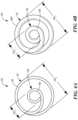
- FIG. 4 Ashows a close-up end view of the first embodiment of the coiled guide, the coiled guide being formed from a flat wire;
- FIG. 4 Bshows a close-up end view of the first embodiment of the coiled guide, the coiled guide being formed from a round wire;
- FIG. 5shows a side view of the first embodiment of a coiled guide within a catheter body
- FIG. 6shows a perspective view of a second embodiment of a coiled guide
- FIG. 7shows a side view of the second embodiment of a coiled guide within a catheter body
- FIGS. 8 A and 8 Bshow a first and second view of an attachment between a shim and a threaded element
- FIG. 9shows a cross-sectional view of a coiled guide and a first embodiment of a single-deflection steering mechanism within a catheter body
- FIG. 10shows a cross-sectional view of a coiled guide and a second embodiment of a single-deflection steering mechanism within a catheter body
- FIG. 11shows a cross-sectional view of a coiled guide and a first embodiment of a dual-deflection steering mechanism within a catheter body
- FIG. 12shows a cross-sectional view of a coiled guide and a second embodiment of a dual-deflection steering mechanism within a catheter body
- FIG. 13shows a cross-sectional view of a coiled guide and a second embodiment of a dual-deflection steering mechanism within a catheter body, with a secondary medical device extending through the coiled guide.
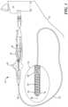
- FIG. 1an exemplary medical system that includes a treatment catheter including a coiled guide is shown in FIG. 1 and is generally designated as “ 10 .”
- the system 10generally includes a catheter 12 that may be coupled to a control unit 14 or operating console.
- the catheter 12may be configured to interact with tissue, such as with one or more electrodes 16 .
- the catheter 12may be a treatment catheter that is configured thermally treat tissue.
- the catheter 12may also include a coiled guide 20 (which may also be referred to as a “coiled guide lumen 20 ”) extending within and along the length of the catheter, as shown and described in more detail in FIGS. 2 - 13 .
- the catheter 12may include an elongate body 22 having a distal portion 24 and a proximal portion 26 , and defining a lumen 28 therebetween.
- the proximal portion 26 of the elongate body 22may be coupled to or otherwise in mechanical, electrical, and/or fluid communication with a handle 30 , which may be, in turn, coupled to or otherwise in mechanical, electrical, and/or fluid communication with the control unit 14 .
- the control unit 14may include one or more energy sources (such as radiofrequency or laser) and/or cryogenic fluid for cryotreatment, vacuums, fluid reservoirs, computers, user input devices, displays, and processors.
- the handle 30may include one or more steering controls 32 that are in mechanical communication with the distal portion 24 of catheter 12 .
- the one or more steering controls 32may be used, for example, to navigate the catheter 12 through the patient's vasculature and/or to modify the size, configuration, and/or operation of a treatment element or assembly at the distal portion 24 .
- the coiled guide 20may define a longitudinal axis 38 and may be located within the elongate body lumen 28 and may extend from the proximal portion 26 to the distal portion 24 of the elongate body 22 .
- the coiled guide 20may be affixed to an inner surface of the elongate body 22 , for example, by adhesive or chemical or thermal bonding. Alternatively, the coiled guide 20 may not be affixed within the elongate body 22 .
- the catheter 12may include a stopper at the proximal end of the elongate body 22 (not shown).
- the coiled guide 20may provide one or more channels or lumens along the length of the elongate body 22 for device components, such as pull wires 40 , electrical wires 42 , secondary medical devices 44 (such as a mapping catheter, as shown in FIG. 13 ), or the like.
- the distal end of the elongate body 22may include an opening 48 through which a secondary medical device 44 or other component may exit the elongate body 22 .
- a mapping catheter 44may extend out of the elongate body 22 and toward a target mapping or treatment site.
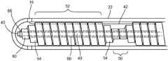
- the coiled guide 20may include a variable outer diameter, with one or more sections 50 having a first outer diameter OD 1 and one or more sections 52 having a second outer diameter OD 2 , with the second outer diameter OD 2 being greater than the first outer diameter OD 1 . Further, there optionally may be a transition section 54 on either side of the larger-diameter sections 52 that each includes a decreasing outer diameter (that is, an outer diameter that transitions from the second outer diameter OD 2 to the first outer diameter OD 1 ).
- the transition section 54may include as few as one coil, in which case the diameter of the transition section coil may be greater than the first outer diameter OD 1 but less than the second outer diameter OD 2 ).
- Each of the smaller-diameter sections 50may include several coils or may include as few as one coil, with each coil being a wrap of wire 56 about 360° ( ⁇ 15°) of the longitudinal axis 38 .
- each of the smaller-diameter sections 50may include between one and five coils, inclusive, whereas each of the larger-diameter sections 52 may include five or more coils.
- Each end 58 of the coiled guide 20may include at least one terminal coil 60 that has an outer diameter that is the same or approximately the same as the first outer diameter OD 1 .
- the coiled guide 20may be formed from any deformable material that can be coiled about a longitudinal axis and maintain its shape.
- the coiled guide 20may be made from an elongate flat strip of metal.
- the wire 56may be wound such that there is a small gap between adjacent coils. The width of the gap may be chosen based on the device in which the coiled guide 20 is used and/or the procedure in which the device is used.
- a secondary guide lumen 66may be inserted through the coiled guide 20 , as shown in FIGS. 3 A and 3 B .
- a single unit of coiled guide 20is shown (that is, one length of a larger-diameter portion 52 , with a transition coil 54 and a smaller-diameter coil 50 on either side).
- the secondary guide lumen 66may be an elongate tube that is made of a biocompatible and has a low coefficient of friction (for example, ⁇ 0.5), such as polyimide.
- the secondary guide lumen 66may be sized to be passed through the coils of the smaller-diameter sections 50 .
- one or more pull wires 40(as shown in FIGS.
- the coiled guide 20is configured such that the secondary guide lumen 66 and/or any other components passed through the smaller-diameter sections 50 may be centered within the elongate body 22 . This may facilitate accurate steering using the one or more pull wires 40 and/or precise placement of a secondary medical device 44 at the treatment site. Further, the low-friction material of the secondary guide lumen 66 may allow the internal components and/or a secondary medical device 44 to slide freely within the secondary guide lumen 66 .
- the larger-diameter sections 52may also provide lumen functionality, similar to the smaller-diameter sections 50 .
- the device components passed through the larger-diameter sections 52may not be centered within the elongate body 22 .
- variable diameter of the coiled guide 20can be seen, for example, in FIGS. 4 A and 4 B .
- the outer diameters OD 1 , OD 2may be any diameters that are suitable for the device in which the coiled guide 20 is used and/or for the internal components of the device and the way in which the device is steered and operated.
- the coiled guide 20 shown in FIGS. 2 A, 3 A, and 4 Amay be made from a flat wire 56
- the coiled guide 20 shown in FIGS. 2 B, 3 B, and 4 Bmay be made from a round wire 56 A.
- the coiled guide 20 shown in FIGS. 2 B, 3 B, and 4 Bmay include the same features as the coiled guide 20 shown in FIGS. 2 A, 3 A, and 4 A .
- the coiled guide 20 of FIG. 6may have the same functionality as the first embodiment of the coiled guide 20 shown in FIGS. 2 A- 5 .
- each of the smaller-diameter sections 50may have a length L 1 that is greater than the length L 2 of each of the larger-diameter sections 52 .
- the first embodiment of the coiled guide 20may include smaller diameter sections 50 that each has a length L 1 that is less than the length L 2 of each of the larger-diameter sections 52 .
- the larger-diameter sections 52 and the transition sections 54may each include as few as one coil, whereas the smaller-diameter sections 50 may each include a plurality of coils. As a non-limiting example, each of the larger-diameter sections 52 may include between one and five coils, inclusive, whereas each of the smaller-diameter sections 50 may include five or more coils.
- the embodiment shown in FIG. 6may be desirable when it is important that a high degree of flexibility be maintained in the elongate body 22 .
- the second coiled guide 20 embodiment shown in FIG. 5may alternatively be formed from a flat wire 56 or a round wire 56 A.
- a secondary guide lumen 66 and/or other device componentsmay be passed through the coiled guide 20 as shown and described in FIGS. 2 A- 5 .
- FIGS. 8 A- 12non-limiting embodiments of a steering mechanism are shown.
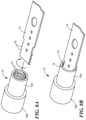
- FIGS. 8 A and 8 Bshow a means of attachment between a threaded assembly 70 in the distal portion 24 of the elongate body 22 to which a shim 72 may be coupled.
- the threaded element 70may be, may define, or may include a threaded annular band.
- the threaded element 70is shown in FIGS. 8 A and 8 B as an assembly having a proximal portion 70 A and a distal portion 70 B.
- the proximal portion 70 Amay be hollow and may include threading 74 on an inner surface
- the distal portion 70 Bmay be hollow or at least partially hollow and at least a portion of the inner surface may also include threading 74 . That is, the threading 74 may extend entirely or partially within the distal portion 70 B.
- the threaded element 70is shown in FIGS. 9 - 12 as an annular band.
- the threaded element 70may be coupled to the interior of the elongate body 22 so that it does not move within the elongate body 22 when a pull force is exerted on the pull wire 40 . Further, the threaded element 70 may be composed of rigid material, such as metal or plastic.
- the shim 72may be a flattened plate that includes threading 76 on two of its edges, the threading 76 being rotatably matable with (that is, able to be screwed into) the threading 74 within the threaded element 70 . Further, the shim 72 may be dimensioned such that the shim 72 is securely attached within the threaded element 70 when the shim 72 is screwed in.
- the shim 72may be composed of a flexible and resilient material, such as thin layer of metal or plastic.
- FIGS. 9 and 10each show a steering method embodiment in which the distal portion 24 of the elongate body 22 may be deflected in a single direction
- FIGS. 11 and 12each show a steering method embodiment in which the distal portion 24 of the elongate body 22 may be deflected in two directions.
- the pull wire 40may be attached to, such as welded or bonded to, a surface of the shim 72 so that a pull force exerted on the pull wire 40 may cause the shim 72 , and therefore the distal portion 24 of the elongate body 22 , to deflect toward the side of the shim to which the pull wire 40 is attached.
- the elongate body 22may be deflectable in a single direction.
- the shim 72may have an at least substantially continuous width, as shown in FIGS. 8 A and 8 B , or it may be tapered as shown in FIGS. 9 and 11 , with the distal end being wide enough to be screwed into the threaded element 70 .
- the narrower diameter of the proximal portion of the shim 72may enhance flexibility of the shim 72 .
- the pull wire 40may be attached directly to the band 70 , but may produce the same one-directional deflection as the embodiment shown in FIG. 9 .
- the embodiment shown in FIG. 11is similar to the embodiment shown in FIG. 9 , except the catheter 12 may include two pull wires 40 , 40 A attached to the shim 72 .
- one pull wire 40may be attached to one face of the shim 72 and a second pull wire 40 A may be attached to the opposite face of the shim 72 .
- a pull force exerted on the pull wire 40may cause the shim 72 , and therefore the distal portion 24 of the elongate body 22 , to deflect toward the side of the shim 72 to which the pull wire 40 is attached.
- a pull force exerted on the pull wire 40 Amay cause the shim 72 , and therefore the distal portion 24 of the elongate body 22 , to deflect toward the side of the shim 72 to which the pull wire 40 A is attached.
- the elongate body 22may be deflectable in two directions.
- the pull wires 40 , 40 Amay be attached directly to the band 70 , but may produce the same dual-directional deflection as the embodiment shown in FIG. 11 .
- the elongate body 22 of the cathetermay be manufactured in a simple, efficient, and cost-effective process.
- a plurality of elongate bodies 22may be manufactured in a single, continuous extruded tube having a single lumen.
- the continuous extruded tubemay then be cut into a plurality of working lengths, each length becoming a catheter elongate body.
- one or more coiled guides 20may be inserted into an elongate body to provide the elongate body with one or more lumens through which various device components and/or secondary medical devices may be passed.
Landscapes
- Health & Medical Sciences (AREA)
- Life Sciences & Earth Sciences (AREA)
- Engineering & Computer Science (AREA)
- Public Health (AREA)
- Animal Behavior & Ethology (AREA)
- Veterinary Medicine (AREA)
- General Health & Medical Sciences (AREA)
- Biomedical Technology (AREA)
- Heart & Thoracic Surgery (AREA)
- Hematology (AREA)
- Biophysics (AREA)
- Anesthesiology (AREA)
- Pulmonology (AREA)
- Mechanical Engineering (AREA)
- Media Introduction/Drainage Providing Device (AREA)
- Surgery (AREA)
- Nuclear Medicine, Radiotherapy & Molecular Imaging (AREA)
- Medical Informatics (AREA)
- Molecular Biology (AREA)
Abstract
Description
Claims (12)
Priority Applications (1)
| Application Number | Priority Date | Filing Date | Title |
|---|---|---|---|
| US17/177,667US12138403B2 (en) | 2014-10-20 | 2021-02-17 | Centering coiled guide |
Applications Claiming Priority (3)
| Application Number | Priority Date | Filing Date | Title |
|---|---|---|---|
| US14/518,545US9839766B2 (en) | 2014-10-20 | 2014-10-20 | Centering coiled guide |
| US15/816,412US10953198B2 (en) | 2014-10-20 | 2017-11-17 | Centering coiled guide |
| US17/177,667US12138403B2 (en) | 2014-10-20 | 2021-02-17 | Centering coiled guide |
Related Parent Applications (1)
| Application Number | Title | Priority Date | Filing Date |
|---|---|---|---|
| US15/816,412ContinuationUS10953198B2 (en) | 2014-10-20 | 2017-11-17 | Centering coiled guide |
Publications (2)
| Publication Number | Publication Date |
|---|---|
| US20210170144A1 US20210170144A1 (en) | 2021-06-10 |
| US12138403B2true US12138403B2 (en) | 2024-11-12 |
Family
ID=55748201
Family Applications (3)
| Application Number | Title | Priority Date | Filing Date |
|---|---|---|---|
| US14/518,545Active2035-04-06US9839766B2 (en) | 2014-10-20 | 2014-10-20 | Centering coiled guide |
| US15/816,412Active2036-06-03US10953198B2 (en) | 2014-10-20 | 2017-11-17 | Centering coiled guide |
| US17/177,667Active2037-04-09US12138403B2 (en) | 2014-10-20 | 2021-02-17 | Centering coiled guide |
Family Applications Before (2)
| Application Number | Title | Priority Date | Filing Date |
|---|---|---|---|
| US14/518,545Active2035-04-06US9839766B2 (en) | 2014-10-20 | 2014-10-20 | Centering coiled guide |
| US15/816,412Active2036-06-03US10953198B2 (en) | 2014-10-20 | 2017-11-17 | Centering coiled guide |
Country Status (5)
| Country | Link |
|---|---|
| US (3) | US9839766B2 (en) |
| EP (1) | EP3209365A4 (en) |
| CN (1) | CN107073244A (en) |
| CA (1) | CA2964824C (en) |
| WO (1) | WO2016061669A1 (en) |
Families Citing this family (2)
| Publication number | Priority date | Publication date | Assignee | Title |
|---|---|---|---|---|
| US9839766B2 (en) | 2014-10-20 | 2017-12-12 | Medtronic Cryocath Lp | Centering coiled guide |
| JP6906883B2 (en)* | 2018-06-04 | 2021-07-21 | 日本ライフライン株式会社 | Balloon catheter |
Citations (78)
| Publication number | Priority date | Publication date | Assignee | Title |
|---|---|---|---|---|
| US4719924A (en) | 1986-09-09 | 1988-01-19 | C. R. Bard, Inc. | Small diameter steerable guidewire with adjustable tip |
| US4724846A (en) | 1986-01-10 | 1988-02-16 | Medrad, Inc. | Catheter guide wire assembly |
| US4917666A (en) | 1988-11-14 | 1990-04-17 | Medtronic Versaflex, Inc. | Steerable thru-lumen catheter |
| EP0435518A1 (en) | 1989-12-29 | 1991-07-03 | Med Institute, Inc. | A flexible, kink-resistant catheter |
| USRE33911E (en) | 1983-07-13 | 1992-05-05 | Advanced Cardiovascular Systems, Inc. | Catheter guide wire with short spring tip and method of using the same |
| US5217474A (en) | 1991-07-15 | 1993-06-08 | Zacca Nadim M | Expandable tip atherectomy method and apparatus |
| US5228441A (en)* | 1991-02-15 | 1993-07-20 | Lundquist Ingemar H | Torquable catheter and method |
| US5228453A (en) | 1991-05-07 | 1993-07-20 | Target Therapeutics, Inc. | Catheter guide wire |
| WO1993020877A1 (en)* | 1992-04-10 | 1993-10-28 | Cardiorhythm | Steerable electrode catheter |
| US5306252A (en) | 1991-07-18 | 1994-04-26 | Kabushiki Kaisha Kobe Seiko Sho | Catheter guide wire and catheter |
| US5449362A (en) | 1991-12-19 | 1995-09-12 | Chaisson; Gary A. | Guiding catheter exchange device |
| US5514128A (en) | 1992-08-18 | 1996-05-07 | Spectranetics Corporation | Fiber optic guide wire and support catheter therefor |
| US5676653A (en) | 1995-06-27 | 1997-10-14 | Arrow International Investment Corp. | Kink-resistant steerable catheter assembly |
| WO1997042996A1 (en) | 1996-05-13 | 1997-11-20 | Ep Technologies, Inc. | Assemblies for creating compound curves in distal catheter regions |
| US5746701A (en) | 1995-09-14 | 1998-05-05 | Medtronic, Inc. | Guidewire with non-tapered tip |
| US5766160A (en) | 1995-06-06 | 1998-06-16 | Target Therapeutics, Inc. | Variable stiffness coils |
| US5827201A (en) | 1996-07-26 | 1998-10-27 | Target Therapeutics, Inc. | Micro-braided guidewire |
| US5895398A (en) | 1996-02-02 | 1999-04-20 | The Regents Of The University Of California | Method of using a clot capture coil |
| US5931830A (en) | 1995-12-07 | 1999-08-03 | Sarcos L.C. | Hollow coil guide wire apparatus for catheters |
| US6017319A (en) | 1996-05-24 | 2000-01-25 | Precision Vascular Systems, Inc. | Hybrid tubular guide wire for catheters |
| US6024765A (en) | 1996-12-30 | 2000-02-15 | Target Therapeutics, Inc. | Vaso-occlusive coil with conical end |
| US6071274A (en) | 1996-12-19 | 2000-06-06 | Ep Technologies, Inc. | Loop structures for supporting multiple electrode elements |
| US6217595B1 (en) | 1996-11-18 | 2001-04-17 | Shturman Cardiology Systems, Inc. | Rotational atherectomy device |
| WO2001054761A2 (en) | 2000-01-28 | 2001-08-02 | William Cook, Europe Aps | Endovascular medical device with plurality of wires |
| US20010049491A1 (en)* | 2000-04-24 | 2001-12-06 | Biotran Corporation, Inc | Process for producing steerable sheath catheters |
| US6332880B1 (en) | 1996-12-19 | 2001-12-25 | Ep Technologies, Inc. | Loop structures for supporting multiple electrode elements |
| US6356791B1 (en) | 1998-06-12 | 2002-03-12 | Cardiac Pacemakers, Inc. | Modified guidewire for left ventricular access lead |
| US20020082585A1 (en)* | 1999-06-15 | 2002-06-27 | Sean Carroll | Defined deflection structure |
| US6458137B1 (en) | 1999-05-26 | 2002-10-01 | Cook Incorporated | Assembly for positioning an embolization coil in the vascular system and a method of introducing a detachable embolization coil |
| US20030018318A1 (en)* | 1999-07-29 | 2003-01-23 | Gerald Melsky | Irrigation and aspiration device |
| US6526979B1 (en) | 1995-06-07 | 2003-03-04 | Conceptus, Inc. | Contraceptive transcervical fallopian tube occlusion devices and methods |
| US6537248B2 (en) | 1998-07-07 | 2003-03-25 | Medtronic, Inc. | Helical needle apparatus for creating a virtual electrode used for the ablation of tissue |
| US20030109861A1 (en)* | 2001-04-12 | 2003-06-12 | Jin Shimada | Steerable sheath catheters |
| US20030130712A1 (en)* | 2002-01-09 | 2003-07-10 | Smits Karel F.A.A. | Method and apparatus for imparting curves in implantable elongated medical instruments |
| US20040073243A1 (en) | 2000-06-29 | 2004-04-15 | Concentric Medical, Inc., A Delaware Corporation | Systems, methods and devices for removing obstructions from a blood vessel |
| US20040167442A1 (en) | 2003-02-26 | 2004-08-26 | Shireman Brice L. | Elongated intracorporal medical device |
| US20040260182A1 (en) | 2003-06-23 | 2004-12-23 | Zuluaga Andres F. | Intraluminal spectroscope with wall contacting probe |
| US20050075582A1 (en) | 1997-03-06 | 2005-04-07 | Scimed Life Systems, Inc. | Guide wire with hydrophilically coated tip |
| US20050080357A1 (en) | 2002-08-26 | 2005-04-14 | Mark Eberhart | Guidewire mounted balloon modulation device and methods of use |
| US6893421B1 (en) | 2000-08-08 | 2005-05-17 | Scimed Life Systems, Inc. | Catheter shaft assembly |
| US6896671B2 (en) | 2003-03-12 | 2005-05-24 | Arrow International, Inc. | Catheter with limited longitudinal extension |
| US20060241419A1 (en) | 2005-03-02 | 2006-10-26 | Terumo Kabushiki Kaisha | Guide wire |
| US7150723B2 (en) | 2001-11-29 | 2006-12-19 | C-I-Medic Co., Ltd. | Medical device including guide wire and balloon catheter for curing a coronary artery |
| US20070208371A1 (en) | 2000-06-29 | 2007-09-06 | Concentric Medical, Inc. | Devices and methods for removing obstructions from a patient and methods for making obstruction removing devices |
| US20070270679A1 (en)* | 2006-05-17 | 2007-11-22 | Duy Nguyen | Deflectable variable radius catheters |
| US20080004546A1 (en) | 2006-07-03 | 2008-01-03 | Asahi Intecc Co., Ltd | Medical guide wire, an assembly body of the same medical guide wire and microcatheter, an assembly body of the same medical guide wire, a balloon catheter and a guiding catheter |
| US20080255654A1 (en) | 2007-03-22 | 2008-10-16 | Bay Street Medical | System for delivering a stent |
| US20090306587A1 (en)* | 2005-06-20 | 2009-12-10 | Zoran Milijasevic | Sleeve Steering and Reinforcement |
| US20100057063A1 (en)* | 2008-07-03 | 2010-03-04 | Steve Arless | Tip design for cryogenic probe with inner coil injection tube |
| US20100185228A1 (en) | 2007-02-27 | 2010-07-22 | Tekulve Kurt J | Variable stiffness occluding device |
| WO2010102105A1 (en) | 2009-03-06 | 2010-09-10 | Cook Incorporated | Reinforced rapid exchange catheter |
| US7848788B2 (en) | 1999-04-15 | 2010-12-07 | The Johns Hopkins University | Magnetic resonance imaging probe |
| US7880578B2 (en) | 2007-10-02 | 2011-02-01 | Advanced Magnet Lab, Inc. | Conductor assembly including a flared aperture region |
| US7918870B2 (en) | 2005-09-12 | 2011-04-05 | Bridgepoint Medical, Inc. | Endovascular devices and methods |
| US20110112476A1 (en)* | 2009-11-09 | 2011-05-12 | Kauphusman James V | Device for reducing axial shortening of catheter or sheath due to repeated deflection |
| US20120123329A1 (en) | 2010-06-30 | 2012-05-17 | Tomihisa Kato | medical guide wire, an assembly of microcatheter and guiding catheter combined with the medical guide wire, and an assembly of ballooncatheter and guiding catheter combined with the medical guide wire |
| US20120165802A1 (en) | 2010-12-27 | 2012-06-28 | Medtronic Cryocath Lp | Method and system to prevent complete obstruction in catheter in case of a kink |
| WO2012116337A1 (en) | 2011-02-25 | 2012-08-30 | Microvention, Inc. | Reinforced balloon catheter |
| US8267985B2 (en) | 2005-05-25 | 2012-09-18 | Tyco Healthcare Group Lp | System and method for delivering and deploying an occluding device within a vessel |
| US8317678B2 (en) | 2005-05-04 | 2012-11-27 | Olympus Endo Technology America Inc. | Rotate-to-advance catheterization system |
| US8372017B2 (en) | 2007-10-30 | 2013-02-12 | General Electric Company | Multi-stranded trackable guidewire |
| US8403867B2 (en) | 2009-05-14 | 2013-03-26 | Medtronic Vascular, Inc. | Concentric guidewire assembly |
| US8535345B2 (en) | 2004-10-07 | 2013-09-17 | DePuy Synthes Products, LLC | Vasoocclusive coil with biplex windings to improve mechanical properties |
| US8545573B2 (en) | 2008-02-12 | 2013-10-01 | Cook Medical Technologies Llc | Spiral occluding device with an occlusion sail |
| US8548873B2 (en) | 2007-02-26 | 2013-10-01 | Dell Products L.P. | System and method for configuring a configurable product |
| US20130338467A1 (en)* | 2010-11-19 | 2013-12-19 | St. Jude Medical, Atrial Fibrillation Division, Inc. | Electrode catheter device with indifferent electrode for direct current tissue therapies |
| US20140052109A1 (en) | 2012-08-19 | 2014-02-20 | Diros Technology Inc. | Steerable Multifunction Catheter Probe with High Guidability and Reversible Rigidity |
| US20140094929A1 (en) | 2012-09-28 | 2014-04-03 | Taewoong Medical Co., Ltd. | Insertion device for plastic stent |
| US8702746B2 (en) | 2008-04-29 | 2014-04-22 | Cook Medical Technologies Llc | Device and method for occlusion of fluid flow through a body vessel |
| US8715441B2 (en) | 2004-01-28 | 2014-05-06 | Applied Medical Resources Corporation | Medical tubing having variable characteristics and method of making same |
| US8777841B2 (en) | 2007-05-18 | 2014-07-15 | Olympus Endo Technology America Inc. | Rotate-to-advance catheterization system |
| US20140276787A1 (en)* | 2013-03-13 | 2014-09-18 | Boston Scientific Scimed, Inc. | Deflectable medical devices |
| US8870908B2 (en) | 2007-08-17 | 2014-10-28 | DePuy Synthes Products, LLC | Twisted primary coil for vascular therapy |
| US20140336572A1 (en)* | 2013-05-07 | 2014-11-13 | St. Jude Medical, Atrial Fibrillation Division, Inc. | Guiding Medical Devices and Associated Methods of Manufacturing |
| US8926528B2 (en) | 2008-08-06 | 2015-01-06 | Biosense Webster, Inc. | Single-axis sensors on flexible backbone |
| US20160058974A1 (en)* | 2011-12-15 | 2016-03-03 | Imricor Medical Systems, Inc. | Steerable sheath including elastomeric member |
| US9615833B2 (en) | 2012-06-29 | 2017-04-11 | Kaneka Corporation | Method for producing in-vivo indwelling member |
| US9839766B2 (en) | 2014-10-20 | 2017-12-12 | Medtronic Cryocath Lp | Centering coiled guide |
- 2014
- 2014-10-20USUS14/518,545patent/US9839766B2/enactiveActive
- 2015
- 2015-10-20WOPCT/CA2015/051049patent/WO2016061669A1/enactiveApplication Filing
- 2015-10-20CNCN201580056631.8Apatent/CN107073244A/enactivePending
- 2015-10-20CACA2964824Apatent/CA2964824C/enactiveActive
- 2015-10-20EPEP15853073.3Apatent/EP3209365A4/enactivePending
- 2017
- 2017-11-17USUS15/816,412patent/US10953198B2/enactiveActive
- 2021
- 2021-02-17USUS17/177,667patent/US12138403B2/enactiveActive
Patent Citations (79)
| Publication number | Priority date | Publication date | Assignee | Title |
|---|---|---|---|---|
| USRE33911E (en) | 1983-07-13 | 1992-05-05 | Advanced Cardiovascular Systems, Inc. | Catheter guide wire with short spring tip and method of using the same |
| US4724846A (en) | 1986-01-10 | 1988-02-16 | Medrad, Inc. | Catheter guide wire assembly |
| US4719924A (en) | 1986-09-09 | 1988-01-19 | C. R. Bard, Inc. | Small diameter steerable guidewire with adjustable tip |
| US4917666A (en) | 1988-11-14 | 1990-04-17 | Medtronic Versaflex, Inc. | Steerable thru-lumen catheter |
| EP0435518A1 (en) | 1989-12-29 | 1991-07-03 | Med Institute, Inc. | A flexible, kink-resistant catheter |
| US5228441A (en)* | 1991-02-15 | 1993-07-20 | Lundquist Ingemar H | Torquable catheter and method |
| US5228453A (en) | 1991-05-07 | 1993-07-20 | Target Therapeutics, Inc. | Catheter guide wire |
| US5217474A (en) | 1991-07-15 | 1993-06-08 | Zacca Nadim M | Expandable tip atherectomy method and apparatus |
| US5306252A (en) | 1991-07-18 | 1994-04-26 | Kabushiki Kaisha Kobe Seiko Sho | Catheter guide wire and catheter |
| US5449362A (en) | 1991-12-19 | 1995-09-12 | Chaisson; Gary A. | Guiding catheter exchange device |
| WO1993020877A1 (en)* | 1992-04-10 | 1993-10-28 | Cardiorhythm | Steerable electrode catheter |
| US5514128A (en) | 1992-08-18 | 1996-05-07 | Spectranetics Corporation | Fiber optic guide wire and support catheter therefor |
| US5766160A (en) | 1995-06-06 | 1998-06-16 | Target Therapeutics, Inc. | Variable stiffness coils |
| US6526979B1 (en) | 1995-06-07 | 2003-03-04 | Conceptus, Inc. | Contraceptive transcervical fallopian tube occlusion devices and methods |
| US5676653A (en) | 1995-06-27 | 1997-10-14 | Arrow International Investment Corp. | Kink-resistant steerable catheter assembly |
| US5746701A (en) | 1995-09-14 | 1998-05-05 | Medtronic, Inc. | Guidewire with non-tapered tip |
| US5931830A (en) | 1995-12-07 | 1999-08-03 | Sarcos L.C. | Hollow coil guide wire apparatus for catheters |
| US5895398A (en) | 1996-02-02 | 1999-04-20 | The Regents Of The University Of California | Method of using a clot capture coil |
| WO1997042996A1 (en) | 1996-05-13 | 1997-11-20 | Ep Technologies, Inc. | Assemblies for creating compound curves in distal catheter regions |
| US6017319A (en) | 1996-05-24 | 2000-01-25 | Precision Vascular Systems, Inc. | Hybrid tubular guide wire for catheters |
| US5827201A (en) | 1996-07-26 | 1998-10-27 | Target Therapeutics, Inc. | Micro-braided guidewire |
| US6217595B1 (en) | 1996-11-18 | 2001-04-17 | Shturman Cardiology Systems, Inc. | Rotational atherectomy device |
| US6332880B1 (en) | 1996-12-19 | 2001-12-25 | Ep Technologies, Inc. | Loop structures for supporting multiple electrode elements |
| US6071274A (en) | 1996-12-19 | 2000-06-06 | Ep Technologies, Inc. | Loop structures for supporting multiple electrode elements |
| US6024765A (en) | 1996-12-30 | 2000-02-15 | Target Therapeutics, Inc. | Vaso-occlusive coil with conical end |
| US20050075582A1 (en) | 1997-03-06 | 2005-04-07 | Scimed Life Systems, Inc. | Guide wire with hydrophilically coated tip |
| US6356791B1 (en) | 1998-06-12 | 2002-03-12 | Cardiac Pacemakers, Inc. | Modified guidewire for left ventricular access lead |
| US6537248B2 (en) | 1998-07-07 | 2003-03-25 | Medtronic, Inc. | Helical needle apparatus for creating a virtual electrode used for the ablation of tissue |
| US7848788B2 (en) | 1999-04-15 | 2010-12-07 | The Johns Hopkins University | Magnetic resonance imaging probe |
| US6458137B1 (en) | 1999-05-26 | 2002-10-01 | Cook Incorporated | Assembly for positioning an embolization coil in the vascular system and a method of introducing a detachable embolization coil |
| US20020082585A1 (en)* | 1999-06-15 | 2002-06-27 | Sean Carroll | Defined deflection structure |
| US20030018318A1 (en)* | 1999-07-29 | 2003-01-23 | Gerald Melsky | Irrigation and aspiration device |
| WO2001054761A2 (en) | 2000-01-28 | 2001-08-02 | William Cook, Europe Aps | Endovascular medical device with plurality of wires |
| US20010049491A1 (en)* | 2000-04-24 | 2001-12-06 | Biotran Corporation, Inc | Process for producing steerable sheath catheters |
| US20070208371A1 (en) | 2000-06-29 | 2007-09-06 | Concentric Medical, Inc. | Devices and methods for removing obstructions from a patient and methods for making obstruction removing devices |
| US20040073243A1 (en) | 2000-06-29 | 2004-04-15 | Concentric Medical, Inc., A Delaware Corporation | Systems, methods and devices for removing obstructions from a blood vessel |
| US6893421B1 (en) | 2000-08-08 | 2005-05-17 | Scimed Life Systems, Inc. | Catheter shaft assembly |
| US20030109861A1 (en)* | 2001-04-12 | 2003-06-12 | Jin Shimada | Steerable sheath catheters |
| US7150723B2 (en) | 2001-11-29 | 2006-12-19 | C-I-Medic Co., Ltd. | Medical device including guide wire and balloon catheter for curing a coronary artery |
| US20030130712A1 (en)* | 2002-01-09 | 2003-07-10 | Smits Karel F.A.A. | Method and apparatus for imparting curves in implantable elongated medical instruments |
| US20050080357A1 (en) | 2002-08-26 | 2005-04-14 | Mark Eberhart | Guidewire mounted balloon modulation device and methods of use |
| US20040167442A1 (en) | 2003-02-26 | 2004-08-26 | Shireman Brice L. | Elongated intracorporal medical device |
| US6896671B2 (en) | 2003-03-12 | 2005-05-24 | Arrow International, Inc. | Catheter with limited longitudinal extension |
| US20040260182A1 (en) | 2003-06-23 | 2004-12-23 | Zuluaga Andres F. | Intraluminal spectroscope with wall contacting probe |
| US8715441B2 (en) | 2004-01-28 | 2014-05-06 | Applied Medical Resources Corporation | Medical tubing having variable characteristics and method of making same |
| US8535345B2 (en) | 2004-10-07 | 2013-09-17 | DePuy Synthes Products, LLC | Vasoocclusive coil with biplex windings to improve mechanical properties |
| US20060241419A1 (en) | 2005-03-02 | 2006-10-26 | Terumo Kabushiki Kaisha | Guide wire |
| US8317678B2 (en) | 2005-05-04 | 2012-11-27 | Olympus Endo Technology America Inc. | Rotate-to-advance catheterization system |
| US8267985B2 (en) | 2005-05-25 | 2012-09-18 | Tyco Healthcare Group Lp | System and method for delivering and deploying an occluding device within a vessel |
| US20090306587A1 (en)* | 2005-06-20 | 2009-12-10 | Zoran Milijasevic | Sleeve Steering and Reinforcement |
| US7918870B2 (en) | 2005-09-12 | 2011-04-05 | Bridgepoint Medical, Inc. | Endovascular devices and methods |
| US20070270679A1 (en)* | 2006-05-17 | 2007-11-22 | Duy Nguyen | Deflectable variable radius catheters |
| US20080004546A1 (en) | 2006-07-03 | 2008-01-03 | Asahi Intecc Co., Ltd | Medical guide wire, an assembly body of the same medical guide wire and microcatheter, an assembly body of the same medical guide wire, a balloon catheter and a guiding catheter |
| US8548873B2 (en) | 2007-02-26 | 2013-10-01 | Dell Products L.P. | System and method for configuring a configurable product |
| US20100185228A1 (en) | 2007-02-27 | 2010-07-22 | Tekulve Kurt J | Variable stiffness occluding device |
| US20080255654A1 (en) | 2007-03-22 | 2008-10-16 | Bay Street Medical | System for delivering a stent |
| US8777841B2 (en) | 2007-05-18 | 2014-07-15 | Olympus Endo Technology America Inc. | Rotate-to-advance catheterization system |
| US8870908B2 (en) | 2007-08-17 | 2014-10-28 | DePuy Synthes Products, LLC | Twisted primary coil for vascular therapy |
| US7880578B2 (en) | 2007-10-02 | 2011-02-01 | Advanced Magnet Lab, Inc. | Conductor assembly including a flared aperture region |
| US8372017B2 (en) | 2007-10-30 | 2013-02-12 | General Electric Company | Multi-stranded trackable guidewire |
| US8545573B2 (en) | 2008-02-12 | 2013-10-01 | Cook Medical Technologies Llc | Spiral occluding device with an occlusion sail |
| US8702746B2 (en) | 2008-04-29 | 2014-04-22 | Cook Medical Technologies Llc | Device and method for occlusion of fluid flow through a body vessel |
| US20100057063A1 (en)* | 2008-07-03 | 2010-03-04 | Steve Arless | Tip design for cryogenic probe with inner coil injection tube |
| US8926528B2 (en) | 2008-08-06 | 2015-01-06 | Biosense Webster, Inc. | Single-axis sensors on flexible backbone |
| WO2010102105A1 (en) | 2009-03-06 | 2010-09-10 | Cook Incorporated | Reinforced rapid exchange catheter |
| US8764727B2 (en) | 2009-03-06 | 2014-07-01 | Cook Medical Technologies Llc | Reinforced rapid exchange catheter |
| US8403867B2 (en) | 2009-05-14 | 2013-03-26 | Medtronic Vascular, Inc. | Concentric guidewire assembly |
| US20110112476A1 (en)* | 2009-11-09 | 2011-05-12 | Kauphusman James V | Device for reducing axial shortening of catheter or sheath due to repeated deflection |
| US20120123329A1 (en) | 2010-06-30 | 2012-05-17 | Tomihisa Kato | medical guide wire, an assembly of microcatheter and guiding catheter combined with the medical guide wire, and an assembly of ballooncatheter and guiding catheter combined with the medical guide wire |
| US20130338467A1 (en)* | 2010-11-19 | 2013-12-19 | St. Jude Medical, Atrial Fibrillation Division, Inc. | Electrode catheter device with indifferent electrode for direct current tissue therapies |
| US20120165802A1 (en) | 2010-12-27 | 2012-06-28 | Medtronic Cryocath Lp | Method and system to prevent complete obstruction in catheter in case of a kink |
| WO2012116337A1 (en) | 2011-02-25 | 2012-08-30 | Microvention, Inc. | Reinforced balloon catheter |
| US20160058974A1 (en)* | 2011-12-15 | 2016-03-03 | Imricor Medical Systems, Inc. | Steerable sheath including elastomeric member |
| US9615833B2 (en) | 2012-06-29 | 2017-04-11 | Kaneka Corporation | Method for producing in-vivo indwelling member |
| US20140052109A1 (en) | 2012-08-19 | 2014-02-20 | Diros Technology Inc. | Steerable Multifunction Catheter Probe with High Guidability and Reversible Rigidity |
| US20140094929A1 (en) | 2012-09-28 | 2014-04-03 | Taewoong Medical Co., Ltd. | Insertion device for plastic stent |
| US20140276787A1 (en)* | 2013-03-13 | 2014-09-18 | Boston Scientific Scimed, Inc. | Deflectable medical devices |
| US20140336572A1 (en)* | 2013-05-07 | 2014-11-13 | St. Jude Medical, Atrial Fibrillation Division, Inc. | Guiding Medical Devices and Associated Methods of Manufacturing |
| US9839766B2 (en) | 2014-10-20 | 2017-12-12 | Medtronic Cryocath Lp | Centering coiled guide |
Non-Patent Citations (5)
| Title |
|---|
| China National Intellectual Property Administration, Notice on the First Office Action and Search Report, dated Aug. 13, 2019, for corresponding Chinese Application No. 201580056631.8, 18 pages. |
| European Patent Office Examination Report for Application No. 15853073.3 dated Jun. 4, 2024 (6 pages). |
| European Patent Office Examination Report for Application No. 15853073.3 dated Jun. 7, 2022 (8 pages). |
| International Search Report and Written Opinion dated Jan. 7, 2016, for corresponding International Application No. PCT/CA2015/051049; International Filing Date: Oct. 20, 2015 consisting of 11-pages. |
| Supplementary European Search Report dated Apr. 11, 2018, for corresponding European Application No. 15853073.3; consisting of 2-pages. |
Also Published As
| Publication number | Publication date |
|---|---|
| US10953198B2 (en) | 2021-03-23 |
| WO2016061669A1 (en) | 2016-04-28 |
| CA2964824A1 (en) | 2016-04-28 |
| CN107073244A (en) | 2017-08-18 |
| US20160106956A1 (en) | 2016-04-21 |
| US20180071491A1 (en) | 2018-03-15 |
| EP3209365A1 (en) | 2017-08-30 |
| CA2964824C (en) | 2018-12-04 |
| EP3209365A4 (en) | 2018-05-16 |
| US9839766B2 (en) | 2017-12-12 |
| US20210170144A1 (en) | 2021-06-10 |
Similar Documents
| Publication | Publication Date | Title |
|---|---|---|
| US10492857B2 (en) | Deployment control apparatus for a catheter with a deployable array | |
| US12311127B2 (en) | Radial and trans-endocardial delivery catheter | |
| US9498602B2 (en) | Guided intravascular catheter sheath having bi-directional steering assembly | |
| US10709870B2 (en) | Steerable medical device and method | |
| US10376170B2 (en) | Catheter with annular lumen to provide distal flushing | |
| JP5154031B2 (en) | Steerable catheter with distal tip directing sheath | |
| JP4152546B2 (en) | Bi-directional electrode catheter | |
| CN102892453B (en) | Magnetic Guidance Catheter | |
| US8256428B2 (en) | Method for treating tissue | |
| US12011549B2 (en) | Sheath visualization | |
| US5562619A (en) | Deflectable catheter | |
| RU2676841C2 (en) | Unidirectional catheter control handle with tensioning control | |
| US12138403B2 (en) | Centering coiled guide | |
| US20090105638A1 (en) | Single use deflectable stylet | |
| US7766868B2 (en) | Deflectable medical therapy delivery device having common lumen profile | |
| US20150105721A1 (en) | Steerable medical devices | |
| EP3583974B1 (en) | Catheter having multiple curvatures and medical apparatus for surgery | |
| US20180256861A1 (en) | Guidewires with Variable Rigidity |
Legal Events
| Date | Code | Title | Description |
|---|---|---|---|
| AS | Assignment | Owner name:MEDTRONIC CRYOCATH LP, CANADA Free format text:ASSIGNMENT OF ASSIGNORS INTEREST;ASSIGNOR:DEAC, IOANA;REEL/FRAME:055296/0442 Effective date:20141020 | |
| FEPP | Fee payment procedure | Free format text:ENTITY STATUS SET TO UNDISCOUNTED (ORIGINAL EVENT CODE: BIG.); ENTITY STATUS OF PATENT OWNER: LARGE ENTITY | |
| STPP | Information on status: patent application and granting procedure in general | Free format text:DOCKETED NEW CASE - READY FOR EXAMINATION | |
| STPP | Information on status: patent application and granting procedure in general | Free format text:NON FINAL ACTION MAILED | |
| STPP | Information on status: patent application and granting procedure in general | Free format text:RESPONSE TO NON-FINAL OFFICE ACTION ENTERED AND FORWARDED TO EXAMINER | |
| STPP | Information on status: patent application and granting procedure in general | Free format text:NOTICE OF ALLOWANCE MAILED -- APPLICATION RECEIVED IN OFFICE OF PUBLICATIONS | |
| ZAAB | Notice of allowance mailed | Free format text:ORIGINAL CODE: MN/=. | |
| STPP | Information on status: patent application and granting procedure in general | Free format text:NOTICE OF ALLOWANCE MAILED -- APPLICATION RECEIVED IN OFFICE OF PUBLICATIONS | |
| STPP | Information on status: patent application and granting procedure in general | Free format text:AWAITING TC RESP., ISSUE FEE NOT PAID | |
| STPP | Information on status: patent application and granting procedure in general | Free format text:NOTICE OF ALLOWANCE MAILED -- APPLICATION RECEIVED IN OFFICE OF PUBLICATIONS | |
| STPP | Information on status: patent application and granting procedure in general | Free format text:PUBLICATIONS -- ISSUE FEE PAYMENT VERIFIED | |
| STCF | Information on status: patent grant | Free format text:PATENTED CASE |