US12138165B2 - Annuloplasty implants - Google Patents
Annuloplasty implantsDownload PDFInfo
- Publication number
- US12138165B2 US12138165B2US17/473,786US202117473786AUS12138165B2US 12138165 B2US12138165 B2US 12138165B2US 202117473786 AUS202117473786 AUS 202117473786AUS 12138165 B2US12138165 B2US 12138165B2
- Authority
- US
- United States
- Prior art keywords
- sleeve
- applications
- implant
- contracting
- force
- Prior art date
- Legal status (The legal status is an assumption and is not a legal conclusion. Google has not performed a legal analysis and makes no representation as to the accuracy of the status listed.)
- Active, expires
Links
Images


Classifications
- A—HUMAN NECESSITIES
- A61—MEDICAL OR VETERINARY SCIENCE; HYGIENE
- A61F—FILTERS IMPLANTABLE INTO BLOOD VESSELS; PROSTHESES; DEVICES PROVIDING PATENCY TO, OR PREVENTING COLLAPSING OF, TUBULAR STRUCTURES OF THE BODY, e.g. STENTS; ORTHOPAEDIC, NURSING OR CONTRACEPTIVE DEVICES; FOMENTATION; TREATMENT OR PROTECTION OF EYES OR EARS; BANDAGES, DRESSINGS OR ABSORBENT PADS; FIRST-AID KITS
- A61F2/00—Filters implantable into blood vessels; Prostheses, i.e. artificial substitutes or replacements for parts of the body; Appliances for connecting them with the body; Devices providing patency to, or preventing collapsing of, tubular structures of the body, e.g. stents
- A61F2/02—Prostheses implantable into the body
- A61F2/24—Heart valves ; Vascular valves, e.g. venous valves; Heart implants, e.g. passive devices for improving the function of the native valve or the heart muscle; Transmyocardial revascularisation [TMR] devices; Valves implantable in the body
- A61F2/2442—Annuloplasty rings or inserts for correcting the valve shape; Implants for improving the function of a native heart valve
- A61F2/2445—Annuloplasty rings in direct contact with the valve annulus
- A—HUMAN NECESSITIES
- A61—MEDICAL OR VETERINARY SCIENCE; HYGIENE
- A61B—DIAGNOSIS; SURGERY; IDENTIFICATION
- A61B17/00—Surgical instruments, devices or methods
- A61B17/064—Surgical staples, i.e. penetrating the tissue
- A—HUMAN NECESSITIES
- A61—MEDICAL OR VETERINARY SCIENCE; HYGIENE
- A61B—DIAGNOSIS; SURGERY; IDENTIFICATION
- A61B17/00—Surgical instruments, devices or methods
- A61B17/068—Surgical staplers, e.g. containing multiple staples or clamps
- A—HUMAN NECESSITIES
- A61—MEDICAL OR VETERINARY SCIENCE; HYGIENE
- A61B—DIAGNOSIS; SURGERY; IDENTIFICATION
- A61B17/00—Surgical instruments, devices or methods
- A61B17/068—Surgical staplers, e.g. containing multiple staples or clamps
- A61B17/072—Surgical staplers, e.g. containing multiple staples or clamps for applying a row of staples in a single action, e.g. the staples being applied simultaneously
- A—HUMAN NECESSITIES
- A61—MEDICAL OR VETERINARY SCIENCE; HYGIENE
- A61F—FILTERS IMPLANTABLE INTO BLOOD VESSELS; PROSTHESES; DEVICES PROVIDING PATENCY TO, OR PREVENTING COLLAPSING OF, TUBULAR STRUCTURES OF THE BODY, e.g. STENTS; ORTHOPAEDIC, NURSING OR CONTRACEPTIVE DEVICES; FOMENTATION; TREATMENT OR PROTECTION OF EYES OR EARS; BANDAGES, DRESSINGS OR ABSORBENT PADS; FIRST-AID KITS
- A61F2/00—Filters implantable into blood vessels; Prostheses, i.e. artificial substitutes or replacements for parts of the body; Appliances for connecting them with the body; Devices providing patency to, or preventing collapsing of, tubular structures of the body, e.g. stents
- A61F2/02—Prostheses implantable into the body
- A61F2/24—Heart valves ; Vascular valves, e.g. venous valves; Heart implants, e.g. passive devices for improving the function of the native valve or the heart muscle; Transmyocardial revascularisation [TMR] devices; Valves implantable in the body
- A61F2/2442—Annuloplasty rings or inserts for correcting the valve shape; Implants for improving the function of a native heart valve
- A61F2/2466—Delivery devices therefor
- A—HUMAN NECESSITIES
- A61—MEDICAL OR VETERINARY SCIENCE; HYGIENE
- A61B—DIAGNOSIS; SURGERY; IDENTIFICATION
- A61B17/00—Surgical instruments, devices or methods
- A61B17/04—Surgical instruments, devices or methods for suturing wounds; Holders or packages for needles or suture materials
- A61B17/0401—Suture anchors, buttons or pledgets, i.e. means for attaching sutures to bone, cartilage or soft tissue; Instruments for applying or removing suture anchors
- A—HUMAN NECESSITIES
- A61—MEDICAL OR VETERINARY SCIENCE; HYGIENE
- A61B—DIAGNOSIS; SURGERY; IDENTIFICATION
- A61B17/00—Surgical instruments, devices or methods
- A61B17/00234—Surgical instruments, devices or methods for minimally invasive surgery
- A61B2017/00238—Type of minimally invasive operation
- A61B2017/00243—Type of minimally invasive operation cardiac
- A—HUMAN NECESSITIES
- A61—MEDICAL OR VETERINARY SCIENCE; HYGIENE
- A61B—DIAGNOSIS; SURGERY; IDENTIFICATION
- A61B17/00—Surgical instruments, devices or methods
- A61B17/00234—Surgical instruments, devices or methods for minimally invasive surgery
- A61B2017/00292—Surgical instruments, devices or methods for minimally invasive surgery mounted on or guided by flexible, e.g. catheter-like, means
- A61B2017/003—Steerable
- A—HUMAN NECESSITIES
- A61—MEDICAL OR VETERINARY SCIENCE; HYGIENE
- A61B—DIAGNOSIS; SURGERY; IDENTIFICATION
- A61B17/00—Surgical instruments, devices or methods
- A61B2017/00831—Material properties
- A61B2017/00867—Material properties shape memory effect
- A—HUMAN NECESSITIES
- A61—MEDICAL OR VETERINARY SCIENCE; HYGIENE
- A61B—DIAGNOSIS; SURGERY; IDENTIFICATION
- A61B17/00—Surgical instruments, devices or methods
- A61B17/04—Surgical instruments, devices or methods for suturing wounds; Holders or packages for needles or suture materials
- A61B17/0401—Suture anchors, buttons or pledgets, i.e. means for attaching sutures to bone, cartilage or soft tissue; Instruments for applying or removing suture anchors
- A61B2017/0427—Suture anchors, buttons or pledgets, i.e. means for attaching sutures to bone, cartilage or soft tissue; Instruments for applying or removing suture anchors having anchoring barbs or pins extending outwardly from the anchor body
- A61B2017/0437—Suture anchors, buttons or pledgets, i.e. means for attaching sutures to bone, cartilage or soft tissue; Instruments for applying or removing suture anchors having anchoring barbs or pins extending outwardly from the anchor body the barbs being resilient or spring-like
- A—HUMAN NECESSITIES
- A61—MEDICAL OR VETERINARY SCIENCE; HYGIENE
- A61B—DIAGNOSIS; SURGERY; IDENTIFICATION
- A61B17/00—Surgical instruments, devices or methods
- A61B17/04—Surgical instruments, devices or methods for suturing wounds; Holders or packages for needles or suture materials
- A61B17/0401—Suture anchors, buttons or pledgets, i.e. means for attaching sutures to bone, cartilage or soft tissue; Instruments for applying or removing suture anchors
- A61B2017/044—Suture anchors, buttons or pledgets, i.e. means for attaching sutures to bone, cartilage or soft tissue; Instruments for applying or removing suture anchors with a threaded shaft, e.g. screws
- A61B2017/0441—Suture anchors, buttons or pledgets, i.e. means for attaching sutures to bone, cartilage or soft tissue; Instruments for applying or removing suture anchors with a threaded shaft, e.g. screws the shaft being a rigid coil or spiral
- A—HUMAN NECESSITIES
- A61—MEDICAL OR VETERINARY SCIENCE; HYGIENE
- A61B—DIAGNOSIS; SURGERY; IDENTIFICATION
- A61B17/00—Surgical instruments, devices or methods
- A61B17/04—Surgical instruments, devices or methods for suturing wounds; Holders or packages for needles or suture materials
- A61B17/0401—Suture anchors, buttons or pledgets, i.e. means for attaching sutures to bone, cartilage or soft tissue; Instruments for applying or removing suture anchors
- A61B2017/0464—Suture anchors, buttons or pledgets, i.e. means for attaching sutures to bone, cartilage or soft tissue; Instruments for applying or removing suture anchors for soft tissue
- A—HUMAN NECESSITIES
- A61—MEDICAL OR VETERINARY SCIENCE; HYGIENE
- A61B—DIAGNOSIS; SURGERY; IDENTIFICATION
- A61B17/00—Surgical instruments, devices or methods
- A61B17/064—Surgical staples, i.e. penetrating the tissue
- A61B2017/0649—Coils or spirals
- A—HUMAN NECESSITIES
- A61—MEDICAL OR VETERINARY SCIENCE; HYGIENE
- A61F—FILTERS IMPLANTABLE INTO BLOOD VESSELS; PROSTHESES; DEVICES PROVIDING PATENCY TO, OR PREVENTING COLLAPSING OF, TUBULAR STRUCTURES OF THE BODY, e.g. STENTS; ORTHOPAEDIC, NURSING OR CONTRACEPTIVE DEVICES; FOMENTATION; TREATMENT OR PROTECTION OF EYES OR EARS; BANDAGES, DRESSINGS OR ABSORBENT PADS; FIRST-AID KITS
- A61F2/00—Filters implantable into blood vessels; Prostheses, i.e. artificial substitutes or replacements for parts of the body; Appliances for connecting them with the body; Devices providing patency to, or preventing collapsing of, tubular structures of the body, e.g. stents
- A61F2/02—Prostheses implantable into the body
- A61F2/24—Heart valves ; Vascular valves, e.g. venous valves; Heart implants, e.g. passive devices for improving the function of the native valve or the heart muscle; Transmyocardial revascularisation [TMR] devices; Valves implantable in the body
- A61F2/2442—Annuloplasty rings or inserts for correcting the valve shape; Implants for improving the function of a native heart valve
- A61F2/2445—Annuloplasty rings in direct contact with the valve annulus
- A61F2/2448—D-shaped rings
- A—HUMAN NECESSITIES
- A61—MEDICAL OR VETERINARY SCIENCE; HYGIENE
- A61F—FILTERS IMPLANTABLE INTO BLOOD VESSELS; PROSTHESES; DEVICES PROVIDING PATENCY TO, OR PREVENTING COLLAPSING OF, TUBULAR STRUCTURES OF THE BODY, e.g. STENTS; ORTHOPAEDIC, NURSING OR CONTRACEPTIVE DEVICES; FOMENTATION; TREATMENT OR PROTECTION OF EYES OR EARS; BANDAGES, DRESSINGS OR ABSORBENT PADS; FIRST-AID KITS
- A61F2220/00—Fixations or connections for prostheses classified in groups A61F2/00 - A61F2/26 or A61F2/82 or A61F9/00 or A61F11/00 or subgroups thereof
- A61F2220/0008—Fixation appliances for connecting prostheses to the body
- A61F2220/0016—Fixation appliances for connecting prostheses to the body with sharp anchoring protrusions, e.g. barbs, pins, spikes
- A—HUMAN NECESSITIES
- A61—MEDICAL OR VETERINARY SCIENCE; HYGIENE
- A61F—FILTERS IMPLANTABLE INTO BLOOD VESSELS; PROSTHESES; DEVICES PROVIDING PATENCY TO, OR PREVENTING COLLAPSING OF, TUBULAR STRUCTURES OF THE BODY, e.g. STENTS; ORTHOPAEDIC, NURSING OR CONTRACEPTIVE DEVICES; FOMENTATION; TREATMENT OR PROTECTION OF EYES OR EARS; BANDAGES, DRESSINGS OR ABSORBENT PADS; FIRST-AID KITS
- A61F2250/00—Special features of prostheses classified in groups A61F2/00 - A61F2/26 or A61F2/82 or A61F9/00 or A61F11/00 or subgroups thereof
- A61F2250/0004—Special features of prostheses classified in groups A61F2/00 - A61F2/26 or A61F2/82 or A61F9/00 or A61F11/00 or subgroups thereof adjustable
- A61F2250/0007—Special features of prostheses classified in groups A61F2/00 - A61F2/26 or A61F2/82 or A61F9/00 or A61F11/00 or subgroups thereof adjustable for adjusting length
- A—HUMAN NECESSITIES
- A61—MEDICAL OR VETERINARY SCIENCE; HYGIENE
- A61F—FILTERS IMPLANTABLE INTO BLOOD VESSELS; PROSTHESES; DEVICES PROVIDING PATENCY TO, OR PREVENTING COLLAPSING OF, TUBULAR STRUCTURES OF THE BODY, e.g. STENTS; ORTHOPAEDIC, NURSING OR CONTRACEPTIVE DEVICES; FOMENTATION; TREATMENT OR PROTECTION OF EYES OR EARS; BANDAGES, DRESSINGS OR ABSORBENT PADS; FIRST-AID KITS
- A61F2250/00—Special features of prostheses classified in groups A61F2/00 - A61F2/26 or A61F2/82 or A61F9/00 or A61F11/00 or subgroups thereof
- A61F2250/0004—Special features of prostheses classified in groups A61F2/00 - A61F2/26 or A61F2/82 or A61F9/00 or A61F11/00 or subgroups thereof adjustable
- A61F2250/001—Special features of prostheses classified in groups A61F2/00 - A61F2/26 or A61F2/82 or A61F9/00 or A61F11/00 or subgroups thereof adjustable for adjusting a diameter
Definitions
- Some embodiments of the present inventionrelate in general to valve repair, and more specifically to repair of an atrioventricular valve of a patient.
- Ischemic heart diseasecauses mitral regurgitation by the combination of ischemic dysfunction of the papillary muscles, and the dilatation of the left ventricle that is present in ischemic heart disease, with the subsequent displacement of the papillary muscles and the dilatation of the mitral valve annulus.
- Mitral regurgitation of blood from the left ventricle into the left atriumresults in increased total stroke volume and decreased cardiac output, and ultimate weakening of the left ventricle secondary to a volume overload and a pressure overload of the left atrium.
- apparatuscomprising an implant structure comprising a flexible sleeve having a first and second sleeve end, a lumen, and at least one opening at a first end of the implant structure (i.e., one of the first and second sleeve ends).
- the implant structureadditionally comprises a closure element (e.g., a closure mechanism) configured to close the at least one opening at the first end of the implant structure.
- the implant structurecomprises a contracting assembly configured to longitudinally contract and expand the implant structure at least in part.
- the closure mechanismcomprises at least one end flap, and the contracting mechanism is configured to actuate the end flap so as to cover the at least one opening.
- the closure mechanismcomprises self-closing strips which are biased to close around the portion of the implant structure that defines the at least one opening.
- the closure mechanismis configured to compress (e.g., by gathering together) excess portions of the sleeve which do not need to be anchored to tissue of a patient.
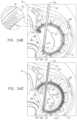
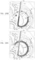
- the implant structurecomprises at least part of an annuloplasty structure (e.g., a partial annuloplasty ring) for repairing a dilated valve annulus of a native atrioventricular valve, such as a mitral or tricuspid valve, of a patient.
- an annuloplasty structuree.g., a partial annuloplasty ring
- the one or more flexible, longitudinal contracting memberse.g., a wire, string, or suture
- the contracting assemblyincludes one or more longitudinal contracting members coupled to the contracting mechanism.
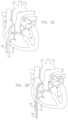
- the implantable structureis placed completely around the annulus, such that none of the one or more longitudinal contracting members is positioned along an anterior portion of the annulus between fibrous trigones of the valve.
- the implantable structureis fastened to the annulus.
- the contracting assemblyis then actuated to contract a longitudinal portion of the sleeve not positioned along the anterior portion of the annulus. Tightening of the implantable structure therefore tightens at least a portion of the posterior portion of the annulus, while preserving the length of the anterior portion of the annulus.
- the anterior portion of the annulusshould generally not be contracted because its tissue is part of the skeleton of the heart.
- the portion of the sleeve deployed along the anterior portion of the annulusprevents dilation of the anterior annulus, because the sleeve is anchored at both ends of the anterior annulus, and the sleeve typically comprises a longitudinally non-extensible material.
- This deployment configurationmay help prevent long-term resizing of annulus, especially the anterior annulus, which sometimes occurs after implantation of partial annuloplasty rings, such as C-bands.
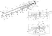
- the contracting assemblyis configured to longitudinally contract the sleeve, and comprises a contracting mechanism and a longitudinal contracting member having first and second member ends.
- the contracting mechanismis disposed longitudinally at a first site of the sleeve, and the second member end is coupled to the sleeve (e.g., by being directly coupled or by being coupled to an element coupled to the sleeve) longitudinally at a second site longitudinally between the first site and the second sleeve end, exclusive.
- the contracting memberalso has a first member end portion, which extends from the first member end toward the second member end along only a longitudinal portion of the contracting member, and is coupled to the contracting mechanism.
- a first portion of the sleevelongitudinally extends from the first sleeve end toward the first site, and a second portion of the sleeve longitudinally extends from the second sleeve end toward the second site.
- the implantable structureis configured such that the contracting assembly applies a longitudinal contracting force only between the first and the second sites.
- one or more of the tissue anchorsare coupled to the sleeve at respective third sites longitudinally between the second site and the second sleeve end, exclusive.
- the implantable structureis configured such that the contracting assembly applies a longitudinal contracting force only between the first and the second sites.
- the longitudinal contracting forcecontracts at least a portion of the sleeve only between the first and the second sites.
- Providing the one or more anchors beyond the ends of the contracting membergenerally distributes force applied by contraction of the contracting assembly over the tissue interfaces of these anchors.
- the force applied by the contracting assemblyis applied predominantly to the single anchor nearest the first end of the contracting member, and the single anchor nearest the second end of the contracting member.
- the tissue anchorsare coupled to the sleeve at respective third sites longitudinally between the second member end and the second sleeve end, exclusive.
- the second siteis at least 5 mm from the second sleeve end, measured when the sleeve is in a straight, relaxed, non-contracted state, such as at least 9 mm, e.g., at least 18 mm.
- the second siteis at a longitudinal distance from the second sleeve end, which distance is no greater than 30% of a total length of the sleeve, the distance and length measured when the sleeve is in the straight, relaxed, non-contracted state.
- at least three of the tissue anchorsare coupled to the sleeve alongside the contracting member, longitudinally between the first and second sites, exclusive.
- the sleeveis substantially longitudinally non-extensible.
- the sleevehas first and second sleeve ends, and first and second portions that longitudinally extend from the first and the second sleeve ends, respectively.
- the sleeveis arranged in a closed loop, such that the first and second portions of the sleeve together define a longitudinally overlapping portion of the sleeve positioned at least partially along the anterior portion of the annulus, and none of the one or more longitudinal contracting members is positioned along the overlapping portion of the sleeve.
- at least one of the tissue anchorspenetrates both the first and second portions of the sleeve at the overlapping portion.
- the sleeveis shaped so as to define an integrally closed loop having no sleeve ends.
- the implantable structureis configured such that the contracting assembly applies a longitudinal contracting force only between the first and the second sites, and not along the overlapping portion.
- the longitudinal contracting forcelongitudinally contracts at least a portion of the sleeve only between the first and the second sites, and not along the overlapping portion.
- the contracting memberextends along neither the first nor the second portion of the sleeve.
- the implantable structurewhen in this closed-loop configuration, is deployed around the entire annulus of the native valve, including an anterior portion of the annulus (on the aortic side of the valve) between the fibrous trigones.
- the contracting memberdoes not extend along the portion of the sleeve deployed along the anterior portion of the annulus, and thus does not extend along the first portion, the second portion, or the overlapping portion of the sleeve.
- the portion of the sleeve deployed along the anterior portion of the annulus (between the trigones)is thus non-contractible.
- tightening of the implantable structuretherefore tightens the posterior portion of the annulus, while preserving the length of the anterior portion of the annulus.
- this deployment configurationmay also help achieve a closed loop that serves as a base ring to which a prosthetic valve is coupled.
- the implantable structurefurther comprises an elongated linking member, which is positioned along an anterior portion of the annulus, so as to join the ends of the implantable structure in a complete loop.
- the linking memberbecomes fixed to the anterior portion of the annulus, thereby helping prevent long-term dilation of the anterior annulus.
- at least a portion of the linking memberis disposed within and covered by the sleeve, into and/or over which fibrous tissue grows over time, helping anchor the linking member to tissue of the anterior annulus.
- none of the anchorsis coupled to the anterior portion of the annulus.
- a first end of the linking memberis typically fixed between 2 and 6 cm from a first end of the sleeve.
- a second end of the linking memberis positioned within 1.5 cm of the same end of the sleeve, either protruding from the end of the sleeve, or recessed within the sleeve.
- the second end of the linking membercomprises (e.g., is shaped so as to define) a first coupling element.
- the implantable structurefurther comprises a second coupling element, which is configured to be coupleable to the first coupling element.
- the second coupling elementis coupled to the implantable structure within 1.5 cm of the second end of the sleeve.
- the second coupling elementmay be coupled to the housing, directly to the sleeve, or otherwise coupled to the implantable structure.
- the linking memberis substantially longitudinally non-extensible, i.e., its length is fixed.
- the linking memberis configured as a spring, which is typically curved, so as to be elastic in a radial direction, i.e., to be compressible like a bow or deflected beam.
- the linking memberis oriented such that it is pressed by elasticity against the anterior portion of the mitral annulus, i.e., the outer wall of the aorta, thereby holding the sleeve covering the linking member against the aortic wall.
- at least two of the tissue anchorsare coupled to the sleeve at respective, different longitudinal sites alongside the linking member, within 6 cm of the first end of the linking member. These tissue anchors may help set the proper direction of curvature of the linking member, for applications in which the linking member is curved.
- the contracting memberis coupled at the first member end portion thereof to the contracting mechanism.
- a second member end portion of the contracting memberis coupled to the end flap.
- the contracting mechanismWhen the contracting mechanism is actuated in a first actuation direction, the contracting mechanism pulls on the contracting member which, in turn, pulls on the end flap, thereby covering the opening at least in part.
- One or more contraction-restricting elementsare coupled to the implant structure and/or to the contracting member. The one or more contraction-restricting elements are configured to restrict contraction of at least a first portion of the implant structure beyond a predetermined amount while the contraction of the remaining portion(s) of the implant structure is ongoing.
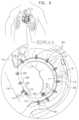
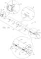
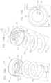
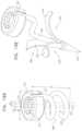
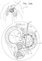
- the contracting mechanismcomprises a rotatable structure, and a housing in which the rotatable structure is positioned.
- the contracting mechanism and the longitudinal contracting memberare arranged such that rotation of the rotatable structure contracts the implant structure and/or adjusts a perimeter of the implant structure.
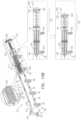
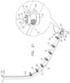
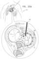
- an anchor deployment manipulatoris advanced into a lumen of the sleeve, and, from within the lumen, deploys the anchors through a wall of the sleeve and into cardiac tissue, thereby anchoring the sleeve around a portion of a valve annulus.
- the anchor deployment manipulatoris typically deflectable.
- the anchor deployment manipulatorcomprises a steerable tube in which is positioned an anchor driver having an elongated, flexible shaft. Rotation of the anchor driver screws the anchors into the cardiac tissue.
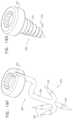
- the anchorsmay, for example, be helical in shape.
- one or more stiffening elementse.g., wires or sutures, are threaded through one or more portions of the sleeve in order to maintain relative positioning of the anchor driver relative to the implant structure during deflection of the anchor driver within the sleeve.
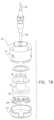
- a rotation toolis provided for rotating the rotatable structure.
- the toolis configured to be guided along (e.g., over, alongside, or through) the longitudinal guide member, to engage the rotatable structure, and to rotate the rotatable structure in response to a rotational force applied to the tool.
- the implantable structurecomprises an adjustable annuloplasty ring structure for repairing a dilated valve annulus of an atrioventricular valve, such as a mitral valve.
- the annuloplasty ring structuremay be used for treating functional mitral regurgitation (FMR) or degenerative mitral valve disease.
- FMRfunctional mitral regurgitation
- a prosthetic heart valveis further provided, which is configured to be coupled to the sleeve.
- the implantable structuremay be advanced toward the annulus of a valve in any suitable procedure, e.g., a transluminal or transcatheter procedure, a percutaneous procedure, a minimally invasive procedure, or an open heart procedure.
- a transluminal or transcatheter proceduree.g., a percutaneous procedure, a minimally invasive procedure, or an open heart procedure.
- the annuloplasty ringis typically configured to be placed only partially around the valve annulus (e.g., to assume a C-shape), and, once anchored in place, to be contracted so as to circumferentially tighten the valve annulus.
- the annuloplasty ringcomprises the flexible contracting member.
- the implant structurecomprises one or more contraction-restricting elements configured to restrict contraction of at least a portion of the implant structure.
- the implant structureis partially-contractible.
- a first anchoris deployed at or in a vicinity of a first trigone of the valve
- a second anchoris deployed at or in a vicinity of a second trigone.
- the implant structureis anchored to the first trigone at a first free end thereof and is anchored to the second trigone at a second free end thereof.
- the body portion of the implant structureextends from the first trigone and toward and along a portion of the annulus that is adjacent to the posterolateral leaflet.
- the contraction-restricted portionis disposed along the annulus and therefore, a portion of the implant structure is contracted (i.e., a contraction-facilitated portion), thereby contracting a portion of the annulus that is between the first and second trigones and adjacent to the posterolateral leaflet and, thereby, reducing a perimeter of the valve annulus and drawing the leaflets together.
- the second free endis not anchored to the trigone, but is instead anchored to a portion of the atrial wall (e.g., a portion of the interatrial septum or a portion of a free wall) of the heart of the patient while the first free end or a first portion of the implant structure adjacent the first free end is anchored to the first trigone.
- the entire contraction-restricted portionis attached to the portion of the atrial wall and the contraction-facilitated portion is disposed between the first and second trigones and runs along the portion of the annulus that is adjacent to the posterolateral leaflet.
- the entire portion of the annulus that is between the first and second trigones and adjacent the posterolateral leafletis contracted, thereby reducing a perimeter of the valve annulus and drawing the leaflets together.
- the contracting mechanismcomprises a spool to which a first end of the contracting member is coupled. Rotation of the spool winds a portion of the contracting member around the spool, thereby contracting the implant structure.
- the contracting mechanismcomprises a housing that houses the spool, and the rotation tool is configured to engage and rotate the spool with respect to the housing.
- the rotation toolcomprises a tube, which is configured to be passed over the longitudinal member coupled to the contracting mechanism, and to engage the housing, such that the housing is held rotationally stationary when the tube is held rotationally stationary.
- the implant structurecomprises an annuloplasty ring structure
- all of the tools and elements of the annuloplasty system that are introduced into left atriumare contained within the sleeve of the annuloplasty ring structure, which reduces the risk that any elements of the system will accidentally be released to the blood circulation, or damage surrounding tissue.
- the lumen of the sleeveprovides guidance if it should be necessary to return to a previously deployed anchor, such as to tighten, loosen, remove, or relocate the anchor.
- the anchorscomprise helical screws, which facilitate such adjusting or removing.
- apparatusincluding an implantable structure, including:
- a flexible sleevehaving first and second sleeve ends
- a contracting assemblywhich is configured to longitudinally contract the sleeve, and which includes:
- a force-distributing elementconfigured to be coupled to the sleeve in a vicinity of the second sleeve end, the force-distributing element is configured to distribute a contraction force by the contracting member between the second member end and the second sleeve end.
- the apparatusincludes a first anchor couplable to the sleeve at a third site longitudinally between the second member end and the second sleeve end; and a second anchor couplable to the sleeve in a vicinity of the second site, the force-distributing element is configured to distribute a contraction force between the first and second anchors.
- the force-distributing elementincludes an element that is longitudinally non-compressible.
- the force-distributing elementincludes a coiled element having a plurality of longitudinally-non-compressible coils.
- the force-distributing elementis advanceable within the sleeve through an opening at the second sleeve end, and the force-distributing element is shaped so as to define one or more protrusions to engage and couple the force-distributing element to the sleeve.
- the apparatusincludes a plurality of tissue anchors, one or more of which are coupled to the sleeve at respective third sites longitudinally between the second site and the second sleeve end, exclusive.
- the apparatusincludes a plurality of tissue anchors, one or more of which are coupled to the sleeve at respective third sites longitudinally between the second member end and the second sleeve end, exclusive.
- the apparatusincludes: second-sleeve-end coupling element couplable to the second sleeve end; and an approximating element coupled at a first end portion thereof to the second-sleeve-end coupling element, and at a second end portion of the approximating element to the force-distributing element, the approximating element being configured to change a spatial orientation of at least a portion of a portion of the sleeve that is between the force-distributing element and the second sleeve end.
- the approximatingincludes a screw shaft, the approximating element is shaped so as to define screw thread for receiving the screw shaft, and the approximating element is configured to shorten the at least the portion of the sleeve between the force-distributing element and the second sleeve end.
- the force-distributing elementis shaped so as to define the screw thread.
- the approximating elementincludes a spring, and the approximating element is configured to shorten the at least the portion of the sleeve between the force-distributing element and the second sleeve end.
- the springhas a tendency to compress in order to compress the portion of the sleeve between the force-distributing element and the second sleeve end.
- the approximating elementincludes an elongate deflectable structural element coupled to the sleeve at the at least the portion, the elongate deflectable structural element having a shape-memory element so as to facilitate deflecting of the at least the portion.
- the flexible sleeveis configured to provide an opening at at least the second sleeve end, and the second-sleeve-end coupling element includes a closure element configured to close the opening.
- the closure elementincludes a plug.
- an implantable structurewhich includes:
- a flexible sleevehaving first and second sleeve ends
- a structural, reference-force componentcoupled to the sleeve at a portion of the sleeve that is between the first and second sleeve ends;
- an approximating elementcoupled at a first end portion thereof to the second-sleeve-end coupling element, and at a second end portion of the approximating element to the structural, reference-force component, the approximating element being configured to change a spatial orientation of at least a portion of a portion of the sleeve that is between the structural, reference-force component and the second sleeve end.
- the structural, reference-force componentincludes a force-distributing element configured to distribute a contraction force by the contracting member between the second member end and the second sleeve end.
- apparatusincluding an implantable structure, including:
- a flexible sleevehaving first and second sleeve ends
- a contracting assemblywhich is configured to longitudinally contract the sleeve, and which includes:
- contracting-member-receiving elementcoupled to the sleeve between the first site and the second sleeve end, exclusive, the contracting member being slidable with respect to the contracting-member-receiving element
- stoppercoupled to the second member end, the stopper being advanceable toward the contracting-member-receiving element during contraction of the sleeve by the contracting mechanism.
- the contracting memberslides within a portion of the contracting-member-receiving element.
- the contracting-member-receiving elementincludes a coupler to engage the stopper to the contracting-member-receiving element.
- the sleevedefines a contracting-assembly-contraction-facilitated portion between the first sleeve end and the contracting-member-receiving element, the contracting-assembly-contraction-facilitated portion being contractible and expandable by the contracting assembly;
- the sleevedefines a contracting-assembly-non-contraction-facilitated portion between the contracting-member-receiving element and the second sleeve end.
- the apparatusincludes an elongate deflectable structural element coupled to the sleeve at the contracting-assembly-non-contraction-facilitated portion, the elongate deflectable structural element having a shape-memory element so as to facilitate deflecting of the contracting-assembly-non-contraction-facilitated portion.
- apparatusincluding an implantable structure, which includes:
- a flexible sleevehaving first and second sleeve ends, the sleeve defining:
- an elongate deflectable structural elementcoupled to the sleeve at the deflectable region, the elongate deflectable structural element having a shape-memory element so as to facilitate deflecting of the deflectable region of the sleeve.
- apparatusincluding an implantable structure, including:
- a flexible sleevehaving first and second sleeve ends
- a contracting assemblywhich is configured to longitudinally contract the sleeve, and which includes:
- a sleeve-shortening elementconfigured to shorten the at least a portion of a portion of the sleeve between the second site and the second sleeve end.
- contracting mechanismincludes a spool around which at least the first member end portion is wound.
- the sleeve-shortening elementincludes a screw shaft, the sleeve-shortening element is shaped so as to define screw thread for receiving the screw shaft.
- the sleeve-shortening elementincludes a spring.
- the springhas a tendency to compress in order to compress the portion of the sleeve between the second site and the second sleeve end.
- apparatusincluding an implantable structure, which includes:
- a flexible sleevehaving first and second sleeve ends
- a contracting assemblywhich is configured to longitudinally contract the sleeve, and which includes:
- a first portion of the sleevelongitudinally extends from the first sleeve end toward the first site, and a second portion of the sleeve longitudinally extends from the second sleeve end toward the second site,
- the sleeveis arranged in a closed loop, such that the first and second portions of the sleeve together define a longitudinally overlapping portion of the sleeve, and
- the implantable structureis configured such that the contracting assembly applies a longitudinal contracting force only between the first and the second sites, and not along the overlapping portion.
- the implantable structurefurther includes a plurality of tissue anchors, at least one of which penetrates both the first and second portions of the sleeve at the overlapping portion.
- the at least one of the tissue anchorsincludes a coupling head and a tissue coupling element, the tissue coupling element penetrates both the first and second portions of the sleeve at the overlapping portion, and the coupling head is positioned within one of the first and second portions of the sleeve at the overlapping portion.
- the plurality of tissue anchorsincludes: (a) a plurality of first tissue anchors of a first configuration, coupled to the sleeve at intervals along a first longitudinally-contiguous portion of the loop; and (b) a plurality of second tissue anchors of a second configuration different from the first configuration, coupled to the sleeve at intervals along a second longitudinally-contiguous portion of the loop different from the first longitudinally-contiguous portion, which second longitudinally contiguous portion includes the longitudinally overlapping portion.
- the first and second tissue anchorsare optionally configured as described below.
- the overlapping portionhas a length of between 5 and 60 mm.
- the contracting memberdoes not extend along the first portion of the sleeve, and does not extend along the second portion of the sleeve.
- the first siteis a first longitudinal distance from the first sleeve end; the second site is at a second longitudinal distance from the second sleeve end, which first and second longitudinal distances are measured when the sleeve is in a straight, relaxed, non-contracted state; and at least one of the first and second longitudinal distances, taken separately, is at least 18 mm.
- the contracting mechanismmay include a housing and a rotatable structure positioned within the housing, which housing is disposed at the first site of the sleeve, and the rotatable structure and the longitudinal contracting member may be arranged such that rotation of the rotatable structure longitudinally contracts the sleeve.
- At least three of the tissue anchorsmay be coupled to the sleeve alongside the contracting member, longitudinally between the first and second sites, exclusive.
- the sleevemay be substantially longitudinally non-extensible.
- apparatusincluding an implantable structure, which includes:
- a flexible sleevehaving first and second sleeve ends
- a contracting assemblywhich is configured to longitudinally contract the sleeve, and which includes:
- tissue anchorsone or more of which are coupled to the sleeve at respective third sites longitudinally between the second site and the second sleeve end, exclusive.
- At least two of the tissue anchorsare coupled to the sleeve at respective third sites longitudinally between the second member end and the second sleeve end, exclusive.
- the second siteis at least 5 mm from the second sleeve end, such as at least 9 mm, e.g., at least 18 mm, measured when the sleeve is in a straight, relaxed, non-contracted state.
- the second siteis at a longitudinal distance from the second sleeve end, which distance is no greater than 30% of a total length of the sleeve, the distance and length measured when the sleeve is in the straight, relaxed, non-contracted state.
- a first portion of the sleevelongitudinally extends from the first sleeve end toward the first site
- the sleeveis arranged in a closed loop, such that the first and second portions of the sleeve together define a longitudinally overlapping portion of the sleeve.
- at least one of the tissue anchorspenetrates both the first and second portions of the sleeve at the overlapping portion.
- the at least one of the tissue anchorsincludes a coupling head and a tissue coupling element
- the tissue coupling elementpenetrates both the first and second portions of the sleeve at the overlapping portion
- the coupling headis positioned within one of the first and second portions of the sleeve at the overlapping portion.
- the overlapping portionhas a length of between 5 and 60 mm.
- the contracting memberdoes not extend along the first portion of the sleeve, and does not extend along the second portion of the sleeve.
- the contracting mechanismmay include a housing and a rotatable structure positioned within the housing, which housing is disposed at the first site of the sleeve, and the rotatable structure and the longitudinal contracting member may be arranged such that rotation of the rotatable structure longitudinally contracts the sleeve.
- At least three of the tissue anchorsmay be coupled to the sleeve alongside the contracting member, longitudinally between the first and second sites, exclusive.
- the implantable structuremay be configured such that the contracting assembly applies a longitudinal contracting force only between the first and the second sites.
- the sleevemay be substantially longitudinally non-extensible.
- apparatusincluding an implantable structure, which includes:
- a flexible sleevehaving first and second sleeve ends
- a contracting assemblywhich includes:
- tissue anchorsone or more of which are coupled to the sleeve at respective third sites selected from the group of sites consisting of: one or more sites longitudinally between the first site and the first sleeve end, exclusive, and one or more sites longitudinally between the second site and the second sleeve end, exclusive.
- At least one of the third sitesis longitudinally between the first site and the first sleeve end, exclusive.
- at least two of the third sitesare longitudinally between the first site and the first sleeve end, exclusive.
- At least one of the third sitesis longitudinally between the second site and the second sleeve end, exclusive.
- at least two of the third sitesare longitudinally between the second site and the second sleeve end, exclusive.
- At least one of the third sitesis longitudinally between the first site and the first sleeve end, exclusive, and at least one of the third sites is longitudinally between the second site and the second sleeve end, exclusive.
- the first siteis a first longitudinal distance from the first sleeve end; the second site is at a second longitudinal distance from the second sleeve end, which first and second longitudinal distances are measured when the sleeve is in a straight, relaxed, non-contracted state; and at least one of the first and second longitudinal distances, taken separately, is at least 5 mm.
- the first distanceis at least 5 mm.
- the second distanceis at least 5 mm.
- at least one of the first and second longitudinal distances, taken separately,is at least 9 mm, such as at least 18 mm.
- a first portion of the sleevelongitudinally extends from the first sleeve end toward the first site
- the sleeveis arranged in a closed loop, such that the first and second portions of the sleeve together define a longitudinally overlapping portion of the sleeve.
- at least one of the tissue anchorspenetrates both the first and second portions of the sleeve at the overlapping portion.
- the at least one of the tissue anchorsincludes a coupling head and a tissue coupling element
- the tissue coupling elementpenetrates both the first and second portions of the sleeve at the overlapping portion
- the coupling headis positioned within one of the first and second portions of the sleeve at the overlapping portion.
- the overlapping portionhas a length of between 5 and 60 mm.
- the contracting memberdoes not extend along the first portion of the sleeve, and does not extend along the second portion of the sleeve.
- the contracting mechanismmay include a housing and a rotatable structure positioned within the housing, which housing is disposed at the first site of the sleeve, and the rotatable structure and the longitudinal contracting member may be arranged such that rotation of the rotatable structure applies the longitudinal contracting force only between the first and the second sites.
- At least three of the tissue anchorsmay be coupled to the sleeve alongside the contracting member, longitudinally between the first and second sites, exclusive.
- the sleevemay be substantially longitudinally non-extensible.
- apparatusincluding an implantable structure, which includes:
- a flexible sleevehaving first and second sleeve ends
- a contracting assemblywhich is configured to longitudinal contract the sleeve, and which includes:
- the first member end of the first contracting member and the first member end of the second contracting memberare coupled to the contracting mechanism
- the second member end of the first longitudinal contracting memberis coupled to the sleeve at a first site that is a first longitudinal distance from the first sleeve end
- the second member end of the second longitudinal contracting memberis coupled to the sleeve at a second site that is a second longitudinal distance from the second sleeve end
- the contracting mechanismis disposed at a third site of the sleeve that is longitudinally between the first and second sites, exclusive, and wherein the first and second longitudinal distances are measured when the sleeve is in a straight, relaxed, non-contracted state, and at least one of the first and second longitudinal distances, taken separately, is at least 5 mm.
- the implantable structurefurther includes a plurality of tissue anchors, one or more of which are coupled to the sleeve at respective fourth sites selected from the group of sites consisting of: one or more sites longitudinally between the first site and the first sleeve end, exclusive, and one or more sites longitudinally between the second site and the second sleeve end, exclusive.
- tissue anchorsare coupled to the sleeve alongside the contracting member, longitudinally between the first and second sites, exclusive.
- each of the first and second longitudinal distancesis at least 5 mm.
- one of the first and second longitudinal distancesis at least 5 mm, and the other of the first and second longitudinal distances is less than 5 mm, such as equal to 0 mm.
- the contracting mechanismmay include a housing and a rotatable structure positioned within the housing, which housing is disposed at the third site of the sleeve, and the rotatable structure and the longitudinal contracting member may be arranged such that rotation of the rotatable structure longitudinally contracts the sleeve.
- each of the first and second longitudinal contracting membersincludes at least one wire.
- apparatusincluding an implantable structure, which includes:
- a flexible sleevearranged as a loop
- first tissue anchors of a first configurationcoupled to the sleeve at intervals along a first longitudinally-contiguous portion of the loop;
- a plurality of second tissue anchors of a second configuration different from the first configurationcoupled to the sleeve at intervals along a second longitudinally-contiguous portion of the loop different from the first longitudinally-contiguous portion.
- the first and second configurationsare different from each other in size.
- the first tissue anchorsinclude first coupling heads and first tissue coupling elements, respectively
- the second tissue anchorsinclude second coupling heads and second tissue coupling elements, respectively
- lengths of the first tissue coupling elementsare greater than lengths of the second tissue coupling elements.
- the implantable structureincludes more first tissue anchors than second tissue anchors, such as at least twice as many first tissue anchors as second tissue anchors.
- the first and second tissue coupling elementsare shaped so as to define a shape selected from the group consisting of: a helix, a spiral, and a screw shaft, and the lengths of the first and second coupling elements are measured along a longitudinal axis of the shape.
- each of the second tissue coupling elementsis shaped so as to define no more than two turns.
- the first tissue anchorsinclude first coupling heads and first tissue coupling elements, respectively
- the second tissue anchorsinclude second coupling heads and second tissue coupling elements, respectively
- the first and second tissue coupling elementsare shaped so as to define a shape selected from the group consisting of: a helix, a spiral, and a screw shaft
- each of the second tissue coupling elementshas fewer turns than does each of the first tissue coupling elements.
- each of the second tissue coupling elementsis selected from the group consisting of: a harpoon anchor, an anchor including spiked arms, a mesh shaped so as to define two discs, an anchor including a barbed shaft.
- each of the second tissue coupling elementsincludes a suture.
- the flexible sleevemay be shaped so as to define an integrally closed loop having no sleeve ends.
- the flexible sleevemay be shaped so as to define first and second sleeve ends, which are coupled to each other to form the loop.
- the first and second sleeve endsare coupled to each other at an overlapping portion.
- apparatusincluding an implantable structure, which includes:
- a flexible sleevehaving first and second sleeve ends
- a contracting assemblywhich is configured to longitudinally contract the sleeve
- an elongated linking memberhaving a first and second linking member ends, which second linking member end includes a first coupling element, wherein the linking member is coupled to the sleeve such that (a) at least a portion of the linking member is disposed within the sleeve, and (b) the first linking member end is longitudinally between the second linking member end and the first sleeve end, exclusive;
- a second coupling elementwhich is configured to be coupleable to the first coupling element, and which is coupled to the implantable structure within 1.5 cm of the first sleeve end, measured when the sleeve is fully longitudinally extended.
- the implantable structurefurther includes a plurality of tissue anchors, at least two of which are coupled to the sleeve at respective, different longitudinal sites alongside the linking member.
- the contracting assemblyincludes a contracting mechanism and a longitudinal contracting member, and the contracting mechanism is coupled to the sleeve within 1.5 cm of the first sleeve end.
- the second coupling elementis coupled to the contracting mechanism.
- the linking memberis configured as a spring.
- the linking memberis curved.
- the linking memberhas a length of between 2 and 6 cm.
- the linking memberincludes metal, such as Nitinol.
- the linking memberis substantially longitudinally non-extensible.
- At least 30% of a length of the linking memberis disposed within the sleeve.
- the flexible sleeveis a first flexible sleeve
- the implantable structurefurther includes a second flexible sleeve, and at least 20% of a length of the linking member is disposed within the second flexible sleeve.
- At least one of the first and second coupling elementsincludes a hook.
- at least one of the first and second coupling elementsincludes a loop.
- the longitudinal contracting membermay include at least one wire.
- the implantable structuremay further include one or more contraction-restricting elements coupled to at least a contraction-restricted portion of the implant structure, each of which contraction-restricting elements includes a coiled element, a portion of which is non-compressible.
- apparatusincluding an implantable structure, which includes:
- a flexible sleevewhich includes a plurality of radiopaque markers, positioned along the sleeve at respective longitudinal sites;
- tissue anchorswhich are configured to be coupled to the sleeve.
- the radiopaque markersinclude a radiopaque ink.
- At least three of the radiopaque markersare longitudinally spaced at a constant interval.
- at least three of the anchorsare coupled to the sleeve, longitudinally spaced at the constant interval.
- the radiopaque markershave respective edges selected from the group consisting of: respective proximal edges, and respective distal edges; the radiopaque markers include first, second, and third radiopaque markers, which first and second markers are adjacent, and which second and third markers are adjacent; and a first longitudinal distance between the selected edge of the first marker and the selected edge of the second marker equals a second longitudinal distance between the selected edge of the second marker and the selected edge of the first marker.
- the anchorsinclude first, second, and third anchors, which first and second anchors are adjacently coupled to the sleeve with the first longitudinal distance therebetween, and which second and third anchors are adjacently coupled to the sleeve with the second longitudinal distance therebetween.
- the implantable structuremay include an annuloplasty ring, which is configured to be implanted along an annulus of an atrioventricular valve of a subject, and to contract the annulus as the sleeve is longitudinally contracted.
- the apparatusmay further include a prosthetic heart valve, which is configured to be coupled to the sleeve.
- an implantable structurewhich includes (a) a flexible sleeve and (b) a contracting assembly, which is configured to longitudinally contract the sleeve, and which includes (i) a contracting mechanism and (ii) one or more longitudinal contracting members coupled to the contracting mechanism;
- the implantable structurecompletely around an annulus of an atrioventricular valve of a subject, such that none of the one or more longitudinal contracting members is positioned along an anterior portion of the annulus between fibrous trigones of the valve;
- providing the implantable structureincludes providing the implantable structure in which the sleeve is shaped so as to define an integrally closed loop having no sleeve ends.
- providing the implantable structureincludes providing the implantable structure in which the sleeve has first and second sleeve ends, and first and second portions that longitudinally extend from the first and the second sleeve ends, respectively; placing the implantable structure includes arranging the sleeve in a closed loop, such that the first and second portions of the sleeve together define a longitudinally overlapping portion of the sleeve positioned at least partially along the anterior portion of the annulus; and none of the one or more longitudinal contracting members is positioned along the overlapping portion of the sleeve.
- fastening the implantable structure to the annulusincludes fastening the sleeve to the annulus using a plurality of tissue anchors, at least one of which penetrates both the first and second portions of the sleeve at the overlapping portion.
- the at least one of the tissue anchorsincludes a coupling head and a tissue coupling element
- fasteningincludes fastening the sleeve to the annulus such that the tissue coupling element penetrates both the first and second portions of the sleeve at the overlapping portion, and the coupling head is positioned within one of the first and second portions of the sleeve at the overlapping portion.
- the plurality of tissue anchorsincludes a plurality of first tissue anchors of a first configuration, and a plurality of second tissue anchors of a second configuration different from the first configuration
- fasteningincludes: (a) coupling the first tissue anchors to the sleeve at intervals along a first longitudinally-contiguous portion of the loop positioned along a portion of the annulus other than the anterior portion of the annulus, and (b) coupling the second tissue anchors to the sleeve at intervals along a second longitudinally-contiguous portion of the loop positioned along the anterior portion of the annulus.
- the first and second tissue anchorsare optionally configured as described below.
- the contracting memberdoes not extend along the first portion of the sleeve, and does not extend along the second portion of the sleeve.
- placingincludes placing the implantable structure such that the one or more longitudinal contracting members are positioned along a non-anterior portion of the annulus, which non-anterior portion does not reach either of the fibrous trigones.
- the contracting mechanismincludes a housing and a rotatable structure positioned within the housing, which housing is disposed at the first site of the sleeve, and actuating the contracting assembly includes rotating the rotatable structure to longitudinally contract the sleeve.
- an implantable structurewhich includes (a) a flexible sleeve, having first and second sleeve ends, and (b) a contracting assembly, which is configured to longitudinally contract the sleeve, and which includes (i) a contracting mechanism, which is disposed longitudinally at a first site of the sleeve, and (ii) a longitudinal contracting member, having (x) a first member end, (y) a second member end, which is coupled to the sleeve longitudinally at a second site, which is longitudinally between the first site and the second sleeve end, exclusive, and (z) a first member end portion, which (1) extends from the first member end toward the second member end along only a longitudinal portion of the contracting member, and (2) is coupled to the contracting mechanism;
- the implantable structureat least partially around an annulus of an atrioventricular valve of a subject;
- tissue anchorsfastening the implantable structure to the annulus, including coupling one or more of the tissue anchors to the sleeve and tissue of the annulus at respective third sites longitudinally between the second site and the second sleeve end, exclusive;
- coupling the one or more tissue anchorsincludes coupling at least two of the tissue anchors to the sleeve and the tissue at respective third sites longitudinally between the second member end and the second sleeve end, exclusive.
- providing the implantable structureincludes providing the implantable structure in which the second site is at least 5 mm from the second sleeve end, measured when the sleeve is in a straight, relaxed, non-contracted state.
- providing the implantable structureincludes providing the implantable structure in which the second site is at a longitudinal distance from the second sleeve end, which distance is no greater than 30% of a total length of the sleeve, the distance and length measured when the sleeve is in the straight, relaxed, non-contracted state.
- a first portion of the sleevelongitudinally extends from the first sleeve end toward the first site
- placing the implantable structureincludes arranging the sleeve in a closed loop, such that the first and second portions of the sleeve together define a longitudinally overlapping portion of the sleeve.
- placing the implantable structureincludes placing the implantable structure such that the overlapping portion is positioned along an anterior portion of the annulus between fibrous trigones of the valve.
- fasteningincludes coupling at least one of the tissue anchors to the tissue such that the anchor penetrates both the first and second portions of the sleeve at the overlapping portion.
- the at least one of the tissue anchorsincludes a coupling head and a tissue coupling element, and fastening includes fastening the sleeve to the annulus such that the tissue coupling element penetrates both the first and second portions of the sleeve at the overlapping portion, and the coupling head is positioned within one of the first and second portions of the sleeve at the overlapping portion.
- providing the implantable structureincludes providing the implantable structure in which the overlapping portion has a length of between 5 and 60 mm.
- providing the implantable structureincludes providing the implantable structure in which the contracting member does not extend along the first portion of the sleeve, and does not extend along the second portion of the sleeve.
- the contracting mechanismincludes a housing and a rotatable structure positioned within the housing, which housing is disposed at the first site of the sleeve, and actuating the contracting assembly includes rotating the rotatable structure to longitudinally contract the sleeve.
- couplingincludes coupling at least three of the tissue anchors to the sleeve alongside the contracting member, longitudinally between the first and second sites, exclusive.
- actuatingincludes actuating the contracting assembly to apply a longitudinal contracting force only between the first and the second sites.
- an implantable structurewhich includes (a) a flexible sleeve, having first and second sleeve ends, and (b) a contracting assembly, which includes (i) a contracting mechanism, which is disposed longitudinally at a first site of the sleeve, and (ii) a longitudinal contracting member, having (x) a first member end, (y) a second member end, which is coupled to the sleeve longitudinally at a second site, which is longitudinally between the first site and the second sleeve end, exclusive, and (z) a first member end portion, which (1) extends from the first member end toward the second member end along only a longitudinal portion of the contracting member, and (2) is coupled to the contracting mechanism, wherein the contracting mechanism is configured to apply a longitudinal contracting force only between the first and the second sites; and
- the implantable structureat least partially around an annulus of an atrioventricular valve of a subject;
- tissue anchorsfastening the implantable structure to the annulus, including coupling one or more of the tissue anchors to the sleeve and tissue of the annulus at respective third sites selected from the group of sites consisting of: one or more sites longitudinally between the first site and the first sleeve end, exclusive, and one or more sites longitudinally between the second site and the second sleeve end, exclusive; and
- At least one of the third sitesis longitudinally between the first site and the first sleeve end, exclusive.
- at least two of the third sitesare longitudinally between the first site and the first sleeve end, exclusive.
- At least one of the third sitesis longitudinally between the second site and the second sleeve end, exclusive.
- at least two of the third sitesare longitudinally between the second site and the second sleeve end, exclusive.
- At least one of the third sitesis longitudinally between the first site and the first sleeve end, exclusive, and at least one of the third sites is longitudinally between the second site and the second sleeve end, exclusive.
- providing the implantable structureincludes providing the implantable structure in which the first site is a first longitudinal distance from the first sleeve end, the second site is at a second longitudinal distance from the second sleeve end, which first and second longitudinal distances are measured when the sleeve is in a straight, relaxed, non-contracted state, and at least one of the first and second longitudinal distances, taken separately, is at least 5 mm.
- the first distanceis at least 5 mm.
- the second distanceis at least 5 mm.
- a first portion of the sleevelongitudinally extends from the first sleeve end toward the first site
- placing the implantable structureincludes arranging the sleeve in a closed loop, such that the first and second portions of the sleeve together define a longitudinally overlapping portion of the sleeve.
- placing the implantable structureincludes placing the implantable structure such that the overlapping portion is positioned along an anterior portion of the annulus between fibrous trigones of the valve.
- fasteningincludes coupling at least one of the tissue anchors to the tissue such that the anchor penetrates both the first and second portions of the sleeve at the overlapping portion.
- the at least one of the tissue anchorsincludes a coupling head and a tissue coupling element, and fastening includes fastening the sleeve to the annulus such that the tissue coupling element penetrates both the first and second portions of the sleeve at the overlapping portion, and the coupling head is positioned within one of the first and second portions of the sleeve at the overlapping portion.
- providing the implantable structureincludes providing the implantable structure in which the overlapping portion has a length of between 5 and 60 mm.
- providing the implantable structureincludes providing the implantable structure in which the contracting member does not extend along the first portion of the sleeve, and does not extend along the second portion of the sleeve.
- the contracting mechanismincludes a housing and a rotatable structure positioned within the housing, which housing is disposed at the first site of the sleeve, and actuating the contracting assembly includes rotating the rotatable structure to longitudinally contract the sleeve.
- couplingincludes coupling at least three of the tissue anchors to the sleeve alongside the contracting member, longitudinally between the first and second sites, exclusive.
- an implantable structurewhich includes (a) a flexible sleeve, having first and second sleeve ends, and (b) a contracting assembly, which is configured to longitudinal contract the sleeve, and which includes (i) a contracting mechanism, (ii) a first longitudinal contracting member, which has first and second member ends, and a first member end portion, which extends from the first member end toward the second member end along only a longitudinal portion of the first contracting member, and (iii) a second longitudinal contracting member, which has first and second member ends, and a first member end portion, which extends from the first member end toward the second member end along only a longitudinal portion of the second contracting member, wherein (a) the first member end of the first contracting member and the first member end of the second contracting member are coupled to the contracting mechanism, (b) the second member end of the first longitudinal contracting member is coupled to the sleeve at a first site that is a first longitudinal distance from the first sleeve end,
- the implantable structureat least partially around an annulus of an atrioventricular valve of a subject;
- fasteningincludes fastening the implantable structure to the annulus using a plurality of tissue anchors, including coupling one or more of the tissue anchors to the sleeve and tissue of the annulus at respective fourth sites selected from the group of sites consisting of: one or more sites longitudinally between the first site and the first sleeve end, exclusive, and one or more sites longitudinally between the second site and the second sleeve end, exclusive.
- fasteningincludes coupling at least three of the tissue anchors to the sleeve alongside the contracting member, longitudinally between the first and second sites, exclusive.
- each of the first and second longitudinal distancesis at least 5 mm.
- one of the first and second longitudinal distancesis at least 5 mm, and the other of the first and second longitudinal distances is less than 5 mm, such as equal to 0 mm.
- the contracting mechanismmay include a housing and a rotatable structure positioned within the housing, which housing is disposed at the third site of the sleeve, and actuating the contracting assembly may include rotating the rotatable structure to longitudinally contract the sleeve.
- a flexible sleeveas a loop completely around an annulus of an atrioventricular valve of a subject, such that (a) a first longitudinally-contiguous portion of the loop is positioned along a portion of the annulus other than an anterior portion of the annulus between fibrous trigones of the valve, and (b) a second longitudinally-contiguous portion of the loop is positioned along the anterior portion of the annulus;
- the first and second configurationsare different from each other in size.
- the first tissue anchorsincluded first coupling heads and first tissue coupling elements, respectively
- the second tissue anchorsinclude second coupling heads and second tissue coupling elements, respectively, and lengths of the first tissue coupling elements are greater than lengths of the second tissue coupling elements.
- coupling the first and the second tissue anchorsincludes coupling more first tissue anchors than second tissue anchors.
- coupling the first and the second tissue anchorsincludes coupling at least twice as many first tissue anchors as second tissue anchors.
- the first and second tissue coupling elementsare shaped so as to define a shape selected from the group consisting of: a helix, a spiral, and a screw shaft, and the lengths of the first and second coupling elements are measured along a longitudinal axis of the shape.
- each of the second tissue coupling elementsis shaped so as to define no more than two turns.
- the first tissue anchorsinclude first coupling heads and first tissue coupling elements, respectively;
- the second tissue anchorsinclude second coupling heads and second tissue coupling elements, respectively;
- the first and second tissue coupling elementsare shaped so as to define a shape selected from the group consisting of: a helix, a spiral, and a screw shaft; and each of the second tissue coupling elements has fewer turns than does each of the first tissue coupling elements.
- each of the second tissue coupling elementsis selected from the group consisting of: a harpoon anchor, an anchor including spiked arms, a mesh shaped so as to define two discs, an anchor including a barbed shaft.
- each of the second tissue coupling elementsincludes a suture.
- the flexible sleeveis shaped so as to define an integrally closed loop having no sleeve ends.
- the flexible sleeveis shaped so as to define first and second sleeve ends
- placingincludes placing the flexible sleeve includes coupling the first and the second sleeve ends to each other to form the loop.
- coupling the first and the second sleeve endsincludes coupling the first and the second sleeve ends to each other at an overlapping portion.
- fasteningincludes fastening the sleeve to the annulus using a plurality of tissue anchors, including coupling at least two of the anchors to the sleeve and tissue of the annulus at respective, different longitudinal sites alongside the linking member.
- the contracting assemblyincludes a contracting mechanism and a longitudinal contracting member, and the contracting mechanism is coupled to the sleeve within 1.5 cm of the first sleeve end.
- the second coupling elementis coupled to the contracting mechanism.
- the linking memberis configured as a spring.
- the linking memberis curved.
- the linking memberhas a length of between 2 and 6 cm.
- the linking memberincludes metal, such as Nitinol.
- the linking memberis substantially longitudinally non-extensible.
- At least 30% of a length of the linking memberis disposed within the sleeve.
- the flexible sleeveis a first flexible sleeve
- the implantable structurefurther includes a second flexible sleeve, and at least 20% of a length of the linking member is disposed within the second flexible sleeve.
- At least one of the first and second coupling elementsincludes a hook.
- at least one of the first and second coupling elementsincludes a loop.
- a flexible sleevewhich includes a plurality of radiopaque markers, positioned along the sleeve at respective longitudinal sites;
- couplingincludes using the radiographic image to enable setting a desired distance between the anchors along the sleeve.
- the radiopaque markersinclude a radiopaque ink.
- At least three of the radiopaque markersare longitudinally spaced at a constant interval.
- at least three of the anchorsare coupled to the sleeve, longitudinally spaced at the constant interval.
- the radiopaque markershave respective edges selected from the group consisting of: respective proximal edges, and respective distal edges; the radiopaque markers include first, second, and third radiopaque markers, which first and second markers are adjacent, and which second and third markers are adjacent; and a first longitudinal distance between the selected edge of the first marker and the selected edge of the second marker equals a second longitudinal distance between the selected edge of the second marker and the selected edge of the first marker.
- the anchorsinclude first, second, and third anchors, and coupling includes adjacently coupling the first and the second anchors to the sleeve with the first longitudinal distance therebetween, and adjacently coupling the second and the third anchors to the sleeve with the second longitudinal distance therebetween.
- apparatusincluding:
- an implant structureconfigured to treat a native atrioventricular valve of a patient, the implant structure including:
- a contracting mechanismcoupled to the implant structure and configured to contract at least a contraction-facilitated portion of the implant structure.
- the implant structurehas a length of between 50 mm and 150 mm.
- the implant structurehas a diameter of between 1 mm and 10 mm.
- the apparatusis configured to be implanted along an annulus of a mitral valve of the patient in a manner in which the implant structure is formed into at least a portion of an annuloplasty ring.
- the closure elementincludes a closure mechanism that includes one or more strips coupled to the sleeve in the vicinity of the at least one end of the sleeve, and the one or more strips have a tendency to be in a closed state in which the one or more strips close around at least a portion of the opening.
- the apparatusfurther includes a delivery tool advanceable within the lumen of the sleeve through the opening, and the tool is configured to expand the one or more strips while advanceable within the lumen of the sleeve and to facilitate positioning of the one or more strips in the closed state when removed from within the lumen of the sleeve.
- the apparatusfurther includes a contracting member coupled to the sleeve that facilitates contraction of the contraction-facilitated portion of the implant structure, the contracting member having a first portion thereof that is coupled to the contracting element.
- the contracting memberis threaded through the sleeve one or more times to facilitate generally-even contraction of the implant structure.
- the apparatusfurther includes one or more contraction-restricting elements coupled to at least a contraction-restricted portion of the implant structure, the one or more contraction-restricting elements being configured to restrict contraction of at least the contraction-restricted portion of the implant structure beyond a predetermined amount.
- the one or more contraction-restricting elementsis coupled to an outer surface of the implant structure.
- each one of the one or more contraction-restricting elementsincludes a segment having at least a portion thereof that is non-compressible along a longitudinal axis of the segment.
- At least one of contraction-restricting elementsis disposed adjacently to one or more contraction-facilitated elements that are compressible along the longitudinal axis of the segment and facilitate contraction of respective portions of the implant structure in vicinities of the one or more contraction-facilitating elements.
- each one of the contraction restriction-elementsis configured to restrict contraction of the contraction-restricted portion of the implant structure while facilitating radial movement of the contraction-restricted portion of the implant structure.
- At least one of the contraction-restricting elementsincludes a coiled element, and at least a portion of the coiled element is non-compressible.
- the coiled elementincludes a shape-memory material and is configured to be generally straightened from a coiled state during delivery of the implant structure to an implantation site of a body of the patient.
- the coiled elementincludes an elongate coiled element disposed within the lumen of the sleeve.
- the coiled elementincludes an elongate coiled element that is coupled to a portion of an outer surface of the sleeve and is disposed alongside the portion of the outer surface of the sleeve.
- the implantis configured for implantation along a native annulus of the native atrioventricular valve of the patient in a manner in which the contraction-restricted portion of the implant structure is disposed along a portion of the annulus at a posterior leaflet of the valve, and the contraction-restricting element is coupled to the contraction-restricted portion.
- the contraction restriction-elementis configured to restrict contraction of the contraction-restricted portion while facilitating radial movement of the contraction-restricted portion.
- the closure elementincludes at least one end flap that is disposed at the at least one end of the sleeve, and
- the first portion of the contracting memberis coupled to the end flap in a manner in which, in response to at least initial actuation of the contracting mechanism, the contracting member draws the end flap at least partially over the opening at the at least one end of the sleeve.
- the one or more contraction-restricting elementseach have a length of between 3 and 120 mm.
- the one or more contraction-restricting elementsare coupled to the contracting member in a vicinity of the first portion thereof,
- the one or more contraction-restricting elementsare disposed along the implant structure at a distance of between 3 and 45 mm from the at least one end of the sleeve,
- the contraction-restricted portion of the implant structureis between 3 and 45 mm from the at least one end of the sleeve
- the one or more contraction-restricting elementsare configured to restrict contraction of the contraction-restricted portion of the implant structure during contraction of a remaining portion of the implant structure by the contracting member.
- the contracting mechanismis disposed at a first portion of the implant structure, and the contracting member extends along the implant structure from the first portion thereof to the at least one end of the sleeve.
- the one or more contraction-restricting elementsare disposed in a vicinity of the at least one end of the sleeve, and the contracting member is looped through a portion of the flap and extends back toward the one or more contraction-restricting elements.
- the contracting mechanismincludes a rotatable structure
- the actuationincludes rotation of the rotatable structure in a first rotational direction in order to actuate the contracting member to draw the flap over the opening.
- the contracting memberin response to rotation of the rotatable structure in a second rotational direction that is opposite the first rotational direction, draws the end flap at least partially away from the opening at the at least one end of the sleeve.
- the at least one end of the sleevedefines a first free end of the implant structure
- the implant structureis shaped so as to define a second free end
- the apparatusis configured to be implanted along an annulus of an atrioventricular valve of the patient, and
- the first and second free ends of the implant structureare drawn toward one another.
- the apparatusis configured to be implanted along an annulus of a mitral valve of the patient,
- the contracting mechanismincludes a rotatable structure, and the actuation includes rotation of the rotatable structure in a first rotational direction to contract the implant structure.
- the contracting memberexpands the implant structure.
- successive portions of the contracting memberadvance in a first advancement direction with respect to the rotatable structure and contact the rotatable structure.
- the rotatable structureincludes a spool, and, in response to the rotation of the spool in the first rotational direction, the contracting member is configured to be wound around the spool.
- the at least one end of the sleeveis pulled toward the contracting mechanism.
- the implant structureis configured to be implanted along an annulus of a mitral valve of the patient
- the contracting memberis configured to contract the implant structure in response to the rotation of the rotatable structure in the first rotational direction
- the implant structureis configured to contract the annulus in response to the contraction of the implant structure.
- the successive portions of the contracting memberare configured to be advanced in a second advancement direction with respect to the rotatable structure and thereby to facilitate expansion of the implant structure in response to rotation of the rotatable structure in a second rotational direction, the second rotational direction being opposite the first rotational direction, and the second advancement direction being opposite the first advancement direction.
- the apparatusfurther includes a mechanical element having a planar surface coupled to the lower surface of the rotatable structure, the mechanical element being shaped to provide:
- the apparatusfurther includes: one or more tissue anchors; and
- a deployment manipulator tubewhich is configured to be removably positioned at least partially within the lumen of the sleeve, such that the deployment manipulator tube extends out of the at least one end of the sleeve;
- an anchor driverwhich is reversibly coupleable to the one or more tissue anchors and which is configured to be at least partially positioned within the deployment manipulator tube, and, while so positioned, to deploy the one or more tissue anchors through a wall of the sleeve.
- the anchor driveris deflectable within the sleeve of the implant structure
- the apparatusfurther includes one or more stiffening elements, the one or more stiffening elements being threaded through one or more portions of the sleeve in order to maintain relative positioning of the manipulator tube relative to the implant structure during deflection of the anchor driver within the sleeve.
- the manipulator tubeis deflectable within the sleeve of the implant structure, and the one or more stiffening elements are configured to maintain relative positioning of the implant structure relative to the manipulator tube during deflection of the manipulator tube.
- the apparatusfurther includes a pusher tube, which is configured to pass over a portion of the deployment manipulator tube, such that a distal end of the pusher tube is in contact with the at least one end of the sleeve.
- the distal end of the pusher tubeis removably coupled to the at least one end of the sleeve.
- the pusher tubeincludes one or more coupling elements, which are configured to removably couple the distal end of the pusher tube to the at least one end of the sleeve.
- the apparatusis configured such that:
- the deployment manipulator tubewhen the deployment manipulator tube is positioned within the lumen of the sleeve, the deployment manipulator tube causes the coupling elements to engage the sleeve, thereby removably coupling the distal end of the pusher tube to the at least one end of the sleeve, and
- the coupling elementsdisengage from the sleeve, thereby decoupling the distal end of the pusher tube from the at least one end of the sleeve.
- the coupling elementsare configured to have a natural tendency to flex inwards toward a central longitudinal axis of the sleeve that passes through the at least one end of the sleeve, and the deployment manipulator tube, when positioned within the lumen of the sleeve, pushes the coupling elements outwards away from the longitudinal axis, thereby causing the coupling elements to engage the sleeve.
- apparatusincluding:
- an implant structureconfigured to treat a native atrioventricular valve of a patient, the implant structure including:
- an anchor delivery tooladvanceable through the opening and within the lumen of the sleeve when the closure element does not facilitate closure of the opening.
- apparatusincluding:
- an implant structureconfigured to treat a native atrioventricular valve of a patient, the implant structure having a length of between 50 mm and 150 mm and a diameter of between 1 mm and 10 mm, the implant structure including:
- the implant structureincluding a sleeve having a lumen and at least one end, the at least one end being shaped so as to define an opening;
- positioning the implant structure along the annulus of the atrioventricular valveincludes transcatheterally positioning the implant structure along the annulus of the atrioventricular valve.
- the methodfurther includes driving one or more tissue anchors through a wall of the sleeve from within the lumen of the sleeve.
- positioning the implant structure along the annulus of the atrioventricular valveincludes positioning the implant structure along the annulus in a manner in which the implant structure is formed into a least a portion of an annuloplasty ring.
- the closure elementincludes a closure mechanism that includes one or more strips coupled to the sleeve in a vicinity of the at least one end of the implant structure, the one or more strips have a tendency to be in a closed state in which the one or more strips close around at least a portion of the opening, and the method further includes:
- fasteningincludes:
- anchoring the first locationincludes anchoring a first free end of the implant structure to the first trigone
- anchoring the second locationincludes anchoring a second free end of the implant structure to the second trigone
- the methodfurther includes contracting at least a first portion of the implant structure by actuating a contracting mechanism coupled to the implant structure.
- the methodfurther includes restricting the contracting of at least a second portion of the implant structure that is less than the entire implant structure, during ongoing contracting of the first portion of the implant structure.
- restricting the contracting of the second portion of the implant structureincludes restricting contraction of a contraction-restricted portion of the implant structure that has a length of between 3 mm and 120 mm.
- restricting the contractingincludes coupling to the second portion of the implant structure a segment having at least a portion thereof that is non-compressible along a longitudinal axis of the segment.
- coupling the segment to the second portion of the implant structureincludes coupling the segment to an outer surface of the implant structure in a vicinity of the second portion of the implant structure.
- coupling the segment to the outer surface of the implant structureincludes restricting contraction of the portion of the implant structure while facilitating radial movement of the portion of the implant structure.
- positioning the implant structure along the annulus of the atrioventricular valveincludes positioning the implant structure in a manner in which the second portion of the implant structure is disposed along a portion of the annulus at a posterior leaflet of the valve, and restricting contraction of the second portion of the implant structure includes restricting contraction of the portion of the annulus at the posterior leaflet of the valve.
- restricting the contracting of the second portion of the implant structureincludes advancing into at least a portion of the lumen of the sleeve, a segment having at least a portion thereof that is non-compressible along a longitudinal axis of the segment.
- advancing the segment into the portion of the lumen of the sleeveincludes advancing a segment that is disposed adjacently to one or more portions that are compressible along the longitudinal axis of the segment.
- advancing the segment into the portion of the lumen of the sleeveincludes advancing a coiled segment into the portion of the sleeve.
- the methodfurther includes, prior to advancing the coiled segment within the sleeve, advancing the coiled segment toward the sleeve in a generally straightened configuration, and advancing the coiled segment into the portion of the sleeve includes allowing the segment to form a coil within the sleeve.
- advancing the segment into the portion of the lumen of the sleeveincludes restricting contraction of the second portion of the implant structure while facilitating radial movement of the second portion of the implant structure.
- positioning the implant structure along the annulus of the atrioventricular valveincludes positioning the implant structure in a manner in which the second portion of the implant structure is disposed along a portion of the annulus at a posterior leaflet of the valve, and restricting contraction of the second portion of the implant structure includes restricting contraction of the portion of the annulus at the posterior leaflet of the valve.
- restricting the contracting of the second portion of the implant structureincludes restricting contraction of a contraction-restricted portion of the implant structure that is between 3 and 45 mm from the at least one end of the sleeve, while facilitating contraction of a contraction-facilitated portion of the implant structure.
- the at least one end of the sleevedefines a first free end of the implant structure
- the implant structuredefines a second free end
- the methodfurther includes:
- fastening the implant structure to the first trigoneincludes fastening the first free end of the of the implant structure to the first trigone
- fastening the implant structure to the second trigoneincludes fastening the second free end of the of the implant structure to the second trigone
- fastening the at least the portion of implant structure to the annulusincludes fastening the entire implant structure along the annulus between the first and second trigones, and
- contracting the first portion of the implant structureincludes contracting the contraction-facilitated portion of the implant structure that is between the second end and the contraction-restricted portion of the implant structure.
- fastening the implant structure to the first trigoneincludes:
- anchoring the implant structure to the second trigoneincludes anchoring the second free end of the of the implant structure to the second trigone.
- fastening the first free end of the of the implant structure to the portion of the atrial wallincludes fastening the contraction-restricted portion of the implant structure to the portion of the atrial wall
- fastening the portion of the implant structure to the annulusincludes fastening the contraction-facilitated portion of the implant to a posterior portion of the annulus between the first and second trigones, and
- contracting the implant structureincludes contracting the contraction-facilitated portion of the implant structure that is between the first and second trigones.
- the atrioventricular valveincludes a mitral valve
- the at least one end of the sleevedefines a first end of the implant structure
- the implant structureis shaped so as to define a second end, and positioning the implant structure along the annulus includes:
- contracting the first portion of the implant structureincludes drawing the first and second ends of the implant structure toward one another.
- actuating the contracting mechanismincludes rotating a rotatable structure of the contracting mechanism
- contracting the implantincludes rotating the rotatable structure in a first rotational direction
- the methodfurther includes locking the contracting mechanism during a period that is subsequent to the rotating of the rotating structure.
- the closure elementincludes a flap at a vicinity of the opening of the sleeve, and the method further includes at least partially drawing the flap over the opening during a first period, by rotating the rotating mechanism in the first rotational direction.
- the methodfurther includes, during a second period, drawing the end flap at least partially away from the opening at the at least one end of the sleeve by rotating the rotatable structure in a second rotational direction that is opposite the first rotational direction.
- the contracting memberresponsively to rotating the rotatable structure, advancing in a first advancement direction with respect to the rotatable structure successive portions of a contracting member that is coupled to the implant structure, the contracting member is and is configured to contract the implant structure.
- the rotatable structureincludes a spool, and advancing the successive portions of the contracting member in the first advancement direction includes winding the successive portions of the contracting member around the spool.
- contracting the first portion of the implant structureincludes rotating further the rotatable member and advancing further successive portions of the contracting member in the first advancement direction, and the contracting includes drawing the at least one end of the sleeve toward the contracting mechanism.
- contracting the implant structureincludes contracting the annulus of the atrioventricular valve.
- the methodfurther includes expanding the implant structure by advancing the successive portions of the contracting member in a second advancement direction that is opposite the first advancement direction by rotating the rotatable structure in a second rotational direction that is opposite the first rotational direction.
- fastening the at least the portion of the implant structure to the annulusincludes:
- a deployment manipulator tuberemovably positioning a deployment manipulator tube through the opening and at least partially within the lumen of the sleeve of the implant structure, such that the deployment manipulator tube extends out of the at least one end of the sleeve;
- driving the one or more anchorsincludes advancing through the deployment manipulator tube an anchor driver that is reversibly couplable to the one or more anchors,
- the methodfurther includes maintaining relative positioning of the implant structure relative to the manipulator tube during the deflecting by applying a force to one or more stiffening elements that are threaded through the sleeve of the implant structure.
- the methodfurther includes placing a pusher tube over the deployment manipulator tube such that a distal end of the pusher tube is in contact with the at least one end of the sleeve.
- the at least one end of the sleeveincludes a proximal end of the sleeve
- the methodfurther includes withdrawing the sleeve from the deployment manipulator tube in a distal direction, and, while withdrawing, pushing the pusher tube against the proximal end of the sleeve.
- the methodfurther includes, following the withdrawing, removably coupling the distal end of the pusher tube to the proximal end of the sleeve.
- removably couplingincludes using one or more one or more coupling elements of the pusher tube to removably couple the distal end of the pusher tube to the proximal end of the sleeve.
- removably couplingincludes positioning the deployment manipulator tube within the lumen of the sleeve such that the deployment manipulator tube causes the coupling elements to engage the sleeve, and the method further includes decoupling the distal end of the pusher tube from the proximal end of the sleeve by withdrawing the deployment manipulator tube from the sleeve such that the coupling elements disengage from the sleeve.
- positioning the implant structure along the annulus, and closing the opening of the at least one end of the sleeveinclude positioning the implant structure along the annulus, and closing the opening of the at least one end of the sleeve during a single procedure.
- positioning the implant structure along the annulus, and closing the opening of the at least one end of the sleeveinclude positioning the implant structure along the annulus, and closing the opening of the at least one end of the sleeve via a single catheter.
- apparatusincluding:
- an annuloplasty structureconfigured for implantation along an annulus of an atrioventricular valve of a heart of a subject, the structure including:
- the coiled elementis shaped such that a pitch of the coiled element at the second portion is smaller than a pitch of the coiled element at the first portion.
- a radius of curvature at a center of the first portionis smaller than a radius of curvature at a center of the second portion, when no external force is applied to the annuloplasty structure.
- the annuloplasty structureincludes an annuloplasty ring.
- the annuloplasty structureincludes a partial annuloplasty ring.
- the apparatusfurther includes a contraction-restricting element configured to be coupled to the second portion of the coiled element, and the second portion is configured to be flexible and less longitudinally compressible than the first portion at least in part by virtue of the contraction-restricting element being coupled thereto.
- the contraction-restricting elementincludes an element selected from the group consisting of: a suture, a staple, a ratchet mechanism, and a bracket.
- a total length of the first portionincludes less than 50% of a resting length of the coiled element.
- a total length of the first portionincludes less than 30% of a resting length of the coiled element.
- the valveincludes a native mitral valve of the subject, and the structure is configured for implantation along the native mitral valve in a manner in which at least the second portion of the implant structure is disposed along a portion of the annulus at a posterior leaflet of the valve.
- the second portionis configured to restrict contraction of the second portion while facilitating radial movement of the second portion of the implant structure.
- the atrioventricular valveincludes a mitral valve
- the coiled elementincludes a plurality of second portions
- the annuloplasty structureis configured for implantation along the annulus in a manner in which:
- the combined length of the first and second of the second portionsis 10-50 mm.
- the annuloplasty structureis configured for implantation along the annulus in a manner in which a third one of the second portions is disposed along a portion of the annulus at a posterior leaflet of the valve.
- a length of the third one of the second portionsis 3-120 mm.
- a length of the third one of the second portionsincludes more than 20% of a resting length of the coiled element.
- the annuloplasty structureincludes:
- a sleevehaving first and second end portions, respectively, and a body portion that is between the first and second end portions;
- a contracting memberthat extends along the body portion between the first and second end portions of the sleeve, the contracting member having first and second end portions, the first end portion of the contracting member being coupled to the sleeve in a vicinity of the first end portion thereof, and the second end portion of the contracting member being coupled to the sleeve in a vicinity of the second end portion thereof,
- the coiled elementbeing configured to be coupled to the sleeve.
- the annuloplasty structurehas a length of between 50 mm and 150 mm.
- the annuloplasty structurehas a diameter of between 1 mm and 10 mm.
- the annuloplasty structureis configured to be implanted along an annulus of a mitral valve of the subject in a manner in which the annuloplasty structure is formed into at least a portion of an annuloplasty ring.
- the annuloplasty structureincludes a partial annuloplasty ring having first and second free ends, the first end of the sleeve defining the first free end of the partial annuloplasty ring, and the second end of the sleeve defining the second free end of the partial annuloplasty ring.
- the coiled elementincludes a shape-memory material configured to be generally straightened from a coiled state during delivery of the annuloplasty structure to an implantation site of a body of the subject.
- the sleevedefines a lumen
- the coiled elementincludes an elongate coiled element disposed within the lumen of the sleeve.
- the coiled elementincludes an elongate coiled element that is configured to be coupled to a portion of an outer surface of the sleeve and rest alongside the portion of the outer surface of the sleeve.
- apparatusincluding:
- an implant structurethat is contractible at least in part, the implant structure including a sleeve, the sleeve having first and second end portions, respectively, and a body portion that is between the first and second end portions;
- a contracting memberthat extends along the body portion between the first and second end portions of the sleeve, the contracting member having first and second end portions, the first end portion of the contracting member being coupled to the sleeve in a vicinity of the first end portion thereof, and the second end portion of the contracting member being coupled to the sleeve in a vicinity of the second end portion thereof;
- At least one contraction-restricting elementthat is coupled to the sleeve and configured to restrict contraction of a contraction-restricted portion of the implant structure during contraction of a remaining portion of the implant structure by the contracting member
- the one or more contraction-restricting elementsbeing coupled to the first end portion of the contracting member and disposed along the implant structure at a distance of between 3 and 45 mm from the first end of the sleeve,
- the contraction-restricting elementbeing configured to restrict contraction of the contraction-restricted portion of the implant structure during contraction of a remaining portion of the implant structure by the contracting member.
- the implantis configured for implantation along a native annulus of a native atrioventricular valve of a patient in a manner in which at least the contraction-restricted portion of the implant structure is disposed along a portion of the annulus in a vicinity of a trigone of the valve, and the contraction-restriction element is coupled to the contraction-restricted portion.
- the apparatusfurther includes a contracting mechanism coupled to the implant structure and configured to contract at least a contraction-facilitated portion of the implant structure.
- the contracting mechanismis disposed at a first portion of the implant structure, and the contracting member extends along the implant structure toward the second end of the sleeve.
- coupling the contraction-restricting element to the contraction-restricted portion of the annuloplasty structureincludes coupling the contraction-restricting element to a portion of the annuloplasty structure disposed along a portion of the annulus at a posterior leaflet of the valve.
- coupling the contraction-restricting element to the contraction-restricted portion of the annuloplasty structureincludes coupling the contraction-restricting element to an outer surface of the annuloplasty structure.
- coupling the contraction-restricting element to the contraction-restricted portion of the annuloplasty structureincludes restricting contraction of the contraction-restricted portion of the annuloplasty structure while facilitating radial movement of the contraction-restricted portion of the annuloplasty structure.
- positioning the annuloplasty structure along the annulus of the atrioventricular valveincludes positioning the annuloplasty structure in a manner in which the contraction-restricted portion of the annuloplasty structure is disposed along a portion of the annulus at a posterior leaflet of the valve, and coupling the contraction-restricting element to the contraction-restricted portion of the annuloplasty structure includes restricting contraction of the contraction-restricted portion of the annulus at the posterior leaflet of the valve.
- coupling the contraction-restricting element to the contraction-restricted portion of the annuloplasty structureincludes advancing into at least a portion of a lumen of the sleeve of the annuloplasty structure, a segment having at least a portion thereof that is non-compressible along a longitudinal axis of the segment.
- advancing the segment into the portion of the lumen of the sleeveincludes advancing a segment that is disposed adjacently to one or more portions that are compressible along the longitudinal axis of the segment.
- advancing the segment into the portion of the lumen of the sleeveincludes restricting contraction of the contraction-restricted of the annuloplasty structure while facilitating radial movement of the contraction-restricted portion of the annuloplasty structure.
- advancing the segment into the portion of the lumen of the sleeveincludes advancing a coiled segment into the portion of the sleeve.
- the methodfurther includes, prior to advancing the coiled segment within the sleeve, advancing the coiled segment toward the sleeve in a generally straightened configuration, and advancing the coiled segment into the portion of the sleeve includes allowing the segment to form a coil within the sleeve.
- fastening the annuloplasty structure to the annulusincludes:
- a deployment manipulator tuberemovably positioning a deployment manipulator tube through the opening and at least partially within the lumen of the sleeve of the annuloplasty structure, such that the deployment manipulator tube extends out of the at least one end of the sleeve;
- driving the one or more anchorsincludes advancing through the deployment manipulator tube an anchor driver that is reversibly couplable to the one or more anchors,
- the methodfurther includes maintaining relative positioning of the annuloplasty structure relative to the manipulator tube during the deflecting by applying a force to one or more stiffening elements that are threaded through the sleeve of the annuloplasty structure.
- coupling the contraction-restricting element to the contraction-restricted portionincludes coupling the contraction-restricting element to a portion of the annuloplasty structure that is between 3 and 45 mm from at least one end of the sleeve, while facilitating contraction of the contraction-facilitated portion of the annuloplasty structure.
- the at least one end of the sleevedefines a first free end of the annuloplasty structure
- the annuloplasty structuredefines a second free end
- fastening the annuloplasty structure to the annulusincludes:
- contracting the first portion of the annuloplasty structureincludes contracting the contraction-facilitated portion of the annuloplasty structure that is between the first and second trigones.
- the at least one end of the sleevedefines a first free end of the annuloplasty structure
- the annuloplasty structuredefines a second free end
- fastening the annuloplasty structure to the annulusincludes:
- fastening the annuloplasty structure to the first trigoneincludes fastening the first free end of the of the annuloplasty structure to the first trigone
- fastening the annuloplasty structure to the second trigoneincludes fastening the second free end of the of the annuloplasty structure to the second trigone
- fastening the annuloplasty structure to the annulusincludes fastening the entire annuloplasty structure along the annulus between the first and second trigones, and
- contracting the contraction-facilitated portion of the annuloplasty structureincludes contracting a portion of the annuloplasty structure that is between the second end and the contraction-restricted portion of the annuloplasty structure.
- fastening the annuloplasty structure to the first trigoneincludes:
- fastening the annuloplasty structure to the second trigoneincludes fastening the second free end of the of the annuloplasty structure to the second trigone.
- the atrioventricular valveincludes a mitral valve
- the annuloplasty structureis shaped so as to define a first end and a second end
- positioning the annuloplasty structure along the annulusincludes:
- contracting the first portion of the annuloplasty structureincludes drawing the first and second ends of the annuloplasty structure toward one another.
- fasteningincludes:
- anchoring the first locationincludes anchoring a first free end of the annuloplasty structure to the first trigone
- anchoring the second locationincludes anchoring a second free end of the annuloplasty structure to the second trigone.
- FIG. 1is a schematic illustration of a system for repairing a dilated atrioventricular valve, such as a mitral valve, in accordance with an application of the present invention
- FIGS. 2 A-Iare schematic illustrations of a procedure for implanting the implantable structure of FIG. 1 to repair a mitral valve, in accordance with an application of the present invention
- FIG. 3is a schematic illustration of the deployment of a tissue anchor into cardiac tissue, in accordance with some applications of the present invention
- FIG. 4is a schematic illustration of another configuration of the implantable structure of FIG. 1 , prior to implantation, in accordance with an application of the present invention
- FIG. 5is a schematic illustration of the implantable structure of FIG. 4 after implantation around the annulus of a mitral valve, in accordance with an application of the present invention
- FIG. 6is schematic cross-sectional illustration of a rotation tool being used to rotate a spool of a contracting mechanism of the implant structures described herein, in accordance with some applications of the present invention
- FIGS. 7 A-Bshow individual components of a contracting mechanism, in accordance with some applications of the present invention.
- FIG. 8is another cross-sectional illustration of the contracting mechanism of FIG. 6 , in accordance with some applications of the present invention.
- FIG. 9is a schematic illustration of the implant structure of FIG. 1 comprising a force-distributing element in a vicinity of a proximal end of the structure, in accordance with some applications of the present invention
- FIGS. 10 A-B , 11 - 12 and 13 A-Bare schematic illustrations of the implant structure of FIG. 1 comprising an approximating element in a vicinity of a proximal end of the structure, in accordance with some applications of the present invention
- FIGS. 14 A-Bare schematic illustrations of an implant structure comprising a sleeve having at least one opening and a closure mechanism for the opening, in accordance with some applications of the present invention
- FIG. 15is a schematic illustration of an implant structure comprising a sleeve having at least one end flap and a contracting mechanism, in accordance with some applications of the present invention
- FIG. 16is a schematic illustration of an anchor deployment manipulator that facilitates deployment of one or more anchors through the sleeve of the implant structure of FIG. 15 , in accordance with some applications of the present invention
- FIGS. 17 A-Care schematic illustrations of the anchor deployment manipulator of FIG. 16 advancing and deploying anchors from within the sleeve of the implant structure of FIG. 15 , in accordance with some applications of the present invention
- FIGS. 17 D-Eare schematic illustrations of the closing of the end flap of the implant structure of FIG. 15 following the anchoring of the structure to the annulus, in accordance with some applications of the present invention.
- FIG. 17 Fshows contraction of at least part of the implant structure of FIG. 15 , in accordance with some applications of the present invention.
- FIG. 18is a schematic illustration showing a portion of the implant structure of FIG. 15 being coupled to a portion of an atrial wall of a heart of a patient; in accordance with some applications of the present invention
- FIGS. 19 A-Jare schematic illustrations of different configurations of tissue anchors, in accordance with respective applications of the present invention.
- FIG. 20is a schematic illustration of a closed-loop configuration of the implantable structure of FIG. 1 , in accordance with an application of the present invention
- FIG. 21is a schematic illustration of yet another configuration of the implantable structure of FIG. 1 , prior to implantation, in accordance with an application of the present invention
- FIG. 22is a schematic illustration of the implantable structure of FIG. 21 after implantation around the annulus of a mitral valve, in accordance with an application of the present invention
- FIGS. 23 A-Bare schematic illustrations of coupling elements, in accordance with respective applications of the present invention.
- FIGS. 24 A-Eare schematic illustrations of configurations of the system of FIG. 1 comprising a coiled element, in accordance with respective applications of the present invention
- FIGS. 25 A-Eare schematic illustrations of additional configurations of the system of FIG. 1 comprising a coiled element, in accordance with respective applications of the present invention
- FIG. 26is a schematic illustration of an implant structure, in accordance with some applications of the present invention.
- FIG. 27is a schematic illustration of an implant structure configured to treat the mitral valve having a contraction-restricting element, in accordance with some applications of the present invention.
- FIG. 28is a schematic illustration of still another configuration of the implantable structure of FIG. 1 , in accordance with an application of the present invention.
- FIGS. 29 A-B and 30are schematic illustrations of a valve prosthesis assembly, in accordance with respective applications of the present invention.
- FIG. 1is a schematic illustration of a system 20 for repairing a dilated atrioventricular valve, such as a mitral valve or a tricuspid valve, in accordance with an application of the present invention.
- System 20comprises an adjustable implantable structure 22 , shown in FIG. 1 in a straight, relaxed, non-contracted state, and an anchor deployment manipulator 24 (shown in FIGS. 2 G-H ).
- implantable structure 22is configured to be deployed as an annuloplasty ring, while for other applications, implantable structure 22 is configured to be deployed as a base ring to which a prosthetic valve is coupled, such as described hereinbelow with reference to FIG. 29 A-B or 30 .
- Implantable structure 22comprises a flexible sleeve 26 .
- Anchor deployment manipulator 24is advanced into sleeve 26 , as shown in FIGS. 2 G-H , and, from within the sleeve, deploys tissue anchors through a wall of the sleeve into cardiac tissue, thereby anchoring the ring around at least a portion of the valve annulus.
- anchor deployment manipulatoris implemented using techniques described in US Patent Application Publication 2010/0280604, which is incorporated herein by reference, with reference to FIGS. 2 , 3 , 4 , 5 A, 5 B, 6 A, 6 B, 7 , 8 , 13 , and/or 20 A-E thereof.
- implantable structure 22comprises a partial annuloplasty ring.
- sleeve 26is configured to be placed only partially around the valve annulus (i.e., to assume a C-shape), and, once anchored in place, to be contracted so as to circumferentially tighten the valve annulus.
- sleeve 26is configured to be implanted entirely around the valve annulus in a closed loop, such as described hereinbelow with reference to FIG. 5 . 20 , 22 , or 29 A-B.
- Implantable structure 22further comprises a contracting assembly 40 , which facilitates contracting of the implantable structure.
- Contracting assembly 40comprises a contracting mechanism 28 , and a longitudinal contracting member 30 , which is coupled to contracting mechanism 28 , extends along a portion of the sleeve, and is typically flexible.
- contracting member 30may comprise at least one wire.
- Contracting assembly 40is described in more detail hereinbelow.
- the implantable structuretypically comprises a plurality of tissue anchors 38 , typically between about 5 and about 20 anchors, such as about 10 or about 16 anchors. In FIG. 1 , anchors 38 are shown coupled to implantable structure 22 , deployed through the wall of sleeve 26 .
- anchors 38are configured as described hereinbelow with reference to FIGS. 19 A-C , 19 D, 19 E, 19 F, 19 G, 19 H, 19 I, and/or 19 J, while for other applications, anchors 38 comprise tissue anchors known in the art.
- Flexible sleeve 26may comprise a braided, knitted, or woven mesh or a tubular structure comprising ePTFE.
- the braidcomprises metal and fabric fibers.
- the metal fiberswhich may comprise Nitinol for example, may help define the shape of the sleeve, e.g., hold the sleeve open to provide space for passage and manipulation of deployment manipulator 24 within the sleeve.
- the fabric fibersmay promote tissue growth into the braid.
- sleeve 26is substantially longitudinally non-extensible, i.e., a length thereof is substantially constant, i.e., cannot be longitudinally stretched, under normal usage conditions.
- the sleeveis somewhat elastic, which gives the sleeve a tendency to longitudinally contract, thereby helping tighten the sleeve.
- the sleevemay be bellows- or accordion-shaped.
- the sleeveis configured to have a tendency to assume a straight shape when in its relaxed, non-contracted state. This straightness may help the surgeon locate the next site for each subsequent anchor during the implantation procedure. For example, because the sleeve assumes a generally straight shape, the sleeve may help provide an indication of distance between adjacent anchoring sites.
- the sleeveis configured to have a controllably variable stiffness. For example, a somewhat stiff wire may be placed in the sleeve to provide the stiffness, and subsequently be removed at the conclusion of the implantation procedure when the stiffness is no longer useful.
- sleeve 26comprises a plurality of radiopaque markers 39 , which are positioned along the sleeve at respective longitudinal sites.
- the markersmay provide an indication in a radiographic image (such as a fluoroscopy image) of how much of the sleeve has been deployed at any given point during an implantation procedure, in order to enable setting a desired distance between anchors 38 along the sleeve.
- the markerscomprise a radiopaque ink.
- the longitudinal distance between the distal edges of adjacent markers, and/or the distance between the proximal edges of adjacent markersis set equal to the desired distance between adjacent anchors.
- the markersmay comprise first, second, and third markers, which first and second markers are adjacent, and which second and third markers are adjacent, and the distance between the proximal and/or distal edges of the first and second markers equal the corresponding distance between the proximal and/or distal edges of the second and third markers.
- the distancemay be between 3 and 15 mm, such as 6 mm, and the longitudinal length of each marker may be between 0.1 and 14 mm, such as 2 mm. (If, for example, the distance were 6 mm and the length were 2 mm, the longitudinal gaps between adjacent markers would have lengths of 4 mm.)
- proximalmeans closer to the orifice through which system 20 is originally placed into the body of the patient, and “distal” means further from this orifice.
- Longitudinal contracting member 30comprises a wire, a ribbon, a rope, or a band, which typically comprises a flexible and/or superelastic material, e.g., nitinol, polyester, HDPE, stainless steel, or cobalt chrome.
- the wirecomprises a radiopaque material.
- longitudinal contracting member 30comprises a braided polyester suture (e.g., TICRONTM).
- longitudinal contracting member 30is coated with polytetrafluoroethylene (PTFE).
- contracting member 30comprises a plurality of wires that are intertwined to form a rope structure.
- implantable structure 22comprises a plurality of contracting members 30 , which may extend along generally the same longitudinal portion of sleeve 26 , or along respective, different portions of sleeve 26 (e.g., as described hereinbelow with reference to FIG. 28 ).
- contracting member 30is positioned at least partially within a lumen of the sleeve 26 , such as entirely within the lumen (as shown in FIGS. 1 , 2 H -I, 4 , 5 , 21 , and 22 , for example).
- the contracting memberis sewn into the wall of the sleeve, such that the contracting member is alternatingly inside and outside of the sleeve along the length of the sleeve (configuration not shown).
- sleeve 26defines an internal channel within which member 30 is positioned (configuration not shown).
- the contracting memberis disposed outside the lumen of the sleeve, such as alongside an outer wall of the sleeve.
- sleeve 26may define an external channel within which contracting member 30 is positioned, or the sleeve may comprise or be shaped so as to define external coupling elements, such as loops or rings (configuration not shown).
- contracting member 30is positioned approximately opposite the anchors.
- contracting mechanism 28comprises a rotatable structure, such as a spool 46 .
- the rotatable structureis arranged such that rotation thereof applies a longitudinal contracting force, thereby contracting at least a longitudinal portion of implantable structure 22 .
- contracting mechanism 28further comprises a housing 44 in which the rotatable structure, e.g., the spool, is positioned.
- Contracting member 30has first and second member ends, and a first member end portion, which extends from the first member end toward the second member end along only a longitudinal portion of the contracting member.
- the first member end portione.g., the first member end of contracting member 30
- contracting mechanism 28such as the rotatable structure, e.g., the spool
- spool 46may be shaped to provide a hole 42 or other coupling mechanism for coupling the first end of contracting member 30 to the spool, and thereby to contracting mechanism 28 .
- Contracting assembly 40is arranged such that rotation of the spool winds a portion of the contracting member around the spool.
- contracting member 30may comprise at least one wire (e.g., exactly one wire) that passes through a coupling mechanism of spool 46 , in order to couple the wire to the spool. The ends of the wire are brought together, and together serve as a second end 53 of contracting member 30 . In this configuration, approximately the longitudinal center of the wire serves as the first end of the contracting member.
- wiree.g., exactly one wire
- contracting mechanism 28may comprise a ratchet contracting mechanism, which typically comprises a ratchet-coupling housing.
- Contracting member 30is shaped so as to define engaging structures, such as grooves or teeth. Techniques may be used that are described in International Application PCT/IL2009/000593, filed Jun. 15, 2009, which published as PCT Publication WO 10/004546, and in U.S. application Ser. No. 12/996,954, which published as US Patent Application Publication 2011/0166649, in the national stage thereof, all of which applications and publications are incorporated herein by reference.
- contracting mechanism 28may comprise a housing or other structure (e.g., a ring or an eyelet) which is shaped so as to define an opening therethrough. Contracting member 30 is drawn through the opening (such that the first member end protrudes beyond the opening), and, once a desired length has been achieved, is locked, such as using a locking bead, or by crimping or knotting.
- a housing or other structuree.g., a ring or an eyelet
- Contracting member 30extends along less than the entire length of sleeve 26 .
- Contracting mechanism 28e.g., housing 44 thereof
- Contracting mechanism 28is disposed at a first site 34 of sleeve 26 that is a first longitudinal distance D 1 from a first end of the sleeve, either a proximal end 49 of sleeve 26 , as shown in FIG. 1 , or a distal end 51 of sleeve 26 , as shown in FIGS. 2 G-I .
- second end 53 of contracting member 30is coupled to the sleeve at a second site 36 that is a second longitudinal distance D 2 from a second end of the sleeve, which second end is longitudinally opposite the first end of the sleeve.
- contracting mechanism 28comprises a rotatable structure
- rotation of the rotatable structuresuch as spool 46
- longitudinally contracts at least a portion of the sleevesuch as by winding a portion of the contracting member around the spool, thereby pulling the far end of the implantable structure toward the spool and shortening and tightening the implantable structure.
- Such rotation of the rotatable structure, or other actuation of contracting assembly 40typically applies a longitudinal contracting force only between first and second sites 34 and 36 , which longitudinally contracts at least a portion, e.g. all, of the sleeve only between first and second sites 34 and 36 .
- the longitudinal forcemay longitudinally contract less than the entire sleeve between first and second sites 34 and 36 in applications in which system 20 comprises coiled element 240 , which provides a contraction-restricting portion of the sleeve, as described hereinbelow with reference to FIGS. 24 A-E and/or 25 A-E.) Therefore, the portions of the sleeve beyond first and second sites 34 and 36 (towards the ends of the sleeve) are not contracted by contracting assembly 40 .
- contracting member 30extends along (i.e., a distance along the sleeve between first and second sites 34 and 36 equals) no more than 80% of the length of the sleeve, e.g., no more than 60% or no more than 50% of the length.
- contracting member 30extends along no more than 80% of a circumference of the loop when the sleeve is placed around the annulus (i.e., the total length of the loop less the length of any overlapping portion).
- contracting member 30extends along (i.e., a distance along the sleeve between first and second sites 34 and 36 equals) at least 20% of the length of the sleeve, e.g., at least than 40% or at least than 50% of the length.
- contracting member 30extends along at least 20% of the circumference of the loop when the sleeve is placed around the annulus, e.g., at least 30% or at least 50%.
- first longitudinal distance D 1measured when sleeve 26 is in a straight, relaxed, non-contracted state, is at least 3 mm, e.g., at least 5 mm, such as at least 9 mm, e.g., at least 14 mm; no greater than 20 mm, such as no greater than 15 mm; and/or between 5 and 20 mm, such as between 9 and 15 mm.
- second longitudinal distance D 2measured when sleeve 26 is in a straight, relaxed, non-contracted state, is at least 3 mm, e.g., at least 5 mm, such as at least 9 mm, e.g., at least 14 mm; no greater than 20 mm, such as no greater than 15 mm; and/or between 5 and 20 mm, such as between 9 and 15 mm.
- first longitudinal distance D 1measured when sleeve 26 is in a straight, relaxed, non-contracted state, is no greater than 20%, such as no greater than 10% of a total length of the sleeve, measured when sleeve 26 is in a straight, relaxed, non-contracted state.
- second longitudinal distance D 2measured when sleeve 26 is in a straight, relaxed, non-contracted state, is no greater than 30%, such as no greater than 20%, e.g., no greater than 10% of the total length of the sleeve measured, when sleeve 26 is in a straight, relaxed, non-contracted state.
- the total length of the sleevemeasured when the sleeve is in a straight, relaxed, non-contracted state is at least 5 cm, no more than 25 cm, and/or between 5 and 25 cm.
- the total length of the sleeveis selected to be between 1.3 and 1.4 times a circumference of the annulus, in order to provide overlapping portion 114 , described hereinbelow with reference to FIGS. 4 and 5 .
- tissue anchors 38e.g., exactly one, at least two, exactly two, at least three, exactly three, or at least four, or no more than four
- sleeve 26longitudinally between contracting mechanism 28 (e.g., housing 44 thereof) and the first sleeve end (i.e., the end of the sleeve to which contracting mechanism 28 is closest), exclusive
- at least 3, such as at least 6, of tissue anchors 38are coupled to the sleeve alongside contracting member 30 , longitudinally between first site 34 and second site 36 (second member end 53 ), exclusive.
- tissue anchors 38e.g., exactly one, at least two, exactly two, at least three, exactly three, or at least four, or no more than four
- sleeve 26longitudinally between second site 36 (second member end 53 ) and the second sleeve end (i.e., the end of the sleeve to which second member end 53 is closest), exclusive
- at least 3, such as at least 6, of tissue anchors 38are coupled to the sleeve alongside contracting member 30 , longitudinally between first site 34 and second site 36 (second member end 53 ), exclusive.
- exactly two tissue anchors 38are coupled to the sleeve longitudinally between the contracting mechanism (e.g., the housing) (first site 34 ) and the first sleeve end, exclusive, exactly two tissue anchors are coupled to the sleeve longitudinally between first site 34 and second site 36 (second member end 53 ), exclusive, and exactly six tissue anchors 38 are coupled to the sleeve alongside the contracting member, longitudinally between first site 34 and second site 36 (second member end 53 ), exclusive.
- the contracting mechanisme.g., the housing
- first site 34first site 34
- second site 36second member end 53
- exactly six tissue anchors 38are coupled to the sleeve alongside the contracting member, longitudinally between first site 34 and second site 36 (second member end 53 ), exclusive.
- Providing the one or more anchors beyond first and second sites 34 and 36i.e., beyond the contracting portion of contracting member 30 ) generally distributes force applied by contraction of contracting assembly 40 over these anchors.
- the force applied by the contracting assemblyis applied predominantly to the single anchor nearest the first end of the contracting member, and the single anchor nearest to second end of the contracting member.
- anchors 38are positioned along sleeve 26 with a longitudinal distance of between 4.5 and 9 mm, such as 6 mm, between each pair of longitudinally-adjacent anchors.
- the anchorsmay be positioned as described above by a surgeon during an implantation procedure, such as described hereinbelow with reference to FIGS. 2 A-I , or the anchors may be prepositioned in the sleeve.
- FIGS. 2 A-Iare schematic illustrations of a procedure for implanting implantable structure 22 to repair a mitral valve 130 , in accordance with an application of the present invention.
- the procedureis typically performed with the aid of imaging, such as fluoroscopy, transesophageal echo, and/or echocardiography.
- the proceduretypically begins by advancing a semi-rigid guidewire 102 into a right atrium 120 of the patient, as shown in FIG. 2 A .
- guidewire 102provides a guide for the subsequent advancement of a sheath 104 therealong and into the right atrium. Once sheath 104 has entered the right atrium, guidewire 102 is retracted from the patient's body.
- Sheath 104typically comprises a 14-20 F sheath, although the size may be selected as appropriate for a given patient. Sheath 104 is advanced through vasculature into the right atrium using a suitable point of origin typically determined for a given patient. For example:
- sheath 104is advanced through an inferior vena cava 122 of the patient (as shown) and into right atrium 120 using a suitable point of origin typically determined for a given patient.
- Sheath 104is advanced distally until the sheath reaches the interatrial septum.
- a resilient needle 106 and a dilatorare advanced through sheath 104 and into the heart.
- the dilatorIn order to advance sheath 104 transseptally into left atrium 124 , the dilator is advanced to the septum, and needle 106 is pushed from within the dilator and is allowed to puncture the septum to create an opening that facilitates passage of the dilator and subsequently sheath 104 therethrough and into left atrium 124 .
- the dilatoris passed through the hole in the septum created by the needle.
- the dilatoris shaped to define a hollow shaft for passage along needle 106 , and the hollow shaft is shaped to define a tapered distal end. This tapered distal end is first advanced through the hole created by needle 106 . The hole is enlarged when the gradually increasing diameter of the distal end of the dilator is pushed through the hole in the septum.
- sheath 104The advancement of sheath 104 through the septum and into the left atrium is followed by the extraction of the dilator and needle 106 from within sheath 104 , as shown in FIG. 2 E .
- implantable structure 22(with anchor deployment manipulator 24 therein) is advanced through sheath 104 into left atrium 124 .
- distal end 51 of sleeve 26is positioned in a vicinity of a left fibrous trigone 142 of an annulus 140 of mitral valve 130 .
- distal end 51 of sleeve 26is shown schematically in the cross-sectional view of the heart, although left trigone 142 is in reality not located in the shown cross-sectional plane, but rather out of the page closer to the viewer.
- the distal endis positioned in a vicinity of a right fibrous trigone 144 of the mitral valve (configuration not shown).
- the distal end of the sleeveis not positioned in the vicinity of either of the trigones, but is instead positioned elsewhere in a vicinity of the mitral valve, such as in a vicinity of the anterior or posterior commissure. Still further alternatively, for some applications, the distal end is positioned along an anterior portion of the annulus, such as described hereinbelow with reference to FIG. 5 .
- outer tube 66 of anchor deployment manipulator 24is steerable, as is known in the catheter art, while for other applications, a separate steerable tube is provided, such as described in the above-mentioned '604 publication, with reference to FIG. 15 and FIG. 16 thereof.
- deployment manipulator 24deploys a first anchor 38 through the wall of sleeve 26 into cardiac tissue near the trigone.
- deployment manipulator 24is repositioned along annulus 140 to another site selected for deployment of a second anchor 38 .
- the first anchoris deployed most distally in the sleeve (generally at or within a few millimeters of the distal end of the sleeve), and each subsequent anchor is deployed more proximally, such that the sleeve is gradually pulled off (i.e., withdrawn from) the deployment manipulator in a distal direction during the anchoring procedure.
- the already-deployed first anchor 38holds the anchored end of sleeve 26 in place, so that the sleeve is drawn from the site of the first anchor towards the site of the second anchor.
- the deployment manipulatoris moved generally laterally along the cardiac tissue, as shown in FIG. 2 H .
- Deployment manipulator 24deploys the second anchor through the wall of the sleeve into cardiac tissue at the second site.
- the portion of sleeve 26 therebetweenmay remain tubular in shape, or may become flattened, which may help reduce any interference of the implantable structure with blood flow.
- anchor driver 68is withdrawn from the subject's body via sheath 104 (typically while leaving outer tube 66 of the deployment manipulator in place in the sleeve), provided with an additional anchor, and then reintroduced into the subject's body and into the outer tube.
- the entire deployment manipulator, including the anchor driveris removed from the body and subsequently reintroduced upon being provided with another anchor.
- deployment manipulator 24is configured to simultaneously hold a plurality of anchors, and to deploy them one at a time at the selected sites.
- deployment manipulator 24is repositioned along the annulus to additional sites, at which respective anchors are deployed, until the last anchor is deployed in a vicinity of right fibrous trigone 144 (or left fibrous trigone 142 if the anchoring began at the right trigone), thereby fastening sleeve 26 and implantable structure 22 to the annulus.
- the last anchoris not deployed in the vicinity of a trigone, but is instead deployed elsewhere in a vicinity of the mitral valve, such as in a vicinity of the anterior or posterior commissure.
- contracting mechanism 28comprises spool 46
- a rotation toolis typically used to rotate spool 46 of contracting mechanism 28 , in order to tighten implantable structure 22 .
- the rotation toolis used that is described and shown in the above-mentioned '604 publication, with reference to FIGS. 6 A-B , 7 , and 8 thereof, and with reference to FIG. 6 hereinbelow.
- contracting mechanism 28comprises longitudinal member 86 that is attached to the contracting mechanism and passes out of the body of the subject, typically via sheath 104 . In order to readily bring the rotation tool to a driving interface of contracting mechanism 28 , the rotation tool is guided over longitudinal member 86 .
- spool 46is configured as described in the '604 publication with reference to FIGS. 1 - 4 , 6 A -B, 7 , and/or 8 thereof.
- Spool 46typically comprises a locking mechanism that prevents rotation of the spool after contracting member 30 has been tightened.
- locking techniquesmay be used that are described and shown in US Application Publication 2010/0161047, which is incorporated herein by reference, with reference to FIG. 4 thereof, and/or with reference to FIGS. 6 B, 7 , and 8 of the above-mentioned '604 publication.
- contracting mechanism 28is configured to tighten contracting member 30 , crimp the contracting member to hold the contracting member taut, and subsequently cut the excess length of the contracting member.
- a rotation handleis used to tighten the implantable structure, such as described and shown in the above-mentioned '604 publication, with reference to FIGS. 9 A-C and 10 A-D thereof.
- deploying the one or more anchors beyond the contracting portion of contracting member 30generally distributes force applied by contraction of contracting assembly 40 over these anchors.
- a force-distributing elemente.g., such as element 540 shown hereinbelow with reference to FIGS. 9 , 10 A -B, 11 - 12 , and 13 A-B
- sleeve 26is coupled to sleeve 26 in order to distribute the force applied by contraction of contraction assembly over these anchors.
- sleeve 26is filled with a material (e.g., polyester, polytetrafluoroethylene (PTFE), polyethylene terephthalate (PET), or expanded polytetrafluoroethylene (ePTFE)) after being implanted.
- the materialis packed within at least a portion, e.g., 50%, 75%, or 100%, of the lumen of sleeve 26 .
- the filler materialfunctions to prevent (1) formation within the lumen of sleeve 26 of clots or (2) introduction of foreign material into the lumen which could obstruct the sliding movement of contracting member 30 .
- sleeve 26comprises DACRONTM.
- proximal end 49 of sleeve 26is closed upon completion of the implantation procedure.
- a closure element 290is coupled to proximal end 49 of sleeve 26 , as described hereinbelow with reference to FIGS. 10 A-B , 11 - 12 , 13 A-B, 14 A-B, 15 - 16 , 17 A-F, and 18 .
- the proximal end of the sleevemay have a natural tendency to close when not held open by deployment manipulator 24 .
- the structuremay be further contracted or relaxed at a later time after the initial implantation, such as between several weeks and several months after the initial implantation.
- a rotation tool or anchor driver of a deployment manipulatormay be reintroduced into the heart and used to contract or relax implantable structure 22 .
- FIG. 3is a schematic illustration of the deployment of one of anchors 38 into cardiac tissue, in accordance with an application of the present invention.
- one or more (such as all) of anchors 38are deployed from left atrium 124 , through tissue of the atrial wall, and into tissue of an upper region of a ventricular wall 150 near the atrium. Because the tissue of the upper region of ventricular wall is thicker than that of the atrial wall, deploying the anchors into the upper region of the ventricular wall generally provides more secure anchoring. In addition, because the anchors are not deployed laterally through the atrial wall, the risk of perforating the atrial wall is reduced.
- FIGS. 4 and 5are schematic illustrations of another configuration of implantable structure 22 , in accordance with an application of the present invention.
- FIG. 4shows implantable structure 22 in a straight, relaxed, non-contracted state, prior to implantation.
- FIG. 5shows the implantable structure after implantation around the annulus of mitral valve 130 , in accordance with an application of the present invention.
- sleeve 26is implanted in a closed loop. More particularly, a first portion 110 of sleeve 26 longitudinally extends from the first sleeve end (i.e., the end of the sleeve to which contracting mechanism 28 , e.g., housing 44 thereof, is closest) toward contracting mechanism 28 , e.g., housing 44 thereof (but typically does not extend all of the way to the contracting mechanism), and a second portion 112 of the sleeve longitudinally extends from the second sleeve end (i.e., the end of the sleeve to which second member end 53 is closest) toward second member end 53 (but typically does not extend all of the way to the second member end).
- sleeve 26is arranged in a closed loop, such that first and second portions 110 and 112 of the sleeve together define a longitudinally overlapping portion 114 of the sleeve.
- the overlapping portiontypically has a length of at least 2 mm (e.g., at least 5 mm), no more than 60 mm (e.g., no more than 50 mm), and/or between 2 mm (e.g., 5 mm) and 60 mm (e.g., 50 mm), and/or a length that is at least 1% of a total length of the sleeve, no more than 40% of the total length (e.g., no more than 30%), and/or between 1% and 40% (e.g., 30%) of the total length of the sleeve, measured when the sleeve is in a straight, relaxed, non-contracted state.
- tissue anchors 38penetrates both first and second portions 110 and 112 of the sleeve at overlapping portion 114 .
- tissue anchor 38 Ecomprises a coupling head and a tissue coupling element, such as described hereinbelow with reference to FIG.
- the tissue coupling elementpenetrates both first and second portions 110 and 112 of the sleeve at overlapping portion 114 , and the coupling head is positioned within one of first and second portions 110 and 112 of the sleeve at the overlapping portion.
- the coupling head of anchor 38 Eis positioned within second portion 112 .
- This configuration of implantable structure 22may be implanted using the procedure described hereinabove with reference to FIGS. 2 A-I , with the following differences. Unlike in the deployment shown in FIGS. 2 G-I , in this configuration sleeve 26 is deployed as a closed band around the entire annulus of the native valve, including an anterior portion 116 of the annulus (on the aortic side of the valve) between fibrous trigones 142 and 144 . Typically, both first and second portions 110 and 112 of sleeve 26 (and thus overlapping portion 114 ) are positioned along anterior portion 116 of the annulus.
- first sleeve endi.e., the end of the sleeve to which contracting mechanism 28 , e.g., housing 44 thereof, is closest
- first portion 110is extended along this portion.
- At least one anchor 38 Dis deployed through the wall of first portion 110 of sleeve 26 into cardiac tissue at the anterior portion of the annulus.
- Additional anchors 38 A and/or 38 Care deployed through the wall of the sleeve around the non-anterior remainder of the annulus, including the posterior portion thereof, as described hereinabove with reference to FIG. 2 H .
- Anchors 38 Cif provided, are deployed beyond the ends of the contracting portion of contracting member 30 , while anchors 38 A are deployed along the portion of the sleeve including the contracting portion of the contracting member.
- a portion of the sleeveis placed on at least a portion of anterior portion 116 of the annulus, and, typically, one or more anchors 38 B are deployed through the wall of the sleeve into tissue at the anterior portion of the annulus.
- anchor 38 Eis deployed from within second portion 112 through the wall of the sleeve and into the cardiac tissue, typically at anterior portion 116 of the annulus, or at a portion of the annulus near anterior portion 116 .
- anchor 38 Eis deployed such that it additionally passes through previously-deployed first portion 110 (passing through the wall of first portion 110 twice).
- anchors 38 B and/or 38 Eare of a different configuration than anchors 38 A, 38 C, and/or 38 D, such as described hereinbelow with reference to FIGS. 19 A-J ; anchors 38 B and 38 E may be of the same configuration as one another, or of different configurations.
- the second sleeve end(i.e., the end of the sleeve to which second member end 53 is closest) is first placed at least partially along anterior portion 116 , in which case second portion 112 is deployed before first portion 110 , and anchor 38 E is deployed from within first portion 110 .
- the sleevemay be deployed in either a clockwise direction or a counterclockwise direction, as viewed from the atrium.
- Contracting assembly 40is actuated, e.g., the rotatable structure of contracting mechanism 28 is rotated, in order to tighten implantable structure 22 , as described hereinabove with reference to FIG. 2 I .
- contracting member 30does not extend along the portion of sleeve 26 deployed along anterior portion 116 of the annulus, and thus does not extend along first portion 110 , second portion 112 , or overlapping portion 114 of sleeve 26 .
- the portion of the sleeve deployed along anterior portion 116 of the annulus(between the trigones) is thus non-contractible.
- contracting member 30is positioned along a non-anterior portion of the annulus, which non-anterior portion does not reach either of the fibrous trigones, e.g., does not reach within 5 mm of either of the trigones. Tightening of implantable structure 22 therefore tightens at least a portion of the posterior portion of the annulus, while preserving the length of anterior portion 116 of the annulus.
- the anterior portion of the annulusshould generally not be contracted because its tissue is part of the skeleton of the heart.
- the portion of the sleeve deployed along the anterior portion of the annulusprevents dilation of the anterior annulus, because the sleeve is anchored at both ends of the anterior annulus, and, as mentioned above, the sleeve typically comprises a longitudinally non-extensible material. This deployment configuration may help prevent long-term resizing of the anterior annulus, which sometimes occurs after implantation of partial annuloplasty rings, such as C-bands.
- the non-contractible portion of sleeve 26extends somewhat beyond one or both of trigones 142 or 144 (in the posterior direction, away from anterior portion 116 of the annulus), such as up to 20 mm, such as up to 10 mm.
- the surgeonis able to decide during the implantation procedure the lengths of the anterior non-contractible area and the posterior contractible area, by selecting the length of overlapping portion 114 . The greater the length of overlapping portion 114 , the greater the relative length of the posterior contractible portion, and the lesser the relative length of the non-contractible portion.
- At least one anchor 38 Cis coupled to cardiac tissue on the posterior side of right fibrous trigone 144 , between the trigone and the end of contracting member 30 .
- at least one anchor 38 Cmay be coupled to cardiac tissue on the posterior side of left fibrous trigone 142 , between the trigone and the other end of contracting member 30 (which, for some applications, is coupled to contracting mechanism 28 , as shown in FIG. 5 ).
- At least one (either one or both) of first and second longitudinal distances D 1 and D 2 (described hereinabove with reference to FIG. 1 ), taken separately,is greater than 40 mm, such as greater than 60 mm.
- This sleeve portion(s) beyond the contracting portion of contracting member 30provide the non-contractible portion of the sleeve positioned along anterior portion 116 of the annulus, and, optionally, the non-contractible portion(s) that extend beyond the anterior portion.
- FIGS. 4 and 5are schematic illustrations of different configurations of anchors 38 , in accordance with respective applications of the present invention.
- anchors 38 deployed along anterior portion 116 of the annulusare of a different configuration from anchors 38 deployed along the remainder of the annulus (including the posterior portion of the annulus).
- anterior portion 116does not comprise muscular or fibrous tissue, but rather thinner aortic tissue (typically the anchors positioned along anterior portion 116 enter the aorta below the aortic leaflets).
- Anchors 38are thus provided that are particularly configured for coupling to anterior portion 116 .
- anchors 38include a plurality of first tissue anchors of a first configuration, and a plurality of second tissue anchors of a second configuration different from the first configuration.
- the first tissue anchorsare labeled 38 A and 38 C in FIG. 5 , and for the sake of brevity, are referenced as 38 A hereinbelow.
- the second tissue anchorsare labeled 38 B, 38 D, and 38 E in FIG. 5 , and for the save of brevity, are referenced as 38 B hereinbelow.
- implantable structure 22comprises more first tissue anchors 38 A than second tissue anchors 38 B, e.g., at least twice as many first tissue anchors as second tissue anchors.
- sleeve 26is typically arranged as a loop.
- the sleevemay be shaped so as to define first and second sleeve ends, which are coupled to each other (optionally, with overlapping portion 114 ) to form the loop.
- the sleevemay shaped so as to define an integrally closed loop having no sleeve ends.
- First tissue anchors 38 Aare coupled to sleeve 26 at intervals along a first longitudinally-contiguous portion of the loop
- second tissue anchors 38 Bare coupled to sleeve 26 at intervals along a second longitudinally-contiguous portion of the loop different from the first longitudinally-contiguous portion.
- the second portion of the loopis deployed along anterior portion 116 of the annulus
- the first portion of the loopis deployed along at least a portion of the remainder of the annulus (including the posterior portion of the annulus).
- FIG. 6is a schematic cross-sectional illustration of a configuration of rotation tool 80 being used to rotate the rotatable structure (e.g., a spool 46 , as shown) of contracting mechanism 28 of implant structure 22 , in accordance with some applications of the present invention.
- Contracting mechanism 28is shaped so as to provide a driving interface 48 which facilitates coupling of rotation tool 80 to spool 46 of contracting mechanism 28 .
- driving interface 48is provided from outside sleeve 26 via a longitudinal member 86 coupled to contracting mechanism 28 .
- Contracting mechanism 28comprises longitudinal member 86 that is attached to contracting mechanism 28 and passes out of the body of the patient.
- rotation tool 80is guided over longitudinal member 86 .
- rotation tool 80comprises one or more tubes that pass over the longitudinal member, as described below.
- longitudinal member 86comprises a wire, which may comprise metal. Because the wire is fairly stiff, the wire generally maintains its direction and orientation with respect to contracting mechanism 28 . The wire thus readily guides the tubes to the contracting mechanism such that the tubes have a desired orientation and position with respect to the contracting mechanism.
- Longitudinal member 86is removably coupled to contracting mechanism 28 , typically to a central portion of an upper surface 50 of spool 46 .
- a distal portion 88 of longitudinal member 86is shaped so as to define a screw thread 90 (i.e., a mechanical structure that is coupled to member 86 at a distal end portion thereof).
- Distal portion 88is screwed into a threaded opening 92 of upper surface 50 , in order to removably couple longitudinal member 86 to contracting mechanism 28 .
- the distal portionis initially coupled to the contracting mechanism before implant structure 22 is placed into an atrium of the patient.
- distal portion 88comprises a discrete element that is fixed to longitudinal member 86 , while for other application, distal portion 88 is integral with longitudinal member 86 .
- rotation tool 80comprises an inner (first) tube 98 , an intermediate (second) tube 96 , and, optionally, an outer (third) tube 94 .
- Rotation of each of the tubesis independently controlled, such as using techniques described in U.S. patent application Ser. No. 12/689,635 to Zipory et al. (published as US 2010/0280604), entitled, “Over-wire rotation tool,” filed Jan. 19, 2010, which is incorporated herein by reference.
- a distal portion of each of tubes 94 , 96 , and 98 that enters the patient's bodycomprises braided plastic
- a proximal portion of each of the tubes that does not enter the patient's bodycomprises a hard material, such as metal (not shown).
- the distal and proximal portionsmay have lengths of between 50 and 100 cm and between 50 and 350 cm, respectively.
- Distal-most portions 94 D, 96 D, and 98 D, respectively, of the distal portionstypically comprise a hard material, such as metal, in order to engage other elements, as described immediately below.
- the distal-most portionscomprise separate elements that are coupled to their respective tubes.
- the distal-most portionsmay have lengths of between 1 and 10 mm.
- Intermediate tube 96is configured to rotate spool 46 .
- intermediate tube 96(such as distal-most portion 96 D thereof) is configured to engage upper surface 50 of spool 46 .
- the upper surfacetypically is shaped so as to define one or more indentations 99 (e.g., grooves), in which corresponding protrusions at the distal end of intermediate tube 96 are positioned, such as by gently rotating tube 96 (or all of the tubes) until such engagement occurs.
- the radius of intermediate tube 96is approximately equal to the distance of each of the indentations from a center of upper surface 50 , so that the protrusions at the distal end of the tube are aligned with the indentations.
- the upper surfacedefines one or more protrusions, which engage indentations on the distal end of tube 96 (configuration not shown). Indentations 99 or the protrusions thus serve as driving interface 48 .
- Rotation of intermediate tube 96causes corresponding rotation of spool 46 , thereby winding contracting member 30 around the spool, and tightening the contracting member.
- An outer tube 94is configured to prevent rotation of spool housing 44 during rotation of spool 46 .
- outer tube 94(such as distal-most portion 94 D thereof) is configured to engage an upper surface 160 of spool housing 44 .
- the upper surfacetypically is shaped so as to define one or more indentations 162 (e.g., grooves), in which corresponding protrusions at the distal end of outer tube 94 are positioned, such as by gently rotating the tube (or all of the tubes) until such engagement occurs.
- the radius of outer tube 94is approximately equal to the distance of each of the indentations from a center of spool housing 44 , so that the protrusions at the distal end of the tube are aligned with the indentations.
- the upper surfacedefines one or more protrusions, which engage indentations on the distal end of tube 94 (configuration not shown).
- outer tube 94is held rotationally stationary, thereby stabilizing spool housing 44 and enabling spool 46 to rotate with respect to housing 44 either in a first rotational direction or a second rotational direction that is opposite the first rotational direction.
- first rotational directioncontracting member 30 is wound around spool 46
- second rotational directioncontracting member 30 is unwound from around spool 46 .
- tool 80is slid within sheath 89 .
- Inner tube 98is configured to decouple longitudinal member 86 from spool 46 after contracting member 30 has been sufficiently wound around the spool, as described above.
- a distal portion of the inner tube(such as distal-most portion 98 D thereof) is shaped so as to engage a distal portion of longitudinal member 86 , which is typically shaped so as to couple with the distal portion of the inner tube.
- Longitudinal member 86 and spool 46are typically configured such that this unscrewing rotation is in the opposite direction of the rotation of the spool that tightens the contracting member. For example, clockwise rotation of the spool (looking down on the spool) may wind the contracting member around the spool, while counterclockwise rotation of longitudinal member 86 may unscrew the longitudinal member from the spool.
- the distal portionmay include a flat portion.
- spool 46is shaped to define driving interface 48 .
- driving interface 48is female.
- the interfacemay be shaped to define a channel which extends through the cylindrical portion of spool 46 from an opening provided by an upper surface 178 (shown below in FIG. 7 A , for example) of spool 46 to an opening provided by a lower surface 180 of spool 46 .
- driving interface 48is shaped so as to define an indentation (e.g., a groove) that does not extend entirely through the cylindrical portion of the spool.
- driving interface 48is male, and defines a protrusion, e.g., a hexagonal head or a head having another shape.
- a distal portion of a rotation tool 80engages spool 46 via driving interface 48 and rotates spool 46 in response to a rotational force applied to the rotation tool.
- the rotational force applied to the rotation toolrotates spool 46 via the portion of the rotation tool that engages driving interface 48 of spool 46 .
- Spool 46typically comprises a locking mechanism that prevents rotation of the spool after contracting member 30 has been tightened.
- locking techniquesmay be used that are described with reference to FIG. 4 of above-mentioned U.S. application Ser. No. 12/341,960 to Cabiri (published as US 2010/0161047), and/or with reference to FIGS. 6B, 7, and 8 of U.S. patent application Ser. No. 12/689,635 to Zipory et al. (published as US 2010/0280604), entitled, “Over-wire rotation tool,” filed Jan. 19, 2010, which are incorporated herein by reference.
- contracting mechanism 28is configured to tighten contracting member 30 , crimp the contracting member to hold the contracting member taut, and subsequently cut the excess length of the contracting member.
- Distal portion 88 of rotation tool 80has a head that is male (e.g., comprising a threaded screwdriver head, as shown) having, such as a slot-head, an Allen-head, a Phillips-head, a Robertson-head, or a hex-head.
- distal portion 88 of rotation tool 80has a head that is female (e.g., comprising a wrench head, having, for example, a square or hex opening), as appropriate for driving interface 48 provided.
- the rotation toolcomprises a shaft (e.g., tube 94 ), at least a portion of which is flexible.
- the rotation toolis used that is described in above-referenced U.S. patent application Ser. No. 12/341,960 (published as US 2010/0161047), with reference to FIG. 4 thereof.
- FIGS. 7 A-Bshow a relationship among individual components of contracting mechanism 28 , in accordance with some applications of the present invention.
- Contracting mechanism 28is shown as comprising spool housing 44 which defines an upper surface 160 and a recessed portion 176 .
- Spool 46is configured to be disposed within housing 44 and defines an upper surface 178 , a lower surface 180 and a cylindrical body portion disposed vertically between surfaces 178 and 180 .
- a contracting mechanism as shown in FIG. 6 Bis used, mutatis mutandis.
- FIG. 7 Athe scope of the present invention includes using the contracting mechanism shown in FIG. 7 B in combination with other components of the apparatus described herein.
- Lower surface 180 of spool 46is shaped to define one or more (e.g., a plurality, as shown) recesses 182 which define structural barrier portions 188 of lower surface 180 . It is to be noted that any suitable number of recesses 182 may be provided, e.g., between 1 and 10 recesses, typically circumferentially (as shown) or otherwise with respect to lower surface 180 of spool 46 .
- spool 46comprises a locking mechanism 164 ( FIG. 6 ).
- locking mechanism 164is coupled, e.g., welded, at least in part to a lower surface of spool housing 44 .
- locking mechanism 164defines a mechanical element having a planar surface that defines slits 184 .
- the surface of locking mechanism 164may also be curved, and not planar.
- Locking mechanism 164is shaped to provide a protrusion 166 which projects out of a plane defined by the planar surface of the mechanical element.
- the slitsdefine a depressible portion 168 of locking mechanism 164 that is disposed in communication with and extends toward protrusion 166 .
- Depressible portion 168is moveable in response to a force applied thereto by a distal element 70 that extends in a distal direction from distal portion 88 of longitudinal member 86 , beyond threaded opening 92 of upper surface 50 , as shown in FIG. 6 .
- planar, mechanical element of locking mechanism 164is shown by way of illustration and not limitation and that any suitable mechanical element having or lacking a planar surface but shaped to define at least one protrusion may be used together with locking mechanism 164 .
- a cap 170is provided that is shaped so as to define a planar surface and an annular wall having an upper surface 186 that is coupled to, e.g., welded to, a lower surface of spool housing 44 .
- the annular wall of cap 170is shaped so as to define a recessed portion 172 of cap 170 that is in alignment with recessed portion 176 of spool housing 44 .
- spool 46 of contracting mechanism 28is shaped to provide a hole 42 or other coupling mechanism for coupling the first end portion of contracting member 30 to the spool, and thereby to contracting mechanism 28 .
- FIG. 6shows contracting mechanism 28 in an unlocked state
- FIG. 8shows the contracting mechanism in a locked state.
- protrusion 166 of locking mechanism 164is disposed within recessed portion 172 of cap 170 .
- Longitudinal member 86is shaped so as to define a distal force applicator 174 that extends distally, typically beyond screw thread 90 .
- the force applicatorextends through spool 46 and pushes against depressible portion 168 of locking mechanism 164 .
- the depressible portionis thus pressed downward, as shown in FIG. 6 , freeing protrusion 166 from within a recess 190 defined by structural barrier portions 188 of the lower portion of spool 46 .
- protrusion 166is freed from within recessed portion 176 provided by spool housing 44 .
- contracting mechanism 28is unlocked, and spool 46 may be rotated with respect to spool housing 44 .
- Cap 170functions to restrict distal pushing of depressible portion 168 beyond a desired distance so as to inhibit deformation of locking mechanism 164 .
- cap 170also provides an interface between contracting mechanism 28 and the heart tissue. This prevents interference of heart tissue on contracting mechanism 28 during the locking and unlocking thereof. Additionally, cap 170 prevents damage to heart tissue by depressible portion 168 as it is pushed downward.
- protrusion 166is positioned within a recess 190 of spool 46 .
- the locked stateis the resting state of locking mechanism 162 .
- Depressible portion 168is disposed in a horizontal position, in response to removal of distal force applicator 174 from within spool 46 .
- Depressible portion 168has a tendency to assume the horizontal position, as shown, and in the absence of a downward pushing force applied to depressible portion 168 by force applicator 174 , depressible portion 168 returns to its horizontal position from its pushed-down state, as shown in FIG. 8 .
- protrusion 166 of locking mechanism 164is removed from recessed portion 172 of cap 170 and is returned within a recess 190 of spool 46 and thereby restricts movement of spool 46 and locks contracting mechanism 28 . Additionally, protrusion 166 of locking mechanism 164 returns in part within recessed portion 176 of spool housing 44 . Thus, recessed portion 176 of spool housing 44 provides supplemental locking of locking mechanism 164 .
- contracting mechanism 28 in FIG. 8is shown without contracting member 30 for clarity of illustration, contracting member 30 is coupled to a portion of contracting mechanism 28 .
- system 20further comprises a flexible pusher element, such as described and shown in US Patent Application Publication 2010/0286767, which is incorporated herein by reference, with reference to FIG. 8 thereof.
- the pusher elementaids with accurately positioning successive anchors 38 during an implantation procedure, such as described hereinabove with reference to FIGS. 2 H and 2 I .
- system 20further comprises a pusher tube that is applied to proximal end 49 of sleeve 26 , such as described in the above-mentioned '604 publication, with reference to FIGS. 14 and/or 18 A -B thereof.
- system 20further comprises a steerable tube, such as described in the above-mentioned '604 publication, with referenced to FIG.
- system 20further comprises a pulling wire, such as described in the above-mentioned '604 publication, with referenced to FIG. 17 thereof.
- system 20further comprises an external control handle, such as described in the above-mentioned '604 publication, with referenced to FIG. 19 thereof.
- contracting assembly 40 and implant structure 22are configured as described with reference to FIG. 23 of the above-mentioned '604 publication, mutatis mutandis.
- system 20is used to treat an atrioventricular valve other than the mitral valve, i.e., the tricuspid valve.
- implantable structure 22 and other components of system 20 described hereinabove as being placed in the left atriumare instead placed in the right atrium.
- implantable structure 22is described hereinabove as being placed in an atrium, for some application the implantable structure is instead placed in either the left or right ventricle.
- FIG. 9is a schematic illustration of implant structure 22 comprising a force-distributing element 540 in a vicinity of proximal end 49 of structure 22 , in accordance with some applications of the present invention.
- Implant structure 22 of FIG. 9is similar to implant structure 22 with the exception that contracting mechanism 28 is coupled to sleeve 26 in a vicinity of distal end 51 , and implant structure 22 of FIG. 9 is couplable to force-distributing element 540 .
- implant structure 22 of FIG. 9does not necessarily (but can) define two areas (having respective distances D 1 and D 2 in FIG. 1 ) through which member 30 does not pass. That is, implant structure 22 of FIG.
- a distal-most anchor 512 of anchors 38is coupled to distal end of sleeve 26 typically but not necessarily distal to contracting mechanism 28 .
- second end 53 of contracting member 30is coupled to the sleeve at a second site 36 that is a longitudinal distance from end 49 of sleeve 26 , which end 49 is longitudinally opposite the end 51 of sleeve 26 .
- a first end portion 530 of contracting member 30is coupled to contracting mechanism 28 at first site 34 of sleeve 26 .
- one or more anchors 38is coupled to the sleeve in the portion of sleeve between site 36 and end 49 of sleeve 26 . It is to be noted that even though only one anchor is shown (i.e., anchor 534 ), more than one anchor may be coupled to the portion of sleeve between site 36 and end 49 of sleeve 26 . Additionally, the next-most-proximal anchor 532 may be disposed under site 36 .
- a proximal-most anchor 534is coupled to the sleeve in a non-contracting-member portion 510 , that is between site 36 and end 49 of sleeve 26 and has excess portions of sleeve 26 which are not anchored to the annulus.
- Force-distributing element 540typically comprises a longitudinally-non-compressible element (e.g., a cylindrical element, as shown), which comprises one or more protrusions 542 for coupling element 540 to sleeve 26 .
- protrusions 542puncture sleeve 26 , which typically comprises a braided mesh.
- force-distributing elementis advanceable within sleeve 26 following implantation thereof via anchors 38 .
- element 540spans over both anchors 532 and 534 in order to distribute forces between anchors 532 and 534 .
- Protrusions 542are constrainable within an oversheath (not shown) which is advanced within the lumen of sleeve 26 in order to advance element 540 within the sleeve. Oversheath is then removed to expose protrusions 542 in order to enable protrusions 542 to protrude and engage sleeve 26 , as shown.
- protrusions 542are constrainable because the entire element 540 comprises a stent or tube which is constrainable within the oversheath.
- element 540is rigid along a longitudinal axis of sleeve 26 but is flexible along a plane perpendicular to the axis.
- element 540may comprise a solid, but flexible cylindrical element, or may comprise a tightly-coiled element which does not compress along the longitudinal axis.
- element 540is entirely rigid.
- element 540comprises a metal (e.g., nitinol, stainless steel, or any other biocompatible material).
- element 540comprises a tube, a coiled element, or a stent shaped so as to define a lumen.
- element 540does not comprise a lumen and is solid (e.g., a rod).
- force-distributing element 540has a length of at least 3 mm, e.g., at least 8 mm, or at least 16 mm.
- Force-distributing element 540generally distributes force applied by contraction of contracting assembly 40 (i.e., mechanism 28 and member 30 ) over anchors 532 and 534 (and/or any other additional anchor disposed between site 36 and end 49 ).
- deployment manipulator 24is coupled to sleeve 26 and comprises an elongate outer tube 66 .
- Tube 66is positioned within sleeve 26 and functions to facilitate advancement of sleeve 26 onto the annulus during implantation.
- the one or more anchorsare coupled to an anchor driver (as described hereinbelow) which slides through the lumen of manipulator 24 (i.e., through tube 66 ).
- a proximal implant-advancement tube 33slides along tube 66 of manipulator 24 .
- a distal end of implant-advancement tube 33comprises one or more coupling elements 29 which are configured to removably couple the distal end of implant-advancement tube 33 to proximal end 49 of sleeve 26 , as described hereinbelow.
- Coupling elements 29hold sleeve 26 surrounding deployment manipulator 24 .
- sleeve 26comprises a coupling-element coupler 536 which is shaped so as to define one or more openings 538 for coupling elements 29 to sleeve 26 .
- coupling elements 29are configured to have a natural tendency to flex inwards toward a central longitudinal axis of tube 33 , and the tube 66 , when positioned within the lumen of sleeve 26 , pushes coupling elements 29 outwards away from the longitudinal axis, thereby causing coupling elements 29 to engage sleeve 26 .
- coupling elements 29may be curved to define outwardly-directed ends that push against or pierce sleeve 26 . Such pushing against or piercing engages sleeve 26 , which, as mentioned above, may comprise braided or woven fabric.
- coupling elements 29Upon removal of tube 66 from within sleeve 26 , coupling elements 29 are allowed to assume their natural inwardly-flexed position, thereby releasing sleeve 26 from coupling elements 29 (i.e., when elements 29 move away from openings 538 ), and decoupling the sleeve from implant-advancement tube 33 .
- FIGS. 10 A-B , 11 - 12 and 13 A-Bare schematic illustrations of implant structure 22 comprising an approximating element 551 in a vicinity of proximal end 49 of structure 22 , in accordance with some applications of the present invention.
- Implant structure 22 of FIGS. 10 A-B , 11 - 12 and 13 A-Bare similar to implant structure 22 of FIG. 9 , as described hereinabove, with the exception that implant structure 22 shown in FIGS. 10 A-B, 11 - 12 and 13 A-B comprise approximating element 551 .
- implant structure 22comprises force-distributing element 540 , as described hereinabove with reference to FIG. 9 .
- force-distributing element 540functions as a structural, reference component to provide a reference force to approximating element 551 .
- implant 540does not comprise force-distributing element 540 , but rather any other structural element, e.g., a metal ring, which functions as a structural, reference component to provide a reference force to approximating element 551 .
- approximating element 551changes a spatial orientation of at least a portion of a portion of sleeve 26 that is between the structural, reference-force component (e.g., force-distributing element 540 ) and end 49 , or to non-contracting-member portion 510 .
- this portion of the portionincludes end 49 .
- this portionincludes the entire portion of sleeve 26 that is between the structural, reference-force component.
- portion 510defines, at least in part, excess portions of sleeve 26 which do not need to be anchored to the annulus of the valve.
- approximating element 551changes the spatial orientation of the excess portion of sleeve 26 so as to reposition such excess portion, either by compressing the excess portion (as shown in FIGS. 10 A-B , 11 - 12 ) or by deflecting the excess portion (as shown in FIGS. 13 A-B ).
- system 20comprises approximating element 551 to accommodate for the excess portions of sleeve 26 which do not need to be anchored to the annulus
- physicianis able to use any length of sleeve 26 prior to implantation, without necessarily having to size the native annulus prior to implantation or without having to cut the excess portions of the sleeve, following anchoring of the sleeve.
- FIGS. 10 A-Bshow implant structure 22 coupled to approximating element 551 comprising a screw shaft 552 and is shaped so as to define a female screw thread 554 .
- approximating element 551defines a second contracting mechanism, or a sleeve-shortening element, in order to contracting mechanism 28 .
- the structural, reference component(e.g., force-distributing element 540 , in FIGS. 10 A-B ) is shaped so as to define thread 554 , or is coupled to a structural element which is shaped so as to define thread 554 .
- system 10comprises closure element 290 , which comprises a plug 550 in such applications which is couplable to end 49 of sleeve 26 .
- a proximal end of shaft 552is coupled to plug 550 .
- plug 550is shaped so as to provide a screwdriver head 537 for engaging a rotating tool in order to rotate screw shaft 552 with respect to thread 554 .
- plug 550comprises coupling elements which couple to openings 538 of coupling-element coupler 536 (described hereinabove with reference to FIG. 9 ) in similar manner to coupling elements 29 .
- element 540is positioned within the lumen of sleeve 26 , as described hereinabove, in order to distribute forces between the proximal anchors 532 and 534 , and also to function as the structural, reference component for approximating element 551 . Then screw shaft 552 is screwed into place with respect to thread 554 , either on its own, or coupled to plug 550 . Plug 550 functions to close the opening provided by proximal end 49 of sleeve following the removal of deployment manipulator 24 (not shown).
- force-distributing element 540comprises a tubular structure, e.g., a tube, a rod, or a stent, by way of illustration and not limitation.
- FIG. 10 Bshows force-distributing element 540 comprising a coiled element having a plurality of longitudinally-non-compressible coils.
- FIG. 11shows implant structure 22 coupled to approximating element 551 comprising a spring 560 .
- spring 560has a tendency to compress, as shown in the bottom enlarged image of FIG. 11 .
- spring 560is made to compress by pushing plug 550 distally and locking plug 550 to sleeve 26 .
- at least a portion of portion 510 of sleeve(or the portion of sleeve 26 between the structural, reference-force component (e.g., element 540 ) and end 49 ) is shortened and/or compressed.
- approximating element 551in such an application, defines a second contracting mechanism, or a sleeve-shortening element, in order to contracting mechanism 28 .
- a distal end of spring 560is coupled to the structural, reference component (e.g., force-distributing element 540 , in FIGS. 10 A-B ) while a proximal end of spring 560 is coupled to plug 550 .
- the structural, reference componente.g., force-distributing element 540 , in FIGS. 10 A-B
- a proximal end of spring 560is coupled to plug 550 .
- FIG. 12shows approximating element 551 comprising both (1) screw shaft 552 and thread 554 (described hereinabove with reference to FIGS. 10 A-B ), and (2) spring 560 (described hereinabove with reference to FIG. 11 ).
- approximating element 551in such an application, defines a second contracting mechanism, or a sleeve-shortening element, in order to contracting mechanism 28 .
- FIGS. 13 A-Bshow approximating element 551 comprising a deflecting element 570 .
- Deflecting element 570comprises a shape-memory material (e.g., nitinol), which is configured to deflect portion 510 having the excess sleeve portion toward a wall 580 of the heart adjacent the annulus.
- deflecting element 570comprises a wire.
- deflecting element 570comprises a tube.
- deflecting element 570comprises a spring.
- deflecting element 570functions as a stiffening element which prevents twisting of sleeve 26 during the anchoring of sleeve 26 to the annulus.
- implant structure 22comprises a contracting-member-receiving element 574 which is coupled to sleeve 26 via protrusions 542 and through which a distal portion of contracting member 30 slides.
- receiving element 574comprises force distributing element 540 (described hereinabove with reference to FIG. 9 ).
- Second end 53 of contracting member 30is coupled to a stopper 572 .
- contracting mechanism 28is actuated, mechanism 28 pulls on member 30 in order to contract structure 22 .
- second end 53 of member 30is pulled toward contracting-member-receiving element 574 until stopper 572 engages with contracting-member-receiving element 574 .
- contracting member 30contracts implant structure 22 .
- Contracting-member-receiving element 574thus ensures that (1) contracting member 30 remains positioned along an upper portion of sleeve 26 , and (2) that the lumen of sleeve 26 is mostly free of member 30 , such that member 30 will not get in the way of or be entangled during implantation of anchors 38 .
- deflection element 570may be used independently or in combination with any one of approximating elements 551 shown herein, namely, shaft 553 and thread 552 (shown in FIGS. 10 A-B and 12 ) and/or spring 560 (shown in FIGS. 11 and 12 ) in order to facilitate compressing of at least a portion of portion 510 defining excess portions of sleeve 26 that are not anchored to the annulus.
- FIGS. 14 A-Bshow a system 280 comprising an implant structure 281 and closure element 290 comprising a closure mechanism comprising self-closing strips 282 a and 282 b , in accordance with some applications of the present invention.
- Implant structure 281is generally similar to implant structure 22 , as described hereinabove with reference to FIGS. 1 and 4 , for example, with the exception that implant structure comprises a closure element 290 at proximal end 49 of structure 281 .
- Closure element 290comprises strips 282 a and 282 b.
- Strips 282 a and 282 bare typically coupled to (e.g., by being threaded through) portions of proximal end 49 (i.e., a first free end) of sleeve 26 of structure 281 in the vicinity of an opening 25 .
- Proximal end 49 of sleeve 26is shaped so as to define an opening 25 for passage therethrough of manipulator 24 (described hereinabove) into a lumen of sleeve 26 .
- Strips 282 a and 282 bdefine generally arcuate elements which comprise a flexible material (e.g., nitinol). Strips 282 a and 282 b have a tendency to close and assume the configuration shown in FIG. 14 B .
- Strips 282 a and 282 bare opened from their closed state when a tool (e.g., such as manipulator 24 , as shown, and described hereinabove with reference to FIG. 2 G-I or 3 , or delivery tube 332 described hereinbelow with reference to FIGS. 24 A-E and 25 A-D) is advanced within the lumen of sleeve 26 (as shown in FIG. 14 A ).
- a toole.g., such as manipulator 24 , as shown, and described hereinabove with reference to FIG. 2 G-I or 3 , or delivery tube 332 described hereinbelow with reference to FIGS. 24 A-E and 25 A-D
- strips 282 a and 282 bassume their biased state thereby closing opening 25 at proximal end 49 of structure 281 .
- strips 282are automatically-activatable when the delivery tool is removed from the lumen of sleeve 26 .
- Strips 282 a and 282 bare coupled to respective strings 284 which couple strips 282 a and 282 b to sleeve 26 .
- Strings 284are crimped together by a crimp 286 .
- manipulator 24is advanceable within the lumen of sleeve 26 so as to facilitate anchoring of structure 281 using anchors 38 , in a manner as described herein with reference to FIGS. 2 A-I , 3 , and 17 A-C, with regard to the implantation of implant structure 22 along the annulus of the mitral valve.
- contracting mechanism 28is actuated in order to adjust a dimension of structure 281 .
- contracting mechanism 28adjusts a tension of contracting member 30 coupled thereto. Contracting mechanism 28 and contracting member 30 are coupled to sleeve 26 .
- contracting member 30is threaded through sleeve 26 one or more times, as shown, the adjusting of the tension of contracting mechanism 30 adjusts the dimension of sleeve 26 and thereby, of implant structure 281 .
- manipulator 24is then removed from the body of the patient, allowing strips 282 a and 282 b to close around opening 25 , and structure 281 remains within the heart.
- structure 281may comprise a stiffening element described hereinbelow with reference to FIG. 15 .
- FIGS. 15 and 16are schematic illustrations of a system 131 for repairing a dilated atrioventricular valve, such as a mitral valve, in accordance with some applications of the present invention.
- System 131comprises an adjustable implant structure 133 , shown alone in FIG. 15 in a non-contracted state, and anchor deployment manipulator 24 , shown alone in FIG. 16 .
- implant structure 133comprises an annuloplasty ring, e.g., a partial annuloplasty ring.
- Implant structure 133comprises a flexible sleeve 26 .
- At least a distal portion of anchor deployment manipulator 24is advanceable within sleeve 26 , as shown hereinbelow, and, from within the sleeve, deploys a plurality of tissue anchors through a wall of the sleeve into cardiac tissue, thereby anchoring or otherwise fastening implant structure 133 around at least a portion of the valve annulus.
- sleeve 26has a length of between 50 mm and 150 mm (e.g., between 70 mm and 120 mm), and a diameter of between 1 mm and 10 mm (e.g., between 2.5 mm and 3.5 mm).
- Implant structure 133is generally similar to implant structure 22 , as described hereinabove with reference to FIGS. 1 and 4 , for example, with the exception that implant structure comprises a closure element 290 at proximal end 49 of structure 133 .
- Sleeve 26is typically configured to be placed only partially around the valve annulus (i.e., to assume a C-shape), and, once anchored in place, to be contracted so as to circumferentially tighten the valve annulus.
- implant structure 133is configured to be placed entirely around the valve annulus.
- implant structure 133comprises a contracting mechanism 28 that actuates a flexible elongated contracting member 30 which extends along implant structure 133 . As shown, contracting member 30 is threaded one or more times through sleeve 26 .
- sleeve 26comprises first and second free ends, respectively (i.e., proximal and distal ends 49 and 51 , respectively).
- Proximal end 49i.e., a first free end
- Proximal end 49is shaped so as to define an opening 25 for passage therethrough of manipulator 24 into a lumen of sleeve 26 .
- Proximal end 49is shaped so as to provide a first end flap 27 which is coupled to (e.g., by being looped through) a portion of contracting member 30 .
- contracting mechanism 28is actuated, contracting member 30 is pulled or released in order to close or open flap 27 over opening 25 .
- implant structure 133comprises a closure element (e.g., closure element 290 ) for closing opening 25 .
- closure element 290comprises flap 27 and the portion of contracting member 30 coupled thereto.
- closure element 290is remotely-controlled by the operating physician.
- system 131comprises a plurality of tissue anchors, typically between about 5 and about 20 anchors, such as about 10 or about 16 anchors.
- the anchorsare configured to be deployed through the wall of sleeve 26 by anchor deployment manipulator 24 . The insertion of the anchors into the sleeve and deployment of the anchors into cardiac tissue is described in detail hereinbelow.
- closure element 290is shown in FIG. 15 as including closure element 290 , the scope of the present invention includes using other closure elements for closing opening 25 .
- a plugsuch as a silicone plug
- an elastomeric bandsuch as a silicone band
- flap 27may be folded over and an anchor (e.g., a tissue anchor 38 , as described herein) may be used to anchor the folded-over flap to the patient's tissue.
- the closure elements described hereinreduce the likelihood of a thrombosis forming inside sleeve 26 , by closing opening 25 , relative to if opening 25 were left opened.
- the closure elements described hereinare used to close opening 25 for a different reason.
- opening 25e.g., using the closure elements described herein
- the deployment of implant structure 133is performed during a single procedure, e.g., by deploying the implant structure and closing opening 25 via a single catheter.
- sleeve 26defines openings 25 at first and second ends thereof, and closure elements are used to close the openings at the first and second ends of the sleeve.
- Flexible sleeve 26may comprise a braided, knitted, or woven mesh or a tubular structure comprising ePTFE or DACRONTM.
- the braidcomprises metal and fabric fibers.
- the metal fiberswhich may comprise Nitinol for example, may help define the shape of the sleeve, e.g., hold the sleeve open to provide space for passage and manipulation of deployment manipulator 24 within the sleeve.
- the fabric fibersmay promote tissue growth into the braid.
- the sleeveis somewhat elastic, which gives the sleeve a tendency to longitudinally contract, thereby helping tighten the sleeve.
- the sleevemay be bellows-shaped or accordion-shaped.
- FIGS. 15 , 16 , and 17 A -Care schematic illustrations of a procedure for implanting implant structure 133 to repair a mitral valve, in accordance with some applications of the present invention.
- structure 133may be implanted in the same manner as structure 22 , described hereinabove with reference to FIGS. 2 A-I and 3 .
- the sleeveis configured to have a tendency to assume a straight shape. This straightness helps the surgeon locate the next site for each subsequent anchor during the implantation procedure, as described hereinabove with reference to FIGS. 2 A-I .
- the sleevemay help provide an indication of distance between adjacent anchoring sites.
- sleeve 26is configured to have a controllably variable stiffness.
- one or more generally stiff stiffening elements 136shown in FIG. 1 , e.g., a wire or a suture, is threaded one or more times (e.g., a plurality of times) through sleeve 26 to provide the stiffness, and subsequently be removed at the conclusion of the implantation procedure when the stiffness is no longer useful, as is described hereinbelow.
- stiffening element 136helps maintain the relative positioning of manipulator 24 with respect to sleeve 26 in order to prevent manipulator 24 from deploying an anchor through sleeve 26 in a vicinity of contracting member 30 . That is, stiffening element 136 helps maintain the shape and integrity of sleeve 26 (i.e., prevents flailing of sleeve 26 ). For some applications, element 136 is pulled directly by an operating physician. For other applications, element 136 is coupled to a portion of manipulator 24 or a component that is slidable within a lumen of manipulator 24 , and is pulled either by the manipulator or any component thereof. Stiffening element 136 helps ensure that the anchors are deployed through sleeve 26 without interfering with contracting member 30 .
- Elongated contracting member 30comprises a wire, a ribbon, a rope, or a band, which typically comprises a flexible and/or superelastic material, e.g., nitinol, polyester, stainless steel, or cobalt chrome.
- the wirecomprises a radiopaque material.
- contracting member 30comprises a braided polyester suture (e.g., TICRONTM).
- contracting member 30is coated with polytetrafluoroethylene (PTFE).
- contracting member 30comprises a plurality of wires that are intertwined to form a rope structure.
- contracting member 30is positioned at least partially within a lumen of the sleeve 26 alternatingly inside and outside of the sleeve along the length of the sleeve.
- sleeve 26defines an internal channel within which member 30 is positioned (configuration not shown).
- the contracting memberis disposed outside the lumen of the sleeve, such as alongside an outer wall of the sleeve.
- sleeve 26may define an external channel within which member 30 is positioned, or the sleeve may comprise or be shaped so as to define external coupling elements, such as loops or rings (configuration not shown).
- contracting member 30is positioned approximately opposite the portion of sleeve 26 through which the anchors are deployed, as described hereinabove.
- contracting mechanism 28comprises a rotatable structure, such as a spool.
- the rotatable structureis arranged such that rotation thereof contracts implant structure 133 .
- a first end portion of contracting member 30is coupled to the spool (e.g., by being looped through a portion of the spool).
- contracting mechanism 28further comprises a housing 44 that houses the rotatable structure, e.g., the spool.
- a braided fabric mesh 41surrounds housing 44 so as to facilitate implantation thereof and induce fibrosis around housing 44 .
- the spoolis positioned in a vicinity of (e.g., within 1 cm of) end 51 of sleeve 26 , as shown.
- a second end portion of contracting member 30is coupled to sleeve 26 in a vicinity of (e.g., within 0.5 cm of) end 49 of the sleeve 26 , opposite end 51 to which the contracting mechanism 28 is positioned.
- contracting mechanism 28is sutured to sleeve 26 by coupling threads 31 .
- the second end portion of contracting member 30is looped through a portion of flap 27 and extends back toward end 51 of sleeve 26 .
- the second end portion of contracting member 30is coupled to sleeve 26 in a vicinity of proximal end 49 of the sleeve at a distance of between 0.2 cm and 2 cm from end 49 . Since contracting member 30 is looped through a portion of contracting mechanism 28 , the free ends of contracting member 30 are brought together, and together serve as the second end portion of contracting member 30 .
- contracting member 30is not looped through a portion of contracting mechanism 28 , a first end of contracting member 30 is fixedly coupled to contracting mechanism 28 , while a second end of contracting member 30 defines the second end portion that is coupled to the portion of sleeve 26 .
- the second end portion of member 30is coupled to sleeve 26 by contraction-restricting elements 138 , e.g., crimping elements 132 and 134 .
- Crimping elements 132 and 134restrict contraction of a contraction-restricted portion 52 (or non-contraction-facilitated portion) of sleeve 26 that has a length of between 5 mm and 30 mm.
- the crimping elementsare disposed such that the contraction-restricted portion of the sleeve is between 3 and 45 mm from one end of the sleeve.
- contraction-facilitated portion 153(or contractible portion) is contractible and expandable in response to respective tightening or loosening of contracting member 30 responsively to the actuation of contracting mechanism 28 .
- contraction-restricted portion 52is restricted from being contracted.
- contraction-restriction portionseach having a length of between 5 mm and 30 mm are disposed, are disposed in the vicinity of both ends of sleeve 26 .
- Rotation of the spool of contracting mechanism 28 in a first rotational directionwinds a portion of contracting member 30 around the spool, thereby pulling the far end of implant structure 133 toward the spool and shortening and tightening implant structure 133 .
- contracting mechanism 28is positioned at an intermediary position along the sleeve, rather than in a vicinity of one of the ends.
- contracting member 30comprises two contracting members, which are respectively connected to the two ends of the sleeve, and both of which are connected to the spool. Rotating the spool contracts both contracting members.
- contracting member 30comprises at least one wire (e.g., exactly one wire) that passes through a coupling mechanism of the spool of contracting mechanism 28 , in order to couple the wire to the spool.
- the free ends of contracting member 30are brought together, and together serve as the second end portion of contracting member 30 , and may be coupled to one of the several locations of sleeve 26 mentioned hereinabove.
- approximately the longitudinal center of the wireserves as first end of the contracting member.
- FIG. 16shows manipulator 24 comprising elongate outer tube 66 (sometimes referred to herein, including in the claims, as a “deployment manipulator tube”) having a tube lumen and a distal end 64 which defines an opening for passage therethrough of the one or more anchors.
- the one or more anchorsare coupled to an anchor driver (as described hereinbelow) which slides through the lumen of manipulator 24 (i.e., through tube 66 ).
- a proximal implant-advancement tube 33slides along tube 66 of manipulator 24 .
- a distal end of implant-advancement tube 33is coupled to a coupler 139 which increases friction at a distal end of implant-advancement tube 33 so as to facilitate a sliding of implant-advancement tube 33 along tube 66 of manipulator 24 , while temporarily maintaining the distal end of implant-advancement tube 33 in place with respect to tube 66 of manipulator 24 .
- Coupler 139comprises one or more (e.g., two, as shown) coupling elements 29 which are configured to removably couple the distal end of implant-advancement tube 33 to proximal end 49 of sleeve 26 , as described hereinbelow. Coupling elements 29 hold sleeve 26 surrounding deployment manipulator 24 .
- coupling elements 29are configured to have a natural tendency to flex inwards toward a central longitudinal axis of tube 33 , and the tube 66 , when positioned within the lumen of sleeve 26 , pushes coupling elements 29 outwards away from the longitudinal axis, thereby causing coupling elements 29 to engage sleeve 26 .
- coupling elements 29may be curved to define outwardly-directed ends that push against or pierce sleeve 26 . Such pushing against or piercing engages sleeve 26 , which, as mentioned above, may comprise braided or woven fabric.
- coupling elements 29Upon removal of tube 66 from within sleeve 26 , coupling elements 29 are allowed to assume their natural inwardly-flexed position, thereby releasing sleeve 26 from the coupling elements, and decoupling the sleeve from implant-advancement tube 33 .
- FIGS. 17 A-Care schematic illustrations of manipulator 24 advanced into a lumen of sleeve 26 of implant structure 133 in order to deploy one or more tissue anchors 38 , in accordance with some applications of the present invention.
- Anchor deployment manipulator 24is advanced into a lumen of sleeve 26 , and, from within the lumen, deploys anchors 38 through a wall of the sleeve and into cardiac tissue, thereby anchoring the sleeve around a portion of the valve annulus.
- implant structure 133 and anchor deployment manipulator 24are introduced into the heart via a sheath 104 , as described hereinabove with reference to FIGS. 2 A-I and 3 .
- an anchor driver 68is slidable within a lumen of tube 66 of manipulator 24 .
- Anchor driver 68is coupled at a distal end thereof to a driving interface 69 that is either male (e.g., comprising a screwdriver head, having, such as a slot-head, an Allen-head, a Phillips-head, a Robertson-head, or a hex-head) or female (e.g., comprising a wrench head, having, for example, a square or hex opening), as appropriate for the driving interface provided.
- Anchor driver 68is steerable and deflectable independently of the steerability and deflectability of tube 66 of manipulator 24 .
- At least one of anchors 38is deployed from a distal end 60 of deployment manipulator 24 while the distal end is positioned such that a central longitudinal axis 62 through distal end 60 of deployment manipulator 24 forms an angle of between about 45 and 90 degrees with the wall of sleeve 26 at the point at which the anchor penetrates the wall, such as between about 75 and 90 degrees, e.g., about 90 degrees (as shown hereinabove with reference to FIGS. 2 A-I and 3 ).
- At least one of anchors 38is deployed from driving interface 69 while interface 69 is positioned such that a central longitudinal axis through the distal end of interface 69 forms an angle of between about 45 and 135 degrees with the wall of sleeve 26 at the point at which the anchor penetrates the wall, such as between about 75 and 100 degrees, e.g., about 90 degrees.
- manipulator 24has steerability and anchor driver 68 has steerability that is independent from the steerability of manipulator 24 .
- the steerability of manipulator 24is in a different plane than the steerability of anchor driver 68 .
- This anchor-penetration pointis typically at a portion of the sleeve that extends distally beyond distal end 64 of deployment manipulator 24 .
- all of the anchorsare deployed at such angles, with the possible exception of the first anchor deployed near the distal end of the sleeve.
- deployment manipulator 24comprises outer tube 66 and anchor driver 68 which is at least partially positioned within tube 66 .
- Anchor driver 68comprises an elongated, flexible shaft 70 , having at its distal end a driver head 72 . Rotation of anchor driver 68 screws anchors 38 into the cardiac tissue.
- Each of anchors 38is shaped so as to define a coupling head 74 and a tissue coupling element 76 .
- the anchorsare typically rigid.
- Tissue coupling elements 76may, for example, be helical or spiral in shape (e.g., having the shape of a corkscrew), as shown in the figures, may comprise screws, or may have other shapes.
- Coupling heads 74may be either male (e.g., a hex or square protrusion) or female (e.g., a straight slot, a hex opening, a Phillips opening, or a Robertson opening).
- the anchorsmay comprise staples, clips, spring-loaded anchors, or other tissue anchors otherwise known in the art.
- outer tube 66 of deployment manipulator 24is steerable, as known in the catheter art.
- outer tube 66typically comprises one or more steering wires, the pulling and releasing of which cause deflection of the distal tip of the tube.
- each of tissue coupling elements 76is shaped so as to define a longitudinal axis 78 (shown in FIG. 3 B ), and is configured to penetrate the cardiac tissue in a direction parallel to longitudinal axis 78 .
- Deployment manipulator 24is configured to deploy tissue coupling element 76 from distal end 64 of the deployment manipulator through the wall of sleeve 26 in a direction parallel to longitudinal axis 78 and parallel to a central longitudinal axis through a distal end of deployment manipulator 24 (i.e., axis 65 is shown hereinabove in FIG. 3 ).
- the plurality of anchorsare applied using the deployment manipulator by loading a first one of the anchors onto the anchor driver, and deploying the anchor into the cardiac tissue.
- the anchor driveris withdrawn from the patient's body (typically while leaving outer tube 66 of the deployment manipulator in place in the sleeve), and a second one of the anchors is loaded onto the anchor driver.
- the anchor driveris reintroduced into the outer tube of the deployment manipulator, and the second anchor is deployed. These steps are repeated until all of the anchors have been deployed.
- the entire deployment manipulator, including the anchor driveris removed from the body and subsequently reintroduced after being provided with another anchor.
- FIG. 17 Ashows the slidable advancement of manipulator 24 through the lumen of sleeve 26 of implant structure 133 .
- Manipulator 24slides proximally from distal end 51 of sleeve 26 in order to facilitate implantation of anchors 38 within cardiac tissue of the patient.
- a first tissue anchor 38is implanted in a vicinity of end 51 (e.g., at end 51 as shown).
- Anchor 38is implanted when anchor driver 68 is rotated in order to corkscrew anchor 38 into the tissue.
- manipulator 24is withdrawn proximally so as to anchor a second anchor 38 into cardiac tissue.
- the first anchor 38is deployed most distally in sleeve 26 (generally at or within a few millimeters of end 51 of sleeve 26 ), and each subsequent anchor is deployed more proximally, such that sleeve 26 is gradually pulled off (i.e., withdrawn from) deployment manipulator 24 in a distal direction during the anchoring procedure.
- the deployment manipulatoris moved generally laterally along the cardiac tissue, as shown in FIGS. 17 B-C .
- Implant-advancement tube 33passes over outer tube 66 of manipulator 24 , and pushes gently in a distal direction on proximal end 49 of sleeve 26 .
- the implant-advancement tubeis held in place against proximal end 49 of sleeve 26 , typically by an external control handle (not shown for clarity of illustration) that is coupled to respective proximal ends of manipulator 24 , tube 66 , anchor driver 68 , and implant-advancement tube 33 .
- outer tube 66is retracted proximally, while implant-advancement tube 33 remains in place to apply a reference force to sleeve 26 with respect to outer tube 66 , helping advance and release sleeve 26 from outer tube 66 , as tube 66 is withdrawn.
- the wall of sleeve 26might snag on outer tube 66 (as mentioned above, the sleeve may comprise braided or woven fabric).
- gentle pushing with the implant-advancement tube in the distal directionmay help free the snag.
- implant-advancement tube 33comprises one or more coupling elements 29 (such as exactly one coupling element or exactly two coupling elements) at a distal end of tube 38 .
- Coupling elements 29are configured to removably couple proximal end 49 of sleeve 26 to the distal end of implant-advancement tube 33 , thereby preventing sleeve 26 from moving distally with respect to outer tube 66 of deployment manipulator 24 , such as using the external control handle, while manipulator 24 is pulled proximally.
- both implant-advancement tube 33 and manipulator 24are pulled proximally (e.g., by pulling proximally the external control handle) and implant-advancement tube 33 thereby applies a passive counter force in order to resist proximal end 49 of sleeve 26 in a manner in which, responsively to the passive force, proximal end 49 of sleeve 26 is advanced distally.
- stiffening element 136maintains relative dispositions of manipulator and/or anchor driver 68 with respect to sleeve 26 . As shown, stiffening element 136 is threaded along sleeve 26 . The relative stiffness of stiffening element 136 to the flexibility of sleeve 26 maintains sleeve 26 in a relative spatial configuration in which contracting member 30 remains above tube 66 of manipulator 24 and/or anchor driver 68 . In such a manner, stiffening element 136 helps ensure that anchors 38 do not interfere with contracting member 30 and that the portion of sleeve 26 that is opposite contracting member 30 is anchored to the annulus.
- Stiffening element 136is loosely coupled (i.e., is not fixed by being knotted or otherwise fastened) to a distal end 35 thereof (shown in FIG. 3 A ) to a distal portion of sleeve 26 in a vicinity of end 51 of sleeve 26 .
- a proximal end of stiffening element 136is coupled to a coupler 37 (or a ring) which is coupled to implant-advancement tube 33 .
- FIG. 17 Cshows anchoring of an additional tissue anchor 38 to the annulus of the valve.
- successive portions of sleeve 26are slid of tube 66 of manipulator 24 .
- portions of stiffening element 136are unthreaded from sleeve 26 .
- sleeve 26is slid off of manipulator 24 and decoupled from coupling elements 29 in order to release sleeve 26 from coupling elements 29 .
- Proximal withdrawal of outer tube 66 from sleeve 26(into or through implant-advancement tube 33 ) allows coupling elements 29 to assume their natural inwardly-flexed position, thereby releasing sleeve 26 from the coupling elements, and decoupling the sleeve from the implant-advancement tube.
- sleeve 26is advanced off deployment manipulator 24 , including outer tube 66 , in a distal direction during the anchoring procedure.
- Outer tube 66 of deployment manipulator 24is proximally withdrawn completely from the sleeve at the conclusion of the anchoring procedure.
- the flexing of the coupling elementsreleases the sleeve at the conclusion of the procedure.
- implant-advancement tube 33is decoupled from sleeve 26 and is withdrawn proximally, implant-advancement tube 33 pulls on stiffening element 136 in order to entirely decouple, by unthreading stiffening element 136 from sleeve 26 .
- FIG. 17 Dis a schematic illustration of implant structure 133 anchored to the annulus of a mitral valve 130 of the patient, in accordance with some applications of the present invention.
- a plurality of tissue anchorse.g., 8 tissue anchors as shown by way of illustration and not limitation
- proximal end 49 of structure 133is anchored in a vicinity of a first trigone 142 (e.g., at first trigone 142 ) of valve 130 by a first anchor 137
- distal end 51 of structure 133is anchored in a vicinity of a second trigone 144 (e.g., at second trigone 144 ) of valve 130 by a second anchor 129 .
- both contraction-restricted portion 52 of sleeve 26 and contraction-facilitated portion 153 of sleeve 26are disposed along a portion of the annulus that is between trigones 142 and 144 and along a junction of the annulus and a posterior leaflet 14 and portions of anterior leaflet 12 .
- contraction-restricted portion 52is disposed along the portion of the annulus, only a section of the portion of the annulus (i.e., the section along which contraction-facilitated portion 153 is disposed) is contracted by implant structure 133 .
- the sleevedefines two contraction-restricted portions 52 , as described hereinabove.
- the contraction-restriction portionsare disposed in the vicinity of trigones 142 and 144 .
- FIG. 17 Dshows implant structure 133 following extraction of manipulator 24 from within the lumen of sleeve 26 .
- flap 27 of closure element 290is disposed in an opened state, as shown.
- implant structure 133is shown in a non-contracted state having an angle ⁇ (alpha) between respective longitudinal axes 78 of successive anchors 38 , angle ⁇ being between 10 degrees and 30 degrees.
- implant structure 133comprises a contracting mechanism, such as contracting mechanism 28 .
- Contracting mechanism 28comprises a rotatable structure, arranged such that initial rotation of the rotatable structure in a first rotational direction in order to pull contracting member 30 , closes flap 27 over the opening at end 49 of implant structure 133 , and further rotation of the rotatable structure in the first rotational direction contracts at least a portion (e.g., the entire contraction-facilitated portion 153 ) of implant structure 133 .
- the rotatable structureis capable of being rotated bidirectionally such that following rotation of the rotatable structure in the first rotational direction in order to contract implant structure 133 , the rotatable structure may be rotated initially in a second rotational direction that is opposite the first rotational direction, in order slacken contracting member 30 to expand at least a portion (e.g., the entire contraction-facilitated portion 153 ) of implant structure 133 .
- flap 27is opened.
- Implant structure 133further comprises a longitudinal member 86 , such as a wire, which is coupled to contracting mechanism 28 and passes out of the body of the patient.
- FIGS. 17 E-Fare schematic illustrations of a rotation tool 80 used to facilitate contraction of implant structure 133 by actuating contracting mechanism 28 .
- a toolsuch as rotation tool 80 , is provided for rotating the rotatable structure.
- Tool 80is configured to be guided over longitudinal member 86 , to engage the rotatable structure of contracting mechanism 28 , and to rotate the rotatable structure in response to a rotational force applied to the tool.
- contracting mechanism 28is shaped so as to provide a driving interface 48 which facilitates coupling of rotation tool 80 to the rotatable structure of contracting mechanism 28 .
- rotation tool 80is guided over (as shown in FIG. 3 E ) the longitudinal member, or alongside the longitudinal member (configuration not shown).
- longitudinal member 86comprises a suture or other highly flexible element.
- the longitudinal membercomprises a tube, through which rotation tool 80 is passed to bring the tool to the driving interface 48 .
- longitudinal member 86has a diameter of between 0.1 and 1 mm, such as 0.4 mm.
- longitudinal member 86is looped through contracting mechanism 28 , and both ends of the longitudinal member are brought together and extend outside of the patient's body.
- the longitudinal memberis decoupled from the contracting mechanism by releasing one end of the longitudinal member, and pulling on the other end to draw the longitudinal member away from the contracting mechanism.
- contracting mechanism 28is positioned in a vicinity of (e.g., within 1 cm of) distal end 51 of sleeve 26 , and access to driving interface 48 is provided from outside sleeve 26 , as shown in FIGS. 17 E-F (in which the contracting mechanism is positioned in a vicinity of end 51 of the sleeve).
- the rotation toolis initially removably attached to the driving interface, prior to the commencement of the implantation procedure, and is subsequently decoupled from the driving interface after the rotatable structure has been rotated.
- contracting mechanism 28may be positioned in a vicinity of distal end 51 or proximal end 49 of sleeve 26 , or at an intermediate location along the sleeve.
- at least a portion of a shaft of the rotation toolis positioned within a sheath 89 which advances through an access sheath that is disposed within the vasculature of the patient.
- FIG. 17 Eshows implant structure 133 prior to contraction thereof.
- Contracting mechanism 28is initially rotated in a first rotational direction so as to close flap 27 over the opening at end 49 of implant structure 133 .
- the angle between respective longitudinal axes 78 of successive anchors 38remains angle ⁇ (alpha).
- contracting mechanism 28is actuated further by rotation tool 80 in order to contract at least a portion of structure 133 (i.e., at least a portion or all of contraction-facilitated portion 153 of structure 133 ).
- sleeve 26 at contraction-facilitated portion 153is shown as being in a contracted state (i.e., wavy, as shown), while sleeve 26 at contraction-restricted portion 52 is shown in a non-contracted state (i.e., straight, as shown).
- FIG. 18is a schematic illustration showing a portion of implant structure 133 being coupled to a portion of an atrial wall 141 of the heart of the patient, in accordance with some applications of the present invention.
- a portione.g., the entire portion
- contraction-restricted portion 52 ofis anchored to the portion of atrial wall 141 .
- the entire contraction-facilitated portion 153may be coupled to the annulus of valve 130 along a portion of the annulus that is between trigones 142 and 144 and along a junction of the annulus and a posterior leaflet 14 and portions of anterior leaflet 12 .
- contraction-restricted portion 52is not disposed along the portion of the annulus, the entire portion of the annulus (i.e., the section along which contraction-facilitated portion 153 is disposed) is contracted by implant structure 133 .
- first anchor 137is anchored to the annulus in a vicinity of first trigone 142 (e.g., at first trigone 142 ), and second anchor 129 is anchored to the annulus in a vicinity of second trigone 144 (e.g., at second trigone 144 ).
- implant structure 133shown in either application in FIG. 17 D or 18 , has the same length when elongated along a longitudinal axis (i.e., when not formed into a curved structure, as shown). It is to be noted that anchoring structure to the annulus of valve 130 using either application as shown in FIG. 17 D or 18 depends on the level of distention of valve 130 of a given patient. That is, for patients having a greater degree of distention, the entire structure 133 is coupled to the annulus along the portion thereof that is between first and second trigones 142 and 144 , respectively, and along the junction of the annulus and posterior leaflet 14 and portions of anterior leaflet 12 .
- excess portions of structure 133may be anchored to the portion of atrial wall 141 .
- the portion of atrial wall 141 to which the portion of structure 133 is anchoredmay be a portion of a free wall of the atrium, as shown, or a portion of the interatrial septum (not shown).
- contraction-restricted portion 52is anchored to the portion of atrial wall 141 .
- each of first tissue anchors 38 Acomprises a helical tissue coupling element 200 , and a tool-engaging head 202 , fixed to one end of the tissue coupling element (the proximal end of the tissue coupling element, opposite the distal end that first penetrates the tissue).
- Anchor 38 Acomprises a hard material, such as metal, e.g., steel, Nitinol, or stainless steel SS316LVM.
- Anchor 38 Amay be manufactured from a single piece of material, or coupling element 200 and tool-engaging head 202 may be manufactured from separate pieces of material and fixed together.
- helical tissue coupling element 200has an inner diameter D 3 of at least 1.5 mm, no greater than 2.5 mm, and/or between 1.5 and 2.5 mm, e.g., 1.8 mm, along an entire length thereof along a central longitudinal axis 210 of the anchor (although the inner diameter is shown as being constant along the entire length of coupling element 200 , the inner diameter optionally varies along the length of the coupling element).
- An outer diameter D 4 of helical tissue coupling element 200may be, for example, at least 2.4 mm, no greater than 5 mm, and/or between 2.4 and 5 mm, e.g., 2.4 mm.
- Tool-engaging head 202is shaped so as to define an engaging opening 212 that passes entirely through the tool-engaging head along axis 210 .
- the engaging openingis typically at least partially non-circular, such as in order to engage a rotating deployment element of a deployment tool.
- engaging opening 212may be shaped so as to define a proximal non-circular internal engaging surface 220 , and a distal circular non-engaging surface 222 .
- Proximal engaging surface 220is shaped to engage a rotating deployment element, such that rotation of the deployment element rotates tool-engaging head 202 and anchor 38 A.
- proximal engaging surface 220may be rectangular (e.g., square), teethed (e.g., defining a plurality of squares with which the rotating element can engage), star-shaped, polygonal (e.g., octagonal), or any other appropriate non-circular shape.
- a portion of the deployment elementmay pass partially or completely through distal non-engaging surface 222 , without engaging this surface.
- the non-engaging surfacemay serve as a shoulder, which pushes against the tissue, providing resistance when the anchor has been sufficiently screwed into the tissue.
- the deployment elementdoes not pass entirely through distal non-engaging surface 222 , such that the deployment element does not press against or into the tissue.
- the deployment elementmay protrude slightly from the distal non-engaging surface 222 , when no force is applied to the deployment element by the tissue.
- Engaging opening 212typically has a cross-sectional area (perpendicular to axis 210 ) of at least 0.8 mm2, such as at least 1.2 mm2.
- a proximal-most portion 224 of helical tissue coupling element 200at the end which is fixed to tool-engaging head 202 , is generally straight and oriented generally parallel to axis 210 , i.e., at angle of between 0 and 15 degrees with the axis, such as 0 degrees.
- Proximal-most portion 224typically has a length of between 0.5 and 2 mm, such as about 1 mm.
- the outer perimeter of tool-engaging head 202is typically circular, and an outer diameter D 5 of tool-engaging head 202 may be, for example, at least 2 mm, no greater than 7 mm, and/or between 2 and 7 mm, such as between 2.5 and 5 mm, e.g., 2.4 mm, 2.5 mm, or 3 mm.
- the outer diameter of anchor 38 Amay be, for example, at least 2 mm, no greater than 7 mm, and/or between 2 and 7 mm, such as between 2.5 and 5 mm.
- the entire length of anchor 38 A, measured along axis 210is typically at least 2.5 mm, no greater than 10 mm, and/or between 2.5 and 10 mm, such as between 3 and 4.5 mm.
- a length L 1 of tissue coupling element 200 , measured along axis 210may be at least 2.5 mm, no greater than 10 mm, and/or between 2.5 and 10 mm, such as between 3 and 4.5 mm.
- helical tissue coupling element 200has between 3 and 5 turns.
- tissue coupling element 200is typically fixed to tool-engaging head 202 near the outer perimeter of the tool-engaging head, such that the tissue coupling element does not block engaging opening 212 .
- the tissue coupling elementmay be fixed to the tool-engaging head such that one or more of the following dimension characterize the anchor:
- Anchor 38 Aincluding both helical tissue coupling element 200 and tool-engaging head 202 , is thus shaped so as to provide a channel along the entire length of the anchor, through which a flexible inner shaft can pass, and through which a rotating deployment element can pass when in its radially-compressed state. More generally, as shown in FIG. 5 B , the channel is sized and shaped such that a right circular cylinder 232 could be placed within the channel, coaxial with anchor 38 A (i.e., the axis of the cylinder coincides with central longitudinal axis 210 of anchor 38 A), and along the entire length of the tissue anchor, the cylinder having a diameter D 6 of at least 1 mm, such as at least 2 mm.
- cylinder 232is an abstract geometric shape, rather than an element of an embodiment of the invention, and, as such, is perfectly cylindrical, i.e., is not shaped so as to define any grooves or other surface or internal anomalies. No portion of anchor 38 A intersects central longitudinal axis 210 .
- FIG. 19 Dis a schematic illustration of a configuration of one of second tissue anchors 38 B, in accordance with an application of the present invention.
- second tissue anchor 38 Bmay be generally similar to first tissue anchor 38 A (e.g., as described hereinabove with reference to FIGS. 19 A-C ), except that second tissue anchor 38 B differs from first tissue anchor 38 A in size.
- second tissue anchor 38 Bmay be smaller than first tissue anchor 38 A.
- a length L 2 of tissue coupling element 200 of second tissue anchor 38 B, measured along axis 210is less than length L 1 of tissue coupling element 200 of first tissue anchor 38 A.
- length L 2may be between 25% and 75% of length L 1 , and/or at least 2 mm, no more than 6 mm, and/or between 2 and 6 mm, such as at least 2 mm, no more than 4 mm, and/or between 2 and 4 mm.
- helical tissue coupling element 200 of second tissue anchor 38 Bhas fewer turns than does helical tissue coupling element 200 of first tissue anchor 38 A.
- helical tissue coupling element 200 of second tissue anchor 38 Bhas between 25% and 75% of the turns of helical tissue coupling element 200 of first tissue anchor 38 B.
- helical tissue coupling element 200 of second tissue anchor 38 Bmay have at least one turn, no more than three turns, and/or between one and three turns.
- each of tissue coupling element 200 of first tissue anchor 38 A and tissue coupling element 200 of second tissue anchor 38 Bis shaped so as to define a shape selected from the group consisting of: a helix, a spiral, and a screw shaft, and the lengths of the coupling elements are measured along a longitudinal axis of the shape.
- the tissue coupling element of second tissue anchor 38 Bhas fewer turns than does the tissue coupling element of first tissue anchor 38 A.
- second tissue anchors 38 Balternatively or additionally differ from first tissue anchors 38 A in that tissue coupling elements 200 of second tissue anchors 38 B are rectangular in cross-section, rather than circular, which may provide a greater tissue surface contact area.
- tissue coupling elements 200 of second tissue anchors 38 Bare rectangular in cross-section, rather than circular, which may provide a greater tissue surface contact area.
- helical second tissue anchors 38 Bmay be shaped so as to define barbs, such as described hereinbelow with reference to FIG. 19 I , mutatis mutandis.
- FIG. 19 Eis a schematic illustration of another configuration of one of second tissue anchors 38 B, in accordance with an application of the present invention.
- each of tissue coupling elements 200 of second tissue anchors 38 Bis shaped similar to a harpoon 238 , which is shaped so as to define a sharp tip 242 and plurality of spikes 244 (e.g., three) that extend toward tool-engaging head 202 .
- Spikes 244are flexible (for example, they may comprise Nitinol or another shape memory alloy).
- spikes 244are initially crimped straight within a bore of a needle (not shown); after the needle and spikes are inserted into the tissue, the needle is withdrawn, leaving the spikes to expand radially outward in the tissue, so as to assume the configuration shown in FIG. 5 F .
- tissue coupling element 200is coupled to tool-engaging head 202 by a shaft 246 .
- FIG. 19 Fis a schematic illustration of another configuration of one of second tissue anchors 38 B, in accordance with an application of the present invention.
- each of tissue coupling elements 200is shaped so as to define a plurality (e.g., three) spiked arms 248 , which are coupled to tool-engaging head 202 by a shaft 280 , and a sharp tip 249 .
- Spiked arms 248typically are flexible (for example, they may comprise Nitinol or another shape memory alloy). After the sharp tip and spiked arms are inserted into the tissue, the spikes expand radially outward and toward the tool-engaging head in the tissue, so as to assume the configuration shown in FIG. 19 F .
- FIG. 19 Gis a schematic illustration of another configuration of one of second tissue anchors 38 B, in accordance with an application of the present invention.
- each of tissue coupling elements 200is shaped so as to define a screw shank 282 , which is coupled to tool-engaging head 202 .
- Shank 282is shaped so as to define a screw thread 284 , and is typically tapered.
- FIG. 19 His a schematic illustration of yet another configuration of one of second tissue anchors 38 B, in accordance with an application of the present invention.
- each of tissue coupling elements 200is shaped similar to a septal occluder, e.g., the Amplatzer® PFO Occluder (AGA Medical Corporation, Madison, MN, USA).
- tissue coupling element 200may be similar to the configuration shown in FIGS. 12 A-C of US Patent Application Publication 2009/0326648 to Machold et al., or FIGS. 21 A-B of US Patent Application Publication 2010/0130992 to Machold et al., both of which publications are incorporated herein by reference.
- tissue coupling element 200comprises a mesh shaped into first and second discs 286 and 288 , and a narrower waist section 289 between the two discs.
- the meshmay comprise wire, such as Nitinol, or a soft material, such as silicone. The wall of the sleeve and the tissue of the annuls are squeezed between the first and second discs, thereby anchoring the sleeve to the tissue.
- FIG. 19 Iis a schematic illustration of another configuration of one of second tissue anchors 38 B, in accordance with an application of the present invention.
- each of tissue coupling elements 200is shaped as a shaft 294 from which barbs 296 protrude radially outward and away from the tip of the tissue coupling elements.
- second tissue anchors 38 Bcomprise sutures which are placed using a delivery tool.
- FIG. 19 Jis a schematic illustration of a configuration of a third tissue anchor 38 C, in accordance with an application of the present invention.
- third tissue anchor 38 Cmay be generally similar to first tissue anchor 38 A (e.g., as described hereinabove with reference to FIGS. 19 A-C ), except that helical tissue coupling element 200 of third tissue anchor 38 C extends from a middle portion of tool-engaging head 202 .
- tool-engaging head 202is not a channel, but rather provides a female groove for engaging a tool to head 202 .
- Head 202provides a surface in a middle portion thereof to which is coupled proximal-most portion 224 of helical tissue coupling element 200 .
- third tissue anchor 38 Ccomprises a suture which is placed using a delivery tool.
- FIG. 20is a schematic illustration of an alternative closed-loop configuration of implantable structure 22 , in accordance with an application of the present invention.
- flexible sleeve 26is shaped so as to define an integrally closed loop having no sleeve ends.
- anchors 38 deployed along anterior portion 116 of the annulusare of a different configuration from anchors 38 deployed along the remainder of the annulus, as described hereinabove with reference to FIGS. 4 - 5 and 19 A -J.
- the anchorsmay be configured as any one of the anchors described hereinabove with reference to FIGS. 19 A-J .
- contracting member 30does not extend along the portion of sleeve 26 deployed along anterior portion 116 of the annulus.
- the portion of the sleeve deployed along anterior portion 116 of the annulus (between the trigones)is thus non-contractible. Tightening of implantable structure 22 therefore tightens at least a portion of the posterior portion of the annulus, while preserving the length of anterior portion 116 of the annulus.
- the anterior portion of the annulusshould generally not be contracted because its tissue is part of the skeleton of the heart.
- the portion of the sleeve deployed along the anterior portion of the annulusprevents dilation of the anterior annulus, because the sleeve is anchored at both ends of the anterior annulus, and, as mentioned above, the sleeve typically comprises a longitudinally non-extensible material. This deployment configuration may help prevent long-term resizing of the anterior annulus, which sometimes occurs after implantation of partial annuloplasty rings, such as C-bands.
- the non-contractible portion of sleeve 26extends somewhat beyond one or both of trigones 142 or 144 (in the posterior direction, away from anterior portion 116 of the annulus), such as up to 20 mm, such as up to 10 mm.
- At least one anchor 38is coupled to cardiac tissue on the posterior side of right fibrous trigone 144 , between the trigone and the end of contracting member 30 .
- at least one anchor 38may be coupled to cardiac tissue on the posterior side of left fibrous trigone 142 , between the trigone and the other end of contracting member 30 (which, for some applications, is coupled to contracting mechanism 28 , as shown in FIG. 20 ).
- FIGS. 21 and 22are schematic illustrations of another configuration of implantable structure 22 , in accordance with an application of the present invention.
- FIG. 21shows implantable structure 22 in a relaxed, non-contracted state
- FIG. 22shows the implantable structure implanted around mitral valve 130 .
- This configuration of implantable structure 22is generally similar to the configuration described hereinabove with reference to FIG. 1 , except as follows.
- implantable structure 22further comprises an elongated linking member 250 , which is positioned at least partially along anterior portion 116 of the annulus, so as to join the ends of implantable structure 22 in a complete loop.
- linking member 250becomes fixed to anterior portion 116 of the annulus, thereby helping prevent long-term dilation of the anterior annulus.
- at least a portion (e.g., at least 30%, such as at least 75% or at least 90%) of a length of linking member 250is disposed within and covered by sleeve 26 , into and/or over which fibrous tissue grows over time, helping anchor the linking member to tissue of the anterior annulus.
- a separate flexible sleeve or a coatinge.g., a polymeric coating
- none of anchors 38is coupled to anterior portion 116 of the annulus.
- Linking member 250has first and second linking member ends 252 and 254 .
- Second linking member end 254comprises (e.g., is shaped so as to define, or is fixed to) a first coupling element 256 .
- First linking member end 252is disposed longitudinally between second linking member end 252 and a first sleeve end (either proximal end 49 , as shown, or distal end 51 , not shown), exclusive.
- Second linking member 254either protrudes from the second end of the sleeve, or is recessed within the second end of the sleeve (as shown, the second end of the sleeve is distal end 51 ).
- a longitudinal portion of linking member 250 in a vicinity of first linking member end 252is coupled to the sleeve.
- the portionmay be threaded through the fabric of the sleeve, and/or sewn (e.g., sutured) to the fabric of the sleeve to hold the linking member in place during deployment, and the linking member may be held in place after implantation by one or more of anchors 38 .
- the linking memberis not initially coupled to the sleeve, but is instead held in place by a delivery tool during the implantation procedure, until being coupled to the sleeve by one or more of the anchors, for example.
- the coupled longitudinal portionmay have a length of between 2 and 10 mm, and optionally includes first linking member end 252 of the linking member.
- Implantable structure 22further comprises a second coupling element 260 , which is configured to be coupleable to first coupling element 256 .
- Second coupling element 260typically is coupled to implantable structure 22 within 1.5 cm of the first end of sleeve 26 (opposite the end mentioned above near which first linking member end 252 is fixed), measured when the sleeve is fully longitudinally extended. As mentioned above, in the configuration shown in FIGS. 21 and 22 , this first end is proximal end 49 .
- contracting mechanism 28(e.g., housing 44 thereof) is disposed along sleeve 26 within 1.5 cm of the first sleeve end (i.e., the same end of the sleeve near which the second coupling element is coupled). Second coupling element 260 may be coupled to contracting mechanism 28 (e.g., to housing 44 ).
- second coupling element 260may be otherwise coupled to sleeve 26 (such as directly coupled), in which case contracting mechanism 28 , e.g., housing 44 thereof, may be coupled to sleeve 26 at a greater longitudinal distance from the end of the sleeve, and one or more of anchors 38 may be coupled to the sleeve longitudinally between the contracting mechanism and the sleeve end, such as described hereinabove with reference to FIGS. 1 , 2 A -I, 4 , and 5 .
- linking member 250is substantially longitudinally non-extensible, i.e., its length is fixed.
- linking member 250comprises metal, such as Nitinol or stainless steel.
- the linking memberhas a length of at least 2 cm, no more than 6 cm, and/or between 2 and 6 cm.
- the linking memberis configured as a spring, which is typically curved, so as to be elastic in a radial direction, i.e., to be compressible like a bow or deflected beam.
- the linking memberis oriented such that it is pressed by elasticity against the anterior portion of the mitral annulus, i.e., the outer wall of the aorta, thereby holding the sleeve covering the linking member against the aortic wall.
- tissue anchors 38are coupled to sleeve 26 at respective, different longitudinal sites alongside linking member 250 , within 6 cm of first linking member end 252 , such as within 2 to 6 cm of the first end. These tissue anchors may help set the proper direction of curvature of the linking member, for applications in which the linking member is curved.
- FIGS. 23 A-Bare schematic illustrations of coupling elements 256 and 260 , in accordance with respective applications of the present invention.
- at least one of first and second coupling elements 256 and 260comprises a hook 270 .
- at least one of the first and second coupling elementscomprises a loop 272 .
- first coupling element 256comprises hook 270
- second coupling element 260comprises a loop 272 .
- both first and second coupling elements 256 and 260comprises respective loops 272 , and the coupling elements are coupled together such as by placing one of anchors 38 through both loops and into cardiac tissue.
- FIGS. 24 A-Eare schematic illustrations of a configuration of system 20 comprising a coiled element 240 , in accordance with some applications of the present invention.
- Implantable structure 22is generally similar to the configuration of implantable structure 22 described hereinabove with reference to FIGS. 1 , 4 and 5 , or with reference to FIG. 20 or 21 - 23 B , mutatis mutandis, with the exception that coiled element 240 is advanced within the lumen of sleeve 26 during the implantation procedure, as described hereinbelow, or is prepositioned in the sleeve prior to commencement of the implantation procedure.
- implantable structure 22is typically configured to not contract the posterior portion of the annulus along the middle scallop (P 2 ) of the posterior leaflet, and to contract portions of the annulus along (a) a lateral scallop (P 1 ) of the posterior leaflet and extending to left fibrous trigone 142 , and (b) the medial scallop (P 3 ) of the posterior leaflet and extending to right fibrous trigone 144 .
- Implantable structure 22is implanted along the annulus of the native mitral valve, such as described hereinabove with reference to FIGS. 2 A-I , mutatis mutandis.
- a contraction-restricting-element advancement tube 330is advanced toward implantable structure 22 through a lumen of a delivery tube 332 .
- deployment manipulator 24shown in FIGS. 2 G-I
- advancement tube 330may be slidable within sheath 104 (shown in FIGS. 2 B-G ).
- advancement tube 330is advanced within the lumen of sleeve 26 until approximately one of the fibrous trigones (e.g., right fibrous trigone 144 , in the direction of implantation shown in FIG. 24 A ), generally in the vicinity of contracting mechanism 28 , e.g., housing 44 thereof.
- advancement tube 330is advanced to near the end of the sleeve, before the overlapping portion through which anchor 38 E passes.
- delivery tube 332is also advanceable within the lumen of sleeve 26 (not shown for clarity of illustration).
- advancement tube 330houses an overtube 334 which, in turn, houses coiled element 240 .
- Coiled element 240comprises a flexible material, e.g., Nitinol, which is biased to assume the coiled shape shown in FIG. 10 C .
- coiled element 240is disposed within overtube 334 in a state in which coiled element 240 is generally straightened from its coiled state, i.e., at least partially uncoiled.
- overtube 334is retracted in the direction indicated by the arrow in FIG. 24 B .
- a pusher(not shown) disposed within overtube 334 proximally to element 240 pushes on element 240 as overtube 334 is retracted.
- a pusherdisposed within overtube 334 proximally to element 240 pushes on element 240 as overtube 334 is retracted.
- successive portions of element 240are exposed from within overtube 334 and assume the pre-determined coiled configuration, as shown.
- coiled element 240is advanced within the lumen of sleeve 26 and comprises a contraction-restricting portion 300 (which defines a contraction-restricting element 138 ) and contractible portions 301 a and 301 b .
- element 240In its deployed configuration, i.e., its coiled configuration, element 240 is typically shaped so as to define a diameter of between 2 and 6 mm, e.g., 3 mm.
- FIG. 24 Dfollowing the advancement of coiled element 240 within the lumen of sleeve 26 , overtube 334 , advancement tube 330 , and delivery tube 332 are removed from within the body of the patient, and the opening at proximal end 49 of implantable structure 22 is typically closed, such as by closure element 290 , described hereinabove with reference to FIGS. 10 A-B , 11 - 12 , 13 A-B, 14 A-B, 15 - 16 , 17 A-F, and 18 .
- contraction-restricting portion 300is a coiled portion of element 240 that is non-compressible, and contractible portions 301 a and 301 b (that are coupled to, or flank, contraction-restricting portion 300 ) are respective portions of element 240 that are compressible.
- Contraction-restricting portion 300defines a pitch that is smaller than that of portions 301 a and 301 b (as shown in the blow-ups in FIG. 24 D ).
- contraction-restricting portion 300would restrict contraction of element 240 (and thereby implantable structure 22 ) along the longitudinal axis, while contractible portions 301 a and 301 b would allow contraction of element 240 (and thereby implantable structure 22 ) along the longitudinal axis.
- contraction-restricting portion 300defines a contraction-restricted portion 352 (or non-contraction-facilitated portion) of structure 22 that is disposed along the portion of the annulus at the posterior leaflet
- contractible portions 301 a and 301 bdefine respective contractible portions 353 a and 353 b (or contraction-facilitated portions) of structure 22 that are contractible and expandable in response to respective tightening or loosening of contracting member 30 (not shown for clarity of illustration) responsively to the actuation of contracting assembly 40 .
- contraction-restricting portion 300has a length of more than 3 mm and/or less than 120 mm (e.g., a length of 3 mm-120 mm), and defines contraction-restricted portion 352 , portion 352 having a length of more than 3 mm and/or less than 120 mm (e.g., a length of 3 mm-120 mm).
- contractible portions 301 a and 301 bfacilitate longitudinal contraction of portions 353 a and 353 b , respectively, while contraction-restricting portion 300 restricts longitudinal contraction of portion 352 , but facilitates radial movement of portion 352 toward the center of the valve (i.e., in the direction as indicated by the arrows). This radial movement of portion 352 brings the posterior leaflet toward the anterior leaflet.
- FIGS. 24 A-Done contraction-restricting portion 300 and two contractible portions 301 a and 301 b are shown in FIGS. 24 A-D by way of illustration and not limitation, and that coiled element 240 may comprise any suitable number of portions 300 or 301 .
- coiled element 240is shown defining two contraction-restricting portions 300 a and 300 b , and two contractible portions 301 a and 301 b .
- contraction-restricting portion 300 adefines contraction-restricted portion 352 a of structure 22 that is disposed along the portion of the annulus at the posterior leaflet
- contraction-restricting portion 300 bdefines contraction-restricted portion 352 b of structure 22 that is disposed in a vicinity of trigone 142
- contractible portions 301 a and 301 bdefine respective contractible portions 353 a and 353 b of structure 22 that are contractible and expandable in response to respective tightening or loosening of contracting member 30 (not shown for clarity of illustration) responsively to the actuation of contracting assembly 40 .
- contraction-restricted portion 352 acomprises more than 10% (e.g., more than 20%), and/or less than 60% (e.g., less than 30%) of the resting length of coiled element 240 .
- each of contractible portions 353 a and 353 bcomprises less than 50% (e.g., less than 20%, or less than 10%) of the resting length of coiled element 240 .
- the total length of the contractible portions of coiled element 240comprises less than 50%, e.g., less than 30%, of the resting length of the coiled element.
- coiled element 240defines two contraction-restricting portions 300 a and 300 b , one of which is disposed along the portion of the annulus at the posterior leaflet, and one of which is disposed in a vicinity of one of the trigones.
- the scope of the present inventionincludes configuration in which coiled element 240 defines three contraction-restricting portions 300 , one of which is disposed along the portion of the annulus at the posterior leaflet, and two of which are disposed in vicinities of respective trigones of the subject.
- coiled element 240defines two contraction-restricting portions 300 , which are disposed in vicinities of respective trigones of the subject, e.g., as described with reference to FIG. 28 .
- the implantable structures described hereinare configured such that the contraction-restricted portions and the contractible portions of the implantable structures are disposed adjacent to respective portions of the mitral annulus, so as to facilitate reshaping of the mitral annulus in a desired manner.
- the lengths of the contraction-restricted portions and the contractible portionstypically correspond to the corresponding portions of the mitral annulus.
- contraction-restricted portions 352 and contractible portions 353are asymmetrically disposed with respect to the mitral annulus.
- lengths of the contraction-restricted portions and the contractible portionsare not equal to one another.
- lengths of the contraction-restricted portions and the contractible portionsare equal to one another.
- system 20is advanced and implanted within the heart of the patient using a minimally-invasive procedure
- any suitable proceduremay be used to advance and implant system 20 , e.g., a transcatheter procedure or a surgical procedure, such as an open-heart surgical procedure.
- FIGS. 25 A-Dare schematic illustrations of another configuration of system 20 , in accordance with an application of the present invention.
- This configurationis similar to the configuration described hereinabove with reference to FIGS. 24 A-E , with the exception that coiled element 240 is not advanced within overtube 334 .
- Coiled element 240is instead advanced directly within the lumen of delivery tube 332 and into the lumen of sleeve 26 in its coiled state, as shown in FIGS. 25 A-C .
- a pushing tube 336slides within delivery tube 332 proximally to coiled element 240 in order to push coiled element 240 from within the lumen of delivery tube 332 .
- delivery tube 332is advanced within the lumen of sleeve 26 until approximately one of the fibrous trigones (e.g., right fibrous trigone 144 , in the direction of implantation shown in FIG. 25 A ), generally in the vicinity of contracting mechanism 28 , e.g., housing 44 thereof.
- advancement tube 330is advanced to near the end of the sleeve, before the overlapping portion through which anchor 38 E passes, and coiled element 240 is positioned within the lumen of sleeve 26 when tube 332 is retracted and pushing tube 336 pushes on coiled element 240 .
- FIG. 25 Eis a schematic illustration of another configuration of system 20 , in accordance with an application of the present invention.
- contraction-restricting portion 300comprises a contraction-restricting segment 268 that is coupled to an outer surface of sleeve 26 .
- segment 268comprises a coiled element, as described hereinabove.
- segment 268comprises a tubular element comprising a material, e.g., a semi-rigid material (such as Nitinol, polyethylene, and/or silicone, e.g., high-rigidity silicone), which restricts compression along a longitudinal axis of segment 268 .
- a semi-rigid materialsuch as Nitinol, polyethylene, and/or silicone, e.g., high-rigidity silicone
- segment 268is coupled to sleeve 26 by being sutured thereto via sutures 264 , by way of illustration and not limitation, typically before implant structure 22 is advanced within the body of the patient.
- Segment 268may be coupled to sleeve 26 using any suitable coupling technique. Segment 268 is typically coupled to sleeve 26 prior to advancing implant structure 22 within the body of the patient.
- Segment 268is typically coupled to portion of sleeve 26 designated for implantation along the annulus of the valve at the posterior leaflet. Alternatively or additionally, segment 268 is coupled to a portion of the sleeve designated for implantation in a vicinity of one or both trigones 144 and 142 . The coupling of segment 268 to the portion of sleeve 26 defines contraction-restricted portion 352 of structure 22 , while the remaining portions of sleeve 26 not coupled to segment 268 define contractible portions 353 a and 353 b of structure 22 . In general, the techniques described hereinabove with respect to contraction-restricting portion 300 , with reference to FIGS. 24 A-E and 25 A-E, may be applied to segment 268 , mutatis mutandis.
- portions of implantable structure 22are contracted using contracting assembly 40 , as described hereinabove.
- contractible portions 353 a and 353 bare contracted, while contraction-restricting portion 300 restricts longitudinal contraction of contraction-restricted portion 352 , but facilitates radial movement of portion 352 toward the center of the valve (i.e., in the direction as indicated by the arrows). This radial movement of portion 352 brings the posterior leaflet toward the anterior leaflet.
- the opening at proximal end 49 of implantable structure 22may be closed, such as by closure element 290 , described hereinabove with reference to FIGS. 10 A-B , 11 - 12 , 13 A-B, 14 A-B, 15 - 16 , 17 A-F, and 18 .
- contraction-restricting segment 268is shown in FIG. 25 E as comprising a tubular element, for some applications, a different element, e.g., a suture, is used to define contraction-restricted portion 352 of implantable structure 22 .
- coiled element 240may be placed inside sleeve 26 .
- One or more contraction-restricting elementse.g., a suture, a staple, a ratchet mechanism, and/or a bracket
- contraction-restricting elementsare placed around portions of the coiled element, in order to decrease the pitch of the coiled element at the portions, thereby reducing the contractibility of the portions.
- a healthcare professionalplaces the contraction-restricting element around given portions of the coiled element intra-procedurally, the portions of the coiled element corresponding to respective portions of a subject's mitral annulus. For example, subsequent to determining the size of the subject's mitral valve, and before placing the implantable structure inside the patient's body, the healthcare professional may place contraction-restricting element around given portions of the coiled element, in order to reduce the contractibility of the portions.
- the healthcare professionalapplies sutures to the coiled element while the element is disposed inside the sizer.
- the sizeris used to guide the suturing and to prevent the healthcare professional from placing a suture through contracting member 30 .
- FIG. 26is a schematic illustration of a system 261 comprising an implant structure 262 and contraction-restricting element 300 comprising contraction-restricting segment 268 that is coupled to an outer surface of sleeve 26 , in accordance with some applications of the present invention.
- Implant structure 262is generally similar to implant structure 22 , as described hereinabove with reference to FIG. 25 E , with the exception that implant structure 262 defines a partial annuloplasty ring structure.
- Implant structure 262is generally similar to implant structure 22 , as described hereinabove with reference to FIGS. 1 , 4 , 15 , 17 A -F, and 18 - 21 , with the exception that contraction-restricting element 138 is coupled to the outer surface of sleeve 26 , and implant structure 262 typically does not comprise crimping element(s) 132 or 134 .
- Structure 262is typically implanted along the annulus in a manner as described hereinabove with reference to FIGS. 2 A-I , 3 , and 17 A-C, with regard to the implantation of implant structures 22 and 133 along the annulus of the mitral valve.
- FIGS. 24 A-E , 25 A-E, and 26Reference is now made to FIGS. 24 A-E , 25 A-E, and 26 . It is to be noted that although structure 22 is shown in FIGS. 24 A-E and 25 A-E, as being placed along the annulus in a manner as to define an overlapping region, the scope of the present invention includes structure 22 shown in FIGS. 24 A-E and 25 A-E placed along the annulus as a partial ring structure, as shown in FIG. 26 .
- FIG. 27is a schematic illustration of coiled element 390 , in accordance with some applications of the present invention.
- techniques described hereinare practiced in combination with techniques described in U.S. patent application Ser. No. 12/341,960 to Cabiri (published as US 2010/0161047), which is incorporated herein by reference.
- FIG. 27is generally similar to FIG. 5 of the aforementioned Cabiri application.
- FIG. 27shows a system 370 for repairing a dilated annulus of a subject comprising an annuloplasty structure 371 that defines an annuloplasty ring, in accordance with some applications of the present invention.
- Annuloplasty structure 371comprises first and second ends 372 and 374 , respectively, which are coupled to (e.g., welded to) a housing 376 that houses contracting mechanism 28 (which is generally as described hereinabove). Housing 376 is shaped to provide first and second coupling members 378 and 380 which are coupled to first and second ends 302 and 304 , of structure 371 , respectively.
- structure 371comprises a linear, elongate structure in a resting configuration thereof. Prior to implantation, first and second ends 372 and 374 of structure 371 are welded or otherwise attached to coupling members 378 and 380 , respectively, thereby facilitating the formation of structure 371 into a substantially ring-shaped structure.
- structure 371typically comprises a body portion (e.g., coiled element 390 ) defining a lumen for housing flexible member 382 .
- a first end of flexible member 382is coupled to contracting mechanism 28 , while a second end of flexible member 382 is coupled to second end 304 of structure 371 .
- structure 371defines a substantially ring-shaped configuration, e.g., a “D”-shaped configuration, as shown, which conforms to the shape of the annulus of a mitral valve of the subject.
- the coiled element 390Prior to contracting of structure 371 , the coiled element 390 is relaxed and structure 371 defines a first perimeter thereof.
- Coiled elementprovides contraction-restricting elements 138 which comprise a material in a configuration in which portions 49 are flexible and less longitudinally compressible, e.g., not longitudinally compressible, with respect to a contractible portion 201 of coiled element 390 , for example, as described hereinabove.
- Contraction-restricting elements 138are configured to be disposed in the vicinity of the trigones of the mitral valve of the heart, e.g., along the fibrous portion of the annulus that is between the trigones when structure 371 is anchored, sutured, fastened or otherwise coupled to the annulus of the mitral valve. Contraction-restricting elements 138 impart rigidity to structure 371 in the portion thereof that is disposed between the fibrous trigones such that structure 371 better mimics the conformation and functionality of the mitral valve.
- both contraction-restricting elements 138have a combined length of 10-50 mm.
- Structure 371defines contractible portion 201 and contraction-restricting elements 138 .
- a radius of curvature at a center of the contractible portion of coiled element 390is smaller than a radius of curvature at a center of contraction-restricting elements 138 , when no external force is applied to the annuloplasty structure.
- contractible portion 201 and contraction-restricting elements 138 of structure 371comprise a coiled element by way of illustration and not limitation.
- contractible portion 201 and contraction-restricting elements 138may comprise stent-like struts, or a braided mesh. In either configuration, contraction-restricting elements 138 are chronically longitudinally compressed in a resting state of structure 371 .
- coiled element 390is used in combination with implant structure 22 (described with reference to FIGS. 10 A- 11 E ), the coiled element defining two contraction-restricting elements 138 , which are disposed in vicinities of respective trigones of the subject.
- FIG. 28is a schematic illustration of another configuration of implantable structure 22 , in accordance with an application of the present invention.
- This configuration of implantable structure 22is generally similar to the configuration described hereinabove with reference to FIG. 1 , except as follows.
- Contracting assembly 40comprises first and second longitudinal contracting members 30 A and 30 B, having respective first member ends and respective second member ends 53 A and 53 B.
- Contracting members 30 A and 30 Bhave respective first and second member ends, and respective first member end portions, which extend from the respective first member ends toward the respective second member ends along only respective longitudinal portions of the contracting members.
- first member end portionse.g., the first member ends
- contracting mechanism 28e.g., a rotatable structure, such as spool 46 .
- Second member end 53 A of first contracting member 30 Ais coupled to sleeve 26 at a first site 39 A at a first longitudinal distance from the first sleeve end.
- Second member end 53 B of second contracting member 30 Bis coupled to sleeve 26 at a second site 39 B at a second longitudinal distance from the second sleeve end.
- Contracting mechanism 28e.g., the rotatable structure, such as spool 46 , is positioned at an intermediary third site along the sleeve, longitudinally between first and second sites 39 A and 39 B, exclusive.
- the contracting mechanismmay be positioned a longitudinal distance from one of the ends of the sleeve, which longitudinal distance equals between 30% and 70% of the length of the sleeve.
- Contracting mechanism 28 and longitudinal members 30 A and 30 Bare arranged to longitudinal contract the sleeve, for example, are arranged such that rotation of the rotatable structure longitudinally contracts the sleeve, such as by winding contracting members 30 A and 30 B around the spool, thereby contracting both of the longitudinal contracting members.
- At least one (either one or both) of the first and second longitudinal distances, taken separately, when measured when the sleeve is in a straight, relaxed, non-contracted state,is at least 3 mm, e.g., at least 5 mm, such as at least 9 mm, e.g., at least 14 mm.
- each of the first and second longitudinal distancesis at least 3 mm, e.g., at least 5 mm, such as at least 9 mm, e.g., at least 14 mm.
- one of the first and second longitudinal distancesis at least 3 mm, such as at least 5 mm (e.g., at least 9 mm, or at least 14 mm), and the other of the first and second longitudinal distances is less than 5 mm, such as less than 3 mm, e.g., is equal to 0 mm.
- FIGS. 29 A-B and 30are schematic illustrations of a valve prosthesis assembly 400 , in accordance with respective applications of the present invention.
- Valve prosthesis assembly 400comprises a prosthetic heart valve 410 that is couplable to a base ring 422 .
- Prosthetic heart valve 410is used to replace a native diseased heart valve.
- Valve 410comprises a plurality of artificial leaflets 430 , which comprise a pliant material.
- Valve 410may implement techniques known in the artificial valve art, such as described, for example, in US Patent Application Publication 2007/0255400 to Parravicini et al., US Patent Application Publication 2004/0122514 to Fogarty et al., US Patent Application Publication 2007/0162111 to Fukamachi et al., and/or US Patent Application Publication 2008/0004697 to Lichtenstein et al., all of which are incorporated herein by reference.
- Valve 410further comprises an annular base 432 , to which artificial leaflets 430 are coupled.
- Annular base 432is configured to be couplable to base ring 422 during an implantation procedure.
- base ring 422may comprise one or more coupling elements 434 , such as clips or magnets, which are configured to be coupled to corresponding coupling elements on a lower surface of annular base 432 (not visible in the figures).
- annular base 432may be configured to be placed within the opening defined by base ring 422 , as shown in FIG. 29 A .
- the base ringis tightened around the annular base, as shown in FIG. 29 B , typically using one or more of the techniques described hereinabove for contracting implant structures.
- valve prosthesis assembly 400such as annular base 432 thereof, is configured to push and hold open the intact diseased native leaflets.
- Base ring 422implements one or more of the techniques of implantable structure 22 described hereinabove.
- base ring 422may be coupled to the annulus of the native diseased valve using the anchoring techniques described hereinabove.
- base ring 422typically comprises sleeve 26 and contracting mechanism 28 , which may, for some applications, comprise a rotatable structure 46 , such as a spool, which is typically implemented using techniques described herein.
- the contracting mechanismis arranged to contract base ring 422 , e.g., the rotatable structure is arranged such that rotation thereof contracts base ring 422 , typically using techniques described herein. Such tightening may serve to couple base ring 422 to annular base 432 , as shown in FIG.
- such tighteningsets the desired dimensions of the base ring, in order to align the coupling elements of the base ring with those of valve 410 , thereby enabling tight coupling, such as for the applications described with reference to FIG. 30 .
- base ring 422comprises a partial ring, such as described hereinabove with reference to FIGS. 2 A-I .
- the base ringis arranged as a full ring, such as described hereinabove with reference to FIGS. 5 , 20 , and 22 .
- Valve prosthesis assembly 400is typically implanted in a minimally invasive transcatheter or percutaneous procedure. The procedure begins with the introduction and implantation of base ring 422 into the heart, such as using techniques for implanting implantable structure 22 , described hereinabove with reference to FIGS. 2 A-I . Prosthetic heart valve 410 is subsequently introduced into the heart and coupled to base ring 422 , as described above. Valve prosthesis assembly 400 is typically used for replacement of a diseased native mitral valve, aortic valve, tricuspid valve, or pulmonary valve.
- Implant structures 22 , 133 , 262 , 281 , and 371may be advanced toward annulus 140 in any suitable procedure, e.g., a transcatheter procedure, a percutaneous procedure, a minimally invasive procedure, or an open heart procedure (in which case one or more elements of systems 20 , 131 , 261 , 280 , and 370 are typically rigid). Regardless of the approach, the procedure typically includes the techniques described hereinabove with reference to FIGS. 2 A-I and 3 .
- contraction-restricting element(s) 138may be placed along implant structures 22 , 133 , 262 , 281 , and 371 is anywhere along implant structures 22 , 133 , 222 , 262 , 281 , and 371 .
- implant structures 22 , 133 , 222 , 262 , 281 , and 371may be further contracted or relaxed at a later time after the initial implantation, such as between several weeks and several months after the initial implantation.
- a rotation tool or anchor driver 68 of deployment manipulator 24is reintroduced into the heart and used to contract or relax implant structures 22 , 133 , 222 , 262 , 281 , and 371 .
- implant structure 22instead comprises a full annuloplasty ring.
- Implant structures 22 , 133 , 222 , 262 , 281 , and 371may comprise an annular portion of a structure, a ring, or a partial ring, which facilitate coupling thereto of a prosthetic valve which replaces the native atrioventricular valve.
- implant structures 22 , 133 , 222 , 262 , 281 , and 371function to treat (e.g., facilitate repair or replacement of) the native atrioventricular valve of the patient.
- systems 20 , 131 , 261 , 220 , 260 , and 280 , and 370are used to treat an atrioventricular valve other than the mitral valve, i.e., the tricuspid valve.
- implant structures 22 , 133 , 222 , 262 , 281 , and 371 and other components of systems 20 , 131 , 261 , 220 , 260 , and 280 , and 370 described hereinabove as being placed in the left atriumare instead placed in the right atrium.
- implant structures 22 , 133 , 222 , 262 , 281 , and 371are described hereinabove as being placed in an atrium, for some application implant structures 22 , 133 , 222 , 262 , 281 , and 371 are instead placed in either the left or right ventricle.
- implant structures 22 , 133 , 222 , 262 , 281 , and 371 described with reference to respective figuresare not limited to the prostheses shown in those figures. Rather, features of the implant structures shown in any of the figures could be used in combination with any of the other features described herein, mutatis mutandis. Examples of the features that may be combined with each other include, but are not limited to:
- any of the closure elements 290 described hereinmay be used independently or in combination for closing the opening at the end of sleeve 26 of any of the implants described herein.
- a plugsuch as a silicone plug
- a bandsuch as a silicone band
- flap 27may be folded over and an anchor (e.g., a tissue anchor 38 , as described herein) may be used to anchor the folded-over flap to the patient's tissue.
- the closure elements described hereinreduce the likelihood of a thrombosis forming inside sleeve 26 , by closing the opening of the sleeve end, relative to if the opening were left opened.
- the closure elements described hereinare used to close the opening for a different reason.
- the closure of the opening (e.g., using the closure elements described herein) and the deployment of implant structure 22is performed during a single procedure, e.g., by deploying the implant structure and closing the opening via a single catheter.
- sleeve 26defines openings at both thereof, and closure elements are used to close the openings at both of the ends of the sleeve.
- any of the implants described hereininclude a plurality of radiopaque markers 39 , as described hereinabove with reference to FIG. 1 .
- the scope of the present inventionincludes use of any of the implants described herein to treat any cardiac valve, e.g., a tricuspid valve, a mitral valve, a pulmonary valve, and an aortic valve. Additionally, the scope of the present invention includes methods for implanting any of the implants described herein, including open-hear/surgical, transluminal/transcatheter, and/or minimally invasive such as by intercostals or percutaneous access.
Landscapes
- Health & Medical Sciences (AREA)
- Cardiology (AREA)
- Life Sciences & Earth Sciences (AREA)
- Engineering & Computer Science (AREA)
- Public Health (AREA)
- Biomedical Technology (AREA)
- Heart & Thoracic Surgery (AREA)
- Surgery (AREA)
- Veterinary Medicine (AREA)
- Animal Behavior & Ethology (AREA)
- General Health & Medical Sciences (AREA)
- Vascular Medicine (AREA)
- Oral & Maxillofacial Surgery (AREA)
- Nuclear Medicine, Radiotherapy & Molecular Imaging (AREA)
- Transplantation (AREA)
- Medical Informatics (AREA)
- Molecular Biology (AREA)
- Prostheses (AREA)
Abstract
Description
- a contracting mechanism, which is disposed at a first site of the sleeve; and
- a longitudinal contracting member, having (a) a first member end, (b) a second member end, which is coupled to the sleeve longitudinally at a second site, which is longitudinally between the first site and the second sleeve end, exclusive, and (c) a first member end portion, which (i) extends from the first member end toward the second member end along only a longitudinal portion of the contracting member, and (ii) is coupled to the contracting mechanism; and
- a contracting mechanism, which is disposed at a first site of the sleeve; and
- a longitudinal contracting member, having (a) a first member end, (b) a second member end, which is longitudinally between the first site and the second sleeve end, exclusive, and (c) a first member end portion, which (i) extends from the first member end toward the second member end along only a longitudinal portion of the contracting member, and (ii) is coupled to the contracting mechanism;
- an anchor-coupling region between the first sleeve end and a vicinity of the sleeve between the first and second sleeve ends, exclusive of the second sleeve end, and
- a deflectable region between the second sleeve end, and a vicinity of the sleeve between the first and second sleeve ends, exclusive of the first sleeve end; and
- a contracting mechanism, which is disposed at a first site of the sleeve; and
- a longitudinal contracting member, having (a) a first member end, (b) a second member end, which is coupled to the sleeve longitudinally at a second site, which is longitudinally between the first site and the second sleeve end, exclusive, and (c) a first member end portion, which (i) extends from the first member end toward the second member end along only a longitudinal portion of the contracting member, and (ii) is coupled to the contracting mechanism; and
- a contracting mechanism, which is disposed at a first site of the sleeve; and
- a longitudinal contracting member, having (a) a first member end, (b) a second member end, which is coupled to the sleeve longitudinally at a second site longitudinally between the first site and the second sleeve end, exclusive, and (c) a first member end portion, which (i) extends from the first member end toward the second member end along only a longitudinal portion of the contracting member, and (ii) is coupled to the contracting mechanism,
- a contracting mechanism, which is disposed at a first site of the sleeve; and
- a longitudinal contracting member, having (a) a first member end, (b) a second member end, which is coupled to the sleeve longitudinally at a second site, which is longitudinally between the first site and the second sleeve end, exclusive, and (c) a first member end portion, which (i) extends from the first member end toward the second member end along only a longitudinal portion of the contracting member, and (ii) is coupled to the contracting mechanism; and
- a contracting mechanism, which is disposed at a first site of the sleeve; and
- a longitudinal contracting member, having (a) a first member end, (b) a second member end, which is coupled to the sleeve longitudinally at a second site, which is longitudinally between the first site and the second sleeve end, exclusive, and (c) a first member end portion, which (i) extends from the first member end toward the second member end along only a longitudinal portion of the contracting member, and (ii) is coupled to the contracting mechanism,
- the contracting mechanism is configured to apply a longitudinal contracting force only between the first and the second sites; and
- a contracting mechanism;
- a first longitudinal contracting member, which has first and second member ends, and a first member end portion, which extends from the first member end toward the second member end along only a longitudinal portion of the first contracting member; and
- a second longitudinal contracting member, which has first and second member ends, and a first member end portion, which extends from the first member end toward the second member end along only a longitudinal portion of the second contracting member; and
- providing an implantable structure, which includes (a) a flexible sleeve, having first and second sleeve ends, (b) a contracting assembly, which is configured to longitudinally contract the sleeve, (c) an elongated linking member, having a first and second linking member ends, which second linking member end includes a first coupling element, the linking member is coupled to the sleeve such that (i) at least a portion of the linking member is disposed within the sleeve, and (ii) the first linking member end is longitudinally between the second linking member end and the first sleeve end, exclusive, and (d) a second coupling element, which is coupled to the implantable structure within 1.5 cm of the first sleeve end, measured when the sleeve is fully longitudinally extended;
- placing (typically in a percutaneous procedure) the flexible sleeve around a portion of an annulus of an atrioventricular valve of a subject, which portion includes a posterior portion of the annulus;
- placing the linking member along an anterior portion of the annulus between fibrous trigones of the valve;
- fastening the flexible sleeve to the portion of the annulus;
- coupling the first and the second coupling elements together;
- actuating the contracting assembly to contract a longitudinal portion of the sleeve.
- a sleeve having a lumen and at least one end, the at least one end being shaped so as to define an opening; and
- a closure element disposed in a vicinity of the at least one end, the closure element being configured to facilitate closure of the opening; and
- the first end of the implant structure is configured to be coupled to a first location along the annulus in a vicinity of a first trigone adjacent to the mitral valve, and
- the second end of the implant structure is configured to be coupled to a second location along the annulus in a vicinity of a second trigone adjacent to the mitral valve.
- the rotatable structure has a first end shaped to define a first opening, and a second end shaped to define a second opening, the rotatable structure being shaped to define a channel extending from the first opening to the second opening, the channel being configured for passage therethrough of an elongate tool, and
- the second end of the rotatable structure has a lower surface thereof shaped to define one or more recesses.
- a protrusion protruding out of a plane of the planar surface of the mechanical element, the protrusion being disposed within one of the recesses during a resting state of the mechanical element, in a manner that restricts rotation of the rotatable structure, and
- a depressible portion coupled to the protrusion, the depressible portion being disposed in communication with the second opening of the lower surface, and configured to dislodge the protrusion from within the recess in response to a force applied thereto by the elongate tool.
- a sleeve having a lumen and at least one end, the at least one end being shaped so as to define an opening; and
- a closure element disposed in a vicinity of the at least one end, the closure element being configured to facilitate closure of the opening; and
- a sleeve having a lumen and at least one end, the at least one end being shaped so as to define an opening; and
- a closure element disposed in a vicinity of the at least one end, the closure element being configured to facilitate closure of the opening.
- fastening the implant structure to a first trigone of the valve by fastening the implant structure to the valve in a vicinity of the first free end; and
- fastening the implant structure to a second trigone of the valve by fastening the implant structure to the valve in a vicinity of the second free end.
- fastening the first free end of the of the implant structure to a portion of an atrial wall of a heart of the patient, and
- fastening a portion of the implant structure that is adjacent to the first free end to the first trigone, and
- positioning the first end of the implant structure at a first trigone of the mitral valve; and
- positioning the second end of the implant structure at a second trigone of the mitral valve.
- a coiled element including:
- at least one first portion thereof which is flexible and longitudinally compressible; and
- at least one second portion thereof in series with the first portion, the second portion being flexible and less longitudinally compressible than the first portion.
- a first one of the second portions is configured to be coupled to the annulus in a vicinity of a left trigone adjacent to the mitral valve, and
- a second one of the second portions is configured to be coupled to the annulus in a vicinity of a right trigone adjacent to the mitral valve.
- positioning an annuloplasty structure along an annulus of an atrioventricular valve of a subject, the implant structure including a sleeve;
- fastening the annuloplasty structure to the annulus;
- while the annuloplasty structure is in a fastened state with respect to the annulus, coupling at least one contraction-restricting element to at least one contraction-restricted portion of the annuloplasty structure; and
- subsequently, contracting at least one contraction-facilitated portion of the annuloplasty structure, the contraction-restricting element restricting contraction of the contraction-restricted portion during the contracting.
- driving one or more tissue anchors through a wall of the sleeve from within the lumen of the sleeve.
- fastening the first free end of the of the annuloplasty structure to the portion of the atrial wall by fastening the contraction-restricted portion of the annuloplasty structure to the portion of the atrial wall,
- fastening the contraction-facilitated portion of the annuloplasty to a posterior portion of the annulus between the first and second trigones, and
- fastening the annuloplasty structure to a first trigone of the valve by fastening the annuloplasty structure to the valve in a vicinity of the first free end; and
- fastening the annuloplasty structure to a second trigone of the valve by fastening the annuloplasty structure to the valve in a vicinity of the second free end.
- fastening the first free end of the of the annuloplasty structure to a portion of an atrial wall of a heart of the subject, and
- fastening a portion of the annuloplasty structure that is adjacent to the first free end to the first trigone, and
- positioning the first end of the annuloplasty structure at a first trigone of the mitral valve; and
- positioning the second end of the annuloplasty structure at a second trigone of the mitral valve.
sheath 104 may be introduced into the femoral vein of the patient, through aninferior vena cava 122, intoright atrium 120, and into aleft atrium 124 transseptally, typically through the fossa ovalis;sheath 104 may be introduced into the basilic vein, through the subclavian vein to the superior vena cava, intoright atrium 120, and intoleft atrium 124 transseptally, typically through the fossa ovalis;sheath 104 may be introduced into the external jugular vein, through the subclavian vein to the superior vena cava, intoright atrium 120, and intoleft atrium 124 transseptally, typically through the fossa ovalis; orsheath 104 may be introduced intoleft atrium 124 transatrially, e.g., via the interatrial groove, or via the upper surface of the left atrium.
- a distance D7 between (a) a
center 226 of the proximal end oftissue coupling element 200 and (b) an outer perimeter of tool-engaginghead 202 is no greater than 20% of a width D5 of tool-engaging head202 (the width is a diameter for applications in which the head is circular), such as no greater than 10% of width D3. For example, distance D7 may be between 0.1 and 0.3 mm, e.g., 0.2 mm; - a distance D8 between (a) a most radially-
inward portion 228 of the proximal end of tissue coupling element200 (i.e., the portion of the proximal end that is closest to centrallongitudinal axis 210 of the anchor) and (b) the outer perimeter of tool-engaginghead 202 is no greater than 40% of width D5 of tool-engaging head202 (the width is a diameter for applications in which the head is circular), such as no greater than 30% of width D5, or no greater than 20% of width D5. For example, distance D8 may be between 0.3 and 0.5 mm, e.g., 0.4 mm; and/or - a distance between (a) a most radially-
outward portion 230 of the proximal end of tissue coupling element200 (i.e., the portion of the proximal end that is furthest from centrallongitudinal axis 210 of the anchor) and (b) the outer perimeter of tool-engaginghead 202 is no greater than 10% of width D5 of tool-engaging head202 (the width is a diameter for applications in which the head is circular), such as no greater than 5% of width D5, e.g., 0. For example, the distance may be between 0 and 0.1 mm, e.g., 0 mm.
- a distance D7 between (a) a
- crimping
elements flap 27,- stiffening
elements 136 coiled element 240,- linking
member 250, - contraction-restricting
segment 268, - self-closing
strips - plug550,
- approximating
element 551, - screw552 and
thread 554, spring 560,- deflecting
element 570, and - force-distributing
element 540.
- crimping
- PCT Publication WO 08/068756 to Gross et al., entitled, “Segmented ring placement,” filed Dec. 5, 2007;
- PCT Publication WO 10/004546 to Gross et al., entitled, “Annuloplasty devices and methods of delivery therefor,” filed on Jun. 15, 2009;
- PCT Publication WO 10/073246 to Cabiri et al., entitled, “Adjustable annuloplasty devices and mechanisms therefor,” filed Dec. 22, 2009;
- PCT Publication WO/2010/128502 to Maisano et al., entitled, “Implantation of repair chords in the heart,” filed May 4, 2010;
- U.S. patent application Ser. No. 12/608,316 to Miller et al., entitled, “Tissue anchor for annuloplasty ring,” filed on Oct. 29, 2009, which published as US Patent Application Publication 2011/0106247
- U.S. patent application Ser. No. 12/689,693 to Hammer et al., entitled, “Deployment techniques for annuloplasty ring,” filed on Jan. 19, 2010, which published as US Patent Application Publication 2010/0280605; and/or
- PCT Publication WO/2010/128503 to Zipory et al., entitled, “Deployment techniques for annuloplasty ring and over-wire rotation tool,” filed May 4, 2010.
Claims (26)
Priority Applications (1)
| Application Number | Priority Date | Filing Date | Title |
|---|---|---|---|
| US17/473,786US12138165B2 (en) | 2011-06-23 | 2021-09-13 | Annuloplasty implants |
Applications Claiming Priority (8)
| Application Number | Priority Date | Filing Date | Title |
|---|---|---|---|
| US13/167,444US9011530B2 (en) | 2008-12-22 | 2011-06-23 | Partially-adjustable annuloplasty structure |
| US13/167,492US8926697B2 (en) | 2011-06-23 | 2011-06-23 | Closed band for percutaneous annuloplasty |
| US13/167,476US8940044B2 (en) | 2011-06-23 | 2011-06-23 | Closure element for use with an annuloplasty structure |
| PCT/IL2012/000250WO2012176195A2 (en) | 2011-06-23 | 2012-06-21 | Closure element for use with annuloplasty structure |
| US201414128756A | 2014-02-06 | 2014-02-06 | |
| US15/474,543US10470882B2 (en) | 2008-12-22 | 2017-03-30 | Closure element for use with annuloplasty structure |
| US16/601,289US11116634B2 (en) | 2008-12-22 | 2019-10-14 | Annuloplasty implants |
| US17/473,786US12138165B2 (en) | 2011-06-23 | 2021-09-13 | Annuloplasty implants |
Related Parent Applications (1)
| Application Number | Title | Priority Date | Filing Date |
|---|---|---|---|
| US16/601,289ContinuationUS11116634B2 (en) | 2008-12-22 | 2019-10-14 | Annuloplasty implants |
Publications (2)
| Publication Number | Publication Date |
|---|---|
| US20210401576A1 US20210401576A1 (en) | 2021-12-30 |
| US12138165B2true US12138165B2 (en) | 2024-11-12 |
Family
ID=47423034
Family Applications (1)
| Application Number | Title | Priority Date | Filing Date |
|---|---|---|---|
| US17/473,786Active2032-09-15US12138165B2 (en) | 2011-06-23 | 2021-09-13 | Annuloplasty implants |
Country Status (4)
| Country | Link |
|---|---|
| US (1) | US12138165B2 (en) |
| EP (3) | EP3345573B1 (en) |
| ES (1) | ES2664243T3 (en) |
| WO (1) | WO2012176195A2 (en) |
Families Citing this family (118)
| Publication number | Priority date | Publication date | Assignee | Title |
|---|---|---|---|---|
| US8608797B2 (en) | 2005-03-17 | 2013-12-17 | Valtech Cardio Ltd. | Mitral valve treatment techniques |
| US8333777B2 (en) | 2005-04-22 | 2012-12-18 | Benvenue Medical, Inc. | Catheter-based tissue remodeling devices and methods |
| US8951285B2 (en) | 2005-07-05 | 2015-02-10 | Mitralign, Inc. | Tissue anchor, anchoring system and methods of using the same |
| US11259924B2 (en) | 2006-12-05 | 2022-03-01 | Valtech Cardio Ltd. | Implantation of repair devices in the heart |
| US9883943B2 (en) | 2006-12-05 | 2018-02-06 | Valtech Cardio, Ltd. | Implantation of repair devices in the heart |
| US11660190B2 (en) | 2007-03-13 | 2023-05-30 | Edwards Lifesciences Corporation | Tissue anchors, systems and methods, and devices |
| US8382829B1 (en) | 2008-03-10 | 2013-02-26 | Mitralign, Inc. | Method to reduce mitral regurgitation by cinching the commissure of the mitral valve |
| EP2296744B1 (en) | 2008-06-16 | 2019-07-31 | Valtech Cardio, Ltd. | Annuloplasty devices |
| US8715342B2 (en) | 2009-05-07 | 2014-05-06 | Valtech Cardio, Ltd. | Annuloplasty ring with intra-ring anchoring |
| US10517719B2 (en) | 2008-12-22 | 2019-12-31 | Valtech Cardio, Ltd. | Implantation of repair devices in the heart |
| US8911494B2 (en) | 2009-05-04 | 2014-12-16 | Valtech Cardio, Ltd. | Deployment techniques for annuloplasty ring |
| US8241351B2 (en) | 2008-12-22 | 2012-08-14 | Valtech Cardio, Ltd. | Adjustable partial annuloplasty ring and mechanism therefor |
| US9011530B2 (en) | 2008-12-22 | 2015-04-21 | Valtech Cardio, Ltd. | Partially-adjustable annuloplasty structure |
| WO2010073246A2 (en) | 2008-12-22 | 2010-07-01 | Valtech Cardio, Ltd. | Adjustable annuloplasty devices and adjustment mechanisms therefor |
| US8353956B2 (en) | 2009-02-17 | 2013-01-15 | Valtech Cardio, Ltd. | Actively-engageable movement-restriction mechanism for use with an annuloplasty structure |
| US9968452B2 (en) | 2009-05-04 | 2018-05-15 | Valtech Cardio, Ltd. | Annuloplasty ring delivery cathethers |
| US9180007B2 (en) | 2009-10-29 | 2015-11-10 | Valtech Cardio, Ltd. | Apparatus and method for guide-wire based advancement of an adjustable implant |
| US9011520B2 (en) | 2009-10-29 | 2015-04-21 | Valtech Cardio, Ltd. | Tissue anchor for annuloplasty device |
| US10098737B2 (en) | 2009-10-29 | 2018-10-16 | Valtech Cardio, Ltd. | Tissue anchor for annuloplasty device |
| US8734467B2 (en) | 2009-12-02 | 2014-05-27 | Valtech Cardio, Ltd. | Delivery tool for implantation of spool assembly coupled to a helical anchor |
| US8870950B2 (en) | 2009-12-08 | 2014-10-28 | Mitral Tech Ltd. | Rotation-based anchoring of an implant |
| US8579964B2 (en) | 2010-05-05 | 2013-11-12 | Neovasc Inc. | Transcatheter mitral valve prosthesis |
| US11653910B2 (en) | 2010-07-21 | 2023-05-23 | Cardiovalve Ltd. | Helical anchor implantation |
| US9554897B2 (en) | 2011-04-28 | 2017-01-31 | Neovasc Tiara Inc. | Methods and apparatus for engaging a valve prosthesis with tissue |
| US9308087B2 (en) | 2011-04-28 | 2016-04-12 | Neovasc Tiara Inc. | Sequentially deployed transcatheter mitral valve prosthesis |
| US9918840B2 (en) | 2011-06-23 | 2018-03-20 | Valtech Cardio, Ltd. | Closed band for percutaneous annuloplasty |
| US10792152B2 (en) | 2011-06-23 | 2020-10-06 | Valtech Cardio, Ltd. | Closed band for percutaneous annuloplasty |
| EP3345573B1 (en) | 2011-06-23 | 2020-01-29 | Valtech Cardio, Ltd. | Closure element for use with annuloplasty structure |
| US8858623B2 (en) | 2011-11-04 | 2014-10-14 | Valtech Cardio, Ltd. | Implant having multiple rotational assemblies |
| EP3656434B1 (en) | 2011-11-08 | 2021-10-20 | Valtech Cardio, Ltd. | Controlled steering functionality for implant-delivery tool |
| EP2881083B1 (en) | 2011-12-12 | 2017-03-22 | David Alon | Heart valve repair device |
| US9345573B2 (en) | 2012-05-30 | 2016-05-24 | Neovasc Tiara Inc. | Methods and apparatus for loading a prosthesis onto a delivery system |
| US9216018B2 (en) | 2012-09-29 | 2015-12-22 | Mitralign, Inc. | Plication lock delivery system and method of use thereof |
| EP2911593B1 (en) | 2012-10-23 | 2020-03-25 | Valtech Cardio, Ltd. | Percutaneous tissue anchor techniques |
| WO2014064694A2 (en) | 2012-10-23 | 2014-05-01 | Valtech Cardio, Ltd. | Controlled steering functionality for implant-delivery tool |
| WO2014087402A1 (en) | 2012-12-06 | 2014-06-12 | Valtech Cardio, Ltd. | Techniques for guide-wire based advancement of a tool |
| US20150351906A1 (en) | 2013-01-24 | 2015-12-10 | Mitraltech Ltd. | Ventricularly-anchored prosthetic valves |
| EP2961351B1 (en) | 2013-02-26 | 2018-11-28 | Mitralign, Inc. | Devices for percutaneous tricuspid valve repair |
| US10449333B2 (en) | 2013-03-14 | 2019-10-22 | Valtech Cardio, Ltd. | Guidewire feeder |
| CN105283214B (en) | 2013-03-15 | 2018-10-16 | 北京泰德制药股份有限公司 | Translate conduit, system and its application method |
| US9572665B2 (en) | 2013-04-04 | 2017-02-21 | Neovasc Tiara Inc. | Methods and apparatus for delivering a prosthetic valve to a beating heart |
| US10070857B2 (en) | 2013-08-31 | 2018-09-11 | Mitralign, Inc. | Devices and methods for locating and implanting tissue anchors at mitral valve commissure |
| WO2015059699A2 (en) | 2013-10-23 | 2015-04-30 | Valtech Cardio, Ltd. | Anchor magazine |
| EP3060169B1 (en)* | 2013-10-25 | 2020-01-15 | Kephalios S.A.S. | Adjustable annuloplasty ring and system |
| US9675353B2 (en) | 2013-11-08 | 2017-06-13 | C.R. Bard, Inc. | Surgical fasteners and associated deployment devices |
| US9615830B2 (en) | 2013-11-08 | 2017-04-11 | C.R. Bard, Inc. | Surgical fastener |
| US9445814B2 (en) | 2013-11-08 | 2016-09-20 | C.R. Bard, Inc. | Surgical fastener |
| US10368870B2 (en)* | 2013-11-08 | 2019-08-06 | C.R. Bard, Inc. | Surgical fastener |
| US9610162B2 (en) | 2013-12-26 | 2017-04-04 | Valtech Cardio, Ltd. | Implantation of flexible implant |
| CN104055604B (en)* | 2014-07-07 | 2016-06-01 | 宁波健世生物科技有限公司 | The heart valve implantation instrument of a kind of band anchoring device |
| EP3174502B1 (en) | 2014-07-30 | 2022-04-06 | Cardiovalve Ltd | Apparatus for implantation of an articulatable prosthetic valve |
| EP3922213A1 (en) | 2014-10-14 | 2021-12-15 | Valtech Cardio, Ltd. | Leaflet-restraining techniques |
| CN110141399B (en) | 2015-02-05 | 2021-07-27 | 卡迪尔维尔福股份有限公司 | Prosthetic valve with axial sliding frame |
| US20160256269A1 (en) | 2015-03-05 | 2016-09-08 | Mitralign, Inc. | Devices for treating paravalvular leakage and methods use thereof |
| CN107847320B (en) | 2015-04-30 | 2020-03-17 | 瓦尔泰克卡迪欧有限公司 | Valvuloplasty techniques |
| CA3007660A1 (en) | 2015-12-15 | 2017-06-22 | Neovasc Tiara Inc. | Transseptal delivery system |
| US10751182B2 (en) | 2015-12-30 | 2020-08-25 | Edwards Lifesciences Corporation | System and method for reshaping right heart |
| US10828160B2 (en) | 2015-12-30 | 2020-11-10 | Edwards Lifesciences Corporation | System and method for reducing tricuspid regurgitation |
| US10433952B2 (en) | 2016-01-29 | 2019-10-08 | Neovasc Tiara Inc. | Prosthetic valve for avoiding obstruction of outflow |
| US10531866B2 (en) | 2016-02-16 | 2020-01-14 | Cardiovalve Ltd. | Techniques for providing a replacement valve and transseptal communication |
| US10702274B2 (en) | 2016-05-26 | 2020-07-07 | Edwards Lifesciences Corporation | Method and system for closing left atrial appendage |
| GB201611910D0 (en) | 2016-07-08 | 2016-08-24 | Valtech Cardio Ltd | Adjustable annuloplasty device with alternating peaks and troughs |
| US20190231525A1 (en) | 2016-08-01 | 2019-08-01 | Mitraltech Ltd. | Minimally-invasive delivery systems |
| CA3031187A1 (en) | 2016-08-10 | 2018-02-15 | Cardiovalve Ltd. | Prosthetic valve with concentric frames |
| CA3042588A1 (en) | 2016-11-21 | 2018-05-24 | Neovasc Tiara Inc. | Methods and systems for rapid retraction of a transcatheter heart valve delivery system |
| US11045627B2 (en) | 2017-04-18 | 2021-06-29 | Edwards Lifesciences Corporation | Catheter system with linear actuation control mechanism |
| US11793633B2 (en) | 2017-08-03 | 2023-10-24 | Cardiovalve Ltd. | Prosthetic heart valve |
| US12064347B2 (en) | 2017-08-03 | 2024-08-20 | Cardiovalve Ltd. | Prosthetic heart valve |
| CA3073834A1 (en) | 2017-08-25 | 2019-02-28 | Neovasc Tiara Inc. | Sequentially deployed transcatheter mitral valve prosthesis |
| US10835221B2 (en) | 2017-11-02 | 2020-11-17 | Valtech Cardio, Ltd. | Implant-cinching devices and systems |
| US11135062B2 (en) | 2017-11-20 | 2021-10-05 | Valtech Cardio Ltd. | Cinching of dilated heart muscle |
| CN116531147A (en) | 2018-01-24 | 2023-08-04 | 爱德华兹生命科学创新(以色列)有限公司 | Contraction of annuloplasty structures |
| EP4248904A3 (en) | 2018-01-26 | 2023-11-29 | Edwards Lifesciences Innovation (Israel) Ltd. | Techniques for facilitating heart valve tethering and chord replacement |
| WO2019195860A2 (en) | 2018-04-04 | 2019-10-10 | Vdyne, Llc | Devices and methods for anchoring transcatheter heart valve |
| WO2020011880A1 (en)* | 2018-07-10 | 2020-01-16 | Syntach Ag | A chain annuloplasty ring, delivery system and related methods |
| EP3820406B1 (en) | 2018-07-12 | 2023-12-20 | Edwards Lifesciences Innovation (Israel) Ltd. | Annuloplasty systems and locking tools therefor |
| US11071627B2 (en) | 2018-10-18 | 2021-07-27 | Vdyne, Inc. | Orthogonally delivered transcatheter heart valve frame for valve in valve prosthesis |
| US12186187B2 (en) | 2018-09-20 | 2025-01-07 | Vdyne, Inc. | Transcatheter deliverable prosthetic heart valves and methods of delivery |
| US11344413B2 (en) | 2018-09-20 | 2022-05-31 | Vdyne, Inc. | Transcatheter deliverable prosthetic heart valves and methods of delivery |
| US10321995B1 (en) | 2018-09-20 | 2019-06-18 | Vdyne, Llc | Orthogonally delivered transcatheter heart valve replacement |
| US10595994B1 (en) | 2018-09-20 | 2020-03-24 | Vdyne, Llc | Side-delivered transcatheter heart valve replacement |
| US11278437B2 (en) | 2018-12-08 | 2022-03-22 | Vdyne, Inc. | Compression capable annular frames for side delivery of transcatheter heart valve replacement |
| EP3626181A1 (en)* | 2018-09-23 | 2020-03-25 | Medtentia International Ltd Oy | A clip for fixation of a medical implant to tissue |
| US11109969B2 (en) | 2018-10-22 | 2021-09-07 | Vdyne, Inc. | Guidewire delivery of transcatheter heart valve |
| CN113271890B (en) | 2018-11-08 | 2024-08-30 | 内奥瓦斯克迪亚拉公司 | Ventricular deployment of transcatheter mitral valve prosthesis |
| US20200188111A1 (en)* | 2018-12-13 | 2020-06-18 | Medtronic Vascular, Inc. | Heart valve repair |
| US11517434B2 (en)* | 2018-12-13 | 2022-12-06 | Medtronic Vascular, Inc. | Annuloplasty device including tube-like structure |
| US11253359B2 (en) | 2018-12-20 | 2022-02-22 | Vdyne, Inc. | Proximal tab for side-delivered transcatheter heart valves and methods of delivery |
| WO2020146842A1 (en) | 2019-01-10 | 2020-07-16 | Vdyne, Llc | Anchor hook for side-delivery transcatheter heart valve prosthesis |
| US11273032B2 (en) | 2019-01-26 | 2022-03-15 | Vdyne, Inc. | Collapsible inner flow control component for side-deliverable transcatheter heart valve prosthesis |
| US11185409B2 (en) | 2019-01-26 | 2021-11-30 | Vdyne, Inc. | Collapsible inner flow control component for side-delivered transcatheter heart valve prosthesis |
| WO2020181154A2 (en) | 2019-03-05 | 2020-09-10 | Vdyne, Inc. | Tricuspid regurgitation control devices for orthogonal transcatheter heart valve prosthesis |
| CA3132873A1 (en) | 2019-03-08 | 2020-09-17 | Neovasc Tiara Inc. | Retrievable prosthesis delivery system |
| US11173027B2 (en) | 2019-03-14 | 2021-11-16 | Vdyne, Inc. | Side-deliverable transcatheter prosthetic valves and methods for delivering and anchoring the same |
| US11076956B2 (en) | 2019-03-14 | 2021-08-03 | Vdyne, Inc. | Proximal, distal, and anterior anchoring tabs for side-delivered transcatheter mitral valve prosthesis |
| CA3135753C (en) | 2019-04-01 | 2023-10-24 | Neovasc Tiara Inc. | Controllably deployable prosthetic valve |
| US11491006B2 (en) | 2019-04-10 | 2022-11-08 | Neovasc Tiara Inc. | Prosthetic valve with natural blood flow |
| CA3138875A1 (en) | 2019-05-04 | 2020-11-12 | Vdyne, Inc. | Cinch device and method for deployment of a side-delivered prosthetic heart valve in a native annulus |
| US11779742B2 (en) | 2019-05-20 | 2023-10-10 | Neovasc Tiara Inc. | Introducer with hemostasis mechanism |
| SG11202112651QA (en) | 2019-05-29 | 2021-12-30 | Valtech Cardio Ltd | Tissue anchor handling systems and methods |
| JP7520897B2 (en) | 2019-06-20 | 2024-07-23 | ニオバスク ティアラ インコーポレイテッド | Thin prosthetic mitral valve |
| US12364606B2 (en) | 2019-07-23 | 2025-07-22 | Edwards Lifesciences Innovation (Israel) Ltd. | Fluoroscopic visualization of heart valve anatomy |
| JP7592647B2 (en)* | 2019-07-23 | 2024-12-02 | エドワーズ ライフサイエンシーズ イノベーション (イスラエル) リミテッド | Contraction of valvular structures |
| EP4480458A3 (en) | 2019-08-20 | 2025-04-09 | Vdyne, Inc. | Delivery devices for side-deliverable transcatheter prosthetic valves |
| US11672661B2 (en) | 2019-08-22 | 2023-06-13 | Silara Medtech Inc. | Annuloplasty systems and methods |
| CN120531525A (en) | 2019-08-26 | 2025-08-26 | 维迪内股份有限公司 | Laterally deliverable transcatheter prosthetic valve and method for its delivery and anchoring |
| JP2022546160A (en) | 2019-08-30 | 2022-11-04 | エドワーズ ライフサイエンシーズ イノベーション (イスラエル) リミテッド | Anchor channel tip |
| EP4034042A1 (en) | 2019-09-25 | 2022-08-03 | Cardiac Implants LLC | Cardiac valve annulus reduction system |
| EP4193934A1 (en) | 2019-10-29 | 2023-06-14 | Edwards Lifesciences Innovation (Israel) Ltd. | Annuloplasty and tissue anchor technologies |
| US11234813B2 (en) | 2020-01-17 | 2022-02-01 | Vdyne, Inc. | Ventricular stability elements for side-deliverable prosthetic heart valves and methods of delivery |
| US12023247B2 (en) | 2020-05-20 | 2024-07-02 | Edwards Lifesciences Corporation | Reducing the diameter of a cardiac valve annulus with independent control over each of the anchors that are launched into the annulus |
| CA3182316A1 (en) | 2020-06-19 | 2021-12-23 | Edwards Lifesciences Innovation (Israel) Ltd. | Self-stopping tissue anchors |
| WO2022086769A1 (en)* | 2020-10-19 | 2022-04-28 | Silara Medtech Inc. | Annuloplasty device, cinching device and method of annuloplasty |
| US12357459B2 (en) | 2020-12-03 | 2025-07-15 | Cardiovalve Ltd. | Transluminal delivery system |
| US20220211501A1 (en)* | 2021-01-06 | 2022-07-07 | Medtronic, Inc. | Segmented annular reduction systems and methods |
| US12396854B2 (en) | 2021-05-12 | 2025-08-26 | Medtronic, Inc. | Systems, devices and methods for reshaping a bodily lumen |
| CN116407349A (en)* | 2021-12-31 | 2023-07-11 | 杭州德晋医疗科技有限公司 | Implant capable of accelerating endothelialization and transcatheter heart repair system |
| WO2025096377A1 (en)* | 2023-10-30 | 2025-05-08 | Edwards Lifesciences Corporation | Heart valve leaflet anchoring |
Citations (1102)
| Publication number | Priority date | Publication date | Assignee | Title |
|---|---|---|---|---|
| US3604488A (en) | 1969-11-19 | 1971-09-14 | Vermont American Corp | Screwdriver attachment |
| US3656185A (en) | 1969-02-04 | 1972-04-18 | Rhone Poulenc Sa | Cardiac valvular support prosthesis |
| US3840018A (en) | 1973-01-31 | 1974-10-08 | M Heifetz | Clamp for occluding tubular conduits in the human body |
| US3874388A (en) | 1973-02-12 | 1975-04-01 | Ochsner Med Found Alton | Shunt defect closure system |
| US3881366A (en) | 1973-11-19 | 1975-05-06 | Gen Motors Corp | Adjustable steering column |
| US3898701A (en) | 1974-01-17 | 1975-08-12 | Russa Joseph | Implantable heart valve |
| US4042979A (en)* | 1976-07-12 | 1977-08-23 | Angell William W | Valvuloplasty ring and prosthetic method |
| US4118805A (en) | 1977-02-28 | 1978-10-10 | Codman & Shurtleff, Inc. | Artificial sphincter |
| US4214349A (en) | 1978-11-30 | 1980-07-29 | Midland-Ross Corporation | Tie wrap |
| US4261342A (en) | 1978-10-26 | 1981-04-14 | Iker Aranguren Duo | Process for installing mitral valves in their anatomical space by attaching cords to an artificial stent |
| US4290151A (en) | 1979-07-31 | 1981-09-22 | Massana Miguel P | Adjustable annular prosthesis for cardiac surgery |
| US4340091A (en) | 1975-05-07 | 1982-07-20 | Albany International Corp. | Elastomeric sheet materials for heart valve and other prosthetic implants |
| US4434828A (en) | 1982-12-20 | 1984-03-06 | Richard Trincia | Screwdriver with handle for storing bits |
| US4473928A (en) | 1980-11-20 | 1984-10-02 | Tridon Limited | Hose clamps |
| US4506669A (en) | 1982-09-22 | 1985-03-26 | Blake Joseph W Iii | Skin approximator |
| US4590937A (en) | 1985-01-07 | 1986-05-27 | American Cyanamid Company | Nonmetallic surgical clip |
| US4602911A (en)* | 1982-08-19 | 1986-07-29 | General Resorts S.A. | Adjustable ringprosthesis |
| US4625727A (en) | 1985-01-24 | 1986-12-02 | Leiboff Arnold R | Anastomosis device with excisable frame |
| US4693248A (en) | 1983-06-20 | 1987-09-15 | Ethicon, Inc. | Two-piece tissue fastener with deformable retaining receiver |
| US4712549A (en) | 1985-07-01 | 1987-12-15 | Edward Weck & Co. | Automatic hemostatic clip applier |
| US4778468A (en) | 1980-09-25 | 1988-10-18 | South African Invention Development Corporation | Surgical implant |
| US4803983A (en) | 1987-03-23 | 1989-02-14 | Siegel Irwin M | Muscle biopsy clamp |
| US4917698A (en) | 1988-12-22 | 1990-04-17 | Baxter International Inc. | Multi-segmented annuloplasty ring prosthesis |
| US4935027A (en) | 1989-08-21 | 1990-06-19 | Inbae Yoon | Surgical suture instrument with remotely controllable suture material advancement |
| US4961738A (en) | 1987-01-28 | 1990-10-09 | Mackin Robert A | Angioplasty catheter with illumination and visualization within angioplasty balloon |
| US5042707A (en) | 1990-10-16 | 1991-08-27 | Taheri Syde A | Intravascular stapler, and method of operating same |
| US5061277A (en) | 1986-08-06 | 1991-10-29 | Baxter International Inc. | Flexible cardiac valvular support prosthesis |
| US5064431A (en) | 1991-01-16 | 1991-11-12 | St. Jude Medical Incorporated | Annuloplasty ring |
| WO1992005093A1 (en) | 1990-09-25 | 1992-04-02 | Allset Marine Lashing Ab | A twist lock for joining corner boxes when loading containers |
| US5104407A (en) | 1989-02-13 | 1992-04-14 | Baxter International Inc. | Selectively flexible annuloplasty ring |
| US5108420A (en) | 1991-02-01 | 1992-04-28 | Temple University | Aperture occlusion device |
| US5125895A (en) | 1986-07-22 | 1992-06-30 | Medtronic Versaflex, Inc. | Steerable catheter |
| US5171252A (en) | 1991-02-05 | 1992-12-15 | Friedland Thomas W | Surgical fastening clip formed of a shape memory alloy, a method of making such a clip and a method of using such a clip |
| US5195962A (en) | 1987-12-22 | 1993-03-23 | Vas-Cath Incorporated | Triple lumen catheter |
| US5201880A (en) | 1992-01-27 | 1993-04-13 | Pioneering Technologies, Inc. | Mitral and tricuspid annuloplasty rings |
| US5258008A (en) | 1992-07-29 | 1993-11-02 | Wilk Peter J | Surgical stapling device and associated method |
| US5292326A (en) | 1990-09-13 | 1994-03-08 | United States Surgical Corporation | Apparatus and method for subcuticular stapling of body tissue |
| US5300034A (en) | 1992-07-29 | 1994-04-05 | Minnesota Mining And Manufacturing Company | Iv injection site for the reception of a blunt cannula |
| US5306296A (en) | 1992-08-21 | 1994-04-26 | Medtronic, Inc. | Annuloplasty and suture rings |
| US5325845A (en) | 1992-06-08 | 1994-07-05 | Adair Edwin Lloyd | Steerable sheath for use with selected removable optical catheter |
| US5327905A (en) | 1992-02-14 | 1994-07-12 | Boaz Avitall | Biplanar deflectable catheter for arrhythmogenic tissue ablation |
| US5346498A (en) | 1991-11-06 | 1994-09-13 | Imagyn Medical, Inc. | Controller for manipulation of instruments within a catheter |
| US5363861A (en) | 1991-11-08 | 1994-11-15 | Ep Technologies, Inc. | Electrode tip assembly with variable resistance to bending |
| US5370685A (en) | 1991-07-16 | 1994-12-06 | Stanford Surgical Technologies, Inc. | Endovascular aortic valve replacement |
| US5383852A (en) | 1992-12-04 | 1995-01-24 | C. R. Bard, Inc. | Catheter with independent proximal and distal control |
| US5389077A (en) | 1993-03-03 | 1995-02-14 | Uresil Corporation | Minimally invasive body cavity penetrating instruments |
| US5411552A (en) | 1990-05-18 | 1995-05-02 | Andersen; Henning R. | Valve prothesis for implantation in the body and a catheter for implanting such valve prothesis |
| US5449368A (en) | 1993-02-18 | 1995-09-12 | Kuzmak; Lubomyr I. | Laparoscopic adjustable gastric banding device and method for implantation and removal thereof |
| US5450860A (en) | 1993-08-31 | 1995-09-19 | W. L. Gore & Associates, Inc. | Device for tissue repair and method for employing same |
| US5456674A (en) | 1993-03-31 | 1995-10-10 | Cordis Corporation | Catheters with variable properties |
| US5464404A (en) | 1993-09-20 | 1995-11-07 | Abela Laser Systems, Inc. | Cardiac ablation catheters and method |
| US5474057A (en) | 1993-02-22 | 1995-12-12 | Valleylab Inc. | Laparoscopic dissection tension retractor device and method |
| US5474518A (en) | 1992-10-05 | 1995-12-12 | Farrer Velazquez; Francisco | Corrective device of urinary incontinence in women |
| US5478353A (en) | 1987-05-14 | 1995-12-26 | Yoon; Inbae | Suture tie device system and method for suturing anatomical tissue proximate an opening |
| US5477856A (en) | 1991-02-15 | 1995-12-26 | Lundquist; Ingemar H. | Torquable catheter and torquable tubular member for use therewith |
| US5487746A (en) | 1994-11-23 | 1996-01-30 | Yu; George W. | Surgical clip having a longitudinal opening through which clamped tissue protrudes |
| US5501683A (en) | 1993-06-18 | 1996-03-26 | Linvatec Corporation | Suture anchor for soft tissue fixation |
| US5565004A (en) | 1995-05-30 | 1996-10-15 | Christoudias; George C. | Christoudias twin forceps approximator |
| US5593424A (en)* | 1994-08-10 | 1997-01-14 | Segmed, Inc. | Apparatus and method for reducing and stabilizing the circumference of a vascular structure |
| US5601572A (en) | 1989-08-16 | 1997-02-11 | Raychem Corporation | Device or apparatus for manipulating matter having a elastic ring clip |
| US5607462A (en) | 1993-09-24 | 1997-03-04 | Cardiac Pathways Corporation | Catheter assembly, catheter and multi-catheter introducer for use therewith |
| US5609598A (en) | 1994-12-30 | 1997-03-11 | Vnus Medical Technologies, Inc. | Method and apparatus for minimally invasive treatment of chronic venous insufficiency |
| US5611794A (en) | 1990-10-11 | 1997-03-18 | Lasersurge, Inc. | Clamp for approximating tissue sections |
| US5626609A (en) | 1990-10-05 | 1997-05-06 | United States Surgical Corporation | Endoscopic surgical instrument |
| US5626607A (en) | 1995-04-03 | 1997-05-06 | Heartport, Inc. | Clamp assembly and method of use |
| US5643317A (en) | 1992-11-25 | 1997-07-01 | William Cook Europe S.A. | Closure prosthesis for transcatheter placement |
| US5669919A (en) | 1996-08-16 | 1997-09-23 | Medtronic, Inc. | Annuloplasty system |
| US5674279A (en) | 1992-01-27 | 1997-10-07 | Medtronic, Inc. | Annuloplasty and suture rings |
| US5676653A (en) | 1995-06-27 | 1997-10-14 | Arrow International Investment Corp. | Kink-resistant steerable catheter assembly |
| US5683402A (en) | 1989-07-31 | 1997-11-04 | Baxter International Inc. | Flexible suture guide and holder |
| US5695504A (en) | 1995-02-24 | 1997-12-09 | Heartport, Inc. | Devices and methods for performing a vascular anastomosis |
| US5702397A (en) | 1996-02-20 | 1997-12-30 | Medicinelodge, Inc. | Ligament bone anchor and method for its use |
| US5702398A (en) | 1997-02-21 | 1997-12-30 | Tarabishy; Sam | Tension screw |
| US5716417A (en) | 1995-06-07 | 1998-02-10 | St. Jude Medical, Inc. | Integral supporting structure for bioprosthetic heart valve |
| US5716397A (en) | 1996-12-06 | 1998-02-10 | Medtronic, Inc. | Annuloplasty device with removable stiffening element |
| US5716370A (en) | 1996-02-23 | 1998-02-10 | Williamson, Iv; Warren | Means for replacing a heart valve in a minimally invasive manner |
| US5728116A (en) | 1994-01-13 | 1998-03-17 | Ethicon, Inc. | Spiral surgical tack |
| US5727569A (en) | 1996-02-20 | 1998-03-17 | Cardiothoracic Systems, Inc. | Surgical devices for imposing a negative pressure to fix the position of cardiac tissue during surgery |
| US5730150A (en) | 1996-01-16 | 1998-03-24 | B. Braun Medical Inc. | Guidewire dispenser |
| US5741297A (en) | 1996-08-28 | 1998-04-21 | Simon; Morris | Daisy occluder and method for septal defect repair |
| US5749371A (en) | 1995-10-06 | 1998-05-12 | Zadini; Filiberto P. | Automatic guidewire placement device for medical catheters |
| US5752963A (en) | 1996-08-19 | 1998-05-19 | Bristol-Myers Squibb Company | Suture anchor driver |
| US5782844A (en) | 1996-03-05 | 1998-07-21 | Inbae Yoon | Suture spring device applicator |
| US5782746A (en) | 1996-02-15 | 1998-07-21 | Wright; John T. M. | Local cardiac immobilization surgical device |
| US5782862A (en) | 1996-07-01 | 1998-07-21 | Bonutti; Peter M. | Suture anchor inserter assembly and method |
| US5797960A (en) | 1993-02-22 | 1998-08-25 | Stevens; John H. | Method and apparatus for thoracoscopic intracardiac procedures |
| US5810882A (en) | 1994-08-05 | 1998-09-22 | Origin Medsystems, Inc. | Surgical helical fastener with applicator and method of use |
| US5824066A (en) | 1995-12-01 | 1998-10-20 | Medtronic, Inc. | Annuloplasty prosthesis |
| WO1998046149A1 (en) | 1997-04-11 | 1998-10-22 | Taccor, Inc. | Steerable catheter with rotatable tip electrode and method of use |
| US5830221A (en) | 1996-09-20 | 1998-11-03 | United States Surgical Corporation | Coil fastener applier |
| US5836311A (en) | 1995-09-20 | 1998-11-17 | Medtronic, Inc. | Method and apparatus for temporarily immobilizing a local area of tissue |
| US5843076A (en) | 1995-06-12 | 1998-12-01 | Cordis Webster, Inc. | Catheter with an electromagnetic guidance sensor |
| US5843120A (en) | 1994-03-17 | 1998-12-01 | Medinol Ltd. | Flexible-expandable stent |
| US5876373A (en) | 1997-04-04 | 1999-03-02 | Eclipse Surgical Technologies, Inc. | Steerable catheter |
| US5885271A (en) | 1997-03-14 | 1999-03-23 | Millennium Cardiac Strategies, Inc. | Device for regional immobilization of a compliant body |
| US5888247A (en) | 1995-04-10 | 1999-03-30 | Cardiothoracic Systems, Inc | Method for coronary artery bypass |
| US5891017A (en) | 1997-01-31 | 1999-04-06 | Baxter Research Medical, Inc. | Surgical stabilizer and method for isolating and immobilizing cardiac tissue |
| US5891112A (en) | 1995-04-28 | 1999-04-06 | Target Therapeutics, Inc. | High performance superelastic alloy braid reinforced catheter |
| US5894843A (en) | 1996-02-20 | 1999-04-20 | Cardiothoracic Systems, Inc. | Surgical method for stabilizing the beating heart during coronary artery bypass graft surgery |
| US5921979A (en) | 1996-12-18 | 1999-07-13 | Guidant Corporation | Apparatus and method for tissue and organ stabilization |
| US5935098A (en) | 1996-12-23 | 1999-08-10 | Conceptus, Inc. | Apparatus and method for accessing and manipulating the uterus |
| US5944738A (en) | 1998-02-06 | 1999-08-31 | Aga Medical Corporation | Percutaneous catheter directed constricting occlusion device |
| US5957953A (en) | 1996-02-16 | 1999-09-28 | Smith & Nephew, Inc. | Expandable suture anchor |
| US5957835A (en) | 1997-05-16 | 1999-09-28 | Guidant Corporation | Apparatus and method for cardiac stabilization and arterial occlusion |
| US5961440A (en) | 1997-01-02 | 1999-10-05 | Myocor, Inc. | Heart wall tension reduction apparatus and method |
| US5961539A (en) | 1997-01-17 | 1999-10-05 | Segmed, Inc. | Method and apparatus for sizing, stabilizing and/or reducing the circumference of an anatomical structure |
| US5972020A (en) | 1997-02-14 | 1999-10-26 | Cardiothoracic Systems, Inc. | Surgical instrument for cardiac valve repair on the beating heart |
| US5980534A (en) | 1998-10-07 | 1999-11-09 | Gimpelson; Richard J. | Cervical clamp |
| US5984959A (en) | 1997-09-19 | 1999-11-16 | United States Surgical | Heart valve replacement tools and procedures |
| US5993459A (en) | 1996-10-04 | 1999-11-30 | Larsen; Scott | Suture anchor installation system with insertion tool |
| US6004329A (en) | 1997-05-29 | 1999-12-21 | Baxter International Inc. | Shape-adjustable surgical implement handle |
| US6010531A (en) | 1993-02-22 | 2000-01-04 | Heartport, Inc. | Less-invasive devices and methods for cardiac valve surgery |
| US6017358A (en) | 1997-05-01 | 2000-01-25 | Inbae Yoon | Surgical instrument with multiple rotatably mounted offset end effectors |
| US6042554A (en) | 1996-05-08 | 2000-03-28 | Heartport, Inc. | Valve sizer and method of use |
| US6045497A (en) | 1997-01-02 | 2000-04-04 | Myocor, Inc. | Heart wall tension reduction apparatus and method |
| US6050936A (en) | 1997-01-02 | 2000-04-18 | Myocor, Inc. | Heart wall tension reduction apparatus |
| US6074417A (en) | 1992-11-16 | 2000-06-13 | St. Jude Medical, Inc. | Total mitral heterologous bioprosthesis to be used in mitral or tricuspid heart replacement |
| US6074341A (en) | 1998-06-09 | 2000-06-13 | Timm Medical Technologies, Inc. | Vessel occlusive apparatus and method |
| US6074401A (en) | 1997-01-09 | 2000-06-13 | Coalescent Surgical, Inc. | Pinned retainer surgical fasteners, instruments and methods for minimally invasive vascular and endoscopic surgery |
| US6086600A (en) | 1997-11-03 | 2000-07-11 | Symbiosis Corporation | Flexible endoscopic surgical instrument for invagination and fundoplication |
| US6086582A (en) | 1997-03-13 | 2000-07-11 | Altman; Peter A. | Cardiac drug delivery system |
| US6102945A (en) | 1998-10-16 | 2000-08-15 | Sulzer Carbomedics, Inc. | Separable annuloplasty ring |
| US6106550A (en) | 1998-07-10 | 2000-08-22 | Sulzer Carbomedics Inc. | Implantable attaching ring |
| US6110200A (en) | 1995-06-07 | 2000-08-29 | St. Jude Medical, Inc. | Adjustable sizing apparatus |
| EP1034753A1 (en) | 1999-03-09 | 2000-09-13 | Jostra AG | Annuloplasty ring |
| US6120496A (en) | 1998-05-05 | 2000-09-19 | Scimed Life Systems, Inc. | Surgical method and apparatus for positioning a diagnostic or therapeutic element within the body and coupling device for use with same |
| US6132370A (en) | 1996-04-26 | 2000-10-17 | Genzyme Corporation | Retractor-mounted coronary stabilizer |
| US6132390A (en) | 1996-02-28 | 2000-10-17 | Eupalamus Llc | Handle for manipulation of a stylet used for deflecting a tip of a lead or catheter |
| US6143024A (en) | 1998-06-04 | 2000-11-07 | Sulzer Carbomedics Inc. | Annuloplasty ring having flexible anterior portion |
| US6159240A (en) | 1998-08-31 | 2000-12-12 | Medtronic, Inc. | Rigid annuloplasty device that becomes compliant after implantation |
| US6162239A (en) | 1996-07-11 | 2000-12-19 | Karl Storz Gmbh & Co. Kg | Instrument with independent pliers |
| US6165183A (en) | 1998-07-15 | 2000-12-26 | St. Jude Medical, Inc. | Mitral and tricuspid valve repair |
| US6174332B1 (en) | 1997-12-05 | 2001-01-16 | St. Jude Medical, Inc. | Annuloplasty ring with cut zone |
| US6182664B1 (en) | 1996-02-19 | 2001-02-06 | Edwards Lifesciences Corporation | Minimally invasive cardiac valve surgery procedure |
| US6183411B1 (en) | 1998-09-21 | 2001-02-06 | Myocor, Inc. | External stress reduction device and method |
| US6187040B1 (en) | 1999-05-03 | 2001-02-13 | John T. M. Wright | Mitral and tricuspid annuloplasty rings |
| US6193732B1 (en) | 1999-01-08 | 2001-02-27 | Cardiothoracic System | Surgical clips and apparatus and method for clip placement |
| US6193734B1 (en) | 1998-01-23 | 2001-02-27 | Heartport, Inc. | System for performing vascular anastomoses |
| US6200315B1 (en) | 1997-12-18 | 2001-03-13 | Medtronic, Inc. | Left atrium ablation catheter |
| US6210347B1 (en) | 1998-08-13 | 2001-04-03 | Peter Forsell | Remote control food intake restriction device |
| US6217610B1 (en) | 1994-07-29 | 2001-04-17 | Edwards Lifesciences Corporation | Expandable annuloplasty ring |
| US6228032B1 (en) | 1997-01-31 | 2001-05-08 | Acuson Corporation | Steering mechanism and steering line for a catheter-mounted ultrasonic transducer |
| US6231602B1 (en) | 1999-04-16 | 2001-05-15 | Edwards Lifesciences Corporation | Aortic annuloplasty ring |
| US6241743B1 (en) | 1999-05-13 | 2001-06-05 | Intellicardia, Inc. | Anastomosis device and method |
| US6251092B1 (en) | 1997-12-30 | 2001-06-26 | Medtronic, Inc. | Deflectable guiding catheter |
| US20010005787A1 (en) | 1997-06-27 | 2001-06-28 | Oz Mehmet C. | Method and apparatus for circulatory valve repair |
| US6269829B1 (en) | 2000-09-29 | 2001-08-07 | Industrial Technology Research Institute | Integrated gas meter |
| US6312447B1 (en) | 1999-10-13 | 2001-11-06 | The General Hospital Corporation | Devices and methods for percutaneous mitral valve repair |
| US6315784B1 (en) | 1999-02-03 | 2001-11-13 | Zarija Djurovic | Surgical suturing unit |
| US6319281B1 (en) | 1999-03-22 | 2001-11-20 | Kumar R. Patel | Artificial venous valve and sizing catheter |
| US6328746B1 (en) | 1998-08-06 | 2001-12-11 | Michael A. Gambale | Surgical screw and driver system |
| US6332893B1 (en) | 1997-12-17 | 2001-12-25 | Myocor, Inc. | Valve to myocardium tension members device and method |
| US20020013571A1 (en) | 1999-04-09 | 2002-01-31 | Evalve, Inc. | Methods and devices for capturing and fixing leaflets in valve repair |
| US20020022862A1 (en) | 1996-08-05 | 2002-02-21 | Arthrex, Inc. | Hex drive bioabsorbable tissue anchor |
| US6355030B1 (en) | 1998-09-25 | 2002-03-12 | Cardiothoracic Systems, Inc. | Instruments and methods employing thermal energy for the repair and replacement of cardiac valves |
| US6361559B1 (en) | 1998-06-10 | 2002-03-26 | Converge Medical, Inc. | Thermal securing anastomosis systems |
| US6368348B1 (en) | 2000-05-15 | 2002-04-09 | Shlomo Gabbay | Annuloplasty prosthesis for supporting an annulus of a heart valve |
| US6402780B2 (en) | 1996-02-23 | 2002-06-11 | Cardiovascular Technologies, L.L.C. | Means and method of replacing a heart valve in a minimally invasive manner |
| US6406493B1 (en) | 2000-06-02 | 2002-06-18 | Hosheng Tu | Expandable annuloplasty ring and methods of use |
| US6406420B1 (en) | 1997-01-02 | 2002-06-18 | Myocor, Inc. | Methods and devices for improving cardiac function in hearts |
| US20020082525A1 (en) | 2000-10-18 | 2002-06-27 | Oslund John C. | Rapid exchange delivery catheter |
| US20020087048A1 (en) | 1998-02-24 | 2002-07-04 | Brock David L. | Flexible instrument |
| US6419696B1 (en) | 2000-07-06 | 2002-07-16 | Paul A. Spence | Annuloplasty devices and related heart valve repair methods |
| US20020095139A1 (en) | 2001-01-13 | 2002-07-18 | Keogh James R. | Method for organ positioning and stabilization |
| US20020103532A1 (en) | 2001-01-30 | 2002-08-01 | Langberg Jonathan J. | Transluminal mitral annuloplasty |
| US20020107531A1 (en) | 2001-02-06 | 2002-08-08 | Schreck Stefan G. | Method and system for tissue repair using dual catheters |
| US20020120292A1 (en) | 2001-02-28 | 2002-08-29 | Morgan Daniel E. | Parabolic eyelet suture anchor |
| US6451054B1 (en) | 1993-02-22 | 2002-09-17 | Hearport, Inc. | Less-invasive devices and methods for treatment of cardiac valves |
| US6458076B1 (en) | 2000-02-01 | 2002-10-01 | 5 Star Medical | Multi-lumen medical device |
| US6461366B1 (en) | 1997-09-12 | 2002-10-08 | Evalve, Inc. | Surgical device for connecting soft tissue |
| US6461336B1 (en) | 2000-02-08 | 2002-10-08 | LARRé JORGE CASADO | Cardiological medical equipment |
| US20020151916A1 (en) | 2001-02-05 | 2002-10-17 | Junichi Muramatsu | Apparatus for ligating living tissues |
| US20020151970A1 (en) | 1999-02-10 | 2002-10-17 | Garrison Michi E. | Methods and devices for implanting cardiac valves |
| US6468285B1 (en) | 1998-09-03 | 2002-10-22 | The Cleveland Clinic Foundation | Surgical instruments and procedures |
| US6470892B1 (en) | 2000-02-10 | 2002-10-29 | Obtech Medical Ag | Mechanical heartburn and reflux treatment |
| WO2002085250A2 (en) | 2001-04-19 | 2002-10-31 | Mathys Orthopädie GmbH | Biologically-functionalised, metabolically-inductive implant surfaces |
| US20020173811A1 (en) | 2001-05-21 | 2002-11-21 | Hosheng Tu | Apparatus and methods for valve removal |
| US20020177904A1 (en) | 1999-12-22 | 2002-11-28 | Huxel Shawn Thayer | Removable stent for body lumens |
| US20020183787A1 (en) | 2001-06-01 | 2002-12-05 | Velocimed, L.L.C. | Closure devices, related delivery methods and tools, and related methods of use |
| US20020188350A1 (en) | 2001-06-11 | 2002-12-12 | Pietro Arru | Annuloplasty prosthesis and a method for its manufacture |
| US20020188301A1 (en) | 2001-06-11 | 2002-12-12 | Dallara Mark Douglas | Tissue anchor insertion system |
| US20020198586A1 (en) | 1995-04-12 | 2002-12-26 | Kanji Inoue | Appliance collapsible for insertion into a human organ and capable of resilient restoration |
| US6503274B1 (en) | 1999-04-16 | 2003-01-07 | Edwards Lifesciences Corporation | Method of implanting a flexible annuloplasty system |
| US6508806B1 (en) | 2000-12-13 | 2003-01-21 | Advanced Cardiovascular Systems, Inc. | Catheter with multi-layer wire reinforced wall construction |
| US6508825B1 (en) | 1997-02-28 | 2003-01-21 | Lumend, Inc. | Apparatus for treating vascular occlusions |
| US20030018358A1 (en) | 1999-06-25 | 2003-01-23 | Vahid Saadat | Apparatus and methods for treating tissue |
| US6524338B1 (en) | 2000-08-25 | 2003-02-25 | Steven R. Gundry | Method and apparatus for stapling an annuloplasty band in-situ |
| US6527780B1 (en) | 2000-10-31 | 2003-03-04 | Odyssey Medical, Inc. | Medical implant insertion system |
| US6530933B1 (en) | 1998-12-31 | 2003-03-11 | Teresa T. Yeung | Methods and devices for fastening bulging or herniated intervertebral discs |
| US6530952B2 (en) | 1997-12-29 | 2003-03-11 | The Cleveland Clinic Foundation | Bioprosthetic cardiovascular valve system |
| US20030050693A1 (en) | 2001-09-10 | 2003-03-13 | Quijano Rodolfo C. | Minimally invasive delivery system for annuloplasty rings |
| US6533772B1 (en) | 2000-04-07 | 2003-03-18 | Innex Corporation | Guide wire torque device |
| US6537290B2 (en) | 2001-03-05 | 2003-03-25 | Edwards Lifesciences Corporation | Sealing access cannula system |
| US6537314B2 (en) | 2000-01-31 | 2003-03-25 | Ev3 Santa Rosa, Inc. | Percutaneous mitral annuloplasty and cardiac reinforcement |
| US6544215B1 (en) | 1998-10-02 | 2003-04-08 | Scimed Life Systems, Inc. | Steerable device for introducing diagnostic and therapeutic apparatus into the body |
| US6547801B1 (en) | 1998-09-14 | 2003-04-15 | Sofradim Production | Gastric constriction device |
| US20030078465A1 (en) | 2001-10-16 | 2003-04-24 | Suresh Pai | Systems for heart treatment |
| US20030078653A1 (en) | 2001-06-15 | 2003-04-24 | Ivan Vesely | Tissue engineered mitral valve chordae and methods of making and using same |
| US6554845B1 (en) | 2000-09-15 | 2003-04-29 | PARÉ Surgical, Inc. | Suturing apparatus and method |
| US20030083538A1 (en) | 2001-11-01 | 2003-05-01 | Cardiac Dimensions, Inc. | Focused compression mitral valve device and method |
| US20030093148A1 (en) | 2001-11-13 | 2003-05-15 | Bolling Steven F. | Mitral valve annuloplasty ring for molding left ventricle geometry |
| US6565603B2 (en) | 1998-06-16 | 2003-05-20 | Cardiac Concepts, Inc. | Mitral valve annuloplasty ring |
| US6569198B1 (en) | 2000-03-31 | 2003-05-27 | Richard A. Wilson | Mitral or tricuspid valve annuloplasty prosthetic device |
| US20030100943A1 (en) | 2001-11-28 | 2003-05-29 | Lee Bolduc | Endovascular aneurysm repair system |
| US20030105519A1 (en) | 1997-09-04 | 2003-06-05 | Roland Fasol | Artificial chordae replacement |
| WO2003047467A1 (en) | 2001-12-04 | 2003-06-12 | Edwards Lifesciences Corporation | Minimally-invasive annuloplasty repair segment delivery template system |
| US6579297B2 (en) | 1997-10-01 | 2003-06-17 | Scimed Life Systems, Inc. | Stent delivery system using shape memory retraction |
| US20030114901A1 (en) | 2001-12-19 | 2003-06-19 | Loeb Marvin P. | Device for treatment of atrioventricular valve regurgitation |
| US20030120340A1 (en) | 2001-12-26 | 2003-06-26 | Jan Liska | Mitral and tricuspid valve repair |
| US6592593B1 (en) | 1998-09-18 | 2003-07-15 | United States Surgical Corporation | Endovascular fastener applicator |
| US20030144657A1 (en) | 2002-01-28 | 2003-07-31 | Cardiac Pacemakers, Inc. | Inner and outer telescoping catheter delivery system |
| US20030144573A1 (en) | 2001-12-19 | 2003-07-31 | Heilman Marlin S. | Back-flow limiting valve member |
| US6602288B1 (en) | 2000-10-05 | 2003-08-05 | Edwards Lifesciences Corporation | Minimally-invasive annuloplasty repair segment delivery template, system and method of use |
| US6602289B1 (en) | 1999-06-08 | 2003-08-05 | S&A Rings, Llc | Annuloplasty rings of particular use in surgery for the mitral valve |
| US6613079B1 (en) | 1998-02-05 | 2003-09-02 | Medtronic, Inc. | Radially-expandable stent with controllable force profile |
| US6613078B1 (en) | 2000-08-02 | 2003-09-02 | Hector Daniel Barone | Multi-component endoluminal graft assembly, use thereof and method of implanting |
| US20030171760A1 (en) | 2000-05-19 | 2003-09-11 | Gambale Richard A | Tissue capturing and suturing device and method |
| US6619291B2 (en) | 2001-04-24 | 2003-09-16 | Edwin J. Hlavka | Method and apparatus for catheter-based annuloplasty |
| US6626917B1 (en) | 1999-10-26 | 2003-09-30 | H. Randall Craig | Helical suture instrument |
| US6626930B1 (en) | 1999-10-21 | 2003-09-30 | Edwards Lifesciences Corporation | Minimally invasive mitral valve repair method and apparatus |
| US20030187467A1 (en) | 2002-03-26 | 2003-10-02 | Stefan Schreck | Sequential heart valve leaflet repair device and method of use |
| US6629534B1 (en) | 1999-04-09 | 2003-10-07 | Evalve, Inc. | Methods and apparatus for cardiac valve repair |
| US20030199974A1 (en) | 2002-04-18 | 2003-10-23 | Coalescent Surgical, Inc. | Annuloplasty apparatus and methods |
| US20030204195A1 (en) | 2002-04-24 | 2003-10-30 | Michael Keane | Device for inserting surgical implants |
| US20030204193A1 (en) | 2002-04-25 | 2003-10-30 | Stefan Gabriel | Suture anchor insertion tool |
| US20030208208A1 (en) | 2002-05-01 | 2003-11-06 | Scimed Life Systems, Inc. | Tying knots |
| US20030208231A1 (en) | 1999-05-11 | 2003-11-06 | Williamson Warren P. | Surgical clamp devices and methods especially useful in cardiac surgery |
| US6652556B1 (en) | 1999-10-27 | 2003-11-25 | Atritech, Inc. | Filter apparatus for ostium of left atrial appendage |
| US20030229350A1 (en) | 1995-08-22 | 2003-12-11 | Kay David B. | Open helical organic tissue anchor having recessible head and method of making the organic tissue anchor |
| US20040002735A1 (en) | 2002-06-27 | 2004-01-01 | Lizardi Jose E. | Suture anchor |
| US20040010287A1 (en) | 1999-08-09 | 2004-01-15 | Bonutti Peter M. | Method and apparatus for securing tissue |
| US6682558B2 (en) | 2001-05-10 | 2004-01-27 | 3F Therapeutics, Inc. | Delivery system for a stentless valve bioprosthesis |
| US20040019377A1 (en) | 2002-01-14 | 2004-01-29 | Taylor Daniel C. | Method and apparatus for reducing mitral regurgitation |
| US20040019359A1 (en) | 2002-07-24 | 2004-01-29 | Worley Seth J. | Telescopic introducer with a compound curvature for inducing alignment and method of using the same |
| US20040024451A1 (en) | 2002-01-02 | 2004-02-05 | Medtronic, Inc. | Prosthetic heart valve system |
| US6689164B1 (en) | 1999-10-12 | 2004-02-10 | Jacques Seguin | Annuloplasty device for use in minimally invasive procedure |
| US6689125B1 (en) | 2000-04-04 | 2004-02-10 | Spinalabs, Llc | Devices and methods for the treatment of spinal disorders |
| US20040034365A1 (en) | 2002-08-16 | 2004-02-19 | Lentz David J. | Catheter having articulation system |
| US20040044365A1 (en) | 2002-09-03 | 2004-03-04 | Bachman Alan B. | Single catheter mitral valve repair device and method for use |
| US20040044350A1 (en) | 1999-04-09 | 2004-03-04 | Evalve, Inc. | Steerable access sheath and methods of use |
| US6702846B2 (en) | 1996-04-09 | 2004-03-09 | Endocare, Inc. | Urological stent therapy system and method |
| US6702826B2 (en) | 2000-06-23 | 2004-03-09 | Viacor, Inc. | Automated annular plication for mitral valve repair |
| US20040049207A1 (en) | 1999-04-09 | 2004-03-11 | Evalve, Inc., A Delaware Corporation | Fixation device and methods for engaging tissue |
| US20040049211A1 (en) | 2002-06-12 | 2004-03-11 | Mitral Interventions, Inc. | Method and apparatus for tissue connection |
| US6711444B2 (en) | 1999-11-22 | 2004-03-23 | Scimed Life Systems, Inc. | Methods of deploying helical diagnostic and therapeutic element supporting structures within the body |
| US6709385B2 (en) | 2000-02-11 | 2004-03-23 | Obtech Medical Ag | Urinary incontinence treatment apparatus |
| US20040059413A1 (en) | 2002-09-20 | 2004-03-25 | Claudio Argento | Suture template for facilitating implantation of a prosthetic heart valve |
| US20040068273A1 (en) | 2002-10-02 | 2004-04-08 | Ibionics Corporation | Automatic laparoscopic incision closing apparatus |
| US6719767B1 (en) | 2000-08-11 | 2004-04-13 | Edwards Lifesciences Corporation | Device and a method for treatment of atrioventricular regurgitation |
| US6719786B2 (en) | 2002-03-18 | 2004-04-13 | Medtronic, Inc. | Flexible annuloplasty prosthesis and holder |
| US6723038B1 (en) | 2000-10-06 | 2004-04-20 | Myocor, Inc. | Methods and devices for improving mitral valve function |
| US6726717B2 (en) | 2001-05-17 | 2004-04-27 | Edwards Lifesciences Corporation | Annular prosthesis for mitral valve |
| US6726716B2 (en) | 2001-08-24 | 2004-04-27 | Edwards Lifesciences Corporation | Self-molding annuloplasty ring |
| US20040111095A1 (en) | 2002-12-05 | 2004-06-10 | Cardiac Dimensions, Inc. | Medical device delivery system |
| US6749630B2 (en) | 2001-08-28 | 2004-06-15 | Edwards Lifesciences Corporation | Tricuspid ring and template |
| US20040122514A1 (en) | 2002-12-20 | 2004-06-24 | Fogarty Thomas J. | Biologically implantable prosthesis and methods of using the same |
| US20040122448A1 (en) | 2002-08-13 | 2004-06-24 | The General Hospital Corporation | Cardiac devices and methods for percutaneous repair of atrioventricular valves |
| US20040127981A1 (en) | 2000-09-20 | 2004-07-01 | Ample Medical, Inc. | Devices, systems, and methods for retaining a native heart valve leaflet |
| US20040127982A1 (en) | 2002-10-01 | 2004-07-01 | Ample Medical, Inc. | Devices, systems, and methods for reshaping a heart valve annulus |
| US20040133274A1 (en) | 2002-11-15 | 2004-07-08 | Webler William E. | Cord locking mechanism for use in small systems |
| US20040133374A1 (en) | 2003-01-07 | 2004-07-08 | Guide Technology, Inc. | System for providing a calibrated path for multi-signal cables in testing of integrated circuits |
| US20040138745A1 (en) | 2001-10-01 | 2004-07-15 | Ample Medical, Inc. | Methods and devices for heart valve treatments |
| US20040138744A1 (en) | 2000-01-31 | 2004-07-15 | Randall Lashinski | Transluminal mitral annuloplasty with active anchoring |
| US6764810B2 (en) | 2002-04-25 | 2004-07-20 | Taiwan Semiconductor Manufacturing Co., Ltd | Method for dual-damascene formation using a via plug |
| US6764310B1 (en) | 1999-09-24 | 2004-07-20 | Honda Giken Kogyo Kabushiki Kaisha | Apparatus for simulating ride on vehicle |
| US6764510B2 (en) | 2002-01-09 | 2004-07-20 | Myocor, Inc. | Devices and methods for heart valve treatment |
| US20040148019A1 (en) | 2002-11-12 | 2004-07-29 | Vidlund Robert M. | Devices and methods for heart valve treatment |
| US20040147943A1 (en) | 2003-01-17 | 2004-07-29 | Olympus Corporation | Clip device for holding a living tissue |
| US20040148021A1 (en)* | 2002-08-29 | 2004-07-29 | Cartledge Richard G. | Implantable devices for controlling the internal circumference of an anatomic orifice or lumen |
| US20040148020A1 (en) | 2002-11-12 | 2004-07-29 | Vidlund Robert M. | Devices and methods for heart valve treatment |
| US6786924B2 (en) | 2001-03-15 | 2004-09-07 | Medtronic, Inc. | Annuloplasty band and method |
| US6786925B1 (en) | 1998-04-20 | 2004-09-07 | St. Jude Medical Inc. | Driver tool with multiple drive gear layers for heart prosthesis fasteners |
| US20040176788A1 (en) | 2003-03-07 | 2004-09-09 | Nmt Medical, Inc. | Vacuum attachment system |
| US6790231B2 (en) | 2001-02-05 | 2004-09-14 | Viacor, Inc. | Apparatus and method for reducing mitral regurgitation |
| US20040181238A1 (en) | 2003-03-14 | 2004-09-16 | David Zarbatany | Mitral valve repair system and method for use |
| US20040181287A1 (en) | 2002-10-22 | 2004-09-16 | Scimed Life Systems | Male urethral stent device |
| US20040181135A1 (en) | 2003-03-12 | 2004-09-16 | Darrell Drysen | Multifunctional catheter handle |
| US20040181206A1 (en) | 2003-03-12 | 2004-09-16 | Chiu Jessica G. | Retrograde pressure regulated infusion |
| US20040186566A1 (en) | 2003-03-18 | 2004-09-23 | Hindrichs Paul J. | Body tissue remodeling methods and apparatus |
| US6797002B2 (en) | 2000-02-02 | 2004-09-28 | Paul A. Spence | Heart valve repair apparatus and methods |
| US6797001B2 (en) | 2002-03-11 | 2004-09-28 | Cardiac Dimensions, Inc. | Device, assembly and method for mitral valve repair |
| US20040193191A1 (en) | 2003-02-06 | 2004-09-30 | Guided Delivery Systems, Inc. | Devices and methods for heart valve repair |
| US6802319B2 (en) | 1993-02-22 | 2004-10-12 | John H. Stevens | Minimally-invasive devices and methods for treatment of congestive heart failure |
| US6805711B2 (en) | 2000-06-02 | 2004-10-19 | 3F Therapeutics, Inc. | Expandable medical implant and percutaneous delivery |
| US20040210307A1 (en) | 2003-04-18 | 2004-10-21 | Alexander Khairkhahan | Percutaneous transcatheter heart valve replacement |
| US20040220593A1 (en) | 2003-05-01 | 2004-11-04 | Secant Medical, Llc | Restraining clip for mitral valve repair |
| US20040243227A1 (en) | 2002-06-13 | 2004-12-02 | Guided Delivery Systems, Inc. | Delivery devices and methods for heart valve repair |
| US20040260393A1 (en) | 2000-09-20 | 2004-12-23 | Ample Medical, Inc. | Devices, systems, and methods for reshaping a heart valve annulus |
| US20040260344A1 (en) | 2003-05-07 | 2004-12-23 | Anpa Medical, Inc. | Suture lock |
| US20040260317A1 (en) | 2003-06-20 | 2004-12-23 | Elliot Bloom | Tensioning device, system, and method for treating mitral valve regurgitation |
| US20040260394A1 (en) | 2003-06-20 | 2004-12-23 | Medtronic Vascular, Inc. | Cardiac valve annulus compressor system |
| US20040267358A1 (en) | 2001-12-11 | 2004-12-30 | Oyvind Reitan | Implant for treating an insufficiency of a heart valve |
| US6837867B2 (en) | 2001-04-30 | 2005-01-04 | Biosense Webster, Inc. | Steerable catheter with reinforced tip |
| US20050004668A1 (en) | 2003-07-02 | 2005-01-06 | Flexcor, Inc. | Annuloplasty rings and methods for repairing cardiac valves |
| US20050010787A1 (en) | 1999-04-30 | 2005-01-13 | Microvision, Inc. | Method and system for identifying data locations associated with real world observations |
| US20050010287A1 (en) | 2000-09-20 | 2005-01-13 | Ample Medical, Inc. | Devices, systems, and methods for supplementing, repairing, or replacing a native heart valve leaflet |
| US20050016560A1 (en) | 2003-07-21 | 2005-01-27 | Dee Voughlohn | Unique hair-styling system and method |
| US6855137B2 (en) | 2002-03-07 | 2005-02-15 | Visionary Biomedical, Inc. | Catheter shaft with coextruded stiffener |
| US6855126B2 (en) | 2001-04-02 | 2005-02-15 | David Flinchbaugh | Conformable balloonless catheter |
| US6858039B2 (en) | 2002-07-08 | 2005-02-22 | Edwards Lifesciences Corporation | Mitral valve annuloplasty ring having a posterior bow |
| US20050049618A1 (en) | 2001-12-13 | 2005-03-03 | Haruhiko Masuda | Clip device for endoscope and clip for endoscope for use therein |
| US20050049692A1 (en) | 2003-09-02 | 2005-03-03 | Numamoto Michael J. | Medical device for reduction of pressure effects of cardiac tricuspid valve regurgitation |
| US20050055087A1 (en) | 2003-09-04 | 2005-03-10 | Guided Delivery Systems, Inc. | Devices and methods for cardiac annulus stabilization and treatment |
| US20050055038A1 (en) | 2002-09-09 | 2005-03-10 | Brian Kelleher | Device and method for endoluminal therapy |
| US20050060030A1 (en) | 2000-01-31 | 2005-03-17 | Lashinski Randall T. | Remotely activated mitral annuloplasty system and methods |
| US20050070926A1 (en) | 2003-09-30 | 2005-03-31 | Ortiz Mark S. | Applier for fastener for single lumen access anastomosis |
| US20050070999A1 (en) | 2000-02-02 | 2005-03-31 | Spence Paul A. | Heart valve repair apparatus and methods |
| US20050075654A1 (en) | 2003-10-06 | 2005-04-07 | Brian Kelleher | Methods and devices for soft tissue securement |
| US20050075727A1 (en) | 2001-10-29 | 2005-04-07 | Wheatley David John | Mitral valve prosthesis |
| US6884250B2 (en) | 2002-07-22 | 2005-04-26 | Niti Medical Technologies Ltd. | Intratubular anastomosis apparatus |
| US20050090827A1 (en) | 2003-10-28 | 2005-04-28 | Tewodros Gedebou | Comprehensive tissue attachment system |
| US20050090834A1 (en) | 2003-10-23 | 2005-04-28 | Aptus Endosystems, Inc. | Prosthesis delivery systems and methods |
| US20050096740A1 (en) | 2001-01-30 | 2005-05-05 | Edwards Lifesciences Ag | Transluminal mitral annuloplasty |
| US6893459B1 (en) | 2000-09-20 | 2005-05-17 | Ample Medical, Inc. | Heart valve annulus device and method of using same |
| US20050107871A1 (en) | 2003-03-30 | 2005-05-19 | Fidel Realyvasquez | Apparatus and methods for valve repair |
| US20050119734A1 (en) | 2002-10-21 | 2005-06-02 | Spence Paul A. | Tissue fastening systems and methods utilizing magnetic guidance |
| US20050125002A1 (en) | 2003-10-31 | 2005-06-09 | George Baran | System and method for manipulating a catheter for delivering a substance to a body cavity |
| US20050125011A1 (en) | 2001-04-24 | 2005-06-09 | Spence Paul A. | Tissue fastening systems and methods utilizing magnetic guidance |
| US20050131533A1 (en) | 2001-05-17 | 2005-06-16 | Ottavio Alfieri | Annuloplasty rings for repair of abnormal mitral valves |
| US6908478B2 (en) | 2001-12-05 | 2005-06-21 | Cardiac Dimensions, Inc. | Anchor and pull mitral valve device and method |
| US6908482B2 (en) | 2001-08-28 | 2005-06-21 | Edwards Lifesciences Corporation | Three-dimensional annuloplasty ring and template |
| US20050137688A1 (en) | 2003-12-23 | 2005-06-23 | Sadra Medical, A Delaware Corporation | Repositionable heart valve and method |
| US20050137690A1 (en) | 2003-12-23 | 2005-06-23 | Sadra Medical | Low profile heart valve and delivery system |
| US20050137695A1 (en) | 2003-12-23 | 2005-06-23 | Sadra Medical | Replacement valve and anchor |
| US20050137686A1 (en) | 2003-12-23 | 2005-06-23 | Sadra Medical, A Delaware Corporation | Externally expandable heart valve anchor and method |
| US20050143767A1 (en) | 2002-08-21 | 2005-06-30 | Olympus Corporation | Living tissue ligation device |
| US6913614B2 (en) | 2003-05-08 | 2005-07-05 | Cardia, Inc. | Delivery system with safety tether |
| US6918917B1 (en) | 2000-10-10 | 2005-07-19 | Medtronic, Inc. | Minimally invasive annuloplasty procedure and apparatus |
| US20050159810A1 (en) | 2004-01-15 | 2005-07-21 | Farzan Filsoufi | Devices and methods for repairing cardiac valves |
| US20050159728A1 (en) | 2004-01-15 | 2005-07-21 | Thomas Medical Products, Inc. | Steerable sheath |
| US20050165429A1 (en) | 2004-01-23 | 2005-07-28 | Peter Douglas | Surgical clamp possessing a combined parallel and scissor style clamp head |
| US6926730B1 (en) | 2000-10-10 | 2005-08-09 | Medtronic, Inc. | Minimally invasive valve repair procedure and apparatus |
| US20050177228A1 (en) | 2003-12-16 | 2005-08-11 | Solem Jan O. | Device for changing the shape of the mitral annulus |
| US20050177180A1 (en) | 2001-11-28 | 2005-08-11 | Aptus Endosystems, Inc. | Devices, systems, and methods for supporting tissue and/or structures within a hollow body organ |
| US20050187568A1 (en) | 2004-02-20 | 2005-08-25 | Klenk Alan R. | Devices and methods for closing a patent foramen ovale with a coil-shaped closure device |
| US20050187613A1 (en) | 2001-11-28 | 2005-08-25 | Aptus Endosystems, Inc. | Systems and methods for attaching a prosthesis within a body lumen or hollow organ |
| US20050192596A1 (en) | 1999-11-18 | 2005-09-01 | Scimed Life Systems, Inc. | Apparatus and method for compressing body tissue |
| US6939337B2 (en) | 2000-07-14 | 2005-09-06 | Cook Incorporated | Medical device including tube having a braid and an expanded coil |
| US20050203606A1 (en) | 2004-03-09 | 2005-09-15 | Vancamp Daniel H. | Stent system for preventing restenosis |
| US20050203549A1 (en) | 2004-03-09 | 2005-09-15 | Fidel Realyvasquez | Methods and apparatus for off pump aortic valve replacement with a valve prosthesis |
| US6945956B2 (en) | 2002-12-23 | 2005-09-20 | Medtronic, Inc. | Steerable catheter |
| US20050216039A1 (en) | 2002-11-15 | 2005-09-29 | Lederman Robert J | Method and device for catheter based repair of cardiac valves |
| US20050222665A1 (en) | 1999-04-23 | 2005-10-06 | Ernest Aranyi | Endovascular fastener applicator |
| US20050234481A1 (en) | 2004-03-31 | 2005-10-20 | Wilson-Cook Medical Inc. | Suture cutting device |
| US20050240199A1 (en) | 2004-04-21 | 2005-10-27 | Jonathan Martinek | Suture anchor installation system and method |
| US20050245821A1 (en) | 2004-03-05 | 2005-11-03 | Assaf Govari | Position sensing system for orthopedic applications |
| US20050251183A1 (en) | 2002-09-13 | 2005-11-10 | Damage Control Surgical Technologies, Inc. | Method and apparatus for vascular and visceral clipping |
| US6964686B2 (en) | 1999-05-17 | 2005-11-15 | Vanderbilt University | Intervertebral disc replacement prosthesis |
| US20050256532A1 (en) | 2004-05-12 | 2005-11-17 | Asha Nayak | Cardiovascular defect patch device and method |
| US20050267478A1 (en) | 2003-06-13 | 2005-12-01 | Corradi Ralph R | Surgical fastener with predetermined resorption rate |
| US20050273138A1 (en) | 2003-12-19 | 2005-12-08 | Guided Delivery Systems, Inc. | Devices and methods for anchoring tissue |
| US6976995B2 (en) | 2002-01-30 | 2005-12-20 | Cardiac Dimensions, Inc. | Fixed length anchor and pull mitral valve device and method |
| US20050288778A1 (en) | 2004-06-29 | 2005-12-29 | Emanuel Shaoulian | Selectively adjustable cardiac valve implants |
| US20050288786A1 (en) | 2004-05-07 | 2005-12-29 | Nmt Medical, Inc. | Closure device with hinges |
| US20060004443A1 (en) | 2000-10-23 | 2006-01-05 | Liddicoat John R | Automated annular plication for mitral valve repair |
| US20060004442A1 (en) | 2004-06-30 | 2006-01-05 | Benjamin Spenser | Paravalvular leak detection, sealing, and prevention |
| US6986775B2 (en) | 2002-06-13 | 2006-01-17 | Guided Delivery Systems, Inc. | Devices and methods for heart valve repair |
| US6989028B2 (en) | 2000-01-31 | 2006-01-24 | Edwards Lifesciences Ag | Medical system and method for remodeling an extravascular tissue structure |
| US20060020333A1 (en) | 2004-05-05 | 2006-01-26 | Lashinski Randall T | Method of in situ formation of translumenally deployable heart valve support |
| US20060020275A1 (en) | 1999-04-09 | 2006-01-26 | Evalve, Inc. | Locking mechanisms for fixation devices and methods of engaging tissue |
| US20060020336A1 (en) | 2001-10-23 | 2006-01-26 | Liddicoat John R | Automated annular plication for mitral valve repair |
| US20060025858A1 (en) | 2004-07-27 | 2006-02-02 | Alameddine Abdallah K | Mitral valve ring for treatment of mitral valve regurgitation |
| US20060030885A1 (en) | 2002-10-15 | 2006-02-09 | Hyde Gregory M | Apparatuses and methods for heart valve repair |
| US6997951B2 (en) | 1999-06-30 | 2006-02-14 | Edwards Lifesciences Ag | Method and device for treatment of mitral insufficiency |
| US20060041319A1 (en) | 2001-07-03 | 2006-02-23 | Reflux Corporation | Perorally removeable anti-reflux valve implantation |
| US7004176B2 (en) | 2003-10-17 | 2006-02-28 | Edwards Lifesciences Ag | Heart valve leaflet locator |
| US7007798B2 (en) | 2001-05-17 | 2006-03-07 | Inion, Ltd. | Storage for surgical fixation devices and arrangement for same |
| US7018406B2 (en) | 1999-11-17 | 2006-03-28 | Corevalve Sa | Prosthetic valve for transluminal delivery |
| US20060069429A1 (en) | 2001-04-24 | 2006-03-30 | Spence Paul A | Tissue fastening systems and methods utilizing magnetic guidance |
| US20060074486A1 (en) | 2000-01-14 | 2006-04-06 | Liddicoat John R | Tissue annuloplasty band and apparatus and method for fashioning, sizing and implanting the same |
| US20060085012A1 (en) | 2004-09-28 | 2006-04-20 | Medtronic Vascular, Inc. | Torquing device delivered over a guidewire to rotate a medical fastener |
| US20060089671A1 (en) | 1999-04-09 | 2006-04-27 | Evalve, Inc. | Fixation devices for variation in engagement of tissue |
| US7037334B1 (en) | 2001-04-24 | 2006-05-02 | Mitralign, Inc. | Method and apparatus for catheter-based annuloplasty using local plications |
| US20060095009A1 (en) | 2004-10-29 | 2006-05-04 | Lampropoulos Fred P | Self-suturing anchor device for a catheter |
| US20060100649A1 (en) | 2002-12-17 | 2006-05-11 | Hart Charles C | Surgical staple-clip and applier |
| US20060106423A1 (en) | 2004-09-28 | 2006-05-18 | Thomas Weisel | Suture anchor |
| US7048754B2 (en) | 2002-03-01 | 2006-05-23 | Evalve, Inc. | Suture fasteners and methods of use |
| US20060122647A1 (en) | 2004-09-24 | 2006-06-08 | Callaghan David J | Occluder device double securement system for delivery/recovery of such occluder device |
| US20060122633A1 (en) | 2002-06-13 | 2006-06-08 | John To | Methods and devices for termination |
| US20060129166A1 (en) | 2004-12-15 | 2006-06-15 | Vance Products Incorporated, D/B/A Cook Urological Incorporated | Radiopaque manipulation devices |
| US20060142694A1 (en) | 2004-12-28 | 2006-06-29 | Bednarek Michael C | Bi-directional steerable catheter control handle |
| US20060149280A1 (en) | 2000-06-27 | 2006-07-06 | Fraser Harvie | Surgical procedures and instruments |
| US7077850B2 (en) | 2002-05-01 | 2006-07-18 | Scimed Life Systems, Inc. | Tissue fastening devices and related insertion tools and methods |
| US20060161265A1 (en) | 2002-12-02 | 2006-07-20 | Levine Andy H | Bariatric sleeve |
| US20060173251A1 (en) | 2005-01-07 | 2006-08-03 | Assaf Govari | Current-based position sensing |
| US20060178700A1 (en) | 2004-12-15 | 2006-08-10 | Martin Quinn | Medical device suitable for use in treatment of a valve |
| US20060184242A1 (en) | 2003-10-20 | 2006-08-17 | Samuel Lichtenstein | Method and apparatus for percutaneous reduction of anterior-posterior diameter of mitral valve |
| US20060184240A1 (en) | 2003-06-25 | 2006-08-17 | Georgia Tech Research Corporation | Annuloplasty chain |
| US20060195134A1 (en) | 2005-02-28 | 2006-08-31 | Medtronic Vascular, Inc. | Device, system, and method for aiding valve annuloplasty |
| US7101396B2 (en) | 2003-10-06 | 2006-09-05 | 3F Therapeutics, Inc. | Minimally invasive valve replacement system |
| US20060206203A1 (en) | 2005-03-10 | 2006-09-14 | Jun Yang | Valvular support prosthesis |
| US20060224169A1 (en) | 2005-03-30 | 2006-10-05 | Weisenburgh William B Ii | Harness and balloon catheter assembly and method for use in anastomosis procedures |
| US7118595B2 (en) | 2002-03-18 | 2006-10-10 | Medtronic, Inc. | Flexible annuloplasty prosthesis and holder |
| US7125421B2 (en) | 2001-08-31 | 2006-10-24 | Mitral Interventions, Inc. | Method and apparatus for valve repair |
| US20060241656A1 (en) | 2002-06-13 | 2006-10-26 | Starksen Niel F | Delivery devices and methods for heart valve repair |
| US20060241748A1 (en) | 2005-03-25 | 2006-10-26 | Lee Leonard Y | Methods and apparatus for controlling the internal circumference of an anatomic orifice or lumen |
| US20060247763A1 (en) | 2003-11-12 | 2006-11-02 | Medtronic Vascular, Inc. | Coronary sinus approach for repair of mitral valve regurgitation |
| US20060259135A1 (en) | 2005-04-20 | 2006-11-16 | The Cleveland Clinic Foundation | Apparatus and method for replacing a cardiac valve |
| US20060271175A1 (en) | 2001-09-07 | 2006-11-30 | Woolfson Steven B | Fixation band for affixing a prosthetic heart valve to tissue |
| US20060276871A1 (en) | 2005-05-20 | 2006-12-07 | Exploramed Nc2, Inc. | Devices, systems and methods for treating benign prostatic hyperplasia and other conditions |
| US20060282161A1 (en) | 2003-06-20 | 2006-12-14 | Medtronic Vascular, Inc. | Valve annulus reduction system |
| US7150737B2 (en) | 2001-07-13 | 2006-12-19 | Sci/Med Life Systems, Inc. | Methods and apparatuses for navigating the subarachnoid space |
| US20060287716A1 (en) | 2005-06-08 | 2006-12-21 | The Cleveland Clinic Foundation | Artificial chordae |
| US20070001627A1 (en) | 2004-08-20 | 2007-01-04 | O2Micro Inc. | Protection for external electrode fluorescent lamp system |
| US7159593B2 (en) | 2003-04-17 | 2007-01-09 | 3F Therapeutics, Inc. | Methods for reduction of pressure effects of cardiac tricuspid valve regurgitation |
| US20070010800A1 (en) | 2005-06-22 | 2007-01-11 | Barry Weitzner | Medical device control system |
| US20070010877A1 (en) | 2003-12-23 | 2007-01-11 | Amr Salahieh | Methods and Apparatus for Endovascularly Replacing a Heart Valve |
| US20070016288A1 (en) | 2005-07-13 | 2007-01-18 | Gurskis Donnell W | Two-piece percutaneous prosthetic heart valves and methods for making and using them |
| US20070016287A1 (en) | 2005-03-25 | 2007-01-18 | Cartledge Richard G | Methods and apparatus for controlling the internal circumference of an anatomic orifice or lumen |
| US20070016286A1 (en) | 2003-07-21 | 2007-01-18 | Herrmann Howard C | Percutaneous heart valve |
| US7166127B2 (en) | 2003-12-23 | 2007-01-23 | Mitralign, Inc. | Tissue fastening systems and methods utilizing magnetic guidance |
| US20070021779A1 (en) | 2003-06-27 | 2007-01-25 | Garvin Dennis D | Device for surgical repair, closure, and reconstruction |
| US20070021781A1 (en) | 2005-07-22 | 2007-01-25 | Jervis James E | Wedge Operated Retainer Device And Methods |
| US7169187B2 (en) | 1999-12-22 | 2007-01-30 | Ethicon, Inc. | Biodegradable stent |
| US20070027536A1 (en) | 2003-12-04 | 2007-02-01 | Tomislav Mihaljevic | Aortic Valve Annuloplasty Rings |
| US20070027533A1 (en) | 2005-07-28 | 2007-02-01 | Medtronic Vascular, Inc. | Cardiac valve annulus restraining device |
| US7172625B2 (en) | 2002-07-16 | 2007-02-06 | Medtronic, Inc. | Suturing rings for implantable heart valve prostheses |
| US20070032807A1 (en) | 2005-08-05 | 2007-02-08 | Ortiz Mark S | Method and clamp for gastric reduction surgery |
| US20070032823A1 (en) | 2005-08-04 | 2007-02-08 | St. Jude Medical Puerto Rico B.V. | Tissue puncture closure device with coiled automatic tamping system |
| US20070038296A1 (en) | 2005-07-15 | 2007-02-15 | Cleveland Clinic | Apparatus and method for remodeling a cardiac valve annulus |
| US20070038221A1 (en) | 1999-10-26 | 2007-02-15 | Stephen Fine | Orthopaedic ligament fixation system |
| US20070038293A1 (en) | 1999-04-09 | 2007-02-15 | St Goar Frederick G | Device and methods for endoscopic annuloplasty |
| US20070039425A1 (en) | 2005-08-16 | 2007-02-22 | Wang Chun F | Screwdriver with torque setting mechanism |
| US20070049970A1 (en) | 2005-09-01 | 2007-03-01 | Ovalis Inc. | Suture-based systems and methods for treating septal defects |
| US20070049942A1 (en) | 2005-08-30 | 2007-03-01 | Hindrichs Paul J | Soft body tissue remodeling methods and apparatus |
| US7186264B2 (en) | 2001-03-29 | 2007-03-06 | Viacor, Inc. | Method and apparatus for improving mitral valve function |
| US20070055206A1 (en) | 2005-08-10 | 2007-03-08 | Guided Delivery Systems, Inc. | Methods and devices for deployment of tissue anchors |
| US20070051377A1 (en) | 2003-11-12 | 2007-03-08 | Medtronic Vascular, Inc. | Cardiac valve annulus reduction system |
| US20070061010A1 (en) | 2005-09-09 | 2007-03-15 | Hauser David L | Device and method for reshaping mitral valve annulus |
| US20070060922A1 (en) | 2005-09-13 | 2007-03-15 | Arthrex, Inc. | Fully-threaded bioabsorbable suture anchor |
| US7192443B2 (en) | 2002-01-11 | 2007-03-20 | Edwards Lifesciences Ag | Delayed memory device |
| US20070066863A1 (en) | 2005-08-31 | 2007-03-22 | Medtronic Vascular, Inc. | Device for treating mitral valve regurgitation |
| US20070083168A1 (en) | 2004-09-30 | 2007-04-12 | Whiting James S | Transmembrane access systems and methods |
| US20070083235A1 (en) | 2005-10-11 | 2007-04-12 | Jervis James E | Helical retainer, tool for using the helical retainer, and methods |
| US20070093857A1 (en) | 2005-10-26 | 2007-04-26 | Campbell Rogers | Devices and methods for treating mitral valve regurgitation |
| US20070093890A1 (en) | 2005-10-26 | 2007-04-26 | Eliasen Kenneth A | Heart valve implant |
| US20070100427A1 (en) | 2005-11-02 | 2007-05-03 | Eric Perouse | Device for treating a blood vessel and associated treatment kit |
| US20070106328A1 (en) | 2002-09-26 | 2007-05-10 | Wardle John L | Retrieval devices for anchored cardiovascular sensors |
| US20070112425A1 (en) | 2005-04-22 | 2007-05-17 | Laurent Schaller | Catheter-based tissue remodeling devices and methods |
| US20070112359A1 (en) | 2004-12-07 | 2007-05-17 | Olympus Corporation | Endo-therapy product system and cartridge including treatment device |
| US20070112422A1 (en) | 2005-11-16 | 2007-05-17 | Mark Dehdashtian | Transapical heart valve delivery system and method |
| US7220277B2 (en) | 2002-03-27 | 2007-05-22 | Sorin Biomedica Cardio S.P.A. | Prosthesis for annuloplasty comprising a perforated element |
| US20070118215A1 (en) | 2005-11-16 | 2007-05-24 | Micardia Corporation | Magnetic engagement of catheter to implantable device |
| US20070118213A1 (en) | 2005-11-23 | 2007-05-24 | Didier Loulmet | Methods, devices, and kits for treating mitral valve prolapse |
| US20070118154A1 (en) | 2005-11-23 | 2007-05-24 | Crabtree Traves D | Methods and apparatus for atrioventricular valve repair |
| US20070118151A1 (en) | 2005-11-21 | 2007-05-24 | The Brigham And Women's Hospital, Inc. | Percutaneous cardiac valve repair with adjustable artificial chordae |
| US7226647B2 (en) | 2003-10-16 | 2007-06-05 | Hewlett-Packard Development Company, L.P. | Permanent fixation of dyes to surface-modified inorganic particulate-coated media |
| US7229452B2 (en) | 2002-04-22 | 2007-06-12 | Tyco Healthcare Group Lp | Tack and tack applier |
| US20070142907A1 (en) | 2005-12-16 | 2007-06-21 | Micardia Corporation | Adjustable prosthetic valve implant |
| US7238191B2 (en) | 2002-09-04 | 2007-07-03 | Endoart S.A. | Surgical ring featuring a reversible diameter remote control system |
| US20070156197A1 (en) | 2005-12-15 | 2007-07-05 | Cardiac Pacemakers, Inc. | Method and apparatus for improved medical device profile |
| US20070162111A1 (en) | 2005-07-06 | 2007-07-12 | The Cleveland Clinic Foundation | Apparatus and method for replacing a cardiac valve |
| US20070191154A1 (en) | 2006-02-10 | 2007-08-16 | Genereux Dana A | Racquet sport apparatus & method |
| US20070198038A1 (en) | 2001-12-03 | 2007-08-23 | Cohen Adam L | Microdevices for Tissue Approximation and Retention, Methods for Using, and Methods for Making |
| US20070197858A1 (en) | 2004-09-27 | 2007-08-23 | Evalve, Inc. | Methods and devices for tissue grasping and assessment |
| US20070198082A1 (en) | 2005-12-15 | 2007-08-23 | The Cleveland Clinic Foundation | Apparatus and method for treating a regurgitant valve |
| WO2007098512A1 (en) | 2006-02-28 | 2007-09-07 | Ami Agency For Medical Innovations Gmbh | Device for inserting securing anchors into human or animal tissue |
| US20070219558A1 (en) | 2006-03-15 | 2007-09-20 | Allen Deutsch | Method and apparatus for arthroscopic surgery using suture anchors |
| US20070239208A1 (en) | 2006-04-05 | 2007-10-11 | Crawford Bruce S | Surgical implantation device and method |
| US20070244554A1 (en) | 2006-04-12 | 2007-10-18 | Medtronic Vascular, Inc. | Annuloplasty Device Having a Helical Anchor and Methods for its Use |
| US20070255400A1 (en) | 2003-10-23 | 2007-11-01 | Parravicini Roberto E | Prosthetic Valve Apparatus, In Particular for Cardiac Applications |
| US7294148B2 (en) | 2004-04-29 | 2007-11-13 | Edwards Lifesciences Corporation | Annuloplasty ring for mitral valve prolapse |
| US20070265491A1 (en) | 1998-05-14 | 2007-11-15 | Calypso Medical Technologies, Inc. | Systems and methods for stabilizing a target location within a human body |
| US20070265700A1 (en) | 2005-10-26 | 2007-11-15 | Eliasen Kenneth A | Safety for Mitral Valve Plug |
| US20070270679A1 (en) | 2006-05-17 | 2007-11-22 | Duy Nguyen | Deflectable variable radius catheters |
| US20070270755A1 (en) | 2006-04-21 | 2007-11-22 | Abbott Laboratories | Guidewire handling device |
| US20070276437A1 (en) | 2006-05-25 | 2007-11-29 | Mitralign, Inc. | Lockers for surgical tensioning members and methods of using the same to secure surgical tensioning members |
| US20070282375A1 (en) | 2006-05-03 | 2007-12-06 | St. Jude Medical, Inc. | Soft body tissue remodeling methods and apparatus |
| US20070282429A1 (en) | 2006-06-01 | 2007-12-06 | Hauser David L | Prosthetic insert for improving heart valve function |
| US20070282414A1 (en) | 2006-06-02 | 2007-12-06 | Cardiac Pacemakers, Inc. | Medical electrical lead with expandable fixation features |
| US20070293943A1 (en) | 2006-06-15 | 2007-12-20 | Mednua Limited | Medical device suitable for use in treatment of a valve |
| US7311728B2 (en) | 1999-06-29 | 2007-12-25 | Edwards Lifesciences Ag | Device and method for treatment of mitral insufficiency |
| US7311729B2 (en) | 2002-01-30 | 2007-12-25 | Cardiac Dimensions, Inc. | Device and method for modifying the shape of a body organ |
| US20070299387A1 (en) | 2006-04-24 | 2007-12-27 | Williams Michael S | System and method for multi-instrument surgical access using a single access port |
| US20070299424A1 (en) | 2006-05-16 | 2007-12-27 | Sarah Cumming | Steerable catheter using flat pull wires and method of making same |
| US20070295172A1 (en) | 2006-06-23 | 2007-12-27 | Darian Swartz | Fastener Holding Device |
| US7314485B2 (en) | 2003-02-03 | 2008-01-01 | Cardiac Dimensions, Inc. | Mitral valve device using conditioned shape memory alloy |
| US20080004697A1 (en) | 2006-06-28 | 2008-01-03 | Samuel Victor Lichtenstein | Method for anchoring a mitral valve |
| US7316710B1 (en) | 2002-12-30 | 2008-01-08 | Advanced Cardiovascular Systems, Inc. | Flexible stent |
| US20080027483A1 (en) | 2002-08-29 | 2008-01-31 | Mitralsoluations, Inc. | Implantable devices for controlling the size and shape of an anatomical structure or lumen |
| US20080027555A1 (en) | 2004-01-02 | 2008-01-31 | Zimmer, Inc. | Multipart component for an orthopaedic implant |
| US7329279B2 (en) | 2003-12-23 | 2008-02-12 | Sadra Medical, Inc. | Methods and apparatus for endovascularly replacing a patient's heart valve |
| US20080035160A1 (en) | 2006-06-21 | 2008-02-14 | Woodson Beverly T | System and method for temporary tongue suspension |
| US20080039743A1 (en) | 2006-08-09 | 2008-02-14 | Coherex Medical, Inc. | Methods for determining characteristics of an internal tissue opening |
| US20080039953A1 (en) | 2006-08-09 | 2008-02-14 | Coherex Medical, Inc. | Devices for reducing the size of an internal tissue opening |
| US20080039935A1 (en) | 2006-08-14 | 2008-02-14 | Wally Buch | Methods and apparatus for mitral valve repair |
| US7335213B1 (en) | 2002-11-15 | 2008-02-26 | Abbott Cardiovascular Systems Inc. | Apparatus and methods for heart valve repair |
| US20080058595A1 (en) | 2006-06-14 | 2008-03-06 | Snoke Phillip J | Medical device introduction systems and methods |
| US20080065011A1 (en) | 2006-09-08 | 2008-03-13 | Philippe Marchand | Integrated heart valve delivery system |
| US20080065149A1 (en) | 2006-09-11 | 2008-03-13 | Thielen Joseph M | PFO clip |
| US20080071366A1 (en) | 2006-09-19 | 2008-03-20 | Yosi Tuval | Axial-force fixation member for valve |
| US20080077144A1 (en) | 2006-09-13 | 2008-03-27 | Crofford Theodore W | Self-opening skin staple |
| US20080082132A1 (en) | 2006-09-28 | 2008-04-03 | Chf Technologies, Inc., A California Corporation | Signal Transmitting and Lesion Excluding Heart Implants for Pacing Defibrillating and/or Sensing of Heart Beat |
| US20080086203A1 (en) | 2006-10-06 | 2008-04-10 | Roberts Harold G | Mitral and tricuspid annuloplasty rings |
| US20080086138A1 (en) | 2006-10-06 | 2008-04-10 | Arthrotek, Inc. | Rotational securing of a suture |
| US20080091257A1 (en) | 2003-12-23 | 2008-04-17 | Xtent, Inc. | Devices and methods for controlling and indicating the length of an interventional element |
| US20080091169A1 (en) | 2006-05-16 | 2008-04-17 | Wayne Heideman | Steerable catheter using flat pull wires and having torque transfer layer made of braided flat wires |
| US20080097483A1 (en) | 2006-05-02 | 2008-04-24 | Ethicon Endo-Surgery, Inc. | Suture management |
| US20080103572A1 (en) | 2006-10-31 | 2008-05-01 | Medtronic, Inc. | Implantable medical lead with threaded fixation |
| US7371210B2 (en) | 1998-02-24 | 2008-05-13 | Hansen Medical, Inc. | Flexible instrument |
| US20080140089A1 (en) | 2004-12-24 | 2008-06-12 | Junichi Kogiso | Ligation Apparatus |
| US20080147093A1 (en) | 2006-12-13 | 2008-06-19 | Roskopf William R | Apparatus for applying hemostatic clips |
| US20080147112A1 (en) | 2006-10-20 | 2008-06-19 | John Wesley Sheets | Stomach invagination method and apparatus |
| US7390329B2 (en) | 2004-05-07 | 2008-06-24 | Usgi Medical, Inc. | Methods for grasping and cinching tissue anchors |
| US20080149685A1 (en) | 2002-09-20 | 2008-06-26 | Id, Llc | Surgical fastener aligning instrument particularly for transoral treatment of gastroesophageal reflux disease |
| US20080167713A1 (en) | 2007-01-08 | 2008-07-10 | Bolling Steven F | Reconfiguring Heart Features |
| US20080177300A1 (en) | 2007-01-24 | 2008-07-24 | Medtronic Vascular, Inc. | Low-Profile Vasculare Closure Systems and Methods of Using Same |
| US20080177380A1 (en) | 2007-01-19 | 2008-07-24 | Starksen Niel F | Methods and devices for heart tissue repair |
| US7404824B1 (en) | 2002-11-15 | 2008-07-29 | Advanced Cardiovascular Systems, Inc. | Valve aptation assist device |
| US20080195126A1 (en) | 2007-02-14 | 2008-08-14 | Jan Otto Solem | Suture and method for repairing a heart |
| US20080208265A1 (en) | 2005-02-08 | 2008-08-28 | Andrew Frazier | System and method for percutaneous palate remodeling |
| US20080208332A1 (en) | 2007-02-23 | 2008-08-28 | Endovalve, Inc. | Valve Prosthesis Systems and Methods |
| US20080221672A1 (en) | 2007-02-23 | 2008-09-11 | Endovalve, Inc. | Mitral Valve System |
| US20080228030A1 (en) | 2006-05-19 | 2008-09-18 | Norman Godin | Article, system, and method for securing medical devices to treat obesity, gastro-esophageal reflux disease (gerd) and irritable bowel syndrome (ibs) reversibly |
| US20080228223A1 (en) | 2007-03-14 | 2008-09-18 | St. Jude Medical, Inc. | Heart valve chordae replacement methods and apparatus |
| US20080234729A1 (en) | 2006-05-18 | 2008-09-25 | Page Edward C | Suture lock fastening device |
| US7431692B2 (en) | 2006-03-09 | 2008-10-07 | Edwards Lifesciences Corporation | Apparatus, system, and method for applying and adjusting a tensioning element to a hollow body organ |
| US20080255427A1 (en) | 2007-01-26 | 2008-10-16 | Olympus Medical Systems Corp. | ligation apparatus and a ligation member |
| US20080262480A1 (en) | 2007-02-15 | 2008-10-23 | Stahler Gregory J | Instrument assembly for robotic instrument system |
| US20080262609A1 (en) | 2006-12-05 | 2008-10-23 | Valtech Cardio, Ltd. | Segmented ring placement |
| US7442207B2 (en) | 2006-04-21 | 2008-10-28 | Medtronic Vascular, Inc. | Device, system, and method for treating cardiac valve regurgitation |
| US20080275551A1 (en) | 2007-05-01 | 2008-11-06 | Edwards Lifesciences Corporation | Inwardly-bowed tricuspid annuloplasty ring |
| US20080275469A1 (en) | 2007-03-05 | 2008-11-06 | Fanton Gary S | Tack anchor systems, bone anchor systems, and methods of use |
| US20080275300A1 (en) | 2007-04-27 | 2008-11-06 | Voyage Medical, Inc. | Complex shape steerable tissue visualization and manipulation catheter |
| US20080281411A1 (en) | 2004-03-26 | 2008-11-13 | Eric Berreklouw | Assembly Comprising A Ring For Attachment In A Passage Surrounded By Body Tissue As Well As An Applicator For Fitting The Ring In The Passage |
| US20080281353A1 (en) | 2007-05-10 | 2008-11-13 | Ernest Aranyi | Powered tacker instrument |
| US7452376B2 (en) | 2004-05-14 | 2008-11-18 | St. Jude Medical, Inc. | Flexible, non-planar annuloplasty rings |
| US20080288062A1 (en) | 2000-05-25 | 2008-11-20 | Bioring Sa | Device for shrinking or reinforcing the valvular orifices of the heart |
| US20080288044A1 (en) | 2005-10-31 | 2008-11-20 | Osborne Thomas A | Composite Stent Graft |
| US20080287862A1 (en) | 2007-05-18 | 2008-11-20 | Boston Scientific Scimed, Inc. | Drive systems and methods of use |
| US20080294247A1 (en) | 2007-05-25 | 2008-11-27 | Medical Entrepreneurs Ii, Inc. | Prosthetic Heart Valve |
| US20080294251A1 (en) | 2006-09-28 | 2008-11-27 | Bioventrix (A Chf Technologies' Company) | Location, time, and/or pressure determining devices, systems, and methods for deployment of lesion-excluding heart implants for treatment of cardiac heart failure and other disease states |
| US20080300629A1 (en) | 2007-05-31 | 2008-12-04 | Wilson-Cook Medical Inc. | Suture lock |
| US20080300537A1 (en) | 2007-06-03 | 2008-12-04 | David Allen Bowman | Method and system for steering a catheter end in multiple planes |
| US20080312506A1 (en) | 2007-06-14 | 2008-12-18 | Ethicon Endo-Surgery, Inc. | Control mechanism for flexible endoscopic device and method of use |
| US20080319455A1 (en) | 2007-03-13 | 2008-12-25 | Harris Peter S | Methods and devices for reducing gastric volume |
| US20090005863A1 (en) | 2006-02-16 | 2009-01-01 | Goetz Wolfgang | Minimally invasive heart valve replacement |
| US20090024110A1 (en) | 2007-07-18 | 2009-01-22 | Wayne Heideman | Catheter and introducer catheter having torque transfer layer and method of manufacture |
| US20090028670A1 (en) | 2007-07-26 | 2009-01-29 | Sri International | Selectively rigidizable and actively steerable articulatable device |
| US7485142B2 (en) | 2001-12-21 | 2009-02-03 | Simcha Milo | Implantation system for annuloplasty rings |
| US20090043381A1 (en) | 2004-10-05 | 2009-02-12 | Macoviak John A | Atrioventricular valve annulus repair systems and methods including retro-chordal anchors |
| US20090054969A1 (en) | 2003-12-23 | 2009-02-26 | Amr Salahieh | Repositionable Heart Valve and Method |
| US20090054723A1 (en) | 1999-08-09 | 2009-02-26 | Alexander Khairkhahan | Retrievable devices for improving cardiac function |
| US20090062866A1 (en) | 2003-06-18 | 2009-03-05 | Jackson Roger P | Polyaxial bone anchor with helical capture connection, insert and dual locking assembly |
| US7500989B2 (en) | 2005-06-03 | 2009-03-10 | Edwards Lifesciences Corp. | Devices and methods for percutaneous repair of the mitral valve via the coronary sinus |
| US20090082797A1 (en) | 2007-09-20 | 2009-03-26 | Fung Gregory W | Devices and methods for remote suture management |
| US7510575B2 (en) | 2001-10-11 | 2009-03-31 | Edwards Lifesciences Corporation | Implantable prosthetic valve |
| US20090088837A1 (en) | 2007-09-28 | 2009-04-02 | The Cleveland Clinic Foundation | Prosthetic chordae assembly and method of use |
| US20090093877A1 (en) | 2007-09-07 | 2009-04-09 | Yaron Keidar | Active holder for annuloplasty ring delivery |
| US20090099650A1 (en) | 2001-11-28 | 2009-04-16 | Lee Bolduc | Devices, systems, and methods for endovascular staple and/or prosthesis delivery and implantation |
| US20090105816A1 (en) | 2007-10-19 | 2009-04-23 | Olsen Daniel H | System using a helical retainer in the direct plication annuloplasty treatment of mitral valve regurgitation |
| US7530995B2 (en) | 2003-04-17 | 2009-05-12 | 3F Therapeutics, Inc. | Device for reduction of pressure effects of cardiac tricuspid valve regurgitation |
| US20090131880A1 (en) | 2005-05-20 | 2009-05-21 | Mayo Foundation For Medical Education And Research | Device And Methods For Reducing Cardiac Valve Regurgitation |
| US7549983B2 (en) | 1999-09-20 | 2009-06-23 | Atritech, Inc. | Method of closing an opening in a wall of the heart |
| US20090163934A1 (en) | 1999-04-09 | 2009-06-25 | Evalve, Inc. | Detachment mechanism for implantable fixation devices |
| US20090166913A1 (en) | 2007-12-30 | 2009-07-02 | Xiaoping Guo | Catheter Shaft and Method of its Manufacture |
| US20090171439A1 (en) | 2005-07-14 | 2009-07-02 | Thomas Nissl | Temporary Stent |
| US20090177266A1 (en) | 2005-02-07 | 2009-07-09 | Powell Ferolyn T | Methods, systems and devices for cardiac valve repair |
| US20090177274A1 (en) | 2006-06-07 | 2009-07-09 | Marcio Scorsin | Device for replacing the chordae tendineae of an atrioventricular valve |
| US20090187216A1 (en) | 2006-05-18 | 2009-07-23 | Arthrex, Inc. | Fenestrated swivel anchor for knotless fixation of tissue |
| US7569062B1 (en) | 1998-07-15 | 2009-08-04 | St. Jude Medical, Inc. | Mitral and tricuspid valve repair |
| US20090222083A1 (en) | 2008-02-06 | 2009-09-03 | Guided Delivery Systems Inc. | Multi-window guide tunnel |
| US7585321B2 (en) | 1996-12-31 | 2009-09-08 | Edwards Lifesciences Pvt, Inc. | Methods of implanting a prosthetic heart valve within a native heart valve |
| US7588582B2 (en) | 2002-06-13 | 2009-09-15 | Guided Delivery Systems Inc. | Methods for remodeling cardiac tissue |
| US20090234280A1 (en) | 2008-03-17 | 2009-09-17 | Boston Scientific Scimed, Inc. | Steering mechanism |
| US7591826B2 (en) | 2000-12-28 | 2009-09-22 | Cardiac Dimensions, Inc. | Device implantable in the coronary sinus to provide mitral valve therapy |
| US20090248148A1 (en) | 2008-03-25 | 2009-10-01 | Ellipse Technologies, Inc. | Systems and methods for adjusting an annuloplasty ring with an integrated magnetic drive |
| US20090254103A1 (en) | 2006-03-29 | 2009-10-08 | Deutsch Harvey L | Method and device for cavity obliteration |
| US7608103B2 (en) | 2002-07-08 | 2009-10-27 | Edwards Lifesciences Corporation | Mitral valve annuloplasty ring having a posterior bow |
| US20090275902A1 (en) | 2008-05-02 | 2009-11-05 | Andrew Heeps | Fluid delivery system for surgical instruments |
| US20090287231A1 (en) | 2006-03-28 | 2009-11-19 | Spatz-Fgia, Inc. | Floating gastrointestinal anchor |
| US20090287304A1 (en) | 2008-05-13 | 2009-11-19 | Kardium Inc. | Medical Device for Constricting Tissue or a Bodily Orifice, for example a mitral valve |
| US7625403B2 (en) | 2006-04-04 | 2009-12-01 | Medtronic Vascular, Inc. | Valved conduit designed for subsequent catheter delivered valve therapy |
| US20090299409A1 (en) | 2008-05-30 | 2009-12-03 | Ethicon Endo-Surgery, Inc. | Endoscopic suturing tension controlling and indication devices |
| US7632303B1 (en) | 2000-06-07 | 2009-12-15 | Advanced Cardiovascular Systems, Inc. | Variable stiffness medical devices |
| US7635386B1 (en) | 2006-03-07 | 2009-12-22 | University Of Maryland, Baltimore | Methods and devices for performing cardiac valve repair |
| US20090326648A1 (en) | 2004-05-14 | 2009-12-31 | Ample Medical, Inc. | Devices, systems, and methods for reshaping a heart valve annulus, including the use of an adjustable bridge implant system |
| US20100001038A1 (en) | 2008-07-02 | 2010-01-07 | Shalom Levin | Pivoting tacker |
| WO2010000454A1 (en) | 2008-07-04 | 2010-01-07 | Corus Uk Limited | Method for coating a steel substrate, and coated steel substrate |
| CA2728078A1 (en)* | 2008-06-16 | 2010-01-14 | Valtech Cardio, Ltd. | Annuloplasty devices and methods of delivery therefor |
| US20100010538A1 (en) | 2008-07-11 | 2010-01-14 | Maquet Cardiovascular Llc | Reshaping the mitral valve of a heart |
| US20100022823A1 (en) | 2005-09-27 | 2010-01-28 | Evalve, Inc. | Methods and devices for tissue grasping and assessment |
| US20100023118A1 (en) | 2008-07-24 | 2010-01-28 | Edwards Lifesciences Corporation | Method and apparatus for repairing or replacing chordae tendinae |
| US20100030328A1 (en) | 2008-04-18 | 2010-02-04 | Medtronic, Inc. | Apparatus for Treating a Heart Valve, in Particular a Mitral Valve |
| US20100030014A1 (en) | 2008-07-30 | 2010-02-04 | Cube S.R.L. | Intracardiac device for restoring the functional elasticity of the cardiac structures, holding tool for the intracardiac device, and method for implantation of the intracardiac device in the heart |
| US20100042147A1 (en) | 2008-08-14 | 2010-02-18 | Edwards Lifesciences Corporation | Method and apparatus for repairing or replacing chordae tendinae |
| US20100049213A1 (en) | 2007-10-19 | 2010-02-25 | Guided Delivery Systems Inc. | Devices and methods for termination |
| US20100057192A1 (en) | 2006-11-07 | 2010-03-04 | David Stephen Celermajer | Devices and methods for the treatment of heart failure |
| US20100063542A1 (en) | 2008-09-08 | 2010-03-11 | Van Der Burg Erik | Knotless suture anchor for soft tissue repair and method of use |
| US20100063550A1 (en) | 2008-09-11 | 2010-03-11 | Innovasis, Inc, | Radiolucent screw with radiopaque marker |
| US20100069834A1 (en) | 2008-09-16 | 2010-03-18 | Jeffrey William Schultz | Catheter with adjustable deflection sensitivity |
| US20100076499A1 (en) | 2008-03-03 | 2010-03-25 | Alaska Hand Research, Llc | Cannulated anchor and system |
| US7686822B2 (en) | 2003-05-13 | 2010-03-30 | Vafa Shayani | Hernia repair method |
| US20100094314A1 (en) | 2008-10-10 | 2010-04-15 | Hernlund Jonathan D | Tether tensioning devices and related methods |
| US7699892B2 (en) | 2006-04-12 | 2010-04-20 | Medtronic Vascular, Inc. | Minimally invasive procedure for implanting an annuloplasty device |
| US7704277B2 (en) | 2004-09-14 | 2010-04-27 | Edwards Lifesciences Ag | Device and method for treatment of heart valve regurgitation |
| US20100106141A1 (en) | 2004-08-05 | 2010-04-29 | Osypka Thomas P | Catheter Control Mechanism and Steerable Catheter |
| US20100114180A1 (en) | 2008-11-05 | 2010-05-06 | K2M, Inc. | Multi-planar, taper lock screw with additional lock |
| US20100121435A1 (en) | 2008-04-16 | 2010-05-13 | Cardiovascular Technologies, Llc | Percutaneous transvalvular intrannular band for mitral valve repair |
| US20100121349A1 (en) | 2008-10-10 | 2010-05-13 | Meier Stephen C | Termination devices and related methods |
| US20100121437A1 (en) | 2008-04-16 | 2010-05-13 | Cardiovascular Technologies, Llc | Transvalvular intraannular band and chordae cutting for ischemic and dilated cardiomyopathy |
| US20100121434A1 (en) | 2004-11-05 | 2010-05-13 | David Paul | Medical Devices and Delivery Systems for Delivering Medical Devices |
| US7722666B2 (en) | 2005-04-15 | 2010-05-25 | Boston Scientific Scimed, Inc. | Valve apparatus, system and method |
| US20100130992A1 (en) | 2003-10-01 | 2010-05-27 | Ample Medical, Inc. | Devices, systems, and methods for reshaping a heart valve annulus, including the use of magnetic tools |
| US20100130989A1 (en) | 2008-11-26 | 2010-05-27 | Smith & Nephew, Inc. | Tissue Repair Device |
| US7731706B2 (en) | 2006-12-29 | 2010-06-08 | St. Jude Medical, Atrial Fibrillation Division, Inc. | True angular catheter shaft deflection apparatus |
| US20100152845A1 (en) | 2005-10-11 | 2010-06-17 | Medtronic Vascular, Inc. | Annuloplasty Device Having Shape-Adjusting Tension Filaments |
| US20100161042A1 (en) | 2008-12-22 | 2010-06-24 | Valtech Cardio,Ltd. | Implantation of repair chords in the heart |
| US20100161047A1 (en) | 2008-12-22 | 2010-06-24 | Valtech Cardio, Ltd. | Adjustable partial annuloplasty ring and mechanism therefor |
| US20100168845A1 (en) | 2008-12-31 | 2010-07-01 | Genesee Biomedical, Inc. | Semi-Rigid Annuloplasty Ring and Band |
| US20100168827A1 (en) | 2008-12-30 | 2010-07-01 | Schultz Jeffrey W | Deflectable sheath introducer |
| US7748389B2 (en) | 2003-12-23 | 2010-07-06 | Sadra Medical, Inc. | Leaflet engagement elements and methods for use thereof |
| US20100174358A1 (en) | 2001-12-03 | 2010-07-08 | Rabkin Dmitry J | Multi-Segment Modular Stent And Methods For Manufacturing Stents |
| US7753932B2 (en) | 2004-03-25 | 2010-07-13 | Boston Scientific Scimed, Inc. | Medical device and related methods of packaging |
| US7753924B2 (en) | 2003-09-04 | 2010-07-13 | Guided Delivery Systems, Inc. | Delivery devices and methods for heart valve repair |
| US20100179574A1 (en) | 2009-01-14 | 2010-07-15 | James Longoria | Synthetic chord |
| US7758632B2 (en) | 2002-05-10 | 2010-07-20 | Cordis Corporation | Frame based unidirectional flow prosthetic implant |
| WO2010085649A1 (en) | 2009-01-22 | 2010-07-29 | St. Jude Medical | Post-operative adjustment tool, minimally invasive attachment apparatus, and adjustable tricuspid ring |
| US7780726B2 (en) | 2001-07-04 | 2010-08-24 | Medtronic, Inc. | Assembly for placing a prosthetic valve in a duct in the body |
| US7780723B2 (en) | 2005-06-13 | 2010-08-24 | Edwards Lifesciences Corporation | Heart valve delivery system |
| US20100217184A1 (en) | 2009-02-20 | 2010-08-26 | Boston Scientific Scimed, Inc. | Steerable catheter having intermediate stiffness transition zone |
| US20100217382A1 (en) | 2009-02-25 | 2010-08-26 | Edwards Lifesciences | Mitral valve replacement with atrial anchoring |
| US20100234935A1 (en) | 2003-04-02 | 2010-09-16 | Boston Scientific Scimed, Inc. | Detachable And Retrievable Stent Assembly |
| US7803185B2 (en) | 2000-09-12 | 2010-09-28 | Shlomo Gabbay | Method of implantation of a heart valve prosthesis through a tubular catheter |
| US20100249915A1 (en) | 2009-03-30 | 2010-09-30 | Ji Zhang | Valve prosthesis with movably attached claspers with apex |
| US20100249908A1 (en) | 2009-03-31 | 2010-09-30 | Edwards Lifesciences Corporation | Prosthetic heart valve system with positioning markers |
| US20100249920A1 (en) | 2007-01-08 | 2010-09-30 | Millipede Llc | Reconfiguring heart features |
| US20100249497A1 (en) | 2009-03-30 | 2010-09-30 | Peine William J | Surgical instrument |
| US20100262232A1 (en) | 2009-04-10 | 2010-10-14 | Lon Southerland Annest | Implantable scaffolding containing an orifice for use with a prosthetic or bio-prosthetic valve |
| US20100262233A1 (en) | 2009-04-12 | 2010-10-14 | Texas Tech University System | Mitral Valve Coaptation Plate For Mitral Valve Regurgitation |
| US7824443B2 (en) | 2003-12-23 | 2010-11-02 | Sadra Medical, Inc. | Medical implant delivery and deployment tool |
| US20100280604A1 (en) | 2009-05-04 | 2010-11-04 | Valtech Cardio, Ltd. | Over-wire rotation tool |
| US20100286628A1 (en) | 2009-05-07 | 2010-11-11 | Rainbow Medical Ltd | Gastric anchor |
| US20100298929A1 (en) | 2005-02-07 | 2010-11-25 | Thornton Troy L | Methods, systems and devices for cardiac valve repair |
| US20100305475A1 (en) | 2007-04-23 | 2010-12-02 | Hinchliffe Peter W J | Guidewire with adjustable stiffness |
| US20100324598A1 (en) | 2002-11-26 | 2010-12-23 | Abbott Laboratories | Multi element biased suture clip |
| US20100324595A1 (en) | 2006-08-09 | 2010-12-23 | Coherex Medical, Inc. | Devices for reducing the size of an internal tissue opening |
| US20110004210A1 (en) | 2005-09-30 | 2011-01-06 | Johnson Kristin D | Flexible Endoscopic Catheter with Ligasure |
| US20110009956A1 (en) | 2002-08-29 | 2011-01-13 | Cartledge Richard G | Magnetic docking system and method for the long term adjustment of an implantable device |
| US7871433B2 (en) | 2001-12-08 | 2011-01-18 | Lattouf Omar M | Treatments for a patient with congestive heart failure |
| US20110011917A1 (en) | 2008-12-31 | 2011-01-20 | Hansen Medical, Inc. | Methods, devices, and kits for treating valve prolapse |
| US20110026208A1 (en) | 2008-12-19 | 2011-02-03 | Panasonic Corporation | Exterior parts and method of manufacturing the same and electronic equipment using the same |
| US20110029066A1 (en) | 2004-05-10 | 2011-02-03 | Ran Gilad | Stent valve and method of using same |
| US7883538B2 (en) | 2002-06-13 | 2011-02-08 | Guided Delivery Systems Inc. | Methods and devices for termination |
| US7883475B2 (en) | 2005-11-08 | 2011-02-08 | Trustees Of Boston University | Manipulators employing multiple deformable elongate members |
| US20110066231A1 (en) | 2007-01-03 | 2011-03-17 | Cartledge Richard G | Implantable devices for controlling the size and shape of an anatomical structure or lumen |
| US20110071626A1 (en) | 2008-05-12 | 2011-03-24 | Wright John T M | Device and Method for the Surgical Treatment of Ischemic Mitral Regurgitation |
| US20110067770A1 (en) | 2009-09-21 | 2011-03-24 | Gulf Sea Ventures LLC | Fluid-directing multiport rotary valve |
| US20110082538A1 (en) | 2009-10-01 | 2011-04-07 | Jonathan Dahlgren | Medical device, kit and method for constricting tissue or a bodily orifice, for example, a mitral valve |
| US20110087146A1 (en) | 2009-10-09 | 2011-04-14 | Boston Scientific Scimed, Inc. | Stomach bypass for the treatment of obesity |
| US7927371B2 (en) | 2005-07-15 | 2011-04-19 | The Cleveland Clinic Foundation | Apparatus and method for reducing cardiac valve regurgitation |
| US20110093002A1 (en) | 2009-10-20 | 2011-04-21 | Wilson-Cook Medical Inc. | Stent-within-stent arrangements |
| US20110106247A1 (en) | 2009-10-29 | 2011-05-05 | Valtech Cardio, Ltd. | Tissue anchor for annuloplasty device |
| US7942927B2 (en) | 2004-03-15 | 2011-05-17 | Baker Medical Research Institute | Treating valve failure |
| US20110118832A1 (en) | 2008-05-22 | 2011-05-19 | Prakash Punjabi | Annuloplasty Device |
| US7947056B2 (en) | 2001-01-18 | 2011-05-24 | Boston Scientific Scimed, Inc. | Steerable sphincterotome and methods for cannulation, papillotomy and sphincterotomy |
| US7955315B2 (en) | 2006-07-24 | 2011-06-07 | Ethicon, Inc. | Articulating laparoscopic device and method for delivery of medical fluid |
| US7955377B2 (en) | 2008-01-22 | 2011-06-07 | Cook Medical Technologies Llc | Valve frame |
| US20110137410A1 (en) | 2009-12-08 | 2011-06-09 | Hacohen Gil | Foldable hinged prosthetic heart valve |
| US20110144576A1 (en) | 2009-12-14 | 2011-06-16 | Voyage Medical, Inc. | Catheter orientation control system mechanisms |
| US20110144703A1 (en) | 2009-02-24 | 2011-06-16 | Krause William R | Flexible Screw |
| US7981152B1 (en) | 2004-12-10 | 2011-07-19 | Advanced Cardiovascular Systems, Inc. | Vascular delivery system for accessing and delivering devices into coronary sinus and other vascular sites |
| US7988724B2 (en) | 2003-12-23 | 2011-08-02 | Sadra Medical, Inc. | Systems and methods for delivering a medical implant |
| US7993368B2 (en) | 2003-03-13 | 2011-08-09 | C.R. Bard, Inc. | Suture clips, delivery devices and methods |
| US7992567B2 (en) | 2005-02-08 | 2011-08-09 | Koninklijke Philips Electronics N.V. | System and method for percutaneous glossoplasty |
| US7993397B2 (en) | 2004-04-05 | 2011-08-09 | Edwards Lifesciences Ag | Remotely adjustable coronary sinus implant |
| US20110202130A1 (en) | 2008-07-29 | 2011-08-18 | St. Jude Medical Cardiology Divison Inc. | Method and system for long term adjustment of an implantable device |
| US20110208283A1 (en) | 2010-02-24 | 2011-08-25 | Rust Matthew J | Transcatheter valve structure and methods for valve delivery |
| US20110230961A1 (en) | 2010-01-05 | 2011-09-22 | Micardia Corporation | Dynamically adjustable annuloplasty ring and papillary muscle repositioning suture |
| US20110230941A1 (en) | 2008-11-26 | 2011-09-22 | Vimecon Gmbh | Laser applicator |
| US20110245855A1 (en) | 2010-03-30 | 2011-10-06 | Fujifilm Corporation | Ligating apparatus |
| US8034103B2 (en) | 2005-12-28 | 2011-10-11 | Sorin Biomedica Cardio S.R.L. | Annuloplasty prosthesis with an auxetic structure |
| US20110257723A1 (en) | 2006-11-07 | 2011-10-20 | Dc Devices, Inc. | Devices and methods for coronary sinus pressure relief |
| US20110257433A1 (en) | 2004-04-07 | 2011-10-20 | The University Of York | Liquids |
| US20110264208A1 (en) | 2010-04-27 | 2011-10-27 | Medtronic, Inc. | Prosthetic Heart Valve Devices and Methods of Valve Repair |
| US20110276062A1 (en) | 2001-11-28 | 2011-11-10 | Aptus Endosystems, Inc. | Devices, systems, and methods for prosthesis delivery and implantation, including the use of a fastener tool |
| US8062355B2 (en) | 2005-11-04 | 2011-11-22 | Jenavalve Technology, Inc. | Self-expandable medical instrument for treating defects in a patient's heart |
| US20110288435A1 (en) | 2010-05-19 | 2011-11-24 | George Michael Christy | Tactile sensory testing instrument |
| US20110295281A1 (en) | 2008-11-28 | 2011-12-01 | Yoshinori Mizumoto | Medical gripping device |
| US20110301498A1 (en) | 2009-02-16 | 2011-12-08 | Dokter Yves Fortems Bvba | Biopsy device |
| US8075616B2 (en) | 2001-12-28 | 2011-12-13 | Edwards Lifesciences Ag | Apparatus for applying a compressive load on body tissue |
| US8096985B2 (en) | 2008-05-07 | 2012-01-17 | Guided Delivery Systems Inc. | Deflectable guide |
| US20120022557A1 (en) | 2010-07-26 | 2012-01-26 | Valtech Cardio, Ltd. | Multiple anchor delivery tool |
| US20120022633A1 (en) | 2010-07-23 | 2012-01-26 | Christopher Olson | Retaining mechanisms for prosthetic valves |
| US8104149B1 (en) | 2010-09-22 | 2012-01-31 | Geraghty, Llc | Money clip |
| US8123801B2 (en) | 2001-12-21 | 2012-02-28 | QuickRing Medical Technologies, Ltd. | Implantation system for annuloplasty rings |
| US20120053628A1 (en) | 2010-08-30 | 2012-03-01 | Depuy Mitek, Inc. | Anchor driver with suture clutch |
| US20120065464A1 (en) | 2010-09-14 | 2012-03-15 | Evalve, Inc. | Flexible actuator mandrel for tissue apposition systems |
| US8142495B2 (en) | 2006-05-15 | 2012-03-27 | Edwards Lifesciences Ag | System and a method for altering the geometry of the heart |
| US8142496B2 (en) | 1999-05-25 | 2012-03-27 | Daidalos Solutions B.V. | Fixing device, in particular for fixing to vascular wall tissue |
| US20120078359A1 (en) | 2009-02-06 | 2012-03-29 | St. Jude Medical, Inc. | Adjustable annuloplasty ring support |
| US8147542B2 (en) | 2008-12-22 | 2012-04-03 | Valtech Cardio, Ltd. | Adjustable repair chords and spool mechanism therefor |
| US8152844B2 (en) | 2008-05-09 | 2012-04-10 | Edwards Lifesciences Corporation | Quick-release annuloplasty ring holder |
| US20120089022A1 (en) | 2010-07-09 | 2012-04-12 | Mitralign, Inc. | Delivery catheter with forward-looking ultrasoung imaging |
| US20120089125A1 (en) | 2010-10-08 | 2012-04-12 | Greatbatch Ltd. | Bi-Directional Catheter Steering Handle |
| US8163013B2 (en) | 2001-10-01 | 2012-04-24 | Mvrx, Inc. | Devices, systems, and methods for reshaping a heart valve annulus, including the use of magnetic tools |
| US20120101571A1 (en) | 2008-11-21 | 2012-04-26 | Percutaneous Cardiovascular Solutions Pty Limited | Heart valve prosthesis and method |
| US20120109155A1 (en) | 2010-10-27 | 2012-05-03 | Mitralign, Inc. | Hand operated device for controlled deployment of a tissue anchor and method of using the same |
| US20120109160A1 (en) | 2010-10-11 | 2012-05-03 | Cook Medical Technologies Llc | Medical devices with detachable pivotable jaws |
| US8172856B2 (en) | 2002-08-02 | 2012-05-08 | Cedars-Sinai Medical Center | Methods and apparatus for atrioventricular valve repair |
| US20120116419A1 (en) | 2010-11-09 | 2012-05-10 | Cook Medical Technologies Llc | Clip system having tether segments for closure |
| US20120123531A1 (en)* | 2010-08-04 | 2012-05-17 | Micardia Corporation | Percutaneous transcatheter repair of heart valves |
| US8187324B2 (en) | 2002-11-15 | 2012-05-29 | Advanced Cardiovascular Systems, Inc. | Telescoping apparatus for delivering and adjusting a medical device in a vessel |
| US20120150290A1 (en) | 2010-11-12 | 2012-06-14 | Shlomo Gabbay | Beating heart buttress and implantation method to prevent prolapse of a heart valve |
| US8202315B2 (en) | 2001-04-24 | 2012-06-19 | Mitralign, Inc. | Catheter-based annuloplasty using ventricularly positioned catheter |
| US20120158021A1 (en) | 2010-12-19 | 2012-06-21 | Mitralign, Inc. | Steerable guide catheter having preformed curved shape |
| US20120158023A1 (en) | 2010-12-16 | 2012-06-21 | Vladimir Mitelberg | Endoscopic Suture Cinch System |
| US8206437B2 (en) | 2001-08-03 | 2012-06-26 | Philipp Bonhoeffer | Implant implantation unit and procedure for implanting the unit |
| US8206439B2 (en) | 2004-02-23 | 2012-06-26 | International Heart Institute Of Montana Foundation | Internal prosthesis for reconstruction of cardiac geometry |
| US8216302B2 (en) | 2005-10-26 | 2012-07-10 | Cardiosolutions, Inc. | Implant delivery and deployment system and method |
| US20120179086A1 (en) | 2009-09-11 | 2012-07-12 | Peter Shank | Anchors with open heads |
| US8231671B2 (en) | 2009-08-28 | 2012-07-31 | June-Hong Kim | Mitral cerclage annuloplasty apparatus |
| US20120209318A1 (en) | 2010-11-15 | 2012-08-16 | Mohammed Abdul Qadeer | Natural orifice transluminal endoscopic devices for closure of luminal perforations and associated methods |
| US20120226349A1 (en) | 2011-03-01 | 2012-09-06 | Medtronic Ventor Technologies Ltd. | Mitral Valve Repair |
| US8262725B2 (en) | 2008-04-16 | 2012-09-11 | Cardiovascular Technologies, Llc | Transvalvular intraannular band for valve repair |
| US8265758B2 (en) | 2005-03-24 | 2012-09-11 | Metacure Limited | Wireless leads for gastrointestinal tract applications |
| US20120239142A1 (en) | 2011-02-25 | 2012-09-20 | Jun Liu | Prosthetic heart valve delivery apparatus |
| US20120245604A1 (en) | 2011-03-25 | 2012-09-27 | Kardium Inc. | Medical kit for constricting tissue or a bodily orifice, for example, a mitral valve |
| US8287591B2 (en) | 2008-09-19 | 2012-10-16 | Edwards Lifesciences Corporation | Transformable annuloplasty ring configured to receive a percutaneous prosthetic heart valve implantation |
| US8287584B2 (en) | 2005-11-14 | 2012-10-16 | Sadra Medical, Inc. | Medical implant deployment tool |
| US8292884B2 (en) | 2002-08-01 | 2012-10-23 | Levine Robert A | Cardiac devices and methods for minimally invasive repair of ischemic mitral regurgitation |
| US20120271198A1 (en) | 2005-03-24 | 2012-10-25 | Windcrest Llc | Vascular guidewire control apparatus |
| US20120277853A1 (en) | 2008-02-28 | 2012-11-01 | Medtronic Vascular, Inc. | System and Method for Percutaneous Mitral Valve Repair |
| US20120283757A1 (en) | 2009-10-29 | 2012-11-08 | Valtech Cardio, Ltd. | Tissue anchor for annuloplasty device |
| US8313525B2 (en) | 2008-03-18 | 2012-11-20 | Medtronic Ventor Technologies, Ltd. | Valve suturing and implantation procedures |
| US20120296349A1 (en) | 2011-05-17 | 2012-11-22 | Boston Scientific Scimed, Inc. | Percutaneous Mitral Annulus Mini-Plication |
| US20120296417A1 (en) | 2011-05-17 | 2012-11-22 | Boston Scientific Scimed, Inc. | Corkscrew Annuloplasty Device |
| US20120310330A1 (en) | 2011-06-01 | 2012-12-06 | Micardia Corporation | Percutaneous transcatheter repair of heart valves via trans-apical access |
| US20120323313A1 (en) | 2011-06-20 | 2012-12-20 | Jacques Seguin | Prosthetic leaflet assembly for repairing a defective cardiac valve and methods of using the same |
| WO2012176195A2 (en) | 2011-06-23 | 2012-12-27 | Valtech Cardio, Ltd. | Closure element for use with annuloplasty structure |
| US8343213B2 (en) | 2003-12-23 | 2013-01-01 | Sadra Medical, Inc. | Leaflet engagement elements and methods for use thereof |
| US8349002B2 (en) | 2008-01-16 | 2013-01-08 | QuickRing Medical Technologies, Ltd. | Adjustable annuloplasty rings |
| US8353956B2 (en) | 2009-02-17 | 2013-01-15 | Valtech Cardio, Ltd. | Actively-engageable movement-restriction mechanism for use with an annuloplasty structure |
| US8357195B2 (en) | 2010-04-15 | 2013-01-22 | Medtronic, Inc. | Catheter based annuloplasty system and method |
| US20130030522A1 (en) | 2010-06-16 | 2013-01-31 | Rowe Stanton J | Devices and methods for heart treatments |
| US20130035759A1 (en) | 2011-08-05 | 2013-02-07 | Yossi Gross | Techniques for percutaneous mitral valve replacement and sealing |
| US20130041314A1 (en) | 2011-08-11 | 2013-02-14 | Cook Medical Technologies Llc | Steerable Catheters |
| US20130046373A1 (en) | 2010-06-24 | 2013-02-21 | Syntheon Cardiology, Llc | Actively Controllable Stent, Stent Graft, Heart Valve and Method of Controlling Same |
| US8382829B1 (en) | 2008-03-10 | 2013-02-26 | Mitralign, Inc. | Method to reduce mitral regurgitation by cinching the commissure of the mitral valve |
| US20130053884A1 (en) | 2011-08-26 | 2013-02-28 | Abbott Cardiovascular Systems, Inc. | Suture fastener combination device |
| US8388680B2 (en) | 2006-10-18 | 2013-03-05 | Guided Delivery Systems, Inc. | Methods and devices for catheter advancement and delivery of substances therethrough |
| US8393517B2 (en) | 2009-06-26 | 2013-03-12 | QuickRing Medical Technologies, Ltd. | Surgical stapler and method of surgical stapling |
| US20130066341A1 (en) | 2011-09-13 | 2013-03-14 | Abbott Cardiovascular Systems, Inc. | Independent gripper |
| US20130066342A1 (en) | 2011-09-13 | 2013-03-14 | Abbott Cardiovascular Systems, Inc. | Gripper pusher mechanism for tissue apposition systems |
| US20130072945A1 (en) | 2011-09-15 | 2013-03-21 | Fujifilm Corporation | Clip unit and ligation device using the same |
| US20130073034A1 (en) | 2003-07-03 | 2013-03-21 | Robert Foster Wilson | Leaflet Reinforcement For Regurgitant Valves |
| US20130079873A1 (en) | 2011-09-26 | 2013-03-28 | Edwards Lifesciences Corporation | Prosthetic mitral valve with ventricular tethers and methods for implanting same |
| US20130085529A1 (en) | 2011-10-03 | 2013-04-04 | Mark Edwin Housman | Knotless suture anchor |
| US8419825B2 (en) | 2008-07-17 | 2013-04-16 | Siemens Vai Metals Technologies Gmbh | Method and system for energy-optimized and CO2 emission-optimized iron production |
| US20130096673A1 (en) | 2008-04-23 | 2013-04-18 | Medtronic, Inc. | Prosthetic Heart Valve Devices And Methods Of Valve Replacement |
| US8425404B2 (en) | 2004-04-02 | 2013-04-23 | Civco Medical Instruments Co., Inc. | System and method for positioning a laparoscopic device |
| US8430926B2 (en) | 2006-08-11 | 2013-04-30 | Japd Consulting Inc. | Annuloplasty with enhanced anchoring to the annulus based on tissue healing |
| US20130110254A1 (en) | 2004-02-09 | 2013-05-02 | Cook Medical Technologies Llc | Woven Implantable Device |
| US20130116776A1 (en) | 2011-11-04 | 2013-05-09 | Valtech Cardio, Ltd. | External aortic ring and spool mechanism therefor |
| US20130123910A1 (en) | 2009-02-09 | 2013-05-16 | St. Jude Medical, Cardiology Division, Inc. | Inflatable minimally invasive system for delivering and securing an annular implant |
| US8449599B2 (en) | 2009-12-04 | 2013-05-28 | Edwards Lifesciences Corporation | Prosthetic valve for replacing mitral valve |
| US8449606B2 (en) | 2005-10-26 | 2013-05-28 | Cardiosolutions, Inc. | Balloon mitral spacer |
| US8449573B2 (en) | 2008-12-05 | 2013-05-28 | Boston Scientific Scimed, Inc. | Insertion device and method for delivery of a mesh carrier |
| US8454686B2 (en) | 2007-09-28 | 2013-06-04 | St. Jude Medical, Inc. | Two-stage collapsible/expandable prosthetic heart valves and anchoring systems |
| US8460368B2 (en) | 2008-02-29 | 2013-06-11 | Edwards Lifesciences Corporation | Expandable member for deploying a prosthetic device |
| US8460371B2 (en) | 2002-10-21 | 2013-06-11 | Mitralign, Inc. | Method and apparatus for performing catheter-based annuloplasty using local plications |
| US8470028B2 (en) | 2005-02-07 | 2013-06-25 | Evalve, Inc. | Methods, systems and devices for cardiac valve repair |
| US20130166017A1 (en) | 2007-07-31 | 2013-06-27 | Syntheon Cardiology, Llc | Actively Controllable Stent, Stent Graft, Heart Valve and Method of Controlling Same |
| US8475491B2 (en) | 2008-04-21 | 2013-07-02 | QuickRing Medical Technologies, Ltd. | Surgical stapling systems |
| US8475525B2 (en) | 2010-01-22 | 2013-07-02 | 4Tech Inc. | Tricuspid valve repair using tension |
| US8480730B2 (en) | 2007-05-14 | 2013-07-09 | Cardiosolutions, Inc. | Solid construct mitral spacer |
| US20130190861A1 (en) | 2012-01-23 | 2013-07-25 | Tendyne Holdings, Inc. | Prosthetic Valve for Replacing Mitral Valve |
| US20130190798A1 (en) | 2011-07-27 | 2013-07-25 | Samir Kapadia | Apparatus, system, and method for treating a regurgitant heart valve |
| US20130204361A1 (en) | 2010-02-03 | 2013-08-08 | Medtronic ATS Medical, Inc. | Semi-flexible annuloplasty ring |
| US20130226289A1 (en) | 2012-02-29 | 2013-08-29 | Valcare, Inc. | Percutaneous annuloplasty system with anterior-posterior adjustment |
| US20130226290A1 (en) | 2012-02-29 | 2013-08-29 | ValCare,Inc. | Methods, devices, and systems for percutaneously anchoring annuloplasty rings |
| US8523940B2 (en) | 2011-05-17 | 2013-09-03 | Boston Scientific Scimed, Inc. | Annuloplasty ring with anchors fixed by curing polymer |
| US20130231701A1 (en) | 2012-03-02 | 2013-09-05 | Abbott Cardiovascular Systems, Inc. | Suture securing systems, devices and methods |
| US8551161B2 (en) | 2006-04-25 | 2013-10-08 | Medtronic Vascular, Inc. | Cardiac valve annulus restraining device |
| US20130297013A1 (en) | 2012-05-04 | 2013-11-07 | St. Jude Medical, Cardiology Division, Inc. | Hypotube shaft with articulation mechanism |
| US20130304197A1 (en) | 2012-02-28 | 2013-11-14 | Mvalve Technologies Ltd. | Cardiac valve modification device |
| US20130325110A1 (en) | 2012-05-16 | 2013-12-05 | Edwards Lifesciences Corporation | Systems and methods for placing a coapting member between valvular leaflets |
| US20130331930A1 (en) | 2012-06-07 | 2013-12-12 | Edwards Lifesciences Corporation | Systems for implanting annuloplasty rings with microanchors |
| US8608797B2 (en) | 2005-03-17 | 2013-12-17 | Valtech Cardio Ltd. | Mitral valve treatment techniques |
| US8628571B1 (en) | 2012-11-13 | 2014-01-14 | Mitraltech Ltd. | Percutaneously-deliverable mechanical valve |
| US8628569B2 (en) | 2006-12-22 | 2014-01-14 | Edwards Lifesciences Corporation | Implantable prosthetic valve assembly and method for making the same |
| US20140031928A1 (en) | 2011-01-25 | 2014-01-30 | National University Of Ireland, Galway | Implant Device |
| US8641727B2 (en) | 2002-06-13 | 2014-02-04 | Guided Delivery Systems, Inc. | Devices and methods for heart valve repair |
| US20140046434A1 (en) | 2012-08-10 | 2014-02-13 | Sorin Group Italia S.R.L. | Valve prosthesis and kit |
| US20140046433A1 (en) | 2012-08-13 | 2014-02-13 | Medtronic, Inc. | Heart Valve Prosthesis |
| US8652202B2 (en) | 2008-08-22 | 2014-02-18 | Edwards Lifesciences Corporation | Prosthetic heart valve and delivery apparatus |
| US8652203B2 (en) | 2010-09-23 | 2014-02-18 | Cardiaq Valve Technologies, Inc. | Replacement heart valves, delivery devices and methods |
| US20140052237A1 (en) | 2011-04-28 | 2014-02-20 | Neovasc, Inc. | Methods and apparatus for engaging a valve prosthesis with tissue |
| US20140058411A1 (en) | 2010-12-07 | 2014-02-27 | Mikhail Soutorine | Surgical Clip and Clip Manipulation Device Therefor |
| US20140067054A1 (en) | 2012-09-06 | 2014-03-06 | Edwards Lifesciences Corporation | Heart Valve Sealing Devices |
| US8668733B2 (en) | 2004-06-16 | 2014-03-11 | Sadra Medical, Inc. | Everting heart valve |
| US20140081394A1 (en) | 2011-05-04 | 2014-03-20 | Medtentia International Ltd. Oy | Medical Device For A Cardiac Valve Implant |
| US8679174B2 (en) | 2005-01-20 | 2014-03-25 | JenaValve Technology, GmbH | Catheter for the transvascular implantation of prosthetic heart valves |
| US20140088368A1 (en) | 2012-01-18 | 2014-03-27 | Kwang-Tai Park | Surgical instrument, surgical mesh and surgical retraction means of the instrument, and surgical method using the instrument |
| US20140088646A1 (en) | 2012-09-21 | 2014-03-27 | Boston Scientific Neuromodulation Corporation | Tissue fixation delivery apparatus |
| US8685086B2 (en) | 2006-02-18 | 2014-04-01 | The Cleveland Clinic Foundation | Apparatus and method for replacing a diseased cardiac valve |
| US20140094826A1 (en) | 2012-09-29 | 2014-04-03 | Mitralign, Inc. | Plication Lock Delivery System and Method of Use Thereof |
| US20140094906A1 (en) | 2007-03-13 | 2014-04-03 | Mitralign, Inc. | Tissue anchors, systems and methods, and devices |
| US20140114390A1 (en) | 2010-01-22 | 2014-04-24 | 4Tech Inc. | Tricuspid valve repair using tension |
| WO2014064964A1 (en) | 2012-10-24 | 2014-05-01 | 浜松ホトニクス株式会社 | Optical scanning device and light source device |
| US20140135799A1 (en) | 2011-02-18 | 2014-05-15 | Guided Delivery Systems Inc. | Implant retrieval device |
| US20140135685A1 (en) | 2012-11-13 | 2014-05-15 | Abbott Cardiovascular Systems Inc. | Steerable assembly for surgical catheter |
| US8728097B1 (en) | 2008-02-26 | 2014-05-20 | Mitralign, Inc. | Tissue plication devices and methods for their use |
| US8728155B2 (en) | 2011-03-21 | 2014-05-20 | Cephea Valve Technologies, Inc. | Disk-based valve apparatus and method for the treatment of valve dysfunction |
| US20140142695A1 (en) | 2008-12-22 | 2014-05-22 | Valtech Cardio, Ltd. | Contractible annuloplasty structures |
| US20140142619A1 (en) | 2009-01-20 | 2014-05-22 | Guided Delivery Systems Inc. | Anchor deployment devices and related methods |
| US8734467B2 (en) | 2009-12-02 | 2014-05-27 | Valtech Cardio, Ltd. | Delivery tool for implantation of spool assembly coupled to a helical anchor |
| US20140148849A1 (en) | 2010-09-03 | 2014-05-29 | Guided Delivery Systems Inc. | Devices and methods for anchoring tissue |
| US20140155783A1 (en) | 2011-02-18 | 2014-06-05 | Guided Delivery Systems Inc. | Systems and methods for variable stiffness tethers |
| US8747463B2 (en) | 2003-08-22 | 2014-06-10 | Medtronic, Inc. | Methods of using a prosthesis fixturing device |
| US20140163690A1 (en) | 2008-07-21 | 2014-06-12 | Jenesis Surgical, Llc | Repositionable endoluminal support structure and its applications |
| US20140188108A1 (en) | 2012-12-28 | 2014-07-03 | Mitralign, Inc. | Energy Assisted Tissue Piercing Device and Method of Use Thereof |
| US8771347B2 (en) | 2011-05-23 | 2014-07-08 | California Institute Of Technology | Accommodating intraocular lens |
| US20140194975A1 (en) | 2013-01-08 | 2014-07-10 | Medtronic CV Luxembourg S.a.r.l. | Method of Treating Paravalvular Leakage After Prosthetic Valve Implantation |
| US20140200662A1 (en) | 2013-01-16 | 2014-07-17 | Mvalve Technologies Ltd. | Anchoring elements for intracardiac devices |
| US8784481B2 (en) | 2007-09-28 | 2014-07-22 | St. Jude Medical, Inc. | Collapsible/expandable prosthetic heart valves with native calcified leaflet retention features |
| US20140207231A1 (en) | 2013-01-24 | 2014-07-24 | Mitraltech Ltd. | Anchoring of prosthetic valve supports |
| US8790394B2 (en) | 2010-05-24 | 2014-07-29 | Valtech Cardio, Ltd. | Adjustable artificial chordeae tendineae with suture loops |
| US8795355B2 (en) | 2007-06-26 | 2014-08-05 | St. Jude Medical, Inc. | Apparatus and method for implanting collapsible/expandable prosthetic heart valves |
| US8795356B2 (en) | 2009-04-15 | 2014-08-05 | Cardiaq Valve Technologies, Inc. | Vascular implant |
| US8795357B2 (en) | 2011-07-15 | 2014-08-05 | Edwards Lifesciences Corporation | Perivalvular sealing for transcatheter heart valve |
| US8808366B2 (en) | 2009-02-27 | 2014-08-19 | St. Jude Medical, Inc. | Stent features for collapsible prosthetic heart valves |
| US20140243859A1 (en) | 2005-07-05 | 2014-08-28 | Mitralign, Inc. | Tissue Anchor and Anchoring System |
| US20140243963A1 (en) | 2009-05-04 | 2014-08-28 | Valtech Cardio, Ltd. | Annuloplasty ring delivery cathethers |
| US20140243894A1 (en) | 2013-02-26 | 2014-08-28 | Mitralign, Inc. | Devices and Methods for Percutaneous Tricuspid Valve Repair |
| US20140243968A1 (en) | 2011-09-09 | 2014-08-28 | Emory University | Systems, devices and methods for repair of heart valve lesions |
| US20140251042A1 (en) | 2013-03-11 | 2014-09-11 | Boston Scientific Scimed, Inc. | Deflection mechanism |
| US8834564B2 (en) | 2006-09-19 | 2014-09-16 | Medtronic, Inc. | Sinus-engaging valve fixation member |
| US20140276648A1 (en) | 2013-03-14 | 2014-09-18 | Valtech Cardio, Ltd. | Guidewire feeder |
| US20140277404A1 (en) | 2013-03-15 | 2014-09-18 | Cardiosolutions, Inc. | Trans-apical implant systems, implants and methods |
| US20140277411A1 (en) | 2011-09-12 | 2014-09-18 | Highlife Sas | Transcatheter valve prosthesis |
| US20140275757A1 (en) | 2013-03-15 | 2014-09-18 | Mitralign, Inc. | Translation Catheters, Systems, and Methods of Use Thereof |
| US20140277427A1 (en) | 2013-03-14 | 2014-09-18 | Cardiaq Valve Technologies, Inc. | Prosthesis for atraumatically grasping intralumenal tissue and methods of delivery |
| US8845717B2 (en) | 2011-01-28 | 2014-09-30 | Middle Park Medical, Inc. | Coaptation enhancement implant, system, and method |
| US20140296962A1 (en) | 2011-10-21 | 2014-10-02 | Syntheon Cardiology, Llc | Actively Controllable Stent, Stent Graft, Heart Valve and Method of Controlling Same |
| US8858623B2 (en) | 2011-11-04 | 2014-10-14 | Valtech Cardio, Ltd. | Implant having multiple rotational assemblies |
| US20140309730A1 (en) | 2011-12-12 | 2014-10-16 | David Alon | Heart Valve Repair Device |
| US20140309661A1 (en) | 2011-11-08 | 2014-10-16 | Valtech Cardio, Ltd. | Controlled steering functionality for implant-delivery tool |
| US8864822B2 (en) | 2003-12-23 | 2014-10-21 | Mitralign, Inc. | Devices and methods for introducing elements into tissue |
| US20140316428A1 (en) | 2011-12-05 | 2014-10-23 | Pi-R-Squared Ltd. | Fracturing calcifications in heart valves |
| US8870949B2 (en) | 2007-10-15 | 2014-10-28 | Edwards Lifesciences Corporation | Transcatheter heart valve with micro-anchors |
| US8870948B1 (en) | 2013-07-17 | 2014-10-28 | Cephea Valve Technologies, Inc. | System and method for cardiac valve repair and replacement |
| US20140324164A1 (en) | 2011-08-05 | 2014-10-30 | Mitraltech Ltd. | Techniques for percutaneous mitral valve replacement and sealing |
| US20140330368A1 (en) | 2013-05-03 | 2014-11-06 | Medtronic, Inc. | Valve Delivery Tool |
| US20140336751A1 (en) | 2013-05-07 | 2014-11-13 | George Kramer | Inflatable Transcatheter Intracardiac Devices and Methods for Treating Incompetent Atrioventricular Valves |
| US8888843B2 (en) | 2011-01-28 | 2014-11-18 | Middle Peak Medical, Inc. | Device, system, and method for transcatheter treatment of valve regurgitation |
| US8889861B2 (en) | 2010-01-22 | 2014-11-18 | Cyclacel Limited | Crystalline forms of a purine derivative |
| US20140343668A1 (en) | 2009-05-07 | 2014-11-20 | Valtech Cardio, Ltd. | Annuloplasty ring with intra-ring anchoring |
| US8894702B2 (en) | 2008-09-29 | 2014-11-25 | Cardiaq Valve Technologies, Inc. | Replacement heart valve and method |
| US20140350660A1 (en) | 2011-12-01 | 2014-11-27 | Graeme Cocks | Endoluminal Prosthesis |
| US8911461B2 (en) | 2007-03-13 | 2014-12-16 | Mitralign, Inc. | Suture cutter and method of cutting suture |
| US20140371843A1 (en) | 2013-06-14 | 2014-12-18 | Cardiosolutions, Inc. | Mitral valve spacer and system and method for implanting the same |
| US20140379006A1 (en) | 2013-06-25 | 2014-12-25 | Mitralign, Inc. | Percutaneous Valve Repair by Reshaping and Resizing Right Ventricle |
| US8926696B2 (en) | 2008-12-22 | 2015-01-06 | Valtech Cardio, Ltd. | Adjustable annuloplasty devices and adjustment mechanisms therefor |
| US8926697B2 (en) | 2011-06-23 | 2015-01-06 | Valtech Cardio, Ltd. | Closed band for percutaneous annuloplasty |
| US8932343B2 (en) | 2011-02-01 | 2015-01-13 | St. Jude Medical, Cardiology Division, Inc. | Blunt ended stent for prosthetic heart valve |
| US8932348B2 (en) | 2006-05-18 | 2015-01-13 | Edwards Lifesciences Corporation | Device and method for improving heart valve function |
| US20150018940A1 (en) | 2013-07-10 | 2015-01-15 | Medtronic, Inc. | Helical coil mitral valve annuloplasty systems and methods |
| US8940044B2 (en) | 2011-06-23 | 2015-01-27 | Valtech Cardio, Ltd. | Closure element for use with an annuloplasty structure |
| US8945211B2 (en) | 2008-09-12 | 2015-02-03 | Mitralign, Inc. | Tissue plication device and method for its use |
| US20150039084A1 (en) | 2006-01-23 | 2015-02-05 | Tamir Levi | Heart Anchor Device |
| US8961602B2 (en) | 2012-01-27 | 2015-02-24 | St. Jude Medical, Cardiology Division, Inc. | Adjustment suture markers for adjustable annuloplasty ring |
| US20150057704A1 (en) | 2012-08-30 | 2015-02-26 | Olympus Medical Systems Corp. | Closure device |
| US8979922B2 (en) | 2004-03-11 | 2015-03-17 | Percutaneous Cardiovascular Solutions Pty Limited | Percutaneous heart valve prosthesis |
| US8992604B2 (en) | 2010-07-21 | 2015-03-31 | Mitraltech Ltd. | Techniques for percutaneous mitral valve replacement and sealing |
| US20150094802A1 (en) | 2012-02-28 | 2015-04-02 | Mvalve Technologies Ltd. | Single-ring cardiac valve support |
| US20150094800A1 (en) | 2013-09-27 | 2015-04-02 | Surendra K. Chawla | Valve repair device |
| US20150100116A1 (en) | 2013-10-07 | 2015-04-09 | Medizinische Universitat Wien | Implant and method for improving coaptation of an atrioventricular valve |
| US9005273B2 (en) | 2003-12-23 | 2015-04-14 | Sadra Medical, Inc. | Assessing the location and performance of replacement heart valves |
| US20150105808A1 (en) | 2009-09-25 | 2015-04-16 | Boston Scientific Scimed, Inc. | Devices for approximating tissue and related methods of use |
| US20150112432A1 (en) | 2011-06-23 | 2015-04-23 | Valtech Cardio, Ltd. | Closed band for percutaneous annuloplasty |
| US20150127097A1 (en) | 2012-06-01 | 2015-05-07 | Universität Duisburg-Essen | Implantable device for improving or rectifying a heart valve insufficiency |
| US20150133997A1 (en) | 2013-11-08 | 2015-05-14 | Coloplast A/S | System and a method for surgical suture fixation |
| US9034032B2 (en) | 2011-10-19 | 2015-05-19 | Twelve, Inc. | Prosthetic heart valve devices, prosthetic mitral valves and associated systems and methods |
| US20150148896A1 (en) | 2013-11-22 | 2015-05-28 | Edwards Lifesciences Corporation | Aortic insufficiency repair device and method |
| US20150157268A1 (en) | 2012-07-04 | 2015-06-11 | Vectorious Medical Technologies Ltd | Organ wall retention mechanism for implants |
| US20150182336A1 (en) | 2013-12-26 | 2015-07-02 | Valtech Cardio, Ltd. | Implantation of flexible implant |
| US9072603B2 (en) | 2010-02-24 | 2015-07-07 | Medtronic Ventor Technologies, Ltd. | Mitral prosthesis and methods for implantation |
| US20150196390A1 (en) | 2014-01-15 | 2015-07-16 | Jianlu Ma | Device and Method for Mitral Valve Regurgitation Treatment |
| US9107749B2 (en) | 2010-02-03 | 2015-08-18 | Edwards Lifesciences Corporation | Methods for treating a heart |
| US20150230919A1 (en) | 2014-02-14 | 2015-08-20 | Edwards Lifesciences Corporation | Percutaneous leaflet augmentation |
| US20150238313A1 (en) | 2014-02-21 | 2015-08-27 | Mitral Valve Technologies, Sarl | Devices, systems and methods for delivering a prosthetic mitral valve and anchoring device |
| US9125742B2 (en) | 2005-12-15 | 2015-09-08 | Georgia Tech Research Foundation | Papillary muscle position control devices, systems, and methods |
| US9125632B2 (en) | 2007-10-19 | 2015-09-08 | Guided Delivery Systems, Inc. | Systems and methods for cardiac remodeling |
| US20150257883A1 (en) | 2014-03-17 | 2015-09-17 | Evalve, Inc. | Mitral valve fixation device removal devices and methods |
| US20150257757A1 (en) | 2014-03-14 | 2015-09-17 | Boston Scientific Scimed, Inc. | Methods and apparatus for clipping tissue |
| US20150257877A1 (en) | 2014-03-17 | 2015-09-17 | Evalve, Inc. | Double orifice device for transcatheter mitral valve replacement |
| US9138316B2 (en) | 2011-01-31 | 2015-09-22 | St. Jude Medical, Inc. | Adjustable annuloplasty ring sizing indicator |
| US20150272586A1 (en) | 2012-10-23 | 2015-10-01 | Valtech Cardio, Ltd. | Percutaneous tissue anchor techniques |
| US20150272734A1 (en) | 2012-10-23 | 2015-10-01 | Valtech Cardio, Ltd. | Controlled steering functionality for implant-delivery tool |
| US20150282931A1 (en) | 2012-11-21 | 2015-10-08 | Edwards Lifesciences Corporation | Retaining mechanisms for prosthetic heart valves |
| US20150313592A1 (en) | 2012-12-06 | 2015-11-05 | In2Bones | Compression Clip Having Convergent Legs |
| US9180007B2 (en) | 2009-10-29 | 2015-11-10 | Valtech Cardio, Ltd. | Apparatus and method for guide-wire based advancement of an adjustable implant |
| US9180005B1 (en) | 2014-07-17 | 2015-11-10 | Millipede, Inc. | Adjustable endolumenal mitral valve ring |
| US9198756B2 (en) | 2010-11-18 | 2015-12-01 | Pavilion Medical Innovations, Llc | Tissue restraining devices and methods of use |
| US20150351904A1 (en) | 2014-06-06 | 2015-12-10 | Edwards Lifesciences Corporation | Prosthetic valve for replacing a mitral valve |
| US20150351910A1 (en) | 2013-01-09 | 2015-12-10 | 4 Tech Inc. | Soft tissue anchors and implantation techniques |
| US20150366666A1 (en) | 2014-06-18 | 2015-12-24 | Middle Peak Medical, Inc. | Mitral valve implants for the treatment of valvular regurgitation |
| US9220507B1 (en) | 2012-10-14 | 2015-12-29 | Manoj B. Patel | Tissue spreading vascular clips with locking mechanism and non-slip clamping surfaces |
| US20160008131A1 (en) | 2013-04-02 | 2016-01-14 | Tendyne Holdings, Inc. | Prosthetic heart valve and systems and methods for delivering the same |
| US20160008129A1 (en) | 2013-03-07 | 2016-01-14 | Cedars-Sinai Medical Center | Method and apparatus for percutaneous delivery and deployment of a cardiovascular prosthesis |
| US20160022970A1 (en) | 2014-07-23 | 2016-01-28 | Stephen J. Forcucci | Devices and methods for treating heart failure |
| US20160029920A1 (en) | 2013-03-28 | 2016-02-04 | Injeq Oy | Bioimpedance sensor, stylet, cannula and method for measuring bioimpedance |
| US9259317B2 (en) | 2008-06-13 | 2016-02-16 | Cardiosolutions, Inc. | System and method for implanting a heart implant |
| US20160051796A1 (en) | 2013-03-28 | 2016-02-25 | Sumitomo Bakelite Co., Ltd. | Catheter, catheter manipulation part, and catheter manufacturing method |
| US9282972B1 (en) | 2012-10-14 | 2016-03-15 | Innovative Urololy, Llc | Surgical clips with penetrating locking mechanism and non-slip clamping surfaces |
| US20160074164A1 (en) | 2013-05-09 | 2016-03-17 | Mitrassist Medical Ltd. | Heart valve assistive prosthesis |
| US20160074165A1 (en) | 2014-09-12 | 2016-03-17 | Mitral Valve Technologies Sarl | Mitral repair and replacement devices and methods |
| US9308360B2 (en) | 2007-08-23 | 2016-04-12 | Direct Flow Medical, Inc. | Translumenally implantable heart valve with formed in place support |
| US20160106539A1 (en) | 2013-05-29 | 2016-04-21 | Mvalve Technologies Ltd. | Cardiac valve support device fitted with valve leaflets |
| US20160113766A1 (en) | 2014-10-23 | 2016-04-28 | Caisson Interventional, LLC | Systems and methods for heart valve therapy |
| US20160113762A1 (en) | 2014-10-22 | 2016-04-28 | Medtronic, Inc. | Devices, systems and methods for tissue approximation, including approximating mitral valve leaflets |
| US20160113764A1 (en) | 2014-06-11 | 2016-04-28 | Medtronic Vascular, Inc. | Prosthetic Valve With Flow Director |
| US20160120642A1 (en) | 2013-05-24 | 2016-05-05 | Valcare, Inc. | Heart and peripheral vascular valve replacement in conjunction with a support ring |
| US20160120645A1 (en) | 2013-06-06 | 2016-05-05 | David Alon | Heart Valve Repair and Replacement |
| US20160155987A1 (en) | 2013-06-19 | 2016-06-02 | Lg Chem, Ltd. | ENCAPSULANT FILM (As Amended) |
| US20160158008A1 (en) | 2008-12-22 | 2016-06-09 | Valtech Cardio, Ltd. | Implantation of repair chords in the heart |
| US20160174981A1 (en) | 2014-12-12 | 2016-06-23 | Atricure, Inc. | Occlusion clip |
| US20160174979A1 (en) | 2014-12-19 | 2016-06-23 | Abbott Cardiovascular Systems, Inc. | Grasping for tissue repair |
| US20160242762A1 (en) | 2013-10-30 | 2016-08-25 | 4Tech Inc. | Multiple anchoring-point tension system |
| US20160242906A1 (en) | 2011-06-21 | 2016-08-25 | Twelve, Inc. | Prosthetic heart valve devices and associated systems and methods |
| US9427327B2 (en) | 2006-12-21 | 2016-08-30 | Rob Gene Parrish | Intervertebral disc spacer |
| US9427316B2 (en) | 2012-04-19 | 2016-08-30 | Caisson Interventional, LLC | Valve replacement systems and methods |
| US20160256149A1 (en) | 2015-03-05 | 2016-09-08 | Guided Delivery Systems Inc. | Devices and methods of visualizing and determining depth of penetration in cardiac tissue |
| US9439763B2 (en) | 2013-02-04 | 2016-09-13 | Edwards Lifesciences Corporation | Prosthetic valve for replacing mitral valve |
| US20160262755A1 (en) | 2013-10-23 | 2016-09-15 | Valtech Cardio, Ltd. | Anchor magazine |
| US20160287387A1 (en) | 2015-04-02 | 2016-10-06 | Abbott Cardiovascular Systems, Inc. | Tissue fixation devices and methods |
| US20160302811A1 (en) | 2014-01-21 | 2016-10-20 | Levita Magnetics International Corp. | Laparoscopic graspers and systems therefor |
| US20160302917A1 (en) | 2013-06-14 | 2016-10-20 | Hazu Gmbh | Method and device for treatment of valve regurgitation |
| US20160317302A1 (en) | 2013-12-16 | 2016-11-03 | Jeko Metodiev Madjarov | Method and apparatus for therapy of aortic valve |
| US20160331523A1 (en) | 2015-05-14 | 2016-11-17 | Edwards Lifesciences Corporation | Heart valve sealing devices and delivery devices therefor |
| US20160346084A1 (en) | 2015-06-01 | 2016-12-01 | Edwards Lifesciences Corporation | Cardiac valve repair devices configured for percutaneous delivery |
| US20160361169A1 (en) | 2006-12-05 | 2016-12-15 | Valtech Cardio, Ltd. | Implantation of repair devices in the heart |
| US20160361058A1 (en) | 2001-11-28 | 2016-12-15 | Medtronic Vascular, Inc. | Devices, systems, and methods for endovascular staple and/or prosthesis delivery and implantation |
| US20170020521A1 (en) | 2015-07-21 | 2017-01-26 | Evalve, Inc. | Tissue grasping devices and related methods |
| US20170035561A1 (en) | 2012-05-16 | 2017-02-09 | Edwards Lifesciences Corporation | Devices for reducing cardiac valve regurgitation |
| US20170035566A1 (en) | 2015-08-06 | 2017-02-09 | Evalve, Inc. | Delivery catheter systems, methods, and devices |
| US20170042678A1 (en) | 2015-08-14 | 2017-02-16 | Caisson Interventional Llc | Systems and methods for heart valve therapy |
| US20170042456A1 (en) | 2006-03-31 | 2017-02-16 | Abbott Diabetes Care Inc. | Analyte Sensor Calibration Management |
| US9572660B2 (en) | 2007-06-04 | 2017-02-21 | St. Jude Medical, Inc. | Prosthetic heart valves |
| US9579090B1 (en) | 2013-02-27 | 2017-02-28 | The Administrators Of The Tulane Educational Fund | Surgical instrument with multiple instrument interchangeability |
| US20170100119A1 (en) | 2009-05-01 | 2017-04-13 | Cayenne Medical, Inc. | Meniscal repair systems and methods |
| US20170100236A1 (en) | 2015-10-09 | 2017-04-13 | Medtronic Vascular, Inc. | Heart Valves Prostheses and Methods for Percutaneous Heart Valve Replacement |
| US9700445B2 (en) | 2014-11-04 | 2017-07-11 | Abbott Cardiovascular Systems, Inc. | One-way actuator knob |
| US20170224955A1 (en) | 2016-02-08 | 2017-08-10 | White Bear Medical LLC | Robotically augmented catheter manipulation handle |
| US9730793B2 (en) | 2012-12-06 | 2017-08-15 | Valtech Cardio, Ltd. | Techniques for guide-wire based advancement of a tool |
| US20170245993A1 (en) | 2014-10-14 | 2017-08-31 | Valtech Cardio, Ltd. | Leaflet-restraining techniques |
| US20170252154A1 (en) | 2013-11-28 | 2017-09-07 | Mvalve Technologies Ltd. | Intracardiac devices comprising stabilizing elements having improved fatigue resistance |
| US20170266413A1 (en) | 2016-03-21 | 2017-09-21 | Edwards Lifesciences Corporation | Cam controlled multi-direction steerable handles |
| US9775963B2 (en) | 2010-11-03 | 2017-10-03 | Biocardia, Inc. | Steerable endoluminal devices and methods |
| US20170281330A1 (en) | 2016-03-29 | 2017-10-05 | SPIRATION, INC., d/b/a OLYMPUS RESPIRATORY AMERICA | Dual membrane airway valve |
| US9788941B2 (en) | 2010-03-10 | 2017-10-17 | Mitraltech Ltd. | Axially-shortening prosthetic valve |
| US9801720B2 (en) | 2014-06-19 | 2017-10-31 | 4Tech Inc. | Cardiac tissue cinching |
| US20170348102A1 (en) | 2015-01-05 | 2017-12-07 | Strait Access Technologies Holdings (Pty) Ltd | Heart valve leaflet capture device |
| US20180008311A1 (en) | 2016-07-05 | 2018-01-11 | Mainstay Medical Limited | Systems and methods for enhanced implantation of electrode leads between tissue layers |
| US20180008409A1 (en) | 2016-07-08 | 2018-01-11 | Valtech Cardio Ltd. | Adjustable annuloplasty device with alternating peaks and troughs |
| US20180021129A1 (en) | 2016-07-21 | 2018-01-25 | Edwards Lifesciences Corporation | Replacement heart valve prosthesis |
| US20180021134A1 (en) | 2016-07-20 | 2018-01-25 | Abbott Cardiovascular Systems Inc. | Independent system for tricuspid valve repair |
| US20180021044A1 (en) | 2011-01-11 | 2018-01-25 | Amserl Medical Corporation | Method and Apparatus for Clamping Tissue Layers and Occluding Tubular Body Structures |
| USD809139S1 (en) | 2015-10-09 | 2018-01-30 | Evalve, Inc. | Handle for a medical device |
| US20180049875A1 (en) | 2015-04-30 | 2018-02-22 | Valtech Cardio, Ltd. | Annuloplasty technologies |
| US9907547B2 (en) | 2014-12-02 | 2018-03-06 | 4Tech Inc. | Off-center tissue anchors |
| US20180078271A1 (en) | 2016-09-19 | 2018-03-22 | Richard Devere Thrasher, III | Double Forceps |
| US20180078361A1 (en) | 2014-11-17 | 2018-03-22 | Mitrassist Medical Ltd. | Assistive device for a cardiac valve |
| US20180092661A1 (en) | 2016-10-05 | 2018-04-05 | Evalve, Inc. | Cardiac valve cutting device |
| US20180126124A1 (en) | 2016-11-07 | 2018-05-10 | Edwards Lifesciences Corporation | Apparatus for the introduction and manipulation of multiple telescoping catheters |
| US20180133008A1 (en) | 2016-11-15 | 2018-05-17 | Abbott Cardiovascular Systems Inc. | Fixation devices, systems and methods for heart valve leaf repair |
| US20180140420A1 (en) | 2015-04-29 | 2018-05-24 | Kephalios S.A.S. | An annuloplasty system and a method for monitoring the effectiveness of an annuloplasty treatment |
| US20180146966A1 (en) | 2016-11-29 | 2018-05-31 | Evalve, Inc. | Tricuspid valve repair system |
| US20180146964A1 (en) | 2016-11-29 | 2018-05-31 | Abbott Cardiovascular Systems Inc. | Cinch and post for tricuspid valve repair |
| US20180153552A1 (en) | 2016-12-06 | 2018-06-07 | Boston Scientific Scimed, Inc. | Compressive coupler for reloadable hemostasis clipping device |
| US20180161159A1 (en) | 2016-12-08 | 2018-06-14 | Evalve, Inc. | Adjustable arm device for grasping tissues |
| US20180168803A1 (en) | 2016-12-21 | 2018-06-21 | TriFlo Cardiovascular Inc. | Heart valve support device and methods for making and using the same |
| US20180185154A1 (en) | 2017-01-05 | 2018-07-05 | Edwards Lifesciences Corporation | Heart valve coaptation device |
| US20180221147A1 (en) | 2017-02-06 | 2018-08-09 | Caisson Interventional, LLC | Systems and methods for heart valve therapy |
| US20180235657A1 (en) | 2017-02-21 | 2018-08-23 | Abbott Cardiovascular Systems Inc. | High torsion delivery catheter element |
| US20180243086A1 (en) | 2017-02-24 | 2018-08-30 | Abbott Cardiovascular Systems Inc. | Double basket assembly for valve repair |
| US20180258665A1 (en) | 2013-02-13 | 2018-09-13 | Nabors Drilling Technologies Usa, Inc. | Slingshot side saddle substructure |
| US10076415B1 (en) | 2018-01-09 | 2018-09-18 | Edwards Lifesciences Corporation | Native valve repair devices and procedures |
| US20180289480A1 (en) | 2017-04-06 | 2018-10-11 | University Of Maryland, Baltimore | Distal anchor apparatus and methods for mitral valve repair |
| US10099050B2 (en) | 2016-01-21 | 2018-10-16 | Medtronic, Inc. | Interventional medical devices, device systems, and fixation components thereof |
| US20180296333A1 (en) | 2017-04-18 | 2018-10-18 | Edwards Lifesciences Corporation | Heart valve sealing devices and delivery devices therefor |
| US10105222B1 (en) | 2018-01-09 | 2018-10-23 | Edwards Lifesciences Corporation | Native valve repair devices and procedures |
| US10111751B1 (en) | 2018-01-09 | 2018-10-30 | Edwards Lifesciences Corporation | Native valve repair devices and procedures |
| US20180318083A1 (en) | 2015-12-30 | 2018-11-08 | Pipeline Medical Technologies, Inc. | Mitral leaflet tethering |
| US10123873B1 (en) | 2018-01-09 | 2018-11-13 | Edwards Lifesciences Corporation | Native valve repair devices and procedures |
| US20180325671A1 (en) | 2017-05-12 | 2018-11-15 | Evalve, Inc. | Long arm valve repair clip |
| US20180325661A1 (en) | 2017-05-10 | 2018-11-15 | Edwards Lifesciences Corporation | Mitral valve spacer device |
| US10130475B1 (en) | 2018-01-09 | 2018-11-20 | Edwards Lifesciences Corporation | Native valve repair devices and procedures |
| US20180333259A1 (en) | 2015-11-23 | 2018-11-22 | Alain Dibie | Assembly for replacing the tricuspid atrioventricular valve |
| US10136993B1 (en) | 2018-01-09 | 2018-11-27 | Edwards Lifesciences Corporation | Native valve repair devices and procedures |
| US20180344457A1 (en) | 2011-08-05 | 2018-12-06 | Mitraltech Ltd. | Techniques for percutaneous mitral valve replacement and sealing |
| US20180353181A1 (en) | 2017-06-07 | 2018-12-13 | Evalve, Inc. | Tissue compression device for cardiac valve repair |
| US10159570B1 (en) | 2018-01-09 | 2018-12-25 | Edwards Lifesciences Corporation | Native valve repair devices and procedures |
| US20190000613A1 (en) | 2017-04-18 | 2019-01-03 | Edwards Lifesciences Corporation | Heart valve sealing devices and delivery devices therefor |
| US20190000623A1 (en) | 2016-07-26 | 2019-01-03 | Zhongshan Hospital, Fudan University | Valve clamp |
| US20190029498A1 (en) | 2017-07-29 | 2019-01-31 | Endoscope Sp. Z O.O. | Mechanical system for controlling distal tip of a medical insertion tube, especially an endoscope insertion tube and an endoscope handle |
| US20190030285A1 (en) | 2017-07-27 | 2019-01-31 | Evalve, Inc. | Intravascular delivery system with centralized steering |
| US20190053810A1 (en) | 2016-03-11 | 2019-02-21 | Cerus Endovascular Limited | Occlusion device |
| US20190060072A1 (en) | 2017-08-28 | 2019-02-28 | Edwards Lifesciences Corporation | Transcatheter device for treating mitral regurgitation |
| US20190069991A1 (en) | 2017-09-07 | 2019-03-07 | Edwards Lifesciences Corporation | Prosthetic spacer device for heart valve |
| US10226309B2 (en) | 2015-10-09 | 2019-03-12 | Evalve, Inc. | Devices, systems, and methods to support, stabilize, and position a medical device |
| US10231837B1 (en) | 2018-01-09 | 2019-03-19 | Edwards Lifesciences Corporation | Native valve repair devices and procedures |
| US10238494B2 (en) | 2015-06-29 | 2019-03-26 | Evalve, Inc. | Self-aligning radiopaque ring |
| US10238493B1 (en) | 2018-01-09 | 2019-03-26 | Edwards Lifesciences Corporation | Native valve repair devices and procedures |
| US10238495B2 (en) | 2015-10-09 | 2019-03-26 | Evalve, Inc. | Delivery catheter handle and methods of use |
| US20190105156A1 (en) | 2016-04-14 | 2019-04-11 | Jiangsu University | Apical implantation mitral valve balloon closure plate blocking body and implantation method |
| US20190111239A1 (en) | 2015-01-21 | 2019-04-18 | Medtronic Vascular, Inc. | Guide catheter with steering mechanisms |
| US20190117400A1 (en) | 2016-06-01 | 2019-04-25 | On-X Life Technologies, Inc. | Pull-through chordae tendineae system |
| US20190117113A1 (en) | 2017-10-24 | 2019-04-25 | St. Jude Medical, Cardiology Division, Inc. | System for measuring impedance between a plurality of electrodes of a medical device |
| US20190125325A1 (en) | 2017-11-02 | 2019-05-02 | Valtech Cardio, Ltd. | Implant-cinching devices and systems |
| US20190142589A1 (en) | 2016-07-13 | 2019-05-16 | Medfree, Inc. | Tissue grasping devices and related methods |
| US20190151093A1 (en) | 2017-11-20 | 2019-05-23 | Valtech Cardio, Ltd. | Cinching of dilated heart muscle |
| US10299924B2 (en) | 2016-02-10 | 2019-05-28 | Abbott Cardiovascular Systems Inc. | System and method for implant delivery |
| US20190159782A1 (en) | 2017-11-28 | 2019-05-30 | Covidien Lp | Surgical ligation clip with tissue stop member |
| US20190167197A1 (en) | 2016-07-28 | 2019-06-06 | Evalve, Inc. | Systems and methods for intra-procedural cardiac pressure monitoring |
| US20190175346A1 (en) | 2015-10-21 | 2019-06-13 | Coremedic Ag | Medical apparatus and method for heart valve repair |
| US20190175345A1 (en) | 2015-10-21 | 2019-06-13 | Coremedic Ag | Medical implant and method for heart valve repair |
| US20190175344A1 (en) | 2017-03-13 | 2019-06-13 | Middle Peak Medical, Inc. | Device, system, and method for transcatheter treatment of valvular regurgitation |
| US20190183648A1 (en) | 2017-12-20 | 2019-06-20 | W. L. Gore & Associates, Inc. | Artificial chordae tendineae repair devices and delivery thereof |
| US20190192296A1 (en) | 2017-01-23 | 2019-06-27 | Edwards Lifesciences Corporation | Covered prosthetic heart valve |
| US20190209323A1 (en) | 2018-01-09 | 2019-07-11 | Edwards Lifesciences Corporation | Native valve repair devices and procedures |
| WO2019145947A1 (en) | 2018-01-24 | 2019-08-01 | Valtech Cardio, Ltd. | Contraction of an annuloplasty structure |
| WO2019145941A1 (en) | 2018-01-26 | 2019-08-01 | Valtech Cardio, Ltd. | Techniques for facilitating heart valve tethering and chord replacement |
| US10368852B2 (en) | 2013-06-26 | 2019-08-06 | Strait Access Technologies Holdings (Pty) Ltd | Orientation device for use in mitral valve repair |
| US20190240023A1 (en) | 2007-03-13 | 2019-08-08 | Edwards Lifesciences Corporation | Tissue anchors, systems and methods, and devices |
| US10376673B2 (en) | 2015-06-19 | 2019-08-13 | Evalve, Inc. | Catheter guiding system and methods |
| US20190261996A1 (en) | 2003-05-19 | 2019-08-29 | Evalve, Inc. | Fixation devices, systems and methods for engaging tissue |
| EP3531975A1 (en) | 2016-10-31 | 2019-09-04 | Cardiac Implants LLC | Flexible radio-opaque protrusions for revealing the position of a constricting cord or annulus ring prior to installation onto a cardiac valve annulus |
| US20190290431A1 (en) | 2018-03-20 | 2019-09-26 | Medtronic Vascular, Inc. | Flexible canopy valve repair systems and methods of use |
| US20190290260A1 (en) | 2018-03-23 | 2019-09-26 | Neochord, Inc. | Device for suture attachment for minimally invasive heart valve repair |
| WO2019182645A1 (en) | 2018-03-23 | 2019-09-26 | Conmed Corporation | Suture anchor driver |
| US20190314155A1 (en) | 2018-04-12 | 2019-10-17 | Edwards Lifesciences Corporation | Mitral valve spacer device |
| US20190321166A1 (en) | 2018-04-18 | 2019-10-24 | Edwards Lifesciences Corporation | Heart valve sealing devices and delivery devices therefor |
| US20190343633A1 (en) | 2018-05-09 | 2019-11-14 | Neochord, Inc. | Suture length adjustment for minimally invasive heart valve repair |
| WO2019224814A1 (en) | 2018-05-24 | 2019-11-28 | Valtech Cardio, Ltd. | Implantable annuloplasty structures to fit multiple annulus sizes |
| US20200015971A1 (en) | 2018-07-12 | 2020-01-16 | Valtech Cardio, Ltd. | Annuloplasty systems and locking tools therefor |
| US10575841B1 (en) | 2016-11-29 | 2020-03-03 | The Lonnie and Shannon Paulos Trust | Soft locking suture anchor assembly and methods of use |
| US20200113683A1 (en) | 2018-10-15 | 2020-04-16 | St. Jude Medical, Cardiology Division, Inc. | Braid Connections For Prosthetic Heart Valves |
| US20200138569A1 (en) | 2017-07-06 | 2020-05-07 | Raghuveer Basude | Tissue grasping devices and related methods |
| US20200205979A1 (en) | 2017-06-19 | 2020-07-02 | Medtentia International Ltd Oy | Delivery device for an annuloplasty implant |
| US20200237512A1 (en) | 2018-10-10 | 2020-07-30 | Edwards Lifesciences Corporation | Valve repair devices for repairing a native valve of a patient |
| US20200337842A1 (en) | 2018-01-09 | 2020-10-29 | Edwards Lifesciences Corporation | Native valve repair devices and procedures |
| US20200352717A1 (en) | 2019-05-06 | 2020-11-12 | The Regents Of The University Of California | Delivery system for transcatheter valves |
| US20200360054A1 (en) | 2019-05-17 | 2020-11-19 | Boston Scientific Scimed, Inc. | Devices to access peripheral regions of the lung for direct visualization with tool attachment |
| US20200360132A1 (en) | 2018-02-08 | 2020-11-19 | Invalve Therapeutics, Inc. | Methods, apparatus and devices to treat heart valves |
| US20200368016A1 (en) | 2019-05-22 | 2020-11-26 | TriFlo Cardiovascular Inc. | Heart valve support device |
| WO2020240282A2 (en) | 2019-05-29 | 2020-12-03 | Valtech Cardio, Ltd. | Tissue anchor handling systems and methods |
| US20210015475A1 (en) | 2019-07-16 | 2021-01-21 | Jan R. Lau | Tissue remodeling systems and methods |
| US20210022850A1 (en) | 2018-04-24 | 2021-01-28 | Raghuveer Basude | Retrievable tissue grasping devices, spacers, artificial valves and related methods |
| WO2021014440A2 (en) | 2019-07-23 | 2021-01-28 | Valtech Cardio, Ltd. | Contraction of an annuloplasty structure |
| US20210052387A1 (en) | 2019-08-22 | 2021-02-25 | Silara Medtech Inc. | Annuloplasty systems and methods |
| WO2021038560A1 (en) | 2019-08-28 | 2021-03-04 | Valtech Cardio, Ltd. | Low-profile steerable catheter |
| WO2021038559A1 (en) | 2019-08-30 | 2021-03-04 | Valtech Cardio, Ltd. | Anchor channel tip |
| US20210059680A1 (en) | 2019-08-28 | 2021-03-04 | Shanghai Huihe Healthcare Technology Co., Ltd. | Clamping Instrument and Clamping Assembly |
| US20210059820A1 (en) | 2019-08-28 | 2021-03-04 | Boston Scientific Scimed, Inc. | Method and device for mitral repair including papillary muscle relocation |
| US20210085461A1 (en) | 2019-09-25 | 2021-03-25 | Cardiac Implants Llc | Constricting a Cardiac Valve Annulus Using a Cord That Has a Loop Portion and a Single Second Portion |
| US20210145584A1 (en) | 2019-10-29 | 2021-05-20 | Valtech Cardio, Ltd. | Annuloplasty and tissue anchor technologies |
| US20210169650A1 (en) | 2017-10-19 | 2021-06-10 | Shanghai Hanyu Medical Technology Co., Ltd | Valve clamping device |
| US20210186698A1 (en) | 2019-12-18 | 2021-06-24 | Evalve, Inc. | Wide clip with deformable width |
| US20210251757A1 (en) | 2018-11-20 | 2021-08-19 | Edwards Lifesciences Corporation | Deployment tools and methods for delivering a device to a native heart valve |
| US20210259835A1 (en) | 2018-11-29 | 2021-08-26 | Edwards Lifesciences Corporation | Catheterization method and apparatus |
| US20210267781A1 (en) | 2018-11-21 | 2021-09-02 | Edwards Lifesciences Corporation | Retrieval devices for heart valve sealing devices |
| CN113331995A (en) | 2020-02-18 | 2021-09-03 | 杭州德晋医疗科技有限公司 | Anchor with locking function, anchor component and ring-retracting system |
| US20210307900A1 (en) | 2011-08-05 | 2021-10-07 | Cardiovalve Ltd. | Implant for heart valve |
| US20210338418A1 (en) | 2018-07-29 | 2021-11-04 | Cuspa Ltd. | Transcatheter artificial cusp for valve insufficiency |
| US20210361428A1 (en) | 2019-02-20 | 2021-11-25 | Edwards Lifesciences Corporation | Counterflexing steerable catheter for transcatheter heart valve therapy |
| US20210361416A1 (en) | 2019-02-11 | 2021-11-25 | Edwards Lifesciences Corporation | Heart valve sealing devices and delivery devices therefor |
| US20210378818A1 (en) | 2019-02-25 | 2021-12-09 | Edwards Lifesciences Corporation | Devices and methods for repair of valvular insufficiency |
| US20210401434A1 (en) | 2020-06-24 | 2021-12-30 | Medtronic Vascular, Inc. | Apparatus and methods for removal of heart valve ligation clip |
| US20220039954A1 (en) | 2019-04-22 | 2022-02-10 | Edwards Lifesciences Corporation | Heart valve repair |
| US20220039943A1 (en) | 2019-02-25 | 2022-02-10 | Edwards Lifesciences Corporation | Heart valve sealing devices and delivery devices therefor |
| US20220071767A1 (en) | 2019-05-20 | 2022-03-10 | Edwards Lifesciences Corporation | Heart valve sealing devices, delivery devices therefor, and retrieval devices |
| WO2022064401A2 (en) | 2020-09-25 | 2022-03-31 | Edwards Lifesciences Innovation (Israel) Ltd. | Anchor magazines |
| US20220096232A1 (en) | 2020-09-25 | 2022-03-31 | Boston Scientific Scimed, Inc. | Tissue anchors minimizing migration and maximizing engagement |
| US20220133327A1 (en) | 2019-07-31 | 2022-05-05 | Hangzhou Valgen Medtech Co., Ltd. | Valve clip with coatings and valve clamping system |
| WO2022090907A1 (en) | 2020-10-27 | 2022-05-05 | Edwards Lifesciences Innovation (Israel) Ltd. | Devices and methods for area reduction and closure of cardiac openings or cavities |
| US20220142781A1 (en) | 2019-11-19 | 2022-05-12 | Hangzhou Valgen Medtech Co., Ltd. | Valve clamping system capable of being independently controlled |
| US20220142780A1 (en) | 2019-08-13 | 2022-05-12 | Hangzhou Valgen Medtech Co., Ltd. | Adjustable valve clip and valve clamping system |
| WO2022101817A2 (en) | 2020-11-13 | 2022-05-19 | Edwards Lifesciences Innovation (Israel) Ltd. | Valve leaflet treatment systems and methods |
| US20220226108A1 (en) | 2019-10-09 | 2022-07-21 | Edwards Lifesciences Corporation | Heart valve sealing devices and delivery devices therefor |
| WO2022153131A1 (en) | 2021-01-15 | 2022-07-21 | Edwards Lifesciences Innovation (Israel) Ltd. | Intercommissural leaflet support |
| US20220233316A1 (en) | 2019-07-23 | 2022-07-28 | Valtech Cardio Ltd. | Fluoroscopic visualization of heart valve anatomy |
| WO2022157592A1 (en) | 2021-01-21 | 2022-07-28 | Edwards Lifesciences Innovation (Israel) Ltd. | Fasteners for percutaneous devices |
| US20220233312A1 (en) | 2019-10-15 | 2022-07-28 | Edwards Lifesciences Corporation | Heart valve sealing devices and delivery devices therefor |
| US20220257196A1 (en) | 2021-02-18 | 2022-08-18 | St. Jude Medical, Cardiology Division, Inc. | Contact Quality System and Method |
| WO2022172149A1 (en) | 2021-02-09 | 2022-08-18 | Edwards Lifesciences Innovation (Israel) Ltd. | Tissue anchors and techniques for use therewith |
| WO2022172108A1 (en) | 2021-02-09 | 2022-08-18 | Edwards Lifesciences Innovation (Israel) Ltd. | Systems and apparatuses for heart valve repair |
| US20220287841A1 (en) | 2019-09-30 | 2022-09-15 | Edwards Lifesciences Corporation | Heart valve sealing devices and delivery devices therefor |
| US20220296248A1 (en) | 2021-03-19 | 2022-09-22 | Evalve, Inc. | Systems for tissue grasping and assessment |
| WO2022200972A1 (en) | 2021-03-25 | 2022-09-29 | Edwards Lifesciences Innovation (Israel) Ltd. | Tissue-contracting implants for heart valves |
| US20220313438A1 (en) | 2019-12-20 | 2022-10-06 | Edwards Lifesciences Innovation (Israel) Ltd. | Implant-adhering techniques |
| US20220313433A1 (en) | 2019-12-23 | 2022-10-06 | Edwards Lifesciences Corporation | Heart valve sealing devices and delivery devices therefor |
| US20220323221A1 (en) | 2020-01-10 | 2022-10-13 | Edwards Lifesciences Innovation (Israel) Ltd. | Catheter ultrasound devices and methods for assessing targeted tissue |
| WO2022224071A1 (en) | 2021-04-22 | 2022-10-27 | Edwards Lifesciences Innovation (Israel) Ltd. | Catheter stabilization devices |
| WO2022229815A1 (en) | 2021-04-29 | 2022-11-03 | Edwards Lifesciences Innovation (Israel) Ltd. | Transcatheter devices and methods for treatment of a heart |
| WO2022250983A1 (en) | 2021-05-25 | 2022-12-01 | Edwards Lifesciences Corporation | Transcatheter devices for repairing a leaflet of a heart valve of a subject |
| US20230014540A1 (en) | 2020-03-31 | 2023-01-19 | Edwards Lifesciences Corporation | High flexibility implant catheter with low compression |
| US20230016867A1 (en) | 2020-03-23 | 2023-01-19 | Edwards Lifesciences Innovation (Israel) Ltd. | Self-locking winch |
| US20230149170A1 (en) | 2021-11-15 | 2023-05-18 | Boston Scientific Scimed, Inc. | Devices, systems, and methods for positioning a leaflet clip |
| US20230218291A1 (en) | 2021-08-13 | 2023-07-13 | Ventrimend, Inc | Edge to edge repair of the mitral valve |
| US20230270549A1 (en) | 2020-07-22 | 2023-08-31 | Mtex Cardio Ag | Cardiac leaflet coapters |
- 2012
- 2012-06-21EPEP17202707.0Apatent/EP3345573B1/enactiveActive
- 2012-06-21EPEP20154017.6Apatent/EP3725269A1/enactivePending
- 2012-06-21WOPCT/IL2012/000250patent/WO2012176195A2/enactiveApplication Filing
- 2012-06-21ESES12803037.6Tpatent/ES2664243T3/enactiveActive
- 2012-06-21EPEP12803037.6Apatent/EP2723274B1/enactiveActive
- 2021
- 2021-09-13USUS17/473,786patent/US12138165B2/enactiveActive
Patent Citations (1369)
| Publication number | Priority date | Publication date | Assignee | Title |
|---|---|---|---|---|
| US3656185A (en) | 1969-02-04 | 1972-04-18 | Rhone Poulenc Sa | Cardiac valvular support prosthesis |
| US3604488A (en) | 1969-11-19 | 1971-09-14 | Vermont American Corp | Screwdriver attachment |
| US3840018A (en) | 1973-01-31 | 1974-10-08 | M Heifetz | Clamp for occluding tubular conduits in the human body |
| US3874388A (en) | 1973-02-12 | 1975-04-01 | Ochsner Med Found Alton | Shunt defect closure system |
| US3881366A (en) | 1973-11-19 | 1975-05-06 | Gen Motors Corp | Adjustable steering column |
| US3898701A (en) | 1974-01-17 | 1975-08-12 | Russa Joseph | Implantable heart valve |
| US4340091A (en) | 1975-05-07 | 1982-07-20 | Albany International Corp. | Elastomeric sheet materials for heart valve and other prosthetic implants |
| US4042979A (en)* | 1976-07-12 | 1977-08-23 | Angell William W | Valvuloplasty ring and prosthetic method |
| US4118805A (en) | 1977-02-28 | 1978-10-10 | Codman & Shurtleff, Inc. | Artificial sphincter |
| US4261342A (en) | 1978-10-26 | 1981-04-14 | Iker Aranguren Duo | Process for installing mitral valves in their anatomical space by attaching cords to an artificial stent |
| US4214349A (en) | 1978-11-30 | 1980-07-29 | Midland-Ross Corporation | Tie wrap |
| US4290151A (en) | 1979-07-31 | 1981-09-22 | Massana Miguel P | Adjustable annular prosthesis for cardiac surgery |
| US4778468A (en) | 1980-09-25 | 1988-10-18 | South African Invention Development Corporation | Surgical implant |
| US4473928A (en) | 1980-11-20 | 1984-10-02 | Tridon Limited | Hose clamps |
| US4602911A (en)* | 1982-08-19 | 1986-07-29 | General Resorts S.A. | Adjustable ringprosthesis |
| US4506669A (en) | 1982-09-22 | 1985-03-26 | Blake Joseph W Iii | Skin approximator |
| US4434828A (en) | 1982-12-20 | 1984-03-06 | Richard Trincia | Screwdriver with handle for storing bits |
| US4693248A (en) | 1983-06-20 | 1987-09-15 | Ethicon, Inc. | Two-piece tissue fastener with deformable retaining receiver |
| US4590937A (en) | 1985-01-07 | 1986-05-27 | American Cyanamid Company | Nonmetallic surgical clip |
| US4625727A (en) | 1985-01-24 | 1986-12-02 | Leiboff Arnold R | Anastomosis device with excisable frame |
| US4712549A (en) | 1985-07-01 | 1987-12-15 | Edward Weck & Co. | Automatic hemostatic clip applier |
| US5125895A (en) | 1986-07-22 | 1992-06-30 | Medtronic Versaflex, Inc. | Steerable catheter |
| US5061277A (en) | 1986-08-06 | 1991-10-29 | Baxter International Inc. | Flexible cardiac valvular support prosthesis |
| US5061277B1 (en) | 1986-08-06 | 2000-02-29 | Baxter Travenol Lab | Flexible cardiac valvular support prosthesis |
| US4961738A (en) | 1987-01-28 | 1990-10-09 | Mackin Robert A | Angioplasty catheter with illumination and visualization within angioplasty balloon |
| US4803983A (en) | 1987-03-23 | 1989-02-14 | Siegel Irwin M | Muscle biopsy clamp |
| US5478353A (en) | 1987-05-14 | 1995-12-26 | Yoon; Inbae | Suture tie device system and method for suturing anatomical tissue proximate an opening |
| US5195962A (en) | 1987-12-22 | 1993-03-23 | Vas-Cath Incorporated | Triple lumen catheter |
| US4917698A (en) | 1988-12-22 | 1990-04-17 | Baxter International Inc. | Multi-segmented annuloplasty ring prosthesis |
| US5104407B1 (en) | 1989-02-13 | 1999-09-21 | Baxter Int | Selectively flexible annuloplasty ring |
| US5104407A (en) | 1989-02-13 | 1992-04-14 | Baxter International Inc. | Selectively flexible annuloplasty ring |
| US5683402A (en) | 1989-07-31 | 1997-11-04 | Baxter International Inc. | Flexible suture guide and holder |
| US5601572A (en) | 1989-08-16 | 1997-02-11 | Raychem Corporation | Device or apparatus for manipulating matter having a elastic ring clip |
| US4935027A (en) | 1989-08-21 | 1990-06-19 | Inbae Yoon | Surgical suture instrument with remotely controllable suture material advancement |
| US5411552A (en) | 1990-05-18 | 1995-05-02 | Andersen; Henning R. | Valve prothesis for implantation in the body and a catheter for implanting such valve prothesis |
| US5292326A (en) | 1990-09-13 | 1994-03-08 | United States Surgical Corporation | Apparatus and method for subcuticular stapling of body tissue |
| WO1992005093A1 (en) | 1990-09-25 | 1992-04-02 | Allset Marine Lashing Ab | A twist lock for joining corner boxes when loading containers |
| US5626609A (en) | 1990-10-05 | 1997-05-06 | United States Surgical Corporation | Endoscopic surgical instrument |
| US5611794A (en) | 1990-10-11 | 1997-03-18 | Lasersurge, Inc. | Clamp for approximating tissue sections |
| US5042707A (en) | 1990-10-16 | 1991-08-27 | Taheri Syde A | Intravascular stapler, and method of operating same |
| US5064431A (en) | 1991-01-16 | 1991-11-12 | St. Jude Medical Incorporated | Annuloplasty ring |
| US5108420A (en) | 1991-02-01 | 1992-04-28 | Temple University | Aperture occlusion device |
| US5171252A (en) | 1991-02-05 | 1992-12-15 | Friedland Thomas W | Surgical fastening clip formed of a shape memory alloy, a method of making such a clip and a method of using such a clip |
| US5477856A (en) | 1991-02-15 | 1995-12-26 | Lundquist; Ingemar H. | Torquable catheter and torquable tubular member for use therewith |
| US5370685A (en) | 1991-07-16 | 1994-12-06 | Stanford Surgical Technologies, Inc. | Endovascular aortic valve replacement |
| US5346498A (en) | 1991-11-06 | 1994-09-13 | Imagyn Medical, Inc. | Controller for manipulation of instruments within a catheter |
| US5363861A (en) | 1991-11-08 | 1994-11-15 | Ep Technologies, Inc. | Electrode tip assembly with variable resistance to bending |
| US5674279A (en) | 1992-01-27 | 1997-10-07 | Medtronic, Inc. | Annuloplasty and suture rings |
| US5201880A (en) | 1992-01-27 | 1993-04-13 | Pioneering Technologies, Inc. | Mitral and tricuspid annuloplasty rings |
| US5327905A (en) | 1992-02-14 | 1994-07-12 | Boaz Avitall | Biplanar deflectable catheter for arrhythmogenic tissue ablation |
| US5325845A (en) | 1992-06-08 | 1994-07-05 | Adair Edwin Lloyd | Steerable sheath for use with selected removable optical catheter |
| US5258008A (en) | 1992-07-29 | 1993-11-02 | Wilk Peter J | Surgical stapling device and associated method |
| US5300034A (en) | 1992-07-29 | 1994-04-05 | Minnesota Mining And Manufacturing Company | Iv injection site for the reception of a blunt cannula |
| US5306296A (en) | 1992-08-21 | 1994-04-26 | Medtronic, Inc. | Annuloplasty and suture rings |
| US5474518A (en) | 1992-10-05 | 1995-12-12 | Farrer Velazquez; Francisco | Corrective device of urinary incontinence in women |
| US6074417A (en) | 1992-11-16 | 2000-06-13 | St. Jude Medical, Inc. | Total mitral heterologous bioprosthesis to be used in mitral or tricuspid heart replacement |
| US5643317A (en) | 1992-11-25 | 1997-07-01 | William Cook Europe S.A. | Closure prosthesis for transcatheter placement |
| US5383852A (en) | 1992-12-04 | 1995-01-24 | C. R. Bard, Inc. | Catheter with independent proximal and distal control |
| US5449368A (en) | 1993-02-18 | 1995-09-12 | Kuzmak; Lubomyr I. | Laparoscopic adjustable gastric banding device and method for implantation and removal thereof |
| US5474057A (en) | 1993-02-22 | 1995-12-12 | Valleylab Inc. | Laparoscopic dissection tension retractor device and method |
| US6802319B2 (en) | 1993-02-22 | 2004-10-12 | John H. Stevens | Minimally-invasive devices and methods for treatment of congestive heart failure |
| US5855614A (en) | 1993-02-22 | 1999-01-05 | Heartport, Inc. | Method and apparatus for thoracoscopic intracardiac procedures |
| US6564805B2 (en) | 1993-02-22 | 2003-05-20 | Heartport, Inc. | Less-invasive devices and methods for treatment of cardiac valves |
| US6010531A (en) | 1993-02-22 | 2000-01-04 | Heartport, Inc. | Less-invasive devices and methods for cardiac valve surgery |
| US6451054B1 (en) | 1993-02-22 | 2002-09-17 | Hearport, Inc. | Less-invasive devices and methods for treatment of cardiac valves |
| US5797960A (en) | 1993-02-22 | 1998-08-25 | Stevens; John H. | Method and apparatus for thoracoscopic intracardiac procedures |
| US6651671B1 (en) | 1993-02-22 | 2003-11-25 | Heartport, Inc. | Lens-invasive devices and methods for cardiac valve surgery |
| US5389077A (en) | 1993-03-03 | 1995-02-14 | Uresil Corporation | Minimally invasive body cavity penetrating instruments |
| US5456674A (en) | 1993-03-31 | 1995-10-10 | Cordis Corporation | Catheters with variable properties |
| US5501683A (en) | 1993-06-18 | 1996-03-26 | Linvatec Corporation | Suture anchor for soft tissue fixation |
| US5450860A (en) | 1993-08-31 | 1995-09-19 | W. L. Gore & Associates, Inc. | Device for tissue repair and method for employing same |
| US5464404A (en) | 1993-09-20 | 1995-11-07 | Abela Laser Systems, Inc. | Cardiac ablation catheters and method |
| US5607462A (en) | 1993-09-24 | 1997-03-04 | Cardiac Pathways Corporation | Catheter assembly, catheter and multi-catheter introducer for use therewith |
| US5728116A (en) | 1994-01-13 | 1998-03-17 | Ethicon, Inc. | Spiral surgical tack |
| US5843120A (en) | 1994-03-17 | 1998-12-01 | Medinol Ltd. | Flexible-expandable stent |
| US6217610B1 (en) | 1994-07-29 | 2001-04-17 | Edwards Lifesciences Corporation | Expandable annuloplasty ring |
| US20010021874A1 (en) | 1994-07-29 | 2001-09-13 | Alexandre Carpentier | Expandable annuloplasty ring |
| US20080097523A1 (en) | 1994-08-05 | 2008-04-24 | Lee Bolduc | Surgical helical fastener with applicator |
| US6296656B1 (en) | 1994-08-05 | 2001-10-02 | Origin Medsystems, Inc. | Surgical helical fastener with applicator |
| US5810882A (en) | 1994-08-05 | 1998-09-22 | Origin Medsystems, Inc. | Surgical helical fastener with applicator and method of use |
| US5709695A (en) | 1994-08-10 | 1998-01-20 | Segmed, Inc. | Apparatus for reducing the circumference of a vascular structure |
| US5593424A (en)* | 1994-08-10 | 1997-01-14 | Segmed, Inc. | Apparatus and method for reducing and stabilizing the circumference of a vascular structure |
| US5487746A (en) | 1994-11-23 | 1996-01-30 | Yu; George W. | Surgical clip having a longitudinal opening through which clamped tissue protrudes |
| US5609598A (en) | 1994-12-30 | 1997-03-11 | Vnus Medical Technologies, Inc. | Method and apparatus for minimally invasive treatment of chronic venous insufficiency |
| US5695504A (en) | 1995-02-24 | 1997-12-09 | Heartport, Inc. | Devices and methods for performing a vascular anastomosis |
| US5855590A (en) | 1995-04-03 | 1999-01-05 | Heartport, Inc. | Clamp assembly and method of use |
| US5626607A (en) | 1995-04-03 | 1997-05-06 | Heartport, Inc. | Clamp assembly and method of use |
| US5888247A (en) | 1995-04-10 | 1999-03-30 | Cardiothoracic Systems, Inc | Method for coronary artery bypass |
| US20020198586A1 (en) | 1995-04-12 | 2002-12-26 | Kanji Inoue | Appliance collapsible for insertion into a human organ and capable of resilient restoration |
| US5891112A (en) | 1995-04-28 | 1999-04-06 | Target Therapeutics, Inc. | High performance superelastic alloy braid reinforced catheter |
| US5565004A (en) | 1995-05-30 | 1996-10-15 | Christoudias; George C. | Christoudias twin forceps approximator |
| US6110200A (en) | 1995-06-07 | 2000-08-29 | St. Jude Medical, Inc. | Adjustable sizing apparatus |
| US5716417A (en) | 1995-06-07 | 1998-02-10 | St. Jude Medical, Inc. | Integral supporting structure for bioprosthetic heart valve |
| US5843076A (en) | 1995-06-12 | 1998-12-01 | Cordis Webster, Inc. | Catheter with an electromagnetic guidance sensor |
| US5676653A (en) | 1995-06-27 | 1997-10-14 | Arrow International Investment Corp. | Kink-resistant steerable catheter assembly |
| US20030229350A1 (en) | 1995-08-22 | 2003-12-11 | Kay David B. | Open helical organic tissue anchor having recessible head and method of making the organic tissue anchor |
| US5836311A (en) | 1995-09-20 | 1998-11-17 | Medtronic, Inc. | Method and apparatus for temporarily immobilizing a local area of tissue |
| US5749371A (en) | 1995-10-06 | 1998-05-12 | Zadini; Filiberto P. | Automatic guidewire placement device for medical catheters |
| US5824066A (en) | 1995-12-01 | 1998-10-20 | Medtronic, Inc. | Annuloplasty prosthesis |
| US5730150A (en) | 1996-01-16 | 1998-03-24 | B. Braun Medical Inc. | Guidewire dispenser |
| US5782746A (en) | 1996-02-15 | 1998-07-21 | Wright; John T. M. | Local cardiac immobilization surgical device |
| US5957953A (en) | 1996-02-16 | 1999-09-28 | Smith & Nephew, Inc. | Expandable suture anchor |
| US6182664B1 (en) | 1996-02-19 | 2001-02-06 | Edwards Lifesciences Corporation | Minimally invasive cardiac valve surgery procedure |
| US5894843A (en) | 1996-02-20 | 1999-04-20 | Cardiothoracic Systems, Inc. | Surgical method for stabilizing the beating heart during coronary artery bypass graft surgery |
| US5702397A (en) | 1996-02-20 | 1997-12-30 | Medicinelodge, Inc. | Ligament bone anchor and method for its use |
| US5727569A (en) | 1996-02-20 | 1998-03-17 | Cardiothoracic Systems, Inc. | Surgical devices for imposing a negative pressure to fix the position of cardiac tissue during surgery |
| US5716370A (en) | 1996-02-23 | 1998-02-10 | Williamson, Iv; Warren | Means for replacing a heart valve in a minimally invasive manner |
| US6402780B2 (en) | 1996-02-23 | 2002-06-11 | Cardiovascular Technologies, L.L.C. | Means and method of replacing a heart valve in a minimally invasive manner |
| US6132390A (en) | 1996-02-28 | 2000-10-17 | Eupalamus Llc | Handle for manipulation of a stylet used for deflecting a tip of a lead or catheter |
| US5782844A (en) | 1996-03-05 | 1998-07-21 | Inbae Yoon | Suture spring device applicator |
| US6702846B2 (en) | 1996-04-09 | 2004-03-09 | Endocare, Inc. | Urological stent therapy system and method |
| US6132370A (en) | 1996-04-26 | 2000-10-17 | Genzyme Corporation | Retractor-mounted coronary stabilizer |
| US6042554A (en) | 1996-05-08 | 2000-03-28 | Heartport, Inc. | Valve sizer and method of use |
| US5782862A (en) | 1996-07-01 | 1998-07-21 | Bonutti; Peter M. | Suture anchor inserter assembly and method |
| US6162239A (en) | 1996-07-11 | 2000-12-19 | Karl Storz Gmbh & Co. Kg | Instrument with independent pliers |
| US20020022862A1 (en) | 1996-08-05 | 2002-02-21 | Arthrex, Inc. | Hex drive bioabsorbable tissue anchor |
| US5669919A (en) | 1996-08-16 | 1997-09-23 | Medtronic, Inc. | Annuloplasty system |
| US5752963A (en) | 1996-08-19 | 1998-05-19 | Bristol-Myers Squibb Company | Suture anchor driver |
| US5741297A (en) | 1996-08-28 | 1998-04-21 | Simon; Morris | Daisy occluder and method for septal defect repair |
| US5830221A (en) | 1996-09-20 | 1998-11-03 | United States Surgical Corporation | Coil fastener applier |
| US5993459A (en) | 1996-10-04 | 1999-11-30 | Larsen; Scott | Suture anchor installation system with insertion tool |
| US5716397A (en) | 1996-12-06 | 1998-02-10 | Medtronic, Inc. | Annuloplasty device with removable stiffening element |
| US5921979A (en) | 1996-12-18 | 1999-07-13 | Guidant Corporation | Apparatus and method for tissue and organ stabilization |
| US5935098A (en) | 1996-12-23 | 1999-08-10 | Conceptus, Inc. | Apparatus and method for accessing and manipulating the uterus |
| US7585321B2 (en) | 1996-12-31 | 2009-09-08 | Edwards Lifesciences Pvt, Inc. | Methods of implanting a prosthetic heart valve within a native heart valve |
| US6589160B2 (en) | 1997-01-02 | 2003-07-08 | Myocor Inc | Heart wall tension reduction apparatus |
| US5961440A (en) | 1997-01-02 | 1999-10-05 | Myocor, Inc. | Heart wall tension reduction apparatus and method |
| US6629921B1 (en) | 1997-01-02 | 2003-10-07 | Myocor, Inc. | Heart wall tension reduction apparatus and method |
| US6165119A (en) | 1997-01-02 | 2000-12-26 | Myocor, Inc. | Heart wall tension reduction apparatus and method |
| US7189199B2 (en) | 1997-01-02 | 2007-03-13 | Myocor, Inc. | Methods and devices for improving cardiac function in hearts |
| US6406420B1 (en) | 1997-01-02 | 2002-06-18 | Myocor, Inc. | Methods and devices for improving cardiac function in hearts |
| US6059715A (en) | 1997-01-02 | 2000-05-09 | Myocor, Inc. | Heart wall tension reduction apparatus |
| US6050936A (en) | 1997-01-02 | 2000-04-18 | Myocor, Inc. | Heart wall tension reduction apparatus |
| US6045497A (en) | 1997-01-02 | 2000-04-04 | Myocor, Inc. | Heart wall tension reduction apparatus and method |
| US6074401A (en) | 1997-01-09 | 2000-06-13 | Coalescent Surgical, Inc. | Pinned retainer surgical fasteners, instruments and methods for minimally invasive vascular and endoscopic surgery |
| US5961539A (en) | 1997-01-17 | 1999-10-05 | Segmed, Inc. | Method and apparatus for sizing, stabilizing and/or reducing the circumference of an anatomical structure |
| US5891017A (en) | 1997-01-31 | 1999-04-06 | Baxter Research Medical, Inc. | Surgical stabilizer and method for isolating and immobilizing cardiac tissue |
| US6228032B1 (en) | 1997-01-31 | 2001-05-08 | Acuson Corporation | Steering mechanism and steering line for a catheter-mounted ultrasonic transducer |
| US5972020A (en) | 1997-02-14 | 1999-10-26 | Cardiothoracic Systems, Inc. | Surgical instrument for cardiac valve repair on the beating heart |
| US5702398A (en) | 1997-02-21 | 1997-12-30 | Tarabishy; Sam | Tension screw |
| US6508825B1 (en) | 1997-02-28 | 2003-01-21 | Lumend, Inc. | Apparatus for treating vascular occlusions |
| US6086582A (en) | 1997-03-13 | 2000-07-11 | Altman; Peter A. | Cardiac drug delivery system |
| US5885271A (en) | 1997-03-14 | 1999-03-23 | Millennium Cardiac Strategies, Inc. | Device for regional immobilization of a compliant body |
| US5876373A (en) | 1997-04-04 | 1999-03-02 | Eclipse Surgical Technologies, Inc. | Steerable catheter |
| WO1998046149A1 (en) | 1997-04-11 | 1998-10-22 | Taccor, Inc. | Steerable catheter with rotatable tip electrode and method of use |
| US6017358A (en) | 1997-05-01 | 2000-01-25 | Inbae Yoon | Surgical instrument with multiple rotatably mounted offset end effectors |
| US5957835A (en) | 1997-05-16 | 1999-09-28 | Guidant Corporation | Apparatus and method for cardiac stabilization and arterial occlusion |
| US6004329A (en) | 1997-05-29 | 1999-12-21 | Baxter International Inc. | Shape-adjustable surgical implement handle |
| US6269819B1 (en) | 1997-06-27 | 2001-08-07 | The Trustees Of Columbia University In The City Of New York | Method and apparatus for circulatory valve repair |
| US7464712B2 (en) | 1997-06-27 | 2008-12-16 | The Trustees Of Columbia University In The City Of New York | Method and apparatus for circulatory valve repair |
| US7509959B2 (en) | 1997-06-27 | 2009-03-31 | The Trustees Of Columbia University In The City Of New York | Method and apparatus for circulatory valve repair |
| US20010005787A1 (en) | 1997-06-27 | 2001-06-28 | Oz Mehmet C. | Method and apparatus for circulatory valve repair |
| US7758596B2 (en) | 1997-06-27 | 2010-07-20 | The Trustees Of Columbia University In The City Of New York | Method and apparatus for circulatory valve repair |
| US20160354082A1 (en) | 1997-06-27 | 2016-12-08 | The Trustees Of Columbia University In The City Of New York | Method and apparatus for circulatory valve repair |
| US8133239B2 (en) | 1997-06-27 | 2012-03-13 | The Trustees Of Columbia University In The City Of New York | Method and apparatus for circulatory valve repair |
| US8721665B2 (en) | 1997-06-27 | 2014-05-13 | The Trustees Of Columbia University In The City Of New York | Method and apparatus for circulatory valve repair |
| US20030105519A1 (en) | 1997-09-04 | 2003-06-05 | Roland Fasol | Artificial chordae replacement |
| US8740918B2 (en) | 1997-09-12 | 2014-06-03 | Evalve, Inc. | Surgical device for connecting soft tissue |
| US9510837B2 (en) | 1997-09-12 | 2016-12-06 | Evalve, Inc. | Surgical device for connecting soft tissue |
| US7981123B2 (en) | 1997-09-12 | 2011-07-19 | Evalve, Inc. | Surgical device for connecting soft tissue |
| US7682369B2 (en) | 1997-09-12 | 2010-03-23 | Evalve, Inc. | Surgical device for connecting soft tissue |
| US6461366B1 (en) | 1997-09-12 | 2002-10-08 | Evalve, Inc. | Surgical device for connecting soft tissue |
| US20170049455A1 (en) | 1997-09-12 | 2017-02-23 | Evalve, Inc. | Surgical device for connecting soft tissue |
| US7288097B2 (en) | 1997-09-12 | 2007-10-30 | Evalve, Inc. | Surgical device for connecting soft tissue |
| US6770083B2 (en) | 1997-09-12 | 2004-08-03 | Evalve, Inc. | Surgical device for connecting soft tissue |
| US5984959A (en) | 1997-09-19 | 1999-11-16 | United States Surgical | Heart valve replacement tools and procedures |
| US6579297B2 (en) | 1997-10-01 | 2003-06-17 | Scimed Life Systems, Inc. | Stent delivery system using shape memory retraction |
| US6086600A (en) | 1997-11-03 | 2000-07-11 | Symbiosis Corporation | Flexible endoscopic surgical instrument for invagination and fundoplication |
| US6174332B1 (en) | 1997-12-05 | 2001-01-16 | St. Jude Medical, Inc. | Annuloplasty ring with cut zone |
| US6332893B1 (en) | 1997-12-17 | 2001-12-25 | Myocor, Inc. | Valve to myocardium tension members device and method |
| US6200315B1 (en) | 1997-12-18 | 2001-03-13 | Medtronic, Inc. | Left atrium ablation catheter |
| US6530952B2 (en) | 1997-12-29 | 2003-03-11 | The Cleveland Clinic Foundation | Bioprosthetic cardiovascular valve system |
| US6251092B1 (en) | 1997-12-30 | 2001-06-26 | Medtronic, Inc. | Deflectable guiding catheter |
| US6193734B1 (en) | 1998-01-23 | 2001-02-27 | Heartport, Inc. | System for performing vascular anastomoses |
| US6613079B1 (en) | 1998-02-05 | 2003-09-02 | Medtronic, Inc. | Radially-expandable stent with controllable force profile |
| US5944738A (en) | 1998-02-06 | 1999-08-31 | Aga Medical Corporation | Percutaneous catheter directed constricting occlusion device |
| US20020087048A1 (en) | 1998-02-24 | 2002-07-04 | Brock David L. | Flexible instrument |
| US7371210B2 (en) | 1998-02-24 | 2008-05-13 | Hansen Medical, Inc. | Flexible instrument |
| US6786925B1 (en) | 1998-04-20 | 2004-09-07 | St. Jude Medical Inc. | Driver tool with multiple drive gear layers for heart prosthesis fasteners |
| US6120496A (en) | 1998-05-05 | 2000-09-19 | Scimed Life Systems, Inc. | Surgical method and apparatus for positioning a diagnostic or therapeutic element within the body and coupling device for use with same |
| US20070265491A1 (en) | 1998-05-14 | 2007-11-15 | Calypso Medical Technologies, Inc. | Systems and methods for stabilizing a target location within a human body |
| US6143024A (en) | 1998-06-04 | 2000-11-07 | Sulzer Carbomedics Inc. | Annuloplasty ring having flexible anterior portion |
| US6074341A (en) | 1998-06-09 | 2000-06-13 | Timm Medical Technologies, Inc. | Vessel occlusive apparatus and method |
| US6361559B1 (en) | 1998-06-10 | 2002-03-26 | Converge Medical, Inc. | Thermal securing anastomosis systems |
| US20030229395A1 (en) | 1998-06-16 | 2003-12-11 | Cardiac Concepts, Inc. | Mitral valve annuloplasty ring |
| US6565603B2 (en) | 1998-06-16 | 2003-05-20 | Cardiac Concepts, Inc. | Mitral valve annuloplasty ring |
| US6106550A (en) | 1998-07-10 | 2000-08-22 | Sulzer Carbomedics Inc. | Implantable attaching ring |
| US6165183A (en) | 1998-07-15 | 2000-12-26 | St. Jude Medical, Inc. | Mitral and tricuspid valve repair |
| US6695866B1 (en) | 1998-07-15 | 2004-02-24 | St. Jude Medical, Inc. | Mitral and tricuspid valve repair |
| US7569062B1 (en) | 1998-07-15 | 2009-08-04 | St. Jude Medical, Inc. | Mitral and tricuspid valve repair |
| US6328746B1 (en) | 1998-08-06 | 2001-12-11 | Michael A. Gambale | Surgical screw and driver system |
| US6210347B1 (en) | 1998-08-13 | 2001-04-03 | Peter Forsell | Remote control food intake restriction device |
| US6159240A (en) | 1998-08-31 | 2000-12-12 | Medtronic, Inc. | Rigid annuloplasty device that becomes compliant after implantation |
| US6468285B1 (en) | 1998-09-03 | 2002-10-22 | The Cleveland Clinic Foundation | Surgical instruments and procedures |
| US6547801B1 (en) | 1998-09-14 | 2003-04-15 | Sofradim Production | Gastric constriction device |
| US6592593B1 (en) | 1998-09-18 | 2003-07-15 | United States Surgical Corporation | Endovascular fastener applicator |
| US20020169358A1 (en) | 1998-09-21 | 2002-11-14 | Myocor, Inc. | External stress reduction device and method |
| US6183411B1 (en) | 1998-09-21 | 2001-02-06 | Myocor, Inc. | External stress reduction device and method |
| US6355030B1 (en) | 1998-09-25 | 2002-03-12 | Cardiothoracic Systems, Inc. | Instruments and methods employing thermal energy for the repair and replacement of cardiac valves |
| US6544215B1 (en) | 1998-10-02 | 2003-04-08 | Scimed Life Systems, Inc. | Steerable device for introducing diagnostic and therapeutic apparatus into the body |
| US5980534A (en) | 1998-10-07 | 1999-11-09 | Gimpelson; Richard J. | Cervical clamp |
| US6102945A (en) | 1998-10-16 | 2000-08-15 | Sulzer Carbomedics, Inc. | Separable annuloplasty ring |
| US6530933B1 (en) | 1998-12-31 | 2003-03-11 | Teresa T. Yeung | Methods and devices for fastening bulging or herniated intervertebral discs |
| US6193732B1 (en) | 1999-01-08 | 2001-02-27 | Cardiothoracic System | Surgical clips and apparatus and method for clip placement |
| US6315784B1 (en) | 1999-02-03 | 2001-11-13 | Zarija Djurovic | Surgical suturing unit |
| US20020151970A1 (en) | 1999-02-10 | 2002-10-17 | Garrison Michi E. | Methods and devices for implanting cardiac valves |
| EP1034753A1 (en) | 1999-03-09 | 2000-09-13 | Jostra AG | Annuloplasty ring |
| US6319281B1 (en) | 1999-03-22 | 2001-11-20 | Kumar R. Patel | Artificial venous valve and sizing catheter |
| US8187299B2 (en) | 1999-04-09 | 2012-05-29 | Evalve, Inc. | Methods and apparatus for cardiac valve repair |
| US8740920B2 (en) | 1999-04-09 | 2014-06-03 | Evalve, Inc. | Fixation devices, systems and methods for engaging tissue |
| US20080167714A1 (en) | 1999-04-09 | 2008-07-10 | Evalve, Inc. | Methods and apparatus for cardiac valve repair |
| US7682319B2 (en) | 1999-04-09 | 2010-03-23 | Evalve, Inc. | Steerable access sheath and methods of use |
| US7666204B2 (en) | 1999-04-09 | 2010-02-23 | Evalve, Inc. | Multi-catheter steerable guiding system and methods of use |
| US7655015B2 (en) | 1999-04-09 | 2010-02-02 | Evalve, Inc. | Fixation devices, systems and methods for engaging tissue |
| US20020013571A1 (en) | 1999-04-09 | 2002-01-31 | Evalve, Inc. | Methods and devices for capturing and fixing leaflets in valve repair |
| US20060020275A1 (en) | 1999-04-09 | 2006-01-26 | Evalve, Inc. | Locking mechanisms for fixation devices and methods of engaging tissue |
| US20100094317A1 (en) | 1999-04-09 | 2010-04-15 | Evalve, Inc. | Fixation devices, systems and methods for engaging tissue |
| US20170239048A1 (en) | 1999-04-09 | 2017-08-24 | Evalve, Inc. | Fixation devices, systems and methods for engaging tissue |
| US7704269B2 (en) | 1999-04-09 | 2010-04-27 | Evalve, Inc. | Methods and apparatus for cardiac valve repair |
| US7563267B2 (en) | 1999-04-09 | 2009-07-21 | Evalve, Inc. | Fixation device and methods for engaging tissue |
| US7226467B2 (en) | 1999-04-09 | 2007-06-05 | Evalve, Inc. | Fixation device delivery catheter, systems and methods of use |
| US7736388B2 (en) | 1999-04-09 | 2010-06-15 | Evalve, Inc. | Fixation devices, systems and methods for engaging tissue |
| US7608091B2 (en) | 1999-04-09 | 2009-10-27 | Evalve, Inc. | Methods and apparatus for cardiac valve repair |
| US20090156995A1 (en) | 1999-04-09 | 2009-06-18 | Evalve, Inc. | Steerable access sheath and methods of use |
| US20150223793A1 (en) | 1999-04-09 | 2015-08-13 | Abbott Vascular, Inc. | Methods and devices for capturing and fixing leaflets in valve repair |
| US7604646B2 (en) | 1999-04-09 | 2009-10-20 | Evalve, Inc. | Locking mechanisms for fixation devices and methods of engaging tissue |
| US20140236198A1 (en) | 1999-04-09 | 2014-08-21 | Evalve, Inc. | Fixation devices, systems and methods for engaging tissue |
| US20040003819A1 (en) | 1999-04-09 | 2004-01-08 | Evalve, Inc. | Methods and apparatus for cardiac valve repair |
| US20090163934A1 (en) | 1999-04-09 | 2009-06-25 | Evalve, Inc. | Detachment mechanism for implantable fixation devices |
| US20040049207A1 (en) | 1999-04-09 | 2004-03-11 | Evalve, Inc., A Delaware Corporation | Fixation device and methods for engaging tissue |
| US7563273B2 (en) | 1999-04-09 | 2009-07-21 | Evalve, Inc. | Methods and devices for capturing and fixing leaflets in valve repair |
| US8057493B2 (en) | 1999-04-09 | 2011-11-15 | Evalve, Inc. | Fixation devices, systems and methods for engaging tissue |
| US20040044350A1 (en) | 1999-04-09 | 2004-03-04 | Evalve, Inc. | Steerable access sheath and methods of use |
| US20080051703A1 (en) | 1999-04-09 | 2008-02-28 | Evalve, Inc. | Multi-catheter steerable guiding system and methods of use |
| US20040039442A1 (en) | 1999-04-09 | 2004-02-26 | Evalve, Inc. | Methods and apparatus for cardiac valve repair |
| US8343174B2 (en) | 1999-04-09 | 2013-01-01 | Evalve, Inc. | Locking mechanisms for fixation devices and methods of engaging tissue |
| US6629534B1 (en) | 1999-04-09 | 2003-10-07 | Evalve, Inc. | Methods and apparatus for cardiac valve repair |
| US6752813B2 (en) | 1999-04-09 | 2004-06-22 | Evalve, Inc. | Methods and devices for capturing and fixing leaflets in valve repair |
| US20060089671A1 (en) | 1999-04-09 | 2006-04-27 | Evalve, Inc. | Fixation devices for variation in engagement of tissue |
| US20040030382A1 (en) | 1999-04-09 | 2004-02-12 | Evalve, Inc. | Methods and apparatus for cardiac valve repair |
| US8323334B2 (en) | 1999-04-09 | 2012-12-04 | Evalve, Inc. | Methods and apparatus for cardiac valve repair |
| US8303608B2 (en) | 1999-04-09 | 2012-11-06 | Evalve, Inc. | Fixation devices for variation in engagement of tissue |
| US20070038293A1 (en) | 1999-04-09 | 2007-02-15 | St Goar Frederick G | Device and methods for endoscopic annuloplasty |
| US6503274B1 (en) | 1999-04-16 | 2003-01-07 | Edwards Lifesciences Corporation | Method of implanting a flexible annuloplasty system |
| US6231602B1 (en) | 1999-04-16 | 2001-05-15 | Edwards Lifesciences Corporation | Aortic annuloplasty ring |
| US20050222665A1 (en) | 1999-04-23 | 2005-10-06 | Ernest Aranyi | Endovascular fastener applicator |
| US20050010787A1 (en) | 1999-04-30 | 2005-01-13 | Microvision, Inc. | Method and system for identifying data locations associated with real world observations |
| US6187040B1 (en) | 1999-05-03 | 2001-02-13 | John T. M. Wright | Mitral and tricuspid annuloplasty rings |
| US20030208231A1 (en) | 1999-05-11 | 2003-11-06 | Williamson Warren P. | Surgical clamp devices and methods especially useful in cardiac surgery |
| US6241743B1 (en) | 1999-05-13 | 2001-06-05 | Intellicardia, Inc. | Anastomosis device and method |
| US6964686B2 (en) | 1999-05-17 | 2005-11-15 | Vanderbilt University | Intervertebral disc replacement prosthesis |
| US8142496B2 (en) | 1999-05-25 | 2012-03-27 | Daidalos Solutions B.V. | Fixing device, in particular for fixing to vascular wall tissue |
| US6602289B1 (en) | 1999-06-08 | 2003-08-05 | S&A Rings, Llc | Annuloplasty rings of particular use in surgery for the mitral valve |
| US20030018358A1 (en) | 1999-06-25 | 2003-01-23 | Vahid Saadat | Apparatus and methods for treating tissue |
| US20090264994A1 (en) | 1999-06-25 | 2009-10-22 | Hansen Medical, Inc. | Apparatus and methods for treating tissue |
| US7186262B2 (en) | 1999-06-25 | 2007-03-06 | Vahid Saadat | Apparatus and methods for treating tissue |
| US6626899B2 (en) | 1999-06-25 | 2003-09-30 | Nidus Medical, Llc | Apparatus and methods for treating tissue |
| US7562660B2 (en) | 1999-06-25 | 2009-07-21 | Hansen Medical, Inc. | Apparatus and methods for treating tissue |
| US7311728B2 (en) | 1999-06-29 | 2007-12-25 | Edwards Lifesciences Ag | Device and method for treatment of mitral insufficiency |
| US6997951B2 (en) | 1999-06-30 | 2006-02-14 | Edwards Lifesciences Ag | Method and device for treatment of mitral insufficiency |
| US20080140116A1 (en) | 1999-08-09 | 2008-06-12 | Bonutti Peter M | Method and apparatus for securing tissue |
| US20090054723A1 (en) | 1999-08-09 | 2009-02-26 | Alexander Khairkhahan | Retrievable devices for improving cardiac function |
| US20040010287A1 (en) | 1999-08-09 | 2004-01-15 | Bonutti Peter M. | Method and apparatus for securing tissue |
| US7549983B2 (en) | 1999-09-20 | 2009-06-23 | Atritech, Inc. | Method of closing an opening in a wall of the heart |
| US6764310B1 (en) | 1999-09-24 | 2004-07-20 | Honda Giken Kogyo Kabushiki Kaisha | Apparatus for simulating ride on vehicle |
| US6689164B1 (en) | 1999-10-12 | 2004-02-10 | Jacques Seguin | Annuloplasty device for use in minimally invasive procedure |
| US6312447B1 (en) | 1999-10-13 | 2001-11-06 | The General Hospital Corporation | Devices and methods for percutaneous mitral valve repair |
| US7744609B2 (en) | 1999-10-21 | 2010-06-29 | Edwards Lifesciences Corporation | Minimally invasive mitral valve repair method and apparatus |
| US7112207B2 (en) | 1999-10-21 | 2006-09-26 | Edwards Lifesciences Corporation | Minimally invasive mitral valve repair method and apparatus |
| US6626930B1 (en) | 1999-10-21 | 2003-09-30 | Edwards Lifesciences Corporation | Minimally invasive mitral valve repair method and apparatus |
| US6626917B1 (en) | 1999-10-26 | 2003-09-30 | H. Randall Craig | Helical suture instrument |
| US20070038221A1 (en) | 1999-10-26 | 2007-02-15 | Stephen Fine | Orthopaedic ligament fixation system |
| US6652556B1 (en) | 1999-10-27 | 2003-11-25 | Atritech, Inc. | Filter apparatus for ostium of left atrial appendage |
| US7892281B2 (en) | 1999-11-17 | 2011-02-22 | Medtronic Corevalve Llc | Prosthetic valve for transluminal delivery |
| US7018406B2 (en) | 1999-11-17 | 2006-03-28 | Corevalve Sa | Prosthetic valve for transluminal delivery |
| US20050192596A1 (en) | 1999-11-18 | 2005-09-01 | Scimed Life Systems, Inc. | Apparatus and method for compressing body tissue |
| US6711444B2 (en) | 1999-11-22 | 2004-03-23 | Scimed Life Systems, Inc. | Methods of deploying helical diagnostic and therapeutic element supporting structures within the body |
| US7169187B2 (en) | 1999-12-22 | 2007-01-30 | Ethicon, Inc. | Biodegradable stent |
| US20020177904A1 (en) | 1999-12-22 | 2002-11-28 | Huxel Shawn Thayer | Removable stent for body lumens |
| US20060074486A1 (en) | 2000-01-14 | 2006-04-06 | Liddicoat John R | Tissue annuloplasty band and apparatus and method for fashioning, sizing and implanting the same |
| US6706065B2 (en) | 2000-01-31 | 2004-03-16 | Ev3 Santa Rosa, Inc. | Endoluminal ventricular retention |
| US20050060030A1 (en) | 2000-01-31 | 2005-03-17 | Lashinski Randall T. | Remotely activated mitral annuloplasty system and methods |
| US6989028B2 (en) | 2000-01-31 | 2006-01-24 | Edwards Lifesciences Ag | Medical system and method for remodeling an extravascular tissue structure |
| US7507252B2 (en) | 2000-01-31 | 2009-03-24 | Edwards Lifesciences Ag | Adjustable transluminal annuloplasty system |
| US6709456B2 (en) | 2000-01-31 | 2004-03-23 | Ev3 Santa Rosa, Inc. | Percutaneous mitral annuloplasty with hemodynamic monitoring |
| US7011682B2 (en) | 2000-01-31 | 2006-03-14 | Edwards Lifesciences Ag | Methods and apparatus for remodeling an extravascular tissue structure |
| US20060116757A1 (en) | 2000-01-31 | 2006-06-01 | Randall Lashinski | Methods and apparatus for remodeling an extravascular tissue structure |
| US20040138744A1 (en) | 2000-01-31 | 2004-07-15 | Randall Lashinski | Transluminal mitral annuloplasty with active anchoring |
| US6537314B2 (en) | 2000-01-31 | 2003-03-25 | Ev3 Santa Rosa, Inc. | Percutaneous mitral annuloplasty and cardiac reinforcement |
| US6458076B1 (en) | 2000-02-01 | 2002-10-01 | 5 Star Medical | Multi-lumen medical device |
| US20060149368A1 (en) | 2000-02-02 | 2006-07-06 | Spence Paul A | Heart valve repair apparatus and methods |
| US20050070999A1 (en) | 2000-02-02 | 2005-03-31 | Spence Paul A. | Heart valve repair apparatus and methods |
| US6797002B2 (en) | 2000-02-02 | 2004-09-28 | Paul A. Spence | Heart valve repair apparatus and methods |
| US7527647B2 (en) | 2000-02-02 | 2009-05-05 | Spence Paul A | Heart valve repair apparatus and methods |
| US8100964B2 (en) | 2000-02-02 | 2012-01-24 | Cardiac Valve Technologies LLC | Heart valve repair apparatus and methods |
| US20120095552A1 (en) | 2000-02-02 | 2012-04-19 | Cardiac Valve Technologies LLC | Heart valve repair apparatus and methods |
| US6461336B1 (en) | 2000-02-08 | 2002-10-08 | LARRé JORGE CASADO | Cardiological medical equipment |
| US6470892B1 (en) | 2000-02-10 | 2002-10-29 | Obtech Medical Ag | Mechanical heartburn and reflux treatment |
| US6709385B2 (en) | 2000-02-11 | 2004-03-23 | Obtech Medical Ag | Urinary incontinence treatment apparatus |
| US6569198B1 (en) | 2000-03-31 | 2003-05-27 | Richard A. Wilson | Mitral or tricuspid valve annuloplasty prosthetic device |
| US6689125B1 (en) | 2000-04-04 | 2004-02-10 | Spinalabs, Llc | Devices and methods for the treatment of spinal disorders |
| US6533772B1 (en) | 2000-04-07 | 2003-03-18 | Innex Corporation | Guide wire torque device |
| US6368348B1 (en) | 2000-05-15 | 2002-04-09 | Shlomo Gabbay | Annuloplasty prosthesis for supporting an annulus of a heart valve |
| US20030171760A1 (en) | 2000-05-19 | 2003-09-11 | Gambale Richard A | Tissue capturing and suturing device and method |
| US20080288062A1 (en) | 2000-05-25 | 2008-11-20 | Bioring Sa | Device for shrinking or reinforcing the valvular orifices of the heart |
| US6406493B1 (en) | 2000-06-02 | 2002-06-18 | Hosheng Tu | Expandable annuloplasty ring and methods of use |
| US6805711B2 (en) | 2000-06-02 | 2004-10-19 | 3F Therapeutics, Inc. | Expandable medical implant and percutaneous delivery |
| US7632303B1 (en) | 2000-06-07 | 2009-12-15 | Advanced Cardiovascular Systems, Inc. | Variable stiffness medical devices |
| US6702826B2 (en) | 2000-06-23 | 2004-03-09 | Viacor, Inc. | Automated annular plication for mitral valve repair |
| US20060149280A1 (en) | 2000-06-27 | 2006-07-06 | Fraser Harvie | Surgical procedures and instruments |
| US6964684B2 (en) | 2000-07-06 | 2005-11-15 | Medtentia | Annuloplasty devices and related heart valve repair methods |
| US6419696B1 (en) | 2000-07-06 | 2002-07-16 | Paul A. Spence | Annuloplasty devices and related heart valve repair methods |
| US6730121B2 (en) | 2000-07-06 | 2004-05-04 | Medtentia | Annuloplasty devices and related heart valve repair methods |
| US6939337B2 (en) | 2000-07-14 | 2005-09-06 | Cook Incorporated | Medical device including tube having a braid and an expanded coil |
| US6613078B1 (en) | 2000-08-02 | 2003-09-02 | Hector Daniel Barone | Multi-component endoluminal graft assembly, use thereof and method of implanting |
| US7011669B2 (en) | 2000-08-11 | 2006-03-14 | Edwards Lifesciences Corporation | Device and method for treatment of atrioventricular regurgitation |
| US6719767B1 (en) | 2000-08-11 | 2004-04-13 | Edwards Lifesciences Corporation | Device and a method for treatment of atrioventricular regurgitation |
| US6524338B1 (en) | 2000-08-25 | 2003-02-25 | Steven R. Gundry | Method and apparatus for stapling an annuloplasty band in-situ |
| US7803185B2 (en) | 2000-09-12 | 2010-09-28 | Shlomo Gabbay | Method of implantation of a heart valve prosthesis through a tubular catheter |
| US6554845B1 (en) | 2000-09-15 | 2003-04-29 | PARÉ Surgical, Inc. | Suturing apparatus and method |
| US20080065204A1 (en) | 2000-09-20 | 2008-03-13 | Ample Medical, Inc. | Devices, systems, and methods for supplementing, repairing, or replacing a native heart valve leaflet |
| US20040260393A1 (en) | 2000-09-20 | 2004-12-23 | Ample Medical, Inc. | Devices, systems, and methods for reshaping a heart valve annulus |
| US20050010287A1 (en) | 2000-09-20 | 2005-01-13 | Ample Medical, Inc. | Devices, systems, and methods for supplementing, repairing, or replacing a native heart valve leaflet |
| US20050216079A1 (en) | 2000-09-20 | 2005-09-29 | Ample Medical, Inc. | Heart valve annulus device and method of using same |
| US6893459B1 (en) | 2000-09-20 | 2005-05-17 | Ample Medical, Inc. | Heart valve annulus device and method of using same |
| US20040127981A1 (en) | 2000-09-20 | 2004-07-01 | Ample Medical, Inc. | Devices, systems, and methods for retaining a native heart valve leaflet |
| US6269829B1 (en) | 2000-09-29 | 2001-08-07 | Industrial Technology Research Institute | Integrated gas meter |
| US20050171601A1 (en) | 2000-10-05 | 2005-08-04 | Cosgrove Delos M. | Minimally-invasive annuloplasty repair segment delivery system |
| US6602288B1 (en) | 2000-10-05 | 2003-08-05 | Edwards Lifesciences Corporation | Minimally-invasive annuloplasty repair segment delivery template, system and method of use |
| US6723038B1 (en) | 2000-10-06 | 2004-04-20 | Myocor, Inc. | Methods and devices for improving mitral valve function |
| US9198757B2 (en) | 2000-10-06 | 2015-12-01 | Edwards Lifesciences, Llc | Methods and devices for improving mitral valve function |
| US6926730B1 (en) | 2000-10-10 | 2005-08-09 | Medtronic, Inc. | Minimally invasive valve repair procedure and apparatus |
| US6918917B1 (en) | 2000-10-10 | 2005-07-19 | Medtronic, Inc. | Minimally invasive annuloplasty procedure and apparatus |
| US20020082525A1 (en) | 2000-10-18 | 2002-06-27 | Oslund John C. | Rapid exchange delivery catheter |
| US20060004443A1 (en) | 2000-10-23 | 2006-01-05 | Liddicoat John R | Automated annular plication for mitral valve repair |
| US6527780B1 (en) | 2000-10-31 | 2003-03-04 | Odyssey Medical, Inc. | Medical implant insertion system |
| US6508806B1 (en) | 2000-12-13 | 2003-01-21 | Advanced Cardiovascular Systems, Inc. | Catheter with multi-layer wire reinforced wall construction |
| US7591826B2 (en) | 2000-12-28 | 2009-09-22 | Cardiac Dimensions, Inc. | Device implantable in the coronary sinus to provide mitral valve therapy |
| US20020095139A1 (en) | 2001-01-13 | 2002-07-18 | Keogh James R. | Method for organ positioning and stabilization |
| US7947056B2 (en) | 2001-01-18 | 2011-05-24 | Boston Scientific Scimed, Inc. | Steerable sphincterotome and methods for cannulation, papillotomy and sphincterotomy |
| US20020103532A1 (en) | 2001-01-30 | 2002-08-01 | Langberg Jonathan J. | Transluminal mitral annuloplasty |
| US20050096740A1 (en) | 2001-01-30 | 2005-05-05 | Edwards Lifesciences Ag | Transluminal mitral annuloplasty |
| US6790231B2 (en) | 2001-02-05 | 2004-09-14 | Viacor, Inc. | Apparatus and method for reducing mitral regurgitation |
| US20020151916A1 (en) | 2001-02-05 | 2002-10-17 | Junichi Muramatsu | Apparatus for ligating living tissues |
| US20020107531A1 (en) | 2001-02-06 | 2002-08-08 | Schreck Stefan G. | Method and system for tissue repair using dual catheters |
| US20020120292A1 (en) | 2001-02-28 | 2002-08-29 | Morgan Daniel E. | Parabolic eyelet suture anchor |
| US6537290B2 (en) | 2001-03-05 | 2003-03-25 | Edwards Lifesciences Corporation | Sealing access cannula system |
| US6786924B2 (en) | 2001-03-15 | 2004-09-07 | Medtronic, Inc. | Annuloplasty band and method |
| US7186264B2 (en) | 2001-03-29 | 2007-03-06 | Viacor, Inc. | Method and apparatus for improving mitral valve function |
| US6855126B2 (en) | 2001-04-02 | 2005-02-15 | David Flinchbaugh | Conformable balloonless catheter |
| WO2002085250A3 (en) | 2001-04-19 | 2003-02-13 | Keramed Medizintechnik Gmbh | Biologically-functionalised, metabolically-inductive implant surfaces |
| WO2002085250A2 (en) | 2001-04-19 | 2002-10-31 | Mathys Orthopädie GmbH | Biologically-functionalised, metabolically-inductive implant surfaces |
| US20130131791A1 (en) | 2001-04-24 | 2013-05-23 | Mitralign, Inc. | Catheter-based annuloplasty using ventricularly positioned catheter |
| US8202315B2 (en) | 2001-04-24 | 2012-06-19 | Mitralign, Inc. | Catheter-based annuloplasty using ventricularly positioned catheter |
| US6619291B2 (en) | 2001-04-24 | 2003-09-16 | Edwin J. Hlavka | Method and apparatus for catheter-based annuloplasty |
| US7037334B1 (en) | 2001-04-24 | 2006-05-02 | Mitralign, Inc. | Method and apparatus for catheter-based annuloplasty using local plications |
| US20140188215A1 (en) | 2001-04-24 | 2014-07-03 | Mitralign, Inc. | Method and apparatus for catheter-based annuloplasty using local plications |
| US20050125011A1 (en) | 2001-04-24 | 2005-06-09 | Spence Paul A. | Tissue fastening systems and methods utilizing magnetic guidance |
| US20060069429A1 (en) | 2001-04-24 | 2006-03-30 | Spence Paul A | Tissue fastening systems and methods utilizing magnetic guidance |
| US6837867B2 (en) | 2001-04-30 | 2005-01-04 | Biosense Webster, Inc. | Steerable catheter with reinforced tip |
| US6682558B2 (en) | 2001-05-10 | 2004-01-27 | 3F Therapeutics, Inc. | Delivery system for a stentless valve bioprosthesis |
| US20050131533A1 (en) | 2001-05-17 | 2005-06-16 | Ottavio Alfieri | Annuloplasty rings for repair of abnormal mitral valves |
| US6726717B2 (en) | 2001-05-17 | 2004-04-27 | Edwards Lifesciences Corporation | Annular prosthesis for mitral valve |
| US7007798B2 (en) | 2001-05-17 | 2006-03-07 | Inion, Ltd. | Storage for surgical fixation devices and arrangement for same |
| US20020173811A1 (en) | 2001-05-21 | 2002-11-21 | Hosheng Tu | Apparatus and methods for valve removal |
| US20020183787A1 (en) | 2001-06-01 | 2002-12-05 | Velocimed, L.L.C. | Closure devices, related delivery methods and tools, and related methods of use |
| US20020188350A1 (en) | 2001-06-11 | 2002-12-12 | Pietro Arru | Annuloplasty prosthesis and a method for its manufacture |
| US20020188301A1 (en) | 2001-06-11 | 2002-12-12 | Dallara Mark Douglas | Tissue anchor insertion system |
| US20030078653A1 (en) | 2001-06-15 | 2003-04-24 | Ivan Vesely | Tissue engineered mitral valve chordae and methods of making and using same |
| US20060041319A1 (en) | 2001-07-03 | 2006-02-23 | Reflux Corporation | Perorally removeable anti-reflux valve implantation |
| US7780726B2 (en) | 2001-07-04 | 2010-08-24 | Medtronic, Inc. | Assembly for placing a prosthetic valve in a duct in the body |
| US7150737B2 (en) | 2001-07-13 | 2006-12-19 | Sci/Med Life Systems, Inc. | Methods and apparatuses for navigating the subarachnoid space |
| US8579965B2 (en) | 2001-08-03 | 2013-11-12 | Jenavalve Technology, Inc. | Methods of implanting an implantation device |
| US8216301B2 (en) | 2001-08-03 | 2012-07-10 | Philipp Bonhoeffer | Implant implantation unit |
| US8585756B2 (en) | 2001-08-03 | 2013-11-19 | Jenavalve Technology, Inc. | Methods of treating valves |
| US8206437B2 (en) | 2001-08-03 | 2012-06-26 | Philipp Bonhoeffer | Implant implantation unit and procedure for implanting the unit |
| US9889002B2 (en) | 2001-08-03 | 2018-02-13 | Jenavalve Technology, Inc. | Devices useful for implantation at a heart valve |
| US8303653B2 (en) | 2001-08-03 | 2012-11-06 | Philipp Bonhoeffer | Implant implantation unit and procedure for implanting the unit |
| US9949824B2 (en) | 2001-08-03 | 2018-04-24 | Jenavalve Technology, Inc. | Devices useful for implantation at a heart valve |
| US6726716B2 (en) | 2001-08-24 | 2004-04-27 | Edwards Lifesciences Corporation | Self-molding annuloplasty ring |
| US6908482B2 (en) | 2001-08-28 | 2005-06-21 | Edwards Lifesciences Corporation | Three-dimensional annuloplasty ring and template |
| US6749630B2 (en) | 2001-08-28 | 2004-06-15 | Edwards Lifesciences Corporation | Tricuspid ring and template |
| US7125421B2 (en) | 2001-08-31 | 2006-10-24 | Mitral Interventions, Inc. | Method and apparatus for valve repair |
| US20060271175A1 (en) | 2001-09-07 | 2006-11-30 | Woolfson Steven B | Fixation band for affixing a prosthetic heart valve to tissue |
| US20030050693A1 (en) | 2001-09-10 | 2003-03-13 | Quijano Rodolfo C. | Minimally invasive delivery system for annuloplasty rings |
| US20040138745A1 (en) | 2001-10-01 | 2004-07-15 | Ample Medical, Inc. | Methods and devices for heart valve treatments |
| US8163013B2 (en) | 2001-10-01 | 2012-04-24 | Mvrx, Inc. | Devices, systems, and methods for reshaping a heart valve annulus, including the use of magnetic tools |
| US7510575B2 (en) | 2001-10-11 | 2009-03-31 | Edwards Lifesciences Corporation | Implantable prosthetic valve |
| US20030078465A1 (en) | 2001-10-16 | 2003-04-24 | Suresh Pai | Systems for heart treatment |
| US20060020336A1 (en) | 2001-10-23 | 2006-01-26 | Liddicoat John R | Automated annular plication for mitral valve repair |
| US20050075727A1 (en) | 2001-10-29 | 2005-04-07 | Wheatley David John | Mitral valve prosthesis |
| US20030083538A1 (en) | 2001-11-01 | 2003-05-01 | Cardiac Dimensions, Inc. | Focused compression mitral valve device and method |
| US20030093148A1 (en) | 2001-11-13 | 2003-05-15 | Bolling Steven F. | Mitral valve annuloplasty ring for molding left ventricle geometry |
| US6805710B2 (en) | 2001-11-13 | 2004-10-19 | Edwards Lifesciences Corporation | Mitral valve annuloplasty ring for molding left ventricle geometry |
| US7329280B2 (en) | 2001-11-13 | 2008-02-12 | Edwards Lifesciences Corp. | Methods of implanting a mitral valve annuloplasty ring to correct mitral regurgitation |
| US20030100943A1 (en) | 2001-11-28 | 2003-05-29 | Lee Bolduc | Endovascular aneurysm repair system |
| US20090099650A1 (en) | 2001-11-28 | 2009-04-16 | Lee Bolduc | Devices, systems, and methods for endovascular staple and/or prosthesis delivery and implantation |
| US20050187613A1 (en) | 2001-11-28 | 2005-08-25 | Aptus Endosystems, Inc. | Systems and methods for attaching a prosthesis within a body lumen or hollow organ |
| US20110276062A1 (en) | 2001-11-28 | 2011-11-10 | Aptus Endosystems, Inc. | Devices, systems, and methods for prosthesis delivery and implantation, including the use of a fastener tool |
| US20060287661A1 (en) | 2001-11-28 | 2006-12-21 | Aptus Endosystems, Inc. | Devices, systems, and methods for supporting tissue and/or structures within a hollow body organ |
| US20110238088A1 (en) | 2001-11-28 | 2011-09-29 | Aptus Endosystems, Inc. | Devices, systems, and methods for supporting tissue and/or structures within a hollow body organ |
| US20060020326A9 (en) | 2001-11-28 | 2006-01-26 | Aptus Endosystems, Inc. | Systems and methods for attaching a prosthesis within a body lumen or hollow organ |
| US20160361058A1 (en) | 2001-11-28 | 2016-12-15 | Medtronic Vascular, Inc. | Devices, systems, and methods for endovascular staple and/or prosthesis delivery and implantation |
| US6960217B2 (en) | 2001-11-28 | 2005-11-01 | Aptus Endosystems, Inc. | Endovascular aneurysm repair system |
| US20050177180A1 (en) | 2001-11-28 | 2005-08-11 | Aptus Endosystems, Inc. | Devices, systems, and methods for supporting tissue and/or structures within a hollow body organ |
| US20070198038A1 (en) | 2001-12-03 | 2007-08-23 | Cohen Adam L | Microdevices for Tissue Approximation and Retention, Methods for Using, and Methods for Making |
| US20100174358A1 (en) | 2001-12-03 | 2010-07-08 | Rabkin Dmitry J | Multi-Segment Modular Stent And Methods For Manufacturing Stents |
| WO2003047467A1 (en) | 2001-12-04 | 2003-06-12 | Edwards Lifesciences Corporation | Minimally-invasive annuloplasty repair segment delivery template system |
| US6908478B2 (en) | 2001-12-05 | 2005-06-21 | Cardiac Dimensions, Inc. | Anchor and pull mitral valve device and method |
| US7871433B2 (en) | 2001-12-08 | 2011-01-18 | Lattouf Omar M | Treatments for a patient with congestive heart failure |
| US20040267358A1 (en) | 2001-12-11 | 2004-12-30 | Oyvind Reitan | Implant for treating an insufficiency of a heart valve |
| US20050049618A1 (en) | 2001-12-13 | 2005-03-03 | Haruhiko Masuda | Clip device for endoscope and clip for endoscope for use therein |
| US20030144573A1 (en) | 2001-12-19 | 2003-07-31 | Heilman Marlin S. | Back-flow limiting valve member |
| US20030114901A1 (en) | 2001-12-19 | 2003-06-19 | Loeb Marvin P. | Device for treatment of atrioventricular valve regurgitation |
| US8123801B2 (en) | 2001-12-21 | 2012-02-28 | QuickRing Medical Technologies, Ltd. | Implantation system for annuloplasty rings |
| US7485142B2 (en) | 2001-12-21 | 2009-02-03 | Simcha Milo | Implantation system for annuloplasty rings |
| US20030120340A1 (en) | 2001-12-26 | 2003-06-26 | Jan Liska | Mitral and tricuspid valve repair |
| US8075616B2 (en) | 2001-12-28 | 2011-12-13 | Edwards Lifesciences Ag | Apparatus for applying a compressive load on body tissue |
| US20040024451A1 (en) | 2002-01-02 | 2004-02-05 | Medtronic, Inc. | Prosthetic heart valve system |
| US7077862B2 (en) | 2002-01-09 | 2006-07-18 | Myocor, Inc. | Devices and methods for heart valve treatment |
| US8070805B2 (en) | 2002-01-09 | 2011-12-06 | Edwards Lifesciences Llc | Devices and methods for heart valve treatment |
| US20080195200A1 (en) | 2002-01-09 | 2008-08-14 | Myocor, Inc. | Devices and methods for heart valve treatment |
| US6764510B2 (en) | 2002-01-09 | 2004-07-20 | Myocor, Inc. | Devices and methods for heart valve treatment |
| US7192443B2 (en) | 2002-01-11 | 2007-03-20 | Edwards Lifesciences Ag | Delayed memory device |
| US20040019377A1 (en) | 2002-01-14 | 2004-01-29 | Taylor Daniel C. | Method and apparatus for reducing mitral regurgitation |
| US20030144657A1 (en) | 2002-01-28 | 2003-07-31 | Cardiac Pacemakers, Inc. | Inner and outer telescoping catheter delivery system |
| US20110035000A1 (en) | 2002-01-30 | 2011-02-10 | Cardiac Dimensions, Inc. | Tissue Shaping Device |
| US7311729B2 (en) | 2002-01-30 | 2007-12-25 | Cardiac Dimensions, Inc. | Device and method for modifying the shape of a body organ |
| US6976995B2 (en) | 2002-01-30 | 2005-12-20 | Cardiac Dimensions, Inc. | Fixed length anchor and pull mitral valve device and method |
| US7048754B2 (en) | 2002-03-01 | 2006-05-23 | Evalve, Inc. | Suture fasteners and methods of use |
| US6855137B2 (en) | 2002-03-07 | 2005-02-15 | Visionary Biomedical, Inc. | Catheter shaft with coextruded stiffener |
| US7364588B2 (en) | 2002-03-11 | 2008-04-29 | Cardiac Dimensions, Inc. | Device, assembly and method for mitral valve repair |
| US6797001B2 (en) | 2002-03-11 | 2004-09-28 | Cardiac Dimensions, Inc. | Device, assembly and method for mitral valve repair |
| US7118595B2 (en) | 2002-03-18 | 2006-10-10 | Medtronic, Inc. | Flexible annuloplasty prosthesis and holder |
| US6719786B2 (en) | 2002-03-18 | 2004-04-13 | Medtronic, Inc. | Flexible annuloplasty prosthesis and holder |
| US20070255397A1 (en) | 2002-03-18 | 2007-11-01 | Ryan Timothy R | Flexible annuloplasty prosthesis and holder |
| US20030187467A1 (en) | 2002-03-26 | 2003-10-02 | Stefan Schreck | Sequential heart valve leaflet repair device and method of use |
| US7220277B2 (en) | 2002-03-27 | 2007-05-22 | Sorin Biomedica Cardio S.P.A. | Prosthesis for annuloplasty comprising a perforated element |
| US20110004298A1 (en) | 2002-04-18 | 2011-01-06 | Medtronic, Inc. | Annuloplasty apparatus and methods |
| US20030199974A1 (en) | 2002-04-18 | 2003-10-23 | Coalescent Surgical, Inc. | Annuloplasty apparatus and methods |
| US20050065601A1 (en) | 2002-04-18 | 2005-03-24 | Coalescent Surgical, Inc. | Annuloplasty apparatus and methods |
| US7229452B2 (en) | 2002-04-22 | 2007-06-12 | Tyco Healthcare Group Lp | Tack and tack applier |
| US20030204195A1 (en) | 2002-04-24 | 2003-10-30 | Michael Keane | Device for inserting surgical implants |
| US20030204193A1 (en) | 2002-04-25 | 2003-10-30 | Stefan Gabriel | Suture anchor insertion tool |
| US6764810B2 (en) | 2002-04-25 | 2004-07-20 | Taiwan Semiconductor Manufacturing Co., Ltd | Method for dual-damascene formation using a via plug |
| US20030208208A1 (en) | 2002-05-01 | 2003-11-06 | Scimed Life Systems, Inc. | Tying knots |
| US7077850B2 (en) | 2002-05-01 | 2006-07-18 | Scimed Life Systems, Inc. | Tissue fastening devices and related insertion tools and methods |
| US7758632B2 (en) | 2002-05-10 | 2010-07-20 | Cordis Corporation | Frame based unidirectional flow prosthetic implant |
| US20070173931A1 (en) | 2002-06-12 | 2007-07-26 | Tremulis William S | Method and apparatus for tissue connection |
| US7618449B2 (en) | 2002-06-12 | 2009-11-17 | Mitral Interventions | Method and apparatus for tissue connection |
| US7101395B2 (en) | 2002-06-12 | 2006-09-05 | Mitral Interventions, Inc. | Method and apparatus for tissue connection |
| US20040049211A1 (en) | 2002-06-12 | 2004-03-11 | Mitral Interventions, Inc. | Method and apparatus for tissue connection |
| US20040243227A1 (en) | 2002-06-13 | 2004-12-02 | Guided Delivery Systems, Inc. | Delivery devices and methods for heart valve repair |
| US7588582B2 (en) | 2002-06-13 | 2009-09-15 | Guided Delivery Systems Inc. | Methods for remodeling cardiac tissue |
| US20140194976A1 (en) | 2002-06-13 | 2014-07-10 | Guided Delivery Systems Inc. | Devices and methods for heart valve repair |
| US8641727B2 (en) | 2002-06-13 | 2014-02-04 | Guided Delivery Systems, Inc. | Devices and methods for heart valve repair |
| US20060025787A1 (en) | 2002-06-13 | 2006-02-02 | Guided Delivery Systems, Inc. | Devices and methods for heart valve repair |
| US7883538B2 (en) | 2002-06-13 | 2011-02-08 | Guided Delivery Systems Inc. | Methods and devices for termination |
| US20060241656A1 (en) | 2002-06-13 | 2006-10-26 | Starksen Niel F | Delivery devices and methods for heart valve repair |
| US20170224489A1 (en) | 2002-06-13 | 2017-08-10 | Guided Delivery Systems, Inc. | Devices and methods for heart valve repair |
| US9226825B2 (en) | 2002-06-13 | 2016-01-05 | Guided Delivery Systems, Inc. | Delivery devices and methods for heart valve repair |
| US6986775B2 (en) | 2002-06-13 | 2006-01-17 | Guided Delivery Systems, Inc. | Devices and methods for heart valve repair |
| US20060122633A1 (en) | 2002-06-13 | 2006-06-08 | John To | Methods and devices for termination |
| US20040002735A1 (en) | 2002-06-27 | 2004-01-01 | Lizardi Jose E. | Suture anchor |
| US6858039B2 (en) | 2002-07-08 | 2005-02-22 | Edwards Lifesciences Corporation | Mitral valve annuloplasty ring having a posterior bow |
| US7608103B2 (en) | 2002-07-08 | 2009-10-27 | Edwards Lifesciences Corporation | Mitral valve annuloplasty ring having a posterior bow |
| US7172625B2 (en) | 2002-07-16 | 2007-02-06 | Medtronic, Inc. | Suturing rings for implantable heart valve prostheses |
| US6884250B2 (en) | 2002-07-22 | 2005-04-26 | Niti Medical Technologies Ltd. | Intratubular anastomosis apparatus |
| US20040019359A1 (en) | 2002-07-24 | 2004-01-29 | Worley Seth J. | Telescopic introducer with a compound curvature for inducing alignment and method of using the same |
| US8292884B2 (en) | 2002-08-01 | 2012-10-23 | Levine Robert A | Cardiac devices and methods for minimally invasive repair of ischemic mitral regurgitation |
| US8172856B2 (en) | 2002-08-02 | 2012-05-08 | Cedars-Sinai Medical Center | Methods and apparatus for atrioventricular valve repair |
| US20040122448A1 (en) | 2002-08-13 | 2004-06-24 | The General Hospital Corporation | Cardiac devices and methods for percutaneous repair of atrioventricular valves |
| US7559936B2 (en) | 2002-08-13 | 2009-07-14 | The General Hospital Corporation | Cardiac devices and methods for percutaneous repair of atrioventricular valves |
| US20040034365A1 (en) | 2002-08-16 | 2004-02-19 | Lentz David J. | Catheter having articulation system |
| US20050143767A1 (en) | 2002-08-21 | 2005-06-30 | Olympus Corporation | Living tissue ligation device |
| US20090125102A1 (en) | 2002-08-29 | 2009-05-14 | Mitralsolutions, Inc. | Implantable devices for controlling the internal circumference of an anatomic orifice or lumen |
| US7175660B2 (en) | 2002-08-29 | 2007-02-13 | Mitralsolutions, Inc. | Apparatus for implanting surgical devices for controlling the internal circumference of an anatomic orifice or lumen |
| US20110257633A1 (en) | 2002-08-29 | 2011-10-20 | Cartledge Richard G | Magnetic docking system and method for the long term adjustment of an implantable device |
| US20040148021A1 (en)* | 2002-08-29 | 2004-07-29 | Cartledge Richard G. | Implantable devices for controlling the internal circumference of an anatomic orifice or lumen |
| US7455690B2 (en) | 2002-08-29 | 2008-11-25 | Mitralsolutions, Inc. | Methods for controlling the internal circumference of an anatomic orifice or lumen |
| US20080027483A1 (en) | 2002-08-29 | 2008-01-31 | Mitralsoluations, Inc. | Implantable devices for controlling the size and shape of an anatomical structure or lumen |
| US20110009956A1 (en) | 2002-08-29 | 2011-01-13 | Cartledge Richard G | Magnetic docking system and method for the long term adjustment of an implantable device |
| US20040044365A1 (en) | 2002-09-03 | 2004-03-04 | Bachman Alan B. | Single catheter mitral valve repair device and method for use |
| US7238191B2 (en) | 2002-09-04 | 2007-07-03 | Endoart S.A. | Surgical ring featuring a reversible diameter remote control system |
| US20050055038A1 (en) | 2002-09-09 | 2005-03-10 | Brian Kelleher | Device and method for endoluminal therapy |
| US20050251183A1 (en) | 2002-09-13 | 2005-11-10 | Damage Control Surgical Technologies, Inc. | Method and apparatus for vascular and visceral clipping |
| US20040059413A1 (en) | 2002-09-20 | 2004-03-25 | Claudio Argento | Suture template for facilitating implantation of a prosthetic heart valve |
| US20080149685A1 (en) | 2002-09-20 | 2008-06-26 | Id, Llc | Surgical fastener aligning instrument particularly for transoral treatment of gastroesophageal reflux disease |
| US20070106328A1 (en) | 2002-09-26 | 2007-05-10 | Wardle John L | Retrieval devices for anchored cardiovascular sensors |
| US20040127982A1 (en) | 2002-10-01 | 2004-07-01 | Ample Medical, Inc. | Devices, systems, and methods for reshaping a heart valve annulus |
| US20040068273A1 (en) | 2002-10-02 | 2004-04-08 | Ibionics Corporation | Automatic laparoscopic incision closing apparatus |
| US20060030885A1 (en) | 2002-10-15 | 2006-02-09 | Hyde Gregory M | Apparatuses and methods for heart valve repair |
| US7087064B1 (en) | 2002-10-15 | 2006-08-08 | Advanced Cardiovascular Systems, Inc. | Apparatuses and methods for heart valve repair |
| US8460371B2 (en) | 2002-10-21 | 2013-06-11 | Mitralign, Inc. | Method and apparatus for performing catheter-based annuloplasty using local plications |
| US20050119734A1 (en) | 2002-10-21 | 2005-06-02 | Spence Paul A. | Tissue fastening systems and methods utilizing magnetic guidance |
| US20040181287A1 (en) | 2002-10-22 | 2004-09-16 | Scimed Life Systems | Male urethral stent device |
| US20040148019A1 (en) | 2002-11-12 | 2004-07-29 | Vidlund Robert M. | Devices and methods for heart valve treatment |
| US20040148020A1 (en) | 2002-11-12 | 2004-07-29 | Vidlund Robert M. | Devices and methods for heart valve treatment |
| US7226477B2 (en) | 2002-11-15 | 2007-06-05 | Advanced Cardiovascular Systems, Inc. | Apparatuses and methods for heart valve repair |
| US7927370B2 (en) | 2002-11-15 | 2011-04-19 | Advanced Cardiovascular Systems, Inc. | Valve aptation assist device |
| US8070804B2 (en) | 2002-11-15 | 2011-12-06 | Abbott Cardiovascular Systems Inc. | Apparatus and methods for heart valve repair |
| US20040133274A1 (en) | 2002-11-15 | 2004-07-08 | Webler William E. | Cord locking mechanism for use in small systems |
| US7485143B2 (en) | 2002-11-15 | 2009-02-03 | Abbott Cardiovascular Systems Inc. | Apparatuses and methods for heart valve repair |
| US20050216039A1 (en) | 2002-11-15 | 2005-09-29 | Lederman Robert J | Method and device for catheter based repair of cardiac valves |
| US7404824B1 (en) | 2002-11-15 | 2008-07-29 | Advanced Cardiovascular Systems, Inc. | Valve aptation assist device |
| US8187324B2 (en) | 2002-11-15 | 2012-05-29 | Advanced Cardiovascular Systems, Inc. | Telescoping apparatus for delivering and adjusting a medical device in a vessel |
| US7335213B1 (en) | 2002-11-15 | 2008-02-26 | Abbott Cardiovascular Systems Inc. | Apparatus and methods for heart valve repair |
| US20100324598A1 (en) | 2002-11-26 | 2010-12-23 | Abbott Laboratories | Multi element biased suture clip |
| US20060161265A1 (en) | 2002-12-02 | 2006-07-20 | Levine Andy H | Bariatric sleeve |
| US20040111095A1 (en) | 2002-12-05 | 2004-06-10 | Cardiac Dimensions, Inc. | Medical device delivery system |
| US20060100649A1 (en) | 2002-12-17 | 2006-05-11 | Hart Charles C | Surgical staple-clip and applier |
| US20040122514A1 (en) | 2002-12-20 | 2004-06-24 | Fogarty Thomas J. | Biologically implantable prosthesis and methods of using the same |
| US6945956B2 (en) | 2002-12-23 | 2005-09-20 | Medtronic, Inc. | Steerable catheter |
| US7316710B1 (en) | 2002-12-30 | 2008-01-08 | Advanced Cardiovascular Systems, Inc. | Flexible stent |
| US20040133374A1 (en) | 2003-01-07 | 2004-07-08 | Guide Technology, Inc. | System for providing a calibrated path for multi-signal cables in testing of integrated circuits |
| US20040147943A1 (en) | 2003-01-17 | 2004-07-29 | Olympus Corporation | Clip device for holding a living tissue |
| US7314485B2 (en) | 2003-02-03 | 2008-01-01 | Cardiac Dimensions, Inc. | Mitral valve device using conditioned shape memory alloy |
| US20040193191A1 (en) | 2003-02-06 | 2004-09-30 | Guided Delivery Systems, Inc. | Devices and methods for heart valve repair |
| US20040176788A1 (en) | 2003-03-07 | 2004-09-09 | Nmt Medical, Inc. | Vacuum attachment system |
| US20040181135A1 (en) | 2003-03-12 | 2004-09-16 | Darrell Drysen | Multifunctional catheter handle |
| US20040181206A1 (en) | 2003-03-12 | 2004-09-16 | Chiu Jessica G. | Retrograde pressure regulated infusion |
| US7993368B2 (en) | 2003-03-13 | 2011-08-09 | C.R. Bard, Inc. | Suture clips, delivery devices and methods |
| US20040181238A1 (en) | 2003-03-14 | 2004-09-16 | David Zarbatany | Mitral valve repair system and method for use |
| US20040186566A1 (en) | 2003-03-18 | 2004-09-23 | Hindrichs Paul J. | Body tissue remodeling methods and apparatus |
| US20050107871A1 (en) | 2003-03-30 | 2005-05-19 | Fidel Realyvasquez | Apparatus and methods for valve repair |
| US20100234935A1 (en) | 2003-04-02 | 2010-09-16 | Boston Scientific Scimed, Inc. | Detachable And Retrievable Stent Assembly |
| US7159593B2 (en) | 2003-04-17 | 2007-01-09 | 3F Therapeutics, Inc. | Methods for reduction of pressure effects of cardiac tricuspid valve regurgitation |
| US7530995B2 (en) | 2003-04-17 | 2009-05-12 | 3F Therapeutics, Inc. | Device for reduction of pressure effects of cardiac tricuspid valve regurgitation |
| US20040210307A1 (en) | 2003-04-18 | 2004-10-21 | Alexander Khairkhahan | Percutaneous transcatheter heart valve replacement |
| US20040220593A1 (en) | 2003-05-01 | 2004-11-04 | Secant Medical, Llc | Restraining clip for mitral valve repair |
| US20040260344A1 (en) | 2003-05-07 | 2004-12-23 | Anpa Medical, Inc. | Suture lock |
| US6913614B2 (en) | 2003-05-08 | 2005-07-05 | Cardia, Inc. | Delivery system with safety tether |
| US7686822B2 (en) | 2003-05-13 | 2010-03-30 | Vafa Shayani | Hernia repair method |
| US20190261997A1 (en) | 2003-05-19 | 2019-08-29 | Evalve, Inc. | Fixation devices, systems and methods for engaging tissue |
| US20190261995A1 (en) | 2003-05-19 | 2019-08-29 | Evalve, Inc. | Fixation devices, systems and methods for engaging tissue |
| US20190261996A1 (en) | 2003-05-19 | 2019-08-29 | Evalve, Inc. | Fixation devices, systems and methods for engaging tissue |
| US20050267478A1 (en) | 2003-06-13 | 2005-12-01 | Corradi Ralph R | Surgical fastener with predetermined resorption rate |
| US20060241622A1 (en) | 2003-06-13 | 2006-10-26 | Zergiebel Earl M | Multiple member interconnect for surgical instrument and absorbable screw fastener |
| US20090062866A1 (en) | 2003-06-18 | 2009-03-05 | Jackson Roger P | Polyaxial bone anchor with helical capture connection, insert and dual locking assembly |
| US20040260317A1 (en) | 2003-06-20 | 2004-12-23 | Elliot Bloom | Tensioning device, system, and method for treating mitral valve regurgitation |
| US20060282161A1 (en) | 2003-06-20 | 2006-12-14 | Medtronic Vascular, Inc. | Valve annulus reduction system |
| US20040260394A1 (en) | 2003-06-20 | 2004-12-23 | Medtronic Vascular, Inc. | Cardiac valve annulus compressor system |
| US20060184240A1 (en) | 2003-06-25 | 2006-08-17 | Georgia Tech Research Corporation | Annuloplasty chain |
| US20070021779A1 (en) | 2003-06-27 | 2007-01-25 | Garvin Dennis D | Device for surgical repair, closure, and reconstruction |
| US20050004668A1 (en) | 2003-07-02 | 2005-01-06 | Flexcor, Inc. | Annuloplasty rings and methods for repairing cardiac valves |
| US20130073034A1 (en) | 2003-07-03 | 2013-03-21 | Robert Foster Wilson | Leaflet Reinforcement For Regurgitant Valves |
| US20070016286A1 (en) | 2003-07-21 | 2007-01-18 | Herrmann Howard C | Percutaneous heart valve |
| US20050016560A1 (en) | 2003-07-21 | 2005-01-27 | Dee Voughlohn | Unique hair-styling system and method |
| US8747463B2 (en) | 2003-08-22 | 2014-06-10 | Medtronic, Inc. | Methods of using a prosthesis fixturing device |
| US20050049692A1 (en) | 2003-09-02 | 2005-03-03 | Numamoto Michael J. | Medical device for reduction of pressure effects of cardiac tricuspid valve regurgitation |
| US20050055087A1 (en) | 2003-09-04 | 2005-03-10 | Guided Delivery Systems, Inc. | Devices and methods for cardiac annulus stabilization and treatment |
| US8343173B2 (en) | 2003-09-04 | 2013-01-01 | Guided Delivery Systems Inc. | Delivery devices and methods for heart valve repair |
| US7753924B2 (en) | 2003-09-04 | 2010-07-13 | Guided Delivery Systems, Inc. | Delivery devices and methods for heart valve repair |
| US20050070926A1 (en) | 2003-09-30 | 2005-03-31 | Ortiz Mark S. | Applier for fastener for single lumen access anastomosis |
| US20100130992A1 (en) | 2003-10-01 | 2010-05-27 | Ample Medical, Inc. | Devices, systems, and methods for reshaping a heart valve annulus, including the use of magnetic tools |
| US20050075654A1 (en) | 2003-10-06 | 2005-04-07 | Brian Kelleher | Methods and devices for soft tissue securement |
| US7101396B2 (en) | 2003-10-06 | 2006-09-05 | 3F Therapeutics, Inc. | Minimally invasive valve replacement system |
| US7226647B2 (en) | 2003-10-16 | 2007-06-05 | Hewlett-Packard Development Company, L.P. | Permanent fixation of dyes to surface-modified inorganic particulate-coated media |
| US7004176B2 (en) | 2003-10-17 | 2006-02-28 | Edwards Lifesciences Ag | Heart valve leaflet locator |
| US20060184242A1 (en) | 2003-10-20 | 2006-08-17 | Samuel Lichtenstein | Method and apparatus for percutaneous reduction of anterior-posterior diameter of mitral valve |
| US20050090834A1 (en) | 2003-10-23 | 2005-04-28 | Aptus Endosystems, Inc. | Prosthesis delivery systems and methods |
| US20070255400A1 (en) | 2003-10-23 | 2007-11-01 | Parravicini Roberto E | Prosthetic Valve Apparatus, In Particular for Cardiac Applications |
| US20050090827A1 (en) | 2003-10-28 | 2005-04-28 | Tewodros Gedebou | Comprehensive tissue attachment system |
| US20050125002A1 (en) | 2003-10-31 | 2005-06-09 | George Baran | System and method for manipulating a catheter for delivering a substance to a body cavity |
| US20070051377A1 (en) | 2003-11-12 | 2007-03-08 | Medtronic Vascular, Inc. | Cardiac valve annulus reduction system |
| US20060247763A1 (en) | 2003-11-12 | 2006-11-02 | Medtronic Vascular, Inc. | Coronary sinus approach for repair of mitral valve regurgitation |
| US20070027536A1 (en) | 2003-12-04 | 2007-02-01 | Tomislav Mihaljevic | Aortic Valve Annuloplasty Rings |
| US20050177228A1 (en) | 2003-12-16 | 2005-08-11 | Solem Jan O. | Device for changing the shape of the mitral annulus |
| US20050273138A1 (en) | 2003-12-19 | 2005-12-08 | Guided Delivery Systems, Inc. | Devices and methods for anchoring tissue |
| US7824443B2 (en) | 2003-12-23 | 2010-11-02 | Sadra Medical, Inc. | Medical implant delivery and deployment tool |
| US7748389B2 (en) | 2003-12-23 | 2010-07-06 | Sadra Medical, Inc. | Leaflet engagement elements and methods for use thereof |
| US20050137690A1 (en) | 2003-12-23 | 2005-06-23 | Sadra Medical | Low profile heart valve and delivery system |
| US8864822B2 (en) | 2003-12-23 | 2014-10-21 | Mitralign, Inc. | Devices and methods for introducing elements into tissue |
| US20070080188A1 (en) | 2003-12-23 | 2007-04-12 | Mitralign, Inc. | Tissue fastening systems and methods |
| US20070010877A1 (en) | 2003-12-23 | 2007-01-11 | Amr Salahieh | Methods and Apparatus for Endovascularly Replacing a Heart Valve |
| US8142493B2 (en) | 2003-12-23 | 2012-03-27 | Mitralign, Inc. | Method of heart valve repair |
| US7329279B2 (en) | 2003-12-23 | 2008-02-12 | Sadra Medical, Inc. | Methods and apparatus for endovascularly replacing a patient's heart valve |
| US9005273B2 (en) | 2003-12-23 | 2015-04-14 | Sadra Medical, Inc. | Assessing the location and performance of replacement heart valves |
| US20050137695A1 (en) | 2003-12-23 | 2005-06-23 | Sadra Medical | Replacement valve and anchor |
| US8343213B2 (en) | 2003-12-23 | 2013-01-01 | Sadra Medical, Inc. | Leaflet engagement elements and methods for use thereof |
| US20090054969A1 (en) | 2003-12-23 | 2009-02-26 | Amr Salahieh | Repositionable Heart Valve and Method |
| US20050137688A1 (en) | 2003-12-23 | 2005-06-23 | Sadra Medical, A Delaware Corporation | Repositionable heart valve and method |
| US20080091257A1 (en) | 2003-12-23 | 2008-04-17 | Xtent, Inc. | Devices and methods for controlling and indicating the length of an interventional element |
| US7166127B2 (en) | 2003-12-23 | 2007-01-23 | Mitralign, Inc. | Tissue fastening systems and methods utilizing magnetic guidance |
| US20050137686A1 (en) | 2003-12-23 | 2005-06-23 | Sadra Medical, A Delaware Corporation | Externally expandable heart valve anchor and method |
| US7988724B2 (en) | 2003-12-23 | 2011-08-02 | Sadra Medical, Inc. | Systems and methods for delivering a medical implant |
| US8840663B2 (en) | 2003-12-23 | 2014-09-23 | Sadra Medical, Inc. | Repositionable heart valve method |
| US20080027555A1 (en) | 2004-01-02 | 2008-01-31 | Zimmer, Inc. | Multipart component for an orthopaedic implant |
| US20050159810A1 (en) | 2004-01-15 | 2005-07-21 | Farzan Filsoufi | Devices and methods for repairing cardiac valves |
| US20050159728A1 (en) | 2004-01-15 | 2005-07-21 | Thomas Medical Products, Inc. | Steerable sheath |
| US20050165429A1 (en) | 2004-01-23 | 2005-07-28 | Peter Douglas | Surgical clamp possessing a combined parallel and scissor style clamp head |
| US20130110254A1 (en) | 2004-02-09 | 2013-05-02 | Cook Medical Technologies Llc | Woven Implantable Device |
| US20050187568A1 (en) | 2004-02-20 | 2005-08-25 | Klenk Alan R. | Devices and methods for closing a patent foramen ovale with a coil-shaped closure device |
| US8206439B2 (en) | 2004-02-23 | 2012-06-26 | International Heart Institute Of Montana Foundation | Internal prosthesis for reconstruction of cardiac geometry |
| US20050245821A1 (en) | 2004-03-05 | 2005-11-03 | Assaf Govari | Position sensing system for orthopedic applications |
| US20050203606A1 (en) | 2004-03-09 | 2005-09-15 | Vancamp Daniel H. | Stent system for preventing restenosis |
| US20050203549A1 (en) | 2004-03-09 | 2005-09-15 | Fidel Realyvasquez | Methods and apparatus for off pump aortic valve replacement with a valve prosthesis |
| US8979922B2 (en) | 2004-03-11 | 2015-03-17 | Percutaneous Cardiovascular Solutions Pty Limited | Percutaneous heart valve prosthesis |
| US7942927B2 (en) | 2004-03-15 | 2011-05-17 | Baker Medical Research Institute | Treating valve failure |
| US7753932B2 (en) | 2004-03-25 | 2010-07-13 | Boston Scientific Scimed, Inc. | Medical device and related methods of packaging |
| US20080281411A1 (en) | 2004-03-26 | 2008-11-13 | Eric Berreklouw | Assembly Comprising A Ring For Attachment In A Passage Surrounded By Body Tissue As Well As An Applicator For Fitting The Ring In The Passage |
| US20050234481A1 (en) | 2004-03-31 | 2005-10-20 | Wilson-Cook Medical Inc. | Suture cutting device |
| US8425404B2 (en) | 2004-04-02 | 2013-04-23 | Civco Medical Instruments Co., Inc. | System and method for positioning a laparoscopic device |
| US7993397B2 (en) | 2004-04-05 | 2011-08-09 | Edwards Lifesciences Ag | Remotely adjustable coronary sinus implant |
| US20110257433A1 (en) | 2004-04-07 | 2011-10-20 | The University Of York | Liquids |
| US20050240199A1 (en) | 2004-04-21 | 2005-10-27 | Jonathan Martinek | Suture anchor installation system and method |
| US7294148B2 (en) | 2004-04-29 | 2007-11-13 | Edwards Lifesciences Corporation | Annuloplasty ring for mitral valve prolapse |
| US20060020327A1 (en) | 2004-05-05 | 2006-01-26 | Lashinski Randall T | Nonstented heart valves with formed in situ support |
| US20060020333A1 (en) | 2004-05-05 | 2006-01-26 | Lashinski Randall T | Method of in situ formation of translumenally deployable heart valve support |
| US8012201B2 (en) | 2004-05-05 | 2011-09-06 | Direct Flow Medical, Inc. | Translumenally implantable heart valve with multiple chamber formed in place support |
| US20050288786A1 (en) | 2004-05-07 | 2005-12-29 | Nmt Medical, Inc. | Closure device with hinges |
| US7390329B2 (en) | 2004-05-07 | 2008-06-24 | Usgi Medical, Inc. | Methods for grasping and cinching tissue anchors |
| US20110029066A1 (en) | 2004-05-10 | 2011-02-03 | Ran Gilad | Stent valve and method of using same |
| US20050256532A1 (en) | 2004-05-12 | 2005-11-17 | Asha Nayak | Cardiovascular defect patch device and method |
| US20090326648A1 (en) | 2004-05-14 | 2009-12-31 | Ample Medical, Inc. | Devices, systems, and methods for reshaping a heart valve annulus, including the use of an adjustable bridge implant system |
| US7452376B2 (en) | 2004-05-14 | 2008-11-18 | St. Jude Medical, Inc. | Flexible, non-planar annuloplasty rings |
| US8668733B2 (en) | 2004-06-16 | 2014-03-11 | Sadra Medical, Inc. | Everting heart valve |
| US20050288778A1 (en) | 2004-06-29 | 2005-12-29 | Emanuel Shaoulian | Selectively adjustable cardiac valve implants |
| US7377941B2 (en) | 2004-06-29 | 2008-05-27 | Micardia Corporation | Adjustable cardiac valve implant with selective dimensional adjustment |
| US7361190B2 (en) | 2004-06-29 | 2008-04-22 | Micardia Corporation | Adjustable cardiac valve implant with coupling mechanism |
| US7510577B2 (en) | 2004-06-29 | 2009-03-31 | Micardia Corporation | Adjustable cardiac valve implant with ferromagnetic material |
| US20060004442A1 (en) | 2004-06-30 | 2006-01-05 | Benjamin Spenser | Paravalvular leak detection, sealing, and prevention |
| US20060025858A1 (en) | 2004-07-27 | 2006-02-02 | Alameddine Abdallah K | Mitral valve ring for treatment of mitral valve regurgitation |
| US20100106141A1 (en) | 2004-08-05 | 2010-04-29 | Osypka Thomas P | Catheter Control Mechanism and Steerable Catheter |
| US20070001627A1 (en) | 2004-08-20 | 2007-01-04 | O2Micro Inc. | Protection for external electrode fluorescent lamp system |
| US20130268069A1 (en) | 2004-09-14 | 2013-10-10 | Edwards Lifesciences Ag | Device and method for reducing mitral valve regurgitation |
| US8460370B2 (en) | 2004-09-14 | 2013-06-11 | Edwards Lifesciences Ag | Device and method for treatment of heart valve regurgitation |
| US7704277B2 (en) | 2004-09-14 | 2010-04-27 | Edwards Lifesciences Ag | Device and method for treatment of heart valve regurgitation |
| US20060122647A1 (en) | 2004-09-24 | 2006-06-08 | Callaghan David J | Occluder device double securement system for delivery/recovery of such occluder device |
| US20070197858A1 (en) | 2004-09-27 | 2007-08-23 | Evalve, Inc. | Methods and devices for tissue grasping and assessment |
| US7635329B2 (en) | 2004-09-27 | 2009-12-22 | Evalve, Inc. | Methods and devices for tissue grasping and assessment |
| US20060085012A1 (en) | 2004-09-28 | 2006-04-20 | Medtronic Vascular, Inc. | Torquing device delivered over a guidewire to rotate a medical fastener |
| US20060106423A1 (en) | 2004-09-28 | 2006-05-18 | Thomas Weisel | Suture anchor |
| US20070083168A1 (en) | 2004-09-30 | 2007-04-12 | Whiting James S | Transmembrane access systems and methods |
| US20090043381A1 (en) | 2004-10-05 | 2009-02-12 | Macoviak John A | Atrioventricular valve annulus repair systems and methods including retro-chordal anchors |
| US20060095009A1 (en) | 2004-10-29 | 2006-05-04 | Lampropoulos Fred P | Self-suturing anchor device for a catheter |
| US8328868B2 (en) | 2004-11-05 | 2012-12-11 | Sadra Medical, Inc. | Medical devices and delivery systems for delivering medical devices |
| US20100121434A1 (en) | 2004-11-05 | 2010-05-13 | David Paul | Medical Devices and Delivery Systems for Delivering Medical Devices |
| US20070112359A1 (en) | 2004-12-07 | 2007-05-17 | Olympus Corporation | Endo-therapy product system and cartridge including treatment device |
| US7981152B1 (en) | 2004-12-10 | 2011-07-19 | Advanced Cardiovascular Systems, Inc. | Vascular delivery system for accessing and delivering devices into coronary sinus and other vascular sites |
| US20060129166A1 (en) | 2004-12-15 | 2006-06-15 | Vance Products Incorporated, D/B/A Cook Urological Incorporated | Radiopaque manipulation devices |
| US20090076600A1 (en) | 2004-12-15 | 2009-03-19 | Mednua Limited | Medical device suitable for use in treatment of a valve |
| US20060178700A1 (en) | 2004-12-15 | 2006-08-10 | Martin Quinn | Medical device suitable for use in treatment of a valve |
| US20080140089A1 (en) | 2004-12-24 | 2008-06-12 | Junichi Kogiso | Ligation Apparatus |
| US20060142694A1 (en) | 2004-12-28 | 2006-06-29 | Bednarek Michael C | Bi-directional steerable catheter control handle |
| US20060173251A1 (en) | 2005-01-07 | 2006-08-03 | Assaf Govari | Current-based position sensing |
| US8679174B2 (en) | 2005-01-20 | 2014-03-25 | JenaValve Technology, GmbH | Catheter for the transvascular implantation of prosthetic heart valves |
| US20090177266A1 (en) | 2005-02-07 | 2009-07-09 | Powell Ferolyn T | Methods, systems and devices for cardiac valve repair |
| US20100298929A1 (en) | 2005-02-07 | 2010-11-25 | Thornton Troy L | Methods, systems and devices for cardiac valve repair |
| US20130282059A1 (en) | 2005-02-07 | 2013-10-24 | Evalve, Inc. | Methods, systems and devices for cardiac valve repair |
| US8470028B2 (en) | 2005-02-07 | 2013-06-25 | Evalve, Inc. | Methods, systems and devices for cardiac valve repair |
| US7992567B2 (en) | 2005-02-08 | 2011-08-09 | Koninklijke Philips Electronics N.V. | System and method for percutaneous glossoplasty |
| US20080208265A1 (en) | 2005-02-08 | 2008-08-28 | Andrew Frazier | System and method for percutaneous palate remodeling |
| US20060195134A1 (en) | 2005-02-28 | 2006-08-31 | Medtronic Vascular, Inc. | Device, system, and method for aiding valve annuloplasty |
| US20060206203A1 (en) | 2005-03-10 | 2006-09-14 | Jun Yang | Valvular support prosthesis |
| US9526613B2 (en) | 2005-03-17 | 2016-12-27 | Valtech Cardio Ltd. | Mitral valve treatment techniques |
| US8608797B2 (en) | 2005-03-17 | 2013-12-17 | Valtech Cardio Ltd. | Mitral valve treatment techniques |
| US20120271198A1 (en) | 2005-03-24 | 2012-10-25 | Windcrest Llc | Vascular guidewire control apparatus |
| US8265758B2 (en) | 2005-03-24 | 2012-09-11 | Metacure Limited | Wireless leads for gastrointestinal tract applications |
| US20070016287A1 (en) | 2005-03-25 | 2007-01-18 | Cartledge Richard G | Methods and apparatus for controlling the internal circumference of an anatomic orifice or lumen |
| US20060241748A1 (en) | 2005-03-25 | 2006-10-26 | Lee Leonard Y | Methods and apparatus for controlling the internal circumference of an anatomic orifice or lumen |
| US20060224169A1 (en) | 2005-03-30 | 2006-10-05 | Weisenburgh William B Ii | Harness and balloon catheter assembly and method for use in anastomosis procedures |
| US7722666B2 (en) | 2005-04-15 | 2010-05-25 | Boston Scientific Scimed, Inc. | Valve apparatus, system and method |
| US20060259135A1 (en) | 2005-04-20 | 2006-11-16 | The Cleveland Clinic Foundation | Apparatus and method for replacing a cardiac valve |
| US20070112425A1 (en) | 2005-04-22 | 2007-05-17 | Laurent Schaller | Catheter-based tissue remodeling devices and methods |
| US8333777B2 (en) | 2005-04-22 | 2012-12-18 | Benvenue Medical, Inc. | Catheter-based tissue remodeling devices and methods |
| US20060276871A1 (en) | 2005-05-20 | 2006-12-07 | Exploramed Nc2, Inc. | Devices, systems and methods for treating benign prostatic hyperplasia and other conditions |
| US20090131880A1 (en) | 2005-05-20 | 2009-05-21 | Mayo Foundation For Medical Education And Research | Device And Methods For Reducing Cardiac Valve Regurgitation |
| US7500989B2 (en) | 2005-06-03 | 2009-03-10 | Edwards Lifesciences Corp. | Devices and methods for percutaneous repair of the mitral valve via the coronary sinus |
| US20060287716A1 (en) | 2005-06-08 | 2006-12-21 | The Cleveland Clinic Foundation | Artificial chordae |
| US7780723B2 (en) | 2005-06-13 | 2010-08-24 | Edwards Lifesciences Corporation | Heart valve delivery system |
| US20070010800A1 (en) | 2005-06-22 | 2007-01-11 | Barry Weitzner | Medical device control system |
| US8951286B2 (en) | 2005-07-05 | 2015-02-10 | Mitralign, Inc. | Tissue anchor and anchoring system |
| US20140243859A1 (en) | 2005-07-05 | 2014-08-28 | Mitralign, Inc. | Tissue Anchor and Anchoring System |
| US8951285B2 (en) | 2005-07-05 | 2015-02-10 | Mitralign, Inc. | Tissue anchor, anchoring system and methods of using the same |
| US20070162111A1 (en) | 2005-07-06 | 2007-07-12 | The Cleveland Clinic Foundation | Apparatus and method for replacing a cardiac valve |
| US20070016288A1 (en) | 2005-07-13 | 2007-01-18 | Gurskis Donnell W | Two-piece percutaneous prosthetic heart valves and methods for making and using them |
| US20090171439A1 (en) | 2005-07-14 | 2009-07-02 | Thomas Nissl | Temporary Stent |
| US7927371B2 (en) | 2005-07-15 | 2011-04-19 | The Cleveland Clinic Foundation | Apparatus and method for reducing cardiac valve regurgitation |
| US20070038296A1 (en) | 2005-07-15 | 2007-02-15 | Cleveland Clinic | Apparatus and method for remodeling a cardiac valve annulus |
| US20070021781A1 (en) | 2005-07-22 | 2007-01-25 | Jervis James E | Wedge Operated Retainer Device And Methods |
| US20070027533A1 (en) | 2005-07-28 | 2007-02-01 | Medtronic Vascular, Inc. | Cardiac valve annulus restraining device |
| US20070032823A1 (en) | 2005-08-04 | 2007-02-08 | St. Jude Medical Puerto Rico B.V. | Tissue puncture closure device with coiled automatic tamping system |
| US20070032807A1 (en) | 2005-08-05 | 2007-02-08 | Ortiz Mark S | Method and clamp for gastric reduction surgery |
| US20070055206A1 (en) | 2005-08-10 | 2007-03-08 | Guided Delivery Systems, Inc. | Methods and devices for deployment of tissue anchors |
| US20070039425A1 (en) | 2005-08-16 | 2007-02-22 | Wang Chun F | Screwdriver with torque setting mechanism |
| US20070049942A1 (en) | 2005-08-30 | 2007-03-01 | Hindrichs Paul J | Soft body tissue remodeling methods and apparatus |
| US20070078297A1 (en) | 2005-08-31 | 2007-04-05 | Medtronic Vascular, Inc. | Device for Treating Mitral Valve Regurgitation |
| US20070066863A1 (en) | 2005-08-31 | 2007-03-22 | Medtronic Vascular, Inc. | Device for treating mitral valve regurgitation |
| US20070049970A1 (en) | 2005-09-01 | 2007-03-01 | Ovalis Inc. | Suture-based systems and methods for treating septal defects |
| US20090076586A1 (en) | 2005-09-09 | 2009-03-19 | Edwards Lifesciences Corporation | Device and Method for ReShaping Mitral Valve Annulus |
| US20070061010A1 (en) | 2005-09-09 | 2007-03-15 | Hauser David L | Device and method for reshaping mitral valve annulus |
| US20070060922A1 (en) | 2005-09-13 | 2007-03-15 | Arthrex, Inc. | Fully-threaded bioabsorbable suture anchor |
| US20100022823A1 (en) | 2005-09-27 | 2010-01-28 | Evalve, Inc. | Methods and devices for tissue grasping and assessment |
| US8052592B2 (en) | 2005-09-27 | 2011-11-08 | Evalve, Inc. | Methods and devices for tissue grasping and assessment |
| US20110004210A1 (en) | 2005-09-30 | 2011-01-06 | Johnson Kristin D | Flexible Endoscopic Catheter with Ligasure |
| US20070083235A1 (en) | 2005-10-11 | 2007-04-12 | Jervis James E | Helical retainer, tool for using the helical retainer, and methods |
| US20100152845A1 (en) | 2005-10-11 | 2010-06-17 | Medtronic Vascular, Inc. | Annuloplasty Device Having Shape-Adjusting Tension Filaments |
| US8216302B2 (en) | 2005-10-26 | 2012-07-10 | Cardiosolutions, Inc. | Implant delivery and deployment system and method |
| US20070265700A1 (en) | 2005-10-26 | 2007-11-15 | Eliasen Kenneth A | Safety for Mitral Valve Plug |
| US20070093857A1 (en) | 2005-10-26 | 2007-04-26 | Campbell Rogers | Devices and methods for treating mitral valve regurgitation |
| US20070093890A1 (en) | 2005-10-26 | 2007-04-26 | Eliasen Kenneth A | Heart valve implant |
| US8778017B2 (en) | 2005-10-26 | 2014-07-15 | Cardiosolutions, Inc. | Safety for mitral valve implant |
| US8449606B2 (en) | 2005-10-26 | 2013-05-28 | Cardiosolutions, Inc. | Balloon mitral spacer |
| US20080288044A1 (en) | 2005-10-31 | 2008-11-20 | Osborne Thomas A | Composite Stent Graft |
| US20070100427A1 (en) | 2005-11-02 | 2007-05-03 | Eric Perouse | Device for treating a blood vessel and associated treatment kit |
| US8062355B2 (en) | 2005-11-04 | 2011-11-22 | Jenavalve Technology, Inc. | Self-expandable medical instrument for treating defects in a patient's heart |
| US7883475B2 (en) | 2005-11-08 | 2011-02-08 | Trustees Of Boston University | Manipulators employing multiple deformable elongate members |
| US8287584B2 (en) | 2005-11-14 | 2012-10-16 | Sadra Medical, Inc. | Medical implant deployment tool |
| US20070112422A1 (en) | 2005-11-16 | 2007-05-17 | Mark Dehdashtian | Transapical heart valve delivery system and method |
| US20070118215A1 (en) | 2005-11-16 | 2007-05-24 | Micardia Corporation | Magnetic engagement of catheter to implantable device |
| US20070118151A1 (en) | 2005-11-21 | 2007-05-24 | The Brigham And Women's Hospital, Inc. | Percutaneous cardiac valve repair with adjustable artificial chordae |
| US20070118154A1 (en) | 2005-11-23 | 2007-05-24 | Crabtree Traves D | Methods and apparatus for atrioventricular valve repair |
| US20070118213A1 (en) | 2005-11-23 | 2007-05-24 | Didier Loulmet | Methods, devices, and kits for treating mitral valve prolapse |
| US9125742B2 (en) | 2005-12-15 | 2015-09-08 | Georgia Tech Research Foundation | Papillary muscle position control devices, systems, and methods |
| US20070198082A1 (en) | 2005-12-15 | 2007-08-23 | The Cleveland Clinic Foundation | Apparatus and method for treating a regurgitant valve |
| US20070156197A1 (en) | 2005-12-15 | 2007-07-05 | Cardiac Pacemakers, Inc. | Method and apparatus for improved medical device profile |
| US20070142907A1 (en) | 2005-12-16 | 2007-06-21 | Micardia Corporation | Adjustable prosthetic valve implant |
| US8034103B2 (en) | 2005-12-28 | 2011-10-11 | Sorin Biomedica Cardio S.R.L. | Annuloplasty prosthesis with an auxetic structure |
| US20150039084A1 (en) | 2006-01-23 | 2015-02-05 | Tamir Levi | Heart Anchor Device |
| US20070191154A1 (en) | 2006-02-10 | 2007-08-16 | Genereux Dana A | Racquet sport apparatus & method |
| US20090005863A1 (en) | 2006-02-16 | 2009-01-01 | Goetz Wolfgang | Minimally invasive heart valve replacement |
| US8685086B2 (en) | 2006-02-18 | 2014-04-01 | The Cleveland Clinic Foundation | Apparatus and method for replacing a diseased cardiac valve |
| WO2007098512A1 (en) | 2006-02-28 | 2007-09-07 | Ami Agency For Medical Innovations Gmbh | Device for inserting securing anchors into human or animal tissue |
| US7635386B1 (en) | 2006-03-07 | 2009-12-22 | University Of Maryland, Baltimore | Methods and devices for performing cardiac valve repair |
| US7431692B2 (en) | 2006-03-09 | 2008-10-07 | Edwards Lifesciences Corporation | Apparatus, system, and method for applying and adjusting a tensioning element to a hollow body organ |
| US7871368B2 (en) | 2006-03-09 | 2011-01-18 | Edwards Lifesciences Corporation | Apparatus, system, and method for applying and adjusting a tensioning element to a hollow body organ |
| US20070219558A1 (en) | 2006-03-15 | 2007-09-20 | Allen Deutsch | Method and apparatus for arthroscopic surgery using suture anchors |
| US20090287231A1 (en) | 2006-03-28 | 2009-11-19 | Spatz-Fgia, Inc. | Floating gastrointestinal anchor |
| US20090254103A1 (en) | 2006-03-29 | 2009-10-08 | Deutsch Harvey L | Method and device for cavity obliteration |
| US20170042456A1 (en) | 2006-03-31 | 2017-02-16 | Abbott Diabetes Care Inc. | Analyte Sensor Calibration Management |
| US7625403B2 (en) | 2006-04-04 | 2009-12-01 | Medtronic Vascular, Inc. | Valved conduit designed for subsequent catheter delivered valve therapy |
| US20070239208A1 (en) | 2006-04-05 | 2007-10-11 | Crawford Bruce S | Surgical implantation device and method |
| US20070244554A1 (en) | 2006-04-12 | 2007-10-18 | Medtronic Vascular, Inc. | Annuloplasty Device Having a Helical Anchor and Methods for its Use |
| US7699892B2 (en) | 2006-04-12 | 2010-04-20 | Medtronic Vascular, Inc. | Minimally invasive procedure for implanting an annuloplasty device |
| US20070244556A1 (en) | 2006-04-12 | 2007-10-18 | Medtronic Vascular, Inc. | Annuloplasty Device Having a Helical Anchor and Methods for its Use |
| US20070270755A1 (en) | 2006-04-21 | 2007-11-22 | Abbott Laboratories | Guidewire handling device |
| US7442207B2 (en) | 2006-04-21 | 2008-10-28 | Medtronic Vascular, Inc. | Device, system, and method for treating cardiac valve regurgitation |
| US20070299387A1 (en) | 2006-04-24 | 2007-12-27 | Williams Michael S | System and method for multi-instrument surgical access using a single access port |
| US8551161B2 (en) | 2006-04-25 | 2013-10-08 | Medtronic Vascular, Inc. | Cardiac valve annulus restraining device |
| US20080097483A1 (en) | 2006-05-02 | 2008-04-24 | Ethicon Endo-Surgery, Inc. | Suture management |
| US20070282375A1 (en) | 2006-05-03 | 2007-12-06 | St. Jude Medical, Inc. | Soft body tissue remodeling methods and apparatus |
| US8591576B2 (en) | 2006-05-15 | 2013-11-26 | Edwards Lifesciences Ag | Method for altering the geometry of the heart |
| US8142495B2 (en) | 2006-05-15 | 2012-03-27 | Edwards Lifesciences Ag | System and a method for altering the geometry of the heart |
| US20070299424A1 (en) | 2006-05-16 | 2007-12-27 | Sarah Cumming | Steerable catheter using flat pull wires and method of making same |
| US20080091169A1 (en) | 2006-05-16 | 2008-04-17 | Wayne Heideman | Steerable catheter using flat pull wires and having torque transfer layer made of braided flat wires |
| US8734699B2 (en) | 2006-05-16 | 2014-05-27 | St. Jude Medical, Atrial Fibrillation Division, Inc. | Steerable catheter using flat pull wires and having torque transfer layer made of braided flat wires |
| US20070270679A1 (en) | 2006-05-17 | 2007-11-22 | Duy Nguyen | Deflectable variable radius catheters |
| US20080234729A1 (en) | 2006-05-18 | 2008-09-25 | Page Edward C | Suture lock fastening device |
| US8932348B2 (en) | 2006-05-18 | 2015-01-13 | Edwards Lifesciences Corporation | Device and method for improving heart valve function |
| US20090187216A1 (en) | 2006-05-18 | 2009-07-23 | Arthrex, Inc. | Fenestrated swivel anchor for knotless fixation of tissue |
| US20080228030A1 (en) | 2006-05-19 | 2008-09-18 | Norman Godin | Article, system, and method for securing medical devices to treat obesity, gastro-esophageal reflux disease (gerd) and irritable bowel syndrome (ibs) reversibly |
| US20070276437A1 (en) | 2006-05-25 | 2007-11-29 | Mitralign, Inc. | Lockers for surgical tensioning members and methods of using the same to secure surgical tensioning members |
| US20120191182A1 (en) | 2006-06-01 | 2012-07-26 | Edwards Lifesciences Corporation | Prosthetic insert for treating a mitral valve |
| US20070282429A1 (en) | 2006-06-01 | 2007-12-06 | Hauser David L | Prosthetic insert for improving heart valve function |
| US20070282414A1 (en) | 2006-06-02 | 2007-12-06 | Cardiac Pacemakers, Inc. | Medical electrical lead with expandable fixation features |
| US20090177274A1 (en) | 2006-06-07 | 2009-07-09 | Marcio Scorsin | Device for replacing the chordae tendineae of an atrioventricular valve |
| US20080058595A1 (en) | 2006-06-14 | 2008-03-06 | Snoke Phillip J | Medical device introduction systems and methods |
| US20070293943A1 (en) | 2006-06-15 | 2007-12-20 | Mednua Limited | Medical device suitable for use in treatment of a valve |
| US20080035160A1 (en) | 2006-06-21 | 2008-02-14 | Woodson Beverly T | System and method for temporary tongue suspension |
| US20070295172A1 (en) | 2006-06-23 | 2007-12-27 | Darian Swartz | Fastener Holding Device |
| US20080004697A1 (en) | 2006-06-28 | 2008-01-03 | Samuel Victor Lichtenstein | Method for anchoring a mitral valve |
| US7955315B2 (en) | 2006-07-24 | 2011-06-07 | Ethicon, Inc. | Articulating laparoscopic device and method for delivery of medical fluid |
| US20080039743A1 (en) | 2006-08-09 | 2008-02-14 | Coherex Medical, Inc. | Methods for determining characteristics of an internal tissue opening |
| US20100324595A1 (en) | 2006-08-09 | 2010-12-23 | Coherex Medical, Inc. | Devices for reducing the size of an internal tissue opening |
| US20080039953A1 (en) | 2006-08-09 | 2008-02-14 | Coherex Medical, Inc. | Devices for reducing the size of an internal tissue opening |
| US8430926B2 (en) | 2006-08-11 | 2013-04-30 | Japd Consulting Inc. | Annuloplasty with enhanced anchoring to the annulus based on tissue healing |
| US20080039935A1 (en) | 2006-08-14 | 2008-02-14 | Wally Buch | Methods and apparatus for mitral valve repair |
| US20080065011A1 (en) | 2006-09-08 | 2008-03-13 | Philippe Marchand | Integrated heart valve delivery system |
| US20080065149A1 (en) | 2006-09-11 | 2008-03-13 | Thielen Joseph M | PFO clip |
| US20080077144A1 (en) | 2006-09-13 | 2008-03-27 | Crofford Theodore W | Self-opening skin staple |
| US8052750B2 (en) | 2006-09-19 | 2011-11-08 | Medtronic Ventor Technologies Ltd | Valve prosthesis fixation techniques using sandwiching |
| US8348995B2 (en) | 2006-09-19 | 2013-01-08 | Medtronic Ventor Technologies, Ltd. | Axial-force fixation member for valve |
| US9642704B2 (en) | 2006-09-19 | 2017-05-09 | Medtronic Ventor Technologies Ltd. | Catheter for implanting a valve prosthesis |
| US8876895B2 (en) | 2006-09-19 | 2014-11-04 | Medtronic Ventor Technologies Ltd. | Valve fixation member having engagement arms |
| US20080071366A1 (en) | 2006-09-19 | 2008-03-20 | Yosi Tuval | Axial-force fixation member for valve |
| US8834564B2 (en) | 2006-09-19 | 2014-09-16 | Medtronic, Inc. | Sinus-engaging valve fixation member |
| US8414643B2 (en) | 2006-09-19 | 2013-04-09 | Medtronic Ventor Technologies Ltd. | Sinus-engaging valve fixation member |
| US8348996B2 (en) | 2006-09-19 | 2013-01-08 | Medtronic Ventor Technologies Ltd. | Valve prosthesis implantation techniques |
| US9387071B2 (en) | 2006-09-19 | 2016-07-12 | Medtronic, Inc. | Sinus-engaging valve fixation member |
| US9301834B2 (en) | 2006-09-19 | 2016-04-05 | Medtronic Ventor Technologies Ltd. | Sinus-engaging valve fixation member |
| US8876894B2 (en) | 2006-09-19 | 2014-11-04 | Medtronic Ventor Technologies Ltd. | Leaflet-sensitive valve fixation member |
| US20080294251A1 (en) | 2006-09-28 | 2008-11-27 | Bioventrix (A Chf Technologies' Company) | Location, time, and/or pressure determining devices, systems, and methods for deployment of lesion-excluding heart implants for treatment of cardiac heart failure and other disease states |
| US20080082132A1 (en) | 2006-09-28 | 2008-04-03 | Chf Technologies, Inc., A California Corporation | Signal Transmitting and Lesion Excluding Heart Implants for Pacing Defibrillating and/or Sensing of Heart Beat |
| US20080086203A1 (en) | 2006-10-06 | 2008-04-10 | Roberts Harold G | Mitral and tricuspid annuloplasty rings |
| US20080086138A1 (en) | 2006-10-06 | 2008-04-10 | Arthrotek, Inc. | Rotational securing of a suture |
| US8388680B2 (en) | 2006-10-18 | 2013-03-05 | Guided Delivery Systems, Inc. | Methods and devices for catheter advancement and delivery of substances therethrough |
| US20080147112A1 (en) | 2006-10-20 | 2008-06-19 | John Wesley Sheets | Stomach invagination method and apparatus |
| US20080103572A1 (en) | 2006-10-31 | 2008-05-01 | Medtronic, Inc. | Implantable medical lead with threaded fixation |
| US20110257723A1 (en) | 2006-11-07 | 2011-10-20 | Dc Devices, Inc. | Devices and methods for coronary sinus pressure relief |
| US20100057192A1 (en) | 2006-11-07 | 2010-03-04 | David Stephen Celermajer | Devices and methods for the treatment of heart failure |
| US20080262609A1 (en) | 2006-12-05 | 2008-10-23 | Valtech Cardio, Ltd. | Segmented ring placement |
| US20160361168A1 (en) | 2006-12-05 | 2016-12-15 | Valtech Cardio, Ltd. | Implantation of repair devices in the heart |
| US20150081014A1 (en) | 2006-12-05 | 2015-03-19 | Valtech Cardio, Ltd. | Implant and anchor placement |
| US20160361169A1 (en) | 2006-12-05 | 2016-12-15 | Valtech Cardio, Ltd. | Implantation of repair devices in the heart |
| US20170000609A1 (en) | 2006-12-05 | 2017-01-05 | Valtech Cardio, Ltd. | Implantation of repair devices in the heart |
| US20080147093A1 (en) | 2006-12-13 | 2008-06-19 | Roskopf William R | Apparatus for applying hemostatic clips |
| US9427327B2 (en) | 2006-12-21 | 2016-08-30 | Rob Gene Parrish | Intervertebral disc spacer |
| US8628569B2 (en) | 2006-12-22 | 2014-01-14 | Edwards Lifesciences Corporation | Implantable prosthetic valve assembly and method for making the same |
| US7731706B2 (en) | 2006-12-29 | 2010-06-08 | St. Jude Medical, Atrial Fibrillation Division, Inc. | True angular catheter shaft deflection apparatus |
| US20110066231A1 (en) | 2007-01-03 | 2011-03-17 | Cartledge Richard G | Implantable devices for controlling the size and shape of an anatomical structure or lumen |
| US9326857B2 (en) | 2007-01-03 | 2016-05-03 | St. Jude Medical, Cardiology Division, Inc. | Implantable devices for controlling the size and shape of an anatomical structure or lumen |
| US20100249920A1 (en) | 2007-01-08 | 2010-09-30 | Millipede Llc | Reconfiguring heart features |
| US20080167713A1 (en) | 2007-01-08 | 2008-07-10 | Bolling Steven F | Reconfiguring Heart Features |
| WO2008088716A1 (en) | 2007-01-19 | 2008-07-24 | Guided Delivery Systems, Inc. | Methods and devices for heart tissue repair |
| US20080177380A1 (en) | 2007-01-19 | 2008-07-24 | Starksen Niel F | Methods and devices for heart tissue repair |
| US20080177300A1 (en) | 2007-01-24 | 2008-07-24 | Medtronic Vascular, Inc. | Low-Profile Vasculare Closure Systems and Methods of Using Same |
| US20080255427A1 (en) | 2007-01-26 | 2008-10-16 | Olympus Medical Systems Corp. | ligation apparatus and a ligation member |
| US20080195126A1 (en) | 2007-02-14 | 2008-08-14 | Jan Otto Solem | Suture and method for repairing a heart |
| US20080262480A1 (en) | 2007-02-15 | 2008-10-23 | Stahler Gregory J | Instrument assembly for robotic instrument system |
| US20080208332A1 (en) | 2007-02-23 | 2008-08-28 | Endovalve, Inc. | Valve Prosthesis Systems and Methods |
| US20080221672A1 (en) | 2007-02-23 | 2008-09-11 | Endovalve, Inc. | Mitral Valve System |
| US20080275469A1 (en) | 2007-03-05 | 2008-11-06 | Fanton Gary S | Tack anchor systems, bone anchor systems, and methods of use |
| US20150051697A1 (en) | 2007-03-13 | 2015-02-19 | Mitralign, Inc. | Systems and methods for introducing elements into tissue |
| US20190240023A1 (en) | 2007-03-13 | 2019-08-08 | Edwards Lifesciences Corporation | Tissue anchors, systems and methods, and devices |
| US8911461B2 (en) | 2007-03-13 | 2014-12-16 | Mitralign, Inc. | Suture cutter and method of cutting suture |
| US20080319455A1 (en) | 2007-03-13 | 2008-12-25 | Harris Peter S | Methods and devices for reducing gastric volume |
| US20140094906A1 (en) | 2007-03-13 | 2014-04-03 | Mitralign, Inc. | Tissue anchors, systems and methods, and devices |
| US8845723B2 (en) | 2007-03-13 | 2014-09-30 | Mitralign, Inc. | Systems and methods for introducing elements into tissue |
| US20080228223A1 (en) | 2007-03-14 | 2008-09-18 | St. Jude Medical, Inc. | Heart valve chordae replacement methods and apparatus |
| US20100305475A1 (en) | 2007-04-23 | 2010-12-02 | Hinchliffe Peter W J | Guidewire with adjustable stiffness |
| US20080275300A1 (en) | 2007-04-27 | 2008-11-06 | Voyage Medical, Inc. | Complex shape steerable tissue visualization and manipulation catheter |
| US20080275551A1 (en) | 2007-05-01 | 2008-11-06 | Edwards Lifesciences Corporation | Inwardly-bowed tricuspid annuloplasty ring |
| US20080281353A1 (en) | 2007-05-10 | 2008-11-13 | Ernest Aranyi | Powered tacker instrument |
| US8480730B2 (en) | 2007-05-14 | 2013-07-09 | Cardiosolutions, Inc. | Solid construct mitral spacer |
| US20080287862A1 (en) | 2007-05-18 | 2008-11-20 | Boston Scientific Scimed, Inc. | Drive systems and methods of use |
| US20080294247A1 (en) | 2007-05-25 | 2008-11-27 | Medical Entrepreneurs Ii, Inc. | Prosthetic Heart Valve |
| US20080300629A1 (en) | 2007-05-31 | 2008-12-04 | Wilson-Cook Medical Inc. | Suture lock |
| US20080300537A1 (en) | 2007-06-03 | 2008-12-04 | David Allen Bowman | Method and system for steering a catheter end in multiple planes |
| US9572660B2 (en) | 2007-06-04 | 2017-02-21 | St. Jude Medical, Inc. | Prosthetic heart valves |
| US20080312506A1 (en) | 2007-06-14 | 2008-12-18 | Ethicon Endo-Surgery, Inc. | Control mechanism for flexible endoscopic device and method of use |
| US8795355B2 (en) | 2007-06-26 | 2014-08-05 | St. Jude Medical, Inc. | Apparatus and method for implanting collapsible/expandable prosthetic heart valves |
| US20090024110A1 (en) | 2007-07-18 | 2009-01-22 | Wayne Heideman | Catheter and introducer catheter having torque transfer layer and method of manufacture |
| US20090028670A1 (en) | 2007-07-26 | 2009-01-29 | Sri International | Selectively rigidizable and actively steerable articulatable device |
| US20130166017A1 (en) | 2007-07-31 | 2013-06-27 | Syntheon Cardiology, Llc | Actively Controllable Stent, Stent Graft, Heart Valve and Method of Controlling Same |
| US9308360B2 (en) | 2007-08-23 | 2016-04-12 | Direct Flow Medical, Inc. | Translumenally implantable heart valve with formed in place support |
| US20090093877A1 (en) | 2007-09-07 | 2009-04-09 | Yaron Keidar | Active holder for annuloplasty ring delivery |
| US20090082797A1 (en) | 2007-09-20 | 2009-03-26 | Fung Gregory W | Devices and methods for remote suture management |
| US8784481B2 (en) | 2007-09-28 | 2014-07-22 | St. Jude Medical, Inc. | Collapsible/expandable prosthetic heart valves with native calcified leaflet retention features |
| US8961595B2 (en) | 2007-09-28 | 2015-02-24 | St. Jude Medical, Inc. | Two-stage collapsible/expandable prosthetic heart valves and anchoring systems |
| US8454686B2 (en) | 2007-09-28 | 2013-06-04 | St. Jude Medical, Inc. | Two-stage collapsible/expandable prosthetic heart valves and anchoring systems |
| US20090088837A1 (en) | 2007-09-28 | 2009-04-02 | The Cleveland Clinic Foundation | Prosthetic chordae assembly and method of use |
| US8870949B2 (en) | 2007-10-15 | 2014-10-28 | Edwards Lifesciences Corporation | Transcatheter heart valve with micro-anchors |
| US20100049213A1 (en) | 2007-10-19 | 2010-02-25 | Guided Delivery Systems Inc. | Devices and methods for termination |
| US20090105816A1 (en) | 2007-10-19 | 2009-04-23 | Olsen Daniel H | System using a helical retainer in the direct plication annuloplasty treatment of mitral valve regurgitation |
| US9125632B2 (en) | 2007-10-19 | 2015-09-08 | Guided Delivery Systems, Inc. | Systems and methods for cardiac remodeling |
| US20130304093A1 (en) | 2007-10-19 | 2013-11-14 | Guided Delivery Systems Inc. | Devices and methods for termination |
| US20090166913A1 (en) | 2007-12-30 | 2009-07-02 | Xiaoping Guo | Catheter Shaft and Method of its Manufacture |
| US8349002B2 (en) | 2008-01-16 | 2013-01-08 | QuickRing Medical Technologies, Ltd. | Adjustable annuloplasty rings |
| US7955377B2 (en) | 2008-01-22 | 2011-06-07 | Cook Medical Technologies Llc | Valve frame |
| US8790367B2 (en) | 2008-02-06 | 2014-07-29 | Guided Delivery Systems Inc. | Multi-window guide tunnel |
| US20140303649A1 (en) | 2008-02-06 | 2014-10-09 | Guided Delivery Systems Inc. | Multi-window guide tunnel |
| US20090222083A1 (en) | 2008-02-06 | 2009-09-03 | Guided Delivery Systems Inc. | Multi-window guide tunnel |
| US20100094248A1 (en) | 2008-02-06 | 2010-04-15 | Guided Delivery Systems Inc. | Multi-window guide tunnel |
| US20140303720A1 (en) | 2008-02-26 | 2014-10-09 | Mitralign, Inc. | Tissue plication devices and methods for their use |
| US8728097B1 (en) | 2008-02-26 | 2014-05-20 | Mitralign, Inc. | Tissue plication devices and methods for their use |
| US20120277853A1 (en) | 2008-02-28 | 2012-11-01 | Medtronic Vascular, Inc. | System and Method for Percutaneous Mitral Valve Repair |
| US8460368B2 (en) | 2008-02-29 | 2013-06-11 | Edwards Lifesciences Corporation | Expandable member for deploying a prosthetic device |
| US20100076499A1 (en) | 2008-03-03 | 2010-03-25 | Alaska Hand Research, Llc | Cannulated anchor and system |
| US8382829B1 (en) | 2008-03-10 | 2013-02-26 | Mitralign, Inc. | Method to reduce mitral regurgitation by cinching the commissure of the mitral valve |
| US20130190863A1 (en) | 2008-03-10 | 2013-07-25 | Mitralign, Inc. | Method to reduce mitral regurgitation by cinching the commissure of the mitral valve |
| US20090234280A1 (en) | 2008-03-17 | 2009-09-17 | Boston Scientific Scimed, Inc. | Steering mechanism |
| US8313525B2 (en) | 2008-03-18 | 2012-11-20 | Medtronic Ventor Technologies, Ltd. | Valve suturing and implantation procedures |
| US20090248148A1 (en) | 2008-03-25 | 2009-10-01 | Ellipse Technologies, Inc. | Systems and methods for adjusting an annuloplasty ring with an integrated magnetic drive |
| US8262725B2 (en) | 2008-04-16 | 2012-09-11 | Cardiovascular Technologies, Llc | Transvalvular intraannular band for valve repair |
| US20100121437A1 (en) | 2008-04-16 | 2010-05-13 | Cardiovascular Technologies, Llc | Transvalvular intraannular band and chordae cutting for ischemic and dilated cardiomyopathy |
| US20130090724A1 (en) | 2008-04-16 | 2013-04-11 | Cardiovascular Technologies, Llc | Transvalvular intraanular band and chordae cutting for ischemic and dilated cardiomyopathy |
| US20100121435A1 (en) | 2008-04-16 | 2010-05-13 | Cardiovascular Technologies, Llc | Percutaneous transvalvular intrannular band for mitral valve repair |
| US8480732B2 (en) | 2008-04-16 | 2013-07-09 | Heart Repair Technologies, Inc. | Transvalvular intraannular band for valve repair |
| US20100030328A1 (en) | 2008-04-18 | 2010-02-04 | Medtronic, Inc. | Apparatus for Treating a Heart Valve, in Particular a Mitral Valve |
| US8475491B2 (en) | 2008-04-21 | 2013-07-02 | QuickRing Medical Technologies, Ltd. | Surgical stapling systems |
| US20130096673A1 (en) | 2008-04-23 | 2013-04-18 | Medtronic, Inc. | Prosthetic Heart Valve Devices And Methods Of Valve Replacement |
| US20090275902A1 (en) | 2008-05-02 | 2009-11-05 | Andrew Heeps | Fluid delivery system for surgical instruments |
| US8096985B2 (en) | 2008-05-07 | 2012-01-17 | Guided Delivery Systems Inc. | Deflectable guide |
| US8152844B2 (en) | 2008-05-09 | 2012-04-10 | Edwards Lifesciences Corporation | Quick-release annuloplasty ring holder |
| US20110071626A1 (en) | 2008-05-12 | 2011-03-24 | Wright John T M | Device and Method for the Surgical Treatment of Ischemic Mitral Regurgitation |
| US20090287304A1 (en) | 2008-05-13 | 2009-11-19 | Kardium Inc. | Medical Device for Constricting Tissue or a Bodily Orifice, for example a mitral valve |
| US20110118832A1 (en) | 2008-05-22 | 2011-05-19 | Prakash Punjabi | Annuloplasty Device |
| US20090299409A1 (en) | 2008-05-30 | 2009-12-03 | Ethicon Endo-Surgery, Inc. | Endoscopic suturing tension controlling and indication devices |
| US9259317B2 (en) | 2008-06-13 | 2016-02-16 | Cardiosolutions, Inc. | System and method for implanting a heart implant |
| WO2010004546A1 (en)* | 2008-06-16 | 2010-01-14 | Valtech Cardio, Ltd. | Annuloplasty devices and methods of delivery therefor |
| CA2728078A1 (en)* | 2008-06-16 | 2010-01-14 | Valtech Cardio, Ltd. | Annuloplasty devices and methods of delivery therefor |
| US9192472B2 (en) | 2008-06-16 | 2015-11-24 | Valtec Cardio, Ltd. | Annuloplasty devices and methods of delivery therefor |
| US20100001038A1 (en) | 2008-07-02 | 2010-01-07 | Shalom Levin | Pivoting tacker |
| WO2010000454A1 (en) | 2008-07-04 | 2010-01-07 | Corus Uk Limited | Method for coating a steel substrate, and coated steel substrate |
| US20100010538A1 (en) | 2008-07-11 | 2010-01-14 | Maquet Cardiovascular Llc | Reshaping the mitral valve of a heart |
| US8419825B2 (en) | 2008-07-17 | 2013-04-16 | Siemens Vai Metals Technologies Gmbh | Method and system for energy-optimized and CO2 emission-optimized iron production |
| US20140163690A1 (en) | 2008-07-21 | 2014-06-12 | Jenesis Surgical, Llc | Repositionable endoluminal support structure and its applications |
| US8852261B2 (en) | 2008-07-21 | 2014-10-07 | Jenesis Surgical, Llc | Repositionable endoluminal support structure and its applications |
| US20100023118A1 (en) | 2008-07-24 | 2010-01-28 | Edwards Lifesciences Corporation | Method and apparatus for repairing or replacing chordae tendinae |
| US20110202130A1 (en) | 2008-07-29 | 2011-08-18 | St. Jude Medical Cardiology Divison Inc. | Method and system for long term adjustment of an implantable device |
| US20100030014A1 (en) | 2008-07-30 | 2010-02-04 | Cube S.R.L. | Intracardiac device for restoring the functional elasticity of the cardiac structures, holding tool for the intracardiac device, and method for implantation of the intracardiac device in the heart |
| US20100042147A1 (en) | 2008-08-14 | 2010-02-18 | Edwards Lifesciences Corporation | Method and apparatus for repairing or replacing chordae tendinae |
| US8652202B2 (en) | 2008-08-22 | 2014-02-18 | Edwards Lifesciences Corporation | Prosthetic heart valve and delivery apparatus |
| US20140163670A1 (en) | 2008-08-22 | 2014-06-12 | Edwards Lifesciences Corporation | Prosthetic heart valve delivery system and method |
| US20100063542A1 (en) | 2008-09-08 | 2010-03-11 | Van Der Burg Erik | Knotless suture anchor for soft tissue repair and method of use |
| US20100063550A1 (en) | 2008-09-11 | 2010-03-11 | Innovasis, Inc, | Radiolucent screw with radiopaque marker |
| US8945211B2 (en) | 2008-09-12 | 2015-02-03 | Mitralign, Inc. | Tissue plication device and method for its use |
| US20100069834A1 (en) | 2008-09-16 | 2010-03-18 | Jeffrey William Schultz | Catheter with adjustable deflection sensitivity |
| US8287591B2 (en) | 2008-09-19 | 2012-10-16 | Edwards Lifesciences Corporation | Transformable annuloplasty ring configured to receive a percutaneous prosthetic heart valve implantation |
| US8894702B2 (en) | 2008-09-29 | 2014-11-25 | Cardiaq Valve Technologies, Inc. | Replacement heart valve and method |
| US20140188140A1 (en) | 2008-10-10 | 2014-07-03 | Guided Delivery Systems Inc. | Termination devices and related methods |
| US20100121349A1 (en) | 2008-10-10 | 2010-05-13 | Meier Stephen C | Termination devices and related methods |
| US20100094314A1 (en) | 2008-10-10 | 2010-04-15 | Hernlund Jonathan D | Tether tensioning devices and related methods |
| US8795298B2 (en) | 2008-10-10 | 2014-08-05 | Guided Delivery Systems Inc. | Tether tensioning devices and related methods |
| US20100114180A1 (en) | 2008-11-05 | 2010-05-06 | K2M, Inc. | Multi-planar, taper lock screw with additional lock |
| US20120101571A1 (en) | 2008-11-21 | 2012-04-26 | Percutaneous Cardiovascular Solutions Pty Limited | Heart valve prosthesis and method |
| US20100130989A1 (en) | 2008-11-26 | 2010-05-27 | Smith & Nephew, Inc. | Tissue Repair Device |
| US20110230941A1 (en) | 2008-11-26 | 2011-09-22 | Vimecon Gmbh | Laser applicator |
| US20110295281A1 (en) | 2008-11-28 | 2011-12-01 | Yoshinori Mizumoto | Medical gripping device |
| US8449573B2 (en) | 2008-12-05 | 2013-05-28 | Boston Scientific Scimed, Inc. | Insertion device and method for delivery of a mesh carrier |
| US20110026208A1 (en) | 2008-12-19 | 2011-02-03 | Panasonic Corporation | Exterior parts and method of manufacturing the same and electronic equipment using the same |
| US20140094903A1 (en) | 2008-12-22 | 2014-04-03 | Valtech Cardio, Ltd. | Implantation of repair chords in the heart |
| US20160158008A1 (en) | 2008-12-22 | 2016-06-09 | Valtech Cardio, Ltd. | Implantation of repair chords in the heart |
| US20100161042A1 (en) | 2008-12-22 | 2010-06-24 | Valtech Cardio,Ltd. | Implantation of repair chords in the heart |
| US8147542B2 (en) | 2008-12-22 | 2012-04-03 | Valtech Cardio, Ltd. | Adjustable repair chords and spool mechanism therefor |
| US20140142695A1 (en) | 2008-12-22 | 2014-05-22 | Valtech Cardio, Ltd. | Contractible annuloplasty structures |
| US20100161043A1 (en) | 2008-12-22 | 2010-06-24 | Valtech Cardio, Ltd. | Implantation of repair chords in the heart |
| US20100161047A1 (en) | 2008-12-22 | 2010-06-24 | Valtech Cardio, Ltd. | Adjustable partial annuloplasty ring and mechanism therefor |
| US20120078355A1 (en) | 2008-12-22 | 2012-03-29 | Yuval Zipory | Deployment techniques for annuloplasty ring and over-wire rotation tool |
| US9011530B2 (en) | 2008-12-22 | 2015-04-21 | Valtech Cardio, Ltd. | Partially-adjustable annuloplasty structure |
| US8808368B2 (en) | 2008-12-22 | 2014-08-19 | Valtech Cardio, Ltd. | Implantation of repair chords in the heart |
| US8926696B2 (en) | 2008-12-22 | 2015-01-06 | Valtech Cardio, Ltd. | Adjustable annuloplasty devices and adjustment mechanisms therefor |
| US20100168827A1 (en) | 2008-12-30 | 2010-07-01 | Schultz Jeffrey W | Deflectable sheath introducer |
| US20110011917A1 (en) | 2008-12-31 | 2011-01-20 | Hansen Medical, Inc. | Methods, devices, and kits for treating valve prolapse |
| US20100168845A1 (en) | 2008-12-31 | 2010-07-01 | Genesee Biomedical, Inc. | Semi-Rigid Annuloplasty Ring and Band |
| US20100179574A1 (en) | 2009-01-14 | 2010-07-15 | James Longoria | Synthetic chord |
| US9173646B2 (en) | 2009-01-20 | 2015-11-03 | Guided Delivery Systems Inc. | Diagnostic catheters, guide catheters, visualization devices and chord manipulation devices, and related kits and methods |
| US20140142619A1 (en) | 2009-01-20 | 2014-05-22 | Guided Delivery Systems Inc. | Anchor deployment devices and related methods |
| US8778021B2 (en) | 2009-01-22 | 2014-07-15 | St. Jude Medical, Cardiology Division, Inc. | Post-operative adjustment tool, minimally invasive attachment apparatus, and adjustable tricuspid ring |
| WO2010085649A1 (en) | 2009-01-22 | 2010-07-29 | St. Jude Medical | Post-operative adjustment tool, minimally invasive attachment apparatus, and adjustable tricuspid ring |
| US20120078359A1 (en) | 2009-02-06 | 2012-03-29 | St. Jude Medical, Inc. | Adjustable annuloplasty ring support |
| US20130123910A1 (en) | 2009-02-09 | 2013-05-16 | St. Jude Medical, Cardiology Division, Inc. | Inflatable minimally invasive system for delivering and securing an annular implant |
| US20110301498A1 (en) | 2009-02-16 | 2011-12-08 | Dokter Yves Fortems Bvba | Biopsy device |
| US9561104B2 (en) | 2009-02-17 | 2017-02-07 | Valtech Cardio, Ltd. | Actively-engageable movement-restriction mechanism for use with an annuloplasty structure |
| US8353956B2 (en) | 2009-02-17 | 2013-01-15 | Valtech Cardio, Ltd. | Actively-engageable movement-restriction mechanism for use with an annuloplasty structure |
| US20100217184A1 (en) | 2009-02-20 | 2010-08-26 | Boston Scientific Scimed, Inc. | Steerable catheter having intermediate stiffness transition zone |
| US20110144703A1 (en) | 2009-02-24 | 2011-06-16 | Krause William R | Flexible Screw |
| US20100217382A1 (en) | 2009-02-25 | 2010-08-26 | Edwards Lifesciences | Mitral valve replacement with atrial anchoring |
| US8808366B2 (en) | 2009-02-27 | 2014-08-19 | St. Jude Medical, Inc. | Stent features for collapsible prosthetic heart valves |
| US20100249497A1 (en) | 2009-03-30 | 2010-09-30 | Peine William J | Surgical instrument |
| US8540767B2 (en) | 2009-03-30 | 2013-09-24 | Causper Medical Inc. | Devices and methods for delivery of aortic and mitral valve prostheses |
| US20100249915A1 (en) | 2009-03-30 | 2010-09-30 | Ji Zhang | Valve prosthesis with movably attached claspers with apex |
| US20100249908A1 (en) | 2009-03-31 | 2010-09-30 | Edwards Lifesciences Corporation | Prosthetic heart valve system with positioning markers |
| US20100262232A1 (en) | 2009-04-10 | 2010-10-14 | Lon Southerland Annest | Implantable scaffolding containing an orifice for use with a prosthetic or bio-prosthetic valve |
| US20100262233A1 (en) | 2009-04-12 | 2010-10-14 | Texas Tech University System | Mitral Valve Coaptation Plate For Mitral Valve Regurgitation |
| US8795356B2 (en) | 2009-04-15 | 2014-08-05 | Cardiaq Valve Technologies, Inc. | Vascular implant |
| US20170100119A1 (en) | 2009-05-01 | 2017-04-13 | Cayenne Medical, Inc. | Meniscal repair systems and methods |
| US20100280604A1 (en) | 2009-05-04 | 2010-11-04 | Valtech Cardio, Ltd. | Over-wire rotation tool |
| US8545553B2 (en) | 2009-05-04 | 2013-10-01 | Valtech Cardio, Ltd. | Over-wire rotation tool |
| US20140243963A1 (en) | 2009-05-04 | 2014-08-28 | Valtech Cardio, Ltd. | Annuloplasty ring delivery cathethers |
| US9474606B2 (en) | 2009-05-04 | 2016-10-25 | Valtech Cardio, Ltd. | Over-wire implant contraction methods |
| US20100280605A1 (en) | 2009-05-04 | 2010-11-04 | Valtech Cardio, Ltd. | Deployment techniques for annuloplasty ring |
| US20180256334A1 (en) | 2009-05-04 | 2018-09-13 | Valtech Cardio, Ltd. | Annuloplasty ring delivery catheters |
| US8911494B2 (en) | 2009-05-04 | 2014-12-16 | Valtech Cardio, Ltd. | Deployment techniques for annuloplasty ring |
| US20140343668A1 (en) | 2009-05-07 | 2014-11-20 | Valtech Cardio, Ltd. | Annuloplasty ring with intra-ring anchoring |
| US9119719B2 (en) | 2009-05-07 | 2015-09-01 | Valtech Cardio, Ltd. | Annuloplasty ring with intra-ring anchoring |
| US20160008132A1 (en) | 2009-05-07 | 2016-01-14 | Valtech Cardio, Ltd. | Multiple anchor delivery tool |
| US20100286628A1 (en) | 2009-05-07 | 2010-11-11 | Rainbow Medical Ltd | Gastric anchor |
| US8393517B2 (en) | 2009-06-26 | 2013-03-12 | QuickRing Medical Technologies, Ltd. | Surgical stapler and method of surgical stapling |
| US8231671B2 (en) | 2009-08-28 | 2012-07-31 | June-Hong Kim | Mitral cerclage annuloplasty apparatus |
| US20120179086A1 (en) | 2009-09-11 | 2012-07-12 | Peter Shank | Anchors with open heads |
| US20110067770A1 (en) | 2009-09-21 | 2011-03-24 | Gulf Sea Ventures LLC | Fluid-directing multiport rotary valve |
| US20150105808A1 (en) | 2009-09-25 | 2015-04-16 | Boston Scientific Scimed, Inc. | Devices for approximating tissue and related methods of use |
| US9023100B2 (en) | 2009-09-29 | 2015-05-05 | Cardiaq Valve Technologies, Inc. | Replacement heart valves, delivery devices and methods |
| US20110082538A1 (en) | 2009-10-01 | 2011-04-07 | Jonathan Dahlgren | Medical device, kit and method for constricting tissue or a bodily orifice, for example, a mitral valve |
| US20110087146A1 (en) | 2009-10-09 | 2011-04-14 | Boston Scientific Scimed, Inc. | Stomach bypass for the treatment of obesity |
| US20110093002A1 (en) | 2009-10-20 | 2011-04-21 | Wilson-Cook Medical Inc. | Stent-within-stent arrangements |
| US20160058557A1 (en) | 2009-10-29 | 2016-03-03 | Valtech Cardio, Ltd. | Apparatus and method for guide-wire based advancement of a rotation assembly |
| WO2011051942A1 (en) | 2009-10-29 | 2011-05-05 | Valtech Cardio, Ltd. | Tissue anchor for annuloplasty device |
| US8277502B2 (en) | 2009-10-29 | 2012-10-02 | Valtech Cardio, Ltd. | Tissue anchor for annuloplasty device |
| US20120283757A1 (en) | 2009-10-29 | 2012-11-08 | Valtech Cardio, Ltd. | Tissue anchor for annuloplasty device |
| US20110106247A1 (en) | 2009-10-29 | 2011-05-05 | Valtech Cardio, Ltd. | Tissue anchor for annuloplasty device |
| US9011520B2 (en) | 2009-10-29 | 2015-04-21 | Valtech Cardio, Ltd. | Tissue anchor for annuloplasty device |
| US9180007B2 (en) | 2009-10-29 | 2015-11-10 | Valtech Cardio, Ltd. | Apparatus and method for guide-wire based advancement of an adjustable implant |
| US9414921B2 (en) | 2009-10-29 | 2016-08-16 | Valtech Cardio, Ltd. | Tissue anchor for annuloplasty device |
| US8734467B2 (en) | 2009-12-02 | 2014-05-27 | Valtech Cardio, Ltd. | Delivery tool for implantation of spool assembly coupled to a helical anchor |
| US8449599B2 (en) | 2009-12-04 | 2013-05-28 | Edwards Lifesciences Corporation | Prosthetic valve for replacing mitral valve |
| US8585755B2 (en) | 2009-12-04 | 2013-11-19 | Edwards Lifesciences Corporation | Prosthetic apparatus for implantation at mitral valve |
| US20180263767A1 (en) | 2009-12-04 | 2018-09-20 | Edwards Lifesciences Corporation | Prosthetic valve for replacing mitral valve |
| US20110137410A1 (en) | 2009-12-08 | 2011-06-09 | Hacohen Gil | Foldable hinged prosthetic heart valve |
| US20110144576A1 (en) | 2009-12-14 | 2011-06-16 | Voyage Medical, Inc. | Catheter orientation control system mechanisms |
| US20110230961A1 (en) | 2010-01-05 | 2011-09-22 | Micardia Corporation | Dynamically adjustable annuloplasty ring and papillary muscle repositioning suture |
| US20140114390A1 (en) | 2010-01-22 | 2014-04-24 | 4Tech Inc. | Tricuspid valve repair using tension |
| US8475525B2 (en) | 2010-01-22 | 2013-07-02 | 4Tech Inc. | Tricuspid valve repair using tension |
| US8889861B2 (en) | 2010-01-22 | 2014-11-18 | Cyclacel Limited | Crystalline forms of a purine derivative |
| US9107749B2 (en) | 2010-02-03 | 2015-08-18 | Edwards Lifesciences Corporation | Methods for treating a heart |
| US20130204361A1 (en) | 2010-02-03 | 2013-08-08 | Medtronic ATS Medical, Inc. | Semi-flexible annuloplasty ring |
| US9072603B2 (en) | 2010-02-24 | 2015-07-07 | Medtronic Ventor Technologies, Ltd. | Mitral prosthesis and methods for implantation |
| US20110208283A1 (en) | 2010-02-24 | 2011-08-25 | Rust Matthew J | Transcatheter valve structure and methods for valve delivery |
| US9788941B2 (en) | 2010-03-10 | 2017-10-17 | Mitraltech Ltd. | Axially-shortening prosthetic valve |
| US20110245855A1 (en) | 2010-03-30 | 2011-10-06 | Fujifilm Corporation | Ligating apparatus |
| US8357195B2 (en) | 2010-04-15 | 2013-01-22 | Medtronic, Inc. | Catheter based annuloplasty system and method |
| US20110264208A1 (en) | 2010-04-27 | 2011-10-27 | Medtronic, Inc. | Prosthetic Heart Valve Devices and Methods of Valve Repair |
| US20110288435A1 (en) | 2010-05-19 | 2011-11-24 | George Michael Christy | Tactile sensory testing instrument |
| US8790394B2 (en) | 2010-05-24 | 2014-07-29 | Valtech Cardio, Ltd. | Adjustable artificial chordeae tendineae with suture loops |
| US20130030522A1 (en) | 2010-06-16 | 2013-01-31 | Rowe Stanton J | Devices and methods for heart treatments |
| US20130046373A1 (en) | 2010-06-24 | 2013-02-21 | Syntheon Cardiology, Llc | Actively Controllable Stent, Stent Graft, Heart Valve and Method of Controlling Same |
| US20120089022A1 (en) | 2010-07-09 | 2012-04-12 | Mitralign, Inc. | Delivery catheter with forward-looking ultrasoung imaging |
| US8992604B2 (en) | 2010-07-21 | 2015-03-31 | Mitraltech Ltd. | Techniques for percutaneous mitral valve replacement and sealing |
| US20120022633A1 (en) | 2010-07-23 | 2012-01-26 | Christopher Olson | Retaining mechanisms for prosthetic valves |
| US20120022557A1 (en) | 2010-07-26 | 2012-01-26 | Valtech Cardio, Ltd. | Multiple anchor delivery tool |
| US20130289718A1 (en) | 2010-08-04 | 2013-10-31 | Valcare, Inc. | Percutaneous transcatheter repair of heart valves |
| US8518107B2 (en) | 2010-08-04 | 2013-08-27 | Valcare, Inc. | Percutaneous transcatheter repair of heart valves |
| US20120123531A1 (en)* | 2010-08-04 | 2012-05-17 | Micardia Corporation | Percutaneous transcatheter repair of heart valves |
| US20120053628A1 (en) | 2010-08-30 | 2012-03-01 | Depuy Mitek, Inc. | Anchor driver with suture clutch |
| US20140148849A1 (en) | 2010-09-03 | 2014-05-29 | Guided Delivery Systems Inc. | Devices and methods for anchoring tissue |
| US20120065464A1 (en) | 2010-09-14 | 2012-03-15 | Evalve, Inc. | Flexible actuator mandrel for tissue apposition systems |
| US10076327B2 (en) | 2010-09-14 | 2018-09-18 | Evalve, Inc. | Flexible actuator mandrel for tissue apposition systems |
| US8104149B1 (en) | 2010-09-22 | 2012-01-31 | Geraghty, Llc | Money clip |
| US8652203B2 (en) | 2010-09-23 | 2014-02-18 | Cardiaq Valve Technologies, Inc. | Replacement heart valves, delivery devices and methods |
| US20120089125A1 (en) | 2010-10-08 | 2012-04-12 | Greatbatch Ltd. | Bi-Directional Catheter Steering Handle |
| US20120109160A1 (en) | 2010-10-11 | 2012-05-03 | Cook Medical Technologies Llc | Medical devices with detachable pivotable jaws |
| US20120109155A1 (en) | 2010-10-27 | 2012-05-03 | Mitralign, Inc. | Hand operated device for controlled deployment of a tissue anchor and method of using the same |
| US9775963B2 (en) | 2010-11-03 | 2017-10-03 | Biocardia, Inc. | Steerable endoluminal devices and methods |
| US20120116419A1 (en) | 2010-11-09 | 2012-05-10 | Cook Medical Technologies Llc | Clip system having tether segments for closure |
| US20120150290A1 (en) | 2010-11-12 | 2012-06-14 | Shlomo Gabbay | Beating heart buttress and implantation method to prevent prolapse of a heart valve |
| US20120209318A1 (en) | 2010-11-15 | 2012-08-16 | Mohammed Abdul Qadeer | Natural orifice transluminal endoscopic devices for closure of luminal perforations and associated methods |
| US9198756B2 (en) | 2010-11-18 | 2015-12-01 | Pavilion Medical Innovations, Llc | Tissue restraining devices and methods of use |
| US20140058411A1 (en) | 2010-12-07 | 2014-02-27 | Mikhail Soutorine | Surgical Clip and Clip Manipulation Device Therefor |
| US20120158023A1 (en) | 2010-12-16 | 2012-06-21 | Vladimir Mitelberg | Endoscopic Suture Cinch System |
| US20120158021A1 (en) | 2010-12-19 | 2012-06-21 | Mitralign, Inc. | Steerable guide catheter having preformed curved shape |
| US20180021044A1 (en) | 2011-01-11 | 2018-01-25 | Amserl Medical Corporation | Method and Apparatus for Clamping Tissue Layers and Occluding Tubular Body Structures |
| US20140031928A1 (en) | 2011-01-25 | 2014-01-30 | National University Of Ireland, Galway | Implant Device |
| US8888843B2 (en) | 2011-01-28 | 2014-11-18 | Middle Peak Medical, Inc. | Device, system, and method for transcatheter treatment of valve regurgitation |
| US8845717B2 (en) | 2011-01-28 | 2014-09-30 | Middle Park Medical, Inc. | Coaptation enhancement implant, system, and method |
| US9138316B2 (en) | 2011-01-31 | 2015-09-22 | St. Jude Medical, Inc. | Adjustable annuloplasty ring sizing indicator |
| US8932343B2 (en) | 2011-02-01 | 2015-01-13 | St. Jude Medical, Cardiology Division, Inc. | Blunt ended stent for prosthetic heart valve |
| US20140155783A1 (en) | 2011-02-18 | 2014-06-05 | Guided Delivery Systems Inc. | Systems and methods for variable stiffness tethers |
| US20140135799A1 (en) | 2011-02-18 | 2014-05-15 | Guided Delivery Systems Inc. | Implant retrieval device |
| US20120239142A1 (en) | 2011-02-25 | 2012-09-20 | Jun Liu | Prosthetic heart valve delivery apparatus |
| US20120226349A1 (en) | 2011-03-01 | 2012-09-06 | Medtronic Ventor Technologies Ltd. | Mitral Valve Repair |
| US8728155B2 (en) | 2011-03-21 | 2014-05-20 | Cephea Valve Technologies, Inc. | Disk-based valve apparatus and method for the treatment of valve dysfunction |
| US20120245604A1 (en) | 2011-03-25 | 2012-09-27 | Kardium Inc. | Medical kit for constricting tissue or a bodily orifice, for example, a mitral valve |
| US20140052237A1 (en) | 2011-04-28 | 2014-02-20 | Neovasc, Inc. | Methods and apparatus for engaging a valve prosthesis with tissue |
| US20140081394A1 (en) | 2011-05-04 | 2014-03-20 | Medtentia International Ltd. Oy | Medical Device For A Cardiac Valve Implant |
| US8523940B2 (en) | 2011-05-17 | 2013-09-03 | Boston Scientific Scimed, Inc. | Annuloplasty ring with anchors fixed by curing polymer |
| US20120296417A1 (en) | 2011-05-17 | 2012-11-22 | Boston Scientific Scimed, Inc. | Corkscrew Annuloplasty Device |
| US20120296349A1 (en) | 2011-05-17 | 2012-11-22 | Boston Scientific Scimed, Inc. | Percutaneous Mitral Annulus Mini-Plication |
| US8771347B2 (en) | 2011-05-23 | 2014-07-08 | California Institute Of Technology | Accommodating intraocular lens |
| US20120310330A1 (en) | 2011-06-01 | 2012-12-06 | Micardia Corporation | Percutaneous transcatheter repair of heart valves via trans-apical access |
| US20120323313A1 (en) | 2011-06-20 | 2012-12-20 | Jacques Seguin | Prosthetic leaflet assembly for repairing a defective cardiac valve and methods of using the same |
| US20160242906A1 (en) | 2011-06-21 | 2016-08-25 | Twelve, Inc. | Prosthetic heart valve devices and associated systems and methods |
| WO2012176195A3 (en) | 2011-06-23 | 2013-03-28 | Valtech Cardio, Ltd. | Closure element for use with annuloplasty structure |
| US8940044B2 (en) | 2011-06-23 | 2015-01-27 | Valtech Cardio, Ltd. | Closure element for use with an annuloplasty structure |
| US20150112432A1 (en) | 2011-06-23 | 2015-04-23 | Valtech Cardio, Ltd. | Closed band for percutaneous annuloplasty |
| US8926697B2 (en) | 2011-06-23 | 2015-01-06 | Valtech Cardio, Ltd. | Closed band for percutaneous annuloplasty |
| WO2012176195A2 (en) | 2011-06-23 | 2012-12-27 | Valtech Cardio, Ltd. | Closure element for use with annuloplasty structure |
| US8795357B2 (en) | 2011-07-15 | 2014-08-05 | Edwards Lifesciences Corporation | Perivalvular sealing for transcatheter heart valve |
| US20130190798A1 (en) | 2011-07-27 | 2013-07-25 | Samir Kapadia | Apparatus, system, and method for treating a regurgitant heart valve |
| US20140324164A1 (en) | 2011-08-05 | 2014-10-30 | Mitraltech Ltd. | Techniques for percutaneous mitral valve replacement and sealing |
| US8852272B2 (en) | 2011-08-05 | 2014-10-07 | Mitraltech Ltd. | Techniques for percutaneous mitral valve replacement and sealing |
| US20210307900A1 (en) | 2011-08-05 | 2021-10-07 | Cardiovalve Ltd. | Implant for heart valve |
| US20130035759A1 (en) | 2011-08-05 | 2013-02-07 | Yossi Gross | Techniques for percutaneous mitral valve replacement and sealing |
| US20210330456A1 (en) | 2011-08-05 | 2021-10-28 | Cardiovalve Ltd. | Implant for heart valve |
| US20190183644A1 (en) | 2011-08-05 | 2019-06-20 | Cardiovalve Ltd. | Implant for heart valve |
| US20180344457A1 (en) | 2011-08-05 | 2018-12-06 | Mitraltech Ltd. | Techniques for percutaneous mitral valve replacement and sealing |
| US20210361422A1 (en) | 2011-08-05 | 2021-11-25 | Cardiovalve Ltd. | Method for use at a heart valve |
| US20130041314A1 (en) | 2011-08-11 | 2013-02-14 | Cook Medical Technologies Llc | Steerable Catheters |
| US20130053884A1 (en) | 2011-08-26 | 2013-02-28 | Abbott Cardiovascular Systems, Inc. | Suture fastener combination device |
| US20140243968A1 (en) | 2011-09-09 | 2014-08-28 | Emory University | Systems, devices and methods for repair of heart valve lesions |
| US20140277411A1 (en) | 2011-09-12 | 2014-09-18 | Highlife Sas | Transcatheter valve prosthesis |
| US20130066341A1 (en) | 2011-09-13 | 2013-03-14 | Abbott Cardiovascular Systems, Inc. | Independent gripper |
| US20130066342A1 (en) | 2011-09-13 | 2013-03-14 | Abbott Cardiovascular Systems, Inc. | Gripper pusher mechanism for tissue apposition systems |
| US8945177B2 (en) | 2011-09-13 | 2015-02-03 | Abbott Cardiovascular Systems Inc. | Gripper pusher mechanism for tissue apposition systems |
| US20130072945A1 (en) | 2011-09-15 | 2013-03-21 | Fujifilm Corporation | Clip unit and ligation device using the same |
| US20130079873A1 (en) | 2011-09-26 | 2013-03-28 | Edwards Lifesciences Corporation | Prosthetic mitral valve with ventricular tethers and methods for implanting same |
| US20130085529A1 (en) | 2011-10-03 | 2013-04-04 | Mark Edwin Housman | Knotless suture anchor |
| US9034032B2 (en) | 2011-10-19 | 2015-05-19 | Twelve, Inc. | Prosthetic heart valve devices, prosthetic mitral valves and associated systems and methods |
| US20140296962A1 (en) | 2011-10-21 | 2014-10-02 | Syntheon Cardiology, Llc | Actively Controllable Stent, Stent Graft, Heart Valve and Method of Controlling Same |
| US20130116776A1 (en) | 2011-11-04 | 2013-05-09 | Valtech Cardio, Ltd. | External aortic ring and spool mechanism therefor |
| US20160113767A1 (en) | 2011-11-04 | 2016-04-28 | Valtech Cardio, Ltd. | Implant having multiple rotational assemblies |
| US9265608B2 (en) | 2011-11-04 | 2016-02-23 | Valtech Cardio, Ltd. | Implant having multiple rotational assemblies |
| US8858623B2 (en) | 2011-11-04 | 2014-10-14 | Valtech Cardio, Ltd. | Implant having multiple rotational assemblies |
| US20140309661A1 (en) | 2011-11-08 | 2014-10-16 | Valtech Cardio, Ltd. | Controlled steering functionality for implant-delivery tool |
| US20170325959A1 (en) | 2011-11-08 | 2017-11-16 | Valtech Cardio, Ltd. | Controlled steering functionality for implant-delivery tool |
| US20140350660A1 (en) | 2011-12-01 | 2014-11-27 | Graeme Cocks | Endoluminal Prosthesis |
| US20140316428A1 (en) | 2011-12-05 | 2014-10-23 | Pi-R-Squared Ltd. | Fracturing calcifications in heart valves |
| US20140309730A1 (en) | 2011-12-12 | 2014-10-16 | David Alon | Heart Valve Repair Device |
| US20190038411A1 (en) | 2011-12-12 | 2019-02-07 | Cardiac Implants Llc | Cardiac Valve Replacement |
| US20140088368A1 (en) | 2012-01-18 | 2014-03-27 | Kwang-Tai Park | Surgical instrument, surgical mesh and surgical retraction means of the instrument, and surgical method using the instrument |
| US20130190861A1 (en) | 2012-01-23 | 2013-07-25 | Tendyne Holdings, Inc. | Prosthetic Valve for Replacing Mitral Valve |
| US8961602B2 (en) | 2012-01-27 | 2015-02-24 | St. Jude Medical, Cardiology Division, Inc. | Adjustment suture markers for adjustable annuloplasty ring |
| US20150094802A1 (en) | 2012-02-28 | 2015-04-02 | Mvalve Technologies Ltd. | Single-ring cardiac valve support |
| US20130304197A1 (en) | 2012-02-28 | 2013-11-14 | Mvalve Technologies Ltd. | Cardiac valve modification device |
| US20130226289A1 (en) | 2012-02-29 | 2013-08-29 | Valcare, Inc. | Percutaneous annuloplasty system with anterior-posterior adjustment |
| US20130226290A1 (en) | 2012-02-29 | 2013-08-29 | ValCare,Inc. | Methods, devices, and systems for percutaneously anchoring annuloplasty rings |
| US20130231701A1 (en) | 2012-03-02 | 2013-09-05 | Abbott Cardiovascular Systems, Inc. | Suture securing systems, devices and methods |
| US9427316B2 (en) | 2012-04-19 | 2016-08-30 | Caisson Interventional, LLC | Valve replacement systems and methods |
| US20130297013A1 (en) | 2012-05-04 | 2013-11-07 | St. Jude Medical, Cardiology Division, Inc. | Hypotube shaft with articulation mechanism |
| US20130325110A1 (en) | 2012-05-16 | 2013-12-05 | Edwards Lifesciences Corporation | Systems and methods for placing a coapting member between valvular leaflets |
| US20170035561A1 (en) | 2012-05-16 | 2017-02-09 | Edwards Lifesciences Corporation | Devices for reducing cardiac valve regurgitation |
| US20150127097A1 (en) | 2012-06-01 | 2015-05-07 | Universität Duisburg-Essen | Implantable device for improving or rectifying a heart valve insufficiency |
| US20130331930A1 (en) | 2012-06-07 | 2013-12-12 | Edwards Lifesciences Corporation | Systems for implanting annuloplasty rings with microanchors |
| US20150157268A1 (en) | 2012-07-04 | 2015-06-11 | Vectorious Medical Technologies Ltd | Organ wall retention mechanism for implants |
| US20140046434A1 (en) | 2012-08-10 | 2014-02-13 | Sorin Group Italia S.R.L. | Valve prosthesis and kit |
| US20140046433A1 (en) | 2012-08-13 | 2014-02-13 | Medtronic, Inc. | Heart Valve Prosthesis |
| US20150057704A1 (en) | 2012-08-30 | 2015-02-26 | Olympus Medical Systems Corp. | Closure device |
| US20160317290A1 (en) | 2012-09-06 | 2016-11-03 | Edwards Lifesciences Corporation | Heart valve sealing devices |
| US9510946B2 (en) | 2012-09-06 | 2016-12-06 | Edwards Lifesciences Corporation | Heart valve sealing devices |
| US20140067052A1 (en) | 2012-09-06 | 2014-03-06 | Edwards Lifesciences Corporation | Heart Valve Sealing Devices |
| US20140067048A1 (en) | 2012-09-06 | 2014-03-06 | Edwards Lifesciences Corporation | Heart Valve Sealing Devices |
| US20140067054A1 (en) | 2012-09-06 | 2014-03-06 | Edwards Lifesciences Corporation | Heart Valve Sealing Devices |
| US20140088646A1 (en) | 2012-09-21 | 2014-03-27 | Boston Scientific Neuromodulation Corporation | Tissue fixation delivery apparatus |
| US20140094826A1 (en) | 2012-09-29 | 2014-04-03 | Mitralign, Inc. | Plication Lock Delivery System and Method of Use Thereof |
| US9220507B1 (en) | 2012-10-14 | 2015-12-29 | Manoj B. Patel | Tissue spreading vascular clips with locking mechanism and non-slip clamping surfaces |
| US9282972B1 (en) | 2012-10-14 | 2016-03-15 | Innovative Urololy, Llc | Surgical clips with penetrating locking mechanism and non-slip clamping surfaces |
| US20180228608A1 (en) | 2012-10-23 | 2018-08-16 | Valtech Cardio, Ltd. | Controlled steering functionality for implant delivery tool |
| US20190321049A1 (en) | 2012-10-23 | 2019-10-24 | Valtech Cardio, Ltd. | Percutaneous tissue anchor techniques |
| US20150272586A1 (en) | 2012-10-23 | 2015-10-01 | Valtech Cardio, Ltd. | Percutaneous tissue anchor techniques |
| US20150272734A1 (en) | 2012-10-23 | 2015-10-01 | Valtech Cardio, Ltd. | Controlled steering functionality for implant-delivery tool |
| WO2014064964A1 (en) | 2012-10-24 | 2014-05-01 | 浜松ホトニクス株式会社 | Optical scanning device and light source device |
| US20140135685A1 (en) | 2012-11-13 | 2014-05-15 | Abbott Cardiovascular Systems Inc. | Steerable assembly for surgical catheter |
| US8628571B1 (en) | 2012-11-13 | 2014-01-14 | Mitraltech Ltd. | Percutaneously-deliverable mechanical valve |
| US20150282931A1 (en) | 2012-11-21 | 2015-10-08 | Edwards Lifesciences Corporation | Retaining mechanisms for prosthetic heart valves |
| US20150313592A1 (en) | 2012-12-06 | 2015-11-05 | In2Bones | Compression Clip Having Convergent Legs |
| US9730793B2 (en) | 2012-12-06 | 2017-08-15 | Valtech Cardio, Ltd. | Techniques for guide-wire based advancement of a tool |
| US20140188108A1 (en) | 2012-12-28 | 2014-07-03 | Mitralign, Inc. | Energy Assisted Tissue Piercing Device and Method of Use Thereof |
| US20140194975A1 (en) | 2013-01-08 | 2014-07-10 | Medtronic CV Luxembourg S.a.r.l. | Method of Treating Paravalvular Leakage After Prosthetic Valve Implantation |
| US9693865B2 (en) | 2013-01-09 | 2017-07-04 | 4 Tech Inc. | Soft tissue depth-finding tool |
| US20150351910A1 (en) | 2013-01-09 | 2015-12-10 | 4 Tech Inc. | Soft tissue anchors and implantation techniques |
| US20140200662A1 (en) | 2013-01-16 | 2014-07-17 | Mvalve Technologies Ltd. | Anchoring elements for intracardiac devices |
| US20140207231A1 (en) | 2013-01-24 | 2014-07-24 | Mitraltech Ltd. | Anchoring of prosthetic valve supports |
| US20150351906A1 (en) | 2013-01-24 | 2015-12-10 | Mitraltech Ltd. | Ventricularly-anchored prosthetic valves |
| US9439763B2 (en) | 2013-02-04 | 2016-09-13 | Edwards Lifesciences Corporation | Prosthetic valve for replacing mitral valve |
| US20180258665A1 (en) | 2013-02-13 | 2018-09-13 | Nabors Drilling Technologies Usa, Inc. | Slingshot side saddle substructure |
| US20140243894A1 (en) | 2013-02-26 | 2014-08-28 | Mitralign, Inc. | Devices and Methods for Percutaneous Tricuspid Valve Repair |
| US9724084B2 (en) | 2013-02-26 | 2017-08-08 | Mitralign, Inc. | Devices and methods for percutaneous tricuspid valve repair |
| US9579090B1 (en) | 2013-02-27 | 2017-02-28 | The Administrators Of The Tulane Educational Fund | Surgical instrument with multiple instrument interchangeability |
| US20160008129A1 (en) | 2013-03-07 | 2016-01-14 | Cedars-Sinai Medical Center | Method and apparatus for percutaneous delivery and deployment of a cardiovascular prosthesis |
| US10105221B2 (en) | 2013-03-07 | 2018-10-23 | Cedars-Sinai Medical Center | Method and apparatus for percutaneous delivery and deployment of a cardiovascular prosthesis |
| US20140251042A1 (en) | 2013-03-11 | 2014-09-11 | Boston Scientific Scimed, Inc. | Deflection mechanism |
| US20140277427A1 (en) | 2013-03-14 | 2014-09-18 | Cardiaq Valve Technologies, Inc. | Prosthesis for atraumatically grasping intralumenal tissue and methods of delivery |
| US20140276648A1 (en) | 2013-03-14 | 2014-09-18 | Valtech Cardio, Ltd. | Guidewire feeder |
| US20140275757A1 (en) | 2013-03-15 | 2014-09-18 | Mitralign, Inc. | Translation Catheters, Systems, and Methods of Use Thereof |
| US20140277404A1 (en) | 2013-03-15 | 2014-09-18 | Cardiosolutions, Inc. | Trans-apical implant systems, implants and methods |
| US20160051796A1 (en) | 2013-03-28 | 2016-02-25 | Sumitomo Bakelite Co., Ltd. | Catheter, catheter manipulation part, and catheter manufacturing method |
| US20160029920A1 (en) | 2013-03-28 | 2016-02-04 | Injeq Oy | Bioimpedance sensor, stylet, cannula and method for measuring bioimpedance |
| US20160008131A1 (en) | 2013-04-02 | 2016-01-14 | Tendyne Holdings, Inc. | Prosthetic heart valve and systems and methods for delivering the same |
| US20140330368A1 (en) | 2013-05-03 | 2014-11-06 | Medtronic, Inc. | Valve Delivery Tool |
| US20140336751A1 (en) | 2013-05-07 | 2014-11-13 | George Kramer | Inflatable Transcatheter Intracardiac Devices and Methods for Treating Incompetent Atrioventricular Valves |
| US20160074164A1 (en) | 2013-05-09 | 2016-03-17 | Mitrassist Medical Ltd. | Heart valve assistive prosthesis |
| US20160120642A1 (en) | 2013-05-24 | 2016-05-05 | Valcare, Inc. | Heart and peripheral vascular valve replacement in conjunction with a support ring |
| US20170042670A1 (en) | 2013-05-24 | 2017-02-16 | Valcare, Inc. | Heart and peripheral vascular valve replacement in conjunction with a support ring |
| US20160106539A1 (en) | 2013-05-29 | 2016-04-21 | Mvalve Technologies Ltd. | Cardiac valve support device fitted with valve leaflets |
| US20160120645A1 (en) | 2013-06-06 | 2016-05-05 | David Alon | Heart Valve Repair and Replacement |
| US20160302917A1 (en) | 2013-06-14 | 2016-10-20 | Hazu Gmbh | Method and device for treatment of valve regurgitation |
| US20140371843A1 (en) | 2013-06-14 | 2014-12-18 | Cardiosolutions, Inc. | Mitral valve spacer and system and method for implanting the same |
| US20160155987A1 (en) | 2013-06-19 | 2016-06-02 | Lg Chem, Ltd. | ENCAPSULANT FILM (As Amended) |
| US20140379006A1 (en) | 2013-06-25 | 2014-12-25 | Mitralign, Inc. | Percutaneous Valve Repair by Reshaping and Resizing Right Ventricle |
| US10368852B2 (en) | 2013-06-26 | 2019-08-06 | Strait Access Technologies Holdings (Pty) Ltd | Orientation device for use in mitral valve repair |
| US20180318080A1 (en) | 2013-07-10 | 2018-11-08 | Medtronic, Inc. | Helical coil mitral valve annuloplasty systems and methods |
| US20150018940A1 (en) | 2013-07-10 | 2015-01-15 | Medtronic, Inc. | Helical coil mitral valve annuloplasty systems and methods |
| US8870948B1 (en) | 2013-07-17 | 2014-10-28 | Cephea Valve Technologies, Inc. | System and method for cardiac valve repair and replacement |
| US20150094800A1 (en) | 2013-09-27 | 2015-04-02 | Surendra K. Chawla | Valve repair device |
| US20150100116A1 (en) | 2013-10-07 | 2015-04-09 | Medizinische Universitat Wien | Implant and method for improving coaptation of an atrioventricular valve |
| US20160262755A1 (en) | 2013-10-23 | 2016-09-15 | Valtech Cardio, Ltd. | Anchor magazine |
| US20160242762A1 (en) | 2013-10-30 | 2016-08-25 | 4Tech Inc. | Multiple anchoring-point tension system |
| US20150133997A1 (en) | 2013-11-08 | 2015-05-14 | Coloplast A/S | System and a method for surgical suture fixation |
| US20150148896A1 (en) | 2013-11-22 | 2015-05-28 | Edwards Lifesciences Corporation | Aortic insufficiency repair device and method |
| US20170252154A1 (en) | 2013-11-28 | 2017-09-07 | Mvalve Technologies Ltd. | Intracardiac devices comprising stabilizing elements having improved fatigue resistance |
| US20160317302A1 (en) | 2013-12-16 | 2016-11-03 | Jeko Metodiev Madjarov | Method and apparatus for therapy of aortic valve |
| US20150182336A1 (en) | 2013-12-26 | 2015-07-02 | Valtech Cardio, Ltd. | Implantation of flexible implant |
| US20150196390A1 (en) | 2014-01-15 | 2015-07-16 | Jianlu Ma | Device and Method for Mitral Valve Regurgitation Treatment |
| US20160302811A1 (en) | 2014-01-21 | 2016-10-20 | Levita Magnetics International Corp. | Laparoscopic graspers and systems therefor |
| US20150230919A1 (en) | 2014-02-14 | 2015-08-20 | Edwards Lifesciences Corporation | Percutaneous leaflet augmentation |
| US20150238313A1 (en) | 2014-02-21 | 2015-08-27 | Mitral Valve Technologies, Sarl | Devices, systems and methods for delivering a prosthetic mitral valve and anchoring device |
| US20150257757A1 (en) | 2014-03-14 | 2015-09-17 | Boston Scientific Scimed, Inc. | Methods and apparatus for clipping tissue |
| US20150257883A1 (en) | 2014-03-17 | 2015-09-17 | Evalve, Inc. | Mitral valve fixation device removal devices and methods |
| US20150257877A1 (en) | 2014-03-17 | 2015-09-17 | Evalve, Inc. | Double orifice device for transcatheter mitral valve replacement |
| US20150351904A1 (en) | 2014-06-06 | 2015-12-10 | Edwards Lifesciences Corporation | Prosthetic valve for replacing a mitral valve |
| US20160113764A1 (en) | 2014-06-11 | 2016-04-28 | Medtronic Vascular, Inc. | Prosthetic Valve With Flow Director |
| US20150366666A1 (en) | 2014-06-18 | 2015-12-24 | Middle Peak Medical, Inc. | Mitral valve implants for the treatment of valvular regurgitation |
| US9801720B2 (en) | 2014-06-19 | 2017-10-31 | 4Tech Inc. | Cardiac tissue cinching |
| US9180005B1 (en) | 2014-07-17 | 2015-11-10 | Millipede, Inc. | Adjustable endolumenal mitral valve ring |
| US20160022970A1 (en) | 2014-07-23 | 2016-01-28 | Stephen J. Forcucci | Devices and methods for treating heart failure |
| US20160074165A1 (en) | 2014-09-12 | 2016-03-17 | Mitral Valve Technologies Sarl | Mitral repair and replacement devices and methods |
| US20170245993A1 (en) | 2014-10-14 | 2017-08-31 | Valtech Cardio, Ltd. | Leaflet-restraining techniques |
| US20160113762A1 (en) | 2014-10-22 | 2016-04-28 | Medtronic, Inc. | Devices, systems and methods for tissue approximation, including approximating mitral valve leaflets |
| US20160113766A1 (en) | 2014-10-23 | 2016-04-28 | Caisson Interventional, LLC | Systems and methods for heart valve therapy |
| US9700445B2 (en) | 2014-11-04 | 2017-07-11 | Abbott Cardiovascular Systems, Inc. | One-way actuator knob |
| US20180078361A1 (en) | 2014-11-17 | 2018-03-22 | Mitrassist Medical Ltd. | Assistive device for a cardiac valve |
| US9907547B2 (en) | 2014-12-02 | 2018-03-06 | 4Tech Inc. | Off-center tissue anchors |
| US20160174981A1 (en) | 2014-12-12 | 2016-06-23 | Atricure, Inc. | Occlusion clip |
| US20160174979A1 (en) | 2014-12-19 | 2016-06-23 | Abbott Cardiovascular Systems, Inc. | Grasping for tissue repair |
| US20170348102A1 (en) | 2015-01-05 | 2017-12-07 | Strait Access Technologies Holdings (Pty) Ltd | Heart valve leaflet capture device |
| US20190111239A1 (en) | 2015-01-21 | 2019-04-18 | Medtronic Vascular, Inc. | Guide catheter with steering mechanisms |
| US20160256149A1 (en) | 2015-03-05 | 2016-09-08 | Guided Delivery Systems Inc. | Devices and methods of visualizing and determining depth of penetration in cardiac tissue |
| US20160287387A1 (en) | 2015-04-02 | 2016-10-06 | Abbott Cardiovascular Systems, Inc. | Tissue fixation devices and methods |
| US20180140420A1 (en) | 2015-04-29 | 2018-05-24 | Kephalios S.A.S. | An annuloplasty system and a method for monitoring the effectiveness of an annuloplasty treatment |
| US20180049875A1 (en) | 2015-04-30 | 2018-02-22 | Valtech Cardio, Ltd. | Annuloplasty technologies |
| US20160331523A1 (en) | 2015-05-14 | 2016-11-17 | Edwards Lifesciences Corporation | Heart valve sealing devices and delivery devices therefor |
| US20160346084A1 (en) | 2015-06-01 | 2016-12-01 | Edwards Lifesciences Corporation | Cardiac valve repair devices configured for percutaneous delivery |
| US10376673B2 (en) | 2015-06-19 | 2019-08-13 | Evalve, Inc. | Catheter guiding system and methods |
| US10238494B2 (en) | 2015-06-29 | 2019-03-26 | Evalve, Inc. | Self-aligning radiopaque ring |
| US20170020521A1 (en) | 2015-07-21 | 2017-01-26 | Evalve, Inc. | Tissue grasping devices and related methods |
| US20170035566A1 (en) | 2015-08-06 | 2017-02-09 | Evalve, Inc. | Delivery catheter systems, methods, and devices |
| US20170042678A1 (en) | 2015-08-14 | 2017-02-16 | Caisson Interventional Llc | Systems and methods for heart valve therapy |
| US10226309B2 (en) | 2015-10-09 | 2019-03-12 | Evalve, Inc. | Devices, systems, and methods to support, stabilize, and position a medical device |
| US20170100236A1 (en) | 2015-10-09 | 2017-04-13 | Medtronic Vascular, Inc. | Heart Valves Prostheses and Methods for Percutaneous Heart Valve Replacement |
| USD809139S1 (en) | 2015-10-09 | 2018-01-30 | Evalve, Inc. | Handle for a medical device |
| US10238495B2 (en) | 2015-10-09 | 2019-03-26 | Evalve, Inc. | Delivery catheter handle and methods of use |
| US20190175345A1 (en) | 2015-10-21 | 2019-06-13 | Coremedic Ag | Medical implant and method for heart valve repair |
| US20190175346A1 (en) | 2015-10-21 | 2019-06-13 | Coremedic Ag | Medical apparatus and method for heart valve repair |
| US20180333259A1 (en) | 2015-11-23 | 2018-11-22 | Alain Dibie | Assembly for replacing the tricuspid atrioventricular valve |
| US20180318083A1 (en) | 2015-12-30 | 2018-11-08 | Pipeline Medical Technologies, Inc. | Mitral leaflet tethering |
| US10099050B2 (en) | 2016-01-21 | 2018-10-16 | Medtronic, Inc. | Interventional medical devices, device systems, and fixation components thereof |
| US20170224955A1 (en) | 2016-02-08 | 2017-08-10 | White Bear Medical LLC | Robotically augmented catheter manipulation handle |
| US10299924B2 (en) | 2016-02-10 | 2019-05-28 | Abbott Cardiovascular Systems Inc. | System and method for implant delivery |
| US20190053810A1 (en) | 2016-03-11 | 2019-02-21 | Cerus Endovascular Limited | Occlusion device |
| US20170266413A1 (en) | 2016-03-21 | 2017-09-21 | Edwards Lifesciences Corporation | Cam controlled multi-direction steerable handles |
| US20170281330A1 (en) | 2016-03-29 | 2017-10-05 | SPIRATION, INC., d/b/a OLYMPUS RESPIRATORY AMERICA | Dual membrane airway valve |
| US20190105156A1 (en) | 2016-04-14 | 2019-04-11 | Jiangsu University | Apical implantation mitral valve balloon closure plate blocking body and implantation method |
| US20190117400A1 (en) | 2016-06-01 | 2019-04-25 | On-X Life Technologies, Inc. | Pull-through chordae tendineae system |
| US20180008311A1 (en) | 2016-07-05 | 2018-01-11 | Mainstay Medical Limited | Systems and methods for enhanced implantation of electrode leads between tissue layers |
| US20180008409A1 (en) | 2016-07-08 | 2018-01-11 | Valtech Cardio Ltd. | Adjustable annuloplasty device with alternating peaks and troughs |
| US20190159898A1 (en) | 2016-07-08 | 2019-05-30 | Valtech Cardio, Ltd. | Adjustable annuloplasty device with alternating peaks and troughs |
| US20190142589A1 (en) | 2016-07-13 | 2019-05-16 | Medfree, Inc. | Tissue grasping devices and related methods |
| US20180021134A1 (en) | 2016-07-20 | 2018-01-25 | Abbott Cardiovascular Systems Inc. | Independent system for tricuspid valve repair |
| US20180021129A1 (en) | 2016-07-21 | 2018-01-25 | Edwards Lifesciences Corporation | Replacement heart valve prosthesis |
| US20190000623A1 (en) | 2016-07-26 | 2019-01-03 | Zhongshan Hospital, Fudan University | Valve clamp |
| US20190167197A1 (en) | 2016-07-28 | 2019-06-06 | Evalve, Inc. | Systems and methods for intra-procedural cardiac pressure monitoring |
| US20180078271A1 (en) | 2016-09-19 | 2018-03-22 | Richard Devere Thrasher, III | Double Forceps |
| US20180092661A1 (en) | 2016-10-05 | 2018-04-05 | Evalve, Inc. | Cardiac valve cutting device |
| EP3531975A1 (en) | 2016-10-31 | 2019-09-04 | Cardiac Implants LLC | Flexible radio-opaque protrusions for revealing the position of a constricting cord or annulus ring prior to installation onto a cardiac valve annulus |
| US20180126124A1 (en) | 2016-11-07 | 2018-05-10 | Edwards Lifesciences Corporation | Apparatus for the introduction and manipulation of multiple telescoping catheters |
| US20180133008A1 (en) | 2016-11-15 | 2018-05-17 | Abbott Cardiovascular Systems Inc. | Fixation devices, systems and methods for heart valve leaf repair |
| US10575841B1 (en) | 2016-11-29 | 2020-03-03 | The Lonnie and Shannon Paulos Trust | Soft locking suture anchor assembly and methods of use |
| US20180146966A1 (en) | 2016-11-29 | 2018-05-31 | Evalve, Inc. | Tricuspid valve repair system |
| US20180146964A1 (en) | 2016-11-29 | 2018-05-31 | Abbott Cardiovascular Systems Inc. | Cinch and post for tricuspid valve repair |
| US20180153552A1 (en) | 2016-12-06 | 2018-06-07 | Boston Scientific Scimed, Inc. | Compressive coupler for reloadable hemostasis clipping device |
| US20180161159A1 (en) | 2016-12-08 | 2018-06-14 | Evalve, Inc. | Adjustable arm device for grasping tissues |
| US20180168803A1 (en) | 2016-12-21 | 2018-06-21 | TriFlo Cardiovascular Inc. | Heart valve support device and methods for making and using the same |
| US20180185154A1 (en) | 2017-01-05 | 2018-07-05 | Edwards Lifesciences Corporation | Heart valve coaptation device |
| US20190192296A1 (en) | 2017-01-23 | 2019-06-27 | Edwards Lifesciences Corporation | Covered prosthetic heart valve |
| US20180221147A1 (en) | 2017-02-06 | 2018-08-09 | Caisson Interventional, LLC | Systems and methods for heart valve therapy |
| US20180235657A1 (en) | 2017-02-21 | 2018-08-23 | Abbott Cardiovascular Systems Inc. | High torsion delivery catheter element |
| US20180243086A1 (en) | 2017-02-24 | 2018-08-30 | Abbott Cardiovascular Systems Inc. | Double basket assembly for valve repair |
| US20190175344A1 (en) | 2017-03-13 | 2019-06-13 | Middle Peak Medical, Inc. | Device, system, and method for transcatheter treatment of valvular regurgitation |
| US20180289480A1 (en) | 2017-04-06 | 2018-10-11 | University Of Maryland, Baltimore | Distal anchor apparatus and methods for mitral valve repair |
| US20190069993A1 (en) | 2017-04-18 | 2019-03-07 | Edwards Lifesciences Corporation | Heart valve sealing devices and delivery devices therefor |
| US20190015208A1 (en) | 2017-04-18 | 2019-01-17 | Edwards Lifesciences Corporation | Heart valve sealing devices and delivery devices therefor |
| US20190029810A1 (en) | 2017-04-18 | 2019-01-31 | Edwards Lifesciences Corporation | Heart valve sealing devices and delivery devices therefor |
| US20190000613A1 (en) | 2017-04-18 | 2019-01-03 | Edwards Lifesciences Corporation | Heart valve sealing devices and delivery devices therefor |
| US20190008643A1 (en) | 2017-04-18 | 2019-01-10 | Edwards Lifesciences Corporation | Heart valve sealing devices and delivery devices therefor |
| US20190060058A1 (en) | 2017-04-18 | 2019-02-28 | Edwards Lifesciences Corporation | Heart valve sealing devices and delivery devices therefor |
| US20190008642A1 (en) | 2017-04-18 | 2019-01-10 | Edwards Lifesciences Corporation | Heart valve sealing devices and delivery devices therefor |
| US20190060059A1 (en) | 2017-04-18 | 2019-02-28 | Edwards Lifesciences Corporation | Heart valve sealing devices and delivery devices therefor |
| US20190060073A1 (en) | 2017-04-18 | 2019-02-28 | Edwards Lifesciences Corporation | Heart valve sealing devices and delivery devices therefor |
| US20190060074A1 (en) | 2017-04-18 | 2019-02-28 | Edwards Lifesciences Corporation | Heart valve sealing devices and delivery devices therefor |
| US20190060075A1 (en) | 2017-04-18 | 2019-02-28 | Edwards Lifesciences Corporation | Heart valve sealing devices and delivery devices therefor |
| US20190015200A1 (en) | 2017-04-18 | 2019-01-17 | Edwards Lifesciences Corporation | Heart valve sealing devices and delivery devices therefor |
| US20190015207A1 (en) | 2017-04-18 | 2019-01-17 | Edwards Lifesciences Corporation | Heart valve sealing devices and delivery devices therefor |
| US20190069992A1 (en) | 2017-04-18 | 2019-03-07 | Edwards Lifesciences Corporation | Heart valve sealing devices and delivery devices therefor |
| US20180296330A1 (en) | 2017-04-18 | 2018-10-18 | Edwards Lifesciences Corporation | Heart valve sealing devices and delivery devices therefor |
| US20190029813A1 (en) | 2017-04-18 | 2019-01-31 | Edwards Lifesciences Corporation | Heart valve sealing devices and delivery devices therefor |
| US20180296332A1 (en) | 2017-04-18 | 2018-10-18 | Edwards Lifesciences Corporation | Heart valve sealing devices and delivery devices therefor |
| US20190021851A1 (en) | 2017-04-18 | 2019-01-24 | Edwards Lifesciences Corporation | Heart valve sealing devices and delivery devices therefor |
| US20180296326A1 (en) | 2017-04-18 | 2018-10-18 | Edwards Lifesciences Corporation | Heart valve sealing devices and delivery devices therefor |
| US20180296331A1 (en) | 2017-04-18 | 2018-10-18 | Edwards Lifesciences Corporation | Heart valve sealing devices and delivery devices therefor |
| US20180296327A1 (en) | 2017-04-18 | 2018-10-18 | Edwards Lifesciences Corporation | Heart valve sealing devices and delivery devices therefor |
| US20180296329A1 (en) | 2017-04-18 | 2018-10-18 | Edwards Lifesciences Corporation | Heart valve sealing devices and delivery devices therefor |
| US20190015199A1 (en) | 2017-04-18 | 2019-01-17 | Edwards Lifesciences Corporation | Heart valve sealing devices and delivery devices therefor |
| US20190021852A1 (en) | 2017-04-18 | 2019-01-24 | Edwards Lifesciences Corporation | Heart valve sealing devices and delivery devices therefor |
| US20180296328A1 (en) | 2017-04-18 | 2018-10-18 | Edwards Lifesciences Corporation | Heart valve sealing devices and delivery devices therefor |
| US20180296333A1 (en) | 2017-04-18 | 2018-10-18 | Edwards Lifesciences Corporation | Heart valve sealing devices and delivery devices therefor |
| US20180296334A1 (en) | 2017-04-18 | 2018-10-18 | Edwards Lifesciences Corporation | Heart valve sealing devices and delivery devices therefor |
| US20180325661A1 (en) | 2017-05-10 | 2018-11-15 | Edwards Lifesciences Corporation | Mitral valve spacer device |
| US20180325671A1 (en) | 2017-05-12 | 2018-11-15 | Evalve, Inc. | Long arm valve repair clip |
| US20180353181A1 (en) | 2017-06-07 | 2018-12-13 | Evalve, Inc. | Tissue compression device for cardiac valve repair |
| US20200205979A1 (en) | 2017-06-19 | 2020-07-02 | Medtentia International Ltd Oy | Delivery device for an annuloplasty implant |
| US20200138569A1 (en) | 2017-07-06 | 2020-05-07 | Raghuveer Basude | Tissue grasping devices and related methods |
| US20190030285A1 (en) | 2017-07-27 | 2019-01-31 | Evalve, Inc. | Intravascular delivery system with centralized steering |
| US20190029498A1 (en) | 2017-07-29 | 2019-01-31 | Endoscope Sp. Z O.O. | Mechanical system for controlling distal tip of a medical insertion tube, especially an endoscope insertion tube and an endoscope handle |
| US20190060072A1 (en) | 2017-08-28 | 2019-02-28 | Edwards Lifesciences Corporation | Transcatheter device for treating mitral regurgitation |
| US20190069991A1 (en) | 2017-09-07 | 2019-03-07 | Edwards Lifesciences Corporation | Prosthetic spacer device for heart valve |
| US20210169650A1 (en) | 2017-10-19 | 2021-06-10 | Shanghai Hanyu Medical Technology Co., Ltd | Valve clamping device |
| US20190117113A1 (en) | 2017-10-24 | 2019-04-25 | St. Jude Medical, Cardiology Division, Inc. | System for measuring impedance between a plurality of electrodes of a medical device |
| US20190125325A1 (en) | 2017-11-02 | 2019-05-02 | Valtech Cardio, Ltd. | Implant-cinching devices and systems |
| US20190151093A1 (en) | 2017-11-20 | 2019-05-23 | Valtech Cardio, Ltd. | Cinching of dilated heart muscle |
| US20190159782A1 (en) | 2017-11-28 | 2019-05-30 | Covidien Lp | Surgical ligation clip with tissue stop member |
| US20190183648A1 (en) | 2017-12-20 | 2019-06-20 | W. L. Gore & Associates, Inc. | Artificial chordae tendineae repair devices and delivery thereof |
| US10111751B1 (en) | 2018-01-09 | 2018-10-30 | Edwards Lifesciences Corporation | Native valve repair devices and procedures |
| US10238493B1 (en) | 2018-01-09 | 2019-03-26 | Edwards Lifesciences Corporation | Native valve repair devices and procedures |
| US20190209323A1 (en) | 2018-01-09 | 2019-07-11 | Edwards Lifesciences Corporation | Native valve repair devices and procedures |
| US10136993B1 (en) | 2018-01-09 | 2018-11-27 | Edwards Lifesciences Corporation | Native valve repair devices and procedures |
| US10159570B1 (en) | 2018-01-09 | 2018-12-25 | Edwards Lifesciences Corporation | Native valve repair devices and procedures |
| US20200337842A1 (en) | 2018-01-09 | 2020-10-29 | Edwards Lifesciences Corporation | Native valve repair devices and procedures |
| US10123873B1 (en) | 2018-01-09 | 2018-11-13 | Edwards Lifesciences Corporation | Native valve repair devices and procedures |
| US10076415B1 (en) | 2018-01-09 | 2018-09-18 | Edwards Lifesciences Corporation | Native valve repair devices and procedures |
| US10105222B1 (en) | 2018-01-09 | 2018-10-23 | Edwards Lifesciences Corporation | Native valve repair devices and procedures |
| US10231837B1 (en) | 2018-01-09 | 2019-03-19 | Edwards Lifesciences Corporation | Native valve repair devices and procedures |
| US10130475B1 (en) | 2018-01-09 | 2018-11-20 | Edwards Lifesciences Corporation | Native valve repair devices and procedures |
| WO2019145947A1 (en) | 2018-01-24 | 2019-08-01 | Valtech Cardio, Ltd. | Contraction of an annuloplasty structure |
| US20200289267A1 (en) | 2018-01-24 | 2020-09-17 | Valtech Cardio, Ltd. | Contraction of an annuloplasty structure |
| US20200337840A1 (en) | 2018-01-26 | 2020-10-29 | Valtech Cardio, Ltd. | Techniques for facilitating heart valve tethering and chord replacement |
| WO2019145941A1 (en) | 2018-01-26 | 2019-08-01 | Valtech Cardio, Ltd. | Techniques for facilitating heart valve tethering and chord replacement |
| US20200360132A1 (en) | 2018-02-08 | 2020-11-19 | Invalve Therapeutics, Inc. | Methods, apparatus and devices to treat heart valves |
| US20190290431A1 (en) | 2018-03-20 | 2019-09-26 | Medtronic Vascular, Inc. | Flexible canopy valve repair systems and methods of use |
| WO2019182645A1 (en) | 2018-03-23 | 2019-09-26 | Conmed Corporation | Suture anchor driver |
| US20190290260A1 (en) | 2018-03-23 | 2019-09-26 | Neochord, Inc. | Device for suture attachment for minimally invasive heart valve repair |
| US20190314155A1 (en) | 2018-04-12 | 2019-10-17 | Edwards Lifesciences Corporation | Mitral valve spacer device |
| US20190321166A1 (en) | 2018-04-18 | 2019-10-24 | Edwards Lifesciences Corporation | Heart valve sealing devices and delivery devices therefor |
| US20210022850A1 (en) | 2018-04-24 | 2021-01-28 | Raghuveer Basude | Retrievable tissue grasping devices, spacers, artificial valves and related methods |
| US20190343633A1 (en) | 2018-05-09 | 2019-11-14 | Neochord, Inc. | Suture length adjustment for minimally invasive heart valve repair |
| WO2019224814A1 (en) | 2018-05-24 | 2019-11-28 | Valtech Cardio, Ltd. | Implantable annuloplasty structures to fit multiple annulus sizes |
| US20210093453A1 (en) | 2018-05-24 | 2021-04-01 | Valtech Cardio, Ltd. | Fabric fiber arrangements for cardiac implants |
| US20200015971A1 (en) | 2018-07-12 | 2020-01-16 | Valtech Cardio, Ltd. | Annuloplasty systems and locking tools therefor |
| US20210338418A1 (en) | 2018-07-29 | 2021-11-04 | Cuspa Ltd. | Transcatheter artificial cusp for valve insufficiency |
| US20200237512A1 (en) | 2018-10-10 | 2020-07-30 | Edwards Lifesciences Corporation | Valve repair devices for repairing a native valve of a patient |
| US20200113683A1 (en) | 2018-10-15 | 2020-04-16 | St. Jude Medical, Cardiology Division, Inc. | Braid Connections For Prosthetic Heart Valves |
| US20210251757A1 (en) | 2018-11-20 | 2021-08-19 | Edwards Lifesciences Corporation | Deployment tools and methods for delivering a device to a native heart valve |
| US20210267781A1 (en) | 2018-11-21 | 2021-09-02 | Edwards Lifesciences Corporation | Retrieval devices for heart valve sealing devices |
| US20210259835A1 (en) | 2018-11-29 | 2021-08-26 | Edwards Lifesciences Corporation | Catheterization method and apparatus |
| US20210361416A1 (en) | 2019-02-11 | 2021-11-25 | Edwards Lifesciences Corporation | Heart valve sealing devices and delivery devices therefor |
| US20210361428A1 (en) | 2019-02-20 | 2021-11-25 | Edwards Lifesciences Corporation | Counterflexing steerable catheter for transcatheter heart valve therapy |
| US20220039943A1 (en) | 2019-02-25 | 2022-02-10 | Edwards Lifesciences Corporation | Heart valve sealing devices and delivery devices therefor |
| US20210378818A1 (en) | 2019-02-25 | 2021-12-09 | Edwards Lifesciences Corporation | Devices and methods for repair of valvular insufficiency |
| US20220039954A1 (en) | 2019-04-22 | 2022-02-10 | Edwards Lifesciences Corporation | Heart valve repair |
| US20200352717A1 (en) | 2019-05-06 | 2020-11-12 | The Regents Of The University Of California | Delivery system for transcatheter valves |
| US20200360054A1 (en) | 2019-05-17 | 2020-11-19 | Boston Scientific Scimed, Inc. | Devices to access peripheral regions of the lung for direct visualization with tool attachment |
| US20220071767A1 (en) | 2019-05-20 | 2022-03-10 | Edwards Lifesciences Corporation | Heart valve sealing devices, delivery devices therefor, and retrieval devices |
| US20200368016A1 (en) | 2019-05-22 | 2020-11-26 | TriFlo Cardiovascular Inc. | Heart valve support device |
| US20220071620A1 (en) | 2019-05-29 | 2022-03-10 | Valtech Cardio Ltd. | Tissue anchor handling systems and methods |
| WO2020240282A2 (en) | 2019-05-29 | 2020-12-03 | Valtech Cardio, Ltd. | Tissue anchor handling systems and methods |
| US20210015475A1 (en) | 2019-07-16 | 2021-01-21 | Jan R. Lau | Tissue remodeling systems and methods |
| WO2021014440A2 (en) | 2019-07-23 | 2021-01-28 | Valtech Cardio, Ltd. | Contraction of an annuloplasty structure |
| US20220233316A1 (en) | 2019-07-23 | 2022-07-28 | Valtech Cardio Ltd. | Fluoroscopic visualization of heart valve anatomy |
| US20220142779A1 (en) | 2019-07-23 | 2022-05-12 | Edwards Lifesciences Innovation (Isreal) Ltd. | Contraction of an annuloplasty structure |
| US20220133327A1 (en) | 2019-07-31 | 2022-05-05 | Hangzhou Valgen Medtech Co., Ltd. | Valve clip with coatings and valve clamping system |
| US20220142780A1 (en) | 2019-08-13 | 2022-05-12 | Hangzhou Valgen Medtech Co., Ltd. | Adjustable valve clip and valve clamping system |
| US20210052387A1 (en) | 2019-08-22 | 2021-02-25 | Silara Medtech Inc. | Annuloplasty systems and methods |
| US20220176076A1 (en) | 2019-08-28 | 2022-06-09 | Edward Lifesciences Innovation (Israel) LTD. | Low-profile steerable catheter |
| WO2021038560A1 (en) | 2019-08-28 | 2021-03-04 | Valtech Cardio, Ltd. | Low-profile steerable catheter |
| US20210059680A1 (en) | 2019-08-28 | 2021-03-04 | Shanghai Huihe Healthcare Technology Co., Ltd. | Clamping Instrument and Clamping Assembly |
| US20210059820A1 (en) | 2019-08-28 | 2021-03-04 | Boston Scientific Scimed, Inc. | Method and device for mitral repair including papillary muscle relocation |
| WO2021038559A1 (en) | 2019-08-30 | 2021-03-04 | Valtech Cardio, Ltd. | Anchor channel tip |
| US20220273436A1 (en) | 2019-08-30 | 2022-09-01 | Edwards Lifesciences Innovation (Israel) Ltd. | Anchor channel tip |
| US20210085461A1 (en) | 2019-09-25 | 2021-03-25 | Cardiac Implants Llc | Constricting a Cardiac Valve Annulus Using a Cord That Has a Loop Portion and a Single Second Portion |
| US20220287841A1 (en) | 2019-09-30 | 2022-09-15 | Edwards Lifesciences Corporation | Heart valve sealing devices and delivery devices therefor |
| US20220226108A1 (en) | 2019-10-09 | 2022-07-21 | Edwards Lifesciences Corporation | Heart valve sealing devices and delivery devices therefor |
| US20220233312A1 (en) | 2019-10-15 | 2022-07-28 | Edwards Lifesciences Corporation | Heart valve sealing devices and delivery devices therefor |
| US20210145584A1 (en) | 2019-10-29 | 2021-05-20 | Valtech Cardio, Ltd. | Annuloplasty and tissue anchor technologies |
| US20220142781A1 (en) | 2019-11-19 | 2022-05-12 | Hangzhou Valgen Medtech Co., Ltd. | Valve clamping system capable of being independently controlled |
| US20210186698A1 (en) | 2019-12-18 | 2021-06-24 | Evalve, Inc. | Wide clip with deformable width |
| US20220313438A1 (en) | 2019-12-20 | 2022-10-06 | Edwards Lifesciences Innovation (Israel) Ltd. | Implant-adhering techniques |
| US20220313433A1 (en) | 2019-12-23 | 2022-10-06 | Edwards Lifesciences Corporation | Heart valve sealing devices and delivery devices therefor |
| US20220323221A1 (en) | 2020-01-10 | 2022-10-13 | Edwards Lifesciences Innovation (Israel) Ltd. | Catheter ultrasound devices and methods for assessing targeted tissue |
| CN113331995A (en) | 2020-02-18 | 2021-09-03 | 杭州德晋医疗科技有限公司 | Anchor with locking function, anchor component and ring-retracting system |
| US20230016867A1 (en) | 2020-03-23 | 2023-01-19 | Edwards Lifesciences Innovation (Israel) Ltd. | Self-locking winch |
| US20230014540A1 (en) | 2020-03-31 | 2023-01-19 | Edwards Lifesciences Corporation | High flexibility implant catheter with low compression |
| US20210401434A1 (en) | 2020-06-24 | 2021-12-30 | Medtronic Vascular, Inc. | Apparatus and methods for removal of heart valve ligation clip |
| US20230270549A1 (en) | 2020-07-22 | 2023-08-31 | Mtex Cardio Ag | Cardiac leaflet coapters |
| WO2022064401A2 (en) | 2020-09-25 | 2022-03-31 | Edwards Lifesciences Innovation (Israel) Ltd. | Anchor magazines |
| US20220096232A1 (en) | 2020-09-25 | 2022-03-31 | Boston Scientific Scimed, Inc. | Tissue anchors minimizing migration and maximizing engagement |
| WO2022090907A1 (en) | 2020-10-27 | 2022-05-05 | Edwards Lifesciences Innovation (Israel) Ltd. | Devices and methods for area reduction and closure of cardiac openings or cavities |
| WO2022101817A2 (en) | 2020-11-13 | 2022-05-19 | Edwards Lifesciences Innovation (Israel) Ltd. | Valve leaflet treatment systems and methods |
| WO2022153131A1 (en) | 2021-01-15 | 2022-07-21 | Edwards Lifesciences Innovation (Israel) Ltd. | Intercommissural leaflet support |
| WO2022157592A1 (en) | 2021-01-21 | 2022-07-28 | Edwards Lifesciences Innovation (Israel) Ltd. | Fasteners for percutaneous devices |
| WO2022172149A1 (en) | 2021-02-09 | 2022-08-18 | Edwards Lifesciences Innovation (Israel) Ltd. | Tissue anchors and techniques for use therewith |
| WO2022172108A1 (en) | 2021-02-09 | 2022-08-18 | Edwards Lifesciences Innovation (Israel) Ltd. | Systems and apparatuses for heart valve repair |
| US20220257196A1 (en) | 2021-02-18 | 2022-08-18 | St. Jude Medical, Cardiology Division, Inc. | Contact Quality System and Method |
| US20220296248A1 (en) | 2021-03-19 | 2022-09-22 | Evalve, Inc. | Systems for tissue grasping and assessment |
| WO2022200972A1 (en) | 2021-03-25 | 2022-09-29 | Edwards Lifesciences Innovation (Israel) Ltd. | Tissue-contracting implants for heart valves |
| WO2022224071A1 (en) | 2021-04-22 | 2022-10-27 | Edwards Lifesciences Innovation (Israel) Ltd. | Catheter stabilization devices |
| WO2022229815A1 (en) | 2021-04-29 | 2022-11-03 | Edwards Lifesciences Innovation (Israel) Ltd. | Transcatheter devices and methods for treatment of a heart |
| WO2022250983A1 (en) | 2021-05-25 | 2022-12-01 | Edwards Lifesciences Corporation | Transcatheter devices for repairing a leaflet of a heart valve of a subject |
| US20230218291A1 (en) | 2021-08-13 | 2023-07-13 | Ventrimend, Inc | Edge to edge repair of the mitral valve |
| US20230149170A1 (en) | 2021-11-15 | 2023-05-18 | Boston Scientific Scimed, Inc. | Devices, systems, and methods for positioning a leaflet clip |
Non-Patent Citations (28)
| Title |
|---|
| Agarwal et al. International Cardiology Perspective Functional Tricuspid Regurgitation, Circ Cardiovasc Interv 2009;2;2;565-573 (2009). |
| Ahmadi, A., G. Spillner, and Th Johannesson. "Hemodynamic changes following experimental production and correction of acute mitral regurgitation with an adjustable ring prosthesis." The Thoracic and cardiovascular surgeon36.06 (1988): 313-319. |
| Ahmadi, Ali et al. "Percutaneously adjustable pulmonary artery band." The Annals of thoracic surgery 60 (1995): S520-S522. |
| Alfieri et al., "An effective technique to correct anterior mitral leaflet prolapse," J Card 14(6):468-470 (1999). |
| Alfieri et al., "The double orifice technique in mitral valve repair: a simple solution for complex problems," Journal of Thoracic Cardiovascular Surgery 122:674-681 (2001). |
| Alfieri et al."Novel Suture Device for Beating-Heart Mitral Leaflet Approximation", Ann Thorac Surg. 2002, 74:1488-1493. |
| Alfieri, "The edge-to-edge repair of the mitral valve," [Abstract] 6th Annual NewEra Cardiac Care: Innovation & Technology, Heart Surgery Forum pp. 103. (2000). |
| Amplatzer Cardiac Plug brochure (English pages), AGA Medical Corporation (Plymouth, MN) (copyright 2008-2010, downloaded Jan. 11, 2011). |
| AMPLATZER® Cribriform Occluder. A patient guide to Percutaneous, Transcatheter, Atrial Septal Defect Closuer, AGA Medical Corporation, Apr. 2008. |
| AMPLATZER® Septal Occluder. A patient guide to the Non-Surgical Closuer of the Atrial Septal Defect Using the AMPLATZER Septal Occluder System, AGA Medical Corporation, Apr. 2008. |
| Assad, Renato S. "Adjustable Pulmonary Artery Banding." (2014). |
| Brennan, Jennifer, 510(k) Summary of safety and effectiveness, Jan. 2008. |
| Daebritz, S. et al. "Experience with an adjustable pulmonary artery banding device in two cases: initial success—midterm failure." The Thoracic and cardiovascular surgeon 47.01 (1999): 51-52. |
| Dang NC et al. "Simplified Placement of Multiple Artificial Mitral Valve Chords," The Heart Surgery Forum #2005-1005, 8 (3) (2005). |
| Dictionary.com definition of "lock", Jul. 29, 2013. |
| Dieter RS, "Percutaneous valve repair: Update on mitral regurgitation and endovascular approaches to the mitral valve," Applications in Imaging, Cardiac Interventions, Supported by an educational grant from Amersham Health pp. 11-14 (2003). |
| Elliott, Daniel S., Gerald W. Timm, and David M. Barrett. "An implantable mechanical urinary sphincter: a new nonhydraulic design concept." Urology52.6 (1998): 1151-1154. |
| Langer et al. Ring plus String: Papillary muscle repositioning as an adjunctive repair technique for ischemic mitral regurgitation, The Journal of Thoracic Cardiovascular surgery vol. 133 No. 1, Jan. 2007. |
| Langer et al. Ring+String, Successful Repair technique for Ischemic mitral regurgitation with severe leaflet Tethering, The Department of Thoracic Cardiovascular surgery, Hamburg, Germany, Nov. 2008. |
| Maisano, "The double-orifice technique as a standardized approach to treat mitral," European Journal of Cardio-thoracic Surgery 17 (2000) 201-205. |
| Odell JA et al., "Early Results 04yf a Simplified Method of Mitral Valve Annuloplasty," Circulation 92:150-154 (1995). |
| O'Reilly S et al., "Heart valve surgery pushes the envelope," Medtech Insight 8(3): 73, 99-108 (2006). |
| Park, Sang C. et al. "A percutaneously adjustable device for banding of the pulmonary trunk." International journal of cardiology 9.4 (1985): 477-484. |
| Swain CP et al., "An endoscopically deliverable tissue-transfixing device for securing biosensors in the gastrointestinal tract," Gastrointestinal Endoscopy 40(6): 730-734 (1994). |
| Swenson, O. An experimental implantable urinary sphincter. Invest Urol. Sep. 1976;14(2):100-3. |
| Swenson, O. and Malinin, T.I., 1978. An improved mechanical device for control of urinary incontinence. Investigative urology, 15(5), pp. 389-391. |
| Swenson, Orvar. "Internal device for control of urinary incontinence." Journal of pediatric surgery 7.5 (1972): 542-545. |
| Tajik, Abdul, "Two dimensional real-time ultrasonic imaging of the heart and great vessels", Mayo Clin Proc. vol. 53:271-303, 1978. |
Also Published As
| Publication number | Publication date |
|---|---|
| US20210401576A1 (en) | 2021-12-30 |
| EP3345573A1 (en) | 2018-07-11 |
| EP2723274A2 (en) | 2014-04-30 |
| EP2723274A4 (en) | 2015-03-04 |
| EP2723274B1 (en) | 2017-12-27 |
| EP3725269A1 (en) | 2020-10-21 |
| WO2012176195A3 (en) | 2013-03-28 |
| ES2664243T3 (en) | 2018-04-18 |
| EP3345573B1 (en) | 2020-01-29 |
| WO2012176195A2 (en) | 2012-12-27 |
Similar Documents
| Publication | Publication Date | Title |
|---|---|---|
| US12138165B2 (en) | Annuloplasty implants | |
| US11116634B2 (en) | Annuloplasty implants | |
| US9662209B2 (en) | Contractible annuloplasty structures | |
| US11185412B2 (en) | Deployment techniques for annuloplasty implants | |
| US11723774B2 (en) | Multiple anchor delivery tool | |
| US8940044B2 (en) | Closure element for use with an annuloplasty structure | |
| US8926697B2 (en) | Closed band for percutaneous annuloplasty | |
| HK40039136A (en) | Closure element for use with annuloplasty structure |
Legal Events
| Date | Code | Title | Description |
|---|---|---|---|
| FEPP | Fee payment procedure | Free format text:ENTITY STATUS SET TO UNDISCOUNTED (ORIGINAL EVENT CODE: BIG.); ENTITY STATUS OF PATENT OWNER: LARGE ENTITY | |
| STPP | Information on status: patent application and granting procedure in general | Free format text:DOCKETED NEW CASE - READY FOR EXAMINATION | |
| AS | Assignment | Owner name:VALTECH CARDIO LTD., ISRAEL Free format text:ASSIGNMENT OF ASSIGNORS INTEREST;ASSIGNORS:GROSS, AMIR;SHEPS, TAL;HAMMER, TAL;AND OTHERS;SIGNING DATES FROM 20171109 TO 20171114;REEL/FRAME:060004/0337 | |
| AS | Assignment | Owner name:VALTECH CARDIO LTD., ISRAEL Free format text:ASSIGNMENT OF ASSIGNORS INTEREST;ASSIGNOR:AVIV, EHUD;REEL/FRAME:060812/0675 Effective date:20220518 | |
| AS | Assignment | Owner name:EDWARDS LIFESCIENCES INNOVATION (ISRAEL) LTD., ISRAEL Free format text:CHANGE OF NAME;ASSIGNOR:VALTECH CARDIO LTD.;REEL/FRAME:061587/0710 Effective date:20220201 | |
| STPP | Information on status: patent application and granting procedure in general | Free format text:NON FINAL ACTION MAILED | |
| STPP | Information on status: patent application and granting procedure in general | Free format text:RESPONSE TO NON-FINAL OFFICE ACTION ENTERED AND FORWARDED TO EXAMINER | |
| ZAAB | Notice of allowance mailed | Free format text:ORIGINAL CODE: MN/=. | |
| STPP | Information on status: patent application and granting procedure in general | Free format text:NOTICE OF ALLOWANCE MAILED -- APPLICATION RECEIVED IN OFFICE OF PUBLICATIONS | |
| STPP | Information on status: patent application and granting procedure in general | Free format text:PUBLICATIONS -- ISSUE FEE PAYMENT VERIFIED | |
| STCF | Information on status: patent grant | Free format text:PATENTED CASE |