US12138003B2 - Medical instruments including wrists with hybrid redirect surfaces - Google Patents
Medical instruments including wrists with hybrid redirect surfacesDownload PDFInfo
- Publication number
- US12138003B2 US12138003B2US16/909,172US202016909172AUS12138003B2US 12138003 B2US12138003 B2US 12138003B2US 202016909172 AUS202016909172 AUS 202016909172AUS 12138003 B2US12138003 B2US 12138003B2
- Authority
- US
- United States
- Prior art keywords
- distal
- proximal
- pulley
- clevis
- redirect
- Prior art date
- Legal status (The legal status is an assumption and is not a legal conclusion. Google has not performed a legal analysis and makes no representation as to the accuracy of the status listed.)
- Active, expires
Links
- 210000000707wristAnatomy0.000titleclaimsabstractdescription105
- 239000012636effectorSubstances0.000claimsabstractdescription82
- 230000003068static effectEffects0.000claimsabstractdescription78
- 230000033001locomotionEffects0.000claimsdescription26
- 238000000034methodMethods0.000description61
- 210000002414legAnatomy0.000description42
- 230000004807localizationEffects0.000description21
- 210000002435tendonAnatomy0.000description17
- 238000003780insertionMethods0.000description16
- 230000037431insertionEffects0.000description16
- 230000007246mechanismEffects0.000description15
- 238000013519translationMethods0.000description14
- 210000003484anatomyAnatomy0.000description11
- 230000008901benefitEffects0.000description11
- 238000005452bendingMethods0.000description8
- 238000013276bronchoscopyMethods0.000description8
- 230000003287optical effectEffects0.000description8
- 238000003860storageMethods0.000description8
- 210000001015abdomenAnatomy0.000description7
- 210000001503jointAnatomy0.000description7
- 238000001839endoscopyMethods0.000description6
- 238000003384imaging methodMethods0.000description6
- 230000001225therapeutic effectEffects0.000description6
- 210000003708urethraAnatomy0.000description6
- 230000009471actionEffects0.000description5
- 230000002262irrigationEffects0.000description5
- 238000003973irrigationMethods0.000description5
- 238000002357laparoscopic surgeryMethods0.000description5
- 238000012545processingMethods0.000description5
- 230000004044responseEffects0.000description5
- 238000013461designMethods0.000description4
- 210000004072lungAnatomy0.000description4
- 238000013507mappingMethods0.000description4
- 230000005855radiationEffects0.000description4
- 238000012546transferMethods0.000description4
- 230000002792vascularEffects0.000description4
- 210000000683abdominal cavityAnatomy0.000description3
- 230000003187abdominal effectEffects0.000description3
- 230000008859changeEffects0.000description3
- 238000002591computed tomographyMethods0.000description3
- 210000001105femoral arteryAnatomy0.000description3
- 239000012530fluidSubstances0.000description3
- 230000002496gastric effectEffects0.000description3
- 230000008569processEffects0.000description3
- 230000001954sterilising effectEffects0.000description3
- 238000004659sterilization and disinfectionMethods0.000description3
- 210000000626ureterAnatomy0.000description3
- 238000001574biopsyMethods0.000description2
- 238000004364calculation methodMethods0.000description2
- 230000006835compressionEffects0.000description2
- 238000007906compressionMethods0.000description2
- 238000004590computer programMethods0.000description2
- 230000008878couplingEffects0.000description2
- 238000010168coupling processMethods0.000description2
- 238000005859coupling reactionMethods0.000description2
- 238000001514detection methodMethods0.000description2
- 238000010586diagramMethods0.000description2
- 238000005516engineering processMethods0.000description2
- 230000006870functionEffects0.000description2
- 210000004013groinAnatomy0.000description2
- 210000003734kidneyAnatomy0.000description2
- 238000005259measurementMethods0.000description2
- 239000013307optical fiberSubstances0.000description2
- 230000005693optoelectronicsEffects0.000description2
- 238000004806packaging method and processMethods0.000description2
- 230000002085persistent effectEffects0.000description2
- 238000000926separation methodMethods0.000description2
- 239000007787solidSubstances0.000description2
- 238000001356surgical procedureMethods0.000description2
- 238000011282treatmentMethods0.000description2
- 206010073306Exposure to radiationDiseases0.000description1
- 208000000913Kidney CalculiDiseases0.000description1
- 206010029148NephrolithiasisDiseases0.000description1
- 238000012084abdominal surgeryMethods0.000description1
- 210000003815abdominal wallAnatomy0.000description1
- 238000005299abrasionMethods0.000description1
- 239000000853adhesiveSubstances0.000description1
- 230000001070adhesive effectEffects0.000description1
- 238000013459approachMethods0.000description1
- 210000001367arteryAnatomy0.000description1
- 230000000712assemblyEffects0.000description1
- 238000000429assemblyMethods0.000description1
- 230000009286beneficial effectEffects0.000description1
- 210000002302brachial arteryAnatomy0.000description1
- 210000001715carotid arteryAnatomy0.000description1
- 238000006073displacement reactionMethods0.000description1
- 210000002310elbow jointAnatomy0.000description1
- 239000000835fiberSubstances0.000description1
- 238000002594fluoroscopyMethods0.000description1
- 239000012634fragmentSubstances0.000description1
- 238000002575gastroscopyMethods0.000description1
- 230000005484gravityEffects0.000description1
- 230000036541healthEffects0.000description1
- 210000001624hipAnatomy0.000description1
- 230000006872improvementEffects0.000description1
- 238000010348incorporationMethods0.000description1
- 230000036512infertilityEffects0.000description1
- 230000003993interactionEffects0.000description1
- 230000003902lesionEffects0.000description1
- 230000003211malignant effectEffects0.000description1
- 239000000463materialSubstances0.000description1
- 239000012528membraneSubstances0.000description1
- 238000012986modificationMethods0.000description1
- 230000004048modificationEffects0.000description1
- 238000012544monitoring processMethods0.000description1
- 230000007170pathologyEffects0.000description1
- 238000011471prostatectomyMethods0.000description1
- 230000001012protectorEffects0.000description1
- 230000029058respiratory gaseous exchangeEffects0.000description1
- 238000005096rolling processMethods0.000description1
- 230000011218segmentationEffects0.000description1
- 238000001228spectrumMethods0.000description1
- 230000000087stabilizing effectEffects0.000description1
- 239000004575stoneSubstances0.000description1
- 238000002560therapeutic procedureMethods0.000description1
- 238000003325tomographyMethods0.000description1
- 210000003437tracheaAnatomy0.000description1
- 230000009466transformationEffects0.000description1
- 238000009211ultrasonic lithotripsyMethods0.000description1
- 210000000689upper legAnatomy0.000description1
- 210000001835visceraAnatomy0.000description1
Images


Classifications
- A—HUMAN NECESSITIES
- A61—MEDICAL OR VETERINARY SCIENCE; HYGIENE
- A61B—DIAGNOSIS; SURGERY; IDENTIFICATION
- A61B17/00—Surgical instruments, devices or methods
- A61B17/28—Surgical forceps
- A61B17/29—Forceps for use in minimally invasive surgery
- A—HUMAN NECESSITIES
- A61—MEDICAL OR VETERINARY SCIENCE; HYGIENE
- A61B—DIAGNOSIS; SURGERY; IDENTIFICATION
- A61B18/00—Surgical instruments, devices or methods for transferring non-mechanical forms of energy to or from the body
- A61B18/04—Surgical instruments, devices or methods for transferring non-mechanical forms of energy to or from the body by heating
- A61B18/12—Surgical instruments, devices or methods for transferring non-mechanical forms of energy to or from the body by heating by passing a current through the tissue to be heated, e.g. high-frequency current
- A61B18/14—Probes or electrodes therefor
- A61B18/1442—Probes having pivoting end effectors, e.g. forceps
- A—HUMAN NECESSITIES
- A61—MEDICAL OR VETERINARY SCIENCE; HYGIENE
- A61B—DIAGNOSIS; SURGERY; IDENTIFICATION
- A61B34/00—Computer-aided surgery; Manipulators or robots specially adapted for use in surgery
- A61B34/30—Surgical robots
- A—HUMAN NECESSITIES
- A61—MEDICAL OR VETERINARY SCIENCE; HYGIENE
- A61B—DIAGNOSIS; SURGERY; IDENTIFICATION
- A61B34/00—Computer-aided surgery; Manipulators or robots specially adapted for use in surgery
- A61B34/70—Manipulators specially adapted for use in surgery
- A61B34/71—Manipulators operated by drive cable mechanisms
- A—HUMAN NECESSITIES
- A61—MEDICAL OR VETERINARY SCIENCE; HYGIENE
- A61G—TRANSPORT, PERSONAL CONVEYANCES, OR ACCOMMODATION SPECIALLY ADAPTED FOR PATIENTS OR DISABLED PERSONS; OPERATING TABLES OR CHAIRS; CHAIRS FOR DENTISTRY; FUNERAL DEVICES
- A61G13/00—Operating tables; Auxiliary appliances therefor
- A61G13/02—Adjustable operating tables; Controls therefor
- A61G13/04—Adjustable operating tables; Controls therefor tiltable around transverse or longitudinal axis
- A—HUMAN NECESSITIES
- A61—MEDICAL OR VETERINARY SCIENCE; HYGIENE
- A61G—TRANSPORT, PERSONAL CONVEYANCES, OR ACCOMMODATION SPECIALLY ADAPTED FOR PATIENTS OR DISABLED PERSONS; OPERATING TABLES OR CHAIRS; CHAIRS FOR DENTISTRY; FUNERAL DEVICES
- A61G13/00—Operating tables; Auxiliary appliances therefor
- A61G13/02—Adjustable operating tables; Controls therefor
- A61G13/06—Adjustable operating tables; Controls therefor raising or lowering of the whole table surface
- A—HUMAN NECESSITIES
- A61—MEDICAL OR VETERINARY SCIENCE; HYGIENE
- A61G—TRANSPORT, PERSONAL CONVEYANCES, OR ACCOMMODATION SPECIALLY ADAPTED FOR PATIENTS OR DISABLED PERSONS; OPERATING TABLES OR CHAIRS; CHAIRS FOR DENTISTRY; FUNERAL DEVICES
- A61G13/00—Operating tables; Auxiliary appliances therefor
- A61G13/02—Adjustable operating tables; Controls therefor
- A61G13/08—Adjustable operating tables; Controls therefor the table being divided into different adjustable sections
- A—HUMAN NECESSITIES
- A61—MEDICAL OR VETERINARY SCIENCE; HYGIENE
- A61G—TRANSPORT, PERSONAL CONVEYANCES, OR ACCOMMODATION SPECIALLY ADAPTED FOR PATIENTS OR DISABLED PERSONS; OPERATING TABLES OR CHAIRS; CHAIRS FOR DENTISTRY; FUNERAL DEVICES
- A61G13/00—Operating tables; Auxiliary appliances therefor
- A61G13/10—Parts, details or accessories
- A—HUMAN NECESSITIES
- A61—MEDICAL OR VETERINARY SCIENCE; HYGIENE
- A61B—DIAGNOSIS; SURGERY; IDENTIFICATION
- A61B17/00—Surgical instruments, devices or methods
- A61B17/00234—Surgical instruments, devices or methods for minimally invasive surgery
- A61B2017/00292—Surgical instruments, devices or methods for minimally invasive surgery mounted on or guided by flexible, e.g. catheter-like, means
- A61B2017/003—Steerable
- A61B2017/00318—Steering mechanisms
- A61B2017/00323—Cables or rods
- A61B2017/00327—Cables or rods with actuating members moving in opposite directions
- A—HUMAN NECESSITIES
- A61—MEDICAL OR VETERINARY SCIENCE; HYGIENE
- A61B—DIAGNOSIS; SURGERY; IDENTIFICATION
- A61B17/00—Surgical instruments, devices or methods
- A61B17/28—Surgical forceps
- A61B17/29—Forceps for use in minimally invasive surgery
- A61B2017/2926—Details of heads or jaws
- A61B2017/2932—Transmission of forces to jaw members
- A61B2017/2933—Transmission of forces to jaw members camming or guiding means
- A—HUMAN NECESSITIES
- A61—MEDICAL OR VETERINARY SCIENCE; HYGIENE
- A61B—DIAGNOSIS; SURGERY; IDENTIFICATION
- A61B18/00—Surgical instruments, devices or methods for transferring non-mechanical forms of energy to or from the body
- A61B2018/00571—Surgical instruments, devices or methods for transferring non-mechanical forms of energy to or from the body for achieving a particular surgical effect
- A61B2018/00577—Ablation
- A—HUMAN NECESSITIES
- A61—MEDICAL OR VETERINARY SCIENCE; HYGIENE
- A61B—DIAGNOSIS; SURGERY; IDENTIFICATION
- A61B18/00—Surgical instruments, devices or methods for transferring non-mechanical forms of energy to or from the body
- A61B2018/00571—Surgical instruments, devices or methods for transferring non-mechanical forms of energy to or from the body for achieving a particular surgical effect
- A61B2018/00595—Cauterization
- A—HUMAN NECESSITIES
- A61—MEDICAL OR VETERINARY SCIENCE; HYGIENE
- A61B—DIAGNOSIS; SURGERY; IDENTIFICATION
- A61B18/00—Surgical instruments, devices or methods for transferring non-mechanical forms of energy to or from the body
- A61B2018/00571—Surgical instruments, devices or methods for transferring non-mechanical forms of energy to or from the body for achieving a particular surgical effect
- A61B2018/00601—Cutting
- A—HUMAN NECESSITIES
- A61—MEDICAL OR VETERINARY SCIENCE; HYGIENE
- A61B—DIAGNOSIS; SURGERY; IDENTIFICATION
- A61B18/00—Surgical instruments, devices or methods for transferring non-mechanical forms of energy to or from the body
- A61B18/04—Surgical instruments, devices or methods for transferring non-mechanical forms of energy to or from the body by heating
- A61B18/12—Surgical instruments, devices or methods for transferring non-mechanical forms of energy to or from the body by heating by passing a current through the tissue to be heated, e.g. high-frequency current
- A61B18/1206—Generators therefor
- A61B2018/1246—Generators therefor characterised by the output polarity
- A61B2018/126—Generators therefor characterised by the output polarity bipolar
- A—HUMAN NECESSITIES
- A61—MEDICAL OR VETERINARY SCIENCE; HYGIENE
- A61B—DIAGNOSIS; SURGERY; IDENTIFICATION
- A61B34/00—Computer-aided surgery; Manipulators or robots specially adapted for use in surgery
- A61B34/30—Surgical robots
- A61B2034/301—Surgical robots for introducing or steering flexible instruments inserted into the body, e.g. catheters or endoscopes
- A—HUMAN NECESSITIES
- A61—MEDICAL OR VETERINARY SCIENCE; HYGIENE
- A61B—DIAGNOSIS; SURGERY; IDENTIFICATION
- A61B34/00—Computer-aided surgery; Manipulators or robots specially adapted for use in surgery
- A61B34/30—Surgical robots
- A61B2034/302—Surgical robots specifically adapted for manipulations within body cavities, e.g. within abdominal or thoracic cavities
- A—HUMAN NECESSITIES
- A61—MEDICAL OR VETERINARY SCIENCE; HYGIENE
- A61B—DIAGNOSIS; SURGERY; IDENTIFICATION
- A61B34/00—Computer-aided surgery; Manipulators or robots specially adapted for use in surgery
- A61B34/30—Surgical robots
- A61B2034/303—Surgical robots specifically adapted for manipulations within body lumens, e.g. within lumen of gut, spine, or blood vessels
- A—HUMAN NECESSITIES
- A61—MEDICAL OR VETERINARY SCIENCE; HYGIENE
- A61B—DIAGNOSIS; SURGERY; IDENTIFICATION
- A61B34/00—Computer-aided surgery; Manipulators or robots specially adapted for use in surgery
- A61B34/30—Surgical robots
- A61B2034/305—Details of wrist mechanisms at distal ends of robotic arms
- A—HUMAN NECESSITIES
- A61—MEDICAL OR VETERINARY SCIENCE; HYGIENE
- A61B—DIAGNOSIS; SURGERY; IDENTIFICATION
- A61B2217/00—General characteristics of surgical instruments
- A61B2217/002—Auxiliary appliance
- A61B2217/005—Auxiliary appliance with suction drainage system
- A—HUMAN NECESSITIES
- A61—MEDICAL OR VETERINARY SCIENCE; HYGIENE
- A61B—DIAGNOSIS; SURGERY; IDENTIFICATION
- A61B2217/00—General characteristics of surgical instruments
- A61B2217/002—Auxiliary appliance
- A61B2217/007—Auxiliary appliance with irrigation system
- A—HUMAN NECESSITIES
- A61—MEDICAL OR VETERINARY SCIENCE; HYGIENE
- A61B—DIAGNOSIS; SURGERY; IDENTIFICATION
- A61B2218/00—Details of surgical instruments, devices or methods for transferring non-mechanical forms of energy to or from the body
- A61B2218/001—Details of surgical instruments, devices or methods for transferring non-mechanical forms of energy to or from the body having means for irrigation and/or aspiration of substances to and/or from the surgical site
- A61B2218/002—Irrigation
- A—HUMAN NECESSITIES
- A61—MEDICAL OR VETERINARY SCIENCE; HYGIENE
- A61B—DIAGNOSIS; SURGERY; IDENTIFICATION
- A61B2218/00—Details of surgical instruments, devices or methods for transferring non-mechanical forms of energy to or from the body
- A61B2218/001—Details of surgical instruments, devices or methods for transferring non-mechanical forms of energy to or from the body having means for irrigation and/or aspiration of substances to and/or from the surgical site
- A61B2218/007—Aspiration
- A—HUMAN NECESSITIES
- A61—MEDICAL OR VETERINARY SCIENCE; HYGIENE
- A61B—DIAGNOSIS; SURGERY; IDENTIFICATION
- A61B34/00—Computer-aided surgery; Manipulators or robots specially adapted for use in surgery
- A61B34/25—User interfaces for surgical systems
- A—HUMAN NECESSITIES
- A61—MEDICAL OR VETERINARY SCIENCE; HYGIENE
- A61B—DIAGNOSIS; SURGERY; IDENTIFICATION
- A61B50/00—Containers, covers, furniture or holders specially adapted for surgical or diagnostic appliances or instruments, e.g. sterile covers
- A61B50/10—Furniture specially adapted for surgical or diagnostic appliances or instruments
- A61B50/13—Trolleys, e.g. carts
Definitions
- the systems and methods disclosed hereinare directed to medical instruments, and more particularly to medical instruments including wrists with hybrid redirect surfaces.
- the medical instruments including wrists with hybrid redirect surfacescan be implemented on robotic medical systems.
- Medical proceduressuch as laparoscopy, may involve accessing and visualizing an internal region of a patient.
- a medical instrumentcan be inserted into an internal region through a laparoscopic access port.
- a robotically-enabled medical systemmay be used to control the insertion and/or manipulation of the medical instrument and an end effector thereof.
- the end effectorcan be connected to an elongated shaft of the medical instrument by an articulable wrist.
- the robotically-enabled medical systemmay also include a robotic arm or other instrument positioning device.
- the robotically-enabled medical systemmay also include a controller used to control the positioning of the medical instrument during the procedure.
- This applicationis directed to medical instruments having a novel wrist architecture that utilizes hybrid redirect surfaces, in which at least one redirect surface is stationary and at least one other is non-stationary.
- a medical instrumentin a first aspect, includes a shaft extending between a proximal end and a distal end and a wrist positioned at the distal end of the shaft.
- the wristincludes a proximal clevis connected to the distal end of the shaft, a distal clevis pivotally connected to the proximal clevis, a static redirect surface, and a dynamic redirect surface.
- the medical instrumentalso includes an end effector connected to the distal clevis of the wrist and a plurality of pull wires extending through the shaft and the wrist and engaged with the end effector.
- the plurality of pull wiresis configured to actuate the wrist and the end effector.
- a first pull wire segment of the plurality of pull wiresis engaged with the static redirect surface.
- a second pull wire segment of the plurality of pull wiresis engaged with the dynamic redirect surface.
- the medical instrumentcan optionally include one or more of the following features, in any combination: (a) wherein the static redirect surface comprises a stationary surface configured to direct the first pull wire segment from a first direction to a second direction through engagement with the static redirect surface; (b) wherein the static redirect surface is positioned between a proximal pulley configured to rotate in a first plane and a distal pulley configured to rotate in a second plane that is orthogonal to the first plane, and wherein the first pull wire segment engages the proximal pulley, the static redirect surface, and the distal pulley; (c) wherein the proximal pulley is positioned at a proximal end of the distal clevis and the distal pulley is positioned at a distal end of the distal clevis; (d) wherein the dynamic redirect surface comprises a surface of a redirect pulley; (e) wherein the second pull wire segment engages a proximal pulley configured to rotate in a first plane on
- a medical instrumentin another aspect, includes a shaft extending between a proximal end and a distal end and a wrist positioned at the distal end of the shaft.
- the wristincludes a proximal clevis connected to the distal end of the shaft, a distal clevis pivotally connected to the proximal clevis by an axle, a first pulley rotatably mounted on the axle, and a second pulley rotatably mounted on the axle.
- the axleextends through a first support leg of the distal clevis that is positioned between the first pulley and the second pulley, and an end effector is connected to the distal clevis of the wrist, the end effector comprising at least one gripping member.
- the medical instrumentoptionally includes one or more of the following features, in any combination: (a) wherein the wrist further comprises a third pulley rotatably mounted on the axle, and a fourth pulley rotatably mounted on the axle, wherein the axle extends through a second support leg of the distal clevis that is positioned between the third pulley and the fourth pulley; (b) wherein the second and third pulleys are positioned between the first and second support legs of the distal clevis; (c) wherein the proximal clevis comprises a third support leg and a fourth support leg, the axle extends through the third and fourth support legs of the proximal clevis, and the first, second, third, and fourth pulleys and the first and second support legs of the distal clevis are positioned between the third and fourth support legs of the proximal clevis; (d) first, second, third, and fourth pull wire segments contacting the first, second, third, and fourth pulleys, respectively, and where
- a medical instrumentin another aspect, includes a shaft extending between a proximal end and a distal end and a wrist positioned at the distal end of the shaft.
- the wristincludes a proximal clevis connected to the distal end of the shaft, a distal clevis pivotally connected to the proximal clevis, a first redirect pulley positioned in the proximal clevis and configured to rotate about a first axis, and a second redirect pulley positioned in the proximal clevis and configured to rotate about a second axis, wherein the second axis is not coaxial with the first axis.
- the instrumentalso includes an end effector connected to the distal clevis of the wrist.
- the medical instrumentcan optionally include one or more of the following features, in any combination: (a) a third redirect pulley positioned in the proximal clevis and configured to rotate about a third axis, and a fourth redirect pulley positioned in the proximal clevis and configured to rotate about a fourth axis; (b) wherein a first support wall of the proximal clevis is positioned between the first redirect pulley and the second redirect pulley, and a second support wall of the proximal clevis is positioned between the third redirect pulley and the fourth redirect pulley; (d) wherein the proximal clevis does not comprise a support wall between the second redirect pulley and the third redirect pulley; and wherein the second axis and the third axis are coaxial; (e) wherein the first axis and the fourth axis are not coaxial; (f) a plurality of pull wires extending through the shaft and the wrist and engaged with the end effector,
- FIG. 1illustrates an embodiment of a cart-based robotic system arranged for diagnostic and/or therapeutic bronchoscopy.
- FIG. 2depicts further aspects of the robotic system of FIG. 1 .
- FIG. 3illustrates an embodiment of the robotic system of FIG. 1 arranged for ureteroscopy.
- FIG. 4illustrates an embodiment of the robotic system of FIG. 1 arranged for a vascular procedure.
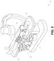
- FIG. 5illustrates an embodiment of a table-based robotic system arranged for a bronchoscopic procedure.
- FIG. 6provides an alternative view of the robotic system of FIG. 5 .
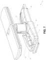
- FIG. 7illustrates an example system configured to stow robotic arm(s).
- FIG. 8illustrates an embodiment of a table-based robotic system configured for a ureteroscopic procedure.
- FIG. 9illustrates an embodiment of a table-based robotic system configured for a laparoscopic procedure.
- FIG. 10illustrates an embodiment of the table-based robotic system of FIGS. 5 - 9 with pitch or tilt adjustment.
- FIG. 11provides a detailed illustration of the interface between the table and the column of the table-based robotic system of FIGS. 5 - 10 .
- FIG. 12illustrates an alternative embodiment of a table-based robotic system.
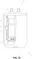
- FIG. 13illustrates an end view of the table-based robotic system of FIG. 12 .
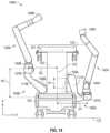
- FIG. 14illustrates an end view of a table-based robotic system with robotic arms attached thereto.
- FIG. 15illustrates an exemplary instrument driver.
- FIG. 16illustrates an exemplary medical instrument with a paired instrument driver.
- FIG. 17illustrates an alternative design for an instrument driver and instrument where the axes of the drive units are parallel to the axis of the elongated shaft of the instrument.
- FIG. 18illustrates an instrument having an instrument-based insertion architecture.
- FIG. 19illustrates an exemplary controller.
- FIG. 20depicts a block diagram illustrating a localization system that estimates a location of one or more elements of the robotic systems of FIGS. 1 - 10 , such as the location of the instrument of FIGS. 16 - 18 , in accordance to an example embodiment.
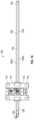
- FIG. 21is a side view of an embodiment of a medical instrument including an end effector connected to a shaft of the medical instrument by a wrist.
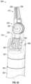
- FIG. 22is a perspective view of an embodiment of an end effector and wrist of a medical instrument that includes static redirect surfaces in the wrist.
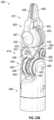
- FIGS. 23 A- 23 Eillustrate an embodiment of a medical instrument including a wrist with hybrid redirect surfaces.
- FIG. 23 Ais a perspective view of the medical instrument.
- FIG. 23 Bis a perspective view of the medical instrument with a distal clevis illustrated as transparent so as to show static redirect surfaces.
- FIG. 23 Cis a is a first side view of the medical instrument.
- FIG. 23 Dis a second side view of the medical instrument.
- FIG. 23 Eis a top view of a proximal clevis of the medical instrument.
- FIG. 24illustrates an embodiment of a distal pulley, jaw member, and pull wire of a medical instrument.
- FIG. 25 Aillustrate an alternative embodiment of a distal clevis that includes hybrid redirect surfaces.
- FIG. 25 Billustrates an example cable path along static and dynamic redirect surfaces for the distal clevis of FIG. 25 A .
- FIG. 26 Aillustrates an example of distal clevis that includes four dynamic redirect surfaces
- FIG. 26 Billustrates another view of the distal clevis of FIG. 26 A .
- aspects of the present disclosuremay be integrated into a robotically-enabled medical system capable of performing a variety of medical procedures, including both minimally invasive, such as laparoscopy, and non-invasive, such as endoscopy, procedures.
- the systemmay be capable of performing bronchoscopy, ureteroscopy, gastroscopy, etc.
- the systemmay provide additional benefits, such as enhanced imaging and guidance to assist the physician. Additionally, the system may provide the physician with the ability to perform the procedure from an ergonomic position without the need for awkward arm motions and positions. Still further, the system may provide the physician with the ability to perform the procedure with improved ease of use such that one or more of the instruments of the system can be controlled by a single user.
- FIG. 1illustrates an embodiment of a cart-based robotically-enabled system 10 arranged for a diagnostic and/or therapeutic bronchoscopy.
- the system 10may comprise a cart 11 having one or more robotic arms 12 to deliver a medical instrument, such as a steerable endoscope 13 , which may be a procedure-specific bronchoscope for bronchoscopy, to a natural orifice access point (i.e., the mouth of the patient positioned on a table in the present example) to deliver diagnostic and/or therapeutic tools.
- a medical instrumentsuch as a steerable endoscope 13
- a natural orifice access pointi.e., the mouth of the patient positioned on a table in the present example
- the cart 11may be positioned proximate to the patient's upper torso in order to provide access to the access point.
- the robotic arms 12may be actuated to position the bronchoscope relative to the access point.
- the arrangement in FIG. 1may also be utilized when performing a gastro-intestinal (GI) procedure with a gastroscope, a specialized endoscope for GI procedures.
- FIG. 2depicts an example embodiment of the cart in greater detail.
- the robotic arms 12may insert the steerable endoscope 13 into the patient robotically, manually, or a combination thereof.
- the steerable endoscope 13may comprise at least two telescoping parts, such as an inner leader portion and an outer sheath portion, each portion coupled to a separate instrument driver from the set of instrument drivers 28 , each instrument driver coupled to the distal end of an individual robotic arm.
- This linear arrangement of the instrument drivers 28which facilitates coaxially aligning the leader portion with the sheath portion, creates a “virtual rail” 29 that may be repositioned in space by manipulating the one or more robotic arms 12 into different angles and/or positions.
- the virtual rails described hereinare depicted in the Figures using dashed lines, and accordingly the dashed lines do not depict any physical structure of the system.
- Translation of the instrument drivers 28 along the virtual rail 29telescopes the inner leader portion relative to the outer sheath portion or advances or retracts the endoscope 13 from the patient.
- the angle of the virtual rail 29may be adjusted, translated, and pivoted based on clinical application or physician preference. For example, in bronchoscopy, the angle and position of the virtual rail 29 as shown represents a compromise between providing physician access to the endoscope 13 while minimizing friction that results from bending the endoscope 13 into the patient's mouth.
- the endoscope 13may be directed down the patient's trachea and lungs after insertion using precise commands from the robotic system until reaching the target destination or operative site. In order to enhance navigation through the patient's lung network and/or reach the desired target, the endoscope 13 may be manipulated to telescopically extend the inner leader portion from the outer sheath portion to obtain enhanced articulation and greater bend radius.
- the use of separate instrument drivers 28also allows the leader portion and sheath portion to be driven independently of each other.
- the endoscope 13may be directed to deliver a biopsy needle to a target, such as, for example, a lesion or nodule within the lungs of a patient.
- the needlemay be deployed down a working channel that runs the length of the endoscope to obtain a tissue sample to be analyzed by a pathologist.
- additional toolsmay be deployed down the working channel of the endoscope for additional biopsies.
- the endoscope 13may endoscopically deliver tools to resect the potentially cancerous tissue.
- diagnostic and therapeutic treatmentscan be delivered in separate procedures.
- the endoscope 13may also be used to deliver a fiducial to “mark” the location of the target nodule as well. In other instances, diagnostic and therapeutic treatments may be delivered during the same procedure.
- the system 10may also include a movable tower 30 , which may be connected via support cables to the cart 11 to provide support for controls, electronics, fluidics, optics, sensors, and/or power to the cart 11 . Placing such functionality in the tower 30 allows for a smaller form factor cart 11 that may be more easily adjusted and/or re-positioned by an operating physician and his/her staff. Additionally, the division of functionality between the cart/table and the support tower 30 reduces operating room clutter and facilitates improving clinical workflow. While the cart 11 may be positioned close to the patient, the tower 30 may be stowed in a remote location to stay out of the way during a procedure.
- the tower 30may include component(s) of a computer-based control system that stores computer program instructions, for example, within a non-transitory computer-readable storage medium such as a persistent magnetic storage drive, solid state drive, etc.
- the execution of those instructionsmay control the entire system or sub-system(s) thereof.
- the instructionswhen executed by a processor of the computer system, the instructions may cause the components of the robotics system to actuate the relevant carriages and arm mounts, actuate the robotics arms, and control the medical instruments.
- the motors in the joints of the robotics armsmay position the arms into a certain posture.
- the tower 30may also include a pump, flow meter, valve control, and/or fluid access in order to provide controlled irrigation and aspiration capabilities to the system that may be deployed through the endoscope 13 . These components may also be controlled using the computer system of the tower 30 . In some embodiments, irrigation and aspiration capabilities may be delivered directly to the endoscope 13 through separate cable(s).
- the tower 30may include a voltage and surge protector designed to provide filtered and protected electrical power to the cart 11 , thereby avoiding placement of a power transformer and other auxiliary power components in the cart 11 , resulting in a smaller, more moveable cart 11 .
- the tower 30may also include support equipment for the sensors deployed throughout the robotic system 10 .
- the tower 30may include optoelectronics equipment for detecting, receiving, and processing data received from the optical sensors or cameras throughout the robotic system 10 . In combination with the control system, such optoelectronics equipment may be used to generate real-time images for display in any number of consoles deployed throughout the system, including in the tower 30 .
- the tower 30may also include an electronic subsystem for receiving and processing signals received from deployed electromagnetic (EM) sensors.
- EMelectromagnetic
- the tower 30may also be used to house and position an EM field generator for detection by EM sensors in or on the medical instrument.
- the tower 30may also include a console 31 in addition to other consoles available in the rest of the system, e.g., console mounted on top of the cart.
- the console 31may include a user interface and a display screen, such as a touchscreen, for the physician operator.
- Consoles in the system 10are generally designed to provide both robotic controls as well as preoperative and real-time information of the procedure, such as navigational and localization information of the endoscope 13 .
- the console 31is not the only console available to the physician, it may be used by a second operator, such as a nurse, to monitor the health or vitals of the patient and the operation of the system 10 , as well as to provide procedure-specific data, such as navigational and localization information.
- the console 30is housed in a body that is separate from the tower 30 .
- the tower 30may be coupled to the cart 11 and endoscope 13 through one or more cables or connections (not shown).
- the support functionality from the tower 30may be provided through a single cable to the cart 11 , simplifying and de-cluttering the operating room.
- specific functionalitymay be coupled in separate cabling and connections. For example, while power may be provided through a single power cable to the cart 11 , the support for controls, optics, fluidics, and/or navigation may be provided through a separate cable.
- FIG. 2provides a detailed illustration of an embodiment of the cart 11 from the cart-based robotically-enabled system shown in FIG. 1 .
- the cart 11generally includes an elongated support structure 14 (often referred to as a “column”), a cart base 15 , and a console 16 at the top of the column 14 .
- the column 14may include one or more carriages, such as a carriage 17 (alternatively “arm support”) for supporting the deployment of one or more robotic arms 12 (three shown in FIG. 2 ).
- the carriage 17may include individually configurable arm mounts that rotate along a perpendicular axis to adjust the base of the robotic arms 12 for better positioning relative to the patient.
- the carriage 17also includes a carriage interface 19 that allows the carriage 17 to vertically translate along the column 14 .
- the carriage interface 19is connected to the column 14 through slots, such as slot 20 , that are positioned on opposite sides of the column 14 to guide the vertical translation of the carriage 17 .
- the slot 20contains a vertical translation interface to position and hold the carriage 17 at various vertical heights relative to the cart base 15 .
- Vertical translation of the carriage 17allows the cart 11 to adjust the reach of the robotic arms 12 to meet a variety of table heights, patient sizes, and physician preferences.
- the individually configurable arm mounts on the carriage 17allow the robotic arm base 21 of the robotic arms 12 to be angled in a variety of configurations.
- the slot 20may be supplemented with slot covers that are flush and parallel to the slot surface to prevent dirt and fluid ingress into the internal chambers of the column 14 and the vertical translation interface as the carriage 17 vertically translates.
- the slot coversmay be deployed through pairs of spring spools positioned near the vertical top and bottom of the slot 20 .
- the coversare coiled within the spools until deployed to extend and retract from their coiled state as the carriage 17 vertically translates up and down.
- the spring-loading of the spoolsprovides force to retract the cover into a spool when the carriage 17 translates towards the spool, while also maintaining a tight seal when the carriage 17 translates away from the spool.
- the coversmay be connected to the carriage 17 using, for example, brackets in the carriage interface 19 to ensure proper extension and retraction of the cover as the carriage 17 translates.
- the column 14may internally comprise mechanisms, such as gears and motors, that are designed to use a vertically aligned lead screw to translate the carriage 17 in a mechanized fashion in response to control signals generated in response to user inputs, e.g., inputs from the console 16 .
- the robotic arms 12may generally comprise robotic arm bases 21 and end effectors 22 , separated by a series of linkages 23 that are connected by a series of joints 24 , each joint comprising an independent actuator, each actuator comprising an independently controllable motor.
- Each independently controllable jointrepresents an independent degree of freedom available to the robotic arm 12 .
- Each of the robotic arms 12may have seven joints, and thus provide seven degrees of freedom. A multitude of joints result in a multitude of degrees of freedom, allowing for “redundant” degrees of freedom. Having redundant degrees of freedom allows the robotic arms 12 to position their respective end effectors 22 at a specific position, orientation, and trajectory in space using different linkage positions and joint angles. This allows for the system to position and direct a medical instrument from a desired point in space while allowing the physician to move the arm joints into a clinically advantageous position away from the patient to create greater access, while avoiding arm collisions.
- the cart base 15balances the weight of the column 14 , carriage 17 , and robotic arms 12 over the floor. Accordingly, the cart base 15 houses heavier components, such as electronics, motors, power supply, as well as components that either enable movement and/or immobilize the cart 11 .
- the cart base 15includes rollable wheel-shaped casters 25 that allow for the cart 11 to easily move around the room prior to a procedure. After reaching the appropriate position, the casters 25 may be immobilized using wheel locks to hold the cart 11 in place during the procedure.
- the console 16allows for both a user interface for receiving user input and a display screen (or a dual-purpose device such as, for example, a touchscreen 26 ) to provide the physician user with both preoperative and intraoperative data.
- Potential preoperative data on the touchscreen 26may include preoperative plans, navigation and mapping data derived from preoperative computerized tomography (CT) scans, and/or notes from preoperative patient interviews.
- Intraoperative data on displaymay include optical information provided from the tool, sensor and coordinate information from sensors, as well as vital patient statistics, such as respiration, heart rate, and/or pulse.
- the console 16may be positioned and tilted to allow a physician to access the console 16 from the side of the column 14 opposite the carriage 17 . From this position, the physician may view the console 16 , robotic arms 12 , and patient while operating the console 16 from behind the cart 11 .
- the console 16also includes a handle 27 to assist with maneuvering and stabilizing the cart 11 .
- FIG. 3illustrates an embodiment of a robotically-enabled system 10 arranged for ureteroscopy.
- the cart 11may be positioned to deliver a ureteroscope 32 , a procedure-specific endoscope designed to traverse a patient's urethra and ureter, to the lower abdominal area of the patient.
- the ureteroscope 32may be directly aligned with the patient's urethra to reduce friction and forces on the sensitive anatomy in the area.
- the cart 11may be aligned at the foot of the table to allow the robotic arms 12 to position the ureteroscope 32 for direct linear access to the patient's urethra. From the foot of the table, the robotic arms 12 may insert the ureteroscope 32 along the virtual rail 33 directly into the patient's lower abdomen through the urethra.
- the ureteroscope 32may be navigated into the bladder, ureters, and/or kidneys for diagnostic and/or therapeutic applications.
- the ureteroscope 32may be directed into the ureter and kidneys to break up kidney stone build up using a laser or ultrasonic lithotripsy device deployed down the working channel of the ureteroscope 32 .
- the resulting stone fragmentsmay be removed using baskets deployed down the ureteroscope 32 .
- FIG. 4illustrates an embodiment of a robotically-enabled system 10 similarly arranged for a vascular procedure.
- the system 10may be configured such that the cart 11 may deliver a medical instrument 34 , such as a steerable catheter, to an access point in the femoral artery in the patient's leg.
- the femoral arterypresents both a larger diameter for navigation as well as a relatively less circuitous and tortuous path to the patient's heart, which simplifies navigation.
- the cart 11may be positioned towards the patient's legs and lower abdomen to allow the robotic arms 12 to provide a virtual rail 35 with direct linear access to the femoral artery access point in the patient's thigh/hip region.
- the medical instrument 34may be directed and inserted by translating the instrument drivers 28 .
- the cartmay be positioned around the patient's upper abdomen in order to reach alternative vascular access points, such as, for example, the carotid and brachial arteries near the shoulder and wrist.
- Embodiments of the robotically-enabled medical systemmay also incorporate the patient's table. Incorporation of the table reduces the amount of capital equipment within the operating room by removing the cart, which allows greater access to the patient.
- FIG. 5illustrates an embodiment of such a robotically-enabled system arranged for a bronchoscopic procedure.
- System 36includes a support structure or column 37 for supporting platform 38 (shown as a “table” or “bed”) over the floor.
- the end effectors of the robotic arms 39 of the system 36comprise instrument drivers 42 that are designed to manipulate an elongated medical instrument, such as a bronchoscope 40 in FIG. 5 , through or along a virtual rail 41 formed from the linear alignment of the instrument drivers 42 .
- a C-arm for providing fluoroscopic imagingmay be positioned over the patient's upper abdominal area by placing the emitter and detector around the table 38 .
- FIG. 6provides an alternative view of the system 36 without the patient and medical instrument for discussion purposes.
- the column 37may include one or more carriages 43 shown as ring-shaped in the system 36 , from which the one or more robotic arms 39 may be based.
- the carriages 43may translate along a vertical column interface 44 that runs the length of the column 37 to provide different vantage points from which the robotic arms 39 may be positioned to reach the patient.
- the carriage(s) 43may rotate around the column 37 using a mechanical motor positioned within the column 37 to allow the robotic arms 39 to have access to multiples sides of the table 38 , such as, for example, both sides of the patient.
- the carriagesmay be individually positioned on the column and may translate and/or rotate independently of the other carriages.
- the system 36can include a patient table or bed with adjustable arm supports in the form of bars or rails extending alongside it.
- One or more robotic arms 39e.g., via a shoulder with an elbow joint
- the robotic arms 39are advantageously capable of being stowed compactly beneath the patient table or bed, and subsequently raised during a procedure.
- the robotic arms 39may be mounted on the carriages 43 through a set of arm mounts 45 comprising a series of joints that may individually rotate and/or telescopically extend to provide additional configurability to the robotic arms 39 .
- the arm mounts 45may be positioned on the carriages 43 such that, when the carriages 43 are appropriately rotated, the arm mounts 45 may be positioned on either the same side of the table 38 (as shown in FIG. 6 ), on opposite sides of the table 38 (as shown in FIG. 9 ), or on adjacent sides of the table 38 (not shown).
- the column 37structurally provides support for the table 38 , and a path for vertical translation of the carriages 43 . Internally, the column 37 may be equipped with lead screws for guiding vertical translation of the carriages, and motors to mechanize the translation of the carriages 43 based the lead screws. The column 37 may also convey power and control signals to the carriages 43 and the robotic arms 39 mounted thereon.
- the table base 46serves a similar function as the cart base 15 in the cart 11 shown in FIG. 2 , housing heavier components to balance the table/bed 38 , the column 37 , the carriages 43 , and the robotic arms 39 .
- the table base 46may also incorporate rigid casters to provide stability during procedures. Deployed from the bottom of the table base 46 , the casters may extend in opposite directions on both sides of the base 46 and retract when the system 36 needs to be moved.
- the system 36may also include a tower (not shown) that divides the functionality of the system 36 between the table and the tower to reduce the form factor and bulk of the table.
- the towermay provide a variety of support functionalities to the table, such as processing, computing, and control capabilities, power, fluidics, and/or optical and sensor processing.
- the towermay also be movable to be positioned away from the patient to improve physician access and de-clutter the operating room. Additionally, placing components in the tower allows for more storage space in the table base 46 for potential stowage of the robotic arms 39 .
- the towermay also include a master controller or console that provides both a user interface for user input, such as keyboard and/or pendant, as well as a display screen (or touchscreen) for preoperative and intraoperative information, such as real-time imaging, navigation, and tracking information.
- a master controller or consolethat provides both a user interface for user input, such as keyboard and/or pendant, as well as a display screen (or touchscreen) for preoperative and intraoperative information, such as real-time imaging, navigation, and tracking information.
- the towermay also contain holders for gas tanks to be used for insufflation.
- a table basemay stow and store the robotic arms when not in use.
- FIG. 7illustrates a system 47 that stows robotic arms in an embodiment of the table-based system.
- carriages 48may be vertically translated into base 49 to stow robotic arms 50 , arm mounts 51 , and the carriages 48 within the base 49 .
- Base covers 52may be translated and retracted open to deploy the carriages 48 , arm mounts 51 , and robotic arms 50 around column 53 , and closed to stow to protect them when not in use.
- the base covers 52may be sealed with a membrane 54 along the edges of its opening to prevent dirt and fluid ingress when closed.
- FIG. 8illustrates an embodiment of a robotically-enabled table-based system configured for a ureteroscopic procedure.
- the table 38may include a swivel portion 55 for positioning a patient off-angle from the column 37 and table base 46 .
- the swivel portion 55may rotate or pivot around a pivot point (e.g., located below the patient's head) in order to position the bottom portion of the swivel portion 55 away from the column 37 .
- the pivoting of the swivel portion 55allows a C-arm (not shown) to be positioned over the patient's lower abdomen without competing for space with the column (not shown) below table 38 .
- the robotic arms 39may directly insert a ureteroscope 56 along a virtual rail 57 into the patient's groin area to reach the urethra.
- stirrups 58may also be fixed to the swivel portion 55 of the table 38 to support the position of the patient's legs during the procedure and allow clear access to the patient's groin area.
- minimally invasive instrumentsmay be inserted into the patient's anatomy.
- the minimally invasive instrumentscomprise an elongated rigid member, such as a shaft, which is used to access anatomy within the patient. After inflation of the patient's abdominal cavity, the instruments may be directed to perform surgical or medical tasks, such as grasping, cutting, ablating, suturing, etc.
- the instrumentscan comprise a scope, such as a laparoscope.
- FIG. 9illustrates an embodiment of a robotically-enabled table-based system configured for a laparoscopic procedure. As shown in FIG.
- the carriages 43 of the system 36may be rotated and vertically adjusted to position pairs of the robotic arms 39 on opposite sides of the table 38 , such that instrument 59 may be positioned using the arm mounts 45 to be passed through minimal incisions on both sides of the patient to reach his/her abdominal cavity.
- FIG. 10illustrates an embodiment of the robotically-enabled medical system with pitch or tilt adjustment.
- the system 36may accommodate tilt of the table 38 to position one portion of the table at a greater distance from the floor than the other.
- the arm mounts 45may rotate to match the tilt such that the robotic arms 39 maintain the same planar relationship with the table 38 .
- the column 37may also include telescoping portions 60 that allow vertical extension of the column 37 to keep the table 38 from touching the floor or colliding with the table base 46 .
- FIG. 11provides a detailed illustration of the interface between the table 38 and the column 37 .
- Pitch rotation mechanism 61may be configured to alter the pitch angle of the table 38 relative to the column 37 in multiple degrees of freedom.
- the pitch rotation mechanism 61may be enabled by the positioning of orthogonal axes 1 , 2 at the column-table interface, each axis actuated by a separate motor 3 , 4 responsive to an electrical pitch angle command. Rotation along one screw 5 would enable tilt adjustments in one axis 1 , while rotation along the other screw 6 would enable tilt adjustments along the other axis 2 .
- a ball jointcan be used to alter the pitch angle of the table 38 relative to the column 37 in multiple degrees of freedom.
- pitch adjustmentsare particularly useful when trying to position the table in a Trendelenburg position, i.e., position the patient's lower abdomen at a higher position from the floor than the patient's upper abdomen, for lower abdominal surgery.
- the Trendelenburg positioncauses the patient's internal organs to slide towards his/her upper abdomen through the force of gravity, clearing out the abdominal cavity for minimally invasive tools to enter and perform lower abdominal surgical or medical procedures, such as laparoscopic prostatectomy.
- FIGS. 12 and 13illustrate isometric and end views of an alternative embodiment of a table-based surgical robotics system 100 .
- the surgical robotics system 100includes one or more adjustable arm supports 105 that can be configured to support one or more robotic arms (see, for example, FIG. 14 ) relative to a table 101 .
- a single adjustable arm support 105is shown, though an additional arm support can be provided on an opposite side of the table 101 .
- the adjustable arm support 105can be configured so that it can move relative to the table 101 to adjust and/or vary the position of the adjustable arm support 105 and/or any robotic arms mounted thereto relative to the table 101 .
- the adjustable arm support 105may be adjusted one or more degrees of freedom relative to the table 101 .
- the adjustable arm support 105provides high versatility to the system 100 , including the ability to easily stow the one or more adjustable arm supports 105 and any robotics arms attached thereto beneath the table 101 .
- the adjustable arm support 105can be elevated from the stowed position to a position below an upper surface of the table 101 . In other embodiments, the adjustable arm support 105 can be elevated from the stowed position to a position above an upper surface of the table 101 .
- the adjustable arm support 105can provide several degrees of freedom, including lift, lateral translation, tilt, etc.
- the arm support 105is configured with four degrees of freedom, which are illustrated with arrows in FIG. 12 .
- a first degree of freedomallows for adjustment of the adjustable arm support 105 in the z-direction (“Z-lift”).
- the adjustable arm support 105can include a carriage 109 configured to move up or down along or relative to a column 102 supporting the table 101 .
- a second degree of freedomcan allow the adjustable arm support 105 to tilt.
- the adjustable arm support 105can include a rotary joint, which can allow the adjustable arm support 105 to be aligned with the bed in a Trendelenburg position.
- a third degree of freedomcan allow the adjustable arm support 105 to “pivot up,” which can be used to adjust a distance between a side of the table 101 and the adjustable arm support 105 .
- a fourth degree of freedomcan permit translation of the adjustable arm support 105 along a longitudinal length of the table.
- the surgical robotics system 100 in FIGS. 12 and 13can comprise a table supported by a column 102 that is mounted to a base 103 .
- the base 103 and the column 102support the table 101 relative to a support surface.
- a floor axis 131 and a support axis 133are shown in FIG. 13 .
- the adjustable arm support 105can be mounted to the column 102 . In other embodiments, the arm support 105 can be mounted to the table 101 or base 103 .
- the adjustable arm support 105can include a carriage 109 , a bar or rail connector 111 and a bar or rail 107 . In some embodiments, one or more robotic arms mounted to the rail 107 can translate and move relative to one another.
- the carriage 109can be attached to the column 102 by a first joint 113 , which allows the carriage 109 to move relative to the column 102 (e.g., such as up and down a first or vertical axis 123 ).
- the first joint 113can provide the first degree of freedom (“Z-lift”) to the adjustable arm support 105 .
- the adjustable arm support 105can include a second joint 115 , which provides the second degree of freedom (tilt) for the adjustable arm support 105 .
- the adjustable arm support 105can include a third joint 117 , which can provide the third degree of freedom (“pivot up”) for the adjustable arm support 105 .
- An additional joint 119(shown in FIG.
- the adjustable arm support 105can include a fourth joint 121 , which can provide a fourth degree of freedom (translation) for the adjustable arm support 105 along a fourth axis 129 .
- FIG. 14illustrates an end view of the surgical robotics system 140 A with two adjustable arm supports 105 A, 105 B mounted on opposite sides of a table 101 .
- a first robotic arm 142 Ais attached to the bar or rail 107 A of the first adjustable arm support 105 B.
- the first robotic arm 142 Aincludes a base 144 A attached to the rail 107 A.
- the distal end of the first robotic arm 142 Aincludes an instrument drive mechanism 146 A that can attach to one or more robotic medical instruments or tools.
- the second robotic arm 142 Bincludes a base 144 B attached to the rail 107 B.
- the distal end of the second robotic arm 142 Bincludes an instrument drive mechanism 146 B.
- the instrument drive mechanism 146 Bcan be configured to attach to one or more robotic medical instruments or tools.
- one or more of the robotic arms 142 A, 142 Bcomprises an arm with seven or more degrees of freedom.
- one or more of the robotic arms 142 A, 142 Bcan include eight degrees of freedom, including an insertion axis (1-degree of freedom including insertion), a wrist (3-degrees of freedom including wrist pitch, yaw and roll), an elbow (1-degree of freedom including elbow pitch), a shoulder (2-degrees of freedom including shoulder pitch and yaw), and base 144 A, 144 B (1-degree of freedom including translation).
- the insertion degree of freedomcan be provided by the robotic arm 142 A, 142 B, while in other embodiments, the instrument itself provides insertion via an instrument-based insertion architecture.
- the end effectors of the system's robotic armsmay comprise (i) an instrument driver (alternatively referred to as “instrument drive mechanism” or “instrument device manipulator”) that incorporates electro-mechanical means for actuating the medical instrument and (ii) a removable or detachable medical instrument, which may be devoid of any electro-mechanical components, such as motors.
- instrument driveralternatively referred to as “instrument drive mechanism” or “instrument device manipulator”
- instrument device manipulatora removable or detachable medical instrument, which may be devoid of any electro-mechanical components, such as motors.
- This dichotomymay be driven by the need to sterilize medical instruments used in medical procedures, and the inability to adequately sterilize expensive capital equipment due to their intricate mechanical assemblies and sensitive electronics. Accordingly, the medical instruments may be designed to be detached, removed, and interchanged from the instrument driver (and thus the system) for individual sterilization or disposal by the physician or the physician's staff. In contrast, the instrument drivers need not be changed or sterilized, and may be draped for protection
- FIG. 15illustrates an example instrument driver.
- instrument driver 62Positioned at the distal end of a robotic arm, instrument driver 62 comprises one or more drive units 63 arranged with parallel axes to provide controlled torque to a medical instrument via drive shafts 64 .
- Each drive unit 63comprises an individual drive shaft 64 for interacting with the instrument, a gear head 65 for converting the motor shaft rotation to a desired torque, a motor 66 for generating the drive torque, an encoder 67 to measure the speed of the motor shaft and provide feedback to the control circuitry, and control circuitry 68 for receiving control signals and actuating the drive unit.
- Each drive unit 63being independently controlled and motorized, the instrument driver 62 may provide multiple (e.g., four as shown in FIG. 15 ) independent drive outputs to the medical instrument.
- the control circuitry 68would receive a control signal, transmit a motor signal to the motor 66 , compare the resulting motor speed as measured by the encoder 67 with the desired speed, and modulate the motor signal to
- the robotic systemmay incorporate a drive interface, such as a sterile adapter connected to a sterile drape, that sits between the instrument driver and the medical instrument.
- a drive interfacesuch as a sterile adapter connected to a sterile drape
- the chief purpose of the sterile adapteris to transfer angular motion from the drive shafts of the instrument driver to the drive inputs of the instrument while maintaining physical separation, and thus sterility, between the drive shafts and drive inputs.
- an example sterile adaptermay comprise a series of rotational inputs and outputs intended to be mated with the drive shafts of the instrument driver and drive inputs on the instrument.
- the sterile drapecomprised of a thin, flexible material such as transparent or translucent plastic, is designed to cover the capital equipment, such as the instrument driver, robotic arm, and cart (in a cart-based system) or table (in a table-based system).
- the capital equipmentsuch as the instrument driver, robotic arm, and cart (in a cart-based system) or table (in a table-based system).
- Use of the drapewould allow the capital equipment to be positioned proximate to the patient while still being located in an area not requiring sterilization (i.e., non-sterile field).
- the medical instrumentmay interface with the patient in an area requiring sterilization (i.e., sterile field).
- FIG. 16illustrates an example medical instrument with a paired instrument driver.
- medical instrument 70comprises an elongated shaft 71 (or elongate body) and an instrument base 72 .
- the instrument base 72also referred to as an “instrument handle” due to its intended design for manual interaction by the physician, may generally comprise rotatable drive inputs 73 , e.g., receptacles, pulleys or spools, that are designed to be mated with drive outputs 74 that extend through a drive interface on instrument driver 75 at the distal end of robotic arm 76 .
- the mated drive inputs 73 of the instrument base 72may share axes of rotation with the drive outputs 74 in the instrument driver 75 to allow the transfer of torque from the drive outputs 74 to the drive inputs 73 .
- the drive outputs 74may comprise splines that are designed to mate with receptacles on the drive inputs 73 .
- the elongated shaft 71is designed to be delivered through either an anatomical opening or lumen, e.g., as in endoscopy, or a minimally invasive incision, e.g., as in laparoscopy.
- the elongated shaft 71may be either flexible (e.g., having properties similar to an endoscope) or rigid (e.g., having properties similar to a laparoscope) or contain a customized combination of both flexible and rigid portions.
- the distal end of a rigid elongated shaftmay be connected to an end effector extending from a jointed wrist formed from a clevis with at least one degree of freedom and a surgical tool or medical instrument, such as, for example, a grasper or scissors, that may be actuated based on force from the tendons as the drive inputs rotate in response to torque received from the drive outputs 74 of the instrument driver 75 .
- a surgical tool or medical instrumentsuch as, for example, a grasper or scissors
- the distal end of a flexible elongated shaftmay include a steerable or controllable bending section that may be articulated and bent based on torque received from the drive outputs 74 of the instrument driver 75 .
- Torque from the instrument driver 75is transmitted down the elongated shaft 71 using tendons along the elongated shaft 71 .
- These individual tendonssuch as pull wires, may be individually anchored to individual drive inputs 73 within the instrument handle 72 .
- the tendonsare directed down one or more pull lumens along the elongated shaft 71 and anchored at the distal portion of the elongated shaft 71 , or in the wrist at the distal portion of the elongated shaft.
- these tendonsmay be coupled to a distally mounted end effector, such as a wrist, grasper, or scissor.
- the tendonmay cause a joint to rotate about an axis, thereby causing the end effector to move in one direction or another.
- the tendonmay be connected to one or more jaws of a grasper at the distal end of the elongated shaft 71 , where tension from the tendon causes the grasper to close.
- the tendonsmay be coupled to a bending or articulating section positioned along the elongated shaft 71 (e.g., at the distal end) via adhesive, control ring, or other mechanical fixation.
- a bending or articulating sectionpositioned along the elongated shaft 71 (e.g., at the distal end) via adhesive, control ring, or other mechanical fixation.
- torque exerted on the drive inputs 73would be transmitted down the tendons, causing the softer, bending section (sometimes referred to as the articulable section or region) to bend or articulate.
- the angle of the spiraling and/or spacing therebetweenmay be altered or engineered for specific purposes, wherein tighter spiraling exhibits lesser shaft compression under load forces, while lower amounts of spiraling results in greater shaft compression under load forces, but limits bending.
- the pull lumensmay be directed parallel to the longitudinal axis of the elongated shaft 71 to allow for controlled articulation in the desired bending or articulable sections.
- the elongated shaft 71houses a number of components to assist with the robotic procedure.
- the shaft 71may comprise a working channel for deploying surgical tools (or medical instruments), irrigation, and/or aspiration to the operative region at the distal end of the shaft 71 .
- the shaft 71may also accommodate wires and/or optical fibers to transfer signals to/from an optical assembly at the distal tip, which may include an optical camera.
- the shaft 71may also accommodate optical fibers to carry light from proximally-located light sources, such as light emitting diodes, to the distal end of the shaft 71 .
- the distal tipmay also comprise the opening of a working channel for delivering tools for diagnostic and/or therapy, irrigation, and aspiration to an operative site.
- the distal tipmay also include a port for a camera, such as a fiberscope or a digital camera, to capture images of an internal anatomical space.
- the distal tipmay also include ports for light sources for illuminating the anatomical space when using the camera.
- the drive shaft axesand thus the drive input axes, are orthogonal to the axis of the elongated shaft 71 .
- This arrangementcomplicates roll capabilities for the elongated shaft 71 .
- Rolling the elongated shaft 71 along its axis while keeping the drive inputs 73 staticresults in undesirable tangling of the tendons as they extend off the drive inputs 73 and enter pull lumens within the elongated shaft 71 .
- the resulting entanglement of such tendonsmay disrupt any control algorithms intended to predict movement of the flexible elongated shaft 71 during an endoscopic procedure.
- FIG. 17illustrates an alternative design for an instrument driver and instrument where the axes of the drive units are parallel to the axis of the elongated shaft of the instrument.
- a circular instrument driver 80comprises four drive units with their drive outputs 81 aligned in parallel at the end of a robotic arm 82 .
- the drive units, and their respective drive outputs 81are housed in a rotational assembly 83 of the instrument driver 80 that is driven by one of the drive units within the assembly 83 .
- the rotational assembly 83rotates along a circular bearing that connects the rotational assembly 83 to the non-rotational portion 84 of the instrument driver 80 .
- Power and controls signalsmay be communicated from the non-rotational portion 84 of the instrument driver 80 to the rotational assembly 83 through electrical contacts that may be maintained through rotation by a brushed slip ring connection (not shown).
- the rotational assembly 83may be responsive to a separate drive unit that is integrated into the non-rotatable portion 84 , and thus not in parallel to the other drive units.
- the rotational mechanism 83allows the instrument driver 80 to rotate the drive units, and their respective drive outputs 81 , as a single unit around an instrument driver axis 85 .
- an instrument 86may comprise an elongated shaft portion 88 and an instrument base 87 (shown with a transparent external skin for discussion purposes) comprising a plurality of drive inputs 89 (such as receptacles, pulleys, and spools) that are configured to receive the drive outputs 81 in the instrument driver 80 .
- the instrument shaft 88extends from the center of the instrument base 87 with an axis substantially parallel to the axes of the drive inputs 89 , rather than orthogonal as in the design of FIG. 16 .
- the medical instrument 86When coupled to the rotational assembly 83 of the instrument driver 80 , the medical instrument 86 , comprising instrument base 87 and instrument shaft 88 , rotates in combination with the rotational assembly 83 about the instrument driver axis 85 . Since the instrument shaft 88 is positioned at the center of instrument base 87 , the instrument shaft 88 is coaxial with instrument driver axis 85 when attached. Thus, rotation of the rotational assembly 83 causes the instrument shaft 88 to rotate about its own longitudinal axis. Moreover, as the instrument base 87 rotates with the instrument shaft 88 , any tendons connected to the drive inputs 89 in the instrument base 87 are not tangled during rotation. Accordingly, the parallelism of the axes of the drive outputs 81 , drive inputs 89 , and instrument shaft 88 allows for the shaft rotation without tangling any control tendons.
- FIG. 18illustrates an instrument having an instrument based insertion architecture in accordance with some embodiments.
- the instrument 150can be coupled to any of the instrument drivers discussed above.
- the instrument 150comprises an elongated shaft 152 , an end effector 162 connected to the shaft 152 , and a handle 170 coupled to the shaft 152 .
- the elongated shaft 152comprises a tubular member having a proximal portion 154 and a distal portion 156 .
- the elongated shaft 152comprises one or more channels or grooves 158 along its outer surface.
- the grooves 158are configured to receive one or more wires or cables 180 therethrough.
- One or more cables 180thus run along an outer surface of the elongated shaft 152 .
- cables 180can also run through the elongated shaft 152 .
- Manipulation of the one or more cables 180results in actuation of the end effector 162 .
- the instrument handle 170which may also be referred to as an instrument base, may generally comprise an attachment interface 172 having one or more mechanical inputs 174 , e.g., receptacles, pulleys or spools, that are designed to be reciprocally mated with one or more torque couplers on an attachment surface of an instrument driver.
- mechanical inputs 174e.g., receptacles, pulleys or spools, that are designed to be reciprocally mated with one or more torque couplers on an attachment surface of an instrument driver.
- the instrument 150comprises a series of pulleys or cables that enable the elongated shaft 152 to translate relative to the handle 170 .
- the instrument 150itself comprises an instrument-based insertion architecture that accommodates insertion of the instrument, thereby minimizing the reliance on a robot arm to provide insertion of the instrument 150 .
- a robotic armcan be largely responsible for instrument insertion.
- any of the robotic systems described hereincan include an input device or controller for manipulating an instrument attached to a robotic arm.
- the controllercan be coupled (e.g., communicatively, electronically, electrically, wirelessly and/or mechanically) with an instrument such that manipulation of the controller causes a corresponding manipulation of the instrument e.g., via master slave control.
- FIG. 19is a perspective view of an embodiment of a controller 182 .
- the controller 182comprises a hybrid controller that can have both impedance and admittance control.
- the controller 182can utilize just impedance or passive control.
- the controller 182can utilize just admittance control.
- the controller 182advantageously can have a lower perceived inertia while in use.
- the controller 182is configured to allow manipulation of two medical instruments, and includes two handles 184 .
- Each of the handles 184is connected to a gimbal 186 .
- Each gimbal 186is connected to a positioning platform 188 .
- each positioning platform 188includes a SCARA arm (selective compliance assembly robot arm) 198 coupled to a column 194 by a prismatic joint 196 .
- the prismatic joints 196are configured to translate along the column 194 (e.g., along rails 197 ) to allow each of the handles 184 to be translated in the z-direction, providing a first degree of freedom.
- the SCARA arm 198is configured to allow motion of the handle 184 in an x-y plane, providing two additional degrees of freedom.
- one or more load cellsare positioned in the controller.
- a load cell(not shown) is positioned in the body of each of the gimbals 186 .
- portions of the controller 182are capable of operating under admittance control, thereby advantageously reducing the perceived inertia of the controller while in use.
- the positioning platform 188is configured for admittance control, while the gimbal 186 is configured for impedance control.
- the gimbal 186is configured for admittance control, while the positioning platform 188 is configured for impedance control. Accordingly, for some embodiments, the translational or positional degrees of freedom of the positioning platform 188 can rely on admittance control, while the rotational degrees of freedom of the gimbal 186 rely on impedance control.
- the robotic systems contemplated by this disclosurecan provide for non-radiation-based navigational and localization means to reduce physician exposure to radiation and reduce the amount of equipment within the operating room.
- the term “localization”may refer to determining and/or monitoring the position of objects in a reference coordinate system. Technologies such as preoperative mapping, computer vision, real-time EM tracking, and robot command data may be used individually or in combination to achieve a radiation-free operating environment. In other cases, where radiation-based imaging modalities are still used, the preoperative mapping, computer vision, real-time EM tracking, and robot command data may be used individually or in combination to improve upon the information obtained solely through radiation-based imaging modalities.
- FIG. 20is a block diagram illustrating a localization system 90 that estimates a location of one or more elements of the robotic system, such as the location of the instrument, in accordance to an example embodiment.
- the localization system 90may be a set of one or more computer devices configured to execute one or more instructions.
- the computer devicesmay be embodied by a processor (or processors) and computer-readable memory in one or more components discussed above.
- the computer devicesmay be in the tower 30 shown in FIG. 1 , the cart 11 shown in FIGS. 1 - 4 , the beds shown in FIGS. 5 - 14 , etc.
- the localization system 90may include a localization module 95 that processes input data 91 - 94 to generate location data 96 for the distal tip of a medical instrument.
- the location data 96may be data or logic that represents a location and/or orientation of the distal end of the instrument relative to a frame of reference.
- the frame of referencecan be a frame of reference relative to the anatomy of the patient or to a known object, such as an EM field generator (see discussion below for the EM field generator).
- Preoperative mappingmay be accomplished through the use of the collection of low dose CT scans.
- Preoperative CT scansare reconstructed into three-dimensional images, which are visualized, e.g. as “slices” of a cutaway view of the patient's internal anatomy.
- image-based models for anatomical cavities, spaces and structures of the patient's anatomy, such as a patient lung networkmay be generated.
- Techniquessuch as center-line geometry may be determined and approximated from the CT images to develop a three-dimensional volume of the patient's anatomy, referred to as model data 91 (also referred to as “preoperative model data” when generated using only preoperative CT scans).
- Network topological modelsmay also be derived from the CT-images, and are particularly appropriate for bronchoscopy.
- the instrumentmay be equipped with a camera to provide vision data (or image data) 92 .
- the localization module 95may process the vision data 92 to enable one or more vision-based (or image-based) location tracking modules or features.
- the preoperative model data 91may be used in conjunction with the vision data 92 to enable computer vision-based tracking of the medical instrument (e.g., an endoscope or an instrument advance through a working channel of the endoscope).
- the robotic systemmay generate a library of expected endoscopic images from the model based on the expected path of travel of the endoscope, each image linked to a location within the model. Intraoperatively, this library may be referenced by the robotic system in order to compare real-time images captured at the camera (e.g., a camera at a distal end of the endoscope) to those in the image library to assist localization.
- Some features of the localization module 95may identify circular geometries in the preoperative model data 91 that correspond to anatomical lumens and track the change of those geometries to determine which anatomical lumen was selected, as well as the relative rotational and/or translational motion of the camera. Use of a topological map may further enhance vision-based algorithms or techniques.
- Optical flowanother computer vision-based technique, may analyze the displacement and translation of image pixels in a video sequence in the vision data 92 to infer camera movement.
- optical flow techniquesmay include motion detection, object segmentation calculations, luminance, motion compensated encoding, stereo disparity measurement, etc. Through the comparison of multiple frames over multiple iterations, movement and location of the camera (and thus the endoscope) may be determined.
- the localization module 95may use real-time EM tracking to generate a real-time location of the endoscope in a global coordinate system that may be registered to the patient's anatomy, represented by the preoperative model.
- EM trackingan EM sensor (or tracker) comprising one or more sensor coils embedded in one or more locations and orientations in a medical instrument (e.g., an endoscopic tool) measures the variation in the EM field created by one or more static EM field generators positioned at a known location.
- the location information detected by the EM sensorsis stored as EM data 93 .
- the EM field generator(or transmitter), may be placed close to the patient to create a low intensity magnetic field that the embedded sensor may detect.
- the magnetic fieldinduces small currents in the sensor coils of the EM sensor, which may be analyzed to determine the distance and angle between the EM sensor and the EM field generator.
- These distances and orientationsmay be intraoperatively “registered” to the patient anatomy (e.g., the preoperative model) in order to determine the geometric transformation that aligns a single location in the coordinate system with a position in the preoperative model of the patient's anatomy.
- an embedded EM tracker in one or more positions of the medical instrumente.g., the distal tip of an endoscope
- Robotic command and kinematics data 94may also be used by the localization module 95 to provide localization data 96 for the robotic system.
- Device pitch and yaw resulting from articulation commandsmay be determined during preoperative calibration. Intraoperatively, these calibration measurements may be used in combination with known insertion depth information to estimate the position of the instrument. Alternatively, these calculations may be analyzed in combination with EM, vision, and/or topological modeling to estimate the position of the medical instrument within the network.
- a number of other input datacan be used by the localization module 95 .
- an instrument utilizing shape-sensing fibercan provide shape data that the localization module 95 can use to determine the location and shape of the instrument.
- the localization module 95may use the input data 91 - 94 in combination(s). In some cases, such a combination may use a probabilistic approach where the localization module 95 assigns a confidence weight to the location determined from each of the input data 91 - 94 . Thus, where the EM data may not be reliable (as may be the case where there is EM interference) the confidence of the location determined by the EM data 93 can be decrease and the localization module 95 may rely more heavily on the vision data 92 and/or the robotic command and kinematics data 94 .
- the robotic systems discussed hereinmay be designed to incorporate a combination of one or more of the technologies above.
- the robotic system's computer-based control systembased in the tower, bed and/or cart, may store computer program instructions, for example, within a non-transitory computer-readable storage medium such as a persistent magnetic storage drive, solid state drive, or the like, that, upon execution, cause the system to receive and analyze sensor data and user commands, generate control signals throughout the system, and display the navigational and localization data, such as the position of the instrument within the global coordinate system, anatomical map, etc.
- a medical instrumentcan include an end effector positioned at the distal end of an elongated shaft.
- the end effectorcan be connected to the distal end of the elongated shaft by a wrist.
- the wristcan be articulable so as to allow for control of the end effector.
- the medical instrumentcan include one or more pull wires extending through the wrist to the end effector.
- the one or more pull wirescan be actuated (e.g., pulled or tensioned) to articulate the wrist and the end effector. As the one or more pull wires extend through the wrist, they can be engaged with one or more pulleys within the wrist.
- FIG. 21is a side view of an embodiment of a medical instrument 200 .
- the medical instrument 200can be similar to the medical instruments described above, for example, with reference to FIGS. 16 - 18 .
- the medical instrument 200includes an elongated shaft 202 and a handle 208 .
- the elongated shaft 202extends between a distal end 204 and a proximal end 206 .
- An end effector 212which in the illustrated embodiment is configured as a grasper, can be positioned at the distal end 204 of the elongated shaft 202 .
- the end effector 212can be connected to the distal end 204 of the elongated shaft 202 by a wrist 210 .
- the wrist 210can be configured to allow one or more degrees of freedom for the instrument 200 .
- the wrist 210can be a two degree-of-freedom wrist.
- a two degree-of-freedom wristcan allow the end effector 212 to pivot or rotate around a pitch axis and a yaw axis.
- the instrument 200includes the handle 208 .
- the handle 208can be configured to connect to an instrument drive mechanism, for example, as shown in FIGS. 16 and 17 , described above.
- the instrument 200may include one or more tendons, cables, or pull wires that extend along (e.g., through or on) the elongated shaft 202 between the end effector 212 and the handle 208 .
- the handle 208may include one or more drive inputs configured to engage one or more drive outputs on the instrument drive mechanism (see FIGS. 16 and 17 ) to allow the instrument drive mechanism to actuate (e.g., tension or pull) the pull wires.
- Actuating the pull wirescan cause motion of wrist 210 and/or the end effector 212 to allow for remote manipulation and control of the end effector 212 .
- actuation of the pull wirescan be configured to cause jaws of the end effector 212 to open and close and/or to allow the end effector 212 to rotate about pitch and/or yaw axes.
- the instrument drive mechanismcan be positioned on a robotic arm. In some embodiments, the robotic arm can be controlled to position, roll, advance, and/or retract the instrument 200 .
- the elongated shaft 202extends through the handle 208 .
- the elongated shaft 202can be configured to advance or retract relative to the handle 208 .
- the instrument drive mechanismis configured to cause the elongated shaft 202 to advance or retract relative to the handle 208 . This can allow, for example, the handle 208 to remain stationary while the elongated shaft 202 and end effector 212 are advanced into a patient during a procedure.
- the proximal end 206 of the elongated shaft 202is attached to the handle 208 such that the elongated shaft 202 extends only between the end effector 212 and the handle 208 .
- redirect surfaces within the wrist 210can be configured to change a direction of a pull wire so as to direct the pull wire between the pulleys.
- some wristsmay include only “static” redirect surfaces.
- a “static” redirect surfacerefers to a non-moving, or stationary surface formed on or within the wrist that contacts a pull wire to redirect it.
- a static redirect surfacecan be a static, stationary, or non-moving wall or channel formed on or in a clevis of the wrist along which a pull wire slides as it is redirected.
- the medical instruments including wrists with hybrid redirect surfaces described in this sectioninclude at least one static redirect surface and at least one “dynamic” redirect surface.
- a “dynamic” redirect surfacerefers to a moving surface of the wrist that contacts a pull wire to redirect it.
- a dynamic redirect surfacecan be a surface of a rotating pulley of the wrist that redirects a pull wire. Examples of static and redirect surfaces will be provided below to more fully illustrate these concepts.
- static redirect surfacesmay be considered more mechanically simple as they may comprise a stationary or static surface.
- static redirect surfacesmay cause more wear on pull wires. Because a static redirect surface remains stationary as it redirects a pull wire, the pull wire may slide across the static redirect surface. Friction between the pull wire and the static redirect surface can cause wear that can shorten the life span of the pull wire.
- Dynamic redirect surfacesmay reduce or eliminate the wear problems that can be associated with static redirect surfaces. This can be because the dynamic redirect surface rotates or otherwise moves along with the movement of the pull wire, reducing the friction therebetween. This can increase the lifespan of the pull wire.
- dynamic redirect surfacesmay be considered more mechanically complex. For example, dynamic redirect surfaces may require additional components (compared with static redirect surfaces). Further, it may be difficult to provide the additional components of a dynamic redirect surface in a small or compact form factor as is often desirable for medical instruments associated with laparoscopic surgery, for example.
- the medical instruments including wrists with hybrid redirect surfaces described in this sectioncan include one or more static redirect surfaces and one or more dynamic redirect surfaces in a manner that can increase the advantages associated with each while minimizing the disadvantages.
- dynamic redirect surfacesare implemented to redirect pull wire segments associated with a close motion of the end effector (e.g., a clamping motion)
- static redirect surfacesare implemented to redirect pull wire segments associated with an open motion of the end effector (e.g., an unclamping motion). Because it often takes more force, tension, or load to close the end effector (or more force is generally applied in the closing direction), the pull wire segments associated with the close motion of the end effector can experience more force and be exposed to more wear.
- the medical instruments including wrists with hybrid redirect surfaces described in this sectioncan include novel structural architecture that can allow for packaging of both static and dynamic redirect surfaces in a minimal form factor that is suitable for a laparoscopic or endoscopic medical instrument and that may provide one or more additional advantages as described further below.
- novel structural architecturecan allow for packaging of both static and dynamic redirect surfaces in a minimal form factor that is suitable for a laparoscopic or endoscopic medical instrument and that may provide one or more additional advantages as described further below.
- FIG. 22shows a perspective view of a distal end of a medical instrument 300 that includes a wrist with only static redirect surfaces.
- a wrist 310is positioned at the distal end 304 of the elongated shaft 302 of the medical instrument 300 .
- the wrist 310includes a proximal clevis 322 and a distal clevis 324 .
- the distal clevis 324is illustrated as transparent so as to visualize features formed within the distal clevis 324 .
- the proximal clevis 322is connected to the distal end 304 of the elongated shaft 302 .
- the distal clevis 324is pivotally connected to the proximal clevis 322 .
- a proximal axle 366can extend through and connect the distal clevis 324 to the proximal clevis 322 such that the distal clevis 324 can rotate relative to the proximal clevis 322 about a longitudinal axis of the proximal axle 366 .
- Thismay allow the wrist 310 to move or articulate in a first degree of freedom.
- the first degree of freedommay be pitch.
- a plurality of pulleys 340can also be mounted on the proximal axle 366 at the joint between the proximal clevis 322 and the distal clevis 324 .
- four proximal pulleys 340are included.
- a plurality of pull wires(not shown) can be engaged with the proximal pulleys 340 and actuated to control the pitch of the medical instrument 300 .
- An end effector 312is connected to the distal clevis 324 .
- the end effector 312comprises a gripper having a first jaw member 356 and a second jaw member 358 .
- Other types of end effectorscan also be used, such as graspers, cutters, scissors, etc.
- each of the jaw members 356 , 358is connected to one of two distal pulleys 350 connected to the distal clevis 324 .
- An example jaw memberis shown alone in FIG. 24 , which is described below.
- a distal axle 367can extend through the distal clevis 324 , and the distal pulleys 350 can be rotatably mounted on the distal axle 367 .
- the distal pulleys 350can thus rotate relative to the distal clevis 324 to allow the end effector 312 to rotated in a second degree of freedom.
- the second degree of freedomcan be yaw.
- a third degree of freedomcan be provided if the distal pulleys 350 are rotated in opposite directions.
- the third degree of freedomcan be opening and closing the end effector 312 .
- the plurality of pull wires(not shown) can be engaged with the distal pulleys 350 and actuated to control the pitch of the medical instrument 300 and to open and close the end effector 312 .
- the proximal axle 366 and the distal axle 367can be oriented along axes that extend in different directions.
- the proximal axle 366extends along the pitch axis and the distal axle 367 extends along the yaw axis.
- the pitch and yaw axescan be orthogonal to each other.
- the proximal pulleys 340 and the distal pulleys 350rotate in different planes, which, in the illustrated embodiment, are orthogonal to each other.
- the plurality of pull wiresneed to be redirected between the proximal pulleys 340 and the distal pulleys 350 .
- the plurality of pull wiresneed to be redirected from the plane of proximal pulleys 340 to the plane of the distal pulleys 350 .
- the distal clevis 324includes a plurality of static redirect surfaces 326 that are configured to redirect the plurality of pull wires.
- the static redirect surfaces 326comprise angled or curved faces formed in the distal clevis 324 for redirecting the plurality of pull wires. As the various pull wire segments of the plurality of pull wires are actuated, the pull wire segments slide across the static redirect surfaces 326 as they are redirected.
- the static redirect surfaces 326can be provided to change a course of direction for one or more pull wire segments of the plurality of pull wires.
- the wrist 310comprises a distal clevis 324 having only static redirect surfaces 326 , in the form of one or more angled, curved or sloped surfaces. While such static redirect surfaces 326 can successfully redirect the pull wires, the sliding of the pull wire segments against the static redirect surfaces 326 can cause abrasion to the outside of the pull wires due to increased friction, thereby reducing pull wire life.
- the space available for static redirect surfaces 326 between the proximal pulleys 340 and the distal pulleys 350can be limited.
- the medical instrument 300 shown in FIG. 22can be considered an N+1 medical instrument because it achieves three degrees of freedom (pitch, yaw, and instrument actuation) using four pull wire segments.
- FIGS. 23 A- 23 Eillustrate a medical instrument 400 with a wrist that includes hybrid redirect surfaces. That is, the wrist of FIGS. 23 A- 23 E includes both static redirect surfaces and dynamic redirect surfaces. Use of hybrid redirect surfaces within the wrist can alleviate wear on the pull wires. While FIGS. 23 A- 23 E illustrate an example configured as a grasper instrument, one skilled in the art will appreciate that the use of hybrid redirect surfaces is not limited to instruments simply for grasping, but can be applicable to many other instruments as well (e.g., cauterization instruments, cutting instruments, suction and irrigation instruments, etc.).
- the medical instrument 400includes both static and dynamic redirect surfaces to realize both the packaging benefits of static redirect surfaces and the performance and life improvements of dynamic redirect surfaces.
- the pull wire segments associated with closing the end effectormay have significantly more load on them the pull wire segments associated with opening the end effector.
- most of the benefits of dynamic redirect surfacescan be realized by having the dynamic redirect surfaces engaged with the pull segments associated with closing the end effector.
- pull wire segments that experience less load and tensioncan be redirected using static redirect surfaces.
- FIG. 23 Ais a perspective view of the medical instrument 400 .
- FIG. 23 Bis another perspective view of the medical instrument 400 , shown with a distal clevis 424 illustrated as transparent so as to visualize certain internal features thereof.
- FIG. 23 Cis a is a first side view of the medical instrument 400 .
- FIG. 23 Dis a second side view of the medical instrument 400 .
- FIG. 23 Eis a top view of a proximal clevis 422 of the medical instrument 400 .
- the medical instrument 400includes an elongated shaft 402 extending to a distal end 404 . Only the distal end 404 of the elongated shaft 402 is visible in FIG. 23 A , but the elongated shaft 402 may be similar to the elongated shaft 202 of the medical instrument 200 described above.
- a wrist 410is positioned at the distal end 404 of the elongated shaft 402 .
- the wrist 410is also connected to an end effector 412 , which as noted above is a grasper in the illustrated embodiment.
- the wrist 410can be configured to allow articulation in two degrees of freedom.
- the two degrees of freedomare pitch and yaw.
- the end effector 412can open and close providing an additional degree of freedom for the medical instrument 400 .
- the medical instrument 400can be considered an N+1 medical instrument because it achieves three degrees of freedom (pitch, yaw, and instrument actuation) using four pull wire segments.
- the wrist 410comprises a proximal clevis 422 and a distal clevis 424 .
- the proximal clevis 422can be attached to the distal end 404 of the elongated shaft 402 .
- the distal clevis 424can be pivotally attached to the proximal clevis 422 .
- the distal clevis 424is pivotally attached to the proximal clevis 422 by an axle 466 which extends through the distal clevis 424 and the proximal clevis 422 .
- the distal clevis 424can rotate about an axis of the axle 466 relative to the proximal clevis 422 .
- Rotation of the distal clevis 424 about an axis of the axle 466 relative to the proximal clevis 422can provide one of the degrees of freedom of the wrist 410 .
- this degree of freedomcan be pitch.
- the axle 466can be considered a pitch axle and the axis of the axle 466 can be considered the pitch axis of the wrist 410 .
- the proximal clevis 422can include a first proximal clevis support leg 474 and a second proximal clevis support leg 476 .
- the axle 466can extend through the first proximal clevis support leg 474 and the second proximal clevis support leg 476 of the proximal clevis 422 .
- the distal clevis 424can include a first distal clevis support leg 470 and a second distal clevis support leg 472 .
- the axle 466extends through the first distal clevis support leg 470 and the second distal clevis support leg 472 of the distal clevis 424 .
- first proximal clevis support leg 474 , the second proximal clevis support leg 476 , the first distal clevis support leg 470 , and the second distal clevis support leg 472can be spaced in a manner that can provide an advantageous architecture for medical instruments with wrists having hybrid redirect surfaces.
- the medical instrument 400includes a plurality of proximal pulleys 440 and a plurality of distal pulleys 450 positioned in the wrist 410 .
- the proximal pulleys 440can be positioned on the axle 466 that connects the proximal clevis 422 and the distal clevis 424 .
- the axle 466can be a pitch axle, and thus, the proximal pulleys 440 may also be considered pitch pulleys 440 .
- the proximal pulleys 440include a first outer proximal pulley 442 , a first inner proximal pulley 444 , a second outer proximal pulley 446 , and a second inner proximal pulley 448 .
- the first outer proximal pulley 442 , the first inner proximal pulley 444 , the second outer proximal pulley 446 , and the second inner proximal pulley 448can each be positioned on the axle 466 such that they can rotate about the axle 466 .
- the proximal pulleys 440each rotate in a pitch plane that is perpendicular to the axis of the axle 466 .
- the distal pulleys 450can be positioned on an axle 467 .
- the axle 467can extend through the distal clevis 424 as shown.
- the axis of the axle 467can provide a second degree of freedom for the medical instrument 400 .
- this second degree of freedomcan be yaw.
- the axle 467can be considered a yaw axle and can provide a yaw axis for the wrist 410 .
- the distal pulleys 450include a first distal pulley 452 and a second distal pulley 454 mounted on the axle 467 .
- Each of the distal pulleys 450can be configured rotate in a yaw plane that is perpendicular to the axis of axle 467 .
- the pitch axle 466 and the yaw axle 467can be oriented at an angle with respect to each other.
- the pitch axle 466 and the yaw axle 467are orthogonal. Accordingly, the pitch plane and the yaw plane can also be orthogonal to each other.
- the end effector 412 of the medical instrument 400can be formed by a first jaw member 456 and a second jaw member 458 .
- the first jaw member 456can be connected to the first distal pulley 452 and the second jaw member 458 can be connected to the second distal pulley 454 .
- the orientation of the end effector 412can be controlled by rotating the first distal pulley 452 and the second distal pulley 454 in the same direction about the axle 467 . For example, by rotating both of the first distal pulley 452 and the second distal pulley 454 in the same direction about the axle 467 the yaw of the end effector 412 can be adjusted.
- the end effector 412can be actuated (e.g., opened or closed in the case of the illustrated grasper) by rotating the first distal pulley 452 and the second distal pulley 454 in the opposite directions about the axle 467 . Actuation of the end effector 412 can be considered a third degree of freedom of the medical instrument 400 .
- the medical instrument 400can include a plurality of pull wires 430 that can be actuated (e.g., pulled or tensioned) to control the three degrees of freedom of the medical instrument 400 (pitch, yaw, and actuation). As shown in FIGS. 23 A- 23 D , the plurality of pull wires 430 are engaged with the proximal pulleys 440 and the distal pulleys 450 . In the illustrated embodiment, the plurality of pull wires 430 include a first pull wire segment 432 , a second pull wire segment 434 , a third pull wire segment 436 , and a fourth pull wire segment 438 which are routed along various paths through the wrist 410 .
- the first pull wire segment 432engages the first outer proximal pulley 442 and the first distal pulley 452 .
- Actuation of the first pull wire segment 432can be associated with closing the first jaw member 456 .
- the second pull wire segment 434can be engaged with the first inner proximal pulley 444 and the second distal pulley 454 .
- the second pull wire segment 434can be associated with opening the second jaw member 458 .
- the third pull wire segment 436can be engaged with the second outer proximal pulley 446 and second distal pulley 454 .
- the third pull wire segment 436can be associated with closing the second jaw member 458 .
- the fourth pull wire segment 438can be engaged with the second inner proximal pulley 448 and the first distal pulley 452 .
- the fourth pull wire segment 438can be associated with opening the first jaw member 456 .
- each of the first pull wire segment 432 and the fourth pull wire segment 438can engage the first distal pulley 452 , but on opposite sides.
- each of the second pull wire segment 434 and the third pull wire segment 436can engage the second distal pulley 454 , but on opposite sides.
- each of the proximal pulleys 440is only engaged by one of the pull wire segments.
- the first pull wire segment 432engages the first outer proximal pulley 442 on the same side of the wrist 410 that the fourth pull wire segment 438 engages the second inner proximal pulley 448 .
- the second pull wire segment 434engages the first inner proximal pulley 444 on the same side of the wrist 410 that the third pull wire segment 436 engages the second outer, proximal pulley 446 .
- the first and fourth pull wire segments 432 , 438are positioned on an opposite side of the wrist 410 than the second and third pull wire segments 434 , 436 .
- the plurality of pull wires 430are redirected between proximal pulleys 440 and distal pulleys 450 .
- the wrist 410 of the instrument 400includes hybrid redirect surfaces. Specifically, in the illustrated embodiment, the wrist 410 includes a pair of static redirect surfaces and a pair of dynamic redirect surfaces positioned between proximal pulleys 440 and distal pulleys 450 . As shown in FIG. 23 B , the pair of static redirect surfaces include a first static redirect surface 426 and a second static redirect surface 433 .
- the first static redirect surface 426 and the second static redirect surface 433can each be an angled or curved surface formed in or on the distal clevis 424 .
- An exampleis visible in FIG. 23 C , which shows the static redirect surface 426 .
- the pair of dynamic redirect surfacesinclude a first dynamic redirect surface 428 and a second dynamic redirect surface 431 .
- Each of the first dynamic redirect surface 428 and the second dynamic redirect surface 431can comprise a surface of a redirect pulley, such as the first redirect pulley 429 and the second redirect pulley 435 that are illustrated in the figures.
- the plurality of pull wires 430are redirected by the static redirect surfaces 426 , 433 and the dynamic redirect surfaces 428 , 431 .
- the first pull wire segment 432engages the first dynamic redirect surface 428 .
- the second pull wire segment 434engages the first static redirect surface 426 .
- the third pull wire segment 436engages the second dynamic redirect surface 431 .
- the fourth pull wire segment 438engages the second static redirect surface 433 .
- the first and third pull wire segments 432 , 436which are associated with closing the end effector 412 are redirected using the dynamic redirect surfaces 428 , 431 of the redirect pulleys 429 , 435 , respectively.
- the second and fourth pull wire segments 434 , 438which are associated with opening the end effector 412 are redirected using the static redirect surfaces 426 , 433 , respectively.
- the medical instrument 400also includes shaft redirect pulleys 480 positioned in the proximal clevis 422 and/or within the elongated shaft 402 .
- the shaft redirect pulleys 480are best seen in FIG. 23 E which is a top down view of the proximal clevis 422 .
- the shaft redirect pulleys 480include a first outer shaft redirect pulley 482 , a first inner shaft redirect pulley 484 , a second outer shaft redirect pulley 486 , and second inner shaft redirect pulley 488 .
- the shaft redirect pulleys 480are in a staggered position. That is, as shown in FIG.
- the first outer shaft redirect pulley 482is positioned on first axis 483 and the first inner shaft redirect pulley 484 is positioned on second axis 485 .
- the first and second axes 483 , 485are not coaxial (in the illustrated embodiment).
- the second inner shaft redirect pulley 488is positioned on a third axis 489 .
- the third axis 489is coaxial with second axis 485 .
- the second outer shaft redirect pulley 486is positioned on fourth axis 487 .
- the fourth axis 487is not coaxial with the first, second, or third axes 483 , 485 , 489 .
- the proximal clevis 422also comprises a first proximal clevis support wall 492 and a second proximal clevis support wall 494 .
- the a first proximal clevis support wall 492is positioned between the first inner and outer shaft redirect pulleys 482 , 484 .
- the second proximal clevis support wall 494is positioned between the second inner and outer shaft redirect pulleys 486 , 484 .
- the first proximal clevis support leg 474 and the second proximal clevis support leg 476are also shown in FIG. 23 E .
- the structure of the medical instrument 400(which includes hybrid redirect surfaces) can provide several notable features and advantages over other types of medical instruments, such as medical instruments that only include static redirect surfaces (e.g., FIG. 22 ).
- the pull wire segments that are associated with closing the end effector 412(the first and third pull wire segments 432 , 436 ) can have greater load than pull wire segments that are used for opening the end effector 412 (the second and fourth pull wire segments 434 , 438 ).
- pull wire segments for closing the end effector 412run along the dynamic redirect surfaces 428 , 431 so as to reduce the risk of pull wire wear, while having pull wires segments for opening the end effector 412 run along the static redirect surfaces 426 , 433 , as illustrated in FIG. 23 B .
- the dynamic redirect surfaces 428 , 431move with the first and third pull wire segments 432 , 436 (as the redirect pulleys 429 , 435 rotate) friction between the dynamic redirect surfaces 428 , 431 and the pull wire segments 432 , 436 can be reduced when compared to the friction experienced between pull wire segments and static redirect surface. As noted previously, this can extend the lifespan of the pull wires.
- the structure of the medical instrument 400can include several features that enable or facilitate the use of hybrid redirect surfaces within the distal clevis 424 .
- the distal clevis support legs 470 , 472 of the distal clevis 424can be positioned between the inner and outer proximal pulleys.
- the first distal clevis support leg 470is positioned between the first outer proximal pulley 442 and the first inner proximal pulley 444 .
- the second distal clevis support leg 472is positioned between the second outer proximal pulley 446 and the second inner, proximal pulley 448 .
- This arrangement or architectureprovides for a distance of separation between the stationary redirect surfaces 426 , 433 and the dynamic redirect surface 428 , 431 (e.g., the redirect pulleys 429 , 435 ). This distance can provide clearance and enough room to mount the redirect pulleys 429 , 435 and for adjacent pull wire segments to pass without interference. This is best seen in FIG. 23 D . Because the first distal clevis support leg 470 is positioned between the first outer, proximal pulley 442 and the first inner, proximal pulley 444 the third pull wire segment 446 has additional room to cross behind the first redirect pulley 429 . Additionally, this configuration can allow the axle of the redirect pulley 429 to be on the outside of the distal clevis support leg 470 , so that the distal clevis support leg 470 does not need to be cut through to accommodate the axle.
- the dynamic redirect pulleys 429 , 432can be sized such that they can reach across to the far distal pulley 450 . This can enable a larger redirect pulley 429 , 432 to be fit within the distal clevis 424 , which can improve the lifetime of the pull wire segment that travels there over. Larger dynamic redirect surfaces (e.g., redirect pulleys) can often lead to larger life performance. As such, it is of benefit to include as large of a redirect pulley as possible within the limited space between the distal and proximal pulleys. This is shown in FIG. 23 D .
- the redirect cable 439is sufficiently large such that pull wire segment 432 crosses from a first lateral side 462 of the to a second lateral side 464 (across plane 460 ) to the first distal pulley 452 , which is located on the opposite side from where the pull wire segment 432 engages the first outer proximal pulley 431 .
- the stationary redirect surface 426is designed to cross behind the pulley 429 without intersection (see FIG. 23 C ), which is enabled by the extra room provided by the distal clevis support leg (discussed above).
- the outer shaft redirect pulleys 482 , 486 in the proximal clevis 422do not share a common axis with the inner shaft redirect pulleys 484 , 488 in the proximal clevis 422 .
- the shaft redirect pulleys 480(see FIG. 23 E ) all provide dynamic redirect surfaces. This can be possible because there may be greater room within the proximal clevis 422 to accommodate the shaft redirect pulleys 480 . As noted above, larger dynamic redirect surfaces (e.g., redirect pulleys) can often lead to longer life performance. In some instances, staggering the shaft redirect pulleys 480 can allow for larger pulleys to be used.
- distal clevis support legs 470 , 472 between the inner and outer proximal pulleys 440can push out the location of the corresponding shaft redirect pulleys 480 that are located in the shaft 402 of the medical instrument 400 .
- the outer shaft redirect pulleys 482 , 486are pushed out, there is less space to fit the multiple (e.g., four) shaft redirect pulleys 480 along a common axis. While it is possible to reduce the size of one or more proximal redirect pulleys 480 , this may reduce the life and performance benefits.
- the proximal redirect pulleys 480are sized such that cables are maintained within the inner diameter of the instrument shaft 402 , while the edge of the outer shaft redirect pulleys 482 , 486 are just inside the outer diameter of the instrument shaft 402 .
- FIG. 24illustrates an embodiment of the first distal pulley 452 and attached jaw member 456 as well as the first pull wire segment 432 and the fourth pull wire segment 438 .
- FIG. 24is also representative of the second distal pulley 454 with associated second pull wire segment 434 and third pull wire segment 436 .
- the first pull wire segment 432is associated with opening the jaw member 456 and the fourth pull wire segment 438 is associated with closing the jaw member 456 .
- the two pull wire segments 432 , 438can be part of the same pull wire, or each part of different pull wires that share a crimp at the jaw member 456 .
- FIGS. 25 A and 25 Billustrate an alternative embodiment of a distal clevis 522 that includes hybrid redirect surfaces.
- dynamic redirect surfaces 529(configured as pulleys) are configured to redirect pull wires 530 along a path that crosses from a far pitch pulley 540 to the opposite side of the yaw pulley 550 .
- the proximal pitch pulleys 540can be all centered and aligned, which can allow them to be larger in size as they are all centered.
- FIGS. 26 A and 26 Bprovide views of another embodiment of a distal clevis 622 .
- the stationary redirect surfaceshave been replaced with dynamic redirect surfaces.
- the distal clevis 622includes four redirect pulleys 629 .
- the instrumentwould not be considered to have a hybrid redirect surface because it only includes one type of redirect surface (dynamic).
- Implementations disclosed hereinprovide systems, methods and apparatus for medical instruments including wrists with hybrid redirect surfaces.
- Couplemay indicate either an indirect connection or a direct connection.
- first componentmay be either indirectly connected to the second component via another component or directly connected to the second component.
- phrases referencing specific computer-implemented processes/functions described hereinmay be stored as one or more instructions on a processor-readable or computer-readable medium.
- the term “computer-readable medium”refers to any available medium that can be accessed by a computer or processor.
- such a mediummay comprise random access memory (RAM), read-only memory (ROM), electrically erasable programmable read-only memory (EEPROM), flash memory, compact disc read-only memory (CD-ROM) or other optical disk storage, magnetic disk storage or other magnetic storage devices, or any other medium that can be used to store desired program code in the form of instructions or data structures and that can be accessed by a computer.
- a computer-readable mediummay be tangible and non-transitory.
- the term “code”may refer to software, instructions, code or data that is/are executable by a computing device or processor.
- the methods disclosed hereincomprise one or more steps or actions for achieving the described method.
- the method steps and/or actionsmay be interchanged with one another without departing from the scope of the claims.
- the order and/or use of specific steps and/or actionsmay be modified without departing from the scope of the claims.
- the term “plurality”denotes two or more. For example, a plurality of components indicates two or more components.
- the term “determining”encompasses a wide variety of actions and, therefore, “determining” can include calculating, computing, processing, deriving, investigating, looking up (e.g., looking up in a table, a database or another data structure), ascertaining and the like. Also, “determining” can include receiving (e.g., receiving information), accessing (e.g., accessing data in a memory) and the like. Also, “determining” can include resolving, selecting, choosing, establishing and the like.
Landscapes
- Health & Medical Sciences (AREA)
- Life Sciences & Earth Sciences (AREA)
- Engineering & Computer Science (AREA)
- Surgery (AREA)
- Public Health (AREA)
- Animal Behavior & Ethology (AREA)
- Biomedical Technology (AREA)
- Veterinary Medicine (AREA)
- General Health & Medical Sciences (AREA)
- Medical Informatics (AREA)
- Molecular Biology (AREA)
- Nuclear Medicine, Radiotherapy & Molecular Imaging (AREA)
- Heart & Thoracic Surgery (AREA)
- Robotics (AREA)
- Physics & Mathematics (AREA)
- Plasma & Fusion (AREA)
- Otolaryngology (AREA)
- Ophthalmology & Optometry (AREA)
- Manipulator (AREA)
Abstract
Description
Claims (19)
Priority Applications (1)
| Application Number | Priority Date | Filing Date | Title |
|---|---|---|---|
| US16/909,172US12138003B2 (en) | 2019-06-25 | 2020-06-23 | Medical instruments including wrists with hybrid redirect surfaces |
Applications Claiming Priority (2)
| Application Number | Priority Date | Filing Date | Title |
|---|---|---|---|
| US201962866205P | 2019-06-25 | 2019-06-25 | |
| US16/909,172US12138003B2 (en) | 2019-06-25 | 2020-06-23 | Medical instruments including wrists with hybrid redirect surfaces |
Publications (2)
| Publication Number | Publication Date |
|---|---|
| US20200405423A1 US20200405423A1 (en) | 2020-12-31 |
| US12138003B2true US12138003B2 (en) | 2024-11-12 |
Family
ID=74043427
Family Applications (1)
| Application Number | Title | Priority Date | Filing Date |
|---|---|---|---|
| US16/909,172Active2043-03-31US12138003B2 (en) | 2019-06-25 | 2020-06-23 | Medical instruments including wrists with hybrid redirect surfaces |
Country Status (4)
| Country | Link |
|---|---|
| US (1) | US12138003B2 (en) |
| EP (1) | EP3989862A4 (en) |
| CN (1) | CN114126529A (en) |
| WO (1) | WO2020263827A1 (en) |
Cited By (2)
| Publication number | Priority date | Publication date | Assignee | Title |
|---|---|---|---|---|
| US12329397B2 (en) | 2022-08-02 | 2025-06-17 | Imperative Care, Inc. | Fluidics management system |
| US12377206B2 (en) | 2023-05-17 | 2025-08-05 | Imperative Care, Inc. | Fluidics control system for multi catheter stack |
Families Citing this family (33)
| Publication number | Priority date | Publication date | Assignee | Title |
|---|---|---|---|---|
| WO2005087128A1 (en) | 2004-03-05 | 2005-09-22 | Hansen Medical, Inc. | Robotic catheter system |
| US8672837B2 (en) | 2010-06-24 | 2014-03-18 | Hansen Medical, Inc. | Methods and devices for controlling a shapeable medical device |
| US9057600B2 (en) | 2013-03-13 | 2015-06-16 | Hansen Medical, Inc. | Reducing incremental measurement sensor error |
| US9014851B2 (en) | 2013-03-15 | 2015-04-21 | Hansen Medical, Inc. | Systems and methods for tracking robotically controlled medical instruments |
| US10231793B2 (en) | 2015-10-30 | 2019-03-19 | Auris Health, Inc. | Object removal through a percutaneous suction tube |
| US9955986B2 (en) | 2015-10-30 | 2018-05-01 | Auris Surgical Robotics, Inc. | Basket apparatus |
| US9949749B2 (en) | 2015-10-30 | 2018-04-24 | Auris Surgical Robotics, Inc. | Object capture with a basket |
| US11026758B2 (en) | 2017-06-28 | 2021-06-08 | Auris Health, Inc. | Medical robotics systems implementing axis constraints during actuation of one or more motorized joints |
| WO2019113391A1 (en) | 2017-12-08 | 2019-06-13 | Auris Health, Inc. | System and method for medical instrument navigation and targeting |
| KR102264368B1 (en) | 2018-01-17 | 2021-06-17 | 아우리스 헬스, 인코포레이티드 | Surgical platform with adjustable arm support |
| USD901018S1 (en) | 2018-01-17 | 2020-11-03 | Auris Health, Inc. | Controller |
| JP7225259B2 (en) | 2018-03-28 | 2023-02-20 | オーリス ヘルス インコーポレイテッド | Systems and methods for indicating probable location of instruments |
| US10872449B2 (en) | 2018-05-02 | 2020-12-22 | Covidien Lp | System and method for constructing virtual radial ultrasound images from CT data and performing a surgical navigation procedure using virtual ultrasound images |
| WO2020033318A1 (en) | 2018-08-07 | 2020-02-13 | Auris Health, Inc. | Combining strain-based shape sensing with catheter control |
| CN113164184B (en) | 2018-08-24 | 2024-06-14 | 奥瑞斯健康公司 | Medical instrument capable of being controlled manually and robotically |
| WO2020264418A1 (en) | 2019-06-28 | 2020-12-30 | Auris Health, Inc. | Console overlay and methods of using same |
| WO2020263949A1 (en) | 2019-06-28 | 2020-12-30 | Auris Health, Inc. | Medical instruments including wrists with hybrid redirect surfaces |
| WO2021028883A1 (en) | 2019-08-15 | 2021-02-18 | Auris Health, Inc. | Medical device having multiple bending sections |
| US11896330B2 (en) | 2019-08-15 | 2024-02-13 | Auris Health, Inc. | Robotic medical system having multiple medical instruments |
| US11207141B2 (en) | 2019-08-30 | 2021-12-28 | Auris Health, Inc. | Systems and methods for weight-based registration of location sensors |
| US11147633B2 (en) | 2019-08-30 | 2021-10-19 | Auris Health, Inc. | Instrument image reliability systems and methods |
| US11737845B2 (en) | 2019-09-30 | 2023-08-29 | Auris Inc. | Medical instrument with a capstan |
| EP4084724A4 (en) | 2019-12-31 | 2023-12-27 | Auris Health, Inc. | ADVANCED BASKET DRIVE MODE |
| CN114901188A (en) | 2019-12-31 | 2022-08-12 | 奥瑞斯健康公司 | Dynamic pulley system |
| US11701492B2 (en) | 2020-06-04 | 2023-07-18 | Covidien Lp | Active distal tip drive |
| US12256923B2 (en) | 2020-08-13 | 2025-03-25 | Covidien Lp | Endoluminal robotic systems and methods for suturing |
| US12383352B2 (en) | 2020-08-13 | 2025-08-12 | Covidien Lp | Endoluminal robotic (ELR) systems and methods |
| US11896333B2 (en) | 2020-08-19 | 2024-02-13 | Covidien Lp | Robotic surgical instrument |
| JP2023549623A (en) | 2020-11-10 | 2023-11-29 | ヴィカリアス・サージカル・インコーポレイテッド | System and method for exchanging surgical instruments in an implantable surgical robotic system |
| CN113197671B (en)* | 2021-06-17 | 2025-09-09 | 瑞龙诺赋(上海)医疗科技有限公司 | Wrist rotating mechanism and surgical robot |
| CN118450854A (en)* | 2022-01-17 | 2024-08-06 | 瑞德医疗机器股份有限公司 | Tweezers device |
| US12303220B2 (en) | 2022-01-26 | 2025-05-20 | Covidien Lp | Autonomous endobronchial access with an EM guided catheter |
| IT202200014779A1 (en)* | 2022-07-14 | 2024-01-14 | Medical Microinstruments Inc | Articulated surgical instrument for robotic surgery or micro-surgery, manufacturing method and assembly method |
Citations (450)
| Publication number | Priority date | Publication date | Assignee | Title |
|---|---|---|---|---|
| US3763860A (en) | 1971-08-26 | 1973-10-09 | H Clarke | Laparoscopy instruments and method for suturing and ligation |
| US4040413A (en) | 1974-07-18 | 1977-08-09 | Fuji Photo Optical Co. Ltd. | Endoscope |
| US4198960A (en) | 1977-01-31 | 1980-04-22 | Olympus Optical Co., Ltd. | Apparatus for removing a foreign matter having individually operable trapping and flexing wires, a central channel for illumination, suction and injection and a laterally disposed bore for feeding fluids |
| US4470407A (en) | 1982-03-11 | 1984-09-11 | Laserscope, Inc. | Endoscopic device |
| US4532935A (en) | 1982-11-01 | 1985-08-06 | Wang Ko P | Bronchoscopic needle assembly |
| US4685458A (en) | 1984-03-01 | 1987-08-11 | Vaser, Inc. | Angioplasty catheter and method for use thereof |
| US4747405A (en) | 1984-03-01 | 1988-05-31 | Vaser, Inc. | Angioplasty catheter |
| US4854301A (en) | 1986-11-13 | 1989-08-08 | Olympus Optical Co., Ltd. | Endoscope apparatus having a chair with a switch |
| US4898574A (en) | 1986-05-08 | 1990-02-06 | Olympus Optical Co., Ltd. | Lithotomic apparatus |
| US4983165A (en) | 1990-01-23 | 1991-01-08 | Loiterman David A | Guidance system for vascular catheter or the like |
| US5029574A (en) | 1988-04-14 | 1991-07-09 | Okamoto Industries, Inc. | Endoscopic balloon with a protective film thereon |
| US5085659A (en) | 1990-11-21 | 1992-02-04 | Everest Medical Corporation | Biopsy device with bipolar coagulation capability |
| US5150452A (en) | 1989-07-28 | 1992-09-22 | Megamation Incorporated | Method and apparatus for anti-collision and collision protection for multiple robot system |
| US5196023A (en) | 1990-02-05 | 1993-03-23 | Werner Martin | Surgical needle holder and cutter for an endo-suture, endo-ligature or the like |
| US5217465A (en) | 1992-02-28 | 1993-06-08 | Alcon Surgical, Inc. | Flexible and steerable aspiration tip for microsurgery |
| US5308323A (en) | 1988-06-06 | 1994-05-03 | Sumitomo Electric Industries. Ltd. | Multiple compartment balloon catheter |
| US5318589A (en) | 1992-04-15 | 1994-06-07 | Microsurge, Inc. | Surgical instrument for endoscopic surgery |
| US5325848A (en) | 1992-09-10 | 1994-07-05 | Ethicon, Inc. | Endoscopic tissue manipulator with expandable frame |
| US5342381A (en) | 1993-02-11 | 1994-08-30 | Everest Medical Corporation | Combination bipolar scissors and forceps instrument |
| US5344395A (en) | 1989-11-13 | 1994-09-06 | Scimed Life Systems, Inc. | Apparatus for intravascular cavitation or delivery of low frequency mechanical energy |
| US5353783A (en) | 1991-12-09 | 1994-10-11 | Nakao Naomi L | Endoscopic method using sheath |
| US5370609A (en) | 1990-08-06 | 1994-12-06 | Possis Medical, Inc. | Thrombectomy device |
| US5372124A (en) | 1991-04-10 | 1994-12-13 | Olympus Optical Co., Ltd. | Treating instrument |
| US5411016A (en) | 1994-02-22 | 1995-05-02 | Scimed Life Systems, Inc. | Intravascular balloon catheter for use in combination with an angioscope |
| US5431649A (en) | 1993-08-27 | 1995-07-11 | Medtronic, Inc. | Method and apparatus for R-F ablation |
| US5441485A (en) | 1994-02-24 | 1995-08-15 | Peters; Michael J. | Bladder catheter |
| US5449356A (en) | 1991-10-18 | 1995-09-12 | Birtcher Medical Systems, Inc. | Multifunctional probe for minimally invasive surgery |
| US5450843A (en) | 1991-05-29 | 1995-09-19 | Origin Medsystems, Inc. | Retraction apparatus and methods for endoscopic surgery |
| US5472426A (en) | 1991-09-12 | 1995-12-05 | B.E.I. Medical | Cervical discectomy instruments |
| US5496267A (en) | 1990-11-08 | 1996-03-05 | Possis Medical, Inc. | Asymmetric water jet atherectomy |
| US5501667A (en) | 1994-03-15 | 1996-03-26 | Cordis Corporation | Perfusion balloon and method of use and manufacture |
| US5520684A (en) | 1993-06-10 | 1996-05-28 | Imran; Mir A. | Transurethral radio frequency apparatus for ablation of the prostate gland and method |
| US5545170A (en) | 1992-10-09 | 1996-08-13 | Innovasive Devices, Inc. | Surgical instrument |
| US5562239A (en) | 1994-04-28 | 1996-10-08 | Ethicon Endo-Surgery, Inc. | Identification device for surgical instrument |
| US5562678A (en) | 1995-06-02 | 1996-10-08 | Cook Pacemaker Corporation | Needle's eye snare |
| US5562648A (en) | 1995-03-31 | 1996-10-08 | E. I. Du Pont De Nemours And Company | Adult incontinent absorbent undergarment |
| US5572999A (en) | 1992-05-27 | 1996-11-12 | International Business Machines Corporation | Robotic system for positioning a surgical instrument relative to a patient's body |
| US5573535A (en) | 1994-09-23 | 1996-11-12 | United States Surgical Corporation | Bipolar surgical instrument for coagulation and cutting |
| US5613973A (en) | 1995-03-10 | 1997-03-25 | Wilson Greatbatch Ltd. | Laraposcopic surgical grasper having an attachable strap |
| US5645083A (en) | 1994-02-10 | 1997-07-08 | Essig; Mitchell N. | Peritoneal surgical method |
| US5653374A (en) | 1994-08-05 | 1997-08-05 | United States Surgical Corporation | Self-contained powered surgical apparatus |
| US5658311A (en) | 1996-07-05 | 1997-08-19 | Schneider (Usa) Inc. | High pressure expander bundle for large diameter stent deployment |
| US5695500A (en) | 1991-06-13 | 1997-12-09 | International Business Machines Corporation | System for manipulating movement of a surgical instrument with computer controlled brake |
| US5697949A (en) | 1995-05-18 | 1997-12-16 | Symbiosis Corporation | Small diameter endoscopic instruments |
| US5710870A (en) | 1995-09-07 | 1998-01-20 | California Institute Of Technology | Decoupled six degree-of-freedom robot manipulator |
| US5716325A (en) | 1990-03-02 | 1998-02-10 | General Surgical Innovations, Inc. | Arthroscopic retractors and method of using the same |
| US5737500A (en) | 1992-03-11 | 1998-04-07 | California Institute Of Technology | Mobile dexterous siren degree of freedom robot arm with real-time control system |
| US5788667A (en) | 1996-07-19 | 1998-08-04 | Stoller; Glenn | Fluid jet vitrectomy device and method for use |
| US5792165A (en) | 1993-07-21 | 1998-08-11 | Charles H. Klieman | Endoscopic instrument with detachable end effector |
| US5797900A (en) | 1996-05-20 | 1998-08-25 | Intuitive Surgical, Inc. | Wrist mechanism for surgical instrument for performing minimally invasive surgery with enhanced dexterity and sensitivity |
| US5798627A (en) | 1995-01-04 | 1998-08-25 | Gilliland; Malcolm T. | Method for simultaneous operation of robot welders |
| US5810770A (en) | 1996-12-13 | 1998-09-22 | Stryker Corporation | Fluid management pump system for surgical procedures |
| US5893869A (en) | 1997-02-19 | 1999-04-13 | University Of Iowa Research Foundation | Retrievable inferior vena cava filter system and method for use thereof |
| US5897491A (en) | 1995-08-30 | 1999-04-27 | Explorent Chirurgische Instruments Gmbh | Device for endoscopic examinations |
| US5924175A (en) | 1997-04-29 | 1999-07-20 | Lippitt; Robert G. | Annularly expanding and retracting gripping and releasing mechanism |
| US5943056A (en) | 1995-07-11 | 1999-08-24 | Fujitsu Ltd. | Interference checking method |
| US5989230A (en) | 1996-01-11 | 1999-11-23 | Essex Technology, Inc. | Rotate to advance catheterization system |
| US6071281A (en) | 1998-05-05 | 2000-06-06 | Ep Technologies, Inc. | Surgical method and apparatus for positioning a diagnostic or therapeutic element within the body and remote power control unit for use with same |
| US6093157A (en) | 1997-10-22 | 2000-07-25 | Scimed Life Systems, Inc. | Radiopaque guide wire |
| US6110171A (en) | 1999-03-09 | 2000-08-29 | Everest Medical Corporation | Electrosurgical cutting and coagulating instrument for open surgery |
| US6120498A (en) | 1998-03-05 | 2000-09-19 | Jani; Mahendra G. | Aspirating handpieces for laser surgical operations |
| US6120476A (en) | 1997-12-01 | 2000-09-19 | Cordis Webster, Inc. | Irrigated tip catheter |
| US6156030A (en) | 1997-06-04 | 2000-12-05 | Y-Beam Technologies, Inc. | Method and apparatus for high precision variable rate material removal and modification |
| US6174318B1 (en) | 1998-04-23 | 2001-01-16 | Scimed Life Systems, Inc. | Basket with one or more moveable legs |
| US6183435B1 (en) | 1999-03-22 | 2001-02-06 | Cordis Webster, Inc. | Multi-directional steerable catheters and control handles |
| US6206903B1 (en) | 1999-10-08 | 2001-03-27 | Intuitive Surgical, Inc. | Surgical tool with mechanical advantage |
| US6236906B1 (en) | 1998-03-26 | 2001-05-22 | Carl-Zeiss-Stiftung | Process and apparatus for hand-controlled guiding of an instrument in a predetermined movement region |
| US6322557B1 (en) | 1997-12-10 | 2001-11-27 | Fedorov Svyatoslav Nikolaevich | Device for removing cataracts |
| US20020019644A1 (en) | 1999-07-12 | 2002-02-14 | Hastings Roger N. | Magnetically guided atherectomy |
| US6375635B1 (en) | 1999-05-18 | 2002-04-23 | Hydrocision, Inc. | Fluid jet surgical instruments |
| US6394998B1 (en) | 1999-01-22 | 2002-05-28 | Intuitive Surgical, Inc. | Surgical tools for use in minimally invasive telesurgical applications |
| US6405078B1 (en) | 1999-01-15 | 2002-06-11 | Biosense Webster, Inc. | Porous irrigated tip electrode catheter |
| US20020111608A1 (en) | 2001-01-18 | 2002-08-15 | George Baerveldt | Minimally invasive glaucoma surgical instrument and method |
| US6440061B1 (en) | 2000-03-24 | 2002-08-27 | Donald E. Wenner | Laparoscopic instrument system for real-time biliary exploration and stone removal |
| US20030004455A1 (en) | 2001-06-28 | 2003-01-02 | Kadziauskas Kenneth E. | Bi-manual phaco needle |
| US6508823B1 (en) | 1998-06-17 | 2003-01-21 | Saphir Medical | Pneumatic control handpiece for surgical and medical use |
| US6522906B1 (en) | 1998-12-08 | 2003-02-18 | Intuitive Surgical, Inc. | Devices and methods for presenting and regulating auxiliary information on an image display of a telesurgical system to assist an operator in performing a surgical procedure |
| US20030040681A1 (en) | 1999-03-09 | 2003-02-27 | Advance Sentry Corporation | Biopsy apparatus and method of obtaining biopsy sample |
| US20030065358A1 (en) | 2001-08-06 | 2003-04-03 | Frecker Mary I. | Multifunctional tool and method for minimally invasive surgery |
| US20030100892A1 (en) | 2000-07-27 | 2003-05-29 | Intuitive Surgical, Inc. | Roll-pitch-roll surgical tool |
| US6577891B1 (en) | 1998-12-22 | 2003-06-10 | Bruker Optik Gmbh | IR spectroscopic endoscope with inflatable balloon |
| US20030109780A1 (en) | 2001-06-07 | 2003-06-12 | Inria Roquencourt | Methods and apparatus for surgical planning |
| US20030109889A1 (en) | 2001-12-12 | 2003-06-12 | Steve Mercereau | Articulating stone basket |
| US20030109877A1 (en) | 1999-10-08 | 2003-06-12 | Intuitive Surgical, Inc. | Minimally invasive surgical hook apparatus and method for using same |
| EP1321106A1 (en) | 1996-02-08 | 2003-06-25 | Symbiosis Corporation | Endoscopic robotic surgical tools and methods |
| US20030158545A1 (en) | 2000-09-28 | 2003-08-21 | Arthrocare Corporation | Methods and apparatus for treating back pain |
| US20030208189A1 (en) | 2001-10-19 | 2003-11-06 | Payman Gholam A. | Integrated system for correction of vision of the human eye |
| US6676668B2 (en) | 2001-12-12 | 2004-01-13 | C.R. Baed | Articulating stone basket |
| US6706050B1 (en) | 1996-05-10 | 2004-03-16 | Emmanuil Giannadakis | System of laparoscopic-endoscopic surgery |
| US20040143253A1 (en) | 2003-01-17 | 2004-07-22 | Vanney Guy P. | Ablation catheter assembly having a virtual electrode comprising portholes |
| US20040153093A1 (en) | 2003-01-31 | 2004-08-05 | Advanced Medical Optics, Inc. | Bi-manual phacoemulsification apparatus and method |
| US20040158261A1 (en) | 2002-05-15 | 2004-08-12 | Vu Dinh Q. | Endoscopic device for spill-proof laparoscopic ovarian cystectomy |
| US20040186349A1 (en) | 2002-12-24 | 2004-09-23 | Usgi Medical Corp. | Apparatus and methods for achieving endoluminal access |
| US20040193146A1 (en) | 2001-02-15 | 2004-09-30 | Endo Via Medical, Inc. | Robotically controlled surgical instruments |
| US20040210116A1 (en) | 2003-04-16 | 2004-10-21 | Granit Medical Innovation, Inc. | Endoscopic retractor instrument and associated method |
| US20040253079A1 (en) | 2003-06-11 | 2004-12-16 | Dan Sanchez | Surgical instrument with a universal wrist |
| US20050033270A1 (en) | 1998-11-20 | 2005-02-10 | Intuitive Surgical, Inc. | Stabilizer for robotic beating-heart surgery |
| US20050054900A1 (en) | 2003-07-21 | 2005-03-10 | Vanderbilt University | Ophthalmic orbital surgery apparatus and method and image-guided navigation system |
| US20050159645A1 (en) | 2003-11-12 | 2005-07-21 | Bertolero Arthur A. | Balloon catheter sheath |
| JP2005270464A (en) | 2004-03-25 | 2005-10-06 | Terumo Corp | Catheter for removing and sucking foreign matter inside blood vessel |
| US20050240178A1 (en) | 2000-12-29 | 2005-10-27 | Intuitive Surgical, Inc. | Bipolar cauterizing instrument |
| US20050261705A1 (en) | 2004-05-21 | 2005-11-24 | Gist Christopher W | Device to remove kidney stones |
| US20060015133A1 (en) | 2000-07-24 | 2006-01-19 | Jeffrey Grayzel | Stiffened balloon catheter for dilatation and stenting |
| US20060058813A1 (en) | 2004-09-15 | 2006-03-16 | Scimed Life Systems | Atraumatic medical device |
| US20060116693A1 (en) | 2004-12-01 | 2006-06-01 | Weisenburgh William B Ii | Apparatus and method for stone capture and removal |
| US20060135963A1 (en) | 2004-09-09 | 2006-06-22 | Kick George F | Expandable gastrointestinal sheath |
| US20060161137A1 (en) | 1997-11-21 | 2006-07-20 | Intuitive Surgical Inc. | Sterile surgical drape |
| US20060156875A1 (en) | 2005-01-19 | 2006-07-20 | Depuy Mitek, Inc. | Fluid cutting device and method of use |
| US20060189891A1 (en) | 2004-12-15 | 2006-08-24 | Irving Waxman | Flexible elongate surgical needle device having a tissue engaging section being of greater flexibility than an intermediate section, and methods of using the device |
| US20070016164A1 (en) | 2005-06-28 | 2007-01-18 | Dudney Joshua L | Actuation handle for a catheter |
| US20070027443A1 (en) | 2005-06-29 | 2007-02-01 | Ondine International, Ltd. | Hand piece for the delivery of light and system employing the hand piece |
| US20070027534A1 (en) | 2005-07-27 | 2007-02-01 | Bjarne Bergheim | Methods and systems for cardiac valve delivery |
| US20070032906A1 (en) | 2002-08-13 | 2007-02-08 | Sutherland Garnette R | Microsurgical robot system |
| US20070106304A1 (en) | 2005-11-03 | 2007-05-10 | Vance Products Incorporated D/B/A Cook Urological Incorporated | Articulating basket with simultaneous basket extension or basket retraction |
| US20070135803A1 (en) | 2005-09-14 | 2007-06-14 | Amir Belson | Methods and apparatus for performing transluminal and other procedures |
| US20070208375A1 (en) | 2006-02-23 | 2007-09-06 | Kouji Nishizawa | Surgical device |
| US20070213668A1 (en) | 2006-03-07 | 2007-09-13 | Aaron Spitz | Foot Operated Irrigation Control Apparatus for Medical Procedures |
| US20070239178A1 (en) | 2002-08-14 | 2007-10-11 | Hansen Medical, Inc. | Robotic medical instrument system |
| US7282055B2 (en) | 2001-03-13 | 2007-10-16 | Olympus Corporation | Medical retrieval instrument |
| US20070250111A1 (en) | 2006-04-25 | 2007-10-25 | Ifung Lu | Medical instrument having an articulatable end effector |
| EP1849423A2 (en) | 2006-04-24 | 2007-10-31 | Ethicon Endo-Surgery, Inc. | Medical instrument having a medical snare |
| US20070299427A1 (en) | 2006-06-14 | 2007-12-27 | Yeung Benny H B | Surgical manipulator |
| US20080015566A1 (en) | 2006-07-13 | 2008-01-17 | Steve Livneh | Surgical sealing and cutting apparatus |
| US20080021440A1 (en) | 2004-09-30 | 2008-01-24 | Solomon Todd R | Electro-mechancial strap stack in robotic arms |
| US20080033467A1 (en) | 2006-06-08 | 2008-02-07 | Olympus Medical Systems Corp. | Calculus crushing apparatus and medical procedure using endoscope |
| US20080046122A1 (en) | 2003-06-30 | 2008-02-21 | Intuitive Surgical, Inc. | Maximum torque driving of robotic surgical tools in robotic surgical systems |
| US20080045981A1 (en) | 2005-04-22 | 2008-02-21 | Ilya Margolin | Ligating clip and ligating clip applicator |
| US20080065112A1 (en) | 1997-06-18 | 2008-03-13 | United States Surgical Corporation | ROBOTIC ARMS DLUs FOR PERFORMING SURGICAL TASKS |
| US20080065111A1 (en) | 2005-12-30 | 2008-03-13 | Blumenkranz Stephen J | Force sensing for surgical instruments |
| US20080125698A1 (en) | 2006-09-08 | 2008-05-29 | Advanced Medical Optics, Inc. | Systems and methods for power and flow rate control |
| US20080187101A1 (en) | 2006-10-16 | 2008-08-07 | Oraya Therapeutics, Inc. | Orthovoltage radiotherapy |
| US20080196533A1 (en) | 2003-11-14 | 2008-08-21 | Massimo Bergamasco | Remotely Actuated Robotic Wrist |
| US20080228104A1 (en) | 2004-03-11 | 2008-09-18 | Uber Arthur E | Energy Assisted Medical Devices, Systems and Methods |
| US20090012507A1 (en) | 2007-03-13 | 2009-01-08 | William Culbertson | Method for patterned plasma-mediated modification of the crystalline lens |
| US20090030446A1 (en) | 2007-07-25 | 2009-01-29 | Measamer John P | Tissue Manipulator |
| US20090036900A1 (en) | 2007-02-02 | 2009-02-05 | Hansen Medical, Inc. | Surgery methods using a robotic instrument system |
| US20090043305A1 (en) | 2004-08-24 | 2009-02-12 | Erbe Elektromedizin Gmbh | Surgical instrument |
| US20090082634A1 (en) | 2007-09-25 | 2009-03-26 | Biten Kishore Kathrani | Surgical method |
| US20090088774A1 (en) | 2007-09-30 | 2009-04-02 | Nitish Swarup | Apparatus and method of user interface with alternate tool mode for robotic surgical tools |
| US20090105723A1 (en) | 2007-10-22 | 2009-04-23 | Boston Scientific Scimed, Inc. | Steerable stone basket |
| US20090131885A1 (en) | 2006-11-08 | 2009-05-21 | Takayuki Akahoshi | Curved Irrigation/Aspiration Needle |
| CN101443069A (en) | 2006-05-17 | 2009-05-27 | 圣朱德医疗有限公司房颤分公司 | Auto lock for catheter handle |
| US20090161827A1 (en) | 2007-12-23 | 2009-06-25 | Oraya Therapeutics, Inc. | Methods and devices for detecting, controlling, and predicting radiation delivery |
| US7559934B2 (en) | 2003-04-07 | 2009-07-14 | Scimed Life Systems, Inc. | Beaded basket retrieval device |
| CN100515347C (en) | 2002-03-19 | 2009-07-22 | 巴德都柏林Itc有限公司 | Biopsy device and biopsy needle module insertable therein |
| US20090192524A1 (en) | 2006-06-29 | 2009-07-30 | Intuitive Surgical, Inc. | Synthetic representation of a surgical robot |
| US20090227998A1 (en) | 2008-03-06 | 2009-09-10 | Aquabeam Llc | Tissue ablation and cautery with optical energy carried in fluid stream |
| US20090248043A1 (en) | 1998-12-08 | 2009-10-01 | Intuitive Surgical, Inc. | Mechanical actuator interface system for robotic surgical tools |
| US20090248041A1 (en) | 2008-03-31 | 2009-10-01 | Intuitive Surgical, Inc. | Robotic surgical tools for laser marking and laser cutting |
| US20090264878A1 (en) | 2008-04-21 | 2009-10-22 | Electro Medical Associates, Llc | Devices and methods for ablating and removing a tissue mass |
| US20090270760A1 (en) | 2008-04-23 | 2009-10-29 | Leimbach Jessica P | Biopsy Devices |
| US20090287188A1 (en) | 2008-05-13 | 2009-11-19 | Boston Scientific Scimed, Inc. | Steering system with locking mechanism |
| US20090299352A1 (en) | 2007-12-21 | 2009-12-03 | Boston Scientific Scimed, Inc. | Steerable laser-energy delivery device |
| US20090312773A1 (en) | 2008-06-13 | 2009-12-17 | Ramiro Cabrera | Endoscopic stitching devices |
| US20100004642A1 (en) | 2008-07-02 | 2010-01-07 | Lumpkin Christopher F | Selectively bendable laser fiber for surgical laser probe |
| US20100010504A1 (en) | 2006-09-19 | 2010-01-14 | The Trustees Of Columbia University In The City Of New York | Systems, devices, and methods for surgery on a hollow anatomically suspended organ |
| US20100016852A1 (en) | 2008-07-16 | 2010-01-21 | Intuitive Surgical, Inc. | Medical instrument electronically energized using drive cables |
| US20100016853A1 (en) | 2008-07-16 | 2010-01-21 | Intuitive Surgical, Inc. | Bipolar cautery instrument |
| US20100011900A1 (en) | 2008-07-16 | 2010-01-21 | Intuitive Surgical, Inc. | Backend mechanism for four-cable wrist |
| US20100011901A1 (en) | 2008-07-16 | 2010-01-21 | Intuitive Surgical, Inc. | Four-cable wrist with solid surface cable channels |
| US20100082017A1 (en) | 2008-09-26 | 2010-04-01 | Advanced Medical Optics, Inc. | Laser modification of intraocular lens |
| US20100081965A1 (en) | 2008-10-01 | 2010-04-01 | John Mugan | Needle biopsy device |
| US7736356B2 (en) | 2001-06-29 | 2010-06-15 | Intutive Surgical Operations, Inc. | Surgical tool having positively positionable tendon-actuated multi-disk wrist joint |
| US20100179632A1 (en) | 2009-01-12 | 2010-07-15 | Medtronic Vascular, Inc. | Robotic Fenestration Device Having Impedance Measurement |
| US20100204605A1 (en) | 2009-02-12 | 2010-08-12 | Keimar, Inc. | Physiological parameter sensors |
| US20100204646A1 (en) | 2009-02-11 | 2010-08-12 | Gianni Plicchi | Robotic manipulator for the remote maneuvering of catheters |
| US20100217235A1 (en) | 2007-02-15 | 2010-08-26 | Thorstenson Chad A | Catheter and method of manufacture |
| US20100225209A1 (en) | 2009-03-09 | 2010-09-09 | Intuitive Surgical, Inc. | Ergonomic surgeon control console in robotic surgical systems |
| US20100228249A1 (en) | 2009-03-09 | 2010-09-09 | Intuitive Surgical, Inc. | User interfaces for electrosurgical tools in robotic surgical systems |
| US20100268211A1 (en) | 2009-04-17 | 2010-10-21 | Kim Manwaring | Inductively Heated Multi-Mode Bipolar Surgical Tool |
| US20100312141A1 (en) | 2009-05-08 | 2010-12-09 | Broncus Technologies, Inc. | Tissue sampling devices, systems and methods |
| US20100331858A1 (en) | 2008-01-30 | 2010-12-30 | The Trustees Of Columbia University In The City Of New York | Systems, devices, and methods for robot-assisted micro-surgical stenting |
| US20110015483A1 (en) | 2009-07-16 | 2011-01-20 | Federico Barbagli | Endoscopic robotic catheter system |
| US20110028790A1 (en) | 2004-09-24 | 2011-02-03 | Vivid Medical, Inc. | Disposable endoscopic access device and portable display |
| US20110071543A1 (en) | 2009-09-23 | 2011-03-24 | Intuitive Surgical, Inc. | Curved cannula surgical system control |
| US20110071541A1 (en) | 2009-09-23 | 2011-03-24 | Intuitive Surgical, Inc. | Curved cannula |
| US20110106146A1 (en) | 2008-05-30 | 2011-05-05 | Chang Wook Jeong | Tool for minimally invasive surgery |
| US20110125165A1 (en) | 2008-05-16 | 2011-05-26 | The Johns Hopkins University | System and method for macro-micro distal dexterity enhancement in micro-surgery of the eye |
| US7963911B2 (en) | 2004-02-09 | 2011-06-21 | Smart Medical Systems Ltd. | Locomotive endoscope assembly for fluid supply |
| US20110152880A1 (en) | 2009-12-23 | 2011-06-23 | Hansen Medical, Inc. | Flexible and steerable elongate instruments with torsion control |
| US20110160713A1 (en) | 2009-09-24 | 2011-06-30 | Ceramoptec Industries Inc. | Twister fiber optic systems and their use in medical applications |
| US20110160745A1 (en) | 2007-04-16 | 2011-06-30 | Tim Fielding | Frame Mapping and Force Feedback Methods, Devices and Systems |
| US20110167611A1 (en) | 2006-11-16 | 2011-07-14 | Intuitive Surgical Operations, Inc. | Methods for Two-Piece End-Effectors of Robotic Surgical Tools |
| US7987046B1 (en) | 2007-04-04 | 2011-07-26 | Garmin Switzerland Gmbh | Navigation device with improved user interface and mounting features |
| US8004229B2 (en) | 2005-05-19 | 2011-08-23 | Intuitive Surgical Operations, Inc. | Software center and highly configurable robotic systems for surgery and other uses |
| US8002713B2 (en) | 2002-03-19 | 2011-08-23 | C. R. Bard, Inc. | Biopsy device and insertable biopsy needle module |
| US20110208211A1 (en) | 2010-02-25 | 2011-08-25 | Tyco Healthcare Group Lp | Articulating endoscopic surgical clip applier |
| US20110213362A1 (en) | 2010-02-26 | 2011-09-01 | Tyco Healthcare Group Lp | Drive Mechanism for Articulation of a Surgical Instrument |
| US20110224660A1 (en) | 2008-12-02 | 2011-09-15 | Ceramoptec Industries Inc. | Diode Laser Induced Vapor/Plasma Mediated Medical Procedures and Device |
| US8038598B2 (en) | 2006-05-15 | 2011-10-18 | Baystate Health, Inc. | Balloon endoscope device |
| US20110257641A1 (en) | 2010-04-14 | 2011-10-20 | Roger Hastings | Phototherapy for renal denervation |
| US20110276085A1 (en) | 2010-05-04 | 2011-11-10 | Jacek Krzyzanowski | End effector assembly with increased clamping force for a surgical instrument |
| US20110313343A1 (en) | 2010-06-18 | 2011-12-22 | Alcon Research, Ltd. | Phacoemulsification Fluidics System Having a Single Pump Head |
| WO2011161218A1 (en) | 2010-06-23 | 2011-12-29 | Renzo Marco Giovanni Brun Del Re | Hand-held biopsy support tool |
| US8092397B2 (en) | 2006-02-22 | 2012-01-10 | Hansen Medical, Inc. | Apparatus for measuring distal forces on a working instrument |
| US20120048759A1 (en) | 2009-04-24 | 2012-03-01 | Aesculap Ag | Cartridge with a plurality of c-shaped ligature clips |
| US20120069167A1 (en) | 2009-05-18 | 2012-03-22 | Koninklijke Philips Electronics N.V. | Marker-free tracking registration and calibration for em-tracked endoscopic system |
| US8187173B2 (en) | 2007-08-28 | 2012-05-29 | Olympus Medical Systems Corp. | Apparatus for advancing an endoscope and method for manipulating the apparatus for advancing an endoscope |
| US20120138660A1 (en) | 2005-08-31 | 2012-06-07 | Ethicon Endo-Surgery, Inc. | Robotically-controlled cable-based surgical end effectors |
| US20120138586A1 (en) | 2010-09-25 | 2012-06-07 | Queen's University At Kingston | Methods and systems for coherent imaging and feedback control for modification of materials |
| US20120209315A1 (en) | 2009-10-27 | 2012-08-16 | Universitat Politecnica De Catalunya | Minimally invasive laparoscopic surgical pliers |
| US8257303B2 (en) | 2005-07-01 | 2012-09-04 | Hansen Medical, Inc. | Robotic catheter system and methods |
| US20120232342A1 (en) | 2009-10-15 | 2012-09-13 | Boris Reydel | Disposable and reusable comlex shaped see-through endoscope |
| US20120253277A1 (en) | 2008-03-17 | 2012-10-04 | Boston Scientific Scimed, Inc. | Steering mechanism |
| US20120259320A1 (en) | 2011-04-07 | 2012-10-11 | Frieder Loesel | System and Method for Performing Lens Fragmentation |
| US20120296318A1 (en) | 2011-05-16 | 2012-11-22 | Wellhoefer Armin | System and process for surgical treatment of an eye as well as process for calibrating a system of such a type |
| US20130006144A1 (en) | 2011-06-28 | 2013-01-03 | Michael Clancy | Biopsy needle with flexible length |
| US20130035537A1 (en) | 2011-08-05 | 2013-02-07 | Wallace Daniel T | Robotic systems and methods for treating tissue |
| US20130053877A1 (en) | 2010-02-05 | 2013-02-28 | Imds Corporation | Multiple Function Surgical Instrument |
| US20130066136A1 (en) | 2010-11-24 | 2013-03-14 | Mount Sinai School Of Medicine | Magnetic based device for retrieving a misplaced article |
| US20130085442A1 (en) | 2010-06-13 | 2013-04-04 | Motus Gi Medical Technologies Ltd. | Systems and methods for cleaning body cavities |
| US20130085486A1 (en) | 2011-10-03 | 2013-04-04 | Biolase, Inc. | Surgical Laser Cutting Device |
| US20130096574A1 (en) | 2011-10-18 | 2013-04-18 | Hyosig Kang | System and method for robotic surgery |
| US20130096422A1 (en) | 2010-02-15 | 2013-04-18 | The University Of Texas At Austin | Interventional photoacoustic imaging system |
| US20130110107A1 (en) | 2011-10-31 | 2013-05-02 | Paul Smith | Endoscopic instrument having a deflectable distal tool |
| US20130110042A1 (en) | 2008-05-12 | 2013-05-02 | Mayo Foundation For Medical Education And Research | Hemostatic Devices and Methods for Use Thereof |
| US20130116716A1 (en) | 2010-11-16 | 2013-05-09 | Deutsches Zentrum Fuer Luft-Und Raumfahrt E.V. | Liquid-jet scalpel |
| US20130144274A1 (en) | 2011-12-02 | 2013-06-06 | Ethicon Endo-Surgery, Inc. | Surgical methods using a surgical device having a fixed angular orientation |
| US20130144395A1 (en) | 2011-12-02 | 2013-06-06 | Ethicon Endo-Surgery, Inc. | Elbow assembly for surgical devices |
| US8480595B2 (en) | 2006-12-13 | 2013-07-09 | Devicor Medical Products, Inc. | Biopsy device with motorized needle cocking |
| WO2013107468A1 (en) | 2012-01-18 | 2013-07-25 | Wavelight Gmbh | Adjusting laser energy in accordace with optical density |
| US20130190796A1 (en) | 2010-07-13 | 2013-07-25 | Loma Vista Medical, Inc. | "inflatable medical devices" |
| US20130225997A1 (en) | 2012-02-28 | 2013-08-29 | Spiration, Inc. | Lung biopsy needle |
| US20130226161A1 (en) | 2012-02-25 | 2013-08-29 | Adam L. Hickenbotham | Devices and Methods for Improving Vision Using Laser Photomiosis |
| US8523762B2 (en) | 2005-11-04 | 2013-09-03 | Olympus Medical Systems Corp. | Endoscope system, endoscope, supporting member, and method of using endoscope system |
| CN103298414A (en) | 2010-09-20 | 2013-09-11 | 随行医疗技术公司 | System for providing surgical access |
| US20130233908A1 (en) | 2011-04-19 | 2013-09-12 | Cardica, Inc. | Active wedge and i-beam for surgical stapler |
| US8540748B2 (en) | 2008-07-07 | 2013-09-24 | Intuitive Surgical Operations, Inc. | Surgical instrument wrist |
| US20130253267A1 (en) | 2011-09-07 | 2013-09-26 | Ashford & St Peter's Hospital | Laparoscopic surgery |
| US20130303876A1 (en) | 2012-03-28 | 2013-11-14 | Mark Gelfand | Carotid body modulation planning and assessment |
| US20130317519A1 (en) | 2012-05-25 | 2013-11-28 | Hansen Medical, Inc. | Low friction instrument driver interface for robotic systems |
| US20130334281A1 (en) | 2012-06-19 | 2013-12-19 | Covidien Lp | Apparatus for endoscopic procedures |
| US20130345686A1 (en) | 2011-12-01 | 2013-12-26 | Joe Denton Brown | End Fire Fiber Arrangements with Improved Erosion Resistance |
| US20140005681A1 (en) | 2012-06-29 | 2014-01-02 | Ethicon Endo-Surgery, Inc. | Ultrasonic surgical instruments with control mechanisms |
| US20140039681A1 (en) | 2012-08-03 | 2014-02-06 | Stryker Corporation | Surgical Manipulator Capable of Controlling a Surgical Instrument in Multiple Modes |
| US20140039517A1 (en) | 2012-08-03 | 2014-02-06 | Stryker Corporation | Navigation System for use with a Surgical Manipulator Operable in Manual or Semi-Autonomous Modes |
| US20140046308A1 (en) | 2011-05-12 | 2014-02-13 | Carl Zeiss Meditec Ag | Laser instrument for eye therapy |
| US20140051985A1 (en) | 2012-08-17 | 2014-02-20 | Tailin Fan | Percutaneous nephrolithotomy target finding system |
| US20140058428A1 (en) | 2012-08-27 | 2014-02-27 | Facet Technologies, Llc | Twist-to-charge mechanism of lancing device |
| US20140058365A1 (en) | 2007-12-17 | 2014-02-27 | Josef F. Bille | System and Method for Using Compensating Incisions in Intrastromal Refractive Surgery |
| US20140100445A1 (en) | 2011-12-15 | 2014-04-10 | Imricor Medical Systems, Inc. | Mri compatible handle and steerable sheath |
| US20140142591A1 (en) | 2012-04-24 | 2014-05-22 | Auris Surgical Robotics, Inc. | Method, apparatus and a system for robotic assisted surgery |
| US20140163736A1 (en) | 2012-12-10 | 2014-06-12 | Intuitive Surgical Operations, Inc. | Collision avoidance during controlled movement of image capturing device and manipulatable device movable arms |
| US20140163318A1 (en) | 2012-12-12 | 2014-06-12 | Boston Scientific Scimed, Inc. | Method and system for transhiatal esophagectomy |
| US20140194905A1 (en) | 2013-01-08 | 2014-07-10 | Boston Scientific Scimed, Inc. | Low profile medical device and related methods of use |
| US20140194859A1 (en) | 2013-01-10 | 2014-07-10 | Pravoslava IANCHULEV | System and method of performing femtosecond laser accomodative capsulotomy |
| US20140222207A1 (en) | 2012-08-03 | 2014-08-07 | Stryker Corporation | Surgical Manipulator Capable of Controlling a Surgical Instrument in Multiple Modes |
| US20140243849A1 (en) | 2013-02-26 | 2014-08-28 | Remzi Saglam | Remotely-operated robotic control system for use with a medical instrument and associated use thereof |
| US8820603B2 (en) | 2006-01-31 | 2014-09-02 | Ethicon Endo-Surgery, Inc. | Accessing data stored in a memory of a surgical instrument |
| US20140246473A1 (en) | 2013-03-01 | 2014-09-04 | Ethicon Endo-Surgery, Inc. | Rotary powered surgical instruments with multiple degrees of freedom |
| US20140257331A1 (en)* | 2013-03-11 | 2014-09-11 | Samsung Electronics Co., Ltd. | Laparoscopic surgical devices having wire reducer |
| US20140257333A1 (en) | 2013-03-07 | 2014-09-11 | Intuitive Surgical Operations, Inc. | Hybrid manual and robotic interventional instruments and methods of use |
| US20140276723A1 (en) | 2013-03-13 | 2014-09-18 | Ethicon Endo-Surgery, Inc. | Electrosurgical device with disposable shaft having rack and pinion drive |
| US20140275956A1 (en) | 2013-03-14 | 2014-09-18 | Tailin Fan | Surgical positioning circuit |
| US20140276956A1 (en) | 2011-11-04 | 2014-09-18 | Titan Medical Inc. | Apparatus and method for controlling an end-effector assembly |
| US20140309655A1 (en) | 2013-04-16 | 2014-10-16 | Calcula Technologies, Inc. | Device for removing kidney stones |
| US20140316203A1 (en) | 2013-04-22 | 2014-10-23 | Gyrus Acmi, Inc. | Surgeon Controlled Endoscope Device and Method |
| US8882660B2 (en) | 2009-05-29 | 2014-11-11 | Nanyang Technological University | Robotic system for flexible endoscopy |
| US20140357984A1 (en) | 2013-05-30 | 2014-12-04 | Translucent Medical, Inc. | System and method for displaying anatomy and devices on a movable display |
| US8945163B2 (en) | 2009-04-01 | 2015-02-03 | Ethicon Endo-Surgery, Inc. | Methods and devices for cutting and fastening tissue |
| US8956280B2 (en) | 2002-05-30 | 2015-02-17 | Intuitive Surgical Operations, Inc. | Apparatus and methods for placing leads using direct visualization |
| US20150073439A1 (en) | 2013-09-06 | 2015-03-12 | Ethicon Endo-Surgery, Inc. | Surgical clip applier with articulation section |
| US20150080879A1 (en) | 2013-09-16 | 2015-03-19 | Ethicon Endo-Surgery, Inc. | Integrated systems for electrosurgical steam or smoke control |
| US20150127045A1 (en)* | 2012-07-17 | 2015-05-07 | Richard Wolf Gmbh | Endoscopic instrument |
| CN104619281A (en) | 2012-04-12 | 2015-05-13 | Ams研究公司 | Surgical laser systems and laser lithotripsy techniques |
| US20150133960A1 (en) | 2012-04-27 | 2015-05-14 | Kuka Laboratories Gmbh | Robotic Surgery System |
| US20150150635A1 (en) | 2013-03-14 | 2015-06-04 | Sri International | Compact robotic wrist |
| US20150164522A1 (en) | 2013-12-12 | 2015-06-18 | Boston Scientific Scimed, Inc. | Adjustable medical retrieval devices and related methods of use |
| US20150190204A1 (en) | 2012-06-28 | 2015-07-09 | Koninklijke Philips N.V. | C-arm trajectory planning for optimal image acquisition in endoscopic surgery |
| US20150201917A1 (en) | 2014-01-17 | 2015-07-23 | Merit Medical Systems, Inc. | Flush cut biopsy needle assembly and method of use |
| WO2015153174A1 (en) | 2014-04-02 | 2015-10-08 | Intuitive Surgical Operations, Inc. | Devices, systems, and methods using a steerable stylet and flexible needle |
| US20150314110A1 (en) | 2014-05-05 | 2015-11-05 | Hansen Medical, Inc. | Balloon visualization for traversing a vessel |
| US9179979B2 (en) | 2010-03-30 | 2015-11-10 | Karl Storz Gmbh & Co. Kg | Medical robot system |
| US20150374446A1 (en) | 2012-08-03 | 2015-12-31 | Stryker Corporation | System and Method for Controlling a Surgical Manipulator Based on Implant Parameters |
| US20160022466A1 (en) | 2014-07-24 | 2016-01-28 | Lim Innovations, Inc. | Sequential series of orthopedic devices that include incremental changes in form |
| US20160022289A1 (en) | 2014-07-28 | 2016-01-28 | Shaw P. Wan | Suction evacuation device |
| US20160030073A1 (en) | 2013-03-14 | 2016-02-04 | Brigham And Women's Hospital, Inc. | System and method for laparoscopic morcellator |
| US20160045208A1 (en) | 2014-08-14 | 2016-02-18 | Boston Scientific Scimed, Inc. | Kidney stone suction device |
| US20160066935A1 (en) | 2014-09-08 | 2016-03-10 | Boston Scientific Scimed, Inc. | Retrieval devices and related methods of use |
| US9296104B2 (en) | 1999-09-17 | 2016-03-29 | Intuitive Surgical Operations, Inc. | Systems and methods for tracking a path using the null-space |
| US9345456B2 (en) | 2004-03-24 | 2016-05-24 | Devicor Medical Products, Inc. | Biopsy device |
| US9345544B2 (en) | 1999-09-17 | 2016-05-24 | Intuitive Surgical Operations, Inc. | Systems and methods for avoiding collisions between manipulator arms using a null-space |
| US20160158490A1 (en) | 2014-11-05 | 2016-06-09 | Clph, Llc | Catheter devices and methods for making them |
| US9375284B2 (en) | 1999-09-17 | 2016-06-28 | Intuitive Surgical Operations, Inc. | Systems and methods for facilitating access to edges of cartesian-coordinate space using the null space |
| US20160183841A1 (en) | 2013-08-15 | 2016-06-30 | Intuitive Surgical Operations Inc. | Graphical User Interface For Catheter Positioning And Insertion |
| US20160199984A1 (en) | 2015-01-14 | 2016-07-14 | Kuka Roboter Gmbh | Method for the Alignment of a Multiaxial Manipulator with an Input Device |
| US9415510B2 (en) | 1999-09-17 | 2016-08-16 | Intuitive Surgical Operations, Inc. | System and methods for positioning a manipulator arm by clutching within a null-perpendicular space concurrent with null-space movement |
| US20160235495A1 (en) | 2008-03-10 | 2016-08-18 | Hansen Medical, Inc. | Robotic ablation catheter |
| US20160242858A1 (en) | 2015-02-25 | 2016-08-25 | Mako Surgical Corp. | Navigation Systems And Methods For Reducing Tracking Interruptions During A Surgical Procedure |
| US20160249932A1 (en) | 2013-10-26 | 2016-09-01 | The United States Of America,As Represented By The Secretary,Department Of Health And Human Services | Atrial appendage ligation |
| WO2016137612A1 (en) | 2015-02-26 | 2016-09-01 | Covidien Lp | Robotically controlling remote center of motion with software and guide tube |
| US20160270865A1 (en) | 2014-07-01 | 2016-09-22 | Auris Surgical Robotics, Inc. | Reusable catheter with disposable balloon attachment and tapered tip |
| US9460536B2 (en) | 2013-03-06 | 2016-10-04 | Olympus Corporation | Endoscope system and method for operating endoscope system that display an organ model image to which an endoscopic image is pasted |
| US20160287279A1 (en) | 2015-04-01 | 2016-10-06 | Auris Surgical Robotics, Inc. | Microsurgical tool for robotic applications |
| US20160302871A1 (en) | 2015-04-15 | 2016-10-20 | Mobius Imaging, Llc | Integrated medical imaging and surgical robotic system |
| US20160303743A1 (en) | 2013-12-11 | 2016-10-20 | Covidien Lp | Wrist and jaw assemblies for robotic surgical systems |
| US20160310146A1 (en) | 2015-04-23 | 2016-10-27 | Via Surgical Ltd. | Surgical fastener delivery and locking mechanism |
| US20160331358A1 (en) | 2013-12-13 | 2016-11-17 | Intuitive Surgical Operations, Inc. | Telescoping biopsy needle |
| US9504604B2 (en) | 2011-12-16 | 2016-11-29 | Auris Surgical Robotics, Inc. | Lithotripsy eye treatment |
| CN205729413U (en) | 2014-07-30 | 2016-11-30 | 柯惠有限合伙公司 | Device for aspiration biopsy |
| US9510911B2 (en) | 1999-09-17 | 2016-12-06 | Intuitive Surgical Operations, Inc. | System and methods for managing multiple null-space objectives and SLI behaviors |
| US9517106B2 (en) | 1999-09-17 | 2016-12-13 | Intuitive Surgical Operations, Inc. | Systems and methods for commanded reconfiguration of a surgical manipulator using the null-space |
| US20160367324A1 (en) | 2014-03-20 | 2016-12-22 | Olympus Corporation | Insertion shape detection apparatus |
| US20170007337A1 (en) | 2014-07-01 | 2017-01-12 | Auris Surgical Robotics, Inc. | Driver-mounted torque sensing mechanism |
| US9561083B2 (en) | 2014-07-01 | 2017-02-07 | Auris Surgical Robotics, Inc. | Articulating flexible endoscopic tool with roll capabilities |
| US20170049471A1 (en) | 2015-08-20 | 2017-02-23 | Boston Scientific Scimed, Inc. | Medical device and related methods |
| US20170055995A1 (en) | 2013-01-14 | 2017-03-02 | Intuitive Surgical Operations, Inc. | Clamping instrument |
| US20170065227A1 (en) | 2014-05-06 | 2017-03-09 | St. Jude Medical, Cardiology Division, Inc. | Electrode support structure assembly |
| US9592042B2 (en) | 2010-04-13 | 2017-03-14 | Central Manchester University Hospitals Nhs Foundation Trust | Surgical device and methods |
| US20170071584A1 (en) | 2014-06-04 | 2017-03-16 | Olympus Corporation | Joining structure and biopsy needle |
| US9597152B2 (en) | 2011-09-10 | 2017-03-21 | Cook Medical Technologies Llc | Control handles for medical devices |
| US20170086934A1 (en) | 2014-03-17 | 2017-03-30 | Intuitive Surgical Operations, Inc. | Surgical drape and systems including surgical drape and attachment sensor |
| US20170095295A1 (en) | 2015-10-02 | 2017-04-06 | Ethicon Endo-Surgery, Llc | System and method of converting user input into motion of a surgical instrument via a robotic surgical system |
| US9622827B2 (en) | 2015-05-15 | 2017-04-18 | Auris Surgical Robotics, Inc. | Surgical robotics system |
| US20170135706A1 (en) | 2010-06-29 | 2017-05-18 | Mighty Oak Medical, Inc. | Patient-matched apparatus and methods for performing surgical procedures |
| US20170151416A1 (en) | 2015-12-01 | 2017-06-01 | Invivo Therapeutics Corporation | Methods and Systems for Delivery of a Trail of a Therapeutic Substance into an Anatomical Space |
| US20170165009A1 (en) | 2015-12-10 | 2017-06-15 | Cambridge Medical Robotics Limited | Driving a surgical instrument articulation |
| US20170172553A1 (en)* | 2015-12-10 | 2017-06-22 | Cambridge Medical Robotics Limited | Pulley arrangement for articulating a surgical instrument |
| WO2017114855A1 (en) | 2015-12-29 | 2017-07-06 | Koninklijke Philips N.V. | System, control unit and method for control of a surgical robot |
| US20170202627A1 (en) | 2016-01-14 | 2017-07-20 | Auris Surgical Robotics, Inc. | Electromagnetic tracking surgical system and method of controlling the same |
| US9713509B2 (en) | 2013-10-24 | 2017-07-25 | Auris Surgical Robotics, Inc. | Instrument device manipulator with back-mounted tool attachment mechanism |
| US20170209073A1 (en) | 2016-01-26 | 2017-07-27 | Auris Surgical Robotics, Inc. | Surgical tools having electromagnetic tracking components |
| US9727963B2 (en) | 2015-09-18 | 2017-08-08 | Auris Surgical Robotics, Inc. | Navigation of tubular networks |
| US9730757B2 (en) | 2011-02-17 | 2017-08-15 | Kuka Roboter Gmbh | Surgical instrument |
| US9737371B2 (en) | 2014-09-30 | 2017-08-22 | Auris Surgical Robotics, Inc. | Configurable robotic surgical system with virtual rail and flexible endoscope |
| US9744335B2 (en) | 2014-07-01 | 2017-08-29 | Auris Surgical Robotics, Inc. | Apparatuses and methods for monitoring tendons of steerable catheters |
| US20170252096A1 (en) | 2016-03-07 | 2017-09-07 | Ethicon Llc | Robotic Bi-Polar Instruments |
| US9763741B2 (en) | 2013-10-24 | 2017-09-19 | Auris Surgical Robotics, Inc. | System for robotic-assisted endolumenal surgery and related methods |
| US20170265923A1 (en) | 2010-11-01 | 2017-09-21 | Atricure, Inc. | Robotic toolkit |
| US20170265954A1 (en) | 2016-03-17 | 2017-09-21 | Intuitive Surgical Operations, Inc. | Stapler with cable-driven advanceable clamping element and dual distal pulleys |
| US20170290631A1 (en) | 2016-04-08 | 2017-10-12 | Auris Surgical Robotics, Inc. | Floating electromagnetic field generator system and method of controlling the same |
| US9788910B2 (en) | 2014-07-01 | 2017-10-17 | Auris Surgical Robotics, Inc. | Instrument-mounted tension sensing mechanism for robotically-driven medical instruments |
| US20170319289A1 (en) | 2014-12-17 | 2017-11-09 | Kuka Roboter Gmbh | System for robot-assisted medical treatment |
| US20170333147A1 (en) | 2016-05-20 | 2017-11-23 | Intuitive Surgical Operations, Inc. | Instrument drape |
| US20180000563A1 (en) | 2016-06-17 | 2018-01-04 | Yaser Shanjani | Intraoral appliances with sensing |
| US9867635B2 (en) | 2013-03-08 | 2018-01-16 | Auris Surgical Robotics, Inc. | Method, apparatus and system for a water jet |
| US20180025666A1 (en) | 2016-07-21 | 2018-01-25 | Auris Surgical Robotics, Inc. | System with emulator movement tracking for controlling medical devices |
| US20180049824A1 (en) | 2016-08-16 | 2018-02-22 | Ethicon Endo-Surgery, Llc | Robotics Tool Exchange |
| US9918681B2 (en) | 2011-09-16 | 2018-03-20 | Auris Surgical Robotics, Inc. | System and method for virtually tracking a surgical tool on a movable display |
| US20180079090A1 (en) | 2016-09-16 | 2018-03-22 | Verb Surgical Inc. | Robotic arms |
| US20180080841A1 (en) | 2016-09-16 | 2018-03-22 | Verb Surgical Inc. | Multi-degree of freedom sensor |
| US9931025B1 (en) | 2016-09-30 | 2018-04-03 | Auris Surgical Robotics, Inc. | Automated calibration of endoscopes with pull wires |
| US9943962B2 (en) | 2015-01-02 | 2018-04-17 | Siemens Aktiengesellschaft | Robotic medical apparatus with collision detection and method for collision detection in a robotic medical apparatus |
| WO2018069679A1 (en) | 2016-10-14 | 2018-04-19 | Cambridge Medical Robotics Limited | Driving arrangement for articulating a surgical instrument |
| US9949749B2 (en) | 2015-10-30 | 2018-04-24 | Auris Surgical Robotics, Inc. | Object capture with a basket |
| US9955986B2 (en) | 2015-10-30 | 2018-05-01 | Auris Surgical Robotics, Inc. | Basket apparatus |
| US9962228B2 (en) | 2016-08-31 | 2018-05-08 | Auris Surgical Robotics, Inc. | Length conservative surgical instrument |
| US20180140371A1 (en) | 2015-05-07 | 2018-05-24 | Cambridge Medical Robotics Ltd | A surgical drape for transferring drive |
| US10016900B1 (en) | 2017-10-10 | 2018-07-10 | Auris Health, Inc. | Surgical robotic arm admittance control |
| US20180193049A1 (en) | 2017-01-10 | 2018-07-12 | Sandy Lawrence Heck | Multifunction surgical instrument for use in laparoscopic surgery |
| US10022192B1 (en) | 2017-06-23 | 2018-07-17 | Auris Health, Inc. | Automatically-initialized robotic systems for navigation of luminal networks |
| US10029367B2 (en) | 1999-09-17 | 2018-07-24 | Intuitive Surgical Operations, Inc. | System and method for managing multiple null-space objectives and constraints |
| US20180206931A1 (en) | 2016-12-20 | 2018-07-26 | Verb Surgical Inc. | Drape attachment to sterile adapters for use in a robotic surgical system |
| US20180250085A1 (en) | 2015-10-16 | 2018-09-06 | Medical Microinstruments S.p.A. | Surgical tool |
| US10080576B2 (en) | 2013-03-08 | 2018-09-25 | Auris Health, Inc. | Method, apparatus, and a system for facilitating bending of an instrument in a surgical or medical robotic environment |
| US20180279852A1 (en) | 2017-03-31 | 2018-10-04 | Auris Health, Inc. | Robotic systems for navigation of luminal networks that compensate for physiological noise |
| US20180289431A1 (en) | 2017-04-07 | 2018-10-11 | Auris Health, Inc. | Patient introducer alignment |
| WO2018189722A1 (en) | 2017-04-14 | 2018-10-18 | Medical Microinstruments S.p.A. | Robotic microsurgical assembly |
| US20180296285A1 (en) | 2015-10-16 | 2018-10-18 | Medical Microinstruments S.p.A. | Surgical tool for robotic surgery and robotic surgical assembly |
| US10117713B2 (en) | 2015-07-01 | 2018-11-06 | Mako Surgical Corp. | Robotic systems and methods for controlling a tool removing material from a workpiece |
| US20180325499A1 (en) | 2017-05-12 | 2018-11-15 | Auris Health, Inc. | Biopsy apparatus and system |
| US10130429B1 (en) | 2016-01-06 | 2018-11-20 | Ethicon Llc | Methods, systems, and devices for controlling movement of a robotic surgical system |
| US10136949B2 (en) | 2015-08-17 | 2018-11-27 | Ethicon Llc | Gathering and analyzing data for robotic surgical systems |
| US10136959B2 (en) | 2016-12-28 | 2018-11-27 | Auris Health, Inc. | Endolumenal object sizing |
| US10145747B1 (en) | 2017-10-10 | 2018-12-04 | Auris Health, Inc. | Detection of undesirable forces on a surgical robotic arm |
| US10149720B2 (en) | 2013-03-08 | 2018-12-11 | Auris Health, Inc. | Method, apparatus, and a system for facilitating bending of an instrument in a surgical or medical robotic environment |
| US10154822B2 (en) | 2007-09-13 | 2018-12-18 | Toby D. Henderson | Patient positioner system |
| US10159533B2 (en) | 2014-07-01 | 2018-12-25 | Auris Health, Inc. | Surgical system with configurable rail-mounted mechanical arms |
| US20190000559A1 (en) | 2017-06-28 | 2019-01-03 | Auris Health, Inc. | Electromagnetic field generator alignment |
| US20190000576A1 (en) | 2017-06-28 | 2019-01-03 | Auris Health, Inc. | Medical robotics systems implementing axis constraints during actuation of one or more motorized joints |
| US20190000560A1 (en) | 2017-06-28 | 2019-01-03 | Auris Health, Inc. | Electromagnetic distortion detection |
| US20190015166A1 (en) | 2016-01-06 | 2019-01-17 | Vanderbilt University | Snare tool manipulator system |
| US10219868B2 (en) | 2016-01-06 | 2019-03-05 | Ethicon Llc | Methods, systems, and devices for controlling movement of a robotic surgical system |
| US20190069962A1 (en) | 2016-02-26 | 2019-03-07 | Think Surgical, Inc. | Method and system for guiding user positioning of a robot |
| US10231867B2 (en) | 2013-01-18 | 2019-03-19 | Auris Health, Inc. | Method, apparatus and system for a water jet |
| US10231793B2 (en) | 2015-10-30 | 2019-03-19 | Auris Health, Inc. | Object removal through a percutaneous suction tube |
| US10244926B2 (en) | 2016-12-28 | 2019-04-02 | Auris Health, Inc. | Detecting endolumenal buckling of flexible instruments |
| US20190099231A1 (en) | 2017-09-29 | 2019-04-04 | Ethicon Llc | Power axle wrist for robotic surgical tool |
| US20190099232A1 (en) | 2017-10-04 | 2019-04-04 | Mako Surgical Corp. | Sterile Drape Assembly For Surgical Robot |
| US20190110839A1 (en) | 2017-10-13 | 2019-04-18 | Auris Health, Inc. | Robotic system configured for navigation path tracing |
| US20190117320A1 (en) | 2016-01-11 | 2019-04-25 | Mazor Robotics Ltd. | Surgical robotic system |
| US20190117324A1 (en) | 2017-10-23 | 2019-04-25 | Ethicon Llc | Distally replaceable cable systems in surgical tools |
| US10285574B2 (en) | 2017-04-07 | 2019-05-14 | Auris Health, Inc. | Superelastic medical instrument |
| US20190142531A1 (en) | 2017-11-13 | 2019-05-16 | Vicarious Surgical Inc. | Virtual reality wrist assembly |
| US10299870B2 (en) | 2017-06-28 | 2019-05-28 | Auris Health, Inc. | Instrument insertion compensation |
| US20190167366A1 (en) | 2017-12-06 | 2019-06-06 | Auris Health, Inc. | Systems and methods to correct for uncommanded instrument roll |
| US10314463B2 (en) | 2014-10-24 | 2019-06-11 | Auris Health, Inc. | Automated endoscope calibration |
| US20190183587A1 (en) | 2017-12-18 | 2019-06-20 | Auris Health, Inc. | Methods and systems for instrument tracking and navigation within luminal networks |
| US20190183585A1 (en) | 2017-12-14 | 2019-06-20 | Auris Health, Inc. | System and method for estimating instrument location |
| US10327855B2 (en) | 2014-09-17 | 2019-06-25 | Intuitive Surgical Operations, Inc. | Systems and methods for utilizing augmented Jacobian to control manipulator joint movement |
| US10350390B2 (en) | 2011-01-20 | 2019-07-16 | Auris Health, Inc. | System and method for endoluminal and translumenal therapy |
| US20190216576A1 (en) | 2018-01-17 | 2019-07-18 | Auris Health, Inc. | Surgical platform with adjustable arm supports |
| US20190231460A1 (en) | 2016-09-19 | 2019-08-01 | Intuitive Surgical Operations, Inc. | Positioning indicator system for a remotely controllable arm and related methods |
| US20190239890A1 (en) | 2018-02-08 | 2019-08-08 | Ethicon Llc | Surgical clip applier with parallel closure jaws |
| US10383765B2 (en) | 2012-04-24 | 2019-08-20 | Auris Health, Inc. | Apparatus and method for a global coordinate system for use in robotic surgery |
| US20190269468A1 (en) | 2018-03-01 | 2019-09-05 | Auris Health, Inc. | Methods and systems for mapping and navigation |
| US10426661B2 (en) | 2013-08-13 | 2019-10-01 | Auris Health, Inc. | Method and apparatus for laser assisted cataract surgery |
| US10426559B2 (en) | 2017-06-30 | 2019-10-01 | Auris Health, Inc. | Systems and methods for medical instrument compression compensation |
| US20190298460A1 (en) | 2018-03-28 | 2019-10-03 | Auris Health, Inc. | Medical instruments with variable bending stiffness profiles |
| US20190298464A1 (en) | 2018-03-29 | 2019-10-03 | Intuitive Surgical Operations, Inc. | Teleoperated surgical instruments |
| US20190298469A1 (en) | 2016-07-14 | 2019-10-03 | Intuitive Surgical Operations, Inc. | Mechanism for managing and retaining a surgical drape |
| US20190298465A1 (en) | 2018-03-29 | 2019-10-03 | Auris Health, Inc. | Robotically-enabled medical systems with multifunction end effectors having rotational offsets |
| US10464209B2 (en) | 2017-10-05 | 2019-11-05 | Auris Health, Inc. | Robotic system with indication of boundary for robotic arm |
| US10470830B2 (en) | 2017-12-11 | 2019-11-12 | Auris Health, Inc. | Systems and methods for instrument based insertion architectures |
| US20190365486A1 (en) | 2018-05-31 | 2019-12-05 | Auris Health, Inc. | Path-based navigation of tubular networks |
| US20190365479A1 (en) | 2018-05-30 | 2019-12-05 | Auris Health, Inc. | Systems and methods for location sensor-based branch prediction |
| US20190365209A1 (en) | 2018-05-31 | 2019-12-05 | Auris Health, Inc. | Robotic systems and methods for navigation of luminal network that detect physiological noise |
| US20190375383A1 (en) | 2018-06-06 | 2019-12-12 | Sensata Technologies, Inc. | Electromechanical braking connector |
| US20190380787A1 (en) | 2018-05-31 | 2019-12-19 | Auris Health, Inc. | Image-based airway analysis and mapping |
| US20200000533A1 (en) | 2018-06-28 | 2020-01-02 | Auris Health, Inc. | Medical systems incorporating pulley sharing |
| US10524866B2 (en) | 2018-03-28 | 2020-01-07 | Auris Health, Inc. | Systems and methods for registration of location sensors |
| US10543048B2 (en) | 2016-12-28 | 2020-01-28 | Auris Health, Inc. | Flexible instrument insertion using an adaptive insertion force threshold |
| US10555778B2 (en) | 2017-10-13 | 2020-02-11 | Auris Health, Inc. | Image-based branch detection and mapping for navigation |
| US20200046434A1 (en) | 2018-08-07 | 2020-02-13 | Auris Health, Inc. | Combining strain-based shape sensing with catheter control |
| US20200060516A1 (en) | 2018-08-24 | 2020-02-27 | Auris Health, Inc. | Manually and robotically controllable medical instruments |
| US20200085516A1 (en) | 2018-09-17 | 2020-03-19 | Auris Health, Inc. | Systems and methods for concomitant medical procedures |
| US20200093554A1 (en) | 2018-09-26 | 2020-03-26 | Auris Health, Inc. | Articulating medical instruments |
| US20200093549A1 (en) | 2018-09-26 | 2020-03-26 | Auris Health, Inc. | Systems and instruments for suction and irrigation |
| US20200100855A1 (en) | 2018-09-28 | 2020-04-02 | Auris Health, Inc. | Robotic systems and methods for concomitant endoscopic and percutaneous medical procedures |
| US20200107894A1 (en) | 2018-10-08 | 2020-04-09 | Auris Health, Inc. | Systems and instruments for tissue sealing |
| US10631949B2 (en) | 2015-09-09 | 2020-04-28 | Auris Health, Inc. | Instrument device manipulator with back-mounted tool attachment mechanism |
| US10639114B2 (en) | 2018-08-17 | 2020-05-05 | Auris Health, Inc. | Bipolar medical instrument |
| US20200138531A1 (en) | 2017-06-06 | 2020-05-07 | Cmr Surgical Limited | Pulley arrangement and pulley guard for articulating a surgical instrument |
| US20200163726A1 (en) | 2010-09-17 | 2020-05-28 | Auris Health, Inc. | Systems and methods for positioning an elongate member inside a body |
| US10667875B2 (en) | 2018-06-27 | 2020-06-02 | Auris Health, Inc. | Systems and techniques for providing multiple perspectives during medical procedures |
| US20200197109A1 (en) | 2017-06-06 | 2020-06-25 | Cmr Surgical Limited | Instrument interface for robotic surgical instrument |
| US20200197112A1 (en) | 2018-12-20 | 2020-06-25 | Auris Health, Inc. | Shielding for wristed instruments |
| US20200206472A1 (en) | 2018-12-28 | 2020-07-02 | Auris Health, Inc. | Percutaneous sheath for robotic medical systems and methods |
| US10702348B2 (en) | 2015-04-09 | 2020-07-07 | Auris Health, Inc. | Surgical system with configurable rail-mounted mechanical arms |
| US10716461B2 (en) | 2017-05-17 | 2020-07-21 | Auris Health, Inc. | Exchangeable working channel |
| US10744035B2 (en) | 2013-06-11 | 2020-08-18 | Auris Health, Inc. | Methods for robotic assisted cataract surgery |
| US10751140B2 (en) | 2018-06-07 | 2020-08-25 | Auris Health, Inc. | Robotic medical systems with high force instruments |
| US20200268460A1 (en) | 2019-02-22 | 2020-08-27 | Auris Health, Inc. | Surgical platform with motorized arms for adjustable arm supports |
| US10765303B2 (en) | 2018-02-13 | 2020-09-08 | Auris Health, Inc. | System and method for driving medical instrument |
| US10765487B2 (en) | 2018-09-28 | 2020-09-08 | Auris Health, Inc. | Systems and methods for docking medical instruments |
| US20200281787A1 (en) | 2019-03-08 | 2020-09-10 | Auris Health, Inc. | Tilt mechanisms for medical systems and applications |
| US20200297437A1 (en) | 2019-03-22 | 2020-09-24 | Auris Health, Inc. | Systems and methods for aligning inputs on medical instruments |
| US20200297444A1 (en) | 2019-03-21 | 2020-09-24 | The Board Of Trustees Of The Leland Stanford Junior University | Systems and methods for localization based on machine learning |
| US10786432B2 (en) | 2011-04-12 | 2020-09-29 | Sartorius Stedim Biotech Gmbh | Use of a device and a method for preparing mixtures of pharmaceutical substances |
| US20200305989A1 (en) | 2019-03-25 | 2020-10-01 | Auris Health, Inc. | Systems and methods for medical stapling |
| US20200305983A1 (en) | 2019-03-29 | 2020-10-01 | Auris Health, Inc. | Systems and methods for optical strain sensing in medical instruments |
| US10792464B2 (en) | 2014-07-01 | 2020-10-06 | Auris Health, Inc. | Tool and method for using surgical endoscope with spiral lumens |
| US10792466B2 (en) | 2017-03-28 | 2020-10-06 | Auris Health, Inc. | Shaft actuating handle |
| US20200315723A1 (en) | 2019-04-08 | 2020-10-08 | Auris Health, Inc. | Systems, methods, and workflows for concomitant procedures |
| US10820954B2 (en) | 2018-06-27 | 2020-11-03 | Auris Health, Inc. | Alignment and attachment systems for medical instruments |
| US10820947B2 (en) | 2018-09-28 | 2020-11-03 | Auris Health, Inc. | Devices, systems, and methods for manually and robotically driving medical instruments |
| US10828118B2 (en) | 2018-08-15 | 2020-11-10 | Auris Health, Inc. | Medical instruments for tissue cauterization |
| US10827913B2 (en) | 2018-03-28 | 2020-11-10 | Auris Health, Inc. | Systems and methods for displaying estimated location of instrument |
| US10835153B2 (en) | 2017-12-08 | 2020-11-17 | Auris Health, Inc. | System and method for medical instrument navigation and targeting |
| US10850013B2 (en) | 2017-12-08 | 2020-12-01 | Auris Health, Inc. | Directed fluidics |
Family Cites Families (1)
| Publication number | Priority date | Publication date | Assignee | Title |
|---|---|---|---|---|
| WO2014030110A1 (en)* | 2012-08-21 | 2014-02-27 | Chinmay Deodhar | Wristed surgical instrument capable of multiple functions, without requiring extra inputs |
- 2020
- 2020-06-23CNCN202080046687.6Apatent/CN114126529A/enactivePending
- 2020-06-23USUS16/909,172patent/US12138003B2/enactiveActive
- 2020-06-23WOPCT/US2020/039138patent/WO2020263827A1/ennot_activeCeased
- 2020-06-23EPEP20831738.8Apatent/EP3989862A4/enactivePending
Patent Citations (542)
| Publication number | Priority date | Publication date | Assignee | Title |
|---|---|---|---|---|
| US3763860A (en) | 1971-08-26 | 1973-10-09 | H Clarke | Laparoscopy instruments and method for suturing and ligation |
| US4040413A (en) | 1974-07-18 | 1977-08-09 | Fuji Photo Optical Co. Ltd. | Endoscope |
| US4198960A (en) | 1977-01-31 | 1980-04-22 | Olympus Optical Co., Ltd. | Apparatus for removing a foreign matter having individually operable trapping and flexing wires, a central channel for illumination, suction and injection and a laterally disposed bore for feeding fluids |
| US4470407A (en) | 1982-03-11 | 1984-09-11 | Laserscope, Inc. | Endoscopic device |
| US4532935A (en) | 1982-11-01 | 1985-08-06 | Wang Ko P | Bronchoscopic needle assembly |
| US4685458A (en) | 1984-03-01 | 1987-08-11 | Vaser, Inc. | Angioplasty catheter and method for use thereof |
| US4747405A (en) | 1984-03-01 | 1988-05-31 | Vaser, Inc. | Angioplasty catheter |
| US4898574A (en) | 1986-05-08 | 1990-02-06 | Olympus Optical Co., Ltd. | Lithotomic apparatus |
| US4854301A (en) | 1986-11-13 | 1989-08-08 | Olympus Optical Co., Ltd. | Endoscope apparatus having a chair with a switch |
| US5029574A (en) | 1988-04-14 | 1991-07-09 | Okamoto Industries, Inc. | Endoscopic balloon with a protective film thereon |
| US5308323A (en) | 1988-06-06 | 1994-05-03 | Sumitomo Electric Industries. Ltd. | Multiple compartment balloon catheter |
| US5150452A (en) | 1989-07-28 | 1992-09-22 | Megamation Incorporated | Method and apparatus for anti-collision and collision protection for multiple robot system |
| US5344395A (en) | 1989-11-13 | 1994-09-06 | Scimed Life Systems, Inc. | Apparatus for intravascular cavitation or delivery of low frequency mechanical energy |
| US4983165A (en) | 1990-01-23 | 1991-01-08 | Loiterman David A | Guidance system for vascular catheter or the like |
| US5196023A (en) | 1990-02-05 | 1993-03-23 | Werner Martin | Surgical needle holder and cutter for an endo-suture, endo-ligature or the like |
| US5716325A (en) | 1990-03-02 | 1998-02-10 | General Surgical Innovations, Inc. | Arthroscopic retractors and method of using the same |
| US5370609A (en) | 1990-08-06 | 1994-12-06 | Possis Medical, Inc. | Thrombectomy device |
| US5496267A (en) | 1990-11-08 | 1996-03-05 | Possis Medical, Inc. | Asymmetric water jet atherectomy |
| US5085659A (en) | 1990-11-21 | 1992-02-04 | Everest Medical Corporation | Biopsy device with bipolar coagulation capability |
| US5372124A (en) | 1991-04-10 | 1994-12-13 | Olympus Optical Co., Ltd. | Treating instrument |
| US5450843A (en) | 1991-05-29 | 1995-09-19 | Origin Medsystems, Inc. | Retraction apparatus and methods for endoscopic surgery |
| US5695500A (en) | 1991-06-13 | 1997-12-09 | International Business Machines Corporation | System for manipulating movement of a surgical instrument with computer controlled brake |
| US5472426A (en) | 1991-09-12 | 1995-12-05 | B.E.I. Medical | Cervical discectomy instruments |
| US5449356A (en) | 1991-10-18 | 1995-09-12 | Birtcher Medical Systems, Inc. | Multifunctional probe for minimally invasive surgery |
| US5353783A (en) | 1991-12-09 | 1994-10-11 | Nakao Naomi L | Endoscopic method using sheath |
| US5217465A (en) | 1992-02-28 | 1993-06-08 | Alcon Surgical, Inc. | Flexible and steerable aspiration tip for microsurgery |
| US5737500A (en) | 1992-03-11 | 1998-04-07 | California Institute Of Technology | Mobile dexterous siren degree of freedom robot arm with real-time control system |
| US5318589A (en) | 1992-04-15 | 1994-06-07 | Microsurge, Inc. | Surgical instrument for endoscopic surgery |
| US5572999A (en) | 1992-05-27 | 1996-11-12 | International Business Machines Corporation | Robotic system for positioning a surgical instrument relative to a patient's body |
| US5325848A (en) | 1992-09-10 | 1994-07-05 | Ethicon, Inc. | Endoscopic tissue manipulator with expandable frame |
| US5545170A (en) | 1992-10-09 | 1996-08-13 | Innovasive Devices, Inc. | Surgical instrument |
| US5342381A (en) | 1993-02-11 | 1994-08-30 | Everest Medical Corporation | Combination bipolar scissors and forceps instrument |
| US5520684A (en) | 1993-06-10 | 1996-05-28 | Imran; Mir A. | Transurethral radio frequency apparatus for ablation of the prostate gland and method |
| US5792165A (en) | 1993-07-21 | 1998-08-11 | Charles H. Klieman | Endoscopic instrument with detachable end effector |
| US5431649A (en) | 1993-08-27 | 1995-07-11 | Medtronic, Inc. | Method and apparatus for R-F ablation |
| US5645083A (en) | 1994-02-10 | 1997-07-08 | Essig; Mitchell N. | Peritoneal surgical method |
| US5411016A (en) | 1994-02-22 | 1995-05-02 | Scimed Life Systems, Inc. | Intravascular balloon catheter for use in combination with an angioscope |
| US5441485A (en) | 1994-02-24 | 1995-08-15 | Peters; Michael J. | Bladder catheter |
| US5501667A (en) | 1994-03-15 | 1996-03-26 | Cordis Corporation | Perfusion balloon and method of use and manufacture |
| US5562239A (en) | 1994-04-28 | 1996-10-08 | Ethicon Endo-Surgery, Inc. | Identification device for surgical instrument |
| US5653374A (en) | 1994-08-05 | 1997-08-05 | United States Surgical Corporation | Self-contained powered surgical apparatus |
| US5573535A (en) | 1994-09-23 | 1996-11-12 | United States Surgical Corporation | Bipolar surgical instrument for coagulation and cutting |
| US5798627A (en) | 1995-01-04 | 1998-08-25 | Gilliland; Malcolm T. | Method for simultaneous operation of robot welders |
| US5613973A (en) | 1995-03-10 | 1997-03-25 | Wilson Greatbatch Ltd. | Laraposcopic surgical grasper having an attachable strap |
| US5562648A (en) | 1995-03-31 | 1996-10-08 | E. I. Du Pont De Nemours And Company | Adult incontinent absorbent undergarment |
| US5697949A (en) | 1995-05-18 | 1997-12-16 | Symbiosis Corporation | Small diameter endoscopic instruments |
| US5562678A (en) | 1995-06-02 | 1996-10-08 | Cook Pacemaker Corporation | Needle's eye snare |
| US5943056A (en) | 1995-07-11 | 1999-08-24 | Fujitsu Ltd. | Interference checking method |
| US5897491A (en) | 1995-08-30 | 1999-04-27 | Explorent Chirurgische Instruments Gmbh | Device for endoscopic examinations |
| US5710870A (en) | 1995-09-07 | 1998-01-20 | California Institute Of Technology | Decoupled six degree-of-freedom robot manipulator |
| US5989230A (en) | 1996-01-11 | 1999-11-23 | Essex Technology, Inc. | Rotate to advance catheterization system |
| EP1321106A1 (en) | 1996-02-08 | 2003-06-25 | Symbiosis Corporation | Endoscopic robotic surgical tools and methods |
| US6706050B1 (en) | 1996-05-10 | 2004-03-16 | Emmanuil Giannadakis | System of laparoscopic-endoscopic surgery |
| US5797900A (en) | 1996-05-20 | 1998-08-25 | Intuitive Surgical, Inc. | Wrist mechanism for surgical instrument for performing minimally invasive surgery with enhanced dexterity and sensitivity |
| US5658311A (en) | 1996-07-05 | 1997-08-19 | Schneider (Usa) Inc. | High pressure expander bundle for large diameter stent deployment |
| US5788667A (en) | 1996-07-19 | 1998-08-04 | Stoller; Glenn | Fluid jet vitrectomy device and method for use |
| US5810770A (en) | 1996-12-13 | 1998-09-22 | Stryker Corporation | Fluid management pump system for surgical procedures |
| US5893869A (en) | 1997-02-19 | 1999-04-13 | University Of Iowa Research Foundation | Retrievable inferior vena cava filter system and method for use thereof |
| US5924175A (en) | 1997-04-29 | 1999-07-20 | Lippitt; Robert G. | Annularly expanding and retracting gripping and releasing mechanism |
| US6156030A (en) | 1997-06-04 | 2000-12-05 | Y-Beam Technologies, Inc. | Method and apparatus for high precision variable rate material removal and modification |
| US20080065112A1 (en) | 1997-06-18 | 2008-03-13 | United States Surgical Corporation | ROBOTIC ARMS DLUs FOR PERFORMING SURGICAL TASKS |
| US6093157A (en) | 1997-10-22 | 2000-07-25 | Scimed Life Systems, Inc. | Radiopaque guide wire |
| US20060161137A1 (en) | 1997-11-21 | 2006-07-20 | Intuitive Surgical Inc. | Sterile surgical drape |
| US6120476A (en) | 1997-12-01 | 2000-09-19 | Cordis Webster, Inc. | Irrigated tip catheter |
| US6322557B1 (en) | 1997-12-10 | 2001-11-27 | Fedorov Svyatoslav Nikolaevich | Device for removing cataracts |
| US6120498A (en) | 1998-03-05 | 2000-09-19 | Jani; Mahendra G. | Aspirating handpieces for laser surgical operations |
| US6236906B1 (en) | 1998-03-26 | 2001-05-22 | Carl-Zeiss-Stiftung | Process and apparatus for hand-controlled guiding of an instrument in a predetermined movement region |
| US6174318B1 (en) | 1998-04-23 | 2001-01-16 | Scimed Life Systems, Inc. | Basket with one or more moveable legs |
| US6071281A (en) | 1998-05-05 | 2000-06-06 | Ep Technologies, Inc. | Surgical method and apparatus for positioning a diagnostic or therapeutic element within the body and remote power control unit for use with same |
| US6508823B1 (en) | 1998-06-17 | 2003-01-21 | Saphir Medical | Pneumatic control handpiece for surgical and medical use |
| US20050033270A1 (en) | 1998-11-20 | 2005-02-10 | Intuitive Surgical, Inc. | Stabilizer for robotic beating-heart surgery |
| US6522906B1 (en) | 1998-12-08 | 2003-02-18 | Intuitive Surgical, Inc. | Devices and methods for presenting and regulating auxiliary information on an image display of a telesurgical system to assist an operator in performing a surgical procedure |
| US20090248043A1 (en) | 1998-12-08 | 2009-10-01 | Intuitive Surgical, Inc. | Mechanical actuator interface system for robotic surgical tools |
| US6577891B1 (en) | 1998-12-22 | 2003-06-10 | Bruker Optik Gmbh | IR spectroscopic endoscope with inflatable balloon |
| US6405078B1 (en) | 1999-01-15 | 2002-06-11 | Biosense Webster, Inc. | Porous irrigated tip electrode catheter |
| US20020111621A1 (en) | 1999-01-22 | 2002-08-15 | Intuitive Surgical, Inc. | Surgical tools for use in minimally invasive telesurgical applications |
| US6394998B1 (en) | 1999-01-22 | 2002-05-28 | Intuitive Surgical, Inc. | Surgical tools for use in minimally invasive telesurgical applications |
| US6110171A (en) | 1999-03-09 | 2000-08-29 | Everest Medical Corporation | Electrosurgical cutting and coagulating instrument for open surgery |
| US20030040681A1 (en) | 1999-03-09 | 2003-02-27 | Advance Sentry Corporation | Biopsy apparatus and method of obtaining biopsy sample |
| US6183435B1 (en) | 1999-03-22 | 2001-02-06 | Cordis Webster, Inc. | Multi-directional steerable catheters and control handles |
| US6375635B1 (en) | 1999-05-18 | 2002-04-23 | Hydrocision, Inc. | Fluid jet surgical instruments |
| US20020019644A1 (en) | 1999-07-12 | 2002-02-14 | Hastings Roger N. | Magnetically guided atherectomy |
| US9375284B2 (en) | 1999-09-17 | 2016-06-28 | Intuitive Surgical Operations, Inc. | Systems and methods for facilitating access to edges of cartesian-coordinate space using the null space |
| US10029367B2 (en) | 1999-09-17 | 2018-07-24 | Intuitive Surgical Operations, Inc. | System and method for managing multiple null-space objectives and constraints |
| US9517106B2 (en) | 1999-09-17 | 2016-12-13 | Intuitive Surgical Operations, Inc. | Systems and methods for commanded reconfiguration of a surgical manipulator using the null-space |
| US9296104B2 (en) | 1999-09-17 | 2016-03-29 | Intuitive Surgical Operations, Inc. | Systems and methods for tracking a path using the null-space |
| US9510911B2 (en) | 1999-09-17 | 2016-12-06 | Intuitive Surgical Operations, Inc. | System and methods for managing multiple null-space objectives and SLI behaviors |
| US9675422B2 (en) | 1999-09-17 | 2017-06-13 | Intuitive Surgical Operations, Inc. | Systems and methods for avoiding collisions between manipulator arms using a null-space |
| US9415510B2 (en) | 1999-09-17 | 2016-08-16 | Intuitive Surgical Operations, Inc. | System and methods for positioning a manipulator arm by clutching within a null-perpendicular space concurrent with null-space movement |
| US9345544B2 (en) | 1999-09-17 | 2016-05-24 | Intuitive Surgical Operations, Inc. | Systems and methods for avoiding collisions between manipulator arms using a null-space |
| US20030109877A1 (en) | 1999-10-08 | 2003-06-12 | Intuitive Surgical, Inc. | Minimally invasive surgical hook apparatus and method for using same |
| US6206903B1 (en) | 1999-10-08 | 2001-03-27 | Intuitive Surgical, Inc. | Surgical tool with mechanical advantage |
| US6440061B1 (en) | 2000-03-24 | 2002-08-27 | Donald E. Wenner | Laparoscopic instrument system for real-time biliary exploration and stone removal |
| US20060015133A1 (en) | 2000-07-24 | 2006-01-19 | Jeffrey Grayzel | Stiffened balloon catheter for dilatation and stenting |
| US6685698B2 (en) | 2000-07-27 | 2004-02-03 | Intuitive Surgical, Inc. | Roll-pitch-roll surgical tool |
| US20030100892A1 (en) | 2000-07-27 | 2003-05-29 | Intuitive Surgical, Inc. | Roll-pitch-roll surgical tool |
| US20030158545A1 (en) | 2000-09-28 | 2003-08-21 | Arthrocare Corporation | Methods and apparatus for treating back pain |
| US20070123855A1 (en) | 2000-12-29 | 2007-05-31 | Intuitive Surgical Inc. | Bipolar cauterizing instrument |
| US20050240178A1 (en) | 2000-12-29 | 2005-10-27 | Intuitive Surgical, Inc. | Bipolar cauterizing instrument |
| US20020111608A1 (en) | 2001-01-18 | 2002-08-15 | George Baerveldt | Minimally invasive glaucoma surgical instrument and method |
| US20040193146A1 (en) | 2001-02-15 | 2004-09-30 | Endo Via Medical, Inc. | Robotically controlled surgical instruments |
| US7282055B2 (en) | 2001-03-13 | 2007-10-16 | Olympus Corporation | Medical retrieval instrument |
| US20030109780A1 (en) | 2001-06-07 | 2003-06-12 | Inria Roquencourt | Methods and apparatus for surgical planning |
| US20030004455A1 (en) | 2001-06-28 | 2003-01-02 | Kadziauskas Kenneth E. | Bi-manual phaco needle |
| US7736356B2 (en) | 2001-06-29 | 2010-06-15 | Intutive Surgical Operations, Inc. | Surgical tool having positively positionable tendon-actuated multi-disk wrist joint |
| US20030065358A1 (en) | 2001-08-06 | 2003-04-03 | Frecker Mary I. | Multifunctional tool and method for minimally invasive surgery |
| US20030208189A1 (en) | 2001-10-19 | 2003-11-06 | Payman Gholam A. | Integrated system for correction of vision of the human eye |
| US20030109889A1 (en) | 2001-12-12 | 2003-06-12 | Steve Mercereau | Articulating stone basket |
| US6676668B2 (en) | 2001-12-12 | 2004-01-13 | C.R. Baed | Articulating stone basket |
| US8002713B2 (en) | 2002-03-19 | 2011-08-23 | C. R. Bard, Inc. | Biopsy device and insertable biopsy needle module |
| CN100515347C (en) | 2002-03-19 | 2009-07-22 | 巴德都柏林Itc有限公司 | Biopsy device and biopsy needle module insertable therein |
| US20040158261A1 (en) | 2002-05-15 | 2004-08-12 | Vu Dinh Q. | Endoscopic device for spill-proof laparoscopic ovarian cystectomy |
| US8956280B2 (en) | 2002-05-30 | 2015-02-17 | Intuitive Surgical Operations, Inc. | Apparatus and methods for placing leads using direct visualization |
| US20070032906A1 (en) | 2002-08-13 | 2007-02-08 | Sutherland Garnette R | Microsurgical robot system |
| US20070239178A1 (en) | 2002-08-14 | 2007-10-11 | Hansen Medical, Inc. | Robotic medical instrument system |
| US20040186349A1 (en) | 2002-12-24 | 2004-09-23 | Usgi Medical Corp. | Apparatus and methods for achieving endoluminal access |
| US20040143253A1 (en) | 2003-01-17 | 2004-07-22 | Vanney Guy P. | Ablation catheter assembly having a virtual electrode comprising portholes |
| US20040153093A1 (en) | 2003-01-31 | 2004-08-05 | Advanced Medical Optics, Inc. | Bi-manual phacoemulsification apparatus and method |
| US7559934B2 (en) | 2003-04-07 | 2009-07-14 | Scimed Life Systems, Inc. | Beaded basket retrieval device |
| US20040210116A1 (en) | 2003-04-16 | 2004-10-21 | Granit Medical Innovation, Inc. | Endoscopic retractor instrument and associated method |
| US20040253079A1 (en) | 2003-06-11 | 2004-12-16 | Dan Sanchez | Surgical instrument with a universal wrist |
| US20080046122A1 (en) | 2003-06-30 | 2008-02-21 | Intuitive Surgical, Inc. | Maximum torque driving of robotic surgical tools in robotic surgical systems |
| US20050054900A1 (en) | 2003-07-21 | 2005-03-10 | Vanderbilt University | Ophthalmic orbital surgery apparatus and method and image-guided navigation system |
| US20050159645A1 (en) | 2003-11-12 | 2005-07-21 | Bertolero Arthur A. | Balloon catheter sheath |
| US20080196533A1 (en) | 2003-11-14 | 2008-08-21 | Massimo Bergamasco | Remotely Actuated Robotic Wrist |
| US7963911B2 (en) | 2004-02-09 | 2011-06-21 | Smart Medical Systems Ltd. | Locomotive endoscope assembly for fluid supply |
| US20080228104A1 (en) | 2004-03-11 | 2008-09-18 | Uber Arthur E | Energy Assisted Medical Devices, Systems and Methods |
| US9345456B2 (en) | 2004-03-24 | 2016-05-24 | Devicor Medical Products, Inc. | Biopsy device |
| JP2005270464A (en) | 2004-03-25 | 2005-10-06 | Terumo Corp | Catheter for removing and sucking foreign matter inside blood vessel |
| US20050261705A1 (en) | 2004-05-21 | 2005-11-24 | Gist Christopher W | Device to remove kidney stones |
| US20090043305A1 (en) | 2004-08-24 | 2009-02-12 | Erbe Elektromedizin Gmbh | Surgical instrument |
| US20060135963A1 (en) | 2004-09-09 | 2006-06-22 | Kick George F | Expandable gastrointestinal sheath |
| US20060058813A1 (en) | 2004-09-15 | 2006-03-16 | Scimed Life Systems | Atraumatic medical device |
| US20110028790A1 (en) | 2004-09-24 | 2011-02-03 | Vivid Medical, Inc. | Disposable endoscopic access device and portable display |
| US20080021440A1 (en) | 2004-09-30 | 2008-01-24 | Solomon Todd R | Electro-mechancial strap stack in robotic arms |
| US20060116693A1 (en) | 2004-12-01 | 2006-06-01 | Weisenburgh William B Ii | Apparatus and method for stone capture and removal |
| US20060189891A1 (en) | 2004-12-15 | 2006-08-24 | Irving Waxman | Flexible elongate surgical needle device having a tissue engaging section being of greater flexibility than an intermediate section, and methods of using the device |
| US20060156875A1 (en) | 2005-01-19 | 2006-07-20 | Depuy Mitek, Inc. | Fluid cutting device and method of use |
| US20080045981A1 (en) | 2005-04-22 | 2008-02-21 | Ilya Margolin | Ligating clip and ligating clip applicator |
| US8749190B2 (en) | 2005-05-19 | 2014-06-10 | Intuitive Surgical Operations, Inc. | Software center and highly configurable robotic systems for surgery and other uses |
| US8541970B2 (en) | 2005-05-19 | 2013-09-24 | Intuitive Surgical Operations, Inc. | Software center and highly configurable robotic systems for surgery and other uses |
| US9687310B2 (en) | 2005-05-19 | 2017-06-27 | Intuitive Surgical Operations, Inc. | Software center and highly configurable robotic systems for surgery and other uses |
| US8004229B2 (en) | 2005-05-19 | 2011-08-23 | Intuitive Surgical Operations, Inc. | Software center and highly configurable robotic systems for surgery and other uses |
| US8786241B2 (en) | 2005-05-19 | 2014-07-22 | Intuitive Surgical Operations, Inc. | Software center and highly configurable robotic systems for surgery and other uses |
| US20070016164A1 (en) | 2005-06-28 | 2007-01-18 | Dudney Joshua L | Actuation handle for a catheter |
| US20070027443A1 (en) | 2005-06-29 | 2007-02-01 | Ondine International, Ltd. | Hand piece for the delivery of light and system employing the hand piece |
| US8257303B2 (en) | 2005-07-01 | 2012-09-04 | Hansen Medical, Inc. | Robotic catheter system and methods |
| US20070027534A1 (en) | 2005-07-27 | 2007-02-01 | Bjarne Bergheim | Methods and systems for cardiac valve delivery |
| US20120138660A1 (en) | 2005-08-31 | 2012-06-07 | Ethicon Endo-Surgery, Inc. | Robotically-controlled cable-based surgical end effectors |
| US20070135803A1 (en) | 2005-09-14 | 2007-06-14 | Amir Belson | Methods and apparatus for performing transluminal and other procedures |
| US20140058404A1 (en) | 2005-11-03 | 2014-02-27 | Cook Medical Technologies Llc | Articulating basket with simultaneous basket extension or basket retraction |
| US20070106304A1 (en) | 2005-11-03 | 2007-05-10 | Vance Products Incorporated D/B/A Cook Urological Incorporated | Articulating basket with simultaneous basket extension or basket retraction |
| US8523762B2 (en) | 2005-11-04 | 2013-09-03 | Olympus Medical Systems Corp. | Endoscope system, endoscope, supporting member, and method of using endoscope system |
| US20080065111A1 (en) | 2005-12-30 | 2008-03-13 | Blumenkranz Stephen J | Force sensing for surgical instruments |
| US8820603B2 (en) | 2006-01-31 | 2014-09-02 | Ethicon Endo-Surgery, Inc. | Accessing data stored in a memory of a surgical instrument |
| US8092397B2 (en) | 2006-02-22 | 2012-01-10 | Hansen Medical, Inc. | Apparatus for measuring distal forces on a working instrument |
| US20070208375A1 (en) | 2006-02-23 | 2007-09-06 | Kouji Nishizawa | Surgical device |
| US20070213668A1 (en) | 2006-03-07 | 2007-09-13 | Aaron Spitz | Foot Operated Irrigation Control Apparatus for Medical Procedures |
| EP1849423A2 (en) | 2006-04-24 | 2007-10-31 | Ethicon Endo-Surgery, Inc. | Medical instrument having a medical snare |
| US20070250111A1 (en) | 2006-04-25 | 2007-10-25 | Ifung Lu | Medical instrument having an articulatable end effector |
| US8038598B2 (en) | 2006-05-15 | 2011-10-18 | Baystate Health, Inc. | Balloon endoscope device |
| CN101443069A (en) | 2006-05-17 | 2009-05-27 | 圣朱德医疗有限公司房颤分公司 | Auto lock for catheter handle |
| US20080033467A1 (en) | 2006-06-08 | 2008-02-07 | Olympus Medical Systems Corp. | Calculus crushing apparatus and medical procedure using endoscope |
| US20070299427A1 (en) | 2006-06-14 | 2007-12-27 | Yeung Benny H B | Surgical manipulator |
| US20090192524A1 (en) | 2006-06-29 | 2009-07-30 | Intuitive Surgical, Inc. | Synthetic representation of a surgical robot |
| US20080015566A1 (en) | 2006-07-13 | 2008-01-17 | Steve Livneh | Surgical sealing and cutting apparatus |
| US20080125698A1 (en) | 2006-09-08 | 2008-05-29 | Advanced Medical Optics, Inc. | Systems and methods for power and flow rate control |
| US20100010504A1 (en) | 2006-09-19 | 2010-01-14 | The Trustees Of Columbia University In The City Of New York | Systems, devices, and methods for surgery on a hollow anatomically suspended organ |
| US20080187101A1 (en) | 2006-10-16 | 2008-08-07 | Oraya Therapeutics, Inc. | Orthovoltage radiotherapy |
| US20090131885A1 (en) | 2006-11-08 | 2009-05-21 | Takayuki Akahoshi | Curved Irrigation/Aspiration Needle |
| US20110238064A1 (en) | 2006-11-16 | 2011-09-29 | Intuitive Surgical Operations, Inc. | Apparatus with Two-Piece End-Effectors for Robotic Surgical Tools |
| US20110167611A1 (en) | 2006-11-16 | 2011-07-14 | Intuitive Surgical Operations, Inc. | Methods for Two-Piece End-Effectors of Robotic Surgical Tools |
| US8480595B2 (en) | 2006-12-13 | 2013-07-09 | Devicor Medical Products, Inc. | Biopsy device with motorized needle cocking |
| US20120253332A1 (en) | 2007-02-02 | 2012-10-04 | Hansen Medical, Inc. | Surgery methods using a robotic instrument system |
| US20090036900A1 (en) | 2007-02-02 | 2009-02-05 | Hansen Medical, Inc. | Surgery methods using a robotic instrument system |
| US20100217235A1 (en) | 2007-02-15 | 2010-08-26 | Thorstenson Chad A | Catheter and method of manufacture |
| US20090012507A1 (en) | 2007-03-13 | 2009-01-08 | William Culbertson | Method for patterned plasma-mediated modification of the crystalline lens |
| US7987046B1 (en) | 2007-04-04 | 2011-07-26 | Garmin Switzerland Gmbh | Navigation device with improved user interface and mounting features |
| US20110160745A1 (en) | 2007-04-16 | 2011-06-30 | Tim Fielding | Frame Mapping and Force Feedback Methods, Devices and Systems |
| US20090030446A1 (en) | 2007-07-25 | 2009-01-29 | Measamer John P | Tissue Manipulator |
| US8187173B2 (en) | 2007-08-28 | 2012-05-29 | Olympus Medical Systems Corp. | Apparatus for advancing an endoscope and method for manipulating the apparatus for advancing an endoscope |
| US10154822B2 (en) | 2007-09-13 | 2018-12-18 | Toby D. Henderson | Patient positioner system |
| US20090082634A1 (en) | 2007-09-25 | 2009-03-26 | Biten Kishore Kathrani | Surgical method |
| US20090088774A1 (en) | 2007-09-30 | 2009-04-02 | Nitish Swarup | Apparatus and method of user interface with alternate tool mode for robotic surgical tools |
| US20090105723A1 (en) | 2007-10-22 | 2009-04-23 | Boston Scientific Scimed, Inc. | Steerable stone basket |
| US20140058365A1 (en) | 2007-12-17 | 2014-02-27 | Josef F. Bille | System and Method for Using Compensating Incisions in Intrastromal Refractive Surgery |
| US20090299352A1 (en) | 2007-12-21 | 2009-12-03 | Boston Scientific Scimed, Inc. | Steerable laser-energy delivery device |
| US20090161827A1 (en) | 2007-12-23 | 2009-06-25 | Oraya Therapeutics, Inc. | Methods and devices for detecting, controlling, and predicting radiation delivery |
| US20100331858A1 (en) | 2008-01-30 | 2010-12-30 | The Trustees Of Columbia University In The City Of New York | Systems, devices, and methods for robot-assisted micro-surgical stenting |
| US20090227998A1 (en) | 2008-03-06 | 2009-09-10 | Aquabeam Llc | Tissue ablation and cautery with optical energy carried in fluid stream |
| US20160235495A1 (en) | 2008-03-10 | 2016-08-18 | Hansen Medical, Inc. | Robotic ablation catheter |
| US20120253277A1 (en) | 2008-03-17 | 2012-10-04 | Boston Scientific Scimed, Inc. | Steering mechanism |
| US20090248041A1 (en) | 2008-03-31 | 2009-10-01 | Intuitive Surgical, Inc. | Robotic surgical tools for laser marking and laser cutting |
| US20090264878A1 (en) | 2008-04-21 | 2009-10-22 | Electro Medical Associates, Llc | Devices and methods for ablating and removing a tissue mass |
| US20090270760A1 (en) | 2008-04-23 | 2009-10-29 | Leimbach Jessica P | Biopsy Devices |
| US20130110042A1 (en) | 2008-05-12 | 2013-05-02 | Mayo Foundation For Medical Education And Research | Hemostatic Devices and Methods for Use Thereof |
| US20090287188A1 (en) | 2008-05-13 | 2009-11-19 | Boston Scientific Scimed, Inc. | Steering system with locking mechanism |
| US20110125165A1 (en) | 2008-05-16 | 2011-05-26 | The Johns Hopkins University | System and method for macro-micro distal dexterity enhancement in micro-surgery of the eye |
| US20110106146A1 (en) | 2008-05-30 | 2011-05-05 | Chang Wook Jeong | Tool for minimally invasive surgery |
| US20090312773A1 (en) | 2008-06-13 | 2009-12-17 | Ramiro Cabrera | Endoscopic stitching devices |
| US20100004642A1 (en) | 2008-07-02 | 2010-01-07 | Lumpkin Christopher F | Selectively bendable laser fiber for surgical laser probe |
| US8540748B2 (en) | 2008-07-07 | 2013-09-24 | Intuitive Surgical Operations, Inc. | Surgical instrument wrist |
| US20100016852A1 (en) | 2008-07-16 | 2010-01-21 | Intuitive Surgical, Inc. | Medical instrument electronically energized using drive cables |
| US20100011900A1 (en) | 2008-07-16 | 2010-01-21 | Intuitive Surgical, Inc. | Backend mechanism for four-cable wrist |
| US8821480B2 (en) | 2008-07-16 | 2014-09-02 | Intuitive Surgical Operations, Inc. | Four-cable wrist with solid surface cable channels |
| US20100016853A1 (en) | 2008-07-16 | 2010-01-21 | Intuitive Surgical, Inc. | Bipolar cautery instrument |
| US20100011901A1 (en) | 2008-07-16 | 2010-01-21 | Intuitive Surgical, Inc. | Four-cable wrist with solid surface cable channels |
| US20160051318A1 (en) | 2008-07-16 | 2016-02-25 | Intuitive Surgical Operations, Inc. | Medical instrument electrically energized using drive cables |
| US20100082017A1 (en) | 2008-09-26 | 2010-04-01 | Advanced Medical Optics, Inc. | Laser modification of intraocular lens |
| US20100081965A1 (en) | 2008-10-01 | 2010-04-01 | John Mugan | Needle biopsy device |
| US20110224660A1 (en) | 2008-12-02 | 2011-09-15 | Ceramoptec Industries Inc. | Diode Laser Induced Vapor/Plasma Mediated Medical Procedures and Device |
| US20130310819A1 (en) | 2008-12-02 | 2013-11-21 | Biolitec Pharma Marketing Ltd. | Laser plasma modulator system for endoscopy and endocavitary surgery |
| US20100179632A1 (en) | 2009-01-12 | 2010-07-15 | Medtronic Vascular, Inc. | Robotic Fenestration Device Having Impedance Measurement |
| US20100204646A1 (en) | 2009-02-11 | 2010-08-12 | Gianni Plicchi | Robotic manipulator for the remote maneuvering of catheters |
| US20100204605A1 (en) | 2009-02-12 | 2010-08-12 | Keimar, Inc. | Physiological parameter sensors |
| US20100228249A1 (en) | 2009-03-09 | 2010-09-09 | Intuitive Surgical, Inc. | User interfaces for electrosurgical tools in robotic surgical systems |
| US20100225209A1 (en) | 2009-03-09 | 2010-09-09 | Intuitive Surgical, Inc. | Ergonomic surgeon control console in robotic surgical systems |
| US8945163B2 (en) | 2009-04-01 | 2015-02-03 | Ethicon Endo-Surgery, Inc. | Methods and devices for cutting and fastening tissue |
| US20100268211A1 (en) | 2009-04-17 | 2010-10-21 | Kim Manwaring | Inductively Heated Multi-Mode Bipolar Surgical Tool |
| US20120048759A1 (en) | 2009-04-24 | 2012-03-01 | Aesculap Ag | Cartridge with a plurality of c-shaped ligature clips |
| US20100312141A1 (en) | 2009-05-08 | 2010-12-09 | Broncus Technologies, Inc. | Tissue sampling devices, systems and methods |
| US20120069167A1 (en) | 2009-05-18 | 2012-03-22 | Koninklijke Philips Electronics N.V. | Marker-free tracking registration and calibration for em-tracked endoscopic system |
| US8882660B2 (en) | 2009-05-29 | 2014-11-11 | Nanyang Technological University | Robotic system for flexible endoscopy |
| US20110015483A1 (en) | 2009-07-16 | 2011-01-20 | Federico Barbagli | Endoscopic robotic catheter system |
| US20110071543A1 (en) | 2009-09-23 | 2011-03-24 | Intuitive Surgical, Inc. | Curved cannula surgical system control |
| US20110071541A1 (en) | 2009-09-23 | 2011-03-24 | Intuitive Surgical, Inc. | Curved cannula |
| US20110160713A1 (en) | 2009-09-24 | 2011-06-30 | Ceramoptec Industries Inc. | Twister fiber optic systems and their use in medical applications |
| US20120232342A1 (en) | 2009-10-15 | 2012-09-13 | Boris Reydel | Disposable and reusable comlex shaped see-through endoscope |
| US20120209315A1 (en) | 2009-10-27 | 2012-08-16 | Universitat Politecnica De Catalunya | Minimally invasive laparoscopic surgical pliers |
| US20110152880A1 (en) | 2009-12-23 | 2011-06-23 | Hansen Medical, Inc. | Flexible and steerable elongate instruments with torsion control |
| US20130053877A1 (en) | 2010-02-05 | 2013-02-28 | Imds Corporation | Multiple Function Surgical Instrument |
| US20130096422A1 (en) | 2010-02-15 | 2013-04-18 | The University Of Texas At Austin | Interventional photoacoustic imaging system |
| US20110208211A1 (en) | 2010-02-25 | 2011-08-25 | Tyco Healthcare Group Lp | Articulating endoscopic surgical clip applier |
| US20110213362A1 (en) | 2010-02-26 | 2011-09-01 | Tyco Healthcare Group Lp | Drive Mechanism for Articulation of a Surgical Instrument |
| US9179979B2 (en) | 2010-03-30 | 2015-11-10 | Karl Storz Gmbh & Co. Kg | Medical robot system |
| US9592042B2 (en) | 2010-04-13 | 2017-03-14 | Central Manchester University Hospitals Nhs Foundation Trust | Surgical device and methods |
| US20110257641A1 (en) | 2010-04-14 | 2011-10-20 | Roger Hastings | Phototherapy for renal denervation |
| US20110276085A1 (en) | 2010-05-04 | 2011-11-10 | Jacek Krzyzanowski | End effector assembly with increased clamping force for a surgical instrument |
| US20130085442A1 (en) | 2010-06-13 | 2013-04-04 | Motus Gi Medical Technologies Ltd. | Systems and methods for cleaning body cavities |
| US20110313343A1 (en) | 2010-06-18 | 2011-12-22 | Alcon Research, Ltd. | Phacoemulsification Fluidics System Having a Single Pump Head |
| WO2011161218A1 (en) | 2010-06-23 | 2011-12-29 | Renzo Marco Giovanni Brun Del Re | Hand-held biopsy support tool |
| US20170135706A1 (en) | 2010-06-29 | 2017-05-18 | Mighty Oak Medical, Inc. | Patient-matched apparatus and methods for performing surgical procedures |
| US20130190796A1 (en) | 2010-07-13 | 2013-07-25 | Loma Vista Medical, Inc. | "inflatable medical devices" |
| US20200163726A1 (en) | 2010-09-17 | 2020-05-28 | Auris Health, Inc. | Systems and methods for positioning an elongate member inside a body |
| CN103298414A (en) | 2010-09-20 | 2013-09-11 | 随行医疗技术公司 | System for providing surgical access |
| US20120138586A1 (en) | 2010-09-25 | 2012-06-07 | Queen's University At Kingston | Methods and systems for coherent imaging and feedback control for modification of materials |
| US20170265923A1 (en) | 2010-11-01 | 2017-09-21 | Atricure, Inc. | Robotic toolkit |
| US20130116716A1 (en) | 2010-11-16 | 2013-05-09 | Deutsches Zentrum Fuer Luft-Und Raumfahrt E.V. | Liquid-jet scalpel |
| US20130066136A1 (en) | 2010-11-24 | 2013-03-14 | Mount Sinai School Of Medicine | Magnetic based device for retrieving a misplaced article |
| US20190314616A1 (en) | 2011-01-20 | 2019-10-17 | Auris Health, Inc. | System and method for endoluminal and translumenal therapy |
| US10350390B2 (en) | 2011-01-20 | 2019-07-16 | Auris Health, Inc. | System and method for endoluminal and translumenal therapy |
| US9730757B2 (en) | 2011-02-17 | 2017-08-15 | Kuka Roboter Gmbh | Surgical instrument |
| US20120259320A1 (en) | 2011-04-07 | 2012-10-11 | Frieder Loesel | System and Method for Performing Lens Fragmentation |
| US10786432B2 (en) | 2011-04-12 | 2020-09-29 | Sartorius Stedim Biotech Gmbh | Use of a device and a method for preparing mixtures of pharmaceutical substances |
| US20130233908A1 (en) | 2011-04-19 | 2013-09-12 | Cardica, Inc. | Active wedge and i-beam for surgical stapler |
| US20140046308A1 (en) | 2011-05-12 | 2014-02-13 | Carl Zeiss Meditec Ag | Laser instrument for eye therapy |
| US20120296318A1 (en) | 2011-05-16 | 2012-11-22 | Wellhoefer Armin | System and process for surgical treatment of an eye as well as process for calibrating a system of such a type |
| US20130006144A1 (en) | 2011-06-28 | 2013-01-03 | Michael Clancy | Biopsy needle with flexible length |
| US20130035537A1 (en) | 2011-08-05 | 2013-02-07 | Wallace Daniel T | Robotic systems and methods for treating tissue |
| US20130253267A1 (en) | 2011-09-07 | 2013-09-26 | Ashford & St Peter's Hospital | Laparoscopic surgery |
| US9597152B2 (en) | 2011-09-10 | 2017-03-21 | Cook Medical Technologies Llc | Control handles for medical devices |
| US9918681B2 (en) | 2011-09-16 | 2018-03-20 | Auris Surgical Robotics, Inc. | System and method for virtually tracking a surgical tool on a movable display |
| US20130085486A1 (en) | 2011-10-03 | 2013-04-04 | Biolase, Inc. | Surgical Laser Cutting Device |
| US20130096574A1 (en) | 2011-10-18 | 2013-04-18 | Hyosig Kang | System and method for robotic surgery |
| US20130110107A1 (en) | 2011-10-31 | 2013-05-02 | Paul Smith | Endoscopic instrument having a deflectable distal tool |
| US20140276956A1 (en) | 2011-11-04 | 2014-09-18 | Titan Medical Inc. | Apparatus and method for controlling an end-effector assembly |
| US20130345686A1 (en) | 2011-12-01 | 2013-12-26 | Joe Denton Brown | End Fire Fiber Arrangements with Improved Erosion Resistance |
| US20130144395A1 (en) | 2011-12-02 | 2013-06-06 | Ethicon Endo-Surgery, Inc. | Elbow assembly for surgical devices |
| US20130144274A1 (en) | 2011-12-02 | 2013-06-06 | Ethicon Endo-Surgery, Inc. | Surgical methods using a surgical device having a fixed angular orientation |
| US20140100445A1 (en) | 2011-12-15 | 2014-04-10 | Imricor Medical Systems, Inc. | Mri compatible handle and steerable sheath |
| US9504604B2 (en) | 2011-12-16 | 2016-11-29 | Auris Surgical Robotics, Inc. | Lithotripsy eye treatment |
| US20150202085A1 (en) | 2012-01-18 | 2015-07-23 | Wavelight Gmbh | Adjusting laser energy in accordance with optical density |
| WO2013107468A1 (en) | 2012-01-18 | 2013-07-25 | Wavelight Gmbh | Adjusting laser energy in accordace with optical density |
| US20130226161A1 (en) | 2012-02-25 | 2013-08-29 | Adam L. Hickenbotham | Devices and Methods for Improving Vision Using Laser Photomiosis |
| US20130225997A1 (en) | 2012-02-28 | 2013-08-29 | Spiration, Inc. | Lung biopsy needle |
| US20130303876A1 (en) | 2012-03-28 | 2013-11-14 | Mark Gelfand | Carotid body modulation planning and assessment |
| CN104619281A (en) | 2012-04-12 | 2015-05-13 | Ams研究公司 | Surgical laser systems and laser lithotripsy techniques |
| US20140142591A1 (en) | 2012-04-24 | 2014-05-22 | Auris Surgical Robotics, Inc. | Method, apparatus and a system for robotic assisted surgery |
| US10383765B2 (en) | 2012-04-24 | 2019-08-20 | Auris Health, Inc. | Apparatus and method for a global coordinate system for use in robotic surgery |
| US20150133960A1 (en) | 2012-04-27 | 2015-05-14 | Kuka Laboratories Gmbh | Robotic Surgery System |
| US20130317519A1 (en) | 2012-05-25 | 2013-11-28 | Hansen Medical, Inc. | Low friction instrument driver interface for robotic systems |
| US20170258534A1 (en) | 2012-06-01 | 2017-09-14 | Intuitive Surgical Operations, Inc. | Systems and methods for avoiding collisions between manipulator arms using a null-space |
| US20130334281A1 (en) | 2012-06-19 | 2013-12-19 | Covidien Lp | Apparatus for endoscopic procedures |
| US20150190204A1 (en) | 2012-06-28 | 2015-07-09 | Koninklijke Philips N.V. | C-arm trajectory planning for optimal image acquisition in endoscopic surgery |
| US20140005681A1 (en) | 2012-06-29 | 2014-01-02 | Ethicon Endo-Surgery, Inc. | Ultrasonic surgical instruments with control mechanisms |
| US20150127045A1 (en)* | 2012-07-17 | 2015-05-07 | Richard Wolf Gmbh | Endoscopic instrument |
| US10350017B2 (en) | 2012-08-03 | 2019-07-16 | Stryker Corporation | Manipulator and method for controlling the manipulator based on joint limits |
| US20170000577A1 (en) | 2012-08-03 | 2017-01-05 | Stryker Corporation | Manipulator and Method for Controlling the Manipulator Based on Joint Limits |
| US10314661B2 (en) | 2012-08-03 | 2019-06-11 | Stryker Corporation | Surgical robotic system and method for controlling an instrument feed rate |
| US9566125B2 (en) | 2012-08-03 | 2017-02-14 | Stryker Corporation | Surgical manipulator having a feed rate calculator |
| US20140039517A1 (en) | 2012-08-03 | 2014-02-06 | Stryker Corporation | Navigation System for use with a Surgical Manipulator Operable in Manual or Semi-Autonomous Modes |
| US10463440B2 (en) | 2012-08-03 | 2019-11-05 | Stryker Corporation | Surgical manipulator and method for resuming semi-autonomous tool path position |
| US9480534B2 (en) | 2012-08-03 | 2016-11-01 | Stryker Corporation | Navigation system and method for removing a volume of tissue from a patient |
| US20150374446A1 (en) | 2012-08-03 | 2015-12-31 | Stryker Corporation | System and Method for Controlling a Surgical Manipulator Based on Implant Parameters |
| US20200030046A1 (en) | 2012-08-03 | 2020-01-30 | Stryker Corporation | Surgical system and method utilizing impulse modeling for controlling an instrument |
| US20150366629A1 (en) | 2012-08-03 | 2015-12-24 | Stryker Corporation | Surgical Manipulator Having a Feed Rate Calculator |
| US20190192249A1 (en) | 2012-08-03 | 2019-06-27 | Stryker Corporation | Surgical Manipulator And Method For Resuming Semi-Autonomous Tool Path Position |
| US20140222207A1 (en) | 2012-08-03 | 2014-08-07 | Stryker Corporation | Surgical Manipulator Capable of Controlling a Surgical Instrument in Multiple Modes |
| US20170172680A1 (en) | 2012-08-03 | 2017-06-22 | Stryker Corporation | Surgical Robotic System and Method For Controlling an Instrument Feed Rate |
| US20140039681A1 (en) | 2012-08-03 | 2014-02-06 | Stryker Corporation | Surgical Manipulator Capable of Controlling a Surgical Instrument in Multiple Modes |
| US20140051985A1 (en) | 2012-08-17 | 2014-02-20 | Tailin Fan | Percutaneous nephrolithotomy target finding system |
| US20140058428A1 (en) | 2012-08-27 | 2014-02-27 | Facet Technologies, Llc | Twist-to-charge mechanism of lancing device |
| US20140163736A1 (en) | 2012-12-10 | 2014-06-12 | Intuitive Surgical Operations, Inc. | Collision avoidance during controlled movement of image capturing device and manipulatable device movable arms |
| US9259282B2 (en) | 2012-12-10 | 2016-02-16 | Intuitive Surgical Operations, Inc. | Collision avoidance during controlled movement of image capturing device and manipulatable device movable arms |
| US20140163318A1 (en) | 2012-12-12 | 2014-06-12 | Boston Scientific Scimed, Inc. | Method and system for transhiatal esophagectomy |
| US20140194905A1 (en) | 2013-01-08 | 2014-07-10 | Boston Scientific Scimed, Inc. | Low profile medical device and related methods of use |
| US20140194859A1 (en) | 2013-01-10 | 2014-07-10 | Pravoslava IANCHULEV | System and method of performing femtosecond laser accomodative capsulotomy |
| US20170055995A1 (en) | 2013-01-14 | 2017-03-02 | Intuitive Surgical Operations, Inc. | Clamping instrument |
| US20190151148A1 (en) | 2013-01-18 | 2019-05-23 | Auris Health, Inc. | Method, apparatus and system for a water jet |
| US10231867B2 (en) | 2013-01-18 | 2019-03-19 | Auris Health, Inc. | Method, apparatus and system for a water jet |
| US20140243849A1 (en) | 2013-02-26 | 2014-08-28 | Remzi Saglam | Remotely-operated robotic control system for use with a medical instrument and associated use thereof |
| US20140246473A1 (en) | 2013-03-01 | 2014-09-04 | Ethicon Endo-Surgery, Inc. | Rotary powered surgical instruments with multiple degrees of freedom |
| US9460536B2 (en) | 2013-03-06 | 2016-10-04 | Olympus Corporation | Endoscope system and method for operating endoscope system that display an organ model image to which an endoscopic image is pasted |
| US20140257333A1 (en) | 2013-03-07 | 2014-09-11 | Intuitive Surgical Operations, Inc. | Hybrid manual and robotic interventional instruments and methods of use |
| US10080576B2 (en) | 2013-03-08 | 2018-09-25 | Auris Health, Inc. | Method, apparatus, and a system for facilitating bending of an instrument in a surgical or medical robotic environment |
| US9867635B2 (en) | 2013-03-08 | 2018-01-16 | Auris Surgical Robotics, Inc. | Method, apparatus and system for a water jet |
| US10149720B2 (en) | 2013-03-08 | 2018-12-11 | Auris Health, Inc. | Method, apparatus, and a system for facilitating bending of an instrument in a surgical or medical robotic environment |
| US20180360435A1 (en) | 2013-03-08 | 2018-12-20 | Auris Health, Inc. | Method, apparatus, and system for facilitating bending of an instrument in a surgical or medical robotic environment |
| US20140257331A1 (en)* | 2013-03-11 | 2014-09-11 | Samsung Electronics Co., Ltd. | Laparoscopic surgical devices having wire reducer |
| US20140276723A1 (en) | 2013-03-13 | 2014-09-18 | Ethicon Endo-Surgery, Inc. | Electrosurgical device with disposable shaft having rack and pinion drive |
| US20150150635A1 (en) | 2013-03-14 | 2015-06-04 | Sri International | Compact robotic wrist |
| US20160030073A1 (en) | 2013-03-14 | 2016-02-04 | Brigham And Women's Hospital, Inc. | System and method for laparoscopic morcellator |
| US20140275956A1 (en) | 2013-03-14 | 2014-09-18 | Tailin Fan | Surgical positioning circuit |
| US10071479B2 (en) | 2013-03-15 | 2018-09-11 | Intuitive Surgical Operations, Inc. | Systems and methods for tracking a path using the null-space |
| US20140309655A1 (en) | 2013-04-16 | 2014-10-16 | Calcula Technologies, Inc. | Device for removing kidney stones |
| US20140316203A1 (en) | 2013-04-22 | 2014-10-23 | Gyrus Acmi, Inc. | Surgeon Controlled Endoscope Device and Method |
| US20140357984A1 (en) | 2013-05-30 | 2014-12-04 | Translucent Medical, Inc. | System and method for displaying anatomy and devices on a movable display |
| US10744035B2 (en) | 2013-06-11 | 2020-08-18 | Auris Health, Inc. | Methods for robotic assisted cataract surgery |
| US20200360183A1 (en) | 2013-06-11 | 2020-11-19 | Auris Health, Inc. | Method, apparatus, and a system for robotic assisted surgery |
| US10426661B2 (en) | 2013-08-13 | 2019-10-01 | Auris Health, Inc. | Method and apparatus for laser assisted cataract surgery |
| US20200121502A1 (en) | 2013-08-13 | 2020-04-23 | Auris Health, Inc. | Method and apparatus for laser assisted cataract surgery |
| US20160183841A1 (en) | 2013-08-15 | 2016-06-30 | Intuitive Surgical Operations Inc. | Graphical User Interface For Catheter Positioning And Insertion |
| US20150073439A1 (en) | 2013-09-06 | 2015-03-12 | Ethicon Endo-Surgery, Inc. | Surgical clip applier with articulation section |
| US20150080879A1 (en) | 2013-09-16 | 2015-03-19 | Ethicon Endo-Surgery, Inc. | Integrated systems for electrosurgical steam or smoke control |
| US20190223974A1 (en) | 2013-10-24 | 2019-07-25 | Auris Health, Inc. | Endoscopic device with helical lumen design |
| US10219874B2 (en) | 2013-10-24 | 2019-03-05 | Auris Health, Inc. | Instrument device manipulator with tension sensing apparatus |
| US9993313B2 (en) | 2013-10-24 | 2018-06-12 | Auris Health, Inc. | Instrument device manipulator with roll mechanism |
| US10405940B2 (en) | 2013-10-24 | 2019-09-10 | Auris Health, Inc. | Endoscopic device with double-helical lumen design |
| US20190336238A1 (en) | 2013-10-24 | 2019-11-07 | Auris Health, Inc. | Instrument device manipulator with tension sensing apparatus |
| US9844412B2 (en) | 2013-10-24 | 2017-12-19 | Auris Surgical Robotics, Inc. | Methods and apparatus for constructing endoscopic device with helical lumen design |
| US9737373B2 (en) | 2013-10-24 | 2017-08-22 | Auris Surgical Robotics, Inc. | Instrument device manipulator and surgical drape |
| US9980785B2 (en) | 2013-10-24 | 2018-05-29 | Auris Health, Inc. | Instrument device manipulator with surgical tool de-articulation |
| US10405939B2 (en) | 2013-10-24 | 2019-09-10 | Auris Health, Inc. | Endoscopic device with helical lumen design |
| US9713509B2 (en) | 2013-10-24 | 2017-07-25 | Auris Surgical Robotics, Inc. | Instrument device manipulator with back-mounted tool attachment mechanism |
| US9763741B2 (en) | 2013-10-24 | 2017-09-19 | Auris Surgical Robotics, Inc. | System for robotic-assisted endolumenal surgery and related methods |
| US20160249932A1 (en) | 2013-10-26 | 2016-09-01 | The United States Of America,As Represented By The Secretary,Department Of Health And Human Services | Atrial appendage ligation |
| US20160303743A1 (en) | 2013-12-11 | 2016-10-20 | Covidien Lp | Wrist and jaw assemblies for robotic surgical systems |
| US20150164522A1 (en) | 2013-12-12 | 2015-06-18 | Boston Scientific Scimed, Inc. | Adjustable medical retrieval devices and related methods of use |
| US20160331358A1 (en) | 2013-12-13 | 2016-11-17 | Intuitive Surgical Operations, Inc. | Telescoping biopsy needle |
| US20150201917A1 (en) | 2014-01-17 | 2015-07-23 | Merit Medical Systems, Inc. | Flush cut biopsy needle assembly and method of use |
| US20170086934A1 (en) | 2014-03-17 | 2017-03-30 | Intuitive Surgical Operations, Inc. | Surgical drape and systems including surgical drape and attachment sensor |
| US20160367324A1 (en) | 2014-03-20 | 2016-12-22 | Olympus Corporation | Insertion shape detection apparatus |
| US20170095234A1 (en) | 2014-04-02 | 2017-04-06 | Intuitive Surgical Operations, Inc. | Devices, Systems, and Methods Using a Steerable Stylet and Flexible Needle |
| WO2015153174A1 (en) | 2014-04-02 | 2015-10-08 | Intuitive Surgical Operations, Inc. | Devices, systems, and methods using a steerable stylet and flexible needle |
| US20150314110A1 (en) | 2014-05-05 | 2015-11-05 | Hansen Medical, Inc. | Balloon visualization for traversing a vessel |
| US20170065227A1 (en) | 2014-05-06 | 2017-03-09 | St. Jude Medical, Cardiology Division, Inc. | Electrode support structure assembly |
| US20170071584A1 (en) | 2014-06-04 | 2017-03-16 | Olympus Corporation | Joining structure and biopsy needle |
| US20170007337A1 (en) | 2014-07-01 | 2017-01-12 | Auris Surgical Robotics, Inc. | Driver-mounted torque sensing mechanism |
| US9561083B2 (en) | 2014-07-01 | 2017-02-07 | Auris Surgical Robotics, Inc. | Articulating flexible endoscopic tool with roll capabilities |
| US20190380797A1 (en) | 2014-07-01 | 2019-12-19 | Auris Health, Inc. | Medical instrument having translatable spool |
| US9788910B2 (en) | 2014-07-01 | 2017-10-17 | Auris Surgical Robotics, Inc. | Instrument-mounted tension sensing mechanism for robotically-driven medical instruments |
| US10814101B2 (en) | 2014-07-01 | 2020-10-27 | Auris Health, Inc. | Apparatuses and methods for monitoring tendons of steerable catheters |
| US20160270865A1 (en) | 2014-07-01 | 2016-09-22 | Auris Surgical Robotics, Inc. | Reusable catheter with disposable balloon attachment and tapered tip |
| US9744335B2 (en) | 2014-07-01 | 2017-08-29 | Auris Surgical Robotics, Inc. | Apparatuses and methods for monitoring tendons of steerable catheters |
| US10792464B2 (en) | 2014-07-01 | 2020-10-06 | Auris Health, Inc. | Tool and method for using surgical endoscope with spiral lumens |
| US10493241B2 (en) | 2014-07-01 | 2019-12-03 | Auris Health, Inc. | Apparatuses and methods for monitoring tendons of steerable catheters |
| US10159533B2 (en) | 2014-07-01 | 2018-12-25 | Auris Health, Inc. | Surgical system with configurable rail-mounted mechanical arms |
| US10398518B2 (en) | 2014-07-01 | 2019-09-03 | Auris Health, Inc. | Articulating flexible endoscopic tool with roll capabilities |
| US20160022466A1 (en) | 2014-07-24 | 2016-01-28 | Lim Innovations, Inc. | Sequential series of orthopedic devices that include incremental changes in form |
| US20160022289A1 (en) | 2014-07-28 | 2016-01-28 | Shaw P. Wan | Suction evacuation device |
| CN205729413U (en) | 2014-07-30 | 2016-11-30 | 柯惠有限合伙公司 | Device for aspiration biopsy |
| US20160045208A1 (en) | 2014-08-14 | 2016-02-18 | Boston Scientific Scimed, Inc. | Kidney stone suction device |
| US20160066935A1 (en) | 2014-09-08 | 2016-03-10 | Boston Scientific Scimed, Inc. | Retrieval devices and related methods of use |
| US10327855B2 (en) | 2014-09-17 | 2019-06-25 | Intuitive Surgical Operations, Inc. | Systems and methods for utilizing augmented Jacobian to control manipulator joint movement |
| US20200261172A1 (en) | 2014-09-30 | 2020-08-20 | Auris Health, Inc. | Configurable robotic surgical system with virtual rail and flexible endoscope |
| US9737371B2 (en) | 2014-09-30 | 2017-08-22 | Auris Surgical Robotics, Inc. | Configurable robotic surgical system with virtual rail and flexible endoscope |
| US10667871B2 (en) | 2014-09-30 | 2020-06-02 | Auris Health, Inc. | Configurable robotic surgical system with virtual rail and flexible endoscope |
| US10314463B2 (en) | 2014-10-24 | 2019-06-11 | Auris Health, Inc. | Automated endoscope calibration |
| US20160158490A1 (en) | 2014-11-05 | 2016-06-09 | Clph, Llc | Catheter devices and methods for making them |
| US20170319289A1 (en) | 2014-12-17 | 2017-11-09 | Kuka Roboter Gmbh | System for robot-assisted medical treatment |
| US9943962B2 (en) | 2015-01-02 | 2018-04-17 | Siemens Aktiengesellschaft | Robotic medical apparatus with collision detection and method for collision detection in a robotic medical apparatus |
| US20160199984A1 (en) | 2015-01-14 | 2016-07-14 | Kuka Roboter Gmbh | Method for the Alignment of a Multiaxial Manipulator with an Input Device |
| US20160242858A1 (en) | 2015-02-25 | 2016-08-25 | Mako Surgical Corp. | Navigation Systems And Methods For Reducing Tracking Interruptions During A Surgical Procedure |
| WO2016137612A1 (en) | 2015-02-26 | 2016-09-01 | Covidien Lp | Robotically controlling remote center of motion with software and guide tube |
| US20200315717A1 (en) | 2015-04-01 | 2020-10-08 | Auris Health, Inc. | Microsurgical tool for robotic applications |
| US20160287279A1 (en) | 2015-04-01 | 2016-10-06 | Auris Surgical Robotics, Inc. | Microsurgical tool for robotic applications |
| US10639109B2 (en) | 2015-04-01 | 2020-05-05 | Auris Health, Inc. | Microsurgical tool for robotic applications |
| US10702348B2 (en) | 2015-04-09 | 2020-07-07 | Auris Health, Inc. | Surgical system with configurable rail-mounted mechanical arms |
| US20200323596A1 (en) | 2015-04-09 | 2020-10-15 | Auris Health, Inc. | Surgical system with configurable rail-mounted mechanical arms |
| US20160302871A1 (en) | 2015-04-15 | 2016-10-20 | Mobius Imaging, Llc | Integrated medical imaging and surgical robotic system |
| US20160310146A1 (en) | 2015-04-23 | 2016-10-27 | Via Surgical Ltd. | Surgical fastener delivery and locking mechanism |
| US20180140371A1 (en) | 2015-05-07 | 2018-05-24 | Cambridge Medical Robotics Ltd | A surgical drape for transferring drive |
| US9636184B2 (en) | 2015-05-15 | 2017-05-02 | Auris Surgical Robotics, Inc. | Swivel bed for a surgical robotics system |
| US20200188043A1 (en) | 2015-05-15 | 2020-06-18 | Auris Health, Inc. | Surgical robotics system |
| US10500001B2 (en) | 2015-05-15 | 2019-12-10 | Auris Health, Inc. | Surgical robotics system |
| US9622827B2 (en) | 2015-05-15 | 2017-04-18 | Auris Surgical Robotics, Inc. | Surgical robotics system |
| US20190290109A1 (en) | 2015-06-26 | 2019-09-26 | Auris Health, Inc. | Automated endoscope calibration |
| US10117713B2 (en) | 2015-07-01 | 2018-11-06 | Mako Surgical Corp. | Robotic systems and methods for controlling a tool removing material from a workpiece |
| US10136949B2 (en) | 2015-08-17 | 2018-11-27 | Ethicon Llc | Gathering and analyzing data for robotic surgical systems |
| US20170049471A1 (en) | 2015-08-20 | 2017-02-23 | Boston Scientific Scimed, Inc. | Medical device and related methods |
| US10631949B2 (en) | 2015-09-09 | 2020-04-28 | Auris Health, Inc. | Instrument device manipulator with back-mounted tool attachment mechanism |
| US10786329B2 (en) | 2015-09-09 | 2020-09-29 | Auris Health, Inc. | Instrument device manipulator with roll mechanism |
| US10482599B2 (en) | 2015-09-18 | 2019-11-19 | Auris Health, Inc. | Navigation of tubular networks |
| US10169875B2 (en) | 2015-09-18 | 2019-01-01 | Auris Health, Inc. | Navigation of tubular networks |
| US9727963B2 (en) | 2015-09-18 | 2017-08-08 | Auris Surgical Robotics, Inc. | Navigation of tubular networks |
| US20170095295A1 (en) | 2015-10-02 | 2017-04-06 | Ethicon Endo-Surgery, Llc | System and method of converting user input into motion of a surgical instrument via a robotic surgical system |
| US20180250085A1 (en) | 2015-10-16 | 2018-09-06 | Medical Microinstruments S.p.A. | Surgical tool |
| US20180296285A1 (en) | 2015-10-16 | 2018-10-18 | Medical Microinstruments S.p.A. | Surgical tool for robotic surgery and robotic surgical assembly |
| US20180221038A1 (en) | 2015-10-30 | 2018-08-09 | Auris Health, Inc. | Object capture with a basket |
| US10231793B2 (en) | 2015-10-30 | 2019-03-19 | Auris Health, Inc. | Object removal through a percutaneous suction tube |
| US20180221039A1 (en) | 2015-10-30 | 2018-08-09 | Auris Health, Inc. | Basket apparatus |
| US20190274764A1 (en) | 2015-10-30 | 2019-09-12 | Auris Health, Inc. | Object removal through a percutaneous suction tube |
| US9955986B2 (en) | 2015-10-30 | 2018-05-01 | Auris Surgical Robotics, Inc. | Basket apparatus |
| US9949749B2 (en) | 2015-10-30 | 2018-04-24 | Auris Surgical Robotics, Inc. | Object capture with a basket |
| US10639108B2 (en) | 2015-10-30 | 2020-05-05 | Auris Health, Inc. | Process for percutaneous operations |
| US20200330167A1 (en) | 2015-10-30 | 2020-10-22 | Auris Health, Inc. | Process for percutaneous operations |
| US20170151416A1 (en) | 2015-12-01 | 2017-06-01 | Invivo Therapeutics Corporation | Methods and Systems for Delivery of a Trail of a Therapeutic Substance into an Anatomical Space |
| US20170165009A1 (en) | 2015-12-10 | 2017-06-15 | Cambridge Medical Robotics Limited | Driving a surgical instrument articulation |
| US20170172553A1 (en)* | 2015-12-10 | 2017-06-22 | Cambridge Medical Robotics Limited | Pulley arrangement for articulating a surgical instrument |
| WO2017114855A1 (en) | 2015-12-29 | 2017-07-06 | Koninklijke Philips N.V. | System, control unit and method for control of a surgical robot |
| US10130429B1 (en) | 2016-01-06 | 2018-11-20 | Ethicon Llc | Methods, systems, and devices for controlling movement of a robotic surgical system |
| US20190015166A1 (en) | 2016-01-06 | 2019-01-17 | Vanderbilt University | Snare tool manipulator system |
| US10219868B2 (en) | 2016-01-06 | 2019-03-05 | Ethicon Llc | Methods, systems, and devices for controlling movement of a robotic surgical system |
| US20190117320A1 (en) | 2016-01-11 | 2019-04-25 | Mazor Robotics Ltd. | Surgical robotic system |
| US20170202627A1 (en) | 2016-01-14 | 2017-07-20 | Auris Surgical Robotics, Inc. | Electromagnetic tracking surgical system and method of controlling the same |
| US20170209073A1 (en) | 2016-01-26 | 2017-07-27 | Auris Surgical Robotics, Inc. | Surgical tools having electromagnetic tracking components |
| US20190069962A1 (en) | 2016-02-26 | 2019-03-07 | Think Surgical, Inc. | Method and system for guiding user positioning of a robot |
| US20170252096A1 (en) | 2016-03-07 | 2017-09-07 | Ethicon Llc | Robotic Bi-Polar Instruments |
| US20170265954A1 (en) | 2016-03-17 | 2017-09-21 | Intuitive Surgical Operations, Inc. | Stapler with cable-driven advanceable clamping element and dual distal pulleys |
| US20170290631A1 (en) | 2016-04-08 | 2017-10-12 | Auris Surgical Robotics, Inc. | Floating electromagnetic field generator system and method of controlling the same |
| US20170333147A1 (en) | 2016-05-20 | 2017-11-23 | Intuitive Surgical Operations, Inc. | Instrument drape |
| US20180000563A1 (en) | 2016-06-17 | 2018-01-04 | Yaser Shanjani | Intraoral appliances with sensing |
| US20190298469A1 (en) | 2016-07-14 | 2019-10-03 | Intuitive Surgical Operations, Inc. | Mechanism for managing and retaining a surgical drape |
| US20180025666A1 (en) | 2016-07-21 | 2018-01-25 | Auris Surgical Robotics, Inc. | System with emulator movement tracking for controlling medical devices |
| US20180049824A1 (en) | 2016-08-16 | 2018-02-22 | Ethicon Endo-Surgery, Llc | Robotics Tool Exchange |
| US20200305992A1 (en) | 2016-08-31 | 2020-10-01 | Auris Health, Inc. | Length conservative surgical instrument |
| US10682189B2 (en) | 2016-08-31 | 2020-06-16 | Auris Health, Inc. | Length conservative surgical instrument |
| US9962228B2 (en) | 2016-08-31 | 2018-05-08 | Auris Surgical Robotics, Inc. | Length conservative surgical instrument |
| US20180079090A1 (en) | 2016-09-16 | 2018-03-22 | Verb Surgical Inc. | Robotic arms |
| US20180080841A1 (en) | 2016-09-16 | 2018-03-22 | Verb Surgical Inc. | Multi-degree of freedom sensor |
| US20190231460A1 (en) | 2016-09-19 | 2019-08-01 | Intuitive Surgical Operations, Inc. | Positioning indicator system for a remotely controllable arm and related methods |
| US10813539B2 (en) | 2016-09-30 | 2020-10-27 | Auris Health, Inc. | Automated calibration of surgical instruments with pull wires |
| US9931025B1 (en) | 2016-09-30 | 2018-04-03 | Auris Surgical Robotics, Inc. | Automated calibration of endoscopes with pull wires |
| WO2018069679A1 (en) | 2016-10-14 | 2018-04-19 | Cambridge Medical Robotics Limited | Driving arrangement for articulating a surgical instrument |
| US20180206931A1 (en) | 2016-12-20 | 2018-07-26 | Verb Surgical Inc. | Drape attachment to sterile adapters for use in a robotic surgical system |
| US20190365201A1 (en) | 2016-12-28 | 2019-12-05 | Auris Health, Inc. | Detecting endolumenal buckling of flexible instruments |
| US20200268459A1 (en) | 2016-12-28 | 2020-08-27 | Auris Health, Inc. | Flexible instrument insertion using an adaptive insertion force threshold |
| US10244926B2 (en) | 2016-12-28 | 2019-04-02 | Auris Health, Inc. | Detecting endolumenal buckling of flexible instruments |
| US10136959B2 (en) | 2016-12-28 | 2018-11-27 | Auris Health, Inc. | Endolumenal object sizing |
| US10543048B2 (en) | 2016-12-28 | 2020-01-28 | Auris Health, Inc. | Flexible instrument insertion using an adaptive insertion force threshold |
| US20190175009A1 (en) | 2016-12-28 | 2019-06-13 | Auris Health, Inc. | Endolumenal object sizing |
| US20180193049A1 (en) | 2017-01-10 | 2018-07-12 | Sandy Lawrence Heck | Multifunction surgical instrument for use in laparoscopic surgery |
| US10792466B2 (en) | 2017-03-28 | 2020-10-06 | Auris Health, Inc. | Shaft actuating handle |
| US20180279852A1 (en) | 2017-03-31 | 2018-10-04 | Auris Health, Inc. | Robotic systems for navigation of luminal networks that compensate for physiological noise |
| US20200367726A1 (en) | 2017-04-07 | 2020-11-26 | Auris Health, Inc. | Superelastic medical instrument |
| US20180289431A1 (en) | 2017-04-07 | 2018-10-11 | Auris Health, Inc. | Patient introducer alignment |
| US10743751B2 (en) | 2017-04-07 | 2020-08-18 | Auris Health, Inc. | Superelastic medical instrument |
| US10285574B2 (en) | 2017-04-07 | 2019-05-14 | Auris Health, Inc. | Superelastic medical instrument |
| WO2018189722A1 (en) | 2017-04-14 | 2018-10-18 | Medical Microinstruments S.p.A. | Robotic microsurgical assembly |
| US20180325499A1 (en) | 2017-05-12 | 2018-11-15 | Auris Health, Inc. | Biopsy apparatus and system |
| US20200345216A1 (en) | 2017-05-17 | 2020-11-05 | Auris Health, Inc. | Exchangeable working channel |
| US10716461B2 (en) | 2017-05-17 | 2020-07-21 | Auris Health, Inc. | Exchangeable working channel |
| US20200138531A1 (en) | 2017-06-06 | 2020-05-07 | Cmr Surgical Limited | Pulley arrangement and pulley guard for articulating a surgical instrument |
| US20200197109A1 (en) | 2017-06-06 | 2020-06-25 | Cmr Surgical Limited | Instrument interface for robotic surgical instrument |
| US10159532B1 (en) | 2017-06-23 | 2018-12-25 | Auris Health, Inc. | Robotic systems for determining a roll of a medical device in luminal networks |
| US10022192B1 (en) | 2017-06-23 | 2018-07-17 | Auris Health, Inc. | Automatically-initialized robotic systems for navigation of luminal networks |
| US20190216548A1 (en) | 2017-06-23 | 2019-07-18 | Auris Health, Inc. | Robotic systems for determining a roll of a medical device in luminal networks |
| US20190000576A1 (en) | 2017-06-28 | 2019-01-03 | Auris Health, Inc. | Medical robotics systems implementing axis constraints during actuation of one or more motorized joints |
| US20190000559A1 (en) | 2017-06-28 | 2019-01-03 | Auris Health, Inc. | Electromagnetic field generator alignment |
| US20190000560A1 (en) | 2017-06-28 | 2019-01-03 | Auris Health, Inc. | Electromagnetic distortion detection |
| US10299870B2 (en) | 2017-06-28 | 2019-05-28 | Auris Health, Inc. | Instrument insertion compensation |
| US20190262086A1 (en) | 2017-06-28 | 2019-08-29 | Auris Health, Inc. | Instrument insertion compensation |
| US10426559B2 (en) | 2017-06-30 | 2019-10-01 | Auris Health, Inc. | Systems and methods for medical instrument compression compensation |
| US20200038123A1 (en) | 2017-06-30 | 2020-02-06 | Auris Health, Inc. | Systems and methods for medical instrument compression compensation |
| US20190099231A1 (en) | 2017-09-29 | 2019-04-04 | Ethicon Llc | Power axle wrist for robotic surgical tool |
| US20190099232A1 (en) | 2017-10-04 | 2019-04-04 | Mako Surgical Corp. | Sterile Drape Assembly For Surgical Robot |
| US20200171660A1 (en) | 2017-10-05 | 2020-06-04 | Auris Health, Inc. | Robotic system with indication of boundary for robotic arm |
| US10464209B2 (en) | 2017-10-05 | 2019-11-05 | Auris Health, Inc. | Robotic system with indication of boundary for robotic arm |
| US20200217733A1 (en) | 2017-10-10 | 2020-07-09 | Auris Health, Inc. | Detection of undesirable forces on a robotic manipulator |
| US10145747B1 (en) | 2017-10-10 | 2018-12-04 | Auris Health, Inc. | Detection of undesirable forces on a surgical robotic arm |
| US10434660B2 (en) | 2017-10-10 | 2019-10-08 | Auris Health, Inc. | Surgical robotic arm admittance control |
| US10016900B1 (en) | 2017-10-10 | 2018-07-10 | Auris Health, Inc. | Surgical robotic arm admittance control |
| US20200039086A1 (en) | 2017-10-10 | 2020-02-06 | Auris Health, Inc. | Surgical robotic arm admittance control |
| US10539478B2 (en) | 2017-10-10 | 2020-01-21 | Auris Health, Inc. | Detection of misalignment of robotic arms |
| US20200170720A1 (en) | 2017-10-13 | 2020-06-04 | Auris Health, Inc. | Image-based branch detection and mapping for navigation |
| US20190110839A1 (en) | 2017-10-13 | 2019-04-18 | Auris Health, Inc. | Robotic system configured for navigation path tracing |
| US10555778B2 (en) | 2017-10-13 | 2020-02-11 | Auris Health, Inc. | Image-based branch detection and mapping for navigation |
| US20190117324A1 (en) | 2017-10-23 | 2019-04-25 | Ethicon Llc | Distally replaceable cable systems in surgical tools |
| US20190142531A1 (en) | 2017-11-13 | 2019-05-16 | Vicarious Surgical Inc. | Virtual reality wrist assembly |
| US20190167366A1 (en) | 2017-12-06 | 2019-06-06 | Auris Health, Inc. | Systems and methods to correct for uncommanded instrument roll |
| US10850013B2 (en) | 2017-12-08 | 2020-12-01 | Auris Health, Inc. | Directed fluidics |
| US10835153B2 (en) | 2017-12-08 | 2020-11-17 | Auris Health, Inc. | System and method for medical instrument navigation and targeting |
| US10779898B2 (en) | 2017-12-11 | 2020-09-22 | Auris Health, Inc. | Systems and methods for instrument based insertion architectures |
| US10470830B2 (en) | 2017-12-11 | 2019-11-12 | Auris Health, Inc. | Systems and methods for instrument based insertion architectures |
| US20190183585A1 (en) | 2017-12-14 | 2019-06-20 | Auris Health, Inc. | System and method for estimating instrument location |
| US20190183587A1 (en) | 2017-12-18 | 2019-06-20 | Auris Health, Inc. | Methods and systems for instrument tracking and navigation within luminal networks |
| US20200146769A1 (en) | 2018-01-17 | 2020-05-14 | Auris Health, Inc. | Surgical platform with adjustable arm supports |
| US20190216576A1 (en) | 2018-01-17 | 2019-07-18 | Auris Health, Inc. | Surgical platform with adjustable arm supports |
| US10517692B2 (en) | 2018-01-17 | 2019-12-31 | Auris Health, Inc. | Surgical platform with adjustable arm supports |
| US20190239890A1 (en) | 2018-02-08 | 2019-08-08 | Ethicon Llc | Surgical clip applier with parallel closure jaws |
| US20200352420A1 (en) | 2018-02-13 | 2020-11-12 | Auris Health, Inc. | System and method for driving medical instrument |
| US10765303B2 (en) | 2018-02-13 | 2020-09-08 | Auris Health, Inc. | System and method for driving medical instrument |
| US20190269468A1 (en) | 2018-03-01 | 2019-09-05 | Auris Health, Inc. | Methods and systems for mapping and navigation |
| US10827913B2 (en) | 2018-03-28 | 2020-11-10 | Auris Health, Inc. | Systems and methods for displaying estimated location of instrument |
| US20190298460A1 (en) | 2018-03-28 | 2019-10-03 | Auris Health, Inc. | Medical instruments with variable bending stiffness profiles |
| US10524866B2 (en) | 2018-03-28 | 2020-01-07 | Auris Health, Inc. | Systems and methods for registration of location sensors |
| US20190298465A1 (en) | 2018-03-29 | 2019-10-03 | Auris Health, Inc. | Robotically-enabled medical systems with multifunction end effectors having rotational offsets |
| US20190298464A1 (en) | 2018-03-29 | 2019-10-03 | Intuitive Surgical Operations, Inc. | Teleoperated surgical instruments |
| US20190365479A1 (en) | 2018-05-30 | 2019-12-05 | Auris Health, Inc. | Systems and methods for location sensor-based branch prediction |
| US20190365209A1 (en) | 2018-05-31 | 2019-12-05 | Auris Health, Inc. | Robotic systems and methods for navigation of luminal network that detect physiological noise |
| US20190365486A1 (en) | 2018-05-31 | 2019-12-05 | Auris Health, Inc. | Path-based navigation of tubular networks |
| US20190380787A1 (en) | 2018-05-31 | 2019-12-19 | Auris Health, Inc. | Image-based airway analysis and mapping |
| US20190375383A1 (en) | 2018-06-06 | 2019-12-12 | Sensata Technologies, Inc. | Electromechanical braking connector |
| US10751140B2 (en) | 2018-06-07 | 2020-08-25 | Auris Health, Inc. | Robotic medical systems with high force instruments |
| US20200375678A1 (en) | 2018-06-07 | 2020-12-03 | Auris Health, Inc. | Robotic medical systems with high force instruments |
| US10667875B2 (en) | 2018-06-27 | 2020-06-02 | Auris Health, Inc. | Systems and techniques for providing multiple perspectives during medical procedures |
| US20200237458A1 (en) | 2018-06-27 | 2020-07-30 | Auris Health, Inc. | Systems and techniques for providing multiple perspectives during medical procedures |
| US10820954B2 (en) | 2018-06-27 | 2020-11-03 | Auris Health, Inc. | Alignment and attachment systems for medical instruments |
| US11399905B2 (en)* | 2018-06-28 | 2022-08-02 | Auris Health, Inc. | Medical systems incorporating pulley sharing |
| US20200000533A1 (en) | 2018-06-28 | 2020-01-02 | Auris Health, Inc. | Medical systems incorporating pulley sharing |
| US20200046434A1 (en) | 2018-08-07 | 2020-02-13 | Auris Health, Inc. | Combining strain-based shape sensing with catheter control |
| US10828118B2 (en) | 2018-08-15 | 2020-11-10 | Auris Health, Inc. | Medical instruments for tissue cauterization |
| US20200222134A1 (en) | 2018-08-17 | 2020-07-16 | Auris Health, Inc. | Medical instrument with mechanical interlock |
| US10639114B2 (en) | 2018-08-17 | 2020-05-05 | Auris Health, Inc. | Bipolar medical instrument |
| US20200060516A1 (en) | 2018-08-24 | 2020-02-27 | Auris Health, Inc. | Manually and robotically controllable medical instruments |
| US20200085516A1 (en) | 2018-09-17 | 2020-03-19 | Auris Health, Inc. | Systems and methods for concomitant medical procedures |
| US20200093549A1 (en) | 2018-09-26 | 2020-03-26 | Auris Health, Inc. | Systems and instruments for suction and irrigation |
| US20200093554A1 (en) | 2018-09-26 | 2020-03-26 | Auris Health, Inc. | Articulating medical instruments |
| US10820947B2 (en) | 2018-09-28 | 2020-11-03 | Auris Health, Inc. | Devices, systems, and methods for manually and robotically driving medical instruments |
| US20200367981A1 (en) | 2018-09-28 | 2020-11-26 | Auris Health, Inc. | Systems and methods for docking medical instruments |
| US20200100855A1 (en) | 2018-09-28 | 2020-04-02 | Auris Health, Inc. | Robotic systems and methods for concomitant endoscopic and percutaneous medical procedures |
| US10765487B2 (en) | 2018-09-28 | 2020-09-08 | Auris Health, Inc. | Systems and methods for docking medical instruments |
| US20200107894A1 (en) | 2018-10-08 | 2020-04-09 | Auris Health, Inc. | Systems and instruments for tissue sealing |
| US20200197112A1 (en) | 2018-12-20 | 2020-06-25 | Auris Health, Inc. | Shielding for wristed instruments |
| US20200206472A1 (en) | 2018-12-28 | 2020-07-02 | Auris Health, Inc. | Percutaneous sheath for robotic medical systems and methods |
| US20200268460A1 (en) | 2019-02-22 | 2020-08-27 | Auris Health, Inc. | Surgical platform with motorized arms for adjustable arm supports |
| US20200281787A1 (en) | 2019-03-08 | 2020-09-10 | Auris Health, Inc. | Tilt mechanisms for medical systems and applications |
| US20200297444A1 (en) | 2019-03-21 | 2020-09-24 | The Board Of Trustees Of The Leland Stanford Junior University | Systems and methods for localization based on machine learning |
| US20200297437A1 (en) | 2019-03-22 | 2020-09-24 | Auris Health, Inc. | Systems and methods for aligning inputs on medical instruments |
| US20200305989A1 (en) | 2019-03-25 | 2020-10-01 | Auris Health, Inc. | Systems and methods for medical stapling |
| US20200305983A1 (en) | 2019-03-29 | 2020-10-01 | Auris Health, Inc. | Systems and methods for optical strain sensing in medical instruments |
| US20200315723A1 (en) | 2019-04-08 | 2020-10-08 | Auris Health, Inc. | Systems, methods, and workflows for concomitant procedures |
Non-Patent Citations (4)
| Title |
|---|
| Hernansanz et al, 2015, A multi-robot cooperation strategy for dexterous task oriented teleoperation, 2015, Elsevier, Robotics and Autonomous Systems, 68(205):156-172. |
| International search report and written opinion dated Sep. 10, 2020 in application No. PCT/US2020/039138. |
| Ramezanifard et al, 2007, A Novel Modeling Approach for Collision Avoidance in Robotic Surgery, 2007 Science Publications, American Journal of Applied Sciences 4(9):693-699. |
| Supplementary European Search Reported dated Sep. 6, 2023, for Application No. 20831738.8, 15 pages. |
Cited By (2)
| Publication number | Priority date | Publication date | Assignee | Title |
|---|---|---|---|---|
| US12329397B2 (en) | 2022-08-02 | 2025-06-17 | Imperative Care, Inc. | Fluidics management system |
| US12377206B2 (en) | 2023-05-17 | 2025-08-05 | Imperative Care, Inc. | Fluidics control system for multi catheter stack |
Also Published As
| Publication number | Publication date |
|---|---|
| US20200405423A1 (en) | 2020-12-31 |
| WO2020263827A1 (en) | 2020-12-30 |
| CN114126529A (en) | 2022-03-01 |
| EP3989862A4 (en) | 2023-10-04 |
| EP3989862A1 (en) | 2022-05-04 |
Similar Documents
| Publication | Publication Date | Title |
|---|---|---|
| US12138003B2 (en) | Medical instruments including wrists with hybrid redirect surfaces | |
| US11957428B2 (en) | Medical instruments including wrists with hybrid redirect surfaces | |
| US12285229B2 (en) | Medical systems incorporating pulley sharing | |
| US11534248B2 (en) | Systems and methods for medical stapling | |
| US11950863B2 (en) | Shielding for wristed instruments | |
| US11896335B2 (en) | Medical instruments for tissue cauterization | |
| US12157238B2 (en) | Systems and methods for robotic arm alignment and docking | |
| US11638618B2 (en) | Systems and methods for aligning inputs on medical instruments | |
| US11864849B2 (en) | Systems and instruments for suction and irrigation | |
| US20200205908A1 (en) | Medical instrument with articulable segment | |
| US12370002B2 (en) | Workspace optimization for robotic surgery | |
| US12357405B2 (en) | Systems and methods for kinematic optimization with shared robotic degrees-of-freedom | |
| US20210030501A1 (en) | Systems and methods for adjusting remote center distances in medical procedures | |
| US11737845B2 (en) | Medical instrument with a capstan | |
| US20250010464A1 (en) | High stiffness bar with internal actuators and internal cabling | |
| US11950872B2 (en) | Dynamic pulley system |
Legal Events
| Date | Code | Title | Description |
|---|---|---|---|
| FEPP | Fee payment procedure | Free format text:ENTITY STATUS SET TO UNDISCOUNTED (ORIGINAL EVENT CODE: BIG.); ENTITY STATUS OF PATENT OWNER: LARGE ENTITY | |
| AS | Assignment | Owner name:AURIS HEALTH, INC., CALIFORNIA Free format text:ASSIGNMENT OF ASSIGNORS INTEREST;ASSIGNOR:SCHUH, TRAVIS MICHAEL;REEL/FRAME:053863/0768 Effective date:20200804 | |
| STPP | Information on status: patent application and granting procedure in general | Free format text:DOCKETED NEW CASE - READY FOR EXAMINATION | |
| STPP | Information on status: patent application and granting procedure in general | Free format text:NON FINAL ACTION MAILED | |
| STPP | Information on status: patent application and granting procedure in general | Free format text:RESPONSE TO NON-FINAL OFFICE ACTION ENTERED AND FORWARDED TO EXAMINER | |
| STPP | Information on status: patent application and granting procedure in general | Free format text:FINAL REJECTION MAILED | |
| STPP | Information on status: patent application and granting procedure in general | Free format text:RESPONSE AFTER FINAL ACTION FORWARDED TO EXAMINER | |
| STPP | Information on status: patent application and granting procedure in general | Free format text:NOTICE OF ALLOWANCE MAILED -- APPLICATION RECEIVED IN OFFICE OF PUBLICATIONS | |
| ZAAA | Notice of allowance and fees due | Free format text:ORIGINAL CODE: NOA | |
| ZAAB | Notice of allowance mailed | Free format text:ORIGINAL CODE: MN/=. | |
| STPP | Information on status: patent application and granting procedure in general | Free format text:DOCKETED NEW CASE - READY FOR EXAMINATION | |
| STPP | Information on status: patent application and granting procedure in general | Free format text:NOTICE OF ALLOWANCE MAILED -- APPLICATION RECEIVED IN OFFICE OF PUBLICATIONS | |
| ZAAB | Notice of allowance mailed | Free format text:ORIGINAL CODE: MN/=. | |
| STPP | Information on status: patent application and granting procedure in general | Free format text:NOTICE OF ALLOWANCE MAILED -- APPLICATION RECEIVED IN OFFICE OF PUBLICATIONS | |
| STPP | Information on status: patent application and granting procedure in general | Free format text:PUBLICATIONS -- ISSUE FEE PAYMENT VERIFIED | |
| STPP | Information on status: patent application and granting procedure in general | Free format text:AWAITING TC RESP, ISSUE FEE PAYMENT VERIFIED | |
| STPP | Information on status: patent application and granting procedure in general | Free format text:PUBLICATIONS -- ISSUE FEE PAYMENT VERIFIED | |
| STCF | Information on status: patent grant | Free format text:PATENTED CASE |