US12137931B2 - Occlusion-crossing devices - Google Patents
Occlusion-crossing devicesDownload PDFInfo
- Publication number
- US12137931B2 US12137931B2US17/209,168US202117209168AUS12137931B2US 12137931 B2US12137931 B2US 12137931B2US 202117209168 AUS202117209168 AUS 202117209168AUS 12137931 B2US12137931 B2US 12137931B2
- Authority
- US
- United States
- Prior art keywords
- tip
- catheter
- distal
- catheter device
- shaft
- Prior art date
- Legal status (The legal status is an assumption and is not a legal conclusion. Google has not performed a legal analysis and makes no representation as to the accuracy of the status listed.)
- Active, expires
Links
Images


Classifications
- A—HUMAN NECESSITIES
- A61—MEDICAL OR VETERINARY SCIENCE; HYGIENE
- A61B—DIAGNOSIS; SURGERY; IDENTIFICATION
- A61B17/00—Surgical instruments, devices or methods
- A61B17/32—Surgical cutting instruments
- A61B17/3205—Excision instruments
- A61B17/3207—Atherectomy devices working by cutting or abrading; Similar devices specially adapted for non-vascular obstructions
- A61B17/320758—Atherectomy devices working by cutting or abrading; Similar devices specially adapted for non-vascular obstructions with a rotating cutting instrument, e.g. motor driven
- A—HUMAN NECESSITIES
- A61—MEDICAL OR VETERINARY SCIENCE; HYGIENE
- A61B—DIAGNOSIS; SURGERY; IDENTIFICATION
- A61B17/00—Surgical instruments, devices or methods
- A61B17/32—Surgical cutting instruments
- A61B17/3205—Excision instruments
- A61B17/3207—Atherectomy devices working by cutting or abrading; Similar devices specially adapted for non-vascular obstructions
- A61B17/320783—Atherectomy devices working by cutting or abrading; Similar devices specially adapted for non-vascular obstructions through side-hole, e.g. sliding or rotating cutter inside catheter
- A—HUMAN NECESSITIES
- A61—MEDICAL OR VETERINARY SCIENCE; HYGIENE
- A61B—DIAGNOSIS; SURGERY; IDENTIFICATION
- A61B17/00—Surgical instruments, devices or methods
- A61B17/00234—Surgical instruments, devices or methods for minimally invasive surgery
- A61B2017/00292—Surgical instruments, devices or methods for minimally invasive surgery mounted on or guided by flexible, e.g. catheter-like, means
- A61B2017/003—Steerable
- A—HUMAN NECESSITIES
- A61—MEDICAL OR VETERINARY SCIENCE; HYGIENE
- A61B—DIAGNOSIS; SURGERY; IDENTIFICATION
- A61B17/00—Surgical instruments, devices or methods
- A61B17/00234—Surgical instruments, devices or methods for minimally invasive surgery
- A61B2017/00292—Surgical instruments, devices or methods for minimally invasive surgery mounted on or guided by flexible, e.g. catheter-like, means
- A61B2017/00336—Surgical instruments, devices or methods for minimally invasive surgery mounted on or guided by flexible, e.g. catheter-like, means with a protective sleeve, e.g. retractable or slidable
- A—HUMAN NECESSITIES
- A61—MEDICAL OR VETERINARY SCIENCE; HYGIENE
- A61B—DIAGNOSIS; SURGERY; IDENTIFICATION
- A61B17/00—Surgical instruments, devices or methods
- A61B2017/00367—Details of actuation of instruments, e.g. relations between pushing buttons, or the like, and activation of the tool, working tip, or the like
- A61B2017/00398—Details of actuation of instruments, e.g. relations between pushing buttons, or the like, and activation of the tool, working tip, or the like using powered actuators, e.g. stepper motors, solenoids
- A—HUMAN NECESSITIES
- A61—MEDICAL OR VETERINARY SCIENCE; HYGIENE
- A61B—DIAGNOSIS; SURGERY; IDENTIFICATION
- A61B17/00—Surgical instruments, devices or methods
- A61B17/32—Surgical cutting instruments
- A61B2017/320004—Surgical cutting instruments abrasive
- A—HUMAN NECESSITIES
- A61—MEDICAL OR VETERINARY SCIENCE; HYGIENE
- A61B—DIAGNOSIS; SURGERY; IDENTIFICATION
- A61B17/00—Surgical instruments, devices or methods
- A61B17/32—Surgical cutting instruments
- A61B2017/320052—Guides for cutting instruments
- A—HUMAN NECESSITIES
- A61—MEDICAL OR VETERINARY SCIENCE; HYGIENE
- A61B—DIAGNOSIS; SURGERY; IDENTIFICATION
- A61B17/00—Surgical instruments, devices or methods
- A61B17/32—Surgical cutting instruments
- A61B2017/320056—Tunnelers
- A—HUMAN NECESSITIES
- A61—MEDICAL OR VETERINARY SCIENCE; HYGIENE
- A61B—DIAGNOSIS; SURGERY; IDENTIFICATION
- A61B90/00—Instruments, implements or accessories specially adapted for surgery or diagnosis and not covered by any of the groups A61B1/00 - A61B50/00, e.g. for luxation treatment or for protecting wound edges
- A61B90/36—Image-producing devices or illumination devices not otherwise provided for
- A61B90/37—Surgical systems with images on a monitor during operation
- A61B2090/373—Surgical systems with images on a monitor during operation using light, e.g. by using optical scanners
- A61B2090/3735—Optical coherence tomography [OCT]
Definitions
- cathetersand specifically, catheters that may include a rotating distal tip having both a directional cutting element and an OCT imaging sensor. More specifically, occlusion-crossing catheters having both imaging and a tip configured to extend in and out of a protective housing are described herein.
- PADPeripheral artery disease
- Peripheral artery diseaseis a progressive narrowing of the blood vessels most often caused by atherosclerosis, the collection of plaque or a fatty substance along the inner lining of the artery wall. Over time, this substance hardens and thickens, which may interfere with blood circulation to the arms, legs, stomach and kidneys. This narrowing forms an occlusion, completely or partially restricting flow through the artery. Blood circulation to the brain and heart may be reduced, increasing the risk for stroke and heart disease.
- Interventional treatments for PADmay include endarterectomy and/or atherectomy.
- Endarterectomyis surgical removal of plaque from the blocked artery to restore or improve blood flow.
- Endovascular therapiessuch as atherectomy are typically minimally invasive techniques that open or widen arteries that have become narrowed or blocked.
- Other treatmentsmay include angioplasty to open the artery.
- a balloon angioplastytypically involves insertion of a catheter into a leg or arm artery and positioning the catheter such that the balloon resides within the blockage. The balloon, connected to the catheter, is expanded to open the artery. Surgeons may then place a wire mesh tube, called a stent, at the area of blockage to keep the artery open.
- Such minimally invasive techniquestypically involve the placement of a guidewire through the occlusion.
- one or more interventional devicesmay be positioned to remove or displace the occlusion.
- placement of the guidewirewhile critical for effective treatment, may be difficult.
- occlusion-crossing devicesintended to assist in the passing of the guidewire through the occlusion.
- Many of the devicessuffer from having poor cutting surfaces that either drill through the occlusion off-center or mash the occlusion rather than drilling therethrough.
- occlusion crossing catheter deviceshaving cutting surfaces that are designed to address some of these concerns are described herein.
- the present inventionrelates to catheters having a rotating distal tip region that includes an OCT imaging sensor and may include one or more tissue dissecting elements. These catheters may also include a central passage or lumen that opens distally, extending along the length of the catheter body, that may be used to pass a guidewire.
- the catheters described hereinmay be configured as: (1) guidewire support/placement catheters; (2) support/placement imaging catheters; (3) occlusion crossing catheters or (4) occlusion crossing imaging catheters. Any of these catheter variations may include one or more of the elements described herein, and any of these catheter variations may be used to treat a disorder, particularly peripheral artery disease. Systems including any of these catheters are also described. For convenience, in the description below, these catheters may be referred to as occlusion crossing catheters. It is to be understood that any of the catheters described herein may be configured as occlusion crossing catheters.
- a cathetermay include a flexible elongate body, a proximal handle (or handle region), and a distal rotating tip.
- the distal tipmay have a corkscrew-like rotating tip which is configured to rotate to enhance forward motion (e.g., at low rates of rotation) without cutting or drilling through the tissue.
- the tipmay be configured to prevent or reduce static friction, avoiding damage to the luminal walls of the vessel and preventing the tip from passing through the adventitia.
- the tipmay be configured to rotate at very low speeds (e.g., less than about 300 revolutions/min, less than 100 rev/min, less than 50 rev/min, less than 30 rev/min, e.g., between about 1 and about 30 rev/min, etc.) at a constant or variable rate.
- very low speedse.g., less than about 300 revolutions/min, less than 100 rev/min, less than 50 rev/min, less than 30 rev/min, e.g., between about 1 and about 30 rev/min, etc.
- the tipmay rotate automatically both clockwise and counterclockwise, alternately.
- the device or systemmay be configured to rotate the distal tip first clockwise, then counterclockwise.
- the clockwise and counterclockwise rotationsmay be performed continuously for a predetermined number of revolutions or partial revolutions, such as more than one revolution (e.g., approximately 2 revolutions, 2.5 revolutions, 3 revolutions, 5 revolutions, 8 revolutions, 10 revolutions, 12 revolutions, 20 revolutions, 50 revolutions, 100 revolutions, or any number of revolution between 1 and 500, including fractions of revolutions).
- the number of rotationsis not predetermined, but may be based on timing or on feedback from the catheter or system.
- the distal tipand therefore the OCT imaging sensor
- any of the catheters described hereinmay include one or more tissue dissecting cutting edges on the rotating distal tip.
- the forward edge of the catheterincludes one or more helical edges, which may be referred to as wedges.
- the helical edgesmay be arranged at the distal end of the device. The edge may have a small diameter, particularly as compared with the ultimate diameter of the device.
- the rotatable distal tipincludes helical flutes that terminate in distal cutting surfaces. The distal cutting surfaces can come together at sharp points configured to slice through tissue.
- the rotatable distal tipcan further include a countersink surrounding the guidewire lumen configured to center the tip around the occlusion.
- Other tip designsare possible.
- the tipcan include grinding edges and/or paddles.
- any of the catheter variations described hereinmay include a central lumen through which a guidewire may be passed for placement across an occlusion using the device.
- the central lumentypically extends along the length of the device from the proximal end or a region distal to the proximal end, to the distal end of the catheter.
- the cathetermay include a distal opening.
- This central lumenmay be referred to as a guidewire lumen.
- the deviceis configured to pass through a lesion or occlusion (or an occluded region or regions of a vessel) to position the catheter beyond the occlusion before a guidewire is passed through the catheter.
- the guidewiremay be housed or held within the lumen while the device is advanced through the occlusion or occluded region of a vessel, such as an artery, vein, or duct, for example a peripheral artery, vein, or bile duct.
- a vesselsuch as an artery, vein, or duct, for example a peripheral artery, vein, or bile duct.
- the catheters described hereincan be configured to apply optical coherence tomography (OCT) to image the tissue.
- OCToptical coherence tomography
- the catheters described hereincan include an imaging sensor, such as an OCT imaging sensor.
- An OCT imaging sensormay include the distal end of an optical fiber and a mirror for directing light in/out of the optical fiber.
- the optical fibermay be affixed to the distal tip structure.
- the imaging sensormay be oriented to image the vessel ahead of the device, perpendicular to the device, and/or behind the device tip.
- the mirror or reflectormay be used to direct the light path entering and exiting the end of the optical fiber to fix the imaging direction for the device.
- the optical fiber and mirrormay be fixed to the rotating distal tip region and may be embedded in a transparent or translucent medium (including transparent cement or other fixative).
- An optical fiber of the OCT systemcan be attached only to the rotating distal tip and at a proximal end but be free to move within the device lumen.
- the optical fibermay wrap and unwrap around the inner lumen as the distal end/tip is rotated clockwise and counterclockwise.
- the length of the optical fiber extending from this affixed region at the rotatable distal tip to the proximal end of the catheteris loose within the catheter body and free to wind/unwind around the catheter body.
- the inventorshave discovered that this loose arrangement of the optical fiber creates advantages compared to systems in which an optical fiber is held along its length or prohibited from off-axis winding, including ease of construction and enhanced catheter flexibility.
- any of the catheters described hereinmay be adapted to allow and control the winding/unwinding of the optical fiber within the catheter, and the optical fiber may be located within the catheter in an off-axis position.
- a catheter device for crossing occlusionsincludes an elongate catheter shaft, a rotatable tip configured to rotate relative to the elongate catheter shaft, a drive shaft, and an OCT imaging sensor.
- the rotatable tipincludes a housing coupled with the elongate catheter shaft and cutting wedges extendable from the housing.
- the drive shafthas a central lumen extending therethrough and extends within the elongate catheter shaft.
- the drive shaftis coupled with the wedges and is configured to rotate the rotatable tip.
- the OCT sensorincludes an optical fiber coupled with the rotatable tip and configured to rotate therewith.
- the elongate catheter shaftis configured to move axially over the drive shaft to extend and retract the wedges from the housing while maintaining a fixed position of the imaging sensor relative to the cutting wedges.
- a handlecan be axially fixed to the drive shaft, and the elongate catheter shaft can be configured to move axially relative to the handle to control the extension of the wedges from the housing.
- the elongate catheter shaftcan be configured to move distally over the drive shaft to position the wedges in a retracted configuration and to move proximally over to the drive shaft to position the wedges in an extended configuration. Distal movement of the catheter shaft can push the housing over the wedges, and proximal movement of the catheter can pull the housing off of the wedges.
- the cutting wedgescan include spiral wedges.
- the housingcan include spiral slots configured such that the spiral wedges are extendable therethrough.
- the optical fibercan be configured to wrap around the drive shaft.
- a torque knobcan be connected to the elongate catheter shaft and configured to translate the elongate catheter shaft without translating the drive shaft or the optical fiber.
- the elongate catheter shaftcan include includes an imaging window therein, and the imaging window can have a length that is greater than or equal to a length of the wedges when the wedges are extended from the housing.
- the drive shaftcan include a central lumen extending therethrough configured to pass a guidewire.
- a method of crossing occlusionincludes inserting a catheter into a lumen, the catheter including an elongate catheter shaft and a rotatable tip; extending cutting wedges from a housing of the rotatable tip by pulling the elongate catheter shaft proximally; rotating the housing and the cutting wedges by rotating a drive shaft attached to the cutting wedges to cut through tissue within the lumen; and imaging the lumen with an OCT sensor attached to the rotatable tip
- the methodcan further include retracting the wedges into the housing by pushing the elongate catheter shaft distally.
- Imaging the lumencan include maintaining the OCT sensor at a fixed location relative to the wedges both when the wedges are extended from the housing and when the wedges are retracted into the housing.
- Extending the cutting wedgescan include activating a mechanism on a handle attached to the catheter.
- the imaging sensorcan include an optical fiber, and the method can further include wrapping the optical fiber around the drive shaft.
- Rotating the housing and the cutting wedgescan include rotating the housing and cutting wedges alternately clockwise and counterclockwise. Each alternate rotation can include a substantially equivalent number of revolutions.
- the drive shaftcan include a central lumen therein, and the method further include extending a guidewire through the central lumen.
- a catheter device for crossing occlusionsincludes an elongate body.
- the catheter devicefurther includes a central lumen extending within the elongate body from a proximal end of the elongate body to a distal end of the elongate body.
- the catheter devicefurther includes a rotatable tip at the distal end of the elongate body and configured to rotate relative to the elongate body.
- the rotatable tipincludes helical flutes that terminate in distal cutting surfaces and a countersink surrounding the central lumen.
- the helical flutescan be rimmed by cutting edges that extend radially between the helical flutes.
- the distal cutting surfacescan come together at sharp distal-facing points configured to slice through tissue.
- the rotatable tipcan include a substantially smooth, curved outer surface that presents an atraumatic tissue-contacting surface when rotated in a first direction and that further presents a dissecting surface when rotated in a second direction.
- Each of the helical flutescan extend less than half way around a circumference of the tip.
- the countersinkcan be framed by knife-like edges at the distal-most end of the tip. The knife-like edges can be formed by the junction of the distal cutting surfaces and the countersink.
- the helical flutescan have a pitch of greater than 0.10 inches.
- the rotatable tipcan further include a proximal stem portion having a channel therein configured to hold a distal end of an optical fiber for optical coherence tomography imaging.
- the channelcan have a rounded base.
- a catheter device for crossing occlusionsincludes an elongate catheter shaft having a fixed jog therein proximal to a distal end of the catheter.
- the fixed joghas a coiled reinforcement therearound.
- the catheter devicefurther includes a central lumen extending within the elongate catheter shaft from a proximal end of the elongate body to a distal end of the elongate body.
- the catheter devicefurther includes a rotatable tip at the distal end of the elongate body and configured to rotate relative to the elongate body and an OCT imaging sensor comprising an optical fiber extending through the elongate catheter body and coupled with the rotatable tip so as to rotate therewith.
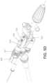
- FIG. 1is a side perspective view of one variation of a catheter device.
- FIG. 2 Ashows the distal section of an exemplary catheter device.
- FIG. 2 Bis a diagram of a distal section of an exemplary catheter device showing the alignment of markers thereon.
- FIG. 2 Cshows an exemplary coiled reinforcement along the shaft of a catheter device.
- FIGS. 3 A- 3 Bshow various side perspective views of the distal end an exemplary catheter device.
- FIG. 3 Cshows the distal end of the device of FIGS. 3 A- 3 B , but with the collar removed.
- FIG. 3 Dshows the distal end of the device of FIGS. 3 A- 3 C , but with the collar and outer sheath removed.
- FIG. 3 Eshows an embodiment of the distal end of an exemplary catheter device wherein the bushing includes a shoulder.
- FIG. 4shows an optical fiber wrapped around a drive shaft of an exemplary catheter device.
- FIGS. 5 A- 5 Eshow a handle assembly or partial handle assembly for an exemplary catheter device.
- FIG. 6shows an exemplary OCT system.
- FIGS. 7 A and 7 Bshow screen captures of an exemplary catheter device including an OCT imaging system.
- FIG. 8shows the orientation of an OCT image relative to a fluoroscopy image from a catheter device.
- FIGS. 9 A- 9 Cshow screen captures used to aid steering an exemplary catheter device.
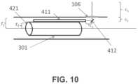
- FIG. 10shows an exemplary diagram used to determine the amount of central masking required for an OCT image of an exemplary catheter device.
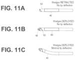
- FIGS. 11 A- 11 Cillustrate one variation of an exemplary catheter having a rotating distal tip region (housing and wedges extendable from the housing) with the rotating wedges retracted into a rotating housing ( FIG. 11 A ); with the rotating wedges extending from the rotating housing ( FIG. 11 B ); and with the distal end region deflecting ( FIG. 11 C ).
- FIGS. 12 A- 12 Fshow a variation of a rotating tip having helical flutes and a countersink.
- FIG. 13shows a variation of a rotating tip having helical flutes, a countersink, and an aggressive leading edge.
- FIG. 14show a variation of a rotating tip having helical flutes, a countersink, and an elongate proximal stem portion to provide a long optical fiber channel.
- FIGS. 15 A- 15 Eshow variations of a rotating tip having helical flutes, a countersink, and different designs of aggressive cutting edges.
- FIGS. 16 A- 16 Bshow variations of a rotating tip having slanted surfaces forming grinding edges.
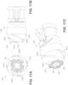
- FIGS. 17 A- 17 Cshow a variation of a rotating tip having a distal grinding surface with an array of sharp points therein.
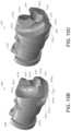
- FIGS. 18 A- 18 Bshow variations of a rotating tip having paddles.
- FIGS. 19 A- 19 Bshow the distal end of an exemplary occlusion-crossing catheter having a rotating distal tip and extendable wedges.
- FIG. 19 Ashows the wedges extended.
- FIG. 19 Bshows the wedges retracted.
- FIGS. 19 C- 19 Dshow a torque knob for use in moving the outer shaft of an exemplary occlusion-crossing catheter such as the catheter in FIGS. 19 A- 19 B .
- FIG. 19 Cshows the torque knob position when the distal wedges are extended.
- FIG. 19 Dshows the torque knob position when the distal wedges are retracted.
- FIGS. 20 A- 20 Cshows an exemplary spine or marker arrangement for orienting a catheter during OCT imaging.
- FIG. 21shows an exemplary OCT image resulting from the spine arrangement shown in FIGS. 20 A- 20 C .
- FIGS. 22 A- 22 Fshow another embodiment of an exemplary occlusion-crossing catheter having a rotating distal tip and extendable wedges.
- FIG. 22 Ashows the wedges retracted.
- FIG. 22 Bshows the wedges extended.
- FIG. 22 Cshows the outer shaft assembly.
- FIG. 22 Dshows the inner shaft assembly.
- FIG. 22 Eshows the housing over the inner shaft assembly of FIG. 22 D with the wedges retracted.
- FIG. 22 Fshows the housing over the inner shaft assembly of FIG. 22 D with the wedges extended.
- FIGS. 23 A- 23 Bshow another embodiment of an exemplary occlusion-crossing catheter having a rotating distal tip and extendable wedges.
- FIG. 23 Ashows the housing over the inner shaft assembly with the wedges are retracted.
- FIG. 23 Bshows the housing over the inner shaft assembly with the wedges extended.
- occlusion crossing catheterssuch as guidewire placement and/or support catheters (which may be referred to as “occlusion crossing catheters” for convenience) may be used to cross an occlusion or lesion. These catheters may be used to place a guidewire within an occluded lumen of a vessel. Any of the catheters described herein may include a guidewire lumen spanning all or most of the length of the device and a rotating and/or oscillating (clockwise and/or counterclockwise relative to the long axis of the catheter) distal tip.
- the catheters described hereincan be dimensioned to fit within vessels of the body, such as blood vessels.
- the catheterscan be configured to be placed within the peripheral blood vessels.
- the catheterscan have an outer diameter of less than 0.1 inch, such as less than 0.09 inches, such as less than or equal to 0.08 inches.
- a catheter devicein one embodiment, includes a distal tip that is rotatable and an onboard imaging system for visualizing the vessel as the device is positioned.
- the systemincludes an OCT imaging system for visualizing the structure and morphology of the vessel walls. The system can see a distance of up to 3 mm, such as up to 2 mm, into the depth of the vessel walls.
- the distal tip of an occlusion-crossing cathetercan include one or more dissecting (e.g., cutting) surfaces.
- the rotatable distal tip regionmay be used to position a catheter through an occluded lumen of a vessel, including for treatment of chronic total occlusions.
- a catheter (which may be used as a guidewire positioning catheter) 100includes an elongate flexible shaft 301 and a rotatable distal tip 305 having an imaging sensor, such as an OCT sensor, connected thereto.
- the shaft 301extends from a handle region 303 and terminates in the rotatable distal tip 305 .
- the device 100 in FIG. 1is not necessarily shown to scale, as the length of the shaft has been reduced to show the other features at a more appropriate scale.
- a guidewire 309can extend through the guidewire catheter device 100 , such as through a guidewire lumen in the shaft 301 .
- the guidewire 309may be held resident in the device 100 as it is positioned within a patient or it may be inserted after the distal end of the shaft 301 , or at least the distal tip 305 , has been positioned within the lumen of the vessel, such as past an occlusion or lesion.
- the guidewire lumencan be housed inside of a drive shaft (not shown in FIG. 1 ) configured to rotate the tip 305 .
- the drive shaftis a tubular shaft such that the drive shaft may surround the guidewire lumen.
- the drive shaftis a solid shaft which extends through the length of the catheter, and runs alongside (e.g., adjacent to) the guidewire lumen.
- the systemcan include an optical fiber (not shown in FIG. 1 ) that is fixed at one end to the distal tip 305 , but is otherwise free to move around, such as within an internal lumen between a lumen housing the guidewire 309 and an outer casing of the shaft 301 .
- Power and imaging lines 307(“cabling”) may extend from the handle region 303 to connect the optical fiber with a power source and a light source for the OCT system.
- the handle region 303can house the control mechanism for controlling the rotation of the distal tip (and OCT reflector/sensor at the end of the optical fiber).
- the control mechanismcontrols the direction of the distal tip as well as the number of revolutions before switching direction.
- the handle region 303can also control the rate of rotation.
- the rate of rotation, as well as the number of clockwise and/or counterclockwise rotationsmay be optimized to advance the distal end of the device though an otherwise occluded lumen of a vessel while generating a cross sectional image of the lumen, i.e., 360 degrees.
- the rate and number of rotationsmay also be optimized to prevent damage to the optical fiber used for the OCT imaging which is attached only at the distal end of the device such that the rest of the fiber can extend along the length of the shaft 301 can wrap, off-axis, around the internal lumen (e.g., guidewire lumen) of the catheter without breaking.
- the internal lumene.g., guidewire lumen
- the shaft 301can include a fixed jog 989 , or a J-shaped bend, near or just proximal to the distal tip 305 .
- the fixed jog 989can have an angle of 10 to 45 degrees, such as between 20 and 30 degrees.
- the jogis shapeable by the user prior to placing the catheter in the body lumen, i.e., the user can fix the jog 989 at the desired angle prior to use.
- the fixed jog 989can aid in steering the shaft 301 to the point of interest.
- the shaft 301can include an outer sheath 284 .
- the outer sheath 284can include a braided material, such as stainless steel, elgiloy, cobalt-chromium alloys, carbon fiber, or Kevlar.
- the braided materialcan improve the stiffness of the catheter to help navigate the catheter through vessel.
- the shaft 301can include a guidewire lumen 363 (see FIG. 3 B ) extending within a drive shaft 421 (see FIGS. 3 A- 3 D ) from the proximal end to the distal end of the catheter.
- the guidewire lumen 363can end in an opening in a distal tip 305 of the device.
- the guidewire lumen 363can thus be configured to pass a guidewire therethrough.
- the distal tip 305can include an imaging sensor, such as an OCT sensor 286 configured to capture images within a lumen.
- the shaft 301can have a coiled reinforcement 222 along a portion of its length.
- the coiled reinforcement 222can be, for example, a spiral extending around the shaft 301 (as shown in FIG. 2 C ). The spiral can advantageously reduce kinking or ovalizing of the shaft profile while still allowing for flexion in all directions.
- the coiled reinforcement 222can be a series of rings connected together with a spine, which allows for flexion that is biased in one direction.
- the coiled reinforcement 222can be made of metal, such as stainless steel.
- the coiled reinforcement 222can be configured such that it provides radial hoop strength while still providing enough flexibility for bending.
- the pitch of the coilcan be adjusted to provide the desired flexibility and strength. While a high pitch can advantageously provide flexibility, a low pitch can provide more hoop strength and prevent kink points.
- the pitchcan be approximately 0.005′′ to 0.050′′.
- the pitchis 0.010′′ for a shaft having an outer diameter of 0.070′′ to 0.080′′.
- the thickness of the coil(in the radial direction) can be adjusted to provide the desired flexibility and strength. While a higher thickness can provide more hoop strength, a lower thickness will provide more flexibility and will keep the outer diameter of the shaft low. In some embodiments, the thickness can be approximately.
- the coiled reinforcement 222can be located at the distal end of the shaft 301 , such as between the distal tip 305 and the fluoroscopy marker 702 (described further below).
- the coiled reinforcement 222can advantageously provide radial hoop strength to the distal end of the shaft 301 where bending is more likely to occur.
- the coiled reinforcement 222can be aligned with a bending point or fixed jog in the catheter, such as the fixed jog 989 described above. Having the coiled reinforcement 222 in line with these bending points can advantageously help avoiding kinking at the bending point.
- the coiled reinforcement 222can help maintain the circular cross-section of the shaft 301 , thereby providing clearance between the fiber and the inner diameter of the shaft 301 even as radial stresses are applied to the shaft 301 as it travels through tortuous anatomy.
- the coiled reinforcement 222can be part of the outer sheath 284 .
- the coiled reinforcementcan be placed over the braided material.
- the coiled reinforcement 222can then be laminated under a polymer layer, such as polyether block amide (Pebax®).
- Pebax®polyether block amide
- the flexibility and stiffness of the shaftcan be optimized based on the durometer or hardness of the polymer layer.
- the durometercan be between 30 and 40D.
- 35D or 40D Pebaxis used as the outer layer, which is soft enough for trackability but can hold the bend of a heat-set fixed bend at the end of the device.
- a lubricious and flexible linersuch as PTFE, can be placed between the coiled reinforcement 222 and the braid to allow relative movement between the two.
- the coiled reinforcement 222can be used to hold any preset curvature in the device (such as the jog 989 ).
- the coiled reinforcement 222includes a series of rings connected together by a spine, the rings can maintain the round cross-section while the spine can hold any preset curvature in the device.
- the reinforcement 222can still be used to hold any preset curvature by designing the reinforcement 222 to include a shape-set material, such as nitinol.
- the deflection of the coiled reinforcement 222can be reinforced by using various durometers of polymer laminate. For example, on the inner radius or inside strip of the curve, a higher durometer material may be used while a lower durometer material can be used on the outside of the curve.
- the coiled reinforcement 222can be closed end (i.e., full loop at the ends) or open ended. Using a closed end can advantageously help attach the coiled reinforcement 222 to the shaft by providing more surface area to weld or solder adjacent components thereto.
- part or all of the coiled reinforcement 222can be used as a radiopaque marker band to indicate the directionality of the shaft 301 .
- one variation of the distal end of the shaft 301can have a distal tip 305 that is roughly corkscrew or helically shaped.
- the distal tip 305can thus include spiral flutes, such as two spiral flutes.
- the distal tip 305rotates and does not extend or retract into a housing, i.e. remains exposed from the shaft 301 .
- the distal tip 305can be attached to a drive shaft 421 that rotates within the outer sheath 284 and can be configured to rotate in both the clockwise and counterclockwise directions.
- the distal tip 305can include a substantially smooth, curved outer surface 322 that presents an atraumatic tissue-contacting surface when rotated in one direction, i.e., the counterclockwise direction in FIGS. 3 A- 3 D , and that further presents a sharp, tissue-cutting surface or edge 403 when rotated in the opposite direction, i.e. the clockwise direction in FIGS. 3 A- 3 D .
- At least a portion of the tip 305can have a diameter that is substantially equal to or greater than the diameter of the shaft 301 . That is, the cutting edge 403 can be helical such that at the distal end, the diameter of the cutting geometry is reduced to the size of the guidewire lumen and gradually increases to the approximate outer diameter of the shaft 301 as it moves proximally. Further, the tip 305 can be configured such that it cuts only in the forward direction and not substantially in the lateral direction. That is, the cutting edge 403 can be substantially forward-facing. Additional tip designs are discussed further below.
- An OCT imaging sensor 286(including the distal end of the optical fiber 411 and the mirror 412 ) can be fixed to the rotatable distal tip 305 and rotate with it.
- the distal end of the optical fiber 411can be secured in a notch 344 formed in the rotatable distal tip 305 .
- An epoxy or other securing material that has a refractive index appropriately mismatched with the end of the optical fiber 411can hold the end of the optical fiber 411 in the notch 344 , as described in U.S. patent application Ser. No. 12/790,703, titled “OPTICAL COHERENCE TOMOGRAPHY FOR BIOLOGICAL IMAGING,” filed May 28, 2010, Publication No.
- the imaging sensor 286can direct the optical beam for OCT imaging from the distal tip 305 of the catheter into the tissue.
- the imaging systemis oriented so that the mirror 412 directs the optical beam approximately or substantially perpendicular to the catheter axis. In some variations, this angle is different or is adjustable. For example, the orientation of the mirror 412 may be changed (including adjusted by the user) to change the direction of imaging and/or image more distally or proximally.
- substantially perpendicularmay include plus or minus 10 degrees, plus or minus 5 degrees, or plus or minus 2 degrees, off of the 90 degree angle that is perpendicular from the elongate axis of the distal tip and/or catheter body.
- the sensor 286can be located close the distal end of the tip 305 , such as just proximal to the cutting edge 403 .
- the sensor 286can be located within 5 mm of the distal end of the tip 305 , such as less than 3 mm, such as approximately 2 mm.
- the resulting imagewill be a closer approximation of the exact tissue or material being passed by the distal end.
- the sensor 286may be directed laterally (e.g., to image the sides of the vessel in which the catheter is traveling), or angled forward or backward.
- the sensor 286can be located off of the central axis of the shaft 301 and close to the outer diameter of the tip 305 , such as within 0.05 inches, e.g. less than 0.3 inches, less than 0.02 inches, or less than or substantially equal to 0.01 inches of the outer diameter of the tip 305 .
- the depth that the OCT system can see into the tissuewill be greater, i.e., the amount of tissue lying within the OCT imaging range is increased.
- the rotating tip 305is held in a chassis 405 that is fixed relative to the shaft 301 , i.e., that does not rotate with the rotating tip 305 .
- the chassis 405is any structure within which the distal tip 305 can rotate and which secures the drive shaft 421 and/or the distal tip 305 to the end of the shaft 301 ; it may also be referred to as a housing.
- the outer sheath 284can be connected to the chassis 405 such that the outer sheath also remains stationary while the distal tip 305 rotates.
- the chassis 405can have one or more “window” regions through which the OCT imaging sensor 286 can view the tissue.
- the chassis 405can include three window regions 346 separated by spines 419 (which may be referred to as posts, struts, dividers, separators, etc.) arranged annularly around the chassis 405 .
- These spines 419may serve as reference markers as the imaging sensor 286 rotates, as discussed below.
- the spines 419may be separated from one another by different distances. For example, one of the windows may be larger than the other two, or smaller than the other two. This asymmetric sizing may provide a visual reference on the display of the OCT imaging.
- the spines 419can have a predetermined and fixed location relative to the jog 989 in the catheter.
- one of the spines 419can be aligned relative to the jog 989 . In one embodiment, shown in FIG.
- the second spine 419is aligned opposite to the jog 989 , i.e., such that the catheter points away from the second spine 419 (the inner curved portion of the jog 989 is opposite to the second spine 419 and the outer curved portion of the jog 989 is axially aligned with the second spine 419 ).
- This alignmentcan be used to help orient the device in a specific direction with respect to the image and/or vessel, as discussed further below.
- the spines 419can all have the same shape as one another.
- the middle spinecan have a different shape so as to provide further visual indication as to the orientation of the device.
- a chassis 2005(which can be used in place of chassis 305 or 405 ) can include spines 2019 a,b,c arranged such that there is 90° between spine 2019 a and 2019 b, 90° between spine 2019 b and 2019 c , and 180° between 2019 c and 1019 a .
- the middle spine 2019 bcan have a different shape than the spines 2019 a,c .
- the middle spine 2019 bcan be thicker and/or include a slot 2022 therein. As described further below, this difference in shape can make it easier for the user to visualize the middle marker (which can be aligned, for example, such that the inner curved portion of the jog 989 is opposite to the marker 2019 b ).
- the distal tip 305can include a groove 392 at the proximal end to engage a bushing 394 (e.g., annular ring).
- the bushing 394can remain fixed with respect to the shaft 301 and may provide a lubricious surface to eliminate or reduce friction and fix the longitudinal position of the distal tip 305 .
- the bushing 394may be made of PEEK or other hard lubricous material.
- the groove 392may be crimped or clamped to the stationary chassis 405 , thereby allowing the rotatable distal tip 305 to have improved stability during rotation.
- the bushing 394includes a shoulder 445 .
- the shoulder 445can extend outward into the space between the distal edge of the chassis 405 and the distal tip 305 .
- the shoulder 445can be made of the same lubricous material as the rest of the bushing 394 .
- the shoulder 445prevents the distal edge of the chassis 405 from rubbing against the tip 305 and further reduces the friction of the system.
- the chassis 405may engage the groove 392 of the distal tip 305 directly, such as by one or more tabs 407 or locks that can be pushed in when the distal tip 905 is held within the chassis 405 to lock the bushing ring 394 and distal tip 305 in position.
- the chassis 405 or distal tip 305can be made from a lubricious material.
- the chassis 405can include one or more openings or ports 422 out of which a clearing fluid, such as saline or water, may be driven to help clear the pathway for imaging the walls of the vessel lumen as the device is operated.
- a clearing fluidsuch as saline or water
- Bloodincluding red blood cells and other blood components, may degrade the ability of the OCT imaging system from imaging other tissues because OCT may not readily “see” through blood.
- the cathetermay be configured to clear the blood from the region of interest, i.e., the region where the optical beam is emitted from the catheter for OCT imaging.
- the ports 422can thus be configured to emit a clearing fluid from the catheter to clear blood from the imaging sensor.
- the port 422is located directly adjacent to the imaging sensor and emits fluid to clear blood from the region where the optical beam is being emitted.
- the ports 422can be less than 2 mm from the imaging sensor, such as less than 1.5 mm.
- the pressure and amount of clearing fluid required to clear the blood from the region of interestcan be low. For example, less than 1 ml, such as less than 0.5 ml, e.g., less than 0.2 ml of clearing fluid can be required to clear the blood from the region of interest.
- the required pressuremay be nominal and the flow of saline or other clearing fluid may be minimal and still effectively clear blood from the imaging space, greatly improving the resolution of the vessel walls and increasing the depth of penetration.
- using small amounts of clearing fluidcan advantageously avoid problems associated with having too much fluid in a small space, such as separation of tissue (e.g., dissection).
- the shaft 301can be configured such that the clearing fluid enters at the proximal end of the catheter and is transported to the distal end by flowing in a space 472 between the outer sheath 284 and the drive shaft 421 .
- the clearing fluidmay be pressurized from the proximal end (e.g., using a syringe, etc.) so that it is pushed out of the opening 422 to clear blood from the OCT pathway.
- the OCT portion of the catheter device 100may be referred to as an off-axis imaging system because the management of the OCT optical fiber 411 is arranged asymmetrically, off-axis with reference to the long axis of the catheter.
- the fiber 411can be configured to extend freely within the shaft 301 in the space 472 between the drive shaft 421 and the outer sheath 284 except where it is attached at the distal end of the device, e.g., at the rotatable distal tip 305 . Accordingly, as shown in FIG. 4 , when the drive shaft 421 is rotated to rotate the distal tip 305 , the fiber 411 can wrap around the drive shaft 421 . This arrangement can advantageously enhance the flexibility, i.e., allow for movement of the catheter without fracturing the optical fiber 411 .
- both the rate of rotation and the number of rotationsmay be controlled to optimize performance, prevent the fiber 411 from binding within the shaft 301 , and prevent the fiber 411 from snapping due to excessive twisting or rotation.
- the distal tip 305may be configured to alternate its rotation from clockwise to counter clockwise.
- the drive shaft 421can be configured to rotate (with the distal tip 305 ) clockwise for a fixed number of rotations and to rotate counterclockwise for the same number of rotation before switching back to clockwise rotations and repeating the process.
- the number of rotations in the clockwise directioncan be substantially equivalent to the number of counter clockwise rotations in order to relieve any residual twisting.
- the deviceis configured to rotate the distal tip n rotations clockwise and n rotations counterclockwise, switching between clockwise and counterclockwise rotational direction after each n rotations.
- the number of rotations ncan be any number, including fractional, typically between 1 and 100; preferably it is between 1 and 10, depending on the length of the catheter and the amount of stress the fiber can withstand.
- the devicemay be configured to rotate approximately 6, 8.5, 10, 12.7, 15, etc. times clockwise, then counterclockwise the same number of rotations.
- the deviceis configured so that it doesn't continuously spin clockwise or counterclockwise, but has a limited number of rotations in either direction (e.g., less than 25 rotations, such as 10 rotations), after which it automatically switches to rotate the other direction.
- the transition between clockwise and counterclockwise rotationmay be performed automatically, which is described in more detail with reference to FIGS. 5 A- 5 E , below.
- the rotationmay be driven by a motor or other driver (e.g., within the handle) or it may be manual.
- the rotationis automatic, and is driven at a constant speed that is typically between about 1 and 300 revolutions per minute (rpm); for example, the rotation rate may be about 10 rpm, 20 rpm, 30 rpm, 40 rpm, 50 rpm, 60 rpm, etc.
- the distal tipis rotated between about 1 and about 100 rpm, e.g., between about 1 and 80 rpm, such as between about 30 and 60 rpm.
- the rate and the consistency of rotationmay be optimized for penetration through the occlusion within the vessel, for image stability, and also to produce relatively streak-free imaging using the OCT.
- the rate of rotationmay be limited to an upper limit speed that is held relatively constant.
- the rate of rotationmay be sufficiently low (e.g., less than 150 or 100 or 50 rpm) so that the distal head rotates but does not ‘drill’ through the tissue, including one or more occlusions.
- the usercan control the rate of rotation, such as by setting the motor to rotate at a particular speed.
- the handle 303 of the devicecan be configured to control rotation and advancement of the shaft 301 .
- the handle 303can include a switch 562 configured to turn the system on or off (i.e. to start the rotation of the distal tip and/or the imaging system).
- the handlecan be covered by a housing 501 which may be configured to conform to a hand or may be configured to lock into a holder (e.g., for connection to a positioning arm, a bed or gurney, etc.).
- a drive systemincluding a motor 503 and drive gears 515 , 516 , 517 , may drive the drive shaft 421 to rotate the distal tip 305 of the device and/or the OCT imaging system relative to the shaft 301 .
- the drive systemis controlled or regulated by a toggling/directional control subsystem for switching the direction of rotation of the drive shaft between the clockwise and counterclockwise direction for a predetermined number of rotations (e.g., 10).
- a mechanical directional controlcan be configured to switch the direction of rotation between clockwise and counterclockwise when the predetermined number of rotations have been completed.
- the directional controlincludes a threaded track (or screw) 511 which rotates to drive a nut 513 in linear motion; rotation of the threaded track by the motor 503 results in linear motion of the nut along the rotating (but longitudinally fixed) threaded track 511 .
- the nut 513moves linearly in a first linear direction (e.g., forward) until it hits one arm of a U-shaped toggle switch 516 , driving the U-shaped toggle switch in the first linear direction and flipping a switch 523 (visible in FIG. 5 D ) to change the direction of the motor 503 to a second rotational direction (e.g., counterclockwise), and causing the nut to move linearly in a second linear direction (e.g., backward) until it hits the opposite side of the U-shape toggle switch 516 , triggering the switch to again change the direction of rotation back to the first rotational direction (e.g., clockwise).
- a first linear directione.g., forward
- a second rotational directione.g., counterclockwise
- a second linear directione.g., backward
- the motor 503may be configured to rotate the drive shaft 421 in either direction at a constant speed.
- the systemmay also include additional elements (e.g., signal conditioners, electrical control elements, etc.) to regulate the motor as it switches direction.
- the number of threads and/or length of the threaded track (screw) 511may determine the number of rotations that are made by the system between changes in rotational direction. For example, the number of rotations may be adjusted by changing the width of the U-shaped toggle 514 (e.g., the spacing between the arms). Lengthening the arms (or increasing the pitch of the screw) would increase the number of rotational turns between changes in direction (n). The toggle may therefore slide from side-to-side in order to switch the direction of the motor.
- the length of the nut 513can also determine the number of rotations that are made by the system between changes in rotational direction, i.e., the longer the nut, the fewer the number of rotations before switching direction.
- the motor 503is rotated in a constant direction, and the switch between clockwise and counterclockwise is achieved by switching between gearing systems, engaging and disengaging an additional gear, or using gears that mechanically change the direction that the drive shaft is driven.
- the drive systemincludes the motor and three gears that engage each other to drive the drive shaft in rotation.
- the motor 503rotates a first gear 517 , which is engaged with a second gear 516 (shown in this example as a 1:1 gearing, although any other gear ratio may be used, as appropriate).
- a third gear 515engages with the second gear 516 .
- the third gearmay drive or regulate an encoder 507 for encoding the rotational motion. This encoded information may in turn be used by the drive system, providing feedback to the drive system, or may be provided to the imaging system.
- the cabling 307can include both a fluid flush line 552 configured to be attached to a fluid source and an optical fiber 411 configured to be connected to the OCT system.
- the flush line 552 and the fiber 411can both run through the handle 303 .
- the fiber 411 and the flush line 552can be bonded at a bonding point 566 in the handle 303 , creating a seal to prevent fluid from leaking into the handle.
- the flush line 552can end at the bonding point 566 , allowing the fluid to exit the flush line and continue down the shaft 301 in the space 572 between the outer sheath 284 and the drive shaft 421 .
- the fiber 411can extend through the bonding point 566 and wrap around the drive shaft 421 in the space 572 . As shown, because the fiber 411 is configured to wrap around the guidewire lumen, a separate fiber management system is not necessary. In some embodiments, a protective coating 564 can surround the optical fiber until distal of the bonding point 566 .
- the fiber 411can be connected at the proximal end to a common-path OCT system 600 .
- the common-path OCT system 600includes a light source 102 , such as a swept frequency laser.
- the light sourcecould be a broadband light source such as a super-luminescent diode (to conduct Time Domain OCT or Spectral Domain OCT using an optical spectrometer).
- the optical fiber 411transfers radiation from the light source 102 to the target 114 .
- the optical fiber 411is in optical contact with an interface medium 106 , i.e. the light exiting the optical fiber and entering the interface medium sees only one interface.
- an interface medium 106i.e. the light exiting the optical fiber and entering the interface medium sees only one interface.
- the end of the optical fiberis embedded in the interface medium 106 .
- the interface medium 106can be, for example, a glue or epoxy.
- the index of refraction of the interface medium 106is different than the index of refraction of the core of the optical fiber 411 . This creates a Fresnel reflection, in which part of the light exits the core, and part of the light is reflected back. Some of the light beam that exits the optical fiber 411 will encounter the target 114 and be reflected or scattered by the target 114 . Some of this reflected or scattered light will, in turn, reenter the tip of the optical fiber 411 and travel back down the fiber 411 in the opposite direction.
- a Faraday isolation device 112such as a Faraday Effect optical circulator, can be used to separate the paths of the outgoing light source signal and the target and reference signals returning from the distal end of the fiber.
- the reflected or scattered target light and the Fresnel-reflected reference light from the fiber facecan travel back to a detector 110 located at the proximal end of the optical fiber 411 .
- the reflected or scattered target light in the OCT system 600travels a longer distance than the Fresnel reflected reference light
- the reflected or scattered target lightcan be displaced by frequency, phase and or time with respect to the reference beam.
- the light from the targetwill be displaced in frequency.
- the difference in displacement in phase, time or frequency between the reflected or scattered target light and the reference lightcan be used to derive the path length difference between the end of the optical fiber tip and the light reflecting or light scattering region of the target.
- the displacementis encoded as a beat frequency heterodyned on the carrier reference beam.
- the light source 102can operate at a wavelength within the biological window where both hemoglobin and water do not strongly absorb the light, i.e. between 800 nm and 1.4 ⁇ m.
- the light source 102can operate at a center wavelength of between about 1300 nm and 1400 nm, such as about 1310 nm to 1340 nm.
- the optical fiber 411can be a single mode optical fiber for the ranges of wavelengths provided by the light source 102 .
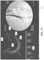
- FIGS. 7 A and 7 Bare exemplary screen captures of an imaging output from the system described herein.
- the displayed image 800is divided into three components.
- On the rightis a fluoroscopic image 810 showing the distal end 805 of the catheter within a vessel 814 . Contrast has been inserted into the vessel 814 to show the extent of the vessel 814 and any occluded regions.
- an OCT image 820On the left is an OCT image 820 .
- the distal tip of the catheterrotates at approximately 30 rpm, and the OCT system provides a continuous set of images as the catheter rotates within the vessel.
- the imagesare combined into a continuously updated OCT image 820 that corresponds to the inside of the lumen in which the catheter is inserted. That is, the OCT image 820 is an image trace of the interior of the vessel just proximal to the distal tip as it rotates.
- the line 822(extending to almost 12 o'clock in the figure) indicates the current direction of the OCT laser beam as it is rotating.
- the circle 824 in the middle of the image 820represents the diameter of the catheter, and thus the area surrounding the circle 824 indicates the vessel.
- the OCT imagingcan extend more than 1 mm from the imaging sensor, such as approximately 2 mm or approximately 3 mm and thus will extend into the walls of the vessel (particularly in the closer region of the vessel) so that the different layers 826 of the vessel may be imaged.
- the three striped rays 744(extending at approximately 2 o'clock, between 7 and 8 o'clock, and approximately 11 o'clock) indicate the location of the three spines of the catheter and thus may act as directional markers, indicating the orientation of the distal end of the catheter within the body.
- the usermay also be able to determine relative orientation of the OCT image (relative to the patient's body orientation) using these striped rays 744 .
- a waterfall view 830 of the OCT imageAs it circles the radius of the body.
- This waterfall image 830may be particularly useful in some applications of the system, for example, indicating the relative longitudinal position of a feature (e.g., layered structures, occlusions, branching region, etc.) as the device is moved longitudinally within the vessel.
- the waterfall view 830typically includes a time axis (the x-axis) while the y-axis shows the image from the OCT sensor.
- the waterfall view 830may provide an indication of when the catheter has crossed an occlusion.
- the waterfall view 830may show the patient's heartbeat when the walls of the vessel move relative to the heartbeat.
- the waterfall view 830may show the walls of the vessel moving with the heartbeat.
- the distal tipis within an occlusion the wall of the vessel
- the waterfall viewwill not show movement of the walls since the occlusion material typically prevents the movement of the walls due to the heartbeat, while in healthy vessels the heartbeat is apparent.
- this effectmay be automated to provide an indication of when the device is within or has crossed an occlusion.
- crossing the boundary of a total occlusionis not well defined and may result in inadvertently dissecting the vessel.
- the vessel wallmay move; if the catheter tip is not in the true lumen all or part of the vessel wall will not move.
- this movement of the wall during heartbeatmay reflect the position within the true versus false lumen.
- FIG. 7 Bshows another screen capture from the same procedure shown in FIG. 7 A .
- the distal tip 305is further within the vessel 814 than in FIG. 7 B .
- the OCT image 820shows a branch 818 of the vessel extending from the vessel in the 2 o'clock position.
- the shaft 301can include a fluoroscopy marker 702 (also shown in FIG. 2 B and FIG. 4 ) that provides varying contrast in a fluoroscopy image depending on its radial orientation.
- the markermay be a radiopaque band with one or more asymmetric features such as a “C”, “T”, or dog bone shape that can be used to radially orient the shaft because the fluoroscopic image of the marker will change depending on its orientation.
- the fluoroscopy marker 702can have a fixed location relative to the spines 419 and/or the jog 989 .
- the fluoroscopy marker 702can be aligned opposite to the jog 989 and/or axially aligned with the second spine 419 described above.
- the fluoroscopy marker 702can be used to align a fluoroscopy image 710 with an OCT image 720 during use of the catheter.
- the shaft 301can be rotated slightly such that the marker 702 is aligned to a particular side of the screen, such as at the 9 o'clock position.
- the up/down position of the catheteri.e. whether the catheter is pointed down, as shown in FIG. 7 , or pointed up
- the OCT imagecan then be oriented such that striped ray 744 from the middle marker (the second spine 419 described above) of the shaft 301 is also at the 9 o'clock position in the OCT image 720 .
- Fluorosyncingcan be performed using manual input from the user, such as information regarding the up/down position and the rotational position, or can be performed automatically.
- the softwaremay draw the OCT image 720 either in a clockwise or counterclockwise direction (depending on the up/down orientation of the catheter in the fluoroscopy image 710 ) and will rotate the image 90°, 180°, or 270° (depending on the rotational position of the catheter in the fluoroscopy image 710 ).
- the absolute and relative position and orientation of the catheter within the patient's bodymay be determined.
- the markers on the chassis/imaging systemvisible in the OCT system) may therefore provide sufficient orientation markers such that the fluoroscopic imaging may be reduced.
- the displayed imagescan be used, in combination with steering mechanisms such as the OCT markers, the fluoroscopy marker, and the fixed jog of the device, to steer the catheter and rotatable tip to the desired location.
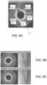
- the OCT image 920shows healthy tissue 956 in the form of a layered structure and non-healthy tissue 958 in the form of a nonlayered structure.
- the cat ears 962 in the imageshow a region between the healthy and unhealthy tissue caused by a slight expansion of the vessel around the catheter at that location. Accordingly, during a CTO procedure, one goal may be to steer the catheter towards the unhealthy tissue. Because the middle spine 419 is aligned opposite to the jog 989 (as shown in FIG.
- the ray 744 corresponding to the middle spine 419can be oriented opposite to the non-healthy tissue 958 to steer the catheter in the correct direction. Identifying the middle spine can be made easier by differentiating the middle spine relative to the rest of the spines (as described with respect to FIGS. 20 A- 20 C ). That is, referring to FIG. 21 , having a different spine shape (such as thicker and with a slot therein as in FIGS. 20 A- 20 C ) can result in a ray 2144 b having a different profile than the rest of the rays 2144 a,c.
- FIG. 9 Bshows the catheter deflected toward the layered, healthy tissue.
- FIG. 9 Cshows the catheter rotated such that it is deflected toward the unhealthy, non-layered structure.
- the systemmay be configured to allow the orientation of the catheter to be rotated into the correct position using the fixed directional markers from the chassis that are visualized by the OCT.
- the distal end of the devicemay be steerable and may be steered while still rotating the distal end of the device.
- Additional steering membersmay also be included, such as a selective stiffening member, which may be withdrawn/inserted to help steer the device, and/or one or more tendon members to bend/extend the device for steering.
- Image correctioncan be performed on the resulting OCT images in order to mask out unwanted or unnecessary portions of the image.
- the fiber 411can be configured such that it ends within the shaft 301 .
- the fiber 411will image the distance c 1 between the fiber 411 distal end and the mirror 412 as well as the axial distance c 2 between the mirror 412 and the outer diameter of the shaft 301 .
- the resulting imagewould therefore include portions that correspond to the interior of the shaft. Accordingly, image processing can be performed such that distance c 1 , c 2 , or c 1 +c 2 is masked out in the displayed image.
- c 1 and c 2are masked out, only the area c 3 would show up on the image (where the total imaging distance or capability of the fiber is equal to c 1 +c 2 +c 3 ).
- up to 100 pixelscan be masked out, such as between 20 and 60 pixels, for example approximately 40 pixels.
- the imagecan be corrected to account for lag of the optical fiber in the amount of rotation at the handle vs. at the distal end of the catheter.
- Images for lag correctioncan be captured automatically.
- imagescan be exported and stored, for example in a movie format.
- the imagescan optionally viewed in adjustable grayscale. Further, the speed of the waterfall view can be adjusted.
- offset or “ghost” imagemay be overlaid atop the OCT to indicate the difference between the predicted and actual rotational orientation of the catheter.
- a manually rotatable devicemay be used with an adjunctive device providing a motorized movement of the distal tip.
- the handle portion of the devicemay set and be secured within a housing that includes a motor and gearing to automatically rotate the distal tip at a predetermined or adjustable speed.
- this motorized accessory devicemay adapt an otherwise manual device to automatically rotate.
- the distal tip of the deviceis rotated through multiple complete rotations (both clockwise and counterclockwise) to move the distal tip and/or any attached imaging sensor in rotation around the elongate longitudinal axis of the device. In some variations the distal tip of the device to create an oscillating motion.
- the tips described hereincan include cutting surfaces configured to slice or grind through tissue as the tip is driven forward.
- the tipscan have a maximum diameter of less than 1′′, such as less than 0.9′′ in diameter, such as approximately 0.8′′.
- the rotating distal endcomprises two or more wedges that are radially separated around the tip region (e.g., spaced equally apart radially). It may be advantageous to have three or more wedges spaced around the tip, which may improve centering of the device, as described herein.
- the rotating distal endcan have a distal tip that is roughly corkscrew or helically shaped with spiral flutes extending around the guidewire lumen.
- the distal tipcan be configured to rotate in both the clockwise and counterclockwise directions and to provide a sharper cutting surface in one direction than the other.
- distal tip 305includes a proximal stem portion 388 configured to slide at least partly into the chasses 405 and to hold the optical fiber for imaging.
- Two helical flutes 391 a,bcan extend from the proximal stem portion 388 to the distal end of the tip 1305 .
- the helical flutes 391 a,bform a substantially smooth, curved outer surface 322 therebetween that spirals distally to the distal end of the guidewire lumen 363 .
- the smooth curved outer surface 322provides an atraumatic tissue-contacting surface when rotated in one direction, i.e., the counterclockwise direction in FIGS. 3 A- 3 D .
- the curved outer surface 322is rimmed by a sharp edge 403 that extends continuously from the proximal stem portion 388 to the distal end of the tip.
- the edge 403provides a tissue-cutting edge when rotated in the opposite direction, i.e. the clockwise direction in FIGS. 3 A- 3 D .
- the flutes 391 a,bform a conic helix such that the diameter of the cutting geometry at the proximal end is approximately the diameter of the catheter outer shaft while the diameter of the cutting geometry at the distal end is reduced to approximately the size of the guidewire lumen.
- a distal tip 1205includes a proximal stem portion 1288 configured to slide at least partly into a chassis and to hold the optical fiber for imaging.
- Two conic helical flutes 1291 a,bcan extend from the proximal stem portion 1288 to the distal end of the tip 1305 .
- the flutes 1291 a,bcan have a higher pitch relative to the flutes 391 a,b of distal tip 305 shown in FIGS. 3 A- 3 D .
- the pitchcan be greater than 0.10 inches for a tip having a maximum diameter of 0.8′′, such as a pitch of approximately 0.15 inches.
- each flute 1291 a,bcan extend less than half way around the circumference of the tip 1205 .
- the helical flutes 1291 a,bcan be rimmed by cutting rim edges 1271 (see edges 1271 a,c for flute 1291 a and edge 1271 b for flute 1291 b in FIG. 12 A ). Because the helical flutes 1291 a,b and cutting rim edges 1271 extend at a steeper angle, the tip 1205 can provide a more aggressive cutting geometry that will slice tissue efficiently and quickly as the tip is drilled through the tissue.
- the cutting rim edges 1271can have a slight thickness (in the radial dimension) to them, providing for a buffer to the sharp edges on either side. Such cutting rim edges 1271 can advantageously help prevent the tip 1205 from cutting a sheath as it moves therethrough.
- the width of the flutes 1291 a,bcan be larger relative to the flutes 391 a,b of the distal tip 305 .
- the widthcan be greater than 0.025 inches for a tip having a maximum diameter of approximately 0.8′′, such as width of greater than 0.030 inches, such as approximately 0.032 inches.
- the larger widthcan advantageously provide more space for clearing material or “chips” as the tip rotates through an occlusion, thereby allowing the tip to move more seamlessly through the occlusion.
- the flutes 1291 a,bcan terminate at the distal end prior to reaching the guidewire lumen 1263 .
- Angled flat sections 1293 a,bcan extend or slope distally from the distal end of each flute 1291 a,b at a lower slope that the flutes 1291 a,b .
- the angled flat sections 1293 a,bcan have a substantially flat surface with knife-like edges 1294 a,b (see FIG. 12 B ) that meet to form pointed tips 1295 a,b .
- the pointed tips 1295 a,bcan face distally (forward) and can form the distal-most portion of the tip 1205 .
- the pointed tips 1295 a,bcan advantageously help pierce or cut through tissue as the tip 1205 is rotated.
- the angled flat sections 1293 a,bcan be slightly wider than the width of the flutes 1291 a,b at the junction between the flat sections 1293 a,b and the flutes 1291 a,b , thereby creating angled blades 1292 a,b (see FIG. 12 I ) on the distal end of the tip 1205 .
- the angled flat sections 1293 a,b and the knife-like edges 1294 a,bcan frame or surround a countersink 1297 (otherwise called a counterbore) extending around the guidewire lumen 1263 .
- the countersink 1297can be an indented volcano-shaped section (e.g., caldera region) that sinks proximally from the knife-like edges 1294 a,b and the pointed tips 1295 a,b .
- the countersink 1297can advantageously help center the tip 1205 on tissue through which it is being driven by allowing the tissue to extend into the countersink 1297 as the tip 1205 is moved distally.
- the distal tip 1205can be configured to cut more aggressively in one direction than in the other. For example, when rotated clockwise in the view of FIG. 12 A , the tip 1205 would cut more aggressively than when rotated in the counterclockwise direction.
- the fiber channel 1289 in which the optical fiber sitscan extend into the distal tip 1205 .
- the fiber channel 1289can be rounded along the bottom to allow for large-diameter fibers, such as GRIN fibers, to fit therein without increasing the diameter of the channel along the outer surface of the tip 1205 .
- a tip 1305can include many of the same features as tip 1205 , including a proximal stem portion 1388 , steep flutes 1391 a,b extending therefrom, flat surfaces 1393 a,b , sharp pointed tips 1395 a,b , and a countersink 1397 around the guidewire lumen 1363 .
- the flat surfaces 1393 a,bcan be nearly perpendicular to the central axis of the tip 1305 , thereby creating thinner and sharper tips 1395 a,b , resulting in a more aggressive tip.
- a tip 1405can include many of the same features as tip 1205 , including a proximal stem portion 1488 , steep flutes 1491 a,b extending therefrom, angled flat sections 1493 a,b , sharp pointed tips 1495 a,b , and a countersink 1497 around the guidewire lumen 1463 .
- the proximal stem portion 1488can be longer, such as at least 50%, 75% or 100% longer, than the stem portion 1388 .
- the proximal stem portion 1488can be more than 4 mm, such as greater than 5 mm, such as approximately 6 mm.
- the longer proximal stem portion 1488can advantageously provide a longer fiber channel 1489 , thus providing additional support for fragile fibers, such as GRIN fibers.
- a tip 1805can include conic flutes extending therein and a rounded distal face.
- the tip 1805can include many of the same features as tip 1205 , including a proximal stem portion 1888 , steep flutes 1891 a,b,c extending therefrom, angled flat sections 1893 a,b,c , and a countersink 1897 around the guidewire lumen 1863 .
- NURDnonuniform rotational distortion
- the angled flat sections 1893 a,b,ccan be thicker and have sharper, less curved edges.
- the angled flat sections 1893 a,b,c and the flutes 1891 a,b,ccan end at the countersink 1897 .
- the junction of the flutes 1891 a,b,c and the angled flat sections 1893 a,b,ccan form a plurality of sharp points 1895 around the rim of the countersink 1897 , making the tip 1805 more aggressive.
- a tip 2005can include conic flutes extending therein and a flat distal face.
- the tip 2005can include many of the same features as tip 1205 , including a proximal stem portion 2088 , steep flutes 2091 a,b,c extending therefrom, angled flat sections 2093 a,b,c , and a countersink 2097 around the guidewire lumen 2063 .
- the flutes 2091 a,bcan have a steeper slope, thereby advantageously helping to move tissue away from the leading edge of the tip 2005 .
- the angled flat sections 2093 a,b,ccan be thicker.
- the angled flat sections 2093 a,b,ccan each have at least one relatively straight edge 2092 a,b,c , along the outer perimeter of the tip 2005 , which can create a more aggressive cutting geometry. Similar to the tip 1805 of FIG. 15 a , the angled flat sections 2093 a,b,c and the flutes 2091 a,b,c of tip 2005 can end at the countersink 2097 . The junction of the flutes 2091 a,b,c and the angled flat sections 2093 a,b,c can form a plurality of sharp points 2095 around the rim of the countersink 2097 .
- a tip 2305can include conic flutes extending therein and a flat distal face.
- the tipcan include many of the same features as tip 1205 , including a proximal stem portion 2388 , steep flutes 2191 a,b,c extending therefrom, angled flat sections 2393 a,b,c , and a countersink 2397 around the guidewire lumen 2363 .
- the angled flat sections 2393 a,b,ccan be thicker.
- the angled flat sections 2393 a,b,ccan each have at least five sharp corners 2396 configured to create a more aggressive cutting geometry. Similar to the tip 1805 of FIG.
- the angled flat sections 2393 a,b,c and the flutes 2391 a,b,c of tip 2305can end at the countersink 2397 .
- the junction of the flutes 2391 a,b,c and the angled flat sections 2393 a,b,ccan form a plurality of sharp points 2395 around the rim of the countersink 2397 .
- a tip 2205can include flutes extending therein from the proximal end of the tip to the distal end of the tip.
- the proximal and distal endscan have substantially the same diameter (i.e., not taper towards the distal end).
- the tip 2205can include many of the same features as tip 1205 , including a proximal stem portion 2288 , two steep flutes 2291 a,b extending therefrom, angled flat sections 2293 a,b,c , and a countersink 2297 around the guidewire lumen 2263 .
- the flutes 2291 a,bcan end in a flat distal surface 2255 that is substantially perpendicular to the guidewire lumen 2263 .
- the flat distal surface 2255can have an annular portion 2256 and two wings 2257 a,b that extend out to meet the rims 2271 a,b between the flutes 2291 a,b.
- a tip 2105can include conic flutes extending therein and a rounded distal face.
- the tip 2015can include many of the same features as tip 1205 , including a proximal stem portion 2188 , steep flutes 2191 a,b,c extending therefrom, angled flat sections 2193 a,b,c , and a countersink 2197 around the guidewire lumen 2163 .
- the flutes 2191 a,bcan have a steeper slope, thereby advantageously helping to move tissue away from the leading edge of the tip 2005 .
- the angled flat sections 2193 a,b,ccan be very thin, almost forming a knife-like surface to help incise tissue. Similar to the tip 1805 of FIG. 15 a , the angled flat sections 2193 a,b,c and the flutes 2191 a,b,c of tip 2105 can end at the countersink 2197 . The junction of the flutes 2191 a,b,c and the angled flat sections 2193 a,b,c can form a ring configured to center the device in the tissue.
- tip embodimentsare possible. For example, referring to FIGS. 16 A- 17 C , some tips can be designed so as to effectively grind through hard tissue.
- a tip 1505can be configured to grind through hard tissue, such as calcium or fibrous tissue.
- the tip 1505can thus include slanted surfaces 1571 , such as four slanted surfaces, that frame the guidewire lumen 1463 .
- the slanted surfaces 1571can come together at sharp edges 1573 (which extend proximally from the guidewire lumen 1463 ).
- the surfaces 1571can end in curved edges 1575 that form distal-facing arcs.
- the surfaces 1571can be either approximately flat (as shown in FIG. 16 A ) or can be concave (as shown in FIG. 16 B ). The concave formation shown in FIG.
- edges 1573can advantageously slice back and forth through hard tissue, thereby grinding away at the tissue.
- the edges 1575can be used to cut and/or clear material to the side.
- each surfacemay also have a sharp distal-facing edge, and these distal-facing edges may meet at discrete sharp points 1577 .
- the tip 1505can be substantially symmetric therearound such that it will cut with substantially the same aggressiveness whether rotated in the forward or reverse directions.
- any of these variationsmay also include a countersink region before the guidewire opening (not shown in FIGS. 15 A- 15 B ).
- a tip 1605can be configured to grind through hard tissue, such as calcium or fibrous tissue.
- the tip 1605can include a distal-most surface 1671 that is substantially perpendicular to the guidewire lumen 1663 .
- a countersink 1297can extend through the center of the surface 1671 around the guidewire lumen 1663 .
- the surface 1671can include a pattern of divots 1673 therein that meet to form a plurality of sharp points 1675 .
- the divots 1673 and sharp points 1675can be formed of an array of pyramidal features machined into the surface 1671 .
- the divots and sharp pointscan be formed by an array of spirals arranged at a shallow pitch.
- the array of sharp points 1675can advantageously be used to grind or slice through hard tissue as the tip is rotated clockwise and/or counterclockwise.
- the tip 1605can include conic flutes 1691 spiraling around the proximal end of the tip, such as four conic flutes 1691 a,b,c,d .
- the conic flutes 1691can be arranged such that the diameter of the cutting geometry at the proximal end is approximately the diameter of the catheter outer shaft while the diameter of the cutting geometry at the distal end (at surface 1671 ) is reduced, such as reduced by 30-60%.
- the conic flutes 1691can advantageously facilitate the advancement of the device and can provide clearing of tissue away from the grinding surface 1671 .
- rotating tipscan be designed to push material aside rather than pull through material.
- a tip 1705can include paddles 1761 extending from a proximal end of the tip 1705 to a distal end (around the guidewire lumen 1763 ).
- the paddles 1761can have thin outer surfaces that slope towards a distal-facing rim 1767 that extends around the guidewire lumen 1763 at the distal end of the tip.
- the rim 1767can have a diameter that is smaller than a diameter of the tip 1705 at the proximal end.
- a large notch 1769can extend between each paddle 1761 .
- the notches 1769can advantageously provide space for plaque, etc. to move into as the tip 1705 bores through an occlusion.
- the tip 1705can include any number of paddles, such as two (as shown in FIG. 18 B ) or four (as shown in FIG. 18 A ).
- the tip 1705can be substantially symmetric therearound such that it will cut with substantially the same aggressiveness whether rotated in the forward or reverse directions.
- the rotatable distal tipincludes a fixed or rotatable housing from which dissection elements may retract or extend relative to an outer housing (i.e., the wedges can actively retract or extend from the housing or the housing can cover the wedges such that the wedges are in a retracted configuration and uncover the wedges such that the wedges are in an extended configuration).
- An imaging elementsuch as an OCT imaging element, may be included in this embodiment as well.
- wedges 49may be extended from a rotatable distal tip 50 .
- FIG. 11 Athe device is shown with the wedges retracted into (or covered by) the rotatable distal tip 50 .
- FIG. 11 Bthe wedges 49 have been extended from the housing 46 .
- the distal end of the devicecan be shared and is shown deflecting upwards (steering in one plane) in FIG. 11 C while the wedges are extended from the housing.
- Both the distal tip and the wedgescan be configured to rotate.
- the wedges 49(which may be sharp blades or may be blunt) can be extended from the distal housing and locked in any position (extended, partially extended or retracted) and rotated clockwise and/or counterclockwise while locked in a retracted, extended or partially extended position.
- the wedgesmay be fully or partially retracted into a distal housing.
- the extension of the wedge from the distal housingmay be limited.
- the wedgesmay be prevented from extending fully out of the distal housing, thereby preventing material (such as a plaque or tissue) from getting caught between the wedges and the housing.
- the wedges at the distal endmay be referred to as a blade or blades, even though they may be substantially blunt.
- the wedgesare configured so that they are forward-cutting, but not side-cutting. This means that they may include a forward-facing cutting edge, and the more lateral edges may be blunted or less sharp.
- the rotating distal tipincludes only a single wedge, rather than multiple wedges.
- the wedge (blade)may be helically arranged at the distal tip.
- FIGS. 19 A- 19 Cshow a specific embodiment of an occlusion crossing catheter 1900 having extendable wedges.
- the catheter 1900can include a tip 1905 having a housing 1946 and wedges 1949 that are extendable out of the housing 1946 , such as in and out of spiral or helical slots 1951 .
- the housing 1946can be mechanically coupled to the outer shaft 1984 of the catheter body while the wedges 1949 can be mechanically coupled to the drive shaft 1921 .
- Axial and rotational movement of the outer shaft 1984 relative to the drive shaft 1921can thus extend the wedges 1949 out of the housing 1946 .
- FIGS. 19 A and 19 Bif the wedges 1949 are extended out of the housing 1946 (as shown in FIG. 19 A ), then the outer shaft 1984 can be rotated counterclockwise and moved distally to bring the wedges 1949 into the housing 1946 (as shown in FIG. 19 B ).
- the catheter 1900can further include imaging, such as optical coherence imaging.
- imagingsuch as optical coherence imaging.
- an optical fiber 1911can be fixed within a notch 1944 .
- Light from the optical fibercan reflect off of a mirror within the notch and through the imaging window 1994 .
- the drive shaft 1921rotates, the distal end of the optical fiber 1911 will also rotate, thereby allowing for circumferential imaging.
- the fiber 1911can be kept at a fixed length relative to the handle and/or light source. Further, rotation of the drive shaft 1921 can be reserved for rotating the tip 1905 for cutting with the wedges 1949 and/or imaging with the optical fiber 1911 .
- the imaging window 1994can have a length greater than or equal to the length of the extended wedges 1949 . Accordingly, as the wedges 1949 go from an extended position to a retracted position, the distal end of the optical fiber 1911 and at least a portion of the notch 1944 will remain within the imaging window 1994 , as shown by the movement of the window 1994 relative to the distal end of the optical fiber 1911 and notch 1944 from FIG. 19 A to FIG. 19 B .
- the torque knob 1990can include an outer barrel portion 1991 and an inner stationary portion 1993 .
- the inner stationary portion 1993can be connected, for example, to the catheter handle.
- the axial position of the stationary portion 1993can be fixed relative to the drive shaft 1921 as well as the optical fiber 1911 .
- the outer barrel portion 1991can be connected to the outer shaft 1984 .
- the outer barrel portion 1991can be configured to rotate and/or translate axially, thereby rotating and/or translating the outer shaft 1984 . Thus, if the barrel 1991 is in a proximal position (as shown in FIG.
- the outer shaftwill also be in a proximal position, thereby leaving the wedges 1949 exposed (as shown in FIG. 19 A ).
- the outer shaft 1984will move distally, thereby moving the housing 1946 over the wedges 1949 (as shown in FIG. 19 B ).
- the catheter 1900can additionally or alternatively include some or all of the features of the other catheter embodiments described herein, such as catheter 100 .
- FIGS. 22 A- 22 Fshow another specific embodiment of an occlusion crossing catheter 2200 having extendable wedges. Similar to the catheter 1900 , the catheter 2200 can include a rotatable tip 2205 having a housing 2246 and wedges 2249 that are extendable out of the housing 2246 , such as in and out of spiral slots 2251 .
- the housing 2246can be mechanically coupled to the outer shaft 2284 , such as through a distal bushing 2282 .
- the distal bushing 2282can fix the housing 2246 axially to the outer shaft 2284 while allowing relative rotation between the housing 2246 and the outer shaft 2284 .
- the wedges 2249can be fixed to the drive shaft 221 (i.e., fixed rotationally and axially). Rotation of the drive shaft 221 can rotate the rotatable tip 2205 relative to the outer shaft 2284 . That is, the wedges 2249 can engage the spiral slots 2251 to allow the housing 2246 to rotate with the wedges 2249 and with the distal bushing 2282 .
- the rotatable tip 2205can both be rotated when the wedges 2249 are in an extended configuration for aggressive dissecting or cutting and be rotated when the wedges 2249 are in a retracted configuration for less aggressive or passive dissecting or cutting.
- An imaging collar 2292can be fixed (i.e., axially and rotationally) between the drive shaft 221 and the wedges 2249 .
- the imaging collar 2292includes an imaging sensor attached thereto and can rotate as part of the rotatable tip 2205 .
- the imaging sensorcan include a distal end of an OCT fiber fixed or embedded within a notch 2244 in the imaging collar 2292 and a mirror 2298 within the notch configured to reflect light from the fiber and into the sample being imaged.
- an attachment collar 2298can be fixed (i.e. axially and rotationally) to the elongate catheter shaft 2284 and can cover a portion of the imaging collar 2292 .
- a window 2294 in the attachment collar 2298can allow light reflected off of the mirror to travel therethrough into the sample.
- the distal end of the optical fiberwill also rotate, thereby allowing for circumferential imaging with the OCT sensor.
- the optical fibercan wrap around a central guidewire lumen as the rotatable distal end 2205 rotates clockwise and counterclockwise.
- Axial movement of the outer shaft 2284 relative to the drive shaft 221can extend the wedges 2249 out of the housing 2246 .
- the outer shaft 2284can be pushed distally to thereby push the housing 2246 over the wedges 2249 .
- the housing 2246can passively rotate over the bushing 2282 (through engagement with the wedges 2246 ) as the outer shaft 2284 moves axially. Accordingly, no active rotate of the outer shaft 2284 is required to extend the wedges 2249 .
- the outer shaft 2284can be pulled proximally without active rotation of the outer shaft 2284 to pull the housing 2246 off of the wedges 2249 .
- the amount of movement of the outer shaft 2284can be limited by a proximal bushing 2283 attached to the housing 2246 .
- the proximal bushing 2283can slide within a slot 2286 fixed to the imaging collar 2292 .
- the bushing 2283will thus move distally as the housing 2246 moves distally to cover the wedges 2249 (see FIG. 22 E ) and move proximally as the housing 2246 moves proximally to expose the wedges 2249 (see FIG. 22 F ).
- a single bushing 2282can be used in the catheter 2200 to limit axial movement of the housing 2249 . Using a single bushing can advantageously reduce the size of the catheter at its distal end.
- the imaging sensorcan remain in a fixed location relative to the wedges 2249 whether the wedges 2249 are extended or retracted. Maintaining the fixed location advantageously allows for a consistent view of the area of tissue being dissected or cut with the wedges 2249 .
- the imaging window 2294can have a length greater than or equal to the length of the extended wedges 2249 .
- the imaging sensori.e., the distal end of the optical fiber
- at least a portion of the notch 2244will remain within the imaging window 2294 , as shown by the movement of the window 2294 relative to the distal end of the optical fiber 2211 and notch 2244 from FIG. 22 A to 22 B .
- the extension, retraction, and rotation of the wedges 2249can be accomplished through the use of a handle, for example a handle having a knob 1990 or similar control.
- a handlefor example a handle having a knob 1990 or similar control.
- the outer shaft 2284can be moved axially relative to the handle while the drive shaft 221 remains stationary relative to handle.
- the catheter 2200can additionally or alternatively include some or all of the features of the other catheter embodiments described herein, such as catheter 100 .
- the catheter 2200can include a fixed jog 2289 therein with spines in the window 2294 aligned so as to help with steering of the catheter 2200 .
- the tips described hereincan exhibit varying levels of rake angles depending on how sharp or the longevity of the tip is desired to match the material to be cut. For example, a less aggressive tip with negative rake angle could be used on softer material for longer lesion. On the other hand, a more aggressive tip with positive rake angle could be used on harder material for a short lesion.
- OCToptical coherence tomography
- Exemplary OCT imaging systemsare described in U.S. patent application Ser. No. 12/790,703, titled “OPTICAL COHERENCE TOMOGRAPHY FOR BIOLOGICAL IMAGING,” filed May 28, 2010, Publication No. US-2010-0305452-A1, U.S. patent application Ser. No. 12/829,267, titled “CATHETER-BASED OFF-AXIS OPTICAL COHERENCE TOMOGRAPHY IMAGING SYSTEM,” filed Jul. 1, 2010, Publication No. US-2010-0021926-A1, International Patent Application titled “OPTICAL COHERENCE TOMOGRAPHY WITH GRADED INDEX FIBER FOR BIOLOGICAL IMAGING,” filed herewith, all of which are incorporated by reference in their entireties.
- a numeric valuemay have a value that is +/ ⁇ 0.1% of the stated value (or range of values), +/ ⁇ 1% of the stated value (or range of values), +/ ⁇ 2% of the stated value (or range of values), +/ ⁇ 5% of the stated value (or range of values), +/ ⁇ 10% of the stated value (or range of values), etc. Any numerical range recited herein is intended to include all sub-ranges subsumed therein.
Landscapes
- Health & Medical Sciences (AREA)
- Surgery (AREA)
- Life Sciences & Earth Sciences (AREA)
- Biomedical Technology (AREA)
- Nuclear Medicine, Radiotherapy & Molecular Imaging (AREA)
- Engineering & Computer Science (AREA)
- Vascular Medicine (AREA)
- Heart & Thoracic Surgery (AREA)
- Medical Informatics (AREA)
- Molecular Biology (AREA)
- Animal Behavior & Ethology (AREA)
- General Health & Medical Sciences (AREA)
- Public Health (AREA)
- Veterinary Medicine (AREA)
- Endoscopes (AREA)
Abstract
Description
Claims (20)
Priority Applications (1)
| Application Number | Priority Date | Filing Date | Title |
|---|---|---|---|
| US17/209,168US12137931B2 (en) | 2011-03-28 | 2021-03-22 | Occlusion-crossing devices |
Applications Claiming Priority (9)
| Application Number | Priority Date | Filing Date | Title |
|---|---|---|---|
| US201161468396P | 2011-03-28 | 2011-03-28 | |
| US201161548179P | 2011-10-17 | 2011-10-17 | |
| US13/433,049US8644913B2 (en) | 2011-03-28 | 2012-03-28 | Occlusion-crossing devices, imaging, and atherectomy devices |
| US201261712149P | 2012-10-10 | 2012-10-10 | |
| US201361799505P | 2013-03-15 | 2013-03-15 | |
| PCT/US2013/064346WO2014059150A1 (en) | 2012-10-10 | 2013-10-10 | Occlusion-crossing devices |
| US201514433786A | 2015-04-06 | 2015-04-06 | |
| US15/954,407US10952763B2 (en) | 2011-03-28 | 2018-04-16 | Occlusion-crossing devices |
| US17/209,168US12137931B2 (en) | 2011-03-28 | 2021-03-22 | Occlusion-crossing devices |
Related Parent Applications (1)
| Application Number | Title | Priority Date | Filing Date |
|---|---|---|---|
| US15/954,407ContinuationUS10952763B2 (en) | 2011-03-28 | 2018-04-16 | Occlusion-crossing devices |
Publications (2)
| Publication Number | Publication Date |
|---|---|
| US20210330345A1 US20210330345A1 (en) | 2021-10-28 |
| US12137931B2true US12137931B2 (en) | 2024-11-12 |
Family
ID=65022334
Family Applications (3)
| Application Number | Title | Priority Date | Filing Date |
|---|---|---|---|
| US14/433,786Active2032-07-13US9949754B2 (en) | 2011-03-28 | 2013-10-10 | Occlusion-crossing devices |
| US15/954,407ActiveUS10952763B2 (en) | 2011-03-28 | 2018-04-16 | Occlusion-crossing devices |
| US17/209,168Active2033-11-10US12137931B2 (en) | 2011-03-28 | 2021-03-22 | Occlusion-crossing devices |
Family Applications Before (2)
| Application Number | Title | Priority Date | Filing Date |
|---|---|---|---|
| US14/433,786Active2032-07-13US9949754B2 (en) | 2011-03-28 | 2013-10-10 | Occlusion-crossing devices |
| US15/954,407ActiveUS10952763B2 (en) | 2011-03-28 | 2018-04-16 | Occlusion-crossing devices |
Country Status (1)
| Country | Link |
|---|---|
| US (3) | US9949754B2 (en) |
Families Citing this family (367)
| Publication number | Priority date | Publication date | Assignee | Title |
|---|---|---|---|---|
| US20070084897A1 (en) | 2003-05-20 | 2007-04-19 | Shelton Frederick E Iv | Articulating surgical stapling instrument incorporating a two-piece e-beam firing mechanism |
| US9060770B2 (en) | 2003-05-20 | 2015-06-23 | Ethicon Endo-Surgery, Inc. | Robotically-driven surgical instrument with E-beam driver |
| US8215531B2 (en) | 2004-07-28 | 2012-07-10 | Ethicon Endo-Surgery, Inc. | Surgical stapling instrument having a medical substance dispenser |
| US9072535B2 (en) | 2011-05-27 | 2015-07-07 | Ethicon Endo-Surgery, Inc. | Surgical stapling instruments with rotatable staple deployment arrangements |
| US11890012B2 (en) | 2004-07-28 | 2024-02-06 | Cilag Gmbh International | Staple cartridge comprising cartridge body and attached support |
| US11998198B2 (en) | 2004-07-28 | 2024-06-04 | Cilag Gmbh International | Surgical stapling instrument incorporating a two-piece E-beam firing mechanism |
| US10159482B2 (en) | 2005-08-31 | 2018-12-25 | Ethicon Llc | Fastener cartridge assembly comprising a fixed anvil and different staple heights |
| US7669746B2 (en) | 2005-08-31 | 2010-03-02 | Ethicon Endo-Surgery, Inc. | Staple cartridges for forming staples having differing formed staple heights |
| US11246590B2 (en) | 2005-08-31 | 2022-02-15 | Cilag Gmbh International | Staple cartridge including staple drivers having different unfired heights |
| US11484312B2 (en) | 2005-08-31 | 2022-11-01 | Cilag Gmbh International | Staple cartridge comprising a staple driver arrangement |
| US9237891B2 (en) | 2005-08-31 | 2016-01-19 | Ethicon Endo-Surgery, Inc. | Robotically-controlled surgical stapling devices that produce formed staples having different lengths |
| US7934630B2 (en) | 2005-08-31 | 2011-05-03 | Ethicon Endo-Surgery, Inc. | Staple cartridges for forming staples having differing formed staple heights |
| US20070106317A1 (en) | 2005-11-09 | 2007-05-10 | Shelton Frederick E Iv | Hydraulically and electrically actuated articulation joints for surgical instruments |
| US11224427B2 (en) | 2006-01-31 | 2022-01-18 | Cilag Gmbh International | Surgical stapling system including a console and retraction assembly |
| US7845537B2 (en) | 2006-01-31 | 2010-12-07 | Ethicon Endo-Surgery, Inc. | Surgical instrument having recording capabilities |
| US8708213B2 (en) | 2006-01-31 | 2014-04-29 | Ethicon Endo-Surgery, Inc. | Surgical instrument having a feedback system |
| US8820603B2 (en) | 2006-01-31 | 2014-09-02 | Ethicon Endo-Surgery, Inc. | Accessing data stored in a memory of a surgical instrument |
| US8186555B2 (en) | 2006-01-31 | 2012-05-29 | Ethicon Endo-Surgery, Inc. | Motor-driven surgical cutting and fastening instrument with mechanical closure system |
| US11278279B2 (en) | 2006-01-31 | 2022-03-22 | Cilag Gmbh International | Surgical instrument assembly |
| US20110295295A1 (en) | 2006-01-31 | 2011-12-01 | Ethicon Endo-Surgery, Inc. | Robotically-controlled surgical instrument having recording capabilities |
| US11793518B2 (en) | 2006-01-31 | 2023-10-24 | Cilag Gmbh International | Powered surgical instruments with firing system lockout arrangements |
| US7753904B2 (en) | 2006-01-31 | 2010-07-13 | Ethicon Endo-Surgery, Inc. | Endoscopic surgical instrument with a handle that can articulate with respect to the shaft |
| US20120292367A1 (en) | 2006-01-31 | 2012-11-22 | Ethicon Endo-Surgery, Inc. | Robotically-controlled end effector |
| US8992422B2 (en) | 2006-03-23 | 2015-03-31 | Ethicon Endo-Surgery, Inc. | Robotically-controlled endoscopic accessory channel |
| US8322455B2 (en) | 2006-06-27 | 2012-12-04 | Ethicon Endo-Surgery, Inc. | Manually driven surgical cutting and fastening instrument |
| US10568652B2 (en) | 2006-09-29 | 2020-02-25 | Ethicon Llc | Surgical staples having attached drivers of different heights and stapling instruments for deploying the same |
| US11980366B2 (en) | 2006-10-03 | 2024-05-14 | Cilag Gmbh International | Surgical instrument |
| US11291441B2 (en) | 2007-01-10 | 2022-04-05 | Cilag Gmbh International | Surgical instrument with wireless communication between control unit and remote sensor |
| US8684253B2 (en) | 2007-01-10 | 2014-04-01 | Ethicon Endo-Surgery, Inc. | Surgical instrument with wireless communication between a control unit of a robotic system and remote sensor |
| US8632535B2 (en) | 2007-01-10 | 2014-01-21 | Ethicon Endo-Surgery, Inc. | Interlock and surgical instrument including same |
| US20080169333A1 (en) | 2007-01-11 | 2008-07-17 | Shelton Frederick E | Surgical stapler end effector with tapered distal end |
| US7673782B2 (en) | 2007-03-15 | 2010-03-09 | Ethicon Endo-Surgery, Inc. | Surgical stapling instrument having a releasable buttress material |
| US8931682B2 (en) | 2007-06-04 | 2015-01-13 | Ethicon Endo-Surgery, Inc. | Robotically-controlled shaft based rotary drive systems for surgical instruments |
| US11564682B2 (en) | 2007-06-04 | 2023-01-31 | Cilag Gmbh International | Surgical stapler device |
| US7753245B2 (en) | 2007-06-22 | 2010-07-13 | Ethicon Endo-Surgery, Inc. | Surgical stapling instruments |
| US11849941B2 (en) | 2007-06-29 | 2023-12-26 | Cilag Gmbh International | Staple cartridge having staple cavities extending at a transverse angle relative to a longitudinal cartridge axis |
| US8573465B2 (en) | 2008-02-14 | 2013-11-05 | Ethicon Endo-Surgery, Inc. | Robotically-controlled surgical end effector system with rotary actuated closure systems |
| US7819298B2 (en) | 2008-02-14 | 2010-10-26 | Ethicon Endo-Surgery, Inc. | Surgical stapling apparatus with control features operable with one hand |
| JP5410110B2 (en) | 2008-02-14 | 2014-02-05 | エシコン・エンド−サージェリィ・インコーポレイテッド | Surgical cutting / fixing instrument with RF electrode |
| US7866527B2 (en) | 2008-02-14 | 2011-01-11 | Ethicon Endo-Surgery, Inc. | Surgical stapling apparatus with interlockable firing system |
| US8636736B2 (en) | 2008-02-14 | 2014-01-28 | Ethicon Endo-Surgery, Inc. | Motorized surgical cutting and fastening instrument |
| US9179912B2 (en) | 2008-02-14 | 2015-11-10 | Ethicon Endo-Surgery, Inc. | Robotically-controlled motorized surgical cutting and fastening instrument |
| US11986183B2 (en) | 2008-02-14 | 2024-05-21 | Cilag Gmbh International | Surgical cutting and fastening instrument comprising a plurality of sensors to measure an electrical parameter |
| US9585657B2 (en) | 2008-02-15 | 2017-03-07 | Ethicon Endo-Surgery, Llc | Actuator for releasing a layer of material from a surgical end effector |
| US9788790B2 (en) | 2009-05-28 | 2017-10-17 | Avinger, Inc. | Optical coherence tomography for biological imaging |
| US8062316B2 (en) | 2008-04-23 | 2011-11-22 | Avinger, Inc. | Catheter system and method for boring through blocked vascular passages |
| US9125562B2 (en) | 2009-07-01 | 2015-09-08 | Avinger, Inc. | Catheter-based off-axis optical coherence tomography imaging system |
| US8696695B2 (en) | 2009-04-28 | 2014-04-15 | Avinger, Inc. | Guidewire positioning catheter |
| US11648005B2 (en) | 2008-09-23 | 2023-05-16 | Cilag Gmbh International | Robotically-controlled motorized surgical instrument with an end effector |
| US9386983B2 (en) | 2008-09-23 | 2016-07-12 | Ethicon Endo-Surgery, Llc | Robotically-controlled motorized surgical instrument |
| US8210411B2 (en) | 2008-09-23 | 2012-07-03 | Ethicon Endo-Surgery, Inc. | Motor-driven surgical cutting instrument |
| US9005230B2 (en) | 2008-09-23 | 2015-04-14 | Ethicon Endo-Surgery, Inc. | Motorized surgical instrument |
| US8608045B2 (en) | 2008-10-10 | 2013-12-17 | Ethicon Endo-Sugery, Inc. | Powered surgical cutting and stapling apparatus with manually retractable firing system |
| US8517239B2 (en) | 2009-02-05 | 2013-08-27 | Ethicon Endo-Surgery, Inc. | Surgical stapling instrument comprising a magnetic element driver |
| RU2525225C2 (en) | 2009-02-06 | 2014-08-10 | Этикон Эндо-Серджери, Инк. | Improvement of drive surgical suturing instrument |
| WO2011003006A2 (en) | 2009-07-01 | 2011-01-06 | Avinger, Inc. | Atherectomy catheter with laterally-displaceable tip |
| US8851354B2 (en) | 2009-12-24 | 2014-10-07 | Ethicon Endo-Surgery, Inc. | Surgical cutting instrument that analyzes tissue thickness |
| US8220688B2 (en) | 2009-12-24 | 2012-07-17 | Ethicon Endo-Surgery, Inc. | Motor-driven surgical cutting instrument with electric actuator directional control assembly |
| US11382653B2 (en) | 2010-07-01 | 2022-07-12 | Avinger, Inc. | Atherectomy catheter |
| US10548478B2 (en) | 2010-07-01 | 2020-02-04 | Avinger, Inc. | Balloon atherectomy catheters with imaging |
| US9345510B2 (en) | 2010-07-01 | 2016-05-24 | Avinger, Inc. | Atherectomy catheters with longitudinally displaceable drive shafts |
| US8783543B2 (en) | 2010-07-30 | 2014-07-22 | Ethicon Endo-Surgery, Inc. | Tissue acquisition arrangements and methods for surgical stapling devices |
| US9351730B2 (en) | 2011-04-29 | 2016-05-31 | Ethicon Endo-Surgery, Llc | Tissue thickness compensator comprising channels |
| US9629814B2 (en) | 2010-09-30 | 2017-04-25 | Ethicon Endo-Surgery, Llc | Tissue thickness compensator configured to redistribute compressive forces |
| US11925354B2 (en) | 2010-09-30 | 2024-03-12 | Cilag Gmbh International | Staple cartridge comprising staples positioned within a compressible portion thereof |
| US11298125B2 (en) | 2010-09-30 | 2022-04-12 | Cilag Gmbh International | Tissue stapler having a thickness compensator |
| US10945731B2 (en) | 2010-09-30 | 2021-03-16 | Ethicon Llc | Tissue thickness compensator comprising controlled release and expansion |
| US9386988B2 (en) | 2010-09-30 | 2016-07-12 | Ethicon End-Surgery, LLC | Retainer assembly including a tissue thickness compensator |
| US12213666B2 (en) | 2010-09-30 | 2025-02-04 | Cilag Gmbh International | Tissue thickness compensator comprising layers |
| US9016542B2 (en) | 2010-09-30 | 2015-04-28 | Ethicon Endo-Surgery, Inc. | Staple cartridge comprising compressible distortion resistant components |
| US11812965B2 (en) | 2010-09-30 | 2023-11-14 | Cilag Gmbh International | Layer of material for a surgical end effector |
| US9788834B2 (en) | 2010-09-30 | 2017-10-17 | Ethicon Llc | Layer comprising deployable attachment members |
| US8695866B2 (en) | 2010-10-01 | 2014-04-15 | Ethicon Endo-Surgery, Inc. | Surgical instrument having a power control circuit |
| EP2691038B1 (en) | 2011-03-28 | 2016-07-20 | Avinger, Inc. | Occlusion-crossing devices, imaging, and atherectomy devices |
| US9949754B2 (en) | 2011-03-28 | 2018-04-24 | Avinger, Inc. | Occlusion-crossing devices |
| AU2012250197B2 (en) | 2011-04-29 | 2017-08-10 | Ethicon Endo-Surgery, Inc. | Staple cartridge comprising staples positioned within a compressible portion thereof |
| US11207064B2 (en) | 2011-05-27 | 2021-12-28 | Cilag Gmbh International | Automated end effector component reloading system for use with a robotic system |
| US9345406B2 (en) | 2011-11-11 | 2016-05-24 | Avinger, Inc. | Occlusion-crossing devices, atherectomy devices, and imaging |
| BR112014024098B1 (en) | 2012-03-28 | 2021-05-25 | Ethicon Endo-Surgery, Inc. | staple cartridge |
| MX358135B (en) | 2012-03-28 | 2018-08-06 | Ethicon Endo Surgery Inc | Tissue thickness compensator comprising a plurality of layers. |
| EP2849660B1 (en) | 2012-05-14 | 2021-08-25 | Avinger, Inc. | Atherectomy catheter drive assemblies |
| US9557156B2 (en) | 2012-05-14 | 2017-01-31 | Avinger, Inc. | Optical coherence tomography with graded index fiber for biological imaging |
| US9101358B2 (en) | 2012-06-15 | 2015-08-11 | Ethicon Endo-Surgery, Inc. | Articulatable surgical instrument comprising a firing drive |
| BR112014032776B1 (en) | 2012-06-28 | 2021-09-08 | Ethicon Endo-Surgery, Inc | SURGICAL INSTRUMENT SYSTEM AND SURGICAL KIT FOR USE WITH A SURGICAL INSTRUMENT SYSTEM |
| US9282974B2 (en) | 2012-06-28 | 2016-03-15 | Ethicon Endo-Surgery, Llc | Empty clip cartridge lockout |
| US9289256B2 (en) | 2012-06-28 | 2016-03-22 | Ethicon Endo-Surgery, Llc | Surgical end effectors having angled tissue-contacting surfaces |
| JP6290201B2 (en) | 2012-06-28 | 2018-03-07 | エシコン・エンド−サージェリィ・インコーポレイテッドEthicon Endo−Surgery,Inc. | Lockout for empty clip cartridge |
| US9408606B2 (en) | 2012-06-28 | 2016-08-09 | Ethicon Endo-Surgery, Llc | Robotically powered surgical device with manually-actuatable reversing system |
| US11278284B2 (en) | 2012-06-28 | 2022-03-22 | Cilag Gmbh International | Rotary drive arrangements for surgical instruments |
| US20140001231A1 (en) | 2012-06-28 | 2014-01-02 | Ethicon Endo-Surgery, Inc. | Firing system lockout arrangements for surgical instruments |
| US12383267B2 (en) | 2012-06-28 | 2025-08-12 | Cilag Gmbh International | Robotically powered surgical device with manually-actuatable reversing system |
| US9498247B2 (en) | 2014-02-06 | 2016-11-22 | Avinger, Inc. | Atherectomy catheters and occlusion crossing devices |
| US11284916B2 (en) | 2012-09-06 | 2022-03-29 | Avinger, Inc. | Atherectomy catheters and occlusion crossing devices |
| BR112015021082B1 (en) | 2013-03-01 | 2022-05-10 | Ethicon Endo-Surgery, Inc | surgical instrument |
| RU2672520C2 (en) | 2013-03-01 | 2018-11-15 | Этикон Эндо-Серджери, Инк. | Hingedly turnable surgical instruments with conducting ways for signal transfer |
| US9283040B2 (en)* | 2013-03-13 | 2016-03-15 | The Spectranetics Corporation | Device and method of ablative cutting with helical tip |
| US9456872B2 (en) | 2013-03-13 | 2016-10-04 | The Spectranetics Corporation | Laser ablation catheter |
| US10383691B2 (en) | 2013-03-13 | 2019-08-20 | The Spectranetics Corporation | Last catheter with helical internal lumen |
| US9629629B2 (en) | 2013-03-14 | 2017-04-25 | Ethicon Endo-Surgey, LLC | Control systems for surgical instruments |
| WO2014143064A1 (en) | 2013-03-15 | 2014-09-18 | Avinger, Inc. | Chronic total occlusion crossing devices with imaging |
| CN105228514B (en) | 2013-03-15 | 2019-01-22 | 阿维格公司 | Optical Pressure Sensor Assembly |
| US11096717B2 (en) | 2013-03-15 | 2021-08-24 | Avinger, Inc. | Tissue collection device for catheter |
| BR112015026109B1 (en) | 2013-04-16 | 2022-02-22 | Ethicon Endo-Surgery, Inc | surgical instrument |
| US9826976B2 (en) | 2013-04-16 | 2017-11-28 | Ethicon Llc | Motor driven surgical instruments with lockable dual drive shafts |
| EP3019096B1 (en) | 2013-07-08 | 2023-07-05 | Avinger, Inc. | System for identification of elastic lamina to guide interventional therapy |
| US9775609B2 (en) | 2013-08-23 | 2017-10-03 | Ethicon Llc | Tamper proof circuit for surgical instrument battery pack |
| MX369362B (en) | 2013-08-23 | 2019-11-06 | Ethicon Endo Surgery Llc | Firing member retraction devices for powered surgical instruments. |
| MX2016010141A (en) | 2014-02-06 | 2017-04-06 | Avinger Inc | Atherectomy catheters and occlusion crossing devices. |
| US20150272580A1 (en) | 2014-03-26 | 2015-10-01 | Ethicon Endo-Surgery, Inc. | Verification of number of battery exchanges/procedure count |
| BR112016021943B1 (en) | 2014-03-26 | 2022-06-14 | Ethicon Endo-Surgery, Llc | SURGICAL INSTRUMENT FOR USE BY AN OPERATOR IN A SURGICAL PROCEDURE |
| US12232723B2 (en) | 2014-03-26 | 2025-02-25 | Cilag Gmbh International | Systems and methods for controlling a segmented circuit |
| US10013049B2 (en) | 2014-03-26 | 2018-07-03 | Ethicon Llc | Power management through sleep options of segmented circuit and wake up control |
| CN106456159B (en) | 2014-04-16 | 2019-03-08 | 伊西康内外科有限责任公司 | Fastener Cartridge Assembly and Nail Retainer Cover Arrangement |
| US10327764B2 (en) | 2014-09-26 | 2019-06-25 | Ethicon Llc | Method for creating a flexible staple line |
| BR112016023825B1 (en) | 2014-04-16 | 2022-08-02 | Ethicon Endo-Surgery, Llc | STAPLE CARTRIDGE FOR USE WITH A SURGICAL STAPLER AND STAPLE CARTRIDGE FOR USE WITH A SURGICAL INSTRUMENT |
| CN106456176B (en) | 2014-04-16 | 2019-06-28 | 伊西康内外科有限责任公司 | Fastener Cartridge Including Extensions With Different Configurations |
| US20150297225A1 (en) | 2014-04-16 | 2015-10-22 | Ethicon Endo-Surgery, Inc. | Fastener cartridges including extensions having different configurations |
| US10405924B2 (en) | 2014-05-30 | 2019-09-10 | The Spectranetics Corporation | System and method of ablative cutting and vacuum aspiration through primary orifice and auxiliary side port |
| US10357277B2 (en) | 2014-07-08 | 2019-07-23 | Avinger, Inc. | High speed chronic total occlusion crossing devices |
| US11311294B2 (en) | 2014-09-05 | 2022-04-26 | Cilag Gmbh International | Powered medical device including measurement of closure state of jaws |
| US10135242B2 (en) | 2014-09-05 | 2018-11-20 | Ethicon Llc | Smart cartridge wake up operation and data retention |
| BR112017004361B1 (en) | 2014-09-05 | 2023-04-11 | Ethicon Llc | ELECTRONIC SYSTEM FOR A SURGICAL INSTRUMENT |
| US10105142B2 (en) | 2014-09-18 | 2018-10-23 | Ethicon Llc | Surgical stapler with plurality of cutting elements |
| CN107427300B (en) | 2014-09-26 | 2020-12-04 | 伊西康有限责任公司 | Surgical suture buttresses and auxiliary materials |
| US11523821B2 (en) | 2014-09-26 | 2022-12-13 | Cilag Gmbh International | Method for creating a flexible staple line |
| US9924944B2 (en) | 2014-10-16 | 2018-03-27 | Ethicon Llc | Staple cartridge comprising an adjunct material |
| US10517594B2 (en) | 2014-10-29 | 2019-12-31 | Ethicon Llc | Cartridge assemblies for surgical staplers |
| US11141153B2 (en) | 2014-10-29 | 2021-10-12 | Cilag Gmbh International | Staple cartridges comprising driver arrangements |
| US9844376B2 (en) | 2014-11-06 | 2017-12-19 | Ethicon Llc | Staple cartridge comprising a releasable adjunct material |
| MA40946A (en) | 2014-11-14 | 2017-09-19 | Access Closure Inc | APPARATUS AND METHODS FOR MAKING A VASCULAR PUNCTURE WATERTIGHT |
| US10736636B2 (en) | 2014-12-10 | 2020-08-11 | Ethicon Llc | Articulatable surgical instrument system |
| US9987000B2 (en) | 2014-12-18 | 2018-06-05 | Ethicon Llc | Surgical instrument assembly comprising a flexible articulation system |
| US10085748B2 (en) | 2014-12-18 | 2018-10-02 | Ethicon Llc | Locking arrangements for detachable shaft assemblies with articulatable surgical end effectors |
| MX389118B (en) | 2014-12-18 | 2025-03-20 | Ethicon Llc | SURGICAL INSTRUMENT WITH AN ANVIL THAT CAN BE SELECTIVELY MOVED ON A DISCRETE, NON-MOBILE AXIS RELATIVE TO A STAPLE CARTRIDGE. |
| US9844374B2 (en) | 2014-12-18 | 2017-12-19 | Ethicon Llc | Surgical instrument systems comprising an articulatable end effector and means for adjusting the firing stroke of a firing member |
| US9943309B2 (en) | 2014-12-18 | 2018-04-17 | Ethicon Llc | Surgical instruments with articulatable end effectors and movable firing beam support arrangements |
| US9844375B2 (en) | 2014-12-18 | 2017-12-19 | Ethicon Llc | Drive arrangements for articulatable surgical instruments |
| EP4241820B1 (en)* | 2015-01-23 | 2025-07-09 | Terumo Kabushiki Kaisha | Guide wire |
| US11154301B2 (en) | 2015-02-27 | 2021-10-26 | Cilag Gmbh International | Modular stapling assembly |
| US9993248B2 (en) | 2015-03-06 | 2018-06-12 | Ethicon Endo-Surgery, Llc | Smart sensors with local signal processing |
| US10548504B2 (en) | 2015-03-06 | 2020-02-04 | Ethicon Llc | Overlaid multi sensor radio frequency (RF) electrode system to measure tissue compression |
| JP2020121162A (en) | 2015-03-06 | 2020-08-13 | エシコン エルエルシーEthicon LLC | Time dependent evaluation of sensor data to determine stability element, creep element and viscoelastic element of measurement |
| US10441279B2 (en) | 2015-03-06 | 2019-10-15 | Ethicon Llc | Multiple level thresholds to modify operation of powered surgical instruments |
| US10245033B2 (en) | 2015-03-06 | 2019-04-02 | Ethicon Llc | Surgical instrument comprising a lockable battery housing |
| US10433844B2 (en) | 2015-03-31 | 2019-10-08 | Ethicon Llc | Surgical instrument with selectively disengageable threaded drive systems |
| US10568520B2 (en) | 2015-07-13 | 2020-02-25 | Avinger, Inc. | Micro-molded anamorphic reflector lens for image guided therapeutic/diagnostic catheters |
| US10238386B2 (en) | 2015-09-23 | 2019-03-26 | Ethicon Llc | Surgical stapler having motor control based on an electrical parameter related to a motor current |
| US10105139B2 (en) | 2015-09-23 | 2018-10-23 | Ethicon Llc | Surgical stapler having downstream current-based motor control |
| US10299878B2 (en) | 2015-09-25 | 2019-05-28 | Ethicon Llc | Implantable adjunct systems for determining adjunct skew |
| US11890015B2 (en) | 2015-09-30 | 2024-02-06 | Cilag Gmbh International | Compressible adjunct with crossing spacer fibers |
| US10478188B2 (en) | 2015-09-30 | 2019-11-19 | Ethicon Llc | Implantable layer comprising a constricted configuration |
| US10433846B2 (en) | 2015-09-30 | 2019-10-08 | Ethicon Llc | Compressible adjunct with crossing spacer fibers |
| USD865166S1 (en)* | 2015-11-13 | 2019-10-29 | Access Closure, Inc. | Sheath adapter |
| US10368865B2 (en) | 2015-12-30 | 2019-08-06 | Ethicon Llc | Mechanisms for compensating for drivetrain failure in powered surgical instruments |
| US10265068B2 (en) | 2015-12-30 | 2019-04-23 | Ethicon Llc | Surgical instruments with separable motors and motor control circuits |
| US10292704B2 (en) | 2015-12-30 | 2019-05-21 | Ethicon Llc | Mechanisms for compensating for battery pack failure in powered surgical instruments |
| JP6927986B2 (en) | 2016-01-25 | 2021-09-01 | アビンガー・インコーポレイテッドAvinger, Inc. | OCT imaging catheter with delay compensation |
| US11213293B2 (en) | 2016-02-09 | 2022-01-04 | Cilag Gmbh International | Articulatable surgical instruments with single articulation link arrangements |
| BR112018016098B1 (en) | 2016-02-09 | 2023-02-23 | Ethicon Llc | SURGICAL INSTRUMENT |
| US11224426B2 (en) | 2016-02-12 | 2022-01-18 | Cilag Gmbh International | Mechanisms for compensating for drivetrain failure in powered surgical instruments |
| US10448948B2 (en) | 2016-02-12 | 2019-10-22 | Ethicon Llc | Mechanisms for compensating for drivetrain failure in powered surgical instruments |
| EP3435892B1 (en) | 2016-04-01 | 2024-04-03 | Avinger, Inc. | Atherectomy catheter with serrated cutter |
| US10456137B2 (en) | 2016-04-15 | 2019-10-29 | Ethicon Llc | Staple formation detection mechanisms |
| US10335145B2 (en) | 2016-04-15 | 2019-07-02 | Ethicon Llc | Modular surgical instrument with configurable operating mode |
| US10426467B2 (en) | 2016-04-15 | 2019-10-01 | Ethicon Llc | Surgical instrument with detection sensors |
| US11179150B2 (en) | 2016-04-15 | 2021-11-23 | Cilag Gmbh International | Systems and methods for controlling a surgical stapling and cutting instrument |
| US11607239B2 (en) | 2016-04-15 | 2023-03-21 | Cilag Gmbh International | Systems and methods for controlling a surgical stapling and cutting instrument |
| US10828028B2 (en) | 2016-04-15 | 2020-11-10 | Ethicon Llc | Surgical instrument with multiple program responses during a firing motion |
| US10357247B2 (en) | 2016-04-15 | 2019-07-23 | Ethicon Llc | Surgical instrument with multiple program responses during a firing motion |
| US10492783B2 (en) | 2016-04-15 | 2019-12-03 | Ethicon, Llc | Surgical instrument with improved stop/start control during a firing motion |
| US20170296173A1 (en) | 2016-04-18 | 2017-10-19 | Ethicon Endo-Surgery, Llc | Method for operating a surgical instrument |
| US10363037B2 (en) | 2016-04-18 | 2019-07-30 | Ethicon Llc | Surgical instrument system comprising a magnetic lockout |
| US11317917B2 (en) | 2016-04-18 | 2022-05-03 | Cilag Gmbh International | Surgical stapling system comprising a lockable firing assembly |
| US11344327B2 (en) | 2016-06-03 | 2022-05-31 | Avinger, Inc. | Catheter device with detachable distal end |
| WO2018006041A1 (en) | 2016-06-30 | 2018-01-04 | Avinger, Inc. | Atherectomy catheter with shapeable distal tip |
| US10500000B2 (en) | 2016-08-16 | 2019-12-10 | Ethicon Llc | Surgical tool with manual control of end effector jaws |
| CN106491166B (en)* | 2016-11-30 | 2023-07-04 | 重庆西山科技股份有限公司 | Rotary cutter |
| US10980536B2 (en) | 2016-12-21 | 2021-04-20 | Ethicon Llc | No-cartridge and spent cartridge lockout arrangements for surgical staplers |
| US10973516B2 (en) | 2016-12-21 | 2021-04-13 | Ethicon Llc | Surgical end effectors and adaptable firing members therefor |
| CN110087565A (en) | 2016-12-21 | 2019-08-02 | 爱惜康有限责任公司 | Surgical stapling system |
| US11090048B2 (en) | 2016-12-21 | 2021-08-17 | Cilag Gmbh International | Method for resetting a fuse of a surgical instrument shaft |
| JP7010956B2 (en) | 2016-12-21 | 2022-01-26 | エシコン エルエルシー | How to staple tissue |
| US11419606B2 (en) | 2016-12-21 | 2022-08-23 | Cilag Gmbh International | Shaft assembly comprising a clutch configured to adapt the output of a rotary firing member to two different systems |
| JP2020501815A (en) | 2016-12-21 | 2020-01-23 | エシコン エルエルシーEthicon LLC | Surgical stapling system |
| US20180168615A1 (en) | 2016-12-21 | 2018-06-21 | Ethicon Endo-Surgery, Llc | Method of deforming staples from two different types of staple cartridges with the same surgical stapling instrument |
| US10813638B2 (en) | 2016-12-21 | 2020-10-27 | Ethicon Llc | Surgical end effectors with expandable tissue stop arrangements |
| US10542982B2 (en) | 2016-12-21 | 2020-01-28 | Ethicon Llc | Shaft assembly comprising first and second articulation lockouts |
| JP6983893B2 (en) | 2016-12-21 | 2021-12-17 | エシコン エルエルシーEthicon LLC | Lockout configuration for surgical end effectors and replaceable tool assemblies |
| US20180168625A1 (en) | 2016-12-21 | 2018-06-21 | Ethicon Endo-Surgery, Llc | Surgical stapling instruments with smart staple cartridges |
| JP7010957B2 (en) | 2016-12-21 | 2022-01-26 | エシコン エルエルシー | Shaft assembly with lockout |
| MX2019007295A (en) | 2016-12-21 | 2019-10-15 | Ethicon Llc | Surgical instrument system comprising an end effector lockout and a firing assembly lockout. |
| US10582928B2 (en) | 2016-12-21 | 2020-03-10 | Ethicon Llc | Articulation lock arrangements for locking an end effector in an articulated position in response to actuation of a jaw closure system |
| US11364077B2 (en)* | 2017-03-24 | 2022-06-21 | The Spectranetics Corporation | Laser energy delivery devices including distal tip orientation indicators |
| US10881399B2 (en) | 2017-06-20 | 2021-01-05 | Ethicon Llc | Techniques for adaptive control of motor velocity of a surgical stapling and cutting instrument |
| US11517325B2 (en) | 2017-06-20 | 2022-12-06 | Cilag Gmbh International | Closed loop feedback control of motor velocity of a surgical stapling and cutting instrument based on measured displacement distance traveled over a specified time interval |
| US10779820B2 (en) | 2017-06-20 | 2020-09-22 | Ethicon Llc | Systems and methods for controlling motor speed according to user input for a surgical instrument |
| US10307170B2 (en) | 2017-06-20 | 2019-06-04 | Ethicon Llc | Method for closed loop control of motor velocity of a surgical stapling and cutting instrument |
| US11071554B2 (en) | 2017-06-20 | 2021-07-27 | Cilag Gmbh International | Closed loop feedback control of motor velocity of a surgical stapling and cutting instrument based on magnitude of velocity error measurements |
| US11382638B2 (en) | 2017-06-20 | 2022-07-12 | Cilag Gmbh International | Closed loop feedback control of motor velocity of a surgical stapling and cutting instrument based on measured time over a specified displacement distance |
| US11090046B2 (en) | 2017-06-20 | 2021-08-17 | Cilag Gmbh International | Systems and methods for controlling displacement member motion of a surgical stapling and cutting instrument |
| US11653914B2 (en) | 2017-06-20 | 2023-05-23 | Cilag Gmbh International | Systems and methods for controlling motor velocity of a surgical stapling and cutting instrument according to articulation angle of end effector |
| US11090049B2 (en) | 2017-06-27 | 2021-08-17 | Cilag Gmbh International | Staple forming pocket arrangements |
| US11324503B2 (en) | 2017-06-27 | 2022-05-10 | Cilag Gmbh International | Surgical firing member arrangements |
| US10993716B2 (en) | 2017-06-27 | 2021-05-04 | Ethicon Llc | Surgical anvil arrangements |
| US11266405B2 (en) | 2017-06-27 | 2022-03-08 | Cilag Gmbh International | Surgical anvil manufacturing methods |
| US11484310B2 (en) | 2017-06-28 | 2022-11-01 | Cilag Gmbh International | Surgical instrument comprising a shaft including a closure tube profile |
| US11246592B2 (en) | 2017-06-28 | 2022-02-15 | Cilag Gmbh International | Surgical instrument comprising an articulation system lockable to a frame |
| USD906355S1 (en) | 2017-06-28 | 2020-12-29 | Ethicon Llc | Display screen or portion thereof with a graphical user interface for a surgical instrument |
| US11564686B2 (en) | 2017-06-28 | 2023-01-31 | Cilag Gmbh International | Surgical shaft assemblies with flexible interfaces |
| EP3420947B1 (en) | 2017-06-28 | 2022-05-25 | Cilag GmbH International | Surgical instrument comprising selectively actuatable rotatable couplers |
| US10765427B2 (en) | 2017-06-28 | 2020-09-08 | Ethicon Llc | Method for articulating a surgical instrument |
| US11259805B2 (en) | 2017-06-28 | 2022-03-01 | Cilag Gmbh International | Surgical instrument comprising firing member supports |
| US10758232B2 (en) | 2017-06-28 | 2020-09-01 | Ethicon Llc | Surgical instrument with positive jaw opening features |
| US10932772B2 (en) | 2017-06-29 | 2021-03-02 | Ethicon Llc | Methods for closed loop velocity control for robotic surgical instrument |
| US11974742B2 (en) | 2017-08-03 | 2024-05-07 | Cilag Gmbh International | Surgical system comprising an articulation bailout |
| US11471155B2 (en) | 2017-08-03 | 2022-10-18 | Cilag Gmbh International | Surgical system bailout |
| US11944300B2 (en) | 2017-08-03 | 2024-04-02 | Cilag Gmbh International | Method for operating a surgical system bailout |
| US11304695B2 (en) | 2017-08-03 | 2022-04-19 | Cilag Gmbh International | Surgical system shaft interconnection |
| US10743872B2 (en) | 2017-09-29 | 2020-08-18 | Ethicon Llc | System and methods for controlling a display of a surgical instrument |
| US11399829B2 (en) | 2017-09-29 | 2022-08-02 | Cilag Gmbh International | Systems and methods of initiating a power shutdown mode for a surgical instrument |
| US11134944B2 (en) | 2017-10-30 | 2021-10-05 | Cilag Gmbh International | Surgical stapler knife motion controls |
| US11090075B2 (en) | 2017-10-30 | 2021-08-17 | Cilag Gmbh International | Articulation features for surgical end effector |
| US10842490B2 (en) | 2017-10-31 | 2020-11-24 | Ethicon Llc | Cartridge body design with force reduction based on firing completion |
| US11071543B2 (en) | 2017-12-15 | 2021-07-27 | Cilag Gmbh International | Surgical end effectors with clamping assemblies configured to increase jaw aperture ranges |
| US11197670B2 (en) | 2017-12-15 | 2021-12-14 | Cilag Gmbh International | Surgical end effectors with pivotal jaws configured to touch at their respective distal ends when fully closed |
| US10779826B2 (en) | 2017-12-15 | 2020-09-22 | Ethicon Llc | Methods of operating surgical end effectors |
| US10835330B2 (en) | 2017-12-19 | 2020-11-17 | Ethicon Llc | Method for determining the position of a rotatable jaw of a surgical instrument attachment assembly |
| US11179151B2 (en) | 2017-12-21 | 2021-11-23 | Cilag Gmbh International | Surgical instrument comprising a display |
| US12336705B2 (en) | 2017-12-21 | 2025-06-24 | Cilag Gmbh International | Continuous use self-propelled stapling instrument |
| US11311290B2 (en) | 2017-12-21 | 2022-04-26 | Cilag Gmbh International | Surgical instrument comprising an end effector dampener |
| US11076853B2 (en) | 2017-12-21 | 2021-08-03 | Cilag Gmbh International | Systems and methods of displaying a knife position during transection for a surgical instrument |
| US12167867B2 (en) | 2018-04-19 | 2024-12-17 | Avinger, Inc. | Occlusion-crossing devices |
| US11207065B2 (en) | 2018-08-20 | 2021-12-28 | Cilag Gmbh International | Method for fabricating surgical stapler anvils |
| US11253256B2 (en)* | 2018-08-20 | 2022-02-22 | Cilag Gmbh International | Articulatable motor powered surgical instruments with dedicated articulation motor arrangements |
| US11291440B2 (en) | 2018-08-20 | 2022-04-05 | Cilag Gmbh International | Method for operating a powered articulatable surgical instrument |
| US11324501B2 (en) | 2018-08-20 | 2022-05-10 | Cilag Gmbh International | Surgical stapling devices with improved closure members |
| US20200054321A1 (en) | 2018-08-20 | 2020-02-20 | Ethicon Llc | Surgical instruments with progressive jaw closure arrangements |
| CN113271877A (en)* | 2018-11-01 | 2021-08-17 | 皇家飞利浦有限公司 | Atherectomy devices and methods including a pre-shaped and curved distal portion |
| US11172929B2 (en) | 2019-03-25 | 2021-11-16 | Cilag Gmbh International | Articulation drive arrangements for surgical systems |
| US11147553B2 (en) | 2019-03-25 | 2021-10-19 | Cilag Gmbh International | Firing drive arrangements for surgical systems |
| US11696761B2 (en) | 2019-03-25 | 2023-07-11 | Cilag Gmbh International | Firing drive arrangements for surgical systems |
| US11147551B2 (en) | 2019-03-25 | 2021-10-19 | Cilag Gmbh International | Firing drive arrangements for surgical systems |
| US11426251B2 (en) | 2019-04-30 | 2022-08-30 | Cilag Gmbh International | Articulation directional lights on a surgical instrument |
| US11471157B2 (en) | 2019-04-30 | 2022-10-18 | Cilag Gmbh International | Articulation control mapping for a surgical instrument |
| US11432816B2 (en) | 2019-04-30 | 2022-09-06 | Cilag Gmbh International | Articulation pin for a surgical instrument |
| US11253254B2 (en) | 2019-04-30 | 2022-02-22 | Cilag Gmbh International | Shaft rotation actuator on a surgical instrument |
| US11452528B2 (en) | 2019-04-30 | 2022-09-27 | Cilag Gmbh International | Articulation actuators for a surgical instrument |
| US11903581B2 (en) | 2019-04-30 | 2024-02-20 | Cilag Gmbh International | Methods for stapling tissue using a surgical instrument |
| US11648009B2 (en) | 2019-04-30 | 2023-05-16 | Cilag Gmbh International | Rotatable jaw tip for a surgical instrument |
| JP7233316B2 (en)* | 2019-06-21 | 2023-03-06 | 朝日インテック株式会社 | Guidewires, guidewire systems and imaging guidewires |
| US11478241B2 (en) | 2019-06-28 | 2022-10-25 | Cilag Gmbh International | Staple cartridge including projections |
| US11051807B2 (en) | 2019-06-28 | 2021-07-06 | Cilag Gmbh International | Packaging assembly including a particulate trap |
| US11638587B2 (en) | 2019-06-28 | 2023-05-02 | Cilag Gmbh International | RFID identification systems for surgical instruments |
| US11497492B2 (en) | 2019-06-28 | 2022-11-15 | Cilag Gmbh International | Surgical instrument including an articulation lock |
| US11298132B2 (en) | 2019-06-28 | 2022-04-12 | Cilag GmbH Inlernational | Staple cartridge including a honeycomb extension |
| US11660163B2 (en) | 2019-06-28 | 2023-05-30 | Cilag Gmbh International | Surgical system with RFID tags for updating motor assembly parameters |
| US11426167B2 (en) | 2019-06-28 | 2022-08-30 | Cilag Gmbh International | Mechanisms for proper anvil attachment surgical stapling head assembly |
| US11399837B2 (en) | 2019-06-28 | 2022-08-02 | Cilag Gmbh International | Mechanisms for motor control adjustments of a motorized surgical instrument |
| US11224497B2 (en) | 2019-06-28 | 2022-01-18 | Cilag Gmbh International | Surgical systems with multiple RFID tags |
| US11523822B2 (en) | 2019-06-28 | 2022-12-13 | Cilag Gmbh International | Battery pack including a circuit interrupter |
| US11684434B2 (en) | 2019-06-28 | 2023-06-27 | Cilag Gmbh International | Surgical RFID assemblies for instrument operational setting control |
| US11553971B2 (en) | 2019-06-28 | 2023-01-17 | Cilag Gmbh International | Surgical RFID assemblies for display and communication |
| US11771419B2 (en) | 2019-06-28 | 2023-10-03 | Cilag Gmbh International | Packaging for a replaceable component of a surgical stapling system |
| US12004740B2 (en) | 2019-06-28 | 2024-06-11 | Cilag Gmbh International | Surgical stapling system having an information decryption protocol |
| US11291451B2 (en) | 2019-06-28 | 2022-04-05 | Cilag Gmbh International | Surgical instrument with battery compatibility verification functionality |
| US11464601B2 (en) | 2019-06-28 | 2022-10-11 | Cilag Gmbh International | Surgical instrument comprising an RFID system for tracking a movable component |
| US11627959B2 (en) | 2019-06-28 | 2023-04-18 | Cilag Gmbh International | Surgical instruments including manual and powered system lockouts |
| US11219455B2 (en) | 2019-06-28 | 2022-01-11 | Cilag Gmbh International | Surgical instrument including a lockout key |
| US11376098B2 (en) | 2019-06-28 | 2022-07-05 | Cilag Gmbh International | Surgical instrument system comprising an RFID system |
| US11853835B2 (en) | 2019-06-28 | 2023-12-26 | Cilag Gmbh International | RFID identification systems for surgical instruments |
| US11241235B2 (en) | 2019-06-28 | 2022-02-08 | Cilag Gmbh International | Method of using multiple RFID chips with a surgical assembly |
| US11298127B2 (en) | 2019-06-28 | 2022-04-12 | Cilag GmbH Interational | Surgical stapling system having a lockout mechanism for an incompatible cartridge |
| US11246678B2 (en) | 2019-06-28 | 2022-02-15 | Cilag Gmbh International | Surgical stapling system having a frangible RFID tag |
| US11259803B2 (en) | 2019-06-28 | 2022-03-01 | Cilag Gmbh International | Surgical stapling system having an information encryption protocol |
| EP4017383A1 (en)* | 2019-08-22 | 2022-06-29 | Philips Image Guided Therapy Corporation | Atherectomy devices including cutting blades having different edge shapes |
| EP4017382A1 (en)* | 2019-08-22 | 2022-06-29 | Koninklijke Philips N.V. | Atherectomy devices including axially oscillating cutting elements |
| CN114746033B (en) | 2019-10-18 | 2025-01-10 | 阿维格公司 | Blocking crossing device |
| US11701111B2 (en) | 2019-12-19 | 2023-07-18 | Cilag Gmbh International | Method for operating a surgical stapling instrument |
| US11446029B2 (en) | 2019-12-19 | 2022-09-20 | Cilag Gmbh International | Staple cartridge comprising projections extending from a curved deck surface |
| US11504122B2 (en) | 2019-12-19 | 2022-11-22 | Cilag Gmbh International | Surgical instrument comprising a nested firing member |
| US11291447B2 (en) | 2019-12-19 | 2022-04-05 | Cilag Gmbh International | Stapling instrument comprising independent jaw closing and staple firing systems |
| US11304696B2 (en) | 2019-12-19 | 2022-04-19 | Cilag Gmbh International | Surgical instrument comprising a powered articulation system |
| US11234698B2 (en) | 2019-12-19 | 2022-02-01 | Cilag Gmbh International | Stapling system comprising a clamp lockout and a firing lockout |
| US11607219B2 (en) | 2019-12-19 | 2023-03-21 | Cilag Gmbh International | Staple cartridge comprising a detachable tissue cutting knife |
| US11464512B2 (en) | 2019-12-19 | 2022-10-11 | Cilag Gmbh International | Staple cartridge comprising a curved deck surface |
| US11529139B2 (en) | 2019-12-19 | 2022-12-20 | Cilag Gmbh International | Motor driven surgical instrument |
| US12035913B2 (en) | 2019-12-19 | 2024-07-16 | Cilag Gmbh International | Staple cartridge comprising a deployable knife |
| US11559304B2 (en) | 2019-12-19 | 2023-01-24 | Cilag Gmbh International | Surgical instrument comprising a rapid closure mechanism |
| US11911032B2 (en) | 2019-12-19 | 2024-02-27 | Cilag Gmbh International | Staple cartridge comprising a seating cam |
| US11529137B2 (en) | 2019-12-19 | 2022-12-20 | Cilag Gmbh International | Staple cartridge comprising driver retention members |
| US11931033B2 (en) | 2019-12-19 | 2024-03-19 | Cilag Gmbh International | Staple cartridge comprising a latch lockout |
| US11844520B2 (en) | 2019-12-19 | 2023-12-19 | Cilag Gmbh International | Staple cartridge comprising driver retention members |
| US11576672B2 (en) | 2019-12-19 | 2023-02-14 | Cilag Gmbh International | Surgical instrument comprising a closure system including a closure member and an opening member driven by a drive screw |
| WO2021158520A1 (en) | 2020-02-03 | 2021-08-12 | Boston Scientific Scimed, Inc. | Steerable crossing catheter |
| USD966512S1 (en) | 2020-06-02 | 2022-10-11 | Cilag Gmbh International | Staple cartridge |
| USD974560S1 (en) | 2020-06-02 | 2023-01-03 | Cilag Gmbh International | Staple cartridge |
| USD976401S1 (en) | 2020-06-02 | 2023-01-24 | Cilag Gmbh International | Staple cartridge |
| USD975850S1 (en) | 2020-06-02 | 2023-01-17 | Cilag Gmbh International | Staple cartridge |
| USD975851S1 (en) | 2020-06-02 | 2023-01-17 | Cilag Gmbh International | Staple cartridge |
| USD967421S1 (en) | 2020-06-02 | 2022-10-18 | Cilag Gmbh International | Staple cartridge |
| USD975278S1 (en) | 2020-06-02 | 2023-01-10 | Cilag Gmbh International | Staple cartridge |
| US11871925B2 (en) | 2020-07-28 | 2024-01-16 | Cilag Gmbh International | Surgical instruments with dual spherical articulation joint arrangements |
| US11452526B2 (en) | 2020-10-29 | 2022-09-27 | Cilag Gmbh International | Surgical instrument comprising a staged voltage regulation start-up system |
| US11779330B2 (en) | 2020-10-29 | 2023-10-10 | Cilag Gmbh International | Surgical instrument comprising a jaw alignment system |
| US11717289B2 (en) | 2020-10-29 | 2023-08-08 | Cilag Gmbh International | Surgical instrument comprising an indicator which indicates that an articulation drive is actuatable |
| US11534259B2 (en) | 2020-10-29 | 2022-12-27 | Cilag Gmbh International | Surgical instrument comprising an articulation indicator |
| US11844518B2 (en) | 2020-10-29 | 2023-12-19 | Cilag Gmbh International | Method for operating a surgical instrument |
| US12053175B2 (en) | 2020-10-29 | 2024-08-06 | Cilag Gmbh International | Surgical instrument comprising a stowed closure actuator stop |
| US11517390B2 (en) | 2020-10-29 | 2022-12-06 | Cilag Gmbh International | Surgical instrument comprising a limited travel switch |
| USD1013170S1 (en) | 2020-10-29 | 2024-01-30 | Cilag Gmbh International | Surgical instrument assembly |
| US11896217B2 (en) | 2020-10-29 | 2024-02-13 | Cilag Gmbh International | Surgical instrument comprising an articulation lock |
| US11931025B2 (en) | 2020-10-29 | 2024-03-19 | Cilag Gmbh International | Surgical instrument comprising a releasable closure drive lock |
| US11617577B2 (en) | 2020-10-29 | 2023-04-04 | Cilag Gmbh International | Surgical instrument comprising a sensor configured to sense whether an articulation drive of the surgical instrument is actuatable |
| USD980425S1 (en) | 2020-10-29 | 2023-03-07 | Cilag Gmbh International | Surgical instrument assembly |
| US11653920B2 (en) | 2020-12-02 | 2023-05-23 | Cilag Gmbh International | Powered surgical instruments with communication interfaces through sterile barrier |
| US11678882B2 (en) | 2020-12-02 | 2023-06-20 | Cilag Gmbh International | Surgical instruments with interactive features to remedy incidental sled movements |
| US11944296B2 (en) | 2020-12-02 | 2024-04-02 | Cilag Gmbh International | Powered surgical instruments with external connectors |
| US11744581B2 (en) | 2020-12-02 | 2023-09-05 | Cilag Gmbh International | Powered surgical instruments with multi-phase tissue treatment |
| US11627960B2 (en) | 2020-12-02 | 2023-04-18 | Cilag Gmbh International | Powered surgical instruments with smart reload with separately attachable exteriorly mounted wiring connections |
| US11849943B2 (en) | 2020-12-02 | 2023-12-26 | Cilag Gmbh International | Surgical instrument with cartridge release mechanisms |
| US11890010B2 (en) | 2020-12-02 | 2024-02-06 | Cllag GmbH International | Dual-sided reinforced reload for surgical instruments |
| US11737751B2 (en) | 2020-12-02 | 2023-08-29 | Cilag Gmbh International | Devices and methods of managing energy dissipated within sterile barriers of surgical instrument housings |
| US11653915B2 (en) | 2020-12-02 | 2023-05-23 | Cilag Gmbh International | Surgical instruments with sled location detection and adjustment features |
| US11744583B2 (en) | 2021-02-26 | 2023-09-05 | Cilag Gmbh International | Distal communication array to tune frequency of RF systems |
| US11793514B2 (en) | 2021-02-26 | 2023-10-24 | Cilag Gmbh International | Staple cartridge comprising sensor array which may be embedded in cartridge body |
| US11730473B2 (en) | 2021-02-26 | 2023-08-22 | Cilag Gmbh International | Monitoring of manufacturing life-cycle |
| US11950777B2 (en) | 2021-02-26 | 2024-04-09 | Cilag Gmbh International | Staple cartridge comprising an information access control system |
| US11723657B2 (en) | 2021-02-26 | 2023-08-15 | Cilag Gmbh International | Adjustable communication based on available bandwidth and power capacity |
| US11812964B2 (en) | 2021-02-26 | 2023-11-14 | Cilag Gmbh International | Staple cartridge comprising a power management circuit |
| US11925349B2 (en) | 2021-02-26 | 2024-03-12 | Cilag Gmbh International | Adjustment to transfer parameters to improve available power |
| US11950779B2 (en) | 2021-02-26 | 2024-04-09 | Cilag Gmbh International | Method of powering and communicating with a staple cartridge |
| US11749877B2 (en) | 2021-02-26 | 2023-09-05 | Cilag Gmbh International | Stapling instrument comprising a signal antenna |
| US11696757B2 (en) | 2021-02-26 | 2023-07-11 | Cilag Gmbh International | Monitoring of internal systems to detect and track cartridge motion status |
| US12108951B2 (en) | 2021-02-26 | 2024-10-08 | Cilag Gmbh International | Staple cartridge comprising a sensing array and a temperature control system |
| US11751869B2 (en) | 2021-02-26 | 2023-09-12 | Cilag Gmbh International | Monitoring of multiple sensors over time to detect moving characteristics of tissue |
| US11701113B2 (en) | 2021-02-26 | 2023-07-18 | Cilag Gmbh International | Stapling instrument comprising a separate power antenna and a data transfer antenna |
| US11980362B2 (en) | 2021-02-26 | 2024-05-14 | Cilag Gmbh International | Surgical instrument system comprising a power transfer coil |
| US12324580B2 (en) | 2021-02-26 | 2025-06-10 | Cilag Gmbh International | Method of powering and communicating with a staple cartridge |
| US11723658B2 (en) | 2021-03-22 | 2023-08-15 | Cilag Gmbh International | Staple cartridge comprising a firing lockout |
| US11826042B2 (en) | 2021-03-22 | 2023-11-28 | Cilag Gmbh International | Surgical instrument comprising a firing drive including a selectable leverage mechanism |
| US11717291B2 (en) | 2021-03-22 | 2023-08-08 | Cilag Gmbh International | Staple cartridge comprising staples configured to apply different tissue compression |
| US11759202B2 (en) | 2021-03-22 | 2023-09-19 | Cilag Gmbh International | Staple cartridge comprising an implantable layer |
| US11806011B2 (en) | 2021-03-22 | 2023-11-07 | Cilag Gmbh International | Stapling instrument comprising tissue compression systems |
| US11737749B2 (en) | 2021-03-22 | 2023-08-29 | Cilag Gmbh International | Surgical stapling instrument comprising a retraction system |
| US11826012B2 (en) | 2021-03-22 | 2023-11-28 | Cilag Gmbh International | Stapling instrument comprising a pulsed motor-driven firing rack |
| US11793516B2 (en) | 2021-03-24 | 2023-10-24 | Cilag Gmbh International | Surgical staple cartridge comprising longitudinal support beam |
| US11896218B2 (en) | 2021-03-24 | 2024-02-13 | Cilag Gmbh International | Method of using a powered stapling device |
| US11903582B2 (en) | 2021-03-24 | 2024-02-20 | Cilag Gmbh International | Leveraging surfaces for cartridge installation |
| US11944336B2 (en) | 2021-03-24 | 2024-04-02 | Cilag Gmbh International | Joint arrangements for multi-planar alignment and support of operational drive shafts in articulatable surgical instruments |
| US11832816B2 (en) | 2021-03-24 | 2023-12-05 | Cilag Gmbh International | Surgical stapling assembly comprising nonplanar staples and planar staples |
| US11849944B2 (en) | 2021-03-24 | 2023-12-26 | Cilag Gmbh International | Drivers for fastener cartridge assemblies having rotary drive screws |
| US11744603B2 (en) | 2021-03-24 | 2023-09-05 | Cilag Gmbh International | Multi-axis pivot joints for surgical instruments and methods for manufacturing same |
| US11849945B2 (en) | 2021-03-24 | 2023-12-26 | Cilag Gmbh International | Rotary-driven surgical stapling assembly comprising eccentrically driven firing member |
| US11786243B2 (en) | 2021-03-24 | 2023-10-17 | Cilag Gmbh International | Firing members having flexible portions for adapting to a load during a surgical firing stroke |
| US11896219B2 (en) | 2021-03-24 | 2024-02-13 | Cilag Gmbh International | Mating features between drivers and underside of a cartridge deck |
| US11786239B2 (en) | 2021-03-24 | 2023-10-17 | Cilag Gmbh International | Surgical instrument articulation joint arrangements comprising multiple moving linkage features |
| US11857183B2 (en) | 2021-03-24 | 2024-01-02 | Cilag Gmbh International | Stapling assembly components having metal substrates and plastic bodies |
| US12102323B2 (en) | 2021-03-24 | 2024-10-01 | Cilag Gmbh International | Rotary-driven surgical stapling assembly comprising a floatable component |
| US11826047B2 (en) | 2021-05-28 | 2023-11-28 | Cilag Gmbh International | Stapling instrument comprising jaw mounts |
| US11980363B2 (en) | 2021-10-18 | 2024-05-14 | Cilag Gmbh International | Row-to-row staple array variations |
| US11877745B2 (en) | 2021-10-18 | 2024-01-23 | Cilag Gmbh International | Surgical stapling assembly having longitudinally-repeating staple leg clusters |
| US12239317B2 (en) | 2021-10-18 | 2025-03-04 | Cilag Gmbh International | Anvil comprising an arrangement of forming pockets proximal to tissue stop |
| US11957337B2 (en) | 2021-10-18 | 2024-04-16 | Cilag Gmbh International | Surgical stapling assembly with offset ramped drive surfaces |
| US12432790B2 (en) | 2021-10-28 | 2025-09-30 | Cilag Gmbh International | Method and device for transmitting UART communications over a security short range wireless communication |
| US12089841B2 (en) | 2021-10-28 | 2024-09-17 | Cilag CmbH International | Staple cartridge identification systems |
| US11937816B2 (en) | 2021-10-28 | 2024-03-26 | Cilag Gmbh International | Electrical lead arrangements for surgical instruments |
| CN116350313A (en)* | 2023-02-07 | 2023-06-30 | 上海思埃然医疗科技有限公司 | Atherosclerosis excision device |
Citations (585)
| Publication number | Priority date | Publication date | Assignee | Title |
|---|---|---|---|---|
| US3367727A (en) | 1965-10-22 | 1968-02-06 | Abraham W. Ward | Oral surgery tool with interchangeable blades |
| US3908637A (en) | 1974-04-22 | 1975-09-30 | Louis W Doroshow | Rigid urethral instrument |
| US4178935A (en) | 1977-07-21 | 1979-12-18 | Ediny Jury G | Method and apparatus for disintegration of urinary concretions |
| US4487206A (en) | 1982-10-13 | 1984-12-11 | Honeywell Inc. | Fiber optic pressure sensor with temperature compensation and reference |
| US4527553A (en) | 1980-04-28 | 1985-07-09 | Upsher Michael S | Laryngoscope with improved light source |
| US4552554A (en) | 1984-06-25 | 1985-11-12 | Medi-Tech Incorporated | Introducing catheter |
| US4578061A (en) | 1980-10-28 | 1986-03-25 | Lemelson Jerome H | Injection catheter and method |
| US4598710A (en) | 1984-01-20 | 1986-07-08 | Urban Engineering Company, Inc. | Surgical instrument and method of making same |
| US4611600A (en) | 1983-11-21 | 1986-09-16 | Cordis Corporation | Optical fiber pressure transducer |
| US4621353A (en) | 1982-09-09 | 1986-11-04 | Burroughs Corporation | Optical memory system providing improved focusing control and improved beam combining and separating apparatus |
| US4639091A (en) | 1983-02-25 | 1987-01-27 | Thomson-Csf | Static deflector device for an infrared beam |
| US4651753A (en) | 1984-10-12 | 1987-03-24 | Jayco Pharmaceuticals | Endoscopic multiple biopsy instrument |
| US4654024A (en) | 1985-09-04 | 1987-03-31 | C.R. Bard, Inc. | Thermorecanalization catheter and method for use |
| US4681106A (en) | 1985-08-12 | 1987-07-21 | Intravascular Surgical Instruments, Inc. | Catheter based surgical methods and apparatus therefor |
| US4686982A (en) | 1985-06-19 | 1987-08-18 | John Nash | Spiral wire bearing for rotating wire drive catheter |
| US4691708A (en) | 1986-03-10 | 1987-09-08 | Cordis Corporation | Optical pressure sensor for measuring blood pressure |
| JPS62275425A (en) | 1986-05-21 | 1987-11-30 | オリンパス光学工業株式会社 | Endoscope |
| US4729763A (en) | 1986-06-06 | 1988-03-08 | Henrie Rodney A | Catheter for removing occlusive material |
| US4771774A (en) | 1986-02-28 | 1988-09-20 | Devices For Vascular Intervention, Inc. | Motor drive unit |
| US4781186A (en) | 1984-05-30 | 1988-11-01 | Devices For Vascular Intervention, Inc. | Atherectomy device having a flexible housing |
| US4808163A (en) | 1987-07-29 | 1989-02-28 | Laub Glenn W | Percutaneous venous cannula for cardiopulmonary bypass |
| US4842578A (en) | 1986-03-12 | 1989-06-27 | Dyonics, Inc. | Surgical abrading instrument |
| US4841977A (en) | 1987-05-26 | 1989-06-27 | Inter Therapy, Inc. | Ultra-thin acoustic transducer and balloon catheter using same in imaging array subassembly |
| US4850354A (en) | 1987-08-13 | 1989-07-25 | Baxter Travenol Laboratories, Inc. | Surgical cutting instrument |
| US4857046A (en) | 1987-10-21 | 1989-08-15 | Cordis Corporation | Drive catheter having helical pump drive shaft |
| EP0347098A2 (en) | 1988-06-13 | 1989-12-20 | Samuel Shiber | Atherectomy system with a guide-wire |
| US4920961A (en) | 1988-06-02 | 1990-05-01 | Circon Corporation | System for disconnetably mounting an endoscope sheath with an endoscope tool |
| US4926858A (en) | 1984-05-30 | 1990-05-22 | Devices For Vascular Intervention, Inc. | Atherectomy device for severe occlusions |
| US5000185A (en) | 1986-02-28 | 1991-03-19 | Cardiovascular Imaging Systems, Inc. | Method for intravascular two-dimensional ultrasonography and recanalization |
| US5002560A (en) | 1989-09-08 | 1991-03-26 | Advanced Cardiovascular Systems, Inc. | Expandable cage catheter with a rotatable guide |
| JPH03502060A (en) | 1988-07-29 | 1991-05-16 | ラディ・メディカル・システムズ・アクチェボラーグ | miniature pressure sensor |
| US5018529A (en) | 1986-06-25 | 1991-05-28 | Radisensor Ab | Miniaturized sensor for physiological pressure measurements |
| US5041082A (en) | 1986-06-16 | 1991-08-20 | Samuel Shiber | Mechanical atherectomy system and method |
| US5047040A (en) | 1987-11-05 | 1991-09-10 | Devices For Vascular Intervention, Inc. | Atherectomy device and method |
| WO1991017698A1 (en) | 1990-05-16 | 1991-11-28 | Brigham And Women's Hospital | Steerable guide wire for tubular cannulation |
| US5085662A (en) | 1989-11-13 | 1992-02-04 | Scimed Life Systems, Inc. | Atherectomy catheter and related components |
| US5099850A (en) | 1989-01-17 | 1992-03-31 | Olympus Optical Co., Ltd. | Ultrasonic diagnostic apparatus |
| US5178153A (en) | 1984-03-08 | 1993-01-12 | Einzig Robert E | Fluid flow sensing apparatus for in vivo and industrial applications employing novel differential optical fiber pressure sensors |
| US5182291A (en) | 1986-02-14 | 1993-01-26 | Sanofi | Pyrozala-pyridyl aminoabkoxyphenol compounds |
| US5190050A (en) | 1991-11-08 | 1993-03-02 | Electro-Catheter Corporation | Tip deflectable steerable catheter |
| JPH05501065A (en) | 1989-03-14 | 1993-03-04 | イントレームド・ラボラトリーズ・インコーポレーテッド | Deflectable end endoscope with attachable shaft assembly |
| US5192291A (en) | 1992-01-13 | 1993-03-09 | Interventional Technologies, Inc. | Rotationally expandable atherectomy cutter assembly |
| JPH05103763A (en) | 1991-03-11 | 1993-04-27 | Hewlett Packard Co <Hp> | Pressure sensor |
| US5217479A (en) | 1991-02-14 | 1993-06-08 | Linvatec Corporation | Surgical cutting instrument |
| JPH0627343A (en) | 1992-07-06 | 1994-02-04 | Nippon Telegr & Teleph Corp <Ntt> | Optical fiber juncture for optical fiber amplifier |
| US5312415A (en) | 1992-09-22 | 1994-05-17 | Target Therapeutics, Inc. | Assembly for placement of embolic coils using frictional placement |
| US5312425A (en) | 1989-09-12 | 1994-05-17 | Devices For Vascular Intervention, Inc. | Atherectomy device having helical blade and blade guide |
| US5321501A (en) | 1991-04-29 | 1994-06-14 | Massachusetts Institute Of Technology | Method and apparatus for optical imaging with means for controlling the longitudinal range of the sample |
| US5333142A (en) | 1992-10-26 | 1994-07-26 | The United States Of America As Represented By The Secretary Of The Navy | Technique for intracavity sum frequency generation |
| US5358472A (en) | 1992-01-13 | 1994-10-25 | Schneider (Usa) Inc. | Guidewire atherectomy catheter and method of using the same |
| US5366464A (en) | 1993-07-22 | 1994-11-22 | Belknap John C | Atherectomy catheter device |
| US5372601A (en) | 1993-03-30 | 1994-12-13 | Lary; Banning G. | Longitudinal reciprocating incisor |
| US5383460A (en) | 1992-10-05 | 1995-01-24 | Cardiovascular Imaging Systems, Inc. | Method and apparatus for ultrasound imaging and atherectomy |
| US5383467A (en) | 1992-11-18 | 1995-01-24 | Spectrascience, Inc. | Guidewire catheter and apparatus for diagnostic imaging |
| US5425273A (en) | 1990-07-27 | 1995-06-20 | Cosurvey Optics | Fiber optic pressure sensor with inclusions in a compressible transparent material |
| US5425371A (en) | 1992-10-05 | 1995-06-20 | Metatech Corporation | Fiberoptic pressure transducer |
| US5429136A (en) | 1993-04-21 | 1995-07-04 | Devices For Vascular Intervention, Inc. | Imaging atherectomy apparatus |
| US5431673A (en) | 1989-02-17 | 1995-07-11 | American Biomed, Inc. | Distal atherectomy catheter |
| JPH07184888A (en) | 1993-12-27 | 1995-07-25 | Toshiba Corp | Ultrasonic diagnostic equipment |
| US5437284A (en) | 1993-12-30 | 1995-08-01 | Camino Laboratories, Inc. | System and method for in vivo calibration of a sensor |
| US5449372A (en) | 1990-10-09 | 1995-09-12 | Scimed Lifesystems, Inc. | Temporary stent and methods for use and manufacture |
| US5460168A (en) | 1992-12-25 | 1995-10-24 | Olympus Optical Co., Ltd. | Endoscope cover assembly and cover-system endoscope |
| US5465147A (en) | 1991-04-29 | 1995-11-07 | Massachusetts Institute Of Technology | Method and apparatus for acquiring images using a ccd detector array and no transverse scanner |
| JPH07308393A (en) | 1994-03-23 | 1995-11-28 | Yasuo Hashimoto | Cancer treating apparatus |
| US5507795A (en) | 1994-04-29 | 1996-04-16 | Devices For Vascular Intervention, Inc. | Catheter with perfusion system |
| US5507725A (en) | 1992-12-23 | 1996-04-16 | Angeion Corporation | Steerable catheter |
| US5507760A (en) | 1993-11-09 | 1996-04-16 | Devices For Vascular Intervention, Inc. | Cutter device |
| US5517998A (en) | 1994-01-24 | 1996-05-21 | Medamicus, Inc. | Closed loop pressure determination system and method for fiber optic pressure transducer system |
| US5529580A (en) | 1987-10-30 | 1996-06-25 | Olympus Optical Co., Ltd. | Surgical resecting tool |
| US5556405A (en) | 1995-10-13 | 1996-09-17 | Interventional Technologies Inc. | Universal dilator with reciprocal incisor |
| US5607394A (en) | 1993-10-07 | 1997-03-04 | Boston Scientific Corp. | Dilatation catheter having a field stylet |
| US5613981A (en) | 1995-04-21 | 1997-03-25 | Medtronic, Inc. | Bidirectional dual sinusoidal helix stent |
| US5620426A (en) | 1992-04-07 | 1997-04-15 | Innovata Biomed Limited | Connecting device |
| US5632754A (en) | 1994-12-23 | 1997-05-27 | Devices For Vascular Intervention | Universal catheter with interchangeable work element |
| US5632755A (en) | 1992-11-09 | 1997-05-27 | Endo Vascular Intruments, Inc. | Intra-artery obstruction clearing apparatus and methods |
| US5674232A (en) | 1990-06-05 | 1997-10-07 | Halliburton; Alexander George | Catheter and method of use thereof |
| US5676012A (en) | 1995-12-05 | 1997-10-14 | Spectrum Manufacturing, Inc. | Process for forming endoscopic shaver blade from elongate tube |
| US5681336A (en) | 1995-09-07 | 1997-10-28 | Boston Scientific Corporation | Therapeutic device for treating vien graft lesions |
| US5690634A (en) | 1993-09-15 | 1997-11-25 | Synthes (U.S.A.) | Medullary drill head |
| EP0808638A1 (en) | 1996-05-20 | 1997-11-26 | Cordis Europa N.V. | Catheter-introduction-sheath with occlusion balloon |
| US5722403A (en) | 1996-10-28 | 1998-03-03 | Ep Technologies, Inc. | Systems and methods using a porous electrode for ablating and visualizing interior tissue regions |
| US5728148A (en) | 1995-11-08 | 1998-03-17 | Pacesetter Ab | Stylet unit for implanting a medical electrode cable |
| US5749846A (en) | 1992-08-12 | 1998-05-12 | Vidamed, Inc. | Medical probe device with optical viewing capability |
| US5795295A (en) | 1996-06-25 | 1998-08-18 | Carl Zeiss, Inc. | OCT-assisted surgical microscope with multi-coordinate manipulator |
| US5807339A (en) | 1995-12-04 | 1998-09-15 | Pacesetter Ab | Stylet unit for stiffening a hollow, flexible, elongated component |
| US5830145A (en) | 1996-09-20 | 1998-11-03 | Cardiovascular Imaging Systems, Inc. | Enhanced accuracy of three-dimensional intraluminal ultrasound (ILUS) image reconstruction |
| US5836957A (en) | 1994-12-22 | 1998-11-17 | Devices For Vascular Intervention, Inc. | Large volume atherectomy device |
| US5843050A (en) | 1995-11-13 | 1998-12-01 | Micro Therapeutics, Inc. | Microcatheter |
| US5843103A (en) | 1997-03-06 | 1998-12-01 | Scimed Life Systems, Inc. | Shaped wire rotational atherectomy device |
| US5851212A (en) | 1997-06-11 | 1998-12-22 | Endius Incorporated | Surgical instrument |
| US5868778A (en) | 1995-10-27 | 1999-02-09 | Vascular Solutions, Inc. | Vascular sealing apparatus and method |
| US5872879A (en) | 1996-11-25 | 1999-02-16 | Boston Scientific Corporation | Rotatable connecting optical fibers |
| US5904651A (en) | 1996-10-28 | 1999-05-18 | Ep Technologies, Inc. | Systems and methods for visualizing tissue during diagnostic or therapeutic procedures |
| WO1999023958A1 (en) | 1997-11-07 | 1999-05-20 | Prolifix Medical, Inc. | Methods and systems for treating obstructions in a body lumen |
| US5907425A (en) | 1995-12-19 | 1999-05-25 | The Board Of Trustees Of The Leland Stanford Junior University | Miniature scanning confocal microscope |
| US5935139A (en) | 1996-05-03 | 1999-08-10 | Boston Scientific Corporation | System for immobilizing or manipulating an object in a tract |
| US5935075A (en) | 1995-09-20 | 1999-08-10 | Texas Heart Institute | Detecting thermal discrepancies in vessel walls |
| US5938671A (en) | 1997-11-14 | 1999-08-17 | Reflow, Inc. | Recanalization apparatus and devices for use therein and method |
| US5938602A (en) | 1996-06-11 | 1999-08-17 | Roke Manor Research Limited | Catheter tracking system and method |
| US5951583A (en) | 1993-05-25 | 1999-09-14 | Vascular Solutions, Inc. | Thrombin and collagen procoagulant and process for making the same |
| US5951482A (en) | 1997-10-03 | 1999-09-14 | Intraluminal Therapeutics, Inc. | Assemblies and methods for advancing a guide wire through body tissue |
| US5951581A (en) | 1996-12-02 | 1999-09-14 | Angiotrax, Inc. | Cutting apparatus having disposable handpiece |
| US5956355A (en) | 1991-04-29 | 1999-09-21 | Massachusetts Institute Of Technology | Method and apparatus for performing optical measurements using a rapidly frequency-tuned laser |
| US5957952A (en) | 1993-05-25 | 1999-09-28 | Vascular Solutions, Inc. | Vascular sealing device |
| US5987995A (en) | 1997-07-17 | 1999-11-23 | Sentec Corporation | Fiber optic pressure catheter |
| US5997558A (en) | 1996-07-26 | 1999-12-07 | Kensey Nash Corporation | System and method or use for revascularizing stenotic bypass grafts and other blood vessels |
| US6001112A (en) | 1998-04-10 | 1999-12-14 | Endicor Medical, Inc. | Rotational atherectomy device |
| US6007530A (en) | 1995-02-09 | 1999-12-28 | C.R. Bard, Inc. | Angioplasty catheter for expanding and/or opening up blood vessels |
| US6010449A (en) | 1997-02-28 | 2000-01-04 | Lumend, Inc. | Intravascular catheter system for treating a vascular occlusion |
| US6013072A (en) | 1997-07-09 | 2000-01-11 | Intraluminal Therapeutics, Inc. | Systems and methods for steering a catheter through body tissue |
| US6017359A (en) | 1993-05-25 | 2000-01-25 | Vascular Solutions, Inc. | Vascular sealing apparatus |
| US6027514A (en) | 1997-12-17 | 2000-02-22 | Fox Hollow Technologies, Inc. | Apparatus and method for removing occluding material from body lumens |
| US6032673A (en) | 1994-10-13 | 2000-03-07 | Femrx, Inc. | Methods and devices for tissue removal |
| US6048349A (en) | 1997-07-09 | 2000-04-11 | Intraluminal Therapeutics, Inc. | Systems and methods for guiding a medical instrument through a body |
| US6080170A (en) | 1996-07-26 | 2000-06-27 | Kensey Nash Corporation | System and method of use for revascularizing stenotic bypass grafts and other occluded blood vessels |
| US6106515A (en) | 1998-08-13 | 2000-08-22 | Intraluminal Therapeutics, Inc. | Expandable laser catheter |
| US6110164A (en) | 1997-12-05 | 2000-08-29 | Intratherapeutics, Inc. | Guideless catheter segment |
| US6120515A (en) | 1996-02-06 | 2000-09-19 | Devices For Vascular Intervention, Inc. | Composite atherectomy cutter |
| US6120516A (en) | 1997-02-28 | 2000-09-19 | Lumend, Inc. | Method for treating vascular occlusion |
| WO2000054659A1 (en) | 1999-03-15 | 2000-09-21 | Prolifix Medical, Inc. | Shielded atherectomy device |
| US6134002A (en) | 1999-01-14 | 2000-10-17 | Duke University | Apparatus and method for the rapid spectral resolution of confocal images |
| US6134003A (en) | 1991-04-29 | 2000-10-17 | Massachusetts Institute Of Technology | Method and apparatus for performing optical measurements using a fiber optic imaging guidewire, catheter or endoscope |
| US6152951A (en) | 1994-03-23 | 2000-11-28 | Hamamatsu Photonics K.K. | Method of treating cancer |
| US6152938A (en) | 1997-08-19 | 2000-11-28 | Curry; Paul | Device for opening blocked tubes |
| US6175669B1 (en) | 1998-03-30 | 2001-01-16 | The Regents Of The Universtiy Of California | Optical coherence domain reflectometry guidewire |
| US6176871B1 (en) | 1993-04-28 | 2001-01-23 | Focal, Inc. | Apparatus and methods for intraluminal photothermoforming |
| US6183432B1 (en) | 1997-11-13 | 2001-02-06 | Lumend, Inc. | Guidewire and catheter with rotating and reciprocating symmetrical or asymmetrical distal tip |
| US6193676B1 (en) | 1997-10-03 | 2001-02-27 | Intraluminal Therapeutics, Inc. | Guide wire assembly |
| WO2001015609A1 (en) | 1999-08-31 | 2001-03-08 | Fox Hollow Technologies | Atherectomy catheter with a rotating and telescoping cutter |
| US6228076B1 (en) | 1999-01-09 | 2001-05-08 | Intraluminal Therapeutics, Inc. | System and method for controlling tissue ablation |
| US6241744B1 (en) | 1998-08-14 | 2001-06-05 | Fox Hollow Technologies, Inc. | Apparatus for deploying a guidewire across a complex lesion |
| US20010005788A1 (en) | 1997-07-24 | 2001-06-28 | Mcguckin James F. | Bladder dialysis urinary catheter |
| US6285903B1 (en) | 1998-06-30 | 2001-09-04 | Eclipse Surgical Technologies, Inc. | Intracorporeal device with radiopaque marker |
| US6290668B1 (en) | 1998-04-30 | 2001-09-18 | Kenton W. Gregory | Light delivery catheter and methods for the use thereof |
| US6294775B1 (en) | 1999-06-08 | 2001-09-25 | University Of Washington | Miniature image acquistion system using a scanning resonant waveguide |
| US6299622B1 (en) | 1999-08-19 | 2001-10-09 | Fox Hollow Technologies, Inc. | Atherectomy catheter with aligned imager |
| WO2001076680A1 (en) | 2000-04-05 | 2001-10-18 | Stx Medical, Inc. | Intralumenal material removal systems and methods |
| US6307985B1 (en) | 1998-07-10 | 2001-10-23 | Micro Therapeutics, Inc. | Optical transmission system |
| US20020019644A1 (en) | 1999-07-12 | 2002-02-14 | Hastings Roger N. | Magnetically guided atherectomy |
| US6375615B1 (en) | 1995-10-13 | 2002-04-23 | Transvascular, Inc. | Tissue penetrating catheters having integral imaging transducers and their methods of use |
| US6402719B1 (en) | 1997-09-05 | 2002-06-11 | Cordis Webster, Inc. | Steerable DMR catheter with infusion tube |
| US20020072706A1 (en) | 2000-12-11 | 2002-06-13 | Thomas Hiblar | Transluminal drug delivery catheter |
| US20020082626A1 (en) | 1999-11-15 | 2002-06-27 | Donohoe Brendan M. | Integrated anastomosis tool with graft vessel attachment device and cutting device |
| US20020082585A1 (en) | 1999-06-15 | 2002-06-27 | Sean Carroll | Defined deflection structure |
| US6416527B1 (en) | 1998-01-28 | 2002-07-09 | St. Jude Medical Cardiovascular Group, Inc. | Vessel cutting device |
| US20020097400A1 (en) | 1996-01-02 | 2002-07-25 | Jung Wayne D. | Apparatus and method for measuring optical characteristics of an object |
| RU2185859C2 (en) | 1995-10-20 | 2002-07-27 | Надим М. Закка | Device for removing stenoses and supporting vascular walls |
| US20020115931A1 (en) | 2001-02-21 | 2002-08-22 | Strauss H. William | Localizing intravascular lesions on anatomic images |
| US6445939B1 (en) | 1999-08-09 | 2002-09-03 | Lightlab Imaging, Llc | Ultra-small optical probes, imaging optics, and methods for using same |
| US6445944B1 (en) | 1999-02-01 | 2002-09-03 | Scimed Life Systems | Medical scanning system and related method of scanning |
| US6447525B2 (en) | 1999-08-19 | 2002-09-10 | Fox Hollow Technologies, Inc. | Apparatus and methods for removing material from a body lumen |
| US6451009B1 (en) | 2000-09-12 | 2002-09-17 | The Regents Of The University Of California | OCDR guided laser ablation device |
| US6451036B1 (en) | 1998-04-10 | 2002-09-17 | Endicor Medical, Inc. | Rotational atherectomy system with stationary cutting elements |
| US6454717B1 (en) | 2000-04-13 | 2002-09-24 | Scimed Life Systems, Inc. | Concentric catheter drive shaft clutch |
| US20020138091A1 (en) | 2001-03-23 | 2002-09-26 | Devonrex, Inc. | Micro-invasive nucleotomy device and method |
| US20020147459A1 (en) | 2001-04-10 | 2002-10-10 | Mehran Bashiri | Devices and methods for removing occlusions in vessels |
| US20020158547A1 (en) | 2001-04-26 | 2002-10-31 | Wood Robert L. | Latchable microelectromechanical structures using non-newtonian fluids, and methods of operating same |
| US6482217B1 (en) | 1998-04-10 | 2002-11-19 | Endicor Medical, Inc. | Neuro thrombectomy catheter |
| US6482216B1 (en) | 1997-03-06 | 2002-11-19 | Scimed Life Systems, Inc. | Ablation device including guidewire with abrasive tip |
| US6485413B1 (en) | 1991-04-29 | 2002-11-26 | The General Hospital Corporation | Methods and apparatus for forward-directed optical scanning instruments |
| US6497649B2 (en) | 2001-01-21 | 2002-12-24 | University Of Washington | Alleviating motion, simulator, and virtual environmental sickness by presenting visual scene components matched to inner ear vestibular sensations |
| US6501551B1 (en) | 1991-04-29 | 2002-12-31 | Massachusetts Institute Of Technology | Fiber optic imaging endoscope interferometer with at least one faraday rotator |
| US20030002038A1 (en) | 2000-01-28 | 2003-01-02 | Kazuma Mawatari | Photothermic transducing spectroscopic analyzer |
| US6503261B1 (en) | 2001-01-17 | 2003-01-07 | Scimed Life Systems, Inc. | Bi-directional atherectomy burr |
| US6511458B2 (en) | 1998-01-13 | 2003-01-28 | Lumend, Inc. | Vascular re-entry catheter |
| US20030028100A1 (en) | 2001-05-01 | 2003-02-06 | Tearney Guillermo J. | Method and apparatus for determination of atherosclerotic plaque type by measurement of tissue optical properties |
| US6517528B1 (en) | 2000-04-13 | 2003-02-11 | Scimed Life Systems, Inc. | Magnetic catheter drive shaft clutch |
| US20030032880A1 (en) | 2001-06-13 | 2003-02-13 | Pauliina Moore | Apparatus and method for ultrasonically identifying vulnerable plaque |
| US20030045835A1 (en) | 2001-08-30 | 2003-03-06 | Vascular Solutions, Inc. | Method and apparatus for coagulation and closure of pseudoaneurysms |
| US6542665B2 (en) | 2001-02-17 | 2003-04-01 | Lucent Technologies Inc. | GRIN fiber lenses |
| US6544230B1 (en) | 1998-03-31 | 2003-04-08 | Transvascular, Inc. | Catheters, systems and methods for percutaneous in situ arterio-venous bypass |
| US6546272B1 (en) | 1999-06-24 | 2003-04-08 | Mackinnon Nicholas B. | Apparatus for in vivo imaging of the respiratory tract and other internal organs |
| US6551302B1 (en) | 1997-09-24 | 2003-04-22 | Michael J. Rosinko | Steerable catheter with tip alignment and surface contact detector |
| US6563105B2 (en) | 1999-06-08 | 2003-05-13 | University Of Washington | Image acquisition with depth enhancement |
| US6564087B1 (en) | 1991-04-29 | 2003-05-13 | Massachusetts Institute Of Technology | Fiber optic needle probes for optical coherence tomography imaging |
| US6565588B1 (en) | 2000-04-05 | 2003-05-20 | Pathway Medical Technologies, Inc. | Intralumenal material removal using an expandable cutting device |
| US20030097044A1 (en) | 2001-11-19 | 2003-05-22 | Tokendo (S.A.R.L.) | Deviated distal viewing endoscope |
| US20030095248A1 (en) | 2001-11-16 | 2003-05-22 | Didier Frot | Optical-fiber refractometer |
| US6572643B1 (en) | 2000-07-19 | 2003-06-03 | Vascular Architects, Inc. | Endoprosthesis delivery catheter assembly and method |
| US6572563B2 (en) | 1999-12-22 | 2003-06-03 | Pentax Corporation | Endoscopic tissue collecting instrument |
| US6575995B1 (en) | 2000-07-14 | 2003-06-10 | Advanced Cardiovascular Systems, Inc. | Expandable cage embolic material filter system and method |
| US6579298B1 (en) | 2000-02-29 | 2003-06-17 | Scimed Life Systems, Inc. | Method and apparatus for treating vein graft lesions |
| US20030120295A1 (en) | 2000-12-20 | 2003-06-26 | Fox Hollow Technologies, Inc. | Debulking catheters and methods |
| US20030120150A1 (en) | 2001-12-21 | 2003-06-26 | Assaf Govari | Wireless position sensor |
| US20030125757A1 (en) | 2000-12-20 | 2003-07-03 | Fox Hollow Technologies, Inc. | Debulking catheters and methods |
| US20030125758A1 (en) | 2000-12-20 | 2003-07-03 | Fox Hollow Technologies, Inc. | Debulking catheters and methods |
| US20030125756A1 (en) | 2001-10-19 | 2003-07-03 | Leonid Shturman | Rotational angioplasty device with abrasive crown |
| US20030139751A1 (en) | 2000-01-25 | 2003-07-24 | Bacchus Vascular Inc. | Apparatus and methods for clot dissolution |
| US6599296B1 (en) | 2001-07-27 | 2003-07-29 | Advanced Cardiovascular Systems, Inc. | Ratcheting handle for intraluminal catheter systems |
| US6615071B1 (en) | 1995-09-20 | 2003-09-02 | Board Of Regents, The University Of Texas System | Method and apparatus for detecting vulnerable atherosclerotic plaque |
| US20030181855A1 (en) | 2002-03-22 | 2003-09-25 | Simpson John A. | Pre-shaped catheter with proximal articulation and pre-formed distal end |
| US6629953B1 (en) | 2000-02-18 | 2003-10-07 | Fox Hollow Technologies, Inc. | Methods and devices for removing material from a vascular site |
| US6638233B2 (en) | 1999-08-19 | 2003-10-28 | Fox Hollow Technologies, Inc. | Apparatus and methods for material capture and removal |
| US6645217B1 (en) | 1999-05-15 | 2003-11-11 | Advanced Cardiovascular Systems, Inc. | Over-the-wire atherectomy catheter |
| US6657727B1 (en) | 1998-09-11 | 2003-12-02 | Joseph A. Izatt | Interferometers for optical coherence domain reflectometry and optical coherence tomography using nonreciprocal optical elements |
| RU2218191C2 (en) | 2002-04-11 | 2003-12-10 | Научно-исследовательский институт радиоэлектроники и лазерной техники Московского государственного технического университета им. Н.Э.Баумана | Endovasal mini robot |
| US20040002650A1 (en) | 2001-06-20 | 2004-01-01 | Evgenia Mandrusov | Agents that stimulate therapeutic angiogenesis and techniques and devices that enable their delivery |
| US6673042B1 (en) | 1999-11-22 | 2004-01-06 | Wilfred J. Samson | Expandable venous cannula and method of use |
| US20040006358A1 (en)* | 2000-04-05 | 2004-01-08 | Pathway Medical Technologies, Inc. | Intralumenal material removal using a cutting device for differential cutting |
| US6687010B1 (en) | 1999-09-09 | 2004-02-03 | Olympus Corporation | Rapid depth scanning optical imaging device |
| US20040039371A1 (en) | 2002-08-23 | 2004-02-26 | Bruce Tockman | Coronary vein navigator |
| US20040057667A1 (en) | 2002-09-20 | 2004-03-25 | Koji Yamada | Optical module and manufacturing method therefor |
| US20040059257A1 (en) | 2001-01-08 | 2004-03-25 | Benny Gaber | Deflectable guiding apparatus |
| JP2004509695A (en) | 2000-09-29 | 2004-04-02 | エンドバシックス,インコーポレイテッド | Flexible flow device and method of breaking obstruction |
| US6728571B1 (en) | 2001-07-16 | 2004-04-27 | Scimed Life Systems, Inc. | Electronically scanned optical coherence tomography with frequency modulated signals |
| US20040082850A1 (en) | 2002-10-23 | 2004-04-29 | Medtonic, Inc. | Methods and apparatus for locating body vessels and occlusions in body vessels |
| US6730063B2 (en) | 1999-10-22 | 2004-05-04 | Corazon Technologies, Inc. | Catheter devices and methods for their use in the treatment of calcified vascular occlusions |
| US20040092915A1 (en) | 1990-08-06 | 2004-05-13 | Levatter Jeffrey I. | Fiber optic laser catheter and method of using it |
| US20040093001A1 (en) | 2002-10-25 | 2004-05-13 | Hamada James S. | Minimal access lumbar diskectomy instrumentation and method |
| USD489973S1 (en) | 2003-06-02 | 2004-05-18 | Vascular Solutions, Inc. | Medical device package |
| JP2004516073A (en) | 2000-12-20 | 2004-06-03 | フォックス ハロウ テクノロジーズ,インコーポレイティド | Reduced volume catheter |
| US6760112B2 (en) | 2001-02-17 | 2004-07-06 | Lucent Technologies Inc. | Grin-fiber lens based optical endoscopes |
| US6758854B1 (en) | 1997-05-09 | 2004-07-06 | St. Jude Medical | Splittable occlusion balloon sheath and process of use |
| US20040147934A1 (en) | 2002-10-18 | 2004-07-29 | Kiester P. Douglas | Oscillating, steerable, surgical burring tool and method of using the same |
| US20040167553A1 (en) | 2000-12-20 | 2004-08-26 | Fox Hollow Technologies, Inc. | Methods and devices for cutting tissue |
| US20040167554A1 (en) | 2000-12-20 | 2004-08-26 | Fox Hollow Technologies, Inc. | Methods and devices for reentering a true lumen from a subintimal space |
| US20040186368A1 (en) | 2003-03-21 | 2004-09-23 | Scimed Life Systems, Inc. | Systems and methods for internal tissue penetration |
| US20040193140A1 (en) | 2003-03-27 | 2004-09-30 | Scimed Life Systems,Inc. | Medical device |
| US6800085B2 (en) | 1997-02-28 | 2004-10-05 | Lumend, Inc. | Methods and apparatus for treating vascular occlusions |
| US20040202418A1 (en) | 2003-04-10 | 2004-10-14 | Margaret Ghiron | Beam shaping and practical methods of reducing loss associated with mating external sources and optics to thin silicon waveguides |
| US20040230213A1 (en) | 2000-04-05 | 2004-11-18 | Pathway Medical Technologies, Inc. | Liquid seal assembly for a rotating torque tube |
| US20040230212A1 (en) | 2000-04-05 | 2004-11-18 | Pathway Medical Technologies, Inc. | Medical sealed tubular structures |
| US6824550B1 (en) | 2000-04-06 | 2004-11-30 | Norbon Medical, Inc. | Guidewire for crossing occlusions or stenosis |
| US20040243162A1 (en) | 2000-04-05 | 2004-12-02 | Pathway Medical Technologies, Inc. | Interventional catheter assemblies and control systems |
| US6830577B2 (en) | 1996-07-26 | 2004-12-14 | Kensey Nash Corporation | System and method of use for treating occluded vessels and diseased tissue |
| US20040254599A1 (en) | 2003-03-25 | 2004-12-16 | Lipoma Michael V. | Method and apparatus for pre-lancing stimulation of puncture site |
| US20040260236A1 (en) | 2002-01-07 | 2004-12-23 | Cardiac Pacemakers, Inc. | Guide catheter steering using pre-shaped rotatable shaft |
| US6845190B1 (en) | 2000-11-27 | 2005-01-18 | University Of Washington | Control of an optical fiber scanner |
| US20050020925A1 (en) | 2003-05-22 | 2005-01-27 | Martin Kleen | Optical coherence tomography system for the examination of human or animal tissue or of organs |
| US20050021075A1 (en) | 2002-12-30 | 2005-01-27 | Bonnette Michael J. | Guidewire having deployable sheathless protective filter |
| US20050027199A1 (en) | 2001-04-11 | 2005-02-03 | Clarke Dana S. | Tissue structure identification in advance of instrument |
| US6853457B2 (en) | 2000-09-04 | 2005-02-08 | Forskningscenter Riso | Optical amplification in coherence reflectometry |
| US6852109B2 (en) | 2002-06-11 | 2005-02-08 | Intraluminal Therapeutics, Inc. | Radio frequency guide wire assembly with optical coherence reflectometry guidance |
| US6856712B2 (en) | 2000-11-27 | 2005-02-15 | University Of Washington | Micro-fabricated optical waveguide for use in scanning fiber displays and scanned fiber image acquisition |
| US20050043614A1 (en) | 2003-08-21 | 2005-02-24 | Huizenga Joel T. | Automated methods and systems for vascular plaque detection and analysis |
| US20050054947A1 (en) | 2003-08-28 | 2005-03-10 | Goldenberg Alec S. | Rotating soft tissue biopsy needle |
| US6867753B2 (en) | 2002-10-28 | 2005-03-15 | University Of Washington | Virtual image registration in augmented display field |
| US20050075660A1 (en) | 2003-10-03 | 2005-04-07 | Chu Michael S. H. | Systems and methods for delivering a medical implant to an anatomical location in a patient |
| US6879851B2 (en) | 2001-06-07 | 2005-04-12 | Lightlab Imaging, Llc | Fiber optic endoscopic gastrointestinal probe |
| US20050085708A1 (en) | 2002-04-19 | 2005-04-21 | University Of Washington | System and method for preparation of cells for 3D image acquisition |
| US20050085721A1 (en) | 2002-04-19 | 2005-04-21 | University Of Washington | System and method for processing specimens and images for optical tomography |
| JP2005114473A (en) | 2003-10-06 | 2005-04-28 | Hitachi Medical Corp | Light detection method and biological light-measuring instrument |
| US20050105097A1 (en) | 2001-12-18 | 2005-05-19 | Massachusetts Institute Of Technology | Systems and methods for phase measurements |
| US20050141843A1 (en) | 2003-12-31 | 2005-06-30 | Invitrogen Corporation | Waveguide comprising scattered light detectable particles |
| US20050149096A1 (en) | 2003-12-23 | 2005-07-07 | Hilal Said S. | Catheter with conduit traversing tip |
| US20050154407A1 (en) | 2000-12-20 | 2005-07-14 | Fox Hollow Technologies, Inc. | Method of evaluating drug efficacy for treating atherosclerosis |
| US20050159712A1 (en) | 2000-07-12 | 2005-07-21 | Erik Andersen | Catheter having a tip with an elongated collar |
| US20050159731A1 (en) | 2004-01-16 | 2005-07-21 | Lee Don W. | Intravascular catheter |
| US20050171478A1 (en) | 1998-01-13 | 2005-08-04 | Selmon Matthew R. | Catheter system for crossing total occlusions in vasculature |
| US20050177068A1 (en) | 2000-12-20 | 2005-08-11 | Fox Hollow Technologies, Inc. | Debulking catheters and methods |
| US20050182295A1 (en) | 2003-12-12 | 2005-08-18 | University Of Washington | Catheterscope 3D guidance and interface system |
| US20050187571A1 (en) | 2004-02-20 | 2005-08-25 | Siemens Aktiengesellschaft | Device for applying and monitoring medical atherectomy |
| US20050192496A1 (en) | 2004-01-09 | 2005-09-01 | Michael Maschke | Catheter for inserting into a vessel |
| JP2005230550A (en) | 2004-02-20 | 2005-09-02 | Siemens Ag | Device for performing and monitoring rotabration |
| US20050197623A1 (en) | 2004-02-17 | 2005-09-08 | Leeflang Stephen A. | Variable steerable catheters and methods for using them |
| JP2005249704A (en) | 2004-03-08 | 2005-09-15 | Fujinon Corp | Tomographic apparatus |
| US20050201662A1 (en) | 2002-07-25 | 2005-09-15 | Petersen Christopher L. | Scanning miniature optical probes with optical distortion correction and rotational control |
| US6947787B2 (en) | 2001-12-21 | 2005-09-20 | Advanced Cardiovascular Systems, Inc. | System and methods for imaging within a body lumen |
| US20050222663A1 (en) | 2000-12-20 | 2005-10-06 | Fox Hollow Technologies, Inc. | Debulking catheters and methods |
| US20050222519A1 (en) | 2000-12-20 | 2005-10-06 | Fox Hollow Technologies, Inc. | Debulking catheters and methods |
| US6961123B1 (en) | 2001-09-28 | 2005-11-01 | The Texas A&M University System | Method and apparatus for obtaining information from polarization-sensitive optical coherence tomography |
| JP2005533533A (en) | 2001-10-24 | 2005-11-10 | シメッド ライフ システムズ インコーポレイテッド | Optical catheter connector |
| US20050251116A1 (en) | 2004-05-05 | 2005-11-10 | Minnow Medical, Llc | Imaging and eccentric atherosclerotic material laser remodeling and/or ablation catheter |
| EP0845692B1 (en) | 1996-11-27 | 2005-11-16 | Olympus Corporation | Optical system with a rotationally asymmetric curved surface |
| US6975898B2 (en) | 2000-06-19 | 2005-12-13 | University Of Washington | Medical imaging, diagnosis, and therapy using a scanning single optical fiber system |
| US20060011820A1 (en) | 2004-07-16 | 2006-01-19 | Kin-Man Yip And Chow-Shing Shin | Fiber-optic sensing system |
| US20060032508A1 (en) | 2000-12-20 | 2006-02-16 | Fox Hollow Technologies, Inc. | Method of evaluating a treatment for vascular disease |
| US20060046235A1 (en) | 1996-09-04 | 2006-03-02 | David Alexander | Interface device and method for interfacing instruments to medical procedure simulation systems |
| US20060049587A1 (en) | 2004-09-09 | 2006-03-09 | Cornwell Webster R | Tool connector |
| US20060064009A1 (en) | 2004-09-21 | 2006-03-23 | Webler William E | Vessel imaging devices and methods |
| US20060084911A1 (en) | 1998-10-06 | 2006-04-20 | Boston Scientific Scimed, Inc. | Driveable catheter systems and methods |
| US20060109478A1 (en) | 2004-11-24 | 2006-05-25 | The General Hospital Corporation | Devices and arrangements for performing coherence range imaging using a common path interferometer |
| US20060135870A1 (en) | 2004-12-20 | 2006-06-22 | Webler William E | Methods and apparatuses for positioning within an internal channel |
| US7068878B2 (en) | 2003-01-24 | 2006-06-27 | University Of Washington | Optical beam scanning system for compact image display or image acquisition |
| US7074231B2 (en) | 1991-06-13 | 2006-07-11 | Advanced Cardiovascular Systems, Inc. | Convertible mode vascular catheter system |
| US20060173475A1 (en) | 2005-02-01 | 2006-08-03 | Boston Scientific Scimed, Inc. | Vascular catheter, system, and method |
| US20060229659A1 (en) | 2004-12-09 | 2006-10-12 | The Foundry, Inc. | Aortic valve repair |
| US20060229646A1 (en) | 2005-04-12 | 2006-10-12 | Sparks Kurt D | Forward-directed atherectomy catheter |
| US20060235366A1 (en) | 2000-12-20 | 2006-10-19 | Fox Hollow Technologies, Inc. | Method of evaluating a treatment for vascular disease |
| US20060236019A1 (en) | 2005-04-19 | 2006-10-19 | Fox Hollow Technologies, Inc. | Libraries and data structures of materials removed by debulking catheters |
| US20060235262A1 (en) | 2005-02-04 | 2006-10-19 | Arnal Kevin R | Needle design for male transobturator sling |
| US7126693B2 (en) | 2004-03-29 | 2006-10-24 | Carl Zeiss Meditec, Inc. | Simple high efficiency optical coherence domain reflectometer design |
| US20060239982A1 (en) | 2000-12-20 | 2006-10-26 | Fox Hollow Technologies, Inc. | Debulking catheters and methods |
| JP2006288775A (en) | 2005-04-12 | 2006-10-26 | Hitachi Medical Corp | System for supporting endoscopic surgery |
| US20060241503A1 (en) | 2005-02-10 | 2006-10-26 | Lightlab Imaging, Inc. | Optical coherence tomography apparatus and methods |
| US20060244973A1 (en) | 2003-10-27 | 2006-11-02 | Seok-Hyun Yun | Method and apparatus for performing optical imaging using frequency-domain interferometry |
| US20060252993A1 (en) | 2005-03-23 | 2006-11-09 | Freed David I | Medical devices and systems |
| JP2006313158A (en) | 2005-05-06 | 2006-11-16 | Siemens Ag | Luminal tomographic image display method and optical coherence tomography apparatus by optical coherence tomography |
| US20060264741A1 (en) | 1993-06-07 | 2006-11-23 | Prince Martin R | Method and apparatus for imaging abdominal aorta and aortic aneurysms |
| US20060264907A1 (en) | 2005-05-02 | 2006-11-23 | Pulsar Vascular, Inc. | Catheters having stiffening mechanisms |
| JP2006526790A (en) | 2003-06-04 | 2006-11-24 | トモフェイズ コーポレーション | Measurement of optical heterogeneity and other properties in materials using light propagation modes |
| JP2006326157A (en) | 2005-05-30 | 2006-12-07 | Olympus Corp | Treatment instrument for endoscope and treatment instrument system for endoscope |
| WO2006133030A2 (en) | 2005-06-06 | 2006-12-14 | Board Of Regents | Oct using spectrally resolved bandwidth |
| US20070010840A1 (en) | 2003-04-22 | 2007-01-11 | Fox Hollow Technologies, Inc. | Methods and devices for cutting tissue at a vascular location |
| US20070015979A1 (en) | 2005-07-14 | 2007-01-18 | Siemens Aktiengesellschaft | Method and device for generating an image using optical coherence tomography |
| US20070038125A1 (en) | 2005-06-27 | 2007-02-15 | Siemens Aktiengesellschaft | Oct-based imaging method |
| US20070035855A1 (en) | 2003-03-03 | 2007-02-15 | Dickensheets David L | Miniature confocal optical device, system, and method |
| US20070038173A1 (en) | 2005-07-27 | 2007-02-15 | Fox Hollow Technologies, Inc. | Methods affecting markers in patients having vascular disease |
| US20070038061A1 (en) | 2005-06-24 | 2007-02-15 | Volcano Corporation | Three dimensional co-registration for intravascular diagnosis and therapy |
| DE202006018883U1 (en) | 2006-12-14 | 2007-02-15 | Aesculap Ag & Co. Kg | Surgical obturator, comprises control element securing the cutting device in an active position |
| US20070050019A1 (en) | 2002-10-15 | 2007-03-01 | Hyde Gregory M | Apparatuses and methods for heart valve repair |
| JP2007083053A (en) | 2005-09-21 | 2007-04-05 | Siemens Ag | CATHETER DEVICE AND IMAGE MONITORING METHOD DURING TREATMENT OF VESSEL |
| US20070078500A1 (en) | 2005-09-30 | 2007-04-05 | Cornova, Inc. | Systems and methods for analysis and treatment of a body lumen |
| JP2007083057A (en) | 2005-09-22 | 2007-04-05 | Siemens Ag | CATHETER DEVICE, TREATMENT DEVICE, AND METHOD FOR CREATION OF EXAMINATION IMAGE FOR IMPLEMENTATION |
| US20070078469A1 (en) | 2000-12-20 | 2007-04-05 | Fox Hollow Technologies, Inc | Testing a patient population having a cardiovascular condition for drug efficacy |
| US20070081166A1 (en) | 2005-09-29 | 2007-04-12 | Bioptigen, Inc. | Portable Optical Coherence Tomography (OCT) Devices and Related Systems |
| CN1947652A (en) | 2005-10-12 | 2007-04-18 | 株式会社拓普康 | Optical image measuring device, fundus observation device, storage media for optical image measuring program and and fundus observation program |
| US20070088230A1 (en) | 2005-09-06 | 2007-04-19 | Fmd Co., Ltd | Medical instrument and medical equipment for treatment, and rotational handle device |
| KR20070047221A (en) | 2005-11-01 | 2007-05-04 | 바이오센스 웹스터 인코포레이티드 | Directional Control of Ultrasound Imaging Catheter |
| US20070106155A1 (en) | 2005-10-31 | 2007-05-10 | Novelis, Inc. | System and method for reducing angular geometric distortion in an imaging device |
| US20070135712A1 (en) | 2005-12-12 | 2007-06-14 | Siemens Aktiengesellschaft | Catheter device |
| US7242480B2 (en) | 2004-05-14 | 2007-07-10 | Medeikon Corporation | Low coherence interferometry for detecting and characterizing plaques |
| US20070167710A1 (en) | 2005-11-29 | 2007-07-19 | Siemens Corporate Research, Inc. | Method and Apparatus for Inner Wall Extraction and Stent Strut Detection Using Intravascular Optical Coherence Tomography Imaging |
| US20070196926A1 (en) | 2006-02-17 | 2007-08-23 | Fox Hollow Technologies, Inc. | Testing lumenectomy samples for Markers of non-vascular diseases |
| US7261687B2 (en) | 2004-03-23 | 2007-08-28 | California Institute Of Technology | Forward scanning imaging optical fiber probe |
| JP2007225349A (en) | 2006-02-21 | 2007-09-06 | Univ Of Tsukuba | Image processing method for three-dimensional optical tomographic image |
| US20070213618A1 (en) | 2006-01-17 | 2007-09-13 | University Of Washington | Scanning fiber-optic nonlinear optical imaging and spectroscopy endoscope |
| US20070219484A1 (en) | 2004-03-04 | 2007-09-20 | Straub Medical Ag | Catheter For Aspirating, Fragmenting And Removing Material |
| US20070250080A1 (en) | 2006-04-20 | 2007-10-25 | Integrated Vascular Systems, Inc. | Resettable clip applier and reset tools |
| US20070255252A1 (en) | 2003-10-07 | 2007-11-01 | Mehta Bharat A | Embolectomy Catheter |
| US7291146B2 (en) | 2003-09-12 | 2007-11-06 | Minnow Medical, Inc. | Selectable eccentric remodeling and/or ablation of atherosclerotic material |
| US7297131B2 (en) | 2002-08-02 | 2007-11-20 | Flowcardia Inc. | Therapeutic ultrasound system |
| JP2007533361A (en) | 2003-10-03 | 2007-11-22 | アキュメン・メディカル・インコーポレイテッド | Inflatable sheath and device and method of manufacturing the same |
| US20070270647A1 (en) | 2006-05-19 | 2007-11-22 | Ams Research Corporation | Handle for Multifunction Endoscope |
| US20070276419A1 (en) | 2006-05-26 | 2007-11-29 | Fox Hollow Technologies, Inc. | Methods and devices for rotating an active element and an energy emitter on a catheter |
| US20070288036A1 (en) | 2006-06-09 | 2007-12-13 | Niranjan Seshadri | Assembly for crossing a chronic total occlusion and method therefor |
| US7311723B2 (en) | 2003-07-11 | 2007-12-25 | University Of Washington | Scanning laser device and methods of use |
| US20070299309A1 (en) | 2005-02-28 | 2007-12-27 | University Of Washington | Monitoring disposition of tethered capsule endoscope in esophagus |
| US20080004644A1 (en) | 2006-06-30 | 2008-01-03 | Atheromed, Inc. | Atherectomy devices and methods |
| US20080004646A1 (en) | 2006-06-30 | 2008-01-03 | Atheromed, Inc. | Atherectomy devices and methods |
| WO2008005888A2 (en) | 2006-06-30 | 2008-01-10 | Atheromed, Inc. | Atherectomy devices and methods |
| US20080015491A1 (en) | 2005-02-24 | 2008-01-17 | Abbott Vascular Solutions, Inc. | Recovery catheter apparatus and method |
| US20080015618A1 (en) | 2006-07-16 | 2008-01-17 | Elazar Sonnenschein | Devices and methods for treating morbid obesity |
| US20080027334A1 (en) | 2004-03-10 | 2008-01-31 | Vascular Solutions, Inc. | Coaxial dual lumen pigtail catheter |
| JP2008023627A (en) | 2006-07-19 | 2008-02-07 | Denso Corp | Optical gas concentration detector and manufacturing method of microstructure used therefor |
| US20080033396A1 (en) | 2006-08-01 | 2008-02-07 | Percutaneous Systems, Inc. | Vascular sheaths and methods for their deployment |
| US20080045986A1 (en) | 2006-06-30 | 2008-02-21 | Atheromed, Inc. | Atherectomy devices and methods |
| US20080049234A1 (en) | 2006-08-23 | 2008-02-28 | Peter Seitz | Colorimetric three-dimensional microscopy |
| US20080058629A1 (en) | 2006-08-21 | 2008-03-06 | University Of Washington | Optical fiber scope with both non-resonant illumination and resonant collection/imaging for multiple modes of operation |
| US20080065205A1 (en) | 2006-09-11 | 2008-03-13 | Duy Nguyen | Retrievable implant and method for treatment of mitral regurgitation |
| WO2008029506A1 (en) | 2006-09-04 | 2008-03-13 | School Juridical Person Kitasato Gakuen | Optical coherence tomography apparatus |
| US20080065124A1 (en) | 1999-08-19 | 2008-03-13 | Foxhollow Technologies, Inc. | High capacity debulking catheter with razor edge cutting window |
| WO2008042987A2 (en) | 2006-10-04 | 2008-04-10 | Pathway Medical Technologies, Inc. | Interventional catheters |
| US20080095421A1 (en) | 2006-10-20 | 2008-04-24 | Siemens Corporation Research, Inc. | Registering 2d and 3d data using 3d ultrasound data |
| US7366376B2 (en) | 2004-09-29 | 2008-04-29 | The General Hospital Corporation | System and method for optical coherence imaging |
| WO2008051951A1 (en) | 2006-10-26 | 2008-05-02 | Wilson-Cook Medical Inc. | Biopsy collection device |
| US7382949B2 (en) | 2004-11-02 | 2008-06-03 | The General Hospital Corporation | Fiber-optic rotational device, optical system and method for imaging a sample |
| WO2008065600A2 (en) | 2006-11-27 | 2008-06-05 | Koninklijke Philips Electronics, N.V. | System and method for fusing real-time ultrasound images with pre-acquired medical images |
| JP2008128708A (en) | 2006-11-17 | 2008-06-05 | Fujifilm Corp | Optical tomographic imaging system |
| US20080132929A1 (en)* | 2005-07-19 | 2008-06-05 | O'sullivan Denis F | Surgical bur with anti-chatter flute geometry |
| US20080139897A1 (en) | 2001-05-31 | 2008-06-12 | Ainsworth Robert D | Catheter with optical fiber sensor |
| US20080147000A1 (en) | 2006-12-13 | 2008-06-19 | University Of Washington | Catheter tip displacement mechanism |
| US20080146942A1 (en) | 2006-12-13 | 2008-06-19 | Ep Medsystems, Inc. | Catheter Position Tracking Methods Using Fluoroscopy and Rotational Sensors |
| US20080154296A1 (en) | 2006-12-22 | 2008-06-26 | The Spectranetics Corporation | Tissue Separating Systems and Methods |
| JP2008145376A (en) | 2006-12-13 | 2008-06-26 | Fujifilm Corp | Optical tomographic imaging system |
| US20080154293A1 (en) | 2006-12-22 | 2008-06-26 | The Spectranetics Corporation | Retractable Separating Systems and Methods |
| US20080177138A1 (en) | 2007-01-19 | 2008-07-24 | Brian Courtney | Scanning mechanisms for imaging probe |
| WO2008087613A2 (en) | 2007-01-20 | 2008-07-24 | Ecole Polytechnique Federale De Lausanne (Epfl) | Dual beam heterodyne fourier domain optical coherence tomography |
| JP2008175698A (en) | 2007-01-18 | 2008-07-31 | Univ Of Tsukuba | Optical coherence tomography image processing method and image processing apparatus |
| US20080186501A1 (en) | 2005-01-12 | 2008-08-07 | University Of Florid Research Foundation, Inc. | Full Circumferential Scanning Oct Intravascular Imaging Probe Based On Scanning Mems Mirror |
| JP2008183208A (en) | 2007-01-30 | 2008-08-14 | Hoya Corp | OCT probe and OCT system. |
| US20080207996A1 (en) | 2005-06-06 | 2008-08-28 | Solar International Products, Inc | Portable Imaging Apparatus |
| US20080221388A1 (en) | 2007-03-09 | 2008-09-11 | University Of Washington | Side viewing optical fiber endoscope |
| US7426036B2 (en) | 2005-07-08 | 2008-09-16 | Imalux Corporation | Common path frequency domain optical coherence reflectometer and common path frequency domain optical coherence tomography device |
| US20080228033A1 (en) | 2005-07-04 | 2008-09-18 | Medizinische Universität Wien | Optical Coherence Tomography Probe Device |
| US7428001B2 (en) | 2002-03-15 | 2008-09-23 | University Of Washington | Materials and methods for simulating focal shifts in viewers using large depth of focus displays |
| US7428053B2 (en) | 2005-07-08 | 2008-09-23 | Imalux Corporation | Common path frequency domain optical coherence reflectometry/tomography device |
| US20080243031A1 (en) | 2007-04-02 | 2008-10-02 | University Of Washington | Catheter with imaging capability acts as guidewire for cannula tools |
| US20080243030A1 (en) | 2007-04-02 | 2008-10-02 | University Of Washington | Multifunction cannula tools |
| US20080262312A1 (en) | 2007-04-17 | 2008-10-23 | University Of Washington | Shadowing pipe mosaicing algorithms with application to esophageal endoscopy |
| JP2008253492A (en) | 2007-04-04 | 2008-10-23 | Fujifilm Corp | Tomographic image processing method, apparatus and program |
| US20080275485A1 (en) | 2006-04-03 | 2008-11-06 | Possis Medical, Inc. | Guidewire with collapsible filter system and method of use |
| US20080287795A1 (en) | 2002-08-26 | 2008-11-20 | Volcano Corporation | System And Method For Identifying A Vascular Border |
| US7455649B2 (en) | 2005-01-05 | 2008-11-25 | Vascular Solutions, Inc. | Abdominal tissue support for femoral puncture procedures |
| WO2008151155A2 (en) | 2007-05-31 | 2008-12-11 | Board Of Regents, The University Of Texas System | Polarization-sensitive spectral interferometry |
| US7474407B2 (en) | 2003-02-20 | 2009-01-06 | Applied Science Innovations | Optical coherence tomography with 3d coherence scanning |
| WO2009006335A1 (en) | 2007-06-28 | 2009-01-08 | Gore Enterprise Holdings, Inc. | Improved catheter |
| WO2009005779A1 (en) | 2007-06-29 | 2009-01-08 | Atheromed, Inc. | Atherectomy devices, systems, and methods |
| US20090018565A1 (en) | 2006-06-30 | 2009-01-15 | Artheromed, Inc. | Atherectomy devices, systems, and methods |
| US20090018566A1 (en) | 2006-06-30 | 2009-01-15 | Artheromed, Inc. | Atherectomy devices, systems, and methods |
| US20090018567A1 (en) | 2006-06-30 | 2009-01-15 | Artheromed, Inc. | Atherectomy devices, systems, and methods |
| WO2009009802A1 (en) | 2007-07-12 | 2009-01-15 | Volcano Corporation | Oct-ivus catheter for concurrent luminal imaging |
| WO2009009799A1 (en) | 2007-07-12 | 2009-01-15 | Volcano Corporation | Catheter for in vivo imaging |
| US20090024084A1 (en) | 2007-07-16 | 2009-01-22 | Peritec Biosciences Ltd. | Multi-lumen catheter assembly and method of providing relative motion thereto |
| US20090024191A1 (en) | 2006-03-03 | 2009-01-22 | University Of Washington | Multi-cladding optical fiber scanner |
| JP2009014751A (en) | 2007-06-29 | 2009-01-22 | Terumo Corp | Optical cable and optical interference diagnostic imaging apparatus using the same |
| US20090024085A1 (en) | 2006-06-30 | 2009-01-22 | Artheromed, Inc | Atherectomy devices, systems, and methods |
| US20090028507A1 (en) | 2007-07-27 | 2009-01-29 | Ashley Wesley Jones | Fiber optic adapter with integrated shutter |
| US20090028407A1 (en) | 2005-11-23 | 2009-01-29 | University Of Washington | Scanning beam with variable sequential framing using interrupted scanning resonance |
| US7488340B2 (en) | 2003-06-02 | 2009-02-10 | Vascular Solutions, Inc. | Vascular access closure system |
| WO2009023635A1 (en) | 2007-08-10 | 2009-02-19 | Board Of Regents, The University Of Texas System | Forward-imaging optical coherence tomography (oct) systems and probe |
| WO2009024344A1 (en) | 2007-08-22 | 2009-02-26 | Carl Mahr Holding Gmbh | Optical microprobe |
| US20090076447A1 (en) | 2007-09-19 | 2009-03-19 | Jack Casas | Method and apparatus for conducting peripheral vascular disease procedures using a novel anchor balloon catheter |
| US20090073455A1 (en) | 2007-09-10 | 2009-03-19 | Terumo Kabushiki Kaisha | Image Diagnostic Apparatus and Method |
| JP2009066252A (en) | 2007-09-14 | 2009-04-02 | Hoya Corp | Endoscopic high-frequency treatment instrument |
| US20090093764A1 (en) | 2007-10-08 | 2009-04-09 | Ais Gmbh Aachen Innovative Solutions | Catheter device |
| US20090099641A1 (en) | 2003-09-12 | 2009-04-16 | Abbott Vascular Solutions Inc. | Delivery system for medical devices |
| JP2009078150A (en) | 1998-08-05 | 2009-04-16 | Boston Scientific Ltd | Automatic / manual longitudinal position transducer for catheter and rotary drive system |
| US7530976B2 (en) | 2001-07-17 | 2009-05-12 | Fox Hollow Technologies, Inc. | Fluid exchange system for controlled and localized irrigation and aspiration |
| US20090125019A1 (en) | 2007-11-08 | 2009-05-14 | Douglass Valerie L | Articulatable Device for Delivering Therapeutic Energy to Tissue |
| US7538859B2 (en) | 2006-02-01 | 2009-05-26 | The General Hospital Corporation | Methods and systems for monitoring and obtaining information of at least one portion of a sample using conformal laser therapy procedures, and providing electromagnetic radiation thereto |
| US7538886B2 (en) | 2006-08-22 | 2009-05-26 | Imalux Corporation | Common path time domain optical coherence reflectometry/tomography device |
| US7539362B2 (en) | 2005-11-21 | 2009-05-26 | Fujifilm Corporation | Optical probe and optical tomography system |
| US20090137893A1 (en) | 2007-11-27 | 2009-05-28 | University Of Washington | Adding imaging capability to distal tips of medical tools, catheters, and conduits |
| US20090135280A1 (en) | 2007-11-27 | 2009-05-28 | University Of Washington | Eliminating illumination crosstalk while imaging using multiple imaging devices |
| US7542145B2 (en) | 2005-09-30 | 2009-06-02 | Fujifilm Corporation | Optical tomography method and optical tomography system |
| US7545504B2 (en) | 2005-10-07 | 2009-06-09 | Biotigen, Inc. | Imaging systems using unpolarized light and related methods and controllers |
| US7544162B2 (en) | 2005-09-30 | 2009-06-09 | Fujifilm Corporation | Optical probe |
| US20090152664A1 (en) | 2007-04-18 | 2009-06-18 | Ethan Jacob Dukenfield Klem | Materials, Systems and Methods for Optoelectronic Devices |
| US7555333B2 (en) | 2000-06-19 | 2009-06-30 | University Of Washington | Integrated optical scanning image acquisition and display |
| US20090185135A1 (en) | 2008-01-22 | 2009-07-23 | Volk Donald A | Real image forming eye examination lens utilizing two reflecting surfaces providing upright image |
| WO2009094341A2 (en) | 2008-01-21 | 2009-07-30 | The Regents Of The University Of California | Endovascular optical coherence tomography device |
| US20090196554A1 (en) | 2006-08-24 | 2009-08-06 | Terumo Kabushiki Kaisha | Coupling device, auxilliary device and adaptor fixing member |
| US20090198125A1 (en) | 2008-02-01 | 2009-08-06 | Fujifilm Corporation | Oct optical probe and optical tomography imaging apparatus |
| US20090196477A1 (en) | 2004-05-29 | 2009-08-06 | The General Hospital Corporation | Process, System And Software Arrangement For A Chromatic Dispersion Compensation Using Reflective Layers In Optical Coherence Tomography (OCT) Imaging |
| US7577471B2 (en) | 2005-09-21 | 2009-08-18 | Siemens Aktiengesellschaft | Optical coherence tomography system |
| EP2090245A1 (en) | 2008-02-15 | 2009-08-19 | Ethicon Endo-Surgery, Inc. | End effector coupling arrangements for a surgical cutting and stapling instrument |
| US20090208143A1 (en) | 2008-02-19 | 2009-08-20 | University Of Washington | Efficient automated urothelial imaging using an endoscope with tip bending |
| US20090216180A1 (en) | 2008-02-25 | 2009-08-27 | Fox Hollow Technologies, Inc. | Methods and devices for cutting tissue |
| US7583872B2 (en) | 2007-04-05 | 2009-09-01 | University Of Washington | Compact scanning fiber device |
| US20090221920A1 (en) | 2008-01-18 | 2009-09-03 | Boppart Stephen A | Low-coherence interferometry and optical coherence tomography for image-guided surgical treatment of solid tumors |
| US20090221904A1 (en) | 2006-05-04 | 2009-09-03 | Shealy David J | Inflammatory condition progression, diagnosis and treatment monitoring methods, systems, apparatus, and uses |
| US20090234220A1 (en) | 2008-03-12 | 2009-09-17 | Simens Aktiengesellschaft | Catheter and associated medical examination and treatment device |
| US20090244547A1 (en) | 2008-03-31 | 2009-10-01 | Fujifilm Corporation | Optical tomographic imaging system, tomographic image acquiring method, and optical tomographic image forming method |
| US20090244485A1 (en) | 2008-03-27 | 2009-10-01 | Walsh Alexander C | Optical coherence tomography device, method, and system |
| US20090264826A1 (en) | 2008-04-21 | 2009-10-22 | Medtronic Vascular, Inc. | Needleless Catheters and Methods for True Lumen Re-Entry in Treatment of Chronic Total Occlusions and Other Disorders |
| US20090268159A1 (en) | 2008-04-23 | 2009-10-29 | University Of Pittsburgh - Of The Commonwealth System Of Higher Education | Automated assessment of optic nerve head with spectral domain optical coherence tomography |
| US20090275966A1 (en) | 2008-05-05 | 2009-11-05 | Miroslav Mitusina | Flexible inner members having flexible regions comprising a plurality of intertwined helical cuts |
| US7616986B2 (en) | 2001-05-07 | 2009-11-10 | University Of Washington | Optical fiber scanner for performing multimodal optical imaging |
| WO2009140617A2 (en) | 2008-05-15 | 2009-11-19 | Axsun Technologies, Inc. | Oct combining probes and integrated systems |
| US20090292199A1 (en) | 2007-06-28 | 2009-11-26 | W.L. Gore & Associates, Inc. | Catheter |
| US20090306520A1 (en) | 2008-06-02 | 2009-12-10 | Lightlab Imaging, Inc. | Quantitative methods for obtaining tissue characteristics from optical coherence tomography images |
| WO2009148317A1 (en) | 2008-06-05 | 2009-12-10 | Technische Universiteit Delft | Automatic catheter positioning system |
| CN101601581A (en) | 2008-06-12 | 2009-12-16 | 奥林巴斯医疗株式会社 | Biological observation apparatus and method |
| US20090318862A1 (en) | 2004-04-07 | 2009-12-24 | Boston Scientific Scimed, Inc. | Balloon catheters and methods for manufacturing balloons for balloon catheters |
| US20090316116A1 (en) | 2008-05-19 | 2009-12-24 | University Of Washington Uw Techtransfer - Invention Licensing | Scanning laser projection display for small handheld devices |
| US7637885B2 (en) | 2004-03-31 | 2009-12-29 | Siemens Aktiengesellschaft | Catheter device for applying a medical cutting balloon intervention |
| US20100004544A1 (en) | 2008-07-02 | 2010-01-07 | Masahiro Toida | Optical tomographic imaging probe, and optical tomographic imaging apparatus using the same |
| US20100021926A1 (en) | 2006-04-17 | 2010-01-28 | Universiti Sains Malaysia | Method for rapid detection of lymphatic filariasis |
| JP2010042182A (en) | 2008-08-18 | 2010-02-25 | Fujifilm Corp | Laser treatment device |
| US20100049225A1 (en) | 2007-10-22 | 2010-02-25 | Atheromed, Inc. | Atherectomy devices and methods |
| US7674253B2 (en) | 2006-08-18 | 2010-03-09 | Kensey Nash Corporation | Catheter for conducting a procedure within a lumen, duct or organ of a living being |
| US7682319B2 (en) | 1999-04-09 | 2010-03-23 | Evalve, Inc. | Steerable access sheath and methods of use |
| US20100082000A1 (en) | 2008-09-30 | 2010-04-01 | Medtronic, Inc. | Catheter system with reinforced member |
| US20100080016A1 (en) | 2008-09-29 | 2010-04-01 | Olympus Corporation | Light source apparatus |
| WO2010039464A1 (en) | 2008-09-30 | 2010-04-08 | AiHeart Medical Technologies, Inc. | Systems and methods for optical viewing and therapeutic intervention in blood vessels |
| US7706863B2 (en) | 2004-01-21 | 2010-04-27 | University Of Washington | Methods for assessing a physiological state of a mammalian retina |
| WO2010056771A1 (en) | 2008-11-11 | 2010-05-20 | Shifamed Llc | Low profile electrode assembly |
| US20100125253A1 (en) | 2008-11-17 | 2010-05-20 | Avinger | Dual-tip Catheter System for Boring through Blocked Vascular Passages |
| US20100130996A1 (en) | 2008-10-13 | 2010-05-27 | Fox Hollow Technologies, Inc. | Devices and methods for manipulating a catheter shaft |
| US7728985B2 (en) | 2005-11-14 | 2010-06-01 | Imalux Corporation | Polarization-sensitive common path optical coherence reflectometry/tomography device |
| JP2010518900A (en) | 2007-02-16 | 2010-06-03 | ラディ・メディカル・システムズ・アクチェボラーグ | Device for measuring the physiological state of the body |
| US7734332B2 (en) | 2002-10-18 | 2010-06-08 | Ariomedica Ltd. | Atherectomy system with imaging guidewire |
| US7738945B2 (en) | 2002-04-19 | 2010-06-15 | University Of Washington | Method and apparatus for pseudo-projection formation for optical tomography |
| US20100198081A1 (en) | 2009-02-02 | 2010-08-05 | John Harold Hanlin | Scanning light imager |
| US7771425B2 (en) | 2003-06-13 | 2010-08-10 | Covidien Ag | Vessel sealer and divider having a variable jaw clamping mechanism |
| US7776062B2 (en) | 2003-10-27 | 2010-08-17 | Besselink Petrus A | Self-activating endoluminal device |
| US20100217245A1 (en) | 2009-02-26 | 2010-08-26 | Prescott Anthony D | Surgical Instrument Having a Magnetically Driven Detachable Tool Assembly |
| US7785286B2 (en) | 2006-03-30 | 2010-08-31 | Volcano Corporation | Method and system for imaging, diagnosing, and/or treating an area of interest in a patient's body |
| US20100241147A1 (en) | 2009-03-23 | 2010-09-23 | Michael Maschke | Catheter and medical apparatus as well as method for assisting an intervention to remove plaque |
| US20100253949A1 (en) | 2007-11-12 | 2010-10-07 | Lightlab Imaging, Inc. | Miniature Optical Elements for Fiber-Optic Beam Shaping |
| US7813609B2 (en) | 2007-11-12 | 2010-10-12 | Lightlab Imaging, Inc. | Imaging catheter with integrated reference reflector |
| US7821643B2 (en) | 2006-09-06 | 2010-10-26 | Imalux Corporation | Common path systems and methods for frequency domain and time domain optical coherence tomography using non-specular reference reflection and a delivering device for optical radiation with a partially optically transparent non-specular reference reflector |
| US7824089B2 (en) | 2006-10-03 | 2010-11-02 | Alcon, Inc. | Gradient index surgical illuminator |
| US20100292539A1 (en) | 2009-05-15 | 2010-11-18 | Medizinisches Laserzentrum Luebeck Gmbh | Forward Scanning OCT Endoscope |
| US20100292721A1 (en) | 2009-05-14 | 2010-11-18 | Fox Hollow Technologies, Inc. | Easily cleaned atherectomy catheters and methods of use |
| US7840283B1 (en) | 2006-09-21 | 2010-11-23 | Pacesetter, Inc. | Bipolar screw-in lead |
| US20100312263A1 (en) | 2009-04-29 | 2010-12-09 | Fox Hollow Technologies, Inc. | Methods and devices for cutting and abrading tissue |
| US20100317973A1 (en) | 2009-06-12 | 2010-12-16 | Henry Nita | Device and method for vascular re-entry |
| US20100324472A1 (en) | 2007-11-14 | 2010-12-23 | Pathway Medical Technologies, Inc. | Delivery and administration of compositions using interventional catheters |
| US20110028977A1 (en) | 2009-07-31 | 2011-02-03 | Zimmer, Gmbh | Orthopaedic reamer |
| US20110023617A1 (en) | 2009-08-03 | 2011-02-03 | University Of Maryland | Ultra-miniature fiber-optic pressure sensor system and method of fabrication |
| US20110040238A1 (en) | 2009-08-12 | 2011-02-17 | Pathway Medical Technologies, Inc. | Interventional catheter assemblies incorporating guide wire brake and management systems |
| US20110060186A1 (en) | 2008-04-27 | 2011-03-10 | Alexander Quillin Tilson | Biological navigation device |
| US20110058250A1 (en) | 2008-08-21 | 2011-03-10 | Nlight Photonics Corporation | High power fiber amplifier with stable output |
| US20110071401A1 (en) | 2009-09-24 | 2011-03-24 | Boston Scientific Scimed, Inc. | Systems and methods for making and using a stepper motor for an intravascular ultrasound imaging system |
| WO2011044387A2 (en) | 2009-10-07 | 2011-04-14 | The Board Of Regents Of The University Of Texas System | Pressure-sensing medical devices, systems and methods, and methods of forming medical devices |
| US20110106004A1 (en) | 2009-08-12 | 2011-05-05 | Pathway Medical Technologies, Inc. | Systems and methods for operating interventional catheters using a common operating console and adaptive interface components |
| US7944568B2 (en) | 2007-12-27 | 2011-05-17 | Fujifilm Corporation | Method and system for producing tomographic image by optical tomography with processing of interference light signals |
| US20110118660A1 (en) | 2006-10-04 | 2011-05-19 | Pathway Medical Technologies, Inc. | Interventional catheters incorporating an active aspiration system |
| WO2011062087A1 (en) | 2009-11-17 | 2011-05-26 | コニカミノルタオプト株式会社 | Probe for optical tomographic image measurement device and method for adjusting probe |
| US7952718B2 (en) | 2007-05-03 | 2011-05-31 | University Of Washington | High resolution optical coherence tomography based imaging for intraluminal and interstitial use implemented with a reduced form factor |
| US20110130777A1 (en) | 2009-12-02 | 2011-06-02 | Fox Hollow Technologies, Inc. | Methods and devices for cutting tissue |
| US20110137140A1 (en) | 2009-07-14 | 2011-06-09 | The General Hospital Corporation | Apparatus, Systems and Methods for Measuring Flow and Pressure within a Vessel |
| US20110144673A1 (en) | 2009-12-11 | 2011-06-16 | Fox Hollow Technologies, Inc. | Material removal device having improved material capture efficiency and methods of use |
| US7972299B2 (en) | 2007-07-09 | 2011-07-05 | Cook Medical Technologies Llc | Balloon catheter with deflation mechanism |
| US20110201924A1 (en) | 2002-04-30 | 2011-08-18 | The General Hospital Corporation | Method and Apparatus for Improving Image Clarity and Sensitivity in Optical Tomography Using Dynamic Feedback to Control Focal Properties and Coherence Gating |
| US8002763B2 (en) | 2008-04-24 | 2011-08-23 | Medtronic Vascular, Inc. | Catheter flushing mandrel |
| US20110208222A1 (en) | 2010-02-25 | 2011-08-25 | Boris Ljahnicky | System and Method for the Treatment of Occluded Vessels |
| US20110257478A1 (en) | 2010-04-20 | 2011-10-20 | Spinewindow Llc | Method and apparatus for performing retro peritoneal dissection |
| US20110264125A1 (en) | 2010-02-26 | 2011-10-27 | Wilson Fletcher T | Systems and methods for endoluminal valve creation |
| US20110270187A1 (en) | 2010-04-28 | 2011-11-03 | Nelson Brian D | Body portal anchors and systems |
| US8059274B2 (en) | 2007-12-07 | 2011-11-15 | The Spectranetics Corporation | Low-loss polarized light diversion |
| US8062316B2 (en) | 2008-04-23 | 2011-11-22 | Avinger, Inc. | Catheter system and method for boring through blocked vascular passages |
| US8068921B2 (en) | 2006-09-29 | 2011-11-29 | Vivant Medical, Inc. | Microwave antenna assembly and method of using the same |
| US20110295148A1 (en) | 2008-12-10 | 2011-12-01 | Jean-Jacques Destoumieux | Device for collecting a tissue sample from an animal |
| US20110301625A1 (en) | 2008-07-25 | 2011-12-08 | Medtronic Vascular, Inc. | Hydrodynamic Thrombectomy Catheter |
| US20110319905A1 (en) | 2010-06-23 | 2011-12-29 | Palme Robert A | Multiple function vascular device |
| US20120002928A1 (en) | 2008-06-20 | 2012-01-05 | Terumo Kabushiki Kaisha | Coupling device and optical imaging device |
| US20120004506A1 (en) | 2010-06-03 | 2012-01-05 | The General Hospital Corporation | Apparatus and method for devices for imaging structures in or at one or more luminal organs |
| US20120046679A1 (en)* | 2010-07-01 | 2012-02-23 | Patel Himanshu N | Atherectomy catheters with longitudinally displaceable drive shafts |
| WO2012057940A1 (en) | 2010-10-28 | 2012-05-03 | Boston Scientific Scimed, Inc. | Systems and methods for reducing non-uniform rotation distortion in ultrasound images |
| US20120123352A1 (en) | 2010-11-11 | 2012-05-17 | Tyco Healthcare Group Lp | Flexible debulking catheters with imaging and methods of use and manufacture |
| WO2012061935A1 (en) | 2010-11-09 | 2012-05-18 | Opsens Inc. | Guidewire with internal pressure sensor |
| US20120136350A1 (en) | 2010-10-21 | 2012-05-31 | Medtronic Ardian Luxembourg S.A.R.L. | Catheter apparatuses, systems, and methods for renal neuromodulation |
| JP2012143558A (en) | 2011-01-10 | 2012-08-02 | Rex Medical Lp | Rotational thrombectomy wire |
| US20120203230A1 (en) | 2011-02-04 | 2012-08-09 | Adams Kenneth M | Curved bur |
| WO2012123737A1 (en) | 2011-03-15 | 2012-09-20 | Barts And The London Nhs Trust | Steerable element for use in surgery |
| US20120238869A1 (en) | 2010-01-19 | 2012-09-20 | Lightlab Imaging, Inc. | Intravascular Optical Coherence Tomography System with Pressure Monitoring Interface and Accessories |
| US20120259337A1 (en) | 2011-04-07 | 2012-10-11 | Synthes Usa, Llc | Surgical drill instrument with motor and locking mechanism to receive an attachment and a cutting burr |
| US20120277730A1 (en) | 2009-06-24 | 2012-11-01 | Amr Salahieh | Steerable Delivery Sheaths |
| US20120289971A1 (en) | 2011-05-11 | 2012-11-15 | Merit Medical Systems, Inc. | Multiple lumen retrieval device and method of using |
| US8313493B2 (en) | 2008-07-10 | 2012-11-20 | Cook Medical Technologies Llc | Hydraulic guidewire advancement system |
| JP2012229976A (en) | 2011-04-26 | 2012-11-22 | Hoya Corp | Optical scanning probe |
| WO2012166332A1 (en) | 2011-05-27 | 2012-12-06 | Lightlab Imaging, Inc. | Optical coherence tomography and pressure based systems and methods |
| US20130035692A1 (en) | 2010-10-06 | 2013-02-07 | Peter Klindt Sorensen | System for use in tissue repair |
| WO2013033490A1 (en) | 2011-08-31 | 2013-03-07 | Volcano Corporation | Rotational imaging systems with stabilizers |
| US20130072787A1 (en) | 2011-09-16 | 2013-03-21 | Translucent Medical, Inc. | System and method for virtually tracking a surgical tool on a movable display |
| CN103027727A (en) | 2011-09-30 | 2013-04-10 | 泰科保健集团有限合伙公司 | Rotating occlusion treatment system |
| WO2013056262A1 (en) | 2011-10-13 | 2013-04-18 | Atheromed, Inc. | Atherectomy apparatus, systems and methods |
| US20130184549A1 (en) | 2004-11-04 | 2013-07-18 | Boston Scientific Scimed, Inc. | Preshaped ablation catheter for ablating pulmonary vein ostia within the heart |
| US20130211221A1 (en) | 2012-02-08 | 2013-08-15 | Imricor Medical Systems, Inc. | System and method for identifying and communicating with an interventional medical device |
| US20130223801A1 (en) | 2012-02-23 | 2013-08-29 | Venkata Adiseshaiah Bhagavatula | Stub lens assemblies for use in optical coherence tomography systems |
| US20130223798A1 (en) | 2011-08-31 | 2013-08-29 | Robert K. Jenner | Optical-electrical rotary joint and methods of use |
| US8548571B2 (en) | 2009-12-08 | 2013-10-01 | Avinger, Inc. | Devices and methods for predicting and preventing restenosis |
| US8548603B2 (en) | 2005-08-09 | 2013-10-01 | Greatbatch Ltd. | Fiber optic assisted medical lead |
| US20130255069A1 (en) | 2012-03-28 | 2013-10-03 | Yoshihiro Higashi | Method for manufacturing pressure sensing device |
| US20130266259A1 (en) | 2012-03-28 | 2013-10-10 | Corning Incorporated | Monolithic beam-shaping optical systems and methods for an oct probe |
| US20130287282A1 (en) | 2011-08-18 | 2013-10-31 | Toshiba Medical Systems Corporation | Image processing display device and an image processing display program |
| US20130317519A1 (en) | 2012-05-25 | 2013-11-28 | Hansen Medical, Inc. | Low friction instrument driver interface for robotic systems |
| US20130325003A1 (en) | 2012-05-31 | 2013-12-05 | Tyco Healthcare Group Lp | Electro-mechanical intravascular device |
| US20130331819A1 (en) | 2004-12-17 | 2013-12-12 | Biocardia, Inc. | Method of Accessing a Contralateral Femoral Artery of a Patient |
| US8632557B2 (en) | 2009-05-12 | 2014-01-21 | Cardiovascular Systems, Inc. | Rotational atherectomy device and method to improve abrading efficiency |
| US8644913B2 (en) | 2011-03-28 | 2014-02-04 | Avinger, Inc. | Occlusion-crossing devices, imaging, and atherectomy devices |
| US8647335B2 (en) | 2006-04-11 | 2014-02-11 | Vimecon Gmbh | Laser applicator |
| US8696695B2 (en) | 2009-04-28 | 2014-04-15 | Avinger, Inc. | Guidewire positioning catheter |
| US20140128893A1 (en) | 2012-11-08 | 2014-05-08 | Covidien Lp | Tissue-removing catheter with rotatable cutter |
| WO2014077870A1 (en) | 2012-11-19 | 2014-05-22 | Lightlab Imaging, Inc. | Multimodel imaging systems, probes and methods |
| WO2014093148A2 (en) | 2012-12-12 | 2014-06-19 | Covidien Lp | Tissue-removing catheter for body lumen |
| US20140187949A1 (en) | 2012-12-31 | 2014-07-03 | Intuitive Surgical Operations, Inc. | Systems and Methods For Interventional Procedure Planning |
| US20140222047A1 (en) | 2012-12-12 | 2014-08-07 | Covidien Lp | Tissue-Removing Catheter Including Urging Mechanism |
| US20140222042A1 (en) | 2012-11-08 | 2014-08-07 | Covidien Lp | Tissue-Removing Catheter Including Operational Control Mechanism |
| US20140243881A1 (en) | 2012-05-15 | 2014-08-28 | Transverse Medical, Inc. | Catheter-based apparatuses and methods |
| US20140275996A1 (en) | 2013-03-12 | 2014-09-18 | Volcano Corporation | Systems and methods for constructing an image of a body structure |
| US20140291985A1 (en) | 2013-03-28 | 2014-10-02 | Covidien Lp | Snap connection for two tubes |
| US20140343410A1 (en) | 2013-05-17 | 2014-11-20 | Benedikt Graf | Determining angular orientation for imaging |
| US20140371718A1 (en) | 2011-06-30 | 2014-12-18 | The Spectranetics Corporation | Reentry cathether and method thereof |
| US20150025310A1 (en) | 2012-03-07 | 2015-01-22 | Oi Medical Limited | Medical applicator |
| US20150036146A1 (en) | 2013-07-31 | 2015-02-05 | Corning Incorporated | Oct probes and oct optical probe component for use therein |
| US20150141816A1 (en) | 2012-05-14 | 2015-05-21 | Avinger, Inc. | Atherectomy catheters with imaging |
| US9119662B2 (en) | 2010-06-14 | 2015-09-01 | Covidien Lp | Material removal device and method of use |
| US9125562B2 (en) | 2009-07-01 | 2015-09-08 | Avinger, Inc. | Catheter-based off-axis optical coherence tomography imaging system |
| CN104968285A (en) | 2013-01-07 | 2015-10-07 | 塔尔雅格医疗有限公司 | Expandable atherectomy device |
| US20150320975A1 (en) | 2012-09-06 | 2015-11-12 | Avinger, Inc. | Re-entry stylet for catheter |
| US20160008025A1 (en) | 2013-03-15 | 2016-01-14 | Avinger, Inc. | Tissue collection device for catheter |
| JP2016508758A (en) | 2012-12-21 | 2016-03-24 | ヴォルカノ コーポレイションVolcano Corporation | Display control for multi-sensor medical devices |
| US9333007B2 (en) | 2007-10-22 | 2016-05-10 | Atheromed, Inc. | Atherectomy devices and methods |
| US9345398B2 (en) | 2012-05-14 | 2016-05-24 | Avinger, Inc. | Atherectomy catheter drive assemblies |
| US9345406B2 (en) | 2011-11-11 | 2016-05-24 | Avinger, Inc. | Occlusion-crossing devices, atherectomy devices, and imaging |
| US20160144155A1 (en) | 2013-07-01 | 2016-05-26 | Avinger, Inc. | Occlusion sheath for imaging catheter |
| US9351757B2 (en) | 2012-01-17 | 2016-05-31 | Covidien Lp | Material removal device and method of use |
| US9498247B2 (en) | 2014-02-06 | 2016-11-22 | Avinger, Inc. | Atherectomy catheters and occlusion crossing devices |
| US9498600B2 (en) | 2009-07-01 | 2016-11-22 | Avinger, Inc. | Atherectomy catheter with laterally-displaceable tip |
| US9557156B2 (en) | 2012-05-14 | 2017-01-31 | Avinger, Inc. | Optical coherence tomography with graded index fiber for biological imaging |
| US9579157B2 (en) | 2012-09-13 | 2017-02-28 | Covidien Lp | Cleaning device for medical instrument and method of use |
| US9592075B2 (en) | 2014-02-06 | 2017-03-14 | Avinger, Inc. | Atherectomy catheters devices having multi-channel bushings |
| US9788790B2 (en) | 2009-05-28 | 2017-10-17 | Avinger, Inc. | Optical coherence tomography for biological imaging |
| US9854979B2 (en) | 2013-03-15 | 2018-01-02 | Avinger, Inc. | Chronic total occlusion crossing devices with imaging |
| US9949754B2 (en) | 2011-03-28 | 2018-04-24 | Avinger, Inc. | Occlusion-crossing devices |
| US20180207417A1 (en) | 2015-07-06 | 2018-07-26 | Avinger, Inc. | Self-alignment mechanism for imaging catheter and drive assembly |
| US10130386B2 (en) | 2013-07-08 | 2018-11-20 | Avinger, Inc. | Identification of elastic lamina to guide interventional therapy |
| US20190021679A1 (en) | 2016-01-25 | 2019-01-24 | Avinger, Inc. | Oct imaging catheter with lag correction |
| US20190029714A1 (en) | 2016-04-01 | 2019-01-31 | Avinger, Inc. | Atherectomy catheter with serrated cutter |
| US20190209206A1 (en) | 2016-06-30 | 2019-07-11 | Avinger, Inc. | Atherectomy catheter with shapeable distal tip |
| US10357277B2 (en) | 2014-07-08 | 2019-07-23 | Avinger, Inc. | High speed chronic total occlusion crossing devices |
| US10363062B2 (en) | 2011-10-17 | 2019-07-30 | Avinger, Inc. | Atherectomy catheters and non-contact actuation mechanism for catheters |
| US20190313941A1 (en) | 2016-11-16 | 2019-10-17 | Avinger, Inc. | Methods, systems and apparatuses for displaying real-time catheter position |
| US10548478B2 (en) | 2010-07-01 | 2020-02-04 | Avinger, Inc. | Balloon atherectomy catheters with imaging |
| US10568520B2 (en) | 2015-07-13 | 2020-02-25 | Avinger, Inc. | Micro-molded anamorphic reflector lens for image guided therapeutic/diagnostic catheters |
| US20200060718A1 (en) | 2010-07-01 | 2020-02-27 | Avinger, Inc. | Atherectomy catheter |
| US20200315654A1 (en) | 2012-09-06 | 2020-10-08 | Avinger, Inc. | Atherectomy catheters and occlusion crossing devices |
| US20200323553A1 (en) | 2016-06-03 | 2020-10-15 | Avinger, Inc. | Catheter device with detachable distal end |
| US10860484B2 (en) | 2016-05-27 | 2020-12-08 | Nxp Usa, Inc. | Data processor having a memory-management-unit which sets a deterministic-quantity value |
| US10932670B2 (en) | 2013-03-15 | 2021-03-02 | Avinger, Inc. | Optical pressure sensor assembly |
| US20210059713A1 (en) | 2018-04-19 | 2021-03-04 | Avinger, Inc. | Occlusion-crossing devices |
Family Cites Families (1)
| Publication number | Priority date | Publication date | Assignee | Title |
|---|---|---|---|---|
| EP3113701B1 (en) | 2014-03-03 | 2020-07-22 | The Spectranetics Corporation | Multiple configuration surgical cutting device |
- 2013
- 2013-10-10USUS14/433,786patent/US9949754B2/enactiveActive
- 2018
- 2018-04-16USUS15/954,407patent/US10952763B2/enactiveActive
- 2021
- 2021-03-22USUS17/209,168patent/US12137931B2/enactiveActive
Patent Citations (671)
| Publication number | Priority date | Publication date | Assignee | Title |
|---|---|---|---|---|
| US3367727A (en) | 1965-10-22 | 1968-02-06 | Abraham W. Ward | Oral surgery tool with interchangeable blades |
| US3908637A (en) | 1974-04-22 | 1975-09-30 | Louis W Doroshow | Rigid urethral instrument |
| US4178935A (en) | 1977-07-21 | 1979-12-18 | Ediny Jury G | Method and apparatus for disintegration of urinary concretions |
| US4527553A (en) | 1980-04-28 | 1985-07-09 | Upsher Michael S | Laryngoscope with improved light source |
| US4578061A (en) | 1980-10-28 | 1986-03-25 | Lemelson Jerome H | Injection catheter and method |
| US4621353A (en) | 1982-09-09 | 1986-11-04 | Burroughs Corporation | Optical memory system providing improved focusing control and improved beam combining and separating apparatus |
| US4487206A (en) | 1982-10-13 | 1984-12-11 | Honeywell Inc. | Fiber optic pressure sensor with temperature compensation and reference |
| US4639091A (en) | 1983-02-25 | 1987-01-27 | Thomson-Csf | Static deflector device for an infrared beam |
| US4611600A (en) | 1983-11-21 | 1986-09-16 | Cordis Corporation | Optical fiber pressure transducer |
| US4598710A (en) | 1984-01-20 | 1986-07-08 | Urban Engineering Company, Inc. | Surgical instrument and method of making same |
| US5178153A (en) | 1984-03-08 | 1993-01-12 | Einzig Robert E | Fluid flow sensing apparatus for in vivo and industrial applications employing novel differential optical fiber pressure sensors |
| US4781186A (en) | 1984-05-30 | 1988-11-01 | Devices For Vascular Intervention, Inc. | Atherectomy device having a flexible housing |
| US4926858A (en) | 1984-05-30 | 1990-05-22 | Devices For Vascular Intervention, Inc. | Atherectomy device for severe occlusions |
| US4552554A (en) | 1984-06-25 | 1985-11-12 | Medi-Tech Incorporated | Introducing catheter |
| US4651753A (en) | 1984-10-12 | 1987-03-24 | Jayco Pharmaceuticals | Endoscopic multiple biopsy instrument |
| US4686982A (en) | 1985-06-19 | 1987-08-18 | John Nash | Spiral wire bearing for rotating wire drive catheter |
| US4681106A (en) | 1985-08-12 | 1987-07-21 | Intravascular Surgical Instruments, Inc. | Catheter based surgical methods and apparatus therefor |
| US4654024A (en) | 1985-09-04 | 1987-03-31 | C.R. Bard, Inc. | Thermorecanalization catheter and method for use |
| US5182291A (en) | 1986-02-14 | 1993-01-26 | Sanofi | Pyrozala-pyridyl aminoabkoxyphenol compounds |
| US4771774A (en) | 1986-02-28 | 1988-09-20 | Devices For Vascular Intervention, Inc. | Motor drive unit |
| US5000185A (en) | 1986-02-28 | 1991-03-19 | Cardiovascular Imaging Systems, Inc. | Method for intravascular two-dimensional ultrasonography and recanalization |
| US4691708A (en) | 1986-03-10 | 1987-09-08 | Cordis Corporation | Optical pressure sensor for measuring blood pressure |
| US4842578A (en) | 1986-03-12 | 1989-06-27 | Dyonics, Inc. | Surgical abrading instrument |
| JPS62275425A (en) | 1986-05-21 | 1987-11-30 | オリンパス光学工業株式会社 | Endoscope |
| US4729763A (en) | 1986-06-06 | 1988-03-08 | Henrie Rodney A | Catheter for removing occlusive material |
| US5041082A (en) | 1986-06-16 | 1991-08-20 | Samuel Shiber | Mechanical atherectomy system and method |
| US5018529A (en) | 1986-06-25 | 1991-05-28 | Radisensor Ab | Miniaturized sensor for physiological pressure measurements |
| US4841977A (en) | 1987-05-26 | 1989-06-27 | Inter Therapy, Inc. | Ultra-thin acoustic transducer and balloon catheter using same in imaging array subassembly |
| US4808163A (en) | 1987-07-29 | 1989-02-28 | Laub Glenn W | Percutaneous venous cannula for cardiopulmonary bypass |
| US4850354A (en) | 1987-08-13 | 1989-07-25 | Baxter Travenol Laboratories, Inc. | Surgical cutting instrument |
| US4857046A (en) | 1987-10-21 | 1989-08-15 | Cordis Corporation | Drive catheter having helical pump drive shaft |
| US5529580A (en) | 1987-10-30 | 1996-06-25 | Olympus Optical Co., Ltd. | Surgical resecting tool |
| US5047040A (en) | 1987-11-05 | 1991-09-10 | Devices For Vascular Intervention, Inc. | Atherectomy device and method |
| US4920961A (en) | 1988-06-02 | 1990-05-01 | Circon Corporation | System for disconnetably mounting an endoscope sheath with an endoscope tool |
| EP0347098A2 (en) | 1988-06-13 | 1989-12-20 | Samuel Shiber | Atherectomy system with a guide-wire |
| JPH03502060A (en) | 1988-07-29 | 1991-05-16 | ラディ・メディカル・システムズ・アクチェボラーグ | miniature pressure sensor |
| US5099850A (en) | 1989-01-17 | 1992-03-31 | Olympus Optical Co., Ltd. | Ultrasonic diagnostic apparatus |
| US5431673A (en) | 1989-02-17 | 1995-07-11 | American Biomed, Inc. | Distal atherectomy catheter |
| JPH05501065A (en) | 1989-03-14 | 1993-03-04 | イントレームド・ラボラトリーズ・インコーポレーテッド | Deflectable end endoscope with attachable shaft assembly |
| US5002560A (en) | 1989-09-08 | 1991-03-26 | Advanced Cardiovascular Systems, Inc. | Expandable cage catheter with a rotatable guide |
| US5312425A (en) | 1989-09-12 | 1994-05-17 | Devices For Vascular Intervention, Inc. | Atherectomy device having helical blade and blade guide |
| US5085662A (en) | 1989-11-13 | 1992-02-04 | Scimed Life Systems, Inc. | Atherectomy catheter and related components |
| WO1991017698A1 (en) | 1990-05-16 | 1991-11-28 | Brigham And Women's Hospital | Steerable guide wire for tubular cannulation |
| US5674232A (en) | 1990-06-05 | 1997-10-07 | Halliburton; Alexander George | Catheter and method of use thereof |
| US5425273A (en) | 1990-07-27 | 1995-06-20 | Cosurvey Optics | Fiber optic pressure sensor with inclusions in a compressible transparent material |
| US20040092915A1 (en) | 1990-08-06 | 2004-05-13 | Levatter Jeffrey I. | Fiber optic laser catheter and method of using it |
| US5449372A (en) | 1990-10-09 | 1995-09-12 | Scimed Lifesystems, Inc. | Temporary stent and methods for use and manufacture |
| US5217479A (en) | 1991-02-14 | 1993-06-08 | Linvatec Corporation | Surgical cutting instrument |
| JPH05103763A (en) | 1991-03-11 | 1993-04-27 | Hewlett Packard Co <Hp> | Pressure sensor |
| US6501551B1 (en) | 1991-04-29 | 2002-12-31 | Massachusetts Institute Of Technology | Fiber optic imaging endoscope interferometer with at least one faraday rotator |
| US5956355A (en) | 1991-04-29 | 1999-09-21 | Massachusetts Institute Of Technology | Method and apparatus for performing optical measurements using a rapidly frequency-tuned laser |
| US6134003A (en) | 1991-04-29 | 2000-10-17 | Massachusetts Institute Of Technology | Method and apparatus for performing optical measurements using a fiber optic imaging guidewire, catheter or endoscope |
| US6160826A (en) | 1991-04-29 | 2000-12-12 | Massachusetts Institute Of Technology | Method and apparatus for performing optical frequency domain reflectometry |
| US5465147A (en) | 1991-04-29 | 1995-11-07 | Massachusetts Institute Of Technology | Method and apparatus for acquiring images using a ccd detector array and no transverse scanner |
| US5459570A (en) | 1991-04-29 | 1995-10-17 | Massachusetts Institute Of Technology | Method and apparatus for performing optical measurements |
| US6564087B1 (en) | 1991-04-29 | 2003-05-13 | Massachusetts Institute Of Technology | Fiber optic needle probes for optical coherence tomography imaging |
| US5321501A (en) | 1991-04-29 | 1994-06-14 | Massachusetts Institute Of Technology | Method and apparatus for optical imaging with means for controlling the longitudinal range of the sample |
| US6485413B1 (en) | 1991-04-29 | 2002-11-26 | The General Hospital Corporation | Methods and apparatus for forward-directed optical scanning instruments |
| US7074231B2 (en) | 1991-06-13 | 2006-07-11 | Advanced Cardiovascular Systems, Inc. | Convertible mode vascular catheter system |
| US5190050A (en) | 1991-11-08 | 1993-03-02 | Electro-Catheter Corporation | Tip deflectable steerable catheter |
| US5358472A (en) | 1992-01-13 | 1994-10-25 | Schneider (Usa) Inc. | Guidewire atherectomy catheter and method of using the same |
| US5192291A (en) | 1992-01-13 | 1993-03-09 | Interventional Technologies, Inc. | Rotationally expandable atherectomy cutter assembly |
| US5620426A (en) | 1992-04-07 | 1997-04-15 | Innovata Biomed Limited | Connecting device |
| JPH0627343A (en) | 1992-07-06 | 1994-02-04 | Nippon Telegr & Teleph Corp <Ntt> | Optical fiber juncture for optical fiber amplifier |
| US5749846A (en) | 1992-08-12 | 1998-05-12 | Vidamed, Inc. | Medical probe device with optical viewing capability |
| US5312415A (en) | 1992-09-22 | 1994-05-17 | Target Therapeutics, Inc. | Assembly for placement of embolic coils using frictional placement |
| US5425371A (en) | 1992-10-05 | 1995-06-20 | Metatech Corporation | Fiberoptic pressure transducer |
| US5383460A (en) | 1992-10-05 | 1995-01-24 | Cardiovascular Imaging Systems, Inc. | Method and apparatus for ultrasound imaging and atherectomy |
| US5333142A (en) | 1992-10-26 | 1994-07-26 | The United States Of America As Represented By The Secretary Of The Navy | Technique for intracavity sum frequency generation |
| US5632755A (en) | 1992-11-09 | 1997-05-27 | Endo Vascular Intruments, Inc. | Intra-artery obstruction clearing apparatus and methods |
| US5383467A (en) | 1992-11-18 | 1995-01-24 | Spectrascience, Inc. | Guidewire catheter and apparatus for diagnostic imaging |
| US5507725A (en) | 1992-12-23 | 1996-04-16 | Angeion Corporation | Steerable catheter |
| US5460168A (en) | 1992-12-25 | 1995-10-24 | Olympus Optical Co., Ltd. | Endoscope cover assembly and cover-system endoscope |
| US5372601A (en) | 1993-03-30 | 1994-12-13 | Lary; Banning G. | Longitudinal reciprocating incisor |
| US5429136A (en) | 1993-04-21 | 1995-07-04 | Devices For Vascular Intervention, Inc. | Imaging atherectomy apparatus |
| US6176871B1 (en) | 1993-04-28 | 2001-01-23 | Focal, Inc. | Apparatus and methods for intraluminal photothermoforming |
| US6017359A (en) | 1993-05-25 | 2000-01-25 | Vascular Solutions, Inc. | Vascular sealing apparatus |
| US5957952A (en) | 1993-05-25 | 1999-09-28 | Vascular Solutions, Inc. | Vascular sealing device |
| US5951583A (en) | 1993-05-25 | 1999-09-14 | Vascular Solutions, Inc. | Thrombin and collagen procoagulant and process for making the same |
| US20060264741A1 (en) | 1993-06-07 | 2006-11-23 | Prince Martin R | Method and apparatus for imaging abdominal aorta and aortic aneurysms |
| US5366464A (en) | 1993-07-22 | 1994-11-22 | Belknap John C | Atherectomy catheter device |
| US5690634A (en) | 1993-09-15 | 1997-11-25 | Synthes (U.S.A.) | Medullary drill head |
| US5607394A (en) | 1993-10-07 | 1997-03-04 | Boston Scientific Corp. | Dilatation catheter having a field stylet |
| US5507760A (en) | 1993-11-09 | 1996-04-16 | Devices For Vascular Intervention, Inc. | Cutter device |
| JPH07184888A (en) | 1993-12-27 | 1995-07-25 | Toshiba Corp | Ultrasonic diagnostic equipment |
| US5437284A (en) | 1993-12-30 | 1995-08-01 | Camino Laboratories, Inc. | System and method for in vivo calibration of a sensor |
| US5517998A (en) | 1994-01-24 | 1996-05-21 | Medamicus, Inc. | Closed loop pressure determination system and method for fiber optic pressure transducer system |
| JPH07308393A (en) | 1994-03-23 | 1995-11-28 | Yasuo Hashimoto | Cancer treating apparatus |
| US6152951A (en) | 1994-03-23 | 2000-11-28 | Hamamatsu Photonics K.K. | Method of treating cancer |
| US6283957B1 (en) | 1994-03-23 | 2001-09-04 | Hamamatsu Photonics K.K. | Cancer therapeutic instrument |
| US5507795A (en) | 1994-04-29 | 1996-04-16 | Devices For Vascular Intervention, Inc. | Catheter with perfusion system |
| US6032673A (en) | 1994-10-13 | 2000-03-07 | Femrx, Inc. | Methods and devices for tissue removal |
| US5836957A (en) | 1994-12-22 | 1998-11-17 | Devices For Vascular Intervention, Inc. | Large volume atherectomy device |
| US5632754A (en) | 1994-12-23 | 1997-05-27 | Devices For Vascular Intervention | Universal catheter with interchangeable work element |
| US6007530A (en) | 1995-02-09 | 1999-12-28 | C.R. Bard, Inc. | Angioplasty catheter for expanding and/or opening up blood vessels |
| US5613981A (en) | 1995-04-21 | 1997-03-25 | Medtronic, Inc. | Bidirectional dual sinusoidal helix stent |
| US5681336A (en) | 1995-09-07 | 1997-10-28 | Boston Scientific Corporation | Therapeutic device for treating vien graft lesions |
| US6615071B1 (en) | 1995-09-20 | 2003-09-02 | Board Of Regents, The University Of Texas System | Method and apparatus for detecting vulnerable atherosclerotic plaque |
| US5935075A (en) | 1995-09-20 | 1999-08-10 | Texas Heart Institute | Detecting thermal discrepancies in vessel walls |
| US5556405A (en) | 1995-10-13 | 1996-09-17 | Interventional Technologies Inc. | Universal dilator with reciprocal incisor |
| US6375615B1 (en) | 1995-10-13 | 2002-04-23 | Transvascular, Inc. | Tissue penetrating catheters having integral imaging transducers and their methods of use |
| RU2185859C2 (en) | 1995-10-20 | 2002-07-27 | Надим М. Закка | Device for removing stenoses and supporting vascular walls |
| US5868778A (en) | 1995-10-27 | 1999-02-09 | Vascular Solutions, Inc. | Vascular sealing apparatus and method |
| US5728148A (en) | 1995-11-08 | 1998-03-17 | Pacesetter Ab | Stylet unit for implanting a medical electrode cable |
| US5843050A (en) | 1995-11-13 | 1998-12-01 | Micro Therapeutics, Inc. | Microcatheter |
| US5807339A (en) | 1995-12-04 | 1998-09-15 | Pacesetter Ab | Stylet unit for stiffening a hollow, flexible, elongated component |
| US5676012A (en) | 1995-12-05 | 1997-10-14 | Spectrum Manufacturing, Inc. | Process for forming endoscopic shaver blade from elongate tube |
| US5907425A (en) | 1995-12-19 | 1999-05-25 | The Board Of Trustees Of The Leland Stanford Junior University | Miniature scanning confocal microscope |
| US20020097400A1 (en) | 1996-01-02 | 2002-07-25 | Jung Wayne D. | Apparatus and method for measuring optical characteristics of an object |
| US6120515A (en) | 1996-02-06 | 2000-09-19 | Devices For Vascular Intervention, Inc. | Composite atherectomy cutter |
| JP2002214127A (en) | 1996-02-27 | 2002-07-31 | Massachusetts Inst Of Technol <Mit> | Method and apparatus for making optical measurements using fiber optic imaging guidewires, catheters or endoscopes |
| US5935139A (en) | 1996-05-03 | 1999-08-10 | Boston Scientific Corporation | System for immobilizing or manipulating an object in a tract |
| EP0808638A1 (en) | 1996-05-20 | 1997-11-26 | Cordis Europa N.V. | Catheter-introduction-sheath with occlusion balloon |
| US5938602A (en) | 1996-06-11 | 1999-08-17 | Roke Manor Research Limited | Catheter tracking system and method |
| US5795295A (en) | 1996-06-25 | 1998-08-18 | Carl Zeiss, Inc. | OCT-assisted surgical microscope with multi-coordinate manipulator |
| US6830577B2 (en) | 1996-07-26 | 2004-12-14 | Kensey Nash Corporation | System and method of use for treating occluded vessels and diseased tissue |
| US5997558A (en) | 1996-07-26 | 1999-12-07 | Kensey Nash Corporation | System and method or use for revascularizing stenotic bypass grafts and other blood vessels |
| US6080170A (en) | 1996-07-26 | 2000-06-27 | Kensey Nash Corporation | System and method of use for revascularizing stenotic bypass grafts and other occluded blood vessels |
| US20060046235A1 (en) | 1996-09-04 | 2006-03-02 | David Alexander | Interface device and method for interfacing instruments to medical procedure simulation systems |
| US5830145A (en) | 1996-09-20 | 1998-11-03 | Cardiovascular Imaging Systems, Inc. | Enhanced accuracy of three-dimensional intraluminal ultrasound (ILUS) image reconstruction |
| US20010020126A1 (en) | 1996-10-28 | 2001-09-06 | David K. Swanson | Systems and methods for visualizing tissue during diagnostic or therapeutic procedures |
| US5722403A (en) | 1996-10-28 | 1998-03-03 | Ep Technologies, Inc. | Systems and methods using a porous electrode for ablating and visualizing interior tissue regions |
| US5904651A (en) | 1996-10-28 | 1999-05-18 | Ep Technologies, Inc. | Systems and methods for visualizing tissue during diagnostic or therapeutic procedures |
| US20020111548A1 (en) | 1996-10-28 | 2002-08-15 | Ep Technologies, Inc. | Ablation and imaging catheter |
| US5872879A (en) | 1996-11-25 | 1999-02-16 | Boston Scientific Corporation | Rotatable connecting optical fibers |
| EP0845692B1 (en) | 1996-11-27 | 2005-11-16 | Olympus Corporation | Optical system with a rotationally asymmetric curved surface |
| US5951581A (en) | 1996-12-02 | 1999-09-14 | Angiotrax, Inc. | Cutting apparatus having disposable handpiece |
| US6800085B2 (en) | 1997-02-28 | 2004-10-05 | Lumend, Inc. | Methods and apparatus for treating vascular occlusions |
| US6010449A (en) | 1997-02-28 | 2000-01-04 | Lumend, Inc. | Intravascular catheter system for treating a vascular occlusion |
| US6120516A (en) | 1997-02-28 | 2000-09-19 | Lumend, Inc. | Method for treating vascular occlusion |
| US5843103A (en) | 1997-03-06 | 1998-12-01 | Scimed Life Systems, Inc. | Shaped wire rotational atherectomy device |
| US6482216B1 (en) | 1997-03-06 | 2002-11-19 | Scimed Life Systems, Inc. | Ablation device including guidewire with abrasive tip |
| US6758854B1 (en) | 1997-05-09 | 2004-07-06 | St. Jude Medical | Splittable occlusion balloon sheath and process of use |
| US5851212A (en) | 1997-06-11 | 1998-12-22 | Endius Incorporated | Surgical instrument |
| US6970732B2 (en) | 1997-07-09 | 2005-11-29 | Intraluminal Therapeutics, Inc. | Method for guiding a medical instrument through a body |
| US6013072A (en) | 1997-07-09 | 2000-01-11 | Intraluminal Therapeutics, Inc. | Systems and methods for steering a catheter through body tissue |
| US6048349A (en) | 1997-07-09 | 2000-04-11 | Intraluminal Therapeutics, Inc. | Systems and methods for guiding a medical instrument through a body |
| US5987995A (en) | 1997-07-17 | 1999-11-23 | Sentec Corporation | Fiber optic pressure catheter |
| US20010005788A1 (en) | 1997-07-24 | 2001-06-28 | Mcguckin James F. | Bladder dialysis urinary catheter |
| US6152938A (en) | 1997-08-19 | 2000-11-28 | Curry; Paul | Device for opening blocked tubes |
| US6402719B1 (en) | 1997-09-05 | 2002-06-11 | Cordis Webster, Inc. | Steerable DMR catheter with infusion tube |
| US6551302B1 (en) | 1997-09-24 | 2003-04-22 | Michael J. Rosinko | Steerable catheter with tip alignment and surface contact detector |
| US5951482A (en) | 1997-10-03 | 1999-09-14 | Intraluminal Therapeutics, Inc. | Assemblies and methods for advancing a guide wire through body tissue |
| US6193676B1 (en) | 1997-10-03 | 2001-02-27 | Intraluminal Therapeutics, Inc. | Guide wire assembly |
| WO1999023958A1 (en) | 1997-11-07 | 1999-05-20 | Prolifix Medical, Inc. | Methods and systems for treating obstructions in a body lumen |
| US6183432B1 (en) | 1997-11-13 | 2001-02-06 | Lumend, Inc. | Guidewire and catheter with rotating and reciprocating symmetrical or asymmetrical distal tip |
| US5938671A (en) | 1997-11-14 | 1999-08-17 | Reflow, Inc. | Recanalization apparatus and devices for use therein and method |
| US6110164A (en) | 1997-12-05 | 2000-08-29 | Intratherapeutics, Inc. | Guideless catheter segment |
| US6027514A (en) | 1997-12-17 | 2000-02-22 | Fox Hollow Technologies, Inc. | Apparatus and method for removing occluding material from body lumens |
| US20050171478A1 (en) | 1998-01-13 | 2005-08-04 | Selmon Matthew R. | Catheter system for crossing total occlusions in vasculature |
| US6511458B2 (en) | 1998-01-13 | 2003-01-28 | Lumend, Inc. | Vascular re-entry catheter |
| US6416527B1 (en) | 1998-01-28 | 2002-07-09 | St. Jude Medical Cardiovascular Group, Inc. | Vessel cutting device |
| US6175669B1 (en) | 1998-03-30 | 2001-01-16 | The Regents Of The Universtiy Of California | Optical coherence domain reflectometry guidewire |
| US6544230B1 (en) | 1998-03-31 | 2003-04-08 | Transvascular, Inc. | Catheters, systems and methods for percutaneous in situ arterio-venous bypass |
| US6001112A (en) | 1998-04-10 | 1999-12-14 | Endicor Medical, Inc. | Rotational atherectomy device |
| US6206898B1 (en) | 1998-04-10 | 2001-03-27 | Endicor Medical, Inc. | Rotational atherectomy device |
| US6482217B1 (en) | 1998-04-10 | 2002-11-19 | Endicor Medical, Inc. | Neuro thrombectomy catheter |
| US6666874B2 (en) | 1998-04-10 | 2003-12-23 | Endicor Medical, Inc. | Rotational atherectomy system with serrated cutting tip |
| US7172610B2 (en) | 1998-04-10 | 2007-02-06 | Ev3 Endovascular, Inc. | Rotational atherectomy system with stationary cutting elements |
| US6451036B1 (en) | 1998-04-10 | 2002-09-17 | Endicor Medical, Inc. | Rotational atherectomy system with stationary cutting elements |
| US6454779B1 (en) | 1998-04-10 | 2002-09-24 | Endicor Medical, Inc. | Rotational atherectomy device |
| US6290668B1 (en) | 1998-04-30 | 2001-09-18 | Kenton W. Gregory | Light delivery catheter and methods for the use thereof |
| US6285903B1 (en) | 1998-06-30 | 2001-09-04 | Eclipse Surgical Technologies, Inc. | Intracorporeal device with radiopaque marker |
| US6307985B1 (en) | 1998-07-10 | 2001-10-23 | Micro Therapeutics, Inc. | Optical transmission system |
| JP2009078150A (en) | 1998-08-05 | 2009-04-16 | Boston Scientific Ltd | Automatic / manual longitudinal position transducer for catheter and rotary drive system |
| US7288087B2 (en) | 1998-08-13 | 2007-10-30 | Intraluminal Therapeutics, Inc. | Expandable laser catheter |
| US6106515A (en) | 1998-08-13 | 2000-08-22 | Intraluminal Therapeutics, Inc. | Expandable laser catheter |
| US6241744B1 (en) | 1998-08-14 | 2001-06-05 | Fox Hollow Technologies, Inc. | Apparatus for deploying a guidewire across a complex lesion |
| US6657727B1 (en) | 1998-09-11 | 2003-12-02 | Joseph A. Izatt | Interferometers for optical coherence domain reflectometry and optical coherence tomography using nonreciprocal optical elements |
| US20060084911A1 (en) | 1998-10-06 | 2006-04-20 | Boston Scientific Scimed, Inc. | Driveable catheter systems and methods |
| US6228076B1 (en) | 1999-01-09 | 2001-05-08 | Intraluminal Therapeutics, Inc. | System and method for controlling tissue ablation |
| US6134002A (en) | 1999-01-14 | 2000-10-17 | Duke University | Apparatus and method for the rapid spectral resolution of confocal images |
| US6445944B1 (en) | 1999-02-01 | 2002-09-03 | Scimed Life Systems | Medical scanning system and related method of scanning |
| WO2000054659A1 (en) | 1999-03-15 | 2000-09-21 | Prolifix Medical, Inc. | Shielded atherectomy device |
| US7682319B2 (en) | 1999-04-09 | 2010-03-23 | Evalve, Inc. | Steerable access sheath and methods of use |
| US6645217B1 (en) | 1999-05-15 | 2003-11-11 | Advanced Cardiovascular Systems, Inc. | Over-the-wire atherectomy catheter |
| US6563105B2 (en) | 1999-06-08 | 2003-05-13 | University Of Washington | Image acquisition with depth enhancement |
| US6294775B1 (en) | 1999-06-08 | 2001-09-25 | University Of Washington | Miniature image acquistion system using a scanning resonant waveguide |
| US20020082585A1 (en) | 1999-06-15 | 2002-06-27 | Sean Carroll | Defined deflection structure |
| US6546272B1 (en) | 1999-06-24 | 2003-04-08 | Mackinnon Nicholas B. | Apparatus for in vivo imaging of the respiratory tract and other internal organs |
| US20020019644A1 (en) | 1999-07-12 | 2002-02-14 | Hastings Roger N. | Magnetically guided atherectomy |
| US6445939B1 (en) | 1999-08-09 | 2002-09-03 | Lightlab Imaging, Llc | Ultra-small optical probes, imaging optics, and methods for using same |
| US6299622B1 (en) | 1999-08-19 | 2001-10-09 | Fox Hollow Technologies, Inc. | Atherectomy catheter with aligned imager |
| US6447525B2 (en) | 1999-08-19 | 2002-09-10 | Fox Hollow Technologies, Inc. | Apparatus and methods for removing material from a body lumen |
| US8911459B2 (en) | 1999-08-19 | 2014-12-16 | Covidien Lp | Debulking catheters and methods |
| US20080065124A1 (en) | 1999-08-19 | 2008-03-13 | Foxhollow Technologies, Inc. | High capacity debulking catheter with razor edge cutting window |
| US6638233B2 (en) | 1999-08-19 | 2003-10-28 | Fox Hollow Technologies, Inc. | Apparatus and methods for material capture and removal |
| WO2001015609A1 (en) | 1999-08-31 | 2001-03-08 | Fox Hollow Technologies | Atherectomy catheter with a rotating and telescoping cutter |
| US6687010B1 (en) | 1999-09-09 | 2004-02-03 | Olympus Corporation | Rapid depth scanning optical imaging device |
| US6730063B2 (en) | 1999-10-22 | 2004-05-04 | Corazon Technologies, Inc. | Catheter devices and methods for their use in the treatment of calcified vascular occlusions |
| US20020082626A1 (en) | 1999-11-15 | 2002-06-27 | Donohoe Brendan M. | Integrated anastomosis tool with graft vessel attachment device and cutting device |
| US6673042B1 (en) | 1999-11-22 | 2004-01-06 | Wilfred J. Samson | Expandable venous cannula and method of use |
| US6572563B2 (en) | 1999-12-22 | 2003-06-03 | Pentax Corporation | Endoscopic tissue collecting instrument |
| US20030139751A1 (en) | 2000-01-25 | 2003-07-24 | Bacchus Vascular Inc. | Apparatus and methods for clot dissolution |
| US20030002038A1 (en) | 2000-01-28 | 2003-01-02 | Kazuma Mawatari | Photothermic transducing spectroscopic analyzer |
| US6629953B1 (en) | 2000-02-18 | 2003-10-07 | Fox Hollow Technologies, Inc. | Methods and devices for removing material from a vascular site |
| US6579298B1 (en) | 2000-02-29 | 2003-06-17 | Scimed Life Systems, Inc. | Method and apparatus for treating vein graft lesions |
| US6565588B1 (en) | 2000-04-05 | 2003-05-20 | Pathway Medical Technologies, Inc. | Intralumenal material removal using an expandable cutting device |
| WO2001076680A1 (en) | 2000-04-05 | 2001-10-18 | Stx Medical, Inc. | Intralumenal material removal systems and methods |
| US20040243162A1 (en) | 2000-04-05 | 2004-12-02 | Pathway Medical Technologies, Inc. | Interventional catheter assemblies and control systems |
| US20040230212A1 (en) | 2000-04-05 | 2004-11-18 | Pathway Medical Technologies, Inc. | Medical sealed tubular structures |
| US7344546B2 (en) | 2000-04-05 | 2008-03-18 | Pathway Medical Technologies | Intralumenal material removal using a cutting device for differential cutting |
| US20040230213A1 (en) | 2000-04-05 | 2004-11-18 | Pathway Medical Technologies, Inc. | Liquid seal assembly for a rotating torque tube |
| US6818001B2 (en) | 2000-04-05 | 2004-11-16 | Pathway Medical Technologies, Inc. | Intralumenal material removal systems and methods |
| US20040006358A1 (en)* | 2000-04-05 | 2004-01-08 | Pathway Medical Technologies, Inc. | Intralumenal material removal using a cutting device for differential cutting |
| US6824550B1 (en) | 2000-04-06 | 2004-11-30 | Norbon Medical, Inc. | Guidewire for crossing occlusions or stenosis |
| US6517528B1 (en) | 2000-04-13 | 2003-02-11 | Scimed Life Systems, Inc. | Magnetic catheter drive shaft clutch |
| US6454717B1 (en) | 2000-04-13 | 2002-09-24 | Scimed Life Systems, Inc. | Concentric catheter drive shaft clutch |
| US20090235396A1 (en) | 2000-06-19 | 2009-09-17 | University Of Washington | Integrated optical scanning image acquisition and display |
| US7555333B2 (en) | 2000-06-19 | 2009-06-30 | University Of Washington | Integrated optical scanning image acquisition and display |
| US6975898B2 (en) | 2000-06-19 | 2005-12-13 | University Of Washington | Medical imaging, diagnosis, and therapy using a scanning single optical fiber system |
| US20050159712A1 (en) | 2000-07-12 | 2005-07-21 | Erik Andersen | Catheter having a tip with an elongated collar |
| US6575995B1 (en) | 2000-07-14 | 2003-06-10 | Advanced Cardiovascular Systems, Inc. | Expandable cage embolic material filter system and method |
| US6572643B1 (en) | 2000-07-19 | 2003-06-03 | Vascular Architects, Inc. | Endoprosthesis delivery catheter assembly and method |
| US6853457B2 (en) | 2000-09-04 | 2005-02-08 | Forskningscenter Riso | Optical amplification in coherence reflectometry |
| US6451009B1 (en) | 2000-09-12 | 2002-09-17 | The Regents Of The University Of California | OCDR guided laser ablation device |
| JP2004509695A (en) | 2000-09-29 | 2004-04-02 | エンドバシックス,インコーポレイテッド | Flexible flow device and method of breaking obstruction |
| US6845190B1 (en) | 2000-11-27 | 2005-01-18 | University Of Washington | Control of an optical fiber scanner |
| US6856712B2 (en) | 2000-11-27 | 2005-02-15 | University Of Washington | Micro-fabricated optical waveguide for use in scanning fiber displays and scanned fiber image acquisition |
| US20020072706A1 (en) | 2000-12-11 | 2002-06-13 | Thomas Hiblar | Transluminal drug delivery catheter |
| US20070078469A1 (en) | 2000-12-20 | 2007-04-05 | Fox Hollow Technologies, Inc | Testing a patient population having a cardiovascular condition for drug efficacy |
| US20050222663A1 (en) | 2000-12-20 | 2005-10-06 | Fox Hollow Technologies, Inc. | Debulking catheters and methods |
| US20050154407A1 (en) | 2000-12-20 | 2005-07-14 | Fox Hollow Technologies, Inc. | Method of evaluating drug efficacy for treating atherosclerosis |
| US20040167553A1 (en) | 2000-12-20 | 2004-08-26 | Fox Hollow Technologies, Inc. | Methods and devices for cutting tissue |
| US20040167554A1 (en) | 2000-12-20 | 2004-08-26 | Fox Hollow Technologies, Inc. | Methods and devices for reentering a true lumen from a subintimal space |
| EP2353526B1 (en) | 2000-12-20 | 2013-09-04 | Covidien LP | Catheter for removing atheromatous or thrombotic occlusive material |
| JP2004516073A (en) | 2000-12-20 | 2004-06-03 | フォックス ハロウ テクノロジーズ,インコーポレイティド | Reduced volume catheter |
| US20060235366A1 (en) | 2000-12-20 | 2006-10-19 | Fox Hollow Technologies, Inc. | Method of evaluating a treatment for vascular disease |
| US20050177068A1 (en) | 2000-12-20 | 2005-08-11 | Fox Hollow Technologies, Inc. | Debulking catheters and methods |
| US20080065125A1 (en) | 2000-12-20 | 2008-03-13 | Foxhollow Technologies, Inc. | High capacity debulking catheter with distal driven cutting wheel |
| US20060032508A1 (en) | 2000-12-20 | 2006-02-16 | Fox Hollow Technologies, Inc. | Method of evaluating a treatment for vascular disease |
| US20030120295A1 (en) | 2000-12-20 | 2003-06-26 | Fox Hollow Technologies, Inc. | Debulking catheters and methods |
| US20030125758A1 (en) | 2000-12-20 | 2003-07-03 | Fox Hollow Technologies, Inc. | Debulking catheters and methods |
| US20030125757A1 (en) | 2000-12-20 | 2003-07-03 | Fox Hollow Technologies, Inc. | Debulking catheters and methods |
| US20060239982A1 (en) | 2000-12-20 | 2006-10-26 | Fox Hollow Technologies, Inc. | Debulking catheters and methods |
| US20050222519A1 (en) | 2000-12-20 | 2005-10-06 | Fox Hollow Technologies, Inc. | Debulking catheters and methods |
| US20040059257A1 (en) | 2001-01-08 | 2004-03-25 | Benny Gaber | Deflectable guiding apparatus |
| US6503261B1 (en) | 2001-01-17 | 2003-01-07 | Scimed Life Systems, Inc. | Bi-directional atherectomy burr |
| US6497649B2 (en) | 2001-01-21 | 2002-12-24 | University Of Washington | Alleviating motion, simulator, and virtual environmental sickness by presenting visual scene components matched to inner ear vestibular sensations |
| US6542665B2 (en) | 2001-02-17 | 2003-04-01 | Lucent Technologies Inc. | GRIN fiber lenses |
| US6760112B2 (en) | 2001-02-17 | 2004-07-06 | Lucent Technologies Inc. | Grin-fiber lens based optical endoscopes |
| US20020115931A1 (en) | 2001-02-21 | 2002-08-22 | Strauss H. William | Localizing intravascular lesions on anatomic images |
| US20020138091A1 (en) | 2001-03-23 | 2002-09-26 | Devonrex, Inc. | Micro-invasive nucleotomy device and method |
| US20020147459A1 (en) | 2001-04-10 | 2002-10-10 | Mehran Bashiri | Devices and methods for removing occlusions in vessels |
| US20050027199A1 (en) | 2001-04-11 | 2005-02-03 | Clarke Dana S. | Tissue structure identification in advance of instrument |
| US20020158547A1 (en) | 2001-04-26 | 2002-10-31 | Wood Robert L. | Latchable microelectromechanical structures using non-newtonian fluids, and methods of operating same |
| US20030028100A1 (en) | 2001-05-01 | 2003-02-06 | Tearney Guillermo J. | Method and apparatus for determination of atherosclerotic plaque type by measurement of tissue optical properties |
| US7616986B2 (en) | 2001-05-07 | 2009-11-10 | University Of Washington | Optical fiber scanner for performing multimodal optical imaging |
| US20080139897A1 (en) | 2001-05-31 | 2008-06-12 | Ainsworth Robert D | Catheter with optical fiber sensor |
| US6879851B2 (en) | 2001-06-07 | 2005-04-12 | Lightlab Imaging, Llc | Fiber optic endoscopic gastrointestinal probe |
| US20030032880A1 (en) | 2001-06-13 | 2003-02-13 | Pauliina Moore | Apparatus and method for ultrasonically identifying vulnerable plaque |
| US20040002650A1 (en) | 2001-06-20 | 2004-01-01 | Evgenia Mandrusov | Agents that stimulate therapeutic angiogenesis and techniques and devices that enable their delivery |
| US6728571B1 (en) | 2001-07-16 | 2004-04-27 | Scimed Life Systems, Inc. | Electronically scanned optical coherence tomography with frequency modulated signals |
| US7530976B2 (en) | 2001-07-17 | 2009-05-12 | Fox Hollow Technologies, Inc. | Fluid exchange system for controlled and localized irrigation and aspiration |
| US6599296B1 (en) | 2001-07-27 | 2003-07-29 | Advanced Cardiovascular Systems, Inc. | Ratcheting handle for intraluminal catheter systems |
| US20030045835A1 (en) | 2001-08-30 | 2003-03-06 | Vascular Solutions, Inc. | Method and apparatus for coagulation and closure of pseudoaneurysms |
| US6961123B1 (en) | 2001-09-28 | 2005-11-01 | The Texas A&M University System | Method and apparatus for obtaining information from polarization-sensitive optical coherence tomography |
| US20030125756A1 (en) | 2001-10-19 | 2003-07-03 | Leonid Shturman | Rotational angioplasty device with abrasive crown |
| JP2005533533A (en) | 2001-10-24 | 2005-11-10 | シメッド ライフ システムズ インコーポレイテッド | Optical catheter connector |
| US20030095248A1 (en) | 2001-11-16 | 2003-05-22 | Didier Frot | Optical-fiber refractometer |
| US20030097044A1 (en) | 2001-11-19 | 2003-05-22 | Tokendo (S.A.R.L.) | Deviated distal viewing endoscope |
| US20050105097A1 (en) | 2001-12-18 | 2005-05-19 | Massachusetts Institute Of Technology | Systems and methods for phase measurements |
| US20030120150A1 (en) | 2001-12-21 | 2003-06-26 | Assaf Govari | Wireless position sensor |
| US6947787B2 (en) | 2001-12-21 | 2005-09-20 | Advanced Cardiovascular Systems, Inc. | System and methods for imaging within a body lumen |
| US20040260236A1 (en) | 2002-01-07 | 2004-12-23 | Cardiac Pacemakers, Inc. | Guide catheter steering using pre-shaped rotatable shaft |
| US7428001B2 (en) | 2002-03-15 | 2008-09-23 | University Of Washington | Materials and methods for simulating focal shifts in viewers using large depth of focus displays |
| US20030181855A1 (en) | 2002-03-22 | 2003-09-25 | Simpson John A. | Pre-shaped catheter with proximal articulation and pre-formed distal end |
| RU2218191C2 (en) | 2002-04-11 | 2003-12-10 | Научно-исследовательский институт радиоэлектроники и лазерной техники Московского государственного технического университета им. Н.Э.Баумана | Endovasal mini robot |
| US20050085721A1 (en) | 2002-04-19 | 2005-04-21 | University Of Washington | System and method for processing specimens and images for optical tomography |
| US7738945B2 (en) | 2002-04-19 | 2010-06-15 | University Of Washington | Method and apparatus for pseudo-projection formation for optical tomography |
| US20050085708A1 (en) | 2002-04-19 | 2005-04-21 | University Of Washington | System and method for preparation of cells for 3D image acquisition |
| US20110201924A1 (en) | 2002-04-30 | 2011-08-18 | The General Hospital Corporation | Method and Apparatus for Improving Image Clarity and Sensitivity in Optical Tomography Using Dynamic Feedback to Control Focal Properties and Coherence Gating |
| US6852109B2 (en) | 2002-06-11 | 2005-02-08 | Intraluminal Therapeutics, Inc. | Radio frequency guide wire assembly with optical coherence reflectometry guidance |
| US20050201662A1 (en) | 2002-07-25 | 2005-09-15 | Petersen Christopher L. | Scanning miniature optical probes with optical distortion correction and rotational control |
| US7297131B2 (en) | 2002-08-02 | 2007-11-20 | Flowcardia Inc. | Therapeutic ultrasound system |
| US20040039371A1 (en) | 2002-08-23 | 2004-02-26 | Bruce Tockman | Coronary vein navigator |
| US20080287795A1 (en) | 2002-08-26 | 2008-11-20 | Volcano Corporation | System And Method For Identifying A Vascular Border |
| US20040057667A1 (en) | 2002-09-20 | 2004-03-25 | Koji Yamada | Optical module and manufacturing method therefor |
| US20070050019A1 (en) | 2002-10-15 | 2007-03-01 | Hyde Gregory M | Apparatuses and methods for heart valve repair |
| US7734332B2 (en) | 2002-10-18 | 2010-06-08 | Ariomedica Ltd. | Atherectomy system with imaging guidewire |
| US20040147934A1 (en) | 2002-10-18 | 2004-07-29 | Kiester P. Douglas | Oscillating, steerable, surgical burring tool and method of using the same |
| US20040082850A1 (en) | 2002-10-23 | 2004-04-29 | Medtonic, Inc. | Methods and apparatus for locating body vessels and occlusions in body vessels |
| US20040093001A1 (en) | 2002-10-25 | 2004-05-13 | Hamada James S. | Minimal access lumbar diskectomy instrumentation and method |
| US6867753B2 (en) | 2002-10-28 | 2005-03-15 | University Of Washington | Virtual image registration in augmented display field |
| US20050021075A1 (en) | 2002-12-30 | 2005-01-27 | Bonnette Michael J. | Guidewire having deployable sheathless protective filter |
| US7068878B2 (en) | 2003-01-24 | 2006-06-27 | University Of Washington | Optical beam scanning system for compact image display or image acquisition |
| US7474407B2 (en) | 2003-02-20 | 2009-01-06 | Applied Science Innovations | Optical coherence tomography with 3d coherence scanning |
| US20070035855A1 (en) | 2003-03-03 | 2007-02-15 | Dickensheets David L | Miniature confocal optical device, system, and method |
| US20040220519A1 (en) | 2003-03-10 | 2004-11-04 | Pathway Medical Technologies, Inc. | Interventional catheter assemblies and control systems |
| US7485127B2 (en) | 2003-03-10 | 2009-02-03 | Pathway Medical Technologies, Inc. | Tubular torque transmitting system for medical device |
| US20040236312A1 (en) | 2003-03-10 | 2004-11-25 | Pathway Medical Technologies, Inc. | Seal for a connector of a movable catheter system |
| US20040181249A1 (en) | 2003-03-10 | 2004-09-16 | Pathway Medical Technologies, Inc. | Bearing system to support a rotatable operating head in an intracorporeal device |
| US20040186368A1 (en) | 2003-03-21 | 2004-09-23 | Scimed Life Systems, Inc. | Systems and methods for internal tissue penetration |
| US20040254599A1 (en) | 2003-03-25 | 2004-12-16 | Lipoma Michael V. | Method and apparatus for pre-lancing stimulation of puncture site |
| US20040193140A1 (en) | 2003-03-27 | 2004-09-30 | Scimed Life Systems,Inc. | Medical device |
| US20040202418A1 (en) | 2003-04-10 | 2004-10-14 | Margaret Ghiron | Beam shaping and practical methods of reducing loss associated with mating external sources and optics to thin silicon waveguides |
| US20070010840A1 (en) | 2003-04-22 | 2007-01-11 | Fox Hollow Technologies, Inc. | Methods and devices for cutting tissue at a vascular location |
| US20050020925A1 (en) | 2003-05-22 | 2005-01-27 | Martin Kleen | Optical coherence tomography system for the examination of human or animal tissue or of organs |
| USD489973S1 (en) | 2003-06-02 | 2004-05-18 | Vascular Solutions, Inc. | Medical device package |
| US7488340B2 (en) | 2003-06-02 | 2009-02-10 | Vascular Solutions, Inc. | Vascular access closure system |
| JP2006526790A (en) | 2003-06-04 | 2006-11-24 | トモフェイズ コーポレーション | Measurement of optical heterogeneity and other properties in materials using light propagation modes |
| US20090073444A1 (en) | 2003-06-04 | 2009-03-19 | Tomophase Corporation | Optical measurements of properties in substances using propagation modes of light |
| US7771425B2 (en) | 2003-06-13 | 2010-08-10 | Covidien Ag | Vessel sealer and divider having a variable jaw clamping mechanism |
| US7311723B2 (en) | 2003-07-11 | 2007-12-25 | University Of Washington | Scanning laser device and methods of use |
| US20050043614A1 (en) | 2003-08-21 | 2005-02-24 | Huizenga Joel T. | Automated methods and systems for vascular plaque detection and analysis |
| US20050054947A1 (en) | 2003-08-28 | 2005-03-10 | Goldenberg Alec S. | Rotating soft tissue biopsy needle |
| US20090099641A1 (en) | 2003-09-12 | 2009-04-16 | Abbott Vascular Solutions Inc. | Delivery system for medical devices |
| US7291146B2 (en) | 2003-09-12 | 2007-11-06 | Minnow Medical, Inc. | Selectable eccentric remodeling and/or ablation of atherosclerotic material |
| JP2007533361A (en) | 2003-10-03 | 2007-11-22 | アキュメン・メディカル・インコーポレイテッド | Inflatable sheath and device and method of manufacturing the same |
| US20050075660A1 (en) | 2003-10-03 | 2005-04-07 | Chu Michael S. H. | Systems and methods for delivering a medical implant to an anatomical location in a patient |
| JP2005114473A (en) | 2003-10-06 | 2005-04-28 | Hitachi Medical Corp | Light detection method and biological light-measuring instrument |
| US20070255252A1 (en) | 2003-10-07 | 2007-11-01 | Mehta Bharat A | Embolectomy Catheter |
| CN1875242A (en) | 2003-10-27 | 2006-12-06 | 通用医疗公司 | Method and apparatus for optical imaging using frequency domain interferometry |
| US7776062B2 (en) | 2003-10-27 | 2010-08-17 | Besselink Petrus A | Self-activating endoluminal device |
| US20060244973A1 (en) | 2003-10-27 | 2006-11-02 | Seok-Hyun Yun | Method and apparatus for performing optical imaging using frequency-domain interferometry |
| US20050182295A1 (en) | 2003-12-12 | 2005-08-18 | University Of Washington | Catheterscope 3D guidance and interface system |
| US20050149096A1 (en) | 2003-12-23 | 2005-07-07 | Hilal Said S. | Catheter with conduit traversing tip |
| US20050141843A1 (en) | 2003-12-31 | 2005-06-30 | Invitrogen Corporation | Waveguide comprising scattered light detectable particles |
| US20050192496A1 (en) | 2004-01-09 | 2005-09-01 | Michael Maschke | Catheter for inserting into a vessel |
| US20050159731A1 (en) | 2004-01-16 | 2005-07-21 | Lee Don W. | Intravascular catheter |
| US7706863B2 (en) | 2004-01-21 | 2010-04-27 | University Of Washington | Methods for assessing a physiological state of a mammalian retina |
| US20050197623A1 (en) | 2004-02-17 | 2005-09-08 | Leeflang Stephen A. | Variable steerable catheters and methods for using them |
| JP2005230550A (en) | 2004-02-20 | 2005-09-02 | Siemens Ag | Device for performing and monitoring rotabration |
| US20050187571A1 (en) | 2004-02-20 | 2005-08-25 | Siemens Aktiengesellschaft | Device for applying and monitoring medical atherectomy |
| US20050203553A1 (en) | 2004-02-20 | 2005-09-15 | Siemens Aktiengesellschaft | Device for the performance and monitoring of rotablation |
| US20070219484A1 (en) | 2004-03-04 | 2007-09-20 | Straub Medical Ag | Catheter For Aspirating, Fragmenting And Removing Material |
| JP2005249704A (en) | 2004-03-08 | 2005-09-15 | Fujinon Corp | Tomographic apparatus |
| US20080027334A1 (en) | 2004-03-10 | 2008-01-31 | Vascular Solutions, Inc. | Coaxial dual lumen pigtail catheter |
| US7261687B2 (en) | 2004-03-23 | 2007-08-28 | California Institute Of Technology | Forward scanning imaging optical fiber probe |
| US7126693B2 (en) | 2004-03-29 | 2006-10-24 | Carl Zeiss Meditec, Inc. | Simple high efficiency optical coherence domain reflectometer design |
| US7637885B2 (en) | 2004-03-31 | 2009-12-29 | Siemens Aktiengesellschaft | Catheter device for applying a medical cutting balloon intervention |
| US20090318862A1 (en) | 2004-04-07 | 2009-12-24 | Boston Scientific Scimed, Inc. | Balloon catheters and methods for manufacturing balloons for balloon catheters |
| US20130023865A1 (en) | 2004-05-05 | 2013-01-24 | Vessix Vascular, Inc. | Imaging and Eccentric Atherosclerotic Material Laser Remodeling and/or Ablation Catheter |
| US20050251116A1 (en) | 2004-05-05 | 2005-11-10 | Minnow Medical, Llc | Imaging and eccentric atherosclerotic material laser remodeling and/or ablation catheter |
| US7242480B2 (en) | 2004-05-14 | 2007-07-10 | Medeikon Corporation | Low coherence interferometry for detecting and characterizing plaques |
| US20090196477A1 (en) | 2004-05-29 | 2009-08-06 | The General Hospital Corporation | Process, System And Software Arrangement For A Chromatic Dispersion Compensation Using Reflective Layers In Optical Coherence Tomography (OCT) Imaging |
| US20060011820A1 (en) | 2004-07-16 | 2006-01-19 | Kin-Man Yip And Chow-Shing Shin | Fiber-optic sensing system |
| US20060049587A1 (en) | 2004-09-09 | 2006-03-09 | Cornwell Webster R | Tool connector |
| US20060064009A1 (en) | 2004-09-21 | 2006-03-23 | Webler William E | Vessel imaging devices and methods |
| US7366376B2 (en) | 2004-09-29 | 2008-04-29 | The General Hospital Corporation | System and method for optical coherence imaging |
| US7382949B2 (en) | 2004-11-02 | 2008-06-03 | The General Hospital Corporation | Fiber-optic rotational device, optical system and method for imaging a sample |
| US20130184549A1 (en) | 2004-11-04 | 2013-07-18 | Boston Scientific Scimed, Inc. | Preshaped ablation catheter for ablating pulmonary vein ostia within the heart |
| US20060109478A1 (en) | 2004-11-24 | 2006-05-25 | The General Hospital Corporation | Devices and arrangements for performing coherence range imaging using a common path interferometer |
| US20060229659A1 (en) | 2004-12-09 | 2006-10-12 | The Foundry, Inc. | Aortic valve repair |
| US20130331819A1 (en) | 2004-12-17 | 2013-12-12 | Biocardia, Inc. | Method of Accessing a Contralateral Femoral Artery of a Patient |
| US20060135870A1 (en) | 2004-12-20 | 2006-06-22 | Webler William E | Methods and apparatuses for positioning within an internal channel |
| EP1859732A1 (en) | 2004-12-20 | 2007-11-28 | Advanced Cardiovascular Systems, Inc. | Methods and apparatuses for positioning within an internal channel |
| US7455649B2 (en) | 2005-01-05 | 2008-11-25 | Vascular Solutions, Inc. | Abdominal tissue support for femoral puncture procedures |
| US20080186501A1 (en) | 2005-01-12 | 2008-08-07 | University Of Florid Research Foundation, Inc. | Full Circumferential Scanning Oct Intravascular Imaging Probe Based On Scanning Mems Mirror |
| US20060173475A1 (en) | 2005-02-01 | 2006-08-03 | Boston Scientific Scimed, Inc. | Vascular catheter, system, and method |
| US20060235262A1 (en) | 2005-02-04 | 2006-10-19 | Arnal Kevin R | Needle design for male transobturator sling |
| US20060241503A1 (en) | 2005-02-10 | 2006-10-26 | Lightlab Imaging, Inc. | Optical coherence tomography apparatus and methods |
| US20080015491A1 (en) | 2005-02-24 | 2008-01-17 | Abbott Vascular Solutions, Inc. | Recovery catheter apparatus and method |
| US20070299309A1 (en) | 2005-02-28 | 2007-12-27 | University Of Washington | Monitoring disposition of tethered capsule endoscope in esophagus |
| US7530948B2 (en) | 2005-02-28 | 2009-05-12 | University Of Washington | Tethered capsule endoscope for Barrett's Esophagus screening |
| US20060252993A1 (en) | 2005-03-23 | 2006-11-09 | Freed David I | Medical devices and systems |
| US20060229646A1 (en) | 2005-04-12 | 2006-10-12 | Sparks Kurt D | Forward-directed atherectomy catheter |
| JP2006288775A (en) | 2005-04-12 | 2006-10-26 | Hitachi Medical Corp | System for supporting endoscopic surgery |
| US20060236019A1 (en) | 2005-04-19 | 2006-10-19 | Fox Hollow Technologies, Inc. | Libraries and data structures of materials removed by debulking catheters |
| US20060264907A1 (en) | 2005-05-02 | 2006-11-23 | Pulsar Vascular, Inc. | Catheters having stiffening mechanisms |
| US20060264743A1 (en) | 2005-05-06 | 2006-11-23 | Siemens Aktiengesellschaft | Method for tomographically displaying a cavity by optical coherence tomography (OCT) and an OCT device for carrying out the method |
| JP2006313158A (en) | 2005-05-06 | 2006-11-16 | Siemens Ag | Luminal tomographic image display method and optical coherence tomography apparatus by optical coherence tomography |
| JP2006326157A (en) | 2005-05-30 | 2006-12-07 | Olympus Corp | Treatment instrument for endoscope and treatment instrument system for endoscope |
| US20070015969A1 (en) | 2005-06-06 | 2007-01-18 | Board Of Regents, The University Of Texas System | OCT using spectrally resolved bandwidth |
| US20080207996A1 (en) | 2005-06-06 | 2008-08-28 | Solar International Products, Inc | Portable Imaging Apparatus |
| WO2006133030A2 (en) | 2005-06-06 | 2006-12-14 | Board Of Regents | Oct using spectrally resolved bandwidth |
| US20070038061A1 (en) | 2005-06-24 | 2007-02-15 | Volcano Corporation | Three dimensional co-registration for intravascular diagnosis and therapy |
| US20070038125A1 (en) | 2005-06-27 | 2007-02-15 | Siemens Aktiengesellschaft | Oct-based imaging method |
| US20080228033A1 (en) | 2005-07-04 | 2008-09-18 | Medizinische Universität Wien | Optical Coherence Tomography Probe Device |
| US7428053B2 (en) | 2005-07-08 | 2008-09-23 | Imalux Corporation | Common path frequency domain optical coherence reflectometry/tomography device |
| US7426036B2 (en) | 2005-07-08 | 2008-09-16 | Imalux Corporation | Common path frequency domain optical coherence reflectometer and common path frequency domain optical coherence tomography device |
| US20070015979A1 (en) | 2005-07-14 | 2007-01-18 | Siemens Aktiengesellschaft | Method and device for generating an image using optical coherence tomography |
| US20080132929A1 (en)* | 2005-07-19 | 2008-06-05 | O'sullivan Denis F | Surgical bur with anti-chatter flute geometry |
| US20070038173A1 (en) | 2005-07-27 | 2007-02-15 | Fox Hollow Technologies, Inc. | Methods affecting markers in patients having vascular disease |
| US8548603B2 (en) | 2005-08-09 | 2013-10-01 | Greatbatch Ltd. | Fiber optic assisted medical lead |
| US20070088230A1 (en) | 2005-09-06 | 2007-04-19 | Fmd Co., Ltd | Medical instrument and medical equipment for treatment, and rotational handle device |
| US7577471B2 (en) | 2005-09-21 | 2009-08-18 | Siemens Aktiengesellschaft | Optical coherence tomography system |
| JP2007083053A (en) | 2005-09-21 | 2007-04-05 | Siemens Ag | CATHETER DEVICE AND IMAGE MONITORING METHOD DURING TREATMENT OF VESSEL |
| US7729745B2 (en) | 2005-09-22 | 2010-06-01 | Siemens Aktiengesellschaft | Device for carrying out rotablation |
| US7753852B2 (en) | 2005-09-22 | 2010-07-13 | Siemens Aktiengesellschaft | Atherectomy catheter with combined OCT/IVUS imaging |
| JP2007083057A (en) | 2005-09-22 | 2007-04-05 | Siemens Ag | CATHETER DEVICE, TREATMENT DEVICE, AND METHOD FOR CREATION OF EXAMINATION IMAGE FOR IMPLEMENTATION |
| US20070081166A1 (en) | 2005-09-29 | 2007-04-12 | Bioptigen, Inc. | Portable Optical Coherence Tomography (OCT) Devices and Related Systems |
| US7542145B2 (en) | 2005-09-30 | 2009-06-02 | Fujifilm Corporation | Optical tomography method and optical tomography system |
| US20070078500A1 (en) | 2005-09-30 | 2007-04-05 | Cornova, Inc. | Systems and methods for analysis and treatment of a body lumen |
| JP2009509690A (en) | 2005-09-30 | 2009-03-12 | コルノヴァ インク | System and method for body cavity analysis and treatment |
| US7544162B2 (en) | 2005-09-30 | 2009-06-09 | Fujifilm Corporation | Optical probe |
| US7545504B2 (en) | 2005-10-07 | 2009-06-09 | Biotigen, Inc. | Imaging systems using unpolarized light and related methods and controllers |
| CN1947652A (en) | 2005-10-12 | 2007-04-18 | 株式会社拓普康 | Optical image measuring device, fundus observation device, storage media for optical image measuring program and and fundus observation program |
| US20070106155A1 (en) | 2005-10-31 | 2007-05-10 | Novelis, Inc. | System and method for reducing angular geometric distortion in an imaging device |
| KR20070047221A (en) | 2005-11-01 | 2007-05-04 | 바이오센스 웹스터 인코포레이티드 | Directional Control of Ultrasound Imaging Catheter |
| US7728985B2 (en) | 2005-11-14 | 2010-06-01 | Imalux Corporation | Polarization-sensitive common path optical coherence reflectometry/tomography device |
| US7539362B2 (en) | 2005-11-21 | 2009-05-26 | Fujifilm Corporation | Optical probe and optical tomography system |
| US20090028407A1 (en) | 2005-11-23 | 2009-01-29 | University Of Washington | Scanning beam with variable sequential framing using interrupted scanning resonance |
| US20070167710A1 (en) | 2005-11-29 | 2007-07-19 | Siemens Corporate Research, Inc. | Method and Apparatus for Inner Wall Extraction and Stent Strut Detection Using Intravascular Optical Coherence Tomography Imaging |
| US20070135712A1 (en) | 2005-12-12 | 2007-06-14 | Siemens Aktiengesellschaft | Catheter device |
| US20070213618A1 (en) | 2006-01-17 | 2007-09-13 | University Of Washington | Scanning fiber-optic nonlinear optical imaging and spectroscopy endoscope |
| US7538859B2 (en) | 2006-02-01 | 2009-05-26 | The General Hospital Corporation | Methods and systems for monitoring and obtaining information of at least one portion of a sample using conformal laser therapy procedures, and providing electromagnetic radiation thereto |
| US20070196926A1 (en) | 2006-02-17 | 2007-08-23 | Fox Hollow Technologies, Inc. | Testing lumenectomy samples for Markers of non-vascular diseases |
| JP2007225349A (en) | 2006-02-21 | 2007-09-06 | Univ Of Tsukuba | Image processing method for three-dimensional optical tomographic image |
| US20090024191A1 (en) | 2006-03-03 | 2009-01-22 | University Of Washington | Multi-cladding optical fiber scanner |
| US7785286B2 (en) | 2006-03-30 | 2010-08-31 | Volcano Corporation | Method and system for imaging, diagnosing, and/or treating an area of interest in a patient's body |
| US20080275485A1 (en) | 2006-04-03 | 2008-11-06 | Possis Medical, Inc. | Guidewire with collapsible filter system and method of use |
| US8647335B2 (en) | 2006-04-11 | 2014-02-11 | Vimecon Gmbh | Laser applicator |
| US20100021926A1 (en) | 2006-04-17 | 2010-01-28 | Universiti Sains Malaysia | Method for rapid detection of lymphatic filariasis |
| US20070250080A1 (en) | 2006-04-20 | 2007-10-25 | Integrated Vascular Systems, Inc. | Resettable clip applier and reset tools |
| US20090221904A1 (en) | 2006-05-04 | 2009-09-03 | Shealy David J | Inflammatory condition progression, diagnosis and treatment monitoring methods, systems, apparatus, and uses |
| US20070270647A1 (en) | 2006-05-19 | 2007-11-22 | Ams Research Corporation | Handle for Multifunction Endoscope |
| US20070276419A1 (en) | 2006-05-26 | 2007-11-29 | Fox Hollow Technologies, Inc. | Methods and devices for rotating an active element and an energy emitter on a catheter |
| US20070288036A1 (en) | 2006-06-09 | 2007-12-13 | Niranjan Seshadri | Assembly for crossing a chronic total occlusion and method therefor |
| US20090018566A1 (en) | 2006-06-30 | 2009-01-15 | Artheromed, Inc. | Atherectomy devices, systems, and methods |
| US20090018567A1 (en) | 2006-06-30 | 2009-01-15 | Artheromed, Inc. | Atherectomy devices, systems, and methods |
| US20080004646A1 (en) | 2006-06-30 | 2008-01-03 | Atheromed, Inc. | Atherectomy devices and methods |
| US20080004643A1 (en) | 2006-06-30 | 2008-01-03 | Atheromed, Inc. | Atherectomy devices and methods |
| US20090018565A1 (en) | 2006-06-30 | 2009-01-15 | Artheromed, Inc. | Atherectomy devices, systems, and methods |
| US20090024085A1 (en) | 2006-06-30 | 2009-01-22 | Artheromed, Inc | Atherectomy devices, systems, and methods |
| WO2008005888A2 (en) | 2006-06-30 | 2008-01-10 | Atheromed, Inc. | Atherectomy devices and methods |
| US20080004644A1 (en) | 2006-06-30 | 2008-01-03 | Atheromed, Inc. | Atherectomy devices and methods |
| US20080004645A1 (en) | 2006-06-30 | 2008-01-03 | Atheromed, Inc. | Atherectomy devices and methods |
| US20080045986A1 (en) | 2006-06-30 | 2008-02-21 | Atheromed, Inc. | Atherectomy devices and methods |
| US20080015618A1 (en) | 2006-07-16 | 2008-01-17 | Elazar Sonnenschein | Devices and methods for treating morbid obesity |
| JP2008023627A (en) | 2006-07-19 | 2008-02-07 | Denso Corp | Optical gas concentration detector and manufacturing method of microstructure used therefor |
| US20080033396A1 (en) | 2006-08-01 | 2008-02-07 | Percutaneous Systems, Inc. | Vascular sheaths and methods for their deployment |
| US7674253B2 (en) | 2006-08-18 | 2010-03-09 | Kensey Nash Corporation | Catheter for conducting a procedure within a lumen, duct or organ of a living being |
| US20080058629A1 (en) | 2006-08-21 | 2008-03-06 | University Of Washington | Optical fiber scope with both non-resonant illumination and resonant collection/imaging for multiple modes of operation |
| US7538886B2 (en) | 2006-08-22 | 2009-05-26 | Imalux Corporation | Common path time domain optical coherence reflectometry/tomography device |
| US20080049234A1 (en) | 2006-08-23 | 2008-02-28 | Peter Seitz | Colorimetric three-dimensional microscopy |
| US20090196554A1 (en) | 2006-08-24 | 2009-08-06 | Terumo Kabushiki Kaisha | Coupling device, auxilliary device and adaptor fixing member |
| WO2008029506A1 (en) | 2006-09-04 | 2008-03-13 | School Juridical Person Kitasato Gakuen | Optical coherence tomography apparatus |
| US7821643B2 (en) | 2006-09-06 | 2010-10-26 | Imalux Corporation | Common path systems and methods for frequency domain and time domain optical coherence tomography using non-specular reference reflection and a delivering device for optical radiation with a partially optically transparent non-specular reference reflector |
| US20080065205A1 (en) | 2006-09-11 | 2008-03-13 | Duy Nguyen | Retrievable implant and method for treatment of mitral regurgitation |
| US7840283B1 (en) | 2006-09-21 | 2010-11-23 | Pacesetter, Inc. | Bipolar screw-in lead |
| US8068921B2 (en) | 2006-09-29 | 2011-11-29 | Vivant Medical, Inc. | Microwave antenna assembly and method of using the same |
| US7824089B2 (en) | 2006-10-03 | 2010-11-02 | Alcon, Inc. | Gradient index surgical illuminator |
| US20080103439A1 (en) | 2006-10-04 | 2008-05-01 | Pathway Medical Technologies, Inc. | Interventional catheters incorporating an active aspiration system |
| WO2008042987A2 (en) | 2006-10-04 | 2008-04-10 | Pathway Medical Technologies, Inc. | Interventional catheters |
| US20080103516A1 (en) | 2006-10-04 | 2008-05-01 | Pathway Medical Technologies, Inc. | Interventional catheters having cutter assemblies and differential cutting surfaces for use in such assemblies |
| US20110118660A1 (en) | 2006-10-04 | 2011-05-19 | Pathway Medical Technologies, Inc. | Interventional catheters incorporating an active aspiration system |
| US20080103446A1 (en) | 2006-10-04 | 2008-05-01 | Pathway Medical Technologies, Inc. | Interventional catheters incorporating aspiration and/or infusion systems |
| US20080095421A1 (en) | 2006-10-20 | 2008-04-24 | Siemens Corporation Research, Inc. | Registering 2d and 3d data using 3d ultrasound data |
| WO2008051951A1 (en) | 2006-10-26 | 2008-05-02 | Wilson-Cook Medical Inc. | Biopsy collection device |
| JP2008128708A (en) | 2006-11-17 | 2008-06-05 | Fujifilm Corp | Optical tomographic imaging system |
| WO2008065600A2 (en) | 2006-11-27 | 2008-06-05 | Koninklijke Philips Electronics, N.V. | System and method for fusing real-time ultrasound images with pre-acquired medical images |
| US20080146942A1 (en) | 2006-12-13 | 2008-06-19 | Ep Medsystems, Inc. | Catheter Position Tracking Methods Using Fluoroscopy and Rotational Sensors |
| US20080147000A1 (en) | 2006-12-13 | 2008-06-19 | University Of Washington | Catheter tip displacement mechanism |
| JP2008145376A (en) | 2006-12-13 | 2008-06-26 | Fujifilm Corp | Optical tomographic imaging system |
| DE202006018883U1 (en) | 2006-12-14 | 2007-02-15 | Aesculap Ag & Co. Kg | Surgical obturator, comprises control element securing the cutting device in an active position |
| US20080154293A1 (en) | 2006-12-22 | 2008-06-26 | The Spectranetics Corporation | Retractable Separating Systems and Methods |
| US20080154296A1 (en) | 2006-12-22 | 2008-06-26 | The Spectranetics Corporation | Tissue Separating Systems and Methods |
| JP2008175698A (en) | 2007-01-18 | 2008-07-31 | Univ Of Tsukuba | Optical coherence tomography image processing method and image processing apparatus |
| US20080177138A1 (en) | 2007-01-19 | 2008-07-24 | Brian Courtney | Scanning mechanisms for imaging probe |
| WO2008086613A1 (en) | 2007-01-19 | 2008-07-24 | Sunnybrook Health Sciences Centre | Imaging probe with combined ultrasound and optical means of imaging |
| WO2008087613A2 (en) | 2007-01-20 | 2008-07-24 | Ecole Polytechnique Federale De Lausanne (Epfl) | Dual beam heterodyne fourier domain optical coherence tomography |
| JP2008183208A (en) | 2007-01-30 | 2008-08-14 | Hoya Corp | OCT probe and OCT system. |
| JP2010518900A (en) | 2007-02-16 | 2010-06-03 | ラディ・メディカル・システムズ・アクチェボラーグ | Device for measuring the physiological state of the body |
| US20080221388A1 (en) | 2007-03-09 | 2008-09-11 | University Of Washington | Side viewing optical fiber endoscope |
| US20080243030A1 (en) | 2007-04-02 | 2008-10-02 | University Of Washington | Multifunction cannula tools |
| US20080243031A1 (en) | 2007-04-02 | 2008-10-02 | University Of Washington | Catheter with imaging capability acts as guidewire for cannula tools |
| JP2008253492A (en) | 2007-04-04 | 2008-10-23 | Fujifilm Corp | Tomographic image processing method, apparatus and program |
| US7583872B2 (en) | 2007-04-05 | 2009-09-01 | University Of Washington | Compact scanning fiber device |
| US20080262312A1 (en) | 2007-04-17 | 2008-10-23 | University Of Washington | Shadowing pipe mosaicing algorithms with application to esophageal endoscopy |
| US20090152664A1 (en) | 2007-04-18 | 2009-06-18 | Ethan Jacob Dukenfield Klem | Materials, Systems and Methods for Optoelectronic Devices |
| US7952718B2 (en) | 2007-05-03 | 2011-05-31 | University Of Washington | High resolution optical coherence tomography based imaging for intraluminal and interstitial use implemented with a reduced form factor |
| WO2008151155A2 (en) | 2007-05-31 | 2008-12-11 | Board Of Regents, The University Of Texas System | Polarization-sensitive spectral interferometry |
| WO2009006335A1 (en) | 2007-06-28 | 2009-01-08 | Gore Enterprise Holdings, Inc. | Improved catheter |
| US20090292199A1 (en) | 2007-06-28 | 2009-11-26 | W.L. Gore & Associates, Inc. | Catheter |
| JP2009014751A (en) | 2007-06-29 | 2009-01-22 | Terumo Corp | Optical cable and optical interference diagnostic imaging apparatus using the same |
| WO2009005779A1 (en) | 2007-06-29 | 2009-01-08 | Atheromed, Inc. | Atherectomy devices, systems, and methods |
| US7972299B2 (en) | 2007-07-09 | 2011-07-05 | Cook Medical Technologies Llc | Balloon catheter with deflation mechanism |
| WO2009009799A1 (en) | 2007-07-12 | 2009-01-15 | Volcano Corporation | Catheter for in vivo imaging |
| WO2009009802A1 (en) | 2007-07-12 | 2009-01-15 | Volcano Corporation | Oct-ivus catheter for concurrent luminal imaging |
| US20090043191A1 (en) | 2007-07-12 | 2009-02-12 | Volcano Corporation | Oct-ivus catheter for concurrent luminal imaging |
| US20090024084A1 (en) | 2007-07-16 | 2009-01-22 | Peritec Biosciences Ltd. | Multi-lumen catheter assembly and method of providing relative motion thereto |
| US20090028507A1 (en) | 2007-07-27 | 2009-01-29 | Ashley Wesley Jones | Fiber optic adapter with integrated shutter |
| WO2009023635A1 (en) | 2007-08-10 | 2009-02-19 | Board Of Regents, The University Of Texas System | Forward-imaging optical coherence tomography (oct) systems and probe |
| WO2009024344A1 (en) | 2007-08-22 | 2009-02-26 | Carl Mahr Holding Gmbh | Optical microprobe |
| US20090073455A1 (en) | 2007-09-10 | 2009-03-19 | Terumo Kabushiki Kaisha | Image Diagnostic Apparatus and Method |
| JP2009066252A (en) | 2007-09-14 | 2009-04-02 | Hoya Corp | Endoscopic high-frequency treatment instrument |
| US20090076447A1 (en) | 2007-09-19 | 2009-03-19 | Jack Casas | Method and apparatus for conducting peripheral vascular disease procedures using a novel anchor balloon catheter |
| US20090093764A1 (en) | 2007-10-08 | 2009-04-09 | Ais Gmbh Aachen Innovative Solutions | Catheter device |
| US9333007B2 (en) | 2007-10-22 | 2016-05-10 | Atheromed, Inc. | Atherectomy devices and methods |
| US20100049225A1 (en) | 2007-10-22 | 2010-02-25 | Atheromed, Inc. | Atherectomy devices and methods |
| US20090125019A1 (en) | 2007-11-08 | 2009-05-14 | Douglass Valerie L | Articulatable Device for Delivering Therapeutic Energy to Tissue |
| US20100253949A1 (en) | 2007-11-12 | 2010-10-07 | Lightlab Imaging, Inc. | Miniature Optical Elements for Fiber-Optic Beam Shaping |
| US7813609B2 (en) | 2007-11-12 | 2010-10-12 | Lightlab Imaging, Inc. | Imaging catheter with integrated reference reflector |
| US20100324472A1 (en) | 2007-11-14 | 2010-12-23 | Pathway Medical Technologies, Inc. | Delivery and administration of compositions using interventional catheters |
| US20090137893A1 (en) | 2007-11-27 | 2009-05-28 | University Of Washington | Adding imaging capability to distal tips of medical tools, catheters, and conduits |
| US20090135280A1 (en) | 2007-11-27 | 2009-05-28 | University Of Washington | Eliminating illumination crosstalk while imaging using multiple imaging devices |
| US8059274B2 (en) | 2007-12-07 | 2011-11-15 | The Spectranetics Corporation | Low-loss polarized light diversion |
| US7944568B2 (en) | 2007-12-27 | 2011-05-17 | Fujifilm Corporation | Method and system for producing tomographic image by optical tomography with processing of interference light signals |
| US20090221920A1 (en) | 2008-01-18 | 2009-09-03 | Boppart Stephen A | Low-coherence interferometry and optical coherence tomography for image-guided surgical treatment of solid tumors |
| WO2009094341A2 (en) | 2008-01-21 | 2009-07-30 | The Regents Of The University Of California | Endovascular optical coherence tomography device |
| US20090185135A1 (en) | 2008-01-22 | 2009-07-23 | Volk Donald A | Real image forming eye examination lens utilizing two reflecting surfaces providing upright image |
| JP2009201969A (en) | 2008-02-01 | 2009-09-10 | Fujifilm Corp | Oct optical probe and optical tomography imaging apparatus |
| US20090198125A1 (en) | 2008-02-01 | 2009-08-06 | Fujifilm Corporation | Oct optical probe and optical tomography imaging apparatus |
| EP2090245A1 (en) | 2008-02-15 | 2009-08-19 | Ethicon Endo-Surgery, Inc. | End effector coupling arrangements for a surgical cutting and stapling instrument |
| US20090208143A1 (en) | 2008-02-19 | 2009-08-20 | University Of Washington | Efficient automated urothelial imaging using an endoscope with tip bending |
| US20090216180A1 (en) | 2008-02-25 | 2009-08-27 | Fox Hollow Technologies, Inc. | Methods and devices for cutting tissue |
| US20090234220A1 (en) | 2008-03-12 | 2009-09-17 | Simens Aktiengesellschaft | Catheter and associated medical examination and treatment device |
| US20090244485A1 (en) | 2008-03-27 | 2009-10-01 | Walsh Alexander C | Optical coherence tomography device, method, and system |
| US20090244547A1 (en) | 2008-03-31 | 2009-10-01 | Fujifilm Corporation | Optical tomographic imaging system, tomographic image acquiring method, and optical tomographic image forming method |
| US20090264826A1 (en) | 2008-04-21 | 2009-10-22 | Medtronic Vascular, Inc. | Needleless Catheters and Methods for True Lumen Re-Entry in Treatment of Chronic Total Occlusions and Other Disorders |
| US20090268159A1 (en) | 2008-04-23 | 2009-10-29 | University Of Pittsburgh - Of The Commonwealth System Of Higher Education | Automated assessment of optic nerve head with spectral domain optical coherence tomography |
| US8361097B2 (en) | 2008-04-23 | 2013-01-29 | Avinger, Inc. | Catheter system and method for boring through blocked vascular passages |
| US10869685B2 (en) | 2008-04-23 | 2020-12-22 | Avinger, Inc. | Catheter system and method for boring through blocked vascular passages |
| US8062316B2 (en) | 2008-04-23 | 2011-11-22 | Avinger, Inc. | Catheter system and method for boring through blocked vascular passages |
| US9918734B2 (en) | 2008-04-23 | 2018-03-20 | Avinger, Inc. | Catheter system and method for boring through blocked vascular passages |
| US9572492B2 (en) | 2008-04-23 | 2017-02-21 | Avinger, Inc. | Occlusion-crossing devices, imaging, and atherectomy devices |
| US8002763B2 (en) | 2008-04-24 | 2011-08-23 | Medtronic Vascular, Inc. | Catheter flushing mandrel |
| US20110060186A1 (en) | 2008-04-27 | 2011-03-10 | Alexander Quillin Tilson | Biological navigation device |
| US20090275966A1 (en) | 2008-05-05 | 2009-11-05 | Miroslav Mitusina | Flexible inner members having flexible regions comprising a plurality of intertwined helical cuts |
| WO2009140617A2 (en) | 2008-05-15 | 2009-11-19 | Axsun Technologies, Inc. | Oct combining probes and integrated systems |
| US20090284749A1 (en) | 2008-05-15 | 2009-11-19 | Axsun Technologies, Inc. | OCT Combining Probes and Integrated Systems |
| US20090316116A1 (en) | 2008-05-19 | 2009-12-24 | University Of Washington Uw Techtransfer - Invention Licensing | Scanning laser projection display for small handheld devices |
| JP2011521747A (en) | 2008-06-02 | 2011-07-28 | ライトラブ イメージング, インコーポレイテッド | Quantitative method for obtaining tissue features from optical coherence tomography images |
| US20090306520A1 (en) | 2008-06-02 | 2009-12-10 | Lightlab Imaging, Inc. | Quantitative methods for obtaining tissue characteristics from optical coherence tomography images |
| WO2009148317A1 (en) | 2008-06-05 | 2009-12-10 | Technische Universiteit Delft | Automatic catheter positioning system |
| CN101601581A (en) | 2008-06-12 | 2009-12-16 | 奥林巴斯医疗株式会社 | Biological observation apparatus and method |
| US20120002928A1 (en) | 2008-06-20 | 2012-01-05 | Terumo Kabushiki Kaisha | Coupling device and optical imaging device |
| US20100004544A1 (en) | 2008-07-02 | 2010-01-07 | Masahiro Toida | Optical tomographic imaging probe, and optical tomographic imaging apparatus using the same |
| US8313493B2 (en) | 2008-07-10 | 2012-11-20 | Cook Medical Technologies Llc | Hydraulic guidewire advancement system |
| US20110301625A1 (en) | 2008-07-25 | 2011-12-08 | Medtronic Vascular, Inc. | Hydrodynamic Thrombectomy Catheter |
| JP2010042182A (en) | 2008-08-18 | 2010-02-25 | Fujifilm Corp | Laser treatment device |
| US20110058250A1 (en) | 2008-08-21 | 2011-03-10 | Nlight Photonics Corporation | High power fiber amplifier with stable output |
| US20100080016A1 (en) | 2008-09-29 | 2010-04-01 | Olympus Corporation | Light source apparatus |
| US20100082000A1 (en) | 2008-09-30 | 2010-04-01 | Medtronic, Inc. | Catheter system with reinforced member |
| WO2010039464A1 (en) | 2008-09-30 | 2010-04-08 | AiHeart Medical Technologies, Inc. | Systems and methods for optical viewing and therapeutic intervention in blood vessels |
| US20100130996A1 (en) | 2008-10-13 | 2010-05-27 | Fox Hollow Technologies, Inc. | Devices and methods for manipulating a catheter shaft |
| WO2010056771A1 (en) | 2008-11-11 | 2010-05-20 | Shifamed Llc | Low profile electrode assembly |
| US20100125253A1 (en) | 2008-11-17 | 2010-05-20 | Avinger | Dual-tip Catheter System for Boring through Blocked Vascular Passages |
| US20110295148A1 (en) | 2008-12-10 | 2011-12-01 | Jean-Jacques Destoumieux | Device for collecting a tissue sample from an animal |
| US20100198081A1 (en) | 2009-02-02 | 2010-08-05 | John Harold Hanlin | Scanning light imager |
| US20100217245A1 (en) | 2009-02-26 | 2010-08-26 | Prescott Anthony D | Surgical Instrument Having a Magnetically Driven Detachable Tool Assembly |
| US20100241147A1 (en) | 2009-03-23 | 2010-09-23 | Michael Maschke | Catheter and medical apparatus as well as method for assisting an intervention to remove plaque |
| US9642646B2 (en) | 2009-04-28 | 2017-05-09 | Avinger, Inc. | Guidewire positioning catheter |
| US20180042520A1 (en) | 2009-04-28 | 2018-02-15 | Himanshu N. Patel | Guidewire positioning catheter |
| US20210345903A1 (en) | 2009-04-28 | 2021-11-11 | Avinger, Inc. | Guidewire positioning catheter |
| US8696695B2 (en) | 2009-04-28 | 2014-04-15 | Avinger, Inc. | Guidewire positioning catheter |
| US20100312263A1 (en) | 2009-04-29 | 2010-12-09 | Fox Hollow Technologies, Inc. | Methods and devices for cutting and abrading tissue |
| US8632557B2 (en) | 2009-05-12 | 2014-01-21 | Cardiovascular Systems, Inc. | Rotational atherectomy device and method to improve abrading efficiency |
| US20100292721A1 (en) | 2009-05-14 | 2010-11-18 | Fox Hollow Technologies, Inc. | Easily cleaned atherectomy catheters and methods of use |
| US20100292539A1 (en) | 2009-05-15 | 2010-11-18 | Medizinisches Laserzentrum Luebeck Gmbh | Forward Scanning OCT Endoscope |
| US20200069253A1 (en) | 2009-05-28 | 2020-03-05 | Avinger, Inc. | Optical coherence tomography for biological imaging |
| US10342491B2 (en) | 2009-05-28 | 2019-07-09 | Avinger, Inc. | Optical coherence tomography for biological imaging |
| US9788790B2 (en) | 2009-05-28 | 2017-10-17 | Avinger, Inc. | Optical coherence tomography for biological imaging |
| US20100317973A1 (en) | 2009-06-12 | 2010-12-16 | Henry Nita | Device and method for vascular re-entry |
| US20120277730A1 (en) | 2009-06-24 | 2012-11-01 | Amr Salahieh | Steerable Delivery Sheaths |
| US9498600B2 (en) | 2009-07-01 | 2016-11-22 | Avinger, Inc. | Atherectomy catheter with laterally-displaceable tip |
| US10729326B2 (en) | 2009-07-01 | 2020-08-04 | Avinger, Inc. | Catheter-based off-axis optical coherence tomography imaging system |
| US10052125B2 (en) | 2009-07-01 | 2018-08-21 | Avinger, Inc. | Atherectomy catheter with laterally-displaceable tip |
| US9125562B2 (en) | 2009-07-01 | 2015-09-08 | Avinger, Inc. | Catheter-based off-axis optical coherence tomography imaging system |
| US20230329746A1 (en) | 2009-07-01 | 2023-10-19 | Avinger, Inc. | Atherectomy catheter with laterally-displaceable tip |
| US20190110809A1 (en) | 2009-07-01 | 2019-04-18 | Avinger, Inc. | Atherectomy catheter with laterally-displaceable tip |
| US20210177262A1 (en) | 2009-07-01 | 2021-06-17 | Avinger, Inc. | Catheter-based off-axis optical coherence tomography imaging system |
| JP2012533353A (en) | 2009-07-14 | 2012-12-27 | ザ ジェネラル ホスピタル コーポレイション | Apparatus, system and method for measuring flow and pressure inside a blood vessel |
| US20110137140A1 (en) | 2009-07-14 | 2011-06-09 | The General Hospital Corporation | Apparatus, Systems and Methods for Measuring Flow and Pressure within a Vessel |
| US20110028977A1 (en) | 2009-07-31 | 2011-02-03 | Zimmer, Gmbh | Orthopaedic reamer |
| US20110023617A1 (en) | 2009-08-03 | 2011-02-03 | University Of Maryland | Ultra-miniature fiber-optic pressure sensor system and method of fabrication |
| US20110106004A1 (en) | 2009-08-12 | 2011-05-05 | Pathway Medical Technologies, Inc. | Systems and methods for operating interventional catheters using a common operating console and adaptive interface components |
| US20110040238A1 (en) | 2009-08-12 | 2011-02-17 | Pathway Medical Technologies, Inc. | Interventional catheter assemblies incorporating guide wire brake and management systems |
| US20110071401A1 (en) | 2009-09-24 | 2011-03-24 | Boston Scientific Scimed, Inc. | Systems and methods for making and using a stepper motor for an intravascular ultrasound imaging system |
| US20110092955A1 (en) | 2009-10-07 | 2011-04-21 | Purdy Phillip D | Pressure-Sensing Medical Devices, Systems and Methods, and Methods of Forming Medical Devices |
| WO2011044387A2 (en) | 2009-10-07 | 2011-04-14 | The Board Of Regents Of The University Of Texas System | Pressure-sensing medical devices, systems and methods, and methods of forming medical devices |
| WO2011062087A1 (en) | 2009-11-17 | 2011-05-26 | コニカミノルタオプト株式会社 | Probe for optical tomographic image measurement device and method for adjusting probe |
| US20110130777A1 (en) | 2009-12-02 | 2011-06-02 | Fox Hollow Technologies, Inc. | Methods and devices for cutting tissue |
| JP2013512736A (en) | 2009-12-02 | 2013-04-18 | タイコ ヘルスケア グループ リミテッド パートナーシップ | Method and apparatus for cutting tissue |
| US20140005534A1 (en) | 2009-12-08 | 2014-01-02 | Xuanmin He | Devices and methods for predicting and preventing restenosis |
| US8548571B2 (en) | 2009-12-08 | 2013-10-01 | Avinger, Inc. | Devices and methods for predicting and preventing restenosis |
| US20110144673A1 (en) | 2009-12-11 | 2011-06-16 | Fox Hollow Technologies, Inc. | Material removal device having improved material capture efficiency and methods of use |
| US20120238869A1 (en) | 2010-01-19 | 2012-09-20 | Lightlab Imaging, Inc. | Intravascular Optical Coherence Tomography System with Pressure Monitoring Interface and Accessories |
| US20110208222A1 (en) | 2010-02-25 | 2011-08-25 | Boris Ljahnicky | System and Method for the Treatment of Occluded Vessels |
| US20110264125A1 (en) | 2010-02-26 | 2011-10-27 | Wilson Fletcher T | Systems and methods for endoluminal valve creation |
| US20110257478A1 (en) | 2010-04-20 | 2011-10-20 | Spinewindow Llc | Method and apparatus for performing retro peritoneal dissection |
| JP2013524930A (en) | 2010-04-22 | 2013-06-20 | ライトラブ イメージング, インコーポレイテッド | Small optical elements for optical fiber beam shaping |
| US20110270187A1 (en) | 2010-04-28 | 2011-11-03 | Nelson Brian D | Body portal anchors and systems |
| US20120004506A1 (en) | 2010-06-03 | 2012-01-05 | The General Hospital Corporation | Apparatus and method for devices for imaging structures in or at one or more luminal organs |
| US9119662B2 (en) | 2010-06-14 | 2015-09-01 | Covidien Lp | Material removal device and method of use |
| US20110319905A1 (en) | 2010-06-23 | 2011-12-29 | Palme Robert A | Multiple function vascular device |
| US10548478B2 (en) | 2010-07-01 | 2020-02-04 | Avinger, Inc. | Balloon atherectomy catheters with imaging |
| US20200060718A1 (en) | 2010-07-01 | 2020-02-27 | Avinger, Inc. | Atherectomy catheter |
| US10349974B2 (en) | 2010-07-01 | 2019-07-16 | Avinger, Inc. | Atherectomy catheters with longitudinally displaceable drive shafts |
| US20120046679A1 (en)* | 2010-07-01 | 2012-02-23 | Patel Himanshu N | Atherectomy catheters with longitudinally displaceable drive shafts |
| US20220273337A1 (en) | 2010-07-01 | 2022-09-01 | Avinger, Inc. | Atherectomy catheter |
| US9345510B2 (en) | 2010-07-01 | 2016-05-24 | Avinger, Inc. | Atherectomy catheters with longitudinally displaceable drive shafts |
| US20130035692A1 (en) | 2010-10-06 | 2013-02-07 | Peter Klindt Sorensen | System for use in tissue repair |
| US20120136350A1 (en) | 2010-10-21 | 2012-05-31 | Medtronic Ardian Luxembourg S.A.R.L. | Catheter apparatuses, systems, and methods for renal neuromodulation |
| WO2012057940A1 (en) | 2010-10-28 | 2012-05-03 | Boston Scientific Scimed, Inc. | Systems and methods for reducing non-uniform rotation distortion in ultrasound images |
| WO2012061935A1 (en) | 2010-11-09 | 2012-05-18 | Opsens Inc. | Guidewire with internal pressure sensor |
| US20120123352A1 (en) | 2010-11-11 | 2012-05-17 | Tyco Healthcare Group Lp | Flexible debulking catheters with imaging and methods of use and manufacture |
| JP2012143558A (en) | 2011-01-10 | 2012-08-02 | Rex Medical Lp | Rotational thrombectomy wire |
| US20120203230A1 (en) | 2011-02-04 | 2012-08-09 | Adams Kenneth M | Curved bur |
| US20140046250A1 (en) | 2011-03-15 | 2014-02-13 | Barts And The London Nhs Trust | Steerable element for use in surgery |
| WO2012123737A1 (en) | 2011-03-15 | 2012-09-20 | Barts And The London Nhs Trust | Steerable element for use in surgery |
| US9949754B2 (en) | 2011-03-28 | 2018-04-24 | Avinger, Inc. | Occlusion-crossing devices |
| US10952763B2 (en) | 2011-03-28 | 2021-03-23 | Avinger, Inc. | Occlusion-crossing devices |
| US20170238808A1 (en) | 2011-03-28 | 2017-08-24 | John B. Simpson | Occlusion-crossing devices, imaging, and atherectomy devices |
| US8644913B2 (en) | 2011-03-28 | 2014-02-04 | Avinger, Inc. | Occlusion-crossing devices, imaging, and atherectomy devices |
| US20120259337A1 (en) | 2011-04-07 | 2012-10-11 | Synthes Usa, Llc | Surgical drill instrument with motor and locking mechanism to receive an attachment and a cutting burr |
| JP2012229976A (en) | 2011-04-26 | 2012-11-22 | Hoya Corp | Optical scanning probe |
| US20120289971A1 (en) | 2011-05-11 | 2012-11-15 | Merit Medical Systems, Inc. | Multiple lumen retrieval device and method of using |
| WO2012166332A1 (en) | 2011-05-27 | 2012-12-06 | Lightlab Imaging, Inc. | Optical coherence tomography and pressure based systems and methods |
| US20140371718A1 (en) | 2011-06-30 | 2014-12-18 | The Spectranetics Corporation | Reentry cathether and method thereof |
| US20130287282A1 (en) | 2011-08-18 | 2013-10-31 | Toshiba Medical Systems Corporation | Image processing display device and an image processing display program |
| WO2013033490A1 (en) | 2011-08-31 | 2013-03-07 | Volcano Corporation | Rotational imaging systems with stabilizers |
| US20130223798A1 (en) | 2011-08-31 | 2013-08-29 | Robert K. Jenner | Optical-electrical rotary joint and methods of use |
| US20130072787A1 (en) | 2011-09-16 | 2013-03-21 | Translucent Medical, Inc. | System and method for virtually tracking a surgical tool on a movable display |
| CN103027727A (en) | 2011-09-30 | 2013-04-10 | 泰科保健集团有限合伙公司 | Rotating occlusion treatment system |
| WO2013056262A1 (en) | 2011-10-13 | 2013-04-18 | Atheromed, Inc. | Atherectomy apparatus, systems and methods |
| US9345511B2 (en) | 2011-10-13 | 2016-05-24 | Atheromed, Inc. | Atherectomy apparatus, systems and methods |
| US10363062B2 (en) | 2011-10-17 | 2019-07-30 | Avinger, Inc. | Atherectomy catheters and non-contact actuation mechanism for catheters |
| US9345406B2 (en) | 2011-11-11 | 2016-05-24 | Avinger, Inc. | Occlusion-crossing devices, atherectomy devices, and imaging |
| US20160262839A1 (en) | 2011-11-11 | 2016-09-15 | Maegan K. Spencer | Occlusion-crossing devices, atherectomy devices, and imaging |
| US9351757B2 (en) | 2012-01-17 | 2016-05-31 | Covidien Lp | Material removal device and method of use |
| US20130211221A1 (en) | 2012-02-08 | 2013-08-15 | Imricor Medical Systems, Inc. | System and method for identifying and communicating with an interventional medical device |
| US20130223801A1 (en) | 2012-02-23 | 2013-08-29 | Venkata Adiseshaiah Bhagavatula | Stub lens assemblies for use in optical coherence tomography systems |
| US20150025310A1 (en) | 2012-03-07 | 2015-01-22 | Oi Medical Limited | Medical applicator |
| US20130255069A1 (en) | 2012-03-28 | 2013-10-03 | Yoshihiro Higashi | Method for manufacturing pressure sensing device |
| US20130266259A1 (en) | 2012-03-28 | 2013-10-10 | Corning Incorporated | Monolithic beam-shaping optical systems and methods for an oct probe |
| US20150141816A1 (en) | 2012-05-14 | 2015-05-21 | Avinger, Inc. | Atherectomy catheters with imaging |
| US9557156B2 (en) | 2012-05-14 | 2017-01-31 | Avinger, Inc. | Optical coherence tomography with graded index fiber for biological imaging |
| US10952615B2 (en) | 2012-05-14 | 2021-03-23 | Avinger, Inc. | Optical coherence tomography with graded index fiber for biological imaging |
| US20200029801A1 (en) | 2012-05-14 | 2020-01-30 | Avinger, Inc. | Atherectomy catheter drive assemblies |
| US9345398B2 (en) | 2012-05-14 | 2016-05-24 | Avinger, Inc. | Atherectomy catheter drive assemblies |
| US10244934B2 (en) | 2012-05-14 | 2019-04-02 | Avinger, Inc. | Atherectomy catheter drive assemblies |
| US20140243881A1 (en) | 2012-05-15 | 2014-08-28 | Transverse Medical, Inc. | Catheter-based apparatuses and methods |
| US20130317519A1 (en) | 2012-05-25 | 2013-11-28 | Hansen Medical, Inc. | Low friction instrument driver interface for robotic systems |
| US20130325003A1 (en) | 2012-05-31 | 2013-12-05 | Tyco Healthcare Group Lp | Electro-mechanical intravascular device |
| US20150320975A1 (en) | 2012-09-06 | 2015-11-12 | Avinger, Inc. | Re-entry stylet for catheter |
| US20200315654A1 (en) | 2012-09-06 | 2020-10-08 | Avinger, Inc. | Atherectomy catheters and occlusion crossing devices |
| US20220168011A1 (en) | 2012-09-06 | 2022-06-02 | Avinger, Inc. | Atherectomy catheters and occlusion crossing devices |
| US10335173B2 (en) | 2012-09-06 | 2019-07-02 | Avinger, Inc. | Re-entry stylet for catheter |
| US9579157B2 (en) | 2012-09-13 | 2017-02-28 | Covidien Lp | Cleaning device for medical instrument and method of use |
| US10406316B2 (en) | 2012-09-13 | 2019-09-10 | Covidien Lp | Cleaning device for medical instrument and method of use |
| US20140128893A1 (en) | 2012-11-08 | 2014-05-08 | Covidien Lp | Tissue-removing catheter with rotatable cutter |
| US20140222042A1 (en) | 2012-11-08 | 2014-08-07 | Covidien Lp | Tissue-Removing Catheter Including Operational Control Mechanism |
| JP2015533584A (en) | 2012-11-08 | 2015-11-26 | コヴィディエン リミテッド パートナーシップ | Tissue removal catheter including motion control mechanism |
| WO2014077870A1 (en) | 2012-11-19 | 2014-05-22 | Lightlab Imaging, Inc. | Multimodel imaging systems, probes and methods |
| WO2014093148A2 (en) | 2012-12-12 | 2014-06-19 | Covidien Lp | Tissue-removing catheter for body lumen |
| US20140222047A1 (en) | 2012-12-12 | 2014-08-07 | Covidien Lp | Tissue-Removing Catheter Including Urging Mechanism |
| JP2016508758A (en) | 2012-12-21 | 2016-03-24 | ヴォルカノ コーポレイションVolcano Corporation | Display control for multi-sensor medical devices |
| US20140187949A1 (en) | 2012-12-31 | 2014-07-03 | Intuitive Surgical Operations, Inc. | Systems and Methods For Interventional Procedure Planning |
| CN104968285A (en) | 2013-01-07 | 2015-10-07 | 塔尔雅格医疗有限公司 | Expandable atherectomy device |
| US20140275996A1 (en) | 2013-03-12 | 2014-09-18 | Volcano Corporation | Systems and methods for constructing an image of a body structure |
| US20160008025A1 (en) | 2013-03-15 | 2016-01-14 | Avinger, Inc. | Tissue collection device for catheter |
| US20210076949A1 (en) | 2013-03-15 | 2021-03-18 | Avinger, Inc. | Chronic total occlusion crossing devices with imaging |
| US10932670B2 (en) | 2013-03-15 | 2021-03-02 | Avinger, Inc. | Optical pressure sensor assembly |
| US9854979B2 (en) | 2013-03-15 | 2018-01-02 | Avinger, Inc. | Chronic total occlusion crossing devices with imaging |
| US10722121B2 (en) | 2013-03-15 | 2020-07-28 | Avinger, Inc. | Chronic total occlusion crossing devices with imaging |
| US20140291985A1 (en) | 2013-03-28 | 2014-10-02 | Covidien Lp | Snap connection for two tubes |
| US20140343410A1 (en) | 2013-05-17 | 2014-11-20 | Benedikt Graf | Determining angular orientation for imaging |
| US20160144155A1 (en) | 2013-07-01 | 2016-05-26 | Avinger, Inc. | Occlusion sheath for imaging catheter |
| US10130386B2 (en) | 2013-07-08 | 2018-11-20 | Avinger, Inc. | Identification of elastic lamina to guide interventional therapy |
| US20150036146A1 (en) | 2013-07-31 | 2015-02-05 | Corning Incorporated | Oct probes and oct optical probe component for use therein |
| US10568655B2 (en) | 2014-02-06 | 2020-02-25 | Avinger, Inc. | Atherectomy catheters devices having multi-channel bushings |
| US9498247B2 (en) | 2014-02-06 | 2016-11-22 | Avinger, Inc. | Atherectomy catheters and occlusion crossing devices |
| US9592075B2 (en) | 2014-02-06 | 2017-03-14 | Avinger, Inc. | Atherectomy catheters devices having multi-channel bushings |
| US10470795B2 (en) | 2014-02-06 | 2019-11-12 | Avinger, Inc. | Atherectomy catheters and occlusion crossing devices |
| US10357277B2 (en) | 2014-07-08 | 2019-07-23 | Avinger, Inc. | High speed chronic total occlusion crossing devices |
| US20200069327A1 (en) | 2014-07-08 | 2020-03-05 | Avinger, Inc. | High speed chronic total occlusion crossing devices |
| US20220039828A1 (en) | 2014-07-08 | 2022-02-10 | Avinger, Inc. | High speed chronic total occlusion crossing devices |
| US20180207417A1 (en) | 2015-07-06 | 2018-07-26 | Avinger, Inc. | Self-alignment mechanism for imaging catheter and drive assembly |
| US20230225616A1 (en) | 2015-07-13 | 2023-07-20 | Avinger, Inc. | Micro-molded anamorphic reflector lens for image guided therapeutic/diagnostic catheters |
| US11033190B2 (en) | 2015-07-13 | 2021-06-15 | Avinger, Inc. | Micro-molded anamorphic reflector lens for image guided therapeutic/diagnostic catheters |
| US10568520B2 (en) | 2015-07-13 | 2020-02-25 | Avinger, Inc. | Micro-molded anamorphic reflector lens for image guided therapeutic/diagnostic catheters |
| US20190021679A1 (en) | 2016-01-25 | 2019-01-24 | Avinger, Inc. | Oct imaging catheter with lag correction |
| US20190029714A1 (en) | 2016-04-01 | 2019-01-31 | Avinger, Inc. | Atherectomy catheter with serrated cutter |
| US10860484B2 (en) | 2016-05-27 | 2020-12-08 | Nxp Usa, Inc. | Data processor having a memory-management-unit which sets a deterministic-quantity value |
| US20220273336A1 (en) | 2016-06-03 | 2022-09-01 | Avinger, Inc. | Catheter device with detachable distal end |
| US20200323553A1 (en) | 2016-06-03 | 2020-10-15 | Avinger, Inc. | Catheter device with detachable distal end |
| US20190209206A1 (en) | 2016-06-30 | 2019-07-11 | Avinger, Inc. | Atherectomy catheter with shapeable distal tip |
| US20190313941A1 (en) | 2016-11-16 | 2019-10-17 | Avinger, Inc. | Methods, systems and apparatuses for displaying real-time catheter position |
| US20210059713A1 (en) | 2018-04-19 | 2021-03-04 | Avinger, Inc. | Occlusion-crossing devices |
Non-Patent Citations (36)
| Title |
|---|
| Aziz et al.; Chronic total occlusions—a stiff challege requiring a major breakthrough: is there light at the end of the tunnel ?; Heart; vol. 91; suppl. III; pp. 42-48; Jun. 2005. |
| Bayer Material Science: ; Snap-Fit Joints for Plastics; 26 pages; retrieved from the Internet: ( https://web.archive.org/web/20121119232733if_/http://fab.cba.mit.edu:80/classes/S62.12/people/vernelle.noel/Plastic_Snap_fit_design.pdf) on Sep. 26, 2018. |
| Black et al.; U.S. Appl. No. 17/652,073 entitled "Optical coherence tomography for biological imaging," filed Feb. 22, 2022. |
| Choma et al.; Sensitivity advantage of swept source and fourier domain optical coherence tomography; Optics Express; 11(18); pp. 2183-2189; Sep. 8, 2003. |
| De Boer et al.; Improved signal-to-noise ratio in spectral-domain compared with time-domain optical coherence tomography; Optics Letters; 28(21); pp. 2067-2069; Nov. 2003. |
| Emkey et al.; Analysis and evaluation of graded-index fiber-lenses; Journal of Lightwave Technology; vol. LT-5; No. 9; pp. 1156-1164; Sep. 1987. |
| Gonzalo et al.; Optical coherence tomography patterns of stent restenosis; Am. Heart J.; 158(2); pp. 284-293; Aug. 2009. |
| Gupta et al.; U.S. Appl. No. 17/445,648 entitled "Tissue collection device for catheter," filed Aug. 23, 2021. |
| Han et al.; In situ Frog Retina Imaging Using Common-Path OCT with a Gold-Coated Bare Fiber Probe; CFM6; San Jose, California; CLEO, May 4, 2008; 2 pages. |
| Kankaria; U.S. Appl. No. 17/209,162 entitled "Optical coherence tomography with graded index fiber for biological imaging," filed Mar. 22, 2021. |
| Leitgeb et al.; Performance of fourier domain vs time domain optical coherence tomography; Optics Express; 11(8); pp. 889-894; Apr. 21, 2003. |
| Linares et al.; Arbitrary single-mode coupling by tapered and nontapered grin fiber lenses; Applied Optics; vol. 29; No. 28; pp. 4003-4007; Oct. 1, 1990. |
| Merriam Webster; Proximal (Definition); 10 pages; retrieved from the internet (https://www.merriam-webster.com/dictionary/proximal) on Jun. 9, 2021. |
| Muller et al.; Time-gated infrared fourier-domain optical coherence tomography; CFM5; San Jose, California; CLEO May 4, 2008; 2 pages. |
| Patel et al.; U.S. Appl. No. 17/347,419 entitled "Micro-molded anamorphic reflector lens for image guided therapeutic/diagnostic catheters," filed Jun. 14, 2021. |
| Patel et al.; U.S. Appl. No. 17/455,655 entitled "Atherectomy catheter with shapeable distal tip," filed Nov. 18, 2021. |
| Patel et al.; U.S. Appl. No. 17/762,815 entitled "Atherectomy catheter with shapeable distal tip," filed Mar. 23, 2022. |
| Patel et al.; U.S. Appl. No. 17/763,810 entitled "Occlusion-crossing devices," filed Mar. 25, 2022. |
| Patel et al.; U.S. Appl. No. 17/816,673 entitled "Atherectomy catheter with serrated cutter," filed Aug. 1, 2022. |
| Patel et al.; U.S. Appl. No. 18/550,243 entitled "Occlusion-crossing devices," filed Sep. 12, 2023. |
| Patel; U.S. Appl. No. 18/480,452 entitled "Occlusion-crossing devices," filed Oct. 3, 2023. |
| Rollins et al.; Optimal interferometer designs for optical coherence tomography; Optics Letters; 24(21); pp. 1484-1486; Nov. 1999. |
| Schmitt et al.; A new rotational thrombectomy catheter: System design and first clinical experiences; Cardiovascular and Interventional Radiology; Springer-Verlag; 22(6); pp. 504-509; Nov. 1, 1999. |
| Sharma et al.; Common-path optical coherence tomography with side-viewing bare fiber probe for endoscopic optical coherence tomography; Rev. Sci. Instrum.; vol. 78; 113102; 5 pages: Nov. 6, 2007. |
| Sharma et al.; Optical coherence tomography based on an all-fiber autocorrelator using probe-end reflection as reference; CWJ13; San Francisco, California; CLEO May 16, 2004; 4 pages. |
| Shinkle et al.; Evaluation of stent placement and outcomes with optical coherence tomography; Interv. Cardiol.; 2(4); pp. 535-543; (manuscript version, 12 pages); Aug. 2010. |
| Simpson et al.; U.S. Appl. No. 17/075,548 entitled "Identification of elastic lamina to guide interventional therapy," filed Oct. 20, 2020. |
| Simpson et al.; U.S. Appl. No. 17/449,867 entitled "Occlusion-crossing devices, imaging, and atherectomy devices," filed Oct. 4, 2021. |
| Smith et al.; U.S. Appl. No. 17/189,123 entitled "Optical pressure sensor assembly," filed Mar. 1, 2021. |
| Spencer et al.; U.S. Appl. No. 17/449,895 entitled "Occlusion-crossing devices, atherectomy devices, and imaging," filed Oct. 4, 2021. |
| Stamper et al.; Plaque characterization with optical coherence tomography. Journal of the American College of Cardiology. 47(8); pp. 69-79; Apr. 18, 2006. |
| Suparno et al.; Light scattering with single-mode fiber collimators; Applied Optics; vol. 33; No. 30; pp. 7200-7205; Oct. 20, 1994. |
| Tachibana et al.; U.S. Appl. No. 17/645,722 entitled "Atherectomy catheter drive assemblies," filed Dec. 22, 2021. |
| Tanaka et al.; Challenges on the frontier of intracoronary imaging: atherosclerotic plaque macrophage measurement by optical coherence tomography; Journal of Biomedical Optics; 15(1); pp.(011104-1)- (011104-8); Jan.- Feb. 2010. |
| Wang et al.; Common-path endoscopic Fourier domain OCT with a reference Michelson interferometer; Proceedings of the SPIE; vol. 7566; pp. 75660L-75660L-7; Jan. 2010. |
| Wikipedia; Hinge; 4 pages; retrieved from the internet (https://en.wikipedia.org/w/index.php?title=Hinge&oldid=479569345) on Jun. 9, 2021. |
Also Published As
| Publication number | Publication date |
|---|---|
| US20210330345A1 (en) | 2021-10-28 |
| US20190021760A1 (en) | 2019-01-24 |
| US10952763B2 (en) | 2021-03-23 |
| US9949754B2 (en) | 2018-04-24 |
| US20150272615A1 (en) | 2015-10-01 |
| US20180042639A9 (en) | 2018-02-15 |
Similar Documents
| Publication | Publication Date | Title |
|---|---|---|
| US12137931B2 (en) | Occlusion-crossing devices | |
| US12257029B2 (en) | Occlusion-crossing devices, imaging, and atherectomy devices | |
| US20250040956A1 (en) | Occlusion-crossing devices | |
| US20240122479A1 (en) | Chronic total occlusion crossing devices with imaging | |
| US20180317953A1 (en) | Tissue-removing catheter | |
| EP4033955B1 (en) | Imaging catheter and imaging system | |
| WO2014059150A1 (en) | Occlusion-crossing devices | |
| US20240252199A1 (en) | Chronic total occlusion treatment system using low refractive index materials |
Legal Events
| Date | Code | Title | Description |
|---|---|---|---|
| FEPP | Fee payment procedure | Free format text:ENTITY STATUS SET TO UNDISCOUNTED (ORIGINAL EVENT CODE: BIG.); ENTITY STATUS OF PATENT OWNER: SMALL ENTITY | |
| FEPP | Fee payment procedure | Free format text:ENTITY STATUS SET TO SMALL (ORIGINAL EVENT CODE: SMAL); ENTITY STATUS OF PATENT OWNER: SMALL ENTITY | |
| STPP | Information on status: patent application and granting procedure in general | Free format text:DOCKETED NEW CASE - READY FOR EXAMINATION | |
| AS | Assignment | Owner name:AVINGER, INC., CALIFORNIA Free format text:ASSIGNMENT OF ASSIGNORS INTEREST;ASSIGNORS:KETAI, THEODORE W.;SMITH, PETER H.;SIGNING DATES FROM 20111024 TO 20120614;REEL/FRAME:063125/0828 | |
| STPP | Information on status: patent application and granting procedure in general | Free format text:NON FINAL ACTION MAILED | |
| AS | Assignment | Owner name:AVINGER, INC., CALIFORNIA Free format text:ASSIGNMENT OF ASSIGNORS INTEREST;ASSIGNOR:NEWHAUSER, RICHARD R.;REEL/FRAME:065959/0705 Effective date:20150821 Owner name:AVINGER, INC., CALIFORNIA Free format text:ASSIGNMENT OF ASSIGNORS INTEREST;ASSIGNOR:FABRO, MYRA L.;REEL/FRAME:065959/0395 Effective date:20201222 | |
| STPP | Information on status: patent application and granting procedure in general | Free format text:RESPONSE TO NON-FINAL OFFICE ACTION ENTERED AND FORWARDED TO EXAMINER | |
| STPP | Information on status: patent application and granting procedure in general | Free format text:FINAL REJECTION MAILED | |
| STPP | Information on status: patent application and granting procedure in general | Free format text:RESPONSE AFTER FINAL ACTION FORWARDED TO EXAMINER | |
| STPP | Information on status: patent application and granting procedure in general | Free format text:NOTICE OF ALLOWANCE MAILED -- APPLICATION RECEIVED IN OFFICE OF PUBLICATIONS | |
| ZAAB | Notice of allowance mailed | Free format text:ORIGINAL CODE: MN/=. | |
| STPP | Information on status: patent application and granting procedure in general | Free format text:PUBLICATIONS -- ISSUE FEE PAYMENT VERIFIED | |
| STPP | Information on status: patent application and granting procedure in general | Free format text:PUBLICATIONS -- ISSUE FEE PAYMENT VERIFIED | |
| STPP | Information on status: patent application and granting procedure in general | Free format text:AWAITING TC RESP, ISSUE FEE PAYMENT VERIFIED | |
| STPP | Information on status: patent application and granting procedure in general | Free format text:PUBLICATIONS -- ISSUE FEE PAYMENT VERIFIED | |
| STCF | Information on status: patent grant | Free format text:PATENTED CASE | |
| AS | Assignment | Owner name:ZYLOX TONBRIDGE MEDICAL LIMITED, CHINA Free format text:SECURITY INTEREST;ASSIGNOR:LUMIVASCULAR, INC.;REEL/FRAME:071135/0568 Effective date:20250408 |