US12137702B2 - Print head for printing a food product layer-by-layer and a system comprising a print head - Google Patents
Print head for printing a food product layer-by-layer and a system comprising a print headDownload PDFInfo
- Publication number
- US12137702B2 US12137702B2US16/488,747US201816488747AUS12137702B2US 12137702 B2US12137702 B2US 12137702B2US 201816488747 AUS201816488747 AUS 201816488747AUS 12137702 B2US12137702 B2US 12137702B2
- Authority
- US
- United States
- Prior art keywords
- print head
- reservoir
- food product
- travel path
- nozzle
- Prior art date
- Legal status (The legal status is an assumption and is not a legal conclusion. Google has not performed a legal analysis and makes no representation as to the accuracy of the status listed.)
- Active, expires
Links
- 235000013305foodNutrition0.000titleclaimsabstractdescription56
- 238000010438heat treatmentMethods0.000claimsdescription31
- 235000009508confectioneryNutrition0.000claimsdescription13
- 235000021055solid foodNutrition0.000claimsdescription8
- 239000002184metalSubstances0.000claimsdescription5
- 239000000463materialSubstances0.000claimsdescription3
- 102000004169proteins and genesHuman genes0.000claimsdescription3
- 108090000623proteins and genesProteins0.000claimsdescription3
- 238000000151depositionMethods0.000claimsdescription2
- 230000003750conditioning effectEffects0.000claims1
- 239000012530fluidSubstances0.000claims1
- 239000007787solidSubstances0.000abstractdescription25
- 244000299461Theobroma cacaoSpecies0.000description99
- 235000019219chocolateNutrition0.000description99
- 230000009969flowable effectEffects0.000description12
- 238000000034methodMethods0.000description9
- 239000008187granular materialSubstances0.000description8
- 239000013078crystalSubstances0.000description7
- 239000007788liquidSubstances0.000description7
- 238000002844meltingMethods0.000description5
- 230000008018meltingEffects0.000description5
- 239000000654additiveSubstances0.000description3
- 230000000996additive effectEffects0.000description3
- 230000001419dependent effectEffects0.000description3
- 238000004519manufacturing processMethods0.000description3
- MIDXCONKKJTLDX-UHFFFAOYSA-N3,5-dimethylcyclopentane-1,2-dioneChemical compoundCC1CC(C)C(=O)C1=OMIDXCONKKJTLDX-UHFFFAOYSA-N0.000description2
- 235000013736caramelNutrition0.000description2
- 230000001143conditioned effectEffects0.000description2
- 238000010276constructionMethods0.000description2
- 239000002826coolantSubstances0.000description2
- 235000013365dairy productNutrition0.000description2
- 238000001125extrusionMethods0.000description2
- 238000010309melting processMethods0.000description2
- 239000000843powderSubstances0.000description2
- 238000005496temperingMethods0.000description2
- 239000004020conductorSubstances0.000description1
- 238000001816coolingMethods0.000description1
- 238000007599dischargingMethods0.000description1
- 230000000694effectsEffects0.000description1
- 239000000155meltSubstances0.000description1
- 238000002360preparation methodMethods0.000description1
- 238000007669thermal treatmentMethods0.000description1
Images


Classifications
- A—HUMAN NECESSITIES
- A23—FOODS OR FOODSTUFFS; TREATMENT THEREOF, NOT COVERED BY OTHER CLASSES
- A23G—COCOA; COCOA PRODUCTS, e.g. CHOCOLATE; SUBSTITUTES FOR COCOA OR COCOA PRODUCTS; CONFECTIONERY; CHEWING GUM; ICE-CREAM; PREPARATION THEREOF
- A23G1/00—Cocoa; Cocoa products, e.g. chocolate; Substitutes therefor
- A23G1/04—Apparatus specially adapted for manufacture or treatment of cocoa or cocoa products
- A23G1/20—Apparatus for moulding, cutting or dispensing chocolate
- A23G1/201—Apparatus not covered by groups A23G1/21 - A23G1/28
- A23G1/205—Apparatus in which the material is shaped at least partially in a mould, in the hollows of a surface, a drum or an endless band, or by drop-by-drop casting or dispensing of the material on a surface, e.g. injection moulding or transfer moulding
- A23G1/206—Apparatus for laying down material in moulds or drop-by-drop on a surface, optionally with associated heating, cooling, portioning, cutting cast-tail or anti-drip device
- A—HUMAN NECESSITIES
- A23—FOODS OR FOODSTUFFS; TREATMENT THEREOF, NOT COVERED BY OTHER CLASSES
- A23P—SHAPING OR WORKING OF FOODSTUFFS, NOT FULLY COVERED BY A SINGLE OTHER SUBCLASS
- A23P20/00—Coating of foodstuffs; Coatings therefor; Making laminated, multi-layered, stuffed or hollow foodstuffs
- A23P20/20—Making of laminated, multi-layered, stuffed or hollow foodstuffs, e.g. by wrapping in preformed edible dough sheets or in edible food containers
- A23P20/25—Filling or stuffing cored food pieces, e.g. combined with coring or making cavities
- A23P2020/253—Coating food items by printing onto them; Printing layers of food products
- A—HUMAN NECESSITIES
- A23—FOODS OR FOODSTUFFS; TREATMENT THEREOF, NOT COVERED BY OTHER CLASSES
- A23P—SHAPING OR WORKING OF FOODSTUFFS, NOT FULLY COVERED BY A SINGLE OTHER SUBCLASS
- A23P30/00—Shaping or working of foodstuffs characterised by the process or apparatus
- A23P30/20—Extruding
- B—PERFORMING OPERATIONS; TRANSPORTING
- B29—WORKING OF PLASTICS; WORKING OF SUBSTANCES IN A PLASTIC STATE IN GENERAL
- B29C—SHAPING OR JOINING OF PLASTICS; SHAPING OF MATERIAL IN A PLASTIC STATE, NOT OTHERWISE PROVIDED FOR; AFTER-TREATMENT OF THE SHAPED PRODUCTS, e.g. REPAIRING
- B29C64/00—Additive manufacturing, i.e. manufacturing of three-dimensional [3D] objects by additive deposition, additive agglomeration or additive layering, e.g. by 3D printing, stereolithography or selective laser sintering
- B29C64/10—Processes of additive manufacturing
- B29C64/106—Processes of additive manufacturing using only liquids or viscous materials, e.g. depositing a continuous bead of viscous material
- B—PERFORMING OPERATIONS; TRANSPORTING
- B29—WORKING OF PLASTICS; WORKING OF SUBSTANCES IN A PLASTIC STATE IN GENERAL
- B29C—SHAPING OR JOINING OF PLASTICS; SHAPING OF MATERIAL IN A PLASTIC STATE, NOT OTHERWISE PROVIDED FOR; AFTER-TREATMENT OF THE SHAPED PRODUCTS, e.g. REPAIRING
- B29C64/00—Additive manufacturing, i.e. manufacturing of three-dimensional [3D] objects by additive deposition, additive agglomeration or additive layering, e.g. by 3D printing, stereolithography or selective laser sintering
- B29C64/20—Apparatus for additive manufacturing; Details thereof or accessories therefor
- B29C64/205—Means for applying layers
- B29C64/209—Heads; Nozzles
- B—PERFORMING OPERATIONS; TRANSPORTING
- B33—ADDITIVE MANUFACTURING TECHNOLOGY
- B33Y—ADDITIVE MANUFACTURING, i.e. MANUFACTURING OF THREE-DIMENSIONAL [3-D] OBJECTS BY ADDITIVE DEPOSITION, ADDITIVE AGGLOMERATION OR ADDITIVE LAYERING, e.g. BY 3-D PRINTING, STEREOLITHOGRAPHY OR SELECTIVE LASER SINTERING
- B33Y30/00—Apparatus for additive manufacturing; Details thereof or accessories therefor
Definitions
- the inventionrelates to a print head comprising a nozzle for printing a food product layer-by-layer and a conveyor for conveying food.
- the inventionfurther relates to a system for printing a food product comprising a print head.
- the known print headcomprises a flow channel for receiving chocolate in liquid state, an auger pump and an extrusion tip.
- This arrangement of the print headallows chocolate in liquid state to flow through the flow channel, wherein a portion of the chocolate material may enter the auger pump to be driven and extruded from the extrusion tip, i.e. the nozzle.
- the extruded chocolatecan be deposited to provide a chocolate confection in a layer-by-layer manner.
- the remaining unused chocolatemay flow around auger pump and out of the flow channel into a recirculation loop.
- the known print headis part of an additive manufacturing system. This known system comprises a reservoir connected to the print head by means of conduits and a pump. The reservoir is configured to provide flowable chocolate.
- the distance between the reservoir for preparing the chocolate and the print headis relatively large. This distance may negatively influence the quality of the flowable chocolate such that without additional temperature control measures the flowable chocolate prepared in the reservoir may become less flowable and/or the stability of the crystal structure of the flowable chocolate to be printed may decrease.
- the print headcomprises a nozzle for printing a food product layer-by-layer and a conveyor for conveying food from a reservoir forming part of the printhead to the nozzle, wherein the reservoir comprises at least one heating unit for melting solid food to be received in the reservoir and the reservoir further comprises an exit near or in the bottom of the reservoir for conveying melted food over a travel path by means of the conveyor from the reservoir to the nozzle.
- the reservoir of the print headis configured to receive food in solid state.
- the print headis suitable for printing a chocolate confection and the food to be received in the reservoir of the print head is chocolate, for example chunks of chocolates or chocolate granules. Supplying food in a solid state to the print head is possible, because the reservoir forms a part of the print head, i.e.
- the reservoirin an assembled state the reservoir, the conveyor section comprising the conveyor and the nozzle form a single unit.
- the reservoirprepares and melts the food by means of the heating unit to render the food flowable.
- the distance between the internal reservoir of the print head and the nozzleis relatively short compared to the distance between a print head and an external reservoir to prepare flowable chocolate as known from the prior art. The distance is defined by the travel path inside the print head between the exit and the nozzle.
- the travel pathit is possible to prepare and deliver the food to the nozzle for printing in an compact and efficient manner, because after melting the food temperature control including cooling may be required along the travel path to the nozzle to achieve and/or to maintain the desired preparation process, in case of chocolate to achieve and/or to maintain the desired temper of the chocolate to print a chocolate confection with no or minimal blooming.
- the travel path in the print head in combination with the conveyorpreferably a screw conveyor, the conditions of the process to prepare the food can be controlled.
- the stability of the crystal structure of the flowable chocolatecan be controlled accurately in the travel path. In this way it is possible to provide a chocolate confection having an attractive aesthetic appearance with no or minimal blooming effect.
- the solid food to be supplied to the print headrequires no or only minimal treatment, in particular no thermal treatment of the food to be supplied to the reservoir is required such that the food can be delivered to the print head in an energy efficient and cost friendly manner.
- the center of the conveyormay coincide with the center of the exit and/or the center of the nozzle may coincide with the center of the exit. In this way a single straight travel path can be achieved between the exit of the reservoir and the nozzle which facilitates a constant product flow through the nozzle and facilitates temperature control of the food in the travel path to control the process, i.e. for chocolate to increase or to maintain the stability of the crystal structure of the chocolate.
- the print headcomprises a processor unit controlling the heating unit and/or a temperature controller arranged adjacent the travel path.
- the heating unitheats the reservoir dependent on the input received by the processor regarding the type of food, the volume of the food, the ambient temperature, or the feedback received from sensors measuring the state of the food in the reservoir and/or in the travel path, etcetera.
- the processor unitcontrols the heating unit and/or the temperature controller arranged adjacent the travel path to provide food to the nozzle in the best condition for printing to obtain a food product having an attractive aesthetic appearance.
- the food conveyed by the conveyor between the exit and the nozzlecan be conditioned by means of at least one temperature controller arranged adjacent the travel path, wherein the temperature controller may comprise sections along the travel path and each section can be controlled independently with respect to a different section to provide different temperature zones in the travel path.
- the desired temperature process for a specific productcan be achieved and/or maintained accurately.
- the desired temper processcan be achieved and/or maintained accurately in the print head having these different temperature sections.
- the print headmay comprise at least one heat exchanger.
- the temperature controllermay comprise the heat exchanger such that it is possible to bring the food flowing through the travel path at the desired temperature.
- the print headis in particular suited for printing a confection from sugar containing food such as for example caramel or chocolate.
- the print headmay also be used for printing a food product from a fat and/or protein containing food, such as dairy.
- the additive manufacturing system for printing a food productcomprises a print head as described in this document and a container for containing food in solid state and having a supply line for providing the food in solid state to the reservoir of the print head.
- the containerdoes not form part of the print head and is spaced from the print head, i.e. the print head and the container are two spaced components of the system.
- the containeris preferably positioned such that it is easily accessible for an operator, for example for refilling the container.
- the supply linemay comprises a hose or a pipe to transport the solid food such as chocolate, preferably chocolate granules, from the container to the reservoir, preferably the hose or the pipe is flexible and/or provided with a screw conveyor (not shown).
- the reservoircan be continuously supplied with substantially equal portions of solid food.
- the solid food in the containermay be in the form of granules or powder or chunks, i.e. pieces of solid food being stamped/crushed to a volume of less than one cubic centimetre.
- the food chunks or granulesmay have a uniform size to facilitate a constant melting process in the reservoir by means of the heating unit.
- the systemfurther comprises a drive system to move the print head in multiple directions and/or to move a platform for carrying the food product in multiple directions.
- FIG. 1shows a schematic front view of a system for printing a food product, in particular chocolate confection
- FIG. 2show a cross section of a first embodiment of a print head
- FIG. 3shows a cross section of a second embodiment of a print head
- FIG. 4shows a portion of a reservoir of a print head with sensors therein.
- FIG. 1shows a schematic view of an additive manufacturing system 1 for printing a customized chocolate confection 10 on a platform 5 by means of a print head 2 with a nozzle 3 .
- a number of componentssuch as for example a drive system are not shown in FIG. 1 for clarity of illustration.
- a drive systemis part of the system 1 and comprises a drive controller (processor) and a memory to be loaded with instructions for printing the chocolate confection 10 .
- the drive controllercontrols drives for moving the print head 2 and/or the platform 5 to print custom-designed chocolates.
- the print head 2 and the platform 5are moveable relative to each other based on signals from the drive controller.
- the platform 5may be moved along the vertical z-axis with use of a first drive, and the print head 2 may be moved in the horizontal x-y plane with the use of a second drive.
- Other configurations of the drivesare also possible, for example drives for moving the print head 2 and/or the platform 5 in three directions (x-y-z).
- the system 1comprises a chamber 7 that can be opened and closed preferably in an airtight manner for providing a clean working environment.
- the system 1further comprises a container 9 for containing chocolate in solid state (not shown).
- the container 9has a supply line 11 for providing the chocolate in solid state to a reservoir 13 of the print head 2 .
- the container 9does not form part of the print head 2 and is spaced from the print head 2 , i.e. the print head 2 and the container 9 are two spaced components of the system 1 that are connected with each other by means of the supply line 11 .
- the container 9is preferably positioned such that it is easily accessible for an operator, for example for refilling the container 9 .
- the solid chocolateis discharged from the container 9 via the supply line 11 to the reservoir 13 .
- the container 9may have a relatively simple design/construction, i.e. no agitating means and/or heating elements are required in the container 9 , because the chocolate received in the container 9 can be discharged from the container 9 without processing.
- the supply line 11may comprises a hose or a pipe to transport the solid chocolate, preferably chocolate granules, from the container 9 to the reservoir 13 .
- the hose or the pipecan be flexible and can be provided with a screw conveyor (not shown). In this way the reservoir 13 can be continuously supplied with substantially equal portions of solid chocolate.
- the solid chocolate in the container 9may be in the form of granules or powder or chunks, i.e. pieces of solid chocolate being stamped/crushed to a volume of less than one cubic centimetre.
- the pieces of solid chocolatehave an uniform size, i.e. have approximately the same size.
- a uniform size of the chocolate chunks/granulesalso facilitates the controllability of the melting process of the chocolate.
- the supply line 11can be relatively long without any risk that the quality of the chocolate deteriorates. Further, no additional measures such as for example heating need to be taken in the supply line 11 to deliver the chocolate in solid state to the reservoir 13 . It is also possible that the inlet of the supply line 11 is located closer to or in the bottom of the container 9 than shown in FIG. 1 .
- the print head 2 shown in FIG. 1comprises the nozzle 3 and a conveyor 15 for conveying chocolate from the reservoir 13 to the nozzle 3 .
- the reservoir 13comprises a heating unit 17 provided in the bottom 21 of the reservoir 13 for melting solid chocolate to be received in the reservoir 13 . It is also possible to provide heating elements (not shown) of heating unit 17 in the sidewalls of the reservoir 13 .
- the reservoir 13further comprises an exit 19 in the bottom 21 of the reservoir 13 for discharging melted chocolate from the reservoir 13 into a travel path by means of the conveyor 15 from the reservoir 13 to the nozzle 3 .
- the reservoir 13forms part of the print head 2 and is integrated therein such that the volume of the reservoir 13 is located in the interior of the print head 2 .
- a high degree of efficiencycan be obtained using such an integrated design of the reservoir 13 of the print head 2 because after melting, the flowable chocolate is directly conveyed over a travel path with length t inside the print head 2 to the nozzle 3 .
- the distance defined by the travel path between the exit 19 and the nozzle 3is smaller than 30 cm, preferably smaller than 20 cm.
- the print head 2further comprises a processor unit 25 controlling the heating unit 17 and/or a temperature controller 20 arranged adjacent the travel path.
- a processor unit 25controlling the heating unit 17 and/or a temperature controller 20 arranged adjacent the travel path.
- the temperature controller 20controls a tempering process of the chocolate along the travel path, preferably over more than 50% of the length t of the travel path.
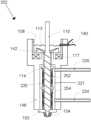
- FIG. 2shows a first embodiment of the print head 102 comprising a reservoir 113 , a nozzle 103 , a screw conveyor 115 and a travel path around the screw conveyor 115 extending between the exit 119 and the nozzle 103 .
- chocolate molted in the reservoir 113is supplied to the nozzle 103 .
- the nozzle 103comprises a nozzle heating 134 to heat the chocolate to the desired temperature before depositing the chocolate on a platform.
- the screw conveyor 115the residence time of the flowable chocolate in the travel path can be controlled.
- the reservoir 113is a bath 108 for melting the solid chocolate supplied by supply line (not shown in FIG. 2 ).
- the bath 108is an open top reservoir such that solid chocolate can be easily supplied from above.
- the bath 108further comprises a closed side wall and a bottom with an exit 119 .
- chocolatecan only be discharged from the bath 108 through the exit 119 .
- the exit 119is the inlet of travel path towards the nozzle 103 .
- the volume of the reservoir 113 /bath 108 to prepare flowable chocolateis approximately 0.1-0.2 dm 3 .
- the chocolate 116 inside the bath 108is heated by means of a heating unit 117 comprising a heating coil to prepare a flowable chocolate 7 .
- the reservoir 113further comprises at least one mixer 112 which is configured to agitate and/or apply shear to the chocolate for bringing the chocolate in liquid state.
- the reservoir 113comprises at least one sensor 140 for detecting the amount of chocolate in the reservoir 113 , such that it is possible to supply more or less solid chocolate to the bath 108 depending on the amount of chocolate in the bath 108 and the desired amount of chocolate in the bath 108 .
- the supply of solid chocolatecan be automatically controlled by means of the sensor 140 .
- the single sensor 140may detect a temperature difference when the sensor 140 is in contact with the air or the chocolate which provides an indication of the chocolate volume inside the bath 108 .
- the temperature controller 120 of the print head 102comprises a heat exchanger 121 , which is positioned along the conveyor screw 115 to control the temperature of the chocolate flowing through reservoir exit 119 into the travel path.
- the heat exchanger 121comprises a supply 124 of coolant (cool liquid) and a discharge line 126 for circulating liquid through the heat exchanger to temper the chocolate conveyed by the conveyor 115 in the travel path.
- the heat exchanger 121also comprises a wall 114 surrounding the screw conveyor 115 .
- the wall 114may be made of a heat conducting material for example a metal.
- the bath 108 of the reservoir 113is surrounded by a part of the housing 146 of the print head, preferably the upper part 142 of the housing 146 of the print head.
- the housing 146is made of a thermally isolating material to provide a print head 102 that can be operated in an energy efficient manner.
- the center of the conveyor 115coincides with the center of the exit 119 and the center of the nozzle 103 coincides with the center of the exit 119 .
- the upper part of the screw conveyor 115extends through the exit 119 into the reservoir 113 .
- the chocolateis first heated in the bath 108 by means of the heating unit 117 to approximately 45° C. to melt all six forms of crystals of the chocolate.
- the chocolateflows throught the exit 119 of the bath 108 into the travel path such that the chocolate is cooled to about 27° C. which will allow crystal types IV and V to form.
- the chocolateis conveyed and agitated by means of the conveyor 115 to create small crystals in the chocolate.
- the chocolateis then heated to about 31° C. by means of the nozzle heating 134 of the nozzle 103 to eliminate any type IV crystals, leaving just type V.
- the chocolateis in a perfect condition to be printed for providing a chocolate confection with no or minimal blooming.
- Other methods of chocolate temperingmay also be used. In or close to the nozzle 103 the temper of chocolate can be measured with a chocolate temper meter (not shown) to ensure accuracy and consistency.
- FIG. 3illustrates a further embodiment of the print head 202 which substantially has the same components as the first embodiment of the print head 102 as shown in FIG. 2 . Therefore, identical parts have been provided with the same reference signs and will not be explained in any more detail here. However, the print head 202 differs from the print head 102 in that the print head 202 has a different temperature controller 220 .
- the temperature controller 220comprises a heat exchanger 221 and two heating coils 252 , 254 which are spaced apart in the longitudinal direction of the travel path.
- the chocolate conveyed by the conveyor 115 between the exit 119 and the nozzle 10can be conditioned by means of the heat exchanger 221 and/or the temperature controller 220 arranged adjacent travel path.
- the heating coils 252 , 254provide sections, i.e. an upper section and a lower section.
- the temperature in the upper section around the heating coil 252can be controlled independently with respect to the temperature in a lower section around the heating coil 254 such that it is possible to provide different temperature zones in the travel path to further optimize the temper process of the chocolate.
- the heat exchanger 221comprises a supply 224 of coolant (cool liquid) and a discharge line 226 for circulating liquid through the heat exchanger.
- FIG. 4shows an alternative sensor arrangement of the reservoir 113 .
- This sensor arrangementcomprises two sensors 140 a , 140 b which are arranged at different heights with respect to the bottom of the bath 108 , i.e. sensor 140 a is arranged higher than sensor 140 b . If the chocolate level in the bath is higher than sensors 140 a , 140 b , sensors 140 a , 140 b provide a positive signal to a processor (not shown) of the system that no more solid chocolate should be supplied to the reservoir 113 . If the chocolate level is between the two sensors 140 a , 140 b as shown in FIG. 4 , than the sensor 140 a sends a negative signal to the processor and the sensor 140 b sends a positive signal.
- the processormay now continue the supply of solid chocolate to maintain the chocolate level constant or if the printing process is finished may stop the supply of chocolate. If the chocolate level in the bath is lower than sensors 140 a , 140 b , sensors 140 a , 140 b provide a negative signal to a processor (not shown) of the system that more solid chocolate should be supplied to the reservoir 113 unless the printing process has finished.
- the figuresshow a print head and a system for preparing a chocolate confection.
- the print head and the system for preparing a food productsuch as a confection, for example a caramel confection.
Landscapes
- Chemical & Material Sciences (AREA)
- Engineering & Computer Science (AREA)
- Materials Engineering (AREA)
- Life Sciences & Earth Sciences (AREA)
- Food Science & Technology (AREA)
- Polymers & Plastics (AREA)
- Manufacturing & Machinery (AREA)
- Physics & Mathematics (AREA)
- Mechanical Engineering (AREA)
- Optics & Photonics (AREA)
- Confectionery (AREA)
Abstract
Description
Claims (14)
Applications Claiming Priority (3)
| Application Number | Priority Date | Filing Date | Title |
|---|---|---|---|
| NL2018501 | 2017-03-13 | ||
| NL2018501ANL2018501B1 (en) | 2017-03-13 | 2017-03-13 | Print head for printing a food product layer-by-layer and a system comprising a print head |
| PCT/NL2018/050149WO2018169389A1 (en) | 2017-03-13 | 2018-03-12 | Print head for printing a food product layer-by-layer and a system comprising a print head |
Publications (2)
| Publication Number | Publication Date |
|---|---|
| US20200045990A1 US20200045990A1 (en) | 2020-02-13 |
| US12137702B2true US12137702B2 (en) | 2024-11-12 |
Family
ID=59381648
Family Applications (1)
| Application Number | Title | Priority Date | Filing Date |
|---|---|---|---|
| US16/488,747Active2040-07-05US12137702B2 (en) | 2017-03-13 | 2018-03-12 | Print head for printing a food product layer-by-layer and a system comprising a print head |
Country Status (4)
| Country | Link |
|---|---|
| US (1) | US12137702B2 (en) |
| EP (1) | EP3576551B1 (en) |
| NL (1) | NL2018501B1 (en) |
| WO (1) | WO2018169389A1 (en) |
Families Citing this family (5)
| Publication number | Priority date | Publication date | Assignee | Title |
|---|---|---|---|---|
| AU2021358025A1 (en)* | 2020-10-05 | 2023-03-30 | Frito-Lay North America, Inc. | Commercial scale 3D food printing |
| EP4136987A1 (en)* | 2021-08-18 | 2023-02-22 | Revo Foods GmbH | 3d print head with screw extruder |
| JP7725941B2 (en)* | 2021-08-27 | 2025-08-20 | セイコーエプソン株式会社 | 3D printing equipment |
| IT202200013690A1 (en)* | 2022-06-28 | 2023-12-28 | Dieng S R L A Socio Unico | FOOD PRINTER |
| CN118141000B (en)* | 2024-05-13 | 2024-07-26 | 福建农林大学 | A chocolate 3D printing method with added functional ingredients |
Citations (20)
| Publication number | Priority date | Publication date | Assignee | Title |
|---|---|---|---|---|
| US4460398A (en)* | 1980-08-05 | 1984-07-17 | Doryokuro Kakunenryo Kaihatsu Jigyodan | Freeze valve having multiple heating-cooling means |
| US4886440A (en)* | 1985-08-28 | 1989-12-12 | Alexander Forrest | Apparatus for producing a restructured food product |
| US20030129921A1 (en) | 2002-01-09 | 2003-07-10 | Shoot The Moon Ii, Llc | Methods and apparatus for chocolate dispensers |
| US20060214335A1 (en)* | 2005-03-09 | 2006-09-28 | 3D Systems, Inc. | Laser sintering powder recycle system |
| US20080213419A1 (en)* | 2007-02-12 | 2008-09-04 | Stratasys, Inc. | Viscosity pump for extrusion-based deposition systems |
| US20110223293A1 (en)* | 2008-06-25 | 2011-09-15 | L'air Liquide Societe Anonyme Pour L'etude Et L'ex | Method for Shaping a Food Product by Cryoextrusion Employing Predictive Temperature Regulation |
| US20120018924A1 (en)* | 2010-07-22 | 2012-01-26 | Stratasys, Inc. | Multiple-zone liquefier assembly for extrusion-based additive manufacturing systems |
| US20120251688A1 (en) | 2011-03-30 | 2012-10-04 | Stratasys, Inc. | Additive manufacturing system and method for printing customized chocolate confections |
| US20120251689A1 (en)* | 2011-03-30 | 2012-10-04 | Stratasys, Inc. | Additive manufacturing system and method with interchangeable cartridges for printing customized chocolate confections |
| WO2014190168A1 (en) | 2013-05-24 | 2014-11-27 | Natural Machines Llc | Manufacturing food using 3d printing technology |
| WO2014190217A1 (en) | 2013-05-22 | 2014-11-27 | Systems And Materials Research Corporation | Additive Manufacturing for Producing Edible Compositions |
| US20150097053A1 (en)* | 2013-10-04 | 2015-04-09 | Stratasys, Inc. | Liquefier assembly with multiple-zone plate heater assembly |
| CN104642684A (en)* | 2013-11-25 | 2015-05-27 | 上海富奇凡机电科技有限公司 | Three-dimensional food printer |
| CN104824302A (en) | 2014-02-08 | 2015-08-12 | 郑州乐彩科技股份有限公司 | 3D printer for chocolate |
| US20150245632A1 (en) | 2014-02-28 | 2015-09-03 | Xerox Corporation | Printed chocolate structures |
| CN105167131A (en)* | 2015-09-15 | 2015-12-23 | 西安源广智能机电设备有限公司 | Printing head of food printer |
| US20160324206A1 (en)* | 2015-05-08 | 2016-11-10 | Massachusetts Institute Of Technology | Fused Deposition Model Cold Slurry Printer |
| CN206119034U (en)* | 2016-08-08 | 2017-04-26 | 南京增材制造研究院发展有限公司 | Take feedway of temperature control function's chocolate 3D printer of detachable |
| CN106626352A (en)* | 2016-10-31 | 2017-05-10 | 宁夏共享模具有限公司 | Cooling device for printing head of 3D printing apparatus |
| US20170295816A1 (en)* | 2016-04-14 | 2017-10-19 | Shanghai Fochif Electromechanical Technology Co., Ltd. | 3d food printer |
- 2017
- 2017-03-13NLNL2018501Apatent/NL2018501B1/ennot_activeIP Right Cessation
- 2018
- 2018-03-12EPEP18710576.2Apatent/EP3576551B1/enactiveActive
- 2018-03-12USUS16/488,747patent/US12137702B2/enactiveActive
- 2018-03-12WOPCT/NL2018/050149patent/WO2018169389A1/ennot_activeCeased
Patent Citations (20)
| Publication number | Priority date | Publication date | Assignee | Title |
|---|---|---|---|---|
| US4460398A (en)* | 1980-08-05 | 1984-07-17 | Doryokuro Kakunenryo Kaihatsu Jigyodan | Freeze valve having multiple heating-cooling means |
| US4886440A (en)* | 1985-08-28 | 1989-12-12 | Alexander Forrest | Apparatus for producing a restructured food product |
| US20030129921A1 (en) | 2002-01-09 | 2003-07-10 | Shoot The Moon Ii, Llc | Methods and apparatus for chocolate dispensers |
| US20060214335A1 (en)* | 2005-03-09 | 2006-09-28 | 3D Systems, Inc. | Laser sintering powder recycle system |
| US20080213419A1 (en)* | 2007-02-12 | 2008-09-04 | Stratasys, Inc. | Viscosity pump for extrusion-based deposition systems |
| US20110223293A1 (en)* | 2008-06-25 | 2011-09-15 | L'air Liquide Societe Anonyme Pour L'etude Et L'ex | Method for Shaping a Food Product by Cryoextrusion Employing Predictive Temperature Regulation |
| US20120018924A1 (en)* | 2010-07-22 | 2012-01-26 | Stratasys, Inc. | Multiple-zone liquefier assembly for extrusion-based additive manufacturing systems |
| US20120251688A1 (en) | 2011-03-30 | 2012-10-04 | Stratasys, Inc. | Additive manufacturing system and method for printing customized chocolate confections |
| US20120251689A1 (en)* | 2011-03-30 | 2012-10-04 | Stratasys, Inc. | Additive manufacturing system and method with interchangeable cartridges for printing customized chocolate confections |
| WO2014190217A1 (en) | 2013-05-22 | 2014-11-27 | Systems And Materials Research Corporation | Additive Manufacturing for Producing Edible Compositions |
| WO2014190168A1 (en) | 2013-05-24 | 2014-11-27 | Natural Machines Llc | Manufacturing food using 3d printing technology |
| US20150097053A1 (en)* | 2013-10-04 | 2015-04-09 | Stratasys, Inc. | Liquefier assembly with multiple-zone plate heater assembly |
| CN104642684A (en)* | 2013-11-25 | 2015-05-27 | 上海富奇凡机电科技有限公司 | Three-dimensional food printer |
| CN104824302A (en) | 2014-02-08 | 2015-08-12 | 郑州乐彩科技股份有限公司 | 3D printer for chocolate |
| US20150245632A1 (en) | 2014-02-28 | 2015-09-03 | Xerox Corporation | Printed chocolate structures |
| US20160324206A1 (en)* | 2015-05-08 | 2016-11-10 | Massachusetts Institute Of Technology | Fused Deposition Model Cold Slurry Printer |
| CN105167131A (en)* | 2015-09-15 | 2015-12-23 | 西安源广智能机电设备有限公司 | Printing head of food printer |
| US20170295816A1 (en)* | 2016-04-14 | 2017-10-19 | Shanghai Fochif Electromechanical Technology Co., Ltd. | 3d food printer |
| CN206119034U (en)* | 2016-08-08 | 2017-04-26 | 南京增材制造研究院发展有限公司 | Take feedway of temperature control function's chocolate 3D printer of detachable |
| CN106626352A (en)* | 2016-10-31 | 2017-05-10 | 宁夏共享模具有限公司 | Cooling device for printing head of 3D printing apparatus |
Non-Patent Citations (5)
| Title |
|---|
| English translation of CN-104642684-A by EPO (OA Appendix). (Year: 2015).* |
| English translation of CN-105167131-A by EPO (OA Appendix). (Year: 2015).* |
| English translation of CN-106626352-A by EPO. (Year: 2017).* |
| English translation of CN-206119034-U by EPO (OA Appendix). (Year: 2017).* |
| International Search Report for International Application No. PCT/NL2018/050149 mailed on May 18, 2018. |
Also Published As
| Publication number | Publication date |
|---|---|
| EP3576551B1 (en) | 2020-12-09 |
| EP3576551A1 (en) | 2019-12-11 |
| NL2018501B1 (en) | 2018-09-21 |
| US20200045990A1 (en) | 2020-02-13 |
| NL2018501A (en) | 2018-09-17 |
| WO2018169389A1 (en) | 2018-09-20 |
Similar Documents
| Publication | Publication Date | Title |
|---|---|---|
| US12137702B2 (en) | Print head for printing a food product layer-by-layer and a system comprising a print head | |
| US9215882B2 (en) | Additive manufacturing system and method for printing customized chocolate confections | |
| CN107788200B (en) | Machines for making liquid or semi-liquid products | |
| CN102458253B (en) | Using thermal imaging for control of a manufacturing process | |
| CN104884227B (en) | Molding-system | |
| US8246891B2 (en) | System and method for manufacturing fatty acid based material products with an injection molding process | |
| CN112739462B (en) | Metering system with metering substance cooling device | |
| US20180345577A1 (en) | Three-dimensional modeling apparatus and modeling material discharging member | |
| US20160114297A1 (en) | Chilled beverage dispensing machine | |
| ES2929589T3 (en) | Molding machine and method for molding a part | |
| CN209832528U (en) | PLA film raw materials mixing extrusion system | |
| US4578021A (en) | Apparatus for the production of granules from two-phase mixtures | |
| CN113043556A (en) | Injection molding machine and control method for injection molding machine | |
| CN101313691A (en) | Temperature regulation of the mass flow in a filling machine | |
| US20170215453A1 (en) | Tempered chocolate printing system, kit and related method | |
| ES2740174T3 (en) | Mixing device and method for mixing reactive plastic components | |
| TW201544012A (en) | Apparatus, system and method for manufacturing a mass blended with granular material | |
| KR101692978B1 (en) | 3d printer that implements the fragrance material | |
| CN105661607B (en) | A kind of food 3D printing device of distal end feed | |
| KR20150054621A (en) | Apparatus for manufacturing shape using food material | |
| JP2017001338A (en) | Liquid colorant corresponding melting discharge device and liquid colorant injection device, and method for controlling liquid colorant corresponding melting discharge device | |
| RU215277U1 (en) | EXTRUDER FOR 3D PRINTING WITH COMPOUNDS BASED ON WAXES AND PARAFFINS | |
| JP2017225543A (en) | Production apparatus and production method for stick-shaped cosmetics | |
| CA1238265A (en) | Apparatus for the production of granules from two- phase mixtures | |
| CN120572703A (en) | Injection molding machine |
Legal Events
| Date | Code | Title | Description |
|---|---|---|---|
| AS | Assignment | Owner name:BYFLOW B.V., NETHERLANDS Free format text:ASSIGNMENT OF ASSIGNORS INTEREST;ASSIGNORS:HOFF, FLORIS PETRAN;DORSSERS, STEFAN CORNELIS GERARDUS;SIGNING DATES FROM 20190819 TO 20190823;REEL/FRAME:050166/0402 | |
| FEPP | Fee payment procedure | Free format text:ENTITY STATUS SET TO UNDISCOUNTED (ORIGINAL EVENT CODE: BIG.); ENTITY STATUS OF PATENT OWNER: SMALL ENTITY | |
| FEPP | Fee payment procedure | Free format text:ENTITY STATUS SET TO SMALL (ORIGINAL EVENT CODE: SMAL); ENTITY STATUS OF PATENT OWNER: SMALL ENTITY | |
| STPP | Information on status: patent application and granting procedure in general | Free format text:DOCKETED NEW CASE - READY FOR EXAMINATION | |
| STPP | Information on status: patent application and granting procedure in general | Free format text:NON FINAL ACTION MAILED | |
| STPP | Information on status: patent application and granting procedure in general | Free format text:RESPONSE TO NON-FINAL OFFICE ACTION ENTERED AND FORWARDED TO EXAMINER | |
| STPP | Information on status: patent application and granting procedure in general | Free format text:NON FINAL ACTION MAILED | |
| STPP | Information on status: patent application and granting procedure in general | Free format text:DOCKETED NEW CASE - READY FOR EXAMINATION | |
| STPP | Information on status: patent application and granting procedure in general | Free format text:NON FINAL ACTION MAILED | |
| STPP | Information on status: patent application and granting procedure in general | Free format text:RESPONSE TO NON-FINAL OFFICE ACTION ENTERED AND FORWARDED TO EXAMINER | |
| STPP | Information on status: patent application and granting procedure in general | Free format text:FINAL REJECTION MAILED | |
| STPP | Information on status: patent application and granting procedure in general | Free format text:RESPONSE AFTER FINAL ACTION FORWARDED TO EXAMINER | |
| STPP | Information on status: patent application and granting procedure in general | Free format text:ADVISORY ACTION MAILED | |
| STPP | Information on status: patent application and granting procedure in general | Free format text:DOCKETED NEW CASE - READY FOR EXAMINATION | |
| STPP | Information on status: patent application and granting procedure in general | Free format text:NON FINAL ACTION MAILED | |
| STPP | Information on status: patent application and granting procedure in general | Free format text:RESPONSE TO NON-FINAL OFFICE ACTION ENTERED AND FORWARDED TO EXAMINER | |
| STPP | Information on status: patent application and granting procedure in general | Free format text:NOTICE OF ALLOWANCE MAILED -- APPLICATION RECEIVED IN OFFICE OF PUBLICATIONS | |
| ZAAB | Notice of allowance mailed | Free format text:ORIGINAL CODE: MN/=. | |
| STPP | Information on status: patent application and granting procedure in general | Free format text:PUBLICATIONS -- ISSUE FEE PAYMENT VERIFIED | |
| STCF | Information on status: patent grant | Free format text:PATENTED CASE |