US12136549B2 - Plasma-enhanced chemical vapor deposition of carbon hard-mask - Google Patents
Plasma-enhanced chemical vapor deposition of carbon hard-maskDownload PDFInfo
- Publication number
- US12136549B2 US12136549B2US16/982,789US201916982789AUS12136549B2US 12136549 B2US12136549 B2US 12136549B2US 201916982789 AUS201916982789 AUS 201916982789AUS 12136549 B2US12136549 B2US 12136549B2
- Authority
- US
- United States
- Prior art keywords
- sccm
- process chamber
- carbon hard
- plasma
- mask layer
- Prior art date
- Legal status (The legal status is an assumption and is not a legal conclusion. Google has not performed a legal analysis and makes no representation as to the accuracy of the status listed.)
- Active, expires
Links
Images


Classifications
- C—CHEMISTRY; METALLURGY
- C23—COATING METALLIC MATERIAL; COATING MATERIAL WITH METALLIC MATERIAL; CHEMICAL SURFACE TREATMENT; DIFFUSION TREATMENT OF METALLIC MATERIAL; COATING BY VACUUM EVAPORATION, BY SPUTTERING, BY ION IMPLANTATION OR BY CHEMICAL VAPOUR DEPOSITION, IN GENERAL; INHIBITING CORROSION OF METALLIC MATERIAL OR INCRUSTATION IN GENERAL
- C23C—COATING METALLIC MATERIAL; COATING MATERIAL WITH METALLIC MATERIAL; SURFACE TREATMENT OF METALLIC MATERIAL BY DIFFUSION INTO THE SURFACE, BY CHEMICAL CONVERSION OR SUBSTITUTION; COATING BY VACUUM EVAPORATION, BY SPUTTERING, BY ION IMPLANTATION OR BY CHEMICAL VAPOUR DEPOSITION, IN GENERAL
- C23C16/00—Chemical coating by decomposition of gaseous compounds, without leaving reaction products of surface material in the coating, i.e. chemical vapour deposition [CVD] processes
- C23C16/44—Chemical coating by decomposition of gaseous compounds, without leaving reaction products of surface material in the coating, i.e. chemical vapour deposition [CVD] processes characterised by the method of coating
- C23C16/50—Chemical coating by decomposition of gaseous compounds, without leaving reaction products of surface material in the coating, i.e. chemical vapour deposition [CVD] processes characterised by the method of coating using electric discharges
- C—CHEMISTRY; METALLURGY
- C23—COATING METALLIC MATERIAL; COATING MATERIAL WITH METALLIC MATERIAL; CHEMICAL SURFACE TREATMENT; DIFFUSION TREATMENT OF METALLIC MATERIAL; COATING BY VACUUM EVAPORATION, BY SPUTTERING, BY ION IMPLANTATION OR BY CHEMICAL VAPOUR DEPOSITION, IN GENERAL; INHIBITING CORROSION OF METALLIC MATERIAL OR INCRUSTATION IN GENERAL
- C23C—COATING METALLIC MATERIAL; COATING MATERIAL WITH METALLIC MATERIAL; SURFACE TREATMENT OF METALLIC MATERIAL BY DIFFUSION INTO THE SURFACE, BY CHEMICAL CONVERSION OR SUBSTITUTION; COATING BY VACUUM EVAPORATION, BY SPUTTERING, BY ION IMPLANTATION OR BY CHEMICAL VAPOUR DEPOSITION, IN GENERAL
- C23C16/00—Chemical coating by decomposition of gaseous compounds, without leaving reaction products of surface material in the coating, i.e. chemical vapour deposition [CVD] processes
- C23C16/04—Coating on selected surface areas, e.g. using masks
- C23C16/042—Coating on selected surface areas, e.g. using masks using masks
- C—CHEMISTRY; METALLURGY
- C23—COATING METALLIC MATERIAL; COATING MATERIAL WITH METALLIC MATERIAL; CHEMICAL SURFACE TREATMENT; DIFFUSION TREATMENT OF METALLIC MATERIAL; COATING BY VACUUM EVAPORATION, BY SPUTTERING, BY ION IMPLANTATION OR BY CHEMICAL VAPOUR DEPOSITION, IN GENERAL; INHIBITING CORROSION OF METALLIC MATERIAL OR INCRUSTATION IN GENERAL
- C23C—COATING METALLIC MATERIAL; COATING MATERIAL WITH METALLIC MATERIAL; SURFACE TREATMENT OF METALLIC MATERIAL BY DIFFUSION INTO THE SURFACE, BY CHEMICAL CONVERSION OR SUBSTITUTION; COATING BY VACUUM EVAPORATION, BY SPUTTERING, BY ION IMPLANTATION OR BY CHEMICAL VAPOUR DEPOSITION, IN GENERAL
- C23C16/00—Chemical coating by decomposition of gaseous compounds, without leaving reaction products of surface material in the coating, i.e. chemical vapour deposition [CVD] processes
- C23C16/22—Chemical coating by decomposition of gaseous compounds, without leaving reaction products of surface material in the coating, i.e. chemical vapour deposition [CVD] processes characterised by the deposition of inorganic material, other than metallic material
- C23C16/26—Deposition of carbon only
- C—CHEMISTRY; METALLURGY
- C23—COATING METALLIC MATERIAL; COATING MATERIAL WITH METALLIC MATERIAL; CHEMICAL SURFACE TREATMENT; DIFFUSION TREATMENT OF METALLIC MATERIAL; COATING BY VACUUM EVAPORATION, BY SPUTTERING, BY ION IMPLANTATION OR BY CHEMICAL VAPOUR DEPOSITION, IN GENERAL; INHIBITING CORROSION OF METALLIC MATERIAL OR INCRUSTATION IN GENERAL
- C23C—COATING METALLIC MATERIAL; COATING MATERIAL WITH METALLIC MATERIAL; SURFACE TREATMENT OF METALLIC MATERIAL BY DIFFUSION INTO THE SURFACE, BY CHEMICAL CONVERSION OR SUBSTITUTION; COATING BY VACUUM EVAPORATION, BY SPUTTERING, BY ION IMPLANTATION OR BY CHEMICAL VAPOUR DEPOSITION, IN GENERAL
- C23C16/00—Chemical coating by decomposition of gaseous compounds, without leaving reaction products of surface material in the coating, i.e. chemical vapour deposition [CVD] processes
- C23C16/44—Chemical coating by decomposition of gaseous compounds, without leaving reaction products of surface material in the coating, i.e. chemical vapour deposition [CVD] processes characterised by the method of coating
- C23C16/46—Chemical coating by decomposition of gaseous compounds, without leaving reaction products of surface material in the coating, i.e. chemical vapour deposition [CVD] processes characterised by the method of coating characterised by the method used for heating the substrate
- C—CHEMISTRY; METALLURGY
- C23—COATING METALLIC MATERIAL; COATING MATERIAL WITH METALLIC MATERIAL; CHEMICAL SURFACE TREATMENT; DIFFUSION TREATMENT OF METALLIC MATERIAL; COATING BY VACUUM EVAPORATION, BY SPUTTERING, BY ION IMPLANTATION OR BY CHEMICAL VAPOUR DEPOSITION, IN GENERAL; INHIBITING CORROSION OF METALLIC MATERIAL OR INCRUSTATION IN GENERAL
- C23C—COATING METALLIC MATERIAL; COATING MATERIAL WITH METALLIC MATERIAL; SURFACE TREATMENT OF METALLIC MATERIAL BY DIFFUSION INTO THE SURFACE, BY CHEMICAL CONVERSION OR SUBSTITUTION; COATING BY VACUUM EVAPORATION, BY SPUTTERING, BY ION IMPLANTATION OR BY CHEMICAL VAPOUR DEPOSITION, IN GENERAL
- C23C16/00—Chemical coating by decomposition of gaseous compounds, without leaving reaction products of surface material in the coating, i.e. chemical vapour deposition [CVD] processes
- C23C16/44—Chemical coating by decomposition of gaseous compounds, without leaving reaction products of surface material in the coating, i.e. chemical vapour deposition [CVD] processes characterised by the method of coating
- C23C16/50—Chemical coating by decomposition of gaseous compounds, without leaving reaction products of surface material in the coating, i.e. chemical vapour deposition [CVD] processes characterised by the method of coating using electric discharges
- C23C16/505—Chemical coating by decomposition of gaseous compounds, without leaving reaction products of surface material in the coating, i.e. chemical vapour deposition [CVD] processes characterised by the method of coating using electric discharges using radio frequency discharges
- H—ELECTRICITY
- H01—ELECTRIC ELEMENTS
- H01L—SEMICONDUCTOR DEVICES NOT COVERED BY CLASS H10
- H01L21/00—Processes or apparatus adapted for the manufacture or treatment of semiconductor or solid state devices or of parts thereof
- H01L21/02—Manufacture or treatment of semiconductor devices or of parts thereof
- H01L21/02104—Forming layers
- H01L21/02107—Forming insulating materials on a substrate
- H01L21/02109—Forming insulating materials on a substrate characterised by the type of layer, e.g. type of material, porous/non-porous, pre-cursors, mixtures or laminates
- H01L21/02112—Forming insulating materials on a substrate characterised by the type of layer, e.g. type of material, porous/non-porous, pre-cursors, mixtures or laminates characterised by the material of the layer
- H01L21/02115—Forming insulating materials on a substrate characterised by the type of layer, e.g. type of material, porous/non-porous, pre-cursors, mixtures or laminates characterised by the material of the layer the material being carbon, e.g. alpha-C, diamond or hydrogen doped carbon
- H—ELECTRICITY
- H01—ELECTRIC ELEMENTS
- H01L—SEMICONDUCTOR DEVICES NOT COVERED BY CLASS H10
- H01L21/00—Processes or apparatus adapted for the manufacture or treatment of semiconductor or solid state devices or of parts thereof
- H01L21/02—Manufacture or treatment of semiconductor devices or of parts thereof
- H01L21/02104—Forming layers
- H01L21/02107—Forming insulating materials on a substrate
- H01L21/02109—Forming insulating materials on a substrate characterised by the type of layer, e.g. type of material, porous/non-porous, pre-cursors, mixtures or laminates
- H01L21/02205—Forming insulating materials on a substrate characterised by the type of layer, e.g. type of material, porous/non-porous, pre-cursors, mixtures or laminates the layer being characterised by the precursor material for deposition
- H—ELECTRICITY
- H01—ELECTRIC ELEMENTS
- H01L—SEMICONDUCTOR DEVICES NOT COVERED BY CLASS H10
- H01L21/00—Processes or apparatus adapted for the manufacture or treatment of semiconductor or solid state devices or of parts thereof
- H01L21/02—Manufacture or treatment of semiconductor devices or of parts thereof
- H01L21/02104—Forming layers
- H01L21/02107—Forming insulating materials on a substrate
- H01L21/02225—Forming insulating materials on a substrate characterised by the process for the formation of the insulating layer
- H01L21/0226—Forming insulating materials on a substrate characterised by the process for the formation of the insulating layer formation by a deposition process
- H01L21/02263—Forming insulating materials on a substrate characterised by the process for the formation of the insulating layer formation by a deposition process deposition from the gas or vapour phase
- H01L21/02271—Forming insulating materials on a substrate characterised by the process for the formation of the insulating layer formation by a deposition process deposition from the gas or vapour phase deposition by decomposition or reaction of gaseous or vapour phase compounds, i.e. chemical vapour deposition
- H01L21/02274—Forming insulating materials on a substrate characterised by the process for the formation of the insulating layer formation by a deposition process deposition from the gas or vapour phase deposition by decomposition or reaction of gaseous or vapour phase compounds, i.e. chemical vapour deposition in the presence of a plasma [PECVD]
- H—ELECTRICITY
- H01—ELECTRIC ELEMENTS
- H01L—SEMICONDUCTOR DEVICES NOT COVERED BY CLASS H10
- H01L21/00—Processes or apparatus adapted for the manufacture or treatment of semiconductor or solid state devices or of parts thereof
- H01L21/02—Manufacture or treatment of semiconductor devices or of parts thereof
- H01L21/027—Making masks on semiconductor bodies for further photolithographic processing not provided for in group H01L21/18 or H01L21/34
- H01L21/033—Making masks on semiconductor bodies for further photolithographic processing not provided for in group H01L21/18 or H01L21/34 comprising inorganic layers
- H01L21/0332—Making masks on semiconductor bodies for further photolithographic processing not provided for in group H01L21/18 or H01L21/34 comprising inorganic layers characterised by their composition, e.g. multilayer masks, materials
- H—ELECTRICITY
- H01—ELECTRIC ELEMENTS
- H01L—SEMICONDUCTOR DEVICES NOT COVERED BY CLASS H10
- H01L21/00—Processes or apparatus adapted for the manufacture or treatment of semiconductor or solid state devices or of parts thereof
- H01L21/02—Manufacture or treatment of semiconductor devices or of parts thereof
- H01L21/027—Making masks on semiconductor bodies for further photolithographic processing not provided for in group H01L21/18 or H01L21/34
- H01L21/033—Making masks on semiconductor bodies for further photolithographic processing not provided for in group H01L21/18 or H01L21/34 comprising inorganic layers
- H01L21/0334—Making masks on semiconductor bodies for further photolithographic processing not provided for in group H01L21/18 or H01L21/34 comprising inorganic layers characterised by their size, orientation, disposition, behaviour, shape, in horizontal or vertical plane
- H01L21/0337—Making masks on semiconductor bodies for further photolithographic processing not provided for in group H01L21/18 or H01L21/34 comprising inorganic layers characterised by their size, orientation, disposition, behaviour, shape, in horizontal or vertical plane characterised by the process involved to create the mask, e.g. lift-off masks, sidewalls, or to modify the mask, e.g. pre-treatment, post-treatment
- H—ELECTRICITY
- H01—ELECTRIC ELEMENTS
- H01L—SEMICONDUCTOR DEVICES NOT COVERED BY CLASS H10
- H01L21/00—Processes or apparatus adapted for the manufacture or treatment of semiconductor or solid state devices or of parts thereof
- H01L21/02—Manufacture or treatment of semiconductor devices or of parts thereof
- H01L21/04—Manufacture or treatment of semiconductor devices or of parts thereof the devices having potential barriers, e.g. a PN junction, depletion layer or carrier concentration layer
- H01L21/18—Manufacture or treatment of semiconductor devices or of parts thereof the devices having potential barriers, e.g. a PN junction, depletion layer or carrier concentration layer the devices having semiconductor bodies comprising elements of Group IV of the Periodic Table or AIIIBV compounds with or without impurities, e.g. doping materials
- H01L21/30—Treatment of semiconductor bodies using processes or apparatus not provided for in groups H01L21/20 - H01L21/26
- H01L21/31—Treatment of semiconductor bodies using processes or apparatus not provided for in groups H01L21/20 - H01L21/26 to form insulating layers thereon, e.g. for masking or by using photolithographic techniques; After treatment of these layers; Selection of materials for these layers
- H01L21/3105—After-treatment
- H01L21/311—Etching the insulating layers by chemical or physical means
- H—ELECTRICITY
- H01—ELECTRIC ELEMENTS
- H01L—SEMICONDUCTOR DEVICES NOT COVERED BY CLASS H10
- H01L21/00—Processes or apparatus adapted for the manufacture or treatment of semiconductor or solid state devices or of parts thereof
- H01L21/02—Manufacture or treatment of semiconductor devices or of parts thereof
- H01L21/04—Manufacture or treatment of semiconductor devices or of parts thereof the devices having potential barriers, e.g. a PN junction, depletion layer or carrier concentration layer
- H01L21/18—Manufacture or treatment of semiconductor devices or of parts thereof the devices having potential barriers, e.g. a PN junction, depletion layer or carrier concentration layer the devices having semiconductor bodies comprising elements of Group IV of the Periodic Table or AIIIBV compounds with or without impurities, e.g. doping materials
- H01L21/30—Treatment of semiconductor bodies using processes or apparatus not provided for in groups H01L21/20 - H01L21/26
- H01L21/324—Thermal treatment for modifying the properties of semiconductor bodies, e.g. annealing, sintering
Definitions
- Carbon chemical vapor deposition (CVD) processesare increasingly prevalent for hard-mask application for semiconductor device fabrication.
- semiconductor devicesstart to require higher memory density and thicker multi-stack structure (e.g., 3D V-NAND, 3D ReRAM)
- capability of developing a carbon hard-mask film which can withstand the long etch timeis becoming a necessity.
- the disadvantageis the significant throughput reduction due to longer process time for 1) thicker film, and/or 2) slower deposition rate.
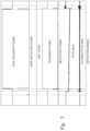
- FIG. 1depicts a schematic of a plasma-enhanced chemical vapor deposition system that can be used to deposit carbon hard-mask layers and other materials, as discussed and described in one or more embodiments herein;
- FIGS. 2 and 3are graphs that depict the delivered RF power, reflected RF power, and arc count data from the RF generator and faceplate bias data while depositing a carbon hard-mask during PECVD processes, as discussed and described in one or more embodiments herein.
- a method for depositing a carbon hard-mask material by plasma-enhanced chemical vapor depositionincludes heating a substrate contained within a process chamber to a temperature in a range from about 100° C. to about 700° C. and producing a plasma with a power generator emitting an RF power of greater than 3 kW.
- the temperatureis in a range from about 300° C. to about 700° C. and the RF power is greater than 3 kW to about 7 kW.
- the methodalso includes flowing a hydrocarbon precursor into the plasma within the process chamber and forming a carbon hard-mask layer on the substrate at a rate of greater than 5,000 ⁇ /min, such as up to about 10,000 ⁇ /min or faster.
- a method for depositing a carbon hard-mask material by PECVDincludes heating a substrate contained within a process chamber to a temperature in a range from about 100° C. to about 700° C. and producing a plasma with a power generator emitting an RF power of greater than 3 kW.
- the methodalso includes flowing a hydrocarbon precursor and a dopant precursor into the plasma within the process chamber and forming a carbon hard-mask layer on the substrate at a rate of greater than 5,000 ⁇ /min to about 10,000 ⁇ /min.
- the dopant precursorcan be or include, but is not limited to, one or more nitrogen-containing precursors, one or more sulfur-containing precursors, one or more boron-containing precursors, or any combination thereof.
- Embodiments discussed and described hereinprovide methods and systems for depositing carbon materials, such carbon hard-mask layers, on a surface of a substrate.
- a method for depositing a carbon hard-mask material by plasma-enhanced chemical vapor deposition (PECVD)is provided and discussed below.
- PECVDplasma-enhanced chemical vapor deposition
- One or more substratescan be positioned or otherwise disposed in a process chamber and heated to a predetermined process temperature.
- One or more carrier gas and/or one or more reactive species gasesare ignited by a power generator emitting an RF power to form the plasma.
- One or more hydrocarbon precursors, and optionally, one or more dopant precursorscan be flowed through or otherwise exposed to the plasma during the deposition process within the process chamber. Once activated by the plasma, the hydrocarbon precursor is reacted, decomposed, or chemically reduced to produce a carbon hard-mask layer, which is deposited or otherwise formed on the substrate.
- one or more dopant precursorscan be flowed or otherwise introduced into the process chamber, exposed to the plasma, and reacted, decomposed, or chemically reduced to produce a doped, carbon hard-mask layer.
- the carbon hard-mask layercan be deposited or otherwise formed on any type of substrate, such as a silicon wafer.
- the substratecan include one or more devices disposed thereon.
- the carbon hard-mask layeris deposited or otherwise formed on one or more devices having a 32-bit architecture (32 ⁇ ON), a 64-bit architecture (64 ⁇ ON), a 96-bit architecture (96 ⁇ ON), or a 128-bit architecture (128 ⁇ ON).
- the plasmais ignited or otherwise generated from the power generator emitting an RF power of about 2.4 kW or greater.
- the RF powercan be about 2.4 kW, about 2.5 kW, about 2.8 kW, about 3 kW, about 3.5 kW, about 4 kW, about 4.5 kW, about 5 kW, or about 5.5 kW to about 6 kW, about 6.5 kW, about 7 kW, about 8 kW, about 9 kW, about 10 kW, about 12 kW, about 15 kW, or greater.
- the RF powercan be about 2.4 kW to about 15 kW, about 2.4 kW to about 12 kW, about 2.4 kW to about 10 kW, about 2.4 kW to about 7 kW, about 2.4 kW to about 5 kW, about 3 kW to about 15 kW, about 3 kW to about 12 kW, about 3 kW to about 10 kW, about 3 kW to about 7 kW, about 3 kW to about 5 kW, about 3.5 kW to about 12 kW, about 3.5 kW to about 10 kW, about 3.5 kW to about 7 kW, about 3.5 kW to about 5 kW, about 3.5 kW to about 4 kW, about 4 kW to about 12 kW, about 4 kW to about 10 kW, about 4 kW to about 7 kW, about 4 kW to about 5 kW, about 5 kW to about 12 kW, about 4 kW to about 10 kW, about 4 kW to about 7 kW, about 4 kW to about 5 kW, about 5 kW to about 12
- the plasmais ignited or otherwise generated from the power generator emitting an RF power of greater than 3 kW.
- the RF powercan be greater than 3 kW, such as about 3.5 kW, about 4 kW, about 4.5 kW, about 5 kW, or about 5.5 kW to about 6 kW, about 6.5 kW, about 7 kW, about 8 kW, about 9 kW, about 10 kW, about 12 kW, about 15 kW, or greater.
- the RF powercan be greater than 3 kW to about 15 kW, greater than 3 kW to about 12 kW, greater than 3 kW to about 10 kW, greater than 3 kW to about 8 kW, greater than 3 kW to about 7 kW, greater than 3 kW to about 5 kW, about 3.5 kW to about 12 kW, about 3.5 kW to about 10 kW, about 3.5 kW to about 7 kW, about 3.5 kW to about 5 kW, about 4 kW to about 12 kW, about 4 kW to about 10 kW, about 4 kW to about 7 kW, about 4 kW to about 5 kW, about 4 kW to about 4.5 kW, about 5 kW to about 12 kW, about 5 kW to about 10 kW, or about 5 kW to about 7 kW.
- the carbon hard-mask layeris deposited or formed at a rate of greater than 5,000 ⁇ /min, such as at a rate of about 5,500 ⁇ /min, about 6,000 ⁇ /min, about 6,500 ⁇ /min, about 7,000 ⁇ /min, or about 7,500 ⁇ /min to about 8,000 ⁇ /min, about 8,500 ⁇ /min, about 9,000 ⁇ /min, about 9,500 ⁇ /min, about 10,000 ⁇ /min, about 12,000 ⁇ /min, about 15,000 ⁇ /min, about 18,000 ⁇ /min, about 20,000 ⁇ /min, or greater.
- the carbon hard-mask layeris deposited or formed at a rate of greater than 5,000 ⁇ /min to about 20,000 ⁇ /min, greater than 5,000 ⁇ /min to about 15,000 ⁇ /min, greater than 5,000 ⁇ /min to about 10,000 ⁇ /min, greater than 5,000 ⁇ /min to about 8,000 ⁇ /min, greater than 5,000 ⁇ /min to about 7,000 ⁇ /min, about 5,500 ⁇ /min to about 15,000 ⁇ /min, about 5,500 ⁇ /min to about 10,000 ⁇ /min, about 5,500 ⁇ /min to about 8,000 ⁇ /min, about 5,500 ⁇ /min to about 7,000 ⁇ /min, about 7,000 ⁇ /min to about 15,000 ⁇ /min, about 7,000 ⁇ /min to about 10,000 ⁇ /min, about 7,000 ⁇ /min to about 9,000 ⁇ /min, or about 7,000 ⁇ /min to about 8,000 ⁇ /min.
- the carbon hard-mask layeris formed to a thickness of greater than 2 ⁇ m, greater than 2.2 ⁇ m, greater than 2.5 ⁇ m, or greater than 2.7 ⁇ m, such as about 2.8 ⁇ m, about 3 ⁇ m, about 3.5 ⁇ m, about 4 ⁇ m, or about 5 ⁇ m to about 5.5 ⁇ m, about 6 ⁇ m, about 7 ⁇ m, about 8 ⁇ m, about 9 ⁇ m, about 10 ⁇ m, about 12 ⁇ m, about 15 ⁇ m, about 18 ⁇ m, about 20 ⁇ m, about 25 ⁇ m, or thicker.
- the carbon hard-mask layeris formed to a thickness of greater than 2 ⁇ m to about 20 ⁇ m, greater than 2 ⁇ m to about 15 ⁇ m, greater than 2 ⁇ m to about 10 ⁇ m, greater than 2 ⁇ m to about 7 ⁇ m, greater than 2.5 ⁇ m to about 20 ⁇ m, greater than 2.5 ⁇ m to about 15 ⁇ m, greater than 2.5 ⁇ m to about 10 ⁇ m, greater than 2.5 ⁇ m to about 7 ⁇ m, greater than 3 ⁇ m to about 20 ⁇ m, greater than 3 ⁇ m to about 15 ⁇ m, greater than 3 ⁇ m to about 10 ⁇ m, or greater than 3 ⁇ m to about 7 ⁇ m.
- the process temperature of the substratecan be about 100° C., about 150° C., about 200° C., about 250° C., or about 300° C. to about 350° C., about 400° C., about 450° C., about 500° C., about 550° C., about 600° C., about 650° C., about 700° C., or greater.
- the process temperature of the substratecan be about 100° C. to about 700° C., about 100° C. to about 650° C., about 100° C. to about 600° C., about 100° C. to about 500° C., about 100° C. to about 400° C., about 300° C. to about 700° C., about 300° C.
- the pressure in the process chambercan be about 1 Torr, about 2 Torr, about 3 Torr, about 4 Torr, or about 5 Torr to about 6 Torr, about 8 Torr, about 10 Torr, about 15 Torr, about 20 Torr, about 30 Torr, about 50 Torr, or greater.
- the pressure in the process chambercan be about 1 Torr to about 30 Torr, about 1 Torr to about 20 Torr, about 1 Torr to about 15 Torr, about 1 Torr to about 10 Torr, about 1 Torr to about 8 Torr, about 1 Torr to about 5 Torr, about 3 Torr to about 30 Torr, about 3 Torr to about 20 Torr, about 3 Torr to about 15 Torr, about 3 Torr to about 10 Torr, about 3 Torr to about 8 Torr, about 3 Torr to about 5 Torr, about 5 Torr to about 30 Torr, about 5 Torr, to about 20 Torr, about 5 Torr to about 15 Torr, about 5 Torr to about 10 Torr, or about 5 Torr to about 8 Torr.
- one or more carrier gas and/or one or more reactive species gasesare flowed or passed into and through the plasma.
- the carrier gas and/or the reactive species gascan be or include, but is not limited to, hydrogen, oxygen, argon, neon, helium, krypton, tetrafluoromethane, nitrogen, radicals thereof, or any combination thereof.
- the flow rate of the carrier gas and/or the reactive species gascan be from about 100 sccm, about 500 sccm, about 1,000 sccm, about 2,000 sccm, about 3,000 sccm, or about 4,000 sccm to about 5,000 sccm, about 6,000 sccm, about 8,000 sccm, about 10,000 sccm, about 12,000 sccm, about 15,000 sccm, about 18,000 sccm, about 20,000 sccm, about 22,000 sccm, about 25,000 sccm, or greater.
- the flow rate of the carrier gas and/or the reactive species gascan be from about 100 sccm to about 25,000 sccm, about 1,000 sccm to about 23,000 sccm, about 1,000 sccm to about 20,000 sccm, about 1,000 sccm to about 15,000 sccm, about 1,000 sccm to about 10,000 sccm, about 1,000 sccm to about 5,000 sccm, about 2,000 sccm to about 20,000 sccm, about 2,000 sccm to about 15,000 sccm, about 2,000 sccm to about 10,000 sccm, about 2,000 sccm to about 5,000 sccm, about 3,000 sccm to about 20,000 sccm, about 3,000 sccm to about 15,000 sccm, about 3,000 sccm to about 10,000 sccm, about 3,000 sccm to about 20,000
- the hydrocarbon precursorcan be or include, but is not limited to, one or more C 1 -C 3 alkyls, one or more C 2 -C 3 alkenes, one or more C 2 -C 3 alkynes, one or more C 1 -C 8 alcohols, one or more C 1 -C 8 ethers, or any combination thereof.
- the hydrocarbon precursorcan be or include, but is not limited to, propylene, acetylene, ethylene, methane, propane, hexane, benzene, isoprene, butadiene, isomers thereof, or any combination thereof.
- the flow rate of the hydrocarbon precursorcan be from about 100 sccm, about 200 sccm, about 300 sccm, about 500 sccm, about 800 sccm, or about 1,000 sccm to about 1,500 sccm, about 2,000 sccm, about 3,000 sccm, about 4,000 sccm, about 5,000 sccm, or greater.
- the flow rate of the hydrocarbon precursorcan be from about 100 sccm to about 5,000 sccm, about 100 sccm to about 4,000 sccm, about 100 sccm to about 3,000 sccm, about 100 sccm to about 2,000 sccm, about 100 sccm to about 1,000 sccm, about 100 sccm to about 500 sccm, about 200 sccm to about 5,000 sccm, about 200 sccm to about 4,000 sccm, about 200 sccm to about 3,000 sccm, about 200 sccm to about 2,000 sccm, about 200 sccm to about 1,000 sccm, about 200 sccm to about 500 sccm, about 500 sccm to about 5,000 sccm, about 500 sccm to about 5,000 sccm, about 500 sccm to about
- a dopant precursoris used to produce a doped, carbon hard-mask material or layer
- the dopant precursorcan be or include, but is not limited to, one or more of nitrogen-containing precursors, sulfur-containing precursors, boron-containing precursors, or any combination thereof.
- the nitrogen-containing precursorcan be or include, but is not limited to, pyrrole, pyridine, one or more aliphatic amines, one or more aromatic amines, one or more nitriles, salts thereof, or any combination thereof.
- the sulfur-containing precursorcan be or include, but is not limited to, thiophene, carbon disulfide, one or more thiols, salts thereof, or any combination thereof.
- the boron-containing precursorcan be or include, but is not limited to, one or more of diborane, triborane, a trialkyl borane (e.g., triethyl borane), a triallyl borane, or any combination thereof.
- diboranetriborane
- a trialkyl boranee.g., triethyl borane
- a triallyl boranee.g., triethyl borane
- the flow rate of the dopant precursorcan be from about 100 sccm, about 200 sccm, about 300 sccm, about 500 sccm, about 800 sccm, or about 1,000 sccm to about 1,500 sccm, about 2,000 sccm, about 3,000 sccm, about 4,000 sccm, about 5,000 sccm, or greater.
- the flow rate of the dopant precursorcan be from about 100 sccm to about 5,000 sccm, about 100 sccm to about 4,000 sccm, about 100 sccm to about 3,000 sccm, about 100 sccm to about 2,000 sccm, about 100 sccm to about 1,000 sccm, about 100 sccm to about 500 sccm, about 200 sccm to about 5,000 sccm, about 200 sccm to about 4,000 sccm, about 200 sccm to about 3,000 sccm, about 200 sccm to about 2,000 sccm, about 200 sccm to about 1,000 sccm, about 200 sccm to about 500 sccm, about 500 sccm to about 5,000 sccm, about 500 sccm to about 5,000 sccm, about 500 sccm to
- FIG. 1depicts a schematic of a PECVD system 100 that can be used to deposit carbon hard-mask layers and other materials.
- the PECVD system 100includes a process chamber 102 containing a substrate support 104 .
- the substrate support 104can include one or more heaters used to regulate and control the temperature of the substrate support 104 and any substrates disposed thereon.
- the PECVD system 100also includes an RF power generator 112 powdered by an AC box 110 .
- the RF power generator 112is coupled to and in fluid communication with a dual match 116 via a HN cable 114 .
- the RF power generator 112is rated to emit an RF power of greater than 3 kW, such as about 5 kW, about 7 kW, about 10 kW, or greater.
- the HN cable 114is also power rated to handle the specified RF power emitted from the RF power generator 112 .
- the dual match 116is coupled to and in fluid communication with the RF strap 118 .
- the PECVD system 100also includes a gas box 120 , a blocker plate 122 , and a face plate 124 .
- the face plate 124further includes one or more thermal heaters 126 connected to an face plate RF filter 128 and an AC box 130 .
- the lower portion of the PECVD system 100includes an RF filter 132 powered by an AC box 134 and an RF strap 136 connected to an electrostatic chuck (ESC) 140 and an ESC filter 142 therebetween.
- ESCelectrostatic chuck
- FIG. 2is a graph that depicts the delivered RF power, reflected RF power, and arc count data from the RF generator and faceplate bias data showing the stability of PECVD process using an RF power of about 3.8 kW to deposit a carbon hard-mask with a thickness of about 35,000 ⁇ (about 3.5 ⁇ m).
- FIG. 3is a graph that depicts the delivered RF power, reflected RF power, and arc count data from the RF generator and faceplate bias data showing the stability of PECVD process using an RF power of about 4.4 kW to deposit a carbon hard-mask with a thickness of about 35,000 ⁇ (about 3.5 ⁇ m).
- high temperature (greater than 600° C.) carbon CVD processcan be used in hard mask patterning for semiconductor device fabrication for its high etch selectivity (greater than 1.5 time) compared to traditional plasma-enhanced CVD (PECVD) carbon process (about 480° C.) while maintaining about 0.3% to about 0.5% defect rate caused by plasma instability.
- PECVDplasma-enhanced CVD
- next generation devicesrequire a thicker multi-stack structure (e.g., 96 ⁇ ON, 128 ⁇ ON), capability of thicker carbon hard-mask deposition is needed.
- the throughputis reduced to less than 50% since the deposition rate is greater than 2 times longer.
- the current processhas poor thickness margin (generally less than 2 ⁇ m) for local charge build up and inconsistent charge dissipation path, mostly leading to the potential risk of catastrophic failure due to instant discharge at film thicknesses greater than 2 ⁇ m. Due to extremely low estimated throughput (less than 50%) and increase failure rate due to inconsistent charge dissipation, future devices with 96 ⁇ or 128 ⁇ ON stack would not be feasible by previously known processes therefore limiting extendibility of high temperature carbon hard-mask.
- a methodcomprising: heating a substrate contained within a process chamber to a temperature in a range from about 100° C. to about 700° C.; producing a plasma with a power generator emitting an RE power of greater than 3 kW; flowing a hydrocarbon precursor into the plasma within the process chamber; and forming a carbon hard-mask layer on the substrate at a rate of greater than 5,000 ⁇ /min.
- a methodcomprising: heating a substrate contained within a process chamber to a temperature in a range from about 300° C. to about 700° C.; producing a plasma with a power generator emitting an RF power of greater than 3 kW to about 7 kW; flowing a hydrocarbon precursor into the plasma within the process chamber; and forming a carbon hard-mask layer on the substrate at a rate of greater than 5,000 ⁇ /min to about 10,000 ⁇ /min.
- a methodcomprising: heating a substrate contained within a process chamber to a temperature in a range from about 100° C. to about 700° C.; producing a plasma with a power generator emitting an RF power of greater than 3 kW; flowing a hydrocarbon precursor into the plasma within the process chamber; flowing a dopant precursor into the plasma within the process chamber, wherein the dopant precursor comprises a nitrogen-containing precursor, a sulfur-containing precursor, a boron-containing precursor, or any combination thereof; and forming a carbon hard-mask layer on the substrate at a rate of greater than 5,000 ⁇ /min to about 10,000 ⁇ /min.
- hydrocarbon precursorcomprises a C 1 -C 3 alkyl, a C 2 -C 8 alkene, a C 2 -C 8 alkyne, or any combination thereof.
- hydrocarbon precursorcomprises propylene, acetylene, ethylene, methane, propane, hexane, benzene, isoprene, butadiene, isomers thereof, or any combination thereof.
- the dopant precursorcomprises the nitrogen-containing precursor
- the nitrogen-containing precursorcomprises pyrrole, pyridine, an aliphatic amine, an aromatic amine, a nitrile, salts thereof, or any combination thereof.
- the dopant precursorcomprises the sulfur-containing precursor
- the sulfur-containing precursorcomprises thiophene, carbon disulfide, a thiol, salts thereof, or any combination thereof.
- the dopant precursorcomprises the boron-containing precursor
- the boron-containing precursorcomprises diborane, triborane, a trialkyl borane, a triallyl borane, or any combination thereof.
- compositions, item, material, substrate, layer, or filmproduced by the method according to any one of paragraphs 1-16.
- compositions, an element or a group of elementsare preceded with the transitional phrase “comprising”, it is understood that we also contemplate the same composition or group of elements with transitional phrases “consisting essentially of,” “consisting of”, “selected from the group of consisting of,” or “is” preceding the recitation of the composition, element, or elements and vice versa.
Landscapes
- Chemical & Material Sciences (AREA)
- Engineering & Computer Science (AREA)
- Physics & Mathematics (AREA)
- Manufacturing & Machinery (AREA)
- General Physics & Mathematics (AREA)
- Computer Hardware Design (AREA)
- Microelectronics & Electronic Packaging (AREA)
- Power Engineering (AREA)
- Condensed Matter Physics & Semiconductors (AREA)
- Chemical Kinetics & Catalysis (AREA)
- General Chemical & Material Sciences (AREA)
- Materials Engineering (AREA)
- Mechanical Engineering (AREA)
- Metallurgy (AREA)
- Organic Chemistry (AREA)
- Inorganic Chemistry (AREA)
- Plasma & Fusion (AREA)
- Chemical Vapour Deposition (AREA)
- Formation Of Insulating Films (AREA)
Abstract
Description
Claims (20)
Priority Applications (1)
| Application Number | Priority Date | Filing Date | Title |
|---|---|---|---|
| US16/982,789US12136549B2 (en) | 2018-04-24 | 2019-03-21 | Plasma-enhanced chemical vapor deposition of carbon hard-mask |
Applications Claiming Priority (3)
| Application Number | Priority Date | Filing Date | Title |
|---|---|---|---|
| US201862662093P | 2018-04-24 | 2018-04-24 | |
| PCT/US2019/023306WO2019209433A1 (en) | 2018-04-24 | 2019-03-21 | Plasma-enhanced chemical vapor deposition of carbon hard-mask |
| US16/982,789US12136549B2 (en) | 2018-04-24 | 2019-03-21 | Plasma-enhanced chemical vapor deposition of carbon hard-mask |
Related Parent Applications (1)
| Application Number | Title | Priority Date | Filing Date |
|---|---|---|---|
| PCT/US2019/023306A-371-Of-InternationalWO2019209433A1 (en) | 2018-04-24 | 2019-03-21 | Plasma-enhanced chemical vapor deposition of carbon hard-mask |
Related Child Applications (1)
| Application Number | Title | Priority Date | Filing Date |
|---|---|---|---|
| US18/899,930ContinuationUS20250022709A1 (en) | 2018-04-24 | 2024-09-27 | Plasma-enhanced chemical vapor deposition of carbon hard-mask |
Publications (2)
| Publication Number | Publication Date |
|---|---|
| US20210043455A1 US20210043455A1 (en) | 2021-02-11 |
| US12136549B2true US12136549B2 (en) | 2024-11-05 |
Family
ID=68294015
Family Applications (2)
| Application Number | Title | Priority Date | Filing Date |
|---|---|---|---|
| US16/982,789Active2041-04-03US12136549B2 (en) | 2018-04-24 | 2019-03-21 | Plasma-enhanced chemical vapor deposition of carbon hard-mask |
| US18/899,930PendingUS20250022709A1 (en) | 2018-04-24 | 2024-09-27 | Plasma-enhanced chemical vapor deposition of carbon hard-mask |
Family Applications After (1)
| Application Number | Title | Priority Date | Filing Date |
|---|---|---|---|
| US18/899,930PendingUS20250022709A1 (en) | 2018-04-24 | 2024-09-27 | Plasma-enhanced chemical vapor deposition of carbon hard-mask |
Country Status (6)
| Country | Link |
|---|---|
| US (2) | US12136549B2 (en) |
| JP (1) | JP7442459B2 (en) |
| KR (2) | KR102670420B1 (en) |
| CN (2) | CN120048727A (en) |
| SG (1) | SG11202009409WA (en) |
| WO (1) | WO2019209433A1 (en) |
Families Citing this family (4)
| Publication number | Priority date | Publication date | Assignee | Title |
|---|---|---|---|---|
| CN111863721B (en)* | 2020-07-31 | 2021-11-26 | 武汉新芯集成电路制造有限公司 | Method for manufacturing semiconductor device |
| KR20230078590A (en)* | 2020-09-29 | 2023-06-02 | 램 리써치 코포레이션 | Deposition Rate Enhancement of Amorphous Carbon Hard Mask Film by Pure Chemical Means |
| US11421324B2 (en)* | 2020-10-21 | 2022-08-23 | Applied Materials, Inc. | Hardmasks and processes for forming hardmasks by plasma-enhanced chemical vapor deposition |
| US20250293026A1 (en)* | 2024-03-15 | 2025-09-18 | Applied Materials, Inc. | High-power carbon hardmask deposition and charge dissipation |
Citations (32)
| Publication number | Priority date | Publication date | Assignee | Title |
|---|---|---|---|---|
| US20040180551A1 (en) | 2003-03-13 | 2004-09-16 | Biles Peter John | Carbon hard mask for aluminum interconnect fabrication |
| US6939808B2 (en) | 2002-08-02 | 2005-09-06 | Applied Materials, Inc. | Undoped and fluorinated amorphous carbon film as pattern mask for metal etch |
| US6967072B2 (en) | 2000-06-08 | 2005-11-22 | Applied Materials, Inc. | Photolithography scheme using a silicon containing resist |
| JP2006156539A (en) | 2004-11-26 | 2006-06-15 | National Institute Of Advanced Industrial & Technology | Plasma reaction gas |
| US7064078B2 (en) | 2004-01-30 | 2006-06-20 | Applied Materials | Techniques for the use of amorphous carbon (APF) for various etch and litho integration scheme |
| US7079740B2 (en) | 2004-03-12 | 2006-07-18 | Applied Materials, Inc. | Use of amorphous carbon film as a hardmask in the fabrication of optical waveguides |
| US7205228B2 (en) | 2003-06-03 | 2007-04-17 | Applied Materials, Inc. | Selective metal encapsulation schemes |
| US20070125762A1 (en) | 2005-12-01 | 2007-06-07 | Applied Materials, Inc. | Multi-zone resistive heater |
| US7256139B2 (en) | 2002-05-08 | 2007-08-14 | Applied Materials, Inc. | Methods and apparatus for e-beam treatment used to fabricate integrated circuit devices |
| US20070202640A1 (en) | 2006-02-28 | 2007-08-30 | Applied Materials, Inc. | Low-k spacer integration into CMOS transistors |
| KR100765806B1 (en) | 2007-04-23 | 2007-10-15 | 주식회사 아토 | Amorphous Carbon Film Deposition Method |
| US7381644B1 (en) | 2005-12-23 | 2008-06-03 | Novellus Systems, Inc. | Pulsed PECVD method for modulating hydrogen content in hard mask |
| US7407893B2 (en) | 2004-03-05 | 2008-08-05 | Applied Materials, Inc. | Liquid precursors for the CVD deposition of amorphous carbon films |
| US7638440B2 (en) | 2004-03-12 | 2009-12-29 | Applied Materials, Inc. | Method of depositing an amorphous carbon film for etch hardmask application |
| US20100093187A1 (en) | 2008-10-14 | 2010-04-15 | Applied Materials, Inc. | Method for Depositing Conformal Amorphous Carbon Film by Plasma-Enhanced Chemical Vapor Deposition (PECVD) |
| US7867578B2 (en) | 2006-06-28 | 2011-01-11 | Applied Materials, Inc. | Method for depositing an amorphous carbon film with improved density and step coverage |
| JP2012019211A (en) | 2010-07-06 | 2012-01-26 | Macronix International Co Ltd | Three-dimensional memory array having improved contact layout of string selection line and bit line |
| US8133819B2 (en) | 2008-02-21 | 2012-03-13 | Applied Materials, Inc. | Plasma etching carbonaceous layers with sulfur-based etchants |
| US8227352B2 (en) | 2010-04-30 | 2012-07-24 | Applied Materials, Inc. | Amorphous carbon deposition method for improved stack defectivity |
| US20120208367A1 (en) | 2011-02-15 | 2012-08-16 | Hynix Semiconductor Inc. | Method for fabricating carbon hard mask and method for fabricating patterns of semiconductor device using the same |
| US8361906B2 (en) | 2010-05-20 | 2013-01-29 | Applied Materials, Inc. | Ultra high selectivity ashable hard mask film |
| CN103210480A (en) | 2010-10-05 | 2013-07-17 | 应用材料公司 | Ultra high selectivity doped amorphous carbon strippable hardmask development and integration |
| US20140057454A1 (en)* | 2007-08-31 | 2014-02-27 | Novellus Systems, Inc. | Methods and apparatus for plasma-based deposition |
| US20150093915A1 (en) | 2013-09-30 | 2015-04-02 | Lam Research Corporation | Sulfur doped carbon hard masks |
| US20160005596A1 (en)* | 2013-03-15 | 2016-01-07 | Applied Materials, Inc. | Ultra-conformal carbon film deposition layer-by-layer deposition of carbon-doped oxide films |
| US20160099147A1 (en) | 2014-10-03 | 2016-04-07 | Applied Materials, Inc. | Gas flow profile modulated control of overlay in plasma cvd films |
| US20170062218A1 (en) | 2015-08-27 | 2017-03-02 | Applied Materials, Inc. | Methods to improve in-film particle performance of amorphous boron-carbon hardmask process in pecvd system |
| US20170178899A1 (en)* | 2015-12-18 | 2017-06-22 | Lam Research Corporation | Directional deposition on patterned structures |
| KR20170093002A (en) | 2016-02-04 | 2017-08-14 | 주식회사 테스 | Method for formation of carbon layer including metal-oxide using plasmas |
| TW201730962A (en) | 2015-10-09 | 2017-09-01 | 應用材料股份有限公司 | Ultra-high modulus and etch selective boron-carbon hard mask |
| CN107587121A (en) | 2017-08-03 | 2018-01-16 | 深圳市科益实业有限公司 | The preparation method of DLC film and eyeglass |
| US9892941B2 (en) | 2005-12-01 | 2018-02-13 | Applied Materials, Inc. | Multi-zone resistive heater |
- 2019
- 2019-03-21KRKR1020207033340Apatent/KR102670420B1/enactiveActive
- 2019-03-21JPJP2020558627Apatent/JP7442459B2/enactiveActive
- 2019-03-21KRKR1020247017178Apatent/KR20240090853A/enactivePending
- 2019-03-21CNCN202510100174.3Apatent/CN120048727A/enactivePending
- 2019-03-21SGSG11202009409WApatent/SG11202009409WA/enunknown
- 2019-03-21CNCN201980028076.6Apatent/CN112041967B/enactiveActive
- 2019-03-21WOPCT/US2019/023306patent/WO2019209433A1/ennot_activeCeased
- 2019-03-21USUS16/982,789patent/US12136549B2/enactiveActive
- 2024
- 2024-09-27USUS18/899,930patent/US20250022709A1/enactivePending
Patent Citations (41)
| Publication number | Priority date | Publication date | Assignee | Title |
|---|---|---|---|---|
| US6967072B2 (en) | 2000-06-08 | 2005-11-22 | Applied Materials, Inc. | Photolithography scheme using a silicon containing resist |
| US7256139B2 (en) | 2002-05-08 | 2007-08-14 | Applied Materials, Inc. | Methods and apparatus for e-beam treatment used to fabricate integrated circuit devices |
| US6939808B2 (en) | 2002-08-02 | 2005-09-06 | Applied Materials, Inc. | Undoped and fluorinated amorphous carbon film as pattern mask for metal etch |
| US20040180551A1 (en) | 2003-03-13 | 2004-09-16 | Biles Peter John | Carbon hard mask for aluminum interconnect fabrication |
| US7205228B2 (en) | 2003-06-03 | 2007-04-17 | Applied Materials, Inc. | Selective metal encapsulation schemes |
| US7064078B2 (en) | 2004-01-30 | 2006-06-20 | Applied Materials | Techniques for the use of amorphous carbon (APF) for various etch and litho integration scheme |
| US7407893B2 (en) | 2004-03-05 | 2008-08-05 | Applied Materials, Inc. | Liquid precursors for the CVD deposition of amorphous carbon films |
| US7079740B2 (en) | 2004-03-12 | 2006-07-18 | Applied Materials, Inc. | Use of amorphous carbon film as a hardmask in the fabrication of optical waveguides |
| US7638440B2 (en) | 2004-03-12 | 2009-12-29 | Applied Materials, Inc. | Method of depositing an amorphous carbon film for etch hardmask application |
| JP2006156539A (en) | 2004-11-26 | 2006-06-15 | National Institute Of Advanced Industrial & Technology | Plasma reaction gas |
| US20070125762A1 (en) | 2005-12-01 | 2007-06-07 | Applied Materials, Inc. | Multi-zone resistive heater |
| US9892941B2 (en) | 2005-12-01 | 2018-02-13 | Applied Materials, Inc. | Multi-zone resistive heater |
| US7381644B1 (en) | 2005-12-23 | 2008-06-03 | Novellus Systems, Inc. | Pulsed PECVD method for modulating hydrogen content in hard mask |
| US20070202640A1 (en) | 2006-02-28 | 2007-08-30 | Applied Materials, Inc. | Low-k spacer integration into CMOS transistors |
| US7867578B2 (en) | 2006-06-28 | 2011-01-11 | Applied Materials, Inc. | Method for depositing an amorphous carbon film with improved density and step coverage |
| KR100765806B1 (en) | 2007-04-23 | 2007-10-15 | 주식회사 아토 | Amorphous Carbon Film Deposition Method |
| US20140057454A1 (en)* | 2007-08-31 | 2014-02-27 | Novellus Systems, Inc. | Methods and apparatus for plasma-based deposition |
| US8133819B2 (en) | 2008-02-21 | 2012-03-13 | Applied Materials, Inc. | Plasma etching carbonaceous layers with sulfur-based etchants |
| US20100093187A1 (en) | 2008-10-14 | 2010-04-15 | Applied Materials, Inc. | Method for Depositing Conformal Amorphous Carbon Film by Plasma-Enhanced Chemical Vapor Deposition (PECVD) |
| JP2012506151A (en) | 2008-10-14 | 2012-03-08 | アプライド マテリアルズ インコーポレイテッド | Method for depositing conformal amorphous carbon films by plasma enhanced chemical vapor deposition (PECVD) |
| US8227352B2 (en) | 2010-04-30 | 2012-07-24 | Applied Materials, Inc. | Amorphous carbon deposition method for improved stack defectivity |
| US8361906B2 (en) | 2010-05-20 | 2013-01-29 | Applied Materials, Inc. | Ultra high selectivity ashable hard mask film |
| JP2012019211A (en) | 2010-07-06 | 2012-01-26 | Macronix International Co Ltd | Three-dimensional memory array having improved contact layout of string selection line and bit line |
| CN103210480A (en) | 2010-10-05 | 2013-07-17 | 应用材料公司 | Ultra high selectivity doped amorphous carbon strippable hardmask development and integration |
| US20120208367A1 (en) | 2011-02-15 | 2012-08-16 | Hynix Semiconductor Inc. | Method for fabricating carbon hard mask and method for fabricating patterns of semiconductor device using the same |
| US20160005596A1 (en)* | 2013-03-15 | 2016-01-07 | Applied Materials, Inc. | Ultra-conformal carbon film deposition layer-by-layer deposition of carbon-doped oxide films |
| JP2015070270A (en) | 2013-09-30 | 2015-04-13 | ラム リサーチ コーポレーションLam Research Corporation | Sulfur doped carbon hard masks |
| CN104517815A (en) | 2013-09-30 | 2015-04-15 | 朗姆研究公司 | Containers having a portioned amount of cleaning composition |
| US20150093915A1 (en) | 2013-09-30 | 2015-04-02 | Lam Research Corporation | Sulfur doped carbon hard masks |
| US9320387B2 (en) | 2013-09-30 | 2016-04-26 | Lam Research Corporation | Sulfur doped carbon hard masks |
| US9837265B2 (en) | 2014-10-03 | 2017-12-05 | Applied Materials, Inc. | Gas flow profile modulated control of overlay in plasma CVD films |
| CN107075671A (en) | 2014-10-03 | 2017-08-18 | 应用材料公司 | Gas flow profile tuning control of a blanket in a plasma CVD film |
| US9390910B2 (en) | 2014-10-03 | 2016-07-12 | Applied Materials, Inc. | Gas flow profile modulated control of overlay in plasma CVD films |
| US20160099147A1 (en) | 2014-10-03 | 2016-04-07 | Applied Materials, Inc. | Gas flow profile modulated control of overlay in plasma cvd films |
| US10373822B2 (en) | 2014-10-03 | 2019-08-06 | Applied Materials, Inc. | Gas flow profile modulated control of overlay in plasma CVD films |
| US20170062218A1 (en) | 2015-08-27 | 2017-03-02 | Applied Materials, Inc. | Methods to improve in-film particle performance of amorphous boron-carbon hardmask process in pecvd system |
| TW201718918A (en) | 2015-08-27 | 2017-06-01 | 應用材料股份有限公司 | Method for improving intra-membrane particle efficiency of an amorphous boron-carbon hard mask process in a PECVD system |
| TW201730962A (en) | 2015-10-09 | 2017-09-01 | 應用材料股份有限公司 | Ultra-high modulus and etch selective boron-carbon hard mask |
| US20170178899A1 (en)* | 2015-12-18 | 2017-06-22 | Lam Research Corporation | Directional deposition on patterned structures |
| KR20170093002A (en) | 2016-02-04 | 2017-08-14 | 주식회사 테스 | Method for formation of carbon layer including metal-oxide using plasmas |
| CN107587121A (en) | 2017-08-03 | 2018-01-16 | 深圳市科益实业有限公司 | The preparation method of DLC film and eyeglass |
Non-Patent Citations (5)
| Title |
|---|
| Chinese Office Action dated Jun. 21, 2024 for Application No. 201980028076.6. |
| International Search Report and Written Opinion dated Jul. 5, 2019 for Application No. PCT/US2019/023306. |
| Japanese Office Action dated Mar. 22, 2023 for Application No. 2020-558627. |
| Japanese Office Action dated Sep. 22, 2023 for Application No. 2020-558627. |
| Korean Office Action dated Sep. 26, 2023 for Application No. 10-2020-7033340. |
Also Published As
| Publication number | Publication date |
|---|---|
| CN120048727A (en) | 2025-05-27 |
| KR20240090853A (en) | 2024-06-21 |
| JP2021522413A (en) | 2021-08-30 |
| SG11202009409WA (en) | 2020-11-27 |
| KR102670420B1 (en) | 2024-05-28 |
| JP7442459B2 (en) | 2024-03-04 |
| US20210043455A1 (en) | 2021-02-11 |
| WO2019209433A1 (en) | 2019-10-31 |
| US20250022709A1 (en) | 2025-01-16 |
| CN112041967A (en) | 2020-12-04 |
| KR20200135880A (en) | 2020-12-03 |
| CN112041967B (en) | 2025-02-14 |
Similar Documents
| Publication | Publication Date | Title |
|---|---|---|
| US20250022709A1 (en) | Plasma-enhanced chemical vapor deposition of carbon hard-mask | |
| CN113529044B (en) | Method for forming nitrogen-containing carbon film and system for performing the method | |
| US10847365B2 (en) | Method of forming conformal silicon carbide film by cyclic CVD | |
| TWI597378B (en) | Method of depositing metals using high frequency plasma | |
| KR101751599B1 (en) | Method of manufacturing semiconductor device, substrate processing apparatus, and program | |
| US20180148832A1 (en) | Methods for depositing flowable carbon films using hot wire chemical vapor deposition | |
| KR20200079343A (en) | Selective growth of SiO2 on dielectric surfaces in the presence of copper | |
| US10066298B2 (en) | Method of manufacturing semiconductor device, substrate processing apparatus, and recording medium | |
| US9741556B2 (en) | Method of manufacturing semiconductor device, substrate processing apparatus, and recording medium | |
| TW201528374A (en) | Sulfur doped carbon hard masks | |
| JP2016164304A5 (en) | ||
| US9330903B2 (en) | Method of manufacturing semiconductor device, substrate processing apparatus and non-transitory computer-readable recording medium | |
| TW201546314A (en) | RF cycle purging to reduce surface roughness in metal oxide and metal nitride films | |
| US20140273524A1 (en) | Plasma Doping Of Silicon-Containing Films | |
| CN102187432A (en) | Method for depositing conformal amorphous carbon film by plasma-enhanced chemical vapor deposition (pecvd) | |
| TW200928618A (en) | Plasma surface treatment to prevent pattern collapse in immersion lithography | |
| JP2019119918A (en) | Film deposition method | |
| US11443919B2 (en) | Film formation via pulsed RF plasma | |
| CN114171450A (en) | Methods of depositing gap fill fluid and related systems and devices | |
| WO2020189509A1 (en) | Film forming method and film forming device | |
| CN116568856B (en) | Hard mask and process for forming the same by plasma enhanced chemical vapor deposition | |
| US20240274313A1 (en) | Structures for patterning substrates and methods and systems for their manufacture |
Legal Events
| Date | Code | Title | Description |
|---|---|---|---|
| FEPP | Fee payment procedure | Free format text:ENTITY STATUS SET TO UNDISCOUNTED (ORIGINAL EVENT CODE: BIG.); ENTITY STATUS OF PATENT OWNER: LARGE ENTITY | |
| STPP | Information on status: patent application and granting procedure in general | Free format text:APPLICATION DISPATCHED FROM PREEXAM, NOT YET DOCKETED | |
| AS | Assignment | Owner name:APPLIED MATERIALS, INC., CALIFORNIA Free format text:ASSIGNMENT OF ASSIGNORS INTEREST;ASSIGNORS:KWON, BYUNG SEOK;KULSHRESHTHA, PRASHANT KUMAR;LEE, KWANGDUK DOUGLAS;AND OTHERS;SIGNING DATES FROM 20181017 TO 20181102;REEL/FRAME:055605/0528 | |
| STPP | Information on status: patent application and granting procedure in general | Free format text:DOCKETED NEW CASE - READY FOR EXAMINATION | |
| STPP | Information on status: patent application and granting procedure in general | Free format text:NON FINAL ACTION MAILED | |
| STPP | Information on status: patent application and granting procedure in general | Free format text:RESPONSE TO NON-FINAL OFFICE ACTION ENTERED AND FORWARDED TO EXAMINER | |
| STPP | Information on status: patent application and granting procedure in general | Free format text:FINAL REJECTION MAILED | |
| STPP | Information on status: patent application and granting procedure in general | Free format text:ADVISORY ACTION MAILED | |
| STCV | Information on status: appeal procedure | Free format text:NOTICE OF APPEAL FILED | |
| STPP | Information on status: patent application and granting procedure in general | Free format text:RESPONSE TO NON-FINAL OFFICE ACTION ENTERED AND FORWARDED TO EXAMINER | |
| STPP | Information on status: patent application and granting procedure in general | Free format text:NON FINAL ACTION MAILED | |
| STPP | Information on status: patent application and granting procedure in general | Free format text:RESPONSE TO NON-FINAL OFFICE ACTION ENTERED AND FORWARDED TO EXAMINER | |
| STPP | Information on status: patent application and granting procedure in general | Free format text:NOTICE OF ALLOWANCE MAILED -- APPLICATION RECEIVED IN OFFICE OF PUBLICATIONS | |
| ZAAB | Notice of allowance mailed | Free format text:ORIGINAL CODE: MN/=. | |
| STPP | Information on status: patent application and granting procedure in general | Free format text:NOTICE OF ALLOWANCE MAILED -- APPLICATION RECEIVED IN OFFICE OF PUBLICATIONS | |
| STPP | Information on status: patent application and granting procedure in general | Free format text:PUBLICATIONS -- ISSUE FEE PAYMENT RECEIVED | |
| STPP | Information on status: patent application and granting procedure in general | Free format text:PUBLICATIONS -- ISSUE FEE PAYMENT VERIFIED | |
| STCF | Information on status: patent grant | Free format text:PATENTED CASE |