US12135120B2 - Luminaire with adjustable lamp modules - Google Patents
Luminaire with adjustable lamp modulesDownload PDFInfo
- Publication number
- US12135120B2 US12135120B2US17/379,608US202117379608AUS12135120B2US 12135120 B2US12135120 B2US 12135120B2US 202117379608 AUS202117379608 AUS 202117379608AUS 12135120 B2US12135120 B2US 12135120B2
- Authority
- US
- United States
- Prior art keywords
- mount
- light
- lamp module
- optic
- base
- Prior art date
- Legal status (The legal status is an assumption and is not a legal conclusion. Google has not performed a legal analysis and makes no representation as to the accuracy of the status listed.)
- Active, expires
Links
- 238000009826distributionMethods0.000description11
- 239000004020conductorSubstances0.000description4
- 239000000463materialSubstances0.000description2
- 239000002861polymer materialSubstances0.000description2
- 238000007789sealingMethods0.000description2
- 229910052782aluminiumInorganic materials0.000description1
- XAGFODPZIPBFFR-UHFFFAOYSA-NaluminiumChemical compound[Al]XAGFODPZIPBFFR-UHFFFAOYSA-N0.000description1
- 239000002131composite materialSubstances0.000description1
- 238000004519manufacturing processMethods0.000description1
- 230000013011matingEffects0.000description1
- 230000007246mechanismEffects0.000description1
- 229910052751metalInorganic materials0.000description1
- 239000007769metal materialSubstances0.000description1
- 239000000203mixtureSubstances0.000description1
- 238000012986modificationMethods0.000description1
- 230000004048modificationEffects0.000description1
- 230000037361pathwayEffects0.000description1
- 229920003229poly(methyl methacrylate)Polymers0.000description1
- 239000004417polycarbonateSubstances0.000description1
- 229920000515polycarbonatePolymers0.000description1
- 229920000642polymerPolymers0.000description1
- 239000004926polymethyl methacrylateSubstances0.000description1
- 230000000717retained effectEffects0.000description1
- 239000007787solidSubstances0.000description1
- 230000007704transitionEffects0.000description1
- 238000009827uniform distributionMethods0.000description1
Images


Classifications
- F—MECHANICAL ENGINEERING; LIGHTING; HEATING; WEAPONS; BLASTING
- F21—LIGHTING
- F21V—FUNCTIONAL FEATURES OR DETAILS OF LIGHTING DEVICES OR SYSTEMS THEREOF; STRUCTURAL COMBINATIONS OF LIGHTING DEVICES WITH OTHER ARTICLES, NOT OTHERWISE PROVIDED FOR
- F21V21/00—Supporting, suspending, or attaching arrangements for lighting devices; Hand grips
- F21V21/14—Adjustable mountings
- F21V21/30—Pivoted housings or frames
- F—MECHANICAL ENGINEERING; LIGHTING; HEATING; WEAPONS; BLASTING
- F21—LIGHTING
- F21S—NON-PORTABLE LIGHTING DEVICES; SYSTEMS THEREOF; VEHICLE LIGHTING DEVICES SPECIALLY ADAPTED FOR VEHICLE EXTERIORS
- F21S8/00—Lighting devices intended for fixed installation
- F21S8/08—Lighting devices intended for fixed installation with a standard
- F21S8/085—Lighting devices intended for fixed installation with a standard of high-built type, e.g. street light
- F21S8/086—Lighting devices intended for fixed installation with a standard of high-built type, e.g. street light with lighting device attached sideways of the standard, e.g. for roads and highways
- F—MECHANICAL ENGINEERING; LIGHTING; HEATING; WEAPONS; BLASTING
- F21—LIGHTING
- F21V—FUNCTIONAL FEATURES OR DETAILS OF LIGHTING DEVICES OR SYSTEMS THEREOF; STRUCTURAL COMBINATIONS OF LIGHTING DEVICES WITH OTHER ARTICLES, NOT OTHERWISE PROVIDED FOR
- F21V7/00—Reflectors for light sources
- F21V7/0091—Reflectors for light sources using total internal reflection
- F—MECHANICAL ENGINEERING; LIGHTING; HEATING; WEAPONS; BLASTING
- F21—LIGHTING
- F21W—INDEXING SCHEME ASSOCIATED WITH SUBCLASSES F21K, F21L, F21S and F21V, RELATING TO USES OR APPLICATIONS OF LIGHTING DEVICES OR SYSTEMS
- F21W2131/00—Use or application of lighting devices or systems not provided for in codes F21W2102/00-F21W2121/00
- F21W2131/10—Outdoor lighting
- F—MECHANICAL ENGINEERING; LIGHTING; HEATING; WEAPONS; BLASTING
- F21—LIGHTING
- F21Y—INDEXING SCHEME ASSOCIATED WITH SUBCLASSES F21K, F21L, F21S and F21V, RELATING TO THE FORM OR THE KIND OF THE LIGHT SOURCES OR OF THE COLOUR OF THE LIGHT EMITTED
- F21Y2105/00—Planar light sources
- F21Y2105/10—Planar light sources comprising a two-dimensional array of point-like light-generating elements
Definitions
- Exemplary embodimentsrelate to light fixtures, for example external light fixtures designed to illuminate streets, paths, parking lots, or other areas.
- Light fixturesor luminaires, are used with electric light sources to provide an aesthetic and functional housing in both interior and exterior applications.
- One type of light fixtureis a street lamp, generally used for exterior lighting of roads, walkways, parks, parking lots, or other large areas requiring a significant amount of lighting. Street lamps typically include a light fixture attached to a pole or a post to provide an elevated lighting position.
- lighting applicationsincluding street lamps have trended towards the use of light emitting diodes (LEDs) as a light source in place of conventional incandescent and fluorescent lamps.
- LEDslight emitting diodes
- a lamp moduleincludes a rotatable base, a mount, a light emitter, and an optic.
- the baseincludes a plate and a projection extending from the plate.
- the mountis rotatably connected to the projection.
- the light emitteris connected to the mount.
- the opticis positioned over the light emitter.
- a lamp moduleincludes a rotatable base having a projection, a mount, a circuit board, and an optic.
- the mountis rotatably connected to the projection.
- the circuit boardincludes an LED connected and is connected to the mount.
- the optichas a light directing element positioned over the LED.
- a light fixturein another exemplary embodiment, includes a housing and a plurality of lamp modules.
- the housingincludes a support.
- the light modulesinclude a base rotatably connected to the support.
- a mountis rotatably connected to the base, a light emitting device connected to the mount having at least one LED, and an optic positioned over the LED.
- FIG. 1is a perspective view of a light fixture according to an exemplary embodiment
- FIG. 2is a front view of the light fixture of FIG. 1 ;
- FIG. 3is a right side view of the light fixture of FIG. 1 ;
- FIG. 4is a perspective, exploded view of the light fixture of FIG. 1 ;
- FIG. 5is a perspective view of a light fixture according to another exemplary embodiment
- FIG. 6is a front view of the light fixture of FIG. 5 ;
- FIG. 7is a left side view of the light fixture of FIG. 5 ;
- FIG. 8is a perspective, exploded view of the light fixture of FIG. 5 ;
- FIG. 9is a perspective, exploded view of an exemplary lamp module
- FIG. 10is a perspective view of the lamp module of FIG. 9 ;
- FIG. 11is a right side view of the lamp module of FIG. 9 ;
- FIG. 12is a top view of the lamp module of FIG. 9 ;
- FIG. 13is a front view of the lamp module of FIG. 9 ;
- FIG. 14is a perspective rear view of the optic of the lamp module of FIG. 9 in accordance with an exemplary embodiment
- FIG. 15is a cut-away, perspective view of the lamp module of FIG. 9 in an exemplary housing
- FIG. 16is a perspective, exploded view of another exemplary lamp module
- FIG. 17is a top perspective view of the lamp module of FIG. 16 ;
- FIG. 18is a bottom perspective view of the lamp module of FIG. 16 ;
- FIG. 19is a top view of the lamp module of FIG. 16 ;
- FIG. 20is a right side view of the lamp module of FIG. 16 ;
- FIG. 21is a front view of the lamp module of FIG. 16 ;
- FIG. 22is a bottom view of the lamp module of FIG. 16 ;
- FIG. 23is a rear perspective view of the exemplary flood light optic of FIG. 16 ;
- FIG. 24is a front perspective view of FIG. 23 ;
- FIG. 25is a front view of FIG. 23 ;
- FIG. 26is a rear view of FIG. 23 ;
- FIG. 27is a rear perspective view of an exemplary spot light optic
- FIG. 28is a front perspective view of FIG. 27 ;
- FIG. 29is a front view of FIG. 27 ;
- FIG. 30is a rear view of FIG. 31 ;
- FIG. 31is a top perspective view of the exemplary lamp module of FIG. 16 , exemplary flood light optic, and the exemplary flood light shielding cover;
- FIG. 32is a top perspective view of the exemplary lamp module of FIG. 16 , exemplary spot light optic, and the exemplary spot light shielding cover.
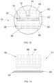
- a light fixture assemblyincludes a housing 10 A, 10 B and a plurality of lamp modules 12 .
- the housing 10is made from aluminum, although other metal, polymer, or composite materials may also be used.
- the housing 10can be configured to contain a variety of lamp modules 10 in different patterns based on the desired use and light output.
- FIGS. 1 - 4illustrate a housing using a 5 ⁇ 5 array of lamp modules 12
- FIGS. 5 - 8illustrate a housing using a 3 ⁇ 3 array of lamp modules 12 .
- different patterns of lamp modules 12are used, including any type of curvilinear, rectilinear, and non-uniform pattern distributions.
- the lamp modulesinclude one or more light emitters, or example light emitting diode (LED) modules.
- the housing 10 and lamp modules 12may utilize other light sources, for example other solid state, electrical filament, fluorescent, plasma, or gas light sources.
- FIGS. 1 - 4show an exemplary flood light housing 10 A designed to be positioned with a substantially vertical orientation.
- the housing 10 Acan be mounted to a pole, post, stake, or other similar structure.
- the housing 10 Aincludes a support 14 and a reflector 16 .
- the support 14connects to, or integrally extends from a post 18 .
- the support 14houses various components to power, direct, and/or control the LED modules as would be understood by one of ordinary skill in the art.
- the componentsmay include drivers, power sources, power converters, motors, and/or communication equipment such as Wi-Fi or Bluetooth capable equipment.
- Reflector 16is pivotally connected to the support 14 , and according to the illustrated embodiment is rotatable with respect to the post 18 to allow a user to selectively direct light emitted from the reflector 16 .
- the rotation of the reflector 16measured by the relative position between a longitudinal axis of the reflector 16 and the longitudinal axis of the post 18 , is between approximately ⁇ 5 degrees and +30 degrees. In an alternative embodiment, the rotation of the reflector 16 is between 0 degrees and +20 degrees.
- the reflector 16partially surrounds the plurality of lamp modules 12 .
- a support 20 having a plurality of ports 22 to receive the lamp modules 12is positioned in the reflector 16 or is integrally formed with the reflector 16 .
- a cover 24 having a series of openingsis positioned around the LED modules 12 and connected to the reflector 16 , for example with mechanical fasteners, such as screws or snap-fit connectors.
- a gasket 26 and a frame 28are also connected to the reflector 16 , for example with mechanical fasteners.
- frame 28supports an outer diffuser or lens (not shown) for protecting the modules 12 and, if desired, providing additional control of the emitted light.
- FIGS. 5 - 8show an exemplary wall mount housing 10 B designed to be positioned with a substantially horizontal orientation extending from a wall.
- the housing 10 Bis connected to a wall or other similar structure and includes a support 30 and a reflector 32 .
- the support 30can include a top portion and a bottom portion that are releasably or permanently connected together, for example with mechanical fasteners.
- the support 30houses various components to power, direct, and/or control the LED modules 12 as would be understood by one of ordinary skill in the art.
- the componentsmay include drivers, power sources, power converters, motors, and/or communication equipment such as Wi-Fi or Bluetooth capable equipment.
- a bracket having a first section 34 A and a second section 34 Bconnects the support 30 to a wall or other similar structure.
- the first section 34 Ais mounted to a wall, for example through one or more mechanical fasteners and the second section 34 B is connected to the support 30 .
- the first section 34 A and the second section 34 Beach include a pair of clips 36 A, 36 B that slidably mate with one another.
- the wall mount reflector 32is similar to the flood light reflector 16 and may include similar components.
- the wall mount reflector 32is pivotally connected to the support 30 and is selectively rotated with respect to the support 30 as discussed above.
- FIGS. 9 - 14show a lamp module 12 utilizing a plurality of LEDs in accordance with an exemplary embodiment.
- the lamp module 12is depicted as incorporated in the flood light housing 10 A and the wall mount housing 10 B of FIGS. 1 - 8 , although it may be used in any type of light fixture or housing.
- the lamp module 12includes a base 50 , a mount 52 , an LED board 54 , a gasket 56 , and an optic 58 .
- the base 50includes a plate 60 and a projection 62 extending from the plate 60 .
- the projectionhas an angled rear surface 64 , a concave bearing surface 66 rotatably receiving the mount 52 , and a curved top 68 connecting the rear surface 64 and the bearing surface 66 .
- Grooves 70 A, 70 Bare formed in the projection 62 , for example on the first and second sides of the projection 62 and/or the bearing surface 66 .
- a first set of grooves 70 Aare formed on a first side of the projection 62 and a second set of grooves 70 B are formed on a second side of the projection 62 .
- a set of groovesare formed on only a single side or a set of continuous grooves extend across the bearing surface 66 .
- the grooves 70 A, 70 Bare substantially V-shape with angled side walls and a planar bottom wall, although other shapes and configurations may be used.
- a slot 72is positioned in the rear surface 64 surrounding an aperture 74 that extends through the bearing surface 66 .
- the slot 72receives a fastener 76 that extends through the aperture 74 to connect the base 50 to the mount 52 .
- the mount 52is rotatably connected to the base 50 so that the orientation of the mount 52 may be adjusted by a user.
- the mount 52has a convex journal surface 78 that engages the concave bearing surface 66 of the base 50 and a wall 80 that receives the LED board 54 .
- the journal surface 78rotates on the bearing surface 66 .
- One or more teeth 82extend from the journal surface 78 to engage the grooves 70 A, 70 B on the base 50 .
- two separate teeth 82extend from either side of the journal surface 78
- a single tooth 82extends from one side of the journal surface 78
- a single tooth 82extends across the journal surface 78 depending on the desired configuration.
- the V-shaped grooves 70 A, 70 Ballow the tooth 82 to slide from one groove to another as selected by a user, and be retained in a desired groove.
- the grooves 70 A, 70 Bare spaced to define specific angles between the mount 52 and the base 50 .
- Indicatorsmay be formed on one or more surfaces of the journal 78 , for example the side surface, to indicate to a user the set angle. Indicators may also be positioned on the projection 62 or elsewhere on the module 12 .
- the mount 52is rotated with respect to the base 50 between approximately 0 degrees and approximately 75 degrees in 5 degree intervals. In various alternative embodiments, the mount 52 may be continuously rotatable on the base 50 between 0 degrees and 75 degrees.
- a slot 84extends through the wall 80 and the journal surface 78 to receive the fastener 76 extending through the projection 62 and a nut 86 is connected to the fastener 76 .
- the slot 84is sized to allow movement of the mount 52 with respect to the base 50 .
- a biasing member(not shown) may be positioned between the nut 86 and the mount 52 . The biasing member provides sufficient force to bias the tooth 82 into a selected groove 70 A, or in embodiments that do not utilize a groove, to substantially retain the position of the mount 52 with respect to the base 50 .
- the mount 52When changing the position of the mount 52 , a user compresses the biasing member, for example by applying force to the mount 52 , to remove the tooth 82 from the groove 70 A.
- the mount 52can be rotatable on the base 50 by non-manual components, such as an automated configuration utilizing a motor, one or more gears, or other rotary actuators.
- the mount 52acts as a heat sink to dissipate heat generated by the LEDs 88 and the LED board 54 .
- the rear surface of the wall 80 and/or the journal surface 78may include fins or other heat dissipating structure.
- the journal surface 78has a set of slots through the rear of the journal surface to form one or more heat dissipating projections.
- One or more aperturesextend into the wall 80 to receive one or more fasteners 90 to connect the LED board 54 to the mount 52 .
- the LED board 54contains a printed circuit board and one or more light sources connected thereto, for example an LED light source 88 .
- the LED board 54includes two rows of four LEDs 88 , although other configurations and any number of LEDs can be used depending on the desired light output and the optic 58 .
- the LED board 54is electrically connected to a power source, such as a driver (not shown) and includes one or more traces or pathways (not shown) connecting to the light sources.
- One or more apertures in the LED board 54receive fasteners 90 to connect the LED board 54 to the mount 52 .
- the LED board 54can be various sizes and shapes as well as utilize various light sources, materials, and other configurations as would be understood by one of ordinary skill in the art when viewing this disclosure.
- the gasket 56is positioned between the LED board 54 and the optic 58 , for example extending around the outer edge of the LED board 54 .
- the optic 58connects to the mount 52 and is positioned over the LED board 54 .
- the optic 48includes a pair of side clips 92 A, 92 B and the mount 52 may have a pair of mating grooves, slots, or other structures designed to releasably receive the clips 92 A, 92 B.
- the clips 92 A, 92 Breleasably secure the optic 58 to the mount 52 so that different optics may be interchanged as desired.
- Other connectionscan be used, including one or more fasteners.
- the gasket 56 positioned between the LED board 54 and the optic 58forms a seal.
- the optic 58includes one or more elements, for example light directing protrusions.
- one light directing protrusionis aligned with each LED 88 —as shown two rows of four light directing protrusions in accordance with the exemplary LED board 54 .
- the optic 58is made from a polymer material, for example polycarbonate or polymethyl methacrylate. In various exemplary embodiments, the optic 58 is a total internal reflection optic. Different types of optics and different materials may be utilized depending on the light source, the desired emitted light, and other design and utility considerations.
- the light directing features of the optic 58include a series of prisms 94 having a top, a first side, and a second side. As best shown in FIG. 12 , the top is planar and the first and second sides are curved, although planar sides may be used depending on the desired light output.
- the prisms 94are spaced from one another by planar valleys 96 .
- the rear of the light directing featuresinclude a dome 98 that extends from the optic 58 towards the LED 88 .
- the dome 98has a substantially V-shaped top depression 100 .
- the depressionis positioned over or around the LEDs 88 .
- the optic 58directs the light emitted from the LEDs 88 so that light from each LED 88 and light from each lamp module 12 overlaps and blends together to provide a substantially uniform light distribution with a smooth transition.
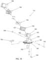
- FIG. 15depicts the lamp module 12 positioned in a port 22 in accordance with an exemplary embodiment.
- the mount 52is rotatable with respect to the base 50 about a first axis of rotation as indicated by the arrows A 1 and the base 50 is rotatable with respect to the support 20 , for example in the port 22 , about a second axis of rotation as indicated by the arrows A 2 .
- the base 50can be rotated 360 degrees, although in alternative embodiments, the rotation of the base 50 can be limited to a predetermined range.
- the base 50is manually rotated by a user and includes a cam lever 102 to selectively lock and release the position of the base 50 .
- FIG. 14the base 50 is manually rotated by a user and includes a cam lever 102 to selectively lock and release the position of the base 50 .
- Rotation of the mount 52 about the first axis and rotation of the base 50 about the second axisallows a user to selectively position one or more lamp modules 12 to adjust the light emitted from a given light fixture.
- a usermay customize the orientation of the lamp modules 12 to direct light to a desired area and to adjust the distribution of the light over a given area. Because each lamp module 12 can be individually adjusted, the light fixture can be configured to emit light over a wide range of areas.
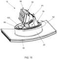
- FIGS. 16 - 22show another exemplary lamp module 112 .
- the lamp module 112includes a base 150 , a mount 152 , an LED board 154 , a gasket 156 , and an optic 158 .
- the base 150includes a plate 160 and a projection 162 extending from the plate 160 .
- the projection 162has a concave bearing surface rotatably receiving the mount 152 .
- the mount 152is rotatably connected to the base 150 so that the orientation of the mount 152 may be adjusted by a user.
- the mount 152has a convex journal surface that engages the concave bearing surface of the base 150 and a wall 180 that receives the LED board 154 . In this embodiment, no grooves or teeth are used.
- a slot 184 having a first portion and a second portionextends through the wall 180 .
- the first portionreceives a fastener 176 extending through the projection 162 .
- a nut 186is connected to the fastener 176 and can be selectively tightened or loosened.
- a usersets the angle of the mount 152 with respect to the base 150 and tightens the fastener 176 to secure the mount's 152 position.
- the second portionreceives one or more conductors (not shown) that pass through the mount 152 and connect to the LED board 154 .
- the mount 152acts as a heat sink to dissipate heat generated by the LED board 154 .
- the mount 152may include fins 182 or other heat dissipating structure.
- the LED board 154contains a printed circuit board and one or more light sources.
- the gasket 156is positioned between the LED board 154 and the optic 158 , for example extending around the outer edge of the LED board 154 .
- the optic 158connects to the mount 152 , for example by one or more mechanical fasteners, such as clips or screws.
- the gasket 156 positioned between the LED board 154 and the optic 158forms a seal.
- the gasket 156includes a sealing element 157 that covers the first and second portion of the slot 184 .
- the sealing element 157can include one or more openings to allow conductors to pass through the gasket.
- an optional shielding cover 188can be connected to the lamp module 112 .
- the shielding cover 188is placed over and at least partially around the optic 158 .
- the size, shape, and design of the shielding cover 188is configured to prevent or minimize light from being emitted to the sides and behind the lamp module 112 . This prevents light from leaking into unwanted places, for example residential areas that may be located behind a light fixture.
- the base 150can also include a rotational lock assembly that locks the position of the base 150 .
- the lock assemblyincludes a cam arm 190 and a moveable stop 192 .
- the stop 192engages a plate or other structure positioned in the housing, preventing rotation of the base.
- a camengages the stop 192 , moving it out of engagement with the housing and allowing a user to rotate the base 150 as desired.
- the stop 192is moved to prevent rotation of the base 150 .
- a conductor connector 194can also be attached to the base to allow for quick connection and disconnection of conductors to the lamp module 112 .
- FIGS. 23 - 26best show an exemplary embodiment of an optic 158 , for example a flood lighting optic used to disperse light over an area.
- the optic 158includes one or more elements, for example light directing protrusions 200 extending from a base 202 .
- one light directing protrusion 200is aligned with each LED.
- the light directing protrusions 200include a curvilinear top portion 204 and a curvilinear bottom portion 206 .
- An intermediate projection 208also extends from the base 202 between the light directing protrusions 200 .
- the intermediate projection 208includes a rectilinear portion 210 and a curvilinear portion 212 .
- the base 202includes an edge that extends around the LED board 154 .
- FIG. 31shows the lamp module 112 with the optic 158 and the shielding cover 188 .
- FIGS. 27 - 30show another exemplary embodiment of an optic 220 , for example a spot lighting optic used to focus light on a specific area.
- the optic 220includes a light directing protrusion 222 extending from a base 224 .
- the light directing protrusion 222includes a top brim 226 and a bottom brim 228 positioned around circular recesses 230 .
- Truncated cylinders 232extend from the base towards the light board 154 with openings that receive, or are positioned proximately over, an LED.
- FIG. 32shows the lamp module 112 with the spot light optic 220 and a second shielding cover 240 .
- certain light fixturescan be used for different lighting applications.
- exterior light distributioncan be divided between Type I-V light distributions.
- Type Iprovides a narrow linear beam distribution for lighting paths and walkways.
- Type IIprovides a linear distribution wider than Type I to accommodate wider lengths such as roadways.
- Type IIIprovides a wider beam distribution than Types I and II to illuminate a larger area that is directed both downward and outward from the light source.
- Type IVmostly directs light outwardly and is designed to be used at the perimeter of areas or mounted on walls.
- Type Vprovides a substantially uniform distribution from all sides of the light source, typically in a square or circular pattern.
- the lamp modules 12 , 112are illustrated as manually positioned, various alternative embodiments may utilize automated and/or remote positioning (not shown).
- the rotation of a reflector 16 , 32 , the base 50 , and the mount 52can be achieved through one or more motors, such as a stepper motor, and a gear or other rotary positioning device.
- the automated positioningmay be controlled locally at each light fixture or remotely, for example from a separate computing device such as a cell phone, tablet, laptop, desktop, or remote server.
- Instructions for controlling the motor(s)may be sent through a wired connection or wirelessly, for example through Wi-Fi or Bluetooth communication interface. Further controls are also provided to allow a user to select light distribution from preset configurations and to modify the position of each module individually.
- the terms “front,” “rear,” “upper,” “lower,” “upwardly,” “downwardly,” and other orientational descriptorsare intended to facilitate the description of the exemplary embodiments of the present application, and are not intended to limit the structure of the exemplary embodiments of the present application to any particular position or orientation.
- Terms of degree, such as “substantially” or “approximately”are understood by those of ordinary skill to refer to reasonable ranges outside of the given value, for example, general tolerances associated with manufacturing, assembly, and use of the described embodiments.
Landscapes
- Engineering & Computer Science (AREA)
- General Engineering & Computer Science (AREA)
- Fastening Of Light Sources Or Lamp Holders (AREA)
- Non-Portable Lighting Devices Or Systems Thereof (AREA)
- Arrangement Of Elements, Cooling, Sealing, Or The Like Of Lighting Devices (AREA)
- Microelectronics & Electronic Packaging (AREA)
- Securing Globes, Refractors, Reflectors Or The Like (AREA)
Abstract
Description
Claims (20)
Priority Applications (1)
| Application Number | Priority Date | Filing Date | Title |
|---|---|---|---|
| US17/379,608US12135120B2 (en) | 2014-05-23 | 2021-07-19 | Luminaire with adjustable lamp modules |
Applications Claiming Priority (4)
| Application Number | Priority Date | Filing Date | Title |
|---|---|---|---|
| US201462002283P | 2014-05-23 | 2014-05-23 | |
| US14/694,773US10274177B2 (en) | 2014-05-23 | 2015-04-23 | Luminaire with adjustable lamp modules |
| US16/399,130US11067264B2 (en) | 2014-05-23 | 2019-04-30 | Luminaire with adjustable lamp modules |
| US17/379,608US12135120B2 (en) | 2014-05-23 | 2021-07-19 | Luminaire with adjustable lamp modules |
Related Parent Applications (1)
| Application Number | Title | Priority Date | Filing Date |
|---|---|---|---|
| US16/399,130ContinuationUS11067264B2 (en) | 2014-05-23 | 2019-04-30 | Luminaire with adjustable lamp modules |
Publications (2)
| Publication Number | Publication Date |
|---|---|
| US20220136687A1 US20220136687A1 (en) | 2022-05-05 |
| US12135120B2true US12135120B2 (en) | 2024-11-05 |
Family
ID=54554642
Family Applications (3)
| Application Number | Title | Priority Date | Filing Date |
|---|---|---|---|
| US14/694,773Active2035-08-31US10274177B2 (en) | 2014-05-23 | 2015-04-23 | Luminaire with adjustable lamp modules |
| US16/399,130ActiveUS11067264B2 (en) | 2014-05-23 | 2019-04-30 | Luminaire with adjustable lamp modules |
| US17/379,608Active2035-09-24US12135120B2 (en) | 2014-05-23 | 2021-07-19 | Luminaire with adjustable lamp modules |
Family Applications Before (2)
| Application Number | Title | Priority Date | Filing Date |
|---|---|---|---|
| US14/694,773Active2035-08-31US10274177B2 (en) | 2014-05-23 | 2015-04-23 | Luminaire with adjustable lamp modules |
| US16/399,130ActiveUS11067264B2 (en) | 2014-05-23 | 2019-04-30 | Luminaire with adjustable lamp modules |
Country Status (7)
| Country | Link |
|---|---|
| US (3) | US10274177B2 (en) |
| EP (1) | EP3146256B1 (en) |
| CN (2) | CN114110493A (en) |
| AU (1) | AU2015264344B2 (en) |
| CA (1) | CA2949514C (en) |
| MX (2) | MX373923B (en) |
| WO (1) | WO2015179422A1 (en) |
Families Citing this family (11)
| Publication number | Priority date | Publication date | Assignee | Title |
|---|---|---|---|---|
| USD775407S1 (en)* | 2015-02-27 | 2016-12-27 | Star Headlight & Lantern Co., Inc. | Optical lens for projecting light from LED light emitters |
| US20180238505A1 (en)* | 2015-10-02 | 2018-08-23 | Led Roadway Lighting Ltd. | Tool-less light engine assembly for led street light fixtures |
| US10247398B2 (en) | 2017-01-22 | 2019-04-02 | GE Lighting Solutions, LLC | Luminaire assembly and tilting mechanism for the luminaire assembly |
| AT519787A1 (en)* | 2017-03-20 | 2018-10-15 | Ing Harald Rosenitsch | Luminaire, in particular street lamp |
| CA3062548A1 (en)* | 2017-05-05 | 2018-11-08 | Hubbell Incorporated | Illuminated mirror |
| US10493901B2 (en) | 2017-09-25 | 2019-12-03 | Milwaukee Electric Tool Corporation | Light assembly for attachment to a surface of a vehicle |
| CN108626647B (en)* | 2018-05-07 | 2020-09-04 | 广东鑫和照明科技实业有限公司 | Adjustable outdoor LED lamp mounting structure and mounting method thereof |
| DE102018131419A1 (en)* | 2018-12-07 | 2020-06-10 | Trilux Gmbh & Co. Kg | Luminaire with fastening device for mast mounting |
| CN109708079B (en)* | 2019-03-12 | 2023-04-21 | 深圳市冰晟光电科技有限公司 | Irradiation direction adjustable supporting mechanism for LED searchlight |
| MX2021014342A (en)* | 2019-05-24 | 2022-04-06 | Hubbell Inc | LIGHTING FIXTURE WITH INTEGRATED INPUT/OUTPUT MODULE. |
| DE202020103721U1 (en) | 2020-06-29 | 2021-10-04 | Zumtobel Lighting Gmbh | Floor lamp |
Citations (13)
| Publication number | Priority date | Publication date | Assignee | Title |
|---|---|---|---|---|
| US4419721A (en)* | 1981-12-21 | 1983-12-06 | Phoenix Products Company, Inc. | Searchlight with modular control mechanism |
| US5580156A (en)* | 1994-09-27 | 1996-12-03 | Koito Manufacturing Co., Ltd. | Marker apparatus |
| US5584576A (en)* | 1995-11-27 | 1996-12-17 | Wei Hong; Shen | Clamping and connecting structure for track lights |
| US20050047142A1 (en)* | 2003-09-02 | 2005-03-03 | Lui Thomas Kim Fung | Remote control assembly comprising a signal light and a spotlight |
| US20080253138A1 (en)* | 2005-06-09 | 2008-10-16 | Canlyte Inc. | Article support device |
| US20110261568A1 (en)* | 2010-02-16 | 2011-10-27 | Martin Professional A/S | Moving head light fixture with bucket shaped head |
| US20120033415A1 (en)* | 2010-02-09 | 2012-02-09 | Sharrah Raymond L | Portable light having a rotatable head |
| US8132944B2 (en)* | 2008-05-23 | 2012-03-13 | Ruud Lighting, Inc. | Recessed LED lighting fixture |
| US8322881B1 (en)* | 2007-12-21 | 2012-12-04 | Appalachian Lighting Systems, Inc. | Lighting fixture |
| US20130268246A1 (en)* | 2012-04-04 | 2013-10-10 | Musco Corporation | Method, system, and apparatus for aiming led lighting |
| US20140177258A1 (en)* | 2011-07-26 | 2014-06-26 | Golight, Inc. | Multi-face rotatable housing and mounting platform |
| US8888320B2 (en)* | 2012-01-27 | 2014-11-18 | Hubbell Incorporated | Prismatic LED module for luminaire |
| US20170097146A1 (en)* | 2009-09-04 | 2017-04-06 | Orion Energy Systems, Inc. | Outdoor lighting fixtures and related systems and methods |
Family Cites Families (31)
| Publication number | Priority date | Publication date | Assignee | Title |
|---|---|---|---|---|
| US5385062A (en)* | 1993-01-21 | 1995-01-31 | The Ahrens-Fox Fire Engine Company | Signal light oscillating mechanism |
| US5584574A (en)* | 1996-01-05 | 1996-12-17 | Hadco Division Of The Genlyte Group Incorporated | Versatile flood light |
| US5970860A (en)* | 1999-01-08 | 1999-10-26 | Yip; Chung Lun | Food processor |
| EP1222426B1 (en) | 1999-10-12 | 2006-05-31 | Eveready Battery Company, Inc. | Flashlight having a pivoting head |
| CN2432435Y (en) | 2000-06-07 | 2001-05-30 | 万樟工业股份有限公司 | Improved projection lamp pattern conversion device |
| JP3838630B2 (en)* | 2002-02-27 | 2006-10-25 | 株式会社ホンダロック | Engine starter for vehicle |
| JP4487516B2 (en)* | 2003-08-26 | 2010-06-23 | トヨタ自動車株式会社 | Parking lock device for vehicle |
| CN100497075C (en)* | 2005-03-02 | 2009-06-10 | 光阳工业股份有限公司 | Adjusting device for steering component of electric scooter |
| CN2797115Y (en)* | 2005-05-11 | 2006-07-19 | 上海大众汽车有限公司 | Rotary seat for vehicle |
| US7431482B1 (en) | 2005-06-21 | 2008-10-07 | W.A.C. Lighting Co. | Modular downlight assembly |
| CN2869548Y (en)* | 2005-12-05 | 2007-02-14 | 张丽英 | Lantern |
| US7364325B2 (en)* | 2006-01-23 | 2008-04-29 | Li-Chun Lai | Lamp structure |
| US7614766B2 (en) | 2006-06-29 | 2009-11-10 | Harvatek Corporation | Modular illumination device with adjustable lighting angles |
| US8057082B2 (en)* | 2007-02-01 | 2011-11-15 | Aimrail Corporation | Multiple axes adjustable lighting system |
| CA2594192A1 (en)* | 2007-07-23 | 2009-01-23 | Lovro Gotovac | Cleat holding device |
| US8003964B2 (en)* | 2007-10-11 | 2011-08-23 | Still River Systems Incorporated | Applying a particle beam to a patient |
| CN101591994B (en)* | 2008-05-28 | 2012-06-27 | 罗士夫 | Micro power-consumption passive electronic locking head |
| US7862197B2 (en) | 2008-09-12 | 2011-01-04 | Golight, Inc. | Searchlight with flexible attachment means |
| US8342709B2 (en)* | 2008-10-24 | 2013-01-01 | Hubbell Incorporated | Light emitting diode module, and light fixture and method of illumination utilizing the same |
| DE102008063369B4 (en) | 2008-12-30 | 2016-12-15 | Erco Gmbh | Lamp and module system for luminaires |
| US8727583B2 (en)* | 2008-12-31 | 2014-05-20 | Hubbell Incorporated | Lamp alignment assembly and lighting device |
| US8172436B2 (en) | 2009-12-01 | 2012-05-08 | Ullman Devices Corporation | Rotating LED light on a magnetic base |
| CN102859252B (en) | 2009-12-07 | 2014-10-22 | 爱格升公司 | Brake stand systems |
| US8240887B2 (en)* | 2010-08-27 | 2012-08-14 | Tyco Electronics Corporation | LED light module |
| US8278806B1 (en) | 2011-03-02 | 2012-10-02 | Osram Sylvania Inc. | LED reflector lamp |
| CN202188386U (en) | 2011-07-18 | 2012-04-11 | 安徽海威半导体照明有限公司 | LED (light-emitting diode) projection lamp |
| EP2753874A2 (en) | 2011-09-08 | 2014-07-16 | Golight, Inc. | Rotatable optical device housing and mounting platform |
| CN202356635U (en)* | 2011-11-22 | 2012-08-01 | 北京星航机电设备厂 | Spindle locking device of horizontal boring machine |
| US9568172B1 (en)* | 2012-05-03 | 2017-02-14 | Musco Corporation | Apparatus, system, and method for aiming LED modules |
| KR102068563B1 (en)* | 2012-09-21 | 2020-01-21 | 엘지전자 주식회사 | Lighting apparatus |
| US20140083217A1 (en)* | 2012-09-27 | 2014-03-27 | Margaret C. Liu | Radially reciprocating lock |
- 2015
- 2015-04-23USUS14/694,773patent/US10274177B2/enactiveActive
- 2015-05-19AUAU2015264344Apatent/AU2015264344B2/enactiveActive
- 2015-05-19CACA2949514Apatent/CA2949514C/enactiveActive
- 2015-05-19CNCN202111440862.2Apatent/CN114110493A/enactivePending
- 2015-05-19EPEP15795443.9Apatent/EP3146256B1/enactiveActive
- 2015-05-19MXMX2016015265Apatent/MX373923B/enactiveIP Right Grant
- 2015-05-19WOPCT/US2015/031611patent/WO2015179422A1/enactiveApplication Filing
- 2015-05-19CNCN201580027357.1Apatent/CN106415117A/enactivePending
- 2016
- 2016-11-22MXMX2020005202Apatent/MX2020005202A/enunknown
- 2019
- 2019-04-30USUS16/399,130patent/US11067264B2/enactiveActive
- 2021
- 2021-07-19USUS17/379,608patent/US12135120B2/enactiveActive
Patent Citations (14)
| Publication number | Priority date | Publication date | Assignee | Title |
|---|---|---|---|---|
| US4419721A (en)* | 1981-12-21 | 1983-12-06 | Phoenix Products Company, Inc. | Searchlight with modular control mechanism |
| US5580156A (en)* | 1994-09-27 | 1996-12-03 | Koito Manufacturing Co., Ltd. | Marker apparatus |
| US5584576A (en)* | 1995-11-27 | 1996-12-17 | Wei Hong; Shen | Clamping and connecting structure for track lights |
| US20050047142A1 (en)* | 2003-09-02 | 2005-03-03 | Lui Thomas Kim Fung | Remote control assembly comprising a signal light and a spotlight |
| US20080253138A1 (en)* | 2005-06-09 | 2008-10-16 | Canlyte Inc. | Article support device |
| US8322881B1 (en)* | 2007-12-21 | 2012-12-04 | Appalachian Lighting Systems, Inc. | Lighting fixture |
| US8132944B2 (en)* | 2008-05-23 | 2012-03-13 | Ruud Lighting, Inc. | Recessed LED lighting fixture |
| US20170097146A1 (en)* | 2009-09-04 | 2017-04-06 | Orion Energy Systems, Inc. | Outdoor lighting fixtures and related systems and methods |
| US20120033415A1 (en)* | 2010-02-09 | 2012-02-09 | Sharrah Raymond L | Portable light having a rotatable head |
| US8801225B2 (en)* | 2010-02-16 | 2014-08-12 | Martin Professional A/S | Moving head light fixture with bucket shaped head |
| US20110261568A1 (en)* | 2010-02-16 | 2011-10-27 | Martin Professional A/S | Moving head light fixture with bucket shaped head |
| US20140177258A1 (en)* | 2011-07-26 | 2014-06-26 | Golight, Inc. | Multi-face rotatable housing and mounting platform |
| US8888320B2 (en)* | 2012-01-27 | 2014-11-18 | Hubbell Incorporated | Prismatic LED module for luminaire |
| US20130268246A1 (en)* | 2012-04-04 | 2013-10-10 | Musco Corporation | Method, system, and apparatus for aiming led lighting |
Also Published As
| Publication number | Publication date |
|---|---|
| US20220136687A1 (en) | 2022-05-05 |
| AU2015264344B2 (en) | 2020-03-05 |
| MX2020005202A (en) | 2020-08-20 |
| EP3146256A1 (en) | 2017-03-29 |
| US10274177B2 (en) | 2019-04-30 |
| EP3146256B1 (en) | 2020-07-15 |
| US20200088391A1 (en) | 2020-03-19 |
| CA2949514A1 (en) | 2015-11-26 |
| CA2949514C (en) | 2023-06-06 |
| CN114110493A (en) | 2022-03-01 |
| MX2016015265A (en) | 2017-04-05 |
| AU2015264344A1 (en) | 2016-12-08 |
| WO2015179422A1 (en) | 2015-11-26 |
| CN106415117A (en) | 2017-02-15 |
| MX373923B (en) | 2020-07-10 |
| US11067264B2 (en) | 2021-07-20 |
| US20150338073A1 (en) | 2015-11-26 |
| EP3146256A4 (en) | 2018-01-17 |
Similar Documents
| Publication | Publication Date | Title |
|---|---|---|
| US12135120B2 (en) | Luminaire with adjustable lamp modules | |
| US7712926B2 (en) | Luminaire comprising adjustable light modules | |
| US10260718B2 (en) | Area luminaire | |
| US10488032B2 (en) | Area luminaire with heat fins | |
| US8602588B2 (en) | Method, system, and apparatus for highly controlled light distribution from light fixture using multiple light sources (LEDs) | |
| JP5217655B2 (en) | Lighting device | |
| EP2513552B1 (en) | Low-glare led-based lighting unit | |
| CN101010541A (en) | Illuminating device | |
| US10030856B2 (en) | Modular area luminaire | |
| AU2021201290A1 (en) | Light fixture having fixed angular position and lamp module for light fixtures | |
| WO2022069368A1 (en) | Systems and methods for adjusting a rotation angle of a luminaire and attaching a luminaire head | |
| US20130163240A1 (en) | Led street lamp | |
| US9068707B1 (en) | Compact LED light source and lighting system | |
| US10774995B2 (en) | PCB module LED lamp having irradiation angle setting up function for Edison socket | |
| KR20210037804A (en) | Led road lamp with controllable light emission angle | |
| CN222836761U (en) | A lamp with directional and non-directional light function adjustment | |
| KR101448389B1 (en) | LED Light Distribution Module Having Controlling Plate of Illuminating Area | |
| US11268668B2 (en) | LED-based lighting fixture providing a selectable chromaticity |
Legal Events
| Date | Code | Title | Description |
|---|---|---|---|
| FEPP | Fee payment procedure | Free format text:ENTITY STATUS SET TO UNDISCOUNTED (ORIGINAL EVENT CODE: BIG.); ENTITY STATUS OF PATENT OWNER: LARGE ENTITY | |
| STPP | Information on status: patent application and granting procedure in general | Free format text:DOCKETED NEW CASE - READY FOR EXAMINATION | |
| AS | Assignment | Owner name:HUBBELL LIGHTING, INC., CONNECTICUT Free format text:NUNC PRO TUNC ASSIGNMENT;ASSIGNOR:HUBBELL INCORPORATED;REEL/FRAME:058838/0162 Effective date:20220112 | |
| AS | Assignment | Owner name:ALLY BANK, AS COLLATERAL AGENT, NEW YORK Free format text:SECURITY AGREEMENT;ASSIGNORS:HUBBELL LIGHTING, INC.;LITECONTROL CORPORATION;CURRENT LIGHTING SOLUTIONS, LLC;AND OTHERS;REEL/FRAME:058982/0844 Effective date:20220201 | |
| AS | Assignment | Owner name:ATLANTIC PARK STRATEGIC CAPITAL FUND, L.P., AS COLLATERAL AGENT, NEW YORK Free format text:SECURITY INTEREST;ASSIGNORS:HUBBELL LIGHTING, INC.;LITECONTROL CORPORATION;CURRENT LIGHTING SOLUTIONS, LLC;AND OTHERS;REEL/FRAME:059034/0469 Effective date:20220201 | |
| AS | Assignment | Owner name:HLI SOLUTIONS, INC., SOUTH CAROLINA Free format text:CHANGE OF NAME;ASSIGNOR:HUBBELL LIGHTING, INC.;REEL/FRAME:063458/0150 Effective date:20220216 | |
| STPP | Information on status: patent application and granting procedure in general | Free format text:NON FINAL ACTION MAILED | |
| STPP | Information on status: patent application and granting procedure in general | Free format text:RESPONSE TO NON-FINAL OFFICE ACTION ENTERED AND FORWARDED TO EXAMINER | |
| STPP | Information on status: patent application and granting procedure in general | Free format text:FINAL REJECTION MAILED | |
| STPP | Information on status: patent application and granting procedure in general | Free format text:ADVISORY ACTION MAILED | |
| AS | Assignment | Owner name:ALLY BANK, AS COLLATERAL AGENT, NEW YORK Free format text:CORRECTIVE ASSIGNMENT TO CORRECT THE PATENT NUMBER 10841994 TO PATENT NUMBER 11570872 PREVIOUSLY RECORDED ON REEL 058982 FRAME 0844. ASSIGNOR(S) HEREBY CONFIRMS THE SECURITY AGREEMENT;ASSIGNORS:HUBBELL LIGHTING, INC.;LITECONTROL CORPORATION;CURRENT LIGHTING SOLUTIONS, LLC;AND OTHERS;REEL/FRAME:066355/0455 Effective date:20220201 | |
| AS | Assignment | Owner name:ATLANTIC PARK STRATEGIC CAPITAL FUND, L.P., AS COLLATERAL AGENT, NEW YORK Free format text:CORRECTIVE ASSIGNMENT TO CORRECT THE PATENT NUMBER PREVIOUSLY RECORDED AT REEL: 059034 FRAME: 0469. ASSIGNOR(S) HEREBY CONFIRMS THE SECURITY INTEREST;ASSIGNORS:HUBBELL LIGHTING, INC.;LITECONTROL CORPORATION;CURRENT LIGHTING SOLUTIONS, LLC;AND OTHERS;REEL/FRAME:066372/0590 Effective date:20220201 | |
| STPP | Information on status: patent application and granting procedure in general | Free format text:DOCKETED NEW CASE - READY FOR EXAMINATION | |
| STPP | Information on status: patent application and granting procedure in general | Free format text:NON FINAL ACTION MAILED | |
| STPP | Information on status: patent application and granting procedure in general | Free format text:RESPONSE TO NON-FINAL OFFICE ACTION ENTERED AND FORWARDED TO EXAMINER | |
| STPP | Information on status: patent application and granting procedure in general | Free format text:NOTICE OF ALLOWANCE MAILED -- APPLICATION RECEIVED IN OFFICE OF PUBLICATIONS | |
| STPP | Information on status: patent application and granting procedure in general | Free format text:PUBLICATIONS -- ISSUE FEE PAYMENT VERIFIED | |
| STCF | Information on status: patent grant | Free format text:PATENTED CASE |