US12134952B2 - Hydraulic fracturing plan and execution of same - Google Patents
Hydraulic fracturing plan and execution of sameDownload PDFInfo
- Publication number
- US12134952B2 US12134952B2US18/158,122US202318158122AUS12134952B2US 12134952 B2US12134952 B2US 12134952B2US 202318158122 AUS202318158122 AUS 202318158122AUS 12134952 B2US12134952 B2US 12134952B2
- Authority
- US
- United States
- Prior art keywords
- valve
- manifold
- fluid
- well
- communicated
- Prior art date
- Legal status (The legal status is an assumption and is not a legal conclusion. Google has not performed a legal analysis and makes no representation as to the accuracy of the status listed.)
- Active
Links
Images


Classifications
- E—FIXED CONSTRUCTIONS
- E21—EARTH OR ROCK DRILLING; MINING
- E21B—EARTH OR ROCK DRILLING; OBTAINING OIL, GAS, WATER, SOLUBLE OR MELTABLE MATERIALS OR A SLURRY OF MINERALS FROM WELLS
- E21B34/00—Valve arrangements for boreholes or wells
- E21B34/02—Valve arrangements for boreholes or wells in well heads
- E—FIXED CONSTRUCTIONS
- E21—EARTH OR ROCK DRILLING; MINING
- E21B—EARTH OR ROCK DRILLING; OBTAINING OIL, GAS, WATER, SOLUBLE OR MELTABLE MATERIALS OR A SLURRY OF MINERALS FROM WELLS
- E21B17/00—Drilling rods or pipes; Flexible drill strings; Kellies; Drill collars; Sucker rods; Cables; Casings; Tubings
- E21B17/006—Accessories for drilling pipes, e.g. cleaners
- E—FIXED CONSTRUCTIONS
- E21—EARTH OR ROCK DRILLING; MINING
- E21B—EARTH OR ROCK DRILLING; OBTAINING OIL, GAS, WATER, SOLUBLE OR MELTABLE MATERIALS OR A SLURRY OF MINERALS FROM WELLS
- E21B33/00—Sealing or packing boreholes or wells
- E21B33/02—Surface sealing or packing
- E21B33/03—Well heads; Setting-up thereof
- E21B33/068—Well heads; Setting-up thereof having provision for introducing objects or fluids into, or removing objects from, wells
- E—FIXED CONSTRUCTIONS
- E21—EARTH OR ROCK DRILLING; MINING
- E21B—EARTH OR ROCK DRILLING; OBTAINING OIL, GAS, WATER, SOLUBLE OR MELTABLE MATERIALS OR A SLURRY OF MINERALS FROM WELLS
- E21B41/00—Equipment or details not covered by groups E21B15/00 - E21B40/00
- E—FIXED CONSTRUCTIONS
- E21—EARTH OR ROCK DRILLING; MINING
- E21B—EARTH OR ROCK DRILLING; OBTAINING OIL, GAS, WATER, SOLUBLE OR MELTABLE MATERIALS OR A SLURRY OF MINERALS FROM WELLS
- E21B43/00—Methods or apparatus for obtaining oil, gas, water, soluble or meltable materials or a slurry of minerals from wells
- E21B43/11—Perforators; Permeators
- E—FIXED CONSTRUCTIONS
- E21—EARTH OR ROCK DRILLING; MINING
- E21B—EARTH OR ROCK DRILLING; OBTAINING OIL, GAS, WATER, SOLUBLE OR MELTABLE MATERIALS OR A SLURRY OF MINERALS FROM WELLS
- E21B43/00—Methods or apparatus for obtaining oil, gas, water, soluble or meltable materials or a slurry of minerals from wells
- E21B43/25—Methods for stimulating production
- E21B43/26—Methods for stimulating production by forming crevices or fractures
- E21B43/2607—Surface equipment specially adapted for fracturing operations
- F—MECHANICAL ENGINEERING; LIGHTING; HEATING; WEAPONS; BLASTING
- F16—ENGINEERING ELEMENTS AND UNITS; GENERAL MEASURES FOR PRODUCING AND MAINTAINING EFFECTIVE FUNCTIONING OF MACHINES OR INSTALLATIONS; THERMAL INSULATION IN GENERAL
- F16K—VALVES; TAPS; COCKS; ACTUATING-FLOATS; DEVICES FOR VENTING OR AERATING
- F16K3/00—Gate valves or sliding valves, i.e. cut-off apparatus with closing members having a sliding movement along the seat for opening and closing
- F16K3/30—Details
- F16K3/36—Features relating to lubrication
- F—MECHANICAL ENGINEERING; LIGHTING; HEATING; WEAPONS; BLASTING
- F16—ENGINEERING ELEMENTS AND UNITS; GENERAL MEASURES FOR PRODUCING AND MAINTAINING EFFECTIVE FUNCTIONING OF MACHINES OR INSTALLATIONS; THERMAL INSULATION IN GENERAL
- F16N—LUBRICATING
- F16N11/00—Arrangements for supplying grease from a stationary reservoir or the equivalent in or on the machine or member to be lubricated; Grease cups
- F—MECHANICAL ENGINEERING; LIGHTING; HEATING; WEAPONS; BLASTING
- F16—ENGINEERING ELEMENTS AND UNITS; GENERAL MEASURES FOR PRODUCING AND MAINTAINING EFFECTIVE FUNCTIONING OF MACHINES OR INSTALLATIONS; THERMAL INSULATION IN GENERAL
- F16N—LUBRICATING
- F16N29/00—Special means in lubricating arrangements or systems providing for the indication or detection of undesired conditions; Use of devices responsive to conditions in lubricating arrangements or systems
- F16N29/02—Special means in lubricating arrangements or systems providing for the indication or detection of undesired conditions; Use of devices responsive to conditions in lubricating arrangements or systems for influencing the supply of lubricant
- F—MECHANICAL ENGINEERING; LIGHTING; HEATING; WEAPONS; BLASTING
- F16—ENGINEERING ELEMENTS AND UNITS; GENERAL MEASURES FOR PRODUCING AND MAINTAINING EFFECTIVE FUNCTIONING OF MACHINES OR INSTALLATIONS; THERMAL INSULATION IN GENERAL
- F16N—LUBRICATING
- F16N39/00—Arrangements for conditioning of lubricants in the lubricating system
- F—MECHANICAL ENGINEERING; LIGHTING; HEATING; WEAPONS; BLASTING
- F16—ENGINEERING ELEMENTS AND UNITS; GENERAL MEASURES FOR PRODUCING AND MAINTAINING EFFECTIVE FUNCTIONING OF MACHINES OR INSTALLATIONS; THERMAL INSULATION IN GENERAL
- F16N—LUBRICATING
- F16N7/00—Arrangements for supplying oil or unspecified lubricant from a stationary reservoir or the equivalent in or on the machine or member to be lubricated
- F16N7/38—Arrangements for supplying oil or unspecified lubricant from a stationary reservoir or the equivalent in or on the machine or member to be lubricated with a separate pump; Central lubrication systems
- F16N7/40—Arrangements for supplying oil or unspecified lubricant from a stationary reservoir or the equivalent in or on the machine or member to be lubricated with a separate pump; Central lubrication systems in a closed circulation system
- F—MECHANICAL ENGINEERING; LIGHTING; HEATING; WEAPONS; BLASTING
- F16—ENGINEERING ELEMENTS AND UNITS; GENERAL MEASURES FOR PRODUCING AND MAINTAINING EFFECTIVE FUNCTIONING OF MACHINES OR INSTALLATIONS; THERMAL INSULATION IN GENERAL
- F16N—LUBRICATING
- F16N2210/00—Applications
- F—MECHANICAL ENGINEERING; LIGHTING; HEATING; WEAPONS; BLASTING
- F16—ENGINEERING ELEMENTS AND UNITS; GENERAL MEASURES FOR PRODUCING AND MAINTAINING EFFECTIVE FUNCTIONING OF MACHINES OR INSTALLATIONS; THERMAL INSULATION IN GENERAL
- F16N—LUBRICATING
- F16N2210/00—Applications
- F16N2210/02—Turbines
Definitions
- the '749 Applicationis also a CIP of U.S. patent application Ser. No. 16/803,156 (the “'156 Application”), filed Feb. 27, 2020, now issued as U.S. Pat. No. 11,242,724, the entire disclosure of which is hereby incorporated herein by reference.
- the '156 Applicationis a CIP of U.S. patent application Ser. No. 16/248,633 (the “'633 Application”), filed Jan. 15, 2019, now issued as U.S. Pat. No. 10,584,552, the entire disclosure of which is hereby incorporated herein by reference.
- the '633 Applicationclaims the benefit of the filing date of, and priority to, U.S. Patent Application No. 62/617,438 (the “'438 Application”), filed Jan. 15, 2018, the entire disclosure of which is hereby incorporated herein by reference.
- the '156 Applicationis also a CIP of U.S. patent application Ser. No. 16/436,623 (the “'623 Application”), filed Jun. 10, 2019, now issued as U.S. Pat. No. 11,208,856, the entire disclosure of which is hereby incorporated herein by reference.
- the '623 Applicationclaims the benefit of the filing date of, and priority to, U.S. Patent Application No. 62/755,170, filed Nov. 2, 2018, the entire disclosure of which is hereby incorporated herein by reference.
- the '156 Applicationis also a CIP of U.S. patent application Ser. No. 16/100,741 (the “'741 Application”), filed Aug. 10, 2018, now issued as U.S. Pat. No. 10,689,938, the entire disclosure of which is hereby incorporated herein by reference.
- the '741 Applicationclaims the benefit of the filing date of, and priority to, U.S. Patent Application No. 62/638,688, filed Mar. 5, 2018, U.S. Patent Application No. 62/638,681, filed Mar. 5, 2018, U.S. Patent Application No. 62/637,220, filed Mar. 1, 2018, U.S. Patent Application No. 62/637,215, filed Mar. 1, 2018, and U.S. Patent Application No. 62/598,914, filed Dec. 14, 2017, the entire disclosures of which are hereby incorporated herein by reference.
- This applicationrelates generally to oil and gas hydraulic fracturing operations and, more particularly, to a hydraulic fracturing plan executable by a hydraulic fracturing system to hydraulically fracture a plurality of oil and gas wells.
- FIG. 1 Ais a diagrammatic illustration of a hydraulic fracturing system operably to execute a hydraulic fracturing plan to hydraulically fracture a plurality of oil and gas wells, according to one or more embodiments.
- FIG. 1 Bis a flow diagram illustrating a method for hydraulically fracturing a plurality of wells by executing a hydraulic fracturing plan using the hydraulic fracturing system of FIG. 1 A , according to one or more embodiments.
- FIG. 2 Aschematically illustrates execution of one or more sub-step(s) of a first step of the method illustrated in FIG. 1 B , which first step is or includes equalizing a lubricator of a frac leg associated with a first well, and opening the first well, according to one or more embodiments.
- FIG. 2 Bschematically illustrates execution of one or more additional sub-step(s) of the first step of the method illustrated in FIG. 1 B , according to one or more embodiments.
- FIG. 2 Cschematically illustrates execution of one or more additional sub-step(s) of the first step of the method illustrated in FIG. 1 B , according to one or more embodiments.
- FIG. 2 Dschematically illustrates execution of one or more additional sub-step(s) of the first step of the method illustrated in FIG. 1 B , according to one or more embodiments.
- FIG. 2 Eschematically illustrates execution of one or more additional sub-step(s) of the first step of the method illustrated in FIG. 1 B , according to one or more embodiments.
- FIG. 2 Fschematically illustrates execution of one or more additional sub-step(s) of the first step of the method illustrated in FIG. 1 B , according to one or more embodiments.
- FIG. 2 Gschematically illustrates execution of one or more additional sub-step(s) of the first step of the method illustrated in FIG. 1 B , according to one or more embodiments.
- FIG. 3is a flow diagram illustrating the various sub-steps, illustrated schematically in FIGS. 2 A and 2 G , of the first step of the method illustrated in FIG. 1 B , according to one or more embodiments.
- FIG. 4is a flow diagram illustrating various sub-steps of a second step of the method illustrated in FIG. 1 B , which second step is or includes perforating a stage of the first well using a wireline perforating system, according to one or more embodiments.
- FIG. 5 Aschematically illustrates execution of one or more sub-step(s) of the second step of the method illustrated in FIG. 1 B , according to one or more embodiments.
- FIG. 5 Bschematically illustrates execution of one or more additional sub-step(s) of the second step of the method illustrated in FIG. 1 B , according to one or more embodiments.
- FIG. 5 Cschematically illustrates execution of one or more additional sub-step(s) of the second step of the method illustrated in FIG. 1 B , according to one or more embodiments.
- FIG. 6is a flow diagram illustrating various sub-steps of a third step of the method illustrated in FIG. 1 B , which third step is or includes closing the first well using a valve apparatus, and draining a lubricator, according to one or more embodiments.
- FIG. 7 Aschematically illustrates execution of one or more sub-step(s) of the third step of the method illustrated in FIG. 1 B , according to one or more embodiments.
- FIG. 7 Bschematically illustrates execution of one or more additional sub-step(s) of the third step of the method illustrated in FIG. 1 B , according to one or more embodiments.
- FIG. 7 Cschematically illustrates execution of one or more additional sub-step(s) of the third step of the method illustrated in FIG. 1 B , according to one or more embodiments.
- FIG. 7 Dschematically illustrates execution of one or more additional sub-step(s) of the third step of the method illustrated in FIG. 1 B , according to one or more embodiments.
- FIG. 7 Eschematically illustrates execution of one or more additional sub-step(s) of the third step of the method illustrated in FIG. 1 B , according to one or more embodiments.
- FIG. 7 Fschematically illustrates execution of one or more additional sub-step(s) of the third step of the method illustrated in FIG. 1 B , according to one or more embodiments.
- FIG. 7 Gschematically illustrates execution of one or more additional sub-step(s) of the third step of the method illustrated in FIG. 1 B , according to one or more embodiments.
- FIG. 7 Hschematically illustrates execution of one or more additional sub-step(s) of the third step of the method illustrated in FIG. 1 B , according to one or more embodiments.
- FIG. 7 Ischematically illustrates execution of one or more additional sub-step(s) of the third step of the method illustrated in FIG. 1 B , according to one or more embodiments.
- FIG. 8is a flow diagram illustrating various sub-steps of a fourth step of the method illustrated in FIG. 1 B , which fourth step is or includes isolating a stage of a second well in preparation for a hydraulic fracturing operation, according to one or more embodiments.
- FIG. 9 Aschematically illustrates execution of one or more sub-step(s) of the fourth step of the method illustrated in FIG. 1 B , according to one or more embodiments.
- FIG. 9 Bschematically illustrates execution of one or more additional sub-step(s) of the fourth step of the method illustrated in FIG. 1 B , according to one or more embodiments.
- FIG. 9 Cschematically illustrates execution of one or more additional sub-step(s) of the fourth step of the method illustrated in FIG. 1 B , according to one or more embodiments.
- FIG. 9 Dschematically illustrates execution of one or more additional sub-step(s) of the fourth step of the method illustrated in FIG. 1 B , according to one or more embodiments.
- FIG. 9 Eschematically illustrates execution of one or more additional sub-step(s) of the fourth step of the method illustrated in FIG. 1 B , according to one or more embodiments.
- FIG. 9 Fschematically illustrates execution of one or more additional sub-step(s) of the fourth step of the method illustrated in FIG. 1 B , according to one or more embodiments.
- FIG. 9 Gschematically illustrates execution of one or more additional sub-step(s) of the fourth step of the method illustrated in FIG. 1 B , according to one or more embodiments.
- FIG. 10is a flow diagram illustrating various sub-steps of a fifth step of the method illustrated in FIG. 1 B , which fifth step is or includes detecting or otherwise determining that a fracturing stage of a third well has ended, according to one or more embodiments.
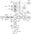
- FIG. 11schematically illustrates execution of one or more subs-step(s) of the fifth step of the method illustrated in FIG. 1 B , according to one or more embodiments.
- FIG. 12is a flow diagram illustrating various sub-steps of a sixth step of the method illustrated in FIG. 1 B , which sixth step is or includes determining whether to permit a regular swap or a continuous pumping swap (or “CP swap”), according to one or more embodiments.
- CP swapcontinuous pumping swap
- FIG. 13is a flow diagram illustrating various sub-steps of a seventh step of the method illustrated in FIG. 1 B , which seventh step is or includes the regular swap from hydraulically fracturing the third well to hydraulically fracturing the second well, according to one or more embodiments.
- FIG. 14 Aschematically illustrates execution of one or more sub-step(s) of the seventh step of the method illustrated in FIG. 1 B , according to one or more embodiments.
- FIG. 14 Bschematically illustrates execution of one or more additional sub-step(s) of the seventh step of the method illustrated in FIG. 1 B , according to one or more embodiments.
- FIG. 15is a flow diagram illustrating various sub-steps of an eighth step of the method illustrated in FIG. 1 B , which eighth step is or includes the CP swap from hydraulically fracturing the third well to hydraulically fracturing the second well, according to one or more embodiments.
- FIG. 16 Aschematically illustrates execution of one or more sub-step(s) of the eighth step of the method illustrated in FIG. 1 B , according to one or more embodiments.
- FIG. 16 Bschematically illustrates execution of one or more additional sub-step(s) of the eighth step of the method illustrated in FIG. 1 B , according to one or more embodiments.
- FIG. 16 Cschematically illustrates execution of one or more additional sub-step(s) of the eighth step of the method illustrated in FIG. 1 B , according to one or more embodiments.
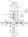
- FIG. 16 Dis a chart illustrating execution of one or more of the various sub-steps, schematically illustrated in FIGS. 16 A through 16 C , of the eighth step of the method illustrated in FIGS. 1 B , according to one or more embodiments.
- FIG. 16 Eis another chart illustrating execution of one or more of the various sub-steps, schematically illustrated in FIGS. 16 A through 16 C , of the eighth step of the method illustrated in FIGS. 1 B , according to one or more embodiments.
- FIG. 17is a flow diagram illustrating various sub-steps of a ninth step of the method illustrated in FIG. 1 B , which ninth step is or includes latching, filling, and pressure testing a frac leg associated with a fourth well in preparation for perforating a stage of the fourth well using the wireline perforating system, according to one or more embodiments.
- FIG. 18 Aschematically illustrates execution of one or more sub-step(s) of the ninth step of the method illustrated in FIG. 1 B , according to one or more embodiments.
- FIG. 18 Bschematically illustrates execution of one or more additional sub-step(s) of the ninth step of the method illustrated in FIG. 1 B , according to one or more embodiments.
- FIG. 18 Cschematically illustrates execution of one or more additional sub-step(s) of the ninth step of the method illustrated in FIG. 1 B , according to one or more embodiments.
- FIG. 18 Dschematically illustrates execution of one or more additional sub-step(s) of the ninth step of the method illustrated in FIG. 1 B , according to one or more embodiments.
- FIG. 18 Eschematically illustrates execution of one or more additional sub-step(s) of the ninth step of the method illustrated in FIG. 1 B , according to one or more embodiments.
- FIG. 18 Fschematically illustrates execution of one or more additional sub-step(s) of the ninth step of the method illustrated in FIG. 1 B , according to one or more embodiments.
- FIG. 18 Gschematically illustrates execution of one or more additional sub-step(s) of the ninth step of the method illustrated in FIG. 1 B , according to one or more embodiments.
- FIG. 19 Ais a flow diagram illustrating a portion of another method for fracturing wells using the fracturing system of FIG. 1 A , which another method includes swapping from simultaneously fracturing first and second wells to simultaneously fracturing third and fourth wells, according to one or more embodiments.
- FIG. 19 Bis a flow diagram illustrating another portion of the another method of FIG. 20 A , according to one or more embodiments.
- FIG. 20is a diagrammatic illustration of a computing node for implementing one or more embodiments of the present disclosure.
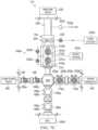
- a hydraulic fracturing system 100for executing a hydraulic fracturing plan to hydraulically fracture wells 105 A through 105 C+n is illustrated, which hydraulic fracturing system 100 includes: a blender 110 adapted to mix fluid from a fluid source 115 with sand from a sand source 120 to produce hydraulic fracturing fluid; a suction manifold 125 adapted to receive the hydraulic fracturing fluid from the blender 110 ; a discharge manifold 130 ; a plurality of swap stations 135 , each adapted to communicate the hydraulic fracturing fluid from the suction manifold 125 to a corresponding pump truck 140 , and, after pressurization by the corresponding pump truck 140 , to communicate the pressurized hydraulic fracturing fluid from the corresponding pump truck 140 to the discharge manifold 130 ; and a zipper manifold 145 adapted to communicate the pressurized hydraulic fracturing fluid from the discharge manifold 130 to a plurality of hydraulic
- each of the swap stations 135is or includes one or more components shown and described in U.S. patent application Ser. No. 16/436,189, filed Jun. 10, 2019, now published as U.S. Patent Application Publication No. 2020/0386359, the entire disclosure of which is hereby incorporated herein by reference.
- a grease system 155is adapted to communicate lubricating grease to various components of the frac legs 150 A through 150 C+n, including, for example, pump-down valves 160 a - b , master valves 165 a - b , and zipper valves 170 a - b associated with each of the frac legs 150 A through 150 C+n (which components are shown in FIGS. 2 A-G , 5 A-C, 7 A-I, 9 A-G, 11 , 14 A-B, 16 A-C, and 18 A-G).
- the grease system 155is or includes one or more components shown and described in U.S. patent application Ser. No. 16/248,648, filed Jan. 15, 2019, now issued as U.S. Pat.
- the grease system 155is or includes one or more components shown and described in U.S. patent application Ser. No. 16/938,341, filed Jul. 24, 2020, now published as U.S. Patent Application Publication No. 2020/0355322, the entire disclosure of which is hereby incorporated herein by reference in its entirety.
- the grease system 155is or includes one or more components shown and described in the '749 Application, filed Apr. 22, 2020, now published as U.S. Patent Application Publication No. 2020/0248529, the entire disclosure of which is hereby incorporated herein by reference in its entirety.
- the grease system 155is or includes one or more components shown and described in the '854 Application, filed May 13, 2021, the entire disclosure of which is hereby incorporated herein by reference in its entirety.
- a controller 156is adapted to control the grease system 155 , the frac legs 150 A through 150 C+n, or both.
- the controller 156is or includes a non-transitory computer readable medium and one or more processors adapted to execute instructions stored on the non-transitory computer readable medium.
- the controller 156is located on-site at the well site. Alternatively, the controller 156 may be located remotely from the well site.
- the controller 156includes a plurality of controllers. In one or more embodiments, the controller 156 includes a plurality of controllers, with one or more controllers located on-site at the well site and/or one or more other controllers located remotely from the well site.
- a method 175 for hydraulically fracturing the wells 105 A through 105 C+n by executing a hydraulic fracturing plan using the hydraulic fracturing system 100 of FIG. 1 Ais illustrated.
- the method 175generally includes: at step(s) 176 a , perforating a stage of each well using, for example, a wireline perforating system 177 ; at step(s) 176 b , isolating the perforated stage of each well using an object dropped, for example, from a launcher 178 of the wireline perforating system 177 ; and, at step(s) 176 c , hydraulically fracturing the isolated/perforated stage of each well.
- the method 175includes: at a step 225 , equalizing a lubricator 220 of the frac leg 150 A associated with the well 105 A, and opening the well 105 A; at a step 230 , perforating a stage of the well 105 A using the wireline perforating system 177 ; at a step 235 , closing the well 105 A using the valve apparatus 210 and draining the lubricator 220 ; at a step 238 a , queuing the well 105 A (as indicated at queue position n 2 ) in a frac queue 239 in preparation for a hydraulic fracturing operation; at a step 238 b , dequeuing the well 105 B (as indicated at queue position n 1 +1) from the frac queue 239 in preparation for the hydraulic fracturing operation; at a step 240 , isolating a stage of the well 105 B in preparation for the hydraulic fracturing operation;
- the controller 156is adapted to control the grease system 155 , the frac legs 150 A through 150 C+n, or both, in order to execute the method 175 described herein.
- the frac queue 239 and the wireline queue 264are stored on a non-transitory computer readable medium that includes or is part of, for example, the controller 156 .
- the frac queue 239is or includes a list of data items, commands, etc., stored on the computer readable medium so as to be retrievable by one or more processors in a definite order (but not necessarily in the order stored), and the frac queue 239 is associated with the wells 105 A through 105 C+n, as shown in FIG.
- the frac queue 239can be at least partially populated by an external source, such as, for example, the frac operator.
- the wireline queue 264is or includes a list of data items, commands, etc., stored on the computer readable medium so as to be retrievable by one or more processors in a definite order (but not necessarily in the order stored), and the wireline queue 264 is associated with the wells 105 A through 105 C+n, as shown in FIG. 1 B .
- the wireline queue 264can be at least partially populated by an external source, such as, for example, the wireline operator.
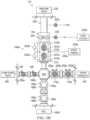
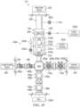
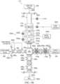
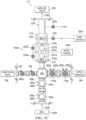
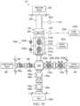
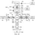
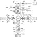
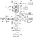
- the frac leg 150 A associated with the well 105 Ais illustrated, which frac leg 150 A includes: a wellhead including the master valves 165 a - b (such as, for example, gate valves) operably coupled to, and adapted to be in fluid communication with, the well 105 A, each of the master valves 165 a - b including associated grease ports (or “GPs”) 185 a - b ; the pump-down valves 160 a - b (such as, for example, gate valves) operably coupled to, and adapted communicate fluid between, a pump-down truck 190 and the well 105 A, via the master valves 165 a - b , each of the pump-down valves 160 a - b including an associated GP 195 ; and the zipper valves 170 a - b (such as, for example, gate valves) operably coupled to, and adapted communicate fluid between, the zipper manifold
- one or both of the zipper valves 170 a - b of each of the frac legs 150 A through 150 C+ninclude(s), or is/are part of, the zipper manifold 145 .
- the frac leg 150 A associated with the well 105 Aalso includes a flow block 205 to which the pump-down valves 160 a - b and the zipper valves 170 a - b are operably coupled.
- the frac leg 150 A associated with the well 105 Afurther includes a valve apparatus 210 via which both the wireline perforating system 177 and the object launched from, for example, the launcher 178 , are permitted entry to the well 105 A.
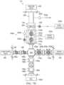
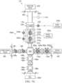
- the valve apparatus 210includes: a containment area 215 a (labeled “WELL”) adapted to be in fluid communication with the well 105 A via the master valves 165 a - b ; a containment area 215 b (labeled “LUB”) adapted to be in fluid communication with the lubricator 220 of the wireline perforating system 177 ; and a containment area 215 c (labeled “LL”) adapted to be in fluid communication with the containment area 215 a via a flow control device 221 a (e.g., a flapper-type flow control device), and adapted to be in fluid communication with the containment area 215 b via a flow control device 221 b (e.g., a flapper-
- An equalization (“EQ”) valve 222 ais connected between the containment areas 215 a and 215 c , which EQ valve 222 a is openable to permit pressure equalization between the containment areas 215 a and 215 c when the flow control device 221 a is closed.
- an equalization valve 222 bis connected between the containment areas 215 b and 215 c , which EQ valve 222 b is openable to permit pressure equalization between the containment areas 215 b and 215 c when the flow control device 221 b is closed.
- an EQ valve 222 cis connected between the lubricator 220 and atmosphere (labeled “ATM”), which EQ valve 222 c permits pressure equalization between the lubricator 220 and atmosphere.
- a drain 223is connected between a latch 234 (via which the lubricator 220 is detachably couplable to the valve apparatus 210 ) and a pump station 224 a , via which drain 223 fluid is communicable to and/or from the lubricator 220 , using, for example, an auto-fill/auto-drain pump of the pump station 224 a , when the lubricator 220 is connected to the valve apparatus 210 via the latch 234 .
- fluidcan also be communicated to the lubricator 220 (via, for example, the containment area 215 c and the EQ valve 222 b ) using one or more boost pump(s) 224 b in order to increase a fluid pressure in the lubricator 220 , aiding in pressure equalization between the lubricator 220 and the associated wellhead.
- the boost pump(s) 224 bmay include: a first boost pump capable of pumping at relatively higher volumes and relatively lower pressures; and a second boost pump capable of pumping at relatively lower volumes and relatively higher pressures.
- the first and second boost pumpsare used in combination to achieve combined pumping at relatively higher volumes and relatively higher pressures.
- a third boost pumpcapable of pumping at relatively higher volumes and relatively higher pressures may be used.
- one or more of the boost pump(s) 224 bmay instead be, include, or be part of the pump station 224 a.
- the valve apparatus 210is or includes one or more components shown and described in U.S. patent application Ser. No. 15/487,785, filed Apr. 14, 2017, now issued as U.S. Pat. No. 10,662,740, the entire disclosure of which is hereby incorporated herein by reference.
- the valve apparatus 210is or includes one or more components shown and described in U.S. patent application Ser. No. 16/721,203, filed Dec. 19, 2019, now published as U.S. Patent Application Publication No. 2020/0123876, the entire disclosure of which is hereby incorporated herein by reference.
- the launcher 178is or includes one or more components shown and described in U.S. patent application Ser. No. 16/248,633, filed Jan. 15, 2019, now issued as U.S. Pat. No. 10,584,552, the entire disclosure of which is hereby incorporated herein by reference.
- the launcher 178is or includes one or more components shown and described in U.S. patent application Ser. No. 16/801,911, filed Feb. 26, 2020, now published as U.S. Patent Application Publication No. 2020/0190933, the entire disclosure of which is hereby incorporated herein by reference.
- the launcher 178is or includes one or more components shown and described in U.S. patent application Ser. No. 16/803,156, filed Feb. 27, 2020, now published as U.S. Patent Application Publication No. 2020/0190934, the entire disclosure of which is hereby incorporated herein by reference.
- the frac legs 150 B through 150 C+n associated with each of the wells 105 B through 105 C+n, respectively,are substantially identical to the frac leg 150 A associated with the well 105 A; therefore, the frac legs 150 B through 150 C+n associated with each of the wells 1056 through 105 C+n will not be described in further detail. Accordingly, each of the frac legs 150 B through 150 C+n associated with the wells 105 B through 105 C+n includes features/components substantially identical to corresponding features/components of the frac leg 150 A associated with the well 105 A, which substantially identical features/components are given the same reference numerals and will also not be described in further detail.
- step 225is or includes equalizing the lubricator 220 of the frac leg 150 A associated with the well 105 A, and opening the well 105 A.
- the lubricator 220is or includes one or more components shown and described in the '749 Application.
- the lubricator 220is or includes one or more components shown and described in the '854 Application.
- the boost pump(s) 224 bis/are turned on to increase a fluid pressure in the lubricator 220 of the frac leg 150 A, thereby aiding in pressure equalization between said lubricator 220 and the well 105 A, as shown in FIGS. 2 A and 3 (indicated by arrow 232 a in FIG. 2 A ).
- the step 265 of latching, filling, and pressure testing the frac leg 150 A associated with the well 105 Ais executed on the frac leg 150 A just prior to the execution of the sub-step 226 a on the frac leg 150 A.
- the step 265will be described in further detail below as executed on the frac leg 150 E; however, the description below also applies to the execution of the step 265 on the frac leg 150 A.
- the EQ valve 222 cis closed; the drain 223 is closed; the lubricator 220 extends within, and is latched to, the latch 234 ; the flow control device 221 b is closed; the EQ valve 222 b is open; the flow control device 221 a is closed; the EQ valve 222 a is closed; the pump-down valves 160 a - b closed, and grease from the grease system 155 is withheld from the corresponding GPs 195 ; the zipper valves 170 a - b are closed, and grease from the grease system 155 is withheld from the corresponding GPs 200 a - b ; and the master valves 165 a - b
- the communication of grease from the grease system 155 to the corresponding GPs 185 a - bis not indicated by arrows in FIG. 2 A but is instead indicated by a lack of shading of the GPs 185 a - b as shown in FIG. 2 A; the same lack of shading indication applies to the GPs 185 a - b as shown in FIGS. 2 B-G , 5 A-C, 7 A-I, 9 A-G, 11 , 14 A-B, 16 A-C, and 18 A-G.
- respective fluid pressures within the containment areas 215 a and 215 care compared to determine whether the fluid pressure in the lubricator 220 of the frac leg 150 A has been equalized to within a threshold amount of the fluid pressure in the well 105 A. If it is determined that the fluid pressure in the lubricator 220 of the frac leg 150 A has not been equalized to within the threshold amount of the fluid pressure in the well 105 A, the EQ valve 222 a is opened at the sub-step 226 c to further encourage such pressure equalization between said lubricator 220 and the well 105 A, as shown in FIGS. 2 B and 3 . Alternatively, the order in which the sub-steps 226 a and 226 c are executed may be reversed, or one of the sub-steps 226 a and 226 c may be omitted altogether.
- the flow control device 221 ais opened, as shown in FIGS. 2 C and 3 .
- the EQ valve 222 ais closed, as shown in FIGS. 2 D and 3 .
- the sub-step 226 e of closing the EQ valve 222 ais also omitted.
- the sub-step 226 emay be executed to close the EQ valve 222 a at any time before, during, or after, execution of the sub-steps 226 d , 226 f , or 226 g .
- the flow control device 221 bis opened, as shown in FIGS. 2 E and 3 .
- the boost pump(s) 224 bis/are turned off, as shown in FIGS. 2 F and 3 .
- the EQ valve 222 bis closed, as shown in FIGS. 2 G and 3 .
- the well 105 Ais ready for execution of the step 230 , namely perforating a stage of the well 105 A using the wireline perforating system 177 , as will be described in detail below in connection with FIGS. 4 and 5 A through 5 C .
- step 230is or includes perforating a stage of the well 105 A using the wireline perforating system 177 .
- the wireline perforating system 177is or includes the pump-down truck 190 , a wireline truck 233 , the lubricator 220 , the launcher 178 , the latch 234 (via which the lubricator 220 is detachably couplable to the valve apparatus 210 ), or any combination thereof.
- the wireline perforating system 177may be or include one or more components shown and described in the '749 Application. In addition, or instead, in one or more embodiments, the wireline perforating system 177 may be or include one or more components shown and described in the '854 Application.
- a plug and perforating gun(s)are deployed from the lubricator 220 , as shown in FIGS. 4 and 5 A (indicated by arrow 232 b in FIG. 5 A ).
- the pump-down valves 160 a - bare opened, as shown in FIGS. 4 and 5 B .
- grease from the grease system 155is communicated to the corresponding GPs 195 of the pump-down valves 160 a - b , respectively, as shown in FIGS. 4 and 5 B (indicated by arrows 232 c in FIG. 5 B ).
- the plug and perforating gun(s)are pumped down into the well 105 A using the pump-down truck 190 , as shown in FIGS. 4 and 5 B (indicated by arrows 232 d and 232 e in FIG. 5 B ).
- the pump-down valves 160 a - bare closed, and grease from the grease system 155 is withheld from the corresponding GPs 195 , as shown in FIGS. 4 and 5 C .
- the sub-step 231 emay be executed to close the pump-down valves 160 a - b at any time before, during, or after, execution of the sub-steps 231 f , 231 g , or 231 h .
- the plugis set in the well 105 A, as shown in FIG. 4 .
- the perforating gun(s)are detonated in the well 105 A, as shown in FIG. 4 .
- the spent perforating gun(s)are retrieved from the well 105 A, as shown in FIGS.
- the well 105 Ais ready for execution of the step 235 , namely closing the well 105 A using the valve apparatus 210 and draining the lubricator 220 , as will be described in detail below in connection with FIGS. 6 and 7 A through 7 I .
- step 235is or includes closing the well 105 A using the valve apparatus 210 and draining the lubricator 220 .
- step 235is or includes closing the well 105 A using the valve apparatus 210 and draining the lubricator 220 .
- step 236 abump up of the retrieved spent perforating gun(s) within the lubricator 220 is determined and/or confirmed.
- the sub-step 236 acan be achieved in several ways, including, but not limited to: prompting the wireline operation for bump up; checking with the wireline operator to determine whether bump up has occurred; detecting bump up using a switch (e.g., a proximity switch) and/or another sensor (e.g., an accelerometer, a wireline speed sensor, a wireline tension sensor, a wireline length sensor, a wireline direction sensor, the like, or any combination thereof) associated with the lubricator 220 ; receiving verbal confirmation that bump up has occurred; or any combination thereof.
- a switche.g., a proximity switch
- another sensore.g., an accelerometer, a wireline speed sensor, a wireline tension sensor, a wireline length sensor, a wireline direction sensor, the like, or any combination thereof
- the flow control device 221 bis closed, as shown in FIGS. 6 and 7 A .
- the flow control device 221 ais closed, as shown in FIGS. 6 and 7 B .
- the EQ valve 222 cis opened, as shown in FIGS. 6 and 7 C , to bleed down a fluid pressure in the lubricator 220 (indicated by arrow 232 g in FIG. 7 C ).
- the EQ valve 222 bis opened, as shown in FIGS. 6 and 7 D .
- the lubricator 220is checked to determine whether the fluid pressure in the lubricator 220 has dropped (or “bled down”) to below a threshold value (e.g., a bleed PSI limit), as shown in FIG. 6 .
- a threshold valuee.g., a bleed PSI limit
- the drain 223is opened, as shown in FIGS. 6 and 7 F .
- the auto-drain pump of the pump station 224 ais turned on to drain fluid from the lubricator 220 via the drain 223 , as shown in FIGS. 6 and 7 F (indicated by arrow 232 h in FIG. 7 F ).
- the auto-drain pumpis allowed to finish auto-draining the lubricator 220 before the drain 223 is closed, as shown in FIGS. 6 and 7 G .
- the latch 234is unlatched, as shown in FIGS. 6 and 7 G .
- the lubricator 220is removed, as shown in FIGS. 6 and 7 H (indicated by arrow 232 i in FIG. 7 H ).
- the EQ valve 222 cis closed, as shown in FIG. 7 I .
- an object drope.g., from the launcher 178
- a pressure testis/are enabled, as shown in FIG. 6 .
- the well 105 Ais ready for execution of the step 240 , namely isolating a stage of the well 105 A in preparation for a hydraulic fracturing operation.
- the step 240will be described in further detail below (in connection with FIGS. 8 and 9 A through 9 G ) as executed on the frac leg 150 B to isolate a stage of the well 105 B; however, the description below also applies to the execution of the step 240 on the frac leg 150 A to isolate a stage of the well 105 A.
- step 240is or includes isolating a stage of the well 105 B in preparation for a hydraulic fracturing operation.
- the step 240 that is or includes isolating the stage of the well 105 Bincludes or is part of a hydraulic fracturing operation.
- the EQ valve 222 bis opened to facilitate pressure equalization between the containment areas 215 b and 215 c , as shown in FIGS. 8 and 9 A .
- an objectis dropped from the launcher 178 , as shown in FIGS. 8 and 9 A .
- respective fluid pressures within the containment areas 215 b and 215 care checked to determine whether the containment areas 215 b and 215 c have been pressure equalized to within a threshold amount, as shown in FIG. 8 .
- the flow control device 221 bis opened, as shown in FIGS. 8 and 9 B .
- the objectpasses into the containment area 215 c , as shown in FIGS. 8 and 9 C .
- the flow control device 221 bis closed, as shown in FIGS. 8 and 9 C .
- the EQ valve 222 bis closed, as shown in FIGS. 8 and 9 D .
- the boost pump(s) 224 bis/are turned on to increase a fluid pressure in the containment area 215 c , thereby aiding in pressure equalization between the containment areas 215 a and 215 c , as shown in FIGS. 8 and 9 D (indicated by arrow 232 j in FIG. 9 D ).
- respective fluid pressures within the containment areas 215 a and 215 care compared to determine whether the fluid pressure in the containment area 215 c has been equalized to within a threshold amount of the fluid pressure in the well 105 B.
- the EQ valve 222 ais opened at the sub-step 241 j to further encourage such pressure equalization between said containment area 215 c and the well 105 B, as shown in FIGS. 8 and 9 E .
- the order in which the sub-steps 241 h and 241 j are executedmay be reversed, or one of the sub-steps 241 h and 241 j may be omitted altogether.
- the flow control device 221 ais opened, as shown in FIGS. 8 and 9 F .
- the boost pump(s) 224 bis/are turned off, as shown in FIGS. 8 and 9 F .
- the EQ valve 222 ais closed, as shown in FIGS. 8 and 9 F .
- the sub-step 241 m of closing the EQ valve 222 ais also omitted.
- the sub-step 241 mmay be executed to close the EQ valve 222 a at any time before, during, or after, execution of the sub-steps 241 k or 241 l .
- the objectis permitted passage to the well 105 B, as shown in FIGS. 8 and 9 G .
- the flow control device 221 ais closed, as shown in FIGS. 8 and 9 G .
- the well 105 Bis ready for execution of the step 245 , namely detecting or otherwise determining that a fracturing stage of the well 105 D has ended, as will be described in detail below in connection with FIGS. 10 and 11 .
- step 245is or includes detecting or otherwise determining that a fracturing stage of the well 105 D has ended.
- the n 1 welle.g., well 105 D
- the n 1 well's frac datais monitored to determine whether the fracturing stage has ended, as shown in FIG. 10 .
- the zipper valves 170 a - b associated with the n 1 +1 wellare dequeued and compared against the frac order (if available).
- grease from the grease system 155is communicated to the corresponding GPs 200 a - b of the zipper valves 170 a - b , respectively, as shown in FIG. 11 (indicated by arrows 232 k in FIG. 5 B ); and hydraulic fracturing fluid is communicated from the zipper manifold 145 to the well 105 D, as shown in FIG. 11 (indicated by arrows 232 l and 232 m in FIG. 11 ).
- step 250is or includes determining whether to permit a regular swap or a CP swap from hydraulically fracturing (at a step 262 ) the well 105 D to hydraulically fracturing (at the step 262 ) the well 105 B, by, for example: checking an idle rate of the hydraulic fracturing system 100 at the sub-step 251 a ; and detecting or otherwise determining that an idle rate of the hydraulic fracturing system 100 is below an upper threshold and above a lower threshold at the sub-step 251 b , or, at the sub-step 251 c , detecting or otherwise determining that the idle rate of the hydraulic fracturing system 100 is below the lower threshold.
- a frac rate of the n 1 well(e.g., well 105 D) is checked; and, at the sub-step 251 b , if the frac rate of the n 1 well is below the upper threshold rate (e.g., 10 bbl) and above the lower threshold rate (e.g., 0 bbl) for a threshold amount of time (e.g., 10 s ), a CP swap from hydraulically fracturing the n 1 well to hydraulically fracturing the n 1 +1 well is permitted at step 260 , but, at the sub-step 251 c , if the frac rate of the n 1 well is below the lower threshold rate for a threshold amount of time, only a regular swap from hydraulically fracturing the n 1 well to hydraulically fracturing the n 1 +1 well is permitted at step 255 .
- the upper threshold ratee.g., 10 bbl
- 0 bbla threshold amount of time
- step 255is or includes executing the regular swap from hydraulically fracturing (at the step 262 ) the n 1 well (e.g., well 105 D) to hydraulically fracturing (at the step 262 ) the n 1 +1 well (e.g., well 105 B).
- the n 1 well's (e.g., well 105 D) zipper valves 170 a - bare closed, and grease from the grease system 155 is withheld from the corresponding GPs 200 a - b , as shown in FIGS. 13 and 14 A .
- a signal to advanceis received, as shown in FIG. 13 .
- a user inputsuch as a screen click may be received at the sub-step 256 b .
- an external signalsuch as an external signal from the frac operator, may be received at the sub-step 256 b .
- a signal to advancemay be generated by detecting or otherwise determining that pressure equalization has been achieved to within a threshold amount between the hydraulic fracturing pressure in the zipper manifold 145 and the fluid pressure in the n 1 +1 well (e.g., well 105 B) for a threshold amount of time.
- the n 1 +1 well's zipper valves 170 a - bare opened, as shown in FIGS. 13 and 14 B , so that hydraulic fracturing fluid is communicated from the zipper manifold 145 to the n 1 +1 well (indicated by arrows 232 n and 232 o in FIGS. 14 B ), and grease from the grease system 155 is communicated to the corresponding GPs 200 a - b (indicated by arrow 232 p in FIG. 14 B ).
- step 260is or includes executing the CP swap from hydraulically fracturing (at the step 262 ) the n 1 well (e.g., well 105 D) to hydraulically fracturing (at the step 262 ) the n 1 +1 well (e.g., well 105 B).
- step 260is or includes executing the CP swap from hydraulically fracturing (at the step 262 ) the n 1 well (e.g., well 105 D) to hydraulically fracturing (at the step 262 ) the n 1 +1 well (e.g., well 105 B).
- the n 1 +1 well'se.g., well 105 B
- zipper valves 170 a - bare opened, as shown in FIGS.
- hydraulic fracturing fluidis communicated from the zipper manifold 145 to the n 1 +1 well (indicated by arrows 232 n and 232 o in FIG. 16 A ), and grease from the grease system 155 is communicated to the corresponding GPs 200 a - b (indicated by arrow 232 p in FIG. 16 A ).
- both the n 1 +1 well's (e.g., well 105 B) zipper valves 170 a - b and the n 1 well's (e.g., well D) zipper valves 170 a - bare allowed to fully open, as shown in FIGS.
- hydraulic fracturing fluidis communicated from the zipper manifold 145 to the n 1 well (indicated by arrows 232 l and 232 m in FIG. 16 B ) and the n 1 +1 well (indicated by arrows 232 n and 232 o in FIG. 14 A ); and grease from the grease system 155 is communicated to the corresponding GPs 200 a - b (indicated by arrows 232 p and 232 k in FIGS. 16 A and 16 B , respectively).
- n 1 well'se.g., well 105 D
- zipper valves 170 a - bare closed, as shown in FIGS. 15 and 16 C , and grease from the grease system 155 is withheld from the corresponding GPs 200 a - b.
- executing the CP swap from hydraulically fracturing (at the step 262 ) the n 1 well (e.g., well 105 D) to hydraulically fracturing (at the step 262 ) the n 1 +1 well (e.g., well 105 B)transitions the zipper valves from one well to the other, opening the second well and subsequently shutting-in the first well, all while pumping.
- the transitionis instantaneous and the total time between stages measured at treatment pressure is less than 20 seconds (as fast as 19 seconds in some instances).
- step 265is or includes latching, filling, and pressure testing the frac leg 150 E associated with the well 105 E in preparation for perforating a stage of the well 105 E using the wireline perforating system 177 (in a manner similar to that described above in connection with the well 105 A and shown in FIGS. 5 A through 5 C ).
- the lubricator 220is stabbed into the latch 234 , as shown in FIGS. 17 and 18 A (indicated by arrow 232 q in FIG.
- the EQ valve 222 cis closed, as shown in FIGS. 17 and 18 B .
- the latch close relayis energized to close the latch 234 , thereby connecting the lubricator 220 to the valve apparatus 210 , as shown in FIGS. 17 and 18 C .
- a latch close proximity switchis checked to determine whether the latch 234 has successfully latched the lubricator 220 to the valve apparatus 210 .
- the latch close relayis de-energized, as shown in FIG. 17 .
- a test pressure relayis energized, as shown in FIG. 17 .
- a determinationis made as to whether the connection of the lubricator 220 to the valve apparatus 210 via the latch 234 is or is not capable of holding pressure, as shown in FIG. 17 .
- the test pressure relayis de-energized, as shown in FIG. 17 .
- the drain 223is opened, as shown in FIGS. 17 and 18 D .
- the EQ valve 222 cis opened, as shown in FIGS. 17 and 18 E .
- the auto-fill pump of the pump station 224 ais turned on to fill the lubricator 220 via the open drain 223 , as shown in FIGS. 17 and 18 E (indicated by arrow 232 r in FIG. 18 E ).
- the auto-fill pumpis allowed to finish auto-filling the lubricator 220 , as shown in FIG. 17 .
- the drain 223is closed, as shown in FIGS. 17 and 18 F .
- the EQ valve 222 cis closed, as shown in FIGS. 17 and 18 F .
- the EQ valve 222 bis opened, as shown in FIGS. 17 and 18 F .
- the boost pump(s) 224 bis/are turned on to increase the fluid pressure within the lubricator 220 , as shown in FIGS. 17 and 18 F (indicated by arrow 232 s in FIG. 18 F ).
- a threshold amounte.g. 500 PSI
- the boost pump(s) 224 bis/are turned off at the sub-step 266 r
- the EQ valve 222 bis closed at the sub-step 266 s in preparation for the next wireline swap (e.g., to the well 105 E), as shown in FIGS. 17 and 18 G .
- a method 270 for fracturing the wells 105 A through 105 C+n using the hydraulic fracturing system 100 of FIG. 1 Ais illustrated, which method 270 includes swapping from simultaneously fracturing the wells n 1 and n 3 (e.g., wells 105 D and 105 X) to simultaneously fracturing the wells n 1 +1 and n 3 +1 (e.g., wells 105 B and 105 V). More particularly, the method 270 includes steps substantially identical to corresponding steps of the method 175 described above, which steps are given the same reference numerals.
- the method 270includes additional steps executable to simultaneously fracture the n 1 and n 3 wells (e.g., wells 105 D and 105 X), and to swap from simultaneously fracturing the n 1 and n 3 wells to simultaneously fracturing the n 1 +1 and n 3 +1 wells (e.g., wells 105 B and 105 V), which additional steps are given the same reference numerals, except that the suffix “′” is added.
- additional stepsare given the same reference numerals, except that the suffix “′” is added.
- the suffix “′”signifies that the referenced step of the method 270 is substantially identical to the corresponding step of the method 175 , except that the referenced step is instead performed on a different one of the wells than that on which the corresponding step of the method 175 is performed (i.e., the steps 225 ′, 230 ′, 235 ′, 238 a ′, 239 ′, 238 b ′, 263 a ′, 264 ′, 263 b ′, 265 ′, and 268 ′ fall into this category), while, in other instances, the suffix “′” signifies that the referenced step of the method 270 is substantially similar to the corresponding step of the method 175 , except that the referenced step is simultaneously performed on another one of the wells other than that on which the corresponding step of the method 175 is performed (i.e., the steps 240 ′, 245 ′, 250 ′, 255 ′, 260 ′, and 262
- an illustrative node 1000 for implementing one or more of the embodiments of one or more of the controller(s)e.g., the controller 156 ), element(s), apparatus, system(s) (e.g., the hydraulic fracturing system 100 ), method(s) (e.g., the method 175 , the method 270 , or both), step(s), and/or sub-step(s), or any combination thereof, described above and/or illustrated in FIGS. 1 A through 19 B is depicted.
- the node 1000includes a microprocessor 1000 a , an input device 1000 b , a storage device 1000 c , a video controller 1000 d , a system memory 1000 e , a display 1000 f , and a communication device 1000 g all interconnected by one or more buses 1000 h .
- the storage device 1000 cmay include a hard drive, CD-ROM, optical drive, any other form of storage device and/or any combination thereof.
- the storage device 1000 cmay include, and/or be capable of receiving, a CD-ROM, DVD-ROM, or any other form of non-transitory computer-readable medium that may contain executable instructions.
- the communication device 1000 gmay include a modem, network card, or any other device to enable the node 1000 to communicate with other node(s).
- the node and the other node(s)represent a plurality of interconnected (whether by intranet or Internet) computer systems, including without limitation, personal computers, mainframes, PDAs, smartphones and cell phones.
- one or more of the embodiments described above and/or illustrated in FIGS. 1 A through 19 Binclude at least the node 1000 and/or components thereof, and/or one or more nodes that are substantially similar to the node 1000 and/or components thereof. In one or more embodiments, one or more of the above-described components of the node 1000 and/or the embodiments described above and/or illustrated in FIGS. 1 A through 19 B include respective pluralities of same components.
- one or more of the embodiments described above and/or illustrated in FIGS. 1 A through 19 Binclude a computer program that includes a plurality of instructions, data, and/or any combination thereof; an application written in, for example, Arena, HyperText Markup Language (HTML), Cascading Style Sheets (CSS), JavaScript, Extensible Markup Language (XML), asynchronous JavaScript and XML (Ajax), and/or any combination thereof; a web-based application written in, for example, Java or Adobe Flex, which in one or more embodiments pulls real-time information from one or more servers, automatically refreshing with latest information at a predetermined time increment; or any combination thereof.
- an applicationwritten in, for example, Arena, HyperText Markup Language (HTML), Cascading Style Sheets (CSS), JavaScript, Extensible Markup Language (XML), asynchronous JavaScript and XML (Ajax), and/or any combination thereof
- a web-based applicationwritten in, for example, Java or Adobe Flex, which in one
- a computer systemtypically includes at least hardware capable of executing machine readable instructions, as well as the software for executing acts (typically machine-readable instructions) that produce a desired result.
- a computer systemmay include hybrids of hardware and software, as well as computer sub-systems.
- hardwaregenerally includes at least processor-capable platforms, such as client-machines (also known as personal computers or servers), and hand-held processing devices (such as smart phones, tablet computers, or personal computing devices (PCDs), for example).
- client-machinesalso known as personal computers or servers
- hand-held processing devicessuch as smart phones, tablet computers, or personal computing devices (PCDs), for example.
- hardwaremay include any physical device that is capable of storing machine-readable instructions, such as memory or other data storage devices.
- other forms of hardwareinclude hardware sub-systems, including transfer devices such as modems, modem cards, ports, and port cards, for example.
- softwareincludes any machine code stored in any memory medium, such as RAM or ROM, and machine code stored on other devices (such as floppy disks, flash memory, or a CD-ROM, for example).
- softwaremay include source or object code.
- softwareencompasses any set of instructions capable of being executed on a node such as, for example, on a client machine or server.
- combinations of software and hardwarecould also be used for providing enhanced functionality and performance for certain embodiments of the present disclosure.
- software functionsmay be directly manufactured into a silicon chip. Accordingly, it should be understood that combinations of hardware and software are also included within the definition of a computer system and are thus envisioned by the present disclosure as possible equivalent structures and equivalent methods.
- computer readable mediumsinclude, for example, passive data storage, such as a random-access memory (RAM) as well as semi-permanent data storage such as a compact disk read only memory (CD-ROM).
- RAMrandom-access memory
- CD-ROMcompact disk read only memory
- One or more embodiments of the present disclosuremay be embodied in the RAM of a computer to transform a standard computer into a new specific computing machine.
- data structuresare defined organizations of data that may enable an embodiment of the present disclosure.
- a data structuremay provide an organization of data, or an organization of executable code.
- any networks and/or one or more portions thereofmay be designed to work on any specific architecture.
- one or more portions of any networksmay be executed on a single computer, local area networks, client-server networks, wide area networks, internets, hand-held and other portable and wireless devices and networks.
- a databasemay be any standard or proprietary database software.
- the databasemay have fields, records, data, and other database elements that may be associated through database specific software.
- datamay be mapped.
- mappingis the process of associating one data entry with another data entry.
- the data contained in the location of a character filecan be mapped to a field in a second table.
- the physical location of the databaseis not limiting, and the database may be distributed.
- the databasemay exist remotely from the server, and run on a separate platform.
- the databasemay be accessible across the Internet. In one or more embodiments, more than one database may be implemented.
- a plurality of instructions stored on a computer readable mediummay be executed by one or more processors to cause the one or more processors to carry out or implement in whole or in part one or more of the embodiments of one or more of the controller(s) (e.g., the controller 156 ), element(s), apparatus, system(s) (e.g., the hydraulic fracturing system 100 ), method(s) (e.g., the method 175 , the method 270 , or both), step(s), and/or sub-step(s), or any combination thereof, described above and/or illustrated in FIGS. 1 A through 19 B .
- the controller(s)e.g., the controller 156
- element(s), apparatus, system(s)e.g., the hydraulic fracturing system 100
- method(s)e.g., the method 175 , the method 270 , or both
- step(s), and/or sub-step(s)or any combination thereof, described above and/or illustrated in FIGS
- such a processormay include one or more of the microprocessor 1000 a , any processor(s) that are part of the components of the hydraulic fracturing system 100 , such as, for example, the controller 156 , and/or any combination thereof, and such a computer readable medium may be distributed among one or more components of the system.
- such a processormay execute the plurality of instructions in connection with a virtual computer system.
- such a plurality of instructionsmay communicate directly with the one or more processors, and/or ay interact with one or more operating systems, middleware, firmware, other applications, and/or any combination thereof, to cause the one or more processors to execute the instructions.
- a first methodhas been disclosed.
- the first methodgenerally includes: (a) permitting performance of a first hydraulic fracturing operation on a first well, which first hydraulic fracturing operation includes pumping fluid into the first well via a first valve associated with the first well, and measuring a flow rate of the fluid being pumped into the first well; (b) determining that the flow rate of the fluid being pumped into the first well is below a flow rate threshold and has been below the flow rate threshold for a threshold amount of time; (c) during pumping of the fluid into the first well via the first valve, opening a second valve associated with a second well; (d) permitting performance of a second hydraulic fracturing operation on the second well, which second hydraulic fracturing operation includes pumping fluid into the second well via the second valve; and (e) during pumping of the fluid into the second well via the second valve, closing the first valve associated with the first well; wherein, during each of steps (a), (b), (c), (d), and (e), fluid is continuously pumped to the first valve
- each of the first and second valvesis in fluid communication with a hydraulic manifold from which fluid is pumped to the first valve and/or the second valve; and, during each of steps (a), (b), (c), (d), and (e), fluid is continuously pumped from the hydraulic manifold to the first valve, the second valve, or both the first valve and the second valve.
- the second valveis opened after step (b).
- the first valveincludes a grease port; and the method further includes withholding grease from the grease port after step (e).
- the second valveincludes a grease port; and the method further includes: during and/or after opening the second valve, communicating grease to the grease port of the second valve.
- each of the first and second valvesis a zipper valve.
- step (d)further includes measuring a flow rate of the fluid being pumped into the second well; and is, or is part of, a hydraulic fracturing stage of the second well; and the method further includes: determining that the hydraulic fracturing stage of the second well has ended; determining that the flow rate of the fluid being pumped into the second well is above the flow rate threshold; closing the second valve associated with the second well; withholding grease from a grease port of the second valve; receiving a signal to advance; opening a third valve associated with a third well; and during and/or after opening the third valve, communicating grease to a grease port of the third valve.
- the first apparatusgenerally includes: a non-transitory computer readable medium; and a plurality of instructions stored on the non-transitory computer readable medium and executable by one or more processors, wherein, when the instructions are executed by the one or more processors, the following steps are executed: (a) permitting performance of a first hydraulic fracturing operation on a first well, which first hydraulic fracturing operation includes pumping fluid into the first well via a first valve associated with the first well, and measuring a flow rate of the fluid being pumped into the first well; (b) determining that the flow rate of the fluid being pumped into the first well is below a flow rate threshold and has been below the flow rate threshold for a threshold amount of time; (c) during pumping of the fluid into the first well via the first valve, opening a second valve associated with a second well; (d) permitting performance of a second hydraulic fracturing operation on the second well, which second hydraulic fracturing operation includes pumping fluid into the second well via the second valve;
- each of the first and second valvesis in fluid communication with a hydraulic manifold from which fluid is pumped to the first valve and/or the second valve; wherein, during each of steps (a), (b), (c), (d), and (e), fluid is continuously pumped from the hydraulic manifold to the first valve, the second valve, or both the first valve and the second valve.
- the second valveis opened after step (b).
- the first valveincludes a grease port; and, when the instructions are executed by the one or more processors, the following step is also executed: withholding grease from the grease port after step (e).
- the second valveincludes a grease port; and, when the instructions are executed by the one or more processors, the following step is also executed: during and/or after opening the second valve, communicating grease to the grease port of the second valve.
- each of the first and second valvesis a zipper valve.
- step (d)further includes measuring a flow rate of the fluid being pumped into the second well; and is, or is part of, a hydraulic fracturing stage of the second well; and, when the instructions are executed by the one or more processors, the following steps are also executed: determining that the hydraulic fracturing stage of the second well has ended; determining that the flow rate of the fluid being pumped into the second well is above the flow rate threshold; closing the second valve associated with the second well; withholding grease from a grease port of the second valve; receiving a signal to advance; opening a third valve associated with a third well; and during and/or after opening the third valve, communicating grease to a grease port of the third valve.
- a second methodhas also been disclosed.
- the second methodgenerally includes: (a) queuing, using a controller, a first well in a first hydraulic fracturing queue, which first hydraulic fracturing queue is associated with a first plurality of wells standing by for hydraulic fracturing, including at least the first well and a second well; (b) dequeuing, using the controller, the second well from the first hydraulic fracturing queue; (c) permitting hydraulic fracturing of the second well; (d) dequeuing, using the controller, the first well from the first hydraulic fracturing queue; and (e) swapping from permitting hydraulic fracturing of the second well to permitting hydraulic fracturing of the first well.
- step (c)includes opening a second valve associated with the second well to permit pumping of fluid into the second well via the second valve; and step (e) includes: opening a first valve associated with the first well to permit pumping of fluid into the first well via the first valve; and closing the second valve associated with the second well. In one or more embodiments, step (c) further includes measuring a flow rate of the fluid being pumped into the second well.
- step (e)further includes, in response to determining that the flow rate of the fluid being pumped into the second well is below a flow rate threshold and has been below the flow rate threshold for a threshold amount of time, the first valve associated with the first well is opened at step (e) before the second valve associated with the second well is closed at step (e). In one or more embodiments, the step (e) further includes, in response to determining that the flow rate of the fluid being pumped into the second well is above a flow rate threshold, the first valve associated with the first well is opened at step (e) after the second valve associated with the second well is closed at step (e).
- the methodfurther includes: (f) queuing, using the controller, a third well in a second hydraulic fracturing queue, which second hydraulic fracturing queue is associated with a second plurality of wells standing by for hydraulic fracturing, including at least the third well and a fourth well; (g) dequeuing, using the controller, the fourth well from the second hydraulic fracturing queue; (h) permitting hydraulic fracturing of the fourth well; (i) dequeuing, using the controller, the third well from the second hydraulic fracturing queue; and (j) swapping from permitting hydraulic fracturing of the fourth well to permitting hydraulic fracturing of the third well.
- steps (c) and (h)are executed simultaneously using hydraulic fracturing fluid from a hydraulic manifold; and steps (e) and (j) are executed simultaneously using hydraulic fracturing fluid from the hydraulic manifold.
- step (c)includes opening a second valve associated with the second well to permit pumping of fluid into the second well via the second valve;
- step (e)includes: opening a first valve associated with the first well to permit pumping of fluid into the first well via the first valve; and closing the second valve associated with the second well;
- step (h)includes opening a fourth valve associated with the fourth well to permit pumping of fluid into the fourth well via the fourth valve; and
- step (j)includes: opening a third valve associated with the third well to permit pumping of fluid into the third well via the third valve; and closing the fourth valve associated with the fourth well.
- a second apparatushas also been disclosed.
- the second apparatusgenerally includes: a non-transitory computer readable medium; and a plurality of instructions stored on the non-transitory computer readable medium and executable by one or more processors, wherein, when the instructions are executed by the one or more processors, the following steps are executed: (a) queuing a first well in a first hydraulic fracturing queue, which first hydraulic fracturing queue includes a first plurality of wells standing by for hydraulic fracturing, including at least the first well and a second well; (b) dequeuing the second well from the first hydraulic fracturing queue; (c) permitting hydraulic fracturing of the second well; (d) dequeuing the first well from the first hydraulic fracturing queue; and (e) swapping from permitting hydraulic fracturing of the second well to permitting hydraulic fracturing of the first well.
- step (c)includes opening a second valve associated with the second well to permit pumping of fluid into the second well via the second valve; and step (e) includes: opening a first valve associated with the first well to permit pumping of fluid into the first well via the first valve; and closing the second valve associated with the second well.
- step (c)further includes measuring a flow rate of the fluid being pumped into the second well.
- the first valve associated with the first wellin response to determining that the flow rate of the fluid being pumped into the second well is below a flow rate threshold and has been below the flow rate threshold for a threshold amount of time, the first valve associated with the first well is opened at step (e) before the second valve associated with the second well is closed at step (e).
- the first valve associated with the first wellin response to determining that the flow rate of the fluid being pumped into the second well is above a flow rate threshold, the first valve associated with the first well is opened at step (e) after the second valve associated with the second well is closed at step (e).
- the following stepsare also executed: (f) queuing a third well in a second hydraulic fracturing queue, which second hydraulic fracturing queue includes a second plurality of wells standing by for hydraulic fracturing, including at least the third well and a fourth well; (g) dequeuing the fourth well from the second hydraulic fracturing queue; (h) permitting hydraulic fracturing of the fourth well; (i) dequeuing the third well from the second hydraulic fracturing queue; and (j) swapping from permitting hydraulic fracturing of the fourth well to permitting hydraulic fracturing of the third well.
- steps (c) and (h)are executed simultaneously using hydraulic fracturing fluid from a hydraulic manifold; and steps (e) and (j) are executed simultaneously using hydraulic fracturing fluid from the hydraulic manifold.
- step (c)includes opening a second valve associated with the second well to permit pumping of fluid into the second well via the second valve;
- step (e)includes: opening a first valve associated with the first well to permit pumping of fluid into the first well via the first valve; and closing the second valve associated with the second well;
- step (h)includes opening a fourth valve associated with the fourth well to permit pumping of fluid into the fourth well via the fourth valve; and
- step (j)includes: opening a third valve associated with the third well to permit pumping of fluid into the third well via the third valve; and closing the fourth valve associated with the fourth well.
- the elements and teachings of the various embodimentsmay be combined in whole or in part in some (or all) of the embodiments.
- one or more of the elements and teachings of the various embodimentsmay be omitted, at least in part, and/or combined, at least in part, with one or more of the other elements and teachings of the various embodiments.
- any spatial referencessuch as, for example, “upper,” “lower,” “above,” “below,” “between,” “bottom,” “vertical,” “horizontal,” “angular,” “upwards,” “downwards,” “side-to-side,” “left-to-right,” “right-to-left,” “top-to-bottom,” “bottom-to-top,” “top,” “bottom,” “bottom-up,” “top-down,” etc., are for the purpose of illustration only and do not limit the specific orientation or location of the structure described above.
- steps, processes, and proceduresare described as appearing as distinct acts, one or more of the steps, one or more of the processes, and/or one or more of the procedures may also be performed in different orders, simultaneously and/or sequentially. In several embodiments, the steps, processes, and/or procedures may be merged into one or more steps, processes and/or procedures.
- one or more of the operational steps in each embodimentmay be omitted.
- some features of the present disclosuremay be employed without a corresponding use of the other features.
- one or more of the above-described embodiments and/or variationsmay be combined in whole or in part with any one or more of the other above-described embodiments and/or variations.
Landscapes
- Engineering & Computer Science (AREA)
- Life Sciences & Earth Sciences (AREA)
- Geology (AREA)
- Mining & Mineral Resources (AREA)
- Physics & Mathematics (AREA)
- Environmental & Geological Engineering (AREA)
- Fluid Mechanics (AREA)
- General Life Sciences & Earth Sciences (AREA)
- Geochemistry & Mineralogy (AREA)
- General Engineering & Computer Science (AREA)
- Mechanical Engineering (AREA)
- Fluid-Pressure Circuits (AREA)
Abstract
Description
Claims (78)
Priority Applications (4)
| Application Number | Priority Date | Filing Date | Title |
|---|---|---|---|
| US18/158,122US12134952B2 (en) | 2017-12-14 | 2023-01-23 | Hydraulic fracturing plan and execution of same |
| US18/159,990US11959358B2 (en) | 2019-06-10 | 2023-01-26 | Bleeding off a hydraulic fracturing manifold used in oil and gas extraction operations |
| PCT/US2023/061352WO2023147408A1 (en) | 2022-01-28 | 2023-01-26 | Bleeding off a hydraulic fracturing manifold used in oil and gas extraction operations |
| US18/935,865US20250059850A1 (en) | 2017-12-14 | 2024-11-04 | Hydraulic fracturing plan and execution of same |
Applications Claiming Priority (20)
| Application Number | Priority Date | Filing Date | Title |
|---|---|---|---|
| US201762598914P | 2017-12-14 | 2017-12-14 | |
| US201862617443P | 2018-01-15 | 2018-01-15 | |
| US201862617438P | 2018-01-15 | 2018-01-15 | |
| US201862637215P | 2018-03-01 | 2018-03-01 | |
| US201862637220P | 2018-03-01 | 2018-03-01 | |
| US201862638688P | 2018-03-05 | 2018-03-05 | |
| US201862638681P | 2018-03-05 | 2018-03-05 | |
| US16/100,741US10689938B2 (en) | 2017-12-14 | 2018-08-10 | Subterranean formation fracking and well workover |
| US201862755170P | 2018-11-02 | 2018-11-02 | |
| US16/248,648US10724682B2 (en) | 2018-01-15 | 2019-01-15 | Delivering and metering grease to process valves |
| US16/248,633US10584552B2 (en) | 2018-01-15 | 2019-01-15 | Object launching apparatus and related methods |
| US201962836761P | 2019-04-22 | 2019-04-22 | |
| US16/436,623US11208856B2 (en) | 2018-11-02 | 2019-06-10 | Subterranean formation fracking and well stack connector |
| US16/803,156US11242724B2 (en) | 2017-12-14 | 2020-02-27 | Launching objects into a wellbore |
| US16/855,749US11480027B2 (en) | 2017-12-14 | 2020-04-22 | Intelligently controlled fluid systems |
| US17/319,854US11867023B2 (en) | 2017-12-14 | 2021-05-13 | Intelligently controlled fluid systems |
| US202163189663P | 2021-05-17 | 2021-05-17 | |
| US17/388,716US11401779B2 (en) | 2017-12-14 | 2021-07-29 | Hydraulic fracturing plan and execution of same |
| US17/878,493US11560770B2 (en) | 2017-12-14 | 2022-08-01 | Hydraulic fracturing plan and execution of same |
| US18/158,122US12134952B2 (en) | 2017-12-14 | 2023-01-23 | Hydraulic fracturing plan and execution of same |
Related Parent Applications (1)
| Application Number | Title | Priority Date | Filing Date |
|---|---|---|---|
| US17/878,493ContinuationUS11560770B2 (en) | 2017-12-14 | 2022-08-01 | Hydraulic fracturing plan and execution of same |
Related Child Applications (2)
| Application Number | Title | Priority Date | Filing Date |
|---|---|---|---|
| US18/159,990Continuation-In-PartUS11959358B2 (en) | 2019-06-10 | 2023-01-26 | Bleeding off a hydraulic fracturing manifold used in oil and gas extraction operations |
| US18/935,865ContinuationUS20250059850A1 (en) | 2017-12-14 | 2024-11-04 | Hydraulic fracturing plan and execution of same |
Publications (2)
| Publication Number | Publication Date |
|---|---|
| US20230160278A1 US20230160278A1 (en) | 2023-05-25 |
| US12134952B2true US12134952B2 (en) | 2024-11-05 |
Family
ID=77365159
Family Applications (7)
| Application Number | Title | Priority Date | Filing Date |
|---|---|---|---|
| US17/319,854ActiveUS11867023B2 (en) | 2017-12-14 | 2021-05-13 | Intelligently controlled fluid systems |
| US17/360,336ActiveUS11480028B2 (en) | 2017-12-14 | 2021-06-28 | Intelligently controlled fluid systems |
| US17/878,493ActiveUS11560770B2 (en) | 2017-12-14 | 2022-08-01 | Hydraulic fracturing plan and execution of same |
| US18/158,122ActiveUS12134952B2 (en) | 2017-12-14 | 2023-01-23 | Hydraulic fracturing plan and execution of same |
| US18/407,069PendingUS20240141747A1 (en) | 2017-12-14 | 2024-01-08 | Oil and gas operations with valve operably coupled to wellhead |
| US18/409,057ActiveUS12378843B2 (en) | 2017-12-14 | 2024-01-10 | Oil and gas operations with valve operably coupled to wellhead |
| US18/935,865PendingUS20250059850A1 (en) | 2017-12-14 | 2024-11-04 | Hydraulic fracturing plan and execution of same |
Family Applications Before (3)
| Application Number | Title | Priority Date | Filing Date |
|---|---|---|---|
| US17/319,854ActiveUS11867023B2 (en) | 2017-12-14 | 2021-05-13 | Intelligently controlled fluid systems |
| US17/360,336ActiveUS11480028B2 (en) | 2017-12-14 | 2021-06-28 | Intelligently controlled fluid systems |
| US17/878,493ActiveUS11560770B2 (en) | 2017-12-14 | 2022-08-01 | Hydraulic fracturing plan and execution of same |
Family Applications After (3)
| Application Number | Title | Priority Date | Filing Date |
|---|---|---|---|
| US18/407,069PendingUS20240141747A1 (en) | 2017-12-14 | 2024-01-08 | Oil and gas operations with valve operably coupled to wellhead |
| US18/409,057ActiveUS12378843B2 (en) | 2017-12-14 | 2024-01-10 | Oil and gas operations with valve operably coupled to wellhead |
| US18/935,865PendingUS20250059850A1 (en) | 2017-12-14 | 2024-11-04 | Hydraulic fracturing plan and execution of same |
Country Status (1)
| Country | Link |
|---|---|
| US (7) | US11867023B2 (en) |
Families Citing this family (20)
| Publication number | Priority date | Publication date | Assignee | Title |
|---|---|---|---|---|
| US11867023B2 (en)* | 2017-12-14 | 2024-01-09 | Downing Wellhead Equipment, Llc | Intelligently controlled fluid systems |
| DE102018101772B4 (en)* | 2018-01-26 | 2022-06-23 | Ifm Electronic Gmbh | Lubricant distributor assembly |
| US10982808B2 (en)* | 2019-05-08 | 2021-04-20 | Fmg Technologies, Inc. | Valve control and/or lubrication system |
| US11959358B2 (en)* | 2019-06-10 | 2024-04-16 | Downing Wellhead Equipment, Llc | Bleeding off a hydraulic fracturing manifold used in oil and gas extraction operations |
| WO2021081339A1 (en) | 2019-10-25 | 2021-04-29 | Cameron International Corporation | System and method for valve greasing in a well tree |
| US12060783B2 (en) | 2021-02-25 | 2024-08-13 | Fmc Technologies, Inc. | System and method for an automated and intelligent frac pumping |
| US11639653B2 (en) | 2021-03-10 | 2023-05-02 | Chevron U.S.A. Inc. | Systems and methods for simultaneously fracturing multiple wells from a common wellpad |
| US12006805B2 (en) | 2021-05-21 | 2024-06-11 | DMS Solutions | System and method for remotely disconnecting a high-pressure pump from an active fracturing operation |
| WO2022256603A1 (en)* | 2021-06-04 | 2022-12-08 | Vault Pressure Control, Llc | Composite fracturing tree |
| US11585200B1 (en) | 2021-10-27 | 2023-02-21 | Force Pressure Control, LLC | Systems and methods for control of a multichannel fracturing pump connection |
| MX2023008154A (en)* | 2022-01-09 | 2023-07-21 | Gr Energy Services Man L P | WELL MONITORING SYSTEM WITH A WELL TRACKER AND METHOD OF USE THE SAME. |
| US11753911B1 (en)* | 2022-03-11 | 2023-09-12 | Caterpillar Inc. | Controlling fluid pressure at a well head based on an operation schedule |
| US20240377026A1 (en)* | 2022-04-29 | 2024-11-14 | Yantai Jereh Petroleum Equipment & Technologies Co., Ltd. | Automatic grease injection system and exploitation system |
| US12196048B2 (en)* | 2022-09-21 | 2025-01-14 | Fmc Technologies, Inc. | Reel deployment for centralized pad system |
| US12104477B1 (en) | 2023-03-13 | 2024-10-01 | Cactus Wellhead, LLC | Well lockout and automation systems and methods |
| US11905781B1 (en) | 2023-05-12 | 2024-02-20 | Forum Us, Inc. | Linear wellhead connection systems and methods |
| US12312928B2 (en) | 2023-06-02 | 2025-05-27 | Halliburton Energy Services, Inc. | Wellbore services system with anytime access for pump maintenance |
| KR102666725B1 (en)* | 2023-11-01 | 2024-05-17 | (주) 한국케이지티콘설턴트 | High-yield recovery and circulation device processing method for eco-friendly non-traditional oil based on wellpad |
| KR102713913B1 (en)* | 2023-11-01 | 2024-10-07 | (주)한국케이지티콘설턴트 | Management method of eco-friendly non-traditional oil recovery and circulation device based on wellpad |
| US12221846B1 (en)* | 2024-05-01 | 2025-02-11 | Pacseal Group, Inc. | Linear grease and hydraulic valve for fracking system maintenance |
Citations (47)
| Publication number | Priority date | Publication date | Assignee | Title |
|---|---|---|---|---|
| US4721158A (en) | 1986-08-15 | 1988-01-26 | Amoco Corporation | Fluid injection control system |
| US4754808A (en) | 1986-06-20 | 1988-07-05 | Conoco Inc. | Methods for obtaining well-to-well flow communication |
| US20070023184A1 (en) | 2005-06-02 | 2007-02-01 | Sanjel Corporation | Well product recovery process |
| US20070125543A1 (en) | 2005-12-01 | 2007-06-07 | Halliburton Energy Services, Inc. | Method and apparatus for centralized well treatment |
| US7559373B2 (en) | 2005-06-02 | 2009-07-14 | Sanjel Corporation | Process for fracturing a subterranean formation |
| US20090194273A1 (en) | 2005-12-01 | 2009-08-06 | Surjaatmadja Jim B | Method and Apparatus for Orchestration of Fracture Placement From a Centralized Well Fluid Treatment Center |
| US20110030963A1 (en) | 2009-08-04 | 2011-02-10 | Karl Demong | Multiple well treatment fluid distribution and control system and method |
| US20110048695A1 (en) | 2009-11-03 | 2011-03-03 | Isolation Equipment Services, Inc. | Manifold and system for servicing multiple wells |
| US20120255734A1 (en) | 2011-04-07 | 2012-10-11 | Todd Coli | Mobile, modular, electrically powered system for use in fracturing underground formations |
| US8490685B2 (en) | 2005-08-19 | 2013-07-23 | Exxonmobil Upstream Research Company | Method and apparatus associated with stimulation treatments for wells |
| US20130306322A1 (en) | 2012-05-21 | 2013-11-21 | General Electric Company | System and process for extracting oil and gas by hydraulic fracturing |
| US20140352968A1 (en)* | 2013-06-03 | 2014-12-04 | Cameron International Corporation | Multi-well simultaneous fracturing system |
| US20150345272A1 (en) | 2014-05-30 | 2015-12-03 | Ge Oil & Gas Pressure Control Lp | Remote Mobile Operation and Diagnostic Center for Frac Services |
| US20160061016A1 (en) | 2014-08-26 | 2016-03-03 | Jordan CIEZOBKA | Hydraulic fracturing system and method |
| US20170123437A1 (en)* | 2015-10-29 | 2017-05-04 | Commando Pressure Control Llc | Mobile zipper unit |
| US20170275980A1 (en)* | 2016-03-28 | 2017-09-28 | Ge Oil & Gas Pressure Control Lp | Systems and methods for fracturing a multiple well pad |
| US20170315566A1 (en) | 2016-04-27 | 2017-11-02 | Cameron International Corporation | Variable frequency drive for a fluid-handling system |
| WO2017201526A1 (en) | 2016-05-20 | 2017-11-23 | Gas Technology Institute | Hydraulic fracturing system and method |
| US20170336022A1 (en)* | 2016-05-23 | 2017-11-23 | Lee C. Gouge | Grease Distribution Systems and Methods |
| US20180045331A1 (en) | 2015-03-09 | 2018-02-15 | Schlumberger Technology Corporation | Automated operation of wellsite equipment |
| US20180179848A1 (en)* | 2016-12-22 | 2018-06-28 | Isolation Equipment Services Inc. | Manifold and swivel connections for servicing multiple wells and method of using same |
| US10174584B2 (en)* | 2014-04-11 | 2019-01-08 | Ge Oil & Gas Pressure Control Lp | Safety systems for isolating overpressure during pressurized fluid operations |
| US20190233275A1 (en) | 2018-01-31 | 2019-08-01 | Halliburton Energy Services, Inc. | Method and apparatus for metering flow during centralized well treatment |
| US10533406B2 (en) | 2013-03-14 | 2020-01-14 | Schlumberger Technology Corporation | Systems and methods for pairing system pumps with fluid flow in a fracturing structure |
| US10563778B2 (en)* | 2018-01-30 | 2020-02-18 | Chevron U.S.A. Inc. | Multi-well fracturing pads using shuttle valves |
| WO2020145978A1 (en) | 2019-01-10 | 2020-07-16 | Halliburton Energy Services, Inc. | Simulfrac pulsed treatment |
| US20200248529A1 (en)* | 2017-12-14 | 2020-08-06 | Downing Wellhead Equipment, Llc | Intelligently controlled fluid systems |
| US20200270977A1 (en) | 2019-02-21 | 2020-08-27 | Crestone Peak Resources | Flow management in existing wells during adjacent well hydraulic fracturing |
| US10801294B2 (en)* | 2018-08-13 | 2020-10-13 | Stream-Flo Industries Ltd. | Adjustable fracturing manifold module, system and method |
| US20200347990A1 (en)* | 2019-05-03 | 2020-11-05 | Gjr Meyer Service, Inc. | Grease manifold system |
| US20200408077A1 (en) | 2019-06-28 | 2020-12-31 | Halliburton Energy Services, Inc. | Pressurizing and protecting a parent well during fracturing of a child well |
| US20210188616A1 (en)* | 2019-12-20 | 2021-06-24 | Fuel Automation Station, LLC | System and method for fluid delivery at a temporary site |
| US11047189B2 (en)* | 2017-08-15 | 2021-06-29 | Insfor—Innovative Solutions For Robotics Ltda.—Me | Autonomous unit launching system for oil and gas wells logging, method of installation and uninstallation of said autonomous unit in the system and rescue system |
| US20210262315A1 (en)* | 2017-12-14 | 2021-08-26 | Downing Wellhead Equipment, Llc | Intelligently controlled fluid systems |
| US20210301933A1 (en)* | 2018-08-30 | 2021-09-30 | Takagi Co., Ltd. | Mixer faucet |
| US20210301638A1 (en)* | 2019-01-04 | 2021-09-30 | Commando Pressure Control Llc | Methods and systems associated with an automated zipper manifold |
| US11137109B2 (en)* | 2019-04-19 | 2021-10-05 | Cactus Wellhead, LLC | Remote greasing system |
| US20210324718A1 (en) | 2020-04-15 | 2021-10-21 | The Anders Family Living Trust | Fracturing system and method therefor |
| US20210363856A1 (en) | 2018-09-19 | 2021-11-25 | Intelligent Wellhead Systems Inc. | Apparatus, system and method for regulating a control mechanism of a well |
| US20210396117A1 (en) | 2020-06-22 | 2021-12-23 | Bj Energy Solutions, Llc | Systems and methods to operate hydraulic fracturing units using automatic flow rate and/or pressure control |
| US20220099227A1 (en) | 2020-09-25 | 2022-03-31 | Isolation Equipment Services Inc. | Manifold for servicing multiple wells and method |
| US20220112796A1 (en) | 2020-10-09 | 2022-04-14 | Halliburton Energy Services, Inc. | Expert system for well treatment |
| US11306835B1 (en)* | 2019-06-17 | 2022-04-19 | KHOLLE Magnolia 2015, LLC | Flapper valves with hydrofoil and valve systems |
| US11396799B2 (en)* | 2019-06-10 | 2022-07-26 | Downing Wellhead Equipment, Llc | Hot swappable fracturing pump system |
| US11401779B2 (en)* | 2017-12-14 | 2022-08-02 | Downing Wellhead Equipment, Llc | Hydraulic fracturing plan and execution of same |
| US20220268141A1 (en) | 2021-02-25 | 2022-08-25 | Fmc Technologies, Inc. | System and method for an automated and intelligent frac pumping |
| US11460368B2 (en)* | 2019-09-13 | 2022-10-04 | Bj Energy Solutions, Llc | Fuel, communications, and power connection systems and related methods |
Family Cites Families (13)
| Publication number | Priority date | Publication date | Assignee | Title |
|---|---|---|---|---|
| US5341835A (en) | 1992-12-14 | 1994-08-30 | Foster Valve Corporation | Lubrication system for valve seat of a gate valve |
| US8408781B2 (en) | 2006-02-21 | 2013-04-02 | Charles D. Welker | System, method and apparatus for entraining air in concrete |
| GB0615260D0 (en)* | 2006-08-01 | 2006-09-06 | Claxton Engineering Services L | Sphere launcher |
| US9068450B2 (en) | 2011-09-23 | 2015-06-30 | Cameron International Corporation | Adjustable fracturing system |
| EP3183413A4 (en)* | 2014-08-19 | 2017-08-02 | Aarbakke Innovation A.S. | Battery operated autonomous scale removal system for wells |
| US10597991B2 (en) | 2014-10-13 | 2020-03-24 | Schlumberger Technology Corporation | Control systems for fracturing operations |
| US9644443B1 (en) | 2015-12-07 | 2017-05-09 | Fhe Usa Llc | Remotely-operated wellhead pressure control apparatus |
| WO2017181051A1 (en) | 2016-04-14 | 2017-10-19 | The Colex Group, Inc. | Valve apparatus |
| US20180073308A1 (en) | 2016-09-13 | 2018-03-15 | Seaboard International, Inc. | Large bore assembly and spherical swivel joint |
| US10358891B2 (en) | 2016-10-24 | 2019-07-23 | Christopher M. Knott | Portable lubrication unit for a hydraulic fracturing valve assembly, and method for pre-pressurizing valves |
| WO2018186857A1 (en)* | 2017-04-05 | 2018-10-11 | Halliburton Energy Services, Inc. | System and method for remotely coupling wireline system to well |
| CA3003358A1 (en)* | 2017-04-28 | 2018-10-28 | Isolation Equipment Services Inc. | Wellbore sleeve injector and method of use |
| US10392894B2 (en) | 2017-11-22 | 2019-08-27 | Fhe Usa Llc | Remotely operated ball drop and night cap removal device for wellhead pressure control apparatus |
- 2021
- 2021-05-13USUS17/319,854patent/US11867023B2/enactiveActive
- 2021-06-28USUS17/360,336patent/US11480028B2/enactiveActive
- 2022
- 2022-08-01USUS17/878,493patent/US11560770B2/enactiveActive
- 2023
- 2023-01-23USUS18/158,122patent/US12134952B2/enactiveActive
- 2024
- 2024-01-08USUS18/407,069patent/US20240141747A1/enactivePending
- 2024-01-10USUS18/409,057patent/US12378843B2/enactiveActive
- 2024-11-04USUS18/935,865patent/US20250059850A1/enactivePending
Patent Citations (51)
| Publication number | Priority date | Publication date | Assignee | Title |
|---|---|---|---|---|
| US4754808A (en) | 1986-06-20 | 1988-07-05 | Conoco Inc. | Methods for obtaining well-to-well flow communication |
| US4721158A (en) | 1986-08-15 | 1988-01-26 | Amoco Corporation | Fluid injection control system |
| US8061427B2 (en) | 2005-06-02 | 2011-11-22 | Sanjel Corporation | Well product recovery process |
| US7559373B2 (en) | 2005-06-02 | 2009-07-14 | Sanjel Corporation | Process for fracturing a subterranean formation |
| US20070023184A1 (en) | 2005-06-02 | 2007-02-01 | Sanjel Corporation | Well product recovery process |
| US8490685B2 (en) | 2005-08-19 | 2013-07-23 | Exxonmobil Upstream Research Company | Method and apparatus associated with stimulation treatments for wells |
| US20090194273A1 (en) | 2005-12-01 | 2009-08-06 | Surjaatmadja Jim B | Method and Apparatus for Orchestration of Fracture Placement From a Centralized Well Fluid Treatment Center |
| US20070125543A1 (en) | 2005-12-01 | 2007-06-07 | Halliburton Energy Services, Inc. | Method and apparatus for centralized well treatment |
| US20110030963A1 (en) | 2009-08-04 | 2011-02-10 | Karl Demong | Multiple well treatment fluid distribution and control system and method |
| US20110048695A1 (en) | 2009-11-03 | 2011-03-03 | Isolation Equipment Services, Inc. | Manifold and system for servicing multiple wells |
| US20120255734A1 (en) | 2011-04-07 | 2012-10-11 | Todd Coli | Mobile, modular, electrically powered system for use in fracturing underground formations |
| US20130306322A1 (en) | 2012-05-21 | 2013-11-21 | General Electric Company | System and process for extracting oil and gas by hydraulic fracturing |
| US10533406B2 (en) | 2013-03-14 | 2020-01-14 | Schlumberger Technology Corporation | Systems and methods for pairing system pumps with fluid flow in a fracturing structure |
| US20140352968A1 (en)* | 2013-06-03 | 2014-12-04 | Cameron International Corporation | Multi-well simultaneous fracturing system |
| US10174584B2 (en)* | 2014-04-11 | 2019-01-08 | Ge Oil & Gas Pressure Control Lp | Safety systems for isolating overpressure during pressurized fluid operations |
| US20150345272A1 (en) | 2014-05-30 | 2015-12-03 | Ge Oil & Gas Pressure Control Lp | Remote Mobile Operation and Diagnostic Center for Frac Services |
| US20160061016A1 (en) | 2014-08-26 | 2016-03-03 | Jordan CIEZOBKA | Hydraulic fracturing system and method |
| US20180045331A1 (en) | 2015-03-09 | 2018-02-15 | Schlumberger Technology Corporation | Automated operation of wellsite equipment |
| US20170123437A1 (en)* | 2015-10-29 | 2017-05-04 | Commando Pressure Control Llc | Mobile zipper unit |
| US20170275980A1 (en)* | 2016-03-28 | 2017-09-28 | Ge Oil & Gas Pressure Control Lp | Systems and methods for fracturing a multiple well pad |
| US20170315566A1 (en) | 2016-04-27 | 2017-11-02 | Cameron International Corporation | Variable frequency drive for a fluid-handling system |
| WO2017201526A1 (en) | 2016-05-20 | 2017-11-23 | Gas Technology Institute | Hydraulic fracturing system and method |
| US20170336022A1 (en)* | 2016-05-23 | 2017-11-23 | Lee C. Gouge | Grease Distribution Systems and Methods |
| US20180179848A1 (en)* | 2016-12-22 | 2018-06-28 | Isolation Equipment Services Inc. | Manifold and swivel connections for servicing multiple wells and method of using same |
| US11047189B2 (en)* | 2017-08-15 | 2021-06-29 | Insfor—Innovative Solutions For Robotics Ltda.—Me | Autonomous unit launching system for oil and gas wells logging, method of installation and uninstallation of said autonomous unit in the system and rescue system |
| US20230160278A1 (en)* | 2017-12-14 | 2023-05-25 | Downing Wellhead Equipment, Llc | Hydraulic fracturing plan and execution of same |
| US11560770B2 (en)* | 2017-12-14 | 2023-01-24 | Downing Wellhead Equipment, Llc | Hydraulic fracturing plan and execution of same |
| US20200248529A1 (en)* | 2017-12-14 | 2020-08-06 | Downing Wellhead Equipment, Llc | Intelligently controlled fluid systems |
| US11401779B2 (en)* | 2017-12-14 | 2022-08-02 | Downing Wellhead Equipment, Llc | Hydraulic fracturing plan and execution of same |
| US20210324706A1 (en)* | 2017-12-14 | 2021-10-21 | Downing Wellhead Equipment, Llc | Intelligently controlled fluid systems |
| US20210262315A1 (en)* | 2017-12-14 | 2021-08-26 | Downing Wellhead Equipment, Llc | Intelligently controlled fluid systems |
| US10563778B2 (en)* | 2018-01-30 | 2020-02-18 | Chevron U.S.A. Inc. | Multi-well fracturing pads using shuttle valves |
| US20190233275A1 (en) | 2018-01-31 | 2019-08-01 | Halliburton Energy Services, Inc. | Method and apparatus for metering flow during centralized well treatment |
| US10801294B2 (en)* | 2018-08-13 | 2020-10-13 | Stream-Flo Industries Ltd. | Adjustable fracturing manifold module, system and method |
| US20210301933A1 (en)* | 2018-08-30 | 2021-09-30 | Takagi Co., Ltd. | Mixer faucet |
| US20210363856A1 (en) | 2018-09-19 | 2021-11-25 | Intelligent Wellhead Systems Inc. | Apparatus, system and method for regulating a control mechanism of a well |
| US20210301638A1 (en)* | 2019-01-04 | 2021-09-30 | Commando Pressure Control Llc | Methods and systems associated with an automated zipper manifold |
| WO2020145978A1 (en) | 2019-01-10 | 2020-07-16 | Halliburton Energy Services, Inc. | Simulfrac pulsed treatment |
| US20200270977A1 (en) | 2019-02-21 | 2020-08-27 | Crestone Peak Resources | Flow management in existing wells during adjacent well hydraulic fracturing |
| US11137109B2 (en)* | 2019-04-19 | 2021-10-05 | Cactus Wellhead, LLC | Remote greasing system |
| US20200347990A1 (en)* | 2019-05-03 | 2020-11-05 | Gjr Meyer Service, Inc. | Grease manifold system |
| US11396799B2 (en)* | 2019-06-10 | 2022-07-26 | Downing Wellhead Equipment, Llc | Hot swappable fracturing pump system |
| US11306835B1 (en)* | 2019-06-17 | 2022-04-19 | KHOLLE Magnolia 2015, LLC | Flapper valves with hydrofoil and valve systems |
| US20200408077A1 (en) | 2019-06-28 | 2020-12-31 | Halliburton Energy Services, Inc. | Pressurizing and protecting a parent well during fracturing of a child well |
| US11460368B2 (en)* | 2019-09-13 | 2022-10-04 | Bj Energy Solutions, Llc | Fuel, communications, and power connection systems and related methods |
| US20210188616A1 (en)* | 2019-12-20 | 2021-06-24 | Fuel Automation Station, LLC | System and method for fluid delivery at a temporary site |
| US20210324718A1 (en) | 2020-04-15 | 2021-10-21 | The Anders Family Living Trust | Fracturing system and method therefor |
| US20210396117A1 (en) | 2020-06-22 | 2021-12-23 | Bj Energy Solutions, Llc | Systems and methods to operate hydraulic fracturing units using automatic flow rate and/or pressure control |
| US20220099227A1 (en) | 2020-09-25 | 2022-03-31 | Isolation Equipment Services Inc. | Manifold for servicing multiple wells and method |
| US20220112796A1 (en) | 2020-10-09 | 2022-04-14 | Halliburton Energy Services, Inc. | Expert system for well treatment |
| US20220268141A1 (en) | 2021-02-25 | 2022-08-25 | Fmc Technologies, Inc. | System and method for an automated and intelligent frac pumping |
Non-Patent Citations (78)
| Title |
|---|
| Bourgoyne Jr. et al., Applied Drilling Engineering, Society of Petroleum Engineers, SPE Textbook Series, vol. 2, 125 pages. |
| Burton, Comparing Multistage Completions Part 13—Operational Efficiency of Plug-and-Perf with Zipper Frac, YouTube (Jun. 23, 2020) https://www.youtube.com/watch?v=LnlhENHTGWg. |
| Casero et al., "Continuous Pumping, Multistage, Hydraulic Fracturing in Kitina Field, Offshore Congo, West Africa," in SPE International Symposium and Exhibition on Formation Damage Control, 2008, vol. All Days, SPE-112442-MS; 20 pages. |
| Chen, "Optimal control of ICV's and well operating conditions for the water-alternating gas injection process," Journal of Petroleum Science and Engineering (2016), pp. 623-640. |
| Continuous Pumping: Freedom Series iControl, retrieved on Feb. 23, 2024, The Wayback Machine—https://web.archive.org/web/20201020115107/https://downingusa.com/freedomseries/continuoaspumping/, IPR2024-00256 Exhibit 2001. |
| Cudd Energy Services, Hydraulic Fracturing Process Animation, YouTube (May 7, 2013), https://www.youtube.com/watch?v=eEADi7X3kPM. |
| Examination Report for Canadian Patent Application No. 3,150,086, dated Apr. 3, 2024, 3 pages. |
| Halliburton, Reducing Days on Location and Time to First Oil (2020). |
| Holzhausen, Impedance of Hydraulic Fractures: Its Measurement and Use for Estimating Fracture Closure Pressure and Dimensions, Society of Petroleum Engineers/U.S. Department of Energy, Applied Geomechanics Inc., and R.P. Gooch, Stanford U., 12 pages. |
| IPR2024-00256 Claim-by-Claim Priority Analysis, IWS Exhibit 1013, 8 pages. |
| IPR2024-00256 Exhibit 2002, Introducing Continuous Pumping, 3 pages. |
| IPR2024-00256 Patent Family Priority Diagram, IWS Exhibit 1011, 1 page. |
| IPR2024-00256 Patent Family Specification Comparisons, IWS Exhibit 1012, 254 pages. |
| IPR2024-00256, John P. Hughett, P.E. Resume, Exhibit 2007, 4 pages. |
| IPR2024-00256, Tim Marvel Communication to Brian Wiesner and Austin Johnson regarding Continuous Pumping Website, dated Oct. 9, 2020, Exhibit 2003, 4 pages. |
| IPR2024-00256, Tim Marvel LinkedIn Post regarding continuous pumping, dated Oct. 12, 2020, Exhibit 2004. |
| IPR2024-00300 Patent Family Priority Diagram, 1 page. |
| IPR2024-00300 Patent Family Specification Comparisons, IWS Exhibit 1012, 274 pages. |
| IPR2024-00584, Email Correspondence Regarding Meet and Confer, Exhibit 2005, dated Dec. 5, 2023, 5 pages. |
| IPR2024-00584, Introducing Continuous Pumping, Exhibit 2002, 4 pages. |
| Jacobs, "The Shale Evolution: Zipper Fracture Takes Hold," J Pet Technol 66 (2014): 60-67. |
| Massaras et al., "Enhanced Fracture Entry Friction Analysis of the Rate Step-Down Test," in SPE Hydraulic Fracturing Technology Conference, 2007, vol. All Days, SPE-106058-MS, 16 pages. |
| Mayerhofer et al., "What is Stimulated Reservoir Volume (SRV)?" Paper presented at the SPE Shale Gas Production Conference, Fort Worth, Texas, USA, Nov. 2008, 14 pages. |
| Mondal, "Pressure transients in wellbores: Water hammer effects and implications for fracture diagnostics," at 12 (2010). |
| Montgomery et al., "Hydraulic Fracturing: History of an Enduring Technology," Journal of Petroleum Technology vol. 62 issue 12 p. 26 (Dec. 2010). |
| Morton, "Unlocking the Earth: A Short History of Hydraulic Fracturing," GEO ExPro, vol. 10, No. 6, Dec. 2013. |
| Mutalik et al., "Case History of Sequential and Simultaneous Fracturing of the Barnett Shale in Parker County." Paper presented at the SPE Annual Technical Conference and Exhibition, Denver, Colorado, USA, Sep. 2008. |
| Oberhofer, "Application of Ball-Drop Technology to Improve Efficiency and Stimulation of Limited Entry Completion Systems," in Abu Dhabi International Petroleum Exhibition & Conference, 2016, vol. Day 2 Tue, Nov. 8, 2016, D021S052R004. |
| Office Action for U.S. Appl. No. 17/388,716, mailed Jan. 5, 2022, 10 pages. |
| Office Action for U.S. Appl. No. 17/651,716, mailed Dec. 20, 2023, 7 pages. |
| Paige et al., "Field Application of Hydraulic Impedance Testing for Fracture Measurement," SPE Production & Facilities, vol. 10, No. 01, pp. 7-12, 1995. |
| Pearson et al., "Results of Stress-Oriented and Aligned Perforating in Fracturing Deviated Wells." J Pet Technol 44 (1992): 10-18. |
| Rassenfoss, "A Look Into What Fractures Really Look Like," Journal of Petroleum Technology, vol. 70, No. 11, pp. 28-36, 2018. |
| Roussel et al., "Optimizing Fracture Spacing and Sequencing in Horizontal-Well Fracturing." SPE Prod & Oper 26 (2011): 173-184. |
| SLB, Sundance Energy Saves USD 500,000 with 60% More Stages per Day in Simultaneous Fracturing Operations (2020). |
| Specification for Wellhead and Christmas Tree Equipment, American Petroleum Institute, 20th Edition, Oct. 2010, 3 pages. |
| Tolman et al. (2009). Method and Apparatus for Simultaneous Stimulation of Multi-Well Pads, SPE Hydraulic fracturing Technology Conference at 1. |
| TTU Research, Hydraulic Fracturing Symposium at Texas Tech, YouTube (Dec. 3, 2013), https://www.youtube.com/watch?v=pKL1_tog0Kk. |
| U.S. Pat. No. 11,401,779 Prosecution File History, 254 pages. |
| U.S. Pat. No. 11,560,770 Prosecution File History, 201 pages. |
| USDC Colorado: Case No. 1:23-cv-01180-RMR-SBP, Downing Wellhead Equipment, LLC, v. Intelligent Wellhead Systems, Inc., Intelligent Wellhead Systems, Corp., and IWS USA Corp., IWS Exhibit 1039, Plaintiff Downing Wellhead Equipment, LLC's Supplemental Objections and Responses to Defendants' Interrogatories (Nos. 1-2), dated Dec. 15, 2023, 17 pages. |
| USDC Colorado: Case No. 1:23-cv-01180-RMR-SBP, Downing Wellhead Equipment, LLC, v. Intelligent Wellhead Systems, Inc., Intelligent Wellhead Systems, Corp., and IWS USA Corp., IWS Exhibit 1040, Order on Motion to Stay, dated Feb. 14, 2024, 23 pages. |
| USDC Colorado: Case No. 1:23-cv-01180-RMR-SP, Downing Wellhead Equipment, LLC v. Intelligent Wellhead Systems, Inc., Intelligent Wellhead Systems, Corp., and IWS USA Corp., Appendix A: Invalidity Contentions Claim Chart for U.S. Pat. No. 11,401,779; 17 pages. |
| USDC Colorado: Case No. 1:23-cv-01180-RMR-SP, Downing Wellhead Equipment, LLC v. Intelligent Wellhead Systems, Inc., Intelligent Wellhead Systems, Corp., and IWS USA Corp., Appendix B: Invalidity Contentions Claim Chart for U.S. Pat. No. 11,560,770; 16 pages. |
| USDC Colorado: Case No. 1:23-cv-01180-RMR-SP, Downing Wellhead Equipment, LLC v. Intelligent Wellhead Systems, Inc., Intelligent Wellhead Systems, Corp., and IWS USA Corp., Defendants' Initial Invalidity Contentions, dated Nov. 22, 2023; 21 pages. |
| USDC Colorado: Case No. 1:23-cv-01180-RMR-SP, Downing Wellhead Equipment, LLC v. Intelligent Wellhead Systems, Inc., Intelligent Wellhead Systems, Corp., and IWS USA Corp., Defendants' Supplemental Invalidity Contentions, dated Dec. 15, 2023; 440 pages. |
| USDC Colorado: Case No. 1:23-cv-01180-RMR-SP, Downing Wellhead Equipment, LLC v. Intelligent Wellhead Systems, Inc., Intelligent Wellhead Systems, Corp., and IWS USA Corp., Document 34, Defendants' Rule 12(b)(6) Motion to Dismiss First Amended Complaint, filed Aug. 21, 2023; 32 pages. |
| USDC Colorado: Case No. 1:23-cv-01180-RMR-SP, Downing Wellhead Equipment, LLC v. Intelligent Wellhead Systems, Inc., Intelligent Wellhead Systems, Corp., and IWS USA Corp., Document 39, Downing's Opposition to Defendants' Rule 12(b)(6) Motion to Dismiss, filed Sep. 11, 2023; 40 pages. |
| USDC Colorado: Case No. 1:23-cv-01180-RMR-SP, Downing Wellhead Equipment, LLC v. Intelligent Wellhead Systems, Inc., Intelligent Wellhead Systems, Corp., and IWS USA Corp., Document 40, Defendants' Reply to Support of Their Rule 12(b)(6) Motion to Dismiss First Amended Complaint, filed Sep. 25, 2023; 15 pages. |
| USDC Colorado: Case No. 1:23-cv-01180-RMR-SP, Downing Wellhead Equipment, LLC, v. Intelligent Wellhead Systems, Inc., Intelligent Wellhead Systems, Corp., and IWS USA Corp., IWS Exhibit 1008, First Amended Complaint for Patent Infringement, Permanent Injunctive Relief Requested, and Demand for a Jury Trial, dated Aug. 7, 2023, 42 pages. |
| USDC Colorado: Case No. 1:23-cv-01180-RMR-SP, Downing Wellhead Equipment, LLC, v. Intelligent Wellhead Systems, Inc., Intelligent Wellhead Systems, Corp., and IWS USA Corp., IWS Exhibit 1014, Plaintiff Downing Wellhead Equipment, LLC's Objections and Responses to Defendants' Interrogatories (Nos. 1-2), dated Nov. 21, 2023, 10 pages. |
| USDC Colorado: Case No. 1:23-cv-01180-RMR-SP, Downing Wellhead Equipment, LLC, v. Intelligent Wellhead Systems, Inc., Intelligent Wellhead Systems, Corp., and IWS USA Corp., IWS Exhibit 1038, Downing's Response to IWS's Initial Invalidity Contentions, dated Jan. 19, 2024, 13 pages. |
| USDC Colorado: Case No. 1:23-cv-01180-RMR-SP, Downing Wellhead Equipment, LLC, v. Intelligent Wellhead Systems, Inc., Intelligent Wellhead Systems, Corp., and IWS USA Corp., IWS Exhibit 1045, Plaintiff Downing's Asserted Claims and Infringement Contentions to Defendants Intelligent Wellhead Systems, Inc., Intelligent Wellhead Systems, Corp., and IWS USA Corp., dated Sep. 27, 2023, 5 pages. |
| USPTO PTAB, IPR2024-00256, U.S. Pat. No. 11,401,779, Intelligent Wellhead Systems, Inc. v. Downing Wellhead Equipment, LLC, Decision Denying Institution of Inter Partes Review, dated Jun. 5, 2024, 23 pages. |
| USPTO PTAB, IPR2024-00256, U.S. Pat. No. 11,401,779, Intelligent Wellhead Systems, Inc. v. Downing Wellhead Equipment, LLC, Declaration of John Hughett Support of Patent Owner's Preliminary Response, Exhibit 2006, dated Mar. 8, 2024, 105 pages. |
| USPTO PTAB, IPR2024-00256, U.S. Pat. No. 11,401,779, Intelligent Wellhead Systems, Inc. v. Downing Wellhead Equipment, LLC, Declaration of Timothy Marvel, Exhibit 2005, dated Mar. 4, 2024, 7 pages. |
| USPTO PTAB, IPR2024-00256, U.S. Pat. No. 11,401,779, Intelligent Wellhead Systems, Inc. v. Downing Wellhead Equipment, LLC, IWS Exhibit 1002, Declaration of Dr. Robert Durham, executed Dec. 1, 2023, 282 pages. |
| USPTO PTAB, IPR2024-00256, U.S. Pat. No. 11,401,779, Intelligent Wellhead Systems, Inc. v. Downing Wellhead Equipment, LLC, Patent Owner Preliminary Response, dated Mar. 8, 2024, 72 pages. |
| USPTO PTAB, IPR2024-00256, U.S. Pat. No. 11,401,779, Intelligent Wellhead Systems, Inc. v. Downing Wellhead Equipment, LLC, Petition for Inter Partes Review, dated Dec. 1, 2023, 106 pages. |
| USPTO PTAB, IPR2024-00300, U.S. Pat. No. 11,560,770, Intelligent Wellhead Systems, Inc. v. Downing Wellhead Equipment, LLC, Decision Granting Institution of Inter Partes Review, dated Jun. 10, 2024, 37 pages. |
| USPTO PTAB, IPR2024-00300, U.S. Pat. No. 11,560,770, Intelligent Wellhead Systems, Inc. v. Downing Wellhead Equipment, LLC, Declaration of John Hughett Support of Patent Owner's Preliminary Response, Exhibit 2006, dated Mar. 8, 2024, 111 pages. |
| USPTO PTAB, IPR2024-00300, U.S. Pat. No. 11,560,770, Intelligent Wellhead Systems, Inc. v. Downing Wellhead Equipment, LLC, IWS Exhibit 1002, Declaration of Dr. Robert Durham, executed Dec. 1, 2023, 354 pages. |
| USPTO PTAB, IPR2024-00300, U.S. Pat. No. 11,560,770, Intelligent Wellhead Systems, Inc. v. Downing Wellhead Equipment, LLC, Patent Owner Preliminary Response, dated Mar. 11, 2024, 63 pages. |
| USPTO PTAB, IPR2024-00300, U.S. Pat. No. 11,560,770, Intelligent Wellhead Systems, Inc. v. Downing Wellhead Equipment, LLC, Petition for Inter Partes Review, dated Dec. 15, 2023, 111 pages. |
| USPTO PTAB, IPR2024-00583, U.S. Pat. No. 11,401,779, Intelligent Wellhead Systems, Inc. v. Downing Wellhead Equipment, LLC, Declaration of Dr. Robert Durham, Executed Mar. 1, 2024, 321 pages. |
| USPTO PTAB, IPR2024-00583, U.S. Pat. No. 11,401,779, Intelligent Wellhead Systems, Inc. v. Downing Wellhead Equipment, LLC, Declaration of John Hughett Support of Patent Owner's Preliminary Response, Exhibit 2006, dated Jun. 17, 2024, 89 pages. |
| USPTO PTAB, IPR2024-00583, U.S. Pat. No. 11,401,779, Intelligent Wellhead Systems, Inc. v. Downing Wellhead Equipment, LLC, Patent Owner Preliminary Response, dated Jun. 17, 2024, 52 pages. |
| USPTO PTAB, IPR2024-00583, U.S. Pat. No. 11,401,779, Intelligent Wellhead Systems, Inc. v. Downing Wellhead Equipment, LLC, Petition for Inter Partes Review, dated Mar. 1, 2024, 117 pages. |
| USPTO PTAB, IPR2024-00584, U.S. Pat. No. 11,560,770, Intelligent Wellhead Systems, Inc. v. Downing Wellhead Equipment, LLC, Declaration of Dr. Robert Durham, Executed Mar. 1, 2024, 199 pages. |
| USPTO PTAB, IPR2024-00584, U.S. Pat. No. 11,560,770, Intelligent Wellhead Systems, Inc. v. Downing Wellhead Equipment, LLC, Declaration of John Hughett Support of Patent Owner's Preliminary Response, Ex.2006, dated Jun. 17, 2024, 76 pages. |
| USPTO PTAB, IPR2024-00584, U.S. Pat. No. 11,560,770, Intelligent Wellhead Systems, Inc. v. Downing Wellhead Equipment, LLC, Patent Family Priority Diagram, 1 page. |
| USPTO PTAB, IPR2024-00584, U.S. Pat. No. 11,560,770, Intelligent Wellhead Systems, Inc. v. Downing Wellhead Equipment, LLC, Patent Owner Preliminary Response, dated Jun. 17, 2024, 40 pages. |
| USPTO PTAB, IPR2024-00584, U.S. Pat. No. 11,560,770, Intelligent Wellhead Systems, Inc. v. Downing Wellhead Equipment, LLC, Petition for Inter Partes Review, dated Mar. 1, 2024, 77 pages. |
| USPTO PTAB, IPR2024-00584, U.S. Pat. No. 11,560,770, Intelligent Wellhead Systems, Inc. v. Downing Wellhead Equipment, LLC, Petitioner's Reasons for Parallel Petitions and Petition Ranking, dated Mar. 1, 2024, 10 pages. |
| Vassiliou, Historical Dictionary of the Petroleum Industry, Second Edition, Rowman & Littlefield, 2018, 11 pages. |
| Waters et al., "Simultaneous Hydraulic Fracturing of Adjacent Horizontal Wells in the Woodford Shale." Paper presented at the SPE Hydraulic Fracturing Technology Conference, The Woodlands, Texas, Jan. 2009. |
| Webster et al., "A Continuous Multistage Tracing Technique," Journal of Petroleum Technology, vol. 17, No. 06, pp. 619-625, 1965. |
| Wells et al., American Oil & Gas Historical Society: Shooters—A "Fracking" History, IWS Exhibit 1016, Apr. 22, 2023, https://aochs.org/technology/hydraulic-fractaring/, 14 pages. |
Also Published As
| Publication number | Publication date |
|---|---|
| US12378843B2 (en) | 2025-08-05 |
| US11867023B2 (en) | 2024-01-09 |
| US20240141747A1 (en) | 2024-05-02 |
| US20210262315A1 (en) | 2021-08-26 |
| US20240141748A1 (en) | 2024-05-02 |
| US11560770B2 (en) | 2023-01-24 |
| US20250059850A1 (en) | 2025-02-20 |
| US20230160278A1 (en) | 2023-05-25 |
| US11480028B2 (en) | 2022-10-25 |
| US20210324706A1 (en) | 2021-10-21 |
| US20220364435A1 (en) | 2022-11-17 |
Similar Documents
| Publication | Publication Date | Title |
|---|---|---|
| US12134952B2 (en) | Hydraulic fracturing plan and execution of same | |
| US11401779B2 (en) | Hydraulic fracturing plan and execution of same | |
| CN103392054B (en) | Method and system for determining feasible hydraulic fracturing options | |
| US20230243249A1 (en) | Hot swappable fracturing pump system | |
| US11788376B2 (en) | Intelligently controlled fluid systems | |
| US7272973B2 (en) | Methods and systems for determining reservoir properties of subterranean formations | |
| US11154796B2 (en) | Apparatus, systems, and methods for automated separation of sand from a wellbore slurry | |
| CA2993293A1 (en) | Simulators and simulation methods using adaptive domains | |
| US11959358B2 (en) | Bleeding off a hydraulic fracturing manifold used in oil and gas extraction operations | |
| US20240247755A1 (en) | Vent sub for lubricator | |
| WO2025049663A1 (en) | Robotic systems and associated automated well completion operations | |
| EP3215706B1 (en) | Methods and systems for fluid removal from a structure | |
| US12378838B2 (en) | Hydraulic fracturing valve system | |
| WO2023147408A1 (en) | Bleeding off a hydraulic fracturing manifold used in oil and gas extraction operations | |
| US20250290842A1 (en) | Systems and methods for characterizing unconventional reservoirs including fractured source rock | |
| US20250084762A1 (en) | Workflow for pore pressure and permeability estimation in unconventional formations | |
| CN118835967A (en) | Method, device, equipment and medium for predicting accumulated production gas-oil ratio of water-drive reservoir |
Legal Events
| Date | Code | Title | Description |
|---|---|---|---|
| AS | Assignment | Owner name:DOWNING WELLHEAD EQUIPMENT, LLC, OKLAHOMA Free format text:ASSIGNMENT OF ASSIGNORS INTEREST;ASSIGNORS:KUEHN, JORDAN;JOHNSON, AUSTIN;BEASON, RONNIE B.;AND OTHERS;SIGNING DATES FROM 20210804 TO 20210930;REEL/FRAME:062454/0026 | |
| FEPP | Fee payment procedure | Free format text:ENTITY STATUS SET TO UNDISCOUNTED (ORIGINAL EVENT CODE: BIG.); ENTITY STATUS OF PATENT OWNER: SMALL ENTITY | |
| FEPP | Fee payment procedure | Free format text:ENTITY STATUS SET TO SMALL (ORIGINAL EVENT CODE: SMAL); ENTITY STATUS OF PATENT OWNER: SMALL ENTITY | |
| STPP | Information on status: patent application and granting procedure in general | Free format text:NON FINAL ACTION MAILED | |
| STPP | Information on status: patent application and granting procedure in general | Free format text:RESPONSE TO NON-FINAL OFFICE ACTION ENTERED AND FORWARDED TO EXAMINER | |
| STPP | Information on status: patent application and granting procedure in general | Free format text:NOTICE OF ALLOWANCE MAILED -- APPLICATION RECEIVED IN OFFICE OF PUBLICATIONS | |
| STPP | Information on status: patent application and granting procedure in general | Free format text:DOCKETED NEW CASE - READY FOR EXAMINATION | |
| STPP | Information on status: patent application and granting procedure in general | Free format text:PUBLICATIONS -- ISSUE FEE PAYMENT VERIFIED | |
| STCF | Information on status: patent grant | Free format text:PATENTED CASE | |
| PGR | Aia trial proceeding filed before the patent and appeal board: post-grant review | Free format text:TRIAL NO: PGR2025-00002 Opponent name:INTELLIGENT WELLHEAD SYSTEMS, INC., INTELLIGENT WELLHEAD SYSTMES, CORP., AND IWS USA CORP. Effective date:20241114 |