US12134938B2 - Cutting elements for earth-boring tools, methods of manufacturing earth-boring tools, and related earth-boring tools - Google Patents
Cutting elements for earth-boring tools, methods of manufacturing earth-boring tools, and related earth-boring toolsDownload PDFInfo
- Publication number
- US12134938B2 US12134938B2US17/650,014US202217650014AUS12134938B2US 12134938 B2US12134938 B2US 12134938B2US 202217650014 AUS202217650014 AUS 202217650014AUS 12134938 B2US12134938 B2US 12134938B2
- Authority
- US
- United States
- Prior art keywords
- cutting
- raised
- edges
- cutting element
- transition surfaces
- Prior art date
- Legal status (The legal status is an assumption and is not a legal conclusion. Google has not performed a legal analysis and makes no representation as to the accuracy of the status listed.)
- Active
Links
Images


Classifications
- E—FIXED CONSTRUCTIONS
- E21—EARTH OR ROCK DRILLING; MINING
- E21B—EARTH OR ROCK DRILLING; OBTAINING OIL, GAS, WATER, SOLUBLE OR MELTABLE MATERIALS OR A SLURRY OF MINERALS FROM WELLS
- E21B10/00—Drill bits
- E21B10/46—Drill bits characterised by wear resisting parts, e.g. diamond inserts
- E21B10/56—Button-type inserts
- E21B10/567—Button-type inserts with preformed cutting elements mounted on a distinct support, e.g. polycrystalline inserts
- E21B10/5676—Button-type inserts with preformed cutting elements mounted on a distinct support, e.g. polycrystalline inserts having a cutting face with different segments, e.g. mosaic-type inserts
- E—FIXED CONSTRUCTIONS
- E21—EARTH OR ROCK DRILLING; MINING
- E21B—EARTH OR ROCK DRILLING; OBTAINING OIL, GAS, WATER, SOLUBLE OR MELTABLE MATERIALS OR A SLURRY OF MINERALS FROM WELLS
- E21B10/00—Drill bits
- E—FIXED CONSTRUCTIONS
- E21—EARTH OR ROCK DRILLING; MINING
- E21B—EARTH OR ROCK DRILLING; OBTAINING OIL, GAS, WATER, SOLUBLE OR MELTABLE MATERIALS OR A SLURRY OF MINERALS FROM WELLS
- E21B10/00—Drill bits
- E21B10/46—Drill bits characterised by wear resisting parts, e.g. diamond inserts
- E21B10/56—Button-type inserts
- E21B10/567—Button-type inserts with preformed cutting elements mounted on a distinct support, e.g. polycrystalline inserts
- E21B10/5673—Button-type inserts with preformed cutting elements mounted on a distinct support, e.g. polycrystalline inserts having a non planar or non circular cutting face
- E—FIXED CONSTRUCTIONS
- E21—EARTH OR ROCK DRILLING; MINING
- E21B—EARTH OR ROCK DRILLING; OBTAINING OIL, GAS, WATER, SOLUBLE OR MELTABLE MATERIALS OR A SLURRY OF MINERALS FROM WELLS
- E21B10/00—Drill bits
- E21B10/42—Rotary drag type drill bits with teeth, blades or like cutting elements, e.g. fork-type bits, fish tail bits
- E21B10/43—Rotary drag type drill bits with teeth, blades or like cutting elements, e.g. fork-type bits, fish tail bits characterised by the arrangement of teeth or other cutting elements
- E—FIXED CONSTRUCTIONS
- E21—EARTH OR ROCK DRILLING; MINING
- E21B—EARTH OR ROCK DRILLING; OBTAINING OIL, GAS, WATER, SOLUBLE OR MELTABLE MATERIALS OR A SLURRY OF MINERALS FROM WELLS
- E21B10/00—Drill bits
- E21B10/46—Drill bits characterised by wear resisting parts, e.g. diamond inserts
- E21B10/54—Drill bits characterised by wear resisting parts, e.g. diamond inserts the bit being of the rotary drag type, e.g. fork-type bits
- E21B10/55—Drill bits characterised by wear resisting parts, e.g. diamond inserts the bit being of the rotary drag type, e.g. fork-type bits with preformed cutting elements
- E—FIXED CONSTRUCTIONS
- E21—EARTH OR ROCK DRILLING; MINING
- E21B—EARTH OR ROCK DRILLING; OBTAINING OIL, GAS, WATER, SOLUBLE OR MELTABLE MATERIALS OR A SLURRY OF MINERALS FROM WELLS
- E21B10/00—Drill bits
- E21B10/46—Drill bits characterised by wear resisting parts, e.g. diamond inserts
- E21B10/56—Button-type inserts
- E21B10/567—Button-type inserts with preformed cutting elements mounted on a distinct support, e.g. polycrystalline inserts
- E21B10/573—Button-type inserts with preformed cutting elements mounted on a distinct support, e.g. polycrystalline inserts characterised by support details, e.g. the substrate construction or the interface between the substrate and the cutting element
- E21B10/5735—Interface between the substrate and the cutting element
Definitions
- This disclosurerelates generally to cutting elements for earth-boring tools and related earth-boring tools and methods. More specifically, disclosed embodiments relate to configurations, designs, and geometries for cutting elements for earth-boring tools, which may increase cutting efficiency.
- Wellboresare formed in subterranean formations for various purposes including, for example, extraction of oil and gas from the subterranean formation and extraction of geothermal heat from the subterranean formation.
- Wellboresmay be formed in a subterranean formation using earth-boring tools, such as an earth-boring rotary drill bit.
- the earth-boring rotary drill bitis rotated and advanced into the subterranean formation.
- the cutting elements, cutters, or abrasive structures thereofcut, crush, shear, and/or abrade away the formation material to form the wellbore.
- the earth-boring rotary drill bitis coupled, either directly or indirectly, to an end of what is referred to in the art as a “drill string,” which comprises a series of elongated tubular segments connected end-to-end that extends into the wellbore from the surface of earth above the subterranean formations being drilled.
- Various tools and components, including the drill bitmay be coupled together at the distal end of the drill string at the bottom of the wellbore being drilled. This assembly of tools and components is referred to in the art as a “bottom-hole assembly” (BHA).
- BHAbottom-hole assembly
- the earth-boring rotary drill bitmay be rotated within the wellbore by rotating the drill string from the surface of the formation, or the drill bit may be rotated by coupling the drill bit to a downhole motor, which is coupled to the drill string and disposed proximate the bottom of the wellbore.
- the downhole motormay include, for example, a hydraulic Moineau-type motor having a shaft, to which the earth-boring rotary drill bit is mounted, that may be caused to rotate by pumping fluid (e.g., drilling mud or fluid) from the surface of the formation down through the center of the drill string, through the hydraulic motor, out from nozzles in the drill bit, and back up to the surface of the formation through the annular space between the outer surface of the drill string and the exposed surface of the formation within the wellbore.
- the downhole motormay be operated with or without drill string rotation.
- Fixed-cutter bitsas opposed to roller cone bits, have no moving parts and are designed to be rotated about the longitudinal axis of the drill string.
- Most fixed-cutter bitsemploy Polycrystalline Diamond Compact (PDC) cutting elements.
- PDCPolycrystalline Diamond Compact
- the cutting edge of a PDC cutting elementdrills rock formations by shearing, like the cutting action of a lathe, as opposed to roller cone bits that drill by indenting and crushing the rock.
- the cutting action of the cutting edgeplays a major role in the amount of energy needed to drill a rock formation.
- a PDC cutting elementis usually composed of a thin layer, (about 3.5 mm), of polycrystalline diamond bonded to a cutting element substrate at an interface.
- the polycrystalline diamond materialis often referred to as the “diamond table.”
- a PDC cutting elementis generally cylindrical with a diameter from about 8 mm up to about 24 mm.
- PDC cutting elementsmay be available in other forms such as oval or triangle-shapes and may be larger or smaller than the sizes stated above.
- a PDC cutting elementmay be fabricated separately from the bit body and secured within cutting element pockets formed in the outer surface of a blade of the bit body.
- a bonding materialsuch as an adhesive or, more typically, a braze alloy may be used to secure the PDC cutting element within the pocket.
- the diamond table of a PDC cutting elementis formed by sintering and bonding together relatively small diamond grains under conditions of high temperature and high pressure (HTHP) in the presence of a catalyst (such as, for example, cobalt, iron, nickel, or alloys and mixtures thereof) to form a layer or “table” of polycrystalline diamond material on the cutting element substrate.
- HTHPhigh temperature and high pressure
- cutting elements for earth-boring toolsmay include a substrate and a polycrystalline diamond material affixed to the substrate at an interface.
- the polycrystalline diamond materialmay have a raised cutting surface including at least two cutting edges, and first transition surfaces between the at least two cutting edges of the raised cutting surface and a longitudinal side surface of the cutting element.
- the first transition surfacesmay include multiple planar surfaces.
- a method of manufacturing earth-boring toolsmay include forming a drill bit body and forming at least one blade extending from one end of the drill bit body.
- the at least one bladecomprising a leading edge section.
- Forming the at least one cutting elementincludes forming a polycrystalline diamond material, affixing a first end of the polycrystalline diamond material at an interface to a substrate, and shaping a second end of the polycrystalline diamond material.
- Shaping the second end of the polycrystalline diamond materialincludes forming at least two cutting edges defining a raised cutting surface, and forming first transition surfaces between the at least two cutting edges of the raised cutting surface and a longitudinal side surface of the cutting element, wherein the first transition surfaces comprise multiple planar surfaces.
- earth-boring toolsmay include a bit body, a plurality of blades extending from one end of the body, each blade comprising a leading edge section, at least one cutting element disposed within each blade proximate the leading edge section of the blade.
- the at least one cutting elementhaving a substrate and a polycrystalline diamond material affixed to the substrate at an interface.
- the polycrystalline diamond materialcomprising a raised cutting surface having at least two cutting edges and first transition surfaces between the at least two cutting edges of the raised cutting surface and a longitudinal side surface of the cutting element.
- the first transition surfacescomprise multiple planar surfaces.
- FIG. 1 Ais a perspective side view of a cutting element for an earth-boring tool having a table geometry according to one or more embodiments of the present disclosure
- FIG. 1 Bis a rotated, perspective side view of the cutting element of FIG. 1 A according to one or more embodiments of the present disclosure
- FIG. 2is a perspective side view of a cutting element for an earth-boring tool according to one or more other embodiments of the present disclosure
- FIG. 3is a perspective side view of a cutting element for an earth-boring tool according to one or more other embodiments of the present disclosure
- FIG. 4is a perspective side view of a cutting element for an earth-boring tool according to one or more other embodiments of the present disclosure
- FIG. 5is a top surface view of a face of a cutting element for an earth-boring tool, illustrating a recess having a substantially rectangular shape according to one or more other embodiments of the present disclosure
- FIG. 6is a top surface view of a face of a cutting element for an earth-boring tool, illustrating a recess and associated transition surface having a substantially oval shape according to one or more other embodiments of the present disclosure
- FIG. 7is a top surface view of a face of a cutting element for an earth-boring tool, illustrating a cutting face having a substantially rectangular raised surface and a corresponding substantially rectangular recess according to one or more other embodiments of the present disclosure
- FIG. 8is a series of perspective side views of cutting elements for earth-boring tools according to one or more other embodiments of the present disclosure.
- FIG. 9is a series of perspective side views of cutting elements for earth-boring tools according to one or more other embodiments of the present disclosure.
- FIG. 10is a perspective side view of an earth-boring tool including one or more cutting elements in accordance with the present disclosure.
- Disclosed embodimentsrelate generally to geometries for cutting elements for earth-boring tools which may exhibit longer useful life, exhibit higher durability, and require lower energy input to achieve a target depth of cut and/or rate of penetration.
- cutting elementsmeans and includes, for example, superabrasive (e.g., polycrystalline diamond compact or “PDC”) cutting elements employed as fixed cutting elements, as well as tungsten carbide inserts and superabrasive inserts employed as cutting elements mounted to a body of an earth-boring tool.
- superabrasivee.g., polycrystalline diamond compact or “PDC”
- tungsten carbide inserts and superabrasive insertsemployed as cutting elements mounted to a body of an earth-boring tool.
- the term “may” with respect to a material, structure, feature, or method actindicates that such is contemplated for use in implementation of an embodiment of the disclosure, and such term is used in preference to the more restrictive term “is” so as to avoid any implication that other compatible materials, structures, features, and methods usable in combination therewith should or must be excluded.
- the term “substantially” in reference to a given parameter, property, or conditionmeans and includes to a degree that one of ordinary skill in the art would understand that the given parameter, property, or condition is met with a degree of variance, such as within acceptable tolerances.
- the parameter, property, or conditionmay be at least 90.0 percent met, at least 95.0 percent met, at least 99.0 percent met, at least 99.9 percent met, or even 100.0 percent met.
- the term “about” used in reference to a given parameteris inclusive of the stated value and has the meaning dictated by the context (e.g., it includes the degree of error associated with measurement of the given parameter, as well as variations resulting from manufacturing tolerances, etc.).
- earth-boring toolmeans and includes any type of bit or tool used for drilling during the formation or enlargement of a wellbore in a subterranean formation.
- earth-boring toolsinclude fixed-cutter bits, roller cone bits, percussion bits, core bits, eccentric bits, bicenter bits, reamers, mills, drag bits, hybrid bits (e.g., bits including rolling components in combination with fixed cutting elements), and other drilling bits and tools known in the art.
- the term “superabrasive material”means and includes any material having a Knoop hardness value of about 3,000 Kgf/mm2 (29,420 MPa) or more.
- Superabrasive materialsinclude, for example, diamond and cubic boron nitride. Superabrasive materials may also be referred to as “superhard” materials.
- polycrystalline materialmeans and includes any structure comprising a plurality of grains (e.g., crystals) of material that are bonded directly together by inter-granular bonds.
- the crystal structures of the individual grains of the materialmay be randomly oriented in space within the polycrystalline material.
- inter-granular bondand “interbonded” mean and include any direct atomic bond (e.g., covalent, metallic, etc.) between atoms in adjacent grains of superabrasive material.
- relative positioningrefers to the orientation and positioning shown in the figures.
- the structures depictedmay take on other orientations (e.g., may be inverted vertically, rotated about any axis, etc.). Accordingly, the descriptions of relative positioning must be reinterpreted in light of such differences in orientation (e.g., resulting in the positioning structures described as being located “above” other structures underneath or to the side of such other structures as a result of reorientation).
- flank anglemeans and includes a smallest angle between a given transition surface and a plane at least substantially parallel to the raised cutting surface.
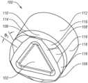
- FIGS. 1 A and 1 Bare perspective side views of an embodiment of a cutting element 100 for an earth-boring tool in accordance with the present disclosure.
- the cutting element 100includes a table 110 positioned and configured to engage with, and remove, an earth formation as the cutting element 100 is advanced toward the earth formation.
- the table 110may include a polycrystalline, superabrasive material, such as, for example, polycrystalline diamond or cubic boron nitride.
- the table 110may be secured to an end of a substrate 112 , forming an interface 114 between the table 110 and the substrate 112 .
- the substrate 112may include a hard, wear-resistant material suitable for use in the downhole environment.
- the substrate 112may include a ceramic-metallic composite material (e.g., a cermet), including particles of a carbide or nitride material (e.g., tungsten carbide) in a matrix of a metal material (e.g., a solvent metal catalyst material configured to catalyze the formation of intergranular bonds among grains of the superabrasive material of the table 110 ).
- a ceramic-metallic composite materiale.g., a cermet
- a carbide or nitride materiale.g., tungsten carbide
- a metal materiale.g., a solvent metal catalyst material configured to catalyze the formation of intergranular bonds among grains of the superabrasive material of the table 110 .
- the table 110 of the cutting element 100may include a raised cutting surface 108 at a farthest distance from the substrate 112 having cutting edges 106 for positioning to first engage with the earth formation and located proximate to radially outermost portions of the table 110 with respect to a longitudinal axis of the cutting element 100 .
- the table 110may also include a recess 102 located proximate to a geometric center of the table 110 and positioned closer to the substrate 112 than the raised cutting surface 108 .
- the table 110may also include transition surfaces 116 extending from portions of the raised cutting surface 108 extending between the cutting edges 106 radially outward toward a periphery of the table 110 and longitudinally from the raised cutting surface 108 toward the substrate 112 .
- Each respective portion of the table 110 located between the cutting edges 106may include multiple transition surfaces 116 .
- the transition surfaces 116may be planar, may extend over at least substantially the same longitudinal distance from the raised cutting surface 108 toward the substrate 112 , and may extend along a respective portion of the angular distance around the perimeter of the table 110 .
- Such transition surfaces 116may present an angular, faceted, series of chamfer surfaces to render the transition between the cutting edges 106 around the perimeter of the table 110 , and between the raised cutting surface 108 and a side surface 118 of the cutting element 100 , more gradual.
- the raised cutting surface 108is generally shaped as a triangle, having three cutting edges 106 proximate a side surface 118 of the cutting element 100 forming nodes of the substantially triangular shape, and three corresponding sides extending between the cutting edges 106 .
- the transition surfaces 116may cause what would otherwise be a planar surface extending from an edge at the perimeter of the cutting surface 108 between the cutting edges 106 to bow radially outward, such that the sides of the generally triangular cutting surface 108 are divided into multiple planar subsections, each planar subsection corresponding to an intersection of a given transition surface 116 with the raised cutting surface 108 .
- the raised cutting surfacemay have another substantially polygonal shape (e.g., rectangle, square, oval, rhombus, pentagon, etc.), with faceted transition surfaces 116 dividing the sides between major nodes of the polygonal shape into subsections.
- Variable flank angles for the transition surfaces 116may reduce the cutter point loading of cutting forces during drilling while reducing the risk of torsional overloading in tougher to drill, higher depth of cut (DOC) applications.
- DOCdepth of cut
- Cutting element 100may include three different flank angles (e.g., first flank angle, second flank angle, and third flank angle) for each of the transition surfaces 116 oriented at different flank angles.
- the flank anglesare the smallest angle between a given transition surface 116 and a plane at least substantially parallel to the raised cutting surface 108 of cutting element 100 .
- Each one of the three different flank anglesdiffers from the other flank angles.
- FIG. 1 Aillustrates the three different flank angles of cutting element 100 .
- a first flank angle ⁇ 1may be between about 25 degrees and about 75 degrees. More specifically, the first flank angle ⁇ 1 may be, for example, between about 35 degrees and about 70 degrees. As a specific, nonlimiting example, the first flank angle ⁇ 1 may be between about 45 degrees and about 65 degrees (e.g., about 50 degrees, about 55 degrees, about 60 degrees).
- the second flank angle ⁇ 2may be, for example, less than the first flank angle ⁇ 1 , and between about 15 degrees and about 65 degrees. More specifically, the second flank angle ⁇ 2 may be, for example, between about 25 degrees and about 60 degrees.
- the second flank angle ⁇ 2may be between about 35 degrees and about 55 degrees (e.g., about 40 degrees, about 45 degrees, about 50 degrees).
- the third flank angle ⁇ 3may be, for example, less than the first flank angle ⁇ 1 and less than the second flank angle ⁇ 2 , and between about 1 degree and about 45 degrees. More specifically, the third flank angle ⁇ 3 may be, for example, between about 5 degrees and about 40 degrees. As a specific, nonlimiting example, the third flank angle ⁇ 3 may be between about 10 degrees and about 35 degrees (e.g., about 15 degrees, about 20 degrees, about 25 degrees).
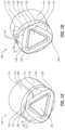
- FIG. 2is a perspective side view of another embodiment of a cutting element 200 in accordance with this disclosure. Similar to the cutting element 100 of FIGS. 1 A and 1 B , the cutting element 200 of FIG. 2 includes a raised cutting surface 208 having cutting edges 206 , and transition surfaces 216 forming a faceted, chamfered transition around the perimeter of the cutting surface 208 between cutting edges 206 .
- the raised cutting surface 208is generally shaped as a triangle, having three cutting edges 206 proximate a side surface 218 of the cutting element 200 forming nodes of the substantially triangular shape, and three corresponding sides extending between the cutting edges 206 .
- the transition surfaces 216may cause what would otherwise be a planar surface extending from an edge at the perimeter of the cutting surface 208 between the cutting edges 206 and to the perimeter of the table 210 to bow radially outward, such that the sides of the generally triangular cutting surface 208 are divided into multiple planar subsections, each planar subsection corresponding to an intersection of a given transition surface 216 with the raised cutting surface 208 .
- the cutting element 200 of FIG. 2does not include the recess of cutting element 100 of FIGS. 1 A and 1 B .
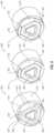
- FIG. 3is a perspective side view of another embodiment of a cutting element 300 in accordance with this disclosure. Similar to the cutting element 100 of FIGS. 1 A and 1 B , the cutting element 300 of FIG. 3 includes a raised cutting surface 308 having cutting edges 306 , a recess 302 , and transition surfaces 316 forming a faceted, chamfered transition around the perimeter of the cutting surface 308 between cutting edges 306 . In the cutting element 300 of FIG. 3 , the intersections between respective transition surfaces 316 may themselves include chamfers 318 or rounded (e.g., radiused) edges. In particular, each intersection between each of the transition surfaces 316 may be chamfered or curved.
- intersections between the transition surfaces 316 and the raised cutting surface 308may be chamfered or curved.
- the intersections between the transition surfaces 316 and the side surface 320 of the cutting element 300e.g., between the transition surfaces 316 and the perimeter of the table 110 , between the transition surfaces and the substrate 112 ) may also be chamfered or curved.
- recess 302may be omitted from cutting element 300 similar to cutting element 200 of FIG. 2 .
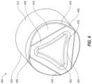
- FIG. 4is a perspective side view of another embodiment of a cutting element 400 in accordance with this disclosure. Similar to FIGS. 1 A through 3 , FIG. 4 illustrates a cutting element 400 including a raised cutting surface 408 having cutting edges 406 and a recess 402 . Unlike FIGS. 1 A through 3 , the transition surfaces 416 depicted in FIG. 4 may be configured as discrete, continuous respective surfaces extending between the cutting edges 406 . Such transition surfaces may cause the perimeter of the raised cutting surface 408 to conform more closely to the general polygonal shape it resembles, with at least substantially straight sides, each side formed by the intersection of a respective transition surface 416 with the raised cutting surface 408 , extending between the nodes of the cutting edges 406 . In some embodiments, recess 402 may be omitted from cutting element 400 similar to cutting element 200 of FIG. 2 .
- the transition surfaces 416 of the cutting element 400 of FIG. 4may include chamfers 418 or rounded surfaces at the intersection between a given transition surface 416 and the cutting surface 408 .
- the intersection between a given transition surface 416 and the side surface 420 of the cutting element 400may be chamfered and/or curved.
- the recess 402 located proximate to the geometrical center of the cutting element 400 , and located closer to the substrate 412 than the raised cutting surface 408may have a substantially triangular shape.
- the portions of the cutting surface 408 generally corresponding to three sides of the substantially triangular shapemay have linear outer edges at intersections with the transition surfaces 416 (or at the chamfers 418 or curves transitioning thereto), and may have nonlinear inner edges at an intersection with another chamfer 418 or curve transitioning from the cutting surface 408 to the recess 402 .
- the raised cutting surface 408may have a variable (e.g., non-constant) thickness in the regions extending between the cutting edges 406 , as measured in a direction perpendicular to the outer edges 424 of the raised cutting surface 408 .
- the inner edges 422 of the cutting surface 408as defined at an intersection of the cutting surface 408 with the chamfer 418 or curve transitioning to the recess 402 , may be arcuate.
- the inner edges 422 of the cutting surface 408may be curved, may bow radially toward the geometric center of the recess 402 , and may peak at least substantially at the midpoint between respective cutting edges 406 , such that the thickest portion of the cutting surface 408 may be located at least substantially at that midpoint.
- the interior edges of the raised cutting surface 408 adjacent to recess 402may be linear (e.g., straight), may have a variable radius or a more complex shape, or may have a peak at a location other than the midpoint between cutting edges 406 .
- FIG. 5is a top surface view of a face 504 of another embodiment of a cutting element 500 for an earth-boring tool, illustrating a recess having a substantially rectangular shape.
- the cutting face 504may not be raised, may be at least substantially planar, and may extend from a side surface 508 at a lateral periphery of the cutting element 500 radially inward.
- the cutting face 504may terminate at a recess 502 located proximate to a geometric center of the cutting element 500 .
- Recess 502may be at least substantially rectangle shaped (e.g., substantially square shaped) with rounded corners 506 .
- the surfaces that define recess 502may be planar (oriented at any angle from 5° to 90° with respect to a longitudinal axis of the cutting element 500 ), may be curved (convex and/or concave) having an at least substantially constant or continuously variable radius (e.g., parabolic), or the surfaces may have a more complex curvature (such as a sinusoidal wave).
- recess 502may be omitted from cutting element 500 similar to cutting element 200 of FIG. 2 .
- FIG. 6is a top surface view of a face 604 of another embodiment of a cutting element 600 for an earth-boring tool.
- the cutting face 606 of the cutting element 600may be raised, may be at least substantially planar, and may only extend to a side surface 608 at a lateral periphery of the cutting element 600 proximate to cutting edges 610 .
- the cutting face 606may intersect with an outer transition surface 604 transitioning from the cutting face 604 longitudinally toward a substrate and radially outward from the cutting face 606 toward the side surface 608 .
- the transition surface 606may extend at an at least substantially constant angle from the cutting face 604 toward the substrate (e.g., may take the form of a chamfer), or may be curved from the cutting face 604 toward the substrate (e.g., at constant or variable radius), or may have a more complex transition geometry.
- the cutting element 600may also include recess 602 located proximate to the geometric center of the cutting element 600 , and positioned closer to the substrate than the cutting face 606 .
- the recess 602may generally be in the shape of an oval (e.g., an ellipse), and the raised cutting face 606 may likewise be at least substantially oval shaped (e.g., ellipse shaped).
- the thickness of the cutting face 606may be at least substantially constant, or may vary (as shown in FIG. 6 ). In some embodiments, recess 602 may be omitted from cutting element 600 similar to cutting element 200 of FIG. 2 .
- FIG. 7is a top surface view of a face of another embodiment of a cutting element 700 for an earth-boring tool.
- the cutting face 706 of the cutting element 700may also be raised, may be at least substantially planar, and may only extend to a side surface 710 at a lateral periphery of the cutting element 700 proximate to cutting edges 708 .
- the cutting face 706may intersect with an inner transition surface 712 transitioning from the cutting face 706 longitudinally toward a substrate to form a recess 702 .
- the transition surface 712may extend at an at least substantially constant angle from a planar bottom of the recess 702 to the cutting face 706 (e.g., may take the form of a chamfer), or may be curved from the planar bottom of the recess 702 to the cutting face 706 (e.g., at constant or variable radius), or may have a more complex transition geometry.
- the inner edges of the transition surface 712 intersecting with the planar bottom surface of the recess 702may be nonlinear.
- the transition surface 712may have a variable (e.g., non-constant) thickness in the regions extending between the nodes of the generally polygonal shape of the cutting surface 706 , as measured in a direction perpendicular to the at least substantially linear edges of the cutting surface 706 extending between the cutting edges 708 .
- the inner edges 714 of the transition surfaces 712as defined at intersections of the transition surface 712 with the planar bottom of the recess 702 , may be arcuate.
- the inner edges 714 of the transition surfaces 712may be curved, may bow radially toward the geometric center of the recess 702 , and may peak at least substantially at the midpoint between respective cutting edges 708 , such that the thickest portion of the transition surfaces 712 may be located at least substantially at that midpoint.
- the interior edges 714 of the inner transition surfaces 712 at the intersection with the planar bottom of the recess 702may be linear (e.g., straight), may have a variable radius or a more complex shape, or may have a peak at a location other than the midpoint between cutting edges 708 .
- the cutting face 706may also intersect with an outer transition surface 704 , which may extend radially outward from the cutting face 706 to the side surface 710 and longitudinally from the cutting face 706 toward the substrate.
- the outer transition surfacesmay take any of the forms, and have any of the configurations, described previously in connection with FIGS. 1 A through 4 .
- the recess 702may generally be in the shape of a rectangle (e.g., a square), and the cutting surface 606 may likewise be at least substantially rectangle shaped (e.g., square shaped). In some embodiments, recess 702 may be omitted from cutting element 700 similar to cutting element 200 of FIG. 2 .
- FIG. 8is a series of perspective side views of other embodiments of cutting elements 800 for earth-boring tools.
- the cutting element 800may be configured to include a raised cutting surface 808 having cutting edges 806 , a recess 802 in the center of the raised cutting surface 808 , and transition surfaces 816 extending from portions of the cutting surface 808 at the outer periphery thereof toward the substrate 812 .
- the transition surfaces 816may extend from the raised cutting surface 808 to a side surface 822 of the cutting element 800 , which may be within the table 810 itself or at the interface 814 with the substrate 812 .
- the cutting element 800may include a first chamfered edge 818 at the cutting edge 806 of the cutting element 800 .
- the first chamfered edge 818may extend around an entire circumference of the table 810 , forming a transition between the side surface 822 and the cutting edge 806 , as well as between the side surface 822 and the transition surfaces 816 .
- the table 810may also include a secondary chamfer 820 between the first chamfered edge 818 and the raised cutting surface 808 proximate to the cutting edges 806 .
- the secondary chamfer 820may intersect laterally with, and generally traverse the same longitudinal distance as, the transition surfaces 816 .
- the secondary chamfer 820 and the transition surfacesmay collectively form a faceted transition from the first chamfer 818 longitudinally toward the cutting face 808 and radially inward toward the geometric center of the cutting element 800 .
- the two embodiments on the right-hand side of FIG. 8illustrate a third chamfer 824 between the secondary chamfer 820 and the raised cutting surface 808 .
- the third chamfer 824may likewise extend around an entire circumference of the table 810 , forming a gradual transition from the secondary chamfer 820 and from the transition surfaces 816 to the cutting face 808 .
- Each of the transition surface 816 , first chamfered edge 818 , secondary chamfer 820 , and third chamfer 824may take the form of a planar surface or an arcuate surface (e.g., concave or convex) transitioning longitudinally and radially between the identified bordering features. As shown in the various views of FIG. 8 , the transition surface 816 , first chamfered edge 818 , secondary chamfer 820 , and third chamfer 824 may be adapted to cover differing longitudinal and radial extents, forming shorter, taller, wider, and/or narrower features, depending on the specific configuration desired.
- Chamfered edgessuch as those described in connection with FIG.
- recess 802may be omitted from cutting element 800 similar to cutting element 200 of FIG. 2 .
- FIG. 9is a series of perspective side views of other embodiments of cutting elements 900 for earth-boring tools.
- the cutting element 900may include a raised cutting surface 908 having cutting edges 906 , a recess 902 , and transition surfaces 916 .
- the various views of FIG. 9also illustrate that the cutting element may include a multi-angled full edge first chamfer 918 and a multi-angled full edge second chamfer 920 .
- the first chamfer 918may extend around an entire circumference of the table 910 , and may form a sloped or curved transition between the side surface 922 of the cutting element 900 and the second chamfer 920 .
- the cutting edge 906may be formed by the first chamfer 918 in some embodiments, at the intersection between the first chamfer 918 and the side surface 922 of the cutting element 900 .
- recess 902may be omitted from cutting element 900 similar to cutting element 200 of FIG. 2 .
- the second chamfer 920may likewise extend around the entire circumference of the table 910 , and may form a sloped or curved transition between the first chamfer 918 and a third chamfer 924 or between the first chamfer 918 and the transition surface 916 and between the first chamfer 918 and the cutting surface 908 .
- the central view of FIG. 9also illustrates a multi-angled full edge third chamfer 924 , which may extend around the entire circumference of the table 910 , and form a sloped or curved transition between the second chamfer 920 and the transition surface 916 and between the second chamfer 920 and the cutting surface 908 .
- the right-hand view of FIG. 9illustrates a fourth chamfer 926 for the generally polygonal shape of the cutting face 908 .
- the fourth chamfer 926may be located at the perimeter of the outer edge of the at least substantially triangular shape of the cutting face 908 , and may form a sloped or curved transition between the transition surface 916 and the cutting face 908 and between the portion of the second chamfer 920 located proximate to the transition surface 916 and the portion of the second chamfer 920 located proximate to the cutting edge 906 .
- the geometries of the several views of FIG. 9may produce a sharp cutting edge 906 at the beginning of an earth-boring operation.
- the effective cutting edgemay wear through the first chamfer 918 , into the second chamfer 920 , into the third chamfer 924 in embodiments including such a feature, and ultimately into the cutting face 908 .
- the width of the effective cutting edgemay gradually increase as this wear and transition occurs, the width of the effective cutting edge may remain sharper when compared to conventional designs for cutting elements known to the inventors.
- the geometries for the cutting elements 900 shown in FIG. 9may also reduce internal stresses induced during cutting, increase fracture and wear resistance, and otherwise improve cutting efficiency.
- the multi-angle full edge chamfers 918 , 920 , and 924 , along with the planar transition surfaces 916 , and chamfersmay improve the flow of fluid around the cutting element 900 , increasing the efficiency of cutting removal, more effectively cooling the cutting element 900 , and increasing the efficiency and durability of the cutting element 900 .
- the features of the cutting elements shown and described in connection with FIGS. 1 A through 9may be combined with one another.
- the faceted transition surfaces 116 shown in FIGS. 1 A and 1 Bmay be implemented on any of the cutting elements shown in FIGS. 4 through 9 .
- the chamfers 318 between faceted transition surfaces 316 shown in FIG. 3may be implemented on any of the cutting elements of FIGS. 4 through 9 , assuming they include the faceted transition surfaces 316 themselves.
- the nonlinear inner edges 422 shown in FIG. 4may be utilized for any of the inner edges for polygonal cutting faces shown in FIGS. 1 A through 3 and 5 through 9 .
- FIGS. 5 through 7may be utilized instead of the generally triangular shapes shown in FIGS. 1 A through 4 , 8 , and 9 .
- the various chamfering configurationsincluding full-edge chamfers, variations in longitudinal and radial distances covered, and extensions of the generally polygonal shapes into the chamfered regions shown in FIGS. 8 and 9 may be utilized with any of the cutting element designs shown and described in connection with FIGS. 1 A through 7 .
- FIG. 10is a perspective view of an earth-boring tool 1000 including one or more cutting elements 1002 , which may be configured as any of the embodiments shown in connection with FIGS. 1 A through 9 , or any possible combination of their features, as described above.
- the cutting elements 1002have been illustrated as having planar cutting faces, but at least one of the cutting element 1002 , up to all of the cutting elements 1002 , may have the complex geometries described above.
- the earth-boring tool 1000may include a body 1004 to which the cutting element(s) 1002 may be secured.
- the cutting element(s) 1002may be secured partially within pockets 1010 extending into one or more of the blades 1006 (e.g., proximate the rotationally leading portions of the blades 1006 as primary cutting elements 1002 , rotationally following those portions as backup cutting elements 1002 , or both).
- cutting elements 1002 as described hereinmay be bonded to and used on other types of earth-boring tools, including, for example, roller cone drill bits, percussion bits, core bits, eccentric bits, bi-center bits, reamers, expandable reamers, mills, hybrid bits, and other drilling bits and tools known in the art.
- modified geometries of the embodiments described aboveare expected to mitigate thumbnail cracking and tangential overload when compared to geometries for other cutting elements known to the inventors. Furthermore, modified geometries of the embodiments described above contain critical angled faces to maintain cutting efficiency while allowing for increased durability. The modified geometries of the embodiments described above will allow for greater use in higher weight and torque drilling environments.
- Embodiment 1A cutting element comprising a substrate and a polycrystalline diamond material affixed to the substrate at an interface.
- the polycrystalline diamond materialcomprising a raised cutting surface comprising at least two cutting edges, and first transition surfaces between the at least two cutting edges of the raised cutting surface and a longitudinal side surface of the cutting element, wherein the first transition surfaces comprise multiple planar surfaces.
- Embodiment 2The cutting element of Embodiment 1, further comprising a recess in a center of the raised cutting surface.
- Embodiment 3The cutting element of Embodiment 2, further comprising second transition surfaces between edges of the raised cutting surfaces and a bottom surface of the recess.
- Embodiment 4The cutting element of Embodiment 2 or Embodiment 3, wherein one or more edges between the raised cutting surface and the second transition surfaces are linear.
- Embodiment 5The cutting element of Embodiment 2 or Embodiment 3, wherein one or more edges between the raised cutting surface and the second transition surfaces comprise one or more arcs.
- Embodiment 6The cutting element of Embodiment 2 or Embodiment 3, wherein edges between the raised cutting surface and the second transition surfaces are chamfered.
- Embodiment 7The cutting element of Embodiment 1 through 6, wherein at least one edge of the raised cutting surface comprises a chamfered edge.
- Embodiment 8The cutting element of Embodiment 1 through 7, wherein the at least two cutting edges of the raised cutting surface are chamfered.
- Embodiment 9The cutting element of Embodiments 1 through 8, wherein edges between the longitudinal side surface of the cutting element and the first transition surfaces are chamfered.
- Embodiment 10The cutting element of Embodiments 1 through 9, wherein edges between the raised cutting surface and the first transition surfaces are chamfered.
- Embodiment 11The cutting element of Embodiments 1 through 10, wherein one or more edges between the raised cutting surface and the second transition surfaces are linear.
- Embodiment 12The cutting element of Embodiments 1 through 11, wherein one or more edges between the raised cutting surface and the first transition surfaces comprise one or more arcs.
- Embodiment 13The cutting element of Embodiments 1 through 12, wherein the raised cutting surface comprises at least three cutting edges.
- Embodiment 14The cutting element of Embodiments 1 through 13, wherein the raised cutting surface comprises at least four cutting edges.
- Embodiment 15A method of manufacturing an earth-boring tool comprising forming a drill bit body, forming at least one blade extending from one end of the drill bit body. The at least one blade comprising a leading edge section. Forming at least one cutting element in each at least one blade proximate the leading edge section of the at least one blade. Forming the at least one cutting element comprises forming a polycrystalline diamond material, affixing a first end of the polycrystalline diamond material at an interface to a substrate, and shaping a second end of the polycrystalline diamond material.
- Shaping the second end of the polycrystalline diamond materialcomprises forming at least two cutting edges defining a raised cutting surface, and forming first transition surfaces between the at least two cutting edges of the raised cutting surface and a longitudinal side surface of the cutting element, wherein the first transition surfaces comprise multiple planar surfaces.
- Embodiment 16The method of Embodiment 15, further comprising forming a recess in a center of the raised cutting surface.
- Embodiment 17The method of Embodiment 16, further comprising forming second transition surfaces between edges of the raised cutting surface and a bottom surface of the recess.
- Embodiment 18An earth-boring tool comprising a bit body, a plurality of blades extending from one end of the body, each blade comprising a leading edge section, at least one cutting element disposed within each blade proximate the leading edge section of the blade.
- the at least one cutting elementcomprising a substrate and a polycrystalline diamond material affixed to the substrate at an interface.
- the polycrystalline diamond materialcomprising a raised cutting surface comprising at least two cutting edges and first transition surfaces between the at least two cutting edges of the raised cutting surface and a longitudinal side surface of the cutting element.
- the first transition surfacescomprise multiple planar surfaces.
- Embodiment 19The earth-boring tool of Embodiment 18, further comprising a recess in a center of the raised cutting surface.
- Embodiment 20The cutting element of Embodiment 19, wherein a bottom surface of the recess is positioned closer to the substrate than the raised cutting surface.
Landscapes
- Engineering & Computer Science (AREA)
- Life Sciences & Earth Sciences (AREA)
- Mining & Mineral Resources (AREA)
- Geology (AREA)
- Mechanical Engineering (AREA)
- Physics & Mathematics (AREA)
- Environmental & Geological Engineering (AREA)
- Fluid Mechanics (AREA)
- General Life Sciences & Earth Sciences (AREA)
- Geochemistry & Mineralogy (AREA)
- Chemical & Material Sciences (AREA)
- Crystallography & Structural Chemistry (AREA)
- Earth Drilling (AREA)
- Processing Of Stones Or Stones Resemblance Materials (AREA)
Abstract
Description
Claims (20)
Priority Applications (5)
| Application Number | Priority Date | Filing Date | Title |
|---|---|---|---|
| MX2023009131AMX2023009131A (en) | 2021-02-05 | 2022-02-04 | Cutting elements for earth-boring tools, and methods of manufacturing earth-boring tools. |
| PCT/US2022/070538WO2022170352A1 (en) | 2021-02-05 | 2022-02-04 | Cutting elements for earth-boring tools, and methods of manufacturing earth-boring tools |
| SE2351010ASE2351010A1 (en) | 2021-02-05 | 2022-02-04 | Cutting elements for earth-boring tools, and methods of manufacturing earth-boring tools |
| US17/650,014US12134938B2 (en) | 2021-02-05 | 2022-02-04 | Cutting elements for earth-boring tools, methods of manufacturing earth-boring tools, and related earth-boring tools |
| NO20230874ANO20230874A1 (en) | 2021-02-05 | 2023-08-16 | Cutting elements for earth-boring tools, and methods of manufacturing earth-boring tools |
Applications Claiming Priority (2)
| Application Number | Priority Date | Filing Date | Title |
|---|---|---|---|
| US202163146531P | 2021-02-05 | 2021-02-05 | |
| US17/650,014US12134938B2 (en) | 2021-02-05 | 2022-02-04 | Cutting elements for earth-boring tools, methods of manufacturing earth-boring tools, and related earth-boring tools |
Publications (2)
| Publication Number | Publication Date |
|---|---|
| US20220251905A1 US20220251905A1 (en) | 2022-08-11 |
| US12134938B2true US12134938B2 (en) | 2024-11-05 |
Family
ID=82703683
Family Applications (1)
| Application Number | Title | Priority Date | Filing Date |
|---|---|---|---|
| US17/650,014ActiveUS12134938B2 (en) | 2021-02-05 | 2022-02-04 | Cutting elements for earth-boring tools, methods of manufacturing earth-boring tools, and related earth-boring tools |
Country Status (6)
| Country | Link |
|---|---|
| US (1) | US12134938B2 (en) |
| CN (1) | CN116917594A (en) |
| MX (1) | MX2023009131A (en) |
| NO (1) | NO20230874A1 (en) |
| SE (1) | SE2351010A1 (en) |
| WO (1) | WO2022170352A1 (en) |
Cited By (3)
| Publication number | Priority date | Publication date | Assignee | Title |
|---|---|---|---|---|
| US20220403706A1 (en)* | 2021-06-18 | 2022-12-22 | Suzhou Superior Industrial Technology Co. Ltd | Drill bit cutters with stepped surfaces |
| US20240401413A1 (en)* | 2023-05-30 | 2024-12-05 | Ulterra Drilling Technologies, L.P. | Drill bits and other downhole drilling tools with non-cylindrical cutter pockets |
| US12320199B1 (en)* | 2022-11-22 | 2025-06-03 | Baker Hughes Oilfield Operations Llc | Cutting elements and geometries for reduced vibrations, earth-boring tools, and related methods |
Families Citing this family (6)
| Publication number | Priority date | Publication date | Assignee | Title |
|---|---|---|---|---|
| USD924949S1 (en) | 2019-01-11 | 2021-07-13 | Us Synthetic Corporation | Cutting tool |
| WO2020180330A1 (en)* | 2019-03-07 | 2020-09-10 | Halliburton Energy Services, Inc. | Shaped cutter arrangements |
| USD1026979S1 (en) | 2020-12-03 | 2024-05-14 | Us Synthetic Corporation | Cutting tool |
| EP4508299A1 (en)* | 2022-04-13 | 2025-02-19 | National Oilwell Varco, L.P. | Drill bit cutter elements with multiple surface finishes |
| US12331595B2 (en)* | 2022-12-12 | 2025-06-17 | Halliburton Energy Services, Inc. | Shaped cutter for drill bit with point-loaded reinforcing ribs |
| WO2025015012A1 (en)* | 2023-07-10 | 2025-01-16 | Schlumberger Technology Corporation | Devices, systems, and methods of a cutting element in a bit |
Citations (135)
| Publication number | Priority date | Publication date | Assignee | Title |
|---|---|---|---|---|
| US4109737A (en) | 1976-06-24 | 1978-08-29 | General Electric Company | Rotary drill bit |
| EP0121083A1 (en) | 1983-02-24 | 1984-10-10 | Union Carbide Corporation | Low-temperature crosslinking of water-borne resins |
| US4529048A (en) | 1982-10-06 | 1985-07-16 | Megadiamond Industries, Inc. | Inserts having two components anchored together at a non-perpendicular angle of attachment for use in rotary type drag bits |
| US4570726A (en) | 1982-10-06 | 1986-02-18 | Megadiamond Industries, Inc. | Curved contact portion on engaging elements for rotary type drag bits |
| US4593777A (en) | 1983-02-22 | 1986-06-10 | Nl Industries, Inc. | Drag bit and cutters |
| US4872520A (en) | 1987-01-16 | 1989-10-10 | Triton Engineering Services Company | Flat bottom drilling bit with polycrystalline cutters |
| US4987800A (en) | 1988-06-28 | 1991-01-29 | Reed Tool Company Limited | Cutter elements for rotary drill bits |
| US4989578A (en) | 1989-08-30 | 1991-02-05 | Lebourg Maurice P | Method for forming diamond cutting elements for a diamond drill bit |
| US5054246A (en) | 1988-09-09 | 1991-10-08 | Cornelius Phaal | Abrasive compacts |
| US5172778A (en) | 1991-11-14 | 1992-12-22 | Baker-Hughes, Inc. | Drill bit cutter and method for reducing pressure loading of cutters |
| EP0572761A1 (en) | 1992-06-05 | 1993-12-08 | Baker Hughes Incorporated | Diamond cutters having modified cutting edge geometry and drill bit mounting arrangement therefor |
| US5333699A (en) | 1992-12-23 | 1994-08-02 | Baroid Technology, Inc. | Drill bit having polycrystalline diamond compact cutter with spherical first end opposite cutting end |
| US5377773A (en) | 1992-02-18 | 1995-01-03 | Baker Hughes Incorporated | Drill bit having combined positive and negative or neutral rake cutters |
| US5449048A (en)* | 1992-12-23 | 1995-09-12 | Baroid Technology, Inc. | Drill bit having chip breaker polycrystalline diamond compact and hard metal insert at gauge surface |
| US5460233A (en)* | 1993-03-30 | 1995-10-24 | Baker Hughes Incorporated | Diamond cutting structure for drilling hard subterranean formations |
| US5467836A (en) | 1992-01-31 | 1995-11-21 | Baker Hughes Incorporated | Fixed cutter bit with shear cutting gage |
| US5499688A (en) | 1993-08-17 | 1996-03-19 | Dennis Tool Company | PDC insert featuring side spiral wear pads |
| WO1997030263A1 (en) | 1996-02-15 | 1997-08-21 | Baker Hughes Incorporated | Polycrystalline diamond cutter with enhanced durability and increased wear life |
| US5709279A (en) | 1995-05-18 | 1998-01-20 | Dennis; Mahlon Denton | Drill bit insert with sinusoidal interface |
| US5871060A (en) | 1997-02-20 | 1999-02-16 | Jensen; Kenneth M. | Attachment geometry for non-planar drill inserts |
| JPH1160667A (en) | 1997-08-11 | 1999-03-02 | Dainichiseika Color & Chem Mfg Co Ltd | Polycarbodiimide compound, method for producing the same, resin composition, and method for treating article |
| US5881830A (en) | 1997-02-14 | 1999-03-16 | Baker Hughes Incorporated | Superabrasive drill bit cutting element with buttress-supported planar chamfer |
| GB2339221A (en) | 1998-07-07 | 2000-01-19 | Smith International | Unplanar non-axisymetrical drilling inserts |
| US6045440A (en) | 1997-11-20 | 2000-04-04 | General Electric Company | Polycrystalline diamond compact PDC cutter with improved cutting capability |
| US6065554A (en) | 1996-10-11 | 2000-05-23 | Camco Drilling Group Limited | Preform cutting elements for rotary drill bits |
| WO2000048789A1 (en) | 1999-02-19 | 2000-08-24 | U.S. Synthetic Corporation | Method for forming a superabrasive polycrystalline cutting tool with an integral chipbreaker feature |
| US6196340B1 (en) | 1997-11-28 | 2001-03-06 | U.S. Synthetic Corporation | Surface geometry for non-planar drill inserts |
| US20010030063A1 (en) | 1999-08-26 | 2001-10-18 | Dykstra Mark W. | Drill bits with reduced exposure of cutters |
| GB2369841A (en) | 2000-12-07 | 2002-06-12 | Smith International | Ultra hard material cutter with shaped cutting surface |
| US6481952B2 (en) | 1999-06-21 | 2002-11-19 | E.C.H. Will Gmbh | Method of and apparatus for accumulating successive stacks of superimposed sheets |
| US6510910B2 (en) | 2001-02-09 | 2003-01-28 | Smith International, Inc. | Unplanar non-axisymmetric inserts |
| US6527069B1 (en) | 1998-06-25 | 2003-03-04 | Baker Hughes Incorporated | Superabrasive cutter having optimized table thickness and arcuate table-to-substrate interfaces |
| US20030158018A1 (en) | 2000-03-01 | 2003-08-21 | Raymond Giannelli | Leg press machine |
| EP0893572B1 (en) | 1997-07-26 | 2003-12-10 | Camco International (UK) Limited | Improvements in or relating to elements faced with superhard material |
| US6672406B2 (en) | 1997-09-08 | 2004-01-06 | Baker Hughes Incorporated | Multi-aggressiveness cuttting face on PDC cutters and method of drilling subterranean formations |
| WO2004007907A1 (en) | 2002-07-12 | 2004-01-22 | Cdx Gas, L.L.C. | Undulating well bore |
| WO2004007901A1 (en) | 2002-07-10 | 2004-01-22 | Diamond Innovations, Inc. | Cutting tools with two-slope profile |
| US20040097532A1 (en) | 2000-11-10 | 2004-05-20 | Jesudason Cynthia Darshini | 3-Substituted oxindole beta 3 agonists |
| US20040163851A1 (en) | 2003-02-21 | 2004-08-26 | Smith International, Inc. | Drill bit cutter element having multiple cusps |
| US6935444B2 (en) | 2003-02-24 | 2005-08-30 | Baker Hughes Incorporated | Superabrasive cutting elements with cutting edge geometry having enhanced durability, method of producing same, and drill bits so equipped |
| US20050269139A1 (en) | 2004-04-30 | 2005-12-08 | Smith International, Inc. | Shaped cutter surface |
| US20060157286A1 (en) | 2005-01-17 | 2006-07-20 | Us Synthetic | Superabrasive inserts including an arcuate peripheral surface |
| US20060210364A1 (en) | 2003-12-23 | 2006-09-21 | Emuge-Werk Richard Glimpel Gmbh & Co. Kg Fabrik Fur Prazisionswerkzeuge | Cutting element and tool equipped with at least one cutting element |
| US20060219439A1 (en) | 2005-04-04 | 2006-10-05 | Smith International, Inc. | Stress relief feature on PDC cutter |
| US20070079995A1 (en) | 2004-02-19 | 2007-04-12 | Mcclain Eric E | Cutting elements configured for casing component drillout and earth boring drill bits including same |
| US7363992B2 (en) | 2006-07-07 | 2008-04-29 | Baker Hughes Incorporated | Cutters for downhole cutting devices |
| US20080190666A1 (en) | 2007-02-09 | 2008-08-14 | Smith International, Inc. | Gage insert |
| WO2008102324A1 (en) | 2007-02-23 | 2008-08-28 | Element Six (Production) (Pty) Ltd | Cutting elements |
| US20080205804A1 (en) | 2007-02-27 | 2008-08-28 | Jian-Dih Jeng | Simplified Fluid Dynamic Bearing Design |
| US20080236900A1 (en) | 2005-06-09 | 2008-10-02 | Us Synthetic Corporation | Cutting element apparatuses and drill bits so equipped |
| JP2008291222A (en) | 2007-04-09 | 2008-12-04 | Bridgestone Corp | Sealing film and solar cell using the same |
| US20090057031A1 (en) | 2007-08-27 | 2009-03-05 | Patel Suresh G | Chamfered edge gage cutters, drill bits so equipped, and methods of cutter manufacture |
| US20100059287A1 (en) | 2008-09-05 | 2010-03-11 | Smith International, Inc. | Cutter geometry for high rop applications |
| US20100084198A1 (en) | 2008-10-08 | 2010-04-08 | Smith International, Inc. | Cutters for fixed cutter bits |
| US7726420B2 (en) | 2004-04-30 | 2010-06-01 | Smith International, Inc. | Cutter having shaped working surface with varying edge chamfer |
| US7757785B2 (en) | 2004-04-30 | 2010-07-20 | Smith International, Inc. | Modified cutters and a method of drilling with modified cutters |
| US20100288564A1 (en) | 2009-05-13 | 2010-11-18 | Baker Hughes Incorporated | Cutting element for use in a drill bit for drilling subterranean formations |
| US20100307829A1 (en) | 2009-06-05 | 2010-12-09 | Baker Hughes Incorporated | Cutting elements including cutting tables with shaped faces configured to provide continuous effective positive back rake angles, drill bits so equipped and methods of drilling |
| US20110031031A1 (en) | 2009-07-08 | 2011-02-10 | Baker Hughes Incorporated | Cutting element for a drill bit used in drilling subterranean formations |
| US20110088950A1 (en) | 2009-10-02 | 2011-04-21 | Baker Hughes Incorporated | Cutting elements configured to generate shear lips during use in cutting, earth boring tools including such cutting elements, and methods of forming and using such cutting elements and earth boring tools |
| US20110155472A1 (en) | 2009-12-28 | 2011-06-30 | Baker Hughes Incorporated | Earth-boring tools having differing cutting elements on a blade and related methods |
| US20110171414A1 (en) | 2010-01-14 | 2011-07-14 | National Oilwell DHT, L.P. | Sacrificial Catalyst Polycrystalline Diamond Element |
| US20110259642A1 (en) | 2010-04-23 | 2011-10-27 | Element Six (Production) (Pty) Ltd. | Cutting elements for earth-boring tools, earth-boring tools including such cutting elements and related methods |
| US20110266070A1 (en) | 2010-05-03 | 2011-11-03 | Baker Hughes Incorporated | Cutting elements, earth-boring tools, and methods of forming such cutting elements and tools |
| US20110286810A1 (en) | 2003-05-27 | 2011-11-24 | Brett Lancaster | Polycrystalline diamond abrasive elements |
| US8191656B2 (en) | 2005-12-20 | 2012-06-05 | Varel International, Ind., L.P. | Auto adaptable cutting structure |
| US20120247834A1 (en) | 2011-03-28 | 2012-10-04 | Diamond Innovations, Inc. | Cutting element having modified surface |
| US20120325563A1 (en) | 2011-06-21 | 2012-12-27 | Baker Hughes Incorporated | Cutting elements for earth-boring tools, earth-boring tools including such cutting elements, and methods of forming such cutting elements for earth-boring tools |
| US8353370B2 (en) | 2009-12-08 | 2013-01-15 | Smith International, Inc. | Polycrystalline diamond cutting element structure |
| US8360175B2 (en) | 2009-05-27 | 2013-01-29 | Kingdream Public Ltd. Co. | Convex crested insert with deflected wedge surfaces |
| WO2013040123A1 (en) | 2011-09-16 | 2013-03-21 | Baker Hughes Incorporated | Cutting elements for earth-boring tools, earth-boring tools including such cutting elements and related methods |
| US20130068534A1 (en) | 2011-09-16 | 2013-03-21 | Baker Hughes Incorporated | Cutting elements for earth-boring tools, earth-boring tools including such cutting elements and related methods |
| US20130068538A1 (en) | 2011-04-22 | 2013-03-21 | Element Six Limited | Cutting elements for earth-boring tools, earth-boring tools including such cutting elements, and related methods |
| US8499860B2 (en) | 2005-12-14 | 2013-08-06 | Smith International, Inc. | Cutting elements having cutting edges with continuous varying radii and bits incorporating the same |
| JP5315838B2 (en) | 2008-07-31 | 2013-10-16 | 日本ゼオン株式会社 | Adhesive composition, composite, and automotive member |
| US20130292188A1 (en) | 2012-05-01 | 2013-11-07 | Baker Hughes Incorporated | Earth-boring tools having cutting elements with cutting faces exhibiting multiple coefficients of friction, and related methods |
| US20140238753A1 (en) | 2013-02-28 | 2014-08-28 | Baker Hughes Incorporated | Cutting elements including non-planar interfaces, earth-boring tools including such cutting elements, and methods of forming cutting elements |
| US20140246253A1 (en) | 2012-05-01 | 2014-09-04 | Baker Hughes Incorporated | Cutting elements for earth-boring tools, earth-boring tools including such cutting elements, and related methods |
| US8851206B2 (en) | 2009-06-29 | 2014-10-07 | Baker Hughes Incorporated | Oblique face polycrystalline diamond cutter and drilling tools so equipped |
| US20140318873A1 (en) | 2012-10-26 | 2014-10-30 | Baker Hughes Incorporated | Rotatable cutting elements and related earth-boring tools and methods |
| US20140366456A1 (en) | 2011-06-22 | 2014-12-18 | Us Synthetic Corporation | Method for laser cutting polycrystalline diamond structures |
| US20150259988A1 (en) | 2014-03-11 | 2015-09-17 | Smith International, Inc. | Cutting elements having non-planar surfaces and downhole cutting tools using such cutting elements |
| US20150259986A1 (en) | 2014-03-17 | 2015-09-17 | Baker Hughes Incorporated | Cutting elements having non-planar cutting faces with selectively leached regions, earth-boring tools including such cutting elements, and related methods |
| US20150285007A1 (en) | 2014-04-08 | 2015-10-08 | Baker Hughes Incorporated | Cutting elements including undulating boundaries between catalyst-containing and catalyst-free regions of polycrystalline superabrasive materials and related earth-boring tools and methods |
| WO2016004136A1 (en) | 2014-07-01 | 2016-01-07 | Duffey Matthew O | Heteroaryl compounds useful as inhibitors of sumo activating enzyme |
| US20160069140A1 (en) | 2011-04-22 | 2016-03-10 | Baker Hughes Incorporated | Multi-chamfer cutting elements having a shaped cutting face, earth-boring tools including such cutting elements, and related methods |
| WO2016044136A1 (en) | 2014-09-15 | 2016-03-24 | Diamond Innovations, Inc. | Polycrystalline diamond compact cutter having surface texturing |
| US20160108678A1 (en) | 2014-10-17 | 2016-04-21 | Ashmin Lc | Boring apparatus and method |
| CN205259954U (en) | 2015-12-24 | 2016-05-25 | 河南四方达超硬材料股份有限公司 | Multiple -cutting -edge special shaped structure polycrystalline diamond compact |
| US9404310B1 (en) | 2012-03-01 | 2016-08-02 | Us Synthetic Corporation | Polycrystalline diamond compacts including a domed polycrystalline diamond table, and applications therefor |
| US9441422B2 (en) | 2012-08-29 | 2016-09-13 | National Oilwell DHT, L.P. | Cutting insert for a rock drill bit |
| US20160265285A1 (en) | 2015-03-12 | 2016-09-15 | Baker Hughes Incorporated | Cutting elements configured to mitigate diamond table failure, earth-boring tools including such cutting elements, and related methods |
| CN205778558U (en) | 2016-05-30 | 2016-12-07 | 成都百施特金刚石钻头有限公司 | Ridged cutting tooth |
| US9598909B2 (en) | 2009-06-29 | 2017-03-21 | Baker Hughes Incorporated | Superabrasive cutters with grooves on the cutting face and drill bits and drilling tools so equipped |
| US20170175452A1 (en) | 2015-12-18 | 2017-06-22 | Baker Hughes Incorporated | Cutting elements, earth-boring tools including cutting elements, and methods of forming cutting elements |
| US9702198B1 (en) | 2013-03-12 | 2017-07-11 | Us Synthetic Corporation | Polycrystalline diamond compacts and methods of fabricating same |
| WO2017172431A2 (en) | 2016-03-31 | 2017-10-05 | Smith International, Inc. | Multiple ridge cutting element |
| US20180148978A1 (en) | 2015-06-18 | 2018-05-31 | Halliburton Energy Services, Inc. | Drill bit cutter having shaped cutting element |
| US10022840B1 (en) | 2013-10-16 | 2018-07-17 | Us Synthetic Corporation | Polycrystalline diamond compact including crack-resistant polycrystalline diamond table |
| US20180274303A1 (en) | 2015-11-30 | 2018-09-27 | Smith International, Inc. | Cutting structure of cutting elements for downhole cutting |
| US20180320450A1 (en) | 2017-05-02 | 2018-11-08 | Baker Hughes, A Ge Company, Llc | Cutting elements configured to reduce impact damage and related tools and methods |
| US10125552B2 (en) | 2015-08-27 | 2018-11-13 | Cnpc Usa Corporation | Convex ridge type non-planar cutting tooth and diamond drill bit |
| US20180355672A1 (en) | 2017-06-13 | 2018-12-13 | Varel Europe S.A.S. | Fixed cutter drill bit having cutter orienting system |
| WO2018231343A1 (en) | 2017-06-13 | 2018-12-20 | Varel International Ind., L.L.C. | Superabrasive cutters for earth boring bits with multiple raised cutting surfaces |
| US20190040689A1 (en) | 2015-08-27 | 2019-02-07 | Cnpc Usa Corporation | Convex ridge type non-planar cutting tooth and diamond drill bit |
| US20190071933A1 (en) | 2017-09-05 | 2019-03-07 | Smith International, Inc. | Cutting elements having non-planar surfaces and tools incorporating the same |
| US20190084087A1 (en) | 2017-02-09 | 2019-03-21 | Us Synthetic Corporation | Energy machined polycrystalline diamond compact and related methods |
| US10240399B2 (en) | 2014-04-16 | 2019-03-26 | National Oilwell DHT, L.P. | Downhole drill bit cutting element with chamfered ridge |
| US20190106943A1 (en) | 2017-10-10 | 2019-04-11 | Varel International Ind., L.L.C. | Drill bit having shaped impregnated shock studs and/or intermediate shaped cutter |
| US10309156B2 (en) | 2013-03-14 | 2019-06-04 | Smith International, Inc. | Cutting structures for fixed cutter drill bit and other downhole cutting tools |
| US20190376346A1 (en) | 2018-06-11 | 2019-12-12 | Varel International Ind., L.L.C. | Spirally and/or radially serrated superhard cutter |
| US20200032589A1 (en) | 2018-07-27 | 2020-01-30 | Baker Hughes, A Ge Company, Llc | Cutting elements configured to reduce impact damage and mitigate polycrystalline, superabrasive material failure earth-boring tools including such cutting elements, and related methods |
| US20200032588A1 (en) | 2018-07-27 | 2020-01-30 | Baker Hughes, A Ge Company, Llc | Cutting elements configured to reduce impact damage related tools and methods - alternate configurations |
| US10550644B2 (en) | 2017-08-23 | 2020-02-04 | Varel International Ind., Llc. | Drill bit having shaped leading cutter and impregnated backup cutter |
| WO2020055882A1 (en) | 2018-09-10 | 2020-03-19 | National Oilwell DHT, L.P. | Drill bit cutter elements and drill bits including same |
| WO2020102016A1 (en) | 2018-11-12 | 2020-05-22 | Smith International Inc. | Non planar cutting element with non planar interface design and tools incorporating such elements |
| WO2020131421A2 (en) | 2018-12-17 | 2020-06-25 | Diamond Innovations, Inc. | Near net shape polycrystalline diamond cutters and methods of making thereof |
| US20200224501A1 (en) | 2019-01-16 | 2020-07-16 | Ulterra Drilling Technologies, L.P. | Shaped cutters |
| US10794118B2 (en) | 2015-11-19 | 2020-10-06 | Smith International, Inc. | Fixed cutter bits and other downhole tools having non-planar cutting elements thereon |
| US10801268B2 (en) | 2015-09-21 | 2020-10-13 | National Oilwell DHT, L.P. | Downhole drill bit with balanced cutting elements and method for making and using same |
| US20200340303A1 (en) | 2015-08-27 | 2020-10-29 | Cnpc Usa Corporation | Polycrystalline diamond cutter with improved geometry for cooling and cutting evacuation and efficiency and durability |
| WO2020245223A1 (en) | 2019-06-04 | 2020-12-10 | Element Six (Uk) Limited | A cutting element and methods of making same |
| WO2020245165A1 (en) | 2019-06-04 | 2020-12-10 | Element Six (Uk) Limited | A cutting element and methods of making same |
| WO2021041753A1 (en) | 2019-08-30 | 2021-03-04 | Smith International Inc. | Polycrystalline diamond cutting element having improved cutting efficiency |
| WO2021080900A1 (en) | 2019-10-21 | 2021-04-29 | Smith International Inc. | Cutter with geometric cutting edges |
| US20210131190A1 (en) | 2019-11-04 | 2021-05-06 | National Oilwell DHT, L.P. | Drill Bit Cutter Elements and Drill Bits Including Same |
| US20210180409A1 (en) | 2019-12-12 | 2021-06-17 | Cnpc Usa Corporation | Shaped Cutter with Alignment Structure for Drill Bit and Assembly Method Thereof |
| WO2021142188A1 (en) | 2020-01-09 | 2021-07-15 | Schlumberger Technology Corporation | Cutting element with nonplanar face to improve cutting efficiency and durability |
| WO2021158218A1 (en) | 2020-02-05 | 2021-08-12 | Baker Hughes Oilfield Operations Llc | Cutting element with improved mechanical efficiency |
| US11091960B2 (en) | 2015-12-18 | 2021-08-17 | Schlumberger Technology Corporation | Placement of non-planar cutting elements |
| US20210277722A1 (en) | 2018-07-13 | 2021-09-09 | Kingdream Public Limited Company | Multiple ridge diamond compact for drill bit and drill bit |
| WO2021178304A1 (en) | 2020-03-02 | 2021-09-10 | Schlumberger Technology Corporation | Ridge shaped element |
| US20210370419A1 (en) | 2020-05-27 | 2021-12-02 | Cnpc Usa Corporation | Cutting Elements with Reduced Variable Back Rake Angle |
| WO2021243362A1 (en) | 2020-05-27 | 2021-12-02 | Cnpc Usa Corporation | Cutting elements with ridged and inclined cutting face |
| US11255129B2 (en) | 2019-01-16 | 2022-02-22 | Ulterra Drilling Technologies, L.P. | Shaped cutters |
- 2022
- 2022-02-04CNCN202280017110.1Apatent/CN116917594A/enactivePending
- 2022-02-04MXMX2023009131Apatent/MX2023009131A/enunknown
- 2022-02-04WOPCT/US2022/070538patent/WO2022170352A1/ennot_activeCeased
- 2022-02-04SESE2351010Apatent/SE2351010A1/ennot_activeApplication Discontinuation
- 2022-02-04USUS17/650,014patent/US12134938B2/enactiveActive
- 2023
- 2023-08-16NONO20230874Apatent/NO20230874A1/enunknown
Patent Citations (198)
| Publication number | Priority date | Publication date | Assignee | Title |
|---|---|---|---|---|
| US4109737A (en) | 1976-06-24 | 1978-08-29 | General Electric Company | Rotary drill bit |
| US4529048A (en) | 1982-10-06 | 1985-07-16 | Megadiamond Industries, Inc. | Inserts having two components anchored together at a non-perpendicular angle of attachment for use in rotary type drag bits |
| US4570726A (en) | 1982-10-06 | 1986-02-18 | Megadiamond Industries, Inc. | Curved contact portion on engaging elements for rotary type drag bits |
| US4593777A (en) | 1983-02-22 | 1986-06-10 | Nl Industries, Inc. | Drag bit and cutters |
| EP0121083A1 (en) | 1983-02-24 | 1984-10-10 | Union Carbide Corporation | Low-temperature crosslinking of water-borne resins |
| US4872520A (en) | 1987-01-16 | 1989-10-10 | Triton Engineering Services Company | Flat bottom drilling bit with polycrystalline cutters |
| US4987800A (en) | 1988-06-28 | 1991-01-29 | Reed Tool Company Limited | Cutter elements for rotary drill bits |
| US5054246A (en) | 1988-09-09 | 1991-10-08 | Cornelius Phaal | Abrasive compacts |
| US4989578A (en) | 1989-08-30 | 1991-02-05 | Lebourg Maurice P | Method for forming diamond cutting elements for a diamond drill bit |
| US5172778A (en) | 1991-11-14 | 1992-12-22 | Baker-Hughes, Inc. | Drill bit cutter and method for reducing pressure loading of cutters |
| US5467836A (en) | 1992-01-31 | 1995-11-21 | Baker Hughes Incorporated | Fixed cutter bit with shear cutting gage |
| US5377773A (en) | 1992-02-18 | 1995-01-03 | Baker Hughes Incorporated | Drill bit having combined positive and negative or neutral rake cutters |
| US5437343A (en) | 1992-06-05 | 1995-08-01 | Baker Hughes Incorporated | Diamond cutters having modified cutting edge geometry and drill bit mounting arrangement therefor |
| EP0572761A1 (en) | 1992-06-05 | 1993-12-08 | Baker Hughes Incorporated | Diamond cutters having modified cutting edge geometry and drill bit mounting arrangement therefor |
| US5333699A (en) | 1992-12-23 | 1994-08-02 | Baroid Technology, Inc. | Drill bit having polycrystalline diamond compact cutter with spherical first end opposite cutting end |
| US5449048A (en)* | 1992-12-23 | 1995-09-12 | Baroid Technology, Inc. | Drill bit having chip breaker polycrystalline diamond compact and hard metal insert at gauge surface |
| US5460233A (en)* | 1993-03-30 | 1995-10-24 | Baker Hughes Incorporated | Diamond cutting structure for drilling hard subterranean formations |
| US5499688A (en) | 1993-08-17 | 1996-03-19 | Dennis Tool Company | PDC insert featuring side spiral wear pads |
| US5709279A (en) | 1995-05-18 | 1998-01-20 | Dennis; Mahlon Denton | Drill bit insert with sinusoidal interface |
| WO1997030263A1 (en) | 1996-02-15 | 1997-08-21 | Baker Hughes Incorporated | Polycrystalline diamond cutter with enhanced durability and increased wear life |
| US6202770B1 (en) | 1996-02-15 | 2001-03-20 | Baker Hughes Incorporated | Superabrasive cutting element with enhanced durability and increased wear life and apparatus so equipped |
| EP0841463B1 (en) | 1996-10-11 | 2004-03-03 | Camco Drilling Group Limited | Preform cutting element for rotary drill bits |
| US6065554A (en) | 1996-10-11 | 2000-05-23 | Camco Drilling Group Limited | Preform cutting elements for rotary drill bits |
| US5881830A (en) | 1997-02-14 | 1999-03-16 | Baker Hughes Incorporated | Superabrasive drill bit cutting element with buttress-supported planar chamfer |
| US5871060A (en) | 1997-02-20 | 1999-02-16 | Jensen; Kenneth M. | Attachment geometry for non-planar drill inserts |
| EP0893572B1 (en) | 1997-07-26 | 2003-12-10 | Camco International (UK) Limited | Improvements in or relating to elements faced with superhard material |
| JPH1160667A (en) | 1997-08-11 | 1999-03-02 | Dainichiseika Color & Chem Mfg Co Ltd | Polycarbodiimide compound, method for producing the same, resin composition, and method for treating article |
| US6672406B2 (en) | 1997-09-08 | 2004-01-06 | Baker Hughes Incorporated | Multi-aggressiveness cuttting face on PDC cutters and method of drilling subterranean formations |
| US6045440A (en) | 1997-11-20 | 2000-04-04 | General Electric Company | Polycrystalline diamond compact PDC cutter with improved cutting capability |
| US6196340B1 (en) | 1997-11-28 | 2001-03-06 | U.S. Synthetic Corporation | Surface geometry for non-planar drill inserts |
| US6527069B1 (en) | 1998-06-25 | 2003-03-04 | Baker Hughes Incorporated | Superabrasive cutter having optimized table thickness and arcuate table-to-substrate interfaces |
| GB2339221A (en) | 1998-07-07 | 2000-01-19 | Smith International | Unplanar non-axisymetrical drilling inserts |
| US6244365B1 (en) | 1998-07-07 | 2001-06-12 | Smith International, Inc. | Unplanar non-axisymmetric inserts |
| US6447560B2 (en)* | 1999-02-19 | 2002-09-10 | Us Synthetic Corporation | Method for forming a superabrasive polycrystalline cutting tool with an integral chipbreaker feature |
| WO2000048789A1 (en) | 1999-02-19 | 2000-08-24 | U.S. Synthetic Corporation | Method for forming a superabrasive polycrystalline cutting tool with an integral chipbreaker feature |
| US6481952B2 (en) | 1999-06-21 | 2002-11-19 | E.C.H. Will Gmbh | Method of and apparatus for accumulating successive stacks of superimposed sheets |
| US20010030063A1 (en) | 1999-08-26 | 2001-10-18 | Dykstra Mark W. | Drill bits with reduced exposure of cutters |
| US20030158018A1 (en) | 2000-03-01 | 2003-08-21 | Raymond Giannelli | Leg press machine |
| US20040097532A1 (en) | 2000-11-10 | 2004-05-20 | Jesudason Cynthia Darshini | 3-Substituted oxindole beta 3 agonists |
| GB2369841A (en) | 2000-12-07 | 2002-06-12 | Smith International | Ultra hard material cutter with shaped cutting surface |
| US6550556B2 (en) | 2000-12-07 | 2003-04-22 | Smith International, Inc | Ultra hard material cutter with shaped cutting surface |
| US6510910B2 (en) | 2001-02-09 | 2003-01-28 | Smith International, Inc. | Unplanar non-axisymmetric inserts |
| WO2004007901A1 (en) | 2002-07-10 | 2004-01-22 | Diamond Innovations, Inc. | Cutting tools with two-slope profile |
| WO2004007907A1 (en) | 2002-07-12 | 2004-01-22 | Cdx Gas, L.L.C. | Undulating well bore |
| US20040163851A1 (en) | 2003-02-21 | 2004-08-26 | Smith International, Inc. | Drill bit cutter element having multiple cusps |
| US6929079B2 (en) | 2003-02-21 | 2005-08-16 | Smith International, Inc. | Drill bit cutter element having multiple cusps |
| US6935444B2 (en) | 2003-02-24 | 2005-08-30 | Baker Hughes Incorporated | Superabrasive cutting elements with cutting edge geometry having enhanced durability, method of producing same, and drill bits so equipped |
| US20110286810A1 (en) | 2003-05-27 | 2011-11-24 | Brett Lancaster | Polycrystalline diamond abrasive elements |
| US20060210364A1 (en) | 2003-12-23 | 2006-09-21 | Emuge-Werk Richard Glimpel Gmbh & Co. Kg Fabrik Fur Prazisionswerkzeuge | Cutting element and tool equipped with at least one cutting element |
| US20070079995A1 (en) | 2004-02-19 | 2007-04-12 | Mcclain Eric E | Cutting elements configured for casing component drillout and earth boring drill bits including same |
| US20050269139A1 (en) | 2004-04-30 | 2005-12-08 | Smith International, Inc. | Shaped cutter surface |
| US7757785B2 (en) | 2004-04-30 | 2010-07-20 | Smith International, Inc. | Modified cutters and a method of drilling with modified cutters |
| US7726420B2 (en) | 2004-04-30 | 2010-06-01 | Smith International, Inc. | Cutter having shaped working surface with varying edge chamfer |
| US7798257B2 (en) | 2004-04-30 | 2010-09-21 | Smith International, Inc. | Shaped cutter surface |
| USRE45748E1 (en) | 2004-04-30 | 2015-10-13 | Smith International, Inc. | Modified cutters and a method of drilling with modified cutters |
| US20100300765A1 (en) | 2004-04-30 | 2010-12-02 | Smith International, Inc. | Modified cutters and a method of drilling with modified cutters |
| US8037951B2 (en) | 2004-04-30 | 2011-10-18 | Smith International, Inc. | Cutter having shaped working surface with varying edge chamfer |
| US20110031030A1 (en) | 2004-04-30 | 2011-02-10 | Smith International, Inc. | Cutter having shaped working surface with varying edge chamfer |
| US8113303B2 (en) | 2004-04-30 | 2012-02-14 | Smith International, Inc | Modified cutters and a method of drilling with modified cutters |
| US7475744B2 (en) | 2005-01-17 | 2009-01-13 | Us Synthetic Corporation | Superabrasive inserts including an arcuate peripheral surface |
| US20060157286A1 (en) | 2005-01-17 | 2006-07-20 | Us Synthetic | Superabrasive inserts including an arcuate peripheral surface |
| US20060219439A1 (en) | 2005-04-04 | 2006-10-05 | Smith International, Inc. | Stress relief feature on PDC cutter |
| US7740090B2 (en) | 2005-04-04 | 2010-06-22 | Smith International, Inc. | Stress relief feature on PDC cutter |
| US20080236900A1 (en) | 2005-06-09 | 2008-10-02 | Us Synthetic Corporation | Cutting element apparatuses and drill bits so equipped |
| US8499860B2 (en) | 2005-12-14 | 2013-08-06 | Smith International, Inc. | Cutting elements having cutting edges with continuous varying radii and bits incorporating the same |
| US20140041948A1 (en) | 2005-12-14 | 2014-02-13 | Smith International Inc. | Cutting elements having cutting edges with continuous varying radii and bits incorporating the same |
| US9145743B2 (en) | 2005-12-14 | 2015-09-29 | Smith International, Inc. | Cutting elements having cutting edges with continuous varying radii and bits incorporating the same |
| US8191656B2 (en) | 2005-12-20 | 2012-06-05 | Varel International, Ind., L.P. | Auto adaptable cutting structure |
| US7363992B2 (en) | 2006-07-07 | 2008-04-29 | Baker Hughes Incorporated | Cutters for downhole cutting devices |
| US20080190666A1 (en) | 2007-02-09 | 2008-08-14 | Smith International, Inc. | Gage insert |
| WO2008102324A1 (en) | 2007-02-23 | 2008-08-28 | Element Six (Production) (Pty) Ltd | Cutting elements |
| US20080205804A1 (en) | 2007-02-27 | 2008-08-28 | Jian-Dih Jeng | Simplified Fluid Dynamic Bearing Design |
| JP2008291222A (en) | 2007-04-09 | 2008-12-04 | Bridgestone Corp | Sealing film and solar cell using the same |
| US20090057031A1 (en) | 2007-08-27 | 2009-03-05 | Patel Suresh G | Chamfered edge gage cutters, drill bits so equipped, and methods of cutter manufacture |
| JP5315838B2 (en) | 2008-07-31 | 2013-10-16 | 日本ゼオン株式会社 | Adhesive composition, composite, and automotive member |
| US20100059287A1 (en) | 2008-09-05 | 2010-03-11 | Smith International, Inc. | Cutter geometry for high rop applications |
| US8783387B2 (en) | 2008-09-05 | 2014-07-22 | Smith International, Inc. | Cutter geometry for high ROP applications |
| US8833492B2 (en) | 2008-10-08 | 2014-09-16 | Smith International, Inc. | Cutters for fixed cutter bits |
| US20100084198A1 (en) | 2008-10-08 | 2010-04-08 | Smith International, Inc. | Cutters for fixed cutter bits |
| US20150047913A1 (en) | 2008-10-08 | 2015-02-19 | Smith International, Inc. | Cutters for fixed cutter bits |
| US20100288564A1 (en) | 2009-05-13 | 2010-11-18 | Baker Hughes Incorporated | Cutting element for use in a drill bit for drilling subterranean formations |
| US8360175B2 (en) | 2009-05-27 | 2013-01-29 | Kingdream Public Ltd. Co. | Convex crested insert with deflected wedge surfaces |
| US8087478B2 (en) | 2009-06-05 | 2012-01-03 | Baker Hughes Incorporated | Cutting elements including cutting tables with shaped faces configured to provide continuous effective positive back rake angles, drill bits so equipped and methods of drilling |
| US20100307829A1 (en) | 2009-06-05 | 2010-12-09 | Baker Hughes Incorporated | Cutting elements including cutting tables with shaped faces configured to provide continuous effective positive back rake angles, drill bits so equipped and methods of drilling |
| US8851206B2 (en) | 2009-06-29 | 2014-10-07 | Baker Hughes Incorporated | Oblique face polycrystalline diamond cutter and drilling tools so equipped |
| US9598909B2 (en) | 2009-06-29 | 2017-03-21 | Baker Hughes Incorporated | Superabrasive cutters with grooves on the cutting face and drill bits and drilling tools so equipped |
| US20110031031A1 (en) | 2009-07-08 | 2011-02-10 | Baker Hughes Incorporated | Cutting element for a drill bit used in drilling subterranean formations |
| US20110088950A1 (en) | 2009-10-02 | 2011-04-21 | Baker Hughes Incorporated | Cutting elements configured to generate shear lips during use in cutting, earth boring tools including such cutting elements, and methods of forming and using such cutting elements and earth boring tools |
| US8353370B2 (en) | 2009-12-08 | 2013-01-15 | Smith International, Inc. | Polycrystalline diamond cutting element structure |
| US20110155472A1 (en) | 2009-12-28 | 2011-06-30 | Baker Hughes Incorporated | Earth-boring tools having differing cutting elements on a blade and related methods |
| US20110171414A1 (en) | 2010-01-14 | 2011-07-14 | National Oilwell DHT, L.P. | Sacrificial Catalyst Polycrystalline Diamond Element |
| US8684112B2 (en) | 2010-04-23 | 2014-04-01 | Baker Hughes Incorporated | Cutting elements for earth-boring tools, earth-boring tools including such cutting elements and related methods |
| US20110259642A1 (en) | 2010-04-23 | 2011-10-27 | Element Six (Production) (Pty) Ltd. | Cutting elements for earth-boring tools, earth-boring tools including such cutting elements and related methods |
| US20110266070A1 (en) | 2010-05-03 | 2011-11-03 | Baker Hughes Incorporated | Cutting elements, earth-boring tools, and methods of forming such cutting elements and tools |
| US20120247834A1 (en) | 2011-03-28 | 2012-10-04 | Diamond Innovations, Inc. | Cutting element having modified surface |
| US9103174B2 (en) | 2011-04-22 | 2015-08-11 | Baker Hughes Incorporated | Cutting elements for earth-boring tools, earth-boring tools including such cutting elements and related methods |
| US9243452B2 (en) | 2011-04-22 | 2016-01-26 | Baker Hughes Incorporated | Cutting elements for earth-boring tools, earth-boring tools including such cutting elements, and related methods |
| US9650837B2 (en) | 2011-04-22 | 2017-05-16 | Baker Hughes Incorporated | Multi-chamfer cutting elements having a shaped cutting face and earth-boring tools including such cutting elements |
| US20170234078A1 (en) | 2011-04-22 | 2017-08-17 | Baker Hughes Incorporated | Multi-chamfer cutting elements having a shaped cutting face and earth-boring tools including such cutting elements |
| US20130068538A1 (en) | 2011-04-22 | 2013-03-21 | Element Six Limited | Cutting elements for earth-boring tools, earth-boring tools including such cutting elements, and related methods |
| US20130068537A1 (en) | 2011-04-22 | 2013-03-21 | Baker Hughes Incorporated | Cutting elements for earth-boring tools, earth-boring tools including such cutting elements and related methods |
| US20160069140A1 (en) | 2011-04-22 | 2016-03-10 | Baker Hughes Incorporated | Multi-chamfer cutting elements having a shaped cutting face, earth-boring tools including such cutting elements, and related methods |
| US20120325563A1 (en) | 2011-06-21 | 2012-12-27 | Baker Hughes Incorporated | Cutting elements for earth-boring tools, earth-boring tools including such cutting elements, and methods of forming such cutting elements for earth-boring tools |
| US20140366456A1 (en) | 2011-06-22 | 2014-12-18 | Us Synthetic Corporation | Method for laser cutting polycrystalline diamond structures |
| US9062505B2 (en) | 2011-06-22 | 2015-06-23 | Us Synthetic Corporation | Method for laser cutting polycrystalline diamond structures |
| WO2013040123A1 (en) | 2011-09-16 | 2013-03-21 | Baker Hughes Incorporated | Cutting elements for earth-boring tools, earth-boring tools including such cutting elements and related methods |
| US9376867B2 (en)* | 2011-09-16 | 2016-06-28 | Baker Hughes Incorporated | Methods of drilling a subterranean bore hole |
| US20140048340A1 (en) | 2011-09-16 | 2014-02-20 | Baker Hughes Incorporated | Cutting elements for earth-boring tools, earth-boring tools including such cutting elements and related methods |
| US20130068534A1 (en) | 2011-09-16 | 2013-03-21 | Baker Hughes Incorporated | Cutting elements for earth-boring tools, earth-boring tools including such cutting elements and related methods |
| US20130306377A1 (en) | 2011-09-16 | 2013-11-21 | Baker Hughes Incorporated | Methods of drilling a subterranean bore hole |
| US9404310B1 (en) | 2012-03-01 | 2016-08-02 | Us Synthetic Corporation | Polycrystalline diamond compacts including a domed polycrystalline diamond table, and applications therefor |
| US20140246253A1 (en) | 2012-05-01 | 2014-09-04 | Baker Hughes Incorporated | Cutting elements for earth-boring tools, earth-boring tools including such cutting elements, and related methods |
| US9428966B2 (en) | 2012-05-01 | 2016-08-30 | Baker Hughes Incorporated | Cutting elements for earth-boring tools, earth-boring tools including such cutting elements, and related methods |
| US20130292188A1 (en) | 2012-05-01 | 2013-11-07 | Baker Hughes Incorporated | Earth-boring tools having cutting elements with cutting faces exhibiting multiple coefficients of friction, and related methods |
| US9441422B2 (en) | 2012-08-29 | 2016-09-13 | National Oilwell DHT, L.P. | Cutting insert for a rock drill bit |
| US20140318873A1 (en) | 2012-10-26 | 2014-10-30 | Baker Hughes Incorporated | Rotatable cutting elements and related earth-boring tools and methods |
| US9388639B2 (en) | 2012-10-26 | 2016-07-12 | Baker Hughes Incorporated | Rotatable cutting elements and related earth-boring tools and methods |
| US20140238753A1 (en) | 2013-02-28 | 2014-08-28 | Baker Hughes Incorporated | Cutting elements including non-planar interfaces, earth-boring tools including such cutting elements, and methods of forming cutting elements |
| US9702198B1 (en) | 2013-03-12 | 2017-07-11 | Us Synthetic Corporation | Polycrystalline diamond compacts and methods of fabricating same |
| US10309156B2 (en) | 2013-03-14 | 2019-06-04 | Smith International, Inc. | Cutting structures for fixed cutter drill bit and other downhole cutting tools |
| US10022840B1 (en) | 2013-10-16 | 2018-07-17 | Us Synthetic Corporation | Polycrystalline diamond compact including crack-resistant polycrystalline diamond table |
| US20220112773A1 (en) | 2014-03-11 | 2022-04-14 | Schlumberger Technology Corporation | Cutting elements having non-planar surfaces and downhole cutting tools using such cutting elements |
| US10287825B2 (en) | 2014-03-11 | 2019-05-14 | Smith International, Inc. | Cutting elements having non-planar surfaces and downhole cutting tools using such cutting elements |
| US20150259988A1 (en) | 2014-03-11 | 2015-09-17 | Smith International, Inc. | Cutting elements having non-planar surfaces and downhole cutting tools using such cutting elements |
| US10378289B2 (en) | 2014-03-17 | 2019-08-13 | Baker Hughes, A Ge Company, Llc | Cutting elements having non-planar cutting faces with selectively leached regions and earth-boring tools including such cutting elements |
| US9845642B2 (en) | 2014-03-17 | 2017-12-19 | Baker Hughes Incorporated | Cutting elements having non-planar cutting faces with selectively leached regions, earth-boring tools including such cutting elements, and related methods |
| US20150259986A1 (en) | 2014-03-17 | 2015-09-17 | Baker Hughes Incorporated | Cutting elements having non-planar cutting faces with selectively leached regions, earth-boring tools including such cutting elements, and related methods |
| US20150285007A1 (en) | 2014-04-08 | 2015-10-08 | Baker Hughes Incorporated | Cutting elements including undulating boundaries between catalyst-containing and catalyst-free regions of polycrystalline superabrasive materials and related earth-boring tools and methods |
| US10753157B2 (en) | 2014-04-16 | 2020-08-25 | National Oilwell DHT, L.P. | Downhole drill bit cutting element with chamfered ridge |
| US10240399B2 (en) | 2014-04-16 | 2019-03-26 | National Oilwell DHT, L.P. | Downhole drill bit cutting element with chamfered ridge |
| WO2016004136A1 (en) | 2014-07-01 | 2016-01-07 | Duffey Matthew O | Heteroaryl compounds useful as inhibitors of sumo activating enzyme |
| WO2016044136A1 (en) | 2014-09-15 | 2016-03-24 | Diamond Innovations, Inc. | Polycrystalline diamond compact cutter having surface texturing |
| US10017994B2 (en) | 2014-10-17 | 2018-07-10 | Ashmin Holding Llc | Boring apparatus and method |
| US20160108678A1 (en) | 2014-10-17 | 2016-04-21 | Ashmin Lc | Boring apparatus and method |
| US10465447B2 (en) | 2015-03-12 | 2019-11-05 | Baker Hughes, A Ge Company, Llc | Cutting elements configured to mitigate diamond table failure, earth-boring tools including such cutting elements, and related methods |
| US20160265285A1 (en) | 2015-03-12 | 2016-09-15 | Baker Hughes Incorporated | Cutting elements configured to mitigate diamond table failure, earth-boring tools including such cutting elements, and related methods |
| US20180148978A1 (en) | 2015-06-18 | 2018-05-31 | Halliburton Energy Services, Inc. | Drill bit cutter having shaped cutting element |
| US10125552B2 (en) | 2015-08-27 | 2018-11-13 | Cnpc Usa Corporation | Convex ridge type non-planar cutting tooth and diamond drill bit |
| US10907416B2 (en) | 2015-08-27 | 2021-02-02 | Cnpc Usa Corporation | Polycrystalline diamond cutter with improved geometry for cooling and cutting evacuation and efficiency and durability |
| US20190040689A1 (en) | 2015-08-27 | 2019-02-07 | Cnpc Usa Corporation | Convex ridge type non-planar cutting tooth and diamond drill bit |
| US20200340303A1 (en) | 2015-08-27 | 2020-10-29 | Cnpc Usa Corporation | Polycrystalline diamond cutter with improved geometry for cooling and cutting evacuation and efficiency and durability |
| US10801268B2 (en) | 2015-09-21 | 2020-10-13 | National Oilwell DHT, L.P. | Downhole drill bit with balanced cutting elements and method for making and using same |
| US10794118B2 (en) | 2015-11-19 | 2020-10-06 | Smith International, Inc. | Fixed cutter bits and other downhole tools having non-planar cutting elements thereon |
| US20180274303A1 (en) | 2015-11-30 | 2018-09-27 | Smith International, Inc. | Cutting structure of cutting elements for downhole cutting |
| US10480253B2 (en) | 2015-12-18 | 2019-11-19 | Baker Hughes, A Ge Company, Llc | Cutting elements, earth-boring tools including cutting elements, and methods of forming cutting elements |
| US20170175452A1 (en) | 2015-12-18 | 2017-06-22 | Baker Hughes Incorporated | Cutting elements, earth-boring tools including cutting elements, and methods of forming cutting elements |
| US11091960B2 (en) | 2015-12-18 | 2021-08-17 | Schlumberger Technology Corporation | Placement of non-planar cutting elements |
| CN205259954U (en) | 2015-12-24 | 2016-05-25 | 河南四方达超硬材料股份有限公司 | Multiple -cutting -edge special shaped structure polycrystalline diamond compact |
| US20210156202A1 (en) | 2016-03-31 | 2021-05-27 | Smith International, Inc. | Multiple ridge cutting element |
| US20190112877A1 (en) | 2016-03-31 | 2019-04-18 | Smith International, Inc. | Multiple ridge cutting element |
| WO2017172431A2 (en) | 2016-03-31 | 2017-10-05 | Smith International, Inc. | Multiple ridge cutting element |
| CN205778558U (en) | 2016-05-30 | 2016-12-07 | 成都百施特金刚石钻头有限公司 | Ridged cutting tooth |
| US20190084087A1 (en) | 2017-02-09 | 2019-03-21 | Us Synthetic Corporation | Energy machined polycrystalline diamond compact and related methods |
| US20190309578A1 (en) | 2017-05-02 | 2019-10-10 | Baker Hughes, A Ge Company, Llc | Cutting elements comprising waveforms and related tools and methods |
| US10400517B2 (en) | 2017-05-02 | 2019-09-03 | Baker Hughes, A Ge Company, Llc | Cutting elements configured to reduce impact damage and related tools and methods |
| US20180320450A1 (en) | 2017-05-02 | 2018-11-08 | Baker Hughes, A Ge Company, Llc | Cutting elements configured to reduce impact damage and related tools and methods |
| US11060356B2 (en) | 2017-06-13 | 2021-07-13 | Varel International Ind., L.L.C. | Superabrasive cutters for earth boring bits with multiple raised cutting surfaces |
| WO2018231343A1 (en) | 2017-06-13 | 2018-12-20 | Varel International Ind., L.L.C. | Superabrasive cutters for earth boring bits with multiple raised cutting surfaces |
| US20180355672A1 (en) | 2017-06-13 | 2018-12-13 | Varel Europe S.A.S. | Fixed cutter drill bit having cutter orienting system |
| US10605010B2 (en) | 2017-06-13 | 2020-03-31 | Varel Europe S.A.S. | Fixed cutter drill bit having cutter orienting system |
| US20200157890A1 (en) | 2017-06-13 | 2020-05-21 | Varel International Ind., L.L.C. | Superabrasive Cutters for Earth Boring Bits with Multiple Raised Cutting Surfaces |
| US10550644B2 (en) | 2017-08-23 | 2020-02-04 | Varel International Ind., Llc. | Drill bit having shaped leading cutter and impregnated backup cutter |
| US20190071933A1 (en) | 2017-09-05 | 2019-03-07 | Smith International, Inc. | Cutting elements having non-planar surfaces and tools incorporating the same |
| US11098532B2 (en) | 2017-09-05 | 2021-08-24 | Schlumberger Technology Corporation | Cutting elements having non-planar surfaces and tools incorporating the same |
| US20210381318A1 (en) | 2017-09-05 | 2021-12-09 | Schlumberger Technology Corporation | Cutting elements having non-planar surfaces and tools incorporating the same |
| US20190106943A1 (en) | 2017-10-10 | 2019-04-11 | Varel International Ind., L.L.C. | Drill bit having shaped impregnated shock studs and/or intermediate shaped cutter |
| US20190376346A1 (en) | 2018-06-11 | 2019-12-12 | Varel International Ind., L.L.C. | Spirally and/or radially serrated superhard cutter |
| US20210277722A1 (en) | 2018-07-13 | 2021-09-09 | Kingdream Public Limited Company | Multiple ridge diamond compact for drill bit and drill bit |
| US20200032589A1 (en) | 2018-07-27 | 2020-01-30 | Baker Hughes, A Ge Company, Llc | Cutting elements configured to reduce impact damage and mitigate polycrystalline, superabrasive material failure earth-boring tools including such cutting elements, and related methods |
| US20200032588A1 (en) | 2018-07-27 | 2020-01-30 | Baker Hughes, A Ge Company, Llc | Cutting elements configured to reduce impact damage related tools and methods - alternate configurations |
| US10570668B2 (en) | 2018-07-27 | 2020-02-25 | Baker Hughes, A Ge Company, Llc | Cutting elements configured to reduce impact damage and mitigate polycrystalline, superabrasive material failure earth-boring tools including such cutting elements, and related methods |
| US10577870B2 (en) | 2018-07-27 | 2020-03-03 | Baker Hughes, A Ge Company, Llc | Cutting elements configured to reduce impact damage related tools and methods—alternate configurations |
| US20210172258A1 (en) | 2018-09-10 | 2021-06-10 | National Oilwell DHT, L.P. | Drill Bit Cutter Elements and Drill Bits Including Same |
| WO2020055882A1 (en) | 2018-09-10 | 2020-03-19 | National Oilwell DHT, L.P. | Drill bit cutter elements and drill bits including same |
| WO2020102016A1 (en) | 2018-11-12 | 2020-05-22 | Smith International Inc. | Non planar cutting element with non planar interface design and tools incorporating such elements |
| US20210372203A1 (en) | 2018-11-12 | 2021-12-02 | Schlumberger Technology Corporation | Non planar cutting element with non planar interface design and tools incorporating such elements |
| WO2020131421A2 (en) | 2018-12-17 | 2020-06-25 | Diamond Innovations, Inc. | Near net shape polycrystalline diamond cutters and methods of making thereof |
| US11255129B2 (en) | 2019-01-16 | 2022-02-22 | Ulterra Drilling Technologies, L.P. | Shaped cutters |
| US11035177B2 (en) | 2019-01-16 | 2021-06-15 | Ulterra Drilling Technologies L.P. | Shaped cutters |
| US20200224501A1 (en) | 2019-01-16 | 2020-07-16 | Ulterra Drilling Technologies, L.P. | Shaped cutters |
| WO2020245223A1 (en) | 2019-06-04 | 2020-12-10 | Element Six (Uk) Limited | A cutting element and methods of making same |
| WO2020245165A1 (en) | 2019-06-04 | 2020-12-10 | Element Six (Uk) Limited | A cutting element and methods of making same |
| WO2021041753A1 (en) | 2019-08-30 | 2021-03-04 | Smith International Inc. | Polycrystalline diamond cutting element having improved cutting efficiency |
| WO2021080900A1 (en) | 2019-10-21 | 2021-04-29 | Smith International Inc. | Cutter with geometric cutting edges |
| US20220381092A1 (en)* | 2019-10-21 | 2022-12-01 | Schlumberger Technology Corporation | Cutter with geometric cutting edges |
| US20210131190A1 (en) | 2019-11-04 | 2021-05-06 | National Oilwell DHT, L.P. | Drill Bit Cutter Elements and Drill Bits Including Same |
| US20220074271A1 (en) | 2019-11-04 | 2022-03-10 | National Oilwell DHT, L.P. | Drill Bit Cutter Elements and Drill Bits Including Same |
| WO2021091836A1 (en) | 2019-11-04 | 2021-05-14 | National Oilwell DHT, L.P. | Drill bit cutter elements and drill bits including same |
| US11208849B2 (en) | 2019-11-04 | 2021-12-28 | National Oilwell DHT, L.P. | Drill bit cutter elements and drill bits including same |
| US20210180409A1 (en) | 2019-12-12 | 2021-06-17 | Cnpc Usa Corporation | Shaped Cutter with Alignment Structure for Drill Bit and Assembly Method Thereof |
| WO2021142188A1 (en) | 2020-01-09 | 2021-07-15 | Schlumberger Technology Corporation | Cutting element with nonplanar face to improve cutting efficiency and durability |
| US20210215003A1 (en) | 2020-01-09 | 2021-07-15 | Schlumberger Technology Corporation | Cutting element with nonplanar face to improve cutting efficiency and durability |
| WO2021158218A1 (en) | 2020-02-05 | 2021-08-12 | Baker Hughes Oilfield Operations Llc | Cutting element with improved mechanical efficiency |
| WO2021178304A1 (en) | 2020-03-02 | 2021-09-10 | Schlumberger Technology Corporation | Ridge shaped element |
| WO2021243361A1 (en) | 2020-05-27 | 2021-12-02 | Cnpc Usa Corporation | Cutting elements with reduced variable back rake angle |
| WO2021243362A1 (en) | 2020-05-27 | 2021-12-02 | Cnpc Usa Corporation | Cutting elements with ridged and inclined cutting face |
| US20220003046A1 (en) | 2020-05-27 | 2022-01-06 | Cnpc Usa Corporation | Cutting Elements with Ridged and Inclined Cutting Face |
| US20210370419A1 (en) | 2020-05-27 | 2021-12-02 | Cnpc Usa Corporation | Cutting Elements with Reduced Variable Back Rake Angle |
Non-Patent Citations (4)
| Title |
|---|
| European Extended Search Report and Opinion for European Application No. 20917982.9, dated Sep. 18, 2023, 7 pages. |
| International Search Report for Application No. PCT/US2022/070538 dated May 10, 2022, 5 pages. |
| International Written Opinion for Application No. PCT/US2022/070538 dated May 10, 2022, 5 pages. |
| Liu et al., Chinese Patent No. CN-205778558-U, Dec. 2016, English Translation dated Nov. 16, 2023. (Year: 2016). |
Cited By (3)
| Publication number | Priority date | Publication date | Assignee | Title |
|---|---|---|---|---|
| US20220403706A1 (en)* | 2021-06-18 | 2022-12-22 | Suzhou Superior Industrial Technology Co. Ltd | Drill bit cutters with stepped surfaces |
| US12320199B1 (en)* | 2022-11-22 | 2025-06-03 | Baker Hughes Oilfield Operations Llc | Cutting elements and geometries for reduced vibrations, earth-boring tools, and related methods |
| US20240401413A1 (en)* | 2023-05-30 | 2024-12-05 | Ulterra Drilling Technologies, L.P. | Drill bits and other downhole drilling tools with non-cylindrical cutter pockets |
Also Published As
| Publication number | Publication date |
|---|---|
| SE2351010A1 (en) | 2023-08-30 |
| WO2022170352A1 (en) | 2022-08-11 |
| MX2023009131A (en) | 2023-09-19 |
| NO20230874A1 (en) | 2023-08-16 |
| US20220251905A1 (en) | 2022-08-11 |
| CN116917594A (en) | 2023-10-20 |
Similar Documents
| Publication | Publication Date | Title |
|---|---|---|
| US12134938B2 (en) | Cutting elements for earth-boring tools, methods of manufacturing earth-boring tools, and related earth-boring tools | |
| US10851594B2 (en) | Kerfing hybrid drill bit and other downhole cutting tools | |
| US20210156202A1 (en) | Multiple ridge cutting element | |
| US10428591B2 (en) | Structures for drilling a subterranean formation | |
| RU2628359C2 (en) | Cutting structures for a drill bit with fixed cutting tools | |
| CN112437827B (en) | Cutting elements configured to reduce impact damage and related tools and methods-alternative configurations | |
| US12049788B2 (en) | Cutter geometry utilizing spherical cutouts | |
| US12227994B2 (en) | Cutting elements and geometries, earth-boring tools, and related methods | |
| RU2629267C2 (en) | Cutting structures for fixed cutter drill bit and other downhole drilling tools | |
| US12320199B1 (en) | Cutting elements and geometries for reduced vibrations, earth-boring tools, and related methods |
Legal Events
| Date | Code | Title | Description |
|---|---|---|---|
| FEPP | Fee payment procedure | Free format text:ENTITY STATUS SET TO UNDISCOUNTED (ORIGINAL EVENT CODE: BIG.); ENTITY STATUS OF PATENT OWNER: LARGE ENTITY | |
| AS | Assignment | Owner name:BAKER HUGHES OILFIELD OPERATIONS LLC, TEXAS Free format text:ASSIGNMENT OF ASSIGNORS INTEREST;ASSIGNORS:DUFFY, STEPHEN;LYONS, NICHOLAS J.;DOSTER, MICHAEL L.;SIGNING DATES FROM 20220201 TO 20220207;REEL/FRAME:058914/0814 | |
| STPP | Information on status: patent application and granting procedure in general | Free format text:DOCKETED NEW CASE - READY FOR EXAMINATION | |
| STPP | Information on status: patent application and granting procedure in general | Free format text:NON FINAL ACTION MAILED | |
| STPP | Information on status: patent application and granting procedure in general | Free format text:RESPONSE TO NON-FINAL OFFICE ACTION ENTERED AND FORWARDED TO EXAMINER | |
| STPP | Information on status: patent application and granting procedure in general | Free format text:FINAL REJECTION MAILED | |
| STPP | Information on status: patent application and granting procedure in general | Free format text:ADVISORY ACTION MAILED | |
| STPP | Information on status: patent application and granting procedure in general | Free format text:DOCKETED NEW CASE - READY FOR EXAMINATION | |
| STPP | Information on status: patent application and granting procedure in general | Free format text:NON FINAL ACTION MAILED | |
| STPP | Information on status: patent application and granting procedure in general | Free format text:FINAL REJECTION MAILED | |
| STPP | Information on status: patent application and granting procedure in general | Free format text:RESPONSE AFTER FINAL ACTION FORWARDED TO EXAMINER | |
| STPP | Information on status: patent application and granting procedure in general | Free format text:NOTICE OF ALLOWANCE MAILED -- APPLICATION RECEIVED IN OFFICE OF PUBLICATIONS | |
| STPP | Information on status: patent application and granting procedure in general | Free format text:PUBLICATIONS -- ISSUE FEE PAYMENT VERIFIED | |
| STCF | Information on status: patent grant | Free format text:PATENTED CASE |