US12133984B2 - Assessing intra-cardiac activation patterns - Google Patents
Assessing intra-cardiac activation patternsDownload PDFInfo
- Publication number
- US12133984B2 US12133984B2US17/339,310US202117339310AUS12133984B2US 12133984 B2US12133984 B2US 12133984B2US 202117339310 AUS202117339310 AUS 202117339310AUS 12133984 B2US12133984 B2US 12133984B2
- Authority
- US
- United States
- Prior art keywords
- torso
- heart
- patient
- electrodes
- activation times
- Prior art date
- Legal status (The legal status is an assumption and is not a legal conclusion. Google has not performed a legal analysis and makes no representation as to the accuracy of the status listed.)
- Active, expires
Links
Images


Classifications
- A—HUMAN NECESSITIES
- A61—MEDICAL OR VETERINARY SCIENCE; HYGIENE
- A61N—ELECTROTHERAPY; MAGNETOTHERAPY; RADIATION THERAPY; ULTRASOUND THERAPY
- A61N1/00—Electrotherapy; Circuits therefor
- A61N1/18—Applying electric currents by contact electrodes
- A61N1/32—Applying electric currents by contact electrodes alternating or intermittent currents
- A61N1/36—Applying electric currents by contact electrodes alternating or intermittent currents for stimulation
- A61N1/362—Heart stimulators
- A61N1/365—Heart stimulators controlled by a physiological parameter, e.g. heart potential
- A61N1/368—Heart stimulators controlled by a physiological parameter, e.g. heart potential comprising more than one electrode co-operating with different heart regions
- A61N1/3684—Heart stimulators controlled by a physiological parameter, e.g. heart potential comprising more than one electrode co-operating with different heart regions for stimulating the heart at multiple sites of the ventricle or the atrium
- A—HUMAN NECESSITIES
- A61—MEDICAL OR VETERINARY SCIENCE; HYGIENE
- A61B—DIAGNOSIS; SURGERY; IDENTIFICATION
- A61B5/00—Measuring for diagnostic purposes; Identification of persons
- A61B5/02—Detecting, measuring or recording for evaluating the cardiovascular system, e.g. pulse, heart rate, blood pressure or blood flow
- A—HUMAN NECESSITIES
- A61—MEDICAL OR VETERINARY SCIENCE; HYGIENE
- A61B—DIAGNOSIS; SURGERY; IDENTIFICATION
- A61B5/00—Measuring for diagnostic purposes; Identification of persons
- A61B5/05—Detecting, measuring or recording for diagnosis by means of electric currents or magnetic fields; Measuring using microwaves or radio waves
- A—HUMAN NECESSITIES
- A61—MEDICAL OR VETERINARY SCIENCE; HYGIENE
- A61B—DIAGNOSIS; SURGERY; IDENTIFICATION
- A61B5/00—Measuring for diagnostic purposes; Identification of persons
- A61B5/24—Detecting, measuring or recording bioelectric or biomagnetic signals of the body or parts thereof
- A61B5/25—Bioelectric electrodes therefor
- A61B5/279—Bioelectric electrodes therefor specially adapted for particular uses
- A61B5/28—Bioelectric electrodes therefor specially adapted for particular uses for electrocardiography [ECG]
- A61B5/282—Holders for multiple electrodes
- A—HUMAN NECESSITIES
- A61—MEDICAL OR VETERINARY SCIENCE; HYGIENE
- A61B—DIAGNOSIS; SURGERY; IDENTIFICATION
- A61B5/00—Measuring for diagnostic purposes; Identification of persons
- A61B5/24—Detecting, measuring or recording bioelectric or biomagnetic signals of the body or parts thereof
- A61B5/316—Modalities, i.e. specific diagnostic methods
- A61B5/318—Heart-related electrical modalities, e.g. electrocardiography [ECG]
- A61B5/339—Displays specially adapted therefor
- A—HUMAN NECESSITIES
- A61—MEDICAL OR VETERINARY SCIENCE; HYGIENE
- A61B—DIAGNOSIS; SURGERY; IDENTIFICATION
- A61B5/00—Measuring for diagnostic purposes; Identification of persons
- A61B5/24—Detecting, measuring or recording bioelectric or biomagnetic signals of the body or parts thereof
- A61B5/316—Modalities, i.e. specific diagnostic methods
- A61B5/318—Heart-related electrical modalities, e.g. electrocardiography [ECG]
- A61B5/346—Analysis of electrocardiograms
- A61B5/349—Detecting specific parameters of the electrocardiograph cycle
- A—HUMAN NECESSITIES
- A61—MEDICAL OR VETERINARY SCIENCE; HYGIENE
- A61B—DIAGNOSIS; SURGERY; IDENTIFICATION
- A61B5/00—Measuring for diagnostic purposes; Identification of persons
- A61B5/74—Details of notification to user or communication with user or patient; User input means
- A61B5/742—Details of notification to user or communication with user or patient; User input means using visual displays
- A—HUMAN NECESSITIES
- A61—MEDICAL OR VETERINARY SCIENCE; HYGIENE
- A61N—ELECTROTHERAPY; MAGNETOTHERAPY; RADIATION THERAPY; ULTRASOUND THERAPY
- A61N1/00—Electrotherapy; Circuits therefor
- A61N1/02—Details
- A61N1/04—Electrodes
- A61N1/0404—Electrodes for external use
- A61N1/0472—Structure-related aspects
- A61N1/0476—Array electrodes (including any electrode arrangement with more than one electrode for at least one of the polarities)
- A—HUMAN NECESSITIES
- A61—MEDICAL OR VETERINARY SCIENCE; HYGIENE
- A61N—ELECTROTHERAPY; MAGNETOTHERAPY; RADIATION THERAPY; ULTRASOUND THERAPY
- A61N1/00—Electrotherapy; Circuits therefor
- A61N1/02—Details
- A61N1/04—Electrodes
- A61N1/0404—Electrodes for external use
- A61N1/0472—Structure-related aspects
- A61N1/0484—Garment electrodes worn by the patient
- A—HUMAN NECESSITIES
- A61—MEDICAL OR VETERINARY SCIENCE; HYGIENE
- A61N—ELECTROTHERAPY; MAGNETOTHERAPY; RADIATION THERAPY; ULTRASOUND THERAPY
- A61N1/00—Electrotherapy; Circuits therefor
- A61N1/18—Applying electric currents by contact electrodes
- A61N1/32—Applying electric currents by contact electrodes alternating or intermittent currents
- A61N1/36—Applying electric currents by contact electrodes alternating or intermittent currents for stimulation
- A61N1/362—Heart stimulators
- A61N1/3627—Heart stimulators for treating a mechanical deficiency of the heart, e.g. congestive heart failure or cardiomyopathy
- A—HUMAN NECESSITIES
- A61—MEDICAL OR VETERINARY SCIENCE; HYGIENE
- A61N—ELECTROTHERAPY; MAGNETOTHERAPY; RADIATION THERAPY; ULTRASOUND THERAPY
- A61N1/00—Electrotherapy; Circuits therefor
- A61N1/18—Applying electric currents by contact electrodes
- A61N1/32—Applying electric currents by contact electrodes alternating or intermittent currents
- A61N1/36—Applying electric currents by contact electrodes alternating or intermittent currents for stimulation
- A61N1/362—Heart stimulators
- A61N1/365—Heart stimulators controlled by a physiological parameter, e.g. heart potential
- A61N1/368—Heart stimulators controlled by a physiological parameter, e.g. heart potential comprising more than one electrode co-operating with different heart regions
- A61N1/3682—Heart stimulators controlled by a physiological parameter, e.g. heart potential comprising more than one electrode co-operating with different heart regions with a variable atrioventricular delay
- A—HUMAN NECESSITIES
- A61—MEDICAL OR VETERINARY SCIENCE; HYGIENE
- A61N—ELECTROTHERAPY; MAGNETOTHERAPY; RADIATION THERAPY; ULTRASOUND THERAPY
- A61N1/00—Electrotherapy; Circuits therefor
- A61N1/18—Applying electric currents by contact electrodes
- A61N1/32—Applying electric currents by contact electrodes alternating or intermittent currents
- A61N1/36—Applying electric currents by contact electrodes alternating or intermittent currents for stimulation
- A61N1/362—Heart stimulators
- A61N1/365—Heart stimulators controlled by a physiological parameter, e.g. heart potential
- A61N1/368—Heart stimulators controlled by a physiological parameter, e.g. heart potential comprising more than one electrode co-operating with different heart regions
- A61N1/3684—Heart stimulators controlled by a physiological parameter, e.g. heart potential comprising more than one electrode co-operating with different heart regions for stimulating the heart at multiple sites of the ventricle or the atrium
- A61N1/36842—Multi-site stimulation in the same chamber
- A—HUMAN NECESSITIES
- A61—MEDICAL OR VETERINARY SCIENCE; HYGIENE
- A61N—ELECTROTHERAPY; MAGNETOTHERAPY; RADIATION THERAPY; ULTRASOUND THERAPY
- A61N1/00—Electrotherapy; Circuits therefor
- A61N1/18—Applying electric currents by contact electrodes
- A61N1/32—Applying electric currents by contact electrodes alternating or intermittent currents
- A61N1/36—Applying electric currents by contact electrodes alternating or intermittent currents for stimulation
- A61N1/362—Heart stimulators
- A61N1/365—Heart stimulators controlled by a physiological parameter, e.g. heart potential
- A61N1/368—Heart stimulators controlled by a physiological parameter, e.g. heart potential comprising more than one electrode co-operating with different heart regions
- A61N1/3684—Heart stimulators controlled by a physiological parameter, e.g. heart potential comprising more than one electrode co-operating with different heart regions for stimulating the heart at multiple sites of the ventricle or the atrium
- A61N1/36843—Bi-ventricular stimulation
Definitions
- the disclosurerelates to electrophysiology and, more particularly, to evaluating the electrical activation patterns of the heart.
- the beat of the heartis controlled by the sinoatrial node, a group of conductive cells located in the right atrium near the entrance of the superior vena cava.
- the depolarization signal generated by the sinoatrial nodeactivates the atrioventricular node.
- the atrioventricular nodebriefly delays the propagation of the depolarization signal, allowing the atria to drain, before passing the depolarization signal to the ventricles of the heart.
- the coordinated contraction of both ventriclesdrives the flow of blood through the torso of a patient.
- the conduction of the depolarization signal from the atrioventricular node to the left and right ventriclesmay be interrupted or slowed. This may result in a dyssynchrony in the contraction of the left and right ventricles, and eventually in heart failure or death.
- Cardiac Resynchronization Therapymay correct the symptoms of electrical dyssynchrony by providing pacing therapy to one or both ventricles or atria, e.g., by providing pacing to encourage earlier activation of the left or right ventricles.
- the ventriclesmay be controlled so that the ventricles contract in synchrony.
- Providing CRT to a patientmay involve determining whether the patient will derive benefit from the CRT prior to implantation of a cardiac rhythm device, determining optimal site for placement of one or more ventricular pacing leads, and programming of device parameters, such as selection of electrodes on multi-polar right or left ventricular leads, as well as selection of the timing of the pacing pulses delivered to the electrodes, such as atrioventricular (A-V) and intra-ventricular (V-V) delays.
- A-Vatrioventricular
- V-Vintra-ventricular
- Assessment of electrical dyssynchrony for these purposeshas typically involved assessing QRS duration clinically. Though CRT is recommended typically for patients with wide QRS duration, hemodynamic improvements through CRT have been reported in narrow QRS heart failure patients. Thus, some patients who may benefit from CRT may not be prescribed CRT based on present electrical dyssynchrony evaluation techniques.
- the disclosureis directed towards techniques for evaluating electrical dyssynchrony of the heart of a patient.
- the evaluation of electrical dyssynchronymay facilitate patient selection for CRT.
- the evaluation of electrical dyssynchronymay also facilitate placement of implantable leads, e.g., one or more left ventricular leads, and programming of device parameters for CRT during an implantation procedure, or reprogramming of device parameters for CRT during a follow-up visit.
- a set of electrodesmay be spatially distributed about the torso of a patient.
- the electrodesmay each sense a body-surface potential signal, and more particularly a torso-surface potential signal, which indicates the depolarization signals of the heart of the patient after the signals have progressed through the torso of the patient. Due to the spatial distribution of the electrodes, the torso-surface potential signal recorded by each electrode may indicate the depolarization of a different spatial region of the heart.
- an activation timeis determined for each torso-surface potential signal, i.e., for each electrode of the set.
- the dispersion or sequence of these activation timesmay be analyzed or presented to provide variety of indications of the electrical dyssynchrony of the heart of the patient.
- isochrone or other activation maps of the torso-surface illustrating the activation timesmay be presented to user to illustrate electrical dyssynchrony of the heart.
- values of one or more statistical indices indicative of the temporal and/or spatial distribution of the activation timesmay be determined.
- Such maps and indices, or other indications of dyssynchrony determined based on the torso-surface activation timesmay indicate electrical dyssynchrony of the heart to a user, and facilitate evaluation of a patient for CRT, and configuration of CRT for the patient.
- the locations of all or a subset of the electrodes, and thus the locations at which the torso-surface potential signals were sensedmay be projected on the surface of a model torso that includes a model heart.
- the inverse problem of electrocardiographybe solved to determine electrical activation times for regions of the model heart based on the torso-surface potential signals sensed from the patient. In this manner, the electrical activity of the heart of the patient may be estimated.
- Various isochrone or other activation time maps of the surface of the model heartmay be generated based on the torso-surface potential signals sensed on the surface of the torso of the patient. Further, values of one or more indices indicative of the temporal and/or spatial distribution of the activation times on model heart may be determined.
- These measures and representations of electrical dyssynchronymay be used to evaluate the suitability of the patient for CRT, adjust the positioning of the CRT leads during implantation, and determine which electrodes of one or more multi-polar leads should be utilized for delivery of CRT, as well as the timing of pacing pulses, such as atrio-ventricular (A-V) and intra-ventricular (V-V) delays for delivery of CRT to the patient.
- A-Vatrio-ventricular
- V-Vintra-ventricular
- the one or more indications of dyssynchronymay be determined or generated based on data collected both during intrinsic conduction and during CRT. The degree of dyssynchrony during intrinsic conduction and CRT may be compared, e.g., to determine whether a patient is a candidate for CRT. Similarly, the one or more indications of dyssynchrony may be determined or generated based on data collected during CRT with different lead positions, different electrode configurations, and/or different CRT parameters, e.g., A-V or V-V delay. The change in dyssynchrony attributable to these different lead positions, different electrode configurations, and/or different CRT parameters may be evaluated.
- a methodcomprises receiving, with a processing unit, a torso-surface potential signal from each of a plurality of electrodes distributed on a torso of a patient. The method further comprises for at least a subset of the plurality of electrodes, calculating, with the processing unit, a torso-surface activation time based on the signal sensed from the electrode, and presenting, by the processing unit, to a user, an indication of a degree of dyssynchrony of the torso-surface activation times via a display.
- a systemcomprises a plurality of electrodes distributed on a torso of a patient, and a processing unit.
- the processing unitis configured to receive a torso-surface potential signal from each of the plurality of electrodes, calculate, for at least a subset of the plurality of electrodes, a torso-surface activation time based on the signal sensed from the electrode, and present, to a user, an indication of a degree of dyssynchrony of the torso-surface activation times via a display.
- a computer-readable storage mediumcomprises instructions that, when executed, cause a processor to receive a torso-surface potential signal from each of a plurality of electrodes distributed on a torso of a patient, calculate, for at least a subset of the plurality of electrodes, a torso-surface activation time based on the signal sensed from the electrodes, and present to a user, an indication of a degree of dyssynchrony of the torso-surface activation times via a display.
- FIG. 1is a conceptual diagram illustrating an example system that may be used to provide CRT to a heart of a patient.
- FIG. 2is a timing diagram showing an example ECG tracing of two healthy heart beats.
- FIG. 3is a timing diagram showing an example ECG tracing of a patient suffering from left bundle branch block.
- FIGS. 4 A and 4 Bare conceptual diagrams illustrating example systems for measuring torso-surface potentials.
- FIG. 5is a block diagram illustrating an example system for measuring torso-surface potentials.
- FIG. 6is a series of simulated isochrone maps of torso-surface activation times for typical left bundle branch block intrinsic rhythm and CRT pacing.
- FIG. 7is a flow diagram illustrating an example operation of a system to provide indications of the cardiac electrical dyssynchrony of a patient based on torso-surface activation times.
- FIG. 8is a flow diagram illustrating an example technique for prescribing and configuring CRT based on an assessment cardiac electrical dyssynchrony of a patient via the torso-surface activation times.
- FIG. 9is a series of isochrone maps of cardiac activation times constructed with two different heart-torso models using body-surface ECG data from the same patient.
- FIG. 10is a flow diagram illustrating an example operation of a system to measure the cardiac electrical dyssynchrony of a patient via the cardiac activation times.
- FIG. 11is a flow diagram illustrating an example technique for configuring CRT based on an assessment of cardiac electrical dyssynchrony of a patient via the cardiac activation times.
- FIG. 1is a conceptual diagram illustrating an example system that may be used to provide CRT to heart 10 of patient 1 .
- the systemmay include an implantable medical device (IMD) 100 .
- IMD 100may be a CRT pacemaker or CRT defibrillator.
- IMD 100may be equipped with one or more leads; leads 102 , 104 , and 106 ; that are inserted into or on the surface of the left ventricle 12 , right ventricle 14 , or right atrium 16 of heart 10 .
- Leads 102 , 104 , and 106may be equipped with one or more electrodes 108 , 110 , and 112 .
- Heart 10may suffer from an electrical dyssynchrony. Electrical dyssynchrony may occur when the depolarization signals that start the contraction of ventricles 12 and 14 do not reach the ventricles in a coordinated manner, and results in an inefficient pumping action of heart 10 .
- Patient 1may experience symptoms of heart failure. Electrical dyssynchrony may be caused by damage to the electrical system of heart 10 , e.g., a bundle branch block or damage to the fascicle of heart 10 . Alternate conduction pathways may form within heart 10 , but these pathways may slow the progress of the electrical depolarization signal and result in the asynchronous contraction of ventricles 12 and 14 .
- IMD 100may provide CRT stimulation to heart 10 of patient 1 .
- IMD 100is depicted as being configured to deliver stimulation to right atrium 16 , right ventricle 14 , and left ventricle 12 of heart 10 .
- IMD 100may be configured to deliver stimulation to other portions of heart 10 depending on the condition of patient 1 .
- IMD 100may interact with an external programmer (not shown) to adjust operating characteristics, such as A-V and V-V delays, of the therapy delivered by IMD 100 .
- IMD 100may also be configured to sense the electrical activity of heart 10 through the electrodes on one or more of leads 102 , 104 , and 106 .
- leads 102 , 104 , 106may extend into the heart 10 of patient 1 to deliver electrical stimulation to heart 10 and synchronize the contraction of ventricles 12 and 14 .
- Right ventricular lead 106extends through one or more veins (not shown), the superior vena cava (not shown), and right atrium 16 , and into right ventricle 14 .
- Left ventricular coronary sinus lead 102extends through one or more veins, the vena cava, right atrium 16 , and into the coronary sinus (not shown) to a region adjacent to the free wall of left ventricle 12 of heart 10 .
- Right atrial lead 104extends through one or more veins and the vena cava, and into the right atrium 16 of heart 10 .
- IMD 100may be equipped with more or fewer leads, depending on the requirements of the therapy provided to patient 1 .
- IMD 100may be equipped with leads that extend to greater or fewer chambers of heart 10 .
- IMD 100may be equipped with multiple leads that extend to a common chamber of heart, e.g., multiple leads extending to the left ventricle 12 .
- IMD 100may also be equipped with one or more leads that are placed on the heart through other means providing access to the cardiac tissue, such as surgical epicardial lead placement, and other pericardial access approaches.
- IMD 100may be equipped with a left ventricular lead that is placed on the heart endocardially.
- IMD 100may in other examples be implanted on the left side of the pectoral region of the patient, or within the abdomen of the patient.
- Electrodes 108 , 110 , and 112may attach to portions of heart 10 to provide electrical stimulation or sense the electrical depolarization and repolarization signals of heart 10 .
- Electrode 108in right ventricle 14 , may be affixed to the wall of heart 10 via a screw based mechanism.
- Electrode 110may comprise multiple electrodes mounted the same lead, allowing lead 102 to both transmit therapeutic shocks as well as electrical sense data detected by electrode 110 .
- Electrodes 110 and 112may be attached to the surface of heart 10 via glue, barbs, or another permanent or semi-permanent attachment mechanism.
- FIG. 2is a timing diagram showing an example ECG tracing 200 in conjunction with certain periods or phases of the mechanical cardiac cycle.
- the depiction and associated description of FIG. 2are generalized in the sense that the relationship between the timing of electrical and mechanical events is not necessarily as described for all subjects, or at all times for any given subject.
- ECG tracing 200depicts the electrical signal of two example healthy cardiac cycles.
- the electrical signal of a healthy heartcomprises a series of 5 characteristic waves: the P-wave, Q-wave, R-wave, S-wave, and T-wave. Each of these waves, and the intervals between them, correspond to discrete events in the functioning of a healthy heart.
- Period 204from the peak of the R-wave to the opening of the aortic valve, generally marks a period of isovolumetric contraction.
- the atrioventricular and aortic valvesare closed, preventing blood flow and leading to an increase in pressure in the ventricles but not yet in the aorta.
- Period 206bounded by the opening and closing of the aortic valves is generally when ejection occurs during the cardiac cycle.
- Period 208bounded by the closing of the aortic valves and the opening of the atrioventricular valves, is the isovolumetric relaxation of the ventricles.
- Periods 210 and 212are collectively known as the late diastole, where the whole heart relaxes and the atria fill with blood.
- Period 210corresponds to a rapid inflow of blood while period 212 corresponds to diastasis, the period of slower flow blood into the atria before the atrial systole 202 occurs again.
- the P-wavemarks the stimulation of the atria and the beginning of the cardiac cycle.
- the atriacontract under the stimulation, forcing blood into the ventricles.
- the PR segmentmarks the delay as the depolarization signal travels from the atrioventricular node to the Purkinje fibers.
- the Q-wavemarks the depolarization of the interventricular septum as an initial part of the depolarization of the ventricles.
- the R-wavefollows the Q-wave and represents the depolarization of the ventricles.
- the S-wavefollows the R-wave and represents the later depolarization of the ventricles.
- the T-wavemarks the recovery and repolarization of the ventricles in preparation for the next beat of the heart.
- the QRS complexspanning from the beginning of the Q-wave to the end of the S-wave, represents the electrical activation of the myocardium. Ventricular contraction of both the left and right ventricles is in response to the electrical activation.
- the QRS complextypically lasts from 80 to 120 ms.
- the relatively large amplitude of the QRS complexis due to the large muscle mass of the ventricles. Issues affecting the synchrony of the ventricular contraction may be demonstrated in the deformation of the QRS complex.
- electrical dyssynchrony in the contraction of the ventriclescan widen the R-wave or produce two R-wave peaks, typically labeled the r-wave and R′-wave, corresponding to the depolarization of each ventricle.
- the S-wave and the T-wavemay be morphologically different than in an EGG tracing of a healthy heart.
- FIG. 3is a timing diagram showing ECG tracing 300 .
- ECG tracing 300depicts the electrical signal of a patient suffering from a left bundle branch block.
- a sign of the conditionis the presence of an rS complex versus the typical QRS complex, though other variations of Q, R, and S waves form combinations that may be present in patients suffering from a left bundle branch block, right bundle branch blocks, or other ventricular conduction conditions.
- the extended duration of the rS complexindicates an extended ventricular contraction time, likely due to electrical dyssynchronies.
- Diagnosis of a left or right bundle branch block, or cardiac electrical dyssyncrony in generaltypically involves measuring the duration of the QRS complex (or other complex marking the depolarization of the ventricles). QRS complexes lasting 100 ms or longer may indicate a partial bundle branch block and 120 ms or longer a complete bundle branch block.
- the initial Q-waveis not visible, instead the tracing shows an initial r-wave, corresponding to the initial depolarization of the right ventricle and followed by an S-wave marking the rapid depolarization of both ventricles after the cardiac signal has reached the left ventricle after traveling through the myocardium of the heart, rather than through the bundle branches. Because the myocardium conducts electricity more slowly than the bundle branches, the entire complex is spread out over a longer period.
- Occult dyssynchroniesmay be present that, while responsive to CRT, may not be readily identifiable from an examination of the typical 12-lead ECG. These occult dyssynchronies may manifest in the electrical signals generated by the heart and measured on the surface of the torso and may be diagnosable through alternative means of analysis, such as by determining cardiac activation times at a plurality of spatially distributed locations according to the techniques described herein.
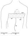
- FIGS. 4 A and 4 Bare conceptual diagrams illustrating example systems for measuring body-surface potentials and, more particularly, torso-surface potentials.
- sensing device 400 Acomprising a set of electrodes 404 A-F (generically “electrodes 404 ”) and strap 408 , is wrapped around the torso of patient 1 such that the electrodes surround heart 10 .
- electrodes 404may be positioned around the circumference of patient 1 , including the posterior, lateral, and anterior surfaces of the torso of patient 1 . In other examples, electrodes 404 may be positioned on any one or more of the posterior, lateral, and anterior surfaces of the torso.
- Electrodes 404may be electrically connected to processing unit 500 via wired connection 406 . Some configurations may use a wireless connection to transmit the signals sensed by electrodes 404 to processing unit 500 , e.g., as channels of data.
- sensing device 400 Acomprises strap 408
- any of a variety of mechanismse.g., tape or adhesives, may be employed to aid in the spacing and placement of electrodes 404 .
- strap 408may comprise an elastic band, strip of tape, or cloth.
- electrodes 404may be placed individually on the torso of patient 1 .
- Electrodes 404may surround heart 10 of patient 1 and record the electrical signals associated with the depolarization and repolarization of heart 10 after the signals have propagated through the torso of patient 1 .
- Each of electrodes 404may be used in a unipolar configuration to sense the torso-surface potentials that reflect the cardiac signals.
- Processing unit 500may also be coupled to a return or indifferent electrode (not shown) which may be used in combination with each of electrodes 404 for unipolar sensing.
- Other configurationsmay have more or fewer electrodes 404 .
- Processing unit 500may record and analyze the torso-surface potential signals sensed by electrodes 404 . As described herein, processing unit 500 may be configured to provide an output to a user indicating the electrical dyssynchrony in heart 10 of patient 1 . The user may make a diagnosis, prescribe CRT, position therapy devices, e.g., leads, or adjust or select treatment parameters based on the indicated electrical dyssynchrony.
- the analysis of the torso-surface potential signals by processing unit 500may take into consideration the location of electrodes 404 on the surface of the torso of patient 1 .
- processing unit 500may be communicatively coupled to an imaging system 501 , which may provide an image that allows processing unit 500 to determine coordinate locations of each of electrodes 400 on the surface of patient 1 .
- Electrodes 404may be visible, or made transparent through the inclusion or removal of certain materials or elements, in the image provided by imaging system 501 .
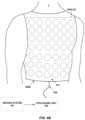
- FIG. 4 Billustrates an example configuration of a system that may be used to evaluate electrical dyssynchrony in heart 10 of patient 1 .
- the systemcomprises a sensing device 400 B, which may comprise vest 410 and electrodes 404 A-ZZ (generically “electrodes 404 ”), a processing unit 500 , and imaging system 501 .
- Processing unit 500 and imaging system 501may perform substantially as described above with respect to FIG. 4 A .
- electrodes 404are distributed over the torso of patient 1 , including the anterior, lateral, and posterior surfaces of the torso of patient 1 .
- Sensing device 400 Bmay comprise a fabric vest 410 with electrodes 404 attached to the fabric. Sensing device 400 B may maintain the position and spacing of electrodes 404 on the torso of patient 1 . Sensing device 400 B may be marked to assist in determining the location of electrodes 404 on the surface of the torso of patient 1 . In some examples, there may be 150 to 256 electrodes 404 distributed around the torso of patient 1 using sensing device 400 B, though other configurations may have more or fewer electrodes 404 .
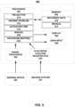
- FIG. 5is a block diagram illustrating an example system for measuring torso-surface potentials and providing indications of electrical dyssynchrony.
- the example systemmay comprise a processing unit 500 and a set of electrodes 404 on a sensing device 400 , e.g., one of example sensing devices 400 A or 400 B ( FIGS. 4 A and 4 B ).
- the systemmay also include an imaging system 501 .
- processing unit 500may comprise a processor 502 , signal processor 504 , memory 506 , display 508 , and user input device 509 .
- Processing unit 500may also include an electrode location registration module 524 .
- processor 502comprises a number of modules and, more particularly, a projection module 514 , an inverse problem module 516 , an activation time module 518 , an indices module 520 , and an isochrones mapping module 522 .
- Memory 506may store recorded data 510 and models 512 .
- Processing unit 500may comprise one or more computing devices, which may be co-located, or dispersed at various locations.
- the various modules of processing unit 500e.g., processor 502 , projection module 514 , inverse problem module 516 , activation time module 518 , statistics module 520 , isochrones mapping module 522 , signal processor 504 , electrode location registration module 524 , display 508 , memory 506 , recorded data 510 and torso models 512 may be implemented in one or more computing devices, which may be co-located, or dispersed at various locations.
- Processor 502and the modules of processor 502 , may be implemented in one or more processors, e.g., microprocessors, of one or more computing devices, as software modules executed by the processor(s).
- Electrode location registration module 524may, in some examples, be implemented in imaging system 501 .
- memory 506may comprise program instructions that, when executed by a programmable processor, e.g., processor 502 , cause the processor and any components thereof to provide the functionality attributed to a processor and processing unit herein.
- Memory 506may include any volatile, non-volatile, magnetic, optical, or electrical media, such as a hard disk, magnetic tape, random access memory (RAM), read-only memory (ROM), CD-ROM, non-volatile RAM (NVRAM), electrically-erasable programmable ROM (EEPROM), flash memory, or any other digital or analog media.
- Memory 506may comprise one or more co-located or distributed memories.
- Memory 506may comprise a tangible article that acts as a non-transitory storage medium for data and program instructions.
- the torso-surface potential signals sensed by electrodes 404 of sensing device 400may be received by signal processor 504 of processing unit 500 .
- Signal processor 504may include an analog-to-digital converter to digitize the torso-surface potential signals.
- Signal processor 504may also include various other components to filter or otherwise condition the digital signals for receipt by processor 502 .
- Electrode location registration module 524may receive imaging data from imaging system 501 . Electrode location registration module 524 analyzes the imaging data. In particular, electrode registration location module 524 identifies electrodes 404 , or elements co-located with the electrodes that are more clearly visible via the imaging modality, within the images. Electrode location registration module 524 may further identify the locations of each of the electrodes on the surface of the patient and/or within a three-dimensional coordinate system. In some examples, the locations of electrodes 404 may be manually identified and registered with processing unit 500 , e.g., by a user, via electrode registration module 524 .
- the imaging datamay comprise data representing one or more images of patient 1 wearing electrodes 404 , e.g., of a sensing device 400 .
- the imagesmay be obtained before or during a medical procedure, e.g., a surgical procedure to implant a cardiac rhythm device and lead system for delivery of CRT.
- processor 502may store the torso-surface potential signals, imaging data from imaging system, electrode location data from electrode location registration module, or any values disclosed herein that are derived by processing of such signals and data by processor 502 , within memory 506 as recorded data 510 .
- Each recorded torso-surface potential signal, or other values derived therefrom,may be associated with a location of the electrode 404 that sensed the torso-surface potential signal.
- the torso-surface potential datamay be correlated with the position of electrodes 404 on the torso of patient 1 , or within a three-dimensional coordinate system, enabling spatial mapping of the data to particular locations on the surface of the torso or within the coordinate system.
- aspects of the techniques described hereinmay be performed at some time after the acquisition of the torso-surface potential signals and location data based on recorded data 510 .
- Processor 502may be configured to provide one or more indications of electrical dyssynchrony based on the torso-surface potential signals and, in some examples, the electrode location data.
- Example indications of electrical dyssynchronyinclude indices illustrating activation times for each electrode/location distributed about the torso or heart, or for one or more subsets of electrodes located within a common region, e.g., within a left posterior, left anterior, right posterior, or right anterior region.
- processor 502may be configured to provide a set of two or more different indications, e.g., several different indications, for each of two or more different regions, e.g., several different regions, of the torso or heart.
- Some indications of dyssynchronymay include statistical values or other indices derived from activation times for each electrode location or one or more subsets of electrodes within one or more regions.
- Other examples indications of electrical dyssynchrony that may be determined based on activation times at various electrodes/locationsinclude graphical indications, such as an isochrone or other activation maps, or an animation of electrical activation.
- Other examples indications of electrical dyssynchrony that may be determined based on activation times at various electrodes/locationsinclude identifying one of a predetermined number of dyssynchrony levels, e.g., high, medium, or low, via text or color, e.g., red, yellow, green, for example.
- the various indications of dyssynchrony for one or more regionsmay be determined based on data collected at two or more different times and/or under two or more different conditions.
- the various indications of dyssynchronymay be determined based on torso-potential signals collected during intrinsic conduction of heart 10 , and also determined based on torso-potential signals collected during CRT. In this manner, the potential dyssynchrony-reducing benefit of CRT may be evaluated for the patient by comparing the different values, graphical representations, or the like, resulting from intrinsic conduction and CRT.
- the various indications of dyssynchronymay be determined each of a plurality of different times based on torso-potential signals collected during delivery of CRT with different lead positions, electrode configurations, or CRT parameters, e.g., A-V or V-V interval values.
- the relative dyssynchrony-reducing benefits of the different lead positions, electrode configurations, or CRT parameters positionsmay be evaluated for the patient by comparing the different values, graphical representations, or the like.
- Models 512may include a plurality of different models, e.g., three-dimensional models, of the human torso and heart.
- a model torso or model heartmay be constructed by manual or semi-automatic image segmentation from available databases of previously acquired medical images (CT/MRI) of a plurality of subjects, e.g., cardiomyopathy patients, different than patient 1 , using commercially available software.
- CT/MRIpreviously acquired medical images
- Each modelmay be discretized using a boundary element method.
- a plurality of different torso modelsmay be generated.
- the different modelsmay represent different subject characteristics, such as different genders, disease states, physical characteristics (e.g., large frame, medium frame and small frame), and heart sizes (e.g., x-large, large, medium, small).
- a usermay select from among the various model torsos and model hearts that may be stored as models 512 in memory 506 , so that the user may more closely match the actual torso and heart 10 of patient 1 with the dimensions and geometry of a model torso and model heart.
- medical images of the patiente.g., CT or MRI images
- single or multiple view 2-D medical imagese.g., x-ray, fluoroscopy
- Projection module 514may project the locations of electrodes 404 , e.g., stored as recorded data 510 within of memory 506 , onto an appropriate, e.g., user-selected, model torso contained in model data module 512 of memory 506 . By projecting the location of electrodes 404 onto the model torso, projection module 514 may also project the torso-surface potential signals of patient 1 sensed by electrodes 404 onto the model torso. In other examples, the measured electrical potentials may be interpolated and resampled at electrode positions given by the model.
- projecting the torso-surface potentials onto the model torsomay allow processor 502 , via inverse problem module 516 , to estimate the electrical activity of at various locations or regions of the model heart corresponding to heart 10 of patient 1 that produced the measured torso-surface potentials.
- Inverse problem module 516may be configured to solve the inverse problem of electrocardiography based on the projection of the measured torso-surface potentials, recorded by electrodes 404 , onto the model torso. Solving the inverse problem of electrocardiography involve the estimation of potentials or activation times in heart 10 based on a relationship between the torso and heart potentials.
- model epicardial potentialsare computed from model torso potentials assuming a source-less volume conductor between the model heart and the model torso in an inverse Cauchy problem for Laplace's equation.
- an analytic relationship between torso-surface potentials and the cardiac transmembrane potentialis assumed. Torso-surface potentials may be simulated based on this relationship.
- inverse problem module 516may utilize techniques described by Ghosh et al. in “Accuracy of Quadratic Versus Linear Interpolation in Non-Invasive Electrocardiography Imaging (ECGI),” Annals of Biomedical Engineering , Vol. 33, No. 9, September 2005, or in “Application of the L1-Norm Regularization to Epicardial Potential Solution of the Inverse Electrocardiography Problem,” Annals of Biomedical Engineering , Vol. 37, No. 5, 2009, both of which are incorporated herein by reference in their entireties. In other examples, any known techniques for solving the inverse problem of electrocardiography be employed by inverse problem module 516 .
- ECGINon-Invasive Electrocardiography Imaging
- Activation time module 518may compute the activation times directly from measured torso-surface potentials, or by estimating model transmembrane potentials. In either case, an activation time for each electrode/location may be determined as a time period between two events, such as between the QRS complex onset and the minimum derivative (or steepest negative slope) of the sensed torso potential signal or estimate epicardial potential signal. Thus, in one example, cardiac activation times are estimated from the steepest negative slope of the model epicardial electrograms.
- Cardiac activation timesmay, in other configurations, be computed based on minimizing the least square difference between the measured torso-surface potentials and simulated torso-surface potentials.
- a color-coded isochrone map of ventricular, epicardial, or torso-surface activation timesmay be shown by display 308 .
- display 308may show a two-color animation of propagation of the activation wavefront across the surface of the model heart or the torso-surface.
- Indices module 520may be configured to compute one or more indices of electrical dyssynchrony from the torso-surface or cardiac activation times. These indices may aid in the determination of whether the patient is a candidate for CRT, placement of CRT leads, and selection of CRT parameters.
- LV lead 102FIG. 1
- LV lead 102may be positioned at the site that reduces dyssynchrony from one or more indices or, alternatively, the largest electrical resynchronization as demonstrated by the indices.
- the same indicesmay be also used for programming A-V and/or V-V delays during follow-up.
- the indicesmay be determined based on the activation times for all electrodes/locations, or for one or more subsets of electrodes in one or more regions, e.g., to facilitate comparison or isolation of a region, such as the posterior and/or left anterior, or left ventricular region.
- One of the indices of electrical dyssynchronymay be a standard deviation index computed as the standard deviation of the activations-times (SDAT) of some or all of electrodes 404 on the surface of the torso of patient 1 .
- SDATstandard deviation of the activations-times
- the SDATmay be calculated using the estimated cardiac activation times over the surface of a model heart.
- a second example index of electrical dyssynchronyis a range of activation times (RAT) which may be computed as the difference between the maximum and the minimum torso-surface or cardiac activation times, e.g., overall, or for a region.
- the RATreflects the span of activation times while the SDAT gives an estimate of the dispersion of the activation times from a mean.
- the SDATalso provides an estimate of the heterogeneity of the activation times, because if activation times are spatially heterogeneous, the individual activation times will be further away from the mean activation time, indicating that one or more regions of heart 10 have been delayed in activation.
- the RATmay be calculated using the estimated cardiac activation times over the surface of a model heart.
- a third example index of electrical dyssynchronyestimates the percentage of electrodes 404 located within a particular region of interest for the torso or heart, whose associated activation times are greater than a certain percentile, for example the 70th percentile, of measured QRS complex duration or the determined activation times for electrodes 404 .
- the region of interestmay be a posterior, left anterior, and/or left-ventricular region, as examples.
- This index, the percentage of late activation (PLAT)provides an estimate of percentage of the region of interest, e.g., posterior and left-anterior area associated with the left ventricular area of heart 10 , which activates late.
- a large value for PLATmay imply delayed activation of substantial portion of the region, e.g., the left ventricle 12 ( FIG.
- the PLATmay be determined for other subsets of electrodes in other regions, such as a right anterior region to evaluate delayed activation in the right ventricle.
- the PLATmay be calculated using the estimated cardiac activation times over the surface of a model heart for either the whole heart or for a particular region, e.g., left or right ventricle, of the heart.
- Isochrone mapping module 522may be configured to generate an isochrone map depicting the dispersion of activation times over the surface of the torso of patient 1 or a model heart. Isochrone mapping module 522 may incorporate changes in the torso-surface or cardiac activation times in near real-time, which may permit near instant feedback as a user adjusts a CRT device or monitors patient 1 to determine if CRT is appropriate. Isochrone maps generated by isochrone mapping module 522 may be presented to the user via display 508 .
- processor 502may generate a variety of images or signals for display to a user via display 508 based on the measured torso-surface potentials, calculated torso-surface or estimated cardiac activation times, or the degree of change in electrical dyssynchrony. For example, a graded response reflecting the efficacy of a particular location of the LV lead 102 during biventricular pacing or single ventricle fusion pacing may be provided to the physician in terms of a red, yellow and green signal. A red signal may be shown if the reduction in electrical dyssynchrony during CRT pacing compared to intrinsic rhythm is negative (an increase in electrical dyssynchrony) or minimal, e.g., less than 5%.
- a yellow signalmay be triggered if there is some reduction in electrical dyssynchrony during CRT pacing compared to intrinsic rhythm, for example between 5% and 15%, but there may be potentially better sites for lead placement. If the reduction in electrical dyssynchrony during CRT pacing compared to intrinsic rhythm is substantial, e.g., greater than 15%, a green signal may be triggered indicating to the physician that the present site provides effective changes in synchronization.
- the feedback from this system in combination with other criterialike magnitude of pacing threshold, impedance, battery life, phrenic nerve stimulation may be also used to choose an optimal pacing vector for one or more multipolar leads.
- the feedback from this systemmay be also used for selecting optimal device timings (A-V delay, V-V delay, etc.) influencing the extent of fusion of intrinsic activation with paced activation from single or multiple ventricular sites, or discerning acute benefit of single site fusion pacing versus multi-site pacing and choice of appropriate pacing type.
- optimal device timingsA-V delay, V-V delay, etc.
- Display 508may also display three-dimensional maps of electrical activity over the surface of the torso of patient 1 or over a model heart. These maps may be isochrone maps showing regions of synchronous electrical activity as the depolarization progresses through heart 10 of patient 1 . Such information may be useful to a practitioner in diagnosing asynchronous electrical activity and developing an appropriate treatment, as well as evaluating the effectiveness of the treatment.
- FIG. 6is a series of simulated isochrone maps 600 of torso-surface activation times over the torso of a patient suffering from an electrical dyssynchrony in the left ventricle before and during treatment with a CRT device.
- the isochrone maps before (intrinsic) and after treatmentare divided into two views: anterior and posterior.
- Line 602represents the location of a subset of electrodes 404 , e.g., a subset of electrodes 404 of sensing device 400 B, that may be used to calculate one or more indices of electrical dyssynchrony.
- line 602may represent electrodes 404 on sensing device 400 A.
- the isochrone maps 600 of the natural and CRT assisted torso-surface activation timesmay be generated using multiple electrodes 404 distributed over the surface of the torso of a patient, e.g., using sensing device 400 B.
- Generation of the isochrone maps 600may include determining the location of electrodes 404 , and sensing torso-surface potential signals with the electrodes.
- Generation of the isochrone maps 600may further include calculating the torso-surface activation time for each electrode or electrode location by determining the point in the recorded QRS complex of the signal sensed by the electrodes corresponding to the maximum negative slope.
- the torso-surface activation timesmay be determined by identifying the minimum derivative of the QRS complex. The measured torso-surface activation times may then be standardized and an isochrone map of the surface of the torso of the patient generated.
- the delayed activation of certain locations associated with certain ones of electrodes 404 due to the electrical dyssynchronyis apparent in the posterior views of the intrinsic torso-surface activation times.
- some regions of isochrone maps 600indicate increased delay in the activation of the underlying heart.
- a corresponding posterior view during treatment with a CRT deviceindicates that regions, the same location as the regions indicating increased delay in the activation of the underlying heart on the maps of intrinsic torso-surface activation times, exhibit increased synchrony in electrical ventricular activity.
- the CRT mapsexhibit decreased range and a lower standard deviation of torso-surface activation times. Further, the posterior regions no longer exhibit delayed activation times.
- the isochrone map of the torso-surface activation times during intrinsic and CRT pacing and changes in distribution of activation-times from intrinsic to CRT pacingmay be used for diagnostic purposes or the adjustment of a CRT device.
- One or more indices of electrical dyssynchronymay also be calculated from the torso-surface activation times used to generate isochrone maps 600 .
- SDATan indication of the spread of the activation times, for the patient's intrinsic heart rhythm using the complete set of electrodes 404 is 64.
- Using the reduced lead set marked by line 602results in an SDAT of 62.
- the RAT for the intrinsic heart rhythm and complete lead setis 166.5 while the reduced lead set has a RAT of 160.
- PLAT for the intrinsic heart rhythm using the reduced and complete lead setsare 56.15% and 66.67%, respectively.
- sensing device 400 A and associated electrodes 404may provide comparable indices of electrical dyssynchrony compared to using an electrode set covering the torso of the patient, such as sensing device 400 B.
- the indices of electrical dyssynchronyalso provide indication of the effectiveness of the CRT device, with the SDAT for the reduced set of electrodes declining to 24, the RAT to 70 and PLAT to 36%. This indicates that the torso-surface activation times during CRT treatment were more narrowly distributed and in a smaller range than in the normal heart rhythm and that the percentage of electrodes 404 located on the left anterior surface of the torso of the patient registering late activation times decreased markedly.
- FIG. 7is a flow diagram illustrating an example operation of a system to evaluate the cardiac electrical dyssynchrony of a patient via the torso-surface activation times.
- the location of electrodese.g., electrodes 404 ( FIGS. 4 A and 4 B ), distributed over the surface of the torso of the patient may be determined ( 700 ).
- a cardiac evente.g., a depolarization, may generate an electrical signal that propagates through the torso of a patient, e.g., patient 1 ( FIG. 1 ) and registers on the electrodes.
- the signal sensed by the electrodesmay be received ( 702 ), e.g., by processing unit 500 ( FIG. 5 ).
- the processing unitmay calculate the torso-surface activation times ( 704 ). In some examples, the processing unit may also construct a torso-surface activation times isochrone map ( 706 ). The processing unit may also calculate at least one index of cardiac electrical dyssynchrony ( 708 ). These indices may comprise one or more of the SDAT ( 710 ), RAT ( 712 ), and the PLAT ( 714 ).
- a cardiac eventsuch as a depolarization, generates an electrical signal that propagates through the torso.
- the electrical signalmay comprise a QRS complex, or a variant caused by a heart related condition such as a left or right bundle branch block.
- the electrical signalmay not propagate uniformly through the torso of a patient due to variations in conductivity within the torso and the heart. These delays may manifest in electrodes distributed over the surface of the torso of the patient registering the same electrical signal at different points in time.
- the electrical signal generated by the cardiac eventmay register on the plurality of electrodes distributed over the surface of the torso of patient.
- the electrodesmay be distributed over the anterior, lateral, and/or posterior surfaces of the torso, allowing the generation of a three-dimensional picture of the electrical activity occurring within the torso.
- the electrodesmay be placed to provide extensive coverage both above and below the heart, e.g., by using sensing device 400 B ( FIG. 4 B ).
- a reduced set of electrodesmay be arranged around the circumference of the torso, circumscribing the heart of the patient, e.g., using sensing device 400 A ( FIG. 4 A ).
- the electrodesmay receive the complete waveform of the electrical signal generated by the cardiac event, and transmit the signal to a processing unit.
- the location of electrodes distributed over the surface of the torso of the patientmay be determined ( 700 ). Locating the electrodes may be performed automatically, e.g. by imaging system 501 and electrode location registration module 524 of processing unit 500 ( FIG. 5 ). The electrodes may be located by analyzing one or more images of the torso of a patient and performing a pattern matching routine, e.g., recognizing the shape of an electrode against the torso of the patient, and storing the location of the electrode on the torso of the patient in processing unit memory.
- a pattern matching routinee.g., recognizing the shape of an electrode against the torso of the patient
- the location of sensing device 400 A or 400 Bmay be determined and the locations of the electrodes determined based on the position of the sensing device, e.g., basing the position of the electrode on the patient through the known position of the electrode on the sensing device. In another example, the position of the electrodes may be measured manually.
- the processing unitmay receive the electrical signal from the electrodes and record the output in memory ( 702 ).
- the processing unitmay record the raw output, e.g., the raw ECG tracing from each electrode, as well as location data for the electrodes, allowing the electrical signals detected by the electrodes to be mapped onto the surface of the torso of the patient.
- the processing unitmay compute the torso-surface activation times ( 704 ).
- a processore.g., processor 502 of processing unit 500 ( FIG. 5 ) may retrieve ECG tracing data stored within the processing unit memory and analyze the tracing to detect depolarization of the ventricles of the heart, typically marked by a QRS complex in the tracing.
- the processormay, in some examples, detect ventricular depolarization by determining the time of the minimum derivative (or steepest negative slope) within the QRS complex measured with respect to the time of QRS complex onset. The determination of the activation time may be made for each electrode and stored in the processing unit memory.
- the processing unitmay construct an isochrone map of the torso-surface activation times, allowing the user to visually inspect the propagation of the electrical signals of the heart after progression through the torso of the patient.
- the isochrone mapmay be constructed by dividing the range of measured torso-surface activation times into a series of sub-ranges. The location of each electrode on the surface of the torso of the patient may be graphically represented. Regions of electrodes whose measured activation times fall within the same sub-range may be represented by the same color on the graphical representation.
- the processing unitmay also calculate one or more indices of electrical dyssynchrony based on the torso-surface activation times ( 708 ). These indices may include the SDAT ( 710 ), RAT ( 712 ), and PLAT ( 714 ). In some examples, the PLAT may be determined as the percentage of posterior electrodes activating after a certain percentage of the QRS complex duration.
- the construction of a torso-surface activation times isochrone map ( 706 ), or other graphical representation of dyssynchrony, as well as the calculation of indices of electrical dyssynchrony ( 708 ),may be performed for a particular region of the torso based the signals received from electrodes ( 702 ) in such regions.
- Graphical representations and indices of electrical dyssynchronymay be determined for each of a plurality of regions based on the signals received from the electrodes for such regions. In some examples, the representations and indices for various regions may be presented together or compared.
- FIG. 8is a flow diagram illustrating an example technique for measuring the cardiac electrical dyssynchrony of a patient via measured torso-surface activation times.
- a processing unit 500may receive torso-surface potential signals from a plurality of electrodes ( 800 ), e.g., electrodes 404 ( FIGS. 4 A and 4 B ).
- the processing unit 500may calculate the torso-surface activation times for each of the plurality of electrodes ( 802 ).
- the processing unit 500may provide at least one indication of cardiac electrical dyssynchrony ( 804 ).
- a usermay evaluate the whether a patient is a candidate for CRT based on the at least one indication of electrical dyssynchrony ( 806 ).
- the usermay also monitor the at least one indication of electrical dyssynchrony ( 808 ), and use the changes in the at least one indication to aid in adjusting the positioning of electrodes, e.g., electrodes 108 , 110 , and 112 ( FIG. 1 ), during implantation of a CRT device ( 810 ), e.g., IMD 100 ( FIG. 1 ), or selection of the various programmable parameters, such as electrode combination and the A-V or V-V pacing intervals, of the CRT device ( 812 ), during implantation or a follow-up visit.
- electrodese.g., electrodes 108 , 110 , and 112
- the various indications of cardiac electrical dyssynchrony described hereinmay indicate the presence of damage to electrical conductivity of the heart of the patient, for example the presence of a left or right bundle branch block, that may not be apparent from the examination of a standard 12-lead ECG readout.
- a large SDATindicates that the activation of the ventricles is occurring over a large time span, indicating that the depolarization of the ventricles is not occurring simultaneously.
- a large RATalso indicates a broad range of activation times and asynchronous contraction of the ventricles.
- a high PLATindicates that a specific region of the heart, e.g., the posterior regions associated with the left ventricle, may be failing to activate in concert with the measured QRS complex. Additionally, by monitoring the at least one indication of cardiac electrical dyssynchrony, the user may detect changes in the electrical activity of the heart caused by different treatments or treatment configurations.
- the various indications of electrical dyssynchronymay be calculated for each of a plurality of regions, e.g., posterior, left anterior, or the like, based on torso-surface activations times from the region. Additionally, evaluating whether a patient is a candidate for CRT based on the at least one indication of electrical dyssynchrony ( 806 ) may include determining the one or more indications of electrical dyssynchrony based on torso-surface activation times both during intrinsic conduction of the heart, and during CRT. Differences between the indications during intrinsic conduction and CRT may indicate that CRT would provide benefit for the patient, e.g., that the patient is a candidate for CRT.
- the usermay also evaluate whether a patient is a candidate for CRT based on at least one indication of electrical dyssynchrony based on intrinsic rhythm alone.
- monitoring the at least one indication of electrical dyssynchrony ( 808 ) during implantation or a follow-up visitmay include determining the one or more indications of electrical dyssynchrony for each of a plurality of lead positions, electrode configurations, or other parameter values based on torso-surface activation times resulting from delivery of CRT at the positions, or with the electrode configurations or parameter values. In this manner, differences between dyssynchrony indications associated with various locations, electrode configurations, or parameter values may be compared to determine preferred locations, configurations, or values.
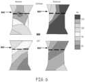
- FIG. 9is a series of isochrone maps of cardiac activation times.
- Views 900 , 902 and 904were constructed using torso-surface potentials measured on the surface of the torso of a patient and projected onto three dimensional models of the torso and the heart of the patient.
- Views 910 , 912 , and 914were constructed using the measured torso-surface potentials of the same patient projected onto a different model torso and model heart.
- the three-dimensional representation of the hearts depicted in views 900 , 902 , 904 , 910 , 912 and 914were constructed using computer tomography (CT) images of hearts obtained from databases of previously acquired cardiothoracic images.
- CTcomputer tomography
- the locations of the electrodes, e.g., electrodes 404 of sensing device 400 B ( FIG. 4 B ), on the torso of the patientmay be plotted to approximate locations on a model torso.
- a computermay be used to solve the inverse problem of electrocardiography, which includes determining the electrical activity on the surface of the heart that would produce the measured torso-surface potentials.
- the isochrone maps illustrated in views 900 , 902 , 904 , 910 , 912 and 914are based on images of hearts of two different patients, which are also used to determine the geometry of the heart and relationship to the corresponding torso for solving the inverse problem of electrocardiography.
- the model torsos and heartsmay be constructed by manual or semi-automatic image segmentation from available databases of previously acquired medical images (CT/MRI) of cardiomyopathy patients using commercially available software.
- CT/MRIpreviously acquired medical images
- Each modelmay be discretized using boundary element method and may be further manipulated to account for patients with different physical characteristics (e.g., large frame, medium frame and small frame) and heart sizes (e.g., x-large, large, medium, small).
- a usermay select the appropriate model torso and heart to suit the patient, e.g., a patient having a large torso may be simulated with a large frame model torso.
- medical images of the patiente.g., CT or MRI images
- One or more views of 2-D medical imagese.g., X-ray or fluoroscopy
- the usermay project the measured torso-surface potentials from the torso of the patient onto the corresponding locations on the model torso.
- the inverse problem of propagating the electrical signals from the model torso to the model heartmay then be solved, and activation times for the model heart may be estimated.
- human thoracic CT images for other subjectswere obtained from image databases.
- Semi-automatic image segmentationwas performed on the images to generate the three-dimensional representation of the different models of hearts and torsos.
- image segmentationmay be done with the AMIRA software package commercially-available from Visage Imaging, Inc., of San Diego, California.
- the projection of electrode locations on the patient torso to the model torsowas approximate.
- the locations of the electrodes on the patient torsowere projected onto the surface of the model torso based on the order in which the electrodes were mounted on the patient.
- the patient and model torsoswere divided into right anterior, left anterior, right posterior and left posterior regions, using the sternum (anterior) and the spine (posterior) as references. Electrodes were arranged in vertical strips and three strips were applied to each region of the torso. Electrodes in these regions were projected on to the corresponding segments of the model torso.
- the method describedis one of many techniques that may be used to registered or map the geometrical distribution of measured electrical potentials.
- the measured electrical potentialsmay be interpolated and resampled at electrode positions given by the model. Projection of the electrode locations from segments of the patient torso onto the corresponding segments of the model torso in the correct order enabled the activation patterns and spatial dispersion of activation on the model heart to reflect the activation patterns and spatial dispersion of activation on the actual patient heart with relative accuracy.
- the inverse problem of electrocardiographybe solved using the Matlab regularization toolbox (Hansen PC, Regularization Tools: A Matlab package for analysis and solution of discrete ill-posed problems, Numerical Algorithms, 6(1994), pp 1-35).
- Input data-sets for solving the inverse problem consistent with the examplemay include multi-electrode surface ECG measurements, the 3-D Cartesian coordinates of the model heart and torso surfaces, and the mesh over each model surface which specified the connectivity of the different points on each surface.
- An output consistent with the techniques of this disclosuremay include activation times on the 3-D model heart surface which can be visualized using visualization software and computer graphics tools.
- the 3-D model heart surfacemay be visualized using the tools in Matlab (Mathworks Inc, Natick, MA) or more advanced visualization software, such as Tecplot (Tecplot Inc, Bellevue, WA).
- Comparing estimated cardiac activation times on two different, both cardiac activation times determined from the same torso-surface potential signals for one subjectshow similar patterns and distribution.
- a region of views 902 and 904corresponds in size and activation time to a region of views 912 and 914 .
- a region of views 902 and 904corresponds to a region of views 912 and 914 .
- the standard deviations of activations time for both modelsare both derived from the same torso-surface potentials for one subject, were similar (17.6 and 15.5 ms). The overall pattern of cardiac activation and measures of dispersion of cardiac activation times are thus not dependent on a specific heart-torso model.
- Using a generic heart-torso modelmay allow a user to create an isochrone model of the cardiac activation time suitable for diagnosis and observation while avoiding expense, inconvenience, and radiation exposure that may be caused by the CT scan or other imaging that may be used to produce a patient-specific model of the heart of the patient.
- FIG. 10is a flow diagram illustrating an example operation of a system to measure the cardiac electrical dyssynchrony of a patient via the cardiac activation times.
- Processing unit 500determines the location of the electrodes 404 , e.g., based on an analysis of imaging data by an electrode location registration module 524 .
- Processing unitprojects the locations of the electrodes onto a model torso, e.g., a selected model torso ( 1002 ).
- a cardiac evente.g., depolarization, occurs causing an electrical signal to propagate through the torso of the patient, and register on the electrodes distributed on the surface of the torso of the patient.
- the torso-surface potential signals sensed by the electrodesmay be received by processing unit 500 ( 1004 ).
- the processing unitmay project the signals onto the surface of the model torso based on the determined locations of the electrodes ( 1006 ).
- the processing unitmay solve the inverse problem of determining epicardial potentials based on torso-surface potentials ( 1008 ).
- the processing unitmay then calculate cardiac activation times at a variety of locations of the model heart based upon the projected torso-surface potentials ( 1010 ).
- the cardiac activation timesmay be computed by, for example, determining the greatest negative slope of the epicardial electrogram potentials ( 1016 ) or by least squares minimization in the solution of the inverse problem ( 1018 ).
- the cardiac activation timemay be displayed ( 1012 ). Examples of potential methods for displaying cardiac activation times include isochrone maps ( 1014 ) and a movie depicting the progression of the wavefront over the model heart ( 1016 ).
- the processing unitmay be configured to allow a user select between, or display simultaneously, various display modes, including the wave front movie and isochrone maps. Additionally, one or more indices of cardiac electrical dyssynchrony may be calculated ( 1018 ), including the SDAT ( 1020 ), RAT ( 1022 ), and PLAT ( 1024 ).
- epicardial potentialsmay be computed from projected torso-surface potentials assuming a source-less volume conductor between the heart and the torso in an inverse Cauchy problem for Laplace's equation.
- an analytic relation between torso-surface potentials and the cardiac transmembrane potentialmay be assumed.
- cardiac activation timesmay be estimated ( 1010 ) from the steepest negative slope of the epicardial electrograms determined from the inverse solution of the torso-surface potential/epicardial potential transformation.
- model torso-surface potentialsmay be simulated based on the analytic relationship approach to determining the cardiac transmembrane potential from torso-surface potential.
- Cardiac activation times(parameters in the analytic relationship) may be computed based on minimizing the least square difference between the projected model torso-surface potentials and simulated torso-surface potentials.
- the construction of a torso-surface activation times isochrone map ( 1014 ), wavefront animation ( 1016 ), or other graphical representation of cardiac electrical dyssynchrony, as well as the calculation of indices of cardiac electrical dyssynchrony ( 1018 ),may be performed for a particular region of the model heart based the computed cardiac activation times in such regions.
- Graphical representations and indices of cardiac electrical dyssynchronymay be determined for each of a plurality of regions based on the computed cardiac activation times in such regions. In some examples, the representations and indices for various regions may be presented together or compared.
- FIG. 11is a flow diagram illustrating an example technique for measuring the cardiac electrical dyssynchrony of a patient via determined cardiac activation times.
- the techniquesmay comprise determining the location of a plurality of electrodes ( 1100 ), projecting the location of the electrodes onto the surface of a model torso ( 1102 ), recording the output of the plurality of electrodes ( 1104 ), projecting the output of the plurality of the electrodes on the surface of the model torso ( 1106 ), solving the inverse problem ( 1108 ) and determining the cardiac activation times for a model heart from the projected torso-surface potentials ( 1110 ).
- the cardiac activation timesmay be displayed ( 1112 ).
- One or more indices of electrical dyssynchronymay be calculated ( 1114 ).
- the output, the indices of cardiac electrical dyssynchrony and cardiac activation time maps,may be monitored, allowing a user to diagnose the patient, adjust the position of CRT electrodes during implantation ( 1118 ), or adjust A-V or V-V pacing intervals of the CRT device ( 1120 ).
- a usermay monitor the output of the calculations ( 1116 ), e.g., the at least one indices of cardiac electrical dyssynchrony or the display of cardiac activation times. Monitoring these values may allow the user to diagnose a condition that might benefit from CRT or to evaluate the effectiveness of CRT.
- the at least one index of cardiac electrical dyssynchronymay indicate the presence of damage to electrical conductivity of the heart of the patient, for example the presence of a left or right bundle branch block, that may not be apparent from the examination of a standard 12 lead ECG readout.
- a large SDATindicates that the activation of the ventricles is occurring over a large time span, indicating that the depolarization of the ventricles is not occurring simultaneously.
- a large RATalso indicates a broad range of activation times and asynchronous contraction of the ventricles.
- a high PLATmay indicate that a specific region of the heart, e.g., the posterior regions more associated with the left ventricle, is failing to activate in concert with the measured QRS complex.
- the usermay adjust the positioning of CRT electrodes, e.g., electrodes 108 , 110 , and 112 of IMD 100 ( FIG. 1 ) according to the displayed cardiac activation times or the indices of cardiac electrical dyssynchrony.
- the processing unitvia a display, may implement system that displays shifting colors based on the percentage change of the indices of cardiac electrical dyssynchrony. As the position of the CRT electrodes are adjusted ( 1118 ), the displayed colors may shift from red to yellow to green based on the percentage improvement of the indices of cardiac electrical dyssynchrony. This may allow a user to rapidly determine if the adjustments of the CRT electrodes are having a positive effect on the symptoms of the patient.
- the usermay adjust the A-V or V-V pacing intervals of an implanted CRT device ( 118 ).
- the minimum value of the indices of cardiac electrical dyssynchronymay indicate adequate pacing intervals.
- Isochrone maps or wave front propagation moviesmay also be used to aid in CRT adjustments or to diagnose conditions that may be responsive to CRT treatment.
- the one or more indications of cardiac electrical dyssynchronymay be determined based on torso-surface activation times during both intrinsic conduction of the heart, and during CRT. Differences between the indications during intrinsic conduction and CRT may indicate that CRT would provide benefit for the patient, e.g., that the patient is a candidate for CRT.
- the one or more indications of cardiac electrical dyssynchronymay be determined for each of a plurality of lead positions, electrode configurations, or other parameter values based on torso-surface activation times resulting from delivery of CRT at the positions, or with the electrode configurations or parameter values. In this manner, differences between cardiac electrical dyssynchrony indications associated with various locations, electrode configurations, or parameter values may be compared to determine preferred locations, configurations, or values.
- the excluded locations or regionsmay be those that are believed to be scar tissue, e.g., identified by low amplitude electrical signals, or locations or regions that are beyond the extent of the far-field QRS complex.
- calculation of an indexmay include determining any statistical or other value based on the torso-surface or cardiac activation times, or some subset thereof.
Landscapes
- Health & Medical Sciences (AREA)
- Life Sciences & Earth Sciences (AREA)
- Cardiology (AREA)
- Heart & Thoracic Surgery (AREA)
- Engineering & Computer Science (AREA)
- Veterinary Medicine (AREA)
- Biomedical Technology (AREA)
- Animal Behavior & Ethology (AREA)
- General Health & Medical Sciences (AREA)
- Public Health (AREA)
- Biophysics (AREA)
- Nuclear Medicine, Radiotherapy & Molecular Imaging (AREA)
- Radiology & Medical Imaging (AREA)
- Pathology (AREA)
- Physics & Mathematics (AREA)
- Medical Informatics (AREA)
- Molecular Biology (AREA)
- Surgery (AREA)
- Physiology (AREA)
- Hospice & Palliative Care (AREA)
- Electrotherapy Devices (AREA)
- Measurement And Recording Of Electrical Phenomena And Electrical Characteristics Of The Living Body (AREA)
Abstract
Description
Claims (30)
Priority Applications (2)
| Application Number | Priority Date | Filing Date | Title |
|---|---|---|---|
| US17/339,310US12133984B2 (en) | 2011-05-03 | 2021-06-04 | Assessing intra-cardiac activation patterns |
| US18/894,301US20250010080A1 (en) | 2011-05-03 | 2024-09-24 | Assessing intra-cardiac activation patterns |
Applications Claiming Priority (5)
| Application Number | Priority Date | Filing Date | Title |
|---|---|---|---|
| US201161482053P | 2011-05-03 | 2011-05-03 | |
| US13/462,480US8972228B2 (en) | 2011-05-03 | 2012-05-02 | Assessing intra-cardiac activation patterns |
| US14/635,498US9974457B2 (en) | 2011-05-03 | 2015-03-02 | Assessing intra-cardiac activation patterns |
| US15/966,523US11027135B2 (en) | 2011-05-03 | 2018-04-30 | Assessing intra-cardiac activation patterns |
| US17/339,310US12133984B2 (en) | 2011-05-03 | 2021-06-04 | Assessing intra-cardiac activation patterns |
Related Parent Applications (1)
| Application Number | Title | Priority Date | Filing Date |
|---|---|---|---|
| US15/966,523ContinuationUS11027135B2 (en) | 2011-05-03 | 2018-04-30 | Assessing intra-cardiac activation patterns |
Related Child Applications (1)
| Application Number | Title | Priority Date | Filing Date |
|---|---|---|---|
| US18/894,301ContinuationUS20250010080A1 (en) | 2011-05-03 | 2024-09-24 | Assessing intra-cardiac activation patterns |
Publications (2)
| Publication Number | Publication Date |
|---|---|
| US20210290960A1 US20210290960A1 (en) | 2021-09-23 |
| US12133984B2true US12133984B2 (en) | 2024-11-05 |
Family
ID=47090700
Family Applications (7)
| Application Number | Title | Priority Date | Filing Date |
|---|---|---|---|
| US13/462,480Active2033-05-03US8972228B2 (en) | 2011-05-03 | 2012-05-02 | Assessing intra-cardiac activation patterns |
| US13/462,404ActiveUS9510763B2 (en) | 2011-05-03 | 2012-05-02 | Assessing intra-cardiac activation patterns and electrical dyssynchrony |
| US14/635,498Active2033-04-20US9974457B2 (en) | 2011-05-03 | 2015-03-02 | Assessing intra-cardiac activation patterns |
| US15/345,225ActiveUS9962097B2 (en) | 2011-05-03 | 2016-11-07 | Assessing intra-cardiac activation patterns and electrical dyssynchrony |
| US15/966,523Active2033-05-30US11027135B2 (en) | 2011-05-03 | 2018-04-30 | Assessing intra-cardiac activation patterns |
| US17/339,310Active2032-10-25US12133984B2 (en) | 2011-05-03 | 2021-06-04 | Assessing intra-cardiac activation patterns |
| US18/894,301PendingUS20250010080A1 (en) | 2011-05-03 | 2024-09-24 | Assessing intra-cardiac activation patterns |
Family Applications Before (5)
| Application Number | Title | Priority Date | Filing Date |
|---|---|---|---|
| US13/462,480Active2033-05-03US8972228B2 (en) | 2011-05-03 | 2012-05-02 | Assessing intra-cardiac activation patterns |
| US13/462,404ActiveUS9510763B2 (en) | 2011-05-03 | 2012-05-02 | Assessing intra-cardiac activation patterns and electrical dyssynchrony |
| US14/635,498Active2033-04-20US9974457B2 (en) | 2011-05-03 | 2015-03-02 | Assessing intra-cardiac activation patterns |
| US15/345,225ActiveUS9962097B2 (en) | 2011-05-03 | 2016-11-07 | Assessing intra-cardiac activation patterns and electrical dyssynchrony |
| US15/966,523Active2033-05-30US11027135B2 (en) | 2011-05-03 | 2018-04-30 | Assessing intra-cardiac activation patterns |
Family Applications After (1)
| Application Number | Title | Priority Date | Filing Date |
|---|---|---|---|
| US18/894,301PendingUS20250010080A1 (en) | 2011-05-03 | 2024-09-24 | Assessing intra-cardiac activation patterns |
Country Status (4)
| Country | Link |
|---|---|
| US (7) | US8972228B2 (en) |
| EP (3) | EP2704626B1 (en) |
| CN (2) | CN103561642B (en) |
| WO (2) | WO2012151389A1 (en) |
Families Citing this family (178)
| Publication number | Priority date | Publication date | Assignee | Title |
|---|---|---|---|---|
| US20070208232A1 (en)* | 2006-03-03 | 2007-09-06 | Physiowave Inc. | Physiologic monitoring initialization systems and methods |
| EP2533853A4 (en) | 2010-02-12 | 2013-11-06 | Brigham & Womens Hospital | SYSTEM AND METHOD FOR AUTOMATED ADJUSTMENT OF CONTROL PARAMETERS IN CARDIAC RESYNCHRONIZATION THERAPY |
| US8972228B2 (en) | 2011-05-03 | 2015-03-03 | Medtronic, Inc. | Assessing intra-cardiac activation patterns |
| US10311978B2 (en)* | 2012-01-30 | 2019-06-04 | Siemens Healthcare Gmbh | Method and system for patient specific planning of cardiac therapies on preoperative clinical data and medical images |
| US20140070949A1 (en)* | 2012-09-11 | 2014-03-13 | Paul Chen | Muscle activity training facility for lower body of user |
| US10244949B2 (en) | 2012-10-07 | 2019-04-02 | Rhythm Diagnostic Systems, Inc. | Health monitoring systems and methods |
| US10610159B2 (en) | 2012-10-07 | 2020-04-07 | Rhythm Diagnostic Systems, Inc. | Health monitoring systems and methods |
| US10413251B2 (en) | 2012-10-07 | 2019-09-17 | Rhythm Diagnostic Systems, Inc. | Wearable cardiac monitor |
| USD850626S1 (en) | 2013-03-15 | 2019-06-04 | Rhythm Diagnostic Systems, Inc. | Health monitoring apparatuses |
| US9830423B2 (en)* | 2013-03-13 | 2017-11-28 | Abhishek Biswas | Virtual communication platform for healthcare |
| US11694797B2 (en)* | 2012-10-30 | 2023-07-04 | Neil S. Davey | Virtual healthcare communication platform |
| EP2945532B1 (en)* | 2013-01-17 | 2019-04-24 | CardioInsight Technologies, Inc. | Wave front detection for electrophysiological signals |
| US8965489B2 (en) | 2013-02-21 | 2015-02-24 | Medtronic, Inc. | Method and determination of cardiac activation from electrograms with multiple deflections |
| US20160012587A1 (en)* | 2013-03-06 | 2016-01-14 | Quynh A. Truong | System and method for non-invasive determination of cardiac activation patterns |
| USD921204S1 (en) | 2013-03-15 | 2021-06-01 | Rds | Health monitoring apparatus |
| US9278219B2 (en) | 2013-03-15 | 2016-03-08 | Medtronic, Inc. | Closed loop optimization of control parameters during cardiac pacing |
| US10064567B2 (en) | 2013-04-30 | 2018-09-04 | Medtronic, Inc. | Systems, methods, and interfaces for identifying optimal electrical vectors |
| US9931048B2 (en) | 2013-04-30 | 2018-04-03 | Medtronic, Inc. | Systems, methods, and interfaces for identifying effective electrodes |
| US9877789B2 (en) | 2013-06-12 | 2018-01-30 | Medtronic, Inc. | Implantable electrode location selection |
| US10251555B2 (en)* | 2013-06-12 | 2019-04-09 | Medtronic, Inc. | Implantable electrode location selection |
| US9474457B2 (en) | 2013-06-12 | 2016-10-25 | Medtronic, Inc. | Metrics of electrical dyssynchrony and electrical activation patterns from surface ECG electrodes |
| US9272148B2 (en) | 2013-07-23 | 2016-03-01 | Medtronic, Inc. | Combination of feedback on mechanical and electrical resynchronization to select therapy parameters |
| US9278220B2 (en) | 2013-07-23 | 2016-03-08 | Medtronic, Inc. | Identification of healthy versus unhealthy substrate for pacing from a multipolar lead |
| US9282907B2 (en) | 2013-07-23 | 2016-03-15 | Medtronic, Inc. | Identification of healthy versus unhealthy substrate for pacing from a multipolar lead |
| US9132274B2 (en)* | 2013-07-26 | 2015-09-15 | Medtronic, Inc. | Determining onsets and offsets of cardiac depolarization and repolarization waves |
| US9265954B2 (en) | 2013-07-26 | 2016-02-23 | Medtronic, Inc. | Method and system for improved estimation of time of left ventricular pacing with respect to intrinsic right ventricular activation in cardiac resynchronization therapy |
| US9265955B2 (en) | 2013-07-26 | 2016-02-23 | Medtronic, Inc. | Method and system for improved estimation of time of left ventricular pacing with respect to intrinsic right ventricular activation in cardiac resynchronization therapy |
| WO2015066322A1 (en) | 2013-11-01 | 2015-05-07 | Boston Scientific Scimed, Inc. | Cardiac mapping using latency interpolation |
| US12042250B2 (en) | 2013-11-15 | 2024-07-23 | The Regents Of The University Of California | Compositions, devices and methods for diagnosing heart failure and for patient-specific modeling to predict outcomes of cardiac resynchronization therapy |
| US9320446B2 (en) | 2013-12-09 | 2016-04-26 | Medtronic, Inc. | Bioelectric sensor device and methods |
| US10206601B2 (en)* | 2013-12-09 | 2019-02-19 | Medtronic, Inc. | Noninvasive cardiac therapy evaluation |
| WO2015106196A1 (en)* | 2014-01-13 | 2015-07-16 | Boston Scientific Scimed, Inc. | Medical devices for mapping cardiac tissue |
| EP3113671B1 (en) | 2014-03-07 | 2023-10-25 | Boston Scientific Scimed, Inc. | Medical devices for mapping cardiac tissue |
| JP2017509399A (en) | 2014-03-11 | 2017-04-06 | ボストン サイエンティフィック サイムド,インコーポレイテッドBoston Scientific Scimed,Inc. | Medical device for mapping heart tissue |
| US9776009B2 (en) | 2014-03-20 | 2017-10-03 | Medtronic, Inc. | Non-invasive detection of phrenic nerve stimulation |
| US11172860B2 (en)* | 2014-05-06 | 2021-11-16 | Peacs Investments B.V. | Estimating distribution fluctuation and/or movement of electrical activity through a heart tissue |
| US10779743B2 (en)* | 2014-05-06 | 2020-09-22 | Peacs B.V. | Estimating distribution, fluctuation and/or movement of electrical activity through a heart tissue |
| JP2017514597A (en)* | 2014-05-09 | 2017-06-08 | ボストン サイエンティフィック サイムド,インコーポレイテッドBoston Scientific Scimed,Inc. | Medical device for mapping heart tissue |
| US9545203B2 (en)* | 2014-06-05 | 2017-01-17 | Guangren Chen | Systems and methods for cardiomyocyte conduction speed mapping |
| US9538930B2 (en)* | 2014-06-05 | 2017-01-10 | Guangren CHEN | Linear multi-domain electrocardiogram |
| CN106456032B (en)* | 2014-06-05 | 2019-11-05 | 陈光人 | Systems and methods for detecting ECG sub-waveforms |
| US9943241B2 (en) | 2014-06-12 | 2018-04-17 | PhysioWave, Inc. | Impedance measurement devices, systems, and methods |
| US10130273B2 (en) | 2014-06-12 | 2018-11-20 | PhysioWave, Inc. | Device and method having automatic user-responsive and user-specific physiological-meter platform |
| US9546898B2 (en) | 2014-06-12 | 2017-01-17 | PhysioWave, Inc. | Fitness testing scale |
| US9949662B2 (en) | 2014-06-12 | 2018-04-24 | PhysioWave, Inc. | Device and method having automatic user recognition and obtaining impedance-measurement signals |
| US9568354B2 (en) | 2014-06-12 | 2017-02-14 | PhysioWave, Inc. | Multifunction scale with large-area display |
| EP3157423B1 (en)* | 2014-06-20 | 2025-01-01 | The Regents of The University of California | Patient-specific modeling of ventricular activation pattern using surface ecg-derived vectorcardiogram in bundle branch block |
| US9589379B2 (en)* | 2014-06-24 | 2017-03-07 | Siemens Healthcare Gmbh | System and method for visualization of cardiac changes under various pacing conditions |
| US9591982B2 (en) | 2014-07-31 | 2017-03-14 | Medtronic, Inc. | Systems and methods for evaluating cardiac therapy |
| US9693696B2 (en) | 2014-08-07 | 2017-07-04 | PhysioWave, Inc. | System with user-physiological data updates |
| US9498137B2 (en) | 2014-08-07 | 2016-11-22 | PhysioWave, Inc. | Multi-function fitness scale with display |
| US9764143B2 (en) | 2014-08-15 | 2017-09-19 | Medtronic, Inc. | Systems and methods for configuration of interventricular interval |
| US9586050B2 (en) | 2014-08-15 | 2017-03-07 | Medtronic, Inc. | Systems and methods for configuration of atrioventricular interval |
| US9586052B2 (en) | 2014-08-15 | 2017-03-07 | Medtronic, Inc. | Systems and methods for evaluating cardiac therapy |
| US9707400B2 (en) | 2014-08-15 | 2017-07-18 | Medtronic, Inc. | Systems, methods, and interfaces for configuring cardiac therapy |
| CN107072577A (en) | 2014-10-17 | 2017-08-18 | 心脏起搏器股份公司 | The system that multiple location trapped state is determined based on sensing heart sound |
| ES2572142B1 (en)* | 2014-10-30 | 2017-06-21 | Fundación Para La Investigación Biomédica Del Hospital Gregorio Marañón | CARDIAC ARRITMIAS LOCATION DEVICE |
| CN107106064B (en) | 2015-01-07 | 2020-07-07 | 圣犹达医疗用品心脏病学部门有限公司 | System, method and apparatus for visualizing cardiac timing information using animation |
| US9750941B2 (en) | 2015-01-23 | 2017-09-05 | Medtronic, Inc. | Criteria for determination of local tissue latency near pacing lead electrodes |
| US20160317840A1 (en)* | 2015-01-29 | 2016-11-03 | Medtronic, Inc. | Noninvasive assessment of cardiac resynchronization therapy |
| US11253178B2 (en) | 2015-01-29 | 2022-02-22 | Medtronic, Inc. | Noninvasive assessment of cardiac resynchronization therapy |
| US9737223B2 (en) | 2015-05-13 | 2017-08-22 | Medtronic, Inc. | Determining onset of cardiac depolarization and repolarization waves for signal processing |
| US10945671B2 (en) | 2015-06-23 | 2021-03-16 | PhysioWave, Inc. | Determining physiological parameters using movement detection |
| US10092761B2 (en)* | 2015-07-01 | 2018-10-09 | Cardiac Pacemakers, Inc. | Automatic vector selection for multi-site pacing |
| US11289207B2 (en) | 2015-07-09 | 2022-03-29 | Peacs Investments B.V. | System for visualizing heart activation |
| US9782094B2 (en) | 2015-07-31 | 2017-10-10 | Medtronic, Inc. | Identifying ambiguous cardiac signals for electrophysiologic mapping |
| US9610045B2 (en) | 2015-07-31 | 2017-04-04 | Medtronic, Inc. | Detection of valid signals versus artifacts in a multichannel mapping system |
| WO2017099582A2 (en)* | 2015-10-21 | 2017-06-15 | Peacs B.V. | Heart condition determination method, robot control and system |
| US10395055B2 (en) | 2015-11-20 | 2019-08-27 | PhysioWave, Inc. | Scale-based data access control methods and apparatuses |
| US10923217B2 (en) | 2015-11-20 | 2021-02-16 | PhysioWave, Inc. | Condition or treatment assessment methods and platform apparatuses |
| US11561126B2 (en) | 2015-11-20 | 2023-01-24 | PhysioWave, Inc. | Scale-based user-physiological heuristic systems |
| US10980483B2 (en) | 2015-11-20 | 2021-04-20 | PhysioWave, Inc. | Remote physiologic parameter determination methods and platform apparatuses |
| US10436630B2 (en) | 2015-11-20 | 2019-10-08 | PhysioWave, Inc. | Scale-based user-physiological data hierarchy service apparatuses and methods |
| US10553306B2 (en) | 2015-11-20 | 2020-02-04 | PhysioWave, Inc. | Scaled-based methods and apparatuses for automatically updating patient profiles |
| CN106880353B (en)* | 2015-12-16 | 2020-06-23 | 厦门大学 | Electrocardio inverse processing method and device |
| WO2017112910A1 (en) | 2015-12-22 | 2017-06-29 | The Regents Of The University Of California | Computational localization of fibrillation sources |
| US11219769B2 (en)* | 2016-02-26 | 2022-01-11 | Medtronic, Inc. | Noninvasive methods and systems of determining the extent of tissue capture from cardiac pacing |
| US10780279B2 (en) | 2016-02-26 | 2020-09-22 | Medtronic, Inc. | Methods and systems of optimizing right ventricular only pacing for patients with respect to an atrial event and left ventricular event |
| WO2017192294A1 (en) | 2016-05-03 | 2017-11-09 | Cardioinsight Technologies, Inc. | Detecting conduction timing |
| CA3022806A1 (en)* | 2016-05-03 | 2017-11-09 | Acutus Medical, Inc. | Cardiac mapping system with efficiency algorithm |
| US10390772B1 (en) | 2016-05-04 | 2019-08-27 | PhysioWave, Inc. | Scale-based on-demand care system |
| US10349855B2 (en) | 2016-06-10 | 2019-07-16 | Biosense Webster (Israel) Ltd. | Identification and visualization of cardiac activation sequence in multi-channel recordings |
| US11458320B2 (en) | 2016-09-06 | 2022-10-04 | Peacs Investments B.V. | Method of cardiac resynchronization therapy |
| US10215619B1 (en) | 2016-09-06 | 2019-02-26 | PhysioWave, Inc. | Scale-based time synchrony |
| EP3318185A1 (en) | 2016-11-04 | 2018-05-09 | Aalborg Universitet | Method and device for analyzing a condition of a heart |
| US10532213B2 (en) | 2017-03-03 | 2020-01-14 | Medtronic, Inc. | Criteria for determination of local tissue latency near pacing electrode |
| US10987517B2 (en) | 2017-03-15 | 2021-04-27 | Medtronic, Inc. | Detection of noise signals in cardiac signals |
| US11612349B2 (en)* | 2017-04-12 | 2023-03-28 | Peacs Investments B.V. | Heart condition determination method and system |
| US10845955B2 (en) | 2017-05-15 | 2020-11-24 | Apple Inc. | Displaying a scrollable list of affordances associated with physical activities |
| US10456056B2 (en)* | 2017-06-21 | 2019-10-29 | Biosense Webster (Israel) Ltd. | Combination torso vest to map cardiac electrophysiology |
| WO2019014453A2 (en) | 2017-07-12 | 2019-01-17 | Cardioinsight Technologies, Inc. | Imaging to determine electrode geometry |
| EP3658227B1 (en) | 2017-07-28 | 2021-05-12 | Medtronic, Inc. | Cardiac cycle selection |
| CN110996784B (en) | 2017-07-28 | 2023-05-30 | 美敦力公司 | generating excitation time |
| US10713790B2 (en)* | 2017-08-01 | 2020-07-14 | Catheter Precision, Inc. | Methods of cardiac mapping and directional guidance |
| US11246662B2 (en) | 2017-08-01 | 2022-02-15 | Catheter Precision, Inc. | Methods of cardiac mapping and model merging |
| US10398348B2 (en)* | 2017-10-19 | 2019-09-03 | Biosense Webster (Israel) Ltd. | Baseline impedance maps for tissue proximity indications |
| EP3703808B1 (en) | 2017-11-02 | 2023-04-05 | Cardiac Pacemakers, Inc. | Systems for his-bundle pacing |
| US11419539B2 (en) | 2017-12-22 | 2022-08-23 | Regents Of The University Of Minnesota | QRS onset and offset times and cycle selection using anterior and posterior electrode signals |
| US10433746B2 (en) | 2017-12-22 | 2019-10-08 | Regents Of The University Of Minnesota | Systems and methods for anterior and posterior electrode signal analysis |
| US10492705B2 (en) | 2017-12-22 | 2019-12-03 | Regents Of The University Of Minnesota | Anterior and posterior electrode signals |
| US10799703B2 (en) | 2017-12-22 | 2020-10-13 | Medtronic, Inc. | Evaluation of his bundle pacing therapy |
| US10786167B2 (en) | 2017-12-22 | 2020-09-29 | Medtronic, Inc. | Ectopic beat-compensated electrical heterogeneity information |
| US10617318B2 (en) | 2018-02-27 | 2020-04-14 | Medtronic, Inc. | Mapping electrical activity on a model heart |
| US10668290B2 (en) | 2018-03-01 | 2020-06-02 | Medtronic, Inc. | Delivery of pacing therapy by a cardiac pacing device |
| US10918870B2 (en) | 2018-03-07 | 2021-02-16 | Medtronic, Inc. | Atrial lead placement for treatment of atrial dyssynchrony |
| DK179980B1 (en) | 2018-03-12 | 2019-11-27 | Apple Inc. | User interfaces for health monitoring |
| EP3768160B1 (en) | 2018-03-23 | 2023-06-07 | Medtronic, Inc. | Vfa cardiac therapy for tachycardia |
| CN111886046B (en) | 2018-03-23 | 2025-05-27 | 美敦力公司 | AV-synchronized VFA cardiac therapy |
| US10780281B2 (en) | 2018-03-23 | 2020-09-22 | Medtronic, Inc. | Evaluation of ventricle from atrium pacing therapy |
| JP2021518192A (en) | 2018-03-23 | 2021-08-02 | メドトロニック,インコーポレイテッド | VfA cardiac resynchronization therapy |
| US11285312B2 (en) | 2018-03-29 | 2022-03-29 | Medtronic, Inc. | Left ventricular assist device adjustment and evaluation |
| US11564641B2 (en) | 2018-04-26 | 2023-01-31 | Vektor Medical, Inc. | Generating simulated anatomies of an electromagnetic source |
| US11259871B2 (en) | 2018-04-26 | 2022-03-01 | Vektor Medical, Inc. | Identify ablation pattern for use in an ablation |
| US10860754B2 (en) | 2018-04-26 | 2020-12-08 | Vektor Medical, Inc. | Calibration of simulated cardiograms |
| US11065060B2 (en) | 2018-04-26 | 2021-07-20 | Vektor Medical, Inc. | Identify ablation pattern for use in an ablation |
| US11350867B2 (en)* | 2018-04-27 | 2022-06-07 | Duke University | Small-scale time delay and single-shot conduction velocity analysis and mapping for cardiac electrophysiology |
| US11317833B2 (en) | 2018-05-07 | 2022-05-03 | Apple Inc. | Displaying user interfaces associated with physical activities |
| DK201870380A1 (en) | 2018-05-07 | 2020-01-29 | Apple Inc. | Displaying user interfaces associated with physical activities |
| US11304641B2 (en) | 2018-06-01 | 2022-04-19 | Medtronic, Inc. | Systems, methods, and interfaces for use in cardiac evaluation |
| US10940321B2 (en) | 2018-06-01 | 2021-03-09 | Medtronic, Inc. | Systems, methods, and interfaces for use in cardiac evaluation |
| EP4541279A3 (en) | 2018-07-05 | 2025-07-16 | The Regents of the University of California | Computational simulations of anatomical structures and body surface electrode positioning |
| US11235161B2 (en) | 2018-09-26 | 2022-02-01 | Medtronic, Inc. | Capture in ventricle-from-atrium cardiac therapy |
| EP3880105B8 (en) | 2018-11-13 | 2025-08-27 | The Vektor Group, Inc. | Augmentation of images with source locations |
| US11951313B2 (en) | 2018-11-17 | 2024-04-09 | Medtronic, Inc. | VFA delivery systems and methods |
| US12296177B2 (en) | 2018-12-21 | 2025-05-13 | Medtronic, Inc. | Delivery systems and methods for left ventricular pacing |
| CN113631097A (en) | 2019-01-25 | 2021-11-09 | Rds公司 | Health monitoring system and method |
| WO2020160451A1 (en)* | 2019-01-31 | 2020-08-06 | The Medical College Of Wisconsin, Inc. | Systems and methods for sound mapping of anatomical and physiological acoustic sources using an array of acoustic sensors |
| US11679265B2 (en) | 2019-02-14 | 2023-06-20 | Medtronic, Inc. | Lead-in-lead systems and methods for cardiac therapy |
| US11291845B2 (en) | 2019-02-18 | 2022-04-05 | Medtronic, Inc. | Medical device system and method for determining His bundle pacing capture |
| US11697025B2 (en) | 2019-03-29 | 2023-07-11 | Medtronic, Inc. | Cardiac conduction system capture |
| US11547858B2 (en) | 2019-03-29 | 2023-01-10 | Medtronic, Inc. | Systems, methods, and devices for adaptive cardiac therapy |
| US11213676B2 (en) | 2019-04-01 | 2022-01-04 | Medtronic, Inc. | Delivery systems for VfA cardiac therapy |
| US11071500B2 (en) | 2019-05-02 | 2021-07-27 | Medtronic, Inc. | Identification of false asystole detection |
| US11813462B2 (en) | 2019-05-07 | 2023-11-14 | Medtronic, Inc. | Supplementation of cardiac conduction system pacing therapy |
| US11712188B2 (en) | 2019-05-07 | 2023-08-01 | Medtronic, Inc. | Posterior left bundle branch engagement |
| US11152100B2 (en) | 2019-06-01 | 2021-10-19 | Apple Inc. | Health application user interfaces |
| US11234077B2 (en) | 2019-06-01 | 2022-01-25 | Apple Inc. | User interfaces for managing audio exposure |
| US11228835B2 (en) | 2019-06-01 | 2022-01-18 | Apple Inc. | User interfaces for managing audio exposure |
| DK201970534A1 (en) | 2019-06-01 | 2021-02-16 | Apple Inc | User interfaces for monitoring noise exposure levels |
| US11209957B2 (en) | 2019-06-01 | 2021-12-28 | Apple Inc. | User interfaces for cycle tracking |
| US10709347B1 (en) | 2019-06-10 | 2020-07-14 | Vektor Medical, Inc. | Heart graphic display system |
| US10595736B1 (en) | 2019-06-10 | 2020-03-24 | Vektor Medical, Inc. | Heart graphic display system |
| WO2020257388A1 (en) | 2019-06-19 | 2020-12-24 | Allina Health System | Systems and methods for optimizing implantable medical device characteristics using data structures and graphical representations |
| US12002588B2 (en) | 2019-07-17 | 2024-06-04 | Apple Inc. | Health event logging and coaching user interfaces |
| US11305127B2 (en) | 2019-08-26 | 2022-04-19 | Medtronic Inc. | VfA delivery and implant region detection |
| EP4021293A4 (en) | 2019-08-28 | 2023-08-09 | Rds | Vital signs or health monitoring systems and methods |
| CN114706505B (en) | 2019-09-09 | 2025-01-28 | 苹果公司 | Research User Interface |
| US12201843B2 (en)* | 2019-10-09 | 2025-01-21 | Medtronic, Inc. | Synchronizing external electrical activity |
| US11497431B2 (en) | 2019-10-09 | 2022-11-15 | Medtronic, Inc. | Systems and methods for configuring cardiac therapy |
| US20210106227A1 (en) | 2019-10-09 | 2021-04-15 | Medtronic, Inc. | Systems, methods, and devices for determining cardiac condition |
| US11642533B2 (en) | 2019-11-04 | 2023-05-09 | Medtronic, Inc. | Systems and methods for evaluating cardiac therapy |
| EP4069066A4 (en) | 2019-12-02 | 2023-12-20 | Medtronic, Inc. | Generating representative cardiac information |
| US11813466B2 (en) | 2020-01-27 | 2023-11-14 | Medtronic, Inc. | Atrioventricular nodal stimulation |
| US12383183B2 (en) | 2020-01-30 | 2025-08-12 | Medtronic, Inc. | Disturbance detection and removal in cardiac signals |
| US11911168B2 (en) | 2020-04-03 | 2024-02-27 | Medtronic, Inc. | Cardiac conduction system therapy benefit determination |
| US20210308458A1 (en) | 2020-04-03 | 2021-10-07 | Medtronic, Inc. | Cardiac conduction system engagement |
| DK181037B1 (en) | 2020-06-02 | 2022-10-10 | Apple Inc | User interfaces for health applications |
| AU2021283914A1 (en) | 2020-06-02 | 2023-01-19 | Apple Inc. | User interfaces for tracking of physical activity events |
| US12402827B2 (en) | 2020-07-10 | 2025-09-02 | Kardionav, Inc. | Methods of ventricular arrhythmia localization using a 3D heart model |
| WO2022011417A1 (en)* | 2020-07-16 | 2022-01-20 | Storm-Road Pty Ltd | Generating animated images |
| US11964160B2 (en) | 2020-07-27 | 2024-04-23 | Medtronic, Inc. | Method and apparatus for delivering bundle branch pacing |
| US12023503B2 (en) | 2020-07-30 | 2024-07-02 | Medtronic, Inc. | ECG belt systems to interoperate with IMDs |
| US20220031222A1 (en) | 2020-07-31 | 2022-02-03 | Medtronic, Inc. | Stable cardiac signal identification |
| US11813464B2 (en) | 2020-07-31 | 2023-11-14 | Medtronic, Inc. | Cardiac conduction system evaluation |
| US12232878B1 (en) | 2020-08-01 | 2025-02-25 | Apple Inc. | Atrial fibrillation user interfaces |
| US11698710B2 (en) | 2020-08-31 | 2023-07-11 | Apple Inc. | User interfaces for logging user activities |
| WO2022067247A1 (en)* | 2020-09-28 | 2022-03-31 | The Trustees Of Columbia University In The City Of New York | Systems and methods for electromechanical wave imaging with machine learning for automated activation map generation |
| US11974853B2 (en) | 2020-10-30 | 2024-05-07 | Vektor Medical, Inc. | Heart graphic display system |
| US12280260B2 (en) | 2020-12-02 | 2025-04-22 | Medtronic, Inc. | Evaluation and adjustment of left bundle branch (LBB) pacing therapy |
| WO2022119880A1 (en) | 2020-12-02 | 2022-06-09 | Medtronic, Inc. | Evaluation and adjustment of left bundle branch (lbb) pacing therapy |
| US12383184B2 (en) | 2021-03-12 | 2025-08-12 | Cardioinsight Technologies Inc. | Late activation of cardiac signals |
| US11338131B1 (en) | 2021-05-05 | 2022-05-24 | Vektor Medical, Inc. | Guiding implantation of an energy delivery component in a body |
| CN118103924A (en) | 2021-08-09 | 2024-05-28 | 维克多医疗股份有限公司 | Organization status graphic display system |
| US11534224B1 (en) | 2021-12-02 | 2022-12-27 | Vektor Medical, Inc. | Interactive ablation workflow system |
| US20230172521A1 (en)* | 2021-12-07 | 2023-06-08 | Medtronic, Inc. | Determination of cardiac conduction system therapy benefit |
| WO2023105316A1 (en) | 2021-12-07 | 2023-06-15 | Medtronic, Inc. | Determination of cardiac conduction system therapy benefit |
| EP4558042A1 (en) | 2022-07-20 | 2025-05-28 | Corify Care, S.L. | Methods to determine the morphology and the location of a heart within a torso |
| CN119655770A (en)* | 2024-11-01 | 2025-03-21 | 华中科技大学同济医学院附属同济医院 | CRT V-V interval optimization method, device, equipment and storage medium |
Citations (331)
| Publication number | Priority date | Publication date | Assignee | Title |
|---|---|---|---|---|
| US4233987A (en) | 1978-08-18 | 1980-11-18 | Alfred Feingold | Curvilinear electrocardiograph electrode strip |
| US4402323A (en) | 1981-05-12 | 1983-09-06 | Medtronic, Inc. | Disposable electrophysiological exploring electrode needle |
| US4428378A (en) | 1981-11-19 | 1984-01-31 | Medtronic, Inc. | Rate adaptive pacer |
| US4497326A (en) | 1981-04-06 | 1985-02-05 | Curry Paul V L | Heart pacing lead |
| US4566456A (en) | 1984-10-18 | 1986-01-28 | Cordis Corporation | Apparatus and method for adjusting heart/pacer rate relative to right ventricular systolic pressure to obtain a required cardiac output |
| US4593702A (en) | 1981-10-22 | 1986-06-10 | Osrodek Badawczo-Rozwojowy Techniki Medycznej "Ormed" | Measuring system for the electrical activity of the heart conducting system on the beat-to-beat basis by a noninvasive method |
| US4674511A (en) | 1979-04-30 | 1987-06-23 | American Hospital Supply Corporation | Medical electrode |
| US4763660A (en) | 1985-12-10 | 1988-08-16 | Cherne Industries, Inc. | Flexible and disposable electrode belt device |
| US4777955A (en) | 1987-11-02 | 1988-10-18 | Cordis Corporation | Left ventricle mapping probe |
| US4787389A (en) | 1987-07-16 | 1988-11-29 | Tnc Medical Devices Pte. Ltd. | Using an implantable antitachycardia defibrillator circuit |
| CN1043621A (en) | 1988-12-30 | 1990-07-11 | 中日友好医院 | Body surface ecg peak records analytical method and scaling graph device thereof |
| US4979507A (en) | 1988-05-10 | 1990-12-25 | Eckhard Alt | Energy saving cardiac pacemaker |
| US5052388A (en) | 1989-12-22 | 1991-10-01 | Medtronic, Inc. | Method and apparatus for implementing activity sensing in a pulse generator |
| US5054496A (en) | 1988-07-15 | 1991-10-08 | China-Japan Friendship Hospital | Method and apparatus for recording and analyzing body surface electrocardiographic peak maps |
| US5311873A (en) | 1992-08-28 | 1994-05-17 | Ecole Polytechnique | Comparative analysis of body surface potential distribution during cardiac pacing |
| US5331960A (en) | 1991-09-16 | 1994-07-26 | Fehlikng Medical Ag | Evaluation method for EKG mapping |
| US5334220A (en) | 1992-11-13 | 1994-08-02 | Siemens Pacesetter, Inc. | Dual-chamber implantable pacemaker having an adaptive AV interval that prevents ventricular fusion beats and method of operating same |
| US5443492A (en) | 1994-02-02 | 1995-08-22 | Medtronic, Inc. | Medical electrical lead and introducer system for implantable pulse generator |
| US5485849A (en) | 1994-01-31 | 1996-01-23 | Ep Technologies, Inc. | System and methods for matching electrical characteristics and propagation velocities in cardiac tissue |
| US5514163A (en) | 1995-02-21 | 1996-05-07 | Medtronic, Inc. | Dual chamber pacing system and method with optimized adjustment of the AV escape interval for treating cardiomyopathy |
| US5552645A (en) | 1994-06-08 | 1996-09-03 | Siemens Medical Systems, Inc. | Automatic probe activation |
| US5628778A (en) | 1994-11-21 | 1997-05-13 | Medtronic Inc. | Single pass medical electrical lead |
| US5671752A (en) | 1995-03-31 | 1997-09-30 | Universite De Montreal/The Royal Insitution For The Advancement Of Learning (Mcgill University) | Diaphragm electromyography analysis method and system |
| US5683432A (en) | 1996-01-11 | 1997-11-04 | Medtronic, Inc. | Adaptive, performance-optimizing communication system for communicating with an implanted medical device |
| US5683429A (en) | 1996-04-30 | 1997-11-04 | Medtronic, Inc. | Method and apparatus for cardiac pacing to prevent atrial fibrillation |
| US5687737A (en) | 1992-10-09 | 1997-11-18 | Washington University | Computerized three-dimensional cardiac mapping with interactive visual displays |
| WO1998026712A1 (en) | 1996-12-18 | 1998-06-25 | John Mccune Anderson | Apparatus for body surface mapping |
| US5810740A (en) | 1995-11-13 | 1998-09-22 | Heart Rhythm Technologies, Inc. | System and method for analyzing electrogram waveforms |
| WO1999006112A1 (en) | 1997-07-31 | 1999-02-11 | Case Western Reserve University | Electrolphysiological cardiac mapping system based on a non-contact non-expandable miniature multi-electrode catheter and method therefor |
| US5876336A (en) | 1994-10-11 | 1999-03-02 | Ep Technologies, Inc. | Systems and methods for guiding movable electrode elements within multiple-electrode structure |
| US5891045A (en) | 1996-07-17 | 1999-04-06 | Cambridge Heart, Inc. | Method and system for obtaining a localized cardiac measure |
| US5922014A (en) | 1997-09-02 | 1999-07-13 | Medtronic, Inc. | Single pass lead and method of use |
| US6055448A (en) | 1994-11-07 | 2000-04-25 | Anderson; John Mccune | Sensor device |
| CN1253761A (en) | 1999-09-27 | 2000-05-24 | 复旦大学 | Dynamic ECG mapping method and device thereof |
| WO2000045700A1 (en) | 1999-02-03 | 2000-08-10 | The Trustees Of Columbia University In The City Of New York | Methods and systems for localizing reentrant circuits from electrogram features |
| US6128535A (en) | 1997-12-05 | 2000-10-03 | Cardiac Pacemakers, Inc. | Automatic capture verification in multisite cardiac pacing |
| US6141588A (en) | 1998-07-24 | 2000-10-31 | Intermedics Inc. | Cardiac simulation system having multiple stimulators for anti-arrhythmia therapy |
| EP1072284A2 (en) | 1999-07-15 | 2001-01-31 | Pacesetter, Inc. | Implantable cardiac stimulation device |
| US6187032B1 (en) | 1997-10-30 | 2001-02-13 | Kabushiki Kaisha Toshiba | Measurement of intracardiac electrophysiological phenomena |
| US6205357B1 (en) | 1998-12-04 | 2001-03-20 | Uab Research Foundation | Methods and apparatus for detecting and treating medical conditions of the heart |
| US6226542B1 (en) | 1998-07-24 | 2001-05-01 | Biosense, Inc. | Three-dimensional reconstruction of intrabody organs |
| US6243603B1 (en) | 1998-09-15 | 2001-06-05 | Uab Research Foundation | Methods and apparatus for detecting medical conditions of the heart |
| US6246898B1 (en) | 1995-03-28 | 2001-06-12 | Sonometrics Corporation | Method for carrying out a medical procedure using a three-dimensional tracking and imaging system |
| WO2001067950A1 (en) | 2000-03-15 | 2001-09-20 | The Regents Of The University Of California | Qrst subtraction using an adaptive template for analysis of tu wave obscured atrial activity |
| US6301496B1 (en) | 1998-07-24 | 2001-10-09 | Biosense, Inc. | Vector mapping of three-dimensionally reconstructed intrabody organs and method of display |
| US6311089B1 (en) | 1996-05-14 | 2001-10-30 | Pacesetter, Inc. | Implantable stimulation device and method for determining ventricular and atrial sensitivity thresholds |
| US6330476B1 (en) | 1996-01-08 | 2001-12-11 | Impulse Dynamics N.V. | Electrical muscle controller using a non-excitatory electric field |
| US6358214B1 (en) | 1998-08-19 | 2002-03-19 | Misha Tereschouk | ECG scanner |
| US6377856B1 (en) | 1999-06-14 | 2002-04-23 | Pacesetter, Inc. | Device and method for implanting medical leads |
| US6381493B1 (en) | 1999-03-29 | 2002-04-30 | Medtronic, Inc. | Ischemia detection during non-standard cardiac excitation patterns |
| US6393316B1 (en) | 1999-05-12 | 2002-05-21 | Medtronic, Inc. | Method and apparatus for detection and treatment of cardiac arrhythmias |
| US20020072682A1 (en) | 2000-07-18 | 2002-06-13 | Hopman Nicholas C. | Wireless electrocardiograph system and method |
| US20020087089A1 (en) | 1996-01-08 | 2002-07-04 | Shlomo Ben-Haim | Method of pacing a heart using implantable device |
| US6418346B1 (en) | 1999-12-14 | 2002-07-09 | Medtronic, Inc. | Apparatus and method for remote therapy and diagnosis in medical devices via interface systems |
| US6442433B1 (en) | 1999-10-26 | 2002-08-27 | Medtronic, Inc. | Apparatus and method for remote troubleshooting, maintenance and upgrade of implantable device systems |
| US20020143264A1 (en) | 2001-03-30 | 2002-10-03 | Cardiac Pacemakers, Inc. | Identifying heart failure patients suitable for resynchronization therapy using QRS complex width from an intracardiac electrogram |
| US6473638B2 (en) | 1999-12-24 | 2002-10-29 | Medtronic, Inc. | Medical device GUI for cardiac electrophysiology display and data communication |
| US20020161307A1 (en) | 2001-03-30 | 2002-10-31 | Yinghong Yu | Method and apparatus for predicting acute response to cardiac resynchronization therapy |
| US6480745B2 (en) | 1999-12-24 | 2002-11-12 | Medtronic, Inc. | Information network interrogation of an implanted device |
| US20020169484A1 (en) | 2001-02-13 | 2002-11-14 | Scott Mathis | Multi-electrode apparatus and method for treatment of congestive heart failure |
| US6484118B1 (en) | 2000-07-20 | 2002-11-19 | Biosense, Inc. | Electromagnetic position single axis system |
| US6507756B1 (en) | 2000-04-03 | 2003-01-14 | Medtronic, Inc. | Dual chamber pacing system having time-adaptive AV delay |
| US20030018277A1 (en) | 2001-07-19 | 2003-01-23 | Bin He | Method and apparatus of three dimension electrocardiographic imaging |
| US6532379B2 (en) | 1995-05-04 | 2003-03-11 | Robert A. Stratbucker | Bio-electic interface adapter with twelve-lead ECG capability and provision for defibrillation |
| US20030050670A1 (en) | 2001-09-13 | 2003-03-13 | Cardiac Pacemakers, Inc. | Atrial pacing and sensing in cardiac resynchronization therapy |
| US20030105495A1 (en) | 2001-12-05 | 2003-06-05 | Cardiac Pacemakers, Inc. | Method and apparatus for sensing cardiac contractile function |
| US6584343B1 (en) | 2000-03-15 | 2003-06-24 | Resolution Medical, Inc. | Multi-electrode panel system for sensing electrical activity of the heart |
| US6599250B2 (en) | 2000-03-17 | 2003-07-29 | Medtronic, Inc. | Heart failure monitor quicklook summary for patient management systems |
| WO2003070323A1 (en) | 2002-02-21 | 2003-08-28 | Technion Research & Development Foundation Ltd. | Ultrasound cardiac stimulator |
| US6625482B1 (en) | 1998-03-06 | 2003-09-23 | Ep Technologies, Inc. | Graphical user interface for use with multiple electrode catheters |
| US6640136B1 (en) | 2001-09-12 | 2003-10-28 | Pacesetters, Inc. | Implantable cardiac stimulation device with automatic electrode selection for avoiding cross-chamber stimulation |
| US6650927B1 (en) | 2000-08-18 | 2003-11-18 | Biosense, Inc. | Rendering of diagnostic imaging data on a three-dimensional map |
| US20030236466A1 (en) | 2002-06-21 | 2003-12-25 | Tarjan Peter P. | Single or multi-mode cardiac activity data collection, processing and display obtained in a non-invasive manner |
| US20040015081A1 (en) | 2002-07-19 | 2004-01-22 | Kramer Andrew P. | Method and apparatus for quantification of cardiac wall motion asynchrony |
| US20040059237A1 (en) | 2002-09-19 | 2004-03-25 | Narayan Sanjiv Mathur | Method and apparatus for classifying and localizing heart arrhythmias |
| US20040097806A1 (en) | 2002-11-19 | 2004-05-20 | Mark Hunter | Navigation system for cardiac therapies |
| US20040102812A1 (en) | 2002-11-27 | 2004-05-27 | Yonce David J. | Method and apparatus for determining relative depolarization at multiple cardiac sensing sites |
| US20040122479A1 (en) | 2002-12-20 | 2004-06-24 | Cardiac Pacemakers, Inc. | Method and apparatus for predicting acute response to cardiac resynchronization therapy at a given stimulation site |
| US20040172079A1 (en) | 2003-02-28 | 2004-09-02 | Medtronic, Inc. | Method and apparatus for optimizing cardiac resynchronization therapy based on left ventricular acceleration |
| US20040172078A1 (en) | 2003-02-28 | 2004-09-02 | Medtronic, Inc. | Method and apparatus for assessing left ventricular function and optimizing cardiac pacing intervals based on left ventricular wall motion |
| US20040193223A1 (en) | 2003-01-28 | 2004-09-30 | Kramer Andrew P. | Method and apparatus for adjustment of sequential biventricular pacing parameters |
| US6804555B2 (en) | 2001-06-29 | 2004-10-12 | Medtronic, Inc. | Multi-site ventricular pacing system measuring QRS duration |
| US20040215245A1 (en) | 2000-05-15 | 2004-10-28 | Stahmann Jeffrey E. | Method and apparatus for delivering defibrillation shock therapy while reducing electrical dispersion due to ventricular conduction disorder |
| US20040215252A1 (en) | 2003-04-25 | 2004-10-28 | Alexander Adrianus Martinus Verbeek | Cardiac pacing for optimal intra-left ventricular resynchronization |
| US20040220635A1 (en) | 2003-04-29 | 2004-11-04 | Medtronic, Inc. | Use of activation and recovery times and dispersions to monitor heart failure status and arrhythmia risk |
| US20040267321A1 (en) | 2003-06-26 | 2004-12-30 | Peter Boileau | Method and apparatus for monitoring drug effects on cardiac electrical signals using an implantable cardiac stimulation device |
| US20050008210A1 (en) | 2000-05-09 | 2005-01-13 | Paieon, Inc. | System and method for three-dimensional reconstruction of an artery |
| US6847836B1 (en) | 2002-02-08 | 2005-01-25 | Lenny Sujdak | Emergency ECG electrode chest pad |
| US20050027320A1 (en) | 2003-07-30 | 2005-02-03 | Medtronic, Inc. | Method of optimizing cardiac resynchronization therapy using sensor signals of septal wall motion |
| EP1504713A1 (en) | 2003-07-14 | 2005-02-09 | Surgical Navigation Technologies, Inc. | Navigation system for cardiac therapies |
| US6882882B2 (en) | 2002-04-22 | 2005-04-19 | Medtronic, Inc. | Atrioventricular delay adjustment |
| US20050090870A1 (en) | 2003-10-24 | 2005-04-28 | Hine Douglas S. | Reconfigurable, fault tolerant multiple-electrode cardiac lead systems |
| US20050096522A1 (en) | 2003-11-05 | 2005-05-05 | Ge Medical Systems Global Technology Company, Llc | Cardiac imaging system and method for quantification of desynchrony of ventricles for biventricular pacing |
| US20050107839A1 (en) | 2003-11-13 | 2005-05-19 | Sanders Richard S. | Implantable cardiac monitor upgradeable to pacemaker or cardiac resynchronization device |
| WO2005056108A2 (en) | 2003-12-03 | 2005-06-23 | Medtronic, Inc. | Method and apparatus for determining an efficacious atrioventricular delay interval |
| US20050149138A1 (en) | 2003-12-24 | 2005-07-07 | Xiaoyi Min | System and method for determining optimal pacing sites based on myocardial activation times |
| US6968237B2 (en) | 2002-05-22 | 2005-11-22 | Pacesetter, Inc. | Implantable coronary sinus lead and lead system |
| US6975900B2 (en) | 1997-07-31 | 2005-12-13 | Case Western Reserve University | Systems and methods for determining a surface geometry |
| US6978184B1 (en) | 2002-07-29 | 2005-12-20 | Marcus Frank I | Optimization method for cardiac resynchronization therapy |
| US6980675B2 (en) | 2000-10-18 | 2005-12-27 | Paieon, Inc. | Method for processing images of coronary arteries |
| US7016719B2 (en) | 1997-07-31 | 2006-03-21 | Case Western Reserve University | System and methods for noninvasive electrocardiographic imaging (ECGI) using generalized minimum residual (GMRes) |
| US20060074285A1 (en) | 2004-09-24 | 2006-04-06 | Paieon Inc. | Apparatus and method for fusion and in-operating-room presentation of volumetric data and 3-D angiographic data |
| US7031777B2 (en) | 2002-09-27 | 2006-04-18 | Medtronic, Inc. | Cardiac vein lead with flexible anode and method for forming same |
| US7033350B2 (en) | 2000-07-07 | 2006-04-25 | Jong-Yoon Bahk | High power semiconductor laser diode |
| US7058443B2 (en) | 2001-04-26 | 2006-06-06 | Medtronic, Inc. | Diagnostic features in biatrial and biventricular pacing systems |
| US7062315B2 (en) | 2000-11-28 | 2006-06-13 | Medtronic, Inc. | Automated template generation algorithm for implantable device |
| WO2006069215A2 (en) | 2004-12-21 | 2006-06-29 | Ebr Systems, Inc. | Leadless cardiac system for pacing and arrhythmia treatment |
| WO2006105474A2 (en) | 2005-03-31 | 2006-10-05 | Proteus Biomedical, Inc. | Automated optimization of multi-electrode pacing for cardiac resynchronization |
| US20060224198A1 (en) | 2005-04-01 | 2006-10-05 | Yanting Dong | Electrogram morphology-based CRT optimization |
| US20060235478A1 (en) | 2005-04-19 | 2006-10-19 | Berry Van Gelder | Optimization of AV intervals in single ventricle fusion pacing through electrogram morphology |
| WO2006115777A1 (en) | 2005-04-28 | 2006-11-02 | Medtronic, Inc. | Method and apparatus for optimizing cardiac resynchronization therapy |
| WO2006117773A1 (en) | 2005-05-03 | 2006-11-09 | Paieon Inc. | Method and apparatus for positioning a biventrivular pacemaker lead and electrode |
| US20060253162A1 (en) | 2005-05-09 | 2006-11-09 | Yi Zhang | Closed loop cardiac resynchronization therapy using cardiac activation sequence information |
| CN1878595A (en) | 2003-11-03 | 2006-12-13 | 坎纳基股份有限公司 | Intravenous cardiac pacing system with wireless power supply |
| WO2007013994A2 (en) | 2005-07-22 | 2007-02-01 | Case Western Reserve University | System and method for noninvasive electrocardiographic image (ecgd |
| US7184835B2 (en) | 2003-12-12 | 2007-02-27 | Cardiac Pacemakers, Inc. | Method and apparatus for adjustable AVD programming using a table |
| WO2007027940A2 (en) | 2005-08-31 | 2007-03-08 | Ebr Systems, Inc. | Methods and systems for heart failure prevention and treatments using ultrasound and leadless implantable devices |
| US7215998B2 (en) | 2003-01-06 | 2007-05-08 | Medtronic, Inc. | Synchronous pacemaker with AV interval optimization |
| US20070142871A1 (en) | 2005-12-20 | 2007-06-21 | Cardiac Pacemakers, Inc. | Implantable device for treating epilepsy and cardiac rhythm disorders |
| US7238158B2 (en) | 1999-05-28 | 2007-07-03 | Allez Physionix, Ltd. | Pulse interleaving in doppler ultrasound imaging |
| US20070167809A1 (en) | 2002-07-22 | 2007-07-19 | Ep Medsystems, Inc. | Method and System For Estimating Cardiac Ejection Volume And Placing Pacemaker Electrodes Using Speckle Tracking |
| US20070232943A1 (en) | 2004-02-09 | 2007-10-04 | Francois Harel | Method for assessing the contraction synchronization of a heart |
| US7286866B2 (en) | 2001-11-05 | 2007-10-23 | Ge Medical Systems Global Technology Company, Llc | Method, system and computer product for cardiac interventional procedure planning |
| US20070250129A1 (en) | 2006-04-25 | 2007-10-25 | Van Oort Geeske | System and method for characterization of atrial wall using digital signal processing |
| US20070265508A1 (en) | 2004-08-15 | 2007-11-15 | Emma Mixed Signal C.V. | Method and system for managing physiological system |
| CN101073502A (en) | 2006-05-03 | 2007-11-21 | 韦伯斯特生物官能公司 | Reinforced ultrasonic image display |
| US20070270703A1 (en)* | 2006-05-10 | 2007-11-22 | Regents Of The University Of Minnesota | Methods and apparatus of three dimensional cardiac electrophysiological imaging |
| WO2007139456A1 (en) | 2006-05-31 | 2007-12-06 | St. Jude Medical Ab | A method in an imd system |
| US7308299B2 (en) | 2003-10-22 | 2007-12-11 | General Electric Company | Method, apparatus and product for acquiring cardiac images |
| US7313444B2 (en) | 1998-11-20 | 2007-12-25 | Pacesetter, Inc. | Self-anchoring coronary sinus lead |
| US20080021336A1 (en) | 2006-04-24 | 2008-01-24 | Dobak John D Iii | Devices and methods for accelerometer-based characterization of cardiac synchrony and dyssynchrony |
| US20080058872A1 (en) | 2006-08-29 | 2008-03-06 | Brockway Marina V | Controlled titration of neurostimulation therapy |
| US20080058656A1 (en) | 2004-10-08 | 2008-03-06 | Costello Benedict J | Electric tomography |
| US7346381B2 (en) | 2002-11-01 | 2008-03-18 | Ge Medical Systems Global Technology Company Llc | Method and apparatus for medical intervention procedure planning |
| US20080119903A1 (en) | 2006-11-17 | 2008-05-22 | Shantha Arcot-Krishnamurthy | Cardiac resynchronization therapy optimization using cardiac activation sequence information |
| US20080140143A1 (en) | 2006-12-08 | 2008-06-12 | Benjamin Ettori | Rate aberrant beat selection and template formation |
| US20080146954A1 (en) | 2004-01-16 | 2008-06-19 | Newcardio, Inc. | Device and procedure for visual three-dimensional presentation of ecg data |
| US7398116B2 (en) | 2003-08-11 | 2008-07-08 | Veran Medical Technologies, Inc. | Methods, apparatuses, and systems useful in conducting image guided interventions |
| US7426412B1 (en) | 2004-10-13 | 2008-09-16 | Pacesetter, Inc. | Evoked potential and impedance based determination of diaphragmatic stimulation |
| US20080242976A1 (en) | 2007-03-30 | 2008-10-02 | Proteus Biomedical, Inc. | Electric field tomography |
| US20080269818A1 (en) | 2007-04-30 | 2008-10-30 | Sullivan Joseph L | Non-Invasive Cardiac Potentiation Therapy |
| US20080269823A1 (en) | 2007-04-30 | 2008-10-30 | Burnes John E | Apparatus and Methods for Automatic Determination of a Fusion Pacing Pre-Excitation Interval |
| US20080281195A1 (en) | 2007-05-09 | 2008-11-13 | General Electric Company | System and method for planning LV lead placement for cardiac resynchronization therapy |
| WO2008138009A1 (en)* | 2007-05-08 | 2008-11-13 | C.R. Bard, Inc. | Rapid 3d mapping using multielectrode position data |
| US7454248B2 (en) | 2004-01-30 | 2008-11-18 | Ge Medical Systems Global Technology, Llc | Method, apparatus and product for acquiring cardiac images |
| US20080306567A1 (en) | 2007-06-07 | 2008-12-11 | Pacesetter, Inc. | System and method for improving crt response and identifying potential non-responders to crt therapy |
| WO2008151077A2 (en) | 2007-06-01 | 2008-12-11 | Cdl Nuclear Technologies, Inc. | Method, apparatus and protocol for screening appropriate patient candidates and for cardiac resychronization therapy (crt), determining cardiac functional response to adjustments of ventricular pacing devices and follow-up of crt patient outcomes |
| US20090005832A1 (en) | 2004-12-20 | 2009-01-01 | Qingsheng Zhu | Circuit-Based Devices and Methods for Pulse Control of Endocardial Pacing in Cardiac Rhythm Management |
| US20090036947A1 (en) | 2006-11-17 | 2009-02-05 | Westlund Randy W | Transvenous Phrenic Nerve Stimulation System |
| US20090043352A1 (en) | 2007-08-07 | 2009-02-12 | Brooke M Jason | Method and apparatus to perform electrode combination selection |
| US20090048528A1 (en) | 2007-08-16 | 2009-02-19 | Bruce Hopenfeld | System and methods for detecting ischemia with a limited extracardiac lead set |
| US20090054946A1 (en) | 2007-08-20 | 2009-02-26 | Medtronic, Inc. | Evaluating therapeutic stimulation electrode configurations based on physiological responses |
| US20090054941A1 (en) | 2007-08-20 | 2009-02-26 | Medtronic, Inc. | Stimulation field management |
| US7499743B2 (en) | 2002-03-15 | 2009-03-03 | General Electric Company | Method and system for registration of 3D images within an interventional system |
| US7509170B2 (en) | 2005-05-09 | 2009-03-24 | Cardiac Pacemakers, Inc. | Automatic capture verification using electrocardiograms sensed from multiple implanted electrodes |
| US20090084382A1 (en) | 2007-09-28 | 2009-04-02 | Fredrik Jalde | Catheter positioning method and computerized control unit for implementing the method |
| US20090093857A1 (en) | 2006-12-28 | 2009-04-09 | Markowitz H Toby | System and method to evaluate electrode position and spacing |
| US20090099468A1 (en) | 2004-12-21 | 2009-04-16 | Aravinda Thiagalingam | Automated Processing of Electrophysiological Data |
| US20090099619A1 (en) | 2007-10-15 | 2009-04-16 | Lessmeier Timothy J | Method for optimizing CRT therapy |
| US20090099469A1 (en) | 2007-10-11 | 2009-04-16 | Flores Pamela A | Wireless ECG/EKG patient telemetry monitoring system |
| US20090112109A1 (en) | 2007-08-31 | 2009-04-30 | Pawel Kuklik | Reconstruction of geometry of a body component and analysis of spatial distribution of electrophysiological values |
| US20090143838A1 (en) | 2003-12-24 | 2009-06-04 | Imad Libbus | Baroreflex modulation to gradually decrease blood pressure |
| US20090157136A1 (en) | 2007-02-16 | 2009-06-18 | Pacesetter, Inc. | Motion-based optimization for placement of cardiac stimulation electrodes |
| US20090157134A1 (en) | 2007-12-13 | 2009-06-18 | Filippo Ziglio | Device For Characterizing the Cardiac Status Of A Patient Equipped With A Biventricular Pacing Active Implant |
| WO2009079344A1 (en) | 2007-12-14 | 2009-06-25 | The Cleveland Clinic Foundation | System and method to characterize cardiac function |
| US7565190B2 (en) | 2003-05-09 | 2009-07-21 | Ge Medical Systems Global Technology Company, Llc | Cardiac CT system and method for planning atrial fibrillation intervention |
| US20090198298A1 (en) | 2007-10-03 | 2009-08-06 | Kaiser Daniel R | Methods and systems for use in selecting cardiac pacing sites |
| US7587074B2 (en) | 2003-07-21 | 2009-09-08 | Paieon Inc. | Method and system for identifying optimal image within a series of images that depict a moving organ |
| US20090232448A1 (en) | 2008-03-14 | 2009-09-17 | Eci Technology, Inc. | Fiber optic multiplexer |
| US20090234414A1 (en) | 2008-03-13 | 2009-09-17 | Sambelashvili Aleksandre T | Apparatus and methods of optimizing atrioventricular pacing delay intervals |
| US20090254140A1 (en) | 2007-02-16 | 2009-10-08 | Pacesetter, Inc. | Cardiac resynchronization therapy optimization using parameter estimation from realtime electrode motion tracking |
| US20090270937A1 (en) | 2001-10-26 | 2009-10-29 | Yonce David J | Morphology-based optimization of cardiac resynchronization therapy |
| US20090270729A1 (en) | 2008-04-25 | 2009-10-29 | Metronic, Inc. | Implantable Device and Method for Monitoring Venous Diameter |
| US7616993B2 (en) | 2006-11-27 | 2009-11-10 | Biotronik Crm Patent Ag | Heart stimulator using a Bezier function to define AV-delay values |
| WO2009139911A2 (en) | 2008-05-16 | 2009-11-19 | Heartscape Technologies, Inc. | Electrode patch monitoring device |
| US20090299201A1 (en) | 2008-06-02 | 2009-12-03 | Medtronic, Inc. | Electrode lead integrity reports |
| US20090299423A1 (en) | 2008-06-03 | 2009-12-03 | Pacesetter, Inc. | Systems and methods for determining inter-atrial conduction delays using multi-pole left ventricular pacing/sensing leads |
| US20090306732A1 (en) | 2008-06-09 | 2009-12-10 | Pacesetter, Inc. | Cardiac resynchronization therapy optimization using electromechanical delay from realtime electrode motion tracking |
| WO2009148429A1 (en) | 2008-06-02 | 2009-12-10 | Medtronic, Inc. | Electrogram storage for suspected non-physiological episodes |
| US20090318995A1 (en) | 2008-06-20 | 2009-12-24 | Pacesetter, Inc. | Cardiac resynchronization therapy optimization using mechanical dyssynchrony and shortening parameters from realtime electrode motion tracking |
| US7664550B2 (en) | 2004-11-30 | 2010-02-16 | Medtronic, Inc. | Method and apparatus for detecting left ventricular lead displacement based upon EGM change |
| WO2010019494A1 (en) | 2008-08-11 | 2010-02-18 | Washington University In St. Louis | Systems and methods for on-site and real-time electrocardiographic imaging (ecgi) |
| US20100049063A1 (en) | 2005-02-07 | 2010-02-25 | Dobak Iii John D | Devices and methods for accelerometer-based characterization of cardiac function and identification of lv target pacing zones |
| US20100069987A1 (en) | 2008-09-15 | 2010-03-18 | Pacesetter, Inc. | Monitoring hf exacerbation and cardiac resynchronization therapy performance |
| US7684863B2 (en) | 2004-12-20 | 2010-03-23 | Medtronic, Inc. | LV threshold measurement and capture management |
| US20100087888A1 (en) | 2008-10-03 | 2010-04-08 | Barun Maskara | Methods and Apparatuses for Cardiac Resynchronization Therapy Mode Selection Based on Intrinsic Conduction |
| US20100094149A1 (en) | 2008-09-12 | 2010-04-15 | Philadelphia Health & Education Corporation, D/B/A Drexel University College Of Medicine | Noninvasive Ultrasound Cardiac Pacemaker and Defibrillator |
| US20100113954A1 (en) | 2008-10-31 | 2010-05-06 | Xiaohong Zhou | Device and Method to Detect The Severity of Ischemia and Heart Attack Risk |
| US20100121403A1 (en) | 2008-11-07 | 2010-05-13 | Pacesetter, Inc. | Identification of electro-mechanical dysynchrony with a non-cardiac resynchronization therapeutic device |
| US20100145405A1 (en) | 2008-12-04 | 2010-06-10 | Pacesetter, Inc. | Systems and Methods for Controlling Ventricular Pacing in Patients with Long Inter-Atrial Conduction Delays |
| US7742629B2 (en) | 2003-09-25 | 2010-06-22 | Paieon Inc. | System and method for three-dimensional reconstruction of a tubular organ |
| WO2010071520A1 (en) | 2008-12-18 | 2010-06-24 | Maquet Critical Care Ab | A method of determining a position of an oesophageal catheter, a control unit and a computer program product |
| US7747047B2 (en) | 2003-05-07 | 2010-06-29 | Ge Medical Systems Global Technology Company, Llc | Cardiac CT system and method for planning left atrial appendage isolation |
| US7751882B1 (en) | 2005-12-21 | 2010-07-06 | Pacesetter, Inc. | Method and system for determining lead position for optimized cardiac resynchronization therapy hemodynamics |
| US20100174137A1 (en) | 2009-01-06 | 2010-07-08 | Youngtack Shim | Adaptive stimulation systems and methods |
| WO2010088485A1 (en) | 2009-01-30 | 2010-08-05 | Medtronic, Inc. | Fusion pacing interval determination |
| WO2010088040A1 (en) | 2009-01-30 | 2010-08-05 | Medtronic, Inc. | Pacing therapy adjustment based on ventriculo-atrial delay |
| US20100198292A1 (en) | 2009-01-30 | 2010-08-05 | Medtronic, Inc. | Evaluating electrode configurations for delivering cardiac pacing therapy |
| US7778685B2 (en) | 2000-10-18 | 2010-08-17 | Paieon Inc. | Method and system for positioning a device in a tubular organ |
| US7778686B2 (en) | 2002-06-04 | 2010-08-17 | General Electric Company | Method and apparatus for medical intervention procedure planning and location and navigation of an intervention tool |
| US7787951B1 (en) | 2003-12-24 | 2010-08-31 | Pacesetter, Inc. | System and method for determining optimal stimulation sites based on ECG information |
| US20100228138A1 (en) | 2009-03-05 | 2010-09-09 | Chen Guangren | System and method for scanning the heart |
| US20100234916A1 (en) | 2009-03-11 | 2010-09-16 | The Board Of Trustees Of The Leland Stanford Junior University | System and method for ventricular pace timing based on isochrones |
| US20100249622A1 (en) | 2005-04-25 | 2010-09-30 | Charles Olson | Location and displaying an ischemic region for ecg diagnostics |
| US20100254583A1 (en) | 2007-12-18 | 2010-10-07 | Koninklijke Philips Electronics N.V. | System for multimodality fusion of imaging data based on statistical models of anatomy |
| US7813785B2 (en) | 2003-07-01 | 2010-10-12 | General Electric Company | Cardiac imaging system and method for planning minimally invasive direct coronary artery bypass surgery |
| US7818040B2 (en) | 2003-09-05 | 2010-10-19 | Medtronic, Inc. | Deflectable medical therapy delivery device having common lumen profile |
| US20100268059A1 (en)* | 2009-04-07 | 2010-10-21 | Pacesetter, Inc. | Therapy optimization via multi-dimensional mapping |
| US7848807B2 (en) | 2005-12-30 | 2010-12-07 | Medtronic, Inc. | Closed loop optimization of A-V and V-V timing |
| US7860580B2 (en) | 2006-04-24 | 2010-12-28 | Medtronic, Inc. | Active fixation medical electrical lead |
| US20110004111A1 (en) | 2004-05-17 | 2011-01-06 | Pacesetter, Inc. | Ischemia detection using intra-cardiac signals |
| US20110004264A1 (en) | 2009-07-02 | 2011-01-06 | Siejko Krzysztof Z | Systems and Methods for Ranking and Selection of Pacing Vectors |
| US20110022112A1 (en) | 2009-07-22 | 2011-01-27 | Pacesetter, Inc. | Systems and methods for determining ventricular pacing sites for use with multi-pole leads |
| US7894889B2 (en) | 2006-01-30 | 2011-02-22 | Cardiac Pacemakers, Inc. | ECG signal power vector detection of ischemia or infarction |
| US20110054560A1 (en) | 2009-09-03 | 2011-03-03 | Pacesetter, Inc. | Pacing, sensing and other parameter maps based on localization system data |
| US20110054286A1 (en) | 2009-08-27 | 2011-03-03 | William Crosby | Expandable Electrode Pad |
| US20110054559A1 (en) | 2009-09-03 | 2011-03-03 | Pacesetter, Inc. | Pacing, sensing and other parameter maps based on localization system data |
| US7912544B1 (en) | 2007-04-20 | 2011-03-22 | Pacesetter, Inc. | CRT responder model using EGM information |
| US7917214B1 (en) | 2007-09-06 | 2011-03-29 | Pacesetter, Inc. | Methods and systems for identifying a preferred pacing configuration for a multi-electrode implantable cardiac electrotherapy device |
| US20110075896A1 (en) | 2009-09-25 | 2011-03-31 | Kazuhiko Matsumoto | Computer readable medium, systems and methods for medical image analysis using motion information |
| US20110112398A1 (en) | 2009-11-08 | 2011-05-12 | Paieon Inc. | Apparatus and method for locating a device tip within a volume |
| US20110118803A1 (en) | 2009-11-18 | 2011-05-19 | Pacesetter, Inc. | Cardiac Resynchronization Therapy Optimization Using Vector Measurements Obtained From Realtime Electrode Position Tracking |
| US7953475B2 (en) | 2006-06-13 | 2011-05-31 | Rhythmia Medical, Inc. | Preprocessing for cardiac mapping |
| US7953482B2 (en) | 2005-03-31 | 2011-05-31 | Medtronic, Inc. | Delivery of CRT therapy during AT/AF termination |
| US20110137369A1 (en) | 2009-12-07 | 2011-06-09 | Pacesetter, Inc. | Optimal pacing configuration via ventricular conduction delays |
| WO2011070166A1 (en) | 2009-12-12 | 2011-06-16 | Bjaellmark Anna | A system to quantify and visualize ventricular rotation pattern of the heart |
| US20110144510A1 (en) | 2009-12-16 | 2011-06-16 | Pacesetter, Inc. | Methods to identify damaged or scarred tissue based on position information and physiological information |
| WO2011090622A1 (en) | 2009-12-30 | 2011-07-28 | Medtronic, Inc. | Catheter system with electrodes and a method for its use in finding an optimal location for an implantable medical device |
| US7996070B2 (en) | 2008-04-24 | 2011-08-09 | Medtronic, Inc. | Template matching method for monitoring of ECG morphology changes |
| WO2011099992A1 (en) | 2010-02-12 | 2011-08-18 | Brigham And Women's Hospital, Inc. | System and method for automated adjustment of cardiac resynchronization therapy control parameters |
| US20110201915A1 (en) | 2008-10-23 | 2011-08-18 | Koninklijke Philips Electronics N.V. | Cardiac and or respiratory gated image acquisition system and method for virtual anatomy enriched real time 2d imaging in interventional radiofrequency ablation or pace maker replacement procecure |
| US8010191B2 (en) | 2004-12-20 | 2011-08-30 | Cardiac Pacemakers, Inc. | Systems, devices and methods for monitoring efficiency of pacing |
| US8010194B2 (en) | 2009-04-01 | 2011-08-30 | David Muller | Determining site-to-site pacing delay for multi-site anti-tachycardia pacing |
| US20110213260A1 (en)* | 2010-02-26 | 2011-09-01 | Pacesetter, Inc. | Crt lead placement based on optimal branch selection and optimal site selection |
| US8019402B1 (en) | 2004-11-12 | 2011-09-13 | Orbital Research Inc | Electrode harness and method of taking biopotential measurements |
| US8032229B2 (en) | 2007-04-30 | 2011-10-04 | Medtronic, Inc. | Therapy adjustment |
| US20110319954A1 (en) | 2010-06-28 | 2011-12-29 | Pacesetter, Inc. | Metrics and techniques for optimization of cardiac therapies |
| US20120004567A1 (en) | 2010-07-01 | 2012-01-05 | Eberle Leanne M | Rhythm correlation diagnostic measurement |
| WO2012037471A2 (en) | 2010-09-17 | 2012-03-22 | Cardioinsight Technologies, Inc. | System and methods for computing activation maps |
| US8160700B1 (en) | 2007-05-16 | 2012-04-17 | Pacesetter, Inc. | Adaptive single site and multi-site ventricular pacing |
| US20120101543A1 (en) | 2010-10-21 | 2012-04-26 | Medtronic, Inc. | Capture threshold measurement for selection of pacing vector |
| US20120101546A1 (en) | 2010-10-21 | 2012-04-26 | Medtronic, Inc. | Method and apparatus to determine the relative energy expenditure for a plurality of pacing vectors |
| US20120109244A1 (en) | 2010-11-03 | 2012-05-03 | Pacesetter, Inc. | Parameters in monitoring cardiac resynchronization therapy response |
| US8175703B2 (en) | 2006-01-25 | 2012-05-08 | Cardiac Pacemakers, Inc. | Cardiac resynchronization therapy parameter optimization |
| US8213693B1 (en) | 2007-05-16 | 2012-07-03 | General Electric Company | System and method to track and navigate a tool through an imaged subject |
| US20120203090A1 (en) | 2011-02-08 | 2012-08-09 | Pacesetter, Inc. | Systems and methods for tracking stroke volume using hybrid impedance configurations employing a multi-pole implantable cardiac lead |
| WO2012106297A2 (en) | 2011-02-01 | 2012-08-09 | Brigham And Women's Hospital, Inc. | System and method for cardiac resychronization therapy control parameter generation using ventricular activation simulation and surface ecg registration |
| WO2012109618A2 (en) | 2011-02-11 | 2012-08-16 | The Johns Hopkins University | System and method for planning a patient-specific cardiac procedure |
| WO2012110940A1 (en) | 2011-02-17 | 2012-08-23 | Koninklijke Philips Electronics N.V. | System for providing an electrical activity map |
| US8265736B2 (en) | 2007-08-07 | 2012-09-11 | Cardiac Pacemakers, Inc. | Method and apparatus to perform electrode combination selection |
| US20120253419A1 (en) | 2011-03-29 | 2012-10-04 | Pacesetter, Inc. | Systems and methods for optimizing ventricular pacing based on left atrial electromechanical activation detected by an av groove electrode |
| US8295943B2 (en) | 2007-08-20 | 2012-10-23 | Medtronic, Inc. | Implantable medical lead with biased electrode |
| US20120283587A1 (en) | 2011-05-03 | 2012-11-08 | Medtronic, Inc. | Assessing intra-cardiac activation patterns and electrical dyssynchrony |
| US20120296387A1 (en) | 2011-05-19 | 2012-11-22 | Xusheng Zhang | Phrenic nerve stimulation detection using heart sounds |
| US20120303084A1 (en) | 2003-10-07 | 2012-11-29 | Medtronic, Inc. | Secure and efficacious therapy delivery for a pacing engine |
| US20120302904A1 (en) | 2011-05-26 | 2012-11-29 | Jie Lian | Heart stimulator and method for a-v delay optimization |
| US8332030B2 (en) | 2005-04-27 | 2012-12-11 | Medtronic, Inc. | Device and method for providing atrial-synchronized ventricular pacing with selective atrial tracking |
| US20120330179A1 (en) | 2011-06-24 | 2012-12-27 | Verathon, Inc. | Electrode contact-quality evaluation |
| WO2013006724A2 (en) | 2011-07-05 | 2013-01-10 | Cardioinsight Technologies, Inc. | System and methods to facilitate providing therapy to a patient |
| US20130018250A1 (en) | 2011-07-14 | 2013-01-17 | Verathon Inc. | Releasable liner for sensor device |
| WO2013010165A1 (en) | 2011-07-14 | 2013-01-17 | Brigham And Women's Hospital, Inc. | System and method for automated adjustment of cardiac resynchronization therapy control parameters |
| WO2013010184A1 (en) | 2011-07-14 | 2013-01-17 | Verathon Inc. | Sensor device with flexible joints |
| US20130030491A1 (en) | 2011-07-28 | 2013-01-31 | Stadler Robert W | Method for discriminating anodal and cathodal capture |
| US20130060298A1 (en) | 2011-09-02 | 2013-03-07 | Vincent E. Splett | Detection of extracardiac stimulation by a cardiac rhythm management device |
| US20130072790A1 (en) | 2011-09-19 | 2013-03-21 | University Of Pittsburgh-Of The Commonwealth System Of Higher Education | Selection and optimization for cardiac resynchronization therapy |
| US20130096446A1 (en) | 2011-10-05 | 2013-04-18 | Kingston General Hospital | Method and System for Differentiating Between Supraventricular Tachyarrhythmia and Ventricular Tachyarrhythmia |
| US20130116739A1 (en) | 2011-11-07 | 2013-05-09 | Paieon Inc. | Method and system for detecting and analyzing heart mecahnics |
| US20130131529A1 (en) | 2011-10-12 | 2013-05-23 | Cardioinsight Technologies, Inc. | Sensing zone for spatially relevant electrical information |
| US20130131749A1 (en) | 2011-11-21 | 2013-05-23 | Medtronic, Inc. | Method for efficient delivery of dual site pacing |
| US20130131751A1 (en) | 2011-11-21 | 2013-05-23 | Medtronic, Inc. | Apparatus and method for selecting a preferred pacing vector in a cardiac resynchronization device |
| US20130136035A1 (en) | 2008-06-03 | 2013-05-30 | Cardiac Pacemakers, Inc. | Methods and systems for providing multiple access within a network |
| US20130150913A1 (en) | 2009-07-07 | 2013-06-13 | Pacesetter, Inc. | Method and system for identifying a potential lead failure in an implantable medical device |
| US20130165988A1 (en) | 2011-12-23 | 2013-06-27 | Medtronic, Inc. | Effectiveness of ventricular sense response in crt |
| US20130165983A1 (en) | 2011-12-22 | 2013-06-27 | Medtronic, Inc. | Monitoring activation times for use in determining pacing effectivness |
| US8509896B2 (en) | 2007-11-14 | 2013-08-13 | Biotronik Crm Patent Ag | Biventricular cardiac stimulator |
| EP2435132B1 (en) | 2009-05-27 | 2013-08-21 | Cardiac Pacemakers, Inc. | Phrenic nerve activation detection |
| US8527051B1 (en) | 2012-07-10 | 2013-09-03 | St. Jude Medical Ab | Detection and reduction of phrenic nerve stimulation |
| US20130261471A1 (en) | 2012-03-27 | 2013-10-03 | Cardiac Pacemakers, Inc. | Baseline determination for phrenic nerve stimulation detection |
| US20130261688A1 (en) | 2012-03-27 | 2013-10-03 | Cardiac Pacemakers, Inc. | Determination of phrenic nerve stimulation threshold |
| US20130289640A1 (en) | 2012-04-27 | 2013-10-31 | Medtronic, Inc. | Heart sound-based pacing vector selection system and method |
| US20130296726A1 (en) | 2012-05-04 | 2013-11-07 | The Cleveland Clinic Foundation | Frequency analysis tool for cardiac resynchronization |
| US8583230B2 (en) | 2011-01-19 | 2013-11-12 | Pacesetter, Inc. | Systems and methods for selectively limiting multi-site ventricular pacing delays during optimization of cardiac resynchronization therapy parameters |
| US20130304407A1 (en) | 2012-05-09 | 2013-11-14 | Cardioinsight Technologies, Inc. | Channel integrity detection |
| US20130324828A1 (en) | 2012-06-05 | 2013-12-05 | Nihon Kohden Corporation | Biological electrode and roll of biological electrode |
| US8615298B2 (en) | 2012-02-17 | 2013-12-24 | Medtronic, Inc. | Criteria for optimal electrical resynchronization derived from multipolar leads or multiple electrodes during biventricular pacing |
| US8617082B2 (en) | 2011-05-19 | 2013-12-31 | Medtronic, Inc. | Heart sounds-based pacing optimization |
| US20140005563A1 (en) | 2008-11-10 | 2014-01-02 | Cardioinsight Technologies, Inc. | Visualization of electrophsiology data |
| US20140018872A1 (en) | 2012-07-12 | 2014-01-16 | Cardiac Pacemakers, Inc. | Adaptive phrenic nerve stimulation detection |
| US8639333B2 (en) | 2011-11-21 | 2014-01-28 | Medtronic, Inc. | Method and apparatus for adaptive cardiac resynchronization therapy employing a multipolar left ventricular lead |
| US20140135867A1 (en) | 2012-11-15 | 2014-05-15 | Medtronic, Inc. | Capture threshold measurement for selection of pacing vector |
| US8738132B1 (en) | 2012-12-06 | 2014-05-27 | Medtronic, Inc. | Effective capture test |
| US8744576B2 (en) | 2011-07-29 | 2014-06-03 | Medtronic, Inc. | Sampling intrinsic AV conduction time |
| US20140163633A1 (en) | 2012-12-06 | 2014-06-12 | Medtronic, Inc. | Effective capture test |
| US20140236252A1 (en) | 2013-02-21 | 2014-08-21 | Medtronic, Inc. | Criteria for optimal electrical resynchronization during fusion pacing |
| US20140277233A1 (en) | 2013-03-15 | 2014-09-18 | Medtronic, Inc. | Closed loop optimization of control parameters during cardiac pacing |
| US20140276125A1 (en) | 2013-03-15 | 2014-09-18 | Pacesetter, Inc. | Method and system for characterizing cardiac function based on dynamic impedance |
| US20140323893A1 (en) | 2013-04-30 | 2014-10-30 | Medtronic, Inc. | Systems, methods, and interfaces for identifying effective electrodes |
| US20140323882A1 (en) | 2013-04-30 | 2014-10-30 | Medtronic, Inc. | Systems, methods, and interfaces for identifying optimal electrical vectors |
| US20140371807A1 (en) | 2013-06-12 | 2014-12-18 | Medtronic, Inc. | Metrics of electrical dyssynchrony and electrical activation patterns from surface ecg electrodes |
| US20140371832A1 (en) | 2013-06-12 | 2014-12-18 | Subham Ghosh | Implantable electrode location selection |
| US20140371833A1 (en) | 2013-06-12 | 2014-12-18 | Subham Ghosh | Implantable electrode location selection |
| US8929984B2 (en) | 2013-02-21 | 2015-01-06 | Medtronic, Inc. | Criteria for optimal electrical resynchronization during fusion pacing |
| US20150026584A1 (en) | 2012-02-28 | 2015-01-22 | Pavel Kobyakov | Previewing expandable content items |
| US20150032171A1 (en) | 2013-07-23 | 2015-01-29 | Medtronic, Inc. | Identification of healthy versus unhealthy substrate for pacing from a multipolar lead |
| US20150032172A1 (en) | 2013-07-26 | 2015-01-29 | Medtronic, Inc. | Method and system for improved estimation of time of left ventricular pacing with respect to intrinsic right ventricular activation in cardiac resynchronization therapy |
| WO2015013271A1 (en) | 2013-07-23 | 2015-01-29 | Medtronic, Inc. | Identification of healthy versus unhealthy substrate for pacing from a multipolar lead |
| WO2015013574A1 (en) | 2013-07-26 | 2015-01-29 | Medtronic, Inc. | Method and system for improved estimation of time of left ventricular pacing with respect to intrinsic right ventricular activation in cardiac resynchronization therapy |
| US9002454B2 (en) | 2011-12-23 | 2015-04-07 | Medtronic, Inc. | Tracking pacing effectiveness based on waveform features |
| US9037238B2 (en) | 2011-11-21 | 2015-05-19 | Michael C. Soldner | Method for efficient delivery of dual site pacing |
| US20150142069A1 (en) | 2013-11-21 | 2015-05-21 | Medtronic, Inc. | Systems and methods for leadless cardiac resynchronization therapy |
| US20150157225A1 (en) | 2013-12-09 | 2015-06-11 | Medtronic, Inc. | Bioelectric sensor device and methods |
| US20150157865A1 (en) | 2013-12-09 | 2015-06-11 | Medtronic, Inc. | Noninvasive cardiac therapy evaluation |
| US20150265840A1 (en) | 2014-03-20 | 2015-09-24 | Medtronic, Inc. | Non-invasive detection of phrenic nerve stimulation |
| US9155897B2 (en) | 2012-05-04 | 2015-10-13 | Medtronic, Inc. | Criteria for optimal electrical resynchronization during biventricular pacing |
| US20160030751A1 (en) | 2014-07-31 | 2016-02-04 | Medtronic, Inc. | Systems and methods for evaluating cardiac therapy |
| US20160030747A1 (en) | 2014-07-30 | 2016-02-04 | Cardiac Pacemakers, Inc. | Pacing site and configuration optimization using a combination of electrical and mechanical information |
| US20160045744A1 (en) | 2014-08-15 | 2016-02-18 | Medtronic, Inc. | Systems and methods for evaluating cardiac therapy |
| US20160045738A1 (en) | 2014-08-15 | 2016-02-18 | Medtronic, Inc. | Systems and methods for configuration of atrioventricular interval |
| US20160045737A1 (en) | 2014-08-15 | 2016-02-18 | Medtronic, Inc. | Systems and methods for configuration of interventricular interval |
| US9272148B2 (en) | 2013-07-23 | 2016-03-01 | Medtronic, Inc. | Combination of feedback on mechanical and electrical resynchronization to select therapy parameters |
| US20160059002A1 (en) | 2014-08-26 | 2016-03-03 | Medtronic, Inc. | Interventional medical systems, devices, and components thereof |
| US9381362B2 (en) | 2012-01-20 | 2016-07-05 | Medtronic, Inc. | Modifying atrioventricular delay based on activation times |
| US20160310733A1 (en) | 2015-04-23 | 2016-10-27 | Medtronic, Inc. | System and method for dual-chamber pacing |
| US20160317840A1 (en) | 2015-01-29 | 2016-11-03 | Medtronic, Inc. | Noninvasive assessment of cardiac resynchronization therapy |
| US20170071675A1 (en) | 2014-05-12 | 2017-03-16 | The Johns Hopkins University | An imaging toolbox for guiding cardiac resynchronization therapy implantation from patient-specific imaging and body surface potential mapping data |
| US20170303840A1 (en) | 2015-01-29 | 2017-10-26 | Medtronic, Inc. | Noninvasive assessment of cardiac resynchronization therapy |
| US20180140847A1 (en) | 2016-11-24 | 2018-05-24 | Biotronik Se & Co. Kg | Bi-ventricular implantable medical device |
| US20180263522A1 (en) | 2017-03-15 | 2018-09-20 | Medtronic, Inc. | Qrs offset and onset determination |
| US20190083800A1 (en) | 2017-09-15 | 2019-03-21 | Medtronic, Inc. | Electrodes for intra-cardiac pacemaker |
| US20190290909A1 (en) | 2018-03-23 | 2019-09-26 | Medtronic, Inc. | Evaluation of ventricle from atrium pacing therapy |
| US10780279B2 (en) | 2016-02-26 | 2020-09-22 | Medtronic, Inc. | Methods and systems of optimizing right ventricular only pacing for patients with respect to an atrial event and left ventricular event |
Family Cites Families (2)
| Publication number | Priority date | Publication date | Assignee | Title |
|---|---|---|---|---|
| JP2002328439A (en) | 2001-04-27 | 2002-11-15 | Nippon Sheet Glass Co Ltd | Original table glass |
| JP4527191B1 (en) | 2009-01-16 | 2010-08-18 | パナソニック株式会社 | Non-aqueous battery electrode group and manufacturing method thereof, cylindrical non-aqueous secondary battery and manufacturing method thereof |
- 2012
- 2012-05-02USUS13/462,480patent/US8972228B2/enactiveActive
- 2012-05-02USUS13/462,404patent/US9510763B2/enactiveActive
- 2012-05-03WOPCT/US2012/036302patent/WO2012151389A1/enactiveApplication Filing
- 2012-05-03EPEP12720386.7Apatent/EP2704626B1/enactiveActive
- 2012-05-03WOPCT/US2012/036262patent/WO2012151364A1/enactiveApplication Filing
- 2012-05-03EPEP20164148.7Apatent/EP3692905A1/enactivePending
- 2012-05-03CNCN201280026661.0Apatent/CN103561642B/enactiveActive
- 2012-05-03EPEP12722007.7Apatent/EP2704627B1/enactiveActive
- 2012-05-03CNCN201280024669.3Apatent/CN103547212B/enactiveActive
- 2015
- 2015-03-02USUS14/635,498patent/US9974457B2/enactiveActive
- 2016
- 2016-11-07USUS15/345,225patent/US9962097B2/enactiveActive
- 2018
- 2018-04-30USUS15/966,523patent/US11027135B2/enactiveActive
- 2021
- 2021-06-04USUS17/339,310patent/US12133984B2/enactiveActive
- 2024
- 2024-09-24USUS18/894,301patent/US20250010080A1/enactivePending
Patent Citations (430)
| Publication number | Priority date | Publication date | Assignee | Title |
|---|---|---|---|---|
| US4233987A (en) | 1978-08-18 | 1980-11-18 | Alfred Feingold | Curvilinear electrocardiograph electrode strip |
| US4674511A (en) | 1979-04-30 | 1987-06-23 | American Hospital Supply Corporation | Medical electrode |
| US4497326A (en) | 1981-04-06 | 1985-02-05 | Curry Paul V L | Heart pacing lead |
| US4402323A (en) | 1981-05-12 | 1983-09-06 | Medtronic, Inc. | Disposable electrophysiological exploring electrode needle |
| US4593702A (en) | 1981-10-22 | 1986-06-10 | Osrodek Badawczo-Rozwojowy Techniki Medycznej "Ormed" | Measuring system for the electrical activity of the heart conducting system on the beat-to-beat basis by a noninvasive method |
| US4428378A (en) | 1981-11-19 | 1984-01-31 | Medtronic, Inc. | Rate adaptive pacer |
| US4566456A (en) | 1984-10-18 | 1986-01-28 | Cordis Corporation | Apparatus and method for adjusting heart/pacer rate relative to right ventricular systolic pressure to obtain a required cardiac output |
| US4763660A (en) | 1985-12-10 | 1988-08-16 | Cherne Industries, Inc. | Flexible and disposable electrode belt device |
| US4787389A (en) | 1987-07-16 | 1988-11-29 | Tnc Medical Devices Pte. Ltd. | Using an implantable antitachycardia defibrillator circuit |
| US4777955A (en) | 1987-11-02 | 1988-10-18 | Cordis Corporation | Left ventricle mapping probe |
| US4979507A (en) | 1988-05-10 | 1990-12-25 | Eckhard Alt | Energy saving cardiac pacemaker |
| US5054496A (en) | 1988-07-15 | 1991-10-08 | China-Japan Friendship Hospital | Method and apparatus for recording and analyzing body surface electrocardiographic peak maps |
| CN1043621A (en) | 1988-12-30 | 1990-07-11 | 中日友好医院 | Body surface ecg peak records analytical method and scaling graph device thereof |
| US5052388A (en) | 1989-12-22 | 1991-10-01 | Medtronic, Inc. | Method and apparatus for implementing activity sensing in a pulse generator |
| US5331960A (en) | 1991-09-16 | 1994-07-26 | Fehlikng Medical Ag | Evaluation method for EKG mapping |
| US5311873A (en) | 1992-08-28 | 1994-05-17 | Ecole Polytechnique | Comparative analysis of body surface potential distribution during cardiac pacing |
| US5687737A (en) | 1992-10-09 | 1997-11-18 | Washington University | Computerized three-dimensional cardiac mapping with interactive visual displays |
| US5334220A (en) | 1992-11-13 | 1994-08-02 | Siemens Pacesetter, Inc. | Dual-chamber implantable pacemaker having an adaptive AV interval that prevents ventricular fusion beats and method of operating same |
| US5485849A (en) | 1994-01-31 | 1996-01-23 | Ep Technologies, Inc. | System and methods for matching electrical characteristics and propagation velocities in cardiac tissue |
| US5443492A (en) | 1994-02-02 | 1995-08-22 | Medtronic, Inc. | Medical electrical lead and introducer system for implantable pulse generator |
| US5552645A (en) | 1994-06-08 | 1996-09-03 | Siemens Medical Systems, Inc. | Automatic probe activation |
| US5876336A (en) | 1994-10-11 | 1999-03-02 | Ep Technologies, Inc. | Systems and methods for guiding movable electrode elements within multiple-electrode structure |
| US6055448A (en) | 1994-11-07 | 2000-04-25 | Anderson; John Mccune | Sensor device |
| US5628778A (en) | 1994-11-21 | 1997-05-13 | Medtronic Inc. | Single pass medical electrical lead |
| US5514163A (en) | 1995-02-21 | 1996-05-07 | Medtronic, Inc. | Dual chamber pacing system and method with optimized adjustment of the AV escape interval for treating cardiomyopathy |
| US6246898B1 (en) | 1995-03-28 | 2001-06-12 | Sonometrics Corporation | Method for carrying out a medical procedure using a three-dimensional tracking and imaging system |
| US5671752A (en) | 1995-03-31 | 1997-09-30 | Universite De Montreal/The Royal Insitution For The Advancement Of Learning (Mcgill University) | Diaphragm electromyography analysis method and system |
| US6532379B2 (en) | 1995-05-04 | 2003-03-11 | Robert A. Stratbucker | Bio-electic interface adapter with twelve-lead ECG capability and provision for defibrillation |
| US5810740A (en) | 1995-11-13 | 1998-09-22 | Heart Rhythm Technologies, Inc. | System and method for analyzing electrogram waveforms |
| US6915149B2 (en) | 1996-01-08 | 2005-07-05 | Biosense, Inc. | Method of pacing a heart using implantable device |
| US20020087089A1 (en) | 1996-01-08 | 2002-07-04 | Shlomo Ben-Haim | Method of pacing a heart using implantable device |
| US6330476B1 (en) | 1996-01-08 | 2001-12-11 | Impulse Dynamics N.V. | Electrical muscle controller using a non-excitatory electric field |
| US5683432A (en) | 1996-01-11 | 1997-11-04 | Medtronic, Inc. | Adaptive, performance-optimizing communication system for communicating with an implanted medical device |
| US5683429A (en) | 1996-04-30 | 1997-11-04 | Medtronic, Inc. | Method and apparatus for cardiac pacing to prevent atrial fibrillation |
| US6311089B1 (en) | 1996-05-14 | 2001-10-30 | Pacesetter, Inc. | Implantable stimulation device and method for determining ventricular and atrial sensitivity thresholds |
| US5891045A (en) | 1996-07-17 | 1999-04-06 | Cambridge Heart, Inc. | Method and system for obtaining a localized cardiac measure |
| WO1998026712A1 (en) | 1996-12-18 | 1998-06-25 | John Mccune Anderson | Apparatus for body surface mapping |
| US7016719B2 (en) | 1997-07-31 | 2006-03-21 | Case Western Reserve University | System and methods for noninvasive electrocardiographic imaging (ECGI) using generalized minimum residual (GMRes) |
| US6772004B2 (en) | 1997-07-31 | 2004-08-03 | Case Western Reserve University | System and method for non-invasive electrocardiographic imaging |
| US6975900B2 (en) | 1997-07-31 | 2005-12-13 | Case Western Reserve University | Systems and methods for determining a surface geometry |
| WO1999006112A1 (en) | 1997-07-31 | 1999-02-11 | Case Western Reserve University | Electrolphysiological cardiac mapping system based on a non-contact non-expandable miniature multi-electrode catheter and method therefor |
| US5922014A (en) | 1997-09-02 | 1999-07-13 | Medtronic, Inc. | Single pass lead and method of use |
| US6187032B1 (en) | 1997-10-30 | 2001-02-13 | Kabushiki Kaisha Toshiba | Measurement of intracardiac electrophysiological phenomena |
| US6128535A (en) | 1997-12-05 | 2000-10-03 | Cardiac Pacemakers, Inc. | Automatic capture verification in multisite cardiac pacing |
| US6625482B1 (en) | 1998-03-06 | 2003-09-23 | Ep Technologies, Inc. | Graphical user interface for use with multiple electrode catheters |
| US6301496B1 (en) | 1998-07-24 | 2001-10-09 | Biosense, Inc. | Vector mapping of three-dimensionally reconstructed intrabody organs and method of display |
| US6456867B2 (en) | 1998-07-24 | 2002-09-24 | Biosense, Inc. | Three-dimensional reconstruction of intrabody organs |
| US6226542B1 (en) | 1998-07-24 | 2001-05-01 | Biosense, Inc. | Three-dimensional reconstruction of intrabody organs |
| US6141588A (en) | 1998-07-24 | 2000-10-31 | Intermedics Inc. | Cardiac simulation system having multiple stimulators for anti-arrhythmia therapy |
| US6358214B1 (en) | 1998-08-19 | 2002-03-19 | Misha Tereschouk | ECG scanner |
| US6243603B1 (en) | 1998-09-15 | 2001-06-05 | Uab Research Foundation | Methods and apparatus for detecting medical conditions of the heart |
| US7313444B2 (en) | 1998-11-20 | 2007-12-25 | Pacesetter, Inc. | Self-anchoring coronary sinus lead |
| US6205357B1 (en) | 1998-12-04 | 2001-03-20 | Uab Research Foundation | Methods and apparatus for detecting and treating medical conditions of the heart |
| WO2000045700A1 (en) | 1999-02-03 | 2000-08-10 | The Trustees Of Columbia University In The City Of New York | Methods and systems for localizing reentrant circuits from electrogram features |
| US6236883B1 (en) | 1999-02-03 | 2001-05-22 | The Trustees Of Columbia University In The City Of New York | Methods and systems for localizing reentrant circuits from electrogram features |
| US6381493B1 (en) | 1999-03-29 | 2002-04-30 | Medtronic, Inc. | Ischemia detection during non-standard cardiac excitation patterns |
| US6393316B1 (en) | 1999-05-12 | 2002-05-21 | Medtronic, Inc. | Method and apparatus for detection and treatment of cardiac arrhythmias |
| US7238158B2 (en) | 1999-05-28 | 2007-07-03 | Allez Physionix, Ltd. | Pulse interleaving in doppler ultrasound imaging |
| US6377856B1 (en) | 1999-06-14 | 2002-04-23 | Pacesetter, Inc. | Device and method for implanting medical leads |
| EP1072284A2 (en) | 1999-07-15 | 2001-01-31 | Pacesetter, Inc. | Implantable cardiac stimulation device |
| CN1253761A (en) | 1999-09-27 | 2000-05-24 | 复旦大学 | Dynamic ECG mapping method and device thereof |
| US6442433B1 (en) | 1999-10-26 | 2002-08-27 | Medtronic, Inc. | Apparatus and method for remote troubleshooting, maintenance and upgrade of implantable device systems |
| US6418346B1 (en) | 1999-12-14 | 2002-07-09 | Medtronic, Inc. | Apparatus and method for remote therapy and diagnosis in medical devices via interface systems |
| US6473638B2 (en) | 1999-12-24 | 2002-10-29 | Medtronic, Inc. | Medical device GUI for cardiac electrophysiology display and data communication |
| US6480745B2 (en) | 1999-12-24 | 2002-11-12 | Medtronic, Inc. | Information network interrogation of an implanted device |
| WO2001067950A1 (en) | 2000-03-15 | 2001-09-20 | The Regents Of The University Of California | Qrst subtraction using an adaptive template for analysis of tu wave obscured atrial activity |
| US6584343B1 (en) | 2000-03-15 | 2003-06-24 | Resolution Medical, Inc. | Multi-electrode panel system for sensing electrical activity of the heart |
| US6599250B2 (en) | 2000-03-17 | 2003-07-29 | Medtronic, Inc. | Heart failure monitor quicklook summary for patient management systems |
| US6507756B1 (en) | 2000-04-03 | 2003-01-14 | Medtronic, Inc. | Dual chamber pacing system having time-adaptive AV delay |
| US7321677B2 (en) | 2000-05-09 | 2008-01-22 | Paieon Inc. | System and method for three-dimensional reconstruction of an artery |
| US20050008210A1 (en) | 2000-05-09 | 2005-01-13 | Paieon, Inc. | System and method for three-dimensional reconstruction of an artery |
| US20040215245A1 (en) | 2000-05-15 | 2004-10-28 | Stahmann Jeffrey E. | Method and apparatus for delivering defibrillation shock therapy while reducing electrical dispersion due to ventricular conduction disorder |
| US7033350B2 (en) | 2000-07-07 | 2006-04-25 | Jong-Yoon Bahk | High power semiconductor laser diode |
| US20020072682A1 (en) | 2000-07-18 | 2002-06-13 | Hopman Nicholas C. | Wireless electrocardiograph system and method |
| US6484118B1 (en) | 2000-07-20 | 2002-11-19 | Biosense, Inc. | Electromagnetic position single axis system |
| US6650927B1 (en) | 2000-08-18 | 2003-11-18 | Biosense, Inc. | Rendering of diagnostic imaging data on a three-dimensional map |
| US6980675B2 (en) | 2000-10-18 | 2005-12-27 | Paieon, Inc. | Method for processing images of coronary arteries |
| US7778685B2 (en) | 2000-10-18 | 2010-08-17 | Paieon Inc. | Method and system for positioning a device in a tubular organ |
| US7062315B2 (en) | 2000-11-28 | 2006-06-13 | Medtronic, Inc. | Automated template generation algorithm for implantable device |
| US20020169484A1 (en) | 2001-02-13 | 2002-11-14 | Scott Mathis | Multi-electrode apparatus and method for treatment of congestive heart failure |
| US20080306568A1 (en) | 2001-03-30 | 2008-12-11 | Cardiac Pacemakers, Inc. | Identifying heart failure patients suitable for resynchronization therapy using QRS complex width from an intracardiac electrogram |
| US6766189B2 (en) | 2001-03-30 | 2004-07-20 | Cardiac Pacemakers, Inc. | Method and apparatus for predicting acute response to cardiac resynchronization therapy |
| US20040162496A1 (en) | 2001-03-30 | 2004-08-19 | Cardiac Pacemakers, Inc. | Method and apparatus for predicting acute response to cardiac resynchronization therapy |
| US20020161307A1 (en) | 2001-03-30 | 2002-10-31 | Yinghong Yu | Method and apparatus for predicting acute response to cardiac resynchronization therapy |
| US20020143264A1 (en) | 2001-03-30 | 2002-10-03 | Cardiac Pacemakers, Inc. | Identifying heart failure patients suitable for resynchronization therapy using QRS complex width from an intracardiac electrogram |
| US7058443B2 (en) | 2001-04-26 | 2006-06-06 | Medtronic, Inc. | Diagnostic features in biatrial and biventricular pacing systems |
| US6804555B2 (en) | 2001-06-29 | 2004-10-12 | Medtronic, Inc. | Multi-site ventricular pacing system measuring QRS duration |
| US6856830B2 (en) | 2001-07-19 | 2005-02-15 | Bin He | Method and apparatus of three dimension electrocardiographic imaging |
| US20030018277A1 (en) | 2001-07-19 | 2003-01-23 | Bin He | Method and apparatus of three dimension electrocardiographic imaging |
| US6640136B1 (en) | 2001-09-12 | 2003-10-28 | Pacesetters, Inc. | Implantable cardiac stimulation device with automatic electrode selection for avoiding cross-chamber stimulation |
| US20030050670A1 (en) | 2001-09-13 | 2003-03-13 | Cardiac Pacemakers, Inc. | Atrial pacing and sensing in cardiac resynchronization therapy |
| US20090270937A1 (en) | 2001-10-26 | 2009-10-29 | Yonce David J | Morphology-based optimization of cardiac resynchronization therapy |
| US7286866B2 (en) | 2001-11-05 | 2007-10-23 | Ge Medical Systems Global Technology Company, Llc | Method, system and computer product for cardiac interventional procedure planning |
| US20030105495A1 (en) | 2001-12-05 | 2003-06-05 | Cardiac Pacemakers, Inc. | Method and apparatus for sensing cardiac contractile function |
| US6847836B1 (en) | 2002-02-08 | 2005-01-25 | Lenny Sujdak | Emergency ECG electrode chest pad |
| WO2003070323A1 (en) | 2002-02-21 | 2003-08-28 | Technion Research & Development Foundation Ltd. | Ultrasound cardiac stimulator |
| US7499743B2 (en) | 2002-03-15 | 2009-03-03 | General Electric Company | Method and system for registration of 3D images within an interventional system |
| US6882882B2 (en) | 2002-04-22 | 2005-04-19 | Medtronic, Inc. | Atrioventricular delay adjustment |
| US6968237B2 (en) | 2002-05-22 | 2005-11-22 | Pacesetter, Inc. | Implantable coronary sinus lead and lead system |
| US7778686B2 (en) | 2002-06-04 | 2010-08-17 | General Electric Company | Method and apparatus for medical intervention procedure planning and location and navigation of an intervention tool |
| US7996063B2 (en) | 2002-06-04 | 2011-08-09 | General Electric Company | Method and apparatus for medical intervention procedure planning and location and navigation of an intervention tool |
| US20030236466A1 (en) | 2002-06-21 | 2003-12-25 | Tarjan Peter P. | Single or multi-mode cardiac activity data collection, processing and display obtained in a non-invasive manner |
| US20040015081A1 (en) | 2002-07-19 | 2004-01-22 | Kramer Andrew P. | Method and apparatus for quantification of cardiac wall motion asynchrony |
| US20070167809A1 (en) | 2002-07-22 | 2007-07-19 | Ep Medsystems, Inc. | Method and System For Estimating Cardiac Ejection Volume And Placing Pacemaker Electrodes Using Speckle Tracking |
| US6978184B1 (en) | 2002-07-29 | 2005-12-20 | Marcus Frank I | Optimization method for cardiac resynchronization therapy |
| US20040059237A1 (en) | 2002-09-19 | 2004-03-25 | Narayan Sanjiv Mathur | Method and apparatus for classifying and localizing heart arrhythmias |
| US7031777B2 (en) | 2002-09-27 | 2006-04-18 | Medtronic, Inc. | Cardiac vein lead with flexible anode and method for forming same |
| US7346381B2 (en) | 2002-11-01 | 2008-03-18 | Ge Medical Systems Global Technology Company Llc | Method and apparatus for medical intervention procedure planning |
| US8401616B2 (en) | 2002-11-19 | 2013-03-19 | Medtronic Navigation, Inc. | Navigation system for cardiac therapies |
| US7599730B2 (en) | 2002-11-19 | 2009-10-06 | Medtronic Navigation, Inc. | Navigation system for cardiac therapies |
| US8060185B2 (en) | 2002-11-19 | 2011-11-15 | Medtronic Navigation, Inc. | Navigation system for cardiac therapies |
| US20100022873A1 (en) | 2002-11-19 | 2010-01-28 | Surgical Navigation Technologies, Inc. | Navigation System for Cardiac Therapies |
| US20040097806A1 (en) | 2002-11-19 | 2004-05-20 | Mark Hunter | Navigation system for cardiac therapies |
| US20040102812A1 (en) | 2002-11-27 | 2004-05-27 | Yonce David J. | Method and apparatus for determining relative depolarization at multiple cardiac sensing sites |
| US20040122479A1 (en) | 2002-12-20 | 2004-06-24 | Cardiac Pacemakers, Inc. | Method and apparatus for predicting acute response to cardiac resynchronization therapy at a given stimulation site |
| US7142922B2 (en) | 2002-12-20 | 2006-11-28 | Cardiac Pacemakers, Inc. | Method and apparatus for predicting acute response to cardiac resynchronization therapy at a given stimulation site |
| US7215998B2 (en) | 2003-01-06 | 2007-05-08 | Medtronic, Inc. | Synchronous pacemaker with AV interval optimization |
| US20040193223A1 (en) | 2003-01-28 | 2004-09-30 | Kramer Andrew P. | Method and apparatus for adjustment of sequential biventricular pacing parameters |
| US20040172078A1 (en) | 2003-02-28 | 2004-09-02 | Medtronic, Inc. | Method and apparatus for assessing left ventricular function and optimizing cardiac pacing intervals based on left ventricular wall motion |
| US20040172079A1 (en) | 2003-02-28 | 2004-09-02 | Medtronic, Inc. | Method and apparatus for optimizing cardiac resynchronization therapy based on left ventricular acceleration |
| US20100114229A1 (en) | 2003-02-28 | 2010-05-06 | Medtronic, Inc. | Method and apparatus for assessing left ventricular function and optimizing cardiac pacing intervals based on left ventricular wall motion |
| US8150513B2 (en) | 2003-02-28 | 2012-04-03 | Medtronic, Inc. | Method and apparatus for assessing left ventricular function and optimizing cardiac pacing intervals based on left ventricular wall motion |
| US7610088B2 (en) | 2003-02-28 | 2009-10-27 | Medtronic, Inc. | Method and apparatus for assessing left ventricular function and optimizing cardiac pacing intervals based on left ventricular wall motion |
| US6885889B2 (en) | 2003-02-28 | 2005-04-26 | Medtronic, Inc. | Method and apparatus for optimizing cardiac resynchronization therapy based on left ventricular acceleration |
| US20040215252A1 (en) | 2003-04-25 | 2004-10-28 | Alexander Adrianus Martinus Verbeek | Cardiac pacing for optimal intra-left ventricular resynchronization |
| US20040220635A1 (en) | 2003-04-29 | 2004-11-04 | Medtronic, Inc. | Use of activation and recovery times and dispersions to monitor heart failure status and arrhythmia risk |
| US7747047B2 (en) | 2003-05-07 | 2010-06-29 | Ge Medical Systems Global Technology Company, Llc | Cardiac CT system and method for planning left atrial appendage isolation |
| US7565190B2 (en) | 2003-05-09 | 2009-07-21 | Ge Medical Systems Global Technology Company, Llc | Cardiac CT system and method for planning atrial fibrillation intervention |
| US20040267321A1 (en) | 2003-06-26 | 2004-12-30 | Peter Boileau | Method and apparatus for monitoring drug effects on cardiac electrical signals using an implantable cardiac stimulation device |
| US7813785B2 (en) | 2003-07-01 | 2010-10-12 | General Electric Company | Cardiac imaging system and method for planning minimally invasive direct coronary artery bypass surgery |
| EP1504713A1 (en) | 2003-07-14 | 2005-02-09 | Surgical Navigation Technologies, Inc. | Navigation system for cardiac therapies |
| US7587074B2 (en) | 2003-07-21 | 2009-09-08 | Paieon Inc. | Method and system for identifying optimal image within a series of images that depict a moving organ |
| US20050027320A1 (en) | 2003-07-30 | 2005-02-03 | Medtronic, Inc. | Method of optimizing cardiac resynchronization therapy using sensor signals of septal wall motion |
| US7092759B2 (en) | 2003-07-30 | 2006-08-15 | Medtronic, Inc. | Method of optimizing cardiac resynchronization therapy using sensor signals of septal wall motion |
| US7398116B2 (en) | 2003-08-11 | 2008-07-08 | Veran Medical Technologies, Inc. | Methods, apparatuses, and systems useful in conducting image guided interventions |
| US7818040B2 (en) | 2003-09-05 | 2010-10-19 | Medtronic, Inc. | Deflectable medical therapy delivery device having common lumen profile |
| US7742629B2 (en) | 2003-09-25 | 2010-06-22 | Paieon Inc. | System and method for three-dimensional reconstruction of a tubular organ |
| US20120303084A1 (en) | 2003-10-07 | 2012-11-29 | Medtronic, Inc. | Secure and efficacious therapy delivery for a pacing engine |
| US7308299B2 (en) | 2003-10-22 | 2007-12-11 | General Electric Company | Method, apparatus and product for acquiring cardiac images |
| US20050090870A1 (en) | 2003-10-24 | 2005-04-28 | Hine Douglas S. | Reconfigurable, fault tolerant multiple-electrode cardiac lead systems |
| CN1878595A (en) | 2003-11-03 | 2006-12-13 | 坎纳基股份有限公司 | Intravenous cardiac pacing system with wireless power supply |
| US7613500B2 (en) | 2003-11-05 | 2009-11-03 | General Electric Company | Methods and apparatus for assisting cardiac resynchronization therapy |
| US7308297B2 (en) | 2003-11-05 | 2007-12-11 | Ge Medical Systems Global Technology Company, Llc | Cardiac imaging system and method for quantification of desynchrony of ventricles for biventricular pacing |
| US20050096522A1 (en) | 2003-11-05 | 2005-05-05 | Ge Medical Systems Global Technology Company, Llc | Cardiac imaging system and method for quantification of desynchrony of ventricles for biventricular pacing |
| US20050107839A1 (en) | 2003-11-13 | 2005-05-19 | Sanders Richard S. | Implantable cardiac monitor upgradeable to pacemaker or cardiac resynchronization device |
| WO2005056108A2 (en) | 2003-12-03 | 2005-06-23 | Medtronic, Inc. | Method and apparatus for determining an efficacious atrioventricular delay interval |
| US7184835B2 (en) | 2003-12-12 | 2007-02-27 | Cardiac Pacemakers, Inc. | Method and apparatus for adjustable AVD programming using a table |
| US7787951B1 (en) | 2003-12-24 | 2010-08-31 | Pacesetter, Inc. | System and method for determining optimal stimulation sites based on ECG information |
| US20050149138A1 (en) | 2003-12-24 | 2005-07-07 | Xiaoyi Min | System and method for determining optimal pacing sites based on myocardial activation times |
| US20090143838A1 (en) | 2003-12-24 | 2009-06-04 | Imad Libbus | Baroreflex modulation to gradually decrease blood pressure |
| US20080146954A1 (en) | 2004-01-16 | 2008-06-19 | Newcardio, Inc. | Device and procedure for visual three-dimensional presentation of ecg data |
| US7454248B2 (en) | 2004-01-30 | 2008-11-18 | Ge Medical Systems Global Technology, Llc | Method, apparatus and product for acquiring cardiac images |
| US20070232943A1 (en) | 2004-02-09 | 2007-10-04 | Francois Harel | Method for assessing the contraction synchronization of a heart |
| US20110004111A1 (en) | 2004-05-17 | 2011-01-06 | Pacesetter, Inc. | Ischemia detection using intra-cardiac signals |
| US20070265508A1 (en) | 2004-08-15 | 2007-11-15 | Emma Mixed Signal C.V. | Method and system for managing physiological system |
| US20060074285A1 (en) | 2004-09-24 | 2006-04-06 | Paieon Inc. | Apparatus and method for fusion and in-operating-room presentation of volumetric data and 3-D angiographic data |
| US20080058656A1 (en) | 2004-10-08 | 2008-03-06 | Costello Benedict J | Electric tomography |
| US7426412B1 (en) | 2004-10-13 | 2008-09-16 | Pacesetter, Inc. | Evoked potential and impedance based determination of diaphragmatic stimulation |
| US8019402B1 (en) | 2004-11-12 | 2011-09-13 | Orbital Research Inc | Electrode harness and method of taking biopotential measurements |
| US7664550B2 (en) | 2004-11-30 | 2010-02-16 | Medtronic, Inc. | Method and apparatus for detecting left ventricular lead displacement based upon EGM change |
| US7684863B2 (en) | 2004-12-20 | 2010-03-23 | Medtronic, Inc. | LV threshold measurement and capture management |
| US20090005832A1 (en) | 2004-12-20 | 2009-01-01 | Qingsheng Zhu | Circuit-Based Devices and Methods for Pulse Control of Endocardial Pacing in Cardiac Rhythm Management |
| US8010191B2 (en) | 2004-12-20 | 2011-08-30 | Cardiac Pacemakers, Inc. | Systems, devices and methods for monitoring efficiency of pacing |
| US20090099468A1 (en) | 2004-12-21 | 2009-04-16 | Aravinda Thiagalingam | Automated Processing of Electrophysiological Data |
| WO2006069215A2 (en) | 2004-12-21 | 2006-06-29 | Ebr Systems, Inc. | Leadless cardiac system for pacing and arrhythmia treatment |
| US20100049063A1 (en) | 2005-02-07 | 2010-02-25 | Dobak Iii John D | Devices and methods for accelerometer-based characterization of cardiac function and identification of lv target pacing zones |
| WO2006105474A2 (en) | 2005-03-31 | 2006-10-05 | Proteus Biomedical, Inc. | Automated optimization of multi-electrode pacing for cardiac resynchronization |
| US8036743B2 (en) | 2005-03-31 | 2011-10-11 | Proteus Biomedical, Inc. | Automated optimization of multi-electrode pacing for cardiac resynchronization |
| US7953482B2 (en) | 2005-03-31 | 2011-05-31 | Medtronic, Inc. | Delivery of CRT therapy during AT/AF termination |
| US20060224198A1 (en) | 2005-04-01 | 2006-10-05 | Yanting Dong | Electrogram morphology-based CRT optimization |
| US20060235478A1 (en) | 2005-04-19 | 2006-10-19 | Berry Van Gelder | Optimization of AV intervals in single ventricle fusion pacing through electrogram morphology |
| US8214041B2 (en) | 2005-04-19 | 2012-07-03 | Medtronic, Inc. | Optimization of AV intervals in single ventricle fusion pacing through electrogram morphology |
| US20100249622A1 (en) | 2005-04-25 | 2010-09-30 | Charles Olson | Location and displaying an ischemic region for ecg diagnostics |
| US8332030B2 (en) | 2005-04-27 | 2012-12-11 | Medtronic, Inc. | Device and method for providing atrial-synchronized ventricular pacing with selective atrial tracking |
| WO2006115777A1 (en) | 2005-04-28 | 2006-11-02 | Medtronic, Inc. | Method and apparatus for optimizing cardiac resynchronization therapy |
| US7769451B2 (en) | 2005-04-28 | 2010-08-03 | Medtronic, Inc. | Method and apparatus for optimizing cardiac resynchronization therapy |
| WO2006117773A1 (en) | 2005-05-03 | 2006-11-09 | Paieon Inc. | Method and apparatus for positioning a biventrivular pacemaker lead and electrode |
| US20090216112A1 (en) | 2005-05-03 | 2009-08-27 | Tsuriel Assis | Method and apparatus for positioning a biventrivular pacemaker lead and electrode |
| US20060253162A1 (en) | 2005-05-09 | 2006-11-09 | Yi Zhang | Closed loop cardiac resynchronization therapy using cardiac activation sequence information |
| US7509170B2 (en) | 2005-05-09 | 2009-03-24 | Cardiac Pacemakers, Inc. | Automatic capture verification using electrocardiograms sensed from multiple implanted electrodes |
| WO2007013994A2 (en) | 2005-07-22 | 2007-02-01 | Case Western Reserve University | System and method for noninvasive electrocardiographic image (ecgd |
| US20090053102A2 (en) | 2005-07-22 | 2009-02-26 | Case Western Reserve University | System and method for noninvasive electrocardiographic imaging (ecgi) |
| WO2007013994A3 (en) | 2005-07-22 | 2007-04-26 | Univ Case Western Reserve | System and method for noninvasive electrocardiographic image (ecgd |
| US7983743B2 (en) | 2005-07-22 | 2011-07-19 | Case Western Reserve University | System and method for noninvasive electrocardiographic imaging (ECGI) |
| EP2436309A2 (en) | 2005-07-22 | 2012-04-04 | Case Western Reserve University | Noninvasive eletrocardiographic image (ECGD) |
| WO2007027940A2 (en) | 2005-08-31 | 2007-03-08 | Ebr Systems, Inc. | Methods and systems for heart failure prevention and treatments using ultrasound and leadless implantable devices |
| US20070142871A1 (en) | 2005-12-20 | 2007-06-21 | Cardiac Pacemakers, Inc. | Implantable device for treating epilepsy and cardiac rhythm disorders |
| US7751882B1 (en) | 2005-12-21 | 2010-07-06 | Pacesetter, Inc. | Method and system for determining lead position for optimized cardiac resynchronization therapy hemodynamics |
| US20110172728A1 (en) | 2005-12-30 | 2011-07-14 | Medtronic, Inc. | Closed loop optimization of a-v and v-v timing |
| US7848807B2 (en) | 2005-12-30 | 2010-12-07 | Medtronic, Inc. | Closed loop optimization of A-V and V-V timing |
| US8175703B2 (en) | 2006-01-25 | 2012-05-08 | Cardiac Pacemakers, Inc. | Cardiac resynchronization therapy parameter optimization |
| US7894889B2 (en) | 2006-01-30 | 2011-02-22 | Cardiac Pacemakers, Inc. | ECG signal power vector detection of ischemia or infarction |
| US20080021336A1 (en) | 2006-04-24 | 2008-01-24 | Dobak John D Iii | Devices and methods for accelerometer-based characterization of cardiac synchrony and dyssynchrony |
| US7860580B2 (en) | 2006-04-24 | 2010-12-28 | Medtronic, Inc. | Active fixation medical electrical lead |
| US20070250129A1 (en) | 2006-04-25 | 2007-10-25 | Van Oort Geeske | System and method for characterization of atrial wall using digital signal processing |
| CN101073502A (en) | 2006-05-03 | 2007-11-21 | 韦伯斯特生物官能公司 | Reinforced ultrasonic image display |
| US8075486B2 (en) | 2006-05-03 | 2011-12-13 | Biosense Webster, Inc. | Enhanced ultrasound image display |
| US20070270703A1 (en)* | 2006-05-10 | 2007-11-22 | Regents Of The University Of Minnesota | Methods and apparatus of three dimensional cardiac electrophysiological imaging |
| WO2007139456A1 (en) | 2006-05-31 | 2007-12-06 | St. Jude Medical Ab | A method in an imd system |
| US7953475B2 (en) | 2006-06-13 | 2011-05-31 | Rhythmia Medical, Inc. | Preprocessing for cardiac mapping |
| US20080058872A1 (en) | 2006-08-29 | 2008-03-06 | Brockway Marina V | Controlled titration of neurostimulation therapy |
| US20080119903A1 (en) | 2006-11-17 | 2008-05-22 | Shantha Arcot-Krishnamurthy | Cardiac resynchronization therapy optimization using cardiac activation sequence information |
| US20090036947A1 (en) | 2006-11-17 | 2009-02-05 | Westlund Randy W | Transvenous Phrenic Nerve Stimulation System |
| EP1925337B1 (en) | 2006-11-27 | 2012-03-28 | Biotronik CRM Patent AG | Heart stimulator |
| US7616993B2 (en) | 2006-11-27 | 2009-11-10 | Biotronik Crm Patent Ag | Heart stimulator using a Bezier function to define AV-delay values |
| US20080140143A1 (en) | 2006-12-08 | 2008-06-12 | Benjamin Ettori | Rate aberrant beat selection and template formation |
| US20090093857A1 (en) | 2006-12-28 | 2009-04-09 | Markowitz H Toby | System and method to evaluate electrode position and spacing |
| US7941213B2 (en) | 2006-12-28 | 2011-05-10 | Medtronic, Inc. | System and method to evaluate electrode position and spacing |
| US20090157136A1 (en) | 2007-02-16 | 2009-06-18 | Pacesetter, Inc. | Motion-based optimization for placement of cardiac stimulation electrodes |
| US8195292B2 (en) | 2007-02-16 | 2012-06-05 | Pacestter, Inc. | Cardiac resynchronization therapy optimization using parameter estimation from realtime electrode motion tracking |
| US20090254140A1 (en) | 2007-02-16 | 2009-10-08 | Pacesetter, Inc. | Cardiac resynchronization therapy optimization using parameter estimation from realtime electrode motion tracking |
| US20080242976A1 (en) | 2007-03-30 | 2008-10-02 | Proteus Biomedical, Inc. | Electric field tomography |
| US7912544B1 (en) | 2007-04-20 | 2011-03-22 | Pacesetter, Inc. | CRT responder model using EGM information |
| US8265738B1 (en) | 2007-04-20 | 2012-09-11 | Pacesetter, Inc. | CRT responder model using EGM information |
| US8032229B2 (en) | 2007-04-30 | 2011-10-04 | Medtronic, Inc. | Therapy adjustment |
| US20080269823A1 (en) | 2007-04-30 | 2008-10-30 | Burnes John E | Apparatus and Methods for Automatic Determination of a Fusion Pacing Pre-Excitation Interval |
| US20080269818A1 (en) | 2007-04-30 | 2008-10-30 | Sullivan Joseph L | Non-Invasive Cardiac Potentiation Therapy |
| WO2008138009A1 (en)* | 2007-05-08 | 2008-11-13 | C.R. Bard, Inc. | Rapid 3d mapping using multielectrode position data |
| US20080281195A1 (en) | 2007-05-09 | 2008-11-13 | General Electric Company | System and method for planning LV lead placement for cardiac resynchronization therapy |
| US8213693B1 (en) | 2007-05-16 | 2012-07-03 | General Electric Company | System and method to track and navigate a tool through an imaged subject |
| US8160700B1 (en) | 2007-05-16 | 2012-04-17 | Pacesetter, Inc. | Adaptive single site and multi-site ventricular pacing |
| WO2008151077A2 (en) | 2007-06-01 | 2008-12-11 | Cdl Nuclear Technologies, Inc. | Method, apparatus and protocol for screening appropriate patient candidates and for cardiac resychronization therapy (crt), determining cardiac functional response to adjustments of ventricular pacing devices and follow-up of crt patient outcomes |
| US20080306567A1 (en) | 2007-06-07 | 2008-12-11 | Pacesetter, Inc. | System and method for improving crt response and identifying potential non-responders to crt therapy |
| EP2016976A1 (en) | 2007-06-07 | 2009-01-21 | Pacesetter, Inc. | System and method for improving CRT response and identifying potential non-responders to CRT therapy |
| US8265736B2 (en) | 2007-08-07 | 2012-09-11 | Cardiac Pacemakers, Inc. | Method and apparatus to perform electrode combination selection |
| US20090043352A1 (en) | 2007-08-07 | 2009-02-12 | Brooke M Jason | Method and apparatus to perform electrode combination selection |
| US20090048528A1 (en) | 2007-08-16 | 2009-02-19 | Bruce Hopenfeld | System and methods for detecting ischemia with a limited extracardiac lead set |
| US20130006332A1 (en) | 2007-08-20 | 2013-01-03 | Medtronics, Inc. | Evaluating therapeutic stimulation electrode configurations based on physiological responses |
| US8295943B2 (en) | 2007-08-20 | 2012-10-23 | Medtronic, Inc. | Implantable medical lead with biased electrode |
| US20090054941A1 (en) | 2007-08-20 | 2009-02-26 | Medtronic, Inc. | Stimulation field management |
| US20090054946A1 (en) | 2007-08-20 | 2009-02-26 | Medtronic, Inc. | Evaluating therapeutic stimulation electrode configurations based on physiological responses |
| US20090112109A1 (en) | 2007-08-31 | 2009-04-30 | Pawel Kuklik | Reconstruction of geometry of a body component and analysis of spatial distribution of electrophysiological values |
| US7917214B1 (en) | 2007-09-06 | 2011-03-29 | Pacesetter, Inc. | Methods and systems for identifying a preferred pacing configuration for a multi-electrode implantable cardiac electrotherapy device |
| US20090084382A1 (en) | 2007-09-28 | 2009-04-02 | Fredrik Jalde | Catheter positioning method and computerized control unit for implementing the method |
| US8180428B2 (en) | 2007-10-03 | 2012-05-15 | Medtronic, Inc. | Methods and systems for use in selecting cardiac pacing sites |
| US20090198298A1 (en) | 2007-10-03 | 2009-08-06 | Kaiser Daniel R | Methods and systems for use in selecting cardiac pacing sites |
| US20090099469A1 (en) | 2007-10-11 | 2009-04-16 | Flores Pamela A | Wireless ECG/EKG patient telemetry monitoring system |
| US20090099619A1 (en) | 2007-10-15 | 2009-04-16 | Lessmeier Timothy J | Method for optimizing CRT therapy |
| US8509896B2 (en) | 2007-11-14 | 2013-08-13 | Biotronik Crm Patent Ag | Biventricular cardiac stimulator |
| US20090157134A1 (en) | 2007-12-13 | 2009-06-18 | Filippo Ziglio | Device For Characterizing the Cardiac Status Of A Patient Equipped With A Biventricular Pacing Active Implant |
| WO2009079344A1 (en) | 2007-12-14 | 2009-06-25 | The Cleveland Clinic Foundation | System and method to characterize cardiac function |
| US20100254583A1 (en) | 2007-12-18 | 2010-10-07 | Koninklijke Philips Electronics N.V. | System for multimodality fusion of imaging data based on statistical models of anatomy |
| US20090234414A1 (en) | 2008-03-13 | 2009-09-17 | Sambelashvili Aleksandre T | Apparatus and methods of optimizing atrioventricular pacing delay intervals |
| US20090232448A1 (en) | 2008-03-14 | 2009-09-17 | Eci Technology, Inc. | Fiber optic multiplexer |
| US7996070B2 (en) | 2008-04-24 | 2011-08-09 | Medtronic, Inc. | Template matching method for monitoring of ECG morphology changes |
| US20090270729A1 (en) | 2008-04-25 | 2009-10-29 | Metronic, Inc. | Implantable Device and Method for Monitoring Venous Diameter |
| US20110190615A1 (en) | 2008-05-16 | 2011-08-04 | Paul David Phillips | Electrode patch monitoring device |
| WO2009139911A2 (en) | 2008-05-16 | 2009-11-19 | Heartscape Technologies, Inc. | Electrode patch monitoring device |
| US20090299201A1 (en) | 2008-06-02 | 2009-12-03 | Medtronic, Inc. | Electrode lead integrity reports |
| WO2009148429A1 (en) | 2008-06-02 | 2009-12-10 | Medtronic, Inc. | Electrogram storage for suspected non-physiological episodes |
| US20090299423A1 (en) | 2008-06-03 | 2009-12-03 | Pacesetter, Inc. | Systems and methods for determining inter-atrial conduction delays using multi-pole left ventricular pacing/sensing leads |
| US20130136035A1 (en) | 2008-06-03 | 2013-05-30 | Cardiac Pacemakers, Inc. | Methods and systems for providing multiple access within a network |
| US20090306732A1 (en) | 2008-06-09 | 2009-12-10 | Pacesetter, Inc. | Cardiac resynchronization therapy optimization using electromechanical delay from realtime electrode motion tracking |
| US8019409B2 (en) | 2008-06-09 | 2011-09-13 | Pacesetter, Inc. | Cardiac resynchronization therapy optimization using electromechanical delay from realtime electrode motion tracking |
| US20090318995A1 (en) | 2008-06-20 | 2009-12-24 | Pacesetter, Inc. | Cardiac resynchronization therapy optimization using mechanical dyssynchrony and shortening parameters from realtime electrode motion tracking |
| WO2010019494A1 (en) | 2008-08-11 | 2010-02-18 | Washington University In St. Louis | Systems and methods for on-site and real-time electrocardiographic imaging (ecgi) |
| US20100094149A1 (en) | 2008-09-12 | 2010-04-15 | Philadelphia Health & Education Corporation, D/B/A Drexel University College Of Medicine | Noninvasive Ultrasound Cardiac Pacemaker and Defibrillator |
| US20100069987A1 (en) | 2008-09-15 | 2010-03-18 | Pacesetter, Inc. | Monitoring hf exacerbation and cardiac resynchronization therapy performance |
| US20100087888A1 (en) | 2008-10-03 | 2010-04-08 | Barun Maskara | Methods and Apparatuses for Cardiac Resynchronization Therapy Mode Selection Based on Intrinsic Conduction |
| US20110201915A1 (en) | 2008-10-23 | 2011-08-18 | Koninklijke Philips Electronics N.V. | Cardiac and or respiratory gated image acquisition system and method for virtual anatomy enriched real time 2d imaging in interventional radiofrequency ablation or pace maker replacement procecure |
| US20100113954A1 (en) | 2008-10-31 | 2010-05-06 | Xiaohong Zhou | Device and Method to Detect The Severity of Ischemia and Heart Attack Risk |
| US20100121403A1 (en) | 2008-11-07 | 2010-05-13 | Pacesetter, Inc. | Identification of electro-mechanical dysynchrony with a non-cardiac resynchronization therapeutic device |
| US20140005563A1 (en) | 2008-11-10 | 2014-01-02 | Cardioinsight Technologies, Inc. | Visualization of electrophsiology data |
| US20100145405A1 (en) | 2008-12-04 | 2010-06-10 | Pacesetter, Inc. | Systems and Methods for Controlling Ventricular Pacing in Patients with Long Inter-Atrial Conduction Delays |
| EP2391270A1 (en) | 2008-12-18 | 2011-12-07 | Maquet Critical Care AB | A method of determining a position of an oesophageal catheter, a control unit and a computer program product |
| WO2010071520A1 (en) | 2008-12-18 | 2010-06-24 | Maquet Critical Care Ab | A method of determining a position of an oesophageal catheter, a control unit and a computer program product |
| US20100174137A1 (en) | 2009-01-06 | 2010-07-08 | Youngtack Shim | Adaptive stimulation systems and methods |
| WO2010088040A1 (en) | 2009-01-30 | 2010-08-05 | Medtronic, Inc. | Pacing therapy adjustment based on ventriculo-atrial delay |
| WO2010088485A1 (en) | 2009-01-30 | 2010-08-05 | Medtronic, Inc. | Fusion pacing interval determination |
| US20100198292A1 (en) | 2009-01-30 | 2010-08-05 | Medtronic, Inc. | Evaluating electrode configurations for delivering cardiac pacing therapy |
| US20100228138A1 (en) | 2009-03-05 | 2010-09-09 | Chen Guangren | System and method for scanning the heart |
| US20100234916A1 (en) | 2009-03-11 | 2010-09-16 | The Board Of Trustees Of The Leland Stanford Junior University | System and method for ventricular pace timing based on isochrones |
| US8010194B2 (en) | 2009-04-01 | 2011-08-30 | David Muller | Determining site-to-site pacing delay for multi-site anti-tachycardia pacing |
| US20110092809A1 (en) | 2009-04-07 | 2011-04-21 | Pacesetter, Inc. | Cardiac coordinate system for motion analysis |
| US8478388B2 (en) | 2009-04-07 | 2013-07-02 | Pacesetter, Inc. | Cardiac coordinate system for motion analysis |
| US20100268059A1 (en)* | 2009-04-07 | 2010-10-21 | Pacesetter, Inc. | Therapy optimization via multi-dimensional mapping |
| US8326419B2 (en) | 2009-04-07 | 2012-12-04 | Pacesetter, Inc. | Therapy optimization via multi-dimensional mapping |
| EP2435132B1 (en) | 2009-05-27 | 2013-08-21 | Cardiac Pacemakers, Inc. | Phrenic nerve activation detection |
| US20110004264A1 (en) | 2009-07-02 | 2011-01-06 | Siejko Krzysztof Z | Systems and Methods for Ranking and Selection of Pacing Vectors |
| US20130150913A1 (en) | 2009-07-07 | 2013-06-13 | Pacesetter, Inc. | Method and system for identifying a potential lead failure in an implantable medical device |
| US20110022112A1 (en) | 2009-07-22 | 2011-01-27 | Pacesetter, Inc. | Systems and methods for determining ventricular pacing sites for use with multi-pole leads |
| US20110054286A1 (en) | 2009-08-27 | 2011-03-03 | William Crosby | Expandable Electrode Pad |
| US20110054559A1 (en) | 2009-09-03 | 2011-03-03 | Pacesetter, Inc. | Pacing, sensing and other parameter maps based on localization system data |
| US8285377B2 (en) | 2009-09-03 | 2012-10-09 | Pacesetter, Inc. | Pacing, sensing and other parameter maps based on localization system data |
| US20110054560A1 (en) | 2009-09-03 | 2011-03-03 | Pacesetter, Inc. | Pacing, sensing and other parameter maps based on localization system data |
| US20110075896A1 (en) | 2009-09-25 | 2011-03-31 | Kazuhiko Matsumoto | Computer readable medium, systems and methods for medical image analysis using motion information |
| US20110112398A1 (en) | 2009-11-08 | 2011-05-12 | Paieon Inc. | Apparatus and method for locating a device tip within a volume |
| US20110118803A1 (en) | 2009-11-18 | 2011-05-19 | Pacesetter, Inc. | Cardiac Resynchronization Therapy Optimization Using Vector Measurements Obtained From Realtime Electrode Position Tracking |
| US20110137369A1 (en) | 2009-12-07 | 2011-06-09 | Pacesetter, Inc. | Optimal pacing configuration via ventricular conduction delays |
| WO2011070166A1 (en) | 2009-12-12 | 2011-06-16 | Bjaellmark Anna | A system to quantify and visualize ventricular rotation pattern of the heart |
| US20110144510A1 (en) | 2009-12-16 | 2011-06-16 | Pacesetter, Inc. | Methods to identify damaged or scarred tissue based on position information and physiological information |
| WO2011090622A1 (en) | 2009-12-30 | 2011-07-28 | Medtronic, Inc. | Catheter system with electrodes and a method for its use in finding an optimal location for an implantable medical device |
| US20120310297A1 (en) | 2010-02-12 | 2012-12-06 | Sweeney Michael O | System and method for automated adjustment of cardiac resynchronization therapy control parameters |
| US9265951B2 (en) | 2010-02-12 | 2016-02-23 | The Brigham And Women's Hospital | System and method for automated adjustment of cardiac resynchronization therapy control parameters |
| WO2011099992A1 (en) | 2010-02-12 | 2011-08-18 | Brigham And Women's Hospital, Inc. | System and method for automated adjustment of cardiac resynchronization therapy control parameters |
| US20110213260A1 (en)* | 2010-02-26 | 2011-09-01 | Pacesetter, Inc. | Crt lead placement based on optimal branch selection and optimal site selection |
| US20110319954A1 (en) | 2010-06-28 | 2011-12-29 | Pacesetter, Inc. | Metrics and techniques for optimization of cardiac therapies |
| US20120004567A1 (en) | 2010-07-01 | 2012-01-05 | Eberle Leanne M | Rhythm correlation diagnostic measurement |
| WO2012037471A3 (en) | 2010-09-17 | 2012-06-21 | Cardioinsight Technologies, Inc. | System and methods for computing activation maps |
| WO2012037471A2 (en) | 2010-09-17 | 2012-03-22 | Cardioinsight Technologies, Inc. | System and methods for computing activation maps |
| US20120101543A1 (en) | 2010-10-21 | 2012-04-26 | Medtronic, Inc. | Capture threshold measurement for selection of pacing vector |
| US20120101546A1 (en) | 2010-10-21 | 2012-04-26 | Medtronic, Inc. | Method and apparatus to determine the relative energy expenditure for a plurality of pacing vectors |
| US20120109244A1 (en) | 2010-11-03 | 2012-05-03 | Pacesetter, Inc. | Parameters in monitoring cardiac resynchronization therapy response |
| US8583230B2 (en) | 2011-01-19 | 2013-11-12 | Pacesetter, Inc. | Systems and methods for selectively limiting multi-site ventricular pacing delays during optimization of cardiac resynchronization therapy parameters |
| WO2012106297A3 (en) | 2011-02-01 | 2012-11-01 | Brigham And Women's Hospital, Inc. | System and method for cardiac resychronization therapy control parameter generation using ventricular activation simulation and surface ecg registration |
| US8805504B2 (en) | 2011-02-01 | 2014-08-12 | Brigham And Women's Hospital | System and method for cardiac resynchronization therapy control parameter generation using ventricular activation simulation and surface ECG registration |
| WO2012106297A2 (en) | 2011-02-01 | 2012-08-09 | Brigham And Women's Hospital, Inc. | System and method for cardiac resychronization therapy control parameter generation using ventricular activation simulation and surface ecg registration |
| US20120203090A1 (en) | 2011-02-08 | 2012-08-09 | Pacesetter, Inc. | Systems and methods for tracking stroke volume using hybrid impedance configurations employing a multi-pole implantable cardiac lead |
| WO2012109618A2 (en) | 2011-02-11 | 2012-08-16 | The Johns Hopkins University | System and method for planning a patient-specific cardiac procedure |
| WO2012109618A3 (en) | 2011-02-11 | 2012-11-01 | The Johns Hopkins University | System and method for planning a patient-specific cardiac procedure |
| WO2012110940A1 (en) | 2011-02-17 | 2012-08-23 | Koninklijke Philips Electronics N.V. | System for providing an electrical activity map |
| US8380308B2 (en) | 2011-03-29 | 2013-02-19 | Pacesetter, Inc. | Systems and methods for optimizing ventricular pacing based on left atrial electromechanical activation detected by an AV groove electrode |
| US20120253419A1 (en) | 2011-03-29 | 2012-10-04 | Pacesetter, Inc. | Systems and methods for optimizing ventricular pacing based on left atrial electromechanical activation detected by an av groove electrode |
| WO2012151389A1 (en) | 2011-05-03 | 2012-11-08 | Medtronic, Inc. | Assessing intra-cardiac activation patterns |
| US11027135B2 (en) | 2011-05-03 | 2021-06-08 | Medtronic, Inc. | Assessing intra-cardiac activation patterns |
| US8972228B2 (en) | 2011-05-03 | 2015-03-03 | Medtronic, Inc. | Assessing intra-cardiac activation patterns |
| US9510763B2 (en) | 2011-05-03 | 2016-12-06 | Medtronic, Inc. | Assessing intra-cardiac activation patterns and electrical dyssynchrony |
| US20170049347A1 (en) | 2011-05-03 | 2017-02-23 | Medtronic, Inc. | Assessing intra-cardiac activation patterns and electrical dyssynchrony |
| US9962097B2 (en) | 2011-05-03 | 2018-05-08 | Medtronic, Inc. | Assessing intra-cardiac activation patterns and electrical dyssynchrony |
| US9974457B2 (en) | 2011-05-03 | 2018-05-22 | Medtronic, Inc. | Assessing intra-cardiac activation patterns |
| US20120283587A1 (en) | 2011-05-03 | 2012-11-08 | Medtronic, Inc. | Assessing intra-cardiac activation patterns and electrical dyssynchrony |
| WO2012151364A1 (en) | 2011-05-03 | 2012-11-08 | Medtronic, Inc. | Assessing intra-cardiac activation patterns and electrical dyssynchrony |
| US20150216434A1 (en) | 2011-05-03 | 2015-08-06 | Medtronic, Inc. | Assessing intra-cardiac activation patterns |
| US20120284003A1 (en)* | 2011-05-03 | 2012-11-08 | Medtronic, Inc. | Assessing intra-cardiac activation patterns |
| US20120296388A1 (en) | 2011-05-19 | 2012-11-22 | Xusheng Zhang | Phrenic nerve stimulation detection using heart sounds |
| US8617082B2 (en) | 2011-05-19 | 2013-12-31 | Medtronic, Inc. | Heart sounds-based pacing optimization |
| US20120296387A1 (en) | 2011-05-19 | 2012-11-22 | Xusheng Zhang | Phrenic nerve stimulation detection using heart sounds |
| US20120302904A1 (en) | 2011-05-26 | 2012-11-29 | Jie Lian | Heart stimulator and method for a-v delay optimization |
| US20120330179A1 (en) | 2011-06-24 | 2012-12-27 | Verathon, Inc. | Electrode contact-quality evaluation |
| US20140135866A1 (en) | 2011-07-05 | 2014-05-15 | Cardioinsight Technologies, Inc. | System and methods to facilitate providing therapy to a patient |
| WO2013006724A3 (en) | 2011-07-05 | 2013-04-04 | Cardioinsight Technologies, Inc. | System and methods to facilitate providing therapy to a patient |
| WO2013006724A2 (en) | 2011-07-05 | 2013-01-10 | Cardioinsight Technologies, Inc. | System and methods to facilitate providing therapy to a patient |
| US20140222099A1 (en) | 2011-07-14 | 2014-08-07 | The Brigham And Women's Hospital | System and method for automated adjustment of cardiac resynchronization therapy control parameters |
| WO2013010165A1 (en) | 2011-07-14 | 2013-01-17 | Brigham And Women's Hospital, Inc. | System and method for automated adjustment of cardiac resynchronization therapy control parameters |
| US20130018251A1 (en) | 2011-07-14 | 2013-01-17 | Verathon Inc. | Sensor device with flexible joints |
| WO2013010184A1 (en) | 2011-07-14 | 2013-01-17 | Verathon Inc. | Sensor device with flexible joints |
| US20130018250A1 (en) | 2011-07-14 | 2013-01-17 | Verathon Inc. | Releasable liner for sensor device |
| US20130030491A1 (en) | 2011-07-28 | 2013-01-31 | Stadler Robert W | Method for discriminating anodal and cathodal capture |
| US8744576B2 (en) | 2011-07-29 | 2014-06-03 | Medtronic, Inc. | Sampling intrinsic AV conduction time |
| US20130060298A1 (en) | 2011-09-02 | 2013-03-07 | Vincent E. Splett | Detection of extracardiac stimulation by a cardiac rhythm management device |
| US20130072790A1 (en) | 2011-09-19 | 2013-03-21 | University Of Pittsburgh-Of The Commonwealth System Of Higher Education | Selection and optimization for cardiac resynchronization therapy |
| US20130096446A1 (en) | 2011-10-05 | 2013-04-18 | Kingston General Hospital | Method and System for Differentiating Between Supraventricular Tachyarrhythmia and Ventricular Tachyarrhythmia |
| US20130131529A1 (en) | 2011-10-12 | 2013-05-23 | Cardioinsight Technologies, Inc. | Sensing zone for spatially relevant electrical information |
| US20130116739A1 (en) | 2011-11-07 | 2013-05-09 | Paieon Inc. | Method and system for detecting and analyzing heart mecahnics |
| US9037238B2 (en) | 2011-11-21 | 2015-05-19 | Michael C. Soldner | Method for efficient delivery of dual site pacing |
| US9199087B2 (en) | 2011-11-21 | 2015-12-01 | Medtronic, Inc. | Apparatus and method for selecting a preferred pacing vector in a cardiac resynchronization device |
| US20130131751A1 (en) | 2011-11-21 | 2013-05-23 | Medtronic, Inc. | Apparatus and method for selecting a preferred pacing vector in a cardiac resynchronization device |
| US20130131749A1 (en) | 2011-11-21 | 2013-05-23 | Medtronic, Inc. | Method for efficient delivery of dual site pacing |
| US8639333B2 (en) | 2011-11-21 | 2014-01-28 | Medtronic, Inc. | Method and apparatus for adaptive cardiac resynchronization therapy employing a multipolar left ventricular lead |
| US20130165983A1 (en) | 2011-12-22 | 2013-06-27 | Medtronic, Inc. | Monitoring activation times for use in determining pacing effectivness |
| US9002454B2 (en) | 2011-12-23 | 2015-04-07 | Medtronic, Inc. | Tracking pacing effectiveness based on waveform features |
| US20130165988A1 (en) | 2011-12-23 | 2013-06-27 | Medtronic, Inc. | Effectiveness of ventricular sense response in crt |
| US9381362B2 (en) | 2012-01-20 | 2016-07-05 | Medtronic, Inc. | Modifying atrioventricular delay based on activation times |
| US9757567B2 (en) | 2012-01-20 | 2017-09-12 | Medtronic, Inc. | Modifying atrioventricular delay based on activation times |
| US8768465B2 (en) | 2012-02-17 | 2014-07-01 | Medtronic, Inc. | Criteria for optimal electrical resynchronization derived from multipolar leads or multiple electrodes during biventricular pacing |
| US8615298B2 (en) | 2012-02-17 | 2013-12-24 | Medtronic, Inc. | Criteria for optimal electrical resynchronization derived from multipolar leads or multiple electrodes during biventricular pacing |
| US20150045849A1 (en) | 2012-02-17 | 2015-02-12 | Medtronic, Inc. | Criteria for optimal electrical resynchronization derived from multipolar leads or multiple electrodes during biventricular pacing |
| US8694099B2 (en) | 2012-02-17 | 2014-04-08 | Medronic, Inc. | Criteria for optimal electrical resynchronization derived from multipolar leads or multiple electrodes during biventricular pacing |
| US8620433B2 (en) | 2012-02-17 | 2013-12-31 | Medtronic, Inc. | Criteria for optimal electrical resynchronization derived from multipolar leads or multiple electrodes during biventricular pacing |
| US20150026584A1 (en) | 2012-02-28 | 2015-01-22 | Pavel Kobyakov | Previewing expandable content items |
| US20130261688A1 (en) | 2012-03-27 | 2013-10-03 | Cardiac Pacemakers, Inc. | Determination of phrenic nerve stimulation threshold |
| US20130261471A1 (en) | 2012-03-27 | 2013-10-03 | Cardiac Pacemakers, Inc. | Baseline determination for phrenic nerve stimulation detection |
| US20130289640A1 (en) | 2012-04-27 | 2013-10-31 | Medtronic, Inc. | Heart sound-based pacing vector selection system and method |
| US20130296726A1 (en) | 2012-05-04 | 2013-11-07 | The Cleveland Clinic Foundation | Frequency analysis tool for cardiac resynchronization |
| US9155897B2 (en) | 2012-05-04 | 2015-10-13 | Medtronic, Inc. | Criteria for optimal electrical resynchronization during biventricular pacing |
| US20130304407A1 (en) | 2012-05-09 | 2013-11-14 | Cardioinsight Technologies, Inc. | Channel integrity detection |
| US20130324828A1 (en) | 2012-06-05 | 2013-12-05 | Nihon Kohden Corporation | Biological electrode and roll of biological electrode |
| US8527051B1 (en) | 2012-07-10 | 2013-09-03 | St. Jude Medical Ab | Detection and reduction of phrenic nerve stimulation |
| US20140018872A1 (en) | 2012-07-12 | 2014-01-16 | Cardiac Pacemakers, Inc. | Adaptive phrenic nerve stimulation detection |
| US20140135867A1 (en) | 2012-11-15 | 2014-05-15 | Medtronic, Inc. | Capture threshold measurement for selection of pacing vector |
| US20140163633A1 (en) | 2012-12-06 | 2014-06-12 | Medtronic, Inc. | Effective capture test |
| US8738132B1 (en) | 2012-12-06 | 2014-05-27 | Medtronic, Inc. | Effective capture test |
| US8929984B2 (en) | 2013-02-21 | 2015-01-06 | Medtronic, Inc. | Criteria for optimal electrical resynchronization during fusion pacing |
| US20140236252A1 (en) | 2013-02-21 | 2014-08-21 | Medtronic, Inc. | Criteria for optimal electrical resynchronization during fusion pacing |
| US9278219B2 (en) | 2013-03-15 | 2016-03-08 | Medtronic, Inc. | Closed loop optimization of control parameters during cardiac pacing |
| US20140277233A1 (en) | 2013-03-15 | 2014-09-18 | Medtronic, Inc. | Closed loop optimization of control parameters during cardiac pacing |
| US20160184590A1 (en) | 2013-03-15 | 2016-06-30 | Medtronic, Inc. | Closed loop optimization of control parameters during cardiac pacing |
| US20140276125A1 (en) | 2013-03-15 | 2014-09-18 | Pacesetter, Inc. | Method and system for characterizing cardiac function based on dynamic impedance |
| WO2014179459A3 (en) | 2013-04-30 | 2015-01-08 | Medtronic, Inc. | Systems, methods, and interfaces for identifying effective electrodes |
| US20140323893A1 (en) | 2013-04-30 | 2014-10-30 | Medtronic, Inc. | Systems, methods, and interfaces for identifying effective electrodes |
| WO2014179459A2 (en) | 2013-04-30 | 2014-11-06 | Medtronic, Inc. | Systems, methods, and interfaces for identifying effective electrodes |
| US20140323882A1 (en) | 2013-04-30 | 2014-10-30 | Medtronic, Inc. | Systems, methods, and interfaces for identifying optimal electrical vectors |
| US20140323892A1 (en) | 2013-04-30 | 2014-10-30 | Medtronic, Inc. | Systems, methods, and interfaces for identifying effective electrodes |
| WO2014179454A1 (en) | 2013-04-30 | 2014-11-06 | Medtronic, Inc. | Systems, methods, and interfaces for identifying optimal electrical vectors |
| US20140371808A1 (en) | 2013-06-12 | 2014-12-18 | Medtronic, Inc. | Metrics of electrical dyssynchrony and electrical activation patterns from surface ecg electrodes |
| US20140371833A1 (en) | 2013-06-12 | 2014-12-18 | Subham Ghosh | Implantable electrode location selection |
| US9474457B2 (en) | 2013-06-12 | 2016-10-25 | Medtronic, Inc. | Metrics of electrical dyssynchrony and electrical activation patterns from surface ECG electrodes |
| US20140371832A1 (en) | 2013-06-12 | 2014-12-18 | Subham Ghosh | Implantable electrode location selection |
| US9486151B2 (en) | 2013-06-12 | 2016-11-08 | Medtronic, Inc. | Metrics of electrical dyssynchrony and electrical activation patterns from surface ECG electrodes |
| US20140371807A1 (en) | 2013-06-12 | 2014-12-18 | Medtronic, Inc. | Metrics of electrical dyssynchrony and electrical activation patterns from surface ecg electrodes |
| US9282907B2 (en) | 2013-07-23 | 2016-03-15 | Medtronic, Inc. | Identification of healthy versus unhealthy substrate for pacing from a multipolar lead |
| US9278220B2 (en) | 2013-07-23 | 2016-03-08 | Medtronic, Inc. | Identification of healthy versus unhealthy substrate for pacing from a multipolar lead |
| WO2015013271A1 (en) | 2013-07-23 | 2015-01-29 | Medtronic, Inc. | Identification of healthy versus unhealthy substrate for pacing from a multipolar lead |
| US9272148B2 (en) | 2013-07-23 | 2016-03-01 | Medtronic, Inc. | Combination of feedback on mechanical and electrical resynchronization to select therapy parameters |
| US20150032016A1 (en) | 2013-07-23 | 2015-01-29 | Medtronic, Inc. | Identification of healthy versus unhealthy substrate for pacing from a multipolar lead |
| US9700728B2 (en) | 2013-07-23 | 2017-07-11 | Medtronic, Inc. | Combination of feedback on mechanical and electrical resynchronization to select therapy parameters |
| US20150032171A1 (en) | 2013-07-23 | 2015-01-29 | Medtronic, Inc. | Identification of healthy versus unhealthy substrate for pacing from a multipolar lead |
| WO2015013574A1 (en) | 2013-07-26 | 2015-01-29 | Medtronic, Inc. | Method and system for improved estimation of time of left ventricular pacing with respect to intrinsic right ventricular activation in cardiac resynchronization therapy |
| US9265955B2 (en) | 2013-07-26 | 2016-02-23 | Medtronic, Inc. | Method and system for improved estimation of time of left ventricular pacing with respect to intrinsic right ventricular activation in cardiac resynchronization therapy |
| US9265954B2 (en) | 2013-07-26 | 2016-02-23 | Medtronic, Inc. | Method and system for improved estimation of time of left ventricular pacing with respect to intrinsic right ventricular activation in cardiac resynchronization therapy |
| US20150032173A1 (en) | 2013-07-26 | 2015-01-29 | Medtronic, Inc. | Method and system for improved estimation of time of left ventricular pacing with respect to intrinsic right ventricular activation in cardiac resynchronization therapy |
| US20150032172A1 (en) | 2013-07-26 | 2015-01-29 | Medtronic, Inc. | Method and system for improved estimation of time of left ventricular pacing with respect to intrinsic right ventricular activation in cardiac resynchronization therapy |
| WO2015013493A1 (en) | 2013-07-26 | 2015-01-29 | Medtronic, Inc. | Method and system for improved estimation of time of left ventricular pacing with respect to intrinsic right ventricular activation in cardiac resynchronization therapy |
| US20150142069A1 (en) | 2013-11-21 | 2015-05-21 | Medtronic, Inc. | Systems and methods for leadless cardiac resynchronization therapy |
| US9320446B2 (en) | 2013-12-09 | 2016-04-26 | Medtronic, Inc. | Bioelectric sensor device and methods |
| US20150157231A1 (en) | 2013-12-09 | 2015-06-11 | Medtronic, Inc. | Noninvasive cardiac therapy evaluation |
| US20150157865A1 (en) | 2013-12-09 | 2015-06-11 | Medtronic, Inc. | Noninvasive cardiac therapy evaluation |
| US20150157225A1 (en) | 2013-12-09 | 2015-06-11 | Medtronic, Inc. | Bioelectric sensor device and methods |
| US20150157232A1 (en) | 2013-12-09 | 2015-06-11 | Medtronic, Inc. | Noninvasive cardiac therapy evaluation |
| US20150265840A1 (en) | 2014-03-20 | 2015-09-24 | Medtronic, Inc. | Non-invasive detection of phrenic nerve stimulation |
| US9776009B2 (en) | 2014-03-20 | 2017-10-03 | Medtronic, Inc. | Non-invasive detection of phrenic nerve stimulation |
| US20170071675A1 (en) | 2014-05-12 | 2017-03-16 | The Johns Hopkins University | An imaging toolbox for guiding cardiac resynchronization therapy implantation from patient-specific imaging and body surface potential mapping data |
| US20160030747A1 (en) | 2014-07-30 | 2016-02-04 | Cardiac Pacemakers, Inc. | Pacing site and configuration optimization using a combination of electrical and mechanical information |
| US20160030751A1 (en) | 2014-07-31 | 2016-02-04 | Medtronic, Inc. | Systems and methods for evaluating cardiac therapy |
| US9591982B2 (en) | 2014-07-31 | 2017-03-14 | Medtronic, Inc. | Systems and methods for evaluating cardiac therapy |
| US9586050B2 (en) | 2014-08-15 | 2017-03-07 | Medtronic, Inc. | Systems and methods for configuration of atrioventricular interval |
| US9586052B2 (en) | 2014-08-15 | 2017-03-07 | Medtronic, Inc. | Systems and methods for evaluating cardiac therapy |
| US9764143B2 (en) | 2014-08-15 | 2017-09-19 | Medtronic, Inc. | Systems and methods for configuration of interventricular interval |
| US20160045737A1 (en) | 2014-08-15 | 2016-02-18 | Medtronic, Inc. | Systems and methods for configuration of interventricular interval |
| US20160045738A1 (en) | 2014-08-15 | 2016-02-18 | Medtronic, Inc. | Systems and methods for configuration of atrioventricular interval |
| US20160045744A1 (en) | 2014-08-15 | 2016-02-18 | Medtronic, Inc. | Systems and methods for evaluating cardiac therapy |
| US20160059002A1 (en) | 2014-08-26 | 2016-03-03 | Medtronic, Inc. | Interventional medical systems, devices, and components thereof |
| US20160317840A1 (en) | 2015-01-29 | 2016-11-03 | Medtronic, Inc. | Noninvasive assessment of cardiac resynchronization therapy |
| US20170303840A1 (en) | 2015-01-29 | 2017-10-26 | Medtronic, Inc. | Noninvasive assessment of cardiac resynchronization therapy |
| US20160310733A1 (en) | 2015-04-23 | 2016-10-27 | Medtronic, Inc. | System and method for dual-chamber pacing |
| US10780279B2 (en) | 2016-02-26 | 2020-09-22 | Medtronic, Inc. | Methods and systems of optimizing right ventricular only pacing for patients with respect to an atrial event and left ventricular event |
| US20180140847A1 (en) | 2016-11-24 | 2018-05-24 | Biotronik Se & Co. Kg | Bi-ventricular implantable medical device |
| US20180263522A1 (en) | 2017-03-15 | 2018-09-20 | Medtronic, Inc. | Qrs offset and onset determination |
| US20190083800A1 (en) | 2017-09-15 | 2019-03-21 | Medtronic, Inc. | Electrodes for intra-cardiac pacemaker |
| US20190290909A1 (en) | 2018-03-23 | 2019-09-26 | Medtronic, Inc. | Evaluation of ventricle from atrium pacing therapy |
Non-Patent Citations (71)
| Title |
|---|
| "Accuracy of Quadratic Versus Linear Interpolation in Noninvasive Electrocardiogramaging (ECGI)," by Subham Ghosh and Yoram Rudy, Annuals of Biomedical Engineering, vol. 33, No. 9, Sep. 2005, pp. 1187-1201. |
| "Cardiac resynchronization therapy in pediatric congenital heart disease: Insights from noninvasive electrocardiogramaging," by Jennifer N.A. Silva, M.D., et al., Heart Rhythm, vol. 6, No. 8, Aug. 1, 2009, pp. 1178-1185. |
| "CardioGuide System Enables Real-Time Navigation of Left Ventricular Leads During Medtronic CRT Implants," Press Release, Apr. 9, 2013, Medtronic, Inc., 2 pp. |
| "Electrocardiogramaging of cardiac resynchronization therapy in heart failure: Observation of variable electrophysiologic responses," by Ping Jia, Ph.D., et al., Heart Rhythm, vol. 3, No. 3, Mar. 1, 2006, pp. 296-310. |
| "Heart Failure Management" datasheet [online]. Medtronic, Minneapolis, Minnesota, [Last updated on Jun. 3, 2013]. Retrieved from the Internet: www.medtronic.com; 9 pp. |
| "Method of Segmentation of Thorax Organs Images Applied to Modeling the Cardiac Electrical Field," by Alina Czerwinska et al., Engineering in Medicine and Biology Society, Proceedings of the 22nd Annual International Conference of the IEEE, vol. 1, 23, Jul. 23, 2000, pp. 402-405. |
| "The Forward and Inverse Problems of Electrocardiography," by Ramesh M. Gulrajani, IEEE Engineering in Medicine and Biology, IEEE Service Center, vol. 17, No. 5, Sep. 1, 1988, pp. 84-101, 122. |
| Amendment filed in counterpart European Patent Application No. EP 12720386.7, filed on Nov. 28, 2013, 11 pp. |
| Biffi et al., "Occurrence of Phrenic Nerve Stimulation in Cardiac Resynchronization Therapy Patients: The Role of Left Ventricular Lead Type and Placement Site," Europace, Jul. 29, 2012, 15:77-82. |
| Botker MD, PhD., et al., "Electromechanical Mapping for Detection of Myocardial Viability in Patients with ischemia Cardiomyopathy," Circulation, Mar. 2001; vol. 103, No. 12, pp. 1631-1637. |
| Communication pursuant to Article 94(3) EPC from counterpart European Application number 12720386.7, dated Apr. 20, 2017, 3 pp. |
| Cuculich, P.S., et al., "The Electrophysiological Cardiac Ventricular Substrate in Patients After Myocardial Infection" J. Am. Coll. Cardiol. Nov. 28, 2011; 58:1893-1902. |
| Dawoud, F. et al., "Inverse Electrocardiogramaging to Assess Electrical Dyssynchrony in Cardiac Resynchronization Therapy Patients," Computing in Cardiology, Sep. 2012; 39:993-996. |
| Examination Report from counterpart European Application No. 12720386.7, dated Feb. 5, 2015, 5 pp. |
| Examination Report from counterpart European Application No. 12720386.7, dated Mar. 15, 2016, 4 pp. |
| Extended Search Report from counterpart European Application No. 20164148.7, dated Jul. 10, 2020, 6 pp. |
| Freund et al., "A Decision-Theoretic Generalization of On-line Learning and an Application to Boosting," Journal of Computer and System Sciences, Dec. 1996; 55(1): 119-139. |
| Friedman et al., "Additive Logistic Regression: a Statistical View of Boosting," Annals of Statistics, Apr. 2000; 28(2):337-374. |
| Friedman, "Greedy Function Approximation: A Gradient Boosting Machine," Annals of Statistics, Oct. 2001; 29(5):1189-1232. |
| Friedman, "Stochastic Gradient Boosting," Computational Statistics and Data Analysis, Feb. 2002; 38(4):367-378. |
| Fung, et al., "Chapter 20, Optimization of Cardiac Resynchronization Therapy," Cardiac Resynchronization Therapy, Second Edition, Jan. 2009, pp. 356-373. |
| Ghosh et al., "Accuracy of Quadratic Versus Linear Interpolation in Non-Invasive Electrocardiogra Imaging (ECGI)," Annals of Biomedical Engineering, vol. 33, No. 9, Sep. 2005, pp. 1187-1201. |
| Ghosh et al., "Application of the L1-Norm Regularization to Epicardial Potential Solution of the Inverse Electrocardiography Problem," Annals of Biomedical Engineering, vol. 37, No. 5, Sep. 2009, 11 pp. |
| Ghosh et al., "Cardiac Memory in Patents with Wolff-Parkinson-White Syndrome: Noninvasive Imaging of Activation and Repolarization Before and After Catheter Ablation," Circulation, Aug. 12, 2008; 118:907-915. |
| Ghosh et al., "Electrophysiological Substrate and Intraventricular LV Dyssynchrony in Non-ischemic Heart Failure Patients Undergoing Cardiac Resynchronization Therapy," Heart rhythm: the official journal of the Heart Rhythm Society, Jan. 2011; 8(5):692-699. |
| Gold et al., "Comparison of Stimulation Sites within Left Ventricular Veins on the Acute Hemodynamic Effects of Cardiac Resynchronization Therapy," Heart Rhythm, Apr. 2005; 2(4):376-381. |
| Hansen, "Regularization Tools: A Matlab Package for Analysis and Solution of Discrete I11-Posed Problems," Version 4.1 for Matlab 7.3; Mar. 2008; 128 pages. Retrieved from the Internet: Jun. 19, 2014 http://www.mathworks.com/matlabcentral/fileexchange/52-regtools. |
| Hayes et al., "Cardiac Resynchronization Therapy and the Relationship of Percent Biventricular Pacing to Symptoms and Survival," Heart Rhythm, Sep. 2011; 8(9):1469-1475. |
| Hopenfeld et al., "The Effect of Conductivity on ST-Segment Epicardial Potentials Arising from Subendocardial Ischemia," Annals of Biomedical Eng., Jun. 2005; vol. 33, No. 6, pp. 751-763. |
| Hurtado, "Electrical and Anatomical Modeling of the Specialized Cardiac Conduction System. A Simulation Study" Universitat Politecnica de Valencia, Mar. 2011, 96 pp. |
| International Preliminary Report on Patentability from International Application No. PCT/US2012/036302, mailed Nov. 14, 2013, 6 pp. |
| International Preliminary Report on Patentability from International Application number PCT/US2012/036262, dated Nov. 5, 2013, 6 pp. |
| International Search Report and Written Opinion from International Application number PCT/US2012/036262, dated Mar. 11, 2013, 5 pp. |
| International Search Report and Written Opinion of International Application No. PCT/US2012/036302, mailed Sep. 3, 2012, 8 pp. |
| Kornreich, "Body surface potential mapping of ST segment changes in acute myocardial infarction," Circulation, Apr. 1993; 87: pp. 773-782. |
| Liu et al., "Three-Dimensional Imaging of Ventricular activation and electrograms from intercavitary recordings," IEEE 2011, vol. 58, No. Apr. 2011, pp. 868-875. |
| Medtronic Vitatron Carelink Encore® Programmer Model 29901 Reference Manual, Jan. 29, 2013, 21 pp. Medtronic, Inc., Minneapolis, MN. |
| Miri et al., "Applicability of body surface potential map in computerized optimization of biventricular pacing", Annals of Biomedical Engineering, vol. 38, No. 3, Mar. 2010, pp. 865-875. |
| Miri et al., "Comparison of the electrophysiologically based optimization methods with different pacing parameters in patient undergoing resynchronization treatment", 30th Annual International IEEE EMBS Conference, Aug. 2008, pp. 1741-1744. |
| Miri et al., "Computerized Optimization of Biventricular Pacing Using Body Surface Potential Map", 31st Annual International Conference of the IEEE EMBS, Sep. 2009, pp. 2815-2818. |
| Miri et al., "Efficiency of Timing Delays and Electrode Positions in Optimization of Biventricular Pacing: A Simulation Study", IEEE Transactions on Biomedical Engineering, vol. 56, No. 11, Nov. 2009, pp. 2573-2582. |
| Modre, et al., "Noninvasive Myocardial Activation Time Imaging: A Novel Inverse Algorithm Applied to Clinical ECG Mapping Data," IEEE Transactions on Biomedical Engineering, vol. 49, No. 10, Oct. 2002, pp. 1153-1161. |
| Nash et al., "An Experimental-Computational Framework for Validating in-vivo ECG Inverse Algorithms," International Journal of Bioelectromagnetism, vol. 2, No. 2, Dec. 31, 2000, 9 pp. |
| Office Action from Chinese Application number 201280026661.0, dated Dec. 11, 2014, 12 pp. |
| Potse et al., "Mathematical Modeling and Simulation of Ventricular Activation Sequences: Implications for Cardiac Resynchronization Therapy," J. of Cardiovasc. Trans. Res., Jan. 27, 2012; 5:146-158. |
| Prinzen et al., "Cardiac Resynchronization Therapy State-of-the-Art of Current Applications, Guidelines, Ongoing Trials, and Areas of Controversy", Circulation, Nov. 26, 2013; 128: 2407-2418. |
| Prosecution History from U.S. Appl. No. 13/462,404, dated Jul. 18, 2013 through Aug. 10, 2016, 200 pp. |
| Prosecution History from U.S. Appl. No. 13/462,480, dated Jul. 3, 2014 through Oct. 22, 2014, 37 pp. |
| Prosecution History from U.S. Appl. No. 14/635,498, dated Jun. 8, 2017 through Feb. 9, 2018, 61 pp. |
| Prosecution History from U.S. Appl. No. 15/345,225, dated Jun. 12, 2017 through Feb. 12, 2018, 50 pp. |
| Prosecution History from U.S. Appl. No. 15/966,523, dated May 15, 2018 through Feb. 25, 2021, 53 pp. |
| Response to Communication dated Apr. 20, 2017, from counterpart European Application number 12720386.7, filed on Aug. 28, 2017, 7 pp. |
| Response to Communication dated Feb. 5, 2015, from counterpart European Patent Application No. EP 12720386.7, filed on Aug. 11, 2015, 2 pp. |
| Response to Communication dated Oct. 24, 2016, from counterpart European Patent Application No. EP 12720386.7, filed on Jan. 3, 2017, 5 pp. |
| Response to Extended Search Report dated Jul. 10, 2020, from counterpart European Application No. 20164148.7, filed Feb. 12, 2021, 10 pp. |
| Ridgeway, "The State of Boosting," Computing Science and Statistics, 1999; 31:172-181. (Applicant points out, in accordance with MPEP 609.04(a), that the year of publication, 1999, is sufficiently earlier than the effective U.S. filing date, Apr. 30, 2018 so that the particular month of publication is not in issue.). |
| Ryu et al., "Simultaneous Electrical and Mechanical Mapping Using 3D Cardiac Mapping System: Novel Approach for Optimal Cardiac Resynchronization Therapy," Journal of Cardiovascular Electrophysiology, Feb. 2010; 21(2):219-22. |
| Singh et al., "Left Ventricular Lead Position and Clinical Outcome in the Multicenter Automatic Defibrillator Implantation Trial-Cardiac Resynchronization Therapy (MADIT-CRT) Trial," Circulation, Mar. 22, 2011; 123:1159-1166. |
| Sperzel et al., "Intraoperative Characterization of Interventricular Mechanical Dyssynchrony Using Electroanatomic Mapping System—A Feasibility Study," Journal of Interventional Cardiac Electrophysiology, Nov. 2012; 35(2):189-96. |
| Steinhaus BM., "Estimating cardiac transmembrane activation and recovery times from unipolar and bipolar extracellular electrograms: a simulation study," Circulation Research, Mar. 1989, 64:449-462. |
| Strik et al., "Electrical and Mechanical Ventricular Activation During Left Bundle Branch Block and Resynchronization," J. of Cardiovasc. Trans. Res., Feb. 7, 2012; 5:117-126. |
| Svendsen et al., "Computational Models of Cardiac Electrical Activation", Chapter 5, Computational Cardiovascular Mechanics, Nov. 2010, pp. 73-88. |
| Sweeney et al., "Analysis of Ventricular Activation Using Surface Electrocardiogramadict Left Ventricular Reverse Volumetric Remodeling During Cardiac Resynchronization Therapy," Circulation, Feb. 9, 2010; 121(5):626-34. |
| Sweeney, et al., "QRS Fusion Complex Analysis Using Wave Interference to Predict Reverse Remodeling During Cardiac Resynchronization Therapy," Heart Rhythm, May 2014, 11: 806-813. |
| Turner et al., "Electrical and mechanical components of dyssynchrony in heart failure patients with normal QRS duration and left bundle-branch block," Circulation, Jul. 2004; 109; 2544-2549. |
| Van Deursen et al., "Vectorcardiography as a Tool for Wasy Optimization of Cardiac Resynchronization Therapy in Canine LBBB Hearts," Circulation Arrhythmia and Electrophysiology, Jun. 1, 2012; 5(3):544-52. |
| Vardas et al., The Task Force for Cardiac Pacing and Cardiac Resynchronization Therapy of the European Society of Cardiology. Developed in Collaboration with the European Heart Rhythm Association, European Heart Journal, Aug. 2007; 28:2256-2295. |
| Varma et al., "Placebo CRT," J Cardiovasc Electrophysiol, vol. 19, Aug. 2008, pp. 878. |
| Wang et al., "Application of the Method of Fundamental Solutions to Potential-based Inverse Electrocardiography," Annals of Biomedical Engineering, vol. 34, No. 8, Aug. 2006, pp. 1272-1288. |
| Wellens, MD et al., "The Electrocardiogram 102 Years After Einthoven," Circulation, vol. 109, No. 5, Feb. 2004; pp. 562-564. |
| Williams, et al., "Short-term hemodynamic effects of cardiac resynchronization therapy in patients with heart failure, a narrow QRS duration and no dyssynchrony," Circulation, Oct. 2009; 120: 1687-1694. |
Also Published As
| Publication number | Publication date |
|---|---|
| EP3692905A1 (en) | 2020-08-12 |
| US11027135B2 (en) | 2021-06-08 |
| CN103561642B (en) | 2015-12-02 |
| US8972228B2 (en) | 2015-03-03 |
| EP2704627A1 (en) | 2014-03-12 |
| EP2704627B1 (en) | 2016-03-16 |
| US20120283587A1 (en) | 2012-11-08 |
| US9962097B2 (en) | 2018-05-08 |
| US20250010080A1 (en) | 2025-01-09 |
| WO2012151389A1 (en) | 2012-11-08 |
| EP2704626A1 (en) | 2014-03-12 |
| US20210290960A1 (en) | 2021-09-23 |
| US20150216434A1 (en) | 2015-08-06 |
| CN103547212A (en) | 2014-01-29 |
| CN103547212B (en) | 2016-03-16 |
| WO2012151364A1 (en) | 2012-11-08 |
| CN103561642A (en) | 2014-02-05 |
| US20170049347A1 (en) | 2017-02-23 |
| US9510763B2 (en) | 2016-12-06 |
| US20180242871A1 (en) | 2018-08-30 |
| US20120284003A1 (en) | 2012-11-08 |
| US9974457B2 (en) | 2018-05-22 |
| EP2704626B1 (en) | 2020-03-25 |
Similar Documents
| Publication | Publication Date | Title |
|---|---|---|
| US12133984B2 (en) | Assessing intra-cardiac activation patterns | |
| EP3419718B1 (en) | Systems of optimizing right ventricular only pacing for patients with respect to an atrial event and left ventricular event | |
| EP3419504B1 (en) | Noninvasive systems of determining the extent of tissue capture from cardiac pacing | |
| US9474457B2 (en) | Metrics of electrical dyssynchrony and electrical activation patterns from surface ECG electrodes | |
| US8326419B2 (en) | Therapy optimization via multi-dimensional mapping | |
| EP2635181B1 (en) | Method for assessing heart function |
Legal Events
| Date | Code | Title | Description |
|---|---|---|---|
| AS | Assignment | Owner name:MEDTRONIC, INC., MINNESOTA Free format text:ASSIGNMENT OF ASSIGNORS INTEREST;ASSIGNORS:GHOSH, SUBHAM;GILLBERG, JEFFREY M.;STADLER, ROBERT W.;REEL/FRAME:056442/0657 Effective date:20120502 | |
| FEPP | Fee payment procedure | Free format text:ENTITY STATUS SET TO UNDISCOUNTED (ORIGINAL EVENT CODE: BIG.); ENTITY STATUS OF PATENT OWNER: LARGE ENTITY | |
| STPP | Information on status: patent application and granting procedure in general | Free format text:DOCKETED NEW CASE - READY FOR EXAMINATION | |
| STPP | Information on status: patent application and granting procedure in general | Free format text:NON FINAL ACTION MAILED | |
| STPP | Information on status: patent application and granting procedure in general | Free format text:FINAL REJECTION MAILED | |
| STPP | Information on status: patent application and granting procedure in general | Free format text:ADVISORY ACTION MAILED | |
| STPP | Information on status: patent application and granting procedure in general | Free format text:DOCKETED NEW CASE - READY FOR EXAMINATION | |
| STPP | Information on status: patent application and granting procedure in general | Free format text:NON FINAL ACTION MAILED | |
| STPP | Information on status: patent application and granting procedure in general | Free format text:RESPONSE TO NON-FINAL OFFICE ACTION ENTERED AND FORWARDED TO EXAMINER | |
| STPP | Information on status: patent application and granting procedure in general | Free format text:FINAL REJECTION MAILED | |
| STPP | Information on status: patent application and granting procedure in general | Free format text:ADVISORY ACTION MAILED | |
| STPP | Information on status: patent application and granting procedure in general | Free format text:DOCKETED NEW CASE - READY FOR EXAMINATION | |
| STPP | Information on status: patent application and granting procedure in general | Free format text:NOTICE OF ALLOWANCE MAILED -- APPLICATION RECEIVED IN OFFICE OF PUBLICATIONS | |
| STPP | Information on status: patent application and granting procedure in general | Free format text:PUBLICATIONS -- ISSUE FEE PAYMENT VERIFIED | |
| STCF | Information on status: patent grant | Free format text:PATENTED CASE |