US12133643B2 - Instrumentation and methods for the implantation of spinal implants - Google Patents
Instrumentation and methods for the implantation of spinal implantsDownload PDFInfo
- Publication number
- US12133643B2 US12133643B2US17/493,149US202117493149AUS12133643B2US 12133643 B2US12133643 B2US 12133643B2US 202117493149 AUS202117493149 AUS 202117493149AUS 12133643 B2US12133643 B2US 12133643B2
- Authority
- US
- United States
- Prior art keywords
- rods
- probe
- ring
- rod structure
- retractor
- Prior art date
- Legal status (The legal status is an assumption and is not a legal conclusion. Google has not performed a legal analysis and makes no representation as to the accuracy of the status listed.)
- Active, expires
Links
Images


Classifications
- A—HUMAN NECESSITIES
- A61—MEDICAL OR VETERINARY SCIENCE; HYGIENE
- A61B—DIAGNOSIS; SURGERY; IDENTIFICATION
- A61B17/00—Surgical instruments, devices or methods
- A61B17/02—Surgical instruments, devices or methods for holding wounds open, e.g. retractors; Tractors
- A61B17/025—Joint distractors
- A—HUMAN NECESSITIES
- A61—MEDICAL OR VETERINARY SCIENCE; HYGIENE
- A61B—DIAGNOSIS; SURGERY; IDENTIFICATION
- A61B17/00—Surgical instruments, devices or methods
- A61B17/02—Surgical instruments, devices or methods for holding wounds open, e.g. retractors; Tractors
- A61B17/0206—Surgical instruments, devices or methods for holding wounds open, e.g. retractors; Tractors with antagonistic arms as supports for retractor elements
- A—HUMAN NECESSITIES
- A61—MEDICAL OR VETERINARY SCIENCE; HYGIENE
- A61B—DIAGNOSIS; SURGERY; IDENTIFICATION
- A61B17/00—Surgical instruments, devices or methods
- A61B17/02—Surgical instruments, devices or methods for holding wounds open, e.g. retractors; Tractors
- A61B17/0218—Surgical instruments, devices or methods for holding wounds open, e.g. retractors; Tractors for minimally invasive surgery
- A—HUMAN NECESSITIES
- A61—MEDICAL OR VETERINARY SCIENCE; HYGIENE
- A61B—DIAGNOSIS; SURGERY; IDENTIFICATION
- A61B17/00—Surgical instruments, devices or methods
- A61B17/02—Surgical instruments, devices or methods for holding wounds open, e.g. retractors; Tractors
- A61B17/0293—Surgical instruments, devices or methods for holding wounds open, e.g. retractors; Tractors with ring member to support retractor elements
- A—HUMAN NECESSITIES
- A61—MEDICAL OR VETERINARY SCIENCE; HYGIENE
- A61B—DIAGNOSIS; SURGERY; IDENTIFICATION
- A61B17/00—Surgical instruments, devices or methods
- A61B17/56—Surgical instruments or methods for treatment of bones or joints; Devices specially adapted therefor
- A61B17/58—Surgical instruments or methods for treatment of bones or joints; Devices specially adapted therefor for osteosynthesis, e.g. bone plates, screws or setting implements
- A61B17/88—Osteosynthesis instruments; Methods or means for implanting or extracting internal or external fixation devices
- A61B17/90—Guides therefor
- A—HUMAN NECESSITIES
- A61—MEDICAL OR VETERINARY SCIENCE; HYGIENE
- A61B—DIAGNOSIS; SURGERY; IDENTIFICATION
- A61B17/00—Surgical instruments, devices or methods
- A61B2017/00017—Electrical control of surgical instruments
- A61B2017/00022—Sensing or detecting at the treatment site
- A61B2017/00026—Conductivity or impedance, e.g. of tissue
- A—HUMAN NECESSITIES
- A61—MEDICAL OR VETERINARY SCIENCE; HYGIENE
- A61B—DIAGNOSIS; SURGERY; IDENTIFICATION
- A61B17/00—Surgical instruments, devices or methods
- A61B2017/00017—Electrical control of surgical instruments
- A61B2017/00221—Electrical control of surgical instruments with wireless transmission of data, e.g. by infrared radiation or radiowaves
- A—HUMAN NECESSITIES
- A61—MEDICAL OR VETERINARY SCIENCE; HYGIENE
- A61B—DIAGNOSIS; SURGERY; IDENTIFICATION
- A61B17/00—Surgical instruments, devices or methods
- A61B2017/00367—Details of actuation of instruments, e.g. relations between pushing buttons, or the like, and activation of the tool, working tip, or the like
- A61B2017/00407—Ratchet means
- A—HUMAN NECESSITIES
- A61—MEDICAL OR VETERINARY SCIENCE; HYGIENE
- A61B—DIAGNOSIS; SURGERY; IDENTIFICATION
- A61B17/00—Surgical instruments, devices or methods
- A61B2017/00831—Material properties
- A61B2017/00946—Material properties malleable
- A—HUMAN NECESSITIES
- A61—MEDICAL OR VETERINARY SCIENCE; HYGIENE
- A61B—DIAGNOSIS; SURGERY; IDENTIFICATION
- A61B17/00—Surgical instruments, devices or methods
- A61B17/02—Surgical instruments, devices or methods for holding wounds open, e.g. retractors; Tractors
- A61B17/025—Joint distractors
- A61B2017/0256—Joint distractors for the spine
- A61B2017/0262—Joint distractors for the spine with a provision for protecting nerves
- A—HUMAN NECESSITIES
- A61—MEDICAL OR VETERINARY SCIENCE; HYGIENE
- A61B—DIAGNOSIS; SURGERY; IDENTIFICATION
- A61B34/00—Computer-aided surgery; Manipulators or robots specially adapted for use in surgery
- A61B34/10—Computer-aided planning, simulation or modelling of surgical operations
- A61B2034/107—Visualisation of planned trajectories or target regions
- A—HUMAN NECESSITIES
- A61—MEDICAL OR VETERINARY SCIENCE; HYGIENE
- A61B—DIAGNOSIS; SURGERY; IDENTIFICATION
- A61B34/00—Computer-aided surgery; Manipulators or robots specially adapted for use in surgery
- A61B34/20—Surgical navigation systems; Devices for tracking or guiding surgical instruments, e.g. for frameless stereotaxis
- A61B2034/2046—Tracking techniques
- A61B2034/2055—Optical tracking systems
- A—HUMAN NECESSITIES
- A61—MEDICAL OR VETERINARY SCIENCE; HYGIENE
- A61B—DIAGNOSIS; SURGERY; IDENTIFICATION
- A61B90/00—Instruments, implements or accessories specially adapted for surgery or diagnosis and not covered by any of the groups A61B1/00 - A61B50/00, e.g. for luxation treatment or for protecting wound edges
- A61B90/39—Markers, e.g. radio-opaque or breast lesions markers
- A61B2090/3966—Radiopaque markers visible in an X-ray image
- A—HUMAN NECESSITIES
- A61—MEDICAL OR VETERINARY SCIENCE; HYGIENE
- A61B—DIAGNOSIS; SURGERY; IDENTIFICATION
- A61B34/00—Computer-aided surgery; Manipulators or robots specially adapted for use in surgery
- A61B34/30—Surgical robots
- A—HUMAN NECESSITIES
- A61—MEDICAL OR VETERINARY SCIENCE; HYGIENE
- A61B—DIAGNOSIS; SURGERY; IDENTIFICATION
- A61B34/00—Computer-aided surgery; Manipulators or robots specially adapted for use in surgery
- A61B34/70—Manipulators specially adapted for use in surgery
- A61B34/76—Manipulators having means for providing feel, e.g. force or tactile feedback
- A—HUMAN NECESSITIES
- A61—MEDICAL OR VETERINARY SCIENCE; HYGIENE
- A61B—DIAGNOSIS; SURGERY; IDENTIFICATION
- A61B90/00—Instruments, implements or accessories specially adapted for surgery or diagnosis and not covered by any of the groups A61B1/00 - A61B50/00, e.g. for luxation treatment or for protecting wound edges
- A61B90/30—Devices for illuminating a surgical field, the devices having an interrelation with other surgical devices or with a surgical procedure
- A—HUMAN NECESSITIES
- A61—MEDICAL OR VETERINARY SCIENCE; HYGIENE
- A61B—DIAGNOSIS; SURGERY; IDENTIFICATION
- A61B90/00—Instruments, implements or accessories specially adapted for surgery or diagnosis and not covered by any of the groups A61B1/00 - A61B50/00, e.g. for luxation treatment or for protecting wound edges
- A61B90/90—Identification means for patients or instruments, e.g. tags
- A61B90/92—Identification means for patients or instruments, e.g. tags coded with colour
Definitions
- spinal implantsare widely utilized in spinal procedures.
- spinal fusion implantsare often employed to immobilize and fuse adjacent vertebral bodies. These implants may be packed with materials that promote bone growth between the vertebral bodies, and may be utilized in conjunction with other fixation devices, such as pedicle screws.
- spinal implantsare among the most important devices for curing spinal maladies, such as disc disease and scoliosis.
- implants that are inserted along a posterior approachinclude posterior lumbar interbody fusion (PLIF) and transforaminal lumbar interbody fusion (TLIF) implants.
- implants that are inserted along an anterior approachinclude anterior lumbar interbody fusion (ALIF) implants.
- PLIFposterior lumbar interbody fusion
- ALIFanterior lumbar interbody fusion
- One type of implant that has garnered more acceptance in recent yearsare lateral implants. These implants are inserted laterally, which allows them to be larger than typical PLIF, TLIF and ALIF implants. This in turn provides for a more stable construct between the vertebral bodies, as well as more fusion to occur through the implant.
- a lateral trans-psoas approachtypically involves the creation of an incision on the lateral side of the patient. Thereafter, a path to the vertebral bodies is systematically created by dilating the skin and muscle tissue through the use of sequential dilators. This allows for the path to be created in a step-wise fashion without tearing or otherwise significantly traumatizing the surrounding tissue. Ultimately, a retractor is placed over the last placed sequential dilator, which can even further retract the surrounding tissue and provides for a suitable passage in which the surgery can be conducted.
- the psoas muscleThis is a muscle that abuts up against spine in various places and includes many nerves.
- the aforementioned sequential dilationis often coupled with neuro-monitoring techniques to ensure even the slow dilation procedure does not result in unwanted nerve impingement.
- the step-wise enlargement of the path to the spinal in this procedurecan, without significant aid from nerve monitoring equipment, result in irreparable harm to the patient.
- this deliberate sequential enlargementadds time to an already time consuming procedure.
- the present inventionmay generally, in a first aspect, relate to a minimally invasive system for accessing the spine. Such access may be for the purpose of removing spinal material and/or for the placement of implants, for example.
- the systemis applied in a method.
- the system and methodare particularly advantageous when access to the spine requires traversing the psoas muscle, as the system is configured to be minimally invasive during insertion and advancement into a body of a patient, thus minimizing the risk of making contact with any nerves during the advancement of the adjustable rod structure.
- the systemallows for the controlled expansion of a pathway to a surgical site.
- the systemincludes three or more rods, a combined profile of the rods forming a taper at a distal end.
- the systemalso includes at least one ring adapted to hold, separate and/or engage with the rods when the rods are retracted from one another.
- a retractorconfigured to engage and secure the rods is also included as part of the system.
- the present inventionrelates to a system for implantation of spinal implants.
- the systemincludes three or more rods moveable from a first position to a second position, a retractor configured to move the rods between the first and second positions; and at least one ring configured to hold the rods in the second position.
- the systemalso includes four rods and a probe, the probe being removable when the rods are in the second position.
- the probeis cannulated.
- the systemalso includes a plurality of rings.
- the ringis slidable over at least one rod.
- the placement of ringmoves the rods to a third position.
- the rodsform a tapered end in the first position.
- the probeforms a tapered end.
- the present inventionis a method that involves initially identifying an approach to the spine, such as a lateral approach.
- the methodincludes the following steps: inserting an adjustable rod structure including three or more rods adjacent to one another into a patient through a percutaneous incision; advancing the adjustable rod structure until a distal end of the adjustable rod structure is proximal to a target site internal to the patient; retracting the three or more rods of the adjustable rod structure creating a portal extending from a location external to the patient to the target site; and advancing a ring into the portal, the ring maintaining a separation between the rods.
- the methodfurther includes removing a probe included with the adjustable rod structure after retracting the three or more rods.
- Other embodiments,may include the use of more than one ring to create a rigid pathway to the surgical site.
- the present inventionis a method of creating access to the spine.
- the methodincludes steps as follows: inserting an adjustable rod structure including three or more rods adjacent to one another into a patient through an incision; advancing the adjustable rod structure until a distal end of the adjustable rod structure is proximal to a target site internal to the patient; retracting the three or more rods of the adjustable rod structure creating a portal extending from a location external to the patient to the target site; and advancing a ring into the portal, the ring maintaining a separation between the rods.
- the methodalso includes a step of removing a probe of the adjustable rod structure after retracting the three or more rods.
- the methodincludes an additional step of engaging a retractor with the adjustable rod structure.
- a probeis removed from the adjustable rod structure.
- the inserting stepincludes placing the probe over a K-wire.
- the inserting stepincludes monitoring the presence of nerves proximate the adjustable rod structure.
- the systems and methodscan also include neuromonitoring, endoscopic devices and techniques, robotic devices, and navigation technology.
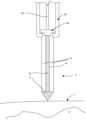
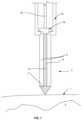
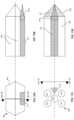
- FIG. 1is a side view of several components of instrumentation for implantation of a spinal implant according to one embodiment of the present invention.
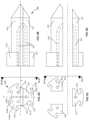
- FIGS. 2 A and 2 Bare rear facing and side views of the adjustable rod structure shown in FIG. 1 in the closed position.
- FIGS. 2 C and 2 Dare rear facing and side views of the adjustable rod structure shown in FIG. 1 in a retracted position.
- FIGS. 2 E and 2 Fare rear facing and side views of the adjustable rod structure shown in FIG. 1 in a retracted position with a probe removed.
- FIGS. 3 A and 3 Bare rear facing and side views of an adjustable rod structure according to another embodiment of the present invention.
- FIGS. 4 A and 4 Bare rear facing and side views of an adjustable rod structure according to another embodiment of the present invention.
- FIGS. 5 A and 5 Bare rear facing and side views of an adjustable rod structure according to another embodiment of the present invention.
- FIGS. 6 A and 6 Bare rear facing and side views of an adjustable rod structure according to another embodiment of the present invention.
- FIGS. 7 A and 7 Bare rear facing and side views of an adjustable rod structure according to another embodiment of the present invention.
- FIGS. 8 A and 8 Bare rear facing and side views of an adjustable rod structure according to another embodiment of the present invention in a closed position.
- FIGS. 8 C and 8 Dare rear facing and side views of the adjustable rod structure shown in FIG. 8 A in a retracted position.
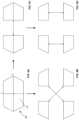
- FIG. 9 Ais a rear facing view of an adjustable rod structure according to another embodiment of the present invention in a first position.
- FIG. 9 Bis a rear facing view of the adjustable rod structure shown in FIG. 9 A in a second position.
- FIG. 9 Cis a rear facing view of the adjustable rod structure shown in FIG. 9 A in a third position.
- FIG. 9 Dis a rear facing view of the adjustable rod structure shown in FIG. 9 A in a fourth position.
- FIG. 10 Ais a rear facing view of the adjustable rod structure according to another embodiment of the present invention.
- FIG. 10 Bis a rear facing view of the adjustable rod structure shown in FIG. 10 A .
- FIG. 11 Ais a rear facing view of the adjustable rod structure according to another embodiment of the present invention.
- FIG. 11 Bis a rear facing view of the adjustable rod structure shown in FIG. 11 A .
- FIG. 12is a rear facing view of an adjustable rod structure according to another embodiment of the present invention.
- FIG. 13is a rear facing view of an adjustable rod structure according to another embodiment of the present invention.
- FIG. 14is a rear facing view of an adjustable rod structure according to another embodiment of the present invention.
- FIG. 15is a rear facing view of an adjustable rod structure according to another embodiment of the present invention.
- FIG. 16is a rear facing view of an adjustable rod structure according to another embodiment of the present invention.
- FIG. 17is a rear facing view of an adjustable rod structure according to another embodiment of the present invention.
- FIG. 18is a rear facing view of an adjustable rod structure according to another embodiment of the present invention.
- FIG. 19is a rear facing view of an adjustable rod structure according to another embodiment of the present invention.
- FIGS. 20 A and 20 Bare rear facing and side views of an adjustable rod structure according to yet another embodiment of the present invention.
- FIGS. 21 A and 21 Bare rear facing and side views of rings disposed on rods for use with an adjustable rod structure according to one embodiment of the present invention, the rings being in a first position on the rods.
- FIGS. 21 C and 21 Dare rear facing and side views of the rings and rods of FIGS. 21 A and 21 B , the rings being in a second position on the rods.
- FIGS. 22 A and 22 Bare rear facing and side views of a ring disposed between rods in another embodiment of the invention.
- FIGS. 23 A and 23 Bare rear facing and side views of a ring with a convex bottom surface disposed between rods in another embodiment of the invention.
- FIG. 24 Ais a side view of stacked rings disposed between rods in another embodiment of the invention.
- FIG. 24 Bis a close up partial interior view of a middle ring of the stacked rings of FIG. 24 A showing an interior wall of the middle ring.
- FIGS. 25 A and 25 Bare rear facing and side views of a ring disposed between rods in accordance with another embodiment of the present invention.
- FIG. 26is a close up partial rear facing view of a ring disposed between rods according to another embodiment of the present invention.
- FIGS. 27 A and 27 Bare rear facing and side views of a ring disposed between rods in accordance with another embodiment of the present invention.
- FIG. 28is a rear facing view of a ring in accordance with another embodiment of the present invention.
- FIG. 29is a rear facing view of a ring in accordance with another embodiment of the present invention.
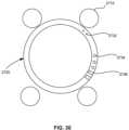
- FIG. 30is a rear facing view of a ring disposed between rods in one embodiment of the invention.
- FIG. 31is a perspective view of a retractor according to another embodiment of the present invention.
- FIG. 32 Ais a partial side view of a retractor according to another embodiment of the present invention.
- FIG. 32 Bis a perspective view of a rod for use with the retractor of FIG. 32 A .
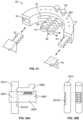
- FIG. 33is a perspective view of a retractor according to another embodiment of the present invention.
- FIG. 34is a partial side view of the retractor shown in FIG. 33 .
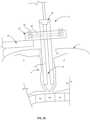
- FIG. 35is a side view of a distractor engaging the retractor of FIG. 33 .
- FIG. 36is a perspective view of an adjustable rod structure according to another embodiment of the present invention.
- FIG. 37 Ais a perspective view of arm elements of a retractor according to another embodiment of the present invention.
- FIG. 37 Bis a perspective view of a retractor in one embodiment of the invention with a handle connected to the arms as depicted in FIG. 37 A .
- the retractoralso includes a mechanism for actuation of the arms (not shown).
- FIGS. 38 - 43depict different steps in the use of the system shown in FIG. 1 .
- FIGS. 44 A and 44 Bare rear facing and side views of an adjustable rod structure according to another embodiment of the present invention.
- the various apparatuses, systems, kits and methods of the present inventionare intended to improve and streamline access to anatomical structures within the body, in particular, structures of and relating to the vertebrae.
- the present inventionis not limited to accessing the spine via specific approaches.
- the present inventionhas applicability to many spinal implantation approaches, and for use in other areas of the body. Through the embodiments described herein, access is achieved under a wide variety of surgical conditions efficiently, safely and with fewer tools than with techniques known in the art.
- proximalmeans closer to the surgeon operating and/or holding a retractor and adjustable rod structure and the term “distal” means closer to the intended anatomical location, such as an intervertebral disc space.
- target anatomical locationas used herein is intended to refer to a location in the body that is the subject of the surgery and for which a portal must be created to achieve access. Examples of a target anatomical location include an intervertebral disc between vertebral bodies in the spine. Other terms that are used interchangeably with target anatomical location herein include intended anatomical location, anatomical location, surgical target site, target site and target anatomical site.
- the present inventionprovides instruments and methodology for providing access to different areas of the body. Although discussed below largely in relation to instruments and methods for providing access to the spine during a spinal fusion procedure, it is to be understood that the present invention may have applicability to other areas of the body, as well as surgery in general.
- the present inventionincludes an adjustable rod structure 9 that is actuated by a retractor.
- Adjustable rod structure 9includes a central rod, or probe 16 , that is located at a center surrounded by other, shorter rods 10 .
- FIGS. 2 A and 2 Bdepict adjustable rod structure 9 in a closed position
- FIGS. 2 C- 2 Fdepict such structure in different open positions.
- Adjustable rod structure 9is designed such that it is easily inserted through an incision and moved towards a surgical target site, such as the lumbar spine. Thereafter, adjustable rod structure 9 can be opened/closed by the retractor, which in one example shown in FIG. 39 (a retractor 50 ), is supported by a stabilizing element 90 , such as a table.
- the retractors as described hereincan be supported by hand, by static structures (e.g., table) or by other means (e.g., robotic systems, as described below) that provide stability for the rods and do not impede access to the anatomical location sought to be accessed for performance of surgery.
- probe 16includes an insertion portion 17 and an extension portion 18 .
- extension portion 18 of probe 16has the same or similar cross section as each individual rod 10 through a portion of its length, but is connected with the larger, conical shaped insertion portion 17 at its distal end. Insertion portion 17 can also be described as a tapered end.
- a diameter of extension portion 18can vary in dimension with respect to a diameter of one or more rods 10 . At its largest cross-section (see FIG.
- insertion portion 17 of probe 16has a profile matching the combined cross section of rods 10 and extension portion 18 , and tapers to a point remote from rods 10 .
- the tip of insertion portion 17can be sharp, rounded or blunt.
- insertion portion 17has an outer surface at a small angle relative to a longitudinal axis of probe 16 so that the outer surface is at an angle less than 45 degrees relative to the longitudinal axis.
- Such a tip structureis advantageous in that muscle tearing is minimized compared with shallower tip surfaces. The steep angle makes it easier for muscle fibers to separate as the probe is advanced. Nonetheless, in some variants, the aforementioned angle can be greater than 45 degrees.
- the shape of insertion portion 17 of probe 16is conical, but can exhibit other shapes, such as an overall bullet-shape, arrow-shape, or any other shape so that it tapers from a proximal to a distal end, the distal end corresponding to the tip.
- the largest outer cross-sectional dimension of probe 16 at a base of insertion portion 17is between approximately 7 and 10 mm in diameter. Again, this is approximately the same as the cross section for all rods 10 and extension portion 18 combined (i.e., profile of adjustable rod structure 9 ) so that it forms a cylinder when in the closed position, as seen in FIG. 2 A .
- the profile of the closed adjustable rod structurecan be up to 16 mm.
- a length of extension portion 18 as shown in FIGS. 2 A-Fis approximately equal to a length of rods 10 .
- Extension portion 18extends in a proximal direction from and is centered on the same longitudinal axis as insertion portion 17 .
- a surface of extension portion 18can be configured or otherwise contoured for attachment to external equipment, such as that used for neuro-monitoring (discussed more fully below).
- the probe structurecan be varied in many respects.
- the length of the extension portion of the probecan be shorter or longer than one or more of the rods.
- the extension portion of the probeis shorter than the rods, but the overall probe is longer than the rods.
- the cross-sectional dimension of the base of insertion portion 17can be smaller or larger than the combined cross-sectional area of the rods surrounding extension portion 18 of probe 16 (i.e., profile).
- extension portion 18 of probe 16can be cylindrical as shown in FIGS. 2 A and 2 C , however, it can also be conical so that it includes an increasing or decreasing cross-section toward insertion portion 17 .
- extension portion 18 and/or insertion portion 17 that are adjacent to and face rods 10can also include surface features so that the rods can nest into the probe and vice versa. Additionally, it is contemplated that the extension portion of the probe can have a square, rectangular, polygonal or other cross-sectional shape, as described in greater detail below.
- the adjustable rod structureincludes gaps between rods and between the rods and the probe when in the closed position. In such configurations, the profile of the rods in the closed position can be the same, larger or smaller than the profile of the insertion portion of the probe.
- Probe 16 as showncan be a single construction or it can be assembled from components or modules, such as separate extension 18 and insertion 17 portions that are physically connected together. For instance, male-female threaded connections can be used to connect the components together either before or during surgery. Of course, other forms of interconnection between probe components are also contemplated. Probe 16 may be manufactured from a variety of biocompatible materials, such as metal materials like titanium or stainless steel, or polymer materials like PEEK. The material of the probe can also be dictated by its use, such as a polymer/metal composite for use with neuro-monitoring equipment, as described below.
- probe 16is surrounded radially by rods 10 .
- rods 10surround probe 16 in a manner so that the rods are symmetrical about a central axis through a length of adjustable rod structure 9 .
- Each rodis circular in cross-section and includes a common diameter.
- Maintenance of the adjustable rod structure in a closed positionis accomplished by application of a stabilizing force to outer surfaces of the rods that is sufficient to hold each rod in position surrounding the probe.
- a closed position of adjustable rod structure 9is maintained by holding an outer perimeter of rods 10 and probe 16 together by hand.
- a closed position of adjustable rod structure 9is maintained by holding an outer perimeter of rods 10 and probe 16 together with a holding element 96 .
- Holding element 96keeps the rods and probe substantially fixed with respect to one another in a closed position so that adjustable rod structure 9 can be transported and/or inserted into a patient as a unitary construct ( FIGS. 1 and 38 ).
- holding element 96is connected to a handle 98 for use in positioning holding element 96 .
- holding element 96includes holes with sizes corresponding to rods 10 so that holding element 96 is disposable over rods 10 . In this manner, holding element 96 resembles a cylinder with multiple chambers, similar to a cylinder of a revolver.
- An example of the holding elementincludes a sterile plastic cap with a flat base and a plurality of tubular extensions extending therefrom, extensions for the rods being shorter than an extension for the probe and each extension closed at one end by the base.
- the cross sectional area of the holding element in this examplewould match the profile of the adjustable rod structure in the closed position.
- a bayonet structureis used as a lock and release mechanism.
- the bayonet structure(not shown) is placed on corresponding surfaces of (1) rods 10 and probe 16 and (2) holes (not shown) within holding element 96 .
- Other lock and release mechanismscan also be incorporated into the combined structure as known in the art.
- a clamp 94can also be used to advance adjustable rod structure 9 into the body either with holding element 96 or separately.
- the rods and probecan further be adapted to engage with holding element 96 at a distal or proximal end of the rods.
- Rods 10are also configured so that a device, such as a retractor as described further below, can be engaged thereto and operated to retract rods 10 away from probe 16 to create an opening, also referred to as a portal, therebetween.
- FIGS. 2 C and 2 Dillustrate adjustable rod structure 9 in retracted positions.
- adjustable rod structure 9is configured to retract at least to the extent shown in FIG. 2 D , so that a space between rods 10 is wide enough to pull probe 16 through the opening created ( FIG. 2 F ).
- a retractorcan be attached to the rods once fully advanced or prior to initial insertion. When attached prior to insertion, the retractor remains engaged to the rods as the rods are advanced toward the target anatomical location.
- the rodsare further configured so that any material 2 , such as tissue or muscle, surrounding the rods is held separated by the rods in the retracted position, as shown in FIG. 2 C .
- the rodsneed to be of a suitable size and material to provide for the necessary strength to retract the tissue.
- rods 10can be provided in various lengths (discussed below), this can vary between longer and shorter rod constructs.
- Each rodis also engineered to withstand a certain amount of deflection under loading. Put another way, the properties of the rod provide sufficient elastic flexibility to withstand deflection that can result from tissue bearing on the rods during use without reaching yield under the highest possible loads.
- the rodscan be varied in many respects. As described above, the rods can be different lengths with respect to each other. The length of each rod can be determined based on the relevant anatomy for an intended surgery. For example, where a target anatomical surface is convex in shape, one side may be closer to the point to the point of entry than the other. Respective rod lengths of the adjustable rod structure can be made to reflect this difference to optimize the effectiveness of the portal created. In a similar manner, one or more of the rods can be a different length relative to the probe. In other examples, the cross-section of the rods and probe can vary with respect to each other in any number of ways.
- a bayonet structureis included where the structure only exists on certain holes in the holding element and on certain rods so that at last some rods are not part of the bayonet structure. This may be advantageous in certain applications where locking of certain rods is not desired.
- the rodscan have varying cross-sectional size along their length so that when combined with the probe, the adjustable rod structure has a tapering shape.
- These rods with varying cross-sectional sizecan also be included with a similarly varying probe.
- the rodscan have a cross-sectional size decreasing in a distal direction while the extension portion of the probe has a constant cross-section.
- both the rods and extension portion of the probecan have a decreasing cross-section in a distal direction.
- the cross-section of the rodsis constant in a distal direction while the extension portion of the probe has a cross sectional size that increases in a distal direction toward the probe tip.
- rods and probeswith varying lengths are contemplated.
- rods 10 and probes 16can be provided in small, medium and large sizes, with a length range between approximately 30 mm for the small size to approximately 170 mm for the large size.
- these are just examples and various sizes within this rangecan be included as part of a kit, described in greater detail below.
- the rodsmay include sensors for use in neuro-monitoring procedures, tracking devices, markers such as LEDs, as well as physical features (not shown) such as indentations, notches, grooves or protrusions configured to correspond to features on retractor 50 and/or the below discussed ring elements.
- sensors for use in neuro-monitoring procedurestracking devices, markers such as LEDs, as well as physical features (not shown) such as indentations, notches, grooves or protrusions configured to correspond to features on retractor 50 and/or the below discussed ring elements.
- markerssuch as LEDs
- physical featuressuch as indentations, notches, grooves or protrusions configured to correspond to features on retractor 50 and/or the below discussed ring elements.
- Such featuresenhance securement between the rods and the retractor and/or ring and may also improve control when adjusting the position of rods relative to the retractor and/or ring.
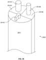
- adjustable rod structure 9may be configured to advance over k-wire or y-wire that guides the structure to a target site within the body. While k-wires are widely known, an example of y-wire is described in U.S. Pat. No. 8,545,531, the disclosure of which is hereby incorporated by reference herein in its entirety.
- FIGS. 20 A and 20 Billustrate an adjustable rod structure 1809 that is so configured. As shown, probe 1816 is cannulated so that it can receive wire 1819 . Additionally or alternatively, a rod 1810 of adjustable rod structure 1809 can also be cannulated in the same way as the probe 1816 .
- Probe 1816can further be varied so that it is cannulated 1813 to incorporate structures that aid in a neuro-monitoring procedure.
- neuro-monitoring technologyis used to detect the proximity of nerves to a sensor.
- probe 1816includes a neuro-monitoring electrode 1813 disposed in a cannulation of probe 1816 .
- Electrode 1813is shown offset from a longitudinal centerline of probe 1816 . While wire is shown situated along the longitudinal axis of probe 1816 , other embodiments could include electrodes placed differently.
- cannulations for electrodescan be in locations on probe 1816 or rods 1810 other than those shown in FIGS. 20 A and 20 B .
- electrode 1813can also be insulated and disposed external to the probe 1816 and rods 1810 .
- the offset nature of neuro-monitoring electrode 1813allows for an exposed sensor 1813 A located at a distal end of probe 1816 to rotate as the probe rotates.
- movement of the sensorsis used to obtain readings to detect the proximity of nerves in multiple directions.
- Sensors 1813 A as contemplated hereinare adapted so that an external controller (not shown) can be calibrated to read measurements by the sensor at any time during advancement of the adjustable rod structure.
- an external controllernot shown
- two or more sensorscan be included on the probe 1816 .
- Electromyographydescribed, for example, in U.S. Pat. Pub. No. 2010/0241129
- mechanomyographydescribed, for example, in U.S. Pat. Nos. 8,343,065, 8,343,079, 8,517,954, 8,882,679, 8,855,822, 8,892,259, 8,942,797, 8,979,767, 8,983,593, 9,039,630, 9,084,550 and 9,301,711, and U.S. Pat. Pub. Nos.
- an accelerometeris positioned to be in communication with a muscle so that when a device, such as the adjustable rod structure, is advanced into the body toward a target anatomical location, the accelerometer can provide output indicating the proximity of the adjustable rod structure to a nerve.
- a transduceris disposed on the probe and is configured to launch sound pulses into tissue. The sound of the reflection from the part of the body contacted by the pulse can indicate whether such sound is originating from tissue, nerves, or other distinct anatomical structures.
- the probes and/or rodscan themselves be configured for use with a neuro-monitoring system.
- the rods and/or probescould be constructed of a combination of polymer and metallic material. The latter may operate as an electrode, while the former may serve as an insulator. Thus, only a portion of the metallic material (for instance, at the ends of the probe) could be exposed. This serves essentially the same purpose as the above discussed electrode.
- variantsmay include probes and/or rods only having a partially composite structure while the remainder of the probe and/or rod is manufactured from a non-composite metal.
- the bullet shaped tip of the probecan be a composite material while the extension can be metallic.
- FIGS. 3 - 19Different embodiments of adjustable rod structures are shown in FIGS. 3 - 19 .
- Rods, and probes where applicable, of these embodimentsare manufactured from various materials, such as those described above. Particular materials for individual rods and probes within an adjustable rod structure can vary and such determinations are a matter of design choice.
- FIGS. 3 A and 3 Billustrate a rod structure 109 having a probe 111 without a tapered insertion portion in the closed position.
- rod structure 109includes four rods 110 , all having a similar or equal circular cross section over a proximal portion of their length. Each rod 110 further includes a taper towards a distal end, as shown.
- the taperis shaped so that an outward facing portion of the rod surface tapers inward, and in this way, the overall cross section of adjustable rod structure 109 becomes smaller toward the distal insertion end.
- Probe 111maintains a circular cross section through most of a length of adjustment structure 109 and only tapers at the extreme distal tip, where it tapers to a point, as shown. Over an extreme distal end of the length of the tapered portion, the profile of rod structure 109 is solely comprised of probe 111 .
- FIGS. 4 A and 4 Billustrate another embodiment of an adjustable rod structure 209 .
- This structureincludes four rods 210 and a probe 216 .
- Rods 210 as illustratedare the same as rods 10 described above.
- Probe 216includes an insertion portion 217 and an extension portion 218 .
- the insertion portion 217further includes a cut portion 212 defined by two non-tapering planar surfaces (best shown in FIG. 4 A ).
- cut portion 212is a groove in insertion portion 217 of probe 216 and is configured to leave space within a profile of adjustable rod structure 209 so that an element, such as a fixation post described in greater detail below, can be inserted into the space as a step of one embodiment of a method.
- the grooveis also of sufficient size so that a finger of a surgeon can be disposed therein when adjustable rod structure 209 is positioned inside the body.
- FIGS. 5 A and 5 Billustrate a four rod adjustable rod structure 309 in a closed position.
- Each rod 310includes the same or similar circular cross-section and tapered tip. In the closed position, the taper of each rod tapers inward so that each terminates at approximately a common point at an insertion end of the adjustable rod structure 309 .
- FIGS. 6 A and 6 Billustrate another embodiment of adjustable rod structure 409 including four rods 410 and a probe 416 in a closed position.
- Rods 410are positioned in a symmetric manner surrounding a center of the adjustable rod structure cross-section, and each rod 410 includes a cone-shaped tip 412 ( FIG. 6 B ) at its distal end adjacent to and facing a back surface of a tapered insertion portion 417 of the probe 416 .
- Tips 412are cone shaped so that rods 410 are configured to anchor to a target site, such as an intervertebral disc, when fully inserted into the patient.
- tipscan include other shapes that taper to a distal end.
- the rods 410 and an extension portion 418 of the probe 416all have a circular cross-section of the same diameter.
- rods 3010are longer than extension portion 3018 of probe 3016 .
- Insertion portion 3017 of the probeincludes cavities 3017 B on its bottom surface 3017 A shaped to correspond to rod tips 3012 which are disposable therein ( FIG. 44 B ).
- Tips 3012 of rods 3010 as shownare conical, however, it is contemplated that tips of other shapes can be included in a similar manner in conjunction with a probe having corresponding surface features to allow such tips to be disposed in the probe. In further variants, these principles can be applied in the opposite manner.
- the tips of the rodscan instead include cavities tapering into a body of each rod, and a corresponding bottom surface on the insertion portion of the probe can have protrusions to match the cavities in the rods.
- the adjustable rod structurecan include more than one type of rod where at least one rod includes a tip corresponding to a cavity in the probe and at least one rod has a flat distal end matching a planar portion of a bottom surface of the insertion portion of the probe, such as the rods of FIGS. 2 A- 2 F .
- FIGS. 7 A and 7 Billustrate yet another embodiment of a four rod and probe adjustable rod structure 509 .
- a distally facing end surface 512 of rods 510is contoured along an arc. The are is oriented so that rods 510 have a concave end surface that mates with a convex bone surface, such as the vertebrae of the spine, when adjustable rod structure 509 is retracted into an open position.
- rods 510 and an extension portion 518 of probe 516all have a circular cross-section of the same or similar diameter.
- the contour of the bottom surface of rods 510can be convex and can otherwise vary from the end surface 512 shown to suit the anatomy of a particular patient or group of patients or even to cooperate with different anatomical structures.
- FIGS. 8 A- 8 Dillustrate a three element adjustable rod structure 609 .
- two of the rods 610are of the same structure, while a third rod 611 traversing a width of rod structure 609 includes similar geometric features but is wider and includes a larger cross-section than rods 610 .
- identical rods 610have a combined profile slightly larger than a profile of rod 611 , as shown.
- Inner surfaces of each rodare planar so that when adjustable rod structure 609 is closed, as shown in FIGS. 8 A and 8 B , the surfaces of the respective rods press together and are flush with one another, leaving only a nominal amount space between each if any space at all.
- an outer surface 610 A, 611 A of each rod 610 , 611forms part of a circular surface so that when the rods are closed, rod structure 609 is largely cylindrical, but with a tapered distal end. As shown, the tapered end is conical and is formed from tapered end portions of each rod 610 , 611 . As best shown in FIGS. 8 A- 8 D , rods 610 , 611 also include a circular hole 613 that is entirely within a cross-section of each rod and is configured to provide a pathway to distribute lighting into a distal region of adjustable rod structure 609 . Of course, differently shaped/sized holes can be provided for different purposes.
- Each rod 610 , 611also includes an engagement feature 614 , 615 having neck portions 614 A, 615 A and arms 614 B, 615 B flaring outward in a lateral direction from neck 614 A, 615 A, respectively.
- An outer surface of arms 614 B, 615 Bforms a partial circular surface so that the outer surface of the combined engagement features represents a second profile for adjustable rod structure 609 outside of the generally circular outer surface of rods 610 , 611 themselves.
- a shape of the engagement features 614 , 615is tailored so that engagement with lighting tools, shims, retractor extensions, and other devices used during surgery, is possible and if already possible, improved.
- Each rod 610 , 611is configured to be retractable in tandem with each other, as well as independently in a linear or radial direction or in a direction that is a combination of both. Each rod can also be rotated either independently or in tandem with one or more of the other rods.
- adjustable rod structure 609can be manufactured from metal, polymers, or a combination of both. Examples include a structure where the engagement features are metal and the rods are a polymer, a structure where the engagement feature is metal with plastic arms, or a structure where the rods are a composite of metal and polymer to accommodate neuro-monitoring.
- each of the three rodsincludes a common cross-section. In yet another, all three are of a different size.
- the hole in one or more rodscan be oval, square or another shape. In addition, one or more rods may not have a hole at all.
- the holeis only disposed in the profile of the adjustable rod structure 609 over part of its length, with at least another part external to the circular perimeter.
- the holecan be on the interior of the profile at a proximal end of a rod, extend within the profile in a distal direction, and then alter trajectory so that it continues outside of the rod as a tube to an end point proximal to the tapered tip.
- the adjustable rod structurecan include four or more rods with cross sectional shapes as described.
- the rods of the adjustable rod structuremay include a chamfer or notch on one corner facing the other two rods.
- This spacecan be configured so that k-wire, y-wire or the like may be placed therethrough.
- FIGS. 9 A- 9 Dillustrate another embodiment of an adjustable rod structure 709 that includes four polygonal rods 710 .
- the combined structure 709forms a hexagon shaped profile.
- the rods 710are configured so that each can be retracted in the x-axis, y-axis or diagonal axes, as best shown in FIGS. 9 C, 9 D and 9 B , respectively.
- the adjustable rod structure 709can be another polygonal shape, such as a pentagon, with each rod having a common cross section.
- the adjustable rod structure 709can include at least two rods having different cross sectional shapes.
- FIGS. 10 A and 10 BIllustrated in FIGS. 10 A and 10 B is another embodiment similar to that shown in FIGS. 9 A- 9 D in that it includes a polygonal shaped adjustable rod structure 809 with four rods 810 . However, it also includes a fixation post 811 . In a closed position, rods 810 and fixation post 811 complete a hexagonal profile, as shown in FIG. 10 A .
- a distal end of adjustable rod structure 809terminates in a tapered end, as shown in FIG. 10 B . However, the tapered end is based on the structure of combined rods 810 and excludes fixation post 811 , as best seen in FIG. 10 B .
- Fixation post 811is independent of rods 810 and is configured to engage or become fixed to soft or hard tissue.
- fixation post 811can engage a vertebral body or disc located between vertebral bodies.
- An arrow shaped tip 811 A at a distal end of fixation post 811is a mechanism for engagement between post 811 and the tissue and is shown in FIG. 10 B .
- the tipcan be threaded, kneaded or have other engagement features.
- the tipcan be conical, as shown in FIG. 10 B , for example, or it can be another shape such as a dome, pyramidal, and so on.
- the fixation postis monolithic. In others, it is not monolithic.
- a body of the fixation postis cylindrical and hollow and the tip includes a conical tip structure with an extension portion extending therefrom sized to fit within the hollow space of the fixation post body.
- the fixation postis configured so that once the combined body and tip of the fixation post have been fully advanced to a target site, a proximal end of the extension portion of the tip can be accessed by a user to screw the tip into a target anatomical surface at the target site. Because there is negligible restraint on relative rotational movement between the body and tip components, the body will remain static as the tip is rotated via the extension.
- two or more fixation postscan be included as part of an adjustable rod structure.
- the systemcan include at least one monolithic fixation post and at least one non-monolithic fixation post, such as a fixation post including a body and a tip component.
- FIGS. 11 A and 11 BAnother embodiment that depicts an adjustable rod structure 909 with a fixation post is depicted in FIGS. 11 A and 11 B .
- a probe 916 with a tapered insertion end 917is surrounded by four rods 910 .
- To one side of the probe 916is a fixation post 911 , as shown in FIG. 11 A .
- the fixation post 911includes a cone shaped or pointed distal end 911 A ( FIG. 11 B ) and is configured so that it is movable independent of the other elements of structure 909 .
- Fixation post 911is configured so that it is securable to an intervertebral space, or other anatomical structure.
- insertion end 917 of probe 916can include a groove or recess (not shown) shaped to allow passage of fixation post 911 .
- fixation post 911may be inserted into the intended anatomical location prior to removing the probe 916 from the adjustable rod structure 909 .
- Fixation post 911is manufactured from materials such as those described above for the probe and rods. It is contemplated that fixation post 911 can be varied in the same ways as described above for fixation post 811 .
- rods of an adjustable rod structureare I-shaped, as shown in FIGS. 12 and 13 .
- each group of I-shaped rods 1010 , 1110surrounds a probe element 1016 , 1116 , respectively.
- an adjustable rod structure 1009includes a single probe 1016 and four rods 1010 of equal size.
- Probe 1016has a circular cross section extending from a proximal end so that the probe is substantially cylindrical in shape. Towards a distal end of the probe, the surface tapers to a distal tip (not shown).
- Each rod 1010has a narrow web 1014 and a wide flange 1015 at each end of web 1014 , thereby forming the I-shape.
- Flanges 1015are semicircular in shape when viewed in section and each flange 1015 is a mirror image of the other.
- the I-shape of rods 1010provides strong flexural capacity (i.e., bending capacity) against loads bearing on the rods pushing the rods inwards, particularly where loads are distributed along a length of the rod. For example, when adjustable rod structure 1009 is advanced into muscle tissue and the rods are retracted, the tissue surrounding the rods bears on rods 1010 urging each rod inward.
- a probe 1116 having indentations 1116 Ais included.
- Indentations 1116 Aare shaped to mate with a semicircular outer surface 1115 of rod flanges 1110 .
- probe 1116 and indentations 1116 A thereinextend longitudinally in a distal direction over a portion of a length of probe 1116 and taper at a distal end to terminate in a tip.
- the indentations 1116 Aextend into a portion of the tapered portion of probe 1116 and fade into the tapered surface in the distal direction when the cross section of probe 1116 decreases in size to a point where it is smaller than the indentation surface (not shown).
- adjustable rod structure 1109 in a closed positionis smaller than that of the adjustable rod structure of FIG. 12 as indentations 1116 A on probe 1116 provide additional room for rods 1110 to be positioned closer to a centerline of the adjustable rod structure cross section.
- adjustable rod structure 1109includes a minimal profile and has the advantage of improved strength in the rods through the I-shape of each.
- the extension of indentations 1116 A into the bullet shaped end portion of probe 1116improves ease of removal of probe 1116 . It is contemplated in other variants of the above embodiment to include one or more rods that are a shape other than an I-beam, while the other rods include I-beam cross-sections.
- an adjustable rod structure 1209includes four circular rods 1210 having the same diameter surrounding a probe 1216 , as shown in FIG. 14 .
- Probe 1216includes four indentations 1216 A, each having a radius matching that of rods 1210 , disposed in a symmetric manner around the cross section of probe 1216 . In a closed position, as best shown in FIG. 14 , each rod 1210 mates with a corresponding indentation 1216 A so that the overall profile of the adjustable rod structure is smaller than it would be otherwise.
- Probe 1216includes a tapered distal end (not shown). In a variant, the tapered distal end can comprise a taper commencing in rods 1210 and then proceeding distally into probe 1216 beyond ends of rods 1210 .
- an adjustable rod structure 1309includes a probe 1316 with indentations 1316 A having a triangular section cut from an otherwise circular section probe element 1316 .
- Each indentation 1316 Aincludes two planar surfaces converging on a line extending from the proximal end of probe 1316 to a tapered distal end of probe 1316 .
- structure 1309includes four rods 1310 . In the closed position, rods 1310 correspond to indentations 1316 A.
- the structure of probe 1316 in this embodimentcan reduce the size of a kit as a larger variety of rod shapes can complement and correspond to the indentations in the probe than might otherwise be possible with other configurations. Thus, fewer probes are needed to complement a variety of rod shapes. For example, both square and circular rods can be positioned adjacent to indentations 1316 A so that either corresponds with probe to create a minimal profile of structure 1309 in the closed position.
- the adjustable rod structurecan have a wide variety of profiles based on a varying quantity, size and shape of the rods, with or without probes.
- FIGS. 16 - 19Some examples of what is contemplated by the present invention in this regard are shown in FIGS. 16 - 19 .
- the adjustable rod structurecan have various forms of a tapered distal end.
- the tapered distal endcan be bullet-shaped or it can be arrow-shaped with a pointed tip.
- an adjustable rod structure 1409includes four rods 1410 and has an oval shaped profile in the closed position.
- an adjustable rod structure 1509includes a probe 1516 and eight rods 1510 disposed radially surrounding probe 1516 in a symmetrical fashion. In a variant, probe 1516 can be substituted with a rod.
- an adjustable rod structure 1609has an octagonal profile in a closed position. Each rod 1610 has the same five sided cross section, with rods 1610 being symmetrical about both x and y axes.
- an adjustable rod structure 1709includes three rods 1710 , 1711 . As shown, rods 1710 have the same four sided cross section, while rod 1711 is somewhat smaller and has three sides.
- the cross-section of the rodscan be non-circular in shape (i.e., rectangular, oval or polygonal), as is shown in certain embodiments.
- the cross section of the adjustable rod structurei.e., the combined section of the rods
- the rods 10can also include a tapering diameter so that the diameter tapers in a distal direction toward the distal (insertion) end or so that the diameter increases toward the distal end.
- the rodscan include a telescoping or lengthening capability. Systems or kits with telescoping rods are advantageous in that fewer sizes (i.e., lengths) of rods would be required for use in an array of surgical conditions.
- the probemay be surrounded by any number of rods.
- the adjustable rod structuremay also be comprised of rods without any probe element.
- the adjustable rod structurecan include five rods, where the combined rod structure forms an arrow shaped insertion end when in the closed position.
- the proximal end of the rodscan include notches or divots spaced at approximately equal intervals. These surface features can be shaped to correspond with a retractor device to allow adjustment of the locked position of the rods relative to the retractor. Through the inclusion of notches or divots on the rods, it is possible to reduce the number of rod lengths necessary for inclusion in a kit. For example, providing rods with notches at specific interval (e.g., 5 mm intervals) could negate the need for rods with small, medium and large lengths in favor of just a one or two such sizes.
- an adjustable rod structuremay vary. This variation can be differing diameters, differing shapes, cannulation and so on.
- an adjustable rod structureincludes five rods, where two have a diameter of 6 mm and the other three have a diameter of 8 mm. It is contemplated that other features of the rods may also vary rod to rod within an adjustable rod structure. In other examples, the position of the rods around a center of the adjustable rod structure can be asymmetrical.
- indicatorscan be included on a proximal end face of the rods to identify and distinguish between them. For example, color coding can be used to signal to a surgeon whether a rod has a bullet shaped tip or whether it is cut orthogonally to its length at a distal end face. This can allow a surgeon to easily line up a given rod with a specific anatomical feature or in a specific orientation. Other indicators such as notches or dots can also be used. Indicators can also be used as a benchmark to adjust and align one or more of the rods.
- Indicatorscan be placed on the rods in many locations. For example, indicators can be placed on a proximal end surface of the rod or within the rod for measurement through medical equipment, such as an x-ray.
- medical equipmentsuch as an x-ray.
- the examples described hereare merely illustrative and many other cross-sectional shapes, rod quantities, symmetry and so on are contemplated as within the scope of the invention.
- the depiction and description of the insertion end of the adjustable rod structure as being arrow or bullet shapedis merely illustrative of one preferred embodiment.
- the arrow or bullet shaped tipmay be varied in a manner appropriate for tissue penetration using the knowledge of an ordinary artisan.
- the insertion endcan be a conical shape or have a pointed tip with a shape that is not specifically an arrow shape.
- the use of “tapered end” to describe the insertion or distal end of the adjustable rod structure throughout the specificationcontemplates the above possibilities and many others for a shape of a penetrating tip of the adjustable rod structure.
- FIGS. 21 A- 21 Ddepict a series of rings 1920 that are advanced along individual rods 1910 of adjustable rod structure 1909 , which can be in the form of any of the above-discussed rod structures.
- Each ring 1920is configured so that it is insertable over rods 1910 of adjustable rod structure 1909 .
- FIGS. 21 B and 21 Dshow the rings disposed over rods 1910 at proximal and distal positions, respectively.
- rings 1920are adapted so that each can slide over a length of rod 1910 .
- ringsare shown as having a depth over a fraction of the rod length, rings can have a depth of an amount up to and above that of the rod length. They are also preferably rotatable with respect to rods 1910 , as discussed below.
- Each ring 1910includes a circular outer profile and extending from that profile, an engagement portion 1921 .
- Engagement portion 1921includes a narrow neck 1921 A and arms 1921 B extending in opposite directions from neck 1921 A, as shown.
- An outer surface of arms 1921 B of engagement portion 1921includes a partial circular profile.
- the shape of engagement portion 1921is configured so that tissue 1902 or other materials are held back when ring 1920 is rotated as shown in FIG. 21 C so that engagement portion 1921 faces outward.
- rings 1920can be inserted with engagement portions 1921 facing inward ( FIG. 21 B ) and then individually rotated into place to push back tissue ( FIG. 21 D ).
- the rings 1920are made of a plastic material, although manufacture using other materials is also contemplated. Rings 1920 inserted over rods maintain a diameter of a portal opening while a retractor remains in place to hold the rods in their open position. In other embodiments as described below (e.g., FIGS. 22 A- 22 B ), the rings, once in position, can hold the rods in place and thus maintain a portal opening with or without the assistance of a retractor.
- rings 1921can include additional engagement features configured for engagement with complementary features on rods 1910 .
- Such featurescan be sized and positioned to control rotation and/or advancement of rings 1920 .
- the ringscould snap into place at different portions of the rod (e.g., at a distal end).
- additional engagement featurescan be disposed at any location on the ring or distributed throughout.
- the geometry of the engagement portioncan be another shape deemed suitable for engagement to tissue expected to be encountered during surgery.
- the ringscan be manufactured in varying lengths so that a size best suited for a particular surgery may be used.
- each ringcan be 10 mm, 20 mm or 30 mm long, measured on an axis extending through holes of the rings. This is discussed in greater detail in the kit embodiments described below.
- a single ring 2020is sized for insertion between rods 2010 when the rods 2010 are in the retracted position.
- FIGS. 22 A and 22 Billustrate four rods 2010 with a single ring 2020 disposed therein.
- Ring 2020is a hollow tube with an opening sufficient for performance of an operation at an intended anatomical location in the body while ring 2020 is in position.
- Ring 2020is manufactured so that an outer surface of the ring diameter contacts and holds rods 2010 when ring 2020 is positioned therebetween. This may entail the inclusion of depressions or slots formed on an outer surface of ring 2020 for receiving a portion of each of rods 2010 .
- a hollow tube ring 2120see FIGS.
- Concave bottom surface 2125 of ring 2120has an arcuate shape so that it can nest or otherwise mate with an intended anatomical location, such as an intervertebral disc 2104 B between vertebral bodies 2104 A.
- bottom surface 2125may be tailored to cooperate with any anatomical structure or the like.
- ring 2120can have a depth so that ring 2120 abuts bone surface 2104 B in a fully advanced position while simultaneously remaining engaged by rods 2110 which remain at a distance, or gap 2180 , from the bone or disc surface.
- gap 2180 between a distal end of rods 2110 and vertebral body or intervertebral disc 2104 A, 2104 B,is covered and protected by ring 2120 , preventing tissue 2102 creep into the portal.
- the gapmay be up to several millimeters over a portion of the ring depth. For example, it can be 0 mm or it can be up to 10 mm.
- Ring 2120 as shown in FIG. 23 Bis configured to perform with the aforementioned gap present while positioned proximal to a target anatomical location.
- the gapmay vary at different locations around the circumference of the ring. For example, the depth of the gap may be shorter on one side of the ring relative to the depth on the opposite side.
- the gapcan be up to 10 mm on one side of the rod and another amount on the other side of the rod that is a function of the 10 mm value and a gradient of the vertebral body surface or a function of the 10 mm value and a radius of a curved surface of the vertebrae.
- each ring 2220 A, 2220 B, 2220 Care included as part of the system, where each ring is stackable as shown in FIG. 24 A .
- each ringhas engagement features 2224 at roughly equal spacing around a rim of the ring to secure it to a corresponding engagement feature 2224 on an adjacent ring.
- ring 2220 Bhas engagement features on a top and bottom rim, as shown in FIG. 24 B .
- the engagement features 2224 at either rimcan be male or female.
- ring 2220 Ahas no engagement features on a top rim, as shown in FIG. 24 A .
- FIG. 24 Bthree engagement features 2224 are visible at the interface between rings, but it is contemplated that engagement features are placed as desired around a circumference of the ring.
- a tube 2222 for lightingis also shown affixed to the combined ring structure in FIGS. 24 A and 24 B .
- Tube 2222can be, for example, a cannulated plastic tube with a wire (not shown) disposed therein. The wire extends to a location toward the distal end of rods 2210 and connects to a light, such as a light emitting diode (“LED”), and from that location light emanates.
- LEDlight emitting diode
- Each ring 2220 shownalso includes additional features. Namely, an inner surface of a wall of ring 2220 B, as shown in FIG. 24 B , includes grooves or holes 2226 having a size and shape so that a tool, such as a spring loaded telescoping tool, is adapted to grip ring 2220 B via holes 2226 .
- a toolsuch as a spring loaded telescoping tool
- tantalum markers 2228Another feature on ring 2220 B, and shown in FIG. 24 B , are tantalum markers 2228 . As shown, there are three tantalum markers on ring 2220 B. Rings are configured to include tantalum markers 2228 so that when the rings are placed into the body, the markers can be used as reference locations to ensure that alignment of the system continues to be maintained.
- tantalum markerscan be used to confirm that each ring is in alignment with each of the other rings, or that the rings are in alignment relative to the rods or to the vertebrae, all during the course of the surgery.
- Tanatalum markerscan be placed pre-operatively or intra-operatively.
- a retracted adjustable rod structurecan include any number of stacked rings (e.g., 2, 3, 4, or more). In some variants where stacked rings are included, none or only some of the rings may include engagement features to interconnect the rings. It is further contemplated that the rings can include additional physical features in addition to those described above. For example, the rings can include holes through their thickness sized for the placement of wire, fiber optic cable or cable for neuro-monitoring.
- the device used to supply lighting to the tubecan be any device capable of lighting the distal end of the adjustable rod structure.
- One or more ringscan also include an interior surface with a black color and having a matte finish.
- the black matte finishcan improve the effect a lighting device has on the intended anatomical location by preventing tissue adjacent to the portal from lighting up among other advantages.
- an LEDmay emit light at the insertion end of an adjustable rod structure where a ring at the same end has a black matte finish. Because of the finish on the ring, the visibility of the lit target site is improved as glare from the ring surface is minimized
- at least one ringcan be manufactured from illuminating material to provide lighting to the intended anatomical location.
- one or more ringscan be assembled from two or more components or pieces.
- a ringcan include two combinable C-shaped semi-cylindrical components.
- one or more ringscan be monolithic and one or more rings can be assembled from two or more components.
- one ringcan be smaller in cross-section than the other.
- a smaller ringwill fit snugly within an inner diameter of a larger ring so that only a nominal amount of space remains between the rings.
- the smaller and larger ringcan be combined with an adhesive prior to surgery to create a combined, preformed ring.
- eachcan have differing thicknesses and heights, provided their combined thickness and height is shaped to slide between, around or over the rods of the adjustable rod structure.
- a first, smaller ring with uniform depth and thicknessfits inside a second, larger L-shaped ring, where the L-shape denotes a dual thickness of the ring and the larger thickness equals the smaller thickness plus the thickness of the smaller ring.
- the smaller ringis constructed of material conducive to lighting such as a clear lucite, lexan or polycarbonate, while the larger ring is a solid color capable of blocking the transmission of light, such as a black matte finish. In this configuration, direction of light into the target site is optimized because the outer ring keeps lighting within the portal, among other reasons.
- one or more ringscan be expandable.
- Ring 2320includes an inner surface that is entirely circular while an outer surface of ring 2320 includes concave indentations 2321 .
- Concave indentations 2321form arc shaped surfaces on the outer surface of ring 2321 and include a curvature sized so that rods 2310 of the adjustable rod structure 2309 are nested and mate with indentations 2321 when ring 2320 is positioned in between rods 2310 .
- the indentations on the ringmaintain an opening size through the access and concurrently minimize a cross-sectional space required for the retracted rods.
- FIG. 26depicts a ring 23020 having grooves 23021 with two planar surfaces adjoined at a line extending parallel to a longitudinal axis of the ring and recessed from an outer surface of the ring.
- grooves 23021are sized so that rods, such as circular rod 23010 shown in FIG. 26 , correspond with groove 23021 .
- Other rodsmay correspond as well, such as rods with an ovular or rectangular profile.
- an outer surface of the ringtapers in a longitudinal direction, such as ring 2420 shown in FIGS. 27 A and 27 B .
- This ring structurewhen inserted between rods, creates a construct that tapers inward toward a distal end of the construct.
- rods 2410can initially be in a parallel orientation, the placement of ring 2420 along with the pressure from surrounding tissue can result in the tapered orientation shown in FIG. 27 B .
- the ringcan have outer surfaces that taper outward towards the distal end of the rods.
- tapering of the outer surface of the ring in either directionmay vary from a taper of an inner surface of the ring so that a wall thickness of the ring varies over its length.
- the inner surfacecan have no taper.
- the outer surfacecan taper outward while the inner surface tapers outward but at a lesser angle relative to the longitudinal axis of the ring.
- a ring for use with an adjustable rod structurecan be placed over retracted rods, examples of which are shown in FIGS. 28 and 29 .
- eight holes 2527are distributed through a perimeter of a ring 2520 .
- An outer surface 2528 of ring 2520protrudes around each hole in a convex fashion to maintain a minimum thickness of the ring throughout.
- Ring 2520is sized and otherwise configured so that it may be placed through rods (not shown) in a retracted position by advancing ring 2520 through the rods via holes 2527 .
- Ring 2520when disposed over retracted rods, provides a larger opening than what would otherwise be available when a ring is placed within an area inside the rods, such as would be the case with ring 2420 shown in FIG. 27 A , for example. This is because only part of the cross-sectional area of ring is interior to the rods. Ring 2520 is further configured so that where retracted rods taper inward in a distal direction, advancement of ring 2520 causes further retraction of the rods. Put another way, ring 2520 reduces or negates any taper extant in the rods. It is further contemplated that with some adjustable rod structures, advancement of ring 2520 causes rods to retract from a closed to a fully retracted position.
- ring 2520is shown having two circular layers through its thickness including a metallic outer layer 2623 A, and a polyurethane inner layer 2623 B. The interface between the two layers is fixed so that neither layer moves with respect to the other. Within the thickness of polyurethane layer 2623 B are holes 2627 distributed equidistantly as best shown in FIG. 29 . In the illustrated embodiment, there are eight holes 2627 sized for rod placement therethrough.
- Ring 2620is configured for placement over rods (not shown) in the same manner as ring 2520 .
- Polyurethane layer 2623 Bincludes an inherent malleability so that in the event that a rod cannot be disposed directly through opening 2627 , hole 2627 may stretch to allow disposition of the rod therethrough.
- the ringcan include indicators such as those shown in FIG. 30 on a top surface of a ring 2720 in place between rods 2710 .
- Indicatorsare used to identify the properties of a ring and can also be used to confirm the alignment of the ring when it is in position between the rods.
- FIG. 30illustrates a ring that includes several types of indicators.
- One indicatoris a quantity and/or pattern of dots 2732 . In one example of how dots can be used, two dots can mean that ring 2720 is length X whereas three dots can mean that the ring is length Y.
- the indicatorscan represent include the diameter of the ring, any contours on its inner or outer surface, the shape of its distal end face (e.g., arcuate, flat), or other physical features such as notches, tantalum marks, and so on.
- colored dots 2734can also represent different features of the rings, e.g., each color can be associated with a property of the ring.
- Another indicator shownis a physical marker on the rim.
- notches 2736are shown on the upper surface of the ring. The shape and/or quantity of notches 2736 can be used to create a system of identifying the characteristics of the ring.
- the ringscan have an ovular or polygonal profile to match an inner area of the adjustable rod structure when in the open position.
- a thickness of the ringcan be modified or be variable at different points on the ring to suit a particular surgery being performed. For example, where it is anticipated that loads from muscle tissue surrounding the adjustable rod structure will be high, rings with a greater thickness can be used than what would be used otherwise.
- the ringmay be thicker at that location of the perimeter to support the load from the rod.
- the ringscan also include engagement features on an interior wall of the ring configured to engage with corresponding features on the rods so that the ring can be disposed entirely external to all rods of the adjustable rod structure.
- ringshaving a profile configured to fit within an opening in a retractor when the retractor is holding rods so that the ring can be inserted into a portal into the patient without removing the retractor.
- Other characteristics of the rings that are contemplated and that may be a variable when assembling a kitinclude whether the ring is disposable, kitted, whether the ring has keys, what materials are used to manufacture the ring, and the variety of features on the ring surface for connecting to tools, other rings, and any other component used in the procedures described herein.
- rings including holes for receiving rodscan include any number of holes for receiving any number of rods.
- rings 2520 of FIG. 28includes eight holes 2527 , but such could be utilized with a four rod adjustable rod structure.
- the systemfurther includes a retractor to complement the adjustable rod structure and rings.
- the retractoris configured to retract the rods of the adjustable rod structure using adjustable arms engagable with individual rods of the adjustable rod structure.
- the armsare adapted for movement so that an area interior to the rods progressively becomes larger with actuation of the arms.
- the retractoris as shown in FIG. 31 .
- the retractor 50 as shownis configured for engagement with the four rod adjustable rod structures shown in FIGS. 1 to 7 , though may be configured for engagement with other adjustable rod structures, such as those described in other embodiments herein.
- the retractor 50includes a semicircular frame 51 with a slot 52 over a portion of its length on an inward facing surface and openings 58 A distributed along its length on a top surface and sized for the placement of pins therethrough, described in greater detail below.
- an engagement featureAt each end face of frame 51 is an engagement feature.
- one end facehas a male engagement member 53 with ratchet teeth and the other end face has a female engagement member 54 that corresponds to ratchet teeth 53 .
- the structureis thus configured so that two frames 51 are engagable with each other, the general principle of which is shown in FIG. 31 . When two frames 51 are engaged, the combined shape of the frames in one plane is circular.
- Ratchet teeth 53are also configured so that single tooth adjustments can adjust the size of the combined frames 51 , moving each frame 51 either closer together or further apart in a linear movement.
- arms 56attached to each frame 51 as shown in FIG. 31 , moving frames 51 relative to each other concurrently retracts or brings together rods disposed in arms 56 of the frames.
- Each arm 56is linear and includes lock pin holes 59 configured and sized for lock pins 58 and an opening 57 with a diameter corresponding to a rod 10 .
- Openings 57are configured so that rods of varying lengths can be used for one retraction operation by securing longer rods to the retraction mechanism at a location on the rod remote from its proximal end so the length below the retractor is similar to shorter rods attached to the retractor.
- openings 57are further configured so that rods can be rotated about their longitudinal axes, either in tandem with one or more of the other rods, or independently.
- Lock pin holes 59are distributed on the length of the rod in two rows and each is configured for receiving a lock pin 58 .
- Lock pin 58is disposed in one of openings 58 A in frame 51 and is further disposed in one of lock pin holes 59 .
- each armis also configured to slide within slot 52 .
- Lock pins 58are configured so that with some actuation, the arm becomes sufficiently disengaged from the frame so that it can be slid within slot 52 . The ease with which the arms rotate and/or slide is a function of how tightly pin 58 is secured to frame 51 and arm 56 .
- Retractor 50can be varied in many respects.
- one or more of the arms 2856include an adjustable locking mechanism 2860 configured to engage with notches 2810 A of a rod 2810 ( FIG. 32 B ) of the adjustable rod structure (not shown).
- Each adjustable locking mechanism 2860includes a spring 2862 so that a surgeon can quickly and easily draw back the locking mechanism 2860 from a rod 2810 disposed in hole 2857 of arm 2856 .
- the spring as shownis a forward biased spring mechanism compressive in the direction of the frame, though the spring used can be varied as a matter of design choice.
- adjustable locking mechanism 2860is configured so that rod 2810 disposed in an arm with the mechanism are releasably secured to the retractor, allowing for securement of the rod at different locations on its length.
- Locking mechanism 2860can be used on one or more arms of a retractor and can include one or more variants of the illustrated structure on a particular retractor. Where two or more adjustable locking mechanisms are included on a retractor, each one is configured to be either individually actuated so that adjustments can be made to one rod without affecting the other rods or for simultaneous actuation and adjustment of the rods.
- One advantage of this variant of the retractoris it reduces the necessity for a wide range of rod sizes to be included a kit as individual rods can effectively cover a range of rod lengths.
- the shape of the framecan vary.
- the framecan be modified so that when fully assembled, a top and bottom surfaces are both curved (i.e., non-planar) and a slot on a side surface running parallel to the top and bottom surfaces is also curved.
- an assembled framecan have a polygonal, oval or other shape.
- the number of components to close the framecan also vary. For example, four frame components can be assembled to complete a polygonal shape, two frame components can be assembled to complete a square shape, and so on.
- the shape and quantity of armscan also vary.
- five armscan be attached to the frame.
- the armscan include a hole sized for rods that is at an angle relative to an axis orthogonal to the frame, allowing rods to be advanced at an angle with respect to an axis of an access portal inside the patient.
- the arms and/or the holes in the armscan be adjustable to alter the angle of the axis through the hole of the arm.
- Structure for pins disposed in the frameis a matter of design choice.
- an equivalent or other substitute for pinscan be disposed in the frame.
- openings in the framecan be configured for placement of the applicable connecting member.
- the holes on the top surface of the framecan be replaced with a slot extending over a portion of the frame length.
- holescan be placed at regular intervals on an inside surface of the frame in place of a slot.
- the holescan be configured to permit insertion of arms therein.
- the armscan include a single channel within a width of the arm and extending parallel to its length in place of locking pin holes.
- the male engagement membercan also be varied to include any surface features that can be shaped so as to correspond and interdigitate with features of the female engagement member.
- the male-female connectioncan be substituted with any form of anchoring mechanism to secure two or more frames.
- FIGS. 33 and 34Another embodiment of a retractor 150 is illustrated in FIGS. 33 and 34 and an example of a tool that can be used with retractor 150 is shown in FIG. 35 .
- An exemplary adjustable rod structure for retractor 150 as shownis that depicted in FIGS. 11 A- 11 B .
- Retractor 150includes a hexagon-shaped frame 151 . The structure forms a ring in that an interior portion of the frame is hollow.
- FIG. 33shows five arms 156 , 156 B each positioned on a top surface of frame 151 . Four of five arms 156 are configured for disposing rods used to expand an opening in the body, while fifth arm 156 B is configured for independent adjustment and insertion of a fixation post, such as that shown in FIGS. 11 A- 11 B .
- each of arms 156is rigidly fixed to frame 151 using pins or other mechanisms for removable fixation (not shown) and includes a tapering end facing inward toward the center of the frame configured so that in a fully closed position, a distance between arms is minimized. In this way, each arm 156 corresponds to the others when positioned toward a center of the frame.
- Each arm in FIG. 33includes two holes 159 configured for placement of a distractor tool 170 ( FIG. 35 ) and described in greater detail below. The inclusion of two holes 159 provides greater flexibility in positioning distractor 170 when retracting opposing arms on the frame.
- Holes 159are similarly positioned on each arm so that adjustment of the position of opposite facing arms produces similar movement of each arm but in opposite directions.
- a further hole 157 Aconfigured for disposing rods therein.
- the tapering ends of each armconverge and nest with one other so that holes 157 A disposed in each arm 156 correspond and align with rods of an adjustment rod structure as such rods would be aligned in the closed position.
- all four rods 910 of adjustable rod structure 909can be disposed in holes 157 A while adjustable rod structure 909 is in the closed position.
- Arm 156 Bis shown with a hole 157 B configured for placement of a fixation post therein. As evident from FIG. 33 , arm 156 B is independently moveable relative to arms 156 .
- a release structure 160is included within frame 151 and positioned below each arm 156 , 156 B.
- each arm 156includes teeth 163 on a portion of its bottom surface.
- teeth 163slide over release structure 160 , locking a new tooth with release structure 160 as arm 156 is advanced.
- Release structure 160is configured so that it has at least some resistance when engaged with teeth 163 in the arm so as to prevent accidental adjustment of arm 156 , 156 B when not desired or intended. Such resistance can be in the form of a spring (not shown).
- each arm 35includes two arms 171 A, 171 B configured to mirror each other and connected at a pivot location 172 .
- an engagement block 174 A, 174 Bconfigured to be disposed in and secured with holes 159 of arms 156 .
- the distractoris configured so that actuation of arms 171 A, 171 B causes opposing arms 156 to be retracted or brought together linearly and in unison.
- distractor 170is configured for manual operation by a surgeon, however, automated technologies for actuation of the arms are also contemplated as within the scope of the invention.
- Retractor 150can be varied in many respects.
- the shape of the frameis square. In another, it is circular. In other examples, four arms are disposed on the frame. In others, any number of arms can be included.
- the arm shapecan vary as a matter of design choice.
- the retractorcan be configured so that each arm is movable independently or in tandem with one or more of the other arms. In one example with an arm for a fixation post, the arm for the fixation post moves in tandem with the other arms. In other examples, the retractor does not include a separate arm for a fixation post.
- FIGS. 37 A and 37 BYet another embodiment of a retractor is shown in FIGS. 37 A and 37 B .
- An exemplary adjustable rod structure that is compatible with the retractor 2950 shown in FIGS. 37 A, 37 Bis depicted in FIGS. 8 A and 8 B combined with features of rods shown in FIG. 36 .
- retractor 2950includes three arms 2956 A, 2956 B, 2956 C. Each arm includes features configured to correspond to protrusions 2914 A- 2914 C on a proximal end surface of an adjustable rod structure 2909 ( FIG. 36 ).
- each of arms 2956 A, 2956 Bincludes notches 2954 A, 2954 B, respectively, that correspond to protrusions 2914 A, 2914 B on the proximal end face of rods 2910 A, 2910 B, seen in FIG. 36 .
- notch 2954 C on arm 2956 Ccorresponds to protrusion 2914 C on rod 2911 .
- Protrusions 2914 A and 2914 Bare circular in dimension while protrusion 2914 C has a key shape. Of course, the shape of these protrusions can vary depending upon the corresponding structure on arms 2956 A-C.
- Arms 2956 A and 2956 Bcan further include holes 2957 configured for engagement by a tool adapted to rotate the arms and hence rotate the attached rods, as needed.
- Arms 2956 A- 2956 C as shownprovide a similar function to the LITe® Pedicle Based Retractor by Stryker®, which is described in U.S. Pat. Pub. No. 2015/0164569, the disclosure of which is incorporated by reference herein in its entirety. Arms 2956 A- 2956 C are further configured to be combined into a tool 2980 as shown in FIG. 37 B .
- Tool 2980 as shownincludes a handle 2981 .
- Handle 2981extends linearly and defines a rack onto which arms 2956 A-C are releasably attached. Fully assembled, tool 2980 includes handle 2981 with arms 2956 A-C releasably disposed thereon.
- arms 2956 A, Bare connected so that actuatable structural features 2958 A- 2958 B, such as knobs, of arm 2956 A, B, are positioned over the rack of handle 2981 .
- actuatable structural features 2958 A- 2958 Bsuch as knobs, of arm 2956 A, B
- Such featuresare configured so that translational, radial, arcuate and rotational movement of arms 2956 A, B about respective structural features 2958 A, B is possible.
- arm 2956 Cis configured to translate laterally relative to a length of handle 2981 . Movement is effected through manipulation of an actuatable structural feature 2958 C, e.g., a pinion, the rotation of which causes arm 2956 C to translate through interconnection between the structural feature 2958 C and grooves in arm 2956 C. Put another way, actuation is facilitated through a rack and pinion mechanism.
- the actuatable structural features 2958 A-Cfacilitate custom retraction to create a portal as desired for a particular surgery.
- Tool 2980 with arms 2956 A-Ccan be varied in many ways.
- arm 2956 Ccan be configured so that it can translate and rotate.
- any single arm or combination of armscan be configured to be movable in one, two, or more of the ways described above.
- the pivot point of the toolis positioned at locations on the arms other than those shown in the figures or those already described as a matter of design choice.
- the armscan be configured to be movable out of a plane passing through arms 2956 A-C and handle 2981 of tool 2980 as shown.
- the retractorcan be self-retracting. Yet another example of a retractor is described in U.S. Pat. No. 8,992,558, assigned to Osteomed LLC, and in Surgical Technique Guide: primaLIFTM LLIF Lateral Lumbar Interbody Fusion System by Osteomed LLC, the disclosures of which are hereby incorporated by reference herein.
- an endoscopic access system(not shown) can be used in conjunction with the adjustable rod structure and retractor to perform surgical procedures. Such systems can operate as an effective aid in visualizing a target anatomical site.
- One example of the endoscopic access systemincludes a frame securable to a retractor, an access portal with a scope holder that is securable to the frame, a probe secured to the scope holder at a proximal end of the probe and having a lens at a distal end of the probe, the probe being adjustable through actuation of a screw or another similar mechanism in the scope holder.
- the probeis a tube.
- An eye pieceis connected to the scope holder and is used to view what is visible from the lens.
- Actuation of the screwadjusts a depth of the lens within a patient.
- the endoscopic access systemcan further include a microprocessor or other forms of automation that can be configured to manipulate the location and focus of the lens during operation of the system when disposed within a portal of a patient during surgery.
- the frame of the systemcan be configured to dock and be secured to a table or another structure other than a retractor.
- the endoscopic systemcan be partially or fully automated through coupling with robotic devices.
- visualization within a portal, the portal defined by the retracted rods as described above,can be accomplished with the naked eye.
- the adjustable rod structure and retractorare further accompanied by a robotic device, or robot (not shown).
- the robotcan be incorporated into the system and used for many purposes.
- the robotcan assist a surgeon who otherwise performs surgical steps through physical movements by complementing those movements.
- a robotcan assist a surgeon in advancing an adjustable rod structure into a patient in a controlled manner. In this manner, the surgeon retains the ability to physically perform the advancement function, albeit with feedback from the robot.
- Thiscan be coupled with preoperative planning steps that help dictate the proper positioning of the adjustable rod structure within a three-dimensional space inside the body, i.e., planning to set outer boundaries for tools and other objects inside the body.
- a working surface area at the target anatomical locationis controlled.
- a boundaryis set to limit movement over a surface of a vertebral body.
- the robotcan be used to track the location of an implant being advanced through a portal in a patient toward a target anatomical site. In this manner, the robot can serve a navigational function.
- the robotcan also include structure allowing for visualization of a target anatomical site through a portal created in a patient.
- the robotcan also be used to trigger signals to a user regarding the proximity between a tracked object and an identified boundary or location to avoid, such as a nerve or a boundary determined based on that defined during the preoperative planning and setting of the tool and/or implant trajectory.
- feedback by the robotcan vary based on the proximity of the tool to the boundary.
- some or all of the functions available through robotic devicescan also be fully automated.
- the degree of assistance to be provided by the robotmay depend on and be determined by the experience or comfort level of the surgeon, or on the difficulty of the procedure being performed, among other factors.
- a surgical systemincludes a computer, a robot in the form of a haptic device and a tracking system (none shown).
- the computersends, receives and stores information from the other components and external data sources as deemed appropriate for a particular type of surgery and/or a particular patient.
- physical measurements within the body of the patientcan be taken with data received by the computer so that detailed information regarding the dimensions of a patient's anatomy can be stored.
- Thisestablishes a coordinate system in the body so that a position of any tool or other object in the body can be identified relative to structures inside the body during surgery. Tool or object location is possible through a connection between the tool and the computer through the haptic device connected to the tool.
- preoperative planningcan be used to establish a haptic boundary, i.e., a three-dimensional space, for the planned surgery.
- the haptic boundaryis defined using coordinates to delineate a boundary limiting an operable area, where the coordinates are based on the established coordinate system and calculated based at least in part on the surgery being performed and the tools being used. For example, input of a trajectory into the body for adjustable rod structure will allow the computer to calculate an appropriate haptic boundary.
- the haptic deviceis prepared for use.
- the haptic deviceis configured to, among other functions, move tools such as adjustable rod structure through physical manipulation of the device by the user. For example, the user pushes a handle of the haptic device connected to the adjustable rod structure.
- the haptic devicecan be programmed in many ways to adjust how a tool is controlled and whether a user receives feedback during use.
- the response the user receives from the haptic device during advancement of a toolis also referred to as haptic guidance.
- the usercan be made aware of such limits through force feedback by the haptic device, such as a vibration. In some variants, such vibration can increase in intensity as the user moves closer to the haptic boundary.
- the haptic devicecan fully prevent further manipulation of a tool by the user if the haptic boundary is reached.
- the robotcan be configured so that the user holds a component of the robot or the tool itself for manipulation of the tool.
- the haptic device, coupled with neuromonitoring technologycan be programmed to limit movement of a tool, e.g., the rod structure, if it has been advanced to a location too close to a nerve based on a predetermined safe distance programmed into the system.
- the usercan use a joystick to move a tool, e.g., adjustable rod structure.
- a joystickWith the use of a joystick, the user's movements are not physically connected to the tool and a position of the tool may be viewed via a monitor.
- the systemcan be configured so that haptic guidance, i.e., force feedback, occurs in the joystick.
- haptic guidancei.e., force feedback
- audio announcementscan be used to warn the user when movement outside of defined boundaries is imminent.
- other forms of guidance known in the artother than haptic guidance are also contemplated to assist a surgeon.
- the tracking systemincludes a tracker that is affixed to an object to be tracked, the object being, for example, a tool such as adjustable rod structure or an implant. Information about the tracker is sent to the computer to provide position information for the robot.
- the trackercan further include LEDs which, by their pattern, indicate a position of the tool being tracked.
- the LEDsmay be placed on the tool or remotely on a rim of the retractor or other structure. Remotely placed LEDs can communicate with the tool through a wired or wireless connection.
- the LEDscan function to alert a surgeon of the proximity of a tool, implant or other object either to the retractor, to boundaries within the surgical site set through preoperative planning, or to other locations of concern, such as nerves.
- Another aspect of the present inventionrelates to a method of using the apparatuses, systems and kits as described herein.
- Several approachesare presently known for accessing the spine for purposes of excising a portion of or an entire intervertebral disc and thereafter implanting a spinal implant or the like.
- the apparatuses, systems and kits described hereinare ideally suited for a lateral trans-psoas approach.
- Other approaches that can be adoptedinclude oblique, such as an oblique lateral interbody fusion; anterior; and posterior. Examples of some of these approaches are found in, for example, U.S. Pat. Pub. No. 2016/0081681 and U.S. Pat. Pub. No. 2012/0035730, the disclosures of which are hereby incorporated by reference herein.
- One advantage of the lateral approachis that a surgeon has the ability to place a larger implant into the body than would otherwise be possible or even place two implants.
- the methodis described in the context of a lateral trans-psoas approach to the spine.
- the adjustable rod structure 1is brought into a closed position. Once in a closed position, the adjustable rod structure is ready for advancement.
- the adjustable rod structurecan be advanced on its own in a manual fashion or alternatively, additional elements can be used, for example, a holding element 96 .
- a holding element 96is used it is secured to the rods or rods and probe by sliding holding element 96 over the rods and probe using handle 98 .
- holding element 96Securement of holding element 96 to rods and probe is achieved with a bayonet structure built onto the surface of the rods and a surface within the holes of the holding element, although other lock and release mechanisms are also contemplated.
- the holding elementkeeps rods and probe fixed relative to one another when in the locked position.
- a clamping device 94is then engaged with a proximal end of adjustable rod structure 9 for additional support, and, in conjunction with handle 98 , used to advance adjustable rod structure 9 to a target site ( FIG. 1 ).
- advancementis accomplished with holding element 96 alone, and thus without clamp 94 or handle 98 .
- holding element 96 with handle 98 alonecan be used.
- a mechanism other than holding element 96can also be used to hold the rods and advance rod structure 9 .
- measurements and other preparation including x-rays and/or fluoroscopyare completed to confirm an entry point for placement of adjustable rod structure 9 into the body and a trajectory for the portal/opening into the body, a percutaneous incision is created in the skin.
- Adjustable rod structure 9in the closed position, is then inserted through the incision as shown in FIG. 38 . Because probe 16 includes a tapered insertion end 17 and exhibits a small enough overall profile in a closed position, advancement of the adjustable rod structure proceeds smoothly through various internal obstacles. For example, in advancing toward the psoas muscle 2 ( FIG.
- insertion end 17 of probe 16splits muscle fibers apart as it advances. Splitting of muscle fibers is more likely and occurs with greater consistency with a smaller angle between the conical surface of insertion end 17 of probe 16 and the longitudinal axis of probe 16 , particularly when the angle is less than 45 degrees. Because the adjustable rod structure remains in the closed position with a diameter of its outer profile in the range of 7-10 mm, the impact of rod structure 9 on muscle tissue 2 is minimal. In addition, insertion end 17 of probe 16 is subject to compression forces during advancement through muscle tissue 2 , and such compression operates to resist any possibility that probe 16 would drop ahead of or otherwise fall out of adjustable rod structure 9 . Put another way, the compression force on probe 16 acts to keep it in place between rods 10 during advancement.
- probe 16is cannulated and an electrode 13 (e.g., wiring) is disposed in the cannulation with a sensor for neuro-monitoring 13 A on insertion end 17 of probe 16 .
- electrode 13e.g., wiring
- neuro-monitor sensor 13 A on the head of probe 16moves relative to a longitudinal axis of the probe and at regular intervals determines a distance to any nerves from sensor 13 A, in accordance with well-established neuro-monitoring procedures.
- sensor 13 Ais offset from a centerline of probe 16 , proximity to nerves is measured in all directions around probe 16 .
- Neuro-monitoringallows the surgeon to avoid making contact with any nerves by adjusting the trajectory of advancement if necessary to avoid same.
- Adjustable rod structure 9is advanced until the probe is positioned proximal to the intended anatomical location, in this case, intervertebral body 4 B, as shown in FIG. 39 .
- the embodiment shown in FIG. 38depicts an electrode 13 for neuro-monitoring in probe 16
- similar electrodes and sensorscould additionally or alternatively be placed in rods 10 .
- Neuromonitoring techniques used in conjunction with this methodcan include those described above, such as EMG, MMG and ultrasound. Examples of such techniques are also incorporated by reference above.
- the electrode and sensor on the probecan be modified and/or substituted as necessary to accommodate the type of neuromonitoring technique being implemented.
- retractor 50is introduced to retract rods 10 of the adjustable rod structure 9 .
- frame halves 51are first engaged as shown in FIG. 31 .
- a table 90is then positioned, if not already, proximal to the incision location and retractor 50 is secured to such table 90 , as shown in FIG. 39 .
- the stabilizing structureis not limited to a table.
- the stabilizing structure for retractor 50can be any deemed preferable by the surgeon, such as a robot configured to secure adjacent rod structures and further configured to retract rods. Such robots can further be configured for image guided motion and can incorporate CT scan technology, for example.
- adjustable rod structure 9 and retractor 50With adjustable rod structure 9 and retractor 50 in position, arms of retractor 50 are engaged to rods at a proximal end of adjustable rod structure 9 .
- holding element 96remains secured to the rods and probe to ensure the combined structure remains stable, particularly prior to engaging adjustable rod structure 9 with retractor 50 .
- holding element 96is removed from adjustable rod structure. In variants where a clamp 94 is used, it is also removed by the time of this step.
- each of the four arms 56 of the retractor 50is actuated so that all four move apart from one another, as best shown in FIG. 40 . Actuation of the arms can be manual or automated (e.g. with a robot).
- arm 56is adjusted via pin 58 prior to retraction so that the range of possible movement for the rod is sufficient to achieve the desired retraction.
- pin 58 for arm 56can be removed and the arm reconnected to the frame on another hole 59 on the arm.
- Rods 10are retracted with arms 56 until the retraction is sufficient to create a desired access portal 92 , and in any event, at least large enough to create a space sufficient to remove the tapered insertion end 17 of probe 16 from between the rods.
- Retractionis performed by retracting arms 56 together in tandem, though it is contemplated that one or more arms can be retracted independently with respect to one or more of the other arms.
- rods 10are shown as retracted sufficiently for removal of probe 16 .
- Probe 16is then removed as shown in FIG. 41 while rods 10 are held in position by retractor 50 .
- a ring 2020 as shown in FIG. 22is then inserted into portal 92 from above retractor 50 and in between rods 10 .
- the ringis advanced as shown in FIG. 42 until it is positioned at a distal end of rods 10 .
- Retractor 50is then removed as shown in FIG. 43 and the ring continues to hold the rods in place. Removal of the retractor leaves room for surgical access to the intervertebral disc 4 B via portal 92 .
- the procedurecontinues by preparing the intended anatomical location, in the embodiment shown, an intervertebral disc space 4 B, for implant placement.
- the implantcan be any kind of implant including those described in U.S. Pat. App. No. 62/319,513, the disclosure of which is hereby incorporated by reference herein; expandable, such as AccuLIF® Expandable Interbody Fusion Technology by Stryker®; Aero® Interbody Fusion Device by Stryker®; Tritanium® PL Posterior Lumbar Cage by Stryker®; peek; bone; or other types of implants.
- expandablesuch as AccuLIF® Expandable Interbody Fusion Technology by Stryker®
- Aero® Interbody Fusion Device by Stryker®Aero® Interbody Fusion Device by Stryker®
- Tritanium® PL Posterior Lumbar Cage by Stryker®peek; bone; or other types of implants.
- the rodsare closed, with or without assistance of a mechanical device such as retractor 50 , and subsequently removed from the patient manually or using clamp 94 or another device capable of gripping the rods.
- the types of surgeries for which implants, including those listed above, can be performedcan vary.
- the Aero® Interbody Fusion Device by Stryker®can be used in at least anterior and lateral approaches to lumbar surgery while the Tritanium® PL Posterior Lumbar Cage implant can be used in posterior lumbar surgery.
- the adjustable rod structureis initially inserted in an already partially dilated position.
- holding element 96is configured so that rods can be retracted while holding element 96 continues to contain the probe, and the holding element 96 remains in place for a period of time after retraction. This keeps the probe from falling to a side of the portal after the rods are retracted.
- the probeincludes a groove as shown in FIGS. 4 A and 4 B .
- Rod structure 209is also sized so that a fixation post can be included in the space of the groove and therefore included as an additional form of securement to a disc space during the procedure.
- the adjustable rod structuredoes not include a probe.
- FIGS. 5 A and 5 Ba four rod adjustable rod structure is shown that is configured for use as a tool for creation of a portal to access the vertebrae.
- Adjustable rod structure 309includes a conical tip based on a tapering end of each of four rods 310 when in the closed position, and the tip is configured to penetrate through muscle in the same way a probe would be. Upon retraction, nothing needs to be removed prior to placement of a ring or other element to stabilize the rods in the retracted position. The method is otherwise the same as described above.
- rods 610include holes 613 through at least part of the length of the rod so that a distal end of the holes faces an interior of rod structure 609 .
- rods 610 , 611are retracted, light is channeled through the rods so that at least an area near the intended anatomical location is lit up. Lighting of the portal can be further varied with rings as described below.
- rods of the adjustable rod structurecan be of varying length and can be employed by securing each rod to the retractor at different points on respective rods based on rod length. In this way, a corresponding rod length among all rods between the retractor and intended anatomical location is achieved.
- the methodcan be performed with an adjustable rod structure having no cannulations and using blunt finger dilation or other techniques in place of neuro-monitoring.
- a wire or cablecan be placed external to a rod or probe and connected to a location on the bullet shaped tip with a neuro-monitoring sensor. It is contemplated that any combination and quantity of holes can be used for disposition of k-wire or y-wire, wiring or cable for neuro-monitoring, lighting or other sensors. One exemplary combination is illustrated in FIGS. 20 A- 20 B . Also, lighting can be configured to light up the entire portal. Any addition contemplated as being positionable through a hole in a rod can also be placed external to the rod.
- the methodis performed with an adjustable rod structure that includes a fixation post, such as those shown in FIGS. 10 A, 10 B, 11 A and 11 B .
- a fixation postsuch as those shown in FIGS. 10 A, 10 B, 11 A and 11 B .
- rods 910 and probe 916are advanced independently of fixation post 911 .
- one approach to the method with structure 909involves first advancing fixation post 911 to the intended anatomical location, here, an intervertebral disc space, and then engaging the disc.
- the fixation postis not monolithic, the tip may be rotated relative to the body of the post to secure the post.
- fixation post 911is independently adjustable relative to rods 910 and probe 916 , fixation post 911 can be removed at any step of the method.
- the fixation postcan be entirely separate from adjustable rod structure 909 and can further be placed without first being secured to a retractor.
- one or more rodscan be replaced once a ring is in place within the rod. This can be done to replace a rod with a fixation post, for example, such as replacing a rod as shown in FIG. 2 A with a rod as depicted in FIG. 6 B , to provide additional securement of the adjustable rod structure to the vertebrae while performing a procedure through the portal.
- ringsconfigured for an alternative insertion method can be used, such as the method of inserting rings as shown in FIGS. 21 A- 21 D .
- Ring 1921 insertionbegins when rods 1910 are retracted to the extent necessary to form a desired portal.
- each of four rodsincludes a ring 1920 , with an engagement portion 1921 .
- engagement portion 1921 for each ringis turned inward toward portal 1992 . This minimizes the intrusion of the rings into the retracted muscle tissue.
- the ringsare then advanced over rods 1910 as shown in FIG. 21 B . When the rings are fully advanced to the distal ends of rods 1910 , as shown in FIG.
- rings 1920are rotated so that engagement portions 1921 face away from portal 1992 .
- Each ring 1920can include engagement features that correspond to engagement features on the rods. This improves rotational control and movement of the ring on the rod. To the extent that the rod has an engagement feature for this purpose, it can extend over part of or the entire length of the rod. The contours of engagement portions 1921 aid in preventing tissue from penetrating into the portal and thus provide added stability.
- rings 1920can be stackable and two or more rings can be stacked onto each rod 1910 . When the rings of FIGS. 21 A- 21 D are used to hold back tissue from creep into a surgical portal, the retractor remains secured to the rods over the duration of the procedure to maintain the position of the rods.
- rings 2020can be stacked onto the first ring.
- FIG. 24 AAn example of the resulting series of rings disposed between the rods is shown in FIG. 24 A .
- ringscan include various features to aid in successfully completing spinal access preparation.
- FIG. 24 Bphysical engagement features 2224 can be built into each ring so that when second, third or more rings (of generally the same cross-section as the first ring) are stacked on rings already in position between the rods, the next ring in the sequence can lock into place.
- the series of rings that are stackedmay have varying lengths or wall thicknesses provided that the cross-section of each ring is approximately the same.
- a second rodis placed over the first and recesses of the ring are aligned with projections extending from a top surface of the lower, positioned ring.
- engagement features 2224are configured so that each ring can lock into an adjacent ring.
- each ringincludes tantalum markers 2228 , as shown.
- an additional step of combining ring components each constituting part of a complete ring cross-sectiontakes place to form a complete ring.
- an x-rayi.e., radiography
- tantalum markers 2228can also be configured to be a unique identifier to distinguish different ring properties such as ring length or wall thickness. In this way, if two or three different ring types are to be inserted into the retracted opening, the surgeon can verify whether the inserted rings are in the proper sequence.
- Features of the ringscan also include holes 2226 sized for engagement by a tool.
- features of the ringcan be used to remove it from its position in the body.
- the retractoris once again engaged with the rods.
- the surgeoninserts a tool into the portal, such as a spring-loaded telescoping tool, the tool having features that correspond to holes 2226 on the ring, and the tool is used to engage holes 2226 .
- a toolsuch as a spring-loaded telescoping tool, the tool having features that correspond to holes 2226 on the ring, and the tool is used to engage holes 2226 .
- a toolsuch as a spring-loaded telescoping tool
- the toolhaving features that correspond to holes 2226 on the ring
- the toolis used to engage holes 2226 .
- one or more of the ringscan be removed simultaneously from the patient.
- the location of the engagement features on the ringis a matter of design choice and the features can also be indentations, notches, recesses or other contoured
- the ringsmay be strategically placed so that those with a black matte finish or constructed from clear lucite are positioned to promote effective lighting of a target anatomical site through the portal. As with other embodiments described above, removal of the rings is followed by closure and removal of the rods of the adjustable rod structure.
- the step of placing rings into the retracted adjustable rod structureincludes reviewing markers on an end surface of the ring such as those shown in FIG. 30 to confirm that the proper ring is being placed and that the ring is properly oriented for placement.
- Markerssuch as shape patterns 2732 , colors 2734 , and physical notches 2736 , among others, can all provide the necessary information to a surgeon to aid in proper placement of the rings.
- the methodinvolves placement of at least two rings between the rods where the second ring is larger or smaller than the first ring. Where the second ring is larger, both rings are advanced into the portal simultaneously. Where the second ring is smaller, the rings can be advanced simultaneously or the second ring can be advanced after the first ring is advanced into position in the portal. In one example, the smaller and larger ring are adhered together prior to insertion into the portal creating a combined dual layer ring. It is contemplated that this approach can be performed in a similar manner where three, four or even more rings are used. It is further contemplated that this multiple ring approach can be applied to any number of rings having varying shapes and sizes provided that the sequence of insertion involves placement of rings having the same size one after the other or by inserting larger rings first followed by those that are smaller.
- the rings disposed into the retracted adjustable rod structurecan also be placed entirely around an outer surface of the retracted rods.
- ring 2520 shown in FIG. 28is placed over retracted rods (not shown) immediately following removal of the retractor. The rods are placed through openings 2527 in the ring and advanced to a distal end of the rods, thus holding the rods in place.
- the ring as shown in FIG. 28can be stackable. In another example, the ring can be as shown in FIG. 29 .
- a method of inserting ring 2620is similar to that described for ring 2520 above, however, ring 2620 has the additional advantage of having holes 2627 in a urethane layer 2623 B of the ring, providing additional tolerance for adjustment in the event that the rods have closed to a position inside that of holes 2627 after removal of the retractor but prior to placement of the ring 2620 over the rods. This is advantageous because it can provide a surgeon with at least several extra seconds for successfully placing the ring after removing the retractor from the rods.
- Other advantages of the rings as shown in FIGS. 28 and 29include that advancement of ring 2520 , 2620 onto rods tapering inward toward each other can cause the rods to retract through the advancement of the ring. In other variants, dimensions of the ring are such that advancement of a ring over rods retracts rods from a fully closed position to a fully retracted position.
- rod depthcan be adjusted with adjustable locking mechanism 2860 to account for variations in a distance to the intended anatomical location between different rods, as shown in FIG. 32 A .
- Rod depthcan also be adjusted in the event that the rods are too long, for example, among other reasons.
- arms 56 of retractor 50can be adjusted either laterally via slot 52 or longitudinally via pin 58 to account for the multitude of sizes and geometries of the adjustable rod structure profile.
- a rod structure including four circular rodswill likely require different arm placement than a rod structure with eight rods having an ovular shape.
- male-female connection 53 , 54can be adjusted to alter the position of the rods.
- teeth 53can be partially removed from opening 54 so that a distance between opposing frames 51 is further apart, altering the relative position of arms 56 .
- certain variants of the retractorcan have an arcuate bottom surface so that movement of the arms along slot 52 causes the attached rods to rotate to an angle relative to an axis parallel to the intended portal. Advancing the rods at such angles can create a tapered portal (opening) in the body of the patient.
- another retractorcan be used.
- the retractor 150 shown in FIG. 33Following initial preparation of the percutaneous incision location and determination of the trajectory of the cut through the tissue, rods of the adjustable rod structure (not shown) are placed through holes 157 A of retractor 150 .
- the adjustable rod structureis advanced in the closed position to the target anatomical location using techniques as described above.
- one or more of the rodsis retracted to create a portal to the intended anatomical location.
- the armsare configured so that retraction can be based on adjustment of one arm 156 , two arms, or any other number of arms, such as all four arms 156 for rods.
- a distractor 170can be used as shown in FIG. 35 , which engages with holes 159 in opposing arms and is actuated to cause arms to be moved apart, hence retracting corresponding rods connected to the arms.
- Each armincludes a release structure 160 to control movement of the arms as adjustments are made.
- Other tools and manual adjustment of the armsare also contemplated in conjunction with the use of retractor 150 .
- retractor 150 shown in FIG. 33includes a separate arm 156 B for securement and advancement of a fixation post through hole 157 B. Arm 156 B is configured so that a fixation post can be advanced independent of other rods, but in some variants, all rods and the fixation post can be advanced into the body in unison.
- arms 2956 A-C of tool 2980are engaged with respective protrusions 2914 A-C on adjustable rod structure 2909 following advancement of the adjustable rod structure through a percutaneous incision of the patient to a target site.
- the arms 2956 A-C of tool 2980are actuated to retract rods 2910 A, 2910 B, 2911 .
- the armscan be retracted individually or collectively. In one variant, retraction can be lateral for rods disposed in arms 2956 A, 2956 B while orthogonal to the lateral direction for the rod disposed in arm 2956 C, as shown in FIG. 37 A .
- each armcan be configured for translational, radial, arcuate and rotational movement.
- retractor arm 2956 Cis configured so that it only translatable.
- other retractorscan be used.
- a retractorcan have engagement features on one arm that correspond to engagement features of two or more rods. In this way, one arm of a retractor member can engage with at least two rods while a second arm can engage with another pair of rods. Thus, actuation of one arm retracts two arms secured thereto.
- This approachcan be further configured so that each arm of the retractor can secure any number of rods. Four or more arms can also be included with the retractor.
- the methodcan be performed by attaching the retractor to the adjustable rod structure prior to completing advancement of the rod structure to the target site.
- the retractoris configured so that it can be used to secure the rods for advancement through a percutaneous incision and into the body, as well as retract the rods upon reaching a target site.
- placement of a k-wirecan follow creation of a percutaneous incision so that the k-wire can be advanced to a target site prior to inserting the adjustable rod structure over the k-wire through a cannulation of the probe, such as that shown in FIG. 20 . In this way, the k-wire can be used to aid in guiding adjustable rod structure to the target site.
- the methodcan be complemented by the use of the endoscopic access system following retraction of the rods and in some variants, following insertion of rings into the portal created through retraction.
- the frame of the systemis secured to the retractor.
- the scope holderis aligned over the portal.
- the probeis aligned so that its axis extends through a volume within the profile of the retracted rods.
- the screw of the support holderis then actuated to lower the probe and accompanying lens into the portal. Actuation of the screw can be achieved using any means known in the art. For example, the screw can be turned counterclockwise to allow free movement of the probe then turned clockwise to secure the screw to the probe.
- the actuation of the screw itselfcan adjust the position of the probe.
- a surgeon viewing the outlet at the lens from an eye piece of the systemuses the current position of the lens to determine whether further adjustment of the probe is necessary. Through the lens, the surgeon can identify whether any adjustments to the position of the adjustable rod structure are necessary or, during the placement of an implant or other surgical procedure, the surgeon can refine his or her approach for implant placement.
- the frame of the endoscopic access systemis secured to a structure other than the retractor. For example, it can be secured to a table, a robot, or any other physical construction that provides stability.
- the methodcan be complemented through the use of a robot as described above.
- the robotcan be incorporated into the methods described herein at various steps and in varying degrees.
- the robotcan assist a surgeon in the placement of the adjustable rod structure. To do so, the surgeon will operate the robot to assist in advancing the rod structure rather than doing so solely using manual means, i.e. so that the procedure is semi-autonomous. Many variants of this approach are contemplated.
- the surgeonwill experience physical feedback if the advancement of the rod structure approaches too closely to nerves or a predetermined surgical boundary in a three-dimensional space. This is made possible in part by a tracking device connected to the rod structure which communicates with the robot to determine, and update, a location of the rod structure during advancement.
- similar principlesare used to advance an implant into a target anatomical site.
- a kitincludes three rods (e.g., FIGS. 8 A- 8 B ), a ring and a retractor.
- the kitcan include more than three rods, more than one ring and a retractor.
- the kitcan include at least one rod of a first size and a second rod of a second size.
- the kitcan include at least one ring of a first size and at least one ring of a second size.
- Rods included in the kitcan vary according to any combination of the following variables: length, profile (i.e., cross-sectional shape), shape of distal end (e.g., flat, curved for conformance with vertebral surface, conical, bullet shaped, pointed or otherwise tapered (e.g., forming part of a pointed tip in combination with other rods)), taper along length, diameter, cannulations, and materials, including whether composite materials are used, among others.
- Rings included in the kitcan vary by length, profile, whether one end surface is arcuate, diameter, wall thickness (and similarly diameter of opening through ring), external features on the ring, openings within the thickness of the ring, materials and number of layers of material on the ring.
- a kitin one example of this embodiment, includes three or more rods of a first size, three or more rods of a second size and three or more rods of a third size.
- the kitalso includes a plurality of rings having at least a first diameter and a length so that at least one ring is approximately 10 mm longer than at least one other ring.
- the kitfurther includes a retractor with arms configured to hold at least three rods in a releasably engagable manner.
- the kitincludes at least three rods and at least five rings, each having a length different from at least one other ring by at least 10 mm, along with a retractor.
- the kitincludes a first rod 30 mm long, a second rod 100 mm long, a third rod 170 mm long, a ring 30 mm long, a ring 40 mm long and a ring 50 mm long, along with a retractor.
- the kitcan include at least three rods, at least one probe, at least one ring and at least one retractor.
- the kitcan further include equipment for neuro-monitoring including an electrode such as wire or cable for transmission of signals, a sensor and an interface for a user.
- the kitcan also include k or y-wire.
- Other embodimentsfurther include lighting adapted for use with the physical scale of the adjustable rod structure, such as those incorporated by reference above.
- the kitcan include an endoscopic access system, a robot, a navigation system or any combination of these.
- the apparatuses, systems and methodscan also include a navigation system.
- the navigation systemincludes a power source, a controller with an interface to monitor advancement of the adjustable rod structure, a connective element to connect the controller with a sensor, and a sensor adapted to monitor the location of a probe or rod it is connected to.
- the connective elementis wireless but can also include a physical wire attached to the sensor.
- the controller and accompanying monitoring equipmentare positioned outside of the body throughout the procedure.
- the interface included with the monitoring equipmentuses LEDs for monitoring the position of the probe and/or rods.
- the interfaceis configured so that the intended anatomical location remains visible throughout the procedure.
- An exemplary navigation system of the variety described above that can be employed in conjunction with the methods described hereinis the SpineMask® Non-Invasive Tracker by Stryker® described in U.S. Pat. Pub. No. 2015/0327948, the disclosure of which is hereby incorporated by reference herein in its entirety.
- the navigation systemis configured so that when the adjustable rod structure is inserted into the patient, the location and trajectory of the rods can be monitored during advancement and adjusted prior to reaching a final position adjacent to an anatomical location associated with surgery. Through this approach, the need for adjustment after the rods are fully inserted into the body is either eliminated or minimized.
- two or more sensorscan be placed on one or more of the rods and probe of the adjustable rod structure.
- a tracker as described above for use as part of a robotic devicecan be incorporated into the navigation system.
- the trackercan be physically placed on the object to be tracked, such as the adjustable rod structure or an implant.
Landscapes
- Health & Medical Sciences (AREA)
- Surgery (AREA)
- Life Sciences & Earth Sciences (AREA)
- Medical Informatics (AREA)
- Nuclear Medicine, Radiotherapy & Molecular Imaging (AREA)
- Engineering & Computer Science (AREA)
- Biomedical Technology (AREA)
- Heart & Thoracic Surgery (AREA)
- Molecular Biology (AREA)
- Animal Behavior & Ethology (AREA)
- General Health & Medical Sciences (AREA)
- Public Health (AREA)
- Veterinary Medicine (AREA)
- Orthopedic Medicine & Surgery (AREA)
- Surgical Instruments (AREA)
- Prostheses (AREA)
Abstract
Description
Claims (8)
Priority Applications (2)
| Application Number | Priority Date | Filing Date | Title |
|---|---|---|---|
| US17/493,149US12133643B2 (en) | 2016-08-23 | 2021-10-04 | Instrumentation and methods for the implantation of spinal implants |
| US18/908,306US20250025149A1 (en) | 2016-08-23 | 2024-10-07 | Instrumentation And Methods For The Implantation Of Spinal Implants |
Applications Claiming Priority (5)
| Application Number | Priority Date | Filing Date | Title |
|---|---|---|---|
| US201662378485P | 2016-08-23 | 2016-08-23 | |
| US201762470534P | 2017-03-13 | 2017-03-13 | |
| PCT/US2017/048009WO2018039228A1 (en) | 2016-08-23 | 2017-08-22 | Instrumentation for the implantation of spinal implants |
| US201916327672A | 2019-02-22 | 2019-02-22 | |
| US17/493,149US12133643B2 (en) | 2016-08-23 | 2021-10-04 | Instrumentation and methods for the implantation of spinal implants |
Related Parent Applications (2)
| Application Number | Title | Priority Date | Filing Date |
|---|---|---|---|
| PCT/US2017/048009ContinuationWO2018039228A1 (en) | 2016-08-23 | 2017-08-22 | Instrumentation for the implantation of spinal implants |
| US16/327,672ContinuationUS11166709B2 (en) | 2016-08-23 | 2017-08-22 | Instrumentation and methods for the implantation of spinal implants |
Related Child Applications (1)
| Application Number | Title | Priority Date | Filing Date |
|---|---|---|---|
| US18/908,306ContinuationUS20250025149A1 (en) | 2016-08-23 | 2024-10-07 | Instrumentation And Methods For The Implantation Of Spinal Implants |
Publications (2)
| Publication Number | Publication Date |
|---|---|
| US20220022860A1 US20220022860A1 (en) | 2022-01-27 |
| US12133643B2true US12133643B2 (en) | 2024-11-05 |
Family
ID=59762093
Family Applications (3)
| Application Number | Title | Priority Date | Filing Date |
|---|---|---|---|
| US16/327,672Active2037-11-13US11166709B2 (en) | 2016-08-23 | 2017-08-22 | Instrumentation and methods for the implantation of spinal implants |
| US17/493,149Active2037-10-20US12133643B2 (en) | 2016-08-23 | 2021-10-04 | Instrumentation and methods for the implantation of spinal implants |
| US18/908,306PendingUS20250025149A1 (en) | 2016-08-23 | 2024-10-07 | Instrumentation And Methods For The Implantation Of Spinal Implants |
Family Applications Before (1)
| Application Number | Title | Priority Date | Filing Date |
|---|---|---|---|
| US16/327,672Active2037-11-13US11166709B2 (en) | 2016-08-23 | 2017-08-22 | Instrumentation and methods for the implantation of spinal implants |
Family Applications After (1)
| Application Number | Title | Priority Date | Filing Date |
|---|---|---|---|
| US18/908,306PendingUS20250025149A1 (en) | 2016-08-23 | 2024-10-07 | Instrumentation And Methods For The Implantation Of Spinal Implants |
Country Status (3)
| Country | Link |
|---|---|
| US (3) | US11166709B2 (en) |
| EP (1) | EP3503814B1 (en) |
| WO (1) | WO2018039228A1 (en) |
Families Citing this family (11)
| Publication number | Priority date | Publication date | Assignee | Title |
|---|---|---|---|---|
| US8992558B2 (en) | 2008-12-18 | 2015-03-31 | Osteomed, Llc | Lateral access system for the lumbar spine |
| WO2018039228A1 (en) | 2016-08-23 | 2018-03-01 | Stryker European Holdings I, Llc | Instrumentation for the implantation of spinal implants |
| EP3668442A2 (en) | 2017-08-17 | 2020-06-24 | Stryker European Holdings I, LLC | Lateral access alignment guide and rigid arm |
| EP3668413B1 (en) | 2017-08-17 | 2021-05-19 | Stryker European Holdings I, LLC | Independent rod suspension |
| EP3443912B1 (en) | 2017-08-17 | 2022-08-24 | Stryker European Operations Holdings LLC | Expanders for rod retraction |
| WO2019036048A2 (en) | 2017-08-17 | 2019-02-21 | Stryker European Holdings I, Llc | Lateral access bridges, shims and lighting including rod lighting |
| EP3545857B1 (en) | 2018-03-30 | 2024-01-03 | Stryker European Operations Holdings LLC | Lateral access retractor and core insertion |
| US11413029B2 (en) | 2018-10-24 | 2022-08-16 | Stryker European Operations Holdings Llc | Anterior to psoas instrumentation |
| US11771464B2 (en) | 2018-11-13 | 2023-10-03 | Stryker European Operations Limited | Probes for surgical access system |
| US11564674B2 (en) | 2019-11-27 | 2023-01-31 | K2M, Inc. | Lateral access system and method of use |
| US12042121B2 (en)* | 2020-12-29 | 2024-07-23 | Canon U.S.A., Inc. | Medical system with medical device overlay display |
Citations (396)
| Publication number | Priority date | Publication date | Assignee | Title |
|---|---|---|---|---|
| US380745A (en) | 1888-04-10 | Speculum | ||
| US447761A (en) | 1891-03-10 | Speculum | ||
| US832201A (en) | 1904-12-12 | 1906-10-02 | Samuel L Kistler | Dilator. |
| US1157202A (en) | 1913-10-14 | 1915-10-19 | Uri C Bates | Surgical apparatus. |
| US1428653A (en) | 1920-06-10 | 1922-09-12 | Nick Peter | Dilator combination |
| US1618261A (en) | 1927-02-22 | Viscera retainer for use in abdominal operations | ||
| US1827497A (en) | 1929-05-22 | 1931-10-13 | Varney William Thomas | Speculum |
| US1839726A (en) | 1930-08-01 | 1932-01-05 | Hubert R Arnold | Circular retractor |
| US1863057A (en) | 1930-03-03 | 1932-06-14 | George A Innes | Surgical drain |
| US1944009A (en) | 1932-06-14 | 1934-01-16 | Ralph W Homer | Intra-abdominal retractor |
| US2313164A (en) | 1939-11-13 | 1943-03-09 | Walfred A Nelson | Self-retaining surgical retractor |
| US2586488A (en) | 1949-05-11 | 1952-02-19 | David P Smith | Table supported surgical retractor |
| US2812758A (en) | 1955-07-26 | 1957-11-12 | John C Blumenschein | Surgical retractor |
| US2854983A (en) | 1957-10-31 | 1958-10-07 | Arnold M Baskin | Inflatable catheter |
| US3070088A (en) | 1961-02-02 | 1962-12-25 | Brahos Nicholas George | Surgical retractor device |
| US3087486A (en) | 1959-03-05 | 1963-04-30 | Cenco Instr Corp | Cardiac electrode means |
| US3221743A (en) | 1962-08-13 | 1965-12-07 | Pa Co Inc Du | System and apparatus for positioning and securing surgical implements |
| US3394700A (en) | 1965-12-24 | 1968-07-30 | Yamamoto Hideo | Circular surgical retractor apparatus |
| US3397699A (en) | 1966-05-05 | 1968-08-20 | Gerald C. Kohl | Retaining catheter having resiliently biased wing flanges |
| US3417746A (en) | 1968-02-27 | 1968-12-24 | Welch Allyn Inc | Illuminating endoscope with disposable elements |
| US3509883A (en) | 1967-11-29 | 1970-05-05 | Gen Electric | Expanding cannula |
| US3522799A (en) | 1967-06-21 | 1970-08-04 | William K Gauthier | Surgical retractor device |
| US3731673A (en) | 1971-03-29 | 1973-05-08 | W Halloran | Self-retaining muscle retractor |
| US3749088A (en) | 1971-06-23 | 1973-07-31 | W Kohlmann | Surgical retractor device |
| US3770342A (en) | 1971-05-07 | 1973-11-06 | R Dudragne | Device for lighting and examining a cavity |
| US3782370A (en) | 1972-07-12 | 1974-01-01 | B Mcdonald | Surgical retractor |
| US3788318A (en) | 1972-06-12 | 1974-01-29 | S Kim | Expandable cannular, especially for medical purposes |
| US3789852A (en) | 1972-06-12 | 1974-02-05 | S Kim | Expandable trochar, especially for medical purposes |
| US3796214A (en) | 1972-12-04 | 1974-03-12 | R Davis | Perineal retractor |
| US3807393A (en) | 1972-03-01 | 1974-04-30 | Donald B Mc | Surgical retractor |
| US3944341A (en) | 1972-09-25 | 1976-03-16 | Retina Foundation | Wide-angle ophthalmoscope and fundus camera |
| US3965890A (en) | 1974-10-18 | 1976-06-29 | William Kohlmann Gauthier | Surgical retractor |
| US3998217A (en) | 1975-01-13 | 1976-12-21 | William E. Trumbull | Surgical retractor device |
| US4010741A (en) | 1976-01-22 | 1977-03-08 | William Kohlmann Gauthier | Surgical retractor |
| US4130113A (en) | 1976-12-15 | 1978-12-19 | Richards Manufacturing Co., Inc. | Retractor |
| US4141364A (en) | 1977-03-18 | 1979-02-27 | Jorge Schultze | Expandable endotracheal or urethral tube |
| US4226228A (en) | 1978-11-02 | 1980-10-07 | Shin Hee J | Multiple joint retractor with light |
| US4254763A (en) | 1979-06-07 | 1981-03-10 | Codman & Shurtleff, Inc. | Surgical retractor assembly |
| US4312353A (en) | 1980-05-09 | 1982-01-26 | Mayfield Education And Research Fund | Method of creating and enlarging an opening in the brain |
| US4337763A (en) | 1980-04-21 | 1982-07-06 | The United States Of America As Represented By The Department Of Health, Education And Welfare | Illuminated surgical instrument |
| US4545374A (en) | 1982-09-03 | 1985-10-08 | Jacobson Robert E | Method and instruments for performing a percutaneous lumbar diskectomy |
| US4589868A (en) | 1984-03-12 | 1986-05-20 | Dretler Stephen P | Expandable dilator-catheter |
| US4616635A (en) | 1984-04-04 | 1986-10-14 | Aesculap-Werke Aktiengesellschaft | Surgical instrument for the splaying of wound edges |
| US4617916A (en) | 1984-11-08 | 1986-10-21 | Minnesota Scientific, Inc. | Retractor apparatus |
| US4716901A (en) | 1984-09-27 | 1988-01-05 | Pratt Burnerd International Limited | Surgical appliance for forming an opening through the skin |
| US4718151A (en) | 1984-11-08 | 1988-01-12 | Minnesota Scientific, Inc. | Retractor apparatus |
| US4739762A (en) | 1985-11-07 | 1988-04-26 | Expandable Grafts Partnership | Expandable intraluminal graft, and method and apparatus for implanting an expandable intraluminal graft |
| US4779611A (en) | 1987-02-24 | 1988-10-25 | Grooters Ronald K | Disposable surgical scope guide |
| US4813401A (en) | 1986-11-26 | 1989-03-21 | Grieshaber Manufacturing Company | Retractor |
| US4817587A (en) | 1987-08-31 | 1989-04-04 | Janese Woodrow W | Ring para-spinal retractor |
| US4896669A (en) | 1988-08-31 | 1990-01-30 | Meadox Medicals, Inc. | Dilatation catheter |
| US4949707A (en) | 1984-11-08 | 1990-08-21 | Minnesota Scientific, Inc. | Retractor apparatus |
| US4971037A (en) | 1988-09-19 | 1990-11-20 | Pilling Co. | Surgical retractor support |
| US4971038A (en) | 1989-04-26 | 1990-11-20 | Farley Daniel K | Table mounted surgical retractor |
| US5032113A (en) | 1989-04-13 | 1991-07-16 | Scimed Life Systems, Inc. | Innerless catheter |
| US5052373A (en) | 1988-07-29 | 1991-10-01 | Michelson Gary K | Spinal retractor |
| US5092314A (en) | 1990-05-08 | 1992-03-03 | Zeitels Steven M | Adjustable supraglottiscope and methods therefor |
| US5116318A (en) | 1989-06-06 | 1992-05-26 | Cordis Corporation | Dilatation balloon within an elastic sleeve |
| US5139511A (en) | 1990-02-14 | 1992-08-18 | Gill Steven S | Expansible cannula |
| US5183464A (en) | 1991-05-17 | 1993-02-02 | Interventional Thermodynamics, Inc. | Radially expandable dilator |
| US5312417A (en) | 1992-07-29 | 1994-05-17 | Wilk Peter J | Laparoscopic cannula assembly and associated method |
| US5320611A (en) | 1993-02-04 | 1994-06-14 | Peter M. Bonutti | Expandable cannula having longitudinal wire and method of use |
| US5351679A (en) | 1992-08-17 | 1994-10-04 | Ilya Mayzels | Surgical endoscopic retractor instrument |
| US5377667A (en) | 1992-12-03 | 1995-01-03 | Michael T. Patton | Speculum for dilating a body cavity |
| US5383889A (en) | 1991-05-29 | 1995-01-24 | Origin Medsystems, Inc. | Tethered everting balloon retractor for hollow bodies and method of using |
| US5391156A (en) | 1992-06-30 | 1995-02-21 | Ethicon, Inc. | Flexible encoscopic surgical port |
| US5391178A (en) | 1994-02-14 | 1995-02-21 | Yapor; Wesley | Cerebral dilator |
| US5425730A (en) | 1994-02-16 | 1995-06-20 | Luloh; K. P. | Illumination cannula system for vitreous surgery |
| US5431676A (en) | 1993-03-05 | 1995-07-11 | Innerdyne Medical, Inc. | Trocar system having expandable port |
| US5452732A (en) | 1994-04-26 | 1995-09-26 | Bircoll; Mel | Method of dissecting along connective tissue lines |
| US5460170A (en) | 1994-08-23 | 1995-10-24 | Hammerslag; Julius G. | Adjustable surgical retractor |
| US5474057A (en) | 1993-02-22 | 1995-12-12 | Valleylab Inc. | Laparoscopic dissection tension retractor device and method |
| US5496345A (en) | 1992-06-02 | 1996-03-05 | General Surgical Innovations, Inc. | Expansible tunneling apparatus for creating an anatomic working space |
| WO1996009013A1 (en) | 1994-09-21 | 1996-03-28 | Wake Forest University | Expandable, intraluminal stents |
| US5512038A (en) | 1993-11-15 | 1996-04-30 | O'neal; Darrell D. | Spinal retractor apparatus having a curved blade |
| US5514153A (en) | 1990-03-02 | 1996-05-07 | General Surgical Innovations, Inc. | Method of dissecting tissue layers |
| US5520611A (en) | 1993-12-16 | 1996-05-28 | Rao; Shekar | Illuminated retractor |
| US5522790A (en) | 1991-05-29 | 1996-06-04 | Origin Medsystems, Inc. | Retraction apparatus and methods for endoscopic surgery |
| US5580344A (en) | 1992-10-22 | 1996-12-03 | Hasson; Harrith M. | Incision converter & method of using the same |
| US5607441A (en) | 1995-03-24 | 1997-03-04 | Ethicon Endo-Surgery, Inc. | Surgical dissector |
| US5653726A (en) | 1994-11-03 | 1997-08-05 | Archimedes Surgical, Inc. | Retrograde dissector and method for facilitating a TRAM flap |
| US5678572A (en) | 1995-01-12 | 1997-10-21 | Shaw; Dein | Cavity expanding device for laparoscopic surgery |
| US5685826A (en) | 1990-11-05 | 1997-11-11 | General Surgical Innovations, Inc. | Mechanically expandable arthroscopic retractors and method of using the same |
| US5688223A (en) | 1995-11-08 | 1997-11-18 | Minnesota Scientific, Inc. | Retractor support with adjustable retractor blades |
| US5702417A (en) | 1995-05-22 | 1997-12-30 | General Surgical Innovations, Inc. | Balloon loaded dissecting instruments |
| US5707362A (en) | 1992-04-15 | 1998-01-13 | Yoon; Inbae | Penetrating instrument having an expandable anchoring portion for triggering protrusion of a safety member and/or retraction of a penetrating member |
| US5728046A (en) | 1995-06-23 | 1998-03-17 | Aesculap Ag | Surgical retractor |
| US5755661A (en) | 1993-06-17 | 1998-05-26 | Schwartzman; Alexander | Planar abdominal wall retractor for laparoscopic surgery |
| US5772681A (en) | 1993-03-02 | 1998-06-30 | Metra Aps | Dilation catheter |
| US5772661A (en) | 1988-06-13 | 1998-06-30 | Michelson; Gary Karlin | Methods and instrumentation for the surgical correction of human thoracic and lumbar spinal disease from the antero-lateral aspect of the spine |
| US5827319A (en) | 1996-05-20 | 1998-10-27 | Innerdyne, Inc. | Radially expandable access system having disposable and reusable components |
| US5827318A (en) | 1990-03-02 | 1998-10-27 | General Surgical Innovations, Inc. | Method of dissecting tissue layers |
| US5860997A (en) | 1990-03-02 | 1999-01-19 | General Surgical Innovations, Inc. | Method of dissecting tissue layers |
| US5865802A (en) | 1988-07-22 | 1999-02-02 | Yoon; Inbae | Expandable multifunctional instruments for creating spaces at obstructed sites endoscopically |
| US5888197A (en) | 1997-07-01 | 1999-03-30 | Thompson Surgical Instruments, Inc. | Cam-operated universal latch joint apparatus |
| WO1999016499A1 (en) | 1997-10-01 | 1999-04-08 | Boston Scientific Corporation | Dilation systems and related methods |
| US5893866A (en) | 1995-05-22 | 1999-04-13 | General Surgical Innovations, Inc. | Balloon dissecting instruments |
| US5897087A (en) | 1994-03-15 | 1999-04-27 | Thompson Surgical Instruments, Inc. | CAM tightened universal joint clamp |
| US5916151A (en) | 1995-03-07 | 1999-06-29 | Charters; John Dumergue | Apparatus for dilating a body cavity |
| US5919128A (en) | 1997-06-18 | 1999-07-06 | The Regents Of The University Of California | Sparse aperture endoscope |
| US5928139A (en) | 1998-04-24 | 1999-07-27 | Koros; Tibor B. | Retractor with adjustable length blades and light pipe guides |
| US5941777A (en) | 1994-11-29 | 1999-08-24 | Soriani & Moser Manufacturers Of Amusement Rides S.R.L. | Perfected amusement ride |
| US5944658A (en) | 1997-09-23 | 1999-08-31 | Koros; Tibor B. | Lumbar spinal fusion retractor and distractor system |
| US5944734A (en) | 1995-05-22 | 1999-08-31 | General Surgical Innovations, Inc. | Balloon dissecting instruments |
| US5954739A (en) | 1990-03-02 | 1999-09-21 | General Surgical Innovations, Inc. | Method of dissecting tissue layers |
| US5957832A (en) | 1993-10-08 | 1999-09-28 | Heartport, Inc. | Stereoscopic percutaneous visualization system |
| US5961499A (en) | 1993-02-04 | 1999-10-05 | Peter M. Bonutti | Expandable cannula |
| US5967970A (en) | 1997-09-26 | 1999-10-19 | Cowan; Michael A. | System and method for balloon-assisted retraction tube |
| US5993472A (en) | 1995-05-22 | 1999-11-30 | General Surgical Innovations, Inc. | Balloon dissecting instruments |
| US6004340A (en) | 1995-05-22 | 1999-12-21 | General Surgical Innovations, Inc. | Balloon dissecting instruments |
| US6004337A (en) | 1992-06-02 | 1999-12-21 | General Surgical Innovations, Inc. | Apparatus for developing an anatomic space for laparoscopic procedures with laparoscopic visualization |
| US6022340A (en) | 1995-12-04 | 2000-02-08 | Target Therapeutics Inc. | Ballon/delivery catheter assembly with adjustable balloOn positioning |
| US6027518A (en) | 1995-05-30 | 2000-02-22 | Gaber; Benny | Seizing instrument |
| US6032671A (en) | 1996-03-20 | 2000-03-07 | General Surgical Innovations, Inc. | Method and apparatus for combined dissection and retraction |
| US6036689A (en) | 1998-09-24 | 2000-03-14 | Tu; Lily Chen | Ablation device for treating atherosclerotic tissues |
| US6074343A (en) | 1999-04-16 | 2000-06-13 | Nathanson; Michael | Surgical tissue retractor |
| US6079761A (en) | 1998-08-10 | 2000-06-27 | The United States Of America As Represented By The Secretary Of The Army | Retractable grappling hook |
| US6083154A (en) | 1997-10-23 | 2000-07-04 | Sofamor S.N.C. | Surgical instrumentation and method for retracting and shifting tissues |
| US6093173A (en) | 1998-09-09 | 2000-07-25 | Embol-X, Inc. | Introducer/dilator with balloon protection and methods of use |
| US6139493A (en) | 1998-07-08 | 2000-10-31 | Koros; Tibor B. | Retractor with adjustable length blades and light pipe guides |
| US6206826B1 (en) | 1997-12-18 | 2001-03-27 | Sdgi Holdings, Inc. | Devices and methods for percutaneous surgery |
| US6206886B1 (en) | 1996-05-03 | 2001-03-27 | William F. Bennett | Arthroscopic rotator cuff repair apparatus and method |
| US6234961B1 (en) | 1998-04-15 | 2001-05-22 | Pineridge Holding Pty. Ltd. | Ball and socket interconnection and retractor assembly employing the same |
| US6235043B1 (en) | 1994-01-26 | 2001-05-22 | Kyphon, Inc. | Inflatable device for use in surgical protocol relating to fixation of bone |
| US6258089B1 (en) | 1998-05-19 | 2001-07-10 | Alphatec Manufacturing, Inc. | Anterior cervical plate and fixation system |
| US6267424B1 (en) | 1998-08-04 | 2001-07-31 | William A. Gillette | Compact grappling hook particularly adapted for military/tactical entry/exit operations in urban terrain |
| US6277136B1 (en) | 1990-03-02 | 2001-08-21 | General Surgical Innovations, Inc. | Method for developing an anatomic space |
| FR2807313A1 (en) | 2000-04-07 | 2001-10-12 | Materiel Orthopedique En Abreg | Device for maintaining the soft tissues during surgery of the vertebral column comprises valves acting on the incision edges mounted on a ring made of two half-rings connected by pins |
| US6312443B1 (en) | 1998-12-23 | 2001-11-06 | Nuvasive, Inc. | Expandable cannula |
| US6322500B1 (en) | 1996-12-23 | 2001-11-27 | University Of Massachusetts | Minimally invasive surgical apparatus |
| US6338730B1 (en) | 1993-02-04 | 2002-01-15 | Peter M. Bonutti | Method of using expandable cannula |
| US6354995B1 (en) | 1998-04-24 | 2002-03-12 | Moshe Hoftman | Rotational lateral expander device |
| US6387095B1 (en) | 1998-02-09 | 2002-05-14 | Loren R. Kennett | Surgical device comprising a radially expandable non-conductive sheath |
| US6431025B1 (en) | 1996-08-30 | 2002-08-13 | Tibor Koros | Ratchet mechanism for a surgical retractor assembly |
| US6436119B1 (en) | 1999-09-30 | 2002-08-20 | Raymedica, Inc. | Adjustable surgical dilator |
| US6464634B1 (en) | 2000-09-27 | 2002-10-15 | Depuy Acromed, Inc. | Surgical retractor system |
| US6466817B1 (en) | 1999-11-24 | 2002-10-15 | Nuvasive, Inc. | Nerve proximity and status detection system and method |
| US6464697B1 (en) | 1998-02-19 | 2002-10-15 | Curon Medical, Inc. | Stomach and adjoining tissue regions in the esophagus |
| US20020193822A1 (en) | 2001-04-16 | 2002-12-19 | Pro Duct Health, Inc. | Externally positioned medical dilator |
| US6511423B2 (en) | 2001-01-17 | 2003-01-28 | Thompson Surgical Instruments, Inc. | Cross bar for a surgical retractor system |
| US6564078B1 (en) | 1998-12-23 | 2003-05-13 | Nuvasive, Inc. | Nerve surveillance cannula systems |
| US6592602B1 (en) | 1999-10-08 | 2003-07-15 | General Surgical Innovations, Inc. | Balloon dissection apparatus |
| US6602190B2 (en) | 2001-05-25 | 2003-08-05 | Minnesota Scientific, Inc. | Multi-position spherical retractor holder |
| US6616605B2 (en) | 2001-02-15 | 2003-09-09 | Genesee Biomedical, Inc. | Quadretractor and method of use |
| US20030191371A1 (en) | 2002-04-05 | 2003-10-09 | Smith Maurice M. | Devices and methods for percutaneous tissue retraction and surgery |
| US6632235B2 (en) | 2001-04-19 | 2003-10-14 | Synthes (U.S.A.) | Inflatable device and method for reducing fractures in bone and in treating the spine |
| US20030195405A1 (en) | 1998-12-23 | 2003-10-16 | Nuvasive, Inc. | Nerve surveillance cannulae systems |
| US20030225433A1 (en) | 2001-10-16 | 2003-12-04 | Granit Medical Innovation, Inc. | Endoscopic retractor instrument and associated method |
| US20030225432A1 (en) | 2002-05-31 | 2003-12-04 | Baptiste Reginald C. | Soft tissue retraction device for an endoscopic instrument |
| US20030229273A1 (en) | 2002-06-06 | 2003-12-11 | Mulac Anthony J. | Universal scissors joint apparatus |
| US20030233115A1 (en) | 2002-04-25 | 2003-12-18 | Eversull Christian Scott | Expandable guide sheath and apparatus and methods using such sheaths |
| US6692462B2 (en) | 1999-05-19 | 2004-02-17 | Mackenzie Andrew J. | System and method for establishing vascular access |
| US20040087833A1 (en) | 2002-10-30 | 2004-05-06 | Thomas Bauer | Retractor |
| US6760616B2 (en) | 2000-05-18 | 2004-07-06 | Nu Vasive, Inc. | Tissue discrimination and applications in medical procedures |
| US20040236186A1 (en) | 2003-01-06 | 2004-11-25 | Chu David Z.J. | Expandable surgical retractor for internal body spaces approached with minimally invasive incisions or through existing orifices |
| US20040243167A1 (en) | 1999-05-28 | 2004-12-02 | Shigeru Tanaka | Specially shaped balloon device for use in surgery and mehtod of use |
| US20040243158A1 (en) | 2003-01-21 | 2004-12-02 | Angioscore, Inc., A Delaware Corporation | Apparatus and methods for treating hardened vascular lesions |
| US6846287B2 (en) | 1998-12-01 | 2005-01-25 | Atropos Limited | Surgical device for retracting and/or sealing an incision |
| US6849064B2 (en) | 2002-10-25 | 2005-02-01 | James S. Hamada | Minimal access lumbar diskectomy instrumentation and method |
| US6866676B2 (en) | 1992-06-02 | 2005-03-15 | General Surgical Innovations, Inc. | Apparatus and method for dissecting tissue layers |
| US6869398B2 (en) | 2003-01-06 | 2005-03-22 | Theodore G. Obenchain | Four-blade surgical speculum |
| US20050119531A1 (en) | 2000-09-01 | 2005-06-02 | Minnesota Scientific, Inc. | Method of performing shoulder surgery |
| US20050124937A1 (en) | 2003-12-05 | 2005-06-09 | Kick George F. | Expandable percutaneous sheath |
| US20050182436A1 (en) | 2004-02-18 | 2005-08-18 | Scimed Life Systems, Inc. | Apparatus and method for creating working channel through tissue |
| US6945933B2 (en) | 2002-06-26 | 2005-09-20 | Sdgi Holdings, Inc. | Instruments and methods for minimally invasive tissue retraction and surgery |
| US6948751B2 (en) | 2000-11-14 | 2005-09-27 | Tactical & Rescue Equipment, Llc | Collapsible grappling hook |
| US20050234493A1 (en) | 2004-03-31 | 2005-10-20 | Carr John P | Methods and devices for cavity creation in mammalian bone tissue |
| US20050234304A1 (en) | 2002-06-26 | 2005-10-20 | Sdgi Holdings, Inc. | Instruments and methods for minimally invasive tissue retraction and surgery |
| US20060004398A1 (en) | 2004-07-02 | 2006-01-05 | Binder Lawrence J Jr | Sequential dilator system |
| US20060052750A1 (en) | 2004-09-09 | 2006-03-09 | Jay Lenker | Expandable transluminal sheath |
| US7056321B2 (en) | 2000-08-01 | 2006-06-06 | Endius, Incorporated | Method of securing vertebrae |
| US20060135987A1 (en) | 2001-11-15 | 2006-06-22 | Jones Donald K | Embolic coil retrieval system |
| US20060135981A1 (en) | 2004-09-09 | 2006-06-22 | Jay Lenker | Expandable transluminal sheath |
| US20060135852A1 (en) | 2004-12-20 | 2006-06-22 | Tibor Koros | Rotatable holder assembly for a surgical retractor blade |
| US20060206008A1 (en) | 2005-03-09 | 2006-09-14 | Dalton Brian E | Retractor and method for percutaneous tissue retraction and surgery |
| US20060206009A1 (en) | 2005-02-10 | 2006-09-14 | The LeVahn Intellectual Property Holding Company, LLC | Movable table mounted split access port with removable handle for minimally invasive surgical procedures |
| WO2006102085A2 (en) | 2005-03-18 | 2006-09-28 | Alphaspine, Inc. | Less invasive access port system and method for using the same |
| US20060224045A1 (en) | 2005-03-31 | 2006-10-05 | Depuy Spine, Inc. | Integrated access device and light source for surgical procedures |
| US20060224044A1 (en) | 2005-03-31 | 2006-10-05 | Depuy Spine, Inc. | Surgical retractors and methods of use |
| US20060258951A1 (en) | 2005-05-16 | 2006-11-16 | Baxano, Inc. | Spinal Access and Neural Localization |
| US7144368B2 (en) | 2003-11-26 | 2006-12-05 | Synthes Spine Company, Lp | Guided retractor and methods of use |
| US7150714B2 (en) | 2004-06-14 | 2006-12-19 | Ebi, L.P. | Minimally invasive surgical spinal exposure system |
| US20060287574A1 (en) | 1999-08-25 | 2006-12-21 | Chin Albert K | Longitudinal dilator |
| US20070010716A1 (en) | 2005-07-11 | 2007-01-11 | Malandain Hugues F | Surgical access device, system, and methods of use |
| US20070032703A1 (en) | 2005-07-11 | 2007-02-08 | Sankaran Meera L | Radially expansive surgical instruments for tissue retraction and methods for using the same |
| US20070060939A1 (en) | 2005-09-02 | 2007-03-15 | Zimmer Spine, Inc. | Expandable and retractable cannula |
| US7195592B2 (en) | 2004-01-27 | 2007-03-27 | Sundaram Ravikumar | Surgical retractor apparatus for use with a surgical port |
| US7207949B2 (en) | 2003-09-25 | 2007-04-24 | Nuvasive, Inc. | Surgical access system and related methods |
| US7211098B2 (en)* | 2004-03-23 | 2007-05-01 | Linvatec Corporation | Dilator for bone tunnels |
| US7223233B2 (en) | 2002-08-02 | 2007-05-29 | Warsaw Orthopedic, Inc. | Systems and techniques for illuminating a surgical space |
| US7235064B2 (en) | 1994-10-07 | 2007-06-26 | Sherwood Services Ag | Method and apparatus for anchoring laparoscopic instruments |
| US20070168043A1 (en) | 2006-01-13 | 2007-07-19 | Anova Corporation | Percutaneous cervical disc reconstruction |
| US20070208366A1 (en) | 2006-03-03 | 2007-09-06 | Richard Pellegrino | Minimally invasive tissue expander systems and methods |
| US20070213591A1 (en) | 2005-09-06 | 2007-09-13 | Stryker Gi Ltd. | Disposable Cap for Endoscope |
| US20070219416A1 (en) | 2006-03-16 | 2007-09-20 | Perez-Cruet Mick J | Minimally invasive surgical access device |
| US20070239159A1 (en) | 2005-07-22 | 2007-10-11 | Vertiflex, Inc. | Systems and methods for stabilization of bone structures |
| US20070270623A1 (en) | 2006-04-28 | 2007-11-22 | Fina Technology, Inc. | Alkylation reaction vessel |
| US20070270653A1 (en) | 2005-04-04 | 2007-11-22 | Spotlight Surgical, Inc. | Illuminated cannula |
| US7326226B2 (en) | 1999-08-04 | 2008-02-05 | Boston Scientific Scimed, Inc. | Percutaneous catheter and guidewire for filtering during ablation of myocardial or vascular tissue |
| US7329268B2 (en) | 2002-07-02 | 2008-02-12 | Warsaw Orthopedic, Inc. | Expandable percutaneous sheath |
| US20080058606A1 (en) | 2002-10-08 | 2008-03-06 | Nuvasive, Inc. | Surgical access system and related methods |
| US20080065178A1 (en) | 1999-11-24 | 2008-03-13 | Nuvasive, Inc. | Electromyography system |
| US7344495B2 (en) | 2004-01-27 | 2008-03-18 | Arvik Enterprises, Llc | Surgical retractor apparatus for use with a surgical port |
| WO2008039427A2 (en) | 2006-09-22 | 2008-04-03 | Alphatec Spine, Inc. | Retractor |
| US20080109026A1 (en) | 2004-10-28 | 2008-05-08 | Strategic Technology Assessment Group | Apparatus and Methods for Performing Brain Surgery |
| US20080147109A1 (en) | 2006-12-15 | 2008-06-19 | Parviz Kambin | Endoscopic balloon tissue dissector and retractor |
| US20080183204A1 (en) | 2005-07-14 | 2008-07-31 | Stout Medical Group, L.P. | Expandable support device and method of use |
| US20080215081A1 (en) | 2007-03-02 | 2008-09-04 | United Orthopedic Corporation & Shao-Kang Hsueh | Expansion mechanism for minimally invasive lumbar operation |
| US20080221586A1 (en) | 2007-02-09 | 2008-09-11 | Alphatec Spine, Inc. | Curviliner spinal access method and device |
| US7435219B2 (en) | 2004-03-25 | 2008-10-14 | Depuy Spine, Inc. | Surgical retractor positioning device |
| US20080255563A1 (en) | 2006-11-03 | 2008-10-16 | Innovative Spine | Instrumentation and method for providing surgical access to a spine |
| US7455639B2 (en) | 2004-09-20 | 2008-11-25 | Stephen Ritland | Opposing parallel bladed retractor and method of use |
| US7458933B2 (en) | 2001-11-21 | 2008-12-02 | Minnesota Scientific, Inc. | Method for knee-joint surgery |
| US20080319432A1 (en) | 2007-06-20 | 2008-12-25 | Scott Ely | Surgical illumination system and method |
| US20080319268A1 (en) | 2005-12-15 | 2008-12-25 | David Michaeli | Radial Expansible Retractor For Minimally Invasive Surgery |
| US7476232B2 (en) | 2005-03-04 | 2009-01-13 | Boston Scientific Scimed, Inc. | Access catheter having dilation capability and related methods |
| US20090024158A1 (en)* | 2007-07-16 | 2009-01-22 | Zimmer Spine, Inc. | Access Port Expander And Method |
| US20090036746A1 (en) | 2007-08-01 | 2009-02-05 | Jonathan Blackwell | Instrumentation for tissue retraction |
| US20090036744A1 (en) | 2005-04-04 | 2009-02-05 | Invuity, Inc. | Illuminated Telescoping Cannula |
| US7488337B2 (en) | 2002-09-30 | 2009-02-10 | Saab Mark A | Apparatus and methods for bone, tissue and duct dilatation |
| US7491168B2 (en) | 2003-12-18 | 2009-02-17 | Depuy Spine, Inc. | Surgical retractor systems and illuminated cannulae |
| US20090062871A1 (en) | 2007-08-27 | 2009-03-05 | Singfatt Chin | Balloon cannula system for accessing and visualizing spine and related methods |
| US7522953B2 (en) | 2001-09-25 | 2009-04-21 | Nuvasive, Inc. | System and methods for performing surgical procedures and assessments |
| US20090149716A1 (en) | 2007-12-07 | 2009-06-11 | Socorro Medical, Inc. | Endoscopic system for accessing constrained surgical spaces |
| US20090171284A1 (en) | 2007-12-27 | 2009-07-02 | Cook Incorporated | Dilation system |
| US7556600B2 (en) | 2004-09-09 | 2009-07-07 | Zimmer Spine, Inc. | Surgical retraction apparatus and associated methods |
| US7582058B1 (en) | 2002-06-26 | 2009-09-01 | Nuvasive, Inc. | Surgical access system and related methods |
| US7594888B2 (en) | 2004-10-29 | 2009-09-29 | Depuy Spine, Inc. | Expandable ports and methods for minimally invasive surgery |
| WO2009137700A1 (en) | 2008-05-07 | 2009-11-12 | Synthes Usa, Llc | Method and apparatus for laterally accessing an intervertebral disc space |
| US7641664B2 (en) | 2004-02-12 | 2010-01-05 | Warsaw Orthopedic, Inc. | Surgical instrumentation and method for treatment of a spinal structure |
| US7645232B2 (en) | 2003-05-16 | 2010-01-12 | Zimmer Spine, Inc. | Access device for minimally invasive surgery |
| US20100041955A1 (en) | 2008-08-13 | 2010-02-18 | Invuity, Inc. | Cyclo Olefin Polymer and Copolymer Medical Devices |
| US7682378B2 (en) | 2004-11-10 | 2010-03-23 | Dfine, Inc. | Bone treatment systems and methods for introducing an abrading structure to abrade bone |
| US7683565B2 (en) | 2006-05-19 | 2010-03-23 | Mako Surgical Corp. | Method and apparatus for controlling a haptic device |
| US7686492B2 (en) | 2006-06-13 | 2010-03-30 | Invuity, Inc. | Film illumination system |
| US7691657B2 (en) | 2003-06-25 | 2010-04-06 | Lg Innotek Co., Ltd. | Light emitting device using nitride semiconductor and fabrication method of the same |
| US7691057B2 (en) | 2003-01-16 | 2010-04-06 | Nuvasive, Inc. | Surgical access system and related methods |
| US7704267B2 (en) | 2004-08-04 | 2010-04-27 | C. R. Bard, Inc. | Non-entangling vena cava filter |
| US20100160947A1 (en) | 2008-12-18 | 2010-06-24 | IMDS, Inc. | Systems and methods for dilation and dissection of tissues |
| US7744612B2 (en) | 2004-02-10 | 2010-06-29 | Spinal Elements, Inc. | System and method for protecting neurovascular structures |
| US7747311B2 (en) | 2002-03-06 | 2010-06-29 | Mako Surgical Corp. | System and method for interactive haptic positioning of a medical device |
| US20100178100A1 (en) | 2006-10-06 | 2010-07-15 | Helmut Fricke | Lockable joint |
| US7758501B2 (en) | 2006-01-04 | 2010-07-20 | Depuy Spine, Inc. | Surgical reactors and methods of minimally invasive surgery |
| US20100180906A1 (en) | 2009-01-22 | 2010-07-22 | Martha Marozsan | Hat Hair Comb Pin |
| US7780594B2 (en) | 2005-10-07 | 2010-08-24 | Alphatec Spine, Inc. | Retractor and methods of use |
| US7785253B1 (en) | 2005-01-31 | 2010-08-31 | Nuvasive, Inc. | Surgical access system and related methods |
| US20100241129A1 (en) | 2009-03-18 | 2010-09-23 | Integrated Spinal Concepts, Inc. | Image-Guided Minimal-Step Placement Of Screw Into Bone |
| US7819801B2 (en) | 2003-02-27 | 2010-10-26 | Nuvasive, Inc. | Surgical access system and related methods |
| US7850608B2 (en) | 2002-10-25 | 2010-12-14 | K2M, Inc. | Minimal incision maximal access MIS spine instrumentation and method |
| US7874982B2 (en) | 2005-11-02 | 2011-01-25 | Depuy Spine, Inc. | Illuminated surgical access system including a surgical access device and coupled light emitter |
| US7887482B2 (en) | 2002-10-25 | 2011-02-15 | K2M, Inc. | Minimal access lumbar diskectomy instrumentation and method |
| US7891801B2 (en) | 2005-05-30 | 2011-02-22 | Konica Minolta Medical & Graphic, Inc. | Ultraviolet ray curable ink-jet ink, ink-jet recording method and ink-jet recording apparatus |
| US7905840B2 (en) | 2003-10-17 | 2011-03-15 | Nuvasive, Inc. | Surgical access system and related methods |
| US7909761B2 (en) | 2006-10-26 | 2011-03-22 | Endoscopic Technologies, Inc. | Atraumatic tissue retraction device |
| US7909832B2 (en) | 2001-03-01 | 2011-03-22 | Warsaw Orthopedic, Inc. | Retractor for percutaneous surgery in a patient and method for use thereof |
| US7918891B1 (en) | 2004-03-29 | 2011-04-05 | Nuvasive Inc. | Systems and methods for spinal fusion |
| US7920922B2 (en) | 2001-07-11 | 2011-04-05 | Nuvasive, Inc. | System and methods for determining nerve proximity, direction, and pathology during surgery |
| US7931589B2 (en) | 2006-11-09 | 2011-04-26 | Ebi, Llc | Surgical retractor device and related methods |
| US7935053B2 (en) | 2006-06-06 | 2011-05-03 | Globus Medical, Inc | Surgical Retractor System |
| US7946982B2 (en) | 2002-10-25 | 2011-05-24 | K2M, Inc. | Minimal incision maximal access MIS spine instrumentation and method |
| US7985179B2 (en) | 2006-01-23 | 2011-07-26 | Pioneer Surgical Technology | Retraction apparatus and method of use |
| US7988623B2 (en) | 2002-10-25 | 2011-08-02 | Zimmer Spine, Inc. | Apparatus and methods for shielding body structures during surgery |
| US20110208005A1 (en)* | 2010-02-24 | 2011-08-25 | David Michaeli | Surgical retractor |
| US8010180B2 (en) | 2002-03-06 | 2011-08-30 | Mako Surgical Corp. | Haptic guidance system and method |
| US20110237898A1 (en)* | 2008-12-18 | 2011-09-29 | Medicinelodge, Inc. Dba Imds Co-Innovation | Lateral access system for the lumbar spine |
| US8062303B2 (en) | 2006-08-16 | 2011-11-22 | K2M, Inc. | Apparatus and methods for inserting an implant |
| US8062217B2 (en) | 2007-01-26 | 2011-11-22 | Theken Spine, Llc | Surgical retractor with removable blades and method of use |
| US20120010472A1 (en) | 2008-12-26 | 2012-01-12 | Scott Spann | Retractor for use during retroperitoneal lateral insertion of spinal implants |
| US20120022575A1 (en) | 2010-07-26 | 2012-01-26 | Warsaw Orthopedic, Inc. An Indiana Corporation | Laterally expanding surgical dilator |
| US8114161B2 (en) | 2005-05-06 | 2012-02-14 | Kensey Nash Corporation | System and devices for the repair of a vertebral disc defect |
| US8114689B2 (en) | 2006-10-31 | 2012-02-14 | Samsung Electronics Co., Ltd. | Method for manufacturing light emitting diode chip and light emitting diode light source module |
| US20120041272A1 (en) | 2010-08-16 | 2012-02-16 | Dietze Jr Donald David | Surgical instrument system and method for providing retraction and vertebral distraction |
| US20120046526A1 (en) | 2010-08-21 | 2012-02-23 | New York Society For The Ruptured And Crippled Maintaining The Hospital For Special Surgery | Instruments for use in femoroacetabular impingement procedures |
| US8157728B2 (en) | 2005-04-01 | 2012-04-17 | Welch Allyn, Inc. | Vaginal speculum |
| US8206293B2 (en) | 2007-03-30 | 2012-06-26 | Exactech, Inc. | Retractor |
| US20120232349A1 (en) | 2011-03-08 | 2012-09-13 | Pioneer Surgical Technology, Inc. | Apparatus And Method For Enlarging An Incision |
| US8287522B2 (en) | 2006-05-19 | 2012-10-16 | Mako Surgical Corp. | Method and apparatus for controlling a haptic device |
| US8343079B2 (en) | 2007-10-18 | 2013-01-01 | Innovative Surgical Solutions, Llc | Neural monitoring sensor |
| US8343065B2 (en) | 2007-10-18 | 2013-01-01 | Innovative Surgical Solutions, Llc | Neural event detection |
| US8348837B2 (en) | 2008-12-09 | 2013-01-08 | Covidien Lp | Anoscope |
| US8353826B2 (en) | 2010-03-11 | 2013-01-15 | Globus Medical, Inc. | Tissue retractor and method of use |
| US8376937B2 (en) | 2010-01-28 | 2013-02-19 | Warsaw Orhtopedic, Inc. | Tissue monitoring surgical retractor system |
| US20130103103A1 (en) | 2011-10-24 | 2013-04-25 | Warsaw Orthopedic, Inc | Surgical system methods for spinal access |
| US8430813B2 (en) | 2006-05-26 | 2013-04-30 | Depuy Spine, Inc. | Illuminated surgical access system including a surgical access device and integrated light emitter |
| US8449463B2 (en) | 2010-10-08 | 2013-05-28 | K2M, Inc. | Lateral access system and method of use |
| US8454504B2 (en) | 2010-02-24 | 2013-06-04 | Meni-Med Ltd | Surgical retractor |
| US8480704B2 (en) | 2009-02-26 | 2013-07-09 | Bhdl Holdings, Llc | Surgical dilator, retractor and mounting pad |
| US8491471B2 (en) | 2006-08-31 | 2013-07-23 | Dignity Health | Inflatable surgical retractor |
| US20130190575A1 (en) | 2011-08-31 | 2013-07-25 | Lanx, Inc. | Lateral Retractor System and Methods of Use |
| US8523767B2 (en) | 2011-06-16 | 2013-09-03 | Warsaw Orthopedic, Inc. | Add-on retractor element for retractor system |
| US8545531B2 (en) | 2009-06-26 | 2013-10-01 | Safe Wire Holding, Llc | Guidewire and method for surgical procedures |
| US8568317B1 (en) | 2005-09-27 | 2013-10-29 | Nuvasive, Inc. | System and methods for nerve monitoring |
| US8585762B2 (en) | 2008-03-14 | 2013-11-19 | DePuy Synthes Products, LLC | Nested expandable sleeve implant |
| US8591567B2 (en) | 2008-11-25 | 2013-11-26 | Edwards Lifesciences Corporation | Apparatus and method for in situ expansion of prosthetic device |
| US20130317303A1 (en) | 2006-08-31 | 2013-11-28 | Dignity Health | Inflatable Surgical Retractor |
| US8608652B2 (en) | 2009-11-05 | 2013-12-17 | Ethicon Endo-Surgery, Inc. | Vaginal entry surgical devices, kit, system, and method |
| US8636656B2 (en) | 2011-08-16 | 2014-01-28 | Warsaw Orthopedic, Inc. | Retractor assemblies with blade drive mechanisms |
| US8635725B2 (en) | 2008-10-28 | 2014-01-28 | Tony Y. Tannoury | Prone and laterally angled surgical device and method |
| US20140039264A1 (en) | 2011-11-01 | 2014-02-06 | DePuy Synthes Products, LLC | Dilation system |
| US8663102B2 (en) | 2010-02-24 | 2014-03-04 | Meni-Med Ltd. | Surgical retractor |
| US20140114139A1 (en) | 2012-10-24 | 2014-04-24 | Blackstone Medical, Inc. | Retractor device and method |
| US20140114135A1 (en) | 2012-10-22 | 2014-04-24 | Alan G Ellman | Tissue Retractor |
| US20140114138A1 (en) | 2012-10-24 | 2014-04-24 | Blackstone Medical, Inc. | Retractor device and method |
| US20140128979A1 (en) | 2011-11-15 | 2014-05-08 | Baxano Surgical, Inc. | Implants for Spinal Therapy |
| US20140142420A1 (en) | 2012-05-16 | 2014-05-22 | Avery M. Jackson, III | Illuminated Endoscopic Pedicle Probe With Replaceable Tip |
| US20140172002A1 (en) | 2012-12-19 | 2014-06-19 | Daniel Predick | Directional Sequential Dilation System With Neuro Monitoring |
| US8758236B2 (en) | 2011-05-10 | 2014-06-24 | Applied Medical Resources Corporation | Wound retractor |
| US8801608B2 (en) | 2009-04-03 | 2014-08-12 | Mitchell A. Hardenbrook | Two-stage spinal access channel with psoas docking |
| US8821394B2 (en) | 2012-03-30 | 2014-09-02 | DePuy Synthes Products, LLC | Methods and devices for tissue retraction |
| US20140257035A1 (en) | 2013-03-11 | 2014-09-11 | Spinal Elements, Inc. | Method of using a surgical tissue retractor |
| US20140257044A1 (en) | 2006-09-25 | 2014-09-11 | Spinal Elements, Inc. | Retractor |
| US20140276869A1 (en) | 2013-03-15 | 2014-09-18 | Novitas Surgical, Llc | Surgical probe incorporating a dilator |
| US20140275801A1 (en) | 2013-03-15 | 2014-09-18 | Regents Of University Of Minnesota | Micro-orifice surgical access system |
| US8855822B2 (en) | 2012-03-23 | 2014-10-07 | Innovative Surgical Solutions, Llc | Robotic surgical system with mechanomyography feedback |
| US20140316212A1 (en) | 2013-04-17 | 2014-10-23 | Alphatec Spine, Inc. | Systems and methods for tissue retraction |
| US8876687B2 (en) | 2006-03-08 | 2014-11-04 | Zimmer Spine, Inc. | Surgical retractor and retractor assembly |
| US8892259B2 (en) | 2012-09-26 | 2014-11-18 | Innovative Surgical Solutions, LLC. | Robotic surgical system with mechanomyography feedback |
| US8900137B1 (en) | 2011-04-26 | 2014-12-02 | Nuvasive, Inc. | Cervical retractor |
| US20140357946A1 (en) | 2013-06-04 | 2014-12-04 | Boston Scientific Scimed, Inc. | Tissue spreader for accessing papilla, and related methods of use |
| US8911364B2 (en) | 2005-09-08 | 2014-12-16 | DePuy Synthes Products, LLC | Spine retractor and distractor device |
| US20150018625A1 (en) | 2013-07-09 | 2015-01-15 | Edwards Lifesciences Corporation | Tissue retractor |
| US20150018623A1 (en) | 2013-07-09 | 2015-01-15 | Adam Friedrich | Surgical Access Systems and Methods |
| US8942797B2 (en) | 2007-10-18 | 2015-01-27 | Innovative Surgical Solutions, Llc | Neural monitoring system |
| US20150045626A1 (en) | 2013-08-12 | 2015-02-12 | Alphatec Spine, Inc. | Blade Attachment and Adjustment Mechanism for Tissue Retraction |
| US20150051506A1 (en) | 2013-08-13 | 2015-02-19 | Innovative Surgical Solutions, Llc | Neural event detection |
| US20150051448A1 (en) | 2011-08-19 | 2015-02-19 | Leonel A. Hunt | Surgical retractor system and methods of use |
| US20150051507A1 (en) | 2013-08-13 | 2015-02-19 | Innovative Surgical Solutions, Llc | Neural event detection |
| US8968363B2 (en) | 2010-03-11 | 2015-03-03 | Globus Medical, Inc. | Tissue retractor and methods of use |
| US8983593B2 (en) | 2011-11-10 | 2015-03-17 | Innovative Surgical Solutions, Llc | Method of assessing neural function |
| US20150080717A1 (en) | 2013-09-18 | 2015-03-19 | Stryker Corporation | Patient specific bone preparation for consistent effective fixation feature engagement |
| US8986344B2 (en) | 2005-12-07 | 2015-03-24 | Spinal Usa, Inc. | Stand-alone access system for minimally invasive spinal surgery |
| US20150088030A1 (en) | 2012-11-06 | 2015-03-26 | Nuvasive, Inc. | Systems and Methods for Performing Neurophysiologic Monitoring During Spine Surgery |
| US20150088029A1 (en) | 2013-09-20 | 2015-03-26 | Innovative Surgical Solutions, Llc | Neural locating system |
| US8992425B2 (en) | 2006-06-06 | 2015-03-31 | Globus Medical, Inc. | Surgical retractor system |
| US20150105624A1 (en) | 2005-09-27 | 2015-04-16 | Nuvasive, Inc. | Surgical access system and related methods |
| US20150112148A1 (en) | 2011-09-02 | 2015-04-23 | Jean Bouquet | Vaginal Speculum |
| US20150119987A1 (en) | 2013-10-28 | 2015-04-30 | Stryker Corporation | Implant design using heterogeneous bone properties and probabilistic tools to determine optimal geometries for fixation features |
| US9039630B2 (en) | 2012-08-22 | 2015-05-26 | Innovative Surgical Solutions, Llc | Method of detecting a sacral nerve |
| US9044280B1 (en) | 2008-10-13 | 2015-06-02 | Nuvasive, Inc. | Surgical access system and related methods |
| US9050146B2 (en) | 2009-11-10 | 2015-06-09 | Nuvasive, Inc. | Method and apparatus for performing spinal surgery |
| US20150164569A1 (en) | 2013-12-13 | 2015-06-18 | Stryker European Holdings I, Llc | Tissue retraction and vertebral displacement devices, systems, and methods for posterior spinal fusion |
| US9060757B2 (en) | 2008-05-05 | 2015-06-23 | Ranier Limited | Distractor |
| US9066701B1 (en) | 2012-02-06 | 2015-06-30 | Nuvasive, Inc. | Systems and methods for performing neurophysiologic monitoring during spine surgery |
| US9084550B1 (en) | 2007-10-18 | 2015-07-21 | Innovative Surgical Solutions, Llc | Minimally invasive nerve monitoring device and method |
| US20150230787A1 (en) | 2014-02-18 | 2015-08-20 | Globus Medical., Inc. | Retracting Tissue |
| US20150230749A1 (en) | 2012-11-06 | 2015-08-20 | Nuvasive, Inc. | Systems and methods for performing neurophysiologic monitoring during spine surgery |
| US9125587B2 (en) | 2013-03-15 | 2015-09-08 | DePuy Synthes Products, Inc. | Surgical retractors |
| US20150257784A1 (en) | 2014-03-11 | 2015-09-17 | Stryker European Holdings I, Llc | Endoscopic surgical systems and methods |
| US9138217B2 (en) | 2009-11-11 | 2015-09-22 | Nu Vasive, Inc. | Surgical access system and related methods |
| US20150327948A1 (en) | 2014-05-14 | 2015-11-19 | Stryker European Holdings I, Llc | Navigation System for and Method of Tracking the Position of a Work Target |
| US20150342589A1 (en) | 2014-05-29 | 2015-12-03 | DePuy Synthes Products, Inc. | Dilation system |
| US9206947B2 (en) | 2007-09-12 | 2015-12-08 | Lumitech Produktion Und Entwicklung Gmbh | LED module, LED illumination means, and LED lamp for the energy-efficient reproduction of white light |
| US20150366548A1 (en) | 2014-06-19 | 2015-12-24 | Warsaw Orohtopedic, Inc. | Cannula with flexible holder and methods of use |
| US9259144B2 (en) | 2002-07-11 | 2016-02-16 | Nuvasive, Inc. | Surgical access system and related methods |
| US20160051242A1 (en) | 2011-12-20 | 2016-02-25 | Life Spine, Inc. | Retractor |
| US9271711B2 (en) | 2012-03-30 | 2016-03-01 | DePuy Synthes Products, Inc. | Methods and devices for tissue retraction |
| US9271709B2 (en) | 2006-01-18 | 2016-03-01 | Invuity, Inc. | Retractor illumination system |
| US20160081681A1 (en) | 2013-10-07 | 2016-03-24 | Warsaw Orthopedic, Inc. | Spinal implant system and method for lumbar and lumbosacral fusion |
| US9301711B2 (en) | 2011-11-10 | 2016-04-05 | Innovative Surgical Solutions, Llc | System and method for assessing neural health |
| US9320506B2 (en) | 2009-10-21 | 2016-04-26 | Thompson Surgical Instruments, Inc. | Retractor system for anterior cervical spine surgery |
| US20160120532A1 (en) | 2014-11-03 | 2016-05-05 | Archer Medical, Inc. | Surgical retractor system and method |
| US9339263B2 (en) | 2014-01-03 | 2016-05-17 | DePuy Synthes Products, Inc. | Dilation system and method |
| US20160183913A1 (en) | 2013-07-17 | 2016-06-30 | Avaz Surgical, Llc | Identifying Anatomical Structures |
| US9380932B1 (en) | 2011-11-02 | 2016-07-05 | Pinnacle Spine Group, Llc | Retractor devices for minimally invasive access to the spine |
| US20160192922A1 (en) | 2014-02-18 | 2016-07-07 | Globus Medical, Inc | Retracting tissue |
| US9387009B2 (en) | 2007-10-05 | 2016-07-12 | DePuy Synthes Products, Inc. | Dilation system and method of using the same |
| US9386916B2 (en) | 2011-12-20 | 2016-07-12 | Life Spine, Inc. | Three-blade spinal retractor |
| US20160199193A1 (en) | 2015-01-14 | 2016-07-14 | Stryker European Holdings I, Llc | Spinal implant with porous and solid surfaces |
| US9408598B1 (en) | 2015-05-18 | 2016-08-09 | Altus Partners, Llc | Systems and methods for accessing an intervertebral disc space in a body of a patient |
| US20160242736A1 (en) | 2015-02-25 | 2016-08-25 | Decision Sciences Medical Company, LLC | Acoustic signal transmission couplants and coupling mediums |
| US9429746B2 (en) | 2006-04-27 | 2016-08-30 | Invuity, Inc. | Micro-optic adapters and tips for surgical illumination fibers |
| US9458935B2 (en) | 2006-10-06 | 2016-10-04 | Helmut Fricke | Lockable joint |
| US9480855B2 (en) | 2012-09-26 | 2016-11-01 | DePuy Synthes Products, Inc. | NIR/red light for lateral neuroprotection |
| US9486133B2 (en) | 2010-08-23 | 2016-11-08 | Nuvasive, Inc. | Surgical access system and related methods |
| US9498200B2 (en) | 2013-05-10 | 2016-11-22 | Spine Wave, Inc. | Method of retracting body tissue during surgery |
| US20160338795A1 (en) | 2015-05-19 | 2016-11-24 | Invuity, Inc. | Multispectral light source |
| US20160345949A1 (en) | 2015-05-28 | 2016-12-01 | William Harvey | Retractor system having an articulated frame |
| US20160361052A1 (en) | 2014-03-03 | 2016-12-15 | Alphatec Spine, Inc. | Soft tissue retractor |
| US20170000562A1 (en) | 2015-07-01 | 2017-01-05 | Mako Surgical Corp. | Implant placement planning |
| US20170007228A1 (en) | 2015-07-07 | 2017-01-12 | Alphatec Spine, Inc. | Retractor and retractor blade |
| US20170014118A1 (en) | 2015-07-15 | 2017-01-19 | Warsaw Orthopedic, Inc. | Surgical instrument and method of use |
| US20170014119A1 (en) | 2015-07-15 | 2017-01-19 | Warsaw Orthopedic, Inc. | Surgical adaptor and method |
| US9554789B2 (en) | 2013-04-17 | 2017-01-31 | DePuy Synthes Products, Inc. | Expandable dilator |
| US20170027555A1 (en) | 2014-04-16 | 2017-02-02 | Ebi, Llc | Surgical retractor |
| US20170065268A1 (en) | 2015-09-04 | 2017-03-09 | Thompson Surgical Instruments, Inc. | Surgical retractor with asymmetric blade |
| US20170071589A1 (en) | 2001-10-30 | 2017-03-16 | DePuy Synthes Products, Inc. | Configured and sized cannula |
| US9610130B2 (en) | 2011-09-23 | 2017-04-04 | Invuite, Inc. | Illuminated and modular soft tissue retractor |
| US9615818B2 (en) | 2010-09-20 | 2017-04-11 | DePuy Synthes Products, Inc. | Spinal access retractor |
| US9636097B2 (en) | 2014-07-31 | 2017-05-02 | Tedan Surgical Innovations, LLC. | Surgical retractor with a locking retractor blade |
| US9655505B1 (en) | 2012-02-06 | 2017-05-23 | Nuvasive, Inc. | Systems and methods for performing neurophysiologic monitoring during spine surgery |
| US20170215856A1 (en) | 2004-10-08 | 2017-08-03 | Nuvasive, Inc. | Surgical Access System and Related Methods |
| US20170231614A1 (en) | 2014-09-10 | 2017-08-17 | Spinal Elements, Inc. | Retractor |
| US9795370B2 (en) | 2014-08-13 | 2017-10-24 | Nuvasive, Inc. | Minimally disruptive retractor and associated methods for spinal surgery |
| US9848863B2 (en) | 2015-02-25 | 2017-12-26 | Globus Medical, Inc | Surgical retractor systems and methods |
| WO2018039228A1 (en) | 2016-08-23 | 2018-03-01 | Stryker European Holdings I, Llc | Instrumentation for the implantation of spinal implants |
| US10548738B2 (en) | 2016-04-07 | 2020-02-04 | Howmedica Osteonics Corp. | Expandable interbody implant |
- 2017
- 2017-08-22WOPCT/US2017/048009patent/WO2018039228A1/ennot_activeCeased
- 2017-08-22USUS16/327,672patent/US11166709B2/enactiveActive
- 2017-08-22EPEP17761411.2Apatent/EP3503814B1/enactiveActive
- 2021
- 2021-10-04USUS17/493,149patent/US12133643B2/enactiveActive
- 2024
- 2024-10-07USUS18/908,306patent/US20250025149A1/enactivePending
Patent Citations (601)
| Publication number | Priority date | Publication date | Assignee | Title |
|---|---|---|---|---|
| US380745A (en) | 1888-04-10 | Speculum | ||
| US447761A (en) | 1891-03-10 | Speculum | ||
| US1618261A (en) | 1927-02-22 | Viscera retainer for use in abdominal operations | ||
| US832201A (en) | 1904-12-12 | 1906-10-02 | Samuel L Kistler | Dilator. |
| US1157202A (en) | 1913-10-14 | 1915-10-19 | Uri C Bates | Surgical apparatus. |
| US1428653A (en) | 1920-06-10 | 1922-09-12 | Nick Peter | Dilator combination |
| US1827497A (en) | 1929-05-22 | 1931-10-13 | Varney William Thomas | Speculum |
| US1863057A (en) | 1930-03-03 | 1932-06-14 | George A Innes | Surgical drain |
| US1839726A (en) | 1930-08-01 | 1932-01-05 | Hubert R Arnold | Circular retractor |
| US1944009A (en) | 1932-06-14 | 1934-01-16 | Ralph W Homer | Intra-abdominal retractor |
| US2313164A (en) | 1939-11-13 | 1943-03-09 | Walfred A Nelson | Self-retaining surgical retractor |
| US2586488A (en) | 1949-05-11 | 1952-02-19 | David P Smith | Table supported surgical retractor |
| US2812758A (en) | 1955-07-26 | 1957-11-12 | John C Blumenschein | Surgical retractor |
| US2854983A (en) | 1957-10-31 | 1958-10-07 | Arnold M Baskin | Inflatable catheter |
| US3087486A (en) | 1959-03-05 | 1963-04-30 | Cenco Instr Corp | Cardiac electrode means |
| US3070088A (en) | 1961-02-02 | 1962-12-25 | Brahos Nicholas George | Surgical retractor device |
| US3221743A (en) | 1962-08-13 | 1965-12-07 | Pa Co Inc Du | System and apparatus for positioning and securing surgical implements |
| US3394700A (en) | 1965-12-24 | 1968-07-30 | Yamamoto Hideo | Circular surgical retractor apparatus |
| US3397699A (en) | 1966-05-05 | 1968-08-20 | Gerald C. Kohl | Retaining catheter having resiliently biased wing flanges |
| US3522799A (en) | 1967-06-21 | 1970-08-04 | William K Gauthier | Surgical retractor device |
| US3509883A (en) | 1967-11-29 | 1970-05-05 | Gen Electric | Expanding cannula |
| US3417746A (en) | 1968-02-27 | 1968-12-24 | Welch Allyn Inc | Illuminating endoscope with disposable elements |
| US3731673A (en) | 1971-03-29 | 1973-05-08 | W Halloran | Self-retaining muscle retractor |
| US3770342A (en) | 1971-05-07 | 1973-11-06 | R Dudragne | Device for lighting and examining a cavity |
| US3749088A (en) | 1971-06-23 | 1973-07-31 | W Kohlmann | Surgical retractor device |
| US3807393A (en) | 1972-03-01 | 1974-04-30 | Donald B Mc | Surgical retractor |
| US3788318A (en) | 1972-06-12 | 1974-01-29 | S Kim | Expandable cannular, especially for medical purposes |
| US3789852A (en) | 1972-06-12 | 1974-02-05 | S Kim | Expandable trochar, especially for medical purposes |
| US3782370A (en) | 1972-07-12 | 1974-01-01 | B Mcdonald | Surgical retractor |
| US3944341A (en) | 1972-09-25 | 1976-03-16 | Retina Foundation | Wide-angle ophthalmoscope and fundus camera |
| US3796214A (en) | 1972-12-04 | 1974-03-12 | R Davis | Perineal retractor |
| US3965890A (en) | 1974-10-18 | 1976-06-29 | William Kohlmann Gauthier | Surgical retractor |
| US3998217A (en) | 1975-01-13 | 1976-12-21 | William E. Trumbull | Surgical retractor device |
| US4010741A (en) | 1976-01-22 | 1977-03-08 | William Kohlmann Gauthier | Surgical retractor |
| US4130113A (en) | 1976-12-15 | 1978-12-19 | Richards Manufacturing Co., Inc. | Retractor |
| US4141364A (en) | 1977-03-18 | 1979-02-27 | Jorge Schultze | Expandable endotracheal or urethral tube |
| US4226228A (en) | 1978-11-02 | 1980-10-07 | Shin Hee J | Multiple joint retractor with light |
| US4254763A (en) | 1979-06-07 | 1981-03-10 | Codman & Shurtleff, Inc. | Surgical retractor assembly |
| US4337763A (en) | 1980-04-21 | 1982-07-06 | The United States Of America As Represented By The Department Of Health, Education And Welfare | Illuminated surgical instrument |
| US4312353A (en) | 1980-05-09 | 1982-01-26 | Mayfield Education And Research Fund | Method of creating and enlarging an opening in the brain |
| US4545374A (en) | 1982-09-03 | 1985-10-08 | Jacobson Robert E | Method and instruments for performing a percutaneous lumbar diskectomy |
| US4589868A (en) | 1984-03-12 | 1986-05-20 | Dretler Stephen P | Expandable dilator-catheter |
| US4616635A (en) | 1984-04-04 | 1986-10-14 | Aesculap-Werke Aktiengesellschaft | Surgical instrument for the splaying of wound edges |
| US4716901A (en) | 1984-09-27 | 1988-01-05 | Pratt Burnerd International Limited | Surgical appliance for forming an opening through the skin |
| US4617916A (en) | 1984-11-08 | 1986-10-21 | Minnesota Scientific, Inc. | Retractor apparatus |
| US4718151A (en) | 1984-11-08 | 1988-01-12 | Minnesota Scientific, Inc. | Retractor apparatus |
| US4949707A (en) | 1984-11-08 | 1990-08-21 | Minnesota Scientific, Inc. | Retractor apparatus |
| US4739762A (en) | 1985-11-07 | 1988-04-26 | Expandable Grafts Partnership | Expandable intraluminal graft, and method and apparatus for implanting an expandable intraluminal graft |
| US4739762B1 (en) | 1985-11-07 | 1998-10-27 | Expandable Grafts Partnership | Expandable intraluminal graft and method and apparatus for implanting an expandable intraluminal graft |
| US4813401A (en) | 1986-11-26 | 1989-03-21 | Grieshaber Manufacturing Company | Retractor |
| US4779611A (en) | 1987-02-24 | 1988-10-25 | Grooters Ronald K | Disposable surgical scope guide |
| US4817587A (en) | 1987-08-31 | 1989-04-04 | Janese Woodrow W | Ring para-spinal retractor |
| US5772661A (en) | 1988-06-13 | 1998-06-30 | Michelson; Gary Karlin | Methods and instrumentation for the surgical correction of human thoracic and lumbar spinal disease from the antero-lateral aspect of the spine |
| US5865802A (en) | 1988-07-22 | 1999-02-02 | Yoon; Inbae | Expandable multifunctional instruments for creating spaces at obstructed sites endoscopically |
| US5052373A (en) | 1988-07-29 | 1991-10-01 | Michelson Gary K | Spinal retractor |
| US4896669A (en) | 1988-08-31 | 1990-01-30 | Meadox Medicals, Inc. | Dilatation catheter |
| US4971037A (en) | 1988-09-19 | 1990-11-20 | Pilling Co. | Surgical retractor support |
| US5032113A (en) | 1989-04-13 | 1991-07-16 | Scimed Life Systems, Inc. | Innerless catheter |
| US4971038A (en) | 1989-04-26 | 1990-11-20 | Farley Daniel K | Table mounted surgical retractor |
| US5116318A (en) | 1989-06-06 | 1992-05-26 | Cordis Corporation | Dilatation balloon within an elastic sleeve |
| US5139511A (en) | 1990-02-14 | 1992-08-18 | Gill Steven S | Expansible cannula |
| US5888196A (en) | 1990-03-02 | 1999-03-30 | General Surgical Innovations, Inc. | Mechanically expandable arthroscopic retractors |
| US7311719B2 (en) | 1990-03-02 | 2007-12-25 | General Surgical Innovations, Inc. | Active cannulas |
| US5827318A (en) | 1990-03-02 | 1998-10-27 | General Surgical Innovations, Inc. | Method of dissecting tissue layers |
| US5954739A (en) | 1990-03-02 | 1999-09-21 | General Surgical Innovations, Inc. | Method of dissecting tissue layers |
| US20030181939A1 (en) | 1990-03-02 | 2003-09-25 | Bonutti Peter M. | Active cannulas |
| US20080103519A1 (en) | 1990-03-02 | 2008-05-01 | Bonutti Peter M | Active cannulas |
| US7217273B2 (en) | 1990-03-02 | 2007-05-15 | General Surgical Innovations, Inc. | Fluid operated retractors |
| US5860997A (en) | 1990-03-02 | 1999-01-19 | General Surgical Innovations, Inc. | Method of dissecting tissue layers |
| US6277136B1 (en) | 1990-03-02 | 2001-08-21 | General Surgical Innovations, Inc. | Method for developing an anatomic space |
| US6187023B1 (en) | 1990-03-02 | 2001-02-13 | General Surgical Innovations, Inc. | Method of dissecting tissue layers |
| US6171299B1 (en) | 1990-03-02 | 2001-01-09 | General Surgical Innovations, Inc. | Method of providing surgical access through an incision |
| US5514153A (en) | 1990-03-02 | 1996-05-07 | General Surgical Innovations, Inc. | Method of dissecting tissue layers |
| US6102928A (en) | 1990-03-02 | 2000-08-15 | General Surgical Innovations, Inc. | Method of dissecting tissue layers |
| US20080065140A1 (en) | 1990-03-02 | 2008-03-13 | Bonutti Peter M | Active cannulas |
| US5092314A (en) | 1990-05-08 | 1992-03-03 | Zeitels Steven M | Adjustable supraglottiscope and methods therefor |
| US5685826A (en) | 1990-11-05 | 1997-11-11 | General Surgical Innovations, Inc. | Mechanically expandable arthroscopic retractors and method of using the same |
| US5183464A (en) | 1991-05-17 | 1993-02-02 | Interventional Thermodynamics, Inc. | Radially expandable dilator |
| US5522790A (en) | 1991-05-29 | 1996-06-04 | Origin Medsystems, Inc. | Retraction apparatus and methods for endoscopic surgery |
| US5383889A (en) | 1991-05-29 | 1995-01-24 | Origin Medsystems, Inc. | Tethered everting balloon retractor for hollow bodies and method of using |
| US5707362A (en) | 1992-04-15 | 1998-01-13 | Yoon; Inbae | Penetrating instrument having an expandable anchoring portion for triggering protrusion of a safety member and/or retraction of a penetrating member |
| US5496345A (en) | 1992-06-02 | 1996-03-05 | General Surgical Innovations, Inc. | Expansible tunneling apparatus for creating an anatomic working space |
| US6004337A (en) | 1992-06-02 | 1999-12-21 | General Surgical Innovations, Inc. | Apparatus for developing an anatomic space for laparoscopic procedures with laparoscopic visualization |
| US6866676B2 (en) | 1992-06-02 | 2005-03-15 | General Surgical Innovations, Inc. | Apparatus and method for dissecting tissue layers |
| US6632234B2 (en) | 1992-06-02 | 2003-10-14 | General Surgical Innovations, Inc. | Apparatus and method for developing an anatomic space for laparoscopic procedures with laparoscopic visualization |
| US5830191A (en) | 1992-06-30 | 1998-11-03 | Ethicon, Inc. | Flexible endoscopic surgical port |
| US5391156A (en) | 1992-06-30 | 1995-02-21 | Ethicon, Inc. | Flexible encoscopic surgical port |
| US5312417A (en) | 1992-07-29 | 1994-05-17 | Wilk Peter J | Laparoscopic cannula assembly and associated method |
| US5351679A (en) | 1992-08-17 | 1994-10-04 | Ilya Mayzels | Surgical endoscopic retractor instrument |
| US5580344A (en) | 1992-10-22 | 1996-12-03 | Hasson; Harrith M. | Incision converter & method of using the same |
| US5377667A (en) | 1992-12-03 | 1995-01-03 | Michael T. Patton | Speculum for dilating a body cavity |
| US5505690A (en) | 1992-12-03 | 1996-04-09 | Michael T. Patton | Speculum for dilating a body cavity |
| US5320611A (en) | 1993-02-04 | 1994-06-14 | Peter M. Bonutti | Expandable cannula having longitudinal wire and method of use |
| US6814715B2 (en) | 1993-02-04 | 2004-11-09 | Bonutti 2003 Trust A | Expandable cannula |
| US5961499A (en) | 1993-02-04 | 1999-10-05 | Peter M. Bonutti | Expandable cannula |
| US6338730B1 (en) | 1993-02-04 | 2002-01-15 | Peter M. Bonutti | Method of using expandable cannula |
| US5474057A (en) | 1993-02-22 | 1995-12-12 | Valleylab Inc. | Laparoscopic dissection tension retractor device and method |
| US5772681A (en) | 1993-03-02 | 1998-06-30 | Metra Aps | Dilation catheter |
| US6325812B1 (en) | 1993-03-05 | 2001-12-04 | Innerdyne, Inc. | Trocar system having expandable port |
| US20030023259A1 (en) | 1993-03-05 | 2003-01-30 | Dubrul William R. | Trocar system having expandable port |
| US7294136B2 (en) | 1993-03-05 | 2007-11-13 | Innerdyne, Inc. | Trocar system having expandable port |
| US6080174A (en) | 1993-03-05 | 2000-06-27 | Innerdyne, Inc. | Trocar system having expandable port |
| US20010039430A1 (en) | 1993-03-05 | 2001-11-08 | Dubrul William R. | Trocar system having expandable port |
| US5431676A (en) | 1993-03-05 | 1995-07-11 | Innerdyne Medical, Inc. | Trocar system having expandable port |
| US6494893B2 (en) | 1993-03-05 | 2002-12-17 | Innderdyne, Inc. | Trocar system having expandable port |
| US5755661A (en) | 1993-06-17 | 1998-05-26 | Schwartzman; Alexander | Planar abdominal wall retractor for laparoscopic surgery |
| US5957832A (en) | 1993-10-08 | 1999-09-28 | Heartport, Inc. | Stereoscopic percutaneous visualization system |
| US5512038A (en) | 1993-11-15 | 1996-04-30 | O'neal; Darrell D. | Spinal retractor apparatus having a curved blade |
| US5520611A (en) | 1993-12-16 | 1996-05-28 | Rao; Shekar | Illuminated retractor |
| US6235043B1 (en) | 1994-01-26 | 2001-05-22 | Kyphon, Inc. | Inflatable device for use in surgical protocol relating to fixation of bone |
| US5391178A (en) | 1994-02-14 | 1995-02-21 | Yapor; Wesley | Cerebral dilator |
| US5425730A (en) | 1994-02-16 | 1995-06-20 | Luloh; K. P. | Illumination cannula system for vitreous surgery |
| US5897087A (en) | 1994-03-15 | 1999-04-27 | Thompson Surgical Instruments, Inc. | CAM tightened universal joint clamp |
| US5452732A (en) | 1994-04-26 | 1995-09-26 | Bircoll; Mel | Method of dissecting along connective tissue lines |
| US5460170A (en) | 1994-08-23 | 1995-10-24 | Hammerslag; Julius G. | Adjustable surgical retractor |
| WO1996009013A1 (en) | 1994-09-21 | 1996-03-28 | Wake Forest University | Expandable, intraluminal stents |
| US7235064B2 (en) | 1994-10-07 | 2007-06-26 | Sherwood Services Ag | Method and apparatus for anchoring laparoscopic instruments |
| US5653726A (en) | 1994-11-03 | 1997-08-05 | Archimedes Surgical, Inc. | Retrograde dissector and method for facilitating a TRAM flap |
| US5941777A (en) | 1994-11-29 | 1999-08-24 | Soriani & Moser Manufacturers Of Amusement Rides S.R.L. | Perfected amusement ride |
| US5678572A (en) | 1995-01-12 | 1997-10-21 | Shaw; Dein | Cavity expanding device for laparoscopic surgery |
| US5916151A (en) | 1995-03-07 | 1999-06-29 | Charters; John Dumergue | Apparatus for dilating a body cavity |
| US5607441A (en) | 1995-03-24 | 1997-03-04 | Ethicon Endo-Surgery, Inc. | Surgical dissector |
| US5944734A (en) | 1995-05-22 | 1999-08-31 | General Surgical Innovations, Inc. | Balloon dissecting instruments |
| US6004340A (en) | 1995-05-22 | 1999-12-21 | General Surgical Innovations, Inc. | Balloon dissecting instruments |
| US5782854A (en) | 1995-05-22 | 1998-07-21 | General Surgical Innovations, Inc. | Balloon loaded dissecting instruments |
| US5702417A (en) | 1995-05-22 | 1997-12-30 | General Surgical Innovations, Inc. | Balloon loaded dissecting instruments |
| US5893866A (en) | 1995-05-22 | 1999-04-13 | General Surgical Innovations, Inc. | Balloon dissecting instruments |
| US5993472A (en) | 1995-05-22 | 1999-11-30 | General Surgical Innovations, Inc. | Balloon dissecting instruments |
| US6027518A (en) | 1995-05-30 | 2000-02-22 | Gaber; Benny | Seizing instrument |
| US5728046A (en) | 1995-06-23 | 1998-03-17 | Aesculap Ag | Surgical retractor |
| US5688223A (en) | 1995-11-08 | 1997-11-18 | Minnesota Scientific, Inc. | Retractor support with adjustable retractor blades |
| US6022340A (en) | 1995-12-04 | 2000-02-08 | Target Therapeutics Inc. | Ballon/delivery catheter assembly with adjustable balloOn positioning |
| US6468205B1 (en) | 1996-03-20 | 2002-10-22 | General Surgical Innovations, Inc. | Method and apparatus for combined dissection and retraction |
| US20030018352A1 (en) | 1996-03-20 | 2003-01-23 | Mollenauer Kenneth H. | Method and apparatus for combined dissection and retraction |
| US6921364B2 (en) | 1996-03-20 | 2005-07-26 | General Surgical Innovations, Inc. | Method and apparatus for combined dissection and retraction |
| US6032671A (en) | 1996-03-20 | 2000-03-07 | General Surgical Innovations, Inc. | Method and apparatus for combined dissection and retraction |
| US6206886B1 (en) | 1996-05-03 | 2001-03-27 | William F. Bennett | Arthroscopic rotator cuff repair apparatus and method |
| US5827319A (en) | 1996-05-20 | 1998-10-27 | Innerdyne, Inc. | Radially expandable access system having disposable and reusable components |
| US6431025B1 (en) | 1996-08-30 | 2002-08-13 | Tibor Koros | Ratchet mechanism for a surgical retractor assembly |
| US6322500B1 (en) | 1996-12-23 | 2001-11-27 | University Of Massachusetts | Minimally invasive surgical apparatus |
| US5919128A (en) | 1997-06-18 | 1999-07-06 | The Regents Of The University Of California | Sparse aperture endoscope |
| US5888197A (en) | 1997-07-01 | 1999-03-30 | Thompson Surgical Instruments, Inc. | Cam-operated universal latch joint apparatus |
| US5944658A (en) | 1997-09-23 | 1999-08-31 | Koros; Tibor B. | Lumbar spinal fusion retractor and distractor system |
| US5967970A (en) | 1997-09-26 | 1999-10-19 | Cowan; Michael A. | System and method for balloon-assisted retraction tube |
| WO1999016499A1 (en) | 1997-10-01 | 1999-04-08 | Boston Scientific Corporation | Dilation systems and related methods |
| US6083154A (en) | 1997-10-23 | 2000-07-04 | Sofamor S.N.C. | Surgical instrumentation and method for retracting and shifting tissues |
| US6206826B1 (en) | 1997-12-18 | 2001-03-27 | Sdgi Holdings, Inc. | Devices and methods for percutaneous surgery |
| US6387095B1 (en) | 1998-02-09 | 2002-05-14 | Loren R. Kennett | Surgical device comprising a radially expandable non-conductive sheath |
| US6464697B1 (en) | 1998-02-19 | 2002-10-15 | Curon Medical, Inc. | Stomach and adjoining tissue regions in the esophagus |
| US6234961B1 (en) | 1998-04-15 | 2001-05-22 | Pineridge Holding Pty. Ltd. | Ball and socket interconnection and retractor assembly employing the same |
| US6354995B1 (en) | 1998-04-24 | 2002-03-12 | Moshe Hoftman | Rotational lateral expander device |
| US5928139A (en) | 1998-04-24 | 1999-07-27 | Koros; Tibor B. | Retractor with adjustable length blades and light pipe guides |
| US6258089B1 (en) | 1998-05-19 | 2001-07-10 | Alphatec Manufacturing, Inc. | Anterior cervical plate and fixation system |
| US6139493A (en) | 1998-07-08 | 2000-10-31 | Koros; Tibor B. | Retractor with adjustable length blades and light pipe guides |
| US6267424B1 (en) | 1998-08-04 | 2001-07-31 | William A. Gillette | Compact grappling hook particularly adapted for military/tactical entry/exit operations in urban terrain |
| US6079761A (en) | 1998-08-10 | 2000-06-27 | The United States Of America As Represented By The Secretary Of The Army | Retractable grappling hook |
| US6569182B1 (en) | 1998-09-09 | 2003-05-27 | Embol-X, Inc. | Introducer/dilator with balloon protection and methods of use |
| US6689152B2 (en) | 1998-09-09 | 2004-02-10 | Edwards Lifesciences Corp. | Introducer/dilator with balloon protection and methods of use |
| US6093173A (en) | 1998-09-09 | 2000-07-25 | Embol-X, Inc. | Introducer/dilator with balloon protection and methods of use |
| US6036689A (en) | 1998-09-24 | 2000-03-14 | Tu; Lily Chen | Ablation device for treating atherosclerotic tissues |
| US6846287B2 (en) | 1998-12-01 | 2005-01-25 | Atropos Limited | Surgical device for retracting and/or sealing an incision |
| US6312443B1 (en) | 1998-12-23 | 2001-11-06 | Nuvasive, Inc. | Expandable cannula |
| US7693562B2 (en) | 1998-12-23 | 2010-04-06 | Nuvasive, Inc. | Nerve surveillance cannulae systems |
| US20080065135A1 (en) | 1998-12-23 | 2008-03-13 | Nuvasive, Inc. | Nerve surveillance cannulae systems |
| US20030195405A1 (en) | 1998-12-23 | 2003-10-16 | Nuvasive, Inc. | Nerve surveillance cannulae systems |
| US20080065144A1 (en) | 1998-12-23 | 2008-03-13 | Marino James F | Nerve surveillance cannulae systems |
| US20080064945A1 (en) | 1998-12-23 | 2008-03-13 | Nuvasive, Inc. | Nerve surveillance cannulae systems |
| US7962191B2 (en) | 1998-12-23 | 2011-06-14 | Nuvasive, Inc. | Nerve surveillance cannulae systems |
| US8489170B2 (en) | 1998-12-23 | 2013-07-16 | Nuvasive, Inc. | Surgical access and nerve surveillance |
| US9014776B2 (en) | 1998-12-23 | 2015-04-21 | Nuvasive, Inc. | Surgical access and nerve surveillance |
| US20150157228A1 (en) | 1998-12-23 | 2015-06-11 | Nuvasive, Inc. | Surgical Access |
| US8165653B2 (en) | 1998-12-23 | 2012-04-24 | Nuvasive, Inc. | Surgical access and nerve surveillance |
| US20070049962A1 (en) | 1998-12-23 | 2007-03-01 | Nuvasive, Inc. | Nerve surveillance cannulae systems |
| US6564078B1 (en) | 1998-12-23 | 2003-05-13 | Nuvasive, Inc. | Nerve surveillance cannula systems |
| US7079883B2 (en) | 1998-12-23 | 2006-07-18 | Nuvaslve, Inc. | Nerve surveillance cannulae systems |
| US6074343A (en) | 1999-04-16 | 2000-06-13 | Nathanson; Michael | Surgical tissue retractor |
| US6692462B2 (en) | 1999-05-19 | 2004-02-17 | Mackenzie Andrew J. | System and method for establishing vascular access |
| US20040243167A1 (en) | 1999-05-28 | 2004-12-02 | Shigeru Tanaka | Specially shaped balloon device for use in surgery and mehtod of use |
| US7326226B2 (en) | 1999-08-04 | 2008-02-05 | Boston Scientific Scimed, Inc. | Percutaneous catheter and guidewire for filtering during ablation of myocardial or vascular tissue |
| US20060287574A1 (en) | 1999-08-25 | 2006-12-21 | Chin Albert K | Longitudinal dilator |
| US6436119B1 (en) | 1999-09-30 | 2002-08-20 | Raymedica, Inc. | Adjustable surgical dilator |
| US6592602B1 (en) | 1999-10-08 | 2003-07-15 | General Surgical Innovations, Inc. | Balloon dissection apparatus |
| US20120029382A1 (en) | 1999-11-24 | 2012-02-02 | Kelleher Brian S | Electromyography System |
| US7177677B2 (en) | 1999-11-24 | 2007-02-13 | Nuvasive, Inc. | Nerve proximity and status detection system and method |
| US8562539B2 (en) | 1999-11-24 | 2013-10-22 | Nuvasive, Inc. | Electromyography system |
| US8641638B2 (en) | 1999-11-24 | 2014-02-04 | Nuvasive, Inc. | Electromyography system |
| US20080065178A1 (en) | 1999-11-24 | 2008-03-13 | Nuvasive, Inc. | Electromyography system |
| US8958869B2 (en) | 1999-11-24 | 2015-02-17 | Nuvasive, Inc. | Electromyography system |
| US6466817B1 (en) | 1999-11-24 | 2002-10-15 | Nuvasive, Inc. | Nerve proximity and status detection system and method |
| US7963927B2 (en) | 1999-11-24 | 2011-06-21 | Nuvasive, Inc. | Electromyography system |
| US20150157227A1 (en) | 1999-11-24 | 2015-06-11 | Nuvasive, Inc. | Electromyography System |
| US7470236B1 (en) | 1999-11-24 | 2008-12-30 | Nuvasive, Inc. | Electromyography system |
| US20080071191A1 (en) | 1999-11-24 | 2008-03-20 | Nuvasive, Inc. | Electromyography system |
| US8337410B2 (en) | 1999-11-24 | 2012-12-25 | Nu Vasive, Inc. | Electromyography system |
| US7991463B2 (en) | 1999-11-24 | 2011-08-02 | Nuvasive, Inc. | Electromyography system |
| FR2807313A1 (en) | 2000-04-07 | 2001-10-12 | Materiel Orthopedique En Abreg | Device for maintaining the soft tissues during surgery of the vertebral column comprises valves acting on the incision edges mounted on a ring made of two half-rings connected by pins |
| US7050848B2 (en) | 2000-05-18 | 2006-05-23 | Nuvasive, Inc. | Tissue discrimination and applications in medical procedures |
| US20060224078A1 (en) | 2000-05-18 | 2006-10-05 | Nuvasive, Inc. | Tissue discrimination and applications in medical procedures |
| US6760616B2 (en) | 2000-05-18 | 2004-07-06 | Nu Vasive, Inc. | Tissue discrimination and applications in medical procedures |
| US20110313312A1 (en) | 2000-05-18 | 2011-12-22 | Nuvasive, Inc. | Tissue Discrimination and Applications in Medical Procedures |
| US8090436B2 (en) | 2000-05-18 | 2012-01-03 | Nuvasive, Inc. | Tissue discrimination and applications in medical procedures |
| US7056321B2 (en) | 2000-08-01 | 2006-06-06 | Endius, Incorporated | Method of securing vertebrae |
| US20050119531A1 (en) | 2000-09-01 | 2005-06-02 | Minnesota Scientific, Inc. | Method of performing shoulder surgery |
| US6464634B1 (en) | 2000-09-27 | 2002-10-15 | Depuy Acromed, Inc. | Surgical retractor system |
| US6948751B2 (en) | 2000-11-14 | 2005-09-27 | Tactical & Rescue Equipment, Llc | Collapsible grappling hook |
| US6511423B2 (en) | 2001-01-17 | 2003-01-28 | Thompson Surgical Instruments, Inc. | Cross bar for a surgical retractor system |
| US6616605B2 (en) | 2001-02-15 | 2003-09-09 | Genesee Biomedical, Inc. | Quadretractor and method of use |
| US7909832B2 (en) | 2001-03-01 | 2011-03-22 | Warsaw Orthopedic, Inc. | Retractor for percutaneous surgery in a patient and method for use thereof |
| US20020193822A1 (en) | 2001-04-16 | 2002-12-19 | Pro Duct Health, Inc. | Externally positioned medical dilator |
| US6632235B2 (en) | 2001-04-19 | 2003-10-14 | Synthes (U.S.A.) | Inflatable device and method for reducing fractures in bone and in treating the spine |
| US6602190B2 (en) | 2001-05-25 | 2003-08-05 | Minnesota Scientific, Inc. | Multi-position spherical retractor holder |
| US8068912B2 (en) | 2001-07-11 | 2011-11-29 | Nuvasive, Inc. | System and methods for determining nerve proximity, direction, and pathology during surgery |
| US8812116B2 (en) | 2001-07-11 | 2014-08-19 | Nuvasive, Inc. | System and methods for determining nerve proximity, direction, and pathology during surgery |
| US7920922B2 (en) | 2001-07-11 | 2011-04-05 | Nuvasive, Inc. | System and methods for determining nerve proximity, direction, and pathology during surgery |
| US8634904B2 (en) | 2001-07-11 | 2014-01-21 | Nuvasive, Inc. | System and methods for determining nerve proximity, direction, and pathology during surgery |
| US8050769B2 (en) | 2001-07-11 | 2011-11-01 | Nuvasive, Inc. | System and methods for determining nerve proximity, direction, and pathology during surgery |
| US9037250B2 (en) | 2001-07-11 | 2015-05-19 | Nuvasive, Inc. | System and methods for determining nerve proximity, direction and pathology during surgery |
| US20150216478A1 (en) | 2001-07-11 | 2015-08-06 | Nuvasive, Inc. | System and methods for determining nerve proximity, direction and pathology during surgery |
| US8055349B2 (en) | 2001-07-11 | 2011-11-08 | Nuvasive, Inc. | System and methods for determining nerve proximity, direction, and pathology during surgery |
| US8244343B2 (en) | 2001-09-25 | 2012-08-14 | Nuvasive, Inc. | System and methods for performing surgical procedures and assessments |
| US8027716B2 (en) | 2001-09-25 | 2011-09-27 | Nuvasive, Inc. | System and methods for performing surgical procedures and assessments |
| US8548579B2 (en) | 2001-09-25 | 2013-10-01 | Nuvasive, Inc. | System and methods for performing surgical procedures and assessments |
| US8005535B2 (en) | 2001-09-25 | 2011-08-23 | Nuvasive, Inc. | System and methods for performing surgical procedures and assessments |
| US8000782B2 (en) | 2001-09-25 | 2011-08-16 | Nuvasive, Inc. | System and methods for performing surgical procedures and assessments |
| US7522953B2 (en) | 2001-09-25 | 2009-04-21 | Nuvasive, Inc. | System and methods for performing surgical procedures and assessments |
| US8768450B2 (en) | 2001-09-25 | 2014-07-01 | Nuvasive, Inc. | System and methods for performing surgical procedures and assessments |
| US8738123B2 (en) | 2001-09-25 | 2014-05-27 | Nuvasive, Inc. | System and methods for performing surgical procedures and assessments |
| US8977352B2 (en) | 2001-09-25 | 2015-03-10 | Nuvasive, Inc. | Systems and methods for performing surgical procedures and assessments |
| US8265744B2 (en) | 2001-09-25 | 2012-09-11 | Nuvasive, Inc. | Systems and methods for performing surgical procedures and assessments |
| US20150150693A1 (en) | 2001-09-25 | 2015-06-04 | Nuvasive, Inc. | Systems and methods for performing surgical procedures and assessments |
| US7396329B2 (en) | 2001-10-16 | 2008-07-08 | Granit Medical Innovations, Llc | Endoscopic retractor instrument and associated method |
| US20030225433A1 (en) | 2001-10-16 | 2003-12-04 | Granit Medical Innovation, Inc. | Endoscopic retractor instrument and associated method |
| US10004488B2 (en) | 2001-10-30 | 2018-06-26 | DePuy Synthes Products, Inc. | Configured and sized cannula |
| US20170071589A1 (en) | 2001-10-30 | 2017-03-16 | DePuy Synthes Products, Inc. | Configured and sized cannula |
| US20060135987A1 (en) | 2001-11-15 | 2006-06-22 | Jones Donald K | Embolic coil retrieval system |
| US7458933B2 (en) | 2001-11-21 | 2008-12-02 | Minnesota Scientific, Inc. | Method for knee-joint surgery |
| US8095200B2 (en) | 2002-03-06 | 2012-01-10 | Mako Surgical Corp. | System and method for using a haptic device as an input device |
| US8571628B2 (en) | 2002-03-06 | 2013-10-29 | Mako Surgical Corp. | Apparatus and method for haptic rendering |
| US8010180B2 (en) | 2002-03-06 | 2011-08-30 | Mako Surgical Corp. | Haptic guidance system and method |
| US7747311B2 (en) | 2002-03-06 | 2010-06-29 | Mako Surgical Corp. | System and method for interactive haptic positioning of a medical device |
| US20030191371A1 (en) | 2002-04-05 | 2003-10-09 | Smith Maurice M. | Devices and methods for percutaneous tissue retraction and surgery |
| US7261688B2 (en) | 2002-04-05 | 2007-08-28 | Warsaw Orthopedic, Inc. | Devices and methods for percutaneous tissue retraction and surgery |
| US7988624B2 (en) | 2002-04-05 | 2011-08-02 | Warsaw Orthopedic, Inc. | Devices and methods for percutaneous tissue retraction and surgery |
| US20030233115A1 (en) | 2002-04-25 | 2003-12-18 | Eversull Christian Scott | Expandable guide sheath and apparatus and methods using such sheaths |
| US20030225432A1 (en) | 2002-05-31 | 2003-12-04 | Baptiste Reginald C. | Soft tissue retraction device for an endoscopic instrument |
| US20030229273A1 (en) | 2002-06-06 | 2003-12-11 | Mulac Anthony J. | Universal scissors joint apparatus |
| US7981029B2 (en) | 2002-06-26 | 2011-07-19 | Warsaw Orthopedic, Inc. | Instruments and methods for minimally invasive tissue retraction and surgery |
| US20050234304A1 (en) | 2002-06-26 | 2005-10-20 | Sdgi Holdings, Inc. | Instruments and methods for minimally invasive tissue retraction and surgery |
| USD652921S1 (en) | 2002-06-26 | 2012-01-24 | Nuvasive, Inc. | Dilator |
| USD652922S1 (en) | 2002-06-26 | 2012-01-24 | Nuvasive, Inc. | Dilator |
| USD652519S1 (en) | 2002-06-26 | 2012-01-17 | Nuvasive, Inc. | Dilator |
| US8708899B2 (en) | 2002-06-26 | 2014-04-29 | Nuvasive, Inc. | Surgical access system and related methods |
| US8915846B2 (en) | 2002-06-26 | 2014-12-23 | Nuvasive, Inc. | Surgical access system and related methods |
| US20140235950A1 (en) | 2002-06-26 | 2014-08-21 | Nuvasive, Inc. | Surgical access system and related methods |
| US7935051B2 (en) | 2002-06-26 | 2011-05-03 | Nuvasive, Inc. | Surgical access system and related methods |
| US8672840B2 (en) | 2002-06-26 | 2014-03-18 | Nuvasive, Inc. | Surgical access system and related methods |
| US8182423B2 (en) | 2002-06-26 | 2012-05-22 | Nuvasive, Inc. | Surgical access system and related methods |
| US7473222B2 (en) | 2002-06-26 | 2009-01-06 | Warsaw Orthopedic, Inc. | Instruments and methods for minimally invasive tissue retraction and surgery |
| USD666294S1 (en) | 2002-06-26 | 2012-08-28 | Nuvasive, Inc. | Dilator |
| USD666292S1 (en) | 2002-06-26 | 2012-08-28 | Nuvasive, Inc. | Dilator |
| US6945933B2 (en) | 2002-06-26 | 2005-09-20 | Sdgi Holdings, Inc. | Instruments and methods for minimally invasive tissue retraction and surgery |
| USD666293S1 (en) | 2002-06-26 | 2012-08-28 | Nuvasive, Inc. | Dilator |
| US8192356B2 (en) | 2002-06-26 | 2012-06-05 | Nuvasive, Inc. | Surgical access system and related methods |
| US7582058B1 (en) | 2002-06-26 | 2009-09-01 | Nuvasive, Inc. | Surgical access system and related methods |
| US8187179B2 (en) | 2002-06-26 | 2012-05-29 | Nuvasive, Inc. | Surgical access system and related methods |
| US7976463B2 (en) | 2002-06-26 | 2011-07-12 | Warsaw Orthopedic, Inc. | Instruments and methods for minimally invasive tissue retraction and surgery |
| US7513869B2 (en) | 2002-06-26 | 2009-04-07 | Warsaw Orthopedic, Inc. | Instruments and methods for minimally invasive tissue retraction and surgery |
| US20140288375A1 (en) | 2002-06-26 | 2014-09-25 | Nuvasive, Inc. | Surgical access system and related methods |
| US20140288374A1 (en) | 2002-06-26 | 2014-09-25 | Nuvasive, Inc. | Surgical access system and related methods |
| US7329268B2 (en) | 2002-07-02 | 2008-02-12 | Warsaw Orthopedic, Inc. | Expandable percutaneous sheath |
| US9259144B2 (en) | 2002-07-11 | 2016-02-16 | Nuvasive, Inc. | Surgical access system and related methods |
| US7223233B2 (en) | 2002-08-02 | 2007-05-29 | Warsaw Orthopedic, Inc. | Systems and techniques for illuminating a surgical space |
| US7488337B2 (en) | 2002-09-30 | 2009-02-10 | Saab Mark A | Apparatus and methods for bone, tissue and duct dilatation |
| US20160081682A1 (en) | 2002-10-08 | 2016-03-24 | Nuvasive, Inc. | Surgical access system and related methods |
| US8192357B2 (en) | 2002-10-08 | 2012-06-05 | Nuvasive, Inc. | Surgical access system and related methods |
| US20160174959A1 (en) | 2002-10-08 | 2016-06-23 | Nuvasive, Inc. | Surgical access system and related methods |
| US9204871B2 (en) | 2002-10-08 | 2015-12-08 | Nuvasive, Inc. | Surgical access system and related methods |
| US8512235B2 (en) | 2002-10-08 | 2013-08-20 | Nuvasive, Inc. | Surgical access system and related methods |
| US20080058606A1 (en) | 2002-10-08 | 2008-03-06 | Nuvasive, Inc. | Surgical access system and related methods |
| US8663100B2 (en) | 2002-10-08 | 2014-03-04 | Nuvasive, Inc. | Surgical access system and related methods |
| US8679006B2 (en) | 2002-10-08 | 2014-03-25 | Nuvasive, Inc. | Surgical access system and related methods |
| US8137284B2 (en) | 2002-10-08 | 2012-03-20 | Nuvasive, Inc. | Surgical access system and related methods |
| US8956283B2 (en) | 2002-10-08 | 2015-02-17 | Nuvasive, Inc. | Surgical access system and related methods |
| US8298139B2 (en) | 2002-10-25 | 2012-10-30 | K2M, Inc. | Minimal incision maximal access MIS spine instrumentation and method |
| US7850608B2 (en) | 2002-10-25 | 2010-12-14 | K2M, Inc. | Minimal incision maximal access MIS spine instrumentation and method |
| US20080132764A1 (en) | 2002-10-25 | 2008-06-05 | Hamada James S | Minimal access lumbar diskectomy instrumentation and method |
| US7887482B2 (en) | 2002-10-25 | 2011-02-15 | K2M, Inc. | Minimal access lumbar diskectomy instrumentation and method |
| US6849064B2 (en) | 2002-10-25 | 2005-02-01 | James S. Hamada | Minimal access lumbar diskectomy instrumentation and method |
| US7883522B2 (en) | 2002-10-25 | 2011-02-08 | K2M, Inc. | Minimal access lumbar diskectomy instrumentation and method |
| US8303499B2 (en) | 2002-10-25 | 2012-11-06 | K2M, Inc. | Minimal incision maximal access MIS spine instrumentation and method |
| US8636657B2 (en) | 2002-10-25 | 2014-01-28 | K2M, Inc. | Minimal incision maximal access MIS spine instrumentation and method |
| US7988623B2 (en) | 2002-10-25 | 2011-08-02 | Zimmer Spine, Inc. | Apparatus and methods for shielding body structures during surgery |
| US9095301B2 (en) | 2002-10-25 | 2015-08-04 | K2M, Inc. | Minimal incision maximal access MIS spine instrumentation and method |
| US7946982B2 (en) | 2002-10-25 | 2011-05-24 | K2M, Inc. | Minimal incision maximal access MIS spine instrumentation and method |
| US20040087833A1 (en) | 2002-10-30 | 2004-05-06 | Thomas Bauer | Retractor |
| US20040236186A1 (en) | 2003-01-06 | 2004-11-25 | Chu David Z.J. | Expandable surgical retractor for internal body spaces approached with minimally invasive incisions or through existing orifices |
| US7390298B2 (en) | 2003-01-06 | 2008-06-24 | City Of Hope | Expandable surgical retractor for internal body spaces approached with minimally invasive incisions or through existing orifices |
| US6869398B2 (en) | 2003-01-06 | 2005-03-22 | Theodore G. Obenchain | Four-blade surgical speculum |
| US9301743B2 (en) | 2003-01-16 | 2016-04-05 | Nuvasive, Inc. | Surgical access system and related methods |
| US8439832B2 (en) | 2003-01-16 | 2013-05-14 | Nuvasive, Inc. | Surgical access system and related methods |
| US8114019B2 (en) | 2003-01-16 | 2012-02-14 | Nuvasive, Inc. | Surgical access system and related methods |
| US8133173B2 (en) | 2003-01-16 | 2012-03-13 | Nuvasive, Inc. | Surgical access system and related methods |
| US8747307B2 (en) | 2003-01-16 | 2014-06-10 | Nuvasive, Inc. | Surgical access system and related methods |
| US8523768B2 (en) | 2003-01-16 | 2013-09-03 | Nuvasive, Inc. | Surgical access system and related methods |
| US20160174958A1 (en) | 2003-01-16 | 2016-06-23 | Nuvasive, Inc. | Surgical access system and related methods |
| US8343046B2 (en) | 2003-01-16 | 2013-01-01 | Nuvasive, Inc. | Surgical access system and related methods |
| US8172750B2 (en) | 2003-01-16 | 2012-05-08 | Nuvasive, Inc. | Surgical access system and related methods |
| US7691057B2 (en) | 2003-01-16 | 2010-04-06 | Nuvasive, Inc. | Surgical access system and related methods |
| US8562521B2 (en) | 2003-01-16 | 2013-10-22 | Nuvasive, Inc. | Surgical access system and related methods |
| US8602982B2 (en) | 2003-01-16 | 2013-12-10 | Nuvasive, Inc. | Surgical access system and related methods |
| US8753270B2 (en) | 2003-01-16 | 2014-06-17 | Nuvasive, Inc. | Surgical access system and related methods |
| US8403841B2 (en) | 2003-01-16 | 2013-03-26 | Nuvasive, Inc. | Surgical access system and related methods |
| US20040243158A1 (en) | 2003-01-21 | 2004-12-02 | Angioscore, Inc., A Delaware Corporation | Apparatus and methods for treating hardened vascular lesions |
| US8550994B2 (en) | 2003-02-27 | 2013-10-08 | Nuvasive, Inc. | Surgical access system and related methods |
| US7819801B2 (en) | 2003-02-27 | 2010-10-26 | Nuvasive, Inc. | Surgical access system and related methods |
| US7892173B2 (en) | 2003-02-27 | 2011-02-22 | Nuvasive, Inc. | Surgical access system and related methods |
| US8696559B2 (en) | 2003-02-27 | 2014-04-15 | Nuvasive, Inc. | Surgical access system and related methods |
| US20140148650A1 (en) | 2003-02-27 | 2014-05-29 | Nuvasive, Inc. | Surgical access system and related methods |
| US8303498B2 (en) | 2003-02-27 | 2012-11-06 | Nuvasive, Inc. | Surgical access system and related methods |
| US7645232B2 (en) | 2003-05-16 | 2010-01-12 | Zimmer Spine, Inc. | Access device for minimally invasive surgery |
| US7691657B2 (en) | 2003-06-25 | 2010-04-06 | Lg Innotek Co., Ltd. | Light emitting device using nitride semiconductor and fabrication method of the same |
| US8591432B2 (en) | 2003-09-25 | 2013-11-26 | Nuvasive, Inc. | Surgical access system and related methods |
| US8016767B2 (en) | 2003-09-25 | 2011-09-13 | Nuvasive, Inc. | Surgical access system and related methods |
| US8628469B2 (en) | 2003-09-25 | 2014-01-14 | Nuvasive, Inc. | Surgical access system and related methods |
| US8821396B1 (en) | 2003-09-25 | 2014-09-02 | Nuvasive, Inc. | Surgical access system and related methods |
| US7207949B2 (en) | 2003-09-25 | 2007-04-24 | Nuvasive, Inc. | Surgical access system and related methods |
| US20160120530A1 (en) | 2003-09-25 | 2016-05-05 | Nuvasive, Inc. | Surgical access system and related methods |
| US8753271B1 (en) | 2003-09-25 | 2014-06-17 | Nuvasive, Inc. | Surgical access system and related methods |
| US9314152B2 (en) | 2003-09-25 | 2016-04-19 | Nuvasive, Inc. | Surgical access system and related methods |
| US8355780B2 (en) | 2003-09-25 | 2013-01-15 | Nuvasive, Inc. | Surgical access system and related methods |
| US8303515B2 (en) | 2003-09-25 | 2012-11-06 | Nuvasive, Inc. | Surgical access system and related methods |
| US8556808B2 (en) | 2003-09-25 | 2013-10-15 | Nuvasive, Inc. | Surgical access system and related methods |
| US8764649B2 (en) | 2003-09-25 | 2014-07-01 | Nuvasive, Inc. | Surgical access system and related methods |
| US9265493B2 (en) | 2003-09-25 | 2016-02-23 | Nuvasive, Inc. | Surgical access system and related methods |
| US8388527B2 (en) | 2003-09-25 | 2013-03-05 | Nuvasive, Inc. | Surgical access system and related method |
| US8942801B2 (en) | 2003-09-25 | 2015-01-27 | Nuvasive, Inc. | Surgical access system and related methods |
| US8500634B2 (en) | 2003-09-25 | 2013-08-06 | Nuvasive, Inc. | Surgical access system and related methods |
| US20150133734A1 (en) | 2003-09-25 | 2015-05-14 | Nuvasive, Inc. | Surgical access system and related methods |
| US8945004B2 (en) | 2003-09-25 | 2015-02-03 | Nuvasive, Inc. | Surgical access system and related methods |
| US7905840B2 (en) | 2003-10-17 | 2011-03-15 | Nuvasive, Inc. | Surgical access system and related methods |
| US20160192921A1 (en) | 2003-10-17 | 2016-07-07 | Nuvasive, Inc. | Surgical Access System and Related Methods |
| US7144368B2 (en) | 2003-11-26 | 2006-12-05 | Synthes Spine Company, Lp | Guided retractor and methods of use |
| US20050124937A1 (en) | 2003-12-05 | 2005-06-09 | Kick George F. | Expandable percutaneous sheath |
| US7491168B2 (en) | 2003-12-18 | 2009-02-17 | Depuy Spine, Inc. | Surgical retractor systems and illuminated cannulae |
| US8622897B2 (en) | 2003-12-18 | 2014-01-07 | DePuy Synthes Products, LLC | Surgical methods and surgical kits |
| US8602984B2 (en) | 2003-12-18 | 2013-12-10 | DePuy Synthes Products, LLC | Surgical retractor systems and illuminated cannulae |
| US7195592B2 (en) | 2004-01-27 | 2007-03-27 | Sundaram Ravikumar | Surgical retractor apparatus for use with a surgical port |
| US7344495B2 (en) | 2004-01-27 | 2008-03-18 | Arvik Enterprises, Llc | Surgical retractor apparatus for use with a surgical port |
| US7744612B2 (en) | 2004-02-10 | 2010-06-29 | Spinal Elements, Inc. | System and method for protecting neurovascular structures |
| US7641664B2 (en) | 2004-02-12 | 2010-01-05 | Warsaw Orthopedic, Inc. | Surgical instrumentation and method for treatment of a spinal structure |
| US20050182436A1 (en) | 2004-02-18 | 2005-08-18 | Scimed Life Systems, Inc. | Apparatus and method for creating working channel through tissue |
| US7211098B2 (en)* | 2004-03-23 | 2007-05-01 | Linvatec Corporation | Dilator for bone tunnels |
| US7435219B2 (en) | 2004-03-25 | 2008-10-14 | Depuy Spine, Inc. | Surgical retractor positioning device |
| US8361156B2 (en) | 2004-03-29 | 2013-01-29 | Nuvasive, Inc. | Systems and methods for spinal fusion |
| US8685105B2 (en) | 2004-03-29 | 2014-04-01 | Nuvasive, Inc. | Systems and methods for spinal fusion |
| US20160038302A1 (en) | 2004-03-29 | 2016-02-11 | Nuvasive, Inc. | Systems and methods for spinal fusion |
| US8608804B2 (en) | 2004-03-29 | 2013-12-17 | Nuvasive, Inc. | Systems and methods for spinal fusion |
| US9180021B2 (en) | 2004-03-29 | 2015-11-10 | Nuvasive, Inc. | Systems and methods for spinal fusion |
| US8574301B2 (en) | 2004-03-29 | 2013-11-05 | Nuvasive, Inc. | Systems and methods for spinal fusion |
| US8187334B2 (en) | 2004-03-29 | 2012-05-29 | Nuvasive, Inc. | System and methods for spinal fusion |
| US8246686B1 (en) | 2004-03-29 | 2012-08-21 | Nuvasive, Inc. | Systems and methods for spinal fusion |
| US7918891B1 (en) | 2004-03-29 | 2011-04-05 | Nuvasive Inc. | Systems and methods for spinal fusion |
| US8814940B2 (en) | 2004-03-29 | 2014-08-26 | Nuvasive, Inc. | Systems and methods for spinal fusion |
| US20050234493A1 (en) | 2004-03-31 | 2005-10-20 | Carr John P | Methods and devices for cavity creation in mammalian bone tissue |
| US7150714B2 (en) | 2004-06-14 | 2006-12-19 | Ebi, L.P. | Minimally invasive surgical spinal exposure system |
| US20060004398A1 (en) | 2004-07-02 | 2006-01-05 | Binder Lawrence J Jr | Sequential dilator system |
| US7704267B2 (en) | 2004-08-04 | 2010-04-27 | C. R. Bard, Inc. | Non-entangling vena cava filter |
| US7556600B2 (en) | 2004-09-09 | 2009-07-07 | Zimmer Spine, Inc. | Surgical retraction apparatus and associated methods |
| US20060135981A1 (en) | 2004-09-09 | 2006-06-22 | Jay Lenker | Expandable transluminal sheath |
| US20060052750A1 (en) | 2004-09-09 | 2006-03-09 | Jay Lenker | Expandable transluminal sheath |
| US7455639B2 (en) | 2004-09-20 | 2008-11-25 | Stephen Ritland | Opposing parallel bladed retractor and method of use |
| US20170215856A1 (en) | 2004-10-08 | 2017-08-03 | Nuvasive, Inc. | Surgical Access System and Related Methods |
| US20080109026A1 (en) | 2004-10-28 | 2008-05-08 | Strategic Technology Assessment Group | Apparatus and Methods for Performing Brain Surgery |
| US7594888B2 (en) | 2004-10-29 | 2009-09-29 | Depuy Spine, Inc. | Expandable ports and methods for minimally invasive surgery |
| US7682378B2 (en) | 2004-11-10 | 2010-03-23 | Dfine, Inc. | Bone treatment systems and methods for introducing an abrading structure to abrade bone |
| US20060135852A1 (en) | 2004-12-20 | 2006-06-22 | Tibor Koros | Rotatable holder assembly for a surgical retractor blade |
| US7785253B1 (en) | 2005-01-31 | 2010-08-31 | Nuvasive, Inc. | Surgical access system and related methods |
| US20060206009A1 (en) | 2005-02-10 | 2006-09-14 | The LeVahn Intellectual Property Holding Company, LLC | Movable table mounted split access port with removable handle for minimally invasive surgical procedures |
| US7476232B2 (en) | 2005-03-04 | 2009-01-13 | Boston Scientific Scimed, Inc. | Access catheter having dilation capability and related methods |
| US7374534B2 (en) | 2005-03-09 | 2008-05-20 | Dalton Brian E | Retractor and method for percutaneous tissue retraction and surgery |
| US20060206008A1 (en) | 2005-03-09 | 2006-09-14 | Dalton Brian E | Retractor and method for percutaneous tissue retraction and surgery |
| WO2006102085A2 (en) | 2005-03-18 | 2006-09-28 | Alphaspine, Inc. | Less invasive access port system and method for using the same |
| US20060224044A1 (en) | 2005-03-31 | 2006-10-05 | Depuy Spine, Inc. | Surgical retractors and methods of use |
| US20060224045A1 (en) | 2005-03-31 | 2006-10-05 | Depuy Spine, Inc. | Integrated access device and light source for surgical procedures |
| US8157728B2 (en) | 2005-04-01 | 2012-04-17 | Welch Allyn, Inc. | Vaginal speculum |
| US20090036744A1 (en) | 2005-04-04 | 2009-02-05 | Invuity, Inc. | Illuminated Telescoping Cannula |
| US7510524B2 (en) | 2005-04-04 | 2009-03-31 | Invuity, Inc. | Optical waveguide sheath |
| US20070270653A1 (en) | 2005-04-04 | 2007-11-22 | Spotlight Surgical, Inc. | Illuminated cannula |
| US8114161B2 (en) | 2005-05-06 | 2012-02-14 | Kensey Nash Corporation | System and devices for the repair of a vertebral disc defect |
| US20060258951A1 (en) | 2005-05-16 | 2006-11-16 | Baxano, Inc. | Spinal Access and Neural Localization |
| US7891801B2 (en) | 2005-05-30 | 2011-02-22 | Konica Minolta Medical & Graphic, Inc. | Ultraviolet ray curable ink-jet ink, ink-jet recording method and ink-jet recording apparatus |
| US20070032703A1 (en) | 2005-07-11 | 2007-02-08 | Sankaran Meera L | Radially expansive surgical instruments for tissue retraction and methods for using the same |
| US20070010716A1 (en) | 2005-07-11 | 2007-01-11 | Malandain Hugues F | Surgical access device, system, and methods of use |
| US20120101341A1 (en) | 2005-07-11 | 2012-04-26 | Warsaw Orthopedic, Inc | Surgical access device system and methods of use |
| US8105236B2 (en) | 2005-07-11 | 2012-01-31 | Kyphon Sarl | Surgical access device, system, and methods of use |
| US20080183204A1 (en) | 2005-07-14 | 2008-07-31 | Stout Medical Group, L.P. | Expandable support device and method of use |
| US20070239159A1 (en) | 2005-07-22 | 2007-10-11 | Vertiflex, Inc. | Systems and methods for stabilization of bone structures |
| US20070060939A1 (en) | 2005-09-02 | 2007-03-15 | Zimmer Spine, Inc. | Expandable and retractable cannula |
| US20070213591A1 (en) | 2005-09-06 | 2007-09-13 | Stryker Gi Ltd. | Disposable Cap for Endoscope |
| US8911364B2 (en) | 2005-09-08 | 2014-12-16 | DePuy Synthes Products, LLC | Spine retractor and distractor device |
| US20150105624A1 (en) | 2005-09-27 | 2015-04-16 | Nuvasive, Inc. | Surgical access system and related methods |
| US8568317B1 (en) | 2005-09-27 | 2013-10-29 | Nuvasive, Inc. | System and methods for nerve monitoring |
| US7780594B2 (en) | 2005-10-07 | 2010-08-24 | Alphatec Spine, Inc. | Retractor and methods of use |
| US7874982B2 (en) | 2005-11-02 | 2011-01-25 | Depuy Spine, Inc. | Illuminated surgical access system including a surgical access device and coupled light emitter |
| US8986344B2 (en) | 2005-12-07 | 2015-03-24 | Spinal Usa, Inc. | Stand-alone access system for minimally invasive spinal surgery |
| US20080319268A1 (en) | 2005-12-15 | 2008-12-25 | David Michaeli | Radial Expansible Retractor For Minimally Invasive Surgery |
| US8152721B2 (en) | 2005-12-15 | 2012-04-10 | Microdel Idea Center Ltd. | Radial expansible retractor for minimally invasive surgery |
| US7758501B2 (en) | 2006-01-04 | 2010-07-20 | Depuy Spine, Inc. | Surgical reactors and methods of minimally invasive surgery |
| US20070168043A1 (en) | 2006-01-13 | 2007-07-19 | Anova Corporation | Percutaneous cervical disc reconstruction |
| US9271709B2 (en) | 2006-01-18 | 2016-03-01 | Invuity, Inc. | Retractor illumination system |
| US7985179B2 (en) | 2006-01-23 | 2011-07-26 | Pioneer Surgical Technology | Retraction apparatus and method of use |
| US20070208366A1 (en) | 2006-03-03 | 2007-09-06 | Richard Pellegrino | Minimally invasive tissue expander systems and methods |
| US8876687B2 (en) | 2006-03-08 | 2014-11-04 | Zimmer Spine, Inc. | Surgical retractor and retractor assembly |
| US20130211202A1 (en) | 2006-03-16 | 2013-08-15 | Thompson Mis | Minimally invasive surgical acess device |
| US20070219416A1 (en) | 2006-03-16 | 2007-09-20 | Perez-Cruet Mick J | Minimally invasive surgical access device |
| US8323185B2 (en) | 2006-03-16 | 2012-12-04 | Thompson Mis, Llc | Surgical access device assembly |
| US7407483B2 (en) | 2006-03-16 | 2008-08-05 | Perez-Cruet Mick J | Minimally invasive surgical access device |
| US9429746B2 (en) | 2006-04-27 | 2016-08-30 | Invuity, Inc. | Micro-optic adapters and tips for surgical illumination fibers |
| US20070270623A1 (en) | 2006-04-28 | 2007-11-22 | Fina Technology, Inc. | Alkylation reaction vessel |
| US8287522B2 (en) | 2006-05-19 | 2012-10-16 | Mako Surgical Corp. | Method and apparatus for controlling a haptic device |
| US7683565B2 (en) | 2006-05-19 | 2010-03-23 | Mako Surgical Corp. | Method and apparatus for controlling a haptic device |
| US8430813B2 (en) | 2006-05-26 | 2013-04-30 | Depuy Spine, Inc. | Illuminated surgical access system including a surgical access device and integrated light emitter |
| US20150164496A1 (en) | 2006-06-06 | 2015-06-18 | Globus Medical, Inc. | Surgical retractor system |
| US8992425B2 (en) | 2006-06-06 | 2015-03-31 | Globus Medical, Inc. | Surgical retractor system |
| US7935053B2 (en) | 2006-06-06 | 2011-05-03 | Globus Medical, Inc | Surgical Retractor System |
| US9649101B2 (en) | 2006-06-06 | 2017-05-16 | Globus Medical, Inc. | Surgical retractor system |
| US7686492B2 (en) | 2006-06-13 | 2010-03-30 | Invuity, Inc. | Film illumination system |
| US8062303B2 (en) | 2006-08-16 | 2011-11-22 | K2M, Inc. | Apparatus and methods for inserting an implant |
| US20130317303A1 (en) | 2006-08-31 | 2013-11-28 | Dignity Health | Inflatable Surgical Retractor |
| US8491471B2 (en) | 2006-08-31 | 2013-07-23 | Dignity Health | Inflatable surgical retractor |
| US9138137B2 (en) | 2006-08-31 | 2015-09-22 | Dignity Health | Inflatable surgical retractor |
| US8882661B2 (en) | 2006-09-22 | 2014-11-11 | Alphatec Spine, Inc. | Retractor |
| US9968347B2 (en) | 2006-09-22 | 2018-05-15 | Alphatec Spine, Inc. | Retractor |
| WO2008039427A2 (en) | 2006-09-22 | 2008-04-03 | Alphatec Spine, Inc. | Retractor |
| US20140257044A1 (en) | 2006-09-25 | 2014-09-11 | Spinal Elements, Inc. | Retractor |
| US9458935B2 (en) | 2006-10-06 | 2016-10-04 | Helmut Fricke | Lockable joint |
| US20100178100A1 (en) | 2006-10-06 | 2010-07-15 | Helmut Fricke | Lockable joint |
| US7909761B2 (en) | 2006-10-26 | 2011-03-22 | Endoscopic Technologies, Inc. | Atraumatic tissue retraction device |
| US8114689B2 (en) | 2006-10-31 | 2012-02-14 | Samsung Electronics Co., Ltd. | Method for manufacturing light emitting diode chip and light emitting diode light source module |
| US20080255563A1 (en) | 2006-11-03 | 2008-10-16 | Innovative Spine | Instrumentation and method for providing surgical access to a spine |
| US7931589B2 (en) | 2006-11-09 | 2011-04-26 | Ebi, Llc | Surgical retractor device and related methods |
| US20080147109A1 (en) | 2006-12-15 | 2008-06-19 | Parviz Kambin | Endoscopic balloon tissue dissector and retractor |
| US8062217B2 (en) | 2007-01-26 | 2011-11-22 | Theken Spine, Llc | Surgical retractor with removable blades and method of use |
| US20080221586A1 (en) | 2007-02-09 | 2008-09-11 | Alphatec Spine, Inc. | Curviliner spinal access method and device |
| US7811230B2 (en) | 2007-03-02 | 2010-10-12 | United Orthopedic Corporation | Expansion mechanism for minimally invasive lumbar operation |
| US20080215081A1 (en) | 2007-03-02 | 2008-09-04 | United Orthopedic Corporation & Shao-Kang Hsueh | Expansion mechanism for minimally invasive lumbar operation |
| US8206293B2 (en) | 2007-03-30 | 2012-06-26 | Exactech, Inc. | Retractor |
| US20080319432A1 (en) | 2007-06-20 | 2008-12-25 | Scott Ely | Surgical illumination system and method |
| US20090024158A1 (en)* | 2007-07-16 | 2009-01-22 | Zimmer Spine, Inc. | Access Port Expander And Method |
| US20090036746A1 (en) | 2007-08-01 | 2009-02-05 | Jonathan Blackwell | Instrumentation for tissue retraction |
| US8852089B2 (en) | 2007-08-01 | 2014-10-07 | Warsaw Orthopedic, Inc. | Instrumentation for tissue retraction |
| US20090062871A1 (en) | 2007-08-27 | 2009-03-05 | Singfatt Chin | Balloon cannula system for accessing and visualizing spine and related methods |
| US9206947B2 (en) | 2007-09-12 | 2015-12-08 | Lumitech Produktion Und Entwicklung Gmbh | LED module, LED illumination means, and LED lamp for the energy-efficient reproduction of white light |
| US20170340317A1 (en) | 2007-10-05 | 2017-11-30 | DePuy Synthes Products, Inc. | Dilation system and method of using the same |
| US9387009B2 (en) | 2007-10-05 | 2016-07-12 | DePuy Synthes Products, Inc. | Dilation system and method of using the same |
| US8343079B2 (en) | 2007-10-18 | 2013-01-01 | Innovative Surgical Solutions, Llc | Neural monitoring sensor |
| US8517954B2 (en) | 2007-10-18 | 2013-08-27 | Innovative Surgical Solutions, Llc | Neural monitoring system |
| US8979767B2 (en) | 2007-10-18 | 2015-03-17 | Innovative Surgical Solutions, Llc | Neural monitoring system |
| US8343065B2 (en) | 2007-10-18 | 2013-01-01 | Innovative Surgical Solutions, Llc | Neural event detection |
| US8942797B2 (en) | 2007-10-18 | 2015-01-27 | Innovative Surgical Solutions, Llc | Neural monitoring system |
| US8882679B2 (en) | 2007-10-18 | 2014-11-11 | Innovative Surgical Solutions, Llc | Neural monitoring system |
| US9084550B1 (en) | 2007-10-18 | 2015-07-21 | Innovative Surgical Solutions, Llc | Minimally invasive nerve monitoring device and method |
| US20090149716A1 (en) | 2007-12-07 | 2009-06-11 | Socorro Medical, Inc. | Endoscopic system for accessing constrained surgical spaces |
| US20090171284A1 (en) | 2007-12-27 | 2009-07-02 | Cook Incorporated | Dilation system |
| US8585762B2 (en) | 2008-03-14 | 2013-11-19 | DePuy Synthes Products, LLC | Nested expandable sleeve implant |
| US9060757B2 (en) | 2008-05-05 | 2015-06-23 | Ranier Limited | Distractor |
| WO2009137700A1 (en) | 2008-05-07 | 2009-11-12 | Synthes Usa, Llc | Method and apparatus for laterally accessing an intervertebral disc space |
| US8808172B2 (en) | 2008-05-07 | 2014-08-19 | DePuy Synthes Products, LLC | Method and apparatus for laterally accessing an intervertebral disc space |
| US20100041955A1 (en) | 2008-08-13 | 2010-02-18 | Invuity, Inc. | Cyclo Olefin Polymer and Copolymer Medical Devices |
| US8317693B2 (en) | 2008-08-13 | 2012-11-27 | Invuity, Inc. | Cyclo olefin polymer and copolymer medical devices |
| US9351718B1 (en) | 2008-10-13 | 2016-05-31 | Nuvasive, Inc. | Surgical access system and related methods |
| US9044280B1 (en) | 2008-10-13 | 2015-06-02 | Nuvasive, Inc. | Surgical access system and related methods |
| US8635725B2 (en) | 2008-10-28 | 2014-01-28 | Tony Y. Tannoury | Prone and laterally angled surgical device and method |
| US8591567B2 (en) | 2008-11-25 | 2013-11-26 | Edwards Lifesciences Corporation | Apparatus and method for in situ expansion of prosthetic device |
| US8348837B2 (en) | 2008-12-09 | 2013-01-08 | Covidien Lp | Anoscope |
| US8992558B2 (en) | 2008-12-18 | 2015-03-31 | Osteomed, Llc | Lateral access system for the lumbar spine |
| US20130090680A1 (en) | 2008-12-18 | 2013-04-11 | Osteomed Llc | Systems and methods for dilation and dissection of tissues |
| US20160278755A1 (en) | 2008-12-18 | 2016-09-29 | Imds | Lateral access system for the lumbar spine |
| US20100160947A1 (en) | 2008-12-18 | 2010-06-24 | IMDS, Inc. | Systems and methods for dilation and dissection of tissues |
| US20110237898A1 (en)* | 2008-12-18 | 2011-09-29 | Medicinelodge, Inc. Dba Imds Co-Innovation | Lateral access system for the lumbar spine |
| US20120035730A1 (en) | 2008-12-26 | 2012-02-09 | Scott Spann | Minimally-invasive retroperitoneal lateral approach for spinal surgery |
| US20120010472A1 (en) | 2008-12-26 | 2012-01-12 | Scott Spann | Retractor for use during retroperitoneal lateral insertion of spinal implants |
| US20100180906A1 (en) | 2009-01-22 | 2010-07-22 | Martha Marozsan | Hat Hair Comb Pin |
| US8480704B2 (en) | 2009-02-26 | 2013-07-09 | Bhdl Holdings, Llc | Surgical dilator, retractor and mounting pad |
| US8870760B2 (en) | 2009-02-26 | 2014-10-28 | Bhdl Holdings, Llc | Surgical dilator, retractor and mounting pad |
| US20100241129A1 (en) | 2009-03-18 | 2010-09-23 | Integrated Spinal Concepts, Inc. | Image-Guided Minimal-Step Placement Of Screw Into Bone |
| US8801608B2 (en) | 2009-04-03 | 2014-08-12 | Mitchell A. Hardenbrook | Two-stage spinal access channel with psoas docking |
| US8545531B2 (en) | 2009-06-26 | 2013-10-01 | Safe Wire Holding, Llc | Guidewire and method for surgical procedures |
| US9320506B2 (en) | 2009-10-21 | 2016-04-26 | Thompson Surgical Instruments, Inc. | Retractor system for anterior cervical spine surgery |
| US8608652B2 (en) | 2009-11-05 | 2013-12-17 | Ethicon Endo-Surgery, Inc. | Vaginal entry surgical devices, kit, system, and method |
| US9050146B2 (en) | 2009-11-10 | 2015-06-09 | Nuvasive, Inc. | Method and apparatus for performing spinal surgery |
| US9138217B2 (en) | 2009-11-11 | 2015-09-22 | Nu Vasive, Inc. | Surgical access system and related methods |
| US8376937B2 (en) | 2010-01-28 | 2013-02-19 | Warsaw Orhtopedic, Inc. | Tissue monitoring surgical retractor system |
| US20130123582A1 (en) | 2010-01-28 | 2013-05-16 | Warsaw Orthopedic, Inc. | Tissue monitoring surgical retractor system |
| US8409089B2 (en) | 2010-02-24 | 2013-04-02 | Meni-Med Ltd. | Surgical retractor |
| US8454504B2 (en) | 2010-02-24 | 2013-06-04 | Meni-Med Ltd | Surgical retractor |
| US8663102B2 (en) | 2010-02-24 | 2014-03-04 | Meni-Med Ltd. | Surgical retractor |
| US20110208005A1 (en)* | 2010-02-24 | 2011-08-25 | David Michaeli | Surgical retractor |
| US8353826B2 (en) | 2010-03-11 | 2013-01-15 | Globus Medical, Inc. | Tissue retractor and method of use |
| US8968363B2 (en) | 2010-03-11 | 2015-03-03 | Globus Medical, Inc. | Tissue retractor and methods of use |
| US20120022575A1 (en) | 2010-07-26 | 2012-01-26 | Warsaw Orthopedic, Inc. An Indiana Corporation | Laterally expanding surgical dilator |
| US20120041272A1 (en) | 2010-08-16 | 2012-02-16 | Dietze Jr Donald David | Surgical instrument system and method for providing retraction and vertebral distraction |
| US20120046526A1 (en) | 2010-08-21 | 2012-02-23 | New York Society For The Ruptured And Crippled Maintaining The Hospital For Special Surgery | Instruments for use in femoroacetabular impingement procedures |
| US9486133B2 (en) | 2010-08-23 | 2016-11-08 | Nuvasive, Inc. | Surgical access system and related methods |
| US10172515B2 (en) | 2010-08-23 | 2019-01-08 | Nuvasive, Inc. | Surgical access system and related methods |
| US20170150956A1 (en) | 2010-09-20 | 2017-06-01 | DePuy Synthes Products, Inc. | Spinal Access Retractor |
| US9615818B2 (en) | 2010-09-20 | 2017-04-11 | DePuy Synthes Products, Inc. | Spinal access retractor |
| US8449463B2 (en) | 2010-10-08 | 2013-05-28 | K2M, Inc. | Lateral access system and method of use |
| US9782158B2 (en) | 2010-10-08 | 2017-10-10 | K2M, Inc. | Lateral access system and method of use |
| US9220491B2 (en) | 2010-10-08 | 2015-12-29 | K2M, Inc. | Lateral access system and method of use |
| US20120232349A1 (en) | 2011-03-08 | 2012-09-13 | Pioneer Surgical Technology, Inc. | Apparatus And Method For Enlarging An Incision |
| US8702600B2 (en) | 2011-03-08 | 2014-04-22 | Pioneer Surgical Technology, Inc. | Apparatus and method for enlarging an incision |
| US8900137B1 (en) | 2011-04-26 | 2014-12-02 | Nuvasive, Inc. | Cervical retractor |
| US8758236B2 (en) | 2011-05-10 | 2014-06-24 | Applied Medical Resources Corporation | Wound retractor |
| US8523767B2 (en) | 2011-06-16 | 2013-09-03 | Warsaw Orthopedic, Inc. | Add-on retractor element for retractor system |
| US8636656B2 (en) | 2011-08-16 | 2014-01-28 | Warsaw Orthopedic, Inc. | Retractor assemblies with blade drive mechanisms |
| US20150051448A1 (en) | 2011-08-19 | 2015-02-19 | Leonel A. Hunt | Surgical retractor system and methods of use |
| US9572560B2 (en) | 2011-08-31 | 2017-02-21 | Zimmer Biomet Spine, Inc. | Lateral retractor system and methods of use |
| US20130190575A1 (en) | 2011-08-31 | 2013-07-25 | Lanx, Inc. | Lateral Retractor System and Methods of Use |
| US20150112148A1 (en) | 2011-09-02 | 2015-04-23 | Jean Bouquet | Vaginal Speculum |
| US9610130B2 (en) | 2011-09-23 | 2017-04-04 | Invuite, Inc. | Illuminated and modular soft tissue retractor |
| US20130103103A1 (en) | 2011-10-24 | 2013-04-25 | Warsaw Orthopedic, Inc | Surgical system methods for spinal access |
| US20180333152A1 (en) | 2011-11-01 | 2018-11-22 | DePuy Synthes Products, Inc. | Dilation System |
| US20140039264A1 (en) | 2011-11-01 | 2014-02-06 | DePuy Synthes Products, LLC | Dilation system |
| US9808232B2 (en) | 2011-11-01 | 2017-11-07 | DePuy Synthes Products, Inc. | Dilation system |
| US9380932B1 (en) | 2011-11-02 | 2016-07-05 | Pinnacle Spine Group, Llc | Retractor devices for minimally invasive access to the spine |
| US9301711B2 (en) | 2011-11-10 | 2016-04-05 | Innovative Surgical Solutions, Llc | System and method for assessing neural health |
| US8983593B2 (en) | 2011-11-10 | 2015-03-17 | Innovative Surgical Solutions, Llc | Method of assessing neural function |
| US8932360B2 (en) | 2011-11-15 | 2015-01-13 | Baxano Surgical, Inc. | Implants for spinal therapy |
| US20140128979A1 (en) | 2011-11-15 | 2014-05-08 | Baxano Surgical, Inc. | Implants for Spinal Therapy |
| US8795167B2 (en) | 2011-11-15 | 2014-08-05 | Baxano Surgical, Inc. | Spinal therapy lateral approach access instruments |
| US20160051242A1 (en) | 2011-12-20 | 2016-02-25 | Life Spine, Inc. | Retractor |
| US9386916B2 (en) | 2011-12-20 | 2016-07-12 | Life Spine, Inc. | Three-blade spinal retractor |
| US9066701B1 (en) | 2012-02-06 | 2015-06-30 | Nuvasive, Inc. | Systems and methods for performing neurophysiologic monitoring during spine surgery |
| US9655505B1 (en) | 2012-02-06 | 2017-05-23 | Nuvasive, Inc. | Systems and methods for performing neurophysiologic monitoring during spine surgery |
| US8855822B2 (en) | 2012-03-23 | 2014-10-07 | Innovative Surgical Solutions, Llc | Robotic surgical system with mechanomyography feedback |
| US8821394B2 (en) | 2012-03-30 | 2014-09-02 | DePuy Synthes Products, LLC | Methods and devices for tissue retraction |
| US9271711B2 (en) | 2012-03-30 | 2016-03-01 | DePuy Synthes Products, Inc. | Methods and devices for tissue retraction |
| US20140142420A1 (en) | 2012-05-16 | 2014-05-22 | Avery M. Jackson, III | Illuminated Endoscopic Pedicle Probe With Replaceable Tip |
| US20180064450A1 (en) | 2012-05-16 | 2018-03-08 | Optical Spine, Llc | Illuminated probe with replaceable tip |
| US9039630B2 (en) | 2012-08-22 | 2015-05-26 | Innovative Surgical Solutions, Llc | Method of detecting a sacral nerve |
| US8892259B2 (en) | 2012-09-26 | 2014-11-18 | Innovative Surgical Solutions, LLC. | Robotic surgical system with mechanomyography feedback |
| US9480855B2 (en) | 2012-09-26 | 2016-11-01 | DePuy Synthes Products, Inc. | NIR/red light for lateral neuroprotection |
| US20140114135A1 (en) | 2012-10-22 | 2014-04-24 | Alan G Ellman | Tissue Retractor |
| US9113854B2 (en) | 2012-10-22 | 2015-08-25 | Alan G Ellman | Tissue retractor |
| US8894574B2 (en) | 2012-10-22 | 2014-11-25 | Alan G Ellman | Tissue retractor |
| US20140114138A1 (en) | 2012-10-24 | 2014-04-24 | Blackstone Medical, Inc. | Retractor device and method |
| US20140114139A1 (en) | 2012-10-24 | 2014-04-24 | Blackstone Medical, Inc. | Retractor device and method |
| US9693761B2 (en) | 2012-10-24 | 2017-07-04 | Blackstone Medical, Inc. | Retractor device and method |
| US20150230749A1 (en) | 2012-11-06 | 2015-08-20 | Nuvasive, Inc. | Systems and methods for performing neurophysiologic monitoring during spine surgery |
| US20150088030A1 (en) | 2012-11-06 | 2015-03-26 | Nuvasive, Inc. | Systems and Methods for Performing Neurophysiologic Monitoring During Spine Surgery |
| US20140172002A1 (en) | 2012-12-19 | 2014-06-19 | Daniel Predick | Directional Sequential Dilation System With Neuro Monitoring |
| US20140257035A1 (en) | 2013-03-11 | 2014-09-11 | Spinal Elements, Inc. | Method of using a surgical tissue retractor |
| US20140275801A1 (en) | 2013-03-15 | 2014-09-18 | Regents Of University Of Minnesota | Micro-orifice surgical access system |
| US20140276869A1 (en) | 2013-03-15 | 2014-09-18 | Novitas Surgical, Llc | Surgical probe incorporating a dilator |
| US9125587B2 (en) | 2013-03-15 | 2015-09-08 | DePuy Synthes Products, Inc. | Surgical retractors |
| US9554789B2 (en) | 2013-04-17 | 2017-01-31 | DePuy Synthes Products, Inc. | Expandable dilator |
| US20140316212A1 (en) | 2013-04-17 | 2014-10-23 | Alphatec Spine, Inc. | Systems and methods for tissue retraction |
| US9498200B2 (en) | 2013-05-10 | 2016-11-22 | Spine Wave, Inc. | Method of retracting body tissue during surgery |
| US20140357946A1 (en) | 2013-06-04 | 2014-12-04 | Boston Scientific Scimed, Inc. | Tissue spreader for accessing papilla, and related methods of use |
| US9808231B2 (en) | 2013-07-09 | 2017-11-07 | Edwards Lifesciences Corporation | Tissue retractor |
| US20150018623A1 (en) | 2013-07-09 | 2015-01-15 | Adam Friedrich | Surgical Access Systems and Methods |
| US10188376B2 (en) | 2013-07-09 | 2019-01-29 | Edwards Lifesciences Corporation | Tissue retractor |
| US20150018625A1 (en) | 2013-07-09 | 2015-01-15 | Edwards Lifesciences Corporation | Tissue retractor |
| US20160183913A1 (en) | 2013-07-17 | 2016-06-30 | Avaz Surgical, Llc | Identifying Anatomical Structures |
| US20150045626A1 (en) | 2013-08-12 | 2015-02-12 | Alphatec Spine, Inc. | Blade Attachment and Adjustment Mechanism for Tissue Retraction |
| US20150051507A1 (en) | 2013-08-13 | 2015-02-19 | Innovative Surgical Solutions, Llc | Neural event detection |
| US20150051506A1 (en) | 2013-08-13 | 2015-02-19 | Innovative Surgical Solutions, Llc | Neural event detection |
| US20150080717A1 (en) | 2013-09-18 | 2015-03-19 | Stryker Corporation | Patient specific bone preparation for consistent effective fixation feature engagement |
| US20150088029A1 (en) | 2013-09-20 | 2015-03-26 | Innovative Surgical Solutions, Llc | Neural locating system |
| US20160081681A1 (en) | 2013-10-07 | 2016-03-24 | Warsaw Orthopedic, Inc. | Spinal implant system and method for lumbar and lumbosacral fusion |
| US20150119987A1 (en) | 2013-10-28 | 2015-04-30 | Stryker Corporation | Implant design using heterogeneous bone properties and probabilistic tools to determine optimal geometries for fixation features |
| US20150164569A1 (en) | 2013-12-13 | 2015-06-18 | Stryker European Holdings I, Llc | Tissue retraction and vertebral displacement devices, systems, and methods for posterior spinal fusion |
| US9339263B2 (en) | 2014-01-03 | 2016-05-17 | DePuy Synthes Products, Inc. | Dilation system and method |
| US20150230787A1 (en) | 2014-02-18 | 2015-08-20 | Globus Medical., Inc. | Retracting Tissue |
| US20160192922A1 (en) | 2014-02-18 | 2016-07-07 | Globus Medical, Inc | Retracting tissue |
| US20160361052A1 (en) | 2014-03-03 | 2016-12-15 | Alphatec Spine, Inc. | Soft tissue retractor |
| US20150257784A1 (en) | 2014-03-11 | 2015-09-17 | Stryker European Holdings I, Llc | Endoscopic surgical systems and methods |
| US20170027555A1 (en) | 2014-04-16 | 2017-02-02 | Ebi, Llc | Surgical retractor |
| US20150327948A1 (en) | 2014-05-14 | 2015-11-19 | Stryker European Holdings I, Llc | Navigation System for and Method of Tracking the Position of a Work Target |
| US10046149B2 (en) | 2014-05-29 | 2018-08-14 | DePuy Synthes Products, Inc. | Dilation system and method |
| US20150342589A1 (en) | 2014-05-29 | 2015-12-03 | DePuy Synthes Products, Inc. | Dilation system |
| US9642607B2 (en) | 2014-05-29 | 2017-05-09 | DePuy Synthes Products, Inc. | Dilation system and method |
| US20150366548A1 (en) | 2014-06-19 | 2015-12-24 | Warsaw Orohtopedic, Inc. | Cannula with flexible holder and methods of use |
| US9636097B2 (en) | 2014-07-31 | 2017-05-02 | Tedan Surgical Innovations, LLC. | Surgical retractor with a locking retractor blade |
| US9795370B2 (en) | 2014-08-13 | 2017-10-24 | Nuvasive, Inc. | Minimally disruptive retractor and associated methods for spinal surgery |
| US20170231614A1 (en) | 2014-09-10 | 2017-08-17 | Spinal Elements, Inc. | Retractor |
| US20160120532A1 (en) | 2014-11-03 | 2016-05-05 | Archer Medical, Inc. | Surgical retractor system and method |
| US20160199193A1 (en) | 2015-01-14 | 2016-07-14 | Stryker European Holdings I, Llc | Spinal implant with porous and solid surfaces |
| US9848863B2 (en) | 2015-02-25 | 2017-12-26 | Globus Medical, Inc | Surgical retractor systems and methods |
| US20160242736A1 (en) | 2015-02-25 | 2016-08-25 | Decision Sciences Medical Company, LLC | Acoustic signal transmission couplants and coupling mediums |
| US9408598B1 (en) | 2015-05-18 | 2016-08-09 | Altus Partners, Llc | Systems and methods for accessing an intervertebral disc space in a body of a patient |
| US20160338795A1 (en) | 2015-05-19 | 2016-11-24 | Invuity, Inc. | Multispectral light source |
| US20160345949A1 (en) | 2015-05-28 | 2016-12-01 | William Harvey | Retractor system having an articulated frame |
| US20170000562A1 (en) | 2015-07-01 | 2017-01-05 | Mako Surgical Corp. | Implant placement planning |
| US20170007228A1 (en) | 2015-07-07 | 2017-01-12 | Alphatec Spine, Inc. | Retractor and retractor blade |
| US20170014118A1 (en) | 2015-07-15 | 2017-01-19 | Warsaw Orthopedic, Inc. | Surgical instrument and method of use |
| US20170014119A1 (en) | 2015-07-15 | 2017-01-19 | Warsaw Orthopedic, Inc. | Surgical adaptor and method |
| US20170065268A1 (en) | 2015-09-04 | 2017-03-09 | Thompson Surgical Instruments, Inc. | Surgical retractor with asymmetric blade |
| US10548738B2 (en) | 2016-04-07 | 2020-02-04 | Howmedica Osteonics Corp. | Expandable interbody implant |
| WO2018039228A1 (en) | 2016-08-23 | 2018-03-01 | Stryker European Holdings I, Llc | Instrumentation for the implantation of spinal implants |
Non-Patent Citations (24)
| Title |
|---|
| Aesculap Spine; Caspar Cervical Retractor System, Product Brochure Apr. 2009 Doc# 510, 16 pages. |
| Biomet Spine, "Timberline Lateral Fusion System, Surgical Technique Guide", Copyright 2014, 52 pages. |
| Biomet Spine; AccuVision Minimally Invasive Spinal Exposure System, Surgical Technique Dec. 2009, 28 pages. |
| Biomet Spine; VuePASS, Surgical Technique Jun. 2007 P/N 216001L. 36 pages. |
| Bush et al., U.S. Appl. No. 62/546,841, filed Aug. 17, 2017, titled "Independent Rod Suspension". |
| Depuy; Pipeline Concorde, Surgical Technique Jul. 2007 M102-20-001, 24 pages. |
| Extended European Search Report for Application No. 09837915.9 dated Mar. 28, 2014. |
| Extended European Search Report including Written Opinion for Application No. EP19166059.6, dated Nov. 29, 2019, pp. 1-11. |
| International Search Report for Application No. PCT/US2009/068474 dated Aug. 9, 2010. |
| International Search Report for Application No. PCT/US2011/032525 dated Dec. 15, 2011. |
| International Search Report for Application No. PCT/US2017/048009 dated Dec. 11, 2017, 7 pages. |
| K2M; Tera Nova, Product Brochure 2012 K2-15-7002-01 Rev.3, 2 pages. |
| Krause et al., U.S. Appl. No. 62/546,780, filed Aug. 17, 2017, titled "Lateral Access Alignment Guide and Rigid Arm" . |
| Lanx; Timberline Lateral Fusion System, Surgical Technique LIT8710-0111.03, copyright 2012, Lanx Inc., Broomfield, CO. 42 pages. |
| Medtronic; Mast Quadrant, Product Brochure 2005 MLITQUDST5, 40 pages. |
| Milz et al., U.S. Appl. No. 62/319,513, filed Apr. 7, 2016, titled "Expandable Interbody Implant." |
| Milz et al., U.S. Appl. No. 62/560,910, filed Sep. 20, 2017, titled "Spinal Implants". |
| NuVasive; Maxcess-XLIF, Surgical Technique 2007 9500138 A.0, 32 pages. |
| Partial European Search Report including Provisional Opinion for EP19166059.6 dated Aug. 26, 2019. |
| Popejoy et al., U.S. Appl. No. 62/546,796, filed Aug. 17, 2017, titled "Bridges and Lighting for Lateral Access". |
| Synthes; Oracle Spacer, Technique Guide Dec. 2010 J8158-C, 40 pages. |
| Wills et al., U.S. Appl. No. 62/103,276, filed Jan. 14, 2015, titled "Spinal Implant With Porous and Solid Surfaces". |
| Zimmer Spine; Harmony Retractor System, Surgical Technique L1477 Rev. A Aug. 2009, 20 pages. |
| Zimmer; ARAS Retractor, Surgical Technique L1377 Rev. A 2007, 20 pages. |
Also Published As
| Publication number | Publication date |
|---|---|
| US11166709B2 (en) | 2021-11-09 |
| EP3503814B1 (en) | 2024-07-10 |
| EP3503814A1 (en) | 2019-07-03 |
| US20190192131A1 (en) | 2019-06-27 |
| US20250025149A1 (en) | 2025-01-23 |
| US20220022860A1 (en) | 2022-01-27 |
| WO2018039228A1 (en) | 2018-03-01 |
Similar Documents
| Publication | Publication Date | Title |
|---|---|---|
| US12133643B2 (en) | Instrumentation and methods for the implantation of spinal implants | |
| US11559328B2 (en) | Multi-shield spinal access system | |
| EP2496160B1 (en) | Spinal surgery apparatus and method | |
| US10293147B2 (en) | Telescopic percutaneous tissue dilation systems and related methods | |
| EP1773438B1 (en) | Telescopic percutaneous tissue dilation systems | |
| US11253274B2 (en) | Screw guide and tissue retractor instrument | |
| ES2806085T3 (en) | Minimally invasive instrumentation for the delivery of an interspinous spacer | |
| US6059790A (en) | Apparatus and method for spinal stabilization | |
| EP2384690B1 (en) | Minimally invasive retractor | |
| CN111278365A (en) | Multi-shield spinal access system | |
| ES2521619T3 (en) | Help for the selection of a bone plate | |
| US20110144687A1 (en) | Lateral Based Retractor System | |
| US9980745B2 (en) | Method and apparatus for securing a guide tube | |
| EP4093306B1 (en) | Spinal implant system | |
| US12295631B2 (en) | Guided systems and methods for implanting fasteners into tissue | |
| CN113825467B (en) | Multi-Shield Spinal Access System | |
| US20250195105A1 (en) | Multi-shield spinal access system | |
| AU2025237958A1 (en) | Multi-shield spinal access system | |
| JP4326332B2 (en) | Method and instrument for interbody fusion |
Legal Events
| Date | Code | Title | Description |
|---|---|---|---|
| FEPP | Fee payment procedure | Free format text:ENTITY STATUS SET TO UNDISCOUNTED (ORIGINAL EVENT CODE: BIG.); ENTITY STATUS OF PATENT OWNER: LARGE ENTITY | |
| AS | Assignment | Owner name:STRYKER EUROPEAN HOLDINGS I, LLC, MICHIGAN Free format text:ASSIGNMENT OF ASSIGNORS INTEREST;ASSIGNOR:BUSH, CHARLES L., JR.;REEL/FRAME:057739/0872 Effective date:20190612 | |
| AS | Assignment | Owner name:STRYKER EUROPEAN OPERATIONS HOLDINGS LLC, MICHIGAN Free format text:NUNC PRO TUNC ASSIGNMENT;ASSIGNOR:BUSH, CHARLES L.;REEL/FRAME:057760/0781 Effective date:20210913 | |
| STPP | Information on status: patent application and granting procedure in general | Free format text:DOCKETED NEW CASE - READY FOR EXAMINATION | |
| STPP | Information on status: patent application and granting procedure in general | Free format text:NON FINAL ACTION MAILED | |
| STPP | Information on status: patent application and granting procedure in general | Free format text:RESPONSE TO NON-FINAL OFFICE ACTION ENTERED AND FORWARDED TO EXAMINER | |
| STPP | Information on status: patent application and granting procedure in general | Free format text:FINAL REJECTION MAILED | |
| STPP | Information on status: patent application and granting procedure in general | Free format text:DOCKETED NEW CASE - READY FOR EXAMINATION | |
| STPP | Information on status: patent application and granting procedure in general | Free format text:NON FINAL ACTION MAILED | |
| STPP | Information on status: patent application and granting procedure in general | Free format text:RESPONSE TO NON-FINAL OFFICE ACTION ENTERED AND FORWARDED TO EXAMINER | |
| STPP | Information on status: patent application and granting procedure in general | Free format text:NOTICE OF ALLOWANCE MAILED -- APPLICATION RECEIVED IN OFFICE OF PUBLICATIONS | |
| ZAAB | Notice of allowance mailed | Free format text:ORIGINAL CODE: MN/=. | |
| STPP | Information on status: patent application and granting procedure in general | Free format text:PUBLICATIONS -- ISSUE FEE PAYMENT VERIFIED | |
| STCF | Information on status: patent grant | Free format text:PATENTED CASE | |
| AS | Assignment | Owner name:STRYKER EUROPEAN OPERATIONS HOLDINGS LLC, MICHIGAN Free format text:CHANGE OF ADDRESS;ASSIGNOR:STRYKER EUROPEAN OPERATIONS HOLDINGS LLC;REEL/FRAME:069730/0754 Effective date:20241217 |