US12132227B2 - Battery, and battery pack and vehicle comprising the same - Google Patents
Battery, and battery pack and vehicle comprising the sameDownload PDFInfo
- Publication number
- US12132227B2 US12132227B2US18/132,085US202318132085AUS12132227B2US 12132227 B2US12132227 B2US 12132227B2US 202318132085 AUS202318132085 AUS 202318132085AUS 12132227 B2US12132227 B2US 12132227B2
- Authority
- US
- United States
- Prior art keywords
- battery
- battery housing
- current collector
- uncoated region
- electrode assembly
- Prior art date
- Legal status (The legal status is an assumption and is not a legal conclusion. Google has not performed a legal analysis and makes no representation as to the accuracy of the status listed.)
- Active
Links
Images


Classifications
- H—ELECTRICITY
- H01—ELECTRIC ELEMENTS
- H01M—PROCESSES OR MEANS, e.g. BATTERIES, FOR THE DIRECT CONVERSION OF CHEMICAL ENERGY INTO ELECTRICAL ENERGY
- H01M10/00—Secondary cells; Manufacture thereof
- H01M10/04—Construction or manufacture in general
- H01M10/0431—Cells with wound or folded electrodes
- H—ELECTRICITY
- H01—ELECTRIC ELEMENTS
- H01M—PROCESSES OR MEANS, e.g. BATTERIES, FOR THE DIRECT CONVERSION OF CHEMICAL ENERGY INTO ELECTRICAL ENERGY
- H01M10/00—Secondary cells; Manufacture thereof
- H01M10/05—Accumulators with non-aqueous electrolyte
- H01M10/058—Construction or manufacture
- H01M10/0587—Construction or manufacture of accumulators having only wound construction elements, i.e. wound positive electrodes, wound negative electrodes and wound separators
- H—ELECTRICITY
- H01—ELECTRIC ELEMENTS
- H01M—PROCESSES OR MEANS, e.g. BATTERIES, FOR THE DIRECT CONVERSION OF CHEMICAL ENERGY INTO ELECTRICAL ENERGY
- H01M50/00—Constructional details or processes of manufacture of the non-active parts of electrochemical cells other than fuel cells, e.g. hybrid cells
- H01M50/10—Primary casings; Jackets or wrappings
- H01M50/102—Primary casings; Jackets or wrappings characterised by their shape or physical structure
- H01M50/107—Primary casings; Jackets or wrappings characterised by their shape or physical structure having curved cross-section, e.g. round or elliptic
- H—ELECTRICITY
- H01—ELECTRIC ELEMENTS
- H01M—PROCESSES OR MEANS, e.g. BATTERIES, FOR THE DIRECT CONVERSION OF CHEMICAL ENERGY INTO ELECTRICAL ENERGY
- H01M50/00—Constructional details or processes of manufacture of the non-active parts of electrochemical cells other than fuel cells, e.g. hybrid cells
- H01M50/10—Primary casings; Jackets or wrappings
- H01M50/147—Lids or covers
- H01M50/148—Lids or covers characterised by their shape
- H01M50/152—Lids or covers characterised by their shape for cells having curved cross-section, e.g. round or elliptic
- H—ELECTRICITY
- H01—ELECTRIC ELEMENTS
- H01M—PROCESSES OR MEANS, e.g. BATTERIES, FOR THE DIRECT CONVERSION OF CHEMICAL ENERGY INTO ELECTRICAL ENERGY
- H01M50/00—Constructional details or processes of manufacture of the non-active parts of electrochemical cells other than fuel cells, e.g. hybrid cells
- H01M50/10—Primary casings; Jackets or wrappings
- H01M50/172—Arrangements of electric connectors penetrating the casing
- H01M50/174—Arrangements of electric connectors penetrating the casing adapted for the shape of the cells
- H01M50/176—Arrangements of electric connectors penetrating the casing adapted for the shape of the cells for prismatic or rectangular cells
- H—ELECTRICITY
- H01—ELECTRIC ELEMENTS
- H01M—PROCESSES OR MEANS, e.g. BATTERIES, FOR THE DIRECT CONVERSION OF CHEMICAL ENERGY INTO ELECTRICAL ENERGY
- H01M50/00—Constructional details or processes of manufacture of the non-active parts of electrochemical cells other than fuel cells, e.g. hybrid cells
- H01M50/40—Separators; Membranes; Diaphragms; Spacing elements inside cells
- H01M50/471—Spacing elements inside cells other than separators, membranes or diaphragms; Manufacturing processes thereof
- H01M50/474—Spacing elements inside cells other than separators, membranes or diaphragms; Manufacturing processes thereof characterised by their position inside the cells
- H—ELECTRICITY
- H01—ELECTRIC ELEMENTS
- H01M—PROCESSES OR MEANS, e.g. BATTERIES, FOR THE DIRECT CONVERSION OF CHEMICAL ENERGY INTO ELECTRICAL ENERGY
- H01M50/00—Constructional details or processes of manufacture of the non-active parts of electrochemical cells other than fuel cells, e.g. hybrid cells
- H01M50/50—Current conducting connections for cells or batteries
- H01M50/531—Electrode connections inside a battery casing
- H01M50/538—Connection of several leads or tabs of wound or folded electrode stacks
- H—ELECTRICITY
- H01—ELECTRIC ELEMENTS
- H01M—PROCESSES OR MEANS, e.g. BATTERIES, FOR THE DIRECT CONVERSION OF CHEMICAL ENERGY INTO ELECTRICAL ENERGY
- H01M50/00—Constructional details or processes of manufacture of the non-active parts of electrochemical cells other than fuel cells, e.g. hybrid cells
- H01M50/50—Current conducting connections for cells or batteries
- H01M50/543—Terminals
- H01M50/547—Terminals characterised by the disposition of the terminals on the cells
- H01M50/55—Terminals characterised by the disposition of the terminals on the cells on the same side of the cell
- H—ELECTRICITY
- H01—ELECTRIC ELEMENTS
- H01M—PROCESSES OR MEANS, e.g. BATTERIES, FOR THE DIRECT CONVERSION OF CHEMICAL ENERGY INTO ELECTRICAL ENERGY
- H01M50/00—Constructional details or processes of manufacture of the non-active parts of electrochemical cells other than fuel cells, e.g. hybrid cells
- H01M50/50—Current conducting connections for cells or batteries
- H01M50/543—Terminals
- H01M50/552—Terminals characterised by their shape
- H01M50/553—Terminals adapted for prismatic, pouch or rectangular cells
- H—ELECTRICITY
- H01—ELECTRIC ELEMENTS
- H01M—PROCESSES OR MEANS, e.g. BATTERIES, FOR THE DIRECT CONVERSION OF CHEMICAL ENERGY INTO ELECTRICAL ENERGY
- H01M50/00—Constructional details or processes of manufacture of the non-active parts of electrochemical cells other than fuel cells, e.g. hybrid cells
- H01M50/50—Current conducting connections for cells or batteries
- H01M50/543—Terminals
- H01M50/564—Terminals characterised by their manufacturing process
- H01M50/566—Terminals characterised by their manufacturing process by welding, soldering or brazing
- Y—GENERAL TAGGING OF NEW TECHNOLOGICAL DEVELOPMENTS; GENERAL TAGGING OF CROSS-SECTIONAL TECHNOLOGIES SPANNING OVER SEVERAL SECTIONS OF THE IPC; TECHNICAL SUBJECTS COVERED BY FORMER USPC CROSS-REFERENCE ART COLLECTIONS [XRACs] AND DIGESTS
- Y02—TECHNOLOGIES OR APPLICATIONS FOR MITIGATION OR ADAPTATION AGAINST CLIMATE CHANGE
- Y02E—REDUCTION OF GREENHOUSE GAS [GHG] EMISSIONS, RELATED TO ENERGY GENERATION, TRANSMISSION OR DISTRIBUTION
- Y02E60/00—Enabling technologies; Technologies with a potential or indirect contribution to GHG emissions mitigation
- Y02E60/10—Energy storage using batteries
- Y—GENERAL TAGGING OF NEW TECHNOLOGICAL DEVELOPMENTS; GENERAL TAGGING OF CROSS-SECTIONAL TECHNOLOGIES SPANNING OVER SEVERAL SECTIONS OF THE IPC; TECHNICAL SUBJECTS COVERED BY FORMER USPC CROSS-REFERENCE ART COLLECTIONS [XRACs] AND DIGESTS
- Y02—TECHNOLOGIES OR APPLICATIONS FOR MITIGATION OR ADAPTATION AGAINST CLIMATE CHANGE
- Y02P—CLIMATE CHANGE MITIGATION TECHNOLOGIES IN THE PRODUCTION OR PROCESSING OF GOODS
- Y02P70/00—Climate change mitigation technologies in the production process for final industrial or consumer products
- Y02P70/50—Manufacturing or production processes characterised by the final manufactured product
Definitions
- the present disclosurerelates to a battery, and a battery pack and a vehicle comprising the same. More particularly, the present disclosure relates to a battery having a structure in which a positive electrode terminal and a negative electrode terminal are arranged close to each other on one side of the battery without greatly changing the structure of the existing battery, and a battery pack and a vehicle comprising the same.
- a jelly roll having a positive electrode tab and a negative electrode tab extending upward and downward along the heightwise direction of a battery housing respectivelymay be applied to maximize the current collection efficiency.
- the positive electrode tab and the negative electrode tabextend to two sides of the jelly roll in the heightwise direction, so there is a likelihood that the positive electrode tab may contact the battery housing.
- the battery housingis electrically connected to the negative electrode tab, a short circuit may occur in the event of additional contact between the positive electrode tab and the battery housing.
- heat generation or explosion of the batterymay occur. Accordingly, an insulation member is needed to effectively prevent the electrical contact between the positive electrode tab extending upwards and the battery housing.
- the battery having the above-described structuremay have an empty space, in particular, between the positive electrode tab and the upper surface of the battery housing or between the positive electrode current collector and the upper surface of the battery housing.
- This empty spacemay cause the jelly roll to move within the battery housing, in particular, along the vertical direction, i.e., the heightwise direction of the battery.
- damagemay occur to the coupling part between the current collector and the uncoated region, and moreover, damage may occur to the coupling part between the current collector and the battery housing and the coupling part between the current collector and the terminal.
- the form factor of batteriesincreases. That is, compared to the existing 1865, 2170 form factor batteries, the diameter and height of batteries is increasing. The increased form factor leads to increased energy density, enhanced safety against thermal runaway and improved cooling efficiency.
- the energy density of batteriesmay be further increased by minimizing the unnecessary space inside the battery housing with the increasing form factor. Accordingly, it is necessary to optimally design a component used for electrical insulation between the electrode assembly and the battery housing to ensure electrical insulation and increase the battery capacity.
- the present disclosureis designed to solve the above-described problem, and therefore the present disclosure is aimed at reducing the internal resistance of a battery and effectively preventing an internal short circuit.
- the present disclosureis aimed at preventing damage from occurring in an electrical coupling part due to the movement of an electrode assembly in a battery housing.
- the present disclosureis aimed at preventing the movement of an electrode assembly using an existing component in the manufacture of a battery, thereby preventing increases in the manufacturing process complexity and the manufacturing cost caused by the application of an additional component.
- the present disclosureis aimed at optimizing the structure of a component used for electrical insulation of the electrode assembly to minimize an unnecessary space inside the battery with larger form factor, thereby maximizing the energy density.
- the insulatormay include a first cover portion which covers an end of the first uncoated region and/or a surface of the first current collector facing the inner surface of the battery housing; and a second cover portion which covers an upper part of the outer circumferential surface of the electrode assembly.
- the second cover portionmay be extended downward vertically from an outer periphery of the first cover portion.
- the first current collectormay be coupled to the first uncoated region and interposed between the first uncoated region and the insulator.
- the first cover portionmay cover a surface of the first current collector facing a top inner surface of the battery housing.
- the first cover portionmay have a thickness corresponding to a distance between the first current collector and a top inner surface of the battery housing.
- At least a part of the first uncoated regionmay be split into a plurality of segments along the winding direction of the electrode assembly.
- the plurality of segmentsmay be bent along a radial direction of the electrode assembly.
- the plurality of segmentsmay overlap in multiple layers along a radial direction of the electrode assembly.
- the insulatormay include a first cover portion interposed between a bent surface of the plurality of segments of the first uncoated region and the inner surface of the battery housing and/or between the first current collector and the inner surface of the battery housing; and a second cover portion which covers an upper part of the outer circumferential surface of the electrode assembly.
- the first current collectormay be coupled onto the bent surface and is interposed between the bent surface and the insulator.
- the first cover portionmay cover a surface of the first current collector facing a top inner surface of the battery housing.
- the first cover portionmay have a thickness corresponding to a distance between the first current collector and the top inner surface of the battery housing.
- the second cover portionmay cover an entire exposed outermost side of the first uncoated region to prevent the first uncoated region from being exposed toward an inner circumferential surface of the battery housing.
- an extended length of the second cover portionmay be equal to or larger than an extended length of the first uncoated region.
- an extended length of the second cover portionmay be equal to or larger than a length from a lower end point of a cut line between the plurality of segments to a bend location of the plurality of segments.
- a lower end of the second cover portionmay be disposed at a lower position than a lower end of the first uncoated region.
- the insulatormay include an insulating polymer material.
- the insulatormay include a material having elastic properties.
- the insulatormay have a center hole having a predetermined diameter at a center of the first cover portion.
- a center of the first current collector and a winding center of the electrode assembly corresponding to the winding axismay be disposed on a same line.
- a diameter of the first current collectormay be equal to or smaller than the predetermined diameter of the center hole of the insulator.
- the diameter of the first current collectormay be larger than a diameter of a winding center hole at the winding center of the electrode assembly.
- the first cover portionmay have a thickness corresponding to a distance between an end of the first uncoated region and a top inner surface of the battery housing.
- At least a part of the first uncoated regionmay be split into a plurality of segments along the winding direction of the electrode assembly.
- the plurality of segmentsmay be bent along a radial direction of the electrode assembly.
- the plurality of segmentsmay overlap in multiple layers along a radial direction of the electrode assembly.
- the plurality of segments of the first uncoated regionmay include a bent surface formed from the plurality of segments being bent, the bent surface facing a top inner surface of the battery housing, and the first cover portion is interposed between the bent surface and the top inner surface of the battery housing.
- the first cover portionmay have a thickness corresponding to a distance between the bent surface and the top inner surface of the battery housing.
- the batterymay further include a terminal electrically connected to the first uncoated region, wherein at least a part of the terminal is exposed through a through-hole on top of the battery housing.
- the terminalmay include a body portion penetrating the through-hole; an outer flange portion on a top outer surface of the battery housing and extending from one side periphery of the body portion along the top outer surface; an inner flange portion on a top inner surface of the battery housing and extending from an opposite side periphery of the body portion toward the inner surface of the battery housing; and a flat portion overlapping the through-hole.
- the flat portion and the top inner surface of the battery housingmay be parallel to each other.
- the flat portion and the first current collectormay be parallel to each other.
- the body portion, the inner flange portion and the flat portion of the terminalmay pass through the through-hole into the battery housing.
- the inner flange portionmay be riveted and fixed to the top inner surface of the battery housing.
- the predetermined diameter of the center hole of the insulatormay be equal to or larger than a diameter of the body portion.
- the predetermined diameter of the center hole of the insulatormay be equal to or larger than a diameter of the inner flange portion.
- the body portion of the terminalmay pass through the center hole of the insulator.
- the flat portion of the terminalmay be electrically coupled to the first current collector through the center hole of the insulator.
- the flat portion of the terminalmay be coupled to the first current collector by welding.
- the batterymay further include an insulation gasket interposed between the battery housing and the terminal to block an electrical connection between the battery housing and the terminal.
- the insulation gasketmay be connected to and integrally formed with the insulator.
- the batterymay further include a side spacer which covers at least a part of the outer circumferential surface of the electrode assembly and contacts an inner circumferential surface of the battery housing.
- the side spacermay cover at least the part of the outer circumferential surface of the electrode assembly along an outer periphery of the electrode assembly.
- the side spacermay have a thickness corresponding to a distance between the outer circumferential surface of the electrode assembly and the inner circumferential surface of the battery housing.
- the side spacermay be connected to and integrally formed with the insulator.
- the side spacermay include an insulating polymer material.
- the side spacermay include a material having elastic properties.
- the second electrodemay include a second active material region coated with a second active material layer along the winding direction and a second uncoated region not coated with the second active material layer, and at least a part of the second uncoated region being an electrode tab.
- the batterymay further include a second current collector coupled to the second uncoated region and located below the electrode assembly.
- the battery housingmay include a beading portion at an end of the battery housing and adjacent to an open portion formed on a bottom of the battery housing and being press-fitted inwards into the battery housing; and a crimping portion on a side closer to the open portion than the beading portion and being extended and bent toward the open portion.
- the second current collectormay include at least one tab coupling portion coupled to the second uncoated region; and at least one housing coupling portion electrically coupled to the beading portion of the inner surface of the battery housing.
- the at least one housing coupling portionmay be compressed and fixed by the crimping portion to the beading portion.
- the at least one housing coupling portionmay be coupled to the beading portion by welding.
- the batterymay further include a cap to cover the open portion of the battery housing.
- the batterymay further include a lower spacer interposed between the cap and the second current collector to prevent the electrode assembly from moving.
- the lower spacermay have a height corresponding to a distance between the second current collector and the cap.
- the lower spacermay include an insulating polymer material.
- the lower spacermay include a material having elastic properties.
- a thickness of the first cover portionmay be different from a thickness of the second cover portion.
- a thickness of the second cover portionmay be smaller than a thickness of the first cover portion.
- the first cover portionmay include a round portion having a predetermined radius of curvature at an outer periphery of the first cover portion.
- the round portionmay be formed at an intersection between an upper surface of the first cover portion and a side of the second cover portion.
- the radius of curvature of the round portionmay be equal to or smaller than a radius of curvature formed at an intersection between a top inner surface of the battery housing and a side of the battery housing.
- the round portionmay come into contact with the inner surface of the battery housing without a gap.
- first cover portion and the second cover portionmay be integrally formed.
- first cover portion and the second cover portionmay be separately formed and attached together.
- the insulation gasketmay include a gasket exposure portion interposed between the outer flange portion and the battery housing; and a gasket insertion portion interposed between the inner flange portion and the battery housing.
- the gasket exposure portion and the gasket insertion portionmay have different thicknesses at different locations.
- a plurality of holes having a smaller diameter than the center holemay be further formed around the center hole of the first cover portion.
- a battery pack according to an embodiment of the present disclosureincludes a plurality of batteries according to an embodiment of the present disclosure as described above and a pack housing to accommodate the plurality of batteries.
- a vehicle according to an embodiment of the present disclosureincludes the battery pack according to an embodiment of the present disclosure as described above.
- a battery structurehaving a structure in which a positive electrode terminal and a negative electrode terminal are applied in the same direction, thereby simplifying the electrical connection structure of a plurality of batteries.
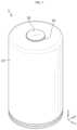
- FIG. 1is a perspective view of a battery according to an embodiment of the present disclosure.
- FIG. 2is a vertical cross-sectional view of the battery of FIG. 1 .
- FIG. 3is a perspective cut-away view showing the inside of the battery of FIG. 1 .
- FIG. 4is a cross-sectional view for describing the inside of the battery of FIG. 1 .
- FIG. 5 Ais a cross-sectional view for describing a battery according to an embodiment of the present disclosure.
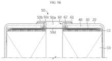
- FIGS. 5 B to 5 Eare cross-sectional views for describing a battery according to another embodiment of the present disclosure.
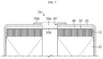
- FIGS. 6 and 7are cross-sectional views for describing a battery according to still another embodiment of the present disclosure.
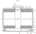
- FIGS. 8 and 9are cross-sectional views for describing a cylindrical secondary battery according to yet another embodiment of the present disclosure.
- FIG. 10is a perspective view for describing a battery pack including the battery of FIG. 1 according to an embodiment of the present disclosure.
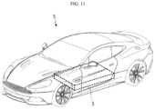
- FIG. 11is a perspective view for describing a vehicle including the battery pack of FIG. 10 .
- substantially equalmay encompass all cases having the deviation regarded as a low level in the corresponding technical field, for example, the deviation of 5% or less.
- a uniform parameter in a predetermined areamay be uniform from the average point of view.
- first, second or the likeare used to describe different elements, these elements are not limited by the terms. These terms are used to distinguish one element from another, and unless stated to the contrary, a first element may be a second element.
- the elementWhen an element is “above (or under)” or “on (or below)” another element, the element can be on an upper surface (or a lower surface) of the other element, and intervening elements may be present between the element and the other element on (or below) the element.
- an elementwhen referred to as being “connected”, “coupled” or “linked” to another element, the element can be directly connected or coupled to the other element, but it should be understood that intervening elements may be present between each element, or each element may be “connected”, “coupled” or “linked” to each other through another element.
- a and/or Brefers to either A or B or both A and B unless expressly stated otherwise
- C to Drefers to C or greater and D or smaller unless expressly stated otherwise.
- a direction that goes along a lengthwise direction of a winding axis of an electrode assembly wound in a roll shapeis herein referred to as an axis direction Y.
- a direction around the winding axisis herein referred to as a circumferential or peripheral direction X.
- a direction that gets closer to or faces away from the winding axisis referred to as a radial direction.
- the direction that gets closer to the winding axisis referred to as a centripetal direction
- the direction that faces away from the winding axisis referred to as a centrifugal direction.
- a battery 1according to an embodiment of the present disclosure includes an electrode assembly 10 , a battery housing 20 , a first current collector 30 and an insulator 40 .
- the battery 1may further include a terminal 50 and/or an insulation gasket 60 and/or a side spacer 70 and/or a second current collector 80 and/or a cap 90 and/or a sealing gasket 100 and/or a lower spacer 110 .
- the electrode assembly 10includes a first electrode having a first polarity, a second electrode having a second polarity and a separator interposed between the first electrode and the second electrode.
- the first electrodecorresponds to a positive or negative electrode
- the second electrodecorresponds to an electrode having the opposite polarity to the first electrode.
- the electrode assembly 10may have, for example, a wound shape. That is, the electrode assembly 10 may be manufactured by winding a stack around a winding center C, the stack formed by stacking the first electrode, the second electrode and the separator interposed between the first electrode and the second electrode at least once. In this case, an additional separator may be provided on the outer circumferential surface of the electrode assembly 10 for insulation from the battery housing 20 .
- the electrode assembly 10may have any well-known winding structure in the related technical field without limitation.
- the first electrodeincludes a first electrode current collector and a first active material region coated on one or two surfaces of the first electrode current collector.
- An uncoated region with no first active material regionexists at one end in the widthwise direction of the first electrode current collector (a direction parallel to the Z axis).
- the uncoated regionitself acts as a first electrode tab.
- the first uncoated region 11is provided on the electrode assembly 10 received in the battery housing 20 in the heightwise direction (the direction parallel to the Z axis).
- the second electrodeincludes a second electrode current collector and a second active material region coated on one or two surfaces of the second electrode current collector.
- An uncoated region with no second active material regionexists at the other end in the widthwise direction of the second electrode current collector (the direction parallel to the Z axis).
- the uncoated regionitself acts as a second electrode tab.
- the second uncoated region 12is provided below the electrode assembly 10 received in the battery housing 20 in the heightwise direction (the direction parallel to the Z axis).
- the electrode assembly 10may be an electrode assembly 10 including the first electrode, the second electrode and the separator interposed between the first electrode and the second electrode, wound around the winding axis to define a core and an outer circumferential surface.
- the first electrodeincludes the first active material region that is coated with an active material layer along the winding direction and the first uncoated region that is not coated with the active material layer, and at least part of the first uncoated region itself may be used as the electrode tab.
- the second electrodeincludes the second active material region that is coated with an active material layer along the winding direction and the second uncoated region that is not coated with the active material layer, and at least part of the second uncoated region 12 itself may be used as the electrode tab.
- the electrode assembly 10may be a wound electrode assembly 10 having a structure in which the first electrode current collector and the second current collector having a sheet shape and the separator interposed between the first and second electrode current collectors are wound in a direction.
- the first electrode current collectorincludes the first uncoated region 11 that is not coated with the active material layer at the end of the long side, and at least part of the first uncoated region 11 itself may be used as the electrode tab.
- the second electrode current collectorincludes the second uncoated region 12 that is not coated with the active material layer at the end of the long side, and at least part of the second uncoated region 12 itself may be used as the electrode tab.
- the electrode assembly 10may be a wound electrode assembly in which the first uncoated region 11 and the second uncoated region 12 having different polarities extend in the opposite directions. That is, the first uncoated region 11 and the second uncoated region 12 may extend and protrude in the opposite directions along the widthwise direction of the electrode assembly 10 , i.e., the heightwise direction of the battery 1 (the direction parallel to the Z axis).
- a positive electrode active material coated on a positive electrode plate and a negative electrode active material coated on a negative electrode platemay include any known active material in the technical field pertaining to the present disclosure without limitation.
- the positive electrode active materialmay include an alkali metal compound represented by formula A[A x M y ]O 2+z (A includes at least one of Li, Na or K; M includes at least one selected from Ni, Co, Mn, Ca, Mg, Al, Ti, Si, Fe, Mo, V, Zr, Zn, Cu, Al, Mo, Sc, Zr, Ru, and Cr; x ⁇ 0, 1 ⁇ x+y ⁇ 2, ⁇ 0.1 ⁇ z ⁇ 2; the stoichiometric coefficients x, y and z are selected to keep the compound electrically neutral).
- Aincludes at least one of Li, Na or K
- Mincludes at least one selected from Ni, Co, Mn, Ca, Mg, Al, Ti, Si, Fe, Mo, V, Zr, Zn, Cu, Al, Mo, Sc, Zr, Ru, and Cr
- x ⁇ 0, 1 ⁇ x+y ⁇ 2, ⁇ 0.1 ⁇ z ⁇ 2the stoichiometric coefficients x, y and z are selected to keep
- the positive electrode active materialmay be an alkali metal compound xLiM 1 O 2 -(1-x)Li 2 M 2 O 3 (M 1 includes at least one element having an average trivalent oxidation state; M 2 includes at least one element having an average tetravalent oxidation state; 0 ⁇ x ⁇ 1) disclosed by U.S. Pat. Nos. 6,677,082 and 6,680,143.
- the positive electrode active materialmay be lithium metal phosphate represented by formula Li a M 1 x Fe 1-x M 2 y P 1-y M 3 z O 4-z
- M 1includes at least one selected from Ti, Si, Mn, Co, Fe, V, Cr, Mo, Ni, Nd, Al, Mg and Al
- M 2includes at least one selected from Ti, Si, Mn, Co, Fe, V, Cr, Mo, Ni, Nd, Al, Mg, Al, As, Sb, Si, Ge, V and S
- M 3includes a halogen group element optionally including F; 0 ⁇ a ⁇ 2, 0 ⁇ x ⁇ 1, 0 ⁇ y ⁇ 1, 0 ⁇ z ⁇ 1; the stoichiometric coefficients a, x, y and z are selected to keep the compound electrically neutral), or Li 3 M 2 (PO 4 ) 3 [M includes at least one selected from Ti, Si, Mn, Fe, Co, V, Cr, Mo, Ni, Al, Mg and Al].
- the positive electrode active materialmay include primary particles and/or secondary particles formed by agglomeration of the primary particles.
- the negative electrode active materialmay include a carbon material, lithium metal or a lithium metal compound, silicon or a silicon compound, tin or a tin compound.
- Metal oxide having the potential of less than 2Vsuch as TiO 2 and SnO 2 may be used as the negative electrode active material.
- the carbon materialmay include low crystalline carbon and high crystalline carbon.
- the separatormay include a porous polymer film made of a polyolefin-based polymer such as an ethylene homopolymer, a propylene homopolymer, an ethylene/butene copolymer, an ethylene/hexene copolymer and an ethylene/methacrylate copolymer, used singly or a stack of them.
- the separatormay include a common porous nonwoven fabric, for example, a nonwoven fabric made of high melting point glass fibers and polyethylene terephthalate fibers.
- the separatormay include a coating layer of inorganic particles on at least one surface thereof. Additionally, the separator itself may be a coating layer of inorganic particles. The particles that form the coating layer may be bonded to each other with a binder to create interstitial volume between adjacent particles.
- the inorganic particlesmay be inorganics having the dielectric constant of 5 or more.
- Non-limiting examples of the inorganic particlesmay include at least one material selected from the group consisting of Pb(Zr,Ti)O 3 (PZT), Pb 1-x La x Zr 1-y Ti y O 3 (PLZT), PB(Mg 3 Nb 2/3 )O 3 —PbTiO 3 (PMN-PT), BaTiO 3 , hafnia (HfO 2 ), SrTiO 3 , TiO 2 , Al 2 O 3 , ZrO 2 , SnO 2 , CeO 2 , MgO, CaO, ZnO and Y 2 O 3 .
- An electrolytemay be a salt having a structure of A + B ⁇ .
- a +includes an alkali metal cation such as Li + , Na + , K + or a combination thereof.
- B ⁇includes at least one anion selected from the group consisting of F ⁇ , Cl ⁇ , Br ⁇ , I ⁇ , NO 3 ⁇ , N(CN) 2 ⁇ , BF 4 ⁇ , ClO 4 ⁇ , AlO 4 ⁇ , AlCl 4 ⁇ , PF 6 ⁇ , SbF 6 ⁇ , AsF 6 ⁇ , BF 2 C 2 O 4 ⁇ , BC 4 O 8 ⁇ , (CF 3 ) 2 PF 4 ⁇ , (CF 3 ) 3 PF 3 ⁇ , (CF 3 ) 4 PF 2 ⁇ , (CF 3 ) 5 PF ⁇ , (CF 3 ) 6 P ⁇ , CF 3 SO 3 ⁇ , C 4 F 9 SO 3
- the electrolytemay be used by dissolving in an organic solvent.
- the organic solventmay include at least one of propylene carbonate (PC), ethylene carbonate (EC), diethyl carbonate (DEC), dimethyl carbonate (DMC), dipropyl carbonate (DPC), dimethyl sulfoxide, acetonitrile, dimethoxyethane, diethoxyethane, tetrahydrofuran, N-methyl-2-pyrrolidone (NMP), ethyl methyl carbonate (EMC) or ⁇ -butyrolactone.
- PCpropylene carbonate
- ECethylene carbonate
- DECdiethyl carbonate
- DMCdimethyl carbonate
- DPCdipropyl carbonate
- dimethyl sulfoxideacetonitrile, dimethoxyethane, diethoxyethane, tetrahydrofuran
- NMPN-methyl-2-pyrrolidone
- EMCethyl
- the first uncoated region 11may be split into a plurality of segments along the winding direction the electrode assembly 10 .
- the segmentsmay have, for example, a trapezoidal shape, a square or rectangular shape, a parallelogram shape, a semi-circular shape, and a semi-oval shape, and may be repeatedly arranged at a predetermined interval along the winding direction.
- the segmentsmay have a larger bottom width than a top width, and the width may increase gradually and/or stepwise as it goes from bottom to top (i.e., in the z direction of FIG. 2 ).
- the plurality of segmentsmay be bent along the radial direction of the electrode assembly 10 .
- the radial directionrefers to a direction toward the core of the electrode assembly 10 or a direction toward the outer circumference of the electrode assembly 10 .
- the plurality of segmentsmay be bent toward the core.
- the plurality of segmentsmay overlap in multiple layers.
- the plurality of segmentsmay overlap in multiple layers along the radial direction of the electrode assembly 10 .
- the plurality of segmentsmay be notched by a laser.
- the segmentsmay be formed by the well-known metal foil cutting process, for example, ultrasonic cutting or punching.
- the gapis preferably 0.2 to 4 mm. When the gap is adjusted to the corresponding numerical range, it is possible to prevent damage to the active material layer near the lower end of the cut line due to the stress that occurs when bending the first uncoated region 11 . Additionally, the gap may prevent damage to the active material layer caused by the clearance when notching or cutting the segments.
- the bent direction of the first uncoated region 11may be, for example, a direction toward the winding center C of the electrode assembly 10 .
- the space occupied by the first uncoated region 11reduces, thereby improving the energy density. Additionally, the increased coupling area between the first uncoated region 11 and the first current collector 30 may lead to the further improved coupling strength and additional resistance reduction effect.
- first uncoated region 11has been described above, it is obvious that the same structure as the first uncoated region 11 may be applied to the second uncoated region 12 .
- the battery housing 20may accommodate the electrode assembly 10 and the first current collector 30 .
- the battery housing 20is an approximately cylindrical container having an open portion on bottom, and for example, may be made of a material having conductive properties such as a metal.
- the material of the battery housing 20may be, for example, aluminum, steel, stainless steel and nickel.
- the bottom of the battery housing 20 having the open portionis referred to as an open end.
- the side (the outer circumferential surface) and the upper surface of the battery housing 20may be integrally formed.
- the upper surface (a surface parallel to the X-Y plane) of the battery housing 20has an approximately flat shape.
- the upper surface disposed on a side opposite to the open portion (or the open end)is referred to as a closed portion.
- the battery housing 20accommodates the electrolyte together with the electrode assembly 10 through the open portion formed on bottom.
- the battery housing 20is electrically connected to the electrode assembly 10 .
- the battery housing 20is electrically connected to the second uncoated region 12 of the electrode assembly 10 .
- the battery housing 20has the same polarity as the second uncoated region 12 .
- the battery housing 20may include a beading portion 21 and a crimping portion 22 formed at the lower end.
- the beading portion 21is disposed below the electrode assembly 10 .
- the beading portion 21is formed by press-fitting the periphery of the outer circumferential surface of the battery housing 20 .
- the beading portion 21may be formed at the end adjacent to the open portion formed on bottom and press-fit inwards.
- the beading portion 21may prevent the electrode assembly 10 having a size approximately corresponding to the inner diameter of the battery housing 20 from slipping out of the open portion formed on bottom of the battery housing 20 , and act as a support in which the cap 90 is seated.
- the crimping portion 22is formed below the beading portion 21 .
- the crimping portion 22may be formed on the side facing the open portion rather than the beading portion 21 , and may be extended and bent toward the open portion.
- the crimping portion 22is extended and bent around the outer circumferential surface of the cap 90 positioned below the beading portion 21 and at least part of the lower surface of the cap 90 .
- the present disclosuredoes not exclude the battery housing 20 not including the beading portion 21 and/or the crimping portion 22 . That is, in the present disclosure, when the battery housing 20 does not include the beading portion 21 and/or the crimping portion 22 , the fixing of the electrode assembly 10 and/or the sealing of the battery housing 20 may be accomplished, for example, by applying an additional component that may serve as a stopper for the electrode assembly 10 . Additionally, when the battery 1 of the present disclosure includes the cap 90 , the fixing of the electrode assembly 10 and/or the sealing of the battery housing 20 may be accomplished, for example, by applying an additional structure in which the cap 90 may be seated and/or through welding between the battery housing 20 and the cap 90 . For example, the applicant's patent publication KR 10-2019-0030016 A discloses a battery in which the beading portion is omitted, and this structure may be employed in the present disclosure.
- the first current collector 30may be coupled on the electrode assembly 10 .
- the first current collector 30may be coupled to the first uncoated region 11 on the electrode assembly 10 .
- the first current collector 30may be interposed between the first uncoated region 11 and the insulator 40 .
- the first current collector 30may be coupled to the first uncoated region 11 on the electrode assembly 10 and interposed between the first uncoated region 11 and the insulator 40 .
- the first current collector 30may be made of a metal material having conductive properties.
- the first current collector 30may include a plurality of concave-convex patterns radially formed on the lower surface thereof. When the concave-convex patterns are formed, the concave-convex patterns may be stamped into the first uncoated region 11 by pressing the first current collector 30 .
- the battery 1 according to another embodiment of the present disclosuremay not include the first current collector 30 .
- the first uncoated region 11may be directly electrically connected to the terminal 50 .
- the first current collector 30may be coupled to the end of the first uncoated region 11 .
- the coupling between the first uncoated region 11 and the first current collector 30may be accomplished, for example, by laser welding.
- the laser weldingmay be performed by partially melting the base material of the first current collector 30 , and selectively, may be performed with a solder for welding interposed between the first current collector 30 and the first uncoated region 11 .
- the solderpreferably has a lower melting point than the first current collector 30 and the first uncoated region 11 .
- resistance welding, ultrasonic welding, spot welding, etc.may be used, but the welding method is not limited thereto.
- the first current collector 30may be coupled onto a coupling surface formed by the end bending of the first uncoated region 11 in a direction parallel to the first current collector 30 .
- the bent direction of the first uncoated region 11may be, for example, a direction toward the winding center C of the electrode assembly 10 .
- the space occupied by the first uncoated region 11reduces, resulting in the improved energy density.
- the increased coupling area between the first uncoated region 11 and the first current collector 30may lead to the coupling strength improvement and resistance reduction effect at the coupling surface.
- the insulator 40may be interposed between the inner surface of the battery housing 20 facing the first uncoated region 11 or the first current collector 30 and the first uncoated region 11 or the first current collector 30 to block the electrical connection between the first uncoated region 11 and the battery housing 20 .
- the insulator 40may be provided between the top of the electrode assembly 10 and the inner surface of the battery housing 20 or between the first current collector 30 coupled on the electrode assembly 10 and the inner surface of the battery housing 20 .
- the insulator 40prevents the contact between the first uncoated region 11 and the battery housing 20 and/or the contact between the first current collector 30 and the battery housing 20 .
- the insulator 40is received in the battery housing 20 , covers at least part of the electrode assembly 10 and is configured to block the electrical connection between the first uncoated region 11 and the battery housing 20 .
- the insulator 40may be made of a material having insulation performance.
- the insulator 40may include an insulating polymer material.
- the insulator 40may include a first cover portion 41 and a second cover portion 42 .
- the second cover portion 42may extend downward vertically from the outer periphery of the first cover portion 41 . That is, the second cover portion 42 refers to a vertically extended part (parallel to the Z axis) from the outer edge of the first cover portion 41 . Accordingly, the first cover portion 41 and the second cover portion 42 may have a shape of a cup.
- the first cover portion 41refers to the remaining part of the insulator 40 except the second cover portion 42 .
- the first cover portion 41refers to a horizontally extended part of the insulator 40 (parallel to the X-Y plane).
- the first cover portion 41may cover the end of the first uncoated region 11 or the surface of the first current collector 30 facing the inner surface of the battery housing 20 .
- the first cover portion 41may cover the surface of the first current collector 30 facing the top inner surface of the battery housing 20 .
- the insulator 40may have a center hole having a predetermined diameter at the center of the first cover portion 41 .
- the insulator 40may have the center hole adjacent to the winding center C.
- the first cover portion 41may have the approximately circular center hole adjacent to the winding center C. Due to the presence of the center hole, the terminal 50 may come into contact with the first current collector 30 or the first uncoated region 11 .
- a plurality of holes having a smaller diameter than the center holemay be further formed around the center hole of the first cover portion 41 .
- the plurality of holesmay be formed around the center hole of the first cover portion 41 to allow an electrolyte solution to move.
- the insulator 40may be placed on the bottom. That is, when the battery 1 of FIG. 2 is placed upside down, i.e., the terminal 50 is disposed on the lower side, the electrolyte solution may be injected into the battery housing 20 .
- the electrolyte solutionmay move down through the center hole provided in the first cover portion 41 of the insulator 40 , move in the horizontal direction through the surface of the first cover portion 41 , and move up through the plurality of holes. Accordingly, the electrolyte solution may be supplied over the entire electrode assembly 10 . That is, when the first cover portion 41 of the insulator 40 has the plurality of holes, the electrolyte solution may be supplied to the electrode assembly 10 smoothly and easily.
- the plurality of holesmay be spaced a predetermined distance apart from each other.
- the plurality of holesmay be arranged on any one straight line running from the center of the insulator 40 to the outer circumferential surface of the insulator 40 .
- the first cover portion 41may be connected to the second cover portion 42 .
- the first cover portion 41 and the second cover portion 42may be integrally formed.
- the first cover portion 41 and the second cover portion 42may be an integrally formed polymer structure.
- the first cover portion 41 and the second cover portion 42may be separately formed and combined or attached together.
- the first cover portion 41 and the second cover portion 42may be separately formed and combined into a polymer structure.
- the materials forming or included in the first cover portion 41 and the second cover portion 42need not be the same, and can be different materials, for example, when combined or attached to each other.
- the thickness of the first cover portion 41may be different from the thickness of the second cover portion 42 .
- the thickness of the second cover portion 42may be smaller than the thickness of the first cover portion 41 .
- the first uncoated region 11 disposed at the outer periphery of the electrode assembly 10may be omitted. Accordingly, a predetermined space may be formed on top of the outer periphery of the electrode assembly 10 where the first uncoated region 11 is omitted. Accordingly, the electrical contact between the first uncoated region 11 and the battery housing 20 may be prevented by the predetermined space.
- the second cover portion 42may be provided. In this instance, the thickness of the second cover portion 42 is smaller than the thickness of the first cover portion 41 , but it is possible to ensure sufficient insulation performance. Furthermore, as the thickness of the second cover portion 42 is smaller than the thickness of the first cover portion 41 , it is possible to minimize the space occupied by the insulator 40 .
- the first cover portion 41may have a round portion R having a predetermined radius of curvature at the outer periphery of the first cover portion 41 .
- the round portion Rmay be formed at the intersection between the upper surface of the first cover portion 41 and the side of the second cover portion 42 .
- the radius of curvature of the round portion Rmay be equal to or smaller than the radius of curvature formed at the intersection between the top inner surface of the battery housing 20 and the side of the battery housing 20 .
- the round portion Rmay be come into close contact with the inner surface of the battery housing 20 without a gap.
- the battery 1 of the present disclosuremay not include the first current collector 30 .
- the insulator 40may include the first cover portion 41 to cover the end of the first uncoated region 11 and the second cover portion 42 to cover the top of the outer circumferential surface of the electrode assembly 10 .
- the first cover portion 41may be disposed in the space between the end of the first uncoated region 11 and the top inner surface of the battery housing 20 .
- the first cover portion 41 of the insulator 40may have the thickness corresponding to the distance between the end of the first uncoated region 11 and the top inner surface of the battery housing 20 . Accordingly, the first cover portion 41 may fill up the space between the end of the first uncoated region 11 and the top inner surface of the battery housing 20 without a gap. Accordingly, it is possible to minimize the movement of the electrode assembly 10 in the battery housing 20 , thereby preventing damage to the electrical coupling part, when vibrations and external impacts are applied to the battery 1 .
- the insulator 40may have the thickness that is equal to or larger than about 0.1 mm. When the insulator 40 is too thin, insulation may degrade. In another aspect, it is because forming the insulator 40 to the thickness that is equal to or smaller than a specific thickness may be procedurally difficult to achieve. Meanwhile, the upper limit of the thickness of the insulator 40 may be a thickness corresponding to the distance between the inner surface of the battery housing 20 and the first uncoated region 11 or the distance between the inner surface of the battery housing 20 and the first current collector 30 . When the insulator 40 is too thick, the insulator 40 occupies a large area of the inner space of the battery housing 20 , resulting in low capacity and high cost of the battery cell.
- the thickness of the insulator 40may be set in the appropriate range to maintain proper insulation and prevent the capacity reduction of the battery cell.
- the thickness of the insulator 40is not limited to the above-described range, and any range of thickness for ensuring insulation and preventing damage to the electrical coupling part by minimizing the movement of the electrode assembly 10 in the battery housing 20 is included in the scope of the present disclosure.
- the insulator 40may include the first cover portion 41 to cover at least part of the first current collector 30 and the second cover portion 42 to cover the top of the outer circumferential surface of the electrode assembly 10 . That is, the first cover portion 41 may cover at least part of the first current collector 30 .
- the first cover portion 41may cover all the areas except some areas disposed at the center on the upper surface of the first current collector 30 . Additionally, the first cover portion 41 may cover some areas of the first uncoated region 11 uncovered with the first current collector 30 .
- the first cover portion 41 of the insulatormay have the thickness corresponding to the distance between the first current collector 30 and the top inner surface of the battery housing 20 . Accordingly, the first cover portion 41 may fill up the space between the first current collector 30 and the top inner surface of the battery housing 20 without a gap. Accordingly, it is possible to minimize the movement of the electrode assembly 10 in the battery housing 20 , thereby preventing damage from occurring in the electrical coupling part, when vibrations and external impacts are applied to the battery 1 .
- the first uncoated region 11may be split into the plurality of segments.
- the plurality of segmentsmay be bent toward the core. Additionally, the plurality of segments may overlap in multiple layers along the radial direction. In this instance, the plurality of segments of the first uncoated region 11 may bend and overlap to form a bent surface.
- the bent surfacemay be approximately parallel to the upper surface of the battery housing.
- the first cover portion 41may cover the bent surface formed by the bend of the plurality of segments of the first uncoated region 11 .
- the second cover portion 42may cover the upper part of the outer circumferential surface of the electrode assembly 10 . Referring to FIG.
- the area of the first current collector 30 coupled onto the bent surface of the plurality of segments on the electrode assembly 10 and interposed between the bent surface and the battery housing 20may be much smaller than the area of the upper surface of the electrode assembly 10 .
- the diameter of the first current collector 30may be equal to or smaller than the diameter of the center hole of the insulator 40 .
- the diameter of the first current collector 30may be larger than the diameter of the winding center hole of the electrode assembly 10 . Since the diameter of the first current collector 30 is larger than the diameter of the winding center hole of the electrode assembly 10 , the first current collector 30 may be supported on the electrode assembly 10 . Meanwhile, the center of the first current collector 30 and the winding center of the electrode assembly 10 may be disposed on the same line.
- the first current collector 30 and the terminal 50may be kept in contact with each other for welding them afterwards.
- the plurality of segments of the first uncoated region 11may be bent in an overlapping manner along the radial direction of the electrode assembly 10 .
- the electrode assembly 10may have the current collection performance at the bent surface by the overlap of the plurality of segments.
- the electrode assembly 10since at least part of the bent surface is electrically coupled to the first current collector 30 , the electrode assembly 10 may be electrically connected to the terminal 50 through the first current collector 30 .
- the present disclosuremay adopt an embodiment in which only the first uncoated region 11 is not bent.
- the first cover portion 41may have the thickness corresponding to the distance between the bent surface of the plurality of segments and the top inner surface of the battery housing 20 . Accordingly, the first cover portion 41 may fill up the space between the bent surface and the top inner surface of the battery housing 20 without a gap.
- the first cover portion 41may be interposed between the bent surface formed by the bend of the plurality of segments of the first uncoated region 11 facing the top inner surface of the battery housing 20 and the top inner surface of the battery housing 20 .
- the first cover portionmay be interposed between the first current collector 30 and the top inner surface of the battery housing 20 .
- the first cover portion 41may have the thickness corresponding to the distance between the first current collector 30 and the top inner surface of the battery housing 20 .
- the area of the first current collector 30 coupled onto the bent surface of the plurality of segments on the electrode assembly 10 and interposed between the bent surface and the battery housing 20may be approximately similar to the area of the upper surface of the electrode assembly 10 .
- the first cover portion 41may cover the first current collector 30 .
- the first cover portion 41may have the thickness corresponding to the distance between the first current collector 30 and the top inner surface of the battery housing 20 . Accordingly, the first cover portion 41 may fill up the space between the first current collector 30 and the top inner surface of the battery housing 20 without a gap. Accordingly, it is possible to minimize the movement of the electrode assembly 10 in the battery housing 20 , thereby preventing damage to the electrical coupling part, when vibrations and external impacts are applied to the battery 1 .
- the second cover portion 42may cover the upper part of the outer circumferential surface of the electrode assembly 10 .
- the second cover portion 42may cover the side of the first uncoated region 11 .
- the second cover portion 42may cover the entire exposed outermost side of the first uncoated region 11 from preventing the first uncoated region 11 from being exposed to the inner circumferential surface of the battery housing 20 . Accordingly, it is possible to effectively prevent the electrical contact between the battery housing 20 having the opposite polarity to the first uncoated region 11 and the first uncoated region 11 . Accordingly, according to the present disclosure, it is possible to effectively prevent an internal short circuit of the cylindrical secondary battery 1 .
- the extended length of the second cover portion 42may be equal to or larger than the extended length of the first uncoated region 11 .
- the extended length of the second cover portion 42should be at least equal to the extended length of the first uncoated region 11 , and to guarantee reliable insulation, the extended length of the second cover portion 42 is preferably longer than the extended length of the first uncoated region 11 even a little bit.
- the extended length of the second cover portion 42may be equal to or larger than the length from the lower end point of the cut line between the plurality of segments to the bend location of the plurality of segments.
- the lower end of the second cover portion 42may be disposed at the lower position than the lower end of the first uncoated region 11 .
- the terminal 50may be electrically connected to the first electrode tab 11 of the electrode assembly 10 . That is, the terminal 50 may be made of a metal material having conductive properties. The terminal 50 may be electrically connected to the first uncoated region 11 , and at least part of the terminal 50 may be exposed through a through-hole formed on top of the battery housing 20 . For example, the terminal 50 may pass through approximately the center of the closed portion formed on top of the battery housing 20 . That is, the battery housing 20 may have the through-hole at the closed portion provided on top of the battery housing 20 . The terminal 50 may be inserted or penetrated into the battery housing 20 through the through-hole.
- a body portion 50 a , an inner flange portion 50 c and a flat portion 50 d of the terminal 50may be inserted or pass into the battery housing 20 through the through-hole. Accordingly, a part of the terminal 50 may be exposed to the top of the battery housing 20 and the remaining part may be disposed in the battery housing 20 .
- the terminal 50may be riveted through the through-hole.
- the terminal 50may be riveted and fixed to the top inner surface of the battery housing 20 .
- the inner flange portion 50 c of the terminal 50may be fixed onto the inner surface of the closed portion of the battery housing 20 , for example, by riveting.
- the terminal 50may be coupled to the first current collector 30 or the first uncoated region 11 through the insulator 40 .
- the terminal 50may be coupled to the first current collector 30 or the first uncoated region 11 through the center hole provided in the insulator 40 .
- the diameter of the center hole of the insulator 40may be equal to or larger than the diameter of the inner flange portion 50 c as described below.
- the flat portion 50 d of the terminal 50may be electrically coupled to the first current collector 30 through the center hole of the insulator 40 .
- the terminal 50may have the first polarity. More preferably, the flat portion 50 d of the terminal 50 may be coupled to the first current collector 30 by welding.
- the weldingmay be performed between the flat portion 50 d provided inside the inner flange portion 50 c and the first current collector 30 .
- the flat portion 50 dmay be provided at the lower end of the terminal 50 .
- the flat portion 50 d and the top inner surface of the battery housing 20may be parallel to each other. Accordingly, the flat portion 50 d and the first current collector 30 may be parallel to each other.
- the welding methodmay include laser welding. In addition to the laser welding, resistance welding and ultrasonic welding may be used, but the welding method is not limited thereto.
- the terminal 50may act as a first electrode terminal in the battery 1 of the present disclosure. When the terminal 50 has the first polarity, the terminal 50 is electrically isolated from the battery housing 20 having the second polarity.
- the electrical insulation between the terminal 50 and the battery housing 20may be achieved by a variety of methods. For example, insulation may be achieved by interposing the insulation gasket 60 as described below between the terminal 50 and the battery housing 20 . Alternatively, insulation may be achieved by forming an insulating coating layer in a part of the terminal 50 . Alternatively, the terminal 50 may be structurally firmly secured to prevent the contact between the terminal 50 and the battery housing 20 . Alternatively, two or more of the above-described methods may be used together.
- the terminal 50includes the body portion 50 a that is inserted into the through-hole; an outer flange portion 50 b extended along the outer surface from one side periphery of the body portion 50 a exposed through the top outer surface of the battery housing 20 ; the inner flange portion 50 c extended to the inner surface from the opposite side periphery of the body portion 50 a exposed through the top inner surface of the battery housing 20 ; and the flat portion 50 d provided inside the inner flange portion 50 c.
- the outer flange portion 50 bis exposed to the outside of the battery housing 20 .
- the outer flange portion 50 bmay be disposed at approximately the center of the upper surface of the battery housing 20 .
- the maximum width of the outer flange portion 50 bmay be larger than the maximum width of the hole formed in the battery housing 20 by the penetration of the terminal 50 .
- the body portion 50 amay be inserted into the battery housing 20 .
- the body portion 50 amay be electrically connected to the first uncoated region 11 through approximately the center of the upper surface of the battery housing 20 . More specifically, the body portion 50 a may be coupled with the first current collector 30 or the first uncoated region 11 through the battery housing 20 and the insulator 40 at the same time.
- the body portion 50 amay be rivet-coupled onto the inner surface of the battery housing 20 by the inner flange portion 50 c . That is, the inner flange portion 50 c bent toward the inner surface of the battery housing 20 may be provided at the lower peripheral end of the body portion 50 a by the application of a cocking jig.
- the maximum width of the body portion 50 amay be larger than the maximum width of the hole of the battery housing 20 formed by the penetration of the body portion 50 a .
- the body portion 50 amay not be bent toward the inner surface of the battery housing 20 . That is, the body portion 50 a may not include the inner flange portion 50 c .
- the body portion 50 amay have an approximately circular shape passing through the hole disposed at approximately the center of the upper surface of the battery housing 20 .
- the body portion 50 amay have a circular shape on the plane, but is not limited thereto.
- the body portion 50 amay have selectively a polygonal shape, a star shape, a shape having a leg extended from the center, etc.
- the terminal 50 , or portions thereofneed not protrude through the top outer surface of the battery housing 20 , but may be flush with or coplanar with the top outer surface of the battery housing 20 . In some embodiments, the terminal 50 , or portions thereof, may be recessed from the top outer surface of the battery housing 20 .
- the insulation gasket 60is interposed between the battery housing 20 and the terminal 50 to prevent the battery housing 20 and the terminal 50 having the opposite polarities from contacting each other. That is, the insulation gasket 60 blocks the electrical connection between the battery housing 20 and the terminal 50 . Accordingly, the upper surface of the battery housing 20 having the approximately flat shape may act as a second electrode terminal of the battery 1 .
- the insulation gasket 60includes a gasket exposure portion 61 and a gasket insertion portion 62 .
- the gasket exposure portion 61is interposed between the outer flange portion 50 b of the terminal 50 and the battery housing 20 .
- the gasket insertion portion 62is interposed between the body portion 50 a of the terminal 50 and the battery housing 20 .
- the gasket insertion portion 62is interposed between the inner flange portion 50 c and the battery housing 20 .
- the gasket insertion portion 62may come into close contact with the inner surface of the battery housing 20 as the shape of the gasket insertion portion 62 is changed together with the body portion 50 a during the riveting of the body portion 50 a .
- the gasket exposure portion 61 and the gasket insertion portion 62 of the insulation gasket 60may have different thicknesses for each location.
- the insulation gasket 60may be made of a resin material having insulating properties.
- the insulation gasket 60may be coupled to the battery housing 20 and the terminal 50 by heat fusion. In this case, it is possible to enhance sealability at the coupling interface between the insulation gasket 60 and the terminal 50 and the coupling interface between the insulation gasket 60 and the battery housing 20 .
- the entire remaining area except the area occupied by the terminal 50 and the insulation gasket 60 on the upper surface of the battery housing 20corresponds to the second electrode terminal having the opposite polarity to the terminal 50 .
- the entire remaining area except the area occupied by the terminal 50 having the insulating coating layer on the upper surface of the battery housing 20may act as the second electrode terminal.
- the cylindrical sidewall of the battery housing 20may be formed as a one piece with the second electrode terminal to prevent discontinuity with the second electrode terminal.
- the connection from the sidewall of the battery housing 20 to the second electrode terminalmay be a smooth curve.
- the present disclosureis not limited thereto, and the connected part may include at least one corner having a predetermined angle.
- the battery 1 according to the embodiment of FIGS. 6 and 7is similar to the battery 1 of the previous embodiment of FIG. 5 A , and overlapping descriptions of the elements that are substantially identical or similar to the previous embodiment are omitted and difference(s) between this embodiment and the previous embodiment will be described below.
- the body portion 50 ahave an approximately circular shape passing through the hole disposed at approximately the center of the upper surface of the battery housing 20 . Accordingly, the gasket insertion portion 62 disposed around the body portion 50 a may come into close contact with the outer circumferential surface of the body portion 50 a . At the same time, the gasket insertion portion 62 may come into close contact with the first current collector 30 . With this structure, it may be easy to insert the terminal 50 into the hole of the battery housing 20 .
- the insulation gasket 60 and the insulator 40may be made of the same material. Further, the insulation gasket 60 may be connected to and integrally formed with the insulator 40 .
- the insulation gasket 60may be made of, for example, a material having the ability to recover its original form. Accordingly, the insulation gasket 60 may be changed into a shape that is easy for coupling when it is inserted into the hole of the battery housing 20 , and when the coupling is completed, the insulation gasket 60 may restore to the state of FIGS. 5 C and 7 .
- thisis an example of coupling the insulation gasket 60 to the hole of the battery housing 20 , and the coupling method is not limited thereto, and it is obvious that other coupling methods may be employed. With this structure, it is possible to further improve the fixation and the vibration resistance by the insulation gasket 60 and the insulator 40 integrally formed into one.
- the battery according to an embodiment of the present disclosuremay further include a side spacer 70 .
- the side spacer 70may cover at least part of the outer circumferential surface of the electrode assembly 10 .
- the side spacer 70may contact at least part of the battery housing 20 .
- the side spacer 70may contact the inner circumferential surface of the battery housing 20 .
- the side spacer 70may cover at least part of the outer circumferential surface of the electrode assembly 10 along the outer circumference of the electrode assembly 10 . That is, the side spacer 70 may be disposed between the outer circumferential surface of the electrode assembly 10 and the inner circumferential surface of the battery housing 20 .
- the side spacer 70may have a thickness corresponding to the distance between the outer circumferential surface of the electrode assembly 10 and the inner circumferential surface of the battery housing 20 .
- the thickness of the side spacer 70is approximately equal to the distance between the outer circumferential surface of the electrode assembly 10 and the inner circumferential surface of the battery housing 20 .
- the thickness of the side spacer 70may be approximately equal to the thickness of the second cover portion 42 of the insulator 40 .
- the side spacer 70may be formed with its end in contact with the second cover portion 42 of the insulator 40 . Further, the side spacer 70 may be integrally formed with the second cover portion 42 . That is, the side spacer 70 may be connected to and integrally formed with the insulator 40 . With this structure, it is possible to further reduce the empty space between the outer circumferential surface of the electrode assembly 10 and the inner circumferential surface of the battery housing 20 , thereby further improving the vibration resistance. Meanwhile, the side spacer 70 may include an insulating polymer material.
- the second current collector 80is coupled to the bottom of the electrode assembly 10 .
- the second current collector 80is made of a metal material having conductive properties and connected to the second uncoated region 12 .
- the second current collector 80may include at least one tab coupling portion 81 coupled to the second uncoated region 12 and at least one housing coupling portion 82 electrically coupled to the beading portion 21 of the inner surface of the battery housing 20 .
- the housing coupling portion 82may be compressed and fixed by the crimping portion 22 .
- the housing coupling portion 82may be coupled to the beading portion 21 by welding.
- the second current collector 80is electrically connected to the battery housing 20 . As shown in FIGS. 4 and 8 , the second current collector 80 may be interposed and fixed between the inner surface (the lower surface) of the beading portion 21 of the battery housing 20 and the sealing gasket 100 . Alternatively, the second current collector 80 may be welded to the inner surface (the lower surface) of the beading portion 21 .
- the second current collector 80may have a leg structure in which the tab coupling portion 81 and the housing coupling portion 82 extend along the radial direction. Preferably, a plurality of leg structures may be provided.
- the tab coupling portion 81may be positioned below the electrode assembly 10 , and disposed at a higher position than the beading portion 21 .
- the second current collector 80has a circular current collector hole at a location corresponding to the winding center hole at the center of the electrode assembly 10 .
- the winding center hole and the current collector hole in communication with each othermay serve as a passage for inserting a welding rod for welding between the terminal 50 and the first current collector 30 or irradiation of laser welding beam.
- the second current collector 80may have a plurality of concave-convex patterns radially formed on one surface thereof. When the concave-convex patterns are formed, the concave-convex patterns may be stamped into the second uncoated region 12 by pressing the second current collector 80 .
- the second current collector 80is coupled to the end of the second uncoated region 12 .
- the coupling between the second uncoated region 12 and the second current collector 80may be accomplished by laser welding.
- the laser weldingmay be performed by partially melting the base material of the second current collector 80 , and selectively, may be performed with a solder for welding interposed between the second current collector 80 and the second uncoated region 12 .
- the solderpreferably has a lower melting point than the second current collector 80 and the second uncoated region 12 .
- resistance welding, ultrasonic welding, etc.may be used, but the welding method is not limited thereto.
- the second current collector 80may be coupled onto a coupling surface formed by bending the end of the second uncoated region 12 in a direction parallel to the second current collector 80 .
- the bent direction of the second uncoated region 12may be a direction toward the winding center C of the electrode assembly 10 .
- the second uncoated region 12may include a plurality of segments to form a bent structure.
- the space occupied by the second uncoated region 12reduces, resulting in the improved energy density.
- the increased coupling area between the second uncoated region 12 and the second current collector 80may lead to the coupling strength improvement and resistance reduction effect at the coupling surface.
- the cap 90may be made of, for example, a metal material to ensure strength.
- the cap 90covers the open portion (the open end) formed on the bottom of the battery housing 20 . That is, the cap 90 forms the lower surface of the battery 1 .
- the cap 90may be non-polar (e.g., has no polarity, such as the first polarity or the second polarity) even when the cap 90 is made of a metal material having conductivity properties.
- Non-polarmay represent that the cap 90 is electrically isolated from the battery housing 20 and the terminal 50 . Accordingly, the cap 90 does not act as a positive or negative electrode terminal. Accordingly, the cap 90 does not need to be electrically connected to the electrode assembly 10 and the battery housing 20 , and its material is not necessarily a conductive metal.
- the cap 90When the battery housing 20 of the present disclosure includes the beading portion 21 , the cap 90 may be seated on the beading portion 21 formed in the battery housing 20 . Additionally, when the battery housing 20 of the present disclosure includes the crimping portion 22 , the cap 90 is fixed by the crimping portion 22 . The sealing gasket 100 may be interposed between the cap 90 and the crimping portion 22 of the battery housing 20 to ensure sealability of the battery housing 20 .
- the battery housing 20 of the present disclosuremay not include the beading portion 21 and/or the crimping portion 22 , and in this case, the sealing gasket 100 may be interposed between a structure for fixing provided on the opening side of the battery housing 20 and the cap 90 to ensure sealability of the battery housing 20 .
- the cap 90or portions thereof, need not be flush or coplanar with the crimping portion 22 , but may protrude or be recessed relative to an outer end of the crimping portion 22 .
- the cap 90may further include a venting portion 91 to prevent the internal pressure from rising above a preset value due to gas generated in the battery housing 20 .
- the venting portion 91corresponds to an area having a smaller thickness than the other areas in the cap 90 .
- the venting portion 91is structurally weaker than any other area. Accordingly, when the internal pressure of the battery housing 20 rises above the predetermined level due to faults in the battery 1 , the venting portion 91 ruptures to force the gas generated in the battery housing 20 out.
- the venting portion 91may be formed by partially reducing the thickness of the battery housing 20 via notching on the upper surface and/or the lower surfaces of the cap 90 .
- the sealing gasket 100may have an approximately ring shape disposed around the cap 90 .
- the sealing gasket 100may cover the lower surface, the upper surface and the side of the cap 90 at the same time.
- the radial length of a region of the sealing gasket 100 that covers the upper surface of the cap 90may be equal to or smaller than the radial length of a region of the sealing gasket 100 that covers the lower surface of the cap 90 .
- the sealing gasket 100When the radial length of the region of the sealing gasket 100 that covers the upper surface of the cap 90 is too long, there may be a likelihood that the sealing gasket 100 may press the second current collector 80 , causing damage to the second current collector 80 or the battery housing 20 , in the sizing process of vertically compressing the battery housing 20 . Accordingly, it is necessary to maintain a small radial length of the region of the sealing gasket 100 that covers the upper surface of the cap 90 on a predetermined level.
- the battery 1may further include the lower spacer 110 .
- the lower spacer 110may be interposed between the cap 90 and the second current collector 80 .
- the lower spacer 110may be configured to prevent the movement of the electrode assembly 10 .
- the lower spacermay have a height corresponding to the distance between the second current collector 80 and the cap 90 . Accordingly, the lower spacer 110 fills up the space between the cap 90 and the second current collector 80 . Accordingly, it is possible to minimize the movement of the electrode assembly 10 in the battery housing 20 , thereby preventing damage to the electrical coupling part, when vibrations and external impact are applied to the battery 1 .
- the lower spacer 110may include an insulating polymer material.
- the insulator 40 , the insulation gasket 60 , the side spacer 70 and the lower spacer 110 of the present disclosuremay include, for example, a material having elastic properties. Accordingly, when vibrations and external impacts are applied to the battery 1 , the insulator 40 , the insulation gasket 60 , the side spacer 70 and the lower spacer 110 may absorb the impacts as it is compressed and then restores to the original state by the elastic properties. Accordingly, it is possible to minimize damage of the internal components of the battery 1 when vibrations and external impact are applied to the battery 1 .
- the battery according to the present disclosuremay have, for example, a ratio of form factor (a value obtained by dividing the diameter of the battery by its height, i.e., defined as a ratio of diameter ⁇ to height H) that is larger than approximately 0.4.
- the form factorrefers to a value indicating the diameter and height of the battery.
- the cylindrical batterymay be 40 mm to 50 mm in diameter, and 60 mm to 130 mm in height.
- the battery according to an embodiment of the present disclosuremay be, for example, 46110 cell, 4875 cell, 48110 cell, 4880 cell, 4680 cell.
- the former two numbersindicate the diameter of the cell, and the remaining numbers indicate the height of the cell.
- the form factor of batteriesincreases.
- the increased form factorleads to increased energy density, enhanced safety against thermal runaway and improved cooling efficiency.
- the energy density of batteriesmay be further increased by minimizing the unnecessary space inside the battery housing with the increasing form factor.
- the battery according to the present disclosurehas an optimal structure for increasing the capacity of the battery while ensuring electrical insulation between the electrode assembly and the battery housing.
- the battery according to an embodiment of the present disclosuremay be a battery having an approximately cylindrical shape with the diameter of approximately 46 mm, the height of approximately 110 mm and the ratio of form factor of approximately 0.418.
- the battery according to another embodimentmay be a battery having an approximately cylindrical shape with the diameter of approximately 48 mm, the height of approximately 75 mm and the ratio of form factor of approximately 0.640.
- the battery according to another embodimentmay be a battery having an approximately cylindrical shape with the diameter of approximately 48 mm, the height of approximately 110 mm and the ratio of form factor of approximately 0.436.
- the battery according to another embodimentmay be a battery having an approximately cylindrical shape with the diameter of approximately 48 mm, the height of approximately 80 mm, and the ratio of form factor of approximately 0.600.
- the battery according to another embodimentmay be a battery having an approximately cylindrical shape with the diameter of approximately 46 mm, the height of approximately 80 mm, and the ratio of form factor of approximately 0.575.
- batteries having the ratio of form factor of approximately 0.4 or lesshave been used. That is, for example, 1865 battery and 2170 battery have been used.
- 1865 batterythe diameter is approximately 18 mm
- the heightis approximately 65 mm
- the ratio of form factoris approximately 0.277.
- 2170 batterythe diameter is approximately 21 mm
- the heightis approximately 70 mm
- the ratio of form factoris approximately 0.300.
- the battery according to the above-described embodimentmay be used to manufacture a battery pack.
- FIG. 10is a perspective view schematically showing the configuration of the battery pack according to an embodiment of the present disclosure.
- the battery pack 3includes an assembly including a plurality of batteries 1 electrically connected to each other and a pack housing 2 in which the assembly is received.
- the battery 1is a battery according to the above-described embodiment.
- illustration of some componentssuch as a busbar for electrical connection of the batteries 1 , a cooling unit and an external terminal is omitted.
- the battery pack 3may be mounted in a vehicle.
- the vehiclemay be, for example, an electric vehicle, a hybrid electric vehicle or a plugin hybrid electric vehicle.
- the vehicleincludes a four-wheeler or a two-wheeler.
- FIG. 11is a perspective view for describing the vehicle including the battery pack 3 of FIG. 10 .
- the vehicle 5includes the battery pack 3 according to an embodiment of the present disclosure.
- the vehicle 5works by the power supplied from the battery pack 3 according to an embodiment of the present disclosure.
Landscapes
- Chemical & Material Sciences (AREA)
- Chemical Kinetics & Catalysis (AREA)
- Electrochemistry (AREA)
- General Chemical & Material Sciences (AREA)
- Engineering & Computer Science (AREA)
- Manufacturing & Machinery (AREA)
- Connection Of Batteries Or Terminals (AREA)
Abstract
Description
- 5: Vehicle
- 3: Battery pack
- 2: Pack housing
- 1: Battery
- 10: Electrode assembly
- C: Winding center
- 11: First uncoated region
- 12: Second uncoated region
- 20: Battery housing
- 21: Beading portion
- 22: Crimping portion
- 30: First current collector
- 40: Insulator
- 41: First cover portion
- 42: Second cover portion
- 50: Terminal
- 50a: Body portion
- 50b: Outer flange portion
- 50c: Inner flange portion
- 50d: Flat portion
- 60: Insulation gasket
- 61: Gasket exposure portion
- 62: Gasket insertion portion
- 70: Side spacer
- 80: Second current collector
- 81: Tab coupling portion
- 82: Housing coupling portion
- 90: Cap
- 100: Sealing gasket
- 110: Lower spacer
- R: Round portion
Claims (28)
Priority Applications (1)
| Application Number | Priority Date | Filing Date | Title |
|---|---|---|---|
| US18/132,085US12132227B2 (en) | 2021-01-19 | 2023-04-07 | Battery, and battery pack and vehicle comprising the same |
Applications Claiming Priority (66)
| Application Number | Priority Date | Filing Date | Title |
|---|---|---|---|
| KR10-2021-0007278 | 2021-01-19 | ||
| KR20210007278 | 2021-01-19 | ||
| KR10-2021-0022881 | 2021-02-19 | ||
| KR20210022894 | 2021-02-19 | ||
| KR10-2021-0022891 | 2021-02-19 | ||
| KR20210022891 | 2021-02-19 | ||
| KR10-2021-0022897 | 2021-02-19 | ||
| KR20210022881 | 2021-02-19 | ||
| KR10-2021-0022894 | 2021-02-19 | ||
| KR20210022897 | 2021-02-19 | ||
| KR10-2021-0024424 | 2021-02-23 | ||
| KR20210024424 | 2021-02-23 | ||
| KR10-2021-0030300 | 2021-03-08 | ||
| KR20210030291 | 2021-03-08 | ||
| KR20210030300 | 2021-03-08 | ||
| KR10-2021-0030291 | 2021-03-08 | ||
| KR10-2021-0046798 | 2021-04-09 | ||
| KR20210046798 | 2021-04-09 | ||
| KR10-2021-0058183 | 2021-05-04 | ||
| KR20210058183 | 2021-05-04 | ||
| KR20210077046 | 2021-06-14 | ||
| KR10-2021-0077046 | 2021-06-14 | ||
| KR20210084326 | 2021-06-28 | ||
| KR10-2021-0084326 | 2021-06-28 | ||
| KR20210131215 | 2021-10-01 | ||
| KR10-2021-0131205 | 2021-10-01 | ||
| KR20210131225 | 2021-10-01 | ||
| KR10-2021-0131215 | 2021-10-01 | ||
| KR10-2021-0131207 | 2021-10-01 | ||
| KR20210131207 | 2021-10-01 | ||
| KR20210131205 | 2021-10-01 | ||
| KR10-2021-0131208 | 2021-10-01 | ||
| KR10-2021-0131225 | 2021-10-01 | ||
| KR20210131208 | 2021-10-01 | ||
| KR10-2021-0137001 | 2021-10-14 | ||
| KR20210137001 | 2021-10-14 | ||
| KR10-2021-0137856 | 2021-10-15 | ||
| KR1020210137856AKR20220105112A (en) | 2021-01-19 | 2021-10-15 | Cylindrical secondary battery cell, and battery pack and vehicle including the same |
| KR10-2021-0142196 | 2021-10-22 | ||
| KR20210142196 | 2021-10-22 | ||
| KR20210153472 | 2021-11-09 | ||
| KR10-2021-0153472 | 2021-11-09 | ||
| KR20210160823 | 2021-11-19 | ||
| KR10-2021-0160823 | 2021-11-19 | ||
| KR20210163809 | 2021-11-24 | ||
| KR10-2021-0163809 | 2021-11-24 | ||
| KR20210165866 | 2021-11-26 | ||
| KR10-2021-0165866 | 2021-11-26 | ||
| KR20210172446 | 2021-12-03 | ||
| KR10-2021-0172446 | 2021-12-03 | ||
| KR20210177091 | 2021-12-10 | ||
| KR10-2021-0177091 | 2021-12-10 | ||
| KR10-2021-0194593 | 2021-12-31 | ||
| KR20210194610 | 2021-12-31 | ||
| KR10-2021-0194612 | 2021-12-31 | ||
| KR10-2021-0194611 | 2021-12-31 | ||
| KR20210194611 | 2021-12-31 | ||
| KR10-2021-0194610 | 2021-12-31 | ||
| KR20210194612 | 2021-12-31 | ||
| KR20210194572 | 2021-12-31 | ||
| KR10-2021-0194572 | 2021-12-31 | ||
| KR1020210194593AKR20220105118A (en) | 2021-01-19 | 2021-12-31 | Cylindrical secondary battery cell, and battery pack and vehicle including the same |
| KR10-2022-0001802 | 2022-01-05 | ||
| KR20220001802 | 2022-01-05 | ||
| PCT/KR2022/001006WO2022158858A2 (en) | 2021-01-19 | 2022-01-19 | Battery, and battery pack and automobile comprising same |
| US18/132,085US12132227B2 (en) | 2021-01-19 | 2023-04-07 | Battery, and battery pack and vehicle comprising the same |
Related Parent Applications (2)
| Application Number | Title | Priority Date | Filing Date |
|---|---|---|---|
| US18/030,442ContinuationUS20240021958A1 (en) | 2021-01-19 | 2022-01-19 | Battery, and battery pack and vehicle comprising the same |
| PCT/KR2022/001006ContinuationWO2022158858A2 (en) | 2021-01-19 | 2022-01-19 | Battery, and battery pack and automobile comprising same |
Publications (2)
| Publication Number | Publication Date |
|---|---|
| US20230246302A1 US20230246302A1 (en) | 2023-08-03 |
| US12132227B2true US12132227B2 (en) | 2024-10-29 |
Family
ID=87431512
Family Applications (1)
| Application Number | Title | Priority Date | Filing Date |
|---|---|---|---|
| US18/132,085ActiveUS12132227B2 (en) | 2021-01-19 | 2023-04-07 | Battery, and battery pack and vehicle comprising the same |
Country Status (1)
| Country | Link |
|---|---|
| US (1) | US12132227B2 (en) |
Families Citing this family (1)
| Publication number | Priority date | Publication date | Assignee | Title |
|---|---|---|---|---|
| CN116014066A (en)* | 2021-10-22 | 2023-04-25 | 株式会社Lg新能源 | Electrode assembly, cylindrical battery, battery pack including the same, and automobile |
Citations (282)
| Publication number | Priority date | Publication date | Assignee | Title |
|---|---|---|---|---|
| GB1191105A (en) | 1966-07-25 | 1970-05-06 | Accumulators Fixes Et De Tract | Improvements in or relating to Electrochemical Generators |
| US3761314A (en) | 1970-06-23 | 1973-09-25 | Accumulateurs Fixes | High discharge rate electric cells and batteries |
| JPS627157U (en) | 1985-06-27 | 1987-01-16 | ||
| JPH06124696A (en) | 1992-08-24 | 1994-05-06 | Sony Corp | Cylindrical battery |
| JPH07201309A (en) | 1993-12-28 | 1995-08-04 | Fuji Elelctrochem Co Ltd | Explosion-proof battery sealing structure |
| JPH0822818A (en) | 1994-07-05 | 1996-01-23 | Matsushita Electric Ind Co Ltd | Alkaline storage battery |
| JPH08102313A (en) | 1994-09-30 | 1996-04-16 | Sony Corp | Nonaqueous electrolytic secondary battery |
| JPH08180849A (en) | 1994-12-22 | 1996-07-12 | Fuji Elelctrochem Co Ltd | Explosion-proof structure of electrochemical device |
| US5576113A (en) | 1993-06-04 | 1996-11-19 | Katayama Special Industries, Ltd. | Battery can, sheet for forming battery can, and method for manufacturing sheet |
| US5665483A (en) | 1994-06-03 | 1997-09-09 | Furukawa Denchi Kabushiki Kaisha | Sealed storage battery |
| CN1170782A (en) | 1996-05-21 | 1998-01-21 | 片山特殊工业株式会社 | Battery shell forming material, battery shell forming method and battery shell |
| JPH1083833A (en) | 1996-09-06 | 1998-03-31 | Japan Storage Battery Co Ltd | Secondary battery |
| JPH10106532A (en) | 1996-09-30 | 1998-04-24 | Sanyo Electric Co Ltd | Sealed storage battery |
| JPH10214609A (en) | 1997-01-30 | 1998-08-11 | Mitsubishi Cable Ind Ltd | Safety structure for sealed battery |
| JPH10228908A (en) | 1997-02-17 | 1998-08-25 | Matsushita Electric Ind Co Ltd | Alkaline storage battery |
| US5849431A (en) | 1995-09-27 | 1998-12-15 | Sony Corporation | High capacity secondary battery of jelly roll type |
| JPH1167279A (en) | 1997-08-25 | 1999-03-09 | Denso Corp | Battery |
| JPH11176447A (en) | 1997-12-10 | 1999-07-02 | Denso Corp | Battery and manufacture thereof |
| JP2955135B2 (en) | 1992-10-01 | 1999-10-04 | 旭化成工業株式会社 | Positive electrode pin and lithium ion battery having the same |
| JPH11297301A (en) | 1998-02-13 | 1999-10-29 | Japan Storage Battery Co Ltd | Cylindrical battery |
| JPH11329398A (en) | 1998-05-18 | 1999-11-30 | Denso Corp | Wound-electrode battery |
| WO2000039868A1 (en) | 1998-12-25 | 2000-07-06 | Matsushita Electric Industrial Co., Ltd. | Cylindrical alkaline storage battery and method of manufacturing the same |
| JP3096519B2 (en) | 1992-04-23 | 2000-10-10 | 三洋電機株式会社 | Video signal processing circuit |
| JP2001028274A (en) | 1999-02-24 | 2001-01-30 | Sanyo Electric Co Ltd | Electrical energy storing element |
| JP2001043844A (en) | 1999-07-30 | 2001-02-16 | Furukawa Battery Co Ltd:The | Long electrode plate for cylindrical storage battery |
| JP2001052756A (en) | 1999-06-01 | 2001-02-23 | Nec Corp | Nonaqueous electrolyte secondary battery and its manufacture |
| KR20010017098A (en) | 1999-08-07 | 2001-03-05 | 김순택 | Prismatic type sealed battery |
| KR20010038811A (en) | 1999-10-27 | 2001-05-15 | 김순택 | Sealed battery |
| JP2001148238A (en) | 1999-11-19 | 2001-05-29 | Sony Corp | Secondary battery |
| US20010004505A1 (en) | 1999-12-15 | 2001-06-21 | Kyung-Jin Kim | Secondary battery having cap assembly |
| WO2001059856A1 (en) | 2000-02-09 | 2001-08-16 | Ngk Insulators, Ltd. | Lithium secondary cell and method for producing the same |
| JP2001256954A (en) | 2000-03-10 | 2001-09-21 | Sony Corp | Electricity storage device |
| US20010051297A1 (en) | 1997-07-29 | 2001-12-13 | Ngk Insulators, Ltd. | Lithium secondary battery |
| US20010053477A1 (en) | 1997-10-14 | 2001-12-20 | Kenshin Kitoh | Lithium secondary battery |
| US20020061435A1 (en) | 2000-11-17 | 2002-05-23 | Japan Storage Battery Co., Ltd. | Battery |
| US6399237B1 (en) | 1999-07-08 | 2002-06-04 | Alcatel | Sealed storage cell with an aluminum terminal |
| US20020110729A1 (en) | 1999-09-30 | 2002-08-15 | Asahi Glass Company, Limited | Electrochemical device |
| US6451473B1 (en) | 1999-06-01 | 2002-09-17 | Nec Tokin Corporation | Non-aqueous electrolyte secondary battery and method of manufacturing the same |
| JP2002289170A (en) | 2001-03-27 | 2002-10-04 | Toshiba Battery Co Ltd | Alkaline secondary battery |
| US20030049536A1 (en) | 2001-09-08 | 2003-03-13 | Nbt Gmbh | Galvanic element with a set of wound electrodes |
| US20030064285A1 (en) | 2001-10-03 | 2003-04-03 | Ngk Insulators, Ltd. | Lithium secondary battery and assembled structure of lithium secondary batteries |
| JP2003115286A (en) | 2001-10-02 | 2003-04-18 | Nec Mobile Energy Kk | Sealed battery |
| CN1426609A (en) | 2000-04-28 | 2003-06-25 | 松下电器产业株式会社 | Battery case and manufacturing method thereof |
| CN1444303A (en) | 2002-03-08 | 2003-09-24 | 居永明 | Repeatedly chargeable-dischargeable lithium ion power cell and its production method |
| US6653017B2 (en) | 2000-03-14 | 2003-11-25 | Sanyo Electric Co., Ltd. | Nonaqueous electrolyte secondary cells |
| US6677082B2 (en) | 2000-06-22 | 2004-01-13 | The University Of Chicago | Lithium metal oxide electrodes for lithium cells and batteries |
| JP2004014173A (en) | 2002-06-04 | 2004-01-15 | Japan Storage Battery Co Ltd | Battery and manufacturing method for battery |
| US6680143B2 (en) | 2000-06-22 | 2004-01-20 | The University Of Chicago | Lithium metal oxide electrodes for lithium cells and batteries |
| US20040023108A1 (en) | 2002-08-05 | 2004-02-05 | Naoya Nakanishi | Battery |
| JP2004095487A (en) | 2002-09-04 | 2004-03-25 | Matsushita Electric Ind Co Ltd | Storage battery and method of manufacturing the same |
| CN1495943A (en) | 2002-09-23 | 2004-05-12 | ����Sdi��ʽ���� | An electrode assembly of a lithium-ion battery and a lithium-ion battery using the same |
| JP2004253253A (en) | 2003-02-20 | 2004-09-09 | Ngk Insulators Ltd | Lithium secondary battery and its manufacturing method |
| JP3588264B2 (en) | 1999-02-22 | 2004-11-10 | 三洋電機株式会社 | Rechargeable battery |
| CN2681364Y (en) | 2004-02-27 | 2005-02-23 | 何策衡 | Rechargeable battery having cathode assembly packaging |
| US20050048365A1 (en) | 2003-08-28 | 2005-03-03 | Matsushita Electric Industrial Co., Ltd. | Battery and manufacturing method thereof |
| US20050058184A1 (en) | 2003-07-25 | 2005-03-17 | Steffen Paul | Method and circuit arrangement for calibration of a sampling control signal which influences the sampling time of a received signal from a sampling phase selection element |
| JP3632586B2 (en) | 2000-10-25 | 2005-03-23 | トヨタ自動車株式会社 | Battery and manufacturing method thereof |
| JP2005129433A (en) | 2003-10-27 | 2005-05-19 | Matsushita Electric Ind Co Ltd | Cylindrical battery and inter-battery connection structure using the same |
| US20050118499A1 (en) | 2003-11-29 | 2005-06-02 | Yong-Sam Kim | Secondary battery |
| US20050158620A1 (en) | 2004-01-16 | 2005-07-21 | Yong-Sam Kim | Secondary battery |
| KR100490526B1 (en) | 1998-10-23 | 2005-08-02 | 삼성에스디아이 주식회사 | Secondary battery assembly |
| US20050181272A1 (en) | 2003-10-20 | 2005-08-18 | Samsung Sdi Co., Ltd. | Lithium ion secondary battery |
| US20050214640A1 (en) | 2004-03-24 | 2005-09-29 | Yong-Sam Kim | Rechargeable battery |
| US20050238951A1 (en) | 2004-04-27 | 2005-10-27 | Seok-Yoon Yoo | Secondary battery |
| KR20050110460A (en) | 2004-05-19 | 2005-11-23 | 삼성에스디아이 주식회사 | Secondary battery and electrodes assembly using the same |
| CN1700495A (en) | 2004-05-19 | 2005-11-23 | 三星Sdi株式会社 | Collector plate and storage battery using it |
| JP3718872B2 (en) | 1994-11-25 | 2005-11-24 | ソニー株式会社 | Dry cell |
| KR20050121914A (en) | 2004-06-23 | 2005-12-28 | 삼성에스디아이 주식회사 | Secondary battery and electrodes assembly |
| KR20050121904A (en) | 2004-06-23 | 2005-12-28 | 삼성에스디아이 주식회사 | Secondary battery and electrodes assembly |
| US20060024574A1 (en) | 2004-06-22 | 2006-02-02 | Hoon Yim | Lithium ion secondary battery having safety vent responsive to temperature and pressure |
| KR20060022128A (en) | 2004-09-06 | 2006-03-09 | 삼성에스디아이 주식회사 | Cylindrical Lithium Ion Secondary Battery and Winding Electrode Assembly Used Thereof |
| US20060063063A1 (en) | 2004-09-22 | 2006-03-23 | Ngk Insulators, Ltd. | Lithium secondary battery |
| WO2006035980A1 (en) | 2004-09-29 | 2006-04-06 | Gs Yuasa Corporation | Enclosed battery, enclosed battery-use lead, and assembled battery formed by a plurality of enclosed batteries |
| KR100612236B1 (en) | 2004-09-07 | 2006-08-11 | 삼성에스디아이 주식회사 | Secondary Battery and Electrode Assembly Used in the Same |
| WO2006085437A1 (en) | 2005-02-09 | 2006-08-17 | Fdk Energy Co., Ltd. | Cylindrical sealed cell |
| CN1832228A (en) | 2005-03-09 | 2006-09-13 | 三洋电机株式会社 | Battery and method of manufacturing the same |
| US20060204841A1 (en) | 2005-03-09 | 2006-09-14 | Sanyo Electric Co., Ltd. | Battery and method of manufacturing same |
| JP2006278018A (en) | 2005-03-28 | 2006-10-12 | Sony Corp | Fluorescent tube and manufacturing method of fluorescent tube |
| KR20070033762A (en) | 2005-09-22 | 2007-03-27 | 삼성에스디아이 주식회사 | Secondary Battery and Manufacturing Method Thereof |
| CN1309105C (en) | 2003-12-24 | 2007-04-04 | 松下电器产业株式会社 | Set of electrode plates for rolled electrochemical component and a cell comprising such electrode plates |
| CN101010818A (en) | 2004-07-28 | 2007-08-01 | 株式会社杰士汤浅 | Closed battery, its manufacturing method, battery pack composed of closed batteries, and its manufacturing method |
| JP2007234486A (en) | 2006-03-03 | 2007-09-13 | Gs Yuasa Corporation:Kk | Battery |
| US7273678B2 (en) | 2002-03-13 | 2007-09-25 | Sanyo Electric Co., Ltd. | Secondary cell |
| CN101083317A (en) | 2006-05-31 | 2007-12-05 | 比亚迪股份有限公司 | Secondary batteries |
| CN200990393Y (en) | 2006-09-04 | 2007-12-12 | 中银(宁波)电池有限公司 | Battery case body and battery produced with the same battery case body |
| US20080026293A1 (en) | 2006-07-26 | 2008-01-31 | Eveready Battery Company, Inc. | Lithium-iron disulfide cylindrical cell with modified positive electrode |
| US20080057394A1 (en) | 2006-09-05 | 2008-03-06 | Saft Groupe Sa | Electrical connection device for an output terminal of a storage battery |
| CN201066701Y (en) | 2007-07-13 | 2008-05-28 | 深圳市比克电池有限公司 | Lithium ion battery |
| KR20080047165A (en) | 2006-11-24 | 2008-05-28 | 주식회사 엘지화학 | Electrode assembly and secondary battery having same |
| JP2008123848A (en) | 2006-11-13 | 2008-05-29 | Gs Yuasa Corporation:Kk | Battery |
| US20080145756A1 (en) | 2006-12-19 | 2008-06-19 | Akihiro Taniguichi | Alkaline storage battery |
| US20080182159A1 (en) | 2006-11-24 | 2008-07-31 | Hitachi Vehicle Energy, Ltd. | Cylindrical secondary battery |
| CN201117731Y (en) | 2007-10-24 | 2008-09-17 | 中国电子科技集团公司第十八研究所 | A high-rate charge-discharge secondary battery structure |
| JP2008243811A (en) | 2007-02-28 | 2008-10-09 | Matsushita Electric Ind Co Ltd | battery |
| CN101286572A (en) | 2007-04-12 | 2008-10-15 | 日立麦克赛尔株式会社 | Coin-shaped non-aqueous electrolyte secondary battery |
| CN100468827C (en) | 2005-12-20 | 2009-03-11 | 深圳华粤宝电池有限公司 | Battery cylindrical shell and cylindrical anti-explosion battery and its processing method and device |
| CN101404338A (en) | 2007-10-02 | 2009-04-08 | 三星Sdi株式会社 | Rechargeable battery |
| US20090104520A1 (en) | 2007-10-19 | 2009-04-23 | Eveready Battery Company, Inc. | Lithium-Iron Disulfide Cell Design |
| JP2009104925A (en) | 2007-10-24 | 2009-05-14 | Toyota Motor Corp | Battery and battery manufacturing method |
| JP2009110885A (en) | 2007-10-31 | 2009-05-21 | Sanyo Electric Co Ltd | Sealed battery and its manufacturing method |
| CN101501884A (en) | 2006-08-09 | 2009-08-05 | 松下电器产业株式会社 | Battery can and battery using the same |
| JP2009176449A (en) | 2008-01-22 | 2009-08-06 | Hitachi Vehicle Energy Ltd | Lithium secondary battery |
| US20090208830A1 (en) | 2005-05-30 | 2009-08-20 | Gs Yuasa Corporation | Lead for sealed battery, sealed battery using the same and method of manufacturing the same |
| US20090208836A1 (en) | 2006-08-11 | 2009-08-20 | Johnson Controls - Saft Advanced Power Solutions Llc | Battery with integrally formed terminal |
| US20090239133A1 (en) | 2007-03-12 | 2009-09-24 | Shinichiro Kosugi | Rolled electrode battery and manufacturing method therefor |
| JP2009259452A (en) | 2008-04-14 | 2009-11-05 | Toyota Motor Corp | Battery and its method for manufacturing |
| US20090280406A1 (en) | 2006-06-02 | 2009-11-12 | Kiyomi Kozuki | Secondary battery |
| JP2009289672A (en) | 2008-05-30 | 2009-12-10 | Hitachi Vehicle Energy Ltd | Wound type power storage device |
| US20090311583A1 (en) | 2008-06-11 | 2009-12-17 | Eveready Battery Company, Inc. | Closure Assembly with Low Vapor Transmission for Electrochemical Cell |
| JP2010033940A (en) | 2008-07-30 | 2010-02-12 | Toshiba Corp | Battery |
| US20100081052A1 (en) | 2008-09-29 | 2010-04-01 | Hideaki Morishima | Non-aqueous electrolyte secondary battery, electrode used for secondary battery, and method of manufacturing electrode |
| CN201466087U (en) | 2009-06-11 | 2010-05-12 | 天津力神电池股份有限公司 | Lithium-ion battery cathode-post riveting sealing structure |
| US20100129716A1 (en) | 2007-05-18 | 2010-05-27 | Fumio Kato | Mercury-free alkaline dry battery |
| US20100151317A1 (en) | 2008-12-12 | 2010-06-17 | Samsung Sdi Co., Ltd. | Rechargeable battery |
| KR20100089092A (en) | 2007-10-29 | 2010-08-11 | 파나소닉 주식회사 | Secondary battery |
| US20100216001A1 (en) | 2009-02-25 | 2010-08-26 | Byun Sang Won | Rechargeable battery |
| JP2010529624A (en) | 2007-06-07 | 2010-08-26 | エイ 123 システムズ,インク. | Cap assembly for high current capacity energy supply equipment |
| US20100266893A1 (en) | 2008-11-25 | 2010-10-21 | A123 Systems, Inc. | Method and Design for Externally Applied Laser Welding of Internal Connections in a High Power Electrochemical Cell |
| CN201638890U (en) | 2010-03-30 | 2010-11-17 | 江苏伊思达电池有限公司 | Pole piece without external lug for coiled lithium ion battery |
| WO2010146154A2 (en) | 2009-06-18 | 2010-12-23 | Varta Microbattery Gmbh | Button cell having winding electrode and method for the production thereof |
| US20100330414A1 (en) | 2007-12-21 | 2010-12-30 | Katsuhiko Mori | Battery can, method for producing the same, and battery |
| CN201725845U (en) | 2010-08-03 | 2011-01-26 | 唐菊香 | Cell of coiled lithium ion battery and coiled lithium ion battery |
| CN201781028U (en) | 2010-07-30 | 2011-03-30 | 比亚迪股份有限公司 | Secondary battery |
| US20110087227A1 (en) | 2008-12-18 | 2011-04-14 | Mazur Kal U | Bone fixation device, tools and methods |
| JP2011113845A (en) | 2009-11-27 | 2011-06-09 | Sugai Sogyo:Kk | Connection device for unit cell, battery pack equipped with the connection device, and method of manufacturing the same |
| US20110171508A1 (en) | 2010-01-11 | 2011-07-14 | Samsung Sdi Co., Ltd. | Secondary battery |
| JP2011159582A (en) | 2010-02-03 | 2011-08-18 | Toyota Motor Corp | Battery and method for manufacturing the same |
| US8007549B2 (en) | 2003-04-11 | 2011-08-30 | Saft Groupe Sa | Electric coupling of a connection to an electrochemical bundle |
| US20110256433A1 (en) | 2008-11-21 | 2011-10-20 | Johnson Controls- Saft Advanced Power Solutions Llc | Current collector for an electrochemical cell |
| US20120058375A1 (en) | 2010-09-03 | 2012-03-08 | Gs Yuasa International Ltd. | Battery |
| US20120094169A1 (en) | 2010-10-13 | 2012-04-19 | Samsung Sdi Co., Ltd. | Secondary battery |
| WO2012090599A1 (en) | 2010-12-29 | 2012-07-05 | 三洋電機株式会社 | Cylindrical battery and method of manufacturing thereof |
| CN202423400U (en) | 2011-12-16 | 2012-09-05 | 日本碍子株式会社 | Anode container, NaS cell and module battery |
| JP5019557B2 (en) | 2006-02-03 | 2012-09-05 | 日立マクセルエナジー株式会社 | Cylindrical non-aqueous electrolyte primary battery |
| JP5030379B2 (en) | 2003-12-24 | 2012-09-19 | パナソニック株式会社 | Winding electrochemical element and battery comprising electrode group |
| JP2012180858A (en) | 2011-02-28 | 2012-09-20 | Jfe Steel Corp | Steel pipe screw joint |
| JP2012190739A (en) | 2011-03-14 | 2012-10-04 | Hitachi Vehicle Energy Ltd | Secondary battery |
| US20120297611A1 (en) | 2010-12-31 | 2012-11-29 | Fuyuan Ma | Nickel-zinc battery and manufacturing method thereof |
| WO2013024774A1 (en) | 2011-08-18 | 2013-02-21 | 日立ビークルエナジー株式会社 | Cylindrical secondary battery |
| US20130136977A1 (en) | 2011-11-29 | 2013-05-30 | Gs Yuasa International Ltd. | Energy storage element |
| US20130183556A1 (en) | 2012-01-16 | 2013-07-18 | Samsung Sdi Co., Ltd. | Secondary battery |
| CN103280543A (en) | 2013-05-21 | 2013-09-04 | 深圳市力可兴电池有限公司 | Structure of cylindrical secondary battery and manufacturing method |
| US20130273401A1 (en) | 2011-07-13 | 2013-10-17 | Lg Chem, Ltd. | Cylindrical secondary battery |
| KR101320581B1 (en) | 2007-01-30 | 2013-10-22 | 삼성에스디아이 주식회사 | Secondary battery |
| CN103427063A (en) | 2012-05-25 | 2013-12-04 | 日立车辆能源株式会社 | Monocell and assembled battery |
| EP2677592A1 (en) | 2011-02-16 | 2013-12-25 | Shin-Kobe Electric Machinery Co., Ltd. | Lithium-ion battery |
| US20140079971A1 (en) | 2012-09-19 | 2014-03-20 | Dijiya Energy Saving Technology Inc. | Lithium battery structure |
| CN203553261U (en) | 2013-11-27 | 2014-04-16 | 杭州山合江新能源技术有限公司 | Planar connection structure for pole cover and current collector |
| US20140113185A1 (en) | 2011-06-28 | 2014-04-24 | Nippon Chemi-Con Corporation | Electricity storage device and method for manufacturing electricity storage device |
| CN103797611A (en) | 2011-08-12 | 2014-05-14 | 约翰逊控制技术有限责任公司 | Current collector for an electromechanical cell |
| US20140205868A1 (en) | 2009-10-13 | 2014-07-24 | Powergenix Systems, Inc. | Cylindrical nickel-zinc cell with positive can |
| US20140212695A1 (en) | 2013-01-30 | 2014-07-31 | Tesla Motors, Inc. | Flexible printed circuit as high voltage interconnect in battery modules |
| US20140234676A1 (en) | 2012-02-21 | 2014-08-21 | Johnson Controls Technology Company | Electrochemical cell having a fixed cell element |
| US20140255748A1 (en) | 2013-03-11 | 2014-09-11 | Atieva, Inc. | Bus bar for battery packs |
| KR101446151B1 (en) | 2010-12-20 | 2014-10-01 | 주식회사 엘지화학 | Secondary battery |
| CN203967145U (en) | 2014-06-27 | 2014-11-26 | 惠州市豪鹏科技有限公司 | Cylindrical battery |
| JP5651536B2 (en) | 2011-05-30 | 2015-01-14 | 日立オートモティブシステムズ株式会社 | Cylindrical secondary battery |
| WO2015025388A1 (en) | 2013-08-22 | 2015-02-26 | 日立オートモティブシステムズ株式会社 | Secondary cell |
| CN104396044A (en) | 2012-06-25 | 2015-03-04 | 丰田自动车株式会社 | Battery |
| CN204230370U (en) | 2014-09-03 | 2015-03-25 | 郴州格兰博科技有限公司 | A kind of nickel-hydrogen battery structure |
| CN104488113A (en) | 2012-10-24 | 2015-04-01 | 丰田自动车株式会社 | Secondary battery including current interruption device |
| US20150104694A1 (en) | 2012-04-17 | 2015-04-16 | Kabushiki Kaisha Toyota Jidoshokki | Electricity storage device |
| US20150140379A1 (en) | 2012-05-04 | 2015-05-21 | Tricopian, Llc | System and method for identifying batteries |
| EP2876338A1 (en) | 2013-11-21 | 2015-05-27 | Western Global Limited | Check valve with back pressure relief |
| JP2015106613A (en) | 2013-11-29 | 2015-06-08 | 日本ケミコン株式会社 | Electric storage device and manufacturing method thereof |
| CN204596910U (en) | 2015-04-27 | 2015-08-26 | 深圳金山电池有限公司 | A kind of coin shape lithium rechargeable battery |
| JP2015222685A (en) | 2014-05-23 | 2015-12-10 | トヨタ自動車株式会社 | Secondary battery electrode |
| CN204885267U (en) | 2015-07-22 | 2015-12-16 | 朝阳立塬新能源有限公司 | Low internal resistance energy storage device is drawn forth to bi -polar |
| US20160043373A1 (en) | 2013-04-01 | 2016-02-11 | Hitachi Automotive Systems, Ltd. | Lithium-ion secondary cell and method for manufacturing same |
| JP5877724B2 (en) | 2012-01-19 | 2016-03-08 | Fdk鳥取株式会社 | Sealing body for sealed battery, sealed battery and manufacturing method thereof |
| CN105449291A (en) | 2015-04-16 | 2016-03-30 | 东莞市创明电池技术有限公司 | A preparation method for cylindrical battery electrodeless welding |
| US20160099451A1 (en) | 2014-10-01 | 2016-04-07 | Toyota Jidosha Kabushiki Kaisha | On-board power source device |
| KR20160043725A (en) | 2014-10-14 | 2016-04-22 | 주식회사 엘지화학 | cylindrical secondary battery comprise notch |
| US20160141589A1 (en) | 2014-11-19 | 2016-05-19 | Samsung Sdi Co., Ltd. | Electrode assembly and battery pack having the same |
| JP2016100323A (en) | 2014-11-26 | 2016-05-30 | トヨタ自動車株式会社 | Battery and manufacturing method thereof |
| US20160155998A1 (en) | 2014-11-28 | 2016-06-02 | Sanyo Electric Co., Ltd. | Secondary battery |
| US20160226056A1 (en) | 2013-09-25 | 2016-08-04 | Commissariat à l'Energie Atomique et aux Energies Alternatives | Method for producing an electrochemical bundle of a lithium battery |
| KR20160092748A (en) | 2015-01-28 | 2016-08-05 | 삼성에스디아이 주식회사 | secondary battery |
| US20160329542A1 (en) | 2015-05-05 | 2016-11-10 | Johnson Controls Technology Company | Welding process for a battery module |
| CN106159350A (en) | 2015-04-27 | 2016-11-23 | 深圳金山电池有限公司 | A kind of coin shape lithium rechargeable battery and preparation method thereof |
| KR101679413B1 (en) | 2015-04-03 | 2016-11-25 | (주)오렌지파워 | Hollow-shaped rechargeable battery |
| JP2016225014A (en) | 2015-05-27 | 2016-12-28 | 日立オートモティブシステムズ株式会社 | Cylindrical secondary battery |
| CN205863251U (en) | 2015-07-17 | 2017-01-04 | 源捷公司 | Battery component |
| US20170047575A1 (en) | 2014-06-26 | 2017-02-16 | Panasonic Intellectual Property Management Co., Ltd. | Rolled-type battery |
| CN106463654A (en) | 2014-07-24 | 2017-02-22 | 松下知识产权经营株式会社 | Cylindrical battery |
| US20170062789A1 (en) | 2015-08-27 | 2017-03-02 | Samsung Sdi Co., Ltd. | Battery pack |
| KR20170033543A (en) | 2015-09-17 | 2017-03-27 | 삼성에스디아이 주식회사 | Electrode assembly and secondary battery using for the same |
| US20170149042A1 (en) | 2015-11-24 | 2017-05-25 | Samsung Sdi Co., Ltd. | Secondary battery and method for manufacturing the same |
| KR101743136B1 (en) | 2014-07-16 | 2017-06-02 | 주식회사 엘지화학 | Secondary battery with decreased internal resistance and method of making the same |
| US20170187068A1 (en) | 2015-12-25 | 2017-06-29 | Panasonic Corporation | Non-aqueous electrolyte secondary cell |
| US20170200935A1 (en) | 2014-07-14 | 2017-07-13 | Orange Power Ltd. | Hollow core secondary battery |
| JP2017143004A (en) | 2016-02-10 | 2017-08-17 | 株式会社Gsユアサ | Power storage element |
| CN107112597A (en) | 2014-12-25 | 2017-08-29 | 三洋电机株式会社 | Cylindrical shape rechargeable nonaqueous electrolytic battery |
| CN206461019U (en) | 2017-02-13 | 2017-09-01 | 山东巨维新能源股份有限公司 | The aluminum shell column battery of end face flow guiding structure |
| CN206461044U (en) | 2017-02-13 | 2017-09-01 | 山东巨维新能源股份有限公司 | The box hat cylindrical battery of end face flow guiding structure |
| CN206471426U (en) | 2016-12-30 | 2017-09-05 | 江西佳沃新能源有限公司 | A kind of lithium battery structure |
| US20170256769A1 (en) | 2016-03-01 | 2017-09-07 | Atieva, Inc. | Battery Pack Bus Bar Assembly with Enlarged Interconnect Mounting Platforms |
| CN107275524A (en) | 2016-03-30 | 2017-10-20 | 罗伯特·博世有限公司 | battery cell |
| CN206619636U (en) | 2017-03-30 | 2017-11-07 | 陕西沃特玛新能源有限公司 | A kind of battery |
| CN107431215A (en) | 2015-03-26 | 2017-12-01 | 日本特殊陶业株式会社 | Electrochemical reaction unit and fuel cell pack |
| KR101807353B1 (en) | 2015-05-11 | 2017-12-08 | 주식회사 엘지화학 | Cylindrical Type Secondary Battery And Method For Manufacturing The Same |
| CN107482156A (en) | 2017-08-29 | 2017-12-15 | 陈育雄 | A kind of polymeric monomer lithium ion battery |
| US20170372848A1 (en) | 2015-01-14 | 2017-12-28 | Ls Mtron Ltd. | Electrical energy storage apparatus having improved coupling structure of internal terminal |
| KR20180026910A (en) | 2016-09-05 | 2018-03-14 | 삼성에스디아이 주식회사 | Secondary Battery |
| JP2018507544A (en) | 2015-01-19 | 2018-03-15 | エル エス エムトロン リミテッドLS Mtron Ltd. | Electrical energy storage device with improved internal terminal installation structure |
| CN107851769A (en) | 2015-08-31 | 2018-03-27 | 松下知识产权经营株式会社 | Rechargeable nonaqueous electrolytic battery |
| CN207217654U (en) | 2017-09-14 | 2018-04-10 | 合肥国轩高科动力能源有限公司 | Insulating connection sheet and full-lug lithium ion battery using same |
| US20180130995A1 (en) | 2016-11-09 | 2018-05-10 | Toyota Jidosha Kabushiki Kaisha | Sealed battery and sealed battery manufacturing method |
| CN207381468U (en) | 2017-11-13 | 2018-05-18 | 济南圣泉集团股份有限公司 | electrode lead-out structure and energy storage device |
| JP2018092778A (en) | 2016-12-02 | 2018-06-14 | 日立化成株式会社 | Lithium ion secondary battery |
| US20180182560A1 (en) | 2013-04-10 | 2018-06-28 | Maxwell Technologies, Inc. | Collector plate for energy storage device and methods of manufacturing |
| WO2018117457A1 (en) | 2016-12-22 | 2018-06-28 | 주식회사 엘지화학 | Cylindrical battery cell manufacturing device comprising secondary crimping mold |
| US20180205044A1 (en) | 2017-01-17 | 2018-07-19 | Fdk Corporation | Sealing body of tube-shaped battery and tube-shaped battery |
| US20180219208A1 (en) | 2015-07-28 | 2018-08-02 | Commissariat A L'energie Atomique Et Aux Energies Alternatives | Lithium storage battery with integrated circuit-breaker for improved operating safety |
| CN108496269A (en) | 2016-11-02 | 2018-09-04 | 株式会社Lg化学 | Electrode assembly and method for manufacturing the same |
| KR20180106367A (en) | 2017-03-20 | 2018-10-01 | 주식회사 엘지화학 | Electrode tap structure of secondary battery |
| JP6406836B2 (en) | 2014-03-13 | 2018-10-17 | Fdk株式会社 | Cylindrical battery manufacturing method and cylindrical battery |
| JP2018163765A (en) | 2017-03-24 | 2018-10-18 | パナソニックIpマネジメント株式会社 | Manufacturing method of sealed battery |
| CN108695451A (en) | 2017-04-07 | 2018-10-23 | 宁德时代新能源科技股份有限公司 | Secondary cell's top cap subassembly and secondary cell |
| KR20180116156A (en) | 2017-04-14 | 2018-10-24 | 주식회사 엘지화학 | Secondry battery and manufacturing method for the same |
| KR20180116004A (en) | 2017-04-14 | 2018-10-24 | 주식회사 엘지화학 | Electrode assembly |
| KR20180129115A (en) | 2017-05-25 | 2018-12-05 | 주식회사 엘지화학 | Cylindrical cell connection separated bus bar and battery module using the same and manufacturing method |
| US20180375162A1 (en) | 2017-06-26 | 2018-12-27 | Sanyo Electric Co., Ltd. | Rectangular secondary battery |
| US20190006639A1 (en) | 2015-12-28 | 2019-01-03 | Gs Yuasa International Ltd. | Energy storage device and method for manufacturing the energy storage device |
| CN208400966U (en) | 2018-05-29 | 2019-01-18 | 江西中汽瑞华新能源科技有限公司 | A kind of high-capacity cylindrical serondary lithium battery |
| GB2564670A (en) | 2017-07-18 | 2019-01-23 | Dyson Technology Ltd | Energy storage device |
| KR20190030016A (en) | 2017-09-13 | 2019-03-21 | 주식회사 엘지화학 | Cylindrical Battery Cell Having no Beading Part |
| JP2019046639A (en) | 2017-09-01 | 2019-03-22 | Amaz技術コンサルティング合同会社 | Sealed electrical storage device |
| KR20190040699A (en) | 2017-10-11 | 2019-04-19 | 삼성에스디아이 주식회사 | Secondary Battery |
| KR20190078094A (en) | 2017-12-26 | 2019-07-04 | 주식회사 엘지화학 | Cylindrical battery cell assembly improved in space utilization and safety and battery module including the same |
| US20190221791A1 (en) | 2018-01-17 | 2019-07-18 | Sanyo Electric Co., Ltd. | Secondary battery and method of manufacturing the same |
| CN209328958U (en) | 2018-12-24 | 2019-08-30 | 苏州安靠电源有限公司 | A kind of battery cap and cylindrical battery |
| US20190296283A1 (en) | 2018-03-23 | 2019-09-26 | Sf Motors, Inc. | Integrated battery cell modules with plug-in battery cells for electric vehicles |
| KR102042999B1 (en) | 2016-02-05 | 2019-11-11 | 주식회사 엘지화학 | Method for Preparation of Stack and Folding-typed Electrode Assembly Having Electrode Taps with Various-Sized |
| CN110459705A (en) | 2019-09-05 | 2019-11-15 | 重庆市紫建电子有限公司 | A button battery that improves radial space utilization |
| TWI679311B (en) | 2018-08-10 | 2019-12-11 | 南韓商Kcf科技有限公司 | Copper foil with minimized bagginess, wrinkle or tear, electrode including the same, secondary battery including the same and method for manufacturing the same |
| US20190379019A1 (en) | 2018-06-11 | 2019-12-12 | Fdk Corporation | Secondary battery |
| CN209912959U (en) | 2019-06-24 | 2020-01-07 | 福建卫东新能源股份有限公司 | Electrode structure of alkaline storage battery |
| KR20200007561A (en) | 2018-07-13 | 2020-01-22 | 주식회사 엘지화학 | Insulation gasket and secondary battery comprising the insulation gasket |
| US20200044289A1 (en) | 2017-05-02 | 2020-02-06 | Apple Inc. | Rechargeable battery features and components |
| KR20200020173A (en) | 2018-08-16 | 2020-02-26 | 주식회사 엘지화학 | Rechargeable battery |
| US20200083492A1 (en) | 2018-09-12 | 2020-03-12 | Cardiac Pacemakers, Inc. | Open tube battery housing |
| WO2020060069A1 (en) | 2018-09-21 | 2020-03-26 | 주식회사 엘지화학 | Battery module including module busbars |
| KR20200037599A (en) | 2018-10-01 | 2020-04-09 | 삼성에스디아이 주식회사 | Secondary battery |
| US20200119328A1 (en) | 2017-04-07 | 2020-04-16 | Contemporary Amperex Technology Co., Limited | Secondary battery |
| KR20200039214A (en) | 2018-10-05 | 2020-04-16 | 주식회사 엘지화학 | Rechargeable battery |
| CN111033807A (en) | 2017-08-31 | 2020-04-17 | 松下知识产权经营株式会社 | Battery block and battery module provided with same |
| KR20200041625A (en) | 2018-10-12 | 2020-04-22 | 삼성에스디아이 주식회사 | Secondary battery |
| US20200144676A1 (en) | 2018-11-05 | 2020-05-07 | Tesla, Inc. | Cell with a tabless electrode |
| JP2020071898A (en) | 2017-03-03 | 2020-05-07 | 株式会社Gsユアサ | Power storage element |
| US20200203773A1 (en) | 2017-10-17 | 2020-06-25 | Ngk Insulators, Ltd. | Lithium secondary battery and method for manufacturing battery-incorporating device |
| KR102128970B1 (en) | 2013-12-18 | 2020-07-02 | 삼성디스플레이 주식회사 | Liquid crystal display |
| WO2020149350A1 (en) | 2019-01-18 | 2020-07-23 | 三洋電機株式会社 | Sealed battery |
| CN111446386A (en) | 2020-03-03 | 2020-07-24 | 珠海冠宇电池股份有限公司 | Button cell and electronic product |
| WO2020159071A1 (en) | 2019-01-30 | 2020-08-06 | 삼성에스디아이(주) | Secondary battery |
| CN211208547U (en) | 2019-12-06 | 2020-08-07 | 苏州市齐凡电子科技有限公司 | Male and female connecting sheet assembly |
| WO2020171426A1 (en) | 2019-02-22 | 2020-08-27 | 주식회사 엘지화학 | Bus bar for battery cell connection, battery pack, and manufacturing method therefor |
| CN111668534A (en) | 2020-05-26 | 2020-09-15 | 大连中比能源科技有限公司 | Lithium battery and preparation method of lithium battery |
| CN211879534U (en) | 2020-04-30 | 2020-11-06 | 宁德时代新能源科技股份有限公司 | Electrode assembly, secondary battery, battery pack and device |
| CN111952525A (en) | 2020-08-20 | 2020-11-17 | 华霆(合肥)动力技术有限公司 | Homonymy mass flow device, battery module and electric motor car |
| US10840555B2 (en) | 2010-11-25 | 2020-11-17 | Murata Manufacturing Co., Ltd. | Nonaqueous electrolyte battery |
| US20200388856A1 (en) | 2019-06-06 | 2020-12-10 | Toyota Jidosha Kabushiki Kaisha | Non-aqueous electrolyte secondary battery |
| CN212182379U (en) | 2020-06-23 | 2020-12-18 | 江西远东电池有限公司 | Aluminum-shell cylindrical battery with directional pressure relief at bottom |
| KR20210006203A (en) | 2019-07-08 | 2021-01-18 | 삼성에스디아이 주식회사 | Secondary battery |
| CN112310574A (en) | 2020-09-30 | 2021-02-02 | 宁德时代新能源科技股份有限公司 | Cylindrical battery cell, battery, electric device, manufacturing method and manufacturing system |
| WO2021020119A1 (en) | 2019-07-30 | 2021-02-04 | 株式会社村田製作所 | Secondary battery, battery pack, electronic device, electrically-powered tool, electrically-powered aircraft, and electrically-powered vehicle |
| WO2021020237A1 (en) | 2019-07-30 | 2021-02-04 | 株式会社村田製作所 | Secondary battery, battery pack, electronic device, electric tool, electric airplane and electric vehicle |
| CN112335075A (en) | 2018-05-25 | 2021-02-05 | 美国纳米有限责任公司 | Silica fiber-incorporated battery |
| US20210039195A1 (en) | 2018-04-04 | 2021-02-11 | Commissariat A L'energie Atomique Et Aux Energies Alternatives | Method And Device For Laser Welding A First Component To A Second Component |
| CN212907981U (en) | 2020-08-20 | 2021-04-06 | 华霆(合肥)动力技术有限公司 | Monomer electricity core, battery module and electric motor car |
| JPWO2019194182A1 (en) | 2018-04-06 | 2021-04-08 | 三洋電機株式会社 | Cylindrical battery |
| CN112909445A (en) | 2021-01-26 | 2021-06-04 | 苏州宇量电池有限公司 | Single-head bipolar multi-tab cylindrical lithium ion battery |
| CN113193165A (en) | 2021-05-28 | 2021-07-30 | 微宏动力系统(湖州)有限公司 | Pole lug and winding battery |
| US20210273298A1 (en) | 2020-02-27 | 2021-09-02 | Mersen France Angers Sas | Busbar for energy storage device |
| CN214378637U (en) | 2021-03-31 | 2021-10-08 | 蜂巢能源科技(无锡)有限公司 | Cylindrical battery and cap structure thereof |
| CN215342666U (en) | 2021-06-01 | 2021-12-28 | 宁波久鼎新能源科技有限公司 | Welding-through-preventing lithium battery end sealing structure |
| US20220037712A1 (en)* | 2018-11-28 | 2022-02-03 | Carl Freudenberg Kg | Electrochemical energy storage cell |
| US20220123444A1 (en) | 2019-08-14 | 2022-04-21 | Contemporary Amperex Technology Co., Limited | Electrode assembly and battery cell |
| CN114865242A (en) | 2021-01-19 | 2022-08-05 | 株式会社Lg新能源 | Riveted structure of electrode terminal, cylindrical battery cell including same, battery pack and vehicle |
| EP4087034A1 (en) | 2021-01-14 | 2022-11-09 | LG Energy Solution, Ltd. | Apparatus and method for producing cylindrical secondary battery cell |
| US20230123195A1 (en) | 2021-10-20 | 2023-04-20 | Contemporary Amperex Technology Limited | Battery cell, battery, power consumption device, and producing method and apparatus of battery cell |
| EP4336649A1 (en) | 2021-11-24 | 2024-03-13 | Lg Energy Solution, Ltd. | Fixing structure of electrode terminal, and battery, battery pack and vehicle including same |
- 2023
- 2023-04-07USUS18/132,085patent/US12132227B2/enactiveActive
Patent Citations (355)
| Publication number | Priority date | Publication date | Assignee | Title |
|---|---|---|---|---|
| GB1191105A (en) | 1966-07-25 | 1970-05-06 | Accumulators Fixes Et De Tract | Improvements in or relating to Electrochemical Generators |
| US3761314A (en) | 1970-06-23 | 1973-09-25 | Accumulateurs Fixes | High discharge rate electric cells and batteries |
| JPS627157U (en) | 1985-06-27 | 1987-01-16 | ||
| JP3096519B2 (en) | 1992-04-23 | 2000-10-10 | 三洋電機株式会社 | Video signal processing circuit |
| JPH06124696A (en) | 1992-08-24 | 1994-05-06 | Sony Corp | Cylindrical battery |
| JP2955135B2 (en) | 1992-10-01 | 1999-10-04 | 旭化成工業株式会社 | Positive electrode pin and lithium ion battery having the same |
| US5576113A (en) | 1993-06-04 | 1996-11-19 | Katayama Special Industries, Ltd. | Battery can, sheet for forming battery can, and method for manufacturing sheet |
| JPH07201309A (en) | 1993-12-28 | 1995-08-04 | Fuji Elelctrochem Co Ltd | Explosion-proof battery sealing structure |
| US5665483A (en) | 1994-06-03 | 1997-09-09 | Furukawa Denchi Kabushiki Kaisha | Sealed storage battery |
| JPH0822818A (en) | 1994-07-05 | 1996-01-23 | Matsushita Electric Ind Co Ltd | Alkaline storage battery |
| JPH08102313A (en) | 1994-09-30 | 1996-04-16 | Sony Corp | Nonaqueous electrolytic secondary battery |
| JP3718872B2 (en) | 1994-11-25 | 2005-11-24 | ソニー株式会社 | Dry cell |
| JPH08180849A (en) | 1994-12-22 | 1996-07-12 | Fuji Elelctrochem Co Ltd | Explosion-proof structure of electrochemical device |
| US5849431A (en) | 1995-09-27 | 1998-12-15 | Sony Corporation | High capacity secondary battery of jelly roll type |
| CN1170782A (en) | 1996-05-21 | 1998-01-21 | 片山特殊工业株式会社 | Battery shell forming material, battery shell forming method and battery shell |
| JPH1083833A (en) | 1996-09-06 | 1998-03-31 | Japan Storage Battery Co Ltd | Secondary battery |
| JPH10106532A (en) | 1996-09-30 | 1998-04-24 | Sanyo Electric Co Ltd | Sealed storage battery |
| JPH10214609A (en) | 1997-01-30 | 1998-08-11 | Mitsubishi Cable Ind Ltd | Safety structure for sealed battery |
| JPH10228908A (en) | 1997-02-17 | 1998-08-25 | Matsushita Electric Ind Co Ltd | Alkaline storage battery |
| US20010051297A1 (en) | 1997-07-29 | 2001-12-13 | Ngk Insulators, Ltd. | Lithium secondary battery |
| JPH1167279A (en) | 1997-08-25 | 1999-03-09 | Denso Corp | Battery |
| US20010053477A1 (en) | 1997-10-14 | 2001-12-20 | Kenshin Kitoh | Lithium secondary battery |
| JPH11176447A (en) | 1997-12-10 | 1999-07-02 | Denso Corp | Battery and manufacture thereof |
| JPH11297301A (en) | 1998-02-13 | 1999-10-29 | Japan Storage Battery Co Ltd | Cylindrical battery |
| JPH11329398A (en) | 1998-05-18 | 1999-11-30 | Denso Corp | Wound-electrode battery |
| KR100490526B1 (en) | 1998-10-23 | 2005-08-02 | 삼성에스디아이 주식회사 | Secondary battery assembly |
| WO2000039868A1 (en) | 1998-12-25 | 2000-07-06 | Matsushita Electric Industrial Co., Ltd. | Cylindrical alkaline storage battery and method of manufacturing the same |
| JP3751782B2 (en) | 1998-12-25 | 2006-03-01 | 松下電器産業株式会社 | Cylindrical alkaline storage battery and manufacturing method thereof |
| JP2000243433A (en) | 1998-12-25 | 2000-09-08 | Matsushita Electric Ind Co Ltd | Cylindrical alkaline storage battery and manufacturing method thereof |
| JP3588264B2 (en) | 1999-02-22 | 2004-11-10 | 三洋電機株式会社 | Rechargeable battery |
| JP2001028274A (en) | 1999-02-24 | 2001-01-30 | Sanyo Electric Co Ltd | Electrical energy storing element |
| JP2001052756A (en) | 1999-06-01 | 2001-02-23 | Nec Corp | Nonaqueous electrolyte secondary battery and its manufacture |
| US6451473B1 (en) | 1999-06-01 | 2002-09-17 | Nec Tokin Corporation | Non-aqueous electrolyte secondary battery and method of manufacturing the same |
| JP3252846B2 (en) | 1999-06-01 | 2002-02-04 | 日本電気株式会社 | Non-aqueous electrolyte secondary battery and method of manufacturing the same |
| US6399237B1 (en) | 1999-07-08 | 2002-06-04 | Alcatel | Sealed storage cell with an aluminum terminal |
| JP2001043844A (en) | 1999-07-30 | 2001-02-16 | Furukawa Battery Co Ltd:The | Long electrode plate for cylindrical storage battery |
| KR20010017098A (en) | 1999-08-07 | 2001-03-05 | 김순택 | Prismatic type sealed battery |
| US20020110729A1 (en) | 1999-09-30 | 2002-08-15 | Asahi Glass Company, Limited | Electrochemical device |
| KR20010038811A (en) | 1999-10-27 | 2001-05-15 | 김순택 | Sealed battery |
| JP2001148238A (en) | 1999-11-19 | 2001-05-29 | Sony Corp | Secondary battery |
| US20010004505A1 (en) | 1999-12-15 | 2001-06-21 | Kyung-Jin Kim | Secondary battery having cap assembly |
| KR20010056363A (en) | 1999-12-15 | 2001-07-04 | 김순택 | Prismatic type sealed battery |
| WO2001059856A1 (en) | 2000-02-09 | 2001-08-16 | Ngk Insulators, Ltd. | Lithium secondary cell and method for producing the same |
| US20030035993A1 (en) | 2000-02-09 | 2003-02-20 | Akio Enomoto | Lithium secondary cell and method for producing the same |
| JP2001256954A (en) | 2000-03-10 | 2001-09-21 | Sony Corp | Electricity storage device |
| US6653017B2 (en) | 2000-03-14 | 2003-11-25 | Sanyo Electric Co., Ltd. | Nonaqueous electrolyte secondary cells |
| CN1426609A (en) | 2000-04-28 | 2003-06-25 | 松下电器产业株式会社 | Battery case and manufacturing method thereof |
| US6677082B2 (en) | 2000-06-22 | 2004-01-13 | The University Of Chicago | Lithium metal oxide electrodes for lithium cells and batteries |
| US6680143B2 (en) | 2000-06-22 | 2004-01-20 | The University Of Chicago | Lithium metal oxide electrodes for lithium cells and batteries |
| JP3632586B2 (en) | 2000-10-25 | 2005-03-23 | トヨタ自動車株式会社 | Battery and manufacturing method thereof |
| JP2002157991A (en) | 2000-11-17 | 2002-05-31 | Japan Storage Battery Co Ltd | Battery |
| US20020061435A1 (en) | 2000-11-17 | 2002-05-23 | Japan Storage Battery Co., Ltd. | Battery |
| JP2002289170A (en) | 2001-03-27 | 2002-10-04 | Toshiba Battery Co Ltd | Alkaline secondary battery |
| CN1407642A (en) | 2001-09-08 | 2003-04-02 | Nbt有限责任公司 | Galvanic with wire-winding electrode group |
| US20030049536A1 (en) | 2001-09-08 | 2003-03-13 | Nbt Gmbh | Galvanic element with a set of wound electrodes |
| JP2003115286A (en) | 2001-10-02 | 2003-04-18 | Nec Mobile Energy Kk | Sealed battery |
| US20030064285A1 (en) | 2001-10-03 | 2003-04-03 | Ngk Insulators, Ltd. | Lithium secondary battery and assembled structure of lithium secondary batteries |
| CN1444303A (en) | 2002-03-08 | 2003-09-24 | 居永明 | Repeatedly chargeable-dischargeable lithium ion power cell and its production method |
| US7273678B2 (en) | 2002-03-13 | 2007-09-25 | Sanyo Electric Co., Ltd. | Secondary cell |
| JP2004014173A (en) | 2002-06-04 | 2004-01-15 | Japan Storage Battery Co Ltd | Battery and manufacturing method for battery |
| US20040023108A1 (en) | 2002-08-05 | 2004-02-05 | Naoya Nakanishi | Battery |
| JP2004095487A (en) | 2002-09-04 | 2004-03-25 | Matsushita Electric Ind Co Ltd | Storage battery and method of manufacturing the same |
| JP4401634B2 (en) | 2002-09-04 | 2010-01-20 | パナソニック株式会社 | Storage battery and manufacturing method thereof |
| CN1495943A (en) | 2002-09-23 | 2004-05-12 | ����Sdi��ʽ���� | An electrode assembly of a lithium-ion battery and a lithium-ion battery using the same |
| JP2004253253A (en) | 2003-02-20 | 2004-09-09 | Ngk Insulators Ltd | Lithium secondary battery and its manufacturing method |
| US8007549B2 (en) | 2003-04-11 | 2011-08-30 | Saft Groupe Sa | Electric coupling of a connection to an electrochemical bundle |
| US20050058184A1 (en) | 2003-07-25 | 2005-03-17 | Steffen Paul | Method and circuit arrangement for calibration of a sampling control signal which influences the sampling time of a received signal from a sampling phase selection element |
| US20050048365A1 (en) | 2003-08-28 | 2005-03-03 | Matsushita Electric Industrial Co., Ltd. | Battery and manufacturing method thereof |
| JP2005100927A (en) | 2003-08-28 | 2005-04-14 | Matsushita Electric Ind Co Ltd | Battery and manufacturing method thereof |
| US20050181272A1 (en) | 2003-10-20 | 2005-08-18 | Samsung Sdi Co., Ltd. | Lithium ion secondary battery |
| KR100551885B1 (en) | 2003-10-20 | 2006-02-10 | 삼성에스디아이 주식회사 | Lithium ion secondary battery |
| JP2005129433A (en) | 2003-10-27 | 2005-05-19 | Matsushita Electric Ind Co Ltd | Cylindrical battery and inter-battery connection structure using the same |
| US20050118499A1 (en) | 2003-11-29 | 2005-06-02 | Yong-Sam Kim | Secondary battery |
| JP2005166664A (en) | 2003-11-29 | 2005-06-23 | Samsung Sdi Co Ltd | Secondary battery |
| JP5030379B2 (en) | 2003-12-24 | 2012-09-19 | パナソニック株式会社 | Winding electrochemical element and battery comprising electrode group |
| CN1309105C (en) | 2003-12-24 | 2007-04-04 | 松下电器产业株式会社 | Set of electrode plates for rolled electrochemical component and a cell comprising such electrode plates |
| US20050158620A1 (en) | 2004-01-16 | 2005-07-21 | Yong-Sam Kim | Secondary battery |
| CN2681364Y (en) | 2004-02-27 | 2005-02-23 | 何策衡 | Rechargeable battery having cathode assembly packaging |
| JP2005276840A (en) | 2004-03-24 | 2005-10-06 | Samsung Sdi Co Ltd | Secondary battery and method of manufacturing current collector plate for secondary battery |
| US20050214640A1 (en) | 2004-03-24 | 2005-09-29 | Yong-Sam Kim | Rechargeable battery |
| US20050238951A1 (en) | 2004-04-27 | 2005-10-27 | Seok-Yoon Yoo | Secondary battery |
| KR20050110460A (en) | 2004-05-19 | 2005-11-23 | 삼성에스디아이 주식회사 | Secondary battery and electrodes assembly using the same |
| US20050260487A1 (en) | 2004-05-19 | 2005-11-24 | Hyon-Sok Kim | Collecting plate and secondary battery with the same |
| US20050260489A1 (en) | 2004-05-19 | 2005-11-24 | Hyon-Sok Kim | Electrode package and secondary battery using the same |
| CN1700495A (en) | 2004-05-19 | 2005-11-23 | 三星Sdi株式会社 | Collector plate and storage battery using it |
| US20060024574A1 (en) | 2004-06-22 | 2006-02-02 | Hoon Yim | Lithium ion secondary battery having safety vent responsive to temperature and pressure |
| US20050287428A1 (en) | 2004-06-23 | 2005-12-29 | Sang-Eun Cheon | Secondary battery |
| US20050287432A1 (en) | 2004-06-23 | 2005-12-29 | Sang-Eun Cheon | Secondary battery |
| KR20050121904A (en) | 2004-06-23 | 2005-12-28 | 삼성에스디아이 주식회사 | Secondary battery and electrodes assembly |
| KR20050121914A (en) | 2004-06-23 | 2005-12-28 | 삼성에스디아이 주식회사 | Secondary battery and electrodes assembly |
| JP4430587B2 (en) | 2004-06-23 | 2010-03-10 | 三星エスディアイ株式会社 | Secondary battery |
| CN100349321C (en) | 2004-06-23 | 2007-11-14 | 三星Sdi株式会社 | Secondary battery |
| CN101010818A (en) | 2004-07-28 | 2007-08-01 | 株式会社杰士汤浅 | Closed battery, its manufacturing method, battery pack composed of closed batteries, and its manufacturing method |
| KR20060022128A (en) | 2004-09-06 | 2006-03-09 | 삼성에스디아이 주식회사 | Cylindrical Lithium Ion Secondary Battery and Winding Electrode Assembly Used Thereof |
| KR100612236B1 (en) | 2004-09-07 | 2006-08-11 | 삼성에스디아이 주식회사 | Secondary Battery and Electrode Assembly Used in the Same |
| JP2006120606A (en) | 2004-09-22 | 2006-05-11 | Ngk Insulators Ltd | Lithium secondary battery |
| US20060063063A1 (en) | 2004-09-22 | 2006-03-23 | Ngk Insulators, Ltd. | Lithium secondary battery |
| US20080038629A1 (en) | 2004-09-29 | 2008-02-14 | Gs Yuasa Corporation | Sealed Battery, Lead for Sealed Battery and Battery Stack Comprising a Plurality of Sealed Batteries |
| WO2006035980A1 (en) | 2004-09-29 | 2006-04-06 | Gs Yuasa Corporation | Enclosed battery, enclosed battery-use lead, and assembled battery formed by a plurality of enclosed batteries |
| WO2006085437A1 (en) | 2005-02-09 | 2006-08-17 | Fdk Energy Co., Ltd. | Cylindrical sealed cell |
| US20060204841A1 (en) | 2005-03-09 | 2006-09-14 | Sanyo Electric Co., Ltd. | Battery and method of manufacturing same |
| CN1832228A (en) | 2005-03-09 | 2006-09-13 | 三洋电机株式会社 | Battery and method of manufacturing the same |
| JP2006278018A (en) | 2005-03-28 | 2006-10-12 | Sony Corp | Fluorescent tube and manufacturing method of fluorescent tube |
| JP5051410B2 (en) | 2005-05-30 | 2012-10-17 | 株式会社Gsユアサ | Sealed battery lead, sealed battery using the lead, and method of manufacturing the battery |
| US20090208830A1 (en) | 2005-05-30 | 2009-08-20 | Gs Yuasa Corporation | Lead for sealed battery, sealed battery using the same and method of manufacturing the same |
| KR20070033762A (en) | 2005-09-22 | 2007-03-27 | 삼성에스디아이 주식회사 | Secondary Battery and Manufacturing Method Thereof |
| CN100468827C (en) | 2005-12-20 | 2009-03-11 | 深圳华粤宝电池有限公司 | Battery cylindrical shell and cylindrical anti-explosion battery and its processing method and device |
| JP5019557B2 (en) | 2006-02-03 | 2012-09-05 | 日立マクセルエナジー株式会社 | Cylindrical non-aqueous electrolyte primary battery |
| JP2007234486A (en) | 2006-03-03 | 2007-09-13 | Gs Yuasa Corporation:Kk | Battery |
| CN101083317A (en) | 2006-05-31 | 2007-12-05 | 比亚迪股份有限公司 | Secondary batteries |
| US20090280406A1 (en) | 2006-06-02 | 2009-11-12 | Kiyomi Kozuki | Secondary battery |
| US20080026293A1 (en) | 2006-07-26 | 2008-01-31 | Eveready Battery Company, Inc. | Lithium-iron disulfide cylindrical cell with modified positive electrode |
| CN101501884A (en) | 2006-08-09 | 2009-08-05 | 松下电器产业株式会社 | Battery can and battery using the same |
| US20090208836A1 (en) | 2006-08-11 | 2009-08-20 | Johnson Controls - Saft Advanced Power Solutions Llc | Battery with integrally formed terminal |
| CN200990393Y (en) | 2006-09-04 | 2007-12-12 | 中银(宁波)电池有限公司 | Battery case body and battery produced with the same battery case body |
| JP2008066302A (en) | 2006-09-05 | 2008-03-21 | Saft Groupe Sa | Storage battery and its manufacturing method |
| US20080057394A1 (en) | 2006-09-05 | 2008-03-06 | Saft Groupe Sa | Electrical connection device for an output terminal of a storage battery |
| JP2008123848A (en) | 2006-11-13 | 2008-05-29 | Gs Yuasa Corporation:Kk | Battery |
| JP4346637B2 (en) | 2006-11-24 | 2009-10-21 | 日立ビークルエナジー株式会社 | Cylindrical secondary battery |
| KR20080047165A (en) | 2006-11-24 | 2008-05-28 | 주식회사 엘지화학 | Electrode assembly and secondary battery having same |
| US20080182159A1 (en) | 2006-11-24 | 2008-07-31 | Hitachi Vehicle Energy, Ltd. | Cylindrical secondary battery |
| US20080145756A1 (en) | 2006-12-19 | 2008-06-19 | Akihiro Taniguichi | Alkaline storage battery |
| KR101320581B1 (en) | 2007-01-30 | 2013-10-22 | 삼성에스디아이 주식회사 | Secondary battery |
| JP2008243811A (en) | 2007-02-28 | 2008-10-09 | Matsushita Electric Ind Co Ltd | battery |
| US20090239133A1 (en) | 2007-03-12 | 2009-09-24 | Shinichiro Kosugi | Rolled electrode battery and manufacturing method therefor |
| CN101286572A (en) | 2007-04-12 | 2008-10-15 | 日立麦克赛尔株式会社 | Coin-shaped non-aqueous electrolyte secondary battery |
| US20100129716A1 (en) | 2007-05-18 | 2010-05-27 | Fumio Kato | Mercury-free alkaline dry battery |
| EP2160777B1 (en) | 2007-06-07 | 2019-03-27 | Lithium Werks Technology Bv | Cap assembly for a high current capacity energy delivery device |
| JP2010529624A (en) | 2007-06-07 | 2010-08-26 | エイ 123 システムズ,インク. | Cap assembly for high current capacity energy supply equipment |
| CN201066701Y (en) | 2007-07-13 | 2008-05-28 | 深圳市比克电池有限公司 | Lithium ion battery |
| CN101404338A (en) | 2007-10-02 | 2009-04-08 | 三星Sdi株式会社 | Rechargeable battery |
| US20090104520A1 (en) | 2007-10-19 | 2009-04-23 | Eveready Battery Company, Inc. | Lithium-Iron Disulfide Cell Design |
| KR20100096100A (en) | 2007-10-19 | 2010-09-01 | 에버레디 배터리 컴퍼니, 인크. | Lithium-iron disulfide cell design |
| JP2009104925A (en) | 2007-10-24 | 2009-05-14 | Toyota Motor Corp | Battery and battery manufacturing method |
| CN201117731Y (en) | 2007-10-24 | 2008-09-17 | 中国电子科技集团公司第十八研究所 | A high-rate charge-discharge secondary battery structure |
| KR20100089092A (en) | 2007-10-29 | 2010-08-11 | 파나소닉 주식회사 | Secondary battery |
| US20100316897A1 (en) | 2007-10-29 | 2010-12-16 | Kiyomi Kozuki | Secondary battery |
| JP2009110885A (en) | 2007-10-31 | 2009-05-21 | Sanyo Electric Co Ltd | Sealed battery and its manufacturing method |
| US20100330414A1 (en) | 2007-12-21 | 2010-12-30 | Katsuhiko Mori | Battery can, method for producing the same, and battery |
| JP2009176449A (en) | 2008-01-22 | 2009-08-06 | Hitachi Vehicle Energy Ltd | Lithium secondary battery |
| JP2009259452A (en) | 2008-04-14 | 2009-11-05 | Toyota Motor Corp | Battery and its method for manufacturing |
| US20110027644A1 (en) | 2008-04-14 | 2011-02-03 | Akira Kiyama | Battery and method for manufacturing the same |
| JP2009289672A (en) | 2008-05-30 | 2009-12-10 | Hitachi Vehicle Energy Ltd | Wound type power storage device |
| US20090311583A1 (en) | 2008-06-11 | 2009-12-17 | Eveready Battery Company, Inc. | Closure Assembly with Low Vapor Transmission for Electrochemical Cell |
| JP2010033940A (en) | 2008-07-30 | 2010-02-12 | Toshiba Corp | Battery |
| US20100081052A1 (en) | 2008-09-29 | 2010-04-01 | Hideaki Morishima | Non-aqueous electrolyte secondary battery, electrode used for secondary battery, and method of manufacturing electrode |
| US20140162097A1 (en) | 2008-11-21 | 2014-06-12 | Johnson Controls - Saft Advanced Power Solutions Llc | Current collector for an electromechanical cell |
| US20110256433A1 (en) | 2008-11-21 | 2011-10-20 | Johnson Controls- Saft Advanced Power Solutions Llc | Current collector for an electrochemical cell |
| US9496557B2 (en) | 2008-11-21 | 2016-11-15 | Johnson Controls -Saft Advanced Power Solutions Llc | Current collector for an electrochemical cell |
| US20100266893A1 (en) | 2008-11-25 | 2010-10-21 | A123 Systems, Inc. | Method and Design for Externally Applied Laser Welding of Internal Connections in a High Power Electrochemical Cell |
| JP2012510143A (en) | 2008-11-25 | 2012-04-26 | エイ 123 システムズ,インク. | Method and design for externally applied laser welding of internal connections in high power electrochemical cells |
| KR20100068080A (en) | 2008-12-12 | 2010-06-22 | 삼성에스디아이 주식회사 | Rechargeable battery |
| US20100151317A1 (en) | 2008-12-12 | 2010-06-17 | Samsung Sdi Co., Ltd. | Rechargeable battery |
| US20110087227A1 (en) | 2008-12-18 | 2011-04-14 | Mazur Kal U | Bone fixation device, tools and methods |
| US20100216001A1 (en) | 2009-02-25 | 2010-08-26 | Byun Sang Won | Rechargeable battery |
| CN201466087U (en) | 2009-06-11 | 2010-05-12 | 天津力神电池股份有限公司 | Lithium-ion battery cathode-post riveting sealing structure |
| WO2010146154A2 (en) | 2009-06-18 | 2010-12-23 | Varta Microbattery Gmbh | Button cell having winding electrode and method for the production thereof |
| US20200212374A1 (en)* | 2009-06-18 | 2020-07-02 | Varta Microbattery Gmbh | Button cell having winding electrode and method for the production thereof |
| US20140205868A1 (en) | 2009-10-13 | 2014-07-24 | Powergenix Systems, Inc. | Cylindrical nickel-zinc cell with positive can |
| KR101839158B1 (en) | 2009-10-13 | 2018-03-15 | 파워지닉스 시스템즈, 인코포레이티드 | Cylindrical Nickel-Zinc Cell with Positive Can |
| US20120231641A1 (en) | 2009-11-27 | 2012-09-13 | Sugai Katumi | Unit cell connecting device, assembled battery having the same, and method of producing the assembled battery |
| JP2011113845A (en) | 2009-11-27 | 2011-06-09 | Sugai Sogyo:Kk | Connection device for unit cell, battery pack equipped with the connection device, and method of manufacturing the same |
| US20110171508A1 (en) | 2010-01-11 | 2011-07-14 | Samsung Sdi Co., Ltd. | Secondary battery |
| JP2011159582A (en) | 2010-02-03 | 2011-08-18 | Toyota Motor Corp | Battery and method for manufacturing the same |
| CN201638890U (en) | 2010-03-30 | 2010-11-17 | 江苏伊思达电池有限公司 | Pole piece without external lug for coiled lithium ion battery |
| CN201781028U (en) | 2010-07-30 | 2011-03-30 | 比亚迪股份有限公司 | Secondary battery |
| CN201725845U (en) | 2010-08-03 | 2011-01-26 | 唐菊香 | Cell of coiled lithium ion battery and coiled lithium ion battery |
| JP2012074359A (en) | 2010-09-03 | 2012-04-12 | Gs Yuasa Corp | battery |
| US20120058375A1 (en) | 2010-09-03 | 2012-03-08 | Gs Yuasa International Ltd. | Battery |
| US20120094169A1 (en) | 2010-10-13 | 2012-04-19 | Samsung Sdi Co., Ltd. | Secondary battery |
| US10840555B2 (en) | 2010-11-25 | 2020-11-17 | Murata Manufacturing Co., Ltd. | Nonaqueous electrolyte battery |
| KR101446151B1 (en) | 2010-12-20 | 2014-10-01 | 주식회사 엘지화학 | Secondary battery |
| WO2012090599A1 (en) | 2010-12-29 | 2012-07-05 | 三洋電機株式会社 | Cylindrical battery and method of manufacturing thereof |
| US20120297611A1 (en) | 2010-12-31 | 2012-11-29 | Fuyuan Ma | Nickel-zinc battery and manufacturing method thereof |
| EP2677592A1 (en) | 2011-02-16 | 2013-12-25 | Shin-Kobe Electric Machinery Co., Ltd. | Lithium-ion battery |
| JP2012180858A (en) | 2011-02-28 | 2012-09-20 | Jfe Steel Corp | Steel pipe screw joint |
| JP2012190739A (en) | 2011-03-14 | 2012-10-04 | Hitachi Vehicle Energy Ltd | Secondary battery |
| JP5651536B2 (en) | 2011-05-30 | 2015-01-14 | 日立オートモティブシステムズ株式会社 | Cylindrical secondary battery |
| US20140113185A1 (en) | 2011-06-28 | 2014-04-24 | Nippon Chemi-Con Corporation | Electricity storage device and method for manufacturing electricity storage device |
| EP2728647A1 (en) | 2011-06-28 | 2014-05-07 | Nippon Chemi-Con Corporation | Electricity storage device and method for manufacturing electricity storage device |
| US20130273401A1 (en) | 2011-07-13 | 2013-10-17 | Lg Chem, Ltd. | Cylindrical secondary battery |
| CN103797611A (en) | 2011-08-12 | 2014-05-14 | 约翰逊控制技术有限责任公司 | Current collector for an electromechanical cell |
| US9496539B2 (en) | 2011-08-12 | 2016-11-15 | Johnson Controls Technology Llc | Current collector for an electromechanical cell |
| WO2013024774A1 (en) | 2011-08-18 | 2013-02-21 | 日立ビークルエナジー株式会社 | Cylindrical secondary battery |
| US20130136977A1 (en) | 2011-11-29 | 2013-05-30 | Gs Yuasa International Ltd. | Energy storage element |
| CN202423400U (en) | 2011-12-16 | 2012-09-05 | 日本碍子株式会社 | Anode container, NaS cell and module battery |
| US20130183556A1 (en) | 2012-01-16 | 2013-07-18 | Samsung Sdi Co., Ltd. | Secondary battery |
| KR20130084086A (en) | 2012-01-16 | 2013-07-24 | 삼성에스디아이 주식회사 | Secondary battery |
| JP5877724B2 (en) | 2012-01-19 | 2016-03-08 | Fdk鳥取株式会社 | Sealing body for sealed battery, sealed battery and manufacturing method thereof |
| US20140234676A1 (en) | 2012-02-21 | 2014-08-21 | Johnson Controls Technology Company | Electrochemical cell having a fixed cell element |
| US20150104694A1 (en) | 2012-04-17 | 2015-04-16 | Kabushiki Kaisha Toyota Jidoshokki | Electricity storage device |
| JP5935878B2 (en) | 2012-04-17 | 2016-06-15 | 株式会社豊田自動織機 | Power storage device |
| US20150140379A1 (en) | 2012-05-04 | 2015-05-21 | Tricopian, Llc | System and method for identifying batteries |
| US20130323574A1 (en) | 2012-05-25 | 2013-12-05 | Hitachi Vehicle Energy, Ltd. | Electric cells and assembled battery |
| JP2013246966A (en) | 2012-05-25 | 2013-12-09 | Hitachi Vehicle Energy Ltd | Unit cell and battery pack |
| CN103427063A (en) | 2012-05-25 | 2013-12-04 | 日立车辆能源株式会社 | Monocell and assembled battery |
| US20150155532A1 (en) | 2012-06-25 | 2015-06-04 | Toyota Jidosha Kabushiki Kaisha | Battery |
| CN104396044A (en) | 2012-06-25 | 2015-03-04 | 丰田自动车株式会社 | Battery |
| US20140079971A1 (en) | 2012-09-19 | 2014-03-20 | Dijiya Energy Saving Technology Inc. | Lithium battery structure |
| CN104488113A (en) | 2012-10-24 | 2015-04-01 | 丰田自动车株式会社 | Secondary battery including current interruption device |
| CN104488113B (en) | 2012-10-24 | 2017-10-27 | 丰田自动车株式会社 | Secondary battery including current interruption device |
| US20140212695A1 (en) | 2013-01-30 | 2014-07-31 | Tesla Motors, Inc. | Flexible printed circuit as high voltage interconnect in battery modules |
| US20140255748A1 (en) | 2013-03-11 | 2014-09-11 | Atieva, Inc. | Bus bar for battery packs |
| US20160043373A1 (en) | 2013-04-01 | 2016-02-11 | Hitachi Automotive Systems, Ltd. | Lithium-ion secondary cell and method for manufacturing same |
| US20180182560A1 (en) | 2013-04-10 | 2018-06-28 | Maxwell Technologies, Inc. | Collector plate for energy storage device and methods of manufacturing |
| CN103280543A (en) | 2013-05-21 | 2013-09-04 | 深圳市力可兴电池有限公司 | Structure of cylindrical secondary battery and manufacturing method |
| WO2015025388A1 (en) | 2013-08-22 | 2015-02-26 | 日立オートモティブシステムズ株式会社 | Secondary cell |
| US20160181577A1 (en) | 2013-08-22 | 2016-06-23 | Hitachi Automotive Systems, Ltd. | Secondary cell |
| US20160226056A1 (en) | 2013-09-25 | 2016-08-04 | Commissariat à l'Energie Atomique et aux Energies Alternatives | Method for producing an electrochemical bundle of a lithium battery |
| EP2876338A1 (en) | 2013-11-21 | 2015-05-27 | Western Global Limited | Check valve with back pressure relief |
| CN203553261U (en) | 2013-11-27 | 2014-04-16 | 杭州山合江新能源技术有限公司 | Planar connection structure for pole cover and current collector |
| JP2015106613A (en) | 2013-11-29 | 2015-06-08 | 日本ケミコン株式会社 | Electric storage device and manufacturing method thereof |
| KR102128970B1 (en) | 2013-12-18 | 2020-07-02 | 삼성디스플레이 주식회사 | Liquid crystal display |
| JP6406836B2 (en) | 2014-03-13 | 2018-10-17 | Fdk株式会社 | Cylindrical battery manufacturing method and cylindrical battery |
| JP2015222685A (en) | 2014-05-23 | 2015-12-10 | トヨタ自動車株式会社 | Secondary battery electrode |
| US20170047575A1 (en) | 2014-06-26 | 2017-02-16 | Panasonic Intellectual Property Management Co., Ltd. | Rolled-type battery |
| JP6735445B2 (en) | 2014-06-26 | 2020-08-05 | パナソニックIpマネジメント株式会社 | Wound battery |
| CN203967145U (en) | 2014-06-27 | 2014-11-26 | 惠州市豪鹏科技有限公司 | Cylindrical battery |
| US20170200935A1 (en) | 2014-07-14 | 2017-07-13 | Orange Power Ltd. | Hollow core secondary battery |
| KR101743136B1 (en) | 2014-07-16 | 2017-06-02 | 주식회사 엘지화학 | Secondary battery with decreased internal resistance and method of making the same |
| CN106463654A (en) | 2014-07-24 | 2017-02-22 | 松下知识产权经营株式会社 | Cylindrical battery |
| CN204230370U (en) | 2014-09-03 | 2015-03-25 | 郴州格兰博科技有限公司 | A kind of nickel-hydrogen battery structure |
| US20160099451A1 (en) | 2014-10-01 | 2016-04-07 | Toyota Jidosha Kabushiki Kaisha | On-board power source device |
| KR20160043725A (en) | 2014-10-14 | 2016-04-22 | 주식회사 엘지화학 | cylindrical secondary battery comprise notch |
| US20160141589A1 (en) | 2014-11-19 | 2016-05-19 | Samsung Sdi Co., Ltd. | Electrode assembly and battery pack having the same |
| JP2016100323A (en) | 2014-11-26 | 2016-05-30 | トヨタ自動車株式会社 | Battery and manufacturing method thereof |
| US20160155998A1 (en) | 2014-11-28 | 2016-06-02 | Sanyo Electric Co., Ltd. | Secondary battery |
| CN105655623A (en) | 2014-11-28 | 2016-06-08 | 三洋电机株式会社 | Secondary battery |
| CN107112597A (en) | 2014-12-25 | 2017-08-29 | 三洋电机株式会社 | Cylindrical shape rechargeable nonaqueous electrolytic battery |
| US20170372848A1 (en) | 2015-01-14 | 2017-12-28 | Ls Mtron Ltd. | Electrical energy storage apparatus having improved coupling structure of internal terminal |
| US20180247773A1 (en) | 2015-01-19 | 2018-08-30 | Ls Mtron Ltd. | Electric energy storage device having improved installation structure of internal terminal |
| JP2018507544A (en) | 2015-01-19 | 2018-03-15 | エル エス エムトロン リミテッドLS Mtron Ltd. | Electrical energy storage device with improved internal terminal installation structure |
| KR20160092748A (en) | 2015-01-28 | 2016-08-05 | 삼성에스디아이 주식회사 | secondary battery |
| CN107431215A (en) | 2015-03-26 | 2017-12-01 | 日本特殊陶业株式会社 | Electrochemical reaction unit and fuel cell pack |
| US20180123143A1 (en) | 2015-03-26 | 2018-05-03 | Ngk Spark Plug Co., Ltd. | Electrochemical reaction unit and fuel cell stack |
| KR101679413B1 (en) | 2015-04-03 | 2016-11-25 | (주)오렌지파워 | Hollow-shaped rechargeable battery |
| CN105449291A (en) | 2015-04-16 | 2016-03-30 | 东莞市创明电池技术有限公司 | A preparation method for cylindrical battery electrodeless welding |
| CN204596910U (en) | 2015-04-27 | 2015-08-26 | 深圳金山电池有限公司 | A kind of coin shape lithium rechargeable battery |
| CN106159350A (en) | 2015-04-27 | 2016-11-23 | 深圳金山电池有限公司 | A kind of coin shape lithium rechargeable battery and preparation method thereof |
| US20160329542A1 (en) | 2015-05-05 | 2016-11-10 | Johnson Controls Technology Company | Welding process for a battery module |
| KR101807353B1 (en) | 2015-05-11 | 2017-12-08 | 주식회사 엘지화학 | Cylindrical Type Secondary Battery And Method For Manufacturing The Same |
| JP2016225014A (en) | 2015-05-27 | 2016-12-28 | 日立オートモティブシステムズ株式会社 | Cylindrical secondary battery |
| CN205863251U (en) | 2015-07-17 | 2017-01-04 | 源捷公司 | Battery component |
| US20170018750A1 (en) | 2015-07-17 | 2017-01-19 | Atieva, Inc. | Battery Assembly with Linear Bus Bar Configuration |
| CN204885267U (en) | 2015-07-22 | 2015-12-16 | 朝阳立塬新能源有限公司 | Low internal resistance energy storage device is drawn forth to bi -polar |
| US20180219208A1 (en) | 2015-07-28 | 2018-08-02 | Commissariat A L'energie Atomique Et Aux Energies Alternatives | Lithium storage battery with integrated circuit-breaker for improved operating safety |
| US20170062789A1 (en) | 2015-08-27 | 2017-03-02 | Samsung Sdi Co., Ltd. | Battery pack |
| KR20170025074A (en) | 2015-08-27 | 2017-03-08 | 삼성에스디아이 주식회사 | Battery pack |
| CN107851769A (en) | 2015-08-31 | 2018-03-27 | 松下知识产权经营株式会社 | Rechargeable nonaqueous electrolytic battery |
| US20210376333A1 (en) | 2015-08-31 | 2021-12-02 | Panasonic Intellectual Property Management Co., Ltd. | Secondary battery |
| KR20170033543A (en) | 2015-09-17 | 2017-03-27 | 삼성에스디아이 주식회사 | Electrode assembly and secondary battery using for the same |
| US20170149042A1 (en) | 2015-11-24 | 2017-05-25 | Samsung Sdi Co., Ltd. | Secondary battery and method for manufacturing the same |
| US20170187068A1 (en) | 2015-12-25 | 2017-06-29 | Panasonic Corporation | Non-aqueous electrolyte secondary cell |
| US20190006639A1 (en) | 2015-12-28 | 2019-01-03 | Gs Yuasa International Ltd. | Energy storage device and method for manufacturing the energy storage device |
| KR102042999B1 (en) | 2016-02-05 | 2019-11-11 | 주식회사 엘지화학 | Method for Preparation of Stack and Folding-typed Electrode Assembly Having Electrode Taps with Various-Sized |
| JP2017143004A (en) | 2016-02-10 | 2017-08-17 | 株式会社Gsユアサ | Power storage element |
| US20170256769A1 (en) | 2016-03-01 | 2017-09-07 | Atieva, Inc. | Battery Pack Bus Bar Assembly with Enlarged Interconnect Mounting Platforms |
| CN107275524A (en) | 2016-03-30 | 2017-10-20 | 罗伯特·博世有限公司 | battery cell |
| KR20180026910A (en) | 2016-09-05 | 2018-03-14 | 삼성에스디아이 주식회사 | Secondary Battery |
| CN108496269A (en) | 2016-11-02 | 2018-09-04 | 株式会社Lg化学 | Electrode assembly and method for manufacturing the same |
| CN108063192A (en) | 2016-11-09 | 2018-05-22 | 丰田自动车株式会社 | Sealed cell and sealed cell manufacturing method |
| US20180130995A1 (en) | 2016-11-09 | 2018-05-10 | Toyota Jidosha Kabushiki Kaisha | Sealed battery and sealed battery manufacturing method |
| JP2018092778A (en) | 2016-12-02 | 2018-06-14 | 日立化成株式会社 | Lithium ion secondary battery |
| WO2018117457A1 (en) | 2016-12-22 | 2018-06-28 | 주식회사 엘지화학 | Cylindrical battery cell manufacturing device comprising secondary crimping mold |
| US20190148683A1 (en) | 2016-12-22 | 2019-05-16 | Lg Chem, Ltd. | Cylindrical Battery Cell Manufacturing Device Comprising Secondary Crimping Mold |
| CN206471426U (en) | 2016-12-30 | 2017-09-05 | 江西佳沃新能源有限公司 | A kind of lithium battery structure |
| US20180205044A1 (en) | 2017-01-17 | 2018-07-19 | Fdk Corporation | Sealing body of tube-shaped battery and tube-shaped battery |
| CN206461019U (en) | 2017-02-13 | 2017-09-01 | 山东巨维新能源股份有限公司 | The aluminum shell column battery of end face flow guiding structure |
| CN206461044U (en) | 2017-02-13 | 2017-09-01 | 山东巨维新能源股份有限公司 | The box hat cylindrical battery of end face flow guiding structure |
| JP2020071898A (en) | 2017-03-03 | 2020-05-07 | 株式会社Gsユアサ | Power storage element |
| KR20180106367A (en) | 2017-03-20 | 2018-10-01 | 주식회사 엘지화학 | Electrode tap structure of secondary battery |
| JP2018163765A (en) | 2017-03-24 | 2018-10-18 | パナソニックIpマネジメント株式会社 | Manufacturing method of sealed battery |
| CN206619636U (en) | 2017-03-30 | 2017-11-07 | 陕西沃特玛新能源有限公司 | A kind of battery |
| US20200119328A1 (en) | 2017-04-07 | 2020-04-16 | Contemporary Amperex Technology Co., Limited | Secondary battery |
| CN108695451A (en) | 2017-04-07 | 2018-10-23 | 宁德时代新能源科技股份有限公司 | Secondary cell's top cap subassembly and secondary cell |
| KR20180116004A (en) | 2017-04-14 | 2018-10-24 | 주식회사 엘지화학 | Electrode assembly |
| CN110476273A (en) | 2017-04-14 | 2019-11-19 | 株式会社Lg化学 | Secondary cell and the method for manufacturing the secondary cell |
| US20190379028A1 (en) | 2017-04-14 | 2019-12-12 | Lg Chem, Ltd. | Electrode Assembly |
| US20200295341A1 (en) | 2017-04-14 | 2020-09-17 | Lg Chem, Ltd. | Secondary Battery And Method For Manufacturing The Same |
| KR20180116156A (en) | 2017-04-14 | 2018-10-24 | 주식회사 엘지화학 | Secondry battery and manufacturing method for the same |
| US20200044289A1 (en) | 2017-05-02 | 2020-02-06 | Apple Inc. | Rechargeable battery features and components |
| KR20180129115A (en) | 2017-05-25 | 2018-12-05 | 주식회사 엘지화학 | Cylindrical cell connection separated bus bar and battery module using the same and manufacturing method |
| US20180375162A1 (en) | 2017-06-26 | 2018-12-27 | Sanyo Electric Co., Ltd. | Rectangular secondary battery |
| US20200144581A1 (en) | 2017-07-18 | 2020-05-07 | Dyson Technology Limited | Energy storage device |
| JP2020527841A (en) | 2017-07-18 | 2020-09-10 | ダイソン・テクノロジー・リミテッド | Energy storage device |
| GB2564670A (en) | 2017-07-18 | 2019-01-23 | Dyson Technology Ltd | Energy storage device |
| CN110870099A (en) | 2017-07-18 | 2020-03-06 | 戴森技术有限公司 | energy storage device |
| CN107482156A (en) | 2017-08-29 | 2017-12-15 | 陈育雄 | A kind of polymeric monomer lithium ion battery |
| CN111033807A (en) | 2017-08-31 | 2020-04-17 | 松下知识产权经营株式会社 | Battery block and battery module provided with same |
| JP2019046639A (en) | 2017-09-01 | 2019-03-22 | Amaz技術コンサルティング合同会社 | Sealed electrical storage device |
| US20190386272A1 (en)* | 2017-09-13 | 2019-12-19 | Lg Chem, Ltd. | Cylindrical Battery Cell Having No Beading Part |
| KR20190030016A (en) | 2017-09-13 | 2019-03-21 | 주식회사 엘지화학 | Cylindrical Battery Cell Having no Beading Part |
| CN207217654U (en) | 2017-09-14 | 2018-04-10 | 合肥国轩高科动力能源有限公司 | Insulating connection sheet and full-lug lithium ion battery using same |
| KR20190040699A (en) | 2017-10-11 | 2019-04-19 | 삼성에스디아이 주식회사 | Secondary Battery |
| US20200235369A1 (en) | 2017-10-11 | 2020-07-23 | Samsung Sdi Co., Ltd. | Secondary battery |
| US20200203773A1 (en) | 2017-10-17 | 2020-06-25 | Ngk Insulators, Ltd. | Lithium secondary battery and method for manufacturing battery-incorporating device |
| CN207381468U (en) | 2017-11-13 | 2018-05-18 | 济南圣泉集团股份有限公司 | electrode lead-out structure and energy storage device |
| US20200127249A1 (en) | 2017-12-26 | 2020-04-23 | Lg Chem, Ltd. | Cylindrical battery cell assembly with improved space utilization and safety, and battery module comprising same |
| KR20190078094A (en) | 2017-12-26 | 2019-07-04 | 주식회사 엘지화학 | Cylindrical battery cell assembly improved in space utilization and safety and battery module including the same |
| CN110048065A (en) | 2018-01-17 | 2019-07-23 | 三洋电机株式会社 | Secondary battery and method for manufacturing same |
| US20190221791A1 (en) | 2018-01-17 | 2019-07-18 | Sanyo Electric Co., Ltd. | Secondary battery and method of manufacturing the same |
| US20190296283A1 (en) | 2018-03-23 | 2019-09-26 | Sf Motors, Inc. | Integrated battery cell modules with plug-in battery cells for electric vehicles |
| US20210039195A1 (en) | 2018-04-04 | 2021-02-11 | Commissariat A L'energie Atomique Et Aux Energies Alternatives | Method And Device For Laser Welding A First Component To A Second Component |
| US20210210792A1 (en) | 2018-04-06 | 2021-07-08 | Sanyo Electric Co., Ltd. | Cylindrical battery |
| JPWO2019194182A1 (en) | 2018-04-06 | 2021-04-08 | 三洋電機株式会社 | Cylindrical battery |
| CN112335075A (en) | 2018-05-25 | 2021-02-05 | 美国纳米有限责任公司 | Silica fiber-incorporated battery |
| CN208400966U (en) | 2018-05-29 | 2019-01-18 | 江西中汽瑞华新能源科技有限公司 | A kind of high-capacity cylindrical serondary lithium battery |
| CN110581235A (en) | 2018-06-11 | 2019-12-17 | Fdk株式会社 | Secondary battery |
| US20190379019A1 (en) | 2018-06-11 | 2019-12-12 | Fdk Corporation | Secondary battery |
| KR20200007561A (en) | 2018-07-13 | 2020-01-22 | 주식회사 엘지화학 | Insulation gasket and secondary battery comprising the insulation gasket |
| TWI679311B (en) | 2018-08-10 | 2019-12-11 | 南韓商Kcf科技有限公司 | Copper foil with minimized bagginess, wrinkle or tear, electrode including the same, secondary battery including the same and method for manufacturing the same |
| KR20200020173A (en) | 2018-08-16 | 2020-02-26 | 주식회사 엘지화학 | Rechargeable battery |
| US20200083492A1 (en) | 2018-09-12 | 2020-03-12 | Cardiac Pacemakers, Inc. | Open tube battery housing |
| WO2020060069A1 (en) | 2018-09-21 | 2020-03-26 | 주식회사 엘지화학 | Battery module including module busbars |
| US20210167467A1 (en) | 2018-09-21 | 2021-06-03 | Lg Chem, Ltd. | Battery module including module bus bar |
| KR20200037599A (en) | 2018-10-01 | 2020-04-09 | 삼성에스디아이 주식회사 | Secondary battery |
| US20220069335A1 (en) | 2018-10-01 | 2022-03-03 | Samsung Sdi Co., Ltd. | Secondary battery |
| KR20200039214A (en) | 2018-10-05 | 2020-04-16 | 주식회사 엘지화학 | Rechargeable battery |
| US20210257652A1 (en) | 2018-10-05 | 2021-08-19 | Lg Chem, Ltd. | Secondary battery |
| US20210344033A1 (en) | 2018-10-12 | 2021-11-04 | Samsung Sdi Co., Ltd. | Secondary battery |
| KR20200041625A (en) | 2018-10-12 | 2020-04-22 | 삼성에스디아이 주식회사 | Secondary battery |
| US20200144676A1 (en) | 2018-11-05 | 2020-05-07 | Tesla, Inc. | Cell with a tabless electrode |
| US20220037712A1 (en)* | 2018-11-28 | 2022-02-03 | Carl Freudenberg Kg | Electrochemical energy storage cell |
| CN209328958U (en) | 2018-12-24 | 2019-08-30 | 苏州安靠电源有限公司 | A kind of battery cap and cylindrical battery |
| WO2020149350A1 (en) | 2019-01-18 | 2020-07-23 | 三洋電機株式会社 | Sealed battery |
| WO2020159071A1 (en) | 2019-01-30 | 2020-08-06 | 삼성에스디아이(주) | Secondary battery |
| WO2020171426A1 (en) | 2019-02-22 | 2020-08-27 | 주식회사 엘지화학 | Bus bar for battery cell connection, battery pack, and manufacturing method therefor |
| US20210278479A1 (en) | 2019-02-22 | 2021-09-09 | Lg Chem, Ltd. | Bus bar for battery cell connection, battery pack, and manufacturing method therefor |
| US20200388856A1 (en) | 2019-06-06 | 2020-12-10 | Toyota Jidosha Kabushiki Kaisha | Non-aqueous electrolyte secondary battery |
| JP2020202038A (en) | 2019-06-06 | 2020-12-17 | トヨタ自動車株式会社 | Nonaqueous electrolyte secondary battery |
| CN209912959U (en) | 2019-06-24 | 2020-01-07 | 福建卫东新能源股份有限公司 | Electrode structure of alkaline storage battery |
| KR20210006203A (en) | 2019-07-08 | 2021-01-18 | 삼성에스디아이 주식회사 | Secondary battery |
| WO2021020119A1 (en) | 2019-07-30 | 2021-02-04 | 株式会社村田製作所 | Secondary battery, battery pack, electronic device, electrically-powered tool, electrically-powered aircraft, and electrically-powered vehicle |
| WO2021020237A1 (en) | 2019-07-30 | 2021-02-04 | 株式会社村田製作所 | Secondary battery, battery pack, electronic device, electric tool, electric airplane and electric vehicle |
| US20220123444A1 (en) | 2019-08-14 | 2022-04-21 | Contemporary Amperex Technology Co., Limited | Electrode assembly and battery cell |
| US20210075051A1 (en) | 2019-09-05 | 2021-03-11 | Chongqing Vdl Electronics Co., Ltd. | Button battery for improving utilization rate of radial space |
| CN110459705A (en) | 2019-09-05 | 2019-11-15 | 重庆市紫建电子有限公司 | A button battery that improves radial space utilization |
| CN211208547U (en) | 2019-12-06 | 2020-08-07 | 苏州市齐凡电子科技有限公司 | Male and female connecting sheet assembly |
| US20210273298A1 (en) | 2020-02-27 | 2021-09-02 | Mersen France Angers Sas | Busbar for energy storage device |
| CN111446386A (en) | 2020-03-03 | 2020-07-24 | 珠海冠宇电池股份有限公司 | Button cell and electronic product |
| US20210280835A1 (en) | 2020-03-03 | 2021-09-09 | Zhuhai Cosmx Battery Co., Ltd. | Housing assembly of button cell, button cell and electronic product |
| CN211879534U (en) | 2020-04-30 | 2020-11-06 | 宁德时代新能源科技股份有限公司 | Electrode assembly, secondary battery, battery pack and device |
| CN111668534A (en) | 2020-05-26 | 2020-09-15 | 大连中比能源科技有限公司 | Lithium battery and preparation method of lithium battery |
| CN212182379U (en) | 2020-06-23 | 2020-12-18 | 江西远东电池有限公司 | Aluminum-shell cylindrical battery with directional pressure relief at bottom |
| CN212907981U (en) | 2020-08-20 | 2021-04-06 | 华霆(合肥)动力技术有限公司 | Monomer electricity core, battery module and electric motor car |
| CN111952525A (en) | 2020-08-20 | 2020-11-17 | 华霆(合肥)动力技术有限公司 | Homonymy mass flow device, battery module and electric motor car |
| CN112310574A (en) | 2020-09-30 | 2021-02-02 | 宁德时代新能源科技股份有限公司 | Cylindrical battery cell, battery, electric device, manufacturing method and manufacturing system |
| EP4087034A1 (en) | 2021-01-14 | 2022-11-09 | LG Energy Solution, Ltd. | Apparatus and method for producing cylindrical secondary battery cell |
| CN114865242A (en) | 2021-01-19 | 2022-08-05 | 株式会社Lg新能源 | Riveted structure of electrode terminal, cylindrical battery cell including same, battery pack and vehicle |
| CN112909445A (en) | 2021-01-26 | 2021-06-04 | 苏州宇量电池有限公司 | Single-head bipolar multi-tab cylindrical lithium ion battery |
| CN214378637U (en) | 2021-03-31 | 2021-10-08 | 蜂巢能源科技(无锡)有限公司 | Cylindrical battery and cap structure thereof |
| CN113193165A (en) | 2021-05-28 | 2021-07-30 | 微宏动力系统(湖州)有限公司 | Pole lug and winding battery |
| CN215342666U (en) | 2021-06-01 | 2021-12-28 | 宁波久鼎新能源科技有限公司 | Welding-through-preventing lithium battery end sealing structure |
| US20230123195A1 (en) | 2021-10-20 | 2023-04-20 | Contemporary Amperex Technology Limited | Battery cell, battery, power consumption device, and producing method and apparatus of battery cell |
| EP4336649A1 (en) | 2021-11-24 | 2024-03-13 | Lg Energy Solution, Ltd. | Fixing structure of electrode terminal, and battery, battery pack and vehicle including same |
Non-Patent Citations (42)
| Title |
|---|
| "Laser Welding vs. Arc (Tig) Welding of Medical Instruments," Accumet, Oct. 22, 2014, 2 pages total. |
| ASM Aerospace Specification Metals Inc., "Aluminum 5052-H19 Foil", 2001, https://asm.matweb.com/search/SpecificMaterial.asp?bassnum=ma5052h19, 2 pages. |
| Automotive & Accessories Magazine, "The core topic of Tesla's ‘Battery Day’: reducing battery manufacturing costs", Sep. 23, 2020, 6 pages. |
| European Ccmmunication pursuant to Rule 114(2) EPC dated May 8, 2024 for European Application No. 22883724.1. |
| European Communication pursuant to Rule 114(2) EPC dated Apr. 16, 2024 for European Application No. 22756576.9. |
| European Communication pursuant to Rule 114(2) EPC dated Apr. 16, 2024 for European Application No. 22895785.8. |
| European Communication pursuant to Rule 114(2) EPC dated Apr. 30, 2024 for European Application No. 22856151.0. |
| European Communication pursuant to Rule 114(2) EPC dated Jun. 6, 2024 for European Application No. 22756569.4. |
| European Communication pursuant to Rule 114(2) EPC dated May 27, 2024 for European Application No. 22756569.4. |
| European Communication pursuant to Rule 114(2) EPC dated May 3, 2024 for European Application No. 22756574.4. |
| European Communication pursuant to Rule 114(2) EPC dated May 3, 2024 for European Application No. 22881171.7. |
| Full English Translation of Japanese Patent Application No. 2002-289170-A dated Oct. 4, 2002. |
| International Search Report for PCT/KR2022/001006 (PCT/ISA/210) dated May 18, 2022. |
| Iowa State University, Center for Nondestructive Evaluation NDE-Ed.org, Physics of Nondestructive Evaluation>Electricity, 2021, https://www.nde-ed.org/Physics/Electricity/voltage.xhtml, 14 pages. |
| Ma et al., "Electro-Thermal Modeling of a Lithium-ion Battery System," Sae International, vol. 3, Issue 2, Oct. 25, 2010, p. 306. |
| Nigel, "Tesla 4680 Cell", Battery Design, Nov. 18, 2022, https://batterydesign.net/tesla-4680-cell, 24 pages. |
| Partial Supplementary European Search Report for dated Jul. 15, 2024 for European Application No. 22742840.6. |
| Third Party Observation dated Apr. 17, 2024 for European Application No. 22742840.6. |
| Third Party Observation dated Apr. 18, 2024 for European Application No. 23214922.9. |
| Third Party Observation dated Apr. 19, 2024 for European Application No. 22742838.0. |
| Third Party Observation dated Apr. 25, 2024 for European Application No. 22742834.9. |
| Third Party Observation dated Apr. 4, 2024 for U.S. Appl. No. 17/592,576. |
| Third Party Observation dated Apr. 9, 2924 for European Application No. 22742833.1. |
| Third Party Observation dated Feb. 13, 2024 for European Application No. 22742834.9. |
| Third Party Observation dated Feb. 2, 2024 for European Application No. 22742840.6. |
| Third Party Observation dated Feb. 26, 2024 for European Application No. 22152256.8. |
| Third Party Observation dated Feb. 26, 2024 for European Application No. 22152262.6. |
| Third Party Observation dated Mar. 22, 2024 for U.S. Appl. No. 17/592,672. |
| Third Party Observsation dated Jul. 22, 2024 for European Application No. 22881172.5. |
| U.S. Advisory Action for U.S. Appl. No. 18/086,485, dated Nov. 3, 2023. |
| U.S. Notice of Allowance dated Jan. 16, 2024 for U.S. Appl. No. 18/131,751. |
| U.S. Notice of Allowance for U.S. Appl. No. 17/579,380, dated Feb. 14, 2024. |
| U.S. Office Action for U.S. Appl. No. 17/579,380, dated Jul. 20, 2023. |
| U.S. Office Action for U.S. Appl. No. 17/592,594, dated Nov. 24, 2023. |
| U.S. Office Action for U.S. Appl. No. 17/592,597, dated Jun. 21, 2023. |
| U.S. Office Action for U.S. Appl. No. 17/665,896, dated Feb. 12, 2024. |
| U.S. Office Action for U.S. Appl. No. 18/086,402 dated Jun. 12, 2024. |
| U.S. Office Action for U.S. Appl. No. 18/086,410, dated Jul. 24, 2023. |
| U.S. Office Action for U.S. Appl. No. 18/086,485, dated Aug. 15, 2023. |
| U.S. Office Action for U.S. Appl. No. 18/132,140, dated Nov. 28, 2023. |
| U.S. Office Action for U.S. Appl. No. 18/132,166, dated Oct. 2, 2023. |
| Youtube, "Tesla Battery Day", Sep. 22, 2020, https://www.youtube.com/watch?v=I6T9xleZTds, 2 pages. |
Also Published As
| Publication number | Publication date |
|---|---|
| US20230246302A1 (en) | 2023-08-03 |
Similar Documents
| Publication | Publication Date | Title |
|---|---|---|
| US20240021958A1 (en) | Battery, and battery pack and vehicle comprising the same | |
| EP4243196A1 (en) | Battery, and battery pack and vehicle comprising same | |
| US20220271403A1 (en) | Battery and current collector applied thereto, and battery pack and vehicle including the battery | |
| US20240128590A1 (en) | Battery, and battery pack and vehicle comprising the same | |
| US20240204372A1 (en) | Method of manufacturing a battery | |
| US20240258664A1 (en) | Cylindrical battery cell, battery pack, vehicle and current collector plate | |
| CA3237671A1 (en) | Cylindrical secondary battery, and battery pack and vehicle comprising same | |
| JP2025072389A (en) | Cylindrical secondary battery, battery pack including same, and automobile | |
| EP4354565A1 (en) | Electrode assembly, battery, and battery pack and vehicle comprising same | |
| US12132227B2 (en) | Battery, and battery pack and vehicle comprising the same | |
| US20250105470A1 (en) | Cylindrical battery, current collector applied thereto, and battery pack and vehicle including the cylindrical battery | |
| JP7709587B2 (en) | Batteries, battery packs including the same, and automobiles | |
| EP4528916A1 (en) | Cylindrical battery cell, and battery pack and vehicle including same | |
| KR20230025339A (en) | Cylindrical secondary battery cell, and battery pack and vehicle including the same |
Legal Events
| Date | Code | Title | Description |
|---|---|---|---|
| FEPP | Fee payment procedure | Free format text:ENTITY STATUS SET TO UNDISCOUNTED (ORIGINAL EVENT CODE: BIG.); ENTITY STATUS OF PATENT OWNER: LARGE ENTITY | |
| STPP | Information on status: patent application and granting procedure in general | Free format text:NON FINAL ACTION MAILED | |
| STPP | Information on status: patent application and granting procedure in general | Free format text:RESPONSE TO NON-FINAL OFFICE ACTION ENTERED AND FORWARDED TO EXAMINER | |
| STPP | Information on status: patent application and granting procedure in general | Free format text:NOTICE OF ALLOWANCE MAILED -- APPLICATION RECEIVED IN OFFICE OF PUBLICATIONS | |
| STPP | Information on status: patent application and granting procedure in general | Free format text:AWAITING TC RESP., ISSUE FEE NOT PAID | |
| STPP | Information on status: patent application and granting procedure in general | Free format text:NOTICE OF ALLOWANCE MAILED -- APPLICATION RECEIVED IN OFFICE OF PUBLICATIONS | |
| STPP | Information on status: patent application and granting procedure in general | Free format text:NOTICE OF ALLOWANCE MAILED -- APPLICATION RECEIVED IN OFFICE OF PUBLICATIONS | |
| STPP | Information on status: patent application and granting procedure in general | Free format text:AWAITING TC RESP., ISSUE FEE NOT PAID | |
| STPP | Information on status: patent application and granting procedure in general | Free format text:PUBLICATIONS -- ISSUE FEE PAYMENT RECEIVED | |
| STPP | Information on status: patent application and granting procedure in general | Free format text:AWAITING TC RESP, ISSUE FEE PAYMENT VERIFIED | |
| STPP | Information on status: patent application and granting procedure in general | Free format text:PUBLICATIONS -- ISSUE FEE PAYMENT VERIFIED | |
| STPP | Information on status: patent application and granting procedure in general | Free format text:AWAITING TC RESP., ISSUE FEE NOT PAID | |
| STPP | Information on status: patent application and granting procedure in general | Free format text:WITHDRAW FROM ISSUE AWAITING ACTION | |
| STPP | Information on status: patent application and granting procedure in general | Free format text:AWAITING TC RESP., ISSUE FEE NOT PAID | |
| STPP | Information on status: patent application and granting procedure in general | Free format text:WITHDRAW FROM ISSUE AWAITING ACTION | |
| STPP | Information on status: patent application and granting procedure in general | Free format text:AWAITING TC RESP., ISSUE FEE NOT PAID | |
| STPP | Information on status: patent application and granting procedure in general | Free format text:PUBLICATIONS -- ISSUE FEE PAYMENT VERIFIED | |
| STPP | Information on status: patent application and granting procedure in general | Free format text:WITHDRAW FROM ISSUE AWAITING ACTION | |
| STPP | Information on status: patent application and granting procedure in general | Free format text:AWAITING TC RESP., ISSUE FEE NOT PAID | |
| STPP | Information on status: patent application and granting procedure in general | Free format text:NOTICE OF ALLOWANCE MAILED -- APPLICATION RECEIVED IN OFFICE OF PUBLICATIONS | |
| STPP | Information on status: patent application and granting procedure in general | Free format text:PUBLICATIONS -- ISSUE FEE PAYMENT VERIFIED | |
| STPP | Information on status: patent application and granting procedure in general | Free format text:WITHDRAW FROM ISSUE AWAITING ACTION | |
| STPP | Information on status: patent application and granting procedure in general | Free format text:NOTICE OF ALLOWANCE MAILED -- APPLICATION RECEIVED IN OFFICE OF PUBLICATIONS | |
| STPP | Information on status: patent application and granting procedure in general | Free format text:PUBLICATIONS -- ISSUE FEE PAYMENT VERIFIED | |
| STPP | Information on status: patent application and granting procedure in general | Free format text:AWAITING TC RESP., ISSUE FEE NOT PAID | |
| STPP | Information on status: patent application and granting procedure in general | Free format text:PUBLICATIONS -- ISSUE FEE PAYMENT VERIFIED | |
| STCF | Information on status: patent grant | Free format text:PATENTED CASE | |
| STPP | Information on status: patent application and granting procedure in general | Free format text:DOCKETED NEW CASE - READY FOR EXAMINATION | |
| STPP | Information on status: patent application and granting procedure in general | Free format text:PUBLICATIONS -- ISSUE FEE PAYMENT VERIFIED | |
| STPP | Information on status: patent application and granting procedure in general | Free format text:WITHDRAW FROM ISSUE AWAITING ACTION | |
| STPP | Information on status: patent application and granting procedure in general | Free format text:AWAITING TC RESP., ISSUE FEE NOT PAID | |
| STPP | Information on status: patent application and granting procedure in general | Free format text:PUBLICATIONS -- ISSUE FEE PAYMENT VERIFIED | |
| STCF | Information on status: patent grant | Free format text:PATENTED CASE | |
| STPP | Information on status: patent application and granting procedure in general | Free format text:AWAITING TC RESP., ISSUE FEE NOT PAID | |
| STPP | Information on status: patent application and granting procedure in general | Free format text:NOTICE OF ALLOWANCE MAILED -- APPLICATION RECEIVED IN OFFICE OF PUBLICATIONS | |
| STPP | Information on status: patent application and granting procedure in general | Free format text:PUBLICATIONS -- ISSUE FEE PAYMENT VERIFIED | |
| STCF | Information on status: patent grant | Free format text:PATENTED CASE |