US12128927B2 - Situation based processing - Google Patents
Situation based processingDownload PDFInfo
- Publication number
- US12128927B2 US12128927B2US16/729,589US201916729589AUS12128927B2US 12128927 B2US12128927 B2US 12128927B2US 201916729589 AUS201916729589 AUS 201916729589AUS 12128927 B2US12128927 B2US 12128927B2
- Authority
- US
- United States
- Prior art keywords
- situation
- obstacle
- vehicle
- information
- signature
- Prior art date
- Legal status (The legal status is an assumption and is not a legal conclusion. Google has not performed a legal analysis and makes no representation as to the accuracy of the status listed.)
- Active, expires
Links
Images


Classifications
- B—PERFORMING OPERATIONS; TRANSPORTING
- B60—VEHICLES IN GENERAL
- B60W—CONJOINT CONTROL OF VEHICLE SUB-UNITS OF DIFFERENT TYPE OR DIFFERENT FUNCTION; CONTROL SYSTEMS SPECIALLY ADAPTED FOR HYBRID VEHICLES; ROAD VEHICLE DRIVE CONTROL SYSTEMS FOR PURPOSES NOT RELATED TO THE CONTROL OF A PARTICULAR SUB-UNIT
- B60W60/00—Drive control systems specially adapted for autonomous road vehicles
- B60W60/001—Planning or execution of driving tasks
- B60W60/0025—Planning or execution of driving tasks specially adapted for specific operations
- G—PHYSICS
- G06—COMPUTING OR CALCULATING; COUNTING
- G06F—ELECTRIC DIGITAL DATA PROCESSING
- G06F18/00—Pattern recognition
- G06F18/20—Analysing
- G06F18/23—Clustering techniques
- G—PHYSICS
- G06—COMPUTING OR CALCULATING; COUNTING
- G06F—ELECTRIC DIGITAL DATA PROCESSING
- G06F18/00—Pattern recognition
- G06F18/20—Analysing
- G06F18/23—Clustering techniques
- G06F18/232—Non-hierarchical techniques
- G06F18/2321—Non-hierarchical techniques using statistics or function optimisation, e.g. modelling of probability density functions
- G06F18/23213—Non-hierarchical techniques using statistics or function optimisation, e.g. modelling of probability density functions with fixed number of clusters, e.g. K-means clustering
- G—PHYSICS
- G06—COMPUTING OR CALCULATING; COUNTING
- G06N—COMPUTING ARRANGEMENTS BASED ON SPECIFIC COMPUTATIONAL MODELS
- G06N3/00—Computing arrangements based on biological models
- G06N3/02—Neural networks
- G06N3/04—Architecture, e.g. interconnection topology
- G06N3/045—Combinations of networks
- G—PHYSICS
- G06—COMPUTING OR CALCULATING; COUNTING
- G06V—IMAGE OR VIDEO RECOGNITION OR UNDERSTANDING
- G06V10/00—Arrangements for image or video recognition or understanding
- G06V10/20—Image preprocessing
- G06V10/255—Detecting or recognising potential candidate objects based on visual cues, e.g. shapes
- G—PHYSICS
- G06—COMPUTING OR CALCULATING; COUNTING
- G06V—IMAGE OR VIDEO RECOGNITION OR UNDERSTANDING
- G06V10/00—Arrangements for image or video recognition or understanding
- G06V10/40—Extraction of image or video features
- G06V10/44—Local feature extraction by analysis of parts of the pattern, e.g. by detecting edges, contours, loops, corners, strokes or intersections; Connectivity analysis, e.g. of connected components
- G06V10/443—Local feature extraction by analysis of parts of the pattern, e.g. by detecting edges, contours, loops, corners, strokes or intersections; Connectivity analysis, e.g. of connected components by matching or filtering
- G06V10/449—Biologically inspired filters, e.g. difference of Gaussians [DoG] or Gabor filters
- G06V10/451—Biologically inspired filters, e.g. difference of Gaussians [DoG] or Gabor filters with interaction between the filter responses, e.g. cortical complex cells
- G06V10/454—Integrating the filters into a hierarchical structure, e.g. convolutional neural networks [CNN]
- G—PHYSICS
- G06—COMPUTING OR CALCULATING; COUNTING
- G06V—IMAGE OR VIDEO RECOGNITION OR UNDERSTANDING
- G06V20/00—Scenes; Scene-specific elements
- G06V20/50—Context or environment of the image
- G06V20/56—Context or environment of the image exterior to a vehicle by using sensors mounted on the vehicle
- G06V20/58—Recognition of moving objects or obstacles, e.g. vehicles or pedestrians; Recognition of traffic objects, e.g. traffic signs, traffic lights or roads
- G—PHYSICS
- G06—COMPUTING OR CALCULATING; COUNTING
- G06V—IMAGE OR VIDEO RECOGNITION OR UNDERSTANDING
- G06V20/00—Scenes; Scene-specific elements
- G06V20/50—Context or environment of the image
- G06V20/59—Context or environment of the image inside of a vehicle, e.g. relating to seat occupancy, driver state or inner lighting conditions
- G06V20/597—Recognising the driver's state or behaviour, e.g. attention or drowsiness
- G—PHYSICS
- G08—SIGNALLING
- G08G—TRAFFIC CONTROL SYSTEMS
- G08G1/00—Traffic control systems for road vehicles
- G08G1/01—Detecting movement of traffic to be counted or controlled
- G08G1/056—Detecting movement of traffic to be counted or controlled with provision for distinguishing direction of travel
- G—PHYSICS
- G08—SIGNALLING
- G08G—TRAFFIC CONTROL SYSTEMS
- G08G1/00—Traffic control systems for road vehicles
- G08G1/16—Anti-collision systems
- G08G1/161—Decentralised systems, e.g. inter-vehicle communication
- G08G1/162—Decentralised systems, e.g. inter-vehicle communication event-triggered
- G—PHYSICS
- G08—SIGNALLING
- G08G—TRAFFIC CONTROL SYSTEMS
- G08G1/00—Traffic control systems for road vehicles
- G08G1/16—Anti-collision systems
- G08G1/165—Anti-collision systems for passive traffic, e.g. including static obstacles, trees
- G—PHYSICS
- G08—SIGNALLING
- G08G—TRAFFIC CONTROL SYSTEMS
- G08G1/00—Traffic control systems for road vehicles
- G08G1/16—Anti-collision systems
- G08G1/166—Anti-collision systems for active traffic, e.g. moving vehicles, pedestrians, bikes
- G—PHYSICS
- G08—SIGNALLING
- G08G—TRAFFIC CONTROL SYSTEMS
- G08G1/00—Traffic control systems for road vehicles
- G08G1/22—Platooning, i.e. convoy of communicating vehicles
- B—PERFORMING OPERATIONS; TRANSPORTING
- B60—VEHICLES IN GENERAL
- B60W—CONJOINT CONTROL OF VEHICLE SUB-UNITS OF DIFFERENT TYPE OR DIFFERENT FUNCTION; CONTROL SYSTEMS SPECIALLY ADAPTED FOR HYBRID VEHICLES; ROAD VEHICLE DRIVE CONTROL SYSTEMS FOR PURPOSES NOT RELATED TO THE CONTROL OF A PARTICULAR SUB-UNIT
- B60W40/00—Estimation or calculation of non-directly measurable driving parameters for road vehicle drive control systems not related to the control of a particular sub unit, e.g. by using mathematical models
- B60W40/08—Estimation or calculation of non-directly measurable driving parameters for road vehicle drive control systems not related to the control of a particular sub unit, e.g. by using mathematical models related to drivers or passengers
- B60W2040/0872—Driver physiology
- B—PERFORMING OPERATIONS; TRANSPORTING
- B60—VEHICLES IN GENERAL
- B60W—CONJOINT CONTROL OF VEHICLE SUB-UNITS OF DIFFERENT TYPE OR DIFFERENT FUNCTION; CONTROL SYSTEMS SPECIALLY ADAPTED FOR HYBRID VEHICLES; ROAD VEHICLE DRIVE CONTROL SYSTEMS FOR PURPOSES NOT RELATED TO THE CONTROL OF A PARTICULAR SUB-UNIT
- B60W2540/00—Input parameters relating to occupants
- B60W2540/10—Accelerator pedal position
- B—PERFORMING OPERATIONS; TRANSPORTING
- B60—VEHICLES IN GENERAL
- B60W—CONJOINT CONTROL OF VEHICLE SUB-UNITS OF DIFFERENT TYPE OR DIFFERENT FUNCTION; CONTROL SYSTEMS SPECIALLY ADAPTED FOR HYBRID VEHICLES; ROAD VEHICLE DRIVE CONTROL SYSTEMS FOR PURPOSES NOT RELATED TO THE CONTROL OF A PARTICULAR SUB-UNIT
- B60W2540/00—Input parameters relating to occupants
- B60W2540/12—Brake pedal position
- B—PERFORMING OPERATIONS; TRANSPORTING
- B60—VEHICLES IN GENERAL
- B60W—CONJOINT CONTROL OF VEHICLE SUB-UNITS OF DIFFERENT TYPE OR DIFFERENT FUNCTION; CONTROL SYSTEMS SPECIALLY ADAPTED FOR HYBRID VEHICLES; ROAD VEHICLE DRIVE CONTROL SYSTEMS FOR PURPOSES NOT RELATED TO THE CONTROL OF A PARTICULAR SUB-UNIT
- B60W2540/00—Input parameters relating to occupants
- B60W2540/18—Steering angle
- B—PERFORMING OPERATIONS; TRANSPORTING
- B60—VEHICLES IN GENERAL
- B60W—CONJOINT CONTROL OF VEHICLE SUB-UNITS OF DIFFERENT TYPE OR DIFFERENT FUNCTION; CONTROL SYSTEMS SPECIALLY ADAPTED FOR HYBRID VEHICLES; ROAD VEHICLE DRIVE CONTROL SYSTEMS FOR PURPOSES NOT RELATED TO THE CONTROL OF A PARTICULAR SUB-UNIT
- B60W2554/00—Input parameters relating to objects
- B60W2554/40—Dynamic objects, e.g. animals, windblown objects
- B60W2554/402—Type
- B60W2554/4023—Type large-size vehicles, e.g. trucks
- B—PERFORMING OPERATIONS; TRANSPORTING
- B60—VEHICLES IN GENERAL
- B60W—CONJOINT CONTROL OF VEHICLE SUB-UNITS OF DIFFERENT TYPE OR DIFFERENT FUNCTION; CONTROL SYSTEMS SPECIALLY ADAPTED FOR HYBRID VEHICLES; ROAD VEHICLE DRIVE CONTROL SYSTEMS FOR PURPOSES NOT RELATED TO THE CONTROL OF A PARTICULAR SUB-UNIT
- B60W2554/00—Input parameters relating to objects
- B60W2554/40—Dynamic objects, e.g. animals, windblown objects
- B60W2554/404—Characteristics
- B60W2554/4046—Behavior, e.g. aggressive or erratic
- B—PERFORMING OPERATIONS; TRANSPORTING
- B60—VEHICLES IN GENERAL
- B60W—CONJOINT CONTROL OF VEHICLE SUB-UNITS OF DIFFERENT TYPE OR DIFFERENT FUNCTION; CONTROL SYSTEMS SPECIALLY ADAPTED FOR HYBRID VEHICLES; ROAD VEHICLE DRIVE CONTROL SYSTEMS FOR PURPOSES NOT RELATED TO THE CONTROL OF A PARTICULAR SUB-UNIT
- B60W2556/00—Input parameters relating to data
- B60W2556/45—External transmission of data to or from the vehicle
- B60W2556/65—Data transmitted between vehicles
- B—PERFORMING OPERATIONS; TRANSPORTING
- B60—VEHICLES IN GENERAL
- B60W—CONJOINT CONTROL OF VEHICLE SUB-UNITS OF DIFFERENT TYPE OR DIFFERENT FUNCTION; CONTROL SYSTEMS SPECIALLY ADAPTED FOR HYBRID VEHICLES; ROAD VEHICLE DRIVE CONTROL SYSTEMS FOR PURPOSES NOT RELATED TO THE CONTROL OF A PARTICULAR SUB-UNIT
- B60W30/00—Purposes of road vehicle drive control systems not related to the control of a particular sub-unit, e.g. of systems using conjoint control of vehicle sub-units
- B60W30/08—Active safety systems predicting or avoiding probable or impending collision or attempting to minimise its consequences
- B60W30/09—Taking automatic action to avoid collision, e.g. braking and steering
- B—PERFORMING OPERATIONS; TRANSPORTING
- B60—VEHICLES IN GENERAL
- B60W—CONJOINT CONTROL OF VEHICLE SUB-UNITS OF DIFFERENT TYPE OR DIFFERENT FUNCTION; CONTROL SYSTEMS SPECIALLY ADAPTED FOR HYBRID VEHICLES; ROAD VEHICLE DRIVE CONTROL SYSTEMS FOR PURPOSES NOT RELATED TO THE CONTROL OF A PARTICULAR SUB-UNIT
- B60W30/00—Purposes of road vehicle drive control systems not related to the control of a particular sub-unit, e.g. of systems using conjoint control of vehicle sub-units
- B60W30/08—Active safety systems predicting or avoiding probable or impending collision or attempting to minimise its consequences
- B60W30/095—Predicting travel path or likelihood of collision
- B60W30/0956—Predicting travel path or likelihood of collision the prediction being responsive to traffic or environmental parameters
- B—PERFORMING OPERATIONS; TRANSPORTING
- B60—VEHICLES IN GENERAL
- B60W—CONJOINT CONTROL OF VEHICLE SUB-UNITS OF DIFFERENT TYPE OR DIFFERENT FUNCTION; CONTROL SYSTEMS SPECIALLY ADAPTED FOR HYBRID VEHICLES; ROAD VEHICLE DRIVE CONTROL SYSTEMS FOR PURPOSES NOT RELATED TO THE CONTROL OF A PARTICULAR SUB-UNIT
- B60W40/00—Estimation or calculation of non-directly measurable driving parameters for road vehicle drive control systems not related to the control of a particular sub unit, e.g. by using mathematical models
- B60W40/02—Estimation or calculation of non-directly measurable driving parameters for road vehicle drive control systems not related to the control of a particular sub unit, e.g. by using mathematical models related to ambient conditions
- B60W40/06—Road conditions
- B—PERFORMING OPERATIONS; TRANSPORTING
- B60—VEHICLES IN GENERAL
- B60W—CONJOINT CONTROL OF VEHICLE SUB-UNITS OF DIFFERENT TYPE OR DIFFERENT FUNCTION; CONTROL SYSTEMS SPECIALLY ADAPTED FOR HYBRID VEHICLES; ROAD VEHICLE DRIVE CONTROL SYSTEMS FOR PURPOSES NOT RELATED TO THE CONTROL OF A PARTICULAR SUB-UNIT
- B60W40/00—Estimation or calculation of non-directly measurable driving parameters for road vehicle drive control systems not related to the control of a particular sub unit, e.g. by using mathematical models
- B60W40/08—Estimation or calculation of non-directly measurable driving parameters for road vehicle drive control systems not related to the control of a particular sub unit, e.g. by using mathematical models related to drivers or passengers
- B—PERFORMING OPERATIONS; TRANSPORTING
- B60—VEHICLES IN GENERAL
- B60W—CONJOINT CONTROL OF VEHICLE SUB-UNITS OF DIFFERENT TYPE OR DIFFERENT FUNCTION; CONTROL SYSTEMS SPECIALLY ADAPTED FOR HYBRID VEHICLES; ROAD VEHICLE DRIVE CONTROL SYSTEMS FOR PURPOSES NOT RELATED TO THE CONTROL OF A PARTICULAR SUB-UNIT
- B60W50/00—Details of control systems for road vehicle drive control not related to the control of a particular sub-unit, e.g. process diagnostic or vehicle driver interfaces
- B60W50/08—Interaction between the driver and the control system
- B60W50/14—Means for informing the driver, warning the driver or prompting a driver intervention
- B—PERFORMING OPERATIONS; TRANSPORTING
- B60—VEHICLES IN GENERAL
- B60W—CONJOINT CONTROL OF VEHICLE SUB-UNITS OF DIFFERENT TYPE OR DIFFERENT FUNCTION; CONTROL SYSTEMS SPECIALLY ADAPTED FOR HYBRID VEHICLES; ROAD VEHICLE DRIVE CONTROL SYSTEMS FOR PURPOSES NOT RELATED TO THE CONTROL OF A PARTICULAR SUB-UNIT
- B60W60/00—Drive control systems specially adapted for autonomous road vehicles
- B60W60/001—Planning or execution of driving tasks
- B60W60/0011—Planning or execution of driving tasks involving control alternatives for a single driving scenario, e.g. planning several paths to avoid obstacles
- B—PERFORMING OPERATIONS; TRANSPORTING
- B60—VEHICLES IN GENERAL
- B60W—CONJOINT CONTROL OF VEHICLE SUB-UNITS OF DIFFERENT TYPE OR DIFFERENT FUNCTION; CONTROL SYSTEMS SPECIALLY ADAPTED FOR HYBRID VEHICLES; ROAD VEHICLE DRIVE CONTROL SYSTEMS FOR PURPOSES NOT RELATED TO THE CONTROL OF A PARTICULAR SUB-UNIT
- B60W60/00—Drive control systems specially adapted for autonomous road vehicles
- B60W60/001—Planning or execution of driving tasks
- B60W60/0015—Planning or execution of driving tasks specially adapted for safety
- B60W60/0016—Planning or execution of driving tasks specially adapted for safety of the vehicle or its occupants
- B—PERFORMING OPERATIONS; TRANSPORTING
- B60—VEHICLES IN GENERAL
- B60W—CONJOINT CONTROL OF VEHICLE SUB-UNITS OF DIFFERENT TYPE OR DIFFERENT FUNCTION; CONTROL SYSTEMS SPECIALLY ADAPTED FOR HYBRID VEHICLES; ROAD VEHICLE DRIVE CONTROL SYSTEMS FOR PURPOSES NOT RELATED TO THE CONTROL OF A PARTICULAR SUB-UNIT
- B60W60/00—Drive control systems specially adapted for autonomous road vehicles
- B60W60/001—Planning or execution of driving tasks
- B60W60/0015—Planning or execution of driving tasks specially adapted for safety
- B60W60/0017—Planning or execution of driving tasks specially adapted for safety of other traffic participants
- B—PERFORMING OPERATIONS; TRANSPORTING
- B60—VEHICLES IN GENERAL
- B60W—CONJOINT CONTROL OF VEHICLE SUB-UNITS OF DIFFERENT TYPE OR DIFFERENT FUNCTION; CONTROL SYSTEMS SPECIALLY ADAPTED FOR HYBRID VEHICLES; ROAD VEHICLE DRIVE CONTROL SYSTEMS FOR PURPOSES NOT RELATED TO THE CONTROL OF A PARTICULAR SUB-UNIT
- B60W60/00—Drive control systems specially adapted for autonomous road vehicles
- B60W60/005—Handover processes
- B60W60/0051—Handover processes from occupants to vehicle
- G—PHYSICS
- G05—CONTROLLING; REGULATING
- G05B—CONTROL OR REGULATING SYSTEMS IN GENERAL; FUNCTIONAL ELEMENTS OF SUCH SYSTEMS; MONITORING OR TESTING ARRANGEMENTS FOR SUCH SYSTEMS OR ELEMENTS
- G05B13/00—Adaptive control systems, i.e. systems automatically adjusting themselves to have a performance which is optimum according to some preassigned criterion
- G05B13/02—Adaptive control systems, i.e. systems automatically adjusting themselves to have a performance which is optimum according to some preassigned criterion electric
- G05B13/0265—Adaptive control systems, i.e. systems automatically adjusting themselves to have a performance which is optimum according to some preassigned criterion electric the criterion being a learning criterion
- G05B13/029—Adaptive control systems, i.e. systems automatically adjusting themselves to have a performance which is optimum according to some preassigned criterion electric the criterion being a learning criterion using neural networks and expert systems
- G—PHYSICS
- G05—CONTROLLING; REGULATING
- G05D—SYSTEMS FOR CONTROLLING OR REGULATING NON-ELECTRIC VARIABLES
- G05D1/00—Control of position, course, altitude or attitude of land, water, air or space vehicles, e.g. using automatic pilots
- G05D1/0011—Control of position, course, altitude or attitude of land, water, air or space vehicles, e.g. using automatic pilots associated with a remote control arrangement
- G05D1/0044—Control of position, course, altitude or attitude of land, water, air or space vehicles, e.g. using automatic pilots associated with a remote control arrangement by providing the operator with a computer generated representation of the environment of the vehicle, e.g. virtual reality, maps
- G—PHYSICS
- G05—CONTROLLING; REGULATING
- G05D—SYSTEMS FOR CONTROLLING OR REGULATING NON-ELECTRIC VARIABLES
- G05D1/00—Control of position, course, altitude or attitude of land, water, air or space vehicles, e.g. using automatic pilots
- G05D1/0055—Control of position, course, altitude or attitude of land, water, air or space vehicles, e.g. using automatic pilots with safety arrangements
- G05D1/0061—Control of position, course, altitude or attitude of land, water, air or space vehicles, e.g. using automatic pilots with safety arrangements for transition from automatic pilot to manual pilot and vice versa
- G—PHYSICS
- G05—CONTROLLING; REGULATING
- G05D—SYSTEMS FOR CONTROLLING OR REGULATING NON-ELECTRIC VARIABLES
- G05D1/00—Control of position, course, altitude or attitude of land, water, air or space vehicles, e.g. using automatic pilots
- G05D1/0088—Control of position, course, altitude or attitude of land, water, air or space vehicles, e.g. using automatic pilots characterized by the autonomous decision making process, e.g. artificial intelligence, predefined behaviours
- G—PHYSICS
- G05—CONTROLLING; REGULATING
- G05D—SYSTEMS FOR CONTROLLING OR REGULATING NON-ELECTRIC VARIABLES
- G05D1/00—Control of position, course, altitude or attitude of land, water, air or space vehicles, e.g. using automatic pilots
- G05D1/02—Control of position or course in two dimensions
- G05D1/021—Control of position or course in two dimensions specially adapted to land vehicles
- G05D1/0212—Control of position or course in two dimensions specially adapted to land vehicles with means for defining a desired trajectory
- G05D1/0214—Control of position or course in two dimensions specially adapted to land vehicles with means for defining a desired trajectory in accordance with safety or protection criteria, e.g. avoiding hazardous areas
- G—PHYSICS
- G05—CONTROLLING; REGULATING
- G05D—SYSTEMS FOR CONTROLLING OR REGULATING NON-ELECTRIC VARIABLES
- G05D1/00—Control of position, course, altitude or attitude of land, water, air or space vehicles, e.g. using automatic pilots
- G05D1/02—Control of position or course in two dimensions
- G05D1/021—Control of position or course in two dimensions specially adapted to land vehicles
- G05D1/0287—Control of position or course in two dimensions specially adapted to land vehicles involving a plurality of land vehicles, e.g. fleet or convoy travelling
- G05D1/0291—Fleet control
- G05D1/0293—Convoy travelling
- G—PHYSICS
- G05—CONTROLLING; REGULATING
- G05D—SYSTEMS FOR CONTROLLING OR REGULATING NON-ELECTRIC VARIABLES
- G05D1/00—Control of position, course, altitude or attitude of land, water, air or space vehicles, e.g. using automatic pilots
- G05D1/20—Control system inputs
- G05D1/22—Command input arrangements
- G05D1/221—Remote-control arrangements
- G05D1/225—Remote-control arrangements operated by off-board computers
- G—PHYSICS
- G05—CONTROLLING; REGULATING
- G05D—SYSTEMS FOR CONTROLLING OR REGULATING NON-ELECTRIC VARIABLES
- G05D1/00—Control of position, course, altitude or attitude of land, water, air or space vehicles, e.g. using automatic pilots
- G05D1/60—Intended control result
- G05D1/617—Safety or protection, e.g. defining protection zones around obstacles or avoiding hazards
- G—PHYSICS
- G05—CONTROLLING; REGULATING
- G05D—SYSTEMS FOR CONTROLLING OR REGULATING NON-ELECTRIC VARIABLES
- G05D1/00—Control of position, course, altitude or attitude of land, water, air or space vehicles, e.g. using automatic pilots
- G05D1/60—Intended control result
- G05D1/69—Coordinated control of the position or course of two or more vehicles
- G05D1/695—Coordinated control of the position or course of two or more vehicles for maintaining a fixed relative position of the vehicles, e.g. for convoy travelling or formation flight
- G—PHYSICS
- G05—CONTROLLING; REGULATING
- G05D—SYSTEMS FOR CONTROLLING OR REGULATING NON-ELECTRIC VARIABLES
- G05D1/00—Control of position, course, altitude or attitude of land, water, air or space vehicles, e.g. using automatic pilots
- G05D1/80—Arrangements for reacting to or preventing system or operator failure
- G05D1/81—Handing over between on-board automatic and on-board manual control
- G—PHYSICS
- G06—COMPUTING OR CALCULATING; COUNTING
- G06F—ELECTRIC DIGITAL DATA PROCESSING
- G06F18/00—Pattern recognition
- G06F18/20—Analysing
- G06F18/22—Matching criteria, e.g. proximity measures
- G—PHYSICS
- G06—COMPUTING OR CALCULATING; COUNTING
- G06F—ELECTRIC DIGITAL DATA PROCESSING
- G06F18/00—Pattern recognition
- G06F18/20—Analysing
- G06F18/24—Classification techniques
- G06F18/243—Classification techniques relating to the number of classes
- G06F18/2431—Multiple classes
- G—PHYSICS
- G06—COMPUTING OR CALCULATING; COUNTING
- G06N—COMPUTING ARRANGEMENTS BASED ON SPECIFIC COMPUTATIONAL MODELS
- G06N20/00—Machine learning
- G—PHYSICS
- G06—COMPUTING OR CALCULATING; COUNTING
- G06N—COMPUTING ARRANGEMENTS BASED ON SPECIFIC COMPUTATIONAL MODELS
- G06N3/00—Computing arrangements based on biological models
- G06N3/02—Neural networks
- G06N3/04—Architecture, e.g. interconnection topology
- G06N3/042—Knowledge-based neural networks; Logical representations of neural networks
- G—PHYSICS
- G06—COMPUTING OR CALCULATING; COUNTING
- G06N—COMPUTING ARRANGEMENTS BASED ON SPECIFIC COMPUTATIONAL MODELS
- G06N3/00—Computing arrangements based on biological models
- G06N3/02—Neural networks
- G06N3/08—Learning methods
- G—PHYSICS
- G06—COMPUTING OR CALCULATING; COUNTING
- G06N—COMPUTING ARRANGEMENTS BASED ON SPECIFIC COMPUTATIONAL MODELS
- G06N5/00—Computing arrangements using knowledge-based models
- G06N5/04—Inference or reasoning models
- G—PHYSICS
- G06—COMPUTING OR CALCULATING; COUNTING
- G06T—IMAGE DATA PROCESSING OR GENERATION, IN GENERAL
- G06T2207/00—Indexing scheme for image analysis or image enhancement
- G06T2207/30—Subject of image; Context of image processing
- G06T2207/30248—Vehicle exterior or interior
- G06T2207/30252—Vehicle exterior; Vicinity of vehicle
- G06T2207/30261—Obstacle
- G—PHYSICS
- G06—COMPUTING OR CALCULATING; COUNTING
- G06V—IMAGE OR VIDEO RECOGNITION OR UNDERSTANDING
- G06V10/00—Arrangements for image or video recognition or understanding
- G06V10/70—Arrangements for image or video recognition or understanding using pattern recognition or machine learning
- G06V10/74—Image or video pattern matching; Proximity measures in feature spaces
- G06V10/75—Organisation of the matching processes, e.g. simultaneous or sequential comparisons of image or video features; Coarse-fine approaches, e.g. multi-scale approaches; using context analysis; Selection of dictionaries
- G06V10/759—Region-based matching
- G—PHYSICS
- G06—COMPUTING OR CALCULATING; COUNTING
- G06V—IMAGE OR VIDEO RECOGNITION OR UNDERSTANDING
- G06V20/00—Scenes; Scene-specific elements
- G06V20/50—Context or environment of the image
- G06V20/56—Context or environment of the image exterior to a vehicle by using sensors mounted on the vehicle
- G06V20/58—Recognition of moving objects or obstacles, e.g. vehicles or pedestrians; Recognition of traffic objects, e.g. traffic signs, traffic lights or roads
- G06V20/584—Recognition of moving objects or obstacles, e.g. vehicles or pedestrians; Recognition of traffic objects, e.g. traffic signs, traffic lights or roads of vehicle lights or traffic lights
- G—PHYSICS
- G07—CHECKING-DEVICES
- G07C—TIME OR ATTENDANCE REGISTERS; REGISTERING OR INDICATING THE WORKING OF MACHINES; GENERATING RANDOM NUMBERS; VOTING OR LOTTERY APPARATUS; ARRANGEMENTS, SYSTEMS OR APPARATUS FOR CHECKING NOT PROVIDED FOR ELSEWHERE
- G07C5/00—Registering or indicating the working of vehicles
- G07C5/02—Registering or indicating driving, working, idle, or waiting time only
- G—PHYSICS
- G08—SIGNALLING
- G08G—TRAFFIC CONTROL SYSTEMS
- G08G1/00—Traffic control systems for road vehicles
- G08G1/01—Detecting movement of traffic to be counted or controlled
- G08G1/048—Detecting movement of traffic to be counted or controlled with provision for compensation of environmental or other condition, e.g. snow, vehicle stopped at detector
- G—PHYSICS
- G08—SIGNALLING
- G08G—TRAFFIC CONTROL SYSTEMS
- G08G1/00—Traffic control systems for road vehicles
- G08G1/09—Arrangements for giving variable traffic instructions
- G08G1/0962—Arrangements for giving variable traffic instructions having an indicator mounted inside the vehicle, e.g. giving voice messages
- G08G1/09626—Arrangements for giving variable traffic instructions having an indicator mounted inside the vehicle, e.g. giving voice messages where the origin of the information is within the own vehicle, e.g. a local storage device, digital map
- H—ELECTRICITY
- H04—ELECTRIC COMMUNICATION TECHNIQUE
- H04W—WIRELESS COMMUNICATION NETWORKS
- H04W4/00—Services specially adapted for wireless communication networks; Facilities therefor
- H04W4/30—Services specially adapted for particular environments, situations or purposes
- H04W4/40—Services specially adapted for particular environments, situations or purposes for vehicles, e.g. vehicle-to-pedestrians [V2P]
- H04W4/46—Services specially adapted for particular environments, situations or purposes for vehicles, e.g. vehicle-to-pedestrians [V2P] for vehicle-to-vehicle communication [V2V]
Definitions
- the present disclosuregenerally relates to detecting and avoiding obstacles in an autonomous driving environment.
- Autonomous vehicle and vehicle equipped with driver assistance modulesare expected to process quickly and accurately sensed information.
- the processingmay include comparing acquired sensed information to reference information related to a vast number of events.
- the store of such reference informationmay consume substantial memory resources and the processing of such reference information may require substantial processing resources.
- FIG. 1 Aillustrates an example of a method
- FIG. 1 Billustrates an example of a signature
- FIG. 1 Cillustrates an example of a dimension expansion process
- FIG. 1 Dillustrates an example of a merge operation
- FIG. 1 Eillustrates an example of hybrid process
- FIG. 1 Fillustrates an example of a first iteration of the dimension expansion process
- FIG. 1 Gillustrates an example of a method
- FIG. 1 Hillustrates an example of a method
- FIG. 1 Iillustrates an example of a method
- FIG. 1 Jillustrates an example of a method
- FIG. 1 Killustrates an example of a method
- FIG. 1 Lillustrates an example of a method
- FIG. 1 Millustrates an example of a method
- FIG. 1 Nillustrates an example of a matching process and a generation of a higher accuracy shape information
- FIG. 1 Oillustrates an example of an image and image identifiers
- FIG. 1 Pillustrates an example of an image, approximated regions of interest, compressed shape information and image identifiers
- FIG. 1 Qillustrates an example of an image, approximated regions of interest, compressed shape information and image identifiers
- FIG. 1 Rillustrates an example of an image
- FIG. 1 Sillustrates an example of a method
- FIG. 2 Aillustrates an example of images of different scales
- FIG. 2 Billustrates an example of images of different scales
- FIG. 2 Cillustrates an example of a method
- FIG. 2 Dillustrates an example of a method
- FIG. 2 Eillustrates an example of a method
- FIG. 2 Fillustrates an example of a method
- FIG. 2 Gillustrates an example of different images
- FIG. 2 Hillustrates an example of a method
- FIG. 2 Iillustrates an example of a method
- FIG. 2 Jillustrates an example of a method
- FIG. 2 Killustrates an example of different images acquisition angles
- FIG. 2 Lillustrates an example of a method
- FIG. 2 Millustrates an example of a method
- FIG. 2 Nillustrates an example of a system
- FIG. 3 Ais a partly-pictorial, partly-block diagram illustration of an exemplary obstacle detection and mapping system, constructed and operative in accordance with embodiments described herein;
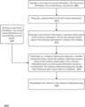
- FIG. 3 Bis a block diagram of an exemplary autonomous driving system to be integrated in the vehicle of FIG. 3 A ;
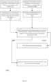
- FIG. 3 Cis a flowchart of an exemplary process to be performed by the autonomous driving system of FIG. 3 B ;
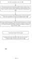
- FIG. 4is a block diagram of an exemplary obstacle avoidance server of FIG. 3 A ;
- FIG. 5is a flowchart of an exemplary process to be performed by the obstacle avoidance server of FIG. 4 ;
- FIG. 6is an example of a method
- FIG. 7is an example of a method
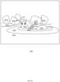
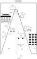
- FIG. 8is an example of a driving scenario
- FIG. 9is an example of a driving scenario
- FIG. 10is an example of a driving scenario
- FIG. 11is an example of a method
- FIG. 12is an example of a method
- FIG. 13is an example of a method
- FIG. 14is an example of a driving scenario
- FIG. 15is an example of a driving scenario
- FIG. 16is an example of a scene
- FIG. 17is an example of a scene
- FIG. 18is an example of a driving scenario
- FIG. 19is an example of a method
- FIG. 20is an example of a method
- FIG. 21is an example of a method
- FIG. 22is an example of a driving scenario
- FIG. 23is an example of a driving scenario
- FIG. 24is an example of a driving scenario
- FIG. 25is an example of a driving scenario
- FIG. 26is an example of a driving scenario
- FIG. 27is an example of a driving scenario
- FIG. 28is an example of a method
- FIG. 29is an example of entity movement functions
- FIG. 30is an example of a method
- FIG. 31is an example of a method
- FIG. 32is an example of a method
- FIG. 33is an example of a method
- FIG. 34is an example of a method
- FIG. 35is an example of a method
- FIG. 37is an example of a driving scenario
- FIG. 36is an example of a method
- FIG. 38is an example of a method
- FIGS. 39 - 44illustrate various data structures including a concept, test images and matching results, as well as various processes related to the data structures;
- FIG. 45is an example of a method
- FIG. 46is an example of a method
- FIG. 47is a timing diagram
- FIG. 48is an example of a method
- FIG. 49is an example of a method
- FIG. 50is an example of a method
- FIG. 51is an example of a method
- FIG. 52is an example of a method
- FIG. 53is an example of an image
- FIG. 54is an example of an image
- FIG. 55is an example of an image
- FIG. 56illustrates examples of two signatures of different resolutions
- FIG. 57illustrates an example of various data structures and processes
- FIG. 58illustrates an example of a vehicle and a system
- FIG. 59is an example of a method
- FIG. 60is an example of a method
- FIG. 61illustrates an example of a method.
- An imageis an example of a media unit. Any reference to an image may be applied mutatis mutandis to a media unit.
- a media unitmay be an example of sensed information. Any reference to a media unit may be applied mutatis mutandis to any type of natural signal such as but not limited to signal generated by nature, signal representing human behavior, signal representing operations related to the stock market, a medical signal, financial series, geodetic signals, geophysical, chemical, molecular, textual and numerical signals, time series, and the like. Any reference to a media unit may be applied mutatis mutandis to sensed information.
- the sensed informationmay be of any kind and may be sensed by any type of sensors—such as a visual light camera, an audio sensor, a sensor that may sense infrared, radar imagery, ultrasound, electro-optics, radiography, LIDAR (light detection and ranging), etc.
- the sensingmay include generating samples (for example, pixel, audio signals) that represent the signal that was transmitted, or otherwise reach the sensor.
- a spanning elementmay be implemented in software or hardware. Different spanning element of a certain iteration are configured to apply different mathematical functions on the input they receive. Non-limiting examples of the mathematical functions include filtering, although other functions may be applied.
- a concept structuremay include one or more clusters. Each cluster may include signatures and related metadata. Each reference to one or more clusters may be applicable to a reference to a concept structure.
- the specification and/or drawingsmay refer to a processor.
- the processormay be a processing circuitry.
- the processing circuitrymay be implemented as a central processing unit (CPU), and/or one or more other integrated circuits such as application-specific integrated circuits (ASICs), field programmable gate arrays (FPGAs), full-custom integrated circuits, etc., or a combination of such integrated circuits.
- CPUcentral processing unit
- ASICsapplication-specific integrated circuits
- FPGAsfield programmable gate arrays
- full-custom integrated circuitsetc., or a combination of such integrated circuits.
- the analysis of content of a media unitmay be executed by generating a signature of the media unit and by comparing the signature to reference signatures.
- the reference signaturesmay be arranged in one or more concept structures or may be arranged in any other manner.
- the signaturesmay be used for object detection or for any other use.
- the signaturemay be generated by creating a multidimensional representation of the media unit.
- the multidimensional representation of the media unitmay have a very large number of dimensions. The high number of dimensions may guarantee that the multidimensional representation of different media units that include different objects is sparse—and that object identifiers of different objects are distant from each other—thus improving the robustness of the signatures.
- each iterationmay include an expansion operations that is followed by a merge operation.
- the expansion operation of an iterationis performed by spanning elements of that iteration.
- the spanning elements of an iterationare irrelevant—thus after determining (by the spanning elements) their relevancy—the spanning elements that are deemed to be irrelevant may be shut down a/or enter an idle mode.
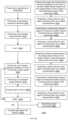
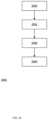
- FIG. 1 Aillustrates a method 5000 for generating a signature of a media unit.
- Method 5000may start by step 5010 of receiving or generating sensed information.
- the sensed informationmay be a media unit of multiple objects.
- Step 5010may be followed by processing the media unit by performing multiple iterations, wherein at least some of the multiple iterations comprises applying, by spanning elements of the iteration, dimension expansion process that are followed by a merge operation.
- the processingmay include:
- Step 5020 of performing a k'th iteration expansion process(k may be a variable that is used to track the number of iterations).
- Step 5030 of performing a k'th iteration merge processStep 5030 of performing a k'th iteration merge process.
- Step 5040 of changing the value of kis Step 5040 of changing the value of k.
- the output of step 5020is a k'th iteration expansion results 5120 .
- step 5030is a k'th iteration merge results 5130 .
- At least some of the K iterationsinvolve selectively reducing the power consumption of some spanning elements (during step 5020 ) that are deemed to be irrelevant.
- FIG. 1 Bis an example of an image signature 6027 of a media unit that is an image 6000 and of an outcome 6013 of the last (K'th) iteration.
- the image 6001is virtually segments to segments 6000 (i,k).
- the segmentsmay be of the same shape and size, but this is not necessarily so.
- Outcome 6013may be a tensor that includes a vector of values per each segment of the media unit.
- One or more objectsmay appear in a certain segment.
- an object identifier(of the signature) points to locations of significant values, within a certain vector associated with the certain segment.
- a top left segment ( 6001 (1,1)) of the imagemay be represented in the outcome 6013 by a vector V(1,1) 6017 (1,1) that has multiple values.
- the number of values per vectormay exceed 100, 200, 500, 1000, and the like.
- the significant valuesmay be selected.
- the significant valuesmay have the values—but may eb selected in any other manner.
- FIG. 1 Billustrates a set of significant responses 6016 (1,1) of vector V(1,1) 6017 (1,1).
- the setincludes five significant values (such as first significant value SV 1 (1,1) 6013 (1,1,1), second significant value SV 2 (1,1), third significant value SV 3 (1,1), fourth significant value SV 4 (1,1), and fifth significant value SV 5 (1,1) 6013 (1,1,5).
- the image signature 6027includes five indexes for the retrieval of the five significant values—first till fifth identifiers ID 1 -ID 5 are indexes for retrieving the first till fifth significant values.
- FIG. 1 Cillustrates a k'th iteration expansion process
- the k'th iteration expansion processstart by receiving the merge results 5060 ′ of a previous iteration.
- the merge results of a previous iterationmay include values are indicative of previous expansion processes—for example—may include values that are indicative of relevant spanning elements from a previous expansion operation, values indicative of relevant regions of interest in a multidimensional representation of the merge results of a previous iteration.
- the merge results (of the previous iteration)are fed to spanning elements such as spanning elements 5061 (1)- 5061 (J).
- Each spanning elementis associated with a unique set of values.
- the setmay include one or more values.
- the spanning elementsapply different functions that may be orthogonal to each other. Using non-orthogonal functions may increase the number of spanning elements—but this increment may be tolerable.
- the spanning elementsmay apply functions that are decorrelated to each other—even if not orthogonal to each other.
- the spanning elementsmay be associated with different combinations of object identifiers that may “cover” multiple possible media units.
- Candidates for combinations of object identifiersmay be selected in various manners—for example based on their occurrence in various images (such as test images) randomly, pseudo randomly, according to some rules and the like. Out of these candidates the combinations may be selected to be decorrelated, to cover said multiple possible media units and/or in a manner that certain objects are mapped to the same spanning elements.
- Each spanning elementcompares the values of the merge results to the unique set (associated with the spanning element) and if there is a match—then the spanning element is deemed to be relevant. If so—the spanning element completes the expansion operation.
- the low power modemay also be referred to as an idle mode, a standby mode, and the like.
- the low power modeis termed low power because the power consumption of an irrelevant spanning element is lower than the power consumption of a relevant spanning element.
- FIG. 1 Cvarious spanning elements are relevant ( 5061 (1)- 5061 (3)) and one spanning element is irrelevant ( 5061 (J)).
- Each relevant spanning elementmay perform a spanning operation that includes assigning an output value that is indicative of an identity of the relevant spanning elements of the iteration.
- the output valuemay also be indicative of identities of previous relevant spanning elements (from previous iterations).
- the output valuemay reflect the numbers fifty, four and eight—for example one thousand multiplied by (fifty+forty) plus forty. Any other mapping function may be applied.
- FIG. 1 Calso illustrates the steps executed by each spanning element:
- FIG. 1 Dis an example of various merge operations.
- a merge operationmay include finding regions of interest.
- the regions of interestare regions within a multidimensional representation of the sensed information.
- a region of interestmay exhibit a more significant response (for example a stronger, higher intensity response).
- the merge operation(executed during a k'th iteration merge operation) may include at least one of the following:
- Proximatemay be a distance that is a certain fraction (for example less than 1%) of the multi-dimensional space, may be a certain fraction of at least one of the regions of interest that are tested for proximity.
- FIG. 1 Eillustrates an example of a hybrid process and an input image 6001 .
- the hybrid processis hybrid in the sense that some expansion and merge operations are executed by a convolutional neural network (CNN) and some expansion and merge operations (denoted additional iterations of expansion and merge) are not executed by the CNN— but rather by a process that may include determining a relevancy of spanning elements and entering irrelevant spanning elements to a low power mode.
- CNNconvolutional neural network
- FIG. 1 Eone or more initial iterations are executed by first and second CNN layers 6010 (1) and 6010 (2) that apply first and second functions 6015 (1) and 6015 (2).
- the output of these layersprovided information about image properties.
- the image propertiesmay not amount to object detection.
- Image propertiesmay include location of edges, properties of curves, and the like.
- the CNNmay include additional layers (for example third till N'th layer 6010 (N)) that may provide a CNN output 6018 that may include object detection information. It should be noted that the additional layers may not be included.
- FIG. 1 Fillustrates an input image 6001 , and a single iteration of an expansion operation and a merge operation.
- FIG. 1 Fthe input image 6001 undergoes two expansion operations.
- the first expansion operationinvolves filtering the input image by a first filtering operation 6031 to provide first regions of interest (denoted 1) in a first filtered image 6031 ′.
- the first expansion operationalso involves filtering the input image by a second filtering operation 6032 to provide first regions of interest (denoted 2) in a second filtered image 6032 ′,
- the merge operationincludes merging the two images by overlaying the first filtered image on the second filtered image to provide regions of interest 1, 2, 12 and 21.
- Region of interest 12is an overlap area shared by a certain region of interest 1 and a certain region of interest 2.
- Region of interest 21is a union of another region of interest 1 and another region of interest 2.
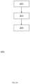
- FIG. 1 Gillustrates method 5200 for generating a signature.
- Method 5200may include the following sequence of steps:
- Step 5210 of receiving or generating an imageStep 5210 of receiving or generating an image.
- Step 5220 of performing a first iteration expansion operation(which is an expansion operation that is executed during a first iteration)
- Step 5230 of performing a first iteration merge operationStep 5230 of performing a first iteration merge operation.
- Step 5240 of amending index k(k is an iteration counter).
- kis an iteration counter.
- FIG. 7in incremented by one—this is only an example of how the number of iterations are tracked.
- Step 5280 of changing the value of index kis Step 5280 of changing the value of index k.
- step 5290If no—there are still iterations to be executed—jumping from step 5290 to step 5260 .
- step 5060 of completing the generation of the signaturemay include, for example, selecting significant attributes, determining retrieval information (for example indexes) that point to the selected significant attributes.
- Step 5220may include:
- Step 5222 of generating multiple representations of the image within a multi-dimensional space of f(1) dimensionsThe expansion operation of step 5220 generates a first iteration multidimensional representation of the first image.
- the number of dimensions of this first iteration multidimensional representationis denoted f(1).
- Step 5224 of assigning a unique index for each region of interest within the multiple representationsFor example, referring to FIG. 6 —indexes 1 and indexes 2 are assigned to regions of interests generated during the first iteration expansion operations 6031 and 6032 .
- Step 5230may include:
- Step 5234 of assigning a unique index for each region of interest within the multiple representationsFor example—referring to FIG. 6 —indexes 1, 2, 12 and 21.
- Step 5260may include:
- Step 5262 of generating multiple representations of the merge results of the (k ⁇ 1)'th iteration within a multi-dimensional space of f(k) dimensionsThe expansion operation of step 5260 generates a k'th iteration multidimensional representation of the first image. The number of dimensions of this kth iteration multidimensional representation is denoted f(k).
- Step 5270may include
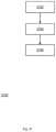
- FIG. 1 Hillustrates a method 5201 .
- the relationships between the regions of interestare overlaps.
- step 5232is replaced by step 5232 ′ of searching for overlaps between regions of interest and define regions of interest that are related to the overlaps.
- Step 5272is replaced by step 5272 ′ of searching for overlaps between regions of interest and define regions of interest that are related to the overlaps.
- FIG. 11 Iillustrates a method 7000 for low-power calculation of a signature.
- Method 7000starts by step 7010 of receiving or generating a media unit of multiple objects.
- Step 7010may be followed by step 7012 of processing the media unit by performing multiple iterations, wherein at least some of the multiple iterations comprises applying, by spanning elements of the iteration, dimension expansion process that are followed by a merge operation.
- the applying of the dimension expansion process of an iterationmay include (a) determining a relevancy of the spanning elements of the iteration; and (b) completing the dimension expansion process by relevant spanning elements of the iteration and reducing a power consumption of irrelevant spanning elements until, at least, a completion of the applying of the dimension expansion process.
- the identifiersmay be retrieval information for retrieving the significant portions.
- the at least some of the multiple iterationsmay be a majority of the multiple iterations.
- the output of the multiple iterationmay include multiple property attributes for each segment out of multiple segments of the media unit; and wherein the significant portions of an output of the multiple iterations may include more impactful property attributes.
- the first iteration of the multiple iterationmay include applying the dimension expansion process by applying different filters on the media unit.
- the at least some of the multiple iterationexclude at least a first iteration of the multiple iterations. See, for example, FIG. 1 E .
- the determining the relevancy of the spanning elements of the iterationmay be based on at least some identities of relevant spanning elements of at least one previous iteration.
- the determining the relevancy of the spanning elements of the iterationmay be based on at least some identities of relevant spanning elements of at least one previous iteration that preceded the iteration.
- the determining the relevancy of the spanning elements of the iterationmay be based on properties of the media unit.
- the determining the relevancy of the spanning elements of the iterationmay be performed by the spanning elements of the iteration.
- Method 7000may include a neural network processing operation that may be executed by one or more layers of a neural network and does not belong to the at least some of the multiple iterations. See, for example, FIG. 1 E .
- the at least one iterationmay be executed without reducing power consumption of irrelevant neurons of the one or more layers.
- the one or more layersmay output information about properties of the media unit, wherein the information differs from a recognition of the multiple objects.
- the applying, by spanning elements of an iteration that differs from the first iteration, the dimension expansion processmay include assigning output values that may be indicative of an identity of the relevant spanning elements of the iteration. See, for example, FIG. 1 C .
- the applying, by spanning elements of an iteration that differs from the first iteration, the dimension expansion processmay include assigning output values that may be indicative a history of dimension expansion processes until the iteration that differs from the first iteration.
- the each spanning elementmay be associated with a subset of reference identifiers.
- the determining of the relevancy of each spanning elements of the iterationmay be based a relationship between the subset of the reference identifiers of the spanning element and an output of a last merge operation before the iteration.
- the output of a dimension expansion process of an iterationmay be a multidimensional representation of the media unit that may include media unit regions of interest that may be associated with one or more expansion processes that generated the regions of interest.
- the merge operation of the iterationmay include selecting a subgroup of media unit regions of interest based on a spatial relationship between the subgroup of multidimensional regions of interest. See, for example, FIGS. 3 and 6 .
- Method 7000may include applying a merge function on the subgroup of multidimensional regions of interest. See, for example, FIGS. 1 C and 1 F .
- Method 7000may include applying an intersection function on the subgroup of multidimensional regions of interest. See, for example, FIGS. 1 C and 1 F .
- the merge operation of the iterationmay be based on an actual size of one or more multidimensional regions of interest.
- the merge operation of the iterationmay be based on relationship between sizes of the multidimensional regions of interest. For example—larger multidimensional regions of interest may be maintained while smaller multidimensional regions of interest may be ignored of.
- the merge operation of the iterationmay be based on changes of the media unit regions of interest during at least the iteration and one or more previous iteration.
- Step 7012may be followed by step 7014 of determining identifiers that are associated with significant portions of an output of the multiple iterations.
- Step 7014may be followed by step 7016 of providing a signature that comprises the identifiers and represents the multiple objects.
- Any of the mentioned above signature generation methodprovides a signature that does not explicitly includes accurate shape information. This adds to the robustness of the signature to shape related inaccuracies or to other shape related parameters.
- the signatureincludes identifiers for identifying media regions of interest.
- Each media region of interestmay represent an object (for example a vehicle, a pedestrian, a road element, a human made structure, wearables, shoes, a natural element such as a tree, the sky, the sun, and the like) or a part of an object (for example—in the case of the pedestrian—a neck, a head, an arm, a leg, a thigh, a hip, a foot, an upper arm, a forearm, a wrist, and a hand).
- an objectfor example a vehicle, a pedestrian, a road element, a human made structure, wearables, shoes, a natural element such as a tree, the sky, the sun, and the like
- a part of an objectfor example—in the case of the pedestrian—a neck, a head, an arm, a leg, a thigh, a hip, a foot, an upper arm, a forearm, a wrist, and a hand.
- a part of an objectmay be regarded as an object.
- the exact shape of the objectmay be of interest.
- FIG. 1 Jillustrates method 7002 of generating a hybrid representation of a media unit.
- Method 7002may include a sequence of steps 7020 , 7022 , 7024 and 7026 .
- Step 7020may include receiving or generating the media unit.
- Step 7022may include processing the media unit by performing multiple iterations, wherein at least some of the multiple iterations comprises applying, by spanning elements of the iteration, dimension expansion process that are followed by a merge operation.
- Step 7024may include selecting, based on an output of the multiple iterations, media unit regions of interest that contributed to the output of the multiple iterations.
- Step 7026may include providing a hybrid representation, wherein the hybrid representation may include (a) shape information regarding shapes of the media unit regions of interest, and (b) a media unit signature that includes identifiers that identify the media unit regions of interest.
- Step 7024may include selecting the media regions of interest per segment out of multiple segments of the media unit. See, for example, FIG. 2 .
- Step 7026may include step 7027 of generating the shape information.
- the shape informationmay include polygons that represent shapes that substantially bound the media unit regions of interest. These polygons may be of a high degree.
- the methodmay include step 7028 of compressing the shape information of the media unit to provide compressed shape information of the media unit.
- FIG. 1 Killustrates method 5002 for generating a hybrid representation of a media unit.
- Method 5002may start by step 5011 of receiving or generating a media unit.
- Step 5011may be followed by processing the media unit by performing multiple iterations, wherein at least some of the multiple iterations comprises applying, by spanning elements of the iteration, dimension expansion process that are followed by a merge operation.
- the processingmay be followed by steps 5060 and 5062 .
- the processingmay include steps 5020 , 5030 , 5040 and 5050 .
- Step 5020may include performing a k'th iteration expansion process (k may be a variable that is used to track the number of iterations).
- Step 5030may include performing a k'th iteration merge process.
- Step 5040may include changing the value of k.
- Step 5050may include checking if all required iterations were done—if so proceeding to steps 5060 and 5062 . Else—jumping to step 5020 .
- the output of step 5020is a k'th iteration expansion result.
- the output of step 5030is a k'th iteration merge result.
- Step 5060may include completing the generation of the signature.
- Step 5062may include generating shape information regarding shapes of media unit regions of interest.
- the signature and the shape informationprovide a hybrid representation of the media unit.
- the combination of steps 5060 and 5062amounts to a providing a hybrid representation, wherein the hybrid representation may include (a) shape information regarding shapes of the media unit regions of interest, and (b) a media unit signature that includes identifiers that identify the media unit regions of interest.
- FIG. 1 Lillustrates method 5203 for generating a hybrid representation of an image.
- Method 5200may include the following sequence of steps:
- Step 5210 of receiving or generating an imageStep 5210 of receiving or generating an image.
- Step 5230 of performing a first iteration expansion operation(which is an expansion operation that is executed during a first iteration)
- Step 5240 of performing a first iteration merge operationStep 5240 of performing a first iteration merge operation.
- Step 5240 of amending index k(k is an iteration counter).
- kis an iteration counter.
- FIG. 1 Lin incremented by one—this is only an example of how the number of iterations are tracked.
- Step 5280 of changing the value of index kis Step 5280 of changing the value of index k.
- step 5290If no—there are still iterations to be executed—jumping from step 5290 to step 5260 .
- step 5060If yes—jumping to step 5060 .
- Step 5060may include completing the generation of the signature. This may include, for example, selecting significant attributes, determining retrieval information (for example indexes) that point to the selected significant attributes.
- Step 5062may include generating shape information regarding shapes of media unit regions of interest.
- the signature and the shape informationprovide a hybrid representation of the media unit.
- the combination of steps 5060 and 5062amounts to a providing a hybrid representation, wherein the hybrid representation may include (a) shape information regarding shapes of the media unit regions of interest, and (b) a media unit signature that includes identifiers that identify the media unit regions of interest.
- Step 5220may include:
- Step 5224 of assigning a unique index for each region of interest within the multiple representations(for example, referring to FIG. 1 F —indexes 1 and indexes 2 following first iteration expansion operations 6031 and 6032 .
- Step 5230may include
- Step 5228 of assigning a unique index for each region of interest within the multiple representationsFor example—referring to FIG. 1 F —indexes 1, 2, 12 and 21.
- Step 5260may include:
- Step 5262 of generating multiple representations of the merge results of the (k ⁇ 1)'th iteration within a multi-dimensional space of f(k) dimensionsThe expansion operation of step 5260 generates a k'th iteration multidimensional representation of the first image. The number of dimensions of this kth iteration multidimensional representation is denoted f(k).
- Step 5270may include
- FIG. 1 Millustrates method 5205 for generating a hybrid representation of an image.
- Method 5200may include the following sequence of steps:
- Step 5210 of receiving or generating an imageStep 5210 of receiving or generating an image.
- Step 5230 of performing a first iteration expansion operation(which is an expansion operation that is executed during a first iteration)
- Step 5240 of performing a first iteration merge operationStep 5240 of performing a first iteration merge operation.
- Step 5240 of amending index k(k is an iteration counter).
- kis an iteration counter.
- FIG. 1 Min incremented by one—this is only an example of how the number of iterations are tracked.
- Step 5280 of changing the value of index kis Step 5280 of changing the value of index k.
- step 5290If no—there are still iterations to be executed—jumping from step 5290 to step 5260 .
- Step 5060may include completing the generation of the signature. This may include, for example, selecting significant attributes, determining retrieval information (for example indexes) that point to the selected significant attributes.
- Step 5062may include generating shape information regarding shapes of media unit regions of interest.
- the signature and the shape informationprovide a hybrid representation of the media unit.
- the combination of steps 5060 and 5062amounts to a providing a hybrid representation, wherein the hybrid representation may include (a) shape information regarding shapes of the media unit regions of interest, and (b) a media unit signature that includes identifiers that identify the media unit regions of interest.
- Step 5220may include:
- Step 5230may include
- Step 5260may include:
- Step 5270may include
- the filtersmay be orthogonal may be non-orthogonal—for example be decorrelated. Using non-orthogonal filters may increase the number of filters—but this increment may be tolerable.
- Object detectionmay include comparing a signature of an input image to signatures of one or more cluster structures in order to find one or more cluster structures that include one or more matching signatures that match the signature of the input image.
- the number of input images that are compared to the cluster structuresmay well exceed the number of signatures of the cluster structures. For example—thousands, tens of thousands, hundreds of thousands (and even more) of input signature may be compared to much less cluster structure signatures.
- the ratio between the number of input images to the aggregate number of signatures of all the cluster structuresmay exceed ten, one hundred, one thousand, and the like.
- the shape information of the input imagesmay be compressed.
- the shape information of signatures that belong to the cluster structuresmay be uncompressed—and of higher accuracy than those of the compressed shape information.
- the shape information of the cluster signaturemay also be compressed.
- Compression of the shape information of cluster signaturesmay be based on a priority of the cluster signature, a popularity of matches to the cluster signatures, and the like.
- the shape information related to an input image that matches one or more of the cluster structuresmay be calculated based on shape information related to matching signatures.
- a shape information regarding a certain identifier within the signature of the input imagemay be determined based on shape information related to the certain identifiers within the matching signatures.
- Any operation on the shape information related to the certain identifiers within the matching signaturesmay be applied in order to determine the (higher accuracy) shape information of a region of interest of the input image identified by the certain identifier.
- the shapesmay be virtually overlaid on each other and the population per pixel may define the shape.
- Other operationsmay include smoothing the overlaid shapes, selecting pixels that appear in all overlaid shapes.
- the compressed shape informationmay be ignored of or be considered.
- FIG. 1 Nillustrates method 7003 of determining shape information of a region of interest of a media unit.
- Method 7003may include a sequence of steps 7030 , 7032 and 7034 .
- Step 7030may include receiving or generating a hybrid representation of a media unit.
- the hybrid representationincludes compressed shape information.
- Step 7032may include comparing the media unit signature of the media unit to signatures of multiple concept structures to find a matching concept structure that has at least one matching signature that matches to the media unit signature.
- Step 7034may include calculating higher accuracy shape information that is related to regions of interest of the media unit, wherein the higher accuracy shape information is of higher accuracy than the compressed shape information of the media unit, wherein the calculating is based on shape information associated with at least some of the matching signatures.
- Step 7034may include at least one out of:
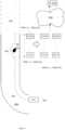
- FIG. 1 Oillustrates a matching process and a generation of a higher accuracy shape information.
- Each cluster structureincludes cluster signatures, metadata regarding the cluster signatures, and shape information regarding the regions of interest identified by identifiers of the cluster signatures.
- first cluster structure 4974 (1)includes multiple (N1) signatures (referred to as cluster signatures CS) CS(1,1)-CS(1,N1) 4975 (1,1)- 4975 (1,N1), metadata 4976 (1), and shape information (Shapeinfo 4977 (1)) regarding shapes of regions of interest associated with identifiers of the CSs.
- cluster signatures CScluster signatures
- shape information 4977 (1)shape information regarding shapes of regions of interest associated with identifiers of the CSs.
- M'th cluster structure 4974includes multiple (N2) signatures (referred to as cluster signatures CS) CS(M, 1 )-CS(M,N2) 4975 (M, 1 )- 4975 (M,N2), metadata 4976 (M), and shape information (Shapeinfo 4977 (M)) regarding shapes of regions of interest associated with identifiers of the CSs.
- cluster signatures CScluster signatures
- CSshape information
- the number of signatures per concept structuremay change over time—for example due to cluster reduction attempts during which a CS is removed from the structure to provide a reduced cluster structure, the reduced structure is checked to determine that the reduced cluster signature may still identify objects that were associated with the (non-reduced) cluster signature—and if so the signature may be reduced from the cluster signature.
- the signatures of each cluster structuresare associated to each other, wherein the association may be based on similarity of signatures and/or based on association between metadata of the signatures.
- each cluster structureis associated with a unique object—then objects of a media unit may be identified by finding cluster structures that are associated with said objects.
- the finding of the matching cluster structuresmay include comparing a signature of the media unit to signatures of the cluster structures- and searching for one or more matching signature out of the cluster signatures.
- FIG. 1 Oa media unit having a hybrid representation undergoes object detection.
- the hybrid representationincludes media unit signature 4972 and compressed shape information 4973 .
- the media unit signature 4972is compared to the signatures of the M cluster structures—from CS(1,1) 4975 (1,1) till CS(M,N2) 4975 (M,N2).
- the methodproceeds by generating shape information that is of higher accuracy then the compressed shape information.
- the generation of the shape informationis done per identifier.
- the methodmay perform the steps of:
- step 4978 (j)the shape information of the j'th identifier of each matching signature- or of each signature of the matching cluster structure.
- the matching signaturesinclude CS(1,1) 2975 (1,1), CS(2,5) 2975 (2,5), CS(7,3) 2975 (7,3) and CS(15,2) 2975 (15,2)
- the j'th identifieris included in CS(1,1) 2975 (1,1), CS(7,3) 2975 (7,3) and CS(15,2) 2975 (15,2)
- the shape information of the j'th identifier of the media unitis determined based on the shape information associated with CS(1,1) 2975 (1,1), CS(7,3) 2975 (7,3) and CS(15,2) 2975 (15,2).
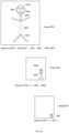
- FIG. 1 Pillustrates an image 8000 that includes four regions of interest 8001 , 8002 , 8003 and 8004 .
- the signature 8010 of image 8000includes various identifiers including ID 1 8011 , ID 2 8012 , ID 3 8013 and ID 4 8014 that identify the four regions of interest 8001 , 8002 , 8003 and 8004 .
- the shapes of the four regions of interest 8001 , 8002 , 8003 and 8004are four polygons. Accurate shape information regarding the shapes of these regions of interest may be generated during the generation of signature 8010 .
- FIG. 1 Qillustrates the compressing of the shape information to represent a compressed shape information that reflects simpler approximations ( 8001 ′, 8002 ′, 8003 ′ and 8004 ′) of the regions of interest 8001 , 8002 , 8003 and 8004 .
- simplermay include less facets, fewer values of angles, and the like.
- the hybrid representation of the media unit, after compressionrepresent a media unit with simplified regions of interest 8001 ′, 8002 ′, 8003 ′ and 8004 ′—as shown in FIG. 1 R .
- Objectsmay appear in an image at different scales.
- Scale invariant object detectionmay improve the reliability and repeatability of the object detection and may also use fewer number of cluster structures—thus reduced memory resources and also lower computational resources required to maintain fewer cluster structures.
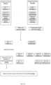
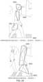
- FIG. 1 Sillustrates method 8020 for scale invariant object detection.
- Method 8020may include a first sequence of steps that may include step 8022 , 8024 , 8026 and 8028 .
- Step 8022may include receiving or generating a first image in which an object appears in a first scale and a second image in which the object appears in a second scale that differs from the first scale.
- Step 8024may include generating a first image signature and a second image signature.
- the first image signatureincludes a first group of at least one certain first image identifier that identifies at least a part of the object. See, for example image 8000 ′ of FIG. 2 A .
- the personis identified by identifiers ID 6 8016 and ID 8 8018 that represent regions of interest 8006 and 8008 .
- the second image signatureincludes a second group of certain second image identifiers that identify different parts of the object.
- the personis identified by identifiers ID 1 8011 , ID 2 8012 , ID 3 8013 , and ID 4 8014 that represent regions of interest 8001 , 8002 , 8003 and 8004 .
- the second groupis larger than first group—as the second group has more members than the first group.
- Step 8026may include linking between the at least one certain first image identifier and the certain second image identifiers.
- Step 8026may include linking between the first image signature, the second image signature and the object.
- Step 8026may include adding the first signature and the second signature to a certain concept structure that is associated with the object. For example, referring to FIG. 1 O , the signatures of the first and second images may be included in a cluster concept out of 4974 (1)- 4974 (M).
- Step 8028may include determining whether an input image includes the object based, at least in part, on the linking.
- the input imagediffers from the first and second images.
- the determiningmay include determining that the input image includes the object when a signature of the input image includes the at least one certain first image identifier or the certain second image identifiers.
- the determiningmay include determining that the input image includes the object when the signature of the input image includes only a part of the at least one certain first image identifier or only a part of the certain second image identifiers.
- the linkingmay be performed for more than two images in which the object appears in more than two scales.
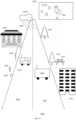
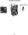
- FIG. 2 Bin which a person appears at three different scales—at three different images.
- first image 8051the person is included in a single region of interest 8061 and the signature 8051 ′ of first image 8051 includes an identifier ID 61 that identifies the single region of interest—identifies the person.
- second image 8052the upper part of the person is included in region of interest 8068 , the lower part of the person is included in region of interest 8069 and the signature 8052 ′ of second image 8052 includes identifiers ID 68 and ID 69 that identify regions of interest 8068 and 8069 respectively.
- third image 8053the eyes of the person are included in region of interest 8062 , the mouth of the person is included in region of interest 8063 , the head of the person appears in region of interest 8064 , the neck and arms of the person appear in region of interest 8065 , the middle part of the person appears in region of interest 8066 , and the lower part of the person appears in region of interest 8067 .
- Signature 8053 ′ of third image 8053includes identifiers ID 62 , ID 63 , ID 64 , ID 65 , ID 55 and ID 67 that identify regions of interest 8062 - 8067 respectively.
- Method 8020may link signatures 8051 ′, 8052 ′ and 8053 ′ to each other. For example—these signatures may be included in the same cluster structure.
- Method 8020may link (i) ID 61 , (ii) signatures ID 68 and ID 69 , and (ii) signature ID 62 , ID 63 , ID 64 , ID 65 , ID 66 and ID 67 .
- FIG. 2 Cillustrates method 8030 for object detection.
- Method 8030may include the steps of method 8020 or may be preceded by steps 8022 , 8024 and 8026 .
- Method 8030may include a sequence of steps 8032 , 8034 , 8036 and 8038 .
- Step 8032may include receiving or generating an input image.
- Step 8034may include generating a signature of the input image.
- Step 8036may include comparing the signature of the input image to signatures of a certain concept structure.
- the certain concept structuremay be generated by method 8020 .
- Step 8038may include determining that the input image comprises the object when at least one of the signatures of the certain concept structure matches the signature of the input image.
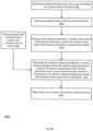
- FIG. 2 Dillustrates method 8040 for object detection.
- Method 8040may include the steps of method 8020 or may be preceded by steps 8022 , 8024 and 8026 .
- Method 8040may include a sequence of steps 8041 , 8043 , 8045 , 8047 and 8049 .
- Step 8041may include receiving or generating an input image.
- Step 8043may include generating a signature of the input image, the signature of the input image comprises only some of the certain second image identifiers; wherein the input image of the second scale.
- Step 8045may include changing a scale of the input image to the first scale to a provide an amended input image.
- Step 8047may include generating a signature of the amended input image.
- Step 8049may include verifying that the input image comprises the object when the signature of the amended input image comprises the at least one certain first image identifier.
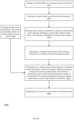
- FIG. 2 Eillustrates method 8050 for object detection.
- Method 8050may include the steps of method 8020 or may be preceded by steps 8022 , 8024 and 8026 .
- Method 8050may include a sequence of steps 8052 , 8054 , 8056 and 8058 .
- Step 8052may include receiving or generating an input image.
- Step 8054may include generating a signature of the input image.
- Step 8056may include searching in the signature of the input image for at least one of (a) the at least one certain first image identifier, and (b) the certain second image identifiers.
- Step 8058may include determining that the input image comprises the object when the signature of the input image comprises the at least one of (a) the at least one certain first image identifier, and (b) the certain second image identifiers.
- step 8056may include searching in the signature of the input image for at least one of (a) one or more certain first image identifier of the at least one certain first image identifier, and (b) at least one certain second image identifier of the certain second image identifiers.
- step 8058may include determining that the input image includes the object when the signature of the input image comprises the at least one of (a) one or more certain first image identifier of the at least one certain first image identifier, and (b) the at least one certain second image identifier.
- a single objectmay include multiple parts that are identified by different identifiers of a signature of the image. In cases such as unsupervised learning, it may be beneficial to link the multiple object parts to each other without receiving prior knowledge regarding their inclusion in the object.
- the linkingcan be done in order to verify a previous linking between the multiple object parts.
- FIG. 2 Fillustrates method 8070 for object detection.
- Method 8070is for movement based object detection.
- Method 8070may include a sequence of steps 8071 , 8073 , 8075 , 8077 , 8078 and 8079 .
- Step 8071may include receiving or generating a video stream that includes a sequence of images.
- Step 8073may include generating image signatures of the images.
- Each imageis associated with an image signature that comprises identifiers.
- Each identifieridentifiers a region of interest within the image.
- Step 8075may include generating movement information indicative of movements of the regions of interest within consecutive images of the sequence of images.
- Step 8075may be preceded by or may include generating or receiving location information indicative of a location of each region of interest within each image. The generating of the movement information is based on the location information.
- Step 8077may include searching, based on the movement information, for a first group of regions of interest that follow a first movement. Different first regions of interest are associated with different parts of an object.
- Step 8078may include linking between first identifiers that identify the first group of regions of interest.
- Step 8079may include linking between first image signatures that include the first linked identifiers.
- Step 8079may include adding the first image signatures to a first concept structure, the first concept structure is associated with the first image.
- Step 8079may be followed by determining whether an input image includes the object based, at least in part, on the linking
- FIG. 2 HAn example of various steps of method 8070 is illustrated in FIG. 2 H .
- FIG. 2 Gillustrates three images 8091 , 8092 and 8093 that were taken at different points in time.
- First image 8091illustrates a gate 8089 ′ that is located in region of interest 8089 and a person that faces the gate. Various parts of the person are located within regions of interest 8081 , 8082 , 8083 , 8084 and 8085 .
- the first image signature 8091 ′includes identifiers ID 81 , ID 82 , ID 83 , ID 84 , ID 85 and ID 89 that identify regions of interest 8081 , 8082 , 8083 , 8084 , 8085 and 8089 respectively.
- the first image location information 8091 ′′includes the locations L 81 , L 82 , L 83 , L 84 , L 85 and L 89 of regions of interest 8081 , 8082 , 8083 , 8084 , 8085 and 8089 respectively.
- a location of a region of interestmay include a location of the center of the region of interest, the location of the borders of the region of interest or any location information that may define the location of the region of interest or a part of the region of interest.
- Second image 8092illustrates a gate that is located in region of interest 8089 and a person that faces the gate. Various parts of the person are located within regions of interest 8081 , 8082 , 8083 , 8084 and 8085 . Second image also includes a pole that is located within region of interest 8086 . In the first image that the pole was concealed by the person.
- the second image signature 8092 ′includes identifiers ID 81 , ID 82 , ID 83 , ID 84 , ID 85 , ID 86 , and ID 89 that identify regions of interest 8081 , 8082 , 8083 , 8084 , 8085 , 8086 and 8089 respectively.
- the second image location information 8092 ′′includes the locations L 81 , L 82 , L 83 , L 84 , L 85 , L 86 and L 89 of regions of interest 8081 , 8082 , 8083 , 8084 , 8085 , 8086 and 8089 respectively.
- Third image 8093illustrates a gate that is located in region of interest 8089 and a person that faces the gate. Various parts of the person are located within regions of interest 8081 , 8082 , 8083 , 8084 and 8085 . Third image also includes a pole that is located within region of interest 8086 , and a balloon that is located within region of interest 8087 .
- the third image signature 8093 ′includes identifiers ID 81 , ID 82 , ID 83 , ID 84 , ID 85 , ID 86 , ID 87 and ID 89 that identify regions of interest 8081 , 8082 , 8083 , 8084 , 8085 , 8086 , 8087 and 8089 respectively.
- the third image location information 8093 ′′includes the locations L 81 , L 82 , L 83 , L 84 , L 85 , L 86 , L 87 and L 89 of regions of interest 8081 , 8082 , 8083 , 8084 , 8085 , 8086 , 8086 and 8089 respectively.
- the motion of the various regions of interestmay be calculated by comparing the location information related to different images.
- the movement informationmay consider the different in the acquisition time of the images.
- FIG. 2 Hillustrates method 8100 for object detection.
- Method 8100may include the steps of method 8070 or may be preceded by steps 8071 , 8073 , 8075 , 8077 and 8078 .
- Method 8100may include the following sequence of steps:
- Step 8102 of receiving or generating an input imageStep 8102 of receiving or generating an input image.
- Step 8104 of generating a signature of the input imageStep 8104 of generating a signature of the input image.
- Step 8106 of comparing the signature of the input image to signatures of a first concept structureincludes first identifiers that were linked to each other based on movements of first regions of interest that are identified by the first identifiers.
- FIG. 21illustrates method 8110 for object detection.
- Method 8110may include the steps of method 8070 or may be preceded by steps 8071 , 8073 , 8075 , 8077 and 8078 .
- Method 8110may include the following sequence of steps:
- Step 8112 of receiving or generating an input imageStep 8112 of receiving or generating an input image.
- Step 8114 of generating a signature of the input imageStep 8114 of generating a signature of the input image.
- Object detectionmay benefit from being robust to the angle of acquisition—to the angle between the optical axis of an image sensor and a certain part of the object. This allows the detection process to be more reliable, use fewer different clusters (may not require multiple clusters for identifying the same object from different images).
- FIG. 2 Jillustrates method 8120 that includes the following steps:
- Step 8122 of receiving or generating images of objects taken from different anglesStep 8122 of receiving or generating images of objects taken from different angles.
- Step 8126 of linking between the images of similar signaturesmay include searching for local similarities.
- the similaritiesare local in the sense that they are calculated per a subset of signatures. For example—assuming that the similarity is determined per two images—then a first signature may be linked to a second signature that is similar to the first image.
- a third signaturemay be linked to the second image based on the similarity between the second and third signatures- and even regardless of the relationship between the first and third signatures.
- Step 8126may include generating a concept data structure that includes the similar signatures.
- This so-called local or sliding window approachin addition to the acquisition of enough images (that will statistically provide a large angular coverage) will enable to generate a concept structure that include signatures of an object taken at multiple directions.
- FIG. 2 Killustrates a person 8130 that is imaged from different angles ( 8131 , 8132 , 8133 , 8134 , 8135 and 8136 ). While the signature of a front view of the person (obtained from angle 8131 ) differs from the signature of the side view of the person (obtained from angle 8136 ), the signature of images taken from multiple angles between angles 8141 and 8136 compensates for the difference—as the difference between images obtained from close angles are similar (local similarity) to each other.
- Object detectionmay be implemented by (a) receiving or generating concept structures that include signatures of media units and related metadata, (b) receiving a new media unit, generating a new media unit signature, and (c) comparing the new media unit signature to the concept signatures of the concept structures.
- the comparisonmay include comparing new media unit signature identifiers (identifiers of objects that appear in the new media unit) to concept signature identifiers and determining, based on a signature matching criteria whether the new media unit signature matches a concept signature. If such a match is found, then the new media unit is regarded as including the object associated with that concept structure.
- the matching processmay be highly effective and may adapt itself to the statistics of appearance of identifiers in different scenarios. For example—a match may be obtained when a relatively rear but highly distinguishing identifier appears in the new media unit signature and in a cluster signature, but a mismatch may be declared when multiple common and slightly distinguishing identifiers appear in the new media unit signature and in a cluster signature.
- FIG. 2 Lillustrates method 8200 for object detection.
- Method 8200may include:
- Step 8210 of receiving an input imageis
- Step 8212 of generating a signature of the input imageStep 8212 of generating a signature of the input image.
- the signature matching criteriamay be a minimal number of matching identifiers that indicate of a match. For example—assuming a signature that include few tens of identifiers, the minimal number may vary between a single identifier to all of the identifiers of the signature.
- an input imagemay include multiple objects and that a signature of the input image may match multiple cluster structures.
- Method 8200is applicable to all of the matching processes- and that the signature matching criteria may be set for each signature of each cluster structure.
- Step 8210may be preceded by step 8202 of determining each signature matching criterion by evaluating object detection capabilities of the signature under different signature matching criteria.
- Step 8202may include:
- Step 8203 of receiving or generating signatures of a group of test imagesStep 8203 of receiving or generating signatures of a group of test images.
- the object detection capabilitymay reflect a percent of signatures of the group of test images that match the signature.
- the selecting of the signature matching criterioncomprises selecting the signature matching criterion that once applied results in a percent of signatures of the group of test images that match the signature that is closets to a predefined desired percent of signatures of the group of test images that match the signature.
- the object detection capabilitymay reflect a significant change in the percent of signatures of the group of test images that match the signature. For example—assuming, that the signature matching criteria is a minimal number of matching identifiers and that changing the value of the minimal numbers may change the percentage of matching test images. A substantial change in the percentage (for example a change of more than 10, 20, 30, 40 percent) may be indicative of the desired value. The desired value may be set before the substantial change, proximate to the substantial change, and the like.
- cluster signatures CS(1,1), CS(2,5), CS(7,3) and CS(15,2)match unit signature 4972 .
- Each of these matchesmay apply a unique signature matching criterion.
- FIG. 2 Millustrates method 8220 for object detection.
- Method 8220is for managing a concept structure.
- Method 8220may include:
- Step 8222 of determining to add a new signature to the concept structuremay already include at least one old signature.
- the new signatureincludes identifiers that identify at least parts of objects.
- the new signature matching criteriondetermines when another signature matches the new signature.
- the determining of the new signature matching criterionmay include evaluating object detection capabilities of the signature under different signature matching criteria.
- Step 8224may include steps 8203 , 8204 and 8206 (include din step 8206 ) of method 8200 .
- FIG. 22 Nillustrates an example of a system capable of executing one or more of the mentioned above methods.
- the systeminclude various components, elements and/or units.
- a component element and/or unitmay be a processing circuitry may be implemented as a central processing unit (CPU), and/or one or more other integrated circuits such as application-specific integrated circuits (ASICs), field programmable gate arrays (FPGAs), full-custom integrated circuits, etc., or a combination of such integrated circuits.
- CPUcentral processing unit
- ASICsapplication-specific integrated circuits
- FPGAsfield programmable gate arrays
- full-custom integrated circuitsetc., or a combination of such integrated circuits.
- each component element and/or unitmay be implemented in hardware, firmware, or software that may be executed by a processing circuitry.
- System 4900may include sensing unit 4902 , communication unit 4904 , input 4911 , processor 4950 , and output 4919 .
- the communication unit 4904may include the input and/or the output.
- Input and/or outputmay be any suitable communications component such as a network interface card, universal serial bus (USB) port, disk reader, modem or transceiver that may be operative to use protocols such as are known in the art to communicate either directly, or indirectly, with other elements of the system.
- a network interface cardsuch as a network interface card, universal serial bus (USB) port, disk reader, modem or transceiver that may be operative to use protocols such as are known in the art to communicate either directly, or indirectly, with other elements of the system.
- USBuniversal serial bus
- a drivermay encounter driving obstacles that are not necessarily indicated in commonly available roadmaps. For example, it is not uncommon for a roadway to have potholes that may complicate the driving process. Some potholes are large enough to cause damage to the wheels or undercarriage of the vehicle. Accordingly, when encountering a pothole, the driver may swerve to avoid it. However, depending on the layout of the roadway and/or traffic conditions, it may not be feasible for the driver to react in such a manner. It is also possible that depending on current visibility, the speed of the vehicle, and/or the alertness of the driver, the driver may not even see the pothole in time to avoid it.
- such systemsmay use one or more sensors to acquire information about the current driving environment in order to determine how to drive along the roadway as per a stored map. It is possible, that the vehicle's sensor(s) may not detect an obstacle, e.g., a pothole, sufficiently in advance in order to enable the system to determine that evasive action should be taken to avoid the obstacle and to perform that action in time. It will be appreciated that such a scenario may be further complicated by the presence of other vehicles and/or pedestrians in the immediate vicinity of the vehicle.
- an obstaclee.g., a pothole
- FIG. 3 Ais a partly-pictorial, partly-block diagram illustration of an exemplary obstacle detection and mapping system 10 (hereinafter referred to also as “system 10 ”) constructed and operative in accordance with embodiments described herein.
- system 10may be operative to process sensor data to detect and map obstacles on a roadway in order to enable an assisted/autonomous driving system to predict and avoid obstacles in the path of a vehicle.
- System 10comprises vehicle 100 and obstacle avoidance server 400 which may be configured to communicate with each other over a communications network such as, for example, the Internet.
- vehicle 100may be configured with an autonomous driving system (not shown) operative to autonomously provide driving instructions to vehicle 100 without the intervention of a human driver.
- an assisted (or “semi-autonomous”) driving systemwhere in at least some situations a human driver may take control of vehicle 100 and/or where in at least some situations the semi-autonomous driving system provides warnings to the driver without necessarily directly controlling vehicle 100 .
- vehicle 100may be configured with at least one sensor 130 to provide information about a current driving environment as vehicle 100 proceeds along roadway 20 .
- sensor 130is depicted in FIG. 3 A as a single entity, in practice, as will be described hereinbelow, there may be multiple sensors 130 arrayed on, or inside of, vehicle 130 .
- sensor(s) 130may be implemented using a conventional camera operative to capture images of roadway 20 and objects in its immediate vicinity. It will be appreciated that sensor 130 may be implemented using any suitable imaging technology instead of, or in addition to, a conventional camera.
- sensor 130may also be operative to use infrared, radar imagery, ultrasound, electro-optics, radiography, LIDAR (light detection and ranging), etc.
- one or more sensors 130may also be installed independently along roadway 20 , where information from such sensors 130 may be provided to vehicle 100 and/or obstacle avoidance server 400 as a service.
- static reference points 30 A and 30 Bmay be located along roadway 20 .
- static reference point 30 Ais depicted as a speed limit sign
- static reference point 30 Bis depicted as an exit sign.
- sensor 130may capture images of static reference points 30 . The images may then be processed by the autonomous driving system in vehicle 100 to provide information about the current driving environment for vehicle 100 , e.g., the speed limit or the location of an upcoming exit.
- Obstacle 40e.g., a pothole
- sensor 130may also be operative to capture images of obstacle 40 .
- the autonomous driving systemmay be operative to detect the presence of obstacle 40 in the images provided by sensor 130 and to determine an appropriate response, e.g., whether or not vehicle 100 should change speed and/or direction to avoid or minimize the impact with obstacle 40 . For example, if the autonomous driving system determines that obstacle 40 is a piece of paper on roadway 20 , no further action may be necessary. However, if obstacle 40 is a pothole, the autonomous driving system may instruct vehicle 100 to slow down and/or swerve to avoid obstacle 40 .
- vehicle 100may drive over/through obstacle 40 (or collide with it) before obstacle 40 is detected and/or an appropriate response may be determined by the autonomous driving system.
- vehicle 100may exchange obstacle information with obstacle avoidance server 400 .
- the autonomous driving systemmay be operative to upload the imagery received from sensor 130 and/or the determination of the nature of obstacle 40 to obstacle avoidance server 400 , and obstacle avoidance server 400 may be operative to provide obstacle information received in such manner from other vehicles 100 in order to enable the autonomous driving system to anticipate and respond to obstacles 40 in advance of, or in parallel to, receiving the relevant imagery from sensor 130 .
- obstacle avoidance server 400 and vehicle 100may exchange obstacle information in real-time (or near real-time) and/or in a burst mode, where the obstacle information may be provided either periodically and/or when conditions are suitable for a data exchange between obstacle avoidance server 400 and vehicle 100 .
- vehicle 100may be configured to perform regular uploads/downloads of obstacle information when the engine is turned on (or off, with a keep alive battery function to facilitate communication with obstacle avoidance server 400 ).
- vehicle 100may be configured to perform such uploads/downloads when stationary (e.g., parked, or waiting at a traffic light) and a sufficiently reliable wireless connection is detected.
- the uploads/downloadsmay be triggered by location, where obstacle information may be downloaded from obstacle avoidance server 400 when vehicle 100 enters an area for which it does not have up-to-date obstacle information.
- the autonomous driving systemmay not detect obstacle 40 at all; it is possible that vehicle 100 may pass by/over/through obstacle 40 without detecting it.
- the autonomous driving systemmay have finite resources available to analyze imagery from sensor 130 in a finite period of time in order to determine a currently relevant driving policy. It is understandable that if, for whatever reason (e.g., driving speed, visibility, etc.), the autonomous driving system does not detect obstacle 40 in real-time or near-real time there may be little benefit to be realized from continuing processing the imagery on vehicle 100 . However, the detection of a “missed” obstacle 40 may be of benefit to another vehicle 100 on roadway 20 .
- vehicle 100may also be configured to upload raw driving data from sensor 130 for processing by obstacle avoidance server 400 to detect obstacles 40 . Obstacle information associated with obstacles 40 detected in such manner may then be provided by obstacle avoidance server 400 as described hereinabove.
- At least one sensor 130may be implemented as an electronic control unit (ECU) controlling the shock absorbers of vehicle 100 .
- Obstacle avoidance server 400may be configured to determine that one or more shocks of a certain magnitude and/or pattern registered by the shock absorber ECU may be indicative of a pothole.
- the sources for raw driving data to be used by obstacle avoidance server 400 to detect obstacles 40may not be limited to just vehicles 100 with an autonomous driving system. Obstacle avoidance server 400 may also receive raw driving data from vehicles that are being driven manually and/or with the assistance of a semi-autonomous driving system. It will be appreciated that in for such vehicles, the raw driving data may include indications of driver recognition of obstacles 40 . For example, when a driver detects obstacle 40 , e.g., sees a pothole, the driver may slow down in approach of obstacle 40 , swerve to avoid it, and/or even change lanes. Accordingly, the raw driving data processed by obstacle avoidance server 400 may also include raw data uploaded from vehicles without an autonomous driving system.
- Obstacle avoidance server 400may use supervised and/or unsupervised learning methods to detect obstacles 40 in the raw driving data; reference data sets for the detection of obstacles 40 and the determination of associated driving policies may be prepared based on unsupervised analysis of raw driving data and/or using manual labelling and extraction.
- vehicle 100is configured with a location-based service, e.g., global positioning satellite (GPS) system
- a location-based servicee.g., global positioning satellite (GPS) system
- GPSglobal positioning satellite
- one possible driving policy for evasive actionmay entail avoiding obstacle 40 by swerving or changing lanes on roadway 20 . If the location-based service is only accurate to within five feet, swerving within the lane may actually increase the likelihood of vehicle 100 hitting the pothole. Similarly, it may not be possible to determine in which lane obstacle 40 is located.
- GPSglobal positioning satellite
- static reference points 30may be used in system 10 to more accurately determine a location for obstacle 40 ; the location of obstacle 40 may be defined as an offset from a fixed location for one of static reference points 30 .
- the location of obstacle 40may be defined as “x” feet past static reference point 30 A, where the distance in feet may be calculated as a function of the frames per second of the camera used for sensor 130 and the speed of vehicle 100 .
- two sensors 130may be employed to use triangulation to determine the distance between static reference point 30 A and obstacle 40 .
- the distancemay be calculated using both reference points 30 A and 30 B to triangulate.
- obstacle 40may be a “persistent obstacle” in that it may be reasonably expected to remain on roadway 20 for an extended period of time. For example, potholes typically remain (and even increase in size) for several months before being repaired. However, some obstacles may be more transient in nature. For example, a tree fallen on the road or debris from a traffic accident may typically be removed from roadway 20 within a few hours. Such transient obstacles may, at least in some cases, be easier to detect than persistent obstacles, e.g., a fallen tree is easier to identifying from an approaching vehicle than a pothole.
- the driving policies for transient obstaclesmay be different than for persistent obstacles.
- the associated driving policymay entail the autonomous driving system “erring on the side of caution” by performing evasive action (e.g., swerving or changing lanes) even if the pothole isn't detected in the data provided by sensor 130 when vehicle 100 reaches the pothole's expected location.
- the associated driving policymay entail the autonomous driving system performing preventative action, e.g., slowing down, prior to reaching the tree's expected location, but not to perform evasive action if the tree isn't actually detected according to the data provided by sensor 130 .
- preventative actione.g., slowing down
- recurring obstacle 50represents a slight depression in roadway 20 .
- the impact on vehicle 100 as it drives over a slight depression in roadway 20may be minimal.
- the slight depressionmay fill with water or mud when it rains, or intermittently ice over during the winter.
- the driving policies for recurring obstacles 50may more heavily weight other environmental factors, e.g., season or weather, than the driving policies for obstacles 40 .
- FIG. 3 Bis a block diagram of an exemplary autonomous driving system 200 (hereinafter also referred to as system 200 ), constructed and implemented in accordance with embodiments described herein.
- Autonomous driving system 200comprises processing circuitry 210 , input/output (I/O) module 220 , camera 230 , telemetry ECU 240 , shock sensor 250 , autonomous driving manager 260 , and obstacle database 270 .
- Autonomous driving manager 260may be instantiated in a suitable memory for storing software such as, for example, an optical storage medium, a magnetic storage medium, an electronic storage medium, and/or a combination thereof.
- autonomous driving system 200may be implemented as an integrated component of an onboard computer system in a vehicle, such as, for example, vehicle 100 from FIG. 3 A .
- system 200may be implemented and a separate component in communication with the onboard computer system.
- autonomous driving system 200may comprise additional components and/or functionality e.g., for autonomous driving of vehicle 100 , such additional components and/or functionality are not depicted in FIG. 3 B and/or described herein.
- Processing circuitry 210may be operative to execute instructions stored in memory (not shown). For example, processing circuitry 210 may be operative to execute autonomous driving manager 260 . It will be appreciated that processing circuitry 210 may be implemented as a central processing unit (CPU), and/or one or more other integrated circuits such as application-specific integrated circuits (ASICs), field programmable gate arrays (FPGAs), full-custom integrated circuits, etc., or a combination of such integrated circuits. It will similarly be appreciated that autonomous driving system 200 may comprise more than one instance of processing circuitry 210 . For example, one such instance of processing circuitry 210 may be a special purpose processor operative to execute autonomous driving manager 260 to perform some, or all, of the functionality of autonomous driving system 200 as described herein.
- ASICsapplication-specific integrated circuits
- FPGAsfield programmable gate arrays
- autonomous driving system 200may comprise more than one instance of processing circuitry 210 .
- one such instance of processing circuitry 210may be a special purpose processor operative to
- I/O module 220may be any suitable communications component such as a network interface card, universal serial bus (USB) port, disk reader, modem or transceiver that may be operative to use protocols such as are known in the art to communicate either directly, or indirectly, with other elements of system 10 ( FIG. 3 A ) and/or system 200 , such as, for example, obstacle avoidance server 400 ( FIG. 3 A ), camera 230 , telemetry ECU 240 , and/or shock sensor 250 . As such, I/O module 220 may be operative to use a wired or wireless connection to connect to obstacle avoidance server 400 via a communications network such as a local area network, a backbone network and/or the Internet, etc.
- a communications networksuch as a local area network, a backbone network and/or the Internet, etc.
- I/O module 220may also be operative to use a wired or wireless connection to connect to other components of system 200 , e.g., camera 230 , telemetry ECU 240 , and/or shock sensor 250 . It will be appreciated that in operation I/O module 220 may be implemented as a multiplicity of modules, where different modules may be operative to use different communication technologies. For example, a module providing mobile network connectivity may be used to connect to obstacle avoidance server 400 , whereas a local area wired connection may be used to connect to camera 230 , telemetry ECU 240 , and/or shock sensor 250 .
- camera 230 , telemetry ECU 240 , and shock sensor 250represent implementations of sensor(s) 130 from FIG. 3 A . It will be appreciated that camera 230 , telemetry ECU 240 , and/or shock sensor 250 may be implemented as integrated components of vehicle 100 ( FIG. 3 A ) and may provide other functionality that is the interests of clarity is not explicitly described herein. As described hereinbelow, system 200 may use information about a current driving environment as received from camera 230 , telemetry ECU 240 , and/or shock sensor 250 to determine an appropriate driving policy for vehicle 100 .
- Autonomous driving manager 260may be an application implemented in hardware, firmware, or software that may be executed by processing circuitry 210 to provide driving instructions to vehicle 100 .
- autonomous driving manager 260may use images received from camera 230 and/or telemetry data received from telemetry ECU 240 to determine an appropriate driving policy for arriving at a given destination and provide driving instructions to vehicle 100 accordingly. It will be appreciated that autonomous driving manager 260 may also be operative to use other data sources when determining a driving policy, e.g., maps of potential routes, traffic congestion reports, etc.
- autonomous driving manager 260comprises obstacle detector 265 , obstacle predictor 262 , and obstacle avoidance module 268 .
- obstacle detector 265 , obstacle predictor 262 , and obstacle avoidance module 268as integrated components of autonomous driving manager 260 may be exemplary.
- the embodiments described hereinmay also support implementation of obstacle detector 265 , obstacle predictor 262 , and obstacle avoidance module 268 as independent applications in communication with autonomous driving manager 260 , e.g., via I/O module 220 .
- Obstacle detector 265 , obstacle predictor 262 , and obstacle avoidance module 268may be implemented in hardware, firmware, or software and may be invoked by autonomous driving manager 260 as necessary to provide input to the determination of an appropriate driving policy for vehicle 100 .
- obstacle detector 265may be operative to use information from sensor(s) 130 ( FIG. 3 A ), e.g., camera 230 , telemetry ECU 240 , and/or shock sensor 250 to detect obstacles in (or near) the driving path of vehicle 100 , e.g., along (or near) roadway 20 ( FIG. 3 A ).
- Obstacle predictor 262may be operative to use obstacle information received from obstacle avoidance server 400 to predict the location of obstacles along or near roadway 20 before, or in parallel to their detection by obstacle detector 265 .
- Obstacle avoidance module 268may be operative to determine an appropriate driving policy based at least on obstacles detected/predicted (or not detected/predicted) by obstacle detector 265 and/or obstacle predictor 262 .
- Autonomous driving manager 260may store obstacle information received from obstacle avoidance server 400 in obstacle database 270 for use by obstacle detector 265 , obstacle predictor 262 , and obstacle avoidance module 268 as described herein. It will be appreciated that obstacle information, including driving policies to avoid detected obstacles may also be stored in obstacle database 270 for use by obstacle detector 265 , obstacle predictor 262 , and obstacle avoidance module 268 .
- FIG. 3 Cis a flowchart of an exemplary obstacle detection and avoidance process 300 (hereinafter also referred to as process 300 ) to be performed by system 200 during (or preceding) a driving session for vehicle 100 ( FIG. 3 A ).
- process 300an exemplary obstacle detection and avoidance process 300
- the components of systems 100 and 200will be referred to herein as per the reference numerals in FIGS. 3 A and 3 B .
- system 200may receive (step 310 ) an obstacle warning from obstacle avoidance server 400 , e.g. obstacle information received from other vehicles 100 using system 10 and/or and other suitable sources as described with reference to FIG. 3 A .
- the obstacle warningmay be received by I/O module 220 .
- the obstacle warningmay be received in a batch update process, either periodically and/or triggered by an event, e.g., when vehicle 100 is turned on, when vehicle 100 enters a new map area, when vehicle 100 enters an area with good wireless reception, etc.
- the obstacle warning received in step 310may also include a description of the obstacle, e.g., a pothole.
- Autonomous driving manager 260may invoke obstacle predictor 262 to estimate (step 320 ) a location for the obstacle associated with the obstacle warning.
- the obstacle warningmay include GPS coordinates for the obstacle
- the coordinatesmay not be accurate enough to provide the location with sufficient precision to be of use in an automated.
- vehicle 10will likely be in movement and it may not be possible to accurately determine the GPS coordinates of vehicle 10 as it approaches the obstacle.
- the obstacle information in the obstacle warningmay include landmarks to be used for calculating the obstacle location.
- the location of the associated obstaclemay be indicated in the obstacle warning as an offset from a local landmark, e.g., one or more of static reference points 30 ( FIG. 3 A ).
- static reference points 30may be visible from a greater distance than obstacle 40 ; a signpost typically extends vertically from the ground such that static reference points 30 may be captured by sensor(s) 130 , e.g., camera 230 , in advance of detection of obstacle 40 .
- Obstacle predictormay then use static reference points 30 to predict a location for the associated obstacle 40 as an offset from the observed location of one or more static reference points 30 before sensor(s) 130 may actually provide an indication of the location.
- Distance from a given static reference point 30may be estimated as a function of current speed for vehicle 10 and a frames-per-second setting for camera 230 .
- multiple static reference pointsmay be used to locate obstacle 40 by triangulation, e.g., a distance from both static reference points 30 A and 30 B may be estimated and then used to predict the location of obstacle 40 .
- sensor(s) 130may be operative to provide an estimate for distance.
- sensor(s)may be operative to use radar imagery, LIDAR, etc.
- Autonomous driving manager 260may invoke obstacle avoidance module 268 to enact (step 330 ) preventative measures to avoid colliding with, or running over, obstacle 40 .
- Obstacle avoidance module 268may enact the preventative measures in accordance with driving policies stored in obstacle database 270 .
- the obstacle warningmay include a description of obstacle 40 , e.g., a pothole.
- obstacle avoidance module 268may select an appropriate driving policy from obstacle database 270 for implementation.
- the selected driving policymay entail a reduction in speed, switching lanes (if possible, under current conditions), swerving within a lane, etc.
- the driving policies in obstacle databasemay be pre-stored in obstacle database 270 .
- the driving policiesmay be derived based on supervised or unsupervised analysis of imagery from actual driving sessions. Some, or all, of the driving policies may also be defined manually.
- the selected driving policymay entail more extreme preventative measures.
- obstacle 40may be described in the obstacle warning as a very large obstacle that may effectively block traffic on roadway 20 , e.g., a rockfall, or debris from a multi-vehicle accident.
- the driving policymay entail actions such as, for example, pulling over on the shoulder, stopping in place, or changing routes.
- Autonomous driving managermay invoke obstacle detector 265 to determine if an obstacle, e.g., obstacle 40 , has been detected (step 340 ).
- obstacle detector 265may use imagery received from sensor(s) 130 to detect obstacle 40 in roadway 20 .
- steps 310 - 330may not always be performed; autonomous driving system 200 may not always receive an obstacle warning in advance of encountering obstacle 40 .
- vehicle 100may be the first vehicle associated with system 10 to encounter obstacle 40 .
- autonomous driving manager 260may continuously execute process 300 in an attempt to detect and avoid obstacles as vehicle 100 progresses along roadway 20 .
- step 340may be performed independently of whether or not an obstacle warning has been received for a given area on roadway 20 .
- the relevant obstacle informationmay be used by obstacle detector 265 to determine whether or not the indicated obstacle, e.g., obstacle 40 , is indeed in place on roadway 20 as indicated in the obstacle warning.
- obstacle detector 265may be detected in response to information received from shock sensor 250 .
- Shock sensor 250may be a sensor operative to monitor the operation of the shock absorbers on vehicle 100 . It will be appreciated that when running over a pothole, shock absorbers may absorb the ensuing shock and stabilize vehicle 100 . It will also be appreciated that in some situations, potholes may not be detected until vehicle 100 actually drives over them. In such a situation, obstacle detector 265 may use information from shock sensor 250 to detect obstacle 40 , albeit after vehicle 100 has already hit obstacle 40 .
- autonomous driving manager 260may invoke obstacle avoidance module 268 to determine whether obstacle 40 is in the path of vehicle 100 (step 350 ). It will be appreciated that some obstacles 40 on roadway 20 may not be in the direct path of vehicle 100 ; some obstacles 40 may be in a different lane than vehicle 100 . Additionally, if step 330 was performed, vehicle 100 may have already switched lanes in advance of obstacle 40 being detected in step 340 . Furthermore, if obstacle 40 was detected using shock sensor 250 , vehicle 100 may have already run over obstacle 40 such that the result of step 350 may be “no”. If obstacle 40 is not detected in step 340 , process control may flow through to step 380 .
- obstacle avoidance module 268may determine whether obstacle 40 is avoidable (step 360 ). It will be appreciated that obstacle 40 may not be detected in step 340 until vehicle 100 is very close. For example, visibility may be poor, obstacle 40 may be located immediately around a bend in roadway 20 , obstacle 40 may be effectively camouflaged by its surroundings (e.g., some potholes are not distinguishable from a distance), etc. Accordingly, by the time obstacle 40 is detected, there may not be enough time to enact avoidance measures prior to impact. If, as per the result of step 350 , obstacle 40 is not avoidable, process control may flow through to step 380 .
- obstacle avoidance module 268may instruct vehicle 100 to avoid (step 370 ) obstacle 40 .
- obstacle avoidance module 268may instruct vehicle 100 to straddle obstacle 40 , swerve within the lane, or switch lanes altogether.
- obstacle avoidance module 268may instruct vehicle 100 to minimize (step 365 ) impact with obstacle 40 .
- obstacle avoidance module 268may instruct vehicle 100 to reduce speed and/or to swerve to avoid hitting the center of obstacle 40 .
- Process controlmay then flow through to step 380 .
- Autonomous driving manager 380may use I/O module 220 to send an obstacle report to obstacle avoidance server 400 .
- the obstacle reportmay, for example, include telemetry data and sensor imagery that may be used by obstacle avoidance server 400 to determine a location for obstacle 40 .
- the obstacle reportmay include camera images (from camera 230 ) and telemetry data (from telemetry ECU 240 ) from a period staring a given number of seconds before obstacle 40 was detected in step 340 .
- the telemetry data and camera imagesmay be from a period defined according to a physical distance from obstacle 40 .
- the obstacle reportmay also include data from shock sensor 250 where applicable.
- step 380may be performed in real time or near real time after obstacle 40 is detected in step 340 .
- step 380may be performed in a periodic and/or event triggered batch process.
- obstacle reportsmay also be provided for “no” results in process 300 . If obstacle 40 is not detected in step 340 , an obstacle report may be provided to obstacle avoidance server 400 indicating that an obstacle was not detected at the associated location. It will be appreciated that in some cases, a “no” result in step 340 may indicate that an obstacle associated with an obstacle warning may no longer be found on roadway 20 , e.g., the pothole may have been filled in. In other cases, where an obstacle warning was not received, the “no” result may indicate that the default condition, e.g., “no obstacles”, is in effect for roadway 20 .
- FIG. 4is a block diagram of an exemplary obstacle avoidance server 400 (hereinafter also referred to as server 400 ), constructed and implemented in accordance with embodiments described herein.
- Server 400comprises processing circuitry 410 , input/output (I/O) module 420 , obstacle avoidance manager 460 , and obstacle database 470 .
- Obstacle avoidance manager 460may be instantiated in a suitable memory for storing software such as, for example, an optical storage medium, a magnetic storage medium, an electronic storage medium, and/or a combination thereof.
- Processing circuitry 410may be operative to execute instructions stored in memory (not shown). For example, processing circuitry 410 may be operative to execute obstacle avoidance manager 260 . It will be appreciated that processing circuitry 410 may be implemented as a central processing unit (CPU), and/or one or more other integrated circuits such as application-specific integrated circuits (ASICs), field programmable gate arrays (FPGAs), full-custom integrated circuits, etc., or a combination of such integrated circuits. It will similarly be appreciated that server 400 may comprise more than one instance of processing circuitry 410 . For example, one such instance of processing circuitry 410 may be a special purpose processor operative to execute obstacle avoidance manager 460 to perform some, or all, of the functionality of server 400 as described herein.
- CPUcentral processing unit
- ASICsapplication-specific integrated circuits
- FPGAsfield programmable gate arrays
- server 400may comprise more than one instance of processing circuitry 410 .
- one such instance of processing circuitry 410may be a special purpose processor
- I/O module 420may be any suitable communications component such as a network interface card, universal serial bus (USB) port, disk reader, modem or transceiver that may be operative to use protocols such as are known in the art to communicate either directly, or indirectly, with other elements of system 10 ( FIG. 3 A ) such as, for example, system 200 ( FIG. 3 B ). As such, I/O module 420 may be operative to use a wired or wireless connection to connect to system 200 via a communications network such as a local area network, a backbone network and/or the Internet, etc. It will be appreciated that in operation I/O module 220 may be implemented as a multiplicity of modules, where different modules may be operative to use different communication technologies.
- USBuniversal serial bus
- a module providing mobile network connectivitymay be used to connect wirelessly to one instance of system 200 , e.g., one vehicle 100 ( FIG. 3 A ), whereas a local area wired connection may be used to connect to a different instance of system 100 , e.g., a different vehicle 100 .
- Obstacle avoidance manager 460may be an application implemented in hardware, firmware, or software that may be executed by processing circuitry 410 to provide obstacle warnings and/or driving policies to vehicles 100 .
- obstacle avoidance manager 460may use obstacle information in obstacle reports received from vehicles 100 to provide obstacle warnings in real time, near real time, and/or batch mode to vehicles 100 in system 10 ( FIG. 3 A ). It will be appreciated that obstacle avoidance manager 460 may also be operative to use other data sources when detecting obstacles and determining driving policies, e.g., maps of potential routes, traffic congestion reports, etc.
- obstacle avoidance manager 460comprises obstacle extractor 462 , obstacle categorizer 464 , obstacle policy manager 466 , and obstacle timer 468 .
- obstacle extractor 462obstacle categorizer 464 , obstacle policy manager 466 , and obstacle timer 468 as integrated components of obstacle avoidance manager 460 may be exemplary.
- the embodiments described hereinmay also support implementation of obstacle extractor 462 , obstacle categorizer 464 , obstacle policy manager 466 , and obstacle timer 468 as independent applications in communication with obstacle avoidance manager 460 , e.g., via I/O module 420 .
- Obstacle extractor 462 , obstacle categorizer 464 , obstacle policy manager 466 , and obstacle timer 468may be implemented in hardware, firmware, or software and may be invoked by obstacle avoidance manager 460 as necessary to provide obstacle warnings and associated driving policies to vehicles 100 .
- obstacle extractor 462may be operative to extract obstacle information from obstacle reports received from vehicles 100 .
- Obstacle categorizer 464may be operative to use categorize obstacles in terms of danger level and/or persistence characteristics.
- Obstacle policy manager 466may be operative to determine an appropriate driving policy for a given obstacle or category of obstacle.
- Obstacle timer 468may be operative to set an expiration timer for obstacles according to their associated obstacle categories.
- Obstacle avoidance manager 460may store obstacle information received from vehicles 100 in obstacle database 270 for use by obstacle extractor 462 , obstacle categorizer 464 , obstacle policy manager 466 , and obstacle timer 468 as described herein. It will be appreciated that obstacle database 470 may also be used to store obstacle information, including driving policies, derived by obstacle extractor 462 , obstacle categorizer 464 , obstacle policy manager 466 , and obstacle timer 468 .
- FIG. 5is a flowchart of an exemplary obstacle detection and warning process 500 (hereinafter also referred to as process 500 ) to be performed by server 400 to support driving sessions for vehicles 100 ( FIG. 3 A ).
- process 500an exemplary obstacle detection and warning process 500
- the components of systems 10 and 200will be referred to herein as per the reference numerals in FIGS. 3 A and 3 B . 1 and 2 .
- the components of server 400will be referred to herein as per the reference numerals in FIG. 4 .
- server 400may receive (step 510 ) an obstacle report from vehicle 100 .
- the obstacle warningmay be received by I/O module 420 .
- the obstacle reportmay be received in real time or near real time after vehicle 100 encounters obstacle 40 .
- the obstacle reportmay be received in a batch update process, either periodically and/or triggered by an event, e.g., when vehicle 100 is turned on, when vehicle 100 enters a new map area, when vehicle 100 enters an area with good wireless reception, etc.
- the obstacle report received in step 510may also include an image of obstacle 40 .
- a given obstacle reportmay not necessarily be triggered by detection of an obstacle by vehicle 100 .
- the obstacle reportmay represent a periodic upload of GPS data, camera images, telemetry data, and/or other sensor data that may not be associated with a specific detection of an obstacle.
- the obstacle reportmay also be associated with a non-detection of an obstacle that was otherwise indicated by a previously issued obstacle warning.
- raw driving data from manually and/or semi-autonomously driven vehiclesmay also be provided to server 400 . In accordance with embodiments described herein, such raw driving data may also be input to process 500 along with obstacle reports.
- obstacle avoidance server 400may invoke obstacle extractor 462 to analyze received obstacle reports and/or raw driving data to determine if a given obstacle report (or raw driving data) includes a reported obstacle (step 520 ), i.e., where the obstacle report specifically addresses an obstacle, whether it was detected by vehicle 100 and/or it was included in a previous obstacle warning.
- Obstacle extractor 462may determine if the obstacle report or raw driving data includes at least a reference to a reported obstacle (step 520 ). It will be appreciated that as described with respect to process 300 , an obstacle report may be sent in response to an obstacle warning, even if the associated obstacle is not actually detected by autonomous driving manager 360 . Such an obstacle report may still include a reference to the reported obstacle. If the obstacle report or raw driving data includes at least a reference to a reported obstacle (step 520 ) processing may continue with step 530 .
- obstacle extractor 462may process (step 525 ) the obstacle report (or raw driving data) to extract obstacle information for obstacles.
- obstacle extractor 464may be operative to detect an obstacle based on an image of an obstacle, where the image may be matched to a reference image of an obstacle stored in obstacle database 470 .
- obstacle extractor 464may be operative to detect an obstacle based on telemetry data, where certain driving patterns may be indicative of a driver avoiding an obstacle.
- obstacle extractor 464may be operative to detect an obstacle based on analysis of shock absorber data, where shock events may be indicative of a vehicle running over a pothole. It will be appreciated that the obstacle information extracted in step 525 may also include reference data that may be used to provide a location for the extracted obstacle, e.g., GPS coordinates, offsets from fixed reference points 30 , radar imagery, etc.
- processing controlmay flow through to step 530 . Otherwise, processing control may return to step 510 .
- Obstacle avoidance manager 460may determine whether a reported obstacle or an extracted obstacle is a “new” obstacle (step 530 ), i.e., whether the associated obstacle is already known to server 400 from a previous iteration of process 300 . If the obstacle is a new obstacle, obstacle avoidance manager 460 may invoke obstacle categorizer 464 to categorize the obstacle. Obstacle categorizer 464 may categorize the obstacle based on a level of danger it may represent to vehicle 100 . For example, if the obstacle is a relatively shallow pothole, obstacle categorizer may assign it to a low-risk category. If the obstacle is a patch of ice, obstacle categorizer may assign it to a medium-risk category. If the obstacle is a large slab of concrete, obstacle categorizer may assign it to a high-risk category. It will be appreciated that the examples provided herein for obstacles and their associated categories are not limiting; the embodiments described herein may support other combinations of obstacles and categories.
- Obstacle categorizer 464may also be operative to categorize obstacles based on their expected persistence.
- a potholemay be a persistent obstacle; it may be expected to remain on roadway 20 for weeks, months, or even years after first being observed.
- Debris from a traffic accidentmay be a temporary obstacle; it may be expected to be cleared from roadway 20 within hours or perhaps a day or two after first being observed.
- Some obstaclesmay be recurring in nature; such obstacles may be observed intermittently in the same location. For example, puddles or ice patches may tend to recur in the same locations based on the topography of roadway 20 .
- Some obstaclesmay have hybrid persistence characteristics.
- a potholemay also tend to fill with rain/slow and freeze during the winter.
- the pothole itselfmay be of a persistent nature, whereas the resulting ice patch (or puddle) may be of a recurring nature.
- Obstacle categorizer 464may categorize (step 535 ) the obstacle accordingly, e.g. as persistent, temporary, recurring, or hybrid.
- Obstacle avoidance manager 460may invoke obstacle policy manager 466 to set (step 539 ), based at least on the obstacle's category, an appropriate driving policy for avoiding (or at least minimizing the risks associated with) the obstacle.
- obstacle avoidance manager 460may use obstacle information stored in obstacle database 470 to determine whether the current obstacle information is consistent with previously observed obstacle information (step 540 ). For example, a pothole may expand in size and/or fill with water/ice compared to a previous observation. Debris from a traffic accident may shift or be partially removed. If the current obstacle information is inconsistent with the stored obstacle information, obstacle avoidance manager 460 may invoke obstacle categorizer 464 to update (step 545 ) the category or categories assigned in step 535 , and obstacle policy manager 466 to update (step 549 ) the driving policy set in step 539 .
- a given obstacle reportmay be associated with a previously issued obstacle warning
- the obstacle reportmay not include sensor data indicative of an observation of the associated obstacle.
- Vehicle 100may receive an obstacle warning, but by the time vehicle 100 reaches the location indicated in the obstacle warning, the associated obstacle may no longer be there.
- obstacle avoidance manager 460may determine that debris from traffic accident may be at a given location on roadway 20 , and send an obstacle warning to vehicle 100 for the given location. However, the debris may be cleared by the time that vehicle 100 reaches the given location.
- vehicle 100may provide an obstacle report to server 400 even though it did not actually detect the obstacle associated with the obstacle warning.
- obstacle avoidance manager 460may determine if an obstacle associated with the obstacle report was actually detected by autonomous driving system 200 or obstacle extractor 462 (step 550 ). If an obstacle was detected per step 550 , obstacle avoidance manager 460 may use obstacle timer 468 to set (step 555 ) a timer for the detected obstacle. The timer may be set according to an anticipated duration for the obstacle. For example, if the obstacle is debris from a traffic accident, the timer may be set to a number of hours; for a pothole the timer may be set for a number of weeks or months.
- the detected obstacle from step 550may already have had a timer set in a previous iteration of process 500 , e.g., the obstacle report is associated with a known obstacle for which an obstacle warning was previously generated and sent to vehicle(s) 100 .
- the timermay be reset to extend the anticipated duration of the obstacle per a more recent observation. For example, if the obstacle was debris from a traffic accident, the timer may have originally been set for two hours. If an obstacle report is received ninety minutes later indicating that the debris is still there, obstacle avoidance manager 460 may reset the timer to update the anticipated duration based on the latest information (i.e., the recent obstacle report).
- obstacle avoidance manager 460may determine if the obstacle warning has expired (step 560 ) according to the timer (re)set in step 555 . If the timer has expired, obstacle avoidance manager 460 may remove (step 465 ) the obstacle from a warning list of currently relevant obstacle warnings. Otherwise, processing control may continue to step 570 .
- Obstacle avoidance manager 460may then update (step 570 ) the warning list as necessary e.g., adding obstacle warnings, modifying driving policies, removing obstacle warnings, etc. Obstacle avoidance manager 460 may then send (step 580 ) the obstacle warning(s) from the warning list to vehicle(s) 100 .
- step 580may be performed in real time or near real time after step 570 .
- step 580may be performed in a periodic and/or event triggered batch process.
- steps 520 - 570may be performed iteratively, e.g., if multiple obstacles are extracted from raw driving data.
- Obstaclesmay be viewed as elements that introduce changes in the behavior of a vehicle. Obstacles may be automatically detected by processing images obtained while a vehicle performs maneuvers that are suspected as being obstacle avoidance maneuvers.
- FIG. 6illustrates a method 1600 executed by computerized system for detecting obstacles.
- the computerized systemmay be located outside a vehicle, may be distributed between different vehicles, and the like.
- Method 1600may start by step 1610 of receiving, from a plurality of vehicles, and by an I/O module of a computerized system, visual information acquired during executions of vehicle maneuvers that are suspected as being obstacle avoidance maneuvers.
- Step 1610may also include receiving behavioral information regarding behavior of the plurality of vehicles, during an execution of the maneuvers that are suspected as being obstacle avoidance maneuvers.
- the behavioral informationmay represent the behavior (speed, direction of propagation, and the like) of the entire vehicle and/or may represent the behavior of parts or components of the vehicle (for example damping a shock by a shock absorber, slowing the vehicle by the breaks, turns of the steering wheel, and the like), and/or may represent the behavior of the driver (the manner in which the driver drives), and the like.
- a determination of what constitutes a vehicle maneuver suspected as being an obstacle avoidance maneuvermay be detected in a supervised manner or in an unsupervised manner.
- method 1600may include receiving examples of maneuvers that are tagged as obstacle avoidance maneuvers.
- Such a maneuvermay be an uncommon maneuver in comparison to at least one out of (a) maneuvers of the same vehicle, (b) maneuvers performed at the same location by other drivers, (c) maneuvers performed in other places by other drivers, and the like.
- the maneuvermay be compared to other maneuvers at the same time of day, at other times of day, at the same date, at other dates and the like.
- the vehicle maneuver suspected as being an obstacle avoidance maneuvermay be detected based on behavioral information that may be obtained from one or more sensors such as an accelerometer, a wheel speed sensor, a vehicle speed sensor, a brake sensor, a steering wheel sensor, a shock absorber sensor, an engine sensor, a driver sensor for sensing one or more physiological parameter of the driver (such as heart beat), or any other sensor—especially any other non-visual sensor.
- sensorssuch as an accelerometer, a wheel speed sensor, a vehicle speed sensor, a brake sensor, a steering wheel sensor, a shock absorber sensor, an engine sensor, a driver sensor for sensing one or more physiological parameter of the driver (such as heart beat), or any other sensor—especially any other non-visual sensor.
- the vehicle maneuver suspected as being an obstacle avoidance maneuvermay involve a change (especially a rapid change) in the direction and/or speed and/or acceleration of the vehicle, a deviation from a lane, a deviation from a previous driving pattern followed at attempt to correct the deviation, and the like.
- the computerized systemmay be fed with examples of vehicle behaviors when bypassing known obstacles, when approaching a significant bump, and the like.
- the determiningmay include ruling out common behaviors such as stopping in front of a red traffic light.
- a fast and significant change in the speed and direction of a vehicle at a linear road pathmay indicate that the vehicle encountered an obstacle.
- the visual informationmay be raw image data (such as images) acquired by a visual sensor of the vehicle, processed images, metadata or any other type of visual information that represents the images acquired by visual sensor.
- the visual informationmay include one or more robust signatures of one or more images acquired by one or more visual sensors of the vehicle.
- An example of a robust signatureis illustrated in U.S. Pat. No. 8,326,775 which is incorporated herein by reference.
- Step 1610may be followed by step 1620 of determining, based at least on the visual information, at least one visual obstacle identifier for visually identifying at least one obstacle.
- the determiningmay include clustering visual information based on the objects represented by the visual information, and generating a visual obstacle identifier that represents a cluster.
- the clustersmay be linked to each other and a visual obstacle identifier may represent a set of linked clusters.
- the determiningmay include filtering out objects that are represented in the visual information based on a frequency of appearance of the objects in the visual information. For example—the road may appear in virtually all images and may be ignored.
- the clusteringmay or may not be responsive to the behavior of the vehicle during the executions of vehicle maneuvers that are suspected as being obstacle avoidance maneuvers.
- the visual obstacle identifiermay be a model of the obstacle, a robust signature of the obstacle, configuration information of a neural network related to the obstacle.
- a model of the obstaclemay define one or more parameters of the obstacle such as shape, size, color of pixels, grayscale of pixels, and the like.
- the configuration information of a neural networkmay include weights to be assigned to a neural network. Different neural networks may be used to detect different obstacles.
- the visual obstacle identifier for visually identifying an obstaclemay identify a group of obstacles to which the obstacle belongs.
- the visual obstacle identifiermay identify a concept. See, for example, U.S. Pat. No. 8,266,185 which is incorporated herein by reference.
- a visual obstacle identifier that identifies an obstaclemay include at least one out of severity metadata indicative of a severity of the obstacle, type metadata indicative of a type of the obstacle (for example—pothole, tree, bump), size metadata indicative of a size of the obstacle, timing metadata indicative of a timing of an existence of the obstacle (for example—persistent, temporary, recurring), and location metadata indicative of a location of the obstacle. See, for example severity metadata 1851 , type metadata 1852 , size metadata 1853 , timing metadata 1854 and location metadata 1855 of FIG. 7 .
- Step 1620may be followed by step 1630 of responding to the outcome of step 1620 .
- step 1630may include transmitting to one or more of the plurality of vehicles, the at least one visual obstacle identifier. Additionally or alternatively, step 1630 may include populating an obstacle database. The visual obstacle identifier may be included in an obstacle warning.
- the behavioral informationis obtained by non-visual sensors of the plurality of vehicles.
- Step 1630may also include verifying, based on at least the visual information, whether the maneuvers that are suspected as being obstacle avoidance maneuvers are actually obstacle avoidance maneuvers.
- the verificationmay include detecting at least a predefined number of indications about a certain obstacle.
- the verificationmay include receiving information from another source (for example input from drivers, information provided from the police, department of transportation or other entity responsible to the maintenance of roads, regarding the existence of obstacles.
- another sourcefor example input from drivers, information provided from the police, department of transportation or other entity responsible to the maintenance of roads, regarding the existence of obstacles.
- Step 1630may be followed by step 1640 of transmitting to one or more of the plurality of vehicles, verification information indicative of the maneuvers that are actually obstacle avoidance maneuvers. This may help the vehicles to ignore maneuvers that were suspected as obstacle avoidance maneuvers—which are not actual obstacle avoidance maneuvers.
- Method 1600enables a vehicle that receives a visual obstacle identifier to identify an obstacle of known parameters—even if the vehicle is the first one to image that obstacle.
- Method 1600may be executed without human intervention and may detect obstacles without prior knowledge of such obstacles. This provides a flexible and adaptive method for detecting obstacles.
- the visual information and/or the visual obstacle identifiermay be very compact—thereby allowing the learning of obstacles and afterwards detecting obstacles to be executed using a relatively small amount of computational and/or storage and/or communication resources.
- FIGS. 8 - 10An example is illustrated in FIGS. 8 - 10 in which first, second and third vehicles perform different obstacle avoidance maneuvers and acquire different numbers of images during said obstacle avoidance maneuvers.
- FIG. 8illustrates a first vehicle (VH 1 ) 1801 that propagates along a road 1820 .
- First vehicle 1801performs a maneuver 1832 suspected as being an obstacle avoidance maneuver when encountered with obstacle 1841 .
- Maneuver 1832is preceded by a non-suspected maneuver 1831 and is followed by another non-suspected maneuver 1833 .
- First vehicle 1801acquires a first plurality (N1) of images I 1 (1)-I 1 (N1) 1700 (1,1)- 1700 (1,N1) during obstacle avoidance maneuver 1832 .
- Visual information V 1 (1)-V 1 (N1) 1702 (1,1)- 1702 (1,N1)is sent from first vehicle 1801 to computerized system (CS) 1710 via network 1720 .
- the visual informationmay be the images themselves. Additionally or alternatively, first vehicle processes the images to provide a representation of the images.
- First vehicle 1801may also transmit behavioral information BI(1)-BI(N1) 1704 (1,1)- 1704 (1,N1) that represents the behavior of the vehicle during maneuver 1832 .
- FIG. 9illustrates a second vehicle (VH 2 ) 1802 that propagates along a road 1820 .
- Second vehicle 1802performs a maneuver 1833 suspected as being an obstacle avoidance maneuver when encountered with obstacle 1841 .
- Maneuver 1832is preceded by a non-suspected maneuver and is followed by another non-suspected maneuver.
- Second vehicle 1802acquires a second plurality (N2) of images I 2 (1)-I 2 (N2) 1700 (2,1)- 1700 (2,N2) during maneuver 1833 .
- Visual information V 2 (1)-V 2 (N2) 1702 (2,1)- 1702 (2,N2)is sent from second vehicle 1802 to computerized system (CS) 1710 via network 1720 .
- the visual informationmay be the images themselves. Additionally or alternatively, second vehicle processes the images to provide a representation of the images.
- Second vehicle 1802may also transmit behavioral information (not shown) that represents the behavior of the vehicle during maneuver 1832 .
- FIG. 10illustrates a third vehicle (VH 2 ) 1803 that propagates along a road.
- Third vehicle 1803performs a maneuver 1834 suspected as being an obstacle avoidance maneuver when encountered with obstacle 1841 .
- Maneuver 1834is preceded by a non-suspected maneuver and is followed by another non-suspected maneuver.
- Third vehicle 1803acquires a third plurality (N3) of images I 3 (1)-I 3 (N3) 1700 (3,1)- 1700 (3,N3) during maneuver 1834 .
- Visual information V 3 (1)-V 3 (N3) 1702 (3,1)- 1702 (3,N3)is sent from third vehicle 1803 to computerized system (CS) 1710 via network 1720 .
- the visual informationmay be the images themselves. Additionally or alternatively, third vehicle processes the images to provide a representation of the images.
- Third vehicle 1803may also transmit behavioral information (not shown) that represents the behavior of the vehicle during maneuver 1832 .
- FIG. 11illustrates a method 1900 for detecting obstacles. The method may be executed by a vehicle.
- Method 1900may start by steps 1910 and 1920 .
- Step 1910may include sensing, by a non-visual sensor of a vehicle, a behavior of a vehicle.
- the non-visual sensormay be an accelerometer, a shock absorber sensor, a brakes sensor, and the like.
- Step 1920may include acquiring, by a visual sensor of the vehicle, images of an environment of the vehicle. Step 1920 may continue even when such a suspected maneuver is not detected.
- Steps 1920 and 1930may be followed by step 1930 of determining, by a processing circuitry of the vehicle, whether the behavior of the vehicle is indicative of a vehicle maneuver that is suspected as being an obstacle avoidance maneuver.
- the vehicle maneuver suspected as being an obstacle avoidance maneuvermay be detected based on behavioral information that may be obtained from one or more sensors such as an accelerometer, a wheel speed sensor, a vehicle speed sensor, a brake sensor, a steering wheel sensor, an engine sensor, a shock absorber sensor, a driver sensor for sensing one or more physiological parameter of the driver (such as heart beat), or any other sensor—especially any other non-visual sensor.
- sensorssuch as an accelerometer, a wheel speed sensor, a vehicle speed sensor, a brake sensor, a steering wheel sensor, an engine sensor, a shock absorber sensor, a driver sensor for sensing one or more physiological parameter of the driver (such as heart beat), or any other sensor—especially any other non-visual sensor.
- the vehicle maneuver suspected as being an obstacle avoidance maneuvermay involve a change (especially a rapid change) in the direction and/or speed and/or acceleration of the vehicle, a deviation from a lane, a deviation from a previous driving pattern followed at attempt to correct the deviation, and the like.
- Step 1930may be followed by step 1940 of processing the images of the environment of the vehicle obtained during a vehicle maneuver that is suspected as being the obstacle avoidance maneuver to provide visual information.
- the visual informationmay be raw image data (such as images) acquired by a visual sensor of the vehicle, processed images, metadata or any other type of visual information that represents the images acquired by visual sensor.
- the visual informationmay include one or more robust signatures of one or more images acquired by one or more visual sensors of the vehicle.
- An example of a robust signatureis illustrated in U.S. Pat. No. 8,326,775 which is incorporated herein by reference.
- Step 1940may be followed by step 1950 of transmitting the visual information to a system that is located outside the vehicle.
- Method 1900may also include step 1960 of receiving at least one visual obstacle identifier from a remote computer.
- Method 1900may include step 1970 receiving verification information indicative of whether the maneuver that was suspected being an obstacle avoidance maneuver is actually an obstacle avoidance maneuver. This may be used in the vehicle during step 1930 .
- Methods 1900 and 1600illustrate a learning process.
- the products of the learning processmay be used to detect obstacles—during an obstacle detection process that uses the outputs of the learning process.
- the obstacle detection processmay include detecting newly detected obstacles that were not detected in the past.
- the learning processmay continue during the obstacle detection process or may terminate before the obstacle detection process.
- FIG. 12illustrates method 2100 for detecting an obstacle.
- Method 2100may start by step 2110 of receiving, by an I/O module of a vehicle, a visual obstacle identifier for visually identifying an obstacle; wherein the visual obstacle identifier is generated based on visual information acquired by at least one visual sensor during an execution of at least vehicle maneuver that is suspected as being an obstacle avoidance maneuver.
- step 2110may include receiving outputs of the learning processes of method 1600 .
- Method 2100may also include step 2120 of acquiring, by a visual sensor of the vehicle, images of an environment of the vehicle.
- Step 2120may be followed by step 2130 of searching, by a processing circuitry of the vehicle, in the images of the environment of the vehicle for an obstacle that is identified by the visual obstacle identifier.
- step 2130may be followed by step 2140 of responding, by the vehicle, to a detection of an obstacle.
- the respondingmay be based on a driving policy, may be responsive to the mode of controlling the vehicle (any level of automation—starting from fully manual control, following by partial human intervention and ending with fully autonomous).
- the respondingmay include generating an alert perceivable by a human driver of the vehicle, sending an alert to a computerized system located outside the vehicle, handing over the control of the vehicle to a human driver, handing over a control of the vehicle to an autonomous driving manager, sending an alert to an autonomous driving manager, performing an obstacle avoidance maneuver, determining whether the obstacle is a newly detected obstacle, informing another vehicle about the obstacle, and the like.
- a vehicleespecially but not limited to an autonomous vehicle, has to know its exact location in order to propagate in an efficient manner. For example—the vehicle may receive an obstacle warning that includes the location of the obstacle.
- Responding to the obstacle warningmay require knowing the exact location of the vehicle.
- an autonomous driving operationmay require a knowledge of the exact location of the vehicle or may be executed in a more optimal manner if the exact location of the vehicle is known.
- the processing burden associated with autonomous driving decisionmay be lowered when an autonomous driving manager is aware of the location of the vehicle.
- GPSGlobal positioning systems
- the methodis image-based in the sense that it is based on images acquired by the vehicle and on a comparison between the acquired images and reference information that was acquired at predefined locations.
- the determining of the actual location of the vehicleis of a resolution that is smaller than a distance between adjacent reference images.
- the resolutionmay be a fraction (for example between 1-15%, between 20-45%, of between 5-50%) of the distance between adjacent reference images.
- the distance between adjacent reference imagesis about 1 meter and the resolution is about 10 to 40 centimeters.
- FIG. 13illustrates method 1300 for determining a location of a vehicle, receiving reference visual information that represents multiple reference images acquired at predefined locations.
- Method 1300may start by step 1310 of receiving reference visual information that represents multiple reference images acquired at predefined locations.
- the multiple reference imagesmay be taken within an area in which the vehicle is located.
- the areamay be of any size and/or dimensions.
- the areamay include a part of a neighborhood, a neighborhood, a part of a city, a city, a part of a state, a state, a part of a country, a country, a part of a continent, a continent, and even the entire world.
- a computerized system and the vehiclemay exchange reference visual information in real-time (or near real-time) and/or in a burst mode, where the reference visual information may be provided either periodically and/or when conditions are suitable for a data exchange between the computerized system and the vehicle.
- a vehiclemay be configured to perform regular uploads/downloads of reference visual information when the engine is turned on (or off, with a keep alive battery function to facilitate communication with the computerized system).
- the vehiclemay be configured to perform such uploads/downloads when stationary (e.g., parked, or waiting at a traffic light) and a sufficiently reliable wireless connection is detected.
- the uploads/downloadsmay be triggered by location, where the reference visual information may be downloaded from the computerized system when the vehicle enters an area for which it does not have up-to-date reference visual information.
- the reference visual informationmay include the reference images themselves or any other representation of the reference images.
- the reference informationmay include robust signatures of reference images.
- the robust signaturemay be robust to at least one out of noise, lighting conditions, rotation, orientation, and the like—which may provide a robust location detection signatures. Furthermore—using robust signatures may simplify the acquisition of the reference images—as there is no need to acquired reference images in different lighting conditions or other conditions to which the robust signature is indifferent.
- the comparison between the reference information and information from the acquired imagemay be even more efficient when the reference visual information and information regarding the acquired image is represented in a cortex representation.
- a cortex representation of an imageis a compressed representation of the visual information that is generated by applying a cortex function that include multiple compression iteration.
- a signature of an imagemay be a map of firing neurons that fire when a neural network is fed with an image. The map undergoes multiple compression iterations during which popular strings are replaced by shorter representations.
- Method 1300may also include step 1320 of acquiring, by a visual sensor of the vehicle, an acquired image of an environment of the vehicle. It should be noted that multiple images may be acquired by the vehicle—but for simplicity of explanation the following text will refer to a single image.
- the vehiclemay repetitively determine its location—and multiple repetitions of steps 1320 , 1330 and 1340 may be repeated multiple times—for different images.
- Step 1330may include generating, based on the acquired image, acquired visual information related to the acquired image.
- the location determinationmay be based on visual image regarding static obstacles. Accordingly—each one of the reference visual information and the acquired visual information may include static visual information related to static objects.
- the extraction of the static visual informationmay include reducing from the visual information any visual information that is related to dynamic objects.
- the extraction of the static informationmay or may not require object recognition.
- the acquired visual informationmay include acquired static visual information that may be related to at least one static object located within the environment of the vehicle.
- Step 1330may be followed by step 1340 of searching for a selected reference image out of the multiple reference images.
- the selected reference imagemay include selected reference static visual information that best matches the acquired static visual information.
- Step 1340may be followed by step 1350 of determining an actual location of the vehicle based on a predefined location of the selected reference image and to a relationship between the acquired static visual information and to the selected reference static visual information.
- the determining of the actual location of the vehiclemay be of a resolution that may be smaller than a distance between the selected reference image and a reference image that may be immediately followed by the selected reference image.
- the determining of the actual location of the vehiclemay include calculating a distance between the predefined location of the selected reference image and the actual location of the vehicle based on a relationship between at least one value of a size parameter of the at least one static object within the selected reference image and at least one value of the size parameter of the at least one static object within the acquired image.
- the determining of the actual location of the vehiclemay include determining whether the actual location of the vehicle precedes the predefined location of the selected reference image or precedes the predefined location of the selected reference image.
- the methodmay include subtracting the first distance from the predefined location of the selected reference image when determining that the actual location of the vehicle precedes the predefined location of the selected reference image.
- the methodmay include adding the first distance from the predefined location of the selected reference image when determining that the actual location of the vehicle follows the predefined location of the selected reference image.
- Each predefined locationmay be associated with a single reference image.
- each reference imagemay be associated with multiple images that differ from each other by scale.
- the images that differ from each other by scalemay represent different relative distances between the vehicle and the predefined image—larger scale may be related to smaller distances.
- images of different scalemay reduce the computational load associated with location determination—as it may eliminate the need to manipulate a single reference image to find an exact math that may determine the distance between the vehicle and the reference location.
- the visual informationmay be a signature of an image may be a map of firing neurons that fire when a neural network is fed with an image. See, for example, the signature of U.S. Pat. Nos. 8,326,775 and 8,312,031, assigned to common assignee, which are hereby incorporated by reference.
- FIG. 14illustrates an example of a vehicle VH 1 1402 that acquires an image I(k) 1404 and tries to determine its location based on analysis of visual information it generates from image I(k) and multiple reference images RI(1,1)-RI(j,1) 1402 (1)- 1402 (j) and RI(j+1,1)-RI(j) 1402 (j+1,1)- 1402 (J, 1).
- the front of the vehicleis positioned between the predefined locations associated with reference images RI(j) and RI(j+1)—and one of these images should be associated with reference visual information that best matches the visual information associated with image I(k).
- the distance between consecutive predefined locationsis DRI 1422 —and the location resolution is finer than DRI.
- FIG. 15illustrates an example of a vehicle VH 1 1402 that acquires an image I(k) 1404 and tries to determine its location based on analysis of visual information ( 1406 ) it generates from image I(k) and visual information related to reference images.
- each predefined locationis associated with a plurality of reference images—with a plurality (p) of reference visual information per reference location— 1408 (1,1)- 1408 (j,1), 1408 (j+1,1)- 1408 (J,1), 1409(1,p)- 1409 (j,p), and 1409 (j+1,p)- 1409 (J,p).
- the front of the vehicleis positioned between the j'th and (j+1)'th predefined locations and the vehicle may determine the best matching predefined location and also the distance from the predefined locations based on the p different reference visual information associated with one of these predefined locations.
- FIGS. 16 and 17illustrate an example of an image and static visual information.
- FIGS. 16 and 17illustrate an example of an image acquired by a vehicle.
- the imageshows two lanes 1411 and 1412 of a road, right building 1413 , vehicles 1414 and 1415 , first tree 1416 , table 1417 , second tree 1418 , cloud 1419 , rain 1420 , left building 1421 , shrubbery 1422 , child 1423 and ball 1424 .
- the dynamic objects of this imageinclude vehicles 1414 and 1415 , cloud 1419 , rain 1420 , shrubbery 1422 , child 1423 and ball 1424 .
- These dynamic objectsmay be represented by visual information (such as signatures) that describe them as dynamic—and visual information related to these dynamic objects may be removed from the visual information of the images to provide static visual information.
- FIG. 17illustrates the removal (blocks 1432 ) of dynamic visual information from the visual information 1430 to provide static visual information 1431 .
- Visual information 1430may be a map of firing neurons of a network that fired when the neural network was fed with image I(k)—or may be a compressed representation (for example a cortex representation) of such map.
- FIG. 18illustrates a driving scenario of a vehicle located in front of a cross road and in a proximity of a knidergarden (KG).
- FIG. 19illustrates method 1450 .
- Method 1450may be aimed to find at least one trigger for human intervention in a control of a vehicle.
- Method 1450may start by step 1452 of receiving, from a plurality of vehicles, and by an I/O module of a computerized system, visual information acquired during situations that are suspected as situations that require human intervention in the control of at least one of the plurality of vehicles.
- Step 1452may be followed by step 1456 of determining, based at least on the visual information, the at least one trigger for human intervention.
- the at least one triggeris represented by trigger visual information.
- Step 1456may include at least one out of
- the determining of step 1456may be executed in an unsupervised manner or a supervised manner.
- the determining of step 1456is responsive to at least one human intervention policy of the at least one vehicle.
- the human intervention policy of a vehiclemay differ from the human intervention policy of another vehicle.
- a human intervention policy of a vehiclemay define certain criteria human intervention such as the danger level of a situation, the complexity of the situation (especially complexity of maneuvers required to overcome the situation), the potential damage that may result to the vehicle, driver or surroundings due to the situation.
- a human intervention policy of a vehiclemay also define certain situations that require human intervention—such as specific locations (for example near a cross road of a school), or specific content (near a school bus), and the like.
- a triggermay be determined during step 1456 when the situation or one of the attributes of the situation (danger level, location, combination of location and time) match those of the human intervention policy.
- Situations that are suspected as requiring human intervention in the control of a vehiclemay be automatically detected by processing images obtained while a vehicle performs maneuvers that are suspected as resulting from situations that are suspected as requiring human intervention in the control of a vehicle.
- Situations that are suspected as requiring human intervention in the control of a vehiclemay be detected based on behavioral information regarding behavior of the plurality of vehicles, during an execution of the maneuvers that are suspected as resulting from situations that are suspected as requiring human intervention in the control of a vehicle.
- the behavioral informationmay represent the behavior (speed, direction of propagation, and the like) of the entire vehicle and/or may represent the behavior of parts or components of the vehicle (for example damping a shock by a shock absorber, slowing the vehicle by the breaks, turns of the steering wheel, and the like), and/or may represent the behavior of the driver (the manner in which the driver drives), and the like.
- the vehiclemay trigger human intervention when this situation is visually detected.
- many events(or some types of events) may be defined (even based on previous recognition of a situation as requiring human intervention in the control of a vehicle) as requiring human intervention.
- an image of a cross road located near a school, an image of a school bus that transports children, an image of a bar and drunken pedestrians near the bar, an image of multiple people that are near the road, and the likemay be flagged as situation as requiring human intervention in the control of a vehicle
- a determination of what constitutes a vehicle maneuver suspected as requiring human intervention in the control of a vehiclemay be detected in a supervised manner or in an unsupervised manner.
- Such a maneuvermay be an uncommon maneuver in comparison to at least one out of (a) maneuvers of the same vehicle, (b) maneuvers performed at the same location by other drivers, (c) maneuvers performed in other places by other drivers, and the like.
- the maneuvermay be compared to other maneuvers at the same time of day, at other times of day, at the same date, at other dates and the like.
- the vehicle maneuver suspected as related to a situation that requires human intervention in the control of a vehiclemay involve a change (especially a rapid change) in the direction and/or speed and/or acceleration of the vehicle, a deviation from a lane, a deviation from a previous driving pattern followed at attempt to correct the deviation, and the like.
- the computerized systemmay be fed with examples of vehicle behaviors that require human intervention in the control of a vehicle.
- the determiningmay include ruling out common behaviors such as stopping in front of a red traffic light.
- a fast and significant change in the speed and direction of a vehicle at a linear road pathmay indicate that the vehicle encountered a situation requiring human intervention in the control of a vehicle
- the visual informationmay be raw image data (such as images) acquired by a visual sensor of the vehicle, processed images, metadata or any other type of visual information that represents the images acquired by visual sensor.
- the visual informationmay include one or more robust signatures of one or more images acquired by one or more visual sensors of the vehicle.
- An example of a robust signatureis illustrated in U.S. Pat. No. 8,326,775 which is incorporated herein by reference.
- Step 1456may be followed by step 1460 of transmitting to one or more of the plurality of vehicles, the trigger visual information.
- FIG. 20illustrates a method 1490 for detecting situation that requires human intervention in the control of a vehicle.
- the methodmay be executed by a vehicle.
- Method 1490may start by steps 1491 and 1492 .
- Step 1491may include sensing, by a non-visual sensor of a vehicle, a behavior of a vehicle.
- the non-visual sensormay be an accelerometer, a shock absorber sensor, a brakes sensor, and the like.
- Step 1492may include acquiring, by a visual sensor of the vehicle, images of an environment of the vehicle.
- Steps 1491 and 1492may be followed by step 1493 of determining, by a processing circuitry of the vehicle, whether the behavior of the vehicle is indicative of a vehicle maneuver that is related to a situation that is suspected as requiring human intervention in the control of a vehicle.
- the vehicle maneuver related to a situation that is suspected as requiring human intervention in the control of a vehiclemay be detected based on behavioral information that may be obtained from one or more sensors such as an accelerometer, a wheel speed sensor, a vehicle speed sensor, a brake sensor, a steering wheel sensor, an engine sensor, a shock absorber sensor, a driver sensor for sensing one or more physiological parameter of the driver (such as heart beat), or any other sensor—especially any other non-visual sensor.
- sensorssuch as an accelerometer, a wheel speed sensor, a vehicle speed sensor, a brake sensor, a steering wheel sensor, an engine sensor, a shock absorber sensor, a driver sensor for sensing one or more physiological parameter of the driver (such as heart beat), or any other sensor—especially any other non-visual sensor.
- the vehicle maneuver related to a situation that is suspected as requiring human intervention in the control of a vehiclemay involve a change (especially a rapid change) in the direction and/or speed and/or acceleration of the vehicle, a deviation from a lane, a deviation from a previous driving pattern followed at attempt to correct the deviation, and the like.
- Step 1493may be followed by step 1494 of processing the images of the environment of the vehicle obtained during a vehicle maneuver related to a situation that is suspected as requiring human intervention in the control of a vehicle to provide visual information.
- the visual informationmay be raw image data (such as images) acquired by a visual sensor of the vehicle, processed images, metadata or any other type of visual information that represents the images acquired by visual sensor.
- the visual informationmay include one or more robust signatures of one or more images acquired by one or more visual sensors of the vehicle.
- An example of a robust signatureis illustrated in U.S. Pat. No. 8,326,775 which is incorporated herein by reference.
- Step 1494may be followed by step 1495 of transmitting the visual information to a system that is located outside the vehicle.
- Method 1490may also include step 1496 of receiving at least one visual obstacle identifier from a remote computer.
- Method 1490may include step 1497 receiving verification information indicative of whether the maneuver related to a situation that is suspected as requiring human intervention in the control of a vehicle maneuver is actually related to a situation that actually requires human intervention in the control of a vehicle. This may be used in the vehicle during step 1493 .
- Methods 1450 and 1490illustrate a learning process.
- the products of the learning processmay be used to detect situations that require human intervention in the control of a vehicle—during a vehicle control process that uses the outputs of the learning process.
- the learning processmay continue during the vehicle control process or may terminate before the vehicle control process.
- FIG. 21illustrates method 1470 .
- Method 1470may start by step 1472 of receiving, by an I/O module of a vehicle, trigger visual information for visually identifying situations that require human intervention in the control of a vehicle.
- the visual obstacle identifieris generated based on visual information acquired by at least one visual sensor during an execution of at least vehicle maneuver that is suspected as being an obstacle avoidance maneuver.
- step 1472may include receiving outputs of the learning processes of method 1450 .
- Method 1470may also include step 1474 of acquiring, by a visual sensor of the vehicle, images of an environment of the vehicle.
- Step 1474may be followed by step 1476 of searching, by a processing circuitry of the vehicle, images of the environment of the vehicle for a situation that is identified by the trigger visual information.
- step 1476may be followed by step 1478 of triggering human intervention in the control of a vehicle. This may include alerting the driver that human intervention is required, handing the control of the vehicle to the driver- and the like.
- Step 1478may include, for example—generating an alert perceivable by a human driver of the vehicle, sending an alert to a computerized system located outside the vehicle, handing over the control of the vehicle to a human driver, handing over a control of the vehicle from an autonomous driving manager, sending an alert to an autonomous driving manager, informing another vehicle about the trigger, and the like.
- FIGS. 22 - 27illustrate example of situations that are suspected as requiring human intervention in the control of a vehicle.
- FIG. 22illustrates first vehicle VH 1 1801 as stopping (position 1501 ) in front of a puddle 1506 and then passing the puddle (may drive straight or change its direction till ending the maneuver at point 1502 .
- the maneuvermay be indicative that passing the puddle may require human intervention.
- Visual information acquired between positions 1501 and 1502are processed during step 1494 .
- FIG. 23illustrates first vehicle VH 1 1801 as sensing pedestrians 1511 and 1512 .
- These pedestrianseither are associated with temporal signatures that illustrate their movement ( 1511 ′ and 1512 ′) and/or the vehicle may sense the movements of the pedestrians—and the vehicle may send (based on the movement) the future movement and the future location ( 1511 ′′ and 1512 ′′) of the pedestrians and perform a maneuver that may include altering speed (for example stopping at point 1513 ) and/or bypassing the pedestrians (maneuver 1515 ).
- Visual information acquired between positions 1513 and 1514 (end of the maneuver)are processed during step 1494 .
- FIG. 24illustrates first vehicle VH 1 1801 as sensing parked vehicles PV 1 1518 and PV 2 1519 that part on both sides of a double-lane bi-directional road, that require the first vehicle to perform a complex maneuver 1520 that includes changing lanes and changing direction relatively rapidly.
- Visual information acquired between positions 1516 (beginning of the maneuver) and 1517 (end of the maneuver)are processed during step 1494 .
- FIG. 25illustrates first vehicle VH 1 1801 as stopping (position 1522 ) in front of wet segment of the road on which rain 1521 (from cloud 1522 ) falls.
- the stop (at location 1522 ) and any further movement after moving to another part of the roadmay be regarded as a maneuver 1523 that is indicative that passing the wet segment may require human intervention.
- Visual information acquired between position 1522 (beginning of the maneuver) and the end of the maneuverare processed during step 1494 .
- FIG. 26illustrates first vehicle VH 1 1801 as stopping (position 1534 ) in front of a situation that may be labeled as a packing or unpacking situation—a track 1531 is parked on the road, there is an open door 1532 , and a pedestrian 1533 carries luggage on the road.
- the first vehicle 1801bypasses the truck and the pedestrian between locations 1534 and 1535 during maneuver 1539 .
- the maneuvermay be indicative that a packing or unpacking situation may require human intervention.
- Visual information acquired between positions 1534 and 1535are processed during step 1494 .
- FIG. 27illustrates first vehicle VH 1 1801 as turning away (maneuver 1540 ) from the road when sensing that it faces a second vehicle VH 2 1802 that moves towards VH 1 1801 .
- Maneuver 1540may be indicative that such as potential collision situation may require human intervention.
- Visual information acquired between positions 1541 and 1542are processed during step 1494 .
- signatures of multiple typemay increase the reliability of the detection, one signature may verify the other signature.
- one signaturemay assist in detecting the entity when the other signature is missing or of a low quality.
- estimating the future movement of an entitybased on the spatial signature of the entity (or of those of entities of the same type) may enable to predict the future effect that this entity may have on the vehicle and allow to determine the future driving pattern of the vehicle in advance.
- the temporal signaturemay be compresses—thus saving memory and allowing a vehicle to allocate limited memory resources for tracking each entity—even when tracking multiple entities.
- FIG. 28illustrates a method 2600 for tracking after an entity.
- Method 2600may include steps 2602 , 2604 , 2606 and 2608 .
- the compressed representation of the entity movement functionmay be indicative of multiple properties of extremum points of the entity movement function.
- the multiple properties of an extremum point of the extremum pointsmay include a location of the extremum point, and at least one derivative of the extremum point.
- the multiple properties of an extremum point of the extremum pointsmay include a location of the extremum point, and at least two derivative of at least two different orders of the extremum point.
- the multiple properties of an extremum point of the extremum pointsmay include a curvature of the function at a vicinity of the extremum point.
- the multiple properties of an extremum point of the extremum pointsmay include a location and a curvature of the function at a vicinity of the extremum point.
- Method 2600may include acquiring the images by a visual sensor of the vehicle. S 2601 .
- At least one image of the various imagesmay be acquired by an image sensor of another vehicle.
- Step 2608may include at least one out of:
- Method 2600may include receiving a compressed representation of another entity movement function, the other entity movement function may be generated by another vehicle and may be indicative of the movement of the entity during at least a subperiod of the tracking period. S 2610 .
- Method 2600may include amending the compressed representation of the entity movement function based on the compressed representation of the other entity movement function. S 2612 .
- Method 2600may include determining a duration of the tracking period. S 2603 .
- the durationmay be determine based on the certainty level of the prediction, based on memory and/or computational resources allocated to the tracking, and the like.
- FIG. 29illustrates examples of entity movement functions.
- One axisis time.
- Other axesare spatial axes (x-axis, y-axis and the like).
- FIG. 30illustrates method 2630 .
- Method 2630may include steps 2631 , 2632 , 2634 and 2636 .
- Method 2630may include calculating or receiving an entity movement function that represents a movement of the entity during a tracking period. S 2632 .
- the reference identification informationmay be a signature of the entity.
- the methodmay include acquiring a sequence of images by an image sensor; and calculating the entity movement based on the sequence of images.
- FIG. 31illustrates a method 2640 .
- Method 2640may include steps 2642 , 2644 , 2646 and 2648 .
- Method 2640may start by calculating or receiving multiple entity movement functions that represent movements of multiple entities. S 2642 .
- FIG. 32illustrates a method 2650 .
- Method 2650may include steps 2652 , 2654 and 2656 .
- Method 2650may start by calculating or receiving (a) an entity movement function that represents a movement of an entity, and (b) a visual signature of the entity. S 2652 .
- FIG. 33illustrates a method 2660 .
- Method 2660may include steps 2662 , 2664 , 2666 and 2668 .
- Step 2662may include calculating or receiving an entity movement function that represents a movement of an entity.
- Step 2664may include comparing the entity movement function to reference entity movement functions to provide comparison results.
- Step 2666may include classifying the object as a selected reference object of the reference objects, based on the comparison results.
- Step 2668may include verifying the classifying of the object as the selected reference object by comparing a visual signature of the object to a reference visual signature of the reference object.
- FIG. 34illustrates a method 2670 .
- Method 2670may include steps 2672 , 2674 , 2676 and 2678 .
- Step 2672may include calculating or receiving a visual signature of the object.
- Step 2674may include comparing a visual signature of the object to reference visual signatures of multiple reference objects to provide comparison results.
- Step 2644may include classifying the object as a selected reference object of the reference objects, based on the comparison results.
- Step 2678may include verifying the classifying of the object as the selected reference object by comparing an entity movement function that represents a movement of the entity to a reference entity movement functions to provide comparison results.
- FIG. 35illustrates a method 2680 .
- Method 2680may include steps 2682 , 2684 and 2686 .
- Method 2680is for generating a signature of an object.
- Step 2682may include calculating or receiving a visual signature of the object.
- Step 2684may include calculating or receiving an entity movement function that represents a movement of the object.
- Step 2686may include generating a spatial-temporal signature of the object that represents the visual signature and the entity movement function of the object.
- FIG. 37illustrates a method 2700 .
- Method 2700may include steps 2702 , 2704 and 2706 .
- Method 2700is for driving a first vehicle based on information received from a second vehicle.
- the exchange of information—especially compact and robust signatures between vehiclesmay improve the driving of the vehicle and at a modest cost—especially when the vehicles exchange compact signatures between themselves.
- Step 2702may include receiving, by the first vehicle, acquired image information regarding (a) a signature of an acquired image that was acquired by the second vehicle, (b) a location of acquisition of the acquired image.
- Step 2704may include extracting, from the acquired image information, information about objects within the acquired image.
- Step 2706may include preforming a driving related operation of the first vehicle based on the information about objects within the acquired image.
- the acquired image information regarding the robust signature of the acquired imagemay be the robust signature of the acquired image.
- the acquired image information regarding the robust signature of the acquired imagemay be a cortex representation of the signature.
- the methodmay include acquiring first vehicle images by the first vehicle; extracting, from the first vehicle acquired images, information about objects within the first vehicle acquired images; and preforming the driving related operation of the first vehicle based on the information about objects within the acquired image and based on the information about objects within the first vehicle acquired images.
- the image informationmay represent data regarding neurons of a neural network, of the second vehicle, that fired when the neural network was fed with the acquired image.
- the extracting, of the information about objects within the acquired imagemay include (a) comparing the signature of the acquired image to concept signatures to provide comparison results; each concept signature represents a type of objects; and (b) determining types of objects that may be included in the acquired image based on the comparison results.
- FIG. 36illustrates one vehicle 1801 that updates another vehicle 1802 —especially with objects that are not currently seen by the other vehicle—thereby allowing the other vehicle to calculate his driving path based (also) on the object it currently does not see.
- a concept structureincludes multiple signatures that are related to each other and metadata related to these signatures.
- the conceptsmay be updated by removing signatures—and even parts of the signatures that are more “costly” to keep than maintain.
- the “cost”may represent one or more factors such as false detection probability, a robustness of the concept, an accuracy of the concept, and the like.
- One or more vehiclesmay decide to update a concept—and then send the update (or an indication about the update) to other vehicles—therefore improving the detection process by using updated concepts.
- FIG. 38illustrates a method 2710 .
- Method 2710may include steps 2712 , 2714 and 2726 .
- Method 2710is for concept update.
- Method 2710may include:
- Each signaturemay represent a map of firing neurons of a neural network.
- Step 2714may include:
- the updated conceptmay be shared between vehicles.
- Reference informationsuch as but not limited to signatures, cluster structures and the like may be related to a vast number of situations. It has been found that situation aware processing may be much more effective than processing that is not situation aware.
- Situation aware processingincludes various steps, some of which may include detecting a situation and then performing a situation related processing based on the situation.
- the situation related processingmay include, for example, object detection, object behavior estimation, responding to an outcome of the object detection, responding to an outcome of an object behavior estimation, and the like.
- the respondingmay include at least one out of (i) performing an obstacle avoidance movement in response to the outcome of the object detection and/or the object behavior estimation, (ii) autonomously driving an autonomous vehicle in response to the outcome of the object detection and/or the object behavior estimation, (iii) assisting a driver in response to the outcome of the object detection and/or the object behavior estimation, (iv) determining which entity (human or non-human) will control the autonomous vehicle in response to the outcome of the object detection and/or the object behavior estimation, (v) communicate with other vehicles in response to the outcome of the object detection and/or the object behavior estimation, and the like.
- a situationmay be at least one of (a) a location of the vehicle, (b) one or more weather conditions, (c) one or more contextual parameters, (d) a road condition, (e) a traffic parameter.
- a road conditionmay include the roughness of the road, the maintenance level of the road, presence of potholes or other related road obstacles, whether the road is slippery, covered with snow or other particles.
- a traffic parameter and the one or more contextual parametersmay include time (hour, day, period or year, certain hours at certain days, and the like), a traffic load, a distribution of vehicles on the road, the behavior of one or more vehicles (aggressive, calm, predictable, unpredictable, and the like), the presence of pedestrians near the road, the presence of pedestrians near the vehicle, the presence of pedestrians away from the vehicle, the behavior of the pedestrians (aggressive, calm, predictable, unpredictable, and the like), risk associated with driving within a vicinity of the vehicle, complexity associated with driving within of the vehicle, the presence (near the vehicle) of at least one out of a kindergarten, a school, a gathering of people, and the like.
- a contextual parametermay be related to the context of the sensed information—context may be depending on or relating to the circumstances that form the setting for an event, statement, or idea.
- FIG. 45illustrates an example of method 3000 .
- Method 3000may start by step 3009 of sensing or receiving first sensed information.
- the first sensed informationmay be any type of information (visual, radar, sonar, non-visual, and the like).
- the first sensed informationmay be sensed by at least one first sensor of a vehicle.
- the first sensed informationmay be sensed by a sensor that does not belong to a vehicle.
- Step 3009may be followed by step 3014 of detecting a situation based on first sensed information.
- Step 3014may be followed by step 3018 of selecting, from reference information, a situation related subset of the reference information.
- the situation related subset of the reference informationis related to the situation.
- Step 3014 of detection of the situationmay include object detection and step 3018 of the selection may be responsive to the detected objects.
- step 3014may not include object detection and/or step 3018 may not be based on a detection or lack of detection of a certain object. For example—if a vehicle is at a certain inclination than step 2018 may include selecting only a part of sensed information based on the inclination (for example if the front vehicle is in a downwards inclination than only a certain lower part of an image sensor of the vehicle may be processed—assuming that an upper part may include irrelevant information—such a clouds or the sky.
- step 3018may include limiting, without recognizing objects, a processing at certain areas of the picture.
- a processingat certain areas of the picture.
- an only relevant area to processis located at the lower part (for example lower half- or any other part—depending at least in part on the inclination and the field of view of the sensors acquiring the image).
- the selectionmay not require identify any objects specifically.
- the limitation of the processing areais based on situation identification.
- the selectionmay be responsive to statistical information, probabilistic information or any other information related to the chances of an appearance of a situation significant information in different parts of the sensed information—for example the appearance of a pedestrian at different locations near a roundabout, within a roundabout, and the like.
- the statistical information, probabilistic information or any other information related to the chances of an appearance of a situation significant information in different parts of the sensed informationmay be used to adjust, fine tune or otherwise adapt the situation related processing. For example—changing detection rules, changing similarity tests, altering signatures match criteria, changing threshold of similarity for inclusion of a signature within a concept, and the like
- the situation related subset of the object related reference informationis a subset of reference information required for performing a situation related processing operation that may be relevant to the situation.
- the reference informationmay be, for example, information that may be compared to sensed information in order to detect objects, detect movement patterns, and the like. The comparing is merely one example of how the reference information can be used.
- a situation related subset of the reference informationmay be related to at least one out of (a) a location of the vehicle, (b) one or more weather conditions, (c) one or more contextual parameters, (d) a road condition, (e) a traffic parameter, (f) a potential risk, and the like.
- the situation related subsetmay include at least one out of (a) signatures and metadata of a cluster structure of roundabouts, (b) signatures and metadata of a cluster structure of a cross road located at a certain city, (c) signatures and metadata of a cluster structure of a highway acquired at sunset, (d) signatures and metadata of a cluster structure of a specific road segment, (e) signatures and metadata of a cluster structure of a specific road segment taken at a certain weather condition, (f) signatures and metadata of a cluster structure of certain roundabout acquired at rush hour, and the like.
- the reference informationmay be stored in a memory unit of the vehicle and the selecting may include informing a processor the locations of the situation related subset, allocating a higher cache or other data retrieval priority to the subset, and the like.
- At least a part of the subsetmay be stored outside the vehicle and the selecting may include retrieving the at least part of the subset to the vehicle.
- the retrieval of the situation related subsetmay include retrieving it to a cache or other memory unit (for example a high priority memory unit) allocated to the processor or included in the processor.
- a cache or other memory unitfor example a high priority memory unit
- the retrievalmay include ignoring reference information not related to the situation—reference information that differs from the situation related subset.
- the retrieval of only the situation related subsetreduces memory resource consumption—as the situation related subset and not the entire reference information is loaded to the vehicle and/or to the processor and/or to the cache and/to a high priority memory unit.
- Method 3000may also include step 3020 of sensing second sensed information.
- the second sensed informationis sensed at a second period.
- the second periodmay follow the detecting of the situation, may precede the detection of the situation, may partially overlap (or fully overlap) the detecting of the situation, may follow the detecting of the situation, may precede the detecting of the situation, may partially overlap (or fully overlap) the detecting of the situation.
- the first sensed informationmay be included in the second sensed information, may partially overlap the second sensed information, may not overlap the second sensed information, may differ by type from the first sensed information, and the like.
- an image that is processed to detect a situationmay also be used for image processing, may be a part of images that are processed to detect movement of objects, and the like.
- the second sensed informationmay be sensed by at least one sensor of a vehicle.
- the second sensed informationmay be sensed by a sensor that does not belong to a vehicle.
- the first and second sensed informationmay be sensed by the same sensor or sensors, may be sensed by completely different sensors, may be sensed in part by a same sensor.
- Steps 3020 and 3018may be followed by step 3024 of performing, by a situation related processing unit, a situation related processing.
- the situation related processingis based on the situation related subset of the reference information and on the second sensed information sensed by the at least one vehicle sensor at a second period.
- the situation related processingmay include object detection and/or object behavior estimation.
- Step 3024may be executed by any of the method illustrated in the specification.
- step 3024may include calculating one or more second signatures of the second sensed information; and searching, out of the concept structures related to the situation, for at least one matching concept structure that matches the one or more second signatures, and determining at least an identity of a detected object based on metadata of the at least one matching concept structure.
- Step 3024may include, for example, object detection, object behavior estimation, and the like.
- Step 3024may include, for example applying any type of machine learning algorithms, not necessarily signatures. e.g. Deep Learning where models are loaded, and input is a direct “pixel information” of the sensor.
- Step 3024may be executed without signature calculation.
- Step 3014 of detecting the situation and step 3024may be executed at the same manner—using the same algorithms, applying a same type of operations, exhibit a same or similar levels of complexity, exhibit a same or similar consumption of memory resources, exhibit a same or similar consumption of processing resources, and the like.
- step 3014 of detecting the situation and step 3024may differ from each other by at least one out of manner of execution—for example may differ from each other by at least one out of—algorithms, type of operations, levels of complexity, consumption of memory resources, consumption of processing resources, and the like.
- Step 3024may be executed by searching matching concept structures and step 3014 may be executed without searching for matching concept structures.
- Step 3014may be executed calculating signatures of a type used in the object related processing.
- Step 3024may be followed by step 3030 of responding to the outcome of the object related processing.
- the respondingmay include at least one out of (i) performing an obstacle avoidance movement in response to the outcome of the object detection and/or the object behavior estimation, (ii) autonomously driving an autonomous vehicle in response to the outcome of the object detection and/or the object behavior estimation, (iii) assisting a driver in response to the outcome of the object detection and/or the object behavior estimation, (iv) determining which entity (human or non-human) will control the autonomous vehicle in response to the outcome of the object detection and/or the object behavior estimation, the determining may be responsive to at least one autonomous driving rule, (v) communicate with other vehicles in response to the outcome of the object detection and/or the object behavior estimation, and the like.
- Method 3000may be executed by different vehicles that cooperate with each other—the cooperation may be made in a distributed manner, in a hierarchical or non-hierarchical manner. For example—one vehicle may process first sensed information from another vehicle, two or more vehicle may share resources to execute step 3024 , and the like.
- FIG. 46illustrates an example of method 3001 .
- Step 3010includes sensing the first sensed information by at least one vehicle sensor during the first period.
- the at least one vehicle sensorbelongs to the same vehicle that includes the one or more second sensors that sensed the second sensed information.
- Step 3010is followed by step 3014 .
- Step 3014is followed by step 3018 .
- Steps 3020 and 3014are followed by step 3018 .
- Step 3018is followed by step 3024 .
- Step 3024is followed by step 3030 .
- the at least one first vehicle sensormay differ from the one or more second sensors.
- the at least one first vehicle sensormay be the one or more second sensors. There may be a partial overlap between the at least one first vehicle sensor and the one or more second sensors.
- FIG. 47includes three timing diagrams 3071 , 3072 and 3073 that illustrates various timing relationships between the first period 3061 , situation detection 3062 and the second period 3062 .
- Timing diagram 3071illustrates the situation detection 3062 as following the first period 3061 and preceding the second period 3062 —without timing overlap.
- Timing diagram 3071illustrates the situation detection 3062 as following the first period 3061 .
- the second period 3062partially overlaps the first period 3061 and overlaps the entire situation detection 3062 .
- Timing diagram 3073illustrates the situation detection 3062 as following the first period 3061 .
- the second period 3062 and the first period 3061start together and the second period 3061 precedes the situation detection 3062 .
- FIG. 48illustrates an example of method 3003 .
- Method 3003 of FIG. 48differs from method 3000 of FIG. 45 by having step 3041 instead of step 3009 , and having step 3050 instead of step 3020 .
- Step 3041includes sensing first sensed information that is first visual information by a camera during a first period.
- Step 3050includes sensing second sensed information that is second visual information by the camera.
- Step 3041is followed by step 3014 .
- Step 3014is followed by step 3018 .
- Steps 3050 and 3014are followed by step 3018 .
- Step 3018is followed by step 3024 .
- Step 3024is followed by step 3030 .
- FIG. 49illustrates an example of method 3003 .
- Method 3003 of FIG. 49differs from method 3000 of FIG. 45 by having step 3042 instead of step 3009 , and having step 3050 instead of step 3020 .
- Step 3042includes sensing non-visual information that is first sensed information by a non-visual sensor that during a first period.
- Step 3051includes sensing second sensed information that is second visual information by the camera.
- Step 3042is followed by step 3014 .
- Step 3014is followed by step 3018 .
- Steps 3050 and 3014are followed by step 3018 .
- Step 3018is followed by step 3024 .
- Step 3024is followed by step 3030 .
- FIG. 50illustrates an example of method 3004 .
- Method 3003 of FIG. 49differs from method 3000 of FIG. 45 by having step 3049 of uploading the situation related subset of the reference information to a situation related processing unit.
- Step 3010is followed by step 3014 .
- Step 3014is followed by step 3018 .
- Step 3018is followed by step 3019 .
- Steps 3019 and 3020are followed by step 3018 .
- Step 3018is followed by step 3024 .
- Step 3024is followed by step 3030 .
- Computational resources and/or memory resourcescan further be saved when the second sensed information is segmented to portions and the processing of the portions is based on their relevancy to the situation.
- the relevancymay also be determined based on the situation and at least one additional parameters—such as the type of the object that is being detected and/or the type of object that its behavior is being monitored.
- Any of the mentioned below methodsmay include determining, based on the situation, a relevancy value for each portion out of multiple portions of the second sensed information.
- the determiningmay be followed by performing the situation related processing based on the relevancy value of the each portion.
- the determining of the relevancy valuemay include finding, for a certain type of object, a relevant portion and an irrelevant portion.
- the performing of the situation related processingis executed without searching for the certain type of object within the irrelevant portion.
- the determining of relevancy valuemay be followed by determining a resolution of signatures or concept structures based on the relevancy value of the each portion.
- the preforming of the situation related processing within the irrelevant portionmay be executed without using concept structures that describe the object of the certain type.
- FIG. 51illustrates an example of method 3005 .
- Method 3005may start by step 3009 of sensing or receiving first sensed information.
- the first sensed informationmay be any type of information (visual, radar, sonar, non-visual, and the like).
- Step 3009may be followed by step 3014 of detecting a situation based on first sensed information.
- Step 3014may be followed by step 3018 of selecting, from reference information, a situation related subset of the reference information.
- the situation related subset of the reference informationis related to the situation.
- Method 3000may also include step 3020 of sensing second sensed information by the at least one vehicle sensor at a second period.
- Step 3030 and step 3009may be followed by step 3051 of determining, based on the situation, a relevancy value for each portion out of multiple portions of the second sensed information.
- Steps 3051 and 3018may be followed by step 3052 of performing, by a situation related processing unit, a situation related processing to find detected objects, wherein the situation related processing is based on the situation related subset of the reference information and on the second sensed information sensed by the at least one vehicle sensor at a second period.
- the processingis based on the relevancy value of each portion.
- Step 3052may be executed by any of the method illustrated in the specification—but is based on the relevancy value of each portion.
- step 3052may include calculating one or more second signatures of the second sensed information; and searching, out of the concept structures related to the situation, for at least one matching concept structure that matches the one or more second signatures, and determining at least an identity of a detected object based on metadata of the at least one matching concept structure.
- the length of the signaturesmay be based on the priority of each portion. For example—shorter or lower resolution signatures may be allocated to lower priority portions.
- the size of the conceptsmay be based on the priority of each portion.
- Step 3052may include, for example, object detection, object behavior estimation, and the like.
- Step 3014 of detecting the situation and step 3052may be executed at the same manner—using the same algorithms, applying a same type of operations, exhibit a same or similar levels of complexity, exhibit a same or similar consumption of memory resources, exhibit a same or similar consumption of processing resources, and the like.
- Step 3024may be followed by step 3052 of responding to the outcome of the object related processing.
- the respondingmay include at least one out of (i) performing an obstacle avoidance movement in response to the outcome of the object detection and/or the object behavior estimation, (ii) autonomously driving an autonomous vehicle in response to the outcome of the object detection and/or the object behavior estimation, (iii) assisting a driver in response to the outcome of the object detection and/or the object behavior estimation, (iv) determining which entity (human or non-human) will control the autonomous vehicle in response to the outcome of the object detection and/or the object behavior estimation, the determining may be responsive to at least one autonomous driving rule, (v) communicate with other vehicles in response to the outcome of the object detection and/or the object behavior estimation, and the like.
- Method 3005may be executed by different vehicles that cooperate with each other—the cooperation may be made in a distributed manner, in a hierarchical or non-hierarchical manner. For example—one vehicle may process first sensed information from another vehicle, two or more vehicle may share resources to execute step 3024 , and the like.
- FIG. 52illustrates an example of method 3006 .
- Method 3006differs from method 51 of FIG. 51 by determining the priority per a combination of second sensed information portions and object types.
- One image portionmay be relevant to one object type and irrelevant for another object type.
- One image portionmay be relevant to multiple object types and irrelevant to one or more object types.
- the relevancy of portion to a type of objectmay be determined in any manner-supervised or unsupervised.
- FIG. 53illustrates an image 3080 of a roundabout.
- Image 3080includes include a curved road 3072 within the roundabout, an ring shaped zone 3073 that surrounds the inner circle 3074 of the roundabout, sand 3078 and few bushes or plants 3075 located in the inner circle 3074 , various trees 3076 that surround the roundabout, a pavement 3075 that surrounds the roundabout, and a vehicle 3071 that is about to enter the roundabout.
- FIG. 54illustrates relevant and irrelevant regions within image 3080 .
- the inner circle 3074 and the elements located within the inner circlemay be deemed irrelevant for searching for vehicles—as indicated by region 3082 .
- the situation related processingmay not search for vehicles in regions 3082 and 3081 - and may not retrieve reference concept structures related to vehicles, may not search for matching concept structures from reference concept data structures associated with vehicles, may use, when searching these regions, vehicle signatures of less resolution.
- FIG. 55illustrates an example of an image acquired by a vehicle.
- the imageshows two lanes 1411 and 1412 of a road, right building 1413 , vehicles 1414 and 1415 , first tree 1416 , table 1417 , second tree 1418 , cloud 1419 , rain 1420 , left building 1421 , shrubbery 1422 , child 1423 and ball 1424 .
- FIG. 56illustrates two signatures of different resolutions—one signature ( 6027 ′) including five indexes and a second signature ( 6027 ′′) include less indexes.
- the number of indexesmay differ from four of five.
- the first and second signaturesmay differ from each other by more than a single index.
- FIG. 57illustrates an example of various data structures and processes.
- each cluster structureincludes cluster signatures, metadata regarding the cluster signature
- first cluster structure 4974 (1)includes multiple (N1) signatures (referred to as cluster signatures CS) CS(1,1)-CS(1,N1) 4975 (1,1)- 4975 (1,N1), and metadata 4976 (1).
- M'th cluster structure 4974 (M)includes multiple (N2) signatures (referred to as cluster signatures CS) CS(M, 1 )-CS(M,N2) 4975 (M, 1 )- 4975 (M,N2), and metadata 4976 (M).
- first cluster structure 4974 (1)second cluster structure 4974 (2), and first cluster structure 4974 (3).
- a media unit signature 4972may be compared to the three clusters in order to find one or more matching clusters 3091 .
- the object or object that represented by the media unit signature 4972is detected 3092 based on the metadata of the matching concept structure.
- FIG. 58illustrates an example of a vehicle 3096 that include a processor 3099 , a cache 3098 , and memory unit 3097 , as well as other components (not shown).
- the vehiclemay communicate with a computerized system 3095 located outside the vehicle.
- the processor 3099may be a processing unit, may include one or more processing units, and the like.
- Processor 3099may be a situation related processing unit and/or may be a risk related processing unit.
- processor 3099When processor 3099 performs operations related to situations (for example execute any method of methods 3000 - 3005 ) then it may be regarded as a situation related processing unit.
- processor 3099When processor 3099 performs operations related to risks (for example execute method 3100 ) then it may be regarded as a risk related processing unit.
- a processing unitmay include one or more processing circuits.
- Reference informationmay be used to detect a large number of scenarios and/or a large number of objects. In such cases the reference information and the processing operation may exhibit a certain level of accuracy and/or a certain response period.
- detecting a pedestrian in relatively low visibility (for example dark) environmentmay be very problematic.
- the accuracy may be improvedis more resources are allocated for detecting such a pedestrian.
- FIG. 59is an example of a method 3100 for detecting potential risks in an efficient and accurate manner.
- Method 3100may start by step 3112 detecting, based on first sensed information sensed by at least one vehicle sensor at a first period, a suspected risk within an environment of the vehicle.
- a suspected riskmay be any object and/or behavior that may damage the vehicle or be damaged by the vehicle.
- the detectionmay or may not include applying at least one of the previously mentioned methods for detecting a situation.
- the situationmay be an occurrence of a suspected risk within an environment of the vehicle.
- the detectionmay include finding potential risk indicators that may be found in various manners—for example—by searching for sensed information of a case that resulted in damage and processing sensed information obtained immediately before the damage occurred to find potential risk indicators.
- the detectioncan be made at situations that are known to be risky or may be executed regardless of prior knowledge.
- the first sensed informationmay be image information, sound information, and the like.
- the first sensed informationmay be a group of pixels that may be brighter than the dark surroundings.
- Step 3112may be followed by step 3114 of selecting, from reference information, a risk related subset of the reference information, wherein the risk related subset of the reference information is related to the suspected risk.
- the selectionmay save bandwidth, same memory resources, save power and may speed up the retrieval—as fewer information is retrieved.
- Step 3114may be followed by step 3116 of determining whether the suspected risk is an actual risk, based at least on part on the risk related subset of the reference information.
- the risk related subset of reference informationmay be risks that were detected in the past. For example—the few pixels that are brighter than their dark surrounding may be a part of a face of a pedestrian of an item worn of held by the pedestrian.
- Step 3116may include object detection, searching for similarity of the sensed information to risk related subset of the reference information that represented a real risk or to risk related subset of the reference information representing an absence of such risk. For example—whether the sensed information represents a pedestrian (located within the path of the vehicle) or not.
- Step 3116may be followed by step 3118 of performing a driving based operation based on the determining 3118 . For example—altering the progress of the vehicle to avoid the risk or reduce the changes of a collision or any other risk.
- the selecting of step 3114may be followed by uploading the risk related subset of the reference information to a risk related processing unit.
- the determining of step 3116may include ignoring reference information that is not a part of the risk related subset of the reference information.
- the reference informationcomprises concept structures, wherein each concept structure comprises multiple signatures and metadata related to the multiple signatures; wherein the risk related subset of the reference information comprises concept structures related to the risk.
- the methodmay include calculating one or more second signatures of the second sensed information; and searching, out of the concept structures related to the risk, for at least one matching concept structure that matches the one or more second signatures.
- Step 3116may include determining at least an identity of a detected object based on metadata of the at least one matching concept structure.
- Step 3112may include detecting without or without searching for matching concept structures.
- Step 3112may or may not be executed without calculating signatures of a type used in the object related processing.
- Step 3116may include determining, based on the risk related subset, a relevancy value for each portion out of multiple portions of the second sensed information.
- Step 3116may be based on the relevancy value of the each portion.
- Step 3116may include finding, for a certain type of risk, a relevant portion and an irrelevant portion; and wherein the determining is executed without searching for the certain type of risk related object within the irrelevant portion.
- the following situationenables an autonomous vehicle to determine by itself whether autonomous driving may be applied in a certain situation.
- At least some of the steps of the following methodsmay be executed by a vehicle, by multiple vehicles, by one or more remote computerized systems located outside vehicles, by a combination of processing units that perform distributed processing (the processing units may be located within or outside a vehicle), and the like.
- Sensed informationmay be sensed by one or more sensors located within one or more vehicles, one or more sensors located outside a vehicle, a combination of sensors within and outside sensors.
- FIG. 60illustrates an example of method 3120 of safe transfer between manned and autonomous driving modes.
- Method 3120may start by step 3009 of sensing or receiving first sensed information.
- the first sensed informationmay be any type of information (visual, radar, sonar, non-visual, and the like).
- the first sensed informationmay be sensed by at least one first sensor of a vehicle.
- the first sensed informationmay be sensed by a sensor that does not belong to a vehicle.
- Step 3009may be followed by step 3014 of detecting a situation based on first sensed information.
- the situationmay be one out of (a) a location of the vehicle, (b) one or more weather conditions, (c) one or more contextual parameters, (d) a road condition, (e) a traffic parameter, (f) a potential risk, and the like.
- Step 3014may be followed by step 3126 of determining, based on the situation, whether the autonomous vehicle is capable to safely autonomously drive through the environment.
- Situationscan be determined to be safe based on successful testing (testing the situation to be safe for autonomous driving).
- the situationmay be deemed to be safe is at least a predefined number of similar situations were successfully tested (testing the situation to be safe for autonomous driving).
- Similar situationcan be defined by using any similarity test and/or similarity test rules.
- a testmay involve actually driving through a situation, processing (for example evaluating whether autonomous driving was safe) sensed information acquired from vehicle while driving, simulation the driving through the situation, a combination of actual driving and simulation or any type of testing.
- a group of scenariosmay be represented by scenario signatures that represent the scenarios and belong to a certain cluster of signatures.
- Signaturesmay be generated in any manner—including the manners illustrated in the current specification.
- clusters that include situationmay be virtually linked to each other in the sense that a group of clusters may be specific examples of a lager cluster—and that once all of the members of the group are safe—the larger cluster may be regarded safe as well.
- One or more risk factorsmay include at least one out of (i) illumination (for example darker environments may be deemed to be risky that more illuminated scenarios, on the other hand driving in a scenario that is too bright (for example when the sum may blind the driver) may also be more risky that slightly more dark scenarios, (ii) traffic load (for example driving over an empty lane is less risky than driving in a heavily crowded lane), (iii) weather conditions (visibility, rain, snow, ice), and the like.
- illuminationfor example darker environments may be deemed to be risky that more illuminated scenarios, on the other hand driving in a scenario that is too bright (for example when the sum may blind the driver) may also be more risky that slightly more dark scenarios
- traffic loadfor example driving over an empty lane is less risky than driving in a heavily crowded lane
- weather conditionsvisibility, rain, snow, ice
- Similar scenariosmay differ from each other by at least one parameter that defines the situation. For example—differ from each other by at least one out of (a) a location of the vehicle, (b) one or more weather conditions, (c) one or more contextual parameters, (d) a road condition, (e) a traffic parameter, (f) a potential risk, and the like.
- Each parameter of (a)-(e)may be associated (learnt or estimated) risk factor—that may be used for determining which situation (tested situation or untested scenario).
- Examples of relationships between tested situation or untested scenariomay include, for example:
- the determiningmay be based at least in part of test results of autonomous driving at similar situations. If enough test results executed in the situation were successful then the situation may be deemed safe.
- step 3134If safe—then allowing autonomous driving (step 3134 ), if unsafe—preventing autonomous driving (step 3130 ).
- the similaritymay be based on supervised or unsupervised learning. For example—assuming that a cluster is safe then the distance between the safe cluster and other untested clusters may be calculated and where other clusters that are within a certain distance from the safe cluster may be deemed safe. The same applies when there are multiple safe clusters—distances between one or more other clusters that are safe to untested clusters may be taken into account.
- Any distance between clustersmay be calculated—for example Euclidian distance between centers of clusters, between the borders of a cluster.
- the similarity between clustersmay be defined, for example, based on a number of similar signatures within the clusters, may be based on relationship between matching and non-matching signatures of different clusters, and the like.
- Similarity between situationsmay also be evaluated—for example by comparing between the similar and/or different signatures of different situations. The comparison may also take into account the location (within the sensed information) of the objects represented by the signatures.
- a safe situationinvolves driving a certain road segment at a certain time of the day without a vehicle in site.
- An evaluated situationincludes driving at the certain road segment at the certain time of the day but at a presence of another vehicle—the difference between the safe situation and the evaluated situation can be easily be detected—as the portion of the images that include the vehicle differ from the corresponding images of the safe situation.
- the same similarity evaluationmay be applied to the absence of presence of any other object or variable—for example the presence or absence of an obstacle.
- FIG. 61illustrates an example of method 3120 ′ of controlling an autonomous vehicle.
- Method 3120 ′may start by step 3009 of sensing or receiving first sensed information.
- the first sensed informationmay be any type of information (visual, radar, sonar, non-visual, and the like).
- the first sensed informationmay be sensed by at least one first sensor of a vehicle.
- the first sensed informationmay be sensed by a sensor that does not belong to a vehicle.
- Step 3009may be followed by step 3014 of detecting a situation based on first sensed information.
- the situationmay be one out of (a) a location of the vehicle, (b) one or more weather conditions, (c) one or more contextual parameters, (d) a road condition, (e) a traffic parameter, (f) a potential risk, and the like.
- Method 3120 ′may also include step 3127 of detecting, in proximity to the first period, objects located within the environment of the vehicle.
- Step 3127may be followed by step 3128 of estimating behavior patterns of the objects located within the environment of the vehicle.
- Steps 3014 and 3128may be followed by step 3126 ′ of determining, based on the situation and the one or more behavior patterns, whether the autonomous vehicle is capable to safely autonomously drive through the environment.
- step 3134If safe—then allowing autonomous driving (step 3134 ), if unsafe—preventing autonomous driving (step 3130 ).
- a method for situation aware processingmay include detecting a situation, based on first sensed information at a first period; selecting, from reference information, a situation related subset of the reference information, wherein the situation related subset of the reference information may be related to the situation; and performing, by a situation related processing unit, a situation related processing, wherein the situation related processing may be based on the situation related subset of the reference information and on second sensed information sensed at a second period, wherein the situation related processing may include at least one out of object detection and object behavior estimation.
- a system for situation aware processingmay include a situation related processing unit and a memory unit; wherein the memory unit may be configured to store first sensed information sensed at a first period; wherein the situation related processing unit may be configured to detect a situation, based on the first sensed information, select, from reference information, a situation related subset of the reference information, wherein the situation related subset of the reference information may be related to the situation; and perform a situation related processing to find detected objects, wherein the situation related processing may be based on the situation related subset of the reference information and on second sensed information sensed by one or more second vehicle sensors at a second period.
- a non-transitory computer readable mediummay store instructions for detecting a situation, based on first sensed information at a first period; selecting, from reference information, a situation related subset of the reference information, wherein the situation related subset of the reference information may be related to the situation; and performing, by a situation related processing unit, a situation related processing, wherein the situation related processing may be based on the situation related subset of the reference information and on second sensed information sensed at a second period, wherein the situation related processing may include at least one out of object detection and object behavior estimation.
- a method for safe transfer between manned and autonomous driving modesmay include detecting, based on first sensed information sensed during a first period, a situation related to an environment of the autonomous vehicle; searching for one or more matching concepts of a group of reference concepts, to which the situation belongs, each reference concept of the group represents a plurality of situations and has a reference concept safety level; wherein for each reference concept of at least a sub-group of the group of reference concepts the safety level of the reference concept may be based on a tested success level of at only some of the plurality of scenarios represented by the reference concept; determining, based on an outcome of the searching, whether the vehicle may be capable to safely autonomously drive through the environment; performing a human assisted driving of the vehicle when determining that the autonomous vehicle may be not capable to safely autonomously drive through the environment; and performing an autonomous driving of the vehicle when determining that the autonomous vehicle may be capable to safely autonomously drive through the environment.
- a system for safe transfer between manned and autonomous driving modesmay include a processing unit and a memory unit; wherein the memory unit may be configured to store first sensed information sensed during a first period; wherein the processing unit may be configured to: detect, based on the first sensed information, a situation related to an environment of the autonomous vehicle; search for one or more matching concepts of a group of reference concepts, to which the situation belongs, wherein each reference concept of the group represents a plurality of situations and has a reference concept safety level, for each reference concept of at least a sub-group of the group of reference concepts the safety level of the reference concept may be based on a tested success level of at only some of the plurality of scenarios represented by the reference concept; and determine, based on an outcome of the searching, whether the vehicle may be capable to safely autonomously drive through the environment.
- a non-transitory computer readable mediumthat may store instructions for: detecting, based on first sensed information sensed during a first period, a situation related to an environment of the autonomous vehicle; searching for one or more matching concepts of a group of reference concepts, to which the situation belongs, each reference concept of the group represents a plurality of situations and has a reference concept safety level, for each reference concept of at least a sub-group of the group of reference concepts the safety level of the reference concept may be based on success levels of multiple attempts to autonomously drive one or more autonomous vehicles at only some of the plurality of scenarios represented by the reference concept; and determine, based on an outcome of the searching, whether the vehicle may be capable to safely autonomously drive through the environment
- a method for risk based processingmay include: detecting, based on first sensed information sensed at a first period, a suspected risk within an environment of a vehicle; selecting, from reference information, a situation related subset of the reference information, wherein the situation related subset of the reference information may be related to the situation; selecting, from reference information, a suspected risk related subset reference information, wherein the potential risk related subset of the reference information may be related to the potential risk; and determining whether the suspected risk may be an actual risk, based at least on part on the suspected risk related subset reference information.
- a non-transitory computer readable mediumthat may store instructions for: detecting, based on first sensed information sensed at a first period, a suspected risk within an environment of a vehicle; selecting, from reference information, a situation related subset of the reference information, wherein the situation related subset of the reference information may be related to the situation; selecting, from reference information, a suspected risk related subset reference information, wherein the potential risk related subset of the reference information may be related to the potential risk; and determining whether the suspected risk may be an actual risk, based at least on part on the suspected risk related subset reference information.
- a system for risk based processingmay include a processing unit and a memory unit; wherein the memory unit may be configured to store first sensed information sensed during a first period; wherein the processing unit may be configured to: detecting, based on the first sensed information, a suspected risk within an environment of a vehicle; select, from reference information, a situation related subset of the reference information, wherein the situation related subset of the reference information may be related to the situation; select, from reference information, a suspected risk related subset reference information, wherein the potential risk related subset of the reference information may be related to the potential risk; and determine whether the suspected risk may be an actual risk, based at least on part on the suspected risk related subset reference information.
- Any reference in the specification to a methodshould be applied mutatis mutandis to a system capable of executing the method and should be applied mutatis mutandis to a non-transitory computer readable medium that may store instructions that once executed by a computer result in the execution of the method.
- Any reference in the specification to a system and any other componentshould be applied mutatis mutandis to a method that may be executed by a system and should be applied mutatis mutandis to a non-transitory computer readable medium that may store instructions that may be executed by the system.
- Any reference in the specification to a non-transitory computer readable mediumshould be applied mutatis mutandis to a system capable of executing the instructions stored in the non-transitory computer readable medium and should be applied mutatis mutandis to method that may be executed by a computer that reads the instructions stored in the non-transitory computer readable medium.
- the inventionmay also be implemented in a computer program for running on a computer system, at least including code portions for performing steps of a method according to the invention when run on a programmable apparatus, such as a computer system or enabling a programmable apparatus to perform functions of a device or system according to the invention.
- the computer programmay cause the storage system to allocate disk drives to disk drive groups.
- a computer programis a list of instructions such as a particular application program and/or an operating system.
- the computer programmay for instance include one or more of: a subroutine, a function, a procedure, an object method, an object implementation, an executable application, an applet, a servlet, a source code, an object code, a shared library/dynamic load library and/or other sequence of instructions designed for execution on a computer system.
- the computer programmay be stored internally on a computer program product such as non-transitory computer readable medium. All or some of the computer program may be provided on non-transitory computer readable media permanently, removably or remotely coupled to an information processing system.
- the non-transitory computer readable mediamay include, for example and without limitation, any number of the following: magnetic storage media including disk and tape storage media; optical storage media such as compact disk media (e.g., CD-ROM, CD-R, etc.) and digital video disk storage media; nonvolatile memory storage media including semiconductor-based memory units such as FLASH memory, EEPROM, EPROM, ROM; ferromagnetic digital memories; MRAM; volatile storage media including registers, buffers or caches, main memory, RAM, etc.
- a computer processtypically includes an executing (running) program or portion of a program, current program values and state information, and the resources used by the operating system to manage the execution of the process.
- An operating systemis the software that manages the sharing of the resources of a computer and provides programmers with an interface used to access those resources.
- An operating systemprocesses system data and user input, and responds by allocating and managing tasks and internal system resources as a service to users and programs of the system.
- the computer systemmay for instance include at least one processing unit, associated memory and a number of input/output (I/O) devices.
- I/Oinput/output
- logic blocksare merely illustrative and that alternative embodiments may merge logic blocks or circuit elements or impose an alternate decomposition of functionality upon various logic blocks or circuit elements.
- architectures depicted hereinare merely exemplary, and that in fact many other architectures may be implemented which achieve the same functionality.
- any arrangement of components to achieve the same functionalityis effectively “associated” such that the desired functionality is achieved.
- any two components herein combined to achieve a particular functionalitymay be seen as “associated with” each other such that the desired functionality is achieved, irrespective of architectures or intermedial components.
- any two components so associatedcan also be viewed as being “operably connected,” or “operably coupled,” to each other to achieve the desired functionality.
- the examples, or portions thereofmay implemented as soft or code representations of physical circuitry or of logical representations convertible into physical circuitry, such as in a hardware description language of any appropriate type.
- the inventionis not limited to physical devices or units implemented in non-programmable hardware but can also be applied in programmable devices or units able to perform the desired device functions by operating in accordance with suitable program code, such as mainframes, minicomputers, servers, workstations, personal computers, notepads, personal digital assistants, electronic games, automotive and other embedded systems, cell phones and various other wireless devices, commonly denoted in this application as ‘computer systems’.
- suitable program codesuch as mainframes, minicomputers, servers, workstations, personal computers, notepads, personal digital assistants, electronic games, automotive and other embedded systems, cell phones and various other wireless devices, commonly denoted in this application as ‘computer systems’.
- any reference signs placed between parenthesesshall not be construed as limiting the claim.
- the word ‘comprising’does not exclude the presence of other elements or steps then those listed in a claim.
- the terms “a” or “an,” as used herein,are defined as one or more than one.
Landscapes
- Engineering & Computer Science (AREA)
- Physics & Mathematics (AREA)
- General Physics & Mathematics (AREA)
- Theoretical Computer Science (AREA)
- Automation & Control Theory (AREA)
- Transportation (AREA)
- Mechanical Engineering (AREA)
- Data Mining & Analysis (AREA)
- Multimedia (AREA)
- Artificial Intelligence (AREA)
- Evolutionary Computation (AREA)
- Human Computer Interaction (AREA)
- Life Sciences & Earth Sciences (AREA)
- Computer Vision & Pattern Recognition (AREA)
- Mathematical Physics (AREA)
- General Engineering & Computer Science (AREA)
- Health & Medical Sciences (AREA)
- General Health & Medical Sciences (AREA)
- Biomedical Technology (AREA)
- Molecular Biology (AREA)
- Evolutionary Biology (AREA)
- Bioinformatics & Computational Biology (AREA)
- Bioinformatics & Cheminformatics (AREA)
- Biodiversity & Conservation Biology (AREA)
- Software Systems (AREA)
- Computing Systems (AREA)
- Probability & Statistics with Applications (AREA)
- Computational Linguistics (AREA)
- Biophysics (AREA)
- Radar, Positioning & Navigation (AREA)
- Remote Sensing (AREA)
- Aviation & Aerospace Engineering (AREA)
- Information Retrieval, Db Structures And Fs Structures Therefor (AREA)
- Medical Informatics (AREA)
- Image Analysis (AREA)
- Business, Economics & Management (AREA)
- Game Theory and Decision Science (AREA)
- Computer Networks & Wireless Communication (AREA)
- Signal Processing (AREA)
Abstract
Description
Step 5221 of filtering the image with multiple filters that are orthogonal to each other to provide multiple filtered images that are representations of the image in a multi-dimensional space of f(1) dimensions. The expansion operation ofstep 5220 generates a first iteration multidimensional representation of the first image. The number of filters is denoted f(1).Step 5224 of assigning a unique index for each region of interest within the multiple representations. (for example, referring toFIG.1F —indexes 1 andindexes 2 following firstiteration expansion operations
Step 5226 of searching for relationships between regions of interest and define regions of interest that are related to the relationships. For example—union or intersection illustrated inFIG.1F .Step 5228 of assigning a unique index for each region of interest within the multiple representations. For example—referring toFIG.1F —indexes
Step 5262 of generating multiple representations of the merge results of the (k−1)'th iteration within a multi-dimensional space of f(k) dimensions. The expansion operation ofstep 5260 generates a k'th iteration multidimensional representation of the first image. The number of dimensions of this kth iteration multidimensional representation is denoted f(k).Step 5264 of assigning a unique index for each region of interest within the multiple representations.
Step 5272 of searching for relationships between regions of interest and define regions of interest that are related to the relationships.Step 5274 of assigning a unique index for each region of interest within the multiple representations.
Processor 4950 may include at least some out of- Multiple spanning elements4951(q).
- Multiple merge elements4952(r).
Object detector 4953.Cluster manager 4954.Controller 4955.Selection unit 4956.- Object
detection determination unit 4957. Signature generator 4958.Movement information unit 4959.Identifier unit 4960.
Obstacle Avoidance
- Determining a complexity of the situation.
- Determining a danger level associated with the situation.
- Determining in response to statistics of maneuvers executed by different vehicles during a same situation that is suspected as a situation that requires human intervention in the control of at least one of the plurality of vehicles.
- Determining based on generated or received movement information of entities included in the visual information. The movement information may represent entity movement functions of the entities.
- The determining may include estimating, based on the entity movement functions, a future movement of the entities.
- Storing, in a memory unit of the vehicle, the compressed representation of the entity movement function.
- Transmitting the compressed representation of the entity movement function to a system that may be located outside the vehicle.
- Estimating, by a processing circuitry of the vehicle, a future movement of the entity, based on the compressed representation of the entity movement function.
- Generating a profile of the entity, by a processing circuitry of the vehicle, based on the compressed representation of the entity movement function.
- Predicting an effect of a future movement of the entity on a future movement of the vehicle, wherein the predicting may be executed by a processing circuitry of the vehicle, and may be based on the compressed representation of the entity movement function.
- searching for a certain movement pattern within the movement of the entity, by a processing circuitry of the vehicle, based on the compressed representation of the entity movement function.
Step 2712 of detecting that a certain signature of an object causes a false detection (see, for exampleFIGS.39 and40 ). The certain signature belongs to a certain concept structure that may include multiple signatures. The false detection may include determining that the object may be represented by the certain concept structure while the object may be of a certain type that may be not related to the certain concept structure. For example—a concept of a pedestrian may classify (by error) a mail box as a pedestrian.Step 2714 of searching for an error inducing part (see, for exampleFIGS.41-43 ) of the certain signature that induced the false detection.Step 2715 of determining whether to remove the error inducing part of the certain signature. This may involve calculating a cost related to a removing the error inducing part from the concept structure—and removing the error inducing part when the cost may be within a predefined range.- Step2726 of removing (see, for example
FIG.44 ) from the concept structure the error inducing part to provide an updated concept structure.
- Generating or receiving a test concept structure that includes (a) first signatures of images that may include one or more objects of the certain type (that should not belong to the concept), and (b) second signatures of second images that may include one or more objects of a given type that may be properly associated with the concept structure. The images of both types may be selected in any manner—for example may be randomly selected.
- Comparing the certain signature to the test concept structure to provide matching first signatures and matching second signatures.
- Comparing the matching first signatures and matching second signatures to find parts that causes false errors and parts that result in positive detection.
- Defining the error inducing part of the certain signature based on an overlap between the matching parts of the certain signature.
- Using contextual understanding of risk—
- i. For example driving near a playground located near the road-children might appear.
- ii. Driving in crowded places.
- Going uphill—and looking for a car that might be overtaking from the other lane in front of me.
- Driving inside a roundabout—putting resources in the areas of roundabout entrances looking for cars that will not yield.
- 4) driving in the forest area—putting resources in looking to the forest on the side roads to verify if no animal suddenly appears.
- Driving at situations that caused accidents in the past.
- Recognizing a sun dazzle—putting more resources into the road pixels
- Using contextual understanding of risk—
- Tested situation differs by being tested at a later or earlier hour (or more generally slightly different lighting conditions).
- Tested situation differs by being tested at different location (although the road segments are the same between the situations)—straight empty one lane, one directional urban road, but in a different place
- Tested situation differs by being tested at different traffic loads (although the locations are the same between the situations).
- Tested situations may differ from each other by degree of predictability of movement of road users should be taken into a—for example driving in a presence of many bikes, motorized kick scooters, and the like may be deemed to be more risky that driving at the presence of cars—due to the lower level of predictability of the bikes, motorized kick scooters.
Claims (23)
Priority Applications (1)
| Application Number | Priority Date | Filing Date | Title |
|---|---|---|---|
| US16/729,589US12128927B2 (en) | 2018-10-18 | 2019-12-30 | Situation based processing |
Applications Claiming Priority (5)
| Application Number | Priority Date | Filing Date | Title |
|---|---|---|---|
| US201862747147P | 2018-10-18 | 2018-10-18 | |
| US201862750822P | 2018-10-26 | 2018-10-26 | |
| US201962827112P | 2019-03-31 | 2019-03-31 | |
| PCT/IB2019/058207WO2020079508A1 (en) | 2018-10-18 | 2019-09-27 | Method and system for obstacle detection |
| US16/729,589US12128927B2 (en) | 2018-10-18 | 2019-12-30 | Situation based processing |
Related Parent Applications (2)
| Application Number | Title | Priority Date | Filing Date |
|---|---|---|---|
| PCT/IB2019/058207Continuation-In-PartWO2020079508A1 (en) | 2018-09-05 | 2019-09-27 | Method and system for obstacle detection |
| PCT/IB2019/058207ContinuationWO2020079508A1 (en) | 2018-09-05 | 2019-09-27 | Method and system for obstacle detection |
Publications (2)
| Publication Number | Publication Date |
|---|---|
| US20200130708A1 US20200130708A1 (en) | 2020-04-30 |
| US12128927B2true US12128927B2 (en) | 2024-10-29 |
Family
ID=70325357
Family Applications (9)
| Application Number | Title | Priority Date | Filing Date |
|---|---|---|---|
| US16/729,320AbandonedUS20200133308A1 (en) | 2018-10-18 | 2019-12-28 | Vehicle to vehicle (v2v) communication less truck platooning |
| US16/729,547Active2039-11-29US12415547B2 (en) | 2018-10-18 | 2019-12-30 | Safe transfer between manned and autonomous driving modes |
| US16/729,572Active2040-10-23US11718322B2 (en) | 2018-10-18 | 2019-12-30 | Risk based assessment |
| US16/729,589Active2040-01-26US12128927B2 (en) | 2018-10-18 | 2019-12-30 | Situation based processing |
| US16/731,477Active2041-02-08US11685400B2 (en) | 2018-10-18 | 2019-12-31 | Estimating danger from future falling cargo |
| US16/731,392AbandonedUS20200218257A1 (en) | 2018-10-18 | 2019-12-31 | Emergency driver assistant |
| US16/731,401ActiveUS11087628B2 (en) | 2018-10-18 | 2019-12-31 | Using rear sensor for wrong-way driving warning |
| US16/731,398Active2041-01-14US11673583B2 (en) | 2018-10-18 | 2019-12-31 | Wrong-way driving warning |
| US16/731,447ActiveUS11029685B2 (en) | 2018-10-18 | 2019-12-31 | Autonomous risk assessment for fallen cargo |
Family Applications Before (3)
| Application Number | Title | Priority Date | Filing Date |
|---|---|---|---|
| US16/729,320AbandonedUS20200133308A1 (en) | 2018-10-18 | 2019-12-28 | Vehicle to vehicle (v2v) communication less truck platooning |
| US16/729,547Active2039-11-29US12415547B2 (en) | 2018-10-18 | 2019-12-30 | Safe transfer between manned and autonomous driving modes |
| US16/729,572Active2040-10-23US11718322B2 (en) | 2018-10-18 | 2019-12-30 | Risk based assessment |
Family Applications After (5)
| Application Number | Title | Priority Date | Filing Date |
|---|---|---|---|
| US16/731,477Active2041-02-08US11685400B2 (en) | 2018-10-18 | 2019-12-31 | Estimating danger from future falling cargo |
| US16/731,392AbandonedUS20200218257A1 (en) | 2018-10-18 | 2019-12-31 | Emergency driver assistant |
| US16/731,401ActiveUS11087628B2 (en) | 2018-10-18 | 2019-12-31 | Using rear sensor for wrong-way driving warning |
| US16/731,398Active2041-01-14US11673583B2 (en) | 2018-10-18 | 2019-12-31 | Wrong-way driving warning |
| US16/731,447ActiveUS11029685B2 (en) | 2018-10-18 | 2019-12-31 | Autonomous risk assessment for fallen cargo |
Country Status (1)
| Country | Link |
|---|---|
| US (9) | US20200133308A1 (en) |
Families Citing this family (36)
| Publication number | Priority date | Publication date | Assignee | Title |
|---|---|---|---|---|
| DK179549B1 (en) | 2017-05-16 | 2019-02-12 | Apple Inc. | Far-field extension for digital assistant services |
| DE102017211887A1 (en)* | 2017-07-12 | 2019-01-17 | Robert Bosch Gmbh | Method and device for locating and automated operation of a vehicle |
| US10909866B2 (en)* | 2018-07-20 | 2021-02-02 | Cybernet Systems Corp. | Autonomous transportation system and methods |
| US10887023B1 (en)* | 2018-10-10 | 2021-01-05 | Wayfarer, Inc. | Variable bandwidth free-space optical communication system for autonomous or semi-autonomous passenger vehicles |
| US11513518B2 (en)* | 2019-01-30 | 2022-11-29 | Toyota Motor Engineering & Manufacturing North America, Inc. | Avoidance of obscured roadway obstacles |
| JP7641086B2 (en)* | 2019-03-19 | 2025-03-06 | 株式会社Subaru | Traffic Control System |
| JP7192627B2 (en)* | 2019-04-04 | 2022-12-20 | 株式会社デンソー | Falling object discrimination device, driving support system and falling object discrimination method |
| US20220348217A1 (en)* | 2019-08-23 | 2022-11-03 | Lg Electronics Inc. | Electronic apparatus for vehicles and operation method thereof |
| US11127288B2 (en)* | 2019-12-05 | 2021-09-21 | Geotoll, Inc. | Wrong way driving detection |
| AU2020415384A1 (en)* | 2019-12-27 | 2022-06-09 | Vetology Innovations, Llc. | Efficient artificial intelligence analysis of images with combined predictive modeling |
| EP3869843B1 (en)* | 2020-02-19 | 2024-06-19 | Volkswagen Ag | Method for invoking a teleoperated driving session, apparatus for performing the steps of the method, vehicle and computer program |
| US11062605B1 (en)* | 2020-03-31 | 2021-07-13 | Toyota Motor North America, Inc. | Transport damage data gathering |
| KR20210133330A (en)* | 2020-04-28 | 2021-11-08 | 주식회사 만도 | driver assistance system and driver assistance method |
| DE102020003073B3 (en)* | 2020-05-22 | 2021-11-04 | Daimler Ag | Method and device for automated driving of a vehicle and vehicle |
| EP4168281B1 (en) | 2020-06-19 | 2025-05-21 | Glydways, Inc. | Braking and signaling schemes for autonomous vehicle system |
| US11769413B2 (en) | 2020-07-23 | 2023-09-26 | AutoBrains Technologies Ltd. | Cut in maneuver alert |
| US11897497B2 (en)* | 2020-07-23 | 2024-02-13 | AutoBrains Technologies Ltd. | School zone alert |
| US12272245B2 (en)* | 2020-07-24 | 2025-04-08 | Autobrains Technologies Ltd | Bypass assistance |
| CN112092827B (en)* | 2020-09-23 | 2022-04-22 | 北京百度网讯科技有限公司 | Automatic driving function control method, automatic driving function control device, electronic equipment and storage medium |
| US11223928B1 (en)* | 2020-10-15 | 2022-01-11 | Toyota Motor Engineering & Manufacturing North America, Inc. | Unsecured object detection and alert |
| DE102020214030A1 (en)* | 2020-11-09 | 2022-05-12 | Robert Bosch Gesellschaft mit beschränkter Haftung | Method and device for controlling a safety device of a vehicle and safety system for a vehicle |
| US11868137B2 (en)* | 2020-11-12 | 2024-01-09 | Honda Motor Co., Ltd. | Systems and methods for path planning with latent state inference and graphical relationships |
| US11438033B2 (en)* | 2020-11-16 | 2022-09-06 | Ultralogic 6G, Llc | Location-based power for high reliability and low latency in 5G/6G |
| US11535271B2 (en) | 2021-01-08 | 2022-12-27 | Argo AI, LLC | Methods and systems for monitoring vehicle motion with driver safety alerts |
| US11718290B2 (en) | 2021-01-12 | 2023-08-08 | Argo AI, LLC | Methods and systems for safe out-of-lane driving |
| US11447149B2 (en)* | 2021-02-01 | 2022-09-20 | Toyota Motor Engineering & Manufacturing North America, Inc. | Systems and methods for detecting and alerting load separation from a moving vehicle |
| JP7693328B2 (en)* | 2021-02-24 | 2025-06-17 | 株式会社小松製作所 | Unmanned vehicle management system and unmanned vehicle management method |
| US20220274592A1 (en)* | 2021-02-26 | 2022-09-01 | Ford Global Technologies, Llc | Vehicle parking navigation |
| EP4074568A1 (en) | 2021-04-15 | 2022-10-19 | Aptiv Technologies Limited | Method for driving an emergency reaction system |
| US11551548B1 (en)* | 2021-11-03 | 2023-01-10 | Here Global B.V. | Apparatus and methods for predicting wrong-way-driving events |
| US11987237B2 (en)* | 2021-12-20 | 2024-05-21 | Waymo Llc | Systems and methods to determine a lane change strategy at a merge region |
| CN115188214B (en)* | 2022-07-11 | 2023-09-22 | 重庆交通大学 | Two-lane hybrid traffic cooperative control method, automobile and readable storage medium |
| JP2024037589A (en)* | 2022-09-07 | 2024-03-19 | 株式会社Subaru | Vehicle driving support device |
| US12157485B2 (en) | 2022-10-12 | 2024-12-03 | Toyota Motor Engineering & Manufacturing North America, Inc. | Truck bed hauling warning system for shifting loads |
| US12105534B1 (en) | 2024-03-14 | 2024-10-01 | Ottopia Technologies Ltd. | Maintaining safety of remotely operated vehicles in variable network conditions |
| EP4578751A1 (en)* | 2024-11-08 | 2025-07-02 | Volvo Car Corporation | Method for adapting driving of a first vehicle based on a safety risk level associated with a cargo of a second vehicle |
Citations (425)
| Publication number | Priority date | Publication date | Assignee | Title |
|---|---|---|---|---|
| US4733353A (en) | 1985-12-13 | 1988-03-22 | General Electric Company | Frame synchronization of multiply redundant computers |
| US4932645A (en) | 1989-03-29 | 1990-06-12 | Am International Incorporated | Method and apparatus for controlling a multiple delivery collator in response to a downstream fault condition |
| US4972363A (en) | 1989-02-01 | 1990-11-20 | The Boeing Company | Neural network using stochastic processing |
| US5078501A (en) | 1986-10-17 | 1992-01-07 | E. I. Du Pont De Nemours And Company | Method and apparatus for optically evaluating the conformance of unknown objects to predetermined characteristics |
| US5214746A (en) | 1991-06-17 | 1993-05-25 | Orincon Corporation | Method and apparatus for training a neural network using evolutionary programming |
| US5307451A (en) | 1992-05-12 | 1994-04-26 | Apple Computer, Inc. | Method and apparatus for generating and manipulating graphical data for display on a computer output device |
| US5412564A (en) | 1994-02-03 | 1995-05-02 | Ecer; Gunes M. | System and method for diet control |
| US5436653A (en) | 1992-04-30 | 1995-07-25 | The Arbitron Company | Method and system for recognition of broadcast segments |
| US5568181A (en) | 1993-12-09 | 1996-10-22 | International Business Machines Corporation | Multimedia distribution over wide area networks |
| US5638425A (en) | 1992-12-17 | 1997-06-10 | Bell Atlantic Network Services, Inc. | Automated directory assistance system using word recognition and phoneme processing method |
| US5745678A (en) | 1994-12-13 | 1998-04-28 | International Business Machines Corporation | Method and system for the secured distribution of multimedia titles |
| US5754938A (en) | 1994-11-29 | 1998-05-19 | Herz; Frederick S. M. | Pseudonymous server for system for customized electronic identification of desirable objects |
| US5763069A (en) | 1994-10-14 | 1998-06-09 | Amoco Corporation | Electrically conductive tapes and processes |
| US5806061A (en) | 1997-05-20 | 1998-09-08 | Hewlett-Packard Company | Method for cost-based optimization over multimeida repositories |
| US5835901A (en) | 1994-01-25 | 1998-11-10 | Martin Marietta Corporation | Perceptive system including a neural network |
| US5852435A (en) | 1996-04-12 | 1998-12-22 | Avid Technology, Inc. | Digital multimedia editing and data management system |
| US5870754A (en) | 1996-04-25 | 1999-02-09 | Philips Electronics North America Corporation | Video retrieval of MPEG compressed sequences using DC and motion signatures |
| US5873080A (en) | 1996-09-20 | 1999-02-16 | International Business Machines Corporation | Using multiple search engines to search multimedia data |
| US5887193A (en) | 1993-07-30 | 1999-03-23 | Canon Kabushiki Kaisha | System for loading control information from peripheral devices which are represented as objects to a controller in a predetermined format in response to connection operation |
| US5926812A (en) | 1996-06-20 | 1999-07-20 | Mantra Technologies, Inc. | Document extraction and comparison method with applications to automatic personalized database searching |
| US5978754A (en) | 1995-09-08 | 1999-11-02 | Kabushiki Kaisha Toshiba | Translation display apparatus and method having designated windows on the display |
| US5991306A (en) | 1996-08-26 | 1999-11-23 | Microsoft Corporation | Pull based, intelligent caching system and method for delivering data over a network |
| US6052481A (en) | 1994-09-02 | 2000-04-18 | Apple Computers, Inc. | Automatic method for scoring and clustering prototypes of handwritten stroke-based data |
| US6070167A (en) | 1997-09-29 | 2000-05-30 | Sharp Laboratories Of America, Inc. | Hierarchical method and system for object-based audiovisual descriptive tagging of images for information retrieval, editing, and manipulation |
| US6076088A (en) | 1996-02-09 | 2000-06-13 | Paik; Woojin | Information extraction system and method using concept relation concept (CRC) triples |
| US6122628A (en) | 1997-10-31 | 2000-09-19 | International Business Machines Corporation | Multidimensional data clustering and dimension reduction for indexing and searching |
| US6128651A (en) | 1999-04-14 | 2000-10-03 | Americom Usa | Internet advertising with controlled and timed display of ad content from centralized system controller |
| US6137911A (en) | 1997-06-16 | 2000-10-24 | The Dialog Corporation Plc | Test classification system and method |
| US6144767A (en) | 1998-04-02 | 2000-11-07 | At&T Corp | Efficient convolutions using polynomial covers |
| US6147636A (en) | 1999-08-16 | 2000-11-14 | The United States Of America As Represented By The Secretary Of The Navy | Synthetic aperture processing for diffusion-equation-based target detection |
| US6163510A (en) | 1998-06-30 | 2000-12-19 | International Business Machines Corporation | Multimedia search and indexing system and method of operation using audio cues with signal thresholds |
| US6243375B1 (en) | 1996-11-08 | 2001-06-05 | Gregory J. Speicher | Internet-audiotext electronic communications system with multimedia based matching |
| US6243713B1 (en) | 1998-08-24 | 2001-06-05 | Excalibur Technologies Corp. | Multimedia document retrieval by application of multimedia queries to a unified index of multimedia data for a plurality of multimedia data types |
| US6275599B1 (en) | 1998-08-28 | 2001-08-14 | International Business Machines Corporation | Compressed image authentication and verification |
| US20010019633A1 (en) | 2000-01-13 | 2001-09-06 | Livio Tenze | Noise reduction |
| US20010034219A1 (en) | 2000-02-04 | 2001-10-25 | Carl Hewitt | Internet-based enhanced radio |
| US6314419B1 (en) | 1999-06-04 | 2001-11-06 | Oracle Corporation | Methods and apparatus for generating query feedback based on co-occurrence patterns |
| US20010038876A1 (en) | 1993-10-22 | 2001-11-08 | Richard M. Anderson | Apparatus and method for producing grain based baker food products |
| US6329986B1 (en) | 1998-02-21 | 2001-12-11 | U.S. Philips Corporation | Priority-based virtual environment |
| US20020004743A1 (en) | 2000-07-04 | 2002-01-10 | Ken Kutaragi | In-contents advertising method, in-contents advertising server, and program-transferring medium for realizing in-contents advertising |
| US20020010715A1 (en) | 2001-07-26 | 2002-01-24 | Garry Chinn | System and method for browsing using a limited display device |
| US20020010682A1 (en) | 2000-07-20 | 2002-01-24 | Johnson Rodney D. | Information archival and retrieval system for internetworked computers |
| US20020019881A1 (en) | 2000-06-16 | 2002-02-14 | Bokhari Wasiq M. | System, method and computer program product for habitat-based universal application of functions to network data |
| US20020032677A1 (en) | 2000-03-01 | 2002-03-14 | Jeff Morgenthaler | Methods for creating, editing, and updating searchable graphical database and databases of graphical images and information and displaying graphical images from a searchable graphical database or databases in a sequential or slide show format |
| US20020038299A1 (en) | 2000-03-20 | 2002-03-28 | Uri Zernik | Interface for presenting information |
| US20020042914A1 (en) | 2000-10-11 | 2002-04-11 | United Video Properties, Inc. | Systems and methods for providing targeted advertisements based on current activity |
| US6381656B1 (en) | 1999-03-10 | 2002-04-30 | Applied Microsystems Corporation | Method and apparatus for monitoring input/output (“I/O”) performance in I/O processors |
| US20020072935A1 (en) | 2000-04-12 | 2002-06-13 | Rowse William T. | Method system and software for transmitting digital media between remote locations |
| US6411229B2 (en) | 2000-04-28 | 2002-06-25 | Matsushita Electric Industrial Co., Ltd. | Variable length decoder |
| US20020087828A1 (en) | 2000-12-28 | 2002-07-04 | International Business Machines Corporation | Symmetric multiprocessing (SMP) system with fully-interconnected heterogenous microprocessors |
| US20020087530A1 (en) | 2000-12-29 | 2002-07-04 | Expresto Software Corp. | System and method for publishing, updating, navigating, and searching documents containing digital video data |
| US20020091947A1 (en) | 2000-12-27 | 2002-07-11 | Seiko Epson Corporation | Apparatus and method for controlling levels of access permission |
| US6422617B1 (en) | 1999-08-09 | 2002-07-23 | Aisin Seiki Kabushiki Kaisha | Door lock device for motor vehicles |
| US20020107827A1 (en) | 2000-11-06 | 2002-08-08 | International Business Machines Corporation | Multimedia network for knowledge representation |
| US20020113812A1 (en) | 2001-02-21 | 2002-08-22 | Walker Bradley K. | Computer network having context sensitive and interactive multimedia applications and controls, forming dynamic user interfaces on local computer terminals |
| US20020126872A1 (en) | 2000-12-21 | 2002-09-12 | Brunk Hugh L. | Method, apparatus and programs for generating and utilizing content signatures |
| US20020129140A1 (en) | 2001-03-12 | 2002-09-12 | Ariel Peled | System and method for monitoring unauthorized transport of digital content |
| US20020126002A1 (en) | 2001-01-15 | 2002-09-12 | 1138037 Ontario Ltd. ("Alirt") | Detecting device and method of using same |
| US20020147637A1 (en) | 2000-07-17 | 2002-10-10 | International Business Machines Corporation | System and method for dynamically optimizing a banner advertisement to counter competing advertisements |
| US20020157116A1 (en) | 2000-07-28 | 2002-10-24 | Koninklijke Philips Electronics N.V. | Context and content based information processing for multimedia segmentation and indexing |
| US20020163532A1 (en) | 2001-03-30 | 2002-11-07 | Koninklijke Philips Electronics N.V. | Streaming video bookmarks |
| US20020174095A1 (en) | 2001-05-07 | 2002-11-21 | Lulich Daniel P. | Very-large-scale automatic categorizer for web content |
| US20020184505A1 (en) | 2001-04-24 | 2002-12-05 | Mihcak M. Kivanc | Recognizer of audio-content in digital signals |
| US20030005432A1 (en) | 2000-11-28 | 2003-01-02 | Ellis Michael D. | Interactive television application with research features |
| US20030004966A1 (en) | 2001-06-18 | 2003-01-02 | International Business Machines Corporation | Business method and apparatus for employing induced multimedia classifiers based on unified representation of features reflecting disparate modalities |
| US6507672B1 (en) | 1997-09-10 | 2003-01-14 | Lsi Logic Corporation | Video encoder for digital video displays |
| US6523046B2 (en) | 2000-02-25 | 2003-02-18 | Microsoft Corporation | Infrastructure and method for supporting generic multimedia metadata |
| US20030037010A1 (en) | 2001-04-05 | 2003-02-20 | Audible Magic, Inc. | Copyright detection and protection system and method |
| US6524861B1 (en) | 1999-01-22 | 2003-02-25 | Medical Laboratory Automation, Inc. | Blood coagulation analyzer |
| US20030041047A1 (en) | 2001-08-09 | 2003-02-27 | International Business Machines Corporation | Concept-based system for representing and processing multimedia objects with arbitrary constraints |
| US6546405B2 (en) | 1997-10-23 | 2003-04-08 | Microsoft Corporation | Annotating temporally-dimensioned multimedia content |
| US6550018B1 (en) | 2000-02-18 | 2003-04-15 | The University Of Akron | Hybrid multiple redundant computer system |
| US6557042B1 (en) | 1999-03-19 | 2003-04-29 | Microsoft Corporation | Multimedia summary generation employing user feedback |
| US20030089216A1 (en) | 2001-09-26 | 2003-05-15 | Birmingham William P. | Method and system for extracting melodic patterns in a musical piece and computer-readable storage medium having a program for executing the method |
| US20030093790A1 (en) | 2000-03-28 | 2003-05-15 | Logan James D. | Audio and video program recording, editing and playback systems using metadata |
| US20030101150A1 (en) | 2001-11-29 | 2003-05-29 | Koninklijke Phiips Electronics N.V. | Intelligent information delivery system |
| US20030105739A1 (en) | 2001-10-12 | 2003-06-05 | Hassane Essafi | Method and a system for identifying and verifying the content of multimedia documents |
| US20030110236A1 (en) | 2001-11-26 | 2003-06-12 | Yudong Yang | Methods and systems for adaptive delivery of multimedia contents |
| US20030115191A1 (en) | 2001-12-17 | 2003-06-19 | Max Copperman | Efficient and cost-effective content provider for customer relationship management (CRM) or other applications |
| US20030126147A1 (en) | 2001-10-12 | 2003-07-03 | Hassane Essafi | Method and a system for managing multimedia databases |
| US6594699B1 (en) | 1997-10-10 | 2003-07-15 | Kasenna, Inc. | System for capability based multimedia streaming over a network |
| US20030140257A1 (en) | 2002-01-22 | 2003-07-24 | Petr Peterka | Encryption, authentication, and key management for multimedia content pre-encryption |
| US6601026B2 (en) | 1999-09-17 | 2003-07-29 | Discern Communications, Inc. | Information retrieval by natural language querying |
| US6611628B1 (en) | 1999-01-29 | 2003-08-26 | Mitsubishi Denki Kabushiki Kaisha | Method of image feature coding and method of image search |
| US20030165269A1 (en) | 2002-02-19 | 2003-09-04 | Eastman Kodak Company | Method for using viewing time to determine affective information in an imaging system |
| US6618711B1 (en) | 1995-12-28 | 2003-09-09 | International Business Machines Corporation | Programmable supervisory circuit and applications thereof |
| US20030174859A1 (en) | 2002-03-14 | 2003-09-18 | Changick Kim | Method and apparatus for content-based image copy detection |
| US20030184598A1 (en) | 1997-12-22 | 2003-10-02 | Ricoh Company, Ltd. | Television-based visualization and navigation interface |
| US20030200217A1 (en) | 2002-04-17 | 2003-10-23 | Ackerman David M. | Method for user verification and authentication and multimedia processing for interactive database management and method for viewing the multimedia |
| US6640015B1 (en) | 1998-06-05 | 2003-10-28 | Interuniversitair Micro-Elektronica Centrum (Imec Vzw) | Method and system for multi-level iterative filtering of multi-dimensional data structures |
| US6643620B1 (en) | 1999-03-15 | 2003-11-04 | Matsushita Electric Industrial Co., Ltd. | Voice activated controller for recording and retrieving audio/video programs |
| US6643643B1 (en) | 1999-01-29 | 2003-11-04 | Lg Electronics Inc. | Method of searching or browsing multimedia data and data structure |
| US20030217335A1 (en) | 2002-05-17 | 2003-11-20 | Verity, Inc. | System and method for automatically discovering a hierarchy of concepts from a corpus of documents |
| US20030229531A1 (en) | 2002-06-05 | 2003-12-11 | Heckerman David E. | Modifying advertisement scores based on advertisement response probabilities |
| US6665657B1 (en) | 1999-11-19 | 2003-12-16 | Niku Corporation | Method and system for cross browsing of various multimedia data sources in a searchable repository |
| US6681032B2 (en) | 1998-07-20 | 2004-01-20 | Viisage Technology, Inc. | Real-time facial recognition and verification system |
| US6704725B1 (en) | 1999-07-05 | 2004-03-09 | Lg Electronics Inc. | Method of searching multimedia data |
| US20040059736A1 (en) | 2002-09-23 | 2004-03-25 | Willse Alan R. | Text analysis techniques |
| US6732149B1 (en) | 1999-04-09 | 2004-05-04 | International Business Machines Corporation | System and method for hindering undesired transmission or receipt of electronic messages |
| US20040091111A1 (en) | 2002-07-16 | 2004-05-13 | Levy Kenneth L. | Digital watermarking and fingerprinting applications |
| US20040098671A1 (en) | 2002-02-21 | 2004-05-20 | Ricoh Company, Ltd. | Interface for printing multimedia information |
| US20040095376A1 (en) | 2002-02-21 | 2004-05-20 | Ricoh Company, Ltd. | Techniques for displaying information stored in multiple multimedia documents |
| US6742094B2 (en) | 2001-01-31 | 2004-05-25 | Kabushiki Kaisha Toshiba | System for access control to hidden storage area in a disk drive |
| US20040111432A1 (en) | 2002-12-10 | 2004-06-10 | International Business Machines Corporation | Apparatus and methods for semantic representation and retrieval of multimedia content |
| US6751363B1 (en) | 1999-08-10 | 2004-06-15 | Lucent Technologies Inc. | Methods of imaging based on wavelet retrieval of scenes |
| US6751613B1 (en) | 1999-08-27 | 2004-06-15 | Lg Electronics Inc. | Multimedia data keyword management method and keyword data structure |
| US20040117638A1 (en) | 2002-11-21 | 2004-06-17 | Monroe David A. | Method for incorporating facial recognition technology in a multimedia surveillance system |
| US6754435B2 (en) | 1999-05-19 | 2004-06-22 | Kwang Su Kim | Method for creating caption-based search information of moving picture data, searching moving picture data based on such information, and reproduction apparatus using said method |
| US20040128511A1 (en) | 2000-12-20 | 2004-07-01 | Qibin Sun | Methods and systems for generating multimedia signature |
| US6763069B1 (en) | 2000-07-06 | 2004-07-13 | Mitsubishi Electric Research Laboratories, Inc | Extraction of high-level features from low-level features of multimedia content |
| US6763519B1 (en) | 1999-05-05 | 2004-07-13 | Sychron Inc. | Multiprogrammed multiprocessor system with lobally controlled communication and signature controlled scheduling |
| US20040153426A1 (en) | 2002-03-12 | 2004-08-05 | Alex Nugent | Physical neural network liquid state machine utilizing nanotechnology |
| US6774917B1 (en) | 1999-03-11 | 2004-08-10 | Fuji Xerox Co., Ltd. | Methods and apparatuses for interactive similarity searching, retrieval, and browsing of video |
| US20040162820A1 (en) | 2002-11-21 | 2004-08-19 | Taylor James | Search cart for search results |
| US6795818B1 (en) | 1999-07-05 | 2004-09-21 | Lg Electronics Inc. | Method of searching multimedia data |
| US6804356B1 (en) | 2000-03-20 | 2004-10-12 | Koninklijke Philips Electronics N.V. | Hierarchical authentication system for images and video |
| US6813395B1 (en) | 1999-07-14 | 2004-11-02 | Fuji Photo Film Co., Ltd. | Image searching method and image processing method |
| US6819797B1 (en) | 1999-01-29 | 2004-11-16 | International Business Machines Corporation | Method and apparatus for classifying and querying temporal and spatial information in video |
| US20040230572A1 (en) | 2001-06-22 | 2004-11-18 | Nosa Omoigui | System and method for semantic knowledge retrieval, management, capture, sharing, discovery, delivery and presentation |
| US20040267774A1 (en) | 2003-06-30 | 2004-12-30 | Ibm Corporation | Multi-modal fusion in content-based retrieval |
| US20050021394A1 (en) | 2002-01-22 | 2005-01-27 | Miedema Folkert Gaayo | Method and system for distributing multimedia object |
| US6877134B1 (en) | 1997-08-14 | 2005-04-05 | Virage, Inc. | Integrated data and real-time metadata capture system and method |
| US20050080788A1 (en) | 2003-08-27 | 2005-04-14 | Sony Corporation | Metadata distribution management system, apparatus, and method, and computer program therefore |
| US20050114198A1 (en) | 2003-11-24 | 2005-05-26 | Ross Koningstein | Using concepts for ad targeting |
| US6901207B1 (en) | 2000-03-30 | 2005-05-31 | Lsi Logic Corporation | Audio/visual device for capturing, searching and/or displaying audio/visual material |
| US20050131884A1 (en) | 2003-12-04 | 2005-06-16 | William Gross | Search engine that dynamically generates search listings |
| US20050163375A1 (en) | 2004-01-23 | 2005-07-28 | Leo Grady | System and method for multi-label image segmentation |
| US20050172130A1 (en) | 2002-03-27 | 2005-08-04 | Roberts David K. | Watermarking a digital object with a digital signature |
| US20050177372A1 (en) | 2002-04-25 | 2005-08-11 | Wang Avery L. | Robust and invariant audio pattern matching |
| US6938025B1 (en) | 2001-05-07 | 2005-08-30 | Microsoft Corporation | Method and apparatus for automatically determining salient features for object classification |
| US20050193015A1 (en) | 2004-02-19 | 2005-09-01 | Sandraic Logic, Llc A California Limited Liability Company | Method and apparatus for organizing, sorting and navigating multimedia content |
| US20050226511A1 (en) | 2002-08-26 | 2005-10-13 | Short Gordon K | Apparatus and method for organizing and presenting content |
| US20050238198A1 (en) | 2004-04-27 | 2005-10-27 | Microsoft Corporation | Multi-image feature matching using multi-scale oriented patches |
| US20050238238A1 (en) | 2002-07-19 | 2005-10-27 | Li-Qun Xu | Method and system for classification of semantic content of audio/video data |
| US20050249398A1 (en) | 2004-04-21 | 2005-11-10 | Ali Khamene | Rapid and robust 3D/3D registration technique |
| US20050256820A1 (en) | 2004-05-14 | 2005-11-17 | Lockheed Martin Corporation | Cognitive arbitration system |
| US20050262428A1 (en) | 2004-05-21 | 2005-11-24 | Little Chad M | System and method for contextual correlation of web document content |
| US20050281439A1 (en) | 2002-07-29 | 2005-12-22 | Lange Daniel H | Method and apparatus for electro-biometric identity recognition |
| US20050289590A1 (en) | 2004-05-28 | 2005-12-29 | Cheok Adrian D | Marketing platform |
| US20050289163A1 (en) | 2004-06-03 | 2005-12-29 | Eric Gordon | Occasion for media objects |
| US20060004745A1 (en) | 2004-06-04 | 2006-01-05 | Agfa Corporation | Structured reporting report data manager |
| US6985172B1 (en) | 1995-12-01 | 2006-01-10 | Southwest Research Institute | Model-based incident detection system with motion classification |
| US20060015580A1 (en) | 2004-07-01 | 2006-01-19 | Home Box Office, A Delaware Corporation | Multimedia content distribution |
| US20060020958A1 (en) | 2004-07-26 | 2006-01-26 | Eric Allamanche | Apparatus and method for robust classification of audio signals, and method for establishing and operating an audio-signal database, as well as computer program |
| US20060033163A1 (en) | 2003-10-01 | 2006-02-16 | Lsi Logic Corporation | I/O and power ESD protection circuits by enhancing substrate-bias in deep-submicron CMOS process |
| US20060050993A1 (en) | 2002-12-19 | 2006-03-09 | Stentiford Frederick W | Searching images |
| US7020654B1 (en) | 2001-12-05 | 2006-03-28 | Sun Microsystems, Inc. | Methods and apparatus for indexing content |
| US20060069668A1 (en) | 2004-09-30 | 2006-03-30 | Citrix Systems, Inc. | Method and apparatus for assigning access control levels in providing access to networked content files |
| US7023979B1 (en) | 2002-03-07 | 2006-04-04 | Wai Wu | Telephony control system with intelligent call routing |
| US20060080311A1 (en) | 2004-10-12 | 2006-04-13 | Ut-Battelle Llc | Agent-based method for distributed clustering of textual information |
| US7043473B1 (en) | 2000-11-22 | 2006-05-09 | Widevine Technologies, Inc. | Media tracking system and method |
| US20060100987A1 (en) | 2002-11-08 | 2006-05-11 | Leurs Nathalie D P | Apparatus and method to provide a recommedation of content |
| US20060112035A1 (en) | 2004-09-30 | 2006-05-25 | International Business Machines Corporation | Methods and apparatus for transmitting signals through network elements for classification |
| US20060120626A1 (en) | 2002-01-04 | 2006-06-08 | Perlmutter Keren O | Registration of separations |
| US20060129822A1 (en) | 2002-08-26 | 2006-06-15 | Koninklijke Philips Electronics, N.V. | Method of content identification, device, and software |
| US20060217818A1 (en) | 2002-10-18 | 2006-09-28 | Yuzuru Fujiwara | Learning/thinking machine and learning/thinking method based on structured knowledge, computer system, and information generation method |
| US20060217828A1 (en) | 2002-10-23 | 2006-09-28 | Hicken Wendell T | Music searching system and method |
| US20060218191A1 (en) | 2004-08-31 | 2006-09-28 | Gopalakrishnan Kumar C | Method and System for Managing Multimedia Documents |
| US20060224529A1 (en) | 2004-03-24 | 2006-10-05 | Illumina, Inc. | Artificial intelligence and global normalization methods for genotyping |
| US20060236343A1 (en) | 2005-04-14 | 2006-10-19 | Sbc Knowledge Ventures, Lp | System and method of locating and providing video content via an IPTV network |
| US20060242130A1 (en) | 2005-04-23 | 2006-10-26 | Clenova, Llc | Information retrieval using conjunctive search and link discovery |
| US20060248558A1 (en) | 1999-10-20 | 2006-11-02 | Barton James M | Client-side multimedia content targeting system |
| US20060251339A1 (en) | 2005-05-09 | 2006-11-09 | Gokturk Salih B | System and method for enabling the use of captured images through recognition |
| US20060251338A1 (en) | 2005-05-09 | 2006-11-09 | Gokturk Salih B | System and method for providing objectified image renderings using recognition information from images |
| US20060253423A1 (en) | 2005-05-07 | 2006-11-09 | Mclane Mark | Information retrieval system and method |
| US20060288002A1 (en) | 2002-12-19 | 2006-12-21 | Koninklijke Philips Electronics N.V. | Reordered search of media fingerprints |
| US7158681B2 (en) | 1998-10-01 | 2007-01-02 | Cirrus Logic, Inc. | Feedback scheme for video compression system |
| US20070022374A1 (en) | 2000-02-24 | 2007-01-25 | International Business Machines Corporation | System and method for classifying electronically posted documents |
| US20070033170A1 (en) | 2000-07-24 | 2007-02-08 | Sanghoon Sull | Method For Searching For Relevant Multimedia Content |
| US20070038614A1 (en) | 2005-08-10 | 2007-02-15 | Guha Ramanathan V | Generating and presenting advertisements based on context data for programmable search engines |
| US20070042757A1 (en) | 2005-08-17 | 2007-02-22 | Bo-Sun Jung | Apparatus and method for transmitting/receiving notification message in a broadcasting system, and system thereof |
| US20070061302A1 (en) | 2005-09-14 | 2007-03-15 | Jorey Ramer | Location influenced search results |
| US20070067304A1 (en) | 2005-09-21 | 2007-03-22 | Stephen Ives | Search using changes in prevalence of content items on the web |
| US20070074147A1 (en) | 2005-09-28 | 2007-03-29 | Audible Magic Corporation | Method and apparatus for identifying an unknown work |
| US20070083611A1 (en) | 2005-10-07 | 2007-04-12 | Microsoft Corporation | Contextual multimedia advertisement presentation |
| US20070091106A1 (en) | 2005-10-25 | 2007-04-26 | Moroney Nathan M | Adaptive lexical classification system |
| US7215828B2 (en) | 2002-02-13 | 2007-05-08 | Eastman Kodak Company | Method and system for determining image orientation |
| US20070130159A1 (en) | 2005-12-07 | 2007-06-07 | Ask Jeeves. Inc. | Method and system to present video content |
| US20070136782A1 (en) | 2004-05-14 | 2007-06-14 | Arun Ramaswamy | Methods and apparatus for identifying media content |
| US20070156720A1 (en) | 2005-08-31 | 2007-07-05 | Eagleforce Associates | System for hypothesis generation |
| US7260564B1 (en) | 2000-04-07 | 2007-08-21 | Virage, Inc. | Network video guide and spidering |
| US20070196013A1 (en) | 2006-02-21 | 2007-08-23 | Microsoft Corporation | Automatic classification of photographs and graphics |
| US20070244902A1 (en) | 2006-04-17 | 2007-10-18 | Microsoft Corporation | Internet search-based television |
| US20070253594A1 (en) | 2006-04-28 | 2007-11-01 | Vobile, Inc. | Method and system for fingerprinting digital video object based on multiresolution, multirate spatial and temporal signatures |
| US7299261B1 (en) | 2003-02-20 | 2007-11-20 | Mailfrontier, Inc. A Wholly Owned Subsidiary Of Sonicwall, Inc. | Message classification using a summary |
| US7302089B1 (en) | 2004-04-29 | 2007-11-27 | National Semiconductor Corporation | Autonomous optical wake-up intelligent sensor circuit |
| US7313805B1 (en) | 1998-11-30 | 2007-12-25 | Sony Corporation | Content navigator graphical user interface system and method |
| US20070298152A1 (en) | 2004-08-12 | 2007-12-27 | Sweetwell N.V. | Functional Sugar Replacement |
| US20080049789A1 (en) | 2006-08-22 | 2008-02-28 | Nokia Corporation | Method and device for assembling forward error correction frames in multimedia streaming |
| US7340358B2 (en) | 2004-12-10 | 2008-03-04 | Yokogawa Electric Corporation | Measurement equipment |
| US7346629B2 (en) | 2003-10-09 | 2008-03-18 | Yahoo! Inc. | Systems and methods for search processing using superunits |
| US20080072256A1 (en) | 2004-02-24 | 2008-03-20 | Dna13 Inc. | System and method for real-time media searching and alerting |
| US7353224B2 (en) | 2001-12-04 | 2008-04-01 | Hewlett-Packard Development Company, L.P. | System and method for efficiently finding near-similar images in massive databases |
| US20080079729A1 (en) | 2006-09-21 | 2008-04-03 | Cognitens Ltd. | Methods and systems for defining, identifying and learning geometric features |
| US20080109433A1 (en) | 2006-11-06 | 2008-05-08 | Rose Norvell S | Internet-based real estate searching system and process |
| US7376672B2 (en) | 2001-08-20 | 2008-05-20 | Microsoft Corporation | System and methods for providing adaptive media property classification |
| US7383179B2 (en) | 2004-09-28 | 2008-06-03 | Clarity Technologies, Inc. | Method of cascading noise reduction algorithms to avoid speech distortion |
| US20080152231A1 (en) | 2005-05-09 | 2008-06-26 | Salih Burak Gokturk | System and method for enabling image recognition and searching of images |
| US20080159622A1 (en) | 2006-12-08 | 2008-07-03 | The Nexus Holdings Group, Llc | Target object recognition in images and video |
| US20080166020A1 (en) | 2005-01-28 | 2008-07-10 | Akio Kosaka | Particle-Group Movement Analysis System, Particle-Group Movement Analysis Method and Program |
| US20080165861A1 (en) | 2006-12-19 | 2008-07-10 | Ortiva Wireless | Intelligent Video Signal Encoding Utilizing Regions of Interest Information |
| US20080201361A1 (en) | 2007-02-16 | 2008-08-21 | Alexander Castro | Targeted insertion of an audio - video advertising into a multimedia object |
| US20080201314A1 (en) | 2007-02-20 | 2008-08-21 | John Richard Smith | Method and apparatus for using multiple channels of disseminated data content in responding to information requests |
| US20080201299A1 (en) | 2004-06-30 | 2008-08-21 | Nokia Corporation | Method and System for Managing Metadata |
| US20080228995A1 (en) | 2004-01-19 | 2008-09-18 | Henry Tan | Portable Data Storage Device Using a Memory Address Mapping Table |
| US20080237359A1 (en) | 2004-05-18 | 2008-10-02 | Kia Silverbrook | Method of authenticating security documents |
| US7433895B2 (en) | 2005-06-24 | 2008-10-07 | Microsoft Corporation | Adding dominant media elements to search results |
| US20080247543A1 (en) | 2007-02-22 | 2008-10-09 | Colin Kennedy Mick | Method and apparatus for protecting digital rights of copyright holders of publicly distributed multimedia files |
| US20080253737A1 (en) | 2007-03-30 | 2008-10-16 | Masaru Kimura | Video Player And Video Playback Control Method |
| US20080263579A1 (en) | 2005-10-21 | 2008-10-23 | Mears Paul M | Methods and apparatus for metering portable media players |
| US20080270373A1 (en) | 2004-05-28 | 2008-10-30 | Koninklijke Philips Electronics, N.V. | Method and Apparatus for Content Item Signature Matching |
| US20080270569A1 (en) | 2007-04-25 | 2008-10-30 | Miovision Technologies Incorporated | Method and system for analyzing multimedia content |
| US20080294278A1 (en) | 2007-05-23 | 2008-11-27 | Blake Charles Borgeson | Determining Viewing Distance Information for an Image |
| US7464086B2 (en) | 2000-08-01 | 2008-12-09 | Yahoo! Inc. | Metatag-based datamining |
| US20080307454A1 (en) | 2007-06-11 | 2008-12-11 | Gulrukh Ahanger | Systems and methods for inserting ads during playback of video media |
| US20080313140A1 (en) | 2007-06-18 | 2008-12-18 | Zeitera, Llc | Method and Apparatus for Multi-Dimensional Content Search and Video Identification |
| US20090022472A1 (en) | 2007-07-16 | 2009-01-22 | Novafora, Inc. | Method and Apparatus for Video Digest Generation |
| US20090024641A1 (en) | 2007-07-20 | 2009-01-22 | Thomas Quigley | Method and system for utilizing context data tags to catalog data in wireless system |
| US20090034791A1 (en) | 2006-12-04 | 2009-02-05 | Lockheed Martin Corporation | Image processing for person and object Re-identification |
| US20090037088A1 (en) | 2007-08-03 | 2009-02-05 | Toyota Jidosha Kabushiki Kaisha | Running plan creating apparatus |
| US20090043637A1 (en) | 2004-06-01 | 2009-02-12 | Eder Jeffrey Scott | Extended value and risk management system |
| US20090043818A1 (en) | 2005-10-26 | 2009-02-12 | Cortica, Ltd. | Signature generation for multimedia deep-content-classification by a large-scale matching system and method thereof |
| US20090080759A1 (en) | 2007-09-20 | 2009-03-26 | Kla-Tencor Corporation | Systems and methods for creating persistent data for a wafer and for using persistent data for inspection-related functions |
| US20090096634A1 (en) | 2007-10-10 | 2009-04-16 | Ossama Emam | Method, system and computer program for driving assistance and monitoring |
| US20090125544A1 (en) | 2007-11-09 | 2009-05-14 | Vibrant Media, Inc. | Intelligent Augmentation Of Media Content |
| US20090157575A1 (en) | 2004-11-23 | 2009-06-18 | Koninklijke Philips Electronics, N.V. | Device and a method to process audio data , a computer program element and computer-readable medium |
| US20090165031A1 (en) | 2007-12-19 | 2009-06-25 | At&T Knowledge Ventures, L.P. | Systems and Methods to Identify Target Video Content |
| US20090172030A1 (en) | 2007-12-27 | 2009-07-02 | Jeremy Schiff | System and method for image classification |
| US20090208106A1 (en) | 2008-02-15 | 2009-08-20 | Digitalsmiths Corporation | Systems and methods for semantically classifying shots in video |
| US20090208118A1 (en) | 2008-02-19 | 2009-08-20 | Xerox Corporation | Context dependent intelligent thumbnail images |
| US20090220138A1 (en) | 2007-04-13 | 2009-09-03 | Three Palm Software | Fast preprocessing algorithms for digital mammography cad and workstation |
| US20090245573A1 (en) | 2008-03-03 | 2009-10-01 | Videolq, Inc. | Object matching for tracking, indexing, and search |
| US20090254572A1 (en) | 2007-01-05 | 2009-10-08 | Redlich Ron M | Digital information infrastructure and method |
| US20090278934A1 (en) | 2003-12-12 | 2009-11-12 | Careview Communications, Inc | System and method for predicting patient falls |
| US20090297048A1 (en) | 2008-06-02 | 2009-12-03 | Massachusetts Institute Of Technology | Fast pattern classification based on a sparse transform |
| US7660468B2 (en) | 2005-05-09 | 2010-02-09 | Like.Com | System and method for enabling image searching using manual enrichment, classification, and/or segmentation |
| US20100042646A1 (en) | 2005-10-26 | 2010-02-18 | Cortica, Ltd. | System and Methods Thereof for Generation of Searchable Structures Respective of Multimedia Data Content |
| US20100082684A1 (en) | 2008-10-01 | 2010-04-01 | Yahoo! Inc. | Method and system for providing personalized web experience |
| US20100104184A1 (en) | 2007-07-16 | 2010-04-29 | Novafora, Inc. | Methods and systems for representation and matching of video content |
| US20100111408A1 (en) | 2008-10-30 | 2010-05-06 | Seiko Epson Corporation | Image processing aparatus |
| US20100125569A1 (en) | 2008-11-18 | 2010-05-20 | Yahoo! Inc. | System and method for autohyperlinking and navigation in url based context queries |
| US20100162405A1 (en) | 2008-12-23 | 2010-06-24 | Valve Corporation | Protecting against polymorphic cheat codes in a video game |
| US20100191391A1 (en) | 2009-01-26 | 2010-07-29 | Gm Global Technology Operations, Inc. | multiobject fusion module for collision preparation system |
| US20100198626A1 (en) | 2009-02-04 | 2010-08-05 | Apple Inc. | Systems and methods for accessing shopping center services using a portable electronic device |
| US20100212015A1 (en) | 2009-02-18 | 2010-08-19 | Korea Advanced Institute Of Science And Technology | Method and system for producing multimedia fingerprint based on quantum hashing |
| US7801893B2 (en) | 2005-09-30 | 2010-09-21 | Iac Search & Media, Inc. | Similarity detection and clustering of images |
| US20100284604A1 (en) | 2009-05-05 | 2010-11-11 | Microsoft Corporation | Efficient image matching |
| US20100293057A1 (en) | 2003-09-30 | 2010-11-18 | Haveliwala Taher H | Targeted advertisements based on user profiles and page profile |
| US20100306193A1 (en) | 2009-05-28 | 2010-12-02 | Zeitera, Llc | Multi-media content identification using multi-level content signature correlation and fast similarity search |
| US20100312736A1 (en) | 2009-06-05 | 2010-12-09 | The Regents Of The University Of California | Critical Branching Neural Computation Apparatus and Methods |
| US20100318493A1 (en) | 2009-06-11 | 2010-12-16 | Jens Nicholas Wessling | Generating a representative sub-signature of a cluster of signatures by using weighted sampling |
| US20100325138A1 (en) | 2009-06-18 | 2010-12-23 | Hon Hai Precision Industry Co., Ltd. | System and method for performing video search on web |
| US20100325581A1 (en) | 2006-11-10 | 2010-12-23 | Microsoft Corporation | Data object linking and browsing tool |
| US7860895B1 (en) | 2005-08-23 | 2010-12-28 | Amazon Technologies, Inc. | Method and system for determining interest spaces among online content sources |
| US7872669B2 (en) | 2004-01-22 | 2011-01-18 | Massachusetts Institute Of Technology | Photo-based mobile deixis system and related techniques |
| US20110029620A1 (en) | 2009-08-03 | 2011-02-03 | Xobni Corporation | Systems and Methods for Profile Building |
| US20110035373A1 (en) | 2009-08-10 | 2011-02-10 | Pixel Forensics, Inc. | Robust video retrieval utilizing audio and video data |
| US20110038545A1 (en) | 2008-04-23 | 2011-02-17 | Mitsubishi Electric Corporation | Scale robust feature-based identifiers for image identification |
| US20110055585A1 (en) | 2008-07-25 | 2011-03-03 | Kok-Wah Lee | Methods and Systems to Create Big Memorizable Secrets and Their Applications in Information Engineering |
| US7921288B1 (en) | 2001-12-12 | 2011-04-05 | Hildebrand Hal S | System and method for providing different levels of key security for controlling access to secured items |
| US7933407B2 (en) | 2001-04-11 | 2011-04-26 | Nice Systems Ltd. | Digital video protection for authenticity verification |
| US20110164810A1 (en) | 2008-01-04 | 2011-07-07 | Tong Zang | Image signatures for use in motion-based three-dimensional reconstruction |
| US20110164180A1 (en) | 2010-01-05 | 2011-07-07 | Samsung Electronics Co., Ltd. | Method for converting sink device and apparatus for providing contents using the same |
| US20110218946A1 (en) | 2010-03-03 | 2011-09-08 | Microsoft Corporation | Presenting content items using topical relevance and trending popularity |
| US20110216209A1 (en) | 2010-03-03 | 2011-09-08 | Fredlund John R | Imaging device for capturing self-portrait images |
| US8023739B2 (en) | 2005-09-27 | 2011-09-20 | Battelle Memorial Institute | Processes, data structures, and apparatuses for representing knowledge |
| US20110246566A1 (en) | 2010-03-31 | 2011-10-06 | Hooman Kashef | Profile for media/audio user preferences database |
| US20110276680A1 (en) | 2010-05-06 | 2011-11-10 | Noam Rimon | Method and system of manipulating data based on user-feedback |
| US20110296315A1 (en) | 2007-02-12 | 2011-12-01 | Oomble, Inc. | Method and system for transferring content from the web to mobile devices |
| US20120131454A1 (en) | 2010-11-24 | 2012-05-24 | Siddharth Shah | Activating an advertisement by performing gestures on the advertisement |
| US20120133497A1 (en) | 2010-11-29 | 2012-05-31 | Denso Corporation | Object appearance frequency estimating apparatus |
| US20120136853A1 (en) | 2010-11-30 | 2012-05-31 | Yahoo Inc. | Identifying reliable and authoritative sources of multimedia content |
| US20120167133A1 (en) | 2010-12-23 | 2012-06-28 | Carroll John W | Dynamic content insertion using content signatures |
| US20120179751A1 (en) | 2011-01-06 | 2012-07-12 | International Business Machines Corporation | Computer system and method for sentiment-based recommendations of discussion topics in social media |
| US20120179642A1 (en) | 2008-05-01 | 2012-07-12 | Peter Sweeney | System and method for using a knowledge representation to provide information based on environmental inputs |
| US20120185445A1 (en) | 2003-05-22 | 2012-07-19 | Carmenso Data Limited Liability Company | Systems, methods, and computer program products for identifying identical files |
| US20120207346A1 (en) | 2011-02-10 | 2012-08-16 | Microsoft Corporation | Detecting and Localizing Multiple Objects in Images Using Probabilistic Inference |
| US20120221470A1 (en) | 2005-03-17 | 2012-08-30 | Dennis Bower Lyon | User authentication and secure transaction system |
| US20120227074A1 (en) | 2011-03-01 | 2012-09-06 | Sony Corporation | Enhanced information for viewer-selected video object |
| US20120239690A1 (en) | 2011-03-16 | 2012-09-20 | Rovi Technologies Corporation | Utilizing time-localized metadata |
| US20120239694A1 (en) | 2010-03-24 | 2012-09-20 | Taykey Ltd. | System and methods for predicting future trends of term taxonomies usage |
| US8275764B2 (en) | 2007-08-24 | 2012-09-25 | Google Inc. | Recommending media programs based on media program popularity |
| US8285718B1 (en) | 2007-12-21 | 2012-10-09 | CastTV Inc. | Clustering multimedia search |
| US20120265735A1 (en) | 2011-04-12 | 2012-10-18 | Mcmillan Francis Gavin | Methods and apparatus to generate a tag for media content |
| US8312031B2 (en) | 2005-10-26 | 2012-11-13 | Cortica Ltd. | System and method for generation of complex signatures for multimedia data content |
| US20120294514A1 (en) | 2011-05-19 | 2012-11-22 | Xerox Corporation | Techniques to enable automated workflows for the creation of user-customized photobooks |
| US20120299961A1 (en) | 2011-05-27 | 2012-11-29 | A9.Com, Inc. | Augmenting a live view |
| US20120301105A1 (en) | 2011-03-22 | 2012-11-29 | Georgia Tech Research Corporation | Systems and methods for retrieving casual sets of events from unstructured signals |
| US8345982B2 (en) | 2005-05-09 | 2013-01-01 | Google Inc. | System and method for search portions of objects in images and features thereof |
| US20130043990A1 (en) | 2011-08-19 | 2013-02-21 | Ahmad I.S.I. Al-Jafar | Blind spot monitoring system |
| US20130067364A1 (en) | 2011-09-08 | 2013-03-14 | Microsoft Corporation | Presenting search result items having varied prominence |
| US20130086499A1 (en) | 2011-09-30 | 2013-04-04 | Matthew G. Dyor | Presenting auxiliary content in a gesture-based system |
| US8418206B2 (en) | 2007-03-22 | 2013-04-09 | United Video Properties, Inc. | User defined rules for assigning destinations of content |
| US20130089248A1 (en) | 2011-10-05 | 2013-04-11 | Cireca Theranostics, Llc | Method and system for analyzing biological specimens by spectral imaging |
| US20130103814A1 (en) | 2011-10-25 | 2013-04-25 | Cbs Interactive Inc. | System and Method for a Shared Media Experience |
| US8442321B1 (en) | 2011-09-14 | 2013-05-14 | Google Inc. | Object recognition in images |
| USRE44225E1 (en) | 1995-01-03 | 2013-05-21 | Prophet Productions, Llc | Abnormality detection and surveillance system |
| US8457827B1 (en) | 2012-03-15 | 2013-06-04 | Google Inc. | Modifying behavior of autonomous vehicle based on predicted behavior of other vehicles |
| US20130151522A1 (en) | 2011-12-13 | 2013-06-13 | International Business Machines Corporation | Event mining in social networks |
| US20130159298A1 (en) | 2011-12-20 | 2013-06-20 | Hilary Mason | System and method providing search results based on user interaction with content |
| US8495489B1 (en) | 2012-05-16 | 2013-07-23 | Luminate, Inc. | System and method for creating and displaying image annotations |
| US20130212493A1 (en) | 2012-02-09 | 2013-08-15 | Kishore Adekhandi Krishnamurthy | Efficient multimedia content discovery and navigation based on reason for recommendation |
| US20130226820A1 (en) | 2012-02-16 | 2013-08-29 | Bazaarvoice, Inc. | Determining advocacy metrics based on user generated content |
| US20130226930A1 (en) | 2012-02-29 | 2013-08-29 | Telefonaktiebolaget L M Ericsson (Publ) | Apparatus and Methods For Indexing Multimedia Content |
| US20130227023A1 (en) | 2005-10-26 | 2013-08-29 | Cortica, Ltd. | System and method for profiling users interest based on multimedia content analysis |
| US8527978B1 (en) | 2008-03-31 | 2013-09-03 | Mcafee, Inc. | System, method, and computer program product for populating a list of known wanted data |
| US20130283401A1 (en) | 2012-04-24 | 2013-10-24 | Samsung Electronics Co., Ltd. | Information content validation for electronic devices |
| US20130346412A1 (en) | 2005-10-26 | 2013-12-26 | Cortica, Ltd. | System and method of detecting common patterns within unstructured data elements retrieved from big data sources |
| US20140019264A1 (en) | 2012-05-07 | 2014-01-16 | Ditto Labs, Inc. | Framework for product promotion and advertising using social networking services |
| US8634980B1 (en) | 2010-10-05 | 2014-01-21 | Google Inc. | Driving pattern recognition and safety control |
| US20140025692A1 (en) | 2012-07-23 | 2014-01-23 | Salesforce.Com, Inc. | Computer implemented methods and apparatus for implementing a topical-based highlights filter |
| US8655878B1 (en) | 2010-05-06 | 2014-02-18 | Zeitera, Llc | Scalable, adaptable, and manageable system for multimedia identification |
| US8655801B2 (en) | 2005-10-26 | 2014-02-18 | Cortica, Ltd. | Computing device, a system and a method for parallel processing of data streams |
| US20140059443A1 (en) | 2012-08-26 | 2014-02-27 | Joseph Akwo Tabe | Social network for media topics of information relating to the science of positivism |
| US20140095425A1 (en) | 2012-09-28 | 2014-04-03 | Sphere Of Influence, Inc. | System and method for predicting events |
| US20140111647A1 (en) | 2011-05-03 | 2014-04-24 | Alon Atsmon | Automatic image content analysis method and system |
| US20140125703A1 (en) | 2012-11-06 | 2014-05-08 | Aol Inc. | Systems and Methods for Generating and Presenting Augmented Video Content |
| US20140147829A1 (en) | 2012-11-29 | 2014-05-29 | Robert Jerauld | Wearable food nutrition feedback system |
| US20140149918A1 (en) | 2010-12-20 | 2014-05-29 | Ashwini Asokan | Techniques for management and presentation of content |
| US20140156691A1 (en) | 2005-12-23 | 2014-06-05 | Digimarc Corporation | Methods for identifying audio or video content |
| US20140152698A1 (en) | 2012-12-03 | 2014-06-05 | Samsung Electronics Co., Ltd. | Method for operating augmented reality contents and device and system for supporting the same |
| US20140169681A1 (en) | 2012-12-13 | 2014-06-19 | Canon Kabushiki Kaisha | Method, apparatus and system for generating a feature vector |
| US20140176604A1 (en) | 2012-12-20 | 2014-06-26 | General Instrument Corporation | Automated Object Selection and Placement for Augmented Reality |
| US20140193077A1 (en) | 2013-01-08 | 2014-07-10 | Canon Kabushiki Kaisha | Image retrieval apparatus, image retrieval method, query image providing apparatus, query image providing method, and program |
| US8782077B1 (en) | 2011-06-10 | 2014-07-15 | Google Inc. | Query image search |
| US8781152B2 (en) | 2010-08-05 | 2014-07-15 | Brian Momeyer | Identifying visual media content captured by camera-enabled mobile device |
| US20140201330A1 (en) | 2011-04-05 | 2014-07-17 | Telefonica, S.A. | Method and device for quality measuring of streaming media services |
| US20140198986A1 (en) | 2013-01-14 | 2014-07-17 | Xerox Corporation | System and method for image selection using multivariate time series analysis |
| US8818916B2 (en) | 2005-10-26 | 2014-08-26 | Cortica, Ltd. | System and method for linking multimedia data elements to web pages |
| US20140250032A1 (en) | 2013-03-01 | 2014-09-04 | Xerox Corporation | Methods, systems and processor-readable media for simultaneous sentiment analysis and topic classification with multiple labels |
| US20140282655A1 (en) | 2013-03-15 | 2014-09-18 | Jason Shay Roberts | System and method for targeted mobile ad delivery based on consumer TV programming viewing habits |
| US20140300722A1 (en) | 2011-10-19 | 2014-10-09 | The Regents Of The University Of California | Image-based measurement tools |
| US8868861B2 (en) | 2009-04-17 | 2014-10-21 | Pioneer Corporation | Information recording apparatus and copy management program for caching content data of digital content |
| US8886648B1 (en) | 2012-01-31 | 2014-11-11 | Google Inc. | System and method for computation of document similarity |
| US20140341476A1 (en) | 2013-05-15 | 2014-11-20 | Google Inc. | Associating classifications with images |
| US20140363044A1 (en) | 2013-06-06 | 2014-12-11 | Apple Inc. | Efficient Machine-Readable Object Detection and Tracking |
| US20140379477A1 (en) | 2013-06-25 | 2014-12-25 | Amobee Inc. | System and method for crowd based content delivery |
| US20150033150A1 (en) | 2013-07-24 | 2015-01-29 | Lg Electronics Inc. | Digital device and control method thereof |
| US8954887B1 (en) | 2008-02-08 | 2015-02-10 | Google Inc. | Long press interface interactions |
| US20150052089A1 (en) | 2013-08-15 | 2015-02-19 | International Business Machines Corporation | Indentifying locations of potential user errors during manipulation of multimedia content |
| US8990199B1 (en) | 2010-09-30 | 2015-03-24 | Amazon Technologies, Inc. | Content search with category-aware visual similarity |
| US20150100562A1 (en) | 2013-10-07 | 2015-04-09 | Microsoft Corporation | Contextual insights and exploration |
| US20150117784A1 (en) | 2013-10-24 | 2015-04-30 | Adobe Systems Incorporated | Image foreground detection |
| US20150120627A1 (en) | 2013-10-29 | 2015-04-30 | Qualcomm Incorporated | Causal saliency time inference |
| US20150127516A1 (en) | 2013-11-07 | 2015-05-07 | Chicago Mercantile Exchange Inc. | Transactionally Deterministic High Speed Financial Exchange Having Improved, Efficiency, Communication, Customization, Performance, Access, Trading Opportunities, Credit Controls, and Fault Tolerance |
| US20150134688A1 (en) | 2013-11-12 | 2015-05-14 | Pinterest, Inc. | Image based search |
| US20150248586A1 (en) | 2014-03-03 | 2015-09-03 | Xerox Corporation | Self-learning object detectors for unlabeled videos using multi-task learning |
| US20150254344A1 (en) | 2008-06-18 | 2015-09-10 | Zeitera, Llc | Scalable, Adaptable, and Manageable System for Multimedia Identification |
| US20150286742A1 (en) | 2014-04-02 | 2015-10-08 | Google Inc. | Systems and methods for optimizing content layout using behavior metrics |
| US20150286872A1 (en) | 2011-06-20 | 2015-10-08 | University Of Southern California | Visual tracking in video images in unconstrained environments by exploiting on-the-fly contxt using supporters and distracters |
| US9165406B1 (en) | 2012-09-21 | 2015-10-20 | A9.Com, Inc. | Providing overlays based on text in a live camera view |
| US20150324356A1 (en) | 2012-11-16 | 2015-11-12 | Telefonica, S.A. | A method and a system for creating a user profile for recommendation purposes |
| US20150332588A1 (en) | 2014-05-15 | 2015-11-19 | Xerox Corporation | Short-time stopping detection from red light camera evidentiary photos |
| US20150363644A1 (en) | 2014-06-17 | 2015-12-17 | Nantworks, LLC | Activity recognition systems and methods |
| US20160007083A1 (en) | 2010-11-07 | 2016-01-07 | Symphony Advanced Media, Inc. | Audience Content Exposure Monitoring Apparatuses, Methods and Systems |
| US9298763B1 (en) | 2013-03-06 | 2016-03-29 | Google Inc. | Methods for providing a profile completion recommendation module |
| US9311308B2 (en) | 2010-10-29 | 2016-04-12 | Hewlett-Packard Development Company, L.P. | Content recommendation for groups |
| US9323754B2 (en) | 2008-06-18 | 2016-04-26 | Gracenote, Inc. | Media fingerprinting and identification system |
| US20160132194A1 (en) | 2014-11-06 | 2016-05-12 | Dropbox, Inc. | Searching digital content |
| US20160210525A1 (en) | 2015-01-16 | 2016-07-21 | Qualcomm Incorporated | Object detection using location data and scale space representations of image data |
| US20160221592A1 (en) | 2013-11-27 | 2016-08-04 | Solfice Research, Inc. | Real Time Machine Vision and Point-Cloud Analysis For Remote Sensing and Vehicle Control |
| US9440647B1 (en) | 2014-09-22 | 2016-09-13 | Google Inc. | Safely navigating crosswalks |
| US20160275766A1 (en) | 2000-10-24 | 2016-09-22 | Avigilon Fortress Corportion | Video surveillance system employing video primitives |
| US9466068B2 (en) | 2005-10-26 | 2016-10-11 | Cortica, Ltd. | System and method for determining a pupillary response to a multimedia data element |
| US20160306798A1 (en) | 2015-04-16 | 2016-10-20 | Microsoft Corporation | Context-sensitive content recommendation using enterprise search and public search |
| US20160342683A1 (en) | 2015-05-21 | 2016-11-24 | Microsoft Technology Licensing, Llc | Crafting a response based on sentiment identification |
| US20160357188A1 (en) | 2015-06-05 | 2016-12-08 | Arafat M.A. ANSARI | Smart vehicle |
| US20170017638A1 (en) | 2015-07-17 | 2017-01-19 | Facebook, Inc. | Meme detection in digital chatter analysis |
| US20170032257A1 (en) | 2015-07-29 | 2017-02-02 | Google Inc. | Modeling personal entities |
| US20170041254A1 (en) | 2015-08-03 | 2017-02-09 | Ittiam Systems (P) Ltd. | Contextual content sharing using conversation medium |
| US20170109602A1 (en) | 2014-07-01 | 2017-04-20 | Naver Corporation | Ocr-based system and method for recognizing map image, recording medium and file distribution system |
| US20170154241A1 (en) | 2015-12-01 | 2017-06-01 | Mobileye Vision Technologies Ltd. | Detecting visual information corresponding to an animal |
| US9679062B2 (en) | 2013-09-18 | 2017-06-13 | Excalibur Ip, Llc | Local recommendation engine |
| US9734533B1 (en) | 2015-01-15 | 2017-08-15 | Chicago Stock Exchange, Inc. | System and method for operating a state-based matching engine |
| US20170255620A1 (en) | 2005-10-26 | 2017-09-07 | Cortica, Ltd. | System and method for determining parameters based on multimedia content |
| US9807442B2 (en) | 2011-07-06 | 2017-10-31 | Symphony Advanced Media, Inc. | Media content synchronized advertising platform apparatuses and systems |
| US20170323568A1 (en) | 2014-10-29 | 2017-11-09 | Denso Corporation | Risk prediction device and driving support system |
| US9875445B2 (en) | 2014-02-25 | 2018-01-23 | Sri International | Dynamic hybrid models for multimodal analysis |
| US20180081368A1 (en) | 2015-04-24 | 2018-03-22 | Hitachi Construction Machinery Co., Ltd. | Vehicle and operation system for transport vehicle for mine |
| US20180101177A1 (en) | 2016-10-11 | 2018-04-12 | Mobileye Vision Technologies Ltd. | Navigating a vehicle based on a detected barrier |
| US20180108258A1 (en) | 2016-10-13 | 2018-04-19 | Conti Temic Microelectronic Gmbh | Method of warning a driver of blind angles and a device for implementing the method |
| US20180157903A1 (en) | 2016-12-06 | 2018-06-07 | General Electric Company | Crowd analytics via one shot learning |
| US20180158323A1 (en) | 2016-07-12 | 2018-06-07 | Denso Corporation | Road condition monitoring system |
| US20180157916A1 (en) | 2016-12-05 | 2018-06-07 | Avigilon Corporation | System and method for cnn layer sharing |
| US20180189613A1 (en) | 2016-04-21 | 2018-07-05 | Ramot At Tel Aviv University Ltd. | Cascaded convolutional neural network |
| US20180204111A1 (en) | 2013-02-28 | 2018-07-19 | Z Advanced Computing, Inc. | System and Method for Extremely Efficient Image and Pattern Recognition and Artificial Intelligence Platform |
| US20180373929A1 (en) | 2017-06-27 | 2018-12-27 | Canon Kabushiki Kaisha | Method and apparatus for comparing objects in images |
| US20190005726A1 (en) | 2017-06-30 | 2019-01-03 | Panasonic Intellectual Property Management Co., Ltd. | Display system, information presentation system, method for controlling display system, computer-readable recording medium, and mobile body |
| US20190045244A1 (en) | 2017-12-20 | 2019-02-07 | Intel Corporation | Distributed 3D Video for Navigation |
| US20190043274A1 (en) | 2016-02-25 | 2019-02-07 | Sumitomo Electric Industries, Ltd. | On-vehicle device and road abnormality alert system |
| US20190039627A1 (en) | 2016-01-26 | 2019-02-07 | Denso Corporation | Alert control apparatus and alert control method |
| US20190056718A1 (en) | 2017-08-18 | 2019-02-21 | Fanuc Corporation | Controller and machine learning device |
| US20190065951A1 (en) | 2017-08-31 | 2019-02-28 | Micron Technology, Inc. | Cooperative learning neural networks and systems |
| US20190096135A1 (en) | 2017-09-26 | 2019-03-28 | Aquifi, Inc. | Systems and methods for visual inspection based on augmented reality |
| US20190171912A1 (en) | 2017-12-05 | 2019-06-06 | Uber Technologies, Inc. | Multiple Stage Image Based Object Detection and Recognition |
| US20190188501A1 (en) | 2017-12-18 | 2019-06-20 | Korea Institute Of Civil Engineering And Building Technology | Artificial intelligence system for providing road surface risk information and method thereof |
| US20190187703A1 (en)* | 2017-12-19 | 2019-06-20 | X Development Llc | Semantic Obstacle Recognition For Path Planning |
| US20190220011A1 (en) | 2018-01-16 | 2019-07-18 | Nio Usa, Inc. | Event data recordation to identify and resolve anomalies associated with control of driverless vehicles |
| US20190227576A1 (en)* | 2018-01-22 | 2019-07-25 | Walmart Apollo, Llc | System and method for position determination for unmanned vehicles |
| US20190279046A1 (en) | 2016-11-01 | 2019-09-12 | Snap Inc. | Neural network for object detection in images |
| US20190304102A1 (en) | 2018-03-30 | 2019-10-03 | Qualcomm Incorporated | Memory efficient blob based object classification in video analytics |
| US20190317513A1 (en) | 2018-04-12 | 2019-10-17 | Baidu Usa Llc | Sensor aggregation framework for autonomous driving vehicles |
| US10491885B1 (en) | 2018-06-13 | 2019-11-26 | Luminar Technologies, Inc. | Post-processing by lidar system guided by camera information |
| US20190364492A1 (en) | 2016-12-30 | 2019-11-28 | Intel Corporation | Methods and devices for radio communications |
| US20190376809A1 (en)* | 2018-04-03 | 2019-12-12 | Mobileye Vision Technologies Ltd. | Selective retrieval of navigational information from a host vehicle |
| US20190384303A1 (en) | 2018-06-19 | 2019-12-19 | Nvidia Corporation | Behavior-guided path planning in autonomous machine applications |
| US20190385460A1 (en) | 2018-06-15 | 2019-12-19 | Phantom Auto Inc. | Restricting areas available to autonomous and teleoperated vehicles |
| US20190384312A1 (en) | 2017-07-11 | 2019-12-19 | Waymo Llc | Methods and Systems for Providing Remote Assistance via Pre-Stored Image Data |
| US20190389459A1 (en) | 2018-06-24 | 2019-12-26 | Mitsubishi Electric Research Laboratories, Inc. | System and Method for Controlling Motion of Vehicle with Variable Speed |
| US20200004251A1 (en) | 2018-07-02 | 2020-01-02 | Baidu Usa Llc | Planning driven perception system for autonomous driving vehicles |
| US20200004248A1 (en) | 2017-03-31 | 2020-01-02 | Intel Corporation | Autonomous mobile goods transfer |
| US20200004265A1 (en) | 2018-06-28 | 2020-01-02 | Baidu Usa Llc | Autonomous driving vehicles with redundant ultrasonic radar |
| US20200005631A1 (en) | 2018-06-29 | 2020-01-02 | Ford Global Technologies, Llc | Vehicle Classification System |
| US20200018606A1 (en) | 2018-07-12 | 2020-01-16 | Toyota Research Institute, Inc. | System and method for mapping through inferences of observed objects |
| US20200018618A1 (en) | 2018-07-12 | 2020-01-16 | Toyota Research Institute, Inc. | Systems and methods for annotating maps to improve sensor calibration |
| US20200020212A1 (en) | 2018-02-28 | 2020-01-16 | Pony Ai Inc. | Directed alert notification by autonomous-driving vehicle |
| US20200043326A1 (en) | 2018-07-31 | 2020-02-06 | Baidu Usa Llc | Use sub-system of autonomous driving vehicles (adv) for police car patrol |
| US20200050973A1 (en) | 2018-08-13 | 2020-02-13 | Here Global B.V. | Method and system for supervised learning of road signs |
| US20200073977A1 (en) | 2018-08-31 | 2020-03-05 | Waymo Llc | Validating road intersections |
| US20200090484A1 (en) | 2018-09-13 | 2020-03-19 | Wistron Corporation | Falling detection method and electronic system using the same |
| US20200097756A1 (en) | 2018-09-26 | 2020-03-26 | Toyota Jidosha Kabushiki Kaisha | Object detection device and object detection method |
| US20200133307A1 (en) | 2018-07-31 | 2020-04-30 | Honda Motor Co., Ltd. | Systems and methods for swarm action |
| US20210019536A1 (en)* | 2018-03-29 | 2021-01-21 | Sony Corporation | Signal processing device and signal processing method, program, and mobile body |
| US20210197808A1 (en)* | 2017-10-20 | 2021-07-01 | Hitachi, Ltd. | Moving body control system |
| US20210197712A1 (en)* | 2018-05-22 | 2021-07-01 | Starship Technologies Oü | Method and system for automatic autonomous road crossing |
Family Cites Families (82)
| Publication number | Priority date | Publication date | Assignee | Title |
|---|---|---|---|---|
| US6269307B1 (en)* | 1998-08-06 | 2001-07-31 | Honda Giken Kogyo Kabushiki Kaisha | Travel safety system for vehicle |
| US6711291B1 (en) | 1999-09-17 | 2004-03-23 | Eastman Kodak Company | Method for automatic text placement in digital images |
| DE60142582D1 (en) | 2000-10-13 | 2010-08-26 | Fraunhofer Ges Forschung | PROCESS FOR MONITORING AN ITERATIVE ARTIFICIAL NEURONAL NETWORK |
| DE60302651T2 (en) | 2002-02-06 | 2006-08-10 | Koninklijke Philips Electronics N.V. | FAST HASH-BASED METADATA RETRIEVAL FOR MULTIMEDIA OBJECTS |
| US10331121B2 (en)* | 2006-04-17 | 2019-06-25 | Ge Global Sourcing Llc | Vehicle communication system |
| GB0321426D0 (en) | 2003-09-12 | 2003-10-15 | Ericsson Telefon Ab L M | Data sharing in a multimedia communication system |
| DE102004005229A1 (en)* | 2004-02-03 | 2005-08-18 | Robert Bosch Gmbh | Distance control system for motor vehicles |
| US8050863B2 (en)* | 2006-03-16 | 2011-11-01 | Gray & Company, Inc. | Navigation and control system for autonomous vehicles |
| JP5345350B2 (en)* | 2008-07-30 | 2013-11-20 | 富士重工業株式会社 | Vehicle driving support device |
| CA2639942C (en)* | 2008-08-20 | 2015-06-23 | Autonomous Solutions, Inc. | Follower vehicle control system and method for forward and reverse convoy movement |
| CN102396008B (en)* | 2009-04-15 | 2014-12-31 | 丰田自动车株式会社 | Alarm output control device |
| CA2754159C (en)* | 2009-08-11 | 2012-05-15 | Certusview Technologies, Llc | Systems and methods for complex event processing of vehicle-related information |
| US9688286B2 (en)* | 2009-09-29 | 2017-06-27 | Omnitracs, Llc | System and method for integrating smartphone technology into a safety management platform to improve driver safety |
| DE102009057219B4 (en)* | 2009-10-24 | 2023-07-20 | Mercedes-Benz Group AG | Device for controlling a headlight of a vehicle |
| US9460353B2 (en)* | 2010-09-16 | 2016-10-04 | California Institute Of Technology | Systems and methods for automated water detection using visible sensors |
| JP5353848B2 (en)* | 2010-09-24 | 2013-11-27 | 株式会社アドヴィックス | Brake device for vehicle |
| WO2018039114A1 (en)* | 2016-08-22 | 2018-03-01 | Peloton Technology, Inc. | Systems for vehicular platooning and methods therefor |
| US9165196B2 (en)* | 2012-11-16 | 2015-10-20 | Intel Corporation | Augmenting ADAS features of a vehicle with image processing support in on-board vehicle platform |
| WO2014083764A1 (en)* | 2012-11-27 | 2014-06-05 | 日産自動車株式会社 | Accidental acceleration/deceleration determination device, accidental-acceleration restriction control device, and accidental acceleration/deceleration determination method |
| JP2014109647A (en)* | 2012-11-30 | 2014-06-12 | Intec Inc | Service provision system |
| US10347127B2 (en)* | 2013-02-21 | 2019-07-09 | Waymo Llc | Driving mode adjustment |
| JP6105092B2 (en) | 2013-03-06 | 2017-03-29 | インテル コーポレイション | Method and apparatus for providing augmented reality using optical character recognition |
| US11294396B2 (en)* | 2013-03-15 | 2022-04-05 | Peloton Technology, Inc. | System and method for implementing pre-cognition braking and/or avoiding or mitigation risks among platooning vehicles |
| EP2871627B1 (en)* | 2013-11-12 | 2016-10-26 | Kapsch TrafficCom AG | Method and onboard unit for warning against wrong-way driving |
| US10253468B1 (en)* | 2014-01-13 | 2019-04-09 | Evolutionary Markings, Inc. | Pavement marker modules |
| US9714037B2 (en)* | 2014-08-18 | 2017-07-25 | Trimble Navigation Limited | Detection of driver behaviors using in-vehicle systems and methods |
| CN107111894B (en) | 2014-09-08 | 2022-04-29 | 西姆克斯有限责任公司 | Augmented or virtual reality simulator for professional and educational training |
| US9305224B1 (en)* | 2014-09-29 | 2016-04-05 | Yuan Ze University | Method for instant recognition of traffic lights countdown image |
| WO2016070193A1 (en) | 2014-10-31 | 2016-05-06 | Nodal Inc. | Systems, apparatus, and methods for improving safety related to movable/moving objects |
| EP3225487B1 (en)* | 2014-11-27 | 2025-03-19 | Hitachi Astemo, Ltd. | Vehicle travel control device |
| US10101742B2 (en)* | 2014-12-07 | 2018-10-16 | Toyota Motor Engineering & Manufacturing North America, Inc. | Mixed autonomous and manual control of autonomous vehicles |
| DE102015200044B4 (en)* | 2015-01-06 | 2022-07-07 | Ford Global Technologies, Llc | Method and device for supporting a maneuvering process of a motor vehicle |
| EP3936363B1 (en)* | 2015-01-12 | 2025-04-30 | Harman International Industries, Incorporated | Cognitive load driving assistant |
| JP6561584B2 (en)* | 2015-05-27 | 2019-08-21 | 株式会社デンソー | Vehicle control apparatus and vehicle control method |
| DE102015213521A1 (en)* | 2015-07-17 | 2017-01-19 | Robert Bosch Gmbh | Method and device for warning against a wrong-moving vehicle |
| DE102015213517A1 (en)* | 2015-07-17 | 2017-01-19 | Robert Bosch Gmbh | Method and device for warning other road users of a wrong-moving vehicle |
| US11040725B2 (en)* | 2015-09-04 | 2021-06-22 | Inrix Inc. | Manual vehicle control notification |
| US9969329B2 (en)* | 2015-09-16 | 2018-05-15 | Sony Corporation | System and method for generation of a preventive alert |
| JP6450852B2 (en)* | 2015-09-17 | 2019-01-09 | 株式会社日立国際電気 | Falling object detection tracking system |
| JP6624878B2 (en)* | 2015-10-15 | 2019-12-25 | キヤノン株式会社 | Image processing apparatus, image processing method, and program |
| US10424203B2 (en)* | 2016-01-29 | 2019-09-24 | Toyota Motor Engineering & Manufacturing North America, Inc. | System and method for driving hazard estimation using vehicle-to-vehicle communication |
| US10192327B1 (en)* | 2016-02-04 | 2019-01-29 | Google Llc | Image compression with recurrent neural networks |
| JP6380766B2 (en)* | 2016-03-14 | 2018-08-29 | 本田技研工業株式会社 | Vehicle control device, vehicle control method, and vehicle control program |
| CN108885722A (en)* | 2016-03-25 | 2018-11-23 | 索尼公司 | Information processing equipment |
| US9701307B1 (en)* | 2016-04-11 | 2017-07-11 | David E. Newman | Systems and methods for hazard mitigation |
| US10353387B2 (en)* | 2016-04-12 | 2019-07-16 | Here Global B.V. | Method, apparatus and computer program product for grouping vehicles into a platoon |
| US10967877B2 (en)* | 2016-04-15 | 2021-04-06 | Honda Motor Co., Ltd. | Vehicle control system, vehicle control method, and vehicle control program |
| JP7005526B2 (en)* | 2016-05-31 | 2022-01-21 | ぺロトン テクノロジー インコーポレイテッド | State machine of platooning controller |
| US9958872B2 (en)* | 2016-06-06 | 2018-05-01 | International Business Machines Corporation | Cargo-based vehicle control |
| DE102016210025A1 (en)* | 2016-06-07 | 2017-12-07 | Robert Bosch Gmbh | Method Device and system for wrong driver identification |
| EP3261017A1 (en)* | 2016-06-20 | 2017-12-27 | Delphi Technologies, Inc. | Image processing system to detect objects of interest |
| US9911334B2 (en)* | 2016-07-12 | 2018-03-06 | Siemens Industry, Inc. | Connected vehicle traffic safety system and a method of warning drivers of a wrong-way travel |
| WO2018035145A1 (en)* | 2016-08-19 | 2018-02-22 | Pcms Holdings, Inc. | Method for changing the lead vehicle of a vehicle platoon |
| KR102573303B1 (en)* | 2016-09-01 | 2023-08-31 | 삼성전자 주식회사 | Autonomous driving method and apparatus |
| US10089882B2 (en)* | 2016-09-21 | 2018-10-02 | Wabco Europe Bvba | Method for controlling an own vehicle to participate in a platoon |
| US9953533B1 (en)* | 2016-10-25 | 2018-04-24 | Denso International America, Inc. | Road hazard warning system |
| US10349126B2 (en)* | 2016-12-19 | 2019-07-09 | Samsung Electronics Co., Ltd. | Method and apparatus for filtering video |
| CN119705500A (en)* | 2016-12-23 | 2025-03-28 | 御眼视觉技术有限公司 | System for navigating a host vehicle and autonomous vehicle |
| US10503176B2 (en)* | 2016-12-30 | 2019-12-10 | Bendix Commercial Vehicle Systems Llc | Self-ordering of fleet vehicles in a platoon |
| US10446031B2 (en)* | 2017-03-14 | 2019-10-15 | Hyundai Mobis Co., Ltd. | Apparatus and method of safety support for vehicle |
| CN107388186A (en)* | 2017-06-06 | 2017-11-24 | 余姚德诚科技咨询有限公司 | Luminous diode warning lamp based on vehicle flux monitor |
| US20190009785A1 (en)* | 2017-07-05 | 2019-01-10 | Panasonic Intellectual Property Management Co., Ltd. | System and method for detecting bullying of autonomous vehicles while driving |
| DE102017214969B4 (en)* | 2017-08-28 | 2024-05-29 | Robert Bosch Gmbh | Method and device for warning a vehicle of wrong-way travel after an accident and/or a safety-critical driving situation, in particular after a temporary standstill of the vehicle |
| US20190073908A1 (en)* | 2017-09-05 | 2019-03-07 | Ford Global Technologies, Llc | Cooperative vehicle operation |
| US10782694B2 (en)* | 2017-09-07 | 2020-09-22 | Tusimple, Inc. | Prediction-based system and method for trajectory planning of autonomous vehicles |
| US10943490B2 (en)* | 2017-10-31 | 2021-03-09 | Cummins, Inc. | Platoon system for vehicles |
| DE102017219665A1 (en)* | 2017-11-06 | 2019-05-09 | Robert Bosch Gmbh | Method for forming and coordinating at least one vehicle group |
| US10719722B2 (en)* | 2017-11-12 | 2020-07-21 | Bendix Commercial Vehicle Systems Llc | Driving oriented digital video recorder system |
| US11040726B2 (en)* | 2017-12-15 | 2021-06-22 | Baidu Usa Llc | Alarm system of autonomous driving vehicles (ADVs) |
| US10908614B2 (en)* | 2017-12-19 | 2021-02-02 | Here Global B.V. | Method and apparatus for providing unknown moving object detection |
| US11351989B2 (en)* | 2018-04-11 | 2022-06-07 | Hyundai Motor Company | Vehicle driving controller, system including the same, and method thereof |
| US10803743B2 (en)* | 2018-05-02 | 2020-10-13 | Lyft, Inc. | Monitoring ambient light for object detection |
| JP2019197467A (en)* | 2018-05-11 | 2019-11-14 | トヨタ自動車株式会社 | Vehicle control device |
| US10650623B2 (en)* | 2018-09-18 | 2020-05-12 | Avinew, Inc. | Detecting of automatic driving |
| US11561540B2 (en)* | 2019-02-26 | 2023-01-24 | Intel Corporation | Augmenting autonomous driving with remote viewer recommendation |
| US11293758B2 (en)* | 2019-05-22 | 2022-04-05 | Ford Global Technologies, Llc | Systems and methods for increasing the accuracy of vehicle positioning |
| KR102785155B1 (en)* | 2019-05-23 | 2025-03-24 | 현대자동차주식회사 | Apparatus and method for controlling an autonomous vehicle |
| US20200410322A1 (en)* | 2019-06-26 | 2020-12-31 | Nvidia Corporation | Neural architecture for self supervised event learning and anomaly detection |
| KR102267184B1 (en)* | 2019-08-20 | 2021-06-21 | 엘지전자 주식회사 | Apparatus and method for detecting falling object |
| JP7243524B2 (en)* | 2019-08-23 | 2023-03-22 | トヨタ自動車株式会社 | Autonomous driving system |
| US11488395B2 (en)* | 2019-10-01 | 2022-11-01 | Toyota Research Institute, Inc. | Systems and methods for vehicular navigation |
| US20210056492A1 (en)* | 2019-11-09 | 2021-02-25 | Ron Zass | Providing information based on detection of actions that are undesired to waste collection workers |
- 2019
- 2019-12-28USUS16/729,320patent/US20200133308A1/ennot_activeAbandoned
- 2019-12-30USUS16/729,547patent/US12415547B2/enactiveActive
- 2019-12-30USUS16/729,572patent/US11718322B2/enactiveActive
- 2019-12-30USUS16/729,589patent/US12128927B2/enactiveActive
- 2019-12-31USUS16/731,477patent/US11685400B2/enactiveActive
- 2019-12-31USUS16/731,392patent/US20200218257A1/ennot_activeAbandoned
- 2019-12-31USUS16/731,401patent/US11087628B2/enactiveActive
- 2019-12-31USUS16/731,398patent/US11673583B2/enactiveActive
- 2019-12-31USUS16/731,447patent/US11029685B2/enactiveActive
Patent Citations (452)
| Publication number | Priority date | Publication date | Assignee | Title |
|---|---|---|---|---|
| US4733353A (en) | 1985-12-13 | 1988-03-22 | General Electric Company | Frame synchronization of multiply redundant computers |
| US5078501A (en) | 1986-10-17 | 1992-01-07 | E. I. Du Pont De Nemours And Company | Method and apparatus for optically evaluating the conformance of unknown objects to predetermined characteristics |
| US4972363A (en) | 1989-02-01 | 1990-11-20 | The Boeing Company | Neural network using stochastic processing |
| US4932645A (en) | 1989-03-29 | 1990-06-12 | Am International Incorporated | Method and apparatus for controlling a multiple delivery collator in response to a downstream fault condition |
| US5214746A (en) | 1991-06-17 | 1993-05-25 | Orincon Corporation | Method and apparatus for training a neural network using evolutionary programming |
| US5436653A (en) | 1992-04-30 | 1995-07-25 | The Arbitron Company | Method and system for recognition of broadcast segments |
| US5307451A (en) | 1992-05-12 | 1994-04-26 | Apple Computer, Inc. | Method and apparatus for generating and manipulating graphical data for display on a computer output device |
| US5638425A (en) | 1992-12-17 | 1997-06-10 | Bell Atlantic Network Services, Inc. | Automated directory assistance system using word recognition and phoneme processing method |
| US5887193A (en) | 1993-07-30 | 1999-03-23 | Canon Kabushiki Kaisha | System for loading control information from peripheral devices which are represented as objects to a controller in a predetermined format in response to connection operation |
| US20010038876A1 (en) | 1993-10-22 | 2001-11-08 | Richard M. Anderson | Apparatus and method for producing grain based baker food products |
| US5568181A (en) | 1993-12-09 | 1996-10-22 | International Business Machines Corporation | Multimedia distribution over wide area networks |
| US5835901A (en) | 1994-01-25 | 1998-11-10 | Martin Marietta Corporation | Perceptive system including a neural network |
| US5412564A (en) | 1994-02-03 | 1995-05-02 | Ecer; Gunes M. | System and method for diet control |
| US6052481A (en) | 1994-09-02 | 2000-04-18 | Apple Computers, Inc. | Automatic method for scoring and clustering prototypes of handwritten stroke-based data |
| US5763069A (en) | 1994-10-14 | 1998-06-09 | Amoco Corporation | Electrically conductive tapes and processes |
| US5835087A (en) | 1994-11-29 | 1998-11-10 | Herz; Frederick S. M. | System for generation of object profiles for a system for customized electronic identification of desirable objects |
| US5754938A (en) | 1994-11-29 | 1998-05-19 | Herz; Frederick S. M. | Pseudonymous server for system for customized electronic identification of desirable objects |
| US5745678A (en) | 1994-12-13 | 1998-04-28 | International Business Machines Corporation | Method and system for the secured distribution of multimedia titles |
| USRE44225E1 (en) | 1995-01-03 | 2013-05-21 | Prophet Productions, Llc | Abnormality detection and surveillance system |
| US5978754A (en) | 1995-09-08 | 1999-11-02 | Kabushiki Kaisha Toshiba | Translation display apparatus and method having designated windows on the display |
| US6985172B1 (en) | 1995-12-01 | 2006-01-10 | Southwest Research Institute | Model-based incident detection system with motion classification |
| US6618711B1 (en) | 1995-12-28 | 2003-09-09 | International Business Machines Corporation | Programmable supervisory circuit and applications thereof |
| US6076088A (en) | 1996-02-09 | 2000-06-13 | Paik; Woojin | Information extraction system and method using concept relation concept (CRC) triples |
| US5852435A (en) | 1996-04-12 | 1998-12-22 | Avid Technology, Inc. | Digital multimedia editing and data management system |
| US5870754A (en) | 1996-04-25 | 1999-02-09 | Philips Electronics North America Corporation | Video retrieval of MPEG compressed sequences using DC and motion signatures |
| US5926812A (en) | 1996-06-20 | 1999-07-20 | Mantra Technologies, Inc. | Document extraction and comparison method with applications to automatic personalized database searching |
| US5991306A (en) | 1996-08-26 | 1999-11-23 | Microsoft Corporation | Pull based, intelligent caching system and method for delivering data over a network |
| US5873080A (en) | 1996-09-20 | 1999-02-16 | International Business Machines Corporation | Using multiple search engines to search multimedia data |
| US6243375B1 (en) | 1996-11-08 | 2001-06-05 | Gregory J. Speicher | Internet-audiotext electronic communications system with multimedia based matching |
| US5806061A (en) | 1997-05-20 | 1998-09-08 | Hewlett-Packard Company | Method for cost-based optimization over multimeida repositories |
| US6137911A (en) | 1997-06-16 | 2000-10-24 | The Dialog Corporation Plc | Test classification system and method |
| US6877134B1 (en) | 1997-08-14 | 2005-04-05 | Virage, Inc. | Integrated data and real-time metadata capture system and method |
| US6507672B1 (en) | 1997-09-10 | 2003-01-14 | Lsi Logic Corporation | Video encoder for digital video displays |
| US6070167A (en) | 1997-09-29 | 2000-05-30 | Sharp Laboratories Of America, Inc. | Hierarchical method and system for object-based audiovisual descriptive tagging of images for information retrieval, editing, and manipulation |
| US6594699B1 (en) | 1997-10-10 | 2003-07-15 | Kasenna, Inc. | System for capability based multimedia streaming over a network |
| US6546405B2 (en) | 1997-10-23 | 2003-04-08 | Microsoft Corporation | Annotating temporally-dimensioned multimedia content |
| US6122628A (en) | 1997-10-31 | 2000-09-19 | International Business Machines Corporation | Multidimensional data clustering and dimension reduction for indexing and searching |
| US20030184598A1 (en) | 1997-12-22 | 2003-10-02 | Ricoh Company, Ltd. | Television-based visualization and navigation interface |
| US6329986B1 (en) | 1998-02-21 | 2001-12-11 | U.S. Philips Corporation | Priority-based virtual environment |
| US6144767A (en) | 1998-04-02 | 2000-11-07 | At&T Corp | Efficient convolutions using polynomial covers |
| US6640015B1 (en) | 1998-06-05 | 2003-10-28 | Interuniversitair Micro-Elektronica Centrum (Imec Vzw) | Method and system for multi-level iterative filtering of multi-dimensional data structures |
| US6163510A (en) | 1998-06-30 | 2000-12-19 | International Business Machines Corporation | Multimedia search and indexing system and method of operation using audio cues with signal thresholds |
| US6681032B2 (en) | 1998-07-20 | 2004-01-20 | Viisage Technology, Inc. | Real-time facial recognition and verification system |
| US6243713B1 (en) | 1998-08-24 | 2001-06-05 | Excalibur Technologies Corp. | Multimedia document retrieval by application of multimedia queries to a unified index of multimedia data for a plurality of multimedia data types |
| US6275599B1 (en) | 1998-08-28 | 2001-08-14 | International Business Machines Corporation | Compressed image authentication and verification |
| US7158681B2 (en) | 1998-10-01 | 2007-01-02 | Cirrus Logic, Inc. | Feedback scheme for video compression system |
| US7313805B1 (en) | 1998-11-30 | 2007-12-25 | Sony Corporation | Content navigator graphical user interface system and method |
| US6524861B1 (en) | 1999-01-22 | 2003-02-25 | Medical Laboratory Automation, Inc. | Blood coagulation analyzer |
| US7302117B2 (en) | 1999-01-29 | 2007-11-27 | Mitsubishi Denki Kabushiki Kaisha | Method of image feature coding and method of image search |
| US6643643B1 (en) | 1999-01-29 | 2003-11-04 | Lg Electronics Inc. | Method of searching or browsing multimedia data and data structure |
| US7013051B2 (en) | 1999-01-29 | 2006-03-14 | Mitsubishi Denki Kabushiki Kaisha | Method of image feature coding and method of image search |
| US6819797B1 (en) | 1999-01-29 | 2004-11-16 | International Business Machines Corporation | Method and apparatus for classifying and querying temporal and spatial information in video |
| US6611628B1 (en) | 1999-01-29 | 2003-08-26 | Mitsubishi Denki Kabushiki Kaisha | Method of image feature coding and method of image search |
| US6381656B1 (en) | 1999-03-10 | 2002-04-30 | Applied Microsystems Corporation | Method and apparatus for monitoring input/output (“I/O”) performance in I/O processors |
| US6774917B1 (en) | 1999-03-11 | 2004-08-10 | Fuji Xerox Co., Ltd. | Methods and apparatuses for interactive similarity searching, retrieval, and browsing of video |
| US6643620B1 (en) | 1999-03-15 | 2003-11-04 | Matsushita Electric Industrial Co., Ltd. | Voice activated controller for recording and retrieving audio/video programs |
| US6557042B1 (en) | 1999-03-19 | 2003-04-29 | Microsoft Corporation | Multimedia summary generation employing user feedback |
| US6732149B1 (en) | 1999-04-09 | 2004-05-04 | International Business Machines Corporation | System and method for hindering undesired transmission or receipt of electronic messages |
| US6128651A (en) | 1999-04-14 | 2000-10-03 | Americom Usa | Internet advertising with controlled and timed display of ad content from centralized system controller |
| US6763519B1 (en) | 1999-05-05 | 2004-07-13 | Sychron Inc. | Multiprogrammed multiprocessor system with lobally controlled communication and signature controlled scheduling |
| US6754435B2 (en) | 1999-05-19 | 2004-06-22 | Kwang Su Kim | Method for creating caption-based search information of moving picture data, searching moving picture data based on such information, and reproduction apparatus using said method |
| US6314419B1 (en) | 1999-06-04 | 2001-11-06 | Oracle Corporation | Methods and apparatus for generating query feedback based on co-occurrence patterns |
| US6704725B1 (en) | 1999-07-05 | 2004-03-09 | Lg Electronics Inc. | Method of searching multimedia data |
| US6795818B1 (en) | 1999-07-05 | 2004-09-21 | Lg Electronics Inc. | Method of searching multimedia data |
| US6813395B1 (en) | 1999-07-14 | 2004-11-02 | Fuji Photo Film Co., Ltd. | Image searching method and image processing method |
| US6422617B1 (en) | 1999-08-09 | 2002-07-23 | Aisin Seiki Kabushiki Kaisha | Door lock device for motor vehicles |
| US6751363B1 (en) | 1999-08-10 | 2004-06-15 | Lucent Technologies Inc. | Methods of imaging based on wavelet retrieval of scenes |
| US6147636A (en) | 1999-08-16 | 2000-11-14 | The United States Of America As Represented By The Secretary Of The Navy | Synthetic aperture processing for diffusion-equation-based target detection |
| US6751613B1 (en) | 1999-08-27 | 2004-06-15 | Lg Electronics Inc. | Multimedia data keyword management method and keyword data structure |
| US6601026B2 (en) | 1999-09-17 | 2003-07-29 | Discern Communications, Inc. | Information retrieval by natural language querying |
| US20060248558A1 (en) | 1999-10-20 | 2006-11-02 | Barton James M | Client-side multimedia content targeting system |
| US6665657B1 (en) | 1999-11-19 | 2003-12-16 | Niku Corporation | Method and system for cross browsing of various multimedia data sources in a searchable repository |
| US20010019633A1 (en) | 2000-01-13 | 2001-09-06 | Livio Tenze | Noise reduction |
| US20010034219A1 (en) | 2000-02-04 | 2001-10-25 | Carl Hewitt | Internet-based enhanced radio |
| US6550018B1 (en) | 2000-02-18 | 2003-04-15 | The University Of Akron | Hybrid multiple redundant computer system |
| US20070022374A1 (en) | 2000-02-24 | 2007-01-25 | International Business Machines Corporation | System and method for classifying electronically posted documents |
| US6523046B2 (en) | 2000-02-25 | 2003-02-18 | Microsoft Corporation | Infrastructure and method for supporting generic multimedia metadata |
| US20020032677A1 (en) | 2000-03-01 | 2002-03-14 | Jeff Morgenthaler | Methods for creating, editing, and updating searchable graphical database and databases of graphical images and information and displaying graphical images from a searchable graphical database or databases in a sequential or slide show format |
| US6804356B1 (en) | 2000-03-20 | 2004-10-12 | Koninklijke Philips Electronics N.V. | Hierarchical authentication system for images and video |
| US20020038299A1 (en) | 2000-03-20 | 2002-03-28 | Uri Zernik | Interface for presenting information |
| US20030093790A1 (en) | 2000-03-28 | 2003-05-15 | Logan James D. | Audio and video program recording, editing and playback systems using metadata |
| US6901207B1 (en) | 2000-03-30 | 2005-05-31 | Lsi Logic Corporation | Audio/visual device for capturing, searching and/or displaying audio/visual material |
| US7260564B1 (en) | 2000-04-07 | 2007-08-21 | Virage, Inc. | Network video guide and spidering |
| US20020072935A1 (en) | 2000-04-12 | 2002-06-13 | Rowse William T. | Method system and software for transmitting digital media between remote locations |
| US6411229B2 (en) | 2000-04-28 | 2002-06-25 | Matsushita Electric Industrial Co., Ltd. | Variable length decoder |
| US20020019881A1 (en) | 2000-06-16 | 2002-02-14 | Bokhari Wasiq M. | System, method and computer program product for habitat-based universal application of functions to network data |
| US20020004743A1 (en) | 2000-07-04 | 2002-01-10 | Ken Kutaragi | In-contents advertising method, in-contents advertising server, and program-transferring medium for realizing in-contents advertising |
| US6763069B1 (en) | 2000-07-06 | 2004-07-13 | Mitsubishi Electric Research Laboratories, Inc | Extraction of high-level features from low-level features of multimedia content |
| US20020147637A1 (en) | 2000-07-17 | 2002-10-10 | International Business Machines Corporation | System and method for dynamically optimizing a banner advertisement to counter competing advertisements |
| US20020010682A1 (en) | 2000-07-20 | 2002-01-24 | Johnson Rodney D. | Information archival and retrieval system for internetworked computers |
| US20070033170A1 (en) | 2000-07-24 | 2007-02-08 | Sanghoon Sull | Method For Searching For Relevant Multimedia Content |
| US20020157116A1 (en) | 2000-07-28 | 2002-10-24 | Koninklijke Philips Electronics N.V. | Context and content based information processing for multimedia segmentation and indexing |
| US7464086B2 (en) | 2000-08-01 | 2008-12-09 | Yahoo! Inc. | Metatag-based datamining |
| US20020042914A1 (en) | 2000-10-11 | 2002-04-11 | United Video Properties, Inc. | Systems and methods for providing targeted advertisements based on current activity |
| US20160275766A1 (en) | 2000-10-24 | 2016-09-22 | Avigilon Fortress Corportion | Video surveillance system employing video primitives |
| US20020107827A1 (en) | 2000-11-06 | 2002-08-08 | International Business Machines Corporation | Multimedia network for knowledge representation |
| US7043473B1 (en) | 2000-11-22 | 2006-05-09 | Widevine Technologies, Inc. | Media tracking system and method |
| US20030005432A1 (en) | 2000-11-28 | 2003-01-02 | Ellis Michael D. | Interactive television application with research features |
| US20040128511A1 (en) | 2000-12-20 | 2004-07-01 | Qibin Sun | Methods and systems for generating multimedia signature |
| US7289643B2 (en) | 2000-12-21 | 2007-10-30 | Digimarc Corporation | Method, apparatus and programs for generating and utilizing content signatures |
| US20020126872A1 (en) | 2000-12-21 | 2002-09-12 | Brunk Hugh L. | Method, apparatus and programs for generating and utilizing content signatures |
| US20020091947A1 (en) | 2000-12-27 | 2002-07-11 | Seiko Epson Corporation | Apparatus and method for controlling levels of access permission |
| US20020087828A1 (en) | 2000-12-28 | 2002-07-04 | International Business Machines Corporation | Symmetric multiprocessing (SMP) system with fully-interconnected heterogenous microprocessors |
| US20020087530A1 (en) | 2000-12-29 | 2002-07-04 | Expresto Software Corp. | System and method for publishing, updating, navigating, and searching documents containing digital video data |
| US20020126002A1 (en) | 2001-01-15 | 2002-09-12 | 1138037 Ontario Ltd. ("Alirt") | Detecting device and method of using same |
| US6742094B2 (en) | 2001-01-31 | 2004-05-25 | Kabushiki Kaisha Toshiba | System for access control to hidden storage area in a disk drive |
| US20020113812A1 (en) | 2001-02-21 | 2002-08-22 | Walker Bradley K. | Computer network having context sensitive and interactive multimedia applications and controls, forming dynamic user interfaces on local computer terminals |
| US20020129140A1 (en) | 2001-03-12 | 2002-09-12 | Ariel Peled | System and method for monitoring unauthorized transport of digital content |
| US20020163532A1 (en) | 2001-03-30 | 2002-11-07 | Koninklijke Philips Electronics N.V. | Streaming video bookmarks |
| US20030037010A1 (en) | 2001-04-05 | 2003-02-20 | Audible Magic, Inc. | Copyright detection and protection system and method |
| US7933407B2 (en) | 2001-04-11 | 2011-04-26 | Nice Systems Ltd. | Digital video protection for authenticity verification |
| US20020184505A1 (en) | 2001-04-24 | 2002-12-05 | Mihcak M. Kivanc | Recognizer of audio-content in digital signals |
| US20020174095A1 (en) | 2001-05-07 | 2002-11-21 | Lulich Daniel P. | Very-large-scale automatic categorizer for web content |
| US6938025B1 (en) | 2001-05-07 | 2005-08-30 | Microsoft Corporation | Method and apparatus for automatically determining salient features for object classification |
| US20030004966A1 (en) | 2001-06-18 | 2003-01-02 | International Business Machines Corporation | Business method and apparatus for employing induced multimedia classifiers based on unified representation of features reflecting disparate modalities |
| US20040230572A1 (en) | 2001-06-22 | 2004-11-18 | Nosa Omoigui | System and method for semantic knowledge retrieval, management, capture, sharing, discovery, delivery and presentation |
| US20020010715A1 (en) | 2001-07-26 | 2002-01-24 | Garry Chinn | System and method for browsing using a limited display device |
| US20030041047A1 (en) | 2001-08-09 | 2003-02-27 | International Business Machines Corporation | Concept-based system for representing and processing multimedia objects with arbitrary constraints |
| US7376672B2 (en) | 2001-08-20 | 2008-05-20 | Microsoft Corporation | System and methods for providing adaptive media property classification |
| US20030089216A1 (en) | 2001-09-26 | 2003-05-15 | Birmingham William P. | Method and system for extracting melodic patterns in a musical piece and computer-readable storage medium having a program for executing the method |
| US20030126147A1 (en) | 2001-10-12 | 2003-07-03 | Hassane Essafi | Method and a system for managing multimedia databases |
| US20030105739A1 (en) | 2001-10-12 | 2003-06-05 | Hassane Essafi | Method and a system for identifying and verifying the content of multimedia documents |
| US20030110236A1 (en) | 2001-11-26 | 2003-06-12 | Yudong Yang | Methods and systems for adaptive delivery of multimedia contents |
| US20030101150A1 (en) | 2001-11-29 | 2003-05-29 | Koninklijke Phiips Electronics N.V. | Intelligent information delivery system |
| US7353224B2 (en) | 2001-12-04 | 2008-04-01 | Hewlett-Packard Development Company, L.P. | System and method for efficiently finding near-similar images in massive databases |
| US7020654B1 (en) | 2001-12-05 | 2006-03-28 | Sun Microsystems, Inc. | Methods and apparatus for indexing content |
| US7921288B1 (en) | 2001-12-12 | 2011-04-05 | Hildebrand Hal S | System and method for providing different levels of key security for controlling access to secured items |
| US20030115191A1 (en) | 2001-12-17 | 2003-06-19 | Max Copperman | Efficient and cost-effective content provider for customer relationship management (CRM) or other applications |
| US20060120626A1 (en) | 2002-01-04 | 2006-06-08 | Perlmutter Keren O | Registration of separations |
| US20030140257A1 (en) | 2002-01-22 | 2003-07-24 | Petr Peterka | Encryption, authentication, and key management for multimedia content pre-encryption |
| US20050021394A1 (en) | 2002-01-22 | 2005-01-27 | Miedema Folkert Gaayo | Method and system for distributing multimedia object |
| US7215828B2 (en) | 2002-02-13 | 2007-05-08 | Eastman Kodak Company | Method and system for determining image orientation |
| US20030165269A1 (en) | 2002-02-19 | 2003-09-04 | Eastman Kodak Company | Method for using viewing time to determine affective information in an imaging system |
| US20040095376A1 (en) | 2002-02-21 | 2004-05-20 | Ricoh Company, Ltd. | Techniques for displaying information stored in multiple multimedia documents |
| US8635531B2 (en) | 2002-02-21 | 2014-01-21 | Ricoh Company, Ltd. | Techniques for displaying information stored in multiple multimedia documents |
| US20040098671A1 (en) | 2002-02-21 | 2004-05-20 | Ricoh Company, Ltd. | Interface for printing multimedia information |
| US7023979B1 (en) | 2002-03-07 | 2006-04-04 | Wai Wu | Telephony control system with intelligent call routing |
| US20040153426A1 (en) | 2002-03-12 | 2004-08-05 | Alex Nugent | Physical neural network liquid state machine utilizing nanotechnology |
| US20030174859A1 (en) | 2002-03-14 | 2003-09-18 | Changick Kim | Method and apparatus for content-based image copy detection |
| US20050172130A1 (en) | 2002-03-27 | 2005-08-04 | Roberts David K. | Watermarking a digital object with a digital signature |
| US20030200217A1 (en) | 2002-04-17 | 2003-10-23 | Ackerman David M. | Method for user verification and authentication and multimedia processing for interactive database management and method for viewing the multimedia |
| US20050177372A1 (en) | 2002-04-25 | 2005-08-11 | Wang Avery L. | Robust and invariant audio pattern matching |
| US20030217335A1 (en) | 2002-05-17 | 2003-11-20 | Verity, Inc. | System and method for automatically discovering a hierarchy of concepts from a corpus of documents |
| US20030229531A1 (en) | 2002-06-05 | 2003-12-11 | Heckerman David E. | Modifying advertisement scores based on advertisement response probabilities |
| US20040091111A1 (en) | 2002-07-16 | 2004-05-13 | Levy Kenneth L. | Digital watermarking and fingerprinting applications |
| US20050238238A1 (en) | 2002-07-19 | 2005-10-27 | Li-Qun Xu | Method and system for classification of semantic content of audio/video data |
| US20050281439A1 (en) | 2002-07-29 | 2005-12-22 | Lange Daniel H | Method and apparatus for electro-biometric identity recognition |
| US20060129822A1 (en) | 2002-08-26 | 2006-06-15 | Koninklijke Philips Electronics, N.V. | Method of content identification, device, and software |
| US20050226511A1 (en) | 2002-08-26 | 2005-10-13 | Short Gordon K | Apparatus and method for organizing and presenting content |
| US20040059736A1 (en) | 2002-09-23 | 2004-03-25 | Willse Alan R. | Text analysis techniques |
| US20060217818A1 (en) | 2002-10-18 | 2006-09-28 | Yuzuru Fujiwara | Learning/thinking machine and learning/thinking method based on structured knowledge, computer system, and information generation method |
| US20060217828A1 (en) | 2002-10-23 | 2006-09-28 | Hicken Wendell T | Music searching system and method |
| US20060100987A1 (en) | 2002-11-08 | 2006-05-11 | Leurs Nathalie D P | Apparatus and method to provide a recommedation of content |
| US20040117638A1 (en) | 2002-11-21 | 2004-06-17 | Monroe David A. | Method for incorporating facial recognition technology in a multimedia surveillance system |
| US20040162820A1 (en) | 2002-11-21 | 2004-08-19 | Taylor James | Search cart for search results |
| US20040111432A1 (en) | 2002-12-10 | 2004-06-10 | International Business Machines Corporation | Apparatus and methods for semantic representation and retrieval of multimedia content |
| US20060050993A1 (en) | 2002-12-19 | 2006-03-09 | Stentiford Frederick W | Searching images |
| US20060288002A1 (en) | 2002-12-19 | 2006-12-21 | Koninklijke Philips Electronics N.V. | Reordered search of media fingerprints |
| US7299261B1 (en) | 2003-02-20 | 2007-11-20 | Mailfrontier, Inc. A Wholly Owned Subsidiary Of Sonicwall, Inc. | Message classification using a summary |
| US20120185445A1 (en) | 2003-05-22 | 2012-07-19 | Carmenso Data Limited Liability Company | Systems, methods, and computer program products for identifying identical files |
| US20040267774A1 (en) | 2003-06-30 | 2004-12-30 | Ibm Corporation | Multi-modal fusion in content-based retrieval |
| US20050080788A1 (en) | 2003-08-27 | 2005-04-14 | Sony Corporation | Metadata distribution management system, apparatus, and method, and computer program therefore |
| US20100293057A1 (en) | 2003-09-30 | 2010-11-18 | Haveliwala Taher H | Targeted advertisements based on user profiles and page profile |
| US20060033163A1 (en) | 2003-10-01 | 2006-02-16 | Lsi Logic Corporation | I/O and power ESD protection circuits by enhancing substrate-bias in deep-submicron CMOS process |
| US7346629B2 (en) | 2003-10-09 | 2008-03-18 | Yahoo! Inc. | Systems and methods for search processing using superunits |
| US20050114198A1 (en) | 2003-11-24 | 2005-05-26 | Ross Koningstein | Using concepts for ad targeting |
| US20050131884A1 (en) | 2003-12-04 | 2005-06-16 | William Gross | Search engine that dynamically generates search listings |
| US20090278934A1 (en) | 2003-12-12 | 2009-11-12 | Careview Communications, Inc | System and method for predicting patient falls |
| US20080228995A1 (en) | 2004-01-19 | 2008-09-18 | Henry Tan | Portable Data Storage Device Using a Memory Address Mapping Table |
| US7872669B2 (en) | 2004-01-22 | 2011-01-18 | Massachusetts Institute Of Technology | Photo-based mobile deixis system and related techniques |
| US20050163375A1 (en) | 2004-01-23 | 2005-07-28 | Leo Grady | System and method for multi-label image segmentation |
| US20050193015A1 (en) | 2004-02-19 | 2005-09-01 | Sandraic Logic, Llc A California Limited Liability Company | Method and apparatus for organizing, sorting and navigating multimedia content |
| US20080072256A1 (en) | 2004-02-24 | 2008-03-20 | Dna13 Inc. | System and method for real-time media searching and alerting |
| US20060224529A1 (en) | 2004-03-24 | 2006-10-05 | Illumina, Inc. | Artificial intelligence and global normalization methods for genotyping |
| US20050249398A1 (en) | 2004-04-21 | 2005-11-10 | Ali Khamene | Rapid and robust 3D/3D registration technique |
| US20050238198A1 (en) | 2004-04-27 | 2005-10-27 | Microsoft Corporation | Multi-image feature matching using multi-scale oriented patches |
| US7302089B1 (en) | 2004-04-29 | 2007-11-27 | National Semiconductor Corporation | Autonomous optical wake-up intelligent sensor circuit |
| US20050256820A1 (en) | 2004-05-14 | 2005-11-17 | Lockheed Martin Corporation | Cognitive arbitration system |
| US20070136782A1 (en) | 2004-05-14 | 2007-06-14 | Arun Ramaswamy | Methods and apparatus for identifying media content |
| US20080237359A1 (en) | 2004-05-18 | 2008-10-02 | Kia Silverbrook | Method of authenticating security documents |
| US20050262428A1 (en) | 2004-05-21 | 2005-11-24 | Little Chad M | System and method for contextual correlation of web document content |
| US20050289590A1 (en) | 2004-05-28 | 2005-12-29 | Cheok Adrian D | Marketing platform |
| US20080270373A1 (en) | 2004-05-28 | 2008-10-30 | Koninklijke Philips Electronics, N.V. | Method and Apparatus for Content Item Signature Matching |
| US20090043637A1 (en) | 2004-06-01 | 2009-02-12 | Eder Jeffrey Scott | Extended value and risk management system |
| US20050289163A1 (en) | 2004-06-03 | 2005-12-29 | Eric Gordon | Occasion for media objects |
| US20060004745A1 (en) | 2004-06-04 | 2006-01-05 | Agfa Corporation | Structured reporting report data manager |
| US20080201299A1 (en) | 2004-06-30 | 2008-08-21 | Nokia Corporation | Method and System for Managing Metadata |
| US20060015580A1 (en) | 2004-07-01 | 2006-01-19 | Home Box Office, A Delaware Corporation | Multimedia content distribution |
| US20060020958A1 (en) | 2004-07-26 | 2006-01-26 | Eric Allamanche | Apparatus and method for robust classification of audio signals, and method for establishing and operating an audio-signal database, as well as computer program |
| US20070298152A1 (en) | 2004-08-12 | 2007-12-27 | Sweetwell N.V. | Functional Sugar Replacement |
| US20060218191A1 (en) | 2004-08-31 | 2006-09-28 | Gopalakrishnan Kumar C | Method and System for Managing Multimedia Documents |
| US7383179B2 (en) | 2004-09-28 | 2008-06-03 | Clarity Technologies, Inc. | Method of cascading noise reduction algorithms to avoid speech distortion |
| US20060112035A1 (en) | 2004-09-30 | 2006-05-25 | International Business Machines Corporation | Methods and apparatus for transmitting signals through network elements for classification |
| US20060069668A1 (en) | 2004-09-30 | 2006-03-30 | Citrix Systems, Inc. | Method and apparatus for assigning access control levels in providing access to networked content files |
| US7805446B2 (en) | 2004-10-12 | 2010-09-28 | Ut-Battelle Llc | Agent-based method for distributed clustering of textual information |
| US20060080311A1 (en) | 2004-10-12 | 2006-04-13 | Ut-Battelle Llc | Agent-based method for distributed clustering of textual information |
| US20090157575A1 (en) | 2004-11-23 | 2009-06-18 | Koninklijke Philips Electronics, N.V. | Device and a method to process audio data , a computer program element and computer-readable medium |
| US7340358B2 (en) | 2004-12-10 | 2008-03-04 | Yokogawa Electric Corporation | Measurement equipment |
| US20080166020A1 (en) | 2005-01-28 | 2008-07-10 | Akio Kosaka | Particle-Group Movement Analysis System, Particle-Group Movement Analysis Method and Program |
| US20120221470A1 (en) | 2005-03-17 | 2012-08-30 | Dennis Bower Lyon | User authentication and secure transaction system |
| US20060236343A1 (en) | 2005-04-14 | 2006-10-19 | Sbc Knowledge Ventures, Lp | System and method of locating and providing video content via an IPTV network |
| US20060242130A1 (en) | 2005-04-23 | 2006-10-26 | Clenova, Llc | Information retrieval using conjunctive search and link discovery |
| US20060253423A1 (en) | 2005-05-07 | 2006-11-09 | Mclane Mark | Information retrieval system and method |
| US8345982B2 (en) | 2005-05-09 | 2013-01-01 | Google Inc. | System and method for search portions of objects in images and features thereof |
| US20080152231A1 (en) | 2005-05-09 | 2008-06-26 | Salih Burak Gokturk | System and method for enabling image recognition and searching of images |
| US7660468B2 (en) | 2005-05-09 | 2010-02-09 | Like.Com | System and method for enabling image searching using manual enrichment, classification, and/or segmentation |
| US20060251339A1 (en) | 2005-05-09 | 2006-11-09 | Gokturk Salih B | System and method for enabling the use of captured images through recognition |
| US20060251338A1 (en) | 2005-05-09 | 2006-11-09 | Gokturk Salih B | System and method for providing objectified image renderings using recognition information from images |
| US8315442B2 (en) | 2005-05-09 | 2012-11-20 | Google Inc. | System and method for enabling image searching using manual enrichment, classification, and/or segmentation |
| US7657100B2 (en) | 2005-05-09 | 2010-02-02 | Like.Com | System and method for enabling image recognition and searching of images |
| US7433895B2 (en) | 2005-06-24 | 2008-10-07 | Microsoft Corporation | Adding dominant media elements to search results |
| US20070038614A1 (en) | 2005-08-10 | 2007-02-15 | Guha Ramanathan V | Generating and presenting advertisements based on context data for programmable search engines |
| US20070042757A1 (en) | 2005-08-17 | 2007-02-22 | Bo-Sun Jung | Apparatus and method for transmitting/receiving notification message in a broadcasting system, and system thereof |
| US7860895B1 (en) | 2005-08-23 | 2010-12-28 | Amazon Technologies, Inc. | Method and system for determining interest spaces among online content sources |
| US20070156720A1 (en) | 2005-08-31 | 2007-07-05 | Eagleforce Associates | System for hypothesis generation |
| US20070061302A1 (en) | 2005-09-14 | 2007-03-15 | Jorey Ramer | Location influenced search results |
| US20070067304A1 (en) | 2005-09-21 | 2007-03-22 | Stephen Ives | Search using changes in prevalence of content items on the web |
| US8023739B2 (en) | 2005-09-27 | 2011-09-20 | Battelle Memorial Institute | Processes, data structures, and apparatuses for representing knowledge |
| US20070074147A1 (en) | 2005-09-28 | 2007-03-29 | Audible Magic Corporation | Method and apparatus for identifying an unknown work |
| US7529659B2 (en) | 2005-09-28 | 2009-05-05 | Audible Magic Corporation | Method and apparatus for identifying an unknown work |
| US7801893B2 (en) | 2005-09-30 | 2010-09-21 | Iac Search & Media, Inc. | Similarity detection and clustering of images |
| US20070083611A1 (en) | 2005-10-07 | 2007-04-12 | Microsoft Corporation | Contextual multimedia advertisement presentation |
| US20080263579A1 (en) | 2005-10-21 | 2008-10-23 | Mears Paul M | Methods and apparatus for metering portable media players |
| US20070091106A1 (en) | 2005-10-25 | 2007-04-26 | Moroney Nathan M | Adaptive lexical classification system |
| US20090043818A1 (en) | 2005-10-26 | 2009-02-12 | Cortica, Ltd. | Signature generation for multimedia deep-content-classification by a large-scale matching system and method thereof |
| US20090216761A1 (en) | 2005-10-26 | 2009-08-27 | Cortica, Ltd. | Signature Based System and Methods for Generation of Personalized Multimedia Channels |
| US8818916B2 (en) | 2005-10-26 | 2014-08-26 | Cortica, Ltd. | System and method for linking multimedia data elements to web pages |
| US20170262437A1 (en) | 2005-10-26 | 2017-09-14 | Cortica, Ltd. | System and method for customizing a display of a user device based on multimedia content element signatures |
| US8266185B2 (en) | 2005-10-26 | 2012-09-11 | Cortica Ltd. | System and methods thereof for generation of searchable structures respective of multimedia data content |
| US20170255620A1 (en) | 2005-10-26 | 2017-09-07 | Cortica, Ltd. | System and method for determining parameters based on multimedia content |
| US8312031B2 (en) | 2005-10-26 | 2012-11-13 | Cortica Ltd. | System and method for generation of complex signatures for multimedia data content |
| US9646006B2 (en) | 2005-10-26 | 2017-05-09 | Cortica, Ltd. | System and method for capturing a multimedia content item by a mobile device and matching sequentially relevant content to the multimedia content item |
| US9466068B2 (en) | 2005-10-26 | 2016-10-11 | Cortica, Ltd. | System and method for determining a pupillary response to a multimedia data element |
| US20120331011A1 (en) | 2005-10-26 | 2012-12-27 | Cortica, Ltd. | System and methods thereof for generation of searchable structures respective of multimedia data content |
| US9104747B2 (en) | 2005-10-26 | 2015-08-11 | Cortica, Ltd. | System and method for signature-based unsupervised clustering of data elements |
| US8799196B2 (en) | 2005-10-26 | 2014-08-05 | Cortica, Ltd. | Method for reducing an amount of storage required for maintaining large-scale collection of multimedia data elements by unsupervised clustering of multimedia data elements |
| US8386400B2 (en) | 2005-10-26 | 2013-02-26 | Cortica Ltd. | Unsupervised clustering of multimedia data using a large-scale matching system |
| US9009086B2 (en) | 2005-10-26 | 2015-04-14 | Cortica, Ltd. | Method for unsupervised clustering of multimedia data using a large-scale matching system |
| US20130227023A1 (en) | 2005-10-26 | 2013-08-29 | Cortica, Ltd. | System and method for profiling users interest based on multimedia content analysis |
| US20130346412A1 (en) | 2005-10-26 | 2013-12-26 | Cortica, Ltd. | System and method of detecting common patterns within unstructured data elements retrieved from big data sources |
| US20090282218A1 (en) | 2005-10-26 | 2009-11-12 | Cortica, Ltd. | Unsupervised Clustering of Multimedia Data Using a Large-Scale Matching System |
| US20140330830A1 (en) | 2005-10-26 | 2014-11-06 | Cortica, Ltd. | Method for unsupervised clustering of multimedia data using a large-scale matching system |
| US8655801B2 (en) | 2005-10-26 | 2014-02-18 | Cortica, Ltd. | Computing device, a system and a method for parallel processing of data streams |
| US8799195B2 (en) | 2005-10-26 | 2014-08-05 | Cortica, Ltd. | Method for unsupervised clustering of multimedia data using a large-scale matching system |
| US20100042646A1 (en) | 2005-10-26 | 2010-02-18 | Cortica, Ltd. | System and Methods Thereof for Generation of Searchable Structures Respective of Multimedia Data Content |
| US20070130159A1 (en) | 2005-12-07 | 2007-06-07 | Ask Jeeves. Inc. | Method and system to present video content |
| US20140156691A1 (en) | 2005-12-23 | 2014-06-05 | Digimarc Corporation | Methods for identifying audio or video content |
| US20070196013A1 (en) | 2006-02-21 | 2007-08-23 | Microsoft Corporation | Automatic classification of photographs and graphics |
| US20070244902A1 (en) | 2006-04-17 | 2007-10-18 | Microsoft Corporation | Internet search-based television |
| US20070253594A1 (en) | 2006-04-28 | 2007-11-01 | Vobile, Inc. | Method and system for fingerprinting digital video object based on multiresolution, multirate spatial and temporal signatures |
| US20080049789A1 (en) | 2006-08-22 | 2008-02-28 | Nokia Corporation | Method and device for assembling forward error correction frames in multimedia streaming |
| US20080079729A1 (en) | 2006-09-21 | 2008-04-03 | Cognitens Ltd. | Methods and systems for defining, identifying and learning geometric features |
| US20080109433A1 (en) | 2006-11-06 | 2008-05-08 | Rose Norvell S | Internet-based real estate searching system and process |
| US20100325581A1 (en) | 2006-11-10 | 2010-12-23 | Microsoft Corporation | Data object linking and browsing tool |
| US20090034791A1 (en) | 2006-12-04 | 2009-02-05 | Lockheed Martin Corporation | Image processing for person and object Re-identification |
| US20080159622A1 (en) | 2006-12-08 | 2008-07-03 | The Nexus Holdings Group, Llc | Target object recognition in images and video |
| US20080165861A1 (en) | 2006-12-19 | 2008-07-10 | Ortiva Wireless | Intelligent Video Signal Encoding Utilizing Regions of Interest Information |
| US20090254572A1 (en) | 2007-01-05 | 2009-10-08 | Redlich Ron M | Digital information infrastructure and method |
| US20110296315A1 (en) | 2007-02-12 | 2011-12-01 | Oomble, Inc. | Method and system for transferring content from the web to mobile devices |
| US20080201361A1 (en) | 2007-02-16 | 2008-08-21 | Alexander Castro | Targeted insertion of an audio - video advertising into a multimedia object |
| US20080201314A1 (en) | 2007-02-20 | 2008-08-21 | John Richard Smith | Method and apparatus for using multiple channels of disseminated data content in responding to information requests |
| US20080247543A1 (en) | 2007-02-22 | 2008-10-09 | Colin Kennedy Mick | Method and apparatus for protecting digital rights of copyright holders of publicly distributed multimedia files |
| US8418206B2 (en) | 2007-03-22 | 2013-04-09 | United Video Properties, Inc. | User defined rules for assigning destinations of content |
| US20080253737A1 (en) | 2007-03-30 | 2008-10-16 | Masaru Kimura | Video Player And Video Playback Control Method |
| US20090220138A1 (en) | 2007-04-13 | 2009-09-03 | Three Palm Software | Fast preprocessing algorithms for digital mammography cad and workstation |
| US20080270569A1 (en) | 2007-04-25 | 2008-10-30 | Miovision Technologies Incorporated | Method and system for analyzing multimedia content |
| US20080294278A1 (en) | 2007-05-23 | 2008-11-27 | Blake Charles Borgeson | Determining Viewing Distance Information for an Image |
| US20080307454A1 (en) | 2007-06-11 | 2008-12-11 | Gulrukh Ahanger | Systems and methods for inserting ads during playback of video media |
| US20080313140A1 (en) | 2007-06-18 | 2008-12-18 | Zeitera, Llc | Method and Apparatus for Multi-Dimensional Content Search and Video Identification |
| US20100104184A1 (en) | 2007-07-16 | 2010-04-29 | Novafora, Inc. | Methods and systems for representation and matching of video content |
| US20090022472A1 (en) | 2007-07-16 | 2009-01-22 | Novafora, Inc. | Method and Apparatus for Video Digest Generation |
| US20090024641A1 (en) | 2007-07-20 | 2009-01-22 | Thomas Quigley | Method and system for utilizing context data tags to catalog data in wireless system |
| US20090037088A1 (en) | 2007-08-03 | 2009-02-05 | Toyota Jidosha Kabushiki Kaisha | Running plan creating apparatus |
| US8275764B2 (en) | 2007-08-24 | 2012-09-25 | Google Inc. | Recommending media programs based on media program popularity |
| US20090080759A1 (en) | 2007-09-20 | 2009-03-26 | Kla-Tencor Corporation | Systems and methods for creating persistent data for a wafer and for using persistent data for inspection-related functions |
| US20090096634A1 (en) | 2007-10-10 | 2009-04-16 | Ossama Emam | Method, system and computer program for driving assistance and monitoring |
| US20090125544A1 (en) | 2007-11-09 | 2009-05-14 | Vibrant Media, Inc. | Intelligent Augmentation Of Media Content |
| US9984369B2 (en) | 2007-12-19 | 2018-05-29 | At&T Intellectual Property I, L.P. | Systems and methods to identify target video content |
| US20090165031A1 (en) | 2007-12-19 | 2009-06-25 | At&T Knowledge Ventures, L.P. | Systems and Methods to Identify Target Video Content |
| US20160026707A1 (en) | 2007-12-21 | 2016-01-28 | CastTV Inc. | Clustering multimedia search |
| US20130066856A1 (en) | 2007-12-21 | 2013-03-14 | CastTV Inc. | Clustering multimedia search |
| US8285718B1 (en) | 2007-12-21 | 2012-10-09 | CastTV Inc. | Clustering multimedia search |
| US20090172030A1 (en) | 2007-12-27 | 2009-07-02 | Jeremy Schiff | System and method for image classification |
| US20110164810A1 (en) | 2008-01-04 | 2011-07-07 | Tong Zang | Image signatures for use in motion-based three-dimensional reconstruction |
| US8954887B1 (en) | 2008-02-08 | 2015-02-10 | Google Inc. | Long press interface interactions |
| US20090208106A1 (en) | 2008-02-15 | 2009-08-20 | Digitalsmiths Corporation | Systems and methods for semantically classifying shots in video |
| US20090208118A1 (en) | 2008-02-19 | 2009-08-20 | Xerox Corporation | Context dependent intelligent thumbnail images |
| US20090245573A1 (en) | 2008-03-03 | 2009-10-01 | Videolq, Inc. | Object matching for tracking, indexing, and search |
| US8527978B1 (en) | 2008-03-31 | 2013-09-03 | Mcafee, Inc. | System, method, and computer program product for populating a list of known wanted data |
| US20110038545A1 (en) | 2008-04-23 | 2011-02-17 | Mitsubishi Electric Corporation | Scale robust feature-based identifiers for image identification |
| US20120179642A1 (en) | 2008-05-01 | 2012-07-12 | Peter Sweeney | System and method for using a knowledge representation to provide information based on environmental inputs |
| US20090297048A1 (en) | 2008-06-02 | 2009-12-03 | Massachusetts Institute Of Technology | Fast pattern classification based on a sparse transform |
| US20150254344A1 (en) | 2008-06-18 | 2015-09-10 | Zeitera, Llc | Scalable, Adaptable, and Manageable System for Multimedia Identification |
| US9323754B2 (en) | 2008-06-18 | 2016-04-26 | Gracenote, Inc. | Media fingerprinting and identification system |
| US20110055585A1 (en) | 2008-07-25 | 2011-03-03 | Kok-Wah Lee | Methods and Systems to Create Big Memorizable Secrets and Their Applications in Information Engineering |
| US20100082684A1 (en) | 2008-10-01 | 2010-04-01 | Yahoo! Inc. | Method and system for providing personalized web experience |
| US20100111408A1 (en) | 2008-10-30 | 2010-05-06 | Seiko Epson Corporation | Image processing aparatus |
| US20100125569A1 (en) | 2008-11-18 | 2010-05-20 | Yahoo! Inc. | System and method for autohyperlinking and navigation in url based context queries |
| US20100162405A1 (en) | 2008-12-23 | 2010-06-24 | Valve Corporation | Protecting against polymorphic cheat codes in a video game |
| US20100191391A1 (en) | 2009-01-26 | 2010-07-29 | Gm Global Technology Operations, Inc. | multiobject fusion module for collision preparation system |
| US20100198626A1 (en) | 2009-02-04 | 2010-08-05 | Apple Inc. | Systems and methods for accessing shopping center services using a portable electronic device |
| US20100212015A1 (en) | 2009-02-18 | 2010-08-19 | Korea Advanced Institute Of Science And Technology | Method and system for producing multimedia fingerprint based on quantum hashing |
| US8868861B2 (en) | 2009-04-17 | 2014-10-21 | Pioneer Corporation | Information recording apparatus and copy management program for caching content data of digital content |
| US20100284604A1 (en) | 2009-05-05 | 2010-11-11 | Microsoft Corporation | Efficient image matching |
| US20100306193A1 (en) | 2009-05-28 | 2010-12-02 | Zeitera, Llc | Multi-media content identification using multi-level content signature correlation and fast similarity search |
| US20100312736A1 (en) | 2009-06-05 | 2010-12-09 | The Regents Of The University Of California | Critical Branching Neural Computation Apparatus and Methods |
| US20100318493A1 (en) | 2009-06-11 | 2010-12-16 | Jens Nicholas Wessling | Generating a representative sub-signature of a cluster of signatures by using weighted sampling |
| US20100325138A1 (en) | 2009-06-18 | 2010-12-23 | Hon Hai Precision Industry Co., Ltd. | System and method for performing video search on web |
| US20110029620A1 (en) | 2009-08-03 | 2011-02-03 | Xobni Corporation | Systems and Methods for Profile Building |
| US20110035373A1 (en) | 2009-08-10 | 2011-02-10 | Pixel Forensics, Inc. | Robust video retrieval utilizing audio and video data |
| US20110164180A1 (en) | 2010-01-05 | 2011-07-07 | Samsung Electronics Co., Ltd. | Method for converting sink device and apparatus for providing contents using the same |
| US20110218946A1 (en) | 2010-03-03 | 2011-09-08 | Microsoft Corporation | Presenting content items using topical relevance and trending popularity |
| US20110216209A1 (en) | 2010-03-03 | 2011-09-08 | Fredlund John R | Imaging device for capturing self-portrait images |
| US20120239694A1 (en) | 2010-03-24 | 2012-09-20 | Taykey Ltd. | System and methods for predicting future trends of term taxonomies usage |
| US20110246566A1 (en) | 2010-03-31 | 2011-10-06 | Hooman Kashef | Profile for media/audio user preferences database |
| US8655878B1 (en) | 2010-05-06 | 2014-02-18 | Zeitera, Llc | Scalable, adaptable, and manageable system for multimedia identification |
| US20110276680A1 (en) | 2010-05-06 | 2011-11-10 | Noam Rimon | Method and system of manipulating data based on user-feedback |
| US8781152B2 (en) | 2010-08-05 | 2014-07-15 | Brian Momeyer | Identifying visual media content captured by camera-enabled mobile device |
| US8990199B1 (en) | 2010-09-30 | 2015-03-24 | Amazon Technologies, Inc. | Content search with category-aware visual similarity |
| US8634980B1 (en) | 2010-10-05 | 2014-01-21 | Google Inc. | Driving pattern recognition and safety control |
| US9311308B2 (en) | 2010-10-29 | 2016-04-12 | Hewlett-Packard Development Company, L.P. | Content recommendation for groups |
| US20160007083A1 (en) | 2010-11-07 | 2016-01-07 | Symphony Advanced Media, Inc. | Audience Content Exposure Monitoring Apparatuses, Methods and Systems |
| US20120131454A1 (en) | 2010-11-24 | 2012-05-24 | Siddharth Shah | Activating an advertisement by performing gestures on the advertisement |
| US20120133497A1 (en) | 2010-11-29 | 2012-05-31 | Denso Corporation | Object appearance frequency estimating apparatus |
| US20120136853A1 (en) | 2010-11-30 | 2012-05-31 | Yahoo Inc. | Identifying reliable and authoritative sources of multimedia content |
| US8396876B2 (en) | 2010-11-30 | 2013-03-12 | Yahoo! Inc. | Identifying reliable and authoritative sources of multimedia content |
| US20140149918A1 (en) | 2010-12-20 | 2014-05-29 | Ashwini Asokan | Techniques for management and presentation of content |
| US20120167133A1 (en) | 2010-12-23 | 2012-06-28 | Carroll John W | Dynamic content insertion using content signatures |
| US20120179751A1 (en) | 2011-01-06 | 2012-07-12 | International Business Machines Corporation | Computer system and method for sentiment-based recommendations of discussion topics in social media |
| US20120207346A1 (en) | 2011-02-10 | 2012-08-16 | Microsoft Corporation | Detecting and Localizing Multiple Objects in Images Using Probabilistic Inference |
| US20120227074A1 (en) | 2011-03-01 | 2012-09-06 | Sony Corporation | Enhanced information for viewer-selected video object |
| US20120239690A1 (en) | 2011-03-16 | 2012-09-20 | Rovi Technologies Corporation | Utilizing time-localized metadata |
| US20120301105A1 (en) | 2011-03-22 | 2012-11-29 | Georgia Tech Research Corporation | Systems and methods for retrieving casual sets of events from unstructured signals |
| US20140201330A1 (en) | 2011-04-05 | 2014-07-17 | Telefonica, S.A. | Method and device for quality measuring of streaming media services |
| US20120265735A1 (en) | 2011-04-12 | 2012-10-18 | Mcmillan Francis Gavin | Methods and apparatus to generate a tag for media content |
| US20140111647A1 (en) | 2011-05-03 | 2014-04-24 | Alon Atsmon | Automatic image content analysis method and system |
| US20120294514A1 (en) | 2011-05-19 | 2012-11-22 | Xerox Corporation | Techniques to enable automated workflows for the creation of user-customized photobooks |
| US20120299961A1 (en) | 2011-05-27 | 2012-11-29 | A9.Com, Inc. | Augmenting a live view |
| US8782077B1 (en) | 2011-06-10 | 2014-07-15 | Google Inc. | Query image search |
| US20150286872A1 (en) | 2011-06-20 | 2015-10-08 | University Of Southern California | Visual tracking in video images in unconstrained environments by exploiting on-the-fly contxt using supporters and distracters |
| US9807442B2 (en) | 2011-07-06 | 2017-10-31 | Symphony Advanced Media, Inc. | Media content synchronized advertising platform apparatuses and systems |
| US20130043990A1 (en) | 2011-08-19 | 2013-02-21 | Ahmad I.S.I. Al-Jafar | Blind spot monitoring system |
| US20130067364A1 (en) | 2011-09-08 | 2013-03-14 | Microsoft Corporation | Presenting search result items having varied prominence |
| US8442321B1 (en) | 2011-09-14 | 2013-05-14 | Google Inc. | Object recognition in images |
| US20130086499A1 (en) | 2011-09-30 | 2013-04-04 | Matthew G. Dyor | Presenting auxiliary content in a gesture-based system |
| US20130089248A1 (en) | 2011-10-05 | 2013-04-11 | Cireca Theranostics, Llc | Method and system for analyzing biological specimens by spectral imaging |
| US20140300722A1 (en) | 2011-10-19 | 2014-10-09 | The Regents Of The University Of California | Image-based measurement tools |
| US20130103814A1 (en) | 2011-10-25 | 2013-04-25 | Cbs Interactive Inc. | System and Method for a Shared Media Experience |
| US20130151522A1 (en) | 2011-12-13 | 2013-06-13 | International Business Machines Corporation | Event mining in social networks |
| US20130159298A1 (en) | 2011-12-20 | 2013-06-20 | Hilary Mason | System and method providing search results based on user interaction with content |
| US8886648B1 (en) | 2012-01-31 | 2014-11-11 | Google Inc. | System and method for computation of document similarity |
| US20130212493A1 (en) | 2012-02-09 | 2013-08-15 | Kishore Adekhandi Krishnamurthy | Efficient multimedia content discovery and navigation based on reason for recommendation |
| US20130226820A1 (en) | 2012-02-16 | 2013-08-29 | Bazaarvoice, Inc. | Determining advocacy metrics based on user generated content |
| US20130226930A1 (en) | 2012-02-29 | 2013-08-29 | Telefonaktiebolaget L M Ericsson (Publ) | Apparatus and Methods For Indexing Multimedia Content |
| US8457827B1 (en) | 2012-03-15 | 2013-06-04 | Google Inc. | Modifying behavior of autonomous vehicle based on predicted behavior of other vehicles |
| US20130283401A1 (en) | 2012-04-24 | 2013-10-24 | Samsung Electronics Co., Ltd. | Information content validation for electronic devices |
| US20140019264A1 (en) | 2012-05-07 | 2014-01-16 | Ditto Labs, Inc. | Framework for product promotion and advertising using social networking services |
| US8495489B1 (en) | 2012-05-16 | 2013-07-23 | Luminate, Inc. | System and method for creating and displaying image annotations |
| US20140025692A1 (en) | 2012-07-23 | 2014-01-23 | Salesforce.Com, Inc. | Computer implemented methods and apparatus for implementing a topical-based highlights filter |
| US20140059443A1 (en) | 2012-08-26 | 2014-02-27 | Joseph Akwo Tabe | Social network for media topics of information relating to the science of positivism |
| US9165406B1 (en) | 2012-09-21 | 2015-10-20 | A9.Com, Inc. | Providing overlays based on text in a live camera view |
| US20140095425A1 (en) | 2012-09-28 | 2014-04-03 | Sphere Of Influence, Inc. | System and method for predicting events |
| US20140125703A1 (en) | 2012-11-06 | 2014-05-08 | Aol Inc. | Systems and Methods for Generating and Presenting Augmented Video Content |
| US20150324356A1 (en) | 2012-11-16 | 2015-11-12 | Telefonica, S.A. | A method and a system for creating a user profile for recommendation purposes |
| US20140147829A1 (en) | 2012-11-29 | 2014-05-29 | Robert Jerauld | Wearable food nutrition feedback system |
| US20140152698A1 (en) | 2012-12-03 | 2014-06-05 | Samsung Electronics Co., Ltd. | Method for operating augmented reality contents and device and system for supporting the same |
| US20140169681A1 (en) | 2012-12-13 | 2014-06-19 | Canon Kabushiki Kaisha | Method, apparatus and system for generating a feature vector |
| US20140176604A1 (en) | 2012-12-20 | 2014-06-26 | General Instrument Corporation | Automated Object Selection and Placement for Augmented Reality |
| US20140193077A1 (en) | 2013-01-08 | 2014-07-10 | Canon Kabushiki Kaisha | Image retrieval apparatus, image retrieval method, query image providing apparatus, query image providing method, and program |
| US20140198986A1 (en) | 2013-01-14 | 2014-07-17 | Xerox Corporation | System and method for image selection using multivariate time series analysis |
| US20180204111A1 (en) | 2013-02-28 | 2018-07-19 | Z Advanced Computing, Inc. | System and Method for Extremely Efficient Image and Pattern Recognition and Artificial Intelligence Platform |
| US20140250032A1 (en) | 2013-03-01 | 2014-09-04 | Xerox Corporation | Methods, systems and processor-readable media for simultaneous sentiment analysis and topic classification with multiple labels |
| US9298763B1 (en) | 2013-03-06 | 2016-03-29 | Google Inc. | Methods for providing a profile completion recommendation module |
| US20140282655A1 (en) | 2013-03-15 | 2014-09-18 | Jason Shay Roberts | System and method for targeted mobile ad delivery based on consumer TV programming viewing habits |
| US20140341476A1 (en) | 2013-05-15 | 2014-11-20 | Google Inc. | Associating classifications with images |
| US20140363044A1 (en) | 2013-06-06 | 2014-12-11 | Apple Inc. | Efficient Machine-Readable Object Detection and Tracking |
| US20140379477A1 (en) | 2013-06-25 | 2014-12-25 | Amobee Inc. | System and method for crowd based content delivery |
| US20150033150A1 (en) | 2013-07-24 | 2015-01-29 | Lg Electronics Inc. | Digital device and control method thereof |
| US20150052089A1 (en) | 2013-08-15 | 2015-02-19 | International Business Machines Corporation | Indentifying locations of potential user errors during manipulation of multimedia content |
| US9679062B2 (en) | 2013-09-18 | 2017-06-13 | Excalibur Ip, Llc | Local recommendation engine |
| US20150100562A1 (en) | 2013-10-07 | 2015-04-09 | Microsoft Corporation | Contextual insights and exploration |
| US20150117784A1 (en) | 2013-10-24 | 2015-04-30 | Adobe Systems Incorporated | Image foreground detection |
| US20150120627A1 (en) | 2013-10-29 | 2015-04-30 | Qualcomm Incorporated | Causal saliency time inference |
| US20150127516A1 (en) | 2013-11-07 | 2015-05-07 | Chicago Mercantile Exchange Inc. | Transactionally Deterministic High Speed Financial Exchange Having Improved, Efficiency, Communication, Customization, Performance, Access, Trading Opportunities, Credit Controls, and Fault Tolerance |
| US20150134688A1 (en) | 2013-11-12 | 2015-05-14 | Pinterest, Inc. | Image based search |
| US20160221592A1 (en) | 2013-11-27 | 2016-08-04 | Solfice Research, Inc. | Real Time Machine Vision and Point-Cloud Analysis For Remote Sensing and Vehicle Control |
| US9875445B2 (en) | 2014-02-25 | 2018-01-23 | Sri International | Dynamic hybrid models for multimodal analysis |
| US20150248586A1 (en) | 2014-03-03 | 2015-09-03 | Xerox Corporation | Self-learning object detectors for unlabeled videos using multi-task learning |
| US20150286742A1 (en) | 2014-04-02 | 2015-10-08 | Google Inc. | Systems and methods for optimizing content layout using behavior metrics |
| US20150332588A1 (en) | 2014-05-15 | 2015-11-19 | Xerox Corporation | Short-time stopping detection from red light camera evidentiary photos |
| US20150363644A1 (en) | 2014-06-17 | 2015-12-17 | Nantworks, LLC | Activity recognition systems and methods |
| US20170109602A1 (en) | 2014-07-01 | 2017-04-20 | Naver Corporation | Ocr-based system and method for recognizing map image, recording medium and file distribution system |
| US9440647B1 (en) | 2014-09-22 | 2016-09-13 | Google Inc. | Safely navigating crosswalks |
| US20170323568A1 (en) | 2014-10-29 | 2017-11-09 | Denso Corporation | Risk prediction device and driving support system |
| US20160132194A1 (en) | 2014-11-06 | 2016-05-12 | Dropbox, Inc. | Searching digital content |
| US9734533B1 (en) | 2015-01-15 | 2017-08-15 | Chicago Stock Exchange, Inc. | System and method for operating a state-based matching engine |
| US10133947B2 (en) | 2015-01-16 | 2018-11-20 | Qualcomm Incorporated | Object detection using location data and scale space representations of image data |
| US20160210525A1 (en) | 2015-01-16 | 2016-07-21 | Qualcomm Incorporated | Object detection using location data and scale space representations of image data |
| US20160306798A1 (en) | 2015-04-16 | 2016-10-20 | Microsoft Corporation | Context-sensitive content recommendation using enterprise search and public search |
| US20180081368A1 (en) | 2015-04-24 | 2018-03-22 | Hitachi Construction Machinery Co., Ltd. | Vehicle and operation system for transport vehicle for mine |
| US20160342683A1 (en) | 2015-05-21 | 2016-11-24 | Microsoft Technology Licensing, Llc | Crafting a response based on sentiment identification |
| US20160357188A1 (en) | 2015-06-05 | 2016-12-08 | Arafat M.A. ANSARI | Smart vehicle |
| US20170017638A1 (en) | 2015-07-17 | 2017-01-19 | Facebook, Inc. | Meme detection in digital chatter analysis |
| US20170032257A1 (en) | 2015-07-29 | 2017-02-02 | Google Inc. | Modeling personal entities |
| US20170041254A1 (en) | 2015-08-03 | 2017-02-09 | Ittiam Systems (P) Ltd. | Contextual content sharing using conversation medium |
| US20170154241A1 (en) | 2015-12-01 | 2017-06-01 | Mobileye Vision Technologies Ltd. | Detecting visual information corresponding to an animal |
| US20190039627A1 (en) | 2016-01-26 | 2019-02-07 | Denso Corporation | Alert control apparatus and alert control method |
| US20190043274A1 (en) | 2016-02-25 | 2019-02-07 | Sumitomo Electric Industries, Ltd. | On-vehicle device and road abnormality alert system |
| US20180189613A1 (en) | 2016-04-21 | 2018-07-05 | Ramot At Tel Aviv University Ltd. | Cascaded convolutional neural network |
| US20180158323A1 (en) | 2016-07-12 | 2018-06-07 | Denso Corporation | Road condition monitoring system |
| US10347122B2 (en) | 2016-07-12 | 2019-07-09 | Denson Corporation | Road condition monitoring system |
| US20180101177A1 (en) | 2016-10-11 | 2018-04-12 | Mobileye Vision Technologies Ltd. | Navigating a vehicle based on a detected barrier |
| US20180108258A1 (en) | 2016-10-13 | 2018-04-19 | Conti Temic Microelectronic Gmbh | Method of warning a driver of blind angles and a device for implementing the method |
| US20190279046A1 (en) | 2016-11-01 | 2019-09-12 | Snap Inc. | Neural network for object detection in images |
| US20180157916A1 (en) | 2016-12-05 | 2018-06-07 | Avigilon Corporation | System and method for cnn layer sharing |
| US20180157903A1 (en) | 2016-12-06 | 2018-06-07 | General Electric Company | Crowd analytics via one shot learning |
| US20190364492A1 (en) | 2016-12-30 | 2019-11-28 | Intel Corporation | Methods and devices for radio communications |
| US20200004248A1 (en) | 2017-03-31 | 2020-01-02 | Intel Corporation | Autonomous mobile goods transfer |
| US20180373929A1 (en) | 2017-06-27 | 2018-12-27 | Canon Kabushiki Kaisha | Method and apparatus for comparing objects in images |
| US20190005726A1 (en) | 2017-06-30 | 2019-01-03 | Panasonic Intellectual Property Management Co., Ltd. | Display system, information presentation system, method for controlling display system, computer-readable recording medium, and mobile body |
| US20190384312A1 (en) | 2017-07-11 | 2019-12-19 | Waymo Llc | Methods and Systems for Providing Remote Assistance via Pre-Stored Image Data |
| US20190056718A1 (en) | 2017-08-18 | 2019-02-21 | Fanuc Corporation | Controller and machine learning device |
| US20190065951A1 (en) | 2017-08-31 | 2019-02-28 | Micron Technology, Inc. | Cooperative learning neural networks and systems |
| US20190096135A1 (en) | 2017-09-26 | 2019-03-28 | Aquifi, Inc. | Systems and methods for visual inspection based on augmented reality |
| US20210197808A1 (en)* | 2017-10-20 | 2021-07-01 | Hitachi, Ltd. | Moving body control system |
| US20190171912A1 (en) | 2017-12-05 | 2019-06-06 | Uber Technologies, Inc. | Multiple Stage Image Based Object Detection and Recognition |
| US20190188501A1 (en) | 2017-12-18 | 2019-06-20 | Korea Institute Of Civil Engineering And Building Technology | Artificial intelligence system for providing road surface risk information and method thereof |
| US20190187703A1 (en)* | 2017-12-19 | 2019-06-20 | X Development Llc | Semantic Obstacle Recognition For Path Planning |
| US20190045244A1 (en) | 2017-12-20 | 2019-02-07 | Intel Corporation | Distributed 3D Video for Navigation |
| US20190220011A1 (en) | 2018-01-16 | 2019-07-18 | Nio Usa, Inc. | Event data recordation to identify and resolve anomalies associated with control of driverless vehicles |
| US20190227576A1 (en)* | 2018-01-22 | 2019-07-25 | Walmart Apollo, Llc | System and method for position determination for unmanned vehicles |
| US20200020212A1 (en) | 2018-02-28 | 2020-01-16 | Pony Ai Inc. | Directed alert notification by autonomous-driving vehicle |
| US20210019536A1 (en)* | 2018-03-29 | 2021-01-21 | Sony Corporation | Signal processing device and signal processing method, program, and mobile body |
| US20190304102A1 (en) | 2018-03-30 | 2019-10-03 | Qualcomm Incorporated | Memory efficient blob based object classification in video analytics |
| US20190376809A1 (en)* | 2018-04-03 | 2019-12-12 | Mobileye Vision Technologies Ltd. | Selective retrieval of navigational information from a host vehicle |
| US20190317513A1 (en) | 2018-04-12 | 2019-10-17 | Baidu Usa Llc | Sensor aggregation framework for autonomous driving vehicles |
| US20210197712A1 (en)* | 2018-05-22 | 2021-07-01 | Starship Technologies Oü | Method and system for automatic autonomous road crossing |
| US10491885B1 (en) | 2018-06-13 | 2019-11-26 | Luminar Technologies, Inc. | Post-processing by lidar system guided by camera information |
| US20190385460A1 (en) | 2018-06-15 | 2019-12-19 | Phantom Auto Inc. | Restricting areas available to autonomous and teleoperated vehicles |
| US20190384303A1 (en) | 2018-06-19 | 2019-12-19 | Nvidia Corporation | Behavior-guided path planning in autonomous machine applications |
| US20190389459A1 (en) | 2018-06-24 | 2019-12-26 | Mitsubishi Electric Research Laboratories, Inc. | System and Method for Controlling Motion of Vehicle with Variable Speed |
| US20200004265A1 (en) | 2018-06-28 | 2020-01-02 | Baidu Usa Llc | Autonomous driving vehicles with redundant ultrasonic radar |
| US20200005631A1 (en) | 2018-06-29 | 2020-01-02 | Ford Global Technologies, Llc | Vehicle Classification System |
| US20200004251A1 (en) | 2018-07-02 | 2020-01-02 | Baidu Usa Llc | Planning driven perception system for autonomous driving vehicles |
| US20200018618A1 (en) | 2018-07-12 | 2020-01-16 | Toyota Research Institute, Inc. | Systems and methods for annotating maps to improve sensor calibration |
| US20200018606A1 (en) | 2018-07-12 | 2020-01-16 | Toyota Research Institute, Inc. | System and method for mapping through inferences of observed objects |
| US20200133307A1 (en) | 2018-07-31 | 2020-04-30 | Honda Motor Co., Ltd. | Systems and methods for swarm action |
| US20200043326A1 (en) | 2018-07-31 | 2020-02-06 | Baidu Usa Llc | Use sub-system of autonomous driving vehicles (adv) for police car patrol |
| US20200050973A1 (en) | 2018-08-13 | 2020-02-13 | Here Global B.V. | Method and system for supervised learning of road signs |
| US20200073977A1 (en) | 2018-08-31 | 2020-03-05 | Waymo Llc | Validating road intersections |
| US20200090484A1 (en) | 2018-09-13 | 2020-03-19 | Wistron Corporation | Falling detection method and electronic system using the same |
| US20200097756A1 (en) | 2018-09-26 | 2020-03-26 | Toyota Jidosha Kabushiki Kaisha | Object detection device and object detection method |
Non-Patent Citations (12)
| Title |
|---|
| Chen, Tiffany Yu-Han, et al. "Glimpse: Continuous, real-time object recognition on mobile devices." Proceedings of the 13th ACM Confrecene on Embedded Networked Sensor Systems. 2015. (Year: 2015). |
| Chen, Yixin, James Ze Wang, and Robert Krovetz. "CLUE: cluster-based retrieval of images by unsupervised learning." IEEE transactions on Image Processing 14.8 (2005); 1187-1201. (Year: 2005). |
| Cooperative Multi-Scale Convolutional Neural, Networks for Person Detection, Markus Eisenbach, Daniel Seichter, Tim Wengefeld, and Horst-Michael Gross Ilmenau University of Technology, Neuroinformatics and Cognitive Robotics Lab (Year; 2016). |
| Hogue, "Tree Pattern Inference and Matching for Wrapper Induction on the World Wide Web", Master's Thesis, Massachusetts Institute of Technology, Jun. 2004, pp. 1-106. |
| Hua et al., "Robust Video Signature Based on Ordinal Measure", Image Processing, 2004, 2004 International Conference on Image Processing (ICIP), vol. 1, IEEE, pp. 685-688, 2004. |
| Iwamoto, "Image Signature Robust To Caption Superimpostion for Video Sequence Identification", IEEE, pp. 3185-3188 (Year: 2006). |
| Jasinschi et al., A Probabilistic Layered Framework for Integrating Multimedia Content and Context Information, 2002, IEEE, p. 2057-2060. (Year: 2002). |
| Jones et al., "Contextual Dynamics of Group-Based Sharing Decisions", 2011, University of Bath, p. 1777-1786. (Year: 2011). |
| Lyon, "Computational Models of Neural Auditory Processing", IEEE International Conference on Acoustics, Speech, and Signal Processing, ICASSP '84, Date of Conference: Mar. 1984, vol. 9, pp. 41-44. |
| Theodoropoulos et al, "Simulating Asynchronous Architectures on Transputer Networks", Proceedings of the Fourth Euromicro Workshop On Parallel and Distributed Processing, 1996. PDP '96, pp. 274-281. |
| Vallet et al ("Personalized Content Retrieval in Context Using Ontological Knowledge" Mar. 2007) (Year: 2007). |
| Wusk et al (Non-Invasive detection of Respiration and Heart Rate with a Vehicle Seat Sensor; www.mdpi.com/journal/sensors; Published: May 8, 2018). (Year: 2018). |
Also Published As
| Publication number | Publication date |
|---|---|
| US20200258390A1 (en) | 2020-08-13 |
| US20200133266A1 (en) | 2020-04-30 |
| US20200255004A1 (en) | 2020-08-13 |
| US11029685B2 (en) | 2021-06-08 |
| US20200133308A1 (en) | 2020-04-30 |
| US20200135029A1 (en) | 2020-04-30 |
| US11718322B2 (en) | 2023-08-08 |
| US20200258391A1 (en) | 2020-08-13 |
| US12415547B2 (en) | 2025-09-16 |
| US11673583B2 (en) | 2023-06-13 |
| US20200130684A1 (en) | 2020-04-30 |
| US11685400B2 (en) | 2023-06-27 |
| US20200130708A1 (en) | 2020-04-30 |
| US11087628B2 (en) | 2021-08-10 |
| US20200218257A1 (en) | 2020-07-09 |
Similar Documents
| Publication | Publication Date | Title |
|---|---|---|
| US12128927B2 (en) | Situation based processing | |
| US11282391B2 (en) | Object detection at different illumination conditions | |
| US11270132B2 (en) | Vehicle to vehicle communication and signatures | |
| US20200391762A1 (en) | Method and system for obstacle detection | |
| US11126870B2 (en) | Method and system for obstacle detection | |
| US11613261B2 (en) | Generating a database and alerting about improperly driven vehicles | |
| US11181911B2 (en) | Control transfer of a vehicle | |
| US12065172B2 (en) | Open door predictor | |
| US12272245B2 (en) | Bypass assistance | |
| US12139150B2 (en) | Electrical scooter alert | |
| US12055408B2 (en) | Estimating a movement of a hybrid-behavior vehicle | |
| US20240239376A1 (en) | Prediction of pedestrian entering the drivable space | |
| US20230040317A1 (en) | Providing a prediction of a radius of a motorcycle turn |
Legal Events
| Date | Code | Title | Description |
|---|---|---|---|
| FEPP | Fee payment procedure | Free format text:ENTITY STATUS SET TO UNDISCOUNTED (ORIGINAL EVENT CODE: BIG.); ENTITY STATUS OF PATENT OWNER: SMALL ENTITY | |
| FEPP | Fee payment procedure | Free format text:ENTITY STATUS SET TO SMALL (ORIGINAL EVENT CODE: SMAL); ENTITY STATUS OF PATENT OWNER: SMALL ENTITY | |
| AS | Assignment | Owner name:CARTICA AI LTD, ISRAEL Free format text:ASSIGNMENT OF ASSIGNORS INTEREST;ASSIGNORS:RAICHELGAUZ, IGAL;ODINAEV, KARINA;REEL/FRAME:052132/0600 Effective date:20200202 | |
| STPP | Information on status: patent application and granting procedure in general | Free format text:RESPONSE TO NON-FINAL OFFICE ACTION ENTERED AND FORWARDED TO EXAMINER | |
| STPP | Information on status: patent application and granting procedure in general | Free format text:NON FINAL ACTION MAILED | |
| STPP | Information on status: patent application and granting procedure in general | Free format text:RESPONSE TO NON-FINAL OFFICE ACTION ENTERED AND FORWARDED TO EXAMINER | |
| AS | Assignment | Owner name:AUTOBRAINS TECHNOLOGIES LTD, ISRAEL Free format text:CHANGE OF NAME;ASSIGNOR:CARTICA AI LTD;REEL/FRAME:062266/0553 Effective date:20210318 | |
| STPP | Information on status: patent application and granting procedure in general | Free format text:RESPONSE TO NON-FINAL OFFICE ACTION ENTERED AND FORWARDED TO EXAMINER | |
| STPP | Information on status: patent application and granting procedure in general | Free format text:FINAL REJECTION MAILED | |
| STPP | Information on status: patent application and granting procedure in general | Free format text:DOCKETED NEW CASE - READY FOR EXAMINATION | |
| STPP | Information on status: patent application and granting procedure in general | Free format text:NON FINAL ACTION MAILED | |
| STPP | Information on status: patent application and granting procedure in general | Free format text:RESPONSE TO NON-FINAL OFFICE ACTION ENTERED AND FORWARDED TO EXAMINER | |
| STPP | Information on status: patent application and granting procedure in general | Free format text:NOTICE OF ALLOWANCE MAILED -- APPLICATION RECEIVED IN OFFICE OF PUBLICATIONS | |
| ZAAB | Notice of allowance mailed | Free format text:ORIGINAL CODE: MN/=. | |
| STPP | Information on status: patent application and granting procedure in general | Free format text:PUBLICATIONS -- ISSUE FEE PAYMENT VERIFIED | |
| STPP | Information on status: patent application and granting procedure in general | Free format text:PUBLICATIONS -- ISSUE FEE PAYMENT VERIFIED | |
| STCF | Information on status: patent grant | Free format text:PATENTED CASE |