US12128487B2 - Bidirectional sheet metal cutting tool - Google Patents
Bidirectional sheet metal cutting toolDownload PDFInfo
- Publication number
- US12128487B2 US12128487B2US16/770,588US201716770588AUS12128487B2US 12128487 B2US12128487 B2US 12128487B2US 201716770588 AUS201716770588 AUS 201716770588AUS 12128487 B2US12128487 B2US 12128487B2
- Authority
- US
- United States
- Prior art keywords
- sheet metal
- cutting
- deflection
- tool
- cut
- Prior art date
- Legal status (The legal status is an assumption and is not a legal conclusion. Google has not performed a legal analysis and makes no representation as to the accuracy of the status listed.)
- Active, expires
Links
- 238000005520cutting processMethods0.000titleclaimsabstractdescription143
- 239000002184metalSubstances0.000titleclaimsabstractdescription122
- 230000002457bidirectional effectEffects0.000titleclaimsabstractdescription15
- 239000000463materialSubstances0.000claimsabstractdescription39
- 239000007769metal materialSubstances0.000claimsdescription27
- 238000005555metalworkingMethods0.000claimsdescription18
- 230000007246mechanismEffects0.000claimsdescription10
- 230000004069differentiationEffects0.000claimsdescription9
- 238000000034methodMethods0.000claimsdescription7
- 230000005489elastic deformationEffects0.000claimsdescription4
- 238000005452bendingMethods0.000description22
- 230000000712assemblyEffects0.000description14
- 238000000429assemblyMethods0.000description14
- 239000000969carrierSubstances0.000description5
- 230000000750progressive effectEffects0.000description5
- 230000009977dual effectEffects0.000description4
- 230000006870functionEffects0.000description3
- 238000010276constructionMethods0.000description2
- 230000003466anti-cipated effectEffects0.000description1
- 230000008901benefitEffects0.000description1
- 230000001419dependent effectEffects0.000description1
- 238000007599dischargingMethods0.000description1
- 230000000694effectsEffects0.000description1
- 238000005516engineering processMethods0.000description1
- 230000008450motivationEffects0.000description1
- 230000008569processEffects0.000description1
- 238000005096rolling processMethods0.000description1
- 238000007790scrapingMethods0.000description1
Images


Classifications
- B—PERFORMING OPERATIONS; TRANSPORTING
- B23—MACHINE TOOLS; METAL-WORKING NOT OTHERWISE PROVIDED FOR
- B23D—PLANING; SLOTTING; SHEARING; BROACHING; SAWING; FILING; SCRAPING; LIKE OPERATIONS FOR WORKING METAL BY REMOVING MATERIAL, NOT OTHERWISE PROVIDED FOR
- B23D19/00—Shearing machines or shearing devices cutting by rotary discs
- B23D19/04—Shearing machines or shearing devices cutting by rotary discs having rotary shearing discs arranged in co-operating pairs
- B—PERFORMING OPERATIONS; TRANSPORTING
- B26—HAND CUTTING TOOLS; CUTTING; SEVERING
- B26D—CUTTING; DETAILS COMMON TO MACHINES FOR PERFORATING, PUNCHING, CUTTING-OUT, STAMPING-OUT OR SEVERING
- B26D1/00—Cutting through work characterised by the nature or movement of the cutting member or particular materials not otherwise provided for; Apparatus or machines therefor; Cutting members therefor
- B26D1/01—Cutting through work characterised by the nature or movement of the cutting member or particular materials not otherwise provided for; Apparatus or machines therefor; Cutting members therefor involving a cutting member which does not travel with the work
- B26D1/12—Cutting through work characterised by the nature or movement of the cutting member or particular materials not otherwise provided for; Apparatus or machines therefor; Cutting members therefor involving a cutting member which does not travel with the work having a cutting member moving about an axis
- B26D1/14—Cutting through work characterised by the nature or movement of the cutting member or particular materials not otherwise provided for; Apparatus or machines therefor; Cutting members therefor involving a cutting member which does not travel with the work having a cutting member moving about an axis with a circular cutting member, e.g. disc cutter
- B26D1/24—Cutting through work characterised by the nature or movement of the cutting member or particular materials not otherwise provided for; Apparatus or machines therefor; Cutting members therefor involving a cutting member which does not travel with the work having a cutting member moving about an axis with a circular cutting member, e.g. disc cutter coacting with another disc cutter
- B26D1/245—Cutting through work characterised by the nature or movement of the cutting member or particular materials not otherwise provided for; Apparatus or machines therefor; Cutting members therefor involving a cutting member which does not travel with the work having a cutting member moving about an axis with a circular cutting member, e.g. disc cutter coacting with another disc cutter for thin material, e.g. for sheets, strips or the like
Definitions
- the disclosure of the present patent applicationrelates to sheet metal tools, and particularly to a bidirectional sheet metal cutting tool that can be mounted on a bending or folding machine.
- Cutting of sheet metal and other sheet materials using a single cutting assemblygenerally requires that the cutting assembly have a capability of acting from one side of the sheet, extend across the entire length of the cut, or deflect the sheet across a part of the cutting assembly.
- the present disclosureis directed to the latter, i.e., to a cutting assembly that deflects the sheet.
- the general cutting techniqueuses a scissors cut configuration, meaning the same assembly applies pressure from both sides of the sheet material or web.
- the scissors cutcan be accomplished by having a cutting blade on both sides or one side of an opposing pair, which can use configurations having at least one of the blades configured as a rotary blade or cutting wheel.
- an extended bypass cutting operationis performed. In the extended bypass cutting operation, the cut material bypasses the hinge or fixed attachment, allowing cutting to continue beyond the dimensional limits imposed by the hinge or fixed attachment.
- progressive linear cuttermeaning that the cutting operation begins at one end of the length of the cut, and continues or progresses along that length. Such cutting is in some cases along a straight line. However, progressive linear cutting can occur with the cut being other than a straight line, for example curved or following a complex directional pattern.
- a familiar example of deflecting the materialis found in scissors-type cutting mechanisms. If the cut has a length that extends beyond the reach of the scissors, the cut material must deflect away from the hinge as the scissors progresses.
- the ability of the sheet metal to deflectis in a large part dependent on the sheet metal being flat. In the case of sheet metal, the deflection becomes difficult if the work (the workpiece) is already formed, for example by a sheet metal brake or other metal deforming machine. As a result, once the material is formed, it does not bend as easily, and when it is bent, it is more likely to become deformed.
- sheet metal bending brakesometimes called “sheet metal brake”, “bending machine” or “sheet metal folder”, folds are made in the sheet material.
- the folded or forms in the sheet materialoften restrict the ability of the sheet metal to deflect, because in effect, the formed material is no longer flat.
- a progressive linear cutteris difficult to use when a free end of the sheet to be cut is formed to have a non-flat shape.
- length and widthcan differ according to the operation.
- lengthcan mean the forward progression of the work through the machine, whereas for the cutting operation, the “length” can mean the direction of the cut. If, as is often the case, the length of the cut is orthogonal to the direction of the forward progression of the work through the machine, the term “length” when describing a cut may be orthogonal to the lengthwise direction of the progression of work through the brake or other metalworking tool.
- the typical approach to using a progressive cutter for sheet metal to be formedis to first use the cutter to cut portions from a larger piece, and then form the portions to a desired shape after the portions are cut.
- This of coursemeans feeding the individual portions to the brake or other forming machine after individual portions are cut.
- Such a process of feeding the individual portionscan be time consuming and either require additional labor or require additional robotic material handling, especially in the case of producing work products of significant length.
- a further characteristic of progressive cuttersis that it is often necessary to perform the cut in one direction. As a result, if the cut is made along a substantial length of cut, it is necessary for the cutting assembly to be returned “home” to a starting point in order to initiate a subsequent cut.
- a sheet metal brakein its simplest form, creates a linear bend in the sheet metal; however, more complex bends and shapes are possible.
- One particular type of brakeis described in U.S. Pat. No. 6,324,882. That brake is configured so that upper and lower beams terminate in clamping tools to support the work, and has at least one tool carrier terminating in a bending tool having a curved pressure surface to press against the work to bend the work against the clamping tools.
- a lower beam arranged on the brake's machine frame and an upper beam arranged on the machine frameare configured so that the work can be fixed in position.
- a bending tool moving deviceallows a bending tool to be moved, in such a manner that the movements of the bending tool can be effected with bending movements of the bending tool.
- That type of sheet metal brake or bending toolhas a bending nose with a curved pressure surface for acting upon one side of the fiat material.
- the bending toolis movable by the bending tool moving device between a starting bending position and an end bending position on a path about the respective bending edge which is predetermined in a defined manner such that the curved pressure surface and the side of the fiat material acted upon move relative to one another in the form of an essentially slide-free rolling on one another.
- This type of brakeis sometimes called a “folder” or bending machine because it can easily be used to create folds in the work.
- the bidirectional sheet metal cutting toolis a cutting tool that performs cuts on webbed material in which a length of cut exceeds a physical dimension of the cutting tool, while limiting flexing of the webbed material during a cutting operation.
- the cutting toolcomprises a cutter assembly riding on a guide track, and having upper and lower sections.
- the upper and lower sectionshave an offset attachment to each other at an interface, wherein the webbed material passes the offset after cutting in an extended bypass cutting operation.
- the interfacehas a curved profile between the upper and lower sections, allowing deflection of the webbed material on at least one side of a cutting direction in the extended bypass cutting operation. At least one pair of cutting wheels engages the webbed material prior to deflection.
- a sheet metal forming toolis equipped with the cutting tool to allow sequential operations involving cutting sheet metal as the webbed material.
- the interfacehas a differentiation in its profile, the differentiation comprising the curved profile and at least one additional profile.
- the differentiationcauses a differential deflection in the sheet metal downstream of the cut as the cutting assembly rides on the guide track.
- the deflection on one side of the sheet metal downstream of the cut exceeding the deflection of an other side of the metal downstream of the cutallows bypass cutting of sheet metal in a manner that reduces distortion of the sheet metal on a side of the cut in which the sheet metal forming tool had created or changed a profile in the sheet material.
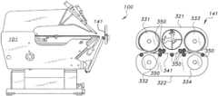
- FIGS. 1 A and 1 Bare perspective views showing a multi-station bending machine having a bidirectional sheet metal cutting tool assembly (also referred to herein as a slitter or slitting assembly) mounted thereon.
- a bidirectional sheet metal cutting tool assemblyalso referred to herein as a slitter or slitting assembly
- FIG. 2is a perspective view showing a multi-station bending machine with a unidirectional cutter assembly (or slitter assembly) mounted thereon.
- FIGS. 3 A, 3 B, 3 C, and 3 Dare perspective views showing details of a bidirectional sheet metal cutting tool.
- FIG. 4is a perspective view showing details of a single cutter head.
- FIG. 5 Ais a top view of a sheet metal slitter having a bidirectional sheet metal cutting tool assembly mounted thereon.
- FIG. 5 Bis a detail view of area 5 B of FIG. 5 A .
- FIG. 5 Cis a front view of the slitter of FIG. 5 A .
- the bidirectional sheet metal cutting toolis a slitter or cutter that is configured with a cutting head that causes the cut work (the workpiece) to deflect in opposite directions on opposite sides of the cutting head, where the work on one side deflects more than the work on the other side. This allows the side of the work that is more easily deflected without causing permanent distortion to deflect more, and allows the deflection on a side of the work that would be damaged or distorted by deflection to be deflected less.
- the deflection on the side of the cutting head facing the sheet metal working toolcan be greater than the deflection on the side of the cutting head facing away from the sheet metal working tool. In that way, the working tool can progressively discharge worked sheet metal past the cutting head, and the major deflection can occur on the side of the cutting head that faces the sheet metal working tool.
- the sheet metal working toolis a sheet metal brake of the type called a “folder”. In a typical arrangement, the sheet metal is progressively discharged from the bender as successive forming operations are performed.
- the sheet metal brakeis given as a non-limiting example.
- the disclosed cuttercan be used with other types of machines that may or may not be able to grip the work.
- the disclosed cuttercan be used for types of webbed material other than sheet metal, with the primary motivation being an ability to deflect the webbed material in a bypass operation as the webbed material passes the cutter.
- a relatively stiff webbing on a rollcan be cut by the disclosed cutter.
- bypass cuttingis described, the disclosed techniques can also be used for pinch cutting, in which opposing elements create a cut in the work.
- the deflection of the work on the side of the cutting head facing the sheet metal working toolappears counter-intuitive because the work would be clamped on that side.
- the reason this is advantageousis that in some cases, which by non-limiting example include sheet metal brakes, the discharged work is formed into non-flat shapes and therefore is not easily deflected without damage.
- the sheet metal on the side of the sheet metal working toolis still flat, i.e., not yet formed into non-flat shapes.
- the sheet metalBy spacing the cutter head away from a clamping position, the sheet metal is able to deflect on the clamped side in a sort of waved pattern. Since the sheet metal is flat on that side, the deflection on that side falls well within the elastic deformation limits of the sheet metal.
- the cutting headis positioned further from the clamping position, thus allowing cutting to take place without the deflection causing plastic deformation of the work.
- This positioningis expected to be necessary if the bends themselves are close to the edge of the final form, so after a cutting operation, it may be necessary to retract the un-formed part of the sheet metal for a subsequent forming operation, such as a subsequent bending operation by the above-described sheet metal brake.
- FIGS. 1 A and 1 Bare perspective views showing a sheet metal folding brake 100 with a cutting wheel assembly mounted.
- the sheet metal folding brakeis given as a non-limiting example, as it is only necessary for the work to be supported in some manner while being cut.
- chassis 101which functions as a frame and has fixed thereto a plurality of stations 111 - 115 . Since the stations 111 - 115 are fixed to the chassis 101 , the stations 111 - 115 are mechanically and functionally part of the chassis 101 .
- a machine controller 130which provides automated machine control functions, for example, by use of a processor and an associated memory.
- the nomenclature of the machine (brake 100 ) and of the workresults in a difference in which direction is described as the “length” and “width”.
- the width of the brake 100is indicated by stations 111 - 115 , whereas the length of the work extends across the same stations 111 - 115 .
- the width of the workis often orthogonal to the width of the machine.
- a brake of this typeis intended to perform bending and folding work on long pieces of metal, for example, 7 meters (21 ft.) long.
- the multiple stations 111 - 115accommodate that length across the width of the brake 100 .
- Cutter assembly (or slitter assembly) 140shown at one end of the brake 100 , is caused to traverse in front of the brake 100 along track 145 , in order to cut a portion of the work after the work is formed by the brake 100 .
- the cutter assembly 140comprises cutter head 141 , which is used to cut sheet metal forming the work.
- the track 145is mounted to the chassis 101 , and the cutter assembly 140 rides on the track 145 to traverse in front of the brake 100 .
- the brake 100forms a width of the work by bending and folding, and then discharges the formed width out the front.
- the formed width of the workextends past cutter head 141 .
- the formed part of the workis positioned past the path of the cutter head, as defined by the path of the cutter assembly 140 along the track 145 .
- the cutter assembly 140is driven along track 145 across the width of the brake 100 by a cutter assembly drive (not separately shown). This allows the brake or other sheet metal forming mechanism to perform work on sequential portions of the sheet material, allowing the sequential portions of the sheet metal material to discharge from the sheet metal forming mechanism.
- cutter head 141In order to cut the work, cutter head 141 must either extend around the work or otherwise move the work out of the way. In the disclosed configuration, cutter head 141 causes the work to deflect, so it is not necessary for the cutter head 141 to extend around the work.
- This deflectioncomprises a major deflection on the side of the work that is substantially flat, and a minor deflection on the side of the work that has been formed.
- the side of the work that is substantially flatis on the side of brake 100
- the major deflectionis 9.525 mm or 3 ⁇ 8 inch
- the minor deflectionis 3.175 mm or 1 ⁇ 8 inch.
- the deflection of the work at the cutter head 141allows the use of a dual cutting wheel configuration in which two sets of opposing wheels are provided on the cutting head 141 .
- the use of two sets of opposing wheels on the cutting headis facilitated by the deflection of the work because the deflection of the work also allows the work to clear a set of cutting wheels not in use during the cut. Since the configuration of FIGS. 1 A and 1 B allows cutting in two directions, the cutter assembly 140 is able to perform sequential cuts in opposite directions, thereby avoiding a need for the cutter assembly 140 to return to a home position on a particular side of the brake 100 .
- cutter 140It is also possible to configure the cutter 140 so that all deflection occurs on one side of the cutter head 141 . However, in the case of a dual cutter head, it would be necessary to either accept engagement with the trailing set of opposing wheels or otherwise configure the cutter head 140 to allow the trailing set of opposing wheels to clear the work. Alternatively, it would be possible to shift the cutter head 141 to reduce or avoid engagement of the cut portion of the work with the trailing set of opposing wheels.
- FIG. 2shows a configuration in which a cutter assembly 240 uses a single cutting configuration for cutting head 241 using a single set of opposing wheels on cutting head 241 .
- This configurationprovides for deflection primarily in one direction of travel of the cutter assembly 240 , so that after each pass, the cutter assembly 240 returns home. This requires a delay resulting from the return operation, during which machine movement is occurring, but makes it easier to configure the deflection of the work on the two sides of the cut. It is anticipated that in some cases, even the small deflection (given in the above example as the minor deflection of 3.175 mm, or 1 ⁇ 8 inch), may be difficult. By using a single set of opposing wheels on the cutting head 241 , the minor deflection can be minimized or perhaps avoided.
- FIGS. 3 A- 3 Dare perspective views showing a non-limiting example of the construction of the cutter head 141 having a dual cutting arrangement. Depicted are upper and lower wheel carriers 321 , 322 and a carrier bracket 327 . Wheel carriers 321 , 322 support upper and lower wheel assemblies 331 , 332 , 333 , 334 , which are configured to rotate from opposite sides of the cutter head 141 according to whether the wheel assemblies are on the upper wheel carrier 321 (wheel assemblies 331 , 333 ) or on the lower wheel carrier 322 (wheel assemblies 332 , 334 ). Wheels assemblies 331 - 334 are configured to cut the work as the work progresses past the first pair of wheel assemblies.
- the lagging wheel assembliesserve primarily as guides. Therefore, the lead pair of wheel assemblies perform the cutting and are sometimes referred to as “slitter wheels”.
- the lagging wheel assembliesare also slitter wheels because cutter assembly 140 performs cutting operations in both directions, but do not perform the cutting when they are lagging.
- Wheel carriers 321 , 322have a curved interface 341 such that, on one side of the cutting head 141 , the curved interface 341 allows the work to deflect down, and on the opposite side of the cutting head 141 , the curved interface 341 allows the work to deflect up. In order to assist this deflection and guide the work without scraping the surface of the work, guide rollers 350 are provided along the interface 341 .
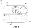
- FIG. 4is a perspective view showing a non-limiting example of the construction of cutter head 241 having a single cutting arrangement. Depicted are upper and lower wheel carriers 421 , 422 and carrier bracket 427 . Wheel carriers 421 , 422 support a single set of upper and lower wheel assemblies 431 , 432 which are configured to rotate from opposite sides of cutter head 241 according to whether the wheel assemblies are on the upper wheel carrier 421 (wheel assembly 431 ) or on the lower wheel carrier 422 (wheel assembly 432 ). Wheels assemblies 431 , 432 are configured to cut the work as the work progresses past the first pair of wheel assemblies. Since cutter assembly 240 uses a single cutting configuration, there are no lagging wheel assemblies.
- FIGS. 5 A- 5 Care views showing a slitter 500 , in which the cutter head or slitter assembly 140 is used on stage platform 511 .
- FIGS. 5 A and 5 Bare a top view and a detail view, respectively, and FIG. 5 C is a front view.
- cutter assembly 140 or 240has a mounting configuration allowing mounting track 145 to the sheet metal tool.
- the platform 511is provided with suction cups 521 , which apply vacuum from a suction source (not shown) in order to hold work, such as sheet metal, in place on the platform 511 .
- the workcan be progressively moved for sequential cuts by movement of the suction cups 521 , by use of a separate gripper, or manually.
- bidirectional cutter head 140While a bidirectional cutter head 140 is shown, it is also possible to use a unidirectional cutter head (e.g., cutter head 240 ). When the bidirectional cutter head 140 is used, sequential cuts can be made without the necessity for the cutting assembly to return “home” to a starting point in order to initiate a subsequent cut.
- a bidirectional cutter head 140When the bidirectional cutter head 140 is used, sequential cuts can be made without the necessity for the cutting assembly to return “home” to a starting point in order to initiate a subsequent cut.
- bidirectional sheet metal cutting toolis not limited to the specific embodiments described above, but encompasses any and all embodiments within the scope of the generic language of the following claims enabled by the embodiments described herein, or otherwise shown in the drawings or described above in terms sufficient to enable one of ordinary skill in the art to make and use the claimed subject matter.
Landscapes
- Engineering & Computer Science (AREA)
- Mechanical Engineering (AREA)
- Life Sciences & Earth Sciences (AREA)
- Forests & Forestry (AREA)
- Bending Of Plates, Rods, And Pipes (AREA)
- Control Of Cutting Processes (AREA)
Abstract
Description
Claims (10)
Applications Claiming Priority (1)
| Application Number | Priority Date | Filing Date | Title |
|---|---|---|---|
| PCT/US2017/068214WO2019125487A1 (en) | 2017-12-22 | 2017-12-22 | Bidirectional sheet metal cutting tool |
Publications (2)
| Publication Number | Publication Date |
|---|---|
| US20210162521A1 US20210162521A1 (en) | 2021-06-03 |
| US12128487B2true US12128487B2 (en) | 2024-10-29 |
Family
ID=66993730
Family Applications (1)
| Application Number | Title | Priority Date | Filing Date |
|---|---|---|---|
| US16/770,588Active2038-08-08US12128487B2 (en) | 2017-12-22 | 2017-12-22 | Bidirectional sheet metal cutting tool |
Country Status (2)
| Country | Link |
|---|---|
| US (1) | US12128487B2 (en) |
| WO (1) | WO2019125487A1 (en) |
Families Citing this family (2)
| Publication number | Priority date | Publication date | Assignee | Title |
|---|---|---|---|---|
| EP3858507A1 (en)* | 2020-01-28 | 2021-08-04 | Sperr & Lechner Splek Maschinenbau GmbH & Co. KG | Folding device for bending a workpiece and method for operating such a folding device |
| DE102020202201B4 (en)* | 2020-01-28 | 2021-09-16 | Sperr & Lechner Splek Maschinenbau GmbH & Co. KG | Folding device for bending a workpiece and a method for operating such a folding device |
Citations (74)
| Publication number | Priority date | Publication date | Assignee | Title |
|---|---|---|---|---|
| US1511892A (en)* | 1923-05-17 | 1924-10-14 | George R Lusby | Shears |
| US1720305A (en)* | 1926-08-05 | 1929-07-09 | J J Burgess | Shears |
| US1745476A (en)* | 1928-02-10 | 1930-02-04 | Cohn Samuel | Means for cutting strips of material |
| US2698661A (en)* | 1950-03-24 | 1955-01-04 | Fred L Macquarrie | Sheet metal slitter |
| US3136191A (en)* | 1961-02-15 | 1964-06-09 | Ford Motor Co | Glass cutting head |
| US3137192A (en)* | 1962-12-21 | 1964-06-16 | Robert M Mcneill | Material cutting device |
| US3277760A (en)* | 1965-01-25 | 1966-10-11 | Grace W R & Co | Apparatus for severing a web |
| US3380158A (en)* | 1966-03-23 | 1968-04-30 | Edward M. Du Bois | Cutting tool |
| US3399586A (en)* | 1966-07-11 | 1968-09-03 | Fletcher Terry Co | Glass cutting head |
| US3742793A (en)* | 1970-07-10 | 1973-07-03 | Pilkington Brothers Ltd | Apparatus for scoring sheet material |
| US3791246A (en)* | 1973-02-26 | 1974-02-12 | Eastman Machine Co | Machine for cutting-sheet-like material such as fabric |
| US3913370A (en)* | 1973-10-05 | 1975-10-21 | Douglas G Break | Supplemental bending attachment for portable sheet material bending brake |
| US3949633A (en)* | 1974-08-19 | 1976-04-13 | Cauffiel Ford B | Slitter line |
| US4001936A (en)* | 1974-11-21 | 1977-01-11 | Kabushiki Kaisha Toa Interia (Toa Interior Co., Ltd.) | Carpet cutter |
| US4245534A (en)* | 1979-08-02 | 1981-01-20 | Van Mark Products Corporation | Slitter for sheet metal or the like |
| US4282735A (en)* | 1979-04-02 | 1981-08-11 | Van Mark Products Corporation | Brake for sheet metal or the like |
| US4283853A (en)* | 1980-03-24 | 1981-08-18 | Fazzini Daniel B | Cutting tool |
| US4381605A (en)* | 1979-11-19 | 1983-05-03 | Folke Holm | Shearing machine having rotatable cutter wheels |
| US4506577A (en)* | 1982-09-16 | 1985-03-26 | Hokkai Can Co., Ltd. | Slitter apparatus |
| US4510785A (en)* | 1981-07-07 | 1985-04-16 | Ets. Y. Jouanel S.A. | Automatic sheet metal folding machine |
| US4589315A (en)* | 1983-12-08 | 1986-05-20 | Clement Kenward J | Wire rope salvaging apparatus |
| US4676133A (en)* | 1984-04-03 | 1987-06-30 | Mitsutoshi Fujimura | Flat-rolled metal product cutting apparatus |
| US4738018A (en) | 1985-11-12 | 1988-04-19 | Ebrahim Ebrahimian | Combined bending and cutting machine for metal sheet and plate |
| US4934234A (en)* | 1987-10-23 | 1990-06-19 | Elio Cavagna | Control unit of the bidirectional traverse of the cutting members in a machine to cut material in sheet |
| CN1045940A (en) | 1989-03-30 | 1990-10-10 | 维美德-阿尔斯特罗姆有限公司 | Plate, band cutting machine |
| US5007318A (en)* | 1989-12-20 | 1991-04-16 | National Steel Corporation | Metal strip edge trimming apparatus |
| US5404739A (en)* | 1993-03-12 | 1995-04-11 | II David L. George | Portable louver-forming tool |
| US5503053A (en)* | 1994-08-18 | 1996-04-02 | Onishilite Industry Co., Ltd. | Sheet material cutting device |
| US5582053A (en)* | 1994-09-22 | 1996-12-10 | Tapco International Corporation | Combined portable sheet bending brake and cutter |
| US5802906A (en)* | 1995-05-11 | 1998-09-08 | Finn-Power Italia Srl | Machine used for folding, profiling and cutting metal sheets |
| US5860312A (en) | 1995-11-29 | 1999-01-19 | Anderson; Carl E. | Bending brake apparatus |
| US5899000A (en)* | 1996-10-30 | 1999-05-04 | Break; Douglas G. | Hand held cutter |
| US5904085A (en)* | 1996-01-24 | 1999-05-18 | Onishilite Industry Co., Ltd. | Sheet material cutting apparatus |
| US5927135A (en)* | 1996-09-28 | 1999-07-27 | Reinhardt Maschinenbau Gmbh | Bending machine |
| US5937723A (en)* | 1996-05-31 | 1999-08-17 | Nec Corporation | Mechanism for cutting a sheet |
| US6000268A (en)* | 1998-12-02 | 1999-12-14 | Van Mark Products Corporation | Multifunction machine for modifying material in a bending brake |
| US6155152A (en)* | 1997-08-11 | 2000-12-05 | Wilheim Bilstein KG Spezialfabrik fur Rundmesser und Plattenventile | Knife holder for a wrapper cutter with a hand guard |
| US20020022562A1 (en)* | 2000-08-08 | 2002-02-21 | Bhs Corrugated Maschinen-Und Anlagenbau Gmbh | Machine for the lengthwise treatment of webs of corrugated board |
| US6408527B1 (en)* | 1998-08-11 | 2002-06-25 | Tapco International Corporation | Scoring tool |
| US6427511B1 (en)* | 1999-01-19 | 2002-08-06 | Reinhardt Maschinenbau Gmbh | Bending machine |
| US20020152866A1 (en)* | 2000-09-02 | 2002-10-24 | Willi Bilstein | Blade holder with schock absorber for a device for longitudinally cutting a material strip |
| US6516648B1 (en)* | 1999-01-19 | 2003-02-11 | Reinhardt Maschinenbau Gmbh | Bending machine for flat material |
| DE20306757U1 (en) | 2002-05-08 | 2003-08-07 | Krasser, Franz, Schwanberg | Machine shearing sheet metal or plastic using pairs of roller-cutters, includes adjustment unit and controller locating cutters in working or resting positions |
| US20030150305A1 (en)* | 2001-12-12 | 2003-08-14 | Terry Fisher | New portable vinyl siding and aluminum cutting tool |
| US20030233756A1 (en)* | 2002-06-22 | 2003-12-25 | Moritz Muhlebach | Device for edge cutting of strips of material |
| US6721060B1 (en)* | 1996-05-01 | 2004-04-13 | Canon Finetech Inc. | Recording medium cutter image forming device using same |
| US20040103706A1 (en)* | 2002-10-11 | 2004-06-03 | Antonio Codatto | Method and device for bending elements, such as panels, metal sheet, plates or suchlike |
| US6748783B1 (en)* | 2002-10-30 | 2004-06-15 | J-Dan | Bend/cut-off gauge for a portable sheet bending brake |
| US6763695B1 (en)* | 2002-10-30 | 2004-07-20 | J-Dan, Inc. | Sheet material cutter and cut-off gauge for use in combination with a sheet bending brake |
| US20050061121A1 (en)* | 2003-09-23 | 2005-03-24 | David Lauderbaugh | Bushings with sacrificial end caps and shims for axially positioning rotating slotting and scoring wheels |
| US20050086991A1 (en)* | 2003-10-28 | 2005-04-28 | Barnett O. L. | Front gauge for a sheet bending brake |
| US7028596B1 (en)* | 1994-01-13 | 2006-04-18 | Elpatronic Ag | Rotary cutting unit |
| US7089669B2 (en)* | 2004-06-02 | 2006-08-15 | Fritz Alvin R | Sheet material cutter with adjustable blades |
| US20060185487A1 (en)* | 2005-02-22 | 2006-08-24 | Li Chou C | Automatic card cutter |
| US7117705B2 (en)* | 2003-11-21 | 2006-10-10 | Tapco International Corporation | Adjustable cutoff |
| US7134372B2 (en)* | 2001-11-08 | 2006-11-14 | Blue Ip, Inc. | CNC slitter machine |
| US20070056419A1 (en)* | 2005-09-09 | 2007-03-15 | Tippmann Dennis J Sr | Apparatus for working pliable material |
| US20070062355A1 (en)* | 2005-09-21 | 2007-03-22 | Dienes Werke Fur Maschinenteile Gmbh & Co. Kg | Longitudinal cutting machine with combined upper blade and lower blade positioning |
| US20080181711A1 (en)* | 2007-01-26 | 2008-07-31 | Hewlett-Packard Development Company, L.P. | Cutter assembly for a printer |
| US20080196471A1 (en) | 2004-06-02 | 2008-08-21 | Nanoferenz Gmbh | Method and Device for Cutting High-Tensile Sheet Metal, and Press |
| US20100147046A1 (en)* | 2004-10-29 | 2010-06-17 | Tapco International Corporation | Sheet metal bending brake |
| US7975582B1 (en)* | 2008-10-13 | 2011-07-12 | Norman Coon | Strip cutting device and methods of use |
| US8079244B2 (en)* | 2006-03-08 | 2011-12-20 | Pro Form S.R.L. | Device and method for bending a metallic strip |
| US8500350B2 (en)* | 2008-03-11 | 2013-08-06 | Seiko Epson Corporation | Cutter device and recording apparatus |
| US20140069247A1 (en)* | 2012-09-12 | 2014-03-13 | Chuan-Sheng Lin | Sheet material cutter |
| KR20150060160A (en) | 2013-11-26 | 2015-06-03 | 주식회사 엘지화학 | Slitter for Metal Sheet Slitting |
| US20150151346A1 (en)* | 2013-12-03 | 2015-06-04 | Ideal Products of Canada | Automated cut and roll machine brake assembly |
| US20150231680A1 (en)* | 2013-11-07 | 2015-08-20 | Illinois Tool Works Inc. | Large scale metal forming control system and method |
| US20160067988A1 (en)* | 2014-09-09 | 2016-03-10 | Canon Kabushiki Kaisha | Cutting apparatus and printing apparatus |
| US20160075042A1 (en)* | 2013-04-26 | 2016-03-17 | Sang-Keun Oh | Safety cutter for jam prevention |
| US20180154535A1 (en)* | 2016-12-01 | 2018-06-07 | Seiko Epson Corporation | Cutting device and printing apparatus |
| US20180282104A1 (en)* | 2017-03-29 | 2018-10-04 | Seiko Epson Corporation | Cutting mechanism |
| US10272583B2 (en)* | 2016-09-21 | 2019-04-30 | Duplo Seiko Corporation | Slitter, sheet cutting device, and sheet processing apparatus |
| US20210229154A1 (en)* | 2020-01-28 | 2021-07-29 | Sperr & Lechner Splek Maschinenbau GmbH & Co. KG | Bending device for bending a workpiece as well as method for operating such a bending device |
Family Cites Families (1)
| Publication number | Priority date | Publication date | Assignee | Title |
|---|---|---|---|---|
| US9767473B2 (en)* | 2007-02-09 | 2017-09-19 | International Business Machines Corporation | Method and apparatus for economic exploitation of waiting time of customers at call centers, contact centers or into interactive voice response (IVR) systems |
- 2017
- 2017-12-22USUS16/770,588patent/US12128487B2/enactiveActive
- 2017-12-22WOPCT/US2017/068214patent/WO2019125487A1/ennot_activeCeased
Patent Citations (75)
| Publication number | Priority date | Publication date | Assignee | Title |
|---|---|---|---|---|
| US1511892A (en)* | 1923-05-17 | 1924-10-14 | George R Lusby | Shears |
| US1720305A (en)* | 1926-08-05 | 1929-07-09 | J J Burgess | Shears |
| US1745476A (en)* | 1928-02-10 | 1930-02-04 | Cohn Samuel | Means for cutting strips of material |
| US2698661A (en)* | 1950-03-24 | 1955-01-04 | Fred L Macquarrie | Sheet metal slitter |
| US3136191A (en)* | 1961-02-15 | 1964-06-09 | Ford Motor Co | Glass cutting head |
| US3137192A (en)* | 1962-12-21 | 1964-06-16 | Robert M Mcneill | Material cutting device |
| US3277760A (en)* | 1965-01-25 | 1966-10-11 | Grace W R & Co | Apparatus for severing a web |
| US3380158A (en)* | 1966-03-23 | 1968-04-30 | Edward M. Du Bois | Cutting tool |
| US3399586A (en)* | 1966-07-11 | 1968-09-03 | Fletcher Terry Co | Glass cutting head |
| US3742793A (en)* | 1970-07-10 | 1973-07-03 | Pilkington Brothers Ltd | Apparatus for scoring sheet material |
| US3791246A (en)* | 1973-02-26 | 1974-02-12 | Eastman Machine Co | Machine for cutting-sheet-like material such as fabric |
| US3913370A (en)* | 1973-10-05 | 1975-10-21 | Douglas G Break | Supplemental bending attachment for portable sheet material bending brake |
| US3949633A (en)* | 1974-08-19 | 1976-04-13 | Cauffiel Ford B | Slitter line |
| US4001936A (en)* | 1974-11-21 | 1977-01-11 | Kabushiki Kaisha Toa Interia (Toa Interior Co., Ltd.) | Carpet cutter |
| US4282735A (en)* | 1979-04-02 | 1981-08-11 | Van Mark Products Corporation | Brake for sheet metal or the like |
| US4245534A (en)* | 1979-08-02 | 1981-01-20 | Van Mark Products Corporation | Slitter for sheet metal or the like |
| US4381605A (en)* | 1979-11-19 | 1983-05-03 | Folke Holm | Shearing machine having rotatable cutter wheels |
| US4283853A (en)* | 1980-03-24 | 1981-08-18 | Fazzini Daniel B | Cutting tool |
| US4510785A (en)* | 1981-07-07 | 1985-04-16 | Ets. Y. Jouanel S.A. | Automatic sheet metal folding machine |
| US4506577A (en)* | 1982-09-16 | 1985-03-26 | Hokkai Can Co., Ltd. | Slitter apparatus |
| US4589315A (en)* | 1983-12-08 | 1986-05-20 | Clement Kenward J | Wire rope salvaging apparatus |
| US4676133A (en)* | 1984-04-03 | 1987-06-30 | Mitsutoshi Fujimura | Flat-rolled metal product cutting apparatus |
| US4738018A (en) | 1985-11-12 | 1988-04-19 | Ebrahim Ebrahimian | Combined bending and cutting machine for metal sheet and plate |
| US4934234A (en)* | 1987-10-23 | 1990-06-19 | Elio Cavagna | Control unit of the bidirectional traverse of the cutting members in a machine to cut material in sheet |
| CN1045940A (en) | 1989-03-30 | 1990-10-10 | 维美德-阿尔斯特罗姆有限公司 | Plate, band cutting machine |
| US5007318A (en)* | 1989-12-20 | 1991-04-16 | National Steel Corporation | Metal strip edge trimming apparatus |
| US5404739A (en)* | 1993-03-12 | 1995-04-11 | II David L. George | Portable louver-forming tool |
| US7028596B1 (en)* | 1994-01-13 | 2006-04-18 | Elpatronic Ag | Rotary cutting unit |
| US5503053A (en)* | 1994-08-18 | 1996-04-02 | Onishilite Industry Co., Ltd. | Sheet material cutting device |
| US5582053A (en)* | 1994-09-22 | 1996-12-10 | Tapco International Corporation | Combined portable sheet bending brake and cutter |
| US5802906A (en)* | 1995-05-11 | 1998-09-08 | Finn-Power Italia Srl | Machine used for folding, profiling and cutting metal sheets |
| US5860312A (en) | 1995-11-29 | 1999-01-19 | Anderson; Carl E. | Bending brake apparatus |
| US5904085A (en)* | 1996-01-24 | 1999-05-18 | Onishilite Industry Co., Ltd. | Sheet material cutting apparatus |
| US6721060B1 (en)* | 1996-05-01 | 2004-04-13 | Canon Finetech Inc. | Recording medium cutter image forming device using same |
| US5937723A (en)* | 1996-05-31 | 1999-08-17 | Nec Corporation | Mechanism for cutting a sheet |
| US5927135A (en)* | 1996-09-28 | 1999-07-27 | Reinhardt Maschinenbau Gmbh | Bending machine |
| US5899000A (en)* | 1996-10-30 | 1999-05-04 | Break; Douglas G. | Hand held cutter |
| US6155152A (en)* | 1997-08-11 | 2000-12-05 | Wilheim Bilstein KG Spezialfabrik fur Rundmesser und Plattenventile | Knife holder for a wrapper cutter with a hand guard |
| US6408527B1 (en)* | 1998-08-11 | 2002-06-25 | Tapco International Corporation | Scoring tool |
| US6000268A (en)* | 1998-12-02 | 1999-12-14 | Van Mark Products Corporation | Multifunction machine for modifying material in a bending brake |
| US6516648B1 (en)* | 1999-01-19 | 2003-02-11 | Reinhardt Maschinenbau Gmbh | Bending machine for flat material |
| US6427511B1 (en)* | 1999-01-19 | 2002-08-06 | Reinhardt Maschinenbau Gmbh | Bending machine |
| US20020022562A1 (en)* | 2000-08-08 | 2002-02-21 | Bhs Corrugated Maschinen-Und Anlagenbau Gmbh | Machine for the lengthwise treatment of webs of corrugated board |
| US20020152866A1 (en)* | 2000-09-02 | 2002-10-24 | Willi Bilstein | Blade holder with schock absorber for a device for longitudinally cutting a material strip |
| US7134372B2 (en)* | 2001-11-08 | 2006-11-14 | Blue Ip, Inc. | CNC slitter machine |
| US20030150305A1 (en)* | 2001-12-12 | 2003-08-14 | Terry Fisher | New portable vinyl siding and aluminum cutting tool |
| DE20306757U1 (en) | 2002-05-08 | 2003-08-07 | Krasser, Franz, Schwanberg | Machine shearing sheet metal or plastic using pairs of roller-cutters, includes adjustment unit and controller locating cutters in working or resting positions |
| US20030233756A1 (en)* | 2002-06-22 | 2003-12-25 | Moritz Muhlebach | Device for edge cutting of strips of material |
| US20040103706A1 (en)* | 2002-10-11 | 2004-06-03 | Antonio Codatto | Method and device for bending elements, such as panels, metal sheet, plates or suchlike |
| US6763695B1 (en)* | 2002-10-30 | 2004-07-20 | J-Dan, Inc. | Sheet material cutter and cut-off gauge for use in combination with a sheet bending brake |
| US6748783B1 (en)* | 2002-10-30 | 2004-06-15 | J-Dan | Bend/cut-off gauge for a portable sheet bending brake |
| US20050061121A1 (en)* | 2003-09-23 | 2005-03-24 | David Lauderbaugh | Bushings with sacrificial end caps and shims for axially positioning rotating slotting and scoring wheels |
| US7021096B2 (en)* | 2003-10-28 | 2006-04-04 | Barnett O Lynn | Front gauge for a sheet bending brake |
| US20050086991A1 (en)* | 2003-10-28 | 2005-04-28 | Barnett O. L. | Front gauge for a sheet bending brake |
| US7117705B2 (en)* | 2003-11-21 | 2006-10-10 | Tapco International Corporation | Adjustable cutoff |
| US7089669B2 (en)* | 2004-06-02 | 2006-08-15 | Fritz Alvin R | Sheet material cutter with adjustable blades |
| US20080196471A1 (en) | 2004-06-02 | 2008-08-21 | Nanoferenz Gmbh | Method and Device for Cutting High-Tensile Sheet Metal, and Press |
| US20100147046A1 (en)* | 2004-10-29 | 2010-06-17 | Tapco International Corporation | Sheet metal bending brake |
| US20060185487A1 (en)* | 2005-02-22 | 2006-08-24 | Li Chou C | Automatic card cutter |
| US20070056419A1 (en)* | 2005-09-09 | 2007-03-15 | Tippmann Dennis J Sr | Apparatus for working pliable material |
| US20070062355A1 (en)* | 2005-09-21 | 2007-03-22 | Dienes Werke Fur Maschinenteile Gmbh & Co. Kg | Longitudinal cutting machine with combined upper blade and lower blade positioning |
| US8079244B2 (en)* | 2006-03-08 | 2011-12-20 | Pro Form S.R.L. | Device and method for bending a metallic strip |
| US20080181711A1 (en)* | 2007-01-26 | 2008-07-31 | Hewlett-Packard Development Company, L.P. | Cutter assembly for a printer |
| US8500350B2 (en)* | 2008-03-11 | 2013-08-06 | Seiko Epson Corporation | Cutter device and recording apparatus |
| US7975582B1 (en)* | 2008-10-13 | 2011-07-12 | Norman Coon | Strip cutting device and methods of use |
| US20140069247A1 (en)* | 2012-09-12 | 2014-03-13 | Chuan-Sheng Lin | Sheet material cutter |
| US20160075042A1 (en)* | 2013-04-26 | 2016-03-17 | Sang-Keun Oh | Safety cutter for jam prevention |
| US20150231680A1 (en)* | 2013-11-07 | 2015-08-20 | Illinois Tool Works Inc. | Large scale metal forming control system and method |
| KR20150060160A (en) | 2013-11-26 | 2015-06-03 | 주식회사 엘지화학 | Slitter for Metal Sheet Slitting |
| US20150151346A1 (en)* | 2013-12-03 | 2015-06-04 | Ideal Products of Canada | Automated cut and roll machine brake assembly |
| US20160067988A1 (en)* | 2014-09-09 | 2016-03-10 | Canon Kabushiki Kaisha | Cutting apparatus and printing apparatus |
| US10272583B2 (en)* | 2016-09-21 | 2019-04-30 | Duplo Seiko Corporation | Slitter, sheet cutting device, and sheet processing apparatus |
| US20180154535A1 (en)* | 2016-12-01 | 2018-06-07 | Seiko Epson Corporation | Cutting device and printing apparatus |
| US20180282104A1 (en)* | 2017-03-29 | 2018-10-04 | Seiko Epson Corporation | Cutting mechanism |
| US20210229154A1 (en)* | 2020-01-28 | 2021-07-29 | Sperr & Lechner Splek Maschinenbau GmbH & Co. KG | Bending device for bending a workpiece as well as method for operating such a bending device |
Non-Patent Citations (1)
| Title |
|---|
| "Mark II TrimMaster", Van Mark Products Corporation (2016), published at www.van-mark.com/brakes/mark-II-trimmaster-contractor-grade.shtml. |
Also Published As
| Publication number | Publication date |
|---|---|
| US20210162521A1 (en) | 2021-06-03 |
| WO2019125487A1 (en) | 2019-06-27 |
Similar Documents
| Publication | Publication Date | Title |
|---|---|---|
| JP5882464B2 (en) | Car seat punching method and car seat punching system | |
| US7659490B2 (en) | Systems for processing plate-like workpieces | |
| EP3647004B1 (en) | Cutting machine to cut panels made of wood or the like | |
| EP2366480B1 (en) | An apparatus for machining door or window frames | |
| US12128487B2 (en) | Bidirectional sheet metal cutting tool | |
| US11279056B2 (en) | Device for carrying out cutting operations on open format edges of a printed product | |
| EP1477447A1 (en) | Folding roller and folding method for paper converting machines | |
| US8225636B2 (en) | Apparatus for forming a duct | |
| JP6759353B2 (en) | Discharger members and machines for processing sheet morphological elements | |
| CA2226826C (en) | Device for turning the front panel of a plate-like workpiece within a folder-gluer | |
| EP3639957B1 (en) | Cutting machine to cut panels made of wood or the like | |
| EP3639958B1 (en) | Cutting machine to cut panels made of wood or the like | |
| US10857581B2 (en) | Machine for bending metal including an adjustable backgauge | |
| US11850650B2 (en) | Tool and method for processing plate-shaped workpieces, in particular metal sheets | |
| CN119403749A (en) | Suction rod systems for converting machines | |
| US12319532B2 (en) | Sheet processing machine | |
| US12391505B2 (en) | Sheet processing machine | |
| EP1738883A2 (en) | Cardboard working machine | |
| KR101862828B1 (en) | Apparatus and method for connecting coil | |
| US20240091970A1 (en) | Sheet processing machine | |
| CN118383611B (en) | Totally-enclosed goods shelf laminate and production equipment thereof | |
| CN115702050A (en) | Apparatus and method for processing elongated metal products | |
| EP3587057B1 (en) | Improved cutting device and method for the separation of bags for flexible packaging made from laminated films | |
| WO2024161360A1 (en) | Machine for producing stacks of laminar products made of paper material and related method of production | |
| KR20220152395A (en) | bending machine |
Legal Events
| Date | Code | Title | Description |
|---|---|---|---|
| FEPP | Fee payment procedure | Free format text:ENTITY STATUS SET TO UNDISCOUNTED (ORIGINAL EVENT CODE: BIG.); ENTITY STATUS OF PATENT OWNER: SMALL ENTITY | |
| FEPP | Fee payment procedure | Free format text:ENTITY STATUS SET TO SMALL (ORIGINAL EVENT CODE: SMAL); ENTITY STATUS OF PATENT OWNER: SMALL ENTITY | |
| STPP | Information on status: patent application and granting procedure in general | Free format text:NON FINAL ACTION MAILED | |
| STPP | Information on status: patent application and granting procedure in general | Free format text:RESPONSE TO NON-FINAL OFFICE ACTION ENTERED AND FORWARDED TO EXAMINER | |
| STPP | Information on status: patent application and granting procedure in general | Free format text:NON FINAL ACTION MAILED | |
| STPP | Information on status: patent application and granting procedure in general | Free format text:FINAL REJECTION MAILED | |
| STPP | Information on status: patent application and granting procedure in general | Free format text:DOCKETED NEW CASE - READY FOR EXAMINATION | |
| STPP | Information on status: patent application and granting procedure in general | Free format text:NON FINAL ACTION MAILED | |
| STPP | Information on status: patent application and granting procedure in general | Free format text:RESPONSE TO NON-FINAL OFFICE ACTION ENTERED AND FORWARDED TO EXAMINER | |
| STPP | Information on status: patent application and granting procedure in general | Free format text:NOTICE OF ALLOWANCE MAILED -- APPLICATION RECEIVED IN OFFICE OF PUBLICATIONS | |
| ZAAB | Notice of allowance mailed | Free format text:ORIGINAL CODE: MN/=. | |
| STPP | Information on status: patent application and granting procedure in general | Free format text:PUBLICATIONS -- ISSUE FEE PAYMENT VERIFIED | |
| STCF | Information on status: patent grant | Free format text:PATENTED CASE |