US12128199B2 - Hybrid transseptal dilator and methods of using the same - Google Patents
Hybrid transseptal dilator and methods of using the sameDownload PDFInfo
- Publication number
- US12128199B2 US12128199B2US17/813,945US202217813945AUS12128199B2US 12128199 B2US12128199 B2US 12128199B2US 202217813945 AUS202217813945 AUS 202217813945AUS 12128199 B2US12128199 B2US 12128199B2
- Authority
- US
- United States
- Prior art keywords
- dilator
- hybrid
- crossing device
- distal tip
- distal
- Prior art date
- Legal status (The legal status is an assumption and is not a legal conclusion. Google has not performed a legal analysis and makes no representation as to the accuracy of the status listed.)
- Active
Links
Images


Classifications
- A—HUMAN NECESSITIES
- A61—MEDICAL OR VETERINARY SCIENCE; HYGIENE
- A61M—DEVICES FOR INTRODUCING MEDIA INTO, OR ONTO, THE BODY; DEVICES FOR TRANSDUCING BODY MEDIA OR FOR TAKING MEDIA FROM THE BODY; DEVICES FOR PRODUCING OR ENDING SLEEP OR STUPOR
- A61M29/00—Dilators with or without means for introducing media, e.g. remedies
- A—HUMAN NECESSITIES
- A61—MEDICAL OR VETERINARY SCIENCE; HYGIENE
- A61B—DIAGNOSIS; SURGERY; IDENTIFICATION
- A61B17/00—Surgical instruments, devices or methods
- A61B17/34—Trocars; Puncturing needles
- A61B17/3415—Trocars; Puncturing needles for introducing tubes or catheters, e.g. gastrostomy tubes, drain catheters
- A—HUMAN NECESSITIES
- A61—MEDICAL OR VETERINARY SCIENCE; HYGIENE
- A61B—DIAGNOSIS; SURGERY; IDENTIFICATION
- A61B17/00—Surgical instruments, devices or methods
- A61B17/34—Trocars; Puncturing needles
- A61B17/3478—Endoscopic needles, e.g. for infusion
- A—HUMAN NECESSITIES
- A61—MEDICAL OR VETERINARY SCIENCE; HYGIENE
- A61B—DIAGNOSIS; SURGERY; IDENTIFICATION
- A61B18/00—Surgical instruments, devices or methods for transferring non-mechanical forms of energy to or from the body
- A61B18/04—Surgical instruments, devices or methods for transferring non-mechanical forms of energy to or from the body by heating
- A61B18/12—Surgical instruments, devices or methods for transferring non-mechanical forms of energy to or from the body by heating by passing a current through the tissue to be heated, e.g. high-frequency current
- A61B18/14—Probes or electrodes therefor
- A61B18/1477—Needle-like probes
- A—HUMAN NECESSITIES
- A61—MEDICAL OR VETERINARY SCIENCE; HYGIENE
- A61M—DEVICES FOR INTRODUCING MEDIA INTO, OR ONTO, THE BODY; DEVICES FOR TRANSDUCING BODY MEDIA OR FOR TAKING MEDIA FROM THE BODY; DEVICES FOR PRODUCING OR ENDING SLEEP OR STUPOR
- A61M25/00—Catheters; Hollow probes
- A61M25/01—Introducing, guiding, advancing, emplacing or holding catheters
- A61M25/06—Body-piercing guide needles or the like
- A—HUMAN NECESSITIES
- A61—MEDICAL OR VETERINARY SCIENCE; HYGIENE
- A61M—DEVICES FOR INTRODUCING MEDIA INTO, OR ONTO, THE BODY; DEVICES FOR TRANSDUCING BODY MEDIA OR FOR TAKING MEDIA FROM THE BODY; DEVICES FOR PRODUCING OR ENDING SLEEP OR STUPOR
- A61M25/00—Catheters; Hollow probes
- A61M25/01—Introducing, guiding, advancing, emplacing or holding catheters
- A61M25/09—Guide wires
- A—HUMAN NECESSITIES
- A61—MEDICAL OR VETERINARY SCIENCE; HYGIENE
- A61B—DIAGNOSIS; SURGERY; IDENTIFICATION
- A61B17/00—Surgical instruments, devices or methods
- A61B17/00234—Surgical instruments, devices or methods for minimally invasive surgery
- A61B2017/00238—Type of minimally invasive operation
- A61B2017/00243—Type of minimally invasive operation cardiac
- A61B2017/00247—Making holes in the wall of the heart, e.g. laser Myocardial revascularization
- A—HUMAN NECESSITIES
- A61—MEDICAL OR VETERINARY SCIENCE; HYGIENE
- A61B—DIAGNOSIS; SURGERY; IDENTIFICATION
- A61B17/00—Surgical instruments, devices or methods
- A61B17/22—Implements for squeezing-off ulcers or the like on inner organs of the body; Implements for scraping-out cavities of body organs, e.g. bones; for invasive removal or destruction of calculus using mechanical vibrations; for removing obstructions in blood vessels, not otherwise provided for
- A61B2017/22038—Implements for squeezing-off ulcers or the like on inner organs of the body; Implements for scraping-out cavities of body organs, e.g. bones; for invasive removal or destruction of calculus using mechanical vibrations; for removing obstructions in blood vessels, not otherwise provided for with a guide wire
- A61B2017/22042—Details of the tip of the guide wire
- A—HUMAN NECESSITIES
- A61—MEDICAL OR VETERINARY SCIENCE; HYGIENE
- A61B—DIAGNOSIS; SURGERY; IDENTIFICATION
- A61B17/00—Surgical instruments, devices or methods
- A61B17/22—Implements for squeezing-off ulcers or the like on inner organs of the body; Implements for scraping-out cavities of body organs, e.g. bones; for invasive removal or destruction of calculus using mechanical vibrations; for removing obstructions in blood vessels, not otherwise provided for
- A61B2017/22038—Implements for squeezing-off ulcers or the like on inner organs of the body; Implements for scraping-out cavities of body organs, e.g. bones; for invasive removal or destruction of calculus using mechanical vibrations; for removing obstructions in blood vessels, not otherwise provided for with a guide wire
- A61B2017/22047—Means for immobilising the guide wire in the patient
- A—HUMAN NECESSITIES
- A61—MEDICAL OR VETERINARY SCIENCE; HYGIENE
- A61B—DIAGNOSIS; SURGERY; IDENTIFICATION
- A61B18/00—Surgical instruments, devices or methods for transferring non-mechanical forms of energy to or from the body
- A61B2018/00315—Surgical instruments, devices or methods for transferring non-mechanical forms of energy to or from the body for treatment of particular body parts
- A61B2018/00345—Vascular system
- A61B2018/00351—Heart
- A—HUMAN NECESSITIES
- A61—MEDICAL OR VETERINARY SCIENCE; HYGIENE
- A61B—DIAGNOSIS; SURGERY; IDENTIFICATION
- A61B18/00—Surgical instruments, devices or methods for transferring non-mechanical forms of energy to or from the body
- A61B18/04—Surgical instruments, devices or methods for transferring non-mechanical forms of energy to or from the body by heating
- A61B18/12—Surgical instruments, devices or methods for transferring non-mechanical forms of energy to or from the body by heating by passing a current through the tissue to be heated, e.g. high-frequency current
- A61B18/14—Probes or electrodes therefor
- A61B2018/1405—Electrodes having a specific shape
- A61B2018/1425—Needle
- A—HUMAN NECESSITIES
- A61—MEDICAL OR VETERINARY SCIENCE; HYGIENE
- A61B—DIAGNOSIS; SURGERY; IDENTIFICATION
- A61B90/00—Instruments, implements or accessories specially adapted for surgery or diagnosis and not covered by any of the groups A61B1/00 - A61B50/00, e.g. for luxation treatment or for protecting wound edges
- A61B90/03—Automatic limiting or abutting means, e.g. for safety
- A61B2090/033—Abutting means, stops, e.g. abutting on tissue or skin
- A—HUMAN NECESSITIES
- A61—MEDICAL OR VETERINARY SCIENCE; HYGIENE
- A61B—DIAGNOSIS; SURGERY; IDENTIFICATION
- A61B90/00—Instruments, implements or accessories specially adapted for surgery or diagnosis and not covered by any of the groups A61B1/00 - A61B50/00, e.g. for luxation treatment or for protecting wound edges
- A61B90/06—Measuring instruments not otherwise provided for
- A61B2090/062—Measuring instruments not otherwise provided for penetration depth
- A—HUMAN NECESSITIES
- A61—MEDICAL OR VETERINARY SCIENCE; HYGIENE
- A61B—DIAGNOSIS; SURGERY; IDENTIFICATION
- A61B90/00—Instruments, implements or accessories specially adapted for surgery or diagnosis and not covered by any of the groups A61B1/00 - A61B50/00, e.g. for luxation treatment or for protecting wound edges
- A61B90/08—Accessories or related features not otherwise provided for
- A61B2090/0807—Indication means
- A—HUMAN NECESSITIES
- A61—MEDICAL OR VETERINARY SCIENCE; HYGIENE
- A61M—DEVICES FOR INTRODUCING MEDIA INTO, OR ONTO, THE BODY; DEVICES FOR TRANSDUCING BODY MEDIA OR FOR TAKING MEDIA FROM THE BODY; DEVICES FOR PRODUCING OR ENDING SLEEP OR STUPOR
- A61M2205/00—General characteristics of the apparatus
- A61M2205/32—General characteristics of the apparatus with radio-opaque indicia
- A—HUMAN NECESSITIES
- A61—MEDICAL OR VETERINARY SCIENCE; HYGIENE
- A61M—DEVICES FOR INTRODUCING MEDIA INTO, OR ONTO, THE BODY; DEVICES FOR TRANSDUCING BODY MEDIA OR FOR TAKING MEDIA FROM THE BODY; DEVICES FOR PRODUCING OR ENDING SLEEP OR STUPOR
- A61M2205/00—General characteristics of the apparatus
- A61M2205/58—Means for facilitating use, e.g. by people with impaired vision
- A61M2205/582—Means for facilitating use, e.g. by people with impaired vision by tactile feedback
Definitions
- the present disclosurerelates to a medical device for using in accessing the cardiovascular system. More particularly the present disclosure relates to a hybrid transseptal dilator for facilitating a transseptal procedure for providing left heart access
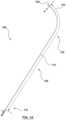
- FIG. 1 Ais an illustration of a hybrid dilator, in accordance with an embodiment of the present invention.
- FIG. 1 Bis an illustration of a proximal portion of the hybrid dilator of FIG. 1 A ;
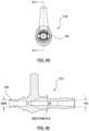
- FIG. 1 Cis a front end view of a distal tip of the hybrid dilator of FIG. 1 A ;
- FIG. 1 Dis an illustration of a proximal portion of the hybrid dilator of FIG. 1 A ;
- FIG. 2 Ais a cross-sectional view of the distal tip of a hybrid dilator taken along the lines 2 A- 2 A of FIG. 1 C ;
- FIG. 2 Bis a cross-sectional view of the distal most end of a hybrid dilator taken along the lines 2 B- 2 B of FIG. 1 C ;
- FIG. 2 Cis an illustration of a distal tip, in accordance with an alternative embodiment of the present invention.
- FIGS. 3 A- 3 Dillustrate alternate embodiments of a distal tip, in accordance with alternate embodiments of the present invention
- FIG. 4 Aillustrates a hybrid dilator in accordance with an embodiment of the present invention, and a standard sheath/dilator assembly usable in a standard transseptal procedure;
- FIGS. 4 B- 4 Gillustrate a proximal portion of the hybrid dilator in accordance with an embodiment of the present invention
- FIGS. 5 A- 5 Cillustrates a proximal portion of a hybrid dilator, in accordance with an alternate embodiment of the present invention
- FIG. 5 Dillustrates a hybrid dilator, in accordance with an alternate embodiment of the present invention
- FIG. 5 Eillustrates an alternative embodiment of a proximal hub, in accordance with an embodiment of the present invention
- FIG. 6 Ais an illustration of a method of using a sheath and dilator, in accordance with a standard trans septal procedure
- FIG. 6 Bis a flowchart illustrating steps in a standard transseptal procedure
- FIG. 7 Ais an illustration of a method for performing a transseptal puncture procedure using a hybrid dilator, in accordance with an embodiment of the present invention
- FIG. 7 Bis a flowchart illustrating steps of a method for performing a transseptal puncture procedure using a hybrid dilator, in accordance with an embodiment of the present invention
- FIG. 8is a cross sectional view of the shaft and distal tip of a hybrid dilator of an alternative embodiment of the present invention.
- FIG. 9is an enlarged view of the distal tip of FIG. 8 .
- a physicianWhen performing a transseptal procedure to gain access to the left atrium of a heart, a physician typically uses a sheath and dilator to support a crossing or puncturing device. In some cases, a physician may not be able to cross through to the left atrium sheath as the transition between sheath and dilator may get stuck or snag at the tissue boundary, and as a result the sheath may not be able to cross through the perforation (or it crosses with difficulty). In other words, the tissue may get hung up at the sheath/dilator interface. Thus, the use of multiple device in a transseptal procedure may make it difficult for the operator to complete the procedure due to the material transitions between various devices which may get caught at the septal tissue interface.
- the problem of a transseptal puncture being performed using a crossing device which is supported by a sheath and dilator set having a transition which may snag on tissue when crossing the septum,can be addressed by using a hybrid dilator (described herein) instead of the sheath and dilator set to thereby eliminate the transition, wherein the hybrid dilator has the appropriate functionality (flexibility, pushability, torqueability, distal taper, etc.) to facilitate a smooth crossing.
- embodiments of the present inventioninclude a hybrid dilator for use with a crossing device in tissue puncturing procedures, the hybrid dilator comprising: a dilator shaft defining a lumen for receiving a crossing device therethrough, the dilator shaft being structured to provide support for the crossing device when the crossing device is used to create a puncture in a tissue; and a distal tip having an outer diameter which tapers down to an outer diameter of the crossing device for providing a smooth transition between the crossing device and the distal tip when the crossing device is inserted through the lumen and protrudes beyond the distal tip.
- the dilator shaftcomprises an inner layer, an outer layer, and a torque layer therebetween.
- embodiments of the present inventioninclude a kit for puncturing a tissue, the kit comprising: a crossing device having a puncturing feature; and a hybrid dilator, wherein the dilator has a dilator shaft defining a lumen for receiving the crossing device therethrough, the dilator shaft being structured to provide support for the crossing device when the crossing device is used to create a puncture in a tissue.
- the hybrid dilatoralso includes a distal tip which has an outer diameter which substantially tapers down to an outer diameter of the crossing device for cooperatively providing a smooth profile when the hybrid dilator is advanced through a tissue over the crossing device.
- the crossing deviceis a mechanical needle with a sharp tip, while in some other embodiments, the crossing device is configured for delivering energy to a tissue.
- embodiments of the present inventioninclude a system for puncturing a tissue, the system comprising: a crossing device having a puncturing feature which is operable to deliver energy to a tissue; an electrosurgical generator which is operable to provide energy to the puncturing feature; and a hybrid dilator, wherein the hybrid dilator has a dilator shaft defining a lumen for receiving the crossing device therethrough, the dilator shaft being structured to provide support for the crossing device when the crossing device is used to create a puncture in a tissue.
- the hybrid dilatoralso includes a distal tip having an outer diameter which substantially tapers down to an outer diameter of the crossing device for cooperatively providing a smooth profile when the hybrid dilator is advanced through a tissue over the crossing device.
- embodiments of the present inventioncomprise a method of using a hybrid dilator and a crossing device for puncturing a septum of a heart, the method comprising the steps of: (a) positioning a distal tip of the hybrid dilator at a desired site of the septum; (b) using the hybrid dilator for supporting a crossing device, located within a lumen of the hybrid dilator, as the crossing device is advanced beyond the distal tip of the hybrid dilator to puncture the septum; and (c) advancing the hybrid dilator over the crossing device thereby dilating the desired site.
- a hybrid dilatoris provided as a composite device that comprises one or more requisite features of a transseptal dilator or sheath or a combination thereof in a single device, in order to provide the combined functionality of a transseptal sheath and dilator assembly in an optimized manner.
- Some of these features that provide the combined functionality of a sheath and dilator assemblymay include shaft rigidity, curvature and internal and exterior tapers that may be incorporated along a distal portion of the hybrid dilator including along a distal tip to facilitate crossing of the hybrid dilator.
- the hybrid dilatormay include features that facilitate handling of the hybrid dilator and/or provide directionality information such as tactile cues or indications to convey the direction of the distal tip curvature for facilitating the transseptal procedure. In some instances these features may be incorporated into a proximal portion of the hybrid dilator such as within a combined proximal hub.
- an optimized methodis provided to perform a transseptal medical procedure.
- the methodprovides for streamlining the procedural workflow by providing a hybrid dilator that includes enhanced functionalities of a conventional transseptal sheath and dilator assembly.
- a reduced number of devicesmay be required in order to complete the transseptal procedure, which enhances procedural efficiency while reducing procedural time and complexity.
- the sheathmay not be large enough to support subsequent advancement of a relatively larger outer diameter (OD) catheter for treatment to the left side of the heart.
- ODouter diameter
- the sheath and dilator assemblymay have to be removed and the catheter may then be advanced over a guidewire that is in place across
- the physicianmay want to use a large delivery sheath for complex procedures (such as ⁇ left atrial appendage closure/occlusion procedures) and knows that it may not be possible to cross with that product, so they may introduce a standard transseptal kit (that includes a sheath, dilator and guidewire) in order to cross and pre-dilate the septum.
- a standard transseptal kitthat includes a sheath, dilator and guidewire
- the three piece kitmay then be removed for exchange, and then discarded, which results in the three products (sheath, dilator, guidewire) only being used for a short procedural time period.
- the sheath and dilator assemblymay only be useful to perform an initial transseptal puncture, leading to waste due to multiple devices being used. Furthermore, performing a transseptal procedure using multiple devices contributes to an increase in procedural time and complexity, and additional cost. Furthermore, with the emergence of more left atrial clinical interventions, there is a growing need for safe and reliable transseptal solutions.
- an oversized hybrid dilatoris provided that reduces the number of physical/geometric transitions as well as the number of material transitions which can both cause difficulties or tactile obstructions for physicians when completing transseptal or other tissue crossings.
- Some examplesinclude smooth lines and tapers to facilitate a seamless transition across tissue.
- the present inventorshave discovered a method to perform a transseptal medical procedure that streamlines the procedural workflow by providing a hybrid dilator that replaces a conventional transseptal sheath and dilator assembly.
- a hybrid dilator of the present inventiona reduced number of devices may be required in order to complete a transseptal procedure. This reduces the number of parts that a physician is required to prepare and assemble for the transseptal procedure and introduce into the patient.
- the present methodprovides a dilator that is usable with a guidewire for access that replaces a sheath, dilator, and guidewire assembly.
- a single piece/unitary device in the form of a hybrid dilatorthat provides smooth tapers functions to facilitate both the crossing and the exchange of devices in a trans-septal procedure while still providing the physician with tactile feedback and distal curve indication that are substantially equivalent to those provided by a sheath/dilator assembly.
- a hybrid dilator 100is provided, as shown in FIG. 1 A .
- the hybrid dilator 100comprises a combination of features that provide a dual functionality of a sheath and a dilator for facilitating a transseptal puncture procedure while avoiding disadvantages of conventional sheath and dilator assemblies.
- the hybrid dilator 100provides the smoothness of a standard transseptal dilator with the control of a standard transseptal sheath. More specifically, the hybrid dilator 100 functions as a single device that removes the need for using a conventional sheath/dilator assembly and eliminates the need for assembly, resulting in less waste.
- the hybrid dilator 100comprises a sheath-like handle with familiar torque and tactile control.
- the hybrid dilator 100defines a proximal portion 110 comprising a molded combination proximal hub 112 , as shown in FIGS. 1 B and 1 D .
- a distal portion 120is coupled to the proximal portion 110 comprising a dilator shaft.
- the dilator shaftextends from the proximal end and defines a curved distal end 130 that terminates in a distal tip 140 , as additionally shown in FIG. 1 C .
- the dilator shaftis formed from a smooth distal tubing 121 that is coupled to the molded proximal hub 112 .
- the distal tubing 121defines a lumen 122 there-through that narrows at the distal tip 140 and which may be used to flush the device prior to use.
- the hybrid dilator 100is provided a single unitary device, this means that one product is to be flushed unlike the prior art sheath/dilator assembly where each product requires flushing.
- the dilator shaftprovides mechanical properties to best facilitate procedural activities. At the distal tip 140 , as illustrated further in FIG.
- the distal tubing 121transitions through a smooth external taper T 3 that widens in the proximal direction to a greater outer diameter OD than a conventional transseptal kit dilator so as to dilate the septum to an appropriate size for the subsequent delivery device or equipment that may be used.
- the OD of the distal tubing 121is substantially constant from the proximal edge of distal tip 140 till the proximal hub 112 where the distal tubing is coupled or attached thereto.
- the OD of the hybrid dilator 100may vary based on the application and clinical use.
- the size of hybrid dilator 100is from about 12 French to about 20 French.
- the hybrid dilatorhas a size of about 12.5 French (outer diameter of about 0.163 inches (0.414 cm) to about 0.166 inches (0.421 cm)). In another example, the hybrid dilator has a size of about 15 French (outer diameter of about 0.193 inches (0.490 cm) to about 0.205 inches (0.521 cm)).
- the distal end 130 of the hybrid dilator 100may be curved as shown in FIG. 1 A .
- the distal end 130 of the hybrid dilatormay be straight.
- the hybrid dilator 100in combination with a puncturing device such as a needle, forms a trajectory that is substantially equivalent to the trajectory achieved by the combination of a sheath/dilator/needle assembly of a conventional transseptal kit to provide physicians with a predictable and repeatable path for completing a transseptal puncture.
- the curved distal end 130facilitates advancement of the hybrid dilator 100 in conjunction with the puncturing device to initiate a transseptal puncture.
- the hybrid dilator 100comprises a shaft formed from distal tubing 121 that is sufficiently rigid to enable positioning of a crossing device such as a puncturing needle or a guidewire to be advanced through it while maintaining the position of the assembly at a desired site, such as a fossa of a septum.
- the hybrid dilator 100functions to provide support and columnar strength to facilitate placement of the crossing device at the desired location.
- distal tubing 121tapers proximally from the distal tip 140 to a greater OD defining a dilating interface to allow dilation of the puncture site 510 ( FIG. 6 A ) to facilitate additional devices to be advanced there-through.
- the distal tip 140provides a lumen 142 that is appropriate for a crossing device such as a puncturing device to be inserted there-through and defines a relatively thin wall to facilitate controlled puncture.
- the puncturing deviceis a mechanical needle or an RF puncturing device that is usable with the hybrid dilator 100 .
- the hybrid dilator 100provides a restricted distal internal diameter (as shown by ID 2 and ID 3 ) at the distal tip 140 to control the distance by which the puncture device such a transseptal needle (with a narrow distal portion) protrudes from the hybrid dilator 100 .
- the narrowest distal portion of a compatible puncturing devicehas an outer diameter less than ID 3 whereby it extends into and through length S 2 of lumen 142 , and beyond distal edge 148 , while, typically, a part of the puncturing device having an outer diameter greater than ID 3 and less than ID 2 will be seated in internal taper T 2 . Consequently, the dimension of length S 2 is significant in determining the distance the puncturing device protrudes from the hybrid dilator 1 . In some such embodiments, this allows the hybrid dilator 100 to meet the same standard as existing transseptal dilators in that it controls the distance by which a transseptal needle can protrude when fully inserted therein.
- the distal tip 140provides an external taper T 3 that allows the dilator OD to transition from a narrow OD 2 at a distal most end or distal edge 148 of the distal tip 140 , to a wider OD 1 at its proximal edge 146 .
- the hybrid dilator 100has smooth lines and a smooth external taper T 3 to facilitate a seamless transition across tissue.
- the hybrid dilator 100functions to reduce the number of physical or geometric transitions or material transitions which can cause difficulties and/or create tactile obstructions hindering a physician's ability to complete a transseptal or other tissue crossing.
- the dilator shaftincludes a distal tubing 121 which, in some examples, comprises a high density polyethylene (HDPE) Tubing.
- the HDPEhas a hardness from about 55 shore D to about 70 shore D, and in a specific example, the HDPE hardness is about 67 shore D.
- the distal tubing 121comprises material that meets the functional requirements of a transseptal sheath/dilator kit.
- the distal tubing 121comprises a straight shaft that transitions into curved distal end 130 .
- the distal tip 140comprises a tapered tip with a smooth external taper T 3 , having a taper angle TA of about 5.5°+/ ⁇ 1° degrees, and internal geometry which provides a controlled internal diameter (ID) to provide a predicable needle extension length.
- IDcontrolled internal diameter
- the length of the external taper T 3ranges from about 0.4 inches (1 cm) to about 1 inch (2.5 cm).
- the taper length for external taper T 3is equal to about 0.646′′ or about 1.6 cm.
- the distal tubing 121has an inner diameter ID 1 that is equal to about 0.109′′ (0.277 cm) and an outer diameter OD 1 that is equal to about 0.166′′ (0.422 cm) along its proximal portion (or proximal length 123 ), which extends from the proximal hub 112 to adjacent the distal tip 140 , as shown in FIG. 1 A .
- the inner diameter at the distal tip 140tapers down along internal taper T 1 from ID 1 to a relatively smaller inner diameter ID 2 .
- the taper length for internal taper T 1is equal to about 0.22′′ (cm 0.56) and ID 2 extends for a distance S 1 for about 0.100′′ (0.254 cm) and ID 2 has a value equal to about 0.056′′ (0.142 cm).
- the inner diameterthen further transitions from ID 2 along an internal taper T 2 to an even smaller inner diameter ID 3 .
- the distal portion of the distal tip (length S 2 )has a length from about 0.71 cm to about 0.74 cm, and in some more specific embodiments, a length from about 0.721 cm to about 0.726 cm.
- taper T 2extends for a distance equal to about 0.044′′ (0.112 cm), where the ID 3 is equal to about 0.034′′ (0.086 cm) and extends for a length S 2 of about 0.285′′ (0.724 cm).
- S 1is equal to zero, whereby internal taper T 1 and internal taper T 2 are adjacent to each other to thereby provide a smooth transition of internal diameter.
- Some alternative embodimentsinclude the dilator shaft substantially comprising a low density polyethylene or a polyether ether ketone, with some such embodiments of the dilator shaft having a hardness from about 40 shore D to about 85 shore D.
- dilator shaftcomprised of a relatively harder material (e.g. HDPE) have an inner diameter ID 1 of about 0.072 inches (0.18 cm) to about 0.11 inches (0.28 cm).
- a relatively softer materiale.g. polyurethanes, polyether block amide
- PEBApolyether block amide
- TPEthermoplastic elastomer
- the hybrid dilatorhas an OD along its proximal length (OD 1 ) that enables the hybrid dilator 100 to dilate a tissue puncture site to a desired extent, while at the same time allowing the wall thickness W p of the distal tubing 121 to be maintained to provide shaft rigidity and stiffness that is comparable to a conventional sheath/dilator assembly.
- the internal geometry of distal tip 140including dual tapers T 1 and T 2 and the inner diameter along the distal tip 140 , provides for insertion of a puncturing device such as needle there-through and for the desired extension of a needle tip.
- the internal geometryalso helps ensure that the wall thickness W Tip ( FIG. 2 B ) at the distal edge 148 of the distal tip 140 is sufficiently thin to ensure crossing and trackability through the transseptal puncture site. Still furthermore, the dual tapers T 1 and T 2 ensure that a smooth transition is provided between the relatively wider inner diameter ID 1 along the proximal portion of distal tubing 121 , and the relatively narrower inner diameter ID 3 at the distal edge 148 .
- the inner diameter ID 3 at distal edge 148is about 0.033 inches (0.084 cm) to about 0.037 inches (0.094 cm) and the outer diameter at distal edge 148 is about 0.040 inches (0.10 cm) to about 0.055 inches (0.14 cm). In one specific example, the inner diameter ID 3 at the distal edge 148 is equal to about 0.034′′ (0.086 cm) ( FIG. 2 B ) and the outer diameter OD 2 at the distal edge is equal to about 0.042′′ (0.107 cm).
- the taper angle TAmay range from about 5° to about 15°.
- the taper length of external taper T 3may range from about 1.0 cm to about 1.6 cm. In some embodiments, length of the external taper T 3 ranges from about 0.4 inches (1 cm) to about 1 inch (2.5 cm). In one example, the taper length of external taper T 3 may be about 1.0 cm with a taper angle TA of about 15°.
- the wall thickness WTip at the distal edge 148 of the distal tip 140is between about 4 thousandths of an inch (0.010 cm) to about 5 thousandths of an inch (0.013 cm). The wall thickness W Tip is sufficient for maintaining mechanical integrity of the distal tip 140 while ensuring that it is not too thick to make it difficult for the distal tip 140 to cross a puncture site within the tissue.
- a distal tip 140may be provided with a single internal taper T 1 as shown. As shown, the distal tubing 121 is shown with inner lumen visible.
- the hybrid dilator 100is an HDPE Dilator with a 12.5 French OD with an 8.5 French ID.
- the ID and ODare representative of the dimensions along the proximal length 123 of the distal tubing 121 .
- the wall thickness Wp along the proximal length 123is about 25.5 thousandths of an inch (0.065 cm) to about 27.5 thousandths of an inch (0.070 cm).
- Bending stiffness for the illustrated exampleis about 3 N/mm and the torque is about 4.5 N cm.
- the hybrid dilatoris a 12.5 French OD dilator with an 8.5 French ID.
- the wall thickness Wp along the proximal length 123 of the distal tubing 121is about 32 thousandths of an inch (0.081 cm). Bending stiffness for the particular example is about 4 N/mm and the torque is about 5 N cm.
- the hybrid dilator 100is a 12.5 French OD dilator with a 4.5 French ID.
- the wall thickness Wp along the proximal length 123 of the distal tubing 121is about 55 thousandths of an inch (0.140 cm). Bending stiffness for the particular example is about 5.5 N/mm and the torque is about 7 N cm.
- the hybrid dilatoris a 15 French dilator where the wall thickness is less than about 26.5 thousandths of an inch (0.067 cm) to provide adequate stiffness.
- a HDPE hybrid dilator 100has: a 12.5F OD which is about 0.162-0.166′′ (0.411-0.422 cm); a 4.5-8.5F ID (about 0.056-0.115 inches or about 0.142-0.292 cm); a wall thickness from about 0.025′′ to about 0.055′′ (about 0.064-0.140 cm), a stiffness of about 3.5 to 5.5 N/mm, and a torque transmission from about 4 to about 7 N cm.
- the dilator shaftis comprised substantially of HDPE and includes: a 12.5 French OD (about 0.162′′-0.166′′ or about 0.411-0.422 cm); an 8.5 French ID (about 0.108′′-0.115′′ or about 0.274-0.2921 cm); a wall thickness from about 23.5 thousandths of an inch (0.06 cm) to about 29 thousandths of an inch (0.074 cm).
- a bending stiffnessfrom about 2.5 to 3.5 N/mm and a torque transmission from about 4 to 4.5 N cm.
- the dilator shaftis HDPE and has: a 12.5 French OD (about 0.162′′-0.166′′ or about 0.411-0.422 cm); a 7.5 French ID (about 0.095′′-0.102′′ or about 0.241-0.259 cm); and a wall thickness which is about 0.03-0.036′′ (about 0.076-0.091 cm). Bending stiffness for such examples is about 3.5 to 4.5 N/mm and the torque transmission is about 4.5 to 5.5 N cm. In some specific embodiments, the wall thickness is about 32 thousandths of an inch (0.081 cm).
- dilator shaftbeing comprised of HDPE and the shaft having: a 12.5 French OD (about 0.162′′-0.166′′ or about 0.411-0.422 cm); a 4.5 French ID (about 0.056′′-0.063′′ or about 0.142-0.160 cm); and a wall thickness of about 0.05-0.055′′ (0.127-0.140 cm).
- bending stiffness for such embodimentsis from about 5 to 6 N/mm and the torque is about 6 N cm to 7 N cm.
- the wall thicknessis about 55 thousandths of an inch (0.140 cm).
- Torquemay range from about 1.0 N cm to about 7 N cm over a length of about 50 cm. In some examples the bending stiffness ranges from about 1.0 N/mm. to about 5.5 N/mm over a span of 50 mm.
- the distal tubing 121may comprise different surface finishes to provide various amounts of friction along the exterior surface.
- the distal tubing 121may be formed substantially of HDPE.
- the dilatormay be formed from multiple material layers or a composite material.
- the multiple layersmay extend concentrically and longitudinally along the length of the distal tubing 121 in the form of multiple tubular layers.
- the inner layer or tubingcomprises an HDPE or a low density polyethylene (LDPE) core with an outer layer of PEBAX (polyether block amide) extrusion. This may provide a relatively smoother exterior finish compared to HDPE.
- PEBAX tubingallows for silicone coating to be disposed thereon to additionally provide a smooth coating on the exterior.
- the distal tip 140comprises a modified taper.
- the tapered distal tip 140may comprise a secondary feature such as a secondary surface modification 147 that creates a surface variation, such as a secondary bump 147 a or a divot 147 b to more closely create the tactile queues of a standard sheath/dilator transseptal kit.
- the first tactile cuecomes from a first/primary feature such as a first surface modification 145 , which may be a first bump 145 a that is represented by the transition between the tapered tip 140 and the proximal length 123 of the distal tubing 121 .
- the second tactile cuecomes from the secondary surface modification 147 , for example the secondary bump 147 a or divot 147 b.
- the tapered distal tip 140may comprise a smooth single external taper T 3 with a single surface modification such as a first surface modification 145 in the form of a first bump 145 a at the transition, as described previously.
- a single surface modificationsuch as a first surface modification 145 in the form of a first bump 145 a at the transition, as described previously.
- the distal tip 140may have two external tapers: external taper T 4 and external taper T 5 as shown in FIG. 3 D , where the first surface modification 145 and secondary surface modification 147 are formed by transitions that form first bump 145 a and second bump 145 b .
- the tactile cuesmimic the cues that are generally obtained from transitions in a standard transseptal kit that includes a standard dilator and sheath assembly.
- the internal tapermay be as shown in FIG. 2 A comprising internal tapers T 1 and T 2 .
- the distal tip 140may have a modified external taper T 3 .
- the geometry of the external taper T 3may be varied.
- the distal tip 140may have surface modifications along the external taper T 3 .
- the external taper T 3may be provided with a secondary bump 147 a
- the external taper T 3may be provided with divot 147 b .
- the external taper T 3may be provided with a modified roughness.
- the ID of the distal tip 140is modified in order to accommodate a crossing/puncturing device such as a needle (for example an RF needle).
- a crossing/puncturing devicesuch as a needle (for example an RF needle).
- internal geometrymay be modified in order to accommodate a crossing/puncturing device such as a guide wire (for example an RF guidewire).
- the shaft distal tubing 121comprises a single material.
- the shaft distal tubing 121may comprise a composite material via co-extrusion or post extrusion processing/layering.
- the shaft distal tubing 121comprises a lubricious coating material along the exterior. In some such examples, the chemistry and/or processing of the lubricious coating material is varied to provide a suitable coating.
- materialmay be used within the distal tubing 121 , and for coating, in accordance with what is known in the art.
- the hybrid dilator 100may be provided with forward facing ports along, the distal tip 140 , to allow for fluid injection when a needle or a guidewire is positioned inside the hybrid dilator 100 .
- the hybrid dilator 100has been created to optimize the tubing stiffness/torque response.
- the handle/hub 112provides enhanced handing features (discussed further herein below).
- the distal tip 140is provided with two external distal tapers.
- the internal controlled geometrymay be provided in varying configurations.
- FIG. 8is a cross sectional view of the shaft and distal tip of a hybrid dilator of an alternative embodiment of the present invention and FIG. 9 is an enlarged view of the distal tip of FIG. 8 , wherein the dilator shaft has more than one layer and the tip is typically comprised of the same material as one of the shaft layers.
- Hybrid dilator 700 of FIG. 8has a shaft 702 which includes three layers, inner layer 706 , outer layer 708 , and a middle layer, torque layer 704 , to improve the torqueability of the device.
- Inner layer 706is typically comprised of HDPE and outer layer 708 typically of Pebax or LDPE.
- Typical embodiments of shaft 702provide a mechanical response that is similar to transseptal sheath and dilator sets that physicians commonly currently use.
- the durometer of the Pebaxmay be selected to adjust the flexibility and pushability of the shaft.
- the torque layeris typically a braided material, while in alternative embodiments the torque layer may be a stiff polymer and/or a metallic hypotube. Some further embodiments of shaft 702 do not include torque layer 704 . While outer layer 708 is typically comprised of Pebax or LDPE, in some alternative embodiments it is made of HDPE, all of which are compatible with lubricious coatings. Typical embodiments of shaft 702 have an outer diameter at least the size of current transseptal sheaths (approximately 0.144′′ (0.366 cm)) to dilate the septum to at least the same size as current sheaths, and have a mechanical response (including flexibility, pushability, and torqueability) comparable to current transseptal sheath and dilator pairings.
- shaft 702have a 12.5 F outer diameter of about 0.163 inches (0.414 cm) to about 0.166 inches (0.421 cm). Other embodiments of shaft 702 have a 15 F outer diameter of about 0.193 inches (0.490 cm) to about 0.205 inches (0.521 cm). Some embodiments of shaft 702 which have the torque layer 704 have a torque transmission from about 4 N cm to about 8 N cm, with one specific embodiment having a torque transmission of about 8.1 N cm.
- the braidnormally functions as an anchor between the inner and outer layers.
- Such embodimentsmay be manufactured using a reflow process which melts both the inner and outer layers into the braided layer whereby the braided layer mechanically joins the two materials together.
- Some such embodimentshave a stainless steel braid and provide 8 N cm of torque transmission.
- FIG. 9illustrates an embodiment of tip 720 typically comprised of HDPE with from about 20 percent to 50 percent of the distal tip being comprised of BaSO4 to facilitate imaging, but alternatively may be comprised of Pebax or any thermoplastic. In some embodiments, tip 720 is comprised of about 40% BaSO4. In testing, HDPE has displayed the advantageous characteristic of being stiff enough to be skive resistant.
- Tip 720 of FIG. 9includes internal lumen 724 , distal edge 722 , and a single external taper T 3 for smooth dilation.
- Internal taper T 1 and internal taper T 2guide devices (e.g. guidewires, needles) from the shaft into the tip area, and limits needle protrusion (of compatible needles) out of the end of the dilator.
- the illustrated exampleincludes two distal side holes 726 for limiting vacuum and pressure formation when withdrawing devices, while alternative examples include different size, location, number of holes, and configuration of holes.
- Other embodiments of tip 720include radiopaque features such as bands and coils made from radiopaque materials (e.g. platinum, gold, tungsten, and/or barium sulfate-filled polymer).
- the inner diameter of tip 720varies from the shaft ID to a smaller diameter compatible with commonly used 0.032′′ (0.081 cm) or 0.035′′ (0.089 cm) devices (e.g. guidewires and needles).
- the length of the external taper T 3is typically more than 1.0 cm long since a shorter length increases the crossing force or may make crossing tissue more abrupt, with some examples of tip 720 having a taper length T 3 up to 3 cm in length.
- the external taper length of the external taper T 3ranges from about 0.4 inches (1 cm) to about 1 inch (2.5 cm).
- the outer diameter of tip 720is typically no greater than 0.055′′ (0.140 cm) or else the force in advancing through tissue would be larger than typical transseptal dilators. As an example, if the device is 0.032′′ (0.081 cm) compatible and has an ID of approximately 0.034′′ (0.086 cm), restraining the tip OD to a maximum of 0.054′′ (0.137 cm) facilitates smooth advancement through tissue.
- shaft 702has an outer diameter of 0.164 inches (0.417 cm) and an inner diameter of 0.072 inches (0.183 cm), the inner diameter of tip 720 at distal edge 722 is compatible with device having outer diameters of 0.032 inches (0.081 cm) or 0.035 inches (0.089 cm), the maximum tip OD is less than 0.055 inches (0.140 cm), the two side holes 726 have diameters of about 0.012 inches (0.030 cm) to about 0.024 inches (0.061 cm), and external taper T 3 has a length of 1.6 cm.
- Typical dilatorshave a taper length of approximately 1 cm and a smaller diameter than the illustrated embodiment.
- hybrid dilator 700has an external taper T 3 with a length of 1.6 cm which corresponds with its relatively larger outer diameter.
- the inner diameter of tip 720 at distal edge 722is about 0.033 inches (0.084 cm) to about 0.037 inches (0.094 cm) and the outer diameter of tip 720 at distal edge 722 is about 0.040 inches (0.10 cm) to about 0.055 inches (0.14 cm).
- hybrid dilator 700include outer layer 708 of shaft 702 being made of thermoplastic to facilitate manufacturing. Some examples have only one internal lumen taper or more than two. Some further embodiments include an electrode configured for puncturing at the tip so that the one device can puncture, cross, and dilate.
- Some embodimentsinclude the shaft having an inner layer 706 made of HDPE and an outer layer 708 made of Pebax, wherein, during manufacture of the device, tip 720 and inner layer 706 are formed in the same extrusion of HDPE whereby tip 720 and inner layer 706 are continuous without any internal joint, which eliminates the risk of a sharp needle being advanced through the dilator catching at a joint between the dilator shaft 702 and tip 720 .
- the hybrid dilator 100comprises a handle defined by a hybrid or combination proximal hub 112 at a proximal end thereof, as additionally shown in FIG. 4 A .
- the proximal hub 112comprises dilator hub 114 that is formed integrally with a sheath hub or a sheath-like hub 116 .
- FIG. 4 Aalso includes a prior art dilator 650 inserted into sheath 660 such as to show a dilator hub 652 and a sheath hub 662 proximally, and dilator 650 extending out of sheath 660 distally.
- Sheath 660 and dilator 650are being advanced across a septum 505 but the heart tissue is catching on sheath 660 .
- hybrid dilator 100which is being advanced across septum 505 without snagging.
- the dilator hub 114comprises a Lure hub or Luer connector 115 and the sheath hub 116 comprises an arm 117 that functions as pseudo side-port that provides the functional feel of a side-port to provide an indication/direction of the distal end curvature.
- the arm 117mimics the side-port of a standard sheath without providing the fluid capability of a standard sheath side-port.
- the proximal hub 112forms a hub/handle that is larger than a standard transseptal dilator hub so as to provide the physician with similar handling and expected tactile feedback, by featuring additional material to hold onto and additionally provides the arm 117 to indicate the direction of the distal end curvature.
- the arm 117may be replaced by functional side-port if the fluid capability is desired.
- FIG. 4 Dillustrates an end view taken from a distal end of the proximal hub 112 showing a coupling 119 of the proximal hub 112 for connecting the proximal hub 112 to the distal tubing 121 .
- the coupling 119may comprise a strain relief.
- FIGS. 4 E and 4 Gshow cross-sectional views of the proximal hub 112 illustrating the internal configuration of the proximal hub 112 , which may include features for facilitating entry of other devices therein during use.
- the proximal hub 112comprises HDPE.
- Proximal hub 112includes an outer diameter OD 3 of 5.25 mm at its distal end, an internal angle IA of 40.0 degrees, and a proximal angle PA of 6.0 degrees.
- Proximal hub 112as illustrated in FIG. 4 F , the proximal column has an outer diameter OD 5 of 6 mm and an outer diameter of OD 4 of 7.37 mm at the Luer connector at its proximal end.
- the distance D 1 between arm endpoint 117 a and opposing point 117 bis 28.39 mm
- the distance D 2 between opposing point 117 b and the central longitudinal axis of proximal hub 112is 6.49 mm.
- Proximal hub 112has an inner diameter ID 5 of 4.25 mm internal to the hub proximal end 113 a , an inner diameter ID 6 of 3 mm at the innermost portion of the lumen, an inner diameter ID 7 at the narrowest portion of the lumen, and an inner diameter ID 8 of 4.12 mm at the hub distal end 113 b of the hub.
- hub location H 1(at the distal end of the proximal internal taper) is 12.40 mm from hub proximal end 113 a
- hub location H 2(at the proximal end of the distal internal taper) is 31.83 mm from hub proximal end 113 a
- hub location H 3(at the distal end of the distal internal taper) is 33.75 mm from hub proximal end 113 a
- hub location H 4(at the distal end of narrowest portion of the lumen) is 35 mm from hub proximal end 113 a.
- an alternate embodiment of a hybrid dilator 200is provided with a modified proximal portion 210 .
- the hybrid dilator 200comprises a valved proximal hub 212 , as shown in FIGS. 5 A- 5 B , where the hub comprises a valve 213 at its proximal end with a cap 220 for retaining the valve in position.
- the valve 213is provided as a hemostasis valve.
- the valved proximal hub 212may additionally comprise an extra feature to direct devices into the valve 213 .
- the proximal hub 212has an insertion guide 218 as a molded or an external feature that function co-operatively with the valve to direct and align product being inserted into the valve 213 .
- the insertion guide 218is provided proximal of the valve 213 .
- a featureis provided within the valved proximal hub 212 to funnel device into the shaft tubing.
- a funnel guide 222is provided to direct and align product inserted into valve 213 into the shaft tubing.
- the funnel guideis positioned distal of the valve 213 .
- the funnel guide 222is provided as a molded feature.
- funnel guide 222is configured such that it also centers the proximal end of the guidewire with respect to the valve. This centering directs the proximal end of the guidewire when it is inserted through the device's distal tip for the purpose of device exchange.
- a hybrid dilator 200is provided with a proximal hub 212 that houses a valve 213 , for example a hemostasis valve, and additionally comprises a side-port port 217 that has a side-port tubing 219 attached thereto, with a stopcock 228 to provide for flushing and aspiration.
- a valve 213for example a hemostasis valve
- a side-port port 217that has a side-port tubing 219 attached thereto, with a stopcock 228 to provide for flushing and aspiration.
- the proximal hub 212may comprise material that is taken from the group consisting of pebax, HDPE, LDPE, and Nylon or a combination thereof to achieve desired lubricity and handling characteristics.
- a proximal hub 112is shown in FIG. 5 E , that comprises a Luer connector 115 according to ISO 594-1,-2. Additionally, an arm 117 is provided in the form of a mock side-port to provide expected handling and align with the distal curve. Additionally, the proximal hub 112 is provided with a strain relief 119 b at its distal end and the distal tubing 121 extends in a distal direction out of strain relief 119 b.
- the proximal hub 112 or valved proximal hub 212may comprise a molded hub. In some embodiments, the proximal hub 112 or valved proximal hub 212 may comprise HDPE. Alternatively, other materials may be used. In some embodiments, the geometry of the hub may be varied as may be suitable. In alternative embodiments of the valved proximal hub 212 , the valve material and/or geometry may be varied as may be known in the art. In some such examples, the slit configuration and/or size may be varied to provide a suitable valve to meet the requirements of the procedure, such as a transseptal procedure.
- the material of the side-port tubing, and the ID and OD of side-port tubingmay be selected and/or varied as may be known to a person skilled in the art.
- the stopcock materialmay be varied as may be known in the art.
- some embodiments of a hybrid dilator of the present inventionmay provide the simplicity of transseptal crossing, and yet may still allow an ablation catheter to be used with it in case the need arises.
- kits for puncturing a tissuecomprising: a crossing device having a puncturing feature; and a hybrid dilator 100 , wherein the dilator has a dilator shaft defining a lumen 122 for receiving the crossing device therethrough, the dilator shaft being structured to provide support for the crossing device when the crossing device is used to create a puncture in a tissue.
- the hybrid dilatoralso includes a distal tip 140 having an outer diameter which substantially tapers down to an outer diameter of the crossing device for cooperatively providing a smooth profile when the hybrid dilator 100 is advanced through a tissue over the crossing device.
- the crossing deviceis a mechanical needle with a sharp tip, while in some other embodiments, the crossing device is configured for delivering energy to a tissue.
- Another aspect of the inventionis a system for puncturing a tissue comprising: a crossing device having a puncturing feature which is operable to deliver energy to a tissue; an electrosurgical generator which is operable to provide energy to the puncturing feature; and a hybrid dilator 100 , wherein the hybrid dilator has a dilator shaft defining a lumen 122 for receiving the crossing device therethrough, the dilator shaft being structured to provide support for the crossing device when the crossing device is used to create a puncture in a tissue.
- the hybrid dilatoralso includes a distal tip 140 having an outer diameter which substantially tapers down to an outer diameter of the crossing device for cooperatively providing a smooth profile when the hybrid dilator is advanced through a tissue over the crossing device.
- a method of the present inventionprovides for streamlining the procedural workflow by providing a hybrid dilator that combines the functionalities of a conventional transseptal sheath and dilator assembly.
- a hybrid dilator of the present inventiona reduced number of devices may be required in order to complete the transseptal procedure, which enhances procedural efficiency while reducing procedural time and complexity.
- FIGS. 6 A and 6 Billustrate an example of method of performing such a conventional transseptal medical procedure 300 .
- the methodcomprises the steps of: at step 310 , gaining access into the right atrium 501 via vasculature using a guidewire; at step 320 , advancing a sheath 20 and dilator 40 over the guidewire into the right atrium 501 , the sheath 20 and dilator 40 forming a sheath and dilator assembly 50 ; at step 330 , exchanging the guidewire for a crossing device 60 which comprises a puncturing device 62 ; at step 340 , advancing the crossing device 60 along with the dilator across a septum 505 to create a transseptal puncture site 510 and dilate the transseptal puncture site.
- the sheath 20may get hung up at the sheath/dilator interface and the transition between the sheath/dilator can affect a physician's ability to cross tissue in a predictable, repeatable fashion. Sometimes the physician may not able to cross through to the sheath (get the sheath across the septal puncture site because the tissue will get hung up at the sheath/dilator interface). If at step 350 , the physician is successful, the physician may be able to advance the sheath and dilator assembly 50 and the crossing device 60 through the transseptal puncture site 510 to enable the sheath and dilator transition to cross the puncture site 510 .
- the physicianmay wish to use a relatively large delivery sheath (for example which is larger than the transseptal sheath 20 ) for complex procedures for example for cryoablation procedures or a left atrial appendage closure/occlusion procedure and knows they cannot cross with the large delivery sheath, so the physician will introduce a standard transseptal kit with the sheath and dilator as discussed at step 350 above to purely to cross and pre-dilate the septum. Once this three piece kit is removed for exchange, it must be disposed, thereby underutilizing the three items (sheath, dilator, guidewire) for only a short procedural presence. The removal of the sheath/dilator assembly and exchange with the larger delivery sheath is described further below.
- the crossing device 60is exchanged with a guidewire 80 , which comprises the steps of removing the crossing device 60 and advancing the guidewire 80 into the left atrium 502 ; at step 370 , removing the sheath and dilator assembly 50 ; and at step 380 , advancing one or more secondary devices 70 such as a relatively large delivery sheath over the guidewire 80 into the left atrium 502 to complete the desired procedure.
- an optimized method 400is provided for carrying out a transseptal procedure.
- the methodcomprises the steps of: at step 410 , gaining access into the right atrium via vasculature using a guidewire; and at step 420 , advancing a hybrid dilator 100 having a supporting shaft/column over the guidewire into the right atrium 501 ;
- the hybrid dilator 100it reduces number of parts that the physician is required to prep/assemble and introduce into the patient from three to two.
- a hybrid dilator 100 and guidewiremay be used.
- the methodadditionally provides: at step 430 , exchanging the guidewire for a crossing device 60 which comprises a puncturing device 62
- the puncturing device 62may comprise a needle.
- the needleis a radiofrequency (RF) needle.
- the needlemay comprise a mechanical needle.
- the puncturing device 62may comprise a radiofrequency (RF) guidewire]; and at step 440 advancing the crossing device and the hybrid dilator across the septum 505 to create a trans septal puncture site 510 and dilate the puncture site 510 to facilitate advancement of one or more secondary devices 70 through the transseptal puncture site.
- the hybrid dilator 100which may also be referred to as the step-up dilator, is provided as a simplified tool. It simplifies the procedural workflow by providing a one piece transseptal tool compared to a sheath and dilator (it is additionally usable with a guidewire and needle as shown).
- the hybrid dilator 100is provided as a one/single oversized dilator and in use it reduces the number of physical/geometric transitions as well as the number of material transitions or tactile obstructions which may allow the physicians to complete a transseptal or other tissue crossings with greater ease.
- the hybrid dilator 100reduces the changes of the hybrid dilator 100 from getting caught at the transseptal puncture site, by provided smooth lines and tapers to facilitate a seamless transition across tissue. This allows the hybrid dilator 100 to be advanced across the septum with greater ease.
- the methodadditionally provides for; at step 450 , exchanging the crossing device 60 with a guidewire 80 and advancing the guidewire 80 into the left atrium; at step 360 , removing the hybrid dilator 100 ; and at step 470 , advancing the one or more secondary devices over the guidewire 80 into the left atrium 502 to complete the desired procedure.
- the physiciancan now introduce just the hybrid dilator 100 over a guidewire as discussed in step 420 using a single device to cross and pre-dilate the septum.
- the hybrid dilator 100 and the initial guidewiremay then be removed for exchange, thus using only two products (hybrid dilator 100 and guidewire, instead of a standard sheath, dilator and guidewire kit).
- the improved methodadditionally provides at steps 460 and 470 removing just the hybrid dilator 100 to allow exchange with the secondary device such as a relatively large delivery sheath for complex procedures, wasting fewer products in the process.
- Another embodiment of the method ofuses a hybrid dilator 100 and a crossing device for puncturing a septum 505 of a heart.
- This embodiment of the methodcomprises the steps of: a) positioning a distal tip 140 of the hybrid dilator at a desired site of the septum; b) using the hybrid dilator 100 for supporting a crossing device, located within a lumen of the hybrid dilator, as the crossing device is advanced beyond the distal tip of the hybrid dilator to puncture the septum; and c) advancing the hybrid dilator over the crossing device thereby dilating the desired site.
- the crossing deviceis a mechanical needle and step (b) further includes applying force with the mechanical needle to the septum to thereby puncture the septum.
- the crossing deviceis configured for delivering energy, and step (b) further includes supplying electrical energy to the crossing device to thereby puncture the septum.
- Some embodimentsfurther comprise a step (d) of exchanging the crossing device with a guidewire and advancing the guidewire into a left atrium, a step (e) of removing the hybrid dilator, and a step (f) of advancing one or more secondary devices over the guidewire into the left atrium.
- the crossing deviceis further configured for use as a guide-wire, and the method further comprises a step (d) of removing the hybrid dilator, and typically, a step (e) of advancing one or more secondary devices over the crossing device into a left atrium.
- a step (d) of removing the hybrid dilatorand typically, a step (e) of advancing one or more secondary devices over the crossing device into a left atrium.
- a methodfor streamlining the procedural workflow by providing a hybrid dilator that combines the functionalities of a conventional transseptal sheath and dilator assembly.
- a hybrid dilator of the present inventiona reduced number of devices may be required in order to complete the transseptal procedure, which enhances procedural efficiency while reducing procedural time and complexity.
- the problem of a transseptal puncture being performed using a crossing device which is supported by a sheath and dilator set having a transition which may snag on tissue when crossing the septum,can be addressed by using a hybrid dilator (described herein) instead of the sheath and dilator set to thereby eliminate the transition, wherein the hybrid dilator has the appropriate functionality (flexibility, pushability, torqueability, distal taper, etc.) to facilitate a smooth crossing.
Landscapes
- Health & Medical Sciences (AREA)
- Life Sciences & Earth Sciences (AREA)
- Engineering & Computer Science (AREA)
- Biomedical Technology (AREA)
- Heart & Thoracic Surgery (AREA)
- Animal Behavior & Ethology (AREA)
- General Health & Medical Sciences (AREA)
- Public Health (AREA)
- Veterinary Medicine (AREA)
- Surgery (AREA)
- Anesthesiology (AREA)
- Hematology (AREA)
- Nuclear Medicine, Radiotherapy & Molecular Imaging (AREA)
- Medical Informatics (AREA)
- Molecular Biology (AREA)
- Pathology (AREA)
- Biophysics (AREA)
- Pulmonology (AREA)
- Gastroenterology & Hepatology (AREA)
- Physics & Mathematics (AREA)
- Plasma & Fusion (AREA)
- Otolaryngology (AREA)
- Media Introduction/Drainage Providing Device (AREA)
- Surgical Instruments (AREA)
Abstract
Description
Claims (20)
Priority Applications (2)
| Application Number | Priority Date | Filing Date | Title |
|---|---|---|---|
| US17/813,945US12128199B2 (en) | 2016-01-07 | 2022-07-21 | Hybrid transseptal dilator and methods of using the same |
| US18/899,785US20250018160A1 (en) | 2016-01-07 | 2024-09-27 | Hybrid transseptal dilator and methods of using the same |
Applications Claiming Priority (4)
| Application Number | Priority Date | Filing Date | Title |
|---|---|---|---|
| US201662275907P | 2016-01-07 | 2016-01-07 | |
| PCT/IB2017/050065WO2017118948A1 (en) | 2016-01-07 | 2017-01-06 | Hybrid transseptal dilator and methods of using the same |
| US201816068589A | 2018-12-12 | 2018-12-12 | |
| US17/813,945US12128199B2 (en) | 2016-01-07 | 2022-07-21 | Hybrid transseptal dilator and methods of using the same |
Related Parent Applications (2)
| Application Number | Title | Priority Date | Filing Date |
|---|---|---|---|
| US16/068,589ContinuationUS11426565B2 (en) | 2016-01-07 | 2017-01-06 | Hybrid transseptal dilator and methods of using the same |
| PCT/IB2017/050065ContinuationWO2017118948A1 (en) | 2016-01-07 | 2017-01-06 | Hybrid transseptal dilator and methods of using the same |
Related Child Applications (1)
| Application Number | Title | Priority Date | Filing Date |
|---|---|---|---|
| US18/899,785ContinuationUS20250018160A1 (en) | 2016-01-07 | 2024-09-27 | Hybrid transseptal dilator and methods of using the same |
Publications (2)
| Publication Number | Publication Date |
|---|---|
| US20220355087A1 US20220355087A1 (en) | 2022-11-10 |
| US12128199B2true US12128199B2 (en) | 2024-10-29 |
Family
ID=59273573
Family Applications (3)
| Application Number | Title | Priority Date | Filing Date |
|---|---|---|---|
| US16/068,589Active2039-12-29US11426565B2 (en) | 2016-01-07 | 2017-01-06 | Hybrid transseptal dilator and methods of using the same |
| US17/813,945ActiveUS12128199B2 (en) | 2016-01-07 | 2022-07-21 | Hybrid transseptal dilator and methods of using the same |
| US18/899,785PendingUS20250018160A1 (en) | 2016-01-07 | 2024-09-27 | Hybrid transseptal dilator and methods of using the same |
Family Applications Before (1)
| Application Number | Title | Priority Date | Filing Date |
|---|---|---|---|
| US16/068,589Active2039-12-29US11426565B2 (en) | 2016-01-07 | 2017-01-06 | Hybrid transseptal dilator and methods of using the same |
Family Applications After (1)
| Application Number | Title | Priority Date | Filing Date |
|---|---|---|---|
| US18/899,785PendingUS20250018160A1 (en) | 2016-01-07 | 2024-09-27 | Hybrid transseptal dilator and methods of using the same |
Country Status (5)
| Country | Link |
|---|---|
| US (3) | US11426565B2 (en) |
| EP (1) | EP3399900A4 (en) |
| JP (4) | JP2019503777A (en) |
| CA (1) | CA3010700C (en) |
| WO (1) | WO2017118948A1 (en) |
Families Citing this family (17)
| Publication number | Priority date | Publication date | Assignee | Title |
|---|---|---|---|---|
| DE102013214067A1 (en) | 2013-07-17 | 2015-01-22 | Fiagon Gmbh | Device and method for connecting a medical instrument to a position detection system |
| DE102013222230A1 (en) | 2013-10-31 | 2015-04-30 | Fiagon Gmbh | Surgical instrument |
| WO2017118948A1 (en)* | 2016-01-07 | 2017-07-13 | Baylis Medical Company Inc. | Hybrid transseptal dilator and methods of using the same |
| EP3579909B1 (en) | 2017-12-05 | 2020-09-09 | Pedersen, Wesley Robert | Transseptal guide wire puncture system |
| EP3719749A1 (en) | 2019-04-03 | 2020-10-07 | Fiagon AG Medical Technologies | Registration method and setup |
| KR20220021468A (en)* | 2019-04-29 | 2022-02-22 | 베이리스 메디컬 컴퍼니 아이엔씨. | Transseptal system, device and method |
| SG11202110918UA (en)* | 2019-05-02 | 2021-10-28 | Intersect Ent Int Gmbh | Sensor carrier |
| US20200353215A1 (en)* | 2019-05-06 | 2020-11-12 | Baylis Medical Company Inc. | System and Methods for Left Atrial Access |
| EP4096763B1 (en)* | 2020-01-29 | 2025-10-15 | Boston Scientific Medical Device Limited | Guidewire for reducing hoop stress |
| US20210370022A1 (en)* | 2020-05-28 | 2021-12-02 | Incept, Llc | Anchoring strain relief member |
| USD960357S1 (en)* | 2020-07-03 | 2022-08-09 | Baylis Medical Company Inc. | Piercing stylet with non-contacting distal tip |
| USD960356S1 (en)* | 2020-07-03 | 2022-08-09 | Baylis Medical Company Inc. | Piercing stylet with non-contacting distal tip |
| CA3189765A1 (en)* | 2020-07-20 | 2022-01-27 | Boston Scientific Medical Device Limited | Hybrid transseptal dilator and methods of using the same |
| US11806000B2 (en)* | 2021-02-15 | 2023-11-07 | Medtronic, Inc. | Transseptal systems and methods |
| CN117279689A (en)* | 2021-05-12 | 2023-12-22 | 泰利福莱克斯生命科学有限公司 | Concentric core puncture positioning system |
| US20230064082A1 (en)* | 2021-08-27 | 2023-03-02 | Merit Medical System, Inc. | Pigtail dilator system |
| CN120676915A (en) | 2022-12-28 | 2025-09-19 | 阿特拉弗斯医疗股份有限公司 | Methods, systems and devices for perforating tissue structures |
Citations (307)
| Publication number | Priority date | Publication date | Assignee | Title |
|---|---|---|---|---|
| US175254A (en) | 1876-03-28 | Improvement in game apparatus | ||
| US827626A (en) | 1905-02-15 | 1906-07-31 | Alexis F Gillet | Game apparatus. |
| US848711A (en) | 1906-06-28 | 1907-04-02 | Daniel Weaver | Game apparatus. |
| US1072954A (en) | 1913-03-29 | 1913-09-09 | Frank B Junn | Game apparatus. |
| US1279654A (en) | 1916-04-14 | 1918-09-24 | Horace M Charlesworth | Game apparatus. |
| US1918094A (en) | 1931-04-04 | 1933-07-11 | Demetrius G Geekas | Game device |
| US1996986A (en) | 1932-05-13 | 1935-04-09 | Weinberg Alexander | Game apparatus |
| US2021989A (en) | 1931-12-08 | 1935-11-26 | Master Matthew J De | Ball tossing game |
| US2146636A (en) | 1937-01-09 | 1939-02-07 | Walter F Lipchow | Baseball game |
| US3429574A (en) | 1965-08-12 | 1969-02-25 | Charles L Williams | Game with ball-receiving spaced divider members |
| US3448739A (en) | 1966-08-22 | 1969-06-10 | Edwards Lab Inc | Double lumen diagnostic balloon catheter |
| US3575415A (en) | 1968-05-17 | 1971-04-20 | Franklin G Fulp | Pocketed ball-receiving target |
| US3595239A (en) | 1969-04-04 | 1971-07-27 | Roy A Petersen | Catheter with electrical cutting means |
| US4129129A (en) | 1977-03-18 | 1978-12-12 | Sarns, Inc. | Venous return catheter and a method of using the same |
| US4244362A (en) | 1978-11-29 | 1981-01-13 | Anderson Charles C | Endotracheal tube control device |
| US4401124A (en) | 1981-08-13 | 1983-08-30 | Technicare Corporation | Reflection enhancement of a biopsy needle |
| US4639252A (en) | 1985-04-05 | 1987-01-27 | Research Medical, Inc. | Venous return catheter |
| US4641649A (en) | 1985-10-30 | 1987-02-10 | Rca Corporation | Method and apparatus for high frequency catheter ablation |
| US4669467A (en) | 1985-03-22 | 1987-06-02 | Massachusetts Institute Of Technology | Mode mixer for a laser catheter |
| US4682596A (en) | 1984-05-22 | 1987-07-28 | Cordis Corporation | Electrosurgical catheter and method for vascular applications |
| US4790311A (en) | 1986-06-03 | 1988-12-13 | Ruiz Oscar F | Radio frequency angioplasty catheter system |
| US4790809A (en) | 1985-08-29 | 1988-12-13 | Medical Engineering Corporation | Ureteral stent |
| US4793350A (en) | 1987-01-06 | 1988-12-27 | Advanced Cardiovascular Systems, Inc. | Liquid filled low profile dilatation catheter |
| US4807620A (en) | 1987-05-22 | 1989-02-28 | Advanced Interventional Systems, Inc. | Apparatus for thermal angioplasty |
| US4832048A (en) | 1987-10-29 | 1989-05-23 | Cordis Corporation | Suction ablation catheter |
| US4840622A (en) | 1987-10-06 | 1989-06-20 | Menlo Care, Inc. | Kink resistant catheter |
| US4863441A (en) | 1987-07-17 | 1989-09-05 | Minnesota Mining And Manufacturing Company | Venous return catheter |
| US4884567A (en) | 1987-12-03 | 1989-12-05 | Dimed Inc. | Method for transvenous implantation of objects into the pericardial space of patients |
| US4892104A (en) | 1988-09-02 | 1990-01-09 | Nihon Kohden Corp. | Apparatus for inspecting an electrically stimulated heart |
| US4896671A (en) | 1988-08-01 | 1990-01-30 | C. R. Bard, Inc. | Catheter with contoured ablation electrode |
| US4928693A (en) | 1989-03-13 | 1990-05-29 | Schneider (Usa), Inc. | Pressure monitor catheter |
| US4936281A (en) | 1989-04-13 | 1990-06-26 | Everest Medical Corporation | Ultrasonically enhanced RF ablation catheter |
| US4960410A (en) | 1989-03-31 | 1990-10-02 | Cordis Corporation | Flexible tubular member for catheter construction |
| US4977897A (en) | 1988-08-17 | 1990-12-18 | Robert Hurwitz | Amniocentesis needle with improved sonographic visibility |
| US4998933A (en) | 1988-06-10 | 1991-03-12 | Advanced Angioplasty Products, Inc. | Thermal angioplasty catheter and method |
| US5006119A (en) | 1989-05-25 | 1991-04-09 | Engineering & Research Associates, Inc. | Hollow core coaxial catheter |
| US5019076A (en) | 1986-09-12 | 1991-05-28 | Yamanashi William S | Radio frequency surgical tool and method |
| US5047026A (en) | 1989-09-29 | 1991-09-10 | Everest Medical Corporation | Electrosurgical implement for tunneling through tissue |
| US5081997A (en) | 1989-03-09 | 1992-01-21 | Vance Products Incorporated | Echogenic devices, material and method |
| US5098431A (en) | 1989-04-13 | 1992-03-24 | Everest Medical Corporation | RF ablation catheter |
| US5112048A (en) | 1990-11-05 | 1992-05-12 | Kienle Robert N | Garage roof party game |
| US5154724A (en) | 1990-05-14 | 1992-10-13 | Andrews Winston A | Atherectomy catheter |
| US5201756A (en) | 1990-06-20 | 1993-04-13 | Danforth Biomedical, Inc. | Radially-expandable tubular elements for use in the construction of medical devices |
| US5209741A (en) | 1991-07-08 | 1993-05-11 | Endomedix Corporation | Surgical access device having variable post-insertion cross-sectional geometry |
| US5211183A (en) | 1987-05-13 | 1993-05-18 | Wilson Bruce C | Steerable memory alloy guide wires |
| US5221256A (en) | 1992-02-10 | 1993-06-22 | Mahurkar Sakharam D | Multiple-lumen catheter |
| US5230349A (en) | 1988-11-25 | 1993-07-27 | Sensor Electronics, Inc. | Electrical heating catheter |
| US5281216A (en) | 1992-03-31 | 1994-01-25 | Valleylab, Inc. | Electrosurgical bipolar treating apparatus |
| US5300069A (en) | 1992-08-12 | 1994-04-05 | Daniel Hunsberger | Electrosurgical apparatus for laparoscopic procedures and method of use |
| US5300068A (en) | 1992-04-21 | 1994-04-05 | St. Jude Medical, Inc. | Electrosurgical apparatus |
| US5314418A (en) | 1990-09-21 | 1994-05-24 | Toyo Boseki Kabushiki Kaisha | Cannula |
| US5318525A (en) | 1992-04-10 | 1994-06-07 | Medtronic Cardiorhythm | Steerable electrode catheter |
| US5327905A (en) | 1992-02-14 | 1994-07-12 | Boaz Avitall | Biplanar deflectable catheter for arrhythmogenic tissue ablation |
| US5364393A (en) | 1990-07-02 | 1994-11-15 | Heart Technology, Inc. | Tissue dissipative recanalization catheter |
| US5372596A (en) | 1993-07-27 | 1994-12-13 | Valleylab Inc. | Apparatus for leakage control and method for its use |
| US5380304A (en) | 1991-08-07 | 1995-01-10 | Cook Incorporated | Flexible, kink-resistant, introducer sheath and method of manufacture |
| US5397304A (en) | 1992-04-10 | 1995-03-14 | Medtronic Cardiorhythm | Shapable handle for steerable electrode catheter |
| US5403338A (en) | 1992-01-21 | 1995-04-04 | Scanlan International, Inc. | Punch for opening passages between two compartments |
| US5423809A (en) | 1992-01-21 | 1995-06-13 | Valleylab Inc. | Electrosurgical control for a trocar |
| US5425382A (en) | 1993-09-14 | 1995-06-20 | University Of Washington | Apparatus and method for locating a medical tube in the body of a patient |
| US5490859A (en) | 1992-11-13 | 1996-02-13 | Scimed Life Systems, Inc. | Expandable intravascular occlusion material removal devices and methods of use |
| US5497774A (en) | 1993-11-03 | 1996-03-12 | Daig Corporation | Guiding introducer for left atrium |
| US5507751A (en) | 1988-11-09 | 1996-04-16 | Cook Pacemaker Corporation | Locally flexible dilator sheath |
| US5509411A (en) | 1993-01-29 | 1996-04-23 | Cardima, Inc. | Intravascular sensing device |
| US5540681A (en) | 1992-04-10 | 1996-07-30 | Medtronic Cardiorhythm | Method and system for radiofrequency ablation of tissue |
| US5545200A (en) | 1993-07-20 | 1996-08-13 | Medtronic Cardiorhythm | Steerable electrophysiology catheter |
| US5555618A (en) | 1993-10-12 | 1996-09-17 | Arrow International Investment Corp. | Method of making electrode-carrying catheter |
| US5571088A (en) | 1993-07-01 | 1996-11-05 | Boston Scientific Corporation | Ablation catheters |
| US5575766A (en) | 1993-11-03 | 1996-11-19 | Daig Corporation | Process for the nonsurgical mapping and treatment of atrial arrhythmia using catheters guided by shaped guiding introducers |
| US5599347A (en) | 1991-02-13 | 1997-02-04 | Applied Medical Resources Corporation | Surgical trocar with cutoff circuit |
| US5605162A (en) | 1991-10-15 | 1997-02-25 | Advanced Cardiovascular Systems, Inc. | Method for using a variable stiffness guidewire |
| US5617878A (en) | 1996-05-31 | 1997-04-08 | Taheri; Syde A. | Stent and method for treatment of aortic occlusive disease |
| US5624430A (en) | 1994-11-28 | 1997-04-29 | Eton; Darwin | Magnetic device to assist transcorporeal guidewire placement |
| US5667488A (en) | 1992-08-12 | 1997-09-16 | Vidamed, Inc. | Transurethral needle ablation device and method for the treatment of the prostate |
| US5674208A (en) | 1993-08-18 | 1997-10-07 | Scimed Life Systems, Inc. | Thin-walled catheter |
| US5673695A (en) | 1995-08-02 | 1997-10-07 | Ep Technologies, Inc. | Methods for locating and ablating accessory pathways in the heart |
| US5683366A (en) | 1992-01-07 | 1997-11-04 | Arthrocare Corporation | System and method for electrosurgical tissue canalization |
| US5720744A (en) | 1995-06-06 | 1998-02-24 | Valleylab Inc | Control system for neurosurgery |
| US5741249A (en) | 1996-10-16 | 1998-04-21 | Fidus Medical Technology Corporation | Anchoring tip assembly for microwave ablation catheter |
| US5766135A (en) | 1995-03-08 | 1998-06-16 | Terwilliger; Richard A. | Echogenic needle tip |
| US5779688A (en) | 1994-10-28 | 1998-07-14 | Intella Interventional Systems, Inc. | Low profile balloon-on-a-wire catheter with shapeable and/or deflectable tip and method |
| US5830214A (en) | 1994-11-08 | 1998-11-03 | Heartport, Inc. | Fluid-evacuating electrosurgical device |
| US5836875A (en) | 1995-10-06 | 1998-11-17 | Cordis Webster, Inc. | Split tip electrode catheter |
| US5849011A (en) | 1995-06-19 | 1998-12-15 | Vidamed, Inc. | Medical device with trigger actuation assembly |
| US5851210A (en) | 1997-03-21 | 1998-12-22 | Torossian; Richard | Stent delivery system and method |
| US5885227A (en) | 1997-03-25 | 1999-03-23 | Radius Medical Technologies, Inc. | Flexible guidewire with radiopaque plastic tip |
| US5888201A (en) | 1996-02-08 | 1999-03-30 | Schneider (Usa) Inc | Titanium alloy self-expanding stent |
| US5893885A (en) | 1996-11-01 | 1999-04-13 | Cordis Webster, Inc. | Multi-electrode ablation catheter |
| US5893848A (en) | 1996-10-24 | 1999-04-13 | Plc Medical Systems, Inc. | Gauging system for monitoring channel depth in percutaneous endocardial revascularization |
| US5904679A (en) | 1989-01-18 | 1999-05-18 | Applied Medical Resources Corporation | Catheter with electrosurgical cutter |
| US5916210A (en) | 1990-01-26 | 1999-06-29 | Intraluminal Therapeutics, Inc. | Catheter for laser treatment of atherosclerotic plaque and other tissue abnormalities |
| US5921957A (en) | 1994-07-12 | 1999-07-13 | Scimed Life Systems, Inc. | Intravascular dilation catheter |
| US5931818A (en) | 1997-08-29 | 1999-08-03 | Stereotaxis, Inc. | Method of and apparatus for intraparenchymal positioning of medical devices |
| US5944023A (en) | 1995-12-07 | 1999-08-31 | Sims Deltec, Inc. | Systems and methods for determining the location of an implanted device including a magnet |
| US5951482A (en) | 1997-10-03 | 1999-09-14 | Intraluminal Therapeutics, Inc. | Assemblies and methods for advancing a guide wire through body tissue |
| US5957842A (en) | 1994-01-27 | 1999-09-28 | Cardima, Inc. | High resolution intravascular signal detection |
| US5964757A (en) | 1997-09-05 | 1999-10-12 | Cordis Webster, Inc. | Steerable direct myocardial revascularization catheter |
| US5967976A (en) | 1994-08-19 | 1999-10-19 | Novoste Corporation | Apparatus and methods for procedures related to the electrophysiology of the heart |
| US5989276A (en) | 1996-11-08 | 1999-11-23 | Advanced Bypass Technologies, Inc. | Percutaneous bypass graft and securing system |
| US6007555A (en) | 1997-04-25 | 1999-12-28 | Surgical Design Corp | Ultrasonic needle for surgical emulsification |
| US6009877A (en) | 1994-06-24 | 2000-01-04 | Edwards; Stuart D. | Method for treating a sphincter |
| US6013072A (en) | 1997-07-09 | 2000-01-11 | Intraluminal Therapeutics, Inc. | Systems and methods for steering a catheter through body tissue |
| US6018676A (en) | 1993-08-31 | 2000-01-25 | Medtronic, Inc. | Ultrasound biopsy needle |
| US6017340A (en) | 1994-10-03 | 2000-01-25 | Wiltek Medical Inc. | Pre-curved wire guided papillotome having a shape memory tip for controlled bending and orientation |
| US6030380A (en) | 1996-12-09 | 2000-02-29 | Bsc Northwest Technology Center, Inc. | Radio frequency transmyocardial revascularization |
| US6048349A (en) | 1997-07-09 | 2000-04-11 | Intraluminal Therapeutics, Inc. | Systems and methods for guiding a medical instrument through a body |
| US6053870A (en) | 1997-11-08 | 2000-04-25 | Angiodynamics, Inc. | Ultrasonic visible surgical needle |
| US6053904A (en) | 1996-04-05 | 2000-04-25 | Robert M. Scribner | Thin wall catheter introducer system |
| US6056747A (en) | 1997-08-04 | 2000-05-02 | Gynecare, Inc. | Apparatus and method for treatment of body tissues |
| US6093185A (en) | 1998-03-05 | 2000-07-25 | Scimed Life Systems, Inc. | Expandable PMR device and method |
| US6106520A (en) | 1997-09-30 | 2000-08-22 | Hearten Medical, Inc. | Endocardial device for producing reversible damage to heart tissue |
| US6106515A (en) | 1998-08-13 | 2000-08-22 | Intraluminal Therapeutics, Inc. | Expandable laser catheter |
| US6117131A (en) | 1995-06-09 | 2000-09-12 | Engineering & Research Associates, Inc. | Multi-electrode probe for thermal ablation |
| US6120494A (en) | 1998-01-23 | 2000-09-19 | Medtronic, Inc. | Method of placing a cannula |
| US6142992A (en) | 1993-05-10 | 2000-11-07 | Arthrocare Corporation | Power supply for limiting power in electrosurgery |
| US6146380A (en) | 1998-01-09 | 2000-11-14 | Radionics, Inc. | Bent tip electrical surgical probe |
| US6156031A (en) | 1995-08-09 | 2000-12-05 | Eclipse Surgical Technologies | Transmyocardial revascularization using radiofrequency energy |
| US6155264A (en) | 1997-03-06 | 2000-12-05 | Scimed Life Systems, Inc. | Percutaneous bypass by tunneling through vessel wall |
| US6171305B1 (en) | 1998-05-05 | 2001-01-09 | Cardiac Pacemakers, Inc. | RF ablation apparatus and method having high output impedance drivers |
| US6179824B1 (en) | 1993-05-10 | 2001-01-30 | Arthrocare Corporation | System and methods for electrosurgical restenosis of body lumens |
| US6193676B1 (en) | 1997-10-03 | 2001-02-27 | Intraluminal Therapeutics, Inc. | Guide wire assembly |
| US6193715B1 (en) | 1999-03-19 | 2001-02-27 | Medical Scientific, Inc. | Device for converting a mechanical cutting device to an electrosurgical cutting device |
| US6210408B1 (en) | 1999-02-24 | 2001-04-03 | Scimed Life Systems, Inc. | Guide wire system for RF recanalization of vascular blockages |
| US6217575B1 (en) | 1999-02-24 | 2001-04-17 | Scimed Life Systems, Inc. | PMR catheter |
| US6221061B1 (en) | 1993-05-12 | 2001-04-24 | Target Therapeutics, Inc. | Lubricious catheters |
| US6228076B1 (en) | 1999-01-09 | 2001-05-08 | Intraluminal Therapeutics, Inc. | System and method for controlling tissue ablation |
| US6245054B1 (en) | 1998-11-09 | 2001-06-12 | Kristine B. Fuimaono | Guiding sheath exchange system |
| US6267758B1 (en) | 1994-01-18 | 2001-07-31 | Esc Medical Systems Ltd. | Apparatus for in situ saphenous vein bypass and less-invasive varicose vein treatment |
| US6283983B1 (en) | 1995-10-13 | 2001-09-04 | Transvascular, Inc. | Percutaneous in-situ coronary bypass method and apparatus |
| US20010021867A1 (en) | 1993-03-16 | 2001-09-13 | Kordis Thomas F. | Cardiac mapping and ablation systems |
| US6292678B1 (en) | 1999-05-13 | 2001-09-18 | Stereotaxis, Inc. | Method of magnetically navigating medical devices with magnetic fields and gradients, and medical devices adapted therefor |
| US6293945B1 (en) | 2000-03-06 | 2001-09-25 | Everest Medical Corporation | Electrosurgical instrument with suction capability |
| US6296615B1 (en) | 1999-03-05 | 2001-10-02 | Data Sciences International, Inc. | Catheter with physiological sensor |
| US6302898B1 (en) | 1994-06-24 | 2001-10-16 | Advanced Closure Systems, Inc. | Devices for sealing punctures in body vessels |
| US6304769B1 (en) | 1997-10-16 | 2001-10-16 | The Regents Of The University Of California | Magnetically directable remote guidance systems, and methods of use thereof |
| US6315777B1 (en) | 1998-07-07 | 2001-11-13 | Medtronic, Inc. | Method and apparatus for creating a virtual electrode used for the ablation of tissue |
| US6328699B1 (en) | 2000-01-11 | 2001-12-11 | Cedars-Sinai Medical Center | Permanently implantable system and method for detecting, diagnosing and treating congestive heart failure |
| US20020019644A1 (en) | 1999-07-12 | 2002-02-14 | Hastings Roger N. | Magnetically guided atherectomy |
| US20020022836A1 (en) | 1999-03-05 | 2002-02-21 | Gyrus Medical Limited | Electrosurgery system |
| US20020022781A1 (en) | 1998-11-06 | 2002-02-21 | Gregory Mclntire | Products and methods for brachytherapy |
| US20020035361A1 (en) | 1999-06-25 | 2002-03-21 | Houser Russell A. | Apparatus and methods for treating tissue |
| US6364877B1 (en) | 1995-06-23 | 2002-04-02 | Gyrus Medical Limited | Electrosurgical generator and system |
| US6385472B1 (en) | 1999-09-10 | 2002-05-07 | Stereotaxis, Inc. | Magnetically navigable telescoping catheter and method of navigating telescoping catheter |
| US6394976B1 (en) | 2000-01-31 | 2002-05-28 | Intraluminal Therapeutics, Inc. | Catheter for controlling the advancement of a guide wire |
| US6395002B1 (en) | 2000-01-18 | 2002-05-28 | Alan G. Ellman | Electrosurgical instrument for ear surgery |
| US20020087156A1 (en) | 1997-07-08 | 2002-07-04 | Maguire Mark A. | Medical device with sensor cooperating with expandable member |
| US20020087153A1 (en) | 1999-08-05 | 2002-07-04 | Broncus Technologies, Inc. | Devices for creating collateral channels |
| US6419674B1 (en) | 1996-11-27 | 2002-07-16 | Cook Vascular Incorporated | Radio frequency dilator sheath |
| US6428551B1 (en) | 1999-03-30 | 2002-08-06 | Stereotaxis, Inc. | Magnetically navigable and/or controllable device for removing material from body lumens and cavities |
| US20020111618A1 (en) | 1999-04-05 | 2002-08-15 | Stewart Mark T. | Ablation catheter assembly with radially decreasing helix and method of use |
| US20020123749A1 (en) | 2001-03-01 | 2002-09-05 | Jain Mudit K. | Ablation catheter with transducer for providing one or more of pressure, temperature and fluid flow data for use in controlling ablation therapy |
| US6450989B2 (en) | 1998-04-27 | 2002-09-17 | Artemis Medical, Inc. | Dilating and support apparatus with disease inhibitors and methods for use |
| US20020147485A1 (en) | 2000-11-15 | 2002-10-10 | George Mamo | Minimally invasive apparatus for implanting a sacral stimulation lead |
| US6475214B1 (en) | 2000-05-01 | 2002-11-05 | Biosense Webster, Inc. | Catheter with enhanced ablation electrode |
| US20020169377A1 (en) | 2000-04-13 | 2002-11-14 | Khairkhahan Alexander K. | Method and apparatus for accessing the left atrial appendage |
| US20020188302A1 (en) | 1998-11-06 | 2002-12-12 | St. Jude Medical Atg, Inc. | Minimally invasive revascularization apparatus and methods |
| US20020198521A1 (en) | 1997-07-08 | 2002-12-26 | Maguire Mark A. | Circumferential ablation device assembly and methods of use and manufacture providing an ablative circumferential band along an expandable member |
| US6508754B1 (en) | 1997-09-23 | 2003-01-21 | Interventional Therapies | Source wire for radiation treatment |
| US20030032929A1 (en) | 1998-12-09 | 2003-02-13 | Mcguckin James F. | Hollow curved superelastic medical needle and method |
| US6524303B1 (en) | 2000-09-08 | 2003-02-25 | Stereotaxis, Inc. | Variable stiffness magnetic catheter |
| US20030040742A1 (en) | 1998-02-20 | 2003-02-27 | Arthrocare Corporation | Systems and methods for electrosurgical spine surgery |
| US6530923B1 (en) | 1998-02-10 | 2003-03-11 | Artemis Medical, Inc. | Tissue removal methods and apparatus |
| US6554827B2 (en) | 2000-12-11 | 2003-04-29 | Scimed Life Systems, Inc. | Radio frequency ablation system |
| US20030083560A1 (en)* | 2001-11-01 | 2003-05-01 | Osypka Thomas P. | Vascular introducer with mapping capabilities |
| US6562049B1 (en) | 2000-03-01 | 2003-05-13 | Cook Vascular Incorporated | Medical introducer apparatus |
| US6565562B1 (en) | 1997-06-27 | 2003-05-20 | Baylis Medical Company Inc. | Method for the radio frequency perforation and the enlargement of a body tissue |
| US20030144658A1 (en) | 2002-01-31 | 2003-07-31 | Yitzhack Schwartz | Radio frequency pulmonary vein isolation |
| US6607529B1 (en) | 1995-06-19 | 2003-08-19 | Medtronic Vidamed, Inc. | Electrosurgical device |
| US20030158480A1 (en) | 2000-05-15 | 2003-08-21 | Audun Tornes | Grooved medical devices with enhanced ultrasound visibility |
| US20030163153A1 (en) | 2002-02-28 | 2003-08-28 | Scheib Mark S. | Retractable dilator needle |
| US6632222B1 (en) | 1993-11-08 | 2003-10-14 | Rita Medical Systems, Inc. | Tissue ablation apparatus |
| US6639999B1 (en) | 1999-11-04 | 2003-10-28 | Eastman Kodak Company | Apparatus for assessing overall quality of hardcopy images |
| US6650923B1 (en) | 2000-04-13 | 2003-11-18 | Ev3 Sunnyvale, Inc. | Method for accessing the left atrium of the heart by locating the fossa ovalis |
| US6651672B2 (en) | 1993-02-22 | 2003-11-25 | Heartport, Inc. | Devices for less-invasive intracardiac interventions |
| US20030225392A1 (en) | 2002-05-31 | 2003-12-04 | Kimberly-Clark Worldwide, Inc. | Low profile transpyloric jejunostomy system and method to enable |
| US6662034B2 (en) | 2000-11-15 | 2003-12-09 | Stereotaxis, Inc. | Magnetically guidable electrophysiology catheter |
| US20040015162A1 (en) | 2002-07-22 | 2004-01-22 | Medtronic Vidamed, Inc. | Method for treating tissue with a wet electrode and apparatus for using same |
| US20040024396A1 (en) | 1999-12-27 | 2004-02-05 | Eggers Philip E. | Electrosurgical accessing of tissue with controlled collateral thermal phenomena |
| US20040030328A1 (en) | 2001-07-12 | 2004-02-12 | Eggers Philip E. | Electrosurgical generator |
| US20040044350A1 (en) | 1999-04-09 | 2004-03-04 | Evalve, Inc. | Steerable access sheath and methods of use |
| US6709444B1 (en) | 1996-02-02 | 2004-03-23 | Transvascular, Inc. | Methods for bypassing total or near-total obstructions in arteries or other anatomical conduits |
| US20040073243A1 (en) | 2000-06-29 | 2004-04-15 | Concentric Medical, Inc., A Delaware Corporation | Systems, methods and devices for removing obstructions from a blood vessel |
| US6723052B2 (en) | 2001-06-07 | 2004-04-20 | Stanley L. Mills | Echogenic medical device |
| US20040077948A1 (en) | 1996-11-06 | 2004-04-22 | Sts Biopolymers, Inc. | Echogenic coatings with overcoat |
| US6733511B2 (en) | 1998-10-02 | 2004-05-11 | Stereotaxis, Inc. | Magnetically navigable and/or controllable device for removing material from body lumens and cavities |
| US20040097881A1 (en) | 2002-11-15 | 2004-05-20 | Applied Medical Resources Corporation | Kink-resistant access sheath and method of making same |
| US20040116851A1 (en) | 2002-12-16 | 2004-06-17 | Intraluminal Therapeutics, Inc. | Deflecting catheter |
| US6752800B1 (en) | 2000-02-18 | 2004-06-22 | Intraluminal Therapeutics Inc. | Catheter handle for controlling the advancement of a guide wire |
| US6755816B2 (en) | 1999-10-04 | 2004-06-29 | Stereotaxis, Inc. | Method for safely and efficiently navigating magnetic devices in the body |
| US20040127963A1 (en) | 1999-01-25 | 2004-07-01 | Uchida Andy H. | Intervertebral decompression |
| US20040133130A1 (en) | 2003-01-06 | 2004-07-08 | Ferry Steven J. | Magnetically navigable medical guidewire |
| US20040133113A1 (en) | 2002-08-24 | 2004-07-08 | Krishnan Subramaniam C. | Method and apparatus for locating the fossa ovalis and performing transseptal puncture |
| US20040143256A1 (en) | 2003-01-21 | 2004-07-22 | Bednarek Michael C. | Ablation catheter and electrode |
| US20040147950A1 (en) | 2003-01-24 | 2004-07-29 | Mueller Richard L. | Atraumatic dilator for human mammary duct |
| US20040181213A1 (en) | 2003-03-11 | 2004-09-16 | Masakatsu Gondo | Electrode rod for treating biological tissue |
| US6811544B2 (en) | 1999-05-11 | 2004-11-02 | Alan K. Schaer | Catheter positioning system |
| US20040230188A1 (en) | 2003-05-12 | 2004-11-18 | Iulian Cioanta | Treatment catheters with thermally insulated regions |
| US6820614B2 (en) | 2000-12-02 | 2004-11-23 | The Bonutti 2003 Trust -A | Tracheal intubination |
| US6834201B2 (en) | 2001-01-29 | 2004-12-21 | Stereotaxis, Inc. | Catheter navigation within an MR imaging device |
| US6842639B1 (en) | 1997-10-03 | 2005-01-11 | Intraluminal Therapeutics, Inc. | Method and apparatus for determining neovascular flow through tissue in a vessel |
| US20050010208A1 (en) | 2002-06-11 | 2005-01-13 | Winston Thomas R. | Radio frequency guide wire assembly with optical coherence reflectometry guidance |
| US6855143B2 (en) | 1997-06-13 | 2005-02-15 | Arthrocare Corporation | Electrosurgical systems and methods for recanalization of occluded body lumens |
| US6860856B2 (en) | 2002-01-11 | 2005-03-01 | Scimed Life Systems, Inc. | Echogenic surface for enhanced ultasonic visibility |
| US20050049628A1 (en) | 2002-08-29 | 2005-03-03 | Medical Components, Inc. | Releasably locking dilator and sheath assembly |
| US20050059966A1 (en) | 2002-02-12 | 2005-03-17 | Mcclurken Michael E. | Fluid-assisted medical devices, systems and methods |
| US20050065507A1 (en) | 2003-09-19 | 2005-03-24 | Baylis Medical Company Inc. | Surgical perforation device with curve |
| US20050070949A1 (en) | 2002-12-20 | 2005-03-31 | Bakos Gregory J. | Transparent dilator device and method of use |
| US20050085806A1 (en) | 2002-06-06 | 2005-04-21 | Map Technologies, Llc | Methods and devices for electrosurgery |
| US20050096529A1 (en) | 1999-08-05 | 2005-05-05 | Broncus Technologies, Inc. | Methods for treating chronic obstructive pulmonary disease |
| US20050101984A1 (en) | 2003-11-06 | 2005-05-12 | Nmt Medical, Inc. | Transseptal puncture apparatus |
| US20050137527A1 (en) | 2003-12-23 | 2005-06-23 | Medical Components, Inc. | Graduated sheath and dilator assembly |
| US20050149012A1 (en) | 2000-02-22 | 2005-07-07 | Gyrus Medical Limited | Tissue resurfacing |
| US20050203504A1 (en) | 1998-10-23 | 2005-09-15 | Wham Robert H. | Method and system for controlling output of RF medical generator |
| US20050203507A1 (en) | 2004-03-12 | 2005-09-15 | Surgrx, Inc. | Electrosurgical instrument and method of use |
| US6951555B1 (en) | 1998-03-16 | 2005-10-04 | Chase Medical, L.P. | Catheter having integral expandable/collapsible lumen |
| US20050228364A1 (en)* | 2004-04-09 | 2005-10-13 | Richard Braga | Tunneler device |
| US20050261607A1 (en) | 2003-04-10 | 2005-11-24 | Intraluminal Therapeutics, Inc. | Shapeable intraluminal device and method therefor |
| US6980843B2 (en) | 2003-05-21 | 2005-12-27 | Stereotaxis, Inc. | Electrophysiology catheter |
| US20050288631A1 (en) | 1998-02-03 | 2005-12-29 | Lewis Brian D | Methods and systems for treating ischemia |
| US20060041253A1 (en) | 2004-08-17 | 2006-02-23 | Newton David W | System and method for performing an electrosurgical procedure |
| US20060064062A1 (en) | 2004-09-22 | 2006-03-23 | Ravisankar Gurusamy | Transseptal puncture needles and needle assemblies |
| US20060074398A1 (en) | 2004-09-30 | 2006-04-06 | Whiting James S | Transmembrane access systems and methods |
| US20060079769A1 (en) | 2004-09-30 | 2006-04-13 | Whiting James S | Transmembrane access systems and methods |
| US20060079884A1 (en) | 2004-10-08 | 2006-04-13 | Intuitive Surgical Inc. | Robotic tool with wristed monopolar electrosurgical end effectors |
| US7029470B2 (en) | 2001-04-26 | 2006-04-18 | Medtronic, Inc. | Ablation system and method of use |
| US20060085054A1 (en) | 2004-09-09 | 2006-04-20 | Zikorus Arthur W | Methods and apparatus for treatment of hollow anatomical structures |
| US20060089638A1 (en) | 2004-10-27 | 2006-04-27 | Yuval Carmel | Radio-frequency device for passivation of vascular plaque and method of using same |
| US20060106375A1 (en) | 2004-11-15 | 2006-05-18 | Werneth Randell L | Ablation system with feedback |
| US20060135962A1 (en) | 2004-09-09 | 2006-06-22 | Kick George F | Expandable trans-septal sheath |
| US20060142756A1 (en) | 2003-01-21 | 2006-06-29 | Baylis Medical Company Inc. | Method of surgical perforation via the delivery of energy |
| US7083566B2 (en) | 2000-05-15 | 2006-08-01 | Ge Healthcare Limited | Grooved brachytherapy sources |
| US20060189972A1 (en) | 2005-02-02 | 2006-08-24 | Gynesonics, Inc. | Method and device for uterine fibroid treatment |
| US7112197B2 (en) | 2003-01-21 | 2006-09-26 | Baylis Medical Company Inc. | Surgical device with pressure monitoring ability |
| US20060241586A1 (en) | 2005-04-22 | 2006-10-26 | Wilk Patent, Llc | Intra-abdominal medical device and associated method |
| US20060247672A1 (en) | 2005-04-27 | 2006-11-02 | Vidlund Robert M | Devices and methods for pericardial access |
| US20060264927A1 (en) | 2005-03-04 | 2006-11-23 | Gyrus Ent, L.L.C. | Surgical instrument and method |
| US20060276710A1 (en) | 2005-03-03 | 2006-12-07 | Krishnan Subramaniam C | Method and apparatus for locating the fossa ovalis, creating a virtual fossa ovalis and performing transseptal puncture |
| JP2006334242A (en) | 2005-06-03 | 2006-12-14 | Olympus Medical Systems Corp | Medical treatment equipment |
| US20070060879A1 (en) | 2001-02-15 | 2007-03-15 | Hansen Medical, Inc. | Coaxial catheter system |
| US20070066975A1 (en) | 2003-01-21 | 2007-03-22 | Christine Wong | Method for creating a channel through an occlusion and apparatus therefor |
| US20070118099A1 (en) | 2005-08-15 | 2007-05-24 | Trout Hugh H Iii | Method and apparatus for endovascular graft cutting |
| US20070123964A1 (en) | 2003-01-21 | 2007-05-31 | Baylis Medical Company | Magnetically guidable energy delivery apparatus and method of using same |
| US20070167775A1 (en) | 2005-12-15 | 2007-07-19 | Galil Medical Ltd. | Method and apparatus for protecting the rectal wall during cryoablation |
| US20070185522A1 (en)* | 2003-01-21 | 2007-08-09 | Gareth Davies | Dilator |
| US20070208256A1 (en) | 2006-03-03 | 2007-09-06 | Medtronic Vascular, Inc. | Multiple Branch Tubular Prosthesis and Methods |
| US20070225681A1 (en) | 2006-03-21 | 2007-09-27 | Medtronic Vascular | Catheter Having a Selectively Formable Distal Section |
| US20070270791A1 (en) | 2006-05-16 | 2007-11-22 | Huisun Wang | Ablation electrode assembly and methods for improved control of temperature and minimization of coagulation and tissue damage |
| US20080039865A1 (en) | 2006-08-08 | 2008-02-14 | Maasal Shaher | Maasal cervical dilator |
| US20080042360A1 (en) | 2006-08-15 | 2008-02-21 | Veikley Aaron M | Hybrid bag toss and card game |
| US7335197B2 (en) | 2004-10-13 | 2008-02-26 | Medtronic, Inc. | Transurethral needle ablation system with flexible catheter tip |
| US20080086120A1 (en) | 2006-09-29 | 2008-04-10 | Mahmood Mirza | Radiofrequency perforation apparatus |
| US20080097213A1 (en) | 2004-10-14 | 2008-04-24 | Cook Incorporated | Echogenic Medical Device and Method of Forming Echogenic Surface |
| US20080108987A1 (en) | 2006-11-07 | 2008-05-08 | Medtronic Vascular, Inc. | Cutting Radio Frequency Catheter for Creating Fenestrations in Graft Cloth |
| US20080146918A1 (en) | 2005-02-08 | 2008-06-19 | Magnin Paul A | Apparatus and methods for low-cost intravascular ultrasound imaging and for crossing severe vascular occlusions |
| US20080171934A1 (en) | 2007-01-12 | 2008-07-17 | Medtronic Vascular, Inc. | Vessel Position and Configuration Imaging Apparatus and Methods |
| US20080208121A1 (en) | 2006-09-29 | 2008-08-28 | Biadillah Youssef | Method for creating a channel through a foreign material |
| US20080275439A1 (en) | 2002-01-25 | 2008-11-06 | David Francischelli | Cardiac ablation and electrical interface system and instrument |
| US20090105742A1 (en) | 2007-10-19 | 2009-04-23 | Pressure Products Medical Supplies Inc. | Transseptal guidewire |
| US20090125097A1 (en) | 2007-11-13 | 2009-05-14 | Medtronic Vascular, Inc. | Device and Method for Stent Graft Fenestration in Situ |
| US20090138009A1 (en) | 2007-11-05 | 2009-05-28 | Viswanathan Raju R | Magnetically guided energy delivery apparatus |
| US20090163850A1 (en) | 2006-05-23 | 2009-06-25 | Vertech, Inc. | Radiofrequency Catheter without Needle for Effectuating RF Treatment |
| US20090171276A1 (en)* | 2004-09-22 | 2009-07-02 | Bednarek Michael C | Transseptal Puncture Needle and Needle Assemblies |
| US20090177114A1 (en) | 2007-12-13 | 2009-07-09 | Yem Chin | Echogenic needle aspiration device |
| US20090264977A1 (en) | 2008-04-21 | 2009-10-22 | Medtronic Vascular, Inc. | Family of Electrodes for Use in Performing in Situ Fenestration Using a Plasma RF Catheter |
| US7651492B2 (en) | 2006-04-24 | 2010-01-26 | Covidien Ag | Arc based adaptive control system for an electrosurgical unit |
| US7678081B2 (en) | 2004-07-12 | 2010-03-16 | Pacesetter, Inc. | Methods and devices for transseptal access |
| US7682360B2 (en) | 2006-12-07 | 2010-03-23 | Tyco Healthcare Group Lp | Bipolar tissue debrider and method |
| US20100087789A1 (en) | 2008-08-29 | 2010-04-08 | AUST Development, LLC | Apparatus and methods for making coated liners and tubular devices including such liners |
| US20100094258A1 (en)* | 2008-10-11 | 2010-04-15 | Asahi Intecc Co., Ltd. | Catheter |
| US20100125282A1 (en) | 2008-11-14 | 2010-05-20 | Medtronic Vascular, Inc. | Robotically Steered RF Catheter |
| US20100168684A1 (en) | 2008-12-30 | 2010-07-01 | Shawn Ryan | Echogenic Enhancement for a Needle |
| US20100179632A1 (en) | 2009-01-12 | 2010-07-15 | Medtronic Vascular, Inc. | Robotic Fenestration Device Having Impedance Measurement |
| US20100191142A1 (en) | 2008-12-29 | 2010-07-29 | Saurav Paul | Anatomical thermal sensing device and method |
| US20100194047A1 (en) | 2009-02-05 | 2010-08-05 | Sauerwine Dean N | Weighted bag toss game |
| US20100249491A1 (en)* | 2009-03-27 | 2010-09-30 | Circulite, Inc. | Two-piece transseptal cannula, delivery system, and method of delivery |
| US20110046619A1 (en) | 2009-08-19 | 2011-02-24 | Wilson-Cook Medical Inc. | Echogenic Electrosurgical Device |
| US7900928B2 (en) | 2007-01-29 | 2011-03-08 | Sapo U.S.A. Corp. | Target game |
| US20110152716A1 (en) | 2009-12-23 | 2011-06-23 | Rafal Chudzik | Biopsy probe mechanism having multiple echogenic features |
| US20110160592A1 (en) | 2008-07-29 | 2011-06-30 | Coco Research PTY Ltd. | Echogenic medical needle |
| US20110190763A1 (en) | 2010-01-29 | 2011-08-04 | Medtronic, Inc. | Needle Design for Recording Monophasic Action Potential and Delivery of Therapy |
| US8257323B2 (en) | 2005-08-03 | 2012-09-04 | Medtronic, Inc. | Cannula system and method |
| US20120265055A1 (en) | 2011-04-15 | 2012-10-18 | Melsheimer Jeffry S | Tubular feeding device having shapeable distal end |
| US20120330156A1 (en) | 2010-12-31 | 2012-12-27 | Volcano Corporation | Pulmonary Embolism Therapeutic Methods Using Therapeutic Ablation Devices and Systems |
| US20130150793A1 (en)* | 2011-12-09 | 2013-06-13 | Jason Ryan Beissel | Novel enhanced introducer assembly |
| US20130178841A1 (en) | 2012-01-05 | 2013-07-11 | Vivant Medical, Inc. | Ablation Systems, Probes, and Methods for Reducing Radiation from an Ablation Probe into the Environment |
| US20130184551A1 (en) | 2012-01-13 | 2013-07-18 | Jude V. Paganelli | Neuromonitoring dilator |
| US20130184735A1 (en) | 2012-01-12 | 2013-07-18 | Fischell Innovations Llc | Carotid sheath with entry and tracking rapid exchange dilators and method of use |
| US8500697B2 (en) | 2007-10-19 | 2013-08-06 | Pressure Products Medical Supplies, Inc. | Transseptal guidewire |
| US20130282084A1 (en) | 2004-09-10 | 2013-10-24 | Vessix Vascular, Inc. | Apparatus and Method for Treatment of In-Stent Restenosis |
| US20140025036A1 (en) | 2011-04-01 | 2014-01-23 | Access Scientific, Llc | Access device |
| US20140094645A1 (en) | 2012-05-22 | 2014-04-03 | Sunshine Heart Company Pty Ltd | Methods, Systems, and Devices Relating to a Removable Percutaneous Interface Line |
| US20140200396A1 (en) | 2008-10-31 | 2014-07-17 | Refine, Llc | Minimally invasive breast lift method with a superior tissue support and an inferior anchor |
| US20140206987A1 (en) | 2003-01-21 | 2014-07-24 | Baylis Medical Company Inc. | Medical apparatus for fluid communication |
| US20140276432A1 (en)* | 2013-03-15 | 2014-09-18 | Access Scientific, Llc | Vascular access device |
| US20140296769A1 (en) | 2013-03-28 | 2014-10-02 | Silk Road Medical, Inc. | Methods and Systems for Establishing Retrograde Carotid Arterial Blood Flow |
| US8911415B2 (en) | 2003-04-08 | 2014-12-16 | C. R. Bard, Inc. | Ureteral access sheath |
| WO2015048795A2 (en) | 2013-09-30 | 2015-04-02 | Biocardia, Inc. | Radial and trans-endocardial delivery catheter |
| US20150173782A1 (en) | 2013-12-23 | 2015-06-25 | Silk Road Medical, Inc. | Methods and Systems for Treatment of Acute Ischemic Stroke |
| US20150173794A1 (en) | 2012-03-23 | 2015-06-25 | Pressure Products Medical Supplies Inc. | Transseptal puncture apparatus and method for using the same |
| WO2015136338A1 (en) | 2013-03-15 | 2015-09-17 | Baylis Medical Company Inc. | Electrosurgical device having a distal aperture |
| US20150351793A1 (en) | 2010-02-08 | 2015-12-10 | Access Scientific, Llc | Access device |
| WO2015192109A1 (en) | 2014-06-13 | 2015-12-17 | InterShunt Technologies, Inc. | Method and catheter for creating an interatrial aperture |
| US20160220741A1 (en) | 2014-03-21 | 2016-08-04 | Route 92 Medical, Inc. | Rapid aspiration thrombectomy system and method |
| US20190021763A1 (en) | 2017-07-20 | 2019-01-24 | Terumo Kabushiki Kaisha | Introducer sheath and introducer |
| US20190247035A1 (en) | 2016-10-25 | 2019-08-15 | Muffin Incorporated | Vascular anchoring introducer sheath |
| US11339579B1 (en) | 2017-05-17 | 2022-05-24 | Kenneth W Stearns | Electrically powered pool vacuum cleaner |
| US11426565B2 (en)* | 2016-01-07 | 2022-08-30 | Boston Scientific Medical Device Limited | Hybrid transseptal dilator and methods of using the same |
Family Cites Families (3)
| Publication number | Priority date | Publication date | Assignee | Title |
|---|---|---|---|---|
| WO2012109557A2 (en)* | 2011-02-10 | 2012-08-16 | Dc Devices, Inc. | Apparatus and methods to create and maintain an intra-atrial pressure relief opening |
| CN102671287B (en)* | 2012-05-07 | 2014-04-02 | 先健科技(深圳)有限公司 | Puncture dilator |
| CN105682726B (en)* | 2013-08-07 | 2020-01-03 | 贝利斯医疗公司 | Method and apparatus for puncturing tissue |
- 2017
- 2017-01-06WOPCT/IB2017/050065patent/WO2017118948A1/ennot_activeCeased
- 2017-01-06JPJP2018535115Apatent/JP2019503777A/enactivePending
- 2017-01-06CACA3010700Apatent/CA3010700C/enactiveActive
- 2017-01-06USUS16/068,589patent/US11426565B2/enactiveActive
- 2017-01-06EPEP17735911.4Apatent/EP3399900A4/enactivePending
- 2021
- 2021-12-03JPJP2021196970Apatent/JP7643673B2/enactiveActive
- 2022
- 2022-07-21USUS17/813,945patent/US12128199B2/enactiveActive
- 2023
- 2023-08-04JPJP2023127649Apatent/JP2023133590A/enactivePending
- 2024
- 2024-09-27USUS18/899,785patent/US20250018160A1/enactivePending
- 2025
- 2025-05-07JPJP2025077515Apatent/JP2025105988A/enactivePending
Patent Citations (340)
| Publication number | Priority date | Publication date | Assignee | Title |
|---|---|---|---|---|
| US175254A (en) | 1876-03-28 | Improvement in game apparatus | ||
| US827626A (en) | 1905-02-15 | 1906-07-31 | Alexis F Gillet | Game apparatus. |
| US848711A (en) | 1906-06-28 | 1907-04-02 | Daniel Weaver | Game apparatus. |
| US1072954A (en) | 1913-03-29 | 1913-09-09 | Frank B Junn | Game apparatus. |
| US1279654A (en) | 1916-04-14 | 1918-09-24 | Horace M Charlesworth | Game apparatus. |
| US1918094A (en) | 1931-04-04 | 1933-07-11 | Demetrius G Geekas | Game device |
| US2021989A (en) | 1931-12-08 | 1935-11-26 | Master Matthew J De | Ball tossing game |
| US1996986A (en) | 1932-05-13 | 1935-04-09 | Weinberg Alexander | Game apparatus |
| US2146636A (en) | 1937-01-09 | 1939-02-07 | Walter F Lipchow | Baseball game |
| US3429574A (en) | 1965-08-12 | 1969-02-25 | Charles L Williams | Game with ball-receiving spaced divider members |
| US3448739A (en) | 1966-08-22 | 1969-06-10 | Edwards Lab Inc | Double lumen diagnostic balloon catheter |
| US3575415A (en) | 1968-05-17 | 1971-04-20 | Franklin G Fulp | Pocketed ball-receiving target |
| US3595239A (en) | 1969-04-04 | 1971-07-27 | Roy A Petersen | Catheter with electrical cutting means |
| US4129129A (en) | 1977-03-18 | 1978-12-12 | Sarns, Inc. | Venous return catheter and a method of using the same |
| US4244362A (en) | 1978-11-29 | 1981-01-13 | Anderson Charles C | Endotracheal tube control device |
| US4401124A (en) | 1981-08-13 | 1983-08-30 | Technicare Corporation | Reflection enhancement of a biopsy needle |
| US4682596A (en) | 1984-05-22 | 1987-07-28 | Cordis Corporation | Electrosurgical catheter and method for vascular applications |
| US4669467A (en) | 1985-03-22 | 1987-06-02 | Massachusetts Institute Of Technology | Mode mixer for a laser catheter |
| US4639252A (en) | 1985-04-05 | 1987-01-27 | Research Medical, Inc. | Venous return catheter |
| US4790809A (en) | 1985-08-29 | 1988-12-13 | Medical Engineering Corporation | Ureteral stent |
| US4641649A (en) | 1985-10-30 | 1987-02-10 | Rca Corporation | Method and apparatus for high frequency catheter ablation |
| US4790311A (en) | 1986-06-03 | 1988-12-13 | Ruiz Oscar F | Radio frequency angioplasty catheter system |
| US5019076A (en) | 1986-09-12 | 1991-05-28 | Yamanashi William S | Radio frequency surgical tool and method |
| US4793350A (en) | 1987-01-06 | 1988-12-27 | Advanced Cardiovascular Systems, Inc. | Liquid filled low profile dilatation catheter |
| US5211183A (en) | 1987-05-13 | 1993-05-18 | Wilson Bruce C | Steerable memory alloy guide wires |
| US4807620A (en) | 1987-05-22 | 1989-02-28 | Advanced Interventional Systems, Inc. | Apparatus for thermal angioplasty |
| US4863441A (en) | 1987-07-17 | 1989-09-05 | Minnesota Mining And Manufacturing Company | Venous return catheter |
| US4840622A (en) | 1987-10-06 | 1989-06-20 | Menlo Care, Inc. | Kink resistant catheter |
| US4832048A (en) | 1987-10-29 | 1989-05-23 | Cordis Corporation | Suction ablation catheter |
| US4884567A (en) | 1987-12-03 | 1989-12-05 | Dimed Inc. | Method for transvenous implantation of objects into the pericardial space of patients |
| US4998933A (en) | 1988-06-10 | 1991-03-12 | Advanced Angioplasty Products, Inc. | Thermal angioplasty catheter and method |
| US4896671A (en) | 1988-08-01 | 1990-01-30 | C. R. Bard, Inc. | Catheter with contoured ablation electrode |
| US4977897A (en) | 1988-08-17 | 1990-12-18 | Robert Hurwitz | Amniocentesis needle with improved sonographic visibility |
| US4892104A (en) | 1988-09-02 | 1990-01-09 | Nihon Kohden Corp. | Apparatus for inspecting an electrically stimulated heart |
| US5507751A (en) | 1988-11-09 | 1996-04-16 | Cook Pacemaker Corporation | Locally flexible dilator sheath |
| US5230349A (en) | 1988-11-25 | 1993-07-27 | Sensor Electronics, Inc. | Electrical heating catheter |
| US5904679A (en) | 1989-01-18 | 1999-05-18 | Applied Medical Resources Corporation | Catheter with electrosurgical cutter |
| US5081997A (en) | 1989-03-09 | 1992-01-21 | Vance Products Incorporated | Echogenic devices, material and method |
| US4928693A (en) | 1989-03-13 | 1990-05-29 | Schneider (Usa), Inc. | Pressure monitor catheter |
| US4960410A (en) | 1989-03-31 | 1990-10-02 | Cordis Corporation | Flexible tubular member for catheter construction |
| US4936281A (en) | 1989-04-13 | 1990-06-26 | Everest Medical Corporation | Ultrasonically enhanced RF ablation catheter |
| US5098431A (en) | 1989-04-13 | 1992-03-24 | Everest Medical Corporation | RF ablation catheter |
| US5006119A (en) | 1989-05-25 | 1991-04-09 | Engineering & Research Associates, Inc. | Hollow core coaxial catheter |
| US5047026A (en) | 1989-09-29 | 1991-09-10 | Everest Medical Corporation | Electrosurgical implement for tunneling through tissue |
| US5916210A (en) | 1990-01-26 | 1999-06-29 | Intraluminal Therapeutics, Inc. | Catheter for laser treatment of atherosclerotic plaque and other tissue abnormalities |
| US5154724A (en) | 1990-05-14 | 1992-10-13 | Andrews Winston A | Atherectomy catheter |
| US5201756A (en) | 1990-06-20 | 1993-04-13 | Danforth Biomedical, Inc. | Radially-expandable tubular elements for use in the construction of medical devices |
| US5364393A (en) | 1990-07-02 | 1994-11-15 | Heart Technology, Inc. | Tissue dissipative recanalization catheter |
| US5314418A (en) | 1990-09-21 | 1994-05-24 | Toyo Boseki Kabushiki Kaisha | Cannula |
| US5112048A (en) | 1990-11-05 | 1992-05-12 | Kienle Robert N | Garage roof party game |
| US5599347A (en) | 1991-02-13 | 1997-02-04 | Applied Medical Resources Corporation | Surgical trocar with cutoff circuit |
| US5209741A (en) | 1991-07-08 | 1993-05-11 | Endomedix Corporation | Surgical access device having variable post-insertion cross-sectional geometry |
| US5380304A (en) | 1991-08-07 | 1995-01-10 | Cook Incorporated | Flexible, kink-resistant, introducer sheath and method of manufacture |
| US5605162A (en) | 1991-10-15 | 1997-02-25 | Advanced Cardiovascular Systems, Inc. | Method for using a variable stiffness guidewire |
| US6032674A (en) | 1992-01-07 | 2000-03-07 | Arthrocare Corporation | Systems and methods for myocardial revascularization |
| US5683366A (en) | 1992-01-07 | 1997-11-04 | Arthrocare Corporation | System and method for electrosurgical tissue canalization |
| US5810764A (en) | 1992-01-07 | 1998-09-22 | Arthrocare Corporation | Resecting loop electrode and method for electrosurgical cutting and ablation |
| US5403338A (en) | 1992-01-21 | 1995-04-04 | Scanlan International, Inc. | Punch for opening passages between two compartments |
| US5423809A (en) | 1992-01-21 | 1995-06-13 | Valleylab Inc. | Electrosurgical control for a trocar |
| US5221256A (en) | 1992-02-10 | 1993-06-22 | Mahurkar Sakharam D | Multiple-lumen catheter |
| US5327905A (en) | 1992-02-14 | 1994-07-12 | Boaz Avitall | Biplanar deflectable catheter for arrhythmogenic tissue ablation |
| US5281216A (en) | 1992-03-31 | 1994-01-25 | Valleylab, Inc. | Electrosurgical bipolar treating apparatus |
| US5540681A (en) | 1992-04-10 | 1996-07-30 | Medtronic Cardiorhythm | Method and system for radiofrequency ablation of tissue |
| US5397304A (en) | 1992-04-10 | 1995-03-14 | Medtronic Cardiorhythm | Shapable handle for steerable electrode catheter |
| US5318525A (en) | 1992-04-10 | 1994-06-07 | Medtronic Cardiorhythm | Steerable electrode catheter |
| US5300068A (en) | 1992-04-21 | 1994-04-05 | St. Jude Medical, Inc. | Electrosurgical apparatus |
| US5667488A (en) | 1992-08-12 | 1997-09-16 | Vidamed, Inc. | Transurethral needle ablation device and method for the treatment of the prostate |
| US5300069A (en) | 1992-08-12 | 1994-04-05 | Daniel Hunsberger | Electrosurgical apparatus for laparoscopic procedures and method of use |
| US5490859A (en) | 1992-11-13 | 1996-02-13 | Scimed Life Systems, Inc. | Expandable intravascular occlusion material removal devices and methods of use |
| US5509411A (en) | 1993-01-29 | 1996-04-23 | Cardima, Inc. | Intravascular sensing device |
| US6651672B2 (en) | 1993-02-22 | 2003-11-25 | Heartport, Inc. | Devices for less-invasive intracardiac interventions |
| US6360128B2 (en) | 1993-03-16 | 2002-03-19 | Ep Technologies, Inc. | Cardiac mapping and ablation systems |
| US20010021867A1 (en) | 1993-03-16 | 2001-09-13 | Kordis Thomas F. | Cardiac mapping and ablation systems |
| US6179824B1 (en) | 1993-05-10 | 2001-01-30 | Arthrocare Corporation | System and methods for electrosurgical restenosis of body lumens |
| US6142992A (en) | 1993-05-10 | 2000-11-07 | Arthrocare Corporation | Power supply for limiting power in electrosurgery |
| US6221061B1 (en) | 1993-05-12 | 2001-04-24 | Target Therapeutics, Inc. | Lubricious catheters |
| US5571088A (en) | 1993-07-01 | 1996-11-05 | Boston Scientific Corporation | Ablation catheters |
| US5575772A (en) | 1993-07-01 | 1996-11-19 | Boston Scientific Corporation | Albation catheters |
| US5545200A (en) | 1993-07-20 | 1996-08-13 | Medtronic Cardiorhythm | Steerable electrophysiology catheter |
| US5372596A (en) | 1993-07-27 | 1994-12-13 | Valleylab Inc. | Apparatus for leakage control and method for its use |
| US5674208A (en) | 1993-08-18 | 1997-10-07 | Scimed Life Systems, Inc. | Thin-walled catheter |
| US6018676A (en) | 1993-08-31 | 2000-01-25 | Medtronic, Inc. | Ultrasound biopsy needle |
| US5622169A (en) | 1993-09-14 | 1997-04-22 | University Of Washington | Apparatus and method for locating a medical tube in the body of a patient |
| US5425382A (en) | 1993-09-14 | 1995-06-20 | University Of Washington | Apparatus and method for locating a medical tube in the body of a patient |
| US5555618A (en) | 1993-10-12 | 1996-09-17 | Arrow International Investment Corp. | Method of making electrode-carrying catheter |
| US5814028A (en) | 1993-11-03 | 1998-09-29 | Daig Corporation | Curved guiding introducers for cardiac access |
| US5497774A (en) | 1993-11-03 | 1996-03-12 | Daig Corporation | Guiding introducer for left atrium |
| US5575766A (en) | 1993-11-03 | 1996-11-19 | Daig Corporation | Process for the nonsurgical mapping and treatment of atrial arrhythmia using catheters guided by shaped guiding introducers |
| US6632222B1 (en) | 1993-11-08 | 2003-10-14 | Rita Medical Systems, Inc. | Tissue ablation apparatus |
| US6267758B1 (en) | 1994-01-18 | 2001-07-31 | Esc Medical Systems Ltd. | Apparatus for in situ saphenous vein bypass and less-invasive varicose vein treatment |
| US5957842A (en) | 1994-01-27 | 1999-09-28 | Cardima, Inc. | High resolution intravascular signal detection |
| US6296636B1 (en) | 1994-05-10 | 2001-10-02 | Arthrocare Corporation | Power supply and methods for limiting power in electrosurgery |
| US6009877A (en) | 1994-06-24 | 2000-01-04 | Edwards; Stuart D. | Method for treating a sphincter |
| US6302898B1 (en) | 1994-06-24 | 2001-10-16 | Advanced Closure Systems, Inc. | Devices for sealing punctures in body vessels |
| US5921957A (en) | 1994-07-12 | 1999-07-13 | Scimed Life Systems, Inc. | Intravascular dilation catheter |
| US5967976A (en) | 1994-08-19 | 1999-10-19 | Novoste Corporation | Apparatus and methods for procedures related to the electrophysiology of the heart |
| US6017340A (en) | 1994-10-03 | 2000-01-25 | Wiltek Medical Inc. | Pre-curved wire guided papillotome having a shape memory tip for controlled bending and orientation |
| US5779688A (en) | 1994-10-28 | 1998-07-14 | Intella Interventional Systems, Inc. | Low profile balloon-on-a-wire catheter with shapeable and/or deflectable tip and method |
| US5830214A (en) | 1994-11-08 | 1998-11-03 | Heartport, Inc. | Fluid-evacuating electrosurgical device |
| US5624430A (en) | 1994-11-28 | 1997-04-29 | Eton; Darwin | Magnetic device to assist transcorporeal guidewire placement |
| US5766135A (en) | 1995-03-08 | 1998-06-16 | Terwilliger; Richard A. | Echogenic needle tip |
| US5720744A (en) | 1995-06-06 | 1998-02-24 | Valleylab Inc | Control system for neurosurgery |
| US6117131A (en) | 1995-06-09 | 2000-09-12 | Engineering & Research Associates, Inc. | Multi-electrode probe for thermal ablation |
| US6607529B1 (en) | 1995-06-19 | 2003-08-19 | Medtronic Vidamed, Inc. | Electrosurgical device |
| US5849011A (en) | 1995-06-19 | 1998-12-15 | Vidamed, Inc. | Medical device with trigger actuation assembly |
| US6364877B1 (en) | 1995-06-23 | 2002-04-02 | Gyrus Medical Limited | Electrosurgical generator and system |
| US5673695A (en) | 1995-08-02 | 1997-10-07 | Ep Technologies, Inc. | Methods for locating and ablating accessory pathways in the heart |
| US6156031A (en) | 1995-08-09 | 2000-12-05 | Eclipse Surgical Technologies | Transmyocardial revascularization using radiofrequency energy |
| US5836875A (en) | 1995-10-06 | 1998-11-17 | Cordis Webster, Inc. | Split tip electrode catheter |
| US6283983B1 (en) | 1995-10-13 | 2001-09-04 | Transvascular, Inc. | Percutaneous in-situ coronary bypass method and apparatus |
| US5944023A (en) | 1995-12-07 | 1999-08-31 | Sims Deltec, Inc. | Systems and methods for determining the location of an implanted device including a magnet |
| US6709444B1 (en) | 1996-02-02 | 2004-03-23 | Transvascular, Inc. | Methods for bypassing total or near-total obstructions in arteries or other anatomical conduits |
| US5888201A (en) | 1996-02-08 | 1999-03-30 | Schneider (Usa) Inc | Titanium alloy self-expanding stent |
| US6053904A (en) | 1996-04-05 | 2000-04-25 | Robert M. Scribner | Thin wall catheter introducer system |
| US5617878A (en) | 1996-05-31 | 1997-04-08 | Taheri; Syde A. | Stent and method for treatment of aortic occlusive disease |
| US5741249A (en) | 1996-10-16 | 1998-04-21 | Fidus Medical Technology Corporation | Anchoring tip assembly for microwave ablation catheter |
| US5893848A (en) | 1996-10-24 | 1999-04-13 | Plc Medical Systems, Inc. | Gauging system for monitoring channel depth in percutaneous endocardial revascularization |
| US5893885A (en) | 1996-11-01 | 1999-04-13 | Cordis Webster, Inc. | Multi-electrode ablation catheter |
| US20040077948A1 (en) | 1996-11-06 | 2004-04-22 | Sts Biopolymers, Inc. | Echogenic coatings with overcoat |
| US5989276A (en) | 1996-11-08 | 1999-11-23 | Advanced Bypass Technologies, Inc. | Percutaneous bypass graft and securing system |
| US6419674B1 (en) | 1996-11-27 | 2002-07-16 | Cook Vascular Incorporated | Radio frequency dilator sheath |
| US6030380A (en) | 1996-12-09 | 2000-02-29 | Bsc Northwest Technology Center, Inc. | Radio frequency transmyocardial revascularization |
| US6155264A (en) | 1997-03-06 | 2000-12-05 | Scimed Life Systems, Inc. | Percutaneous bypass by tunneling through vessel wall |
| US5851210A (en) | 1997-03-21 | 1998-12-22 | Torossian; Richard | Stent delivery system and method |
| US5885227A (en) | 1997-03-25 | 1999-03-23 | Radius Medical Technologies, Inc. | Flexible guidewire with radiopaque plastic tip |
| US6007555A (en) | 1997-04-25 | 1999-12-28 | Surgical Design Corp | Ultrasonic needle for surgical emulsification |
| US6855143B2 (en) | 1997-06-13 | 2005-02-15 | Arthrocare Corporation | Electrosurgical systems and methods for recanalization of occluded body lumens |
| US6565562B1 (en) | 1997-06-27 | 2003-05-20 | Baylis Medical Company Inc. | Method for the radio frequency perforation and the enlargement of a body tissue |
| US20020087156A1 (en) | 1997-07-08 | 2002-07-04 | Maguire Mark A. | Medical device with sensor cooperating with expandable member |
| US20020198521A1 (en) | 1997-07-08 | 2002-12-26 | Maguire Mark A. | Circumferential ablation device assembly and methods of use and manufacture providing an ablative circumferential band along an expandable member |
| US6869431B2 (en) | 1997-07-08 | 2005-03-22 | Atrionix, Inc. | Medical device with sensor cooperating with expandable member |
| US6048349A (en) | 1997-07-09 | 2000-04-11 | Intraluminal Therapeutics, Inc. | Systems and methods for guiding a medical instrument through a body |
| US6013072A (en) | 1997-07-09 | 2000-01-11 | Intraluminal Therapeutics, Inc. | Systems and methods for steering a catheter through body tissue |
| US6970732B2 (en) | 1997-07-09 | 2005-11-29 | Intraluminal Therapeutics, Inc. | Method for guiding a medical instrument through a body |
| US6663621B1 (en) | 1997-07-09 | 2003-12-16 | Intraluminal Therapeutics, Inc. | Systems and methods for steering a catheter through body tissue |
| US6063093A (en) | 1997-07-09 | 2000-05-16 | Intraluminal Therapeutics, Inc. | Systems and methods for guiding a medical instrument through a body |
| US6056747A (en) | 1997-08-04 | 2000-05-02 | Gynecare, Inc. | Apparatus and method for treatment of body tissues |
| US5931818A (en) | 1997-08-29 | 1999-08-03 | Stereotaxis, Inc. | Method of and apparatus for intraparenchymal positioning of medical devices |
| US5964757A (en) | 1997-09-05 | 1999-10-12 | Cordis Webster, Inc. | Steerable direct myocardial revascularization catheter |
| US6508754B1 (en) | 1997-09-23 | 2003-01-21 | Interventional Therapies | Source wire for radiation treatment |
| US6106520A (en) | 1997-09-30 | 2000-08-22 | Hearten Medical, Inc. | Endocardial device for producing reversible damage to heart tissue |
| US6842639B1 (en) | 1997-10-03 | 2005-01-11 | Intraluminal Therapeutics, Inc. | Method and apparatus for determining neovascular flow through tissue in a vessel |
| US6193676B1 (en) | 1997-10-03 | 2001-02-27 | Intraluminal Therapeutics, Inc. | Guide wire assembly |
| US5951482A (en) | 1997-10-03 | 1999-09-14 | Intraluminal Therapeutics, Inc. | Assemblies and methods for advancing a guide wire through body tissue |
| US6304769B1 (en) | 1997-10-16 | 2001-10-16 | The Regents Of The University Of California | Magnetically directable remote guidance systems, and methods of use thereof |
| US6053870A (en) | 1997-11-08 | 2000-04-25 | Angiodynamics, Inc. | Ultrasonic visible surgical needle |
| US6146380A (en) | 1998-01-09 | 2000-11-14 | Radionics, Inc. | Bent tip electrical surgical probe |
| US6120494A (en) | 1998-01-23 | 2000-09-19 | Medtronic, Inc. | Method of placing a cannula |
| US20050288631A1 (en) | 1998-02-03 | 2005-12-29 | Lewis Brian D | Methods and systems for treating ischemia |
| US6530923B1 (en) | 1998-02-10 | 2003-03-11 | Artemis Medical, Inc. | Tissue removal methods and apparatus |
| US20030040742A1 (en) | 1998-02-20 | 2003-02-27 | Arthrocare Corporation | Systems and methods for electrosurgical spine surgery |
| US6093185A (en) | 1998-03-05 | 2000-07-25 | Scimed Life Systems, Inc. | Expandable PMR device and method |
| US6951555B1 (en) | 1998-03-16 | 2005-10-04 | Chase Medical, L.P. | Catheter having integral expandable/collapsible lumen |
| US6450989B2 (en) | 1998-04-27 | 2002-09-17 | Artemis Medical, Inc. | Dilating and support apparatus with disease inhibitors and methods for use |
| US6171305B1 (en) | 1998-05-05 | 2001-01-09 | Cardiac Pacemakers, Inc. | RF ablation apparatus and method having high output impedance drivers |
| US6315777B1 (en) | 1998-07-07 | 2001-11-13 | Medtronic, Inc. | Method and apparatus for creating a virtual electrode used for the ablation of tissue |
| US6106515A (en) | 1998-08-13 | 2000-08-22 | Intraluminal Therapeutics, Inc. | Expandable laser catheter |
| US6485485B1 (en) | 1998-08-13 | 2002-11-26 | Intraluminal Therapeutics, Inc. | Expandable laser catheter |
| US20050004585A1 (en) | 1998-10-02 | 2005-01-06 | Hall Andrew F. | Magnetically navigable and/or controllable device for removing material from body lumens and cavities |
| US6740103B2 (en) | 1998-10-02 | 2004-05-25 | Stereotaxis, Inc. | Magnetically navigable and/or controllable device for removing material from body lumens and cavities |
| US6733511B2 (en) | 1998-10-02 | 2004-05-11 | Stereotaxis, Inc. | Magnetically navigable and/or controllable device for removing material from body lumens and cavities |
| US20050203504A1 (en) | 1998-10-23 | 2005-09-15 | Wham Robert H. | Method and system for controlling output of RF medical generator |
| US20020188302A1 (en) | 1998-11-06 | 2002-12-12 | St. Jude Medical Atg, Inc. | Minimally invasive revascularization apparatus and methods |
| US20020022781A1 (en) | 1998-11-06 | 2002-02-21 | Gregory Mclntire | Products and methods for brachytherapy |
| US6245054B1 (en) | 1998-11-09 | 2001-06-12 | Kristine B. Fuimaono | Guiding sheath exchange system |
| US20030032929A1 (en) | 1998-12-09 | 2003-02-13 | Mcguckin James F. | Hollow curved superelastic medical needle and method |
| US6228076B1 (en) | 1999-01-09 | 2001-05-08 | Intraluminal Therapeutics, Inc. | System and method for controlling tissue ablation |
| US20040127963A1 (en) | 1999-01-25 | 2004-07-01 | Uchida Andy H. | Intervertebral decompression |
| US20010012934A1 (en) | 1999-02-24 | 2001-08-09 | Scimed Life Systems, Inc. | Guide wire system for RF recanalization of vascular blockages |
| US6210408B1 (en) | 1999-02-24 | 2001-04-03 | Scimed Life Systems, Inc. | Guide wire system for RF recanalization of vascular blockages |
| US6562031B2 (en) | 1999-02-24 | 2003-05-13 | Scime Life Systems, Inc. | Guide wire system for RF recanalization of vascular blockages |
| US6217575B1 (en) | 1999-02-24 | 2001-04-17 | Scimed Life Systems, Inc. | PMR catheter |
| US20020022836A1 (en) | 1999-03-05 | 2002-02-21 | Gyrus Medical Limited | Electrosurgery system |
| US6296615B1 (en) | 1999-03-05 | 2001-10-02 | Data Sciences International, Inc. | Catheter with physiological sensor |
| US6193715B1 (en) | 1999-03-19 | 2001-02-27 | Medical Scientific, Inc. | Device for converting a mechanical cutting device to an electrosurgical cutting device |
| US6428551B1 (en) | 1999-03-30 | 2002-08-06 | Stereotaxis, Inc. | Magnetically navigable and/or controllable device for removing material from body lumens and cavities |
| US6702811B2 (en) | 1999-04-05 | 2004-03-09 | Medtronic, Inc. | Ablation catheter assembly with radially decreasing helix and method of use |
| US20020111618A1 (en) | 1999-04-05 | 2002-08-15 | Stewart Mark T. | Ablation catheter assembly with radially decreasing helix and method of use |
| US20040044350A1 (en) | 1999-04-09 | 2004-03-04 | Evalve, Inc. | Steerable access sheath and methods of use |
| US6811544B2 (en) | 1999-05-11 | 2004-11-02 | Alan K. Schaer | Catheter positioning system |
| US6292678B1 (en) | 1999-05-13 | 2001-09-18 | Stereotaxis, Inc. | Method of magnetically navigating medical devices with magnetic fields and gradients, and medical devices adapted therefor |
| US20020035361A1 (en) | 1999-06-25 | 2002-03-21 | Houser Russell A. | Apparatus and methods for treating tissue |
| US6911026B1 (en) | 1999-07-12 | 2005-06-28 | Stereotaxis, Inc. | Magnetically guided atherectomy |
| US20020019644A1 (en) | 1999-07-12 | 2002-02-14 | Hastings Roger N. | Magnetically guided atherectomy |
| US20020087153A1 (en) | 1999-08-05 | 2002-07-04 | Broncus Technologies, Inc. | Devices for creating collateral channels |
| US20050096529A1 (en) | 1999-08-05 | 2005-05-05 | Broncus Technologies, Inc. | Methods for treating chronic obstructive pulmonary disease |
| US6385472B1 (en) | 1999-09-10 | 2002-05-07 | Stereotaxis, Inc. | Magnetically navigable telescoping catheter and method of navigating telescoping catheter |
| US6755816B2 (en) | 1999-10-04 | 2004-06-29 | Stereotaxis, Inc. | Method for safely and efficiently navigating magnetic devices in the body |
| US6639999B1 (en) | 1999-11-04 | 2003-10-28 | Eastman Kodak Company | Apparatus for assessing overall quality of hardcopy images |
| US20040024396A1 (en) | 1999-12-27 | 2004-02-05 | Eggers Philip E. | Electrosurgical accessing of tissue with controlled collateral thermal phenomena |
| US6328699B1 (en) | 2000-01-11 | 2001-12-11 | Cedars-Sinai Medical Center | Permanently implantable system and method for detecting, diagnosing and treating congestive heart failure |
| US6395002B1 (en) | 2000-01-18 | 2002-05-28 | Alan G. Ellman | Electrosurgical instrument for ear surgery |
| US6394976B1 (en) | 2000-01-31 | 2002-05-28 | Intraluminal Therapeutics, Inc. | Catheter for controlling the advancement of a guide wire |
| US6752800B1 (en) | 2000-02-18 | 2004-06-22 | Intraluminal Therapeutics Inc. | Catheter handle for controlling the advancement of a guide wire |
| US20050149012A1 (en) | 2000-02-22 | 2005-07-07 | Gyrus Medical Limited | Tissue resurfacing |
| US6562049B1 (en) | 2000-03-01 | 2003-05-13 | Cook Vascular Incorporated | Medical introducer apparatus |
| US6293945B1 (en) | 2000-03-06 | 2001-09-25 | Everest Medical Corporation | Electrosurgical instrument with suction capability |
| US6650923B1 (en) | 2000-04-13 | 2003-11-18 | Ev3 Sunnyvale, Inc. | Method for accessing the left atrium of the heart by locating the fossa ovalis |
| US7056294B2 (en) | 2000-04-13 | 2006-06-06 | Ev3 Sunnyvale, Inc | Method and apparatus for accessing the left atrial appendage |
| US20020169377A1 (en) | 2000-04-13 | 2002-11-14 | Khairkhahan Alexander K. | Method and apparatus for accessing the left atrial appendage |
| US6475214B1 (en) | 2000-05-01 | 2002-11-05 | Biosense Webster, Inc. | Catheter with enhanced ablation electrode |
| US20030158480A1 (en) | 2000-05-15 | 2003-08-21 | Audun Tornes | Grooved medical devices with enhanced ultrasound visibility |
| US7083566B2 (en) | 2000-05-15 | 2006-08-01 | Ge Healthcare Limited | Grooved brachytherapy sources |
| US20040073243A1 (en) | 2000-06-29 | 2004-04-15 | Concentric Medical, Inc., A Delaware Corporation | Systems, methods and devices for removing obstructions from a blood vessel |
| US6524303B1 (en) | 2000-09-08 | 2003-02-25 | Stereotaxis, Inc. | Variable stiffness magnetic catheter |
| US20020147485A1 (en) | 2000-11-15 | 2002-10-10 | George Mamo | Minimally invasive apparatus for implanting a sacral stimulation lead |
| US6662034B2 (en) | 2000-11-15 | 2003-12-09 | Stereotaxis, Inc. | Magnetically guidable electrophysiology catheter |
| US6820614B2 (en) | 2000-12-02 | 2004-11-23 | The Bonutti 2003 Trust -A | Tracheal intubination |
| US6554827B2 (en) | 2000-12-11 | 2003-04-29 | Scimed Life Systems, Inc. | Radio frequency ablation system |
| US6834201B2 (en) | 2001-01-29 | 2004-12-21 | Stereotaxis, Inc. | Catheter navigation within an MR imaging device |
| US20050119556A1 (en) | 2001-01-29 | 2005-06-02 | Gillies George T. | Catheter navigation within an MR imaging device |
| US20070060879A1 (en) | 2001-02-15 | 2007-03-15 | Hansen Medical, Inc. | Coaxial catheter system |
| US6955675B2 (en) | 2001-03-01 | 2005-10-18 | Cardiac Pacemakers, Inc. | Ablation catheter with transducer for providing one or more of pressure, temperature and fluid flow data for use in controlling ablation therapy |
| US20020123749A1 (en) | 2001-03-01 | 2002-09-05 | Jain Mudit K. | Ablation catheter with transducer for providing one or more of pressure, temperature and fluid flow data for use in controlling ablation therapy |
| US7029470B2 (en) | 2001-04-26 | 2006-04-18 | Medtronic, Inc. | Ablation system and method of use |
| US6723052B2 (en) | 2001-06-07 | 2004-04-20 | Stanley L. Mills | Echogenic medical device |
| US20040030328A1 (en) | 2001-07-12 | 2004-02-12 | Eggers Philip E. | Electrosurgical generator |
| US20030083560A1 (en)* | 2001-11-01 | 2003-05-01 | Osypka Thomas P. | Vascular introducer with mapping capabilities |
| US6860856B2 (en) | 2002-01-11 | 2005-03-01 | Scimed Life Systems, Inc. | Echogenic surface for enhanced ultasonic visibility |
| US20080275439A1 (en) | 2002-01-25 | 2008-11-06 | David Francischelli | Cardiac ablation and electrical interface system and instrument |
| US20030144658A1 (en) | 2002-01-31 | 2003-07-31 | Yitzhack Schwartz | Radio frequency pulmonary vein isolation |
| US6814733B2 (en) | 2002-01-31 | 2004-11-09 | Biosense, Inc. | Radio frequency pulmonary vein isolation |
| US20050059966A1 (en) | 2002-02-12 | 2005-03-17 | Mcclurken Michael E. | Fluid-assisted medical devices, systems and methods |
| US7618430B2 (en) | 2002-02-28 | 2009-11-17 | Biosense Webster, Inc. | Retractable dilator needle |
| US20030163153A1 (en) | 2002-02-28 | 2003-08-28 | Scheib Mark S. | Retractable dilator needle |
| US20030225392A1 (en) | 2002-05-31 | 2003-12-04 | Kimberly-Clark Worldwide, Inc. | Low profile transpyloric jejunostomy system and method to enable |
| US20050085806A1 (en) | 2002-06-06 | 2005-04-21 | Map Technologies, Llc | Methods and devices for electrosurgery |
| US20050010208A1 (en) | 2002-06-11 | 2005-01-13 | Winston Thomas R. | Radio frequency guide wire assembly with optical coherence reflectometry guidance |
| US6852109B2 (en) | 2002-06-11 | 2005-02-08 | Intraluminal Therapeutics, Inc. | Radio frequency guide wire assembly with optical coherence reflectometry guidance |
| US20040015162A1 (en) | 2002-07-22 | 2004-01-22 | Medtronic Vidamed, Inc. | Method for treating tissue with a wet electrode and apparatus for using same |
| US20040133113A1 (en) | 2002-08-24 | 2004-07-08 | Krishnan Subramaniam C. | Method and apparatus for locating the fossa ovalis and performing transseptal puncture |
| US20050049628A1 (en) | 2002-08-29 | 2005-03-03 | Medical Components, Inc. | Releasably locking dilator and sheath assembly |
| US20040097881A1 (en) | 2002-11-15 | 2004-05-20 | Applied Medical Resources Corporation | Kink-resistant access sheath and method of making same |
| US20040116851A1 (en) | 2002-12-16 | 2004-06-17 | Intraluminal Therapeutics, Inc. | Deflecting catheter |
| US6951554B2 (en) | 2002-12-16 | 2005-10-04 | Intraluminal Therapeutics Inc. | Deflecting catheter |
| US20050070949A1 (en) | 2002-12-20 | 2005-03-31 | Bakos Gregory J. | Transparent dilator device and method of use |
| US20040133130A1 (en) | 2003-01-06 | 2004-07-08 | Ferry Steven J. | Magnetically navigable medical guidewire |
| US20070185522A1 (en)* | 2003-01-21 | 2007-08-09 | Gareth Davies | Dilator |
| US20060142756A1 (en) | 2003-01-21 | 2006-06-29 | Baylis Medical Company Inc. | Method of surgical perforation via the delivery of energy |
| US20070066975A1 (en) | 2003-01-21 | 2007-03-22 | Christine Wong | Method for creating a channel through an occlusion and apparatus therefor |
| US7112197B2 (en) | 2003-01-21 | 2006-09-26 | Baylis Medical Company Inc. | Surgical device with pressure monitoring ability |
| US20140206987A1 (en) | 2003-01-21 | 2014-07-24 | Baylis Medical Company Inc. | Medical apparatus for fluid communication |
| US7828796B2 (en) | 2003-01-21 | 2010-11-09 | Baylis Medical Company Inc. | Method for creating a channel through an occlusion and apparatus therefor |
| US20040143256A1 (en) | 2003-01-21 | 2004-07-22 | Bednarek Michael C. | Ablation catheter and electrode |
| US20070123964A1 (en) | 2003-01-21 | 2007-05-31 | Baylis Medical Company | Magnetically guidable energy delivery apparatus and method of using same |
| US20040147950A1 (en) | 2003-01-24 | 2004-07-29 | Mueller Richard L. | Atraumatic dilator for human mammary duct |
| US20040181213A1 (en) | 2003-03-11 | 2004-09-16 | Masakatsu Gondo | Electrode rod for treating biological tissue |
| US8911415B2 (en) | 2003-04-08 | 2014-12-16 | C. R. Bard, Inc. | Ureteral access sheath |
| US20050261607A1 (en) | 2003-04-10 | 2005-11-24 | Intraluminal Therapeutics, Inc. | Shapeable intraluminal device and method therefor |
| US20040230188A1 (en) | 2003-05-12 | 2004-11-18 | Iulian Cioanta | Treatment catheters with thermally insulated regions |
| US6980843B2 (en) | 2003-05-21 | 2005-12-27 | Stereotaxis, Inc. | Electrophysiology catheter |
| US20050065507A1 (en) | 2003-09-19 | 2005-03-24 | Baylis Medical Company Inc. | Surgical perforation device with curve |
| US20050101984A1 (en) | 2003-11-06 | 2005-05-12 | Nmt Medical, Inc. | Transseptal puncture apparatus |
| US7666203B2 (en) | 2003-11-06 | 2010-02-23 | Nmt Medical, Inc. | Transseptal puncture apparatus |
| US20050137527A1 (en) | 2003-12-23 | 2005-06-23 | Medical Components, Inc. | Graduated sheath and dilator assembly |
| US20050203507A1 (en) | 2004-03-12 | 2005-09-15 | Surgrx, Inc. | Electrosurgical instrument and method of use |
| US20050228364A1 (en)* | 2004-04-09 | 2005-10-13 | Richard Braga | Tunneler device |
| US7678081B2 (en) | 2004-07-12 | 2010-03-16 | Pacesetter, Inc. | Methods and devices for transseptal access |
| US20060041253A1 (en) | 2004-08-17 | 2006-02-23 | Newton David W | System and method for performing an electrosurgical procedure |
| US20060135962A1 (en) | 2004-09-09 | 2006-06-22 | Kick George F | Expandable trans-septal sheath |
| US20060085054A1 (en) | 2004-09-09 | 2006-04-20 | Zikorus Arthur W | Methods and apparatus for treatment of hollow anatomical structures |
| US20130282084A1 (en) | 2004-09-10 | 2013-10-24 | Vessix Vascular, Inc. | Apparatus and Method for Treatment of In-Stent Restenosis |
| US8114110B2 (en) | 2004-09-22 | 2012-02-14 | St. Jude Medical, Atrial Fibrillation Division, Inc. | Transseptal puncture needle and needle assemblies |
| US20060064062A1 (en) | 2004-09-22 | 2006-03-23 | Ravisankar Gurusamy | Transseptal puncture needles and needle assemblies |
| US20090171276A1 (en)* | 2004-09-22 | 2009-07-02 | Bednarek Michael C | Transseptal Puncture Needle and Needle Assemblies |
| US20060079787A1 (en) | 2004-09-30 | 2006-04-13 | Whiting James S | Transmembrane access systems and methods |
| US20060079769A1 (en) | 2004-09-30 | 2006-04-13 | Whiting James S | Transmembrane access systems and methods |
| US20060074398A1 (en) | 2004-09-30 | 2006-04-06 | Whiting James S | Transmembrane access systems and methods |
| US20060079884A1 (en) | 2004-10-08 | 2006-04-13 | Intuitive Surgical Inc. | Robotic tool with wristed monopolar electrosurgical end effectors |
| US7335197B2 (en) | 2004-10-13 | 2008-02-26 | Medtronic, Inc. | Transurethral needle ablation system with flexible catheter tip |
| US20080097213A1 (en) | 2004-10-14 | 2008-04-24 | Cook Incorporated | Echogenic Medical Device and Method of Forming Echogenic Surface |
| US20060089638A1 (en) | 2004-10-27 | 2006-04-27 | Yuval Carmel | Radio-frequency device for passivation of vascular plaque and method of using same |
| US20060106375A1 (en) | 2004-11-15 | 2006-05-18 | Werneth Randell L | Ablation system with feedback |
| US20060189972A1 (en) | 2005-02-02 | 2006-08-24 | Gynesonics, Inc. | Method and device for uterine fibroid treatment |
| US20080146918A1 (en) | 2005-02-08 | 2008-06-19 | Magnin Paul A | Apparatus and methods for low-cost intravascular ultrasound imaging and for crossing severe vascular occlusions |
| US20060276710A1 (en) | 2005-03-03 | 2006-12-07 | Krishnan Subramaniam C | Method and apparatus for locating the fossa ovalis, creating a virtual fossa ovalis and performing transseptal puncture |
| US20060264927A1 (en) | 2005-03-04 | 2006-11-23 | Gyrus Ent, L.L.C. | Surgical instrument and method |
| US20060241586A1 (en) | 2005-04-22 | 2006-10-26 | Wilk Patent, Llc | Intra-abdominal medical device and associated method |
| US20060247672A1 (en) | 2005-04-27 | 2006-11-02 | Vidlund Robert M | Devices and methods for pericardial access |
| JP2006334242A (en) | 2005-06-03 | 2006-12-14 | Olympus Medical Systems Corp | Medical treatment equipment |
| US8257323B2 (en) | 2005-08-03 | 2012-09-04 | Medtronic, Inc. | Cannula system and method |
| US20070118099A1 (en) | 2005-08-15 | 2007-05-24 | Trout Hugh H Iii | Method and apparatus for endovascular graft cutting |
| US20070167775A1 (en) | 2005-12-15 | 2007-07-19 | Galil Medical Ltd. | Method and apparatus for protecting the rectal wall during cryoablation |
| US20070208256A1 (en) | 2006-03-03 | 2007-09-06 | Medtronic Vascular, Inc. | Multiple Branch Tubular Prosthesis and Methods |
| US20070225681A1 (en) | 2006-03-21 | 2007-09-27 | Medtronic Vascular | Catheter Having a Selectively Formable Distal Section |
| US7651492B2 (en) | 2006-04-24 | 2010-01-26 | Covidien Ag | Arc based adaptive control system for an electrosurgical unit |
| US20070270791A1 (en) | 2006-05-16 | 2007-11-22 | Huisun Wang | Ablation electrode assembly and methods for improved control of temperature and minimization of coagulation and tissue damage |
| US20090163850A1 (en) | 2006-05-23 | 2009-06-25 | Vertech, Inc. | Radiofrequency Catheter without Needle for Effectuating RF Treatment |
| US20080039865A1 (en) | 2006-08-08 | 2008-02-14 | Maasal Shaher | Maasal cervical dilator |
| US20080042360A1 (en) | 2006-08-15 | 2008-02-21 | Veikley Aaron M | Hybrid bag toss and card game |
| US20120232546A1 (en) | 2006-09-29 | 2012-09-13 | Baylis Medical Company | Radiofrequency Perforation Apparatus |
| US8192425B2 (en) | 2006-09-29 | 2012-06-05 | Baylis Medical Company Inc. | Radiofrequency perforation apparatus |
| US20080086120A1 (en) | 2006-09-29 | 2008-04-10 | Mahmood Mirza | Radiofrequency perforation apparatus |
| US20080208121A1 (en) | 2006-09-29 | 2008-08-28 | Biadillah Youssef | Method for creating a channel through a foreign material |
| US20080108987A1 (en) | 2006-11-07 | 2008-05-08 | Medtronic Vascular, Inc. | Cutting Radio Frequency Catheter for Creating Fenestrations in Graft Cloth |
| US7682360B2 (en) | 2006-12-07 | 2010-03-23 | Tyco Healthcare Group Lp | Bipolar tissue debrider and method |
| US20080171934A1 (en) | 2007-01-12 | 2008-07-17 | Medtronic Vascular, Inc. | Vessel Position and Configuration Imaging Apparatus and Methods |
| US7900928B2 (en) | 2007-01-29 | 2011-03-08 | Sapo U.S.A. Corp. | Target game |
| US8500697B2 (en) | 2007-10-19 | 2013-08-06 | Pressure Products Medical Supplies, Inc. | Transseptal guidewire |
| US20090105742A1 (en) | 2007-10-19 | 2009-04-23 | Pressure Products Medical Supplies Inc. | Transseptal guidewire |
| US20090138009A1 (en) | 2007-11-05 | 2009-05-28 | Viswanathan Raju R | Magnetically guided energy delivery apparatus |
| US20090125097A1 (en) | 2007-11-13 | 2009-05-14 | Medtronic Vascular, Inc. | Device and Method for Stent Graft Fenestration in Situ |
| US20090177114A1 (en) | 2007-12-13 | 2009-07-09 | Yem Chin | Echogenic needle aspiration device |
| US20090264977A1 (en) | 2008-04-21 | 2009-10-22 | Medtronic Vascular, Inc. | Family of Electrodes for Use in Performing in Situ Fenestration Using a Plasma RF Catheter |
| US20110160592A1 (en) | 2008-07-29 | 2011-06-30 | Coco Research PTY Ltd. | Echogenic medical needle |
| US20100087789A1 (en) | 2008-08-29 | 2010-04-08 | AUST Development, LLC | Apparatus and methods for making coated liners and tubular devices including such liners |
| US20100094258A1 (en)* | 2008-10-11 | 2010-04-15 | Asahi Intecc Co., Ltd. | Catheter |
| US20140200396A1 (en) | 2008-10-31 | 2014-07-17 | Refine, Llc | Minimally invasive breast lift method with a superior tissue support and an inferior anchor |
| US20100125282A1 (en) | 2008-11-14 | 2010-05-20 | Medtronic Vascular, Inc. | Robotically Steered RF Catheter |
| US20100191142A1 (en) | 2008-12-29 | 2010-07-29 | Saurav Paul | Anatomical thermal sensing device and method |
| US8388549B2 (en) | 2008-12-29 | 2013-03-05 | St. Jude Medical, Atrial Fibrillation Division, Inc. | Anatomical thermal sensing device and method |
| US20100168684A1 (en) | 2008-12-30 | 2010-07-01 | Shawn Ryan | Echogenic Enhancement for a Needle |
| US20100179632A1 (en) | 2009-01-12 | 2010-07-15 | Medtronic Vascular, Inc. | Robotic Fenestration Device Having Impedance Measurement |
| US20100194047A1 (en) | 2009-02-05 | 2010-08-05 | Sauerwine Dean N | Weighted bag toss game |
| US20100249491A1 (en)* | 2009-03-27 | 2010-09-30 | Circulite, Inc. | Two-piece transseptal cannula, delivery system, and method of delivery |
| US20110046619A1 (en) | 2009-08-19 | 2011-02-24 | Wilson-Cook Medical Inc. | Echogenic Electrosurgical Device |
| US20110152716A1 (en) | 2009-12-23 | 2011-06-23 | Rafal Chudzik | Biopsy probe mechanism having multiple echogenic features |
| US20110190763A1 (en) | 2010-01-29 | 2011-08-04 | Medtronic, Inc. | Needle Design for Recording Monophasic Action Potential and Delivery of Therapy |
| US20150351793A1 (en) | 2010-02-08 | 2015-12-10 | Access Scientific, Llc | Access device |
| US20120330156A1 (en) | 2010-12-31 | 2012-12-27 | Volcano Corporation | Pulmonary Embolism Therapeutic Methods Using Therapeutic Ablation Devices and Systems |
| US20140025036A1 (en) | 2011-04-01 | 2014-01-23 | Access Scientific, Llc | Access device |
| US20120265055A1 (en) | 2011-04-15 | 2012-10-18 | Melsheimer Jeffry S | Tubular feeding device having shapeable distal end |
| US20130150793A1 (en)* | 2011-12-09 | 2013-06-13 | Jason Ryan Beissel | Novel enhanced introducer assembly |
| US20130178841A1 (en) | 2012-01-05 | 2013-07-11 | Vivant Medical, Inc. | Ablation Systems, Probes, and Methods for Reducing Radiation from an Ablation Probe into the Environment |
| US20130184735A1 (en) | 2012-01-12 | 2013-07-18 | Fischell Innovations Llc | Carotid sheath with entry and tracking rapid exchange dilators and method of use |
| US20130184551A1 (en) | 2012-01-13 | 2013-07-18 | Jude V. Paganelli | Neuromonitoring dilator |
| US20150173794A1 (en) | 2012-03-23 | 2015-06-25 | Pressure Products Medical Supplies Inc. | Transseptal puncture apparatus and method for using the same |
| US20140094645A1 (en) | 2012-05-22 | 2014-04-03 | Sunshine Heart Company Pty Ltd | Methods, Systems, and Devices Relating to a Removable Percutaneous Interface Line |
| JP2015533091A (en) | 2012-05-22 | 2015-11-19 | サンシャイン・ハート・カンパニー・ピーティーワイ・リミテッド | Method, system and apparatus for detachable percutaneous interface wires |
| US20140276432A1 (en)* | 2013-03-15 | 2014-09-18 | Access Scientific, Llc | Vascular access device |
| WO2015136338A1 (en) | 2013-03-15 | 2015-09-17 | Baylis Medical Company Inc. | Electrosurgical device having a distal aperture |
| US20140296769A1 (en) | 2013-03-28 | 2014-10-02 | Silk Road Medical, Inc. | Methods and Systems for Establishing Retrograde Carotid Arterial Blood Flow |
| WO2015048795A2 (en) | 2013-09-30 | 2015-04-02 | Biocardia, Inc. | Radial and trans-endocardial delivery catheter |
| US20150173782A1 (en) | 2013-12-23 | 2015-06-25 | Silk Road Medical, Inc. | Methods and Systems for Treatment of Acute Ischemic Stroke |
| US20160220741A1 (en) | 2014-03-21 | 2016-08-04 | Route 92 Medical, Inc. | Rapid aspiration thrombectomy system and method |
| WO2015192109A1 (en) | 2014-06-13 | 2015-12-17 | InterShunt Technologies, Inc. | Method and catheter for creating an interatrial aperture |
| US11426565B2 (en)* | 2016-01-07 | 2022-08-30 | Boston Scientific Medical Device Limited | Hybrid transseptal dilator and methods of using the same |
| US20190247035A1 (en) | 2016-10-25 | 2019-08-15 | Muffin Incorporated | Vascular anchoring introducer sheath |
| US11339579B1 (en) | 2017-05-17 | 2022-05-24 | Kenneth W Stearns | Electrically powered pool vacuum cleaner |
| US20190021763A1 (en) | 2017-07-20 | 2019-01-24 | Terumo Kabushiki Kaisha | Introducer sheath and introducer |
Non-Patent Citations (2)
| Title |
|---|
| International Search Report and Written Opinion received for PCT Patent Application No. PCT/IB2017/050065, mailed on Apr. 18, 2017, 16 pages. |
| Patent Corporation Treaty, International Preliminary Report on Patentability, dated Jul. 10, 2018. |
Also Published As
| Publication number | Publication date |
|---|---|
| JP2023133590A (en) | 2023-09-22 |
| US20250018160A1 (en) | 2025-01-16 |
| CA3010700C (en) | 2024-06-18 |
| JP2022028927A (en) | 2022-02-16 |
| EP3399900A1 (en) | 2018-11-14 |
| US11426565B2 (en) | 2022-08-30 |
| WO2017118948A1 (en) | 2017-07-13 |
| US20190015644A1 (en) | 2019-01-17 |
| JP7643673B2 (en) | 2025-03-11 |
| CA3010700A1 (en) | 2017-07-13 |
| EP3399900A4 (en) | 2019-10-16 |
| JP2019503777A (en) | 2019-02-14 |
| JP2025105988A (en) | 2025-07-10 |
| US20220355087A1 (en) | 2022-11-10 |
Similar Documents
| Publication | Publication Date | Title |
|---|---|---|
| US12128199B2 (en) | Hybrid transseptal dilator and methods of using the same | |
| US20230040020A1 (en) | Methods and Devices for Puncturing Tissue | |
| EP2956197B1 (en) | Steerable medical device having multiple curve profiles | |
| JP2019503777A5 (en) | ||
| US9662477B2 (en) | Microaccess kit comprising a tapered needle | |
| EP4039315B1 (en) | Guide extension catheter | |
| US20230149675A1 (en) | Hybrid transseptal dilator and methods of using the same | |
| WO2009094089A1 (en) | An improved apparatus and method for achieving micropuncture | |
| EP1663371B1 (en) | Deflectable medical therapy delivery device having common lumen profile | |
| US20230405269A1 (en) | Single-catheter enabled pda access and occluder deployment and recapture | |
| JP2016179008A (en) | catheter | |
| HK40077739A (en) | Guide extension catheter | |
| JP2013013654A (en) | Catheter | |
| HK40036552A (en) | Guide extension catheter | |
| HK40036552B (en) | Guide extension catheter |
Legal Events
| Date | Code | Title | Description |
|---|---|---|---|
| AS | Assignment | Owner name:BOSTON SCIENTIFIC MEDICAL DEVICE LIMITED, IRELAND Free format text:ASSIGNMENT OF ASSIGNORS INTEREST;ASSIGNOR:BAYLIS MEDICAL COMPANY INC.;REEL/FRAME:060799/0530 Effective date:20220601 Owner name:BAYLIS MEDICAL COMPANY INC., CANADA Free format text:ASSIGNMENT OF ASSIGNORS INTEREST;ASSIGNORS:THOMPSON SMITH, MELANIE;DAVIES, GARETH;LEING, LINUS HOI CHE;REEL/FRAME:060579/0449 Effective date:20170104 | |
| FEPP | Fee payment procedure | Free format text:ENTITY STATUS SET TO UNDISCOUNTED (ORIGINAL EVENT CODE: BIG.); ENTITY STATUS OF PATENT OWNER: LARGE ENTITY | |
| STPP | Information on status: patent application and granting procedure in general | Free format text:DOCKETED NEW CASE - READY FOR EXAMINATION | |
| STPP | Information on status: patent application and granting procedure in general | Free format text:NON FINAL ACTION MAILED | |
| STPP | Information on status: patent application and granting procedure in general | Free format text:FINAL REJECTION MAILED | |
| STPP | Information on status: patent application and granting procedure in general | Free format text:RESPONSE AFTER FINAL ACTION FORWARDED TO EXAMINER | |
| STPP | Information on status: patent application and granting procedure in general | Free format text:ADVISORY ACTION MAILED | |
| STPP | Information on status: patent application and granting procedure in general | Free format text:DOCKETED NEW CASE - READY FOR EXAMINATION | |
| STPP | Information on status: patent application and granting procedure in general | Free format text:NON FINAL ACTION MAILED | |
| STPP | Information on status: patent application and granting procedure in general | Free format text:RESPONSE TO NON-FINAL OFFICE ACTION ENTERED AND FORWARDED TO EXAMINER | |
| STPP | Information on status: patent application and granting procedure in general | Free format text:NOTICE OF ALLOWANCE MAILED -- APPLICATION RECEIVED IN OFFICE OF PUBLICATIONS | |
| ZAAB | Notice of allowance mailed | Free format text:ORIGINAL CODE: MN/=. | |
| STPP | Information on status: patent application and granting procedure in general | Free format text:PUBLICATIONS -- ISSUE FEE PAYMENT RECEIVED | |
| STPP | Information on status: patent application and granting procedure in general | Free format text:PUBLICATIONS -- ISSUE FEE PAYMENT VERIFIED | |
| STCF | Information on status: patent grant | Free format text:PATENTED CASE |