US12127743B2 - Inverting braided aneurysm implant with dome feature - Google Patents
Inverting braided aneurysm implant with dome featureDownload PDFInfo
- Publication number
- US12127743B2 US12127743B2US17/478,081US202117478081AUS12127743B2US 12127743 B2US12127743 B2US 12127743B2US 202117478081 AUS202117478081 AUS 202117478081AUS 12127743 B2US12127743 B2US 12127743B2
- Authority
- US
- United States
- Prior art keywords
- implant
- braided segment
- braided
- distal
- segment
- Prior art date
- Legal status (The legal status is an assumption and is not a legal conclusion. Google has not performed a legal analysis and makes no representation as to the accuracy of the status listed.)
- Active
Links
- 239000007943implantSubstances0.000titleclaimsabstractdescription194
- 206010002329AneurysmDiseases0.000titleclaimsabstractdescription145
- 230000003073embolic effectEffects0.000claimsabstractdescription28
- 238000000034methodMethods0.000claimsdescription48
- 238000007493shaping processMethods0.000claimsdescription14
- 230000006835compressionEffects0.000claimsdescription3
- 238000007906compressionMethods0.000claimsdescription3
- 239000010410layerSubstances0.000description29
- 238000011282treatmentMethods0.000description18
- 239000000463materialSubstances0.000description9
- 230000001732thrombotic effectEffects0.000description5
- 230000017531blood circulationEffects0.000description4
- 210000004204blood vesselAnatomy0.000description4
- 238000005056compactionMethods0.000description4
- 230000006870functionEffects0.000description4
- 238000004873anchoringMethods0.000description3
- 239000008280bloodSubstances0.000description3
- 210000004369bloodAnatomy0.000description3
- 238000012986modificationMethods0.000description2
- 230000004048modificationEffects0.000description2
- 238000012856packingMethods0.000description2
- 239000002356single layerSubstances0.000description2
- 210000005166vasculatureAnatomy0.000description2
- 201000002282venous insufficiencyDiseases0.000description2
- 206010000060Abdominal distensionDiseases0.000description1
- 208000022211Arteriovenous MalformationsDiseases0.000description1
- 241000722921Tulipa gesnerianaSpecies0.000description1
- 239000000853adhesiveSubstances0.000description1
- 230000001070adhesive effectEffects0.000description1
- 230000002411adverseEffects0.000description1
- 210000003484anatomyAnatomy0.000description1
- 230000005744arteriovenous malformationEffects0.000description1
- 230000015572biosynthetic processEffects0.000description1
- 230000000903blocking effectEffects0.000description1
- 210000005013brain tissueAnatomy0.000description1
- 230000000694effectsEffects0.000description1
- 230000008030eliminationEffects0.000description1
- 238000003379elimination reactionMethods0.000description1
- 230000035876healingEffects0.000description1
- 238000002513implantationMethods0.000description1
- 230000001939inductive effectEffects0.000description1
- 239000003550markerSubstances0.000description1
- 238000005259measurementMethods0.000description1
- 230000006833reintegrationEffects0.000description1
- 238000002560therapeutic procedureMethods0.000description1
Images


Classifications
- A—HUMAN NECESSITIES
- A61—MEDICAL OR VETERINARY SCIENCE; HYGIENE
- A61B—DIAGNOSIS; SURGERY; IDENTIFICATION
- A61B17/00—Surgical instruments, devices or methods
- A61B17/12—Surgical instruments, devices or methods for ligaturing or otherwise compressing tubular parts of the body, e.g. blood vessels or umbilical cord
- A61B17/12022—Occluding by internal devices, e.g. balloons or releasable wires
- A61B17/12099—Occluding by internal devices, e.g. balloons or releasable wires characterised by the location of the occluder
- A61B17/12109—Occluding by internal devices, e.g. balloons or releasable wires characterised by the location of the occluder in a blood vessel
- A61B17/12113—Occluding by internal devices, e.g. balloons or releasable wires characterised by the location of the occluder in a blood vessel within an aneurysm
- A—HUMAN NECESSITIES
- A61—MEDICAL OR VETERINARY SCIENCE; HYGIENE
- A61B—DIAGNOSIS; SURGERY; IDENTIFICATION
- A61B17/00—Surgical instruments, devices or methods
- A61B17/12—Surgical instruments, devices or methods for ligaturing or otherwise compressing tubular parts of the body, e.g. blood vessels or umbilical cord
- A61B17/12022—Occluding by internal devices, e.g. balloons or releasable wires
- A61B17/12027—Type of occlusion
- A61B17/12031—Type of occlusion complete occlusion
- A—HUMAN NECESSITIES
- A61—MEDICAL OR VETERINARY SCIENCE; HYGIENE
- A61B—DIAGNOSIS; SURGERY; IDENTIFICATION
- A61B17/00—Surgical instruments, devices or methods
- A61B17/12—Surgical instruments, devices or methods for ligaturing or otherwise compressing tubular parts of the body, e.g. blood vessels or umbilical cord
- A61B17/12022—Occluding by internal devices, e.g. balloons or releasable wires
- A61B17/12131—Occluding by internal devices, e.g. balloons or releasable wires characterised by the type of occluding device
- A61B17/1214—Coils or wires
- A—HUMAN NECESSITIES
- A61—MEDICAL OR VETERINARY SCIENCE; HYGIENE
- A61B—DIAGNOSIS; SURGERY; IDENTIFICATION
- A61B17/00—Surgical instruments, devices or methods
- A61B17/12—Surgical instruments, devices or methods for ligaturing or otherwise compressing tubular parts of the body, e.g. blood vessels or umbilical cord
- A61B17/12022—Occluding by internal devices, e.g. balloons or releasable wires
- A61B17/12131—Occluding by internal devices, e.g. balloons or releasable wires characterised by the type of occluding device
- A61B17/12168—Occluding by internal devices, e.g. balloons or releasable wires characterised by the type of occluding device having a mesh structure
- A61B17/12172—Occluding by internal devices, e.g. balloons or releasable wires characterised by the type of occluding device having a mesh structure having a pre-set deployed three-dimensional shape
- A—HUMAN NECESSITIES
- A61—MEDICAL OR VETERINARY SCIENCE; HYGIENE
- A61L—METHODS OR APPARATUS FOR STERILISING MATERIALS OR OBJECTS IN GENERAL; DISINFECTION, STERILISATION OR DEODORISATION OF AIR; CHEMICAL ASPECTS OF BANDAGES, DRESSINGS, ABSORBENT PADS OR SURGICAL ARTICLES; MATERIALS FOR BANDAGES, DRESSINGS, ABSORBENT PADS OR SURGICAL ARTICLES
- A61L31/00—Materials for other surgical articles, e.g. stents, stent-grafts, shunts, surgical drapes, guide wires, materials for adhesion prevention, occluding devices, surgical gloves, tissue fixation devices
- A61L31/14—Materials characterised by their function or physical properties, e.g. injectable or lubricating compositions, shape-memory materials, surface modified materials
- A61L31/18—Materials at least partially X-ray or laser opaque
- A—HUMAN NECESSITIES
- A61—MEDICAL OR VETERINARY SCIENCE; HYGIENE
- A61B—DIAGNOSIS; SURGERY; IDENTIFICATION
- A61B17/00—Surgical instruments, devices or methods
- A61B2017/00526—Methods of manufacturing
- A—HUMAN NECESSITIES
- A61—MEDICAL OR VETERINARY SCIENCE; HYGIENE
- A61B—DIAGNOSIS; SURGERY; IDENTIFICATION
- A61B17/00—Surgical instruments, devices or methods
- A61B2017/00831—Material properties
- A61B2017/00867—Material properties shape memory effect
- A—HUMAN NECESSITIES
- A61—MEDICAL OR VETERINARY SCIENCE; HYGIENE
- A61B—DIAGNOSIS; SURGERY; IDENTIFICATION
- A61B17/00—Surgical instruments, devices or methods
- A61B2017/00831—Material properties
- A61B2017/00902—Material properties transparent or translucent
- A61B2017/00915—Material properties transparent or translucent for radioactive radiation
- A61B2017/0092—Material properties transparent or translucent for radioactive radiation for X-rays
- A—HUMAN NECESSITIES
- A61—MEDICAL OR VETERINARY SCIENCE; HYGIENE
- A61B—DIAGNOSIS; SURGERY; IDENTIFICATION
- A61B17/00—Surgical instruments, devices or methods
- A61B17/12—Surgical instruments, devices or methods for ligaturing or otherwise compressing tubular parts of the body, e.g. blood vessels or umbilical cord
- A61B17/12022—Occluding by internal devices, e.g. balloons or releasable wires
- A61B2017/1205—Introduction devices
Definitions
- the present inventiongenerally relates to medical instruments, and more particularly, to embolic implants for aneurysm therapy.
- Cranial aneurysmscan be complicated and difficult to treat due to their proximity to critical brain tissues.
- Current treatmentscan involve intravascularly delivering embolic coils that fill the sac of the aneurysm or block the entrance or neck of the aneurysm to prevent blood flow into the aneurysm.
- embolic coilsWhen filling an aneurysm sac, the embolic coils clots the blood, creating a thrombotic mass within the aneurysm.
- blood flow into the entrance of the aneurysmis inhibited, inducing venous stasis in the aneurysm and facilitating a natural formation of a thrombotic mass within the aneurysm.
- Naturally formed thrombotic massescan result in improved healing compared to aneurysm masses packed with embolic material because naturally formed thrombotic masses can reduce the likelihood of distention from arterial walls and facilitate reintegration into the original parent vessel shape along the neck plane.
- properly placing embolic coils across the aneurysm neckcan be challenging. Embolic coils delivered to the neck of the aneurysm can potentially have the adverse effect of impeding the flow of blood in the adjoining blood vessel, particularly if the entrance is overpacked. Conversely, if the entrance is insufficiently packed, blood flow can persist into the aneurysm.
- treating certain aneurysm morphologye.g.
- embolic coilsdo not always effectively treat aneurysms as aneurysms treated with multiple coils often recanalize or compact because of poor coiling, lack of coverage across the aneurysm neck, blood flow, or large aneurysm size.
- Tubular braided implantshave the potential to easily, accurately, and safely treat an aneurysm or other arterio-venous malformation in a parent vessel without blocking flow into perforator vessels communicating with the parent vessel.
- a tubular braided implant that can be used in addition to, or as an alternative to embolic coil treatments of aneurysmsis disclosed in U.S. Pat. No. 10,653,425, incorporated herein by reference.
- Example implants presented hereincan be implanted in an aneurysm to cause thrombogenesis within the aneurysm's sac.
- Example implantsinclude a braid that can extend across the aneurysm neck and anchor to aneurysm's walls at least in the proximal portion of the aneurysm sac.
- Example implantscan further include a dome feature configured to press into aneurysm walls near the aneurysm's dome at a distal portion of the aneurysm sac.
- the braid at the aneurysm's neck and the dome featurecan be joined or constricted at a junction.
- the dome featurecan facilitate proper anchoring of the braid across the aneurysm's neck.
- Various examples of implants having variations in dome features and variations in braided portionsare presented herein. The dome features and braided portions are interchangeable between examples.
- An example implantcan include a first braided segment, a second braided segment, and a band.
- the example implantcan be shaped to have a predetermined shape.
- the first braided segmentcan include a distal open end.
- the second braided segmentcan include a proximal pinched end.
- the bandcan be positioned at a junction between the first braided segment and the second braided segment.
- the bandcan constrict the first braided segment and the second braided segment at the junction.
- the first braided segmentcan function as a dome feature and the second braided segment can be positioned across an aneurysm neck.
- the first braided segmentcan extend in a distal direction from the band and form a bowl shape.
- the second braided segmentcan extend in a proximal direction from the band.
- the second braided segmentcan include two inversions separating three sections which at least partially overlap each other such that the pinched end is affixed to an innermost section of the three sections, the band is affixed to an outermost section of the three sections, and a middle section of the three sections extends between the two inversions and is positioned within outermost section and around the innermost section.
- the entirety of the first braided segment of the implantcan be positioned in the distal direction from the entirety of the second braided segment of the implant.
- the band and the pinched endcan be approximately aligned along a longitudinal axis.
- the first braided segment and the second braided segmentcan be respectively approximately radially symmetrical with respect to the longitudinal axis.
- the implantcan be collapsible to a dimension sized to traverse a microcatheter within neurovasculature.
- the implantcan be configured to be manipulated at the pinched end to position the implant in an implanted shape in a spherical cavity.
- the implanted shapecan be based in part on the predetermined shape and based in part on the geometry of the spherical cavity.
- the first braided sectioncan provide a force pressing the second braided section in the proximal direction due to compression of the first braided section against a dome of the spherical cavity.
- the open endcan be positioned approximate a distal wall of the spherical cavity, the band can be suspended within the spherical cavity, and the second braided segment can include two inversions separating three sections which at least partially overlap each other.
- the two inversions and the three sections of the second braided segment when the implant is in the implanted shapecan correspond approximately to the two inversions and the three sections of the second braided segment when the implant is in the predetermined shape.
- a diameter of the open endis collapsed in comparison to the diameter of the open end when the implant is in the predetermined shape.
- a height of the first segmentis foreshortened in comparison to the height of the first segment when the implant is in the predetermined shape.
- the open endcan include closed looped braid strands.
- the bandcan include radiopaque material.
- the implantcan be stable in two different implanted shapes, where the stable shape that the implant takes can be selected during treatment to fit within a smaller or larger spherical cavity.
- the implantcan be stable in a first implanted shape based on the predetermined shape when constrained by a first substantially spherical cavity.
- the implantcan be stable in a second implanted shape based on the predetermined shape when constrained by a second substantially spherical cavity smaller than the first substantially spherical cavity,
- the open endis positioned approximate a distal wall of the first substantially spherical cavity, the band is suspended within the first substantially spherical cavity, and the second braided segment includes two inversions separating three sections which at least partially overlap each other.
- the two inversions and the three sections of the second braided segment when the implant is in the first implanted shapecorrespond approximately to the two inversions and the three sections of the second braided segment when the implant is in the predetermined shape.
- the open endis positioned approximate a distal wall of the second substantially spherical cavity, the band is suspended within the second substantially spherical cavity, and the second braided segment includes two inversions separating three sections which at least partially overlap each other.
- One of the two inversions, when the implant is in the second implanted shape,corresponds to a bend in the middle section when the implant is in the predetermined shape.
- An example method for constructing an implantcan include one or more of the following steps presented in no particular order, and the method can include additional steps not included here.
- a bandcan be affixed between a first braided segment and a second braided segment, the first braided segment including a distal open end and the second braided segment including a proximal pinched end.
- the implantcan be shaped to a predetermined shape to which the implant is capable of self-expanding.
- Shaping the implant to the predetermined shapecan include: forming the first braided segment to a bowl shape extending in a distal direction from the band; inverting the second braided segment to form a proximal inversion folded toward the distal direction thereby defining an outermost section of the second braided segment; and inverting the second braided segment to form a distal inversion folded toward the proximal direction thereby defining a middle section between the proximal and distal inversions of the second braided segment that is at least partially surrounded by the outermost section and defining an innermost section between the distal inversion and the pinched end that is at least partially surrounded by the middle section.
- the methodcan further include shaping the implant to the predetermined shape such that when the implant is in the predetermined shape, the entirety of the first braided segment is positioned in the distal direction from the entirety of the second braided segment.
- the methodcan further include shaping the implant to the predetermined shape such that when the implant is in the predetermined shape, the band and the pinched end are approximately aligned along a longitudinal axis and the first braided segment and the second braided segment are respectively approximately radially symmetrical with respect to the longitudinal axis.
- the methodcan further include collapsing the implant and positioning the implant in a microcatheter sized to traverse neurovasculature.
- the methodcan further include affixing a delivery system to the implant approximate the pinched end so that the pinched end can be manipulated to move the implant from a distal end of the microcatheter.
- the methodcan further include forming a bend in the middle section of the second braided segment that is configured to fold to form an inversion when the implant is positioned, via manipulation of the pinched end, in a substantially spherical cavity.
- An example method of treating an aneurysmcan include one or more of the following steps presented in no particular order, and the method can include additional steps not included here.
- An open end of a first braided segment of an implantcan be pushed from a distal end of a microcatheter into a sac of an aneurysm.
- the first braided segmentcan be shaped to form a distal sack positioned against a dome of the aneurysm and extending centrally through the sac to a band affixed to the first braided segment.
- An outer section of a second braided segment of the implantcan be shaped to form proximal sack extending centrally through the sac from the band, positioned against a portion of the aneurysm wall in a proximal direction from the distal sack, and extending across at least a portion of a neck opening of the aneurysm.
- the second braided segmentcan be inverted approximate the neck opening of the aneurysm.
- the second braided segmentcan be inverted within the proximal sack.
- the methodcan further include pressing the distal sack into the dome.
- the methodcan further include implanting embolic coils near a distal wall of the aneurysm.
- the methodcan further include pressing the distal sack into the embolic coils.
- the methodcan further include releasing the implant in an implanted configuration such that the first braided segment provides a force to press the second braided segment in the proximal direction.
- the implantcan have a predetermined shape in which the second braided segment includes two inversions separating three sections which at least partially overlap each other such that the pinched end is affixed to an innermost section of the three sections, the band is affixed to an outermost section of the three sections which forms the proximal sack, a middle section of the three sections extends between the two inversions, the middle section is positioned within outermost section and around the innermost section, and the middle section includes a bend.
- the step of inverting the second braided segment within the proximal sackcan include folding the middle section at the bend such that the bend forms an inversion of the second braided segment within the proximal sack.
- Another example implantcan include an embolic coil, a braided segment, and a band positioned at a junction between the embolic coil and braided segment.
- the implantcan have a predetermined shape in which the embolic coil extends in a distal direction from the band forming a spiral shape and the braided segment extends in a proximal direction from the band and comprises two inversions separating three sections.
- the three sectioncan at least partially overlap each other.
- the braided segmentcan have a pinched end that is affixed to an innermost section of the three sections.
- the bandcan be affixed to an outermost section of the three sections.
- a middle section of the three sectionscan extend between the two inversions and can be positioned within the outermost section and around the innermost section.
- the braided segmentcan otherwise be configured similarly to the second braided segment or proximal braided segment of any example braided implant described herein.
- a bandcan be affixed at a junction between an embolic coil and a distal end of a braided segment.
- the implantcan be shaped to a predetermined shape to which the implant is capable of self-expanding.
- the shapingcan include forming the embolic coil to a spiral shape extending in a distal direction from the band; inverting the braided segment to form a proximal inversion folded toward the distal direction thereby defining an outermost section of the second braided segment; and inverting the braided segment to form a distal inversion folded toward the proximal direction thereby defining a middle section between the proximal and distal inversion of the second braided segment that is at least partially surrounded by the outermost section and defining an innermost section between the distal inversion and the pinched end that is at least partially surrounded by the middle section.
- the example methodcan further include any of the steps for shaping the braided segment as described in any other example method for constructing an implant presented herein as such methods relate to shaping a second braided segment or a proximal braided segment.
- Another method of treating an aneurysmcan include one or more of the following steps presented in no particular order, and the method can include additional steps not included here.
- An embolic coil of an implantcan be pushed from a distal end of a microcatheter into a sac of an aneurysm. The embolic coil can be positioned against a distal wall of the aneurysm.
- a band joining the embolic coil to the braided segmentcan be positioned within the aneurysm sac.
- the braided segmentcan be shaped to include two inversions.
- the braided segmentcan be released from a delivery system such that the braided segment remains anchored within the aneurysm sac.
- the example methodcan further include any of the steps for implanting the braided segment as described in any other example method of treatment presented herein as such methods relate to implanting a second braided segment or a proximal braided segment.
- Another example implantcan include a wire frame, a braided segment, and a band positioned at a junction between the wire frame and the braided segment.
- the implantcan have a predetermined shape in which the wire frame extends in a distal direction from the band forming a spiral shape and the braided segment extends in a proximal direction from the band and includes two inversions separating three sections which at least partially overlap each other.
- a pinched end of the braided segmentcan be is affixed to an innermost section of the three sections.
- the bandcan be affixed to an outermost section of the three sections.
- a middle section of the three sectionscan extend between the two inversions and can be positioned within the outermost section and around the innermost section.
- the braided segmentcan otherwise be configured similarly to the second braided segment or proximal braided segment of any example braided implant described herein.
- a bandcan be affixed at a junction between a wire frame and a distal end of a braided segment.
- the implantcan be shaped to a predetermined shape to which the implant can be capable of self-expanding.
- the shapingcan include forming the wire frame to a spiral shape extending in a distal direction from the band; inverting the braided segment to form a proximal inversion folded toward the distal direction thereby defining an outermost section of the second braided segment; and inverting the braided segment to form a distal inversion folded toward the proximal direction thereby defining a middle section between the proximal and distal inversion of the second braided segment that is at least partially surrounded by the outermost section and defining an innermost section between the distal inversion and a pinched end of the braided segment that is at least partially surrounded by the middle section.
- the example methodcan further include any of the steps for shaping the braided segment as described in any other example method for constructing an implant presented herein as such methods relate to shaping a second braided segment or a proximal braided segment.
- a method of treating an aneurysmcan include one or more of the following steps presented in no particular order, and the method can include additional steps not included here.
- a wire frame of an implantcan be pushed from a distal end of a microcatheter into a sac of an aneurysm.
- the wire framecan be positioned against a distal wall of the aneurysm.
- a band joining the wire frame to a braided segment of the implantcan be positioned within the aneurysm sac.
- the braided segmentcan be shaped to include two inversions.
- the braided segmentcan be released from a delivery system such that the braided segment remains anchored within the aneurysm sac.
- the example methodcan further include any of the steps for implanting the braided segment as described in any other example method of treatment presented herein as such methods relate to implanting a second braided segment or a proximal braided segment.
- FIG. 1 Ais an illustration of an example implant in a predetermined shape according to aspects of the present invention.
- FIG. 1 Bis an illustration of the example implant illustrated in FIG. 1 A in an implanted shape according to aspects of the present invention.
- FIGS. 2 A through 2 Gare a sequence of illustrations depicting an example aneurysm treatment according to aspects of the present invention.
- FIG. 3 Ais an illustration of another example implant in a predetermined shape according to aspects of the present invention.
- FIGS. 3 B and 3 Care illustrations of the example implant illustrated in FIG. 3 A in two stable implanted shapes according to aspects of the present invention.
- FIGS. 4 A through 4 Dare a sequence of illustrations depicting another example aneurysm treatment according to aspects of the present invention.
- FIG. 5 Ais an illustration of dimensions of an example implant in a predetermined shape according to aspects of the present invention.
- FIG. 5 Bis an illustration of dimensions of an example aneurysm having a substantially spherical cavity.
- FIG. 5 Cis an illustration of dimensions of an example implant in an implanted shape according to aspects of the present invention.
- FIGS. 6 A and 6 Bare illustrations of another example implant in a predetermined shape ( FIG. 6 A ) and an implanted shape ( FIG. 6 B ) according to aspects of the present invention.
- FIGS. 7 A and 7 Bare illustrations of another example implant in a predetermined shape ( FIG. 7 A ) and an implanted shape ( FIG. 7 B ) according to aspects of the present invention.
- FIG. 8is an illustration of a braid having closed looped ends according to aspects of the present invention.
- FIG. 9is an illustration of another aneurysm treatment according to aspects of the present invention.
- FIGS. 10 A and 10 Bare illustrations of another example implant in a predetermined shape ( FIG. 10 A ) and an implanted shape ( FIG. 10 B ) according to aspects of the present invention.
- FIGS. 11 A and 11 Bare illustrations of another example implant in a predetermined shape ( FIG. 11 A ) and an implanted shape ( FIG. 11 B ) according to aspects of the present invention.
- FIGS. 1 A and 1 Bare illustrations of a profile of an example implant 100 that can have a predetermined shape as illustrated in FIG. 1 and an implanted shape as illustrated in FIG. 1 B .
- the implant 100can include a distal braided segment 140 and a proximal braided segment 120 , where a distal direction 24 and a proximal direction 22 are defined in relation to a physician administering the treatment.
- the braided segments 120 , 140can each be separate braids that are joined by a band 130 or can be a contiguous braid constricted by the band 130 .
- the braided segments 120 , 140can be joined or constructed by an adhesive, suture, or other suitable material or component.
- the band 130preferably includes radiopaque material.
- the radiopaque materialcan allow the band 130 to function as fluoroscopic marker that can be visualized during implantation as an indication of the position of the implant 100 .
- the distal braided segment 140can have an open end 114 .
- the proximal braided segment 120can have a pinched end 112 attached to a detachment feature 150 .
- the detachment feature 150is illustrated as a flat key that can be used with a mechanical implant delivery system (not illustrated).
- the braided segments 120 , 140can include memory shape material that can be heat set to the predetermined shape, can be deformed for delivery through a catheter ( FIG. 2 A ), and can self-expand to the implanted shape ( FIG. 1 B ) that is based on the predetermined shape and confined by the anatomy of an aneurysm 10 in which it is implanted.
- FIG. 1 Aillustrates the predetermined shape of the implant 100 in which the distal braided segment 140 extends in a distal direction 24 from the band 130 forming a bowl shape and the proximal braided segment 120 extends in the proximal direction 22 from the band 130 and includes two inversions 122 , 124 separating three sections 142 , 144 , 148 which at least partially overlap each other.
- the pinched end 112is affixed to an innermost section 148 of the three sections.
- the band 130is affixed to an outermost section 142 of the three sections.
- a middle section 144 of the three sectionsextends between the two inversions 122 , 124 and is positioned within outermost section 142 and around the innermost section 148 .
- the entirety of the distal braided segmentis positioned in the distal direction 24 from the entirety of the proximal braided segment 120 .
- the band 130 and the pinched end 112can be approximately aligned along a longitudinal axis (L-L).
- the distal braided segment 140 and the proximal braided segment 120can be respectively approximately radially symmetrical with respect to the longitudinal axis (L-L).
- FIG. 1 Billustrates the distal braided segment 140 functioning as a dome feature pressing into walls 14 of the aneurysm 10 near a dome 15 or distal portion of the aneurysm walls 14 .
- FIG. 1 Billustrates the proximal braided segment 120 extending across a neck 16 of the aneurysm 10 and anchoring to aneurysm's walls 14 at least in a proximal portion of the aneurysm sac 12 .
- the implant 100provides sufficient coverage across the aneurysm neck 16 to induce venous stasis in the aneurysm sac 12 and provides a low density of embolic material within the aneurysm sac 12 so that a majority of thrombotic mass within the aneurysm 10 following treatment is naturally formed.
- the distal braided segment 140provides a force (F) in the proximal direction 22 to inhibit the proximal braided segment 120 from moving distally into the aneurysm sac 12 .
- the proximal braided segment 120can have an outer layer 142 a contacting the aneurysm's wall 14 , a sack 144 a nested within the outer layer 142 a , a proximal inversion 122 a positioned at the aneurysm's neck 16 , and a distal inversion 124 a positioned near the band 130 .
- An inner layer 148 a of the proximal braided segment 120can form a compaction resistant column extending from approximate the band 130 to approximate the aneurysm's neck 16 through the sack 144 a .
- the proximal braided segment 120can be constricted radially when implanted so that the outer layer 142 a presses into the aneurysm walls 14 as it moves toward the predetermined shape ( FIG. 1 A ) and is inhibited from attaining the predetermined shape due to confinement within the aneurysm 10 . Further, the sack 144 a can press into the outer layer 142 a to facilitate anchoring of the proximal braided segment 120 .
- the outer layer 142 a of the proximal braided segment 120 in the implanted shapecan correspond to the outer layer 142 in the predetermined shape
- the proximal inversion 122 a in the implanted shapecan correspond to the inversion 122 adjacent to the outer layer 142 in the predetermined shape
- the sack 144 a in the implanted shapecan correspond to the middle section 144 in the predetermined shape
- the distal inversion 124 a in the implanted shapecan correspond to the inversion 124 adjacent to the innermost section 148 in the predetermined shape
- the inner layer 148 a in the implanted shapecan correspond to the innermost section 148 in the predetermined shape.
- the sack 144 acan have a neck opening 126 a corresponding to a neck opening 126 in the predetermined shape.
- the neck opening 126 ais constricted around the inner layer 148 a to inhibit blood from entering the sack 144 a.
- FIGS. 2 A through 2 Gare a sequence of illustrations depicting an example aneurysm treatment.
- FIG. 2 Aillustrates the implant 100 positioned within a catheter 60 .
- the implant 100is collapsed for delivery through vasculature.
- the braided segments 120 , 140can be tubular.
- the terms “tubular” and “tube”are to be construed broadly and are not limited to a structure that is a right cylinder or strictly circumferential in cross-section or of a uniform cross-section throughout its length.
- a tubular structurecan have a tapered or curved outer surface without departing from the scope of the present invention.
- each of the braided segments 120 , 140are extended in respective tubular shapes respectively having a single layer of braid.
- the distal braided segment 140preferably has a length L 1 that is less than the length L 2 of the proximal braided segment 120 when each are respectively collapsed to single layer tubular shapes having approximately equal diameter as illustrated in FIG. 2 A .
- a delivery systemcan be attached to the detachment feature 150 to move the implant 100 through the catheter 60 .
- the implant 100can be manipulated at the pinched end and the catheter 60 can be manipulated to move the implant 100 through the sequence of treatment steps illustrated in FIGS. 2 B through 2 G .
- FIG. 2 Billustrates the distal braided segment 140 being pushed from the catheter 60 into the sac 12 of the aneurysm 10 .
- the distal braided segment 140expands toward the bowl shape of the predetermined shape illustrated in FIGS. 1 A and 1 s inhibited from moving completely to the bowl shape by contacting walls 14 of the aneurysm 10 .
- FIG. 2 Cillustrates the distal braided segment 140 pressed into the dome 15 of the aneurysm wall 14 , the band 130 being positioned in the aneurysm sac 12 , and the proximal braided segment 120 beginning to be expelled from the catheter 60 .
- the band 130includes radiopaque material
- the band 130can be visualized within the aneurysm sac 12 to confirm that the distal braided segment 140 is completely expelled from the catheter 60 .
- a portion of the proximal braided segment 120 corresponding to the outer layer 142 in the predetermined shapeis illustrated as expanding outwardly to move toward the predetermined shape of the outer layer 142 .
- the expelled portion of the proximal braided segment 120is inhibited from moving completely to the predetermined shape as it comes into contact with aneurysm walls 14 and neck opening 16 .
- FIG. 2 Dillustrates the distal braided segment 140 pressed further into the dome 15 and additional braid from the proximal braided segment 120 being expelled from the catheter 60 .
- FIG. 2 Eillustrates the proximal braided segment 120 expanding to conform to the aneurysm walls 14 and neck opening 16 as the proximal braided segment 120 is further expelled from the catheter 60 .
- FIG. 2 Fillustrates the proximal braided segment 120 beginning to invert near the neck opening 16 as the proximal braided segment 120 is further expelled from the catheter 60 .
- FIG. 2 Gillustrates the proximal braided segment 120 fully expelled so that the implant 100 is in an implanted shape similar to as illustrated in FIG. 1 B .
- the detachment feature 150can be disengaged and the catheter 60 can be retracted to leave the implant 100 implanted as illustrated in FIG. 1 B .
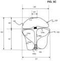
- FIG. 3 Ais an illustration of another example implant 200 in a predetermined shape.
- FIGS. 3 B and 3 Care illustrations of the example implant 200 in two stable implanted shapes.
- the implant 200can treat a range of aneurysm sizes including a larger aneurysm 10 a as illustrated in FIG. 3 B and a smaller aneurysm 10 b as illustrated in FIG. 3 C .
- the implant 200can have a first implanted shape ( FIG. 3 B ) that can be conducive for treating larger aneurysms 10 a and a second implanted shape ( FIG. 3 C ) that can be conducive for treating smaller aneurysms 10 b .
- the implant 200can include a distal braided segment 240 having an open end 214 and a predetermined shape similar to that of the distal braided segment 140 of the implant 100 illustrated in FIG. 1 A .
- the implant 200can include a proximal braided segment 220 having a pinched end 212 and two inversions 222 , 224 similar to corresponding features 112 , 122 , 124 of the proximal braided segment 120 of the implant 100 illustrated in FIG. 1 A .
- the proximal braided segment 220can have an outermost section 242 affixed to the band 130 , a middle section 244 extending between the two inversions 222 , 224 , and an innermost section 246 surrounded by the middle section 244 and affixed to the detachment feature 150 at the pinched end 212 .
- the middle section 244 of the implant 200 illustrated in FIG. 3 Acan further include one or more bends 232 , 234 to facilitate movement of the implant 200 into the implanted shape illustrated in FIG. 3 C .
- the innermost section 246 of the implant 200 illustrated in FIG. 3 Acan be truncated so that the pinched end 112 (and thereby the detachment feature 150 ) is suspended within a sack formed by the middle section 244 when the implant 200 is in the predetermined shape.
- FIG. 3 Billustrates the implant 200 in a first implanted shape in the larger aneurysm 10 a having a substantially spherical cavity that is larger than a substantially spherical cavity of the smaller aneurysm 10 b illustrated in FIG. 3 C .
- the first implanted shape illustrated in FIG. 3 Billustrates the implant 200 in a first implanted shape in the larger aneurysm 10 a having a substantially spherical cavity that is larger than a substantially spherical cavity of the smaller aneurysm 10 b illustrated in FIG. 3 C .
- the open end 214is positioned approximate a distal wall, dome 15 a of the larger aneurysm 10 a , the band 130 is suspended within a sac 12 a of the larger aneurysm 10 a , and the proximal braided segment 220 has two inversions 222 a , 224 a separating three sections 242 a , 244 a , 246 a which at least partially overlap each other.
- the two inversions 222 a , 224 a and the three sections 242 a , 244 a , 246 a of the proximal braided segment 220 when the implant is in the first implanted shapecorrespond approximately to the two inversions 222 , 224 and the three sections 242 , 244 , 246 of the proximal braided segment 220 when the implant 200 is in the predetermined shape as illustrated in FIG. 3 A .
- the proximal braided segment 220is anchored into the aneurysm walls 14 a at least in part by a force F in the proximal direction 22 from the distal braided segment 240 so that the proximal braided segment 220 remains in place across the aneurysm neck 16 a .
- the sack 244 acan have a neck opening 226 a corresponding to a neck opening 226 in the predetermined shape.
- the first implanted shape of the implant 200 illustrated in FIG. 3 Bcan be similar to that of the implanted shape of the implant 100 illustrated in FIG. 1 B with an exception that the inner layer 246 a of the implant 200 illustrated in FIG. 3 B is foreshortened compared to the inner layer 148 a of the implant 100 illustrated in FIG. 1 B .
- the implant 200can be implanted in the larger aneurysm 10 a as illustrated in FIG. 3 B following steps similar to those illustrated in FIGS. 2 A through 2 G .
- FIG. 3 Cillustrates the implant 200 in a second implanted shape in the smaller spherical cavity of the smaller aneurysm 10 b .
- the open end 214is positioned approximate a distal wall, dome 15 b of the smaller aneurysm 10 b , the band 130 is suspended within the smaller aneurysm 10 b , and the second braided segment 220 has two inversions 222 b , 224 b separating three sections 242 b , 244 b , 246 b which at least partially overlap each other.
- One of the two inversions 224 bwhen the implant is in the second implanted shape, corresponds to a bend 232 in the middle section 244 when the implant 200 is in the predetermined shape illustrated in FIG. 3 A .
- the proximal braided segment 220is anchored into the aneurysm walls 14 b at least in part by a force F in the proximal direction 22 from the distal braided segment 240 so that the proximal braided segment 220 remains in place across the aneurysm neck 16 b .
- the proximal braided segment 220can be radially constricted so that an outer layer 242 b presses into the aneurysm wall 14 .
- a middle layer 244 bcan press into the outer layer 242 b to further anchor the proximal braided segment 220 .
- An inner layer 246 bcan press into the middle layer 244 b to further anchor the proximal braided segment 220 .
- FIGS. 4 A through 4 Dare a sequence of illustrations depicting an example aneurysm treatment where the implant 100 is implanted in the second implanted shape illustrated in FIG. 3 C .
- the treatment sequencecan begin following steps similar to as illustrated in FIGS. 2 A through 2 C .
- implants 100 , 200 illustrated in FIGS. 1 A and 3 Ahave similar dimensions
- the second implanted shape of the implant 200 illustrated in FIG. 3 Callows that implant 200 to be implanted in a smaller aneurysm 10 b compared to the aneurysm 10 illustrated in FIGS. 2 B through 2 G .
- the distal braided segment 240 of the implant 200 illustrated in FIGS. 4 A through 4 Dtherefore may occupy a greater percentage of the volume of the smaller aneurysm sac 12 b compared to the treatment illustrated in FIGS. 2 A through 2 G .
- FIG. 4 Aillustrates the distal braided segment 240 pressed into the dome 15 b and braid from the proximal braided segment 220 being expelled from the catheter 60 .
- FIG. 4 Billustrates the proximal braided segment 220 expanding to conform to the aneurysm walls 14 b and neck opening 16 b as the proximal braided segment 220 is further expelled from the catheter 60 .
- FIG. 4 Cillustrates the proximal braided segment 220 inverted to a shape similar to that of the first implanted shape illustrated in FIG. 3 B .
- the proximal braided segment 220extends into the vasculature, impeding flow from a stem blood vessel 20 to branch blood vessels 22 a , 22 b . While it may be possible to leave the proximal braided segment 220 stabilized in this shape when implanted, it may not be desirable to do so.
- FIG. 4 Dillustrates the proximal braided segment 220 collapsed to the second implanted shape similar to that illustrated in FIG. 3 C .
- Movement of the proximal braided segment 220 into the second implanted shapecan be accomplished via manipulation of the catheter 60 and the pinched end 212 .
- Bends 232 , 234 in the middle section 244 of the proximal braided section 220 in the predetermined shapecan promote movement of the proximal braided section 220 from the shape illustrated in FIG. 4 C to the second implanted shape illustrated in FIG. 4 D .
- the detachment feature 150can be disengaged and the catheter 60 can be retracted to leave the implant 200 implanted as illustrated in FIG. 3 C .
- FIG. 5 Ais an illustration of dimensions of an example implant in a predetermined shape.
- the proximal braided segment 120has a height (H 1 ) and a diameter (D 1 ).
- the distal braided segment 140has a height (H 2 ) and a diameter (D 2 ).
- the open end 114 of the distal braided segment 140has a diameter (D 3 ) about equal to that of the diameter (D 2 ) of the distal braided segment 140 .
- the implant 100has a height H 3 that is at least the sum of the height (H 1 ) of the proximal braided segment 120 and the height (H 2 ) of the distal braided segment 140 .
- Predetermined shapes of other example implants illustrated and described herein, and variations thereofcan have similar dimensions.
- FIG. 5 Bis an illustration of height (HA), sac diameter (DA), and neck diameter (DN) measurements of an aneurysm 10 .
- the location of the plane 18 defining a boundary between the aneurysm 10 and blood vesselsis also illustrated.
- the diameter (D 1 ) of the proximal braided segment 120 and the diameter (D 2 ) of the distal braided segment 140to be about equal to, or slightly greater than the sac diameter (DA) so that the distal braided segment 140 and proximal braided segment 120 press radially into the aneurysm walls 14 .
- a diameter (D 3 ′) of the open end 114 of the distal braided segment 140 in the implanted shapecan be collapsed relative to the diameter (D 3 ) of the open end 114 distal braided segment 140 in the predetermined shape.
- the implant 100has a height (H 3 ′) that is at least the sum of the height (H 1 ′) of the proximal braided segment 120 and the height (H 2 ′) of the distal braided segment 140 .
- the height (H 3 ′) of the implant 100can be elongated or collapsed compared to the height (H 3 ) of the implant when in the predetermined shape.
- Radial constriction of the diameter (D 1 ′) of the proximal section 120can cause elongation of height (H 1 ′) of the proximal section, while collapse of the diameter (D 3 ′) of the open end 114 and longitudinal compression of the distal braided section 140 can cause foreshortening of the height (H 2 ′) of the distal braided section 140 and reduction or elimination of any gap between the distal and proximal braided sections 120 , 140 .
- Implanted shapes of other example implants illustrated and described herein, and variations thereofcan have similar dimensions.
- FIG. 6 Ais an illustration of an example implant 300 in another alternative predetermined shape.
- FIG. 6 Bis an illustration of the example implant 300 in an implanted shape.
- the implant 300includes a distal braided segment 340 and a proximal braided segment 320 .
- the distal braided segment 340can have an open end 314 and be shaped and implanted similarly to the distal braided segments 140 , 240 in previous figures.
- the proximal braided segment 320can have a pinched end 312 with a detachment feature 150 attached thereto.
- the implant 300can be formed in the predetermined shape, collapsed for delivery through a microcatheter, attached to a delivery system at the detachment feature 150 , and implanted in the implanted shape.
- FIG. 6 Aillustrates proximal braided segment 320 having two inversions 322 , 324 , dividing the proximal braided segment 320 into three segments 342 , 344 , 346 in the predetermined shape.
- the proximal braided segment 320can have an outermost section 342 extending from the band 130 to one of the inversions 322 , an innermost section 346 extending from the pinched end 312 to the other of the inversions 324 , and a middle section 344 extending between the two inversions 322 , 324 .
- the proximal braided segment 320 and distal braided segment 340can each be substantially radially symmetrical about a central vertical axis.
- the outermost sections 142 , 242 , 342are respectively similar to each other; the innermost section 346 of the implant 300 illustrated in FIG. 6 A can be elongated, foreshortened, or any length between the innermost sections 148 , 246 of the previously illustrated implants 100 , 200 ; and the middle section 344 of the proximal braided segment 320 illustrated in FIG. 6 A has an undulating pattern rather than the “S” shape of the middle section 144 , 244 of previously illustrated implants 100 , 200 .
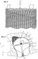
- the undulating middle section 344can be radially symmetrical to form a honeycomb shape.
- the middle section 344 in the undulating patterncan provide a force pattern pressing outwardly to anchor the implant 300 within an aneurysm that is different from a force pattern that could be provided by the middle sections 144 , 244 having the “S” shape.
- the pinched end 312 of the braid 310 in FIG. 6 Acan be positioned near the inversion 324 adjacent the inner segment 346 as illustrated.
- the inner segment 346can be shaped to extend to the inversion 322 adjacent the outer section 342 to provide a compaction resistant column.
- FIG. 6 Billustrates the proximal braided segment 320 having an outer layer 342 a shaped to contact an aneurysm wall, compressed extensions of an undulating middle layer 344 a nested within the outer layer 342 a , a proximal inversion 322 a positioned to be placed an aneurysm neck, and a distal inversion 324 a positioned to be placed near the band 130 .
- the detachment feature 150 and pinched end 312 of the proximal braided segment 320can be positioned within the aneurysm sac, extending from an innermost layer 346 a of proximal braided segment 320 , either near the distal inversion 324 a as illustrated, near the proximal inversion 322 a , or at a position in between.
- the detachment feature 150 and pinched end 312can be positioned to reduce the likelihood that the implant 300 becomes impacted.
- the distal braided segment 340can provide a force F in the proximal direction 22 against the proximal braided segment 320 to anchor the implant 300 within an aneurysm or spherical cavity.
- the outer layer 342 a and middle layer 344 acan provide a radially outward force to anchor the implant 30 within an aneurysm or spherical cavity.
- FIG. 7 Ais an illustration of an example implant 400 in another alternative predetermined shape.
- FIG. 7 Bis an illustration of the example implant 400 in an implanted shape.
- the implant 400has a distal braided segment 440 having an open end 414 and a proximal braided segment 420 having a pinched end 412 .
- a detachment feature 150can be attached to the proximal braided segment 420 at the pinched end 412 .
- the implant 400can be formed in the predetermined shape, collapsed for delivery through a microcatheter, attached to a delivery system at the detachment feature 150 , and implanted in the implanted shape.
- FIG. 7 Aillustrates the proximal braided segment 420 having two inversions 422 , 424 , dividing the proximal braided segment 420 into three sections 442 , 444 , 446 .
- the proximal braided segment 420can have an outermost section 442 extending from the band 130 to one of the inversions 422 , an innermost section 446 extending from the pinched end 412 to the other of the inversions 424 , and a middle section 444 extending between the two inversions 422 , 424 .
- the proximal braided segment 420can be substantially radially symmetrical about a central vertical axis (L-L).
- the distal braided segment 440can be shaped and implanted similar to the distal braided segment 140 , 240 , 340 of previously illustrated implants 100 , 200 , 300 .
- the outermost sections 142 , 242 , 442can be similar to each other, the middle section 444 of the proximal braided segment 420 illustrated in FIG. 7 A can have a less pronounced “S” shape compared to the “S” shaped middle section 144 , 244 illustrated in FIGS. 1 A and 3 A , and the innermost section 446 can be conical or “V” shaped in profile with the pinched end 412 positioned near the proximal inversion 422 . When implanted, the innermost section 446 can reshape to form a compaction resistant column.
- FIG. 7 Billustrates the proximal braided segment 420 in an implanted shape having an outer layer 442 a shaped to contact an aneurysm wall, a tulip or heart shaped sack 444 a nested within the outer layer 442 a , a proximal inversion 422 a positioned to be placed at an aneurysm neck, a distal inversion 424 a positioned to be placed near the band 130 , and a compaction resistant column 446 a extending within the sack 444 a .
- the detachment feature 150 and pinched end 412can be positioned within the sack 444 a near the proximal inversion 422 a .
- the detachment feature 150 and pinched end 412can be positioned to reduce the likelihood that the implant 400 becomes impacted.
- the distal braided segment 440can provide a force F in the proximal direction 22 against the proximal braided segment 420 to anchor the implant 400 within an aneurysm or spherical cavity.
- the outer layer 442 a and middle layer 444 acan provide a radial force to anchor the implant 400 within an aneurysm or spherical cavity.
- FIG. 8is an illustration of a braid having closed looped ends 30 .
- the braidcan be positioned so that the closed looped ends 30 correspond to the open end 114 , 214 , 314 , 414 of any of the previously illustrated implants 100 , 200 , 300 , 400 .
- FIG. 9is an illustration of another aneurysm treatment.
- embolic coils 32can be implanted prior to the implant 100 .
- the embolic coils 32can be implanted by known methods. Any of the previously illustrated implants 100 , 200 , 300 , 400 can be subsequently implanted following steps illustrated and described herein and variations thereof.
- FIGS. 10 A and 10 Bare illustrations of another example implant 500 in a predetermined shape ( FIG. 10 A ) and an implanted shape ( FIG. 10 B ).
- the implant 500includes an embolic coil 552 formed in a spiraling predetermined shape.
- the embolic coil 552can function as a dome feature configured to press into aneurysm walls near the aneurysm's dome, distal portion of the aneurysm sac.
- FIGS. 11 A and 11 Bare illustrations of another example implant in a predetermined shape ( FIG. 11 A ) and an implanted shape ( FIG. 11 B ).
- the implant 600includes a wire frame 654 configured to anchor in an aneurysm dome, thereby functioning as a dome feature.
- the implants 500 , 600 respectively illustrated in FIGS. 10 A, 10 B, 11 A, and 11 Bcan respectively further include a proximal braided segment 520 , 620 configured to extend across the aneurysm neck and anchor to the aneurysm's walls at least in the proximal portion of the aneurysm sac 12 .
- Each of the proximal braided segments 520 , 620can be respectively joined to the embolic coil 552 or wire frame 654 by the band 130 .
- Any of the previously illustrated proximal braided segments 120 , 220 , 320 , 420 and variations thereofcan be used in place of either of the proximal braided segments 520 , 620 illustrated in FIGS. 10 A through 11 B .
- the embolic coil 552 or the wire frame 654can be elongated within a microcatheter and expelled from the microcatheter into an aneurysm or cavity.
- the respective proximal braided segment 520 , 620can subsequently be expelled from the catheter and implanted as described elsewhere herein.
- the terms “about” or “approximately” for any numerical values or rangesindicate a suitable dimensional tolerance that allows the part or collection of components to function for its intended purpose as described herein. More specifically, “about” or “approximately” may refer to the range of values ⁇ 20% of the recited value, e.g. “about 90%” may refer to the range of values from 71% to 99%.
Landscapes
- Health & Medical Sciences (AREA)
- Surgery (AREA)
- Life Sciences & Earth Sciences (AREA)
- Veterinary Medicine (AREA)
- Heart & Thoracic Surgery (AREA)
- Vascular Medicine (AREA)
- Public Health (AREA)
- General Health & Medical Sciences (AREA)
- Animal Behavior & Ethology (AREA)
- Biomedical Technology (AREA)
- Medical Informatics (AREA)
- Molecular Biology (AREA)
- Nuclear Medicine, Radiotherapy & Molecular Imaging (AREA)
- Engineering & Computer Science (AREA)
- Reproductive Health (AREA)
- Neurosurgery (AREA)
- Physics & Mathematics (AREA)
- Optics & Photonics (AREA)
- Epidemiology (AREA)
- Surgical Instruments (AREA)
- Prostheses (AREA)
Abstract
Description
Claims (19)
Priority Applications (1)
| Application Number | Priority Date | Filing Date | Title |
|---|---|---|---|
| US17/478,081US12127743B2 (en) | 2020-09-23 | 2021-09-17 | Inverting braided aneurysm implant with dome feature |
Applications Claiming Priority (2)
| Application Number | Priority Date | Filing Date | Title |
|---|---|---|---|
| US202063082013P | 2020-09-23 | 2020-09-23 | |
| US17/478,081US12127743B2 (en) | 2020-09-23 | 2021-09-17 | Inverting braided aneurysm implant with dome feature |
Publications (2)
| Publication Number | Publication Date |
|---|---|
| US20220087681A1 US20220087681A1 (en) | 2022-03-24 |
| US12127743B2true US12127743B2 (en) | 2024-10-29 |
Family
ID=77910692
Family Applications (1)
| Application Number | Title | Priority Date | Filing Date |
|---|---|---|---|
| US17/478,081ActiveUS12127743B2 (en) | 2020-09-23 | 2021-09-17 | Inverting braided aneurysm implant with dome feature |
Country Status (5)
| Country | Link |
|---|---|
| US (1) | US12127743B2 (en) |
| EP (1) | EP3973893A1 (en) |
| JP (1) | JP2022052766A (en) |
| KR (1) | KR20220040411A (en) |
| CN (1) | CN114246628A (en) |
Cited By (1)
| Publication number | Priority date | Publication date | Assignee | Title |
|---|---|---|---|---|
| US20230404590A1 (en)* | 2022-06-15 | 2023-12-21 | DePuy Synthes Products, Inc. | Inverting braided aneurysm treatment system having a semi-frustoconically-shaped portion |
Families Citing this family (3)
| Publication number | Priority date | Publication date | Assignee | Title |
|---|---|---|---|---|
| US12004750B2 (en) | 2008-05-01 | 2024-06-11 | Aneuclose Llc | Methods for creating an expandable two-part intrasacular aneurysm occlusion device from a tubular mesh |
| CN115530907A (en)* | 2022-09-29 | 2022-12-30 | 珠海通桥医疗科技有限公司 | Interventional embolization treatment device for intracranial aneurysm |
| US20240108354A1 (en)* | 2022-10-03 | 2024-04-04 | DePuy Synthes Products, Inc. | Braided implant with integrated embolic coil |
Citations (175)
| Publication number | Priority date | Publication date | Assignee | Title |
|---|---|---|---|---|
| US4085757A (en) | 1976-04-29 | 1978-04-25 | P Pevsner | Miniature balloon catheter method and apparatus |
| US4282875A (en) | 1979-01-24 | 1981-08-11 | Serbinenko Fedor A | Occlusive device |
| US4517979A (en) | 1983-07-14 | 1985-05-21 | Cordis Corporation | Detachable balloon catheter |
| US5261916A (en) | 1991-12-12 | 1993-11-16 | Target Therapeutics | Detachable pusher-vasoocclusive coil assembly with interlocking ball and keyway coupling |
| US5304195A (en) | 1991-12-12 | 1994-04-19 | Target Therapeutics, Inc. | Detachable pusher-vasoocclusive coil assembly with interlocking coupling |
| US5928260A (en) | 1997-07-10 | 1999-07-27 | Scimed Life Systems, Inc. | Removable occlusion system for aneurysm neck |
| US5941249A (en) | 1996-09-05 | 1999-08-24 | Maynard; Ronald S. | Distributed activator for a two-dimensional shape memory alloy |
| US5964797A (en) | 1996-08-30 | 1999-10-12 | Target Therapeutics, Inc. | Electrolytically deployable braided vaso-occlusion device |
| US6063100A (en) | 1998-03-10 | 2000-05-16 | Cordis Corporation | Embolic coil deployment system with improved embolic coil |
| US6193708B1 (en) | 1997-08-05 | 2001-02-27 | Scimed Life Systems, Inc. | Detachable aneurysm neck bridge (I) |
| CA2395796A1 (en) | 2000-01-24 | 2001-07-26 | Scimed Life Systems, Inc. | Aneurysm closure device |
| US20010044595A1 (en) | 2000-05-02 | 2001-11-22 | Wilson-Cook Medical, Inc. | Introducer apparatus with eversible sleeve |
| US6375606B1 (en) | 1999-03-17 | 2002-04-23 | Stereotaxis, Inc. | Methods of and apparatus for treating vascular defects |
| US6379329B1 (en) | 1999-06-02 | 2002-04-30 | Cordis Neurovascular, Inc. | Detachable balloon embolization device and method |
| US6391037B1 (en) | 2000-03-02 | 2002-05-21 | Prodesco, Inc. | Bag for use in the intravascular treatment of saccular aneurysms |
| US20020068974A1 (en) | 2000-07-21 | 2002-06-06 | Kuslich Stephen D. | Expandable porous mesh bag device and methods of use for reduction, filling, fixation and supporting of bone |
| CA2431594A1 (en) | 2000-10-24 | 2002-09-12 | Martin Dieck | Device and methods for treating vascular malformations |
| US6454780B1 (en) | 2001-06-21 | 2002-09-24 | Scimed Life Systems, Inc. | Aneurysm neck obstruction device |
| US20020147497A1 (en) | 2001-04-06 | 2002-10-10 | Integrated Vascular Systems, Inc. | Methods for treating spinal discs |
| US20020169473A1 (en) | 1999-06-02 | 2002-11-14 | Concentric Medical, Inc. | Devices and methods for treating vascular malformations |
| US6506204B2 (en) | 1996-01-24 | 2003-01-14 | Aga Medical Corporation | Method and apparatus for occluding aneurysms |
| US20030171739A1 (en) | 1998-09-04 | 2003-09-11 | Richard Murphy | Detachable aneurysm neck bridge |
| WO2003086240A1 (en) | 2002-04-12 | 2003-10-23 | Boston Scientific Limited | Devices for retaining vaso-occlussive devices within an aneurysm |
| US20040034386A1 (en) | 2002-08-19 | 2004-02-19 | Michael Fulton | Aneurysm stent |
| US20040093014A1 (en) | 1998-11-10 | 2004-05-13 | Hanh Ho | Bioactive components for incorporation with vaso-occlusive members |
| US20040153120A1 (en) | 2003-02-03 | 2004-08-05 | Seifert Paul S. | Systems and methods of de-endothelialization |
| US20040210297A1 (en) | 2003-04-18 | 2004-10-21 | A-Spine Holding Group Corp. | Filling device and system for treating a deformed or diseased spine |
| US20050021072A1 (en) | 2003-07-25 | 2005-01-27 | Scimed Life Systems, Inc. | Method and system for delivering an implant utilizing a lumen reducing member |
| US6849081B2 (en) | 1994-12-22 | 2005-02-01 | Scimed Life Systems, Inc. | Implant delivery assembly with expandable coupling/decoupling mechanism |
| US20050177103A1 (en) | 2003-11-10 | 2005-08-11 | Angiotech International Ag | Intravascular devices and fibrosis-inducing agents |
| WO2005074814A2 (en) | 2004-01-30 | 2005-08-18 | Nmt Medical, Inc. | Devices, systems, and methods for closure of cardiac openings |
| US20050251200A1 (en) | 2002-08-29 | 2005-11-10 | Stephen Porter | Device for closure of a vascular defect and method for treating the same |
| US6964657B2 (en) | 1997-10-17 | 2005-11-15 | Micro Therapeutics, Inc. | Catheter system and method for injection of a liquid embolic composition and a solidification agent |
| US6994711B2 (en) | 1998-03-10 | 2006-02-07 | Cordis Corporation | Small diameter embolic coil hydraulic deployment system |
| US20060052816A1 (en) | 2004-08-31 | 2006-03-09 | Cook Incorporated | Device for treating an aneurysm |
| US20060064151A1 (en) | 2004-09-22 | 2006-03-23 | Guterman Lee R | Cranial aneurysm treatment arrangement |
| US20060155323A1 (en) | 2005-01-07 | 2006-07-13 | Porter Stephen C | Intra-aneurysm devices |
| US20070088387A1 (en) | 2005-10-19 | 2007-04-19 | Pulsar Vascular, Inc. | Implantable aneurysm closure systems and methods |
| WO2007076480A2 (en) | 2005-12-23 | 2007-07-05 | Levy Elad I | Bifurcated aneurysm treatment arrangement |
| US20070162071A1 (en) | 2004-03-19 | 2007-07-12 | Burkett David H | Locking component for an embolic filter assembly |
| US20070167876A1 (en) | 2006-01-17 | 2007-07-19 | Euteneuer Charles L | Occluding guidewire and methods |
| US20070191884A1 (en) | 2005-10-19 | 2007-08-16 | Pulsar Vascular, Inc. | Methods and systems for endovascularly clipping and repairing lumen and tissue defects |
| US20070233188A1 (en) | 2006-03-31 | 2007-10-04 | Hunt John V | Adhesives for use with suture system minimize tissue erosion |
| EP1527753B1 (en) | 2003-10-29 | 2008-02-27 | Cordis Neurovascular, Inc. | Neck covering device for an aneurysm |
| US20080103505A1 (en) | 2006-10-26 | 2008-05-01 | Hendrik Raoul Andre Fransen | Containment device for site-specific delivery of a therapeutic material and methods of use |
| CA2598048A1 (en) | 2006-11-20 | 2008-05-20 | Stout Medical Group, L.P. | Mechanical tissue device and method |
| US7377932B2 (en) | 2005-06-02 | 2008-05-27 | Cordis Neurovascular, Inc. | Embolic coil delivery system with mechanical release mechanism |
| US20080281350A1 (en) | 2006-12-13 | 2008-11-13 | Biomerix Corporation | Aneurysm Occlusion Devices |
| WO2008150346A1 (en) | 2007-05-31 | 2008-12-11 | Rex Medical, L.P. | Closure device for left atrial appendage |
| WO2008151204A1 (en) | 2007-06-04 | 2008-12-11 | Sequent Medical Inc. | Methods and devices for treatment of vascular defects |
| US20090036877A1 (en) | 2007-08-01 | 2009-02-05 | Boston Scientific Scimed, Inc. | Spring detach joint for delivering a detachable implantable device |
| US20090062841A1 (en) | 2004-03-19 | 2009-03-05 | Aga Medical Corporation | Device for occluding vascular defects |
| WO2009048700A1 (en) | 2007-10-12 | 2009-04-16 | Aga Medical Corporation | Multi-component vascular device |
| WO2009105365A1 (en) | 2008-02-19 | 2009-08-27 | Aga Medical Corporation | Medical devices for treating a target site and associated method |
| US20090227983A1 (en) | 2003-03-27 | 2009-09-10 | Boston Scientific Scimed, Inc. | Medical device |
| DE102008015781A1 (en) | 2008-03-26 | 2009-10-01 | Neuß, Malte, Dipl.-Ing. (FH) Dr.med. | Device for sealing defects in the vascular system |
| WO2009135166A2 (en) | 2008-05-02 | 2009-11-05 | Sequent Medical Inc. | Filamentary devices for treatment of vascular defects |
| US20090287294A1 (en) | 2008-04-21 | 2009-11-19 | Rosqueta Arturo S | Braid-Ball Embolic Devices |
| US20090287297A1 (en) | 2001-07-20 | 2009-11-19 | Cox Brian J | Aneurysm Treatment Device And Method Of Use |
| EP1054635B1 (en) | 1998-02-10 | 2010-01-06 | Artemis Medical, Inc. | Occlusion, anchoring, tensioning or flow direction apparatus |
| US20100023046A1 (en) | 2008-07-24 | 2010-01-28 | Aga Medical Corporation | Multi-layered medical device for treating a target site and associated method |
| EP1659988B1 (en) | 2003-08-15 | 2010-02-17 | Atritech, Inc. | System and method for delivering a left atrial appendage blood clot barrier device |
| WO2010030991A1 (en) | 2008-09-12 | 2010-03-18 | Micrus Endovascular Corporation | Self- expandable aneurysm filling device and system |
| EP1923005B1 (en) | 2004-03-19 | 2010-07-14 | Aga Medical Corporation | Multi-Layer braided structures for occluding vascular defects |
| US20100211156A1 (en) | 2001-11-09 | 2010-08-19 | Boston Scientific Scimed, Inc. | Stent delivery device with embolic protection |
| US20100324649A1 (en) | 2009-06-18 | 2010-12-23 | Graftcraft I Goteborg Ab | Device and method for treating ruptured aneurysms |
| EP2266456A1 (en) | 2008-03-19 | 2010-12-29 | Sysmex Corporation | Method of analyzing biological component, biological component analyzer, reaction cartridge of biological component analyzer and extraction cartridge of biological component analyzer |
| WO2011057002A2 (en) | 2009-11-05 | 2011-05-12 | Sequent Medical Inc. | Multiple layer filamentary devices or treatment of vascular defects |
| US20110112588A1 (en) | 2009-11-10 | 2011-05-12 | Carefusion 207, Inc. | Systems and methods for vertebral or other bone structure height restoration and stabilization |
| US20110137317A1 (en) | 2009-12-07 | 2011-06-09 | O'halloran Damien | Methods and Apparatus For Treating Vertebral Fractures |
| US7985238B2 (en) | 2005-06-02 | 2011-07-26 | Codman & Shurtleff, Inc. | Embolic coil delivery system with spring wire release mechanism |
| US8048145B2 (en) | 2004-07-22 | 2011-11-01 | Endologix, Inc. | Graft systems having filling structures supported by scaffolds and methods for their use |
| US8062325B2 (en) | 2006-07-31 | 2011-11-22 | Codman & Shurtleff, Inc. | Implantable medical device detachment system and methods of using the same |
| US20120010644A1 (en) | 2009-07-09 | 2012-01-12 | Sideris Eleftherios B | Method and apparatus for occluding a physiological opening |
| WO2012034135A1 (en) | 2010-09-10 | 2012-03-15 | Maria Aboytes | Devices and methods for the treatment of vascular defects |
| EP2324775B1 (en) | 2007-08-02 | 2012-06-20 | Occlutech Holding AG | Method of producing a medical implantable device |
| EP2468349A1 (en) | 2004-09-17 | 2012-06-27 | Codman & Shurtleff, Inc. | Thin film metallic devices for plugging aneurysms or vessels |
| US20120165732A1 (en) | 2010-12-23 | 2012-06-28 | Synthes Usa, Llc | Balloon catheter comprising a zero-profile tip |
| US20120191123A1 (en) | 2011-01-21 | 2012-07-26 | Obalon Therapeutics. Inc. | Intragastric device |
| US20120283768A1 (en)* | 2011-05-05 | 2012-11-08 | Sequent Medical Inc. | Method and apparatus for the treatment of large and giant vascular defects |
| US20120323267A1 (en) | 2011-06-17 | 2012-12-20 | Aga Medical Corporation | Occlusion device and associated deployment method |
| EP2543345A1 (en) | 2010-03-02 | 2013-01-09 | Microport Medical Shanghai Co., Ltd. | Surgical apparatus for aneurysms |
| WO2013025711A1 (en) | 2011-08-15 | 2013-02-21 | W.L. Gore & Associates, Inc. | Heart occlusion devices |
| EP2623039A1 (en) | 2006-10-05 | 2013-08-07 | pfm medical ag | Implantable device |
| US20130204351A1 (en) | 2012-02-02 | 2013-08-08 | Inceptus Medical LLC | Aneurysm Graft Devices And Methods |
| US20130211495A1 (en) | 2009-11-09 | 2013-08-15 | Covidien Lp | Interference-relief type delivery detachment systems |
| US8523902B2 (en) | 2009-01-30 | 2013-09-03 | Kfx Medical Corporation | System and method for attaching soft tissue to bone |
| US20130261658A1 (en) | 2012-03-30 | 2013-10-03 | Micrus Endovascular Llc | Embolic coil detachment mechanism with flexible distal member, resistive electrical heating element and shape memory polymer element |
| WO2013159065A1 (en) | 2012-04-20 | 2013-10-24 | Paul Lubock | Expandable occlusion devices and methods of use |
| WO2013162817A1 (en) | 2012-04-23 | 2013-10-31 | Covidien Lp | Delivery system with hooks for resheathability |
| US20130325054A1 (en) | 2012-06-01 | 2013-12-05 | Acandis Gmbh & Co. Kg | System for delivering a stretch resistant vaso-occlusive device and a method of producing same |
| US20140005714A1 (en) | 2012-01-06 | 2014-01-02 | Inceptus Medical, Inc. | Multilayered expandable braided devices and methods of use |
| US20140135812A1 (en) | 2012-11-13 | 2014-05-15 | Covidien Lp | Occlusive devices |
| WO2014078286A1 (en) | 2012-11-16 | 2014-05-22 | W. L. Gore & Associates, Inc | Implantable medical device deployment system |
| US8777974B2 (en) | 2004-03-19 | 2014-07-15 | Aga Medical Corporation | Multi-layer braided structures for occluding vascular defects |
| US20140200607A1 (en) | 2013-01-14 | 2014-07-17 | Microvention, Inc. | Occlusive Device |
| JP2014522268A (en) | 2011-05-23 | 2014-09-04 | ラザラス エフェクト, インコーポレイテッド | Recovery system and method of use |
| US20140257361A1 (en) | 2013-03-08 | 2014-09-11 | Aga Medical Corporation | Medical device for treating a target site |
| US20140277013A1 (en) | 2013-03-15 | 2014-09-18 | Microvention, Inc. | Multi-Component Obstruction Removal System And Method |
| US20140277096A1 (en) | 2013-03-14 | 2014-09-18 | Valve Medical Ltd. | Temporary valve and valve-filter |
| US8900304B1 (en) | 2014-06-17 | 2014-12-02 | Abdulrazzaq Alobaid | Kyphoplasty cement encapsulation balloon |
| US20140358178A1 (en) | 2013-08-16 | 2014-12-04 | Sequent Medical Inc. | Filamentary devices for treatment of vascular defects |
| DE102013106031A1 (en) | 2013-06-11 | 2014-12-11 | Acandis Gmbh & Co. Kg | Medical implant and system with such an implant |
| CN104334117A (en) | 2012-01-26 | 2015-02-04 | 恩多沙普公司 | Systems, devices, and methods for delivering a lumen occlusion device using distal and/or proximal control |
| US20150057703A1 (en) | 2013-08-20 | 2015-02-26 | Boston Scientific Scimed, Inc. | Braided hemostasis shaft for improved torsional response |
| US8998947B2 (en) | 2010-09-10 | 2015-04-07 | Medina Medical, Inc. | Devices and methods for the treatment of vascular defects |
| DE202008018523U1 (en) | 2007-09-26 | 2015-04-29 | Aga Medical Corporation | Braided vascular devices without end clamps |
| US9055948B2 (en) | 2004-11-09 | 2015-06-16 | Stryker Corporation | Vaso-occlusive devices comprising complex-shape proximal portion and smaller diameter distal portion |
| US20150272589A1 (en) | 2014-03-31 | 2015-10-01 | DePuy Synthes Products, LLC | Aneurysm occlusion device |
| US9161758B2 (en) | 2007-04-16 | 2015-10-20 | Occlutech Holding Ag | Occluder for occluding an atrial appendage and production process therefor |
| EP1483009B1 (en) | 2002-03-08 | 2015-10-21 | Covidien LP | Distal protection devices having controllable wire motion |
| US20150335333A1 (en) | 2013-01-03 | 2015-11-26 | Donald K. Jones | Detachable Coil Release System and Handle System |
| US20150374483A1 (en) | 2013-03-15 | 2015-12-31 | Insera Therapeutics, Inc. | Vascular treatment devices and methods |
| US20160022445A1 (en) | 2013-03-15 | 2016-01-28 | Covidien Lp | Occlusive Device |
| EP1725185B1 (en) | 2004-01-22 | 2016-04-27 | Microvention, Inc. | Aneurysm treatment device |
| JP2016518155A (en) | 2013-03-13 | 2016-06-23 | アーロン・ヴィ・カプラン | Device and method for performing an emptying operation on the left atrial appendage |
| WO2016107357A1 (en) | 2014-12-30 | 2016-07-07 | 先健科技(深圳)有限公司 | Occluder, manufacturing method thereof and woven mesh pipe for manufacturing occluder |
| US20160192912A1 (en) | 2007-01-23 | 2016-07-07 | Cvdevices, Llc | Devices, systems, and methods for atrial appendage occlusion using light cure |
| US20160249934A1 (en) | 2013-08-16 | 2016-09-01 | Sequent Medical, Inc. | Filamentary devices for treatment of vascular defects |
| US20160249935A1 (en) | 2014-04-14 | 2016-09-01 | Sequent Medical, Inc. | Devices for therapeutic vascular procedures |
| EP2367482B1 (en) | 2009-12-31 | 2016-10-12 | Covidien LP | Device for blood flow restoration and thrombus management |
| EP2923674B1 (en) | 2004-12-22 | 2016-12-07 | W.L. Gore & Associates, Inc. | Filament-wound implantable devices |
| EP2854704B1 (en) | 2012-06-04 | 2016-12-21 | Penumbra, Inc. | Aneurysm occlusion system |
| EP2063791B1 (en) | 2006-09-22 | 2016-12-21 | W.L. Gore & Associates, Inc. | Cerebral vasculature device |
| US9526813B2 (en) | 2009-07-13 | 2016-12-27 | Yissum Research Development Company Of The Hebrew University Of Jerusalem Ltd. | Intraluminal polymeric devices for the treatment of aneurysms |
| EP1574169B1 (en) | 1999-02-01 | 2017-01-18 | Board Of Regents, The University Of Texas System | Woven intravascular devices |
| US20170027726A1 (en) | 2014-03-17 | 2017-02-02 | Terumo Kabushiki Kaisha | Stent delivery system and stent delivery method |
| US9561096B2 (en) | 2001-11-26 | 2017-02-07 | Thomas J. Fogarty | Devices and methods for treatment of vascular aneurysms |
| US9579104B2 (en) | 2011-11-30 | 2017-02-28 | Covidien Lp | Positioning and detaching implants |
| US20170079662A1 (en) | 2015-09-23 | 2017-03-23 | Covidien Lp | Occlusive devices |
| US20170079661A1 (en) | 2015-09-23 | 2017-03-23 | Covidien Lp | Occlusive devices |
| US20170079717A1 (en) | 2014-05-14 | 2017-03-23 | President And Fellows Of Harvard College | Catheter Device for Transmitting and Reflecting Light |
| US20170258473A1 (en) | 2016-03-11 | 2017-09-14 | Sequent Medical, Inc. | Systems and methods for delivery of stents and stent-like devices |
| WO2017161283A1 (en) | 2016-03-17 | 2017-09-21 | Swaminathan Jayaraman | Occluding anatomical structures |
| US20170304595A1 (en) | 2016-04-25 | 2017-10-26 | Medtronic Vascular, Inc. | Balloon catheter including a drug delivery sheath |
| US20170312109A1 (en) | 2016-04-28 | 2017-11-02 | Medtronic Vascular, Inc. | Implantable medical device delivery system |
| US20170316561A1 (en) | 2016-04-28 | 2017-11-02 | Medtronic Navigation, Inc. | Method and Apparatus for Image-Based Navigation |
| US20170312484A1 (en) | 2016-04-28 | 2017-11-02 | Medtronic Vascular, Inc. | Drug coated inflatable balloon having a thermal dependent release layer |
| US20170319826A1 (en) | 2013-12-20 | 2017-11-09 | Microvention, Inc. | Steerable guidewire system |
| US20170333236A1 (en) | 2006-03-30 | 2017-11-23 | Medtronic Vascular, Inc. | Prosthesis with guide lumen |
| US20170333228A1 (en) | 2016-05-17 | 2017-11-23 | Medtronic Vascular, Inc. | Tool and method for compressing a stented prosthesis |
| CN107374688A (en) | 2017-07-17 | 2017-11-24 | 湖南瑞康通科技发展有限公司 | Plugging device in a kind of tube chamber |
| EP1633275B1 (en) | 2003-05-15 | 2017-11-29 | Biomerix Corporation | Reticulated elastomeric matrices, their manufacture and use in implantable devices |
| US20170340383A1 (en) | 2011-09-30 | 2017-11-30 | Medtronic Advanced Energy Llc | Electrosurgical balloons |
| US20170340333A1 (en) | 2015-02-25 | 2017-11-30 | Galaxy Therapeutics, Llc | System for and method of treating aneurysms |
| US20170348514A1 (en) | 2016-06-01 | 2017-12-07 | Microvention, Inc. | Reinforced Balloon Catheter |
| US20170348014A1 (en) | 2016-06-03 | 2017-12-07 | Stryker Corporation | Inverting thrombectomy apparatuses and methods |
| US10004510B2 (en) | 2011-06-03 | 2018-06-26 | Pulsar Vascular, Inc. | Systems and methods for enclosing an anatomical opening, including shock absorbing aneurysm devices |
| US20180206850A1 (en) | 2015-07-28 | 2018-07-26 | Hangzhou Nuomao Medtech Co., Ltd. | Left atrial appendage occluder |
| US20180242979A1 (en) | 2017-02-23 | 2018-08-30 | DePuy Synthes Products, Inc. | Aneurysm device and delivery system |
| US20180303531A1 (en) | 2017-04-24 | 2018-10-25 | Baxter International Inc. | Single-handed applicator |
| US20180317933A1 (en) | 2016-08-03 | 2018-11-08 | Henry Nita LLC | Devices and Methods for Treatment of Endovascular and Non-Endovascular Defects in Humans |
| US20180338767A1 (en) | 2017-05-25 | 2018-11-29 | Microvention, Inc. | Adhesive occlusion systems |
| WO2019038293A1 (en) | 2017-08-21 | 2019-02-28 | Cerus Endovascular Limited | Occlusion device |
| US20190142567A1 (en) | 2016-02-16 | 2019-05-16 | Insera Therapeutics, Inc. | Multilayer devices for inhibiting distal migration of flow diverting stents |
| US20190192167A1 (en)* | 2017-12-22 | 2019-06-27 | DePuy Synthes Products, Inc. | Aneurysm device and delivery system |
| US20190192165A1 (en) | 2016-09-01 | 2019-06-27 | Microvention, Inc. | Temporary Aortic Occlusion Device |
| US20190192162A1 (en) | 2017-12-21 | 2019-06-27 | DePuy Synthes Products, Inc. | Implantable medical device detachment system with split tube and cylindrical coupling |
| US20190192168A1 (en)* | 2017-12-22 | 2019-06-27 | DePuy Synthes Products, Inc. | Aneurysm device and delivery system |
| US20190223879A1 (en) | 2018-01-23 | 2019-07-25 | Swaminathan Jayaraman | Device to treat vascular defect and method of making the same |
| EP3517055A1 (en) | 2018-01-24 | 2019-07-31 | DePuy Synthes Products, Inc. | Aneurysm device and delivery system |
| US20190328398A1 (en) | 2018-04-27 | 2019-10-31 | DePuy Synthes Products, Inc. | Implantable medical device detachment system with split tube |
| US20190357914A1 (en) | 2018-05-25 | 2019-11-28 | DePuy Synthes Products, Inc. | Aneurysm device and delivery system |
| US10517604B2 (en) | 2010-04-14 | 2019-12-31 | Microvention, Inc. | Implant delivery device |
| US20200000477A1 (en) | 2016-08-03 | 2020-01-02 | Henry Nita LLC | Embolization Plug |
| US20200069313A1 (en) | 2018-05-25 | 2020-03-05 | DePuy Synthes Products, Inc. | Aneurysm device and delivery system |
| EP3636171A1 (en) | 2018-10-11 | 2020-04-15 | National University of Ireland Galway | A device for implantation in a left atrial appendage of the heart |
| EP3636173A2 (en) | 2018-10-12 | 2020-04-15 | DePuy Synthes Products, Inc. | Folded aneurysm treatment device |
| US10653425B1 (en) | 2019-05-21 | 2020-05-19 | DePuy Synthes Products, Inc. | Layered braided aneurysm treatment device |
| US20200268365A1 (en) | 2015-01-20 | 2020-08-27 | Neurogami Medical, Inc. | Micrograft for the treatment of intracranial aneurysms and method for use |
| US20200367897A1 (en)* | 2019-05-25 | 2020-11-26 | Galaxy Therapeutics, Inc. | Systems and methods for treating aneurysms |
| US20210137526A1 (en) | 2019-11-11 | 2021-05-13 | Stryker Corporation | Embolic devices for occluding body lumens |
| US11464518B2 (en) | 2008-05-01 | 2022-10-11 | Aneuclose Llc | Proximal concave neck bridge with central lumen and distal net for occluding cerebral aneurysms |
| US11607226B2 (en) | 2019-05-21 | 2023-03-21 | DePuy Synthes Products, Inc. | Layered braided aneurysm treatment device with corrugations |
| US11672542B2 (en) | 2019-05-21 | 2023-06-13 | DePuy Synthes Products, Inc. | Aneurysm treatment with pushable ball segment |
Family Cites Families (1)
| Publication number | Priority date | Publication date | Assignee | Title |
|---|---|---|---|---|
| EP2387950A1 (en)* | 2010-05-23 | 2011-11-23 | Occlutech Holding AG | Medical implant and manufacturing method thereof |
- 2021
- 2021-09-17USUS17/478,081patent/US12127743B2/enactiveActive
- 2021-09-23EPEP21198510.6Apatent/EP3973893A1/ennot_activeWithdrawn
- 2021-09-23CNCN202111117150.7Apatent/CN114246628A/enactivePending
- 2021-09-23KRKR1020210125580Apatent/KR20220040411A/ennot_activeWithdrawn
- 2021-09-24JPJP2021155307Apatent/JP2022052766A/enactivePending
Patent Citations (203)
| Publication number | Priority date | Publication date | Assignee | Title |
|---|---|---|---|---|
| US4085757A (en) | 1976-04-29 | 1978-04-25 | P Pevsner | Miniature balloon catheter method and apparatus |
| US4282875A (en) | 1979-01-24 | 1981-08-11 | Serbinenko Fedor A | Occlusive device |
| US4517979A (en) | 1983-07-14 | 1985-05-21 | Cordis Corporation | Detachable balloon catheter |
| US5261916A (en) | 1991-12-12 | 1993-11-16 | Target Therapeutics | Detachable pusher-vasoocclusive coil assembly with interlocking ball and keyway coupling |
| US5304195A (en) | 1991-12-12 | 1994-04-19 | Target Therapeutics, Inc. | Detachable pusher-vasoocclusive coil assembly with interlocking coupling |
| US6849081B2 (en) | 1994-12-22 | 2005-02-01 | Scimed Life Systems, Inc. | Implant delivery assembly with expandable coupling/decoupling mechanism |
| US6506204B2 (en) | 1996-01-24 | 2003-01-14 | Aga Medical Corporation | Method and apparatus for occluding aneurysms |
| US5964797A (en) | 1996-08-30 | 1999-10-12 | Target Therapeutics, Inc. | Electrolytically deployable braided vaso-occlusion device |
| US5941249A (en) | 1996-09-05 | 1999-08-24 | Maynard; Ronald S. | Distributed activator for a two-dimensional shape memory alloy |
| US5928260A (en) | 1997-07-10 | 1999-07-27 | Scimed Life Systems, Inc. | Removable occlusion system for aneurysm neck |
| US6193708B1 (en) | 1997-08-05 | 2001-02-27 | Scimed Life Systems, Inc. | Detachable aneurysm neck bridge (I) |
| US6964657B2 (en) | 1997-10-17 | 2005-11-15 | Micro Therapeutics, Inc. | Catheter system and method for injection of a liquid embolic composition and a solidification agent |
| EP1054635B1 (en) | 1998-02-10 | 2010-01-06 | Artemis Medical, Inc. | Occlusion, anchoring, tensioning or flow direction apparatus |
| US6063100A (en) | 1998-03-10 | 2000-05-16 | Cordis Corporation | Embolic coil deployment system with improved embolic coil |
| US6994711B2 (en) | 1998-03-10 | 2006-02-07 | Cordis Corporation | Small diameter embolic coil hydraulic deployment system |
| US20030171739A1 (en) | 1998-09-04 | 2003-09-11 | Richard Murphy | Detachable aneurysm neck bridge |
| US20080281302A1 (en) | 1998-09-04 | 2008-11-13 | Boston Scientific Scimed, Inc. | Detachable aneurysm neck bridge |
| US20040093014A1 (en) | 1998-11-10 | 2004-05-13 | Hanh Ho | Bioactive components for incorporation with vaso-occlusive members |
| EP1574169B1 (en) | 1999-02-01 | 2017-01-18 | Board Of Regents, The University Of Texas System | Woven intravascular devices |
| US6375606B1 (en) | 1999-03-17 | 2002-04-23 | Stereotaxis, Inc. | Methods of and apparatus for treating vascular defects |
| US20020169473A1 (en) | 1999-06-02 | 2002-11-14 | Concentric Medical, Inc. | Devices and methods for treating vascular malformations |
| US6379329B1 (en) | 1999-06-02 | 2002-04-30 | Cordis Neurovascular, Inc. | Detachable balloon embolization device and method |
| CA2395796A1 (en) | 2000-01-24 | 2001-07-26 | Scimed Life Systems, Inc. | Aneurysm closure device |
| US6391037B1 (en) | 2000-03-02 | 2002-05-21 | Prodesco, Inc. | Bag for use in the intravascular treatment of saccular aneurysms |
| US20010044595A1 (en) | 2000-05-02 | 2001-11-22 | Wilson-Cook Medical, Inc. | Introducer apparatus with eversible sleeve |
| US20020068974A1 (en) | 2000-07-21 | 2002-06-06 | Kuslich Stephen D. | Expandable porous mesh bag device and methods of use for reduction, filling, fixation and supporting of bone |
| CA2431594A1 (en) | 2000-10-24 | 2002-09-12 | Martin Dieck | Device and methods for treating vascular malformations |
| US20020147497A1 (en) | 2001-04-06 | 2002-10-10 | Integrated Vascular Systems, Inc. | Methods for treating spinal discs |
| US6454780B1 (en) | 2001-06-21 | 2002-09-24 | Scimed Life Systems, Inc. | Aneurysm neck obstruction device |
| US20090287297A1 (en) | 2001-07-20 | 2009-11-19 | Cox Brian J | Aneurysm Treatment Device And Method Of Use |
| US20100211156A1 (en) | 2001-11-09 | 2010-08-19 | Boston Scientific Scimed, Inc. | Stent delivery device with embolic protection |
| US9561096B2 (en) | 2001-11-26 | 2017-02-07 | Thomas J. Fogarty | Devices and methods for treatment of vascular aneurysms |
| EP1483009B1 (en) | 2002-03-08 | 2015-10-21 | Covidien LP | Distal protection devices having controllable wire motion |
| EP1494619B1 (en) | 2002-04-12 | 2009-08-12 | Boston Scientific Limited | Devices for retaining vaso-occlussive devices within an aneurysm |
| US9314326B2 (en) | 2002-04-12 | 2016-04-19 | Stryker Corporation | System and method for retaining vaso-occlusive devices within an aneurysm |
| WO2003086240A1 (en) | 2002-04-12 | 2003-10-23 | Boston Scientific Limited | Devices for retaining vaso-occlussive devices within an aneurysm |
| US20040034386A1 (en) | 2002-08-19 | 2004-02-19 | Michael Fulton | Aneurysm stent |
| US20050251200A1 (en) | 2002-08-29 | 2005-11-10 | Stephen Porter | Device for closure of a vascular defect and method for treating the same |
| EP1569565B1 (en) | 2002-12-13 | 2008-07-23 | Boston Scientific Limited | Detachable aneurysm neck bridge |
| US20040153120A1 (en) | 2003-02-03 | 2004-08-05 | Seifert Paul S. | Systems and methods of de-endothelialization |
| US20090227983A1 (en) | 2003-03-27 | 2009-09-10 | Boston Scientific Scimed, Inc. | Medical device |
| US20040210297A1 (en) | 2003-04-18 | 2004-10-21 | A-Spine Holding Group Corp. | Filling device and system for treating a deformed or diseased spine |
| EP1633275B1 (en) | 2003-05-15 | 2017-11-29 | Biomerix Corporation | Reticulated elastomeric matrices, their manufacture and use in implantable devices |
| US20050021072A1 (en) | 2003-07-25 | 2005-01-27 | Scimed Life Systems, Inc. | Method and system for delivering an implant utilizing a lumen reducing member |
| EP1659988B1 (en) | 2003-08-15 | 2010-02-17 | Atritech, Inc. | System and method for delivering a left atrial appendage blood clot barrier device |
| EP1527753B1 (en) | 2003-10-29 | 2008-02-27 | Cordis Neurovascular, Inc. | Neck covering device for an aneurysm |
| US20050177103A1 (en) | 2003-11-10 | 2005-08-11 | Angiotech International Ag | Intravascular devices and fibrosis-inducing agents |
| EP1725185B1 (en) | 2004-01-22 | 2016-04-27 | Microvention, Inc. | Aneurysm treatment device |
| WO2005074814A2 (en) | 2004-01-30 | 2005-08-18 | Nmt Medical, Inc. | Devices, systems, and methods for closure of cardiac openings |
| US20130018414A1 (en) | 2004-01-30 | 2013-01-17 | W.L. Gore & Associates | Devices, Systems and Methods for Closure of Cardiac Openings |
| US8777974B2 (en) | 2004-03-19 | 2014-07-15 | Aga Medical Corporation | Multi-layer braided structures for occluding vascular defects |
| US20070162071A1 (en) | 2004-03-19 | 2007-07-12 | Burkett David H | Locking component for an embolic filter assembly |
| EP1923005B1 (en) | 2004-03-19 | 2010-07-14 | Aga Medical Corporation | Multi-Layer braided structures for occluding vascular defects |
| US20090062841A1 (en) | 2004-03-19 | 2009-03-05 | Aga Medical Corporation | Device for occluding vascular defects |
| US8048145B2 (en) | 2004-07-22 | 2011-11-01 | Endologix, Inc. | Graft systems having filling structures supported by scaffolds and methods for their use |
| US20060052816A1 (en) | 2004-08-31 | 2006-03-09 | Cook Incorporated | Device for treating an aneurysm |
| EP2468349A1 (en) | 2004-09-17 | 2012-06-27 | Codman & Shurtleff, Inc. | Thin film metallic devices for plugging aneurysms or vessels |
| US20060064151A1 (en) | 2004-09-22 | 2006-03-23 | Guterman Lee R | Cranial aneurysm treatment arrangement |
| WO2006052322A2 (en) | 2004-09-22 | 2006-05-18 | Guterman Lee R | Cranial aneurysm treatment arrangement |
| US9055948B2 (en) | 2004-11-09 | 2015-06-16 | Stryker Corporation | Vaso-occlusive devices comprising complex-shape proximal portion and smaller diameter distal portion |
| EP2923674B1 (en) | 2004-12-22 | 2016-12-07 | W.L. Gore & Associates, Inc. | Filament-wound implantable devices |
| US20060155323A1 (en) | 2005-01-07 | 2006-07-13 | Porter Stephen C | Intra-aneurysm devices |
| US7377932B2 (en) | 2005-06-02 | 2008-05-27 | Cordis Neurovascular, Inc. | Embolic coil delivery system with mechanical release mechanism |
| US7985238B2 (en) | 2005-06-02 | 2011-07-26 | Codman & Shurtleff, Inc. | Embolic coil delivery system with spring wire release mechanism |
| US20070088387A1 (en) | 2005-10-19 | 2007-04-19 | Pulsar Vascular, Inc. | Implantable aneurysm closure systems and methods |
| US20070191884A1 (en) | 2005-10-19 | 2007-08-16 | Pulsar Vascular, Inc. | Methods and systems for endovascularly clipping and repairing lumen and tissue defects |
| US8551132B2 (en) | 2005-10-19 | 2013-10-08 | Pulsar Vascular, Inc. | Methods and systems for endovascularly clipping and repairing lumen and tissue defects |
| WO2007076480A2 (en) | 2005-12-23 | 2007-07-05 | Levy Elad I | Bifurcated aneurysm treatment arrangement |
| US20070167876A1 (en) | 2006-01-17 | 2007-07-19 | Euteneuer Charles L | Occluding guidewire and methods |
| US20170333236A1 (en) | 2006-03-30 | 2017-11-23 | Medtronic Vascular, Inc. | Prosthesis with guide lumen |
| US20070233188A1 (en) | 2006-03-31 | 2007-10-04 | Hunt John V | Adhesives for use with suture system minimize tissue erosion |
| US8062325B2 (en) | 2006-07-31 | 2011-11-22 | Codman & Shurtleff, Inc. | Implantable medical device detachment system and methods of using the same |
| EP2063791B1 (en) | 2006-09-22 | 2016-12-21 | W.L. Gore & Associates, Inc. | Cerebral vasculature device |
| EP2623039A1 (en) | 2006-10-05 | 2013-08-07 | pfm medical ag | Implantable device |
| US20080103505A1 (en) | 2006-10-26 | 2008-05-01 | Hendrik Raoul Andre Fransen | Containment device for site-specific delivery of a therapeutic material and methods of use |
| US20080119886A1 (en) | 2006-11-20 | 2008-05-22 | Stout Medical Group. L.P. | Mechanical tissue device and method |
| CA2598048A1 (en) | 2006-11-20 | 2008-05-20 | Stout Medical Group, L.P. | Mechanical tissue device and method |
| US20080281350A1 (en) | 2006-12-13 | 2008-11-13 | Biomerix Corporation | Aneurysm Occlusion Devices |
| US20160192912A1 (en) | 2007-01-23 | 2016-07-07 | Cvdevices, Llc | Devices, systems, and methods for atrial appendage occlusion using light cure |
| US9826980B2 (en) | 2007-04-16 | 2017-11-28 | Occlutech Holding Ag | Occluder for occluding an atrial appendage and production process therefor |
| US9161758B2 (en) | 2007-04-16 | 2015-10-20 | Occlutech Holding Ag | Occluder for occluding an atrial appendage and production process therefor |
| WO2008150346A1 (en) | 2007-05-31 | 2008-12-11 | Rex Medical, L.P. | Closure device for left atrial appendage |
| EP2157937B1 (en) | 2007-06-04 | 2017-03-22 | Sequent Medical, Inc. | Devices for treatment of vascular defects |
| US20130274863A1 (en) | 2007-06-04 | 2013-10-17 | Sequent Medical Inc. | Methods and devices for treatment of vascular defects |
| US9259337B2 (en) | 2007-06-04 | 2016-02-16 | Sequent Medical, Inc. | Methods and devices for treatment of vascular defects |
| WO2008151204A1 (en) | 2007-06-04 | 2008-12-11 | Sequent Medical Inc. | Methods and devices for treatment of vascular defects |
| US20090036877A1 (en) | 2007-08-01 | 2009-02-05 | Boston Scientific Scimed, Inc. | Spring detach joint for delivering a detachable implantable device |
| EP2324775B1 (en) | 2007-08-02 | 2012-06-20 | Occlutech Holding AG | Method of producing a medical implantable device |
| DE202008018523U1 (en) | 2007-09-26 | 2015-04-29 | Aga Medical Corporation | Braided vascular devices without end clamps |
| WO2009048700A1 (en) | 2007-10-12 | 2009-04-16 | Aga Medical Corporation | Multi-component vascular device |
| WO2009105365A1 (en) | 2008-02-19 | 2009-08-27 | Aga Medical Corporation | Medical devices for treating a target site and associated method |
| EP2266456A1 (en) | 2008-03-19 | 2010-12-29 | Sysmex Corporation | Method of analyzing biological component, biological component analyzer, reaction cartridge of biological component analyzer and extraction cartridge of biological component analyzer |
| DE102008015781A1 (en) | 2008-03-26 | 2009-10-01 | Neuß, Malte, Dipl.-Ing. (FH) Dr.med. | Device for sealing defects in the vascular system |
| US20090287291A1 (en) | 2008-04-21 | 2009-11-19 | Becking Frank P | Embolic Device Delivery Systems |
| US20090287294A1 (en) | 2008-04-21 | 2009-11-19 | Rosqueta Arturo S | Braid-Ball Embolic Devices |
| US11464518B2 (en) | 2008-05-01 | 2022-10-11 | Aneuclose Llc | Proximal concave neck bridge with central lumen and distal net for occluding cerebral aneurysms |
| WO2009135166A2 (en) | 2008-05-02 | 2009-11-05 | Sequent Medical Inc. | Filamentary devices for treatment of vascular defects |
| US9232992B2 (en) | 2008-07-24 | 2016-01-12 | Aga Medical Corporation | Multi-layered medical device for treating a target site and associated method |
| US20100023046A1 (en) | 2008-07-24 | 2010-01-28 | Aga Medical Corporation | Multi-layered medical device for treating a target site and associated method |
| WO2010030991A1 (en) | 2008-09-12 | 2010-03-18 | Micrus Endovascular Corporation | Self- expandable aneurysm filling device and system |
| US8523902B2 (en) | 2009-01-30 | 2013-09-03 | Kfx Medical Corporation | System and method for attaching soft tissue to bone |
| US20100324649A1 (en) | 2009-06-18 | 2010-12-23 | Graftcraft I Goteborg Ab | Device and method for treating ruptured aneurysms |
| US20120010644A1 (en) | 2009-07-09 | 2012-01-12 | Sideris Eleftherios B | Method and apparatus for occluding a physiological opening |
| US9526813B2 (en) | 2009-07-13 | 2016-12-27 | Yissum Research Development Company Of The Hebrew University Of Jerusalem Ltd. | Intraluminal polymeric devices for the treatment of aneurysms |
| WO2011057002A2 (en) | 2009-11-05 | 2011-05-12 | Sequent Medical Inc. | Multiple layer filamentary devices or treatment of vascular defects |
| US20110152993A1 (en)* | 2009-11-05 | 2011-06-23 | Sequent Medical Inc. | Multiple layer filamentary devices or treatment of vascular defects |
| US20130211495A1 (en) | 2009-11-09 | 2013-08-15 | Covidien Lp | Interference-relief type delivery detachment systems |
| US20110112588A1 (en) | 2009-11-10 | 2011-05-12 | Carefusion 207, Inc. | Systems and methods for vertebral or other bone structure height restoration and stabilization |
| US20110137317A1 (en) | 2009-12-07 | 2011-06-09 | O'halloran Damien | Methods and Apparatus For Treating Vertebral Fractures |
| EP2367482B1 (en) | 2009-12-31 | 2016-10-12 | Covidien LP | Device for blood flow restoration and thrombus management |
| EP2543345A1 (en) | 2010-03-02 | 2013-01-09 | Microport Medical Shanghai Co., Ltd. | Surgical apparatus for aneurysms |
| US10517604B2 (en) | 2010-04-14 | 2019-12-31 | Microvention, Inc. | Implant delivery device |
| US20150209050A1 (en) | 2010-09-10 | 2015-07-30 | Medina Medical, Inc. | Devices and methods for the treatment of vascular defects |
| WO2012034135A1 (en) | 2010-09-10 | 2012-03-15 | Maria Aboytes | Devices and methods for the treatment of vascular defects |
| US20150342613A1 (en) | 2010-09-10 | 2015-12-03 | Medina Medical, Inc. | Devices and methods for the treatment of vascular defects |
| US8974512B2 (en) | 2010-09-10 | 2015-03-10 | Medina Medical, Inc. | Devices and methods for the treatment of vascular defects |
| US8998947B2 (en) | 2010-09-10 | 2015-04-07 | Medina Medical, Inc. | Devices and methods for the treatment of vascular defects |
| US20120165732A1 (en) | 2010-12-23 | 2012-06-28 | Synthes Usa, Llc | Balloon catheter comprising a zero-profile tip |
| US20120191123A1 (en) | 2011-01-21 | 2012-07-26 | Obalon Therapeutics. Inc. | Intragastric device |
| US20120283768A1 (en)* | 2011-05-05 | 2012-11-08 | Sequent Medical Inc. | Method and apparatus for the treatment of large and giant vascular defects |
| JP2014522268A (en) | 2011-05-23 | 2014-09-04 | ラザラス エフェクト, インコーポレイテッド | Recovery system and method of use |
| US10004510B2 (en) | 2011-06-03 | 2018-06-26 | Pulsar Vascular, Inc. | Systems and methods for enclosing an anatomical opening, including shock absorbing aneurysm devices |
| US20120323267A1 (en) | 2011-06-17 | 2012-12-20 | Aga Medical Corporation | Occlusion device and associated deployment method |
| WO2013025711A1 (en) | 2011-08-15 | 2013-02-21 | W.L. Gore & Associates, Inc. | Heart occlusion devices |
| US20170340383A1 (en) | 2011-09-30 | 2017-11-30 | Medtronic Advanced Energy Llc | Electrosurgical balloons |
| US9579104B2 (en) | 2011-11-30 | 2017-02-28 | Covidien Lp | Positioning and detaching implants |
| US20140005714A1 (en) | 2012-01-06 | 2014-01-02 | Inceptus Medical, Inc. | Multilayered expandable braided devices and methods of use |
| CN104334117A (en) | 2012-01-26 | 2015-02-04 | 恩多沙普公司 | Systems, devices, and methods for delivering a lumen occlusion device using distal and/or proximal control |
| US20130204351A1 (en) | 2012-02-02 | 2013-08-08 | Inceptus Medical LLC | Aneurysm Graft Devices And Methods |
| US20130261658A1 (en) | 2012-03-30 | 2013-10-03 | Micrus Endovascular Llc | Embolic coil detachment mechanism with flexible distal member, resistive electrical heating element and shape memory polymer element |
| WO2013159065A1 (en) | 2012-04-20 | 2013-10-24 | Paul Lubock | Expandable occlusion devices and methods of use |
| WO2013162817A1 (en) | 2012-04-23 | 2013-10-31 | Covidien Lp | Delivery system with hooks for resheathability |
| US20130325054A1 (en) | 2012-06-01 | 2013-12-05 | Acandis Gmbh & Co. Kg | System for delivering a stretch resistant vaso-occlusive device and a method of producing same |
| EP2854704B1 (en) | 2012-06-04 | 2016-12-21 | Penumbra, Inc. | Aneurysm occlusion system |
| US20140135812A1 (en) | 2012-11-13 | 2014-05-15 | Covidien Lp | Occlusive devices |
| WO2014078286A1 (en) | 2012-11-16 | 2014-05-22 | W. L. Gore & Associates, Inc | Implantable medical device deployment system |
| US20150335333A1 (en) | 2013-01-03 | 2015-11-26 | Donald K. Jones | Detachable Coil Release System and Handle System |
| US20140200607A1 (en) | 2013-01-14 | 2014-07-17 | Microvention, Inc. | Occlusive Device |
| US20140257361A1 (en) | 2013-03-08 | 2014-09-11 | Aga Medical Corporation | Medical device for treating a target site |
| JP2016518155A (en) | 2013-03-13 | 2016-06-23 | アーロン・ヴィ・カプラン | Device and method for performing an emptying operation on the left atrial appendage |
| US20140277096A1 (en) | 2013-03-14 | 2014-09-18 | Valve Medical Ltd. | Temporary valve and valve-filter |
| US20160022445A1 (en) | 2013-03-15 | 2016-01-28 | Covidien Lp | Occlusive Device |
| US20150374483A1 (en) | 2013-03-15 | 2015-12-31 | Insera Therapeutics, Inc. | Vascular treatment devices and methods |
| US20140277013A1 (en) | 2013-03-15 | 2014-09-18 | Microvention, Inc. | Multi-Component Obstruction Removal System And Method |
| DE102013106031A1 (en) | 2013-06-11 | 2014-12-11 | Acandis Gmbh & Co. Kg | Medical implant and system with such an implant |
| US20140358178A1 (en) | 2013-08-16 | 2014-12-04 | Sequent Medical Inc. | Filamentary devices for treatment of vascular defects |
| US20160249934A1 (en) | 2013-08-16 | 2016-09-01 | Sequent Medical, Inc. | Filamentary devices for treatment of vascular defects |
| US20150057703A1 (en) | 2013-08-20 | 2015-02-26 | Boston Scientific Scimed, Inc. | Braided hemostasis shaft for improved torsional response |
| US20170319826A1 (en) | 2013-12-20 | 2017-11-09 | Microvention, Inc. | Steerable guidewire system |
| US20170333678A1 (en) | 2013-12-20 | 2017-11-23 | Microvention, Inc. | Segmented embolic system |
| US20170027726A1 (en) | 2014-03-17 | 2017-02-02 | Terumo Kabushiki Kaisha | Stent delivery system and stent delivery method |
| US20150272589A1 (en) | 2014-03-31 | 2015-10-01 | DePuy Synthes Products, LLC | Aneurysm occlusion device |
| US20190223881A1 (en) | 2014-04-14 | 2019-07-25 | Sequent Medical, Inc. | Devices for therapeutic vascular procedures |
| US20160249935A1 (en) | 2014-04-14 | 2016-09-01 | Sequent Medical, Inc. | Devices for therapeutic vascular procedures |
| US9629635B2 (en) | 2014-04-14 | 2017-04-25 | Sequent Medical, Inc. | Devices for therapeutic vascular procedures |
| US20170079717A1 (en) | 2014-05-14 | 2017-03-23 | President And Fellows Of Harvard College | Catheter Device for Transmitting and Reflecting Light |
| US8900304B1 (en) | 2014-06-17 | 2014-12-02 | Abdulrazzaq Alobaid | Kyphoplasty cement encapsulation balloon |
| WO2016107357A1 (en) | 2014-12-30 | 2016-07-07 | 先健科技(深圳)有限公司 | Occluder, manufacturing method thereof and woven mesh pipe for manufacturing occluder |
| US20200268365A1 (en) | 2015-01-20 | 2020-08-27 | Neurogami Medical, Inc. | Micrograft for the treatment of intracranial aneurysms and method for use |
| US20170340333A1 (en) | 2015-02-25 | 2017-11-30 | Galaxy Therapeutics, Llc | System for and method of treating aneurysms |
| US20180206850A1 (en) | 2015-07-28 | 2018-07-26 | Hangzhou Nuomao Medtech Co., Ltd. | Left atrial appendage occluder |
| US20170079661A1 (en) | 2015-09-23 | 2017-03-23 | Covidien Lp | Occlusive devices |
| US20170079662A1 (en) | 2015-09-23 | 2017-03-23 | Covidien Lp | Occlusive devices |
| EP3146916A1 (en) | 2015-09-23 | 2017-03-29 | Covidien LP | Occlusive devices |
| US20190142567A1 (en) | 2016-02-16 | 2019-05-16 | Insera Therapeutics, Inc. | Multilayer devices for inhibiting distal migration of flow diverting stents |
| US20170258473A1 (en) | 2016-03-11 | 2017-09-14 | Sequent Medical, Inc. | Systems and methods for delivery of stents and stent-like devices |
| US20190110796A1 (en) | 2016-03-17 | 2019-04-18 | Swaminathan Jayaraman | Occluding anatomical structures |
| WO2017161283A1 (en) | 2016-03-17 | 2017-09-21 | Swaminathan Jayaraman | Occluding anatomical structures |
| US20170304595A1 (en) | 2016-04-25 | 2017-10-26 | Medtronic Vascular, Inc. | Balloon catheter including a drug delivery sheath |
| US20170312484A1 (en) | 2016-04-28 | 2017-11-02 | Medtronic Vascular, Inc. | Drug coated inflatable balloon having a thermal dependent release layer |
| US20170316561A1 (en) | 2016-04-28 | 2017-11-02 | Medtronic Navigation, Inc. | Method and Apparatus for Image-Based Navigation |
| US20170312109A1 (en) | 2016-04-28 | 2017-11-02 | Medtronic Vascular, Inc. | Implantable medical device delivery system |
| US20170333228A1 (en) | 2016-05-17 | 2017-11-23 | Medtronic Vascular, Inc. | Tool and method for compressing a stented prosthesis |
| US20170348514A1 (en) | 2016-06-01 | 2017-12-07 | Microvention, Inc. | Reinforced Balloon Catheter |
| US20170348014A1 (en) | 2016-06-03 | 2017-12-07 | Stryker Corporation | Inverting thrombectomy apparatuses and methods |
| US20200000477A1 (en) | 2016-08-03 | 2020-01-02 | Henry Nita LLC | Embolization Plug |
| US20180317933A1 (en) | 2016-08-03 | 2018-11-08 | Henry Nita LLC | Devices and Methods for Treatment of Endovascular and Non-Endovascular Defects in Humans |
| US20190192165A1 (en) | 2016-09-01 | 2019-06-27 | Microvention, Inc. | Temporary Aortic Occlusion Device |
| US10743884B2 (en) | 2017-02-23 | 2020-08-18 | DePuy Synthes Products, Inc. | Aneurysm device and delivery system |
| US10751066B2 (en) | 2017-02-23 | 2020-08-25 | DePuy Synthes Products, Inc. | Aneurysm device and delivery system |
| US20200375606A1 (en) | 2017-02-23 | 2020-12-03 | DePuy Synthes Products, Inc. | Aneurysm method and system |
| US20210007755A1 (en) | 2017-02-23 | 2021-01-14 | DePuy Synthes Products, Inc. | Intrasaccular aneurysm treatment device with varying coatings |
| US20210177429A1 (en) | 2017-02-23 | 2021-06-17 | DePuy Synthes Products, Inc. | Aneurysm method and system |
| US20180242979A1 (en) | 2017-02-23 | 2018-08-30 | DePuy Synthes Products, Inc. | Aneurysm device and delivery system |
| US20180303531A1 (en) | 2017-04-24 | 2018-10-25 | Baxter International Inc. | Single-handed applicator |
| US20180338767A1 (en) | 2017-05-25 | 2018-11-29 | Microvention, Inc. | Adhesive occlusion systems |
| CN107374688A (en) | 2017-07-17 | 2017-11-24 | 湖南瑞康通科技发展有限公司 | Plugging device in a kind of tube chamber |
| WO2019038293A1 (en) | 2017-08-21 | 2019-02-28 | Cerus Endovascular Limited | Occlusion device |
| US20190192162A1 (en) | 2017-12-21 | 2019-06-27 | DePuy Synthes Products, Inc. | Implantable medical device detachment system with split tube and cylindrical coupling |
| US20190192168A1 (en)* | 2017-12-22 | 2019-06-27 | DePuy Synthes Products, Inc. | Aneurysm device and delivery system |
| US20190192167A1 (en)* | 2017-12-22 | 2019-06-27 | DePuy Synthes Products, Inc. | Aneurysm device and delivery system |
| US20190223879A1 (en) | 2018-01-23 | 2019-07-25 | Swaminathan Jayaraman | Device to treat vascular defect and method of making the same |
| EP3517055A1 (en) | 2018-01-24 | 2019-07-31 | DePuy Synthes Products, Inc. | Aneurysm device and delivery system |
| US20190328398A1 (en) | 2018-04-27 | 2019-10-31 | DePuy Synthes Products, Inc. | Implantable medical device detachment system with split tube |
| US20200069313A1 (en) | 2018-05-25 | 2020-03-05 | DePuy Synthes Products, Inc. | Aneurysm device and delivery system |
| US20190357914A1 (en) | 2018-05-25 | 2019-11-28 | DePuy Synthes Products, Inc. | Aneurysm device and delivery system |
| EP3636171A1 (en) | 2018-10-11 | 2020-04-15 | National University of Ireland Galway | A device for implantation in a left atrial appendage of the heart |
| EP3636173A2 (en) | 2018-10-12 | 2020-04-15 | DePuy Synthes Products, Inc. | Folded aneurysm treatment device |
| US10653425B1 (en) | 2019-05-21 | 2020-05-19 | DePuy Synthes Products, Inc. | Layered braided aneurysm treatment device |
| US11607226B2 (en) | 2019-05-21 | 2023-03-21 | DePuy Synthes Products, Inc. | Layered braided aneurysm treatment device with corrugations |
| US11672542B2 (en) | 2019-05-21 | 2023-06-13 | DePuy Synthes Products, Inc. | Aneurysm treatment with pushable ball segment |
| US20200367897A1 (en)* | 2019-05-25 | 2020-11-26 | Galaxy Therapeutics, Inc. | Systems and methods for treating aneurysms |
| US20210137526A1 (en) | 2019-11-11 | 2021-05-13 | Stryker Corporation | Embolic devices for occluding body lumens |
Non-Patent Citations (1)
| Title |
|---|
| Extended European Search Report dated Feb. 11, 2022 issued in corresponding EP Appln. No. 21 19 8510. |
Cited By (1)
| Publication number | Priority date | Publication date | Assignee | Title |
|---|---|---|---|---|
| US20230404590A1 (en)* | 2022-06-15 | 2023-12-21 | DePuy Synthes Products, Inc. | Inverting braided aneurysm treatment system having a semi-frustoconically-shaped portion |
Also Published As
| Publication number | Publication date |
|---|---|
| CN114246628A (en) | 2022-03-29 |
| JP2022052766A (en) | 2022-04-04 |
| US20220087681A1 (en) | 2022-03-24 |
| KR20220040411A (en) | 2022-03-30 |
| EP3973893A1 (en) | 2022-03-30 |
Similar Documents
| Publication | Publication Date | Title |
|---|---|---|
| US11583282B2 (en) | Layered braided aneurysm treatment device | |
| US11607226B2 (en) | Layered braided aneurysm treatment device with corrugations | |
| US11278292B2 (en) | Inverting braided aneurysm treatment system and method | |
| US12127743B2 (en) | Inverting braided aneurysm implant with dome feature | |
| US20230062395A1 (en) | Intrasaccular inverting braid with highly flexible fill material | |
| US20220225997A1 (en) | Aneurysm treatment device | |
| US20220323082A1 (en) | Layered braided aneurysm treatment device | |
| EP3718491A2 (en) | Aneurysm treatment device | |
| US20220202425A1 (en) | Semispherical braided aneurysm treatment system and method | |
| EP3741313A1 (en) | Layered braided aneurysm treatment device | |
| CN116648201B (en) | Vascular occlusion device and method of manufacturing the same | |
| EP3984473A1 (en) | Inverting braided aneurysm treatment system | |
| US20240366227A1 (en) | Devices for treatment of vascular defects | |
| US20240016499A1 (en) | Braided implant with atraumatic end | |
| EP3854320A1 (en) | Layered braided aneurysm treatment device | |
| WO2024102366A1 (en) | Devices for treatment of vascular defects | |
| WO2023175451A1 (en) | Semispherical braided aneurysm treatment system and method |
Legal Events
| Date | Code | Title | Description |
|---|---|---|---|
| AS | Assignment | Owner name:DEPUY SYNTHES PRODUCTS, INC., MASSACHUSETTS Free format text:ASSIGNMENT OF ASSIGNORS INTEREST;ASSIGNORS:XU, RUIJIAO;GOROCHOW, LACEY;REEL/FRAME:057518/0292 Effective date:20200915 | |
| FEPP | Fee payment procedure | Free format text:ENTITY STATUS SET TO UNDISCOUNTED (ORIGINAL EVENT CODE: BIG.); ENTITY STATUS OF PATENT OWNER: LARGE ENTITY | |
| STPP | Information on status: patent application and granting procedure in general | Free format text:DOCKETED NEW CASE - READY FOR EXAMINATION | |
| STPP | Information on status: patent application and granting procedure in general | Free format text:NON FINAL ACTION MAILED | |
| STPP | Information on status: patent application and granting procedure in general | Free format text:RESPONSE TO NON-FINAL OFFICE ACTION ENTERED AND FORWARDED TO EXAMINER | |
| STPP | Information on status: patent application and granting procedure in general | Free format text:FINAL REJECTION MAILED | |
| STPP | Information on status: patent application and granting procedure in general | Free format text:DOCKETED NEW CASE - READY FOR EXAMINATION | |
| ZAAA | Notice of allowance and fees due | Free format text:ORIGINAL CODE: NOA | |
| ZAAB | Notice of allowance mailed | Free format text:ORIGINAL CODE: MN/=. | |
| STPP | Information on status: patent application and granting procedure in general | Free format text:NOTICE OF ALLOWANCE MAILED -- APPLICATION RECEIVED IN OFFICE OF PUBLICATIONS | |
| ZAAA | Notice of allowance and fees due | Free format text:ORIGINAL CODE: NOA | |
| STPP | Information on status: patent application and granting procedure in general | Free format text:DOCKETED NEW CASE - READY FOR EXAMINATION | |
| STPP | Information on status: patent application and granting procedure in general | Free format text:NOTICE OF ALLOWANCE MAILED -- APPLICATION RECEIVED IN OFFICE OF PUBLICATIONS | |
| ZAAB | Notice of allowance mailed | Free format text:ORIGINAL CODE: MN/=. | |
| STPP | Information on status: patent application and granting procedure in general | Free format text:PUBLICATIONS -- ISSUE FEE PAYMENT VERIFIED | |
| STCF | Information on status: patent grant | Free format text:PATENTED CASE |