US12126152B2 - Ball mount with integrated cable gland - Google Patents
Ball mount with integrated cable glandDownload PDFInfo
- Publication number
- US12126152B2 US12126152B2US17/729,513US202217729513AUS12126152B2US 12126152 B2US12126152 B2US 12126152B2US 202217729513 AUS202217729513 AUS 202217729513AUS 12126152 B2US12126152 B2US 12126152B2
- Authority
- US
- United States
- Prior art keywords
- mount
- sealing insert
- sidewall
- compression fitting
- ball mount
- Prior art date
- Legal status (The legal status is an assumption and is not a legal conclusion. Google has not performed a legal analysis and makes no representation as to the accuracy of the status listed.)
- Active, expires
Links
Images


Classifications
- H—ELECTRICITY
- H02—GENERATION; CONVERSION OR DISTRIBUTION OF ELECTRIC POWER
- H02G—INSTALLATION OF ELECTRIC CABLES OR LINES, OR OF COMBINED OPTICAL AND ELECTRIC CABLES OR LINES
- H02G15/00—Cable fittings
- H02G15/013—Sealing means for cable inlets
- F—MECHANICAL ENGINEERING; LIGHTING; HEATING; WEAPONS; BLASTING
- F16—ENGINEERING ELEMENTS AND UNITS; GENERAL MEASURES FOR PRODUCING AND MAINTAINING EFFECTIVE FUNCTIONING OF MACHINES OR INSTALLATIONS; THERMAL INSULATION IN GENERAL
- F16L—PIPES; JOINTS OR FITTINGS FOR PIPES; SUPPORTS FOR PIPES, CABLES OR PROTECTIVE TUBING; MEANS FOR THERMAL INSULATION IN GENERAL
- F16L3/00—Supports for pipes, cables or protective tubing, e.g. hangers, holders, clamps, cleats, clips, brackets
- F16L3/16—Supports for pipes, cables or protective tubing, e.g. hangers, holders, clamps, cleats, clips, brackets with special provision allowing movement of the pipe
Definitions
- electrical devicessuch as cameras, lighting, sensors, and machine vision, or the components thereof, or the cables extending therefrom, may be exposed to harsh environments which may be damaging to these electrical devices. These damaging conditions include exposure to extreme temperatures, water, or high humidity levels; ingress of airborne particulates such as corrosive agents or other foreign objects; or physical impact.
- wire conduitsincluding chemical-resistant, heat-reflective, water-proof, or high-strength protective sleeving, may be applied to the cables connected to an electrical device to protect the electrical system from exposure, damage, or deterioration.
- high strength, corrosion resistant, enclosuresmay be utilized to house industrial electronics to better enable these electrical devices to withstand various harsh conditions.
- these electrical devicesare typically adjustably fixed to a conventional mount, bracket, or stand.
- Conventional adjustable mounts, brackets, or standsconfigured to accommodate electrical devices, or enclosures for the same, are typically configured to rotate, tilt, and/or pan.
- protective enclosures for certain electrical devices, and the cables extending therefrommay limit the adjustability of said electrical devices when attached to conventional mounts.
- the conventional mounts, brackets, or standsmay subject these electrical devices, and the cables extending therefrom, to damage resulting from harsh operating conditions.
- At least one embodimentrelates to a mount assembly
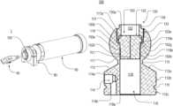
- a mount assemblycomprising a mount configured to support an enclosure in an adjustable manner, the mount including a body having an opening and a base, the mount having an internal passage extending through the opening of the body in an axial direction of the mount; a compression fitting secured to the mount; and a sealing insert disposed in the internal passage of the mount, wherein the sealing insert is interposed between the compression fitting and the mount in the internal passage.
- a ball mount assemblycomprising a ball mount including a body having an opening and a base, the ball mount having an internal passage extending through the opening of the body in an axial direction of the ball mount; a compression fitting secured to the ball mount; and a sealing insert disposed in the internal passage of the ball mount, wherein the sealing insert is interposed between the compression fitting and the ball mount in the internal passage, and wherein the internal passage of the ball mount is defined by a first sidewall and a second sidewall.
- a ball mount assemblyfor a leak resistant enclosure for an electrical device, the mount assembly comprising a ball mount including a body having a first opening and a base having a second opening configured to communicate with a leak resistant enclosure, the ball mount having an internal passage extending from the first opening of the body to the second opening of the base in an axial direction of the ball mount; a fitting secured to the ball mount; and a sealing insert disposed in the internal passage of the ball mount.
- FIG. 1 Ais a front perspective view of a mounted enclosure system including a mount assembly, according to a first exemplary embodiment.
- FIG. 1 Bis a rear perspective view of the mounted enclosure system shown in
- FIG. 1 AA .
- FIG. 2is an exploded view of the mount assembly shown in FIG. 1 A .
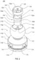
- FIG. 3 Ais a perspective view of the mount assembly shown in FIG. 1 A .
- FIG. 3 Bis a side view of the mount assembly shown in FIG. 1 A .
- FIG. 3 Cis a front view of the mount assembly shown in FIG. 1 A .
- FIG. 4 Ais a side view of the mount assembly shown in FIG. 1 A .
- FIG. 4 Bis a side cross-sectional view of the mount assembly between lines IVB and IVB shown in FIG. 4 A .
- FIG. 4 Cis a side cross-sectional view of the mount assembly between lines IVB and IVB shown in FIG. 4 A having a cable passing therethrough.
- FIG. 5 Ais a perspective view of a ball mount according to an exemplary embodiment.
- FIG. 5 Bis a bottom perspective view of the ball mount shown in FIG. 5 A .
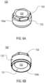
- FIG. 6 Ais a perspective view of a compression fitting according to an exemplary embodiment.
- FIG. 6 Bis a bottom perspective view of the compression fitting shown in FIG. 6 A .
- FIG. 6 Cis a front view of the compression fitting shown in FIG. 6 A .
- FIG. 6 Dis a side cross-sectional view of the compression fitting between lines VID and VID shown in FIG. 6 C .
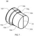
- FIG. 7is a perspective view of a sealing insert according to an exemplary embodiment.
- FIG. 8is an exploded view of a mount assembly, according to a second exemplary embodiment.
- FIG. 9is a perspective view of the mount assembly shown in FIG. 8 .
- FIG. 10 Ais a perspective view of a tilt mount according to an exemplary embodiment.
- FIG. 10 Bis a side perspective view of the tilt mount shown in FIG. 10 A .
- FIG. 11 Ais a perspective view of a ball mount according to another exemplary embodiment.
- FIG. 11 Bis a side perspective view of the ball mount shown in FIG. 11 A .
- FIG. 12 Ais a perspective view of a sealing insert according to another exemplary embodiment.
- FIG. 12 Bis a perspective view of the sealing insert shown in FIG. 12 A with a cable passing through the sealing insert.
- FIG. 13is a perspective view of a sealing insert according to yet another exemplary embodiment.
- FIG. 14is a perspective view of a sealing insert according to yet another exemplary embodiment.
- FIG. 15 Ais a perspective view of a compression fitting according to another exemplary embodiment.
- FIG. 15 Bis a side view of the compression fitting shown in FIG. 15 A .
- an adjustable mount assemblyhaving a sealing device integrated therein and which may be directly connected to and/or integrated with a device, apparatus, enclosure, or mount.
- Various aspects of adjustable mount assemblies and methods described hereinachieve technical advantages including but not limited to those noted herein.
- embodiments in the present disclosureare described specifically with respect to an adjustable mount assembly for an industrial enclosure, hereinafter referred to as a mounted enclosure system.
- a mounted enclosure systeman industrial enclosure
- the apparatus and methods described hereinapply to and can be used for other applications.
- FIGS. 1 A- 1 Bshow an exemplary embodiment of a mounted enclosure system 1 designed to provide maximum protection to electrical systems contained therein from harsh industrial environments without compromising the adjustability of the electrical system.
- the mounted enclosure system 1may include a mount assembly 100 having a sealing device, such as a soft rubber, foam, or like device integrated therein, an enclosure 60 , and a clamping mechanism 80 .
- the enclosure 60 and the clamping mechanism 80may be designed in a variety of different shapes and configurations, and it is to be understood that the present disclosure is not limited to exemplary embodiments depicted in FIGS. 1 A and 1 B .
- the mount assembly 100 shown in FIGS. 1 A- 1 Bis designed to allow a cable and/or tube to pass therethrough.
- the cable and/or tubemay be configured to provide an electrical signal and/or a fluid flow through the mount assembly 100 .
- the mount assembly 100may be configured to form a leak resistant connection with the enclosure 60 and to be supported by the clamping mechanism 80 .
- the mount assembly 100may also form a pressure seal between the mount assembly 100 and the enclosure 60 .
- the enclosure 60may be designed to accommodate electrical devices such as cameras, lighting, sensors, barcode readers, lasers, machine vision, security equipment, and the like.
- the clamping mechanism 80may be designed to accommodate the mount assembly 100 through a variety of different mechanisms so long as the clamping mechanism 80 is configured to support the mount assembly 100 .
- the clamping mechanism 80may be loosened and/or adjusted so that the mount assembly 100 may be adjusted relative to the clamping mechanism 80 .
- an angle position of the mount assembly 100 , and the enclosure 60may be adjusted relative to the clamping mechanism 80 .
- the structure of the mount assembly 100 , and the components thereof,are described in more detail below.
- FIGS. 2 - 4 Cillustrate various views of the mount assembly 100 according to one exemplary embodiment.
- FIG. 2shows an exploded view of the mount assembly 100 which may include a ball mount 110 , a compression fitting 130 , and a sealing insert 150 .
- FIGS. 3 A- 4 Cshow various assembled views of the mount assembly 100 depicting how the ball mount 110 , the compression fitting 130 , and the sealing insert 150 may fit together according to the exemplary embodiment.
- FIGS. 4 B- 4 Cshow a side cross-sectional view of the mount assembly 100 between the lines IVB and IVB shown in FIG. 4 A .
- the mount assembly 100when assembled, includes a ball mount 110 (shown in further detail in FIGS. 5 A- 5 B ), a compression fitting 130 (shown in further detail in FIGS. 6 A- 6 D ), and a sealing insert 150 (shown in further detail in FIG. 7 ).
- the ball mount 110includes a body portion 111 having an opening 117 a and a base portion 112 having an opening 118 a .
- the ball mount 110further includes an internal passage 116 extending from the opening 117 a of the body portion 111 in an axial direction of the ball mount 110 .
- the internal passage 116is further configured to extend from the opening 117 a to the opening 118 a along the axial direction of the ball mount.
- the sealing insert 150is configured to be inserted into the internal passage 116 of the ball mount 110 and secured in the internal passage 116 by the compression fitting 130 .
- the compression fitting 130is configured to be fit to the ball mount 110 such that the sealing insert 150 is securely interposed between the compression fitting 130 and the ball mount 110 in the internal passage 116 .
- the ball mount 110 , the compression fitting 130 , and the sealing insert 150are each configured to allow a cable 40 to pass therethrough.
- the mountmay be an adjustable mount, whether that adjustment be rotational, tilting, panning, or a combination thereof.
- the adjustable mountis a ball mount 110 configured to swivel and having the body portion 111 and the base portion 112 .
- the ball mount 110includes the internal passage 116 extending from the opening 117 a of the body portion 111 in the axial direction of the ball mount 110 .
- the body portion 111 and the base portion 112 of the ball mount 110may be coupled to each other at a neck 113 .
- the ball mount 110may be made of any suitable material, for example, aluminum, plastic, and stainless steel.
- the body portion 111may be made of the same material as the base portion 112 .
- ball mount 110may be comprised of one or more different materials.
- the body portion 111may be made of, and/or coated with, materials different than the base portion 112 .
- the body portion 111 of the ball mount 110is configured to be substantially round in shape and to have the internal passage 116 formed therein at the opening 117 a of the ball mount 110 .
- the opening 117 a of the body portion 111may be centrally located on the ball mount 110 about the center axis of the ball mount 110 .
- the opening 117 ais configured to allow a cable 40 to pass therethrough.
- the opening 117 ais further configured to receive and support the sealing insert 150 in the internal passage 116 and thereby provide a seal on the inside of the internal passage 116 .
- the opening 117 a of the body portion 111is also configured to receive the compression fitting 130 .
- the outer surface 133 of the compression fitting 130may be, but is not limited to being, coupled to the ball mount 110 via an interference fit, a threaded fit, a snap fit, a fit using an adhesive (e.g., glue), or any other type of fit.
- at least a portion of the opening 117 a of the body portion 111is configured to align within an opening of the clamping mechanism 80 .
- the opening 117 amay be disposed within the enclosure 60 .
- the base portion 112 of the ball mount 110may be configured to be coupled to, and/or integrated with, a device, apparatus, enclosure, mount, or the like.
- the base portion 112although not particularly limited to this configuration, includes a top surface 112 a , and upper side surface 112 b , a lower side surface 112 c , and a bottom surface 112 d .
- the top surface 112 ais configured to be integral with the neck 113 coupling the body portion 111 and the base portion 112 .
- the upper side surface 112 b and/or the lower side surface 112 cmay include an input/output to at least one air channel 114 .
- the at least one air channel 114may contain a first air fitting port 114 a as a threaded inlet and/or outlet.
- the lower side surface 112 cmay be, but is not limited to being, coupled to the enclosure 60 via an interference fit, a threaded fit, a snap fit, a fit using an adhesive (e.g., glue), or any other type of fit.
- the bottom surface 112 dis configured to include the internal passage 116 extending from the opening 118 a of the base portion 112 in the axial direction of the ball mount 110 .
- the opening 118 ais configured to allow a cable 40 to pass therethrough.
- the base portion 112 of the ball mount 110may further include a groove portion 115 for a sealing mechanism, such as an O-ring, capable of forming a seal between the ball mount 110 and the enclosure 60 .
- the groove portion 115may be disposed between the upper side surface 112 b and the lower side surface 112 c of the ball mount 110 in order to provide an air tight seal between the upper side surface 112 b and the bottom surface 112 d .
- the upper side surface 112 bis configured to include the at least one air channel 114 having a first air fitting port 114 a as an inlet and/or outlet and the bottom surface 112 d is configured to include the at least one air channel 114 having a second air fitting port 114 b as the other of an inlet and/or outlet.
- the present disclosureis not particularly limited to this embodiment.
- the first air fitting port 114 a and the second air fitting port 114 bmay be configured to allow for a fluid flow in either direction and may be configured to receive any type of fluid and/or gas.
- the base portion 112 of the ball mount 110may further include at least one mounting hole 120 .
- the base portion 112comprises a plurality of mounting holes 120 disposed radially around a periphery of the opening 118 a of the base portion 112 .
- the ball mount 110may include mounting holes 120 in addition to, or instead of, a lower side surface 112 c having a threaded portion.
- the ball mount 110includes the internal passage 116 extending through the body portion 111 , the neck 113 , and the base portion 112 in the axial direction of the ball mount 110 .
- the internal passage 116is configured to extend from the opening 117 a of the body portion 111 to the opening 118 a of the base portion 112 .
- the internal passage 116 of the body portion 111includes a first sidewall 117 , a second sidewall 118 , and a shoulder portion 119 disposed between the first sidewall 117 and the second sidewall 118 .
- the first sidewall 117 , a portion of the second sidewall 118 , and the shoulder portion 119are located within the body portion 111 and a portion of the second sidewall 118 is located in the base portion 112 .
- the position of the shoulder portion 119 within the internal passage 116is not particularly limited to this embodiment.
- at least a portion of the shoulder portion 119may be located in the neck 113 and/or the base portion 112 .
- the first sidewall 117 and/or the second sidewall 118are configured to be substantially cylindrical in shape.
- the first sidewall 117 and/or the second sidewall 118may comprise a threaded wall disposed along a portion of, or along the entire, first sidewall 117 and/or the second sidewall 118 .
- the first sidewall 117is preferably configured to have a threaded wall portion for fitting the outer surface 133 of the compression fitting 130 to the ball mount 110 for securing the sealing insert 150 within the internal passage 116 .
- a force applied by the compression fitting 130 to the sealing insert 150secures the sealing insert 150 to the internal passage 116 thereby providing a seal between the first sidewall 117 and the second sidewall 118 .
- the shoulder portion 119 of the internal passage 116includes an outer edge 119 a having a first diameter measured in the radial direction from the center axis and an inner edge 119 b having a second diameter measured in the radial direction from the center axis.
- the shoulder portion 119is configured to meet with the first sidewall 117 at an interface defined by the outer edge 119 a and to meet with the second sidewall 118 at an interface defined by the inner edge 119 b .
- the outer edge 119 a and the inner edge 119 bare substantially circular in shape and are formed concentric with one another such that the first diameter is greater than the second diameter.
- the outer edge 119 a and the inner edge 119 bmay not share a common center.
- the outer edge 119 a and the inner edge 119 bmay both be formed in a plane intersecting the center axis such that the shoulder portion 119 is formed substantially perpendicular to the first sidewall 117 and/or the second sidewall 118 .
- the outer edge 119 amay be formed on a side of the ball mount 110 closer in an axial direction to the opening 117 a of the body portion 111 than the inner edge 119 b such that the shoulder portion 119 is configured to be inclined in a downward direction toward the opening 118 a .
- the outer edge 119 amay be formed on a side of the ball mount 110 closer in an axial direction to the opening 118 a of the base portion 112 than the inner edge 119 b such that the shoulder portion 119 is configured to be inclined in a upward direction toward the opening 117 a.
- the diameter of the opening 117 a of the body portion 111may be substantially similar to the first diameter of the outer edge 119 a .
- the diameter of the opening 118 a of the base portion 112may be substantially similar to the second diameter of the inner edge 119 b .
- the diameter of the opening 117 a of the body portion 111may be larger than the first diameter of the outer edge 119 a .
- the diameter of the opening 118 a of the base portion 112may be larger than the second diameter of the inner edge 119 b .
- the diameter of the opening 117 a of the body portion 111may be smaller than the first diameter of the outer edge 119 a .
- the diameter of the opening 118 a of the base portion 112may be smaller than the second diameter of the inner edge 119 b.
- the mount assembly 200includes a tilt mount 210 comprising a body portion 211 and a base portion.
- the body portion 211comprises a through hole 211 a configured to be pivotally attached to an external mount or support.
- the mount assembly 200may be adjusted about an axis extending through the through hole 211 a such that an angle position of the mount assembly 200 , and the enclosure 60 mountable thereon, may be adjusted. While FIGS.
- the mount assembly 200may be tilted about the axis extending through the through hole 211 a , the mount assembly 200 may be configured to be adjusted (i.e., rotate, tilt, pan, or a combination thereof) about any axis relative to the mount assembly 200 and/or a mounting device for the same.
- FIGS. 11 A- 11 Banother alternative embodiment of a ball mount 310 is shown.
- the alternative embodiment of the ball mount 310 shown in FIGS. 11 A- 11 Bis similar to the embodiment of the ball mount 110 shown in FIGS. 1 A- 5 B , the tilt mount 210 shown in FIGS. 8 - 10 B , and described above except for the differences described herein.
- a modified ball mount 310includes a body portion 311 and a base portion 312 .
- the base portion 312may include a top surface 312 a , and upper side surface 312 b , a lower side surface 312 c , a bottom surface 312 d , a first side surface 312 e , and a second side surface 312 f.
- the top surface 312 ais configured to be integral with a neck 313 coupling the body portion 311 and the base portion 312 .
- the bottom surface 312 dmay be, but is not limited to being, coupled to the enclosure 60 by mounting holes 320 a and 320 b which may be configured to receive a fastener from the top surface 312 a .
- the base portion 312may be coupled to the enclosure 60 by the upper surface 312 b and/or the lower side surface 312 c which may be threaded.
- the bottom surface 312 dis configured to include an internal passage 316 extending from an opening 318 a of the base portion 312 in the axial direction of the modified ball mount 310 to an opening 317 a of the body portion 311 .
- the opening 318 a and the opening 317 aare configured to allow a cable 40 to pass therethrough.
- the compression fitting 130is configured to secure the sealing insert 150 in the internal passage 116 of the ball mount 110 .
- the compression fitting 130includes an exterior opening 130 a located on a distal end side of the compression fitting 130 relative to the sealing insert 150 in the axial direction, an interior opening 130 b located on a proximal end side of the compression fitting 130 relative to the sealing insert 150 in the axial direction, an inner surface 132 , and an outer surface 133 .
- the outer surface 133may comprise a threaded portion configured to pair with the internal passage 116 of the ball mount 110 such that at least a portion of the outer surface 133 of the compression fitting 130 is fastened to at least a portion of the first sidewall 117 of the ball mount 110 .
- the compression fitting 130may be a tapered sealing nut having a head 134 .
- the compression fittingis configured to fit within the opening 117 a of the body portion 111 such that at least a portion of the head 134 extends above the opening 117 a to allow the compression fitting 130 to be tightened.
- the compression fitting 130may be tightened such that the entire compression fitting 130 is disposed within the internal passage 116 and below the opening 117 a .
- the compression fitting 130is further configured to allow a cable 40 to pass through each of the ball mount 110 , the compression fitting 130 , and the sealing insert 150 .
- the inner surface 132 of the compression fitting 130is configured to include a chamfered portion 131 as shown in the cross-sectional view of the compression fitting 130 depicted in FIG. 6 D .
- the chamfered portion 131is compressed and pressed against the sealing insert 150 at least one seal is formed between a portion of a volume defined by the first sidewall 117 and a portion of a volume defined by the second sidewall 118 .
- the seal formed between internal passage 116 and the compression fitting 130may be a liquid-tight seal and/or an air-tight seal.
- the compression fitting 130is configured to be adjustably, removably, and/or permanently disposed in the opening 117 a of the body portion 111 and to be coupled with the first sidewall 117 of the ball mount 110 such that the sealing insert 150 is securely interposed between the compression fitting 130 and the ball mount 110 in the internal passage 116 .
- the chamfered portion 131 of the compression fitting 130is configured to apply a compressive force in the axial direction toward the sealing insert 150 to secure the sealing insert 150 and a compressive force inward in the radial direction to create a first seal between the sealing insert 150 and an object (e.g., the cable 40 ) passing through the sealing insert 150 .
- Both compressive forces applied to the sealing insert 150establish a second seal between the sealing insert 150 and the first sidewall 117 , the second sidewall 118 , and/or the shoulder portion 119 . Additionally, a third seal is formed between the sealing insert 150 and compression fitting 130 .
- the chamfered portion 131 of the compression fitting 130is configured to contact the sealing insert 150 at a first distance from a center axis of the ball mount 110 in a direction orthogonal to the center axis.
- the inner edge 119 b of the shoulder portion 119is located at a second distance from the center axis of the ball mount 110 in the orthogonal direction, and the first distance is greater than the second distance.
- the outer edge 119 a of the shoulder portion 119is located at a third distance from the center axis of the ball mount 110 in the orthogonal direction, and the first distance is less than the third distance.
- FIGS. 6 A- 6 Dillustrate that the compression fitting 130 may be a tapered sealing nut
- the compression fitting 130may include a chamfered portion 131 configured to compress the sealing insert 150 against the shoulder portion 119 of the internal passage 116
- the chamfermay occur on the compression fitting 130 and/or the shoulder portion 119 .
- the chamfered portion 131 between the inner surface 132 and the outer surface 133may alternatively comprise a beveled surface, a filleted surface, or a straight surface so as to form right angles between the inner surface 132 and the outer surface 133 .
- the shoulder portion 119may alternatively comprise a chamfered surface, a beveled surface, a filleted surface, or a straight surface so as to form a right angle(s) between the first sidewall 117 and the second sidewall 118 .
- the compression fitting 130is made of any suitable material, for example, aluminum, plastic, and stainless steel.
- the mount assembly 100may include the compression fitting 330 depicted in FIGS. 15 A- 15 B .
- the compression fitting 330is similar to the embodiment of the compression fitting 130 described above except for the differences described below.
- the compression fitting 330may be configured to secure the sealing insert 150 in the internal passage 116 of the ball mount 110 .
- the compression fitting 330includes an exterior opening 330 a located on a distal end side of the compression fitting 330 relative to the sealing insert 150 in the axial direction, an interior opening 330 b located on a proximal end side of the compression fitting 330 relative to the sealing insert 150 in the axial direction, an inner surface 332 , a first outer surface 333 , and a second outer surface 337 .
- the length of the second outer surface 337is preferably at least twice the length of the first outer surface 333 .
- the second outer surface 337may be formed on an extended portion 336 of the compression fitting 330 in order to allow a conduit or tubing to be connected to the extended portion 336 .
- the extended portion 336is substantially tubular in shape.
- the second outer surface 337 of the compression fitting 330may comprise a threaded portion configured to be connected to conduit or tubing for the cable 40 .
- the first outer surface 333may comprise a threaded portion configured to pair with the internal passage 116 of the ball mount 110 such that at least a portion of the outer surface 333 of the compression fitting 330 is fastened to at least a portion of the first sidewall 117 of the ball mount 110 .
- the sealing insert 150is configured to be inserted into the internal passage 116 of the ball mount 110 and secured in the internal passage 116 by the compression fitting 130 thereby forming a leak resistant seal.
- the sealing insert 150is configured to provide a water-tight and/or air-tight seal between a portion of the volume defined by the first sidewall 117 and a portion of the volume defined by the second sidewall 118 .
- the sealing insert 150may be disposed entirely within the body portion 111 of the ball mount 110 .
- the sealing insert 150may be disposed partly within the body portion 111 and partly within the base portion 112 .
- the sealing insert 150can be the same as those described above.
- the sealing insert 150may be a cord grip, a cable gland, or like mechanism configured to allow cables, tubes, wires, and the like to pass therethrough.
- the sealing insert 150may be made of any suitable material, such as a soft piece of material like rubber, foam, or like material.
- the sealing insert 150may be a split insert including a first sealing part 150 a and a second sealing part 150 b having a slit portion 151 formed between the first sealing part 150 a and the second sealing part 150 b .
- the first sealing part 150 a and the second sealing part 150 bare configured to allow a cable 40 to pass therethrough and to provide a water-tight and/or air-tight seal on the cable 40 along the slit portion 151 .
- One technical effect of the sealing insert having the first sealing part 150 a and the second sealing part 150 bis that the sealing insert 150 may be formed around a cable 40 having a large connector 41 .
- the sealing insert 150may comprise a substantially cylindrical shape.
- the sealing insert 150may comprise a major surface 152 a , a minor surface 152 b , a top surface 152 c and a bottom surface 152 d ; the major surface 152 a having a diameter greater than the minor surface 152 b .
- the sealing insert 150may further include a middle surface 152 e disposed between the major surface 152 a and the minor surface 152 b such that the middle surface 152 e and the major surface are connected by a middle shoulder 152 g .
- the top surface of the sealing insert 150may have an edge 152 f that is substantially radiused. Alternatively, the edge 152 f may be chamfered, beveled, filleted, or straight so as to form a right angle.
- the sealing insert 150is configured such that the major surface 152 a and/or the top surface 152 c may form a water-tight and/or air-tight seal with the compression fitting 130 .
- the major surface 152 a and/or the top surface 152 care configured to form a seal with the chamfered portion 131 .
- the edge 152 fis configured to form a seal with the chamfered portion 131 .
- the sealing insert 150is configured such that the middle shoulder 152 g is configured to form a seal with the shoulder portion 119 of the ball mount 110 .
- the major surface 152 amay have a diameter smaller than the first diameter defined by the outer edge 119 a of the shoulder such that an annular void is formed within a space defined by the ball mount 110 , the compression fitting 130 , and the sealing insert 150 .
- the entire middle shoulder 152 gmay be disposed on the shoulder portion 119 .
- the sealing insert 150may be configured such that the middle surface 152 e and the minor surface 152 b form a water-tight and/or air-tight seal with the second sidewall 118 .
- the top surface 152 c and the inner surface 132 of the compression fitting 130may define a first cavity disposed at least in part in the body portion 111 .
- the bottom surface 152 d and the volume formed within the second sidewall 118may define a second cavity disposed at least in part in the base portion 112 .
- the sealing insert 150may be configured such that the slit portion is disposed along the axial direction of the mount assembly 100 .
- a cable 40may pass from the first cavity to the second cavity and through each of the ball mount 110 , the compression fitting 130 , and the sealing insert 150 .
- the compression fitting 130 and the sealing insert 150may both be configured to be attachable to, and removable from, the ball mount 110 .
- the compression fitting 130 and the sealing insert 150may be integrally formed as a singular component.
- the present disclosureis not particularly limited to this embodiment.
- the mount assembly 100may include the sealing insert 350 depicted in FIGS. 12 A- 12 B .
- the sealing insert 350is similar to the embodiment of the sealing insert 150 described above except for the differences described herein.
- the sealing insert 350is configured to be a solid body having a cable hole 353 extending therethrough from a top surface 352 c to a bottom surface of the sealing insert 350 .
- the sealing insert 350is configured such that the major surface 352 a and/or the top surface 352 c may form a water-tight and/or air-tight seal with the compression fitting 130 .
- the major surface 352 a and/or the top surface 352 care configured to form a seal with the chamfered portion 131 .
- an edge 352 fis configured to form a seal with the chamfered portion 131 .
- the sealing insert 350is configured such that the middle shoulder 352 g is configured to form a seal with the shoulder portion 119 of the ball mount 110 .
- the mount assembly 100may include the sealing insert 450 depicted in FIG. 13 .
- the sealing insert 450is similar to the embodiment of the sealing insert 150 described above except for the differences described herein.
- the sealing insert 450is configured to be a solid body or plug.
- the sealing insert 450may be configured to prevent objects, gas, and/or fluid from passing through the internal passage 116 of the ball mount 110 .
- the sealing insert 450may include a major surface 452 a , a minor surface 452 b , a top surface, a bottom surface 452 d , a middle shoulder 452 g , and an edge portion 452 f
- the top surface of the sealing insert 450 and the inner surface 132 of the compression fitting 130may define a first cavity disposed at least in part in the body portion 111 .
- the bottom surface 452 d and the volume formed within the second sidewall 118may define a second cavity disposed at least in part in the base portion 112 .
- the sealing insert 450is configured to form a liquid-tight seal and/or an air-tight seal between the first cavity and the second cavity.
- the mount assembly 100may include the sealing insert 550 depicted in FIG. 14 .
- the sealing insert 550is similar to the embodiment of the sealing insert 150 and the sealing insert 350 described above except for the differences described herein.
- the sealing insertis configured to include a first sealing part 550 a and a second sealing part 550 b having a slit portion 551 and a cable hole 553 disposed therein.
- the cable holemay be configured to be substantially round in shape.
- the cable hole 553is configured to extend along the sealing insert 550 in the axial direction and the slit portion 551 is configured to extend from the top surface 552 c to the bottom surface of the sealing insert 550 .
- the sealing insert 550may further include a major surface 552 a , a minor surface 552 b , a top surface 552 c , a bottom surface, a middle shoulder 552 g , and an edge portion 552 f.
- the term “substantially” and similar termsgenerally mean+/ ⁇ 10% of the disclosed values, unless specified otherwise.
- structural featurese.g., to describe shape, size, orientation, direction, relative position, etc.
- the term “substantially” and similar termsare meant to cover minor variations in structure that may result from, for example, the manufacturing or assembly process and are intended to have a broad meaning in harmony with the common and accepted usage by those of ordinary skill in the art to which the subject matter of this disclosure pertains. Accordingly, these terms should be interpreted as indicating that insubstantial or inconsequential modifications or alterations of the subject matter described and claimed are considered to be within the scope of the disclosure as recited in the appended claims.
- Coupledmeans the joining of two members directly or indirectly to one another. Such joining may be stationary (e.g., permanent or fixed) or moveable (e.g., removable or releasable). Such joining may be achieved with the two members coupled directly to each other, with the two members coupled to each other using a separate intervening member and any additional intermediate members coupled with one another, or with the two members coupled to each other using an intervening member that is integrally formed as a single unitary body with one of the two members.
- Coupledor variations thereof are modified by an additional term (e.g., directly coupled)
- the generic definition of “coupled” provided aboveis modified by the plain language meaning of the additional term (e.g., “directly coupled” means the joining of two members without any separate intervening member), resulting in a narrower definition than the generic definition of “coupled” provided above.
- Such couplingmay be mechanical, electrical, or fluidic.
Landscapes
- Engineering & Computer Science (AREA)
- General Engineering & Computer Science (AREA)
- Mechanical Engineering (AREA)
- Insertion, Bundling And Securing Of Wires For Electric Apparatuses (AREA)
- Pivots And Pivotal Connections (AREA)
Abstract
Description
Claims (5)
Priority Applications (1)
| Application Number | Priority Date | Filing Date | Title |
|---|---|---|---|
| US17/729,513US12126152B2 (en) | 2021-04-29 | 2022-04-26 | Ball mount with integrated cable gland |
Applications Claiming Priority (2)
| Application Number | Priority Date | Filing Date | Title |
|---|---|---|---|
| US202163181478P | 2021-04-29 | 2021-04-29 | |
| US17/729,513US12126152B2 (en) | 2021-04-29 | 2022-04-26 | Ball mount with integrated cable gland |
Publications (2)
| Publication Number | Publication Date |
|---|---|
| US20220349498A1 US20220349498A1 (en) | 2022-11-03 |
| US12126152B2true US12126152B2 (en) | 2024-10-22 |
Family
ID=83808356
Family Applications (1)
| Application Number | Title | Priority Date | Filing Date |
|---|---|---|---|
| US17/729,513Active2042-08-31US12126152B2 (en) | 2021-04-29 | 2022-04-26 | Ball mount with integrated cable gland |
Country Status (1)
| Country | Link |
|---|---|
| US (1) | US12126152B2 (en) |
Cited By (1)
| Publication number | Priority date | Publication date | Assignee | Title |
|---|---|---|---|---|
| US20250172233A1 (en)* | 2023-11-29 | 2025-05-29 | Chicony Electronics Co., Ltd. | Rotating base and image capturing module |
Citations (82)
| Publication number | Priority date | Publication date | Assignee | Title |
|---|---|---|---|---|
| US1187642A (en)* | 1914-10-17 | 1916-06-20 | Max J Milz | Pipe-joint |
| US1500921A (en)* | 1919-06-21 | 1924-07-08 | Bramson Mogens Louis | Flexible pipe line |
| US3033596A (en)* | 1960-05-09 | 1962-05-08 | Jerry M Pearring | Cable-passing swivel |
| US3646496A (en)* | 1969-07-30 | 1972-02-29 | Williams Instruments | Electrical cable connector and grounding means |
| US4030741A (en) | 1975-01-20 | 1977-06-21 | Harvey Hubbell, Incorporated | Cord grips |
| DE3734873A1 (en)* | 1987-10-15 | 1989-04-27 | Kabelmetal Electro Gmbh | Bush for branching or connecting points of electrical cables |
| US4842059A (en)* | 1988-09-16 | 1989-06-27 | Halliburton Logging Services, Inc. | Flex joint incorporating enclosed conductors |
| US4853965A (en)* | 1988-02-05 | 1989-08-01 | The Quaker Oats Company | Flexible joint mechanism |
| US5110224A (en)* | 1989-11-15 | 1992-05-05 | Stc Plc | Flexible cable termination with swivel couplings |
| US5132492A (en)* | 1991-05-06 | 1992-07-21 | Heath Company | Limited travel universally adjustable electrical fixture |
| US5197767A (en)* | 1985-04-09 | 1993-03-30 | Tsubakimoto Chain Co. | Flexible supporting sheath for cables and the like |
| FR2728047A1 (en)* | 1994-12-12 | 1996-06-14 | Aeg Schneider Automation | Sealed box-cable joint for fibre=optic cables |
| US6029293A (en)* | 1998-02-06 | 2000-02-29 | Speakman Company | Sensor assembly having flexibly mounted fiber optic proximity sensor |
| US6053504A (en)* | 1996-11-21 | 2000-04-25 | Rxs Kabelgarnituren Gmbh | Clamping ring for flange connections in cable fittings and pipes |
| US6328270B1 (en)* | 1999-11-12 | 2001-12-11 | Elbex Video Ltd. | Swivel joint with cable passage for a television camera or a case |
| US6376766B1 (en)* | 1998-06-03 | 2002-04-23 | Anton Hummel Verwaltungs Gmbh | Mounting for oblong structures with an electrical shielding |
| US6578800B2 (en)* | 2000-06-15 | 2003-06-17 | Kuka Roboter Gmbh | Apparatus for fixing a cable guidance hose |
| US6629651B1 (en)* | 1997-01-10 | 2003-10-07 | Water Pik, Inc. | Flexible shower arm assembly |
| US20040119246A1 (en)* | 2002-08-02 | 2004-06-24 | Josef Woller | Sealing device |
| US6846201B2 (en)* | 2002-12-20 | 2005-01-25 | The Boeing Company | Electrical cable clamping method and apparatus |
| US20070124923A1 (en)* | 2005-12-02 | 2007-06-07 | Yazaki Corporation | Rotatable clamp for wire harness and unit utilizing same |
| WO2007118334A1 (en)* | 2006-04-19 | 2007-10-25 | Taimi R & D Inc. | Multifunctionally swivelling coupling assembly for fluid lines |
| US7296771B2 (en) | 2005-07-14 | 2007-11-20 | Garmin Ltd. | Separable ball and socket assembly for electronic device mounts |
| EP1890368A2 (en)* | 2006-08-18 | 2008-02-20 | Olaf Johannsen ApS | A cable gland |
| USD588903S1 (en) | 2007-12-24 | 2009-03-24 | Carnevali Jeffrey D | Suction cup clamp assembly |
| US7534965B1 (en) | 2008-01-29 | 2009-05-19 | Thompson David M | Cable grommet with ball and socket |
| US7781685B2 (en)* | 2005-09-07 | 2010-08-24 | Anton Hummel Verwaltungs Gmbh | Kit or set comprising at least two differently dimensioned types of cable glands |
| WO2011051005A2 (en)* | 2009-10-29 | 2011-05-05 | Endress+Hauser Gmbh+Co.Kg | Cable feedthrough and measuring device comprising a cable feedthrough |
| DE102009059211A1 (en) | 2009-12-18 | 2011-06-22 | Pflitsch GmbH & Co. KG, 42499 | Arrangement for liquid-tightly and breathably leading cable through punch and wall of e.g. junction box, in building system engineering, has valve connected with outdoor atmosphere and connected with inner space of component over air gap |
| EP2369211A2 (en) | 2010-03-10 | 2011-09-28 | Pflitsch GmbH & Co. KG. | Device for a sealed feedthrough of long moulded parts |
| US8201800B2 (en) | 2008-08-06 | 2012-06-19 | Gentex Corporation | Two ball mount with wiring passage |
| US8201785B2 (en) | 2006-10-31 | 2012-06-19 | Ardisam, Inc. | Camera positioning systems |
| EP2492566A2 (en) | 2011-02-26 | 2012-08-29 | Pflitsch GmbH & Co. KG. | Screw connection for sealed lead-through of conduits |
| US20120315780A1 (en)* | 2011-06-09 | 2012-12-13 | John Mezzalingua Associates, Inc. | Sealing member for sealing a connection between a coaxial cable connector and a port |
| DE202012012427U1 (en) | 2012-06-02 | 2013-01-25 | Pflitsch Gmbh & Co. Kg | Screw connection for sealed cable bushings |
| US8419309B2 (en) | 2006-11-29 | 2013-04-16 | Wimberley, Inc. | Pivoting ball mount having four equally spaced contact points |
| EP1675244B1 (en) | 2004-12-21 | 2013-06-12 | Pflitsch GmbH & Co. KG. | Screw gland for sealed conduit feedthroughs |
| US20130168957A1 (en)* | 2009-11-23 | 2013-07-04 | Ira H. Kaplan | Adjustable swivel fluid conduit pathway |
| US20130256467A1 (en)* | 2010-12-01 | 2013-10-03 | Markus Aumiller | Holding device for holding a cable |
| US8602662B1 (en) | 2010-11-04 | 2013-12-10 | John Mans | Camera and accessories clamping mount |
| US20140030903A1 (en)* | 2012-07-26 | 2014-01-30 | Thomas & Betts International, Inc. | Cable gland for electrical cable fitting |
| US8690599B2 (en)* | 2009-10-07 | 2014-04-08 | Hummel Ag | Cable gland for a shielded cable |
| DE102012107406A1 (en)* | 2012-08-10 | 2014-05-15 | Endress + Hauser Gmbh + Co. Kg | Connection device with shielding contact |
| US8910914B2 (en)* | 2012-04-04 | 2014-12-16 | Audix Corporation | Mount for electronics equipment |
| US8919221B2 (en) | 2010-03-19 | 2014-12-30 | Avc Industrial Corp. | Cable gland and gasket ring assembly |
| EP2469671B1 (en) | 2010-12-23 | 2015-04-22 | Tyco Electronics AMP GmbH | Clamping Ring, Cable Gland and Method of Fitting a Cable Gland |
| US20150137456A1 (en)* | 2012-06-22 | 2015-05-21 | Tranberg As | Packer for Cable Gland and Use of the Same |
| GB2523098A (en)* | 2014-02-12 | 2015-08-19 | Avc Ind Corp | Cable gland assembly |
| US9188280B2 (en) | 2011-08-02 | 2015-11-17 | Industrial Revolution, Inc. | Mounting device |
| US20160039098A1 (en) | 2014-08-11 | 2016-02-11 | Swivel-Link, LLC | Swivel link for mounting end of arm tooling |
| US20160141853A1 (en)* | 2014-11-14 | 2016-05-19 | Robert Findley | Ball grip compression fitting |
| US9385520B1 (en)* | 2014-06-19 | 2016-07-05 | Arlington Industries, Inc. | Rain tight fitting for PVC jacketed metal-clad electrical cable |
| US9436067B2 (en)* | 2013-12-13 | 2016-09-06 | Vivotek Inc. | Movable bracket and camera device having the movable bracket |
| US9568145B2 (en) | 2009-10-28 | 2017-02-14 | Jeffrey D. Carnevali | Flex base with ball mount |
| US9625791B2 (en) | 2015-01-23 | 2017-04-18 | Gopro, Inc. | Swivel camera mount |
| KR101728442B1 (en)* | 2015-07-15 | 2017-04-19 | 조미희 | Cable Gland |
| US9880451B2 (en) | 2014-10-22 | 2018-01-30 | Gopro, Inc. | Quick-release ball-and-socket joint camera mount |
| DE102016120039A1 (en)* | 2016-10-20 | 2018-04-26 | Schlemmer Gmbh | Fastening device and cable arrangement |
| US10082726B2 (en)* | 2016-03-15 | 2018-09-25 | Axis Ab | Ball joint |
| US10178209B1 (en) | 2017-11-29 | 2019-01-08 | Andrew Hesse | Accessory mount for smartphones, tablets, iPads, and cameras |
| DE102017212582A1 (en)* | 2017-07-21 | 2019-01-24 | Ifm Electronic Gmbh | Cable gland and connector with a cable gland |
| US20190123534A1 (en)* | 2017-08-25 | 2019-04-25 | Mike Pastusek | Cable Connector |
| US20190190190A1 (en)* | 2017-12-15 | 2019-06-20 | Radiall Sa | Cable joint articulated extension piece for a connector intended to be linked to at least one cable |
| WO2019134768A1 (en)* | 2018-01-08 | 2019-07-11 | Agro Ag | Cable screw connection |
| CN110333173A (en)* | 2019-06-25 | 2019-10-15 | 宁波东方电缆股份有限公司 | A kind of sealing structure of sea cable apparatus for permeability test |
| US10547769B2 (en) | 2014-10-02 | 2020-01-28 | Gopro, Inc. | Swivel camera mount |
| US10548380B2 (en) | 2013-02-01 | 2020-02-04 | Treefrog Developments, Inc. | Waterproof housing for an electronic device |
| US20200161848A1 (en)* | 2018-11-17 | 2020-05-21 | Hamilton Sundstrand Corporation | Electrical assembly sealing arrangement |
| US10787866B2 (en)* | 2015-11-18 | 2020-09-29 | Halliburton Energy Services, Inc. | Segmented bend-limiter for slickline rope sockets and cable-heads |
| US20200316792A1 (en) | 2019-04-03 | 2020-10-08 | Swivel-Link, LLC | Boom arm for positioning an auxiliary electrical device |
| US10801664B1 (en) | 2019-04-03 | 2020-10-13 | Swivel-Link, LLC | Articulating sensor bracket |
| US20200358276A1 (en)* | 2017-11-24 | 2020-11-12 | Harting Electric Gmbh & Co. Kg | Cable feedthrough |
| USD904169S1 (en) | 2019-02-08 | 2020-12-08 | Swivel-Link, LLC | Bracket base |
| USD904912S1 (en) | 2019-04-03 | 2020-12-15 | Swivel-Link, LLC | Sensor bracket assembly |
| USD904862S1 (en) | 2019-04-03 | 2020-12-15 | Swivel-Link, LLC | Telescoping link |
| US20210013707A1 (en)* | 2019-07-12 | 2021-01-14 | Hubbell Incorporated | Liquid epoxy brush barrier |
| EP3787123A1 (en)* | 2019-08-28 | 2021-03-03 | Etel S. A.. | Cable shield connecting assembly for electrical device and method for securing and grounding a cable to a cylindrical housing of an electric rotary motor |
| US20210234354A1 (en)* | 2018-05-17 | 2021-07-29 | Hubbell Limited | Cable gland |
| KR20210157721A (en)* | 2020-06-22 | 2021-12-29 | 주식회사 금빛 | Cable fixing device with sealing structure inside |
| CN113904286A (en)* | 2021-12-13 | 2022-01-07 | 江苏亨通海洋光网系统有限公司 | High-pressure cabin-penetrating sealing structure and method for submarine cable test |
| US20220403973A1 (en)* | 2021-06-11 | 2022-12-22 | APG Vision LLC | Clamping Mechanism for a Ball Mount |
| KR102558748B1 (en)* | 2022-06-24 | 2023-08-25 | 일신산업전기 주식회사 | explosion-proof cable gland |
- 2022
- 2022-04-26USUS17/729,513patent/US12126152B2/enactiveActive
Patent Citations (88)
| Publication number | Priority date | Publication date | Assignee | Title |
|---|---|---|---|---|
| US1187642A (en)* | 1914-10-17 | 1916-06-20 | Max J Milz | Pipe-joint |
| US1500921A (en)* | 1919-06-21 | 1924-07-08 | Bramson Mogens Louis | Flexible pipe line |
| US3033596A (en)* | 1960-05-09 | 1962-05-08 | Jerry M Pearring | Cable-passing swivel |
| US3646496A (en)* | 1969-07-30 | 1972-02-29 | Williams Instruments | Electrical cable connector and grounding means |
| US4030741A (en) | 1975-01-20 | 1977-06-21 | Harvey Hubbell, Incorporated | Cord grips |
| US5197767A (en)* | 1985-04-09 | 1993-03-30 | Tsubakimoto Chain Co. | Flexible supporting sheath for cables and the like |
| DE3734873A1 (en)* | 1987-10-15 | 1989-04-27 | Kabelmetal Electro Gmbh | Bush for branching or connecting points of electrical cables |
| US4853965A (en)* | 1988-02-05 | 1989-08-01 | The Quaker Oats Company | Flexible joint mechanism |
| US4842059A (en)* | 1988-09-16 | 1989-06-27 | Halliburton Logging Services, Inc. | Flex joint incorporating enclosed conductors |
| US5110224A (en)* | 1989-11-15 | 1992-05-05 | Stc Plc | Flexible cable termination with swivel couplings |
| US5132492A (en)* | 1991-05-06 | 1992-07-21 | Heath Company | Limited travel universally adjustable electrical fixture |
| FR2728047A1 (en)* | 1994-12-12 | 1996-06-14 | Aeg Schneider Automation | Sealed box-cable joint for fibre=optic cables |
| US6053504A (en)* | 1996-11-21 | 2000-04-25 | Rxs Kabelgarnituren Gmbh | Clamping ring for flange connections in cable fittings and pipes |
| US6629651B1 (en)* | 1997-01-10 | 2003-10-07 | Water Pik, Inc. | Flexible shower arm assembly |
| US6029293A (en)* | 1998-02-06 | 2000-02-29 | Speakman Company | Sensor assembly having flexibly mounted fiber optic proximity sensor |
| US6376766B1 (en)* | 1998-06-03 | 2002-04-23 | Anton Hummel Verwaltungs Gmbh | Mounting for oblong structures with an electrical shielding |
| US6328270B1 (en)* | 1999-11-12 | 2001-12-11 | Elbex Video Ltd. | Swivel joint with cable passage for a television camera or a case |
| US6578800B2 (en)* | 2000-06-15 | 2003-06-17 | Kuka Roboter Gmbh | Apparatus for fixing a cable guidance hose |
| US20040119246A1 (en)* | 2002-08-02 | 2004-06-24 | Josef Woller | Sealing device |
| US6846201B2 (en)* | 2002-12-20 | 2005-01-25 | The Boeing Company | Electrical cable clamping method and apparatus |
| EP1675244B1 (en) | 2004-12-21 | 2013-06-12 | Pflitsch GmbH & Co. KG. | Screw gland for sealed conduit feedthroughs |
| US7296771B2 (en) | 2005-07-14 | 2007-11-20 | Garmin Ltd. | Separable ball and socket assembly for electronic device mounts |
| US7781685B2 (en)* | 2005-09-07 | 2010-08-24 | Anton Hummel Verwaltungs Gmbh | Kit or set comprising at least two differently dimensioned types of cable glands |
| US20070124923A1 (en)* | 2005-12-02 | 2007-06-07 | Yazaki Corporation | Rotatable clamp for wire harness and unit utilizing same |
| US7938451B2 (en)* | 2006-04-19 | 2011-05-10 | Taimi R&D Inc. | Multifunctionally swivelling coupling assembly for fluid lines |
| WO2007118334A1 (en)* | 2006-04-19 | 2007-10-25 | Taimi R & D Inc. | Multifunctionally swivelling coupling assembly for fluid lines |
| EP1890368A2 (en)* | 2006-08-18 | 2008-02-20 | Olaf Johannsen ApS | A cable gland |
| US8201785B2 (en) | 2006-10-31 | 2012-06-19 | Ardisam, Inc. | Camera positioning systems |
| US8419309B2 (en) | 2006-11-29 | 2013-04-16 | Wimberley, Inc. | Pivoting ball mount having four equally spaced contact points |
| USD588903S1 (en) | 2007-12-24 | 2009-03-24 | Carnevali Jeffrey D | Suction cup clamp assembly |
| US7534965B1 (en) | 2008-01-29 | 2009-05-19 | Thompson David M | Cable grommet with ball and socket |
| US8201800B2 (en) | 2008-08-06 | 2012-06-19 | Gentex Corporation | Two ball mount with wiring passage |
| US8690599B2 (en)* | 2009-10-07 | 2014-04-08 | Hummel Ag | Cable gland for a shielded cable |
| US9568145B2 (en) | 2009-10-28 | 2017-02-14 | Jeffrey D. Carnevali | Flex base with ball mount |
| WO2011051005A2 (en)* | 2009-10-29 | 2011-05-05 | Endress+Hauser Gmbh+Co.Kg | Cable feedthrough and measuring device comprising a cable feedthrough |
| US20130168957A1 (en)* | 2009-11-23 | 2013-07-04 | Ira H. Kaplan | Adjustable swivel fluid conduit pathway |
| DE102009059211A1 (en) | 2009-12-18 | 2011-06-22 | Pflitsch GmbH & Co. KG, 42499 | Arrangement for liquid-tightly and breathably leading cable through punch and wall of e.g. junction box, in building system engineering, has valve connected with outdoor atmosphere and connected with inner space of component over air gap |
| EP2369211A2 (en) | 2010-03-10 | 2011-09-28 | Pflitsch GmbH & Co. KG. | Device for a sealed feedthrough of long moulded parts |
| EP2369211B1 (en) | 2010-03-10 | 2020-12-02 | Pflitsch GmbH & Co. KG. | Device for a sealed feedthrough of long moulded parts |
| US8919221B2 (en) | 2010-03-19 | 2014-12-30 | Avc Industrial Corp. | Cable gland and gasket ring assembly |
| US8602662B1 (en) | 2010-11-04 | 2013-12-10 | John Mans | Camera and accessories clamping mount |
| US20130256467A1 (en)* | 2010-12-01 | 2013-10-03 | Markus Aumiller | Holding device for holding a cable |
| EP2469671B1 (en) | 2010-12-23 | 2015-04-22 | Tyco Electronics AMP GmbH | Clamping Ring, Cable Gland and Method of Fitting a Cable Gland |
| EP2492566A2 (en) | 2011-02-26 | 2012-08-29 | Pflitsch GmbH & Co. KG. | Screw connection for sealed lead-through of conduits |
| US20120315780A1 (en)* | 2011-06-09 | 2012-12-13 | John Mezzalingua Associates, Inc. | Sealing member for sealing a connection between a coaxial cable connector and a port |
| US9188280B2 (en) | 2011-08-02 | 2015-11-17 | Industrial Revolution, Inc. | Mounting device |
| US8910914B2 (en)* | 2012-04-04 | 2014-12-16 | Audix Corporation | Mount for electronics equipment |
| DE202012012427U1 (en) | 2012-06-02 | 2013-01-25 | Pflitsch Gmbh & Co. Kg | Screw connection for sealed cable bushings |
| US20150137456A1 (en)* | 2012-06-22 | 2015-05-21 | Tranberg As | Packer for Cable Gland and Use of the Same |
| US20140030903A1 (en)* | 2012-07-26 | 2014-01-30 | Thomas & Betts International, Inc. | Cable gland for electrical cable fitting |
| DE102012107406A1 (en)* | 2012-08-10 | 2014-05-15 | Endress + Hauser Gmbh + Co. Kg | Connection device with shielding contact |
| US10548380B2 (en) | 2013-02-01 | 2020-02-04 | Treefrog Developments, Inc. | Waterproof housing for an electronic device |
| US9436067B2 (en)* | 2013-12-13 | 2016-09-06 | Vivotek Inc. | Movable bracket and camera device having the movable bracket |
| GB2523098A (en)* | 2014-02-12 | 2015-08-19 | Avc Ind Corp | Cable gland assembly |
| US9385520B1 (en)* | 2014-06-19 | 2016-07-05 | Arlington Industries, Inc. | Rain tight fitting for PVC jacketed metal-clad electrical cable |
| US9415520B2 (en) | 2014-08-11 | 2016-08-16 | Swivel-Link, LLC | Swivel link for mounting end of arm tooling |
| US20160039098A1 (en) | 2014-08-11 | 2016-02-11 | Swivel-Link, LLC | Swivel link for mounting end of arm tooling |
| US10547769B2 (en) | 2014-10-02 | 2020-01-28 | Gopro, Inc. | Swivel camera mount |
| US9880451B2 (en) | 2014-10-22 | 2018-01-30 | Gopro, Inc. | Quick-release ball-and-socket joint camera mount |
| US10642133B2 (en) | 2014-10-22 | 2020-05-05 | Gopro, Inc. | Quick-release ball-and-socket joint camera mount |
| US20160141853A1 (en)* | 2014-11-14 | 2016-05-19 | Robert Findley | Ball grip compression fitting |
| US9625791B2 (en) | 2015-01-23 | 2017-04-18 | Gopro, Inc. | Swivel camera mount |
| KR101728442B1 (en)* | 2015-07-15 | 2017-04-19 | 조미희 | Cable Gland |
| US10787866B2 (en)* | 2015-11-18 | 2020-09-29 | Halliburton Energy Services, Inc. | Segmented bend-limiter for slickline rope sockets and cable-heads |
| US10082726B2 (en)* | 2016-03-15 | 2018-09-25 | Axis Ab | Ball joint |
| DE102016120039A1 (en)* | 2016-10-20 | 2018-04-26 | Schlemmer Gmbh | Fastening device and cable arrangement |
| DE102017212582A1 (en)* | 2017-07-21 | 2019-01-24 | Ifm Electronic Gmbh | Cable gland and connector with a cable gland |
| US20190123534A1 (en)* | 2017-08-25 | 2019-04-25 | Mike Pastusek | Cable Connector |
| US20200358276A1 (en)* | 2017-11-24 | 2020-11-12 | Harting Electric Gmbh & Co. Kg | Cable feedthrough |
| US10178209B1 (en) | 2017-11-29 | 2019-01-08 | Andrew Hesse | Accessory mount for smartphones, tablets, iPads, and cameras |
| US20190190190A1 (en)* | 2017-12-15 | 2019-06-20 | Radiall Sa | Cable joint articulated extension piece for a connector intended to be linked to at least one cable |
| WO2019134768A1 (en)* | 2018-01-08 | 2019-07-11 | Agro Ag | Cable screw connection |
| US20210234354A1 (en)* | 2018-05-17 | 2021-07-29 | Hubbell Limited | Cable gland |
| US20200161848A1 (en)* | 2018-11-17 | 2020-05-21 | Hamilton Sundstrand Corporation | Electrical assembly sealing arrangement |
| USD904169S1 (en) | 2019-02-08 | 2020-12-08 | Swivel-Link, LLC | Bracket base |
| USD904912S1 (en) | 2019-04-03 | 2020-12-15 | Swivel-Link, LLC | Sensor bracket assembly |
| US10801664B1 (en) | 2019-04-03 | 2020-10-13 | Swivel-Link, LLC | Articulating sensor bracket |
| US20200316792A1 (en) | 2019-04-03 | 2020-10-08 | Swivel-Link, LLC | Boom arm for positioning an auxiliary electrical device |
| USD904862S1 (en) | 2019-04-03 | 2020-12-15 | Swivel-Link, LLC | Telescoping link |
| US11293589B2 (en) | 2019-04-03 | 2022-04-05 | Swivel-Link, LLC | Articulating sensor bracket |
| CN110333173A (en)* | 2019-06-25 | 2019-10-15 | 宁波东方电缆股份有限公司 | A kind of sealing structure of sea cable apparatus for permeability test |
| US20210013707A1 (en)* | 2019-07-12 | 2021-01-14 | Hubbell Incorporated | Liquid epoxy brush barrier |
| US11283198B2 (en)* | 2019-08-28 | 2022-03-22 | Etel S.A. | Cable shield connecting assembly for electrical device |
| EP3787123A1 (en)* | 2019-08-28 | 2021-03-03 | Etel S. A.. | Cable shield connecting assembly for electrical device and method for securing and grounding a cable to a cylindrical housing of an electric rotary motor |
| KR20210157721A (en)* | 2020-06-22 | 2021-12-29 | 주식회사 금빛 | Cable fixing device with sealing structure inside |
| US20220403973A1 (en)* | 2021-06-11 | 2022-12-22 | APG Vision LLC | Clamping Mechanism for a Ball Mount |
| CN113904286A (en)* | 2021-12-13 | 2022-01-07 | 江苏亨通海洋光网系统有限公司 | High-pressure cabin-penetrating sealing structure and method for submarine cable test |
| KR102558748B1 (en)* | 2022-06-24 | 2023-08-25 | 일신산업전기 주식회사 | explosion-proof cable gland |
Cited By (1)
| Publication number | Priority date | Publication date | Assignee | Title |
|---|---|---|---|---|
| US20250172233A1 (en)* | 2023-11-29 | 2025-05-29 | Chicony Electronics Co., Ltd. | Rotating base and image capturing module |
Also Published As
| Publication number | Publication date |
|---|---|
| US20220349498A1 (en) | 2022-11-03 |
Similar Documents
| Publication | Publication Date | Title |
|---|---|---|
| US7819021B2 (en) | Fluid meter | |
| US12126152B2 (en) | Ball mount with integrated cable gland | |
| US5107286A (en) | Environmentally sealed camera housing | |
| US9305446B1 (en) | Security camera with internal sealing arrangement | |
| RU2429149C2 (en) | Tube wall lead-through joint and wall element | |
| US11808394B2 (en) | Seal system | |
| US11588268B1 (en) | Extendable electrical outlet enclosure | |
| US8445782B2 (en) | Flexible conduit coupling connector | |
| KR200481843Y1 (en) | Apparatus For Installation Of CCTV Camera | |
| EP1928759A2 (en) | Tubular membrane vent | |
| JP2009063547A (en) | Gas meter mounting unit | |
| JPH01102317A (en) | Closed container for electric sensor | |
| US20240307723A1 (en) | Adapter for concealed sprinkler | |
| KR100785430B1 (en) | Marine pipe fixing device | |
| US20220403973A1 (en) | Clamping Mechanism for a Ball Mount | |
| JP2969514B2 (en) | Mounting structure of sensor for fluid measurement | |
| US20030146620A1 (en) | Swivel drop ear elbow fitting | |
| CN112197081A (en) | Connecting structure of liquid level sensor and joint | |
| US20250183631A1 (en) | Method and a tight connector, for fixing a cable especially an electrical one | |
| JP2009185677A (en) | Oil-level oiling gage attachment structure | |
| US20250264178A1 (en) | Pipe fitting | |
| US5542714A (en) | Adapter for coupling a pair of pipe elements | |
| JPH11336967A (en) | Hose joint | |
| HU223040B1 (en) | Mount housing | |
| FI112689B (en) | Angled tap case for connecting wall mounted taps to water pipes, has pipe connection screwed into cylindrical part of case which may contain sealing ring |
Legal Events
| Date | Code | Title | Description |
|---|---|---|---|
| AS | Assignment | Owner name:ALLISON PARK GROUP, INC., PENNSYLVANIA Free format text:ASSIGNMENT OF ASSIGNORS INTEREST;ASSIGNORS:DONATELLI, GREGORY M.;MCGEARY, CHRISTOPHER C.;MCMEEKIN, DAVID M.;AND OTHERS;SIGNING DATES FROM 20210429 TO 20210505;REEL/FRAME:059736/0539 | |
| FEPP | Fee payment procedure | Free format text:ENTITY STATUS SET TO UNDISCOUNTED (ORIGINAL EVENT CODE: BIG.); ENTITY STATUS OF PATENT OWNER: SMALL ENTITY | |
| AS | Assignment | Owner name:APG HOLDINGS INC, PENNSYLVANIA Free format text:CHANGE OF NAME;ASSIGNOR:ALLISON PARK GROUP, INC.;REEL/FRAME:059807/0218 Effective date:20210824 | |
| AS | Assignment | Owner name:APG VISION LLC, PENNSYLVANIA Free format text:ASSIGNMENT OF ASSIGNORS INTEREST;ASSIGNOR:APG HOLDING INC;REEL/FRAME:059773/0183 Effective date:20211121 | |
| FEPP | Fee payment procedure | Free format text:ENTITY STATUS SET TO SMALL (ORIGINAL EVENT CODE: SMAL); ENTITY STATUS OF PATENT OWNER: SMALL ENTITY | |
| AS | Assignment | Owner name:APG VISION LLC, PENNSYLVANIA Free format text:CORRECTIVE ASSIGNMENT TO CORRECT THE THE NAME OF THE ASSIGNOR PREVIOUSLY RECORDED ON REEL 059773 FRAME 0183. ASSIGNOR(S) HEREBY CONFIRMS THE ASSIGNMENT;ASSIGNOR:APG HOLDINGS INC;REEL/FRAME:060131/0438 Effective date:20211121 | |
| STPP | Information on status: patent application and granting procedure in general | Free format text:DOCKETED NEW CASE - READY FOR EXAMINATION | |
| STPP | Information on status: patent application and granting procedure in general | Free format text:NON FINAL ACTION MAILED | |
| STPP | Information on status: patent application and granting procedure in general | Free format text:RESPONSE TO NON-FINAL OFFICE ACTION ENTERED AND FORWARDED TO EXAMINER | |
| STPP | Information on status: patent application and granting procedure in general | Free format text:FINAL REJECTION MAILED | |
| STPP | Information on status: patent application and granting procedure in general | Free format text:RESPONSE AFTER FINAL ACTION FORWARDED TO EXAMINER | |
| STPP | Information on status: patent application and granting procedure in general | Free format text:ADVISORY ACTION MAILED | |
| STPP | Information on status: patent application and granting procedure in general | Free format text:RESPONSE AFTER FINAL ACTION FORWARDED TO EXAMINER | |
| STPP | Information on status: patent application and granting procedure in general | Free format text:NOTICE OF ALLOWANCE MAILED -- APPLICATION RECEIVED IN OFFICE OF PUBLICATIONS | |
| STPP | Information on status: patent application and granting procedure in general | Free format text:PUBLICATIONS -- ISSUE FEE PAYMENT VERIFIED | |
| STCF | Information on status: patent grant | Free format text:PATENTED CASE |