US12121353B2 - Systems and interfaces for blood sampling - Google Patents
Systems and interfaces for blood samplingDownload PDFInfo
- Publication number
- US12121353B2 US12121353B2US18/331,376US202318331376AUS12121353B2US 12121353 B2US12121353 B2US 12121353B2US 202318331376 AUS202318331376 AUS 202318331376AUS 12121353 B2US12121353 B2US 12121353B2
- Authority
- US
- United States
- Prior art keywords
- skin
- subject
- fluid
- vacuum
- blood
- Prior art date
- Legal status (The legal status is an assumption and is not a legal conclusion. Google has not performed a legal analysis and makes no representation as to the accuracy of the status listed.)
- Active
Links
- 238000010241blood samplingMethods0.000titledescription10
- 210000004369bloodAnatomy0.000claimsabstractdescription146
- 239000008280bloodSubstances0.000claimsabstractdescription146
- 239000012530fluidSubstances0.000claimsdescription308
- 230000008859changeEffects0.000claimsdescription14
- 230000004044responseEffects0.000claimsdescription3
- 239000000126substanceSubstances0.000abstractdescription205
- 238000012546transferMethods0.000abstractdescription151
- 238000000034methodMethods0.000abstractdescription102
- 210000001124body fluidAnatomy0.000abstractdescription34
- 210000003722extracellular fluidAnatomy0.000abstractdescription24
- 230000002829reductive effectEffects0.000abstractdescription20
- 210000003491skinAnatomy0.000description432
- 238000003780insertionMethods0.000description90
- 230000037431insertionEffects0.000description90
- 108091006146ChannelsProteins0.000description88
- 238000003860storageMethods0.000description75
- 239000000463materialSubstances0.000description63
- 239000012491analyteSubstances0.000description57
- 230000004913activationEffects0.000description46
- 230000007246mechanismEffects0.000description44
- 238000004458analytical methodMethods0.000description42
- 238000004891communicationMethods0.000description37
- 239000012528membraneSubstances0.000description34
- 239000002245particleSubstances0.000description33
- 230000000670limiting effectEffects0.000description29
- 229920000642polymerPolymers0.000description28
- 239000000203mixtureSubstances0.000description26
- 238000006243chemical reactionMethods0.000description21
- 238000012360testing methodMethods0.000description21
- 239000007787solidSubstances0.000description20
- 210000004027cellAnatomy0.000description18
- -1440BInorganic materials0.000description17
- 230000009471actionEffects0.000description17
- 210000004207dermisAnatomy0.000description17
- 210000002615epidermisAnatomy0.000description17
- 239000000853adhesiveSubstances0.000description16
- 230000001070adhesive effectEffects0.000description16
- 239000003814drugSubstances0.000description15
- 238000000926separation methodMethods0.000description15
- 239000007789gasSubstances0.000description14
- 230000035515penetrationEffects0.000description14
- 239000003146anticoagulant agentSubstances0.000description13
- 229940127219anticoagulant drugDrugs0.000description13
- 235000013870dimethyl polysiloxaneNutrition0.000description13
- 239000007788liquidSubstances0.000description13
- 229920000435poly(dimethylsiloxane)Polymers0.000description13
- 239000004205dimethyl polysiloxaneSubstances0.000description12
- 230000000007visual effectEffects0.000description12
- 239000003795chemical substances by applicationSubstances0.000description11
- 239000002105nanoparticleSubstances0.000description11
- 229940079593drugDrugs0.000description10
- 230000006870functionEffects0.000description10
- 150000002500ionsChemical class0.000description10
- 229910052751metalInorganic materials0.000description10
- 239000002184metalSubstances0.000description10
- 239000012190activatorSubstances0.000description9
- 239000003230hygroscopic agentSubstances0.000description9
- 238000004519manufacturing processMethods0.000description9
- 244000052769pathogenSpecies0.000description9
- 210000002381plasmaAnatomy0.000description9
- 238000004987plasma desorption mass spectroscopyMethods0.000description9
- 229920000431shape-memory polymerPolymers0.000description9
- 229920005573silicon-containing polymerPolymers0.000description9
- 238000002560therapeutic procedureMethods0.000description9
- 230000008901benefitEffects0.000description8
- 201000010099diseaseDiseases0.000description8
- 208000037265diseases, disorders, signs and symptomsDiseases0.000description8
- 230000003993interactionEffects0.000description8
- 238000005259measurementMethods0.000description8
- CXQXSVUQTKDNFP-UHFFFAOYSA-NoctamethyltrisiloxaneChemical compoundC[Si](C)(C)O[Si](C)(C)O[Si](C)(C)CCXQXSVUQTKDNFP-UHFFFAOYSA-N0.000description8
- 241000894007speciesSpecies0.000description8
- WQZGKKKJIJFFOK-GASJEMHNSA-NGlucoseNatural productsOC[C@H]1OC(O)[C@H](O)[C@@H](O)[C@@H]1OWQZGKKKJIJFFOK-GASJEMHNSA-N0.000description7
- QVGXLLKOCUKJST-UHFFFAOYSA-Natomic oxygenChemical compound[O]QVGXLLKOCUKJST-UHFFFAOYSA-N0.000description7
- 238000001514detection methodMethods0.000description7
- 239000006260foamSubstances0.000description7
- 239000008103glucoseSubstances0.000description7
- 239000003550markerSubstances0.000description7
- 239000011859microparticleSubstances0.000description7
- 229910052760oxygenInorganic materials0.000description7
- 239000001301oxygenSubstances0.000description7
- 239000002904solventSubstances0.000description7
- LFQSCWFLJHTTHZ-UHFFFAOYSA-NEthanolChemical compoundCCOLFQSCWFLJHTTHZ-UHFFFAOYSA-N0.000description6
- RJKFOVLPORLFTN-LEKSSAKUSA-NProgesteroneChemical compoundC1CC2=CC(=O)CC[C@]2(C)[C@@H]2[C@@H]1[C@@H]1CC[C@H](C(=O)C)[C@@]1(C)CC2RJKFOVLPORLFTN-LEKSSAKUSA-N0.000description6
- 230000008867communication pathwayEffects0.000description6
- 230000008878couplingEffects0.000description6
- 238000010168coupling processMethods0.000description6
- 238000005859coupling reactionMethods0.000description6
- 229920001971elastomerPolymers0.000description6
- 239000011888foilSubstances0.000description6
- 239000010410layerSubstances0.000description6
- 230000003287optical effectEffects0.000description6
- 230000008569processEffects0.000description6
- 230000011664signalingEffects0.000description6
- 239000000243solutionSubstances0.000description6
- 210000001519tissueAnatomy0.000description6
- KCXVZYZYPLLWCC-UHFFFAOYSA-NEDTAChemical compoundOC(=O)CN(CC(O)=O)CCN(CC(O)=O)CC(O)=OKCXVZYZYPLLWCC-UHFFFAOYSA-N0.000description5
- FAPWRFPIFSIZLT-UHFFFAOYSA-MSodium chlorideChemical compound[Na+].[Cl-]FAPWRFPIFSIZLT-UHFFFAOYSA-M0.000description5
- 239000002131composite materialSubstances0.000description5
- 239000000975dyeSubstances0.000description5
- 150000002739metalsChemical class0.000description5
- 230000037361pathwayEffects0.000description5
- 238000005070samplingMethods0.000description5
- 239000004593EpoxySubstances0.000description4
- 102000001554HemoglobinsHuman genes0.000description4
- 108010054147HemoglobinsProteins0.000description4
- ZLMJMSJWJFRBEC-UHFFFAOYSA-NPotassiumChemical compound[K]ZLMJMSJWJFRBEC-UHFFFAOYSA-N0.000description4
- VYPSYNLAJGMNEJ-UHFFFAOYSA-NSilicium dioxideChemical compoundO=[Si]=OVYPSYNLAJGMNEJ-UHFFFAOYSA-N0.000description4
- MUMGGOZAMZWBJJ-DYKIIFRCSA-NTestostosteroneChemical compoundO=C1CC[C@]2(C)[C@H]3CC[C@](C)([C@H](CC4)O)[C@@H]4[C@@H]3CCC2=C1MUMGGOZAMZWBJJ-DYKIIFRCSA-N0.000description4
- 238000002679ablationMethods0.000description4
- 230000001133accelerationEffects0.000description4
- 230000017531blood circulationEffects0.000description4
- 239000003086colorantSubstances0.000description4
- 238000005520cutting processMethods0.000description4
- 229940039227diagnostic agentDrugs0.000description4
- 239000000032diagnostic agentSubstances0.000description4
- 229960001484edetic acidDrugs0.000description4
- 239000005556hormoneSubstances0.000description4
- 229940088597hormoneDrugs0.000description4
- NOESYZHRGYRDHS-UHFFFAOYSA-NinsulinChemical compoundN1C(=O)C(NC(=O)C(CCC(N)=O)NC(=O)C(CCC(O)=O)NC(=O)C(C(C)C)NC(=O)C(NC(=O)CN)C(C)CC)CSSCC(C(NC(CO)C(=O)NC(CC(C)C)C(=O)NC(CC=2C=CC(O)=CC=2)C(=O)NC(CCC(N)=O)C(=O)NC(CC(C)C)C(=O)NC(CCC(O)=O)C(=O)NC(CC(N)=O)C(=O)NC(CC=2C=CC(O)=CC=2)C(=O)NC(CSSCC(NC(=O)C(C(C)C)NC(=O)C(CC(C)C)NC(=O)C(CC=2C=CC(O)=CC=2)NC(=O)C(CC(C)C)NC(=O)C(C)NC(=O)C(CCC(O)=O)NC(=O)C(C(C)C)NC(=O)C(CC(C)C)NC(=O)C(CC=2NC=NC=2)NC(=O)C(CO)NC(=O)CNC2=O)C(=O)NCC(=O)NC(CCC(O)=O)C(=O)NC(CCCNC(N)=N)C(=O)NCC(=O)NC(CC=3C=CC=CC=3)C(=O)NC(CC=3C=CC=CC=3)C(=O)NC(CC=3C=CC(O)=CC=3)C(=O)NC(C(C)O)C(=O)N3C(CCC3)C(=O)NC(CCCCN)C(=O)NC(C)C(O)=O)C(=O)NC(CC(N)=O)C(O)=O)=O)NC(=O)C(C(C)CC)NC(=O)C(CO)NC(=O)C(C(C)O)NC(=O)C1CSSCC2NC(=O)C(CC(C)C)NC(=O)C(NC(=O)C(CCC(N)=O)NC(=O)C(CC(N)=O)NC(=O)C(NC(=O)C(N)CC=1C=CC=CC=1)C(C)C)CC1=CN=CN1NOESYZHRGYRDHS-UHFFFAOYSA-N0.000description4
- 230000001717pathogenic effectEffects0.000description4
- 229920001296polysiloxanePolymers0.000description4
- 229920001343polytetrafluoroethylenePolymers0.000description4
- 239000011591potassiumSubstances0.000description4
- 229910052700potassiumInorganic materials0.000description4
- 230000002441reversible effectEffects0.000description4
- 239000011780sodium chlorideSubstances0.000description4
- 238000002174soft lithographyMethods0.000description4
- 239000003381stabilizerSubstances0.000description4
- 239000000758substrateSubstances0.000description4
- 241000894006BacteriaSpecies0.000description3
- 108010078791Carrier ProteinsProteins0.000description3
- KRKNYBCHXYNGOX-UHFFFAOYSA-KCitrateChemical compound[O-]C(=O)CC(O)(CC([O-])=O)C([O-])=OKRKNYBCHXYNGOX-UHFFFAOYSA-K0.000description3
- 102000004190EnzymesHuman genes0.000description3
- 108090000790EnzymesProteins0.000description3
- PEDCQBHIVMGVHV-UHFFFAOYSA-NGlycerineChemical compoundOCC(O)COPEDCQBHIVMGVHV-UHFFFAOYSA-N0.000description3
- AEMRFAOFKBGASW-UHFFFAOYSA-NGlycolic acidChemical compoundOCC(O)=OAEMRFAOFKBGASW-UHFFFAOYSA-N0.000description3
- HTTJABKRGRZYRN-UHFFFAOYSA-NHeparinChemical compoundOC1C(NC(=O)C)C(O)OC(COS(O)(=O)=O)C1OC1C(OS(O)(=O)=O)C(O)C(OC2C(C(OS(O)(=O)=O)C(OC3C(C(O)C(O)C(O3)C(O)=O)OS(O)(=O)=O)C(CO)O2)NS(O)(=O)=O)C(C(O)=O)O1HTTJABKRGRZYRN-UHFFFAOYSA-N0.000description3
- DGAQECJNVWCQMB-PUAWFVPOSA-MIlexoside XXIXChemical compoundC[C@@H]1CC[C@@]2(CC[C@@]3(C(=CC[C@H]4[C@]3(CC[C@@H]5[C@@]4(CC[C@@H](C5(C)C)OS(=O)(=O)[O-])C)C)[C@@H]2[C@]1(C)O)C)C(=O)O[C@H]6[C@@H]([C@H]([C@@H]([C@H](O6)CO)O)O)O.[Na+]DGAQECJNVWCQMB-PUAWFVPOSA-M0.000description3
- KFZMGEQAYNKOFK-UHFFFAOYSA-NIsopropanolChemical compoundCC(C)OKFZMGEQAYNKOFK-UHFFFAOYSA-N0.000description3
- OKKJLVBELUTLKV-UHFFFAOYSA-NMethanolChemical compoundOCOKKJLVBELUTLKV-UHFFFAOYSA-N0.000description3
- KWYUFKZDYYNOTN-UHFFFAOYSA-MPotassium hydroxideChemical compound[OH-].[K+]KWYUFKZDYYNOTN-UHFFFAOYSA-M0.000description3
- HEMHJVSKTPXQMS-UHFFFAOYSA-MSodium hydroxideChemical compound[OH-].[Na+]HEMHJVSKTPXQMS-UHFFFAOYSA-M0.000description3
- 239000003963antioxidant agentSubstances0.000description3
- 235000006708antioxidantsNutrition0.000description3
- 239000000227bioadhesiveSubstances0.000description3
- QKSKPIVNLNLAAV-UHFFFAOYSA-Nbis(2-chloroethyl) sulfideChemical compoundClCCSCCClQKSKPIVNLNLAAV-UHFFFAOYSA-N0.000description3
- 239000000872bufferSubstances0.000description3
- 239000002738chelating agentSubstances0.000description3
- 239000003153chemical reaction reagentSubstances0.000description3
- 150000001875compoundsChemical class0.000description3
- 230000006835compressionEffects0.000description3
- 238000007906compressionMethods0.000description3
- 239000007933dermal patchSubstances0.000description3
- 238000012377drug deliveryMethods0.000description3
- 229940088598enzymeDrugs0.000description3
- 230000012953feeding on blood of other organismEffects0.000description3
- 230000036541healthEffects0.000description3
- 238000010438heat treatmentMethods0.000description3
- 229960002897heparinDrugs0.000description3
- 229920000669heparinPolymers0.000description3
- 230000002209hydrophobic effectEffects0.000description3
- 230000013011matingEffects0.000description3
- 238000002156mixingMethods0.000description3
- 238000000465mouldingMethods0.000description3
- 238000004806packaging method and processMethods0.000description3
- 239000008194pharmaceutical compositionSubstances0.000description3
- 230000004962physiological conditionEffects0.000description3
- 239000004417polycarbonateSubstances0.000description3
- 229920000515polycarbonatePolymers0.000description3
- 239000004810polytetrafluoroethyleneSubstances0.000description3
- 229910001414potassium ionInorganic materials0.000description3
- 239000003755preservative agentSubstances0.000description3
- 230000005855radiationEffects0.000description3
- 238000010079rubber tappingMethods0.000description3
- 238000007790scrapingMethods0.000description3
- 238000007789sealingMethods0.000description3
- 239000011734sodiumSubstances0.000description3
- 229910052708sodiumInorganic materials0.000description3
- 229940124597therapeutic agentDrugs0.000description3
- DNXHEGUUPJUMQT-UHFFFAOYSA-N(+)-estroneNatural productsOC1=CC=C2C3CCC(C)(C(CC4)=O)C4C3CCC2=C1DNXHEGUUPJUMQT-UHFFFAOYSA-N0.000description2
- VOXZDWNPVJITMN-ZBRFXRBCSA-N17β-estradiolChemical compoundOC1=CC=C2[C@H]3CC[C@](C)([C@H](CC4)O)[C@@H]4[C@@H]3CCC2=C1VOXZDWNPVJITMN-ZBRFXRBCSA-N0.000description2
- IJRKANNOPXMZSG-SSPAHAAFSA-N2-hydroxypropane-1,2,3-tricarboxylic acid;(2r,3s,4r,5r)-2,3,4,5,6-pentahydroxyhexanalChemical compoundOC[C@@H](O)[C@@H](O)[C@H](O)[C@@H](O)C=O.OC(=O)CC(O)(C(O)=O)CC(O)=OIJRKANNOPXMZSG-SSPAHAAFSA-N0.000description2
- CIWBSHSKHKDKBQ-JLAZNSOCSA-NAscorbic acidChemical compoundOC[C@H](O)[C@H]1OC(=O)C(O)=C1OCIWBSHSKHKDKBQ-JLAZNSOCSA-N0.000description2
- IJGRMHOSHXDMSA-UHFFFAOYSA-NAtomic nitrogenChemical compoundN#NIJGRMHOSHXDMSA-UHFFFAOYSA-N0.000description2
- 241000193738Bacillus anthracisSpecies0.000description2
- CURLTUGMZLYLDI-UHFFFAOYSA-NCarbon dioxideChemical compoundO=C=OCURLTUGMZLYLDI-UHFFFAOYSA-N0.000description2
- UGFAIRIUMAVXCW-UHFFFAOYSA-NCarbon monoxideChemical compound[O+]#[C-]UGFAIRIUMAVXCW-UHFFFAOYSA-N0.000description2
- VEXZGXHMUGYJMC-UHFFFAOYSA-MChloride anionChemical compound[Cl-]VEXZGXHMUGYJMC-UHFFFAOYSA-M0.000description2
- VYZAMTAEIAYCRO-UHFFFAOYSA-NChromiumChemical compound[Cr]VYZAMTAEIAYCRO-UHFFFAOYSA-N0.000description2
- 239000004821Contact adhesiveSubstances0.000description2
- 229920000089Cyclic olefin copolymerPolymers0.000description2
- 239000004713Cyclic olefin copolymerSubstances0.000description2
- 108020004414DNAProteins0.000description2
- DNXHEGUUPJUMQT-CBZIJGRNSA-NEstroneChemical compoundOC1=CC=C2[C@H]3CC[C@](C)(C(CC4)=O)[C@@H]4[C@@H]3CCC2=C1DNXHEGUUPJUMQT-CBZIJGRNSA-N0.000description2
- 238000005033Fourier transform infrared spectroscopyMethods0.000description2
- 206010018910HaemolysisDiseases0.000description2
- 102000004877InsulinHuman genes0.000description2
- 108090001061InsulinProteins0.000description2
- XEEYBQQBJWHFJM-UHFFFAOYSA-NIronChemical compound[Fe]XEEYBQQBJWHFJM-UHFFFAOYSA-N0.000description2
- 206010028980NeoplasmDiseases0.000description2
- PXHVJJICTQNCMI-UHFFFAOYSA-NNickelChemical compound[Ni]PXHVJJICTQNCMI-UHFFFAOYSA-N0.000description2
- MUBZPKHOEPUJKR-UHFFFAOYSA-NOxalic acidChemical compoundOC(=O)C(O)=OMUBZPKHOEPUJKR-UHFFFAOYSA-N0.000description2
- 239000004698PolyethyleneSubstances0.000description2
- 229920000954PolyglycolidePolymers0.000description2
- 239000004642PolyimideSubstances0.000description2
- 239000004743PolypropyleneSubstances0.000description2
- 239000004793PolystyreneSubstances0.000description2
- 229910000831SteelInorganic materials0.000description2
- QAOWNCQODCNURD-UHFFFAOYSA-NSulfuric acidChemical compoundOS(O)(=O)=OQAOWNCQODCNURD-UHFFFAOYSA-N0.000description2
- 108090000190ThrombinProteins0.000description2
- RTAQQCXQSZGOHL-UHFFFAOYSA-NTitaniumChemical compound[Ti]RTAQQCXQSZGOHL-UHFFFAOYSA-N0.000description2
- XSQUKJJJFZCRTK-UHFFFAOYSA-NUreaChemical compoundNC(N)=OXSQUKJJJFZCRTK-UHFFFAOYSA-N0.000description2
- 241000700605VirusesSpecies0.000description2
- 210000001015abdomenAnatomy0.000description2
- 238000010521absorption reactionMethods0.000description2
- 230000002411adverseEffects0.000description2
- AEMFNILZOJDQLW-QAGGRKNESA-Nandrost-4-ene-3,17-dioneChemical compoundO=C1CC[C@]2(C)[C@H]3CC[C@](C)(C(CC4)=O)[C@@H]4[C@@H]3CCC2=C1AEMFNILZOJDQLW-QAGGRKNESA-N0.000description2
- AEMFNILZOJDQLW-UHFFFAOYSA-NandrostenedioneNatural productsO=C1CCC2(C)C3CCC(C)(C(CC4)=O)C4C3CCC2=C1AEMFNILZOJDQLW-UHFFFAOYSA-N0.000description2
- 229960005471androstenedioneDrugs0.000description2
- 239000004599antimicrobialSubstances0.000description2
- 239000012062aqueous bufferSubstances0.000description2
- 238000000149argon plasma sinteringMethods0.000description2
- 238000003556assayMethods0.000description2
- 239000011230binding agentSubstances0.000description2
- IISBACLAFKSPIT-UHFFFAOYSA-Nbisphenol AChemical compoundC=1C=C(O)C=CC=1C(C)(C)C1=CC=C(O)C=C1IISBACLAFKSPIT-UHFFFAOYSA-N0.000description2
- 230000036760body temperatureEffects0.000description2
- 201000011510cancerDiseases0.000description2
- 229910002091carbon monoxideInorganic materials0.000description2
- 239000000919ceramicSubstances0.000description2
- OSASVXMJTNOKOY-UHFFFAOYSA-NchlorobutanolChemical compoundCC(C)(O)C(Cl)(Cl)ClOSASVXMJTNOKOY-UHFFFAOYSA-N0.000description2
- HVYWMOMLDIMFJA-DPAQBDIFSA-NcholesterolChemical compoundC1C=C2C[C@@H](O)CC[C@]2(C)[C@@H]2[C@@H]1[C@@H]1CC[C@H]([C@H](C)CCCC(C)C)[C@@]1(C)CC2HVYWMOMLDIMFJA-DPAQBDIFSA-N0.000description2
- ZPUCINDJVBIVPJ-LJISPDSOSA-NcocaineChemical compoundO([C@H]1C[C@@H]2CC[C@@H](N2C)[C@H]1C(=O)OC)C(=O)C1=CC=CC=C1ZPUCINDJVBIVPJ-LJISPDSOSA-N0.000description2
- 238000004040coloringMethods0.000description2
- 229920001577copolymerPolymers0.000description2
- DDRJAANPRJIHGJ-UHFFFAOYSA-NcreatinineChemical compoundCN1CC(=O)NC1=NDDRJAANPRJIHGJ-UHFFFAOYSA-N0.000description2
- 230000009089cytolysisEffects0.000description2
- 230000018044dehydrationEffects0.000description2
- 238000006297dehydration reactionMethods0.000description2
- 238000007865dilutingMethods0.000description2
- 239000003085diluting agentSubstances0.000description2
- 150000002009diolsChemical class0.000description2
- 230000000694effectsEffects0.000description2
- 230000005670electromagnetic radiationEffects0.000description2
- 229930182833estradiolNatural products0.000description2
- 229960005309estradiolDrugs0.000description2
- 229960003399estroneDrugs0.000description2
- 239000011521glassSubstances0.000description2
- RWSXRVCMGQZWBV-WDSKDSINSA-NglutathioneChemical compoundOC(=O)[C@@H](N)CCC(=O)N[C@@H](CS)C(=O)NCC(O)=ORWSXRVCMGQZWBV-WDSKDSINSA-N0.000description2
- 230000008588hemolysisEffects0.000description2
- 239000002117illicit drugSubstances0.000description2
- 229940125396insulinDrugs0.000description2
- 230000001788irregularEffects0.000description2
- JVTAAEKCZFNVCJ-UHFFFAOYSA-Nlactic acidChemical compoundCC(O)C(O)=OJVTAAEKCZFNVCJ-UHFFFAOYSA-N0.000description2
- 210000002751lymphAnatomy0.000description2
- 230000005499meniscusEffects0.000description2
- 244000005700microbiomeSpecies0.000description2
- 230000004048modificationEffects0.000description2
- 238000012986modificationMethods0.000description2
- 238000012544monitoring processMethods0.000description2
- 230000037368penetrate the skinEffects0.000description2
- 230000035699permeabilityEffects0.000description2
- 229920003023plasticPolymers0.000description2
- 239000004033plasticSubstances0.000description2
- 229920000747poly(lactic acid)Polymers0.000description2
- 229920000058polyacrylatePolymers0.000description2
- 229920000573polyethylenePolymers0.000description2
- 229920000139polyethylene terephthalatePolymers0.000description2
- 239000005020polyethylene terephthalateSubstances0.000description2
- 229920001721polyimidePolymers0.000description2
- 229920001155polypropylenePolymers0.000description2
- 229920002223polystyrenePolymers0.000description2
- 229920000915polyvinyl chloridePolymers0.000description2
- 239000004800polyvinyl chlorideSubstances0.000description2
- 239000000843powderSubstances0.000description2
- 230000035935pregnancyEffects0.000description2
- 239000000186progesteroneSubstances0.000description2
- 229960003387progesteroneDrugs0.000description2
- 239000000583progesterone congenerSubstances0.000description2
- 230000001737promoting effectEffects0.000description2
- 239000000376reactantSubstances0.000description2
- 238000012552reviewMethods0.000description2
- 210000003296salivaAnatomy0.000description2
- 150000003839saltsChemical class0.000description2
- 239000004065semiconductorSubstances0.000description2
- 230000001953sensory effectEffects0.000description2
- 239000012781shape memory materialSubstances0.000description2
- 229910052710siliconInorganic materials0.000description2
- 239000010703siliconSubstances0.000description2
- 235000012239silicon dioxideNutrition0.000description2
- 229920002379silicone rubberPolymers0.000description2
- 239000011343solid materialSubstances0.000description2
- 229910001220stainless steelInorganic materials0.000description2
- 239000010935stainless steelSubstances0.000description2
- 239000010959steelSubstances0.000description2
- 235000000346sugarNutrition0.000description2
- BDHFUVZGWQCTTF-UHFFFAOYSA-MsulfonateChemical compound[O-]S(=O)=OBDHFUVZGWQCTTF-UHFFFAOYSA-M0.000description2
- 239000004094surface-active agentSubstances0.000description2
- 210000001138tearAnatomy0.000description2
- 229960003604testosteroneDrugs0.000description2
- 229960004072thrombinDrugs0.000description2
- 239000010936titaniumSubstances0.000description2
- 229910052719titaniumInorganic materials0.000description2
- XLYOFNOQVPJJNP-UHFFFAOYSA-NwaterSubstancesOXLYOFNOQVPJJNP-UHFFFAOYSA-N0.000description2
- JIAARYAFYJHUJI-UHFFFAOYSA-Lzinc dichlorideChemical compound[Cl-].[Cl-].[Zn+2]JIAARYAFYJHUJI-UHFFFAOYSA-L0.000description2
- GVJHHUAWPYXKBD-IEOSBIPESA-Nα-tocopherolChemical compoundOC1=C(C)C(C)=C2O[C@@](CCC[C@H](C)CCC[C@H](C)CCCC(C)C)(C)CCC2=C1CGVJHHUAWPYXKBD-IEOSBIPESA-N0.000description2
- PAPBSGBWRJIAAV-UHFFFAOYSA-Nε-CaprolactoneChemical compoundO=C1CCCCCO1PAPBSGBWRJIAAV-UHFFFAOYSA-N0.000description2
- SNICXCGAKADSCV-JTQLQIEISA-N(-)-NicotineChemical compoundCN1CCC[C@H]1C1=CC=CN=C1SNICXCGAKADSCV-JTQLQIEISA-N0.000description1
- JYEUMXHLPRZUAT-UHFFFAOYSA-N1,2,3-triazineChemical compoundC1=CN=NN=C1JYEUMXHLPRZUAT-UHFFFAOYSA-N0.000description1
- AMGNHZVUZWILSB-UHFFFAOYSA-N1,2-bis(2-chloroethylsulfanyl)ethaneChemical compoundClCCSCCSCCClAMGNHZVUZWILSB-UHFFFAOYSA-N0.000description1
- NWUYHJFMYQTDRP-UHFFFAOYSA-N1,2-bis(ethenyl)benzene;1-ethenyl-2-ethylbenzene;styreneChemical compoundC=CC1=CC=CC=C1.CCC1=CC=CC=C1C=C.C=CC1=CC=CC=C1C=CNWUYHJFMYQTDRP-UHFFFAOYSA-N0.000description1
- YHRGRBPJIRKFND-UHFFFAOYSA-N1,3-bis(2-chloroethylsulfanyl)propaneChemical compoundClCCSCCCSCCClYHRGRBPJIRKFND-UHFFFAOYSA-N0.000description1
- AQJNKLADFCYHNW-UHFFFAOYSA-N1,3-dichloro-1-(1,3-dichloropropylsulfanyl)propaneChemical compoundClCCC(Cl)SC(Cl)CCClAQJNKLADFCYHNW-UHFFFAOYSA-N0.000description1
- AYSIRJGVBLMLAS-UHFFFAOYSA-N1,4-bis(2-chloroethylsulfanyl)butaneChemical compoundClCCSCCCCSCCClAYSIRJGVBLMLAS-UHFFFAOYSA-N0.000description1
- CUJOZMZOOCTTAZ-UHFFFAOYSA-N1,5-bis(2-chloroethylsulfanyl)pentaneChemical compoundClCCSCCCCCSCCClCUJOZMZOOCTTAZ-UHFFFAOYSA-N0.000description1
- FWVCSXWHVOOTFJ-UHFFFAOYSA-N1-(2-chloroethylsulfanyl)-2-[2-(2-chloroethylsulfanyl)ethoxy]ethaneChemical compoundClCCSCCOCCSCCClFWVCSXWHVOOTFJ-UHFFFAOYSA-N0.000description1
- IJGBNRTYNRKNHS-UHFFFAOYSA-N1-chloro-2-(2-chloroethylsulfanylmethoxymethylsulfanyl)ethaneChemical compoundClCCSCOCSCCClIJGBNRTYNRKNHS-UHFFFAOYSA-N0.000description1
- RKTJTTAEKCRXNL-UHFFFAOYSA-N1-chloro-2-(2-chloroethylsulfanylmethylsulfanyl)ethaneChemical compoundClCCSCSCCClRKTJTTAEKCRXNL-UHFFFAOYSA-N0.000description1
- FDAYLTPAFBGXAB-UHFFFAOYSA-N2-chloro-n,n-bis(2-chloroethyl)ethanamineChemical compoundClCCN(CCCl)CCClFDAYLTPAFBGXAB-UHFFFAOYSA-N0.000description1
- UQZPGHOJMQTOHB-UHFFFAOYSA-N2-chloro-n-(2-chloroethyl)-n-ethylethanamineChemical compoundClCCN(CC)CCClUQZPGHOJMQTOHB-UHFFFAOYSA-N0.000description1
- 1021000311266-phosphogluconolactonaseHuman genes0.000description1
- 1080100297316-phosphogluconolactonaseProteins0.000description1
- QTBSBXVTEAMEQO-UHFFFAOYSA-MAcetateChemical compoundCC([O-])=OQTBSBXVTEAMEQO-UHFFFAOYSA-M0.000description1
- 235000017166Bambusa arundinaceaNutrition0.000description1
- 235000017491Bambusa tuldaNutrition0.000description1
- BVKZGUZCCUSVTD-UHFFFAOYSA-MBicarbonateChemical compoundOC([O-])=OBVKZGUZCCUSVTD-UHFFFAOYSA-M0.000description1
- 229910001369BrassInorganic materials0.000description1
- 235000003351Brassica creticaNutrition0.000description1
- 235000003343Brassica rupestrisNutrition0.000description1
- 241000219193BrassicaceaeSpecies0.000description1
- 229910000906BronzeInorganic materials0.000description1
- OYPRJOBELJOOCE-UHFFFAOYSA-NCalciumChemical compound[Ca]OYPRJOBELJOOCE-UHFFFAOYSA-N0.000description1
- UXVMQQNJUSDDNG-UHFFFAOYSA-LCalcium chlorideChemical compound[Cl-].[Cl-].[Ca+2]UXVMQQNJUSDDNG-UHFFFAOYSA-L0.000description1
- 241000283707CapraSpecies0.000description1
- 229920000049Carbon (fiber)Polymers0.000description1
- 229910000975Carbon steelInorganic materials0.000description1
- 102000016938CatalaseHuman genes0.000description1
- 108010053835CatalaseProteins0.000description1
- 241000700199Cavia porcellusSpecies0.000description1
- 241000282693CercopithecidaeSpecies0.000description1
- 239000005046ChlorosilaneSubstances0.000description1
- RYGMFSIKBFXOCR-UHFFFAOYSA-NCopperChemical compound[Cu]RYGMFSIKBFXOCR-UHFFFAOYSA-N0.000description1
- 241000699800CricetinaeSpecies0.000description1
- 229920001651CyanoacrylatePolymers0.000description1
- 102000053602DNAHuman genes0.000description1
- IAYPIBMASNFSPL-UHFFFAOYSA-NEthylene oxideChemical compoundC1CO1IAYPIBMASNFSPL-UHFFFAOYSA-N0.000description1
- 241000282326Felis catusSpecies0.000description1
- KRHYYFGTRYWZRS-UHFFFAOYSA-MFluoride anionChemical compound[F-]KRHYYFGTRYWZRS-UHFFFAOYSA-M0.000description1
- 206010017533Fungal infectionDiseases0.000description1
- 108010050375Glucose 1-DehydrogenaseProteins0.000description1
- 239000004366Glucose oxidaseSubstances0.000description1
- 108010015776Glucose oxidaseProteins0.000description1
- 108010024636GlutathioneProteins0.000description1
- 241000282575GorillaSpecies0.000description1
- 241000282412HomoSpecies0.000description1
- 229920000271Kevlar®Polymers0.000description1
- 244000178870Lavandula angustifoliaSpecies0.000description1
- 235000010663Lavandula angustifoliaNutrition0.000description1
- 241000623906Lytta vesicatoriaSpecies0.000description1
- FYYHWMGAXLPEAU-UHFFFAOYSA-NMagnesiumChemical compound[Mg]FYYHWMGAXLPEAU-UHFFFAOYSA-N0.000description1
- 241000124008MammaliaSpecies0.000description1
- MWCLLHOVUTZFKS-UHFFFAOYSA-NMethyl cyanoacrylateChemical compoundCOC(=O)C(=C)C#NMWCLLHOVUTZFKS-UHFFFAOYSA-N0.000description1
- 229910000934Monel 400Inorganic materials0.000description1
- 241000699666Mus <mouse, genus>Species0.000description1
- 241000699660Mus musculusSpecies0.000description1
- 229910000990Ni alloyInorganic materials0.000description1
- 241000283973Oryctolagus cuniculusSpecies0.000description1
- 241000282577Pan troglodytesSpecies0.000description1
- 241001504519Papio ursinusSpecies0.000description1
- 241001494479PecoraSpecies0.000description1
- 108091005804PeptidasesProteins0.000description1
- 102000035195PeptidasesHuman genes0.000description1
- 108700020962PeroxidaseProteins0.000description1
- 102000003992PeroxidasesHuman genes0.000description1
- OAICVXFJPJFONN-UHFFFAOYSA-NPhosphorusChemical compound[P]OAICVXFJPJFONN-UHFFFAOYSA-N0.000description1
- 244000082204Phyllostachys viridisSpecies0.000description1
- 235000015334Phyllostachys viridisNutrition0.000description1
- 229920002845Poly(methacrylic acid)Polymers0.000description1
- 229920002732PolyanhydridePolymers0.000description1
- 239000002202Polyethylene glycolSubstances0.000description1
- 229920001710PolyorthoesterPolymers0.000description1
- 229920001328Polyvinylidene chloridePolymers0.000description1
- 102000004257Potassium ChannelHuman genes0.000description1
- 239000004820Pressure-sensitive adhesiveSubstances0.000description1
- 241000288906PrimatesSpecies0.000description1
- 239000004365ProteaseSubstances0.000description1
- 208000003251PruritusDiseases0.000description1
- 206010037660PyrexiaDiseases0.000description1
- 238000001069Raman spectroscopyMethods0.000description1
- 241000700159RattusSpecies0.000description1
- 241000700157Rattus norvegicusSpecies0.000description1
- 229910052581Si3N4Inorganic materials0.000description1
- XUIMIQQOPSSXEZ-UHFFFAOYSA-NSiliconChemical compound[Si]XUIMIQQOPSSXEZ-UHFFFAOYSA-N0.000description1
- 229920002125Sokalan®Polymers0.000description1
- 229910000639Spring steelInorganic materials0.000description1
- NINIDFKCEFEMDL-UHFFFAOYSA-NSulfurChemical compound[S]NINIDFKCEFEMDL-UHFFFAOYSA-N0.000description1
- 102000019197Superoxide DismutaseHuman genes0.000description1
- 108010012715Superoxide dismutaseProteins0.000description1
- 229920006362Teflon®Polymers0.000description1
- 229910001069Ti alloyInorganic materials0.000description1
- ATJFFYVFTNAWJD-UHFFFAOYSA-NTinChemical compound[Sn]ATJFFYVFTNAWJD-UHFFFAOYSA-N0.000description1
- 239000007983Tris bufferSubstances0.000description1
- 108090000631TrypsinProteins0.000description1
- 102000004142TrypsinHuman genes0.000description1
- 108060005989TryptaseProteins0.000description1
- 102000001400TryptaseHuman genes0.000description1
- LEHOTFFKMJEONL-UHFFFAOYSA-NUric AcidChemical compoundN1C(=O)NC(=O)C2=C1NC(=O)N2LEHOTFFKMJEONL-UHFFFAOYSA-N0.000description1
- TVWHNULVHGKJHS-UHFFFAOYSA-NUric acidNatural productsN1C(=O)NC(=O)C2NC(=O)NC21TVWHNULVHGKJHS-UHFFFAOYSA-N0.000description1
- 108010067973ValinomycinProteins0.000description1
- PNNCWTXUWKENPE-UHFFFAOYSA-N[N].NC(N)=OChemical compound[N].NC(N)=OPNNCWTXUWKENPE-UHFFFAOYSA-N0.000description1
- 239000002253acidSubstances0.000description1
- 230000002378acidificating effectEffects0.000description1
- 230000003213activating effectEffects0.000description1
- 239000012790adhesive layerSubstances0.000description1
- 229910045601alloyInorganic materials0.000description1
- 239000000956alloySubstances0.000description1
- 229940087168alpha tocopherolDrugs0.000description1
- 239000000427antigenSubstances0.000description1
- 108091007433antigensProteins0.000description1
- 102000036639antigensHuman genes0.000description1
- 239000007864aqueous solutionSubstances0.000description1
- 150000004982aromatic aminesChemical class0.000description1
- 238000003491arrayMethods0.000description1
- 235000010323ascorbic acidNutrition0.000description1
- 229960005070ascorbic acidDrugs0.000description1
- 239000011668ascorbic acidSubstances0.000description1
- 230000001363autoimmuneEffects0.000description1
- 150000001540azidesChemical class0.000description1
- 230000001580bacterial effectEffects0.000description1
- 239000011425bambooSubstances0.000description1
- 238000005452bendingMethods0.000description1
- 230000009286beneficial effectEffects0.000description1
- 229960000686benzalkonium chlorideDrugs0.000description1
- CADWTSSKOVRVJC-UHFFFAOYSA-Nbenzyl(dimethyl)azanium;chlorideChemical compound[Cl-].C[NH+](C)CC1=CC=CC=C1CADWTSSKOVRVJC-UHFFFAOYSA-N0.000description1
- DMFGNRRURHSENX-UHFFFAOYSA-Nberyllium copperChemical compound[Be].[Cu]DMFGNRRURHSENX-UHFFFAOYSA-N0.000description1
- 239000000560biocompatible materialSubstances0.000description1
- 230000005540biological transmissionEffects0.000description1
- 238000005422blastingMethods0.000description1
- 230000000740bleeding effectEffects0.000description1
- 238000009530blood pressure measurementMethods0.000description1
- 238000009529body temperature measurementMethods0.000description1
- 239000010951brassSubstances0.000description1
- 239000010974bronzeSubstances0.000description1
- 230000003139buffering effectEffects0.000description1
- 239000004067bulking agentSubstances0.000description1
- CQEYYJKEWSMYFG-UHFFFAOYSA-Nbutyl acrylateChemical compoundCCCCOC(=O)C=CCQEYYJKEWSMYFG-UHFFFAOYSA-N0.000description1
- 239000011575calciumSubstances0.000description1
- 229910052791calciumInorganic materials0.000description1
- 239000001110calcium chlorideSubstances0.000description1
- 229910001628calcium chlorideInorganic materials0.000description1
- 239000004202carbamideSubstances0.000description1
- 150000001720carbohydratesChemical class0.000description1
- 235000014633carbohydratesNutrition0.000description1
- 239000001569carbon dioxideSubstances0.000description1
- 229910002092carbon dioxideInorganic materials0.000description1
- 239000004917carbon fiberSubstances0.000description1
- 239000010962carbon steelSubstances0.000description1
- 150000001746carotenesChemical class0.000description1
- 235000005473carotenesNutrition0.000description1
- 150000001768cationsChemical class0.000description1
- 210000000080chela (arthropods)Anatomy0.000description1
- 125000003636chemical groupChemical group0.000description1
- 238000005229chemical vapour depositionMethods0.000description1
- VNJCDDZVNHPVNM-UHFFFAOYSA-Nchloro(ethyl)silaneChemical classCC[SiH2]ClVNJCDDZVNHPVNM-UHFFFAOYSA-N0.000description1
- YGZSVWMBUCGDCV-UHFFFAOYSA-Nchloro(methyl)silaneChemical classC[SiH2]ClYGZSVWMBUCGDCV-UHFFFAOYSA-N0.000description1
- NBWIIOQJUKRLKW-UHFFFAOYSA-Nchloro(phenyl)silaneChemical classCl[SiH2]C1=CC=CC=C1NBWIIOQJUKRLKW-UHFFFAOYSA-N0.000description1
- 229960004926chlorobutanolDrugs0.000description1
- KOPOQZFJUQMUML-UHFFFAOYSA-NchlorosilaneChemical classCl[SiH3]KOPOQZFJUQMUML-UHFFFAOYSA-N0.000description1
- 235000012000cholesterolNutrition0.000description1
- 239000011651chromiumSubstances0.000description1
- 229910052804chromiumInorganic materials0.000description1
- 238000002983circular dichroismMethods0.000description1
- 229940001468citrateDrugs0.000description1
- 230000003749cleanlinessEffects0.000description1
- 229960003920cocaineDrugs0.000description1
- 239000000084colloidal systemSubstances0.000description1
- 238000007398colorimetric assayMethods0.000description1
- 229920002055compound 48/80Polymers0.000description1
- FCFNRCROJUBPLU-UHFFFAOYSA-Ncompound M126Natural productsCC(C)C1NC(=O)C(C)OC(=O)C(C(C)C)NC(=O)C(C(C)C)OC(=O)C(C(C)C)NC(=O)C(C)OC(=O)C(C(C)C)NC(=O)C(C(C)C)OC(=O)C(C(C)C)NC(=O)C(C)OC(=O)C(C(C)C)NC(=O)C(C(C)C)OC1=OFCFNRCROJUBPLU-UHFFFAOYSA-N0.000description1
- 238000012790confirmationMethods0.000description1
- 239000000356contaminantSubstances0.000description1
- 229910052802copperInorganic materials0.000description1
- 239000010949copperSubstances0.000description1
- OANFWJQPUHQWDL-UHFFFAOYSA-Ncopper iron manganese nickelChemical compound[Mn].[Fe].[Ni].[Cu]OANFWJQPUHQWDL-UHFFFAOYSA-N0.000description1
- KUNSUQLRTQLHQQ-UHFFFAOYSA-Ncopper tinChemical compound[Cu].[Sn]KUNSUQLRTQLHQQ-UHFFFAOYSA-N0.000description1
- 229940072645coumadinDrugs0.000description1
- 229940109239creatinineDrugs0.000description1
- 238000004132cross linkingMethods0.000description1
- 239000000179crotalid venomSubstances0.000description1
- 150000004292cyclic ethersChemical group0.000description1
- 230000001419dependent effectEffects0.000description1
- 238000005137deposition processMethods0.000description1
- 230000000994depressogenic effectEffects0.000description1
- 239000002274desiccantSubstances0.000description1
- 206010012601diabetes mellitusDiseases0.000description1
- 238000003745diagnosisMethods0.000description1
- GYZLOYUZLJXAJU-UHFFFAOYSA-Ndiglycidyl etherChemical classC1OC1COCC1CO1GYZLOYUZLJXAJU-UHFFFAOYSA-N0.000description1
- 238000005553drillingMethods0.000description1
- 230000035622drinkingEffects0.000description1
- 239000013013elastic materialSubstances0.000description1
- 239000013536elastomeric materialSubstances0.000description1
- 238000002848electrochemical methodMethods0.000description1
- 239000003792electrolyteSubstances0.000description1
- 230000008030eliminationEffects0.000description1
- 238000003379elimination reactionMethods0.000description1
- 239000003995emulsifying agentSubstances0.000description1
- 239000003623enhancerSubstances0.000description1
- 230000007613environmental effectEffects0.000description1
- 230000002255enzymatic effectEffects0.000description1
- 125000003700epoxy groupChemical group0.000description1
- 210000003743erythrocyteAnatomy0.000description1
- 238000005530etchingMethods0.000description1
- 235000019441ethanolNutrition0.000description1
- DEFVIWRASFVYLL-UHFFFAOYSA-Nethylene glycol bis(2-aminoethyl)tetraacetic acidChemical compoundOC(=O)CN(CC(O)=O)CCOCCOCCN(CC(O)=O)CC(O)=ODEFVIWRASFVYLL-UHFFFAOYSA-N0.000description1
- 238000001704evaporationMethods0.000description1
- 230000008020evaporationEffects0.000description1
- 230000005284excitationEffects0.000description1
- 239000002360explosiveSubstances0.000description1
- 238000000605extractionMethods0.000description1
- 239000011152fibreglassSubstances0.000description1
- 239000000945fillerSubstances0.000description1
- 238000010304firingMethods0.000description1
- 230000009969flowable effectEffects0.000description1
- 229920002313fluoropolymerPolymers0.000description1
- 239000000499gelSubstances0.000description1
- 229910021397glassy carbonInorganic materials0.000description1
- 229940116332glucose oxidaseDrugs0.000description1
- 235000019420glucose oxidaseNutrition0.000description1
- 239000003292glueSubstances0.000description1
- 229960003180glutathioneDrugs0.000description1
- 235000003969glutathioneNutrition0.000description1
- 235000011187glycerolNutrition0.000description1
- PCHJSUWPFVWCPO-UHFFFAOYSA-NgoldChemical compound[Au]PCHJSUWPFVWCPO-UHFFFAOYSA-N0.000description1
- 229910052737goldInorganic materials0.000description1
- 239000010931goldSubstances0.000description1
- 239000008236heating waterSubstances0.000description1
- 235000012907honeyNutrition0.000description1
- 239000012943hotmeltSubstances0.000description1
- 239000000017hydrogelSubstances0.000description1
- 150000004679hydroxidesChemical class0.000description1
- 150000001261hydroxy acidsChemical class0.000description1
- 230000000774hypoallergenic effectEffects0.000description1
- 238000003018immunoassayMethods0.000description1
- 239000007943implantSubstances0.000description1
- 230000006872improvementEffects0.000description1
- 238000011065in-situ storageMethods0.000description1
- 229910001055inconels 600Inorganic materials0.000description1
- 229910000816inconels 718Inorganic materials0.000description1
- 229910001090inconels X-750Inorganic materials0.000description1
- 230000036512infertilityEffects0.000description1
- 230000000977initiatory effectEffects0.000description1
- 238000002347injectionMethods0.000description1
- 239000007924injectionSubstances0.000description1
- 238000001746injection mouldingMethods0.000description1
- 238000001990intravenous administrationMethods0.000description1
- 238000002642intravenous therapyMethods0.000description1
- PNDPGZBMCMUPRI-UHFFFAOYSA-NiodineChemical compoundIIPNDPGZBMCMUPRI-UHFFFAOYSA-N0.000description1
- 239000003456ion exchange resinSubstances0.000description1
- 229920003303ion-exchange polymerPolymers0.000description1
- 229910052742ironInorganic materials0.000description1
- 229940090046jet injectorDrugs0.000description1
- 239000004761kevlarSubstances0.000description1
- 239000004310lactic acidSubstances0.000description1
- 235000014655lactic acidNutrition0.000description1
- 239000001102lavandula veraSubstances0.000description1
- 235000018219lavenderNutrition0.000description1
- GIKLTQKNOXNBNY-OWOJBTEDSA-NlewisiteChemical compoundCl\C=C\[As](Cl)ClGIKLTQKNOXNBNY-OWOJBTEDSA-N0.000description1
- AGBQKNBQESQNJD-UHFFFAOYSA-MlipoateChemical compound[O-]C(=O)CCCCC1CCSS1AGBQKNBQESQNJD-UHFFFAOYSA-M0.000description1
- 235000019136lipoic acidNutrition0.000description1
- 230000005980lung dysfunctionEffects0.000description1
- 206010025135lupus erythematosusDiseases0.000description1
- 239000011777magnesiumSubstances0.000description1
- 229910052749magnesiumInorganic materials0.000description1
- 201000004792malariaDiseases0.000description1
- 239000011159matrix materialSubstances0.000description1
- HAWPXGHAZFHHAD-UHFFFAOYSA-NmechlorethamineChemical compoundClCCN(C)CCClHAWPXGHAZFHHAD-UHFFFAOYSA-N0.000description1
- 210000002752melanocyteAnatomy0.000description1
- 239000000155meltSubstances0.000description1
- 238000002844meltingMethods0.000description1
- 230000008018meltingEffects0.000description1
- 239000002207metaboliteSubstances0.000description1
- 229910021645metal ionInorganic materials0.000description1
- MYWUZJCMWCOHBA-VIFPVBQESA-NmethamphetamineChemical compoundCN[C@@H](C)CC1=CC=CC=C1MYWUZJCMWCOHBA-VIFPVBQESA-N0.000description1
- 229960001252methamphetamineDrugs0.000description1
- VNWKTOKETHGBQD-UHFFFAOYSA-NmethaneChemical compoundCVNWKTOKETHGBQD-UHFFFAOYSA-N0.000description1
- 230000000813microbial effectEffects0.000description1
- 238000005459micromachiningMethods0.000description1
- 210000003097mucusAnatomy0.000description1
- 235000010460mustardNutrition0.000description1
- 238000004848nephelometryMethods0.000description1
- 230000007935neutral effectEffects0.000description1
- 229910052759nickelInorganic materials0.000description1
- 229910001000nickel titaniumInorganic materials0.000description1
- HLXZNVUGXRDIFK-UHFFFAOYSA-Nnickel titaniumChemical compound[Ti].[Ti].[Ti].[Ti].[Ti].[Ti].[Ti].[Ti].[Ti].[Ti].[Ti].[Ni].[Ni].[Ni].[Ni].[Ni].[Ni].[Ni].[Ni].[Ni].[Ni].[Ni].[Ni].[Ni].[Ni]HLXZNVUGXRDIFK-UHFFFAOYSA-N0.000description1
- 229960002715nicotineDrugs0.000description1
- SNICXCGAKADSCV-UHFFFAOYSA-NnicotineNatural productsCN1CCCC1C1=CC=CN=C1SNICXCGAKADSCV-UHFFFAOYSA-N0.000description1
- 229910052757nitrogenInorganic materials0.000description1
- 229920003986novolacPolymers0.000description1
- 102000039446nucleic acidsHuman genes0.000description1
- 108020004707nucleic acidsProteins0.000description1
- 150000007523nucleic acidsChemical class0.000description1
- 238000000424optical density measurementMethods0.000description1
- 238000000399optical microscopyMethods0.000description1
- 239000003960organic solventSubstances0.000description1
- 229940039748oxalateDrugs0.000description1
- 230000003647oxidationEffects0.000description1
- 238000007254oxidation reactionMethods0.000description1
- 239000005022packaging materialSubstances0.000description1
- 230000036961partial effectEffects0.000description1
- 230000000737periodic effectEffects0.000description1
- 208000028169periodontal diseaseDiseases0.000description1
- 239000008177pharmaceutical agentSubstances0.000description1
- JIRJHEXNDQBKRZ-UHFFFAOYSA-Nphosgene oximeChemical compoundON=C(Cl)ClJIRJHEXNDQBKRZ-UHFFFAOYSA-N0.000description1
- 239000008363phosphate bufferSubstances0.000description1
- 230000000704physical effectEffects0.000description1
- 239000000049pigmentSubstances0.000description1
- 238000000711polarimetryMethods0.000description1
- 229920000111poly(butyric acid)Polymers0.000description1
- 229920001606poly(lactic acid-co-glycolic acid)Polymers0.000description1
- 229920003229poly(methyl methacrylate)Polymers0.000description1
- 239000004584polyacrylic acidSubstances0.000description1
- 229920000728polyesterPolymers0.000description1
- 229920001223polyethylene glycolPolymers0.000description1
- 239000004633polyglycolic acidSubstances0.000description1
- 239000004626polylactic acidSubstances0.000description1
- 239000012704polymeric precursorSubstances0.000description1
- 229920000193polymethacrylatePolymers0.000description1
- 239000004926polymethyl methacrylateSubstances0.000description1
- 229920002635polyurethanePolymers0.000description1
- 239000004814polyurethaneSubstances0.000description1
- 239000005033polyvinylidene chlorideSubstances0.000description1
- 108020001213potassium channelProteins0.000description1
- 239000002243precursorSubstances0.000description1
- 238000002360preparation methodMethods0.000description1
- 238000003825pressingMethods0.000description1
- 238000012545processingMethods0.000description1
- 102000004169proteins and genesHuman genes0.000description1
- 108090000623proteins and genesProteins0.000description1
- 238000004445quantitative analysisMethods0.000description1
- 239000010453quartzSubstances0.000description1
- 239000002516radical scavengerSubstances0.000description1
- 238000007674radiofrequency ablationMethods0.000description1
- NPCOQXAVBJJZBQ-UHFFFAOYSA-Nreduced coenzyme Q9Natural productsCOC1=C(O)C(C)=C(CC=C(C)CCC=C(C)CCC=C(C)CCC=C(C)CCC=C(C)CCC=C(C)CCC=C(C)CCC=C(C)CCC=C(C)C)C(O)=C1OCNPCOQXAVBJJZBQ-UHFFFAOYSA-N0.000description1
- 230000009467reductionEffects0.000description1
- 238000000820replica mouldingMethods0.000description1
- 238000011160researchMethods0.000description1
- 239000012056semi-solid materialSubstances0.000description1
- 230000007781signaling eventEffects0.000description1
- 239000000377silicon dioxideSubstances0.000description1
- HQVNEWCFYHHQES-UHFFFAOYSA-Nsilicon nitrideChemical compoundN12[Si]34N5[Si]62N3[Si]51N64HQVNEWCFYHHQES-UHFFFAOYSA-N0.000description1
- 229910052814silicon oxideInorganic materials0.000description1
- 201000002859sleep apneaDiseases0.000description1
- 238000000935solvent evaporationMethods0.000description1
- 238000001179sorption measurementMethods0.000description1
- 238000004611spectroscopical analysisMethods0.000description1
- 238000004528spin coatingMethods0.000description1
- 230000000087stabilizing effectEffects0.000description1
- 230000003068static effectEffects0.000description1
- 230000000638stimulationEffects0.000description1
- 210000000434stratum corneumAnatomy0.000description1
- 150000008163sugarsChemical class0.000description1
- 229910052717sulfurInorganic materials0.000description1
- 239000011593sulfurSubstances0.000description1
- 230000008093supporting effectEffects0.000description1
- 210000004243sweatAnatomy0.000description1
- 230000001225therapeutic effectEffects0.000description1
- 229920001169thermoplasticPolymers0.000description1
- 229920001187thermosetting polymerPolymers0.000description1
- RTKIYNMVFMVABJ-UHFFFAOYSA-LthimerosalChemical compound[Na+].CC[Hg]SC1=CC=CC=C1C([O-])=ORTKIYNMVFMVABJ-UHFFFAOYSA-L0.000description1
- 229940033663thimerosalDrugs0.000description1
- 229960002663thioctic acidDrugs0.000description1
- 229910052718tinInorganic materials0.000description1
- 239000011135tinSubstances0.000description1
- 229960000984tocofersolanDrugs0.000description1
- 239000003053toxinSubstances0.000description1
- 231100000765toxinToxicity0.000description1
- 238000012549trainingMethods0.000description1
- 230000001960triggered effectEffects0.000description1
- LENZDBCJOHFCAS-UHFFFAOYSA-NtrisChemical compoundOCC(N)(CO)COLENZDBCJOHFCAS-UHFFFAOYSA-N0.000description1
- 239000012588trypsinSubstances0.000description1
- 229940040064ubiquinolDrugs0.000description1
- QNTNKSLOFHEFPK-UPTCCGCDSA-Nubiquinol-10Chemical compoundCOC1=C(O)C(C)=C(C\C=C(/C)CC\C=C(/C)CC\C=C(/C)CC\C=C(/C)CC\C=C(/C)CC\C=C(/C)CC\C=C(/C)CC\C=C(/C)CC\C=C(/C)CCC=C(C)C)C(O)=C1OCQNTNKSLOFHEFPK-UPTCCGCDSA-N0.000description1
- 229940116269uric acidDrugs0.000description1
- 210000002700urineAnatomy0.000description1
- FCFNRCROJUBPLU-DNDCDFAISA-NvalinomycinChemical compoundCC(C)[C@@H]1NC(=O)[C@H](C)OC(=O)[C@@H](C(C)C)NC(=O)[C@@H](C(C)C)OC(=O)[C@H](C(C)C)NC(=O)[C@H](C)OC(=O)[C@@H](C(C)C)NC(=O)[C@@H](C(C)C)OC(=O)[C@H](C(C)C)NC(=O)[C@H](C)OC(=O)[C@@H](C(C)C)NC(=O)[C@@H](C(C)C)OC1=OFCFNRCROJUBPLU-DNDCDFAISA-N0.000description1
- 229910052720vanadiumInorganic materials0.000description1
- GPPXJZIENCGNKB-UHFFFAOYSA-NvanadiumChemical compound[V]#[V]GPPXJZIENCGNKB-UHFFFAOYSA-N0.000description1
- 239000002435venomSubstances0.000description1
- 210000001048venomAnatomy0.000description1
- 231100000611venomToxicity0.000description1
- 230000003612virological effectEffects0.000description1
- 239000011782vitaminSubstances0.000description1
- 229940088594vitaminDrugs0.000description1
- 229930003231vitaminNatural products0.000description1
- 235000013343vitaminNutrition0.000description1
- 230000001755vocal effectEffects0.000description1
- PJVWKTKQMONHTI-UHFFFAOYSA-NwarfarinChemical compoundOC=1C2=CC=CC=C2OC(=O)C=1C(CC(=O)C)C1=CC=CC=C1PJVWKTKQMONHTI-UHFFFAOYSA-N0.000description1
- 239000001993waxSubstances0.000description1
- 239000011592zinc chlorideSubstances0.000description1
- 235000005074zinc chlorideNutrition0.000description1
- 235000004835α-tocopherolNutrition0.000description1
- 239000002076α-tocopherolSubstances0.000description1
Images


Classifications
- A—HUMAN NECESSITIES
- A61—MEDICAL OR VETERINARY SCIENCE; HYGIENE
- A61B—DIAGNOSIS; SURGERY; IDENTIFICATION
- A61B5/00—Measuring for diagnostic purposes; Identification of persons
- A61B5/15—Devices for taking samples of blood
- A61B5/150007—Details
- A61B5/150053—Details for enhanced collection of blood or interstitial fluid at the sample site, e.g. by applying compression, heat, vibration, ultrasound, suction or vacuum to tissue; for reduction of pain or discomfort; Skin piercing elements, e.g. blades, needles, lancets or canulas, with adjustable piercing speed
- A61B5/150061—Means for enhancing collection
- A61B5/150099—Means for enhancing collection by negative pressure, other than vacuum extraction into a syringe by pulling on the piston rod or into pre-evacuated tubes
- A—HUMAN NECESSITIES
- A61—MEDICAL OR VETERINARY SCIENCE; HYGIENE
- A61B—DIAGNOSIS; SURGERY; IDENTIFICATION
- A61B10/00—Instruments for taking body samples for diagnostic purposes; Other methods or instruments for diagnosis, e.g. for vaccination diagnosis, sex determination or ovulation-period determination; Throat striking implements
- A61B10/0045—Devices for taking samples of body liquids
- A61B10/0051—Devices for taking samples of body liquids for taking saliva or sputum samples
- A—HUMAN NECESSITIES
- A61—MEDICAL OR VETERINARY SCIENCE; HYGIENE
- A61B—DIAGNOSIS; SURGERY; IDENTIFICATION
- A61B10/00—Instruments for taking body samples for diagnostic purposes; Other methods or instruments for diagnosis, e.g. for vaccination diagnosis, sex determination or ovulation-period determination; Throat striking implements
- A61B10/0045—Devices for taking samples of body liquids
- A61B10/0064—Devices for taking samples of body liquids for taking sweat or sebum samples
- A—HUMAN NECESSITIES
- A61—MEDICAL OR VETERINARY SCIENCE; HYGIENE
- A61B—DIAGNOSIS; SURGERY; IDENTIFICATION
- A61B10/00—Instruments for taking body samples for diagnostic purposes; Other methods or instruments for diagnosis, e.g. for vaccination diagnosis, sex determination or ovulation-period determination; Throat striking implements
- A61B10/02—Instruments for taking cell samples or for biopsy
- A—HUMAN NECESSITIES
- A61—MEDICAL OR VETERINARY SCIENCE; HYGIENE
- A61B—DIAGNOSIS; SURGERY; IDENTIFICATION
- A61B5/00—Measuring for diagnostic purposes; Identification of persons
- A61B5/14—Devices for taking samples of blood ; Measuring characteristics of blood in vivo, e.g. gas concentration within the blood, pH-value of blood
- A61B5/1405—Devices for taking blood samples
- A61B5/1411—Devices for taking blood samples by percutaneous method, e.g. by lancet
- A—HUMAN NECESSITIES
- A61—MEDICAL OR VETERINARY SCIENCE; HYGIENE
- A61B—DIAGNOSIS; SURGERY; IDENTIFICATION
- A61B5/00—Measuring for diagnostic purposes; Identification of persons
- A61B5/15—Devices for taking samples of blood
- A61B5/150007—Details
- A61B5/150015—Source of blood
- A61B5/150022—Source of blood for capillary blood or interstitial fluid
- A—HUMAN NECESSITIES
- A61—MEDICAL OR VETERINARY SCIENCE; HYGIENE
- A61B—DIAGNOSIS; SURGERY; IDENTIFICATION
- A61B5/00—Measuring for diagnostic purposes; Identification of persons
- A61B5/15—Devices for taking samples of blood
- A61B5/150007—Details
- A61B5/150206—Construction or design features not otherwise provided for; manufacturing or production; packages; sterilisation of piercing element, piercing device or sampling device
- A61B5/150267—Modular design or construction, i.e. subunits are assembled separately before being joined together or the device comprises interchangeable or detachable modules
- A—HUMAN NECESSITIES
- A61—MEDICAL OR VETERINARY SCIENCE; HYGIENE
- A61B—DIAGNOSIS; SURGERY; IDENTIFICATION
- A61B5/00—Measuring for diagnostic purposes; Identification of persons
- A61B5/15—Devices for taking samples of blood
- A61B5/150007—Details
- A61B5/150343—Collection vessels for collecting blood samples from the skin surface, e.g. test tubes, cuvettes
- A—HUMAN NECESSITIES
- A61—MEDICAL OR VETERINARY SCIENCE; HYGIENE
- A61B—DIAGNOSIS; SURGERY; IDENTIFICATION
- A61B5/00—Measuring for diagnostic purposes; Identification of persons
- A61B5/15—Devices for taking samples of blood
- A61B5/150007—Details
- A61B5/150374—Details of piercing elements or protective means for preventing accidental injuries by such piercing elements
- A61B5/150381—Design of piercing elements
- A61B5/150389—Hollow piercing elements, e.g. canulas, needles, for piercing the skin
- A—HUMAN NECESSITIES
- A61—MEDICAL OR VETERINARY SCIENCE; HYGIENE
- A61B—DIAGNOSIS; SURGERY; IDENTIFICATION
- A61B5/00—Measuring for diagnostic purposes; Identification of persons
- A61B5/15—Devices for taking samples of blood
- A61B5/150007—Details
- A61B5/150374—Details of piercing elements or protective means for preventing accidental injuries by such piercing elements
- A61B5/150381—Design of piercing elements
- A61B5/150412—Pointed piercing elements, e.g. needles, lancets for piercing the skin
- A—HUMAN NECESSITIES
- A61—MEDICAL OR VETERINARY SCIENCE; HYGIENE
- A61B—DIAGNOSIS; SURGERY; IDENTIFICATION
- A61B5/00—Measuring for diagnostic purposes; Identification of persons
- A61B5/15—Devices for taking samples of blood
- A61B5/150007—Details
- A61B5/150374—Details of piercing elements or protective means for preventing accidental injuries by such piercing elements
- A61B5/150534—Design of protective means for piercing elements for preventing accidental needle sticks, e.g. shields, caps, protectors, axially extensible sleeves, pivotable protective sleeves
- A—HUMAN NECESSITIES
- A61—MEDICAL OR VETERINARY SCIENCE; HYGIENE
- A61B—DIAGNOSIS; SURGERY; IDENTIFICATION
- A61B5/00—Measuring for diagnostic purposes; Identification of persons
- A61B5/15—Devices for taking samples of blood
- A61B5/150007—Details
- A61B5/150732—Needle holders, for instance for holding the needle by the hub, used for example with double-ended needle and pre-evacuated tube
- A—HUMAN NECESSITIES
- A61—MEDICAL OR VETERINARY SCIENCE; HYGIENE
- A61B—DIAGNOSIS; SURGERY; IDENTIFICATION
- A61B5/00—Measuring for diagnostic purposes; Identification of persons
- A61B5/15—Devices for taking samples of blood
- A61B5/150969—Low-profile devices which resemble patches or plasters, e.g. also allowing collection of blood samples for testing
- A—HUMAN NECESSITIES
- A61—MEDICAL OR VETERINARY SCIENCE; HYGIENE
- A61B—DIAGNOSIS; SURGERY; IDENTIFICATION
- A61B5/00—Measuring for diagnostic purposes; Identification of persons
- A61B5/15—Devices for taking samples of blood
- A61B5/151—Devices specially adapted for taking samples of capillary blood, e.g. by lancets, needles or blades
- A61B5/15101—Details
- A61B5/15103—Piercing procedure
- A61B5/15105—Purely manual piercing, i.e. the user pierces the skin without the assistance of any driving means or driving devices
- A—HUMAN NECESSITIES
- A61—MEDICAL OR VETERINARY SCIENCE; HYGIENE
- A61B—DIAGNOSIS; SURGERY; IDENTIFICATION
- A61B5/00—Measuring for diagnostic purposes; Identification of persons
- A61B5/15—Devices for taking samples of blood
- A61B5/151—Devices specially adapted for taking samples of capillary blood, e.g. by lancets, needles or blades
- A61B5/15101—Details
- A61B5/15103—Piercing procedure
- A61B5/15107—Piercing being assisted by a triggering mechanism
- A—HUMAN NECESSITIES
- A61—MEDICAL OR VETERINARY SCIENCE; HYGIENE
- A61B—DIAGNOSIS; SURGERY; IDENTIFICATION
- A61B5/00—Measuring for diagnostic purposes; Identification of persons
- A61B5/14—Devices for taking samples of blood ; Measuring characteristics of blood in vivo, e.g. gas concentration within the blood, pH-value of blood
- A61B5/1405—Devices for taking blood samples
- A61B5/1438—Devices for taking blood samples using pre-evacuated means
- A—HUMAN NECESSITIES
- A61—MEDICAL OR VETERINARY SCIENCE; HYGIENE
- A61B—DIAGNOSIS; SURGERY; IDENTIFICATION
- A61B5/00—Measuring for diagnostic purposes; Identification of persons
- A61B5/15—Devices for taking samples of blood
- A61B5/150007—Details
- A61B5/150053—Details for enhanced collection of blood or interstitial fluid at the sample site, e.g. by applying compression, heat, vibration, ultrasound, suction or vacuum to tissue; for reduction of pain or discomfort; Skin piercing elements, e.g. blades, needles, lancets or canulas, with adjustable piercing speed
- A61B5/150167—Adjustable piercing speed of skin piercing element, e.g. blade, needle, lancet or canula, for example with varying spring force or pneumatic drive
- A—HUMAN NECESSITIES
- A61—MEDICAL OR VETERINARY SCIENCE; HYGIENE
- A61B—DIAGNOSIS; SURGERY; IDENTIFICATION
- A61B5/00—Measuring for diagnostic purposes; Identification of persons
- A61B5/15—Devices for taking samples of blood
- A61B5/150007—Details
- A61B5/150175—Adjustment of penetration depth
- A—HUMAN NECESSITIES
- A61—MEDICAL OR VETERINARY SCIENCE; HYGIENE
- A61B—DIAGNOSIS; SURGERY; IDENTIFICATION
- A61B5/00—Measuring for diagnostic purposes; Identification of persons
- A61B5/15—Devices for taking samples of blood
- A61B5/150007—Details
- A61B5/150946—Means for varying, regulating, indicating or limiting the speed or time of blood collection
- A—HUMAN NECESSITIES
- A61—MEDICAL OR VETERINARY SCIENCE; HYGIENE
- A61B—DIAGNOSIS; SURGERY; IDENTIFICATION
- A61B5/00—Measuring for diagnostic purposes; Identification of persons
- A61B5/15—Devices for taking samples of blood
- A61B5/151—Devices specially adapted for taking samples of capillary blood, e.g. by lancets, needles or blades
- A61B5/15101—Details
- A61B5/15115—Driving means for propelling the piercing element to pierce the skin, e.g. comprising mechanisms based on shape memory alloys, magnetism, solenoids, piezoelectric effect, biased elements, resilient elements, vacuum or compressed fluids
- A—HUMAN NECESSITIES
- A61—MEDICAL OR VETERINARY SCIENCE; HYGIENE
- A61B—DIAGNOSIS; SURGERY; IDENTIFICATION
- A61B5/00—Measuring for diagnostic purposes; Identification of persons
- A61B5/15—Devices for taking samples of blood
- A61B5/151—Devices specially adapted for taking samples of capillary blood, e.g. by lancets, needles or blades
- A61B5/15142—Devices intended for single use, i.e. disposable
- A—HUMAN NECESSITIES
- A61—MEDICAL OR VETERINARY SCIENCE; HYGIENE
- A61B—DIAGNOSIS; SURGERY; IDENTIFICATION
- A61B5/00—Measuring for diagnostic purposes; Identification of persons
- A61B5/15—Devices for taking samples of blood
- A61B5/153—Devices specially adapted for taking samples of venous or arterial blood, e.g. with syringes
- A61B5/154—Devices using pre-evacuated means
Definitions
- the present inventiongenerally relates to systems and methods for delivering and/or receiving a substance or substances such as blood, from subjects, e.g., from the skin and/or from beneath the skin.
- Phlebotomy or venipunctureis the process of obtaining intravenous access for the purpose of intravenous therapy or obtaining a sample of venous blood. This process is typically practiced by medical practitioners, including paramedics, phlebotomists, doctors, nurses, and the like. Substantial equipment is needed to obtain blood from a subject, including the use of evacuated (vacuum) tubes, e.g., such as the VacutainerTM (Becton, Dickinson and company) and VacuetteTM (Greiner Bio-One GmBH) systems. Other equipment includes hypodermic needles, syringes, and the like. However, such procedures are complicated and require sophisticated training of practitioners, and often cannot be done in non-medical settings. Accordingly, improvements in methods of obtaining blood or other fluids from the skin are still needed.
- evacuated (vacuum) tubese.g., such as the VacutainerTM (Becton, Dickinson and company) and VacuetteTM (
- the present inventiongenerally relates to systems and methods for delivering and/or receiving a substance or substances such as blood, from subjects, e.g., from the skin and/or from beneath the skin.
- a substance or substancessuch as blood
- the subject matter of the present inventioninvolves, in some cases, interrelated products, alternative solutions to a particular problem, and/or a plurality of different uses of one or more systems and/or articles.
- the inventionis generally directed to a device for receiving blood or other fluids from a subject.
- the deviceincludes a flexible concave member moveable between a first configuration and a second configuration, a needle mechanically coupled to the flexible concave member such that the needle is in a first position when the flexible concave member is in the first configuration and the needle is in a second position when the flexible concave member is in the second configuration, an applicator region containing the needle at least when the needle is in the second position, and a vacuum chamber having a pressure less than atmospheric pressure.
- movement of the flexible concave member from the first configuration to the second configurationcreates a fluid communication pathway between the vacuum chamber and the applicator region.
- the devicein another set of embodiments, includes a flexible concave member moveable between a first configuration and a second configuration, a needle mechanically coupled to the flexible concave member such that the needle is in a first position when the flexible concave member is in the first configuration and the needle is in a second position when the flexible concave member is in the second configuration, an applicator region containing the needle at least when the needle is in the second position, a piercing member mechanically coupled to the flexible concave member such that the piercing member is able to move when the flexible concave member moves from the first configuration to the second configuration, a vacuum chamber having a pressure less than atmospheric pressure, and a pierceable surface in fluidic communication with the vacuum chamber.
- the piercing memberis positioned to pierce the pierceable surface when the piercing member is moved by the flexible concave member.
- the deviceincludes a flexible concave member moveable between a first configuration and a second configuration, an actuator able to move the flexible concave member between the first configuration and the second configuration when actuated, a needle mechanically coupled to the flexible concave member such that the needle is in a first position when the flexible concave member is in the first configuration and the needle is in a second position when the flexible concave member is in the second configuration, an applicator region containing the needle at least when the needle is in the second position, and a vacuum chamber having a pressure less than atmospheric pressure.
- the actuatorwhen actuated, is able to create a fluid communication pathway between the vacuum chamber and the applicator region.
- the deviceincludes a flexible concave member moveable between a first configuration and a second configuration, an actuator able to move the flexible concave member between the first configuration and the second configuration when actuated, a needle mechanically coupled to the flexible concave member such that the needle is in a first position when the flexible concave member is in the first configuration and the needle is in a second position when the flexible concave member is in the second configuration, an applicator region containing the needle at least when the needle is in the second position, a piercing member mechanically coupled to the actuator, a vacuum chamber having a pressure less than atmospheric pressure, and a pierceable surface in fluidic communication with the vacuum chamber.
- the piercing memberin some embodiments, is positioned to pierce the pierceable surface when moved by the actuator.
- the deviceincludes a flexible concave member moveable between a first configuration and a second configuration, a needle mechanically coupled to the flexible concave member such that the needle is in a first position when the flexible concave member is in the first configuration and the needle is in a second position when the flexible concave member is in the second configuration, an applicator region containing the needle at least when the needle is in the second position, and a vacuum chamber.
- movement of the vacuum chambercreates a fluidic communication pathway between the vacuum chamber and the applicator region.
- the deviceincludes a flexible concave member moveable between a first configuration and a second configuration, a needle mechanically coupled to the flexible concave member such that the needle is in a first position when the flexible concave member is in the first configuration and the needle is in a second position when the flexible concave member is in the second configuration, an applicator region containing the needle at least when the needle is in the second position, and a vacuum chamber.
- movement of the vacuum chambercauses movement of the flexible concave member from the first configuration to the second configuration.
- the present inventionis generally directed to a simple, one-piece, low-profile, high acceleration, high energy, actuation mechanism for inserting microneedles (or other objects) into the skin for the purpose of delivering or receiving bodily fluids, such as blood or interstitial fluid.
- a device of the inventionis actuated by a deployment actuator which can provide advantage in ease of operation, speed of operation, reduction or elimination of pain, etc.
- the present inventionis generally directed to a device for receiving blood from the skin and/or from beneath the skin of a subject.
- the deviceincludes a substance transfer component, a vacuum chamber having an internal pressure less than atmospheric pressure before blood is received into the device, and a storage chamber, separate from the vacuum chamber, for receiving blood from the subject via the substance transfer component when a negative pressure is applied to the skin of the subject.
- the deviceincludes at least 6 microneedles, and a storage chamber for receiving blood from the subject.
- the storage chamberhas an internal pressure less than atmospheric pressure prior to receiving blood.
- the devicein yet another set of embodiments, includes a plurality of microneedles having a combined skin-penetration area of at least about 500 nm 2 , and a storage chamber for receiving blood from the subject through the plurality of microneedles.
- the areamay also be larger, for example, at least about 2,500 micrometers 2 .
- the storage chamberhas an internal pressure less than atmospheric pressure prior to receiving blood.
- the deviceincludes a deployment actuator, a substance transfer component fastened to a deformable portion of the deformable structure, and a storage chamber for receiving blood from the subject via the substance transfer component.
- the devicewhen the device is applied to the surface of the skin of a subject and the structure is deformed, the substance transfer component is driven into the skin of the subject.
- the deviceincludes a deployment actuator, a substance transfer component fastened to the deployment actuator, and a storage chamber for receiving blood from the subject via the substance transfer component.
- the deployment actuatorcan insert the substance transfer component into the skin at a speed of at least about 1 cm/s. Higher speeds may also be desirable in some embodiments, e.g., at least about 1 m/s.
- the deviceincludes a substance transfer component, a first storage chamber for receiving blood from the subject via the substance transfer component, and a second storage chamber for receiving blood from the subject via the substance transfer component.
- the first storage chambermay comprise a first anticoagulant
- the second storage chambermay comprise a second anticoagulant.
- the deviceincludes a substance transfer component, a first storage chamber for receiving blood from the subject via the substance transfer component, and a reaction entity contained within the first storage chamber able to react with an analyte contained within the blood.
- a product of the reaction entity with the analyteis determinable, and in certain embodiments, the storage chamber has an internal pressure less than atmospheric pressure prior to receiving blood.
- the deviceincludes a substance transfer component, a storage chamber for receiving blood from the subject via the substance transfer component, and a potassium sensor able to determine potassium ions within blood contained within the device.
- the storage chamberhas an internal pressure less than atmospheric pressure prior to receiving blood.
- the deviceincludes a substance transfer component, a storage chamber for receiving blood from the subject via the substance transfer component, and a flow controller able to control blood flow into the storage chamber. In certain cases, the storage chamber has an internal pressure less than atmospheric pressure prior to receiving blood.
- the deviceincludes a substance transfer component, and a storage chamber for receiving fluid from the subject via the substance transfer component.
- the devicecarries a color indicative of a recommended bodily use site for the device.
- the devicein still another set of embodiments, includes a substance transfer component for receiving fluid from the subject, a storage chamber for receiving fluid from the subject via the substance transfer component, and an exit port for removing the fluid from the device, separate from the substance transfer component.
- the deviceincludes a substance transfer component for receiving fluid from the subject, and a storage chamber for receiving fluid from the subject via the substance transfer component.
- the deviceis constructed and arranged to reproducibly obtain from the subject, and deliver to an analysis device, a fluid sample of less than about 1 ml.
- the deviceincludes a fluid sample device comprising a substance transfer component for receiving fluid from the subject, and a storage chamber for receiving fluid from the subject via the substance transfer component.
- Another aspect of the inventioninvolves a device able to receive a substance or deliver a substance from or to a subject including a triggering mechanism able to move a substance transfer component, relative to the skin of a subject, in a short period of time, and/or at a relatively high velocity, and/or at a relatively high force, and/or at a relatively high pressure.
- a devicein which a plurality of skin insertion objects that are relatively small, are inserted to a relatively complete depth into and/or through the skin in routine device operation.
- the inventionis directed to an adaptor having a maximum length of no more than about 100 mm and a diameter of no more than about 16 mm.
- the adaptoris able to immobilize a device having a largest lateral dimension of no more than about 50 mm, and/or a largest vertical dimension, extending from the skin of the subject when the device is applied to the subject, of no more than about 10 mm.
- the inventionis directed to a kit.
- the kitincludes a fluid sample device comprising a substance transfer component for receiving fluid from the subject and a storage chamber for receiving fluid from the subject via the substance transfer component, and an external analytical apparatus having a port for mating with a port on the fluid sample device.
- the present inventionis directed to a method of making one or more of the embodiments described herein, for example, devices for receiving blood from a subject. In another aspect, the present invention is directed to a method of using one or more of the embodiments described herein, for example, devices for receiving blood from a subject.
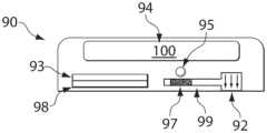
- FIGS. 1 A- 1 Billustrate devices according to certain embodiments of the invention
- FIGS. 2 A- 2 Cillustrate devices according to various embodiments of the invention
- FIG. 2 Dillustrates a kit containing more than one device, in yet another embodiment of the invention
- FIG. 2 Eillustrates a device according to still another embodiment of the invention
- FIG. 3illustrates a device in one embodiment of the invention, having a vacuum chamber
- FIG. 4illustrates a device in another embodiment of the invention, having a vacuum chamber and a storage chamber
- FIG. 5illustrates a device in yet another embodiment of the invention, having a flow controller
- FIG. 6illustrates a device according to another embodiment of the invention.
- FIG. 7illustrates a device in yet another embodiment of the invention, having an exit port
- FIG. 8illustrates a device containing a fluid reservoir, in another embodiment of the invention.
- FIG. 9illustrates an adaptor according to one embodiment of the invention.
- FIGS. 10 A- 10 Cillustrate a device in still another embodiment illustrating a deployment actuator
- FIG. 11illustrates yet another embodiment of the invention in which a device is actuated by a deployment actuator
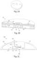
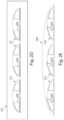
- FIGS. 12 A and 12 Billustrate yet another embodiment of the invention, in which a device is actuated by a deployment actuator, at different stages of operation of the device;
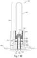
- FIGS. 13 A- 13 Eillustrate several devices in accordance with various embodiments of the inventions.
- the present inventiongenerally relates to systems and methods for delivering and/or receiving a substance or substances such as blood from subjects.
- the present inventionis directed to devices and methods for receiving or extracting blood from a subject, e.g., from the skin and/or from beneath the skin, using devices containing a substance transfer component (for example, one or more needles or microneedles) and a reduced pressure or vacuum chamber having an internal pressure less than atmospheric pressure prior to receiving blood.
- the devicemay contain a “snap dome” or other deformable structure, which may be used, at least in part, to urge or move needles or other suitable substance transfer component into the skin of a subject.
- the devicemay contain a snap dome or other flexible concave member and a needle mechanically coupled to the flexible concave member such that the needle may be urged or moved into the skin using the flexible concave member.
- Other aspects of the present inventionare directed at other devices for receiving blood (or other bodily fluids, e.g., interstitial fluid), kits involving such devices, methods of making such devices, methods of using such devices, and the like.
- the received fluidmay be any suitable bodily fluid, such as interstitial fluid, other skin-associated material, mucosal material or fluid, whole blood, perspiration, saliva, plasma, tears, lymph, urine, plasma, or any other bodily fluid, or combinations thereof.
- Substances received from a subjectcan include solid or semi-solid material such as skin, cells, or any other substance from the subject.
- Substances that can be delivered to a subject in accordance with some embodiments of the inventioninclude diagnostic substances, therapeutic substances such as drugs, and the like.
- Various embodiments of the inventionare described below in the context of delivering or receiving a fluid, such as blood, from or through the skin.
- the devices and methods of other embodiments of the inventioncan be used for receiving any substance from the skin and/or from beneath the skin of the subject, and/or for delivering any substance to the subject, e.g. to the skin and/or a location beneath the skin of the subject.
- the present inventionis generally directed to devices and methods for receiving or extracting blood or other bodily fluids from a subject, e.g., from the skin and/or from beneath the skin, using devices containing a substance transfer component (for example, one or more microneedles).
- the devicemay also contain, in some embodiments, a storage chamber having an internal pressure less than atmospheric pressure prior to receiving blood or other bodily fluids.
- the devicemay pierce the skin of the subject, and fluid can then be delivered and/or received from the subject.
- the subjectis usually human, although non-human subjects may be used in certain instances, for instance, other mammals such as a dog, a cat, a horse, a rabbit, a cow, a pig, a sheep, a goat, a rat (e.g., Rattus norvegicus ), a mouse (e.g., Mus musculus ), a guinea pig, a hamster, a primate (e.g., a monkey, a chimpanzee, a baboon, an ape, a gorilla, etc.), or the like.
- other mammalssuch as a dog, a cat, a horse, a rabbit, a cow, a pig, a sheep, a goat, a rat (e.g., Rattus norvegicus ), a mouse (e.g., Mus musculus ), a guinea pig, a hamster, a primate (e.g.
- the devicecan be applied to the skin, and activated to receive fluid from the subject.
- the device, or a portion thereofmay then be processed to determine the fluid and/or an analyte within the fluid, alone or with an external apparatus.
- fluidmay be received from the device, and/or the device may contain sensors or agents able to determine the fluid and/or an analyte suspected of being contained in the fluid.
- the inventionin one set of embodiments, involves the determination of a condition of a subject. Bodily fluids and/or other material associated with the skin may be analyzed, for instance, as an indication of a past, present and/or future condition of the subject, or to determine conditions that are external to the subject. Determination may occur, for instance, visually, tactilely, by odor, via instrumentation, etc.
- the present inventionis generally directed to various devices for delivering and/or receiving blood, or other bodily fluids, from the skin and/or from beneath the skin of a subject. Accordingly, in the description that follows, the discussion of blood is by way of example only, and in other embodiments, other fluids may be received from the skin in addition to and/or instead of blood.
- the deviceincludes a substance transfer component able to deliver or receive fluid from the subject into the device.
- “substance transfer component”is any component or combination of components that facilitates movement of a fluid from one portion of the device to another, and/or from the device to the subject or vice versa.
- the substance transfer componentmay include an opening of any size and/or geometry that is constructed to receive fluid into the device.
- an opening of a substance transfer componentmay lie in a two-dimensional plane or the opening may include a three-dimensional cavity, hole, groove, slit, etc.
- the substance transfer componentmay also include one or more microneedles or other skin insertion objects, arranged to cause fluid to be released from the subject, e.g., by piercing the skin of a subject.
- a substance transfer componentcan include a hollow needle or a solid needle. If a solid needle is used, then if fluid migrates along the needle due to surface forces (e.g., capillary action), then the solid needle can be part of a substance transfer component. If fluid (e.g. blood or interstitial fluid) partially or fully fills an enclosure surrounding a needle after puncture of skin (whether the needle is or is not withdrawn from the skin after puncture), then the enclosure can define at least part of a substance transfer component.
- a substance transfer componentmay include any other suitable fluid transporter or flow activator. Other components including partially or fully enclosed channels, microfluidic channels, tubes, wicking members, vacuum containers, etc. can be, or be a part of, substance transfer components.
- the fluidmay be received from and/or through the skin of a subject (or other mucosal surface).
- the substance transfer componentmay include, for example, one or more needles and/or microneedles, a hygroscopic agent, a cutter or other piercing element, an electrically-assisted system, or the like, as discussed in detail herein. If needles or microneedles are used, they may be solid or hollow, i.e., blood or other fluid may travel in and/or around the needles or microneedles into the device. In some cases, the needles or microneedles may also be removed from the subject, e.g., after insertion into the skin, for example, to increase the flow of blood or other fluids from the subject.
- the substance transfer componentincludes solid needles that are removed from the skin and a cup or channel to direct the flow of blood or other bodily fluids.
- the devicemay include a support structure, such as a housing.
- the housingmay be used, as discussed herein, for applying the substance transfer component to the surface of the skin of the subject, e.g., so that fluid may be delivered and/or received from the skin of the subject.
- the housingmay immobilize the substance transfer component such that the substance transfer component cannot move relative to the housing; in other cases, however, the substance transfer component, or a portion thereof, may be able to move relative to the housing.
- the substance transfer componentis immobilized relative to the housing, and the deployment actuator is positioned within the device such that application of the device to the skin causes at least a portion of the substance transfer component to pierce the skin of the subject.
- the housingencloses a deployment actuator.
- the deployment actuatormay move from a first position to a second position.
- the first positionmay be one where the deployment actuator has attached thereto a substance transfer component that does not contact the skin (e.g., a skin insertion object of the substance transfer component may be contained within a recess of the substance transfer component), while the second position of the deployment actuator may be one where the substance transfer component does contact the skin, and in some cases, the substance transfer component may pierce the skin.
- the deployment actuatormay be moved using any suitable technique, e.g., manually, mechanically, electromagnetically, using a servo mechanism, or the like.
- the deployment actuatormay be moved from a first position to a second position by pushing a button on the device, which causes the deployment actuator to move (either directly, or through a mechanism linking the button with the deployment actuator).
- Other mechanismse.g., dials, levers, sliders, etc., as discussed herein
- the deployment actuatormay be moved from a first position to a second position automatically, for example, upon activation by a computer, upon remote activation, after a period of time has elapsed, or the like.
- a servo connected to the deployment actuatoris activated electronically, moving the deployment actuator from the first position to the second position.
- the deployment actuatormay include a triggering mechanism that initiates deployment.
- the deployment actuator and/or the substance transfer componentmay also be moved from the second position to the first position.
- the deployment actuatormay be moved, which may move the substance transfer component away from contact with the skin.
- the deployment actuatormay be moved from the second position to the first position using any suitable technique, including those described above, and the technique for moving the deployment actuator from the second position to the first position may be the same or different as that moving the deployment actuator from the first position to the second position.
- the devicemay be able to draw skin towards the substance transfer component.
- the devicemay include a vacuum interface or region.
- the interface or regionmay be connected with a vacuum source (external and/or internal to the device), and when a vacuum is applied, skin may be drawn towards the device, e.g., for contact with a substance transfer component, such as one or more needles or microneedles.
- the deviceincludes a deployment actuator able to drive a substance transfer component or a substance transfer component into the skin, e.g., so that the substance transfer component can receive a fluid from the skin and/or from beneath the skin of a subject, and/or so that the substance transfer component can deliver a substance to a subject, e.g. deliver a substance to the skin and/or to a location beneath the skin of a subject.
- the deployment actuatormay be a structure that can be deformed using unaided force (e.g., by a human pushing the structure), or other forces (e.g., electrically-applied forces, mechanical interactions or the like), but is able to restore its original shape after the force is removed or at least partially reduced.
- the deployment actuatormay restore its original shape spontaneously, or some action (e.g., heating) may be needed to restore the structure to its original shape.
- the deployment actuatormay be formed out a suitable elastic material, in some cases.
- the deployment actuatormay be formed from a plastic, a polymer, a metal, etc.
- the deployment actuatormay have a concave or convex shape.
- the edges of the deployment actuatormay be put under compressive stress such that the structure “bows” out to form a concave or convex shape.
- a person pushing against the concave or convex shapemay deform the deployment actuator, but after the person stops pushing on the deployment actuator, the deployment actuator may be able to return to its original concave or convex shape, e.g., spontaneously or with the aid of other forces as previously discussed.
- the deployment actuatormay be bistable, i.e., having two different positions in which the deployment actuator is stable.
- the deployment actuatormay include a flexible concave member or a reversibly deformable structure that is moveable between a first configuration and a second configuration.
- the first configurationmay have a concave shape, such as a dome shape
- the second configurationmay have a different shape, for example, a deformed shape (e.g., a “squashed dome”), a convex shape, an inverted concave shape, or the like. See, for example, FIG. 10 B .
- the flexible concave member(or a deployment actuator) may be moved between the first configuration and the second configuration manually, e.g., by pushing on the flexible concave member using a hand or a finger, and/or the flexible concave member may be moved using an actuator such as is described herein.
- the flexible concave membermay be able to spontaneously return from the second configuration back to the first configuration, e.g., as is shown in FIG. 10 .
- the flexible concave membermay not be able to return to the first configuration, for instance, in order to prevent accidental repeated uses of the flexible concave member.
- the flexible concave memberin some embodiments, may be a deployment actuator, although in other embodiments, it need not be.
- the flexible concave member(or a deployment actuator, in some embodiments) may be mechanically coupled to one or more needles (e.g., microneedles), or other substance transfer components such as those discussed herein. If needles are used, the needles can be hollow or solid, and there may be one or more than one needle.
- needlese.g., microneedles
- the needlescan be hollow or solid, and there may be one or more than one needle.
- the devicecan include more than one needle (e.g., as in an array of needles), and/or the needle may be a microneedle.)
- the needlemay be directly immobilized on the flexible concave member, or the needles can be mechanically coupled to the flexible concave member using bars, rods, levers, plates, springs, or other suitable structures.
- the needle(or other substance transfer component), in some embodiments, is mechanically coupled to the flexible concave member such that the needle is in a first position when the flexible concave member is in a first configuration and the needle is in a second position when the flexible concave member is in a second configuration.
- movement of the flexible concave memberis able to cause the needle to move from a first position to a second position.
- the first position of the needlemay be a withdrawn position while the second position may be a deployed position where the needles are able to contact and/or be inserted into the skin of a subject, for example, in an applicator region, for example, a recess within the device.
- first position and the second positionmay be separated by relatively small distances.
- first position and the second positionmay be separated by a distance of less than about 10 mm, less than about 9 mm, less than about 8 mm, less than about 7 mm, less than about 6 mm, less than about 5 mm, less than about 4 mm, less than about 3 mm, or less than about 2 mm, etc.
- high speeds and/or accelerationssuch as those discussed herein can be achieved.
- a devicemay be placed into contact with the skin of a subject such that a recess or other suitable applicator region is proximate or in contact with the skin.
- the flexible concave memberor deployment actuator
- the flexible concave memberis able to cause a needle (or other substance transfer component) to move to a second position within the recess or other applicator region and to contact or penetrate the skin of the subject.
- the devicemay also include a retraction mechanism able to move the needle (or other substance transfer component) away from the skin after the flexible concave member (or a deployment actuator) reaches a second configuration.
- Retraction of the flexible concave membermay, in some embodiments, be caused by the flexible concave member itself, e.g., spontaneously returning from the second configuration back to the first configuration, and/or the device may include a separate retraction mechanism, for example, a spring, an elastic member, a collapsible foam, or the like.
- the retraction mechanismmay be useable only once or a limited number of times.
- a spring or a collapsible foammay be used that includes a “breakaway” component, preventing reuse, or the spring may be “pre-packaged” within the device so that it can only be used once, and no mechanism is available within the device that allows the spring to be re-compressed.
- the needlemay be used for delivering and/or receiving a substance or substances such as blood, from a subject, e.g., from the skin and/or from beneath the skin.
- a vacuum chamberhaving a reduced pressure or an internal pressure less than atmospheric pressure prior to receiving blood or other bodily fluids (e.g., interstitial fluid) may be used to assist in the receiving of the fluid from the skin after the needle (or other substance transfer component) has penetrated the skin.
- the fluid received from the skinmay be collected in the vacuum chamber and/or in a collection chamber.
- the collection chambermay be separated from the vacuum chamber using a gas permeable membrane (e.g., one that is substantially impermeable to blood or other bodily fluids), a hydrophilic membrane, a porous structure, a dissolvable interface, or the like, e.g., as is discussed herein.
- a gas permeable membranee.g., one that is substantially impermeable to blood or other bodily fluids
- hydrophilic membranee.g., one that is substantially impermeable to blood or other bodily fluids
- a hydrophilic membranee.g., one that is substantially impermeable to blood or other bodily fluids
- a hydrophilic membranee.g., one that is substantially impermeable to blood or other bodily fluids
- a porous structuree.g., as is discussed herein.
- movement of a deployment actuator and/or a flexible concave member from a first configuration to a second configurationmay be used to create a fluid communication pathway between a vacuum chamber and an applicator region such as a recess that contains or is able to contain needles or other substance transfer components for contact or insertion into the skin of the subject.
- a flexible concave member and/or a deployment actuatormay be mechanically coupled to a piercing member such that the piercing member is able to move when the flexible concave member moves from the first configuration to the second configuration.
- the piercing membermay be, for example, a needle, a microneedle, a blade, a wire, or the like.
- the piercing membermay be inserted or slid past or into a pierceable surface.
- the pierceable surfacemay be a foil or an airtight seal that is pierced, sliced, punctured, peeled, ripped, etc., or otherwise disrupted due to the movement of the piercing member, e.g., into and/or across the pierceable surface.
- the pierceable surfacemay separate a vacuum chamber from an applicator region such that, when disrupted, a fluid communication pathway is thereby created between the vacuum chamber and the applicator region.
- a vacuum chambere.g., pushing on the vacuum chamber manually, or actuation involving movement of the vacuum chamber, may be used to cause disruption of the pierceable surface.
- structure 700has a generally concave shape, and is positioned on the surface of skin 710 .
- structure 700may be a flexible concave member.
- Structure 700also contains a plurality of substance transfer components 720 for insertion into the skin.
- a person(indicated by finger 705 ) pushes onto structure 700 , deforming at least a portion of the structure and thereby forcing substance transfer components 720 into at least a portion of the skin.
- FIG. 10 Cafter the person releases structure 700 , the structure is allowed to return to its original position, e.g., spontaneously, lifting substance transfer components 720 out of the skin.
- blood or other fluids 750may come out of the skin through the holes created by the substance transfer components, and optionally the fluid may be collected by the device for later storage and/or use, as discussed herein.
- a device 1100is illustrated schematically in which a substance transfer component comprising a substance transfer component is driven by a deployment actuator, such as a flexible concave member.
- device 1100includes a housing 1102 defining a plurality of chambers and channels.
- a plurality of components that can be separable from and attachable to each othere.g., modular components
- device 1100includes a surface 1104 for positioning the device proximate the skin of a subject during use.
- the devicecan include an adhesive layer 1106 where the adhesive is selected to be suitable for retaining the device in a relatively fixed position relative to the skin during use, but may allow for relatively easy removal of the device from the skin following use. Specific non-limiting examples of adhesives are discussed below. The adhesive also can be selected to assist in maintaining a vacuum within portions of the device proximate the skin as will be understood.
- device 1100includes a skin insertion object 1108 .
- the skin insertion objectsmay be, for example, a substance transfer component and/or a skin insertion object as discussed herein. Specific non-limiting examples include needles or microneedles, e.g., as shown in FIG. 11 .
- the substance transfer componentcan be or include, as described elsewhere herein and in other documents incorporated herein by reference, any of a variety of components able to receive a substance from the skin and/or from beneath the skin of a subject, and or deliver a substance to the skin and/or to a location beneath the skin of the subject.
- the substance transfer componentmay include one or more needles and/or microneedles, a hygroscopic agent, a cutter or other piercing element, an electrically-assisted system, or the like.
- skin insertion objects 1108define an array of microinsertion objects such as solid or hollow microneedles.
- skin insertion object 1108is selected to have a particular size and profile for a particular use.
- the skin insertion objectsmay include an array of insertion or microinsertion objects which, in the device illustrated, emanate from a base 1110 which will be described further below.
- a plurality of skin insertion objects 1108are relatively small, and are relatively completely driven into the skin.
- skin insertion objectsinclude needles or microneedles, e.g., as described in greater detail below.
- the skin insertion objectsmay be positioned to address the skin of the subject, each protruding from a base and defining a length from the base, and are able to be inserted into or through the skin to a depth essentially equal to their length but are prevented, by the base, from inserting at a depth greater than their length.
- the plurality of skin insertion objectshave an average length (measured from the base) of no more than about 1,000 microns or more than about 2,000 microns, although lengths can differ between individual skin insertion objects.
- the skin insertion objectsare of relatively uniform length, together defining an average length and each differing from the average length by no more than about 50%, about 40%, about 30%, about 10%, or about 5%.
- the average length of the skin insertion objectsare no more than about 1,500 microns, no more than about 1,000 microns, no more than about 900 microns, no more than about 800 microns, no more than about 750 microns, no more than about 600 microns, no more than about 500 microns, no more than about 400 microns, or no more than about 350 microns.
- a triggering mechanism as discussed hereinis provided that is able to move the skin insertion objects from a fully predeployed position to a fully deployed position with a force sufficient to insert the plurality of skin insertion object into or through the skin to an average depth of at least about 50% the average length of the plurality of skin insertion objects.
- the triggering mechanismis able to insert the plurality of skin insertion objects to an average depth of at least about 55%, at least about 60%, at least about 65%, at least about 70%, at least about 75%, at least about 80%, at least about 85%, at least about 90%, at least about 92%, about 94%, about 96%, or about 98% of the average length of the plurality of skin insertion objects.
- skin insertion objects 1108are mounted on a flexible structure 1112 which, as illustrated, is maintained relatively rigidly through various aspects of the device but which mounts skin insertion objects 1108 flexibly for up/down movement relative to the skin.
- Flexible structure 1112can be a membrane, a single or multi-layer structure selected from various polymers, metals, or the like to provide sufficient properties such as any combination of flexibility, elasticity, gas permeability or impermeability, fluid permeability or impermeability, or the like for desired operation.
- Portions of flexible structure 1112 , skin insertion objects 1108 , and other interior walls of the devicedefine a region 1114 which allows for movement of skin insertion objects 1108 relative to the skin for delivery of a substance to and/or receiving of a substance from the skin or beneath the skin, and, where a substance is received from the skin or from beneath the skin, region 1114 can serve as a reservoir for introduction of the substance into the device.
- region 1114when positioned against the skin, can expose vacuum to that portion of the skin proximate surface 1104 of the device and abutting the chamber.
- Device 1100also includes a device actuator 1116 which, as illustrated, includes a proximate portion 1118 which can be addressed by a user of the device (who may be the same or different from the subject the device is administered to) and a distal portion 1120 for addressing skin insertion objects 1108 via flexible structure 1112 .
- Proximal portion 1118 and distal portion 1120are, in the device illustrated, opposite ends of a single component but, as would be understood by those of ordinary skill in the art, the actuator can include a plurality of individual components operably linked in any way necessary to perform actuation as will be described.
- FIG. 11is a cross-section of a device illustrating various components and channels within the device.
- device actuator 1116is directly connected to or otherwise operably linked to a deployment actuator 1122 which, in the device illustrated, is in the form of a “snap dome,” the function and use of which will be described below.
- the snap dome in this figurehas an approximately circular profile, and may define in some embodiments a flexible concave member.
- the structuremay define an interior and a periphery which, if not circular, may include a plurality of tabs, protrusions, or the like sufficient for support of structure 1122 within the device.
- a plurality of tabs (or the essentially circular perimeter of) the deviceare supported within holders 1124 , and the center, snap dome portion of the device is operably linked to device actuator 1116 , such that movement of the central portion of snap dome 1122 and the periphery of the snap dome can be controlled independently of each other.
- Holders 1124are directly connected to or otherwise operably linked to an actuator retraction component 1126 which, in the device illustrated, can be a ring-shaped structure positioned under and supporting holders 1124 .
- Holders 1124can be individual holders and/or a ring-like structure surrounding the periphery of snap dome 1122 .
- a series of one, two, or more support membersare positioned near the top of device 1100 and serve to define a series of channels for sample flow, vacuum control, or the like as will be described.
- region 1114when the device is positioned against skin, can serve to expose a portion of the skin defined by the periphery of the region to a vacuum, to skin insertion objects 1108 as they move toward and/or away from the skin, and/or to transfer a substance from or to the subject.
- Region 1114can house a substance for transfer to the subject, in the form of a pharmaceutical composition or the like, optionally loaded on skin insertion objects 1108 . Where blood and/or interstitial fluid is drawn from a subject, region 1114 can serve to introduce the substance into the device from the subject.
- a channel 1132connects region 1114 to other portions of the device in this example.
- Channel 1132can be used to deliver a substance to region 1114 for transfer to a subject, or for application of a vacuum to region 1114 , and/or for receiving a substance from a subject.
- the remainder of the description of device 1100will be made within the context of receiving a substance such as blood and/or interstitial fluid from a subject, but it is to be understood that substances can also be delivered via various channels.
- Channel 1132typically emanates in one direction from region 1114 although a plurality of channels can emanate from the region, arranged radially or otherwise relative to the center of the device.
- channel 1132first passes laterally from the center of the device and then upwardly where, near the top of the device, it can, optionally, include one wall defining a window 1134 through which a user of the device can observe transfer of a substance, or through which analysis of a substance may occur. It can also itself define a reservoir, in whole or in part, or be connected to an internal or an external reservoir for maintaining, storing, and/or transferring a substance drawn from a subject. As shown here, it can be connected to a substance collection reservoir 1136 which, as illustrated, is a disc-shaped reservoir formed in the device housing and surrounding the center of the device including device actuator 1116 and related components.
- Device 1100illustrated as one example of devices provided by the invention, includes a vacuum chamber for applying a vacuum proximate the skin of a subject for receiving a substance from the skin.
- vacuum chamber 1138is positioned in a central portion of the device surrounding device actuator 1116 , although it can be provided anywhere in or proximate the device.
- the vacuum chambercan be evacuated to an appropriate level just prior to use, or the device can be pre-packaged under vacuum as described elsewhere herein.
- vacuum chamber 1138is in fluid communication with substance collection reservoir 1136 but, in its initial state and prior to use, a membrane or other component, such as support member 1128 , separates channel 1132 connecting it to region 1102 .
- a vacuum actuation component 1140can be actuated to puncture the membrane or other component (e.g., 1128 ) and thereby connect vacuum chamber 1138 with channel 1132 , at an appropriate time during use of the device.
- device actuator 1116 and vacuum actuation component 1140can be combined into a single button or operably linked so that only one operation is needed to actuate both the microinsertion objects and the vacuum.
- Deployment actuator 1122can be provided in a variety of forms including a monostable or bistable configuration. In the embodiment illustrated, a bistable configuration is illustrated including first and second low energy or stable configurations separated by a relatively high energy or unstable configuration. As shown, deployment actuator 1122 is shown in a “cocked” or predeployed position.
- the deployment actuator(or the flexible concave member) may be formed from any suitable material, for example, a metal such as stainless steel (e.g., 301, 301LN, 304, 304L, 304LN, 304H, 305, 312, 321, 321H, 316, 316L, 316LN, 316Ti, 317L, 409, 410, 430, 440A, 440B, 440C, 440F, 904L), carbon steel, spring steel, spring brass, phosphor bronze, beryllium copper, titanium, titanium alloy steels, chrome vanadium, nickel alloy steels (e.g., Monel 400, Monel K 500, Inconel 600, Inconel 718, Inconel x 750, etc.), a polymer (e.g., polyvinylchloride, polypropylene, polycarbonate, etc.), a composite or a laminate (e.g., comprising fiberglass, carbon fiber, bamboo, Kevlar, etc
- the deployment actuatormay be of any shape and/or size.
- the deployment actuatoris a flexible concave member.
- the deployment actuatormay have, for instance, a generally domed shape (e.g., as in a snap dome), and be circular (no legs), or the deployment actuator may have other shapes, e.g., oblong, triangular (3 legs), square (4 legs), pentagonal (5 legs), hexagonal (6 legs), spiderlegged, starlike, clover-shaped (with any number of lobes, e.g., 2, 3, 4, 5, etc.), or the like.
- the deployment actuatormay have, in some embodiments, a hole, a port, a slot, dimple, or button in the middle.
- the deployment actuatormay also have a serrated disc or a wave shape.
- the skin insertion objectsmay be mounted on the deployment actuator. In other cases, however, the skin insertion objects are mounted on a separate structure which is driven or actuated upon movement of the deployment actuator.
- the deployment actuatoris not planar, and has a portion that can be in a first position (a “cocked” or predeployed position) or a second position (a “fired” or deployed position), optionally separated by a relatively high energy configuration.
- first position and the second positionare stable (i.e., the structure is bistable), although conversion between the first position and the second position requires the structure to proceed through an unstable configuration.
- the distance or separation between the first position and the second position of the deployment actuator or the flexible concave memberis relatively small. Such distances or separations may be achieved using snap domes or other configurations such as those described herein, in contrast to springs or other devices which require longer translational or other movements.
- the perpendicular distance (i.e., in a direction away from the skin) in the deployment actuator between the top of the structure and the bottom of the structure (excluding the skin insertion objects) when the device containing the structure is placed on the skin of a subjectmay be no more than about 5 mm, no more than about 4 mm, no more than about 3 mm, no more than about 2 mm, no more than about 1 mm in some cases, no more than about 0.8 mm, no more than about 0.5 mm, or no more than about 0.3 mm. In one set of embodiments, the distance is between about 0.3 mm and about 1.5 mm.
- the deployment actuatormay have a greatest lateral dimension (parallel to the skin) when the device containing the structure is placed on the skin of a subject of no more than about 50 mm, no more than about 40 mm, no more than about 30 mm, no more than about 25 mm, no more than about 20 mm, no more than about 15 mm, no more than about 5 mm, no more than about 4 mm, no more than about 3 mm, no more than about 2 mm, no more than about 1 mm in some cases, no more than about 0.8 mm, no more than about 0.5 mm, or no more than about 0.3 mm.
- the distanceis between about 0.3 mm and about 1.5 mm.
- Device 1100is placed against the skin of a subject such that at least a portion of surface 1104 contacts the skin.
- a cover member(not shown) can cover surface 1104 of the device and can cover region 1114 , to protect surface 1104 and region 1114 from contaminants, etc. optionally maintaining the interior of the device in a sterile condition.
- the covercan be peeled off or otherwise removed from the device, and the device placed against the skin, optionally adhering to the skin.
- Vacuum actuation component 1140can be actuated to expose channel 1132 and region 1114 to vacuum at any time, including before, simultaneously, or after actuation of skin insertion objects 1108 .
- vacuum actuation component 1140is actuated to apply vacuum to region 1114 prior to actuation to skin insertion objects 1108 , thereby to create a vacuum against the skin proximate region 1114 prior to use. Actuation of device actuator 1116 can take place before or after deployment of vacuum.
- distal portion 1120engages skin insertion objects 1108 (optionally via flexible structure 1112 ) to drive them toward the skin.
- foil 1128is first broken, then component 1126 is compressed, then component 1126 is broken, before flexible structure 1112 is stretched and the deployment actuator 1122 of the device fires or is actuated.
- Membranes or other members 1112 , 1128 , or 1130may have, in some cases, sufficient flexibility and/or elasticity to allow device actuator 1116 to drive skin insertion objects 1108 sufficiently distally (downwardly, as shown) to engage the skin of the subject and carry out the desired function of the device.
- support member 1128is a foil or the like used for the purpose of initially separating vacuum reservoir 1138 from channel 1132 (e.g., prior to use), when device actuator 1116 is moved downwardly, vacuum actuation component 1140 may rupture support member 1128 proximate device actuator 1116 , or flexibly deform as need be, so long as member 1130 (or another component) serves to allow device actuator 1116 to move slidably within the device while maintaining sufficient vacuum in vacuum reservoir 1138 and related channels for use of the device.
- a vacuumcan draw the substance into region 1114 , through channel or channels 1132 , and into substance collection reservoir 1136 .
- device actuator 1116first urges or moves structure 1122 from its first stable configuration to a relatively unstable configuration and beyond that point, at which point the structure 1122 rapidly moves to a second stable configuration associated with downward driving of device actuator 1116 to quickly drive access skin insertion objects 1108 proximate the skin.
- retraction component 1126drives holder 1124 upwardly, retracting structure 1122 and device actuator 1116 from skin insertion objects 1108 .
- device actuator 1116can be operably linked to skin insertion objects 1108 and receive the transfer component, or it can move freely relative to skin insertion objects 1108 , whereby flexible structure 1112 (e.g., an elastic membrane) or other component can withdraw skin insertion objects 1108 from the skin.
- retraction component 1126can itself be a deployment actuator such as a leaf spring, coil spring, foam, or the like.
- retraction component 1126is first compressed and, depending upon the size and arrangement of components 1126 , 1124 , 1122 , 1116 and 1108 , during compression, skin insertion objects 1108 can be driven downwardly to some extent.
- deployment actuator 1122can be urged or moved from its first configuration through an unstable configuration and can return to its second configuration, driving skin insertion objects 1108 against the skin.
- retraction component 1126can expand and, with structure 1122 optionally remaining in its second, downwardly-driven low-energy configuration, device actuator 1116 can be retracted and skin insertion objects 1108 retracted from the skin.
- device 1150is illustrated schematically.
- Device 1150is similar to and can be considered essentially identical to device 1100 in all aspects other than those described here with respect to FIGS. 12 A and 12 B . As such, the reader will observe that not all components are provided, although other components similar to those of device 1100 can exist.
- One way in which device 1150 differs from device 1100is that in device 1150 , in the pre-deployment or post-deployment retracted configuration, membrane 1112 is drawn proximally (upwardly) as illustrated in FIG. 12 B . Membrane 1112 is in a less-stressed lower-energy configuration as shown in FIG.
- Devices 1100 , 1150 , and other similar devicesare one way to enact a triggering mechanism that can move skin insertion objects 1108 or other similar transfer component relative to the skin in particularly advantageous ways.
- triggering mechanismsinclude, in addition to the examples shown in FIGS. 11 and 12 , blasting caps, explosives, other chemical reactions, solenoids or other electrical interactions, pneumatics (e.g., compressed air), other thermal interactions or mechanical interactions, or the like.
- the triggering mechanismmay move skin insertion objects 1108 from a fully predeployed position (e.g., as shown in FIG. 11 ) to a fully deployed position in which skin insertion objects 1108 are fully engaged with the skin, in a short period of time.
- that period of timeis less than about 0.01 seconds, and in other embodiments, less than about 0.009 seconds, less than about 0.008 seconds, less than about 0.007 seconds, less than about 0.006 seconds, less than about 0.005 seconds, less than about 0.004 seconds, less than about 0.003 seconds, less than about 0.002 seconds, less than about 0.001 seconds, less than about 0.0005 seconds, less than about 0.00025, or less than about 0.0001 seconds.
- skin insertion objects 1108move quickly relative to skin during deployment via the triggering mechanism, reaching a speed of at least about 4 m/s, at least about 5 m/s, at least about 6 m/s, at least about 7 m/s, at least about 8 m/s, at least about 10 m/s, at least about 12 m/s, at least about 15 m/s, or at least about 20 m/sat the point at which skin insertion objects 1108 first touch the skin during deployment.
- skin insertion objects 1108achieve relatively high accelerations due to the triggering mechanism, for example, at least about 4 m/s 2 , about 6 m/s 2 , about 8 m/s 2 , about 10 m/s 2 , about 12 m/s 2 , about 15 m/s 2 , or about 20 m/s 2 , at least about 30 m/s 2 , at least about 50 m/s 2 , at least about 100 m/s 2 , at least about 300 m/s 2 , at least about 500 m/s 2 , at least about 1,000 m/s 2 , at least about 3,000 m/s 2 , at least about 5,000 m/s 2 , at least about 10,000 m/s 2 , at least about 30,000 m/s 2 , at least about 50,000 m/s 2 , at least about 100,000 m/s 2 , at least about 200,000 m/s 2 , or at least about 300,000 m/s 2 .
- the skin insertion objects 1108are accelerated for relatively short periods of time, e.g., less than about 1 s, less than about 300 ms, less than about 100 ms, less than about 30 ms, less than about 10 ms, less than about 3 ms, or less than about 1 ms, and/or over relatively short distances, e.g., less than about 5 mm, less than about 4 mm, less than about 3 mm, less than about 2 mm, less than about 1 mm, less than about 800 micrometers, less than 600 micrometers, less than 500 micrometers, less than 400 micrometers, less than about 300 micrometers, less than about 200 micrometers, less than about 100 micrometers, less than about 50 micrometers, etc.
- relatively short periods of timee.g., less than about 1 s, less than about 300 ms, less than about 100 ms, less than about 30 ms, less than about 10 ms, less than about 3 ms, or less
- skin insertion objectst 1108are driven by a force created at least in part by the triggering mechanism of at least about 6 micronewtons, about 8 micronewtons, about 10 micronewtons, about 12 micronewtons, or about 15 micronewtons.
- skin insertion objects 1108apply a pressure to the skin, during deployment caused by the triggering mechanism, of at least about 100 N/m 2 , at least about 300 N/m 2 , at least about 1,000 N/m 2 , at least about 3,000 N/m 2 , etc.
- the areacan be measured as the area of skin displaced by the transfer component at full deployment, e.g., the area of the skin ruptured by the total of the cross sectional area of all skin insertion objects inserted into the skin, at the top surface of the skin.
- the skin insertion objectsare forced into the skin via the triggering mechanism with a force sufficient to insert the skin insertion objects into or through the skin to an average depth of at least about 60% of the skin insertion object (or the average length of the skin insertion objects, if more than one is used, e.g., as in an array of microneedles).
- the depthis at least about 65%, at least about 70%, at least about 75%, at least about 80%, at least about 85%, at least about 90%, or at least about 95% of the skin insertion objects, e.g., the length of the needle or the microneedle inserted into the skin.
- FIG. 13 Aa device 900 for receiving blood or other fluids from a subject is shown positioned onto the skin 999 of a subject.
- Device 900includes first module 905 and second module 910 .
- First module 905includes vacuum chamber 907 , and optionally, collection chamber 908 , which can be used to collect blood or other bodily fluids from the subject.
- vacuum chamber 907may be used to urge or move the fluid from the subject into the device, and into collection chamber 908 and/or vacuum chamber 907 .
- First module 905can, in some embodiments, be detached from second module 910 , and replaced with a fresh first module 905 , for example, for repeated uses of the device.
- First module 905includes a substantially cylindrical vacuum chamber 907 , and, within vacuum chamber 907 , collection chamber 908 . In other embodiments, however collection chamber 908 may be positioned elsewhere within the device besides within vacuum chamber 907 , including within module 910 .
- Vacuum chamber 907may be, for example, a VacutainerTM tube, a VacuetteTM tube, or other similar vacuum tube, many of which are commercially available.
- collection chamber 908may be positioned within the vacuum chamber 907 .
- Collection chamber 908may thus have a shape that fits substantially inside of vacuum chamber 907 .
- collection chamber 908may also be removable from vacuum chamber 907 , for example, for analysis of blood or other bodily fluids received from the subject. In other cases, however, collection chamber 908 may not be easily removed from vacuum chamber 907 .
- passages 906allow vacuum chamber 907 and collection chamber 908 to be in fluidic communication.
- Passages 906may be, for example, holes, tubes, or other suitable openings that allow the two chambers to be in fluidic communication with each other.
- the two chambersmay have substantially the same pressure (i.e., substantially the same reduced pressure), such that, when the reduced pressure causes blood or other bodily fluids to flow into first module 905 , the fluid first enters the collection chamber 908 .
- collection chamber 908may be separated from vacuum chamber 907 using a gas permeable membrane, a hydrophilic membrane, a porous structure, a dissolvable interface, or the like, i.e., to prevent blood or other bodily fluids from exiting collection chamber 908 into vacuum chamber 907 .
- Passage 906could be positioned anywhere along chamber 908 , including the top of chamber 908 in the orientation shown in FIG. 13 A .
- First module 905also contains, at one end, a surface or a seal 909 that can be pierced as is discussed below. Before use, first module 905 may be separate from second module 910 , and this end of first module 905 may be sealed using surface 909 , thereby preventing the loss of reduced pressure from within vacuum chamber 907 , prior to use of the first module 905 within device 900 .
- the pierceable surfacemay be, for example, a foil, a metal, a polymer, rubber, a rubber septum, or the like that can be pierced by a piercing member 912 from second module 910 , as is discussed below.
- First module 905may be connected to second module 910 to form device 900 .
- piercing member 912is inserted into pierceable surface 909 as first module 905 and second module 910 are connected to each other.
- Piercing member 912may be, for example, a needle, a microneedle, a blade, or other piercing structure that is able to penetrate the pierceable surface 909 when first module 905 and second module 910 are connected.
- Piercing member 912may be, e.g., a hollow needle, and in some cases, piercing member is in fluidic communication with applicator region 940 .
- a fluidic connectionmay be formed between vacuum chamber 907 , and a fluid received from the skin of a subject, e.g., within applicator region 940 , as is discussed below.
- first module 905 and second module 910When first module 905 and second module 910 are connected, a surface of first module 905 pushes down on one or more activation members 916 as is shown in FIG. 13 A .
- activation member 916has a generally cylindrical shape that is pushed down onto flexible concave member 920 .
- Activation members 916then can be used to move flexible concave member 920 , as is discussed below.
- other mechanical couplingsmay be used in addition to or instead of activation members, for example, levers, gears, or the like.
- the surface used to move activation members 916as is shown in FIG.
- 13 Ais the same pierceable surface as discussed above that is pierced by piercing member 912 when first module 905 and second module 910 are connected.
- other surfacesmay be used, or the portions used to push activation members 916 may be different than the pierceable surface of first module 905 that is pierced by piercing member 912 .
- Activation members 916push a flexible concave member 920 , e.g., a “snap dome,” or other suitable structure, for example, a deformable structure (e.g., a deployment actuator) such as described herein.
- flexible concave member 920can be in either a first configuration or a second configuration, where the first configuration is “concave down” while the second configuration is “concave up.”
- the second configuration of flexible concave member 920is shown.
- the flexible concave memberDue to the concave shape of the flexible concave member, and/or the materials used to form the flexible concave member, the flexible concave member cannot adopt a stable configuration in a position midway between the first configuration and the second configuration, or in other words, the flexible concave member is able to “snap” from the first configuration to the second configuration.
- This movement of flexible concave member 920 from the first configuration to the second configurationis caused by activation members 916 pushing against a surface of the flexible concave member.
- first module 905 and second module 910the activation members 916 are pushed by a surface of first module 905 into flexible concave member 920 , thereby causing flexible concave member 920 to “snap” from the first configuration to the second configuration.
- this actionmay be quite rapid, as is discussed herein.
- the connection of the componentsmay be used to load the device by compressing a component.
- the actual firingis controlled by a release mechanism (e.g., a button).
- Flexible concave member 920in the example shown in FIG. 13 A , is mechanically coupled to a microneedle array 930 via activation ring 925 .
- microneedles 930may be formed or attached to a plate 932 that can be moved as activation ring 925 and/or flexible concave member 920 are moved.
- other mechanical couplingsmay be used to mechanically couple the flexible concave member and the microneedle array, or in some cases, microneedles 930 may be directly attached to flexible concave member 920 . Examples of other mechanical coupling systems that can be used include, but are not limited, activation members, levers, gears, or the like.
- microneedles 930are driven rapidly downward.
- activation ring 925would be in a raised position in FIG. 13 A , and would be pushed downward during actuation, e.g., to activate plate 932 and microneedles 930 by momentum transfer or the like.
- spring 964may be used to hold activation ring 925 in a raised position prior to use. In this example, such movement causes the microneedles to become moved to a lower position in which the microneedles are able to contact the skin of a subject in applicator region 940 , and preferably inserted or penetrated into the skin of the subject. In some cases, optionally, the microneedles may also be withdrawn from the skin after insertion, for example, due to the flexible concave member returning to the first configuration, and/or due to the presence of a retraction mechanism. For example, as is shown in FIG.
- module 905when module 905 is attached to module 910 , module 905 may be pushed hard enough to compress spring 964 , which allows activation members 916 to press down on flexible concave member 920 . This in turn compresses spring 966 , positioning needles 930 above the skin 999 . With additional force, activation members 916 causes flexible concave member 920 to snap into its second configuration, which inserts needles 930 into the skin 999 . When force is released from module 905 , spring 966 raises activation members 916 and module 905 , and spring 966 raises flexible concave member 920 , causing plate 932 and needles 930 to retract from skin 999 . In some embodiments, however, plate 932 may be elastomeric and thus could also function as a retraction mechanism (or as part of a retraction mechanism, e.g., in combination with the configuration shown in FIG. 13 A ).
- piercing member 912is a hollow shaft that extends from vacuum chamber 907 through second module 910 to applicator region 940 . Because of the action of the vacuum from vacuum chamber 907 , blood is drawn through hollow piercing member 912 into collection chamber 908 to be collected therein.
- Other configurations for the removal of blood or other fluidsmay be used in other embodiments. For instance, a channel that circumvents the needle array and snap dome may be used in some cases.
- vacuum chamber 907 and/or collection chamber 908may be clear or substantially clear, thereby allowing monitoring of the receiving fluids such as blood from the subject to occur.
- collection chamber 908when collection chamber 908 is filled or partially filled to a certain extent, the device can be removed from the skin of the subject.
- first module 905 and second module 910may be removed from each other, so that the blood within blood collection chamber 908 can be analyzed using suitable techniques such as those described herein.
- vacuum chamber 907may be a VacutainerTM tube or a VacuetteTM tube as previously described, and first module 905 may thus be interfaced with standard commercially-available equipment able to process VacutainerTM tubes or a VacuetteTM tubes.
- the collection chambermay be removed from the vacuum chamber 907 for later analysis.
- FIG. 13 BAnother example of a device including a flexible concave member is illustrated in FIG. 13 B .
- first module 905includes vacuum chamber 907 , which may be a VacutainerTM tube or a VacuetteTM tube, or other similar tube or vacuum chamber as is described herein.
- vacuum chamber 907has a septum 902 that covers an end of vacuum chamber 907 , and thereby allows vacuum chamber 907 to retain its reduced pressure prior to use.
- septum 902may be part of the VacutainerTM tube or a VacuetteTM tube.
- a capmay be present on first module 905 , as is illustrated with cap 903 in FIG. 13 B .
- cap 903may include an opening 904 to allow the insertion of a piercing member 912 into septum 902 .
- At the end of second module 910may be a cap 903 (or a shield in some cases) that can be used to at least partially protect an end of second module 910 , including needles 930 , e.g., before or after use.
- Cap 903may form a seal with vacuum chamber 907 and also may be able to slide into body 919 of second module 910 while keeping such a seal intact.
- first module 905is connected to second module 910 such that piercing member 912 on first module 905 is inserted through septum 902 of second module 910 into the reduced pressure environment of vacuum chamber 907 .
- Piercing member 912can be, for example, a hollow needle, and insertion of piercing member 912 allows a fluidic connection with the reduced pressure within vacuum chamber 907 to be formed.
- Second module 910contains similar components as those previously described with respect to FIG. 13 A , including a flexible concave member 920 that is moved from a first configuration to a second configuration upon the connection of second chamber 907 with second module 910 .
- the second configurationis illustrated in FIG. 13 B .
- the body 919 of second module 910may be formed out of any suitable material, for example, a polymer, rubber, or the like.
- no activation membersare used, and cap 903 is directly used to move the flexible concave member from a first configuration to a second configuration, e.g., by having a portion of cap 903 pushing against a portion of flexible concave member 920 .
- Spring 964is used in FIG.
- spring 966is compressed and can function as a retraction mechanism when flexible concave member 920 is moved from the first configuration to a second configuration, similar to the above discussion with reference to FIG. 13 A .
- flexible concave member 920As flexible concave member 920 is moved from the first configuration to a second configuration, flexible concave member 920 is able to move activation members 924 , which causes plate 932 having one or more needles 930 attached thereon to move from a first position to a second position.
- needles 930are in a first position when flexible concave member 920 is in a first configuration
- needles 930are in a second position when flexible concave member 920 is in a second configuration.
- the second positionis shown in FIG. 13 B .
- Needles 930are present within applicator region 940 , which, in this example, is present as a recess within device 900 .
- the needlesmay contact or may be inserted into the skin of a subject, in some cases allowing blood to be drawn from the subject.
- the blood from the subjectis then urged or moved into second module 910 , and in particular, into collection chamber 908 within second module 910 .
- Collection chamber 908is positioned such that it is in fluidic communication with piercing member 912 , which, in this embodiment, is a hollow needle, i.e., blood flows from applicator region 940 directly into a first end collection chamber 908 , while an opposing end of collection chamber 908 is in fluidic communication with the reduced pressure environment of vacuum chamber 907 via piercing member 912 , thereby providing the driving force for blood to flow into collection chamber 908 .
- blood entering collection chamber 908cannot move into vacuum chamber 907 due to the presence of gas-permeable membrane 935 that is present at the opposing end of piercing member 912 , which connects the piercing member to collection chamber 908 .
- a removable cap and needle assemblywhich may contain plate 932 and needles 930 (for example, microneedles), can be removed and disposed, then replaced with a closed cap for transportation and/or storage (not shown). The cap could be removed prior to placing the device 900 in an analysis machine, for example.
- FIG. 13 CA different configuration is illustrated in FIG. 13 C , in another embodiment of the invention.
- device 900is positioned on skin 999 (shown sideways in this figure).
- First module 905includes vacuum chamber 907 , similar to the embodiment described above with respect to FIG. 13 B .
- vacuum chamber 905may be a VacutainerTM tube or a VacuetteTM tube, or another similar vacuum chamber.
- the vacuum chamberis not positioned perpendicular with respect to the surface of the skin, as in FIGS. 13 A and 13 B , but instead is positioned substantially parallel to the skin when device 900 is used.
- Applicator region 940 containing needles 930is positioned on the right side of device 900 as is shown in FIG. 13 C , rather than on the bottom of the device as shown in FIGS. 13 A and 13 B , i.e., the device is depicted in a sideways orientation in FIG. 13 C with skin 999 on the right of the device as shown in this figure.
- devices as discussed hereinmay work over a range of orientations, including horizontal, vertical, upside down, at an angle, etc.
- the devicemay be applied to any suitable location on the body of a subject while the subject is in any suitable (or comfortable) position, e.g., standing, sitting, lying down, etc., and thus, the device may be applied at any suitable angle necessary to access the skin of the subject at the desired location.
- first module 905 including a vacuum chamber 907can be connected to second module 910 .
- First module 905also includes a septum 902 for maintaining the reduced pressure inside vacuum chamber 907 , and optionally cap 903 for protection.
- Cap 903may include an opening 904 to allow the insertion of a piercing member 912 into septum 902 .
- cap 903may be supplied as part of the VacutainerTM tube or a VacuetteTM tube, e.g., to hold a septum in place prior to use.
- septum 902 of first module 905is penetrated by piercing member 912 from second module 910 .
- connecting first module 905 and second module 910does not immediately result in the receiving of blood by the device.
- piercing member 912in this embodiment a hollow tube, is connected to a small chamber 914 which is blocked at one end by pierceable surface 950 .
- pierceable surface 950remains intact, even when first module 905 is connected to second module 910 such that septum 902 is pierced by piercing member 912 , device 900 is still able to maintain a reduced pressure within vacuum chamber 907 , prior to use.
- Second module 910may be formed out of any suitable material, for example, a polymer, rubber, or the like.
- Second module 910also includes a flexible concave member 920 .
- flexible concave member 920has characteristics similar to those previously described, e.g., flexible concave member 920 can adopt a first configuration or a second configuration, although flexible concave member 920 is not able to adopt a stable configuration in a position midway between the first configuration and the second configuration.
- Mechanically coupled to flexible concave member 920is piercing member 955 .
- Piercing member 955may be directly attached to flexible concave member 920 , or piercing member 955 may be positioned such that movement of flexible concave member 920 from a first configuration to a second configuration causes piercing member 955 to move, as is illustrated in FIG. 13 C .
- flexible concave member 920pushes piercing member 955 downwards (i.e., to the right in FIG. 13 C ), which causes piercing member 955 to come into contact with pierceable surface 950 , causing pierceable surface 950 to be pierced or otherwise be disrupted. Disruption of pierceable surface 950 thus allows fluidic communication with reduced pressure within vacuum chamber 907 to occur.
- device 900also includes a retraction mechanism that is able to urge or move flexible concave member 920 to move from the second configuration back to the first configuration.
- the retraction mechanismmay cause retraction of the flexible concave member away from the skin, and/or the retraction mechanism may be able to move the flexible concave member from the second configuration to the first configuration.
- the retraction mechanismmay be designed only to cause retraction of the flexible concave member away from the skin, without being able to return the flexible concave member to the first configuration.
- the retraction mechanismtakes the form of a spring 966 , which is positioned around activation member 924 .
- spring 966When flexible concave member 920 is moved from the first configuration to the second configuration, spring 966 is compressed, and the compressed spring subsequently tries to expand, thereby pushing flexible concave member 920 from the second configuration back to the first configuration, thus illustrating a configuration in which the retraction mechanism is able to both retract the flexible concave member away from the skin and return it to the first configuration.
- Spring 966may be, in some embodiments, initially partially compressed, then addition force, e.g., caused by moving flexible concave member 920 from the first configuration to the second configuration, may be used to further compress the spring, and/or to be able to cause subsequent configuration changes to occur, e.g., as previously discussed.
- other retraction mechanismsmay be used in addition to or besides a spring, for example, a compressible foam.
- activation member 924mechanically couples flexible concave member 920 to needles 930 attached to plate 932 .
- mechanical couplingis performed via activation members 924 in this example, although in other embodiments, other mechanical coupling systems may be used.
- needles 930are pushed downwardly (i.e., to the right in FIG. 13 C ) through applicator region 940 , for insertion into the skin of a subject.
- the activation membermay be withdrawn due to mechanical action of spring 966 or another retraction mechanism, withdrawing plate 932 and needles 930 away from the skin (i.e., to the left in FIG. 13 C ), and thereby allowing blood to flow from the subject.
- Flexible concave member 920may be actuated using any suitable actuator, for example, buttons, dials, levers, sliders, or the like.
- FIG. 13 Can example of an actuator having the form of a button that is pushed by a user is illustrated.
- a button dome 960is illustrated covering activation member 963 .
- the button domemay be made out of any suitable material, e.g. a rubber or a polymer.
- Blood released from the skin of a subject, after insertion of needles 930may flow into applicator region 940 and into transfer channel 965 .
- the blood(or other received fluid) may flow into collection chamber 908 , positioned in this example at the top of second module 910 in FIG. 13 C covered by a cap 911 .
- Cap 911may subsequently be removed, e.g., for access of blood or other fluid within collection chamber 908 .
- Transfer channel 968fluidically connects collection chamber 908 to a region surrounding flexible concave member 920 , which is in fluidic communication with vacuum chamber 907 through the piercing of pierceable surface 950 by piercing member 955 and piercing member 912 , as noted above.
- fluidic accessmay be facilitated by holes or other structures within flexible concave member 920 , as is indicated by holes 921 in FIG. 13 C .
- member 955which is activated by the movement of flexible concave member 920 from a first configuration to a second configuration (e.g., upon pushing of button 960 , as noted above)
- a fluidic pathwayis created from vacuum chamber 907 through piercing member 912 , pierceable surface 950 , holes 921 in flexible concave surface 920 , through channel 968 to collection chamber 908 , and from collection chamber 908 through channel 965 to applicator region 940 .
- transfer channel 968may be separated from collection chamber 908 , e.g., to prevent blood or other bodily fluids from flowing through the rest of second module 910 , using an appropriate separator, such as a gas-permeable membrane, a hydrophilic membrane, a porous structure, or the like (not shown in FIG. 13 C ).
- FIG. 13 DA similar configuration is illustrated in FIG. 13 D , in accordance with another embodiment of the invention.
- Device 900is positioned on the surface of skin 999 , and like the device shown in FIG. 13 C , includes first module 905 , comprising a VacutainerTM tube or a VacuetteTM tube, or other suitable vacuum chamber, and second module 910 containing various other components.
- first module 905also contains collection chamber 908 , and the routing in this device of blood or other bodily fluids received from the skin of a subject is somewhat different than the device shown in FIG. 13 C .
- collection chamber 908may have a shape that fits substantially inside vacuum chamber 907 , and in certain embodiments, collection chamber 908 may also be removable from vacuum chamber 907 , for instance, for analysis of blood or other bodily fluids that are received from the subject. In other embodiments, however, collection chamber 908 may not be easily removable from vacuum chamber 907 .
- first module 905 and second module 910can be connected together to form device 900 without releasing the reduced pressure within vacuum chamber 907 .
- Pierceable surface 950in this embodiment, can be pierced by piercing member 955 .
- a fluidic communication pathwayis formed from vacuum chamber 907 , through channel 967 , to applicator region 940 .
- the device in FIG. 13 Dalso requires a button to be pushed to activate the device.
- button dome 960may be pushed to move activation member 963 , causing it to push flexible concave member 920 from a first configuration to a second configuration.
- Flexible concave member 920cannot adopt a stable configuration in a position midway between the first configuration and the second configuration.
- flexible concave member 920is illustrated in the first configuration. When flexible concave member 920 is moved from the first configuration to a second configuration, flexible concave member 920 moves activation member 924 (i.e., to the right in FIG.
- Needles 930are then moved through applicator region 940 and can be inserted into the skin of a subject.
- a retractor mechanism(not shown) may be used to move flexible concave member 920 away from the skin, and/or to return flexible concave member 920 from the second configuration to the first configuration, moving activator rods 924 away from the skin (i.e., to the left in FIG. 13 D ), withdrawing needles 930 from the skin of the subject.
- the insertion of needles into the skin of the subjectmay cause blood or other bodily fluids to be released into applicator region 940 .
- the fluidsmay then flow through channels 967 into collection chamber 908 , for example, due to action of the vacuum from second chamber 907 , which is released when activation member 963 pushes piercing member 955 downwardly into pierceable surface 950 , thereby causing a fluidic connection with vacuum chamber 907 to be formed with applicator region 940 .
- collection chamber 908may be separate from vacuum chamber 907 using a gas-permeable membrane, a hydrophilic membrane, a porous structure or the like (not shown).
- device 900may be prepackaged with an internal vacuum, e.g., within chamber 971 .
- the vacuummay initially be charged in the device using a septum ( 970 ) during manufacture.
- device 900does not include separate modules in this example.
- the body 919 of device 900may be formed out of any suitable material, for example, a polymer, rubber, or the like.
- Vacuum or reduced pressureis introduced in the embodiment shown in FIG. 13 E via port 970 , which is located on one side of device 900 .
- a vacuummay be present within first chamber 971 of the device, which is separated from collection chamber 908 of the device due to the presence of pierceable surface 950 dividing the two chambers.
- Pierceable surface 950may be pierced using one or more piercing members 955 which are connected, either directly or indirectly, to a button on top of device 900 that can be pushed by a user to activate device 900 .
- the buttonmay be connected to an actuator rod to cause piercing member 955 to pierce pierceable surface 950 .
- button 960is pushed, piercing members 955 are inserted into pierceable surface 950 to create fluidic communication between first chamber 971 and collection chamber 908 .
- device 900may also include a retraction mechanism such as those previously discussed, although such a retraction mechanism is not illustrated in FIG. 13 E .
- Blood or other bodily fluids entering applicator region 940can enter channel 967 under influence of the reduce pressure from the reduced pressure in chamber 971 , which is in fluidic communication with collection chamber 908 .
- blood or other bodily fluidsmay flow from applicator region 940 , through channel 967 , and into collection chamber 908 to be collected therein.
- Optional support tube 980may be used to protect applicator region 940 of the device prior to use, or simply to allow the device to be placed on a surface before or after use.
- support tube 980may be of a size similar to a VacutainerTM tube or a VacuetteTM tube, which may be used to interface device 900 with commercially-available phlebotomy equipment able to process or handle VacutainerTM or VacuetteTM tubes.
- support tube 980may be attached and cap 960 may be removed in order to allow a sample contained within the device to be processed on automated diagnostic equipment designed for use with VacutainerTM and/or VacuetteTM tubes.
- the devicemay be constructed and arranged to interface with various test strips, cartridges, or cuvettes, including those that are commercially available.
- Non-limiting examples of such systemsinclude i-STAT Cartridges, Hemocue cuvettes, Hemopoint cuvettes, Novobiomed test strips, Cholestech cartridges, or the like.
- the devicemay be constructed and arranged such that blood or other bodily fluids received from the skin of a subject may be delivered to a cartridge or a cuvette, e.g., for subsequent insertion into a meter, e.g., into an i-STAT Cartridge.
- blood received from a subject as is discussed hereinmay be placed on a Hemocue or Hemopoint cuvette (e.g., manually, or by insertion of the cuvette into the device as is discussed herein, similar in manner to a test strip), or a test strip such as a test strip used in a Novobiomed handheld device.
- a Hemocue or Hemopoint cuvettee.g., manually, or by insertion of the cuvette into the device as is discussed herein, similar in manner to a test strip
- a test stripsuch as a test strip used in a Novobiomed handheld device.
- Devices of the inventioncan provide significant advantage according to some embodiments. For example, triggering mechanisms able to move substance transfer components or skin insertion objects in short time periods, and/or at high velocities, and/or with high forces, and/or with high pressure, and/or drive relatively short skin insertion objects such as microinsertion objects or microneedles relatively deeply into the skin and/or through the skin, and/or any combination of the above can provide significant advantage. In some embodiments, these features can provide better control of substance delivery or receiving.
- better mechanical stabilitycan be provided in some cases by shorter skin insertion objects (e.g., bending and/or buckling can be avoided) and relatively shorter skin insertion objects, designed to be driven relatively completely (for example, through nearly all of their entire length) into the skin may offer better control of penetration in some embodiments. If better control of penetration can be achieved, better delivery or receiving can also be achieved in some cases, for example, resulting in less pain or essentially painless deployment.
- shorter skin insertion objectse.g., bending and/or buckling can be avoided
- relatively shorter skin insertion objectsdesigned to be driven relatively completely (for example, through nearly all of their entire length) into the skin may offer better control of penetration in some embodiments. If better control of penetration can be achieved, better delivery or receiving can also be achieved in some cases, for example, resulting in less pain or essentially painless deployment.
- skin insertion objectsare used to deliver a substance such as a pharmaceutical composition into or through the skin, more precise delivery can be provided, according to certain embodiments.
- precise control over depth of insertion of the skin insertion objectse.g., by using devices designed to insert the skin insertion objects essentially fully
- the skin insertion objectscontain and/or are coated with a pharmaceutical composition
- quick and/or high velocity, and/or high force and/or pressure application of skin insertion objects to the skinmay in certain embodiments result in lower pain or painless deployment.
- many devices as discussed hereinuse various techniques for delivering and/or receiving fluid, for example, in connection with fluid transporters, substance transfer components, skin insertion objects, microinsertion objects, or the like.
- one or more needles and/or microneedles, a hygroscopic agent, a cutter or other piercing element, an electrically-assisted system, or the likemay be used in conjunction with a snap dome or other device as described above. Additional examples of such techniques are described herein and/or in the applications incorporated herein.
- fluidsmay be delivered and/or received in a variety of ways, and various systems and methods for delivering and/or receiving fluid from the skin are discussed below and/or in the applications incorporated herein.
- techniques for piercing or altering the surface of the skin to transport a fluidare discussed, for example, using a needle such as a hypodermic needle or microneedles, chemicals applied to the skin (e.g., penetration enhancers), jet injectors or other techniques such as those discussed below, etc.
- a needlesuch as a hypodermic needle can be used to deliver and/or receive fluid to or from the skin.
- Hypodermic needlesare well-known to those of ordinary skill in the art, and can be obtained commercially with a range of needle gauges.
- the needlemay be in the 20-30 gauge range, or the needle may be 32 gauge, 33 gauge, 34 gauge, etc.
- the needlesmay be of any suitable size and length, and may be solid or hollow.
- the needlesmay have any suitable cross-section (e.g., perpendicular to the direction of penetration), for example, circular, square, oval, elliptical, rectangular, rounded rectangle, triangular, polygonal, hexagonal, irregular, etc.
- the needlemay have a length of less than about 5 mm, less than about 4 mm, less than about 3 mm, less than about 2 mm, less than about 1 mm, less than about 800 micrometers, less than 600 micrometers, less than 500 micrometers, less than 400 micrometers, less than about 300 micrometers, less than about 200 micrometers, less than about 175 micrometers, less than about 150 micrometers, less than about 125 micrometers, less than about 100 micrometers, less than about 75 micrometers, less than about 50 micrometers, etc.
- the needlemay also have a largest cross-sectional dimension of less than about 5 mm, less than about 4 mm, less than about 3 mm, less than about 2 mm, less than about 1 mm, less than about 800 micrometers, less than 600 micrometers, less than 500 micrometers, less than 400 micrometers, less than about 300 micrometers, less than about 200 micrometers, less than about 175 micrometers, less than about 150 micrometers, less than about 125 micrometers, less than about 100 micrometers, less than about 75 micrometers, less than about 50 micrometers, etc.
- the needlemay have a rectangular cross section having dimensions of 175 micrometers by 50 micrometers.
- the needlemay have an aspect ratio of length to largest cross-sectional dimension of at least about 2:1, at least about 3:1, at least about 4:1, at least 5:1, at least about 7:1, at least about 10:1, at least about 15:1, at least about 20:1, at least about 25:1, at least about 30:1, etc.
- the needleis a microneedle.
- microneedlessuch as those disclosed in U.S. Pat. No. 6,334,856, issued Jan. 1, 2002, entitled “Microneedle Devices and Methods of Manufacture and Use Thereof,” by Allen, et al., may be used to deliver and/or receive fluids or other materials to or from a subject.
- the microneedlesmay be hollow or solid, and may be formed from any suitable material, e.g., metals, ceramics, semiconductors, organics, polymers, and/or composites.
- Examplesinclude, but are not limited to, pharmaceutical grade stainless steel, titanium, nickel, iron, gold, tin, chromium, copper, alloys of these or other metals, silicon, silicon dioxide, and polymers, including polymers of hydroxy acids such as lactic acid and glycolic acid polylactide, polyglycolide, polylactide-co-glycolide, and copolymers with polyethylene glycol, polyanhydrides, polyorthoesters, polyurethanes, polybutyric acid, polyvaleric acid, polylactide-co-caprolactone, polycarbonate, polymethacrylic acid, polyethylenevinyl acetate, polytetrafluorethylene, polymethyl methacrylate, polyacrylic acid, or polyesters.
- pharmaceutical grade stainless steeltitanium, nickel, iron, gold, tin, chromium, copper, alloys of these or other metals, silicon, silicon dioxide, and polymers, including polymers of hydroxy acids such as lactic acid and glycolic acid polylactide, polygly
- microneedlesmay be used.
- arrays of microneedlesmay be used, and the microneedles may be arranged in the array in any suitable configuration, e.g., periodic, random, etc.
- the arraymay have 3 or more, 4 or more, 5 or more, 6 or more, 10 or more, 15 or more, 20 or more, 35 or more, 50 or more, 100 or more, or any other suitable number of microneedles.
- the devicemay have at least 3 but no more than 5 needles or microneedles (or other substance transfer components), at least 6 but no more than 10 needles or microneedles, or at least 11 but no more than 20 needles or microneedles.
- a microneedlewill have an average cross-sectional dimension (e.g., diameter) of less than about a micron. It should be understood that references to “needle” or “microneedle” as discussed herein are by way of example and ease of presentation only, and that in other embodiments, more than one needle and/or microneedle may be present in any of the descriptions herein.
- needlesrelative to the skin for these purposes including, in one embodiment, introducing needles into the skin at an angle, relative to the skin's surface, other than 90°, i.e., to introduce a needle or needles into the skin in a slanting fashion so as to limit the depth of penetration. In another embodiment, however, the needles may enter the skin at approximately 90°.
- the microneedlesmay be present in an array selected such that the density of microneedles within the array is between about 0.5 needles/mm 2 and about 10 needles/mm 2 , and in some cases, the density may be between about 0.6 needles/mm 2 and about 5 needles/mm 2 , between about 0.8 needles/mm 2 and about 3 needles/mm 2 , between about 1 needles/mm 2 and about 2.5 needles/mm 2 , or the like.
- the needlesmay be positioned within the array such that no two needles are closer than about 1 mm, about 0.9 mm, about 0.8 mm, about 0.7 mm, about 0.6 mm, about 0.5 mm, about 0.4 mm, about 0.3 mm, about 0.2 mm, about 0.1 mm, about 0.05 mm, about 0.03 mm, about 0.01 mm, etc.
- the microneedlesmay be chosen such that the area of the microneedles (determined by determining the area of penetration or perforation on the surface of the skin of the subject by the microneedles) allows for adequate flow of fluid to or from the subject.
- the microneedlesmay be chosen to have smaller or larger areas (or smaller or large diameters), so long as the area of contact for the microneedles to the skin is sufficient to allow adequate blood flow from the subject to the device.
- the microneedlesmay be selected to have a combined skin-penetration area of at least about 500 nm 2 , at least about 1,000 nm 2 , at least about 3,000 nm 2 , at least about 10,000 nm 2 , at least about 30,000 nm 2 , at least about 100,000 nm 2 , at least about 300,000 nm 2 , at least about 1 microns 2 , at least about 3 microns 2 , at least about 10 microns 2 , at least about 30 microns 2 , at least about 100 microns 2 , at least about 300 microns 2 , at least about 500 microns 2 , at least about 1,000 microns 2 , at least about 2,000 microns 2 , at least about 2,500 microns 2 , at least about 3,000 microns 2 , at least about 5,000 microns 2 , at least about 8,000 microns 2 , at least about 10,000 microns 2 , at least about 35,000 microns
- the microneedlesmay have any suitable length, and the length may be, in some cases, dependent on the application. For example, needles designed to only penetrate the epidermis may be shorter than needles designed to also penetrate into the dermis, or to extend beneath the dermis or the skin.
- the microneedlesmay have a maximum penetration into the skin of no more than about 3 mm, no more than about 2 mm, no more than about 1.75 mm, no more than about 1.5 mm, no more than about 1.25 mm, no more than about 1 mm, no more than about 900 micron, no more than about 800 microns, no more than about 750 microns, no more than about 600 microns, no more than about 500 microns, no more than about 400 microns, no more than about 300 microns, no more than about 100 microns, no more than about 175 micrometers, no more than about 150 micrometers, no more than about 125 micrometers, no more than about 100 micrometers, no more than about 75 micrometers, no more than about 50 micrometers, etc.
- the needlemay be selected so as to have a maximum penetration into the skin of at least about 50 micrometers, at least about 100 micrometers, at least about 300 micrometers, at least about 500 micrometers, at least about 1 mm, at least about 2 mm, at least about 3 mm, etc.
- the fluidis delivered and/or received manually, e.g., by manipulating a plunger on a syringe.
- the fluidcan be delivered and/or received from the skin mechanically or automatically, e.g., using a piston pump or the like.
- Fluidmay also be received using vacuums such as those discussed herein.
- vacuummay be applied to a conduit, such as a needle, in fluidic communication with a bodily fluid in order to draw up at least a portion of the fluid from the skin.
- fluidis received using capillary action (e.g., using a microfluidic channel or hypodermic needle having a suitably narrow inner diameter).
- pressuremay be applied to force fluid out of the needle.
- pressurized fluidsmay be used to deliver fluids or other materials into the skin, for instance, using a jet injector or a “hypospray.”
- a jet injector or a “hypospray”e.g., a high-pressure “jet” of liquid or powder (e.g., a biocompatible liquid, such as saline) that drives material into the skin, and the depth of penetration may be controlled, for instance, by controlling the pressure of the jet.
- the pressuremay come from any suitable source, e.g., a standard gas cylinder or a gas cartridge.
- a non-limiting example of such a devicecan be seen in U.S. Pat. No. 4,103,684, issued Aug. 1, 1978, entitled “Hydraulically Powered Hypodermic Injector with Adapters for Reducing and Increasing Fluid Injection Force,” by Ismach.
- fluidmay be received using a hygroscopic agent applied to the surface of the skin, or proximate the skin.
- a device as described hereinmay contain a hygroscopic agent.
- pressuremay be applied to drive the hygroscopic agent into the skin.
- Hygroscopic agentstypically are able to attract water from the surrounding environment, for instance, through absorption or adsorption.
- Non-limiting examples of hygroscopic agentsinclude sugar, honey, glycerol, ethanol, methanol, sulfuric acid, methamphetamine, iodine, many chloride and hydroxide salts, and a variety of other substances.
- hygroscopic agentmay be chosen based on its physical or reactive properties, e.g., inertness or biocompatibility towards the skin of the subject, depending on the application.
- the devicemay comprise a cutter able to cut or pierce the surface of the skin.
- the cuttermay comprise any mechanism able to create a path through which fluids may be delivered and/or received from the skin.
- the cuttermay comprise a hypodermic needle, a blade (e.g., a knife blade, a serrated blade, etc.), a piercing element (e.g., a lancet or a solid or a hollow needle), or the like, which can be applied to the skin to create a suitable conduit for the delivery and/or receiving of fluid from the skin.
- a cutteris used to create such a pathway and removed, then fluid may be delivered and/or received via this pathway.
- the cutterremains in place within the skin, and fluid may be delivered and/or received through a conduit within the cutter.
- fluidmay be received using an electric charge.
- reverse iontophoresismay be used.
- reverse iontophoresisuses a small electric current to drive charged and highly polar compounds across the skin. Since the skin is negatively charged at physiologic pH, it acts as a permselective membrane to cations, and the passage of counterions across the skin induces an electroosmotic solvent flow that may carry neutral molecules in the anode-to-cathode direction. Components in the solvent flow may be analyzed as described elsewhere herein.
- a reverse iontophoresis apparatusmay comprise an anode cell and a cathode cell, each in contact with the skin.
- the anode cellmay be filled, for example, with an aqueous buffer solution (i.e., aqueous Tris buffer) having a pH greater than 4 and an electrolyte (i.e. sodium chloride).
- the cathode cellcan be filled with aqueous buffer.
- a first electrodee.g., an anode
- a second electrodee.g., a cathode
- the electrodesare not in direct contact with the skin.
- a currentmay be applied to induce reverse iontophoresis, thereby receiving a fluid from the skin.
- the current appliedmay be, for example, greater than 0.01 mA, greater than 0.3 mA, greater than 0.1 mA, greater than 0.3 mA, greater than 0.5 mA, or greater than 1 mA. It should be understood that currents outside these ranges may be used as well.
- the currentmay be applied for a set period of time. For example, the current may be applied for greater than 30 seconds, greater than 1 minute, greater than 5 minutes, greater than 30 minutes, greater than 1 hour, greater than 2 hours, or greater than 5 hours. It should be understood that times outside these ranges may be used as well.
- the devicemay comprise an apparatus for ablating the skin.
- ablationcomprises removing a microscopic patch of stratum corneum (i.e., ablation forms a micropore), thus allowing access to bodily fluids.
- thermal, radiofrequency, and/or laser energymay be used for ablation.
- thermal ablationmay be applied using a heating element.
- Radiofrequency ablationmay be carried out using a frequency and energy capable of heating water and/or tissue.
- a lasermay also be used to irradiate a location on the skin to remove a portion.
- the heatmay be applied in pulses such that a steep temperature gradient exists essentially perpendicular to the surface of the skin.
- a temperature of at least 100° C., at least 200° C., at least 300° C., or at least 400° C.may be applied for less than 1 second, less than 0.1 seconds, less than 0.01 seconds, less than 0.005 seconds, or less than 0.001 seconds.
- the devicemay comprise a mechanism for taking a solid sample of tissue.
- a solid tissue samplemay be acquired by methods such as scraping the skin or cutting out a portion.
- Scrapingmay comprise a reciprocating action whereby an instrument is scraped along the surface of the skin in two or more directions.
- Scrapingcan also be accomplished by a rotating action, for example parallel to the surface of the skin and in one direction (i.e., with a roller drum) or parallel to the surface of the skin and in a circular manner (i.e., with a drilling instrument).
- a cutting mechanismmay comprise a blade capable of making one or more incisions and a mechanism for removing a portion of tissue (i.e., by suction or mechanically picking up) or may use a pincer mechanism for cutting out a portion of tissue.
- a cutting mechanismmay also function by a coring action. For example, a hollow cylindrical device can be penetrated into the skin such that a cylindrical core of tissue may be removed.
- a solid samplemay be analyzed directly or may be liquefied prior to analysis. Liquefaction can comprise treatment with organic solvents, enzymatic solutions, surfactants, etc.
- the devicemay also contain, in some embodiments, a vacuum source.
- the vacuum sourceis one that is self-contained within the device, i.e., the device need not be connected to an external vacuum source (e.g., a house vacuum) during use of the device to receive blood from the skin.
- the vacuum sourcemay include a vacuum chamber having a pressure less than atmospheric pressure before blood (or other fluid) is received into the device, i.e., the vacuum chamber is at a “negative pressure” (that is, negative relative to atmospheric pressure) or a “vacuum pressure” (or just having a “vacuum”).
- the vacuum in the vacuum chambermay be at least about 50 mmHg, at least about 100 mmHg, at least about 150 mmHg, at least about 200 mmHg, at least about 250 mmHg, at least about 300 mmHg, at least about 350 mmHg, at least about 400 mmHg, at least about 450 mmHg, at least about 500 mmHg, at least 550 mmHg, at least 600 mmHg, at least 650 mmHg, at least about 700 mmHg, or at least about 750 mmHg, i.e., below atmospheric pressure.
- the pressure within the vacuumis at a “reduced pressure” relative to atmospheric pressure, e.g., the vacuum chamber is a reduced pressure chamber.
- the vacuum chamberis a reduced pressure chamber.
- other pressuresmay be used and/or that different methods may be used to produce other pressures (greater than or less than atmospheric pressure).
- an external vacuum or a mechanical devicemay be used as the vacuum source; various additional examples are discussed in detail herein.
- a devicemay be used to receive fluid without an external power and/or a vacuum source.
- examples of such devicesinclude skin patches, strips, tapes, bandages, or the like.
- a skin patchmay be contacted with the skin of a subject, and a vacuum created through a change in shape of a portion of the skin patch or other device (e.g., using a shape memory polymer), which may be used to deliver and/or receive fluid from the skin.
- a shape memory polymermay be shaped to be flat at a first temperature (e.g., room temperature) but curved at a second temperature (e.g., body temperature), and when applied to the skin, the shape memory polymer may alter from a flat shape to a curved shape, thereby creating a vacuum.
- a mechanical devicemay be used to create the vacuum, For example, springs, coils, expanding foam (e.g., from a compressed state), a shape memory polymer, shape memory metal, or the like may be stored in a compressed or wound released upon application to a subject, then released (e.g., unwinding, uncompressing, etc.), to mechanically create the vacuum.
- the deviceis “pre-packaged” with a suitable vacuum source (e.g., a pre-evacuated vacuum chamber); for instance, in one embodiment, the device may be applied to the skin and activated in some fashion to create and/or access the vacuum source.
- a chemical reactionmay be used to create a vacuum, e.g., a reaction in which a gas is produced, which can be harnessed to provide the mechanical force to create a vacuum.
- a component of the devicemay be able to create a vacuum in the absence of mechanical force.
- the devicemay include a self-contained vacuum actuator, for example, chemical reactants, a deformable structure, a spring, a piston, etc.
- the devicemay be able to create a pressure differential (e.g. a vacuum).
- the pressure differentialmay be created by a pressure regulator.
- pressure regulatoris a pressure controller component or system able to create a pressure differential between two or more locations.
- the pressure differentialshould be at least sufficient to urge or move the movement of fluid or other material in accordance with various embodiments of the invention as discussed herein, and the absolute pressures at the two or more locations are not important so long as their differential is appropriate, and their absolute values are reasonable for the purposes discussed herein.
- the pressure regulatormay produce a pressure higher than atmospheric pressure in one location, relative to a lower pressure at another location (atmospheric pressure or some other pressure), where the differential between the pressures is sufficient to urge or move fluid in accordance with the invention.
- the regulator or controllerwill involve a pressure lower than atmospheric pressure (a vacuum) in one location, and a higher pressure at another location(s) (atmospheric pressure or a different pressure) where the differential between the pressures is sufficient to urge or move fluid in accordance with the invention.
- vacuumor “pressure” is used herein, in association with a pressure regulator or pressure differential of the invention, it should be understood that the opposite can be implemented as well, as would be understood by those of ordinary skill in the art, i.e., a vacuum chamber can be replaced in many instances with a pressure chamber, for creating a pressure differential suitable for urging the movement of fluid or other material.
- the pressure regulatormay be an external source of vacuum (e.g. a lab, clinic, hospital, etc., house vacuum line or external vacuum pump), a mechanical device, a vacuum chamber, pre-packaged vacuum chamber, or the like.
- vacuummay be created manually, e.g., by manipulating a syringe pump, a plunger, or the like, or the low pressure may be created mechanically or automatically, e.g., using a piston pump, a syringe, a bulb, a Venturi tube, manual (mouth) suction, etc., or the like.
- Vacuum chamberscan be used in some embodiments, where the device contains, e.g., regions in which a vacuum exits or can be created (e.g. a variable volume chamber, a change in volume of which will affect vacuum or pressure).
- a vacuum chambercan include pre-evacuated (i.e., pre-packaged) chambers or regions, and/or self-contained actuators.
- a “self-contained” vacuum (or pressure) regulatormeans one that is associated with (e.g., on or within) the device, e.g. one that defines an integral part of the device, or is a separate component constructed and arranged to be specifically connectable to the particular device to form a pressure differential (i.e., not a connection to an external source of vacuum such as a hospital's, clinic's, or lab's house vacuum line, or a vacuum pump suitable for very general use).
- the self-contained vacuum sourcemay be actuated in some fashion to create a vacuum within the device.
- the self-contained vacuum sourcemay include a piston, a syringe, a mechanical device such as a vacuum pump able to create a vacuum within the device, and/or chemicals or other reactants that can react to increase or decrease pressure which, with the assistance of mechanical or other means driven by the reaction, can form a pressure differential associated with a pressure regulator.
- Chemical reactioncan also drive mechanical actuation with or without a change in pressure based on the chemical reaction itself.
- a self-contained vacuum sourcecan also include an expandable foam, a shape memory material, or the like.
- One category of self-contained vacuum or pressure regulators of the inventionincludes self-contained assisted regulators. These are regulators that, upon actuation (e.g., the push of a button, or automatic actuation upon, e.g., removal from a package or urging a device against the skin), a vacuum or pressure associated with the device is formed where the force that pressurizes or evacuates a chamber is not the same as the actuation force.
- self-contained assisted regulatorsinclude chambers evacuated by expansion driven by a spring triggered by actuation, release of a shape-memory material or expandable material upon actuation, initiation of a chemical reaction upon actuation, or the like.
- Another category of self-contained vacuum or pressure regulators of the inventionare devices that are not necessarily pre-packaged with pressure or vacuum, but which can be pressurized or evacuated, e.g. by a subject, health care professional at a hospital or clinic prior to use, e.g. by connecting a chamber of the device to a source of vacuum or pressure.
- the subject, or another personmay actuate the device to create a pressure or vacuum within the device, for example, immediately prior to use of the device.
- the vacuum or pressure regulatormay be a “pre-packaged” pressure or vacuum chamber in the device when used (i.e., the device can be provided ready for use by a subject or practitioner with an evacuated region on or in the device, without the need for any actuation to form the initial vacuum).
- a pre-packaged pressure or vacuum chamber regulatorcan, e.g., be a region evacuated (relative to atmospheric pressure) upon manufacture and/or at some point prior to the point at which it is used by a subject or practitioner. For example, a chamber is evacuated upon manufacture, or after manufacture but before delivery of the device to the user, e.g. the clinician or subject.
- the devicecontains a vacuum chamber having a vacuum of at least about 50 mmHg, at least about 100 mmHg, at least about 150 mmHg, at least about 200 mmHg, at least about 250 mmHg, at least about 300 mmHg, at least about 350 mmHg, at least about 400 mmHg, at least about 450 mmHg, at least about 500 mmHg, at least about 550 mmHg, at least about 600 mmHg, at least about 650 mmHg, at least about 700 mmHg, or at least about 750 mmHg below atmospheric pressure.
- a device of the present inventionmay not have an external power and/or a vacuum source.
- the deviceis “pre-loaded” with a suitable vacuum source; for instance, in one embodiment, the device may be applied to the skin and activated in some fashion to create and/or access the vacuum source.
- a device of the present inventionmay be contacted with the skin of a subject, and a vacuum created through a change in shape of a portion of the device (e.g., using a shape memory polymer), or the device may contain one or more sealed, self-contained vacuum chambers, where a seal is punctured in some manner to create a vacuum.
- a vacuum chambermay be in fluidic communication with a needle, which can be used to move the skin towards the device, receive fluid from the skin, or the like.
- a shape memory polymermay be shaped to be flat at a first temperature (e.g., room temperature) but curved at a second temperature (e.g., body temperature), and when applied to the skin, the shape memory polymer may alter from a flat shape to a curved shape, thereby creating a vacuum.
- a mechanical devicemay be used to create the vacuum, For example, springs, coils, expanding foam (e.g., from a compressed state), a shape memory polymer, shape memory metal, or the like may be stored in a compressed or wound released upon application to a subject, then released (e.g., unwinding, uncompressing, etc.), to mechanically create the vacuum.
- Non-limiting examples of shape-memory polymers and metalsinclude Nitinol, compositions of oligo(epsilon-caprolactone)diol and crystallizable oligo(rho-dioxanone)diol, or compositions of oligo(epsilon-caprolactone)dimethacrylate and n-butyl acrylate.
- a chemical reactionmay be used to create a vacuum, e.g., a reaction in which a gas is produced, which can be harnessed to provide the mechanical force to create a vacuum.
- the devicemay be used to create a vacuum automatically, once activated, without any external control by a user.
- the devicecontains a vacuum chamber that is also used as a storage chamber to receive blood or other fluid received from the subject into the device.
- blood received from a subject through or via the substance transfer componentmay enter the vacuum chamber due to its negative pressure (i.e., because the chamber has an internal pressure less than atmospheric pressure), and optionally stored in the vacuum chamber for later use.
- FIG. 3A non-limiting example is illustrated in FIG. 3 .
- device 600contains vacuum chamber 610 , which is connected to substance transfer component 620 (which may be, e.g., one or more microneedles). Upon activation of vacuum chamber 610 (e.g., using actuator 660 , as discussed below), vacuum chamber 610 may be put into fluidic communication with substance transfer component 620 .
- Substance transfer component 620may accordingly cause negative pressure to be applied to the skin of the subject, for instance, due to the internal pressure within vacuum chamber 610 .
- Fluid (e.g., blood) exciting the skin via substance transfer component 620may accordingly be drawn into the device and into vacuum chamber 610 , e.g., through conduit 612 .
- the fluid collected by the devicecan then be analyzed within the device or removed from the device for analysis, storage, etc.
- the devicemay include separate vacuum chambers and storage chambers (e.g., chambers to store fluid such as blood from the subject).
- the vacuum chamber and storage chambersmay be in fluid communication, and may have any suitable arrangement.
- the vacuum from the vacuum chambermay be used, at least in part, to receive fluid from the skin, which is then directed into a storage chamber, e.g., for later analysis or use, for example, as discussed below.
- a storage chambere.g., for later analysis or use, for example, as discussed below.
- bloodmay be received into the device, flowing towards a vacuum chamber, but the fluid may be prevented from entering the vacuum chamber.
- a material permeable to gas but not to a liquid such as bloodmay be used.
- the materialmay be a membrane such as a hydrophilic or hydrophobic membrane having a suitable porosity, a porous structure, a porous ceramic frit, a dissolvable interface (e.g., formed from a salt or a polymer, etc.), or the like.
- a membranesuch as a hydrophilic or hydrophobic membrane having a suitable porosity, a porous structure, a porous ceramic frit, a dissolvable interface (e.g., formed from a salt or a polymer, etc.), or the like.
- device 600contains vacuum chamber 610 and storage chamber 615 .
- Vacuum chamber 610can be put in fluidic communication with storage chamber 615 via conduit 612 , which contains material 614 .
- Material 614may be any material permeable to gas but not to a liquid in this example, e.g., material 614 may be a membrane such as a hydrophilic membrane or a hydrophobic membrane that has a porosity that allows gas exchange to occur but does not allow the passage of blood from the subject.
- the flow of blood (or other fluid) into the storage chambermay be controlled using a flow controller.
- the flow controllermay be manually and/or automatically controlled to control the flow of blood.
- the flow controllermay activate or deactivate when a certain amount or volume of fluid has entered the storage chamber in certain cases. For instance, the flow controller may stop blood flow after a predetermined amount or volume of blood has entered the storage chamber, and/or the flow controller may be able to control the internal pressure of the storage chamber, e.g., to a specific level, such as a predetermined level.
- suitable flow controllers for the deviceinclude, but are not limited to, a membrane, a valve, a dissolvable interface, a gate, or the like.
- device 600includes a vacuum chamber 610 and a storage chamber 615 .
- Fluid entering device 600 via substance transfer component 620is prevented from entering storage chamber 615 due to flow controller 645 present within conduit 611 .
- flow controller 645may be opened, thereby allowing at least some fluid to enter storage chamber 615 .
- storage chamber 615also contains at least a partial vacuum, although this vacuum may be greater or less than the pressure within chamber 610 .
- flow controller 645may initially be open, or be externally controllable (e.g., via an actuator), or the like. In some cases, the flow controller may control the flow of fluid into the device such that, after collection, at least some vacuum is still present in the device.
- the devicemay be constructed and arranged to reproducibly obtain from the subject a controlled amount of fluid, e.g., a controlled amount or volume of blood.
- the amount of fluid reproducibly obtained from the subjectmay be controlled, for example, using flow controllers, materials permeable to gas but not to liquids, membranes, valves, pumps, gates, microfluidic systems, or the like, as discussed herein.
- the volume of blood or other fluid obtained from the subjectneed not be strictly a function of the initial vacuum pressure or volume within the device.
- a flow controllermay initially be opened (e.g., manually, automatically, electronically, etc.) to allow fluid to begin entering the device; and when a predetermined condition is reached (e.g., when a certain volume or amount of blood has entered the device), the flow controller may be closed at that point, even if some vacuum pressure remains within the device. In some cases, this control of fluid allows the amount of fluid reproducibly obtained from the subject to be controlled to a great extent.
- the amount of fluid received from the subjectmay be controlled to be less than about 1 ml, may be less than about 300 microliters, less than about 100 microliters, less than about 30 microliters, less than about 10 microliters, less than about 3 microliters, less than about 1 microliter, etc.
- FIGS. 6 and 8Further examples of various embodiments of the invention are illustrated in FIGS. 6 and 8 .
- device 500is illustrated.
- device 500includes a deployment actuator 501 , an adhesive 502 for adhesion of the device to the skin, and a substance transfer component system 503 .
- substance transfer component system 503includes a plurality of microneedles 505 , although other substance transfer components as discussed herein may also be used.
- Microneedles 505are contained within recess 508 .
- vacuum chamber 513which, in this example, is self-contained within device 500 . Vacuum chamber 513 is in fluidic communication with recess 508 via channel 511 , for example, as controlled by a controller or an actuator.
- Actuator 560is shown at the top of device 500 .
- Actuator 560may be, for example, a button, switch, slider, dial, etc. and may cause microneedles 505 to move towards the skin when the device is placed on the skin.
- the microneedlesmay be moved mechanically (e.g., compression spring, Belleville spring, etc.), electrically (e.g., with the aid of a servo, which may be computer-controlled), pneumatically, etc.
- actuator 560(or another actuator) may be used to cause the miconeedles to be withdrawn from the skin, and/or the microneedles may be withdrawn automatically after delivering and/or receiving fluid from the subject, e.g., without any intervention by the subject, or by another person.
- actuator 560may be used to cause the miconeedles to be withdrawn from the skin, and/or the microneedles may be withdrawn automatically after delivering and/or receiving fluid from the subject, e.g., without any intervention by the subject, or by another person.
- Non-limiting examples of such techniquesare discussed in detail below.
- device 500includes a deployment actuator 501 , an adhesive 502 for adhesion of the device to the skin, and a substance transfer component system 503 .
- substance transfer component system 503includes a plurality of microneedles 505 within recess 508 , although other substance transfer components as discussed herein may also be used.
- Actuator 560is shown at the top of device 500 . Actuator 560 may be, for example, a button, switch, slider, dial, etc. and may cause microneedles 505 to move towards the skin when the device is placed on the skin.
- the microneedlesmay be moved mechanically (e.g., compression spring, Belleville spring, etc.), electrically (e.g., with the aid of a servo, which may be computer-controlled), pneumatically, etc., e.g., via component 584 (e.g., a piston, a screw, a mechanical linkage, etc.).
- actuator 560may also be able to withdraw the microneedles from the skin after use, e.g., after a fluid is delivered and/or received from the skin.
- Chamber 513in this figure, is a self-contained vacuum chamber. Vacuum chamber 513 is in fluidic communication with recess 508 via channel 511 , for example, as controlled by a controller or an actuator. Also illustrated in FIG. 8 is fluid reservoir 540 , which may contain a fluid such as an anticoagulant. The fluid may be introduced into blood or other fluid received from the skin. Controlling fluid flow from fluid reservoir may be one or more suitable fluidic control elements, e.g., pumps, nozzles, valves, or the like, for example, pump 541 in FIG. 8 .
- suitable fluidic control elementse.g., pumps, nozzles, valves, or the like, for example, pump 541 in FIG. 8 .
- the substance transfer componentmay be fastened on a deployment actuator.
- the deployment actuatorcan bring the substance transfer component to the skin, and in certain instances, insert the substance transfer component into the skin.
- the substance transfer componentcan be moved mechanically, electrically (e.g., with the aid of a servo, which may be computer-controlled), pneumatically, via a piston, a screw, a mechanical linkage, or the like.
- the deployment actuatorcan insert the substance transfer component into the skin at a speed of at least about 0.1 cm/s, at least about 0.3 cm/s, about 1 cm/s, at least about 3 cm/s, at least about 10 cm/s, at least about 30 cm/s, at least about 1 m/s, at least about 2 m/s, at least about 3 m/s, at least about 4 m/s, at least about 5 m/s, at least about 6 m/s, at least about 7 m/s, at least about 8 m/s, at least about 9 m/s, at least about 10 m/s, at least about 12 m/s, etc., at the point where the substance transfer component initially contacts the skin.
- relatively faster insertion speedsmay increase the ability of the substance transfer component to penetrate the skin (without deforming the skin or causing the skin to move in response), and/or decrease the amount of pain felt by the application of the substance transfer component to the skin.
- Any suitable method of controlling the penetration speed into the skinmay be used, include those described herein.
- blood or other bodily fluidsmay be stored within the device for later use and/or analysis.
- the devicemay be attached to a suitable external apparatus able to analyze a portion of the device (e.g., containing the fluid), and/or the external apparatus may remove at least some of the blood or other fluid from the device for subsequent analysis and/or storage.
- at least some analysismay be performed by the device itself, e.g., using one or more sensors, etc., contained within the device.
- a storage chambermay contain a reagent or a reaction entity able to react with an analyte suspected of being present in the blood (or other fluid) entering the device, and in some cases, the reaction entity may be determined to determine the analyte.
- the determinationmay be made externally of the device, e.g., by determining a color change or a change in fluorescence, etc. The determination may be made by a person, or by an external apparatus able to analyze at least a portion of the device. In some cases, the determination may be made without removing blood from the device, e.g., from the storage chamber.
- the devicemay include one or more sensors (e.g., ion sensors such as K + sensors, colorimetric sensors, fluorescence sensors, etc.), and/or contain “windows” that allow light to penetrate the device.
- sensorse.g., ion sensors such as K + sensors, colorimetric sensors, fluorescence sensors, etc.
- the windowsmay be formed of glass, plastic, etc., and may be selected to be at least partially transparent to one or a range of suitable wavelengths, depending on the analyte or condition to be determined.
- the entire devicemay be mounted in an external apparatus, and light from the external apparatus may pass through or otherwise interact with at least a portion of the device (e.g., be reflected or refracted via the device) to determine the analyte and/or the reaction entity.
- the devicemay be interfaced with an external apparatus able to determine an analyte contained within a fluid in the device, for example within a storage chamber as discussed herein.
- the devicemay be mounted on an external holder, the device may include a port for transporting fluid out of the device, the device may include a window for interrogating a fluid contained within the device, or the like. Examples may be seen in a U.S. provisional patent application filed on even date herewith, entitled “Sampling Device Interfaces,” incorporated herein by reference in its entirety.
- the devicemay contain a portion able to determine a fluid removed from the skin.
- a portion of the devicemay contain a sensor, or reagents able to interact with an analyte contained or suspected to be present within the received fluid from the subject, for example, a marker for a disease state.
- the sensormay be embedded within or integrally connected to the device, or positioned remotely but with physical, electrical, and/or optical connection with the device so as to be able to sense a chamber within or fluid from the device.
- the sensormay be in fluidic communication with fluid received from a subject, directly, via a microfluidic channel, an analytical chamber, etc.
- the sensormay be able to sense an analyte, e.g., one that is suspected of being in a fluid received from a subject.
- a sensormay be free of any physical connection with the device, but may be positioned so as to detect the results of interaction of electromagnetic radiation, such as infrared, ultraviolet, or visible light, which has been directed toward a portion of the device, e.g., a chamber within the device.
- a sensormay be positioned on or within the device, and may sense activity in a chamber by being connected optically to the chamber.
- Sensing communicationcan also be provided where the chamber is in communication with a sensor fluidly, optically or visually, thermally, pneumatically, electronically, or the like, so as to be able to sense a condition of the chamber.
- the sensormay be positioned downstream of a chamber, within a channel such a microfluidic channel, on an external apparatus, or the like.
- the inventionprovides, in certain embodiments, sensors able to determine an analyte. Such determination may occur within the skin, and/or externally of the subject, e.g., within a device on the surface of the skin, depending on the embodiment.
- “Determine,” in this contextgenerally refers to the analysis of a species, for example, quantitatively or qualitatively, and/or the detection of the presence or absence of the species. “Determining” may also refer to the analysis of an interaction between two or more species, for example, quantitatively or qualitatively, and/or by detecting the presence or absence of the interaction, e.g. determination of the binding between two species.
- the speciesmay be, for example, a bodily fluid and/or an analyte suspected of being present in the bodily fluid. “Determining” also means detecting or quantifying interaction between species.
- Non-limiting examples of sensorsinclude dye-based detection systems, affinity-based detection systems, microfabricated gravimetric analyzers, CCD cameras, optical detectors, optical microscopy systems, electrical systems, thermocouples and thermistors, pressure sensors, etc.
- the sensorcan include a colorimetric detection system in some cases, which may be external to the device, or microfabricated into the device in certain cases.
- a colorimetric detection systemif a dye or a fluorescent entity is used (e.g. in a particle), the colorimetric detection system may be able to detect a change or shift in the frequency and/or intensity of the dye or fluorescent entity.
- the devicemay include an ion selective electrode.
- the ion selective electrodemay be able to determine a specific ion and/or ions such as K + , H + , Na + , Ag + , Pb 2+ , Cd 2+ , or the like.
- a potassium-selective electrodemay include an ion exchange resin membrane, using valinomycin, a potassium channel, as the ion carrier in the membrane to provide potassium specificity.
- analytesexamples include, but are not limited to, pH or metal ions, proteins, nucleic acids (e.g. DNA, RNA, etc.), drugs, sugars (e.g., glucose), hormones (e.g., estradiol, estrone, progesterone, progestin, testosterone, androstenedione, etc.), carbohydrates, or other analytes of interest.
- Other conditions that can be determinedcan include pH changes, which may indicate disease, yeast infection, periodontal disease at a mucosal surface, oxygen or carbon monoxide levels which indicate lung dysfunction, and drug levels, e.g., legal prescription levels of drugs such as coumadin, other drugs such as nicotine, or illegal such as cocaine.
- analytesinclude those indicative of disease, such as cancer specific markers such as CEA and PSA, viral and bacterial antigens, and autoimmune indicators such as antibodies to double stranded DNA, indicative of Lupus. Still other conditions include exposure to elevated carbon monoxide, which could be from an external source or due to sleep apnea, too much heat (important in the case of babies whose internal temperature controls are not fully self-regulating) or from fever. Still other potentially suitable analytes include various pathogens such as bacteria or viruses, and/or markers produced by such pathogens.
- the senormay contain an antibody able to interact with a marker for a disease state, an enzyme such as glucose oxidase or glucose 1-dehydrogenase able to detect glucose, or the like.
- the analytemay be determined quantitatively or qualitatively, and/or the presence or absence of the analyte within the received fluid may be determined in some cases.
- Those of ordinary skill in the artwill be aware of many suitable commercially-available sensors, and the specific sensor used may depend on the particular analyte being sensed.
- sensor techniquesinclude pressure or temperature measurements, spectroscopy such as infrared, absorption, fluorescence, UV/visible, FTIR (“Fourier Transform Infrared Spectroscopy”), or Raman; piezoelectric measurements; immunoassays; electrical measurements, electrochemical measurements (e.g., ion-specific electrodes); magnetic measurements, optical measurements such as optical density measurements; circular dichroism; light scattering measurements such as quasielectric light scattering; polarimetry; refractometry; chemical indicators such as dyes; or turbidity measurements, including nephelometry.
- spectroscopysuch as infrared, absorption, fluorescence, UV/visible, FTIR (“Fourier Transform Infrared Spectroscopy”), or Raman
- piezoelectric measurementssuch as infrared, absorption, fluorescence, UV/visible, FTIR (“Fourier Transform Infrared Spectroscopy”), or Raman
- piezoelectric measurementssuch as in
- a sensor in the devicemay be used to determine a condition of the blood present within the device.
- the sensormay indicate the condition of analytes commonly found within the blood, for example, O 2 , K + , hemoglobin, Na + , glucose, or the like.
- the sensormay determine the degree of hemolysis within blood contained within the device. Without wishing to be bound by any theory, it is believed that in some cases, hemolysis of red blood cells may cause the release of potassium ions and/or free hemoglobin into the blood.
- the devicemay indicate the usability of the blood (or other fluid) contained within the device, e.g., by indicating the degree of stress or the amount of blood lysis.
- Other examples of devices suitable for indicating the usability of the blood (or other fluid) contained within the deviceare also discussed herein (e.g., by indicating the amount of time blood has been contained in the device, the temperature history of the device, etc.).
- fluids received from the subjectwill often contain various analytes within the body that are important for diagnostic purposes, for example, markers for various disease states, such as glucose (e.g., for diabetics); other example analytes include ions such as sodium, potassium, chloride, calcium, magnesium, and/or bicarbonate (e.g., to determine dehydration); gases such as carbon dioxide or oxygen; H + (i.e., pH); metabolites such as urea, blood urea nitrogen or creatinine; hormones such as estradiol, estrone, progesterone, progestin, testosterone, androstenedione, etc. (e.g., to determine pregnancy, illicit drug use, or the like); or cholesterol.
- markers for various disease statessuch as glucose (e.g., for diabetics); other example analytes include ions such as sodium, potassium, chloride, calcium, magnesium, and/or bicarbonate (e.g., to determine dehydration); gases such as carbon dioxide or oxygen; H + (i.e
- certain embodiments of the present inventionare generally directed at methods for receiving fluids from the body, and optionally determining one or more analytes within the received fluid.
- at least a portion of the fluidmay be stored, and/or analyzed to determine one or more analytes, e.g., a marker for a disease state, or the like.
- the fluid received from the skinmay be subjected to such uses, and/or one or more materials previously delivered to the skin may be subject to such uses.
- analytesinclude various pathogens such as bacteria or viruses, and/or markers produced by such pathogens.
- pathogenssuch as bacteria or viruses
- markers produced by such pathogensinclude various pathogens such as bacteria or viruses, and/or markers produced by such pathogens.
- one or more analytes within the pooled region of fluidmay be determined in some fashion, which may be useful in determining a past, present and/or future condition of the subject.
- the devicemay connected to an external apparatus for determining at least a portion of the device, a fluid removed from the device, an analyte suspected of being present within the fluid, or the like.
- the devicemay be connected to an external analytical apparatus, and fluid removed from the device for later analysis, or the fluid may be analyzed within the device in situ, e.g., by adding one or more reaction entities to the device, for instance, to a storage chamber, or to analytical chamber within the device.
- the external apparatusmay have a port or other suitable surface for mating with a port or other suitable surface on the device, and blood or other fluid can be removed from the device using any suitable technique, e.g., using vacuum or pressure, etc.
- the bloodmay be removed by the external apparatus, and optionally, stored and/or analyzed in some fashion.
- the devicemay include an exit port for removing a fluid from the device (e.g., blood).
- fluid contained within a storage chamber in the devicemay be removed from the device, and stored for later use or analyzed outside of the device.
- the exit portmay be separate from the substance transfer component.
- An exampleis shown with exit port 670 and substance transfer component 620 in device 600 in FIG. 7 .
- the exit portcan be in fluidic communication with vacuum chamber 610 , which can also serve as a fluid reservoir in some cases.
- the devicemay also be positioned in a centrifuge and subjected to various g forces (e.g., to a centripetal force of at least 50 g), e.g., to cause at separation of cells or other substances within a fluid within the device to occur.
- various g forcese.g., to a centripetal force of at least 50 g
- the devicemay include an anticoagulant or a stabilizing agent for stabilizing the fluid received from the skin.
- the anticoagulantmay be located in a vacuum chamber and/or a collection chamber, depending on the application.
- the fluidmay be stored within the device for a certain period of time, and/or the device (or a portion thereof) may be moved or shipped to another location for analysis or later use.
- a devicemay contain anticoagulant or a stabilizing agent in a storage chamber.
- more than one anticoagulantmay be used, e.g., in the same storage chamber, or in more than one storage chamber.
- an anticoagulantmay be used for blood received from the skin.
- anticoagulantsinclude, but are not limited to, heparin, citrate, thrombin, oxalate, ethylenediaminetetraacetic acid (EDTA), sodium polyanethol sulfonate, acid citrate dextrose.
- Other agentsmay be used in conjunction or instead of anticoagulants, for example, stabilizing agents such as solvents, diluents, buffers, chelating agents, antioxidants, binding agents, preservatives, antimicrobials, or the like.
- preservativesinclude, for example, benzalkonium chloride, chlorobutanol, parabens, or thimerosal.
- Non-limiting examples of antioxidantsinclude ascorbic acid, glutathione, lipoic acid, uric acid, carotenes, alpha-tocopherol, ubiquinol, or enzymes such as catalase, superoxide dismutase, or peroxidases.
- examples of microbialsinclude, but are not limited to, ethanol or isopropyl alcohol, azides, or the like.
- examples of chelating agentsinclude, but are not limited to, ethylene glycol tetraacetic acid or ethylenediaminetetraacetic acid.
- buffersinclude phosphate buffers such as those known to ordinary skill in the art.
- At least a portion of the devicemay be colored to indicate the anticoagulant(s) contained within the device.
- the colors usedmay be identical or equivalent to that commercially used for VacutainersTM, VacuettesTM, or other commercially-available phlebotomy equipment.
- lavender and/or purplemay indicate ethylenediaminetetraacetic acid
- light bluemay indicate citrate
- dark bluemay indicate ethylenediaminetetraacetic acid
- greenmay indicate heparin
- graymay indicate a fluoride and/or an oxalate
- orangemay indicate a thrombin
- yellowmay indicate sodium polyanethol sulfonate and/or acid citrate dextrose
- blackmay indicate citrate
- brownmay indicate heparin, etc.
- other coloring systemsmay be used.
- the devicecarries a color indicative of a recommended bodily use site for the device, e.g., a first color indicative of a device suitable for placement on the back, a second color indicative of a device suitable for placement on a leg, a third color indicative of a device suitable for placement on the arm, etc.
- a device of the invention as discussed hereinmay be shipped to another location for analysis.
- the devicemay include an anticoagulant or a stabilizing agent contained within the device, e.g., within a storage chamber for the fluid.
- fluidsuch as blood received from the skin may be delivered to a chamber (e.g., a storage chamber) within the device, then the device, or a portion of the device (e.g., a module) may be shipped to another location for analysis. Any form of shipping may be used, e.g., via mail.
- FIG. 1 ANon-limiting examples of various devices of the invention are shown in FIG. 1 .
- device 90is used for receiving a fluid from a subject when the device is placed on the skin of a subject.
- Device 90includes sensor 95 and substance transfer component 92 , e.g., a needle, a microneedle, etc., as discussed herein.
- substance transfer component 92In fluidic communication with substance transfer component 92 via fluidic channel 99 is sensing chamber 97 .
- sensing chamber 97may contain agents such as particles, enzymes, dyes, etc., for analyzing bodily fluids, such as interstitial fluid or blood.
- fluidmay be received using substance transfer component 92 by a vacuum, for example, a self-contained vacuum contained within device 90 .
- device 90also contains a display 94 and associated electronics 93 , batteries or other power supplies, etc., which may be used to display sensor readings obtained via sensor 95 .
- device 90may also optionally contain memory 98 , transmitters for transmitting a signal indicative of sensor 95 to a receiver, etc.
- device 90may contain a vacuum source (not shown) that is self-contained within device 90 , although in other embodiments, the vacuum source may be external to device 90 . (In still other instances, other systems may be used to deliver and/or receive fluid from the skin, as is discussed herein.)
- the skinafter being placed on the skin of a subject, the skin may be drawn upward into a recess containing substance transfer component 92 , for example, upon exposure to the vacuum source. Access to the vacuum source may be controlled by any suitable method, e.g., by piercing a seal or a septum; by opening a valve or moving a gate, etc.
- the vacuum sourcemay be put into fluidic communication with the recess such that skin is drawn into the recess containing substance transfer component 92 due to the vacuum. Skin drawn into the recess may come into contact with substance transfer component 92 (e.g., solid or hollow needles), which may, in some cases, pierce the skin and allow a fluid to be delivered and/or received from the skin.
- substance transfer component 92may be actuated and moved downward to come into contact with the skin, and optionally retracted after use.
- FIG. 1 BAnother non-limiting example of a device is shown in FIG. 1 B .
- Device 90 in this figureincludes substance transfer component 92 , e.g., a needle, a microneedle, etc., as discussed herein.
- substance transfer component 92In fluidic communication with substance transfer component 92 via fluidic channel 99 is chamber 97 , which may contain a drug or other agent to be delivered to the subject.
- fluidmay be delivered with a pressure controller, and/or received using substance transfer component 92 by a vacuum, for example, a self-contained vacuum contained within device 90 . For instance, upon creating a vacuum, skin may be drawn up towards substance transfer component 92 , and substance transfer component 92 may pierce the skin.
- Fluid from chamber 97can then be delivered into the skin through fluid channel 99 and substance transfer component 92 .
- device 90also contains a display 94 and associated electronics 93 , batteries or other power supplies, etc., which may be used control delivery of fluid to the skin.
- device 90may also optionally contain memory 98 , transmitters for transmitting a signal indicative of device 90 or fluid delivery to a receiver, etc.
- FIG. 2 Aillustrates a view of the device (with the cover removed), while FIG. 2 B schematically illustrates the device in cross-section.
- device 50includes a needle 52 contained within a recess 55 . Needle 52 may be solid or hollow, depending on the embodiment.
- Device 50also includes a self-contained vacuum chamber 60 , which wraps around the central portion of the device where needle 52 and recess 55 are located.
- a channel 62connects vacuum chamber 60 with recess 55 , separated by a foil or a membrane 67 .
- button 58is also shown in device 50 .
- the vacuummay be used, for example, to draw skin into recess 55 , preferably such that it contacts needle 52 and pierces the surface, thereby gaining access to an internal fluid.
- the fluidmay be controlled, for example, by controlling the size of needle 52 , and thereby the depth of penetration.
- the penetrationmay be limited to the epidermis, e.g., to collect interstitial fluid, or to the dermis, e.g., to collect blood.
- the vacuummay also be used to at least partially secure device 50 on the surface of the skin, and/or to assist in the receiving of fluid from the skin.
- fluidmay flow into channel 62 under action of the vacuum, and optionally to sensor 61 , e.g., for detection of an analyte contained within the fluid.
- sensor 61may produce a color change if an analyte is present, or otherwise produce a detectable signal.
- device 50may contain a cover, displays, ports, transmitters, sensors, channels such as microfluidic channels, chambers, and/or various electronics, e.g., to control or monitor fluid transport into or out of device 50 , to determine an analyte present within a fluid delivered and/or received from the skin, to determine the status of the device, to report or transmit information regarding the device and/or analytes, or the like, as is discussed in more detail herein.
- device 50may contain an adhesive, e.g., on surface 54 , for adhesion of the device to the skin.
- device 500includes a deployment actuator 501 , and an associated substance transfer component system 503 .
- Substance transfer component system 503includes a plurality of needles or microneedles 505 , although other substance transfer components as discussed herein may also be used.
- sensor 510Also shown in FIG. 5 is sensor 510 , connected via channels 511 to recess 508 containing needles or microneedles 505 .
- Chamber 513may be a self-contained vacuum chamber, and chamber 513 may be in fluidic communication with recess 508 via channel 511 , for example, as controlled by a controller or an actuator (not shown).
- device 500also contains display 525 , which is connected to sensor 510 via electrical connection 522 .
- the fluidmay flow through channel 511 to be determined by sensor 510 , e.g., due to action of the vacuum from vacuum chamber 513 .
- the vacuumis used, for example, to draw skin into recess 508 , preferably such that it contacts needles or microneedles 505 and pierces the surface of the skin to gain access to a fluid internal of the subject, such as blood or interstitial fluid, etc.
- the fluidmay be controlled, for example, by controlling the size of needle 505 , and thereby the depth of penetration.
- the penetrationmay be limited to the epidermis, e.g., to collect interstitial fluid, or to the dermis, e.g., to collect blood.
- a microprocessor or other controllermay display on display 525 a suitable signal. As is discussed below, a display is shown in this figure by way of example only; in other embodiments, no display may be present, or other signals may be used, for example, lights, smell, sound, feel, taste, or the like.
- more than one substance transfer component systemmay be present within the device.
- the devicemay be able to be used repeatedly, and/or the device may be able to deliver and/or receive fluid at more than one location on a subject, e.g., sequentially and/or simultaneously. In some cases, the device may be able to simultaneously deliver and receive fluid to and from a subject.
- FIG. 2 EA non-limiting example of a device having more than one substance transfer component system is illustrated with reference to FIG. 2 E .
- device 500contains a plurality of structures such as those described herein for delivering and/or receiving fluid from a subject.
- device 500 in this examplecontains 3 such units, although any number of units are possible in other embodiments.
- device 500contains three such substance transfer component systems 575 .
- Each of these substance transfer component systemsmay independently have the same or different structures, depending on the particular application, and they may have structures such as those described herein.
- the devicemay be an electrical and/or a mechanical device applicable or affixable to the surface of the skin, e.g., using adhesive, or other techniques such as those described herein.
- the adhesivemay be permanent or temporary, and may be used to affix the device to the surface of the skin.
- the adhesivemay be any suitable adhesive, for example, a pressure sensitive adhesive, a contact adhesive, a permanent adhesive, a hydrogel, a cyanoacrylate, a glue, a gum, hot melts, an epoxy, or the like. In some cases, the adhesive is chosen to be biocompatible or hypoallergenic.
- the devicemay be mechanically held to the skin, for example, the device may include mechanical elements such as straps, belts, buckles, strings, ties, elastic bands, or the like.
- a strapmay be worn around the device to hold the device in place against the skin of the subject.
- a combination of these and/or other techniquesmay be used.
- the devicemay be affixed to a subject's arm or leg using adhesive and a strap.
- the devicemay be a handheld device that is applied to the surface of the skin of a subject. In some cases, however, the device may be sufficiently small or portable that the subject can self-administer the device. In certain embodiments, the device may also be powered. In some instances, the device may be applied to the surface of the skin, and is not inserted into the skin. In other embodiments, however, at least a portion of the device may be inserted into the skin, for example, mechanically.
- the devicemay include a cutter, such as a hypodermic needle, a knife blade, a piercing element (e.g., a solid or hollow needle), or the like, as discussed herein.
- Activation of the devicescan be carried out in a variety of ways.
- a devicecan be applied to a subject and a region of the device activated (e.g., pushed, pressed, or tapped by a user) to inject a needle or a microneedle so as to access interstitial fluid.
- the same or a different tapping or pushing actioncan activate a vacuum source, open and/or close one or more of a variety of valves, or the like.
- the devicecan be a simple one in which it is applied to the skin and operates automatically (where e.g., application to the skin accesses interstitial fluid and draws interstitial fluid into an analysis region) or the device can be applied to the skin and one tapping or other activation can cause fluid to flow through administration of a needle or a microneedle, opening of a valve, activation of vacuum, or any combination. Any number of activation protocols can be carried out by a user repeatedly pushing or tapping a location or selectively, sequentially, and/or periodically activating a variety of switches.
- activation of needles or microneedles, creation of suction blisters, opening and/or closing of valves, and other techniques to facilitate one or more analysiscan be carried out electronically or in other manners facilitated by the subject or by an outside controlling entity.
- a device or patchcan be provided proximate a subject's skin and a radio frequency, electromagnetic, or other signal can be provided by a nearby controller or a distant source to activate any of the needles, blister devices, valves or other components of the devices described so that any assay or assays can be carried out as desired.
- fluidmay be delivered to the subject, and such fluids may contain materials useful for delivery, e.g., forming at least a portion of the fluid, dissolved within the fluid, carried by the fluid (e.g., suspended or dispersed), or the like.
- suitable materialsinclude, but are not limited to, particles such as microparticles or nanoparticles, a chemical, a drug or a therapeutic agent, a diagnostic agent, a carrier, or the like.
- fluidgenerally refers to a substance that tends to flow and to conform to the outline of its container.
- fluidsare materials that are unable to withstand a static shear stress, and when a shear stress is applied, the fluid experiences a continuing and permanent distortion.
- the fluidmay have any suitable viscosity that permits at least some flow of the fluid.
- Non-limiting examples of fluidsinclude liquids and gases, but may also include free-flowing solid particles, viscoelastic fluids, and the like.
- the fluidmay include a flowable matrix or a gel, e.g., formed from biodegradable and/or biocompatible material such as polylactic acid, polyglycolic acid, poly(lactic-co-glycolic acid), etc., or other similar materials.
- a flowable matrix or a gele.g., formed from biodegradable and/or biocompatible material such as polylactic acid, polyglycolic acid, poly(lactic-co-glycolic acid), etc., or other similar materials.
- fluids or other materials delivered to the subjectmay be used for indication of a past, present and/or future condition of the subject.
- the condition of the subject to be determinedmay be one that is currently existing in the subject, and/or one that is not currently existing, but the subject is susceptible or otherwise is at an increased risk to that condition.
- the conditionmay be a medical condition, e.g., diabetes or cancer, or other physiological conditions, such as dehydration, pregnancy, illicit drug use, or the like.
- the materialsmay include a diagnostic agent, for example, one which can determine an analyte within the subject, e.g., one that is a marker for a disease state.
- material delivered to the skine.g., to the dermis or epidermis, to a pooled region of fluid, etc., of a subject may include a particle including an antibody directed at a marker produced by bacteria.
- the materials delivered to the subjectmay be used to determine conditions that are external to the subject.
- the materialsmay contain reaction entities able to recognize pathogens or other environmental conditions surrounding the subject, for example, an antibody able to recognize an external pathogen (or pathogen marker).
- the pathogenmay be anthrax and the antibody may be an antibody to anthrax spores.
- the pathogenmay be a Plasmodia (some species of which causes malaria) and the antibody may be an antibody that recognizes the Plasmodia.
- the deviceis of a relatively small size.
- the devicemay be sized such that it is wearable and/or carryable by a subject.
- the devicemay be self-contained, needing no wires, cables, tubes, external structural elements, or other external support.
- the devicemay be positioned on any suitable position of the subject, for example, on the arm or leg, on the back, on the abdomen, etc.
- the devicemay be affixed or held onto the surface of the skin using any suitable technique, e.g., using adhesives, mechanical elements such as straps, belts, buckles, strings, ties, elastic bands, or the like.
- the devicemay be positioned on the subject such that the subject is able to move around (e.g., walking, exercising, typing, writing, drinking or eating, using the bathroom, etc.) while wearing the device.
- the devicemay have a mass and/or dimensions such that the subject is able to wear the device for at least about 5 minutes, and in some cases for longer periods of time, e.g., at least about 10 minutes, at least about 15 minutes, at least about 30 minutes, at least about 45 minutes, at least about 1 hour, at least about 3 hours, at least 5 hours, at least about 8 hours, at least about 1 day, at least about 2 days, at least about 4 days, at least about 1 week, at least about 2 weeks, at least about 4 weeks, etc.
- the deviceis relatively lightweight.
- the devicemay have a mass of no more than about 1 kg, no more than about 300 g, no more than about 150 g, no more than about 100 g, no more than about 50 g, no more than about 30 g, no more than about 25 g, no more than about 20 g, no more than about 10 g, no more than about 5 g, or no more than about 2 g.
- the devicehas a mass of between about 2 g and about 25 g, a mass of between about 2 g and about 10 g, a mass of between 10 g and about 50 g, a mass of between about 30 g and about 150 g, etc.
- the devicein some cases, may be relatively small.
- the devicemay be constructed and arranged to lie relatively close to the skin.
- the devicemay have a largest vertical dimension, extending from the skin of the subject when the device is positioned on the skin, of no more than about 25 cm, no more than about 10 cm, no more than about 7 cm, no more than about 5 cm, no more than about 3 cm, no more than about 2 cm, no more than about 1 cm, no more than about 8 mm, no more than about 5 mm, no more than about 3 mm, no more than about 2 mm, no more than about 1 mm, or no more than about 0.5 mm.
- the devicemay have a largest vertical dimension of between about 0.5 cm and about 1 cm, between about 2 and about 3 cm, between about 2.5 cm and about 5 cm, between about 2 cm and about 7 cm, between about 0.5 mm and about 7 cm, etc.
- the devicemay have a relatively small size.
- the devicemay have a largest lateral dimension (e.g., parallel to the skin) of no more than about 25 cm, no more than about 10 cm, no more than about 7 cm, no more than about 5 cm, no more than about 3 cm, no more than about 2 cm, or no more than about 1 cm.
- the devicemay have a largest lateral dimension of between about 0.5 cm and about 1 cm, between about 2 and about 3 cm, between about 2.5 cm and about 5 cm, between about 2 cm and about 7 cm, etc.
- the devicemay have a largest lateral dimension of no more than about 5 cm, a largest vertical dimension of no more than about 1 cm, and a mass of no more than about 25 g; or the device may have a largest lateral dimension of no more than about 5 cm, a largest vertical dimension of no more than about 1 cm, and a mass of no more than about 25 g; etc.
- the devicemay also contain an activator.
- the activatormay be constructed and arranged to cause exposure of the substance transfer component to the skin upon activation of the activator.
- the activatormay cause a chemical to be released to contact the skin, a microneedle to be driven into the skin, a vacuum to be applied to the skin, a jet of fluid to be directed to the skin, or the like.
- the activatormay be activated by the subject, and/or by another person (e.g., a health care provider), or the device itself may be self-activating, e.g., upon application to the skin of a subject.
- the activatormay be activated once, or multiple times in some cases.
- the devicemay be activated, for example, by pushing a button, pressing a switch, moving a slider, turning a dial, or the like.
- the subject, and/or another personmay activate the activator.
- the devicemay be remotely activated.
- a health care providermay send an electromagnetic signal which is received by the device in order to activate the device, e.g., a wireless signal, a radio signal, etc.
- the devicemay include channels such as microfluidic channels, which may be used to deliver and/or receive fluids and/or other materials into or out of the skin, e.g., within the pooled region of fluid.
- the microfluidic channelsare in fluid communication with a substance transfer component that is used to deliver and/or receive fluids to or from the skin.
- the devicemay include a hypodermic needle that can be inserted into the skin, and fluid may be delivered into the skin via the needle and/or received from the skin via the needle.
- the devicemay also include one or more microfluidic channels to contain fluid for delivery to the needle, e.g., from a source of fluid, and/or to receive fluid from the skin, e.g., for delivery to an analytical chamber within the device, to a reservoir for later analysis, or the like.
- more than one chambermay be present within the device, and in some cases, some or all of the chambers may be in fluidic communication, e.g., via channels such as microfluidic channels.
- the devicemay contain chambers for sensing an analyte, chambers for holding reagents, chambers for controlling temperature, chambers for controlling pH or other conditions, chambers for creating or buffering pressure or vacuum, chambers for controlling or dampening fluid flow, mixing chambers, or the like.
- the devicemay include a microfluidic channel.
- microfluidic“microfluidic,” “microscopic,” “microscale,” the “micro-” prefix (for example, as in “microchannel”), and the like generally refers to elements or articles having widths or diameters of less than about 1 mm, and less than about 100 microns (micrometers) in some cases.
- larger channelsmay be used instead of, or in conjunction with, microfluidic channels for any of the embodiments discussed herein.
- channels having widths or diameters of less than about 10 mm, less than about 9 mm, less than about 8 mm, less than about 7 mm, less than about 6 mm, less than about 5 mm, less than about 4 mm, less than about 3 mm, or less than about 2 mmmay be used in certain instances.
- the element or articleincludes a channel through which a fluid can flow.
- specified widthscan be a smallest width (i.e. a width as specified where, at that location, the article can have a larger width in a different dimension), or a largest width (i.e. where, at that location, the article has a width that is no wider than as specified, but can have a length that is greater).
- the microfluidic channelmay have an average cross-sectional dimension (e.g., perpendicular to the direction of flow of fluid in the microfluidic channel) of less than about 1 mm, less than about 500 microns, less than about 300 microns, or less than about 100 microns.
- the microfluidic channelmay have an average diameter of less than about 60 microns, less than about 50 microns, less than about 40 microns, less than about 30 microns, less than about 25 microns, less than about 10 microns, less than about 5 microns, less than about 3 microns, or less than about 1 micron.
- a “channel,” as used herein,means a feature on or in an article (e.g., a substrate) that at least partially directs the flow of a fluid.
- the channelmay be formed, at least in part, by a single component, e.g. an etched substrate or molded unit.
- the channelcan have any cross-sectional shape, for example, circular, oval, triangular, irregular, square or rectangular (having any aspect ratio), or the like, and can be covered or uncovered (i.e., open to the external environment surrounding the channel).
- at least one portion of the channelcan have a cross-section that is completely enclosed, and/or the entire channel may be completely enclosed along its entire length with the exception of its inlet and outlet.
- a channelmay have any aspect ratio, e.g., an aspect ratio (length to average cross-sectional dimension) of at least about 2:1, more typically at least about 3:1, at least about 5:1, at least about 10:1, etc.
- a “cross-sectional dimension,” in reference to a fluidic or microfluidic channel,is measured in a direction generally perpendicular to fluid flow within the channel.
- a channelgenerally will include characteristics that facilitate control over fluid transport, e.g., structural characteristics and/or physical or chemical characteristics (hydrophobicity vs. hydrophilicity) and/or other characteristics that can exert a force (e.g., a containing force) on a fluid.
- the fluid within the channelmay partially or completely fill the channel.
- the fluidmay be held or confined within the channel or a portion of the channel in some fashion, for example, using surface tension (e.g., such that the fluid is held within the channel within a meniscus, such as a concave or convex meniscus).
- surface tensione.g., such that the fluid is held within the channel within a meniscus, such as a concave or convex meniscus.
- some (or all) of the channelsmay be of a particular size or less, for example, having a largest dimension perpendicular to fluid flow of less than about 5 mm, less than about 2 mm, less than about 1 mm, less than about 500 microns, less than about 200 microns, less than about 100 microns, less than about 60 microns, less than about 50 microns, less than about 40 microns, less than about 30 microns, less than about 25 microns, less than about 10 microns, less than about 3 microns, less than about 1 micron, less than about 300 nm, less than about 100 nm, less than about 30 nm, or less than about 10 nm or less in some cases.
- the channelis a capillary.
- the devicemay contain one or more chambers or reservoirs for holding fluid.
- the chambersmay be in fluidic communication with one or more substance transfer components and/or one or more microfluidic channels.
- the devicemay contain a chamber for collecting fluid received from a subject (e.g., for storage and/or later analysis), a chamber for containing a fluid for delivery to the subject (e.g., blood, saline, optionally containing drugs, hormones, vitamins, pharmaceutical agents, or the like), etc.
- the deviceAfter receiving the fluid into the device, the device, or a portion thereof, may be removed from the skin of the subject, e.g., by the subject or by another person.
- the entire devicemay be removed, or a portion of the device containing the storage reservoir may be removed from the device, and optionally replaced with another storage reservoir.
- the devicemay contain two or more modules, for example, a first module that is able to cause receiving of fluid from the skin into a storage reservoir, and a second module containing the storage module.
- the module containing the storage reservoirmay be removed from the device.
- modules and modular systemsare discussed below; other examples are discussed in U.S. Provisional Patent Application Ser. No. 61/256,931, filed Oct. 30, 2009, entitled “Modular Systems for Application to the Skin,” incorporated by reference herein in its entirety.
- the devicemay include at least two modules manually separable from each other, including a first module comprising a vacuum chamber, and a second module comprising other components such as those described herein.
- the modulesmay be separable without the use of tools.
- the second modulemay include one or more components such as a substance transfer component (e.g., a needle or microneedle), an applicator region such as a recess, a deployment actuator such as a flexible concave member, a collection chamber, a sensor, a processor, or the like.
- the first modulemay be defined entirely or partially by a vacuum chamber, and the first module may be removed and replaced with a fresh vacuum chamber, during or between uses.
- the first modulemay be inserted into the device when blood or other bodily fluids are desired to be received from a subject, and optionally, used to cause blood to be received from the subject, e.g., as discussed above with reference to FIG. 13 A .
- the first modulemay be substantially cylindrical, and in some embodiments, the first module may be a VacutainerTM tube, a VacuetteTM tube, or other commercially-available vacuum tube, or other vacuum source such as is described herein.
- a VacutainerTM or VacuetteTM tube that is usedmay have a maximum length of no more than about 75 mm or about 100 mm and a diameter of no more than about 16 mm or about 13 mm.
- the devicein certain embodiments, may also contain an adaptor able to hold or immobilize such tubes on the device, for example, a clamp. Other examples of adaptors are discussed in detail herein.
- the devicemay have a shape or geometry that mimics a VacutainerTM or VacuetteTM tube, e.g., one having the above dimensions.
- the devicein some embodiments, is substantially cylindrically symmetric.
- the received fluidmay then be sent to a clinical and/or laboratory setting, e.g., for analysis.
- the entire devicemay be sent to the clinical and/or laboratory setting; in other embodiments, however, only a portion of the device (e.g., a module containing a storage reservoir containing the fluid) may be sent to the clinical and/or laboratory setting.
- the fluidmay be shipped using any suitable technique (e.g., by mail, by hand, etc.).
- the subjectmay give the fluid to appropriate personnel at a clinical visit. For instance, a doctor may prescribe a device as discussed above for use by the subject, and at the next doctor visit, the subject may give the doctor the received fluid, e.g., contained within a device or module.
- the devicemay contain an indicator.
- the indicatormay be used for determining a condition of a fluid contained within the device, e.g., within a fluid storage chamber or a fluid reservoir.
- the indicatormay indicate one or more conditions associated with the introduction of fluid into the storage component and/or one or more conditions associated with storage of fluid in the storage component.
- the indicatormay indicate the condition of blood or ISF within the device, e.g., as the device is being transported or shipped to a clinical or a laboratory setting.
- the indicatormay indicate the condition of the blood through any suitable technique, e.g., visually (such as with a color change), using a display, by producing a sound, etc.
- the indicatormay have a display that is green if the fluid has not been exposed to certain temperatures or if there is no adverse chemical reaction present within the fluid (e.g., a change in pH, growth of microorganisms, etc.), but is yellow or red if adverse conditions are or have been present (e.g., exposure to temperatures that are too extreme, growth of microorganisms, etc.).
- the displaymay display a visual message, a sound may be produced by the device, or the like.
- the indicatormay be activated upon the accessing of fluid by the access component and/or introduction of fluid into the storage component.
- the indicatormay be activated upon the introduction of fluid within a fluid storage reservoir, upon activation of the device (e.g., to receive fluid from a subject, as discussed below), upon activation by a user (e.g., by the subject, or another person), etc.
- the indicatormay determine the condition of fluid within a fluid storage reservoir within the device using one or more suitable sensors, for example, pH sensors, temperature sensors (e.g., thermocouples), oxygen sensors, or the like.
- a sensormay be present within or proximate the fluid storage reservoir for determining the temperature of the fluid within the fluid storage reservoir.
- more than one sensor measurementmay be taken, e.g., at multiple points of time or even continuously.
- the indicatormay also record the sensor determinations, e.g., for analysis or later study.
- time informationmay be determined and/or recorded by the indicator.
- the time fluid enters a fluid storage reservoirmay be recorded, e.g., using a time/date stamp (e.g., absolute time), and/or using the duration of time that fluid has been present within the fluid storage reservoir.
- the time informationmay also be recorded in some embodiments.
- information from sensors and/or time informationmay be used to determine a condition of the fluid within the fluid storage reservoir.
- the indicatormay indicate that, as discussed above.
- the temperature of the deviceis too low (e.g., reaches 0° C.) or too high (e.g., reaches 100° C. or 37° C.)
- thismay be displayed by a display on the indicator.
- fluid exposed to temperature extremesmay be identified, e.g., as being problematic or spoiled.
- the pH of fluid within the devicemay be kept within certain conditions, and if the pH is exceeded (e.g., too acidic or too basic), this may be displayed by a display on the indicator, for example, if the pH is less than 6 or 5, or greater than 8 or 9.
- the time that fluid is present within the devicemay be kept within certain limits as well, as another condition.
- the indicatormay indicate that fluid has been present within the device for more than about 12 hours, more than about 18 hours, or more than about 24 hours, which may indicate the fluid as being problematic, spoiled, etc.
- conditions such as thesemay also be combined (e.g., time and temperature).
- fluid exposed to a first temperaturemay be allowed to be present within the device for a first time
- fluid exposed to a second temperaturemay be allowed to be present within the device for a second time, before the indicator displays this.
- the indicatormay record and/or transmit sensor or time information. This may be recorded and/or transmitted using any suitable format. For instance, the information may be transmitted using a wireless signal, a radio signal, etc., or recorded on any suitable electronic media, e.g., on a microchip, flash drive, optically, magnetically, etc.
- various components of the systems and devices of the inventioncan be formed of a polymer, for example, an elastomeric polymer such as polydimethylsiloxane (“PDMS”), polytetrafluoroethylene (“PTFE” or Teflon®), or the like.
- a microfluidic channelmay be implemented by fabricating the fluidic system separately using PDMS or other soft lithography techniques (details of soft lithography techniques suitable for this embodiment are discussed in the references entitled “Soft Lithography,” by Younan Xia and George M. Whitesides, published in the Annual Review of Material Science, 1998, Vol. 28, pages 153-184, and “Soft Lithography in Biology and Biochemistry,” by George M.
- polymersinclude, but are not limited to, polyethylene terephthalate (PET), polyacrylate, polymethacrylate, polycarbonate, polystyrene, polyethylene, polypropylene, polyvinylchloride, cyclic olefin copolymer (COC), polytetrafluoroethylene, a fluorinated polymer, a silicone such as polydimethylsiloxane, polyvinylidene chloride, bis-benzocyclobutene (“BCB”), a polyimide, a fluorinated derivative of a polyimide, or the like. Combinations, copolymers, or blends involving polymers including those described above are also envisioned.
- the devicemay also be formed from composite materials, for example, a composite of a polymer and a semiconductor material.
- various components of the inventionare fabricated from polymeric and/or flexible and/or elastomeric materials, and can be conveniently formed of a hardenable fluid, facilitating fabrication via molding (e.g. replica molding, injection molding, cast molding, etc.).
- the hardenable fluidcan be essentially any fluid that can be induced to solidify, or that spontaneously solidifies, into a solid capable of containing and/or transporting fluids contemplated for use in and with the fluidic network.
- the hardenable fluidcomprises a polymeric liquid or a liquid polymeric precursor (i.e. a “prepolymer”).
- Suitable polymeric liquidscan include, for example, thermoplastic polymers, thermoset polymers, waxes, metals, or mixtures or composites thereof heated above their melting point.
- a suitable polymeric liquidmay include a solution of one or more polymers in a suitable solvent, which solution forms a solid polymeric material upon removal of the solvent, for example, by evaporation.
- Such polymeric materialswhich can be solidified from, for example, a melt state or by solvent evaporation, are well known to those of ordinary skill in the art.
- a variety of polymeric materials, many of which are elastomeric,are suitable, and are also suitable for forming molds or mold masters, for embodiments where one or both of the mold masters is composed of an elastomeric material.
- a non-limiting list of examples of such polymersincludes polymers of the general classes of silicone polymers, epoxy polymers, and acrylate polymers.
- Epoxy polymersare characterized by the presence of a three-membered cyclic ether group commonly referred to as an epoxy group, 1,2-epoxide, or oxirane.
- diglycidyl ethers of bisphenol Acan be used, in addition to compounds based on aromatic amine, triazine, and cycloaliphatic backbones.
- Another exampleincludes the well-known Novolac polymers.
- Non-limiting examples of silicone elastomers suitable for use according to the inventioninclude those formed from precursors including the chlorosilanes such as methylchlorosilanes, ethylchlorosilanes, phenylchlorosilanes, etc.
- Silicone polymersare used in certain embodiments, for example, the silicone elastomer polydimethylsiloxane.
- Non-limiting examples of PDMS polymersinclude those sold under the trademark Sylgard by Dow Chemical Co., Midland, MI, and particularly Sylgard 182, Sylgard 184, and Sylgard 186.
- Silicone polymers including PDMShave several beneficial properties simplifying fabrication of the microfluidic structures of the invention. For instance, such materials are inexpensive, readily available, and can be solidified from a prepolymeric liquid via curing with heat.
- PDMSsare typically curable by exposure of the prepolymeric liquid to temperatures of about, for example, about 65° C. to about 75° C. for exposure times of, for example, about an hour.
- silicone polymerssuch as PDMS
- PDMSpolymethyl methacrylate copolymer
- flexible (e.g., elastomeric) molds or masterscan be advantageous in this regard.
- One advantage of forming structures such as microfluidic structures of the invention from silicone polymers, such as PDMS,is the ability of such polymers to be oxidized, for example by exposure to an oxygen-containing plasma such as an air plasma, so that the oxidized structures contain, at their surface, chemical groups capable of cross-linking to other oxidized silicone polymer surfaces or to the oxidized surfaces of a variety of other polymeric and non-polymeric materials.
- an oxygen-containing plasmasuch as an air plasma
- oxidized siliconesuch as oxidized PDMS can also be sealed irreversibly to a range of oxidized materials other than itself including, for example, glass, silicon, silicon oxide, quartz, silicon nitride, polyethylene, polystyrene, glassy carbon, and epoxy polymers, which have been oxidized in a similar fashion to the PDMS surface (for example, via exposure to an oxygen-containing plasma).
- Oxidation and sealing methods useful in the context of the present invention, as well as overall molding techniques,are described in the art, for example, in an article entitled “Rapid Prototyping of Microfluidic Systems and Polydimethylsiloxane,” Anal. Chem., 70:474-480, 1998 (Duffy et al.), incorporated herein by reference.
- microfluidic structures of the inventionor interior, fluid-contacting surfaces
- these surfacescan be much more hydrophilic than the surfaces of typical elastomeric polymers (where a hydrophilic interior surface is desired).
- Such hydrophilic channel surfacescan thus be more easily filled and wetted with aqueous solutions than can structures comprised of typical, unoxidized elastomeric polymers or other hydrophobic materials.
- Signal structures or generatorsinclude, but are not limited to, displays (visual, LED, light, etc.), speakers, chemical-releasing chambers (e.g., containing a volatile chemical), mechanical devices, heaters, coolers, or the like.
- the signal structure or generatormay be integral with the device (e.g., integrally connected with a deployment actuator for application to the skin of the subject, e.g., containing a substance transfer component such as a needle or a microneedle), or the signal structure may not be integrally connected with the deployment actuator.
- a “signal structure” or a “signal generator”is any apparatus able to generate a signal that is related to a condition of a medium.
- the mediummay be a bodily fluid, such as blood or interstitial fluid.
- signaling methodssuch as these may be used to indicate the presence and/or concentration of an analyte determined by the sensor, e.g., to the subject, and/or to another entity, such as those described below.
- a visual signalit can be provided in the form of change in opaqueness, a change in intensity of color and/or opaqueness, or can be in the form of a message (e.g., numerical signal, or the like), an icon (e.g., signaling by shape or otherwise a particular medical condition), a brand, logo, or the like.
- the devicemay include a display.
- a written messagesuch as “take next dose,” or “glucose level is high” or a numerical value might be provided, or a message such as “toxin is present.”
- These messages, icons, logos, or the likecan be provided as an electronic read-out by a component of a device and/or can be displayed as in inherent arrangement of one or more components of the device.
- a devicedetermines a physical condition of a subject and produces a signal related to the condition that can be readily understood by the subject (e.g., by provision of a visual “OK” signal as described above) or can be designed so as not to be readily understandable by a subject.
- the signalcan take a variety of forms. In one form, the signal might be a series of letters or numbers that mean nothing to the subject (e.g., A1278CDQ) which would have meaning to a medical professional or the like (and/or be decodable by the same, e.g., with reference to a suitable decoder) and can be associated with a particular physiological condition.
- a signal in the form of bar codecan be provided by a device such that, under a particular condition or set of conditions the bar code appears and/or disappears, or changes, and can be read by a bar code reader to communicate information about the subject or analyte.
- the devicecan be designed such that an ultraviolet signal is produced, or a signal that can be read only under ultraviolet light (e.g., a simple spot or patch, or any other signal such as a series of number, letters, bar code, message, or the like that can be readily understandable or not readily understandable by a subject) can be provided.
- the signalmay be invisible to the human eye but, upon application UV light or other excitation energy, may be readable.
- the signalcan be easily readable or understandable by a user via visual observation, or with other sensory activity such as smell, feel, etc.
- equipment as described abovemay be needed to determine a signal provided by the device, such as equipment in a clinical setting, etc.
- the deviceis able to transmit a signal indicative of the analyte to a receiver, e.g., as a wireless signal, a radio signal, etc.
- quantitative and/or qualitative analysescan be provided by a device. That is, the device in some cases may provide analyses that allow “yes/no” tests or the like, or tests that provide information on the quantity, concentration, or level of a particular analyte or analytes.
- Display configurationscan be provided by the invention that reflect the amount of a particular analyte present in a subject at a particular point in time, or any other variable (presence of analysis over time, type of analyte, etc.) display configurations can take a variety of forms.
- a dialcan be provided, similar to that of a speedometer with a series of level indications (e.g., numbers around the dial) and a “needle” or other device that indicates a particular level.
- a particular area of the devicee.g., on a display
- a “color wheel”can be provided where the amount of a particular analyte present can control which colors of the wheel are visible.
- different analytescan cause different colors of a wheel or different bars of a graph to become visible or invisible in a multiple analyte analysis.
- Multiple-analyte quantitative analysescan be reflected in multiple color wheels, a single color wheel with different colors per analyte where the intensity of each color reflects the amount of the analyte, or, for example, a plurality of bar graphs where each bar graph is reflective of a particular analyte and the level of the bar (and/or degree to which an area is filled in with visible color or other visible feature) is reflective of the amount of the analyte.
- whatever signal is displayedcan be understandable or not understandable to any number of participants.
- a devicemay provide a signal that is not understandable to a subject or not even visible or otherwise able to be sensed by a subject, and a reader can be provided adjacent or approximate the device that can provide a visible signal that is understandable or not understandable to the subject, or can transmit a signal to another entity for analysis.
- a calibration or controlis provided proximate (or otherwise easily comparable with) a signal, e.g., a visual calibration/control or comparator next to or close to a visual signal provided by a device and/or implanted agents, particles, or the like.
- a visual control or referencecan be used with another sensory signal, such as that of smell, taste, temperature, itch, etc.
- a reference/control and/or experimental confirmation componentcan be provided, to be used in connection with an in-skin test or vice versa.
- References/indicatorscan also be used to indicate the state of life of a device, changing color or intensity and/or changing in another signaling aspect as the device changes relative to its useful life, so that a user can determine when the device should no longer be relied upon and/or removed.
- an indicator or controlcan be effected by adding analyte to the control (e.g., from a source outside of the source to be determine) to confirm operability of the device and/or to provide a reference against which to measure a signal of the device.
- a devicecan include a button to be tapped by a user which will allow an analyte from a reservoir to transfer to an indicator region to provide a signal, to demonstrate operability of the device and/or provide a comparator for analysis
- an agente.g. a binding partner attached to a nanoparticle
- the agentcan be provided in a gradient in concentration across a sensing region of the device.
- a sensing regioncan include a membrane or other apparatus through which analyte is required to flow or pass prior to capture and identification, and the pathway for analyte travel can vary as a function of position of display region.
- a subject having a condition such as a physiological condition to be analyzedreads and/or otherwise determines a signal from a device.
- the devicemay transmit a signal indicative of a condition of the subject and/or the device.
- a signal produced by a devicecan be acquired in the form of a representation (e.g. a digitized signal, or the like) and transmitted to another entity for analysis and/or action.
- a signalcan be produced by a device, e.g., based on a sensor reading of an analyte, based on fluid delivered and/or received from the skin, based on a condition of the device, or the like.
- the signalmay represent any suitable data or image.
- the signalmay represent the presence and/or concentration of an analyte in fluid received from a subject, the amount of fluid received from a subject and/or delivered to the subject, the number of times the device has been used, the battery life of the device, the amount of vacuum left in the device, the cleanliness or sterility of the device, the identity of the device (e.g., where multiple devices are given unique identification numbers, to prevent counterfeiting, accidental exchange of equipment to incorrect users, etc.), or the like.
- an image of the signal(e.g., a visual image or photograph) can be obtained and transmitted to a different entity (for example, a user can take a cell phone picture of a signal generated by the device and send it, via cell phone, the other entity).
- a different entityfor example, a user can take a cell phone picture of a signal generated by the device and send it, via cell phone, the other entity.
- the other entity that the signal is transmitted tocan be a human (e.g., a clinician) or a machine. In some cases, the other entity may be able to analyze the signal and take appropriate action.
- the other entityis a machine or processor that analyzes the signal and optionally sends a signal back to the device to give direction as to activity (e.g., a cell phone can be used to transmit an image of a signal to a processor which, under one set of conditions, transmits a signal back to the same cell phone giving direction to the user, or takes other action).
- Other actionscan include automatic stimulation of the device or a related device to dispense a medicament or pharmaceutical, or the like.
- the signal to direct dispensing of a pharmaceuticalcan take place via the same used to transmit the signal to the entity (e.g., cell phone) or a different vehicle or pathway. Telephone transmission lines, wireless networks, Internet communication, and the like can also facilitate communication of this type.
- a devicemay be a glucose monitor.
- As signalmay be generated by the device and an image of the signal captured by a cell phone camera and then transmitted via cell phone to a clinician. The clinician may then determine that the glucose (or e.g., insulin) level is appropriate or inappropriate and send a message indicating this back to the subject via cell phone.
- Information regarding the analysiscan also be transmitted to the same or a different entity, or a different location simply by removing the device or a portion of the device from the subject and transferring it to a different location.
- a devicecan be used in connection with a subject to analyze presence and/or amount of a particular analyte.
- the device, or a portion of the device carrying a signal or signals indicative of the analysis or analysescan be removed and, e.g., attached to a record associated with the subject.
- a patch or other devicecan be worn by a subject to determine presence and/or amount of one or more analytes qualitatively, quantitatively, and/or over time. The subject can visit a clinician who can remove the patch (or other device) or a portion of the patch and attach it to a medical record associated with the subject.
- the devicemay be used once, or multiple times, depending on the application. For instance, obtaining samples for sensing, according to certain embodiments of the invention, can be done such that sensing can be carried out continuously, discretely, or a combination of these. For example, where a bodily fluid such as blood or interstitial fluid is accessed for determination of an analyte, fluid can be accessed discretely (i.e., as a single dose, once or multiple times), or continuously by creating a continuous flow of fluid which can be analyzed once or any number of times. Additionally, testing can be carried out once, at a single point in time, or at multiple points in time, and/or from multiple samples (e.g., at multiple locations relative to the subject).
- obtaining samples for sensingcan be done continuously, discretely, or a combination of these.
- fluidcan be accessed discretely (i.e., as a single dose, once or multiple times), or continuously by creating a continuous flow of fluid which can be analyzed once or any number of times.
- a needle or a microneedle, or other device(s)can be used to access a fluid of a subject such as interstitial fluid.
- Fluidcan be drawn to a point of analysis and analyzed in any manner described herein. For example, an analysis can be carried out once, to determine the presence and/or quantity of a single analyte, or a number of tests can be carried out. From a single sample of fluid, a particular test or number of tests can be carried out essentially simultaneously, or analyses can be carried out over time.
- fluidcan be drawn continuously from the subject and one or more tests can be carried out of any number of points in time. A variety of reasons for carrying out one or more tests over the course of time exists, as would be understood by those of ordinary skill in the art. One such reason is to determine whether the quantity or another characteristic of an analyte is constant in a subject, or changes over time. A variety of specific techniques for continuous and/or discrete testing will be described herein.
- one or more materialsare delivered to the skin.
- suitable materialsinclude, but are not limited to, particles such as microparticles or nanoparticles, a chemical, a drug or a therapeutic agent, a diagnostic agent, a carrier, or the like.
- the particlesmay be, for example, nanoparticles or microparticles, and in some cases, the particles may be anisotropic particles. In some cases, a plurality of particles may be used, and in some cases, some, or substantially all, of the particles may be the same.
- At least about 10%, at least about 30%, at least about 40%, at least about 50%, at least about 60%, at least about 70%, at least about 80%, at least about 90%, at least about 95%, or at least about 99% of the particlesmay have the same shape, and/or may have the same composition.
- the particlesmay be used for a variety of purposes.
- the particlesmay contain a diagnostic agent or a reaction entity able to interact with and/or associate with an analyte, or another reaction entity, or other particles.
- Such particlesmay be useful, for example, to determine one or more analytes, such as a marker of a disease state, as discussed below.
- the particlesmay contain a drug or a therapeutic agent, positioned on the surface and/or internally of the particles, which may be released by the particles and delivered to the subject. Specific examples of these and other embodiments are discussed in detail below.
- a depot of materialmay be formed within the skin, and the depot may be temporary or permanent.
- materials within the depotmay eventually degrade (e.g., if the material is biodegradable), enter the bloodstream, or be sloughed off to the environment, e.g., as the cells of the dermis differentiate to form new epidermis and accordingly push the material towards the surface of the skin.
- the depot of materialmay be present within the subject on a temporary basis (e.g., on a time scale of days or weeks), in certain instances.
- certain aspects of the present inventionare generally directed to particles such as anisotropic particles or colloids, which can be used in a wide variety of applications.
- the particlesmay be present within the skin, or externally of the skin, e.g., in a device on the surface of the skin.
- the particlesmay include microparticles and/or nanoparticles.
- a “microparticle”is a particle having an average diameter on the order of micrometers (i.e., between about 1 micrometer and about 1 mm)
- a “nanoparticle”is a particle having an average diameter on the order of nanometers (i.e., between about 1 nm and about 1 micrometer.
- the particlesmay be spherical or non-spherical, in some cases.
- the particlesmay be oblong or elongated, or have other shapes such as those disclosed in U.S. patent application Ser. No. 11/851,974, filed Sep. 7, 2007, entitled “Engineering Shape of Polymeric Micro- and Nanoparticles,” by S. Mitragotri, et al.; International Patent Application No. PCT/US2007/077889, filed Sep. 7, 2007, entitled “Engineering Shape of Polymeric Micro- and Nanoparticles,” by S. Mitragotri, et al., published as WO 2008/031035 on Mar. 13, 2008; U.S. patent application Ser. No. 11/272,194, filed Nov.
- a pooled region of fluidsuch as a suction blister
- a pooled region of fluidmay be formed in the skin to facilitate delivery and/or receiving of fluid from the skin.
- certain aspects of the present inventionare generally directed to the creation of suction blisters or other pooled regions of fluid within the skin.
- a pooled region of fluidcan be created between the dermis and epidermis of the skin.
- Suction blisters or other pooled regionsmay form in a manner such that the suction blister or other pooled region is not significantly pigmented in some cases, since the basal layer of the epidermis contains melanocytes, which are responsible for producing pigments.
- Such regionscan be created by causing the dermis and the epidermis to at least partially separate, and as will be discussed below, a number of techniques can be used to at least partially separate the dermis from the epidermis.
- a pool of interstitial fluidis formed between layers of skin of a subject and, after forming the pool, fluid is drawn from the pool by accessing the fluid through a layer of skin, for example, puncturing the outer layer of skin with a microneedle.
- a suction blistercan be formed and then the suction blister can be punctured and fluid can be drawn from the blister.
- an interstitial regioncan be accessed and fluid drawn from that region without first forming a pool of fluid via a suction blister or the like.
- a microneedle or microneedlescan be applied to the interstitial region and fluid can be drawn there from.
- Pooled regions of fluidsmay be formed on any suitable location within the skin of a subject. Factors such as safety or convenience may be used to select a suitable location, as (in humans) the skin is relatively uniform through the body, with the exception of the hands and feet. As non-limiting examples, the pooled region may be formed on an arm or a leg, on the chest, abdomen, or the back of the subject, or the like.
- the size of the pooled region of fluid that is formed in the skin and/or the duration that the pooled region lasts within the skindepends on a variety of factors, such as the technique of creating the pooled region, the size of the pooled region, the size of the region of skin to which the technique is applied, the amount of fluid received from the pooled region (if any), any materials that are delivered into the pooled region, or the like. For example, if vacuum is applied to the skin to create a suction blister, the vacuum applied to the skin, the duration of the vacuum, and/or the area of the skin affected may be controlled to control the size and/or duration of the suction blister.
- the volume of the pooled regionmay be kept to less than about 2 ml or less than about 1 ml in certain cases, or the average diameter of the pooled region (i.e., the diameter of a circle having the same area as the pooled region) may be kept to less than about 5 cm, less than about 4 cm, less than about 3 cm, less than about 2 cm, less than about 1 cm, less than about 5 mm, less than about 4 mm, less than about 3 mm, less than about 2 mm, or less than about 1 mm.
- vacuumis applied to create a suction blister, or otherwise used to collect interstitial fluid from a subject.
- other methodsmay be used to create as a pooled region of fluid within the skin besides, or in addition to, the use of vacuum.
- vacuumi.e., the amount of pressure below atmospheric pressure, such that atmospheric pressure has a vacuum of 0 mmHg, i.e., the pressure is gauge pressure rather than absolute pressure
- the pooled region of fluid thus formedcan be referred to as a suction blister.
- vacuums of at least about 50 mmHg, at least about 100 mmHg, at least about 150 mmHg, at least about 200 mmHg, at least about 250 mmHg, at least about 300 mmHg, at least about 350 mmHg, at least about 400 mmHg, at least about 450 mmHg, at least about 500 mmHg, at least about 550 mmHg, at least about 600 mmHg, at least about 650 mmHg, at least about 700 mmHg, or at least about 750 mmHgmay be applied to the skin, e.g., to cause a suction blister and/or to collect interstitial fluid from a subject (as discussed, these measurements are negative relative to atmospheric pressure. Different amounts of vacuum may be applied to different subjects in some cases, for example, due to differences in the physical characteristics of the skin of the subjects.
- the vacuummay be applied to any suitable region of the skin, and the area of the skin to which the vacuum may be controlled in some cases.
- the average diameter of the region to which vacuum is appliedmay be kept to less than about 5 cm, less than about 4 cm, less than about 3 cm, less than about 2 cm, less than about 1 cm, less than about 5 mm, less than about 4 mm, less than about 3 mm, less than about 2 mm, or less than about 1 mm.
- such vacuumsmay be applied for any suitable length of time at least sufficient to cause at least some separation of the dermis from the epidermis to occur.
- vacuummay be applied to the skin for at least about 1 min, at least about 3 min, at least about 5 min, at least about 10 min, at least about 15 min, at least about 30 min, at least about 1 hour, at least about 2 hours, at least about 3 hours, at least about 4 hours, etc.
- devices suitable for creating such suction blistersare discussed in more detail below.
- bodily fluidssuch as blood or interstitial fluid may be received from the skin using vacuum without the creation of a suction blister.
- Other non-limiting fluidsinclude saliva, sweat, tears, mucus, plasma, lymph, or the like.
- heatmay be used.
- a portion of the skinmay be heated to at least about 40° C., at least about 50° C., at least about 55° C., or at least about 60° C., using any suitable technique, to cause such separation to occur.
- the skinmay be heated, for instance, using an external heat source (e.g., radiant heat or a heated water bath), a chemical reaction, electromagnetic radiation (e.g., microwave radiation, infrared radiation, etc.), or the like.
- the radiationmay be focused on a relatively small region of the skin, e.g., to at least partially spatially contain the amount of heating within the skin that occurs.
- a separation chemicalmay be applied to the skin to at least partially cause separation of the dermis and the epidermis to occur.
- separation chemicalsinclude proteases such as trypsin, purified human skin tryptase, or compound 48/80. Separation compounds such as these are commercially available from various sources.
- the separation chemicalmay be applied directly to the skin, e.g., rubbed into the surface of the skin, or in some cases, the separation chemical can be delivered into the subject, for example, between the epidermis and dermis of the skin.
- the separation chemicalcan, for example, be injected in between the dermis and the epidermis.
- blistering agentsuch as pit viper venom or blister beetle venom.
- blistering agentsinclude phosgene oxime, Lewisite, sulfur mustards (e.g., mustard gas or 1,5-dichloro-3-thiapentane, 1,2-bis(2-chloroethylthio)ethane, 1,3-bis(2-chloroethylthio)-n-propane, 1,4-bis(2-chloroethylthio)-n-butane, 1,5-bis(2-chloroethylthio)-n-pentane, 2-chloroethylchloromethylsulfide, bis(2-chloroethyl)sulfide, bis(2-chloroethylthio)methane, bis(2-chloroethylthiomethyl)ether, or bis(2-chloroethylthioethyl)ether),
- sulfur mustardse.g., mustard gas
- a devicemay be inserted into the skin and used to mechanically separate the epidermis and the dermis, for example, a wedge or a spike.
- Fluidsmay also be used to separate the epidermis and the dermis, in yet another set of embodiments.
- saline or another relatively inert fluidmay be injected into the skin between the epidermis and the dermis to cause them to at least partially separate.
- vacuum and heatmay be applied to the skin of a subject, sequentially and/or simultaneously, to cause such separation to occur.
- vacuumis applied while the skin is heated to a temperature of between about 40° C. and about 50° C.
- One aspect of the present inventionis directed to an adaptor able to position a device of the invention in apparatuses designed to contain VacutainerTM tubes or Vacuette tubes.
- the Vacutainer or Vacuette tube sizeshave a maximum length of no more than about 75 mm or about 100 mm and a diameter of no more than about 16 mm or about 13 mm.
- the adaptormay be able to immobilize a device of the invention therein, e.g., for subsequent use or processing.
- devices of the inventionmay have a largest lateral dimension of no more than about 50 mm, and/or a largest vertical dimension, extending from the skin of the subject when the device is applied to the subject, of no more than about 10 mm.
- FIG. 9An example of such a device is shown in FIG. 9 , with device 800 contained within adapter 850 .
- the devicemay contained within the adaptor using any suitable technique, e.g., using clips, springs, braces, bands, or the application of force to the device present within the adaptor.
- the present inventionis directed to a kit including one or more of the compositions previously discussed, e.g., a kit including a device for the delivery and/or receiving of fluid from the skin, a kit including a device able to create a pooled region of fluid within the skin of a subject, a kit including a device able to determine a fluid, or the like.
- a kit containing more than one device of the inventionis illustrated in FIG. 2 D , with kit 150 containing devices 152 .
- a “kit,” as used herein,typically defines a package or an assembly including one or more of the compositions or devices of the invention, and/or other compositions or devices associated with the invention, for example, as previously described.
- the present inventionis directed to methods of promoting one or more embodiments of the invention as discussed herein.
- “promoted”includes all methods of doing business including, but not limited to, methods of selling, advertising, assigning, licensing, contracting, instructing, educating, researching, importing, exporting, negotiating, financing, loaning, trading, vending, reselling, distributing, repairing, replacing, insuring, suing, patenting, or the like that are associated with the systems, devices, apparatuses, articles, methods, compositions, kits, etc. of the invention as discussed herein.
- the phrase “at least one,” in reference to a list of one or more elements,should be understood to mean at least one element selected from any one or more of the elements in the list of elements, but not necessarily including at least one of each and every element specifically listed within the list of elements and not excluding any combinations of elements in the list of elements.
- This definitionalso allows that elements may optionally be present other than the elements specifically identified within the list of elements to which the phrase “at least one” refers, whether related or unrelated to those elements specifically identified.
- “at least one of A and B”can refer, in one embodiment, to at least one, optionally including more than one, A, with no B present (and optionally including elements other than B); in another embodiment, to at least one, optionally including more than one, B, with no A present (and optionally including elements other than A); in yet another embodiment, to at least one, optionally including more than one, A, and at least one, optionally including more than one, B (and optionally including other elements); etc.
Landscapes
- Health & Medical Sciences (AREA)
- Life Sciences & Earth Sciences (AREA)
- Engineering & Computer Science (AREA)
- Medical Informatics (AREA)
- Surgery (AREA)
- Veterinary Medicine (AREA)
- Public Health (AREA)
- Pathology (AREA)
- Biomedical Technology (AREA)
- Heart & Thoracic Surgery (AREA)
- General Health & Medical Sciences (AREA)
- Molecular Biology (AREA)
- Animal Behavior & Ethology (AREA)
- Hematology (AREA)
- Physics & Mathematics (AREA)
- Biophysics (AREA)
- Dermatology (AREA)
- Manufacturing & Machinery (AREA)
- Pain & Pain Management (AREA)
- Pulmonology (AREA)
- Measurement Of The Respiration, Hearing Ability, Form, And Blood Characteristics Of Living Organisms (AREA)
Abstract
Description
Claims (24)
Priority Applications (1)
| Application Number | Priority Date | Filing Date | Title |
|---|---|---|---|
| US18/331,376US12121353B2 (en) | 2010-11-09 | 2023-06-08 | Systems and interfaces for blood sampling |
Applications Claiming Priority (6)
| Application Number | Priority Date | Filing Date | Title |
|---|---|---|---|
| US41156610P | 2010-11-09 | 2010-11-09 | |
| US13/292,254US8808202B2 (en) | 2010-11-09 | 2011-11-09 | Systems and interfaces for blood sampling |
| US14/327,987US20140336536A1 (en) | 2010-11-09 | 2014-07-10 | Systems and interfaces for blood sampling |
| US15/297,253US20170224264A1 (en) | 2010-11-09 | 2016-10-19 | Systems and interfaces for blood sampling |
| US17/396,549US12310728B2 (en) | 2010-11-09 | 2021-08-06 | Systems and interfaces for blood sampling |
| US18/331,376US12121353B2 (en) | 2010-11-09 | 2023-06-08 | Systems and interfaces for blood sampling |
Related Parent Applications (1)
| Application Number | Title | Priority Date | Filing Date |
|---|---|---|---|
| US17/396,549ContinuationUS12310728B2 (en) | 2010-11-09 | 2021-08-06 | Systems and interfaces for blood sampling |
Publications (2)
| Publication Number | Publication Date |
|---|---|
| US20230309873A1 US20230309873A1 (en) | 2023-10-05 |
| US12121353B2true US12121353B2 (en) | 2024-10-22 |
Family
ID=44999958
Family Applications (5)
| Application Number | Title | Priority Date | Filing Date |
|---|---|---|---|
| US13/292,254Active2032-03-12US8808202B2 (en) | 2010-11-09 | 2011-11-09 | Systems and interfaces for blood sampling |
| US14/327,987AbandonedUS20140336536A1 (en) | 2010-11-09 | 2014-07-10 | Systems and interfaces for blood sampling |
| US15/297,253AbandonedUS20170224264A1 (en) | 2010-11-09 | 2016-10-19 | Systems and interfaces for blood sampling |
| US17/396,549Active2034-01-10US12310728B2 (en) | 2010-11-09 | 2021-08-06 | Systems and interfaces for blood sampling |
| US18/331,376ActiveUS12121353B2 (en) | 2010-11-09 | 2023-06-08 | Systems and interfaces for blood sampling |
Family Applications Before (4)
| Application Number | Title | Priority Date | Filing Date |
|---|---|---|---|
| US13/292,254Active2032-03-12US8808202B2 (en) | 2010-11-09 | 2011-11-09 | Systems and interfaces for blood sampling |
| US14/327,987AbandonedUS20140336536A1 (en) | 2010-11-09 | 2014-07-10 | Systems and interfaces for blood sampling |
| US15/297,253AbandonedUS20170224264A1 (en) | 2010-11-09 | 2016-10-19 | Systems and interfaces for blood sampling |
| US17/396,549Active2034-01-10US12310728B2 (en) | 2010-11-09 | 2021-08-06 | Systems and interfaces for blood sampling |
Country Status (6)
| Country | Link |
|---|---|
| US (5) | US8808202B2 (en) |
| EP (2) | EP2637562B1 (en) |
| JP (2) | JP6055773B2 (en) |
| CN (1) | CN103370007B (en) |
| ES (1) | ES2565805T3 (en) |
| WO (1) | WO2012064802A1 (en) |
Families Citing this family (118)
| Publication number | Priority date | Publication date | Assignee | Title |
|---|---|---|---|---|
| ES2820335T3 (en) | 2007-04-16 | 2021-04-20 | Corium Inc | Solvent Cast Microneedle Arrays Containing Active Agent |
| JPWO2009125682A1 (en)* | 2008-04-09 | 2011-08-04 | アークレイ株式会社 | Liquid feeding control method and liquid feeding control system |
| ES2687258T3 (en) | 2008-05-21 | 2018-10-24 | Theraject, Inc. | Manufacturing procedure of microneedle assemblies |
| US20110105952A1 (en)* | 2009-10-30 | 2011-05-05 | Seventh Sense Biosystems, Inc. | Relatively small devices applied to the skin, modular systems, and methods of use thereof |
| US20100256524A1 (en)* | 2009-03-02 | 2010-10-07 | Seventh Sense Biosystems, Inc. | Techniques and devices associated with blood sampling |
| WO2011053796A2 (en)* | 2009-10-30 | 2011-05-05 | Seventh Sense Biosystems, Inc. | Systems and methods for treating, sanitizing, and/or shielding the skin or devices applied to the skin |
| WO2011094573A1 (en) | 2010-01-28 | 2011-08-04 | Seventh Sense Biosystems, Inc. | Monitoring or feedback systems and methods |
| WO2011140274A2 (en) | 2010-05-04 | 2011-11-10 | Corium International, Inc. | Method and device for transdermal delivery of parathyroid hormone using a microprojection array |
| WO2011163347A2 (en) | 2010-06-23 | 2011-12-29 | Seventh Sense Biosystems, Inc. | Sampling devices and methods involving relatively little pain |
| US20120016308A1 (en) | 2010-07-16 | 2012-01-19 | Seventh Sense Biosystems, Inc. | Low-pressure packaging for fluid devices |
| US20130158482A1 (en) | 2010-07-26 | 2013-06-20 | Seventh Sense Biosystems, Inc. | Rapid delivery and/or receiving of fluids |
| WO2012021801A2 (en) | 2010-08-13 | 2012-02-16 | Seventh Sense Biosystems, Inc. | Systems and techniques for monitoring subjects |
| WO2012064802A1 (en) | 2010-11-09 | 2012-05-18 | Seventh Sense Biosystems, Inc. | Systems and interfaces for blood sampling |
| US8647357B2 (en) | 2011-02-05 | 2014-02-11 | Birch Narrows Development Llc | Lancet device with flexible cover |
| CN103874461B (en) | 2011-04-29 | 2017-05-10 | 第七感生物系统有限公司 | Devices for collecting and/or manipulating blood spots or other bodily fluids |
| KR102013466B1 (en) | 2011-04-29 | 2019-08-22 | 세븐쓰 센스 바이오시스템즈, 인크. | Delivering and/or receiving fluids |
| US20130158468A1 (en) | 2011-12-19 | 2013-06-20 | Seventh Sense Biosystems, Inc. | Delivering and/or receiving material with respect to a subject surface |
| WO2012149155A1 (en) | 2011-04-29 | 2012-11-01 | Seventh Sense Biosystems, Inc. | Systems and methods for collecting fluid from a subject |
| US20130211289A1 (en) | 2012-01-25 | 2013-08-15 | Tasso, Inc. | Handheld Device for Drawing, Collecting, and Analyzing Bodily Fluid |
| US11360076B2 (en) | 2012-03-30 | 2022-06-14 | Weavr Health Corp. | Methods and systems to collect a biological sample |
| US9445762B2 (en)* | 2012-08-30 | 2016-09-20 | Mystic Pharmaceuticals, Inc. | Fully self-contained unit dose devices for allergy skin testing |
| EP2892496B1 (en) | 2012-09-06 | 2017-06-28 | Theranos, Inc. | Devices for bodily fluid sample collection |
| US9636062B2 (en) | 2012-09-06 | 2017-05-02 | Theranos, Inc. | Systems, devices, and methods for bodily fluid sample collection |
| US10248765B1 (en) | 2012-12-05 | 2019-04-02 | Theranos Ip Company, Llc | Systems, devices, and methods for bodily fluid sample collection, transport, and handling |
| US9386948B2 (en) | 2012-12-05 | 2016-07-12 | Theranos, Inc. | Systems, devices, and methods for bodily fluid sample transport |
| US9861978B2 (en) | 2012-12-05 | 2018-01-09 | Boston Microfluidics, Inc. | Mechanically actuated vacuum controlled fluid collection |
| BR112015014969B1 (en) | 2012-12-21 | 2021-12-07 | Corium, Inc | MICROSTRUCTURE APPARATUS AND METHOD OF MANUFACTURING A MICROSTRUCTURE APPARATUS |
| EP2968887B1 (en) | 2013-03-12 | 2022-05-04 | Corium, Inc. | Microprojection applicators |
| CA2903763C (en) | 2013-03-15 | 2021-11-16 | Corium International, Inc. | Microarray with polymer-free microstructures, methods of making, and methods of use |
| BR112015022625B1 (en) | 2013-03-15 | 2023-01-31 | Corium, Inc | MICROSTRUCTURE DEVICE FOR DELIVERY OF THERAPEUTIC AGENT |
| WO2014160804A2 (en) | 2013-03-26 | 2014-10-02 | The Trustees Of Columbia University In The City Of New York | Fluid extraction and drug delivery system and methods using microneedles |
| KR101486791B1 (en)* | 2013-04-09 | 2015-01-28 | 조선대학교산학협력단 | Apparatus for invasing microneedle |
| ES2832756T3 (en)* | 2013-04-15 | 2021-06-11 | Becton Dickinson Co | Biological fluid sampling device |
| BR112015026222B1 (en)* | 2013-04-15 | 2022-05-17 | Becton, Dickinson And Company | Biological fluid sample collection device and biological fluid examination system |
| CA2909263C (en)* | 2013-04-15 | 2020-01-28 | Becton, Dickinson And Company | Biological fluid sampling transfer device and biological fluid separation and testing system |
| US9237866B2 (en) | 2013-04-29 | 2016-01-19 | Birch Narrows Development, LLC | Blood glucose management |
| WO2015009970A1 (en) | 2013-07-18 | 2015-01-22 | Erythron Llc | Spectroscopic measurements with parallel array detector |
| US11358138B2 (en) | 2013-07-19 | 2022-06-14 | Boston Microfluidics Inc. | Fluid sample collection device |
| GB201401133D0 (en)* | 2014-01-23 | 2014-03-12 | Renephra Ltd | Fluid extraction device, applicator device and associated methods |
| US20150338338A1 (en) | 2014-02-28 | 2015-11-26 | Erythron, Llc | Method and Apparatus for Determining Markers of Health by Analysis of Blood |
| CN106456439B (en) | 2014-03-12 | 2021-06-25 | 赛拉诺斯知识产权有限责任公司 | Systems, devices and methods for body fluid sample collection |
| US10039910B2 (en)* | 2014-03-26 | 2018-08-07 | Nanomed Skincare, Inc. | Plumber-like mass transport device for dermal and transdermal delivery of a liquid or solid composition |
| US9737251B2 (en)* | 2014-05-28 | 2017-08-22 | Verily Life Sciences Llc | Needle-free blood draw |
| CN106999120B (en) | 2014-08-01 | 2021-05-14 | 塔索公司 | Devices, systems, and methods for gravity-enhanced microfluidic collection, handling, and delivery of liquids |
| WO2016025709A1 (en)* | 2014-08-13 | 2016-02-18 | Oregon Health & Science University | Dried blood spot collection device |
| US10624843B2 (en) | 2014-09-04 | 2020-04-21 | Corium, Inc. | Microstructure array, methods of making, and methods of use |
| ES2702285T3 (en)* | 2014-10-14 | 2019-02-28 | Becton Dickinson Co | Management of blood samples using open cell foam |
| EP4338668A1 (en) | 2014-10-14 | 2024-03-20 | Becton, Dickinson and Company | Blood sample management using open cell foam |
| US9730625B2 (en) | 2015-03-02 | 2017-08-15 | Verily Life Sciences Llc | Automated blood sampling device |
| US10765361B2 (en)* | 2015-03-02 | 2020-09-08 | Verily Life Sciences Llc | Automated sequential injection and blood draw |
| CA2954658C (en)* | 2015-03-10 | 2019-06-11 | Becton, Dickinson And Company | Biological fluid micro-sample management device |
| MX383371B (en) | 2015-03-24 | 2025-03-13 | Univ Connecticut | ARTIFICIAL SALIVARY GLAND. |
| EP3282937A4 (en) | 2015-04-14 | 2018-11-21 | Nueon Inc. | Method and apparatus for determining markers of health by analysis of blood |
| WO2017004067A1 (en) | 2015-06-29 | 2017-01-05 | Corium International, Inc. | Microarray for delivery of therapeutic agent, methods of use, and methods of making |
| US10371606B2 (en) | 2015-07-21 | 2019-08-06 | Theraos IP Company, LLC | Bodily fluid sample collection and transport |
| CN107771057B (en) | 2015-08-06 | 2021-03-09 | 贝克顿·迪金森公司 | Biological fluid collection device and biological fluid collection system |
| CA2996863C (en) | 2015-09-01 | 2021-04-13 | Becton, Dickinson And Company | Depth filtration device for separating specimen phases |
| JP7142569B2 (en) | 2015-09-09 | 2022-09-27 | ドローブリッジ ヘルス,インコーポレイテッド | Systems, methods and devices for sample collection, stabilization and storage |
| CA3009328C (en) | 2015-12-21 | 2024-03-05 | Tasso, Inc. | Devices, systems and methods for actuation and retraction in fluid collection |
| WO2017165403A1 (en) | 2016-03-21 | 2017-09-28 | Nueon Inc. | Porous mesh spectrometry methods and apparatus |
| EP3711670B1 (en)* | 2016-05-04 | 2022-03-16 | midge medical GmbH | Body fluid extraction device |
| WO2017193076A1 (en)* | 2016-05-06 | 2017-11-09 | Theranos, Inc. | Methods and devices for sample collection and stabilization |
| US10136848B2 (en)* | 2016-05-20 | 2018-11-27 | Winnoz Technology, Inc. | Device and system of blood collection, and method thereof |
| US11166658B2 (en)* | 2016-07-28 | 2021-11-09 | Invitae Corporation | Blood sampling system and method |
| CN106264563B (en)* | 2016-09-22 | 2018-12-21 | 李建翠 | A kind of blood collector |
| WO2018085699A1 (en) | 2016-11-04 | 2018-05-11 | Nueon Inc. | Combination blood lancet and analyzer |
| GB2590813B (en) | 2017-01-10 | 2021-10-27 | Drawbridge Health Inc | Devices, systems, and methods for sample collection |
| US10912539B2 (en)* | 2017-02-07 | 2021-02-09 | New York University | Endoswab for sampling and culture in minimally invasive surgery |
| US10641733B2 (en)* | 2017-03-20 | 2020-05-05 | National Technology & Engineering Solutions Of Sandia, Llc | Active mechanical-environmental-thermal MEMS device for nanoscale characterization |
| CN119868710A (en) | 2017-06-15 | 2025-04-25 | 以色列三级跳远有限责任公司 | Patch pump system and device for managing diabetes and method thereof |
| JP7332572B2 (en) | 2017-07-13 | 2023-08-23 | ベクトン・ディキンソン・アンド・カンパニー | biofluid collector |
| US20190015827A1 (en) | 2017-07-17 | 2019-01-17 | Tasso, Inc. | Apparatus, Systems And Methods For Preparing And Shipping Samples |
| RU185085U1 (en)* | 2017-08-07 | 2018-11-21 | Федеральное государственное бюджетное образовательное учреждение высшего образования "Кубанский государственный медицинский университет" Министерства здравоохранения Российской Федерации (ФГБОУ ВО КубГМУ Минздрава России) | DEVICE FOR PREPARING THE GUM FOR BLOOD SAMPLING |
| US12214156B2 (en) | 2017-08-28 | 2025-02-04 | Triple Jump Israel Ltd. | Systems, methods, apparatuses and devices for drug or substance delivery |
| CN107569243B (en)* | 2017-08-30 | 2021-03-19 | 天津华鸿科技股份有限公司 | Heel hemostix |
| WO2019067567A1 (en)* | 2017-09-26 | 2019-04-04 | Juno Diagnostics, Inc. | Devices, systems and methods for biomarker analysis |
| CA3080117A1 (en) | 2017-10-27 | 2019-05-02 | Juno Diagnostics, Inc. | Devices, systems and methods for ultra-low volume liquid biopsy |
| WO2019083825A1 (en) | 2017-10-27 | 2019-05-02 | Boston Microfluidics, Inc. | Fluid sample collection device |
| WO2019094624A2 (en) | 2017-11-08 | 2019-05-16 | Theranos Ip Company, Llc | Methods and devices for sample collection and stabilization |
| TWI640296B (en)* | 2017-12-12 | 2018-11-11 | 研能科技股份有限公司 | Blood glucose detecting device |
| CN108324328B (en)* | 2018-02-05 | 2021-07-13 | 湖南擎晟医疗器械科技有限责任公司 | Clinical laboratory is with head epidermis sebum sample thief |
| WO2019165078A1 (en)* | 2018-02-22 | 2019-08-29 | The Regents Of The University Of Michigan | Liquid activated devices and systems |
| CN112203586B (en)* | 2018-05-14 | 2024-07-09 | 露普医疗股份公司 | Sample collection devices, systems, and methods for extracting and collecting a sample of a user's bodily fluid |
| US11484877B2 (en) | 2018-05-29 | 2022-11-01 | Weavr Health Corp. | Blood metering device with desiccant and support for storage media and inlay with flange |
| CA3101188A1 (en)* | 2018-06-14 | 2019-12-19 | Becton, Dickinson And Company | Atmospheric-balanced vacuum for blood gas sample stabilization with an evacuated container |
| KR200491531Y1 (en)* | 2018-07-26 | 2020-04-22 | 조영행 | Foreign body inhaler |
| JP7460607B2 (en) | 2018-09-14 | 2024-04-02 | タッソ インコーポレイテッド | Body fluid collection devices and related methods |
| US11772097B2 (en) | 2018-10-19 | 2023-10-03 | Renegadexbio, Pbc | Simultaneous spot test and storage of blood samples |
| GB2595060B (en) | 2018-10-23 | 2022-11-02 | Weavr Health Corp | Funnel with extension tube to augment blood collection device |
| JP2022507378A (en)* | 2018-11-13 | 2022-01-18 | タッソ インコーポレイテッド | Body fluid collection devices including electronic devices and related systems and methods |
| JP2020161569A (en)* | 2019-03-25 | 2020-10-01 | 株式会社東芝 | Housing, electronic device, method for manufacturing housing, and method for manufacturing electronic device |
| AU2020265824B2 (en) | 2019-05-02 | 2025-08-14 | Yourbio Health, Inc. | Devices and methods for receiving fluids |
| CN110279473A (en)* | 2019-07-10 | 2019-09-27 | 石彦斌 | Blood taking needle and the rear automatic separating apparatus of needle holder |
| DE102019121614A1 (en)* | 2019-08-11 | 2021-02-11 | Ahmet Yapici | Device and method for separating blood |
| ES2940212T3 (en)* | 2019-11-13 | 2023-05-04 | Loop Medical Sa | Sample collection device for extracting and collecting a sample of a fluid from a user |
| EP4142589A1 (en) | 2020-05-01 | 2023-03-08 | YourBio Health, Inc. | Vacuum generation devices and methods |
| WO2022043748A2 (en)* | 2020-08-23 | 2022-03-03 | Preci Health Sa | Capillary blood sampling device and method of use |
| EP4000518A1 (en)* | 2020-11-24 | 2022-05-25 | Loop Medical SA | Trigger mechanism for a sample collection device and sample collection device including the same |
| EP4066738B1 (en)* | 2021-03-29 | 2024-10-23 | Loop Medical SA | Electronic module for a sample collection device and system comprising the same |
| GB2605429A (en)* | 2021-03-31 | 2022-10-05 | Mint Diagnostics Ltd | Collection device for bodily fluids |
| US12178979B2 (en) | 2021-10-13 | 2024-12-31 | Satio, Inc. | Dermal patch for delivering a pharmaceutical |
| US11877848B2 (en)* | 2021-11-08 | 2024-01-23 | Satio, Inc. | Dermal patch for collecting a physiological sample |
| CN117479881A (en)* | 2021-04-14 | 2024-01-30 | 萨蒂奥股份有限公司 | Free standing skin patch for detection of physiological analytes |
| US11964121B2 (en) | 2021-10-13 | 2024-04-23 | Satio, Inc. | Mono dose dermal patch for pharmaceutical delivery |
| US12053284B2 (en)* | 2021-11-08 | 2024-08-06 | Satio, Inc. | Dermal patch for collecting a physiological sample |
| US12029562B2 (en)* | 2021-04-14 | 2024-07-09 | Satio, Inc. | Dermal patch system |
| US12048543B2 (en) | 2021-11-08 | 2024-07-30 | Satio, Inc. | Dermal patch for collecting a physiological sample with removable vial |
| US12023156B2 (en) | 2021-10-13 | 2024-07-02 | Satio, Inc. | Dermal patch for collecting a physiological sample |
| US11510602B1 (en)* | 2021-11-08 | 2022-11-29 | Satio, Inc. | Dermal patch for collecting a physiological sample |
| US12214346B2 (en) | 2021-10-13 | 2025-02-04 | Satio, Inc. | Dermal patch with a diagnostic test strip |
| CN113069114B (en)* | 2021-04-27 | 2025-07-11 | 中国人民解放军陆军军医大学第一附属医院 | A rat femoral artery blood sampling device |
| US11478175B1 (en) | 2021-10-20 | 2022-10-25 | Paulus Holdings Limited | Devices for collecting capillary blood and methods for same |
| FR3128364B1 (en)* | 2021-10-26 | 2024-06-28 | Hopital Fond Adolphe De Rothschild | EYE SUCTION DEVICE |
| CN116177003A (en)* | 2021-11-26 | 2023-05-30 | 江苏屹海玻璃科技有限公司 | Storage equipment for glass processing |
| US11957465B2 (en) | 2022-08-23 | 2024-04-16 | Reddrop Dx, Inc. | Accelerated ergonomic collection of capillary blood |
| CN117982139A (en)* | 2022-11-07 | 2024-05-07 | 深圳华大智造科技股份有限公司 | A collection device for piercing a barrier to collect liquid |
| WO2024159031A1 (en)* | 2023-01-25 | 2024-08-02 | Oral Genome Corp. | Saliva paired imaging test apparatus and method |
| CN117281511B (en)* | 2023-08-25 | 2024-09-24 | 国家海洋环境监测中心 | Automatic collection system of birds biological sample |
Citations (713)
| Publication number | Priority date | Publication date | Assignee | Title |
|---|---|---|---|---|
| US2735671A (en) | 1956-02-21 | Time delay mechanism | ||
| US2961233A (en) | 1959-07-29 | 1960-11-22 | Honeywell Regulator Co | Time delay mechanism |
| US2976735A (en) | 1958-09-12 | 1961-03-28 | Gen Motors Corp | Mechanical time delay mechanism |
| US3060429A (en) | 1958-05-16 | 1962-10-23 | Certificate of correction | |
| US3072122A (en) | 1959-01-15 | 1963-01-08 | Rosenthal Sol Roy | Package for transcutaneous injection |
| US3339546A (en) | 1963-12-13 | 1967-09-05 | Squibb & Sons Inc | Bandage for adhering to moist surfaces |
| US3519171A (en) | 1968-04-26 | 1970-07-07 | Continental Can Co | Dispensing container with metering and time delay valve mechanism |
| US3551554A (en) | 1968-08-16 | 1970-12-29 | Crown Zellerbach Corp | Enhancing tissue penetration of physiologically active agents with dmso |
| US3601861A (en) | 1969-05-20 | 1971-08-31 | Nitto Shoji Kk | Top comb mechanism of a combing machine |
| US3645253A (en) | 1968-11-12 | 1972-02-29 | Organon | Instrument for the withdrawal of body fluids |
| US3711602A (en) | 1970-10-30 | 1973-01-16 | Crown Zellerbach Corp | Compositions for topical application for enhancing tissue penetration of physiologically active agents with dmso |
| US3711606A (en) | 1970-09-02 | 1973-01-16 | Crown Zellerbach Corp | Enhancing tissue penetration of physiologically active steroidal agents with dmso |
| US3740421A (en) | 1966-09-19 | 1973-06-19 | Basf Wyandotte Corp | Polyoxyethylene-polyoxypropylene aqueous gels |
| US3753432A (en) | 1971-03-10 | 1973-08-21 | L Guerra | Hypodermic syringe for blood tests |
| US3761013A (en) | 1972-03-20 | 1973-09-25 | S Schuster | Double wall package for storing items in bacteria-free condition |
| US3908657A (en) | 1973-01-15 | 1975-09-30 | Univ Johns Hopkins | System for continuous withdrawal of blood |
| US3958561A (en) | 1973-02-05 | 1976-05-25 | Microbyx Corporation | Methods and devices for collecting body fluids |
| US3964482A (en) | 1971-05-17 | 1976-06-22 | Alza Corporation | Drug delivery device |
| US4103684A (en) | 1976-12-30 | 1978-08-01 | Aaron Ismach | Hydraulically powered hypodermic injector with adapters for reducing and increasing fluid injection force |
| US4150744A (en) | 1976-02-27 | 1979-04-24 | Smith & Nephew Pharmaceuticals Ltd. | Packaging |
| US4203520A (en) | 1978-08-28 | 1980-05-20 | Schuster Samuel J | Receptacle for receiving articles for storage in sterilized condition |
| US4210156A (en) | 1978-04-24 | 1980-07-01 | Bennett Elmer T | Finger stick blood collection apparatus |
| US4253460A (en) | 1979-07-27 | 1981-03-03 | E. R. Squibb & Sons, Inc. | Ostomy adhesive |
| US4280509A (en) | 1977-11-11 | 1981-07-28 | Bethkenhagen Juergen | Valved blood sampling device |
| EP0043738A2 (en) | 1980-07-09 | 1982-01-13 | THE PROCTER & GAMBLE COMPANY | Penetrating topical pharmaceutical compositions |
| US4329999A (en) | 1980-03-03 | 1982-05-18 | Michael Phillips | Patient attached patch and method of making |
| US4340067A (en) | 1980-03-31 | 1982-07-20 | Rattenborg Christen C | Blood collection syringe |
| US4392499A (en) | 1979-06-21 | 1983-07-12 | Towse Eric R | Adaptor for facilitating blood sampling procedures |
| US4437567A (en) | 1982-01-27 | 1984-03-20 | The Kendall Company | Sterile package and method of making |
| EP0115388A1 (en) | 1983-01-13 | 1984-08-08 | Genetics International, Inc. | Blood sampling instrument |
| GB2153223A (en) | 1984-02-01 | 1985-08-21 | Nitto Electric Ind Co | Composition for percutaneously administering metoclopramide |
| US4537776A (en) | 1983-06-21 | 1985-08-27 | The Procter & Gamble Company | Penetrating topical pharmaceutical compositions containing N-(2-hydroxyethyl) pyrrolidone |
| US4553552A (en) | 1984-02-21 | 1985-11-19 | Valdespino Joseph M | Hemodialysis meter |
| US4557943A (en) | 1983-10-31 | 1985-12-10 | Advanced Semiconductor Materials America, Inc. | Metal-silicide deposition using plasma-enhanced chemical vapor deposition |
| US4572210A (en) | 1981-07-01 | 1986-02-25 | Marquest Medical Products, Inc. | Syringe with means for allowing passage of air while preventing the passage of blood to obtain a gas-free blood sample |
| JPS61198061A (en) | 1985-02-28 | 1986-09-02 | Sekisui Chem Co Ltd | Gas barrier type packaging body |
| US4615697A (en) | 1983-11-14 | 1986-10-07 | Bio-Mimetics, Inc. | Bioadhesive compositions and methods of treatment therewith |
| US4621268A (en) | 1984-02-08 | 1986-11-04 | Keeling Michael R | Fluid application method and apparatus |
| US4627445A (en) | 1985-04-08 | 1986-12-09 | Garid, Inc. | Glucose medical monitoring system |
| US4640297A (en) | 1984-01-24 | 1987-02-03 | Bilbate Limited | Fluid sampling device |
| US4653513A (en) | 1985-08-09 | 1987-03-31 | Dombrowski Mitchell P | Blood sampler |
| US4696309A (en) | 1983-04-12 | 1987-09-29 | Eberhart Stephan | Portable apparatus for taking blood samples |
| US4706676A (en) | 1985-02-11 | 1987-11-17 | The United States Of America As Represented By The Secretary Of The Army | Dermal substance collection device |
| EP0250693A1 (en) | 1986-06-20 | 1988-01-07 | A. Menarini S.a.S. | Portable device for the instantaneous drawing of blood |
| US4740365A (en) | 1984-04-09 | 1988-04-26 | Toyo Boseki Kabushiki Kaisha | Sustained-release preparation applicable to mucous membrane in oral cavity |
| JPS63108264A (en) | 1986-10-25 | 1988-05-13 | Nippon Telegr & Teleph Corp <Ntt> | Magnetic enzyme measurement method and inspection reagent piece to be used for executing said method |
| US4756314A (en) | 1985-10-28 | 1988-07-12 | Alza Corporation | Sweat collection patch |
| US4764378A (en) | 1986-02-10 | 1988-08-16 | Zetachron, Inc. | Buccal drug dosage form |
| US4772470A (en) | 1985-04-27 | 1988-09-20 | Nitto Electric Industrial Co., Ltd. | Oral bandage and oral preparations |
| US4796644A (en) | 1985-07-11 | 1989-01-10 | Fresenius Ag | Apparatus for infusion and removal of samples of blood and other body fluids |
| US4820720A (en) | 1987-08-24 | 1989-04-11 | Alza Corporation | Transdermal drug composition with dual permeation enhancers |
| US4821733A (en) | 1987-08-18 | 1989-04-18 | Dermal Systems International | Transdermal detection system |
| US4855298A (en) | 1986-11-21 | 1989-08-08 | Tanabe Seiyaku Co., Ltd. | 6-Halo-1,2,3,4-tetrahydroquinazoline-4-spiro-4-imidazolidine-2,2'5'-triones useful for the treatment and prophylaxis of diabetic complications |
| US4855989A (en) | 1986-07-09 | 1989-08-08 | Gyger Fritz | Stylus |
| US4856533A (en) | 1985-01-29 | 1989-08-15 | Sekisui Kagaku Kogyo Kabushiki Kaisha | Vacuum blood-collection tube |
| US4863970A (en) | 1986-11-14 | 1989-09-05 | Theratech, Inc. | Penetration enhancement with binary system of oleic acid, oleins, and oleyl alcohol with lower alcohols |
| US4883068A (en) | 1988-03-14 | 1989-11-28 | Dec In Tech, Inc. | Blood sampling device and method |
| US4908404A (en) | 1988-08-22 | 1990-03-13 | Biopolymers, Inc. | Synthetic amino acid-and/or peptide-containing graft copolymers |
| EP0365196A2 (en) | 1988-10-12 | 1990-04-25 | Thorne, Smith, Astill Technologies, Inc. | Medical droplet whole blood and like monitoring |
| US4957108A (en) | 1988-09-08 | 1990-09-18 | Sudor Partners | Method and apparatus for determination of chemical species in body fluid |
| US4971068A (en) | 1989-07-07 | 1990-11-20 | Bio-Plexus, Inc. | Blood vessel locating needle assembly with thermochromic indicator |
| CN2065878U (en) | 1990-01-15 | 1990-11-21 | 韩建礼 | Glass subatmospheric pressure test tube |
| US4973468A (en) | 1989-03-22 | 1990-11-27 | Cygnus Research Corporation | Skin permeation enhancer compositions |
| JPH0360645A (en) | 1989-07-28 | 1991-03-15 | Safety Diagnostics Inc | Method and device for taking blood component from human or animal body, in safety and in painlell state that penetration is minimum |
| US5006342A (en) | 1986-12-22 | 1991-04-09 | Cygnus Corporation | Resilient transdermal drug delivery device |
| US5014718A (en) | 1988-01-22 | 1991-05-14 | Safety Diagnostics, Inc. | Blood collection and testing method |
| US5015677A (en) | 1986-04-25 | 1991-05-14 | Bio-Polymers, Inc. | Adhesives derived from bioadhesive polyphenolic proteins |
| US5036861A (en) | 1990-01-11 | 1991-08-06 | Sembrowich Walter L | Method and apparatus for non-invasively monitoring plasma glucose levels |
| US5054499A (en) | 1989-03-27 | 1991-10-08 | Swierczek Remi D | Disposable skin perforator and blood testing device |
| US5076273A (en) | 1988-09-08 | 1991-12-31 | Sudor Partners | Method and apparatus for determination of chemical species in body fluid |
| JPH0453536A (en) | 1990-06-21 | 1992-02-21 | Nissho Corp | Vacuum blood-collecting tube |
| WO1992004867A1 (en) | 1990-09-17 | 1992-04-02 | Anders Trell | A blood sampling device |
| US5108927A (en) | 1985-09-04 | 1992-04-28 | Wadley Technologies, Inc. | Specimen transport device containing a specimen stabilizing composition |
| US5145565A (en) | 1989-05-01 | 1992-09-08 | Spacelabs, Inc. | Contamination-free method and apparatus for measuring body fluid chemical parameters |
| US5161532A (en) | 1990-04-19 | 1992-11-10 | Teknekron Sensor Development Corporation | Integral interstitial fluid sensor |
| US5174291A (en) | 1987-10-05 | 1992-12-29 | Rijksuniversiteit Te Groningen | Process for using a measuring cell assembly for glucose determination |
| WO1993000043A1 (en) | 1991-06-21 | 1993-01-07 | Novo Nordisk A/S | Blood sampler |
| JPH0563506A (en) | 1991-08-30 | 1993-03-12 | Sony Corp | Balanced/unbalanced conversion circuit |
| US5213568A (en) | 1990-03-30 | 1993-05-25 | Medtronic Inc. | Activity controlled electrotransport drug delivery device |
| US5231993A (en) | 1991-11-20 | 1993-08-03 | Habley Medical Technology Corporation | Blood sampler and component tester with guide member |
| EP0555554A1 (en) | 1992-02-13 | 1993-08-18 | Kabushiki Kaisya Advance | Simple blood sampling device |
| US5238655A (en) | 1990-07-09 | 1993-08-24 | Bradley V. Brown | Apparatus for collecting blood sample |
| US5279294A (en) | 1985-04-08 | 1994-01-18 | Cascade Medical, Inc. | Medical diagnostic system |
| US5305746A (en) | 1992-09-29 | 1994-04-26 | Aspect Medical Systems, Inc. | Disposable, pre-gelled, self-prepping electrode |
| US5342397A (en) | 1993-10-18 | 1994-08-30 | Ethicon, Inc. | Cutting edge and tapercut needles having a blunt tip |
| US5368047A (en) | 1993-04-28 | 1994-11-29 | Nissho Corporation | Suction-type blood sampler |
| US5379895A (en) | 1993-09-13 | 1995-01-10 | Minnesota Mining And Manufacturing Company | Package for surgical device |
| US5402798A (en) | 1991-07-18 | 1995-04-04 | Swierczek; Remi | Disposable skin perforator and blood testing device |
| JPH0795975A (en) | 1993-09-30 | 1995-04-11 | Kyoto Daiichi Kagaku:Kk | Blood-collecting device |
| WO1995010223A2 (en) | 1993-10-13 | 1995-04-20 | Inomet, Inc. | Interstitial fluid collection and constituent measurement |
| US5415177A (en) | 1992-12-31 | 1995-05-16 | Zadini; Filiberto P. | Automatic guide wire placement device for intravascular catheters |
| WO1995015783A1 (en) | 1993-12-07 | 1995-06-15 | Principal Ab | Device for use in transdermal perfusion procedures |
| US5438984A (en) | 1988-09-08 | 1995-08-08 | Sudor Partners | Apparatus and method for the collection of analytes on a dermal patch |
| US5441048A (en) | 1988-09-08 | 1995-08-15 | Sudor Partners | Method and apparatus for determination of chemical species in perspiration |
| US5441490A (en) | 1991-01-09 | 1995-08-15 | Principal Ab | Transdermal perfusion of fluids |
| US5443080A (en) | 1993-12-22 | 1995-08-22 | Americate Transtech, Inc. | Integrated system for biological fluid constituent analysis |
| US5445611A (en) | 1993-12-08 | 1995-08-29 | Non-Invasive Monitoring Company (Nimco) | Enhancement of transdermal delivery with ultrasound and chemical enhancers |
| JPH07255706A (en) | 1994-03-22 | 1995-10-09 | Advance Co Ltd | Simple blood taking device |
| US5458140A (en) | 1993-11-15 | 1995-10-17 | Non-Invasive Monitoring Company (Nimco) | Enhancement of transdermal monitoring applications with ultrasound and chemical enhancers |
| JPH08598A (en) | 1994-06-24 | 1996-01-09 | Nissho Corp | Blood suction out implement |
| JPH0880291A (en) | 1994-09-13 | 1996-03-26 | Koki Eng:Kk | Isobaric pack structure of blood collection tube |
| US5504011A (en) | 1994-10-21 | 1996-04-02 | International Technidyne Corporation | Portable test apparatus and associated method of performing a blood coagulation test |
| US5507288A (en) | 1994-05-05 | 1996-04-16 | Boehringer Mannheim Gmbh | Analytical system for monitoring a substance to be analyzed in patient-blood |
| US5516487A (en) | 1994-06-22 | 1996-05-14 | Isolab, Inc. | Absorbent paper for liquid sampling and impregnated paper calibrators and controls |
| US5520727A (en) | 1993-08-16 | 1996-05-28 | The Regents Of University Of California | Aqueous algal-based phenolic type adhesives and glues |
| US5529581A (en) | 1994-05-17 | 1996-06-25 | International Technidyne Corporation | Lancet device for creating a skin incision |
| US5540709A (en) | 1991-11-12 | 1996-07-30 | Actimed Laboratories, Inc. | Lancet device |
| US5552118A (en) | 1994-07-22 | 1996-09-03 | Critical Device Corporation | Needleless vacuum container port system |
| US5560543A (en) | 1994-09-19 | 1996-10-01 | Board Of Regents, The University Of Texas System | Heat-resistant broad-bandwidth liquid droplet generators |
| US5574134A (en) | 1989-07-11 | 1996-11-12 | University Of Delaware | Polypeptide monomers, linearly extended and/or crosslinked forms thereof, and applications thereof |
| US5580794A (en) | 1993-08-24 | 1996-12-03 | Metrika Laboratories, Inc. | Disposable electronic assay device |
| JPH08317918A (en) | 1995-05-25 | 1996-12-03 | Advance Co Ltd | Blood drawing device |
| US5596988A (en) | 1993-06-30 | 1997-01-28 | Biomedical Sensors, Ltd. | Multi-parameter sensor apparatus |
| WO1997008987A1 (en) | 1995-09-08 | 1997-03-13 | Integ, Inc. | Enhanced interstitial fluid collection |
| WO1997010745A1 (en) | 1995-09-08 | 1997-03-27 | Integ, Inc. | Body fluid sampler |
| US5636640A (en) | 1995-02-06 | 1997-06-10 | Volunteers For Medical Engineering | Liquid sampling and test apparatus |
| US5662127A (en) | 1996-01-17 | 1997-09-02 | Bio-Plas, Inc. | Self-contained blood withdrawal apparatus and method |
| WO1997034587A2 (en) | 1996-03-20 | 1997-09-25 | Svedman Paul | Transdermal device |
| US5676144A (en) | 1988-09-08 | 1997-10-14 | Sudor Partners | Method and apparatus for determination of chemical species in body fluid |
| US5680872A (en) | 1993-08-10 | 1997-10-28 | Kabushiki Kaisya Advance | Simple blood-collecting device |
| US5682233A (en) | 1995-09-08 | 1997-10-28 | Integ, Inc. | Interstitial fluid sampler |
| EP0803288A2 (en) | 1996-04-26 | 1997-10-29 | Kyoto Daiichi Kagaku Co., Ltd. | Device and method for analyzing a sample |
| US5685875A (en) | 1992-09-25 | 1997-11-11 | Cobe Laboratories, Inc. | Fluid sampling device for closed collection systems |
| WO1997048442A1 (en) | 1996-06-18 | 1997-12-24 | Alza Corporation | Device for enhancing transdermal agent delivery or sampling |
| US5701910A (en) | 1995-04-13 | 1997-12-30 | Advanced Cytometric Inc. | Aspiration needle apparatus incorporating its own vacuum and method and adapter for use therewith |
| US5714390A (en) | 1996-10-15 | 1998-02-03 | Bio-Tech Imaging, Inc. | Cartridge test system for the collection and testing of blood in a single step |
| US5741138A (en) | 1996-08-12 | 1998-04-21 | The Procter & Gamble Company | Oral compositions |
| WO1998024366A2 (en) | 1996-12-06 | 1998-06-11 | Abbott Laboratories | Method and apparatus for obtaining blood for diagnostic tests |
| US5800420A (en) | 1994-11-04 | 1998-09-01 | Elan Medical Technologies Limited | Analyte-controlled liquid delivery device and analyte monitor |
| US5811108A (en) | 1995-06-26 | 1998-09-22 | Goeringer; Leslie A. | Sun blocking tattoo sticker |
| US5813614A (en) | 1994-03-29 | 1998-09-29 | Electrosols, Ltd. | Dispensing device |
| US5817012A (en) | 1988-09-08 | 1998-10-06 | Sudormed, Inc. | Method of determining an analyte |
| US5857983A (en) | 1996-05-17 | 1999-01-12 | Mercury Diagnostics, Inc. | Methods and apparatus for sampling body fluid |
| US5858188A (en) | 1990-02-28 | 1999-01-12 | Aclara Biosciences, Inc. | Acrylic microchannels and their use in electrophoretic applications |
| US5873900A (en) | 1995-09-13 | 1999-02-23 | Empi, Inc. | Electronic pain feedback system and method |
| US5876675A (en) | 1997-08-05 | 1999-03-02 | Caliper Technologies Corp. | Microfluidic devices and systems |
| US5879311A (en) | 1996-05-17 | 1999-03-09 | Mercury Diagnostics, Inc. | Body fluid sampling device and methods of use |
| US5885211A (en) | 1993-11-15 | 1999-03-23 | Spectrix, Inc. | Microporation of human skin for monitoring the concentration of an analyte |
| US5897508A (en) | 1993-12-16 | 1999-04-27 | C.A. Greiner & Sohne Gesellschaft M.B.H. | Holding device for a blood sample removal tubule of a blood removal device |
| WO1999027852A1 (en) | 1997-12-02 | 1999-06-10 | Abbott Laboratories | Method and apparatus for obtaining interstitial fluid for diagnostic tests |
| CN1222334A (en) | 1998-01-04 | 1999-07-14 | 山东龙冠医疗用品有限公司 | Automatic hemostix |
| CN2331315Y (en) | 1998-03-03 | 1999-08-04 | 黄鹏 | Disposable hemospast |
| US5951493A (en) | 1997-05-16 | 1999-09-14 | Mercury Diagnostics, Inc. | Methods and apparatus for expressing body fluid from an incision |
| US5951492A (en) | 1996-05-17 | 1999-09-14 | Mercury Diagnostics, Inc. | Methods and apparatus for sampling and analyzing body fluid |
| US5955096A (en) | 1996-06-25 | 1999-09-21 | Brown University Research Foundation | Methods and compositions for enhancing the bioadhesive properties of polymers using organic excipients |
| US5963136A (en) | 1998-07-15 | 1999-10-05 | O'brien; Charles Terrence | Interactive prescription compliance and life safety system |
| US5964718A (en) | 1997-11-21 | 1999-10-12 | Mercury Diagnostics, Inc. | Body fluid sampling device |
| US5972386A (en) | 1995-12-19 | 1999-10-26 | Flinders Technologies Pty, Ltd. | Dry solid medium for storage and analysis of genetic material |
| US5985312A (en) | 1996-01-26 | 1999-11-16 | Brown University Research Foundation | Methods and compositions for enhancing the bioadhesive properties of polymers |
| WO1999059657A1 (en) | 1998-05-20 | 1999-11-25 | Novo Nordisk A/S | A medical apparatus for use by a patient for medical self treatment of diabetes |
| US5998588A (en) | 1995-09-01 | 1999-12-07 | University Of Washington | Interactive molecular conjugates |
| US6007845A (en) | 1994-07-22 | 1999-12-28 | Massachusetts Institute Of Technology | Nanoparticles and microparticles of non-linear hydrophilic-hydrophobic multiblock copolymers |
| US6015392A (en) | 1996-05-17 | 2000-01-18 | Mercury Diagnostics, Inc. | Apparatus for sampling body fluid |
| EP0977032A1 (en) | 1997-03-12 | 2000-02-02 | Kyoto Daiichi Kagaku Co., Ltd. | Testing instrument for analyzing liquid sample |
| US6024710A (en) | 1997-04-30 | 2000-02-15 | Becton Dickinson And Company | Blood collection tube closure for use with a needle holder |
| US6040135A (en) | 1998-03-06 | 2000-03-21 | Biosafe Laboratories, Inc. | Method for correcting for blood volume in a serum analyte determination |
| US6044303A (en) | 1995-09-13 | 2000-03-28 | Empi Corp. | TENS device with electronic pain intensity scale |
| US6048337A (en) | 1992-01-07 | 2000-04-11 | Principal Ab | Transdermal perfusion of fluids |
| US6050988A (en) | 1997-12-11 | 2000-04-18 | Alza Corporation | Device for enhancing transdermal agent flux |
| JP2000116629A (en) | 1998-10-15 | 2000-04-25 | Kdk Corp | Wearing body |
| DE19833868A1 (en) | 1997-05-23 | 2000-05-04 | Wagner Wolfgang | Instrument to puncture skin to draw drop of blood for medical analysis has a suction cup with a suction pump to lie on the skin with a test strip which immediately absorbs the blood from the prick |
| US6063365A (en) | 1998-09-10 | 2000-05-16 | International Flavors & Fragrances Inc. | Application of film forming technology to fragrance control release systems; and resultant fragrance control release systems |
| US6063039A (en) | 1996-12-06 | 2000-05-16 | Abbott Laboratories | Method and apparatus for obtaining blood for diagnostic tests |
| US6063029A (en) | 1992-12-07 | 2000-05-16 | Hisamitsu Pharmaceutical Co., Inc. | Diagnostic patch and method for diagnosis using the same |
| WO2000035357A1 (en) | 1998-12-18 | 2000-06-22 | Sontra Medical, Inc. | Methods and apparatus for enhancement of transdermal transport |
| WO2000035530A1 (en) | 1998-12-18 | 2000-06-22 | Minimed Inc. | Insertion sets with micro-piercing members for use with medical devices and methods of using the same |
| US6083196A (en) | 1997-12-11 | 2000-07-04 | Alza Corporation | Device for enhancing transdermal agent flux |
| US6091975A (en) | 1998-04-01 | 2000-07-18 | Alza Corporation | Minimally invasive detecting device |
| US6099484A (en) | 1996-05-17 | 2000-08-08 | Amira Medical | Methods and apparatus for sampling and analyzing body fluid |
| EP1027864A1 (en) | 1999-02-12 | 2000-08-16 | Dino Cagetti | Blood withdrawal device using an evacuated test-tube |
| US6107102A (en) | 1995-06-07 | 2000-08-22 | Regents Of The University Of California | Therapeutic microdevices and methods of making and using same |
| US6126899A (en) | 1996-04-03 | 2000-10-03 | The Perkins-Elmer Corporation | Device for multiple analyte detection |
| US6132449A (en) | 1999-03-08 | 2000-10-17 | Agilent Technologies, Inc. | Extraction and transportation of blood for analysis |
| US6132702A (en) | 1998-02-27 | 2000-10-17 | The Procter & Gamble Company | Oral care compositions comprising chlorite and methods |
| US6133318A (en) | 1995-11-15 | 2000-10-17 | Hart; Francis J. | Oxalic acid or oxalate compositions and methods for bacterial, viral, and other diseases or conditions |
| US6152942A (en) | 1999-06-14 | 2000-11-28 | Bayer Corporation | Vacuum assisted lancing device |
| WO2000074763A2 (en) | 1999-06-04 | 2000-12-14 | Georgia Tech Research Corporation | Devices and methods for enhanced microneedle penetration of biological barriers |
| US6162639A (en) | 1997-12-19 | 2000-12-19 | Amira Medical | Embossed test strip system |
| US6190315B1 (en) | 1998-01-08 | 2001-02-20 | Sontra Medical, Inc. | Sonophoretic enhanced transdermal transport |
| US6192890B1 (en) | 1998-03-31 | 2001-02-27 | David H Levy | Changeable tattoos |
| US6228100B1 (en) | 1999-10-25 | 2001-05-08 | Steven Schraga | Multi-use lancet device |
| US6235313B1 (en) | 1992-04-24 | 2001-05-22 | Brown University Research Foundation | Bioadhesive microspheres and their use as drug delivery and imaging systems |
| US6234990B1 (en) | 1996-06-28 | 2001-05-22 | Sontra Medical, Inc. | Ultrasound enhancement of transdermal transport |
| WO2001043643A1 (en) | 1999-12-16 | 2001-06-21 | Alza Corporation | Device for enhancing transdermal flux of sampled agents |
| US6252129B1 (en) | 1996-07-23 | 2001-06-26 | Electrosols, Ltd. | Dispensing device and method for forming material |
| US20010005772A1 (en) | 1999-12-28 | 2001-06-28 | Sony Corporation | Home doctor system, blood capsule and injection appliance |
| US6261245B1 (en) | 1998-01-22 | 2001-07-17 | Terumo Kabushiki Kaisha | Body-fluid inspection device |
| US6267724B1 (en) | 1998-07-30 | 2001-07-31 | Microfab Technologies, Inc. | Implantable diagnostic sensor |
| US6306993B1 (en) | 1997-05-21 | 2001-10-23 | The Board Of Trustees Of The Leland Stanford, Jr. University | Method and composition for enhancing transport across biological membranes |
| US6309887B1 (en) | 1998-01-27 | 2001-10-30 | Flexsite Diagnostics, Inc. | Filter paper treatment for improved diagnostic assays |
| JP2001314394A (en) | 2000-05-10 | 2001-11-13 | Terumo Corp | Tip |
| US6315951B1 (en) | 1998-05-20 | 2001-11-13 | Lre Technology Partner Gmbh | Test strip measuring system |
| US6322574B1 (en) | 1999-10-29 | 2001-11-27 | Medical Plastic Devices M.P.D. Inc. | Disposable lancet |
| CN2462854Y (en) | 2001-01-19 | 2001-12-05 | 陈晖紘 | Ergonomic Safety Vacuum Syringe |
| WO2001093946A1 (en) | 2000-06-08 | 2001-12-13 | Becton, Dickson And Company | Skin permeability enhancing device to withdraw or administer a substance and method of manufacturing the device |
| US6332871B1 (en) | 1996-05-17 | 2001-12-25 | Amira Medical | Blood and interstitial fluid sampling device |
| US6334856B1 (en) | 1998-06-10 | 2002-01-01 | Georgia Tech Research Corporation | Microneedle devices and methods of manufacture and use thereof |
| WO2002000101A2 (en) | 2000-06-27 | 2002-01-03 | Rosedale Medical, Inc. | Analyte monitor |
| US6340354B1 (en) | 1996-05-17 | 2002-01-22 | Christopher L Rambin | Automated compulsory blood extraction system |
| WO2002005890A2 (en) | 2000-07-14 | 2002-01-24 | Becton, Dickinson And Company | Microdevice and method of manufacturing a microdevice |
| US20020010414A1 (en) | 1999-08-25 | 2002-01-24 | Coston Anthony F. | Tissue electroperforation for enhanced drug delivery and diagnostic sampling |
| US20020013538A1 (en) | 1997-09-30 | 2002-01-31 | David Teller | Method and apparatus for health signs monitoring |
| US6349229B1 (en) | 1998-04-09 | 2002-02-19 | Matsushita Electric Industrial Co., Ltd. | Body fluid testing device |
| US6349850B1 (en) | 1996-06-04 | 2002-02-26 | Societe De Conseils De Recherches Et D'applications Scientifiques Scras | Method for preparing an injectable preparation and device for implementing same |
| US6361944B1 (en) | 1996-07-29 | 2002-03-26 | Nanosphere, Inc. | Nanoparticles having oligonucleotides attached thereto and uses therefor |
| JP2002085384A (en) | 2000-09-12 | 2002-03-26 | Terumo Corp | Tip for component measuring device and component measuring device and system |
| WO2002030506A2 (en) | 2000-10-12 | 2002-04-18 | Ink Jet Technology Ltd. | Transdermal method |
| WO2002030301A1 (en) | 2000-10-13 | 2002-04-18 | Alza Corporation | Apparatus and method for piercing skin with microprotrusions |
| US6379324B1 (en) | 1999-06-09 | 2002-04-30 | The Procter & Gamble Company | Intracutaneous microneedle array apparatus |
| US6379317B1 (en) | 1997-11-28 | 2002-04-30 | Hans Kintzig | Analytical measuring device with lancing device |
| US6391471B1 (en) | 1999-03-29 | 2002-05-21 | Kabushiki Kaisha Toshiba | Functional device and multi-component multi-phase type polymeric shaped material |
| US6394952B1 (en) | 1998-02-03 | 2002-05-28 | Adeza Biomedical Corporation | Point of care diagnostic systems |
| US20020065453A1 (en) | 2000-08-18 | 2002-05-30 | Lesho Matthew J. | Analyte monitoring device alarm augmentation system |
| US6406919B1 (en) | 1999-12-16 | 2002-06-18 | Biosafe Laboratories, Inc. | Whole blood collection device and method |
| US20020076443A1 (en) | 2000-06-19 | 2002-06-20 | Stanley Stein | Multiple phase cross-linked compositions and uses thereof |
| US6409679B2 (en) | 2000-06-13 | 2002-06-25 | Pacific Paragon Investment Fund Ltd. | Apparatus and method for collecting bodily fluid |
| US20020082543A1 (en) | 2000-12-14 | 2002-06-27 | Jung-Hwan Park | Microneedle devices and production thereof |
| US20020099308A1 (en) | 1998-02-17 | 2002-07-25 | Bojan Peter M. | Fluid collection and monitoring device |
| US20020099356A1 (en) | 2001-01-19 | 2002-07-25 | Unger Evan C. | Transmembrane transport apparatus and method |
| US6436078B1 (en) | 1994-12-06 | 2002-08-20 | Pal Svedman | Transdermal perfusion of fluids |
| US20020112981A1 (en) | 2000-10-31 | 2002-08-22 | Cooper Michael B. | Package and delivery system for bone graft particles |
| US20020119136A1 (en) | 1996-05-09 | 2002-08-29 | Novozymes A/S | Antimicrobial peroxidase compositions |
| US6451240B1 (en)* | 1999-06-09 | 2002-09-17 | The Procter & Gamble Company | Method of manufacturing an intracutaneous microneedle array |
| US20020130093A1 (en) | 2001-03-06 | 2002-09-19 | Ferrara, Raymond G. | Packaging system for frozen allograft tissue forms |
| US20020130042A1 (en) | 2000-03-02 | 2002-09-19 | Moerman Piet H.C. | Combined lancet and electrochemical analyte-testing apparatus |
| JP2002272710A (en) | 2001-03-16 | 2002-09-24 | Yamatake Corp | Liquid sampling device |
| US20020138049A1 (en) | 1998-06-10 | 2002-09-26 | Allen Mark G. | Microneedle devices and methods of manufacture and use thereof |
| US20020143320A1 (en) | 2001-03-30 | 2002-10-03 | Levin Bruce H. | Tracking medical products with integrated circuits |
| US6461644B1 (en) | 1996-03-25 | 2002-10-08 | Richard R. Jackson | Anesthetizing plastics, drug delivery plastics, and related medical products, systems and methods |
| WO2002078533A2 (en) | 2001-03-29 | 2002-10-10 | Inverness Medical Limited | Integrated sample testing meter |
| US6465002B1 (en) | 2000-03-13 | 2002-10-15 | Brown University Research Foundation | Liquid crystalline polymers |
| US20020156415A1 (en) | 2000-08-24 | 2002-10-24 | Redding Bruce K. | Ultrasonically enhanced substance delivery system and device |
| US20020168290A1 (en) | 2002-05-09 | 2002-11-14 | Yuzhakov Vadim V. | Physiological sample collection devices and methods of using the same |
| US20020169411A1 (en) | 2001-05-11 | 2002-11-14 | The Procter & Gamble Co. | Portable interstitial fluid monitoring system |
| US20020169394A1 (en) | 1993-11-15 | 2002-11-14 | Eppstein Jonathan A. | Integrated tissue poration, fluid harvesting and analysis device, and method therefor |
| US6485703B1 (en) | 1998-07-31 | 2002-11-26 | The Texas A&M University System | Compositions and methods for analyte detection |
| US6485439B1 (en) | 1998-04-28 | 2002-11-26 | Roche Diagnostics Corporation | Apparatus for suctioning and pumping body fluid from an incision |
| US20020177761A1 (en) | 2001-04-26 | 2002-11-28 | Phoenix Bioscience | Integrated lancing and analytic device |
| US6491902B2 (en) | 2001-01-29 | 2002-12-10 | Salvona Llc | Controlled delivery system for hair care products |
| US20020188221A1 (en) | 2001-06-12 | 2002-12-12 | Borzu Sohrab | Percutaneous biological fluid constituent sampling and measurement devices and methods |
| US20020187556A1 (en) | 2001-06-12 | 2002-12-12 | Robert Shartle | Biological fluid constituent sampling and measurement devices and methods |
| WO2002100253A2 (en) | 2001-06-12 | 2002-12-19 | Pelikan Technologies, Inc. | Blood sampling device with diaphragm actuated lancet |
| WO2002101359A2 (en) | 2001-06-12 | 2002-12-19 | Pelikan Technologies, Inc. | Integrated blood sampling analysis system with multi-use sampling module |
| WO2002100460A2 (en) | 2001-06-12 | 2002-12-19 | Pelikan Technologies, Inc. | Electric lancet actuator |
| US6501976B1 (en) | 2001-06-12 | 2002-12-31 | Lifescan, Inc. | Percutaneous biological fluid sampling and analyte measurement devices and methods |
| US20030004437A1 (en) | 2001-06-20 | 2003-01-02 | Collins Margie M. | Blood collection safety device |
| US6502697B1 (en) | 1997-07-07 | 2003-01-07 | Loctite (R&D) Limited | Container for anaerobic products |
| US6503209B2 (en) | 2001-05-18 | 2003-01-07 | Said I. Hakky | Non-invasive focused energy blood withdrawal and analysis system |
| US6506168B1 (en) | 2000-05-26 | 2003-01-14 | Abbott Laboratories | Apparatus and method for obtaining blood for diagnostic tests |
| US20030040682A1 (en) | 1998-02-24 | 2003-02-27 | Robert Tapper | Sensor controlled analysis and therapeutic delivery system |
| US6527716B1 (en) | 1997-12-30 | 2003-03-04 | Altea Technologies, Inc. | Microporation of tissue for delivery of bioactive agents |
| US6532386B2 (en) | 1998-08-31 | 2003-03-11 | Johnson & Johnson Consumer Companies, Inc. | Electrotransort device comprising blades |
| WO2003020134A2 (en) | 2001-08-29 | 2003-03-13 | Roche Diagnostics Gmbh | Wicking methods and structures for use in sampling bodily fluids |
| US6538089B1 (en) | 1999-02-05 | 2003-03-25 | Forskarpatent I Syd Ab | Gels with a shape memory |
| US6537243B1 (en) | 2000-10-12 | 2003-03-25 | Abbott Laboratories | Device and method for obtaining interstitial fluid from a patient for diagnostic tests |
| US20030065294A1 (en) | 2001-09-28 | 2003-04-03 | Pickup Ray L. | Cutaneous administration system |
| WO2003026611A2 (en) | 2001-09-26 | 2003-04-03 | Baxter International Inc. | Preparation of submicron sized nanoparticles via dispersion and solvent or liquid phase removal |
| US6548264B1 (en) | 2000-05-17 | 2003-04-15 | University Of Florida | Coated nanoparticles |
| WO2003030984A1 (en) | 2001-10-05 | 2003-04-17 | Becton, Dickinson And Company | Microdevice and method of delivering or withdrawing a substance through the skin of an animal |
| US20030083645A1 (en) | 2001-10-26 | 2003-05-01 | Massachusetts Institute Of Technology | Microneedle transport device |
| US20030083685A1 (en) | 2001-06-12 | 2003-05-01 | Freeman Dominique M. | Sampling module device and method |
| US6558361B1 (en) | 2000-03-09 | 2003-05-06 | Nanopass Ltd. | Systems and methods for the transport of fluids through a biological barrier and production techniques for such systems |
| WO2003039632A2 (en) | 2001-11-02 | 2003-05-15 | Meridian Medical Technologies, Inc. | A medicament container, a medicament dispensing kit for administering medication and a method for packaging the same |
| US20030100846A1 (en) | 1998-01-08 | 2003-05-29 | Linda Custer | System, method, and device for non-invasive body fluid sampling and analysis |
| JP2003159238A (en) | 2001-10-10 | 2003-06-03 | Lifescan Inc | Instrument for sampling physiological fluid |
| US20030109807A1 (en) | 2000-01-27 | 2003-06-12 | Meinhard Knoll | Device and method for removing liquid from endogenic tissue and determining the concentrations of substance in said liquid |
| US20030113540A1 (en) | 1998-11-20 | 2003-06-19 | The General Hospital Corporation, A Massachusetts Corporation | Permanent, removable tissue markings |
| US6589562B1 (en) | 2000-10-25 | 2003-07-08 | Salvona L.L.C. | Multicomponent biodegradable bioadhesive controlled release system for oral care products |
| US20030135167A1 (en) | 2001-09-19 | 2003-07-17 | Gonnelli Robert R. | Microneedles, microneedle arrays, and systems and methods relating to same |
| US20030135201A1 (en) | 2001-09-28 | 2003-07-17 | Gonnelli Robert R. | Microneedle with membrane |
| US20030135158A1 (en) | 2001-09-21 | 2003-07-17 | Gonnelli Robert R. | Gas pressure actuated microneedle arrays, and systems and methods relating to same |
| KR20030061753A (en) | 2003-06-24 | 2003-07-22 | 신세현 | Blood cell rheometer |
| US20030143746A1 (en) | 2002-01-31 | 2003-07-31 | Sage Burton H. | Self-calibrating body anayte monitoring system |
| US6603987B2 (en) | 2000-07-11 | 2003-08-05 | Bayer Corporation | Hollow microneedle patch |
| US6607495B1 (en) | 1999-06-18 | 2003-08-19 | University Of Virginia Patent Foundation | Apparatus for fluid transport and related method thereof |
| US6611707B1 (en) | 1999-06-04 | 2003-08-26 | Georgia Tech Research Corporation | Microneedle drug delivery device |
| WO2003070099A1 (en) | 2002-02-21 | 2003-08-28 | Facet Technologies, Llc | Blood analyzer and pricking device for use in blood analysis |
| US20030162304A1 (en) | 2002-02-25 | 2003-08-28 | Cepheid | Fluid processing and control |
| US6614522B1 (en) | 1995-09-08 | 2003-09-02 | Integ, Inc. | Body fluid sampler |
| US6620123B1 (en) | 1999-12-17 | 2003-09-16 | Sontra Medical, Inc. | Method and apparatus for producing homogenous cavitation to enhance transdermal transport |
| US6624882B2 (en) | 1995-09-08 | 2003-09-23 | Integ, Inc. | Methods of sampling body fluid |
| US20030181863A1 (en) | 2000-11-09 | 2003-09-25 | Ackley Donald E. | Microneedle adapter |
| US6629057B2 (en) | 1999-11-05 | 2003-09-30 | Beckman Coulter, Inc. | Comprehensive verification systems and methods for analyzer-read clinical assays |
| US6626884B1 (en) | 1998-10-26 | 2003-09-30 | Noble House Group Pty. Ltd. | Sampling in blood collection |
| US20030187394A1 (en) | 2002-04-02 | 2003-10-02 | Wilkinson Bradley M | Method and device for intradermally delivering a substance |
| US20030187395A1 (en) | 2002-04-02 | 2003-10-02 | Gabel Jonathan B. | Intradermal delivery device |
| WO2003083469A2 (en) | 2002-04-02 | 2003-10-09 | Inverness Medical Limited | Integrated sample testing meter |
| US20030195398A1 (en) | 2000-05-31 | 2003-10-16 | Kabushiki Kaisha Toshiba | Life support apparatus and method and method for providing advertisement information |
| US20030204148A1 (en) | 2000-07-06 | 2003-10-30 | Lange Daniel H. | Objective pain measurement system and method |
| WO2003088851A1 (en) | 2001-06-12 | 2003-10-30 | Pelikan Technologies, Inc. | Tissue penetration device |
| US20030208138A1 (en) | 2001-07-09 | 2003-11-06 | Lorin Olson | Micro-needles and methods of manufacture and use thereof |
| EP1360934A1 (en) | 2002-05-09 | 2003-11-12 | Lifescan, Inc. | Devices and methods for accessing and analyzing physiological fluid |
| US20030212344A1 (en) | 2002-05-09 | 2003-11-13 | Vadim Yuzhakov | Physiological sample collection devices and methods of using the same |
| US20030212423A1 (en) | 2002-05-09 | 2003-11-13 | Pugh Jerry T. | Analyte test element with molded lancing blade |
| US20030212345A1 (en) | 2002-05-09 | 2003-11-13 | Mcallister Devin | Minimal procedure analyte test system |
| US6656147B1 (en) | 2000-07-17 | 2003-12-02 | Becton, Dickinson And Company | Method and delivery device for the transdermal administration of a substance |
| WO2003099123A1 (en) | 2002-05-22 | 2003-12-04 | Spectrx, Inc. | System and method for the extraction and monitoring of a biological fluid |
| US6660527B2 (en) | 2002-03-28 | 2003-12-09 | David Karl Stroup | Fluid-transfer collection assembly and method of using the same |
| US6669961B2 (en) | 2000-08-15 | 2003-12-30 | Board Of Trustees Of University Of Illinois | Microparticles |
| US6678554B1 (en) | 1999-04-16 | 2004-01-13 | Johnson & Johnson Consumer Companies, Inc. | Electrotransport delivery system comprising internal sensors |
| JP2004008413A (en) | 2002-06-05 | 2004-01-15 | Advance Co Ltd | Simple blood collecting utensil, and blood collecting method |
| US20040010207A1 (en) | 2002-07-15 | 2004-01-15 | Flaherty J. Christopher | Self-contained, automatic transcutaneous physiologic sensing system |
| CN2600055Y (en) | 2003-02-14 | 2004-01-21 | 高炳源 | Rubber-plastic composite film packaged type negative blood sampling tube |
| US6685921B2 (en) | 2000-10-25 | 2004-02-03 | The Procter & Gamble Company | Dental care compositions |
| JP2004057489A (en) | 2002-07-29 | 2004-02-26 | Arkray Inc | Puncture unit, puncture member detacher and puncture apparatus |
| US6706000B2 (en) | 1997-11-21 | 2004-03-16 | Amira Medical | Methods and apparatus for expressing body fluid from an incision |
| US20040053894A1 (en) | 2002-09-18 | 2004-03-18 | Bone Care International, Inc. | Formulation for lipophilic agents |
| WO2004022133A2 (en) | 2002-09-05 | 2004-03-18 | Pelikan Technologies Inc. | Methods and apparatus for lancet actuation |
| US20040058458A1 (en) | 2002-04-18 | 2004-03-25 | The Regents Of The University Of Michigan | Modulated chemical sensors |
| US6712792B2 (en) | 2001-05-02 | 2004-03-30 | Becton, Dickinson And Company | Flashback blood collection needle |
| US20040068202A1 (en) | 2000-11-30 | 2004-04-08 | Hans-Axel Hansson | System and method for automatic taking of specimens |
| US20040087990A1 (en) | 2002-04-19 | 2004-05-06 | Pelikan Technologies, Inc. | Method and apparatus for body fluid sampling with hybrid actuation |
| US20040098009A1 (en) | 2002-04-19 | 2004-05-20 | Pelikan Technologies, Inc. | Method and apparatus for body fluid sampling and analyte sensing |
| US20040096959A1 (en) | 2000-12-19 | 2004-05-20 | Matthias Stiene | Analyte measurement |
| US6741877B1 (en) | 1997-03-04 | 2004-05-25 | Dexcom, Inc. | Device and method for determining analyte levels |
| US20040102717A1 (en) | 2002-11-26 | 2004-05-27 | Yan Qi | Disposable automatic safety assembly means for test and/or delivery |
| US6743211B1 (en) | 1999-11-23 | 2004-06-01 | Georgia Tech Research Corporation | Devices and methods for enhanced microneedle penetration of biological barriers |
| US20040106904A1 (en) | 2002-10-07 | 2004-06-03 | Gonnelli Robert R. | Microneedle array patch |
| US6749575B2 (en) | 2001-08-20 | 2004-06-15 | Alza Corporation | Method for transdermal nucleic acid sampling |
| US20040127818A1 (en) | 2002-12-27 | 2004-07-01 | Roe Steven N. | Precision depth control lancing tip |
| JP2004191336A (en) | 2002-12-13 | 2004-07-08 | Advance Co Ltd | Chip for inspection |
| US20040133126A1 (en) | 2002-09-03 | 2004-07-08 | Mcnenny James H. | Crime scene DNA identifier |
| EP1437093A1 (en) | 2001-09-19 | 2004-07-14 | Terumo Kabushiki Kaisha | Apparatus for measuring component and chip |
| US20040138688A1 (en) | 2002-10-09 | 2004-07-15 | Jean Pierre Giraud | Lancet system including test strips and cassettes for drawing and sampling bodily material |
| US20040137640A1 (en) | 2001-04-12 | 2004-07-15 | Konomu Hirao | Specimen analyzing implement |
| US6765081B2 (en) | 2001-12-19 | 2004-07-20 | Industrial Technology Research Institute | Thermal responsive, water-soluble polymers |
| US6766817B2 (en) | 2001-07-25 | 2004-07-27 | Tubarc Technologies, Llc | Fluid conduction utilizing a reversible unsaturated siphon with tubarc porosity action |
| US20040162521A1 (en) | 2002-10-07 | 2004-08-19 | Henrik Bengtsson | Needle device comprising a plurality of needles |
| US20040163987A1 (en) | 2003-02-25 | 2004-08-26 | John Allen | Automatically opening medical device package and method of manufacture |
| US20040171980A1 (en) | 1998-12-18 | 2004-09-02 | Sontra Medical, Inc. | Method and apparatus for enhancement of transdermal transport |
| US6786874B2 (en) | 2001-01-26 | 2004-09-07 | Abbott Laboratories | Apparatus and method for the collection of interstitial fluids |
| US6798920B1 (en) | 2000-03-29 | 2004-09-28 | Xerox Corporation | Method for half tone phase matching at run boundaries |
| WO2004085995A2 (en) | 2003-03-24 | 2004-10-07 | Rosedale Medical Inc. | Analyte concentration detection devices and methods |
| US20040199103A1 (en) | 2002-06-25 | 2004-10-07 | Sung-Yun Kwon | Solid solution perforator for drug delivery and other applications |
| US20040204744A1 (en) | 2003-04-14 | 2004-10-14 | Remon Medicaltechnologies Ltd. | Apparatus and methods using acoustic telemetry for intrabody communications |
| US20040210247A1 (en) | 2000-05-01 | 2004-10-21 | Kouichi Sonoda | Apparatus for measuring component and chip |
| EP1470781A2 (en) | 2003-04-23 | 2004-10-27 | Matsushita Electric Industrial Co., Ltd. | Lancet device and case therefor |
| US6811090B2 (en) | 1999-08-03 | 2004-11-02 | Hamamatsu Photonics K.K. | Minute droplet forming method a minute droplet forming apparatus |
| US20040236250A1 (en) | 2000-03-27 | 2004-11-25 | Alastair Hodges | Method and device for sampling and analyzing interstitial fluid and whole blood samples |
| US6825161B2 (en) | 2002-04-26 | 2004-11-30 | Salvona Llc | Multi component controlled delivery system for soap bars |
| US20040247016A1 (en) | 1997-04-07 | 2004-12-09 | Faries Durward I. | Medical item thermal treatment systems and method of monitoring medical items for compliance with prescribed requirements |
| US20040253185A1 (en) | 2003-06-12 | 2004-12-16 | Atrium Medical Corp. | Medicated ink |
| EP1491143A1 (en) | 2003-06-27 | 2004-12-29 | SensLab - Gesellschaft zur Entwicklung und Herstellung bioelektrochemischer Sensoren mbH | Diagnostic or analytic device for single use with integrated lancet |
| WO2005000118A1 (en) | 2003-06-27 | 2005-01-06 | Ehrfeld Miktotechnik Ag | Device and method for drawing a sample and analyzing body fluids |
| US20050000514A1 (en) | 2001-01-12 | 2005-01-06 | Becton, Dickinson And Company | Medicament microdevice delivery system, cartridge and method of use |
| JP2005011364A (en) | 2004-07-07 | 2005-01-13 | Mitsubishi Electric Corp | Commerce system |
| US20050015055A1 (en) | 2003-07-18 | 2005-01-20 | Chang-Ming Yang | Sterilized safety syringe |
| US20050019902A1 (en) | 1995-09-28 | 2005-01-27 | Mathies Richard A. | Miniaturized integrated nucleic acid processing and analysis device and method |
| US20050027176A1 (en) | 2003-07-31 | 2005-02-03 | Skymoon Research & Development, Llc | Optical in vivo analyte probe using embedded intradermal particles |
| US20050027308A1 (en) | 2001-02-27 | 2005-02-03 | Davis John W. | Methods for performing anastomosis |
| US20050033197A1 (en) | 2001-12-06 | 2005-02-10 | Cottler Patrick S | Apparatus for fluid transport and related method thereof |
| US20050038669A1 (en) | 2003-05-02 | 2005-02-17 | Orametrix, Inc. | Interactive unified workstation for benchmarking and care planning |
| US6860873B2 (en) | 1999-03-12 | 2005-03-01 | Integ, Inc. | Methods for collecting body fluid |
| US20050054907A1 (en) | 2003-09-08 | 2005-03-10 | Joseph Page | Highly portable and wearable blood analyte measurement system |
| WO2005023111A1 (en) | 2003-09-02 | 2005-03-17 | Koji Sode | Glucose sensor and glucose level measuring apparatus |
| WO2005025413A2 (en) | 2003-09-11 | 2005-03-24 | Theranos, Inc. | Medical device for analyte monitoring and drug delivery |
| US20050064529A1 (en) | 2001-12-17 | 2005-03-24 | Sung-Yun Kwon | Diagnostic sensing apparatus |
| US20050069925A1 (en) | 2003-08-15 | 2005-03-31 | Russell Ford | Microprocessors, devices, and methods for use in monitoring of physiological analytes |
| US20050070819A1 (en) | 2003-03-31 | 2005-03-31 | Rosedale Medical, Inc. | Body fluid sampling constructions and techniques |
| EP1522260A1 (en) | 2003-06-27 | 2005-04-13 | Ehrfeld Mikrotechnik AG | Device for blood sampling and simultaneous quantitative determination of blood analytes |
| US20050085838A1 (en) | 2003-02-25 | 2005-04-21 | Bennie Thompson | Method of operating a biopsy device |
| US20050090766A1 (en) | 2003-10-24 | 2005-04-28 | Renzo Montanari | Tube for blood collecting with a vacuum method |
| US20050106066A1 (en) | 2003-01-14 | 2005-05-19 | Micronics, Inc. | Microfluidic devices for fluid manipulation and analysis |
| US20050106713A1 (en) | 2003-09-03 | 2005-05-19 | Phan Brigitte C. | Personal diagnostic devices and related methods |
| US6896666B2 (en) | 2002-11-08 | 2005-05-24 | Kochamba Family Trust | Cutaneous injection delivery under suction |
| US6908448B2 (en) | 2001-08-24 | 2005-06-21 | Dermisonics, Inc. | Substance delivery device |
| US20050137481A1 (en) | 2003-12-18 | 2005-06-23 | Paul Sheard | Monitoring method and apparatus |
| US6918901B1 (en) | 1997-12-10 | 2005-07-19 | Felix Theeuwes | Device and method for enhancing transdermal agent flux |
| US6925317B1 (en) | 1999-06-11 | 2005-08-02 | Spectrx, Inc. | Integrated alignment devices, system, and methods for efficient fluid extraction, substance delivery and other applications |
| JP2005211189A (en) | 2004-01-28 | 2005-08-11 | Advance Co Ltd | Blood collecting apparatus |
| US20050172852A1 (en) | 2003-11-12 | 2005-08-11 | The General Hospital Corporation | Variable appearance tissue markings |
| US6931277B1 (en) | 1999-06-09 | 2005-08-16 | The Procter & Gamble Company | Intracutaneous microneedle array apparatus |
| US20050182307A1 (en) | 2000-06-01 | 2005-08-18 | Science Applications International Corporation | Systems and methods for monitoring health and delivering drugs transdermally |
| US20050196747A1 (en) | 2004-03-05 | 2005-09-08 | Matthias Stiene | Analyte test system for determining the concentration of an analyte in a physiological or aqueous fluid |
| JP2005245705A (en) | 2004-03-03 | 2005-09-15 | Sekisui Chem Co Ltd | Dispenser |
| US20050203360A1 (en) | 2003-12-09 | 2005-09-15 | Brauker James H. | Signal processing for continuous analyte sensor |
| US20050201974A1 (en) | 2003-12-09 | 2005-09-15 | Spherics, Inc. | Bioadhesive polymers with catechol functionality |
| US20050215923A1 (en) | 2004-03-26 | 2005-09-29 | Wiegel Christopher D | Fingertip conforming fluid expression cap |
| US6952604B2 (en) | 2001-12-21 | 2005-10-04 | Becton, Dickinson And Company | Minimally-invasive system and method for monitoring analyte levels |
| US20050221276A1 (en) | 2002-10-11 | 2005-10-06 | Case Western Reserve University | Sensor system |
| US20050227269A1 (en) | 2004-04-09 | 2005-10-13 | Research Think Tank, Inc. | Devices and methods for collection, storage and transportation of biological specimens |
| WO2005095965A1 (en) | 2004-03-03 | 2005-10-13 | Bayer Technology Services Gmbh | Analytical platform and method for generating protein expression profiles of cell populations |
| US20050228313A1 (en) | 2003-12-04 | 2005-10-13 | University Technologies International Inc. | Fluid sampling, analysis and delivery system |
| US20050245844A1 (en) | 2004-05-03 | 2005-11-03 | Mace Chad H | Analyte test device |
| US20050251152A1 (en) | 2004-05-05 | 2005-11-10 | Atrium Medical Corp. | Illuminated medicated ink marker |
| US20050249672A1 (en) | 2002-06-12 | 2005-11-10 | Bolbot John A | Temporary tattoo for testing the sensitivity of skin to chemicals |
| US20050261632A1 (en) | 2004-05-18 | 2005-11-24 | Bai Xu | High-Aspect-Ratio Microdevices and Methods for Transdermal Delivery and Sampling of Active Substances |
| US20050261639A1 (en) | 2004-05-05 | 2005-11-24 | Atrium Medical Corp. | Medicated ink marker |
| US20050267422A1 (en) | 2004-05-26 | 2005-12-01 | Kriesel Marshall S | Fluid delivery apparatus |
| WO2005123173A1 (en) | 2004-06-10 | 2005-12-29 | 3M Innovative Properties Company | Patch application device and kit |
| EP1611837A2 (en) | 2004-06-30 | 2006-01-04 | Lifescan Scotland Ltd | Fluid handling devices |
| US20060001551A1 (en) | 2004-06-30 | 2006-01-05 | Ulrich Kraft | Analyte monitoring system with wireless alarm |
| US20060004271A1 (en) | 2004-07-01 | 2006-01-05 | Peyser Thomas A | Devices, methods, and kits for non-invasive glucose measurement |
| WO2006003403A1 (en) | 2004-07-02 | 2006-01-12 | The University Court Of The University Of Edinburgh | Fluid-bicontinuos particle-stabilised gels |
| US20060015061A1 (en) | 2004-07-16 | 2006-01-19 | Shih-Chi Kuo | Microneedle array device and its fabrication method |
| JP2006014789A (en) | 2004-06-30 | 2006-01-19 | Terumo Corp | Body fluid sampler and body fluid sampling method |
| US6990367B2 (en) | 2001-06-12 | 2006-01-24 | Lifescan, Inc | Percutaneous biological fluid sampling and analyte measurement devices and methods |
| US20060024774A1 (en)* | 2004-07-27 | 2006-02-02 | Zocchi Michael R | Sensor array |
| US20060030790A1 (en) | 2004-08-06 | 2006-02-09 | Braig James R | Sample element with barrier material and vacuum |
| US20060036187A1 (en) | 2004-06-30 | 2006-02-16 | Hester Vos | Devices, systems and methods for extracting bodily fluid and monitoring an analyte therein |
| WO2006019823A2 (en) | 2004-07-15 | 2006-02-23 | Freedom-2, Llc | Modified tissue marking pigment and method for modifying tissue marking pigment |
| US7004928B2 (en) | 2002-02-08 | 2006-02-28 | Rosedale Medical, Inc. | Autonomous, ambulatory analyte monitor or drug delivery device |
| US20060058602A1 (en) | 2004-08-17 | 2006-03-16 | Kwiatkowski Krzysztof C | Interstitial fluid analyzer |
| WO2006027586A1 (en) | 2004-09-08 | 2006-03-16 | Alertis Medical As | Sensor |
| US20060089566A1 (en) | 2004-10-27 | 2006-04-27 | Dehart Damon | Blood expression device |
| JP2006109894A (en) | 2004-10-12 | 2006-04-27 | Casio Comput Co Ltd | Blood component measuring device |
| US7037277B1 (en) | 1998-07-21 | 2006-05-02 | Spectrx, Inc. | System and method for fluid management in a continuous fluid collection and sensor device |
| EP1652551A2 (en) | 2001-09-05 | 2006-05-03 | 3M Innovative Properties Company | Microneedle arrays and methods of manufacturing the same |
| US20060091669A1 (en) | 2004-11-01 | 2006-05-04 | Becton, Dickinson And Company | Label system with fill line indicator |
| WO2006050032A2 (en) | 2004-10-28 | 2006-05-11 | Sontra Medical Corporation | System and method for analyte sampling and analysis with hydrogel |
| US20060100654A1 (en) | 2003-12-19 | 2006-05-11 | Mitsuo Fukuda | Medical needle and medical device |
| US7047070B2 (en) | 2002-04-02 | 2006-05-16 | Becton, Dickinson And Company | Valved intradermal delivery device and method of intradermally delivering a substance to a patient |
| US20060129065A1 (en) | 2002-12-13 | 2006-06-15 | Daisuke Matsumoto | Needle-insertion device |
| US20060129140A1 (en) | 2004-12-15 | 2006-06-15 | Todd Kirk W | System and method for identifying and controlling ophthalmic surgical devices and components |
| US20060142651A1 (en) | 2004-07-13 | 2006-06-29 | Mark Brister | Analyte sensor |
| US20060157362A1 (en) | 2005-01-18 | 2006-07-20 | Stat Medical Devices, Inc. | Cartridge with lancets and testing device using the cartridge |
| US20060173261A1 (en) | 2005-01-31 | 2006-08-03 | Magnus Kall | Biopotential sensor |
| US20060184189A1 (en) | 2002-11-15 | 2006-08-17 | Lorin Olson | Cap for a dermal tissue lancing device |
| US20060189895A1 (en) | 2003-12-31 | 2006-08-24 | Neel Gary T | Test strip container with integrated meter having strip coding capability |
| US7097631B2 (en) | 2003-10-31 | 2006-08-29 | Alza Corporation | Self-actuating applicator for microprojection array |
| US20060200046A1 (en) | 2003-09-19 | 2006-09-07 | Bryan Windus-Smith | Method for extracting a medical device from a medical device package |
| US20060202385A1 (en) | 2003-11-10 | 2006-09-14 | Agency For Science Technology And Research | Microneedles and microneedle fabrication |
| US20060228259A1 (en) | 2005-04-12 | 2006-10-12 | Chromodex Inc. | Joint-diagnostic spectroscopic and biosensor meter |
| WO2006105968A1 (en) | 2005-04-07 | 2006-10-12 | F. Hoffmann-La Roche Ag | Method and device for the extraction of a body fluid |
| JP2006280912A (en) | 2005-03-10 | 2006-10-19 | Fuji Photo Film Co Ltd | Puncture needle for blood sampling |
| WO2006111741A1 (en) | 2005-04-18 | 2006-10-26 | Epsom & St Helier University Hospitals Nhs Trust | A method of measuring the glomerular filtration rate of a human or animal patient, a self-use kit for providing blood samples for use in measuring the glomerular filtration rate of a patient, and a method of collecting timed samples of capillary blood from a patient |
| US7131987B2 (en) | 2000-10-16 | 2006-11-07 | Corium International, Inc. | Microstructures and method for treating and conditioning skin which cause less irritation during exfoliation |
| US20060259195A1 (en) | 2004-12-22 | 2006-11-16 | Eliuk Walter W | Automated pharmacy admixture system (APAS) |
| US20060257883A1 (en) | 2005-05-10 | 2006-11-16 | Bjoraker David G | Detection and measurement of hematological parameters characterizing cellular blood components |
| WO2006121510A2 (en) | 2005-05-09 | 2006-11-16 | Theranos, Inc. | Point-of-care fluidic systems and uses thereof |
| US20060265246A1 (en) | 2005-05-10 | 2006-11-23 | Cardinal Health 303, Inc. | Medication safety system featuring a multiplexed RFID interrogator panel |
| WO2006128034A1 (en) | 2005-05-25 | 2006-11-30 | Georgia Tech Research Corporation | Microneedles and methods for microinfusion |
| WO2006132504A1 (en) | 2005-06-08 | 2006-12-14 | Jae Chern Yoo | Lancet device and method for sampling and injecting blood using the lancet device |
| US20070004989A1 (en) | 2005-06-29 | 2007-01-04 | Parvinder Dhillon | Device for transdermal sampling |
| WO2007002522A1 (en) | 2005-06-27 | 2007-01-04 | 3M Innovative Properties Company | Microneedle cartridge assembly and method of applying |
| WO2007002521A2 (en) | 2005-06-27 | 2007-01-04 | 3M Innovative Properties Company | Microneedle array applicator device |
| US20070016446A1 (en) | 1996-12-23 | 2007-01-18 | Brown Stephen J | Network media access control system for encouraging patient compliance with a treatment plan |
| US7172071B2 (en) | 2003-08-05 | 2007-02-06 | Biomet Manufacturing Corp. | Method and apparatus for use of a vacuum package for allograft material |
| US7174199B2 (en) | 1998-05-13 | 2007-02-06 | Animas Technologies, Llc | Monitoring a physiological analytes |
| US20070031293A1 (en) | 2005-08-04 | 2007-02-08 | Beatty Christopher C | Method and apparatus for collecting and diluting a liquid sample |
| US20070031283A1 (en) | 2005-06-23 | 2007-02-08 | Davis Charles Q | Assay cartridges and methods for point of care instruments |
| US20070036686A1 (en) | 2005-05-31 | 2007-02-15 | Mehdi Hatamian | Systems for tracking and testing of medical specimens and data |
| WO2007021979A2 (en) | 2005-08-12 | 2007-02-22 | Bayer Healthcare Llc | Integrated test system for monitoring bodily fluids |
| US20070046476A1 (en) | 2005-08-25 | 2007-03-01 | Aegis 3 | System providing medical personnel with immediate critical data for emergency treatments |
| US7185764B2 (en) | 2002-06-24 | 2007-03-06 | Macronix International Co., Ltd. | Wafer shipping device and storage method for preventing fluoridation in bonding pads |
| US20070054119A1 (en) | 2005-03-04 | 2007-03-08 | Piotr Garstecki | Systems and methods of forming particles |
| US20070066934A1 (en) | 2005-09-19 | 2007-03-22 | Transport Pharmaceuticals, Inc. | Electrokinetic delivery system and methods therefor |
| US20070078376A1 (en) | 2005-09-30 | 2007-04-05 | Smith Gregory A | Functionalized microneedles transdermal drug delivery systems, devices, and methods |
| US20070078414A1 (en) | 2005-08-05 | 2007-04-05 | Mcallister Devin V | Methods and devices for delivering agents across biological barriers |
| US20070083131A1 (en) | 2005-09-30 | 2007-04-12 | Rosedale Medical, Inc. | Catalysts for body fluid sample extraction |
| US20070088248A1 (en) | 2005-09-02 | 2007-04-19 | Iomai Corporation | Devices for transcutaneous delivery of vaccines and transdermal delivery of drugs and uses thereof |
| US20070093864A1 (en) | 2005-10-20 | 2007-04-26 | Pugh Jerry T | Method for lancing a dermal tissue target site |
| US20070092637A1 (en) | 2005-09-15 | 2007-04-26 | Plastic Logic Limited | Forming holes using laser energy |
| US20070100219A1 (en) | 2005-10-27 | 2007-05-03 | Smiths Medical Pm, Inc. | Single use pulse oximeter |
| US20070105176A1 (en) | 2005-09-28 | 2007-05-10 | Ibey Bennett L | Method and apparatus for glucose monitoring |
| US20070112180A1 (en) | 1999-07-19 | 2007-05-17 | California Institute Of Technology | Detection of biomolecules by sensitizer-linked substrates |
| US20070123801A1 (en) | 2005-11-28 | 2007-05-31 | Daniel Goldberger | Wearable, programmable automated blood testing system |
| US20070129618A1 (en) | 2005-06-20 | 2007-06-07 | Daniel Goldberger | Blood parameter testing system |
| US7235056B2 (en) | 1996-05-17 | 2007-06-26 | Amira Medical | Body fluid sampling device and methods of use |
| WO2007073870A2 (en) | 2005-12-15 | 2007-07-05 | Roche Diagnostics Gmbh | Piercing system for removing a sample of bodily fluid |
| US20070161926A1 (en) | 2006-01-11 | 2007-07-12 | Canon Kabushiki Kaisha | Body fluid sampling device |
| US20070161964A1 (en) | 2006-01-10 | 2007-07-12 | Yuzhakov Vadim V | Microneedle array, patch, and applicator for transdermal drug delivery |
| WO2007079530A1 (en) | 2006-01-12 | 2007-07-19 | Mycrolab Pty Ltd | New instrumentation systems and methods |
| US20070167340A1 (en) | 2004-06-23 | 2007-07-19 | Wolfgang Barthel | Multi-chambered pouch |
| US7247144B2 (en) | 1996-05-17 | 2007-07-24 | Roche Diagnostics Operations, Inc. | Methods and apparatus for sampling and analyzing body fluid |
| US20070173740A1 (en) | 2006-01-05 | 2007-07-26 | Roche Diagnostics Operations, Inc. | Lancet integrated test element tape dispenser |
| US20070169411A1 (en) | 2006-01-25 | 2007-07-26 | Thiessen Randall J | Rotating bed gasifier |
| WO2007088905A1 (en) | 2006-01-31 | 2007-08-09 | Matsushita Electric Industrial Co., Ltd. | Blood test method and blood test apparatus |
| US20070185515A1 (en) | 2004-06-25 | 2007-08-09 | Facet Technologies, Llc | Low cost safety lancet |
| US20070185432A1 (en) | 2005-09-19 | 2007-08-09 | Transport Pharmaceuticals, Inc. | Electrokinetic system and method for delivering methotrexate |
| WO2007091671A1 (en) | 2006-02-09 | 2007-08-16 | Matsushita Electric Industrial Co., Ltd. | Blood test device |
| WO2007092585A2 (en) | 2006-02-08 | 2007-08-16 | Becton, Dickinson And Company | Biological specimen collection and storage devices |
| JP2007209549A (en) | 2006-02-09 | 2007-08-23 | Advance Co Ltd | Blood collecting apparatus |
| JP2007209747A (en) | 2006-01-11 | 2007-08-23 | Canon Inc | Body fluid collection device |
| WO2007097754A1 (en) | 2006-02-22 | 2007-08-30 | Dexcom, Inc. | Analyte sensor |
| US20070208275A1 (en) | 2006-03-01 | 2007-09-06 | Home Access Health Corporation | Specimen collection device |
| US20070210159A1 (en) | 2006-03-09 | 2007-09-13 | Mott Peter E | Electrosurgical device having RFID and optical imaging capabilities |
| EP1834589A2 (en) | 2006-03-13 | 2007-09-19 | Sysmex Corporation | Micropore forming system, micropore forming device, chip container, and chip container kit |
| JP2007236686A (en) | 2006-03-09 | 2007-09-20 | Terumo Corp | Package |
| US20070224084A1 (en) | 2006-03-24 | 2007-09-27 | Holmes Elizabeth A | Systems and Methods of Sample Processing and Fluid Control in a Fluidic System |
| WO2007108519A1 (en) | 2006-03-22 | 2007-09-27 | Matsushita Electric Industrial Co., Ltd. | Blood test apparatus |
| WO2007108987A2 (en) | 2006-03-16 | 2007-09-27 | Calibra Medical, Inc. | Infusion device pump |
| US20070232956A1 (en) | 2004-09-13 | 2007-10-04 | Microsample Ltd. | Method and Apparatus for Sampling and Analysis of Fluids |
| US20070233199A1 (en) | 2002-12-26 | 2007-10-04 | Moore Mark P | Communicating Medical Event Information |
| US20070231355A1 (en) | 2006-01-23 | 2007-10-04 | L'oreal | Cosmetic composition comprising multiphasic particles |
| WO2007115291A2 (en) | 2006-04-04 | 2007-10-11 | Freedom-2, Inc. | Tissue markings with discrete absorption particles |
| US20070238943A1 (en) | 2006-04-07 | 2007-10-11 | Radiometer Medical Aps | Mounting device for an electrochemical sensor unit |
| US20070237800A1 (en) | 2004-11-10 | 2007-10-11 | Joerg Lahann | Multiphasic biofunctional nano-components and methods for use thereof |
| US20070249962A1 (en) | 2001-06-12 | 2007-10-25 | Don Alden | Method and apparatus for lancet launching device integrated onto a blood-sampling cartridge |
| WO2007124411A1 (en) | 2006-04-20 | 2007-11-01 | 3M Innovative Properties Company | Device for applying a microneedle array |
| US20070270672A1 (en) | 2004-08-31 | 2007-11-22 | Hayter Paul G | Wearable Sensor Device and System |
| US20070272738A1 (en) | 2005-05-06 | 2007-11-29 | Berkun Kenneth A | Systems and Methods for Generating, Reading and Transferring Identifiers |
| US20070275193A1 (en) | 2004-02-13 | 2007-11-29 | Desimone Joseph M | Functional Materials and Novel Methods for the Fabrication of Microfluidic Devices |
| US7316671B2 (en) | 2002-08-29 | 2008-01-08 | Becton, Dickinson And Company | Microprotrusion arrays and methods for using same to deliver substances into tissue |
| US20080009763A1 (en) | 2006-06-09 | 2008-01-10 | Jin-Chern Chiou | Microprobe array structure and method for manufacturing the same |
| US20080014627A1 (en) | 2005-12-02 | 2008-01-17 | Cabochon Aesthetics, Inc. | Devices and methods for selectively lysing cells |
| US20080021491A1 (en) | 2002-04-19 | 2008-01-24 | Freeman Dominique M | Method and apparatus for penetrating tissue |
| US20080033319A1 (en) | 2006-08-03 | 2008-02-07 | Kloepfer Hans G | Self-Contained Test Unit for Testing Body Fluids |
| JP2008022988A (en) | 2006-07-19 | 2008-02-07 | Ritsumeikan | Blood collection device |
| WO2008016646A2 (en) | 2006-07-31 | 2008-02-07 | The Charles Stark Draper Laboratory, Inc. | Quantum dot based fluorescent ion-sensor |
| US20080051689A1 (en) | 2001-11-16 | 2008-02-28 | National Quality Care, Inc. | Wearable ultrafiltration device |
| JP2008054884A (en) | 2006-08-30 | 2008-03-13 | Setsunan Univ | Liquid collection measuring apparatus and liquid collection measurement method |
| WO2008031035A2 (en) | 2006-09-08 | 2008-03-13 | The Regents Of The University Of California | Engineering shape of polymeric micro-and nanoparticles |
| US7344587B2 (en) | 2003-08-06 | 2008-03-18 | The General Hospital Corporation | Magnetic ink tissue markings |
| US7344499B1 (en) | 1998-06-10 | 2008-03-18 | Georgia Tech Research Corporation | Microneedle device for extraction and sensing of bodily fluids |
| US20080077096A1 (en) | 2006-09-27 | 2008-03-27 | Terumo Kabushiki Kaisha | Body fluid sampling unit |
| US20080077430A1 (en) | 2006-09-25 | 2008-03-27 | Singer Michael S | Systems and methods for improving medication adherence |
| US20080081695A1 (en) | 2001-06-14 | 2008-04-03 | Patchen Jeffery A | Viewer Interactive Event System |
| US20080086051A1 (en) | 2006-09-20 | 2008-04-10 | Ethicon Endo-Surgery, Inc. | System, storage medium for a computer program, and method for displaying medical images |
| WO2008043156A1 (en) | 2006-10-13 | 2008-04-17 | Noble House Group Pty. Ltd. | Means for sampling animal blood |
| US20080097241A1 (en) | 2006-10-18 | 2008-04-24 | California Institute Of Technology | Sampling device |
| JP2008099988A (en) | 2006-10-20 | 2008-05-01 | Olympus Corp | Blood collection device |
| JP2008099992A (en) | 2006-10-20 | 2008-05-01 | Olympus Corp | Blood collection device |
| US20080099478A1 (en) | 2006-10-28 | 2008-05-01 | Alfons Gleich | Multicomponent cartridge assembly |
| WO2008052034A1 (en) | 2006-10-24 | 2008-05-02 | Medapps, Inc. | Systems and methods for remote patient monitoring, communication, and command execution |
| US20080108958A1 (en) | 2004-12-10 | 2008-05-08 | 3M Innovative Properties Company | Medical Device |
| US20080108959A1 (en) | 2006-07-21 | 2008-05-08 | Industry-Academic Cooperation Foundation, Yonsei University | Solid type microneedle and methods for preparing it |
| US7374949B2 (en) | 2003-05-29 | 2008-05-20 | Bayer Healthcare Llc | Diagnostic test strip for collecting and detecting an analyte in a fluid sample |
| US7374545B2 (en) | 2001-11-27 | 2008-05-20 | Shl Telemedicine International, Ltd. | Device for sampling blood droplets under vacuum conditions |
| US20080125743A1 (en) | 2006-11-28 | 2008-05-29 | Yuzhakov Vadim V | Tissue Conforming Microneedle Array and Patch For Transdermal Drug Delivery or Biological Fluid Collection |
| WO2008062032A1 (en) | 2006-11-24 | 2008-05-29 | Eveon | An automatic miniature injector and sample-taker device for medical use |
| US20080125673A1 (en) | 2006-09-08 | 2008-05-29 | Becton, Dickinson And Company | Sample container with physical fill-line indicator |
| US20080129486A1 (en) | 2005-04-26 | 2008-06-05 | Joel Jeckelmann | Energy-Optimised Data Transmission for a Medical Appliance |
| JP2008518662A (en) | 2004-10-28 | 2008-06-05 | ソントラ メディカル コーポレイション | System and method for analyte sampling and analysis using hydrogels |
| US20080138583A1 (en) | 2006-07-17 | 2008-06-12 | Rajmohan Bhandari | Micro-needle arrays having non-planar tips and methods of manufacture thereof |
| US20080140049A1 (en) | 2004-12-17 | 2008-06-12 | Functional Microsructures Limited | Microneedle Device for Transdermal Transport of Fluid |
| US20080154107A1 (en) | 2006-12-20 | 2008-06-26 | Jina Arvind N | Device, systems, methods and tools for continuous glucose monitoring |
| WO2008081444A2 (en) | 2007-01-01 | 2008-07-10 | Sindolor Medical Ltd | A device and method for piercing a patient's skin with an injector whilst eliminating pain caused by the piercing |
| US20080167613A1 (en) | 2006-10-06 | 2008-07-10 | Khouri Roger K | Closed System and Method for Atraumatic, Low Pressure, Continuous Harvesting, Processing, and Grafting of Lipoaspirate |
| US20080167535A1 (en) | 2002-08-22 | 2008-07-10 | Stivoric John M | Devices and systems for contextual and physiological-based reporting, entertainment, control of other devices, health assessment and therapy |
| US7402441B2 (en) | 2002-04-05 | 2008-07-22 | Smart Holograms Limited | Method of detecting an analyte in a fluid |
| US20080183140A1 (en) | 2006-11-29 | 2008-07-31 | West Pharmaceutical Services, Inc. | Syringe cartridge system |
| US20080183144A1 (en) | 2007-01-22 | 2008-07-31 | Trautman Joseph C | Applicators for microneedles |
| US7413868B2 (en) | 2003-11-05 | 2008-08-19 | Trellis Bioscience, Inc. | Use of particulate labels in bioanalyte detection methods |
| US20080199851A1 (en) | 2006-02-21 | 2008-08-21 | Richard Laswell Egan | Methods and compositions for analyte detection |
| US20080200838A1 (en) | 2005-11-28 | 2008-08-21 | Daniel Goldberger | Wearable, programmable automated blood testing system |
| US20080200791A1 (en) | 2006-10-04 | 2008-08-21 | Dexcom, Inc. | Analyte sensor |
| CN101248998A (en) | 2008-03-31 | 2008-08-27 | 天津超然生物技术有限公司 | Vacuum hemostix |
| US20080221407A1 (en) | 2007-03-09 | 2008-09-11 | Nellcor Puritan Bennett Llc | Method for evaluating skin hydration and fluid compartmentalization |
| US20080217391A1 (en) | 2007-01-31 | 2008-09-11 | Intellidot Corporation | Optical markings |
| US20080220411A1 (en) | 2007-03-09 | 2008-09-11 | The Regents Of The University Of Michigan | Non-linear rotation rates of remotely driven particles and uses thereof |
| WO2008109845A2 (en) | 2007-03-07 | 2008-09-12 | Becton, Dickinson And Company | Safety blood collection assembly with indicator |
| EP1844710B1 (en) | 2006-04-13 | 2008-10-15 | Haemedic AB | Lancet for skin puncture |
| US20080267537A1 (en) | 2005-07-13 | 2008-10-30 | Intermec Ip Corp. | Noise Reduction by Image Subtraction in an Automatic Data Collection Device, Such as an Image Acquisition Device |
| US20080269685A1 (en) | 2007-04-16 | 2008-10-30 | Parminder Singh | Solvent-cast microneedle arrays containing active |
| US20080275327A1 (en) | 2005-03-09 | 2008-11-06 | Susanne Holm Faarbaek | Three-Dimensional Adhesive Device Having a Microelectronic System Embedded Therein |
| US20080275378A1 (en) | 2007-05-03 | 2008-11-06 | Herndon Terry O | Method and apparatus for the formation of multiple microconduits |
| US20080281290A1 (en) | 2007-05-07 | 2008-11-13 | Ofer Yodfat | Reciprocating Delivery Of Fluids To The Body With Analyte Concentration Monitoring |
| US20080283603A1 (en) | 2007-05-14 | 2008-11-20 | Peter Barron | Barcode scanner operator interface |
| EP1997431A1 (en) | 2006-03-22 | 2008-12-03 | Panasonic Corporation | Biosensor and apparatus for measuring concentration of components |
| US20080300508A1 (en) | 2007-05-30 | 2008-12-04 | Inverness Medical Switzerland Gmbh | Diagnostic patch |
| WO2008153930A1 (en) | 2007-06-08 | 2008-12-18 | The Charles Stark Draper Laboratory, Inc. | Sensors for the detection of diols and carbohydrates using boronic acid chelators for glucose |
| DE202008010918U1 (en) | 2008-08-15 | 2008-12-24 | Dienst, Michael | Blister-based disposable syringe system for taking a blood sample |
| US20080315994A1 (en) | 2005-09-21 | 2008-12-25 | Intermec Ip Corp. | Method, Apparatus, and System for Selecting and Locating Objects Having Radio Frequency Identification (Rfid) Tags |
| US20080319347A1 (en) | 2007-06-21 | 2008-12-25 | Tomer Keren | Diagnostic thimble |
| WO2009004627A2 (en) | 2007-07-02 | 2009-01-08 | Medingo Ltd. | A device for drug delivery |
| WO2009008267A1 (en) | 2007-07-11 | 2009-01-15 | Konica Minolta Opto, Inc. | Bodily fluid collection device and bodily fluid collection method |
| CN101347384A (en) | 2008-08-29 | 2009-01-21 | 苏建强 | Inner sticky pad type film sealed vacuum hemostix |
| WO2009011138A1 (en) | 2007-07-18 | 2009-01-22 | Panasonic Corporation | Piercing device, blood inspection device, and piercing method |
| US20090036795A1 (en) | 2005-09-26 | 2009-02-05 | Koninklijke Philips Electronics, N.V. | Substance sampling and/or substance delivery via skin |
| US20090048536A1 (en) | 2002-04-19 | 2009-02-19 | Dominique Freeman | Method and apparatus for body fluid sampling and analyte sensing |
| US20090054971A1 (en) | 2005-04-07 | 2009-02-26 | Terumo Kabushiki Kaisha | Drug eluting stent system and manufacturing process of drug eluting stent system |
| WO2009027950A2 (en) | 2007-08-29 | 2009-03-05 | Brighter Ab | A portable medical apparatus comprising sampling means, determining means and injecting means |
| JP2009045473A (en) | 2001-07-19 | 2009-03-05 | Arkray Inc | Puncture device |
| US20090076453A1 (en) | 2005-12-23 | 2009-03-19 | Signe Thorning Mejlhede | Device for Administration |
| JP2009066385A (en) | 2007-08-23 | 2009-04-02 | Terumo Corp | Puncture instrument |
| US20090088648A1 (en) | 2007-06-18 | 2009-04-02 | Ronen Jaffe | Methods and devices for image-guided manipulation or sensing or anatomic structures |
| US20090099478A1 (en) | 2006-03-13 | 2009-04-16 | Microsample Ltd | Method and apparatus for piercing the skin and delivery or collection of liquids |
| US20090099427A1 (en) | 2007-10-12 | 2009-04-16 | Arkal Medical, Inc. | Microneedle array with diverse needle configurations |
| US20090099529A1 (en) | 2006-06-22 | 2009-04-16 | William Anderson | Antiseptic cap with thread cover |
| US20090101447A1 (en) | 2007-10-23 | 2009-04-23 | Terry Durham | Forklift Height Indicator |
| US20090105614A1 (en) | 2005-08-18 | 2009-04-23 | Rohm Co., Ltd. | Analyte collection chip |
| WO2009055693A2 (en) | 2007-10-24 | 2009-04-30 | The Regents Of The University Of Michigan | Methods for forming biodegradable nanocomponents with controlled shapes and sizes via electrified jetting |
| US20090118662A1 (en) | 2004-08-10 | 2009-05-07 | Schnall Robert P | Drug delivery devices |
| US20090124994A1 (en) | 2007-11-08 | 2009-05-14 | Roe Steven N | Miniature drug delivery pump with a piezoelectric drive system |
| US7537590B2 (en) | 2004-07-30 | 2009-05-26 | Microchips, Inc. | Multi-reservoir device for transdermal drug delivery and sensing |
| EP2064993A1 (en) | 2006-09-19 | 2009-06-03 | Panasonic Corporation | Blood sensor and blood examining instrument including same |
| WO2009071775A1 (en) | 2007-11-02 | 2009-06-11 | Commissariat A L'energie Atomique | Blood sampling device comprising at least one filter |
| US20090155838A1 (en) | 2007-11-28 | 2009-06-18 | Smart Tube, Inc. | Devices, systems and methods for the collection, stimulation, stabilization, and analysis of a biological sample |
| US7556615B2 (en) | 2001-09-12 | 2009-07-07 | Becton, Dickinson And Company | Microneedle-based pen device for drug delivery and method for using same |
| US20090182306A1 (en) | 2006-07-21 | 2009-07-16 | Georgia Tech Research Corporation | Microneedle Devices and Methods of Drug Delivery or Fluid Withdrawal |
| US20090187117A1 (en) | 2004-01-16 | 2009-07-23 | Terumo Kabushiki Kaisha | Packing material and medical instrument set package |
| US20090187167A1 (en) | 2007-12-17 | 2009-07-23 | New World Pharmaceuticals, Llc | Integrated intra-dermal delivery, diagnostic and communication system |
| US20090198215A1 (en) | 2007-04-30 | 2009-08-06 | Medtronic Minimed, Inc. | Adhesive patch systems and methods |
| US7572237B2 (en) | 2002-11-06 | 2009-08-11 | Abbott Diabetes Care Inc. | Automatic biological analyte testing meter with integrated lancing device and methods of use |
| US7575717B2 (en) | 2001-08-17 | 2009-08-18 | City Technology Limited | Assay device for evaluating entrainable substances |
| US20090209883A1 (en) | 2008-01-17 | 2009-08-20 | Michael Higgins | Tissue penetrating apparatus |
| US20090206158A1 (en) | 2006-08-31 | 2009-08-20 | Serge Thuries | Auto-focusing method for an automatic data collection device, such as an image acquisition device |
| WO2009101112A1 (en) | 2008-02-11 | 2009-08-20 | F. Hoffmann-La Roche Ag | Device and method for removing body fluids |
| US20090215159A1 (en) | 2006-01-23 | 2009-08-27 | Quidel Corporation | Device for handling and analysis of a biological sample |
| WO2009104765A1 (en) | 2008-02-21 | 2009-08-27 | テルモ株式会社 | Puncture tool with mechanism for relieving needle puncture pain and tool for relieving needle puncture pain |
| US20090216103A1 (en) | 2004-07-13 | 2009-08-27 | Dexcom, Inc. | Transcutaneous analyte sensor |
| US20090216629A1 (en) | 2008-02-21 | 2009-08-27 | James Terry L | System and Method for Incentivizing a Healthcare Individual Through Music Distribution |
| WO2009107135A2 (en) | 2008-02-27 | 2009-09-03 | Mon4D Ltd. | Device, system and method for modular analyte monitoring |
| US7585412B2 (en) | 2000-04-13 | 2009-09-08 | Transvivo, Inc. | Specialized hollow fiber membranes for plasmapheresis and ultrafiltration |
| FR2929135A1 (en) | 2008-03-31 | 2009-10-02 | Commissariat Energie Atomique | DEVICE FOR ALIQUOTAGE AND EXEMPTION OF A LIQUID |
| WO2009126653A1 (en) | 2008-04-09 | 2009-10-15 | Los Gatos Research, Inc. | Transdermal patch system |
| US20090264720A1 (en) | 2008-04-17 | 2009-10-22 | The Cooper Health System | Wearable Automated Blood Sampling and Monitoring System |
| WO2009145920A1 (en) | 2008-05-30 | 2009-12-03 | Intuity Medical, Inc. | Body fluid sampling device -- sampling site interface |
| WO2009149308A2 (en) | 2008-06-04 | 2009-12-10 | Seventh Sense Biosystems, Inc. | Compositions and methods for rapid one-step diagnosis |
| WO2009148624A1 (en) | 2008-06-06 | 2009-12-10 | Intuity Medical, Inc. | Detection meter and mode of operation |
| US7631760B2 (en) | 2008-02-07 | 2009-12-15 | Amcor Flexibles Healthcare, Inc. | Dual compartment pouch |
| WO2009151421A1 (en) | 2008-06-11 | 2009-12-17 | The Regents Of The University Of Michigan | Multiphasic nano-components comprising colorants |
| US20090315684A1 (en) | 2008-05-07 | 2009-12-24 | Sacco John J | CUI-Tagged Catheter Devices and System |
| US20090318779A1 (en) | 2006-05-24 | 2009-12-24 | Bao Tran | Mesh network stroke monitoring appliance |
| US20090318846A1 (en) | 2004-05-28 | 2009-12-24 | Georgia Tech Research Corporation | Methods and apparatus for surface ablation |
| US20100022864A1 (en) | 2008-05-02 | 2010-01-28 | Aspect Medical Systems, Inc. | Skin preparation device and biopotential sensor |
| WO2010011641A2 (en) | 2008-07-21 | 2010-01-28 | The Regents Of The University Of Michigan | Microphasic micro-components and methods for controlling morphology via electrified jetting |
| US20100042137A1 (en) | 2008-02-19 | 2010-02-18 | Oronsky Bryan T | Acupuncture and acupressure therapies |
| US20100069730A1 (en) | 2006-03-23 | 2010-03-18 | Chris Bergstrom | System and Methods for Improved Diabetes Data Management and Use Employing Wireless Connectivity Between Patients and Healthcare Providers and Repository of Diabetes Management Information |
| CN101678196A (en) | 2007-04-16 | 2010-03-24 | 德万·法兹勒·霍克·乔杜里 | Microneedle transdermal delivery device |
| US20100111970A1 (en) | 2002-12-24 | 2010-05-06 | Pfizer Inc. | Anti-NGF Antibodies and Methods Using Same |
| US20100114014A1 (en) | 2005-10-04 | 2010-05-06 | Cambridge Biostability Limited | Pharmaceutical compositions stabilised in glassy particles |
| US20100121368A1 (en) | 2007-07-21 | 2010-05-13 | Kim Stanley I | Lancet system |
| US20100147763A1 (en) | 2007-01-24 | 2010-06-17 | Whatman, Inc. | Modified porous membranes, methods of membrane pore modification, and methods of use thereof |
| US20100160894A1 (en) | 2006-06-30 | 2010-06-24 | Julian Joseph F | Automatic injection device |
| US7758518B2 (en) | 2001-06-08 | 2010-07-20 | Roche Diagnostics Operations, Inc. | Devices and methods for expression of bodily fluids from an incision |
| US7767017B2 (en) | 2004-11-10 | 2010-08-03 | The Regents Of The University Of Michigan | Multi-phasic nanoparticles |
| US20100222703A1 (en) | 2007-07-18 | 2010-09-02 | Panasonic Corporation | Blood test device |
| WO2010101621A1 (en) | 2009-03-02 | 2010-09-10 | Seventh Sense Biosystems, Inc. | Devices and methods for the analysis of an extractable medium |
| WO2010101625A2 (en) | 2009-03-02 | 2010-09-10 | Seventh Sense Biosystems, Inc. | Oxygen sensor |
| US20100240079A1 (en) | 2007-08-23 | 2010-09-23 | James Jackson | Glucose tolerace test device |
| WO2010110916A2 (en) | 2009-03-26 | 2010-09-30 | Seventh Sense Biosystems, Inc. | Determination of tracers within subjects |
| US20100261988A1 (en) | 2007-12-25 | 2010-10-14 | Rapidx Ltd. | Devices and methods for reduced-pain blood sampling |
| JP2010233803A (en) | 2009-03-31 | 2010-10-21 | Sysmex Corp | Puncture instrument for forming micropore |
| WO2010120294A1 (en) | 2009-04-15 | 2010-10-21 | C.R. Bard, Inc. | Biopsy apparatus having integrated fluid management |
| US20100269837A1 (en) | 2009-03-26 | 2010-10-28 | Seventh Sense Biosystems, Inc. | Monitoring of implants and other devices |
| US20100282834A1 (en) | 2007-04-19 | 2010-11-11 | Gambro Lundia Ab | Fluid processing medical apparatus and method for setting-up a fluid processing medical apparatus |
| US20100292191A1 (en) | 2007-12-20 | 2010-11-18 | Cognis Ip Management Gmbh | Alkylene Oxide Adducts of Oligosaccharides |
| US20100305518A1 (en) | 2009-05-27 | 2010-12-02 | Moga Benjamin J | Active microneedle array |
| US20100318111A1 (en) | 2007-01-10 | 2010-12-16 | Htl-Strefa Spolka Akcyjna | Patient's skin puncturing device |
| US20100324451A1 (en) | 2007-02-09 | 2010-12-23 | Panasonic Corporation | Blood testing apparatus |
| US20110003770A1 (en) | 2000-10-31 | 2011-01-06 | Eek Bjorn C J | Method and pharmaceutical to treat spinal discs |
| WO2011016019A1 (en) | 2009-08-04 | 2011-02-10 | Pollogen Ltd. | Cosmetic skin rejuvination |
| US20110040208A1 (en) | 2009-08-11 | 2011-02-17 | Abbott Diabetes Care Inc. | Integrated lancet and test strip and methods of making and using same |
| US20110040317A1 (en) | 2009-08-13 | 2011-02-17 | Miti Systems Inc. | Lancet block and lancet activating device |
| WO2011053796A2 (en) | 2009-10-30 | 2011-05-05 | Seventh Sense Biosystems, Inc. | Systems and methods for treating, sanitizing, and/or shielding the skin or devices applied to the skin |
| US20110105828A1 (en) | 2009-10-30 | 2011-05-05 | Magnetic Acupuncture, LLC | Methods of treating a body part |
| US20110105872A1 (en) | 2009-10-30 | 2011-05-05 | Seventh Sense Biosystems, Inc. | Systems and methods for application to skin and control of actuation, delivery, and/or perception thereof |
| US20110105952A1 (en) | 2009-10-30 | 2011-05-05 | Seventh Sense Biosystems, Inc. | Relatively small devices applied to the skin, modular systems, and methods of use thereof |
| US20110112384A1 (en) | 2007-10-24 | 2011-05-12 | Christoph Eisenhardt | Medical system having consumables monitoring |
| US20110112438A1 (en) | 2004-05-05 | 2011-05-12 | Becton, Dickinson And Company | Squeeze Activated Medical Puncturing Device |
| US7942827B2 (en) | 2005-07-11 | 2011-05-17 | Infotonics Technology Center, Inc. | Minimally invasive allergy testing system |
| US20110125058A1 (en) | 2009-11-24 | 2011-05-26 | Seven Sense Biosystems, Inc. | Patient-enacted sampling technique |
| US20110172510A1 (en) | 2010-01-13 | 2011-07-14 | Seventh Sense Biosystems, Inc. | Rapid delivery and/or withdrawal of fluids |
| US20110172508A1 (en) | 2010-01-13 | 2011-07-14 | Seventh Sense Biosystems, Inc. | Sampling device interfaces |
| US20110181410A1 (en) | 2010-01-28 | 2011-07-28 | Seventh Sense Biosystems, Inc. | Monitoring or feedback systems and methods |
| US20110212453A1 (en) | 2010-02-12 | 2011-09-01 | Agarwal Abhishek K | Assay card for sample acquisition, treatment and reaction |
| US20110245708A1 (en) | 2010-03-30 | 2011-10-06 | Finkel Julia C | Apparatus and method for human algometry |
| US8043480B2 (en) | 2004-11-10 | 2011-10-25 | The Regents Of The University Of Michigan | Methods for forming biodegradable nanocomponents with controlled shapes and sizes via electrified jetting |
| US20110276027A1 (en) | 2010-05-04 | 2011-11-10 | Corium International, Inc. | Applicators for microneedles |
| US8058077B2 (en) | 2003-06-20 | 2011-11-15 | Roche Diagnostics Operations, Inc. | Method for coding information on a biosensor test strip |
| US20110281346A1 (en) | 2010-05-12 | 2011-11-17 | Haemonetics Corporation | Donated Blood Collection Kit |
| US8071384B2 (en) | 1997-12-22 | 2011-12-06 | Roche Diagnostics Operations, Inc. | Control and calibration solutions and methods for their use |
| US20110306853A1 (en) | 2010-03-19 | 2011-12-15 | Michael Darryl Black | Body fluid sampling/fluid delivery device |
| US20120010529A1 (en) | 2010-06-23 | 2012-01-12 | Seventh Sense Biosystems, Inc. | Sampling devices and methods involving relatively little pain |
| US20120016308A1 (en) | 2010-07-16 | 2012-01-19 | Seventh Sense Biosystems, Inc. | Low-pressure packaging for fluid devices |
| US20120039809A1 (en) | 2010-08-13 | 2012-02-16 | Seventh Sense Biosystems, Inc. | Systems and techniques for monitoring subjects |
| US20120041338A1 (en) | 2010-08-13 | 2012-02-16 | Seventh Sense Biosystems, Inc. | Clinical and/or consumer techniques and devices |
| US8133246B1 (en) | 2004-04-16 | 2012-03-13 | Caribbean Medical Brokers, Inc. | Safety lancet assembly |
| US8133191B2 (en) | 2006-02-16 | 2012-03-13 | Syneron Medical Ltd. | Method and apparatus for treatment of adipose tissue |
| US20120089050A1 (en) | 2008-06-05 | 2012-04-12 | Lightnix, Inc | Puncture needle cartridge and puncture device |
| WO2012058337A2 (en) | 2010-10-27 | 2012-05-03 | Dexcom, Inc. | Continuous analyte monitor data recording device operable in a blinded mode |
| US20120123297A1 (en) | 2010-11-09 | 2012-05-17 | Seventh Sense Biosystems, Inc. | Systems and interfaces for blood sampling |
| US8202240B2 (en) | 2008-08-12 | 2012-06-19 | Caridianbct, Inc. | System and method for collecting plasma protein fractions from separated blood components |
| US20120184906A1 (en) | 2010-12-22 | 2012-07-19 | Mcallister Devin V | Microneedle patch applicator |
| US20120203242A1 (en) | 2009-07-16 | 2012-08-09 | Circ Medtech Ltd. | Circumcision device and method for mass circumcision |
| US20120271125A1 (en) | 2011-04-11 | 2012-10-25 | Seventh Sense Biosystems, Inc. | Devices and methods for delivery and/or withdrawal of fluids and preservation of withdrawn fluids |
| US20120277697A1 (en) | 2011-04-29 | 2012-11-01 | Seventh Sense Biosystems, Inc. | Systems and methods for collecting fluid from a subject |
| US20120277629A1 (en) | 2011-04-29 | 2012-11-01 | Seventh Sense Biosystems, Inc. | Systems and methods for collection and/or manipulation of blood spots or other bodily fluids |
| US20120277696A1 (en) | 2011-04-29 | 2012-11-01 | Seventh Sense Biosystems, Inc. | Delivering and/or receiving fluids |
| US20120315271A1 (en) | 2004-04-07 | 2012-12-13 | Pfizer Inc. | Methods for treating bone cancer by administering a nerve growth factor antagonist antibody |
| US8344028B2 (en) | 2009-04-17 | 2013-01-01 | Xenoport, Inc. | Gamma-amino-butyric acid derivatives as GABAB receptor ligands |
| US20130006217A1 (en) | 2011-04-22 | 2013-01-03 | Gary Hattersley | METHOD OF DRUG DELIVERY FOR PTH, PTHrP AND RELATED PEPTIDES |
| US20130018279A1 (en) | 2009-09-01 | 2013-01-17 | Pathway Genomics | "blood sample collection apparatus and kits" |
| US8383044B2 (en) | 2009-07-09 | 2013-02-26 | Becton, Dickinson And Company | Blood sampling device |
| US8396529B2 (en) | 2008-05-06 | 2013-03-12 | Neurosky, Inc. | Dry electrode device and method of assembly |
| US8440085B2 (en) | 2011-06-06 | 2013-05-14 | Pall Corporation | Plasma separation |
| US20130131741A1 (en) | 2011-11-21 | 2013-05-23 | Lampros Kourtis | Systems, devices, and methods for anchoring orthopaedic implants to bone |
| US8460210B2 (en) | 2010-01-19 | 2013-06-11 | Christopher A. Jacobs | Vacuum assisted lancing system with controlled rate and method for blood extraction with minimal pain |
| US8465425B2 (en) | 1998-04-30 | 2013-06-18 | Abbott Diabetes Care Inc. | Analyte monitoring device and methods of use |
| US20130158468A1 (en) | 2011-12-19 | 2013-06-20 | Seventh Sense Biosystems, Inc. | Delivering and/or receiving material with respect to a subject surface |
| US20130158482A1 (en) | 2010-07-26 | 2013-06-20 | Seventh Sense Biosystems, Inc. | Rapid delivery and/or receiving of fluids |
| US8523894B2 (en) | 2000-05-26 | 2013-09-03 | Roche Diagnostics Operations, Inc. | System for withdrawing body fluid |
| US8530231B2 (en) | 2006-12-27 | 2013-09-10 | Kaneka Corporation | Vacuum blood collection tube |
| US8628724B2 (en) | 2012-01-03 | 2014-01-14 | Charleston Area Medical Center, Inc. | Integrated needle and test strip with aspiration apparatus and method of use |
| US8647575B2 (en) | 2008-11-21 | 2014-02-11 | Terumo Kabushiki Kaisha | Device for measuring blood component |
| US8744546B2 (en) | 2005-05-05 | 2014-06-03 | Dexcom, Inc. | Cellulosic-based resistance domain for an analyte sensor |
| WO2014160893A2 (en) | 2013-03-27 | 2014-10-02 | Ismail Moussa | All-in-one analyte sensor in a detachable external mobile device case |
| WO2014172246A1 (en) | 2013-04-15 | 2014-10-23 | Becton, Dickinson And Company | Biological fluid sampling transfer device and biological fluid separation and testing system |
| US8882794B2 (en) | 2009-07-29 | 2014-11-11 | Wah Leong Lum | Lancet device with lance retraction |
| US8900180B2 (en) | 2005-11-18 | 2014-12-02 | 3M Innovative Properties Company | Coatable compositions, coatings derived therefrom and microarrays having such coatings |
| US8971980B2 (en) | 2004-06-15 | 2015-03-03 | Abbott Diabetes Care Inc. | Analyte test device |
| JP2015054104A (en) | 2013-09-12 | 2015-03-23 | 一般社団法人健康科学リソースセンター | Body fluid collection device and inspection device |
| US9033989B2 (en) | 2012-06-04 | 2015-05-19 | Depuy (Ireland) | Surgical cutting guide |
| US9039638B2 (en) | 2005-01-19 | 2015-05-26 | Roche Diagnostics Operations, Inc. | Test unit for carrying out a one-time testing of a body fluid |
| US20150157787A1 (en) | 2013-12-05 | 2015-06-11 | W. L. Gore & Associates, Inc. | Needle guide and related systems and methods |
| US20150342509A1 (en) | 2014-05-28 | 2015-12-03 | Google Inc. | Needle-Free Blood Draw |
| JP2016517735A (en) | 2013-04-15 | 2016-06-20 | ベクトン・ディキンソン・アンド・カンパニーBecton, Dickinson And Company | Biological fluid sampling device |
| US20170067803A1 (en) | 2015-09-09 | 2017-03-09 | Drawbridge Health, Inc. | Systems, Methods, and Devices for Sample Collection, Stabilization and Preservation |
| US20170172481A1 (en) | 2015-12-21 | 2017-06-22 | Tasso, Inc. | Devices, Systems and Methods for Actuation and Retraction in Fluid Collection |
| US9763590B1 (en) | 2004-11-12 | 2017-09-19 | Orbital Research Inc. | Physiological recording device or electrode |
| WO2017191221A1 (en) | 2016-05-04 | 2017-11-09 | Midge Medical Gmbh | Body fluid extraction device |
| CN107438394A (en) | 2015-03-02 | 2017-12-05 | 威里利生命科学有限责任公司 | Automatic Blood Sampling Device |
| US20180008183A1 (en) | 2015-01-28 | 2018-01-11 | Seventh Sense Biosystems, Inc. | Devices and methods for delivering and/or receiving fluid |
| US20180242890A1 (en) | 2010-01-13 | 2018-08-30 | Seventh Sense Biosystems, Inc. | Sampling device interfaces |
| US20190159709A1 (en) | 2016-07-29 | 2019-05-30 | Seventh Sense Biosystems, Inc. | Delivering and/or receiving fluids |
| US20190216380A1 (en) | 2016-08-24 | 2019-07-18 | Becton, Dickinson And Company | Device for Obtaining a Blood Sample |
| US20200085414A1 (en) | 2018-09-14 | 2020-03-19 | Tasso, Inc. | Bodily fluid collection devices and related methods |
| US20210016070A1 (en) | 2018-03-30 | 2021-01-21 | Labnpeople Co., Ltd. | Multi-type microneedle |
| US20210137435A1 (en) | 2019-11-13 | 2021-05-13 | Loop Medical Sa | Sample collection device, system and method for extracting and collecting a sample of a fluid of a user |
| US20210228124A1 (en) | 2009-03-02 | 2021-07-29 | Seventh Sense Biosystems, Inc. | Delivering and/or receiving fluids |
| US20220313129A1 (en) | 2019-05-02 | 2022-10-06 | Yourbio Health, Inc. | Devices and methods for receiving fluids |
Family Cites Families (8)
| Publication number | Priority date | Publication date | Assignee | Title |
|---|---|---|---|---|
| JP2001321368A (en) | 2000-05-16 | 2001-11-20 | Fuji Photo Film Co Ltd | Plasma taking tool |
| US7266379B2 (en) | 2001-05-30 | 2007-09-04 | Palm, Inc. | Resource location through location history |
| CA2393720C (en) | 2002-07-12 | 2010-09-14 | Eli Lilly And Company | Crystalline 2,5-dione-3-(1-methyl-1h-indol-3-yl)-4-[1-(pyridin-2-ylmethyl)piperidin-4-yl]-1h-indol-3-yl]-1h-pyrrole mono-hydrochloride |
| PL376767A1 (en) | 2005-08-25 | 2007-03-05 | Htl-Strefa Spółka Z Ograniczoną Odpowiedzialnością | Apparatus for patient's skin punctures |
| EP1776925A1 (en) | 2005-10-20 | 2007-04-25 | Roche Diagnostics GmbH | Analyzing means with lancet and test element |
| JP5796251B2 (en) | 2010-04-23 | 2015-10-21 | ベーリンガー インゲルハイム マイクロパーツ ゲゼルシャフト ミットベシュレンクテル ハフツングBoehringer Ingelheim microParts GmbH | Plasma separator with central channel structure |
| US9157903B2 (en) | 2011-02-25 | 2015-10-13 | Honeywell International Inc. | Microfluidic separation of plasma for colormetric assay |
| JP2024108264A (en) | 2023-01-31 | 2024-08-13 | 株式会社吉野工業所 | Bottle caps |
- 2011
- 2011-11-09WOPCT/US2011/059876patent/WO2012064802A1/enactiveApplication Filing
- 2011-11-09CNCN201180060903.3Apatent/CN103370007B/enactiveActive
- 2011-11-09EPEP11785255.8Apatent/EP2637562B1/enactiveActive
- 2011-11-09EPEP15186987.2Apatent/EP2992827B1/enactiveActive
- 2011-11-09USUS13/292,254patent/US8808202B2/enactiveActive
- 2011-11-09JPJP2013537946Apatent/JP6055773B2/enactiveActive
- 2011-11-09ESES11785255.8Tpatent/ES2565805T3/enactiveActive
- 2014
- 2014-07-10USUS14/327,987patent/US20140336536A1/ennot_activeAbandoned
- 2016
- 2016-10-19USUS15/297,253patent/US20170224264A1/ennot_activeAbandoned
- 2016-12-05JPJP2016235911Apatent/JP2017042641A/enactivePending
- 2021
- 2021-08-06USUS17/396,549patent/US12310728B2/enactiveActive
- 2023
- 2023-06-08USUS18/331,376patent/US12121353B2/enactiveActive
Patent Citations (982)
| Publication number | Priority date | Publication date | Assignee | Title |
|---|---|---|---|---|
| US2735671A (en) | 1956-02-21 | Time delay mechanism | ||
| US3060429A (en) | 1958-05-16 | 1962-10-23 | Certificate of correction | |
| US2976735A (en) | 1958-09-12 | 1961-03-28 | Gen Motors Corp | Mechanical time delay mechanism |
| US3072122A (en) | 1959-01-15 | 1963-01-08 | Rosenthal Sol Roy | Package for transcutaneous injection |
| US2961233A (en) | 1959-07-29 | 1960-11-22 | Honeywell Regulator Co | Time delay mechanism |
| US3339546A (en) | 1963-12-13 | 1967-09-05 | Squibb & Sons Inc | Bandage for adhering to moist surfaces |
| US3740421A (en) | 1966-09-19 | 1973-06-19 | Basf Wyandotte Corp | Polyoxyethylene-polyoxypropylene aqueous gels |
| US3519171A (en) | 1968-04-26 | 1970-07-07 | Continental Can Co | Dispensing container with metering and time delay valve mechanism |
| US3551554A (en) | 1968-08-16 | 1970-12-29 | Crown Zellerbach Corp | Enhancing tissue penetration of physiologically active agents with dmso |
| US3645253A (en) | 1968-11-12 | 1972-02-29 | Organon | Instrument for the withdrawal of body fluids |
| US3601861A (en) | 1969-05-20 | 1971-08-31 | Nitto Shoji Kk | Top comb mechanism of a combing machine |
| US3711606A (en) | 1970-09-02 | 1973-01-16 | Crown Zellerbach Corp | Enhancing tissue penetration of physiologically active steroidal agents with dmso |
| US3711602A (en) | 1970-10-30 | 1973-01-16 | Crown Zellerbach Corp | Compositions for topical application for enhancing tissue penetration of physiologically active agents with dmso |
| US3753432A (en) | 1971-03-10 | 1973-08-21 | L Guerra | Hypodermic syringe for blood tests |
| US3964482A (en) | 1971-05-17 | 1976-06-22 | Alza Corporation | Drug delivery device |
| US3761013A (en) | 1972-03-20 | 1973-09-25 | S Schuster | Double wall package for storing items in bacteria-free condition |
| US3908657A (en) | 1973-01-15 | 1975-09-30 | Univ Johns Hopkins | System for continuous withdrawal of blood |
| US3958561A (en) | 1973-02-05 | 1976-05-25 | Microbyx Corporation | Methods and devices for collecting body fluids |
| US4150744A (en) | 1976-02-27 | 1979-04-24 | Smith & Nephew Pharmaceuticals Ltd. | Packaging |
| US4103684A (en) | 1976-12-30 | 1978-08-01 | Aaron Ismach | Hydraulically powered hypodermic injector with adapters for reducing and increasing fluid injection force |
| US4280509A (en) | 1977-11-11 | 1981-07-28 | Bethkenhagen Juergen | Valved blood sampling device |
| US4210156A (en) | 1978-04-24 | 1980-07-01 | Bennett Elmer T | Finger stick blood collection apparatus |
| US4203520A (en) | 1978-08-28 | 1980-05-20 | Schuster Samuel J | Receptacle for receiving articles for storage in sterilized condition |
| US4392499A (en) | 1979-06-21 | 1983-07-12 | Towse Eric R | Adaptor for facilitating blood sampling procedures |
| US4253460A (en) | 1979-07-27 | 1981-03-03 | E. R. Squibb & Sons, Inc. | Ostomy adhesive |
| US4329999A (en) | 1980-03-03 | 1982-05-18 | Michael Phillips | Patient attached patch and method of making |
| US4340067A (en) | 1980-03-31 | 1982-07-20 | Rattenborg Christen C | Blood collection syringe |
| EP0043738A2 (en) | 1980-07-09 | 1982-01-13 | THE PROCTER & GAMBLE COMPANY | Penetrating topical pharmaceutical compositions |
| US4572210A (en) | 1981-07-01 | 1986-02-25 | Marquest Medical Products, Inc. | Syringe with means for allowing passage of air while preventing the passage of blood to obtain a gas-free blood sample |
| US4437567A (en) | 1982-01-27 | 1984-03-20 | The Kendall Company | Sterile package and method of making |
| EP0115388A1 (en) | 1983-01-13 | 1984-08-08 | Genetics International, Inc. | Blood sampling instrument |
| US4696309A (en) | 1983-04-12 | 1987-09-29 | Eberhart Stephan | Portable apparatus for taking blood samples |
| US4537776A (en) | 1983-06-21 | 1985-08-27 | The Procter & Gamble Company | Penetrating topical pharmaceutical compositions containing N-(2-hydroxyethyl) pyrrolidone |
| US4557943A (en) | 1983-10-31 | 1985-12-10 | Advanced Semiconductor Materials America, Inc. | Metal-silicide deposition using plasma-enhanced chemical vapor deposition |
| US4615697A (en) | 1983-11-14 | 1986-10-07 | Bio-Mimetics, Inc. | Bioadhesive compositions and methods of treatment therewith |
| US4640297A (en) | 1984-01-24 | 1987-02-03 | Bilbate Limited | Fluid sampling device |
| GB2153223A (en) | 1984-02-01 | 1985-08-21 | Nitto Electric Ind Co | Composition for percutaneously administering metoclopramide |
| US4621268A (en) | 1984-02-08 | 1986-11-04 | Keeling Michael R | Fluid application method and apparatus |
| US4553552A (en) | 1984-02-21 | 1985-11-19 | Valdespino Joseph M | Hemodialysis meter |
| US4740365A (en) | 1984-04-09 | 1988-04-26 | Toyo Boseki Kabushiki Kaisha | Sustained-release preparation applicable to mucous membrane in oral cavity |
| US4856533A (en) | 1985-01-29 | 1989-08-15 | Sekisui Kagaku Kogyo Kabushiki Kaisha | Vacuum blood-collection tube |
| US4706676A (en) | 1985-02-11 | 1987-11-17 | The United States Of America As Represented By The Secretary Of The Army | Dermal substance collection device |
| JPS61198061A (en) | 1985-02-28 | 1986-09-02 | Sekisui Chem Co Ltd | Gas barrier type packaging body |
| US4627445A (en) | 1985-04-08 | 1986-12-09 | Garid, Inc. | Glucose medical monitoring system |
| US4637403A (en) | 1985-04-08 | 1987-01-20 | Garid, Inc. | Glucose medical monitoring system |
| US5279294A (en) | 1985-04-08 | 1994-01-18 | Cascade Medical, Inc. | Medical diagnostic system |
| US4772470A (en) | 1985-04-27 | 1988-09-20 | Nitto Electric Industrial Co., Ltd. | Oral bandage and oral preparations |
| US4796644A (en) | 1985-07-11 | 1989-01-10 | Fresenius Ag | Apparatus for infusion and removal of samples of blood and other body fluids |
| US4653513A (en) | 1985-08-09 | 1987-03-31 | Dombrowski Mitchell P | Blood sampler |
| US5108927A (en) | 1985-09-04 | 1992-04-28 | Wadley Technologies, Inc. | Specimen transport device containing a specimen stabilizing composition |
| US4756314A (en) | 1985-10-28 | 1988-07-12 | Alza Corporation | Sweat collection patch |
| US4764378A (en) | 1986-02-10 | 1988-08-16 | Zetachron, Inc. | Buccal drug dosage form |
| US5015677A (en) | 1986-04-25 | 1991-05-14 | Bio-Polymers, Inc. | Adhesives derived from bioadhesive polyphenolic proteins |
| EP0250693A1 (en) | 1986-06-20 | 1988-01-07 | A. Menarini S.a.S. | Portable device for the instantaneous drawing of blood |
| US4855989A (en) | 1986-07-09 | 1989-08-08 | Gyger Fritz | Stylus |
| JPS63108264A (en) | 1986-10-25 | 1988-05-13 | Nippon Telegr & Teleph Corp <Ntt> | Magnetic enzyme measurement method and inspection reagent piece to be used for executing said method |
| US4863970A (en) | 1986-11-14 | 1989-09-05 | Theratech, Inc. | Penetration enhancement with binary system of oleic acid, oleins, and oleyl alcohol with lower alcohols |
| US4855298A (en) | 1986-11-21 | 1989-08-08 | Tanabe Seiyaku Co., Ltd. | 6-Halo-1,2,3,4-tetrahydroquinazoline-4-spiro-4-imidazolidine-2,2'5'-triones useful for the treatment and prophylaxis of diabetic complications |
| US5006342A (en) | 1986-12-22 | 1991-04-09 | Cygnus Corporation | Resilient transdermal drug delivery device |
| US4821733A (en) | 1987-08-18 | 1989-04-18 | Dermal Systems International | Transdermal detection system |
| US4820720A (en) | 1987-08-24 | 1989-04-11 | Alza Corporation | Transdermal drug composition with dual permeation enhancers |
| US5174291A (en) | 1987-10-05 | 1992-12-29 | Rijksuniversiteit Te Groningen | Process for using a measuring cell assembly for glucose determination |
| US5014718A (en) | 1988-01-22 | 1991-05-14 | Safety Diagnostics, Inc. | Blood collection and testing method |
| US4883068A (en) | 1988-03-14 | 1989-11-28 | Dec In Tech, Inc. | Blood sampling device and method |
| US4908404A (en) | 1988-08-22 | 1990-03-13 | Biopolymers, Inc. | Synthetic amino acid-and/or peptide-containing graft copolymers |
| US4957108A (en) | 1988-09-08 | 1990-09-18 | Sudor Partners | Method and apparatus for determination of chemical species in body fluid |
| US5441048A (en) | 1988-09-08 | 1995-08-15 | Sudor Partners | Method and apparatus for determination of chemical species in perspiration |
| US5944662A (en) | 1988-09-08 | 1999-08-31 | Sudormed, Inc. | Method and apparatus of determination of chemical species in perspiration |
| US5438984A (en) | 1988-09-08 | 1995-08-08 | Sudor Partners | Apparatus and method for the collection of analytes on a dermal patch |
| US5817012A (en) | 1988-09-08 | 1998-10-06 | Sudormed, Inc. | Method of determining an analyte |
| US5076273A (en) | 1988-09-08 | 1991-12-31 | Sudor Partners | Method and apparatus for determination of chemical species in body fluid |
| US5817011A (en) | 1988-09-08 | 1998-10-06 | Sudormed, Inc. | Method and apparatus for determination of chemical species in perspiration |
| US5676144A (en) | 1988-09-08 | 1997-10-14 | Sudor Partners | Method and apparatus for determination of chemical species in body fluid |
| US5638815A (en) | 1988-09-08 | 1997-06-17 | Sudor Partners | Method and apparatus for determination of chemical species in perspiration |
| EP0365196A2 (en) | 1988-10-12 | 1990-04-25 | Thorne, Smith, Astill Technologies, Inc. | Medical droplet whole blood and like monitoring |
| US4973468A (en) | 1989-03-22 | 1990-11-27 | Cygnus Research Corporation | Skin permeation enhancer compositions |
| WO1992002175A1 (en) | 1989-03-27 | 1992-02-20 | Remi Swierczek | Disposable skin perforator and blood testing device |
| US5054499A (en) | 1989-03-27 | 1991-10-08 | Swierczek Remi D | Disposable skin perforator and blood testing device |
| US5201324A (en) | 1989-03-27 | 1993-04-13 | Remi Swierczek | Disposable skin perforator and blood testing device |
| US5145565A (en) | 1989-05-01 | 1992-09-08 | Spacelabs, Inc. | Contamination-free method and apparatus for measuring body fluid chemical parameters |
| US4971068A (en) | 1989-07-07 | 1990-11-20 | Bio-Plexus, Inc. | Blood vessel locating needle assembly with thermochromic indicator |
| US5574134A (en) | 1989-07-11 | 1996-11-12 | University Of Delaware | Polypeptide monomers, linearly extended and/or crosslinked forms thereof, and applications thereof |
| JPH0360645A (en) | 1989-07-28 | 1991-03-15 | Safety Diagnostics Inc | Method and device for taking blood component from human or animal body, in safety and in painlell state that penetration is minimum |
| US5036861A (en) | 1990-01-11 | 1991-08-06 | Sembrowich Walter L | Method and apparatus for non-invasively monitoring plasma glucose levels |
| CN2065878U (en) | 1990-01-15 | 1990-11-21 | 韩建礼 | Glass subatmospheric pressure test tube |
| US5858188A (en) | 1990-02-28 | 1999-01-12 | Aclara Biosciences, Inc. | Acrylic microchannels and their use in electrophoretic applications |
| US5213568A (en) | 1990-03-30 | 1993-05-25 | Medtronic Inc. | Activity controlled electrotransport drug delivery device |
| US5161532A (en) | 1990-04-19 | 1992-11-10 | Teknekron Sensor Development Corporation | Integral interstitial fluid sensor |
| JPH0453536A (en) | 1990-06-21 | 1992-02-21 | Nissho Corp | Vacuum blood-collecting tube |
| EP0535266A1 (en) | 1990-06-21 | 1993-04-07 | Nissho Corporation | Evacuated container for collecting blood |
| US5238655A (en) | 1990-07-09 | 1993-08-24 | Bradley V. Brown | Apparatus for collecting blood sample |
| WO1992004867A1 (en) | 1990-09-17 | 1992-04-02 | Anders Trell | A blood sampling device |
| US5441490A (en) | 1991-01-09 | 1995-08-15 | Principal Ab | Transdermal perfusion of fluids |
| US5441490B1 (en) | 1991-01-09 | 1997-09-16 | Svedman Paul | Transdermal perfusion of fluids |
| JPH06508286A (en) | 1991-06-21 | 1994-09-22 | ノボ ノルディスク アクティーゼルスカブ | blood sampler |
| US5505212A (en) | 1991-06-21 | 1996-04-09 | Novo Nordisk A/S | Blood sampler |
| WO1993000043A1 (en) | 1991-06-21 | 1993-01-07 | Novo Nordisk A/S | Blood sampler |
| US5402798A (en) | 1991-07-18 | 1995-04-04 | Swierczek; Remi | Disposable skin perforator and blood testing device |
| JPH0563506A (en) | 1991-08-30 | 1993-03-12 | Sony Corp | Balanced/unbalanced conversion circuit |
| US5540709A (en) | 1991-11-12 | 1996-07-30 | Actimed Laboratories, Inc. | Lancet device |
| US5231993A (en) | 1991-11-20 | 1993-08-03 | Habley Medical Technology Corporation | Blood sampler and component tester with guide member |
| US20020115967A1 (en) | 1992-01-07 | 2002-08-22 | Principal Ab | Transdermal perfusion of fluids |
| US6048337A (en) | 1992-01-07 | 2000-04-11 | Principal Ab | Transdermal perfusion of fluids |
| US6855133B2 (en) | 1992-01-07 | 2005-02-15 | Principal Ab | Transdermal perfusion of fluids |
| US5320607A (en) | 1992-02-13 | 1994-06-14 | Kabushiki Kaisya Advance | Simple blood sampling device |
| EP0555554A1 (en) | 1992-02-13 | 1993-08-18 | Kabushiki Kaisya Advance | Simple blood sampling device |
| US6235313B1 (en) | 1992-04-24 | 2001-05-22 | Brown University Research Foundation | Bioadhesive microspheres and their use as drug delivery and imaging systems |
| US5685875A (en) | 1992-09-25 | 1997-11-11 | Cobe Laboratories, Inc. | Fluid sampling device for closed collection systems |
| US5305746A (en) | 1992-09-29 | 1994-04-26 | Aspect Medical Systems, Inc. | Disposable, pre-gelled, self-prepping electrode |
| US6063029A (en) | 1992-12-07 | 2000-05-16 | Hisamitsu Pharmaceutical Co., Inc. | Diagnostic patch and method for diagnosis using the same |
| US5415177A (en) | 1992-12-31 | 1995-05-16 | Zadini; Filiberto P. | Automatic guide wire placement device for intravascular catheters |
| US5368047A (en) | 1993-04-28 | 1994-11-29 | Nissho Corporation | Suction-type blood sampler |
| US5596988A (en) | 1993-06-30 | 1997-01-28 | Biomedical Sensors, Ltd. | Multi-parameter sensor apparatus |
| US5680872A (en) | 1993-08-10 | 1997-10-28 | Kabushiki Kaisya Advance | Simple blood-collecting device |
| US5520727A (en) | 1993-08-16 | 1996-05-28 | The Regents Of University Of California | Aqueous algal-based phenolic type adhesives and glues |
| US5580794A (en) | 1993-08-24 | 1996-12-03 | Metrika Laboratories, Inc. | Disposable electronic assay device |
| US5379895A (en) | 1993-09-13 | 1995-01-10 | Minnesota Mining And Manufacturing Company | Package for surgical device |
| JPH0795975A (en) | 1993-09-30 | 1995-04-11 | Kyoto Daiichi Kagaku:Kk | Blood-collecting device |
| WO1995010223A2 (en) | 1993-10-13 | 1995-04-20 | Inomet, Inc. | Interstitial fluid collection and constituent measurement |
| US7001343B2 (en) | 1993-10-13 | 2006-02-21 | Integ, Inc. | Interstitial fluid collection and constituent measurement |
| US6080116A (en) | 1993-10-13 | 2000-06-27 | Integ Incorporated | Interstitial fluid collection and constituent measurement |
| US6602205B1 (en) | 1993-10-13 | 2003-08-05 | Integ, Inc. | Interstitial fluid collection and constituent measurement |
| US7137957B2 (en) | 1993-10-13 | 2006-11-21 | Integ, Inc. | Interstitial fluid collection and constituent measurement |
| US5820570A (en) | 1993-10-13 | 1998-10-13 | Integ Incorporated | Interstitial fluid collection and constituent measurement |
| US7066885B2 (en) | 1993-10-13 | 2006-06-27 | Integ, Inc. | Interstitial fluid collection and constituent measurement |
| US5746217A (en) | 1993-10-13 | 1998-05-05 | Integ Incorporated | Interstitial fluid collection and constituent measurement |
| US5582184A (en) | 1993-10-13 | 1996-12-10 | Integ Incorporated | Interstitial fluid collection and constituent measurement |
| US7014615B2 (en) | 1993-10-13 | 2006-03-21 | Integ, Inc. | Interstitial fluid collection and constituent measurement |
| US5342397A (en) | 1993-10-18 | 1994-08-30 | Ethicon, Inc. | Cutting edge and tapercut needles having a blunt tip |
| US5458140A (en) | 1993-11-15 | 1995-10-17 | Non-Invasive Monitoring Company (Nimco) | Enhancement of transdermal monitoring applications with ultrasound and chemical enhancers |
| US20020169394A1 (en) | 1993-11-15 | 2002-11-14 | Eppstein Jonathan A. | Integrated tissue poration, fluid harvesting and analysis device, and method therefor |
| US5885211A (en) | 1993-11-15 | 1999-03-23 | Spectrix, Inc. | Microporation of human skin for monitoring the concentration of an analyte |
| EP0838232A2 (en) | 1993-12-07 | 1998-04-29 | Pal Svedman | Device for use in transdermal perfusion procedures |
| WO1995015783A1 (en) | 1993-12-07 | 1995-06-15 | Principal Ab | Device for use in transdermal perfusion procedures |
| US5445611A (en) | 1993-12-08 | 1995-08-29 | Non-Invasive Monitoring Company (Nimco) | Enhancement of transdermal delivery with ultrasound and chemical enhancers |
| US5897508A (en) | 1993-12-16 | 1999-04-27 | C.A. Greiner & Sohne Gesellschaft M.B.H. | Holding device for a blood sample removal tubule of a blood removal device |
| US5443080A (en) | 1993-12-22 | 1995-08-22 | Americate Transtech, Inc. | Integrated system for biological fluid constituent analysis |
| JPH07255706A (en) | 1994-03-22 | 1995-10-09 | Advance Co Ltd | Simple blood taking device |
| US5813614A (en) | 1994-03-29 | 1998-09-29 | Electrosols, Ltd. | Dispensing device |
| US5507288A (en) | 1994-05-05 | 1996-04-16 | Boehringer Mannheim Gmbh | Analytical system for monitoring a substance to be analyzed in patient-blood |
| US5507288B1 (en) | 1994-05-05 | 1997-07-08 | Boehringer Mannheim Gmbh | Analytical system for monitoring a substance to be analyzed in patient-blood |
| US5529581A (en) | 1994-05-17 | 1996-06-25 | International Technidyne Corporation | Lancet device for creating a skin incision |
| US5516487A (en) | 1994-06-22 | 1996-05-14 | Isolab, Inc. | Absorbent paper for liquid sampling and impregnated paper calibrators and controls |
| JPH08598A (en) | 1994-06-24 | 1996-01-09 | Nissho Corp | Blood suction out implement |
| US5552118A (en) | 1994-07-22 | 1996-09-03 | Critical Device Corporation | Needleless vacuum container port system |
| US6007845A (en) | 1994-07-22 | 1999-12-28 | Massachusetts Institute Of Technology | Nanoparticles and microparticles of non-linear hydrophilic-hydrophobic multiblock copolymers |
| JPH0880291A (en) | 1994-09-13 | 1996-03-26 | Koki Eng:Kk | Isobaric pack structure of blood collection tube |
| US5560543A (en) | 1994-09-19 | 1996-10-01 | Board Of Regents, The University Of Texas System | Heat-resistant broad-bandwidth liquid droplet generators |
| US5504011A (en) | 1994-10-21 | 1996-04-02 | International Technidyne Corporation | Portable test apparatus and associated method of performing a blood coagulation test |
| US5591403A (en) | 1994-10-21 | 1997-01-07 | International Technidyne Corporation | Portable prothrombin time test apparatus and associated method of performing a prothrombin time test |
| US5800781A (en) | 1994-10-21 | 1998-09-01 | International Technidyne Corporation | Blood sampling device |
| US5807375A (en) | 1994-11-04 | 1998-09-15 | Elan Medical Technologies Limited | Analyte-controlled liquid delivery device and analyte monitor |
| US5820622A (en) | 1994-11-04 | 1998-10-13 | Elan Medical Technologies Limited | Analyte-controlled liquid delivery device and analyte monitor |
| US5800420A (en) | 1994-11-04 | 1998-09-01 | Elan Medical Technologies Limited | Analyte-controlled liquid delivery device and analyte monitor |
| US6436078B1 (en) | 1994-12-06 | 2002-08-20 | Pal Svedman | Transdermal perfusion of fluids |
| US5636640A (en) | 1995-02-06 | 1997-06-10 | Volunteers For Medical Engineering | Liquid sampling and test apparatus |
| US5701910A (en) | 1995-04-13 | 1997-12-30 | Advanced Cytometric Inc. | Aspiration needle apparatus incorporating its own vacuum and method and adapter for use therewith |
| JPH08317918A (en) | 1995-05-25 | 1996-12-03 | Advance Co Ltd | Blood drawing device |
| US5891053A (en) | 1995-05-25 | 1999-04-06 | Kabushiki Kaisya Advance | Blood-collecting device |
| US6107102A (en) | 1995-06-07 | 2000-08-22 | Regents Of The University Of California | Therapeutic microdevices and methods of making and using same |
| US5811108A (en) | 1995-06-26 | 1998-09-22 | Goeringer; Leslie A. | Sun blocking tattoo sticker |
| US5998588A (en) | 1995-09-01 | 1999-12-07 | University Of Washington | Interactive molecular conjugates |
| US6712776B2 (en) | 1995-09-08 | 2004-03-30 | Integ, Inc. | Enhanced interstitial fluid collection |
| US6624882B2 (en) | 1995-09-08 | 2003-09-23 | Integ, Inc. | Methods of sampling body fluid |
| US6614522B1 (en) | 1995-09-08 | 2003-09-02 | Integ, Inc. | Body fluid sampler |
| US5823973A (en) | 1995-09-08 | 1998-10-20 | Integ, Inc. | Needle assembly for fluid sampler |
| US6997886B2 (en) | 1995-09-08 | 2006-02-14 | Integ, Inc. | Enhanced interstitial fluid collection |
| US6203504B1 (en) | 1995-09-08 | 2001-03-20 | Integ, Inc. | Enhanced interstitial fluid collection |
| US7041067B2 (en) | 1995-09-08 | 2006-05-09 | Integ, Inc. | Body fluid sampler |
| US5879310A (en) | 1995-09-08 | 1999-03-09 | Integ, Inc. | Body fluid sampler |
| WO1997008987A1 (en) | 1995-09-08 | 1997-03-13 | Integ, Inc. | Enhanced interstitial fluid collection |
| US5879367A (en) | 1995-09-08 | 1999-03-09 | Integ, Inc. | Enhanced interstitial fluid collection |
| US5682233A (en) | 1995-09-08 | 1997-10-28 | Integ, Inc. | Interstitial fluid sampler |
| WO1997010745A1 (en) | 1995-09-08 | 1997-03-27 | Integ, Inc. | Body fluid sampler |
| US6940591B2 (en) | 1995-09-08 | 2005-09-06 | Integ, Inc. | Body fluid sampler |
| US6152889A (en) | 1995-09-08 | 2000-11-28 | Integ, Inc. | Body fluid sampler |
| US5873900A (en) | 1995-09-13 | 1999-02-23 | Empi, Inc. | Electronic pain feedback system and method |
| US6044303A (en) | 1995-09-13 | 2000-03-28 | Empi Corp. | TENS device with electronic pain intensity scale |
| US20050019902A1 (en) | 1995-09-28 | 2005-01-27 | Mathies Richard A. | Miniaturized integrated nucleic acid processing and analysis device and method |
| US6133318A (en) | 1995-11-15 | 2000-10-17 | Hart; Francis J. | Oxalic acid or oxalate compositions and methods for bacterial, viral, and other diseases or conditions |
| US5972386A (en) | 1995-12-19 | 1999-10-26 | Flinders Technologies Pty, Ltd. | Dry solid medium for storage and analysis of genetic material |
| US5662127A (en) | 1996-01-17 | 1997-09-02 | Bio-Plas, Inc. | Self-contained blood withdrawal apparatus and method |
| US5985312A (en) | 1996-01-26 | 1999-11-16 | Brown University Research Foundation | Methods and compositions for enhancing the bioadhesive properties of polymers |
| WO1997034587A2 (en) | 1996-03-20 | 1997-09-25 | Svedman Paul | Transdermal device |
| US6461644B1 (en) | 1996-03-25 | 2002-10-08 | Richard R. Jackson | Anesthetizing plastics, drug delivery plastics, and related medical products, systems and methods |
| US6126899A (en) | 1996-04-03 | 2000-10-03 | The Perkins-Elmer Corporation | Device for multiple analyte detection |
| EP0803288A2 (en) | 1996-04-26 | 1997-10-29 | Kyoto Daiichi Kagaku Co., Ltd. | Device and method for analyzing a sample |
| US20020119136A1 (en) | 1996-05-09 | 2002-08-29 | Novozymes A/S | Antimicrobial peroxidase compositions |
| US6340354B1 (en) | 1996-05-17 | 2002-01-22 | Christopher L Rambin | Automated compulsory blood extraction system |
| US6099484A (en) | 1996-05-17 | 2000-08-08 | Amira Medical | Methods and apparatus for sampling and analyzing body fluid |
| US6319210B1 (en) | 1996-05-17 | 2001-11-20 | Amira Medical | Methods and apparatus for expressing body fluid from an incision |
| US6332871B1 (en) | 1996-05-17 | 2001-12-25 | Amira Medical | Blood and interstitial fluid sampling device |
| US5879311A (en) | 1996-05-17 | 1999-03-09 | Mercury Diagnostics, Inc. | Body fluid sampling device and methods of use |
| US7235056B2 (en) | 1996-05-17 | 2007-06-26 | Amira Medical | Body fluid sampling device and methods of use |
| US6793633B2 (en) | 1996-05-17 | 2004-09-21 | Roche Diagnostics Operations, Inc. | Blood and interstitial fluid sampling device |
| US5857983A (en) | 1996-05-17 | 1999-01-12 | Mercury Diagnostics, Inc. | Methods and apparatus for sampling body fluid |
| US7247144B2 (en) | 1996-05-17 | 2007-07-24 | Roche Diagnostics Operations, Inc. | Methods and apparatus for sampling and analyzing body fluid |
| US5951492A (en) | 1996-05-17 | 1999-09-14 | Mercury Diagnostics, Inc. | Methods and apparatus for sampling and analyzing body fluid |
| US6015392A (en) | 1996-05-17 | 2000-01-18 | Mercury Diagnostics, Inc. | Apparatus for sampling body fluid |
| US6349850B1 (en) | 1996-06-04 | 2002-02-26 | Societe De Conseils De Recherches Et D'applications Scientifiques Scras | Method for preparing an injectable preparation and device for implementing same |
| JP2009254899A (en) | 1996-06-04 | 2009-11-05 | Soc De Conseils De Recherches & D'applications Scientifiques Sas | Process for preparing injectable preparation and device for implementing preparation process |
| WO1997048442A1 (en) | 1996-06-18 | 1997-12-24 | Alza Corporation | Device for enhancing transdermal agent delivery or sampling |
| US6230051B1 (en) | 1996-06-18 | 2001-05-08 | Alza Corporation | Device for enhancing transdermal agent delivery or sampling |
| US6537264B1 (en) | 1996-06-18 | 2003-03-25 | Alza Corp | Device and method for enhancing transdermal flux of agents being sampled |
| US6219574B1 (en) | 1996-06-18 | 2001-04-17 | Alza Corporation | Device and method for enchancing transdermal sampling |
| US5955096A (en) | 1996-06-25 | 1999-09-21 | Brown University Research Foundation | Methods and compositions for enhancing the bioadhesive properties of polymers using organic excipients |
| US6234990B1 (en) | 1996-06-28 | 2001-05-22 | Sontra Medical, Inc. | Ultrasound enhancement of transdermal transport |
| US6491657B2 (en) | 1996-06-28 | 2002-12-10 | Sontra Medical, Inc. | Ultrasound enhancement of transdermal transport |
| US6252129B1 (en) | 1996-07-23 | 2001-06-26 | Electrosols, Ltd. | Dispensing device and method for forming material |
| US6361944B1 (en) | 1996-07-29 | 2002-03-26 | Nanosphere, Inc. | Nanoparticles having oligonucleotides attached thereto and uses therefor |
| US5741138A (en) | 1996-08-12 | 1998-04-21 | The Procter & Gamble Company | Oral compositions |
| US5714390A (en) | 1996-10-15 | 1998-02-03 | Bio-Tech Imaging, Inc. | Cartridge test system for the collection and testing of blood in a single step |
| US6027459A (en) | 1996-12-06 | 2000-02-22 | Abbott Laboratories | Method and apparatus for obtaining blood for diagnostic tests |
| WO1998024366A2 (en) | 1996-12-06 | 1998-06-11 | Abbott Laboratories | Method and apparatus for obtaining blood for diagnostic tests |
| US6206841B1 (en) | 1996-12-06 | 2001-03-27 | Abbott Laboratories | Method and apparatus for obtaining blood for diagnostic tests |
| CN1524493A (en) | 1996-12-06 | 2004-09-01 | ���Ͽع�����˾ | Method and apparatus for collecting blood for diagnostic testing |
| US6063039A (en) | 1996-12-06 | 2000-05-16 | Abbott Laboratories | Method and apparatus for obtaining blood for diagnostic tests |
| US6837858B2 (en) | 1996-12-06 | 2005-01-04 | Abbott Laboratories | Method and apparatus for obtaining blood for diagnostic tests |
| US6071249A (en) | 1996-12-06 | 2000-06-06 | Abbott Laboratories | Method and apparatus for obtaining blood for diagnostic tests |
| US6071251A (en) | 1996-12-06 | 2000-06-06 | Abbott Laboratories | Method and apparatus for obtaining blood for diagnostic tests |
| US20020169393A1 (en) | 1996-12-06 | 2002-11-14 | Cunningham David D. | Method and apparatus for obtaining blood for diagnostic tests |
| US6093156A (en) | 1996-12-06 | 2000-07-25 | Abbott Laboratories | Method and apparatus for obtaining blood for diagnostic tests |
| US6306104B1 (en) | 1996-12-06 | 2001-10-23 | Abbott Laboratories | Method and apparatus for obtaining blood for diagnostic tests |
| US6283926B1 (en) | 1996-12-06 | 2001-09-04 | Abbott Laboratories | Method and apparatus for obtaining blood for diagnostic tests |
| US20070016446A1 (en) | 1996-12-23 | 2007-01-18 | Brown Stephen J | Network media access control system for encouraging patient compliance with a treatment plan |
| US6741877B1 (en) | 1997-03-04 | 2004-05-25 | Dexcom, Inc. | Device and method for determining analyte levels |
| EP0977032A1 (en) | 1997-03-12 | 2000-02-02 | Kyoto Daiichi Kagaku Co., Ltd. | Testing instrument for analyzing liquid sample |
| US20040247016A1 (en) | 1997-04-07 | 2004-12-09 | Faries Durward I. | Medical item thermal treatment systems and method of monitoring medical items for compliance with prescribed requirements |
| US6024710A (en) | 1997-04-30 | 2000-02-15 | Becton Dickinson And Company | Blood collection tube closure for use with a needle holder |
| US5951493A (en) | 1997-05-16 | 1999-09-14 | Mercury Diagnostics, Inc. | Methods and apparatus for expressing body fluid from an incision |
| US6071250A (en) | 1997-05-16 | 2000-06-06 | Amira Medical | Methods and apparatus for expressing body fluid from an incision |
| US6306993B1 (en) | 1997-05-21 | 2001-10-23 | The Board Of Trustees Of The Leland Stanford, Jr. University | Method and composition for enhancing transport across biological membranes |
| DE19833868A1 (en) | 1997-05-23 | 2000-05-04 | Wagner Wolfgang | Instrument to puncture skin to draw drop of blood for medical analysis has a suction cup with a suction pump to lie on the skin with a test strip which immediately absorbs the blood from the prick |
| US6502697B1 (en) | 1997-07-07 | 2003-01-07 | Loctite (R&D) Limited | Container for anaerobic products |
| US5876675A (en) | 1997-08-05 | 1999-03-02 | Caliper Technologies Corp. | Microfluidic devices and systems |
| US20020013538A1 (en) | 1997-09-30 | 2002-01-31 | David Teller | Method and apparatus for health signs monitoring |
| US6969359B2 (en) | 1997-11-21 | 2005-11-29 | Roche Diagnostics Operations, Inc. | Body fluid sampling device |
| US5964718A (en) | 1997-11-21 | 1999-10-12 | Mercury Diagnostics, Inc. | Body fluid sampling device |
| US6066103A (en) | 1997-11-21 | 2000-05-23 | Amira Medical | Body fluid sampling device |
| US6706000B2 (en) | 1997-11-21 | 2004-03-16 | Amira Medical | Methods and apparatus for expressing body fluid from an incision |
| US6464649B1 (en) | 1997-11-21 | 2002-10-15 | Amira Medical | Body fluid sampling device |
| US6379317B1 (en) | 1997-11-28 | 2002-04-30 | Hans Kintzig | Analytical measuring device with lancing device |
| WO1999027852A1 (en) | 1997-12-02 | 1999-06-10 | Abbott Laboratories | Method and apparatus for obtaining interstitial fluid for diagnostic tests |
| US6155992A (en) | 1997-12-02 | 2000-12-05 | Abbott Laboratories | Method and apparatus for obtaining interstitial fluid for diagnostic tests |
| US6918901B1 (en) | 1997-12-10 | 2005-07-19 | Felix Theeuwes | Device and method for enhancing transdermal agent flux |
| US6050988A (en) | 1997-12-11 | 2000-04-18 | Alza Corporation | Device for enhancing transdermal agent flux |
| US6083196A (en) | 1997-12-11 | 2000-07-04 | Alza Corporation | Device for enhancing transdermal agent flux |
| US6162639A (en) | 1997-12-19 | 2000-12-19 | Amira Medical | Embossed test strip system |
| US6455324B1 (en) | 1997-12-19 | 2002-09-24 | Amira Medical | Embossed test strip system |
| US8071384B2 (en) | 1997-12-22 | 2011-12-06 | Roche Diagnostics Operations, Inc. | Control and calibration solutions and methods for their use |
| US6527716B1 (en) | 1997-12-30 | 2003-03-04 | Altea Technologies, Inc. | Microporation of tissue for delivery of bioactive agents |
| CN1222334A (en) | 1998-01-04 | 1999-07-14 | 山东龙冠医疗用品有限公司 | Automatic hemostix |
| US6190315B1 (en) | 1998-01-08 | 2001-02-20 | Sontra Medical, Inc. | Sonophoretic enhanced transdermal transport |
| US20030100846A1 (en) | 1998-01-08 | 2003-05-29 | Linda Custer | System, method, and device for non-invasive body fluid sampling and analysis |
| US6261245B1 (en) | 1998-01-22 | 2001-07-17 | Terumo Kabushiki Kaisha | Body-fluid inspection device |
| US6309887B1 (en) | 1998-01-27 | 2001-10-30 | Flexsite Diagnostics, Inc. | Filter paper treatment for improved diagnostic assays |
| US6394952B1 (en) | 1998-02-03 | 2002-05-28 | Adeza Biomedical Corporation | Point of care diagnostic systems |
| US20020099308A1 (en) | 1998-02-17 | 2002-07-25 | Bojan Peter M. | Fluid collection and monitoring device |
| US20030040682A1 (en) | 1998-02-24 | 2003-02-27 | Robert Tapper | Sensor controlled analysis and therapeutic delivery system |
| US7008384B2 (en) | 1998-02-24 | 2006-03-07 | Robert Tapper | Sensor controlled analysis and therapeutic delivery system |
| US6132702A (en) | 1998-02-27 | 2000-10-17 | The Procter & Gamble Company | Oral care compositions comprising chlorite and methods |
| CN2331315Y (en) | 1998-03-03 | 1999-08-04 | 黄鹏 | Disposable hemospast |
| US6040135A (en) | 1998-03-06 | 2000-03-21 | Biosafe Laboratories, Inc. | Method for correcting for blood volume in a serum analyte determination |
| US6192890B1 (en) | 1998-03-31 | 2001-02-27 | David H Levy | Changeable tattoos |
| US6091975A (en) | 1998-04-01 | 2000-07-18 | Alza Corporation | Minimally invasive detecting device |
| US6349229B1 (en) | 1998-04-09 | 2002-02-19 | Matsushita Electric Industrial Co., Ltd. | Body fluid testing device |
| US6485439B1 (en) | 1998-04-28 | 2002-11-26 | Roche Diagnostics Corporation | Apparatus for suctioning and pumping body fluid from an incision |
| US6878120B2 (en) | 1998-04-28 | 2005-04-12 | Roche Diagnostics Operations, Inc. | Methods and apparatus for suctioning and pumping body fluid from an incision |
| US8465425B2 (en) | 1998-04-30 | 2013-06-18 | Abbott Diabetes Care Inc. | Analyte monitoring device and methods of use |
| US7174199B2 (en) | 1998-05-13 | 2007-02-06 | Animas Technologies, Llc | Monitoring a physiological analytes |
| US20070142721A1 (en) | 1998-05-13 | 2007-06-21 | Bret Berner | Monitoring of physiological analytes |
| WO1999059657A1 (en) | 1998-05-20 | 1999-11-25 | Novo Nordisk A/S | A medical apparatus for use by a patient for medical self treatment of diabetes |
| US6315951B1 (en) | 1998-05-20 | 2001-11-13 | Lre Technology Partner Gmbh | Test strip measuring system |
| US6334856B1 (en) | 1998-06-10 | 2002-01-01 | Georgia Tech Research Corporation | Microneedle devices and methods of manufacture and use thereof |
| US20020138049A1 (en) | 1998-06-10 | 2002-09-26 | Allen Mark G. | Microneedle devices and methods of manufacture and use thereof |
| US7344499B1 (en) | 1998-06-10 | 2008-03-18 | Georgia Tech Research Corporation | Microneedle device for extraction and sensing of bodily fluids |
| US6503231B1 (en) | 1998-06-10 | 2003-01-07 | Georgia Tech Research Corporation | Microneedle device for transport of molecules across tissue |
| US5963136A (en) | 1998-07-15 | 1999-10-05 | O'brien; Charles Terrence | Interactive prescription compliance and life safety system |
| US7037277B1 (en) | 1998-07-21 | 2006-05-02 | Spectrx, Inc. | System and method for fluid management in a continuous fluid collection and sensor device |
| US6267724B1 (en) | 1998-07-30 | 2001-07-31 | Microfab Technologies, Inc. | Implantable diagnostic sensor |
| US6485703B1 (en) | 1998-07-31 | 2002-11-26 | The Texas A&M University System | Compositions and methods for analyte detection |
| US6532386B2 (en) | 1998-08-31 | 2003-03-11 | Johnson & Johnson Consumer Companies, Inc. | Electrotransort device comprising blades |
| US6063365A (en) | 1998-09-10 | 2000-05-16 | International Flavors & Fragrances Inc. | Application of film forming technology to fragrance control release systems; and resultant fragrance control release systems |
| JP2000116629A (en) | 1998-10-15 | 2000-04-25 | Kdk Corp | Wearing body |
| US6626884B1 (en) | 1998-10-26 | 2003-09-30 | Noble House Group Pty. Ltd. | Sampling in blood collection |
| US6800122B2 (en) | 1998-11-20 | 2004-10-05 | Freedom-2, Llc | Permanent, removable tissue markings |
| US6814760B2 (en) | 1998-11-20 | 2004-11-09 | The General Hospital Corporation | Permanent, removable tissue markings |
| US20030159615A1 (en) | 1998-11-20 | 2003-08-28 | Freedom-2, Inc. | Permanent, removable tissue markings |
| US20030113540A1 (en) | 1998-11-20 | 2003-06-19 | The General Hospital Corporation, A Massachusetts Corporation | Permanent, removable tissue markings |
| US20040171980A1 (en) | 1998-12-18 | 2004-09-02 | Sontra Medical, Inc. | Method and apparatus for enhancement of transdermal transport |
| JP2002532165A (en) | 1998-12-18 | 2002-10-02 | メドトロニック ミニメド インコーポレイテッド | Insert set with micro-piercing member for use with a medical device and method of using such insert set |
| WO2000035357A1 (en) | 1998-12-18 | 2000-06-22 | Sontra Medical, Inc. | Methods and apparatus for enhancement of transdermal transport |
| WO2000035530A1 (en) | 1998-12-18 | 2000-06-22 | Minimed Inc. | Insertion sets with micro-piercing members for use with medical devices and methods of using the same |
| US6538089B1 (en) | 1999-02-05 | 2003-03-25 | Forskarpatent I Syd Ab | Gels with a shape memory |
| EP1027864A1 (en) | 1999-02-12 | 2000-08-16 | Dino Cagetti | Blood withdrawal device using an evacuated test-tube |
| US6132449A (en) | 1999-03-08 | 2000-10-17 | Agilent Technologies, Inc. | Extraction and transportation of blood for analysis |
| US6364890B1 (en) | 1999-03-08 | 2002-04-02 | Agilent Technologies, Inc. | Extraction and transportation of blood for analysis |
| US7182910B2 (en) | 1999-03-12 | 2007-02-27 | Integ, Inc. | Collection well for body fluid tester |
| US6899851B2 (en) | 1999-03-12 | 2005-05-31 | Integ, Inc. | Collection well for body fluid tester |
| US6860873B2 (en) | 1999-03-12 | 2005-03-01 | Integ, Inc. | Methods for collecting body fluid |
| US6391471B1 (en) | 1999-03-29 | 2002-05-21 | Kabushiki Kaisha Toshiba | Functional device and multi-component multi-phase type polymeric shaped material |
| US6678554B1 (en) | 1999-04-16 | 2004-01-13 | Johnson & Johnson Consumer Companies, Inc. | Electrotransport delivery system comprising internal sensors |
| EP1187653B1 (en) | 1999-06-04 | 2010-03-31 | Georgia Tech Research Corporation | Devices for enhanced microneedle penetration of biological barriers |
| WO2000074763A2 (en) | 1999-06-04 | 2000-12-14 | Georgia Tech Research Corporation | Devices and methods for enhanced microneedle penetration of biological barriers |
| US6611707B1 (en) | 1999-06-04 | 2003-08-26 | Georgia Tech Research Corporation | Microneedle drug delivery device |
| US20070225676A1 (en) | 1999-06-04 | 2007-09-27 | Prausnitz Mark R | Microneedle drug delivery device |
| US6931277B1 (en) | 1999-06-09 | 2005-08-16 | The Procter & Gamble Company | Intracutaneous microneedle array apparatus |
| US6451240B1 (en)* | 1999-06-09 | 2002-09-17 | The Procter & Gamble Company | Method of manufacturing an intracutaneous microneedle array |
| US6379324B1 (en) | 1999-06-09 | 2002-04-30 | The Procter & Gamble Company | Intracutaneous microneedle array apparatus |
| US6652478B1 (en) | 1999-06-09 | 2003-11-25 | The Procter & Gamble Company | Intracutaneous edged microneedle apparatus |
| US6925317B1 (en) | 1999-06-11 | 2005-08-02 | Spectrx, Inc. | Integrated alignment devices, system, and methods for efficient fluid extraction, substance delivery and other applications |
| US6152942A (en) | 1999-06-14 | 2000-11-28 | Bayer Corporation | Vacuum assisted lancing device |
| US6607495B1 (en) | 1999-06-18 | 2003-08-19 | University Of Virginia Patent Foundation | Apparatus for fluid transport and related method thereof |
| US20070112180A1 (en) | 1999-07-19 | 2007-05-17 | California Institute Of Technology | Detection of biomolecules by sensitizer-linked substrates |
| US6811090B2 (en) | 1999-08-03 | 2004-11-02 | Hamamatsu Photonics K.K. | Minute droplet forming method a minute droplet forming apparatus |
| US7133717B2 (en) | 1999-08-25 | 2006-11-07 | Johnson & Johnson Consumer Companies, Inc. | Tissue electroperforation for enhanced drug delivery and diagnostic sampling |
| US20020010414A1 (en) | 1999-08-25 | 2002-01-24 | Coston Anthony F. | Tissue electroperforation for enhanced drug delivery and diagnostic sampling |
| US6228100B1 (en) | 1999-10-25 | 2001-05-08 | Steven Schraga | Multi-use lancet device |
| US6322574B1 (en) | 1999-10-29 | 2001-11-27 | Medical Plastic Devices M.P.D. Inc. | Disposable lancet |
| US6629057B2 (en) | 1999-11-05 | 2003-09-30 | Beckman Coulter, Inc. | Comprehensive verification systems and methods for analyzer-read clinical assays |
| US6743211B1 (en) | 1999-11-23 | 2004-06-01 | Georgia Tech Research Corporation | Devices and methods for enhanced microneedle penetration of biological barriers |
| US20050137531A1 (en) | 1999-11-23 | 2005-06-23 | Prausnitz Mark R. | Devices and methods for enhanced microneedle penetration of biological barriers |
| US6562014B2 (en) | 1999-12-16 | 2003-05-13 | Alza Corporation | Device and method for enhancing transdermal flux of agents being sampled |
| US20020077584A1 (en) | 1999-12-16 | 2002-06-20 | Wei-Qi Lin | Device and method for enhancing transdermal flux of agents being sampled |
| WO2001043643A1 (en) | 1999-12-16 | 2001-06-21 | Alza Corporation | Device for enhancing transdermal flux of sampled agents |
| US6406919B1 (en) | 1999-12-16 | 2002-06-18 | Biosafe Laboratories, Inc. | Whole blood collection device and method |
| US6620123B1 (en) | 1999-12-17 | 2003-09-16 | Sontra Medical, Inc. | Method and apparatus for producing homogenous cavitation to enhance transdermal transport |
| US20010005772A1 (en) | 1999-12-28 | 2001-06-28 | Sony Corporation | Home doctor system, blood capsule and injection appliance |
| US6969351B2 (en) | 2000-01-27 | 2005-11-29 | Meinhard Knoll | Device and method for removing liquid from endogenic tissue and determining the concentrations of substance in said liquid |
| US20030109807A1 (en) | 2000-01-27 | 2003-06-12 | Meinhard Knoll | Device and method for removing liquid from endogenic tissue and determining the concentrations of substance in said liquid |
| US6706159B2 (en) | 2000-03-02 | 2004-03-16 | Diabetes Diagnostics | Combined lancet and electrochemical analyte-testing apparatus |
| US20020130042A1 (en) | 2000-03-02 | 2002-09-19 | Moerman Piet H.C. | Combined lancet and electrochemical analyte-testing apparatus |
| US6558361B1 (en) | 2000-03-09 | 2003-05-06 | Nanopass Ltd. | Systems and methods for the transport of fluids through a biological barrier and production techniques for such systems |
| US6696075B2 (en) | 2000-03-13 | 2004-02-24 | Brown University Research Foundation | Liquid crystalline polymers |
| US20030228367A1 (en) | 2000-03-13 | 2003-12-11 | Brown University Research Foundation | Liquid crystalline polymers |
| US6465002B1 (en) | 2000-03-13 | 2002-10-15 | Brown University Research Foundation | Liquid crystalline polymers |
| US20040236250A1 (en) | 2000-03-27 | 2004-11-25 | Alastair Hodges | Method and device for sampling and analyzing interstitial fluid and whole blood samples |
| EP1639938A1 (en) | 2000-03-27 | 2006-03-29 | Lifescan, Inc. | Method and device for sampling and analyzing interstitial fluid and whole blood samples |
| US6798920B1 (en) | 2000-03-29 | 2004-09-28 | Xerox Corporation | Method for half tone phase matching at run boundaries |
| US7585412B2 (en) | 2000-04-13 | 2009-09-08 | Transvivo, Inc. | Specialized hollow fiber membranes for plasmapheresis and ultrafiltration |
| US20040210247A1 (en) | 2000-05-01 | 2004-10-21 | Kouichi Sonoda | Apparatus for measuring component and chip |
| JP2001314394A (en) | 2000-05-10 | 2001-11-13 | Terumo Corp | Tip |
| US6548264B1 (en) | 2000-05-17 | 2003-04-15 | University Of Florida | Coated nanoparticles |
| US6506168B1 (en) | 2000-05-26 | 2003-01-14 | Abbott Laboratories | Apparatus and method for obtaining blood for diagnostic tests |
| US8523894B2 (en) | 2000-05-26 | 2013-09-03 | Roche Diagnostics Operations, Inc. | System for withdrawing body fluid |
| US20030195398A1 (en) | 2000-05-31 | 2003-10-16 | Kabushiki Kaisha Toshiba | Life support apparatus and method and method for providing advertisement information |
| US20050182307A1 (en) | 2000-06-01 | 2005-08-18 | Science Applications International Corporation | Systems and methods for monitoring health and delivering drugs transdermally |
| US6607513B1 (en) | 2000-06-08 | 2003-08-19 | Becton, Dickinson And Company | Device for withdrawing or administering a substance and method of manufacturing a device |
| WO2001093946A1 (en) | 2000-06-08 | 2001-12-13 | Becton, Dickson And Company | Skin permeability enhancing device to withdraw or administer a substance and method of manufacturing the device |
| US6409679B2 (en) | 2000-06-13 | 2002-06-25 | Pacific Paragon Investment Fund Ltd. | Apparatus and method for collecting bodily fluid |
| US20020076443A1 (en) | 2000-06-19 | 2002-06-20 | Stanley Stein | Multiple phase cross-linked compositions and uses thereof |
| US7585278B2 (en) | 2000-06-27 | 2009-09-08 | Intuity Medical, Inc. | Analyte monitor |
| US6540675B2 (en) | 2000-06-27 | 2003-04-01 | Rosedale Medical, Inc. | Analyte monitor |
| WO2002000101A2 (en) | 2000-06-27 | 2002-01-03 | Rosedale Medical, Inc. | Analyte monitor |
| US6923764B2 (en) | 2000-06-27 | 2005-08-02 | Rosedale Medical, Inc. | Analyte monitor |
| US20030135333A1 (en) | 2000-06-27 | 2003-07-17 | Rosedale Medical, Inc. | Analyte Monitor |
| US20020087056A1 (en) | 2000-06-27 | 2002-07-04 | Aceti John Gregory | Analyte monitor |
| JP2004500948A (en) | 2000-06-27 | 2004-01-15 | ローズデイル メディカル インコーポレイテッド | Test component monitor |
| US20030204148A1 (en) | 2000-07-06 | 2003-10-30 | Lange Daniel H. | Objective pain measurement system and method |
| US6768920B2 (en) | 2000-07-06 | 2004-07-27 | Algodyne, Ltd. | System for delivering pain-reduction medication |
| US6826426B2 (en) | 2000-07-06 | 2004-11-30 | Algodyne, Ltd. | Objective pain signal acquisition system and processed signal |
| US6603987B2 (en) | 2000-07-11 | 2003-08-05 | Bayer Corporation | Hollow microneedle patch |
| US20020183688A1 (en) | 2000-07-14 | 2002-12-05 | Lastovich Alexander G. | Microdevice and method of manufacturing a microdevice |
| US6440096B1 (en) | 2000-07-14 | 2002-08-27 | Becton, Dickinson And Co. | Microdevice and method of manufacturing a microdevice |
| WO2002005890A2 (en) | 2000-07-14 | 2002-01-24 | Becton, Dickinson And Company | Microdevice and method of manufacturing a microdevice |
| US6656147B1 (en) | 2000-07-17 | 2003-12-02 | Becton, Dickinson And Company | Method and delivery device for the transdermal administration of a substance |
| US6669961B2 (en) | 2000-08-15 | 2003-12-30 | Board Of Trustees Of University Of Illinois | Microparticles |
| US20020065453A1 (en) | 2000-08-18 | 2002-05-30 | Lesho Matthew J. | Analyte monitoring device alarm augmentation system |
| US20020156415A1 (en) | 2000-08-24 | 2002-10-24 | Redding Bruce K. | Ultrasonically enhanced substance delivery system and device |
| JP2002085384A (en) | 2000-09-12 | 2002-03-26 | Terumo Corp | Tip for component measuring device and component measuring device and system |
| US6537243B1 (en) | 2000-10-12 | 2003-03-25 | Abbott Laboratories | Device and method for obtaining interstitial fluid from a patient for diagnostic tests |
| WO2002030506A2 (en) | 2000-10-12 | 2002-04-18 | Ink Jet Technology Ltd. | Transdermal method |
| WO2002030301A1 (en) | 2000-10-13 | 2002-04-18 | Alza Corporation | Apparatus and method for piercing skin with microprotrusions |
| US7131987B2 (en) | 2000-10-16 | 2006-11-07 | Corium International, Inc. | Microstructures and method for treating and conditioning skin which cause less irritation during exfoliation |
| US6589562B1 (en) | 2000-10-25 | 2003-07-08 | Salvona L.L.C. | Multicomponent biodegradable bioadhesive controlled release system for oral care products |
| US6685921B2 (en) | 2000-10-25 | 2004-02-03 | The Procter & Gamble Company | Dental care compositions |
| US20020112981A1 (en) | 2000-10-31 | 2002-08-22 | Cooper Michael B. | Package and delivery system for bone graft particles |
| US20110003770A1 (en) | 2000-10-31 | 2011-01-06 | Eek Bjorn C J | Method and pharmaceutical to treat spinal discs |
| US20030181863A1 (en) | 2000-11-09 | 2003-09-25 | Ackley Donald E. | Microneedle adapter |
| US20040068202A1 (en) | 2000-11-30 | 2004-04-08 | Hans-Axel Hansson | System and method for automatic taking of specimens |
| US20020082543A1 (en) | 2000-12-14 | 2002-06-27 | Jung-Hwan Park | Microneedle devices and production thereof |
| CN1499949A (en) | 2000-12-19 | 2004-05-26 | ����˹ҽ������˾ | Analyte measurement |
| US20040096959A1 (en) | 2000-12-19 | 2004-05-20 | Matthias Stiene | Analyte measurement |
| US20050000514A1 (en) | 2001-01-12 | 2005-01-06 | Becton, Dickinson And Company | Medicament microdevice delivery system, cartridge and method of use |
| US20020099356A1 (en) | 2001-01-19 | 2002-07-25 | Unger Evan C. | Transmembrane transport apparatus and method |
| CN2462854Y (en) | 2001-01-19 | 2001-12-05 | 陈晖紘 | Ergonomic Safety Vacuum Syringe |
| US6786874B2 (en) | 2001-01-26 | 2004-09-07 | Abbott Laboratories | Apparatus and method for the collection of interstitial fluids |
| US6491902B2 (en) | 2001-01-29 | 2002-12-10 | Salvona Llc | Controlled delivery system for hair care products |
| US20050027308A1 (en) | 2001-02-27 | 2005-02-03 | Davis John W. | Methods for performing anastomosis |
| US20020130093A1 (en) | 2001-03-06 | 2002-09-19 | Ferrara, Raymond G. | Packaging system for frozen allograft tissue forms |
| JP2002272710A (en) | 2001-03-16 | 2002-09-24 | Yamatake Corp | Liquid sampling device |
| WO2002078533A2 (en) | 2001-03-29 | 2002-10-10 | Inverness Medical Limited | Integrated sample testing meter |
| CN1501788A (en) | 2001-03-29 | 2004-06-02 | ����˹ҽ������˾ | Sampling test comprehensive tester |
| US20020143320A1 (en) | 2001-03-30 | 2002-10-03 | Levin Bruce H. | Tracking medical products with integrated circuits |
| US20040137640A1 (en) | 2001-04-12 | 2004-07-15 | Konomu Hirao | Specimen analyzing implement |
| US6783502B2 (en) | 2001-04-26 | 2004-08-31 | Phoenix Bioscience | Integrated lancing and analytic device |
| US20020177761A1 (en) | 2001-04-26 | 2002-11-28 | Phoenix Bioscience | Integrated lancing and analytic device |
| US6712792B2 (en) | 2001-05-02 | 2004-03-30 | Becton, Dickinson And Company | Flashback blood collection needle |
| US20020169411A1 (en) | 2001-05-11 | 2002-11-14 | The Procter & Gamble Co. | Portable interstitial fluid monitoring system |
| WO2002091922A1 (en) | 2001-05-11 | 2002-11-21 | The Procter & Gamble Company | Portable interstitial fluid monitoring system |
| JP2004532079A (en) | 2001-05-11 | 2004-10-21 | ザ プロクター アンド ギャンブル カンパニー | Portable interstitial fluid monitoring system |
| US6591124B2 (en) | 2001-05-11 | 2003-07-08 | The Procter & Gamble Company | Portable interstitial fluid monitoring system |
| JP2009078173A (en) | 2001-05-11 | 2009-04-16 | Corium Internatl Inc | Portable interstitial fluid monitoring system |
| US6503209B2 (en) | 2001-05-18 | 2003-01-07 | Said I. Hakky | Non-invasive focused energy blood withdrawal and analysis system |
| US7758518B2 (en) | 2001-06-08 | 2010-07-20 | Roche Diagnostics Operations, Inc. | Devices and methods for expression of bodily fluids from an incision |
| US20020187556A1 (en) | 2001-06-12 | 2002-12-12 | Robert Shartle | Biological fluid constituent sampling and measurement devices and methods |
| US20030083685A1 (en) | 2001-06-12 | 2003-05-01 | Freeman Dominique M. | Sampling module device and method |
| US6501976B1 (en) | 2001-06-12 | 2002-12-31 | Lifescan, Inc. | Percutaneous biological fluid sampling and analyte measurement devices and methods |
| US7001344B2 (en) | 2001-06-12 | 2006-02-21 | Pelikan Technologies, Inc. | Blood sampling device with diaphragm actuated lancet |
| US7041068B2 (en) | 2001-06-12 | 2006-05-09 | Pelikan Technologies, Inc. | Sampling module device and method |
| WO2002100460A2 (en) | 2001-06-12 | 2002-12-19 | Pelikan Technologies, Inc. | Electric lancet actuator |
| US20030055326A1 (en) | 2001-06-12 | 2003-03-20 | Borzu Sohrab | Percutaneous biological fluid sampling and analyte measurement devices and methods |
| US20040249310A1 (en) | 2001-06-12 | 2004-12-09 | Robert Shartle | Biological fluid constituent sampling and measurement devices and methods |
| WO2002101359A2 (en) | 2001-06-12 | 2002-12-19 | Pelikan Technologies, Inc. | Integrated blood sampling analysis system with multi-use sampling module |
| JP2005517463A (en) | 2001-06-12 | 2005-06-16 | ペリカン テクノロジーズ インコーポレイテッド | Electric lancet actuator |
| US20020188221A1 (en) | 2001-06-12 | 2002-12-12 | Borzu Sohrab | Percutaneous biological fluid constituent sampling and measurement devices and methods |
| US7025774B2 (en) | 2001-06-12 | 2006-04-11 | Pelikan Technologies, Inc. | Tissue penetration device |
| US20070249962A1 (en) | 2001-06-12 | 2007-10-25 | Don Alden | Method and apparatus for lancet launching device integrated onto a blood-sampling cartridge |
| WO2003088851A1 (en) | 2001-06-12 | 2003-10-30 | Pelikan Technologies, Inc. | Tissue penetration device |
| WO2002100253A2 (en) | 2001-06-12 | 2002-12-19 | Pelikan Technologies, Inc. | Blood sampling device with diaphragm actuated lancet |
| US6990367B2 (en) | 2001-06-12 | 2006-01-24 | Lifescan, Inc | Percutaneous biological fluid sampling and analyte measurement devices and methods |
| US20030083686A1 (en) | 2001-06-12 | 2003-05-01 | Freeman Dominique M. | Tissue penetration device |
| US20080081695A1 (en) | 2001-06-14 | 2008-04-03 | Patchen Jeffery A | Viewer Interactive Event System |
| US20030004437A1 (en) | 2001-06-20 | 2003-01-02 | Collins Margie M. | Blood collection safety device |
| US20030208138A1 (en) | 2001-07-09 | 2003-11-06 | Lorin Olson | Micro-needles and methods of manufacture and use thereof |
| JP2009045473A (en) | 2001-07-19 | 2009-03-05 | Arkray Inc | Puncture device |
| US7066586B2 (en) | 2001-07-25 | 2006-06-27 | Tubarc Technologies, Llc | Ink refill and recharging system |
| US6918404B2 (en) | 2001-07-25 | 2005-07-19 | Tubarc Technologies, Llc | Irrigation and drainage based on hydrodynamic unsaturated fluid flow |
| US6766817B2 (en) | 2001-07-25 | 2004-07-27 | Tubarc Technologies, Llc | Fluid conduction utilizing a reversible unsaturated siphon with tubarc porosity action |
| US7575717B2 (en) | 2001-08-17 | 2009-08-18 | City Technology Limited | Assay device for evaluating entrainable substances |
| US6749575B2 (en) | 2001-08-20 | 2004-06-15 | Alza Corporation | Method for transdermal nucleic acid sampling |
| US6908448B2 (en) | 2001-08-24 | 2005-06-21 | Dermisonics, Inc. | Substance delivery device |
| US7264627B2 (en) | 2001-08-29 | 2007-09-04 | Roche Diagnostics Operations, Inc. | Wicking methods and structures for use in sampling bodily fluids |
| WO2003020134A2 (en) | 2001-08-29 | 2003-03-13 | Roche Diagnostics Gmbh | Wicking methods and structures for use in sampling bodily fluids |
| EP1652551A2 (en) | 2001-09-05 | 2006-05-03 | 3M Innovative Properties Company | Microneedle arrays and methods of manufacturing the same |
| US7556615B2 (en) | 2001-09-12 | 2009-07-07 | Becton, Dickinson And Company | Microneedle-based pen device for drug delivery and method for using same |
| CN1551743A (en) | 2001-09-19 | 2004-12-01 | 泰尔茂株式会社 | Content measuring device and its core body |
| US20030135167A1 (en) | 2001-09-19 | 2003-07-17 | Gonnelli Robert R. | Microneedles, microneedle arrays, and systems and methods relating to same |
| EP1437093A1 (en) | 2001-09-19 | 2004-07-14 | Terumo Kabushiki Kaisha | Apparatus for measuring component and chip |
| US20030135158A1 (en) | 2001-09-21 | 2003-07-17 | Gonnelli Robert R. | Gas pressure actuated microneedle arrays, and systems and methods relating to same |
| WO2003026611A2 (en) | 2001-09-26 | 2003-04-03 | Baxter International Inc. | Preparation of submicron sized nanoparticles via dispersion and solvent or liquid phase removal |
| US20030065294A1 (en) | 2001-09-28 | 2003-04-03 | Pickup Ray L. | Cutaneous administration system |
| US20030135201A1 (en) | 2001-09-28 | 2003-07-17 | Gonnelli Robert R. | Microneedle with membrane |
| US20050137536A1 (en) | 2001-09-28 | 2005-06-23 | Gonnelli Robert R. | Microneedle with membrane |
| US20090043250A1 (en) | 2001-09-28 | 2009-02-12 | Gonnelli Robert R | Microneedle with membrane |
| US6689100B2 (en) | 2001-10-05 | 2004-02-10 | Becton, Dickinson And Company | Microdevice and method of delivering or withdrawing a substance through the skin of an animal |
| WO2003030984A1 (en) | 2001-10-05 | 2003-04-17 | Becton, Dickinson And Company | Microdevice and method of delivering or withdrawing a substance through the skin of an animal |
| JP2003159238A (en) | 2001-10-10 | 2003-06-03 | Lifescan Inc | Instrument for sampling physiological fluid |
| JP2005525141A (en) | 2001-10-26 | 2005-08-25 | マサチューセッツ インスティテュート オブ テクノロジー | Fine needle transport device |
| US7429258B2 (en) | 2001-10-26 | 2008-09-30 | Massachusetts Institute Of Technology | Microneedle transport device |
| US20080319392A1 (en) | 2001-10-26 | 2008-12-25 | Angel Aimee B | Microneedle transport device |
| WO2003037403A1 (en) | 2001-10-26 | 2003-05-08 | Massachusetts Institute Of Technology | Microneedle transport device |
| US20030083618A1 (en) | 2001-10-26 | 2003-05-01 | Massachusetts Institute Of Technology | Transdermal transport device with an electrolytic actuator |
| US20030083645A1 (en) | 2001-10-26 | 2003-05-01 | Massachusetts Institute Of Technology | Microneedle transport device |
| US8246582B2 (en) | 2001-10-26 | 2012-08-21 | Massachusetts Institute Of Technology | Microneedle transdermal transport device |
| WO2003039632A2 (en) | 2001-11-02 | 2003-05-15 | Meridian Medical Technologies, Inc. | A medicament container, a medicament dispensing kit for administering medication and a method for packaging the same |
| US7896830B2 (en) | 2001-11-16 | 2011-03-01 | Fresenius Medical Care Holdings, Inc. | Wearable ultrafiltration device |
| US20080051689A1 (en) | 2001-11-16 | 2008-02-28 | National Quality Care, Inc. | Wearable ultrafiltration device |
| US7374545B2 (en) | 2001-11-27 | 2008-05-20 | Shl Telemedicine International, Ltd. | Device for sampling blood droplets under vacuum conditions |
| US20050033197A1 (en) | 2001-12-06 | 2005-02-10 | Cottler Patrick S | Apparatus for fluid transport and related method thereof |
| US20050064529A1 (en) | 2001-12-17 | 2005-03-24 | Sung-Yun Kwon | Diagnostic sensing apparatus |
| US6765081B2 (en) | 2001-12-19 | 2004-07-20 | Industrial Technology Research Institute | Thermal responsive, water-soluble polymers |
| US6952604B2 (en) | 2001-12-21 | 2005-10-04 | Becton, Dickinson And Company | Minimally-invasive system and method for monitoring analyte levels |
| US20030143746A1 (en) | 2002-01-31 | 2003-07-31 | Sage Burton H. | Self-calibrating body anayte monitoring system |
| US7004928B2 (en) | 2002-02-08 | 2006-02-28 | Rosedale Medical, Inc. | Autonomous, ambulatory analyte monitor or drug delivery device |
| US8870903B2 (en) | 2002-02-21 | 2014-10-28 | Facet Technologies, Llc | Blood sampling device |
| WO2003070099A1 (en) | 2002-02-21 | 2003-08-28 | Facet Technologies, Llc | Blood analyzer and pricking device for use in blood analysis |
| US7883473B2 (en) | 2002-02-21 | 2011-02-08 | Facet Technologies, Llc | Blood sampling device |
| US7150755B2 (en) | 2002-02-21 | 2006-12-19 | Facet Technologies, Llc | Blood sampling device |
| US20030162304A1 (en) | 2002-02-25 | 2003-08-28 | Cepheid | Fluid processing and control |
| US6660527B2 (en) | 2002-03-28 | 2003-12-09 | David Karl Stroup | Fluid-transfer collection assembly and method of using the same |
| US7047070B2 (en) | 2002-04-02 | 2006-05-16 | Becton, Dickinson And Company | Valved intradermal delivery device and method of intradermally delivering a substance to a patient |
| US20030187394A1 (en) | 2002-04-02 | 2003-10-02 | Wilkinson Bradley M | Method and device for intradermally delivering a substance |
| US20030187395A1 (en) | 2002-04-02 | 2003-10-02 | Gabel Jonathan B. | Intradermal delivery device |
| WO2003083469A2 (en) | 2002-04-02 | 2003-10-09 | Inverness Medical Limited | Integrated sample testing meter |
| WO2003082091A2 (en) | 2002-04-02 | 2003-10-09 | Inverness Medical Limited | Integrated sample testing meter |
| JP2005522243A (en) | 2002-04-02 | 2005-07-28 | ライフスキャン・スコットランド・リミテッド | Integrated sample tester |
| US7402441B2 (en) | 2002-04-05 | 2008-07-22 | Smart Holograms Limited | Method of detecting an analyte in a fluid |
| US20040058458A1 (en) | 2002-04-18 | 2004-03-25 | The Regents Of The University Of Michigan | Modulated chemical sensors |
| US20090131829A1 (en) | 2002-04-19 | 2009-05-21 | Dominique Freeman | Tissue penetration device |
| US20080021491A1 (en) | 2002-04-19 | 2008-01-24 | Freeman Dominique M | Method and apparatus for penetrating tissue |
| US20090054813A1 (en) | 2002-04-19 | 2009-02-26 | Dominique Freeman | Method and apparatus for body fluid sampling and analyte sensing |
| US20090048536A1 (en) | 2002-04-19 | 2009-02-19 | Dominique Freeman | Method and apparatus for body fluid sampling and analyte sensing |
| US20040087990A1 (en) | 2002-04-19 | 2004-05-06 | Pelikan Technologies, Inc. | Method and apparatus for body fluid sampling with hybrid actuation |
| US20040098009A1 (en) | 2002-04-19 | 2004-05-20 | Pelikan Technologies, Inc. | Method and apparatus for body fluid sampling and analyte sensing |
| US6825161B2 (en) | 2002-04-26 | 2004-11-30 | Salvona Llc | Multi component controlled delivery system for soap bars |
| EP1360934A1 (en) | 2002-05-09 | 2003-11-12 | Lifescan, Inc. | Devices and methods for accessing and analyzing physiological fluid |
| US20030212344A1 (en) | 2002-05-09 | 2003-11-13 | Vadim Yuzhakov | Physiological sample collection devices and methods of using the same |
| US20030212347A1 (en) | 2002-05-09 | 2003-11-13 | Borzu Sohrab | Devices and methods for accessing and analyzing physiological fluid |
| US20030212423A1 (en) | 2002-05-09 | 2003-11-13 | Pugh Jerry T. | Analyte test element with molded lancing blade |
| US20030212345A1 (en) | 2002-05-09 | 2003-11-13 | Mcallister Devin | Minimal procedure analyte test system |
| US20020168290A1 (en) | 2002-05-09 | 2002-11-14 | Yuzhakov Vadim V. | Physiological sample collection devices and methods of using the same |
| US7335166B2 (en) | 2002-05-22 | 2008-02-26 | Spectrx, Inc. | System and method for the extraction and monitoring of a biological fluid |
| WO2003099123A1 (en) | 2002-05-22 | 2003-12-04 | Spectrx, Inc. | System and method for the extraction and monitoring of a biological fluid |
| US20060178599A1 (en) | 2002-05-22 | 2006-08-10 | Mark Faupel | Sytem and method for the extraction and monitoring of a biological fluid |
| JP2004008413A (en) | 2002-06-05 | 2004-01-15 | Advance Co Ltd | Simple blood collecting utensil, and blood collecting method |
| US20050249672A1 (en) | 2002-06-12 | 2005-11-10 | Bolbot John A | Temporary tattoo for testing the sensitivity of skin to chemicals |
| US7185764B2 (en) | 2002-06-24 | 2007-03-06 | Macronix International Co., Ltd. | Wafer shipping device and storage method for preventing fluoridation in bonding pads |
| US20040199103A1 (en) | 2002-06-25 | 2004-10-07 | Sung-Yun Kwon | Solid solution perforator for drug delivery and other applications |
| WO2004006982A2 (en) | 2002-07-15 | 2004-01-22 | Insulet Corporation | Self-contained, automatic transcutaneous physiologic sensing system |
| US20040010207A1 (en) | 2002-07-15 | 2004-01-15 | Flaherty J. Christopher | Self-contained, automatic transcutaneous physiologic sensing system |
| JP2004057489A (en) | 2002-07-29 | 2004-02-26 | Arkray Inc | Puncture unit, puncture member detacher and puncture apparatus |
| US20080167535A1 (en) | 2002-08-22 | 2008-07-10 | Stivoric John M | Devices and systems for contextual and physiological-based reporting, entertainment, control of other devices, health assessment and therapy |
| US7422567B2 (en) | 2002-08-29 | 2008-09-09 | Becton, Dickinson And Company | Microabrader with controlled abrasion features |
| US8075826B2 (en) | 2002-08-29 | 2011-12-13 | Becton, Dickinson And Company | Microprotrusion arrays and methods for using same to deliver substances into tissue |
| US20090270792A1 (en) | 2002-08-29 | 2009-10-29 | Lastovich Alexander G | Microprotrusion arrays and methods for using same to deliver substances into tissue |
| US7316671B2 (en) | 2002-08-29 | 2008-01-08 | Becton, Dickinson And Company | Microprotrusion arrays and methods for using same to deliver substances into tissue |
| US20080103434A1 (en) | 2002-08-29 | 2008-05-01 | Lastovich Alexander G | Microprotrusion Arrays and Methods for Using Same to Deliver Substances into Tissue |
| US20040133126A1 (en) | 2002-09-03 | 2004-07-08 | Mcnenny James H. | Crime scene DNA identifier |
| WO2004022133A2 (en) | 2002-09-05 | 2004-03-18 | Pelikan Technologies Inc. | Methods and apparatus for lancet actuation |
| US20040053894A1 (en) | 2002-09-18 | 2004-03-18 | Bone Care International, Inc. | Formulation for lipophilic agents |
| US20040106904A1 (en) | 2002-10-07 | 2004-06-03 | Gonnelli Robert R. | Microneedle array patch |
| US7544185B2 (en) | 2002-10-07 | 2009-06-09 | Novo Nordisk A/S | Needle device comprising a plurality of needles |
| US20040162521A1 (en) | 2002-10-07 | 2004-08-19 | Henrik Bengtsson | Needle device comprising a plurality of needles |
| US20040138688A1 (en) | 2002-10-09 | 2004-07-15 | Jean Pierre Giraud | Lancet system including test strips and cassettes for drawing and sampling bodily material |
| US20050221276A1 (en) | 2002-10-11 | 2005-10-06 | Case Western Reserve University | Sensor system |
| US7572237B2 (en) | 2002-11-06 | 2009-08-11 | Abbott Diabetes Care Inc. | Automatic biological analyte testing meter with integrated lancing device and methods of use |
| US6896666B2 (en) | 2002-11-08 | 2005-05-24 | Kochamba Family Trust | Cutaneous injection delivery under suction |
| US20060184189A1 (en) | 2002-11-15 | 2006-08-17 | Lorin Olson | Cap for a dermal tissue lancing device |
| US20040102717A1 (en) | 2002-11-26 | 2004-05-27 | Yan Qi | Disposable automatic safety assembly means for test and/or delivery |
| JP2004191336A (en) | 2002-12-13 | 2004-07-08 | Advance Co Ltd | Chip for inspection |
| US20060129065A1 (en) | 2002-12-13 | 2006-06-15 | Daisuke Matsumoto | Needle-insertion device |
| US20100111970A1 (en) | 2002-12-24 | 2010-05-06 | Pfizer Inc. | Anti-NGF Antibodies and Methods Using Same |
| US20070233199A1 (en) | 2002-12-26 | 2007-10-04 | Moore Mark P | Communicating Medical Event Information |
| US20040127818A1 (en) | 2002-12-27 | 2004-07-01 | Roe Steven N. | Precision depth control lancing tip |
| US20050106066A1 (en) | 2003-01-14 | 2005-05-19 | Micronics, Inc. | Microfluidic devices for fluid manipulation and analysis |
| CN2600055Y (en) | 2003-02-14 | 2004-01-21 | 高炳源 | Rubber-plastic composite film packaged type negative blood sampling tube |
| US20050085838A1 (en) | 2003-02-25 | 2005-04-21 | Bennie Thompson | Method of operating a biopsy device |
| US20040163987A1 (en) | 2003-02-25 | 2004-08-26 | John Allen | Automatically opening medical device package and method of manufacture |
| CN1753646A (en) | 2003-02-25 | 2006-03-29 | 伊西康内外科公司 | Biopsy device with variable speed cutter advance |
| WO2004085995A2 (en) | 2003-03-24 | 2004-10-07 | Rosedale Medical Inc. | Analyte concentration detection devices and methods |
| JP2006521555A (en) | 2003-03-24 | 2006-09-21 | ローズデイル メディカル インコーポレイテッド | Apparatus and method for analyte concentration detection |
| US20050070819A1 (en) | 2003-03-31 | 2005-03-31 | Rosedale Medical, Inc. | Body fluid sampling constructions and techniques |
| US20040204744A1 (en) | 2003-04-14 | 2004-10-14 | Remon Medicaltechnologies Ltd. | Apparatus and methods using acoustic telemetry for intrabody communications |
| EP1470781A2 (en) | 2003-04-23 | 2004-10-27 | Matsushita Electric Industrial Co., Ltd. | Lancet device and case therefor |
| US20050038669A1 (en) | 2003-05-02 | 2005-02-17 | Orametrix, Inc. | Interactive unified workstation for benchmarking and care planning |
| US7374949B2 (en) | 2003-05-29 | 2008-05-20 | Bayer Healthcare Llc | Diagnostic test strip for collecting and detecting an analyte in a fluid sample |
| US20040253185A1 (en) | 2003-06-12 | 2004-12-16 | Atrium Medical Corp. | Medicated ink |
| US8058077B2 (en) | 2003-06-20 | 2011-11-15 | Roche Diagnostics Operations, Inc. | Method for coding information on a biosensor test strip |
| KR20030061753A (en) | 2003-06-24 | 2003-07-22 | 신세현 | Blood cell rheometer |
| EP1522260A1 (en) | 2003-06-27 | 2005-04-13 | Ehrfeld Mikrotechnik AG | Device for blood sampling and simultaneous quantitative determination of blood analytes |
| EP1491143A1 (en) | 2003-06-27 | 2004-12-29 | SensLab - Gesellschaft zur Entwicklung und Herstellung bioelektrochemischer Sensoren mbH | Diagnostic or analytic device for single use with integrated lancet |
| US20070213638A1 (en)* | 2003-06-27 | 2007-09-13 | Peter Herbrechtsmeier | Device and Method for Drawing a Sample and Analyzing Body |
| WO2005000118A1 (en) | 2003-06-27 | 2005-01-06 | Ehrfeld Miktotechnik Ag | Device and method for drawing a sample and analyzing body fluids |
| US20050015055A1 (en) | 2003-07-18 | 2005-01-20 | Chang-Ming Yang | Sterilized safety syringe |
| US20050027176A1 (en) | 2003-07-31 | 2005-02-03 | Skymoon Research & Development, Llc | Optical in vivo analyte probe using embedded intradermal particles |
| US7172071B2 (en) | 2003-08-05 | 2007-02-06 | Biomet Manufacturing Corp. | Method and apparatus for use of a vacuum package for allograft material |
| US7344587B2 (en) | 2003-08-06 | 2008-03-18 | The General Hospital Corporation | Magnetic ink tissue markings |
| US20050069925A1 (en) | 2003-08-15 | 2005-03-31 | Russell Ford | Microprocessors, devices, and methods for use in monitoring of physiological analytes |
| US20060258959A1 (en) | 2003-09-02 | 2006-11-16 | Koji Sode | Glucose sensor and glucose level measuring apparatus |
| WO2005023111A1 (en) | 2003-09-02 | 2005-03-17 | Koji Sode | Glucose sensor and glucose level measuring apparatus |
| WO2005084534A1 (en) | 2003-09-03 | 2005-09-15 | Life Patch International, Inc. | Personal diagnostic devices and related methods |
| US20050106713A1 (en) | 2003-09-03 | 2005-05-19 | Phan Brigitte C. | Personal diagnostic devices and related methods |
| US20050054907A1 (en) | 2003-09-08 | 2005-03-10 | Joseph Page | Highly portable and wearable blood analyte measurement system |
| US20060182738A1 (en) | 2003-09-11 | 2006-08-17 | Holmes Elizabeth A | Medical device for analyte monitoring and drug delivery |
| WO2005025413A2 (en) | 2003-09-11 | 2005-03-24 | Theranos, Inc. | Medical device for analyte monitoring and drug delivery |
| US20060200046A1 (en) | 2003-09-19 | 2006-09-07 | Bryan Windus-Smith | Method for extracting a medical device from a medical device package |
| US20050090766A1 (en) | 2003-10-24 | 2005-04-28 | Renzo Montanari | Tube for blood collecting with a vacuum method |
| US7097631B2 (en) | 2003-10-31 | 2006-08-29 | Alza Corporation | Self-actuating applicator for microprojection array |
| US20070027427A1 (en) | 2003-10-31 | 2007-02-01 | Trautman Joseph C | Self-actuating applicator for microprojection array |
| US7413868B2 (en) | 2003-11-05 | 2008-08-19 | Trellis Bioscience, Inc. | Use of particulate labels in bioanalyte detection methods |
| US20060202385A1 (en) | 2003-11-10 | 2006-09-14 | Agency For Science Technology And Research | Microneedles and microneedle fabrication |
| US20050172852A1 (en) | 2003-11-12 | 2005-08-11 | The General Hospital Corporation | Variable appearance tissue markings |
| US20050228313A1 (en) | 2003-12-04 | 2005-10-13 | University Technologies International Inc. | Fluid sampling, analysis and delivery system |
| US20050201974A1 (en) | 2003-12-09 | 2005-09-15 | Spherics, Inc. | Bioadhesive polymers with catechol functionality |
| US20050203360A1 (en) | 2003-12-09 | 2005-09-15 | Brauker James H. | Signal processing for continuous analyte sensor |
| US20050137481A1 (en) | 2003-12-18 | 2005-06-23 | Paul Sheard | Monitoring method and apparatus |
| US20060100654A1 (en) | 2003-12-19 | 2006-05-11 | Mitsuo Fukuda | Medical needle and medical device |
| US20060189895A1 (en) | 2003-12-31 | 2006-08-24 | Neel Gary T | Test strip container with integrated meter having strip coding capability |
| US20090187117A1 (en) | 2004-01-16 | 2009-07-23 | Terumo Kabushiki Kaisha | Packing material and medical instrument set package |
| JP2005211189A (en) | 2004-01-28 | 2005-08-11 | Advance Co Ltd | Blood collecting apparatus |
| US20070275193A1 (en) | 2004-02-13 | 2007-11-29 | Desimone Joseph M | Functional Materials and Novel Methods for the Fabrication of Microfluidic Devices |
| JP2005245705A (en) | 2004-03-03 | 2005-09-15 | Sekisui Chem Co Ltd | Dispenser |
| WO2005095965A1 (en) | 2004-03-03 | 2005-10-13 | Bayer Technology Services Gmbh | Analytical platform and method for generating protein expression profiles of cell populations |
| JP2007526460A (en) | 2004-03-03 | 2007-09-13 | バイエル・テクノロジー・サービシーズ・ゲゼルシャフト・ミット・ベシュレンクテル・ハフツング | Analytical platform and method for generating protein expression profiles of cell populations |
| US20050196747A1 (en) | 2004-03-05 | 2005-09-08 | Matthias Stiene | Analyte test system for determining the concentration of an analyte in a physiological or aqueous fluid |
| US20050215923A1 (en) | 2004-03-26 | 2005-09-29 | Wiegel Christopher D | Fingertip conforming fluid expression cap |
| US20120315271A1 (en) | 2004-04-07 | 2012-12-13 | Pfizer Inc. | Methods for treating bone cancer by administering a nerve growth factor antagonist antibody |
| US20050227269A1 (en) | 2004-04-09 | 2005-10-13 | Research Think Tank, Inc. | Devices and methods for collection, storage and transportation of biological specimens |
| US8133246B1 (en) | 2004-04-16 | 2012-03-13 | Caribbean Medical Brokers, Inc. | Safety lancet assembly |
| WO2005107594A2 (en) | 2004-05-03 | 2005-11-17 | Abbott Laboratories | Analyte test device |
| US20050245844A1 (en) | 2004-05-03 | 2005-11-03 | Mace Chad H | Analyte test device |
| US9101302B2 (en) | 2004-05-03 | 2015-08-11 | Abbott Diabetes Care Inc. | Analyte test device |
| US20050261639A1 (en) | 2004-05-05 | 2005-11-24 | Atrium Medical Corp. | Medicated ink marker |
| US20050251152A1 (en) | 2004-05-05 | 2005-11-10 | Atrium Medical Corp. | Illuminated medicated ink marker |
| US20110112438A1 (en) | 2004-05-05 | 2011-05-12 | Becton, Dickinson And Company | Squeeze Activated Medical Puncturing Device |
| US20050261632A1 (en) | 2004-05-18 | 2005-11-24 | Bai Xu | High-Aspect-Ratio Microdevices and Methods for Transdermal Delivery and Sampling of Active Substances |
| US20050267422A1 (en) | 2004-05-26 | 2005-12-01 | Kriesel Marshall S | Fluid delivery apparatus |
| US20090318846A1 (en) | 2004-05-28 | 2009-12-24 | Georgia Tech Research Corporation | Methods and apparatus for surface ablation |
| WO2005123173A1 (en) | 2004-06-10 | 2005-12-29 | 3M Innovative Properties Company | Patch application device and kit |
| US8971980B2 (en) | 2004-06-15 | 2015-03-03 | Abbott Diabetes Care Inc. | Analyte test device |
| US20070167340A1 (en) | 2004-06-23 | 2007-07-19 | Wolfgang Barthel | Multi-chambered pouch |
| US20070185515A1 (en) | 2004-06-25 | 2007-08-09 | Facet Technologies, Llc | Low cost safety lancet |
| JP2006015148A (en) | 2004-06-30 | 2006-01-19 | Lifescan Scotland Ltd | Liquid handling equipment |
| JP2006014789A (en) | 2004-06-30 | 2006-01-19 | Terumo Corp | Body fluid sampler and body fluid sampling method |
| US20060036187A1 (en) | 2004-06-30 | 2006-02-16 | Hester Vos | Devices, systems and methods for extracting bodily fluid and monitoring an analyte therein |
| US20060001551A1 (en) | 2004-06-30 | 2006-01-05 | Ulrich Kraft | Analyte monitoring system with wireless alarm |
| US20060004303A1 (en) | 2004-06-30 | 2006-01-05 | Weidenhaupt Klaus P | Fluid handling devices |
| EP1611837A2 (en) | 2004-06-30 | 2006-01-04 | Lifescan Scotland Ltd | Fluid handling devices |
| US20060004271A1 (en) | 2004-07-01 | 2006-01-05 | Peyser Thomas A | Devices, methods, and kits for non-invasive glucose measurement |
| WO2006003403A1 (en) | 2004-07-02 | 2006-01-12 | The University Court Of The University Of Edinburgh | Fluid-bicontinuos particle-stabilised gels |
| JP2005011364A (en) | 2004-07-07 | 2005-01-13 | Mitsubishi Electric Corp | Commerce system |
| US20090216103A1 (en) | 2004-07-13 | 2009-08-27 | Dexcom, Inc. | Transcutaneous analyte sensor |
| US20060142651A1 (en) | 2004-07-13 | 2006-06-29 | Mark Brister | Analyte sensor |
| WO2006019823A2 (en) | 2004-07-15 | 2006-02-23 | Freedom-2, Llc | Modified tissue marking pigment and method for modifying tissue marking pigment |
| US20060015061A1 (en) | 2004-07-16 | 2006-01-19 | Shih-Chi Kuo | Microneedle array device and its fabrication method |
| US20060024774A1 (en)* | 2004-07-27 | 2006-02-02 | Zocchi Michael R | Sensor array |
| US7537590B2 (en) | 2004-07-30 | 2009-05-26 | Microchips, Inc. | Multi-reservoir device for transdermal drug delivery and sensing |
| US20060030790A1 (en) | 2004-08-06 | 2006-02-09 | Braig James R | Sample element with barrier material and vacuum |
| US20090118662A1 (en) | 2004-08-10 | 2009-05-07 | Schnall Robert P | Drug delivery devices |
| US20060058602A1 (en) | 2004-08-17 | 2006-03-16 | Kwiatkowski Krzysztof C | Interstitial fluid analyzer |
| US20070270672A1 (en) | 2004-08-31 | 2007-11-22 | Hayter Paul G | Wearable Sensor Device and System |
| WO2006027586A1 (en) | 2004-09-08 | 2006-03-16 | Alertis Medical As | Sensor |
| US20070232956A1 (en) | 2004-09-13 | 2007-10-04 | Microsample Ltd. | Method and Apparatus for Sampling and Analysis of Fluids |
| JP2006109894A (en) | 2004-10-12 | 2006-04-27 | Casio Comput Co Ltd | Blood component measuring device |
| US20060089566A1 (en) | 2004-10-27 | 2006-04-27 | Dehart Damon | Blood expression device |
| WO2006050032A2 (en) | 2004-10-28 | 2006-05-11 | Sontra Medical Corporation | System and method for analyte sampling and analysis with hydrogel |
| JP2008518662A (en) | 2004-10-28 | 2008-06-05 | ソントラ メディカル コーポレイション | System and method for analyte sampling and analysis using hydrogels |
| US20060091669A1 (en) | 2004-11-01 | 2006-05-04 | Becton, Dickinson And Company | Label system with fill line indicator |
| US20070237800A1 (en) | 2004-11-10 | 2007-10-11 | Joerg Lahann | Multiphasic biofunctional nano-components and methods for use thereof |
| US8043480B2 (en) | 2004-11-10 | 2011-10-25 | The Regents Of The University Of Michigan | Methods for forming biodegradable nanocomponents with controlled shapes and sizes via electrified jetting |
| US8052849B2 (en) | 2004-11-10 | 2011-11-08 | The Regents Of The University Of Michigan | Multi-phasic nanoparticles |
| US7947772B2 (en) | 2004-11-10 | 2011-05-24 | The Regents Of The University Of Michigan | Multiphasic nano-components comprising colorants |
| US8241651B2 (en) | 2004-11-10 | 2012-08-14 | The Regents Of The University Of Michigan | Multiphasic biofunctional nano-components and methods for use thereof |
| US8187708B2 (en) | 2004-11-10 | 2012-05-29 | The Regents Of The University Of Michigan | Microphasic micro-components and methods for controlling morphology via electrified jetting |
| US7767017B2 (en) | 2004-11-10 | 2010-08-03 | The Regents Of The University Of Michigan | Multi-phasic nanoparticles |
| US9763590B1 (en) | 2004-11-12 | 2017-09-19 | Orbital Research Inc. | Physiological recording device or electrode |
| US20080108958A1 (en) | 2004-12-10 | 2008-05-08 | 3M Innovative Properties Company | Medical Device |
| US20060129140A1 (en) | 2004-12-15 | 2006-06-15 | Todd Kirk W | System and method for identifying and controlling ophthalmic surgical devices and components |
| US20080140049A1 (en) | 2004-12-17 | 2008-06-12 | Functional Microsructures Limited | Microneedle Device for Transdermal Transport of Fluid |
| US20060259195A1 (en) | 2004-12-22 | 2006-11-16 | Eliuk Walter W | Automated pharmacy admixture system (APAS) |
| US20060157362A1 (en) | 2005-01-18 | 2006-07-20 | Stat Medical Devices, Inc. | Cartridge with lancets and testing device using the cartridge |
| US8934955B2 (en) | 2005-01-18 | 2015-01-13 | Stat Medical Devices, Inc. | Cartridge with lancets and test strips and testing device using the cartridge |
| US9039638B2 (en) | 2005-01-19 | 2015-05-26 | Roche Diagnostics Operations, Inc. | Test unit for carrying out a one-time testing of a body fluid |
| US20060173261A1 (en) | 2005-01-31 | 2006-08-03 | Magnus Kall | Biopotential sensor |
| US20070054119A1 (en) | 2005-03-04 | 2007-03-08 | Piotr Garstecki | Systems and methods of forming particles |
| US20080275327A1 (en) | 2005-03-09 | 2008-11-06 | Susanne Holm Faarbaek | Three-Dimensional Adhesive Device Having a Microelectronic System Embedded Therein |
| JP2006280912A (en) | 2005-03-10 | 2006-10-19 | Fuji Photo Film Co Ltd | Puncture needle for blood sampling |
| US20090054971A1 (en) | 2005-04-07 | 2009-02-26 | Terumo Kabushiki Kaisha | Drug eluting stent system and manufacturing process of drug eluting stent system |
| US7833172B2 (en) | 2005-04-07 | 2010-11-16 | Roche Diagnostics Operations, Inc. | Method and device for the extraction of a body fluid |
| JP2008534192A (en) | 2005-04-07 | 2008-08-28 | エフ ホフマン−ラ ロッシュ アクチェン ゲゼルシャフト | Method and apparatus for collecting body fluid |
| WO2006105968A1 (en) | 2005-04-07 | 2006-10-12 | F. Hoffmann-La Roche Ag | Method and device for the extraction of a body fluid |
| US20060228259A1 (en) | 2005-04-12 | 2006-10-12 | Chromodex Inc. | Joint-diagnostic spectroscopic and biosensor meter |
| WO2006111741A1 (en) | 2005-04-18 | 2006-10-26 | Epsom & St Helier University Hospitals Nhs Trust | A method of measuring the glomerular filtration rate of a human or animal patient, a self-use kit for providing blood samples for use in measuring the glomerular filtration rate of a patient, and a method of collecting timed samples of capillary blood from a patient |
| US20080129486A1 (en) | 2005-04-26 | 2008-06-05 | Joel Jeckelmann | Energy-Optimised Data Transmission for a Medical Appliance |
| US8744546B2 (en) | 2005-05-05 | 2014-06-03 | Dexcom, Inc. | Cellulosic-based resistance domain for an analyte sensor |
| US20070272738A1 (en) | 2005-05-06 | 2007-11-29 | Berkun Kenneth A | Systems and Methods for Generating, Reading and Transferring Identifiers |
| US20060264779A1 (en) | 2005-05-09 | 2006-11-23 | Kemp Timothy M | Fluidic medical devices and uses thereof |
| US20060264782A1 (en) | 2005-05-09 | 2006-11-23 | Holmes Elizabeth A | Point-of-care fluidic systems and uses thereof |
| WO2006121510A2 (en) | 2005-05-09 | 2006-11-16 | Theranos, Inc. | Point-of-care fluidic systems and uses thereof |
| US20060265246A1 (en) | 2005-05-10 | 2006-11-23 | Cardinal Health 303, Inc. | Medication safety system featuring a multiplexed RFID interrogator panel |
| US20060257883A1 (en) | 2005-05-10 | 2006-11-16 | Bjoraker David G | Detection and measurement of hematological parameters characterizing cellular blood components |
| WO2006128034A1 (en) | 2005-05-25 | 2006-11-30 | Georgia Tech Research Corporation | Microneedles and methods for microinfusion |
| US20080269666A1 (en) | 2005-05-25 | 2008-10-30 | Georgia Tech Research Corporation | Microneedles and Methods for Microinfusion |
| US20070036686A1 (en) | 2005-05-31 | 2007-02-15 | Mehdi Hatamian | Systems for tracking and testing of medical specimens and data |
| WO2006132504A1 (en) | 2005-06-08 | 2006-12-14 | Jae Chern Yoo | Lancet device and method for sampling and injecting blood using the lancet device |
| US20070129618A1 (en) | 2005-06-20 | 2007-06-07 | Daniel Goldberger | Blood parameter testing system |
| US20070031283A1 (en) | 2005-06-23 | 2007-02-08 | Davis Charles Q | Assay cartridges and methods for point of care instruments |
| WO2007002522A1 (en) | 2005-06-27 | 2007-01-04 | 3M Innovative Properties Company | Microneedle cartridge assembly and method of applying |
| WO2007002521A2 (en) | 2005-06-27 | 2007-01-04 | 3M Innovative Properties Company | Microneedle array applicator device |
| US20070004989A1 (en) | 2005-06-29 | 2007-01-04 | Parvinder Dhillon | Device for transdermal sampling |
| US7942827B2 (en) | 2005-07-11 | 2011-05-17 | Infotonics Technology Center, Inc. | Minimally invasive allergy testing system |
| US20080267537A1 (en) | 2005-07-13 | 2008-10-30 | Intermec Ip Corp. | Noise Reduction by Image Subtraction in an Automatic Data Collection Device, Such as an Image Acquisition Device |
| US20070031293A1 (en) | 2005-08-04 | 2007-02-08 | Beatty Christopher C | Method and apparatus for collecting and diluting a liquid sample |
| US20090187160A1 (en) | 2005-08-05 | 2009-07-23 | Mcallister Devin V | Methods and devices for delivering agents across biological barriers |
| US20070078414A1 (en) | 2005-08-05 | 2007-04-05 | Mcallister Devin V | Methods and devices for delivering agents across biological barriers |
| WO2007021979A2 (en) | 2005-08-12 | 2007-02-22 | Bayer Healthcare Llc | Integrated test system for monitoring bodily fluids |
| JP2009504273A (en) | 2005-08-12 | 2009-02-05 | バイエル・ヘルスケア・エルエルシー | Integrated inspection system for body fluid monitoring |
| US20090105614A1 (en) | 2005-08-18 | 2009-04-23 | Rohm Co., Ltd. | Analyte collection chip |
| US20070046476A1 (en) | 2005-08-25 | 2007-03-01 | Aegis 3 | System providing medical personnel with immediate critical data for emergency treatments |
| US20070088248A1 (en) | 2005-09-02 | 2007-04-19 | Iomai Corporation | Devices for transcutaneous delivery of vaccines and transdermal delivery of drugs and uses thereof |
| US20070092637A1 (en) | 2005-09-15 | 2007-04-26 | Plastic Logic Limited | Forming holes using laser energy |
| US20070066934A1 (en) | 2005-09-19 | 2007-03-22 | Transport Pharmaceuticals, Inc. | Electrokinetic delivery system and methods therefor |
| US20070185432A1 (en) | 2005-09-19 | 2007-08-09 | Transport Pharmaceuticals, Inc. | Electrokinetic system and method for delivering methotrexate |
| US20080315994A1 (en) | 2005-09-21 | 2008-12-25 | Intermec Ip Corp. | Method, Apparatus, and System for Selecting and Locating Objects Having Radio Frequency Identification (Rfid) Tags |
| US20090036795A1 (en) | 2005-09-26 | 2009-02-05 | Koninklijke Philips Electronics, N.V. | Substance sampling and/or substance delivery via skin |
| US20070105176A1 (en) | 2005-09-28 | 2007-05-10 | Ibey Bennett L | Method and apparatus for glucose monitoring |
| JP2009509679A (en) | 2005-09-30 | 2009-03-12 | インテュイティ メディカル インコーポレイテッド | Body fluid collection promotion means |
| US20070179404A1 (en) | 2005-09-30 | 2007-08-02 | Rosedale Medical, Inc. | Fully integrated wearable or handheld monitor |
| US20070083131A1 (en) | 2005-09-30 | 2007-04-12 | Rosedale Medical, Inc. | Catalysts for body fluid sample extraction |
| US20070078376A1 (en) | 2005-09-30 | 2007-04-05 | Smith Gregory A | Functionalized microneedles transdermal drug delivery systems, devices, and methods |
| US20100114014A1 (en) | 2005-10-04 | 2010-05-06 | Cambridge Biostability Limited | Pharmaceutical compositions stabilised in glassy particles |
| US20070093864A1 (en) | 2005-10-20 | 2007-04-26 | Pugh Jerry T | Method for lancing a dermal tissue target site |
| US20070100219A1 (en) | 2005-10-27 | 2007-05-03 | Smiths Medical Pm, Inc. | Single use pulse oximeter |
| US8900180B2 (en) | 2005-11-18 | 2014-12-02 | 3M Innovative Properties Company | Coatable compositions, coatings derived therefrom and microarrays having such coatings |
| US20080200838A1 (en) | 2005-11-28 | 2008-08-21 | Daniel Goldberger | Wearable, programmable automated blood testing system |
| US20070123801A1 (en) | 2005-11-28 | 2007-05-31 | Daniel Goldberger | Wearable, programmable automated blood testing system |
| US20080014627A1 (en) | 2005-12-02 | 2008-01-17 | Cabochon Aesthetics, Inc. | Devices and methods for selectively lysing cells |
| JP2009519064A (en) | 2005-12-15 | 2009-05-14 | エフ ホフマン−ラ ロッシュ アクチェン ゲゼルシャフト | Puncture system for collecting body fluid samples |
| US7811236B2 (en) | 2005-12-15 | 2010-10-12 | Roche Diagnostics Operations, Inc. | Puncturing system for collecting body fluid sample |
| WO2007073870A2 (en) | 2005-12-15 | 2007-07-05 | Roche Diagnostics Gmbh | Piercing system for removing a sample of bodily fluid |
| EP2077128A1 (en) | 2005-12-23 | 2009-07-08 | Unomedical A/S | Injection Device |
| US20090076453A1 (en) | 2005-12-23 | 2009-03-19 | Signe Thorning Mejlhede | Device for Administration |
| US20070173740A1 (en) | 2006-01-05 | 2007-07-26 | Roche Diagnostics Operations, Inc. | Lancet integrated test element tape dispenser |
| US20070161964A1 (en) | 2006-01-10 | 2007-07-12 | Yuzhakov Vadim V | Microneedle array, patch, and applicator for transdermal drug delivery |
| US20070161926A1 (en) | 2006-01-11 | 2007-07-12 | Canon Kabushiki Kaisha | Body fluid sampling device |
| JP2007209747A (en) | 2006-01-11 | 2007-08-23 | Canon Inc | Body fluid collection device |
| WO2007079530A1 (en) | 2006-01-12 | 2007-07-19 | Mycrolab Pty Ltd | New instrumentation systems and methods |
| US20070231355A1 (en) | 2006-01-23 | 2007-10-04 | L'oreal | Cosmetic composition comprising multiphasic particles |
| US20090215159A1 (en) | 2006-01-23 | 2009-08-27 | Quidel Corporation | Device for handling and analysis of a biological sample |
| US20070169411A1 (en) | 2006-01-25 | 2007-07-26 | Thiessen Randall J | Rotating bed gasifier |
| WO2007088905A1 (en) | 2006-01-31 | 2007-08-09 | Matsushita Electric Industrial Co., Ltd. | Blood test method and blood test apparatus |
| US20090130646A1 (en) | 2006-02-08 | 2009-05-21 | Becton, Dickinson And Company | Blood collection device, method, and system for using the same |
| WO2007092585A2 (en) | 2006-02-08 | 2007-08-16 | Becton, Dickinson And Company | Biological specimen collection and storage devices |
| JP2007209549A (en) | 2006-02-09 | 2007-08-23 | Advance Co Ltd | Blood collecting apparatus |
| WO2007091671A1 (en) | 2006-02-09 | 2007-08-16 | Matsushita Electric Industrial Co., Ltd. | Blood test device |
| US8133191B2 (en) | 2006-02-16 | 2012-03-13 | Syneron Medical Ltd. | Method and apparatus for treatment of adipose tissue |
| US20080199851A1 (en) | 2006-02-21 | 2008-08-21 | Richard Laswell Egan | Methods and compositions for analyte detection |
| WO2007097754A1 (en) | 2006-02-22 | 2007-08-30 | Dexcom, Inc. | Analyte sensor |
| US20070208275A1 (en) | 2006-03-01 | 2007-09-06 | Home Access Health Corporation | Specimen collection device |
| JP2007236686A (en) | 2006-03-09 | 2007-09-20 | Terumo Corp | Package |
| US20070210159A1 (en) | 2006-03-09 | 2007-09-13 | Mott Peter E | Electrosurgical device having RFID and optical imaging capabilities |
| US20090099478A1 (en) | 2006-03-13 | 2009-04-16 | Microsample Ltd | Method and apparatus for piercing the skin and delivery or collection of liquids |
| EP1834589A2 (en) | 2006-03-13 | 2007-09-19 | Sysmex Corporation | Micropore forming system, micropore forming device, chip container, and chip container kit |
| WO2007108987A2 (en) | 2006-03-16 | 2007-09-27 | Calibra Medical, Inc. | Infusion device pump |
| WO2007108519A1 (en) | 2006-03-22 | 2007-09-27 | Matsushita Electric Industrial Co., Ltd. | Blood test apparatus |
| EP1997431A1 (en) | 2006-03-22 | 2008-12-03 | Panasonic Corporation | Biosensor and apparatus for measuring concentration of components |
| US20100234768A1 (en) | 2006-03-22 | 2010-09-16 | Matsushita Electric Industrial Co., Ltd. | Blood test apparatus |
| US20100069730A1 (en) | 2006-03-23 | 2010-03-18 | Chris Bergstrom | System and Methods for Improved Diabetes Data Management and Use Employing Wireless Connectivity Between Patients and Healthcare Providers and Repository of Diabetes Management Information |
| US20070224084A1 (en) | 2006-03-24 | 2007-09-27 | Holmes Elizabeth A | Systems and Methods of Sample Processing and Fluid Control in a Fluidic System |
| WO2007115291A2 (en) | 2006-04-04 | 2007-10-11 | Freedom-2, Inc. | Tissue markings with discrete absorption particles |
| US20070238943A1 (en) | 2006-04-07 | 2007-10-11 | Radiometer Medical Aps | Mounting device for an electrochemical sensor unit |
| EP1844710B1 (en) | 2006-04-13 | 2008-10-15 | Haemedic AB | Lancet for skin puncture |
| US7811302B2 (en) | 2006-04-13 | 2010-10-12 | Haemedic Ab | Lancet device for puncturing the skin |
| US20090198189A1 (en) | 2006-04-20 | 2009-08-06 | 3M Innovative Properties Company | Device for applying a microneedle array |
| WO2007124411A1 (en) | 2006-04-20 | 2007-11-01 | 3M Innovative Properties Company | Device for applying a microneedle array |
| US20090318779A1 (en) | 2006-05-24 | 2009-12-24 | Bao Tran | Mesh network stroke monitoring appliance |
| US20080009763A1 (en) | 2006-06-09 | 2008-01-10 | Jin-Chern Chiou | Microprobe array structure and method for manufacturing the same |
| US20090099529A1 (en) | 2006-06-22 | 2009-04-16 | William Anderson | Antiseptic cap with thread cover |
| US20100160894A1 (en) | 2006-06-30 | 2010-06-24 | Julian Joseph F | Automatic injection device |
| US20080138583A1 (en) | 2006-07-17 | 2008-06-12 | Rajmohan Bhandari | Micro-needle arrays having non-planar tips and methods of manufacture thereof |
| JP2008022988A (en) | 2006-07-19 | 2008-02-07 | Ritsumeikan | Blood collection device |
| US20090182306A1 (en) | 2006-07-21 | 2009-07-16 | Georgia Tech Research Corporation | Microneedle Devices and Methods of Drug Delivery or Fluid Withdrawal |
| US20080108959A1 (en) | 2006-07-21 | 2008-05-08 | Industry-Academic Cooperation Foundation, Yonsei University | Solid type microneedle and methods for preparing it |
| WO2008016646A2 (en) | 2006-07-31 | 2008-02-07 | The Charles Stark Draper Laboratory, Inc. | Quantum dot based fluorescent ion-sensor |
| US20080033319A1 (en) | 2006-08-03 | 2008-02-07 | Kloepfer Hans G | Self-Contained Test Unit for Testing Body Fluids |
| JP2008054884A (en) | 2006-08-30 | 2008-03-13 | Setsunan Univ | Liquid collection measuring apparatus and liquid collection measurement method |
| US20090206158A1 (en) | 2006-08-31 | 2009-08-20 | Serge Thuries | Auto-focusing method for an automatic data collection device, such as an image acquisition device |
| US20080112886A1 (en) | 2006-09-08 | 2008-05-15 | The Regents Of The University Of California | Engineering shape of polymeric micro- and nanoparticles |
| WO2008031035A2 (en) | 2006-09-08 | 2008-03-13 | The Regents Of The University Of California | Engineering shape of polymeric micro-and nanoparticles |
| US20080125673A1 (en) | 2006-09-08 | 2008-05-29 | Becton, Dickinson And Company | Sample container with physical fill-line indicator |
| EP2064993A1 (en) | 2006-09-19 | 2009-06-03 | Panasonic Corporation | Blood sensor and blood examining instrument including same |
| US20080086051A1 (en) | 2006-09-20 | 2008-04-10 | Ethicon Endo-Surgery, Inc. | System, storage medium for a computer program, and method for displaying medical images |
| US20080077430A1 (en) | 2006-09-25 | 2008-03-27 | Singer Michael S | Systems and methods for improving medication adherence |
| US20110034830A1 (en) | 2006-09-27 | 2011-02-10 | Terumo Kabushiki Kaisha | Body fluid sampling unit |
| US20080077096A1 (en) | 2006-09-27 | 2008-03-27 | Terumo Kabushiki Kaisha | Body fluid sampling unit |
| JP2008079853A (en) | 2006-09-27 | 2008-04-10 | Terumo Corp | Body liquid collection unit |
| US20080200791A1 (en) | 2006-10-04 | 2008-08-21 | Dexcom, Inc. | Analyte sensor |
| US20080167613A1 (en) | 2006-10-06 | 2008-07-10 | Khouri Roger K | Closed System and Method for Atraumatic, Low Pressure, Continuous Harvesting, Processing, and Grafting of Lipoaspirate |
| US20100094170A1 (en) | 2006-10-13 | 2010-04-15 | Craig Douglas Wilson | Means for Sampling Animal Blood |
| WO2008043156A1 (en) | 2006-10-13 | 2008-04-17 | Noble House Group Pty. Ltd. | Means for sampling animal blood |
| US20080097241A1 (en) | 2006-10-18 | 2008-04-24 | California Institute Of Technology | Sampling device |
| JP2008099988A (en) | 2006-10-20 | 2008-05-01 | Olympus Corp | Blood collection device |
| JP2008099992A (en) | 2006-10-20 | 2008-05-01 | Olympus Corp | Blood collection device |
| WO2008052034A1 (en) | 2006-10-24 | 2008-05-02 | Medapps, Inc. | Systems and methods for remote patient monitoring, communication, and command execution |
| US20080099478A1 (en) | 2006-10-28 | 2008-05-01 | Alfons Gleich | Multicomponent cartridge assembly |
| WO2008062032A1 (en) | 2006-11-24 | 2008-05-29 | Eveon | An automatic miniature injector and sample-taker device for medical use |
| US20100030111A1 (en) | 2006-11-24 | 2010-02-04 | Eveon | Automatic miniature injector and sample-taker device for medical use |
| US20080125743A1 (en) | 2006-11-28 | 2008-05-29 | Yuzhakov Vadim V | Tissue Conforming Microneedle Array and Patch For Transdermal Drug Delivery or Biological Fluid Collection |
| US20080183140A1 (en) | 2006-11-29 | 2008-07-31 | West Pharmaceutical Services, Inc. | Syringe cartridge system |
| US20080154107A1 (en) | 2006-12-20 | 2008-06-26 | Jina Arvind N | Device, systems, methods and tools for continuous glucose monitoring |
| US8530231B2 (en) | 2006-12-27 | 2013-09-10 | Kaneka Corporation | Vacuum blood collection tube |
| US20100049126A1 (en) | 2007-01-01 | 2010-02-25 | Sindolor Medical Ltd. | Device and method for piercing a patient's skin with an injector whilst reducing pain caused by the piercing |
| WO2008081444A2 (en) | 2007-01-01 | 2008-07-10 | Sindolor Medical Ltd | A device and method for piercing a patient's skin with an injector whilst eliminating pain caused by the piercing |
| US20100318111A1 (en) | 2007-01-10 | 2010-12-16 | Htl-Strefa Spolka Akcyjna | Patient's skin puncturing device |
| US20080183144A1 (en) | 2007-01-22 | 2008-07-31 | Trautman Joseph C | Applicators for microneedles |
| US8821446B2 (en) | 2007-01-22 | 2014-09-02 | Corium International, Inc. | Applicators for microneedles |
| US20100147763A1 (en) | 2007-01-24 | 2010-06-17 | Whatman, Inc. | Modified porous membranes, methods of membrane pore modification, and methods of use thereof |
| US20080217391A1 (en) | 2007-01-31 | 2008-09-11 | Intellidot Corporation | Optical markings |
| US20100324451A1 (en) | 2007-02-09 | 2010-12-23 | Panasonic Corporation | Blood testing apparatus |
| JP2010520036A (en) | 2007-03-07 | 2010-06-10 | ベクトン・ディキンソン・アンド・カンパニー | Safe blood collection assembly with indicator |
| WO2008109845A2 (en) | 2007-03-07 | 2008-09-12 | Becton, Dickinson And Company | Safety blood collection assembly with indicator |
| US20080220411A1 (en) | 2007-03-09 | 2008-09-11 | The Regents Of The University Of Michigan | Non-linear rotation rates of remotely driven particles and uses thereof |
| US20080221407A1 (en) | 2007-03-09 | 2008-09-11 | Nellcor Puritan Bennett Llc | Method for evaluating skin hydration and fluid compartmentalization |
| CN101678196A (en) | 2007-04-16 | 2010-03-24 | 德万·法兹勒·霍克·乔杜里 | Microneedle transdermal delivery device |
| US20080269685A1 (en) | 2007-04-16 | 2008-10-30 | Parminder Singh | Solvent-cast microneedle arrays containing active |
| US20100282834A1 (en) | 2007-04-19 | 2010-11-11 | Gambro Lundia Ab | Fluid processing medical apparatus and method for setting-up a fluid processing medical apparatus |
| US20090198215A1 (en) | 2007-04-30 | 2009-08-06 | Medtronic Minimed, Inc. | Adhesive patch systems and methods |
| US20080275378A1 (en) | 2007-05-03 | 2008-11-06 | Herndon Terry O | Method and apparatus for the formation of multiple microconduits |
| US20080281290A1 (en) | 2007-05-07 | 2008-11-13 | Ofer Yodfat | Reciprocating Delivery Of Fluids To The Body With Analyte Concentration Monitoring |
| US20080283603A1 (en) | 2007-05-14 | 2008-11-20 | Peter Barron | Barcode scanner operator interface |
| US20080300508A1 (en) | 2007-05-30 | 2008-12-04 | Inverness Medical Switzerland Gmbh | Diagnostic patch |
| WO2008153930A1 (en) | 2007-06-08 | 2008-12-18 | The Charles Stark Draper Laboratory, Inc. | Sensors for the detection of diols and carbohydrates using boronic acid chelators for glucose |
| US20090088648A1 (en) | 2007-06-18 | 2009-04-02 | Ronen Jaffe | Methods and devices for image-guided manipulation or sensing or anatomic structures |
| US20080319347A1 (en) | 2007-06-21 | 2008-12-25 | Tomer Keren | Diagnostic thimble |
| WO2009004627A2 (en) | 2007-07-02 | 2009-01-08 | Medingo Ltd. | A device for drug delivery |
| WO2009008267A1 (en) | 2007-07-11 | 2009-01-15 | Konica Minolta Opto, Inc. | Bodily fluid collection device and bodily fluid collection method |
| US20100210970A1 (en) | 2007-07-18 | 2010-08-19 | Panasonic Corporation | Piercing device, blood inspection device, and piercing method |
| WO2009011138A1 (en) | 2007-07-18 | 2009-01-22 | Panasonic Corporation | Piercing device, blood inspection device, and piercing method |
| US20100222703A1 (en) | 2007-07-18 | 2010-09-02 | Panasonic Corporation | Blood test device |
| US20100121368A1 (en) | 2007-07-21 | 2010-05-13 | Kim Stanley I | Lancet system |
| JP2009066385A (en) | 2007-08-23 | 2009-04-02 | Terumo Corp | Puncture instrument |
| US20100240079A1 (en) | 2007-08-23 | 2010-09-23 | James Jackson | Glucose tolerace test device |
| US20110137203A1 (en) | 2007-08-23 | 2011-06-09 | Terumo Kabushiki Kaisha | Puncture instrument |
| US20110282173A1 (en) | 2007-08-29 | 2011-11-17 | Brighter Ab | Portable medical apparatus |
| WO2009027950A2 (en) | 2007-08-29 | 2009-03-05 | Brighter Ab | A portable medical apparatus comprising sampling means, determining means and injecting means |
| US20090099427A1 (en) | 2007-10-12 | 2009-04-16 | Arkal Medical, Inc. | Microneedle array with diverse needle configurations |
| US20090101447A1 (en) | 2007-10-23 | 2009-04-23 | Terry Durham | Forklift Height Indicator |
| WO2009055693A2 (en) | 2007-10-24 | 2009-04-30 | The Regents Of The University Of Michigan | Methods for forming biodegradable nanocomponents with controlled shapes and sizes via electrified jetting |
| US8517938B2 (en) | 2007-10-24 | 2013-08-27 | Roche Diagnostics Operations, Inc. | Medical system having consumables monitoring |
| US20110112384A1 (en) | 2007-10-24 | 2011-05-12 | Christoph Eisenhardt | Medical system having consumables monitoring |
| US20100324449A1 (en) | 2007-11-02 | 2010-12-23 | Rostaing Herve | Blood Sampling Device Comprising At Least One Filter |
| WO2009071775A1 (en) | 2007-11-02 | 2009-06-11 | Commissariat A L'energie Atomique | Blood sampling device comprising at least one filter |
| US20090124994A1 (en) | 2007-11-08 | 2009-05-14 | Roe Steven N | Miniature drug delivery pump with a piezoelectric drive system |
| US20090155838A1 (en) | 2007-11-28 | 2009-06-18 | Smart Tube, Inc. | Devices, systems and methods for the collection, stimulation, stabilization, and analysis of a biological sample |
| US20090187167A1 (en) | 2007-12-17 | 2009-07-23 | New World Pharmaceuticals, Llc | Integrated intra-dermal delivery, diagnostic and communication system |
| US20100292191A1 (en) | 2007-12-20 | 2010-11-18 | Cognis Ip Management Gmbh | Alkylene Oxide Adducts of Oligosaccharides |
| US20100261988A1 (en) | 2007-12-25 | 2010-10-14 | Rapidx Ltd. | Devices and methods for reduced-pain blood sampling |
| US20090209883A1 (en) | 2008-01-17 | 2009-08-20 | Michael Higgins | Tissue penetrating apparatus |
| US7631760B2 (en) | 2008-02-07 | 2009-12-15 | Amcor Flexibles Healthcare, Inc. | Dual compartment pouch |
| US9028426B2 (en) | 2008-02-11 | 2015-05-12 | Roche Diagnostics Operations, Inc. | Device and method for withdrawing body fluid |
| JP2011511660A (en) | 2008-02-11 | 2011-04-14 | エフ ホフマン−ラ ロッシュ アクチェン ゲゼルシャフト | Apparatus and method for extracting body fluid |
| WO2009101112A1 (en) | 2008-02-11 | 2009-08-20 | F. Hoffmann-La Roche Ag | Device and method for removing body fluids |
| US20100042137A1 (en) | 2008-02-19 | 2010-02-18 | Oronsky Bryan T | Acupuncture and acupressure therapies |
| WO2009104765A1 (en) | 2008-02-21 | 2009-08-27 | テルモ株式会社 | Puncture tool with mechanism for relieving needle puncture pain and tool for relieving needle puncture pain |
| US20090216629A1 (en) | 2008-02-21 | 2009-08-27 | James Terry L | System and Method for Incentivizing a Healthcare Individual Through Music Distribution |
| WO2009107135A2 (en) | 2008-02-27 | 2009-09-03 | Mon4D Ltd. | Device, system and method for modular analyte monitoring |
| CN101248998A (en) | 2008-03-31 | 2008-08-27 | 天津超然生物技术有限公司 | Vacuum hemostix |
| FR2929135A1 (en) | 2008-03-31 | 2009-10-02 | Commissariat Energie Atomique | DEVICE FOR ALIQUOTAGE AND EXEMPTION OF A LIQUID |
| WO2009126653A1 (en) | 2008-04-09 | 2009-10-15 | Los Gatos Research, Inc. | Transdermal patch system |
| US20090264720A1 (en) | 2008-04-17 | 2009-10-22 | The Cooper Health System | Wearable Automated Blood Sampling and Monitoring System |
| US20100022864A1 (en) | 2008-05-02 | 2010-01-28 | Aspect Medical Systems, Inc. | Skin preparation device and biopotential sensor |
| US8396529B2 (en) | 2008-05-06 | 2013-03-12 | Neurosky, Inc. | Dry electrode device and method of assembly |
| US20090315684A1 (en) | 2008-05-07 | 2009-12-24 | Sacco John J | CUI-Tagged Catheter Devices and System |
| US20100010374A1 (en) | 2008-05-30 | 2010-01-14 | Intuity Medical, Inc. | Body fluid sampling device - sampling site interface |
| JP2011521709A (en) | 2008-05-30 | 2011-07-28 | インテュイティ メディカル インコーポレイテッド | Body fluid collection device and collection site interface |
| WO2009145920A1 (en) | 2008-05-30 | 2009-12-03 | Intuity Medical, Inc. | Body fluid sampling device -- sampling site interface |
| WO2009149308A2 (en) | 2008-06-04 | 2009-12-10 | Seventh Sense Biosystems, Inc. | Compositions and methods for rapid one-step diagnosis |
| US20100069726A1 (en) | 2008-06-04 | 2010-03-18 | Seventh Sense Biosystems, Inc. | Compositions and methods for rapid one-step diagnosis |
| US20120089050A1 (en) | 2008-06-05 | 2012-04-12 | Lightnix, Inc | Puncture needle cartridge and puncture device |
| WO2009148624A1 (en) | 2008-06-06 | 2009-12-10 | Intuity Medical, Inc. | Detection meter and mode of operation |
| US20100021947A1 (en) | 2008-06-06 | 2010-01-28 | Intuity Medical, Inc. | Detection meter and mode of operation |
| JP2011522593A (en) | 2008-06-06 | 2011-08-04 | インテュイティ メディカル インコーポレイテッド | Detector and operating mode |
| WO2009151421A1 (en) | 2008-06-11 | 2009-12-17 | The Regents Of The University Of Michigan | Multiphasic nano-components comprising colorants |
| WO2010011641A2 (en) | 2008-07-21 | 2010-01-28 | The Regents Of The University Of Michigan | Microphasic micro-components and methods for controlling morphology via electrified jetting |
| US8202240B2 (en) | 2008-08-12 | 2012-06-19 | Caridianbct, Inc. | System and method for collecting plasma protein fractions from separated blood components |
| DE202008010918U1 (en) | 2008-08-15 | 2008-12-24 | Dienst, Michael | Blister-based disposable syringe system for taking a blood sample |
| CN101347384A (en) | 2008-08-29 | 2009-01-21 | 苏建强 | Inner sticky pad type film sealed vacuum hemostix |
| US8647575B2 (en) | 2008-11-21 | 2014-02-11 | Terumo Kabushiki Kaisha | Device for measuring blood component |
| WO2010101621A1 (en) | 2009-03-02 | 2010-09-10 | Seventh Sense Biosystems, Inc. | Devices and methods for the analysis of an extractable medium |
| US20150087944A1 (en) | 2009-03-02 | 2015-03-26 | Seventh Sense Biosystems, Inc. | Techniques and devices associated with blood sampling |
| US20220071534A9 (en) | 2009-03-02 | 2022-03-10 | Yourbio Health, Inc. | Delivering and/or receiving fluids |
| US20210330227A1 (en) | 2009-03-02 | 2021-10-28 | Seventh Sense Biosystems, Inc. | Techniques and devices associated with blood sampling |
| US20210228124A1 (en) | 2009-03-02 | 2021-07-29 | Seventh Sense Biosystems, Inc. | Delivering and/or receiving fluids |
| US10939860B2 (en) | 2009-03-02 | 2021-03-09 | Seventh Sense Biosystems, Inc. | Techniques and devices associated with blood sampling |
| US10799166B2 (en) | 2009-03-02 | 2020-10-13 | Seventh Sense Biosystems, Inc. | Delivering and/or receiving fluids |
| US20110288389A9 (en) | 2009-03-02 | 2011-11-24 | Seventh Sense Biosystems, Inc. | Oxygen sensor |
| US20180317829A9 (en) | 2009-03-02 | 2018-11-08 | Seventh Sense Biosystems, Inc. | Delivering and/or receiving fluids |
| US20180132774A1 (en) | 2009-03-02 | 2018-05-17 | Seventh Sense Biosystems, Inc. | Delivering and/or receiving fluids |
| US9775551B2 (en) | 2009-03-02 | 2017-10-03 | Seventh Sense Biosystems, Inc. | Devices and techniques associated with diagnostics, therapies, and other applications, including skin-associated applications |
| WO2010101625A2 (en) | 2009-03-02 | 2010-09-10 | Seventh Sense Biosystems, Inc. | Oxygen sensor |
| US9730624B2 (en) | 2009-03-02 | 2017-08-15 | Seventh Sense Biosystems, Inc. | Delivering and/or receiving fluids |
| US20170127990A1 (en) | 2009-03-02 | 2017-05-11 | Seventh Sense Biosystems, Inc. | Techniques and devices associated with blood sampling |
| US20150313522A1 (en) | 2009-03-02 | 2015-11-05 | Seventh Sense Biosystems, Inc. | Devices and techniques associated with diagnostics, therapies, and other applications, including skin-associated applications |
| US9113836B2 (en) | 2009-03-02 | 2015-08-25 | Seventh Sense Biosystems, Inc. | Devices and techniques associated with diagnostics, therapies, and other applications, including skin-associated applications |
| WO2010101620A2 (en) | 2009-03-02 | 2010-09-10 | Seventh Sense Biosystems, Inc. | Systems and methods for creating and using suction blisters or other pooled regions of fluid within the skin |
| WO2010101626A1 (en) | 2009-03-02 | 2010-09-10 | Seventh Sense Biosystems, Inc. | Techniques and devices associated with blood sampling |
| US20130079666A1 (en) | 2009-03-02 | 2013-03-28 | Seventh Sense Biosystems, Inc. | Delivering and/or receiving fluids |
| US20110009847A1 (en) | 2009-03-02 | 2011-01-13 | Seventh Sense Biosystems, Inc. | Systems and methods for creating and using suction blisters or other pooled regions of fluid within the skin |
| US20100249560A1 (en) | 2009-03-02 | 2010-09-30 | Seventh Sense Biosystems, Inc. | Oxygen sensor |
| US20150038876A1 (en) | 2009-03-02 | 2015-02-05 | Seventh Sense Biosystems, Inc. | Delivering and/or receiving fluids |
| US20100256524A1 (en) | 2009-03-02 | 2010-10-07 | Seventh Sense Biosystems, Inc. | Techniques and devices associated with blood sampling |
| US20100256465A1 (en) | 2009-03-02 | 2010-10-07 | Seventh Sense Biosystems, Inc. | Devices and techniques associated with diagnostics, therapies, and other applications, including skin-associated applications |
| US8821412B2 (en) | 2009-03-02 | 2014-09-02 | Seventh Sense Biosystems, Inc. | Delivering and/or receiving fluids |
| WO2010110916A2 (en) | 2009-03-26 | 2010-09-30 | Seventh Sense Biosystems, Inc. | Determination of tracers within subjects |
| US20100269837A1 (en) | 2009-03-26 | 2010-10-28 | Seventh Sense Biosystems, Inc. | Monitoring of implants and other devices |
| US20100272652A1 (en) | 2009-03-26 | 2010-10-28 | Seventh Sense Biosystems, Inc. | Determination of tracers within subjects |
| JP2010233803A (en) | 2009-03-31 | 2010-10-21 | Sysmex Corp | Puncture instrument for forming micropore |
| WO2010120294A1 (en) | 2009-04-15 | 2010-10-21 | C.R. Bard, Inc. | Biopsy apparatus having integrated fluid management |
| US8344028B2 (en) | 2009-04-17 | 2013-01-01 | Xenoport, Inc. | Gamma-amino-butyric acid derivatives as GABAB receptor ligands |
| US20100305518A1 (en) | 2009-05-27 | 2010-12-02 | Moga Benjamin J | Active microneedle array |
| US8383044B2 (en) | 2009-07-09 | 2013-02-26 | Becton, Dickinson And Company | Blood sampling device |
| US20120203242A1 (en) | 2009-07-16 | 2012-08-09 | Circ Medtech Ltd. | Circumcision device and method for mass circumcision |
| US8882794B2 (en) | 2009-07-29 | 2014-11-11 | Wah Leong Lum | Lancet device with lance retraction |
| WO2011016019A1 (en) | 2009-08-04 | 2011-02-10 | Pollogen Ltd. | Cosmetic skin rejuvination |
| US20110040208A1 (en) | 2009-08-11 | 2011-02-17 | Abbott Diabetes Care Inc. | Integrated lancet and test strip and methods of making and using same |
| US20110040317A1 (en) | 2009-08-13 | 2011-02-17 | Miti Systems Inc. | Lancet block and lancet activating device |
| US20130018279A1 (en) | 2009-09-01 | 2013-01-17 | Pathway Genomics | "blood sample collection apparatus and kits" |
| US20210369150A1 (en) | 2009-10-30 | 2021-12-02 | Seventh Sense Biosystems, Inc. | Relatively small devices applied to the skin, modular systems, and methods of use thereof |
| US20190053740A1 (en) | 2009-10-30 | 2019-02-21 | Seventh Sense Biosystems, Inc. | Relatively small devices applied to the skin, modular systems, and methods of use thereof |
| US20110105952A1 (en) | 2009-10-30 | 2011-05-05 | Seventh Sense Biosystems, Inc. | Relatively small devices applied to the skin, modular systems, and methods of use thereof |
| US20110105951A1 (en) | 2009-10-30 | 2011-05-05 | Seventh Sense Biosystems, Inc. | Systems and methods for treating, sanitizing, and/or shielding the skin or devices applied to the skin |
| US20110105872A1 (en) | 2009-10-30 | 2011-05-05 | Seventh Sense Biosystems, Inc. | Systems and methods for application to skin and control of actuation, delivery, and/or perception thereof |
| US20110105828A1 (en) | 2009-10-30 | 2011-05-05 | Magnetic Acupuncture, LLC | Methods of treating a body part |
| WO2011053796A2 (en) | 2009-10-30 | 2011-05-05 | Seventh Sense Biosystems, Inc. | Systems and methods for treating, sanitizing, and/or shielding the skin or devices applied to the skin |
| WO2011065972A2 (en) | 2009-11-24 | 2011-06-03 | Seventh Sense Biosystems, Inc. | Patient-enacted sampling technique |
| US20110125058A1 (en) | 2009-11-24 | 2011-05-26 | Seven Sense Biosystems, Inc. | Patient-enacted sampling technique |
| US20150057510A1 (en) | 2009-11-24 | 2015-02-26 | Seventh Sense Biosystems, Inc. | Patient-enacted sampling technique |
| WO2011088214A2 (en) | 2010-01-13 | 2011-07-21 | Seventh Sense Biosystems, Inc. | Rapid delivery and/or withdrawal of fluids |
| US20110251562A1 (en) | 2010-01-13 | 2011-10-13 | Seventh Sense Biosystems, Inc. | Rapid delivery and/or withdrawal of fluids |
| US20220287642A1 (en) | 2010-01-13 | 2022-09-15 | Yourbio Health, Inc. | Rapid delivery and/or withdrawal of fluids |
| US20200015751A9 (en) | 2010-01-13 | 2020-01-16 | Seventh Sense Biosystems, Inc. | Rapid delivery and/or withdrawal of fluids |
| US20180242890A1 (en) | 2010-01-13 | 2018-08-30 | Seventh Sense Biosystems, Inc. | Sampling device interfaces |
| US20180310884A1 (en) | 2010-01-13 | 2018-11-01 | Seventh Sense Biosystems, Inc. | Rapid delivery and/or withdrawal of fluids |
| US20110172508A1 (en) | 2010-01-13 | 2011-07-14 | Seventh Sense Biosystems, Inc. | Sampling device interfaces |
| US20210022681A1 (en) | 2010-01-13 | 2021-01-28 | Seventh Sense Biosystems, Inc. | Sampling device interfaces |
| US20110172510A1 (en) | 2010-01-13 | 2011-07-14 | Seventh Sense Biosystems, Inc. | Rapid delivery and/or withdrawal of fluids |
| US8460210B2 (en) | 2010-01-19 | 2013-06-11 | Christopher A. Jacobs | Vacuum assisted lancing system with controlled rate and method for blood extraction with minimal pain |
| US20110181410A1 (en) | 2010-01-28 | 2011-07-28 | Seventh Sense Biosystems, Inc. | Monitoring or feedback systems and methods |
| US20150278476A1 (en) | 2010-01-28 | 2015-10-01 | Seventh Sense Biosystems, Inc. | Monitoring or feedback systems and methods |
| US9041541B2 (en) | 2010-01-28 | 2015-05-26 | Seventh Sense Biosystems, Inc. | Monitoring or feedback systems and methods |
| US20110212453A1 (en) | 2010-02-12 | 2011-09-01 | Agarwal Abhishek K | Assay card for sample acquisition, treatment and reaction |
| US20110306853A1 (en) | 2010-03-19 | 2011-12-15 | Michael Darryl Black | Body fluid sampling/fluid delivery device |
| US20110245708A1 (en) | 2010-03-30 | 2011-10-06 | Finkel Julia C | Apparatus and method for human algometry |
| US20110276027A1 (en) | 2010-05-04 | 2011-11-10 | Corium International, Inc. | Applicators for microneedles |
| US20110281346A1 (en) | 2010-05-12 | 2011-11-17 | Haemonetics Corporation | Donated Blood Collection Kit |
| US20120010529A1 (en) | 2010-06-23 | 2012-01-12 | Seventh Sense Biosystems, Inc. | Sampling devices and methods involving relatively little pain |
| US20160038068A1 (en) | 2010-06-23 | 2016-02-11 | Seventh Sense Biosystems, Inc. | Sampling devices and methods involving relatively little pain |
| US9033898B2 (en) | 2010-06-23 | 2015-05-19 | Seventh Sense Biosystems, Inc. | Sampling devices and methods involving relatively little pain |
| US20120016308A1 (en) | 2010-07-16 | 2012-01-19 | Seventh Sense Biosystems, Inc. | Low-pressure packaging for fluid devices |
| US20190023473A1 (en) | 2010-07-16 | 2019-01-24 | Seventh Sense Biosystems, Inc. | Low-pressure packaging for fluid devices |
| US20130081960A1 (en) | 2010-07-16 | 2013-04-04 | Seventh Sense Biosystems, Inc. | Low-pressure packaging for fluid devices |
| US8561795B2 (en) | 2010-07-16 | 2013-10-22 | Seventh Sense Biosystems, Inc. | Low-pressure packaging for fluid devices |
| US20220062607A1 (en) | 2010-07-26 | 2022-03-03 | Yourbio Health, Inc. | Rapid delivery and/or receiving of fluids |
| US20130158482A1 (en) | 2010-07-26 | 2013-06-20 | Seventh Sense Biosystems, Inc. | Rapid delivery and/or receiving of fluids |
| US20170120023A1 (en) | 2010-07-26 | 2017-05-04 | Seventh Sense Biosystems, Inc, | Rapid delivery and/or receiving of fluids |
| US11202895B2 (en) | 2010-07-26 | 2021-12-21 | Yourbio Health, Inc. | Rapid delivery and/or receiving of fluids |
| US20120041338A1 (en) | 2010-08-13 | 2012-02-16 | Seventh Sense Biosystems, Inc. | Clinical and/or consumer techniques and devices |
| US20220249818A1 (en) | 2010-08-13 | 2022-08-11 | Yourbio Health, Inc. | Clinical and/or consumer techniques and devices |
| US20170215790A1 (en) | 2010-08-13 | 2017-08-03 | Seventh Sense Biosystems, Inc. | Systems and techniques for monitoring subjects |
| US20120039809A1 (en) | 2010-08-13 | 2012-02-16 | Seventh Sense Biosystems, Inc. | Systems and techniques for monitoring subjects |
| US20190209820A1 (en) | 2010-08-13 | 2019-07-11 | Seventh Sense Biosystems, Inc. | Clinical and/or consumer techniques and devices |
| US11177029B2 (en) | 2010-08-13 | 2021-11-16 | Yourbio Health, Inc. | Systems and techniques for monitoring subjects |
| US20220215921A1 (en) | 2010-08-13 | 2022-07-07 | Yourbio Health, Inc. | Systems and techniques for monitoring subjects |
| US20170120022A1 (en) | 2010-08-13 | 2017-05-04 | Seventh Sense Biosystems, Inc. | Clinical and/or consumer techniques and devices |
| WO2012058337A2 (en) | 2010-10-27 | 2012-05-03 | Dexcom, Inc. | Continuous analyte monitor data recording device operable in a blinded mode |
| US8808202B2 (en) | 2010-11-09 | 2014-08-19 | Seventh Sense Biosystems, Inc. | Systems and interfaces for blood sampling |
| US20140336536A1 (en) | 2010-11-09 | 2014-11-13 | Seventh Sense Biosystems, Inc. | Systems and interfaces for blood sampling |
| US20220133192A1 (en) | 2010-11-09 | 2022-05-05 | Yourbio Health, Inc. | Systems and interfaces for blood sampling |
| WO2012064802A1 (en) | 2010-11-09 | 2012-05-18 | Seventh Sense Biosystems, Inc. | Systems and interfaces for blood sampling |
| US20120123297A1 (en) | 2010-11-09 | 2012-05-17 | Seventh Sense Biosystems, Inc. | Systems and interfaces for blood sampling |
| US20170224264A1 (en) | 2010-11-09 | 2017-08-10 | Seventh Sense Biosystems, Inc. | Systems and interfaces for blood sampling |
| US20120184906A1 (en) | 2010-12-22 | 2012-07-19 | Mcallister Devin V | Microneedle patch applicator |
| US20120271125A1 (en) | 2011-04-11 | 2012-10-25 | Seventh Sense Biosystems, Inc. | Devices and methods for delivery and/or withdrawal of fluids and preservation of withdrawn fluids |
| US20130006217A1 (en) | 2011-04-22 | 2013-01-03 | Gary Hattersley | METHOD OF DRUG DELIVERY FOR PTH, PTHrP AND RELATED PEPTIDES |
| EP3087919A1 (en) | 2011-04-29 | 2016-11-02 | Seventh Sense Biosystems, Inc. | Receiving fluids |
| EP2701601A1 (en) | 2011-04-29 | 2014-03-05 | Seventh Sense Biosystems, Inc. | Devices and methods for collection and/or manipulation of blood spots or other bodily fluids |
| US20170127991A1 (en) | 2011-04-29 | 2017-05-11 | Seventh Sense Biosystems, Inc. | Systems and methods for collection and/or manipulation of blood spots or other bodily fluids |
| US20220313128A1 (en) | 2011-04-29 | 2022-10-06 | Yourbio Health, Inc. | Systems and methods for collection and/or manipulation of blood spots or other bodily fluids |
| US20160262676A1 (en) | 2011-04-29 | 2016-09-15 | Seventh Sense Biosystems, Inc. | Systems and methods for collecting fluid from a subject |
| US20220257158A1 (en) | 2011-04-29 | 2022-08-18 | Yourbio Health, Inc. | Plasma or serum production and removal of fluids under reduced pressure |
| US20130138058A9 (en) | 2011-04-29 | 2013-05-30 | Seventh Sense Biosystems, Inc. | Delivering and/or receiving fluids |
| US20120275955A1 (en) | 2011-04-29 | 2012-11-01 | Seventh Sense Biosystems, Inc. | Plasma or serum production and removal of fluids under reduced pressure |
| US20120277696A1 (en) | 2011-04-29 | 2012-11-01 | Seventh Sense Biosystems, Inc. | Delivering and/or receiving fluids |
| US11253179B2 (en) | 2011-04-29 | 2022-02-22 | Yourbio Health, Inc. | Systems and methods for collection and/or manipulation of blood spots or other bodily fluids |
| US9295417B2 (en) | 2011-04-29 | 2016-03-29 | Seventh Sense Biosystems, Inc. | Systems and methods for collecting fluid from a subject |
| WO2012149134A1 (en) | 2011-04-29 | 2012-11-01 | Seventh Sense Biosystems, Inc. | Devices and methods for collection and/or manipulation of blood spots or other bodily fluids |
| US20150320349A1 (en) | 2011-04-29 | 2015-11-12 | Seventh Sense Biosystems, Inc. | Plasma or serum production and removal of fluids under reduced pressure |
| US9119578B2 (en) | 2011-04-29 | 2015-09-01 | Seventh Sense Biosystems, Inc. | Plasma or serum production and removal of fluids under reduced pressure |
| US20120277629A1 (en) | 2011-04-29 | 2012-11-01 | Seventh Sense Biosystems, Inc. | Systems and methods for collection and/or manipulation of blood spots or other bodily fluids |
| US10188335B2 (en) | 2011-04-29 | 2019-01-29 | Seventh Sense Biosystems, Inc. | Plasma or serum production and removal of fluids under reduced pressure |
| US20210259599A1 (en) | 2011-04-29 | 2021-08-26 | Seventh Sense Biosystems, Inc. | Systems and methods for collecting fluid from a subject |
| JP2014516645A (en) | 2011-04-29 | 2014-07-17 | セブンス センス バイオシステムズ,インコーポレーテッド | Delivery and / or receipt of fluid |
| US20120277697A1 (en) | 2011-04-29 | 2012-11-01 | Seventh Sense Biosystems, Inc. | Systems and methods for collecting fluid from a subject |
| US8827971B2 (en) | 2011-04-29 | 2014-09-09 | Seventh Sense Biosystems, Inc. | Delivering and/or receiving fluids |
| US20190336058A1 (en) | 2011-04-29 | 2019-11-07 | Seventh Sense Biosystems, Inc. | Plasma or serum production and removal of fluids under reduced pressure |
| US10835163B2 (en) | 2011-04-29 | 2020-11-17 | Seventh Sense Biosystems, Inc. | Systems and methods for collecting fluid from a subject |
| US8440085B2 (en) | 2011-06-06 | 2013-05-14 | Pall Corporation | Plasma separation |
| US20130131741A1 (en) | 2011-11-21 | 2013-05-23 | Lampros Kourtis | Systems, devices, and methods for anchoring orthopaedic implants to bone |
| US10543310B2 (en) | 2011-12-19 | 2020-01-28 | Seventh Sense Biosystems, Inc. | Delivering and/or receiving material with respect to a subject surface |
| US20130158468A1 (en) | 2011-12-19 | 2013-06-20 | Seventh Sense Biosystems, Inc. | Delivering and/or receiving material with respect to a subject surface |
| US20200353155A1 (en) | 2011-12-19 | 2020-11-12 | Seventh Sense Biosystems, Inc. | Delivering and/or receiving material with respect to a subject surface |
| US20170281852A1 (en) | 2011-12-19 | 2017-10-05 | Seventh Sense Biosystems, Inc. | Delivering and/or receiving material with respect to a subject surface |
| US8628724B2 (en) | 2012-01-03 | 2014-01-14 | Charleston Area Medical Center, Inc. | Integrated needle and test strip with aspiration apparatus and method of use |
| US9033989B2 (en) | 2012-06-04 | 2015-05-19 | Depuy (Ireland) | Surgical cutting guide |
| WO2014160893A2 (en) | 2013-03-27 | 2014-10-02 | Ismail Moussa | All-in-one analyte sensor in a detachable external mobile device case |
| JP2016517735A (en) | 2013-04-15 | 2016-06-20 | ベクトン・ディキンソン・アンド・カンパニーBecton, Dickinson And Company | Biological fluid sampling device |
| WO2014172246A1 (en) | 2013-04-15 | 2014-10-23 | Becton, Dickinson And Company | Biological fluid sampling transfer device and biological fluid separation and testing system |
| JP2015054104A (en) | 2013-09-12 | 2015-03-23 | 一般社団法人健康科学リソースセンター | Body fluid collection device and inspection device |
| US20150157787A1 (en) | 2013-12-05 | 2015-06-11 | W. L. Gore & Associates, Inc. | Needle guide and related systems and methods |
| US20150342509A1 (en) | 2014-05-28 | 2015-12-03 | Google Inc. | Needle-Free Blood Draw |
| US20180008183A1 (en) | 2015-01-28 | 2018-01-11 | Seventh Sense Biosystems, Inc. | Devices and methods for delivering and/or receiving fluid |
| CN107438394A (en) | 2015-03-02 | 2017-12-05 | 威里利生命科学有限责任公司 | Automatic Blood Sampling Device |
| US20170067803A1 (en) | 2015-09-09 | 2017-03-09 | Drawbridge Health, Inc. | Systems, Methods, and Devices for Sample Collection, Stabilization and Preservation |
| US20170172481A1 (en) | 2015-12-21 | 2017-06-22 | Tasso, Inc. | Devices, Systems and Methods for Actuation and Retraction in Fluid Collection |
| WO2017191221A1 (en) | 2016-05-04 | 2017-11-09 | Midge Medical Gmbh | Body fluid extraction device |
| US20190159709A1 (en) | 2016-07-29 | 2019-05-30 | Seventh Sense Biosystems, Inc. | Delivering and/or receiving fluids |
| US20190216380A1 (en) | 2016-08-24 | 2019-07-18 | Becton, Dickinson And Company | Device for Obtaining a Blood Sample |
| US20210016070A1 (en) | 2018-03-30 | 2021-01-21 | Labnpeople Co., Ltd. | Multi-type microneedle |
| US20200085414A1 (en) | 2018-09-14 | 2020-03-19 | Tasso, Inc. | Bodily fluid collection devices and related methods |
| US20220313129A1 (en) | 2019-05-02 | 2022-10-06 | Yourbio Health, Inc. | Devices and methods for receiving fluids |
| US20210137435A1 (en) | 2019-11-13 | 2021-05-13 | Loop Medical Sa | Sample collection device, system and method for extracting and collecting a sample of a fluid of a user |
Non-Patent Citations (52)
| Title |
|---|
| Air-Tite Products Co., Inc.—Luer Lock. Oct. 14, 2008. Retrieved from the Internet: https.//web.archive.org/web/20081023203858/https://www.air-tite-shop.com/c-7-luer-lock.aspx on Aug. 28, 2019. 2 pages. |
| Air-Tite Products Co., Inc.—Luer Slip. Oct. 14, 2008. Retrieved from the Internet: https.//web.archive.org/web/20081014224752/https://www.air-tite-shop.com/c-6-luer-slip.aspx on Aug. 28, 2019. 2 pages. |
| Angell et al., Silicon Micromechanical Devices. Scientific American. Apr. 1983;248:44-55. |
| Aungst et al., Contributions of drug solubilization, partitioning, barrier disruption, and solvent permeation to the enhancement of skin permeation of various compounds with fatty acids and amines. Pharm Res. Jul. 1990;7(7):712-8. |
| Baroli, Penetration of metallic nanoparticles in human full-thickness skin. J. Ind. Derm. 2007;127:1701-12. Epub Mar. 22, 2007. |
| Bina et al., Clinical impact of prandial state, exercise, and site preparation on the equivalence of alternative-site blood glucose testing. Diabetes Care. Apr. 2003;26(4):981-5. |
| Brown, Encapsulation of glucose oxidase and an oxygen-quenched fluorophore in polyelectrolyte-coated calcium alginate microspheres as optical glucose sensor systems. Biosens Bioelec. 2005;21:212-16. Epub Sep. 17, 2004. |
| Chinese Office Action mailed Aug. 1, 2016 for Application No. 201180060903.6. |
| Chinese Office Action mailed Feb. 10, 2017 in connection with Application No. CN 201180060903.3. |
| Chinese Office Action mailed Jan. 14, 2016 for Application No. 201180060903.3. |
| Chinese Office Action mailed Jul. 13, 2015 for Application No. 201180060903.3. |
| Chinese Office Action mailed Sep. 30, 2014 for Application No. 201180060903.3. |
| Cormier et al., Transdermal delivery of desmopressin using a coated microneedle array patch system. J Control Release. Jul. 7, 2004;97(3):503-11. |
| Declaration of Ian Hanson dated Jul. 14, 2020, and submitted in connection with an Opposition proceeding filed against EP 3087919. 5 pages. |
| Definition of Couple. Cambridge English Dictionary. Accessed Oct. 1, 20192 from <https://dictionary.cambridge.org/us/dictionary/english/coupled>. 1 page. |
| Definition of Couple. Merriam-Webster.com. Accessed Oct. 1, 20192 from <https://www.merriam-webster.com/dictionary/coupled>. 2 pages. |
| Definition of Stability. Miniphysics.com. Accessed Oct. 18, 2019 from <https://www.miniphysics.com/stability.html>. 6 pages. |
| Definition of Stable. Dictionary.com. Accessed Oct. 12, 2019 from <https://www.dictionary.com/browse/stable>. 3 pages. |
| Definition of Stable. Merriam-Webster.com. Accessed Oct. 12, 2019 from <https://www.merriam-webster.com/dictionary/stable>. 2 pages. |
| Duffy et al., Rapid Prototyping of Microfluidic Systems and Polydimethylsiloxane. Anal Chem. Dec. 1, 1998;70:4974-84. |
| Elias, The Microscopic Structure of the Epidermis and Its Derivatives. In: Percutaneous Absorption-Mechanisms-Methodology. Bronaugh et al., eds. Marcell Dekker. 1989;3-12. (The year of publication is sufficiently earlier than the effective U.S. filing date and any foreign priority date so that the particular month of publication is not in issue. See MPEP 609.04(a)). |
| European Extended Search Report mailed Dec. 23, 2015 for EP Application No. 15186987.2. |
| European Intention to Grant mailed Nov. 10, 2016 for Application 1518697.2. |
| European Office Action mailed Feb. 19, 2015 for Application No. EP 11785255.8. |
| European Office Action mailed Jul. 30, 2014 for Application No. EP 11785255.8. |
| Fineberg et al., Use of an automated device for alternative site blood glucose monitoring. Diabetes Care. Jul. 2001;24(7):1217-20. |
| Fuhrer et al., Building a Smart Hospital using RFID technologies: Use Cases and Implementation. 2006; 14 pages. |
| Gomes et al., Evaluation of nanoparticles loaded with benzopsoralen in rat peritoneal exudate cells. Int J Pharm. Mar. 6, 2007;332(1-2):153-60. Epub Sep. 27, 2006. |
| Greiner Bio-One Preanalytics Catalogue. www.gbo.com/preanalytics. Feb. 2012. 76 pages. |
| Interlocutory decision in Opposition proceedings (Art. 101(3)(a) and 106(2) EPC) for Application No. EP 16 162 360.8; Patent No. EP-B-3 087 919, mailed Apr. 22, 2021. 145 pages. |
| International Preliminary Report on Patentability mailed May 23, 2013 for PCT/US2011/059876. |
| International Search Report and Written Opinion for PCT/US2011/059876 mailed Feb. 22, 2012. |
| Japanese Notice of Allowance mailed Oct. 4, 2016 for Japanese Application No. 2013-537946. |
| Japanese Notice of Reasons for Rejection mailed Sep. 22, 2017 in connection with Japanese Application No. 2016-235911. |
| Japanese Office Action mailed Oct. 20, 2015 for Application No. JP 2013-537946. |
| Kost et al., Chapter 4. Ultrasound-Mediated Transdermal Drug Delivery. In: Topical Drug Bioavailability Bioequivalance, and Penetration. Shah et al., eds. Plennum, NY. 1993:91-104. (The year of publication is sufficiently earlier than the effective U.S. filing date and any foreign priority date so that the particular month of publication is not in issue. See MPEP 609.04(a)). |
| Matriano et al., Macroflux microprojection array patch technology: a new and efficient approach for intracutaneous immunization. Pharm Res. Jan. 2002;19(1):63-70. |
| Matsuura et al., Development of a blood extraction device for a miniature SMBG system. Dec. 27, 2007. Proceedings vol. 6799, BioMEMS and Nanotechnology III; 67990N (2007) https://doi.org/10.1117/12.758869. Event: SPIE Microelectronics, MEMS, and Nanotechnology, 2007, Canberra, ACT, Australia. |
| McShane, Microcapsules as ‘smart tattoo’ glucose sensors: engineering systems with enzymes and glucose-binding sensing elements, Top Fluor. Spec., 2006, vol. 11, Glc. Sens., p. 131-163. (The year of publication is sufficiently earlier than the effective U.S. filing date and any foreign priority date so that the particular month of publication is not in issue. See MPEP 609.04(a)). |
| Mitragotri et al., Sonophoresis: Enhanced Transdermal Drug Delivery by Application of Ultrasound. In: Encl. of Pharm. Tech., vol. 14, Swarbrick, J., Boylan, J., (Eds.), vol. 14, 103-122, 1996. (After reasonable inquiry, the undersigned believes this was available in 1996, but cannot determine the exact date of this publication. The year of publication is sufficiently earlier than the effective U.S. filing date and priority date so that the particular month and year of publication is not in issue. See MPEP 609.04(a).). |
| Rousche et al., A method for pneumatically inserting an array of penetrating electrodes into cortical tissue. Annals of Biomedical Engineering. Jul. 1992;20(4):413-22. |
| Rousche et al., A System for Impact Insertion of a 100 Electrode Array into Cortical Tissue. Annual Intl Conf IEEE Engineer Med Biol Soc. 1990;12(2):0494-95. (The year of publication is sufficiently earlier than the effective U.S. filing date and any foreign priority date so that the particular month of publication is not in issue. See MPEP 609.04(a)). |
| Rouse, Effects of mechanical flexion on the penetration of fullerene amino acid-derivatized peptide nanoparticles through skin. Nano Lett. Jan. 2007;7(1):155-60. Epub Dec. 6, 2006. |
| Safe-T-Fill®: 100% Plastic Capillary Blood Collection Systems. RAM Scientific. [Month of publication not listed on copy] 2003. Last accessed Jun. 28, 2012 at http//www.ramsci.com. |
| Sof-Tact Manual. Date Unknown. 57 pages. (After reasonable inquiry, the undersigned believes this manual was available beginning 2001, but cannot determine the exact date of this publication. The year of publication is sufficiently earlier than the effective U.S. filing date and priority date so that the particular month and year of publication is not in issue. See MPEP 609.04(a).). |
| Strogatz, Chapter 2: Flows on the Line. In Nonlinear Dynamics and Chaos. Westview Press. Boulder, CO. 1994:15-43. 38 pages total. |
| Suk et al., Gene delivery to differentiated neurotypic cells with RGD and HIV Tat peptide functionalized polymeric nanoparticles. Biomaterials. Oct. 2006;27(29):5143-50. |
| Uhrich, Polymeric systems for controlled drug release. Chem. Rev. 1999;99:3181-98. Epub Oct. 26, 1999. |
| Verbaan et al., Improved piercing of microneedle arrays in dermatomed human skin by an impact insertion method. J Control Release. May 22, 2008;128(1):80-8. Epub Feb. 26, 2008. |
| Whatman Neonatal Screening Cards-Capabilities. GE Healthcare. Dec. 2009; 12 pages. www.gelifesciences.com/whatman. |
| Whitesides et al., Soft lithography in biology and biochemistry. Annu Rev Biomed Eng. Aug. 2001;3:335-73. |
| Xia et al., Soft Lithography. Ann Rev Mater Sci. Aug. 1998;28:153-84. |
Also Published As
| Publication number | Publication date |
|---|---|
| US8808202B2 (en) | 2014-08-19 |
| US20220133192A1 (en) | 2022-05-05 |
| EP2992827A1 (en) | 2016-03-09 |
| US20120123297A1 (en) | 2012-05-17 |
| US20230309873A1 (en) | 2023-10-05 |
| EP2637562B1 (en) | 2016-01-27 |
| US12310728B2 (en) | 2025-05-27 |
| ES2565805T3 (en) | 2016-04-07 |
| US20170224264A1 (en) | 2017-08-10 |
| JP2017042641A (en) | 2017-03-02 |
| EP2637562A1 (en) | 2013-09-18 |
| JP2014501555A (en) | 2014-01-23 |
| JP6055773B2 (en) | 2016-12-27 |
| CN103370007B (en) | 2018-12-18 |
| CN103370007A (en) | 2013-10-23 |
| US20140336536A1 (en) | 2014-11-13 |
| EP2992827B1 (en) | 2017-04-19 |
| WO2012064802A1 (en) | 2012-05-18 |
Similar Documents
| Publication | Publication Date | Title |
|---|---|---|
| US12121353B2 (en) | Systems and interfaces for blood sampling | |
| US20230320661A1 (en) | Rapid delivery and/or withdrawal of fluids | |
| US12076518B2 (en) | Rapid delivery and/or receiving of fluids | |
| US20210369150A1 (en) | Relatively small devices applied to the skin, modular systems, and methods of use thereof | |
| EP2523706B1 (en) | Rapid delivery and/or withdrawal of fluids | |
| US20210259599A1 (en) | Systems and methods for collecting fluid from a subject | |
| EP2493536B1 (en) | Relatively small devices applied to the skin, modular systems, and methods of use thereof | |
| US20120271125A1 (en) | Devices and methods for delivery and/or withdrawal of fluids and preservation of withdrawn fluids | |
| US20110172508A1 (en) | Sampling device interfaces |
Legal Events
| Date | Code | Title | Description |
|---|---|---|---|
| FEPP | Fee payment procedure | Free format text:ENTITY STATUS SET TO UNDISCOUNTED (ORIGINAL EVENT CODE: BIG.); ENTITY STATUS OF PATENT OWNER: SMALL ENTITY | |
| AS | Assignment | Owner name:YOURBIO HEALTH, INC., MASSACHUSETTS Free format text:CHANGE OF NAME;ASSIGNOR:SEVENTH SENSE BIOSYSTEMS, INC.;REEL/FRAME:064002/0571 Effective date:20210817 Owner name:SEVENTH SENSE BIOSYSTEMS, INC., MASSACHUSETTS Free format text:ASSIGNMENT OF ASSIGNORS INTEREST;ASSIGNOR:BRANCAZIO, DAVID;REEL/FRAME:063957/0749 Effective date:20120107 | |
| FEPP | Fee payment procedure | Free format text:ENTITY STATUS SET TO SMALL (ORIGINAL EVENT CODE: SMAL); ENTITY STATUS OF PATENT OWNER: SMALL ENTITY | |
| STPP | Information on status: patent application and granting procedure in general | Free format text:NON FINAL ACTION MAILED | |
| STPP | Information on status: patent application and granting procedure in general | Free format text:RESPONSE TO NON-FINAL OFFICE ACTION ENTERED AND FORWARDED TO EXAMINER | |
| STPP | Information on status: patent application and granting procedure in general | Free format text:FINAL REJECTION MAILED | |
| STPP | Information on status: patent application and granting procedure in general | Free format text:RESPONSE AFTER FINAL ACTION FORWARDED TO EXAMINER | |
| STPP | Information on status: patent application and granting procedure in general | Free format text:ADVISORY ACTION MAILED | |
| STPP | Information on status: patent application and granting procedure in general | Free format text:RESPONSE AFTER FINAL ACTION FORWARDED TO EXAMINER | |
| STPP | Information on status: patent application and granting procedure in general | Free format text:NOTICE OF ALLOWANCE MAILED -- APPLICATION RECEIVED IN OFFICE OF PUBLICATIONS | |
| STPP | Information on status: patent application and granting procedure in general | Free format text:DOCKETED NEW CASE - READY FOR EXAMINATION | |
| STPP | Information on status: patent application and granting procedure in general | Free format text:NOTICE OF ALLOWANCE MAILED -- APPLICATION RECEIVED IN OFFICE OF PUBLICATIONS | |
| STPP | Information on status: patent application and granting procedure in general | Free format text:PUBLICATIONS -- ISSUE FEE PAYMENT VERIFIED | |
| STCF | Information on status: patent grant | Free format text:PATENTED CASE |