US12121329B2 - Wearable vital signs monitor with selective signal acquisition - Google Patents
Wearable vital signs monitor with selective signal acquisitionDownload PDFInfo
- Publication number
- US12121329B2 US12121329B2US16/806,998US202016806998AUS12121329B2US 12121329 B2US12121329 B2US 12121329B2US 202016806998 AUS202016806998 AUS 202016806998AUS 12121329 B2US12121329 B2US 12121329B2
- Authority
- US
- United States
- Prior art keywords
- patient
- frequency
- measurements
- measurement
- patient physiological
- Prior art date
- Legal status (The legal status is an assumption and is not a legal conclusion. Google has not performed a legal analysis and makes no representation as to the accuracy of the status listed.)
- Active
Links
Images


Classifications
- A—HUMAN NECESSITIES
- A61—MEDICAL OR VETERINARY SCIENCE; HYGIENE
- A61B—DIAGNOSIS; SURGERY; IDENTIFICATION
- A61B5/00—Measuring for diagnostic purposes; Identification of persons
- A61B5/02—Detecting, measuring or recording for evaluating the cardiovascular system, e.g. pulse, heart rate, blood pressure or blood flow
- A61B5/0205—Simultaneously evaluating both cardiovascular conditions and different types of body conditions, e.g. heart and respiratory condition
- A61B5/02055—Simultaneously evaluating both cardiovascular condition and temperature
- A—HUMAN NECESSITIES
- A61—MEDICAL OR VETERINARY SCIENCE; HYGIENE
- A61B—DIAGNOSIS; SURGERY; IDENTIFICATION
- A61B5/00—Measuring for diagnostic purposes; Identification of persons
- A61B5/0002—Remote monitoring of patients using telemetry, e.g. transmission of vital signals via a communication network
- A61B5/0015—Remote monitoring of patients using telemetry, e.g. transmission of vital signals via a communication network characterised by features of the telemetry system
- A61B5/0024—Remote monitoring of patients using telemetry, e.g. transmission of vital signals via a communication network characterised by features of the telemetry system for multiple sensor units attached to the patient, e.g. using a body or personal area network
- A—HUMAN NECESSITIES
- A61—MEDICAL OR VETERINARY SCIENCE; HYGIENE
- A61B—DIAGNOSIS; SURGERY; IDENTIFICATION
- A61B5/00—Measuring for diagnostic purposes; Identification of persons
- A61B5/24—Detecting, measuring or recording bioelectric or biomagnetic signals of the body or parts thereof
- A61B5/316—Modalities, i.e. specific diagnostic methods
- A61B5/318—Heart-related electrical modalities, e.g. electrocardiography [ECG]
- A—HUMAN NECESSITIES
- A61—MEDICAL OR VETERINARY SCIENCE; HYGIENE
- A61B—DIAGNOSIS; SURGERY; IDENTIFICATION
- A61B5/00—Measuring for diagnostic purposes; Identification of persons
- A61B5/68—Arrangements of detecting, measuring or recording means, e.g. sensors, in relation to patient
- A61B5/6801—Arrangements of detecting, measuring or recording means, e.g. sensors, in relation to patient specially adapted to be attached to or worn on the body surface
- A61B5/6802—Sensor mounted on worn items
- A—HUMAN NECESSITIES
- A61—MEDICAL OR VETERINARY SCIENCE; HYGIENE
- A61B—DIAGNOSIS; SURGERY; IDENTIFICATION
- A61B5/00—Measuring for diagnostic purposes; Identification of persons
- A61B5/68—Arrangements of detecting, measuring or recording means, e.g. sensors, in relation to patient
- A61B5/6801—Arrangements of detecting, measuring or recording means, e.g. sensors, in relation to patient specially adapted to be attached to or worn on the body surface
- A61B5/6813—Specially adapted to be attached to a specific body part
- A61B5/6814—Head
- A—HUMAN NECESSITIES
- A61—MEDICAL OR VETERINARY SCIENCE; HYGIENE
- A61B—DIAGNOSIS; SURGERY; IDENTIFICATION
- A61B5/00—Measuring for diagnostic purposes; Identification of persons
- A61B5/68—Arrangements of detecting, measuring or recording means, e.g. sensors, in relation to patient
- A61B5/6801—Arrangements of detecting, measuring or recording means, e.g. sensors, in relation to patient specially adapted to be attached to or worn on the body surface
- A61B5/6813—Specially adapted to be attached to a specific body part
- A61B5/6823—Trunk, e.g., chest, back, abdomen, hip
- A—HUMAN NECESSITIES
- A61—MEDICAL OR VETERINARY SCIENCE; HYGIENE
- A61B—DIAGNOSIS; SURGERY; IDENTIFICATION
- A61B5/00—Measuring for diagnostic purposes; Identification of persons
- A61B5/68—Arrangements of detecting, measuring or recording means, e.g. sensors, in relation to patient
- A61B5/6801—Arrangements of detecting, measuring or recording means, e.g. sensors, in relation to patient specially adapted to be attached to or worn on the body surface
- A61B5/6813—Specially adapted to be attached to a specific body part
- A61B5/6824—Arm or wrist
- A—HUMAN NECESSITIES
- A61—MEDICAL OR VETERINARY SCIENCE; HYGIENE
- A61B—DIAGNOSIS; SURGERY; IDENTIFICATION
- A61B5/00—Measuring for diagnostic purposes; Identification of persons
- A61B5/68—Arrangements of detecting, measuring or recording means, e.g. sensors, in relation to patient
- A61B5/6801—Arrangements of detecting, measuring or recording means, e.g. sensors, in relation to patient specially adapted to be attached to or worn on the body surface
- A61B5/6813—Specially adapted to be attached to a specific body part
- A61B5/6829—Foot or ankle
- A—HUMAN NECESSITIES
- A61—MEDICAL OR VETERINARY SCIENCE; HYGIENE
- A61B—DIAGNOSIS; SURGERY; IDENTIFICATION
- A61B5/00—Measuring for diagnostic purposes; Identification of persons
- A61B5/68—Arrangements of detecting, measuring or recording means, e.g. sensors, in relation to patient
- A61B5/6801—Arrangements of detecting, measuring or recording means, e.g. sensors, in relation to patient specially adapted to be attached to or worn on the body surface
- A61B5/683—Means for maintaining contact with the body
- A61B5/6831—Straps, bands or harnesses
- A—HUMAN NECESSITIES
- A61—MEDICAL OR VETERINARY SCIENCE; HYGIENE
- A61B—DIAGNOSIS; SURGERY; IDENTIFICATION
- A61B5/00—Measuring for diagnostic purposes; Identification of persons
- A61B5/72—Signal processing specially adapted for physiological signals or for diagnostic purposes
- A61B5/7271—Specific aspects of physiological measurement analysis
- A61B5/7275—Determining trends in physiological measurement data; Predicting development of a medical condition based on physiological measurements, e.g. determining a risk factor
- A—HUMAN NECESSITIES
- A61—MEDICAL OR VETERINARY SCIENCE; HYGIENE
- A61B—DIAGNOSIS; SURGERY; IDENTIFICATION
- A61B5/00—Measuring for diagnostic purposes; Identification of persons
- A61B5/74—Details of notification to user or communication with user or patient; User input means
- A61B5/742—Details of notification to user or communication with user or patient; User input means using visual displays
- A—HUMAN NECESSITIES
- A61—MEDICAL OR VETERINARY SCIENCE; HYGIENE
- A61N—ELECTROTHERAPY; MAGNETOTHERAPY; RADIATION THERAPY; ULTRASOUND THERAPY
- A61N1/00—Electrotherapy; Circuits therefor
- A61N1/18—Applying electric currents by contact electrodes
- A61N1/32—Applying electric currents by contact electrodes alternating or intermittent currents
- A61N1/36—Applying electric currents by contact electrodes alternating or intermittent currents for stimulation
- A61N1/372—Arrangements in connection with the implantation of stimulators
- A61N1/37211—Means for communicating with stimulators
- A61N1/37235—Aspects of the external programmer
- A61N1/37247—User interfaces, e.g. input or presentation means
- A—HUMAN NECESSITIES
- A61—MEDICAL OR VETERINARY SCIENCE; HYGIENE
- A61N—ELECTROTHERAPY; MAGNETOTHERAPY; RADIATION THERAPY; ULTRASOUND THERAPY
- A61N1/00—Electrotherapy; Circuits therefor
- A61N1/18—Applying electric currents by contact electrodes
- A61N1/32—Applying electric currents by contact electrodes alternating or intermittent currents
- A61N1/36—Applying electric currents by contact electrodes alternating or intermittent currents for stimulation
- A61N1/372—Arrangements in connection with the implantation of stimulators
- A61N1/37211—Means for communicating with stimulators
- A61N1/37252—Details of algorithms or data aspects of communication system, e.g. handshaking, transmitting specific data or segmenting data
- A61N1/37258—Alerting the patient
- A—HUMAN NECESSITIES
- A61—MEDICAL OR VETERINARY SCIENCE; HYGIENE
- A61N—ELECTROTHERAPY; MAGNETOTHERAPY; RADIATION THERAPY; ULTRASOUND THERAPY
- A61N1/00—Electrotherapy; Circuits therefor
- A61N1/18—Applying electric currents by contact electrodes
- A61N1/32—Applying electric currents by contact electrodes alternating or intermittent currents
- A61N1/38—Applying electric currents by contact electrodes alternating or intermittent currents for producing shock effects
- A61N1/39—Heart defibrillators
- A61N1/3904—External heart defibrillators [EHD]
- A—HUMAN NECESSITIES
- A61—MEDICAL OR VETERINARY SCIENCE; HYGIENE
- A61B—DIAGNOSIS; SURGERY; IDENTIFICATION
- A61B2560/00—Constructional details of operational features of apparatus; Accessories for medical measuring apparatus
- A61B2560/02—Operational features
- A61B2560/0242—Operational features adapted to measure environmental factors, e.g. temperature, pollution
- A—HUMAN NECESSITIES
- A61—MEDICAL OR VETERINARY SCIENCE; HYGIENE
- A61B—DIAGNOSIS; SURGERY; IDENTIFICATION
- A61B5/00—Measuring for diagnostic purposes; Identification of persons
- A61B5/02—Detecting, measuring or recording for evaluating the cardiovascular system, e.g. pulse, heart rate, blood pressure or blood flow
- A61B5/024—Measuring pulse rate or heart rate
- A61B5/02405—Determining heart rate variability
- A—HUMAN NECESSITIES
- A61—MEDICAL OR VETERINARY SCIENCE; HYGIENE
- A61B—DIAGNOSIS; SURGERY; IDENTIFICATION
- A61B5/00—Measuring for diagnostic purposes; Identification of persons
- A61B5/02—Detecting, measuring or recording for evaluating the cardiovascular system, e.g. pulse, heart rate, blood pressure or blood flow
- A61B5/026—Measuring blood flow
- A61B5/029—Measuring blood output from the heart, e.g. minute volume
- A—HUMAN NECESSITIES
- A61—MEDICAL OR VETERINARY SCIENCE; HYGIENE
- A61B—DIAGNOSIS; SURGERY; IDENTIFICATION
- A61B5/00—Measuring for diagnostic purposes; Identification of persons
- A61B5/05—Detecting, measuring or recording for diagnosis by means of electric currents or magnetic fields; Measuring using microwaves or radio waves
- A61B5/053—Measuring electrical impedance or conductance of a portion of the body
- A—HUMAN NECESSITIES
- A61—MEDICAL OR VETERINARY SCIENCE; HYGIENE
- A61B—DIAGNOSIS; SURGERY; IDENTIFICATION
- A61B5/00—Measuring for diagnostic purposes; Identification of persons
- A61B5/08—Measuring devices for evaluating the respiratory organs
- A61B5/0816—Measuring devices for examining respiratory frequency
- A—HUMAN NECESSITIES
- A61—MEDICAL OR VETERINARY SCIENCE; HYGIENE
- A61B—DIAGNOSIS; SURGERY; IDENTIFICATION
- A61B5/00—Measuring for diagnostic purposes; Identification of persons
- A61B5/103—Measuring devices for testing the shape, pattern, colour, size or movement of the body or parts thereof, for diagnostic purposes
- A61B5/11—Measuring movement of the entire body or parts thereof, e.g. head or hand tremor or mobility of a limb
- A61B5/1112—Global tracking of patients, e.g. by using GPS
- A—HUMAN NECESSITIES
- A61—MEDICAL OR VETERINARY SCIENCE; HYGIENE
- A61B—DIAGNOSIS; SURGERY; IDENTIFICATION
- A61B5/00—Measuring for diagnostic purposes; Identification of persons
- A61B5/103—Measuring devices for testing the shape, pattern, colour, size or movement of the body or parts thereof, for diagnostic purposes
- A61B5/11—Measuring movement of the entire body or parts thereof, e.g. head or hand tremor or mobility of a limb
- A61B5/1116—Determining posture transitions
- A—HUMAN NECESSITIES
- A61—MEDICAL OR VETERINARY SCIENCE; HYGIENE
- A61B—DIAGNOSIS; SURGERY; IDENTIFICATION
- A61B5/00—Measuring for diagnostic purposes; Identification of persons
- A61B5/103—Measuring devices for testing the shape, pattern, colour, size or movement of the body or parts thereof, for diagnostic purposes
- A61B5/11—Measuring movement of the entire body or parts thereof, e.g. head or hand tremor or mobility of a limb
- A61B5/1118—Determining activity level
- A—HUMAN NECESSITIES
- A61—MEDICAL OR VETERINARY SCIENCE; HYGIENE
- A61B—DIAGNOSIS; SURGERY; IDENTIFICATION
- A61B5/00—Measuring for diagnostic purposes; Identification of persons
- A61B5/145—Measuring characteristics of blood in vivo, e.g. gas concentration or pH-value ; Measuring characteristics of body fluids or tissues, e.g. interstitial fluid or cerebral tissue
- A61B5/14532—Measuring characteristics of blood in vivo, e.g. gas concentration or pH-value ; Measuring characteristics of body fluids or tissues, e.g. interstitial fluid or cerebral tissue for measuring glucose, e.g. by tissue impedance measurement
- A—HUMAN NECESSITIES
- A61—MEDICAL OR VETERINARY SCIENCE; HYGIENE
- A61B—DIAGNOSIS; SURGERY; IDENTIFICATION
- A61B5/00—Measuring for diagnostic purposes; Identification of persons
- A61B5/74—Details of notification to user or communication with user or patient; User input means
- A61B5/746—Alarms related to a physiological condition, e.g. details of setting alarm thresholds or avoiding false alarms
- A—HUMAN NECESSITIES
- A61—MEDICAL OR VETERINARY SCIENCE; HYGIENE
- A61B—DIAGNOSIS; SURGERY; IDENTIFICATION
- A61B5/00—Measuring for diagnostic purposes; Identification of persons
- A61B5/74—Details of notification to user or communication with user or patient; User input means
- A61B5/7475—User input or interface means, e.g. keyboard, pointing device, joystick
Definitions
- WVSMsWearable vital signs monitors
- the accuracy of some physiologic signalscan be affected by the conditions under which they are sensed or collected.
- acquisition of some physiological signalssuch as heart rate trend can be susceptible to noise or interference.
- Other signalssuch as resting heart rate can be difficult to measure unless the wearer has been sedentary for a certain period of time.
- Still other signalssuch as non-invasive blood pressure monitoring cannot be measured accurately unless the wearer is not moving to improve accuracy.
- some signalssuch as body weight cannot be measured with a WVSM and may involve using additional equipment such as a scale that is not a part of the core wearable system.
- FIG. 1is a diagram of components of a sample wearable cardioverter defibrillator (WCD) system incorporating a wearable vital sign monitor (WVSM) in accordance with one or more embodiments.
- WCDwearable cardioverter defibrillator
- WVSMwearable vital sign monitor
- FIG. 2is a diagram showing sample components of an external defibrillator, such as the one belonging in the system of FIG. 1 , including a WVSM in accordance with one or more embodiments.
- FIG. 3is a diagram of sample embodiments of components of a WCD system and an WVSM monitor in accordance with one or more embodiments.
- FIG. 4is a diagram illustrating WVSM monitoring categories and the respective example physiological signals in each category in accordance with one or more embodiments.
- FIG. 5is a diagram illustrating WVSM acquisition of a heart rate signal as an example in accordance with one or more embodiments.
- FIG. 6is a flow diagram of a method of acquiring a patient physiological parameter using two or more categories of monitoring in accordance with one or more embodiments.
- Coupledmay mean that two or more elements are in direct physical and/or electrical contact.
- coupledmay also mean that two or more elements may not be in direct contact with each other, but yet may still cooperate and/or interact with each other.
- “coupled”may mean that two or more elements do not contact each other but are indirectly joined together via another element or intermediate elements.
- “On,” “overlying,” and “over”may be used to indicate that two or more elements are in direct physical contact with each other. It should be noted, however, that “over” may also mean that two or more elements are not in direct contact with each other. For example, “over” may mean that one element is above another element but not contact each other and may have another element or elements in between the two elements.
- the term “and/or”may mean “and”, it may mean “or”, it may mean “exclusive-or”, it may mean “one”, it may mean “some, but not all”, it may mean “neither”, and/or it may mean “both”, although the scope of claimed subject matter is not limited in this respect.
- the terms “comprise” and “include,” along with their derivatives,may be used and are intended as synonyms for each other.
- FIG. 1is a diagram of components of a sample wearable cardioverter defibrillator (WCD) system incorporating a wearable vital sign monitor (WVSM) in accordance with one or more embodiments.
- a wearable cardioverter defibrillator (WCD) system 10can protect an ambulatory patient by electrically restarting his or her heart if needed.
- WCD system 10may have a number of components. These components can be provided separately as modules that can be interconnected, or can be combined with other components, and so on.
- WCD system 10can include a wearable vital systems monitor (WVSM) 150 that is capable of monitoring one or more physiological parameters of the patient 82 for example as one or more of the patient parameters collected by WCD system 10 .
- WVSM 150can come in a variety of form factors or support structures including, for example, a wrist band or watch, a chest band, an arm band, a head band, a leg band, or an ankle band.
- WSVM 150can be part of a support structure that comprises a cuff or similar device, or the support structure can comprise a vest, belt, or garment.
- WSVM 150can be part of WCD system 10 , and in other embodiments, WVSM 150 can be completely separate from WCD system 10 , and the scope of the disclosed subject matter is not limited in this respect.
- WSVM 150can comprise a machine or computing platform comprising a processor and a memory coupled with the processor.
- the memorycan include instructions thereon to configure the processor to perform any of the methods or operations described herein.
- the methods or operationscan be stored on a non-transitory machine readable or computer readable medium that, when the instructions are executed by the processor, configure the processor to perform any of the methods or operations described herein.
- FIG. 1depicts a patient 82 .
- Patient 82may also be referred to as a person and/or wearer, since the patient is wearing components of the WCD system 10 .
- Patient 82is ambulatory, which means that, while wearing the wearable portion of the WCD system 10 , patient 82 can walk around and is not necessarily bed-ridden.
- patient 82may be considered to be also a “user” of the WCD system 10 , this is not a requirement.
- a user of the wearable cardioverter defibrillator (WCD)may also be a clinician such as a doctor, nurse, emergency medical technician (EMT) or other similarly tasked individual or group of individuals. In some cases, a user may even be a bystander.
- EMTemergency medical technician
- a WCD system 10can be configured to defibrillate the patient 82 who is wearing the designated parts the WCD system 10 .
- Defibrillatingcan be by the WCD system 10 delivering an electrical charge to the patient's body in the form of an electric shock.
- the electric shockcan be delivered in one or more pulses.
- FIG. 1also depicts components of a WCD system 10 made according to embodiments.
- a support structure 170or garment, that is wearable by ambulatory patient 82 .
- support structure 170can be configured to be worn by ambulatory patient 82 for at least several hours per day, and for at least several days, even a few months.
- support structure 170is shown only generically in FIG. 1 , and in fact partly conceptually.
- FIG. 1is provided merely to illustrate concepts about support structure 170 and is not to be construed as limiting how support structure 170 is implemented, or how it is worn.
- Support structure 170can be implemented in many different ways. For example, it can be implemented in a single component or a combination of multiple components.
- support structure 170could include a vest, a half-vest, a garment, etc. In such embodiments such items can be worn similarly to analogous articles of clothing.
- support structure 170could include a harness, one or more belts or straps, etc. In such embodiments, such items can be worn by the patient around the torso, hips, over the shoulder, etc.
- support structure 170can include a container or housing, which can even be waterproof. In such embodiments, the support structure can be worn by being attached to the patient's body by adhesive material, for example as shown and described in U.S. Pat. No.
- Support structure 170can even be implemented as described for the support structure of U.S. application Ser. No. 15/120,655, published as US 2017/0056682 A1, which is incorporated herein by reference in its entirety.
- additional components of the WCD system 10can be in the housing of a support structure instead of being attached externally to the support structure, for example as described in the US 2017/0056682 A1 document. There can be other examples.
- FIG. 1shows a sample external defibrillator 100 .
- some aspects of external defibrillator 100include a housing and an energy storage module within the housing.
- defibrillator 100is sometimes called a main electronics module or a monitor.
- the energy storage modulecan be configured to store an electrical charge.
- Other componentscan cause at least some of the stored electrical charge to be discharged via electrodes through the patient to deliver one or more defibrillation shocks through the patient 82 .
- FIG. 1also shows sample defibrillation electrodes 104 and/or 108 , which are coupled to external defibrillator 100 via electrode leads 105 .
- Defibrillation electrodes 104 and/or 108can be configured to be worn by patient 82 in several ways.
- defibrillator 100 and defibrillation electrodes 104 and/or 108can be coupled to support structure 170 , directly or indirectly.
- support structure 170can be configured to be worn by ambulatory patient 82 to maintain at least one of electrodes 104 and/or 108 on the body of ambulatory patient 82 , while patient 82 is moving around, etc.
- the electrodecan be thus maintained on the body by being attached to the skin of patient 82 , simply pressed against the skin directly or through garments, etc. In some embodiments the electrode is not necessarily pressed against the skin but becomes biased that way upon sensing a condition that could merit intervention by the WCD system 10 .
- many of the components of defibrillator 100can be considered coupled to support structure 170 directly, or indirectly via at least one of defibrillation electrodes 104 and/or 108 .
- defibrillator 100can administer, via electrodes 104 and/or 108 , a brief, strong electric pulse 111 through the body.
- Pulse 111is also known as shock, defibrillation shock, therapy, electrotherapy, therapy shock, etc. Pulse 111 is intended to go through and restart heart 85 to save the life of patient 82 . Pulse 111 can further include one or more pacing pulses of lesser magnitude to simply pace heart 85 if needed, and so on.
- a typical defibrillatordecides whether to defibrillate or not based on an electrocardiogram (ECG) signal of the patient.
- ECGelectrocardiogram
- External defibrillator 100may initiate defibrillation, or hold-off defibrillation, based on a variety of inputs, with the ECG signal merely being one of these inputs.
- a WCD system 10can obtain data from patient 82 .
- the WCD system 10may optionally include at least an outside monitoring device 180 .
- Device 180is called an “outside” device because it could be provided as a standalone device, for example not within the housing of defibrillator 100 .
- Device 180can be configured to sense or monitor at least one local parameter.
- a local parametercan be a parameter of patient 82 , or a parameter of the WCD system 10 , or a parameter of the environment, as will be described later in this document.
- outside monitoring device 180can comprise a hub or similar device through which connections and/or leads may be made of the various components of the WCD system 100 .
- outside monitoring device 180can include, for example, one or more ECG leads, a right-leg drive (RLD) lead, leads connected to the defibrillation electrodes 104 and/or 108 , and so on.
- outside monitoring device 180can include a controller or processor that is used to implement at least a portion of the shock/no-shock algorithm to determine whether a shock should or should not be applied to the patient 82 , although the scope of the disclosed subject matter is not limited in this respect.
- device 180may include one or more sensors or transducers. Each one of such sensors can be configured to sense a parameter of patient 82 , and to render an input responsive to the sensed parameter.
- the inputis quantitative, such as values of a sensed parameter.
- the inputis qualitative, such as informing whether a threshold is crossed, and so on.
- these inputs about patient 82are also called physiological inputs and patient inputs.
- a sensorcan be construed more broadly, as encompassing many individual sensors.
- device 180can be physically coupled to support structure 170 .
- device 180may be communicatively coupled with other components that are coupled to support structure 170 .
- Such communicationcan be implemented by a communication module, as will be deemed applicable by a person skilled in the art in view of this description.
- one or more of the components of the shown WCD system 10may be customized for patient 82 .
- This customizationmay include a number of aspects.
- support structure 170can be fitted to the body of patient 82 .
- baseline physiological parameters of patient 82can be measured, such as the heart rate of patient 82 while resting, while walking, motion detector outputs while walking, etc.
- the measured values of such baseline physiological parameterscan be used to customize the WCD system 10 , in order to make its diagnoses more accurate, since patients' bodies differ from one another.
- such parameter valuescan be stored in a memory of the WCD system 10 , and so on.
- a programming interfacecan be made according to embodiments, which receives such measured values of baseline physiological parameters. Such a programming interface may input automatically in the WCD system 10 these, along with other data.
- WCD system 10may include a wearable vital systems monitor (WVSM) 150 that is capable of monitoring one or more physiological parameters of the patient 82 as one or more of the patient parameters collected by WCD system 10 .
- WVSM 150can be part of WCD system 10 , and in other embodiments, WVSM 150 can be completely separate from WCD system 10 , and the scope of the disclosed subject matter is not limited in this respect.
- the WVSM 150is capable of obtaining frequent physiological measurements while the patient 82 is wearing the WVSM 150 through the day and/or during the night when the patient 82 is sleeping.
- the WVSM 150can be provided in various types of form factors to be placed on the patient's body at various locations and/or to integrate with WCD system 10 in various ways.
- WVSM 150can be worn on the wrist of the patient 82 or various other locations on the patient 82 such as on the arm, leg, ankle, chest, or back of the patient 82 depending on the provided form factor and/or technology utilized by the WVSM 150 to a physiological reading.
- WVSM 150can be incorporated into an external device or accessory such as a smartphone.
- Such devicesmay come in various other form factors such as a patch, watch, earring, eyeglasses, ankle bracelet, and so on, wherein WVSM 150 can be unobtrusive.
- WVSM 150can include a sensor built into the alert button or stop button of the WCD system 10 wherein the alert button or stop button is used by the patient 82 to stop an impending shock if the patient so desires.
- the patientis already aware of the location of the alert button or stop button which would provide a simple and readily available device for the patient to use to take an appropriate measurement, for example a blood pressure or heart rate reading.
- WVSM 150when WVSM 150 is in the alert button or stop button, the patient's blood pressure can be obtained whenever the patient 82 needs to abort a shock.
- WVSM 150can include or otherwise comprise an optical pulse oximetry sensor and/or a methemoglobin sensor wherein optical NIBP sensor functionality can be implemented using a pulse oximetry or methemoglobin sensor.
- WVSM 150can comprise a cuff-less blood pressure monitor 150 can be incorporated in one or more of the ECG electrodes of the WCD system 10 .
- Such a WVSM 150can be an optical sensor or an electro-mechanical sensor such as described in “A CMOS-based Tactile Sensor for Continuous Blood Pressure Monitoring”, Kirstein, Sedivy, et al., Proceedings of the Design, Automation and Test in Europe Conference and Exhibition, 1530-1591/05 (March 2005) which is incorporated herein by reference in its entirety.
- WVSM 150can be adapted for use in proposed adhesive type defibrillators as disclosed in U.S. Pat. No. 8,024,037.
- WVSM 150can be disposed in one of the adhesive modules as shown in the '037 patent, or in an “appendage” or “flap” that extends from the module so that WVSM 150 can be positioned on an appropriate location on the patient.
- Embodiments of a WVSM 150can include a wireless communication interface such as BLUETOOTH, near-field communication (NFC), Wi-Fi DIRECT, ZIGBEE, and so on, to transmit the physiological data to a module of the WCD system 10 , to a personal communication device of the WCD system 10 for example as disclosed in U.S. Pat. No. 8,838,235, or to another remote device. Said U.S. Pat. No. 8,838,235 is incorporated herein by reference in its entirety.
- a wired communication linkcan be used instead of a wireless communication link.
- WVSM 150can be implemented in an electrode that can be configured so that the blood pressure data is transmitted on a wire bundled with the wire or wires of the electrode sensors, or multiplexed on the same wire as the electrode data, and so on.
- FIG. 2is a diagram showing sample components of an external defibrillator, such as the one belonging in the system of FIG. 1 , including a WVSM in accordance with one or more embodiments.
- Some components of WCD system 10can be, for example, included in external defibrillator 100 of FIG. 1 .
- the components shown in FIG. 2can be provided in a housing 201 , which may also be referred to as casing 201 .
- External defibrillator 200is intended for a patient who would be wearing it, such as ambulatory patient 82 of FIG. 1 .
- Defibrillator 200may further include a user interface 280 for a user 282 .
- User 282can be patient 82 , also known as wearer 82 .
- user 282can be a local rescuer at the scene, such as a bystander who might offer assistance, or a trained person.
- user 282might be a remotely located trained caregiver in communication with the WCD system 10 .
- User interface 280can be made in a number of ways.
- User interface 280may include output devices, which can be visual, audible or tactile, for communicating to a user 282 by outputting images, sounds or vibrations. Images, sounds, vibrations, and anything that can be perceived by user 282 can also be called human-perceptible indications (HPIs).
- output devicesThere are many examples of output devices.
- an output devicecan be a light, or a screen to display what is sensed, detected and/or measured, and provide visual feedback to user 282 acting as a rescuer for their resuscitation attempts, and so on.
- Another output devicecan be a speaker, which can be configured to issue voice prompts, beeps, loud alarm sounds and/or words to warn bystanders, etc.
- User interface 280further may include input devices for receiving inputs from users.
- Such input devicesmay include various controls, such as pushbuttons, keyboards, touchscreens, one or more microphones, and so on.
- An input devicecan be a cancel switch, which is sometimes called an “I am alive” switch or “live man” switch. In some embodiments, actuating the cancel switch can prevent the impending delivery of a shock and may be referred to as a stop button in such embodiments.
- Defibrillator 200may include an internal monitoring device 281 .
- Device 281is called an “internal” device because it is incorporated within housing 201 .
- Monitoring device 281can sense or monitor patient parameters such as patient physiological parameters, system parameters and/or environmental parameters, all of which can be called patient data.
- internal monitoring device 281can be complementary or an alternative to outside monitoring device 180 of FIG. 1 . Allocating which of the parameters are to be monitored by which of monitoring devices 180 , 281 can be done according to design considerations.
- Device 281may include one or more sensors as also described elsewhere in this document.
- Patient parametersmay include patient physiological parameters.
- Patient physiological parametersmay include, for example and without limitation, those physiological parameters that can be of any help in detecting by the WCD system 10 whether or not the patient is in need of a shock or other intervention or assistance.
- Patient physiological parametersmay also optionally include the patient's medical history, event history, and so on. Examples of such parameters include the patient's ECG, blood oxygen level, blood flow, blood pressure, blood perfusion, pulsatile change in light transmission or reflection properties of perfused tissue, heart sounds, heart wall motion, breathing sounds and pulse.
- monitoring device 180 and/or monitoring device 281may include one or more sensors configured to acquire patient physiological signals.
- sensors or transducersinclude one or more electrodes to detect ECG data, a perfusion sensor, a pulse oximeter, a device for detecting blood flow (e.g. a Doppler device), a sensor for detecting blood pressure (e.g. a cuff), an optical sensor, illumination detectors and sensors perhaps working together with light sources for detecting color change in tissue, a motion sensor, a device that can detect heart wall movement, a sound sensor, a device with a microphone, an SpO2 sensor, and so on.
- monitoring device 180 and/or monitoring device 281may include WVSM 150 and may tangibly embody one or more embodiments of WVSM 150 or may operate in conjunction with WVSM 150 , and the scope of the disclosed subject matter is not limited in this respect.
- sensorscan help detect the patient's pulse, and can therefore also be called pulse detection sensors, pulse sensors, and pulse rate sensors.
- a person skilled in the artmay implement other ways of performing pulse detection.
- the local parameteris a trend that can be detected in a monitored physiological parameter of patient 282 .
- a trendcan be detected by comparing values of parameters at different times over short and long terms.
- Parameters whose detected trends can particularly help a cardiac rehabilitation programinclude: a) cardiac function (e.g. ejection fraction, stroke volume, cardiac output, etc.); b) heart rate variability at rest or during exercise; c) heart rate profile during exercise and measurement of activity vigor, such as from the profile of an accelerometer signal and informed from adaptive rate pacemaker technology; d) heart rate trending; e) perfusion, such as from SpO2, CO2, or other parameters such as those mentioned above; f) respiratory function, respiratory rate, etc.; g) motion, level of activity; and so on.
- cardiac functione.g. ejection fraction, stroke volume, cardiac output, etc.
- c) heart rate profile during exercise and measurement of activity vigorsuch as from the profile of an accelerometer signal and informed
- a trendOnce a trend is detected, it can be stored and/or reported via a communication link, optionally along with a warning if warranted. From the report, a physician monitoring the progress of patient (user) 282 will know about a condition that is either not improving or deteriorating.
- Patient state parametersinclude recorded aspects of patient (user) 282 , such as motion, posture, whether they have spoken recently plus may be also what they said, and so on, plus optionally the history of these parameters.
- one of these monitoring devicescould include a location sensor such as a Global Positioning System (GPS) location sensor. Such a sensor can detect the location, plus a speed can be detected as a rate of change of location over time.
- GPSGlobal Positioning System
- Many motion detectorsoutput a motion signal that is indicative of the motion of the detector, and thus of the patient's body.
- SCAsudden cardiac arrest
- a WCD system 10 made according to embodimentsmay thus include a motion detector 287 .
- a motion detectorcan be implemented within monitoring device 180 or monitoring device 281 .
- Such a motion detectorcan be made in many ways as is known in the art, for example by using an accelerometer.
- a motion detector 287is implemented within monitoring device 281 .
- a motion detector of a WCD system 10 according to embodimentscan be configured to detect a motion event.
- a motion eventcan be defined as is convenient, for example a change in motion from a baseline motion or rest, etc. In such cases, a sensed patient parameter can include motion.
- System parameters of a WCD system 10can include system identification, battery status, system date and time, reports of self-testing, records of data entered, records of episodes and intervention, and so on.
- the motion detectormay render or generate, from the detected motion event or motion, a motion detection input that can be received by a subsequent device or functionality.
- Environmental parameterscan include ambient temperature and pressure. Moreover, a humidity sensor may provide information as to whether or not it is likely raining. Presumed patient location could also be considered an environmental parameter. The patient location could be presumed or determined, if monitoring device 180 and/or monitoring device 281 includes a GPS location sensor as described above, and if it is presumed that the patient is wearing the WCD system 10 .
- Defibrillator 200typically includes a defibrillation port 210 , which can be a socket in housing 201 .
- Defibrillation port 210includes electrical node 214 and/or electrical node 218 .
- Leads of defibrillation electrode 204 and/or defibrillation electrode 208such as leads 105 of FIG. 1 , can be plugged into defibrillation port 210 so as to make electrical contact with node 214 and node 218 , respectively. It is also possible that defibrillation electrode 204 and/or defibrillation electrode 208 instead are connected continuously to defibrillation port 210 .
- defibrillation port 210can be used for guiding, via electrodes, to the wearer at least some of the electrical charge that has been stored in an energy storage module 250 that is described more fully later in this document.
- the electric chargewill be the shock for defibrillation, pacing, and so on.
- Defibrillator 200may optionally also have a sensor port 219 in housing 201 , which is also sometimes known as an ECG port.
- Sensor port 219can be adapted for plugging in sensing electrodes 209 , which are also known as ECG electrodes and ECG leads. It is also possible that sensing electrodes 209 can be connected continuously to sensor port 219 , instead.
- Sensing electrodes 209are types of transducers that can help sense an ECG signal, e.g. a 12-lead signal, or a signal from a different number of leads, especially if the leads make good electrical contact with the body of the patient and in particular with the skin of the patient.
- the support structure 170can be configured to be worn by patient 282 so as to maintain sensing electrodes 209 on a body of patient (user) 282 .
- sensing electrodes 209can be attached to the inside of support structure 170 for making good electrical contact with the patient, similarly with defibrillation electrodes 204 and/or 208 .
- a WCD system 10also includes a fluid that can be deployed automatically between the electrodes and the patient's skin.
- the fluidcan be conductive, such as by including an electrolyte, for establishing a better electrical contact between the electrodes and the skin. Electrically speaking, when the fluid is deployed, the electrical impedance between each electrode and the skin is reduced. Mechanically speaking, the fluid may be in the form of a low-viscosity gel so that it does not flow away after being deployed from the location it is released near the electrode.
- the fluidcan be used for both defibrillation electrodes 204 and/or 208 , and for sensing electrodes 209 .
- a WCD system 10further includes a fluid deploying mechanism 274 .
- Fluid deploying mechanism 274can be configured to cause at least some of the fluid to be released from the reservoir, and be deployed near one or both of the patient locations to which electrodes 204 and/or 208 are configured to be attached to the patient.
- fluid deploying mechanism 274is activated prior to the electrical discharge responsive to receiving activation signal (AS) from a processor 230 , which is described more fully later in this document.
- ASactivation signal
- defibrillator 200also includes a measurement circuit 220 , as one or more of its working together with its sensors or transducers. Measurement circuit 220 senses one or more electrical physiological signals of the patient from sensor port 219 , if provided. Even if defibrillator 200 lacks sensor port 219 , measurement circuit 220 optionally may obtain physiological signals through nodes 214 and/or 218 instead, when defibrillation electrodes 204 and/or 208 are attached to the patient. In these embodiments, the input reflects an ECG measurement.
- the patient parametercan be an ECG, which can be sensed as a voltage difference between electrodes 204 and 208 .
- the patient parametercan be an impedance, which can be sensed between electrodes 204 and 208 and/or between the connections of sensor port 219 considered pairwise. Sensing the impedance can be useful for detecting, among other things, whether these electrodes 204 and/or 208 and/or sensing electrodes 209 are not making good electrical contact with the patient's body. These patient physiological signals may be sensed when available. Measurement circuit 220 can then render or generate information about them as inputs, data, other signals, etc. As such, measurement circuit 220 can be configured to render a patient input responsive to a patient parameter sensed by a sensor.
- measurement circuit 220can be configured to render a patient input, such as values of an ECG signal, responsive to the ECG signal sensed by sensing electrodes 209 . More strictly speaking, the information rendered by measurement circuit 220 is output from it, but this information can be called an input because it is received as an input by a subsequent device or functionality.
- Defibrillator 200also includes a processor 230 .
- Processor 230may be implemented in a number of ways. Such ways include, by way of example and not of limitation, digital and/or analog processors such as microprocessors and Digital Signal Processors (DSPs), controllers such as microcontrollers, software running in a machine, programmable circuits such as Field Programmable Gate Arrays (FPGAs), Field-Programmable Analog Arrays (FPAAs), Programmable Logic Devices (PLDs), Application Specific Integrated Circuits (ASICs), any combination of one or more of these, and so on.
- DSPsDigital Signal Processors
- FPGAsField Programmable Gate Arrays
- FPAAsField-Programmable Analog Arrays
- PLDsProgrammable Logic Devices
- ASICsApplication Specific Integrated Circuits
- Processor 230may include, or have access to, a non-transitory storage medium, such as memory 238 that is described more fully later in this document.
- a memory 238can have a non-volatile component for storage of machine-readable and machine-executable instructions.
- a set of such instructionscan also be called a program.
- the instructionswhich may also be referred to as “software,” generally provide functionality by performing acts, operations and/or methods as may be disclosed herein or understood by one skilled in the art in view of the disclosed embodiments.
- instances of the softwaremay be referred to as a “module” and by other similar terms.
- a moduleincludes a set of the instructions to offer or fulfill a particular functionality. Embodiments of modules and the functionality delivered are not limited by the embodiments described in this document.
- Detection module 232can include a Ventricular Fibrillation (VF) detector.
- VFVentricular Fibrillation
- the patient's sensed ECG from measurement circuit 220which can be available as inputs, data that reflect values, or values of other signals, may be used by the VF detector to determine whether the patient is experiencing VF.
- Detecting VFis useful because VF typically results in sudden cardiac arrest (SCA).
- Detection module 232can also include a Ventricular Tachycardia (VT) detector, and so on.
- VTVentricular Tachycardia
- Another such module in processor 230can be an advice module 234 , which generates advice for what to do.
- the advicecan be based on outputs of detection module 232 .
- the adviceis a shock/no shock determination that processor 230 can make, for example via advice module 234 .
- the shock/no shock determinationcan be made by executing a stored Shock Advisory Algorithm (SAA).
- SAAShock Advisory Algorithm
- a Shock Advisory Algorithmcan make a shock/no shock determination from one or more ECG signals that are captured according to embodiments, and determine whether or not a shock criterion is met. The determination can be made from a rhythm analysis of the captured ECG signal or otherwise.
- an electrical chargeis delivered to the patient.
- Delivering the electrical chargeis also known as discharging and shocking the patient. As mentioned above, such can be for defibrillation, pacing, and so on.
- a very reliable shock/no shock determinationcan be made from a segment of the sensed ECG signal of the patient.
- the ECG signalis often corrupted by electrical noise, which can make it difficult to analyze. Too much noise sometimes causes an incorrect detection of a heart arrhythmia, resulting in a false alarm to the patient.
- noisy ECG signalsmay be handled as described in U.S. application Ser. No. 16/037,990, filed on Jul. 17, 2018 and since published as US 2019/0030351 A1, and in U.S. application Ser. No. 16/038,007, filed on Jul. 17, 2018 and since published as US 2019/0030352 A1, both by the same applicant and incorporated herein by reference in their entireties.
- Processor 230can include additional modules, such as other module 236 , for other functions. In addition, if internal monitoring device 281 is provided, processor 230 may receive its inputs, etc.
- Defibrillator 200optionally further includes a memory 238 , which can work together with processor 230 .
- Memory 238may be implemented in a number of ways. Such ways include, by way of example and not of limitation, volatile memories, Nonvolatile Memories (NVM), Read-Only Memories (ROM), Random Access Memories (RAM), magnetic disk storage media, optical storage media, smart cards, flash memory devices, any combination of these, and so on.
- Memory 238is thus a non-transitory storage medium.
- Memory 238if provided, can include programs and/or instructions for processor 230 , which processor 230 may be able to read and execute. More particularly, the programs can include sets of instructions in the form of code, which processor 230 may be able to execute upon reading.
- Executingis performed by physical manipulations of physical quantities, and may result in functions, operations, processes, acts, actions and/or methods to be performed, and/or the processor to cause other devices or components or blocks to perform such functions, operations, processes, acts, actions and/or methods.
- the programscan be operational for the inherent needs of processor 230 and can also include protocols and ways that decisions can be made by advice module 234 .
- memory 238can store prompts for user 282 , if this user is a local rescuer.
- memory 238can store data. This data can include patient data, system data and environmental data, for example as learned by internal monitoring device 281 and outside monitoring device 180 . The data can be stored in memory 238 before it is transmitted out of defibrillator 200 or can be stored there after it is received by defibrillator 200 .
- Defibrillator 200can optionally include a communication module 290 , for establishing one or more wired and/or wireless communication links with other devices of other entities, such as a remote assistance center, Emergency Medical Services (EMS), and so on.
- the communication module 290may include short range wireless communication circuitry for example in accordance with a BLUETOOTH or ZIGBEE standard, short or medium range wireless communication for example a W-Fi or wireless local area network (WLAN) in accordance with an Institute of Electrical and Electronics Engineers (IEEE) 802.11x standard, or a wireless wide area network (WWAN) in accordance with a Third Generation Partnership Project (3GPP) including a 3G, 4G, or 5G New Radio (NR) standard.
- the communication linkscan be used to transfer data and commands.
- the datamay be patient data, event information, therapy attempted, cardiopulmonary resuscitation (CPR) performance, system data, environmental data, and so on.
- communication module 290may transmit wirelessly, e.g. on a daily basis, heart rate, respiratory rate, and other vital signs data to a server accessible over the internet, for instance as described in U.S. application Ser. No. 13/959,894 filed Aug. 6, 2012 and published as US 2014/0043149 A1 and which is incorporated herein by reference in its entirety.
- This datacan be analyzed directly by the patient's physician and can also be analyzed automatically by algorithms designed to detect a developing illness and then notify medical personnel via text, email, phone, etc.
- Module 290may also include such interconnected sub-components as may be deemed necessary by a person skilled in the art, for example an antenna, portions of a processor, supporting electronics, outlet for a telephone or a network cable, etc.
- WVSM 150can couple with communication module 290 of defibrillator 200 via a wired or wireless communication link.
- WVSM 150can couple with defibrillator 200 via outside monitoring device 180 of FIG. 1 acting as an intermediate device, connector, bus, router, switch, or hub, and the scope of the disclosed subject matter is not limited in this respect.
- Defibrillator 200also may include a power source 240 .
- power source 240typically includes a battery. Such a battery typically can be implemented as a battery pack, which can be rechargeable or not. Sometimes a combination of rechargeable and non-rechargeable battery packs is provided.
- Other embodiments of power source 240can include an alternating current (AC) power override, for where AC power will be available, an energy-storing capacitor or bank of capacitors, and so on. Appropriate components may be included to provide for charging or replacing power source 240 .
- power source 240is controlled and/or monitored by processor 230 .
- Defibrillator 200additionally may include an energy storage module 250 .
- Energy storage module 250can be coupled to the support structure 170 of the WCD system 10 , for example either directly or via the electrodes and their leads. Module 250 is where some electrical energy can be stored temporarily in the form of an electrical charge when preparing it for discharge to administer a shock. In some embodiments, module 250 can be charged from power source 240 to the desired amount of energy as controlled by processor 230 . In typical implementations, module 250 includes a capacitor 252 which can be a single capacitor or a system or bank of capacitors, and so on. In some embodiments, energy storage module 250 includes a device that exhibits high power density such as an ultracapacitor. As described above, capacitor 252 can store the energy in the form of an electrical charge for delivering to the patient.
- a decision to shockcan be made responsive to the shock criterion being met, as per the above-mentioned determination.
- processor 230can be configured to cause at least some or all of the electrical charge stored in module 250 to be discharged through patient 82 while the support structure is worn by patient 82 so as to deliver a shock 111 to patient 82 .
- defibrillator 200can include a discharge circuit 255 .
- processor 230can be configured to control discharge circuit 255 to discharge through the patient 82 at least some or all of the electrical charge stored in energy storage module 250 . Discharging can be to nodes 214 and/or 218 , and from there to defibrillation electrodes 204 and/or 208 , so as to cause a shock to be delivered to the patient.
- Circuit 255can include one or more switches 257 . Switches 257 can be made in a number of ways, such as by an H-bridge, and so on. Circuit 255 could also be thus controlled via processor 230 , and/or user interface 280 .
- a time waveform of the dischargemay be controlled by thus controlling discharge circuit 255 .
- the amount of energy of the dischargecan be controlled by how much energy storage module has been charged, and by how long discharge circuit 255 is controlled to remain open.
- Defibrillator 200optionally can include other components.
- FIG. 3is a diagram of sample embodiments of components of a WCD system and an WVSM monitor in accordance with one or more embodiments.
- a support structure 370includes a vest-like wearable garment. Support structure 370 has a back side 371 , and a front side 372 that closes in front of the chest of the patient.
- WVSM 150can operate as part of WCD system 10 as discussed in further detail below.
- the WCD system 10 of FIG. 3can include an external defibrillator 300 .
- FIG. 3does not show any support for external defibrillator 300 , which may be carried in a purse, on a belt, by a strap over the shoulder, and so on.
- Wires 305connect external defibrillator 300 to electrodes 304 , 308 , and/or 309 .
- electrodes 304 and 308are defibrillation electrodes
- electrodes 309are ECG sensing electrodes.
- Support structure 370is configured to be worn by the ambulatory patient to maintain electrodes 304 , 308 , and/or 309 on a body of the patient.
- Back defibrillation electrodes 308can be maintained in pockets 378 .
- the inside of pockets 378can be made with loose netting, so that electrodes 308 can contact the back of the patient 82 , especially with the help of the conductive fluid that has been deployed in such embodiments.
- sensing electrodes 309are maintained in positions that surround the patient's torso, for sensing ECG signals and/or the impedance of the patient 82 .
- ECG signals in a WCD system 10may include too much electrical noise to be useful.
- multiple ECG sensing electrodes 309are provided, for presenting many options to processor 230 . These options are different vectors for sensing the ECG signal, as described in more detail below.
- WVSM 150can communicate with external defibrillator 300 , for example via a wireless communication link 310 in some embodiments. In other embodiments, WVSM 150 150 also can communicate with external defibrillator 300 via a wired communication link, and the scope of the disclosed subject matter is not limited in this respect.
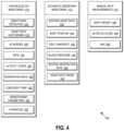
- FIG. 4is a diagram illustrating WVSM monitoring categories and the respective example physiological signals in each category in accordance with one or more embodiments.
- a WVSM 150 as described hereincan be configured to acquire specific physiologic signals at optimal times to maximize the accuracy of the recorded data and enable a WVSM 150 to accurately monitor any physiologic signal that can be acquired non-invasively.
- any physiologic signalcan be categorized into at least one of several different acquisition frequency categories.
- physiological signalscan be assigned to one of following three categories.
- a first monitoring category 410can comprise Continuous 24/7 Monitoring. Physiological signals in this category 410 are monitored continuously while the WVSM 150 is being worn by the patient 82 or user.
- physiological parameters that can fall under the Continuous 24/7 Monitoring category 410can include arrhythmia detection 416 , heart rate histograms 418 , atrial fibrillation (AF) burden 420 , peripheral capillary oxygen saturation (SpO2) 422 , activity and/or steps 424 , respiration rate 426 , core body temperature 428 , hemodynamic parameters 430 , or hydration 432 , among others.
- a second monitoring category 412can comprise Automatic Sedentary Monitoring. Physiological signals in this category can be automatically monitored when the WVSM 150 determines that the patient 82 or user is sedentary or otherwise meets the criteria for a “resting” measurement. Some examples of physiological parameters that can fall under the Automatic Sedentary Monitoring category 412 can include resting heart rate 434 , body position 436 , daily snapshot 438 , blood pressure 440 , resting respiration rate 442 , or heart rate trend 444 , among others.
- An example procedure for determining that the physiological signals that can fall within the Automatic Sedentary Monitoring category 412 to be acquiredcan include be any combination of the following. (a) Time-based via a one-time user input of “active” hours and “sedentary” hours; (b) Time-based via time of day (e.g.
- Sensed low activity or sleeping period using an accelerometer in the WVSM 150(c) Sensed low activity or sleeping period using an accelerometer in the WVSM 150 ; (d) Triggered using analysis of the signals acquired by various sensors for the continuous 24/7 monitoring, for example the signals acquired by the continuous ECG sensors could be characterized as “not noisy”, thereby triggering a sedentary recording of other physiologic signals; or (e) Triggered using sensed physiologic signals, for example a respiration rate below a certain threshold for a certain period of time could trigger a sedentary resting heart rate recording.
- a third monitoring category 414can comprise Manual Spot Measurements.
- Physiological signals in this category 414can be monitored via manual intervention from the patient 82 or user, which can be triggered by user input to the WVSM 150 , by physical attachment of an accessory component to acquire the signal, or by wireless communication with a compatible device.
- Some examples of physiological parameters that can fall under the Manual Spot Measurements category 414can include body weight 446 , blood glucose 448 , or blood alcohol concentration (BAC) 450 , among others.
- WVSM 150can wirelessly communicate with WCD system 10 wherein WCD system 10 can obtain an ECG reading from the patient 82 and transmit the ECG reading to WSVM 150 for display, processing, or saving of the ECG reading.
- the ECG reading incan be obtained by the patient 82 initiating the WVSM 150 to obtain the ECG reading from the WCD system 10 .
- WVSM 150can be wirelessly coupled to a scale (not shown) and the weight reading from the scale can be wireless transmitted to the WVSM 150 for display, processing, or saving of the weight reading.
- Manual Spot Readings 414can be utilized, and the scope of the disclosed subject matter is not limited in this respect.
- the same physiological signalin addition to the physiological signals being sorted into frequency categories, the same physiological signal could be recorded continuously, while sedentary, and also manually, and then aggregated together to form an optimal, combined, or representative view of the physiologic signal.
- the effect of noise or other artifacts on a continuous signalcan be offset or factored out by the influence of a more accurate sedentary recording.
- An example of aggregating the same physiological signal taken at different times and/or in different categoriesis shown in and described with respect to FIG. 5 , below.
- FIG. 5is a diagram illustrating WVSM acquisition of a heart rate signal as an example in accordance with one or more embodiments.
- aggregation process 500can comprise obtaining a heart rate trend 510 using a Continuous 24/7 Monitoring process 410 .
- a sedentary heart rate trend 512can be obtained using an Automatic Sedentary Monitoring process 412 .
- a manual heart rate trend measurement 514 for X amount of timecan be obtained using a Manual Spot Measurements process 414 .
- An aggregated optimal heart rate trend 516can be obtained by combining the measurements from the categories, optionally applying weighting and/or rules to the measurements.
- Table 1 belowillustrates an example in which physiological signal aggregation and processing can be performed to generate optimal heart rate values that can be used to find a heart rate trend 516 .
- the continuous heart rate trend measurement 510can be recorded once per minute regardless of the presence of noise in a simple implementation.
- the sedentary heart rate trend measurement 512 valuecan be aggregated with the continuous measurement 510 result for that particular minute and weighted with more importance than the continuous measurement 510 .
- the sedentary heart rate trend measurement 512can be weighted at 80 percent whereas the continuous heart rate trend measurement 510 can be weighted at 20 percent.
- Such an aggregation with weightingcan result in a more accurate or representative aggregated heart rate trend, for example as shown in Table 1 below.
- a manual spot measurement 514also can be aggregated into the overall trend, for example with no specific weighting to the measurement wherein the reading can stand alone. It is noted that these are merely examples of how measurements can be aggregated and/or weighted, and the scope of the disclosed subject matter is not limited in these respects.
- aggregated measurements or a measurement trend, or bothcan be presented to a user, patient 82 , or a professional such as a doctor, physician assistant, nurse, technician, patient advocate, or other healthcare provider, and so on, for example on a display of the WVSM 150 .
- the aggregated measurements or measurement trendcan be transmitted to a smartphone, tablet, computer, or similar computing device that is directly connected or wirelessly connected to the WVSM 150 , or that is remotely connected the WVSM 150 via a network.
- Such remotely located devices and/or personneluse the aggregated measurements or measurement trend to provide assistance, medical care, or well-being advice, and so on, to the user or patient 82 based at least in part on the aggregated measurements or measurement trend. It should be noted these are merely examples of other devices and/or personnel that the aggregated measurements or trends can be transmitted to and monitored, and the scope of the claimed subject matter is not limited in these respects.
- Method 600illustrates one example of how physiological parameters can be obtained using different monitoring categories and then aggregated.
- a first measurement of a patient physiological parametercan be obtained based at a first frequency based on Continuous 24/7 Monitoring 410 .
- the first frequencycan be continuous or can occur sufficiently often per a unit time to be considered continuous.
- a first weightingcan be applied to the first measurement.
- a determinationcan be made whether the patient 82 is sedentary. If not, then the Continuous 24/7 Monitoring 410 can continue at operation 610 . If the patient 82 is stationary, then at operation 616 a second measurement of the patient physiological parameter can be obtained at a second frequency based on Automatic Sedentary Monitoring 412 . For example, the frequency of such measurements can be obtained whenever the WSVM 150 detects that the patient 82 is sedentary or inactive.
- a second weightingcan be applied at operation 618 to the second measurement. The first and the second measurements can then be aggregated to obtain a trend at operation 620 .
Landscapes
- Health & Medical Sciences (AREA)
- Life Sciences & Earth Sciences (AREA)
- Engineering & Computer Science (AREA)
- General Health & Medical Sciences (AREA)
- Biomedical Technology (AREA)
- Veterinary Medicine (AREA)
- Public Health (AREA)
- Animal Behavior & Ethology (AREA)
- Heart & Thoracic Surgery (AREA)
- Molecular Biology (AREA)
- Surgery (AREA)
- Medical Informatics (AREA)
- Pathology (AREA)
- Biophysics (AREA)
- Physics & Mathematics (AREA)
- Cardiology (AREA)
- Physiology (AREA)
- Nuclear Medicine, Radiotherapy & Molecular Imaging (AREA)
- Radiology & Medical Imaging (AREA)
- Computer Networks & Wireless Communication (AREA)
- Pulmonology (AREA)
- Artificial Intelligence (AREA)
- Computer Vision & Pattern Recognition (AREA)
- Signal Processing (AREA)
- Human Computer Interaction (AREA)
- Psychiatry (AREA)
- Electrotherapy Devices (AREA)
- Measurement And Recording Of Electrical Phenomena And Electrical Characteristics Of The Living Body (AREA)
Abstract
Description
| TABLE 1 |
| Example heart rate signal aggregation |
| Time | Continuous Result | Sedentary Result | Aggregated Result |
| 2:00:00 | 65 bpm | None | 2:00 - 65 bpm |
| 2:01:00 | 150 bpm (noisy) | None | 2:01 - 75 bpm |
| 2:01:15 | None | 56 bpm | |
| 2:02:00 | 70 bpm | None | 2:02 - 70 bpm |
| 2:02:48 | +Manual - 82 bpm | ||
Claims (13)
Priority Applications (2)
| Application Number | Priority Date | Filing Date | Title |
|---|---|---|---|
| US16/806,998US12121329B2 (en) | 2019-03-08 | 2020-03-02 | Wearable vital signs monitor with selective signal acquisition |
| US18/917,258US20250031979A1 (en) | 2019-03-08 | 2024-10-16 | Wearable vital signs monitor with selective signal acquisition |
Applications Claiming Priority (2)
| Application Number | Priority Date | Filing Date | Title |
|---|---|---|---|
| US201962815914P | 2019-03-08 | 2019-03-08 | |
| US16/806,998US12121329B2 (en) | 2019-03-08 | 2020-03-02 | Wearable vital signs monitor with selective signal acquisition |
Related Child Applications (1)
| Application Number | Title | Priority Date | Filing Date |
|---|---|---|---|
| US18/917,258ContinuationUS20250031979A1 (en) | 2019-03-08 | 2024-10-16 | Wearable vital signs monitor with selective signal acquisition |
Publications (2)
| Publication Number | Publication Date |
|---|---|
| US20200281479A1 US20200281479A1 (en) | 2020-09-10 |
| US12121329B2true US12121329B2 (en) | 2024-10-22 |
Family
ID=72336629
Family Applications (2)
| Application Number | Title | Priority Date | Filing Date |
|---|---|---|---|
| US16/806,998ActiveUS12121329B2 (en) | 2019-03-08 | 2020-03-02 | Wearable vital signs monitor with selective signal acquisition |
| US18/917,258PendingUS20250031979A1 (en) | 2019-03-08 | 2024-10-16 | Wearable vital signs monitor with selective signal acquisition |
Family Applications After (1)
| Application Number | Title | Priority Date | Filing Date |
|---|---|---|---|
| US18/917,258PendingUS20250031979A1 (en) | 2019-03-08 | 2024-10-16 | Wearable vital signs monitor with selective signal acquisition |
Country Status (1)
| Country | Link |
|---|---|
| US (2) | US12121329B2 (en) |
Families Citing this family (5)
| Publication number | Priority date | Publication date | Assignee | Title |
|---|---|---|---|---|
| US12300368B1 (en)* | 2019-03-07 | 2025-05-13 | West Affum Holdings Dac | Analysis and presentation of aggregated patient and device data within a system that includes a medical device |
| US12121329B2 (en) | 2019-03-08 | 2024-10-22 | West Affum Holdings Dac | Wearable vital signs monitor with selective signal acquisition |
| GB2613624A (en)* | 2021-12-10 | 2023-06-14 | Metix Ltd | Vital signs monitor and medical device |
| US20240021286A1 (en)* | 2022-07-13 | 2024-01-18 | West Affum Holdings Dac | Remote management of wearable cardiac defibrillation system |
| CN116035550B (en)* | 2023-01-28 | 2023-06-27 | 深圳市美林医疗器械科技有限公司 | Wearable signal acquisition device for noninvasive cardiac output measurement |
Citations (102)
| Publication number | Priority date | Publication date | Assignee | Title |
|---|---|---|---|---|
| US3724355A (en) | 1970-06-12 | 1973-04-03 | K Schranz | Apparatus for processing exposed photographic film or the like |
| US3724455A (en) | 1970-06-02 | 1973-04-03 | P Unger | Cardiac warning device |
| US4583524A (en) | 1984-11-21 | 1986-04-22 | Hutchins Donald C | Cardiopulmonary resuscitation prompting |
| US4619265A (en) | 1984-03-08 | 1986-10-28 | Physio-Control Corporation | Interactive portable defibrillator including ECG detection circuit |
| US4928690A (en) | 1988-04-25 | 1990-05-29 | Lifecor, Inc. | Portable device for sensing cardiac function and automatically delivering electrical therapy |
| US4955381A (en) | 1988-08-26 | 1990-09-11 | Cardiotronics, Inc. | Multi-pad, multi-function electrode |
| US5078134A (en) | 1988-04-25 | 1992-01-07 | Lifecor, Inc. | Portable device for sensing cardiac function and automatically delivering electrical therapy |
| US5228449A (en) | 1991-01-22 | 1993-07-20 | Athanasios G. Christ | System and method for detecting out-of-hospital cardiac emergencies and summoning emergency assistance |
| US5348008A (en) | 1991-11-25 | 1994-09-20 | Somnus Corporation | Cardiorespiratory alert system |
| US5394892A (en) | 1990-04-02 | 1995-03-07 | K J Mellet Nominees Pty Ltd | CPR prompting apparatus |
| US5405362A (en) | 1991-04-29 | 1995-04-11 | The Board Of Regents For The University Of Texas System | Interactive external defibrillation and drug injection system |
| US5474574A (en) | 1992-06-24 | 1995-12-12 | Cardiac Science, Inc. | Automatic external cardioverter/defibrillator |
| US5662690A (en) | 1994-12-08 | 1997-09-02 | Heartstream, Inc. | Defibrillator with training features and pause actuator |
| US5782878A (en) | 1994-12-07 | 1998-07-21 | Heartstream, Inc. | External defibrillator with communications network link |
| US5792204A (en) | 1996-05-08 | 1998-08-11 | Pacesetter, Inc. | Methods and apparatus for controlling an implantable device programmer using voice commands |
| WO1998039061A2 (en) | 1997-03-07 | 1998-09-11 | Cadent Medical Corporation | Wearable defibrillation system |
| US5902249A (en) | 1995-03-03 | 1999-05-11 | Heartstream, Inc. | Method and apparatus for detecting artifacts using common-mode signals in differential signal detectors |
| US5913685A (en) | 1996-06-24 | 1999-06-22 | Hutchins; Donald C. | CPR computer aiding |
| US5944669A (en) | 1997-11-20 | 1999-08-31 | Lifecor, Inc. | Apparatus and method for sensing cardiac function |
| US6047203A (en) | 1997-03-17 | 2000-04-04 | Nims, Inc. | Physiologic signs feedback system |
| US6065154A (en) | 1998-04-07 | 2000-05-23 | Lifecor, Inc. | Support garments for patient-worn energy delivery apparatus |
| US6108197A (en) | 1992-05-15 | 2000-08-22 | Via, Inc. | Flexible wearable computer |
| US6201992B1 (en) | 1999-04-01 | 2001-03-13 | Agilent Technologies, Inc. | Defibrillator interface capable of generating video images |
| US6263238B1 (en) | 1998-04-16 | 2001-07-17 | Survivalink Corporation | Automatic external defibrillator having a ventricular fibrillation detector |
| US6287328B1 (en) | 1999-04-08 | 2001-09-11 | Agilent Technologies, Inc. | Multivariable artifact assessment |
| US6319011B1 (en) | 1995-04-06 | 2001-11-20 | Michael J. Motti | Automatic training defibrillator simulator and method |
| US6334070B1 (en) | 1998-11-20 | 2001-12-25 | Medtronic Physio-Control Manufacturing Corp. | Visual and aural user interface for an automated external defibrillator |
| US6356785B1 (en) | 1997-11-06 | 2002-03-12 | Cecily Anne Snyder | External defibrillator with CPR prompts and ACLS prompts and methods of use |
| US6437083B1 (en) | 2001-12-06 | 2002-08-20 | General Electric Company | Process for preparing branched aromatic polycarbonates |
| US20020181680A1 (en) | 1999-10-05 | 2002-12-05 | Marshal Linder | Data collection and system management for patient-worn medical devices |
| US6529875B1 (en) | 1996-07-11 | 2003-03-04 | Sega Enterprises Ltd. | Voice recognizer, voice recognizing method and game machine using them |
| US20030158593A1 (en) | 2002-02-19 | 2003-08-21 | Heilman Marlin S. | Cardiac garment |
| US6762917B1 (en) | 2001-06-12 | 2004-07-13 | Novx Corporation | Method of monitoring ESC levels and protective devices utilizing the method |
| US20050107833A1 (en) | 2003-11-13 | 2005-05-19 | Freeman Gary A. | Multi-path transthoracic defibrillation and cardioversion |
| US7065401B2 (en) | 2002-05-08 | 2006-06-20 | Michael Worden | Method of applying electrical signals to a patient and automatic wearable external defibrillator |
| US7099715B2 (en) | 2004-02-17 | 2006-08-29 | Cardionet, Inc. | Distributed cardiac activity monitoring with selective filtering |
| US7212850B2 (en) | 2003-11-26 | 2007-05-01 | Cardionet, Inc. | System and method for processing and presenting arrhythmia information to facilitate heart arrhythmia identification and treatment |
| US20080312709A1 (en) | 2007-06-13 | 2008-12-18 | Volpe Shane S | Wearable medical treatment device with motion/position detection |
| US20090005827A1 (en) | 2007-06-26 | 2009-01-01 | David Weintraub | Wearable defibrillator |
| US7559902B2 (en) | 2003-08-22 | 2009-07-14 | Foster-Miller, Inc. | Physiological monitoring garment |
| US7587237B2 (en) | 2004-02-02 | 2009-09-08 | Cardionet, Inc. | Biological signal management |
| US20100007413A1 (en) | 2006-11-10 | 2010-01-14 | Koninklijke Philips Electronics N.V. | Ecg electrode contact quality measurement system |
| US20100298899A1 (en)* | 2007-06-13 | 2010-11-25 | Donnelly Edward J | Wearable medical treatment device |
| US7865238B2 (en) | 2004-09-29 | 2011-01-04 | Koninklijke Philips Electronics N.V. | High-voltage module for an external defibrillator |
| US7870761B2 (en) | 2002-05-14 | 2011-01-18 | Koninklijke Philips Electronics N.V. | Garment and method for producing the same |
| US7941207B2 (en) | 2004-01-21 | 2011-05-10 | Cardionet, Inc. | Cardiac monitoring |
| US20110288604A1 (en) | 2010-05-18 | 2011-11-24 | Kaib Thomas E | Wearable therapeutic device |
| US20110288605A1 (en) | 2010-05-18 | 2011-11-24 | Zoll Medical Corporation | Wearable ambulatory medical device with multiple sensing electrodes |
| US8135462B2 (en) | 2002-08-26 | 2012-03-13 | Physio-Control, Inc. | Pulse detection using patient physiological signals |
| US20120112903A1 (en) | 2010-11-08 | 2012-05-10 | Zoll Medical Corporation | Remote medical device alarm |
| US20120144551A1 (en) | 2010-12-09 | 2012-06-14 | Eric Guldalian | Conductive Garment |
| US20120150008A1 (en) | 2010-12-09 | 2012-06-14 | Kaib Thomas E | Electrode with redundant impedance reduction |
| US20120158075A1 (en) | 2010-12-16 | 2012-06-21 | Kaib Thomas E | Water resistant wearable medical device |
| US20120191476A1 (en) | 2011-01-20 | 2012-07-26 | Reid C Shane | Systems and methods for collection, organization and display of ems information |
| US20120265265A1 (en) | 2011-04-13 | 2012-10-18 | Mehdi Razavi | Automated External Defibrillator Pad System |
| US20120283794A1 (en) | 2011-05-02 | 2012-11-08 | Kaib Thomas E | Patient-worn energy delivery apparatus and techniques for sizing same |
| US20120293323A1 (en) | 2011-03-25 | 2012-11-22 | Zoll Medical Corporation | System and method for adapting alarms in a wearable medical device |
| US20120302860A1 (en) | 2011-03-25 | 2012-11-29 | Zoll Medical Corporation | Selection of optimal channel for rate determination |
| US20120310315A1 (en) | 2009-03-17 | 2012-12-06 | Savage Walter T | Device and method for reducing patient transthoracic impedance for the purpose of delivering a therapeutic current |
| US8369944B2 (en) | 2007-06-06 | 2013-02-05 | Zoll Medical Corporation | Wearable defibrillator with audio input/output |
| US20130085538A1 (en) | 2011-09-01 | 2013-04-04 | Zoll Medical Corporation | Wearable monitoring and treatment device |
| US20130231711A1 (en) | 2012-03-02 | 2013-09-05 | Thomas E. Kaib | Systems and methods for configuring a wearable medical monitoring and/or treatment device |
| US20130245388A1 (en) | 2011-09-01 | 2013-09-19 | Mc10, Inc. | Electronics for detection of a condition of tissue |
| US8548557B2 (en) | 2010-08-12 | 2013-10-01 | Covidien Lp | Medical electrodes |
| US20130274565A1 (en) | 2012-04-13 | 2013-10-17 | Alois Antonin Langer | Outpatient health emergency warning system |
| US20130317852A1 (en) | 2012-05-22 | 2013-11-28 | Geneva Healthcare, LLC | Medical device information portal |
| US20130325078A1 (en) | 2012-05-31 | 2013-12-05 | Zoll Medical Corporation | Medical monitoring and treatment device with external pacing |
| US8615295B2 (en) | 2009-03-17 | 2013-12-24 | Cardiothrive, Inc. | External defibrillator |
| US20140025131A1 (en) | 2012-07-20 | 2014-01-23 | Physio-Control, Inc. | Wearable defibrillator with voice prompts and voice recognition |
| US20140070957A1 (en) | 2012-09-11 | 2014-03-13 | Gianluigi LONGINOTTI-BUITONI | Wearable communication platform |
| US20140073486A1 (en)* | 2012-09-04 | 2014-03-13 | Bobo Analytics, Inc. | Systems, devices and methods for continuous heart rate monitoring and interpretation |
| US20140163663A1 (en) | 2012-12-11 | 2014-06-12 | Piyush Poddar | Method and system for switching shock vectors and decreasing transthoracic impedance for cardioversion and defibrillation |
| US8904214B2 (en) | 2010-07-09 | 2014-12-02 | Zoll Medical Corporation | System and method for conserving power in a medical device |
| US20140378786A1 (en)* | 2013-03-15 | 2014-12-25 | Fitbit, Inc. | Multimode sensor devices |
| US20140378812A1 (en) | 2011-12-20 | 2014-12-25 | Sensible Medical Innovatons | Thoracic garment of positioning electromagnetic (em) transducers and methods of using such thoracic garment |
| US20150039053A1 (en) | 2013-06-28 | 2015-02-05 | Zoll Medical Corporation | Systems and methods of delivering therapy using an ambulatory medical device |
| US9089685B2 (en) | 2013-02-25 | 2015-07-28 | West Affum Holdings Corp. | Wearable defibrillator with a multivector shock waveform |
| US9132267B2 (en) | 2013-03-04 | 2015-09-15 | Zoll Medical Corporation | Flexible therapy electrode system |
| US20150328472A1 (en) | 2014-05-13 | 2015-11-19 | Physio-Control, Inc. | Wearable cardioverter defibrillator components discarding ecg signals prior to making shock/no shock determination |
| US20160004831A1 (en) | 2014-07-07 | 2016-01-07 | Zoll Medical Corporation | Medical device with natural language processor |
| US20160082277A1 (en) | 2013-02-25 | 2016-03-24 | West Affum Holdings Corp. | Wearable cardioverter defibrillator (wcd) system informing patient that it is validating just-detected cardiac arrhythmia |
| US9592403B2 (en) | 2013-02-25 | 2017-03-14 | West Affum Holdings Corp. | Wearable cardioverter defibrillator (WCD) system making shock/no shock determinations from multiple patient parameters |
| US20180185662A1 (en) | 2017-01-05 | 2018-07-05 | West Affum Holdings Corp. | Wearable cardioverter defibrillator having adjustable alarm time |
| US20180242875A1 (en)* | 2017-02-28 | 2018-08-30 | Zoll Medical Corporation | Configuring a cardiac monitoring device |
| US20190110755A1 (en)* | 2017-10-17 | 2019-04-18 | Whoop, Inc. | Applied data quality metrics for physiological measurements |
| US20190159696A1 (en) | 2014-10-30 | 2019-05-30 | West Affum Holdings Corp. | Wearable cardioverter defibrillator with improved ecg electrodes |
| US20190282178A1 (en)* | 2018-03-16 | 2019-09-19 | Zoll Medical Corporation | Monitoring physiological status based on bio-vibrational and radio frequency data analysis |
| US20190329054A1 (en) | 2018-04-26 | 2019-10-31 | West Affum Holdings Corp. | Multi-sensory alarm for a wearable cardiac defibrillator |
| US20200027568A1 (en) | 2018-07-17 | 2020-01-23 | West Affum Holdings Corp. | Physician House Call Portal |
| US20200121251A1 (en)* | 2018-10-18 | 2020-04-23 | Boston Scientific Scimed Inc. | Multilayer wearable device |
| US20200206518A1 (en)* | 2018-12-28 | 2020-07-02 | Zoll Medical Corporation | Wearable medical device response mechanisms and methods of use |
| US20200230428A1 (en) | 2019-01-18 | 2020-07-23 | West Affum Holdings Corp. | Wcd system prioritization of alerts based on severity and/or required timeliness of user response |
| US20200281479A1 (en) | 2019-03-08 | 2020-09-10 | West Affum Holdings Corp. | Wearable Vital Signs Monitor With Selective Signal Acquisition |
| US20210050111A1 (en) | 2019-08-15 | 2021-02-18 | West Affum Holdings Corp. | Wcd system alert issuance and resolution |
| US11013409B2 (en)* | 2015-07-07 | 2021-05-25 | Zoll Medical Corporation | Systems and methods for communicating data |
| US11103145B1 (en)* | 2017-06-14 | 2021-08-31 | Vivaquant Llc | Physiological signal monitoring and apparatus therefor |
| US11103717B2 (en) | 2017-07-28 | 2021-08-31 | West Affum Holdings Corp. | Wearable cardioverter defibrillator (WCD) system reacting to high-frequency ECG noise |
| US11154230B2 (en) | 2017-01-05 | 2021-10-26 | West Affum Holdings Corp. | Wearable cardioverter defibrillator having reduced noise prompts |
| US11160990B1 (en) | 2018-02-14 | 2021-11-02 | West Affum Holdings Corp. | Wearable cardioverter defibrillator (WCD) alarms |
| US11191971B2 (en) | 2019-03-07 | 2021-12-07 | West Affum Holdings Corp. | Wearable cardioverter defibrillator (WCD) system with active ECG cable shielding |
| US11219373B2 (en)* | 2014-12-22 | 2022-01-11 | Eggers & Associates, Inc. | Wearable apparatus, system and method for detection of cardiac arrest and alerting emergency response |
| US11324405B2 (en)* | 2015-12-07 | 2022-05-10 | Medici Technologies Llc | Observational heart failure monitoring system |
- 2020
- 2020-03-02USUS16/806,998patent/US12121329B2/enactiveActive
- 2024
- 2024-10-16USUS18/917,258patent/US20250031979A1/enactivePending
Patent Citations (127)
| Publication number | Priority date | Publication date | Assignee | Title |
|---|---|---|---|---|
| US3724455A (en) | 1970-06-02 | 1973-04-03 | P Unger | Cardiac warning device |
| US3724355A (en) | 1970-06-12 | 1973-04-03 | K Schranz | Apparatus for processing exposed photographic film or the like |
| US4619265A (en) | 1984-03-08 | 1986-10-28 | Physio-Control Corporation | Interactive portable defibrillator including ECG detection circuit |
| USRE34800E (en) | 1984-11-21 | 1994-11-29 | Hutchins; Donald C. | Cardiopulmonary resuscitation prompting |
| US4583524A (en) | 1984-11-21 | 1986-04-22 | Hutchins Donald C | Cardiopulmonary resuscitation prompting |
| US4928690A (en) | 1988-04-25 | 1990-05-29 | Lifecor, Inc. | Portable device for sensing cardiac function and automatically delivering electrical therapy |
| US5078134A (en) | 1988-04-25 | 1992-01-07 | Lifecor, Inc. | Portable device for sensing cardiac function and automatically delivering electrical therapy |
| US4955381A (en) | 1988-08-26 | 1990-09-11 | Cardiotronics, Inc. | Multi-pad, multi-function electrode |
| US5394892A (en) | 1990-04-02 | 1995-03-07 | K J Mellet Nominees Pty Ltd | CPR prompting apparatus |
| US5228449A (en) | 1991-01-22 | 1993-07-20 | Athanasios G. Christ | System and method for detecting out-of-hospital cardiac emergencies and summoning emergency assistance |
| US5405362A (en) | 1991-04-29 | 1995-04-11 | The Board Of Regents For The University Of Texas System | Interactive external defibrillation and drug injection system |
| US5353793A (en) | 1991-11-25 | 1994-10-11 | Oishi-Kogyo Company | Sensor apparatus |
| US5348008A (en) | 1991-11-25 | 1994-09-20 | Somnus Corporation | Cardiorespiratory alert system |
| US6108197A (en) | 1992-05-15 | 2000-08-22 | Via, Inc. | Flexible wearable computer |
| US5474574A (en) | 1992-06-24 | 1995-12-12 | Cardiac Science, Inc. | Automatic external cardioverter/defibrillator |
| US5782878A (en) | 1994-12-07 | 1998-07-21 | Heartstream, Inc. | External defibrillator with communications network link |
| US5662690A (en) | 1994-12-08 | 1997-09-02 | Heartstream, Inc. | Defibrillator with training features and pause actuator |
| US5902249A (en) | 1995-03-03 | 1999-05-11 | Heartstream, Inc. | Method and apparatus for detecting artifacts using common-mode signals in differential signal detectors |
| US6319011B1 (en) | 1995-04-06 | 2001-11-20 | Michael J. Motti | Automatic training defibrillator simulator and method |
| US5792204A (en) | 1996-05-08 | 1998-08-11 | Pacesetter, Inc. | Methods and apparatus for controlling an implantable device programmer using voice commands |
| US5913685A (en) | 1996-06-24 | 1999-06-22 | Hutchins; Donald C. | CPR computer aiding |
| US6529875B1 (en) | 1996-07-11 | 2003-03-04 | Sega Enterprises Ltd. | Voice recognizer, voice recognizing method and game machine using them |
| US6427083B1 (en) | 1997-03-07 | 2002-07-30 | Cardiac Science, Inc. | Defibrillation system |
| WO1998039061A2 (en) | 1997-03-07 | 1998-09-11 | Cadent Medical Corporation | Wearable defibrillation system |
| US6148233A (en) | 1997-03-07 | 2000-11-14 | Cardiac Science, Inc. | Defibrillation system having segmented electrodes |
| US6671545B2 (en) | 1997-03-07 | 2003-12-30 | Cardiac Science, Inc. | Defibrillator with controller operating in a low power mode |
| US6546285B1 (en) | 1997-03-07 | 2003-04-08 | Cardiac Science, Inc. | Long term wear electrode for defibrillation system |
| US20110022105A9 (en) | 1997-03-07 | 2011-01-27 | Owen James M | Defibrillation system |
| US6304780B1 (en) | 1997-03-07 | 2001-10-16 | Cardiac Science Inc. | External defibrillator system with diagnostic module |
| US6047203A (en) | 1997-03-17 | 2000-04-04 | Nims, Inc. | Physiologic signs feedback system |
| US6356785B1 (en) | 1997-11-06 | 2002-03-12 | Cecily Anne Snyder | External defibrillator with CPR prompts and ACLS prompts and methods of use |
| US5944669A (en) | 1997-11-20 | 1999-08-31 | Lifecor, Inc. | Apparatus and method for sensing cardiac function |
| US6065154A (en) | 1998-04-07 | 2000-05-23 | Lifecor, Inc. | Support garments for patient-worn energy delivery apparatus |
| US6263238B1 (en) | 1998-04-16 | 2001-07-17 | Survivalink Corporation | Automatic external defibrillator having a ventricular fibrillation detector |
| US6334070B1 (en) | 1998-11-20 | 2001-12-25 | Medtronic Physio-Control Manufacturing Corp. | Visual and aural user interface for an automated external defibrillator |
| US6201992B1 (en) | 1999-04-01 | 2001-03-13 | Agilent Technologies, Inc. | Defibrillator interface capable of generating video images |
| US6287328B1 (en) | 1999-04-08 | 2001-09-11 | Agilent Technologies, Inc. | Multivariable artifact assessment |
| US6681003B2 (en) | 1999-10-05 | 2004-01-20 | Lifecor, Inc. | Data collection and system management for patient-worn medical devices |
| US20020181680A1 (en) | 1999-10-05 | 2002-12-05 | Marshal Linder | Data collection and system management for patient-worn medical devices |
| US6762917B1 (en) | 2001-06-12 | 2004-07-13 | Novx Corporation | Method of monitoring ESC levels and protective devices utilizing the method |
| US6437083B1 (en) | 2001-12-06 | 2002-08-20 | General Electric Company | Process for preparing branched aromatic polycarbonates |
| US20030158593A1 (en) | 2002-02-19 | 2003-08-21 | Heilman Marlin S. | Cardiac garment |
| US7065401B2 (en) | 2002-05-08 | 2006-06-20 | Michael Worden | Method of applying electrical signals to a patient and automatic wearable external defibrillator |
| US7870761B2 (en) | 2002-05-14 | 2011-01-18 | Koninklijke Philips Electronics N.V. | Garment and method for producing the same |
| US8135462B2 (en) | 2002-08-26 | 2012-03-13 | Physio-Control, Inc. | Pulse detection using patient physiological signals |
| US7559902B2 (en) | 2003-08-22 | 2009-07-14 | Foster-Miller, Inc. | Physiological monitoring garment |
| US20050107833A1 (en) | 2003-11-13 | 2005-05-19 | Freeman Gary A. | Multi-path transthoracic defibrillation and cardioversion |
| US20050107834A1 (en) | 2003-11-13 | 2005-05-19 | Freeman Gary A. | Multi-path transthoracic defibrillation and cardioversion |
| US7907996B2 (en) | 2003-11-26 | 2011-03-15 | Cardionet, Inc. | System and method for processing and presenting arrhythmia information to facilitate heart arrhythmia identification and treatment |
| US7212850B2 (en) | 2003-11-26 | 2007-05-01 | Cardionet, Inc. | System and method for processing and presenting arrhythmia information to facilitate heart arrhythmia identification and treatment |
| US7941207B2 (en) | 2004-01-21 | 2011-05-10 | Cardionet, Inc. | Cardiac monitoring |
| US7587237B2 (en) | 2004-02-02 | 2009-09-08 | Cardionet, Inc. | Biological signal management |
| US7099715B2 (en) | 2004-02-17 | 2006-08-29 | Cardionet, Inc. | Distributed cardiac activity monitoring with selective filtering |
| US7865238B2 (en) | 2004-09-29 | 2011-01-04 | Koninklijke Philips Electronics N.V. | High-voltage module for an external defibrillator |
| US20100007413A1 (en) | 2006-11-10 | 2010-01-14 | Koninklijke Philips Electronics N.V. | Ecg electrode contact quality measurement system |
| US8369944B2 (en) | 2007-06-06 | 2013-02-05 | Zoll Medical Corporation | Wearable defibrillator with audio input/output |
| US20140324112A1 (en) | 2007-06-06 | 2014-10-30 | Zoll Medical Corporation | Wearable defibrillator with audio input/output |
| US8965500B2 (en) | 2007-06-06 | 2015-02-24 | Zoll Medical Corporation | Wearable defibrillator with audio input/output |
| US8140154B2 (en) | 2007-06-13 | 2012-03-20 | Zoll Medical Corporation | Wearable medical treatment device |
| US7974689B2 (en) | 2007-06-13 | 2011-07-05 | Zoll Medical Corporation | Wearable medical treatment device with motion/position detection |
| US20080312709A1 (en) | 2007-06-13 | 2008-12-18 | Volpe Shane S | Wearable medical treatment device with motion/position detection |
| US20100298899A1 (en)* | 2007-06-13 | 2010-11-25 | Donnelly Edward J | Wearable medical treatment device |
| US20090005827A1 (en) | 2007-06-26 | 2009-01-01 | David Weintraub | Wearable defibrillator |
| US20120310315A1 (en) | 2009-03-17 | 2012-12-06 | Savage Walter T | Device and method for reducing patient transthoracic impedance for the purpose of delivering a therapeutic current |
| US8615295B2 (en) | 2009-03-17 | 2013-12-24 | Cardiothrive, Inc. | External defibrillator |
| US9008801B2 (en) | 2010-05-18 | 2015-04-14 | Zoll Medical Corporation | Wearable therapeutic device |
| US20110288604A1 (en) | 2010-05-18 | 2011-11-24 | Kaib Thomas E | Wearable therapeutic device |
| US20110288605A1 (en) | 2010-05-18 | 2011-11-24 | Zoll Medical Corporation | Wearable ambulatory medical device with multiple sensing electrodes |
| US8904214B2 (en) | 2010-07-09 | 2014-12-02 | Zoll Medical Corporation | System and method for conserving power in a medical device |
| US9454219B2 (en) | 2010-07-09 | 2016-09-27 | Zoll Medical Corporation | System and method for conserving power in a medical device |
| US8548557B2 (en) | 2010-08-12 | 2013-10-01 | Covidien Lp | Medical electrodes |
| US20120112903A1 (en) | 2010-11-08 | 2012-05-10 | Zoll Medical Corporation | Remote medical device alarm |
| US20120150008A1 (en) | 2010-12-09 | 2012-06-14 | Kaib Thomas E | Electrode with redundant impedance reduction |
| US20120144551A1 (en) | 2010-12-09 | 2012-06-14 | Eric Guldalian | Conductive Garment |
| US20120158075A1 (en) | 2010-12-16 | 2012-06-21 | Kaib Thomas E | Water resistant wearable medical device |
| US20120191476A1 (en) | 2011-01-20 | 2012-07-26 | Reid C Shane | Systems and methods for collection, organization and display of ems information |
| US9408548B2 (en) | 2011-03-25 | 2016-08-09 | Zoll Medical Corporation | Selection of optimal channel for rate determination |
| US20120302860A1 (en) | 2011-03-25 | 2012-11-29 | Zoll Medical Corporation | Selection of optimal channel for rate determination |
| US20120293323A1 (en) | 2011-03-25 | 2012-11-22 | Zoll Medical Corporation | System and method for adapting alarms in a wearable medical device |
| US8897860B2 (en) | 2011-03-25 | 2014-11-25 | Zoll Medical Corporation | Selection of optimal channel for rate determination |
| US20120265265A1 (en) | 2011-04-13 | 2012-10-18 | Mehdi Razavi | Automated External Defibrillator Pad System |
| US20120283794A1 (en) | 2011-05-02 | 2012-11-08 | Kaib Thomas E | Patient-worn energy delivery apparatus and techniques for sizing same |
| US20130245388A1 (en) | 2011-09-01 | 2013-09-19 | Mc10, Inc. | Electronics for detection of a condition of tissue |
| US9131901B2 (en) | 2011-09-01 | 2015-09-15 | Zoll Medical Corporation | Wearable monitoring and treatment device |
| US20130085538A1 (en) | 2011-09-01 | 2013-04-04 | Zoll Medical Corporation | Wearable monitoring and treatment device |
| US8644925B2 (en) | 2011-09-01 | 2014-02-04 | Zoll Medical Corporation | Wearable monitoring and treatment device |
| US20140378812A1 (en) | 2011-12-20 | 2014-12-25 | Sensible Medical Innovatons | Thoracic garment of positioning electromagnetic (em) transducers and methods of using such thoracic garment |
| US20130231711A1 (en) | 2012-03-02 | 2013-09-05 | Thomas E. Kaib | Systems and methods for configuring a wearable medical monitoring and/or treatment device |
| US20130274565A1 (en) | 2012-04-13 | 2013-10-17 | Alois Antonin Langer | Outpatient health emergency warning system |
| US20130317852A1 (en) | 2012-05-22 | 2013-11-28 | Geneva Healthcare, LLC | Medical device information portal |
| US20130325078A1 (en) | 2012-05-31 | 2013-12-05 | Zoll Medical Corporation | Medical monitoring and treatment device with external pacing |
| US20140025131A1 (en) | 2012-07-20 | 2014-01-23 | Physio-Control, Inc. | Wearable defibrillator with voice prompts and voice recognition |
| US20140073486A1 (en)* | 2012-09-04 | 2014-03-13 | Bobo Analytics, Inc. | Systems, devices and methods for continuous heart rate monitoring and interpretation |
| US20140070957A1 (en) | 2012-09-11 | 2014-03-13 | Gianluigi LONGINOTTI-BUITONI | Wearable communication platform |
| US20140163663A1 (en) | 2012-12-11 | 2014-06-12 | Piyush Poddar | Method and system for switching shock vectors and decreasing transthoracic impedance for cardioversion and defibrillation |
| US9592403B2 (en) | 2013-02-25 | 2017-03-14 | West Affum Holdings Corp. | Wearable cardioverter defibrillator (WCD) system making shock/no shock determinations from multiple patient parameters |
| US20160082277A1 (en) | 2013-02-25 | 2016-03-24 | West Affum Holdings Corp. | Wearable cardioverter defibrillator (wcd) system informing patient that it is validating just-detected cardiac arrhythmia |
| US9089685B2 (en) | 2013-02-25 | 2015-07-28 | West Affum Holdings Corp. | Wearable defibrillator with a multivector shock waveform |
| US9132267B2 (en) | 2013-03-04 | 2015-09-15 | Zoll Medical Corporation | Flexible therapy electrode system |
| US20140378786A1 (en)* | 2013-03-15 | 2014-12-25 | Fitbit, Inc. | Multimode sensor devices |
| US20150039053A1 (en) | 2013-06-28 | 2015-02-05 | Zoll Medical Corporation | Systems and methods of delivering therapy using an ambulatory medical device |
| US9579516B2 (en) | 2013-06-28 | 2017-02-28 | Zoll Medical Corporation | Systems and methods of delivering therapy using an ambulatory medical device |
| US20150328472A1 (en) | 2014-05-13 | 2015-11-19 | Physio-Control, Inc. | Wearable cardioverter defibrillator components discarding ecg signals prior to making shock/no shock determination |
| US20160004831A1 (en) | 2014-07-07 | 2016-01-07 | Zoll Medical Corporation | Medical device with natural language processor |
| US20190159696A1 (en) | 2014-10-30 | 2019-05-30 | West Affum Holdings Corp. | Wearable cardioverter defibrillator with improved ecg electrodes |
| US11219373B2 (en)* | 2014-12-22 | 2022-01-11 | Eggers & Associates, Inc. | Wearable apparatus, system and method for detection of cardiac arrest and alerting emergency response |
| US11013409B2 (en)* | 2015-07-07 | 2021-05-25 | Zoll Medical Corporation | Systems and methods for communicating data |
| US11324405B2 (en)* | 2015-12-07 | 2022-05-10 | Medici Technologies Llc | Observational heart failure monitoring system |
| US20180185662A1 (en) | 2017-01-05 | 2018-07-05 | West Affum Holdings Corp. | Wearable cardioverter defibrillator having adjustable alarm time |
| US11154230B2 (en) | 2017-01-05 | 2021-10-26 | West Affum Holdings Corp. | Wearable cardioverter defibrillator having reduced noise prompts |
| US11083906B2 (en) | 2017-01-05 | 2021-08-10 | West Affum Holdings Corp. | Wearable cardioverter defibrillator having adjustable alarm time |
| US20180242875A1 (en)* | 2017-02-28 | 2018-08-30 | Zoll Medical Corporation | Configuring a cardiac monitoring device |
| US11103145B1 (en)* | 2017-06-14 | 2021-08-31 | Vivaquant Llc | Physiological signal monitoring and apparatus therefor |
| US11103717B2 (en) | 2017-07-28 | 2021-08-31 | West Affum Holdings Corp. | Wearable cardioverter defibrillator (WCD) system reacting to high-frequency ECG noise |
| US20190110755A1 (en)* | 2017-10-17 | 2019-04-18 | Whoop, Inc. | Applied data quality metrics for physiological measurements |
| US11160990B1 (en) | 2018-02-14 | 2021-11-02 | West Affum Holdings Corp. | Wearable cardioverter defibrillator (WCD) alarms |
| US20190282178A1 (en)* | 2018-03-16 | 2019-09-19 | Zoll Medical Corporation | Monitoring physiological status based on bio-vibrational and radio frequency data analysis |
| US11198015B2 (en) | 2018-04-26 | 2021-12-14 | West Affum Holdings Corp. | Multi-sensory alarm for a wearable cardiac defibrillator |
| US20190329054A1 (en) | 2018-04-26 | 2019-10-31 | West Affum Holdings Corp. | Multi-sensory alarm for a wearable cardiac defibrillator |
| US20200027568A1 (en) | 2018-07-17 | 2020-01-23 | West Affum Holdings Corp. | Physician House Call Portal |
| US20200121251A1 (en)* | 2018-10-18 | 2020-04-23 | Boston Scientific Scimed Inc. | Multilayer wearable device |
| US20200206518A1 (en)* | 2018-12-28 | 2020-07-02 | Zoll Medical Corporation | Wearable medical device response mechanisms and methods of use |
| US20200230428A1 (en) | 2019-01-18 | 2020-07-23 | West Affum Holdings Corp. | Wcd system prioritization of alerts based on severity and/or required timeliness of user response |
| US20210370079A9 (en) | 2019-01-18 | 2021-12-02 | West Affum Holdings Corp. | Wcd system prioritization of alerts based on severity and/or required timeliness of user response |
| US11191971B2 (en) | 2019-03-07 | 2021-12-07 | West Affum Holdings Corp. | Wearable cardioverter defibrillator (WCD) system with active ECG cable shielding |
| US20200281479A1 (en) | 2019-03-08 | 2020-09-10 | West Affum Holdings Corp. | Wearable Vital Signs Monitor With Selective Signal Acquisition |
| US20210050111A1 (en) | 2019-08-15 | 2021-02-18 | West Affum Holdings Corp. | Wcd system alert issuance and resolution |
Non-Patent Citations (7)
| Title |
|---|
| "Elias Ebrahimzadeh, et al., A novel approach to predict sudden cardiac death (SCD) using nonlinear and time-frequency analyses from HRV signals", Feb. 4, 2014, PubMed (Year: 2014).* |
| Heartstart MRx and XL AED Algorithm—Application Note, Jul. 2001, Edition 2 Philips Healthcare, USA. |
| Klein, H. U., Goldenberg I., & Moss, A. J., Risk Stratification for Implantable Cardioverter Defibrillator Therapy: The Role of the Wearable Cardioverter-Defibrillator, Clinical update, European Heart Journal, May 31, 2013, pp. 1-14, doi:10.1093/eurheartj/eht167, European Society of Cardiology. |
| LIFECOR LifeVest System Model WCD 3100 Operator's Manual, 2006, PN 20B0040 Rev FI, Zoll Lifecor Corporation, Pittsburgh, PA. |
| LifeVest Model 4000 Patient Manual, Zoll, 2009, PN 20B0047 Rev B. |
| Pagan-Carlo, et al., "Encircling Overlapping Multipulse Shock Waveforms for Transthoracic Defibrillation," JACC Journals, Dec. 1998, vol. 32 Issue 7, p. 2065-2071. |
| The LifeVest Network/Patient Data Management System, Zoll, 2015, 2000503 Rev A. |
Also Published As
| Publication number | Publication date |
|---|---|
| US20250031979A1 (en) | 2025-01-30 |
| US20200281479A1 (en) | 2020-09-10 |
Similar Documents
| Publication | Publication Date | Title |
|---|---|---|
| US12403324B2 (en) | Wearable medical device (WMD) implementing adaptive techniques to save power | |
| US20240245906A1 (en) | Wearable cardioverter defibrillator (wcd) system measuring patient's respiration | |
| US11998752B2 (en) | Wearable cardioverter defibrillator with a non-invasive blood pressure monitor | |
| US12121329B2 (en) | Wearable vital signs monitor with selective signal acquisition | |
| US20240350817A1 (en) | Wearable cardioverter defibrillator (wcd) system reacting to high-frequency ecg noise | |
| EP3398651B1 (en) | Wearable cardioverter defibrillator (wcd) system computing heart rate from noisy ecg signal | |
| US11672996B2 (en) | Wearable cardioverter defibrillator with AI-based features | |
| US20240058596A1 (en) | Multichannel posture dependent template based rhythm discrimination in a wearable cardioverter defibrillator | |
| EP3570287A2 (en) | Wearable medical (wm) system monitoring ecg signal of ambulatory patient for heart condition | |
| US20190344090A1 (en) | Wearable cardioverter defibrillator using cpap information | |
| US20250090101A1 (en) | Identifying reliable vectors | |
| US20250160724A1 (en) | Atrial fibrillation detection | |
| US20220087537A1 (en) | WVSM With Continuous Monitoring and Automatic Acquisition of Selected Signals | |
| US20230026404A1 (en) | Wearable medical devices detecting declines in health and probability of adverse events | |
| US20220314011A1 (en) | Heart rate calculator with reduced overcounting | |
| US20250166767A1 (en) | Analysis and presentation of aggregated patient and device data within a system that includes a medical device | |
| US12172023B2 (en) | Data channel selection and timeline navigation in a cardiac monitoring system | |
| US20230285764A1 (en) | Wearable medical system (wms) implementing wearable cardioverter defibrillator (wcd) and recording ecg of patient in regular mode and in rich mode | |
| US20220240832A1 (en) | Wearable medical device with zoneless arrhythmia detection | |
| US20250082249A1 (en) | Method And System For Detecting Ventricular Fibrillation | |
| US20250058133A1 (en) | Wearable medical system responsive to certain ecg patterns | |
| US20240066310A1 (en) | Garment change and wash detection in a wearable cardioverter defibrillator (wcd) | |
| US20240165418A1 (en) | Charging and specifying a capacitor for storing charge in a wearable cardiac defibrillator (wcd) | |
| US20250229089A1 (en) | Wcd with fixed rate demand pacing and demand pacing with intrinsic search | |
| US20250262445A1 (en) | Wearable medical device implementing low power communication |
Legal Events
| Date | Code | Title | Description |
|---|---|---|---|
| FEPP | Fee payment procedure | Free format text:ENTITY STATUS SET TO UNDISCOUNTED (ORIGINAL EVENT CODE: BIG.); ENTITY STATUS OF PATENT OWNER: LARGE ENTITY | |
| STPP | Information on status: patent application and granting procedure in general | Free format text:APPLICATION DISPATCHED FROM PREEXAM, NOT YET DOCKETED | |
| AS | Assignment | Owner name:WEST AFFUM HOLDINGS CORP., CAYMAN ISLANDS Free format text:ASSIGNMENT OF ASSIGNORS INTEREST;ASSIGNOR:PHYSIO-CONTROL, INC.;REEL/FRAME:053808/0132 Effective date:20200728 Owner name:STRYKER CORP., MICHIGAN Free format text:ASSIGNMENT OF ASSIGNORS INTEREST;ASSIGNOR:ENGMAN, ZOIE R.;REEL/FRAME:053807/0783 Effective date:20200821 | |
| STPP | Information on status: patent application and granting procedure in general | Free format text:DOCKETED NEW CASE - READY FOR EXAMINATION | |
| STPP | Information on status: patent application and granting procedure in general | Free format text:NON FINAL ACTION MAILED | |
| AS | Assignment | Owner name:WEST AFFUM HOLDINGS CORP., CAYMAN ISLANDS Free format text:ASSIGNMENT OF ASSIGNORS INTEREST;ASSIGNOR:PHYSIO-CONTROL, INC.;REEL/FRAME:058189/0781 Effective date:20211102 | |
| STPP | Information on status: patent application and granting procedure in general | Free format text:RESPONSE TO NON-FINAL OFFICE ACTION ENTERED AND FORWARDED TO EXAMINER | |
| STPP | Information on status: patent application and granting procedure in general | Free format text:FINAL REJECTION MAILED | |
| STPP | Information on status: patent application and granting procedure in general | Free format text:ADVISORY ACTION MAILED | |
| STPP | Information on status: patent application and granting procedure in general | Free format text:DOCKETED NEW CASE - READY FOR EXAMINATION | |
| STPP | Information on status: patent application and granting procedure in general | Free format text:NON FINAL ACTION MAILED | |
| AS | Assignment | Owner name:WEST AFFUM HOLDINGS DAC, IRELAND Free format text:ASSIGNMENT OF ASSIGNORS INTEREST;ASSIGNOR:WEST AFFUM HOLDINGS CORP.;REEL/FRAME:060389/0694 Effective date:20220427 | |
| STPP | Information on status: patent application and granting procedure in general | Free format text:RESPONSE TO NON-FINAL OFFICE ACTION ENTERED AND FORWARDED TO EXAMINER | |
| STPP | Information on status: patent application and granting procedure in general | Free format text:FINAL REJECTION MAILED | |
| AS | Assignment | Owner name:PERCEPTIVE CREDIT HOLDINGS IV, LP, NEW YORK Free format text:SECURITY AGREEMENT;ASSIGNOR:WEST AFFUM HOLDINGS DESIGNATED ACTIVITY COMPANY;REEL/FRAME:065116/0049 Effective date:20230929 | |
| STPP | Information on status: patent application and granting procedure in general | Free format text:RESPONSE AFTER FINAL ACTION FORWARDED TO EXAMINER | |
| STPP | Information on status: patent application and granting procedure in general | Free format text:ADVISORY ACTION MAILED | |
| STPP | Information on status: patent application and granting procedure in general | Free format text:DOCKETED NEW CASE - READY FOR EXAMINATION | |
| STPP | Information on status: patent application and granting procedure in general | Free format text:NON FINAL ACTION MAILED | |
| STPP | Information on status: patent application and granting procedure in general | Free format text:RESPONSE TO NON-FINAL OFFICE ACTION ENTERED AND FORWARDED TO EXAMINER | |
| STPP | Information on status: patent application and granting procedure in general | Free format text:NOTICE OF ALLOWANCE MAILED -- APPLICATION RECEIVED IN OFFICE OF PUBLICATIONS | |
| ZAAB | Notice of allowance mailed | Free format text:ORIGINAL CODE: MN/=. | |
| STPP | Information on status: patent application and granting procedure in general | Free format text:PUBLICATIONS -- ISSUE FEE PAYMENT VERIFIED | |
| STCF | Information on status: patent grant | Free format text:PATENTED CASE | |
| AS | Assignment | Owner name:WEST AFFUM HOLDINGS CORP., CAYMAN ISLANDS Free format text:ASSIGNMENT OF ASSIGNORS INTEREST;ASSIGNOR:PHYSIO-CONTROL, INC. / STRYKER CORPORATION;REEL/FRAME:070386/0698 Effective date:20211102 |