US12119664B2 - Systems, tool storage units, and methods for providing electrical power - Google Patents
Systems, tool storage units, and methods for providing electrical powerDownload PDFInfo
- Publication number
- US12119664B2 US12119664B2US17/750,285US202217750285AUS12119664B2US 12119664 B2US12119664 B2US 12119664B2US 202217750285 AUS202217750285 AUS 202217750285AUS 12119664 B2US12119664 B2US 12119664B2
- Authority
- US
- United States
- Prior art keywords
- antenna
- receiving
- transmitting
- unit
- storage unit
- Prior art date
- Legal status (The legal status is an assumption and is not a legal conclusion. Google has not performed a legal analysis and makes no representation as to the accuracy of the status listed.)
- Active
Links
Images


Classifications
- A—HUMAN NECESSITIES
- A47—FURNITURE; DOMESTIC ARTICLES OR APPLIANCES; COFFEE MILLS; SPICE MILLS; SUCTION CLEANERS IN GENERAL
- A47B—TABLES; DESKS; OFFICE FURNITURE; CABINETS; DRAWERS; GENERAL DETAILS OF FURNITURE
- A47B88/00—Drawers for tables, cabinets or like furniture; Guides for drawers
- A47B88/90—Constructional details of drawers
- A47B88/919—Accessories or additional elements for drawers, e.g. drawer lighting
- B—PERFORMING OPERATIONS; TRANSPORTING
- B25—HAND TOOLS; PORTABLE POWER-DRIVEN TOOLS; MANIPULATORS
- B25H—WORKSHOP EQUIPMENT, e.g. FOR MARKING-OUT WORK; STORAGE MEANS FOR WORKSHOPS
- B25H3/00—Storage means or arrangements for workshops facilitating access to, or handling of, work tools or instruments
- F—MECHANICAL ENGINEERING; LIGHTING; HEATING; WEAPONS; BLASTING
- F21—LIGHTING
- F21V—FUNCTIONAL FEATURES OR DETAILS OF LIGHTING DEVICES OR SYSTEMS THEREOF; STRUCTURAL COMBINATIONS OF LIGHTING DEVICES WITH OTHER ARTICLES, NOT OTHERWISE PROVIDED FOR
- F21V33/00—Structural combinations of lighting devices with other articles, not otherwise provided for
- F21V33/008—Leisure, hobby or sport articles, e.g. toys, games or first-aid kits; Hand tools; Toolboxes
- F21V33/0084—Hand tools; Toolboxes
- H—ELECTRICITY
- H02—GENERATION; CONVERSION OR DISTRIBUTION OF ELECTRIC POWER
- H02J—CIRCUIT ARRANGEMENTS OR SYSTEMS FOR SUPPLYING OR DISTRIBUTING ELECTRIC POWER; SYSTEMS FOR STORING ELECTRIC ENERGY
- H02J50/00—Circuit arrangements or systems for wireless supply or distribution of electric power
- H02J50/10—Circuit arrangements or systems for wireless supply or distribution of electric power using inductive coupling
- H—ELECTRICITY
- H02—GENERATION; CONVERSION OR DISTRIBUTION OF ELECTRIC POWER
- H02J—CIRCUIT ARRANGEMENTS OR SYSTEMS FOR SUPPLYING OR DISTRIBUTING ELECTRIC POWER; SYSTEMS FOR STORING ELECTRIC ENERGY
- H02J50/00—Circuit arrangements or systems for wireless supply or distribution of electric power
- H02J50/20—Circuit arrangements or systems for wireless supply or distribution of electric power using microwaves or radio frequency waves
- H—ELECTRICITY
- H02—GENERATION; CONVERSION OR DISTRIBUTION OF ELECTRIC POWER
- H02J—CIRCUIT ARRANGEMENTS OR SYSTEMS FOR SUPPLYING OR DISTRIBUTING ELECTRIC POWER; SYSTEMS FOR STORING ELECTRIC ENERGY
- H02J50/00—Circuit arrangements or systems for wireless supply or distribution of electric power
- H02J50/40—Circuit arrangements or systems for wireless supply or distribution of electric power using two or more transmitting or receiving devices
Definitions
- a system for providing electrical power to an element coupled to a tool storage unitcomprises a transmitting unit coupled to the tool storage unit.
- the transmitting unitincludes a data processing and communication module and a transmitting antenna configured to be coupled to an electrical power supply and transmit energy.
- the systemalso includes a receiving unit coupled to the tool storage unit.
- the receiving unitincludes a receiving antenna and the element.
- the elementcould be a light emitting diode (LED) light, an electric motor, or an actuator.
- LEDlight emitting diode
- the transmitting unitcould be in the tool storage unit, and the receiving unit could be in in the tool storage unit.
- the transmitting antennacould include an induction coil or a radio frequency (RF) emitting antenna.
- RFradio frequency
- the receiving antennacould include an induction coil or a RF emitting antenna.
- the transmitting unitcould comprise at least one of an electrical power supply or first power electronics, and the receiving unit could further comprise second power electronics.
- the tool storage unitincludes a housing configured to store a tool, a transmitting unit mounted to the housing, a receiving unit mounted to the housing, and an electrically powered component mounted to the housing.
- the transmitting unitis configured to be electrically coupled to an electrical power supply and to transmit energy.
- the receiving unitincludes a receiving antenna.
- the electrically powered componentis electrically coupled to the receiving antenna.
- the transmitting antenna and the receiving antennaare positioned within a predetermined distance on the housing.
- the receiving antennais configured to receive the energy transmitted by the transmitting antenna and to use the received energy to power the electrically powered component.
- the electrically powered componentmay be a LED light, an electric motor, an actuator, or a speaker.
- the transmitting antennacould include an induction coil or a RF emitting antenna.
- the receiving antennacould include an induction coil or a RF emitting antenna.
- the housingcould include a first portion and a second portion.
- the transmitting unitcould be mounted on the first portion.
- the receiving unitcould be mounted on the second portion.
- the second portioncould be configured to move with respect to the first portion such that the transmitting antenna and the receiving antenna are positioned within the predetermined distance.
- the electrically powered componentcould be fixedly mounted to the housing.
- the electrically powered componentcould be detachably mounted to the housing.
- the receiving antennacould be configured to receive energy transmitted by the transmitting antenna at least when the receiving antenna is parallel to the transmitting antenna.
- the receiving unitcould include a plurality of receiving antennas.
- Each receiving antenna of the plurality of receiving antennascould be configured to receive energy from a common transmitting antenna.
- the receiving unitcould further include an electric motor, and wherein the receiving antenna is an induction coil.
- the transmitting unitcould be configured to induce a current in the receiving unit.
- the receiving unitcould further comprise an energy storage element.
- the receiving unitcould be configured to charge the energy storage element and the electrically powered component.
- a non-transitory computer-readable mediumhaving stored thereon program instructions that upon execution of a processor, cause performance of operations.
- the operationsinclude powering a transmitting antenna of a transmitting unit, wherein powering the transmitting antenna causes a receiving unit of a tool storage unit to receive energy.
- the tool storage unitincludes a housing configured to store a tool, the transmitting unit mounted to the housing, the receiving unit mounted to the housing, and an electrically powered component mounted to the housing.
- the transmitting antennais configured to be electrically coupled to an electrical power supply and to transmit energy.
- the electrically powered componentis coupled to the receiving antenna.
- the transmitting antenna and the receiving antennaare positioned within a predetermined distance on the housing.
- the receiving antennais configured to receive the energy transmitted by the transmitting antenna and to use the received energy to power the electrically powered component.
- FIG. 1 Ais a perspective view of a tool storage unit with a closed housing in accordance with an example embodiment.
- FIG. 1 Bis a perspective view tool storage unit with an open housing in accordance with an example embodiment.
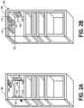
- FIG. 2 Adepicts a cross sectional view of a tool storage unit with a closed housing in accordance with an example embodiment.
- FIG. 2 Bdepicts a cross sectional view of a tool storage unit with an open housing in accordance with an example embodiment.
- FIG. 3is a block diagram of a transmitting unit in accordance with an example embodiment.
- FIG. 4is a block diagram of a receiving unit in accordance with an example embodiment.
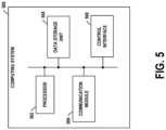
- FIG. 5is a block diagram of a computing system in accordance with an example embodiment.
- Tool storage unitsmay have electrically powered components to which battery packs and/or other external power sources may supply power.
- the electrically powered componentsmay be connected to these power sources through wired connections.
- a light source of a tool storage unitmay be connected using a wire to a battery pack of the storage unit.
- the light source of the tool storage unitmight be connected to a computing device that may supply power and may provide instructions on whether to turn on or off.
- the electrically powered componentmight be mounted to a movable element of the tool storage unit
- the power sourcemight be mounted to a non-movable component of the tool storage unit.
- a light source of the storage unitmay be connected to a drawer of the tool storage unit to facilitate continuous illumination of the drawer regardless of the position of the drawer.
- the power sourcemay be connected to the main power source and/or computing device, which may be mounted on the storage unit.
- the wires connecting the drawer and the power sourcemay start to wear down and/or break. Further, the wires may become caught between the drawer and the storage unit during the process of opening and/or closing the storage unit.
- the light sourcemay be attached to a housing door of the storage unit and/or connected to a power source of the storage unit.
- a power source of the storage unitWhen a user opens and/or closes the housing, the wires connecting the light source and the power supply may become caught between the housing door and the rest of the tool storage unit.
- the electrically powered componentmay be connected through a wired connection to a receiving unit, which may wirelessly receive energy transmitted by a nearby transmitting unit.
- the electrically powered componentmay be physically connected to the receiving unit and mounted on a movable component of the tool storage unit (e.g., a drawer, a door, etc.).
- a movable component of the tool storage unite.g., a drawer, a door, etc.
- the receiving unitmay receive the energy transmitted by the transmitting unit, and the receiving unit may power the transmitting unit.
- the tool storage unit 100may be connected to a computing system and a main power source. Further, the tool storage unit 100 may include various components, e.g., light sources, locks, mechanical sensors, and others. Each of these components may be connected to the computing system and/or main power source.
- various componentse.g., light sources, locks, mechanical sensors, and others. Each of these components may be connected to the computing system and/or main power source.
- the computing systemmay receive information from various components of the tool storage unit 100 and transmit instructions to various components of the tool storage unit 100 . For instance, the computing system may receive a signal from a sensor of the storage device indicating that the storage unit is closed. In response, the computing system may send an instruction to a light source of the storage unit to turn on.
- FIG. 1 Bdepicts the tool storage unit 100 with an opened housing 102 .
- a usermay lift the housing door 104 to be near the top of the housing 102 , perhaps to access tools or equipment stored in the housing 102 .
- a light source 114 and/or one or more other electrically powered componentsmay be attached to the housing 102 and/or the housing door 104 .
- the light source 114may be connected to a receiving antenna 112 .
- the light source 114 and the receiving antenna 112may be part of a receiving unit.
- the receiving unitmay receive energy transmitted by a transmitting antenna of a transmitting unit.
- the transmitting antenna 120may be one of multiple transmitting antennas that are able to transmit energy to a receiving antenna.
- FIG. 2 Adepicts a cross section of the tool storage unit 100 with a closed housing. As shown in FIG. 1 A , FIG. 2 A depicts a cross section of the tool storage unit 100 along a line AA. Shown in FIG. 2 A , tool storage unit 100 includes the receiving antenna 112 and the light source 114 as part of the receiving unit, and both the receiving antenna 112 and the light source 114 may be attached to a housing door 104 of a housing 102 . Further, tool storage unit 100 may include the transmitting antenna 110 and the transmitting antenna 120 as part of one or more transmitting units.
- Power transmitted by one or both of the transmitting antennas 110 and 120may help power a light source 114 .
- the transmitting antennas 110 and 120may help power the receiving antenna through induction, where the current in the transmitting antennas 110 and 120 may produce a magnetic field, which may in turn cause a current to be induced in a receiving antenna, e.g., the receiving antenna 112 .
- the receiving antennamay perhaps need to be less than a predetermined distance away and/or be at a particular angle in order to receive energy from the transmitting antenna 110 and/or the transmitting antenna 120 .
- the predetermined distancemay be from contact (e.g., zero inches) to approximately 36 inches.
- the predetermined distancemay be 12 inches.
- the predetermined distancemay be between 6 inches and 18 inches.
- the predetermined distancemay be between 3 inches and 15 inches.
- the predetermined distancemay be between 9 inches and 21 inches.
- the angle between the receiving antenna and transmitting antennamay be between 135 degrees and 225 degrees for the receiving antenna to receive energy from the transmitting antenna.
- receiving antennamay be concentric with a transmitting antenna, and the receiving antenna may receive energy from the transmitting antenna.
- the receiving antenna 112may not be able to receive any transmitted energy from the transmitting antennas 110 and 120 in the position shown by FIG. 2 A . Rather, the transmitting antenna 110 may be at an incorrect angle (e.g., perpendicular) relative to the receiving antenna 112 and too far away from the transmitting antenna 120 . Additionally, the transmitting antenna 120 may be too far away from the receiving antenna 112 for the transmitting antenna 120 to induce any current in the receiving antenna 112 .
- the distance from the receiving antenna 112 to the transmitting antenna 110(e.g., a distance 152 ) and the distance from receiving antenna 114 to the transmitting antenna 120 (e.g., a distance 154 ) may both be more than a predetermined distance value, such that the transmitting antennas 110 and 120 are unable to transmit signals so far.
- the predetermined distance valuecould be between zero inches (e.g., from contact) to 36 inches.
- the predetermined distance valuemay depend on signal strength from the transmitting antenna. If the signal strength of the transmitting antenna is high, the predetermined distance value may also be high. Whereas, if the signal strength of the transmitting antenna is low, the predetermined distance may also be low.
- the receiving antenna 112may become closer to the transmitting antenna 110 and/or transmitting antenna 120 . Additionally or alternatively, the receiving antenna 112 may become in the plane (e.g., parallel) or out of the plane (e.g., perpendicular) to transmitting antenna 110 and/or transmitting antenna 120 , causing the receiving antenna 112 to be able to receive energy or no longer be able to receive energy from transmitting antenna 110 and/or transmitting antenna 120 .
- the tool storage unit 100may also include various other components.
- the tool storage unit 100may include a sensor that senses whether the housing door 104 is in a closed position in order to determine whether to power the transmitting antenna 110 and/or the transmitting antenna 120 .
- the computing devicemay determine to not power the transmitting antenna 110 and/or the transmitting antenna 120 .
- the computing devicemay determine to power the transmitting antenna 110 and/or the transmitting antenna 120 so as to facilitate powering components (e.g., light sources) connected to the receiving units.
- powering componentse.g., light sources
- FIG. 2 Bdepicts a cross section of a storage device with an open housing. As shown in FIG. 1 B , FIG. 2 B depicts a cross section of the tool storage unit 100 along a line BB. As shown, the transmitting antenna 110 may be adjacent and parallel to the receiving antenna 112 . When the transmitting antenna 110 is powered, the transmitting antenna may induce a current in the receiving antenna 112 , which may facilitate powering the lighting source 114 .
- the transmitting antenna 110may be close enough to the receiving antenna 112 that the receiving antenna 112 is able to receive energy transmitted by the transmitting antenna 110 (e.g., a distance 156 between the transmitting antenna 110 and the receiving antenna 112 may be less than a predetermined value).
- a distance 158 from the transmitting antenna 120 to the receiving antenna 112may be less or more than the predetermined threshold, but receiving antenna 112 may be unable to receive the transmitted energy as the receiving antenna 112 is not in the correct orientation relative to the transmitting antenna 120 .
- the tool storage unit 100may not include the transmitting antenna 110 (not shown in FIG. 2 B ).
- a usermay move the receiving antenna 112 such that it is in the same plane as the transmitting antenna 120 to enable the receiving antenna 112 to receive energy from the transmitting antenna 120 .
- the receiving antenna 112may move from being out of plane of the transmitting antenna 120 to in plane with the transmitting antenna 120 and/or from being out of concentricity to being in concentricity with the transmitting antenna 120 .
- FIGS. 1 A, 1 B, 2 A, and 2 Bare provided for illustration, and are not meant to be limiting. Various other components and variations on the positioning of the transmitting unit and receiving unit are possible.
- the orientations and positions of the transmitting antennas and receiving antennasmay depend on several factors, including the number of times the transmitting antenna and receiving antenna wires are wrapped, the direction that the transmitting antenna and receiving antenna wires are wrapped, the amount of current flowing through the transmitting antenna and the receiving antenna, the structure of the tool storage unit 100 , among various other factors.
- one or more transmitting units and one or more receiving unitscan be used to power components attached to drawers or other enclosures of tool storage unit 100 .
- the receiving unitcould be attached to a side of the drawer and the transmitting unit could be attached to be parallel with the receiving unit when the drawer is pushed into the storage unit.
- the transmitting unit and receiving unitare lined together (e.g., when the drawer is pushed into the storage unit)
- the receiving unitmay receive energy from the transmitting unit.
- the receiving unitmay store the energy in an energy storage element (e.g., a battery), which may be used later.
- the energy storage elementmay be connected with a light source, and when the user pulls the drawer out, a computing device of the tool storage unit 100 , of the transmitting unit, and/or of receiving unit may transmit a signal to the light source to operate (e.g., turn on).
- FIG. 3is a block diagram of a transmitting unit 300 .
- Transmitting unit 300may contain various components.
- the transmitting unit 300may include an electrical power supply 302 , a data processing and communication module 304 , and a transmitting antenna 306 .
- the transmitting unit 300may also include various other components, including one or more transmitting antennas, sensors, and power electronics.
- the electrical power supply 302may be a device capable of supplying tool storage unit 100 with power.
- the electrical power supply 302may include a wired power connection to an AC power outlet, one or more batteries, one or more fuel cells, among other examples.
- electrical power supply 302may be optional or be part of the tool storage unit that is not the transmitting unit 300 .
- the tool storage unitmight not include an electrical power supply 302 and the tool storage unit is configured to couple to an external electrical power supply.
- the data processing and communication module 304may include one or more computing systems that perform and/or are configured to perform operations. Further, the data processing and communication module 304 may include one or more wireless communication modules that facilitate communication by the transmitting unit 300 with one or more entities according to one or more protocols.
- the data processing and communication module 304may be or may include a wired interface, such as an Ethernet interface, a radio-frequency (RF) antenna, or a Wi-Fi antenna, which may be able to send and receive data from other antennas, e.g., Bluetooth antennas, RF antennas, and Wi-Fi antennas.
- the data processing and communication module 304may include other, perhaps additional, components as well.
- the transmitting unit 300may also include the transmitting antenna 306 .
- the transmitting antenna 306may include one or more induction coils and/or one or more RF antennas.
- the induction coilsmay produce and/or be configured to produce one or more magnetic fields.
- the RF antennasmay transmit and/or be configured to transmit a beam or wave of radio frequency radiation. Both the induction coils and/or RF antennas may induce and/or be configured to induce an electric current in a receiving antenna of a receiving unit.
- the transmitting antenna 306may include a configuration of induction coils and/or RF antennas that are suited to transmitting energy to the receiving unit, perhaps such that the transmitting antennas are oriented such that they may project and/or cast a magnetic field and/or wave in varying planes/vectors from each other.
- the transmitting antennasmay be orientated orthogonal/perpendicular to the other transmitting antenna, perhaps in an implementation as illustrated in FIGS. 1 A, 1 B, 2 A, and 2 B .
- the transmitting unit 300may also include additional components, including an alternating current/direct current (AC/DC) converter, amplifiers, power electronics, directional couplers, analog-to-digital converters, capacitor networks, logic elements, and/or other components that may facilitate this process.
- AC/DC convertermay be a separate component or part of the electrical power supply 302 that facilitates converting alternating current received from a wall power supply to direct current, which a computing system of the transmitting unit 300 and/or of the tool storage unit may then be used to power the components of the transmitting unit 300 .
- Amplifiersmay help attenuate signals from microcontrollers and/or sensors.
- Power electronicsmay include rectifiers (e.g., AC to DC converters), inverters (e.g., DC to AC converters), DC to DC converters, and AC to AC converters.
- transmitting unit 300may not include all of the components illustrated in FIG. 3 .
- data processing and communicationmay be limited to a computing system of the tool storage system, and the computing system of the tool storage system may send instructions to the components of the transmitting unit 300 .
- FIG. 4is a block diagram of a receiving unit 400 .
- the receiving unit 400may contain various components.
- the receiving unit 400may include an electrically powered component 402 , a data storage unit 404 , and a receiving antenna 406 .
- the receiving unit 400may also include various other components.
- the electrically powered component 402may include a light source (e.g., a light emitting diode (LED), fluorescent lights, etc.), an electric motor, speaker, and/or other element that may convert or facilitate converting electric power to heat, light, sound, or motion.
- a light sourcee.g., a light emitting diode (LED), fluorescent lights, etc.
- an electric motore.g., a motor that may convert or facilitate converting electric power to heat, light, sound, or motion.
- the electrically powered component 402may not be part of receiving unit 400 and instead integrated into another component of the tool storage unit.
- the data storage unit 404may include one or more data storage units that perform and/or are configured to store data.
- the tool storage unitmay have one or more other data storage units aside from the data storage unit 404 of the receiving unit 400 .
- data storage unit 404 and/or other data storage units of receiving unit 400may store instructions, which one or more processors may execute to perform various operations described herein.
- the receiving unit 400may not include the data storage unit 404 , and the receiving unit 400 may only include the electrically powered component 402 and the receiving antenna 406 .
- the receiving antenna 406may include one or more induction coils and/or one or more RF antennas.
- the induction coilsmay produce and/or be configured to produce one or more magnetic fields.
- the RF antennasmay transmit and/or be configured to transmit a beam or wave of radio frequency radiation.
- a transmitting antennamay induce a current in the receiving antenna 406 when the receiving antenna placed less than a predetermined distance away and in a particular orientation from the transmitting antenna.
- receiving unit 400may not include all of the components illustrated in FIG. 4 .
- data processing and communicationmay be limited to a computing system of the tool storage system, and the computing system of the tool storage system may send instructions to the components of receiving unit 400 .
- the electrically powered component 402 of the receiving unit 400may be an LED light and the receiver antenna 406 may be an induction coil.
- the electrically powered component 402 of the receiving unit 400could be an electric motor and the receiving antenna 406 could be an induction coil.
- the receiving unit 400may include a supplemental energy storage element, which may be charged initially.
- the electrically powered component 402may be operated initially, even if the receiving antenna 406 of receiving unit 400 is not able to capture and/or receive energy from the transmitting unit 300 .
- the tool storage unitcould include one or more transmitting units, e.g., the transmitting unit 300 , and one or more receiving units, e.g., the receiving unit 400 .
- one or more transmitting units, one or more receiving units, certain components of the one or more transmitting units, and/or certain components of the one or more receiving unitscould be fixably mounted to the tool storage unit (e.g., the housing).
- a receiving unitcould include a light, which could be fixed onto the tool storage unit, perhaps in a configuration shown in FIGS. 1 A, 1 B, 2 A , and/or 2 B.
- one or more receiving units, certain components of the one or more transmitting units, and/or certain components of the one or more receiving unitscould be modular and/or detachably mounted to the tool storage unit (e.g., the housing) through fasteners.
- the receiving unit or electrically powered componentcould be detachably mounted to the tool storage using VELCRO®, mating magnets connectors, adhesive, etc.
- the transmitting antenna 306 and/or the receiving antenna 406may be a coil of wire or other conductive material which, when placed in a magnetic field where the magnetic field lines pass through the plane or planes formed by the coil, induce an electric current in the coil.
- the transmitting unit 300may only include one or more transmitting antennas, e.g., the transmitting antenna 306
- the receiving unit 400may only include one or more receiving antennas, e.g., the receiving antenna 406
- the receiving unit 400may only include one or more receiving antennas, e.g., the receiving antenna 406 , to receive energy transmitted by the transmitting antenna 306 , and the receiving unit 400 may not include the electrically powered component 402 or the data storage unit 404 .
- one or more transmitting antennas and/or one or more receiving antennasmay both be coil shaped.
- the size of each transmitting antennamay depend on the specifications of each receiving antenna (e.g., size, distance apart, etc.), and each receiving antenna may be sized to interact with a magnetic field and/or a transmitting antenna outputting an electromagnetic signal.
- Energy captured by the one or more receiving antennasmay, in addition to powering the electronics in the light so the light operates, charge an energy storage element that may be attached to the electrically powered component of the receiving unit.
- the receiving unitmay have an additional component that may be capable of storing energy (e.g., one or more batteries and/or capacitors), and this additional component may be connected to the electrically powered component.
- the additional component capable of storing energymay power the electrically powered component of the receiving unit even when the receiving antenna is not receiving and/or capturing energy from the transmitting unit.
- one or more receiving antennas and/or one or more transmitting antennasmay be connected to an AC/DC converter which may be connected to a charging circuit and a communication unit.
- one or more receiving antennasmay be embedded within the electrically powered component, enclosed within the housing of the tool storage unit, and/or affixed to the outer surface of the tool storage unit.
- FIG. 5is a simplified block diagram of an example computing system 500 .
- the computing system 500may perform and/or be configured to perform one or more operations. These operations could include those disclosed in this disclosure.
- the computing system 500may also include various components.
- the computing system 500may include a processor 502 , a data storage unit 504 , a communication module 506 , and a control interface 508 .
- the processor 502may include one or more general-purpose processors (e.g., microprocessors). Further, the processor 502 may execute program instructions included in the data storage unit 504 .
- the data storage unit 504may be or may include one or more volatile, non-volatile, removable, and/or non-removable storage components, which may be integrated in whole or in part with the processor 502 .
- the data storage unit 504may include magnetic, optical, and/or flash storage.
- the data storage unit 504may be or may include a non-transitory computer-readable storage medium, having stored thereon program instructions (e.g., compiled or non-compiled program logic and/or machine code) that, upon execution by the processor 502 , cause the computing system 500 and/or another computing system to perform one or more operations, including, for example, the operations described in this disclosure.
- program instructionsmay define and/or be part of a software application.
- the data storage unit 504may also store any data as described in this disclosure, among other data.
- the processor 502may execute program instructions in response to receiving an input, such as input received via the communication module 506 and/or the control interface 508 .
- the communication module 506may allow the computing system 500 to connect with and/or communicate with another entity according to one or more protocols.
- the computing system 500may thus send data to and/or receive data from one or more other entities in line with one or more protocols.
- the communication module 506may be or may include a wired interface, such as an Ethernet interface.
- the communication module 506may include at least one of a Bluetooth antenna, an RF antenna, or a Wi-Fi antenna, which may be able to send and receive data from other antennas, e.g., Bluetooth antennas, RF antennas, and Wi-Fi antennas.
- the control interface 508could allow for user input, including manual overrides.
- a storage unitcould include a lock.
- a usermay manually disable the lock actuator and/or disable the computing system 500 .
- the computing system 500may include one or more of the above-described components and may be configured or arranged in various ways. In some examples, the computing system 500 may be configured to operate in line with various other computing systems, e.g., perhaps computing systems of the transmitting unit 300 and/or the receiving unit 400 if the transmitting unit 300 and/or the receiving unit 400 include computing systems.
- a system for providing electrical power to an element coupled to a tool storage unitmay include a transmitting unit coupled to the tool storage unit.
- the transmitting unitmay include a data processing and communication module. Additionally, the transmitting unit may include a transmitting antenna configured to be coupled to an electrical power supply and transmit energy.
- the systemmay include a receiving unit coupled to the tool storage unit.
- the receiving unitmay include a receiving antenna. Also, the receiving unit may include the element.
- the elementcould be a light emitting diode (LED) light, an electric motor, or an actuator.
- LEDlight emitting diode
- the transmitting unitcould be in the tool storage unit, and the receiving unit could be in in the tool storage unit.
- the transmitting antennacould include an induction coil or a radio frequency (RF) emitting antenna.
- RFradio frequency
- the receiving antennacould include an induction coil or a RF emitting antenna.
- the transmitting unitcould comprise at least one of an electrical power supply or first power electronics, and the receiving unit could further comprise second power electronics.
- the tool storage unitincludes a housing configured to store a tool, a transmitting unit mounted to the housing, a receiving unit mounted to the housing, and an electrically powered component mounted to the housing.
- the transmitting unitis configured to be electrically coupled to an electrical power supply and to transmit energy.
- the receiving unitincludes a receiving antenna.
- the electrically powered componentis electrically coupled to the receiving antenna.
- the transmitting antenna and the receiving antennaare positioned within a predetermined distance on the housing.
- the receiving antennais configured to receive the energy transmitted by the transmitting antenna and to use the received energy to power the electrically powered component.
- the electrically powered componentmay be a LED light, an electric motor, an actuator, or a speaker.
- the transmitting antennacould include an induction coil or a RF emitting antenna.
- the receiving antennacould include an induction coil or a RF emitting antenna.
- the housingcould include a first portion and a second portion.
- the transmitting unitcould be mounted on the first portion.
- the receiving unitcould be mounted on the second portion.
- the second portioncould be configured to move with respect to the first portion such that the transmitting antenna and the receiving antenna are positioned within the predetermined distance.
- the electrically powered componentcould be fixedly mounted to the housing.
- the electrically powered componentcould be detachably mounted to the housing.
- the receiving antennacould be configured to receive energy transmitted by the transmitting antenna at least when the receiving antenna is parallel to the transmitting antenna.
- the receiving unitcould include a plurality of receiving antennas.
- Each receiving antenna of the plurality of receiving antennascould be configured to receive energy from a common transmitting antenna.
- the receiving unitcould further include an electric motor, and wherein the receiving antenna is an induction coil.
- the transmitting unitcould be configured to induce a current in the receiving unit.
- the receiving antennacould be configured to receive energy in a radio frequency spectrum or a microwave frequency spectrum.
- the receiving unitcould further comprise an energy storage element.
- the receiving unitcould be configured to charge the energy storage element and the electrically powered component.
- the tool storage unitincludes a housing configured to store a tool, a transmitting unit mounted to the housing, the transmitting unit electrically coupled to an electrical power supply, and a receiving unit mounted to the housing, where the electrically powered component is mounted to the housing and is electrically coupled to the receiving antenna.
- the methodincludes positioning a transmitting antenna of the transmitting unit within a predetermined distance of a receiving antenna of the receiving unit.
- the methodincludes receiving, via the electrical power supply, electrical power at the transmitting antenna.
- the methodincludes transmitting energy, via the transmitting antenna, to the receiving antenna. And the method includes powering the electrically powered component using energy received by the receiving antenna.
- all or substantially all of the received energyis used to power to the electrically powered component.
- powering the electrically powered component using energy received by the receiving antennacomprises operating the electrically powered component using energy received by the receiving antenna. In some examples, all or substantially all of the received energy is used to operate the electrically powered component.
- the methodfurther includes charging an energy storage element using another portion of the received energy. Additionally or alternatively, in some embodiments, the method further includes charging the electrically powered component using another portion of the received energy.
- a non-transitory computer-readable medium having stored thereon program instructions that upon execution of a processor, cause performance of operationsis provided.
- the operationsinclude powering a transmitting antenna of a transmitting unit, wherein powering the transmitting antenna causes a receiving unit of a tool storage unit to receive energy.
- the tool storage unitincludes a housing configured to store a tool, a transmitting unit mounted to the housing, a receiving unit mounted to the housing, and an electrically powered component mounted to the housing.
- the transmitting unitincludes a transmitting antenna configured to be electrically coupled to an electrical power supply and to transmit energy.
- the receiving unitincludes a receiving antenna.
- the electrically powered componentis coupled to the receiving antenna.
- the transmitting antenna and the receiving antennaare positioned within a predetermined distance on the housing.
- the receiving antennais configured to receive the energy transmitted by the transmitting antenna and to use the received energy to power the electrically powered component.
- the articles “a,” “an,” and “the”are used to introduce elements and/or functions of the example embodiments.
- the intent of using those articlesis that there is one or more of the introduced elements and/or functions.
- the intent of using the term “and/or” within a list of at least two elements or functions and the intent of using the terms “at least one of,” “at least one of the following,” “one or more of,” “one or more from among,” and “one or more of the following” immediately preceding a list of at least two components or functionsis to cover each embodiment including a listed component or function independently and each embodiment including a combination of the listed components or functions.
- an embodiment described as including A, B, and/or C, or at least one of A, B, and C, or at least one of: A, B, and C, or at least one of A, B, or C, or at least one of: A, B, or C, or one or more of A, B, and C, or one or more of: A, B, and C, or one or more of: A, B, and C, or one or more of: A, B, or C, or one or more of: A, B, or Cis intended to cover each of the following possible embodiments: (i) an embodiment including A, but not B and not C, (ii) an embodiment including B, but not A and not C, (iii) an embodiment including C, but not A and not B, (iv) an embodiment including A and B, but not C, (v) an embodiment including A and C, but not B, (v) an embodiment including B and C, but not A, and/or (vi) an embodiment including A, B, and C.
- the embodimentscan include one A or multiple A.
- the embodiments including component or function Bcan include one B or multiple B.
- the embodiments including component or function Cthe embodiments can include one C or multiple C.
- “A”can represent a component
- “B”can represent a system
- “C”can represent a system.
Landscapes
- Engineering & Computer Science (AREA)
- Computer Networks & Wireless Communication (AREA)
- Power Engineering (AREA)
- Mechanical Engineering (AREA)
- General Engineering & Computer Science (AREA)
- Charge And Discharge Circuits For Batteries Or The Like (AREA)
- Near-Field Transmission Systems (AREA)
- Portable Power Tools In General (AREA)
- Arrangements For Transmission Of Measured Signals (AREA)
Abstract
Description
Claims (20)
Priority Applications (6)
| Application Number | Priority Date | Filing Date | Title |
|---|---|---|---|
| US17/750,285US12119664B2 (en) | 2022-05-20 | 2022-05-20 | Systems, tool storage units, and methods for providing electrical power |
| GB2307119.4AGB2620670A (en) | 2022-05-20 | 2023-05-12 | Systems, tool storage units, and methods for providing electrical power |
| AU2023203093AAU2023203093A1 (en) | 2022-05-20 | 2023-05-17 | Systems, tool storage units, and methods for providing electrical power |
| CA3199930ACA3199930A1 (en) | 2022-05-20 | 2023-05-18 | Systems, tool storage units, and methods for providing electrical power |
| TW112118784ATW202412432A (en) | 2022-05-20 | 2023-05-19 | Systems, tool storage units, and methods for providing electrical power |
| CN202310573809.2ACN117086837A (en) | 2022-05-20 | 2023-05-19 | System, tool storage unit and method for providing power |
Applications Claiming Priority (1)
| Application Number | Priority Date | Filing Date | Title |
|---|---|---|---|
| US17/750,285US12119664B2 (en) | 2022-05-20 | 2022-05-20 | Systems, tool storage units, and methods for providing electrical power |
Publications (2)
| Publication Number | Publication Date |
|---|---|
| US20230378809A1 US20230378809A1 (en) | 2023-11-23 |
| US12119664B2true US12119664B2 (en) | 2024-10-15 |
Family
ID=86872662
Family Applications (1)
| Application Number | Title | Priority Date | Filing Date |
|---|---|---|---|
| US17/750,285ActiveUS12119664B2 (en) | 2022-05-20 | 2022-05-20 | Systems, tool storage units, and methods for providing electrical power |
Country Status (6)
| Country | Link |
|---|---|
| US (1) | US12119664B2 (en) |
| CN (1) | CN117086837A (en) |
| AU (1) | AU2023203093A1 (en) |
| CA (1) | CA3199930A1 (en) |
| GB (1) | GB2620670A (en) |
| TW (1) | TW202412432A (en) |
Citations (68)
| Publication number | Priority date | Publication date | Assignee | Title |
|---|---|---|---|---|
| US20070290654A1 (en) | 2006-06-14 | 2007-12-20 | Assaf Govari | Inductive charging of tools on surgical tray |
| US20090206674A1 (en)* | 2005-07-19 | 2009-08-20 | Olympus Medical Systems Corp. | Medical instrument storage system |
| US20090212639A1 (en) | 2008-02-25 | 2009-08-27 | L & P Property Management Company | Inductively coupled consoles |
| US20100181964A1 (en) | 2009-01-22 | 2010-07-22 | Mark Huggins | Wireless power distribution system and method for power tools |
| US20100201201A1 (en)* | 2009-02-10 | 2010-08-12 | Qualcomm Incorporated | Wireless power transfer in public places |
| US20110140540A1 (en)* | 2010-07-09 | 2011-06-16 | Industrial Technology Research Institute | Charge apparatus |
| US20120140963A1 (en)* | 2009-08-11 | 2012-06-07 | Widex A/S | Storage system for a hearing aid |
| US8228026B2 (en) | 2008-02-25 | 2012-07-24 | L & P Property Management Company | Inductively coupled shelving and storage containers |
| US8317350B2 (en) | 2009-02-25 | 2012-11-27 | Black & Decker Inc. | Power tool with a light for illuminating a workpiece |
| US8328381B2 (en) | 2009-02-25 | 2012-12-11 | Black & Decker Inc. | Light for a power tool and method of illuminating a workpiece |
| WO2013042508A1 (en) | 2011-09-22 | 2013-03-28 | Hitachi Koki Co., Ltd. | Electric tool case adapted for wireless power feeding and wireless power feeding system including the same |
| US8487478B2 (en) | 2008-05-13 | 2013-07-16 | Qualcomm Incorporated | Wireless power transfer for appliances and equipments |
| US8567796B2 (en) | 2009-09-01 | 2013-10-29 | The Stanley Works Israel Ltd. | Rolling container assembly with adjustable storage units |
| US20140036482A1 (en)* | 2010-09-30 | 2014-02-06 | Black & Decker Inc. | Lighted power tool |
| US8720239B2 (en) | 2010-02-02 | 2014-05-13 | Snap-On Incorporated | Tool box locking mechanisms for remote activation |
| US8820955B2 (en) | 2009-02-25 | 2014-09-02 | Black & Decker Inc. | Power tool with light emitting assembly |
| US8854224B2 (en) | 2009-02-10 | 2014-10-07 | Qualcomm Incorporated | Conveying device information relating to wireless charging |
| US8878393B2 (en) | 2008-05-13 | 2014-11-04 | Qualcomm Incorporated | Wireless power transfer for vehicles |
| US20140353191A1 (en) | 2011-11-22 | 2014-12-04 | John DeCicco | Hand tool case |
| US8907623B2 (en) | 2012-03-06 | 2014-12-09 | Robert Bosch Gmbh | Construction site radio device |
| US20150022146A1 (en) | 2011-11-22 | 2015-01-22 | Brett Huber | System composed of a hand tool case and a hand tool battery |
| US20150102769A1 (en) | 2013-05-10 | 2015-04-16 | DvineWave Inc. | Wireless charging of tools using a toolbox transmitter |
| US9028088B2 (en) | 2010-09-30 | 2015-05-12 | Black & Decker Inc. | Lighted power tool |
| US9106083B2 (en) | 2011-01-18 | 2015-08-11 | Mojo Mobility, Inc. | Systems and method for positioning freedom, and support of different voltages, protocols, and power levels in a wireless power system |
| US20150227127A1 (en)* | 2014-02-07 | 2015-08-13 | Enovate Medical, Llc | Medical cart for dispensing medication |
| AU2015218412A1 (en) | 2010-02-02 | 2015-09-10 | Snap-On Incorporated | Tool box locking mechanisms for remote activation |
| US9136729B2 (en) | 2012-06-18 | 2015-09-15 | Black & Decker Inc. | Power tool battery pack wireless charger |
| US9132543B2 (en) | 2009-09-01 | 2015-09-15 | The Stanley Works Israel Ltd. | Rolling container assembly with adjustable storage units |
| US9166440B2 (en) | 2011-01-10 | 2015-10-20 | Powermat Technologies Ltd. | System for transferring power inductively to items within a container |
| US9221169B2 (en) | 2009-07-09 | 2015-12-29 | Robert Bosch Gmbh | Tool box, especially hand tool box |
| US9312924B2 (en) | 2009-02-10 | 2016-04-12 | Qualcomm Incorporated | Systems and methods relating to multi-dimensional wireless charging |
| US9356659B2 (en) | 2011-01-18 | 2016-05-31 | Mojo Mobility, Inc. | Chargers and methods for wireless power transfer |
| US9478991B2 (en) | 2010-04-30 | 2016-10-25 | Powermat Technologies Ltd. | System and method for transferring power inductively over an extended region |
| US9496732B2 (en) | 2011-01-18 | 2016-11-15 | Mojo Mobility, Inc. | Systems and methods for wireless power transfer |
| US9553471B2 (en) | 2013-03-15 | 2017-01-24 | Bosch Automotive Service Solutions Inc. | Method and system for wirelessly charge a diagnostic tool |
| US9583953B2 (en) | 2009-02-10 | 2017-02-28 | Qualcomm Incorporated | Wireless power transfer for portable enclosures |
| CN206140447U (en) | 2016-03-10 | 2017-05-03 | 苏州宝时得电动工具有限公司 | Intelligent toolbox |
| US20170211875A1 (en) | 2016-01-04 | 2017-07-27 | Lg Electronics Inc. | Refrigerator |
| US20170244270A1 (en)* | 2016-02-22 | 2017-08-24 | WiBotic Inc. | Systems and Methods of Electrically Powering Devices |
| US9748780B2 (en) | 2010-10-27 | 2017-08-29 | Makita Corporation | Electric power tool system |
| US20170310133A1 (en) | 2016-04-21 | 2017-10-26 | GM Global Technology Operations LLC | Powered Toolbox |
| US9837862B2 (en) | 2014-10-16 | 2017-12-05 | DePuy Synthes Products, Inc. | Inductively-powered surgical instrument system |
| US9887576B2 (en) | 2014-12-24 | 2018-02-06 | Robert Bosch Tool Corporation | Inductive charging holster for power tools in mobile applications |
| CN107671812A (en) | 2017-10-24 | 2018-02-09 | 石家庄华泰电力工具有限公司 | Multi-purpose tool cabinet |
| US9893555B1 (en) | 2013-10-10 | 2018-02-13 | Energous Corporation | Wireless charging of tools using a toolbox transmitter |
| US20180241240A1 (en) | 2012-02-16 | 2018-08-23 | Black & Decker Inc. | Power tool battery pack wireless charger |
| US10063096B2 (en) | 2011-11-22 | 2018-08-28 | Robert Bosch Gmbh | System having a hand tool case, latent heat storage unit, and a hand tool battery provided for inductive charging |
| US10115520B2 (en) | 2011-01-18 | 2018-10-30 | Mojo Mobility, Inc. | Systems and method for wireless power transfer |
| US10126368B2 (en) | 2012-12-21 | 2018-11-13 | Robert Bosch Gmbh | Inductive charging device |
| EP3402033A1 (en) | 2017-05-10 | 2018-11-14 | Continental Automotive GmbH | Method for charging an accumulator of a tool, tool case, tool cabinet, charging system for charging an accumulator of a tool and vehicle |
| US10141770B2 (en) | 2011-01-18 | 2018-11-27 | Mojo Mobility, Inc. | Powering and/or charging with a plurality of protocols |
| US10293476B2 (en) | 2014-07-12 | 2019-05-21 | Festool Gmbh | Stack arrangement and transport container having bus interfaces |
| US10379167B2 (en) | 2016-10-03 | 2019-08-13 | Snap-On Incorporated | Rechargeable tool and battery status monitoring in an automated tool control system |
| US10418828B2 (en) | 2014-09-09 | 2019-09-17 | Robert Bosch Gmbh | Storage system |
| WO2019211148A1 (en) | 2018-05-04 | 2019-11-07 | Robert Bosch Gmbh | Tool storage device |
| WO2019216536A1 (en) | 2017-05-12 | 2019-11-14 | 엘에스전선 주식회사 | Cabinet |
| US10575417B2 (en) | 2014-09-08 | 2020-02-25 | The Stanley Works Israel Ltd. | Jobsite communications center |
| US20200063955A1 (en) | 2018-08-23 | 2020-02-27 | Snap-On Incorporated | Illumination for storage units |
| CN211673199U (en) | 2019-09-24 | 2020-10-16 | 广东雷霆技术有限公司 | Spliced power-free intelligent cabinet |
| US20210007189A1 (en) | 2018-03-17 | 2021-01-07 | Nelson Walter MONTEIRO | Induction heated hand tool container |
| US20210104914A1 (en) | 2019-09-27 | 2021-04-08 | Milwaukee Electric Tool Corporation | Power Distribution for Modular Storage |
| US10992185B2 (en) | 2012-07-06 | 2021-04-27 | Energous Corporation | Systems and methods of using electromagnetic waves to wirelessly deliver power to game controllers |
| US20210122027A1 (en) | 2019-10-24 | 2021-04-29 | Etablissements Georges Renault | Industrial device for the recharging of an electromechanical tool when this tool is affixed to a support |
| US11005285B2 (en) | 2012-03-21 | 2021-05-11 | Mojo Mobility, Inc. | Wireless power transfer |
| US11063473B2 (en) | 2011-11-22 | 2021-07-13 | Robert Bosch Gmbh | Handheld tool carrying case |
| US20220009064A1 (en) | 2010-09-30 | 2022-01-13 | Black & Decker Inc. | Lighted power tool |
| US20220102995A1 (en)* | 2020-09-29 | 2022-03-31 | Milwaukee Electric Tool Corporation | Universal wireless charging of power tool battery packs |
| US20220167825A1 (en) | 2020-12-01 | 2022-06-02 | Haier Us Appliance Solutions, Inc. | Dishwashing appliance having a wirelessly powered light assembly |
- 2022
- 2022-05-20USUS17/750,285patent/US12119664B2/enactiveActive
- 2023
- 2023-05-12GBGB2307119.4Apatent/GB2620670A/enactivePending
- 2023-05-17AUAU2023203093Apatent/AU2023203093A1/enactivePending
- 2023-05-18CACA3199930Apatent/CA3199930A1/enactivePending
- 2023-05-19TWTW112118784Apatent/TW202412432A/enunknown
- 2023-05-19CNCN202310573809.2Apatent/CN117086837A/enactivePending
Patent Citations (104)
| Publication number | Priority date | Publication date | Assignee | Title |
|---|---|---|---|---|
| US20090206674A1 (en)* | 2005-07-19 | 2009-08-20 | Olympus Medical Systems Corp. | Medical instrument storage system |
| US20070290654A1 (en) | 2006-06-14 | 2007-12-20 | Assaf Govari | Inductive charging of tools on surgical tray |
| US8228026B2 (en) | 2008-02-25 | 2012-07-24 | L & P Property Management Company | Inductively coupled shelving and storage containers |
| US20090212639A1 (en) | 2008-02-25 | 2009-08-27 | L & P Property Management Company | Inductively coupled consoles |
| US20090212638A1 (en)* | 2008-02-25 | 2009-08-27 | L & P Property Management Company | Inductively coupled work surfaces |
| US20130234481A1 (en) | 2008-02-25 | 2013-09-12 | L & P Property Management Company | Inductively coupled consoles |
| US8421407B2 (en) | 2008-02-25 | 2013-04-16 | L & P Property Management Company | Inductively coupled work surfaces |
| US9991747B2 (en) | 2008-05-13 | 2018-06-05 | Qualcomm Incorporated | Signaling charging in wireless power environment |
| US9130407B2 (en) | 2008-05-13 | 2015-09-08 | Qualcomm Incorporated | Signaling charging in wireless power environment |
| US9190875B2 (en) | 2008-05-13 | 2015-11-17 | Qualcomm Incorporated | Method and apparatus with negative resistance in wireless power transfers |
| US9184632B2 (en) | 2008-05-13 | 2015-11-10 | Qualcomm Incorporated | Wireless power transfer for furnishings and building elements |
| US9178387B2 (en) | 2008-05-13 | 2015-11-03 | Qualcomm Incorporated | Receive antenna for wireless power transfer |
| US9954399B2 (en) | 2008-05-13 | 2018-04-24 | Qualcomm Incorporated | Reverse link signaling via receive antenna impedance modulation |
| US8487478B2 (en) | 2008-05-13 | 2013-07-16 | Qualcomm Incorporated | Wireless power transfer for appliances and equipments |
| US9236771B2 (en) | 2008-05-13 | 2016-01-12 | Qualcomm Incorporated | Method and apparatus for adaptive tuning of wireless power transfer |
| US8878393B2 (en) | 2008-05-13 | 2014-11-04 | Qualcomm Incorporated | Wireless power transfer for vehicles |
| US8965461B2 (en) | 2008-05-13 | 2015-02-24 | Qualcomm Incorporated | Reverse link signaling via receive antenna impedance modulation |
| US8611815B2 (en) | 2008-05-13 | 2013-12-17 | Qualcomm Incorporated | Repeaters for enhancement of wireless power transfer |
| US8629650B2 (en) | 2008-05-13 | 2014-01-14 | Qualcomm Incorporated | Wireless power transfer using multiple transmit antennas |
| US8892035B2 (en) | 2008-05-13 | 2014-11-18 | Qualcomm Incorporated | Repeaters for enhancement of wireless power transfer |
| US20100181964A1 (en) | 2009-01-22 | 2010-07-22 | Mark Huggins | Wireless power distribution system and method for power tools |
| US9312924B2 (en) | 2009-02-10 | 2016-04-12 | Qualcomm Incorporated | Systems and methods relating to multi-dimensional wireless charging |
| US20100201201A1 (en)* | 2009-02-10 | 2010-08-12 | Qualcomm Incorporated | Wireless power transfer in public places |
| US8854224B2 (en) | 2009-02-10 | 2014-10-07 | Qualcomm Incorporated | Conveying device information relating to wireless charging |
| US9583953B2 (en) | 2009-02-10 | 2017-02-28 | Qualcomm Incorporated | Wireless power transfer for portable enclosures |
| US8820955B2 (en) | 2009-02-25 | 2014-09-02 | Black & Decker Inc. | Power tool with light emitting assembly |
| US9352458B2 (en) | 2009-02-25 | 2016-05-31 | Black & Decker Inc. | Power tool with light for illuminating workpiece |
| US8317350B2 (en) | 2009-02-25 | 2012-11-27 | Black & Decker Inc. | Power tool with a light for illuminating a workpiece |
| US8328381B2 (en) | 2009-02-25 | 2012-12-11 | Black & Decker Inc. | Light for a power tool and method of illuminating a workpiece |
| US8827483B2 (en) | 2009-02-25 | 2014-09-09 | Black & Decker Inc. | Light for a power tool and method of illuminating a workpiece |
| US8506108B2 (en) | 2009-02-25 | 2013-08-13 | Black & Decker Inc. | Power tool with light for illuminating a workpiece |
| US9221169B2 (en) | 2009-07-09 | 2015-12-29 | Robert Bosch Gmbh | Tool box, especially hand tool box |
| US20120140963A1 (en)* | 2009-08-11 | 2012-06-07 | Widex A/S | Storage system for a hearing aid |
| US9643629B2 (en) | 2009-09-01 | 2017-05-09 | The Stanley Works Isreal Ltd. | Rolling container assembly with adjustable storage units |
| US8936258B2 (en) | 2009-09-01 | 2015-01-20 | The Stanley Works Israel Ltd. | Rolling container assembly with adjustable storage units |
| US9566990B2 (en) | 2009-09-01 | 2017-02-14 | The Stanley Works Israel Ltd. | Container with pivotable side latch |
| US10106180B2 (en) | 2009-09-01 | 2018-10-23 | The Stanley Works Israel Ltd. | Transportable container |
| US8567796B2 (en) | 2009-09-01 | 2013-10-29 | The Stanley Works Israel Ltd. | Rolling container assembly with adjustable storage units |
| US10787186B2 (en) | 2009-09-01 | 2020-09-29 | The Stanley Works Israel Ltd. | Container assembly with adjustable mount structures |
| US9132543B2 (en) | 2009-09-01 | 2015-09-15 | The Stanley Works Israel Ltd. | Rolling container assembly with adjustable storage units |
| AU2015218412A1 (en) | 2010-02-02 | 2015-09-10 | Snap-On Incorporated | Tool box locking mechanisms for remote activation |
| US8720239B2 (en) | 2010-02-02 | 2014-05-13 | Snap-On Incorporated | Tool box locking mechanisms for remote activation |
| US9478991B2 (en) | 2010-04-30 | 2016-10-25 | Powermat Technologies Ltd. | System and method for transferring power inductively over an extended region |
| US20110140540A1 (en)* | 2010-07-09 | 2011-06-16 | Industrial Technology Research Institute | Charge apparatus |
| US9644837B2 (en) | 2010-09-30 | 2017-05-09 | Black & Decker Inc. | Lighted power tool |
| US11090786B2 (en) | 2010-09-30 | 2021-08-17 | Black & Decker Inc. | Lighted power tool |
| US20200114499A1 (en) | 2010-09-30 | 2020-04-16 | Black & Decker Inc. | Lighted power tool |
| US20220009064A1 (en) | 2010-09-30 | 2022-01-13 | Black & Decker Inc. | Lighted power tool |
| US20140036482A1 (en)* | 2010-09-30 | 2014-02-06 | Black & Decker Inc. | Lighted power tool |
| US10543588B2 (en) | 2010-09-30 | 2020-01-28 | Black & Decker Inc. | Lighted power tool |
| US9328915B2 (en) | 2010-09-30 | 2016-05-03 | Black & Decker Inc. | Lighted power tool |
| US9028088B2 (en) | 2010-09-30 | 2015-05-12 | Black & Decker Inc. | Lighted power tool |
| US9748780B2 (en) | 2010-10-27 | 2017-08-29 | Makita Corporation | Electric power tool system |
| US9166440B2 (en) | 2011-01-10 | 2015-10-20 | Powermat Technologies Ltd. | System for transferring power inductively to items within a container |
| US9496732B2 (en) | 2011-01-18 | 2016-11-15 | Mojo Mobility, Inc. | Systems and methods for wireless power transfer |
| US10141770B2 (en) | 2011-01-18 | 2018-11-27 | Mojo Mobility, Inc. | Powering and/or charging with a plurality of protocols |
| US9356659B2 (en) | 2011-01-18 | 2016-05-31 | Mojo Mobility, Inc. | Chargers and methods for wireless power transfer |
| US9178369B2 (en) | 2011-01-18 | 2015-11-03 | Mojo Mobility, Inc. | Systems and methods for providing positioning freedom, and support of different voltages, protocols, and power levels in a wireless power system |
| US10115520B2 (en) | 2011-01-18 | 2018-10-30 | Mojo Mobility, Inc. | Systems and method for wireless power transfer |
| US9112364B2 (en) | 2011-01-18 | 2015-08-18 | Mojo Mobility, Inc. | Multi-dimensional inductive charger and applications thereof |
| US9112363B2 (en) | 2011-01-18 | 2015-08-18 | Mojo Mobility, Inc. | Intelligent charging of multiple electric or electronic devices with a multi-dimensional inductive charger |
| US9112362B2 (en) | 2011-01-18 | 2015-08-18 | Mojo Mobility, Inc. | Methods for improved transfer efficiency in a multi-dimensional inductive charger |
| US9106083B2 (en) | 2011-01-18 | 2015-08-11 | Mojo Mobility, Inc. | Systems and method for positioning freedom, and support of different voltages, protocols, and power levels in a wireless power system |
| WO2013042508A1 (en) | 2011-09-22 | 2013-03-28 | Hitachi Koki Co., Ltd. | Electric tool case adapted for wireless power feeding and wireless power feeding system including the same |
| US20140353191A1 (en) | 2011-11-22 | 2014-12-04 | John DeCicco | Hand tool case |
| US20150022146A1 (en) | 2011-11-22 | 2015-01-22 | Brett Huber | System composed of a hand tool case and a hand tool battery |
| US10063096B2 (en) | 2011-11-22 | 2018-08-28 | Robert Bosch Gmbh | System having a hand tool case, latent heat storage unit, and a hand tool battery provided for inductive charging |
| US11063473B2 (en) | 2011-11-22 | 2021-07-13 | Robert Bosch Gmbh | Handheld tool carrying case |
| US20180241240A1 (en) | 2012-02-16 | 2018-08-23 | Black & Decker Inc. | Power tool battery pack wireless charger |
| US8907623B2 (en) | 2012-03-06 | 2014-12-09 | Robert Bosch Gmbh | Construction site radio device |
| US11005285B2 (en) | 2012-03-21 | 2021-05-11 | Mojo Mobility, Inc. | Wireless power transfer |
| US9948128B2 (en) | 2012-06-18 | 2018-04-17 | Black & Decker Inc. | Power tool battery pack wireless charger |
| US9136729B2 (en) | 2012-06-18 | 2015-09-15 | Black & Decker Inc. | Power tool battery pack wireless charger |
| US10199856B2 (en) | 2012-06-18 | 2019-02-05 | Black & Decker Inc. | Power tool battery pack wireless charger |
| US10992185B2 (en) | 2012-07-06 | 2021-04-27 | Energous Corporation | Systems and methods of using electromagnetic waves to wirelessly deliver power to game controllers |
| US10126368B2 (en) | 2012-12-21 | 2018-11-13 | Robert Bosch Gmbh | Inductive charging device |
| US9553471B2 (en) | 2013-03-15 | 2017-01-24 | Bosch Automotive Service Solutions Inc. | Method and system for wirelessly charge a diagnostic tool |
| US20150102769A1 (en) | 2013-05-10 | 2015-04-16 | DvineWave Inc. | Wireless charging of tools using a toolbox transmitter |
| US9893555B1 (en) | 2013-10-10 | 2018-02-13 | Energous Corporation | Wireless charging of tools using a toolbox transmitter |
| US20150227127A1 (en)* | 2014-02-07 | 2015-08-13 | Enovate Medical, Llc | Medical cart for dispensing medication |
| US10293476B2 (en) | 2014-07-12 | 2019-05-21 | Festool Gmbh | Stack arrangement and transport container having bus interfaces |
| US10575417B2 (en) | 2014-09-08 | 2020-02-25 | The Stanley Works Israel Ltd. | Jobsite communications center |
| US10418828B2 (en) | 2014-09-09 | 2019-09-17 | Robert Bosch Gmbh | Storage system |
| US9837862B2 (en) | 2014-10-16 | 2017-12-05 | DePuy Synthes Products, Inc. | Inductively-powered surgical instrument system |
| US10411510B2 (en) | 2014-10-16 | 2019-09-10 | DePuy Synthes Products, Inc. | Inductively-powered surgical instrument system and method |
| US9887576B2 (en) | 2014-12-24 | 2018-02-06 | Robert Bosch Tool Corporation | Inductive charging holster for power tools in mobile applications |
| US20170211875A1 (en) | 2016-01-04 | 2017-07-27 | Lg Electronics Inc. | Refrigerator |
| US20170244270A1 (en)* | 2016-02-22 | 2017-08-24 | WiBotic Inc. | Systems and Methods of Electrically Powering Devices |
| CN206140447U (en) | 2016-03-10 | 2017-05-03 | 苏州宝时得电动工具有限公司 | Intelligent toolbox |
| US20170310133A1 (en) | 2016-04-21 | 2017-10-26 | GM Global Technology Operations LLC | Powered Toolbox |
| US10379167B2 (en) | 2016-10-03 | 2019-08-13 | Snap-On Incorporated | Rechargeable tool and battery status monitoring in an automated tool control system |
| EP3402033A1 (en) | 2017-05-10 | 2018-11-14 | Continental Automotive GmbH | Method for charging an accumulator of a tool, tool case, tool cabinet, charging system for charging an accumulator of a tool and vehicle |
| WO2019216536A1 (en) | 2017-05-12 | 2019-11-14 | 엘에스전선 주식회사 | Cabinet |
| CN107671812A (en) | 2017-10-24 | 2018-02-09 | 石家庄华泰电力工具有限公司 | Multi-purpose tool cabinet |
| CN107671812B (en) | 2017-10-24 | 2020-09-08 | 石家庄华泰电力工具有限公司 | Multifunctional tool cabinet |
| US20210007189A1 (en) | 2018-03-17 | 2021-01-07 | Nelson Walter MONTEIRO | Induction heated hand tool container |
| WO2019211148A1 (en) | 2018-05-04 | 2019-11-07 | Robert Bosch Gmbh | Tool storage device |
| US20200063955A1 (en) | 2018-08-23 | 2020-02-27 | Snap-On Incorporated | Illumination for storage units |
| US10976047B2 (en)* | 2018-08-23 | 2021-04-13 | Snap-On Incorporated | Illumination for storage units |
| CN211673199U (en) | 2019-09-24 | 2020-10-16 | 广东雷霆技术有限公司 | Spliced power-free intelligent cabinet |
| US20210104914A1 (en) | 2019-09-27 | 2021-04-08 | Milwaukee Electric Tool Corporation | Power Distribution for Modular Storage |
| US20210122027A1 (en) | 2019-10-24 | 2021-04-29 | Etablissements Georges Renault | Industrial device for the recharging of an electromechanical tool when this tool is affixed to a support |
| US20220102995A1 (en)* | 2020-09-29 | 2022-03-31 | Milwaukee Electric Tool Corporation | Universal wireless charging of power tool battery packs |
| US20220167825A1 (en) | 2020-12-01 | 2022-06-02 | Haier Us Appliance Solutions, Inc. | Dishwashing appliance having a wirelessly powered light assembly |
Non-Patent Citations (2)
| Title |
|---|
| Search Report prepared by the United Kingdom Patent Office in application No. GB23071194 dated Nov. 8, 2023. |
| Shahmohammadi et al, "Circuit Model for Resonant Cavity Mode Enabled Wireless Power Transfer", https://ieeexplore.ieee.org/abstract/document/7824451, (2017). |
Also Published As
| Publication number | Publication date |
|---|---|
| GB2620670A (en) | 2024-01-17 |
| TW202412432A (en) | 2024-03-16 |
| CN117086837A (en) | 2023-11-21 |
| CA3199930A1 (en) | 2023-11-20 |
| GB202307119D0 (en) | 2023-06-28 |
| US20230378809A1 (en) | 2023-11-23 |
| AU2023203093A1 (en) | 2023-12-07 |
Similar Documents
| Publication | Publication Date | Title |
|---|---|---|
| EP2683054B1 (en) | Contactless multi-charger system and controlling method thereof | |
| US9667085B2 (en) | Wireless charger for electronic device | |
| JP5759388B2 (en) | System and method for multi-dimensional wireless charging | |
| JP3719510B2 (en) | Storage room with contactless charger | |
| JP4707626B2 (en) | Contactless charger and combination of this charger and portable electronic device | |
| JP5180406B2 (en) | Wireless power transmission device | |
| US10574091B2 (en) | Enclosures for high power wireless power transfer systems | |
| US20160141097A1 (en) | Multi-plane receiving coil for wirelessly charging a battery | |
| EP2728709A1 (en) | Electrical power transmission system | |
| US20130257368A1 (en) | Portable Wireless Charging System | |
| US20180269714A1 (en) | Double-d split coil winding | |
| CN105337336A (en) | Inductive wireless power transfer system having coupler assembly | |
| JP2010098861A (en) | Charger apparatus of mobile electronic device | |
| EP3061175B1 (en) | Wireless power transmitter | |
| US20180205268A1 (en) | Method for operating wireless power transmission device | |
| KR101601153B1 (en) | A locking system comprising wireless power transfer and recharge technology | |
| CN112491149A (en) | Box type multi-angle wireless charger and use method | |
| US12119664B2 (en) | Systems, tool storage units, and methods for providing electrical power | |
| KR101504068B1 (en) | Transmission system for providing customized wireless recharge | |
| WO2014156014A1 (en) | Contactless charging device | |
| US10784043B2 (en) | Wireless power transmission device, wireless power reception device, and wireless charging system | |
| KR20170137494A (en) | A wireless power transmitter | |
| CN207398900U (en) | A kind of intelligent electronic device | |
| US20190036368A1 (en) | Apparatus and system for harvesting magnetic energy | |
| JP5838685B2 (en) | Wireless space power supply system |
Legal Events
| Date | Code | Title | Description |
|---|---|---|---|
| FEPP | Fee payment procedure | Free format text:ENTITY STATUS SET TO UNDISCOUNTED (ORIGINAL EVENT CODE: BIG.); ENTITY STATUS OF PATENT OWNER: LARGE ENTITY | |
| AS | Assignment | Owner name:SNAP-ON INCORPORATED, WISCONSIN Free format text:ASSIGNMENT OF ASSIGNORS INTEREST;ASSIGNORS:GABBEY, NICHOLAS A.;KUTER-ARNEBECK, OTTOLEO;REEL/FRAME:060286/0971 Effective date:20220519 | |
| STPP | Information on status: patent application and granting procedure in general | Free format text:ADVISORY ACTION MAILED | |
| STPP | Information on status: patent application and granting procedure in general | Free format text:DOCKETED NEW CASE - READY FOR EXAMINATION | |
| STPP | Information on status: patent application and granting procedure in general | Free format text:NON FINAL ACTION MAILED | |
| STPP | Information on status: patent application and granting procedure in general | Free format text:FINAL REJECTION MAILED | |
| STPP | Information on status: patent application and granting procedure in general | Free format text:RESPONSE AFTER FINAL ACTION FORWARDED TO EXAMINER | |
| STPP | Information on status: patent application and granting procedure in general | Free format text:NOTICE OF ALLOWANCE MAILED -- APPLICATION RECEIVED IN OFFICE OF PUBLICATIONS | |
| STPP | Information on status: patent application and granting procedure in general | Free format text:PUBLICATIONS -- ISSUE FEE PAYMENT RECEIVED | |
| STPP | Information on status: patent application and granting procedure in general | Free format text:PUBLICATIONS -- ISSUE FEE PAYMENT VERIFIED | |
| STCF | Information on status: patent grant | Free format text:PATENTED CASE |