US12117614B2 - Transparent lightguide for viewing a scene and a near-eye display - Google Patents
Transparent lightguide for viewing a scene and a near-eye displayDownload PDFInfo
- Publication number
- US12117614B2 US12117614B2US17/265,586US202017265586AUS12117614B2US 12117614 B2US12117614 B2US 12117614B2US 202017265586 AUS202017265586 AUS 202017265586AUS 12117614 B2US12117614 B2US 12117614B2
- Authority
- US
- United States
- Prior art keywords
- loe
- partially reflecting
- light
- reflecting surfaces
- reflectance
- Prior art date
- Legal status (The legal status is an assumption and is not a legal conclusion. Google has not performed a legal analysis and makes no representation as to the accuracy of the status listed.)
- Active, expires
Links
Images


Classifications
- G—PHYSICS
- G02—OPTICS
- G02B—OPTICAL ELEMENTS, SYSTEMS OR APPARATUS
- G02B27/00—Optical systems or apparatus not provided for by any of the groups G02B1/00 - G02B26/00, G02B30/00
- G02B27/01—Head-up displays
- G02B27/017—Head mounted
- G02B27/0172—Head mounted characterised by optical features
- G—PHYSICS
- G02—OPTICS
- G02B—OPTICAL ELEMENTS, SYSTEMS OR APPARATUS
- G02B27/00—Optical systems or apparatus not provided for by any of the groups G02B1/00 - G02B26/00, G02B30/00
- G02B27/10—Beam splitting or combining systems
- G02B27/14—Beam splitting or combining systems operating by reflection only
- G02B27/145—Beam splitting or combining systems operating by reflection only having sequential partially reflecting surfaces
- G—PHYSICS
- G02—OPTICS
- G02B—OPTICAL ELEMENTS, SYSTEMS OR APPARATUS
- G02B6/00—Light guides; Structural details of arrangements comprising light guides and other optical elements, e.g. couplings
Definitions
- the inventionis directed generally to head-mounted display devices and particularly to light-guide optical elements that are part of such devices.
- a device that is worn by a viewer for simultaneous viewing of a real scene and of a projected image from a display deviceis widely known and is generally referred to as a “head-mounted display” (HMD) or “near-eye display” (NED).
- HMDhead-mounted display
- NEDnear-eye display
- Such a deviceis generally constructed as goggles or spectacles or as a helmet or visor, to be worn on the head of the viewer, and includes one or two image projectors (each including an electro-optic display component) and optical components to deliver the projected images into the viewer's eyes.
- one such optical componentis a lightguide, which is positioned in front of each of the viewer's eyes.
- Such a lightguideserves to expand the field of view (i.e. the angular size of the screen of the display component) and the viewing window (i.e., the window within which the viewer's eye may be located so as to view the entire display screen, also known as an “eye motion box”).
- a lightguideis a block (or slab) of transparent material, with two parallel major surfaces, along which the light, conveying the collimated image projected from the display component, propagates by total internal reflection.
- the blockincludes a structural coupling-out arrangement, functional so that part of that light is coupled-out, through one of the major surfaces, towards the corresponding eye of the viewer.
- the coupling-out arrangementincludes a diffractive structure in one or both of the major surfaces.
- the coupling-out arrangementincludes a set of obliquely angled mutually parallel partially reflective surfaces, also known interchangeably as facets, internal to the block.
- the coupling-out arrangementbe less visible, or even invisible, to outside observers.
- the present inventionseeks to provide improvements to lightguides used in head-mounted displays (HMDs), such that would diminish the undesirable visibility effects otherwise experienced by an external observer when observing through such a lightguide the face of a viewer, wearing the HMD.
- HMDshead-mounted displays
- Such an effectmay be caused by part of the light reflected from the viewer's eye and face being coupled into the lightguide, thus attenuating the light reaching the external observer, resulting in apparent darkening of the lightguide in the external observer's view and masking the face and eye of the viewer.
- Another undesirable visibility effect in lightguides of prior artmay be caused by light within the lightguide that is reflected from an end surface and propagates backwards, whereby it is coupled out toward the outside observer, who perceives it as a glare.
- certain embodiments of the inventionprovide various techniques to increase the light transmission through the lightguide between the viewer's face and an outside observer and to decrease the amount of other light projected from the lightguide toward the outside observer.
- a light-guide optical elementfor simultaneous viewing, by an eye of a viewer, of a real scene and of a projected image introduced into the LOE, the LOE comprising:
- the reflectance of each of the partially reflecting surfacesis such that the total power of the light that is coupled out is less than one fifth, and in some of the embodiments less than one tenth, of the total power of the light conveying the projected image that is introduced into the LOE.
- the reflectance of each of the partially reflecting surfacesis less than 13% and in some of the embodiments it is less than 5%.
- a light-guide optical elementfor simultaneous viewing, by an eye of a viewer, of a real scene and of a projected image, conveyed by light that is polarized in a first orientation and introduced into the LOE, the LOE comprising:
- the first polarized orientationmay be S-polarized relative to the partially reflecting surfaces.
- the partially reflecting surfacesare substantially transparent to P-polarization for an angular range of at least about 30 degrees including a direction normal to the first major surface.
- LOElight-guide optical element
- the reflectance of the last one in sequence of the partially reflecting surfaces for the part of the light that is coupled out from it toward any point within the eye motion boxis at least four times greater than its reflectance for light travelling in a direction normal to the first and second major surfaces.
- the blockhas an end surface onto which light propagating within the LOE that passes the partially reflecting surfaces impinges, wherein the end surface is coated with a light-absorbing layer, configured to absorb light introduced into the LOE and not coupled out.
- the light-absorbing layermay be implemented as black paint applied to a rough end surface.
- optical systemfor simultaneous viewing, by a viewer, of a natural scene and of an image on a near-eye image projector, the optical system comprising:
- FIG. 1 Ais a sectional top view of an exemplary lightguide optical element (LOE) as used in a head-mounted display (HMD);
- LOElightguide optical element
- FIG. 1 Bis a schematic front view of the LOE of FIG. 1 A as perceived by an external observer.
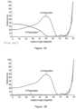
- FIG. 2is a graph, showing typical reflectance values of partially reflective surfaces along a LOE according to the invention, compared to those in an LOE of prior art.
- FIG. 3 Ais a graph, showing typical reflectance values for two different orthogonal polarization orientations of a partially reflective surface in an LOE of prior art.
- FIG. 3 Bis a graph, showing typical reflectance values for two different orthogonal polarization orientations of a partially reflective surface in an LOE according to the invention.
- FIG. 4 Ais a sectional top view of the LOE of FIG. 1 A , showing certain ray traces;
- FIG. 4 Bis an enlarged view of a detail in the LOE of FIG. 4 A .
- FIG. 4 Cis a graph of reflectance as a function of direction in three partially reflecting surfaces of the LOE of FIG. 1 B .
- FIGS. 5 A and 5 Bare each a sectional top view of the LOE of FIG. 4 A , showing an end face without and with a light-absorbing layer, respectively.
- FIG. 1 Aillustrates schematically, by way of introduction, a head-mounted display (HMD) formed, in this example, as spectacles to be worn by a viewer, that includes a lightguide optical element (LOE) 10 , with partially reflective surfaces, which is positioned in front of an eye 20 of the viewer when wearing the HMD. Additionally it includes—
- HMDhead-mounted display
- LOElightguide optical element
- the HMDthere may be a single image projector, associated with one of the eyes, in other configurations there may be two image projectors, each associated with a corresponding one of the viewer's eyes, and in yet other configurations there may be a single image projector, arranged to project the image into two LOEs, associated with corresponding eyes, or into a single long LOE, extending in front of both eyes.
- the lightguide optical element (LOE) 10is shown in FIG. 1 A in a horizontal cross-sectional view, with tracing of selected light rays of the collimated image as they propagate within the LOE and out toward the viewer.
- the LOE 10is basically an elongated block 11 , constructed of transparent material and having two mutually parallel major surfaces—a front surface 12 and a rear surface 14 . Near one end of the block 11 there is a coupling-in arrangement associated with an entrance window, through which the collimated image is introduced into the LOE. In this example it is an oblique reflective surface 18 , with an entrance window 19 defined adjacent to it on the rear surface 14 .
- the entrance windowmay be on an angled prism attached to one of the major surfaces or the entrance window may be at an end surface of the block.
- Embedded in block 11is a series of oblique partially reflective surfaces 16 , all mutually parallel, to be referred to as “facets”. Adjacent to the entire group of partially reflective surfaces 16 there is defined, at a certain distance from the rear surface 14 and parallel to it, a viewing region 17 , also known as an eye motion box, which signifies an area within which an eye of the viewer may be located in order to be able to view the entire image, allowing for motion of the eye and some leeway in the placement of the HMD relative to the eye 20 .
- eye motion boxalso known as an eye motion box
- a corresponding LOEmay be configured with an entrance window on the front surface or on an end surface of the block 11 .
- the present inventionaddresses also such configurations.
- image-conveying light from the coupling optics 24enters the block 11 through the entrance window 19 and is deflected, in this example, by the oblique reflective surface 18 so as to propagate along the block 11 while undergoing total internal reflections from the major surfaces 12 and 14 .
- the entrance windowis on an end surface
- the light entering itmay proceed directly (i.e., without deflection) to propagate along the block.
- the lightis intercepted by the partially reflective surfaces (facets) 16 and part of it is deflected, or coupled out, into the viewing window (eye motion box) 17 .
- the intensity of the remaining lightdiminishes, requiring the following facets to have commensurately higher reflectance so that the intensity of the light coupled out remains constant; thus the last facet to be intercepted by the light should have the highest reflectance.
- the facetsremain substantially visible to an external observer (as mentioned in the Summary section above). This is due to their transmittance being relatively low, thus attenuating light reflected from the viewer's face and eye 20 , through the block 11 of the LOE in a direction generally normal to its major surfaces 12 and 14 , to the external observer's eyes (not shown).
- FIG. 1 Bis a front view of the LOE 10 as it would appear to the external observer.
- the facets 16appear as strips of varying darkness, obscuring the viewer's face; the leftmost facet appears darkest, since it is designed with the highest reflectance and thus—with the lowest transmittance.
- the facetsmay also produce a glare, visible to the external observer, which is due to remaining propagating light being reflected from an end face 15 of the block 11 and coupled out by the facets 16 through the front major surface 12 toward the observer's eyes.
- a guiding principle of certain embodiments of the present inventionis to reduce reflectance of the facets so as to increase their overall transmittance for light passing across the LOE, making them seem transparent and thus invisible to an outside observer.
- the reflectance of facetsvary along the LOE, from the first to the last encountered facet, extending typically from 10% to 25% within the ranges of incidence angles, polarization orientation and spectral band of interest.
- the ranges of interest of incidence anglesare determined by optical-geometric consideration in the design of the LOE and of the HMD, of which the LOE is a part.
- the ranges of interest of polarization orientation and spectral bandare largely determined by the characteristics of the image projector or by operational requirements.
- a further guiding principle of certain embodiments of the present inventionis to reduce or possibly minimize reflectance of facets outside any one or more of these ranges, thus increasing their transmittance for light across the LOE.
- the line 31representing the intensity of the propagating light
- the line 32representing the reflectance of successive facets
- the intensity of light coupled out toward the vieweris roughly uniform.
- the linesrepresent optimal design values; in actuality, the inclined lines would partly resemble steps, corresponding to the facets.
- the dashed linesrepresent typical values for a LOE of prior art, designed for use in a head-mounted display (HMD), wherein reflectances have been chosen to provide a relatively clear view of the natural scene.
- HMDhead-mounted display
- These linesare seen to be similar to the dotted lines, but with reduced slopes.
- the linearly descending line 34starting again at 100 (signifying the full intensity of light entering the LOE), reaches only about 50% at the end, signifying that only about 50% of the propagating light energy has been coupled out (toward the viewing window).
- the ascending line 35reaches only about 42, signifying that the reflectance of the last facet is only about 42%. This results in its transmittance at the pertinent angles of incidence being about 58% and presumably being commensurately high also in a direction across the LOE, along which the natural scene is being viewed—high enough for the scene to appear satisfactorily clear.
- the reflectance of facets in exemplary embodiments of the inventionis further substantially reduced, as represented by the solid plot lines in FIG. 2 .
- the ascending solid line 38reaches only about 13, signifying that the total reflectance of the last (i.e., highest reflectivity) facet is preferably no more than about 13% (and in some particularly preferred embodiments no more than about 5%), and the linear solid line 39 descends only to about 63, signifying that only about 37% of the propagating light energy is coupled out.
- the transmittance of the last facetis raised to approximately 87%, which significantly reduces visibility of the facet to an outsider observing the user's face; the transmittance of the other facets is even greater.
- at least 63% of the image intensity coupled into the LOEcontinues propagating along the LOE beyond the last facet and therefore goes to waste.
- the proportion of coupled-in illumination which propagates beyond the last facetis greater than two-thirds, and in certain particularly preferred cases, greater than 80%, or even 90%.
- the image-conveying light that enters (or is coupled into) the LOEis S-polarized relative to the facets.
- Thismay, in some HMDs, be due to the image projector itself inherently emitting polarized light (e.g., a liquid-crystal display) or due to a polarizing filter being interposed in the path between the image projector (or the collimating assembly) and the LOE.
- the reflectance of the facets for P-polarized lightis minimized or substantially reduced, relative to their reflectance for S-polarized light.
- the facetsare substantially transparent to P-polarization over an angular range of at least about 30 degrees that includes an incident light direction normal to the first major surface. This maximizes the transmittance of the facets for P-polarized light, allowing more of the light emanating from the viewer's face, to reach an outside observer, thus rendering the facets to be more transparent and less visible to him. It is noted that this feature is applied in addition to reflectance optimization for S-polarized light, which may be according to the conventional approach or according to the first aspect of the present invention.
- the term “substantially transparent”is used in its normal sense. Quantitatively, it typically refers to transmittance in excess of 95%, and most preferably in excess of 98%.
- FIG. 3 Ashows, by way of example, the reflectance of a typical facet, in a conventional LOE, for two polarization orientations, namely P-polarization and S-polarization, orthogonal to it, as a function of the angle of an incident light beam.
- FIG. 3 Bis a similar plot of reflectances for a LOE in an exemplary embodiment corresponding to the second aspect of the invention.
- the reflectance of S-polarized incident lightwithin the range of incidence angles of interest, is optimized to values representing either a balance between efficient display image transmission and natural scene visibility, i.e. typically in the range of 10%-25%, or reduced reflectance according to the first aspect of the present invention, described above.
- the reflectance of P-polarized incident light in or near a direction normal to the major block surfacesis substantially reduced, as clearly seen in the FIG. 5 B when compared to FIG. 5 A .
- this reductionis by a factor of at least 4, more preferably—of at least 8.
- the value of reflectance for P-polarization in that directionis preferably no more than about a third, more preferably a fifth, of the value of the corresponding reflectance of the facet for S-polarization.
- the reflectivity of any of the facets at incidence angles different from the range of incidence angles that will direct the incoming image-conveying light, propagating along the LOE, towards the wearer's eye, or more generally towards the eye motion boxare substantially reduced.
- the range of incidence angles over which reflectance is thus reducedincludes, in particular, those corresponding to the direction of light passing across the LOE—such as from the viewer's face and eye towards an outside viewer. This is equivalent to increased transmittance along that direction, rendering the facets less visible.
- FIG. 4 Ashows a sectional view of an exemplary typical LOE 10 , with rays of display signal (i.e., image-conveying light) propagating therethrough from the left end and deflected (or coupled out) by means of five facets 16 .
- display signali.e., image-conveying light
- the rays shownare central rays originally emanating from selected three points across the displayed image, namely: Rays depicted as solid lines 42 emanate from a central point in the image; rays depicted as long dashes 41 emanate from a rightmost point (as seen by the viewer) of the image; rays depicted as short dashes 43 emanate from a leftmost point (as seen by the viewer) of the image.
- Rays from different image pointsreach the eye 20 through different facets.
- rays reaching the eye from the leftmost pointpass mainly through the first (leftmost) facet 16 a
- rays reaching the eye from a middle pointpass mainly through the third (middle) facet 16 b
- rays reaching the eye from a rightmost pointpass mainly through the fifth (rightmost) facet 16 c .
- each such raythere is a unique incidence angle at the corresponding facet. More generally, there will be, for each facet, a given range of incidence angle (from a corresponding part of the image) that direct rays towards any point within the eye motion box (EMB) 17 , where it may enter the eye 20 .
- EMBeye motion box
- the ray from the image leftis incident at an angle of about 30 degrees
- the ray from the image centeris incident at about 23 degrees
- the ray from the image rightis incident at about 16 degrees. It is noted that the same angles of incidence apply also to all the other facets.
- the only ray of interestis that from the right side of the image (long dashes), as it alone reaches the EMB 17 .
- a range of incidence angles near 16 degrees, at which rays emanating from close by regions of the image are reflected into the EMB 17This is the range over which reflectance must remain high according to the design (or possibly reduced according to the first and/or second aspect of the invention).
- the reflectance of the facet 16 c for incoming light signal at angles substantially different from the aforementioned design rangeare, according to the third aspect of the invention, reduced relative to the reflectance values at the design range.
- the reflectance of the last facet in the sequence for the part of the light that is coupled out from it toward any point within the eye motion boxis preferably at least twice its reflectance for light travelling in a direction normal to the major surfaces.
- FIG. 4 Cdepicts schematically the design aim for facet 16 c of FIG. 4 A , namely relatively high reflectance for incidence angles in the range of 16 to 21 degrees (for rays reaching the EMB), as depicted by rectangle 51 and relatively low reflectance for higher incidence angles, preferably in the range of 22 to 25 degrees, depicted by vertical lines 52 . Also seen in FIG. 4 C is a plot 53 (solid line) of reflectance vs. incidence angle for the facet 16 c of FIG. 4 A to satisfy these requirements; it is to be compared to a similar plot 54 (dashed line) for a conventional facet.
- FIGS. 5 A and 5 BA further aspect of the present invention, useful alone or in combination with any one or more of the above aspects of the invention and applicable to all configurations of a lightguide (including diffractive waveguides), will now be disclosed with reference to FIGS. 5 A and 5 B .
- FIG. 5 Aresidual image-conveying light propagating along the LOE 10 and not coupled-out toward the viewing window continues and reaches an end surface 15 # of the LOE. At least part of this light will be reflected back from the end surface and will propagate in a reverse direction 25 along the LOE, where the coupling-out arrangement typically causes part of that light to be coupled outwards 27 , away from the user. This may result in an undesirable glow, or glare, emanating from the LOE and visible by outside observers. This effect may be particularly pronounced with a LOE according to the first aspect of the present invention, since a relatively large proportion of the injected image intensity is transmitted by all of the facets and reaches the end surface 15 .
- a light-absorbent coating, film or layer 35is applied to the end surface 15 of the LOE 10 .
- the light-absorbent coatingmay advantageously be applied also to any of the other three side surfaces of the LOE.
- the light-absorbent coating 35can conveniently be implemented as a layer of black paint.
- the coatingin some embodiments may be configured to have a rough surface, which can be achieved by roughening the edge of the LOE prior to application of paint, or by employing a rough film or layer, which is bonded to the relevant side surface of the LOE using an optical adhesive or the like.
- orientation of the LOE as illustrated in the drawingsmay be regarded as a “side-injection” implementation, where the image illumination entering the LOE enters near a side edge and propagates sideway. It should be appreciated that all features shown are equally applicable to “top down” implementations, where an image is injected from the top of the LOE and propagates downward, which also fall within the scope of the invention. In certain cases, other intermediate orientations are also applicable, and are included within the scope of the present invention except where explicitly excluded.
Landscapes
- Physics & Mathematics (AREA)
- General Physics & Mathematics (AREA)
- Optics & Photonics (AREA)
- Lens Barrels (AREA)
- Optical Elements Other Than Lenses (AREA)
Abstract
Description
- a block of transparent material having a first major surface and a second major surface, parallel to the first major surface, so that light conveying a projected image introduced into the LOE propagates within the LOE by internal reflection at the first and second major surfaces, and a plurality of mutually-parallel partially reflecting surfaces internal to the block and obliquely oriented relative to the first major surface, the partially reflecting surfaces being configured so as to couple-out a part of the light through the second major surface,
- wherein the reflectance of each of the partially reflecting surfaces is such that the total power of the light that is coupled out is less than one third of the total power of the light conveying the projected image that is introduced into the LOE.
- a block of transparent material having a first major surface and a second major surface parallel to the first major surface so that light conveying a projected image introduced into the LOE propagates within the LOE by internal reflection at the first and second major surfaces, and a plurality of mutually-parallel partially reflecting surfaces internal to the block and obliquely oriented relative to the first major surface so as to couple-out a part of the light towards the eye of the viewer,
- wherein the reflectance of each of the partially reflecting surfaces in a direction normal to the major surfaces for light polarized in a second orientation, orthogonal to the first orientation, is less than one third of its reflectance in the direction for light polarized in the first orientation.
- a block of transparent material having a first major surface and a second major surface parallel to the first major surface so that light conveying a projected image, introduced into the LOE, propagates along the LOE in a first direction by internal reflection at the first and second major surfaces, there being defined, in a plane outside and parallel to the first major surface, an eye motion box of a given size, and
- a plurality of mutually-parallel partially reflecting surfaces internal to the block, arranged sequentially along the first direction and obliquely oriented relative to the first major surface so as to couple-out a part of the light towards the eye motion box,
- wherein the reflectance of the last one in sequence of the partially reflecting surfaces for the part of the light that is coupled out from it toward any point within the eye motion box is at least twice its reflectance for light travelling in a direction normal to the first and second major surfaces.
- the LOE of any one of claims1-10; and
- a support structure deployed to support the LOE on the head of the viewer in facing relation to at least one eye of the viewer.
- an image projector22 (which, in turn, includes an electro-optical display device or spatial light modulator such as an LCOS device), operative to generate images according to signals fed to it, and a collimating optical assembly, configured to project light corresponding to a collimated version of the image—all not shown) and
coupling optics 24, to couple the projected image into theLOE 10.
Claims (11)
Priority Applications (1)
| Application Number | Priority Date | Filing Date | Title |
|---|---|---|---|
| US17/265,586US12117614B2 (en) | 2019-05-06 | 2020-05-06 | Transparent lightguide for viewing a scene and a near-eye display |
Applications Claiming Priority (4)
| Application Number | Priority Date | Filing Date | Title |
|---|---|---|---|
| US201962843644P | 2019-05-06 | 2019-05-06 | |
| US201962844771P | 2019-05-08 | 2019-05-08 | |
| PCT/IB2020/054289WO2020225747A1 (en) | 2019-05-06 | 2020-05-06 | Transparent lightguide for viewing a scene and a near-eye display |
| US17/265,586US12117614B2 (en) | 2019-05-06 | 2020-05-06 | Transparent lightguide for viewing a scene and a near-eye display |
Related Parent Applications (1)
| Application Number | Title | Priority Date | Filing Date |
|---|---|---|---|
| PCT/IB2020/054289A-371-Of-InternationalWO2020225747A1 (en) | 2019-05-06 | 2020-05-06 | Transparent lightguide for viewing a scene and a near-eye display |
Related Child Applications (1)
| Application Number | Title | Priority Date | Filing Date |
|---|---|---|---|
| US18/818,684ContinuationUS20240419000A1 (en) | 2019-05-06 | 2024-08-29 | Transparent lightguide for viewing a scene and a near-eye display |
Publications (2)
| Publication Number | Publication Date |
|---|---|
| US20210165231A1 US20210165231A1 (en) | 2021-06-03 |
| US12117614B2true US12117614B2 (en) | 2024-10-15 |
Family
ID=70680553
Family Applications (2)
| Application Number | Title | Priority Date | Filing Date |
|---|---|---|---|
| US17/265,586Active2042-06-10US12117614B2 (en) | 2019-05-06 | 2020-05-06 | Transparent lightguide for viewing a scene and a near-eye display |
| US18/818,684PendingUS20240419000A1 (en) | 2019-05-06 | 2024-08-29 | Transparent lightguide for viewing a scene and a near-eye display |
Family Applications After (1)
| Application Number | Title | Priority Date | Filing Date |
|---|---|---|---|
| US18/818,684PendingUS20240419000A1 (en) | 2019-05-06 | 2024-08-29 | Transparent lightguide for viewing a scene and a near-eye display |
Country Status (8)
| Country | Link |
|---|---|
| US (2) | US12117614B2 (en) |
| EP (1) | EP3966623A1 (en) |
| JP (2) | JP7699376B2 (en) |
| KR (2) | KR102862815B1 (en) |
| CN (2) | CN118131484A (en) |
| IL (1) | IL285571B2 (en) |
| TW (2) | TWI845670B (en) |
| WO (1) | WO2020225747A1 (en) |
Families Citing this family (27)
| Publication number | Priority date | Publication date | Assignee | Title |
|---|---|---|---|---|
| IL237337B (en) | 2015-02-19 | 2020-03-31 | Amitai Yaakov | Compact head-mounted display system having uniform image |
| CN110431467A (en) | 2017-01-28 | 2019-11-08 | 鲁姆斯有限公司 | Augmented reality imaging system |
| WO2019077614A1 (en) | 2017-10-22 | 2019-04-25 | Lumus Ltd. | ENHANCED REALITY DEVICE MOUNTED ON THE HEAD AND USING AN OPTICAL BENCH |
| CN111417883B (en) | 2017-12-03 | 2022-06-17 | 鲁姆斯有限公司 | Optical equipment alignment method |
| US10551544B2 (en) | 2018-01-21 | 2020-02-04 | Lumus Ltd. | Light-guide optical element with multiple-axis internal aperture expansion |
| MY203244A (en) | 2018-04-08 | 2024-06-19 | Lumus Ltd | Optical sample characterization |
| KR102752134B1 (en) | 2018-05-14 | 2025-01-08 | 루머스 리미티드 | Projector configuration with sub-optical aperture for near-eye display and corresponding optical system |
| IL278511B2 (en) | 2018-05-17 | 2025-01-01 | Lumus Ltd | Near-eye display having overlapping projector assemblies |
| IL259518B2 (en) | 2018-05-22 | 2023-04-01 | Lumus Ltd | Optical system and method for improvement of light field uniformity |
| MX2020012512A (en) | 2018-05-23 | 2021-02-16 | Lumus Ltd | Optical system including light-guide optical element with partially-reflective internal surfaces. |
| CN119595595A (en) | 2018-06-21 | 2025-03-11 | 鲁姆斯有限公司 | Technique for measuring refractive index non-uniformity between plates of light-guiding optical element (LOE) |
| EP3824335B1 (en) | 2018-07-16 | 2023-10-18 | Lumus Ltd. | Light-guide optical element employing polarized internal reflectors |
| CN112601993A (en) | 2018-08-26 | 2021-04-02 | 鲁姆斯有限公司 | Reflection suppression in near-eye displays |
| CN116184666A (en) | 2018-09-09 | 2023-05-30 | 鲁姆斯有限公司 | Optical system comprising a light-guiding optical element with two-dimensional expansion |
| US11947130B2 (en) | 2018-11-08 | 2024-04-02 | Lumus Ltd. | Optical devices and systems with dichroic beamsplitter color combiner |
| TWM642752U (en) | 2018-11-08 | 2023-06-21 | 以色列商魯姆斯有限公司 | Light-guide display with reflector |
| MX2021008808A (en) | 2019-01-24 | 2021-08-24 | Lumus Ltd | Optical systems including loe with three stage expansion. |
| WO2020174433A1 (en) | 2019-02-28 | 2020-09-03 | Lumus Ltd. | Compact collimated image projector |
| TWI800657B (en) | 2019-03-12 | 2023-05-01 | 以色列商魯姆斯有限公司 | Image projector |
| TWI845670B (en) | 2019-05-06 | 2024-06-21 | 以色列商魯姆斯有限公司 | Transparent lightguide for viewing a scene and a near-eye display |
| WO2021105982A1 (en) | 2019-11-25 | 2021-06-03 | Lumus Ltd. | Method of polishing a surface of a waveguide |
| IL270991B (en) | 2019-11-27 | 2020-07-30 | Lumus Ltd | Lightguide optical element for polarization scrambling |
| TWI884834B (en) | 2019-12-05 | 2025-05-21 | 以色列商魯姆斯有限公司 | Optical device and method of fabricating optical device |
| CN114787687B (en) | 2019-12-25 | 2024-07-30 | 鲁姆斯有限公司 | Systems and methods for eye tracking based on redirection of light from the eye using an optical arrangement associated with a light guide optical element |
| WO2021220267A1 (en) | 2020-04-30 | 2021-11-04 | Lumus Ltd. | Optical sample characterization |
| CN218848473U (en) | 2020-05-12 | 2023-04-11 | 鲁姆斯有限公司 | Equipment including projection optics and light guides |
| WO2024257610A1 (en)* | 2023-06-16 | 2024-12-19 | Agc株式会社 | Glass and method for producing glass |
Citations (121)
| Publication number | Priority date | Publication date | Assignee | Title |
|---|---|---|---|---|
| US3829197A (en) | 1971-10-20 | 1974-08-13 | Balzers Patent Beteilig Ag | Antireflective multilayer coating on a highly refractive substrate |
| JPH02182447A (en) | 1989-01-09 | 1990-07-17 | Mitsubishi Electric Corp | Dielectric multilayer reflective film |
| US5930046A (en) | 1997-02-13 | 1999-07-27 | Optical Coating Laboratory, Inc. | Low net stress multilayer thin film coatings |
| US6231992B1 (en) | 1998-09-04 | 2001-05-15 | Yazaki Corporation | Partial reflector |
| US20020080487A1 (en) | 1996-07-25 | 2002-06-27 | Seiko Epson Corporation | Optical element suitable for projection display apparatus |
| US20030165017A1 (en)* | 2000-06-05 | 2003-09-04 | Yaakov Amitai | Substrate-guided optical beam expander |
| US20030235768A1 (en) | 2000-05-16 | 2003-12-25 | Fincher Graciela Beatriz Blanchet | Aqueous dispersions for color imaging |
| US20040033528A1 (en) | 2000-06-18 | 2004-02-19 | Yaakov Amitai | Dynamic optical devices |
| US20040032660A1 (en) | 2000-10-05 | 2004-02-19 | Yaakov Amitai | Optical switching devices |
| US20050078388A1 (en) | 2003-09-10 | 2005-04-14 | Yaakov Amitai | Optical devices particularly for remote viewing applications |
| US20050083592A1 (en) | 2003-09-10 | 2005-04-21 | Yaakov Amitai | High Brightness optical device |
| US20050180687A1 (en) | 2002-03-21 | 2005-08-18 | Yaakov Amitai | Light guide optical device |
| WO2006098097A1 (en) | 2005-03-14 | 2006-09-21 | Nikon Corporation | Image display optical system and image display |
| US20060221448A1 (en) | 2005-04-04 | 2006-10-05 | Mirage Innovations Ltd. | Multi-plane optical apparatus |
| JP2007010830A (en) | 2005-06-29 | 2007-01-18 | Nikon Corp | Image display optical system and image display apparatus |
| US20070015967A1 (en) | 2003-04-01 | 2007-01-18 | Boston Scientific Scimed, Inc. | Autosteering vision endoscope |
| US20070091445A1 (en) | 2003-09-10 | 2007-04-26 | Yaakov Amitai | Substrate-guided optical devices |
| US20070155277A1 (en) | 2005-07-25 | 2007-07-05 | Avi Amitai | Mobile/portable and personal pre-recorded sound effects electronic amplifier device/gadget |
| US20070159673A1 (en)* | 2005-11-21 | 2007-07-12 | Freeman Mark O | Substrate-guided display with improved image quality |
| US20080025667A1 (en) | 2004-08-05 | 2008-01-31 | Yaakov Amitai | Optical Device for Light Coupling |
| US20080151379A1 (en) | 2005-02-10 | 2008-06-26 | Lumus Ltd. | Substrate-Guide Optical Device Utilizing Polarization Beam Splitters |
| US20080186604A1 (en) | 2005-02-10 | 2008-08-07 | Lumus Ltd | Substrate-Guided Optical Device Particularly for Vision Enhanced Optical Systems |
| US20080198471A1 (en) | 2004-06-17 | 2008-08-21 | Lumus Ltd. | Substrate-Guided Optical Device with Wide Aperture |
| US20080278812A1 (en) | 2005-11-08 | 2008-11-13 | Lumus Ltd. | Polarizing Optical System |
| US20090052047A1 (en) | 2006-02-14 | 2009-02-26 | Lumus Ltd. | Substrate-guided imaging lens |
| US20090122414A1 (en) | 2005-02-10 | 2009-05-14 | Lumus Ltd. | Substrate-Guided Optical Device Utilzing Thin Transparent Layer |
| US20090153437A1 (en) | 2006-03-08 | 2009-06-18 | Lumus Ltd. | Device and method for alignment of binocular personal display |
| US20100171680A1 (en) | 2007-06-04 | 2010-07-08 | Lumus Ltd. | Distributed head-mounted display system |
| JP2011150231A (en) | 2010-01-25 | 2011-08-04 | Shimadzu Corp | Display device |
| JP2012058404A (en) | 2010-09-07 | 2012-03-22 | Shimadzu Corp | Optical component and display device using the same |
| US20120179369A1 (en) | 2005-02-17 | 2012-07-12 | Lumus Ltd. | Personal navigation system |
| US20130070344A1 (en) | 2011-09-15 | 2013-03-21 | Seiko Epson Corporation | Virtual image display device and manufacturing method of virtual image display device |
| WO2013049248A2 (en) | 2011-09-26 | 2013-04-04 | Osterhout Group, Inc. | Video display modification based on sensor input for a see-through near-to-eye display |
| US20130163089A1 (en) | 2011-12-23 | 2013-06-27 | David D. Bohn | Reflective array waveguide |
| US20130242392A1 (en) | 2012-03-15 | 2013-09-19 | Google Inc. | Near-to-eye display with diffractive lens |
| US20140003762A1 (en) | 2012-06-11 | 2014-01-02 | Magic Leap, Inc. | Multiple depth plane three-dimensional display using a wave guide reflector array projector |
| US20140118836A1 (en) | 2007-04-22 | 2014-05-01 | Lumus Ltd. | Collimating optical device and system |
| US8913865B1 (en)* | 2013-06-27 | 2014-12-16 | Microsoft Corporation | Waveguide including light turning gaps |
| US20150019398A1 (en) | 2008-04-21 | 2015-01-15 | Bgc Partners, Inc. | Trading orders with decaying reserves |
| CN104536138A (en) | 2015-01-25 | 2015-04-22 | 上海理湃光晶技术有限公司 | Planar waveguide binocular optical display device with saw-toothed sandwich structure |
| US20150138451A1 (en) | 2012-05-21 | 2015-05-21 | Lumus Ltd. | Head-mounted display with an eyeball-tracker integrated system |
| US20150198805A1 (en) | 2006-08-22 | 2015-07-16 | Lumus Ltd. | Optical device having a light transmitting substrate with external light coupling means |
| US20150235473A1 (en) | 2013-11-27 | 2015-08-20 | Magic Leap, Inc. | Displaying augmented reality or virtual reality through a substrate coupled to the user's eye |
| US20150309316A1 (en) | 2011-04-06 | 2015-10-29 | Microsoft Technology Licensing, Llc | Ar glasses with predictive control of external device based on event input |
| US20150331546A1 (en) | 2012-12-20 | 2015-11-19 | Flatfrog Laboratories Ab | Improvements in tir-based optical touch systems of projection-type |
| US20160024731A1 (en) | 2013-03-05 | 2016-01-28 | Jose Manuel Sanchez De La Cruz | Traffic protection barrier for roads |
| US20160109712A1 (en) | 2010-10-21 | 2016-04-21 | Lockheed Martin Corporation | Head-mounted display apparatus employing one or more fresnel lenses |
| US20160116739A1 (en) | 2014-09-29 | 2016-04-28 | Magic Leap, Inc. | Architectures and methods for outputting different wavelength light out of waveguides |
| US20160161740A1 (en) | 2010-11-08 | 2016-06-09 | Microsoft Technology Licensing, Llc | Automatic variable virtual focus for augmented reality displays |
| US20160189432A1 (en) | 2010-11-18 | 2016-06-30 | Microsoft Technology Licensing, Llc | Automatic focus improvement for augmented reality displays |
| US20160209648A1 (en) | 2010-02-28 | 2016-07-21 | Microsoft Technology Licensing, Llc | Head-worn adaptive display |
| US20160266387A1 (en) | 2013-11-27 | 2016-09-15 | Magic Leap, Inc. | Virtual and augmented reality systems and methods having improved diffractive grating structures |
| US20160341964A1 (en) | 2007-08-03 | 2016-11-24 | Lumus Ltd. | Substrate-guide optical device |
| CN205787362U (en) | 2016-02-26 | 2016-12-07 | 中国航空工业集团公司洛阳电光设备研究所 | Optical waveguide components, two-dimensional expansion fiber waveguide device, head-up display and illuminator |
| US9523852B1 (en) | 2012-03-28 | 2016-12-20 | Rockwell Collins, Inc. | Micro collimator system and method for a head up display (HUD) |
| US20170017095A1 (en) | 2014-04-02 | 2017-01-19 | Essilor International (Compagnie Generale D'optique) | Method Of Calculating An Optical System According To A Given Spectacle Frame |
| US20170045744A1 (en) | 2014-04-23 | 2017-02-16 | Lumus Ltd. | Compact head-mounted display system |
| US20170052376A1 (en) | 2005-11-08 | 2017-02-23 | Lumus Ltd. | Polarizing optical system |
| US9738041B2 (en) | 2013-11-15 | 2017-08-22 | Seiko Epson Corporation | Optical element, image display device and method for manufacturing same |
| JP2017146494A (en) | 2016-02-18 | 2017-08-24 | 大日本印刷株式会社 | Light guide plate and display device |
| US20170336636A1 (en) | 2014-11-11 | 2017-11-23 | Lumus Ltd. | Compact head-mounted display system protected by a hyperfine structure |
| US20170363799A1 (en) | 2014-12-25 | 2017-12-21 | Lumus Ltd. | Method for fabricating a substrate-guided optical device |
| US20180039082A1 (en) | 2015-02-19 | 2018-02-08 | Lumus Ltd. | Compact head-mounted display system having uniform image |
| US20180067315A1 (en) | 2014-12-25 | 2018-03-08 | Lumus Ltd. | Substrate-guided optical device |
| US20180157057A1 (en) | 2016-12-02 | 2018-06-07 | Lumus Ltd. | Optical system with compact collimating image projector |
| US20180210202A1 (en) | 2016-10-09 | 2018-07-26 | Lumus Ltd. | Aperture multiplier using a rectangular waveguide |
| US20180246333A1 (en)* | 2017-02-24 | 2018-08-30 | Beijing Ned+Ar Display Technology Co., Ltd. | Waveguide optical element and near-eye display apparatus |
| US10078222B2 (en) | 2016-03-07 | 2018-09-18 | Seiko Epson Corporation | Light guide device and virtual-image display device |
| US20180275384A1 (en) | 2016-11-08 | 2018-09-27 | Lumus Ltd | Light-guide device with optical cutoff edge and corresponding production methods |
| US20180284443A1 (en) | 2017-03-28 | 2018-10-04 | Seiko Epson Corporation | Display apparatus |
| US20180284447A1 (en)* | 2017-03-28 | 2018-10-04 | Seiko Epson Corporation | Light guide device and display apparatus |
| US20180284448A1 (en) | 2017-03-28 | 2018-10-04 | Seiko Epson Corporation | Light guide device and display device |
| US20180292592A1 (en) | 2017-02-22 | 2018-10-11 | Lumus Ltd. | Light guide optical assembly |
| US20180292599A1 (en) | 2017-04-06 | 2018-10-11 | Lumus Ltd | Light-guide optical element and method of its manufacture |
| US20180341223A1 (en) | 2017-05-23 | 2018-11-29 | Samsung Electronics Co., Ltd. | Hologram reproducing apparatus and method thereof |
| US20190056600A1 (en) | 2016-12-31 | 2019-02-21 | Lumus Ltd | Eye tracker based on retinal imaging via light-guide optical element |
| US20190170327A1 (en) | 2017-12-03 | 2019-06-06 | Lumus Ltd. | Optical illuminator device |
| US20190208187A1 (en) | 2018-01-02 | 2019-07-04 | Lumus Ltd. | Augmented reality displays with active alignment and corresponding methods |
| US20190212487A1 (en)* | 2017-03-22 | 2019-07-11 | Lumus Ltd. | Overlapping facets |
| US20190227215A1 (en) | 2018-01-21 | 2019-07-25 | Lumus Ltd. | Light-guide optical element with multiple-axis internal aperture expansion |
| US20190278086A1 (en) | 2016-05-18 | 2019-09-12 | Lumus Ltd. | Head-mounted imaging device |
| US20190293838A1 (en)* | 2018-03-20 | 2019-09-26 | Invensas Bonding Technologies, Inc. | Direct-bonded lamination for improved image clarity in optical devices |
| US20190346609A1 (en) | 2018-05-14 | 2019-11-14 | Lumus Ltd. | Projector configuration with subdivided optical aperture for near-eye displays, and corresponding optical systems |
| US20190361240A1 (en) | 2018-05-27 | 2019-11-28 | Lumus Ltd | Substrate-guide based optical systems with field curvature effect mitigation |
| US20190377187A1 (en) | 2017-01-04 | 2019-12-12 | Lumus Ltd. | Optical system for near-eye displays |
| US20190391408A1 (en) | 2018-06-26 | 2019-12-26 | Lumus Ltd. | Compact collimating optical device and system |
| US20200103650A1 (en) | 2017-06-06 | 2020-04-02 | Wave Optics Ltd. | Augmented reality system |
| US20200150330A1 (en) | 2018-11-11 | 2020-05-14 | Lumus Ltd | Near eye display with intermediate window |
| US10678055B2 (en) | 2016-11-30 | 2020-06-09 | Magic Leap, Inc. | Method and system for high resolution digitized display |
| US20200200963A1 (en) | 2018-09-09 | 2020-06-25 | Lumus Ltd. | Optical systems including light-guide optical elements with two-dimensional expansion |
| US20200209667A1 (en) | 2017-07-19 | 2020-07-02 | Lumus Ltd. | Lcos illumination via loe |
| US20200249481A1 (en) | 2017-09-29 | 2020-08-06 | Lumus Ltd. | Augmented Reality Display |
| US20200278557A1 (en) | 2017-10-22 | 2020-09-03 | Lumus Ltd. | Head-Mounted Augmented Reality Device Employing An Optical Bench |
| US20200292818A1 (en) | 2017-10-16 | 2020-09-17 | Oorym Optics Ltd. | Highly efficient compact head-mounted display system |
| US20200292417A1 (en) | 2017-12-03 | 2020-09-17 | Lumus Ltd. | Optical device testing method and apparatus |
| US20200292819A1 (en) | 2017-11-21 | 2020-09-17 | Lumus Ltd. | Optical aperture expansion arrangement for near-eye displays |
| US20200310024A1 (en) | 2019-01-24 | 2020-10-01 | Lumus Ltd. | Optical Systems including Light-Guide Optical Elements with Two-Dimensional Expansion |
| US20200371311A1 (en) | 2017-12-03 | 2020-11-26 | Lumus Ltd. | Optical device alignment methods |
| US20210033872A1 (en) | 2018-05-22 | 2021-02-04 | Lumus Ltd. | Optical system and method for improvement of light field uniformity |
| US20210033862A1 (en)* | 2018-07-16 | 2021-02-04 | Lumus Ltd. | Light-Guide Optical Element Employing Polarized Internal Reflectors |
| US20210041699A1 (en)* | 2017-10-30 | 2021-02-11 | Hitachi-Lg Data Storage, Inc. | Waveguide and video image display device |
| US20210055561A1 (en) | 2018-05-17 | 2021-02-25 | Lumus Ltd. | Near-eye display having overlapping projector assemblies |
| US20210055218A1 (en) | 2018-04-08 | 2021-02-25 | Lumus Ltd. | Optical Sample Characterization |
| US20210063733A1 (en) | 2018-05-23 | 2021-03-04 | Lumus Ltd. | Optical system including light-guide optical element with partially-reflective internal surfaces |
| US20210072553A1 (en) | 2017-12-10 | 2021-03-11 | Lumus Ltd. | Image Projector |
| WO2021051068A1 (en) | 2019-09-13 | 2021-03-18 | Arizona Board Of Regents On Behalf Of The University Of Arizona | Pupil matched occlusion-capable optical see-through head-mounted display |
| WO2021055278A2 (en) | 2019-09-19 | 2021-03-25 | Akalana Management Llc | Optical systems with reflective prism input couplers |
| US20210099691A1 (en) | 2018-01-02 | 2021-04-01 | Lumus Ltd. | Augmented reality displays with active alignment and corresponding methods |
| US20210109351A1 (en) | 2018-09-06 | 2021-04-15 | Lumus Ltd. | Near-Eye Display with Laser Diode Illumination |
| US10983355B2 (en) | 2018-01-03 | 2021-04-20 | Sajjad A. Khan | Method and system for occlusion capable compact displays |
| US20210116367A1 (en) | 2018-06-21 | 2021-04-22 | Lumus Ltd. | Measurement Technique for Refractive Index Inhomogeneity Between Plates of a Lightguide Optical Element (LOE) |
| US11009737B1 (en) | 2019-09-17 | 2021-05-18 | Facebook Technologies, Llc | Occluder / dimmer based on polarization-selective scatterer and near-eye display containing same |
| US11016302B2 (en) | 2015-03-17 | 2021-05-25 | Raytrx, Llc | Wearable image manipulation and control system with high resolution micro-displays and dynamic opacity augmentation in augmented reality glasses |
| US20210165231A1 (en) | 2019-05-06 | 2021-06-03 | Lumus Ltd | Transparent lightguide for viewing a scene and a near-eye display |
| US20210173480A1 (en) | 2010-02-28 | 2021-06-10 | Microsoft Technology Licensing, Llc | Ar glasses with predictive control of external device based on event input |
| US20210231951A1 (en) | 2018-07-23 | 2021-07-29 | Magic Leap, Inc. | Systems and methods for external light management |
| US20210271084A1 (en) | 2018-07-10 | 2021-09-02 | Shimadzu Corporation | Image display device |
| US20210271006A1 (en) | 2018-08-26 | 2021-09-02 | Lumus Ltd. | Near-eye displays with scenery reflection suppression |
| US20220004014A1 (en) | 2018-11-08 | 2022-01-06 | Lumus Ltd. | Optical Devices and Systems with Dichroic Beamsplitter Color Combiner |
| US20220004001A1 (en) | 2018-11-08 | 2022-01-06 | Lumus Ltd. | Light-Guide Display with Reflector |
| US11378391B2 (en) | 2020-02-14 | 2022-07-05 | Toyota Motor Engineering & Manufacturing North America, Inc. | Closed spray testing container for spray measurement verification |
Family Cites Families (16)
| Publication number | Priority date | Publication date | Assignee | Title |
|---|---|---|---|---|
| JPH01298323A (en)* | 1988-05-27 | 1989-12-01 | Canon Inc | display device |
| WO1997034182A1 (en)* | 1996-03-11 | 1997-09-18 | Seiko Epson Corporation | Head-mounted display |
| CN1957269A (en)* | 2004-05-17 | 2007-05-02 | 株式会社尼康 | Optical elements and combiner optical systems and image-display units |
| US8212859B2 (en)* | 2006-10-13 | 2012-07-03 | Apple Inc. | Peripheral treatment for head-mounted displays |
| US9667954B2 (en)* | 2006-10-13 | 2017-05-30 | Apple Inc. | Enhanced image display in head-mounted displays |
| JP2011039490A (en)* | 2009-07-17 | 2011-02-24 | Sony Corp | Image display device, head-mounted display, and light beam extending device |
| US8471967B2 (en)* | 2011-07-15 | 2013-06-25 | Google Inc. | Eyepiece for near-to-eye display with multi-reflectors |
| CN102402005B (en)* | 2011-12-06 | 2015-11-25 | 北京理工大学 | Bifocal-surface monocular stereo helmet-mounted display device with free-form surfaces |
| JP6060512B2 (en)* | 2012-04-02 | 2017-01-18 | セイコーエプソン株式会社 | Head-mounted display device |
| CN104503087B (en)* | 2015-01-25 | 2019-07-30 | 上海理湃光晶技术有限公司 | Polarize guide-lighting planar waveguide optical display device |
| JP2016177231A (en)* | 2015-03-23 | 2016-10-06 | セイコーエプソン株式会社 | Light guide device, head-mounted display, and manufacturing method for light guide device |
| HK1256792A1 (en)* | 2015-09-23 | 2019-10-04 | Magic Leap, Inc. | Eye imaging with an off-axis imager |
| JP6577342B2 (en)* | 2015-11-16 | 2019-09-18 | 株式会社村上開明堂 | Cold mirror of head-up display device and head-up display device |
| CN108700714A (en)* | 2016-01-06 | 2018-10-23 | 伊奎蒂公司 | Head-mounted display with pivoting imaging light guide |
| US9964769B2 (en)* | 2016-06-10 | 2018-05-08 | Google Llc | Head-wearable displays with a tiled field of view using a single microdisplay |
| CN109116559B (en)* | 2017-06-26 | 2024-06-11 | 京东方科技集团股份有限公司 | Display system and image display method |
- 2020
- 2020-05-06TWTW109115109Apatent/TWI845670B/enactive
- 2020-05-06WOPCT/IB2020/054289patent/WO2020225747A1/ennot_activeCeased
- 2020-05-06JPJP2021506543Apatent/JP7699376B2/enactiveActive
- 2020-05-06KRKR1020217028236Apatent/KR102862815B1/enactiveActive
- 2020-05-06TWTW113118218Apatent/TWI880746B/enactive
- 2020-05-06KRKR1020257031079Apatent/KR20250142979A/enactivePending
- 2020-05-06CNCN202410266005.2Apatent/CN118131484A/enactivePending
- 2020-05-06ILIL285571Apatent/IL285571B2/enunknown
- 2020-05-06USUS17/265,586patent/US12117614B2/enactiveActive
- 2020-05-06EPEP20725240.4Apatent/EP3966623A1/enactivePending
- 2020-05-06CNCN202080014384.6Apatent/CN113439230B/enactiveActive
- 2024
- 2024-08-29USUS18/818,684patent/US20240419000A1/enactivePending
- 2025
- 2025-06-10JPJP2025097071Apatent/JP2025123285A/enactivePending
Patent Citations (196)
| Publication number | Priority date | Publication date | Assignee | Title |
|---|---|---|---|---|
| US3829197A (en) | 1971-10-20 | 1974-08-13 | Balzers Patent Beteilig Ag | Antireflective multilayer coating on a highly refractive substrate |
| JPH02182447A (en) | 1989-01-09 | 1990-07-17 | Mitsubishi Electric Corp | Dielectric multilayer reflective film |
| US20020080487A1 (en) | 1996-07-25 | 2002-06-27 | Seiko Epson Corporation | Optical element suitable for projection display apparatus |
| US5930046A (en) | 1997-02-13 | 1999-07-27 | Optical Coating Laboratory, Inc. | Low net stress multilayer thin film coatings |
| US6231992B1 (en) | 1998-09-04 | 2001-05-15 | Yazaki Corporation | Partial reflector |
| US20030235768A1 (en) | 2000-05-16 | 2003-12-25 | Fincher Graciela Beatriz Blanchet | Aqueous dispersions for color imaging |
| US20030165017A1 (en)* | 2000-06-05 | 2003-09-04 | Yaakov Amitai | Substrate-guided optical beam expander |
| US6829095B2 (en)* | 2000-06-05 | 2004-12-07 | Lumus, Ltd. | Substrate-guided optical beam expander |
| US20040033528A1 (en) | 2000-06-18 | 2004-02-19 | Yaakov Amitai | Dynamic optical devices |
| US20040032660A1 (en) | 2000-10-05 | 2004-02-19 | Yaakov Amitai | Optical switching devices |
| US20090052046A1 (en) | 2002-03-21 | 2009-02-26 | Lumus Ltd. | Light guide optical device |
| US20050180687A1 (en) | 2002-03-21 | 2005-08-18 | Yaakov Amitai | Light guide optical device |
| US20090097127A1 (en) | 2002-03-21 | 2009-04-16 | Lumus Ltd. | Light guide optical device |
| US20070015967A1 (en) | 2003-04-01 | 2007-01-18 | Boston Scientific Scimed, Inc. | Autosteering vision endoscope |
| US20050083592A1 (en) | 2003-09-10 | 2005-04-21 | Yaakov Amitai | High Brightness optical device |
| US20050078388A1 (en) | 2003-09-10 | 2005-04-14 | Yaakov Amitai | Optical devices particularly for remote viewing applications |
| US20070091445A1 (en) | 2003-09-10 | 2007-04-26 | Yaakov Amitai | Substrate-guided optical devices |
| US20070097513A1 (en) | 2003-09-10 | 2007-05-03 | Yaakov Amitai | Substrate-guided optical devices |
| US20080285140A1 (en) | 2003-09-10 | 2008-11-20 | Lumus Ltd. | Substrate-guided optical devices |
| US20080106775A1 (en) | 2003-09-10 | 2008-05-08 | Lumus Ltd. | High brightness optical device |
| US20080198471A1 (en) | 2004-06-17 | 2008-08-21 | Lumus Ltd. | Substrate-Guided Optical Device with Wide Aperture |
| US20080025667A1 (en) | 2004-08-05 | 2008-01-31 | Yaakov Amitai | Optical Device for Light Coupling |
| US20190361241A1 (en) | 2005-02-10 | 2019-11-28 | Lumus Ltd. | Substrate-guide optical device |
| US20180267317A1 (en) | 2005-02-10 | 2018-09-20 | Lumus Ltd | Substrate-guide optical device |
| US8873150B2 (en) | 2005-02-10 | 2014-10-28 | Lumus Ltd. | Method of making a substrate-guided optical device utilizing polarization beam splitters |
| US20080151379A1 (en) | 2005-02-10 | 2008-06-26 | Lumus Ltd. | Substrate-Guide Optical Device Utilizing Polarization Beam Splitters |
| US20080186604A1 (en) | 2005-02-10 | 2008-08-07 | Lumus Ltd | Substrate-Guided Optical Device Particularly for Vision Enhanced Optical Systems |
| US20160116743A1 (en) | 2005-02-10 | 2016-04-28 | Lumus Ltd. | Substrate-guide optical device |
| US20160170212A1 (en) | 2005-02-10 | 2016-06-16 | Lumus Ltd. | Substrate-guide optical device |
| US20160170213A1 (en) | 2005-02-10 | 2016-06-16 | Lumus Ltd. | Substrate-guide optical device |
| US20160170214A1 (en) | 2005-02-10 | 2016-06-16 | Lumus Ltd. | Substrate-guide optical device |
| US20190011710A1 (en) | 2005-02-10 | 2019-01-10 | Lumus Ltd. | Substrate-guide optical device |
| US20130279017A1 (en) | 2005-02-10 | 2013-10-24 | Lumus Ltd. | Substrate-guided optical device |
| US20090122414A1 (en) | 2005-02-10 | 2009-05-14 | Lumus Ltd. | Substrate-Guided Optical Device Utilzing Thin Transparent Layer |
| US20130276960A1 (en) | 2005-02-10 | 2013-10-24 | Lumus Ltd. | Method of Making a Substrate-Guided Optical Device Utilizing Polarization Beam Splitters |
| US20130229717A1 (en) | 2005-02-10 | 2013-09-05 | Lumus Ltd. | Substrate-Guide Optical Device |
| US20190285900A1 (en) | 2005-02-10 | 2019-09-19 | Lumus Ltd. | Substrate-guide optical device |
| US20190339530A1 (en) | 2005-02-10 | 2019-11-07 | Lumus Ltd. | Substrate-guide optical device |
| US20120179369A1 (en) | 2005-02-17 | 2012-07-12 | Lumus Ltd. | Personal navigation system |
| WO2006098097A1 (en) | 2005-03-14 | 2006-09-21 | Nikon Corporation | Image display optical system and image display |
| US20060221448A1 (en) | 2005-04-04 | 2006-10-05 | Mirage Innovations Ltd. | Multi-plane optical apparatus |
| JP2007010830A (en) | 2005-06-29 | 2007-01-18 | Nikon Corp | Image display optical system and image display apparatus |
| US20070155277A1 (en) | 2005-07-25 | 2007-07-05 | Avi Amitai | Mobile/portable and personal pre-recorded sound effects electronic amplifier device/gadget |
| US20200285060A1 (en) | 2005-11-08 | 2020-09-10 | Lumus Ltd. | Polarizing optical system |
| US20080278812A1 (en) | 2005-11-08 | 2008-11-13 | Lumus Ltd. | Polarizing Optical System |
| US20170052376A1 (en) | 2005-11-08 | 2017-02-23 | Lumus Ltd. | Polarizing optical system |
| US20180373039A1 (en) | 2005-11-08 | 2018-12-27 | Lumus Ltd. | Polarizing optical system |
| US20170052377A1 (en) | 2005-11-08 | 2017-02-23 | Lumus Ltd. | Polarizing optical system |
| US20070171329A1 (en)* | 2005-11-21 | 2007-07-26 | Freeman Mark O | Display with image-guiding substrate |
| US20070159673A1 (en)* | 2005-11-21 | 2007-07-12 | Freeman Mark O | Substrate-guided display with improved image quality |
| US20070171328A1 (en)* | 2005-11-21 | 2007-07-26 | Freeman Mark O | Substrate-guided display |
| US7959308B2 (en)* | 2005-11-21 | 2011-06-14 | Microvision, Inc. | Substrate-guided display with improved image quality |
| US7736006B2 (en)* | 2005-11-21 | 2010-06-15 | Microvision, Inc. | Substrate-guided display with improved image quality |
| US7710655B2 (en)* | 2005-11-21 | 2010-05-04 | Microvision, Inc. | Display with image-guiding substrate |
| US20100201953A1 (en)* | 2005-11-21 | 2010-08-12 | Microvision, Inc. | Substrate-Guided Display Having Polarization Selective Input Structure |
| US7905603B2 (en)* | 2005-11-21 | 2011-03-15 | Microvision, Inc. | Substrate-guided display having polarization selective input structure |
| US20100202034A1 (en)* | 2005-11-21 | 2010-08-12 | Microvision, Inc. | Substrate-Guided Display with Improved Image Quality |
| US20090052047A1 (en) | 2006-02-14 | 2009-02-26 | Lumus Ltd. | Substrate-guided imaging lens |
| US20090153437A1 (en) | 2006-03-08 | 2009-06-18 | Lumus Ltd. | Device and method for alignment of binocular personal display |
| US20150198805A1 (en) | 2006-08-22 | 2015-07-16 | Lumus Ltd. | Optical device having a light transmitting substrate with external light coupling means |
| US20150205140A1 (en) | 2006-08-22 | 2015-07-23 | Lumus Ltd. | Optical device having a light transmitiing substrate with external light coupling means |
| US20150205141A1 (en) | 2006-08-22 | 2015-07-23 | Lumus Ltd. | Optical device having a light transmitting substrate with external light coupling means |
| US20140118836A1 (en) | 2007-04-22 | 2014-05-01 | Lumus Ltd. | Collimating optical device and system |
| US20140118813A1 (en) | 2007-04-22 | 2014-05-01 | Lumus Ltd | Collimating optical device and system |
| US20140118837A1 (en) | 2007-04-22 | 2014-05-01 | Lumus Ltd. | Collimating optical device and system |
| US20140126056A1 (en) | 2007-04-22 | 2014-05-08 | Lumus Ltd. | Collimating optical device and system |
| US20140126057A1 (en) | 2007-04-22 | 2014-05-08 | Lumus Ltd. | Collimating optical device and system |
| US20140126051A1 (en) | 2007-04-22 | 2014-05-08 | Lumus Ltd. | Collimating optical device and system |
| US20140126175A1 (en) | 2007-04-22 | 2014-05-08 | Lumus Ltd. | Collimating optical device and system |
| US20140126052A1 (en) | 2007-04-22 | 2014-05-08 | Lumus Ltd. | Collimating optical device and system |
| US20160349518A1 (en) | 2007-04-22 | 2016-12-01 | Lumus Ltd. | Collimating optical device and system |
| US20150277127A1 (en) | 2007-04-22 | 2015-10-01 | Lumus Ltd. | Collimating optical device and system |
| US20150293360A1 (en) | 2007-04-22 | 2015-10-15 | Lumus Ltd. | Collimating optical device and system |
| US20160187656A1 (en) | 2007-04-22 | 2016-06-30 | Lumus Ltd. | Collimating optical device and system |
| US20100171680A1 (en) | 2007-06-04 | 2010-07-08 | Lumus Ltd. | Distributed head-mounted display system |
| US20160341964A1 (en) | 2007-08-03 | 2016-11-24 | Lumus Ltd. | Substrate-guide optical device |
| US20150019398A1 (en) | 2008-04-21 | 2015-01-15 | Bgc Partners, Inc. | Trading orders with decaying reserves |
| JP2011150231A (en) | 2010-01-25 | 2011-08-04 | Shimadzu Corp | Display device |
| US20160209648A1 (en) | 2010-02-28 | 2016-07-21 | Microsoft Technology Licensing, Llc | Head-worn adaptive display |
| US20210173480A1 (en) | 2010-02-28 | 2021-06-10 | Microsoft Technology Licensing, Llc | Ar glasses with predictive control of external device based on event input |
| JP2012058404A (en) | 2010-09-07 | 2012-03-22 | Shimadzu Corp | Optical component and display device using the same |
| US20160109712A1 (en) | 2010-10-21 | 2016-04-21 | Lockheed Martin Corporation | Head-mounted display apparatus employing one or more fresnel lenses |
| US20160161740A1 (en) | 2010-11-08 | 2016-06-09 | Microsoft Technology Licensing, Llc | Automatic variable virtual focus for augmented reality displays |
| US20160189432A1 (en) | 2010-11-18 | 2016-06-30 | Microsoft Technology Licensing, Llc | Automatic focus improvement for augmented reality displays |
| US20150309316A1 (en) | 2011-04-06 | 2015-10-29 | Microsoft Technology Licensing, Llc | Ar glasses with predictive control of external device based on event input |
| US20130070344A1 (en) | 2011-09-15 | 2013-03-21 | Seiko Epson Corporation | Virtual image display device and manufacturing method of virtual image display device |
| WO2013049248A2 (en) | 2011-09-26 | 2013-04-04 | Osterhout Group, Inc. | Video display modification based on sensor input for a see-through near-to-eye display |
| US20130163089A1 (en) | 2011-12-23 | 2013-06-27 | David D. Bohn | Reflective array waveguide |
| US20130242392A1 (en) | 2012-03-15 | 2013-09-19 | Google Inc. | Near-to-eye display with diffractive lens |
| US9523852B1 (en) | 2012-03-28 | 2016-12-20 | Rockwell Collins, Inc. | Micro collimator system and method for a head up display (HUD) |
| US20150138451A1 (en) | 2012-05-21 | 2015-05-21 | Lumus Ltd. | Head-mounted display with an eyeball-tracker integrated system |
| US20200133008A1 (en) | 2012-05-21 | 2020-04-30 | Lumus Ltd. | Head-mounted display eyeball tracker integrated system |
| US20170357095A1 (en) | 2012-05-21 | 2017-12-14 | Lumus Ltd. | Head-mounted display eyeball tracker integrated system |
| US20140003762A1 (en) | 2012-06-11 | 2014-01-02 | Magic Leap, Inc. | Multiple depth plane three-dimensional display using a wave guide reflector array projector |
| US20150331546A1 (en) | 2012-12-20 | 2015-11-19 | Flatfrog Laboratories Ab | Improvements in tir-based optical touch systems of projection-type |
| US20160024731A1 (en) | 2013-03-05 | 2016-01-28 | Jose Manuel Sanchez De La Cruz | Traffic protection barrier for roads |
| US20150003796A1 (en)* | 2013-06-27 | 2015-01-01 | John Grant Bennett | Waveguide including light turning gaps |
| US8913865B1 (en)* | 2013-06-27 | 2014-12-16 | Microsoft Corporation | Waveguide including light turning gaps |
| US9738041B2 (en) | 2013-11-15 | 2017-08-22 | Seiko Epson Corporation | Optical element, image display device and method for manufacturing same |
| US20160266387A1 (en) | 2013-11-27 | 2016-09-15 | Magic Leap, Inc. | Virtual and augmented reality systems and methods having improved diffractive grating structures |
| US20150235473A1 (en) | 2013-11-27 | 2015-08-20 | Magic Leap, Inc. | Displaying augmented reality or virtual reality through a substrate coupled to the user's eye |
| US20170017095A1 (en) | 2014-04-02 | 2017-01-19 | Essilor International (Compagnie Generale D'optique) | Method Of Calculating An Optical System According To A Given Spectacle Frame |
| US20170045744A1 (en) | 2014-04-23 | 2017-02-16 | Lumus Ltd. | Compact head-mounted display system |
| US20210157150A1 (en) | 2014-04-23 | 2021-05-27 | Lumus Ltd. | Compact head-mounted display system |
| US20190155035A1 (en) | 2014-04-23 | 2019-05-23 | Lumus Ltd. | Compact head-mounted display system |
| US20160116739A1 (en) | 2014-09-29 | 2016-04-28 | Magic Leap, Inc. | Architectures and methods for outputting different wavelength light out of waveguides |
| US20170336636A1 (en) | 2014-11-11 | 2017-11-23 | Lumus Ltd. | Compact head-mounted display system protected by a hyperfine structure |
| US20210003849A1 (en) | 2014-11-11 | 2021-01-07 | Lumus Ltd. | Compact head-mounted display system protected by a hyperfine structure |
| US20200089001A1 (en) | 2014-11-11 | 2020-03-19 | Lumus Ltd. | Compact head-mounted display system protected by a hyperfine structure |
| US20200183170A1 (en) | 2014-12-25 | 2020-06-11 | Lumus Ltd. | Substrate-guided optical device |
| US20170363799A1 (en) | 2014-12-25 | 2017-12-21 | Lumus Ltd. | Method for fabricating a substrate-guided optical device |
| US20200326545A1 (en) | 2014-12-25 | 2020-10-15 | Lumus Ltd. | Substrate-guided optical device |
| US20180067315A1 (en) | 2014-12-25 | 2018-03-08 | Lumus Ltd. | Substrate-guided optical device |
| CN104536138A (en) | 2015-01-25 | 2015-04-22 | 上海理湃光晶技术有限公司 | Planar waveguide binocular optical display device with saw-toothed sandwich structure |
| US20180039082A1 (en) | 2015-02-19 | 2018-02-08 | Lumus Ltd. | Compact head-mounted display system having uniform image |
| US20210018755A1 (en) | 2015-02-19 | 2021-01-21 | Lumus Ltd. | Compact head-mounted display system having uniform image |
| US11016302B2 (en) | 2015-03-17 | 2021-05-25 | Raytrx, Llc | Wearable image manipulation and control system with high resolution micro-displays and dynamic opacity augmentation in augmented reality glasses |
| JP2017146494A (en) | 2016-02-18 | 2017-08-24 | 大日本印刷株式会社 | Light guide plate and display device |
| CN205787362U (en) | 2016-02-26 | 2016-12-07 | 中国航空工业集团公司洛阳电光设备研究所 | Optical waveguide components, two-dimensional expansion fiber waveguide device, head-up display and illuminator |
| US10078222B2 (en) | 2016-03-07 | 2018-09-18 | Seiko Epson Corporation | Light guide device and virtual-image display device |
| US20190278086A1 (en) | 2016-05-18 | 2019-09-12 | Lumus Ltd. | Head-mounted imaging device |
| US10564417B2 (en) | 2016-10-09 | 2020-02-18 | Lumus Ltd. | Aperture multiplier using a rectangular waveguide |
| US20180210202A1 (en) | 2016-10-09 | 2018-07-26 | Lumus Ltd. | Aperture multiplier using a rectangular waveguide |
| US20200183159A1 (en) | 2016-10-09 | 2020-06-11 | Lumus Ltd. | Aperture Multiplier with Depolarizer |
| US20190064518A1 (en) | 2016-10-09 | 2019-02-28 | Lumus Ltd. | Aperture multiplier using a rectangular waveguide |
| US20200033572A1 (en) | 2016-11-08 | 2020-01-30 | Lumus Ltd. | Light-guide device with optical cutoff edge and corresponding production methods |
| US20180275384A1 (en) | 2016-11-08 | 2018-09-27 | Lumus Ltd | Light-guide device with optical cutoff edge and corresponding production methods |
| US10678055B2 (en) | 2016-11-30 | 2020-06-09 | Magic Leap, Inc. | Method and system for high resolution digitized display |
| US20180157057A1 (en) | 2016-12-02 | 2018-06-07 | Lumus Ltd. | Optical system with compact collimating image projector |
| US20200241308A1 (en) | 2016-12-31 | 2020-07-30 | Lumus Ltd. | Eye tracker based on retinal imaging via light-guide optical element |
| US20190056600A1 (en) | 2016-12-31 | 2019-02-21 | Lumus Ltd | Eye tracker based on retinal imaging via light-guide optical element |
| US20190377187A1 (en) | 2017-01-04 | 2019-12-12 | Lumus Ltd. | Optical system for near-eye displays |
| US20190293856A1 (en) | 2017-02-22 | 2019-09-26 | Lumus Ltd. | Light guide optical assembly |
| US20200041713A1 (en) | 2017-02-22 | 2020-02-06 | Lumus Ltd. | Light guide optical assembly |
| US20200292744A1 (en) | 2017-02-22 | 2020-09-17 | Lumus Ltd. | Light guide optical assembly |
| US20180292592A1 (en) | 2017-02-22 | 2018-10-11 | Lumus Ltd. | Light guide optical assembly |
| US10330938B2 (en)* | 2017-02-24 | 2019-06-25 | Beijing Ned+Ar Display Technology Co., Ltd. | Waveguide optical element and near-eye display apparatus |
| US20180246333A1 (en)* | 2017-02-24 | 2018-08-30 | Beijing Ned+Ar Display Technology Co., Ltd. | Waveguide optical element and near-eye display apparatus |
| US20190212487A1 (en)* | 2017-03-22 | 2019-07-11 | Lumus Ltd. | Overlapping facets |
| US20220003914A1 (en)* | 2017-03-22 | 2022-01-06 | Lumus Ltd. | Overlapping facets |
| US10481319B2 (en)* | 2017-03-22 | 2019-11-19 | Lumus Ltd. | Overlapping facets |
| US20200110211A1 (en)* | 2017-03-22 | 2020-04-09 | Lumus Ltd. | Overlapping facets |
| US20180284447A1 (en)* | 2017-03-28 | 2018-10-04 | Seiko Epson Corporation | Light guide device and display apparatus |
| US20180284443A1 (en) | 2017-03-28 | 2018-10-04 | Seiko Epson Corporation | Display apparatus |
| US10509229B2 (en)* | 2017-03-28 | 2019-12-17 | Seiko Epson Corporation | Light guide device and display apparatus |
| US20180284448A1 (en) | 2017-03-28 | 2018-10-04 | Seiko Epson Corporation | Light guide device and display device |
| JP2018165744A (en) | 2017-03-28 | 2018-10-25 | セイコーエプソン株式会社 | Light guide device and display device |
| US20180292599A1 (en) | 2017-04-06 | 2018-10-11 | Lumus Ltd | Light-guide optical element and method of its manufacture |
| US20180341223A1 (en) | 2017-05-23 | 2018-11-29 | Samsung Electronics Co., Ltd. | Hologram reproducing apparatus and method thereof |
| US20200103650A1 (en) | 2017-06-06 | 2020-04-02 | Wave Optics Ltd. | Augmented reality system |
| US20200209667A1 (en) | 2017-07-19 | 2020-07-02 | Lumus Ltd. | Lcos illumination via loe |
| US20200249481A1 (en) | 2017-09-29 | 2020-08-06 | Lumus Ltd. | Augmented Reality Display |
| US20200292818A1 (en) | 2017-10-16 | 2020-09-17 | Oorym Optics Ltd. | Highly efficient compact head-mounted display system |
| US20200278557A1 (en) | 2017-10-22 | 2020-09-03 | Lumus Ltd. | Head-Mounted Augmented Reality Device Employing An Optical Bench |
| US11143872B2 (en)* | 2017-10-30 | 2021-10-12 | Hitachi-Lg Data Storage, Inc. | Waveguide and video image display device |
| US20210041699A1 (en)* | 2017-10-30 | 2021-02-11 | Hitachi-Lg Data Storage, Inc. | Waveguide and video image display device |
| US20200292819A1 (en) | 2017-11-21 | 2020-09-17 | Lumus Ltd. | Optical aperture expansion arrangement for near-eye displays |
| US20200292417A1 (en) | 2017-12-03 | 2020-09-17 | Lumus Ltd. | Optical device testing method and apparatus |
| US20200371311A1 (en) | 2017-12-03 | 2020-11-26 | Lumus Ltd. | Optical device alignment methods |
| US20190170327A1 (en) | 2017-12-03 | 2019-06-06 | Lumus Ltd. | Optical illuminator device |
| US20210072553A1 (en) | 2017-12-10 | 2021-03-11 | Lumus Ltd. | Image Projector |
| US20190208187A1 (en) | 2018-01-02 | 2019-07-04 | Lumus Ltd. | Augmented reality displays with active alignment and corresponding methods |
| US20200120329A1 (en) | 2018-01-02 | 2020-04-16 | Lumus Ltd. | Augmented reality displays with active alignment and corresponding methods |
| US20210099691A1 (en) | 2018-01-02 | 2021-04-01 | Lumus Ltd. | Augmented reality displays with active alignment and corresponding methods |
| US10983355B2 (en) | 2018-01-03 | 2021-04-20 | Sajjad A. Khan | Method and system for occlusion capable compact displays |
| US20190227215A1 (en) | 2018-01-21 | 2019-07-25 | Lumus Ltd. | Light-guide optical element with multiple-axis internal aperture expansion |
| US20210033773A1 (en) | 2018-01-21 | 2021-02-04 | Lumus Ltd. | Light-guide optical element with multiple-axis internal aperture expansion |
| US20190293838A1 (en)* | 2018-03-20 | 2019-09-26 | Invensas Bonding Technologies, Inc. | Direct-bonded lamination for improved image clarity in optical devices |
| US11256004B2 (en)* | 2018-03-20 | 2022-02-22 | Invensas Bonding Technologies, Inc. | Direct-bonded lamination for improved image clarity in optical devices |
| US20210055218A1 (en) | 2018-04-08 | 2021-02-25 | Lumus Ltd. | Optical Sample Characterization |
| US20210055466A1 (en) | 2018-05-14 | 2021-02-25 | Lumus Ltd. | Projector configuration with subdivided optical aperture for near-eye displays, and corresponding optical systems |
| US20190346609A1 (en) | 2018-05-14 | 2019-11-14 | Lumus Ltd. | Projector configuration with subdivided optical aperture for near-eye displays, and corresponding optical systems |
| US20210055561A1 (en) | 2018-05-17 | 2021-02-25 | Lumus Ltd. | Near-eye display having overlapping projector assemblies |
| US20210033872A1 (en) | 2018-05-22 | 2021-02-04 | Lumus Ltd. | Optical system and method for improvement of light field uniformity |
| US20210063733A1 (en) | 2018-05-23 | 2021-03-04 | Lumus Ltd. | Optical system including light-guide optical element with partially-reflective internal surfaces |
| US20190361240A1 (en) | 2018-05-27 | 2019-11-28 | Lumus Ltd | Substrate-guide based optical systems with field curvature effect mitigation |
| US20210116367A1 (en) | 2018-06-21 | 2021-04-22 | Lumus Ltd. | Measurement Technique for Refractive Index Inhomogeneity Between Plates of a Lightguide Optical Element (LOE) |
| US20190391408A1 (en) | 2018-06-26 | 2019-12-26 | Lumus Ltd. | Compact collimating optical device and system |
| US20210271084A1 (en) | 2018-07-10 | 2021-09-02 | Shimadzu Corporation | Image display device |
| US20210033862A1 (en)* | 2018-07-16 | 2021-02-04 | Lumus Ltd. | Light-Guide Optical Element Employing Polarized Internal Reflectors |
| US20210231951A1 (en) | 2018-07-23 | 2021-07-29 | Magic Leap, Inc. | Systems and methods for external light management |
| US20210271006A1 (en) | 2018-08-26 | 2021-09-02 | Lumus Ltd. | Near-eye displays with scenery reflection suppression |
| US20210109351A1 (en) | 2018-09-06 | 2021-04-15 | Lumus Ltd. | Near-Eye Display with Laser Diode Illumination |
| US20210247608A1 (en) | 2018-09-09 | 2021-08-12 | Lumas Ltd. | Optical Systems including Light-Guide Optical Elements with Two-Dimensional Expansion |
| US20200200963A1 (en) | 2018-09-09 | 2020-06-25 | Lumus Ltd. | Optical systems including light-guide optical elements with two-dimensional expansion |
| US20220004001A1 (en) | 2018-11-08 | 2022-01-06 | Lumus Ltd. | Light-Guide Display with Reflector |
| US20220004014A1 (en) | 2018-11-08 | 2022-01-06 | Lumus Ltd. | Optical Devices and Systems with Dichroic Beamsplitter Color Combiner |
| US20210141141A1 (en) | 2018-11-11 | 2021-05-13 | Lumus Ltd. | Near eye display with intermediate window |
| US20200150330A1 (en) | 2018-11-11 | 2020-05-14 | Lumus Ltd | Near eye display with intermediate window |
| US20200310024A1 (en) | 2019-01-24 | 2020-10-01 | Lumus Ltd. | Optical Systems including Light-Guide Optical Elements with Two-Dimensional Expansion |
| US20210239898A1 (en) | 2019-01-24 | 2021-08-05 | Lumus Ltd. | Optical Systems including Light-Guide Optical Elements with Two-Dimensional Expansion |
| US20210165231A1 (en) | 2019-05-06 | 2021-06-03 | Lumus Ltd | Transparent lightguide for viewing a scene and a near-eye display |
| WO2021051068A1 (en) | 2019-09-13 | 2021-03-18 | Arizona Board Of Regents On Behalf Of The University Of Arizona | Pupil matched occlusion-capable optical see-through head-mounted display |
| US11009737B1 (en) | 2019-09-17 | 2021-05-18 | Facebook Technologies, Llc | Occluder / dimmer based on polarization-selective scatterer and near-eye display containing same |
| WO2021055278A2 (en) | 2019-09-19 | 2021-03-25 | Akalana Management Llc | Optical systems with reflective prism input couplers |
| US11378391B2 (en) | 2020-02-14 | 2022-07-05 | Toyota Motor Engineering & Manufacturing North America, Inc. | Closed spray testing container for spray measurement verification |
Non-Patent Citations (6)
| Title |
|---|
| International Commission on Non-Ionizing Radiation Protection "ICNIRP Guidelines for Limiting Exposure to Time-Varying Electric, Magnetic and Electromagnetic Fields (Up to 300 Ghz)" Published in: Health Physics 74 (4):494-522; 1998. |
| Jan van de Kraats et al. "Directional and nondirectional spectral reflection from the human fovea" journal of biomedical optics 13(2), 024010 (Mar./ Apr. 2008. |
| Japanese Office Action for JP2021-5056543 mailed on Apr. 2, 2024. |
| O.Yang et al;"Antireflection Effects at NanoStructures Materials Interfaces and teh Suppression of Thin-Film Intereference";published in Nanotechnology 24 (2013). |
| Petros L.StAvroulakis et al : "Suppression iof backsacattered diffraction from sub-wavelength ‘moth-eye arrays’"; published in Optics Express Jan. 2013. |
| R.J Wiblein et al ;"Optimized Anti- Reflective structures for As_2s_3 Chalcogenide Optical Fibers", published in Optics Express , May 2, 2016 vol. 24 No. 9. |
Also Published As
| Publication number | Publication date |
|---|---|
| EP3966623A1 (en) | 2022-03-16 |
| US20210165231A1 (en) | 2021-06-03 |
| KR20250142979A (en) | 2025-09-30 |
| IL285571B2 (en) | 2024-12-01 |
| TW202436931A (en) | 2024-09-16 |
| KR102862815B1 (en) | 2025-09-19 |
| TWI880746B (en) | 2025-04-11 |
| CN113439230B (en) | 2024-04-02 |
| IL285571B1 (en) | 2024-08-01 |
| KR20220003503A (en) | 2022-01-10 |
| US20240419000A1 (en) | 2024-12-19 |
| JP7699376B2 (en) | 2025-06-27 |
| IL285571A (en) | 2021-09-30 |
| JP2025123285A (en) | 2025-08-22 |
| WO2020225747A1 (en) | 2020-11-12 |
| TWI845670B (en) | 2024-06-21 |
| TW202043855A (en) | 2020-12-01 |
| CN118131484A (en) | 2024-06-04 |
| JP2022532688A (en) | 2022-07-19 |
| CN113439230A (en) | 2021-09-24 |
Similar Documents
| Publication | Publication Date | Title |
|---|---|---|
| US12117614B2 (en) | Transparent lightguide for viewing a scene and a near-eye display | |
| US12092825B2 (en) | Compact head-mounted display system having uniform image | |
| US11940625B2 (en) | Light-guide display with reflector | |
| US20210141141A1 (en) | Near eye display with intermediate window | |
| EP2788809B1 (en) | Compact illumination module for head mounted display | |
| US8760762B1 (en) | Image waveguide utilizing two mirrored or polarized surfaces | |
| CN103718083B (en) | Head-mounted display and eyepiece for head-mounted display | |
| EP3822694B1 (en) | Image display device | |
| CN107861243B (en) | Optical Components and Display Devices | |
| US12111470B2 (en) | Optical system and mixed reality device | |
| US12164136B2 (en) | Display device and optical element for use in the display device | |
| WO2019239466A1 (en) | Image display device |
Legal Events
| Date | Code | Title | Description |
|---|---|---|---|
| AS | Assignment | Owner name:LUMUS LTD., ISRAEL Free format text:ASSIGNMENT OF ASSIGNORS INTEREST;ASSIGNORS:GELBERG, JONATHAN;EISENFELD, TSION;REEL/FRAME:055127/0234 Effective date:20210202 | |
| FEPP | Fee payment procedure | Free format text:ENTITY STATUS SET TO UNDISCOUNTED (ORIGINAL EVENT CODE: BIG.); ENTITY STATUS OF PATENT OWNER: LARGE ENTITY | |
| STPP | Information on status: patent application and granting procedure in general | Free format text:APPLICATION DISPATCHED FROM PREEXAM, NOT YET DOCKETED | |
| STPP | Information on status: patent application and granting procedure in general | Free format text:DOCKETED NEW CASE - READY FOR EXAMINATION | |
| STPP | Information on status: patent application and granting procedure in general | Free format text:NON FINAL ACTION MAILED | |
| STPP | Information on status: patent application and granting procedure in general | Free format text:RESPONSE TO NON-FINAL OFFICE ACTION ENTERED AND FORWARDED TO EXAMINER | |
| STPP | Information on status: patent application and granting procedure in general | Free format text:FINAL REJECTION MAILED | |
| STPP | Information on status: patent application and granting procedure in general | Free format text:RESPONSE AFTER FINAL ACTION FORWARDED TO EXAMINER | |
| STPP | Information on status: patent application and granting procedure in general | Free format text:ADVISORY ACTION MAILED | |
| STPP | Information on status: patent application and granting procedure in general | Free format text:DOCKETED NEW CASE - READY FOR EXAMINATION | |
| ZAAB | Notice of allowance mailed | Free format text:ORIGINAL CODE: MN/=. | |
| STPP | Information on status: patent application and granting procedure in general | Free format text:AWAITING TC RESP, ISSUE FEE PAYMENT RECEIVED | |
| STPP | Information on status: patent application and granting procedure in general | Free format text:AWAITING TC RESP, ISSUE FEE PAYMENT VERIFIED | |
| STPP | Information on status: patent application and granting procedure in general | Free format text:PUBLICATIONS -- ISSUE FEE PAYMENT VERIFIED | |
| STCF | Information on status: patent grant | Free format text:PATENTED CASE |