US12115639B2 - Drilling tool and use in a screw-driving operation - Google Patents
Drilling tool and use in a screw-driving operationDownload PDFInfo
- Publication number
- US12115639B2 US12115639B2US16/639,694US201816639694AUS12115639B2US 12115639 B2US12115639 B2US 12115639B2US 201816639694 AUS201816639694 AUS 201816639694AUS 12115639 B2US12115639 B2US 12115639B2
- Authority
- US
- United States
- Prior art keywords
- extension
- drill bit
- assembly
- longitudinal end
- tool
- Prior art date
- Legal status (The legal status is an assumption and is not a legal conclusion. Google has not performed a legal analysis and makes no representation as to the accuracy of the status listed.)
- Active, expires
Links
- 238000005553drillingMethods0.000titleclaimsabstractdescription46
- 230000007246mechanismEffects0.000claimsabstractdescription26
- 230000009471actionEffects0.000claimsabstractdescription18
- 230000014759maintenance of locationEffects0.000claimsdescription10
- 230000005355Hall effectEffects0.000description3
- 230000001419dependent effectEffects0.000description3
- 230000008901benefitEffects0.000description2
- 238000002955isolationMethods0.000description2
- 238000000034methodMethods0.000description2
- 230000002093peripheral effectEffects0.000description2
- 241000270708TestudinidaeSpecies0.000description1
- 230000004913activationEffects0.000description1
- 230000008878couplingEffects0.000description1
- 238000010168coupling processMethods0.000description1
- 238000005859coupling reactionMethods0.000description1
- 238000001514detection methodMethods0.000description1
- 239000000428dustSubstances0.000description1
- 238000005516engineering processMethods0.000description1
- 230000014509gene expressionEffects0.000description1
- 238000003780insertionMethods0.000description1
- 230000037431insertionEffects0.000description1
- 239000000463materialSubstances0.000description1
- 238000005259measurementMethods0.000description1
- 239000002184metalSubstances0.000description1
- 230000000750progressive effectEffects0.000description1
- 230000000717retained effectEffects0.000description1
- 230000002441reversible effectEffects0.000description1
- 238000004804windingMethods0.000description1
Images


Classifications
- B—PERFORMING OPERATIONS; TRANSPORTING
- B25—HAND TOOLS; PORTABLE POWER-DRIVEN TOOLS; MANIPULATORS
- B25F—COMBINATION OR MULTI-PURPOSE TOOLS NOT OTHERWISE PROVIDED FOR; DETAILS OR COMPONENTS OF PORTABLE POWER-DRIVEN TOOLS NOT PARTICULARLY RELATED TO THE OPERATIONS PERFORMED AND NOT OTHERWISE PROVIDED FOR
- B25F3/00—Associations of tools for different working operations with one portable power-drive means; Adapters therefor
- B—PERFORMING OPERATIONS; TRANSPORTING
- B23—MACHINE TOOLS; METAL-WORKING NOT OTHERWISE PROVIDED FOR
- B23B—TURNING; BORING
- B23B51/00—Tools for drilling machines
- B23B51/08—Drills combined with tool parts or tools for performing additional working
- B—PERFORMING OPERATIONS; TRANSPORTING
- B25—HAND TOOLS; PORTABLE POWER-DRIVEN TOOLS; MANIPULATORS
- B25B—TOOLS OR BENCH DEVICES NOT OTHERWISE PROVIDED FOR, FOR FASTENING, CONNECTING, DISENGAGING OR HOLDING
- B25B21/00—Portable power-driven screw or nut setting or loosening tools; Attachments for drilling apparatus serving the same purpose
- B25B21/007—Attachments for drilling apparatus for screw or nut setting or loosening
- B—PERFORMING OPERATIONS; TRANSPORTING
- B25—HAND TOOLS; PORTABLE POWER-DRIVEN TOOLS; MANIPULATORS
- B25B—TOOLS OR BENCH DEVICES NOT OTHERWISE PROVIDED FOR, FOR FASTENING, CONNECTING, DISENGAGING OR HOLDING
- B25B21/00—Portable power-driven screw or nut setting or loosening tools; Attachments for drilling apparatus serving the same purpose
- B25B21/02—Portable power-driven screw or nut setting or loosening tools; Attachments for drilling apparatus serving the same purpose with means for imparting impact to screwdriver blade or nut socket
- B25B21/026—Impact clutches
- B—PERFORMING OPERATIONS; TRANSPORTING
- B25—HAND TOOLS; PORTABLE POWER-DRIVEN TOOLS; MANIPULATORS
- B25D—PERCUSSIVE TOOLS
- B25D16/00—Portable percussive machines with superimposed rotation, the rotational movement of the output shaft of a motor being modified to generate axial impacts on the tool bit
- B25D16/006—Mode changers; Mechanisms connected thereto
- B—PERFORMING OPERATIONS; TRANSPORTING
- B25—HAND TOOLS; PORTABLE POWER-DRIVEN TOOLS; MANIPULATORS
- B25D—PERCUSSIVE TOOLS
- B25D17/00—Details of, or accessories for, portable power-driven percussive tools
- B25D17/005—Attachments or adapters placed between tool and hammer
- B—PERFORMING OPERATIONS; TRANSPORTING
- B25—HAND TOOLS; PORTABLE POWER-DRIVEN TOOLS; MANIPULATORS
- B25D—PERCUSSIVE TOOLS
- B25D17/00—Details of, or accessories for, portable power-driven percussive tools
- B25D17/08—Means for retaining and guiding the tool bit, e.g. chucks allowing axial oscillation of the tool bit
- B25D17/084—Rotating chucks or sockets
- B25D17/088—Rotating chucks or sockets with radial movable locking elements co-operating with bit shafts specially adapted therefor
- B—PERFORMING OPERATIONS; TRANSPORTING
- B25—HAND TOOLS; PORTABLE POWER-DRIVEN TOOLS; MANIPULATORS
- B25D—PERCUSSIVE TOOLS
- B25D2216/00—Details of portable percussive machines with superimposed rotation, the rotational movement of the output shaft of a motor being modified to generate axial impacts on the tool bit
- B25D2216/0084—Mode-changing mechanisms
- B—PERFORMING OPERATIONS; TRANSPORTING
- B25—HAND TOOLS; PORTABLE POWER-DRIVEN TOOLS; MANIPULATORS
- B25D—PERCUSSIVE TOOLS
- B25D2217/00—Details of, or accessories for, portable power-driven percussive tools
- B25D2217/003—Details relating to chucks with radially movable locking elements
- B25D2217/0038—Locking members of special shape
- B25D2217/0042—Ball-shaped locking members
Definitions
- the present disclosurerelates in particular to a drilling tool and to the use of same in a screw-driving operation.
- a drilling toolis a tool that allows a hole to be drilled in a wall by way of a drill bit.
- a toolis portable and comprises a handle for manipulating the tool and a front end for the attachment of the drill bit, the outside diameter of the drill bit being dependent on the desired diameter of drilling.
- drill bitscomprising a drilling portion cut into a helix and a cylindrical portion for attachment to the front end of the tool, which comprises jaws for clamping this cylindrical portion, are known.
- This type of drill bit and toolis generally reserved for a mode of drilling without hammer action, the rotation of the drill bit about its axis alone being used to drill a hole.
- SDSsuch as an SDS+, SDSmax, etc.
- U.S. Pat. No. 4,468,826describes a hammer drilling tool which is not equipped with a connection of SDS type. Moreover, even though the tool is able to be fitted with an accessory around the drill bit, this tool is not configured to adapt operating parameters according to the equipment (drill bit or accessory) used.
- U.S. Pat. No. 5,409,333describes a drilling tool which is not fitted with an SDS type connection and which is not configured to transmit a hammer action.
- the present disclosureseeks to improve on the current technology in a way that is simple, effective and economical.
- the present disclosurethus proposes a drilling tool, configured to operate in two drilling modes, respectively with and without hammer action.
- the toolcomprises a front end equipped with a rotating part for mounting a drill bit by way of an SDS-type push-fitting, characterized in that the rotating part comprises an extension connection mechanism for removable attachment to a first longitudinal end of a tubular extension, this tubular extension being configured to extend along and around a drill bit mounted in the rotating part and including a second longitudinal end configured to bear a screw-driving element, such that the tool can be used for a screw-driving operation even when it is equipped with the drill bit.
- the extensioncan be mounted on the tool that can remain fitted with a drill bit. There is therefore no need to remove the drill bit or even to fit a new front end on the tool in order to be able to attach the extension to it.
- Thismakes it possible to significantly simplify the use of the tool for a screw-driving operation, only the extension having to be handled in order to switch from a drilling operation to a screw-driving operation, and vice versa. This mode can be used to perform this screw-driving operation.
- the tool according to the present disclosuremay comprise one or more of the following features, considered in isolation from one another or in combination with one another:
- the present disclosurealso relates to a tubular extension for a tool as described hereinabove, said extension having an elongate shape and comprising a first longitudinal end for removable attachment to said extension connection mechanism of the front end of the tool, and a second longitudinal end configured to bear at least one screw-driving bit, the extension comprising a longitudinal internal bore which is open at said first end and of which the length and the external diameter are configured such that the extension can be mounted on the tool even when the latter is equipped with a drill bit.
- the extension according to the present disclosuremay comprise one or more of the following features, considered in isolation from one another or in combination with one another:
- the present disclosurealso relates to an assembly comprising a tool and at least one extension both as described in the foregoing.
- the present disclosurealso relates to a method for using a tool as described hereinabove, for a screw-driving operation, the method comprising a step consisting in possibly retaining a drill bit on the front end of the tool and affixing, to this front end, an extension as described hereinabove.
- FIG. 1is a schematic perspective view of a drilling tool equipped with a tubular extension according to the present disclosure, the drilling tool being depicted in part;
- FIG. 2is a schematic perspective and sectioned view of the tool of FIG. 1 ;
- FIG. 3is a schematic perspective view of the tool of FIG. 3 , the extension having been removed from the front end of the tool;
- FIG. 4is a schematic view in axial section of part of the front end and of the extension of the tool of FIG. 1 ;
- FIG. 5is a schematic and exploded perspective view of the elements of FIG. 4 ;
- FIG. 6is a schematic and perspective view of an alternative form of embodiment of a drilling tool equipped with an extension according to the present disclosure, the drilling tool being depicted in part and the extension being removed from the front end of the tool;
- FIG. 7very schematically depicts an electronic circuit for the control of the tool.
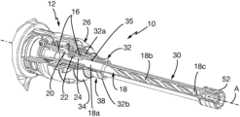
- FIGS. 1 to 5depict a first embodiment of a drilling tool 10 according to the present disclosure, this tool being depicted in part.
- such a tool 10is portable and therefore comprises a handle for a user to hold and a front end 12 for mounting a drill bit, only the front end 12 of the tool being visible in the drawings.
- This tool 10is able to operate in two drilling modes, respectively with and without hammer action.
- the tool 10is equipped with a first selector (not depicted) for selecting the mode of operation from these two drilling modes.
- This first selectoris situated on a housing of the tool and is accessible to the user. It may come in the form of a rotary knob that the user can move between two positions, for example spaced 180° apart, a first position for selecting the mode of drilling without hammer action, in which an arrow on the knob points for example toward a first drawing provided on the housing and depicting for example a drill bit, and a second position for selecting the mode of drilling with hammer action, in which the arrow on the knob points toward another drawing provided on the housing and depicting for example a hammer.
- the front end 12 of the toolis configured to accept a drill bit via an SDS-type push-fit, which may be SDS+, SDSmax or the like.
- a drill bitis chosen according to its drilling diameter, namely to the diameter of its drilling portion 18 b .
- the diameter of its SDS attachment portion 18 ais standard.
- the front end 12comprises a fixed part and a rotary part rotating about the axis A.
- the rotating partcomprises an SDS-type mechanism 14 for push-fitting the drill bit, which mechanism will not be described in detail as it forms part of the general knowledge of a person skilled in the art in this field.
- this push-fitting mechanism 14comprise a rotary ring 16 that extends around the SDS-fixing portion 18 a of the drill bit 18 and that comprises radial through-slots 20 in which there are mounted rollers 22 intended to engage in longitudinal grooves 24 in this portion 18 a of the drill bit.
- a locking mechanism 26allows the rollers 22 to be blocked radially in the grooves while at the same time allowing the drill bit a translational travel in the front end of the tool, which travel is notably dependent on the length of the grooves 24 .
- the mechanism 26is accessible to the user who can unlock the assembly in order to remove the drill bit or replace same.
- the rotating part of the front end of the tool 10further comprises an extension connection mechanism 28 for removable attachment of an extension referred to in the drawings by the reference 30 .
- This extension 30is tubular and has an elongate overall shape. It is configured to extend along and around the drill bit 18 , beyond its drilling tip 18 c .
- the extension 30comprises two opposite longitudinal ends including:
- the extension connection mechanism 28comprises a tubular body 32 intended to be secured in terms of rotation to the rotating part of the front end of the tool.
- the body 32is intended to extend around a portion of the ring 16 and may be secured in terms of rotation to this ring directly.
- itcomprises an end portion 32 a , situated on the same side as the ring 16 , and configured to fit onto the ring 16 .
- This end portion 32 ais surmounted by an annular seal 34 that collaborates both with the ring 16 and the aforementioned locking mechanism 26 to prevent the passage of dust between these components during operation.
- the body 32further comprises or defines an internal annular groove 32 g for housing another annular seal 35 , such as an O-ring, which extends around the part 18 a of the drill bit and engages with this portion 18 a when the latter is mounted in the front end of the tool.
- the body 32further comprises, on the opposite side to its portion 32 a , an end portion 32 b configured to engage by male/female push-fitting with the first end 30 a of the extension.
- this portion 32 bis female and accommodates the male end 30 a of the extension.
- the reverseis conceivable, as visible in the alternative form of embodiment in FIG. 6 , in which the first end of the extension is female and accepts a male portion of the front end of the tool.
- the extension 30is intended to be set in rotation by the rotating part of the front end of the tool and therefore to rotate as one with this rotating part. This inability to rotate independently of one another can be obtained in a simple way by collaboration of shapes, the male-female push-fitting being for example performed by portions with polygonal cross sections, as in the example depicted.
- the inside of the portion 32 b of the body thus in cross sectionhas a polygonal and, more precisely, hexagonal, shape that complements the cross-sectional shape of the end 30 a of the extension.
- the end 30 a of the extensionthus comprises planar exterior faces uniformly distributed on its circumference and connected one to the next by longitudinal edge corners 30 b .
- the end 30 ais, for example, of the SW 13 type.
- each edge corner 30 bis interrupted by a localized recess 36 .
- the recesses 36are situated on the one same circumference centered on the longitudinal axis of the extension, which coincides with the axis A of the drill bit and of the front end, and form sectors of an external peripheral annular groove.
- the recesses 36are intended to collaborate with a ball retention system 38 borne by the body 32 of the extension connection mechanism 28 .
- the ball retention system 38comprises at least one ball 40 engaged in a radial hole in the portion 32 b of the body and held in this hole by way of a split ring 42 that surrounds the portion 32 b , passing over the ball.
- the ball 40is prevented from escaping radially outward by this ring, and radially inward by the shape or dimensions of the hole, the radially internal opening of which may for example be of a diameter smaller than the diameter of the ball.
- the ball 40is urged radially inward by the ring 42 and by default adopts a position in which it partially projects radially into the internal passage of the portion 32 a into which the end 30 a of the extension is push-fitted.
- the ball 40is therefore engaged in a recess 36 of the extension, allowing the extension to be retained axially in relation to the front end.
- a manual force to extract the extensioncan be applied by the user to overcome the resistance of the ball and pull the extension off the tool, in axial translation.
- the extension 30comprises or defines an internal longitudinal bore 44 to accept a drill bit, when such a drill bit is mounted in the front end of the tool.
- the dimensions of this bore 44are therefore notably dependent on those of the drill bit.
- the bore 44comprises two cylindrical portions 44 a and 44 b .
- the portion 44 asituated on the front-end side of the tool, has a diameter D 1 so that it surrounds, with a small radial clearance, the portion 18 b of the drill bit, which is of standard diameter as mentioned in the foregoing.
- the portion 44 bsituated on the opposite side, has a diameter D 2 , where D 2 is equal to or less than D 1 , so as to surround with clearance the portion 18 a of the drill bit.
- the example depictedis particularly well suited to a drill bit of which the diameter of its portion 18 a is at most equal to the diameter of its portion 18 b (in which case the diameters of the portions 44 a and 44 b are identical). If the diameter of the portion 18 a of the drill bit were greater than the diameter of its portion 18 b , the diameter of the portion 44 b would be greater and the alternative form of embodiment of FIG. 6 would be adopted because its extension is able to accommodate a drill bit of larger diameter.
- the length of the portion 44 acan be predetermined.
- the length of the portion 44 bis also predetermined, so as to maintain an axial clearance between the tip 18 c of the drill bit and the end 30 b of the extension ( FIG. 2 ).
- the length of the portion 44 bis therefore greater than the longest length of a portion 18 a of a drill bit of diameter D 2 .
- An additional margin on this clearancemay be used in order to give the possibility for translational movement of the drill bit inside the extension, particularly when a screw-driving operation is being performed while the tool is in hammer drill mode.
- the hammer actionis not, however, needed during screw driving and therefore the drilling mode without hammer action will be favored.
- the extension and the drill bitare driven in rotation by the rotating part of the front end of the tool.
- the end 30 b of the extension 30is configured to accommodate by male-female push-fitting, various types of end piece and coupling. It comprises a tubular wall 48 of polygonal, and more exactly hexagonal, cross section. This wall 48 comprises an annular row of flat external faces 48 a and an annular row of flat internal faces 48 b .
- a first elementcan be mounted on the wall 48 and engage through complementing shapes with the faces 48 a
- a second elementcan be mounted in the wall 48 and engage, through complementing shapes, with the faces 48 b .
- the complementing shapesallow these elements to be secured against rotation with respect to the extension.
- An end-stop socket 50 or screw-driving socket 52may for example be mounted on the wall 48 and comprise a female hexagonal portion (for example SW13) that complements the faces 48 a .
- the end-stop socket 50is intended to bear against a wall to limit the depth to which a fastener, such as a screw, is screwed into this wall.
- the screw-driving socket 52comprises, for example, a hexagon-socket female end portion for driving a hexagon-head screw.
- a screw-driving bit 54may for example be mounted in the wall.
- This bitcomprises a male (for example SW 10 ) hexagonal portion complementing the faces 48 b , and a screw-driving portion of flat-blade or cruciform or some other type.
- the bit 54can be used in combination with the socket 50 .
- the insertion of the bit 54 into the wall 48may be limited by a transverse wall 56 that closes the internal bore 44 of the extension, near its end 30 b .
- Such closureis advantageous insofar as it makes it possible to improve the torsional strength of the extension.
- the axial position of the socket 50 and 52 on the wall 48can be defined by the socket pressing against an external annular flange 58 situated on the end 30 b.
- the faces 48 b of the wallare separated from one another by edge corners each comprising a localized recess 58 .
- the recesses 58are situated on the one same circumference centered on the longitudinal axis of the extension and form sectors of an external peripheral annular groove.
- the recesses 58are intended to engage with a ball retention system 60 borne by the socket 52 and similar to the ball retention system 38 described in the foregoing.
- This system 60is intended to ensure axial retention of the socket 52 on the wall 48 of the extension.
- the tool 10is advantageously able to operate at two, drilling/screw-driving speeds which are respectively high speed and low speed.
- the tool 10is also equipped with a speed selector 66 ( FIG. 7 ). This selector 66 is situated on the casing of the tool and is accessible to the user.
- the toolpreferably comprises a brushless motor 62 electronically controlled and, through the speed selector, making it possible to choose a torque and a speed that are suited to the desired function.
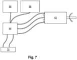
- FIG. 7depicts an electronic control circuit for controlling the tool.
- This circuitcomprises the motor 62 that drives the rotating part of the front end 12 of the tool.
- the motor 62is connected by a microcontroller 64 to the selector 66 and to the trigger 68 for operating the tool.
- the microcontroller 64is also connected to a mode selector 70 for selecting a mode with or without hammer action.
- the microcontroller 64controls the motor 62 according to instructions received from the trigger 68 and from the torque/speed selector 66 .
- the selector 66is provided with a magnet that is detected by two hall-effect sensors mounted on the electronic control circuit. Detection activates one or other of the modes of use: a normal mode with a maximum rotational speed of 800 revolutions/minute and a maximum torque of 7 N.m for hammer drilling and high speed, and a mode with a speed reduced to 300 revolutions/minute and a maximum torque of 15 N.m for low-speed high-torque screw-driving and for hammer drilling with a lower impact force. Activation of a mode makes it possible to define the maximum rotational speed of the tool.
- the trigger 68 of the toolbecause of its progressive action makes it possible to achieve any rotational speed within the range thus defined, without the torque varying.
- the hall-effect sensorsdetect at each moment the position of the rotor of the brushless motor. The phases of the stator windings can thus be switched in the appropriate sequence.
- the electronic circuitthus makes it possible to control the rotational speed of the motor very precisely, the angular position (for example the number of turns of screwing) and the tightening torque.
- the speed and angular positionare perfectly determined by the hall-effect sensors that detect the position of the magnets of the rotor of the motor.
- the tightening torqueis deduced/calculated from the measurement of the current injected into the various phases of the stator of the motor. This is because current and torque are directly proportional.
- a screw-driving elementcould be incorporated directly into the extension.
- the screw-driving elementwould then not be added on to the extension as in the aforementioned examples, but formed of one piece with this extension.
- the extensionhas a length of the order of 200 mm and is made of metal.
Landscapes
- Engineering & Computer Science (AREA)
- Mechanical Engineering (AREA)
- Percussive Tools And Related Accessories (AREA)
- Earth Drilling (AREA)
Abstract
Description
- said first end has a polygonal shape in cross section;
- said extension connection mechanism is configured to engage with said first end by way of a male-female push-fitting;
- said extension comprising a tubular body configured to extend around part of the drill bit and around said first end;
- said body has a ball retention system configured to retain said first end once connected, said ball retention system comprising at least one ball that is borne by said body and is configured to cooperate by engagement with at least one recess provided on said first end;
- said body comprises an internal annular groove for receiving a first O-ring seal configured to engage with said drill bit;
- said front end comprises a second O-ring mounted between said body and SDS-type push-fitting mechanism for the drill bit;
- the tool comprises a first, mode, selector for selecting between said drilling modes with and without hammer action, and a second, speed, selector for selecting between a first speed, suitable for hammer drilling with a high impact force and fast screw driving, and a second, lower, speed, suitable for slow, high-torque screw driving and hammer drilling with a lower impact force;
- the tool comprises a brushless motor for driving the rotation of said rotating part, this motor being connected by a microcontroller to said first and second selectors and to a trigger for actuating the tool; and
- said rotating part is able not to transmit hammer actions to said extension.
- said bore comprises at least two cylindrical portions of different diameters, including a first portion of larger diameter located toward said first end;
- said second end is configured to receive at least one element affixed by male or female push-fitting, or even two elements affixed by male and female push-fitting, respectively; and
- said second end has a polygonal shape in cross section.
- a first
longitudinal end 30aconfigured to be connected removably to the front end of the tool, and in particular to its rotating part, so that the extension can be driven in rotation, and - a second
longitudinal end 30bconfigured to bear at least one screw-driving element.
- a first
Claims (12)
Applications Claiming Priority (3)
| Application Number | Priority Date | Filing Date | Title |
|---|---|---|---|
| FR1757781 | 2017-08-22 | ||
| FR1757781AFR3070290B1 (en) | 2017-08-22 | 2017-08-22 | DRILLING TOOL AND USE THEREOF FOR TIGHTENING OPERATION |
| PCT/US2018/046857WO2019040336A1 (en) | 2017-08-22 | 2018-08-17 | Drilling tool and use in a screw-driving operation |
Publications (2)
| Publication Number | Publication Date |
|---|---|
| US20200262045A1 US20200262045A1 (en) | 2020-08-20 |
| US12115639B2true US12115639B2 (en) | 2024-10-15 |
Family
ID=60138543
Family Applications (1)
| Application Number | Title | Priority Date | Filing Date |
|---|---|---|---|
| US16/639,694Active2039-06-24US12115639B2 (en) | 2017-08-22 | 2018-08-17 | Drilling tool and use in a screw-driving operation |
Country Status (4)
| Country | Link |
|---|---|
| US (1) | US12115639B2 (en) |
| EP (1) | EP3672753B1 (en) |
| FR (1) | FR3070290B1 (en) |
| WO (1) | WO2019040336A1 (en) |
Families Citing this family (2)
| Publication number | Priority date | Publication date | Assignee | Title |
|---|---|---|---|---|
| FR3070290B1 (en)* | 2017-08-22 | 2020-02-21 | Illinois Tool Works Inc | DRILLING TOOL AND USE THEREOF FOR TIGHTENING OPERATION |
| EP4272901A1 (en) | 2022-05-03 | 2023-11-08 | Milwaukee Electric Tool Corporation | Method and power tool including loss of control mitigation |
Citations (71)
| Publication number | Priority date | Publication date | Assignee | Title |
|---|---|---|---|---|
| US3336611A (en)* | 1966-03-01 | 1967-08-22 | Henry A Harry | Combination rotary tools |
| US3484114A (en)* | 1967-09-12 | 1969-12-16 | Emil A Rodin | Screw installing attachment for power tools |
| US3932904A (en)* | 1972-10-27 | 1976-01-20 | United Shoe Machinery Company Ab | Combination tool |
| US3965510A (en)* | 1975-05-09 | 1976-06-29 | Illinois Tool Works Inc. | Combination drilling and wrenching tool |
| US4007795A (en)* | 1976-02-13 | 1977-02-15 | Skil Corporation | Attachment for a rotary-hammer tool |
| US4107949A (en)* | 1975-11-14 | 1978-08-22 | Robert Bosch Gmbh | Tool shank and chuck combination for hammer drill |
| US4107800A (en) | 1977-06-13 | 1978-08-22 | Illinois Tool Works Inc. | Combination drilling and wrenching tool |
| US4191227A (en) | 1977-05-04 | 1980-03-04 | Knipping (Proprietary) Limited | Attachment for a power tool |
| US4218795A (en)* | 1979-03-07 | 1980-08-26 | Illinois Tool Works Inc. | Drill bit with fastener-driving collar assembly |
| US4218794A (en)* | 1979-03-23 | 1980-08-26 | Illinois Tool Works Inc. | Hole-drilling and fastener-driving combination tool |
| US4296656A (en) | 1980-04-21 | 1981-10-27 | Illinois Tool Works Inc. | Driver bit attachment |
| US4468826A (en)* | 1982-06-11 | 1984-09-04 | Black & Decker Inc. | Hammer-drill for masonry fasteners |
| US4551875A (en)* | 1980-10-23 | 1985-11-12 | International Telephone And Telegraph Corporation | Combination tool |
| US4588335A (en) | 1984-09-14 | 1986-05-13 | Pearson Jr Claude C | Quick change tool retention device for power operated mechanism |
| US4617844A (en) | 1983-07-18 | 1986-10-21 | Vsi Corporation | Removable key for wrenching tool |
| US4791690A (en)* | 1987-04-20 | 1988-12-20 | Kuang Wu Huang | Combination drill bit and socket drive assembly |
| US4796319A (en)* | 1987-06-11 | 1989-01-10 | David Taft | Combination screw-tapping and screwdriving tool |
| US4810139A (en) | 1986-11-28 | 1989-03-07 | No-Ma Engineering Incorporated | Quick-change over-spindle adapter |
| US4818157A (en) | 1986-12-31 | 1989-04-04 | James E. Scapillato | Quick-change adapter and tools for use with the adapter |
| US4954025A (en)* | 1990-01-16 | 1990-09-04 | Diversified Fastening Systems, Inc. | Anchor set tool |
| US5110145A (en)* | 1991-06-24 | 1992-05-05 | Stewart Patrick A | Power tool adaptor |
| US5168781A (en) | 1991-10-21 | 1992-12-08 | Illinois Tool Works Inc. | Drive socket |
| US5191666A (en)* | 1991-07-24 | 1993-03-09 | Corbin Linn N | Drill adapter |
| US5313680A (en)* | 1992-04-14 | 1994-05-24 | Ringler William G | Combination drilling and wrenching tool |
| US5409333A (en)* | 1994-02-01 | 1995-04-25 | Ho-Shuenn Huang | Multiply functioned drill means |
| US5490683A (en) | 1994-07-27 | 1996-02-13 | Mednext Inc. | Tool shaft coupler |
| US5586847A (en) | 1995-06-06 | 1996-12-24 | Mattern, Jr.; Charles J. | Power tool adapter |
| US5651647A (en)* | 1995-10-11 | 1997-07-29 | Gbr Pilot Master, Inc. | Auxiliary chuck and screwdriver for electric drills |
| US5711043A (en)* | 1996-10-08 | 1998-01-27 | Diversified Fastening Systems, Inc. | Set tool and cap |
| US5782570A (en) | 1995-10-23 | 1998-07-21 | Chicago Pneumatic Tool Company | Alignment of attachment(s) mounted on a power tool |
| US5810367A (en) | 1996-08-09 | 1998-09-22 | S-B Power Tool Company | Wrenchless holder for working tools |
| US5829929A (en) | 1997-05-08 | 1998-11-03 | Lewis; Michael P. | Long bit hole saw arbor |
| US5897121A (en) | 1998-07-20 | 1999-04-27 | Case; Gregory | Drill attachment and tool for actuating jacks on trailers |
| US5908076A (en) | 1997-01-10 | 1999-06-01 | Power Tool Holders Incorporated | Impact tool driver |
| US5913509A (en) | 1997-01-14 | 1999-06-22 | Black & Decker Inc. | Clamp for a power tool |
| EP1078718A2 (en) | 1999-08-24 | 2001-02-28 | Illinois Tool Works Inc. | Drilling and fastener driving tool |
| US6321855B1 (en)* | 1994-12-29 | 2001-11-27 | George Edward Barnes | Anti-vibration adaptor |
| US6557648B2 (en)* | 2000-10-20 | 2003-05-06 | Hitachi Koki Co., Ltd. | Operation mode switching mechanism for a hammer drill |
| US6623220B2 (en)* | 2000-09-01 | 2003-09-23 | Credo Tool Corporation | Quick change mandrel assembly for use with a hole saw and a pilot drill bit |
| US7104738B2 (en)* | 2003-06-27 | 2006-09-12 | Jore Corporation | Hole saw arbor |
| US7147409B2 (en) | 2004-03-17 | 2006-12-12 | Wienhold James L | Drill countersink assembly |
| US7174969B2 (en)* | 2003-05-14 | 2007-02-13 | Black & Decker Inc. | Rotary hammer |
| US20070074350A1 (en)* | 2005-09-30 | 2007-04-05 | Christian Dreps | Multi-purpose tool |
| US20070160435A1 (en)* | 2006-01-11 | 2007-07-12 | Walley Chao | Hole cutter having detachable hole-sawing blade |
| US7314097B2 (en)* | 2005-02-24 | 2008-01-01 | Black & Decker Inc. | Hammer drill with a mode changeover mechanism |
| US20080056836A1 (en)* | 2006-08-30 | 2008-03-06 | Hsuan-Sen Shiao | Edged clamping device for clamping a drill bit |
| US7354230B2 (en)* | 2003-12-23 | 2008-04-08 | Lynn Bauman | Bit holding apparatus for use with a power tool |
| US7717192B2 (en)* | 2007-11-21 | 2010-05-18 | Black & Decker Inc. | Multi-mode drill with mode collar |
| DE202010011308U1 (en) | 2010-08-12 | 2010-12-23 | Sheng, Wen Jiung, Zhubei City | Assembly with a drill head and a socket |
| US20100326686A1 (en)* | 2007-02-23 | 2010-12-30 | Chi Hoe Leong | Rotary power tool operable in either an impact mode or a drill mode |
| EP2345496A1 (en)* | 2010-01-18 | 2011-07-20 | Harald Göttlich | Tool holder |
| US8057136B2 (en)* | 2008-07-09 | 2011-11-15 | Hsin Ying Enterprises Co., Ltd. | Power tool combination |
| US8061000B2 (en)* | 2008-06-06 | 2011-11-22 | Black & Decker Inc. | Anchor installation tool |
| US20130021783A1 (en)* | 2010-09-30 | 2013-01-24 | Black & Decker Inc. | Lighted power tool |
| US20130221058A1 (en)* | 2012-02-27 | 2013-08-29 | Milwaukee Electric Tool Corporation | Pin anchor driver |
| US8602285B2 (en)* | 2008-06-06 | 2013-12-10 | Black & Decker | Anchor installation tool |
| US8622667B1 (en)* | 2011-09-20 | 2014-01-07 | Earl L. Seay | Drill motor adapter |
| US20140028226A1 (en)* | 2012-07-26 | 2014-01-30 | Milwaukee Electric Tool Corporation | Brushless direct-current motor and control for power tool |
| US20140131059A1 (en)* | 2012-11-13 | 2014-05-15 | Milwaukee Electric Tool Corporation | High-power cordless, hand-held power tool including a brushless direct current motor |
| US20150101177A1 (en) | 2013-10-11 | 2015-04-16 | Irwin Industrial Tool Company | Drilling apparatus and method |
| US9108312B2 (en)* | 2012-09-11 | 2015-08-18 | Milwaukee Electric Tool Corporation | Multi-stage transmission for a power tool |
| US9339924B2 (en)* | 2011-07-26 | 2016-05-17 | Black & Decker Inc. | Hammer |
| US20160250738A1 (en)* | 2015-02-27 | 2016-09-01 | Black & Decker Inc. | Impact tool with control mode |
| US20160354888A1 (en)* | 2015-06-02 | 2016-12-08 | Milwaukee Electric Tool Corporation | Multi-speed power tool with electronic clutch |
| US9623545B2 (en)* | 2013-02-08 | 2017-04-18 | Milwaukee Electric Tool Corporation | Apparatus with active software clamping of supply voltage |
| US20170173766A1 (en)* | 2015-12-17 | 2017-06-22 | Illinois Tool Works Inc. | Power tool adapter |
| US20170217000A1 (en)* | 2014-10-13 | 2017-08-03 | Mercator Innovations Bvba | Combination screwdriver and torque limiting system |
| US20170217005A1 (en)* | 2016-02-02 | 2017-08-03 | Black & Decker Inc. | Tool holder connection system |
| US9744658B2 (en)* | 2013-03-15 | 2017-08-29 | Milwaukee Electric Tool Corporation | Power tool operation recording and playback |
| US20180238367A1 (en)* | 2017-02-23 | 2018-08-23 | Brian M. Laue | Wedge Anchor Setting Tool and Method |
| US20200262045A1 (en)* | 2017-08-22 | 2020-08-20 | Illinois Tool Works Inc. | Drilling tool and use in a screw-driving operation |
- 2017
- 2017-08-22FRFR1757781Apatent/FR3070290B1/enactiveActive
- 2018
- 2018-08-17USUS16/639,694patent/US12115639B2/enactiveActive
- 2018-08-17WOPCT/US2018/046857patent/WO2019040336A1/ennot_activeCeased
- 2018-08-17EPEP18765772.1Apatent/EP3672753B1/enactiveActive
Patent Citations (73)
| Publication number | Priority date | Publication date | Assignee | Title |
|---|---|---|---|---|
| US3336611A (en)* | 1966-03-01 | 1967-08-22 | Henry A Harry | Combination rotary tools |
| US3484114A (en)* | 1967-09-12 | 1969-12-16 | Emil A Rodin | Screw installing attachment for power tools |
| US3932904A (en)* | 1972-10-27 | 1976-01-20 | United Shoe Machinery Company Ab | Combination tool |
| US3965510A (en)* | 1975-05-09 | 1976-06-29 | Illinois Tool Works Inc. | Combination drilling and wrenching tool |
| US4107949A (en)* | 1975-11-14 | 1978-08-22 | Robert Bosch Gmbh | Tool shank and chuck combination for hammer drill |
| US4007795A (en)* | 1976-02-13 | 1977-02-15 | Skil Corporation | Attachment for a rotary-hammer tool |
| US4191227A (en) | 1977-05-04 | 1980-03-04 | Knipping (Proprietary) Limited | Attachment for a power tool |
| US4107800A (en) | 1977-06-13 | 1978-08-22 | Illinois Tool Works Inc. | Combination drilling and wrenching tool |
| US4218795A (en)* | 1979-03-07 | 1980-08-26 | Illinois Tool Works Inc. | Drill bit with fastener-driving collar assembly |
| US4218794A (en)* | 1979-03-23 | 1980-08-26 | Illinois Tool Works Inc. | Hole-drilling and fastener-driving combination tool |
| US4296656A (en) | 1980-04-21 | 1981-10-27 | Illinois Tool Works Inc. | Driver bit attachment |
| US4551875A (en)* | 1980-10-23 | 1985-11-12 | International Telephone And Telegraph Corporation | Combination tool |
| US4468826A (en)* | 1982-06-11 | 1984-09-04 | Black & Decker Inc. | Hammer-drill for masonry fasteners |
| US4617844A (en) | 1983-07-18 | 1986-10-21 | Vsi Corporation | Removable key for wrenching tool |
| US4588335A (en) | 1984-09-14 | 1986-05-13 | Pearson Jr Claude C | Quick change tool retention device for power operated mechanism |
| US4810139A (en) | 1986-11-28 | 1989-03-07 | No-Ma Engineering Incorporated | Quick-change over-spindle adapter |
| US4818157A (en) | 1986-12-31 | 1989-04-04 | James E. Scapillato | Quick-change adapter and tools for use with the adapter |
| US4791690A (en)* | 1987-04-20 | 1988-12-20 | Kuang Wu Huang | Combination drill bit and socket drive assembly |
| US4796319A (en)* | 1987-06-11 | 1989-01-10 | David Taft | Combination screw-tapping and screwdriving tool |
| US4954025A (en)* | 1990-01-16 | 1990-09-04 | Diversified Fastening Systems, Inc. | Anchor set tool |
| US5110145A (en)* | 1991-06-24 | 1992-05-05 | Stewart Patrick A | Power tool adaptor |
| US5191666A (en)* | 1991-07-24 | 1993-03-09 | Corbin Linn N | Drill adapter |
| US5168781A (en) | 1991-10-21 | 1992-12-08 | Illinois Tool Works Inc. | Drive socket |
| US5313680A (en)* | 1992-04-14 | 1994-05-24 | Ringler William G | Combination drilling and wrenching tool |
| US5409333A (en)* | 1994-02-01 | 1995-04-25 | Ho-Shuenn Huang | Multiply functioned drill means |
| US5490683A (en) | 1994-07-27 | 1996-02-13 | Mednext Inc. | Tool shaft coupler |
| US6321855B1 (en)* | 1994-12-29 | 2001-11-27 | George Edward Barnes | Anti-vibration adaptor |
| US5586847A (en) | 1995-06-06 | 1996-12-24 | Mattern, Jr.; Charles J. | Power tool adapter |
| US5651647A (en)* | 1995-10-11 | 1997-07-29 | Gbr Pilot Master, Inc. | Auxiliary chuck and screwdriver for electric drills |
| US5782570A (en) | 1995-10-23 | 1998-07-21 | Chicago Pneumatic Tool Company | Alignment of attachment(s) mounted on a power tool |
| US5810367A (en) | 1996-08-09 | 1998-09-22 | S-B Power Tool Company | Wrenchless holder for working tools |
| US5711043A (en)* | 1996-10-08 | 1998-01-27 | Diversified Fastening Systems, Inc. | Set tool and cap |
| US5908076A (en) | 1997-01-10 | 1999-06-01 | Power Tool Holders Incorporated | Impact tool driver |
| US5913509A (en) | 1997-01-14 | 1999-06-22 | Black & Decker Inc. | Clamp for a power tool |
| US5829929A (en) | 1997-05-08 | 1998-11-03 | Lewis; Michael P. | Long bit hole saw arbor |
| US5897121A (en) | 1998-07-20 | 1999-04-27 | Case; Gregory | Drill attachment and tool for actuating jacks on trailers |
| EP1078718A2 (en) | 1999-08-24 | 2001-02-28 | Illinois Tool Works Inc. | Drilling and fastener driving tool |
| US6223375B1 (en)* | 1999-08-24 | 2001-05-01 | Illinois Tool Works Inc | Drilling and fastener driving tool |
| US6623220B2 (en)* | 2000-09-01 | 2003-09-23 | Credo Tool Corporation | Quick change mandrel assembly for use with a hole saw and a pilot drill bit |
| US6557648B2 (en)* | 2000-10-20 | 2003-05-06 | Hitachi Koki Co., Ltd. | Operation mode switching mechanism for a hammer drill |
| US7174969B2 (en)* | 2003-05-14 | 2007-02-13 | Black & Decker Inc. | Rotary hammer |
| US7104738B2 (en)* | 2003-06-27 | 2006-09-12 | Jore Corporation | Hole saw arbor |
| US7354230B2 (en)* | 2003-12-23 | 2008-04-08 | Lynn Bauman | Bit holding apparatus for use with a power tool |
| US7147409B2 (en) | 2004-03-17 | 2006-12-12 | Wienhold James L | Drill countersink assembly |
| US7314097B2 (en)* | 2005-02-24 | 2008-01-01 | Black & Decker Inc. | Hammer drill with a mode changeover mechanism |
| US20070074350A1 (en)* | 2005-09-30 | 2007-04-05 | Christian Dreps | Multi-purpose tool |
| US20070160435A1 (en)* | 2006-01-11 | 2007-07-12 | Walley Chao | Hole cutter having detachable hole-sawing blade |
| US20080056836A1 (en)* | 2006-08-30 | 2008-03-06 | Hsuan-Sen Shiao | Edged clamping device for clamping a drill bit |
| US20100326686A1 (en)* | 2007-02-23 | 2010-12-30 | Chi Hoe Leong | Rotary power tool operable in either an impact mode or a drill mode |
| US7717192B2 (en)* | 2007-11-21 | 2010-05-18 | Black & Decker Inc. | Multi-mode drill with mode collar |
| US8602285B2 (en)* | 2008-06-06 | 2013-12-10 | Black & Decker | Anchor installation tool |
| US8061000B2 (en)* | 2008-06-06 | 2011-11-22 | Black & Decker Inc. | Anchor installation tool |
| US8057136B2 (en)* | 2008-07-09 | 2011-11-15 | Hsin Ying Enterprises Co., Ltd. | Power tool combination |
| EP2345496A1 (en)* | 2010-01-18 | 2011-07-20 | Harald Göttlich | Tool holder |
| DE202010011308U1 (en) | 2010-08-12 | 2010-12-23 | Sheng, Wen Jiung, Zhubei City | Assembly with a drill head and a socket |
| US20130021783A1 (en)* | 2010-09-30 | 2013-01-24 | Black & Decker Inc. | Lighted power tool |
| US9339924B2 (en)* | 2011-07-26 | 2016-05-17 | Black & Decker Inc. | Hammer |
| US8622667B1 (en)* | 2011-09-20 | 2014-01-07 | Earl L. Seay | Drill motor adapter |
| US20130221058A1 (en)* | 2012-02-27 | 2013-08-29 | Milwaukee Electric Tool Corporation | Pin anchor driver |
| US20140028226A1 (en)* | 2012-07-26 | 2014-01-30 | Milwaukee Electric Tool Corporation | Brushless direct-current motor and control for power tool |
| US9108312B2 (en)* | 2012-09-11 | 2015-08-18 | Milwaukee Electric Tool Corporation | Multi-stage transmission for a power tool |
| US20140131059A1 (en)* | 2012-11-13 | 2014-05-15 | Milwaukee Electric Tool Corporation | High-power cordless, hand-held power tool including a brushless direct current motor |
| US9623545B2 (en)* | 2013-02-08 | 2017-04-18 | Milwaukee Electric Tool Corporation | Apparatus with active software clamping of supply voltage |
| US9744658B2 (en)* | 2013-03-15 | 2017-08-29 | Milwaukee Electric Tool Corporation | Power tool operation recording and playback |
| US20150101177A1 (en) | 2013-10-11 | 2015-04-16 | Irwin Industrial Tool Company | Drilling apparatus and method |
| US9364903B2 (en)* | 2013-10-11 | 2016-06-14 | Irwin Industrial Tool Company | Drilling apparatus and method |
| US20170217000A1 (en)* | 2014-10-13 | 2017-08-03 | Mercator Innovations Bvba | Combination screwdriver and torque limiting system |
| US20160250738A1 (en)* | 2015-02-27 | 2016-09-01 | Black & Decker Inc. | Impact tool with control mode |
| US20160354888A1 (en)* | 2015-06-02 | 2016-12-08 | Milwaukee Electric Tool Corporation | Multi-speed power tool with electronic clutch |
| US20170173766A1 (en)* | 2015-12-17 | 2017-06-22 | Illinois Tool Works Inc. | Power tool adapter |
| US20170217005A1 (en)* | 2016-02-02 | 2017-08-03 | Black & Decker Inc. | Tool holder connection system |
| US20180238367A1 (en)* | 2017-02-23 | 2018-08-23 | Brian M. Laue | Wedge Anchor Setting Tool and Method |
| US20200262045A1 (en)* | 2017-08-22 | 2020-08-20 | Illinois Tool Works Inc. | Drilling tool and use in a screw-driving operation |
Non-Patent Citations (7)
| Title |
|---|
| "International Search Report and Written Opinion", PCT/US2018/046857 (10 pages), Nov. 16, 2018. |
| "Search Report and Written Opinion", Corresponding French Application No. 1757781 (7 pages), May 4, 2018. |
| Canadian Office Action for Canadian Application No. 3,004,892, dated Dec. 27, 2018 (3 pages). |
| Drill bit adapter image, retrieved from Google prior to Dec. 1, 2016 (1 page). |
| European Patent Office as International Searching Authority, International Search Report and Written Opinion for corresponding PCT Application No. PCT/US2016/064677 mailed Feb. 23, 2017. |
| International Preliminary Report on Patentability for International Application No. PCT/US2016/064677, mailed Jun. 28, 2018 (9 pages). |
| Snappy Drilling Accessories, available at http://www.ttrackusa.com/snappy_drill_bitts.htm, printed Dec. 1, 2016 (5pages). |
Also Published As
| Publication number | Publication date |
|---|---|
| US20200262045A1 (en) | 2020-08-20 |
| FR3070290A1 (en) | 2019-03-01 |
| EP3672753B1 (en) | 2023-12-27 |
| EP3672753A1 (en) | 2020-07-01 |
| WO2019040336A1 (en) | 2019-02-28 |
| FR3070290B1 (en) | 2020-02-21 |
Similar Documents
| Publication | Publication Date | Title |
|---|---|---|
| KR101960650B1 (en) | Portable power tool | |
| EP1710050B1 (en) | Magnetic device for holding and driving bits and fasteners | |
| US7481608B2 (en) | Rotatable chuck | |
| US5470180A (en) | Reversible drill/driver tool | |
| US9248507B2 (en) | Hand-held power tool | |
| EP2599590B1 (en) | Tangless helical coil insert inserting tool | |
| EP3067156B1 (en) | Rotary impact tool | |
| US4653358A (en) | Tools for use in tightening or removing screw-threaded fasteners | |
| US20130093149A1 (en) | Tool attachment | |
| US20050284648A1 (en) | Device having a torque-limiting unit | |
| US20090139378A1 (en) | Driver tool having adjustable structure | |
| US6321626B1 (en) | Magnetic driving tool having a telescopic pipe | |
| US12115639B2 (en) | Drilling tool and use in a screw-driving operation | |
| US8276483B2 (en) | Hand-held power tool with a tool holder | |
| US6056298A (en) | Chuck lock bit changer | |
| US10882165B2 (en) | Drive guide | |
| US6932357B2 (en) | Gear reducing collet nut assembly | |
| EP3853486B1 (en) | Accessory for a hammer drill and its use for inserting a wallbolt | |
| KR100758324B1 (en) | Tool for fastening screw parts | |
| JP3195281U (en) | Auto screwdriver magnetic coupling | |
| CN209332319U (en) | Machine converter for dentistry implant operation | |
| JP2008005679A (en) | Rotary operating tool | |
| EP3698922A1 (en) | Nut running tool | |
| KR20090009669U (en) | Power tool with integrated magnetization means |
Legal Events
| Date | Code | Title | Description |
|---|---|---|---|
| AS | Assignment | Owner name:ILLINOIS TOOL WORKS INC., ILLINOIS Free format text:ASSIGNMENT OF ASSIGNORS INTEREST;ASSIGNORS:PERRIER, MATTHIEU;TOURNIER, LUDOVIC;SOCIETE DE PROSPECTION ET D'INVENTIONS TECHNIQUES;REEL/FRAME:051834/0774 Effective date:20170925 | |
| FEPP | Fee payment procedure | Free format text:ENTITY STATUS SET TO UNDISCOUNTED (ORIGINAL EVENT CODE: BIG.); ENTITY STATUS OF PATENT OWNER: LARGE ENTITY | |
| STPP | Information on status: patent application and granting procedure in general | Free format text:APPLICATION DISPATCHED FROM PREEXAM, NOT YET DOCKETED | |
| STPP | Information on status: patent application and granting procedure in general | Free format text:DOCKETED NEW CASE - READY FOR EXAMINATION | |
| STPP | Information on status: patent application and granting procedure in general | Free format text:NON FINAL ACTION MAILED | |
| STPP | Information on status: patent application and granting procedure in general | Free format text:RESPONSE TO NON-FINAL OFFICE ACTION ENTERED AND FORWARDED TO EXAMINER | |
| STPP | Information on status: patent application and granting procedure in general | Free format text:FINAL REJECTION MAILED | |
| STPP | Information on status: patent application and granting procedure in general | Free format text:DOCKETED NEW CASE - READY FOR EXAMINATION | |
| STPP | Information on status: patent application and granting procedure in general | Free format text:NOTICE OF ALLOWANCE MAILED -- APPLICATION RECEIVED IN OFFICE OF PUBLICATIONS | |
| ZAAB | Notice of allowance mailed | Free format text:ORIGINAL CODE: MN/=. | |
| STPP | Information on status: patent application and granting procedure in general | Free format text:AWAITING TC RESP., ISSUE FEE NOT PAID | |
| STPP | Information on status: patent application and granting procedure in general | Free format text:NOTICE OF ALLOWANCE MAILED -- APPLICATION RECEIVED IN OFFICE OF PUBLICATIONS | |
| STPP | Information on status: patent application and granting procedure in general | Free format text:PUBLICATIONS -- ISSUE FEE PAYMENT VERIFIED | |
| STCF | Information on status: patent grant | Free format text:PATENTED CASE |