US12115335B2 - Sterilization arrangement for drug delivery device - Google Patents
Sterilization arrangement for drug delivery deviceDownload PDFInfo
- Publication number
- US12115335B2 US12115335B2US17/153,613US202117153613AUS12115335B2US 12115335 B2US12115335 B2US 12115335B2US 202117153613 AUS202117153613 AUS 202117153613AUS 12115335 B2US12115335 B2US 12115335B2
- Authority
- US
- United States
- Prior art keywords
- drug delivery
- delivery system
- cavity
- container
- needle
- Prior art date
- Legal status (The legal status is an assumption and is not a legal conclusion. Google has not performed a legal analysis and makes no representation as to the accuracy of the status listed.)
- Active, expires
Links
- 238000012377drug deliveryMethods0.000titleclaimsabstractdescription75
- 230000001954sterilising effectEffects0.000titleclaimsdescription13
- 238000004659sterilization and disinfectionMethods0.000titledescription11
- 239000003814drugSubstances0.000claimsabstractdescription23
- 239000012530fluidSubstances0.000claimsabstractdescription15
- 230000004913activationEffects0.000claimsabstractdescription9
- 238000004891communicationMethods0.000claimsabstractdescription9
- 238000000034methodMethods0.000claimsdescription25
- 230000008569processEffects0.000claimsdescription12
- 230000005355Hall effectEffects0.000claimsdescription4
- 230000000977initiatory effectEffects0.000claimsdescription4
- 230000006698inductionEffects0.000claimsdescription2
- 230000003213activating effectEffects0.000claims1
- 239000007924injectionSubstances0.000description12
- 238000002347injectionMethods0.000description12
- 229940079593drugDrugs0.000description6
- 239000007788liquidSubstances0.000description6
- 238000002360preparation methodMethods0.000description6
- 230000001225therapeutic effectEffects0.000description6
- 230000007246mechanismEffects0.000description4
- 230000000994depressogenic effectEffects0.000description3
- 230000003760hair shineEffects0.000description2
- 238000012986modificationMethods0.000description2
- 230000004048modificationEffects0.000description2
- 241000894006BacteriaSpecies0.000description1
- 230000006978adaptationEffects0.000description1
- 229940090047auto-injectorDrugs0.000description1
- 239000000356contaminantSubstances0.000description1
- 238000010586diagramMethods0.000description1
- 239000000243solutionSubstances0.000description1
- 230000001960triggered effectEffects0.000description1
- 230000000007visual effectEffects0.000description1
Images


Classifications
- A—HUMAN NECESSITIES
- A61—MEDICAL OR VETERINARY SCIENCE; HYGIENE
- A61M—DEVICES FOR INTRODUCING MEDIA INTO, OR ONTO, THE BODY; DEVICES FOR TRANSDUCING BODY MEDIA OR FOR TAKING MEDIA FROM THE BODY; DEVICES FOR PRODUCING OR ENDING SLEEP OR STUPOR
- A61M5/00—Devices for bringing media into the body in a subcutaneous, intra-vascular or intramuscular way; Accessories therefor, e.g. filling or cleaning devices, arm-rests
- A61M5/001—Apparatus specially adapted for cleaning or sterilising syringes or needles
- A—HUMAN NECESSITIES
- A61—MEDICAL OR VETERINARY SCIENCE; HYGIENE
- A61L—METHODS OR APPARATUS FOR STERILISING MATERIALS OR OBJECTS IN GENERAL; DISINFECTION, STERILISATION OR DEODORISATION OF AIR; CHEMICAL ASPECTS OF BANDAGES, DRESSINGS, ABSORBENT PADS OR SURGICAL ARTICLES; MATERIALS FOR BANDAGES, DRESSINGS, ABSORBENT PADS OR SURGICAL ARTICLES
- A61L2/00—Methods or apparatus for disinfecting or sterilising materials or objects other than foodstuffs or contact lenses; Accessories therefor
- A61L2/0005—Methods or apparatus for disinfecting or sterilising materials or objects other than foodstuffs or contact lenses; Accessories therefor for pharmaceuticals, biologicals or living parts
- A61L2/0011—Methods or apparatus for disinfecting or sterilising materials or objects other than foodstuffs or contact lenses; Accessories therefor for pharmaceuticals, biologicals or living parts using physical methods
- A61L2/0029—Radiation
- A61L2/0047—Ultraviolet radiation
- A—HUMAN NECESSITIES
- A61—MEDICAL OR VETERINARY SCIENCE; HYGIENE
- A61L—METHODS OR APPARATUS FOR STERILISING MATERIALS OR OBJECTS IN GENERAL; DISINFECTION, STERILISATION OR DEODORISATION OF AIR; CHEMICAL ASPECTS OF BANDAGES, DRESSINGS, ABSORBENT PADS OR SURGICAL ARTICLES; MATERIALS FOR BANDAGES, DRESSINGS, ABSORBENT PADS OR SURGICAL ARTICLES
- A61L2/00—Methods or apparatus for disinfecting or sterilising materials or objects other than foodstuffs or contact lenses; Accessories therefor
- A61L2/02—Methods or apparatus for disinfecting or sterilising materials or objects other than foodstuffs or contact lenses; Accessories therefor using physical phenomena
- A61L2/08—Radiation
- A61L2/10—Ultraviolet radiation
- A—HUMAN NECESSITIES
- A61—MEDICAL OR VETERINARY SCIENCE; HYGIENE
- A61L—METHODS OR APPARATUS FOR STERILISING MATERIALS OR OBJECTS IN GENERAL; DISINFECTION, STERILISATION OR DEODORISATION OF AIR; CHEMICAL ASPECTS OF BANDAGES, DRESSINGS, ABSORBENT PADS OR SURGICAL ARTICLES; MATERIALS FOR BANDAGES, DRESSINGS, ABSORBENT PADS OR SURGICAL ARTICLES
- A61L2/00—Methods or apparatus for disinfecting or sterilising materials or objects other than foodstuffs or contact lenses; Accessories therefor
- A61L2/24—Apparatus using programmed or automatic operation
- A—HUMAN NECESSITIES
- A61—MEDICAL OR VETERINARY SCIENCE; HYGIENE
- A61M—DEVICES FOR INTRODUCING MEDIA INTO, OR ONTO, THE BODY; DEVICES FOR TRANSDUCING BODY MEDIA OR FOR TAKING MEDIA FROM THE BODY; DEVICES FOR PRODUCING OR ENDING SLEEP OR STUPOR
- A61M5/00—Devices for bringing media into the body in a subcutaneous, intra-vascular or intramuscular way; Accessories therefor, e.g. filling or cleaning devices, arm-rests
- A61M5/14—Infusion devices, e.g. infusing by gravity; Blood infusion; Accessories therefor
- A61M5/142—Pressure infusion, e.g. using pumps
- A61M5/14244—Pressure infusion, e.g. using pumps adapted to be carried by the patient, e.g. portable on the body
- A61M5/14248—Pressure infusion, e.g. using pumps adapted to be carried by the patient, e.g. portable on the body of the skin patch type
- A—HUMAN NECESSITIES
- A61—MEDICAL OR VETERINARY SCIENCE; HYGIENE
- A61M—DEVICES FOR INTRODUCING MEDIA INTO, OR ONTO, THE BODY; DEVICES FOR TRANSDUCING BODY MEDIA OR FOR TAKING MEDIA FROM THE BODY; DEVICES FOR PRODUCING OR ENDING SLEEP OR STUPOR
- A61M5/00—Devices for bringing media into the body in a subcutaneous, intra-vascular or intramuscular way; Accessories therefor, e.g. filling or cleaning devices, arm-rests
- A61M5/14—Infusion devices, e.g. infusing by gravity; Blood infusion; Accessories therefor
- A61M5/162—Needle sets, i.e. connections by puncture between reservoir and tube ; Connections between reservoir and tube
- A—HUMAN NECESSITIES
- A61—MEDICAL OR VETERINARY SCIENCE; HYGIENE
- A61M—DEVICES FOR INTRODUCING MEDIA INTO, OR ONTO, THE BODY; DEVICES FOR TRANSDUCING BODY MEDIA OR FOR TAKING MEDIA FROM THE BODY; DEVICES FOR PRODUCING OR ENDING SLEEP OR STUPOR
- A61M5/00—Devices for bringing media into the body in a subcutaneous, intra-vascular or intramuscular way; Accessories therefor, e.g. filling or cleaning devices, arm-rests
- A61M5/178—Syringes
- A61M5/31—Details
- A61M5/32—Needles; Details of needles pertaining to their connection with syringe or hub; Accessories for bringing the needle into, or holding the needle on, the body; Devices for protection of needles
- A—HUMAN NECESSITIES
- A61—MEDICAL OR VETERINARY SCIENCE; HYGIENE
- A61L—METHODS OR APPARATUS FOR STERILISING MATERIALS OR OBJECTS IN GENERAL; DISINFECTION, STERILISATION OR DEODORISATION OF AIR; CHEMICAL ASPECTS OF BANDAGES, DRESSINGS, ABSORBENT PADS OR SURGICAL ARTICLES; MATERIALS FOR BANDAGES, DRESSINGS, ABSORBENT PADS OR SURGICAL ARTICLES
- A61L2202/00—Aspects relating to methods or apparatus for disinfecting or sterilising materials or objects
- A61L2202/10—Apparatus features
- A61L2202/14—Means for controlling sterilisation processes, data processing, presentation and storage means, e.g. sensors, controllers, programs
- A—HUMAN NECESSITIES
- A61—MEDICAL OR VETERINARY SCIENCE; HYGIENE
- A61L—METHODS OR APPARATUS FOR STERILISING MATERIALS OR OBJECTS IN GENERAL; DISINFECTION, STERILISATION OR DEODORISATION OF AIR; CHEMICAL ASPECTS OF BANDAGES, DRESSINGS, ABSORBENT PADS OR SURGICAL ARTICLES; MATERIALS FOR BANDAGES, DRESSINGS, ABSORBENT PADS OR SURGICAL ARTICLES
- A61L2202/00—Aspects relating to methods or apparatus for disinfecting or sterilising materials or objects
- A61L2202/10—Apparatus features
- A61L2202/18—Aseptic storing means
- A61L2202/182—Rigid packaging means
- A—HUMAN NECESSITIES
- A61—MEDICAL OR VETERINARY SCIENCE; HYGIENE
- A61L—METHODS OR APPARATUS FOR STERILISING MATERIALS OR OBJECTS IN GENERAL; DISINFECTION, STERILISATION OR DEODORISATION OF AIR; CHEMICAL ASPECTS OF BANDAGES, DRESSINGS, ABSORBENT PADS OR SURGICAL ARTICLES; MATERIALS FOR BANDAGES, DRESSINGS, ABSORBENT PADS OR SURGICAL ARTICLES
- A61L2202/00—Aspects relating to methods or apparatus for disinfecting or sterilising materials or objects
- A61L2202/20—Targets to be treated
- A61L2202/21—Pharmaceuticals, e.g. medicaments, artificial body parts
- A—HUMAN NECESSITIES
- A61—MEDICAL OR VETERINARY SCIENCE; HYGIENE
- A61M—DEVICES FOR INTRODUCING MEDIA INTO, OR ONTO, THE BODY; DEVICES FOR TRANSDUCING BODY MEDIA OR FOR TAKING MEDIA FROM THE BODY; DEVICES FOR PRODUCING OR ENDING SLEEP OR STUPOR
- A61M5/00—Devices for bringing media into the body in a subcutaneous, intra-vascular or intramuscular way; Accessories therefor, e.g. filling or cleaning devices, arm-rests
- A61M5/14—Infusion devices, e.g. infusing by gravity; Blood infusion; Accessories therefor
- A61M5/142—Pressure infusion, e.g. using pumps
- A61M5/14244—Pressure infusion, e.g. using pumps adapted to be carried by the patient, e.g. portable on the body
- A61M5/14248—Pressure infusion, e.g. using pumps adapted to be carried by the patient, e.g. portable on the body of the skin patch type
- A61M2005/14252—Pressure infusion, e.g. using pumps adapted to be carried by the patient, e.g. portable on the body of the skin patch type with needle insertion means
- A—HUMAN NECESSITIES
- A61—MEDICAL OR VETERINARY SCIENCE; HYGIENE
- A61M—DEVICES FOR INTRODUCING MEDIA INTO, OR ONTO, THE BODY; DEVICES FOR TRANSDUCING BODY MEDIA OR FOR TAKING MEDIA FROM THE BODY; DEVICES FOR PRODUCING OR ENDING SLEEP OR STUPOR
- A61M5/00—Devices for bringing media into the body in a subcutaneous, intra-vascular or intramuscular way; Accessories therefor, e.g. filling or cleaning devices, arm-rests
- A61M5/178—Syringes
- A61M5/20—Automatic syringes, e.g. with automatically actuated piston rod, with automatic needle injection, filling automatically
- A61M2005/2006—Having specific accessories
- A—HUMAN NECESSITIES
- A61—MEDICAL OR VETERINARY SCIENCE; HYGIENE
- A61M—DEVICES FOR INTRODUCING MEDIA INTO, OR ONTO, THE BODY; DEVICES FOR TRANSDUCING BODY MEDIA OR FOR TAKING MEDIA FROM THE BODY; DEVICES FOR PRODUCING OR ENDING SLEEP OR STUPOR
- A61M5/00—Devices for bringing media into the body in a subcutaneous, intra-vascular or intramuscular way; Accessories therefor, e.g. filling or cleaning devices, arm-rests
- A61M5/178—Syringes
- A61M5/20—Automatic syringes, e.g. with automatically actuated piston rod, with automatic needle injection, filling automatically
- A61M2005/2026—Semi-automatic, e.g. user activated piston is assisted by additional source of energy
- A—HUMAN NECESSITIES
- A61—MEDICAL OR VETERINARY SCIENCE; HYGIENE
- A61M—DEVICES FOR INTRODUCING MEDIA INTO, OR ONTO, THE BODY; DEVICES FOR TRANSDUCING BODY MEDIA OR FOR TAKING MEDIA FROM THE BODY; DEVICES FOR PRODUCING OR ENDING SLEEP OR STUPOR
- A61M5/00—Devices for bringing media into the body in a subcutaneous, intra-vascular or intramuscular way; Accessories therefor, e.g. filling or cleaning devices, arm-rests
- A61M5/178—Syringes
- A61M5/24—Ampoule syringes, i.e. syringes with needle for use in combination with replaceable ampoules or carpules, e.g. automatic
- A61M5/2455—Ampoule syringes, i.e. syringes with needle for use in combination with replaceable ampoules or carpules, e.g. automatic with sealing means to be broken or opened
- A61M5/2466—Ampoule syringes, i.e. syringes with needle for use in combination with replaceable ampoules or carpules, e.g. automatic with sealing means to be broken or opened by piercing without internal pressure increase
- A61M2005/247—Ampoule syringes, i.e. syringes with needle for use in combination with replaceable ampoules or carpules, e.g. automatic with sealing means to be broken or opened by piercing without internal pressure increase with fixed or steady piercing means, e.g. piercing under movement of ampoule
- A—HUMAN NECESSITIES
- A61—MEDICAL OR VETERINARY SCIENCE; HYGIENE
- A61M—DEVICES FOR INTRODUCING MEDIA INTO, OR ONTO, THE BODY; DEVICES FOR TRANSDUCING BODY MEDIA OR FOR TAKING MEDIA FROM THE BODY; DEVICES FOR PRODUCING OR ENDING SLEEP OR STUPOR
- A61M2205/00—General characteristics of the apparatus
- A61M2205/05—General characteristics of the apparatus combined with other kinds of therapy
- A61M2205/051—General characteristics of the apparatus combined with other kinds of therapy with radiation therapy
- A61M2205/053—General characteristics of the apparatus combined with other kinds of therapy with radiation therapy ultraviolet
- A—HUMAN NECESSITIES
- A61—MEDICAL OR VETERINARY SCIENCE; HYGIENE
- A61M—DEVICES FOR INTRODUCING MEDIA INTO, OR ONTO, THE BODY; DEVICES FOR TRANSDUCING BODY MEDIA OR FOR TAKING MEDIA FROM THE BODY; DEVICES FOR PRODUCING OR ENDING SLEEP OR STUPOR
- A61M2205/00—General characteristics of the apparatus
- A61M2205/33—Controlling, regulating or measuring
- A61M2205/3317—Electromagnetic, inductive or dielectric measuring means
- A—HUMAN NECESSITIES
- A61—MEDICAL OR VETERINARY SCIENCE; HYGIENE
- A61M—DEVICES FOR INTRODUCING MEDIA INTO, OR ONTO, THE BODY; DEVICES FOR TRANSDUCING BODY MEDIA OR FOR TAKING MEDIA FROM THE BODY; DEVICES FOR PRODUCING OR ENDING SLEEP OR STUPOR
- A61M2205/00—General characteristics of the apparatus
- A61M2205/58—Means for facilitating use, e.g. by people with impaired vision
- A61M2205/583—Means for facilitating use, e.g. by people with impaired vision by visual feedback
- A61M2205/585—Means for facilitating use, e.g. by people with impaired vision by visual feedback having magnification means, e.g. magnifying glasses
- A—HUMAN NECESSITIES
- A61—MEDICAL OR VETERINARY SCIENCE; HYGIENE
- A61M—DEVICES FOR INTRODUCING MEDIA INTO, OR ONTO, THE BODY; DEVICES FOR TRANSDUCING BODY MEDIA OR FOR TAKING MEDIA FROM THE BODY; DEVICES FOR PRODUCING OR ENDING SLEEP OR STUPOR
- A61M2205/00—General characteristics of the apparatus
- A61M2205/82—Internal energy supply devices
- A61M2205/8206—Internal energy supply devices battery-operated
- A—HUMAN NECESSITIES
- A61—MEDICAL OR VETERINARY SCIENCE; HYGIENE
- A61M—DEVICES FOR INTRODUCING MEDIA INTO, OR ONTO, THE BODY; DEVICES FOR TRANSDUCING BODY MEDIA OR FOR TAKING MEDIA FROM THE BODY; DEVICES FOR PRODUCING OR ENDING SLEEP OR STUPOR
- A61M2209/00—Ancillary equipment
- A61M2209/10—Equipment for cleaning
- A—HUMAN NECESSITIES
- A61—MEDICAL OR VETERINARY SCIENCE; HYGIENE
- A61M—DEVICES FOR INTRODUCING MEDIA INTO, OR ONTO, THE BODY; DEVICES FOR TRANSDUCING BODY MEDIA OR FOR TAKING MEDIA FROM THE BODY; DEVICES FOR PRODUCING OR ENDING SLEEP OR STUPOR
- A61M5/00—Devices for bringing media into the body in a subcutaneous, intra-vascular or intramuscular way; Accessories therefor, e.g. filling or cleaning devices, arm-rests
- A61M5/14—Infusion devices, e.g. infusing by gravity; Blood infusion; Accessories therefor
- A61M5/142—Pressure infusion, e.g. using pumps
- A61M5/145—Pressure infusion, e.g. using pumps using pressurised reservoirs, e.g. pressurised by means of pistons
- A61M5/1452—Pressure infusion, e.g. using pumps using pressurised reservoirs, e.g. pressurised by means of pistons pressurised by means of pistons
- A61M5/14566—Pressure infusion, e.g. using pumps using pressurised reservoirs, e.g. pressurised by means of pistons pressurised by means of pistons with a replaceable reservoir for receiving a piston rod of the pump
- A—HUMAN NECESSITIES
- A61—MEDICAL OR VETERINARY SCIENCE; HYGIENE
- A61M—DEVICES FOR INTRODUCING MEDIA INTO, OR ONTO, THE BODY; DEVICES FOR TRANSDUCING BODY MEDIA OR FOR TAKING MEDIA FROM THE BODY; DEVICES FOR PRODUCING OR ENDING SLEEP OR STUPOR
- A61M5/00—Devices for bringing media into the body in a subcutaneous, intra-vascular or intramuscular way; Accessories therefor, e.g. filling or cleaning devices, arm-rests
- A61M5/178—Syringes
- A61M5/20—Automatic syringes, e.g. with automatically actuated piston rod, with automatic needle injection, filling automatically
Definitions
- the present disclosurerelates generally to a drug delivery device and, in particular, to a sterilization arrangement for a drug delivery device.
- Various types of automatic injection or drug delivery deviceshave been developed to allow drug solutions and other liquid therapeutic preparations to be administered by untrained personnel or to be self-injected.
- these devicesinclude a reservoir that is pre-filled with the liquid therapeutic preparation, and some type of automatic needle-injection mechanism that can be triggered by the user.
- an auto-injectorWhen the volume of fluid or drug to be administered is generally below a certain volume, such as 1 mL, an auto-injector is typically used, which typically has an injection time of about 10 to 15 seconds.
- the injection timeWhen the volume of fluid or drug to be administered is above 1 mL, the injection time generally becomes longer resulting in difficulties for the patient to maintain contact between the device and the target area of the patient's skin.
- the traditional method for a drug to be injected slowly into a patientis to initiate an IV and inject the drug into the patient's body slowly. Such a procedure is typically performed in a hospital or outpatient setting.
- Certain devicesallow for self-injection in a home setting and are capable of gradually injecting a liquid therapeutic preparation into the skin of a patient.
- these devicesare small enough (both in height and in overall size) to allow them to be “worn” by a patient while the liquid therapeutic preparation is being infused into the patient.
- These devicestypically include a pump or other type of discharge mechanism to force the liquid therapeutic preparation to flow out of a reservoir and into the injection needle.
- Such devicesalso typically include a valve or flow control mechanism to cause the liquid therapeutic preparation to begin to flow at the proper time and a triggering mechanism to initiate the injection.
- a drug delivery system for injecting a medicamentincludes a housing defining a cavity, a container received within the cavity and configured to receive a medicament, the container comprising a stopper configured to move within the container and a closure, a drive assembly received within the cavity and configured to drive the stopper within the container, a needle actuator assembly received within the cavity and comprising a needle configured to be placed in fluid communication with the container, the needle moveable from a first position and a second position spaced from the first position, and a sterilization arrangement received within the cavity and configured to sterilize at least one of the container, the drive assembly, and the needle actuator assembly upon activation of the drug delivery system.
- the sterilization arrangementmay include at least one light source that radiates ultraviolet light to sterilize at least one of the container, the drive assembly, and the needle actuator assembly.
- the at least one light sourcemay include at least one light emitting diode (LED) light.
- the sterilization arrangementmay include a power source operatively connected to the at least one light source.
- the power sourcemay include at least one battery.
- the sterilization arrangementmay include a sensor operatively connected to the power source and configured to send a signal to the power source upon initiation of a drug delivery process for the drug delivery system.
- An actuation buttonmay be provided in the housing and movable between a first, inactive position and a second, activation position in which a drug delivery process of the drug delivery system is initiated.
- the actuation buttonmay include a magnet that activates the sensor when the actuation button is moved from the first, inactive position to the second, activation position.
- the sensormay be a Hall Effect transistor sensor.
- the sterilization arrangementmay include a timer operatively connected to the light source and configured to shut off the light source after a predetermined amount of time.
- the at least one light sourcemay include four light sources. The light sources may be positioned on different inner side surfaces of the housing.
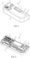
- FIG. 1is a perspective view of a drug delivery system according to one aspect of the present invention.
- FIG. 2is a perspective, cross-sectional view of the drug delivery system of FIG. 1 according to one aspect of the present invention.
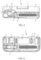
- FIG. 3is a front, cross-sectional view of the drug delivery system of FIG. 1 according to one aspect of the present invention.
- FIG. 4is a top view of the drug delivery system of FIG. 1 according to one aspect of the present invention, showing a top portion of the housing removed and the drug delivery system in a pre-use position.
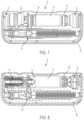
- FIG. 5is a top, cross-sectional view of the drug delivery system of FIG. 1 according to one aspect of the present invention, showing the drug delivery system in a pre-use position.
- FIG. 6is a front, cross-sectional view of the drug delivery system of FIG. 1 according to one aspect of the present invention, showing the drug delivery system in a pre-use position.
- FIG. 7is a top view of the drug delivery system of FIG. 1 according to one aspect of the present invention, showing a top portion of the housing removed and the drug delivery system in an initial actuation position.
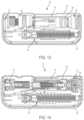
- FIG. 8is a top, cross-sectional view of the drug delivery system of FIG. 1 according to one aspect of the present invention, showing the drug delivery system in an initial actuation position.
- FIG. 9is a front, cross-sectional view of the drug delivery system of FIG. 1 according to one aspect of the present invention, showing the drug delivery system in an initial actuation position.
- FIG. 10is a top view of the drug delivery system of FIG. 1 according to one aspect of the present invention, showing a top portion of the housing removed and the drug delivery system in a use position.
- FIG. 11is a top, cross-sectional view of the drug delivery system of FIG. 1 according to one aspect of the present invention, showing the drug delivery system in a use position.
- FIG. 12is a front, cross-sectional view of the drug delivery system of FIG. 1 according to one aspect of the present invention, showing the drug delivery system in a use position.
- FIG. 13is a top view of the drug delivery system of FIG. 1 according to one aspect of the present invention, showing a top portion of the housing removed and the drug delivery system in a post-use position.
- FIG. 14is a top, cross-sectional view of the drug delivery system of FIG. 1 according to one aspect of the present invention, showing the drug delivery system in a post-use position.
- FIG. 15is a front, cross-sectional view of the drug delivery system of FIG. 1 according to one aspect of the present invention, showing the drug delivery system in a post-use position.
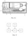
- FIG. 16is a top view of a drug delivery system including a sterilization arrangement according to another aspect of the present invention, showing a top portion of the housing removed.
- FIG. 17is a schematic illustration of the sterilization arrangement of the drug delivery system of FIG. 16 .
- a drug delivery system 10includes a drive assembly 12 , a container 14 , a valve assembly 16 , and a needle actuator assembly 18 .
- the drive assembly 12 , the container 14 , the valve assembly 16 , and the needle actuator assembly 18are at least partially positioned within a cavity defined by a housing 20 .
- the housing 20includes a top portion 22 and a bottom portion 24 , although other suitable arrangements for the housing 20 may be utilized.
- the drug delivery system 10is an injector device configured to be worn or secured to a user and to deliver a predetermined dose of a medicament provided within the container 14 via injection into the user.
- the system 10may be utilized to deliver a “bolus injection” where a medicament is delivered within a set time period.
- the medicamentmay be delivered over a time period of up to 45 minutes, although other suitable injection amounts and durations may be utilized.
- a bolus administration or deliverycan be carried out with rate controlling or have no specific rate controlling.
- the system 10may deliver the medicament at a fixed pressure to the user with the rate being variable. The general operation of the system 10 is described below in reference to FIGS. 1 - 15 .
- the system 10is configured to operate through the engagement of an actuation button 26 by a user, which results in a needle 28 of the needle assembly 18 piercing the skin of a user, the actuation of the drive assembly 12 to place the needle 28 in fluid communication with the container 14 and to expel fluid or medicament from the container 14 , and the withdrawal of the needle 28 after injection of the medicament is complete.
- actuation button 26by a user
- the actuation of the drive assembly 12to place the needle 28 in fluid communication with the container 14 and to expel fluid or medicament from the container 14
- withdrawal of the needle 28 after injection of the medicamentis complete.
- the housing 20 of the system 10includes an indicator window 30 for viewing an indicator arrangement 32 configured to provide an indication to a user on the status of the system 10 and a container window 31 for viewing the container 14 .
- the indicator window 30may be a magnifying lens for providing a clear view of the indicator arrangement 32 .
- the indicator arrangement 32moves along with the needle actuator assembly 18 during use of the system 10 to indicate a pre-use status, use status, and post-use status of the system 10 .
- the indicator arrangement 32provides visual indicia regarding the status, although other suitable indicia, such an auditory or tactile, may be provided as an alternative or additional indicia.
- the container 14is spaced from the drive assembly 12 and the valve assembly 16 and the needle 28 is in a retracted position.
- the drive assembly 12engages the container 14 to move the container 14 toward the valve assembly 16 , which is configured to pierce a closure 36 of the container 14 and place the medicament within the container 14 in fluid communication with the needle 28 via a tube (not shown) or other suitable arrangement.
- the drive assembly 12is configured to engage a stopper 34 of the container 14 , which will initially move the entire container 14 into engagement with the valve assembly 16 due to the incompressibility of the fluid or medicament within the container 14 .
- the initial actuation of the system 10is caused by engagement of the actuation button 26 by a user, which releases the needle actuator assembly 18 and the drive assembly 12 as discussed below in more detail.
- the needle 28is still in the retracted position and about to move to the extended position to inject the user of the system 10 .
- the needle 28is in the extended position at least partially outside of the housing 20 with the drive assembly 12 moving the stopper 34 within the container 14 to deliver the medicament from the container 14 , through the needle 28 , and to the user.
- the valve assembly 16has already pierced a closure 36 of the container 14 to place the container 14 in fluid communication with the needle 28 , which also allows the drive assembly 12 to move the stopper 34 relative to the container 14 since fluid is able to be dispensed from the container 14 .
- FIGS. 10At the post-use position of the system 10 , shown in FIGS.
- the needle 28is in the retracted position and engaged with a pad to seal the needle 28 and prevent any residual flow of fluid or medicament from the container 14 .
- the container 14 and valve assembly 16may be the container 14 and valve assembly 16 shown and described in International Publication No. WO 2015/081337, which is hereby incorporated by reference in its entirety.
- a sterilizeris also provided in the system 10 .
- the sterilizerincludes a light source 50 to sterilize the inner components of the system 10 .
- the light source 50provides ultraviolet (UV) light to the inner cavity of the housing 20 .
- the UV light provided by the light source 50is directed to the inner components of the system 10 to sterilize the inner components, such as the drive assembly 12 , the container 14 , the valve assembly 16 , and the needle actuator assembly 18 .
- the light source 50includes one or more light emitting diode (LED) lights.
- a single light source 50is provided in the housing 20 . It is also contemplated that a plurality of light sources 50 are provided in the housing 20 .
- the light source 50shines UV light on each component in the system 10 . In another aspect, the light source 50 shines UV light on a portion of the components in the system 10 . Any bacteria or contaminants growing or developing inside of the system 10 are sterilized by the UV light to provide a sterile environment inside the housing 20 . In one aspect, the light sources 50 are each positioned on a different inner side surface of the housing 20 .
- the light sources 50are connected to a power source 52 .
- the power source 52may be any arrangement capable of providing power to illuminate the light sources 50 .
- the power source 52may be provided within the housing 20 .
- the power source 52may be provided on the top portion 22 and/or the bottom portion 24 .
- the power source 52includes at least one battery.
- the power source 52may be provided as a power source external to the housing 20 .
- the power source 52may be a battery pack wired to the housing 20 , but provided external to the housing 20 .
- the power source 52may be replaceable and/or rechargeable.
- a plurality of batteriesare provided as the power source 52 to power the light sources 50 .
- the batteriesmay be charged by an external connector, such as a cord extending to an electrical outlet, or by an induction arrangement (not shown).
- a sensor 54is also provided in the housing 20 to actuate the light sources 50 upon initiation of the drug delivery actuation process.
- the sensor 54is configured to sense when the drug delivery actuation process has been initiated and sends a signal to the power source 52 to supply power from the power source 52 to the light sources 50 so that UV light is emitted by the light sources 50 to sterilize one or more components in the system 10 .
- the sensor 54is a Hall Effect transistor sensor that cooperates with a magnet 56 provided on or in a switch or button of the system 10 .
- the sensor 54is provided on the actuation button 26 of the system 10 .
- the senor 54could be provided on a switch or button (not shown) separate from the actuation button 26 so that the light source 50 could be activated independently of the drug delivery actuation process.
- the sensor 54sends a signal to activate the power source 52 to supply power to the light sources 50 . Therefore, as the system 10 proceeds through the drug delivery process, the light sources 50 sterilize the inner components of the system 10 .
- a timer 58is connected to the power source 52 so that, after a predetermined amount of time of activation, the light sources 50 will be turned off. The length of time that the light sources 50 are activated is adjustable by the timer 58 .
- a method of sterilizing a drug delivery system 10is described.
- the actuation button 26is depressed.
- the magnet 56 provided in the actuation button 26actuates the sensor 54 .
- the sensor 54sends a signal to the power source 52 to activate the power source 52 .
- the power source 52then supplies power to the light sources 50 to activate the LED lights within the light sources 50 .
- the LED lights of the light sources 50cast UV light over the inner components of the system 10 to sterilize the inner components.
- the UV lightis cast on at least one of the drive assembly 12 , the container 14 , the valve assembly 16 , and the needle actuator assembly 18 . It is also contemplated that the UV light may be cast on each of the drive assembly 12 , the container 14 , the valve assembly 16 , and the needle actuator assembly 18 .
- the timer 58shuts off the light sources 50 to stop the emittance of the UV light.
- a usercan recharge the power source 54 either internally or externally of the housing 20 .
Landscapes
- Health & Medical Sciences (AREA)
- Life Sciences & Earth Sciences (AREA)
- Veterinary Medicine (AREA)
- Public Health (AREA)
- General Health & Medical Sciences (AREA)
- Animal Behavior & Ethology (AREA)
- Biomedical Technology (AREA)
- Engineering & Computer Science (AREA)
- Hematology (AREA)
- Heart & Thoracic Surgery (AREA)
- Anesthesiology (AREA)
- Vascular Medicine (AREA)
- Epidemiology (AREA)
- Chemical & Material Sciences (AREA)
- Medicinal Chemistry (AREA)
- Molecular Biology (AREA)
- Dermatology (AREA)
- Infusion, Injection, And Reservoir Apparatuses (AREA)
- Apparatus For Disinfection Or Sterilisation (AREA)
Abstract
Description
Claims (20)
Priority Applications (3)
| Application Number | Priority Date | Filing Date | Title |
|---|---|---|---|
| US17/153,613US12115335B2 (en) | 2017-10-16 | 2021-01-20 | Sterilization arrangement for drug delivery device |
| US18/115,369US11878140B2 (en) | 2017-10-16 | 2023-02-28 | Sterilization arrangement for drug delivery device |
| US18/115,349US20230201447A1 (en) | 2017-10-16 | 2023-02-28 | Sterilization Arrangement for Drug Delivery Device |
Applications Claiming Priority (3)
| Application Number | Priority Date | Filing Date | Title |
|---|---|---|---|
| US201762572715P | 2017-10-16 | 2017-10-16 | |
| US16/160,114US10926023B2 (en) | 2017-10-16 | 2018-10-15 | Sterilization arrangement for drug delivery device |
| US17/153,613US12115335B2 (en) | 2017-10-16 | 2021-01-20 | Sterilization arrangement for drug delivery device |
Related Parent Applications (1)
| Application Number | Title | Priority Date | Filing Date |
|---|---|---|---|
| US16/160,114ContinuationUS10926023B2 (en) | 2017-10-16 | 2018-10-15 | Sterilization arrangement for drug delivery device |
Related Child Applications (2)
| Application Number | Title | Priority Date | Filing Date |
|---|---|---|---|
| US18/115,349ContinuationUS20230201447A1 (en) | 2017-10-16 | 2023-02-28 | Sterilization Arrangement for Drug Delivery Device |
| US18/115,369ContinuationUS11878140B2 (en) | 2017-10-16 | 2023-02-28 | Sterilization arrangement for drug delivery device |
Publications (2)
| Publication Number | Publication Date |
|---|---|
| US20210138147A1 US20210138147A1 (en) | 2021-05-13 |
| US12115335B2true US12115335B2 (en) | 2024-10-15 |
Family
ID=64051832
Family Applications (4)
| Application Number | Title | Priority Date | Filing Date |
|---|---|---|---|
| US16/160,114Active2039-02-28US10926023B2 (en) | 2017-10-16 | 2018-10-15 | Sterilization arrangement for drug delivery device |
| US17/153,613Active2039-07-03US12115335B2 (en) | 2017-10-16 | 2021-01-20 | Sterilization arrangement for drug delivery device |
| US18/115,369ActiveUS11878140B2 (en) | 2017-10-16 | 2023-02-28 | Sterilization arrangement for drug delivery device |
| US18/115,349PendingUS20230201447A1 (en) | 2017-10-16 | 2023-02-28 | Sterilization Arrangement for Drug Delivery Device |
Family Applications Before (1)
| Application Number | Title | Priority Date | Filing Date |
|---|---|---|---|
| US16/160,114Active2039-02-28US10926023B2 (en) | 2017-10-16 | 2018-10-15 | Sterilization arrangement for drug delivery device |
Family Applications After (2)
| Application Number | Title | Priority Date | Filing Date |
|---|---|---|---|
| US18/115,369ActiveUS11878140B2 (en) | 2017-10-16 | 2023-02-28 | Sterilization arrangement for drug delivery device |
| US18/115,349PendingUS20230201447A1 (en) | 2017-10-16 | 2023-02-28 | Sterilization Arrangement for Drug Delivery Device |
Country Status (8)
| Country | Link |
|---|---|
| US (4) | US10926023B2 (en) |
| EP (1) | EP3697467A1 (en) |
| JP (3) | JP6982174B2 (en) |
| CN (2) | CN111372625B (en) |
| AU (3) | AU2018352137B2 (en) |
| CA (2) | CA3079354C (en) |
| MX (1) | MX2020003785A (en) |
| WO (1) | WO2019079174A1 (en) |
Families Citing this family (14)
| Publication number | Priority date | Publication date | Assignee | Title |
|---|---|---|---|---|
| EP1762259B2 (en) | 2005-09-12 | 2025-01-01 | Unomedical A/S | Inserter for an infusion set with a first and second spring units |
| WO2012123274A1 (en) | 2011-03-14 | 2012-09-20 | Unomedical A/S | Inserter system with transport protection |
| IL295010B1 (en) | 2015-03-10 | 2025-06-01 | Regeneron Pharma | Pollution-free piercing system and method |
| CN119950880A (en) | 2017-05-05 | 2025-05-09 | 里珍纳龙药品有限公司 | Auto-injectors and related methods of use |
| US10869961B2 (en)* | 2017-11-06 | 2020-12-22 | Sorrel Medical Ltd. | Local disinfection for drug delivery system |
| US10869960B2 (en)* | 2017-11-06 | 2020-12-22 | Sorrel Medical Ltd | Local disinfection for prefilled drug delivery system |
| US11458292B2 (en) | 2019-05-20 | 2022-10-04 | Unomedical A/S | Rotatable infusion device and methods thereof |
| US20220355033A1 (en)* | 2019-06-21 | 2022-11-10 | Preci Health Sa | Medical injection system and method |
| EP3881875A1 (en)* | 2020-03-20 | 2021-09-22 | Littringer, Eva | Delivery device for delivering a drug |
| CN115671330A (en)* | 2021-07-30 | 2023-02-03 | 通用电气精准医疗有限责任公司 | Probe disinfection device, probe disinfection method and ultrasonic imaging system |
| USD1007676S1 (en) | 2021-11-16 | 2023-12-12 | Regeneron Pharmaceuticals, Inc. | Wearable autoinjector |
| EP4197572A1 (en)* | 2021-12-17 | 2023-06-21 | Becton, Dickinson and Company | Thermoelectric generator for powering autoinjector |
| JP2025507615A (en) | 2022-02-21 | 2025-03-21 | バイエル・ヘルスケア・エルエルシー | Systems, methods and devices for the delivery of therapeutic or diagnostic agents - Patents.com |
| CN115887824B (en)* | 2022-11-04 | 2025-08-19 | 中国人民解放军火箭军特色医学中心 | Wearing formula is from injection medical kit |
Citations (25)
| Publication number | Priority date | Publication date | Assignee | Title |
|---|---|---|---|---|
| WO1993002720A1 (en) | 1991-08-06 | 1993-02-18 | Senetek Plc | Medicament injector and method |
| US20010041869A1 (en)* | 2000-03-23 | 2001-11-15 | Causey James D. | Control tabs for infusion devices and methods of using the same |
| WO2004024211A2 (en) | 2002-09-12 | 2004-03-25 | Children's Hospital Medical Center | Method and device for painless injection of medication |
| US20050047975A1 (en) | 2003-08-26 | 2005-03-03 | Winsource Industries Limited | UV sterilisation air-flow chamber |
| WO2005018705A2 (en) | 2003-08-12 | 2005-03-03 | Becton, Dickinson And Company | Patch-like infusion device |
| US20100114026A1 (en)* | 2008-11-03 | 2010-05-06 | Calibra Medical, Inc. | Dosage sensing unit with tactile feedback |
| WO2010133698A2 (en) | 2009-05-22 | 2010-11-25 | Ann Marie Durkin | A sterilising apparatus |
| US20110125013A1 (en) | 2008-07-29 | 2011-05-26 | Neer Charles S | Ultraviolet Tubing and Tip Sterilizer |
| US20130066274A1 (en) | 2011-09-13 | 2013-03-14 | Unitract Syringe Pty Ltd | Sterile fluid pathway connection to drug containers for drug delivery pumps |
| WO2013155153A1 (en) | 2012-04-13 | 2013-10-17 | Becton, Dickinson And Company | Microinfuser with automatic needle retraction |
| US20130303996A1 (en)* | 2012-04-16 | 2013-11-14 | Puracath Medical, Inc. | System and method for disinfecting a catheter system |
| US20130317422A1 (en) | 2009-06-23 | 2013-11-28 | Djlm Innovations, Llc | Device for flow-through ultraviolet light decontamination of microbial contaminants |
| US20130323120A1 (en) | 2012-05-31 | 2013-12-05 | Becton, Dickinson And Company | Uv disinfection system for needleless connector |
| WO2014179774A1 (en) | 2013-05-03 | 2014-11-06 | Becton, Dickinson And Company | Drug delivery device |
| WO2015081337A2 (en) | 2013-12-01 | 2015-06-04 | Becton, Dickinson And Company | Medicament device |
| US20150352297A1 (en) | 2014-06-09 | 2015-12-10 | Dance Biopharm Inc. | Liquid drug cartridges and associated dispenser |
| US20160045633A1 (en)* | 2014-08-15 | 2016-02-18 | Lifeloc Technologies, Inc. | Systems and methods for surface decontamination |
| CN105999482A (en) | 2016-06-03 | 2016-10-12 | 曲建强 | Vaccination device |
| US20160367767A1 (en) | 2015-06-16 | 2016-12-22 | Kathryn Cashman | Inhalant device |
| WO2017093803A1 (en) | 2015-12-03 | 2017-06-08 | Unitract Syringe Pty Ltd | Systems and methods for controlled drug delivery pumps |
| US20170232185A1 (en) | 2016-02-17 | 2017-08-17 | Acist Medical Systems, Inc. | Sterilization of fluid paths in injection system |
| US20170290977A1 (en)* | 2014-09-15 | 2017-10-12 | Sanofi | Large volume skin patch medicament delivery device with integrated skin sterilization mechanism for the injection site |
| EP3348284A2 (en) | 2017-01-12 | 2018-07-18 | Tecpharma Licensing AG | A method for sterilization of a fluid path for an injection device |
| US20190022306A1 (en) | 2016-02-12 | 2019-01-24 | Amgen Inc. | Drug delivery device, method of manufacture, and method of use |
| US11040137B2 (en)* | 2017-05-19 | 2021-06-22 | Min Wei | Wearable drug delivery device |
Family Cites Families (9)
| Publication number | Priority date | Publication date | Assignee | Title |
|---|---|---|---|---|
| US7449012B2 (en)* | 2004-08-06 | 2008-11-11 | Meridian Medical Technologies, Inc. | Automatic injector |
| AU2006210865B2 (en)* | 2005-02-01 | 2008-12-04 | Kaleo, Inc. | Devices, systems, and methods for medicament delivery |
| US7834328B2 (en) | 2006-01-31 | 2010-11-16 | Redmond Russell J | Method and apparatus for sterilizing intraluminal and percutaneous access sites |
| WO2007126851A2 (en)* | 2006-03-29 | 2007-11-08 | Intelliject, Llc | Devices, systems and methods for medicament delivery |
| US9370621B2 (en)* | 2008-12-16 | 2016-06-21 | Medtronic Minimed, Inc. | Needle insertion systems and methods |
| CA2818974A1 (en) | 2010-11-29 | 2012-06-07 | Sanofi-Aventis Deutschland Gmbh | Infusion pump drug delivery system for delivering at least two medicaments |
| KR102082888B1 (en) | 2013-12-18 | 2020-02-28 | 마리아 패트리샤 코헨 | Uv sterilizing catheters and catheter connectors |
| CA2937327C (en)* | 2014-01-21 | 2018-02-27 | Parenteral Technologies, Llc | Force actuated injection device |
| CA2994803C (en)* | 2014-08-18 | 2023-09-12 | Windgap Medical, Inc. | Portable drug mixing and delivery device and associated methods |
- 2018
- 2018-10-15CACA3079354Apatent/CA3079354C/enactiveActive
- 2018-10-15USUS16/160,114patent/US10926023B2/enactiveActive
- 2018-10-15JPJP2020521552Apatent/JP6982174B2/enactiveActive
- 2018-10-15MXMX2020003785Apatent/MX2020003785A/enunknown
- 2018-10-15AUAU2018352137Apatent/AU2018352137B2/enactiveActive
- 2018-10-15WOPCT/US2018/055865patent/WO2019079174A1/ennot_activeCeased
- 2018-10-15EPEP18796332.7Apatent/EP3697467A1/enactivePending
- 2018-10-15CNCN201880075658.5Apatent/CN111372625B/enactiveActive
- 2018-10-15CACA3163187Apatent/CA3163187A1/enactivePending
- 2018-10-15CNCN202210371032.7Apatent/CN114712534B/enactiveActive
- 2021
- 2021-01-20USUS17/153,613patent/US12115335B2/enactiveActive
- 2021-05-18AUAU2021203196Apatent/AU2021203196B2/enactiveActive
- 2021-11-18JPJP2021187792Apatent/JP7217331B2/enactiveActive
- 2023
- 2023-01-23JPJP2023008140Apatent/JP7500790B2/enactiveActive
- 2023-02-17AUAU2023200940Apatent/AU2023200940B2/enactiveActive
- 2023-02-28USUS18/115,369patent/US11878140B2/enactiveActive
- 2023-02-28USUS18/115,349patent/US20230201447A1/enactivePending
Patent Citations (36)
| Publication number | Priority date | Publication date | Assignee | Title |
|---|---|---|---|---|
| US5360410A (en) | 1991-01-16 | 1994-11-01 | Senetek Plc | Safety syringe for mixing two-component medicaments |
| WO1993002720A1 (en) | 1991-08-06 | 1993-02-18 | Senetek Plc | Medicament injector and method |
| US20010041869A1 (en)* | 2000-03-23 | 2001-11-15 | Causey James D. | Control tabs for infusion devices and methods of using the same |
| US7637891B2 (en) | 2002-09-12 | 2009-12-29 | Children's Hospital Medical Center | Method and device for painless injection of medication |
| WO2004024211A2 (en) | 2002-09-12 | 2004-03-25 | Children's Hospital Medical Center | Method and device for painless injection of medication |
| WO2005018705A2 (en) | 2003-08-12 | 2005-03-03 | Becton, Dickinson And Company | Patch-like infusion device |
| US7857131B2 (en) | 2003-08-12 | 2010-12-28 | Becton, Dickinson And Company | Patch-like infusion device |
| US20050047975A1 (en) | 2003-08-26 | 2005-03-03 | Winsource Industries Limited | UV sterilisation air-flow chamber |
| US20110125013A1 (en) | 2008-07-29 | 2011-05-26 | Neer Charles S | Ultraviolet Tubing and Tip Sterilizer |
| US20100114026A1 (en)* | 2008-11-03 | 2010-05-06 | Calibra Medical, Inc. | Dosage sensing unit with tactile feedback |
| WO2010133698A2 (en) | 2009-05-22 | 2010-11-25 | Ann Marie Durkin | A sterilising apparatus |
| US20120068088A1 (en) | 2009-05-22 | 2012-03-22 | Shasta Limited | Sterilising Apparatus |
| US20130317422A1 (en) | 2009-06-23 | 2013-11-28 | Djlm Innovations, Llc | Device for flow-through ultraviolet light decontamination of microbial contaminants |
| US20130066274A1 (en) | 2011-09-13 | 2013-03-14 | Unitract Syringe Pty Ltd | Sterile fluid pathway connection to drug containers for drug delivery pumps |
| US20150080800A1 (en) | 2012-04-13 | 2015-03-19 | Becton, Dickinson And Company | Microinfuser with Automatic Needle Retraction |
| WO2013155153A1 (en) | 2012-04-13 | 2013-10-17 | Becton, Dickinson And Company | Microinfuser with automatic needle retraction |
| US20130303996A1 (en)* | 2012-04-16 | 2013-11-14 | Puracath Medical, Inc. | System and method for disinfecting a catheter system |
| US20130323120A1 (en) | 2012-05-31 | 2013-12-05 | Becton, Dickinson And Company | Uv disinfection system for needleless connector |
| US20160058941A1 (en) | 2013-05-03 | 2016-03-03 | Becton Dickinson And Company | Drug delivery device |
| WO2014179774A1 (en) | 2013-05-03 | 2014-11-06 | Becton, Dickinson And Company | Drug delivery device |
| JP2017500996A (en) | 2013-12-01 | 2017-01-12 | ベクトン・ディキンソン・アンド・カンパニーBecton, Dickinson And Company | Drug device |
| US20170028132A1 (en)* | 2013-12-01 | 2017-02-02 | Becton, Dickinson And Company | Medicament Device |
| WO2015081337A2 (en) | 2013-12-01 | 2015-06-04 | Becton, Dickinson And Company | Medicament device |
| US20150352301A1 (en)* | 2014-06-09 | 2015-12-10 | Dance Biopharm Inc. | Self-puncturing liquid drug cartridges and associated dispenser |
| WO2015191478A1 (en) | 2014-06-09 | 2015-12-17 | Dance Biopharm Inc. | Liquid drug cartridges and associated dispenser |
| US20150352297A1 (en) | 2014-06-09 | 2015-12-10 | Dance Biopharm Inc. | Liquid drug cartridges and associated dispenser |
| US20160045633A1 (en)* | 2014-08-15 | 2016-02-18 | Lifeloc Technologies, Inc. | Systems and methods for surface decontamination |
| US20170290977A1 (en)* | 2014-09-15 | 2017-10-12 | Sanofi | Large volume skin patch medicament delivery device with integrated skin sterilization mechanism for the injection site |
| US20160367767A1 (en) | 2015-06-16 | 2016-12-22 | Kathryn Cashman | Inhalant device |
| WO2017093803A1 (en) | 2015-12-03 | 2017-06-08 | Unitract Syringe Pty Ltd | Systems and methods for controlled drug delivery pumps |
| US20190022306A1 (en) | 2016-02-12 | 2019-01-24 | Amgen Inc. | Drug delivery device, method of manufacture, and method of use |
| US20170232185A1 (en) | 2016-02-17 | 2017-08-17 | Acist Medical Systems, Inc. | Sterilization of fluid paths in injection system |
| WO2017142808A1 (en) | 2016-02-17 | 2017-08-24 | Acist Medical Systems, Inc. | Sterilization of fluid paths in injection system |
| CN105999482A (en) | 2016-06-03 | 2016-10-12 | 曲建强 | Vaccination device |
| EP3348284A2 (en) | 2017-01-12 | 2018-07-18 | Tecpharma Licensing AG | A method for sterilization of a fluid path for an injection device |
| US11040137B2 (en)* | 2017-05-19 | 2021-06-22 | Min Wei | Wearable drug delivery device |
Also Published As
| Publication number | Publication date |
|---|---|
| BR112020007283A2 (en) | 2020-11-03 |
| MX2020003785A (en) | 2020-08-03 |
| US20210138147A1 (en) | 2021-05-13 |
| AU2021203196B2 (en) | 2022-11-17 |
| JP2022010393A (en) | 2022-01-14 |
| WO2019079174A1 (en) | 2019-04-25 |
| JP2023041764A (en) | 2023-03-24 |
| CA3163187A1 (en) | 2019-04-25 |
| AU2018352137B2 (en) | 2021-02-18 |
| AU2021203196A1 (en) | 2021-06-10 |
| CA3079354C (en) | 2022-08-30 |
| AU2023200940B2 (en) | 2024-11-14 |
| CA3079354A1 (en) | 2019-04-25 |
| US20230201448A1 (en) | 2023-06-29 |
| JP7500790B2 (en) | 2024-06-17 |
| CN114712534A (en) | 2022-07-08 |
| JP2020536699A (en) | 2020-12-17 |
| US11878140B2 (en) | 2024-01-23 |
| JP6982174B2 (en) | 2021-12-17 |
| CN111372625A (en) | 2020-07-03 |
| US10926023B2 (en) | 2021-02-23 |
| US20190111202A1 (en) | 2019-04-18 |
| AU2023200940A1 (en) | 2023-03-23 |
| AU2018352137A1 (en) | 2020-05-07 |
| CN111372625B (en) | 2022-04-29 |
| US20230201447A1 (en) | 2023-06-29 |
| JP7217331B2 (en) | 2023-02-02 |
| EP3697467A1 (en) | 2020-08-26 |
| CN114712534B (en) | 2024-09-10 |
Similar Documents
| Publication | Publication Date | Title |
|---|---|---|
| US12115335B2 (en) | Sterilization arrangement for drug delivery device | |
| CN109843353A (en) | For connecting drug delivery device and method using relevant fluid flow path | |
| US20230338645A1 (en) | Time Delay Mechanism for a Hydraulic Drug Delivery Device | |
| US11554211B2 (en) | Connector for aseptic transfer of fluid | |
| US20240366883A1 (en) | Needle Shield Remover Assembly for Wearable Injector | |
| MX2020007000A (en) | Port interface for drug delivery device. | |
| BR112020007283B1 (en) | DRUG DELIVERY SYSTEM FOR INJECTING A MEDICATION | |
| US20230414877A1 (en) | Drug Delivery Device with Adhesive Assembly | |
| US20250032729A1 (en) | Alarm Indicator for Drug Delivery Device | |
| US20240342391A1 (en) | Needle Shield Remover with Cam Release | |
| CA3190882A1 (en) | Fluid transfer system for drug delivery device | |
| WO2020243434A1 (en) | Cartridge adapter for drug delivery device |
Legal Events
| Date | Code | Title | Description |
|---|---|---|---|
| AS | Assignment | Owner name:BECTON, DICKINSON AND COMPANY, NEW JERSEY Free format text:ASSIGNMENT OF ASSIGNORS INTEREST;ASSIGNOR:FALKOVICH, MARGARITA;REEL/FRAME:054971/0270 Effective date:20200603 | |
| FEPP | Fee payment procedure | Free format text:ENTITY STATUS SET TO UNDISCOUNTED (ORIGINAL EVENT CODE: BIG.); ENTITY STATUS OF PATENT OWNER: LARGE ENTITY | |
| STPP | Information on status: patent application and granting procedure in general | Free format text:APPLICATION DISPATCHED FROM PREEXAM, NOT YET DOCKETED | |
| STPP | Information on status: patent application and granting procedure in general | Free format text:DOCKETED NEW CASE - READY FOR EXAMINATION | |
| STPP | Information on status: patent application and granting procedure in general | Free format text:NON FINAL ACTION MAILED | |
| STPP | Information on status: patent application and granting procedure in general | Free format text:NON FINAL ACTION MAILED | |
| STPP | Information on status: patent application and granting procedure in general | Free format text:RESPONSE TO NON-FINAL OFFICE ACTION ENTERED AND FORWARDED TO EXAMINER | |
| STPP | Information on status: patent application and granting procedure in general | Free format text:FINAL REJECTION MAILED | |
| STPP | Information on status: patent application and granting procedure in general | Free format text:DOCKETED NEW CASE - READY FOR EXAMINATION | |
| STPP | Information on status: patent application and granting procedure in general | Free format text:NON FINAL ACTION MAILED | |
| STPP | Information on status: patent application and granting procedure in general | Free format text:RESPONSE TO NON-FINAL OFFICE ACTION ENTERED AND FORWARDED TO EXAMINER | |
| STPP | Information on status: patent application and granting procedure in general | Free format text:NOTICE OF ALLOWANCE MAILED -- APPLICATION RECEIVED IN OFFICE OF PUBLICATIONS | |
| ZAAB | Notice of allowance mailed | Free format text:ORIGINAL CODE: MN/=. | |
| STPP | Information on status: patent application and granting procedure in general | Free format text:PUBLICATIONS -- ISSUE FEE PAYMENT VERIFIED | |
| STCF | Information on status: patent grant | Free format text:PATENTED CASE |