US12115332B2 - Methods and systems for encapsulation devices for housing cells and agents - Google Patents
Methods and systems for encapsulation devices for housing cells and agentsDownload PDFInfo
- Publication number
- US12115332B2 US12115332B2US17/516,179US202117516179AUS12115332B2US 12115332 B2US12115332 B2US 12115332B2US 202117516179 AUS202117516179 AUS 202117516179AUS 12115332 B2US12115332 B2US 12115332B2
- Authority
- US
- United States
- Prior art keywords
- void
- channel
- membrane
- encapsulation device
- vascularization
- Prior art date
- Legal status (The legal status is an assumption and is not a legal conclusion. Google has not performed a legal analysis and makes no representation as to the accuracy of the status listed.)
- Active, expires
Links
Images


Classifications
- A—HUMAN NECESSITIES
- A61—MEDICAL OR VETERINARY SCIENCE; HYGIENE
- A61M—DEVICES FOR INTRODUCING MEDIA INTO, OR ONTO, THE BODY; DEVICES FOR TRANSDUCING BODY MEDIA OR FOR TAKING MEDIA FROM THE BODY; DEVICES FOR PRODUCING OR ENDING SLEEP OR STUPOR
- A61M37/00—Other apparatus for introducing media into the body; Percutany, i.e. introducing medicines into the body by diffusion through the skin
- A61M37/0069—Devices for implanting pellets, e.g. markers or solid medicaments
- A—HUMAN NECESSITIES
- A61—MEDICAL OR VETERINARY SCIENCE; HYGIENE
- A61F—FILTERS IMPLANTABLE INTO BLOOD VESSELS; PROSTHESES; DEVICES PROVIDING PATENCY TO, OR PREVENTING COLLAPSING OF, TUBULAR STRUCTURES OF THE BODY, e.g. STENTS; ORTHOPAEDIC, NURSING OR CONTRACEPTIVE DEVICES; FOMENTATION; TREATMENT OR PROTECTION OF EYES OR EARS; BANDAGES, DRESSINGS OR ABSORBENT PADS; FIRST-AID KITS
- A61F2/00—Filters implantable into blood vessels; Prostheses, i.e. artificial substitutes or replacements for parts of the body; Appliances for connecting them with the body; Devices providing patency to, or preventing collapsing of, tubular structures of the body, e.g. stents
- A61F2/02—Prostheses implantable into the body
- A61F2/022—Artificial gland structures using bioreactors
- A—HUMAN NECESSITIES
- A61—MEDICAL OR VETERINARY SCIENCE; HYGIENE
- A61L—METHODS OR APPARATUS FOR STERILISING MATERIALS OR OBJECTS IN GENERAL; DISINFECTION, STERILISATION OR DEODORISATION OF AIR; CHEMICAL ASPECTS OF BANDAGES, DRESSINGS, ABSORBENT PADS OR SURGICAL ARTICLES; MATERIALS FOR BANDAGES, DRESSINGS, ABSORBENT PADS OR SURGICAL ARTICLES
- A61L27/00—Materials for grafts or prostheses or for coating grafts or prostheses
- A61L27/14—Macromolecular materials
- A—HUMAN NECESSITIES
- A61—MEDICAL OR VETERINARY SCIENCE; HYGIENE
- A61L—METHODS OR APPARATUS FOR STERILISING MATERIALS OR OBJECTS IN GENERAL; DISINFECTION, STERILISATION OR DEODORISATION OF AIR; CHEMICAL ASPECTS OF BANDAGES, DRESSINGS, ABSORBENT PADS OR SURGICAL ARTICLES; MATERIALS FOR BANDAGES, DRESSINGS, ABSORBENT PADS OR SURGICAL ARTICLES
- A61L27/00—Materials for grafts or prostheses or for coating grafts or prostheses
- A61L27/36—Materials for grafts or prostheses or for coating grafts or prostheses containing ingredients of undetermined constitution or reaction products thereof, e.g. transplant tissue, natural bone, extracellular matrix
- A61L27/38—Materials for grafts or prostheses or for coating grafts or prostheses containing ingredients of undetermined constitution or reaction products thereof, e.g. transplant tissue, natural bone, extracellular matrix containing added animal cells
- A61L27/3804—Materials for grafts or prostheses or for coating grafts or prostheses containing ingredients of undetermined constitution or reaction products thereof, e.g. transplant tissue, natural bone, extracellular matrix containing added animal cells characterised by specific cells or progenitors thereof, e.g. fibroblasts, connective tissue cells, kidney cells
- A61L27/3834—Cells able to produce different cell types, e.g. hematopoietic stem cells, mesenchymal stem cells, marrow stromal cells, embryonic stem cells
- A—HUMAN NECESSITIES
- A61—MEDICAL OR VETERINARY SCIENCE; HYGIENE
- A61L—METHODS OR APPARATUS FOR STERILISING MATERIALS OR OBJECTS IN GENERAL; DISINFECTION, STERILISATION OR DEODORISATION OF AIR; CHEMICAL ASPECTS OF BANDAGES, DRESSINGS, ABSORBENT PADS OR SURGICAL ARTICLES; MATERIALS FOR BANDAGES, DRESSINGS, ABSORBENT PADS OR SURGICAL ARTICLES
- A61L27/00—Materials for grafts or prostheses or for coating grafts or prostheses
- A61L27/50—Materials characterised by their function or physical properties, e.g. injectable or lubricating compositions, shape-memory materials, surface modified materials
- A61L27/52—Hydrogels or hydrocolloids
- A—HUMAN NECESSITIES
- A61—MEDICAL OR VETERINARY SCIENCE; HYGIENE
- A61L—METHODS OR APPARATUS FOR STERILISING MATERIALS OR OBJECTS IN GENERAL; DISINFECTION, STERILISATION OR DEODORISATION OF AIR; CHEMICAL ASPECTS OF BANDAGES, DRESSINGS, ABSORBENT PADS OR SURGICAL ARTICLES; MATERIALS FOR BANDAGES, DRESSINGS, ABSORBENT PADS OR SURGICAL ARTICLES
- A61L27/00—Materials for grafts or prostheses or for coating grafts or prostheses
- A61L27/50—Materials characterised by their function or physical properties, e.g. injectable or lubricating compositions, shape-memory materials, surface modified materials
- A61L27/54—Biologically active materials, e.g. therapeutic substances
- A—HUMAN NECESSITIES
- A61—MEDICAL OR VETERINARY SCIENCE; HYGIENE
- A61M—DEVICES FOR INTRODUCING MEDIA INTO, OR ONTO, THE BODY; DEVICES FOR TRANSDUCING BODY MEDIA OR FOR TAKING MEDIA FROM THE BODY; DEVICES FOR PRODUCING OR ENDING SLEEP OR STUPOR
- A61M37/00—Other apparatus for introducing media into the body; Percutany, i.e. introducing medicines into the body by diffusion through the skin
- A—HUMAN NECESSITIES
- A61—MEDICAL OR VETERINARY SCIENCE; HYGIENE
- A61L—METHODS OR APPARATUS FOR STERILISING MATERIALS OR OBJECTS IN GENERAL; DISINFECTION, STERILISATION OR DEODORISATION OF AIR; CHEMICAL ASPECTS OF BANDAGES, DRESSINGS, ABSORBENT PADS OR SURGICAL ARTICLES; MATERIALS FOR BANDAGES, DRESSINGS, ABSORBENT PADS OR SURGICAL ARTICLES
- A61L2300/00—Biologically active materials used in bandages, wound dressings, absorbent pads or medical devices
- A61L2300/20—Biologically active materials used in bandages, wound dressings, absorbent pads or medical devices containing or releasing organic materials
- A61L2300/252—Polypeptides, proteins, e.g. glycoproteins, lipoproteins, cytokines
- A—HUMAN NECESSITIES
- A61—MEDICAL OR VETERINARY SCIENCE; HYGIENE
- A61L—METHODS OR APPARATUS FOR STERILISING MATERIALS OR OBJECTS IN GENERAL; DISINFECTION, STERILISATION OR DEODORISATION OF AIR; CHEMICAL ASPECTS OF BANDAGES, DRESSINGS, ABSORBENT PADS OR SURGICAL ARTICLES; MATERIALS FOR BANDAGES, DRESSINGS, ABSORBENT PADS OR SURGICAL ARTICLES
- A61L2300/00—Biologically active materials used in bandages, wound dressings, absorbent pads or medical devices
- A61L2300/60—Biologically active materials used in bandages, wound dressings, absorbent pads or medical devices characterised by a special physical form
- A61L2300/62—Encapsulated active agents, e.g. emulsified droplets
- A—HUMAN NECESSITIES
- A61—MEDICAL OR VETERINARY SCIENCE; HYGIENE
- A61M—DEVICES FOR INTRODUCING MEDIA INTO, OR ONTO, THE BODY; DEVICES FOR TRANSDUCING BODY MEDIA OR FOR TAKING MEDIA FROM THE BODY; DEVICES FOR PRODUCING OR ENDING SLEEP OR STUPOR
- A61M2202/00—Special media to be introduced, removed or treated
- A61M2202/03—Gases in liquid phase, e.g. cryogenic liquids
- A—HUMAN NECESSITIES
- A61—MEDICAL OR VETERINARY SCIENCE; HYGIENE
- A61M—DEVICES FOR INTRODUCING MEDIA INTO, OR ONTO, THE BODY; DEVICES FOR TRANSDUCING BODY MEDIA OR FOR TAKING MEDIA FROM THE BODY; DEVICES FOR PRODUCING OR ENDING SLEEP OR STUPOR
- A61M2205/00—General characteristics of the apparatus
- A61M2205/04—General characteristics of the apparatus implanted
Definitions
- Embodiments of the present disclosurerelate to implantable medical devices.
- implantable encapsulation devicesare provided that are operable to house cells, tissue, and/or therapeutic agents and deliver therapeutic effects to a host or recipient of the device.
- pancreas transplantation and islet transplantationare known methods for treating diabetes.
- pancreas and islet transplantation into diabetic patientsis limited to a small percent of patients who might benefit from either procedure due to the lack of available human pancreata or pancreatic islets.
- insulin secreting cells derived from human stem cellsthere is a possibility of treating patients with insulin dependent diabetes through transplantation.
- insulin secreting cellscould be provided with an immuno-isolating implantable device and placed in the diabetic patient to act as an insulin delivery source.
- islet transplantation protocolSince the islet transplantation protocol was established, clinical islet transplantation has been regarded as a treatment method for treating type 1 diabetics. However, the low engraftment success of transplanted islet cells remains a major cause of failure of long-term blood sugar regulation. Upon implantation, it is necessary for islet cells to be successfully engrafted through revascularization and blood flow regulation within a few days after transplantation. However, transplanted islet cells are exposed to a state with low vascular density and insufficient oxygen conditions, making it difficult to achieve normal engraftment of islet cells and the ability to achieve regulated insulin secretion in the patient.
- Embodiments of the present disclosureprovide encapsulation devices having a matrix or scaffold for supporting cells.
- methods of preparing and forming an encapsulation device with a matrixare provided.
- Donor islet cellse.g. from a cadaver
- cells derived from differentiation of stem cellsfor example
- embodiments of the present disclosurecontemplate and provide one or more matrix structures within a void or cell-receiving area of the device.
- Matrices of the present disclosureprovide a structural means of stabilizing and aggregating cells.
- PCT/US2017/060036 to Papasrelate to encapsulation devices and are each incorporated by reference in their entireties herein for all purposes.
- PCT/US2017/060034 to Papasrelate to encapsulation devices and are each incorporated by reference in their entireties herein for all purposes.
- PCT/US2017/060041 to Papasrelate to encapsulation devices and are each incorporated by reference in their entireties herein for all purposes.
- membranes of the present disclosureinclude various materials, including those deemed appropriate by a person skilled in the art for an implantable medical device.
- membranes of the present disclosureare contemplated as being prepared from a polymeric material.
- the single layer gradient membraneis prepared from such polymeric materials as: polysulfone, polyarylethersulfone (PAES), polyethersulfone (PES), cellulose ester (cellulose acetate, cellulose triacetate, cellulose nitrate), nanocellulose, regenerated cellulose (RC), silicone, polyamide (nylon), polyimide, polyamide imide, polyamide urea, polycarbonate, ceramic, titanium oxide, aluminum oxide, silicon, zeolite (alumosilicate), polyarylonitrile (PAN), polyethylene (PE), low density polyethylene (LDPE), polypropylene (PP), polytetrafluoroethylene (PTFE), polyvinylidene fluoride (PVDF), polyvinylchloride (PVC), polypiperazine amide
- a single layer gradient membraneincludes a polymeric material including polytetrafluoroethylene (PTFE).
- PTFEis provided for at least a vascularizing layer of devices of the present disclosure. Additional materials are contemplated as being provided in membranes and implants of the present disclosure in addition to or in lieu of PTFE.
- the advantages of the presently disclosed immune-isolation implantable devicesinclude a maximization of surface area presented by the device available for vascularization by a host.
- implantable devices or portions thereof that include an immuno-isolation devicepresent a surface area that may be vascularized by the host when implanted. This structure maximizes vascularization of the device as a whole in the animal.
- a method for filling an implantable encapsulation deviceincluding an internal void for encapsulation of cells, a channel adjacent a first side of the void and separated from the void by a fluid permeable membrane, and a vascularization membrane on a second side of the void is provided.
- the methodincludes introducing a composition including cells and a matrix-forming material into the void; introducing a cross-linking agent into the channel, whereby the cross-linking agent passes the fluid permeable membrane to cross-link the matrix-forming material near the fluid permeable membrane; introducing a quenching agent into the channel, whereby the quenching agent passes the fluid permeable membrane to reduce cross-linking of the matrix-forming material, whereby the void includes a matrix gradient having higher cross-linking near the fluid permeable membrane and lower cross-linking density near the vascularization membrane.
- an implantable encapsulation devicein one embodiment, includes a first void for receiving and encapsulating cells, wherein the first void has a first side; a channel adjacent the first side of the first void and separated from the first void by a gas permeable membrane; wherein the channel occupies a portion of the first side of the first void that is less than all of the first side of the first void; and wherein the portion of the first side of the first void not occupied by the channel includes a vascularization membrane.
- cryopreservation solution(s)are applied to the device in a flow-through manner in which solution is continuously applied through the device and/or solution is delivered through an opening and allowed to remain static while cooling occurs. Additionally, methods and systems of the present disclosure further contemplate the provision of applying cryopreservation solution(s) to an exterior of an encapsulation device in lieu of or in addition to the application of solution(s) to the gas chamber.
- the cryopreservation solutionincludes dimethyl sulfoxide.
- the solution(s)are contemplated as including various different concentrations of dimethyl sulfoxide and, in various embodiments, include dimethyl sulfoxide provided with or diluted in additional fluid.
- Embodiments of the present disclosurefurther contemplate delivering a fluid (gas or liquid) to increase thermal energy within the device and/or cells.
- a fluidgas or liquid
- gase.g. ambient air
- liquidis provided in or through a gas chamber of an encapsulation device to thaw or otherwise increase a temperature of the device and housed cells.
- the present disclosureis not limited to methods of freezing or cooling devices and cells.
- encapsulation devicesare provided with a cell matrix for housing, supporting, and promoting proper functioning of cells.
- a matrix-forming materialsuch as alginate
- a flow channel or internal conduitto form a matrix with a greater density proximal to the gas chamber and a decreasing density (at least in terms of cross-linking) at distances farther away from the channel and membrane between the channel and the matrix.
- Such embodimentsallow for solution(s) to be provided to the device through the flow channel or chamber while reducing risk that the solution(s) will block or clog the membranes and prevent gas delivery (for example) into the matrix.
- Various embodiments of the present disclosurecontemplate the provision of a flow channel and the use of that channel for multiple purposes.
- systems and methods of the present disclosurecontemplate applying and conveying a cryopreservation solution to or through the channel to freeze the device and housed cells.
- the channel(s) of such devicesmust later be available for receiving fluid (e.g. oxygen-carrying gas) to deliver necessary materials to the cells as shown and described herein in various embodiments.
- processes related to cryopreservation and the application of cryopreservation solution(s)preferably avoid clogging or obstructing the channel, the membrane, and the matrix.
- methods of the present disclosureinclude treating or washing encapsulation subsequent to cryopreservation or thawing steps.
- sodium chlorideis applied to the exterior surfaces and/or inner channel of a device to wash or treat the device and remove any dimethyl sulfoxide (or other materials) that may be present on the device and which may have undesirable impacts on the cells if not removed or remedied.
- matrix formationis provided wherein calcium chloride is provided within a flow channel of an encapsulation device and sodium chloride is provided or injected into the cell chamber of the device to form a matrix with a desired gradient or density distribution.
- a gradientis formed by the interaction between calcium chloride and sodium chloride, and wherein the matrix includes a greater density proximal to the channel.
- a methodfor filling an implantable encapsulation device including an internal void for encapsulation of cells, a channel adjacent a first side of the void and separated from the void by fluid permeable membrane, and a vascularization membrane on a second side of the void.
- the methodincludes introducing a composition including cells and a matrix-forming material into the void and introducing a cross-linking agent into the channel, whereby the cross-linking agent passes the fluid permeable membrane to cross-link the matrix-forming material near the fluid permeable membrane.
- a quenching agentis introduced at least one of into the channel or to surround the chamber, whereby the quenching agent passes the fluid permeable membrane to reduce cross-linking of the matrix-forming material, whereby the void includes a matrix gradient having higher cross-linking near the fluid permeable membrane and lower cross-linking density near the vascularization membrane.
- an implantable encapsulation devicein one embodiment, includes a first void for receiving and encapsulating cells.
- the first voidhas a first side and a channel adjacent the first side of the first void and separated from the first void by a gas permeable membrane.
- the channeloccupies a portion of the first side of the first void that is less than all of the first side of the first void.
- the portion of the first side of the first void not occupied by the channelincludes a vascularization membrane.
- a method for preparing an implantable encapsulation devicewherein the device includes first and second chambers for encapsulation of cells; a channel adjacent first exterior surfaces of the first and second chambers and separated from interiors of the chambers by at least one fluid permeable membrane; and wherein the first and second chambers have second exterior surfaces.
- the methodincludes introducing a composition including cells into the interiors of the chambers, delivering a fluid into the channel to increase or decrease a temperature of the cells, and delivering a fluid across the second exterior surfaces of the first and second chambers to increase or decrease a temperature of the cells.
- cryopreservation and fluid delivery conceptsmay be provided with the device of FIG. 5 even if not specially shown and described.
- FIG. 1is a cross-section of an encapsulation device with at least one port according to embodiments of the present disclosure.
- FIG. 2is a cross-sectional view of an encapsulation device according to embodiments of the present disclosure.
- FIG. 3is an elevation view of an encapsulation device according to embodiments of the present disclosure.
- FIG. 4is a cross-sectional elevation view of a portion of an encapsulation device according to embodiments of the present disclosure.
- FIG. 5is a cross-sectional elevation view of a portion of an encapsulation device according to embodiments of the present disclosure.
- FIG. 6is a cross-sectional elevation view of a portion of an encapsulation device according to embodiments of the present disclosure.
- FIG. 7is an elevation view of an implantable encapsulation device according to embodiments of the present disclosure.
- FIG. 8is a cross-sectional elevation view of an implantable encapsulation device according to embodiments of the present disclosure.
- FIG. 9is a cross-sectional elevation view of an implantable encapsulation device according to embodiments of the present disclosure.
- FIG. 10is a cross-sectional elevation view of an implantable encapsulation device according to embodiments of the present disclosure.
- FIG. 11is a cross-sectional elevation view of an implantable encapsulation device according to embodiments of the present disclosure.
- FIG. 12is a cross-sectional elevation view of an implantable encapsulation device according to embodiments of the present disclosure.
- FIG. 13is a cross-sectional elevation view of an implantable encapsulation device and related methods according to embodiments of the present disclosure.
- FIG. 14is a cross-sectional elevation view of an implantable encapsulation device and related methods according to embodiments of the present disclosure.
- FIG. 15is a cross-sectional elevation view of an implantable encapsulation device and related methods according to embodiments of the present disclosure.
- FIG. 16is a cross-sectional elevation view of an implantable encapsulation device and related methods according to embodiments of the present disclosure.
- FIG. 18is a perspective view of portions of an implantable encapsulation device and related methods according to embodiments of the present disclosure.
- FIG. 20is a cross-section elevation view of an implantable encapsulation device and related methods according to embodiments of the present disclosure.
- FIG. 21is a top plan view of an implantable encapsulation device and related methods according to embodiments of the present disclosure.
- FIG. 22is a cross-sectional elevation view of an implantable encapsulation device and related methods according to embodiments of the present disclosure.
- FIG. 24is a transparent top plan view of an implantable encapsulation device and related methods according to embodiments of the present disclosure.
- FIG. 26is an exploded top plan view of an implantable encapsulation device and related methods according to embodiments of the present disclosure.
- FIG. 28is a cross-section top plan view of an implantable encapsulation device and related methods according to embodiments of the present disclosure.
- FIG. 29is a cross-sectional elevation view of an implantable encapsulation device and related methods according to embodiments of the present disclosure.
- FIG. 31is a cross-sectional top plan view of an implantable encapsulation device and related methods according to embodiments of the present disclosure.
- FIG. 32is a cross-sectional top plan view of portions of an implantable encapsulation device and related methods according to embodiments of the present disclosure.
- FIG. 34is a transparent top plan view of portions of an implantable encapsulation device and related methods according to embodiments of the present disclosure.
- “about”means within a statistically meaningful range of a value or values such as a stated concentration, length, molecular weight, pH, sequence identity, time frame, temperature or volume. Such a value or range can be within an order of magnitude, typically within 20%, more typically within 10%, and even more typically within 5% of a given value or range. The allowable variation encompassed by “about” will depend upon the particular system under study, and can be readily appreciated by one of skill in the art.
- FIG. 1is a cross-sectional elevation view of an encapsulation device 2 according to embodiments of the present disclosure.
- the device 2includes an internal volume or void 4 that is operable to receive and house cells 6 or tissue.
- the device 2further includes at least one membrane 8 .
- the at least one membrane 8includes a vascularization membrane that is impermeable to cells.
- an immunoisolation membrane 10is also provided. Non-cell factors or molecules 12 may escape or pass through the membrane(s) 8 , 10 , while cells 6 are contained.
- At least one port 14is provided, and the port allows for access to the internal volume 4 of the device. The port 14 may be utilized to load cells and tissue into the device, for example.
- the entire device 2is operable to be implanted into a patient (e.g. a human patient).
- the device 2is preferably sized and operable to be subcutaneously inserted into a patient, where a device function including, but not limited to, the egress or leaching of non-cell factors 12 provides therapeutic effects to the patient.
- a device functionincluding, but not limited to, the egress or leaching of non-cell factors 12 provides therapeutic effects to the patient.
- Various embodiments of the present disclosureprovide encapsulation devices having a vascularization membrane and an immunoisolation membrane. Certain embodiments provide encapsulation devices having only a vascularization membrane to allow blood vessels to grow into tissue.
- FIG. 2is a cross-sectional elevation view of an encapsulation device 16 according to embodiments of the present disclosure.
- two internal voids or chambers 18 a , 18 b housing cells 6are shown.
- the voidsmay be accessed for the introduction of cells through ports (not shown).
- a fluid channel 20for introduction of a fluid, either gas or liquid, as described further below.
- oxygenmay be introduced into channel 20 for maintaining the cells in a viable and functional state. For example, oxygen may improve the viability of the cells, while also promoting functionality of the cells including, but not limited to, insulin secretion.
- Other uses and configurations of channel 20are provided herein.
- Channel 20may be accessed for the introduction of fluids through ports (not shown). Between channel 20 and voids 18 a , 18 b is a membrane 22 a , 22 b through which fluids in channel 20 may pass into voids 18 a , 18 b .
- the membrane 22 a , 22 bmay be a fluid-permeable membrane.
- the membranes 22 a , 22 bare constructed from materials such as polytetraflouroethylene (PTFE) or other similar material (e.g., as described throughout the present disclosure).
- the encapsulation device 16further may further include layers 24 a , 24 b , each of which may include an immunoisolation membrane and a vascularization membrane, the functions of which are described elsewhere herein.
- Devices of the present disclosureincluding those shown in FIG. 2 , are contemplated as including a mesh or other structural support element(s) surrounding all or part of the encapsulation device 16 .
- cellsare provided within an encapsulation device and the cells include a diameter of between approximately 5-15 micrometers ( ⁇ m).
- devicesinclude spheroids or aggregates of cells including dimensions of between approximately 50 and 500 microns.
- vascularization membranesare provided with pore sizes of about 5-10 ⁇ m, and the immunoisolation membrane includes pore sizes of about 0.2-0.6 ⁇ m.
- the immunoisolation membraneis contemplated as including a thickness of about 20-40 ⁇ m, and the vascularization membrane may have of thickness of about 10-100 ⁇ m, and preferably about 30 ⁇ m with pore sizes of between approximately 0.1 ⁇ m and 1.0 ⁇ m (and preferably of about 0.4 ⁇ m).
- the membranesare constructed from materials such as polytetraflouroethylene (PTFE) or other similar material (e.g., as described throughout the present disclosure).
- PTFEpolytetraflouroethylene
- the present disclosure and embodiments described hereinare not limited to the aforementioned pore sizes and thicknesses of the membranes.
- International Application PCT/US2017/060036 to Papaswhich is previously hereby incorporated by reference in its entirety, discloses various structures and dimensions for implants and membranes which are contemplated for use herein.
- the voidhas a volume of between about 4.5 ⁇ L and about 400 ⁇ L, or any intermediate range between those endpoints.
- encapsulation devices of the present disclosureinclude a length of between about 2 and about 10 cm, or any intermediate range, such as between about 4 and about 5 cm.
- encapsulation devices of the present disclosureinclude a width of between about 1 and about 5 cm, or any intermediate range, such as between about 2 and about 3 cm.
- the encapsulation devicesmay be generally rectangular (or other geometric shape, e.g., polygonal) with a thickness sufficient to accommodate the layers of membranes and voids.
- cells 6 provided within an encapsulation deviceare contemplated as including islet cells or stem cell derived beta cells or the like, e.g., for regulating blood glucose, or other cells or spheroids that may produce and release a therapeutic agent that is useful in the body.
- the cells in the different encapsulation devicesmay be the same, similar, or various different combinations of cells may be included within the encapsulation devices or throughout the device(s).
- the cells in the first encapsulation devicemay be the same as the cells in the second encapsulation device.
- the cells in the first encapsulation devicemay be the different from the cells in the second encapsulation device.
- FIG. 3is a cross-sectional elevation view of an encapsulation device 30 according to embodiments of the present disclosure.
- the device 30includes a plurality of layers and spaced apart voids 32 .
- the layers and voids 32may be secured by sutures, a kinetic glue, or welded together (e.g., spot welded, or the like) with space 34 provided to permit vascularization.
- a plurality of spot welds 33are provided to join or attach features of the device.
- two or more of the devices shown in FIG. 2may be provided and secured together by spot welds 33 or various other securing means.
- FIGS. 4 - 6illustrate embodiments according to the present disclosure relating to the formation of a matrix within a void for embedding or aggregating cells in a graduated matrix by use of a fluid channel and a void for housing of cells.
- FIG. 4is a cross-sectional elevation view of an encapsulation device 50 and method of using the same.
- an encapsulation device 50is provided with cells 52 .
- the cells 52are provided and housed in an internal void 54 of the device.
- the cellsmay be provided in the form of spheroids including multiple cells within each spheroid. Alternatively, individual cells or “clumps” of cells may be loaded into the voids 54 of the device.
- the voidis bounded by at least one membrane 56 .
- the membrane 56preferably surrounds and encapsulates the void 54 but is shown as an upper and lower-layer in the cross-section of FIG. 4 .
- a channel 58is provided adjacent to the membrane, and the channel 58 is operable to receive and convey fluids including gases.
- the matrix-forming materialhas not yet formed a membrane, and in various embodiments, systems and methods are provided wherein oxygen gas is conveyed to and through the channel 58 .
- the oxygenis provided to maintain viability of the cells and is allowed to diffuse across the membrane 56 .
- the channelis provided as a confined tubular channel.
- the channel 58is provided as a gap or space between adjacent membranes, only one of which is shown in FIG. 4 in which a second void 54 is adjacent channel 58 and opposite the first void 54 .
- the channel 58is provided adjacent to the void 54 and is separated by the membrane 56 .
- Oxygenis provided and allowed to flow through the channel. Oxygen is allowed to diffuse through the membrane and infiltrate at least a portion of the void 54 .
- methods and systemscontemplate interrupting or stopping the flow of oxygen.
- a cross-linking agente.g. calcium chloride, or CaCl 2
- CaCl 2calcium chloride
- the cross-linking agentdiffuses through the membrane 56 , it reacts with and activates the matrix-forming material 60 to become cross-linked and form a matrix 62 to support the cells and promote proper function.
- an area or portion of the matrix-forming material around a portion of the cells 52 and closest to the membraneis caused to be cross-linked first and to a greater degree than a portion of the matrix-forming material that is spaced apart from the channel 58 .
- the present disclosurecontemplates various materials for forming a matrix or scaffold.
- glutaraldehydeG is used as a crosslinking agent for improving biocompatibility and durability.
- other crosslinking agentsare contemplated.
- An ideal biomaterial crosslinking agentincludes no cytotoxicity and includes a low-cost material.
- the agentimproves the mechanical performance of the materials.
- Various chemical crosslinking agents and natural crosslinking agentsare contemplated.
- contemplated chemical crosslinking agentsinclude, but are not limited to, glutaraldehyde (GA), carbodiimide (1-ethyl-3-(3-dimethyl aminopropyl)-carbodiimide (EDC)), epoxy compounds, six methylene diisocyanate, glycerin and alginate, or the like.
- contemplated natural crosslinking agentsinclude, but are not limited to, genipin (GP), nordihydroguaiaretic acid (NDGA), tannic acid and procyanidins (PC).
- GPgenipin
- NDGAnordihydroguaiaretic acid
- PCprocyanidins
- concentrations of crosslinking agentsare contemplated herewith and no limitation with respect to an amount, proportion, or concentration of any particular crosslinking agent is provided.
- agents and materialsare provided to form a matrix or scaffold as shown and described herein.
- various plasma gelsare contemplated for use.
- Commercially available productssuch as SURGIFLO® Hemostatic Matrix and Grifols VISTASEAL® are contemplated as clotting or cross-linking agents for use with systems and methods of the present disclosure.
- Matrices and devices of the present disclosureare contemplated as being biodegradable in various embodiments. In other embodiments, the matrices and devices are contemplated as being substantially non-biodegradable, permanent features.
- matrices formed by practice of the inventionmay have a thickness of between about 10 ⁇ m and about 600 ⁇ m, or any intermediate range thereof.
- the channel 58is then provided with a fluid or quenching agent to quench the matrix-forming reaction between the cross-linking agent and the matrix-forming material.
- the quenching agentis contemplated as including physiological saline and the matrix includes an alginate matrix.
- the introduction of the quenching agentserves to limit or intentionally stop the growth and formation of the matrix 62 once the matrix has reached a desired state.
- a fluid or quenching agente.g., saline, or the like
- the devicemay be bathed in a media or a physiological saline that does not crosslink including, but not limited to, sodium alginate.
- the cells 52may be loaded via an opening 64 of the void 54 via a loader 66 .
- the fluid or quenching agentmay be introduced into the channel 58 via an opening 68 in the channel 58 by tubing 70 (e.g., removable tubing). Further, the fluid or quenching agent may surround the chamber 56 and/or the channel 58 within a bath or containment device 74 .
- the matrixincludes a hydrogel matrix, and the cross-linking agent includes a divalent ion such as calcium.
- the matrixincludes a fibrin matrix, the cross-linking agent includes thrombin, and a quenching agent includes a thrombolytic agent.
- the matrixincludes an alginate and at least one of calcium chloride, barium chloride, and strontium chloride is used as the cross-linking agent, and saline or sodium chloride is used as the quenching agent.
- methods of preparing encapsulation devices with cells embedded in a graduated density matrixare provided.
- the matrixis less dense near a surface of cell-containing chamber that is vascularized and/or exposed to the body.
- methodsinclude providing a channel with specific agents in the specific order or sequence shown and described with respect to FIGS. 4 - 6 .
- agentsare provided to the gas channel for predetermined amounts of time based on the specific materials provided and the amount of matrix formation that is desired. Specifically, since it is contemplated that various method steps of the present disclosure will be performed without the physical ability to view or actively monitor the extent of matrix formation, materials are delivered through the channel 58 for specific time periods.
- Additional embodiments according to the present disclosureincludes an implantable encapsulation device including an internal chamber for encapsulation of cells, a channel adjacent a first side of the chamber and separated from the chamber by fluid permeable membrane, and a vascularization membrane on a second side of the chamber, wherein the chamber includes a matrix gradient having higher cross-linking near the fluid permeable membrane and lower cross-linking density near the vascularization membrane. Still further additional embodiments according to the disclosure is the implantation of such an encapsulation device into a patient in need thereof to provide a therapeutic benefit to the patient.
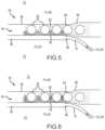
- FIGS. 7 - 12illustrate embodiments according to the present disclosure relating to an encapsulation device in which a channel for delivery of a fluid (such as oxygen, a cross-linking agent, a quenching agent, a cryopreservation solution, etc.) is configured to allow for vascularization between cell-containing chambers in a device, while still maintaining a channel for the delivery of fluids.
- a fluidsuch as oxygen, a cross-linking agent, a quenching agent, a cryopreservation solution, etc.
- the “footprint” of the channel 86is the same or approximately the same as the footprint of the chambers 82 a , 82 b , however, the disclosure also contemplates a channel 86 that has a smaller footprint, for example, more narrow, so that the chambers 82 a , 82 b extend beyond the channel 86 in a manner that there is open space between the chambers 82 a , 82 b outside of the channel 86 . Such open space exposes surfaces of the chambers 82 a , 82 b to allow for vascularization thereon.
- the one channelbe a non-linear arrangement or path.
- curvilinear channelsmay include peaks and troughs.
- oxygenmay no longer need to be delivered through the channel 86 .
- FIG. 8is a cross-sectional elevation view of a portion of the encapsulation 80 device taken at line A-A of FIG. 7 .
- a channel 86extends through the device and void spaces or chambers 82 a , 82 b are provided.
- the footprint of the channel 86is smaller than the footprint of the lower chamber 82 b .
- the footprint or area of the channelmay be from about 10% to about 90%, or any intermediate range thereof, of the footprint of the lower or upper chamber.
- the void spaces 82 a , 82 b or exposed surface of the lower chamber 82 b that does not have the serpentine channel 86may have a vascularization membrane 84 provided to promote vascularization of that surface.
- the channel 86is provided in a curvilinear or serpentine shape and reduced in footprint so that some portion of the inner surfaces of the voids are exposed and may be vascularized.
- the portion of the inner surface of the void not occupied by the oxygen channelpreferably includes both an immunoisolation layer and a vascularization layer.
- FIG. 9 - 11are cross-sectional views of encapsulation devices of alternative embodiments according to the present disclosure and taken at line A-A of FIG. 7 .
- FIG. 9shows a compact serpentine arrangement of a channel 86 with voids 82 a , 82 b on opposing sides of the channel 86 that may be vascularized.
- FIG. 10shows a channel 86 bounded by first and second voids 82 a , 82 b .
- FIG. 11shows a zig-zag type channel 86 with voids 82 a , 82 b on opposing sides thereof.
- FIG. 12is a cross-sectional view of embodiments of an encapsulation device according to the present disclosure and taken at line B-B of FIG. 7 .
- the channel 86is shown in phantom and a plurality of cells 88 are provided.
- the cellsmay be provided in the form of spheroids including multiple cells within each spheroid. Alternatively, individual cells or “clumps” of cells may be loaded into the voids 82 of the device.
- a channel 86is provided as an arcuate or serpentine channel to provide sufficient surface area of the channel for oxygen or other fluid delivery to cells 88 .
- a layer of cellsincludes a plurality of cells 88 .
- such an oxygen delivery membermay function well while oxygen gas is flowing to the device.
- these devicesmay limit the amount of vascularization and therefore limit later-stage delivery of oxygen to the cells (e.g., after implantation).
- embodiments of the present disclosurecontemplate and provide oxygen delivery channels that extend through void spaces 82 a , 82 b , provide enhanced surface area for delivery of oxygen, and do not unduly limit vascularization of components of the device.
- FIGS. 8 - 12generally depict one gas channel 86 of an encapsulation device, the present disclosure is not limited to devices having a single gas channel. It is contemplated, for example, that a plurality of gas channels extend through and between void spaces 82 of the present disclosure. In embodiments including a plurality of gas channels, it is preferred that the gas channels are arranged or staggered in three-dimensions so as to not block, impede, or segregate a layer of cells from a vascularization membrane.
- Another embodiment of the present inventionincludes implantation of an encapsulation device having a reduced fluid channel footprint as described herein into a patient in need thereof to provide a therapeutic benefit to the patient.
- vascularization on the device between cell chamber layersis achieved.
- FIGS. 13 and 14illustrate embodiments according to the present disclosure relating to use of an encapsulation device in which a channel for delivery of a fluid is used to freeze and/or thaw (i.e., modulate the temperature of) cells in the device.
- a channel for delivery of a fluidis used to freeze and/or thaw (i.e., modulate the temperature of) cells in the device.
- Use of the device as described hereinmay more rapidly and effectively freeze (i.e., cryopreserve) cells, for example, after loading the device with cells and before implantation.
- cellsmay be more rapidly and effectively warmed prior to implantation. In this manner, there is less opportunity for damage to cells to occur.
- FIG. 13is a cross-sectional elevation view of an encapsulation device 100 according to embodiments of the present disclosure.
- the encapsulation device 100includes a flow channel 102 extending through or at least partially through an interior volume of the device 100 .
- the channel 102extends between two cell chambers 104 a , 104 b and the device may optionally include an outer immunoisolation membrane and/or vascularization membrane 106 .
- a fluid flow 108is contemplated as being provided through the channel 102 .
- the flow 108is contemplated as being a flow of fluid (e.g.
- cryopreservation fluidsuch as a liquid including dimethyl sulfoxide, or the like
- the flow 108is contemplated as including chilled air or various other fluids.
- a second flow of fluid 110is provided to an exterior of the device. The second flow is contemplated as including a cryopreservation medium and/or a washing medium.
- cells in the cell chambers 104 a , 104 bmay be more rapidly and efficiently cooled and frozen because cooling medium from fluid flows 108 and 110 comes into contact with two sides of the cell chambers 104 a , 104 b.
- FIGS. 4 - 6 of matrix and scaffold formationmay be used with the embodiments of FIGS. 7 - 14 .
- the embodiments of FIGS. 7 - 14are not limited to the concepts and methods of matrix formation of FIGS. 4 - 6 (for example). Indeed, it is believed that patentable features and various novel, useful features are provided in the embodiments of FIGS. 7 - 14 irrespective of the method of formation, crosslinking of matrices, etc. Similarly, it is believed that patentable features and various novel, useful features are provided in the embodiments of FIGS. 1 - 6 regardless of the orientation, shape, and layout of the gas channel(s).
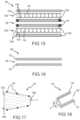
- FIGS. 15 - 19show embodiments according to the present disclosure relating to a stacked or multi-stack, oxygen-enabled encapsulation device 120 with enhanced vascularization and/or ability for temperature modulation.
- Use of the deviceis described herein may enable an increase in viability by reducing oxygen consumption rates and toxic metabolite production rates by an implanted cell.
- an encapsulation device 120includes a plurality of cell chambers 122 with voids 123 operable to receive and house cells 124 within a formed matrix.
- the cells 124may be provided in the form of spheroids including multiple cells within each spheroid. Alternatively, individual cells or “clumps” of cells may be loaded into the cell chambers 122 of the device 120 .
- the chambers 122 or other membranes of the encapsulation device 120may be constructed from materials such as polytetraflouroethylene (PTFE) or other similar material (e.g., as described throughout the present disclosure).
- PTFEpolytetraflouroethylene
- the encapsulation device 120includes one or more channels 126 .
- the channels 126extend through or at least partially through an interior volume of the encapsulation device 120 .
- a channel 126may be provided adjacent to and extends between two cell chambers 122 a , 122 b .
- the channels 126are fabricated from a rubber or plastic.
- the channels 126may be fabricated from a fluid-permeable silicone rubber tube, or may be fabricated from another material as described throughout the present disclosure.
- the channels 126include one or more ports 128 which operate as inlets/outlets for a fluid.
- the encapsulation device 120may include an inlet 128 a and an outlet 128 b for oxygen.
- an immunoisolation membrane 130 amay at least partially surround or encapsulate the cell chamber 122 a and a vascularization membrane 132 a may at least partially surround or encapsulate the immunoisolation membrane 130 a .
- An immunoisolation membrane 130 bmay at least partially surround or encapsulate the cell chamber 122 b and a vascularization membrane 132 b may at least partially surround or encapsulate the immunoisolation membrane 130 b .
- both the vascularization membrane 132 amay be positioned on at least a side of the cell chamber 122 a and the vascularization membrane 132 b may be positioned on at least a side of the cell chamber 122 b adjacent to the channel 126 .
- a vascularization membrane 132 cmay at least partially surround and encapsulate the channel 126 in addition to the arrangement as provided in the example embodiment described with respect to FIG. 15 of one or more outer immunoisolation membranes 130 and/or one or more vascularization membranes 132 a , 132 b respective to the cell chambers 122 a , 122 b .
- Including a vascularization membrane 132 c around the channel 126may allow for vascularization formation around the channel 126 in addition to vascularization formation about the cell chambers 122 a , 122 b .
- the channel 126may range between 0.20 millimeters (mm) ( 1/128th inches) and 0.80 mm ( 1/32nd inches) in diameter (d).
- the encapsulation device 120is secured with space provided to permit vascularization.
- the encapsulation device 120may be secured by sutures, a kinetic glue, or welded together (e.g., spot welded, or the like).
- a plurality of spot welds 134are provided to join or attach features of the encapsulation device 120 .
- the cell chambers 122 a , 122 bare stacked such that cell chamber 122 a is above the cell chamber 122 b (or below, depending on view) and similarly oriented.
- the one or more channels 126may make a single pass through the encapsulation device 120 , or may be wound at least once.
- the one or more channels 126may be wound once or multiple times while embedded between vascularization membranes 132 .
- the one or more channels 126may be embedded between vascularization membranes 132 a , 132 b and/or within vascularization membrane 132 c as shown throughout FIGS. 15 - 19 .
- the encapsulation device 120embodied in at least FIGS. 15 - 19 include a two cell chambers 122 a , 122 b separated by a central flow channel 126 or chamber for oxygen delivery, which allow for vasculature to be created between the two stacked cell chambers 122 a , 122 b and promote oxygen delivery through the gas-permeable flow channel 126 .
- fluidmay permeate from the channel 126 and into the cell chambers 122 a , 122 b through the respective vascularization membranes 132 a , 132 b .
- oxygenis allowed to diffuse through the vascularization membranes 132 a , 132 b and infiltrate at least a portion of the respective cell chambers 122 a , 122 b.
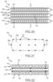
- FIGS. 20 - 34show embodiments according to the present disclosure relating to a stacked or multi-stack, oxygen-enabled encapsulation device 140 with enhanced vascularization and/or ability for temperature modulation.
- the enhanced vascularization and/or temperature modulationmay occur in vitro or in vivo.
- an encapsulation device 140includes a plurality of cell chambers 142 with voids 143 operable to receive and house cells 144 within a formed matrix.
- the cells 144may be provided in the form of spheroids including multiple cells within each spheroid. Alternatively, individual cells or “clumps” of cells may be loaded into the cell chambers 142 of the device 140 .
- the chambers 142 or membranesare constructed from materials such as polytetraflouroethylene (PTFE) or other similar material (e.g., as described throughout the present disclosure).
- the encapsulation device 140includes one or more channels 146 .
- the channels 146extend through or at least partially through an interior volume of the encapsulation device 140 .
- a channel 146 ais provided adjacent to and extends between two cell chambers 142 a , 142 b
- a channel 146 bis provided adjacent to and extends between two cell chambers 142 b , 142 c .
- the channels 146are fabricated from a rubber or plastic.
- the channels 146may be fabricated from a fluid-permeable silicone rubber tube, or may be fabricated from another material as described throughout the present disclosure.
- the encapsulation device 140is not limited to the three chambers 142 and two channels 146 as illustrated in FIG. 20 . Instead, the encapsulation device 140 may include any number of chambers 142 and channels 146 in a stacked configuration, as represented by the sets of three dots in FIG. 20 , without departing from the scope of the present disclosure.
- the channels 146include one or more ports 148 which operate as inlets/outlets for a fluid.
- the encapsulation device 140may include an inlet 148 a and an outlet 148 b for oxygen.
- the inlet 148 a and the outlet 148 bmay be separate.
- the inlet 148 a and the outlet 148 bmay be combined as a multi-layer or sheathed port (e.g., a skin integrated catheter) embedded within a stack of chambers 142 e , 142 f , 142 g , 142 h with respective channels 146 e , 146 f , 146 g , 146 h , where the inlet 148 a is in an inner portion and the outlet 148 b is in an outer portion (or vice versa).
- FIG. 26provides an exploded view of the stack in FIG.
- channels 146 within adjacent chambers 142 in the stackare connected by an exterior channel or line 156 to complete a circuit between the inlet 148 a and the outlet 148 b .
- a direct exterior channel or line 158 as shown in FIG. 26may supplement or bypass at least a portion of the pathway created by the channels 146 and the exterior channels or lines 156 to couple the inlet 148 a to the outlet 148 b directly.
- the exterior channels 156 , 158may be coated with vasculature or vascularization membranes.
- channels 146may in addition or alternatively be used as a heat exchanger.
- the encapsulation device 140may include one or more vascularization membranes 150 .
- a vascularization membrane 150 amay at least partially surround or encapsulate the cell chamber 142 a
- a vascularization membrane 150 bmay at least partially surround or encapsulate the cell chamber 142 b
- a vascularization membrane 150 cmay at least partially surround or encapsulate the cell chamber 142 c .
- both the vascularization membrane 150 amay be positioned on at least a side of the cell chamber 142 a and the vascularization membrane 150 b may be positioned on at least a side of the cell chamber 142 b adjacent to the channel 146 a
- Both the vascularization membrane 150 bmay be positioned on at least a side of the cell chamber 142 b and the vascularization membrane 150 c may be positioned on at least a side of the cell chamber 124 c adjacent to the channel 146 b.
- the encapsulation device 140is secured with space provided to permit vascularization.
- the encapsulation device 140may be secured by sutures, a kinetic glue, or welded together (e.g., spot welded, or the like).
- a plurality of spot welds 152are provided to join or attach features of the encapsulation device 140 .
- the cell chambers 142are stacked.
- the one or more channels 146may make a single pass through the encapsulation device 140 , or may be wound at least once.
- the one or more channels 146may be wound once or multiple times, embedded between vascularization membranes 150 .
- the one or more channels 146may be embedded between vascularization membranes 150 a , 150 b and/or between vascularization membrane 150 b , 150 c as shown throughout FIGS. 20 - 34 .
- the encapsulation device 140may include a separate vascularization membrane in which the channels 146 are embedded, where the separate vascularization membranes are spaced from the vascularization membranes 150 a , 150 b , 150 c a select amount to allow for vascularization in the space between the cell chambers 142 and the channels 146 .
- vasculaturemay form between the channels 146 (or gas chambers 146 ) and the cell chambers 142 . It is noted where the channel 146 is wound or where there are multiple channels 146 , spacing between channel passes or channels may range between 50 and 500 micrometers.
- the encapsulation device 140may additionally include immunoisolation membranes 154 .
- an immunoisolation membrane 154may at least partially surround or encapsulate the cell chamber 142 and a vascularization membrane 150 may at least partially surround or encapsulate the immunoisolation membrane 154 . It is contemplated any of the embodiments shown in FIGS. 20 - 34 may include both the vascularization membranes 150 and the immunoisolation membranes 154 , although not shown.
- FIG. 30is a cross-sectional elevation view of a device with a channel 146 extending therein.
- the channelis contemplated as comprising a support member 143 to support and position the channel.
- the channel 146is contemplated as comprising a serpentine or winding channel (see, e.g., FIG. 28 ).
- the support member 143is contemplated as comprising a mesh or porous structure to allow cells and other features to pass through and extend above and below the channel 146 .
- the support member 143is contemplated as comprising pores with a pore size ranging between 1 and 750 micrometers.
- the pore sizemay range between 150 and 300 micrometers.
- the pore sizemay be at least 400 micrometers.
- the pore sizes of the support member 143may vary based on a particular application, and no limitation with respect to pore size is provided.
- the entire encapsulation device 140may be secured via spot welds, gluing or the like.
- the tubing 146may be secured on the bottom or top chamber 142 (e.g., of the stack) vascularization membrane 150 (e.g., that is not isolating) or immunoisolation membrane 154 .
- FIGS. 31 - 32depict a support member 143 .
- the support member 143is contemplated as an optional support structure for a channel 146 , for example.
- the support membercomprises a mesh or permeable member that is provided within or at least partially within the encapsulation device 140 .
- a vascularization membraneis contemplated as being provided on one or more sides of the support member.
- the encapsulation device 140 embodied in at least FIGS. 20 - 34include two or more cell chambers 142 separated or partially separated by one or more flow channels 146 for oxygen delivery, which allow for vasculature to be created between the stacked cell chambers 142 and promote oxygen delivery through the channels 146 , while also providing support via the vasculature for when the oxygen delivery is interrupted.
- fluidmay permeate from the one or more channels 146 and into the cell chambers 146 through the respective vascularization membranes 150 .
- oxygenis allowed to diffuse through the vascularization membranes 150 and infiltrate at least a portion of the respective cell chambers 142 .
- a “cold” gasmay be between 0 degrees Celsius (° Celsius or ° C.) and 37° Celsius.
- the “cold” gasmay be between 17° Celsius and 27° Celsius, and preferably may be 17° Celsius.
- the “cold” gasmay be at 8° Celsius room temperature (RT).
- oxygenmay refer to a pure or substantially pure O 2 gas, a mixture of pure O 2 gas and air, or air.
- any embodiment directed to a particular encapsulation device as shown in FIGS. 1 - 34may be directed to any other encapsulation device shown without departing from the scope of the present disclosure, unless otherwise noted.
- spheroid cellsare provided in a cell chamber and a matrix is not formed in the encapsulation device.
- Methods of the present disclosureincluding but not limited to those related to cryopreservation are contemplated for such devices including spheroids. Examples of spheroid cells are provided in International Application PCT/NL2017/050098 to Van Beurden which is hereby incorporated by reference in its entirety.
Landscapes
- Health & Medical Sciences (AREA)
- Life Sciences & Earth Sciences (AREA)
- Engineering & Computer Science (AREA)
- Chemical & Material Sciences (AREA)
- Biomedical Technology (AREA)
- Veterinary Medicine (AREA)
- Animal Behavior & Ethology (AREA)
- General Health & Medical Sciences (AREA)
- Public Health (AREA)
- Transplantation (AREA)
- Dermatology (AREA)
- Medicinal Chemistry (AREA)
- Oral & Maxillofacial Surgery (AREA)
- Epidemiology (AREA)
- Heart & Thoracic Surgery (AREA)
- Hematology (AREA)
- Cell Biology (AREA)
- Anesthesiology (AREA)
- Medical Informatics (AREA)
- Molecular Biology (AREA)
- Dispersion Chemistry (AREA)
- Vascular Medicine (AREA)
- Cardiology (AREA)
- Chemical Kinetics & Catalysis (AREA)
- Botany (AREA)
- Zoology (AREA)
- Urology & Nephrology (AREA)
- Developmental Biology & Embryology (AREA)
- Prostheses (AREA)
- Apparatus Associated With Microorganisms And Enzymes (AREA)
- Medicines Containing Material From Animals Or Micro-Organisms (AREA)
- Materials For Medical Uses (AREA)
- Micro-Organisms Or Cultivation Processes Thereof (AREA)
Abstract
Description
Claims (12)
Priority Applications (1)
| Application Number | Priority Date | Filing Date | Title |
|---|---|---|---|
| US17/516,179US12115332B2 (en) | 2020-10-30 | 2021-11-01 | Methods and systems for encapsulation devices for housing cells and agents |
Applications Claiming Priority (2)
| Application Number | Priority Date | Filing Date | Title |
|---|---|---|---|
| US202063108017P | 2020-10-30 | 2020-10-30 | |
| US17/516,179US12115332B2 (en) | 2020-10-30 | 2021-11-01 | Methods and systems for encapsulation devices for housing cells and agents |
Publications (2)
| Publication Number | Publication Date |
|---|---|
| US20220134074A1 US20220134074A1 (en) | 2022-05-05 |
| US12115332B2true US12115332B2 (en) | 2024-10-15 |
Family
ID=81381117
Family Applications (1)
| Application Number | Title | Priority Date | Filing Date |
|---|---|---|---|
| US17/516,179Active2042-04-10US12115332B2 (en) | 2020-10-30 | 2021-11-01 | Methods and systems for encapsulation devices for housing cells and agents |
Country Status (8)
| Country | Link |
|---|---|
| US (1) | US12115332B2 (en) |
| EP (1) | EP4236866A4 (en) |
| JP (1) | JP7589903B2 (en) |
| KR (1) | KR20230117119A (en) |
| CN (1) | CN116761652A (en) |
| AU (1) | AU2021372247A1 (en) |
| CA (1) | CA3196876A1 (en) |
| WO (1) | WO2022094380A1 (en) |
Families Citing this family (6)
| Publication number | Priority date | Publication date | Assignee | Title |
|---|---|---|---|---|
| EP3534834A4 (en) | 2016-11-03 | 2020-05-13 | Arizona Board of Regents on behalf of the University of Arizona | ENCAPSULATION DEVICE SYSTEMS WITH OXYGEN SENSORS WITH OR WITHOUT EXOGENOUS OXYGEN DELIVERY |
| CA3042712A1 (en) | 2016-11-03 | 2018-08-09 | Arizona Board Of Regents On Behalf Of The University Of Arizona | Methods and systems for real-time assessment of cells in encapsulation devices pre- and post-transplantation |
| KR102460406B1 (en) | 2016-11-03 | 2022-10-31 | 아리조나 보드 오브 리전츠 온 비해프 오브 더 유니버시티 오브 아리조나 | Layered Tissue Encapsulation Device Systems with or Without Oxygen Delivery |
| CN116761652A (en) | 2020-10-30 | 2023-09-15 | 亚利桑那大学董事会 | Methods and systems for packaging devices containing cells and reagents |
| WO2024091534A1 (en)* | 2022-10-25 | 2024-05-02 | The Regents Of The University Of Michigan | Implantable encapsulated device with controlled perfusion that generates reprogrammed cells |
| WO2024243181A2 (en)* | 2023-05-22 | 2024-11-28 | Procyon Technologies Llc | Methods and systems for improved biocompatible membranes for implantable devices |
Citations (102)
| Publication number | Priority date | Publication date | Assignee | Title |
|---|---|---|---|---|
| DE8909058U1 (en) | 1988-08-02 | 1989-09-28 | Arndt, Helge, 3007 Gehrden | Device for long-term continuous supply of a soluble substance |
| EP0344314A1 (en) | 1987-11-26 | 1989-12-06 | Kaunassky Politekhnichesky Institut Imeni Antanasa Snechkusa | Device for measuring the rate of oxygen consumption by microorganisms in liquid media |
| US4902476A (en)* | 1983-01-14 | 1990-02-20 | Baxter International Inc. | Heat exchanger and blood oxygenator apparatus |
| WO1991000119A1 (en) | 1989-06-30 | 1991-01-10 | Baxter International Inc. | Implantable device |
| US5169390A (en) | 1990-05-21 | 1992-12-08 | Athayde Amulya L | Osmotic infusion device |
| US5324518A (en)* | 1989-12-08 | 1994-06-28 | Biosynthesis, Inc. | Implantable structure for containing substances for delivery to a body |
| JPH06205665A (en) | 1992-09-09 | 1994-07-26 | Joerg Gerlach | Module for cultivating microorganism and for utilizing and/or maintaining metabolism |
| US5368028A (en)* | 1989-08-11 | 1994-11-29 | Cb-Carmel Biotechnology Ltd. | System for monitoring and controlling blood and tissue constituent levels |
| WO1996032076A1 (en)* | 1995-04-11 | 1996-10-17 | Baxter Internatonal Inc. | Tissue implant systems |
| US5595621A (en) | 1993-09-29 | 1997-01-21 | Johnson & Johnson Medical, Inc. | Method of making absorbable structures for ligament and tendon repair |
| US5626561A (en) | 1995-06-07 | 1997-05-06 | Gore Hybrid Technologies, Inc. | Implantable containment apparatus for a therapeutical device and method for loading and reloading the device therein |
| US5713888A (en) | 1990-10-31 | 1998-02-03 | Baxter International, Inc. | Tissue implant systems |
| US5741330A (en) | 1990-10-31 | 1998-04-21 | Baxter International, Inc. | Close vascularization implant material |
| US5814405A (en) | 1995-08-04 | 1998-09-29 | W. L. Gore & Associates, Inc. | Strong, air permeable membranes of polytetrafluoroethylene |
| US5837234A (en) | 1995-06-07 | 1998-11-17 | Cytotherapeutics, Inc. | Bioartificial organ containing cells encapsulated in a permselective polyether suflfone membrane |
| US5843069A (en) | 1995-06-07 | 1998-12-01 | Gore Hybrid Technologies, Inc. | Implantable containment apparatus for a therapeutical device and method for loading and reloading the device therein |
| US5980889A (en) | 1993-08-10 | 1999-11-09 | Gore Hybrid Technologies, Inc. | Cell encapsulating device containing a cell displacing core for maintaining cell viability |
| US6060640A (en)* | 1995-05-19 | 2000-05-09 | Baxter International Inc. | Multiple-layer, formed-in-place immunoisolation membrane structures for implantation of cells in host tissue |
| US6143293A (en) | 1998-03-26 | 2000-11-07 | Carnegie Mellon | Assembled scaffolds for three dimensional cell culturing and tissue generation |
| US6156305A (en) | 1994-07-08 | 2000-12-05 | Baxter International Inc. | Implanted tumor cells for the prevention and treatment of cancer |
| WO2001012158A1 (en) | 1999-08-16 | 2001-02-22 | Thomas Jefferson University | Implantable drug delivery catheter system with capillary interface |
| US6197575B1 (en) | 1998-03-18 | 2001-03-06 | Massachusetts Institute Of Technology | Vascularized perfused microtissue/micro-organ arrays |
| WO2002100335A2 (en) | 2001-06-08 | 2002-12-19 | Boehringer Ingelheim Pharmaceuticals, Inc. | Methods for improving cell line activity in immunoisolation devices |
| US20030054544A1 (en) | 2001-09-14 | 2003-03-20 | Medcell Biologics, Inc. | Oxygen enriched bioreactor and method of culturing cells |
| US20030087427A1 (en)* | 1998-07-17 | 2003-05-08 | Colton Clark K | Method and apparatus for delivering oxygen to cells |
| US6562616B1 (en) | 1999-06-21 | 2003-05-13 | The General Hospital Corporation | Methods and devices for cell culturing and organ assist systems |
| US20030129736A1 (en) | 1999-07-15 | 2003-07-10 | Eduardo Mitrani | Device and method for performing a biological modification of a fluid |
| EP1351623A1 (en) | 2000-01-12 | 2003-10-15 | Beta O 2 Technologies Ltd. | Implantable device |
| US20040010320A1 (en) | 2000-05-11 | 2004-01-15 | Huckle James William | Tissue regrafting |
| US20040024342A1 (en) | 1999-04-23 | 2004-02-05 | Weitzel William Frederick | Extracorporeal fluid circuit and related methods |
| US20040166141A1 (en) | 1998-03-02 | 2004-08-26 | Anthony Cerami | Methods and devices for modulating the immune response |
| US20040197374A1 (en) | 2003-04-02 | 2004-10-07 | Alireza Rezania | Implantable pouch seeded with insulin-producing cells to treat diabetes |
| US20050136092A1 (en)* | 2000-01-01 | 2005-06-23 | Beta-O2 Technologies Ltd. | Implantable device |
| US20050221485A1 (en) | 2002-07-30 | 2005-10-06 | Augustinus Bader | Method and device for culturing cells |
| US20050267440A1 (en) | 2004-06-01 | 2005-12-01 | Herman Stephen J | Devices and methods for measuring and enhancing drug or analyte transport to/from medical implant |
| US20060013835A1 (en) | 2003-05-02 | 2006-01-19 | Anderson Aron B | Controlled release bioactive agent delivery device |
| US20060019333A1 (en)* | 2004-06-07 | 2006-01-26 | Rodgers Seth T | Control of reactor environmental conditions |
| WO2006106506A2 (en) | 2005-04-04 | 2006-10-12 | Technion Research & Development Foundation Ltd. | Medical scaffold, methods of fabrication and using thereof |
| US20070061015A1 (en) | 2005-09-09 | 2007-03-15 | Peder Jensen | System and method for tissue generation and bone regeneration |
| US20070066138A1 (en) | 2005-04-05 | 2007-03-22 | The Ohio State University Research Foundation | Diffusion Delivery Systems and Methods of Fabrication |
| US20080021436A1 (en) | 1998-04-30 | 2008-01-24 | Abbott Diabetes Care, Inc. | Analyte Monitoring Device and Methods of Use |
| WO2008100559A2 (en) | 2007-02-14 | 2008-08-21 | Bioengine, Inc. | Medical devices having a micro-fluidic channeled vasculature |
| CN201337642Y (en) | 2008-12-05 | 2009-11-04 | 中国人民解放军军事医学科学院野战输血研究所 | Novel immune isolation unit |
| US7659219B2 (en) | 2005-07-29 | 2010-02-09 | Gore Enterprise Holdings, Inc. | Highly porous self-cohered web materials having haemostatic properties |
| US20100082114A1 (en)* | 2008-04-29 | 2010-04-01 | Peter Gingras | Tissue repair implant |
| US20100124564A1 (en) | 2008-11-14 | 2010-05-20 | Laura Martinson | Encapsulation of pancreatic cells derived from human pluripotent stem cells |
| US20100130916A1 (en)* | 2008-11-26 | 2010-05-27 | Yaki Stern | Apparatus for transportation of oxygen to implanted cells |
| US20100160760A1 (en) | 1997-03-04 | 2010-06-24 | Dexcom, Inc. | Device and method for determining analyte levels |
| US20100172952A1 (en)* | 2007-01-31 | 2010-07-08 | Technion Research & Development Foundation Ltd. | Electrospun Scaffolds And Methods Of Generating And Using Same |
| US20100196439A1 (en)* | 2006-12-22 | 2010-08-05 | Medtronic, Inc. | Angiogenesis Mechanism and Method, and Implantable Device |
| US20100228110A1 (en)* | 2009-03-09 | 2010-09-09 | Achilleas Tsoukalis | Implantable biosensor with automatic calibration |
| US20100240117A1 (en) | 2006-03-14 | 2010-09-23 | Agency Of Science, Technology And Research | Three dimensional fabrication of biocompatible structures in anatomical shapes and dimensions for tissue engineering and organ replacement |
| US20100255059A1 (en) | 2009-04-02 | 2010-10-07 | Ynano, Llc | Artificial micro-gland |
| US20110054589A1 (en) | 2009-08-27 | 2011-03-03 | Boston Scientific Scimed, Inc. | Stent with variable cross section braiding filament and method for making same |
| CN102012390A (en) | 2010-11-15 | 2011-04-13 | 普林斯顿医疗科技(珠海)有限公司 | Wireless multifunctional continuous glucose monitoring system |
| US20110092949A1 (en) | 2008-04-25 | 2011-04-21 | Wang Taylor G | Immunoisolation patch system for cellular transplantation |
| US20120041355A1 (en) | 2003-12-12 | 2012-02-16 | Edman Carl F | Multiple section parenteral drug delivery apparatus |
| KR20120091008A (en) | 2009-08-28 | 2012-08-17 | 세르노바 코포레이션 | Cell transplantation method and apparatus |
| EP2508212A1 (en) | 2011-04-05 | 2012-10-10 | Universitätsklinikum Freiburg | Biocompatible and biodegradable gradient layer system for regenerative medicine and for tissue support |
| US20130289540A1 (en) | 2012-04-27 | 2013-10-31 | Gregory Zeltser | Implantable bioartificial perfusion system |
| US20130344131A1 (en) | 2012-06-22 | 2013-12-26 | Z-Medica, Llc | Hemostatic devices |
| US20140014226A1 (en) | 2011-02-21 | 2014-01-16 | Chad Green | Loading system for an encapsulation device |
| US20140039383A1 (en) | 2007-10-09 | 2014-02-06 | Dexcom, Inc. | Integrated insulin delivery system with continuous glucose sensor |
| US8647861B2 (en) | 2008-07-16 | 2014-02-11 | Children's Medical Center Corporation | Organ mimic device with microchannels and methods of use and manufacturing thereof |
| US20140051162A1 (en) | 2012-08-20 | 2014-02-20 | Terumo Bct, Inc. | Method of Loading and Distributing Cells in a Bioreactor of a Cell Expansion System |
| KR20140023252A (en) | 2010-10-06 | 2014-02-26 | 프로퓨사 인코퍼레이티드 | Tissue-integrating sensors |
| US20140088347A1 (en) | 2011-02-23 | 2014-03-27 | Ams Research Corporation | Pelvic implant and therapeutic agent system and method |
| US20140236078A1 (en)* | 2013-02-18 | 2014-08-21 | Michael J. Dalton | Transplanted cell containment and nutrition device |
| US20140257515A1 (en)* | 2013-03-07 | 2014-09-11 | Viacyte, Inc. | 3-dimensional large capacity cell encapsulation device assembly |
| US20140308315A1 (en) | 2009-02-28 | 2014-10-16 | Charles Knezevich | Apparatus, system, and method for creating immunologically enhanced spaces in-vivo |
| WO2014173441A1 (en) | 2013-04-24 | 2014-10-30 | Nestec S.A. | Encapsulation device |
| CN203915611U (en) | 2011-02-09 | 2014-11-05 | 贝克顿·迪金森公司 | With the attached cover of infusion base portion joint and for transmitting the transfer system of medicine |
| US20150112247A1 (en) | 2013-09-24 | 2015-04-23 | Giner, Inc. | System for gas treatment of a cell implant |
| US20150129497A1 (en) | 2012-01-09 | 2015-05-14 | H. David Humes | Cartridge and method for increasing myocardial function |
| WO2015145264A2 (en) | 2014-03-27 | 2015-10-01 | Beta-O2 Technologies Ltd. | Implantable medical devices |
| US20150320836A1 (en) | 2012-07-06 | 2015-11-12 | The Regents Of The University Of California | Cryopreservation of cells inside a macro-encapsulation device |
| US20150359472A1 (en) | 2014-06-16 | 2015-12-17 | The Regents Of The University Of California | Measuring oxygen levels in an implant, and implants having incorporated oxygen sensing |
| US20160022180A1 (en) | 2014-07-24 | 2016-01-28 | Thomas Jefferson University | Long-term implantable monitoring system & methods of use |
| US20160038207A1 (en) | 2009-02-12 | 2016-02-11 | Warsaw Orthopedic, Inc. | Segmented delivery system |
| US20160082236A1 (en) | 2013-06-07 | 2016-03-24 | The Regents Of The University Of California | Transplantation device and method of use |
| US20160123848A1 (en) | 2014-10-31 | 2016-05-05 | General Electric Company | Semi-automated sampling system for aseptic sampling |
| KR20160094391A (en) | 2013-12-05 | 2016-08-09 | 라이프스캔, 인코포레이티드 | Bolus dosing feedback for the management of diabetes |
| US20170072074A1 (en)* | 2012-12-28 | 2017-03-16 | Glusense Ltd. | Implantable cell encapsulation device |
| US20170173262A1 (en)* | 2017-03-01 | 2017-06-22 | François Paul VELTZ | Medical systems, devices and methods |
| US20180000395A1 (en) | 2016-06-29 | 2018-01-04 | Glysens Incorporated | Bio-adaptable implantable sensor apparatus and methods |
| WO2018067813A1 (en) | 2016-10-05 | 2018-04-12 | The Arizona Board Of Regents On Behalf Of The University Of Arizona | Methods and systems for augmenting immune system responses |
| US20180126134A1 (en)* | 2016-11-08 | 2018-05-10 | W. L. Gore & Associates, Inc. | Implantable Encapsulation Devices |
| WO2018085714A1 (en) | 2016-11-03 | 2018-05-11 | The Arizona Board Of Regents On Behalf Of The University Of Arizona | Encapsulation device systems with oxygen sensors with or without exogenous oxygen delivery |
| WO2018102077A2 (en) | 2016-11-03 | 2018-06-07 | The Arizona Board Of Regents On Behalf Of The University Of Arizona | Methods, systems, and implantable devices for enhancing blood glucose regulation |
| CA3042709A1 (en) | 2016-11-03 | 2018-08-09 | Arizona Board Of Regents On Behalf Of The University Of Arizona | Stacked tissue encapsulation device systems with or without oxygen delivery |
| WO2018144099A1 (en) | 2016-11-03 | 2018-08-09 | The Arizona Board Of Regents On Behalf Of The University Of Arizona | Methods and systems for real-time assessment of cells in encapsulation devices pre-and post-transplantation |
| US20180263238A1 (en) | 2017-03-20 | 2018-09-20 | Boston Scientific Limited | Cell encapsulation device |
| US20180298343A1 (en) | 2017-04-12 | 2018-10-18 | Arunthathy Sivakumaran | Compositions and methods for a three dimensional ex-vivo glomerular cell co-culture biological engineering model |
| US20180318566A1 (en) | 2017-05-04 | 2018-11-08 | Giner, Inc. | Robust, implantable gas delivery device and methods, systems and devices including same |
| US20180344665A1 (en)* | 2008-11-12 | 2018-12-06 | Nectero Medical, Inc. | Compositions for tissue stabilization |
| US20190076840A1 (en) | 2015-10-06 | 2019-03-14 | University Of Pittsburgh - Of The Commonwealth System Of Higher Education | Microfluidic tissue development systems |
| US20190136176A1 (en) | 2016-05-27 | 2019-05-09 | Hitachi High-Technologies Corporation | Device and method for fabricating three-dimensional structure from cells |
| US20190211294A1 (en) | 2016-08-21 | 2019-07-11 | Adva Biotechnology Ltd. | Bioreactor and methods of use thereof |
| US10695379B2 (en) | 2016-10-19 | 2020-06-30 | Beta Cell Technologies, Pty Ltd | Cell population seeding in dermal matrices for endocrine disorder management |
| US11033666B2 (en) | 2016-11-15 | 2021-06-15 | Giner Life Sciences, Inc. | Percutaneous gas diffusion device suitable for use with a subcutaneous implant |
| US20210401564A1 (en) | 2018-09-24 | 2021-12-30 | Arizona Board Regents On Behalf Of The University Of Arizona | Methods and systems for implantable medical devices and vascularization membranes |
| WO2022094380A1 (en) | 2020-10-30 | 2022-05-05 | Arizona Board Of Regents On Behalf Of The University Of Arizona | Methods and systems for encapsulation devices for housing cells and agents |
- 2021
- 2021-11-01CNCN202180074614.2Apatent/CN116761652A/enactivePending
- 2021-11-01JPJP2023527322Apatent/JP7589903B2/enactiveActive
- 2021-11-01CACA3196876Apatent/CA3196876A1/enactivePending
- 2021-11-01KRKR1020237018223Apatent/KR20230117119A/ennot_activeCeased
- 2021-11-01WOPCT/US2021/057526patent/WO2022094380A1/ennot_activeCeased
- 2021-11-01EPEP21887706.6Apatent/EP4236866A4/enactivePending
- 2021-11-01USUS17/516,179patent/US12115332B2/enactiveActive
- 2021-11-01AUAU2021372247Apatent/AU2021372247A1/ennot_activeAbandoned
Patent Citations (130)
| Publication number | Priority date | Publication date | Assignee | Title |
|---|---|---|---|---|
| US4902476A (en)* | 1983-01-14 | 1990-02-20 | Baxter International Inc. | Heat exchanger and blood oxygenator apparatus |
| EP0344314A1 (en) | 1987-11-26 | 1989-12-06 | Kaunassky Politekhnichesky Institut Imeni Antanasa Snechkusa | Device for measuring the rate of oxygen consumption by microorganisms in liquid media |
| DE8909058U1 (en) | 1988-08-02 | 1989-09-28 | Arndt, Helge, 3007 Gehrden | Device for long-term continuous supply of a soluble substance |
| WO1991000119A1 (en) | 1989-06-30 | 1991-01-10 | Baxter International Inc. | Implantable device |
| US5368028A (en)* | 1989-08-11 | 1994-11-29 | Cb-Carmel Biotechnology Ltd. | System for monitoring and controlling blood and tissue constituent levels |
| US5324518A (en)* | 1989-12-08 | 1994-06-28 | Biosynthesis, Inc. | Implantable structure for containing substances for delivery to a body |
| US5169390A (en) | 1990-05-21 | 1992-12-08 | Athayde Amulya L | Osmotic infusion device |
| US5741330A (en) | 1990-10-31 | 1998-04-21 | Baxter International, Inc. | Close vascularization implant material |
| US5713888A (en) | 1990-10-31 | 1998-02-03 | Baxter International, Inc. | Tissue implant systems |
| US5882354A (en) | 1990-10-31 | 1999-03-16 | Baxter International Inc. | Close vascularization implant material |
| JPH06205665A (en) | 1992-09-09 | 1994-07-26 | Joerg Gerlach | Module for cultivating microorganism and for utilizing and/or maintaining metabolism |
| US5980889A (en) | 1993-08-10 | 1999-11-09 | Gore Hybrid Technologies, Inc. | Cell encapsulating device containing a cell displacing core for maintaining cell viability |
| US5595621A (en) | 1993-09-29 | 1997-01-21 | Johnson & Johnson Medical, Inc. | Method of making absorbable structures for ligament and tendon repair |
| US6156305A (en) | 1994-07-08 | 2000-12-05 | Baxter International Inc. | Implanted tumor cells for the prevention and treatment of cancer |
| WO1996032076A1 (en)* | 1995-04-11 | 1996-10-17 | Baxter Internatonal Inc. | Tissue implant systems |
| US6060640A (en)* | 1995-05-19 | 2000-05-09 | Baxter International Inc. | Multiple-layer, formed-in-place immunoisolation membrane structures for implantation of cells in host tissue |
| US5837234A (en) | 1995-06-07 | 1998-11-17 | Cytotherapeutics, Inc. | Bioartificial organ containing cells encapsulated in a permselective polyether suflfone membrane |
| US5626561A (en) | 1995-06-07 | 1997-05-06 | Gore Hybrid Technologies, Inc. | Implantable containment apparatus for a therapeutical device and method for loading and reloading the device therein |
| US5843069A (en) | 1995-06-07 | 1998-12-01 | Gore Hybrid Technologies, Inc. | Implantable containment apparatus for a therapeutical device and method for loading and reloading the device therein |
| US5814405A (en) | 1995-08-04 | 1998-09-29 | W. L. Gore & Associates, Inc. | Strong, air permeable membranes of polytetrafluoroethylene |
| US20100160760A1 (en) | 1997-03-04 | 2010-06-24 | Dexcom, Inc. | Device and method for determining analyte levels |
| US20040166141A1 (en) | 1998-03-02 | 2004-08-26 | Anthony Cerami | Methods and devices for modulating the immune response |
| US6197575B1 (en) | 1998-03-18 | 2001-03-06 | Massachusetts Institute Of Technology | Vascularized perfused microtissue/micro-organ arrays |
| US6143293A (en) | 1998-03-26 | 2000-11-07 | Carnegie Mellon | Assembled scaffolds for three dimensional cell culturing and tissue generation |
| US20080021436A1 (en) | 1998-04-30 | 2008-01-24 | Abbott Diabetes Care, Inc. | Analyte Monitoring Device and Methods of Use |
| US20030087427A1 (en)* | 1998-07-17 | 2003-05-08 | Colton Clark K | Method and apparatus for delivering oxygen to cells |
| US20040024342A1 (en) | 1999-04-23 | 2004-02-05 | Weitzel William Frederick | Extracorporeal fluid circuit and related methods |
| US6562616B1 (en) | 1999-06-21 | 2003-05-13 | The General Hospital Corporation | Methods and devices for cell culturing and organ assist systems |
| US20030129736A1 (en) | 1999-07-15 | 2003-07-10 | Eduardo Mitrani | Device and method for performing a biological modification of a fluid |
| WO2001012158A1 (en) | 1999-08-16 | 2001-02-22 | Thomas Jefferson University | Implantable drug delivery catheter system with capillary interface |
| US20050136092A1 (en)* | 2000-01-01 | 2005-06-23 | Beta-O2 Technologies Ltd. | Implantable device |
| EP1351623A1 (en) | 2000-01-12 | 2003-10-15 | Beta O 2 Technologies Ltd. | Implantable device |
| US20040133188A1 (en)* | 2000-01-12 | 2004-07-08 | Pnina Vardi | Implantable device |
| US7892222B2 (en)* | 2000-01-12 | 2011-02-22 | Beta O 2 Technologies Ltd. | Implantable device |
| US20040010320A1 (en) | 2000-05-11 | 2004-01-15 | Huckle James William | Tissue regrafting |
| WO2002100335A2 (en) | 2001-06-08 | 2002-12-19 | Boehringer Ingelheim Pharmaceuticals, Inc. | Methods for improving cell line activity in immunoisolation devices |
| US20090110669A1 (en)* | 2001-06-08 | 2009-04-30 | Boehringer Ingelheim Pharmaceuticals, Inc. | Methods for improving cell line activity in immunoisolation devices |
| JP2004530431A (en) | 2001-06-08 | 2004-10-07 | ベーリンガー インゲルハイム ファーマシューティカルズ インコーポレイテッド | Methods for improving cell line activity in immunoisolation devices |
| US20030054544A1 (en) | 2001-09-14 | 2003-03-20 | Medcell Biologics, Inc. | Oxygen enriched bioreactor and method of culturing cells |
| US20050221485A1 (en) | 2002-07-30 | 2005-10-06 | Augustinus Bader | Method and device for culturing cells |
| US20040197374A1 (en) | 2003-04-02 | 2004-10-07 | Alireza Rezania | Implantable pouch seeded with insulin-producing cells to treat diabetes |
| US20060013835A1 (en) | 2003-05-02 | 2006-01-19 | Anderson Aron B | Controlled release bioactive agent delivery device |
| US20120041355A1 (en) | 2003-12-12 | 2012-02-16 | Edman Carl F | Multiple section parenteral drug delivery apparatus |
| US20050267440A1 (en) | 2004-06-01 | 2005-12-01 | Herman Stephen J | Devices and methods for measuring and enhancing drug or analyte transport to/from medical implant |
| US20060019333A1 (en)* | 2004-06-07 | 2006-01-26 | Rodgers Seth T | Control of reactor environmental conditions |
| CN101123984A (en) | 2004-11-30 | 2008-02-13 | 贝塔O2技术有限公司 | Implantable device |
| US20090074832A1 (en) | 2005-04-04 | 2009-03-19 | Technion Research & Development Foundation Ltd. | Medical Scaffold, Methods of Fabrication and Using Thereof |
| WO2006106506A2 (en) | 2005-04-04 | 2006-10-12 | Technion Research & Development Foundation Ltd. | Medical scaffold, methods of fabrication and using thereof |
| US20070066138A1 (en) | 2005-04-05 | 2007-03-22 | The Ohio State University Research Foundation | Diffusion Delivery Systems and Methods of Fabrication |
| US7659219B2 (en) | 2005-07-29 | 2010-02-09 | Gore Enterprise Holdings, Inc. | Highly porous self-cohered web materials having haemostatic properties |
| US8518123B2 (en) | 2005-09-09 | 2013-08-27 | Board Of Trustees Of The University Of Arkansas | System and method for tissue generation and bone regeneration |
| US20070061015A1 (en) | 2005-09-09 | 2007-03-15 | Peder Jensen | System and method for tissue generation and bone regeneration |
| US20100240117A1 (en) | 2006-03-14 | 2010-09-23 | Agency Of Science, Technology And Research | Three dimensional fabrication of biocompatible structures in anatomical shapes and dimensions for tissue engineering and organ replacement |
| US20100196439A1 (en)* | 2006-12-22 | 2010-08-05 | Medtronic, Inc. | Angiogenesis Mechanism and Method, and Implantable Device |
| US20100172952A1 (en)* | 2007-01-31 | 2010-07-08 | Technion Research & Development Foundation Ltd. | Electrospun Scaffolds And Methods Of Generating And Using Same |
| WO2008100559A2 (en) | 2007-02-14 | 2008-08-21 | Bioengine, Inc. | Medical devices having a micro-fluidic channeled vasculature |
| US20140052095A1 (en) | 2007-10-09 | 2014-02-20 | Dexcom, Inc. | Integrated insulin delivery system with continuous glucose sensor |
| US20140039383A1 (en) | 2007-10-09 | 2014-02-06 | Dexcom, Inc. | Integrated insulin delivery system with continuous glucose sensor |
| US20110092949A1 (en) | 2008-04-25 | 2011-04-21 | Wang Taylor G | Immunoisolation patch system for cellular transplantation |
| US20100082114A1 (en)* | 2008-04-29 | 2010-04-01 | Peter Gingras | Tissue repair implant |
| US8647861B2 (en) | 2008-07-16 | 2014-02-11 | Children's Medical Center Corporation | Organ mimic device with microchannels and methods of use and manufacturing thereof |
| US20180344665A1 (en)* | 2008-11-12 | 2018-12-06 | Nectero Medical, Inc. | Compositions for tissue stabilization |
| US8278106B2 (en) | 2008-11-14 | 2012-10-02 | Viacyte, Inc. | Encapsulation of pancreatic cells derived from human pluripotent stem cells |
| US20100124564A1 (en) | 2008-11-14 | 2010-05-20 | Laura Martinson | Encapsulation of pancreatic cells derived from human pluripotent stem cells |
| WO2010061387A2 (en) | 2008-11-26 | 2010-06-03 | Beta O2 Technologies Ltd. | Apparatus for transportation of oxygen to implanted cells |
| US20100130916A1 (en)* | 2008-11-26 | 2010-05-27 | Yaki Stern | Apparatus for transportation of oxygen to implanted cells |
| CN201337642Y (en) | 2008-12-05 | 2009-11-04 | 中国人民解放军军事医学科学院野战输血研究所 | Novel immune isolation unit |
| US20160038207A1 (en) | 2009-02-12 | 2016-02-11 | Warsaw Orthopedic, Inc. | Segmented delivery system |
| US20140308315A1 (en) | 2009-02-28 | 2014-10-16 | Charles Knezevich | Apparatus, system, and method for creating immunologically enhanced spaces in-vivo |
| US20100228110A1 (en)* | 2009-03-09 | 2010-09-09 | Achilleas Tsoukalis | Implantable biosensor with automatic calibration |
| US20100255059A1 (en) | 2009-04-02 | 2010-10-07 | Ynano, Llc | Artificial micro-gland |
| US20110054589A1 (en) | 2009-08-27 | 2011-03-03 | Boston Scientific Scimed, Inc. | Stent with variable cross section braiding filament and method for making same |
| US20120245705A1 (en) | 2009-08-28 | 2012-09-27 | Craig Hasilo | Methods and devices for cellular transplantation |
| KR20120091008A (en) | 2009-08-28 | 2012-08-17 | 세르노바 코포레이션 | Cell transplantation method and apparatus |
| KR20140023252A (en) | 2010-10-06 | 2014-02-26 | 프로퓨사 인코퍼레이티드 | Tissue-integrating sensors |
| CN102012390A (en) | 2010-11-15 | 2011-04-13 | 普林斯顿医疗科技(珠海)有限公司 | Wireless multifunctional continuous glucose monitoring system |
| CN203915611U (en) | 2011-02-09 | 2014-11-05 | 贝克顿·迪金森公司 | With the attached cover of infusion base portion joint and for transmitting the transfer system of medicine |
| US9433557B2 (en)* | 2011-02-21 | 2016-09-06 | Viacyte, Inc. | Loading system for an encapsulation device |
| US20140014226A1 (en) | 2011-02-21 | 2014-01-16 | Chad Green | Loading system for an encapsulation device |
| US20140088347A1 (en) | 2011-02-23 | 2014-03-27 | Ams Research Corporation | Pelvic implant and therapeutic agent system and method |
| WO2012136701A1 (en) | 2011-04-05 | 2012-10-11 | Universitätsklinikum Freiburg | Biocompatible and biodegradable gradient layer system for regenerative medicine and for tissue support |
| EP2508212A1 (en) | 2011-04-05 | 2012-10-10 | Universitätsklinikum Freiburg | Biocompatible and biodegradable gradient layer system for regenerative medicine and for tissue support |
| JP2014514942A (en) | 2011-04-05 | 2014-06-26 | ウニベルジテートスクリニクム フライブルク | Biocompatible and biodegradable gradient layer systems for regenerative medicine and tissue support |
| US20150129497A1 (en) | 2012-01-09 | 2015-05-14 | H. David Humes | Cartridge and method for increasing myocardial function |
| US20130289540A1 (en) | 2012-04-27 | 2013-10-31 | Gregory Zeltser | Implantable bioartificial perfusion system |
| US20130344131A1 (en) | 2012-06-22 | 2013-12-26 | Z-Medica, Llc | Hemostatic devices |
| US20150320836A1 (en) | 2012-07-06 | 2015-11-12 | The Regents Of The University Of California | Cryopreservation of cells inside a macro-encapsulation device |
| US20140051162A1 (en) | 2012-08-20 | 2014-02-20 | Terumo Bct, Inc. | Method of Loading and Distributing Cells in a Bioreactor of a Cell Expansion System |
| US20170072074A1 (en)* | 2012-12-28 | 2017-03-16 | Glusense Ltd. | Implantable cell encapsulation device |
| US20140236078A1 (en)* | 2013-02-18 | 2014-08-21 | Michael J. Dalton | Transplanted cell containment and nutrition device |
| CN105163688A (en) | 2013-03-07 | 2015-12-16 | 韦尔赛特公司 | Three-dimensional large-capacity cell encapsulation device components |
| US20140257515A1 (en)* | 2013-03-07 | 2014-09-11 | Viacyte, Inc. | 3-dimensional large capacity cell encapsulation device assembly |
| WO2014173441A1 (en) | 2013-04-24 | 2014-10-30 | Nestec S.A. | Encapsulation device |
| US20160184569A1 (en) | 2013-04-24 | 2016-06-30 | Neskec S.A. | Encapsulation device |
| US20160082236A1 (en) | 2013-06-07 | 2016-03-24 | The Regents Of The University Of California | Transplantation device and method of use |
| US20190336267A1 (en)* | 2013-09-24 | 2019-11-07 | Giner Life Sciences, Inc. | System for gas treatment of a cell implant |
| US20150112247A1 (en) | 2013-09-24 | 2015-04-23 | Giner, Inc. | System for gas treatment of a cell implant |
| CN105792775A (en) | 2013-09-24 | 2016-07-20 | 杜松子酒有限公司 | System for gas treatment of cell implants |
| KR20160094391A (en) | 2013-12-05 | 2016-08-09 | 라이프스캔, 인코포레이티드 | Bolus dosing feedback for the management of diabetes |
| US20150273200A1 (en) | 2014-03-27 | 2015-10-01 | Beta-O2 Technologies Ltd. | Implantable Medical Devices |
| WO2015145264A2 (en) | 2014-03-27 | 2015-10-01 | Beta-O2 Technologies Ltd. | Implantable medical devices |
| US20150359472A1 (en) | 2014-06-16 | 2015-12-17 | The Regents Of The University Of California | Measuring oxygen levels in an implant, and implants having incorporated oxygen sensing |
| US20160022180A1 (en) | 2014-07-24 | 2016-01-28 | Thomas Jefferson University | Long-term implantable monitoring system & methods of use |
| US20160123848A1 (en) | 2014-10-31 | 2016-05-05 | General Electric Company | Semi-automated sampling system for aseptic sampling |
| US20190076840A1 (en) | 2015-10-06 | 2019-03-14 | University Of Pittsburgh - Of The Commonwealth System Of Higher Education | Microfluidic tissue development systems |
| US20190136176A1 (en) | 2016-05-27 | 2019-05-09 | Hitachi High-Technologies Corporation | Device and method for fabricating three-dimensional structure from cells |
| US20180000395A1 (en) | 2016-06-29 | 2018-01-04 | Glysens Incorporated | Bio-adaptable implantable sensor apparatus and methods |
| US20190211294A1 (en) | 2016-08-21 | 2019-07-11 | Adva Biotechnology Ltd. | Bioreactor and methods of use thereof |
| WO2018067813A1 (en) | 2016-10-05 | 2018-04-12 | The Arizona Board Of Regents On Behalf Of The University Of Arizona | Methods and systems for augmenting immune system responses |
| US20190224377A1 (en) | 2016-10-05 | 2019-07-25 | Arizona Board Of Regents On Behalf Of The University Of Arizona | Methods and systems for augmenting immune system responses |
| US10695379B2 (en) | 2016-10-19 | 2020-06-30 | Beta Cell Technologies, Pty Ltd | Cell population seeding in dermal matrices for endocrine disorder management |
| CA3042709A1 (en) | 2016-11-03 | 2018-08-09 | Arizona Board Of Regents On Behalf Of The University Of Arizona | Stacked tissue encapsulation device systems with or without oxygen delivery |
| US20190328289A1 (en) | 2016-11-03 | 2019-10-31 | Arizona Board Of Regents On Behalf Of The University Of Arizona | Encapsulation device systems with oxygen sensors with or without exogenous oxygen delivery |
| US20210386333A1 (en) | 2016-11-03 | 2021-12-16 | Arizona Board Of Regents On Behalf Of The University Of Arizona | Methods, systems, and implantable devices for enhancing blood glucose regulation |
| US20200281709A1 (en) | 2016-11-03 | 2020-09-10 | Arizona Board Of Regents On Behalf Of The University Of Arizona | Stacked tissue encapsulation device systems with or without oxygen delivery |
| WO2018144099A1 (en) | 2016-11-03 | 2018-08-09 | The Arizona Board Of Regents On Behalf Of The University Of Arizona | Methods and systems for real-time assessment of cells in encapsulation devices pre-and post-transplantation |
| WO2018144098A1 (en) | 2016-11-03 | 2018-08-09 | The Arizona Board Of Regents On Behalf Of The University Of Arizona | Stacked tissue encapsulation device systems with or without oxygen delivery |
| US20200063085A1 (en) | 2016-11-03 | 2020-02-27 | Arizona Board Of Regents On Behalf Of The University Of Arizona | Methods and systems for real-time assessment of cells in encapsulation devices pre-and post-transplantation |
| WO2018102077A2 (en) | 2016-11-03 | 2018-06-07 | The Arizona Board Of Regents On Behalf Of The University Of Arizona | Methods, systems, and implantable devices for enhancing blood glucose regulation |
| US20200054257A1 (en) | 2016-11-03 | 2020-02-20 | Arizona Board Of Regents On Behalf Of The University Of Arizona | Methods, systems, and implantable devices for enhancing blood glucose regulation |
| WO2018085714A1 (en) | 2016-11-03 | 2018-05-11 | The Arizona Board Of Regents On Behalf Of The University Of Arizona | Encapsulation device systems with oxygen sensors with or without exogenous oxygen delivery |
| WO2018089397A2 (en) | 2016-11-08 | 2018-05-17 | W.L. Gore & Associates, Inc. | Implantable encapsulation devices |
| US20180126134A1 (en)* | 2016-11-08 | 2018-05-10 | W. L. Gore & Associates, Inc. | Implantable Encapsulation Devices |
| US11033666B2 (en) | 2016-11-15 | 2021-06-15 | Giner Life Sciences, Inc. | Percutaneous gas diffusion device suitable for use with a subcutaneous implant |
| US20170173262A1 (en)* | 2017-03-01 | 2017-06-22 | François Paul VELTZ | Medical systems, devices and methods |
| US20180263238A1 (en) | 2017-03-20 | 2018-09-20 | Boston Scientific Limited | Cell encapsulation device |
| US20180298343A1 (en) | 2017-04-12 | 2018-10-18 | Arunthathy Sivakumaran | Compositions and methods for a three dimensional ex-vivo glomerular cell co-culture biological engineering model |
| US20180318566A1 (en) | 2017-05-04 | 2018-11-08 | Giner, Inc. | Robust, implantable gas delivery device and methods, systems and devices including same |
| US20210401564A1 (en) | 2018-09-24 | 2021-12-30 | Arizona Board Regents On Behalf Of The University Of Arizona | Methods and systems for implantable medical devices and vascularization membranes |
| WO2022094380A1 (en) | 2020-10-30 | 2022-05-05 | Arizona Board Of Regents On Behalf Of The University Of Arizona | Methods and systems for encapsulation devices for housing cells and agents |
Non-Patent Citations (116)
| Title |
|---|
| "Membrane Basics," PermSelect—Silicone Gas Exchange Membranes, 2021, retrieved from https://www.permselect.com/membranes, 9 pages. |
| Carlsson et al., "Transplantation of macroencapsulated human islets within the bioartificial pancreas BAir to patients with type 1 diabetes mellitus," American Journal of Transplantation, vol. 18, 2018, pp. 1735-1744. |
| Communication Pursuant to Article 94(3) for Europe Patent Application No. 17866485.0, dated Dec. 28, 2022, 6 pages. |
| Communication pursuant to Article 94(3) for Europe Patent Application No. 17875181.4, dated Feb. 9, 2023, 6 pages. |
| Communication Pursuant to Article 94(3) for Europe Patent Application No. 17894862.6, dated Feb. 1, 2023, 9 pages. |
| Communication Pursuant to Article 94(3) for Europe Patent Application No. 17895433.5, dated Jan. 2, 2023, 4 pages. |
| Corrected Notice of Allowance for U.S. Appl. No. 16/347,147, dated Apr. 20, 2023, 2 pages. |
| Corrected Notice of Allowance for U.S. Appl. No. 16/347,388, dated May 20, 2022, 6 pages. |
| Extended European Search Report for Europe Patent Application No. 17866485.0, dated Apr. 25, 2020, 9 pages. |
| Extended European Search Report for Europe Patent Application No. 17875181.4, dated Apr. 28, 2020, 4 pages. |
| Extended European Search Report for Europe Patent Application No. 17894862.6, dated May 20, 2020, 4 pages. |
| Extended European Search Report for Europe Patent Application No. 19867716.3, dated Oct. 6, 2022, 12 pages. |
| Extended European Search Report for European Patent Application No. 17895433.5, dated Apr. 17, 2020, 7 pages. |
| Geller et al., "Use of an Immunoisolation Device for Cell Transplantation and Tumor Immunotherapy." Annals New York Academy of Science, Date Unnknown, 14 pages. |
| Gholipourmalekabadi et al., "Oxygen-Generatin Biomaterials: A New, Viable Paradigm for Tissue Engineering?" Trends in Biotechnology, vol. 34, No. 12, Dec. 2016, pp. 1010-1021. |
| Intent to Grant (with English translation) for China Patent Application No. 201780081104.1, dated Oct. 19, 2022, 6 pages. |
| International Preliminary Report on Patentability for International (PCT) Application No. PCT/US2019/052728, dated Apr. 1, 2021, 9 pages. |
| International Preliminary Report on Patentability for International (PCT) Application No. PCT/US2021/057526, dated May 11, 2023, 9 pages. |
| International Search Report and Written Opinion for International (PCT) Patent Application No. PCT/US2017/060014, dated Jul. 10, 2018, 14 pages. |
| International Search Report and Written Opinion for International (PCT) Patent Application No. PCT/US2017/060034, dated Jul. 12, 2018, 9 pages. |
| International Search Report and Written Opinion for International (PCT) Patent Application No. PCT/US2017/060036, dated Feb. 16, 2018, 14 pages. |
| International Search Report and Written Opinion for International (PCT) Patent Application No. PCT/US2017/060043, dated Jun. 14, 2018, 9 pages. |
| International Search Report and Written Opinion for International (PCT) Patent Application No. PCT/US2019/052728, dated Dec. 13, 2019, 10 pages. |
| International Search Report and Written Opinion for International (PCT) Patent Application No. PCT/US2021/057526, dated Mar. 2, 2022, 16 pages. |
| Invitation to Pay additional Fees for International (PCT) Patent Application No. PCT/US2021/057526, dated Jan. 5, 2022, 3 pages. |
| Knoepiler, "ViaCyte CEO Paul Laikind Interview: Trial Update, Melton's Concerns, & Future," The Niche, Mar. 2, 2015, retrieved from https://ipscell.com/2015/03/viacyte, 6 pages. |
| Krishnan et al., "Cellular Immunoisolation for Islet Transplantation by a Novel Dual Porosity Electrospun Membrane," Transplantation Proceedings, vol. 43, No. 9, Nov. 2011, pp. 3256-3261. |
| Krishnan et al., "Islet And Stem Cell Encapsulation for Clinical Transplantation," Review of Diabetic Studies, vol. 11, No. 1, 2014, pp. 84-101. |
| Lathuiliere et al., "Encapsulated Cellular Implants for Recombinant Protein Delivery and Therapeutic Modulation of the Immune System," International Journal of Molecular Sciences, vol. 16, 2015, pp. 10578-10600. |
| Lee et al., "Cytokines in Cancer Immunotherapy," Cancers, vol. 3, 2011, pp. 3856-3893. |
| Lemons et al., "Biomaterials Science: An Introduction to Materials In Medicine," Elsevier Science, 2004, pp. 88-89, 629, & 642. [best available quality]. |
| Lemons et al., "Biomaterials Science: An Introduction to Materials In Medicine," Elsevier Science, 2004, Table of Contents and Preface only. |
| Makadia et al., "Poly Lactic-co-Glycolic Acid (PLGA) as Biodegradable Controlled Drug Delivery Carrier," Polymers (Basel), vol. 3, No. 3, Sep. 1, 2011, pp. 1377-1397. |
| Manickavasagam et al., "Critical Assessment of Implantable Drug Delivery Devices in Glaucoma Management," Jounral of Drug Delivery, vol. 2013, No. 895013, Jul. 2013, 12 pages. |
| Notice of Acceptance for Australia Patent Application No. 2017355528, dated Mar. 22, 2021, 4 pages. |
| Notice of Acceptance for Australia Patent Application No. 2017396753, dated Apr. 20, 2021, 4 pages. |
| Notice of Allowance (with English translation) for China Patent Application No. 201780081318.9, dated Oct. 19, 2022, 6 pages. |
| Notice of Allowance for Australia Patent Application No. 2017366791, dated Jan. 8, 2021, 4 pages. |
| Notice of Allowance for Australia Patent Application No. 202106840, dated Jun. 8, 2023, 4 pages. |
| Notice of Allowance for Australian Patent Application No. 2017396754, dated Jul. 21, 2021, 4 pages. |
| Notice of Allowance for Canada Patent Application No. 3114197, dated Apr. 17, 2023, 1 page. |
| Notice of Allowance for China Patent Application No. 201780081103.7, dated Mar. 23, 2022, 2 pages. |
| Notice of Allowance for Korea Patent Application No. 10-2019-7015935, dated Jul. 25, 2022, 3 pages. |
| Notice of Allowance for Korea Patent Application No. 10-2019-7015937, dated Jul. 22, 2022, 3 pages. |
| Notice of Allowance for Korea Patent Application No. 10-2019-7015937, dated May 20, 2022, 6 pages. |
| Notice of Allowance for U.S. Appl. No. 16/347,147, dated Apr. 17, 2023, 7 pages. |
| Notice of Allowance for U.S. Appl. No. 16/347,388, dated May 12, 2022, 10 pages. |
| Notice of Allowance for U.S. Appl. No. 16/647,338, dated Mar. 24, 2023, 7 pages. |
| Official Action (no English translation available) for Korea Patent Application No. 10-2022-7028922, dated Feb. 3, 2023, 5 pages. |
| Official Action (with English summary) for China Patent Application No. 201780081105.6, dated Apr. 18, 2023, 8 pages. |
| Official Action (with English summary) for Japan Patent Application No. 2021-540389, dated Jan. 17, 2023, 6 pages. |
| Official Action (with English summary) for Japan Patent Application No. 2021-540389, dated Jun. 21, 2022, 7 pages. |
| Official Action (with English translation) for China Patent Application No. 201980062844.X, dated Aug. 12, 2023, 30 pages. |
| Official Action (with English translation) for Korea Patent Application No. 10-2021-7012313, dated Mar. 3, 2023, 17 pages. |
| Official Action for Australi Patent Application No. 2017366791, dated Jun. 22, 2020, 4 pages. |
| Official Action for Australia Patent Application No. 2017355528, dated Aug. 20, 2020, 5 pages. |
| Official Action for Australia Patent Application No. 2017355528, dated Nov. 16, 2020, 4 pages. |
| Official Action for Australia Patent Application No. 2017396753, dated Jan. 27, 2021, 5 pages. |
| Official Action for Australia Patent Application No. 2017396753, dated Jul. 23, 2020, 4 pages. |
| Official Action for Australia Patent Application No. 2019346547, dated Feb. 9, 2022, 4 pages. |
| Official Action for Australia Patent Application No. 2019346547, dated Jan. 13, 2023, 6 pages. |
| Official Action for Australia Patent Application No. 2019346547, dated Sep. 2, 2022, 4 pages. |
| Official Action for Australia Patent Application No. 202106840, dated Jun. 6, 2022, 3 pages. |
| Official Action for Australia Patent Application No. 2021202373, dated Oct. 24, 2022, 7 pages. |
| Official Action for Australia Patent Application No. 2021204321, dated Jan. 19, 2023, 4 pages. |
| Official Action for Australia Patent Application No. 2021204321, dated Jun. 6, 2022, 3 pages. |
| Official Action for Australia Patent Application No. 2021206840, dated Jan. 17, 2023, 3 pages. |
| Official Action for Australia Patent Application No. 2021206840, dated May 1, 2023, 4 pages. |
| Official Action for Australia Patent Application No. 2021206840, dated May 30, 2023, 3 pages. |
| Official Action for Australian Patent Application No. 2017396754, dated Nov. 12, 2020, 7 pages. |
| Official Action for Canada patent Application No. 3114197, dated Jun. 6, 2022, 6 pages. |
| Official Action for China Patent Application No. 201780081103.7, dated Jan. 11, 2021, 11 pages. |
| Official Action for China Patent Application No. 201780081103.7, dated Nov. 1, 2021, 11 pages. |
| Official Action for China Patent Application No. 201780081104.1, dated Apr. 2, 2021, 10 pages. |
| Official Action for China Patent Application No. 201780081104.1, dated Dec. 2, 2021, 11 pages. |
| Official Action for China Patent Application No. 201780081104.1, dated Jun. 30, 2022, 27 pages. |
| Official Action for China Patent Application No. 201780081105.6, dated Aug. 9, 2021, 12 pages. |
| Official Action for China Patent Application No. 201780081105.6, dated Mar. 24, 2022, 12 pages. |
| Official Action for China Patent Application No. 201780081105.6, dated Sep. 29, 2022, 8 pages. |
| Official Action for China Patent Application No. 201780081318.9, dated Apr. 7, 2022, 22 pages. |
| Official Action for China Patent Application No. 201780081318.9, dated Feb. 1, 2021, 8 pages. |
| Official Action for China Patent Application No. 201780081318.9, dated Sep. 1, 2021, 12 pages. |
| Official Action for India Patent Application No. 202117012735, dated Feb. 11, 2022, 5 pages. |
| Official Action for Korea Patent Application No. 10-2019-7015935, dated Feb. 8, 2022, 9 pages. |
| Official Action for Korea Patent Application No. 10-2019-7015936, dated Feb. 22, 2022, 11 pages. |
| Official Action for Korea Patent Application No. 10-2019-7015936, dated Jul. 25, 2022, 5 pages. |
| Official Action for Korea Patent Application No. 10-2019-7015937, dated Jan. 12, 2022, 14 pages. |
| Official Action for Korea Patent Application No. 10-2019-7015938, dated Sep. 30, 2021, 5 pages. |
| Official Action for Korea Patent Application No. 10-2022-7037085, dated Jun. 20, 2023, 9 pages. |
| Official Action for Korea Patent Application No. 10-2022-7037086, dated Jun. 15, 2023, 6 pages. |
| Official Action for Korea Patent Application No. 2019-7015936, dated Nov. 29, 2022, 3 pages. |
| Official Action for Singapore Patent Application No. 11201905390Q, dated Apr. 28, 2023, 3 pages. |
| Official Action for Singapore Patent Application No. 11201905391W, dated Apr. 28, 2023, 4 pages. |
| Official Action for Taiwan Patent Application No. 108134435, dated Jul. 18, 2023, 11 pages. |
| Official Action for U.S. Appl. No. 16/347,147, dated Apr. 8, 2021, 8 pages. Restriction Requirement. |
| Official Action for U.S. Appl. No. 16/347,147, dated Jan. 10, 2023, 15 pages. |
| Official Action for U.S. Appl. No. 16/347,147, dated Jul. 2, 2021, 12 pages. |
| Official Action for U.S. Appl. No. 16/347,147, dated Jun. 2, 2022, 14 pages. |
| Official Action for U.S. Appl. No. 16/347,147, dated Nov. 12, 2021, 11 pages. |
| Official Action for U.S. Appl. No. 16/347,160, dated Dec. 19, 2022, 19 pages. |
| Official Action for U.S. Appl. No. 16/347,160, dated Dec. 28, 2020, 15 pages. |
| Official Action for U.S. Appl. No. 16/347,160, dated Jul. 7, 2022, 14 pages. |
| Official Action for U.S. Appl. No. 16/347,160, dated Nov. 29, 2021, 14 pages. |
| Official Action for U.S. Appl. No. 16/347,388, dated May 11, 2021, 10 pages. |
| Official Action for U.S. Appl. No. 16/347,388, dated Oct. 4, 2021, 10 pages. |
| Official Action for U.S. Appl. No. 16/647,338, dated Dec. 15, 2022, 9 pages. |
| Official Action for U.S. Appl. No. 16/647,338, dated Jun. 16, 2022, 10 pages. |
| Official Action for U.S. Appl. No. 17/387,595, dated Apr. 10, 2023, 29 pages. |
| Official Action for U.S. Appl. No. 17/387,595, dated Dec. 19, 2022, 20 pages. |
| Official Action for U.S. Appl. No. 17/387,595, dated Mar. 28, 2022, 18 pages. |
| Official Action for U.S. Appl. No. 17/387,595, dated Nov. 10, 2021, 15 pages. |
| Official Action for U.S. Appl. No. 17/876,302, dated Apr. 3, 2023, 19 pages. |
| Official Action for U.S. Appl. No. 17/876,302, dated Oct. 25, 2022, 22 pages. |
| Partial Supplementary European Search Report for Europe Patent Application No. 19867716.3, dated May 23, 2022, 13 pages. |
| Suszynski et al., "Assessment of Tissue-Engineered Islet Graft Viability by Fluorine Magnetic Resonance Spectroscopy," Transplant Proc., vol. 43, No. 9, Nov. 2011, pp. 3221-3225. |
| Wang et al., "Overcoming foreign-body reaction through nanotopography: Biocompatibility and Immunoisolation properties of a nanofibrous membrane," Biomaterials, vol. 102, Sep. 30, 2016, pp. 249-258. |
Also Published As
| Publication number | Publication date |
|---|---|
| EP4236866A4 (en) | 2024-12-18 |
| US20220134074A1 (en) | 2022-05-05 |
| WO2022094380A1 (en) | 2022-05-05 |
| AU2021372247A1 (en) | 2023-06-22 |
| EP4236866A1 (en) | 2023-09-06 |
| CN116761652A (en) | 2023-09-15 |
| JP2023548877A (en) | 2023-11-21 |
| JP7589903B2 (en) | 2024-11-26 |
| KR20230117119A (en) | 2023-08-07 |
| CA3196876A1 (en) | 2022-05-05 |
Similar Documents
| Publication | Publication Date | Title |
|---|---|---|
| US12115332B2 (en) | Methods and systems for encapsulation devices for housing cells and agents | |
| AU738641B2 (en) | Bioreactor | |
| KR102460406B1 (en) | Layered Tissue Encapsulation Device Systems with or Without Oxygen Delivery | |
| US20220362002A1 (en) | Methods and systems for implantable medical devices and vascularization membranes | |
| US5324518A (en) | Implantable structure for containing substances for delivery to a body | |
| ES2227607T3 (en) | SOLID SUPPORT FOR USE IN CELL CULTURE, ESPECIALLY FOR THE CULTURE OF HEPATIC CELLS, BIOLOGICAL REACTOR CONTAINING SUCH SOLID SUPPORT AND ITS USE IN A BIOARTIFICIAL LIVER SYSTEM. | |
| Samuel et al. | Neurological improvement during bioartificial liver sessions in patients with acute Liver failure awaiting transplantation1 | |
| US8048419B2 (en) | Extracorporeal cell-based therapeutic device and delivery system | |
| US5741334A (en) | Artificial pancreatic perfusion device | |
| Lacy | Treating diabetes with transplanted cells | |
| CN101466360A (en) | Multi-membrane immunoisolation system for cell transplantation | |
| KR102768340B1 (en) | Perfusion bioreactors, perfusion devices, artificial liver systems, and related methods | |
| WO2014197798A2 (en) | Transplantation device and method of use | |
| Pişkin | Biomaterials in different forms for tissue engineering: an overview | |
| US20230355271A1 (en) | Methods and systems for therapeutic molecule delivery to subcutaneous or intraperitoneal sites | |
| Krishnan et al. | Vascularization and cellular isolation potential of a novel electrospun cell delivery vehicle | |
| WO2024243181A2 (en) | Methods and systems for improved biocompatible membranes for implantable devices | |
| WO2024243182A2 (en) | Methods and systems for preserving and monitoring organs, cells and tissues |
Legal Events
| Date | Code | Title | Description |
|---|---|---|---|
| FEPP | Fee payment procedure | Free format text:ENTITY STATUS SET TO UNDISCOUNTED (ORIGINAL EVENT CODE: BIG.); ENTITY STATUS OF PATENT OWNER: LARGE ENTITY | |
| STPP | Information on status: patent application and granting procedure in general | Free format text:DOCKETED NEW CASE - READY FOR EXAMINATION | |
| AS | Assignment | Owner name:PROCYON TECHNOLOGIES LLC, ARIZONA Free format text:ASSIGNMENT OF ASSIGNORS INTEREST;ASSIGNOR:PAPAS, KLEARCHOS;REEL/FRAME:059577/0271 Effective date:20210201 Owner name:ARIZONA BOARD OF REGENTS ON BEHALF OF THE UNIVERSITY OF ARIZONA, ARIZONA Free format text:ASSIGNMENT OF ASSIGNORS INTEREST;ASSIGNOR:PAPAS, KLEARCHOS;REEL/FRAME:059577/0271 Effective date:20210201 | |
| STPP | Information on status: patent application and granting procedure in general | Free format text:NON FINAL ACTION MAILED | |
| STPP | Information on status: patent application and granting procedure in general | Free format text:RESPONSE TO NON-FINAL OFFICE ACTION ENTERED AND FORWARDED TO EXAMINER | |
| STPP | Information on status: patent application and granting procedure in general | Free format text:NOTICE OF ALLOWANCE MAILED -- APPLICATION RECEIVED IN OFFICE OF PUBLICATIONS | |
| ZAAB | Notice of allowance mailed | Free format text:ORIGINAL CODE: MN/=. | |
| STPP | Information on status: patent application and granting procedure in general | Free format text:NOTICE OF ALLOWANCE MAILED -- APPLICATION RECEIVED IN OFFICE OF PUBLICATIONS | |
| FEPP | Fee payment procedure | Free format text:ENTITY STATUS SET TO SMALL (ORIGINAL EVENT CODE: SMAL); ENTITY STATUS OF PATENT OWNER: LARGE ENTITY | |
| STPP | Information on status: patent application and granting procedure in general | Free format text:PUBLICATIONS -- ISSUE FEE PAYMENT VERIFIED | |
| STCF | Information on status: patent grant | Free format text:PATENTED CASE | |
| FEPP | Fee payment procedure | Free format text:ENTITY STATUS SET TO UNDISCOUNTED (ORIGINAL EVENT CODE: BIG.); ENTITY STATUS OF PATENT OWNER: LARGE ENTITY |