US12115317B2 - Connectors for conduits - Google Patents
Connectors for conduitsDownload PDFInfo
- Publication number
- US12115317B2 US12115317B2US17/399,978US202117399978AUS12115317B2US 12115317 B2US12115317 B2US 12115317B2US 202117399978 AUS202117399978 AUS 202117399978AUS 12115317 B2US12115317 B2US 12115317B2
- Authority
- US
- United States
- Prior art keywords
- connector
- connection
- internal
- locking fingers
- wall
- Prior art date
- Legal status (The legal status is an assumption and is not a legal conclusion. Google has not performed a legal analysis and makes no representation as to the accuracy of the status listed.)
- Active
Links
Images


Classifications
- A—HUMAN NECESSITIES
- A61—MEDICAL OR VETERINARY SCIENCE; HYGIENE
- A61M—DEVICES FOR INTRODUCING MEDIA INTO, OR ONTO, THE BODY; DEVICES FOR TRANSDUCING BODY MEDIA OR FOR TAKING MEDIA FROM THE BODY; DEVICES FOR PRODUCING OR ENDING SLEEP OR STUPOR
- A61M16/00—Devices for influencing the respiratory system of patients by gas treatment, e.g. ventilators; Tracheal tubes
- A61M16/08—Bellows; Connecting tubes ; Water traps; Patient circuits
- A61M16/0816—Joints or connectors
- A61M16/0825—Joints or connectors with ball-sockets
- A—HUMAN NECESSITIES
- A61—MEDICAL OR VETERINARY SCIENCE; HYGIENE
- A61M—DEVICES FOR INTRODUCING MEDIA INTO, OR ONTO, THE BODY; DEVICES FOR TRANSDUCING BODY MEDIA OR FOR TAKING MEDIA FROM THE BODY; DEVICES FOR PRODUCING OR ENDING SLEEP OR STUPOR
- A61M16/00—Devices for influencing the respiratory system of patients by gas treatment, e.g. ventilators; Tracheal tubes
- A61M16/08—Bellows; Connecting tubes ; Water traps; Patient circuits
- A61M16/0875—Connecting tubes
- A—HUMAN NECESSITIES
- A61—MEDICAL OR VETERINARY SCIENCE; HYGIENE
- A61M—DEVICES FOR INTRODUCING MEDIA INTO, OR ONTO, THE BODY; DEVICES FOR TRANSDUCING BODY MEDIA OR FOR TAKING MEDIA FROM THE BODY; DEVICES FOR PRODUCING OR ENDING SLEEP OR STUPOR
- A61M16/00—Devices for influencing the respiratory system of patients by gas treatment, e.g. ventilators; Tracheal tubes
- A61M16/10—Preparation of respiratory gases or vapours
- A61M16/1075—Preparation of respiratory gases or vapours by influencing the temperature
- A61M16/1095—Preparation of respiratory gases or vapours by influencing the temperature in the connecting tubes
- A—HUMAN NECESSITIES
- A61—MEDICAL OR VETERINARY SCIENCE; HYGIENE
- A61M—DEVICES FOR INTRODUCING MEDIA INTO, OR ONTO, THE BODY; DEVICES FOR TRANSDUCING BODY MEDIA OR FOR TAKING MEDIA FROM THE BODY; DEVICES FOR PRODUCING OR ENDING SLEEP OR STUPOR
- A61M16/00—Devices for influencing the respiratory system of patients by gas treatment, e.g. ventilators; Tracheal tubes
- A61M16/10—Preparation of respiratory gases or vapours
- A61M16/14—Preparation of respiratory gases or vapours by mixing different fluids, one of them being in a liquid phase
- A61M16/16—Devices to humidify the respiration air
- A61M16/161—Devices to humidify the respiration air with means for measuring the humidity
- A—HUMAN NECESSITIES
- A61—MEDICAL OR VETERINARY SCIENCE; HYGIENE
- A61M—DEVICES FOR INTRODUCING MEDIA INTO, OR ONTO, THE BODY; DEVICES FOR TRANSDUCING BODY MEDIA OR FOR TAKING MEDIA FROM THE BODY; DEVICES FOR PRODUCING OR ENDING SLEEP OR STUPOR
- A61M39/00—Tubes, tube connectors, tube couplings, valves, access sites or the like, specially adapted for medical use
- A61M39/10—Tube connectors; Tube couplings
- A61M2039/1027—Quick-acting type connectors
- A—HUMAN NECESSITIES
- A61—MEDICAL OR VETERINARY SCIENCE; HYGIENE
- A61M—DEVICES FOR INTRODUCING MEDIA INTO, OR ONTO, THE BODY; DEVICES FOR TRANSDUCING BODY MEDIA OR FOR TAKING MEDIA FROM THE BODY; DEVICES FOR PRODUCING OR ENDING SLEEP OR STUPOR
- A61M39/00—Tubes, tube connectors, tube couplings, valves, access sites or the like, specially adapted for medical use
- A61M39/10—Tube connectors; Tube couplings
- A61M2039/1077—Adapters, e.g. couplings adapting a connector to one or several other connectors
- A—HUMAN NECESSITIES
- A61—MEDICAL OR VETERINARY SCIENCE; HYGIENE
- A61M—DEVICES FOR INTRODUCING MEDIA INTO, OR ONTO, THE BODY; DEVICES FOR TRANSDUCING BODY MEDIA OR FOR TAKING MEDIA FROM THE BODY; DEVICES FOR PRODUCING OR ENDING SLEEP OR STUPOR
- A61M2205/00—General characteristics of the apparatus
- A61M2205/33—Controlling, regulating or measuring
- A61M2205/3368—Temperature
- A—HUMAN NECESSITIES
- A61—MEDICAL OR VETERINARY SCIENCE; HYGIENE
- A61M—DEVICES FOR INTRODUCING MEDIA INTO, OR ONTO, THE BODY; DEVICES FOR TRANSDUCING BODY MEDIA OR FOR TAKING MEDIA FROM THE BODY; DEVICES FOR PRODUCING OR ENDING SLEEP OR STUPOR
- A61M2205/00—General characteristics of the apparatus
- A61M2205/58—Means for facilitating use, e.g. by people with impaired vision
- A61M2205/583—Means for facilitating use, e.g. by people with impaired vision by visual feedback
- A61M2205/584—Means for facilitating use, e.g. by people with impaired vision by visual feedback having a color code
- A—HUMAN NECESSITIES
- A61—MEDICAL OR VETERINARY SCIENCE; HYGIENE
- A61M—DEVICES FOR INTRODUCING MEDIA INTO, OR ONTO, THE BODY; DEVICES FOR TRANSDUCING BODY MEDIA OR FOR TAKING MEDIA FROM THE BODY; DEVICES FOR PRODUCING OR ENDING SLEEP OR STUPOR
- A61M2210/00—Anatomical parts of the body
- A61M2210/06—Head
- A61M2210/0618—Nose
- F—MECHANICAL ENGINEERING; LIGHTING; HEATING; WEAPONS; BLASTING
- F16—ENGINEERING ELEMENTS AND UNITS; GENERAL MEASURES FOR PRODUCING AND MAINTAINING EFFECTIVE FUNCTIONING OF MACHINES OR INSTALLATIONS; THERMAL INSULATION IN GENERAL
- F16L—PIPES; JOINTS OR FITTINGS FOR PIPES; SUPPORTS FOR PIPES, CABLES OR PROTECTIVE TUBING; MEANS FOR THERMAL INSULATION IN GENERAL
- F16L37/00—Couplings of the quick-acting type
- F16L37/24—Couplings of the quick-acting type in which the connection is made by inserting one member axially into the other and rotating it to a limited extent, e.g. with bayonet-action
- F16L37/244—Couplings of the quick-acting type in which the connection is made by inserting one member axially into the other and rotating it to a limited extent, e.g. with bayonet-action the coupling being co-axial with the pipe
- F16L37/248—Bayonet-type couplings
Definitions
- the present inventionrelates to connectors for use in breathing circuits, more particularly, though not solely, to connectors to be used at the terminal end of a breathing conduit.
- Providing connectors for the terminal ends of breathing conduitis of importance for the continued and safe delivery of gas therapies to patients.
- humidified or other gasesmay be transported via a series of conduits to provide for a breathing circuit, supplying the gas to a patient interface, such as for example to nasal cannula, mouthpieces, full face masks, nasal masks.
- a breathing circuitsupplying the gas to a patient interface, such as for example to nasal cannula, mouthpieces, full face masks, nasal masks.
- Different conduitsmay be used in different parts of the breathing circuit.
- conduit most closely associated with the patientmay be of small diameter and may need to be more flexible, whilst conduit further away from the patient can be of a larger diameter, less flexible and may include electronics, such as heaters or other sensing circuitry.
- an airflow sourcemay need to be removed or replaced, or a patient interface may need to be removed from a breathing circuit, or other conduit forming a part of a breathing circuit may need to be replaced.
- a patient interfacemay need to be removed from a breathing circuit, or other conduit forming a part of a breathing circuit may need to be replaced.
- detaching the particular componente.g. conduit or a patient interface
- detachmentsmay adversely impact on the maintenance or continued delivery of a gas therapy to a patient, or may become a frustration for the person making such a detachment.
- a slow or difficult connection mechanismcan potentially place the patient's health in danger.
- conduit connectorthat provides a “quick-connect” or “quick-release” capability, and yet which facilitates the rapid and correct alignment and connection of a new connector, as well as facilitating interchangeability of components, can provide greater comfort and/or safety for the patient.
- a connectorto be provided at a terminal end of a breathing conduit, the connector comprising:
- a connectorto be provided at a terminal end of a breathing conduit, the connector comprising:
- the one or more internal connection featuresmay be surface feature(s) that extend radially inward from the surface of an internal side wall of the body.
- the one or more internal connection featuresmay comprise one or more tabs.
- the one or more tab(s)may be a raised protrusion.
- the internal connection featuresmay be oriented so as to be radially aligned with said one or more external alignment features and/or said one or more external visual aids.
- At least one (optionally one) of said internal connection featuresmay comprise a longitudinally extensive channel or recess, said channel or recess may be configured to locate, retain, or position a printed circuit board (PCB) arrangement.
- PCBprinted circuit board
- the internal surfacemay comprise one or more internal alignment features configured for aligning at least one connection feature of another connector to be received internally thereof into an aligned connection orientation therewith.
- Said internal surfacemay comprise one or more internal alignment features configured to, in use, rotatably orient a male connection feature of another connector into an aligned connection orientation for connection with the connector, or at least into connection with, said one or more internal connection features located on or about the internal surface of the body.
- the internal alignment feature(s)may be surface feature(s) that extend radially inward from the surface of an internal side wall of the body.
- the internal alignment feature(s)may comprise one or more tab(s).
- the one or more tab(s)may be a raised protrusion.
- the one or more tab(s)may comprise a pair of shoulders, sloping away from each other and away from an end of the tab at the intersection of the shoulders, the end of the tab located substantially more toward a terminal end of the second end of the connector than the shoulders.
- the internal alignment feature(s)may be one or more ribs extending substantially in a longitudinal direction of said connector and along said internal surface, optionally being a surface of an internal side wall of the body.
- the internal alignment featuresmay comprise: 1-10 ribs, or 2-8 ribs, or 4-6 ribs, or 2 ribs, or 3 ribs, or 4 ribs, or 6 ribs, or 8 ribs, or 10 ribs.
- Two or more sets of internal alignment featuresmay be provided on or about the internal surface of the body, optionally there are two sets of alignment features.
- Each said set of internal alignmentmay comprise an equal number of internal alignment features as another set.
- the internal surfacemay comprise two of said internal alignment features.
- the internal alignment featuresmay, in use, rotatably align a pair of fingers extending from another connector when inserted into or placed into engagement or surface contact with said internal surface of the connector.
- the first endmay be configured for engagement with the terminal end of the breathing conduit.
- the first endmay comprise a sleeved portion to be attached to the terminal end of the breathing conduit and to form a pneumatic connection therewith.
- At least a part of said sleeved portionmay be insertable into or to be located or housed within an interior surface or the lumen of the terminal end of the breathing conduit.
- At least a part of said sleeved portionmay be receivable upon or to be located or housed upon an exterior surface of the terminal end of the breathing conduit.
- the external alignment feature(s) and/or the external visual aid(s)may comprise one or more external surface features extending radially outwardly from the outer surface of an external side wall of the body.
- the external alignment feature(s)may comprise one or more tab(s).
- the one or more tab(s)may be a raised protrusion.
- the external alignment feature(s)may be one or more rib(s) (or protrusion(s)) extending substantially in a longitudinal direction with the connector and along said external surface, optionally being a surface of an external side wall of the body.
- the at least one, or each rib or protrusionmay comprise a pair of shoulders, said shoulders sloping away from each other and away from an end of the rib or protrusion at the intersection of the shoulders, the end of the rib or protrusion located substantially more toward a terminal end of the second end of the connector than the shoulders.
- the at least one, or each rib or protrusionmay be substantially tongue shaped, and/or substantially triangular and/or substantially tapers toward an end.
- the external alignment featuresmay comprise: 1-10 ribs, or 2-8 ribs, or 4-6 ribs, or 2 ribs, or 3 ribs, or 4 ribs, or 6 ribs, or 8 ribs, or 10 ribs.
- External alignment featuresmay be spaced, arrayed or arranged evenly or equidistantly from each other about the circumference or a radius of the external surface.
- the external alignment featuremay be a projection of a length that extends in a substantially longitudinal direction of said connector and along said external surface, and a height of said projection from the external surface varies along said length.
- the height of said external alignment featuremay taper along said length.
- the height of said projectionmay either:
- each said external alignment featuremay be a stepped protrusion, the stepped protrusion being a more radially outwardly extending projection than an adjacent portion of the external alignment feature.
- the stepped projectionmay be configured to be co-located or co-locatable for keying with a reciprocally shaped recess or cut-out of at least a part of a sleeved portion of another connector when brought to bear into connection therewith during a connection between the connector and said another connector.
- the stepped projectionmay be configured to act as a key to reciprocally locate with a reciprocally shaped recess or cut-out of a component brought into connection therewith.
- each said external alignment featuremay be a recess or cut-out, the recess or cut-out configured for receiving a protrusion or projection of a reciprocally shaped portion of another connector.
- the recess or cut-outmay be configured to be co-located or co-locatable for keying with a reciprocal protrusion or projection of at least a part of a sleeved portion of another connector when brought to bear into connection therewith during a connection between the connector and said another connector.
- the recess or cut-outmay be configured to act as a keyway to reciprocally locate with a reciprocally shaped protrusion or projection of a component brought into connection therewith.
- the stepped protrusion or recess or cut-outmay be of the following shapes or profiles for locating with or receiving a substantially reciprocally shaped recess or cut-out, or a protrusion or projection: semi-circular, triangular, rectangular or other recti-linear or geometric shapes, elliptical, wedge shaped.
- a radially extensive flange or lipmay project from the external surface of the body.
- Said flange or lipmay substantially defines a stop end for a point or length of maximum engagement of another connector when made with the external surface of the connector.
- Said flange or lipmay comprise one or both of:
- Said flange or lipmay be longitudinally extensive so as to be configured for an engagement with the terminal end of the breathing conduit.
- a sheathoptionally may be an overmoulded sheath, providing for a pneumatic engagement of an external surface of the body with a terminal end of a breathing tube, optionally the sheath pneumatically engages the first end of the connector with the terminal end of a breathing tube.
- Said sheathmay comprise one or both of:
- Said recessed or grooved regions and/or said extending projection regions of said sheathmay be wholly or at least partially aligned with said recessed or grooved regions and/or said extending projection regions of said flange or lip.
- An internal surface of the bodymay be configured to locate, retain, or position a printed circuit board (PCB) arrangement.
- PCBprinted circuit board
- the PCB facilities circuitrymay be for: control, sensing (e.g. temperature, humidity, flow rate), heating (e.g. heater wires) or other electronic components for a breathing conduit to be used as a part of a breathing circuit.
- the connectormay provide for a plurality of separate sealing surfaces upon which separate connections with separate another connectors may be made, optionally there may be two separate sealing surfaces to accommodate two different connectors.
- the connectormay be configured to provide a first separate sealing surface when a separate connection is made thereto by another connector, the first sealing surface defined by one or both of:
- the connectormay be configured to provide a body of the second end, for sealing upon a second sealing surface of another connector, the second sealing surface defined by:
- the connectormay be configured to provide a body of the second end for sealing upon a third sealing surface of another connector, the third sealing surface defined by:
- the connectormay be configured to provide a body of the second end for sealing upon a fourth sealing surface of another connector, the fourth sealing surface defined by:
- an internal side wall surface of the second end of the another connectorwhere the internal side wall surface extends as a shoulder radially outwardly from one or more male connection features (such as one or more locking fingers), a part of the body of the second end of the connector being brought to bear substantially upon a radially outward surface of the shoulder.
- the connectormay be configured to provide a body of the second end for sealing upon a fifth sealing surface of another connector, the fifth sealing surface defined by:
- a radially outward surface of one or more male connection featuresin particular a radially outward surface of one or more locking fingers located within a second end of the another connector.
- the connectormay be configured to provide a body of the second end, for sealing upon a sixth sealing surface of another connector
- the sixth sealing surfacemay be defined by one or both of:
- a lateral face or a baseextending as a floor between an outward periphery of a shoulder extending radially outwardly from one or more male connection features of another connector, such a lateral face or base extending as a floor being located within a second end of the another connector.
- the connectorfurther comprises one or both of:
- a. surrounding of the one or more internal male connection featuresis an outer wall, an exterior surface of the outer wall being tapered, tapered in a direction substantially longitudinally with the connector,
- surrounding of the one or more internal male connection featuresis an outer wall, the outer or at least an exterior surface of the outer wall, comprising
- the one or more locking fingersmay be housed substantially within the second end of the connector.
- a spacemay be defined between an outer surface of the one or more internal male connection features and an inner surface of the outer wall.
- Said one or more internal male connection featuresmay be oriented so as to be radially aligned with said one or more external alignment features and/or said one or more external visual aids.
- the external alignment feature(s)may comprise one or more cut-outs in a terminal end face of the outer wall of the second end, said cut-outs configured to be received by a substantially reciprocally shaped portion on a connector to which said outer wall is to be placed into contact.
- External alignment featuresmay be spaced, arrayed or arranged evenly or equidistantly from each other about the circumference a terminal end face of the outer wall of the second end.
- the external alignment featuresmay be configured to be co-located or co-locatable for keying with a reciprocally shaped projection of a sleeved portion of another connector when brought to bear into connection therewith during a connection between a terminal face of the second end of the connector and said another connector.
- Said locking fingersmay comprise a recess on an outer surface of each said finger, said recess to receive an internal connection feature, such as a raised protrusion that may extend in a radially inward direction toward said recess or a tab, of another connector configured for connection thereto.
- an internal connection featuresuch as a raised protrusion that may extend in a radially inward direction toward said recess or a tab, of another connector configured for connection thereto.
- the recessmay be shaped for receipt of the internal connection feature of another connector.
- a tip of said locking fingersmay be of an at least partially chamfered configuration.
- a recess or cut-outProvided at a terminal face of the outer wall of the second end of the connector may be a recess or cut-out, the recess or cut-out configured for receiving or being placed into connection with a protrusion or projection of a reciprocally shaped portion of another connector.
- the recess or cut-outmay be configured to be co-located or co-locatable for keying with a reciprocally protrusion or projection of at least a part of a sleeved portion of another connector when brought to bear into connection therewith during a connection between the connector and said another connector.
- the recess or cut-outmay be configured to act as a keyway to reciprocally locate with a reciprocally shaped protrusion or projection of a component brought into connection therewith.
- a longitudinally extensive protrusionProvided substantially at or toward a terminal face of the outer wall of the second end of the connector may be a longitudinally extensive protrusion, the protrusion being a more longitudinally extending projection than an adjacent portion of the terminal face of the outer wall of the second end of the connector.
- the protrusionmay be configured to be co-located or co-locatable for keying with a reciprocally shaped recess or cut-out of at least a part of a portion of another connector when brought to bear into connection therewith during a connection between the connector and said another connector.
- the protrusionmay be configured to act as a key to reciprocally locate with a reciprocally shaped recess or cut-out of a component brought into connection therewith.
- the alignment featuremay be a recess or cut-out of the following shapes or profiles for locating with or receiving a substantially reciprocally shaped protrusion or projection of another connector: semi-circular, triangular, rectangular or other recti-linear or geometric shapes, elliptical, wedge shaped.
- the outer wallmay be a sleeve, configured for use as a 22 mm male taper connector to another connector comprising a female connection facility.
- the outer wallmay be a sleeve, configured for use as a 22 mm female taper connector to another connector comprising a male connection facility.
- the connector bodymay be formed of Polycarbonate (PC), Polyethylene (PE), Acrylonitrile Butadiene Styrene (ABS) or polypropylene (PP).
- PCPolycarbonate
- PEPolyethylene
- ABSAcrylonitrile Butadiene Styrene
- PPpolypropylene
- the body of the connectormay comprise an outwardly flared portion located at the first end of the connector.
- the internal surface of the second end of the bodyfurther may comprise a protrusion for an engagement (e.g. interference fit) with a commensurately shaped portion of another connector to be received by or within the internal surface bounded by the outer wall.
- an engagemente.g. interference fit
- the protrusionmay extend as a shoulder radially outwardly from the one or more locking fingers, optionally also extending longitudinally in a direction toward an open end of the second end of the connector.
- the protrusionmay extend as a shoulder radially outwardly from one or both of:
- a spacemay be defined between a radially outward surface of the shoulder and an inner surface of the outer wall, said space receivable of a terminal end of another connector, the terminal end of the another connector received as an interference fit between the outward surface of the shoulder and the inner surface of the outer wall.
- Substantially adjacent to, or at least in part abutting the shoulder and the inner surface of the outer wall,may be a base, the base extending as a floor between an outward periphery of the shoulder and the inner surface of the wall.
- the basemay define a sealing surface upon with a terminal end or a face of a terminal end of another connector may become engaged therewith, optionally forming a pneumatic connection.
- a cuffmay be provided about the first end of the connector body, and optionally at least partially overlapping of a portion of the second end of the connector body.
- the cuffmay be pre-formed or may be an overmoulded material overmoulded about the connector body.
- the cuffmay be dimensioned to as to provide for a relatively smooth or uninterrupted outer surface contour with an exterior surface of the outer wall substantially abutting or substantially adjacent to an intersection with the cuff.
- Said cuffmay comprise an indicator of size of the connector upon which it is provided, or for a particular component or size of a component to be associated with the connector (optionally the component being a patient interface, such as a nasal cannula).
- the cuffmay be colour-coded as an indicator of a connector size or for a particular component or size of component to be associated with the connector (optionally the component being a patient interface, such as a nasal cannula).
- the cuffmay be dimensioned to transition from a substantially circular exterior surface contour form, when substantially abutting or substantially adjacent to or with an exterior surface of the outer wall of the connector, to a substantially square exterior surface contour form provided substantially (optionally wholly) about the first end of the connector body.
- the cuffmay extend from the second end of the connector body to overlap upon an exterior surface of a breathing tube to which said connector is to be, in use, engaged or be engageable, or said cuff extends to overlap upon at least a portion of a component to be associated with the terminal end of the breathing tube.
- the cuffmay be an elastic or elasticised material, optionally being a silicone or thermoplastic elastomers (TPE).
- TPEthermoplastic elastomers
- the body of the connectormay comprise at least one recess or groove shaped to receive one or more splines on an inner surface of the cuff.
- a swivel-type connector componentmay be, in use, connected with the first end of the connector.
- the swivel-type connectormay be configured to connect with the terminal end of a conduit, and the swivel-type connector is configured to connect to the body of the connector.
- the connectormay comprise at least one retaining protrusion, the retaining protrusion extending in a radially inward direction from the body of the connector.
- the retaining protrusionmay comprise one or both of:
- a ramped surfaceoptionally ramped away from the first end of the body
- the connectormay comprise at least one attachment arm.
- the attachmentmay comprise the at least one retaining protrusion.
- the at least one attachment armmay be cantilevered relative to the body of the connector to allow for flexibility of the attachment arm in at least a direction radial to the body of the connector optionally radially inward, outward or both.
- the connectormay comprise at least one cut-out region located around at least part of the attachment arm.
- the cut-out regionpromoting flexibility in a radial direction.
- the connectormay comprise a pair of attachment arms.
- the attachment armmay be located within the recess or groove shaped to receive a spline on an inner surface of a cuff.
- the body of the connector or the attachment armmay comprise a recess to receive part of said swivel-type connector component.
- the swivel-type connector componentmay connect to the conduit via a thread.
- the swivel-type connectormay connect to the first end such that relative movement of the connector body and swivel-type connector is allowed rotationally, yet prevented axially.
- the swivel-type connectormay comprise a surface or surfaces which form(s) a rotatable seal with the inner surface of the connector body.
- the connectormay be configured to provide a first separate surface for sealing upon when a separate connection is made thereto by another connector, the first surface defined by:
- the connectormay be configured to provide a second separate surface for sealing upon when a separate connection is made thereto by another connector, the second surface defined by:
- the connectormay be configured to provide a third separate surface for sealing upon when a separate connection is made thereto by another connector, the third surface defined by:
- the connectormay be configured to provide a fourth separate surface for sealing upon when a separate connection is made thereto by another connector, the fourth surface defined by:
- an internal side wall surface of the second end of the connectorwhere the internal side wall surface extends as a shoulder radially outwardly from said one or more male connection features (such as the one or more locking fingers), a part of another connector (such as a lip or flange, optionally which may include a shoulder) being brought to bear substantially upon a radially outward surface of the shoulder.
- the connectormay be configured to provide a fifth separate surface for sealing upon when a separate connection is made thereto by another connector, the fifth surface defined by:
- the connectormay be configured to provide a sixth separate surface for sealing upon when a separate connection is made thereto by another connector, the sixth surface defined by one or both of:
- the or an external alignment feature(s) of the connectormay be shaped or configured to:
- a connector for use with a conduit to supply gases to a usercomprising:
- Overlap of said cuff with a said breathing tubemay facilitate for at least in part a relief of strain otherwise imparted to an engagement or connection made between the breathing tube and said first end or a component to be associated with said first end.
- a diameter of the second end's outer wallmay be smallest at a terminal end of the second end, with the diameter increasing in a direction extending away from the terminal end of the second end towards the first end.
- the one or more locking fingersmay be housed substantially within the second end of the connector.
- a spacemay be defined between an outer surface of the one or more internal male connection features and an inner surface of the outer wall.
- the outer wallmay comprise one or more alignment feature(s) and/or one or more external visual aid(s), the one or more alignment feature(s) configured for aligning of said outer wall and said connector, or another connection, into an aligned connection therebetween, and/or the one or more external visual aid(s) is/are configured for, in use, providing an externally visible guide for alignment of said connector or another connector into an aligned connection therebetween.
- Said locking fingersmay comprise a recess on an outer surface of each said finger, said recess to receiving an internal connection feature, such as a raised protrusion that may extend in a radially inward direction toward said recess or a tab, of another connector configured for connection thereto.
- an internal connection featuresuch as a raised protrusion that may extend in a radially inward direction toward said recess or a tab, of another connector configured for connection thereto.
- the recessmay be shaped for receipt of the internal connection feature of another connector.
- a tip of said locking fingersmay be of an at least partially chamfered configuration.
- a recess or cut-outProvided at a terminal face of the outer wall of the second end of the connector may be a recess or cut-out, the recess or cut-out configured for receiving a protrusion or projection of a reciprocally shaped portion of another connector.
- the recess or cut-outmay be configured to be co-located or co-locatable for keying with a reciprocally protrusion or projection of at least a part of a sleeved portion of another connector when brought to bear into connection therewith during a connection between the connector and said another connector.
- the recess or cut-outmay be configured to act as a keyway to reciprocally locate with a reciprocally shaped protrusion or projection of a component brought into connection therewith.
- a longitudinally extensive protrusionProvided substantially at or toward a terminal face of the outer wall of the second end of the connector may be a longitudinally extensive protrusion, the protrusion being a more longitudinally extending projection than an adjacent portion of the terminal face of the outer wall of the second end of the connector.
- the protrusionmay be configured to be co-located or co-locatable for keying with a reciprocally shaped recess or cut-out of at least a part of a portion of another connector when brought to bear into connection therewith during a connection between the connector and said another connector.
- the protrusionmay be configured to act as a key to reciprocally locate with a reciprocally shaped recess or cut-out of a component brought into connection therewith.
- the stepped protrusion or recess or cut-outmay be of the following shapes or profiles for locating with or receiving a substantially reciprocally shaped recess or cut-out, or a protrusion or projection: semi-circular, triangular, rectangular or other recti-linear or geometric shapes, elliptical, wedge shaped.
- the outer wallmay be a sleeve, configured for use as a 22 mm male taper connector to another connector comprising a female connection facility.
- the outer wallmay be a sleeve, configured for use as a 22 female taper connector to another connector comprising a male connection facility.
- the connector bodymay be formed of Polycarbonate (PC), Polyethylene (PE), Acrylonitrile Butadiene Styrene (ABS) or polypropylene (PP).
- PCPolycarbonate
- PEPolyethylene
- ABSAcrylonitrile Butadiene Styrene
- PPpolypropylene
- the internal surface of the second end of the bodyfurther may comprise a protrusion for an engagement (e.g. an interference fit) with a commensurately shaped portion of another connector to be received by or within the internal surface bounded by the outer wall.
- an engagemente.g. an interference fit
- the protrusionmay extend as a shoulder radially outwardly from the one or more locking fingers, optionally also extending longitudinally in a direction toward an open end of the second end of the connector.
- the protrusionmay extend as a shoulder radially outwardly from one or both of:
- a spacemay be defined between a radially outward surface of the shoulder and an inner surface of the outer wall, said space receivable of a terminal end of another connector, the terminal end of the another connector received as an interference fit between the outward surface of the shoulder and the inner surface of the outer wall.
- Substantially adjacent to, or at least in part abutting the shoulder and the inner surface of the outer wall,may be a base, the base extending as a floor between an outward periphery of the shoulder and the inner surface of the wall.
- the basemay define a sealing surface upon with a terminal end or a face of a terminal end of another connector may become engaged therewith, optionally forming a pneumatic connection.
- a cuffmay be provided about the first end of the connector body, and optionally at least partially overlapping of a portion of the second end of the connector body.
- the cuffmay be a pre-formed or an overmoulded material overmoulded about the connector body.
- the cuffmay be dimensioned to as to provide for a relatively smooth or uninterrupted outer surface contour with an exterior surface of the outer wall substantially abutting or substantially adjacent to an intersection with the cuff.
- Said cuffmay comprise an indicator of size of the connector upon which it is provided, or for a particular component or size of a component to be associated with the connector (optionally the component being a patient interface, such as a nasal cannula).
- the cuffmay be colour-coded as an indicator of a connector size or for a particular component or size of component to be associated with the connector (optionally the component being a patient interface, such as a nasal cannula).
- the cuffmay be dimensioned to transition from a substantially circular exterior surface contour form, when substantially abutting or substantially adjacent to or with an exterior surface of the outer wall of the connector, to a substantially square exterior surface contour form provided substantially (optionally wholly) about the first end of the connector body.
- the body of the connectormay comprise at least one recess or groove shaped to receive one or more splines on an inner surface of the cuff.
- a swivel-type connector componentmay be, in use, connected the body of the connector.
- the swivel-type connectormay be configured to connect with the terminal end of a conduit, and the swivel-type connector is configured to connect with the body of the connector.
- the connectormay comprise at least one retaining protrusion, the retaining protrusion extending in a radially inward direction from the body of the connector.
- the retaining protrusionmay comprise one or both of:
- the connectormay comprise at least one attachment arm.
- the attachmentmay comprise the at least one retaining protrusion.
- the at least one attachment armmay be cantilevered relative to the body of the connector to allow for flexibility of the attachment arm in at least a direction radial to the body of the connector optionally radially inward, outward or both.
- the connectormay comprise at least one cut-out region located around at least part of the attachment arm.
- the cut-out regionpromoting flexibility in a radial direction.
- the connectormay comprise a pair of attachment arms.
- the attachment armmay be located within the recess or groove shaped to receive a spline on an inner surface of a cuff.
- the body of the connector or the attachment armmay comprise a recess to receive part of said swivel-type connector component.
- the swivel-type connector componentmay connect to the conduit via a thread.
- the swivel-type connectormay connect to the first end such that relative movement of the connector body and swivel-type connector is allowed rotationally, yet prevented axially.
- the swivel-type connectormay comprise a surface or surfaces which form(s) a rotatable seal with the inner surface of the connector body.
- the or an external alignment feature(s) of the connectormay be shaped or configured to:
- a connector of the first or second aspectswherein said another connector is configured to be engaged or engagable with the connector.
- a connectorconfigured to be engaged or engageable with a second connector the second connector being defined by the connector of the first or second aspects.
- the connectormay seal with at least one of the following surfaces of the second connector:
- the alignment featuresmay be configured to align the connector with second connector
- connection featuresmay be configured to facilitate connection between said connector and second connector.
- connection and/or alignment featuresmay provide for, at least in part, sealing, or a sealing surface, between the connector and second connector.
- At least one of the ribs or protrusions of the connectormay be configured to match with corresponding recesses (for example recesses of a cuff or sleeve) second connector, and/or at least one recess of the connector is configured to match with corresponding ribs or protrusions of second connector
- the one or more internal connection and/or alignment feature(s)may be to be co-located or co-locatable for keying with a reciprocally shaped projection or recess of a portion of second connector
- the at least one of the ribs and/or recessesmay be arranged circumferentially around the internal surface of the connector, optionally the ribs and/or protrusions are spaced equidistantly around the circumference of the internal surface of the connector.
- ribs and/or recessesThere may be one or more or a plurality of ribs and/or recesses, optionally there are 2, or 3, or 4, or 5, or 6 ribs and/or recesses.
- the at least one protrusion or ribmay extend in a substantially longitudinal direction along the internal surface of the body.
- the at least one protrusion or ribmay extend substantially from at or near a terminal end of the second end of the connector in a direction toward the first end of the connector.
- At least one recessmay be located in a side wall or an internal surface of the body of the connector, the at least one recess configured to accommodate an associated projection(s) of said second connector when said second connector is brought into a mating or connection with said connector.
- the connectormay be configured to provide at least a first internal surface for sealing upon an external part of a said second connector, when a connection or mating is made thereto by or with said second connector, the first internal surface is provided by a circumferential portion of the internal surface of the body, optionally said circumferential portion located at or near the second end of the body of the connector and provided so as to be substantially continuously and substantially circumferentially locatable about an external part of a said second connector to which the first internal surface is to be put into connection or a mating arrangement therewith.
- the alignment or connection featuremay form at least part of the first internal surface of the body
- the at least one protrusion or ribmay form at least part of the first internal surface.
- At least one protrusion or ribmay extend in a substantially longitudinal direction along a side wall of the first internal surface.
- the at least one protrusion or ribmay extend substantially from at or near a terminal end of the second end of the connector in a direction toward the first end of the connector.
- the first internal surfacemay be substantially curved when viewed in cross section
- the profile of the first internal surface(e.g. the radius of curvature and location of a curve of the first internal surface) may match an external profile (e.g. an external curve or curvature) of a cuff of a said second connector.
- the at least one alignment or connection feature(optionally a protrusion or rib) is/are of a sufficient dimension so as to, in use, extend substantially to an outer-most apex of the external profile of the second connector.
- the at least one alignment or connection featuremay be of a sufficient dimension so as to, in use, extend substantially to a position between the outer-most apex of the external profile of a cuff of the second connector and the end of the cuff nearest the terminal end of the second connector.
- the at least one alignment or connection featuremay be of a sufficient dimension so as to, in use, extend substantially to a position between the outer-most apex of the external profile of a cuff of the second connector and the end of the cuff nearest the end of the second connector connected to a conduit.
- the connectormay be configured to provide a second internal surface for sealing upon when a connection or mating is made thereto by or with said second connector, the second surface defined by a substantially radially extensive flange or lip projecting radially inward from the internal surface of the body as a side wall surface, said side wall surface providing a face.
- the facemay be of a dimension sufficient to seal upon a respective face of a said second connector.
- the facemay be configured to provide for a substantially planar surface upon which a portion or a surface of a said second connector can mate or engage therewith.
- the facemay be oriented to substantially face toward said second end of said connector.
- the facemay be configured to mate or seal upon a side wall, or ledge, or lip or base, or end of a second connector.
- the radially extensive flange or lipmay comprise at least one of said internal connection or alignment feature.
- connection or alignment featuremay be a rib or protrusion
- the facemay comprise one or more internal connection and/or alignment feature(s), the internal connection and/or alignment feature(s) is/are to be co-located or co-locatable for keying with a reciprocally shaped projection or recess of a portion of second connector
- At least one recessmay be located in a side wall or an internal surface of the connector, the at least one recess to accommodate projections of said second connector.
- the recessmay be a depression or other surface relief feature provided upon the face.
- the depression or other surface relief featuremay be a cut-out of the face.
- the recessmay be configured to accommodate or be receivable of an associated projection or other shaped feature of a said second connector when said second connector is brought into a mating or connection with said second internal surface.
- At least one protrusionmay be located in a side wall or an internal surface of the connector, the at least one protrusion to accommodate recesses of said second connector.
- the connectormay be configured to provide at least a third internal surface for sealing upon an external part of a said second connector, when a connection or mating is made thereto by or with said second connector, the third internal surface is provided by a circumferential portion of the internal surface of the body, optionally said circumferential portion located at or near the first end of the body, or at or near the second end of the body of the connector and provided so as to be substantially continuously and substantially circumferentially locatable about an external part of a said second connector to which the third internal surface is to be put into connection or a mating arrangement therewith.
- the alignment or connection featuremay form at least part of the third internal surface of the body
- the at least one recessmay form at least part of the third internal surface.
- the at least one recessmay be shaped so as to accommodate projections of said second connector.
- the recessmay comprise a pair of shoulders, sloping away from each other and away from an end at the intersection of the shoulders, the end of the recess located substantially more toward the first end of the connector than the shoulders.
- the at least one recessmay be substantially tongue shaped, and/or substantially triangular and/or substantially tapers toward an end.
- the recessmay be a longitudinal channel.
- the connectormay comprise one or more sealing surface(s), the one or more sealing surface(s) defined by one or more of:
- An adaptermay be configured to facilitate connection between two connectors, wherein the connector of any of the first to ninth aspects is provided as part of the adapter.
- the or an external alignment feature(s) of the connectormay be shaped or configured to:
- a connector assemblycomprising a first connector and a second connector, the first connector for connection with the second connector,
- the first connectormay be defined by the connector of the first and second aspects.
- the second connectormay be defined by the connector of any one of the third, fourth or fifth aspects.
- the internal connection features of the first connector or the second connectormay be male connection features and optionally comprise one or more (optionally a pair) of locking fingers.
- the internal connection features of the first connector or the second connectormay comprising one or more (optionally a pair) of locking fingers.
- the first and/or second connectorsmay comprise one or more external visual aid(s) is/are configured for, in use, providing an externally visible guide for alignment of said connectors into an aligned connection therebetween.
- An exterior surface of the outer wall of the first and/or second connector(s)may be tapered in a direction substantially longitudinally with the connector.
- This inventionmay also be said broadly to consist in the parts, elements and features referred to or indicated in the specification of the application, individually or collectively, and any or all combinations of any two or more said parts, elements or features, and where specific integers are mentioned herein which have known equivalents in the art to which this invention relates, such known equivalents are deemed to be incorporated herein as if individually set forth.
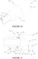
- FIG. 1is a perspective view of a connector from a second end (connector connecting end).
- FIG. 1 Ais a perspective view of a connector from a second end (connector connecting end).
- FIG. 2is a perspective view from the other end of the connector of FIG. 1 .
- FIG. 2 Ais a perspective view from the other end of the connector of FIG. 1 A .
- FIG. 2 Bshows the connector of FIGS. 1 A and 2 A as part of an assembly with a conduit and another connector.
- FIG. 3is a side view of the connector of FIG. 2
- FIG. 4is another side view where the connector has been rotated through 90°.
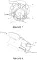
- FIGS. 5 - 7are each different views showing the interior of the second end of the connector of FIG. 1 .
- FIG. 8is a cross-section through the c centre or mid-line of the connector of FIG. 1 .
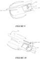
- FIG. 9is another cross-section of the connector of FIG. 1 , axially rotated relative to FIG. 8 .
- FIG. 10is yet another cross-section of the connector of FIG. 1 , axially rotated relative to FIGS. 8 and 9 .
- FIG. 11is a perspective view of an alternative embodiment connector to that of FIG. 1 .
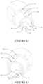
- FIGS. 12 , 13 , 14 , and 16are different views of the second end of the connector of FIG. 11 .
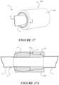
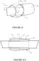
- FIGS. 15 and 17illustrate the same views as FIGS. 14 and 16 , yet with respect to the connector of FIGS. 1 A and 2 A
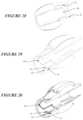
- FIG. 18is a cross-section through the connector of FIG. 11 showing internal features.
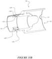
- FIG. 19is another sectional view through the connector of FIG. 11 .
- FIG. 20is a sectional view through the connector of FIGS. 1 A and 2 A .
- FIGS. 21 - 23illustrate a sequence in which the connector of FIGS. 11 , 12 , 13 , 14 , 16 and 19 is connected or engaged with another connector (being the connector illustrated by FIGS. 28 - 29 ).
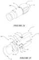
- FIG. 24shows a perspective view of the engagement made by the connectors shown in FIGS. 21 - 23 .
- FIG. 25shows a cross-section of the inter-connecting features of the engagement when made shown by FIGS. 21 - 23 .
- FIGS. 26 - 27show a known connector having male connecting features in the form of a pair of locking fingers, such a connector able to be brought into engagement with the connector of FIG. 1 in a similar manner to that shown by FIGS. 21 - 23 .
- FIG. 28is a cross-section through the left-hand end connector of the connector arrangements shown in FIGS. 21 - 23 .
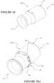
- FIG. 28 Ashows a perspective view of a connector.
- FIG. 28 B 1shows a side view of the connector of FIG. 28 A .
- FIG. 28 B 2shows a top view of the connector of FIG. 28 A .
- FIG. 28 Cshows a lanyard connected to the connector of FIGS. 28 A - 28 B 2 .
- FIG. 28 Dshows an assembly of the connector of FIGS. 28 A - 28 B 2 with an attached optional lanyard, and a patient interface as a tracheostomy interface.
- FIG. 28 Eshows an assembly of the connector of FIGS. 28 A - 28 B 2 connected to a patient interface as a nasal cannula.
- FIG. 28 Fshows an assembly of the connector of FIGS. 28 A - 28 B 2 with a lanyard and connected to a connector.
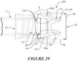
- FIG. 29is an external perspective view of the connector of FIG. 28 .
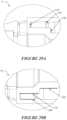
- FIGS. 29 A and 29 Bare close-up views of the regions encircled as items ‘A’ or ‘B’ in FIG. 29 .
- FIG. 30is a cross-section of another connector embodiment, additionally illustrating a swivel-type arrangement in combination with a cuff arrangement.
- FIG. 31is an external perspective view of the connector of FIG. 30 .
- FIG. 32shows a connection in particular by a flange or lip with a male connection feature of a connector as shown by FIGS. 28 - 29 .
- FIG. 33 Ashows how a body of a connector upon which a cuff is to be used may include a groove or other recess for receiving a spline or other projection of a cuff
- FIG. 33 Bshows the cuff which is to be placed upon the body.
- FIG. 34 Ais another connector embodiment, shown as a perspective view, while FIGS. 34 B and 34 C are different end perspective views of the cuff shown in FIG. 34 A .
- FIG. 35is a cross-section through the centre or mid-line of the connector of FIG. 34 A illustrating internal parts, including a swivel-type connector component.
- FIG. 35 Ais a perspective view of a connector.
- FIG. 35 Bis a cross-section of connector of FIG. 35 A.
- FIG. 36is a perspective view of a connector.
- FIG. 36 Ais an end view of the connector of FIG. 36 .
- FIG. 36is a perspective view of a connector.
- FIG. 36 Ais an end view of the connector of FIG. 36 A
- FIG. 37shows a connector in engagement with a second connector.
- FIG. 37 Ashows a cross-section of FIG. 37 .
- FIG. 38shows a connector in engagement with a second connector.
- FIG. 38 Ashows a cross-section of FIG. 38 .
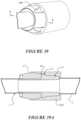
- FIG. 39shows a connector in engagement with a second connector.
- FIG. 39 Ashows a cross-section of FIG. 39 .
- FIG. 40shows a connector in engagement with a second connector.
- FIG. 40 Ashows a cross-section of FIG. 40 .
- FIG. 41shows a connector in engagement with a second connector.
- FIG. 41 Ashows a cross-section of FIG. 41 .
- FIG. 42shows a connector in engagement with a second connector.
- FIG. 42 Ashows a cross-section of FIG. 42 .
- FIG. 43shows engagement between a connector and a second connector
- Provision of new and different connectorscan improve patient safety in the successful and maintained delivery of gas therapies, such as delivery of humidified gas or other gas to a patient.
- a connector 1to be provided at a terminal end of a breathing conduit (indicated as C in the figures).
- the breathing conduitmay be a medical breathing conduit.
- the connector 1comprises a body 4 having a first end 5 and a second end 6 .
- the body 4itself internally defines a lumen 7 for the passage of gas therethrough between each of the first and second ends 5 , 6 .
- the ends 5 , 6 of the connector 1may each be considered to be either upstream or downstream of the other end when placed into a breathing circuit, for example the direction of gas flow will determine whether an end 5 is fluidly upstream or downstream of the other end 6 .
- the first end 5in use, being engaged or engageable with the terminal end of a breathing conduit 3 or at least a component to be associated with the terminal end of the breathing tube.
- the second end 6 of the connector 1is, in use, to be engaged or engageable with another connector.
- the second end 6 of connector 1may be put into engagement with a suitably configured end of another connector.
- Suitably configured other connectors as shown hereinare illustrated by:
- An internal surface 8 of the bodycomprises one or more internal connection features 9 configured for connection with another connector which is to be, in use, received internally.
- An external surface 10 of the body 4comprises one or more external alignment feature(s) 11 configured for aligning said connector or another connection into an externally aligned connection therebetween.
- Such visual aid(s)may also be configured to provide dual function as an alignment feature.
- a visual aidcan be of a sufficient bulk or tapered dimension so as to transition from being a visual aid to being an alignment feature itself.
- connection features 9is/are surface feature(s) that extend radially inward from the inner surface 8 of an internal side wall of the body 4 .
- the one or more internal connection features 9can be one or more tabs, where a tab is a raised protrusion extending from the inner surface 8 .
- connection features 9can be oriented so as to be radially aligned with respective external alignment features 11 and/or the corresponding external visual aids 12 .
- connection features 9Although the figures show a pair of connection features 9 , it will be appreciated further connection features may be provided about the inner surface 8 .
- connection features 9may include a longitudinally extensive channel or recess 13 , or the connection feature may be split into two more parts to allow for such a channel or recess 13 (or slot).
- a channel or recess 13is configured to locate, retain, or position a printed circuit board (PCB) arrangement (not shown) which may be inserted into such a slot.
- PCBprinted circuit board
- a channel or recess 13 (or slot)may be provided at other locations about the inner surface 8 .
- the internal surface 8can include one or more internal alignment features 14 .
- Such internal alignment featuresare configured for aligning a connection feature of another connector (e.g. one or more male lock fingers that may extend into the internal space of the body 4 ) that is placed in contact therewith, for example when the connector feature of another connector is inserted into or is received internally of the body 4 at the second end.
- the connection feature of another connectoris oriented (such as by being rotated) to be brought into an aligned connection orientation with the internal connection features 9 of connector 1 .
- the internal surface 8has the one or more internal alignment features 14 configured to, in use, rotatably orient a male connection feature of another connector into an aligned connection orientation for connection with the connector, or at least into connection with one or more of the internal connection features 9 located on or about the internal or inner surface 8 of the body 4 .
- the internal alignment feature(s) 9may be surface feature(s) that extend in a radially inward direction from the surface of an internal side wall of the body 4 , or the inner surface 8 .
- the internal alignment feature(s)may be of the form of one or more tab(s), where a tab is advantageously a raised protrusion.
- Each tabmay be shaped so as to provide a pair of shoulders, each shoulder sloping away from each other and away from an end (for example an apex, or rounded apex, or a flat or curved surface, such as that shown by FIGS. 1 A, 2 A, 17 , 20 ) at the intersection of the shoulders.
- Such an end of the shouldersbeing located substantially more toward a terminal end of the second end of the connector. In this manner, such a tab can guide or encourage a male connection feature that comes into contact with the shoulders to slide down the slope of each shoulder, thereby being auto-rotated.
- the internal alignment feature(s) 14may be one or more ribs extending substantially in a longitudinal direction of the connector 1 , and along the internal surface 8 .
- there may be any number of ribsbut for example there may be: 1-10 ribs, or 2-8 ribs, or 4-6 ribs, or 2 ribs, or 3 ribs, or 4 ribs, or 6 ribs, or 8 ribs, or 10 ribs.
- each setmay have an equal (i.e. same) number of such internal alignment features as another set.
- a pair of internal alignment features 14that in use, rotatably align a pair of fingers (i.e. male locking fingers) that extend from another connector when inserted into or placed into engagement or surface contact with said internal surface of the connector 1 .
- the first end 5is configured for engagement with the terminal end of a breathing conduit.
- a first endcan include a sleeved portion 15 to be attached to the terminal end of the breathing conduit, with which a suitable connection, such as a pneumatic connection can be made.
- a suitable connectionsuch as a pneumatic connection
- At least a part of the sleeved portion 15is configured to be insertable into or to be located or housed within an interior surface of the lumen of the terminal end of the breathing conduit (i.e. an internal connection is made), or alternatively the sleeved portion may be receivable upon or to be located or housed upon an exterior surface of the terminal end of the breathing conduit (i.e. an external connection is made).
- thesecan be external surface features which extend radially outwardly from the outer surface 10 of an external side wall of the body 4 .
- thesemay be in the form of a tab or raised protrusion.
- the external alignment feature(s) 11 or visual aids 12may include one or more ribs extending substantially in a longitudinal direction with the connector and along the external surface 10 of the body 4 .
- FIGS. 1 A and 2 Ashow an alternative configuration of the external visual aid(s) 12 of the connector.
- the external visual aid(s) 12comprise a raised protrusion with an end 12 A (for example an apex, or rounded apex, or a flat or curved surface) and a pair of shoulders 12 B.
- the shoulders 12 Bare arranged to slope away from each other and away from an end at the intersection of the shoulders.
- the end 12 Ais located toward a second end 6 of the connector, and the shoulders are located nearer the first end 5 of the connector (than to the second end 6 ), for example near the flange or lip 16 .
- the external visual aid(s) 12may optionally be substantially tongue shaped, and/or substantially triangular and/or substantially taper toward an end.
- FIG. 2 Bshows an assembly comprising the connector 1 , a conduit C, and another connector 258 .
- the another connector 258may, for example, be the connector as described in U.S. Ser. No. 62/252,149 and/or U.S. Ser. No. 10/452,448 (as U.S. Pat. No. 6,953,354) to the common applicant, Fisher & Paykel Healthcare Limited, the contents of both of which are incorporated herein.
- FIGS. 15 and 17show end views of the connector of FIGS. 1 A and 2 A .
- FIG. 20shows a cross-section of the connector of FIGS. 1 A and 2 A .
- the external alignment featurescan be spaced, arrayed or arranged evenly or equidistantly from each other about the circumference or a radius of the external surface 10 .
- the external alignment feature 11 and/or visual aid 12may be a projection of a length that extends in a substantially longitudinal direction of the connector and along the external surface 10 , with a height of the projection from the external surface varying along its length.
- the height of the external alignment feature and/or visual aidcan taper along this length.
- the height of the projectionmay taper either so the height:
- FIG. 3in particular illustrates a tapered arrangement matching a) above (i.e. a taper that reduced in height as the projection progresses toward the terminal end of the second end 6 ).
- a stepped protrusionthat may form the external alignment feature identified as item 11 in the figures.
- the stepped protrusionbeing a more radially outwardly extending projection than an adjacent portion of the external alignment feature.
- the stepped projectioncan be configured to co-locate or provide for co-location of a suitably shaped part which may be keyed therewith.
- the stepped projectionallows for keying with a reciprocally shaped recess or cut-out of at least a part of a sleeved portion of another connector when brought to bear or into contact for connection between the connector 1 and another connector.
- a recess or cut-outconfigured for receiving a protrusion or projection of a reciprocally shaped portion of another connector.
- the recess or cut-outcan be configured to be co-located or co-locatable for keying with a reciprocal protrusion or projection of at least a part of a sleeved portion of another connector.
- Such a recess or cut-outeffectively acts as a keyway for a key which may be brought to bear upon it.
- Suitable shapes or profiles for the key or keywaymay be used. It will be appreciated any suitable shape can be employed, although particularly preferred shapes or profiles include: semi-circular, triangular, rectangular or other recti-linear or geometric shapes, elliptical, wedge shapes.
- the connector 1may further comprise of a radially extensive flange or lip 16 that projects outwardly or away from the external surface 10 of the body 4 .
- Such a flange or lip 16may effectively define a stop end for a point or length of maximum engagement by another connector when made with the external surface 10 of the connector 1 .
- the flange or lipmay optionally also provide for a sealing surface upon which another connector may make substantially a pneumatic connection therewith.
- the flange or lip 16may additionally comprises one or both of: 1) one or more radially and/or longitudinally recessed or grooved regions 18 a , or 2) one or more radially and/or longitudinally extending projection regions 19 a.
- the flange or lip 16may also be sufficiently longitudinally extensive so as to be configured for an engagement with the terminal end of the breathing conduit, or a component to be associated with the terminal end of the breathing conduit.
- the external alignment feature(s) 11 of the connector 1may be shaped or configured to prevent connection of the internal connection features 9 of the connector with another connector (for example connector 40 ), when the external alignment feature(s) of the connector 1 and an external alignment feature of another connector (for example connector 40 ) are in an unaligned orientation.
- the external alignment feature(s) 11 of the connector 1may be shaped or configured to allow connection of the internal connection features 9 of the connector with another connector (for example connector 40 ), when the external alignment feature(s) 11 of the connector 1 and an external alignment feature of another connector (for example connector 41 ) are in an aligned orientation.
- a sheath 17such as an overmoulding, may surround or provide for an engagement (whether pneumatic or not) about an external surface of the body 4 .
- a sheath 17may be provided for the one or more radially and/or longitudinally recessed or grooved regions 18 b , and/or the one or more radially and/or longitudinally extending projection regions 19 b.
- the various recessed or grooved regions 18 b and/or said extending projection regions 19 b of the sheathmay be wholly or at least partially aligned with the recessed or grooved regions 18 a and/or said extending projection regions 19 a of the flange or lip 16 .
- an internal surface 8 of the body 4can provide for, toward the second end 6 of the connector 1 , the locating, retention, or positioning of a printed circuit board (PCB) arrangement.
- PCBprinted circuit board
- a PCBmay be provided upon a relatively planar plate and may be inserted within the body 4 .
- the PCBmay be used for various reasons, may in some particular configurations facilities circuitry for: control, sensing (e.g. temperature, humidity, flow rate), heating (e.g. heater wires) or other electronic components for a breathing conduit to be used as a part of a breathing circuit.
- the connector 1may provide for a sealing surface upon which separate connections with separate other connectors may be made.
- the connector 1may be configured to provide a first separate surface for sealing upon when a separate connection is made thereto by another connector, the first surface defined by one or both of:
- the connector 1when the connector 1 , is configured in a first sealing mode where the surface for sealing is provided for, at least in part, by said side wall surface 20 , such a first mode of sealing would require the removal, or avoidance, of providing for the radially and/or longitudinally extensive grooves from at least the flange or lip 16 and optionally also from the sheath (or cuff) 17 .
- the connector 1may be configured to provide a body of the second end, for sealing upon a second sealing surface of another connector 200 , the second sealing surface defined by:
- the connector 1may be configured to provide a body of the second end for sealing upon a third sealing surface of another connector 200 , the third sealing surface defined by:
- the connector 1is configured to provide a body of the second end for sealing upon a fourth sealing surface of another connector 200 , the fourth sealing surface defined by:
- the connector 1is configured to provide a body of the second end for sealing upon a fifth sealing surface of another connector 200 , the fifth sealing surface defined by:
- the connector 1is configured to provide a body of the second end, for sealing upon a sixth sealing surface of another connector 200 , the sixth sealing surface defined by one or both of:
- the connector 1 as described hereinhas particular application to being an upstream connector component attached to the terminal end of a breathing conduit which is to supply gas to a patient interface.
- the connector 1is capable of operating to be both a female and a male type connector, thereby improving the useability and ability to connect to other types of connectors (where those other connectors provide for male connection features or female connection features).
- the connector 1may have particular application as a connector for a breathing conduit providing a supply of gas from a source.
- the ‘another connector’ described abovemay be, but without limitation, be a downstream patient interface end connector for a breathing conduit which provides the supplied gas to a patient interface (such as, but not limited to full face masks, nasal cannula, oro-nasal masks, nasal masks—and whether each of these are of a sealing or non-sealing type).
- FIGS. 21 - 25show a connection made by a connector 200 with the connector 1 .
- Another connector(as referred to above) or second connector, configured to be engaged or engagable with the connector.
- the another connectormay be bought into mating and/or connection and seal with at least one of the following surfaces of the connector 1 :
- FIGS. 36 and 36 Adisclose a connector to be coupled or mated in a sealing arrangement with a second connector (for example connector 1 .)
- This connector 220may be the another connector as described above.
- the connector 220may be provided at a terminal end of a breathing conduit C. Alternatively or additionally, the connector 220 may form part of adapter, which may facilitate the connection of two connectors, i.e. the connection of the connector 1 , and any other connector.
- the connectorhas a body 201 , comprising a first end 202 and a second end 203 .
- the first end 202is engaged or engageable with the terminal end of the breathing conduit C or at least a component to be associated with the terminal end of the breathing conduit or tube (for example an adapter as described above.)
- the second end 203 of the connector 220is engaged or engageable with a second or another connector (for example, the connector 1 ).
- the connector 220comprises an internal lumen or passage way to receive the second connection internally.
- the internal surface of the body 201may comprise one or more internal connection and/or alignment features 210 , 211 , 212 .
- the internal connection and/or alignment features 210 , 211 , 212may facilitate sealing (pneumatic or otherwise) and/or alignment of the connector and a second connector (for example connector 1 ) when connected or during connection.
- the internal connection and/or alignment features 210 , 211 , 212may also provide for a visual indication of alignment so a user may more easily align and connect the connector 220 , with a second connector.
- the internal connection and/or alignment featuresmay also provide for retention of the connector 220 with a second connector when connected therewith.
- the internal connection and/or alignment features 210 , 211 , 212may comprise a rib or protrusion 211 projecting radially inward from the body 201 of the connector 220 , or from a notional or actual internal wall or surface of the body 201 .
- the protrusion(s) or rib(s) 211may extend in a substantially longitudinal direction along a side wall of the internal surface of the body 201 of the connector 220 .
- the protrusion(s) or rib(s) 211may extend substantially from at or near a second end 203 (for example terminal end of the second end of the connector) in a direction toward the first end 202 of the connector 220 .
- the internal connection and/or alignment features 210 , 211 , 212may comprise a recess 210 , 212 projecting radially outward from a notional or actual internal wall or surface.
- the at least one recess 210 , 212may be located in a side wall or an internal surface of the body 201 of the connector.
- the at least one recessmay be configured to accommodate an associated projection(s) of a second connector (for example projection 11 of connector 1 ) when said second connector is brought into a mating or connection with said connector 220 .
- the internal connection and/or alignment features 210 , 211 , 212may provide for, at least in part, sealing, or a sealing surface, between the connector and another connector.
- the internal connection and/or alignment features 210 , 211 , 212themselves, or in combination with an inner surface of the body of the connector, may seal with the second connector (for example connector 1 )
- the internal connection and/or alignment features 210 , 211 , 212may be shaped so as to match corresponding features of the second connector.
- the ribs 211 , of the connectormay be configured to match with corresponding recesses (for example longitudinally recessed or grooved regions 18 b of the connector 1 of a cuff or sleeve 17 ) of a second connector (for example connector 1 ).
- the recesses 210 , 212may be configured to match with corresponding ribs or protrusions (for example visual alignment features 12 or protrusion 16 ) of a second connector.
- the internal connection and/or alignment features 210 , 211 , 212may be co-located or co-locatable for keying with a reciprocally shaped projection or recess of a portion of a second connector. This may be one mechanism of providing an alignment function between the connector 220 and a second connector.
- the internal connection and/or alignment features 210 , 211 , 212may be shaped to facilitate correct orientation for coupling, so that when the connector 220 is brought into contact with the second connector the connectors are aligned, to ensure the internal connection and/or alignment features 210 , 211 , 212 line up with the corresponding ribs or protrusion, and/or recess on the second connector.
- the keyingmay also prevent rotation of the components relative to each other when in a coupled state.
- the internal connection and/or alignment features 210 , 211 , 212may be arranged circumferentially around the internal surface of the connector.
- the internal connection and/or alignment features 210 , 211 , 212(for example the ribs and/or protrusions) may be spaced equidistantly around the circumference of the internal surface of the body 201 of the connector 220 .
- the internal connection and/or alignment features 210 , 211 , 212may be arranged so that they are not equidistant (i.e. non-symmetrical about a plane), this may only allow connection between the connector 220 and a second connector in a particular orientation.
- connection and/or alignment features 210 , 211 , 212ribs and/or recesses
- the pair of recesses 210 , 212may be located so they are spaced equidistantly around the circumference of the internal surface of the body 201 of the connector 220 .
- the recesses 210 , 212 , 212may be arranged so that they not equidistant (i.e. non-symmetrical about a plane).
- the recesses 210 , 212may be arranged to be overlapping such that one, at least partially, fits within the other or one is at least partially defined by the other.
- the internal surface of the body 201 of the connector 220may comprise at least one sealing surface or surface for sealing.
- the sealing surfaces as mentioned hereinare labelled, for convenience and clarity, as the first, second and third sealing surfaces.
- a connectormay comprise a for example third, or second sealing surface without necessarily comprising a first sealing surface.
- the inclusion of a particularly numbered sealing surfacedoes not require the inclusion of the earlier numbered sealing surface(s).
- the connector 220may provide at least a first internal surface for sealing upon an external part of a said second connector, when a connection or mating is made thereto by or with said second connector.
- the first internal surfaceis provided by a circumferential portion of the internal surface of the body 201 .
- the circumferential portionmay be located at or near the second end 203 of the body 201 of the connector 220 .
- the first sealing surfacemay be provided so as to be substantially continuously and substantially circumferentially locatable about an external part of a second connector (for example a cuff or sleeve 17 of the connector 1 .)
- FIGS. 37 - 40 Aillustrate examples of a connector 220 , which seal with a second connector (being connector 1 ), by at least a first internal sealing surface.
- the internal connection and/or alignment features 210 , 211 , 212may form at least part of the first internal surface of the body.
- the recess(es) and/or rib(s) or protrusion(s)may form at least part of the first internal surface.
- the protrusion(s) or rib(s) 211may extend in a substantially longitudinal direction along the internal surface of the body 201 of the connector 220 .
- the protrusion(s) or rib(s) 211may extend substantially from at or near a second end 203 (for example terminal end of the second end of the connector) in a direction toward the first end 202 of the connector 220 . It will be appreciated that the ribs and/or protrusions 211 of the connector 1 may extend only part way into or along the channel 18 b.
- the first internal surface of the body 201 of the connector 220may be substantially curved when viewed in cross section (as shown in the cross sections of FIGS. 37 A, 38 A, 39 A and 40 A ). Additionally or alternatively, the profile of the first internal surface (e.g. the radius of curvature and location of a curve of the first internal surface) may match an external profile (e.g. an external curve or curvature) of a cuff or sleeve 17 of a second connector. The profile of the first internal surface may allow for sealing between the first internal surface and a cuff or sleeve 17 of a second connector.
- FIGS. 37 - 40 Aillustrate where the first internal surface is profiled to match the profile of a cuff or sleeve 17 of a second connector (for example connector 1 ).
- FIGS. 37 to 40 Ashow a series of embodiments of the connector 220 where the ribs or protrusions 211 extend into the recesses or longitudinal channels 18 b of the sleeve 17 .
- FIG. 37shows a connector 220 where the first internal surface and the ribs or protrusions 211 extend to the end, or substantially near the end of the cuff or sleeve 17 of the connector 1 .
- FIG. 37 Ashows a cross section of the connector 220 in completed connection with the second connector, being connector 1 . It is also envisaged that the first internal surface may extend past the end of the cuff or sleeve 17 of the connector 1 .
- FIG. 38shows a connector 220 where the first internal surface and the ribs or protrusions 211 extend to a position between an outer-most apex of the external profile of the cuff of sleeve 17 of the second connector 1 and the end of the cuff or sleeve 17 nearest the terminal end (connected to conduit C) of the second connector.
- FIG. 38 Ashows a cross section of the connector 220 in completed connection with the second connector (being connector 1 .)
- the connector 220may be made from a soft rubberised material, so, the second end of the connector can be stretched over the apex of the sleeve 17 .
- the embodiments of FIGS. 39 - 42 Amay also be made of a soft of rubberised material.
- the connectormay be made of a rigid material.
- FIG. 39shows a connector 220 , where the first internal surface and the ribs or protrusions 211 are of a sufficient dimension so as to, in use, extend substantially to an outer-most apex of the external profile defined by the sleeve 17 of the connector 1 .
- FIG. 40shows a connector 220 where the first internal surface and the ribs or protrusions 211 extend to a position between the outer-most apex of the external profile of the cuff of sleeve 17 of the second connector 1 and the end of the cuff or sleeve 17 nearest the end of the second connector 1 not connected to a conduit C.
- FIG. 40 Ashows a cross section of the connector 220 in completed connection with the second connector, being connector 1 .
- the connector 220may provide a second internal surface for sealing upon when a connection or mating is made thereto by or with said another connector.
- the second surfacebeing defined by a substantially radially extensive flange or lip 204 (for example as shown in FIGS. 36 and 36 A ).
- the flange or lip 204projects radially inward from the internal surface of the body as a side wall surface.
- the flange or lip 204may provide a face, upon which a respective face (for example flange or lip 12 , or a terminal end) of the second connector seals.
- the radially extensive flange or lip 204may comprise at least one of said internal connection or alignment feature.
- the at least one connection or alignment featuremay be a rib or protrusion, or a recess.
- the at least one recessmay be located in flange or lip 204 , or be a depression or other surface relief feature provided upon the face of the flange or lip 204 .
- the depression or other surface relief featureis a cut-out of the face.
- the internal connection and/or alignment feature(s)may be to be co-located or co-locatable for keying with a reciprocally shaped projection or recess of a portion of a second connector.
- the connector 220may comprise ribs 211 , which are co-locatable with recesses 18 a of the connector 1 .
- the connector 220may also comprise at least one recess 210 located in flange or lip 204 , the at least one recess 210 being co-locatable with ribs or projections 11 of the second connector (being connector 1 ).
- the recessmay be configured to accommodate or be receivable of an associated projection or other shaped feature of a second connector when the second connector is brought into a mating or connection with said second internal surface.
- the at least one protrusionmay be located in a side wall or an internal surface of the connector, the at least one protrusion to accommodate recesses of said another connector.
- the face of the flange or lip 24may be configured to provide for a substantially planar surface upon which a portion or a surface of the second connector can mate or engage with.
- the facemay be oriented to substantially face toward said second end 203 of said connector 220 .
- the facemay mate or seal upon a side wall, or ledge, or lip or base, or end of a second connector.
- the facemay seal with a corresponding face of the flange or lip 16 of the connector 1 .
- the connectormay also provide at least a third internal surface for sealing upon an external part of a second connector, when a connection or mating is made thereto by or with the second connector.
- the third internal surfaceis provided by a circumferential portion of the internal surface of the body, optionally said circumferential portion located at or near the first end of the body of the connector and provided so as to be substantially continuously and substantially circumferentially locatable about an external part of a said another connector to which the third internal surface is to be put into connection or a mating arrangement therewith.
- the connector 220may provide at least a third internal surface for sealing upon an external part of a said second connector, when a connection or mating is made thereto by or with said second connector.
- the third internal surfaceis provided by a circumferential portion of the internal surface of the body 201 .
- the circumferential portionmay be located at or near the first end 202 of the body 201 of the connector 220 .
- the third internal surfaceis located near the second end 203 of the body 201 .
- the first sealing surfacemay be provided so as to be substantially continuously and substantially circumferentially locatable about an external part of a said second connector (for example an external surface 10 of the body 4 of the connector 1 .)
- the alignment or connection featuremay form at least part of the third internal surface of the body.
- the recess 212forms part of the third internal surface for sealing.
- the at least one recessmay be shaped so as to accommodate projections of said second connector for example the visual indicator 12 .
- the recessmay be configured to accommodate and seal with at least part of the projection of the second connector.
- the remaining internal surface of the body of the connector 220may then seal with at least part of the external surface 10 of the body 4 of the second connector 1 .
- the recessmay comprise a pair of shoulders, sloping away from each other and away from an end (for example an apex) at the intersection of the shoulders.
- the end of the recessbeing located substantially more toward the first end of the connector 220 than the shoulders.
- the at least one recessmay be substantially tongue shaped, and/or substantially triangular and/or substantially tapers toward an end.
- the recessmay extend only part of the way into the body of the connector 220 (as shown in FIG. 42 .) As such when the connector 220 is connected to the second connector 1 , the body 201 of the connector 220 may extend only part of the way onto the second connector 1 .
- the recessmay be a longitudinal channel (for example to accommodate the ribs 12 of FIG. 1 )
- FIGS. 42 - 42 Ashow connectors 220 , which seal, at least in part, with a second connector (being connector 1 ) by a third sealing surface.
- the connector 220seals with part of the external surface 10 of the body 4 of the second connector 1 , including part of the rib or protrusion 12 .
- FIG. 43shows the connection of the connector 220 with a second connector (for example connector 1 ).
- the second connector 1is inserted into the connector 220 , such that the external alignment feature(s) 11 or visual aids 12 are mated and optionally seal with their corresponding internal connection/alignment features 210 , 212 .
- the recessed or grooved regions 18 Bmate (and optionally seal) with the ribs 211 .
- the connectormay comprise any combination of the first, second and third sealing surfaces as described above.
- the second connectormay be a single piece as shown in FIGS. 37 - 41 , or made from multiple pieces as shown in FIGS. 42 and 42 A (and with reference to the connector 1 as described above.)
- connectors 200 and 40which are operationally compatible with the connector 1 .
- the following descriptionis provided primarily with reference to the connectors 200 and 40 , as seen in FIGS. 21 - 25 and 28 - 35 B .
- a connector 200 , 40for use with a conduit to supply gases to a user.
- the connector 200 , 40to be provided at a terminal end of a breathing conduit.
- the connector 200 , 40comprises a body 50 , the body comprising a first end 51 and a second end 52 , the body 50 internally defining a lumen 53 for the passage of gas therethrough between each of the first and second ends.
- the first end 51in use, being engaged or engageable with the terminal end of the breathing conduit or at least a component to be associated with the terminal end of the breathing conduit.
- the connector 200may be connected to the terminal end of the breathing conduit by a swivel-type connector connected to the body of the connector.
- the second end 52in use, to be engaged or engageable with another connector (such as the connector of item 1 previously described herein).
- An internal surface of the bodycomprises one or more internal male connection features 53 extending therein configured for connection with a female end or female part of another connector receivable of said male connection features 53 .
- the male internal connection features 53comprising one or more (optionally a pair) of locking fingers 54 .
- the connector 200 , 40comprising one or both of:
- the first end of the connector 51comprises a sleeve portion that flares outwardly.
- the outwardly flared portionallows for movement of a connected breathing conduit relative to the connector 40 , so that the breathing conduit may flex and bending without damage from the connector. Additionally, the outwardly flared sleeve portion also allows the user to better grip the connector for easier connection and disconnection with other connectors.
- the connectormay comprise at least one securement feature 231 .
- FIG. 28 Ashows an embodiment of the connector 200 where the securement 231 is formed by a recessed region 232 and a bridging portion 234 .
- the bridging portion 234allows for the connection of a lanyard (or a part of a lanyard) to be fastened to the connector 200 .
- Other structural features (forming the securement feature 231 ) for attaching the lanyard to the connector 200are envisaged such as an integral loop or clip.
- FIG. 28 B 1shows a side view of the connector 200 of FIG. 28 A .
- the connector 200may comprise a pair of securement features 231 (although in the side view of connector 200 only a single securement feature 231 is shown, the second securement feature 231 being hidden from view), and they may be, for example, disposed equidistantly around a perimeter of connector 200 .
- FIG. 28 B 2shows a top view of the connector 200 of the connector 200 of FIG. 28 A comprising a pair of securement systems 231 .
- the pair of securement systems 231are located in an opposing manner, such that the securement systems 231 are located on opposite sides of the connector 200 .
- a lanyard 240may be connected to one or both of these securement systems 231 .
- FIG. 28 Cshows a lanyard 240 fastened or engaged with the securement feature 231 of the connector 200 .
- the lanyard 240comprises a looped portion 241 which can be fastened around the bridge 234 and then pulled through itself to securely associate the lanyard 240 to the connector 200 .
- the lanyard 240can then be placed around a user's neck, or a feature of the environment to take or support at least some of the weight of the connector 200 , attached conduit, and/or interface.
- FIG. 28 Dshows the connector 200 with an attached lanyard 240 (optional), and a patient interface as a tracheostomy interface 250 via a conduit C.
- the tracheostomy interfaceis connected to a tracheostomy guard 253 .
- the tracheostomy guard 253may be, for example, that as described in U.S. Ser. No. 62/329,638 to the common applicant, Fisher & Paykel Healthcare Limited, the contents of which are incorporated herein.
- FIG. 28 Eshows the connector 200 without a lanyard and connected to a patient interface such as a nasal cannula 251 via a conduit C.
- An optional tube clip TCmay be utilised and provided along a conduit C.
- the tube clip TCmay comprise features for being attached to an item in the environment to thereby assist with support of the conduit C, the interface 251 or other parts of a breathing circuit. In this way the weight of the part of the breathing circuit close to a patient or user can be supported.
- FIG. 28 Fshows the connector 200 with a lanyard 240 and connected to a connector 252 via a conduit C.
- a connector 40for use with a conduit to supply gases to a user.
- the connectorcomprises a body 50 , the body 50 comprising a first end 51 and a second end 52 .
- the body 50internally defining a lumen for the passage of gas therethrough between each of the first and second ends.
- the first end 51in use, being engaged or engageable with the terminal end of the breathing conduit (such as a tube leading to a patient interface) or at least a component to be associated with the terminal end of the breathing tube.
- the second end 52in use, to be engaged or engageable with another connector.
- An external surface of the body 50comprises a cuff 65 provided at least substantially about the first end 51 of the connector body 50 (optionally at least partially overlapping of a portion of the second end 52 of the connector body 50 ), said cuff 65 extending substantially longitudinally down at least a part of a length of the breathing tube to be engaged or engageable with the first end 51 , and wherein said cuff is an elasticised or elastic-type material, such as silicone or a thermoplastic elastomers (TPE) type material.
- TPEthermoplastic elastomers
- a diameter of the second end's 52 outer wall 55is smallest at a terminal end 58 of the second end (i.e. being the external diameter), with the (external) diameter increasing in a direction extending away from the terminal end 58 of the second end 52 towards the first end 51 .
- the one or more locking fingers 54are housed substantially within the second end 52 of the connector 200 , 40 .
- a space 59is defined between an outer surface of the one or more internal male connection features 53 (or locking fingers 54 ) and an inner surface 60 of the outer wall.
- the outer wall 55is configured to provide for one or more alignment feature(s) 57 and/or one or more external visual aid(s).
- the one or more alignment feature(s) 57assist in aligning the outer wall with a reciprocally shaped feature on another connector.
- External visual aidsmay include graphics or other visual indicators for a user to correctly align and position the alignment feature on the outer wall with a reciprocal feature of another connector which is brought to bear upon the alignment feature(s) 57 .
- the one or more internal male connection features 53is/are oriented so as to be radially aligned with the external alignment features 57 and/or the external visual aids.
- Each of these thingsin combination providing visual indicators, as well as physical aides to ensure a correct alignment of once connector with another connector.
- the external alignment feature(s) 57may be one or more cut-outs at a terminal end 58 or face of the outer wall 55 of the second end 52 .
- the cut-outscan be configured to be received by a substantially reciprocally shaped portion on a connector to which said outer wall is to be placed into contact.
- the various external alignment features 57can be spaced, arrayed or arranged evenly or equidistantly from each other about the circumference a terminal end face of the outer wall of the second end.
- the external alignment features 57are configured to be co-located or co-locatable for keying with a reciprocally shaped projection of a sleeved portion of another connector when brought to bear into connection during a connection between a terminal face 58 of the second end 52 of the connector 200 , 40 and another connector.
- the external alignment feature(s) 57 of the connector 40may be shaped or configured to prevent connection of the internal connection features 53 of the connector with another connector (for example connector 1 ), when the external alignment feature(s) of the connector 40 and an external alignment feature of another connector (for example connector 1 ) are in an unaligned orientation.
- the external alignment feature(s) 57 of the connector 40may be shaped or configured to allow connection of the internal connection features 53 of the connector with another connector (for example connector 1 ), when the external alignment feature(s) 57 of the connector 40 and an external alignment feature of another connector (for example connector 1 ) are in an aligned orientation.
- the locking fingers 54may comprise a recess 61 on an outer surface of each finger 54 .
- a recess 61provided for receiving or engaging with an internal connection feature, such as a raised protrusion or tab such as a locking tab 14 of a connector such as that indicated as item 1 .
- the recess 61can be shaped for receipt of the internal connection feature (e.g. item 14 ) of another connector (e.g. the connector indicated as item 1 herein).
- a tip 62 of the locking fingersmay be of an at least partially chamfered configuration, preferentially to assist in the locking fingers 54 being able to be received into engagement by a connection feature such as that itemised as 14 .
- Various shapes of the alignment feature 57 as a cut outmay be provided, for example: semi-circular, triangular, rectangular or other recti-linear or geometric shapes, elliptical, wedge shaped.
- the outer wall 55operates as a sleeve, for being brought into a sleeved connection with another connector (whether as a male or female connection).
- the outer wallis configured for use as a 22 mm male taper connector to another connector comprising a female connection facility, and in another the outer wall is a sleeve, configured for use as a 22 female taper connector to another connector comprising a male connection facility.
- the connectors or at least their bodymay be formed of any medically suitable materials, however particularly preferred is Polycarbonate (PC), Polyethylene (PE), Acrylonitrile Butadiene Styrene (ABS) or polypropylene (PP).
- PCPolycarbonate
- PEPolyethylene
- ABSAcrylonitrile Butadiene Styrene
- PPpolypropylene
- the internal surface of the second end 52 of the bodymay further comprise a protrusion for an engagement (e.g. an interference fit) with a commensurately shaped portion of another connector to be received by or within the internal surface bounded by the outer wall 55 .
- a protrusioncan extend as a shoulder 63 radially outwardly from the one or more locking fingers 54 , or from a base 64 extending as a floor from the inner surface of the outer wall 55 .
- the shouldermay also optionally also extending longitudinally in a direction toward an open end of the second end of the connector.
- an inner surface of the outer wallmay comprise of a radially inwardly extending protrusion 60 a .
- a space 59is defined between a radially outward surface of the shoulder 63 and an inner surface of the outer wall or the inwardly extending protrusion 60 a , such a space being sized and shaped so as to be receivable of a terminal end of another connector, such as a lip or flange part of another connector.
- the terminal end of the another connectorcan be received in the space as an interference fit between the outward surface of the shoulder and the inner surface of the outer wall or the protrusion 60 a .
- FIG. 32shows an assembly of a lip or flange (or a shoulder) 91 of another connector 90 which can be brought into such an interference fit in the space 59 with a connector such as that itemised as connector 200 .
- the lip or flange 91can be retained or held in place by the interference fit, and can also provide for a suitable pneumatic seal between each of these parts.
- the base 64may define a sealing surface upon which a terminal end or a face of a terminal end of another connector may become engaged therewith, optionally forming a pneumatic connection.
- the connector 200is configured to provide for a plurality of separate sealing surfaces upon which seals may be made, whether as a seal between component parts along the entirety of a surface or a point or particular location along that surface. As such, the connector 200 provides for six separate and different sealing surface options. Each of which are described below.
- the connector 200may be configured to provide a first separate surface for sealing upon when a separate connection is made thereto by another connector (such as connector 1 ), the first surface defined by:
- the connector 200may be configured to provide a second separate surface for sealing upon when a separate connection is made thereto by another connector (such as connector 90 ), the second surface defined by:
- the connector 200may be configured to provide a third separate surface for sealing upon when a separate connection is made thereto by another connector (such as connector 90 ), the third surface defined by:
- the connector 200is configured to provide a fourth separate surface for sealing upon when a separate connection is made thereto by another connector (such as 90 ), the fourth surface defined by:
- the connector 200is configured to provide a fifth separate surface for sealing upon when a separate connection is made thereto by another connector (such as 90 ), the fifth surface defined by:
- the connector 200is configured to provide a sixth separate surface for sealing upon when a separate connection is made thereto by another connector (such as 90 ), the sixth surface defined by one or both of:
- a cuff 65may be provided about the first end 51 of the connector body 50 , and may optionally at least partially overlap a portion of the second end 52 of the connector body.
- a cuff 65may be typically an overmoulded material, overmoulded about the connector body 50 , or the cuff may be a pre-formed component which is assembled into position. Alternatively, the cuff may be pre-formed, so that it can then be slipped over or placed onto the connector body into position.
- the cuff 65can be dimensioned to as to provide for a relatively smooth or uninterrupted outer surface contour with an exterior surface of the outer wall substantially abutting or substantially adjacent to an intersection 66 with the cuff.
- the cuffmay include an indicator of the connector to which it (i.e. the cuff) is in place therewith, or may provide an indication for a particular component or size of a component to be associated with the connector (optionally for example where the component is a patient interface, such as a nasal cannula or mask or other such interfaces).
- an indicatormay be by way of colour.
- the cuff 65can be dimensioned to transition from a substantially circular exterior surface contour form, when substantially abutting or substantially adjacent to or with an exterior surface of the outer wall of the connector, to a substantially square exterior surface contour form provided substantially (optionally wholly) about the first end of the connector body. In this manner, a user may be able to apply more torque or force so as to disengage such a connector 40 from a connected engagement with another connector.
- cuff 65transitions from a substantially circular profile (indicated by item 120 ) in the region 121 where the cuff 65 intersects or is provided substantially adjacent with the body of the connector 40 , to be a substantially more square or recti-linear shape in the region 122 .
- FIGS. 30 and 35additionally illustrate a swivel-type connector component 67 having a thread 123 for being threadably engaging of a terminal end of a conduit to be brought into engagement therewith, and so therefore into fluid communication with the lumen of the connector 40 .
- the cuff 65may extend from substantially the second end 52 of the connector body 50 to overlap upon an exterior surface of a breathing tube or conduit to which said connector is to be, in use, engaged or be engageable, or said cuff extends to overlap upon at least a portion of a component to be associated with the terminal end of the breathing tube.
- the outer surface of the cuffmay be textured or otherwise surface treated to increase friction or grip to allow a user to apply a force or torque to the cuff (and in turn the connector).
- the cuffmay comprise of one or more splines 124 or other inwardly projecting portions on an inside surface for engagement or fitting into a suitably shaped recess or groove 70 on an outer surface of the body 50 to which the cuff is to be put into connection therewith.
- a suitably shaped recess or groove 70on an outer surface of the body 50 to which the cuff is to be put into connection therewith.
- FIG. 33 Ain which the cuff has been made partially see-through, and a groove 70 is then provided in an outer surface of the body 50 of the connector 40 .
- FIGS. 33 B and 34 Cshow the cuff 65 arrangement on its own and splines 124 or other projections are more evident.
- the cuff 65may be an elastic or elasticised-type material, for example may be a silicone or a thermoplastic elastomer (TPE).
- TPEthermoplastic elastomer
- the cuff 65may facilitate for at least in part a relief of strain otherwise imparted to an engagement or connection made between the breathing conduit and said first end or a component to be associated with the first end 51 .
- a further component(for example swivel-type connector component 67 as shown in FIG. 29 ) which may be associated with the connector 200 , 40 is a swivel type arrangement.
- the purposebeing to provide for a connection to the terminal end of a conduit, yet a swivel (or axially rotatable) type connection with the connector 200 , 40 and the connector body 50 .
- a swivel-type connector component 67is, in use, connected with at least a part of the body 50 of a connector.
- the swivel-type connector 67can be configured to connect with the terminal end of a conduit, and the swivel-type connector is configured to connect with the first end 51 of the connector.
- the swivel-type connector component 67can connect or engage with the terminal end of a conduit via a thread or threaded type engagement.
- the swivel-type connector component 67can connect to the body of the connector, such that relative movement of the connector body and swivel-type connector is allowed rotationally, yet prevented axially.
- the swivel-type connector component 67can comprise a surface or surfaces 68 which forms a rotatable seal with the inner surface 69 of the connector body.
- the inner surface 69 of the connector 40may comprise of a pair of wall portions 125 which act to bound to locate the surface 68 within in a manner which allows for an axially located orientation of the swivel-type connector component 67 with the connector body, and which allows for the surface or surfaces 68 to rotate radially. In this way, a swivel type connection is made with the connector body.
- FIGS. 35 A and 35 Bshow a connector 40 where the body of the connector 40 comprises an attachment arm 129 , for attachment of the swivel-type connector component 67 with the connector 40 .
- the attachment arm 129may comprise at least one wall portion or attachment barb or retaining protrusion 125 , the protrusion 125 may engage with a corresponding lip or flange or at least part of the body of the swivel-type connector component 67 , to retain the swivel-type connector component 67 in a axial direction while allowing rotation of the swivel-type connector component 67 relative to the connector body.
- the retaining protrusion 125may include a ramped surface in a direction away from the first end 51 of the connector.
- the ramped surfacemay allow for insertion of the swivel-type connector component 67 .
- the protrusion 125may also comprise a substantially flat side optionally in a direction perpendicular to the body of the connector, configured prevent relative axial movement of the swivel-type connector component 67 .
- the attachment arm 129may be cantilevered from part of the body so as to bend or flex relative the body.
- the cantilevered construction of the attachment arm 129may allow for easier insertion of the swivel-type connector component 67 , as the attachment arm 129 may flex outwardly to accommodate the insertion of a swivel-type connector component 67 .
- the attachment arm 129may be surrounded by a cut-out region 128 , the cut out region allowing the attachment arm to flex relative to the connector body.
- the cut-out region 128may be arranged around the attachment arm 129 to promote flexibility in at least a radially outward direction from the connector 40 .
- the attachment arm 129may comprise a recess configured to receive part of the swivel-type connector component 67 (for example surface 68 .)
Landscapes
- Health & Medical Sciences (AREA)
- Heart & Thoracic Surgery (AREA)
- Pulmonology (AREA)
- Engineering & Computer Science (AREA)
- Anesthesiology (AREA)
- Biomedical Technology (AREA)
- Hematology (AREA)
- Life Sciences & Earth Sciences (AREA)
- Animal Behavior & Ethology (AREA)
- General Health & Medical Sciences (AREA)
- Public Health (AREA)
- Veterinary Medicine (AREA)
- Emergency Medicine (AREA)
- Quick-Acting Or Multi-Walled Pipe Joints (AREA)
- Infusion, Injection, And Reservoir Apparatuses (AREA)
Abstract
Description
- a body, the body comprising a first end and a second end, the body internally defining a lumen for the passage of gas therethrough between each of the first and second ends,
- the first end, in use, being engaged or engageable with the terminal end of the breathing conduit or at least a component to be associated with the terminal end of the breathing tube, and
- the second end, in use, to be engaged or engageable with another connector, and
- wherein an internal surface of the body comprises one or more internal connection features configured for connection with said another connector which may be received internally therein, and
- wherein an external surface of the body comprises one or more external alignment feature(s) configured for aligning said connector or another connection into an externally aligned connection therebetween.
- a body, the body comprising a first end and a second end, the body internally defining a lumen for the passage of gas therethrough between each of the first and second ends,
- the first end, in use, being engaged or engageable with the terminal end of the breathing conduit or at least a component to be associated with the terminal end of the breathing tube, and
- the second end, in use, to be engaged or engageable with another connector, and
- wherein an internal surface of the body comprises one or more internal connection features configured for connection with said another connector which may be received internally therein, and
- wherein one or more external visual aid(s) is/are configured for, in use, providing an externally visible guide for alignment of said connector or another connector into an aligned connection therebetween.
- a. reduces in a direction extending from a base of the external alignment feature toward a terminal end of the second end of the connector, or
- b. increases in a direction extending from a base of the external alignment feature toward a terminal end of the second end of the connector.
- i. one or more radially and/or longitudinally recessed or grooved regions, or
- ii. one or more radially and/or longitudinally extending projection regions.
- i. one or more radially and/or longitudinally recessed or grooved regions, or
- ii. one or more radially and/or longitudinally extending projection regions.
- a side wall surface of a radially extensive flange or lip projecting from the external surface of the body, said side wall to face a terminal end face of another connector which may be brought to bear substantially upon said side wall, or
- an inner surface, substantially at or toward the terminal end of the second end of the connector when brought to bear upon a radially outward facing surface of another connector, such as a radially outwardly facing surface of another connector.
- an internal side wall surface provided substantially at or toward a base end of the second end of the another connector, in use, the body of the second end of the connector being brought to bear substantially upon the internal side wall surface or a location along the internal side wall surface at or toward the base end of another connector.
- prevent connection of the internal connection features of the connector with another connector, when the external alignment feature(s) of the connector and an external alignment feature of another connector are in an unaligned orientation, and/or
- allow connection of the internal connection features of the connector with another connector, when the external alignment feature(s) of the connector and an external alignment feature of another connector are in an aligned orientation.
- a body, the body comprising a first end and a second end, the body internally defining a lumen for the passage of gas therethrough between each of the first and second ends,
- the first end, in use, being engaged or engageable with the terminal end of the breathing conduit or at least a component to be associated with the terminal end of the breathing tube, and
- the second end, in use, to be engaged or engageable with another connector, and
- wherein an internal surface of the body comprises one or more internal male connection features extending therein configured for connection with a female end or female part of another connector receivable of said male connection features, the male internal connection features comprising one or more (optionally a pair) of locking fingers, and
- wherein the connector further comprises an outer wall surrounding of the one or more internal male connection features is an outer wall, an exterior surface of the outer wall being tapered, tapered in a direction substantially longitudinally with the connector,
- a body, the body comprising a first end and a second end, the body internally defining a lumen for the passage of gas therethrough between each of the first and second ends,
- the first end, in use, being engaged or engageable with the terminal end of the breathing conduit or at least a component to be associated with the terminal end of the breathing tube, and
- the second end, in use, to be engaged or engageable with another connector, and
- wherein an internal surface of the body comprises one or more internal male connection features extending therein configured for connection with a female end or female part of another connector receivable of said male connection features, the male internal connection features comprising one or more (optionally a pair) of locking fingers, and
- wherein the connector further comprises an outer wall surrounding of the one or more internal male connection features, the outer or at least an exterior surface of the outer wall, comprising:
- one or more external alignment feature(s) configured for aligning the outer wall of said connector, or said connector, or another connection into an externally aligned connection therebetween, and/or one or more external visual aid(s) is/are configured for, in use, providing an externally visible guide for alignment of said connector or another connector into an aligned connection therebetween.
- the one or more locking fingers,
- a base extending as a floor from the inner surface of the outer wall, optionally the shoulder extends longitudinally in a direction toward an open end of the second end of the connector.
- a terminal face of the second end of the connector when brought to bear upon a flange or lip (or shoulder) that projects outwardly or away from an external surface of the body of another connector.
- an internal side wall surface provided substantially at or toward a base end of the second end of the connector, a part of another connector (such as a lip or flange, optionally which may include a shoulder) being brought to bear substantially upon the internal side wall surface or a location along the internal side wall surface at or toward the base end.
- an internal side wall surface of a protrusion extending radially inwardly of the internal side wall surface of the second end, a part of another connector (such as a lip or flange, optionally which may include a shoulder) being brought to bear substantially upon the surface or a location along the surface of the protrusion.
- a radially outward surface of the one or more male connection features, in particular a radially outward surface of one or more locking fingers located within the second end of the connector.
- a lateral face or ledge of a shoulder extending radially outwardly from the one or more male connection features, in particular a radially outwardly extensive face or ledge extending radially outwardly from one or more locking fingers located within the second end of the connector, or
- a lateral face or the base extending as a floor between an outward periphery of a shoulder extending radially outwardly from one or more male connection features, and the inner surface of the wall.
- prevent connection of the internal connection features of the connector with another connector, when the external alignment feature(s) of the connector and an external alignment feature of another connector are in an unaligned orientation, and/or
- allow connection of the internal connection features of the connector with another connector, when the external alignment feature(s) of the connector and an external alignment feature of another connector are in an aligned orientation.
- a body, the body comprising a first end and a second end, the body internally defining a lumen for the passage of gas therethrough between each of the first and second ends,
- the first end, in use, being engaged or engageable with the terminal end of the breathing conduit or at least a component to be associated with the terminal end of the breathing tube, and
- the second end, in use, to be engaged or engageable with another connector, and
- wherein an external surface of the body comprises a cuff provided at least substantially about the first end of the connector body (optionally at least partially overlapping of a portion of the second end of the connector body), said cuff extending substantially longitudinally down at least a part of a length of the breathing tube to be engaged or engageable with the first end, and
- wherein said cuff is an elasticised or elastic-type material.
- the one or more locking fingers,
- a base extending as a floor from the inner surface of the outer wall, optionally the shoulder extends longitudinally in a direction toward an open end of the second end of the connector.
- a ramped surface optionally ramped away from the first end of the body a surface substantially perpendicular to the inner wall of a body of the connector.
- prevent connection of the internal connection features of the connector with another connector, when the external alignment feature(s) of the connector and an external alignment feature of another connector are in an unaligned orientation, and/or
- allow connection of the internal connection features of the connector with another connector, when the external alignment feature(s) of the connector and an external alignment feature of another connector are in an aligned orientation.
- an external surface of the body,
- a side wall of a radially extensive flange or lip,
- an external surface of a cuff provided about the first end of the connector body.
- a body, the body comprising a first end and a second end,
- the first end, in use, being engaged or engageable with the terminal end of the breathing conduit or at least a component to be associated with the terminal end of the breathing tube, and
- the second end, in use, to be engaged or engageable with a second connector, and
- wherein an internal surface of the body comprises one or more internal connection and/or alignment features configured for connection with said second connector which may be received internally therein, and
- wherein the one or more internal connection and/or alignment features comprise at least one of:
- a protrusion or rib projecting radially inward
- a recess projecting radially outward from a notional or actual internal wall or surface.
- a first sealing surface as described above,
- a second sealing surface as described above,
- a third sealing surface as described above.
- A breathing conduit assembly, may comprise:
- a breathing conduit, and
- a connector of any of the first to ninth aspects,
- wherein the connector is coupled to, or associated with, or associated to the breathing conduit.
- prevent connection of the internal connection features of the connector with another connector, when the external alignment feature(s) of the connector and an external alignment feature of another connector are in an unaligned orientation, and/or
- allow connection of the internal connection features of the connector with another connector, when the external alignment feature(s) of the connector and an external alignment feature of another connector are in an aligned orientation.
- the first connector comprising:
- a first connector body, the first connector body comprising a first end and a second end, the first connector body internally defining a lumen for the passage of gas therethrough between each of the first and second ends,
- the first end, in use, being engaged or engageable with a terminal end of a breathing conduit or a component to be associated with the terminal end of the breathing conduit, and
- the second end, in use, to be engaged or engageable with the second connector, and
- wherein an internal surface of the body comprises one or more internal connection features, and
- wherein an external surface of the body comprises one or more external alignment feature(s);
- the second connector comprising:
- a second connector body, the second connector body comprising a first end and a second end, the body internally defining a lumen for the passage of gas therethrough between each of the first and second ends,
- the first end, in use, being engaged or engageable with the terminal end of the breathing conduit or component to be associated with the terminal end of the breathing tube, and
- the second end, in use, to be engaged or engageable with the first connector, and
- wherein an internal surface of the body comprises one or more internal connection features
- an outer wall surrounding of the one or more internal connection features, the outer wall or at least an exterior surface of the outer wall comprising one or more external alignment feature(s);
- wherein when the external alignment feature(s) of the first connector, and the external alignment feature(s) of the second connector are in an aligned orientation the internal connection features of the first connector, and the internal connection features of the second connector are oriented for connection.
- the first connector comprising:
- the
second end 52 of a connector200 (see for exampleFIGS.21-25 ), - the
second end 100 of a connector80 (as shown inFIGS.26,27 ) which provides for a pair ofmale connection fingers 53 in the form of a pair locking fingers54 (such aconnector 80 is already known from PCT/NZ2012/000142 published as WO 2013/022356 to the common applicant, Fisher & Paykel Healthcare Limited, the contents of which are incorporated herein), - the
second end 5 of a connector40 (as shown inFIGS.30,31 )
- the
- a. reduces in a direction extending from a base of the external alignment feature toward a terminal end of the second end of the connector, or
- b. increases in a direction extending from a base of the external alignment feature toward a terminal end of the second end of the connector.
- a
side wall surface 20 of a radially extensive flange orlip 16 projecting from theexternal surface 10 of thebody 4, theside wall 20 to face a terminal end face of another connector which may be brought to bear substantially upon theside wall 20, or - an
inner surface 8, substantially at or toward the terminal end of the second end of theconnector 1 when brought to bear upon a radially outward facing surface of another connector, such as a radially outwardly facing surface160 (as for example see inFIG.29B ) of another connector.
- a
- an internal
side wall surface 60 provided substantially at or toward abase end 64 of the second end of the anotherconnector 200, the body of the second end of theconnector 1 is brought to bear substantially upon the internal side wall surface or a location along the internal side wall surface at or toward the base end of anotherconnector 200. For example seeitem 180 inFIG.29B .
- an internal
- an internal
side wall surface 60 of aprotrusion 60A extending radially inwardly of the internalside wall surface 60 of thesecond end 52 of the anotherconnector 200, when said body of the second end of theconnector 1 is brought to bear substantially upon the surface or a location along the surface of theprotrusion 60A of the anotherconnector 200. For example, seeitem 140 inFIG.29A .
- an internal
- an internal
side wall surface 60 of thesecond end 52 of the anotherconnector 200, where the internal side wall surface extends as ashoulder 63 radially outwardly from one or more male connection features (such as the one or more locking fingers54), a part of the body of the second end of theconnector 1 being brought to bear substantially upon a radially outward surface of the shoulder. For example, seeitem 170 inFIG.29B .
- an internal
- a radially outward surface of one or more male connection features, in particular a radially outward surface of one or more locking fingers located within the
second end 52 of the anotherconnector 200. For example, seeitem 160 inFIG.29B .
- a radially outward surface of one or more male connection features, in particular a radially outward surface of one or more locking fingers located within the
- a lateral face or ledge of a shoulder extending radially outwardly from one or more male connection features, in particular a radially outwardly extensive face or ledge extending radially outwardly from one or more locking fingers located within the
second end 52 of anotherconnector 200, for example seeitem 150 inFIG.29A , or - a lateral face or a base extending as a floor between an outward periphery of a shoulder extending radially outwardly from one or more male connection features of another
connector 200, such a lateral face or base extending as a floor being located within a second end of anotherconnector 200, for example seeitem 130 inFIG.29A .
- a lateral face or ledge of a shoulder extending radially outwardly from one or more male connection features, in particular a radially outwardly extensive face or ledge extending radially outwardly from one or more locking fingers located within the
- at least an
external surface 10 of thebody 4. - at least a side wall of a radially extensive flange or lip. For example the another connector may seal with the
side wall 20, of the radially extensive flange orlip 16, projecting from theexternal surface 10 of thebody 4 - at least an external surface of a cuff or
sleeve 17 provided about the first end of theconnector 1.
- at least an
- a. surrounding of the one or more internal male connection features53 is an
outer wall 55, anexterior surface 56 of the outer wall being tapered, tapered in a direction substantially longitudinally with the connector (for example, seeFIG.30 to illustrate a tapered arrangement), - b. surrounding of the one or more internal male connection features53 is an
outer wall 55, the outer or at least anexterior surface 56 of the outer wall, comprising: one or more external alignment feature(s)57 configured for aligning theconnector 40 or another connector into an externally aligned connection therebetween, and/or one or more external visual aid(s) is/are configured for, in use, providing an externally visible guide for alignment of the connector or another connector into an aligned connection therebetween (for example, seeFIGS.28-29 to illustrate such an arrangement).
- a. surrounding of the one or more internal male connection features53 is an
- a
terminal face 58 of thesecond end 52 of theconnector 200 when brought to bear upon a flange or lip16 (or shoulder) that projects outwardly or away from an external surface of the body of anotherconnector 1. For example, seeFIG.23 for such a sealed surface.
- a
- an internal
side wall surface 60 provided substantially at or toward abase end 64 of the second end of theconnector 200, a part of another connector90 (such as a lip orflange 91, optionally which may include a shoulder) being brought to bear substantially upon the internal side wall surface or a location along the internal side wall surface at or toward the base end. For example seeitem 180 inFIG.29B .
- an internal
- an internal
side wall surface 60 of aprotrusion 60A extending radially inwardly of the internalside wall surface 60 of thesecond end 52, a part of another connector90 (such as a lip orflange 91, optionally which may include a shoulder) being brought to bear substantially upon the surface or a location along the surface of theprotrusion 60A. For example, seeitem 140 ofFIG.29A .
- an internal
- an internal
side wall surface 60 of thesecond end 52 of theconnector 200, where the internal side wall surface extends as ashoulder 63 radially outwardly from said one or more male connection features (such as the one or more locking fingers54), a part of another connector90 (such as a lip orflange 91, optionally which may include a shoulder) being brought to bear substantially upon a radially outward surface of the shoulder. For example, seeitem 170 ofFIG.29B .
- an internal
- a radially outward surface of the one or more male connection features, in particular a radially outward surface of one or more locking fingers located within the
second end 52 of theconnector 200. For example, seeitem 160 ofFIG.29B .
- a radially outward surface of the one or more male connection features, in particular a radially outward surface of one or more locking fingers located within the
- a lateral face or ledge of a shoulder extending radially outwardly from the one or more male connection features, in particular a radially outwardly extensive face or ledge extending radially outwardly from one or more locking fingers located within the
second end 52 of the connector200 (for example seeitem 150FIG.29A ); or - a lateral face or the base extending as a floor between an outward periphery of a shoulder extending radially outwardly from one or more male connection features, and the inner surface of the wall (for example see
item 130 ofFIG.29A ).
- a lateral face or ledge of a shoulder extending radially outwardly from the one or more male connection features, in particular a radially outwardly extensive face or ledge extending radially outwardly from one or more locking fingers located within the
Claims (21)
Priority Applications (2)
| Application Number | Priority Date | Filing Date | Title |
|---|---|---|---|
| US17/399,978US12115317B2 (en) | 2015-09-04 | 2021-08-11 | Connectors for conduits |
| US18/887,941US20250010011A1 (en) | 2015-09-04 | 2024-09-17 | Connectors for conduits |
Applications Claiming Priority (5)
| Application Number | Priority Date | Filing Date | Title |
|---|---|---|---|
| US201562214643P | 2015-09-04 | 2015-09-04 | |
| US201662347965P | 2016-06-09 | 2016-06-09 | |
| PCT/IB2016/055258WO2017037660A1 (en) | 2015-09-04 | 2016-09-02 | Connectors for conduits |
| US201815756953A | 2018-10-03 | 2018-10-03 | |
| US17/399,978US12115317B2 (en) | 2015-09-04 | 2021-08-11 | Connectors for conduits |
Related Parent Applications (2)
| Application Number | Title | Priority Date | Filing Date |
|---|---|---|---|
| US15/756,953ContinuationUS20190022344A1 (en) | 2015-09-04 | 2016-09-02 | Connectors for conduits |
| PCT/IB2016/055258ContinuationWO2017037660A1 (en) | 2015-09-04 | 2016-09-02 | Connectors for conduits |
Related Child Applications (1)
| Application Number | Title | Priority Date | Filing Date |
|---|---|---|---|
| US18/887,941ContinuationUS20250010011A1 (en) | 2015-09-04 | 2024-09-17 | Connectors for conduits |
Publications (2)
| Publication Number | Publication Date |
|---|---|
| US20210402127A1 US20210402127A1 (en) | 2021-12-30 |
| US12115317B2true US12115317B2 (en) | 2024-10-15 |
Family
ID=58186952
Family Applications (5)
| Application Number | Title | Priority Date | Filing Date |
|---|---|---|---|
| US15/756,953PendingUS20190022344A1 (en) | 2015-09-04 | 2016-09-02 | Connectors for conduits |
| US17/364,512PendingUS20210322706A1 (en) | 2015-09-04 | 2021-06-30 | Connectors for conduits |
| US17/399,978ActiveUS12115317B2 (en) | 2015-09-04 | 2021-08-11 | Connectors for conduits |
| US17/399,898PendingUS20210402126A1 (en) | 2015-09-04 | 2021-08-11 | Connectors for conduits |
| US18/887,941PendingUS20250010011A1 (en) | 2015-09-04 | 2024-09-17 | Connectors for conduits |
Family Applications Before (2)
| Application Number | Title | Priority Date | Filing Date |
|---|---|---|---|
| US15/756,953PendingUS20190022344A1 (en) | 2015-09-04 | 2016-09-02 | Connectors for conduits |
| US17/364,512PendingUS20210322706A1 (en) | 2015-09-04 | 2021-06-30 | Connectors for conduits |
Family Applications After (2)
| Application Number | Title | Priority Date | Filing Date |
|---|---|---|---|
| US17/399,898PendingUS20210402126A1 (en) | 2015-09-04 | 2021-08-11 | Connectors for conduits |
| US18/887,941PendingUS20250010011A1 (en) | 2015-09-04 | 2024-09-17 | Connectors for conduits |
Country Status (11)
| Country | Link |
|---|---|
| US (5) | US20190022344A1 (en) |
| EP (3) | EP4434567A3 (en) |
| JP (3) | JP7286316B2 (en) |
| KR (2) | KR102650815B1 (en) |
| CN (5) | CN108472468B (en) |
| AU (5) | AU2016314616B2 (en) |
| CA (1) | CA2997387A1 (en) |
| ES (1) | ES2985660T3 (en) |
| GB (3) | GB2557506B (en) |
| SG (1) | SG10202001915UA (en) |
| WO (1) | WO2017037660A1 (en) |
Families Citing this family (28)
| Publication number | Priority date | Publication date | Assignee | Title |
|---|---|---|---|---|
| ES2935418T3 (en) | 2011-08-10 | 2023-03-06 | Fisher & Paykel Healthcare Ltd | Conduit connector for a patient breathing device |
| USD747471S1 (en)* | 2012-08-10 | 2016-01-12 | Fisher & Paykel Healthcare Limited | Connector |
| US10143818B2 (en) | 2013-01-22 | 2018-12-04 | Fisher & Paykel Healthcare Limited | Dual-connector wye piece |
| WO2016043604A1 (en) | 2014-09-17 | 2016-03-24 | Fisher & Paykel Healthcare Limited | Connectors for respiratory assistance systems |
| US11446462B2 (en) | 2015-03-31 | 2022-09-20 | Fisher & Paykel Healthcare Limited | Apparatus for use in a respiratory support system |
| WO2017037660A1 (en) | 2015-09-04 | 2017-03-09 | Fisher & Paykel Healthcare Limited | Connectors for conduits |
| USD807995S1 (en) | 2015-09-22 | 2018-01-16 | Fisher & Paykel Healthcare Limited | Circuit kit for a humidifier |
| USD841147S1 (en)* | 2015-09-30 | 2019-02-19 | Fisher & Paykel Healthcare Limited | Circuit kit for a humidifier |
| EP3365072B1 (en) | 2015-10-24 | 2022-10-19 | King Systems Corporation | Breathing circuit systems and devices |
| USD809656S1 (en) | 2016-06-10 | 2018-02-06 | Fisher & Paykel Healthcare Limited | Connector for a breathing circuit |
| USD841148S1 (en) | 2016-07-21 | 2019-02-19 | Fisher & Paykel Healthcare Limited | Breathing tube |
| AU2018290190B2 (en) | 2017-06-23 | 2024-06-06 | Fisher & Paykel Healthcare Limited | Connectors for respiratory assistance systems |
| CN112714660B (en)* | 2018-09-12 | 2023-07-04 | 费森尤斯卡比德国有限公司 | Port for a catheter subcutaneously implanted in a patient |
| US20200190915A1 (en)* | 2018-12-18 | 2020-06-18 | Baker Hughes, A Ge Company, Llc | Guiding sleeve for aligning downhole tubulars |
| CN109876257A (en)* | 2019-03-28 | 2019-06-14 | 广州鲸科医疗科技有限公司 | A kind of pipeline of respiratory therapy device |
| DE102019115639A1 (en)* | 2019-06-07 | 2020-12-10 | Hamilton Medical Ag | Nasal cannula with improved secured connection to a supply line |
| USD1006981S1 (en) | 2019-09-06 | 2023-12-05 | Fisher & Paykel Healthcare Limited | Breathing conduit |
| JP2022547229A (en) | 2019-09-09 | 2022-11-10 | フィッシャー アンド ペイケル ヘルスケア リミテッド | respiratory therapy systems and devices |
| USD948027S1 (en) | 2019-09-10 | 2022-04-05 | Fisher & Paykel Healthcare Limited | Connector for a breathing conduit |
| EP4081284A4 (en) | 2019-12-26 | 2024-01-24 | Fisher & Paykel Healthcare Limited | RESPIRATORY THERAPY SYSTEM, INCUBATOR AND ITS MEDICAL RESPIRATORY GAS DISTRIBUTION DUCT |
| USD940861S1 (en) | 2020-03-03 | 2022-01-11 | Fisher & Paykel Healthcare Limited | Connector for a respiratory system conduit |
| USD974551S1 (en) | 2020-12-09 | 2023-01-03 | Fisher & Paykel Healthcare Limited | Connector assembly and connector |
| CN219110484U (en)* | 2021-03-10 | 2023-06-02 | 费雪派克医疗保健有限公司 | Patient Interface Components |
| USD1073919S1 (en) | 2021-05-17 | 2025-05-06 | Fisher & Paykel Healthcare Limited | Respiratory system conduit with connector |
| USD995758S1 (en) | 2021-06-11 | 2023-08-15 | Fisher & Paykel Healthcare Limited | Tube assembly and connector |
| NL2028804B1 (en)* | 2021-07-22 | 2023-01-27 | Inreda Diabetic B V | Transport element for transporting a substance contained in a reservoir, infusion set comprising such a transport element, system for regulating the concentration of glucose in the blood of a person comprising such an infusion set, combination of a reservoir and such a transport element, infusion set or system, and method of at least fluidly connecting such a transport element to a reservoir |
| USD1064254S1 (en) | 2021-10-21 | 2025-02-25 | Hamilton Medical Ag | Breathing tube for medical respiratory apparatus |
| US12435821B1 (en)* | 2025-05-15 | 2025-10-07 | Kangkang Tong | Quick-insertion connection structure for professional atomizer foam cannon |
Citations (452)
| Publication number | Priority date | Publication date | Assignee | Title |
|---|---|---|---|---|
| US132604A (en) | 1872-10-29 | Improvement in pjpe-couplsngs | ||
| US327877A (en) | 1885-10-06 | Universal angle coupling and union | ||
| US643358A (en)* | 1899-06-09 | 1900-02-13 | Matthew J Konold | Hose-coupling. |
| US778936A (en)* | 1904-04-26 | 1905-01-03 | Christopher B J Witmond | Hose-coupling. |
| US1080674A (en)* | 1913-01-14 | 1913-12-09 | Peter Berg | Threadless hose-coupling. |
| US1130726A (en)* | 1913-09-29 | 1915-03-09 | Cleveland Pneumatic Tool Co | Coupling. |
| US1194793A (en)* | 1914-06-30 | 1916-08-15 | Stjdwektht | |
| US1673338A (en)* | 1926-01-23 | 1928-06-12 | Thomas E Mitchell | Pipe coupling |
| US1880098A (en) | 1930-07-01 | 1932-09-27 | Nat Electric Prod Corp | Swivel connecter fitting for conduits and the like |
| US1916449A (en)* | 1931-03-23 | 1933-07-04 | Smith Robert Eugene | Hose and pipe coupling |
| US2124474A (en) | 1937-07-20 | 1938-07-19 | Albert J Scholtes | Quick interlocking duplicate end hose coupling |
| US2479580A (en) | 1946-05-01 | 1949-08-23 | Marce John | Pipe coupling |
| US2727759A (en) | 1951-10-27 | 1955-12-20 | Hughes Tool Co | Valved couplers for fluid-conducting conduits |
| US2910308A (en)* | 1956-04-10 | 1959-10-27 | Dura Vent Corp | Snap-in lug-in-groove type resilient conduit joint |
| US3287031A (en) | 1964-09-21 | 1966-11-22 | William H Simmons | Indexed keyed connection |
| US3323774A (en) | 1963-11-26 | 1967-06-06 | Resiflex Lab | Composite closure-drip chamber-valve means unit for administration of liquids |
| US3513844A (en) | 1968-04-30 | 1970-05-26 | Metro Hospital Supply Co Inc | Adjustable nonrestrictive nasal cannula |
| US3601361A (en) | 1968-08-09 | 1971-08-24 | Wolf Geraete Gmbh | Plug-in coupling for garden and other hoses |
| US3813115A (en)* | 1972-10-27 | 1974-05-28 | Johns Manville | Plastic pipe thrust resistant joint |
| US3815754A (en) | 1971-09-16 | 1974-06-11 | Pall Corp | Box filter |
| US3932153A (en) | 1974-02-14 | 1976-01-13 | John Byrns | Nebulizer bacteria filter |
| US4036616A (en) | 1974-05-01 | 1977-07-19 | Robert A. Baker | Bacteria filter and method of assembling same |
| US4111514A (en) | 1977-06-23 | 1978-09-05 | International Telephone And Telegraph Corporation | Polarizing keying device for electrical connectors |
| US4128407A (en) | 1975-11-03 | 1978-12-05 | James Frederick Chapel | Sterile oxygen system and replaceable filter therefore |
| US4161949A (en) | 1977-10-27 | 1979-07-24 | Pennwalt Corporation | Aseptic connector |
| GB1563359A (en) | 1975-12-17 | 1980-03-26 | Tucker Fasteners Ltd | Strain relief bushings |
| US4211439A (en)* | 1978-07-26 | 1980-07-08 | Moldestad Jon P | Safety device for hose connections |
| USD267199S (en) | 1980-07-17 | 1982-12-07 | Abbott Laboratories | Vial and solution container connecting device |
| US4386948A (en) | 1979-12-20 | 1983-06-07 | American Hospital Supply Corporation | Filter drive |
| US4443028A (en)* | 1981-08-14 | 1984-04-17 | L. R. Nelson Corporation, Inc. | Quick coupling assembly |
| US4446869A (en) | 1983-03-07 | 1984-05-08 | Trimed, Inc. | Water absorbing trap to protect an infrared exhaled carbon dioxide apnea monitor of a patient's respiration |
| US4584997A (en) | 1984-02-27 | 1986-04-29 | Delong Harold D | Volumetric flow gauge |
| US4589684A (en) | 1983-10-11 | 1986-05-20 | Trutek Research, Inc. | Anesthesiology connector |
| US4601497A (en) | 1980-10-29 | 1986-07-22 | Proprietary Technology | Swivelable quick connector assembly |
| US4601495A (en) | 1982-04-23 | 1986-07-22 | Victaulic Company Of America | Pipeline system and method of assembly |
| US4661110A (en) | 1985-05-13 | 1987-04-28 | Sherwood Medical Company | Multiple passage connector fitting for a medical tube |
| US4676241A (en) | 1984-01-16 | 1987-06-30 | W.L.G. Technology | Ventilation tube swivel |
| US4758023A (en)* | 1987-05-14 | 1988-07-19 | The Singer Company | Removable connection assembly |
| US4773448A (en) | 1987-02-26 | 1988-09-27 | Francis Norman L | Freeze-resistant plastic pipe and method for its manufacture |
| DE3709122A1 (en) | 1987-03-20 | 1988-09-29 | Lang Volker | Temperature-measuring device for sterile, exact measurement of the temperature of respiratory gas in intubation systems having non-sterile-sterilizable sensors |
| USD300271S (en) | 1987-03-16 | 1989-03-14 | Hans Rudolph Inc. | Three-way T-shaped respiratory valve with single balloon |
| USD300272S (en) | 1987-05-18 | 1989-03-14 | Hans Rudolph, Inc. | Three-way T-shaped respiratory valve with dual balloon |
| USD302040S (en) | 1985-08-14 | 1989-07-04 | Louis Gibeck Ab | Moisture/heat exchanger for respiratory apparatus or similar article |
| US4936841A (en) | 1988-03-31 | 1990-06-26 | Fujisawa Pharmaceutical Co., Ltd. | Fluid container |
| WO1990014122A1 (en) | 1989-05-19 | 1990-11-29 | Intersurgical Limited | Respiratory filter |
| US5005571A (en) | 1988-11-25 | 1991-04-09 | Dietz Henry G | Mouth nose mask for use with an inhalation therapy and/or breathing monitoring apparatus |
| US5009252A (en) | 1990-05-03 | 1991-04-23 | The United States Of America As Represented By The Secretary Of The Army | Air distribution connector valve |
| US5040527A (en) | 1990-12-18 | 1991-08-20 | Healthscan Products Inc. | Metered dose inhalation unit with slide means |
| US5064226A (en) | 1990-05-30 | 1991-11-12 | Hubbell Incorporated | Nonmetallic conduit fitting with transverse biasing abutments |
| USD328033S (en) | 1990-05-25 | 1992-07-21 | Akzo N.V. | Rubber stopper |
| US5158569A (en) | 1990-12-21 | 1992-10-27 | Ballard Medical Products | Catheter placement locking and sealing device |
| US5169180A (en) | 1990-08-14 | 1992-12-08 | Brass-Craft Manufacturing Company | Fluid conducting connector assembly with insulative properties |
| US5230727A (en) | 1992-06-05 | 1993-07-27 | Cybermedic, Inc. | Air filter for medical ventilation equipment and the like |
| US5281206A (en) | 1983-01-24 | 1994-01-25 | Icu Medical, Inc. | Needle connector with rotatable collar |
| WO1994004211A1 (en) | 1992-08-26 | 1994-03-03 | Flow-Meter S.P.A. | Nebulizer apparatus for high-humidity oxygen therapy |
| US5335656A (en) | 1988-04-15 | 1994-08-09 | Salter Laboratories | Method and apparatus for inhalation of treating gas and sampling of exhaled gas for quantitative analysis |
| USD362718S (en) | 1994-04-22 | 1995-09-26 | Mcgaw, Inc. | Turn lock cannula |
| US5456676A (en) | 1994-02-18 | 1995-10-10 | Merit Medical Systems, Inc. | Rotatable bubble-free connector |
| US5460172A (en) | 1993-11-01 | 1995-10-24 | Artema Medical Ab | Moisture and heat exchanging unit for a respiration device |
| USD363541S (en) | 1992-09-29 | 1995-10-24 | Maxxim Medical, Inc. | Rotating adapter for a catheter |
| US5529284A (en) | 1986-01-15 | 1996-06-25 | Berger; Martin H. | Reusable pipe union assembly with automatic fluid flow checking |
| US5584997A (en) | 1993-09-02 | 1996-12-17 | Tsuchiya Mfg. Co., Ltd. | Separation module and bundle unit of hollow thread-type porous membrane elements and methods of producing same |
| JPH0928806A (en) | 1995-07-20 | 1997-02-04 | Takasaki Kinzoku Kogyo Kk | Artificial breathing device |
| US5620427A (en) | 1995-04-27 | 1997-04-15 | David R. Kipp | Luer lock system |
| WO1997015376A2 (en) | 1995-10-27 | 1997-05-01 | Filtec Uk Limited | Filtering |
| EP0809768A1 (en) | 1995-12-13 | 1997-12-03 | Sherwood Medical Company | Leak proof tube connection site |
| WO1997048433A1 (en) | 1996-06-18 | 1997-12-24 | Intavent Orthofix Limited | Respiratory filter unit |
| DE19615290A1 (en) | 1996-04-18 | 1998-01-22 | M & M Medizintechnik Handelsge | Breathing gas filtration device for medical apparatus |
| US5718143A (en) | 1994-11-21 | 1998-02-17 | Metal Container Corporation | Method and apparatus for forming container end having annular panel with non-uniform radius of curvature |
| US5725511A (en) | 1995-09-07 | 1998-03-10 | Urrutia; Sharon A. | Method and apparatus for prevention of blood-type mismatches |
| US5725258A (en) | 1995-02-23 | 1998-03-10 | Bundy Corporation | Fluid quick connector |
| US5735271A (en) | 1994-05-18 | 1998-04-07 | Ballard Medical Products | Multiple access adaptors for monitoring, sampling, medicating, aspirating, and ventilating the respiratory tract of a patient |
| US5738142A (en) | 1996-08-09 | 1998-04-14 | Case Corporation | Pressure holding directional control valve |
| US5741084A (en)* | 1995-03-27 | 1998-04-21 | Del Rio; Eddy H. | Wear compensating axial connection |
| USD395502S (en) | 1996-03-19 | 1998-06-23 | Mcgaw, Inc. | Catheter plug |
| GB2328260A (en) | 1997-08-16 | 1999-02-17 | Rasmussen Gmbh | Plug-in coupling for fluid ducts |
| WO1999012598A1 (en) | 1997-09-08 | 1999-03-18 | King Systems Corporation | Sleeved filter for a breathing circuit |
| USD424687S (en) | 1997-04-18 | 2000-05-09 | Vital Signs Inc. | Breathing tube for conveying oxygen or anesthesia gas to lungs and conveying exhaled gas away from lungs of patient |
| USD427308S (en) | 1999-01-22 | 2000-06-27 | Medimop Medical Projects Ltd. | Vial adapter |
| US6099519A (en) | 1994-07-29 | 2000-08-08 | Tyco Healthcare Group Lp | Catheter sleeve connecting assembly |
| USD431634S (en) | 1999-09-13 | 2000-10-03 | Mantz Robert F | Adapter tee |
| EP1068889A1 (en) | 1999-07-16 | 2001-01-17 | 3M Innovative Properties Company | High efficiency medical breathing system filter based on a filtration medium of a nonwoven web of thermoplastic resin fibers |
| USD439326S1 (en) | 1999-05-31 | 2001-03-20 | Mpv-Truma Gesellschaft Fuer Medizintechnische Produkte Mbh | Nasal respiration mask |
| USD443863S1 (en) | 2000-08-30 | 2001-06-19 | The Lamson & Sessions Co. | Flexible conduit elbow for interconnecting sections of rigid electrical conduit |
| US20010004970A1 (en) | 1999-01-11 | 2001-06-28 | Hollister William H. | Needle protection apparatus used with a vial |
| USD449107S1 (en) | 2000-10-05 | 2001-10-09 | Kimberly-Clark Worldwide, Inc. | Multi-port adapter for a respiratory care system |
| US20010029949A1 (en) | 2000-03-02 | 2001-10-18 | Blackhurst Michael Joseph | Filter |
| US20010031819A1 (en) | 2000-03-17 | 2001-10-18 | Ritsuo Iwata | Adhesives |
| US20020017302A1 (en) | 1996-11-18 | 2002-02-14 | Fukunaga Atsuo F. | Unilimb respiratory conduit and components |
| EP1181945A1 (en) | 1998-01-23 | 2002-02-27 | Respiratory Support Products Inc. | Medical air hose having internal flow heater |
| JP2002126094A (en) | 2000-10-24 | 2002-05-08 | Terumo Corp | Connector system |
| US6402207B1 (en) | 1997-06-09 | 2002-06-11 | Qd Enterprises, Llc | Safety indexed medical connectors |
| US20020112730A1 (en)* | 1998-12-01 | 2002-08-22 | Dutkiewicz Edward P. | Oxygen delivery and gas sensing nasal cannula system |
| US6439234B1 (en) | 1998-04-03 | 2002-08-27 | Salter Labs | Nasal cannula |
| US20020149200A1 (en) | 2000-07-14 | 2002-10-17 | Hiroyuki Fumioka | Socket for artificial dialyzer |
| US20020173748A1 (en) | 1998-10-29 | 2002-11-21 | Mcconnell Susan | Reservoir connector |
| US6484724B1 (en) | 2000-07-28 | 2002-11-26 | Ian Alexander Sloan | Universal respiratory device coupler |
| USD466607S1 (en) | 2001-08-27 | 2002-12-03 | Kimberly-Clark Worldwide, Inc. | Flexible connector |
| USD468015S1 (en) | 2001-01-22 | 2002-12-31 | Astra Tech Ab | Combined connector with valve and non-return valve for medical equipment |
| EP1277488A1 (en) | 2001-07-17 | 2003-01-22 | GOTTLIEB WEINMANN GERÄTE FÜR MEDIZIN UND ARBEITSSCHUTZ GMBH & CO. | Filtering device for respiratory air |
| USD471262S1 (en) | 2002-02-19 | 2003-03-04 | Nitto Kohki Co., Ltd. | Plug of pipe coupling |
| USD472316S1 (en) | 2002-04-30 | 2003-03-25 | Sterling Medivations, Inc. | Pen needle catheter connector |
| USD472630S1 (en) | 2002-04-30 | 2003-04-01 | Sterling Medivations, Inc. | Pen needle catheter connector |
| US6561549B1 (en) | 1998-09-10 | 2003-05-13 | Mdc Sarl | Sealing connector with variable geometry |
| EP1314446A2 (en) | 2001-11-27 | 2003-05-28 | GOTTLIEB WEINMANN GERÄTE FÜR MEDIZIN UND ARBEITSSCHUTZ GMBH & CO. | Breathing mask |
| US6581974B1 (en) | 2001-09-29 | 2003-06-24 | Ragner Manufacturing, Llc | Pivot adaptor attachment for vacuum cleaners |
| USD476232S1 (en) | 2001-10-01 | 2003-06-24 | Reckitt Benckiser Inc. | Bottle cap |
| US20030116963A1 (en) | 2001-12-21 | 2003-06-26 | Kimberly-Clark Worldwide, Inc. | Medical connector |
| US20030136932A1 (en) | 2001-08-10 | 2003-07-24 | Doyle Mark C. | Valved male luer |
| WO2003082406A2 (en) | 2002-03-22 | 2003-10-09 | Invacare Corporation | Nasal mask |
| WO2003090827A1 (en) | 2002-04-23 | 2003-11-06 | Resmed Limited | Ergonomic and adjustable respiratory mask assembly |
| EP1403838A1 (en) | 2002-09-27 | 2004-03-31 | Dorado C.I.G.S. S.p.A. | Apparatus for contest among competitors |
| EP1408313A2 (en) | 2002-10-07 | 2004-04-14 | Gottlieb Weinmann Geräte für Medizin und Arbeitsschutz GmbH + Co. | Thermal mass flow sensor |
| US20040090066A1 (en) | 2002-04-15 | 2004-05-13 | Martin Hoffmann | Plug-in coupling for fluidic systems |
| US20040103686A1 (en) | 2002-10-23 | 2004-06-03 | Emil Fehr | Device in a process engineering column |
| US20040108218A1 (en) | 2001-02-26 | 2004-06-10 | Stubergh Jan Reidar | Process for preparing silicon and optionally aluminum and silumin (aluminum-silicon alloy) |
| US20040156915A1 (en) | 2000-11-24 | 2004-08-12 | Harman Anthony David | Generation of therapeutic microfoam |
| EP1449502A1 (en) | 2003-02-21 | 2004-08-25 | Flow Meter S.p.A. | Method and apparatus for rising body temperature of a person in hypothermic status |
| US6803496B2 (en) | 1997-09-10 | 2004-10-12 | The Procter & Gamble Company | Method for maintaining or improving skin health |
| CN2652420Y (en) | 2003-08-12 | 2004-11-03 | 周雁 | Handle type emergency trachea puncture catheter |
| EP1479405A1 (en) | 2003-05-21 | 2004-11-24 | Kabushiki Kaisha Top | One touch connector for tracheotomy tube |
| EP1481702A2 (en) | 2003-05-30 | 2004-12-01 | Fisher & Paykel Healthcare Limited | Breathing assistance apparatus |
| KR20040103139A (en) | 2003-05-31 | 2004-12-08 | 김의웅 | Oxygen inhalation kit |
| WO2004108218A1 (en) | 2003-06-11 | 2004-12-16 | Fisher & Paykel Healthcare Limited | A probe and breathing circuit |
| US20050011524A1 (en) | 2003-07-17 | 2005-01-20 | Marguerite Thomlinson | Nasal interface apparatus |
| US20050028822A1 (en) | 2003-08-08 | 2005-02-10 | Tiara Medical Systems, Inc. | Sealing nasal cannula |
| WO2005018524A2 (en) | 2003-08-18 | 2005-03-03 | Wondka Anthony D | Method and device for non-invasive ventilation with nasal interface |
| EP1520599A1 (en) | 2003-10-03 | 2005-04-06 | Fisher & Paykel Healthcare Limited | Swivel connector |
| US20050085794A1 (en) | 2001-10-05 | 2005-04-21 | Patrick Denoth | Catheter connecting device |
| US6893055B2 (en) | 2002-07-03 | 2005-05-17 | Ems-Chemie Ag | Snap connection for connecting two tube ends |
| US6915705B1 (en) | 2002-04-03 | 2005-07-12 | Ric Investments, Inc. | Flow sensor and flow resistive element |
| US6932390B1 (en) | 2002-10-28 | 2005-08-23 | Arlington Industries, Inc. | Swivel fitting |
| WO2005079670A1 (en) | 2004-02-23 | 2005-09-01 | Sherwood Services Ag | Receptacle for sensors |
| US20050188990A1 (en) | 2004-02-12 | 2005-09-01 | Fukunaga Atsuo F. | Multifunctional integrated filter and breathing conduit |
| US6953354B2 (en) | 2002-06-05 | 2005-10-11 | Fisher & Paykel Healthcare Limited | Connector for breathing conduits |
| WO2005102431A2 (en) | 2004-04-20 | 2005-11-03 | Aerogen, Inc. | Aerosol delivery apparatus for pressure assisted breathing |
| EP1023912B1 (en) | 1999-01-30 | 2005-11-23 | Weinmann Geräte für Medizin GmbH & Co. KG | Respiratory device |
| US20050283114A1 (en) | 2004-06-16 | 2005-12-22 | Timothy Bresina | Device and method for insertion of a cannula of an infusion device |
| US7007694B2 (en) | 2004-05-21 | 2006-03-07 | Acoba, Llc | Nasal cannula |
| US20060107960A1 (en) | 1999-02-09 | 2006-05-25 | Resmed Limited | Respiratory mask assembly |
| US20060107958A1 (en) | 2004-11-22 | 2006-05-25 | Sleeper Geoffrey P | Adjustable sealing nasal cannula |
| USD522109S1 (en) | 2004-10-07 | 2006-05-30 | Fisher & Paykel Healthcare Limited | Connector |
| US20060113690A1 (en) | 2002-08-30 | 2006-06-01 | Huddart Brett J | Humidification system |
| USD522360S1 (en) | 2005-04-28 | 2006-06-06 | Zobele Espana, S.A. | Cap for containers of air-fresheners, insecticides, and the like |
| US20060157056A1 (en) | 2005-01-18 | 2006-07-20 | Burk Marc A | Heat and moisture exchange device for respiratory therapy |
| WO2007019625A1 (en) | 2005-08-15 | 2007-02-22 | Resmed Ltd | Humidifier and/or flow generator for cpap device |
| US20070043334A1 (en) | 2005-07-25 | 2007-02-22 | Industrie Borla S.P.A. | Medical valve connector |
| WO2007024812A1 (en) | 2005-08-23 | 2007-03-01 | Aerogen, Inc. | Self-sealing t-piece and valved t-piece |
| US7201167B2 (en) | 2004-04-20 | 2007-04-10 | Aerogen, Inc. | Method and composition for the treatment of lung surfactant deficiency or dysfunction |
| US20070088327A1 (en) | 2005-07-25 | 2007-04-19 | Industrie Borla S.P.A. | Medical connector |
| USD543620S1 (en) | 2006-01-12 | 2007-05-29 | Resmed Limited | Adjustable forehead support dial for respiratory mask |
| US20070163588A1 (en) | 2005-11-08 | 2007-07-19 | Jack Hebrank | Respirators for Delivering Clean Air to an Individual User |
| US20070169825A1 (en) | 2006-01-20 | 2007-07-26 | Value Plastics, Inc. | Fluid conduit coupling assembly having male and female couplers with integral valves |
| USD547657S1 (en) | 2005-12-16 | 2007-07-31 | Guala Pack S.P.A. | Closure for containers |
| US20070175473A1 (en) | 2005-09-12 | 2007-08-02 | Lewis Charles A | High flow therapy device utilizing a non-sealing respiratory interface and related methods |
| US7263994B2 (en) | 1997-06-17 | 2007-09-04 | Fisher & Paykel Healthcare Limited | Respiratory humidification system |
| USD551340S1 (en) | 2000-03-13 | 2007-09-18 | Innomed Technologies, Inc. | Nasal interface |
| JP2007236567A (en) | 2006-03-07 | 2007-09-20 | Senko Medical Instr Mfg Co Ltd | Rotary connector |
| USD553005S1 (en) | 2003-01-27 | 2007-10-16 | Medical Instill Technologies, Inc. | Container and valve assembly |
| US7290541B2 (en) | 2004-04-20 | 2007-11-06 | Aerogen, Inc. | Aerosol delivery apparatus and method for pressure-assisted breathing systems |
| US20070276356A1 (en) | 2004-06-29 | 2007-11-29 | C. R. Bard, Inc. | Methods And Systems For Providing Fluid Communication With A Gastrostomy Tube |
| USD556899S1 (en) | 2004-05-28 | 2007-12-04 | Resmed Limited | Swivel elbow |
| USD557414S1 (en) | 2005-03-28 | 2007-12-11 | Medical Components, Inc. | Luer with connecting cap |
| US7306121B2 (en) | 2005-03-21 | 2007-12-11 | Hygiene-Technik Inc. | Gooseneck squeezable dispenser |
| US7311752B2 (en) | 2005-09-12 | 2007-12-25 | Argonide Corporation | Electrostatic air filter |
| US20080041391A1 (en) | 2006-02-06 | 2008-02-21 | Lazarus Medical, L.L.C. | Ventilator to tracheotomy tube coupling |
| USD565731S1 (en) | 2005-09-22 | 2008-04-01 | Karl Storz Gmbh & Co. Kg | Valve for medical instruments |
| US20080093846A1 (en) | 2006-08-03 | 2008-04-24 | Joshua Sparks | Clampless tube connection with integrated sealing and locking feature |
| US20080105257A1 (en) | 2006-11-08 | 2008-05-08 | Resmed Limited | Humidifier for respiratory apparatus |
| USD570457S1 (en) | 2007-08-08 | 2008-06-03 | Aquamira Technologies, Inc. | Hose connector |
| EP1933074A2 (en) | 2006-12-12 | 2008-06-18 | John Guest International Limited | Improvements in or relating to tube couplings |
| US20080142019A1 (en) | 2005-09-12 | 2008-06-19 | Lewis Charles A | High flow therapy device utilizing a non-sealing respiratory interface and related methods |
| US20080183153A1 (en) | 2007-01-31 | 2008-07-31 | Benlan, Inc. | Enteral Feeding Tube Connector |
| US20080190436A1 (en) | 2006-08-04 | 2008-08-14 | Jaffe Michael B | Nasal and oral patient interface |
| US20080214990A1 (en) | 2007-03-02 | 2008-09-04 | Smith & Nephew, Inc. | Fluid Conduit Connection |
| US20080236577A1 (en) | 2007-03-28 | 2008-10-02 | John Sylvester Power | Humidification in Breathing Circuits |
| US20080264413A1 (en) | 2007-04-25 | 2008-10-30 | Resmed Limited | Connectors for connecting components of a breathing apparatus |
| US20080287920A1 (en) | 2007-05-16 | 2008-11-20 | Fangrow Thomas F | Medical connector with closeable male luer |
| WO2008144298A1 (en) | 2007-05-18 | 2008-11-27 | Alsius Corporation | System and method for effecting non-standard fluid line connections |
| US7484769B2 (en) | 2006-07-17 | 2009-02-03 | Alcon, Inc. | Connector to cassette interface system |
| CN101365509A (en) | 2005-12-14 | 2009-02-11 | 莫哲奈特医疗公司 | High flow therapy device |
| USD586907S1 (en) | 2006-04-14 | 2009-02-17 | Resmed Limited | Respiratory mask assembly |
| USD586911S1 (en) | 2007-11-29 | 2009-02-17 | Fisher & Paykel Healthcare Limited | Nasal interface |
| US20090101147A1 (en) | 2005-09-12 | 2009-04-23 | Mergenet Medical, Inc. | High Flow Therapy Artificial Airway Interfaces and Related Methods |
| US20090120434A1 (en) | 2005-08-15 | 2009-05-14 | Resmed Limited | Compliant coupling or adaptor |
| DE102007063556A1 (en) | 2007-12-28 | 2009-07-02 | Weinmann Geräte für Medizin GmbH + Co. KG | Breathing device for use as e.g. tracheostoma device, has hose coupling for respiratory gas tube, and receiver arranged for pressure measuring connection and/or oxygen connection in region of hose coupling |
| JP2009160031A (en) | 2007-12-28 | 2009-07-23 | Nemoto Kyorindo:Kk | Medical connector and medical device set |
| WO2009094532A1 (en) | 2008-01-25 | 2009-07-30 | Salter Labs | Respiratory therapy system including a nasal cannula assembly |
| US20090223523A1 (en) | 2008-03-10 | 2009-09-10 | Hsiner Co., Ltd. | Respiratory mask |
| US20090223963A1 (en) | 2006-10-27 | 2009-09-10 | Guala Pack S.P.A. | Cap For Container Provided With Guarantee Seal |
| USD600343S1 (en) | 2008-10-22 | 2009-09-15 | Resmed Limited | Elbow for respiratory mask |
| CN101541367A (en)* | 2006-11-08 | 2009-09-23 | 雷斯梅德有限公司 | Catheter for use in a respiratory device |
| US20090240178A1 (en) | 2008-03-20 | 2009-09-24 | Tyco Healthcare Group Lp | Safety connector assembly |
| US20090266357A1 (en) | 2008-04-29 | 2009-10-29 | The General Electric Company | Respiratory connector and arrangement for connecting an inspiratory tube and an expiratory tube to a medical apparatus |
| US20090299158A1 (en) | 2008-04-30 | 2009-12-03 | Paul Boatner | Integrated pressure and temperature cannula |
| WO2009146484A1 (en) | 2008-06-05 | 2009-12-10 | Resmed Ltd | Treatment of respiratory conditions |
| USD606494S1 (en) | 2004-08-27 | 2009-12-22 | Holliday Randall A | Bulge-type cable connector assembly |
| USD609091S1 (en) | 2008-07-21 | 2010-02-02 | Kisling Ag | Closing device |
| US20100043789A1 (en) | 2008-08-21 | 2010-02-25 | Fine David H | Systems for generating nitric oxide |
| USD612481S1 (en) | 2008-08-07 | 2010-03-23 | Resmed Limited | Elbow for respiratory mask |
| US20100116272A1 (en) | 2008-09-17 | 2010-05-13 | Resmed Limited | Cuff for air delivery conduit |
| US20100148500A1 (en) | 2007-09-06 | 2010-06-17 | Hirokazu Uehara | Rotating connector |
| US20100168600A1 (en) | 2008-06-06 | 2010-07-01 | Salter Labs | Support structure for airflow temperature sensor and the method of using the same |
| US20100163051A1 (en) | 2008-12-31 | 2010-07-01 | John Brewer | Respiratory Manifold With Bridge |
| US20100192957A1 (en) | 2008-12-01 | 2010-08-05 | Nicholas Alexander Hobson | Nasal cannula |
| US20100206310A1 (en) | 2009-02-16 | 2010-08-19 | Atom Medical Corporation | Pressure Controller for Artificial Respirator and Artificial Respirator Using the Same |
| US7785300B2 (en) | 2003-05-23 | 2010-08-31 | Icu Medical, Inc. | Medical connector and method for nasally administering or removing a substance |
| US20100242961A1 (en) | 2009-03-31 | 2010-09-30 | Nellcor Puritan Bennett Llc | Systems and methods for preventing water damage in a breathing assistance system |
| USD627059S1 (en) | 2000-03-13 | 2010-11-09 | Innomed Technologies, Inc. | Nasal interface |
| USD628288S1 (en) | 2009-01-22 | 2010-11-30 | Resmed Limited | Cuff for air delivery tube |
| USD629891S1 (en) | 2009-01-12 | 2010-12-28 | Resmed Limited | Cuff for air delivery tube |
| USD630732S1 (en) | 2009-09-29 | 2011-01-11 | Medimop Medical Projects Ltd. | Vial adapter with female connector |
| US7874596B2 (en) | 2005-05-27 | 2011-01-25 | Norma Germany Gmbh | Connecting arrangement with end sections of two fluid conduits to be connected |
| USD631452S1 (en) | 2009-10-09 | 2011-01-25 | Samsung Electronics Co., Ltd. | Mobile phone |
| USD631542S1 (en) | 2008-12-12 | 2011-01-25 | Mark L. Anderson | Port |
| US20110067704A1 (en) | 2008-03-04 | 2011-03-24 | Resmed Limited | Unobtrusive interface systems |
| US20110071504A1 (en) | 2009-09-24 | 2011-03-24 | Saltell Josef | Connection device for medical tubing |
| CN201775849U (en) | 2010-09-07 | 2011-03-30 | 林钧 | Simple oxygen supply connector |
| US20110074148A1 (en) | 2008-05-02 | 2011-03-31 | Terumo Kabushiki Kaisha | Connector assembly |
| CN102019014A (en) | 2009-09-23 | 2011-04-20 | 崇仁(厦门)医疗器械有限公司 | Respiratory assistance device |
| USD637713S1 (en) | 2009-11-20 | 2011-05-10 | Carmel Pharma Ab | Medical device adaptor |
| US7946291B2 (en) | 2004-04-20 | 2011-05-24 | Novartis Ag | Ventilation systems and methods employing aerosol generators |
| WO2011062510A1 (en) | 2009-11-18 | 2011-05-26 | Fisher & Paykel Healthcare Limited | Nasal interface |
| US20110120472A1 (en) | 2007-09-07 | 2011-05-26 | Galemed Corporation | Adjustable volume manual resuscitation bag assembly |
| US20110139826A1 (en) | 2009-12-16 | 2011-06-16 | Water Pik, Inc. | Squeeze bottle for sinus cavity rinse |
| US20110139151A1 (en) | 2009-12-15 | 2011-06-16 | Nellcor Puritan Bennett Llc | Tracheal tube and tube extension |
| US20110148097A1 (en) | 2004-06-18 | 2011-06-23 | Ping Jeffrey H | Specifically Compatible Connectors for Administration of Stored Gases |
| WO2011079226A1 (en) | 2009-12-23 | 2011-06-30 | Value Plastics | Male bayonet connector |
| US20110162644A1 (en) | 2001-02-16 | 2011-07-07 | Anthony John Ujhazy | Methods and apparatus for supplying clean breathable gas |
| USD645547S1 (en) | 2007-11-19 | 2011-09-20 | Value Plastics, Inc. | Male quick connect fitting |
| US8020551B2 (en) | 2003-06-20 | 2011-09-20 | Resmed Limited | Breathable gas apparatus with humidifier |
| US20110240031A1 (en) | 2008-12-22 | 2011-10-06 | Koninklijke Philips Electronics, N.V. | Respiratory interface device including a mechanism for managing nose bridge pressure |
| US20110265796A1 (en) | 2010-04-30 | 2011-11-03 | Resmed Limited | Respiratory mask |
| US8092409B2 (en) | 2007-05-18 | 2012-01-10 | Tyco Healthcare Group Lp | Reinforced connector |
| USD656231S1 (en) | 2009-04-20 | 2012-03-20 | Resmed Limited | Respiratory mask |
| WO2012052903A1 (en) | 2010-10-21 | 2012-04-26 | Koninklijke Philips Electronics N.V. | Humidifier bypass valve |
| US8186352B2 (en) | 2003-02-21 | 2012-05-29 | Resmed Limited | Nasal assembly |
| USD661785S1 (en) | 2010-11-12 | 2012-06-12 | Liqui-Box Corporation | Dispensing connector collar with a single barb |
| US20120157914A1 (en) | 2010-12-15 | 2012-06-21 | Infusion Innovations, Inc. | Devices, Assemblies and Methods for Controlling Fluid Flow |
| US8257286B2 (en) | 2006-09-21 | 2012-09-04 | Tyco Healthcare Group Lp | Safety connector apparatus |
| US8256459B2 (en) | 2004-02-23 | 2012-09-04 | Tyco Healthcare Group Lp | Fluid conduit connector apparatus |
| US20120247477A1 (en) | 2011-03-31 | 2012-10-04 | Nellcor Puritan Bennett Llc | Tracheal tube with connector insert |
| US8317203B2 (en) | 2007-06-29 | 2012-11-27 | Karl Storz Gmbh & Co. Kg | Coupling device for attaching medical instruments to a holding device |
| USD672037S1 (en) | 2009-09-24 | 2012-12-04 | Intersurgical Ag | Connector for tubing |
| US20120305001A1 (en) | 2009-12-23 | 2012-12-06 | Fisher & Paykel Healthcare Limited | Interface |
| US20130037030A1 (en) | 2010-03-08 | 2013-02-14 | Koninklijke Philips Electronics N.V. | Patient interface device with cheekbone stabilization |
| WO2013022356A1 (en) | 2011-08-10 | 2013-02-14 | Fisher & Paykel Healthcare Limited | Conduit connector for a patient breathing device |
| US8376412B2 (en) | 2009-03-16 | 2013-02-19 | Theodore D. Johnson | One piece connection assembly |
| US8397727B2 (en) | 2007-08-24 | 2013-03-19 | Resmed Limited | Mask vent |
| US8439039B2 (en) | 1999-06-18 | 2013-05-14 | Resmed Limited | Connector for a respiratory mask and a respiratory mask |
| USD682415S1 (en) | 2005-12-09 | 2013-05-14 | Unomedical A/S | Medical device |
| US20130133651A1 (en) | 2010-04-27 | 2013-05-30 | Fisher & Paykel Healthcare Limited | Apparatus for supplying gases to a patient |
| WO2013088439A1 (en) | 2011-12-13 | 2013-06-20 | Oridion Medical 1987 Ltd. | Luer connectors |
| USD685463S1 (en) | 2011-05-05 | 2013-07-02 | ResMed Limitd | Respiratory mask |
| US20130167841A1 (en) | 2012-01-03 | 2013-07-04 | General Electric Company | Apparatus, System, and Method of Fluid Delivery Connection |
| US8485193B2 (en) | 2006-02-06 | 2013-07-16 | Lazarus Medical, LLC | Ventilator to tracheotomy tube coupling |
| WO2013127474A1 (en) | 2012-03-02 | 2013-09-06 | Hamilton Bonaduz Ag | Respiratory tube |
| US8534278B2 (en) | 2005-12-01 | 2013-09-17 | Oridion Medical (1987) Ltd. | Endoscopic bite block |
| US20130245611A1 (en)* | 2012-03-16 | 2013-09-19 | Technoflex | Secure fluids transfer system for medical use |
| US20130255670A1 (en) | 2012-04-02 | 2013-10-03 | Lexion Medical, Llc | System and Method for Performing a Surgical Procedure |
| US20130264821A1 (en) | 2012-04-05 | 2013-10-10 | Benjamin S. Duck | Connector |
| USD691717S1 (en) | 2011-09-12 | 2013-10-15 | Korr Medical Technologies, Inc. | Valve tee for patient breath analyzer |
| USD691712S1 (en) | 2006-04-14 | 2013-10-15 | Resmed Limited | Respiratory mask |
| USD692555S1 (en) | 2010-05-11 | 2013-10-29 | Dalhousie University | Respiratory device filter |
| US20130284167A1 (en) | 2012-04-30 | 2013-10-31 | Eric Porteous | Patient nasal interface for use with a nasal airway pressure system |
| US20130292592A1 (en) | 2012-05-01 | 2013-11-07 | Daniel Py | Device for connecting or filling and method |
| USD695890S1 (en) | 2012-04-24 | 2013-12-17 | O-Two Medical Technologies Inc. | Disposable CPAP connector for a patient facemask |
| US20140000626A1 (en) | 2010-10-18 | 2014-01-02 | Fisher & Paykel Healthcare Limited | Nasal cannula, conduit and securement system |
| USD697200S1 (en) | 2011-01-12 | 2014-01-07 | Activaero Gmbh | Mobile inhaler device |
| US20140014108A1 (en) | 2012-07-16 | 2014-01-16 | David G. Dillard | Oxygen delivery device for diffusing gas flow |
| USD698440S1 (en) | 2011-07-29 | 2014-01-28 | Nordson Corporation | Connector for fluid tubing |
| WO2014015382A1 (en) | 2012-07-27 | 2014-01-30 | Resmed Limited | Patient interface and method for making same |
| US20140053846A1 (en) | 1999-03-13 | 2014-02-27 | Innomed Technologies, Inc. | Ventilation interface for sleep apnea therapy |
| WO2014077706A1 (en) | 2012-11-14 | 2014-05-22 | Fisher & Paykel Healthcare Limited | Zone heating for respiratory circuits |
| US20140144438A1 (en) | 2012-11-27 | 2014-05-29 | Resmed Limited | Methods and apparatus for ionization therapy |
| US8741220B2 (en) | 2005-12-15 | 2014-06-03 | Fisher & Paykel Healthcare Limited | Breathing assistance apparatus |
| US20140158127A1 (en) | 2012-12-07 | 2014-06-12 | Parion Sciences, Inc. | Nasal cannula for delivery of aerosolized medicaments |
| USD707355S1 (en) | 2011-09-29 | 2014-06-17 | Medline Industries, Inc. | Connector |
| WO2014097145A1 (en) | 2012-12-20 | 2014-06-26 | Koninklijke Philips N.V. | Inline adapter for a respiratory therapy device |
| US20140191501A1 (en) | 2011-06-08 | 2014-07-10 | Nxstage Medical, Inc. | Methods, devices, and systems for coupling fluid lines |
| US20140200475A1 (en) | 2010-08-04 | 2014-07-17 | Darren Rubin | Universal medical gas delivery system |
| USD709996S1 (en) | 2012-10-18 | 2014-07-29 | Bitspower International Co., Ltd. | Pipe connector structure |
| USD710695S1 (en) | 2012-09-04 | 2014-08-12 | Hoffer Plastics Corporation | Safety closure |
| US8814849B1 (en) | 2013-02-14 | 2014-08-26 | Nexus Medical, Llc | Infusion check valve for medical devices |
| WO2014129912A1 (en) | 2013-02-20 | 2014-08-28 | Fisher & Paykel Healthcare Limited | Connector for multiple sized connections |
| US20140238401A1 (en) | 2013-02-22 | 2014-08-28 | Walter Jent Paschall | Cpap system |
| US20140261416A1 (en) | 2011-10-28 | 2014-09-18 | Koninklijke Philips N.V. | Thermal cooler & dehumidifier for exhalation path in ventilator system |
| US8870238B2 (en) | 2011-06-27 | 2014-10-28 | Smiths Medical Asd, Inc. | Fitting for medicament infusion systems |
| USD717942S1 (en) | 2012-10-03 | 2014-11-18 | Koninklijke Philips N.V. | Patient interface assembly |
| US20140338669A1 (en) | 2011-12-15 | 2014-11-20 | Shenzhen Mindray Bio-Medical Electronics Co., Ltd. | Air circuit adapter |
| USD719650S1 (en) | 2013-10-02 | 2014-12-16 | Terumo Kabushiki Kaisha | Medical syringe |
| US20140373841A1 (en) | 2007-06-01 | 2014-12-25 | Ramses Nashed | Respiratory face mask and breathing circuit assembly |
| WO2014205513A1 (en) | 2013-06-25 | 2014-12-31 | Resmed Limited | Outlet connection assembly and method of making the same |
| US8960727B2 (en)* | 2011-01-04 | 2015-02-24 | Carefusion Corporation | Method and system for visually indicating a secure connection |
| US8967144B2 (en) | 2009-06-19 | 2015-03-03 | Advanced Circulatory Systems, Inc. | Vacuum and positive pressure ventilation systems and methods for intrathoracic pressure regulation |
| US20150059745A1 (en) | 2012-04-05 | 2015-03-05 | Fisher & Paykel Healthcare Limited | Respiratory assistance apparatus |
| US20150068519A1 (en) | 2013-09-06 | 2015-03-12 | Breathe Technologies, Inc. | Jet pump adaptor for ventilation system |
| USD724720S1 (en) | 2012-08-10 | 2015-03-17 | Fisher & Paykel Healthcare Limited | Cannula |
| WO2015038014A1 (en) | 2013-09-13 | 2015-03-19 | Fisher And Paykel Healthcare Limited | Humidification system |
| US20150083121A1 (en) | 2006-11-01 | 2015-03-26 | Joseph Fisher | Portable life support apparatus |
| USD726287S1 (en) | 2012-05-31 | 2015-04-07 | Nordson Corporation | Twist lock connector |
| USD727492S1 (en) | 2012-12-06 | 2015-04-21 | Koninklijke Philips N.V. | Disposable airway adapter for respiratory gas monitoring |
| EP2877224A1 (en) | 2012-05-18 | 2015-06-03 | ResMed Limited | Nasal mask system |
| USD732664S1 (en) | 2013-02-25 | 2015-06-23 | B. Braun Melsungen Ag | Proximal catheter hub body |
| USD735038S1 (en) | 2012-07-18 | 2015-07-28 | Guala Pack S.P.A. | Cap for a container |
| USD735326S1 (en) | 2012-08-10 | 2015-07-28 | Fisher & Paykel Healthcare Limited | Connector for a patient breathing device |
| US20150209568A1 (en) | 2012-05-21 | 2015-07-30 | Carmel Pharma Ab | Arrangement in a Medical Connector Device |
| USD736914S1 (en) | 2014-01-29 | 2015-08-18 | Joseph P. Schultz | Shielded medical connector |
| USD736906S1 (en) | 2014-01-28 | 2015-08-18 | Joseph P. Schultz | Nasal-irrigation cap |
| EP2906287A1 (en) | 2012-10-12 | 2015-08-19 | Becton Dickinson France | Adaptor for a drug delivery device and method for mounting said adaptor thereon |
| USD737963S1 (en) | 2013-12-05 | 2015-09-01 | Becton, Dickinson And Company | Pen needle outer cover with non-patient end closure |
| USD737953S1 (en) | 2013-07-26 | 2015-09-01 | Resmed Limited | Patient interface |
| US9132252B2 (en) | 2009-05-29 | 2015-09-15 | Resmed Limited | PAP system |
| WO2015142192A1 (en) | 2014-03-17 | 2015-09-24 | Fisher & Paykel Healthcare Limited | Medical tubes for respiratory systems |
| US20150320962A1 (en) | 2012-12-17 | 2015-11-12 | Konlnklijke Philips N.V. | Rotary fluid coupler |
| US20150320949A1 (en) | 2011-12-27 | 2015-11-12 | Koninklijke Philips N.V. | Respiratory measurement apparatus having integrated filter |
| US9188267B2 (en) | 2010-05-04 | 2015-11-17 | Norma U.S. Holding Llc | Connector assembly with retainer for joining fluid conduits |
| USD746416S1 (en) | 2013-08-23 | 2015-12-29 | Penn Aluminum International LLC | End-fitting of a concentric-tube heat exchanger |
| US20160001031A1 (en) | 2013-02-19 | 2016-01-07 | Fisher & Paykel Healthcare Limited | Apparatus and method for providing gases to a user |
| USD747794S1 (en) | 2013-05-07 | 2016-01-19 | Koninklijke Philips N.V. | Patient interface assembly |
| US20160038701A1 (en) | 2014-08-08 | 2016-02-11 | Carefusion 2200, Inc. | Wash port assemblies for airway adapters |
| US9259535B2 (en) | 2006-06-22 | 2016-02-16 | Excelsior Medical Corporation | Antiseptic cap equipped syringe |
| USD750239S1 (en) | 2013-10-31 | 2016-02-23 | Nordson Corporation | Adapter collar for a syringe |
| USD751687S1 (en) | 2013-09-26 | 2016-03-15 | The Periodic Breathing Foundation, Llc | Tubing set |
| US20160082218A1 (en) | 2014-09-24 | 2016-03-24 | Fisher & Paykel Healthcare Limited | Swivel connector |
| US20160106913A1 (en) | 2014-10-20 | 2016-04-21 | Becton Dickinson Holdings Pte Ltd | Iv flow regulator |
| US20160131292A1 (en) | 2014-11-10 | 2016-05-12 | Specified Medical Technologies, LLC | Oxygen supply quick-connect adapter |
| USD757259S1 (en) | 2012-04-05 | 2016-05-24 | Medline Industries, Inc. | Female portion of a connector |
| USD757933S1 (en) | 2014-09-11 | 2016-05-31 | Medimop Medical Projects Ltd. | Dual vial adapter assemblage |
| USD759486S1 (en) | 2014-09-08 | 2016-06-21 | Neomed, Inc. | Syringe tip cap |
| US20160199634A1 (en) | 2013-08-21 | 2016-07-14 | Cedic S. R. L. | Needlefree valve device |
| USD762843S1 (en) | 2014-03-18 | 2016-08-02 | Resmed Limited | Air delivery tube |
| US20160228668A1 (en) | 2015-02-10 | 2016-08-11 | Kristy Rowberry Martin | Respiration insert for induction mask |
| USD764049S1 (en) | 2013-12-12 | 2016-08-16 | Redmed Limited | Patient interface |
| USD768285S1 (en) | 2015-06-04 | 2016-10-04 | George A Reed | Respiratory apparatus |
| US20160287824A1 (en) | 2015-04-03 | 2016-10-06 | Invent Medical Corporation | Ventilator |
| WO2016157105A1 (en) | 2015-03-31 | 2016-10-06 | Fisher & Paykel Healthcare Limited | A user interface and system for supplying gases to an airway |
| WO2016157101A1 (en) | 2015-03-31 | 2016-10-06 | Fisher & Paykel Healthcare Limited | Apparatus for use in a respiratory support system |
| US20160305574A1 (en) | 2015-04-20 | 2016-10-20 | Colder Products Company | Single-use aseptic fluid couplings |
| US9480809B2 (en) | 2007-07-30 | 2016-11-01 | Resmed Limited | Patient interface |
| USD771247S1 (en) | 2014-12-26 | 2016-11-08 | Panasonic Healthcare Holdings Co., Ltd. | Device for attaching and detaching needle to/from syringe |
| USD777317S1 (en) | 2013-12-16 | 2017-01-24 | Ed-Liq | Cannula and cap |
| USD777324S1 (en) | 2016-03-04 | 2017-01-24 | Becton Dickinson France | Medical shield remover |
| US20170036007A1 (en) | 2015-08-07 | 2017-02-09 | Merit Medical Systems, Inc. | Medical break-away connectors |
| US20170065788A1 (en) | 2015-09-08 | 2017-03-09 | Jeng-Yu Chou | Medical joint and check valve module thereof |
| US20170065789A1 (en) | 2015-09-08 | 2017-03-09 | Medica Holdings Llc | Respiratory Tee Piece |
| USD781417S1 (en) | 2014-09-08 | 2017-03-14 | Neomed, Inc. | Male enteral coupling |
| USD784525S1 (en) | 2015-12-08 | 2017-04-18 | Becton Dickinson France S.A.S. | Cap for a medical injector having a hemispherical portion |
| USD785161S1 (en) | 2010-09-10 | 2017-04-25 | Resmed Limited | Elbow component for respiratory mask |
| USD785789S1 (en) | 2013-11-25 | 2017-05-02 | Medline Industries, Inc. | Connector |
| USD787054S1 (en) | 2016-04-14 | 2017-05-16 | Becton, Dickinson And Company | Pen needle hub |
| USD787053S1 (en) | 2016-04-14 | 2017-05-16 | Becton, Dickinson And Company | Pen needle inner shield |
| USD787661S1 (en) | 2013-07-26 | 2017-05-23 | Resmed Limited | Plenum, clip and nozzles module for patient interface |
| US9669181B2 (en) | 2011-11-01 | 2017-06-06 | Intersurgical Ag | Breathing systems |
| US9675774B2 (en) | 2009-04-02 | 2017-06-13 | Breathe Technologies, Inc. | Methods, systems and devices for non-invasive open ventilation with gas delivery nozzles in free space |
| USD790054S1 (en) | 2015-09-25 | 2017-06-20 | Fisher & Paykel Healthcare Limitied | Swivel connector |
| USD791310S1 (en) | 2014-03-19 | 2017-07-04 | ERBE-USA, Inc. | Endoscope connector |
| USD791938S1 (en) | 2015-05-18 | 2017-07-11 | Fresenius Kabi Deutschland Gmbh | Enteral feeding connector male component with tethered closure |
| US20170197055A1 (en) | 2014-07-07 | 2017-07-13 | Fisher & Paykel Healthcare Limited | Medical tubes and connectors for gases delivery systems |
| USD792586S1 (en) | 2015-05-18 | 2017-07-18 | Fresenius Kabi Deutschland Gmbh | Enteral feeding connector female component |
| USD792584S1 (en) | 2014-09-08 | 2017-07-18 | Neomed, Inc. | Male enteral coupling |
| USD794184S1 (en) | 2016-03-11 | 2017-08-08 | Laborie Medical Technologies, Corp. | Catheter connector |
| USD794781S1 (en) | 2015-04-13 | 2017-08-15 | Medela Holding Ag | Valve component for a breastmilk collection system |
| USD800895S1 (en) | 2015-09-25 | 2017-10-24 | Fisher & Paykel Healthcare Limited | Face mask cushion |
| US20170333662A1 (en) | 2011-06-08 | 2017-11-23 | Resmed Limited | Air delivery conduit |
| USD804023S1 (en) | 2016-04-14 | 2017-11-28 | Becton, Dickinson And Company | Pen needle inner shield |
| USD804661S1 (en) | 2015-03-06 | 2017-12-05 | Otsuka Pharmaceutical Factory, Inc. | Outlet port for infusion solution bag |
| USD805629S1 (en) | 2015-06-03 | 2017-12-19 | Smart Rs Inc. | Adaptor for inhaled medication delivery |
| USD805630S1 (en) | 2016-02-02 | 2017-12-19 | Resmed Limited | Air delivery tube |
| US20170361051A1 (en) | 2016-06-16 | 2017-12-21 | Loewenstein Medical Technology S.A. | Connecting socket and rotary sleeve for respiration |
| USD807995S1 (en) | 2015-09-22 | 2018-01-16 | Fisher & Paykel Healthcare Limited | Circuit kit for a humidifier |
| US9868001B2 (en) | 2007-10-05 | 2018-01-16 | 3M Innovative Properties Company | Respirator flow control apparatus and method |
| USD809656S1 (en) | 2016-06-10 | 2018-02-06 | Fisher & Paykel Healthcare Limited | Connector for a breathing circuit |
| US9884176B2 (en) | 2004-11-05 | 2018-02-06 | Icu Medical, Inc. | Medical connector |
| US20180117270A1 (en) | 2015-03-20 | 2018-05-03 | Resmed Limited | Methods and apparatus for ventilatory treatment of respiratory disorders |
| US20180140819A1 (en) | 2016-11-21 | 2018-05-24 | Sunder Biomedical Tech. Co. | Medical Connector |
| US20180200148A1 (en) | 2017-01-17 | 2018-07-19 | Becton Dickinson and Company Limited | Syringe Adapter with Lock Mechanism |
| USD825749S1 (en) | 2016-04-14 | 2018-08-14 | Becton, Dickinson And Company | Pen needle outer cover |
| USD827125S1 (en) | 2015-09-09 | 2018-08-28 | Neores Ab | Mask for respiratory therapies |
| USD834533S1 (en) | 2018-01-17 | 2018-11-27 | Ppc Broadband, Inc. | Torque sleeve |
| USD835260S1 (en) | 2017-04-06 | 2018-12-04 | Abithas, Llc | Delivery assist device for metered dose inhaler |
| USD837743S1 (en) | 2018-01-17 | 2019-01-08 | Ppc Broadband, Inc. | Torque sleeve |
| US20190022344A1 (en) | 2015-09-04 | 2019-01-24 | Fisher & Paykel Healthcare Limited | Connectors for conduits |
| USD841147S1 (en) | 2015-09-30 | 2019-02-19 | Fisher & Paykel Healthcare Limited | Circuit kit for a humidifier |
| USD841148S1 (en) | 2016-07-21 | 2019-02-19 | Fisher & Paykel Healthcare Limited | Breathing tube |
| US10245407B2 (en) | 2013-09-13 | 2019-04-02 | Fisher & Paykel Healthcare Limited | Connections for humidification system |
| USD847326S1 (en) | 2016-11-03 | 2019-04-30 | Koninklijke Philips N.V. | Positive airway pressure tube for sleep therapy |
| USD847752S1 (en) | 2015-01-26 | 2019-05-07 | Tyco Electronics Svenska Ab | Electrical or optical connector |
| USD849242S1 (en) | 2017-11-21 | 2019-05-21 | Fisher & Paykel Healthcare Limited | Nasal cannula assembly |
| US20190151842A1 (en) | 2017-11-22 | 2019-05-23 | Ancestry.Com Dna, Llc | Sample collection kit including cap having selectively movable sleeve |
| US20190167935A1 (en) | 2012-08-03 | 2019-06-06 | Fisher & Paykel Healthcare Limited | Deformable insert for low pressure patient interface |
| US10322254B2 (en) | 2011-07-08 | 2019-06-18 | Resmed Limited | Swivel elbow and connector assembly for patient interface systems |
| USD852356S1 (en) | 2014-07-31 | 2019-06-25 | Nordson Corporation | Enteral feeding connector component |
| USD852949S1 (en) | 2016-09-22 | 2019-07-02 | Fisher & Paykel Healthcare Limited | Connector for a nasal cannula assembly |
| USD855794S1 (en) | 2013-03-27 | 2019-08-06 | ResMed Pty Ltd | Elbow module for a patient interface |
| USD856510S1 (en) | 2018-01-29 | 2019-08-13 | Fisher & Paykel Healthcare Limited | Combined elbow and swivel with a rotatable pressure port |
| JP1639030S (en) | 2019-03-29 | 2019-08-13 | ||
| USD860445S1 (en) | 2017-04-07 | 2019-09-17 | Ovesco Endoscopy Ag | Bougienage cap for medical purposes |
| USD863545S1 (en) | 2016-11-30 | 2019-10-15 | ResMed Pty Ltd | Air delivery adapter for respiratory mask |
| US10449320B2 (en) | 2013-10-15 | 2019-10-22 | Fisher & Paykel Healthcare Limited | Sensing and control arrangements for respiratory device |
| USD867586S1 (en) | 2017-07-26 | 2019-11-19 | Fisher & Paykel Healthcare Limited | Connector |
| USD867583S1 (en) | 2017-06-26 | 2019-11-19 | Samsung Bioepis Co., Ltd. | Injector for medicine |
| USD867587S1 (en) | 2016-08-29 | 2019-11-19 | Medela Holding Ag | Safety valve component for a breastmilk collection system |
| US20190381268A1 (en) | 2015-01-20 | 2019-12-19 | Oridion Medical 1987 Ltd. | Adapter |
| USD875242S1 (en) | 2017-09-20 | 2020-02-11 | Fisher & Paykel Healthcare Limited | Nasal mask and breathing tube set |
| US10576233B2 (en) | 2012-08-29 | 2020-03-03 | Fisher & Paykel Healthcare Limited | Nasal interfaces for respiratory therapy |
| USD878549S1 (en) | 2017-11-21 | 2020-03-17 | Fisher & Paykel Healthcare Limited | Connector for nasal cannula assembly |
| USD879953S1 (en) | 2017-04-24 | 2020-03-31 | Dentsply Ih Ab | Catheter package with collection bag |
| US20200129724A1 (en) | 2017-05-01 | 2020-04-30 | Fisher & Paykel Healthcare Limited | Conduit connector assembly of a patient interface, an anti-asphyxia valve for a conduit connector assembly and a connector |
| USD887577S1 (en) | 2018-07-05 | 2020-06-16 | Neuroderm, Ltd. | Vial adapter |
| USD893024S1 (en) | 2018-10-01 | 2020-08-11 | Hf Scientific, Inc. | Cap for a solution bag |
| USD894376S1 (en) | 2018-05-23 | 2020-08-25 | Fisher & Paykel Healthcare Limited | Insufflation circuit assembly |
| USD895103S1 (en) | 2016-11-30 | 2020-09-01 | ResMed Pty Ltd | Combination respiratory mask and heat and moisture exchanger unit |
| USD896929S1 (en) | 2014-03-14 | 2020-09-22 | Colder Products Company | Coupling |
| USD896758S1 (en) | 2019-02-22 | 2020-09-22 | Ppc Broadband, Inc. | Connector sleeve with cutout |
| US10786663B2 (en) | 2015-03-02 | 2020-09-29 | Fresenius Medical Care Deutschland Gmbh | Medical fluid coupling and a latching connector for establishing a fluid communication between two systems |
| US10792486B2 (en) | 2012-11-12 | 2020-10-06 | Icu Medical, Inc. | Medical connector |
| USD901673S1 (en) | 2017-03-09 | 2020-11-10 | Fisher & Paykel Healthcare Limited | Frame and breathing tube assembly for a nasal mask |
| USD903121S1 (en) | 2016-07-26 | 2020-11-24 | C. R. Bard, Inc. | Vascular access port stem |
| USD909564S1 (en) | 2019-05-07 | 2021-02-02 | Healthy Humming, LLC | Nasal interface |
| USD924377S1 (en) | 2019-07-29 | 2021-07-06 | Essen Tech Co., Ltd. | Pipe connector |
| USD924154S1 (en) | 2017-10-16 | 2021-07-06 | Power Products, Llc | Plug |
| US20210205589A1 (en) | 2020-01-07 | 2021-07-08 | CRM Medical Devices, Inc. | Catheter and click connector |
| USD925734S1 (en) | 2018-08-31 | 2021-07-20 | Carefusion 303, Inc. | Intravenous priming cap |
| USD928925S1 (en) | 2018-12-28 | 2021-08-24 | Shi Ke Lei | Quick hose connector assembly |
| USD930184S1 (en) | 2019-07-18 | 2021-09-07 | Spectrum Solutions L.L.C. | Sample collection device |
| USD933815S1 (en) | 2016-10-24 | 2021-10-19 | ResMed Pty Ltd | Combined elbow and tube module for patient interface |
| USD940861S1 (en) | 2020-03-03 | 2022-01-11 | Fisher & Paykel Healthcare Limited | Connector for a respiratory system conduit |
| US11224728B2 (en) | 2014-12-23 | 2022-01-18 | Edge Systems Llc | Devices and methods for treating the skin using a porous member |
| USD944939S1 (en) | 2020-02-26 | 2022-03-01 | Soclean, Inc. | Connector for a sanitizing machine |
| USD944936S1 (en) | 2020-02-26 | 2022-03-01 | Soclean Inc. | Connector for a sanitizing machine |
| USD947133S1 (en) | 2019-04-11 | 2022-03-29 | Norman R. Byrne | Woven cover for electrical conduit |
| USD948027S1 (en) | 2019-09-10 | 2022-04-05 | Fisher & Paykel Healthcare Limited | Connector for a breathing conduit |
| USD949295S1 (en) | 2020-02-26 | 2022-04-19 | Soclean Inc. | Connector for a sanitizing machine |
| USD949294S1 (en) | 2020-06-09 | 2022-04-19 | Vista Water Group, Llc | Plumbing fitting |
| USD958968S1 (en) | 2018-11-28 | 2022-07-26 | Fisher & Paykel Healthcare Limited | Breathing tube with mesh |
| JP1723039S (en) | 2021-05-19 | 2022-08-23 | Nasal mask conduit and frame assembly | |
| USD968587S1 (en) | 2019-07-08 | 2022-11-01 | Fisher & Paykel Healthcare Limited | Breathing tube |
| USD970721S1 (en) | 2019-08-14 | 2022-11-22 | Anaconda Biomed, Sl | Cannula |
| US11504099B1 (en) | 2021-09-10 | 2022-11-22 | Invoy Holdings Inc. | Systems, devices, components and methods for breath analysis |
| USD973887S1 (en) | 2020-02-13 | 2022-12-27 | Problem Solver Technologies, Llc | Oral-motor pharyngeal muscle exerciser |
| USD973862S1 (en) | 2018-10-29 | 2022-12-27 | Fisher & Paykel Healthcare Limited | Expiratory tube |
| USD974551S1 (en) | 2020-12-09 | 2023-01-03 | Fisher & Paykel Healthcare Limited | Connector assembly and connector |
| TWD223055S (en) | 2021-06-11 | 2023-01-11 | 紐西蘭商費雪派克保健有限公司 | Tube assembly and connector |
| USD975839S1 (en) | 2021-01-15 | 2023-01-17 | Comdek Industrial Corporation | Airway adapter |
| US20230021629A1 (en) | 2020-01-10 | 2023-01-26 | Fisher & Paykel Healthcare Limited | Connectors for respiratory gases tubes |
| USD977087S1 (en) | 2010-08-23 | 2023-01-31 | Fisher & Paykel Healthcare Limited | Patient interface |
| JP1737290S (en) | 2022-09-30 | 2023-02-20 | medical connector | |
| USD984639S1 (en) | 2022-11-10 | 2023-04-25 | Zejia Fang | Cuff connector |
| USD988500S1 (en) | 2020-12-22 | 2023-06-06 | Pigeon Corporation | Breast pump valve |
| TWD226455S (en) | 2021-07-16 | 2023-07-11 | 紐西蘭商費雪 & 佩凱爾關心健康有限公司 | Breathing tube assembly |
| USD1006981S1 (en) | 2019-09-06 | 2023-12-05 | Fisher & Paykel Healthcare Limited | Breathing conduit |
Family Cites Families (16)
| Publication number | Priority date | Publication date | Assignee | Title |
|---|---|---|---|---|
| US5738143A (en)* | 1996-08-08 | 1998-04-14 | The United States Of America As Represented By The Secretary Of The Army | Butterfly actuated quick coupling connector valve |
| AU2003244171B2 (en)* | 2002-09-09 | 2007-11-15 | Fisher & Paykel Healthcare Limited | Limb for Breathing Circuit |
| CN101468222B (en)* | 2003-02-21 | 2016-04-20 | 瑞思迈有限公司 | Nasal assembly |
| US7040598B2 (en)* | 2003-05-14 | 2006-05-09 | Cardinal Health 303, Inc. | Self-sealing male connector |
| US8177772B2 (en)* | 2005-09-26 | 2012-05-15 | C. R. Bard, Inc. | Catheter connection systems |
| US8006877B2 (en)* | 2007-04-18 | 2011-08-30 | Sperian Respiratory Protection Usa, Llc | Backpack for self contained breathing apparatus |
| BRPI0819440B8 (en)* | 2007-11-14 | 2023-01-31 | Ric Investments Llc | mask set, e, mask set kit |
| EP2251061B1 (en)* | 2009-05-11 | 2018-04-18 | Kpr U.S., Llc | Discriminating fluid connection system |
| US20120172830A1 (en)* | 2009-09-08 | 2012-07-05 | Terumo Kabushiki Kaisha | Mixing apparatus and piercing method for a double-ended needle |
| CN102655807B (en)* | 2009-12-18 | 2016-04-20 | 马奎特紧急护理公司 | Gas meters for ultrasonic measurements in respiratory equipment |
| US8707950B1 (en)* | 2010-08-04 | 2014-04-29 | Darren Rubin | Universal medical gas delivery system |
| NL2007552C2 (en)* | 2011-10-07 | 2013-04-09 | Andries Valk | Coupling device, line path and line end section. |
| CN118340973A (en)* | 2011-11-11 | 2024-07-16 | 瑞思迈私人有限公司 | Exchanger assembly for respiratory therapy |
| EP2838602A4 (en)* | 2012-04-17 | 2016-04-20 | Py Inst Llc Dr | Self closing connector |
| CA3130843A1 (en)* | 2012-08-08 | 2014-02-13 | Fisher & Paykel Healthcare Limited | Breathing tube assemblies with adjustable elbow |
| EP2843197B1 (en)* | 2013-08-29 | 2019-09-04 | Ansaldo Energia Switzerland AG | Blade for a rotary flow machine, the blade having specific retaining means for a radial strip seal |
- 2016
- 2016-09-02WOPCT/IB2016/055258patent/WO2017037660A1/ennot_activeCeased
- 2016-09-02CNCN201680060677.1Apatent/CN108472468B/enactiveActive
- 2016-09-02EPEP24179119.3Apatent/EP4434567A3/enactivePending
- 2016-09-02CNCN202110326702.9Apatent/CN113209441A/enactivePending
- 2016-09-02SGSG10202001915UApatent/SG10202001915UA/enunknown
- 2016-09-02EPEP16840949.8Apatent/EP3344319B8/enactiveActive
- 2016-09-02AUAU2016314616Apatent/AU2016314616B2/enactiveActive
- 2016-09-02CNCN202410189965.3Apatent/CN118079171A/enactivePending
- 2016-09-02EPEP21214001.6Apatent/EP3984581B1/enactiveActive
- 2016-09-02CNCN202110325459.9Apatent/CN113069659B/enactiveActive
- 2016-09-02ESES16840949Tpatent/ES2985660T3/enactiveActive
- 2016-09-02CACA2997387Apatent/CA2997387A1/enactivePending
- 2016-09-02USUS15/756,953patent/US20190022344A1/enactivePending
- 2016-09-02CNCN202111589945.8Apatent/CN114259644B/enactiveActive
- 2016-09-02KRKR1020187009444Apatent/KR102650815B1/enactiveActive
- 2016-09-02GBGB1803152.6Apatent/GB2557506B/enactiveActive
- 2016-09-02JPJP2018512159Apatent/JP7286316B2/enactiveActive
- 2016-09-02GBGB2101955.9Apatent/GB2589035B/enactiveActive
- 2016-09-02GBGB2108646.7Apatent/GB2593110B/enactiveActive
- 2016-09-02KRKR1020247009276Apatent/KR20240045325A/enactivePending
- 2021
- 2021-06-30USUS17/364,512patent/US20210322706A1/enactivePending
- 2021-08-09AUAU2021215105Apatent/AU2021215105B2/enactiveActive
- 2021-08-11USUS17/399,978patent/US12115317B2/enactiveActive
- 2021-08-11USUS17/399,898patent/US20210402126A1/enactivePending
- 2022
- 2022-09-14AUAU2022231700Apatent/AU2022231700B2/enactiveActive
- 2023
- 2023-02-03JPJP2023015080Apatent/JP7623409B2/enactiveActive
- 2023-06-09AUAU2023203626Apatent/AU2023203626B2/enactiveActive
- 2024
- 2024-08-19JPJP2024137540Apatent/JP2024169430A/enactivePending
- 2024-09-17USUS18/887,941patent/US20250010011A1/enactivePending
- 2025
- 2025-08-28AUAU2025223830Apatent/AU2025223830A1/enactivePending
Patent Citations (516)
| Publication number | Priority date | Publication date | Assignee | Title |
|---|---|---|---|---|
| US132604A (en) | 1872-10-29 | Improvement in pjpe-couplsngs | ||
| US327877A (en) | 1885-10-06 | Universal angle coupling and union | ||
| US643358A (en)* | 1899-06-09 | 1900-02-13 | Matthew J Konold | Hose-coupling. |
| US778936A (en)* | 1904-04-26 | 1905-01-03 | Christopher B J Witmond | Hose-coupling. |
| US1080674A (en)* | 1913-01-14 | 1913-12-09 | Peter Berg | Threadless hose-coupling. |
| US1130726A (en)* | 1913-09-29 | 1915-03-09 | Cleveland Pneumatic Tool Co | Coupling. |
| US1194793A (en)* | 1914-06-30 | 1916-08-15 | Stjdwektht | |
| US1673338A (en)* | 1926-01-23 | 1928-06-12 | Thomas E Mitchell | Pipe coupling |
| US1880098A (en) | 1930-07-01 | 1932-09-27 | Nat Electric Prod Corp | Swivel connecter fitting for conduits and the like |
| US1916449A (en)* | 1931-03-23 | 1933-07-04 | Smith Robert Eugene | Hose and pipe coupling |
| US2124474A (en) | 1937-07-20 | 1938-07-19 | Albert J Scholtes | Quick interlocking duplicate end hose coupling |
| US2479580A (en) | 1946-05-01 | 1949-08-23 | Marce John | Pipe coupling |
| US2727759A (en) | 1951-10-27 | 1955-12-20 | Hughes Tool Co | Valved couplers for fluid-conducting conduits |
| US2910308A (en)* | 1956-04-10 | 1959-10-27 | Dura Vent Corp | Snap-in lug-in-groove type resilient conduit joint |
| US3323774A (en) | 1963-11-26 | 1967-06-06 | Resiflex Lab | Composite closure-drip chamber-valve means unit for administration of liquids |
| US3287031A (en) | 1964-09-21 | 1966-11-22 | William H Simmons | Indexed keyed connection |
| US3513844A (en) | 1968-04-30 | 1970-05-26 | Metro Hospital Supply Co Inc | Adjustable nonrestrictive nasal cannula |
| US3601361A (en) | 1968-08-09 | 1971-08-24 | Wolf Geraete Gmbh | Plug-in coupling for garden and other hoses |
| US3815754A (en) | 1971-09-16 | 1974-06-11 | Pall Corp | Box filter |
| US3813115A (en)* | 1972-10-27 | 1974-05-28 | Johns Manville | Plastic pipe thrust resistant joint |
| US3932153A (en) | 1974-02-14 | 1976-01-13 | John Byrns | Nebulizer bacteria filter |
| US4036616A (en) | 1974-05-01 | 1977-07-19 | Robert A. Baker | Bacteria filter and method of assembling same |
| US4128407A (en) | 1975-11-03 | 1978-12-05 | James Frederick Chapel | Sterile oxygen system and replaceable filter therefore |
| SE435756B (en)* | 1975-12-17 | 1984-10-15 | Usm Corp | LOAD RECORDING BUSHING FOR A CABLE OR HOSE |
| GB1563359A (en) | 1975-12-17 | 1980-03-26 | Tucker Fasteners Ltd | Strain relief bushings |
| US4111514A (en) | 1977-06-23 | 1978-09-05 | International Telephone And Telegraph Corporation | Polarizing keying device for electrical connectors |
| US4161949A (en) | 1977-10-27 | 1979-07-24 | Pennwalt Corporation | Aseptic connector |
| US4211439A (en)* | 1978-07-26 | 1980-07-08 | Moldestad Jon P | Safety device for hose connections |
| US4386948A (en) | 1979-12-20 | 1983-06-07 | American Hospital Supply Corporation | Filter drive |
| USD267199S (en) | 1980-07-17 | 1982-12-07 | Abbott Laboratories | Vial and solution container connecting device |
| US4601497A (en) | 1980-10-29 | 1986-07-22 | Proprietary Technology | Swivelable quick connector assembly |
| US4443028A (en)* | 1981-08-14 | 1984-04-17 | L. R. Nelson Corporation, Inc. | Quick coupling assembly |
| US4601495A (en) | 1982-04-23 | 1986-07-22 | Victaulic Company Of America | Pipeline system and method of assembly |
| US5281206A (en) | 1983-01-24 | 1994-01-25 | Icu Medical, Inc. | Needle connector with rotatable collar |
| US4446869A (en) | 1983-03-07 | 1984-05-08 | Trimed, Inc. | Water absorbing trap to protect an infrared exhaled carbon dioxide apnea monitor of a patient's respiration |
| US4589684A (en) | 1983-10-11 | 1986-05-20 | Trutek Research, Inc. | Anesthesiology connector |
| US4676241A (en) | 1984-01-16 | 1987-06-30 | W.L.G. Technology | Ventilation tube swivel |
| US4584997A (en) | 1984-02-27 | 1986-04-29 | Delong Harold D | Volumetric flow gauge |
| US4661110A (en) | 1985-05-13 | 1987-04-28 | Sherwood Medical Company | Multiple passage connector fitting for a medical tube |
| USD302040S (en) | 1985-08-14 | 1989-07-04 | Louis Gibeck Ab | Moisture/heat exchanger for respiratory apparatus or similar article |
| US5529284A (en) | 1986-01-15 | 1996-06-25 | Berger; Martin H. | Reusable pipe union assembly with automatic fluid flow checking |
| US4773448A (en) | 1987-02-26 | 1988-09-27 | Francis Norman L | Freeze-resistant plastic pipe and method for its manufacture |
| USD300271S (en) | 1987-03-16 | 1989-03-14 | Hans Rudolph Inc. | Three-way T-shaped respiratory valve with single balloon |
| DE3709122A1 (en) | 1987-03-20 | 1988-09-29 | Lang Volker | Temperature-measuring device for sterile, exact measurement of the temperature of respiratory gas in intubation systems having non-sterile-sterilizable sensors |
| US4758023A (en)* | 1987-05-14 | 1988-07-19 | The Singer Company | Removable connection assembly |
| USD300272S (en) | 1987-05-18 | 1989-03-14 | Hans Rudolph, Inc. | Three-way T-shaped respiratory valve with dual balloon |
| US4936841A (en) | 1988-03-31 | 1990-06-26 | Fujisawa Pharmaceutical Co., Ltd. | Fluid container |
| US5335656A (en) | 1988-04-15 | 1994-08-09 | Salter Laboratories | Method and apparatus for inhalation of treating gas and sampling of exhaled gas for quantitative analysis |
| US5005571A (en) | 1988-11-25 | 1991-04-09 | Dietz Henry G | Mouth nose mask for use with an inhalation therapy and/or breathing monitoring apparatus |
| WO1990014122A1 (en) | 1989-05-19 | 1990-11-29 | Intersurgical Limited | Respiratory filter |
| US5009252A (en) | 1990-05-03 | 1991-04-23 | The United States Of America As Represented By The Secretary Of The Army | Air distribution connector valve |
| USD328033S (en) | 1990-05-25 | 1992-07-21 | Akzo N.V. | Rubber stopper |
| US5064226A (en) | 1990-05-30 | 1991-11-12 | Hubbell Incorporated | Nonmetallic conduit fitting with transverse biasing abutments |
| US5169180A (en) | 1990-08-14 | 1992-12-08 | Brass-Craft Manufacturing Company | Fluid conducting connector assembly with insulative properties |
| US5040527A (en) | 1990-12-18 | 1991-08-20 | Healthscan Products Inc. | Metered dose inhalation unit with slide means |
| US5158569A (en) | 1990-12-21 | 1992-10-27 | Ballard Medical Products | Catheter placement locking and sealing device |
| US5230727A (en) | 1992-06-05 | 1993-07-27 | Cybermedic, Inc. | Air filter for medical ventilation equipment and the like |
| WO1994004211A1 (en) | 1992-08-26 | 1994-03-03 | Flow-Meter S.P.A. | Nebulizer apparatus for high-humidity oxygen therapy |
| USD363541S (en) | 1992-09-29 | 1995-10-24 | Maxxim Medical, Inc. | Rotating adapter for a catheter |
| US5584997A (en) | 1993-09-02 | 1996-12-17 | Tsuchiya Mfg. Co., Ltd. | Separation module and bundle unit of hollow thread-type porous membrane elements and methods of producing same |
| US5460172A (en) | 1993-11-01 | 1995-10-24 | Artema Medical Ab | Moisture and heat exchanging unit for a respiration device |
| US5456676A (en) | 1994-02-18 | 1995-10-10 | Merit Medical Systems, Inc. | Rotatable bubble-free connector |
| USD362718S (en) | 1994-04-22 | 1995-09-26 | Mcgaw, Inc. | Turn lock cannula |
| US5735271A (en) | 1994-05-18 | 1998-04-07 | Ballard Medical Products | Multiple access adaptors for monitoring, sampling, medicating, aspirating, and ventilating the respiratory tract of a patient |
| US6099519A (en) | 1994-07-29 | 2000-08-08 | Tyco Healthcare Group Lp | Catheter sleeve connecting assembly |
| US5718143A (en) | 1994-11-21 | 1998-02-17 | Metal Container Corporation | Method and apparatus for forming container end having annular panel with non-uniform radius of curvature |
| US5725258A (en) | 1995-02-23 | 1998-03-10 | Bundy Corporation | Fluid quick connector |
| US5741084A (en)* | 1995-03-27 | 1998-04-21 | Del Rio; Eddy H. | Wear compensating axial connection |
| US5620427A (en) | 1995-04-27 | 1997-04-15 | David R. Kipp | Luer lock system |
| JPH0928806A (en) | 1995-07-20 | 1997-02-04 | Takasaki Kinzoku Kogyo Kk | Artificial breathing device |
| US5725511A (en) | 1995-09-07 | 1998-03-10 | Urrutia; Sharon A. | Method and apparatus for prevention of blood-type mismatches |
| WO1997015376A2 (en) | 1995-10-27 | 1997-05-01 | Filtec Uk Limited | Filtering |
| EP0809768A1 (en) | 1995-12-13 | 1997-12-03 | Sherwood Medical Company | Leak proof tube connection site |
| USD395502S (en) | 1996-03-19 | 1998-06-23 | Mcgaw, Inc. | Catheter plug |
| DE19615290A1 (en) | 1996-04-18 | 1998-01-22 | M & M Medizintechnik Handelsge | Breathing gas filtration device for medical apparatus |
| WO1997048433A1 (en) | 1996-06-18 | 1997-12-24 | Intavent Orthofix Limited | Respiratory filter unit |
| US5738142A (en) | 1996-08-09 | 1998-04-14 | Case Corporation | Pressure holding directional control valve |
| US5901705A (en) | 1996-10-17 | 1999-05-11 | King Systems Corporation | Sleeved filter for a breathing circuit |
| US20020017302A1 (en) | 1996-11-18 | 2002-02-14 | Fukunaga Atsuo F. | Unilimb respiratory conduit and components |
| USD424687S (en) | 1997-04-18 | 2000-05-09 | Vital Signs Inc. | Breathing tube for conveying oxygen or anesthesia gas to lungs and conveying exhaled gas away from lungs of patient |
| US6402207B1 (en) | 1997-06-09 | 2002-06-11 | Qd Enterprises, Llc | Safety indexed medical connectors |
| US7263994B2 (en) | 1997-06-17 | 2007-09-04 | Fisher & Paykel Healthcare Limited | Respiratory humidification system |
| GB2328260A (en) | 1997-08-16 | 1999-02-17 | Rasmussen Gmbh | Plug-in coupling for fluid ducts |
| WO1999012598A1 (en) | 1997-09-08 | 1999-03-18 | King Systems Corporation | Sleeved filter for a breathing circuit |
| US6803496B2 (en) | 1997-09-10 | 2004-10-12 | The Procter & Gamble Company | Method for maintaining or improving skin health |
| EP1181945A1 (en) | 1998-01-23 | 2002-02-27 | Respiratory Support Products Inc. | Medical air hose having internal flow heater |
| US6439234B1 (en) | 1998-04-03 | 2002-08-27 | Salter Labs | Nasal cannula |
| US6561549B1 (en) | 1998-09-10 | 2003-05-13 | Mdc Sarl | Sealing connector with variable geometry |
| US20020173748A1 (en) | 1998-10-29 | 2002-11-21 | Mcconnell Susan | Reservoir connector |
| US20020112730A1 (en)* | 1998-12-01 | 2002-08-22 | Dutkiewicz Edward P. | Oxygen delivery and gas sensing nasal cannula system |
| US20010004970A1 (en) | 1999-01-11 | 2001-06-28 | Hollister William H. | Needle protection apparatus used with a vial |
| USD427308S (en) | 1999-01-22 | 2000-06-27 | Medimop Medical Projects Ltd. | Vial adapter |
| EP1023912B1 (en) | 1999-01-30 | 2005-11-23 | Weinmann Geräte für Medizin GmbH & Co. KG | Respiratory device |
| US20060107960A1 (en) | 1999-02-09 | 2006-05-25 | Resmed Limited | Respiratory mask assembly |
| US20140053846A1 (en) | 1999-03-13 | 2014-02-27 | Innomed Technologies, Inc. | Ventilation interface for sleep apnea therapy |
| USD439326S1 (en) | 1999-05-31 | 2001-03-20 | Mpv-Truma Gesellschaft Fuer Medizintechnische Produkte Mbh | Nasal respiration mask |
| US8439039B2 (en) | 1999-06-18 | 2013-05-14 | Resmed Limited | Connector for a respiratory mask and a respiratory mask |
| EP1068889A1 (en) | 1999-07-16 | 2001-01-17 | 3M Innovative Properties Company | High efficiency medical breathing system filter based on a filtration medium of a nonwoven web of thermoplastic resin fibers |
| USD431634S (en) | 1999-09-13 | 2000-10-03 | Mantz Robert F | Adapter tee |
| US20010029949A1 (en) | 2000-03-02 | 2001-10-18 | Blackhurst Michael Joseph | Filter |
| USD551340S1 (en) | 2000-03-13 | 2007-09-18 | Innomed Technologies, Inc. | Nasal interface |
| USD627059S1 (en) | 2000-03-13 | 2010-11-09 | Innomed Technologies, Inc. | Nasal interface |
| US20010031819A1 (en) | 2000-03-17 | 2001-10-18 | Ritsuo Iwata | Adhesives |
| US20020149200A1 (en) | 2000-07-14 | 2002-10-17 | Hiroyuki Fumioka | Socket for artificial dialyzer |
| US6484724B1 (en) | 2000-07-28 | 2002-11-26 | Ian Alexander Sloan | Universal respiratory device coupler |
| USD443863S1 (en) | 2000-08-30 | 2001-06-19 | The Lamson & Sessions Co. | Flexible conduit elbow for interconnecting sections of rigid electrical conduit |
| USD449107S1 (en) | 2000-10-05 | 2001-10-09 | Kimberly-Clark Worldwide, Inc. | Multi-port adapter for a respiratory care system |
| JP2002126094A (en) | 2000-10-24 | 2002-05-08 | Terumo Corp | Connector system |
| US20040156915A1 (en) | 2000-11-24 | 2004-08-12 | Harman Anthony David | Generation of therapeutic microfoam |
| USD468015S1 (en) | 2001-01-22 | 2002-12-31 | Astra Tech Ab | Combined connector with valve and non-return valve for medical equipment |
| US20110162644A1 (en) | 2001-02-16 | 2011-07-07 | Anthony John Ujhazy | Methods and apparatus for supplying clean breathable gas |
| US8622057B2 (en) | 2001-02-16 | 2014-01-07 | Resmed Ltd | Methods and apparatus for supplying clean breathable gas |
| US20040108218A1 (en) | 2001-02-26 | 2004-06-10 | Stubergh Jan Reidar | Process for preparing silicon and optionally aluminum and silumin (aluminum-silicon alloy) |
| EP1277488A1 (en) | 2001-07-17 | 2003-01-22 | GOTTLIEB WEINMANN GERÄTE FÜR MEDIZIN UND ARBEITSSCHUTZ GMBH & CO. | Filtering device for respiratory air |
| US20030136932A1 (en) | 2001-08-10 | 2003-07-24 | Doyle Mark C. | Valved male luer |
| USD466607S1 (en) | 2001-08-27 | 2002-12-03 | Kimberly-Clark Worldwide, Inc. | Flexible connector |
| US6581974B1 (en) | 2001-09-29 | 2003-06-24 | Ragner Manufacturing, Llc | Pivot adaptor attachment for vacuum cleaners |
| USD476232S1 (en) | 2001-10-01 | 2003-06-24 | Reckitt Benckiser Inc. | Bottle cap |
| US20050085794A1 (en) | 2001-10-05 | 2005-04-21 | Patrick Denoth | Catheter connecting device |
| EP1314446A2 (en) | 2001-11-27 | 2003-05-28 | GOTTLIEB WEINMANN GERÄTE FÜR MEDIZIN UND ARBEITSSCHUTZ GMBH & CO. | Breathing mask |
| US20030116963A1 (en) | 2001-12-21 | 2003-06-26 | Kimberly-Clark Worldwide, Inc. | Medical connector |
| USD471262S1 (en) | 2002-02-19 | 2003-03-04 | Nitto Kohki Co., Ltd. | Plug of pipe coupling |
| WO2003082406A2 (en) | 2002-03-22 | 2003-10-09 | Invacare Corporation | Nasal mask |
| US6915705B1 (en) | 2002-04-03 | 2005-07-12 | Ric Investments, Inc. | Flow sensor and flow resistive element |
| US20040090066A1 (en) | 2002-04-15 | 2004-05-13 | Martin Hoffmann | Plug-in coupling for fluidic systems |
| WO2003090827A1 (en) | 2002-04-23 | 2003-11-06 | Resmed Limited | Ergonomic and adjustable respiratory mask assembly |
| USD472630S1 (en) | 2002-04-30 | 2003-04-01 | Sterling Medivations, Inc. | Pen needle catheter connector |
| USD472316S1 (en) | 2002-04-30 | 2003-03-25 | Sterling Medivations, Inc. | Pen needle catheter connector |
| US6953354B2 (en) | 2002-06-05 | 2005-10-11 | Fisher & Paykel Healthcare Limited | Connector for breathing conduits |
| US6893055B2 (en) | 2002-07-03 | 2005-05-17 | Ems-Chemie Ag | Snap connection for connecting two tube ends |
| US20060113690A1 (en) | 2002-08-30 | 2006-06-01 | Huddart Brett J | Humidification system |
| EP1403838A1 (en) | 2002-09-27 | 2004-03-31 | Dorado C.I.G.S. S.p.A. | Apparatus for contest among competitors |
| EP1408313A2 (en) | 2002-10-07 | 2004-04-14 | Gottlieb Weinmann Geräte für Medizin und Arbeitsschutz GmbH + Co. | Thermal mass flow sensor |
| US20040103686A1 (en) | 2002-10-23 | 2004-06-03 | Emil Fehr | Device in a process engineering column |
| US6932390B1 (en) | 2002-10-28 | 2005-08-23 | Arlington Industries, Inc. | Swivel fitting |
| USD553005S1 (en) | 2003-01-27 | 2007-10-16 | Medical Instill Technologies, Inc. | Container and valve assembly |
| EP1449502A1 (en) | 2003-02-21 | 2004-08-25 | Flow Meter S.p.A. | Method and apparatus for rising body temperature of a person in hypothermic status |
| US8186352B2 (en) | 2003-02-21 | 2012-05-29 | Resmed Limited | Nasal assembly |
| EP1479405A1 (en) | 2003-05-21 | 2004-11-24 | Kabushiki Kaisha Top | One touch connector for tracheotomy tube |
| US7785300B2 (en) | 2003-05-23 | 2010-08-31 | Icu Medical, Inc. | Medical connector and method for nasally administering or removing a substance |
| US20040261797A1 (en) | 2003-05-30 | 2004-12-30 | White Craig Karl | Breathing assistance apparatus |
| EP1481702A2 (en) | 2003-05-30 | 2004-12-01 | Fisher & Paykel Healthcare Limited | Breathing assistance apparatus |
| KR20040103139A (en) | 2003-05-31 | 2004-12-08 | 김의웅 | Oxygen inhalation kit |
| WO2004108218A1 (en) | 2003-06-11 | 2004-12-16 | Fisher & Paykel Healthcare Limited | A probe and breathing circuit |
| US8020551B2 (en) | 2003-06-20 | 2011-09-20 | Resmed Limited | Breathable gas apparatus with humidifier |
| US20050011524A1 (en) | 2003-07-17 | 2005-01-20 | Marguerite Thomlinson | Nasal interface apparatus |
| US20050028822A1 (en) | 2003-08-08 | 2005-02-10 | Tiara Medical Systems, Inc. | Sealing nasal cannula |
| CN2652420Y (en) | 2003-08-12 | 2004-11-03 | 周雁 | Handle type emergency trachea puncture catheter |
| WO2005018524A2 (en) | 2003-08-18 | 2005-03-03 | Wondka Anthony D | Method and device for non-invasive ventilation with nasal interface |
| US7406966B2 (en) | 2003-08-18 | 2008-08-05 | Menlo Lifesciences, Llc | Method and device for non-invasive ventilation with nasal interface |
| US20050077726A1 (en)* | 2003-10-03 | 2005-04-14 | White Craig Karl | Connector |
| EP1520599A1 (en) | 2003-10-03 | 2005-04-06 | Fisher & Paykel Healthcare Limited | Swivel connector |
| US7458615B2 (en) | 2003-10-03 | 2008-12-02 | Fisher & Paykel Healthcare Limited | Connector |
| US20050188990A1 (en) | 2004-02-12 | 2005-09-01 | Fukunaga Atsuo F. | Multifunctional integrated filter and breathing conduit |
| WO2005079670A1 (en) | 2004-02-23 | 2005-09-01 | Sherwood Services Ag | Receptacle for sensors |
| US8256459B2 (en) | 2004-02-23 | 2012-09-04 | Tyco Healthcare Group Lp | Fluid conduit connector apparatus |
| US7290541B2 (en) | 2004-04-20 | 2007-11-06 | Aerogen, Inc. | Aerosol delivery apparatus and method for pressure-assisted breathing systems |
| WO2005102431A2 (en) | 2004-04-20 | 2005-11-03 | Aerogen, Inc. | Aerosol delivery apparatus for pressure assisted breathing |
| US7946291B2 (en) | 2004-04-20 | 2011-05-24 | Novartis Ag | Ventilation systems and methods employing aerosol generators |
| US7267121B2 (en) | 2004-04-20 | 2007-09-11 | Aerogen, Inc. | Aerosol delivery apparatus and method for pressure-assisted breathing systems |
| US7201167B2 (en) | 2004-04-20 | 2007-04-10 | Aerogen, Inc. | Method and composition for the treatment of lung surfactant deficiency or dysfunction |
| US7007694B2 (en) | 2004-05-21 | 2006-03-07 | Acoba, Llc | Nasal cannula |
| USD556899S1 (en) | 2004-05-28 | 2007-12-04 | Resmed Limited | Swivel elbow |
| US20050283114A1 (en) | 2004-06-16 | 2005-12-22 | Timothy Bresina | Device and method for insertion of a cannula of an infusion device |
| US20110148097A1 (en) | 2004-06-18 | 2011-06-23 | Ping Jeffrey H | Specifically Compatible Connectors for Administration of Stored Gases |
| US20070276356A1 (en) | 2004-06-29 | 2007-11-29 | C. R. Bard, Inc. | Methods And Systems For Providing Fluid Communication With A Gastrostomy Tube |
| USD606494S1 (en) | 2004-08-27 | 2009-12-22 | Holliday Randall A | Bulge-type cable connector assembly |
| USD522109S1 (en) | 2004-10-07 | 2006-05-30 | Fisher & Paykel Healthcare Limited | Connector |
| US9884176B2 (en) | 2004-11-05 | 2018-02-06 | Icu Medical, Inc. | Medical connector |
| US20060107958A1 (en) | 2004-11-22 | 2006-05-25 | Sleeper Geoffrey P | Adjustable sealing nasal cannula |
| US20060157056A1 (en) | 2005-01-18 | 2006-07-20 | Burk Marc A | Heat and moisture exchange device for respiratory therapy |
| US7306121B2 (en) | 2005-03-21 | 2007-12-11 | Hygiene-Technik Inc. | Gooseneck squeezable dispenser |
| USD557414S1 (en) | 2005-03-28 | 2007-12-11 | Medical Components, Inc. | Luer with connecting cap |
| USD522360S1 (en) | 2005-04-28 | 2006-06-06 | Zobele Espana, S.A. | Cap for containers of air-fresheners, insecticides, and the like |
| US7874596B2 (en) | 2005-05-27 | 2011-01-25 | Norma Germany Gmbh | Connecting arrangement with end sections of two fluid conduits to be connected |
| US7666170B2 (en) | 2005-07-25 | 2010-02-23 | Industrie Borla S.P.A. | Medical valve connector |
| US20070043334A1 (en) | 2005-07-25 | 2007-02-22 | Industrie Borla S.P.A. | Medical valve connector |
| US20070088327A1 (en) | 2005-07-25 | 2007-04-19 | Industrie Borla S.P.A. | Medical connector |
| WO2007019625A1 (en) | 2005-08-15 | 2007-02-22 | Resmed Ltd | Humidifier and/or flow generator for cpap device |
| US20090120434A1 (en) | 2005-08-15 | 2009-05-14 | Resmed Limited | Compliant coupling or adaptor |
| WO2007024812A1 (en) | 2005-08-23 | 2007-03-01 | Aerogen, Inc. | Self-sealing t-piece and valved t-piece |
| US20090101147A1 (en) | 2005-09-12 | 2009-04-23 | Mergenet Medical, Inc. | High Flow Therapy Artificial Airway Interfaces and Related Methods |
| US20130104888A1 (en) | 2005-09-12 | 2013-05-02 | Mergenet Medical, Inc. | High Flow Therapy Device Utilizing A Non-Sealing Respiratory Interface and Related Methods |
| US7311752B2 (en) | 2005-09-12 | 2007-12-25 | Argonide Corporation | Electrostatic air filter |
| US20080142019A1 (en) | 2005-09-12 | 2008-06-19 | Lewis Charles A | High flow therapy device utilizing a non-sealing respiratory interface and related methods |
| US20070175473A1 (en) | 2005-09-12 | 2007-08-02 | Lewis Charles A | High flow therapy device utilizing a non-sealing respiratory interface and related methods |
| USD565731S1 (en) | 2005-09-22 | 2008-04-01 | Karl Storz Gmbh & Co. Kg | Valve for medical instruments |
| US20070163588A1 (en) | 2005-11-08 | 2007-07-19 | Jack Hebrank | Respirators for Delivering Clean Air to an Individual User |
| US8534278B2 (en) | 2005-12-01 | 2013-09-17 | Oridion Medical (1987) Ltd. | Endoscopic bite block |
| USD682415S1 (en) | 2005-12-09 | 2013-05-14 | Unomedical A/S | Medical device |
| CN101365509A (en) | 2005-12-14 | 2009-02-11 | 莫哲奈特医疗公司 | High flow therapy device |
| US8741220B2 (en) | 2005-12-15 | 2014-06-03 | Fisher & Paykel Healthcare Limited | Breathing assistance apparatus |
| USD547657S1 (en) | 2005-12-16 | 2007-07-31 | Guala Pack S.P.A. | Closure for containers |
| USD543620S1 (en) | 2006-01-12 | 2007-05-29 | Resmed Limited | Adjustable forehead support dial for respiratory mask |
| US20070169825A1 (en) | 2006-01-20 | 2007-07-26 | Value Plastics, Inc. | Fluid conduit coupling assembly having male and female couplers with integral valves |
| US8485193B2 (en) | 2006-02-06 | 2013-07-16 | Lazarus Medical, LLC | Ventilator to tracheotomy tube coupling |
| US20080041391A1 (en) | 2006-02-06 | 2008-02-21 | Lazarus Medical, L.L.C. | Ventilator to tracheotomy tube coupling |
| JP2007236567A (en) | 2006-03-07 | 2007-09-20 | Senko Medical Instr Mfg Co Ltd | Rotary connector |
| USD586907S1 (en) | 2006-04-14 | 2009-02-17 | Resmed Limited | Respiratory mask assembly |
| USD691712S1 (en) | 2006-04-14 | 2013-10-15 | Resmed Limited | Respiratory mask |
| US9259535B2 (en) | 2006-06-22 | 2016-02-16 | Excelsior Medical Corporation | Antiseptic cap equipped syringe |
| US7484769B2 (en) | 2006-07-17 | 2009-02-03 | Alcon, Inc. | Connector to cassette interface system |
| US20080093846A1 (en) | 2006-08-03 | 2008-04-24 | Joshua Sparks | Clampless tube connection with integrated sealing and locking feature |
| US20080190436A1 (en) | 2006-08-04 | 2008-08-14 | Jaffe Michael B | Nasal and oral patient interface |
| US8257286B2 (en) | 2006-09-21 | 2012-09-04 | Tyco Healthcare Group Lp | Safety connector apparatus |
| US8287517B2 (en) | 2006-09-21 | 2012-10-16 | Tyco Healtcare Group Lp | Safety connector assembly |
| US20090223963A1 (en) | 2006-10-27 | 2009-09-10 | Guala Pack S.P.A. | Cap For Container Provided With Guarantee Seal |
| US20150083121A1 (en) | 2006-11-01 | 2015-03-26 | Joseph Fisher | Portable life support apparatus |
| US9440040B2 (en) | 2006-11-08 | 2016-09-13 | Resmed Limited | Humidifier for respiratory apparatus |
| US20080105257A1 (en) | 2006-11-08 | 2008-05-08 | Resmed Limited | Humidifier for respiratory apparatus |
| CN101541367A (en)* | 2006-11-08 | 2009-09-23 | 雷斯梅德有限公司 | Catheter for use in a respiratory device |
| EP1933074A2 (en) | 2006-12-12 | 2008-06-18 | John Guest International Limited | Improvements in or relating to tube couplings |
| US20080183153A1 (en) | 2007-01-31 | 2008-07-31 | Benlan, Inc. | Enteral Feeding Tube Connector |
| US20080214990A1 (en) | 2007-03-02 | 2008-09-04 | Smith & Nephew, Inc. | Fluid Conduit Connection |
| US20080236577A1 (en) | 2007-03-28 | 2008-10-02 | John Sylvester Power | Humidification in Breathing Circuits |
| US20080264413A1 (en) | 2007-04-25 | 2008-10-30 | Resmed Limited | Connectors for connecting components of a breathing apparatus |
| WO2008144447A2 (en) | 2007-05-16 | 2008-11-27 | Icu Medical, Inc. | Medical connector with closeable male luer |
| US20080287920A1 (en) | 2007-05-16 | 2008-11-20 | Fangrow Thomas F | Medical connector with closeable male luer |
| US8092409B2 (en) | 2007-05-18 | 2012-01-10 | Tyco Healthcare Group Lp | Reinforced connector |
| WO2008144298A1 (en) | 2007-05-18 | 2008-11-27 | Alsius Corporation | System and method for effecting non-standard fluid line connections |
| US20140373841A1 (en) | 2007-06-01 | 2014-12-25 | Ramses Nashed | Respiratory face mask and breathing circuit assembly |
| US8317203B2 (en) | 2007-06-29 | 2012-11-27 | Karl Storz Gmbh & Co. Kg | Coupling device for attaching medical instruments to a holding device |
| US9480809B2 (en) | 2007-07-30 | 2016-11-01 | Resmed Limited | Patient interface |
| USD570457S1 (en) | 2007-08-08 | 2008-06-03 | Aquamira Technologies, Inc. | Hose connector |
| US8397727B2 (en) | 2007-08-24 | 2013-03-19 | Resmed Limited | Mask vent |
| US20100148500A1 (en) | 2007-09-06 | 2010-06-17 | Hirokazu Uehara | Rotating connector |
| US20110120472A1 (en) | 2007-09-07 | 2011-05-26 | Galemed Corporation | Adjustable volume manual resuscitation bag assembly |
| US9868001B2 (en) | 2007-10-05 | 2018-01-16 | 3M Innovative Properties Company | Respirator flow control apparatus and method |
| USD654573S1 (en) | 2007-11-19 | 2012-02-21 | Value Plastics, Inc. | Female quick connect fitting |
| USD645547S1 (en) | 2007-11-19 | 2011-09-20 | Value Plastics, Inc. | Male quick connect fitting |
| USD586911S1 (en) | 2007-11-29 | 2009-02-17 | Fisher & Paykel Healthcare Limited | Nasal interface |
| DE102007063556A1 (en) | 2007-12-28 | 2009-07-02 | Weinmann Geräte für Medizin GmbH + Co. KG | Breathing device for use as e.g. tracheostoma device, has hose coupling for respiratory gas tube, and receiver arranged for pressure measuring connection and/or oxygen connection in region of hose coupling |
| JP2009160031A (en) | 2007-12-28 | 2009-07-23 | Nemoto Kyorindo:Kk | Medical connector and medical device set |
| WO2009094532A1 (en) | 2008-01-25 | 2009-07-30 | Salter Labs | Respiratory therapy system including a nasal cannula assembly |
| US20110067704A1 (en) | 2008-03-04 | 2011-03-24 | Resmed Limited | Unobtrusive interface systems |
| US20090223523A1 (en) | 2008-03-10 | 2009-09-10 | Hsiner Co., Ltd. | Respiratory mask |
| US20090240178A1 (en) | 2008-03-20 | 2009-09-24 | Tyco Healthcare Group Lp | Safety connector assembly |
| US20090266357A1 (en) | 2008-04-29 | 2009-10-29 | The General Electric Company | Respiratory connector and arrangement for connecting an inspiratory tube and an expiratory tube to a medical apparatus |
| US20090299158A1 (en) | 2008-04-30 | 2009-12-03 | Paul Boatner | Integrated pressure and temperature cannula |
| US20110074148A1 (en) | 2008-05-02 | 2011-03-31 | Terumo Kabushiki Kaisha | Connector assembly |
| WO2009146484A1 (en) | 2008-06-05 | 2009-12-10 | Resmed Ltd | Treatment of respiratory conditions |
| US20110253136A1 (en) | 2008-06-05 | 2011-10-20 | Resmed Limited | Treatment of respiratory conditions |
| US20100168600A1 (en) | 2008-06-06 | 2010-07-01 | Salter Labs | Support structure for airflow temperature sensor and the method of using the same |
| USD609091S1 (en) | 2008-07-21 | 2010-02-02 | Kisling Ag | Closing device |
| USD612481S1 (en) | 2008-08-07 | 2010-03-23 | Resmed Limited | Elbow for respiratory mask |
| US20100043789A1 (en) | 2008-08-21 | 2010-02-25 | Fine David H | Systems for generating nitric oxide |
| USD754327S1 (en) | 2008-09-17 | 2016-04-19 | Resmed Limited | Cuff for air delivery conduit |
| US20100116272A1 (en) | 2008-09-17 | 2010-05-13 | Resmed Limited | Cuff for air delivery conduit |
| USD600343S1 (en) | 2008-10-22 | 2009-09-15 | Resmed Limited | Elbow for respiratory mask |
| US20100192957A1 (en) | 2008-12-01 | 2010-08-05 | Nicholas Alexander Hobson | Nasal cannula |
| USD631542S1 (en) | 2008-12-12 | 2011-01-25 | Mark L. Anderson | Port |
| US20110240031A1 (en) | 2008-12-22 | 2011-10-06 | Koninklijke Philips Electronics, N.V. | Respiratory interface device including a mechanism for managing nose bridge pressure |
| US20100163051A1 (en) | 2008-12-31 | 2010-07-01 | John Brewer | Respiratory Manifold With Bridge |
| USD629891S1 (en) | 2009-01-12 | 2010-12-28 | Resmed Limited | Cuff for air delivery tube |
| USD628288S1 (en) | 2009-01-22 | 2010-11-30 | Resmed Limited | Cuff for air delivery tube |
| USD677789S1 (en) | 2009-01-22 | 2013-03-12 | Resmed Limited | Cuff with air delivery tube |
| US20100206310A1 (en) | 2009-02-16 | 2010-08-19 | Atom Medical Corporation | Pressure Controller for Artificial Respirator and Artificial Respirator Using the Same |
| US8376412B2 (en) | 2009-03-16 | 2013-02-19 | Theodore D. Johnson | One piece connection assembly |
| US20100242961A1 (en) | 2009-03-31 | 2010-09-30 | Nellcor Puritan Bennett Llc | Systems and methods for preventing water damage in a breathing assistance system |
| US9675774B2 (en) | 2009-04-02 | 2017-06-13 | Breathe Technologies, Inc. | Methods, systems and devices for non-invasive open ventilation with gas delivery nozzles in free space |
| USD656231S1 (en) | 2009-04-20 | 2012-03-20 | Resmed Limited | Respiratory mask |
| US9132252B2 (en) | 2009-05-29 | 2015-09-15 | Resmed Limited | PAP system |
| US8967144B2 (en) | 2009-06-19 | 2015-03-03 | Advanced Circulatory Systems, Inc. | Vacuum and positive pressure ventilation systems and methods for intrathoracic pressure regulation |
| CN102019014A (en) | 2009-09-23 | 2011-04-20 | 崇仁(厦门)医疗器械有限公司 | Respiratory assistance device |
| USD672037S1 (en) | 2009-09-24 | 2012-12-04 | Intersurgical Ag | Connector for tubing |
| US20110071504A1 (en) | 2009-09-24 | 2011-03-24 | Saltell Josef | Connection device for medical tubing |
| USD630732S1 (en) | 2009-09-29 | 2011-01-11 | Medimop Medical Projects Ltd. | Vial adapter with female connector |
| USD631452S1 (en) | 2009-10-09 | 2011-01-25 | Samsung Electronics Co., Ltd. | Mobile phone |
| WO2011062510A1 (en) | 2009-11-18 | 2011-05-26 | Fisher & Paykel Healthcare Limited | Nasal interface |
| USD637713S1 (en) | 2009-11-20 | 2011-05-10 | Carmel Pharma Ab | Medical device adaptor |
| US20110139151A1 (en) | 2009-12-15 | 2011-06-16 | Nellcor Puritan Bennett Llc | Tracheal tube and tube extension |
| US20110139826A1 (en) | 2009-12-16 | 2011-06-16 | Water Pik, Inc. | Squeeze bottle for sinus cavity rinse |
| US20120305001A1 (en) | 2009-12-23 | 2012-12-06 | Fisher & Paykel Healthcare Limited | Interface |
| WO2011079226A1 (en) | 2009-12-23 | 2011-06-30 | Value Plastics | Male bayonet connector |
| US20130037030A1 (en) | 2010-03-08 | 2013-02-14 | Koninklijke Philips Electronics N.V. | Patient interface device with cheekbone stabilization |
| US20130133651A1 (en) | 2010-04-27 | 2013-05-30 | Fisher & Paykel Healthcare Limited | Apparatus for supplying gases to a patient |
| US20110265796A1 (en) | 2010-04-30 | 2011-11-03 | Resmed Limited | Respiratory mask |
| US10265492B2 (en) | 2010-04-30 | 2019-04-23 | Resmed Limited | Respiratory mask |
| US9188267B2 (en) | 2010-05-04 | 2015-11-17 | Norma U.S. Holding Llc | Connector assembly with retainer for joining fluid conduits |
| USD692555S1 (en) | 2010-05-11 | 2013-10-29 | Dalhousie University | Respiratory device filter |
| US20140200475A1 (en) | 2010-08-04 | 2014-07-17 | Darren Rubin | Universal medical gas delivery system |
| USD977087S1 (en) | 2010-08-23 | 2023-01-31 | Fisher & Paykel Healthcare Limited | Patient interface |
| CN201775849U (en) | 2010-09-07 | 2011-03-30 | 林钧 | Simple oxygen supply connector |
| USD785161S1 (en) | 2010-09-10 | 2017-04-25 | Resmed Limited | Elbow component for respiratory mask |
| US20140000626A1 (en) | 2010-10-18 | 2014-01-02 | Fisher & Paykel Healthcare Limited | Nasal cannula, conduit and securement system |
| WO2012052903A1 (en) | 2010-10-21 | 2012-04-26 | Koninklijke Philips Electronics N.V. | Humidifier bypass valve |
| USD661785S1 (en) | 2010-11-12 | 2012-06-12 | Liqui-Box Corporation | Dispensing connector collar with a single barb |
| US20120157914A1 (en) | 2010-12-15 | 2012-06-21 | Infusion Innovations, Inc. | Devices, Assemblies and Methods for Controlling Fluid Flow |
| US8960727B2 (en)* | 2011-01-04 | 2015-02-24 | Carefusion Corporation | Method and system for visually indicating a secure connection |
| US20150167877A1 (en) | 2011-01-04 | 2015-06-18 | Carefusion Corporation | Visual indicator for a secure fluid connection |
| USD697200S1 (en) | 2011-01-12 | 2014-01-07 | Activaero Gmbh | Mobile inhaler device |
| US20120247477A1 (en) | 2011-03-31 | 2012-10-04 | Nellcor Puritan Bennett Llc | Tracheal tube with connector insert |
| USD685463S1 (en) | 2011-05-05 | 2013-07-02 | ResMed Limitd | Respiratory mask |
| US20170333662A1 (en) | 2011-06-08 | 2017-11-23 | Resmed Limited | Air delivery conduit |
| US20140191501A1 (en) | 2011-06-08 | 2014-07-10 | Nxstage Medical, Inc. | Methods, devices, and systems for coupling fluid lines |
| US9879807B2 (en) | 2011-06-08 | 2018-01-30 | Nxstage Medical, Inc. | Methods, devices, and systems for coupling fluid lines |
| US8870238B2 (en) | 2011-06-27 | 2014-10-28 | Smiths Medical Asd, Inc. | Fitting for medicament infusion systems |
| US10322254B2 (en) | 2011-07-08 | 2019-06-18 | Resmed Limited | Swivel elbow and connector assembly for patient interface systems |
| USD698440S1 (en) | 2011-07-29 | 2014-01-28 | Nordson Corporation | Connector for fluid tubing |
| US20230381484A1 (en) | 2011-08-10 | 2023-11-30 | Fisher & Paykel Healthcare Limited | Conduit connector for a patient breathing device |
| US20210361924A1 (en) | 2011-08-10 | 2021-11-25 | Fisher & Paykel Healthcare Limited | Conduit connector for a patient breathing device |
| WO2013022356A1 (en) | 2011-08-10 | 2013-02-14 | Fisher & Paykel Healthcare Limited | Conduit connector for a patient breathing device |
| US10335583B2 (en) | 2011-08-10 | 2019-07-02 | Fisher & Paykel Healthcare Limited | Conduit connector for a patient breathing device |
| US9808612B2 (en) | 2011-08-10 | 2017-11-07 | Fisher & Paykel Healthcare Limited | Conduit connector for a patient breathing device |
| US11052236B2 (en) | 2011-08-10 | 2021-07-06 | Fisher & Paykel Healthcare Limited | Conduit connector for a patient breathing device |
| US10835733B1 (en) | 2011-08-10 | 2020-11-17 | Fisher & Paykel Healthcare Limited | Conduit connector for a patient breathing device |
| USD691717S1 (en) | 2011-09-12 | 2013-10-15 | Korr Medical Technologies, Inc. | Valve tee for patient breath analyzer |
| USD707355S1 (en) | 2011-09-29 | 2014-06-17 | Medline Industries, Inc. | Connector |
| US20140261416A1 (en) | 2011-10-28 | 2014-09-18 | Koninklijke Philips N.V. | Thermal cooler & dehumidifier for exhalation path in ventilator system |
| US9669181B2 (en) | 2011-11-01 | 2017-06-06 | Intersurgical Ag | Breathing systems |
| WO2013088439A1 (en) | 2011-12-13 | 2013-06-20 | Oridion Medical 1987 Ltd. | Luer connectors |
| US20180064901A1 (en) | 2011-12-13 | 2018-03-08 | Oridion Medical 1987 Ltd. | Luer connectors |
| US20140338669A1 (en) | 2011-12-15 | 2014-11-20 | Shenzhen Mindray Bio-Medical Electronics Co., Ltd. | Air circuit adapter |
| US20150320949A1 (en) | 2011-12-27 | 2015-11-12 | Koninklijke Philips N.V. | Respiratory measurement apparatus having integrated filter |
| US20130167841A1 (en) | 2012-01-03 | 2013-07-04 | General Electric Company | Apparatus, System, and Method of Fluid Delivery Connection |
| US20160193440A1 (en) | 2012-01-03 | 2016-07-07 | Carefusion Corporation | Apparatus, system, and method of fluid delivery connection |
| WO2013127474A1 (en) | 2012-03-02 | 2013-09-06 | Hamilton Bonaduz Ag | Respiratory tube |
| US20150128944A1 (en) | 2012-03-02 | 2015-05-14 | Hamilton Bonaduz Ag | Breathing tube |
| US20130245611A1 (en)* | 2012-03-16 | 2013-09-19 | Technoflex | Secure fluids transfer system for medical use |
| US20130255670A1 (en) | 2012-04-02 | 2013-10-03 | Lexion Medical, Llc | System and Method for Performing a Surgical Procedure |
| US20150059745A1 (en) | 2012-04-05 | 2015-03-05 | Fisher & Paykel Healthcare Limited | Respiratory assistance apparatus |
| US20130264821A1 (en) | 2012-04-05 | 2013-10-10 | Benjamin S. Duck | Connector |
| USD757259S1 (en) | 2012-04-05 | 2016-05-24 | Medline Industries, Inc. | Female portion of a connector |
| USD695890S1 (en) | 2012-04-24 | 2013-12-17 | O-Two Medical Technologies Inc. | Disposable CPAP connector for a patient facemask |
| US20130284167A1 (en) | 2012-04-30 | 2013-10-31 | Eric Porteous | Patient nasal interface for use with a nasal airway pressure system |
| US20130292592A1 (en) | 2012-05-01 | 2013-11-07 | Daniel Py | Device for connecting or filling and method |
| EP2877224A1 (en) | 2012-05-18 | 2015-06-03 | ResMed Limited | Nasal mask system |
| US20150209568A1 (en) | 2012-05-21 | 2015-07-30 | Carmel Pharma Ab | Arrangement in a Medical Connector Device |
| USD726287S1 (en) | 2012-05-31 | 2015-04-07 | Nordson Corporation | Twist lock connector |
| US20140014108A1 (en) | 2012-07-16 | 2014-01-16 | David G. Dillard | Oxygen delivery device for diffusing gas flow |
| USD735038S1 (en) | 2012-07-18 | 2015-07-28 | Guala Pack S.P.A. | Cap for a container |
| WO2014015382A1 (en) | 2012-07-27 | 2014-01-30 | Resmed Limited | Patient interface and method for making same |
| US20190167935A1 (en) | 2012-08-03 | 2019-06-06 | Fisher & Paykel Healthcare Limited | Deformable insert for low pressure patient interface |
| USD928948S1 (en) | 2012-08-10 | 2021-08-24 | Fisher & Paykel Healthcare Limited | Connector |
| USD816216S1 (en) | 2012-08-10 | 2018-04-24 | Fisher & Paykel Healthcare Limited | Connector |
| USD834712S1 (en) | 2012-08-10 | 2018-11-27 | Fisher & Paykel Healthcare Limited | Connector |
| USD861162S1 (en) | 2012-08-10 | 2019-09-24 | Fisher & Paykel Healthcare Limited | Connector |
| USD899590S1 (en) | 2012-08-10 | 2020-10-20 | Fisher & Paykel Healthcare Limited | Connector |
| USD747471S1 (en) | 2012-08-10 | 2016-01-12 | Fisher & Paykel Healthcare Limited | Connector |
| USD735326S1 (en) | 2012-08-10 | 2015-07-28 | Fisher & Paykel Healthcare Limited | Connector for a patient breathing device |
| USD928949S1 (en) | 2012-08-10 | 2021-08-24 | Fisher & Paykel Healthcare Limited | Connector |
| USD724720S1 (en) | 2012-08-10 | 2015-03-17 | Fisher & Paykel Healthcare Limited | Cannula |
| US10576233B2 (en) | 2012-08-29 | 2020-03-03 | Fisher & Paykel Healthcare Limited | Nasal interfaces for respiratory therapy |
| USD710695S1 (en) | 2012-09-04 | 2014-08-12 | Hoffer Plastics Corporation | Safety closure |
| USD717942S1 (en) | 2012-10-03 | 2014-11-18 | Koninklijke Philips N.V. | Patient interface assembly |
| EP2906287A1 (en) | 2012-10-12 | 2015-08-19 | Becton Dickinson France | Adaptor for a drug delivery device and method for mounting said adaptor thereon |
| USD709996S1 (en) | 2012-10-18 | 2014-07-29 | Bitspower International Co., Ltd. | Pipe connector structure |
| US10792486B2 (en) | 2012-11-12 | 2020-10-06 | Icu Medical, Inc. | Medical connector |
| WO2014077706A1 (en) | 2012-11-14 | 2014-05-22 | Fisher & Paykel Healthcare Limited | Zone heating for respiratory circuits |
| US20150290416A1 (en) | 2012-11-27 | 2015-10-15 | Resmed Limited | Methods and apparatus for ionization |
| EP2925396A1 (en) | 2012-11-27 | 2015-10-07 | Resmed Limited | Methods and apparatus for ionization |
| US20140144438A1 (en) | 2012-11-27 | 2014-05-29 | Resmed Limited | Methods and apparatus for ionization therapy |
| USD727492S1 (en) | 2012-12-06 | 2015-04-21 | Koninklijke Philips N.V. | Disposable airway adapter for respiratory gas monitoring |
| US20140158127A1 (en) | 2012-12-07 | 2014-06-12 | Parion Sciences, Inc. | Nasal cannula for delivery of aerosolized medicaments |
| US20150320962A1 (en) | 2012-12-17 | 2015-11-12 | Konlnklijke Philips N.V. | Rotary fluid coupler |
| US20150306332A1 (en) | 2012-12-20 | 2015-10-29 | Koninklijke Philips N.V. | Inline adapter for a respiratory therapy device |
| WO2014097145A1 (en) | 2012-12-20 | 2014-06-26 | Koninklijke Philips N.V. | Inline adapter for a respiratory therapy device |
| US8814849B1 (en) | 2013-02-14 | 2014-08-26 | Nexus Medical, Llc | Infusion check valve for medical devices |
| US20160001031A1 (en) | 2013-02-19 | 2016-01-07 | Fisher & Paykel Healthcare Limited | Apparatus and method for providing gases to a user |
| WO2014129912A1 (en) | 2013-02-20 | 2014-08-28 | Fisher & Paykel Healthcare Limited | Connector for multiple sized connections |
| US20140238401A1 (en) | 2013-02-22 | 2014-08-28 | Walter Jent Paschall | Cpap system |
| USD732664S1 (en) | 2013-02-25 | 2015-06-23 | B. Braun Melsungen Ag | Proximal catheter hub body |
| USD855794S1 (en) | 2013-03-27 | 2019-08-06 | ResMed Pty Ltd | Elbow module for a patient interface |
| USD747794S1 (en) | 2013-05-07 | 2016-01-19 | Koninklijke Philips N.V. | Patient interface assembly |
| WO2014205513A1 (en) | 2013-06-25 | 2014-12-31 | Resmed Limited | Outlet connection assembly and method of making the same |
| USD808516S1 (en) | 2013-07-26 | 2018-01-23 | Resmed Limited | Frame for patient interface |
| USD737953S1 (en) | 2013-07-26 | 2015-09-01 | Resmed Limited | Patient interface |
| USD787661S1 (en) | 2013-07-26 | 2017-05-23 | Resmed Limited | Plenum, clip and nozzles module for patient interface |
| US20160199634A1 (en) | 2013-08-21 | 2016-07-14 | Cedic S. R. L. | Needlefree valve device |
| USD746416S1 (en) | 2013-08-23 | 2015-12-29 | Penn Aluminum International LLC | End-fitting of a concentric-tube heat exchanger |
| US20150068519A1 (en) | 2013-09-06 | 2015-03-12 | Breathe Technologies, Inc. | Jet pump adaptor for ventilation system |
| US10245407B2 (en) | 2013-09-13 | 2019-04-02 | Fisher & Paykel Healthcare Limited | Connections for humidification system |
| WO2015038014A1 (en) | 2013-09-13 | 2015-03-19 | Fisher And Paykel Healthcare Limited | Humidification system |
| USD751687S1 (en) | 2013-09-26 | 2016-03-15 | The Periodic Breathing Foundation, Llc | Tubing set |
| USD719650S1 (en) | 2013-10-02 | 2014-12-16 | Terumo Kabushiki Kaisha | Medical syringe |
| US10449320B2 (en) | 2013-10-15 | 2019-10-22 | Fisher & Paykel Healthcare Limited | Sensing and control arrangements for respiratory device |
| USD750239S1 (en) | 2013-10-31 | 2016-02-23 | Nordson Corporation | Adapter collar for a syringe |
| USD832431S1 (en) | 2013-11-25 | 2018-10-30 | Medline Industries, Inc. | Connector |
| USD785789S1 (en) | 2013-11-25 | 2017-05-02 | Medline Industries, Inc. | Connector |
| USD791939S1 (en) | 2013-11-25 | 2017-07-11 | Medline Industries, Inc. | Connector |
| USD737963S1 (en) | 2013-12-05 | 2015-09-01 | Becton, Dickinson And Company | Pen needle outer cover with non-patient end closure |
| USD764049S1 (en) | 2013-12-12 | 2016-08-16 | Redmed Limited | Patient interface |
| USD777317S1 (en) | 2013-12-16 | 2017-01-24 | Ed-Liq | Cannula and cap |
| USD736906S1 (en) | 2014-01-28 | 2015-08-18 | Joseph P. Schultz | Nasal-irrigation cap |
| USD736914S1 (en) | 2014-01-29 | 2015-08-18 | Joseph P. Schultz | Shielded medical connector |
| USD896929S1 (en) | 2014-03-14 | 2020-09-22 | Colder Products Company | Coupling |
| WO2015142192A1 (en) | 2014-03-17 | 2015-09-24 | Fisher & Paykel Healthcare Limited | Medical tubes for respiratory systems |
| USD762843S1 (en) | 2014-03-18 | 2016-08-02 | Resmed Limited | Air delivery tube |
| USD791310S1 (en) | 2014-03-19 | 2017-07-04 | ERBE-USA, Inc. | Endoscope connector |
| US20170197055A1 (en) | 2014-07-07 | 2017-07-13 | Fisher & Paykel Healthcare Limited | Medical tubes and connectors for gases delivery systems |
| USD852356S1 (en) | 2014-07-31 | 2019-06-25 | Nordson Corporation | Enteral feeding connector component |
| US20160038701A1 (en) | 2014-08-08 | 2016-02-11 | Carefusion 2200, Inc. | Wash port assemblies for airway adapters |
| USD781417S1 (en) | 2014-09-08 | 2017-03-14 | Neomed, Inc. | Male enteral coupling |
| USD759486S1 (en) | 2014-09-08 | 2016-06-21 | Neomed, Inc. | Syringe tip cap |
| USD792584S1 (en) | 2014-09-08 | 2017-07-18 | Neomed, Inc. | Male enteral coupling |
| USD757933S1 (en) | 2014-09-11 | 2016-05-31 | Medimop Medical Projects Ltd. | Dual vial adapter assemblage |
| US20160082218A1 (en) | 2014-09-24 | 2016-03-24 | Fisher & Paykel Healthcare Limited | Swivel connector |
| US20160106913A1 (en) | 2014-10-20 | 2016-04-21 | Becton Dickinson Holdings Pte Ltd | Iv flow regulator |
| US20160131292A1 (en) | 2014-11-10 | 2016-05-12 | Specified Medical Technologies, LLC | Oxygen supply quick-connect adapter |
| US11224728B2 (en) | 2014-12-23 | 2022-01-18 | Edge Systems Llc | Devices and methods for treating the skin using a porous member |
| USD771247S1 (en) | 2014-12-26 | 2016-11-08 | Panasonic Healthcare Holdings Co., Ltd. | Device for attaching and detaching needle to/from syringe |
| US20190381268A1 (en) | 2015-01-20 | 2019-12-19 | Oridion Medical 1987 Ltd. | Adapter |
| USD847752S1 (en) | 2015-01-26 | 2019-05-07 | Tyco Electronics Svenska Ab | Electrical or optical connector |
| US20160228668A1 (en) | 2015-02-10 | 2016-08-11 | Kristy Rowberry Martin | Respiration insert for induction mask |
| US10786663B2 (en) | 2015-03-02 | 2020-09-29 | Fresenius Medical Care Deutschland Gmbh | Medical fluid coupling and a latching connector for establishing a fluid communication between two systems |
| USD804661S1 (en) | 2015-03-06 | 2017-12-05 | Otsuka Pharmaceutical Factory, Inc. | Outlet port for infusion solution bag |
| US20180117270A1 (en) | 2015-03-20 | 2018-05-03 | Resmed Limited | Methods and apparatus for ventilatory treatment of respiratory disorders |
| US20180085544A1 (en) | 2015-03-31 | 2018-03-29 | Fisher & Paykel Healthcare Limited | A user interface and system for supplying gases to an airway |
| US20180078728A1 (en) | 2015-03-31 | 2018-03-22 | Fisher & Paykel Healthcare Limited | Apparatus for use in a respiratory support system |
| US20230147017A1 (en) | 2015-03-31 | 2023-05-11 | Fisher & Paykel Healthcare Limited | Apparatus for use in a respiratory support system |
| WO2016157105A1 (en) | 2015-03-31 | 2016-10-06 | Fisher & Paykel Healthcare Limited | A user interface and system for supplying gases to an airway |
| WO2016157101A1 (en) | 2015-03-31 | 2016-10-06 | Fisher & Paykel Healthcare Limited | Apparatus for use in a respiratory support system |
| US20160287824A1 (en) | 2015-04-03 | 2016-10-06 | Invent Medical Corporation | Ventilator |
| USD794781S1 (en) | 2015-04-13 | 2017-08-15 | Medela Holding Ag | Valve component for a breastmilk collection system |
| US20160305574A1 (en) | 2015-04-20 | 2016-10-20 | Colder Products Company | Single-use aseptic fluid couplings |
| USD792586S1 (en) | 2015-05-18 | 2017-07-18 | Fresenius Kabi Deutschland Gmbh | Enteral feeding connector female component |
| USD791938S1 (en) | 2015-05-18 | 2017-07-11 | Fresenius Kabi Deutschland Gmbh | Enteral feeding connector male component with tethered closure |
| USD805629S1 (en) | 2015-06-03 | 2017-12-19 | Smart Rs Inc. | Adaptor for inhaled medication delivery |
| USD768285S1 (en) | 2015-06-04 | 2016-10-04 | George A Reed | Respiratory apparatus |
| US20170036007A1 (en) | 2015-08-07 | 2017-02-09 | Merit Medical Systems, Inc. | Medical break-away connectors |
| US20210402126A1 (en) | 2015-09-04 | 2021-12-30 | Fisher & Paykel Healthcare Limited | Connectors for conduits |
| US20190022344A1 (en) | 2015-09-04 | 2019-01-24 | Fisher & Paykel Healthcare Limited | Connectors for conduits |
| US20210322706A1 (en) | 2015-09-04 | 2021-10-21 | Fisher & Paykel Healthcare Limited | Connectors for conduits |
| US20170065788A1 (en) | 2015-09-08 | 2017-03-09 | Jeng-Yu Chou | Medical joint and check valve module thereof |
| US20170065789A1 (en) | 2015-09-08 | 2017-03-09 | Medica Holdings Llc | Respiratory Tee Piece |
| USD827125S1 (en) | 2015-09-09 | 2018-08-28 | Neores Ab | Mask for respiratory therapies |
| USD827126S1 (en) | 2015-09-09 | 2018-08-28 | Neores Ab | Mask for respiratory therapies |
| USD807995S1 (en) | 2015-09-22 | 2018-01-16 | Fisher & Paykel Healthcare Limited | Circuit kit for a humidifier |
| USD923768S1 (en) | 2015-09-22 | 2021-06-29 | Fisher & Paykel Healthcare Limited | Circuit kit for a humidifier |
| USD790054S1 (en) | 2015-09-25 | 2017-06-20 | Fisher & Paykel Healthcare Limitied | Swivel connector |
| USD849931S1 (en) | 2015-09-25 | 2019-05-28 | Fisher & Paykel Healthcare Limited | Face mask cushion |
| USD800895S1 (en) | 2015-09-25 | 2017-10-24 | Fisher & Paykel Healthcare Limited | Face mask cushion |
| USD841147S1 (en) | 2015-09-30 | 2019-02-19 | Fisher & Paykel Healthcare Limited | Circuit kit for a humidifier |
| USD923169S1 (en) | 2015-09-30 | 2021-06-22 | Fisher & Paykel Healthcare Limited | Circuit kit for a humidifier |
| USD784525S1 (en) | 2015-12-08 | 2017-04-18 | Becton Dickinson France S.A.S. | Cap for a medical injector having a hemispherical portion |
| USD805630S1 (en) | 2016-02-02 | 2017-12-19 | Resmed Limited | Air delivery tube |
| USD878546S1 (en) | 2016-02-02 | 2020-03-17 | ResMed Pty Ltd | Air delivery tube |
| USD849232S1 (en) | 2016-02-02 | 2019-05-21 | Resmed Limited | Air delivery tube |
| USD777324S1 (en) | 2016-03-04 | 2017-01-24 | Becton Dickinson France | Medical shield remover |
| USD794184S1 (en) | 2016-03-11 | 2017-08-08 | Laborie Medical Technologies, Corp. | Catheter connector |
| USD787054S1 (en) | 2016-04-14 | 2017-05-16 | Becton, Dickinson And Company | Pen needle hub |
| USD804023S1 (en) | 2016-04-14 | 2017-11-28 | Becton, Dickinson And Company | Pen needle inner shield |
| USD825749S1 (en) | 2016-04-14 | 2018-08-14 | Becton, Dickinson And Company | Pen needle outer cover |
| USD787053S1 (en) | 2016-04-14 | 2017-05-16 | Becton, Dickinson And Company | Pen needle inner shield |
| USD917690S1 (en) | 2016-06-10 | 2021-04-27 | Fisher & Paykel Healthcare Limited | Connector for a breathing circuit |
| USD857880S1 (en) | 2016-06-10 | 2019-08-27 | Fisher & Paykel Healthcare Limited | Connector for a breathing circuit |
| USD809656S1 (en) | 2016-06-10 | 2018-02-06 | Fisher & Paykel Healthcare Limited | Connector for a breathing circuit |
| US20170361051A1 (en) | 2016-06-16 | 2017-12-21 | Loewenstein Medical Technology S.A. | Connecting socket and rotary sleeve for respiration |
| USD841148S1 (en) | 2016-07-21 | 2019-02-19 | Fisher & Paykel Healthcare Limited | Breathing tube |
| USD880686S1 (en) | 2016-07-21 | 2020-04-07 | Fisher & Paykel Healthcare Limited | Breathing tube |
| USD903121S1 (en) | 2016-07-26 | 2020-11-24 | C. R. Bard, Inc. | Vascular access port stem |
| USD867587S1 (en) | 2016-08-29 | 2019-11-19 | Medela Holding Ag | Safety valve component for a breastmilk collection system |
| USD879956S1 (en) | 2016-09-22 | 2020-03-31 | Fisher & Paykel Healthcare Limited | Connector for a nasal cannula assembly |
| USD910840S1 (en) | 2016-09-22 | 2021-02-16 | Fisher & Paykel Healthcare Limited | Connector for a nasal cannula assembly |
| USD852949S1 (en) | 2016-09-22 | 2019-07-02 | Fisher & Paykel Healthcare Limited | Connector for a nasal cannula assembly |
| USD938016S1 (en) | 2016-10-24 | 2021-12-07 | ResMed Pty Ltd | Shroud/stabilizer module for patient interface |
| USD933815S1 (en) | 2016-10-24 | 2021-10-19 | ResMed Pty Ltd | Combined elbow and tube module for patient interface |
| USD847326S1 (en) | 2016-11-03 | 2019-04-30 | Koninklijke Philips N.V. | Positive airway pressure tube for sleep therapy |
| US20180140819A1 (en) | 2016-11-21 | 2018-05-24 | Sunder Biomedical Tech. Co. | Medical Connector |
| USD895103S1 (en) | 2016-11-30 | 2020-09-01 | ResMed Pty Ltd | Combination respiratory mask and heat and moisture exchanger unit |
| USD863545S1 (en) | 2016-11-30 | 2019-10-15 | ResMed Pty Ltd | Air delivery adapter for respiratory mask |
| US20180200148A1 (en) | 2017-01-17 | 2018-07-19 | Becton Dickinson and Company Limited | Syringe Adapter with Lock Mechanism |
| USD901673S1 (en) | 2017-03-09 | 2020-11-10 | Fisher & Paykel Healthcare Limited | Frame and breathing tube assembly for a nasal mask |
| USD835260S1 (en) | 2017-04-06 | 2018-12-04 | Abithas, Llc | Delivery assist device for metered dose inhaler |
| USD860445S1 (en) | 2017-04-07 | 2019-09-17 | Ovesco Endoscopy Ag | Bougienage cap for medical purposes |
| USD879953S1 (en) | 2017-04-24 | 2020-03-31 | Dentsply Ih Ab | Catheter package with collection bag |
| US20200129724A1 (en) | 2017-05-01 | 2020-04-30 | Fisher & Paykel Healthcare Limited | Conduit connector assembly of a patient interface, an anti-asphyxia valve for a conduit connector assembly and a connector |
| USD867583S1 (en) | 2017-06-26 | 2019-11-19 | Samsung Bioepis Co., Ltd. | Injector for medicine |
| USD867586S1 (en) | 2017-07-26 | 2019-11-19 | Fisher & Paykel Healthcare Limited | Connector |
| USD875242S1 (en) | 2017-09-20 | 2020-02-11 | Fisher & Paykel Healthcare Limited | Nasal mask and breathing tube set |
| USD924154S1 (en) | 2017-10-16 | 2021-07-06 | Power Products, Llc | Plug |
| USD893016S1 (en) | 2017-11-21 | 2020-08-11 | Fisher & Paykel Healthcare Limited | Nasal cannula assembly |
| USD849242S1 (en) | 2017-11-21 | 2019-05-21 | Fisher & Paykel Healthcare Limited | Nasal cannula assembly |
| USD878549S1 (en) | 2017-11-21 | 2020-03-17 | Fisher & Paykel Healthcare Limited | Connector for nasal cannula assembly |
| USD870878S1 (en) | 2017-11-21 | 2019-12-24 | Fisher & Paykel Healthcare Limited | Nasal cannula assembly |
| US20190151842A1 (en) | 2017-11-22 | 2019-05-23 | Ancestry.Com Dna, Llc | Sample collection kit including cap having selectively movable sleeve |
| USD834533S1 (en) | 2018-01-17 | 2018-11-27 | Ppc Broadband, Inc. | Torque sleeve |
| USD837743S1 (en) | 2018-01-17 | 2019-01-08 | Ppc Broadband, Inc. | Torque sleeve |
| USD876617S1 (en) | 2018-01-29 | 2020-02-25 | Fisher & Paykel Healthcare Limited | Combined elbow and swivel with a rotatable pressure port |
| USD856510S1 (en) | 2018-01-29 | 2019-08-13 | Fisher & Paykel Healthcare Limited | Combined elbow and swivel with a rotatable pressure port |
| USD894376S1 (en) | 2018-05-23 | 2020-08-25 | Fisher & Paykel Healthcare Limited | Insufflation circuit assembly |
| USD887577S1 (en) | 2018-07-05 | 2020-06-16 | Neuroderm, Ltd. | Vial adapter |
| USD925734S1 (en) | 2018-08-31 | 2021-07-20 | Carefusion 303, Inc. | Intravenous priming cap |
| USD893024S1 (en) | 2018-10-01 | 2020-08-11 | Hf Scientific, Inc. | Cap for a solution bag |
| USD973862S1 (en) | 2018-10-29 | 2022-12-27 | Fisher & Paykel Healthcare Limited | Expiratory tube |
| USD958968S1 (en) | 2018-11-28 | 2022-07-26 | Fisher & Paykel Healthcare Limited | Breathing tube with mesh |
| USD928925S1 (en) | 2018-12-28 | 2021-08-24 | Shi Ke Lei | Quick hose connector assembly |
| USD896758S1 (en) | 2019-02-22 | 2020-09-22 | Ppc Broadband, Inc. | Connector sleeve with cutout |
| JP1639030S (en) | 2019-03-29 | 2019-08-13 | ||
| USD947133S1 (en) | 2019-04-11 | 2022-03-29 | Norman R. Byrne | Woven cover for electrical conduit |
| USD909564S1 (en) | 2019-05-07 | 2021-02-02 | Healthy Humming, LLC | Nasal interface |
| USD968587S1 (en) | 2019-07-08 | 2022-11-01 | Fisher & Paykel Healthcare Limited | Breathing tube |
| USD930184S1 (en) | 2019-07-18 | 2021-09-07 | Spectrum Solutions L.L.C. | Sample collection device |
| USD924377S1 (en) | 2019-07-29 | 2021-07-06 | Essen Tech Co., Ltd. | Pipe connector |
| USD970721S1 (en) | 2019-08-14 | 2022-11-22 | Anaconda Biomed, Sl | Cannula |
| USD1006981S1 (en) | 2019-09-06 | 2023-12-05 | Fisher & Paykel Healthcare Limited | Breathing conduit |
| USD983353S1 (en) | 2019-09-10 | 2023-04-11 | Fisher & Paykel Healthcare Limited | Connector for a breathing conduit |
| USD948027S1 (en) | 2019-09-10 | 2022-04-05 | Fisher & Paykel Healthcare Limited | Connector for a breathing conduit |
| US20210205589A1 (en) | 2020-01-07 | 2021-07-08 | CRM Medical Devices, Inc. | Catheter and click connector |
| US20230021629A1 (en) | 2020-01-10 | 2023-01-26 | Fisher & Paykel Healthcare Limited | Connectors for respiratory gases tubes |
| USD973887S1 (en) | 2020-02-13 | 2022-12-27 | Problem Solver Technologies, Llc | Oral-motor pharyngeal muscle exerciser |
| USD944936S1 (en) | 2020-02-26 | 2022-03-01 | Soclean Inc. | Connector for a sanitizing machine |
| USD949295S1 (en) | 2020-02-26 | 2022-04-19 | Soclean Inc. | Connector for a sanitizing machine |
| USD944939S1 (en) | 2020-02-26 | 2022-03-01 | Soclean, Inc. | Connector for a sanitizing machine |
| USD940861S1 (en) | 2020-03-03 | 2022-01-11 | Fisher & Paykel Healthcare Limited | Connector for a respiratory system conduit |
| USD949294S1 (en) | 2020-06-09 | 2022-04-19 | Vista Water Group, Llc | Plumbing fitting |
| USD974551S1 (en) | 2020-12-09 | 2023-01-03 | Fisher & Paykel Healthcare Limited | Connector assembly and connector |
| USD988500S1 (en) | 2020-12-22 | 2023-06-06 | Pigeon Corporation | Breast pump valve |
| USD975839S1 (en) | 2021-01-15 | 2023-01-17 | Comdek Industrial Corporation | Airway adapter |
| JP1723039S (en) | 2021-05-19 | 2022-08-23 | Nasal mask conduit and frame assembly | |
| TWD223055S (en) | 2021-06-11 | 2023-01-11 | 紐西蘭商費雪派克保健有限公司 | Tube assembly and connector |
| USD995758S1 (en) | 2021-06-11 | 2023-08-15 | Fisher & Paykel Healthcare Limited | Tube assembly and connector |
| TWD226455S (en) | 2021-07-16 | 2023-07-11 | 紐西蘭商費雪 & 佩凱爾關心健康有限公司 | Breathing tube assembly |
| US11504099B1 (en) | 2021-09-10 | 2022-11-22 | Invoy Holdings Inc. | Systems, devices, components and methods for breath analysis |
| JP1737290S (en) | 2022-09-30 | 2023-02-20 | medical connector | |
| USD984639S1 (en) | 2022-11-10 | 2023-04-25 | Zejia Fang | Cuff connector |
Non-Patent Citations (14)
| Title |
|---|
| AQR Safety Connection, Staubli, [Post date: Nov. 29, 2023], [Site seen Aug. 9, 2023], Seen at URL: https://www.staubli.com/fr/en/ fluid-connectors/products/quick-and-dry-disconnect-couplings/breathing-air.html (Year: 2023). |
| Fisher & Paykel Healthcare Limited, Junior Tube and Chamber Kit brochure, 900PT531, 2012, 4 pp. |
| Fisher & Paykel ICON ThermoSmart Heated CPAP Tubing, 6 Foot, Fisher & Paykel, [Post date unknown], [Site seen Mar. 23, 2023], Seen at URL: https://helpmedicalsupplies.com/products/6-thermosmart-heated-hose-tubing-for-f-p-icon-cpap-machine?variant= 9981444522099 (Year: 2023), 1 p. |
| Huapa Mini hose connector for CPAP hose CPAP accessories Resmed air nasal masks, Amazon.com, first posted Oct. 9, 2018, https://amzn.to/3x62sdy, 8 pp. |
| JML Medical, Adaptor One Way Valve 220Dx221D w/Oxygen Stem, Teleflex, [Post date unknown], downloaded May 19, 2022, https://www.jmlmed.com/collections/respiratory-products/products/one-way-valve-by-teleflex, 2 pp. |
| New Leaf Home Medical, Pressure Line Adaptor for Ventilation Accessories, Medline, [Post date Unknown], downloaded May 19, 2022 https://newleafhomemedical.com/pressure-line-adaptor-for-ventilation-accessories/, 1 p. |
| Pall Corporation, Jun. 10, 2019, Multiple-Patient-Use Anesthesia Circuits, product description, 5 pp. |
| Photos of current commercial connector illustrated in reference 1, 3 pages. |
| Prestan Rescue Mask Adapters 50 Pack, Prestan, heartsmart.com, [Post date: unknown], [Site seen Aug. 9, 2023], Seen at URL:+ https://www.heartsmart.com/prestan-rescue-mask-adapters-p (Year: 2023). |
| RC Medical Incorporated, Hudson Dual Spray MDI Adaptor, CS/50, [Post date: Post date unknown], downloaded, May 19, 2022, https://www.rcmedical.com/viewProduct.cfm?productID=871, 1 p. |
| Replacement Non-Heated Hose Tubing for Fisher & Paykel SleepStyle Auto CPAP Machine, Fisher & Paykel, .cpapstoreusa.com, [Post Date: Jun. 26, 2022], [Site seen Mar. 23, 2023], Seen at URL: https://www.cpapstoreusa.com/product/ replacement-non-heated-hose-tubing-for-fisher-paykel-sleepstyle-auto-cpap-machine/ (Year: 2022), 1 p. |
| Replacement Tube Assembly for WIS_P, IBEET Short Tube Supplies—Quick Release & 360-Degree Rotatable, IBEET, Amazon.com, [Post date: Oct. 28, 2021], Seen at URL: https://www.amazon.com/Replacement-Tube-Assembly-Short-Supplies/dp/ B09GM12TMG (Year: 2021), 4 pp. |
| Salter Labs, "Air-Q Intubating Laryngeal Airways (ILA) the everyday airway that's ready for the unexpected."; Dec. 2018; 8 pages. |
| Thomas Scientific, Coupling Insert, In-Line Hose Barb, [Post date: unknown], [Site seen Nov. 21, 2023], https://www.thomassci.com/Laboratory-Supplies/Tubing-Connectors/_/Coupling-Insert-In-Line-Hose- Barb-Straight-Thru2. |
Also Published As
Similar Documents
| Publication | Publication Date | Title |
|---|---|---|
| US12115317B2 (en) | Connectors for conduits | |
| AU2024204701B2 (en) | Conduit connector for a patient breathing device | |
| JP2018529421A5 (en) |
Legal Events
| Date | Code | Title | Description |
|---|---|---|---|
| FEPP | Fee payment procedure | Free format text:ENTITY STATUS SET TO UNDISCOUNTED (ORIGINAL EVENT CODE: BIG.); ENTITY STATUS OF PATENT OWNER: LARGE ENTITY | |
| STPP | Information on status: patent application and granting procedure in general | Free format text:SPECIAL NEW | |
| STPP | Information on status: patent application and granting procedure in general | Free format text:NON FINAL ACTION MAILED | |
| STPP | Information on status: patent application and granting procedure in general | Free format text:RESPONSE TO NON-FINAL OFFICE ACTION ENTERED AND FORWARDED TO EXAMINER | |
| STPP | Information on status: patent application and granting procedure in general | Free format text:FINAL REJECTION MAILED | |
| STPP | Information on status: patent application and granting procedure in general | Free format text:NON FINAL ACTION MAILED | |
| STPP | Information on status: patent application and granting procedure in general | Free format text:RESPONSE TO NON-FINAL OFFICE ACTION ENTERED AND FORWARDED TO EXAMINER | |
| STPP | Information on status: patent application and granting procedure in general | Free format text:NOTICE OF ALLOWANCE MAILED -- APPLICATION RECEIVED IN OFFICE OF PUBLICATIONS | |
| ZAAA | Notice of allowance and fees due | Free format text:ORIGINAL CODE: NOA | |
| ZAAB | Notice of allowance mailed | Free format text:ORIGINAL CODE: MN/=. | |
| STPP | Information on status: patent application and granting procedure in general | Free format text:DOCKETED NEW CASE - READY FOR EXAMINATION | |
| STPP | Information on status: patent application and granting procedure in general | Free format text:NOTICE OF ALLOWANCE MAILED -- APPLICATION RECEIVED IN OFFICE OF PUBLICATIONS | |
| ZAAA | Notice of allowance and fees due | Free format text:ORIGINAL CODE: NOA | |
| ZAAB | Notice of allowance mailed | Free format text:ORIGINAL CODE: MN/=. | |
| STPP | Information on status: patent application and granting procedure in general | Free format text:PUBLICATIONS -- ISSUE FEE PAYMENT VERIFIED | |
| STCF | Information on status: patent grant | Free format text:PATENTED CASE |