US12114920B2 - Inflatable sleeve multi-electrode catheter - Google Patents
Inflatable sleeve multi-electrode catheterDownload PDFInfo
- Publication number
- US12114920B2 US12114920B2US17/017,206US202017017206AUS12114920B2US 12114920 B2US12114920 B2US 12114920B2US 202017017206 AUS202017017206 AUS 202017017206AUS 12114920 B2US12114920 B2US 12114920B2
- Authority
- US
- United States
- Prior art keywords
- inflatable sleeve
- catheter
- electrodes
- segment
- end section
- Prior art date
- Legal status (The legal status is an assumption and is not a legal conclusion. Google has not performed a legal analysis and makes no representation as to the accuracy of the status listed.)
- Active, expires
Links
- 238000003780insertionMethods0.000claimsabstractdescription5
- 230000037431insertionEffects0.000claimsabstractdescription5
- 210000000056organAnatomy0.000claimsabstractdescription4
- FAPWRFPIFSIZLT-UHFFFAOYSA-MSodium chlorideChemical compound[Na+].[Cl-]FAPWRFPIFSIZLT-UHFFFAOYSA-M0.000claimsdescription6
- 229910001285shape-memory alloyInorganic materials0.000claimsdescription4
- 210000001519tissueAnatomy0.000description24
- 210000003492pulmonary veinAnatomy0.000description22
- 238000002679ablationMethods0.000description20
- 238000000034methodMethods0.000description19
- 210000005246left atriumAnatomy0.000description9
- 230000003902lesionEffects0.000description9
- 239000008280bloodSubstances0.000description7
- 210000004369bloodAnatomy0.000description7
- 230000000747cardiac effectEffects0.000description6
- 238000002955isolationMethods0.000description6
- 238000013507mappingMethods0.000description6
- 239000012530fluidSubstances0.000description5
- 210000003484anatomyAnatomy0.000description4
- 238000004891communicationMethods0.000description3
- 230000002262irrigationEffects0.000description3
- 238000003973irrigationMethods0.000description3
- 238000005259measurementMethods0.000description3
- 230000001225therapeutic effectEffects0.000description3
- ZKGSEEWIVLAUNH-UHFFFAOYSA-N1,2,3-trichloro-4-(3-chlorophenyl)benzeneChemical compoundClC1=CC=CC(C=2C(=C(Cl)C(Cl)=CC=2)Cl)=C1ZKGSEEWIVLAUNH-UHFFFAOYSA-N0.000description2
- 230000006793arrhythmiaEffects0.000description2
- 206010003119arrhythmiaDiseases0.000description2
- 230000000694effectsEffects0.000description2
- 238000009429electrical wiringMethods0.000description2
- 208000007536ThrombosisDiseases0.000description1
- 238000011298ablation treatmentMethods0.000description1
- 230000002350accommodative effectEffects0.000description1
- 230000000712assemblyEffects0.000description1
- 238000000429assemblyMethods0.000description1
- 230000008901benefitEffects0.000description1
- 210000005242cardiac chamberAnatomy0.000description1
- 238000013153catheter ablationMethods0.000description1
- 238000010276constructionMethods0.000description1
- 238000002405diagnostic procedureMethods0.000description1
- 239000003814drugSubstances0.000description1
- 229940079593drugDrugs0.000description1
- 230000006870functionEffects0.000description1
- 210000005003heart tissueAnatomy0.000description1
- 208000014674injuryDiseases0.000description1
- 238000004519manufacturing processMethods0.000description1
- 239000000463materialSubstances0.000description1
- 239000002184metalSubstances0.000description1
- 230000003278mimic effectEffects0.000description1
- 238000012986modificationMethods0.000description1
- 230000004048modificationEffects0.000description1
- 239000012811non-conductive materialSubstances0.000description1
- 230000003287optical effectEffects0.000description1
- 230000037361pathwayEffects0.000description1
- 230000008569processEffects0.000description1
- 230000002685pulmonary effectEffects0.000description1
- 238000005086pumpingMethods0.000description1
- 238000007674radiofrequency ablationMethods0.000description1
- 239000000523sampleSubstances0.000description1
- 238000002560therapeutic procedureMethods0.000description1
- 230000008733traumaEffects0.000description1
- 230000002792vascularEffects0.000description1
- 210000003462veinAnatomy0.000description1
Images


Classifications
- A—HUMAN NECESSITIES
- A61—MEDICAL OR VETERINARY SCIENCE; HYGIENE
- A61B—DIAGNOSIS; SURGERY; IDENTIFICATION
- A61B18/00—Surgical instruments, devices or methods for transferring non-mechanical forms of energy to or from the body
- A61B18/04—Surgical instruments, devices or methods for transferring non-mechanical forms of energy to or from the body by heating
- A61B18/12—Surgical instruments, devices or methods for transferring non-mechanical forms of energy to or from the body by heating by passing a current through the tissue to be heated, e.g. high-frequency current
- A61B18/14—Probes or electrodes therefor
- A61B18/1487—Trocar-like, i.e. devices producing an enlarged transcutaneous opening
- A—HUMAN NECESSITIES
- A61—MEDICAL OR VETERINARY SCIENCE; HYGIENE
- A61B—DIAGNOSIS; SURGERY; IDENTIFICATION
- A61B18/00—Surgical instruments, devices or methods for transferring non-mechanical forms of energy to or from the body
- A61B18/04—Surgical instruments, devices or methods for transferring non-mechanical forms of energy to or from the body by heating
- A61B18/12—Surgical instruments, devices or methods for transferring non-mechanical forms of energy to or from the body by heating by passing a current through the tissue to be heated, e.g. high-frequency current
- A61B18/14—Probes or electrodes therefor
- A61B18/1492—Probes or electrodes therefor having a flexible, catheter-like structure, e.g. for heart ablation
- A—HUMAN NECESSITIES
- A61—MEDICAL OR VETERINARY SCIENCE; HYGIENE
- A61B—DIAGNOSIS; SURGERY; IDENTIFICATION
- A61B18/00—Surgical instruments, devices or methods for transferring non-mechanical forms of energy to or from the body
- A61B2018/00053—Mechanical features of the instrument of device
- A61B2018/00059—Material properties
- A—HUMAN NECESSITIES
- A61—MEDICAL OR VETERINARY SCIENCE; HYGIENE
- A61B—DIAGNOSIS; SURGERY; IDENTIFICATION
- A61B18/00—Surgical instruments, devices or methods for transferring non-mechanical forms of energy to or from the body
- A61B2018/00053—Mechanical features of the instrument of device
- A61B2018/00214—Expandable means emitting energy, e.g. by elements carried thereon
- A—HUMAN NECESSITIES
- A61—MEDICAL OR VETERINARY SCIENCE; HYGIENE
- A61B—DIAGNOSIS; SURGERY; IDENTIFICATION
- A61B18/00—Surgical instruments, devices or methods for transferring non-mechanical forms of energy to or from the body
- A61B2018/00315—Surgical instruments, devices or methods for transferring non-mechanical forms of energy to or from the body for treatment of particular body parts
- A61B2018/00345—Vascular system
- A61B2018/00351—Heart
- A61B2018/00375—Ostium, e.g. ostium of pulmonary vein or artery
- A—HUMAN NECESSITIES
- A61—MEDICAL OR VETERINARY SCIENCE; HYGIENE
- A61B—DIAGNOSIS; SURGERY; IDENTIFICATION
- A61B18/00—Surgical instruments, devices or methods for transferring non-mechanical forms of energy to or from the body
- A61B2018/00571—Surgical instruments, devices or methods for transferring non-mechanical forms of energy to or from the body for achieving a particular surgical effect
- A61B2018/00577—Ablation
- A—HUMAN NECESSITIES
- A61—MEDICAL OR VETERINARY SCIENCE; HYGIENE
- A61B—DIAGNOSIS; SURGERY; IDENTIFICATION
- A61B18/00—Surgical instruments, devices or methods for transferring non-mechanical forms of energy to or from the body
- A61B18/04—Surgical instruments, devices or methods for transferring non-mechanical forms of energy to or from the body by heating
- A61B18/12—Surgical instruments, devices or methods for transferring non-mechanical forms of energy to or from the body by heating by passing a current through the tissue to be heated, e.g. high-frequency current
- A61B18/14—Probes or electrodes therefor
- A61B2018/1405—Electrodes having a specific shape
- A61B2018/1407—Loop
- A—HUMAN NECESSITIES
- A61—MEDICAL OR VETERINARY SCIENCE; HYGIENE
- A61B—DIAGNOSIS; SURGERY; IDENTIFICATION
- A61B18/00—Surgical instruments, devices or methods for transferring non-mechanical forms of energy to or from the body
- A61B18/04—Surgical instruments, devices or methods for transferring non-mechanical forms of energy to or from the body by heating
- A61B18/12—Surgical instruments, devices or methods for transferring non-mechanical forms of energy to or from the body by heating by passing a current through the tissue to be heated, e.g. high-frequency current
- A61B18/14—Probes or electrodes therefor
- A61B2018/1405—Electrodes having a specific shape
- A61B2018/144—Wire
- A—HUMAN NECESSITIES
- A61—MEDICAL OR VETERINARY SCIENCE; HYGIENE
- A61B—DIAGNOSIS; SURGERY; IDENTIFICATION
- A61B18/00—Surgical instruments, devices or methods for transferring non-mechanical forms of energy to or from the body
- A61B18/04—Surgical instruments, devices or methods for transferring non-mechanical forms of energy to or from the body by heating
- A61B18/12—Surgical instruments, devices or methods for transferring non-mechanical forms of energy to or from the body by heating by passing a current through the tissue to be heated, e.g. high-frequency current
- A61B18/14—Probes or electrodes therefor
- A61B2018/1467—Probes or electrodes therefor using more than two electrodes on a single probe
- A—HUMAN NECESSITIES
- A61—MEDICAL OR VETERINARY SCIENCE; HYGIENE
- A61B—DIAGNOSIS; SURGERY; IDENTIFICATION
- A61B18/00—Surgical instruments, devices or methods for transferring non-mechanical forms of energy to or from the body
- A61B18/04—Surgical instruments, devices or methods for transferring non-mechanical forms of energy to or from the body by heating
- A61B18/12—Surgical instruments, devices or methods for transferring non-mechanical forms of energy to or from the body by heating by passing a current through the tissue to be heated, e.g. high-frequency current
- A61B18/14—Probes or electrodes therefor
- A61B2018/1497—Electrodes covering only part of the probe circumference
Definitions
- the present inventionrelates generally to medical probes, and particularly to cardiac electro-anatomical mapping and ablation catheters.
- Multi-electrode cardiac catheterswere previously proposed in the patent literature.
- U.S. Pat. No. 9,289,606describes catheter systems that include direction-sensitive, multi-polar tip electrode assemblies, including configurations for producing narrow, linear lesions as well as distributed, wide area lesions.
- the electrode elementsare distributed contiguously in a linear or arcuate fashion on an outermost surface of a tubular base structure.
- the tubular base structurecomprises electrically-nonconductive material.
- U.S. Pat. No. 8,600,472describes cardiac catheters, including a lasso catheter, for use in a system for electrical mapping and ablation of the heart.
- the lasso catheterhas an array of raised, circumferential ring bump electrodes wherein each circumferential electrode has multiple perforations, which are in fluid communication with a cavity or chamber formed under the surface of the circumferential ring.
- the cavityis formed 360 degrees around the outer surface or loop lumen of the lasso segment of the catheter which is in fluid communication with a breach hole (or holes) drilled through loop lumen and in fluid communication with an irrigating lumen.
- Pulmonary vein (PV) isolation proceduresoften apply ablation to induce circumferential lesions at an ostium of a PV for the purpose of eliminating unwanted electrical pathways that may cause arrhythmia.
- U.S. Patent Application Publication 2016/0175041describes cardiac ablation that is carried out by introducing a catheter into the left atrium, extending a lasso guide through the lumen of the catheter to engage the wall of a PV, and deploying a balloon over the lasso guide.
- the balloonhas an electrode assembly disposed its exterior.
- the electrode assemblyincludes a plurality of ablation electrodes circumferentially arranged about the longitudinal axis of the catheter.
- the inflated balloonis positioned against the PV ostium, so that the ablation electrodes are in galvanic contact with the PV, and electrical energy is conducted through the ablation electrodes to produce a circumferential lesion that circumscribes the PV.
- An embodiment of the present inventionthat is described hereinafter provides an apparatus including a shaft and an inflatable sleeve catheter.
- the shaftis configured for insertion through a sheath into a cavity of an organ of a patient.
- the inflatable sleeve catheteris fixed to a distal end of the shaft, with the inflatable sleeve catheter including (i) a resilient inner end section, which is fixed to the distal end of the shaft and is formed so as to assume a predefined shape when unconstrained, (ii) an inflatable sleeve that envelopes the inner end section, and a plurality of electrodes that are disposed over the inflatable sleeve and are configured to contact tissue.
- the resilient inner end sectionis straight. In other embodiments, the inflatable sleeve catheter is deflectable.
- the electrodeshave a cylinder shape. In other embodiments, the electrodes have a hemi-cylinder shape.
- the inflatable sleeve catheteris a lasso catheter
- the resilient inner end sectionis formed so as to assume an arcuate shape when unconstrained, and wherein the plurality of electrodes is circumferentially disposed over the inflatable sleeve.
- the inner end sectionis made at least partially of a shape memory alloy having a self-configurable pre-formed shape including a straight base segment and an arcuated segment parts.
- the inflatable sleeveenvelopes the inner end section by being threaded by the inner end section along the straight base segment and an arcuated segment parts of the inner end section.
- the inner end sectionturns unconstrained when exiting the sheath.
- the inflatable sleeveis configured to be inflated using saline solution.
- the apparatusfurther includes a flexible PCB sheet having the plurality of electrodes disposed thereon.
- the flexible PCB sheetis glued to the inflatable sleeve.
- a methodincluding inserting into a cavity of an organ of a patient, through a sheath, an inflatable sleeve catheter fixed to a distal end of a shaft, the inflatable sleeve catheter including (i) a resilient inner end section, which is fixed to the distal end of the shaft and is formed so as to assume a predefined shape when unconstrained, (ii) an inflatable sleeve that envelopes the inner end section, and (iii) a plurality of electrodes that are disposed over the inflatable sleeve and are configured to contact tissue.
- the inflatable sleeve catheterexits the sheath in the cavity and the resilient inner end section assumes the predefined shape, the inflatable sleeve is inflated, and contact is made between the plurality of electrodes and tissue, and performing a medical procedure using the electrodes.
- a method of manufacturing an inflatable sleeve catheterincluding fixing to a distal end of a shaft a resilient inner end section, which is formed so as to assume, when unconstrained, a predefined shape.
- the inner end sectionis enveloped with an inflatable sleeve.
- a plurality of electrodesis disposed over an outer circumference of the inflatable sleeve, that are configured to contact tissue.
- FIG. 1is a schematic, pictorial illustration of a system for electro-anatomical mapping and ablation, in accordance with an embodiment of the present invention
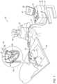
- FIG. 2is a schematic, pictorial illustration of the distal portion of the inflatable sleeve lasso catheter shown in FIG. 1 in an operating position for electro-anatomical sensing and ablation, in accordance with an embodiment of the invention
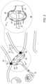
- FIG. 3is a schematic cross-section of the inflatable sleeve lasso catheter of FIG. 2 , in accordance with an embodiment of the invention
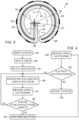
- FIG. 4is a flow chart that schematically illustrates a method for pulmonary vein (PV) isolation using the inflatable sleeve lasso catheter of FIG. 2 , in accordance with an embodiment of the invention.
- PVpulmonary vein
- FIG. 5is a schematic cross-section of an inflatable sleeve deflectable linear catheter, in accordance with an embodiment of the invention.
- Distal ends of diagnostic and/or therapeutic catheters for cardiac applicationssuch as arcuated distal ends or distal ends that have a deflectable shape (e.g., piecewise linear shape), or have a rigid linear shape, conventionally take their shape from a resilient end section, which is fixed to the distal end of a shaft, and which is formed to assume a predefined (e.g., an arcuate, or straight) shape when unconstrained.
- the arcuate shapeshould enable, in principle, electrodes disposed over the arcuate end section to engage some or all of the circumference of an opening in the heart, such as an ostium of a pulmonary vein (PV).
- the distal endmay be deflected to fit variable anatomy (e.g., a septum) to enable some or all of the electrodes disposed over the deflectable distal end to engage the target cardiac tissue.
- a resilient distal sectionsuch as an arcuate one or a linear one, which is made of rigid materials, such as a plastic-coated metal, with a cross-section large enough to support electrodes, may not easily accommodate a variable shape of the opening.
- a portion of the electrodes disposed over the circumference of, for example, the arcuate end sectionactually comes in contact with tissue, leaving the electrodes not in contact with tissue in the blood pool.
- unwanted electrophysiological signals from the bloodinterfere.
- electrical poweris injected into the blood, which may cause side effects such as blood clots.
- linear rigid distal ends and even deflectable onesmay not easily accommodate a variable shape of an anatomy (e.g., chamber wall tissue).
- Electrodes that do contact tissuemay, due to the rigidity of the arcuate end section, be only in partial contact with tissue, e.g., with a significant portion of electrode area still in contact with blood pool. Such electrodes may also give unwanted electrophysiological signals and may contribute to side effects of an ablation.
- Embodiments of the present inventionthat are described hereinafter provide a catheter comprising an inflatable sleeve that envelopes a thin inner end section, which, when unconstrained, takes a predefined shape, such as an arcuate shape.
- the disclosed inner end sectionwhich is also called hereinafter the “wire former,” threads the inflatable sleeve through the entire length of the sleeve.
- the disclosed wire formergives the sleeve its predefined (e.g., arcuate, linear) shape and serves as a rigid “backbone,” whereas the inflatable sleeve gives the catheter the needed balance between extra structural stiffness and tissue accommodative properties.
- the stiffness of the inflatable sleevecan be tuned by adjusting the rate of saline solution that is pumped into the sleeve to maintain the sleeve's inflation.
- the thickness of the sleeve and/or the plastic type used for the sleeve constructioncan be selected to give the optimized balance.
- multiple electrodesare disposed circumferentially and equidistantly over the entire outer circumferential, or elongated, surface of the inflatable sleeve. Due to its inherent capability to accept anatomy shape while maintaining sufficient resilience, the cross-sectional diameter of the disclosed inflatable sleeve catheter can be made large enough to support large-area electrodes, which can still be brought into full contact with tissue.
- the inflatable catheterwhich is fixed to the distal end of a shaft, is advanced through a sheath by a physician into a desired body location, such as the left atrium, with the wire former straightened by a sheath.
- a desired body locationsuch as the left atrium
- the wire formerresumes its unconstrained arcuate form.
- the physicianthen inflates the sleeve and maneuvers the catheter to establish contact between the electrodes disposed on the sleeve and tissue, such as of an ostium.
- the physiciandeflates the lasso, and withdraws the deflated lasso catheter through the sheath.
- the withdrawal processis typically made easier by using a thin wire former.
- the electrodesare formed on an electrode support, which is typically a flexible PCB sheet, and the support is glued to the inflatable sleeve.
- the electrodesare disposed on the outer (tissue-facing) circumference of the inflatable sleeve, and are not fully cylindrical, i.e., do not fully surround the inflatable sleeve to reach the inner circumference that faces away from the tissue. This configuration helps minimizing unnecessary exposure of the electrodes to blood.
- the disclosed inflatable sleevecan support large-area electrodes, which can be, for example, glued to the sleeve.
- Large-area electrodescan clinically outperform small electrodes, for example, by creating larger lesions.
- large electrodesare more resilient to being scraped off when the catheter is pushed against an ostium wall tissue so the electrodes can come in firm contact with tissue.
- the disclosed inflatable sleeve cathetermay have superior diagnostic and therapeutic capabilities (e.g., relative to other types of catheters such as balloon catheters) and its use may increase the rate of successful and safe ablation treatments of severe cardiac conditions, such as drug-resistant arrhythmia.
- FIG. 1is a schematic, pictorial illustration of a system 20 for electro-anatomical mapping and ablation, in accordance with an embodiment of the present invention.
- inflatable sleeve lasso catheter 40is fitted at the distal end of a shaft 22 that is inserted through a shaft 23 into a heart 26 of a patient 28 on a table 29 .
- FIG. 1depicts a physician 30 using an inflatable sleeve lasso catheter 40 to perform an electro-anatomical mapping of a cardiac chamber, such as a left atrium 45 of heart 26 .
- Inset 25further shows inflatable sleeve lasso catheter 40 disposed with multiple electrodes 53 .
- physician 30retracts sheath 23 , and catheter 40 takes a lasso shape due to the wire former, shown in FIG. 3 , self-expanding into its pre-formed arcuate shape.
- physician 30inflates a sleeve 50 by pumping saline solution into sleeve 50 .
- Physician 30further manipulates shaft 22 to place electrodes 53 disposed over a perimeter of sleeve 50 in contact with tissue, such as with an ostium of a PV, as seen in FIG. 2 .
- electrodes 53acquire and/or inject signals from and/or to the tissue of left atrium 45 .
- a processor 38 in console 24receives these signals via an electrical interface 35 , and uses information contained in these signals to construct an electro-anatomical map 31 .
- processor 38may display electro-anatomical map 31 on a display 26 .
- processor 38stores electro-anatomical map 31 in memory 41 .
- Physician 30navigates the distal end of a shaft 22 to a target location inside left atrium 45 of heart 26 by manipulating shaft 22 using a manipulator 32 near the proximal end of the catheter and/or deflection from sheath 23 .
- inflatable sleeve lasso catheter 40is maintained in a collapsed configuration by sheath 23 .
- sheath 23also serves to minimize vascular trauma along the way to the target location.
- a tracking systemis used to track the respective locations of electrodes 53 , such that each of the diagnostic signals may be associated with the location at which the diagnostic signal was acquired.
- a suitable tracking systemis, for example, the Advanced Catheter Location (ACL) system, made by Biosense-Webster (Irvine, California), which is described in U.S. Pat. No. 8,456,182, whose disclosure is incorporated herein by reference.
- ACLAdvanced Catheter Location
- a processorestimates the respective locations of electrodes 53 based on impedances measured between each of the electrodes, and a plurality of surface-electrodes 49 that are coupled to the skin of patient 28 .
- processor 38is further configured to indicate the quality of physical contact between inflatable sleeve lasso catheter 40 an inner surface of left atrium 45 during measurement and/or during ablation.
- Processor 38typically comprises a general-purpose computer with software programmed to carry out the functions described herein.
- the softwaremay be downloaded to the computer in electronic form, over a network, for example, or it may, alternatively or additionally, be provided and/or stored on non-transitory tangible media, such as magnetic, optical, or electronic memory.
- FIG. 2is a schematic, pictorial illustration of the distal portion of inflatable sleeve lasso catheter 40 shown in FIG. 1 in an operating position for radiofrequency ablation, in accordance with an embodiment of the invention.
- Inflatable sleeve lasso catheter 40is shown fully inflated and fixed to the distal end of shaft 22 .
- the distal end of shaft 22defines a longitudinal axis 70 along and parallel to the distal end of shaft 22 .
- the arcuate inner end sectioncauses inflated sleeve 50 to spiral about longitudinal axis 70 and at the same time to slightly prograde.
- the term “arcuate” or “arcuate shape”denotes a shape of an arc segment extending about a longitudinal axis and which arc segment may be bent in a semi-circular segment or elliptical segment as viewed by an observer facing longitudinal axis 70 (as in FIG. 3 ).
- the flexible sleevemay define an arcuate shape with a generally constant radii (as measured from axis 70 ), which can be seen in FIG. 2 .
- flexible sleevemay define an arcuate shape that extends in the form of an outward spiral with radii that increase (r 1 , r 2 , r 3 , r 4 , r 5 .
- the arc segmentcan extend less than 90 degrees to over 180 degrees ( FIG. 3 ) and in certain cases up to 720 degrees with respect to the longitudinal axis 70 .
- the arcuate segmentmay also translate along axis 70 to mimic part of a spiral or helicoid about axis 70 .
- a fully inflated sleeve 50 of inflatable sleeve lasso catheter 40contacts an ostium 60 of a PV 61 over an entire circumference of ostium 60 .
- Inflated sleevehas multiple ablation electrodes 53 disposed on a flexible PCB 55 , on an outer surface of sleeve 50 .
- Electrodes 53are further useful to obtain electrograms to confirm electrical isolation of the PV following ablation.
- An inset 48shows inflatable lasso 40 from a perspective that emphasizes the inherent capability of the combined structure of the wire former and inflatable sleeve 50 to both accept shape of an anatomy while pushing tissue hard enough to have hemi-cylinder-shaped electrodes 53 firmly in contact with ostium 60 tissue over most or an entirety of electrodes 53 area, i.e., with minimal, if any electrode area left exposed to blood.
- FIG. 2The example illustration shown in FIG. 2 is chosen purely for the sake of conceptual clarity.
- other geometrical shapes of electrodes 53are possible, such as an oval patch.
- FIG. 3is a schematic cross-section of inflatable sleeve lasso catheter 40 of FIG. 2 , in accordance with an embodiment of the invention.
- sleeve 50is threaded by a wire former 57 that occupies a circumferential space 58 defined by sleeve 50 .
- Electrodes 53are disposed on the flexible PCB 55 , which is itself disposed over an external outer surface of sleeve 50 .
- Sleeve 50is shown fully inflated, e.g., by saline solution 66 , which is pumped via a lumen (not shown) that goes inside shaft 22 and is in fluid connection with sleeve 50 .
- wire former 57is made at least partially of a shape memory alloy having a self-configurable pre-formed shape comprising straight base segment 62 and arcuated segment 63 parts.
- wire former 57turns unconstrained and as a result self-configures from a collapsed straight configuration into an expanded configuration having straight base segment 62 and arcuated segment 63 parts.
- FIG. 3The example illustration shown in FIG. 3 is chosen purely for the sake of conceptual clarity.
- FIG. 3only shows parts relevant to embodiments of the present invention. Other details, such as irrigation holes, temperature sensors, and electrical wiring are omitted for simplicity of presentation.
- FIG. 4is a flow chart that schematically illustrates a method for pulmonary (PV) vein isolation, in accordance with an embodiment of the invention.
- the proceduremay begin with physician 30 inserting inflatable sleeve lasso catheter 40 into the left atrium of a heart, at an insertion step 83 .
- physician 30deploys catheter 40 out of sheath 23 in the vicinity of the interior wall of ostium 60 , letting wire former 57 take its preformed shape.
- physician 30inflates sleeve 50 .
- physician 30brings the inflatable lasso catheter into circumferential contact with ostium 60 of PV 61 , which brings electrodes 53 into firm contact with ostium 60 wall tissue. Once inflatable lasso catheter 40 is in position, pre-ablation cardio-electrograms are acquired by physician 30 , at a measurement step 91 .
- the methodnow proceeds to a decision step 93 , in which physician 30 determines, based on the electrograms, whether electrodes 53 are correctly positioned. If the determination at decision step 93 is negative, then the method returns to step 89 and physician 30 may reattempt to optimally position inflatable lasso catheter 40 .
- the methodproceeds to an ablation step during which physician 30 performs ablation using electrodes 53 .
- the ablation operationcreates circumferential lesion 59 in a region of tissue that circumscribes ostium 60 .
- Lesion 59should block electrical propagation and effectively electrically isolate PV 61 from the heart.
- post-ablation electrogramsare obtained by physician 30 from electrodes 53 of inflatable lasso catheter 40 , at measurement step 100 .
- physician 30may perform another attempt by looping back to positioning step 89 .
- the proceduremay be iterated to treat another PV ostium by withdrawal of the distal end of shaft 22 and thereby of the deflated lasso catheter 40 .
- the methodmay then return to step 85 .
- physician 30may end the procedure and retract the catheter from the heart, at a retraction step 104 .
- FIG. 4The example flow chart shown in FIG. 4 is chosen purely for the sake of conceptual clarity. In alternative embodiments, additional steps may be performed, such applying irrigation to cool ostium 60 tissue.
- a sleeve cathetermay be implemented for various types of catheter geometries, including a catheter carrying a linear array of electrodes, where the catheter may be rigid or deflectable. While the shown embodiment is of a deflectable distal end, the same description is valid for a straight, linear, distal end.
- FIG. 5is a schematic cross-section of an inflatable sleeve deflectable linear catheter 44 , in accordance with an embodiment of the invention.
- a sleeve 500 of catheter 44is threaded by a deflectable wire former 570 that occupies a space 580 defined by sleeve 500 .
- Wire former 570may be made by separate links and may include elements to deflect the wire.
- wire former 570is made at least partially of a shape memory alloy having a self-configurable pre-formed shape, such as of a straight line.
- Electrodes 530which are cylinder shape electrodes, are disposed on a flexible PCB 550 , which is itself disposed over an external outer surface of sleeve 500 .
- Sleeve 500is shown fully inflated, e.g., by saline solution 66 , which is pumped via a lumen (not shown) that goes inside a shaft of the catheter and is in fluid connection with sleeve 500 .
- FIG. 5The example illustration shown in FIG. 5 is chosen purely for the sake of conceptual clarity.
- FIG. 5only shows parts relevant to embodiments of the present invention. Other details, such as deflection elements, irrigation holes, temperature sensors, and electrical wiring are omitted for simplicity of presentation.
- the lasso, straight, and deflectable catheters embodiments described abovewere brought by way of example.
- the disclosed inflatable sleevemay be used with any shape of an inner end section, such as, as another example, of a multi-arm catheter.
Landscapes
- Health & Medical Sciences (AREA)
- Surgery (AREA)
- Life Sciences & Earth Sciences (AREA)
- Engineering & Computer Science (AREA)
- Heart & Thoracic Surgery (AREA)
- Medical Informatics (AREA)
- Otolaryngology (AREA)
- Plasma & Fusion (AREA)
- Physics & Mathematics (AREA)
- Biomedical Technology (AREA)
- Veterinary Medicine (AREA)
- Nuclear Medicine, Radiotherapy & Molecular Imaging (AREA)
- Molecular Biology (AREA)
- Animal Behavior & Ethology (AREA)
- General Health & Medical Sciences (AREA)
- Public Health (AREA)
- Cardiology (AREA)
- Surgical Instruments (AREA)
- Measurement And Recording Of Electrical Phenomena And Electrical Characteristics Of The Living Body (AREA)
- Media Introduction/Drainage Providing Device (AREA)
Abstract
Description
Claims (13)
Priority Applications (6)
| Application Number | Priority Date | Filing Date | Title |
|---|---|---|---|
| US17/017,206US12114920B2 (en) | 2019-10-22 | 2020-09-10 | Inflatable sleeve multi-electrode catheter |
| IL277985AIL277985B2 (en) | 2019-10-22 | 2020-10-12 | Multi-electrode catheter with inflatable sleeve |
| JP2020176493AJP7532201B2 (en) | 2019-10-22 | 2020-10-21 | Inflatable Sleeve Multielectrode Catheter |
| EP20203141.5AEP3811885B1 (en) | 2019-10-22 | 2020-10-21 | Inflatable sleeve multi-electrode catheter |
| CN202011136985.2ACN112690895A (en) | 2019-10-22 | 2020-10-22 | Inflatable sleeve multi-electrode catheter |
| US18/899,166US20250017649A1 (en) | 2019-10-22 | 2024-09-27 | Inflatable sleeve multi-electrode catheter |
Applications Claiming Priority (2)
| Application Number | Priority Date | Filing Date | Title |
|---|---|---|---|
| US201962924394P | 2019-10-22 | 2019-10-22 | |
| US17/017,206US12114920B2 (en) | 2019-10-22 | 2020-09-10 | Inflatable sleeve multi-electrode catheter |
Related Child Applications (1)
| Application Number | Title | Priority Date | Filing Date |
|---|---|---|---|
| US18/899,166DivisionUS20250017649A1 (en) | 2019-10-22 | 2024-09-27 | Inflatable sleeve multi-electrode catheter |
Publications (2)
| Publication Number | Publication Date |
|---|---|
| US20210113263A1 US20210113263A1 (en) | 2021-04-22 |
| US12114920B2true US12114920B2 (en) | 2024-10-15 |
Family
ID=73005464
Family Applications (2)
| Application Number | Title | Priority Date | Filing Date |
|---|---|---|---|
| US17/017,206Active2042-04-13US12114920B2 (en) | 2019-10-22 | 2020-09-10 | Inflatable sleeve multi-electrode catheter |
| US18/899,166PendingUS20250017649A1 (en) | 2019-10-22 | 2024-09-27 | Inflatable sleeve multi-electrode catheter |
Family Applications After (1)
| Application Number | Title | Priority Date | Filing Date |
|---|---|---|---|
| US18/899,166PendingUS20250017649A1 (en) | 2019-10-22 | 2024-09-27 | Inflatable sleeve multi-electrode catheter |
Country Status (5)
| Country | Link |
|---|---|
| US (2) | US12114920B2 (en) |
| EP (1) | EP3811885B1 (en) |
| JP (1) | JP7532201B2 (en) |
| CN (1) | CN112690895A (en) |
| IL (1) | IL277985B2 (en) |
Families Citing this family (3)
| Publication number | Priority date | Publication date | Assignee | Title |
|---|---|---|---|---|
| US20220370119A1 (en)* | 2021-05-18 | 2022-11-24 | Biosense Webster (Israel) Ltd. | Catheter with multiple physically symmetrical ablation electrodes that are asymmetric electrically |
| CN115317144B (en)* | 2022-07-19 | 2023-03-21 | 姜勇 | Auxiliary operation system and operation robot in radiation therapy or ablation therapy process |
| US20250120653A1 (en)* | 2023-10-16 | 2025-04-17 | Biosense Webster (Israel) Ltd. | Flexible circuit electrodes for lasso catheter |
Citations (21)
| Publication number | Priority date | Publication date | Assignee | Title |
|---|---|---|---|---|
| US5499981A (en) | 1993-03-16 | 1996-03-19 | Ep Technologies, Inc. | Flexible interlaced multiple electrode assemblies |
| US5700262A (en) | 1995-10-16 | 1997-12-23 | Neuro Navigational, L.L.C. | Bipolar electrode with fluid channels for less invasive neurosurgery |
| US6371955B1 (en) | 1999-08-10 | 2002-04-16 | Biosense Webster, Inc. | Atrial branding iron catheter and a method for treating atrial fibrillation |
| US20030069570A1 (en)* | 1999-10-02 | 2003-04-10 | Witzel Thomas H. | Methods for repairing mitral valve annulus percutaneously |
| US6592581B2 (en) | 1998-05-05 | 2003-07-15 | Cardiac Pacemakers, Inc. | Preformed steerable catheter with movable outer sleeve and method for use |
| US20030153905A1 (en)* | 2002-01-25 | 2003-08-14 | Edwards Stuart Denzil | Selective ablation system |
| US6723094B1 (en) | 1998-12-18 | 2004-04-20 | Kai Desinger | Electrode assembly for a surgical instrument provided for carrying out an electrothermal coagulation of tissue |
| US20040106920A1 (en) | 2000-12-04 | 2004-06-03 | Jenkins Thomas R. | Loop structure including inflatable therapeutic device |
| US20040167509A1 (en)* | 2003-02-24 | 2004-08-26 | Scimed Life Systems, Inc. | Probes having helical and loop shaped inflatable therapeutic elements |
| US20040215186A1 (en)* | 2003-03-03 | 2004-10-28 | Sinus Rhythm Technologies, Inc. | Electrical block positioning devices and methods of use therefor |
| US20060089634A1 (en)* | 2002-05-13 | 2006-04-27 | Anderson Neil L | Ablation catheter |
| US20110152855A1 (en) | 2009-10-27 | 2011-06-23 | Mayse Martin L | Delivery devices with coolable energy emitting assemblies |
| US8456182B2 (en) | 2008-09-30 | 2013-06-04 | Biosense Webster, Inc. | Current localization tracker |
| US20130165990A1 (en)* | 2011-12-23 | 2013-06-27 | Vessix Vascular, Inc. | Methods and apparatuses for remodeling tissue of or adjacent to a body passage |
| US8600472B2 (en) | 2008-12-30 | 2013-12-03 | Biosense Webster (Israel), Ltd. | Dual-purpose lasso catheter with irrigation using circumferentially arranged ring bump electrodes |
| US8900214B2 (en) | 2007-03-30 | 2014-12-02 | Onset Medical Corporation | Expandable trans-septal sheath |
| US20150141982A1 (en) | 2013-11-21 | 2015-05-21 | Biosense Webster (Israel), Ltd. | Multi-electrode balloon catheter with circumferential and point electrodes |
| US9289606B2 (en) | 2010-09-02 | 2016-03-22 | St. Jude Medical, Atrial Fibrillation Division, Inc. | System for electroporation therapy |
| US20160175041A1 (en) | 2014-12-22 | 2016-06-23 | Biosense Webster (Israel) Ltd. | Balloon for ablation around pulmonary veins |
| WO2017174387A1 (en) | 2016-04-08 | 2017-10-12 | Biotronik Ag | Device for energy output and/or measurement of electrical activity |
| US20190314610A1 (en)* | 2012-10-01 | 2019-10-17 | Qmax, Llc | Helical balloon catheter |
Family Cites Families (3)
| Publication number | Priority date | Publication date | Assignee | Title |
|---|---|---|---|---|
| US8287532B2 (en)* | 2009-04-13 | 2012-10-16 | Biosense Webster, Inc. | Epicardial mapping and ablation catheter |
| WO2011019838A2 (en)* | 2009-08-14 | 2011-02-17 | Boston Scientific Scimed, Inc. | Systems and methods for making and using medical ablation systems having mapping catheters with improved anchoring ability |
| US9474850B2 (en)* | 2012-12-11 | 2016-10-25 | Biosense Webster (Israel) Ltd. | Lasso catheter with guide wire |
- 2020
- 2020-09-10USUS17/017,206patent/US12114920B2/enactiveActive
- 2020-10-12ILIL277985Apatent/IL277985B2/enunknown
- 2020-10-21EPEP20203141.5Apatent/EP3811885B1/enactiveActive
- 2020-10-21JPJP2020176493Apatent/JP7532201B2/enactiveActive
- 2020-10-22CNCN202011136985.2Apatent/CN112690895A/enactivePending
- 2024
- 2024-09-27USUS18/899,166patent/US20250017649A1/enactivePending
Patent Citations (25)
| Publication number | Priority date | Publication date | Assignee | Title |
|---|---|---|---|---|
| US5499981A (en) | 1993-03-16 | 1996-03-19 | Ep Technologies, Inc. | Flexible interlaced multiple electrode assemblies |
| US5700262A (en) | 1995-10-16 | 1997-12-23 | Neuro Navigational, L.L.C. | Bipolar electrode with fluid channels for less invasive neurosurgery |
| US6592581B2 (en) | 1998-05-05 | 2003-07-15 | Cardiac Pacemakers, Inc. | Preformed steerable catheter with movable outer sleeve and method for use |
| US6723094B1 (en) | 1998-12-18 | 2004-04-20 | Kai Desinger | Electrode assembly for a surgical instrument provided for carrying out an electrothermal coagulation of tissue |
| US6371955B1 (en) | 1999-08-10 | 2002-04-16 | Biosense Webster, Inc. | Atrial branding iron catheter and a method for treating atrial fibrillation |
| US20030069570A1 (en)* | 1999-10-02 | 2003-04-10 | Witzel Thomas H. | Methods for repairing mitral valve annulus percutaneously |
| US20040106920A1 (en) | 2000-12-04 | 2004-06-03 | Jenkins Thomas R. | Loop structure including inflatable therapeutic device |
| US20030153905A1 (en)* | 2002-01-25 | 2003-08-14 | Edwards Stuart Denzil | Selective ablation system |
| JP2010000370A (en) | 2002-05-13 | 2010-01-07 | Cathrx Ltd | Ablation catheter |
| US20060089634A1 (en)* | 2002-05-13 | 2006-04-27 | Anderson Neil L | Ablation catheter |
| US20050004566A1 (en) | 2003-02-24 | 2005-01-06 | Taimisto Miriam H. | Probes having helical and loop shaped inflatable therapeutic elements |
| US20040167509A1 (en)* | 2003-02-24 | 2004-08-26 | Scimed Life Systems, Inc. | Probes having helical and loop shaped inflatable therapeutic elements |
| US20040215186A1 (en)* | 2003-03-03 | 2004-10-28 | Sinus Rhythm Technologies, Inc. | Electrical block positioning devices and methods of use therefor |
| US8900214B2 (en) | 2007-03-30 | 2014-12-02 | Onset Medical Corporation | Expandable trans-septal sheath |
| US8456182B2 (en) | 2008-09-30 | 2013-06-04 | Biosense Webster, Inc. | Current localization tracker |
| US8600472B2 (en) | 2008-12-30 | 2013-12-03 | Biosense Webster (Israel), Ltd. | Dual-purpose lasso catheter with irrigation using circumferentially arranged ring bump electrodes |
| US20110152855A1 (en) | 2009-10-27 | 2011-06-23 | Mayse Martin L | Delivery devices with coolable energy emitting assemblies |
| JP2013508121A (en) | 2009-10-27 | 2013-03-07 | イノベイティブ パルモナリー ソリューションズ, インコーポレイテッド | Delivery device having a coolable energy release assembly |
| US9289606B2 (en) | 2010-09-02 | 2016-03-22 | St. Jude Medical, Atrial Fibrillation Division, Inc. | System for electroporation therapy |
| US20130165990A1 (en)* | 2011-12-23 | 2013-06-27 | Vessix Vascular, Inc. | Methods and apparatuses for remodeling tissue of or adjacent to a body passage |
| US20190314610A1 (en)* | 2012-10-01 | 2019-10-17 | Qmax, Llc | Helical balloon catheter |
| US20150141982A1 (en) | 2013-11-21 | 2015-05-21 | Biosense Webster (Israel), Ltd. | Multi-electrode balloon catheter with circumferential and point electrodes |
| US20160175041A1 (en) | 2014-12-22 | 2016-06-23 | Biosense Webster (Israel) Ltd. | Balloon for ablation around pulmonary veins |
| WO2017174387A1 (en) | 2016-04-08 | 2017-10-12 | Biotronik Ag | Device for energy output and/or measurement of electrical activity |
| CN108882961A (en) | 2016-04-08 | 2018-11-23 | 百多力公司 | For transmitting energy and/or measuring the device of electrical activity |
Non-Patent Citations (5)
| Title |
|---|
| English translation of Decision to Grant a Patent dated Jul. 2, 2024, from corresponding Japanese Application No. 2020-176493. |
| English translation of Notice of Reasons for Refusal dated Mar. 26, 2024, from corresponding Japanese Application No. 2020-176493. |
| English translation of Search Report dated Mar. 27, 2024, from corresponding Japanese Application No. 2020-176493. |
| English translation of Written Opinion dated Jun. 20, 2024, from corresponding Japanese Application No. 2020-176493. |
| Extended European Search Report dated Mar. 19, 2021, from corresponding European Application No. 20203141.5. |
Also Published As
| Publication number | Publication date |
|---|---|
| EP3811885A1 (en) | 2021-04-28 |
| IL277985B1 (en) | 2024-05-01 |
| US20210113263A1 (en) | 2021-04-22 |
| JP2021065708A (en) | 2021-04-30 |
| EP3811885B1 (en) | 2024-01-10 |
| IL277985A (en) | 2021-04-29 |
| IL277985B2 (en) | 2024-09-01 |
| CN112690895A (en) | 2021-04-23 |
| US20250017649A1 (en) | 2025-01-16 |
| JP7532201B2 (en) | 2024-08-13 |
| EP3811885C0 (en) | 2024-01-10 |
Similar Documents
| Publication | Publication Date | Title |
|---|---|---|
| EP3906876B1 (en) | Catheter with stretchable irrigation tube | |
| US20250017649A1 (en) | Inflatable sleeve multi-electrode catheter | |
| JP7102149B2 (en) | Multi-electrode assembly with controlled folding mechanism | |
| ES2763532T3 (en) | Basket Catheter with Far Field Electrode | |
| CN106562820B (en) | Double basket type catheter | |
| AU2013260655B2 (en) | Lasso catheter with tip electrode | |
| US20190175263A1 (en) | Balloon catheter with reverse spiral guidewire | |
| RU2687604C2 (en) | Catheter with multiple lengths proof beam located on one or more distal segments | |
| JP7077020B2 (en) | Catheter with support structure with variable dimensions | |
| KR101193709B1 (en) | Ablation devices with sensor structures | |
| CN103417290B (en) | The conduit with helical form end for tissue ablation | |
| EP2229905B1 (en) | An ablation catheter | |
| JP6946030B2 (en) | Distributed irrigation geometry for catheter tip design | |
| JP6890946B2 (en) | Lasso catheter with movable ablation needle | |
| CN105615993A (en) | Catheter with soft distal tip for mapping and ablating tubular region | |
| JP6869665B2 (en) | High electrode density basket catheter | |
| JP2008501440A (en) | Ablation catheter with fixation function for simultaneous use | |
| US20170071661A1 (en) | Dual node multiray electrode catheter | |
| EP4162866A1 (en) | Measuring tissue proximity for multi-electrode catheter | |
| JP2017124159A (en) | Dual node multiray electrode catheter | |
| EP3900659A1 (en) | Ablation of a hard-to-access region | |
| CN106852705A (en) | The many umbrella width electrode catheters of binode |
Legal Events
| Date | Code | Title | Description |
|---|---|---|---|
| FEPP | Fee payment procedure | Free format text:ENTITY STATUS SET TO UNDISCOUNTED (ORIGINAL EVENT CODE: BIG.); ENTITY STATUS OF PATENT OWNER: LARGE ENTITY | |
| AS | Assignment | Owner name:BIOSENSE WEBSTER (ISRAEL) LTD., ISRAEL Free format text:ASSIGNMENT OF ASSIGNORS INTEREST;ASSIGNOR:GOVARI, ASSAF;REEL/FRAME:053893/0461 Effective date:20200915 | |
| STPP | Information on status: patent application and granting procedure in general | Free format text:APPLICATION DISPATCHED FROM PREEXAM, NOT YET DOCKETED | |
| STPP | Information on status: patent application and granting procedure in general | Free format text:DOCKETED NEW CASE - READY FOR EXAMINATION | |
| STPP | Information on status: patent application and granting procedure in general | Free format text:NON FINAL ACTION MAILED | |
| STPP | Information on status: patent application and granting procedure in general | Free format text:FINAL REJECTION MAILED | |
| STPP | Information on status: patent application and granting procedure in general | Free format text:RESPONSE AFTER FINAL ACTION FORWARDED TO EXAMINER | |
| STPP | Information on status: patent application and granting procedure in general | Free format text:ADVISORY ACTION MAILED | |
| STPP | Information on status: patent application and granting procedure in general | Free format text:NON FINAL ACTION MAILED | |
| STPP | Information on status: patent application and granting procedure in general | Free format text:RESPONSE TO NON-FINAL OFFICE ACTION ENTERED AND FORWARDED TO EXAMINER | |
| STPP | Information on status: patent application and granting procedure in general | Free format text:NOTICE OF ALLOWANCE MAILED -- APPLICATION RECEIVED IN OFFICE OF PUBLICATIONS | |
| ZAAB | Notice of allowance mailed | Free format text:ORIGINAL CODE: MN/=. | |
| STPP | Information on status: patent application and granting procedure in general | Free format text:NOTICE OF ALLOWANCE MAILED -- APPLICATION RECEIVED IN OFFICE OF PUBLICATIONS | |
| ZAAB | Notice of allowance mailed | Free format text:ORIGINAL CODE: MN/=. | |
| STPP | Information on status: patent application and granting procedure in general | Free format text:PUBLICATIONS -- ISSUE FEE PAYMENT VERIFIED | |
| STCF | Information on status: patent grant | Free format text:PATENTED CASE |