US12114895B2 - Modular spine stabilization system and associated instruments - Google Patents
Modular spine stabilization system and associated instrumentsDownload PDFInfo
- Publication number
- US12114895B2 US12114895B2US18/111,687US202318111687AUS12114895B2US 12114895 B2US12114895 B2US 12114895B2US 202318111687 AUS202318111687 AUS 202318111687AUS 12114895 B2US12114895 B2US 12114895B2
- Authority
- US
- United States
- Prior art keywords
- flexible
- stabilization system
- spine
- spine stabilization
- couplers
- Prior art date
- Legal status (The legal status is an assumption and is not a legal conclusion. Google has not performed a legal analysis and makes no representation as to the accuracy of the status listed.)
- Active
Links
- 230000006641stabilisationEffects0.000titleclaimsabstractdescription80
- 238000011105stabilizationMethods0.000titleclaimsabstractdescription80
- 210000000988bone and boneAnatomy0.000claimsdescription30
- 238000002324minimally invasive surgeryMethods0.000abstractdescription13
- 238000002513implantationMethods0.000abstractdescription11
- 238000011282treatmentMethods0.000abstractdescription8
- 238000005452bendingMethods0.000description42
- 238000000034methodMethods0.000description21
- 241000722921Tulipa gesnerianaSpecies0.000description14
- 238000005259measurementMethods0.000description9
- 238000001356surgical procedureMethods0.000description7
- 230000007246mechanismEffects0.000description5
- 230000004927fusionEffects0.000description4
- 230000006378damageEffects0.000description3
- 208000014674injuryDiseases0.000description3
- 239000000463materialSubstances0.000description3
- 206010061246Intervertebral disc degenerationDiseases0.000description2
- 208000027418Wounds and injuryDiseases0.000description2
- 230000008901benefitEffects0.000description2
- 239000004568cementSubstances0.000description2
- 238000007906compressionMethods0.000description2
- 230000008878couplingEffects0.000description2
- 238000010168coupling processMethods0.000description2
- 238000005859coupling reactionMethods0.000description2
- 208000018180degenerative disc diseaseDiseases0.000description2
- 230000009977dual effectEffects0.000description2
- 238000003780insertionMethods0.000description2
- 230000037431insertionEffects0.000description2
- 208000021600intervertebral disc degenerative diseaseDiseases0.000description2
- 230000008569processEffects0.000description2
- 230000009467reductionEffects0.000description2
- 238000010079rubber tappingMethods0.000description2
- 230000000087stabilizing effectEffects0.000description2
- 210000001519tissueAnatomy0.000description2
- 238000013459approachMethods0.000description1
- 239000002639bone cementSubstances0.000description1
- 230000001684chronic effectEffects0.000description1
- 230000006837decompressionEffects0.000description1
- 230000000368destabilizing effectEffects0.000description1
- 201000010099diseaseDiseases0.000description1
- 208000037265diseases, disorders, signs and symptomsDiseases0.000description1
- 230000000694effectsEffects0.000description1
- 230000007717exclusionEffects0.000description1
- 238000002684laminectomyMethods0.000description1
- 230000007774longtermEffects0.000description1
- 230000006996mental stateEffects0.000description1
- 230000003278mimic effectEffects0.000description1
- 229940124583pain medicationDrugs0.000description1
- 230000006461physiological responseEffects0.000description1
- 230000001737promoting effectEffects0.000description1
- 208000024891symptomDiseases0.000description1
- 230000007704transitionEffects0.000description1
- 238000013519translationMethods0.000description1
- 230000008733traumaEffects0.000description1
- 238000003466weldingMethods0.000description1
Images


Classifications
- A—HUMAN NECESSITIES
- A61—MEDICAL OR VETERINARY SCIENCE; HYGIENE
- A61B—DIAGNOSIS; SURGERY; IDENTIFICATION
- A61B17/00—Surgical instruments, devices or methods
- A61B17/56—Surgical instruments or methods for treatment of bones or joints; Devices specially adapted therefor
- A61B17/58—Surgical instruments or methods for treatment of bones or joints; Devices specially adapted therefor for osteosynthesis, e.g. bone plates, screws or setting implements
- A61B17/68—Internal fixation devices, including fasteners and spinal fixators, even if a part thereof projects from the skin
- A61B17/70—Spinal positioners or stabilisers, e.g. stabilisers comprising fluid filler in an implant
- A61B17/7001—Screws or hooks combined with longitudinal elements which do not contact vertebrae
- A61B17/7002—Longitudinal elements, e.g. rods
- A61B17/7019—Longitudinal elements having flexible parts, or parts connected together, such that after implantation the elements can move relative to each other
- A61B17/7026—Longitudinal elements having flexible parts, or parts connected together, such that after implantation the elements can move relative to each other with a part that is flexible due to its form
- A—HUMAN NECESSITIES
- A61—MEDICAL OR VETERINARY SCIENCE; HYGIENE
- A61B—DIAGNOSIS; SURGERY; IDENTIFICATION
- A61B17/00—Surgical instruments, devices or methods
- A61B17/56—Surgical instruments or methods for treatment of bones or joints; Devices specially adapted therefor
- A61B17/58—Surgical instruments or methods for treatment of bones or joints; Devices specially adapted therefor for osteosynthesis, e.g. bone plates, screws or setting implements
- A61B17/68—Internal fixation devices, including fasteners and spinal fixators, even if a part thereof projects from the skin
- A61B17/70—Spinal positioners or stabilisers, e.g. stabilisers comprising fluid filler in an implant
- A61B17/7001—Screws or hooks combined with longitudinal elements which do not contact vertebrae
- A61B17/7002—Longitudinal elements, e.g. rods
- A61B17/7004—Longitudinal elements, e.g. rods with a cross-section which varies along its length
- A—HUMAN NECESSITIES
- A61—MEDICAL OR VETERINARY SCIENCE; HYGIENE
- A61B—DIAGNOSIS; SURGERY; IDENTIFICATION
- A61B17/00—Surgical instruments, devices or methods
- A61B17/56—Surgical instruments or methods for treatment of bones or joints; Devices specially adapted therefor
- A61B17/58—Surgical instruments or methods for treatment of bones or joints; Devices specially adapted therefor for osteosynthesis, e.g. bone plates, screws or setting implements
- A61B17/68—Internal fixation devices, including fasteners and spinal fixators, even if a part thereof projects from the skin
- A61B17/70—Spinal positioners or stabilisers, e.g. stabilisers comprising fluid filler in an implant
- A61B17/7001—Screws or hooks combined with longitudinal elements which do not contact vertebrae
- A61B17/7002—Longitudinal elements, e.g. rods
- A61B17/7014—Longitudinal elements, e.g. rods with means for adjusting the distance between two screws or hooks
- A—HUMAN NECESSITIES
- A61—MEDICAL OR VETERINARY SCIENCE; HYGIENE
- A61B—DIAGNOSIS; SURGERY; IDENTIFICATION
- A61B17/00—Surgical instruments, devices or methods
- A61B17/56—Surgical instruments or methods for treatment of bones or joints; Devices specially adapted therefor
- A61B17/58—Surgical instruments or methods for treatment of bones or joints; Devices specially adapted therefor for osteosynthesis, e.g. bone plates, screws or setting implements
- A61B17/68—Internal fixation devices, including fasteners and spinal fixators, even if a part thereof projects from the skin
- A61B17/70—Spinal positioners or stabilisers, e.g. stabilisers comprising fluid filler in an implant
- A61B17/7001—Screws or hooks combined with longitudinal elements which do not contact vertebrae
- A61B17/7002—Longitudinal elements, e.g. rods
- A61B17/7019—Longitudinal elements having flexible parts, or parts connected together, such that after implantation the elements can move relative to each other
- A61B17/7026—Longitudinal elements having flexible parts, or parts connected together, such that after implantation the elements can move relative to each other with a part that is flexible due to its form
- A61B17/7028—Longitudinal elements having flexible parts, or parts connected together, such that after implantation the elements can move relative to each other with a part that is flexible due to its form the flexible part being a coil spring
- A—HUMAN NECESSITIES
- A61—MEDICAL OR VETERINARY SCIENCE; HYGIENE
- A61B—DIAGNOSIS; SURGERY; IDENTIFICATION
- A61B17/00—Surgical instruments, devices or methods
- A61B17/56—Surgical instruments or methods for treatment of bones or joints; Devices specially adapted therefor
- A61B17/58—Surgical instruments or methods for treatment of bones or joints; Devices specially adapted therefor for osteosynthesis, e.g. bone plates, screws or setting implements
- A61B17/68—Internal fixation devices, including fasteners and spinal fixators, even if a part thereof projects from the skin
- A61B17/70—Spinal positioners or stabilisers, e.g. stabilisers comprising fluid filler in an implant
- A61B17/7074—Tools specially adapted for spinal fixation operations other than for bone removal or filler handling
- A61B17/7083—Tools for guidance or insertion of tethers, rod-to-anchor connectors, rod-to-rod connectors, or longitudinal elements
- A61B17/7085—Tools for guidance or insertion of tethers, rod-to-anchor connectors, rod-to-rod connectors, or longitudinal elements for insertion of a longitudinal element down one or more hollow screw or hook extensions, i.e. at least a part of the element within an extension has a component of movement parallel to the extension's axis
- A—HUMAN NECESSITIES
- A61—MEDICAL OR VETERINARY SCIENCE; HYGIENE
- A61B—DIAGNOSIS; SURGERY; IDENTIFICATION
- A61B17/00—Surgical instruments, devices or methods
- A61B17/56—Surgical instruments or methods for treatment of bones or joints; Devices specially adapted therefor
- A61B17/58—Surgical instruments or methods for treatment of bones or joints; Devices specially adapted therefor for osteosynthesis, e.g. bone plates, screws or setting implements
- A61B17/68—Internal fixation devices, including fasteners and spinal fixators, even if a part thereof projects from the skin
- A61B17/84—Fasteners therefor or fasteners being internal fixation devices
- A61B17/86—Pins or screws or threaded wires; nuts therefor
- A61B17/8625—Shanks, i.e. parts contacting bone tissue
- A61B17/863—Shanks, i.e. parts contacting bone tissue with thread interrupted or changing its form along shank, other than constant taper
- A—HUMAN NECESSITIES
- A61—MEDICAL OR VETERINARY SCIENCE; HYGIENE
- A61B—DIAGNOSIS; SURGERY; IDENTIFICATION
- A61B17/00—Surgical instruments, devices or methods
- A61B17/56—Surgical instruments or methods for treatment of bones or joints; Devices specially adapted therefor
- A61B17/58—Surgical instruments or methods for treatment of bones or joints; Devices specially adapted therefor for osteosynthesis, e.g. bone plates, screws or setting implements
- A61B17/88—Osteosynthesis instruments; Methods or means for implanting or extracting internal or external fixation devices
- A61B17/8863—Apparatus for shaping or cutting osteosynthesis equipment by medical personnel
- A—HUMAN NECESSITIES
- A61—MEDICAL OR VETERINARY SCIENCE; HYGIENE
- A61B—DIAGNOSIS; SURGERY; IDENTIFICATION
- A61B17/00—Surgical instruments, devices or methods
- A61B17/56—Surgical instruments or methods for treatment of bones or joints; Devices specially adapted therefor
- A61B17/58—Surgical instruments or methods for treatment of bones or joints; Devices specially adapted therefor for osteosynthesis, e.g. bone plates, screws or setting implements
- A61B17/68—Internal fixation devices, including fasteners and spinal fixators, even if a part thereof projects from the skin
- A61B17/70—Spinal positioners or stabilisers, e.g. stabilisers comprising fluid filler in an implant
- A61B17/7001—Screws or hooks combined with longitudinal elements which do not contact vertebrae
- A61B17/7032—Screws or hooks with U-shaped head or back through which longitudinal rods pass
- A—HUMAN NECESSITIES
- A61—MEDICAL OR VETERINARY SCIENCE; HYGIENE
- A61B—DIAGNOSIS; SURGERY; IDENTIFICATION
- A61B90/00—Instruments, implements or accessories specially adapted for surgery or diagnosis and not covered by any of the groups A61B1/00 - A61B50/00, e.g. for luxation treatment or for protecting wound edges
- A61B90/06—Measuring instruments not otherwise provided for
- A61B2090/061—Measuring instruments not otherwise provided for for measuring dimensions, e.g. length
- A—HUMAN NECESSITIES
- A61—MEDICAL OR VETERINARY SCIENCE; HYGIENE
- A61B—DIAGNOSIS; SURGERY; IDENTIFICATION
- A61B90/00—Instruments, implements or accessories specially adapted for surgery or diagnosis and not covered by any of the groups A61B1/00 - A61B50/00, e.g. for luxation treatment or for protecting wound edges
- A61B90/90—Identification means for patients or instruments, e.g. tags
- A61B90/92—Identification means for patients or instruments, e.g. tags coded with colour
Definitions
- the present disclosuregenerally relates to medical devices for the treatment of spinal conditions, and specifically to an implantable, modular spine stabilization system for controlling or restricting relative motion between vertebrae Instruments for the assembly and/or implantation of such a modular spine stabilization system are also provided.
- the spineincludes a series of joints known as motion segment units. Each unit represents the smallest component of the spine to exhibit a kinematic behavior characteristic of the entire spine.
- the motion segment unitis capable of flexion, extension, lateral bending, and translation.
- the components of each motion segment unitinclude two adjacent vertebrae, the corresponding apophyseal joints, an intervertebral disc, and connecting ligamentous tissue, with each component of the motion segment unit contributing to the mechanical stability of the joint.
- the intervertebral discs that separate adjacent vertebraeprovide stiffness that helps to restrain relative motion of the vertebrae in flexion, extension, axial rotation, and lateral bending.
- a damaged discmay provide inadequate stiffness, which may result in excessive relative vertebral motion when the spine is under a given load, causing pain and further damage to the disc.
- treatmentmay include fusion, discectomy, and/or a laminectomy.
- Surgical treatmenttypically includes decompression procedures to restore normal disc height, realign the column, and alleviate the pain.
- One such treatment methodinvolves the rigid fixation of the spine at one or more levels by securing a rigid rod against the spine to prevent motion and thereby enable fusion.
- An alternative surgical treatmentalso stabilizes the spine, but preserves motion instead of promoting fusion.
- This type of dynamic stabilizationtypically involves the fixation of a dynamic or spring-like coupler between vertebrae, which would still serve to stabilize and limit motion of the spine, but also allow close-to-normal motion, mimicking the physiological response of a healthy motion segment and providing pain relief, at that level.
- the present disclosureprovides an implantable, modular spine stabilization system that allows for multi-level treatment of the spine by providing either rigid fixation or dynamic stabilization at different levels to be treated.
- This modular spine stabilization systemmay be configured to span multiple spine levels, and have a curvature that closely matches the curvature of the spine over those multiple levels to be treated. Further, the modular spine stabilization system allows adjustment of the curvature of the overall system such that the system may be adapted for a patient for a customized fit.
- Instrumentsare also provided for the assembly and/or implantation of the modular spine stabilization system.
- the associated instrumentsmay include instruments for adjusting the curvature of the system to the patient, and for implanting the curved system into the patient.
- the instrumentsmay be configured for implantation of the system in a minimally invasive surgery. Methods for stabilizing a spine using the implantable, modular spine stabilization system and the associated instruments for assembly and implantation are also provided.
- a kit for modular spine stabilizationmay comprise an implantable modular spine stabilization system and an associated instrument set for use with the implantable modular spine stabilization system.
- the spine stabilization systemmay comprise one or more flexible couplers for dynamic stabilization of a spinal segment of a patient's spine. Each coupler may have a stem.
- the systemmay further comprise one or more rigid rods for rigid stabilization of a spinal segment of the patient's spine. Each rigid rod may have an elongated shaft.
- One or more bone fasteners for attaching the flexible couplers or rigid rods to a patient's spineare also provided in the system.
- the instrument setmay include a bending instrument for bending a stem of one of the flexible couplers.
- a flexible couplermay be configured to attach to one or more flexible couplers. In other embodiments, a flexible coupler may be configured to attach to a rigid rod.
- the bending instrumentmay comprise a base having a pivoting arm, a pivoting rod holder, and a radius of curvature selection wheel.
- the pivoting armmay have a pusher bar and a pusher head extending from a lower surface therefrom.
- the pivoting rod holdermay have a portal for receiving a rod of a medical device to be bent.
- the bending instrumentmay be configured such that the lowering of the pivoting arm causes the pusher bar to press against the radius of curvature selection wheel and the pusher head to press against the rod held within the pivoting rod holder.
- the pivoting armcan include a handle attachment end.
- the basecan also include a handle attachment end.
- the radius of curvature selection wheelincludes one or more detents corresponding to a different radius of curvature.
- the pivoting armcan attach to the base at a pivoting hinge.
- the bending instrumentmay be used for bending rods of medical devices.
- the bending instrumentmay be used to bend a stem of the medical device.
- the medical devicemay be a flexible coupler such as the one provided in the modular spine stabilization system of the present disclosure.
- Other instruments provided with the instrument set of the present disclosuremay include a flexible coupler and rod inserter tool.
- the flexible coupler and rod inserter toolmay include an angularly adjustable neck, and be configured for use in a minimally invasive surgery.
- Another instrument that may be provided with the instrument set of the present disclosureincludes a contouring template. Still another instrument may include a flexible coupler and rigid rod clamping instrument configured to clamp onto a guide rod, which may also be provided with the instrument set of the present disclosure.
- the modular spine stabilization system of the present disclosuremay include bone fasteners.
- the bone fastenermay comprise a head portion and a shank portion.
- the head portionmay include a cavity for receiving an implantable device.
- the shank portionmay include an elongated shaft extending to a distal tip.
- the shank portionmay have an enlarged head captured within the cavity of the head portion and being defined by a first leading threaded portion adjacent the distal tip.
- the shank portionmay be defined by a first leading threaded portion adjacent the distal tip, a second trailing threaded portion adjacent the head portion, and an intermediate threaded portion extending between the first and second threaded portions.
- the implantable devicemay comprise a rod.
- the first leading threaded portionincludes quad lead threads and the second trailing threaded portion may include quad lead threads.
- the shank portionmay have a generally uniform diameter from the second trailing threaded portion to the end of the intermediate threaded portion, while the first leading threaded portion may have a conical shape.
- the first leading threaded portionmay include cutting notches.
- the bone fastenermay be cannulated and include cement holes for use with bone cement, in some embodiments.
- the bone fastenermay be color coded for different sizes, and may be configured with a self-tapping distal tip.
- a locking device for securing the implantable device within the cavitymay be provided, in which the locking device is a set screw.
- the head portionmay be attached to an extended head portion at a scored region. This extended head portion may be configured to break away from the head region after use.
- the bone fastenermay include an elongate head region for use in a minimally invasive surgery. Once the assembly process is completed, this elongate head region may be snapped off.
- the present disclosuremay also provide an implantable, modular spine stabilization system.
- This systemmay include one or more flexible couplers for dynamic stabilization of a spinal segment of a patient's spine.
- Each flexible couplermay have a flexible main body and a bendable stem extending therefrom.
- the systemmay also include one or more rigid rods for rigid stabilization of a spinal segment of the patient's spine.
- Each rigid rodmay have an elongated shaft.
- FIG. 1is a perspective view of an exemplary embodiment of a modular spine stabilization system of the present disclosure.
- FIG. 2 Ais a perspective view of an exemplary embodiment of a flexible coupler of the present disclosure having a curved stem.
- FIG. 2 Bis a perspective view of an exemplary embodiment of a flexible coupler of the present disclosure having a straight stem.
- FIG. 2 Cis a partial cutaway view of the flexible coupler of FIG. 2 B showing an internal range-of-motion limiting mechanism.
- FIG. 3 Ais a perspective view of an exemplary embodiment of a rigid rod of the present disclosure having a curved shaft.
- FIG. 3 Bis a perspective view of an exemplary embodiment of a rigid rod of the present disclosure having a straight shaft.
- FIGS. 4 A to 4 Fillustrate various configurations of the modular spine stabilization system of the present disclosure, in which:
- FIG. 4 Ais an exploded view of a system configuration comprising a flexible coupler with a straight stem and a curved rod;
- FIG. 4 Bis a perspective view of a system configuration comprising a flexible coupler with a curved stem attached to a curved rod;
- FIG. 4 Cis a perspective view of a system configuration comprising a flexible coupler with a straight stem attached to a straight rod;
- FIG. 4 Dis a perspective view of a system configuration comprising a flexible coupler with a curved stem attached to a curved rod;
- FIG. 4 Eis perspective view of a system configuration comprising two flexible couplers and a rod, and all of which have curved stems or shafts, for attachment in series together;
- FIG. 4 Fis a perspective view of a system configuration comprising two flexible couplers and a rod, all of which have straight stems or shafts.
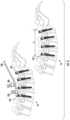
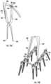
- FIG. 5shows exemplary embodiments of instruments of an instrument set of the present disclosure which are useful for contouring a stem of a flexible coupler.
- FIG. 6shows an exemplary method of using some of the instruments of FIG. 5 for determining a curvature of a flexible coupler.
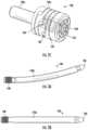
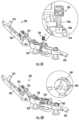
- FIG. 7 Ais a perspective view of an exemplary embodiment of a bending instrument of the present disclosure for bending a stem of a flexible coupler, attached to detachable handles.
- FIG. 7 Bis a perspective view of the bending instrument of FIG. 7 A , without the detachable handles.
- FIGS. 8 A to 8 Hillustrate a method for bending a stem of a flexible coupler using the bending instrument of FIGS. 7 A and 7 B , in which:
- FIG. 8 Ashows the bending instrument in an open position with the arm raised
- FIG. 8 Bshows the flexible coupler mounting unit swiveled upward on the bending instrument
- FIG. 8 Cshows the selected flexible coupler inserted into the flexible coupler mounting unit of the bending instrument, including an enlarged view
- FIG. 8 Dshows the flexible coupler mounting unit swiveled back to reside within the base of the bending instrument and the correct radius chosen, including an enlarged view;
- FIG. 8 Gshows the bending instrument in an open position, with the flexible coupler mounting unit swiveled upward, including an enlarged view;
- FIG. 8 Hshows the flexible coupler with a bent stem being removed from the bending instrument.
- FIG. 9 Ais a front view of an exemplary embodiment of a bone fastener of the present disclosure for use with the modular spine stabilization system.
- FIG. 9 Billustrates a perspective view of the bone fastener of FIG. 9 A and having an attached extended head portion.
- FIG. 9 Cillustrates a shaft for use with the head portion of the bone fastener of FIG. 9 A .
- FIG. 9 Dillustrates a top-down view of the shaft of FIG. 9 C , in which the head region may include an extended tulip head.
- FIGS. 11 A to 11 Care perspective views of an exemplary embodiment of a flexible coupler and rod inserter tool of the present disclosure, in which:
- FIG. 11 Aillustrates a perspective view of the inserter tool
- FIG. 11 Bshows a method of using the inserter tool to grasp a flexible coupler of the system of FIG. 1 ;
- FIG. 11 Cshows the inserter tool in use with a flexible coupler of the system of FIG. 1 .
- FIG. 12 Aillustrates an exemplary surgical guide for making incisions to access the patient's spine
- FIGS. 12 C to 12 Eshow a method of using the inserter tool to introduce a flexible coupler and rod construct into the patient's spine.
- FIG. 13is a perspective view of the modular spine stabilization system of the present disclosure in use with a crosslink.
- FIG. 14 Ais a perspective view of an exemplary embodiment of a measurement tool of the instrument set of the present disclosure, for determining a crosslink length.
- FIG. 14 Bshows the measurement tool of FIG. 14 A in use to measure a distance between two pairs of rods.
- FIG. 15 Ais a perspective view of another exemplary embodiment of a measurement tool of the instrument set of the present disclosure, for measuring a length of a system configuration.
- the present disclosureprovides an implantable, modular spine stabilization system that allows for multi-level treatment of the spine by providing either rigid fixation or dynamic stabilization at different levels to be treated.
- This modular spine stabilization systemmay be configured to span multiple spine levels, and have a curvature that closely matches the curvature of the spine over those multiple levels to be treated. Further, the modular spine stabilization system allows adjustment of the curvature of the overall system such that the system may be adapted for a patient for a customized fit.
- Instrumentsare also provided for the assembly and/or implantation of the modular spine stabilization system.
- the associated instrumentsmay include instruments for adjusting the curvature of the system to the patient, and for implanting the curved system into the patient.
- the instrumentsmay be configured for implantation of the system in a minimally invasive surgery.
- FIG. 1illustrates an exemplary embodiment of a modular spine stabilization system 100 of the present disclosure.
- the system 100may be configured for multi-level treatment of the spine, with different, individual levels being either rigidly fixed or dynamically stabilized.
- a pair of implantable flexible couplers 120may be connected in series, along with an implantable rigid rod 140 , to enable multi-level spine stabilization with varied degrees of fixation at individual levels.
- Bone fasteners 160may be used to secure the couplers 120 and the rigid rod 140 to the spine.
- These flexible couplers 120allow limited motion at that level where they are positioned, while the rigid rod 140 provides rigid fixation where it is connected.
- FIG. 2 Ashows an exemplary embodiment of a flexible coupler 120 having a curved or angled stem 132 b
- FIG. 2 Bshows an exemplary embodiment of a flexible coupler 120 having a straight stem 132 a
- Each of the stems 132 a , 132 bmay include a threaded end 138 , as shown.
- the flexible coupler 120may be similar to the flexible coupler described in U.S. Pat. Nos. 10,092,329, 9,522,018, and 8,920,473, the contents of all of which are herein incorporated in their entirety by reference.
- the flexible coupler 120may comprise a main body 122 such as the cylindrical body shown in FIGS. 2 A to 2 C .
- the flexible coupler body 122may be flexible, compressible, and/or extendable, and formed from a series of coil units 122 a .
- the series of coil units 122 amay be connected to one another to form a stepwise series of slots 124 .
- Each slot 124terminates at an opening 126 of the flexible body 122 .
- a threaded opening 128may be provided on the flexible body 122 , as shown in FIG. 2 C .
- the flexible coupler body 122may comprise an internal distraction-compression stopping mechanism to control or limit the range of motion that can be offered.
- a range-of-motion limiting mechanism 136may be provided within the flexible coupler body 122 .
- the internal distraction-compression stopping mechanism 136may be similar to the one described in the aforementioned patents.
- the flexible coupler body 122may vary in degree of stiffness based on the height, width, distance or angle between two adjacent slots 124 and the number of units 122 A forming the coupler body 122 . Further, one or more units 122 A may be formed from different materials so as to vary the mechanical properties of the body 122 . In addition, the dimensions of the units 122 A, slots 124 , and openings 126 can be varied within a single body 122 .
- each of these flexible couplers 120 or rigid fixation rods 140may be provided in various sizes (e.g., length, diameter, angle of stem).
- FIGS. 4 A to 4 Fshow the various modular constructs, or configurations, in which this modular spine stabilization system 100 may be assembled and utilized:
- FIG. 4 Ashows a system configuration, or construct, comprising a flexible coupler 120 with a straight stem 132 a to be attached to a rigid rod 140 having a curved shaft 142 b
- FIG. 4 Bshows a system configuration, or construct, comprising a flexible coupler 120 with a curved stem 132 b attached to a rigid rod 140 having a curved shaft 142 b.
- FIG. 4 Cshows a system configuration, or construct, comprising a flexible coupler 120 with a straight stem 132 a attached to a rigid rod 140 with a straight shaft 142 a
- FIG. 4 Dshows a system configuration, or construct, comprising a flexible coupler 120 with a curved stem 132 b attached to a rigid rod 140 having a curved shaft 142 b.
- FIG. 4 Eshows a system configuration, or construct, comprising two flexible couplers 120 and a rigid rod 140 , all of which have curved stems 132 b or a curved shaft 142 b , attached in series together.
- FIG. 4 Fshows a system configuration, or construct, comprising two flexible couplers 120 and a rigid rod 140 , all of which have straight stems 132 a or a straight shaft 142 a , attached in series together.
- any one of those dynamic or rigid componentscould be substituted with one having a straight stem or shaft as well.
- the various combinations and configurations or constructs shownare merely for illustration purposes only.
- a set of instruments 200may be provided for implanting the modular spine stabilization system 100 .
- the instrumentsmay be particularly useful fora minimally invasive surgery (MIS) technique.
- MISminimally invasive surgery
- FIG. 5shows various instruments forming part of the instrument set 200 of the present disclosure that can be used to contour (i.e., bend) the stem 132 of the flexible coupler 120 in order to adapt it to the unique curvature of the patient's spine, as shown in FIG. 6 .
- the patient's spine 10has a natural curvature that poses a challenge when connecting components such as the flexible couplers 120 of the present disclosure together in series, in order to span and treat multiple levels.
- the flexible couplers 120are able to connect end-to-end and mimic the curvature of that portion A of the patient's spine 10 to be treated, and where the flexible couplers 120 are to be implanted.
- These instrumentsinclude a grasper tool 210 which cooperates with a clamping instrument 220 that can hold onto a guide rod 230 .
- a flexible coupler template 240may be provided which may help the surgeon to approximate the correct angle of the stem 132 (i.e., length and angle of curved stem) based on the size of the flexible coupler 120 . Using these tools, the surgeon may be able to select the appropriately sized coupler and also determine the correct contour for the stem 132 of the flexible coupler 120 .
- the bending instrument 250may comprise a base or main body 252 configured to attach to detachable handles 270 .
- FIG. 7 Billustrates the base 252 without the detachable handles 270 , and in greater detail.
- the flexible coupler mounting unit 254can be pivoted or raised to a perpendicular, 90 degree angle relative to the base 252 after lifting arm 256 .
- the arm 256attaches to the base 252 with a pivoting hinge mechanism 260 . Once the arm 256 is raised, placing the bending instrument 250 in an open position, the flexible coupler mounting unit 254 can be pivoted 90 degrees upward to receive the straight stem 132 a of the flexible coupler 120 .
- the arm 256may include a handle attachment end 266 for attachment to a detachable handle 270 .
- the base 254may also include a handle attachment knob 268 for attachment to a detachable handle 270 .
- Stability bars 278 extending from the base 252may also be provided, as shown in FIG. 7 B .
- FIGS. 8 A to 8 Hillustrate the steps for bending the straight stem 132 a using the bending instrument 250 of FIGS. 7 A and 7 B .
- FIG. 8 Ashows the bending instrument 250 in an open position, i.e., the arm 256 is raised upwards, allowing the flexible coupler mounting unit 254 to swivel or flip upwards 90 degrees on the bending instrument base 252 , as shown in FIG. 8 B .
- This pivoting of the flexible coupler mounting unit 254exposes a portal 266 for receiving the straight stem 132 a of the flexible coupler 120 .
- the selected flexible coupler 120may be inserted by threading the threaded end 138 of the straight stem 132 a into the portal 266 of the flexible coupler mounting unit 254 of the bending instrument 250 , as shown in FIG. 8 C .
- the desired radius of curvature for the straight stem 132 ais selected by dialing the appropriate degree of bending on the radius selection wheel 262 .
- the desired radius of curvaturemay be selected using the template 240 provided as a selection guide.
- This radius selection wheel 262includes various angled ramps or detents 264 about its circumference. Rotation of the radius selection wheel 262 exposes a particular angled ramp or detent 264 , as represented in FIG. 8 D , in which the flexible coupler mounting unit 254 is pivoted back 90 degrees counterclockwise to lay within the base 252 .
- the arm 256 of the bending instrument 250may then be lowered, as shown in FIG. 8 E .
- a protruding pusher bar 274 extending from the arm 256pushes against the radius selection wheel 262 at the selected detent 264 , as shown in FIGS. 8 E and 8 F .
- a pusher head 272 extending from the arm 256urges against the straight stem 132 a with a corresponding amount of force, thus bending the straight stem 132 a of the flexible coupler 120 .
- the pusher head 272may have at a free end a contoured or curved contact surface 274 to allow it to effectively push against the cylindrical outer surface of the stem 132 a when in contact.
- a damper in the form of a spring 276may be provided, as shown, to facilitate the lowering of the arm 256 against the bending instrument base 252 .
- the detachable handles 270which are attached to the bending instrument base 252 at attachment knob 268 as well as the arm 256 at attachment end 266 also help facilitate the lowering of the arm 256 against the base 252 to place the instrument 250 in a fully closed position.
- the flexible coupler 120 with the now bent stem 132 bcan be removed from the portal 266 by unscrewing it from the flexible coupler mounting unit 254 , as shown in FIG. 8 G .
- FIG. 8 Hshows the flexible coupler fully removed from the bending instrument 250 .
- FIG. 9 Aillustrates one exemplary embodiment of a bone fastener 160 for use with the modular spine stabilization system 100 of the present disclosure.
- the bone fastener 160may comprise a head portion 162 shaped like a tulip and a shank portion 166 .
- the head portion 162may include a cavity 164 for receiving an implantable device, and an enlarged head 184 of the shank portion 166 which may sit within the cavity 164 .
- the diameter of the head portion 162may be in the range of about 5.5 to 9.5 mm.
- the shank portion 166may include an elongated shaft 168 extending from the enlarged head 184 to a distal tip 172 .
- the enlarged head 184may include a tool-engaging opening 186 , as shown in FIG. 9 D .
- the shaft 168 of the shank portion 166may be defined by a first leading threaded portion 170 a adjacent the distal tip 172 , a second trailing threaded portion 170 c adjacent the head portion 162 , and an intermediate threaded portion 170 b extending between the first and second threaded portions.
- the first leading threaded portion 170 acan include quad lead threads
- the second trailing threaded portion 170 ccan include quad lead threads
- the shaft 168may have the same nominal diameter (i.e., outer thread diameter) throughout the entire length of the shaft.
- the first leading threaded portion 170 amay have a conical shape in some embodiments.
- the first leading threaded portion 170 amay include cutting notches 178 , as shown in FIG. 9 A .
- the bone fastener 160may be provided with cement holes 174 in some embodiments, as shown. Additionally, the bone fastener 160 may be color coded for different sizes, and may be configured with a self-tapping distal tip 172 .
- a locking device 184 for securing the implantable device within the cavity 164may be provided.
- This locking device 184may be a set screw, for example.
- the head portion 162may be an extended tulip head, to accommodate minimally invasive surgery (MIS) instrumentation and techniques during implantation.
- FIG. 9 Bshows a perspective view of the extended tulip head 192 , which also includes extended walls 194 forming the tulip head extension and being attached at a scored or cutaway portion 196 that can be broken off from the tulip head 162 after use.
- FIG. 9 Cillustrates a detailed view of the shaft 166
- FIG. 9 Dillustrates a top-down view of the shaft 168 , both without the attached tulip head portion 162 .
- first leading threaded portion 170 a with quad lead threadsand a second trailing threaded portion 170 c with quad lead threads
- other types of lead threadscan also be utilized such as dual lead threads, if so desired.
- any of the threaded portions 170 a , 170 b , 170 c of the shank 166may be provided with double, triple or quad lead threads, although quad lead threads will provide enhanced bone purchase.
- FIGS. 10 A and 10 Billustrate an exemplary method of using the bone fasteners 160 having the tulip head extension 192 attached thereto with the modular spine stabilization system of the present disclosure.
- FIG. 10 Ashows the bone fasteners 160 with attached tulip head extensions 192 inserted into the patient's spine
- FIG. 10 Bshows the system configuration or construct now placed within the bone fasteners 160 .
- These tulip head extensions 192are particularly helpful for MIS techniques.
- the tulip head extensions 192can be useful for performing rod reduction procedures.
- bone fasteners 160may be provided having tulip head extensions but of a shorter relative length than for those to be used in a MIS technique.
- instrumentssuch as a trocar awl, awl, screw dilator, dilator, and screw length ruler may be provided.
- a tapfor instance, with a 1 ⁇ 4 inch coupling
- a tap with a dilator and T-handle with a ratchetmay also be provided within this instrument set 200 as well.
- a polyaxial screwdriverfor example, having a straight handle and a T-handle alternative
- a nut driverfor instance, with a 1 ⁇ 4 inch coupling
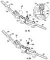
- FIGS. 11 A to 11 Cshow various views of an exemplary embodiment of a flexible coupler and rod inserter tool 280 that may be part of the instrument set 200 of the present disclosure.
- the inserter tool 280may include an arm 282 extending into a gripping end 284 for holding onto a flexible coupler and rigid rod construct, a handle 286 , and have a pivotable neck 288 connecting the arm 282 and handle 286 , as shown in FIG. 11 A , which would allow the angular insertion of the implantable components of the modular spine stabilization system 100 .
- the pivotable neck 288is angularly adjustable, and may be locked in position using a tightening nut 312 , for example, as shown in FIG. 11 A in the enlarged view.
- the gripping end 284may include curved walls 292 that are configured to firmly grasp the flexible coupler body 122 , while finger projections 294 may be provided to support and stabilize the elongated shaft 142 of the rigid rod 140 extending from the flexible coupler and rigid rod construct, as shown in FIG. 11 B . These finger projections 294 may be operatively movable from an open position ( FIG. 11 B ) into a closed position for firmly gripping the flexible coupler body 122 , as shown in FIG. 11 C .
- the flexible coupler 120is threadedly connected to a rigid rod 140 , and the construct is grasped by the flexible coupler and rigid rod inserter tool 280 .
- incisionscan be made to enable the inserter tool 280 to access the spine 10 .
- the upper-most incision lines IL 1indicate the suggested length and location for the incisions for enabling access of the inserter tool 280 .
- the incisionsmay be, for example, about 3 cm in length.
- the second set of shorter incision lines IL 2(e.g., 1.5 cm) as shown below upper-most incision lines IL 1 are for the insertion of the bone fasteners 160 at the adjacent levels.
- FIGS. 12 B to 12 Dillustrate a method of using the inserter tool 280 to introduce the flexible coupler and rigid rod construct into the patient, whereby the inserter tool 280 is able to hold the flexible coupler and rigid rod construct while positioning it between the walls 294 of the extended tulip extensions 292 , and seat the construct into the heads 162 of the bone screws 160 .
- the angled and adjustable neck 288 of the inserter tool 280enables the user to have the necessary angle of approach to perform the steps in a minimally invasive manner.
- the modular spine stabilization system 100 of the present disclosuremay be used for stabilization of both sides of a patient's spine, as illustrated in FIG. 13 in which a series of flexible coupler to rigid rod constructs may be assembled for implantation along both sides of the spine.
- a crosslink 300may be used to further stabilize the system 100 .
- a measurement toolmay be provided with the instrument set 200 to determine the appropriate length of the crosslink 310 to use.
- the measurement tool 290may include a pair of pivoting arms 292 hinged together in a manner similar to scissors or pliers, with one end of the pivoting arms 292 interconnected and cooperating to indicate measurement size.
- one of the pivoting arms 292may include a laterally extending bar 300 having indicia 302 representing units of length thereon, while the other pivoting arm 292 may have a slot 304 for slidingly receiving the laterally extending bar 300 .
- This same pivoting arm 292may further include a window 306 through which the user may view the indicia 302 on the laterally extending bar 300 as it slides across the slot 304 .
- a locking nut 308may be provided to lock the laterally extending bar 300 within the slot 304 and prevent further movement of the pivoting arms 292 .
- tips 296configured to be placed on the elongated shafts 142 of laterally opposed rigid rods 140 for measuring the distance between the rigid rods 140 located on opposed sides of the spine, as shown in FIG. 14 B .
- the tips 296may have a curved inner surface for placement against the cylindrical surface of the elongate shafts 142 , similar to the manner shown in FIG. 14 B . This measured distance can then determine what length crosslink 310 would be suited for use at this level.
- the tips 296may be configured for placement within the set screws 184 inside the head portions 162 of bone screws 160 , in order to measure the length between the bone screws 160 , as shown in FIG. 15 B . As shown in FIG. 15 A , the tips 296 may be shaped and sized to seat within the set screws 184 . When used in this manner, the measurement tool 290 can also serve to determine the length of a construct, or between bone screws 160 , on the same side of the spine.
- FIG. 13shows an embodiment in which the pair of constructs is essentially mirror images of one another, it is also understood that there can be variances between one of the constructs of the pair. For example, it is possible that one could use a coupler at one level, on one side, and then a rod at the same level, on the opposite side, of the spine.
Landscapes
- Health & Medical Sciences (AREA)
- Orthopedic Medicine & Surgery (AREA)
- Neurology (AREA)
- Life Sciences & Earth Sciences (AREA)
- Surgery (AREA)
- Heart & Thoracic Surgery (AREA)
- Engineering & Computer Science (AREA)
- Biomedical Technology (AREA)
- Nuclear Medicine, Radiotherapy & Molecular Imaging (AREA)
- Medical Informatics (AREA)
- Molecular Biology (AREA)
- Animal Behavior & Ethology (AREA)
- General Health & Medical Sciences (AREA)
- Public Health (AREA)
- Veterinary Medicine (AREA)
- Surgical Instruments (AREA)
Abstract
Description
Claims (20)
Priority Applications (1)
| Application Number | Priority Date | Filing Date | Title |
|---|---|---|---|
| US18/111,687US12114895B2 (en) | 2018-12-21 | 2023-02-20 | Modular spine stabilization system and associated instruments |
Applications Claiming Priority (4)
| Application Number | Priority Date | Filing Date | Title |
|---|---|---|---|
| US201862783700P | 2018-12-21 | 2018-12-21 | |
| US201862783541P | 2018-12-21 | 2018-12-21 | |
| US16/723,072US11583318B2 (en) | 2018-12-21 | 2019-12-20 | Modular spine stabilization system and associated instruments |
| US18/111,687US12114895B2 (en) | 2018-12-21 | 2023-02-20 | Modular spine stabilization system and associated instruments |
Related Parent Applications (1)
| Application Number | Title | Priority Date | Filing Date |
|---|---|---|---|
| US16/723,072ContinuationUS11583318B2 (en) | 2018-12-21 | 2019-12-20 | Modular spine stabilization system and associated instruments |
Publications (2)
| Publication Number | Publication Date |
|---|---|
| US20230200857A1 US20230200857A1 (en) | 2023-06-29 |
| US12114895B2true US12114895B2 (en) | 2024-10-15 |
Family
ID=71101941
Family Applications (2)
| Application Number | Title | Priority Date | Filing Date |
|---|---|---|---|
| US16/723,072ActiveUS11583318B2 (en) | 2018-12-21 | 2019-12-20 | Modular spine stabilization system and associated instruments |
| US18/111,687ActiveUS12114895B2 (en) | 2018-12-21 | 2023-02-20 | Modular spine stabilization system and associated instruments |
Family Applications Before (1)
| Application Number | Title | Priority Date | Filing Date |
|---|---|---|---|
| US16/723,072ActiveUS11583318B2 (en) | 2018-12-21 | 2019-12-20 | Modular spine stabilization system and associated instruments |
Country Status (5)
| Country | Link |
|---|---|
| US (2) | US11583318B2 (en) |
| EP (1) | EP3897414B1 (en) |
| AU (2) | AU2019403451B2 (en) |
| ES (1) | ES2999983T3 (en) |
| WO (1) | WO2020132571A1 (en) |
Families Citing this family (2)
| Publication number | Priority date | Publication date | Assignee | Title |
|---|---|---|---|---|
| US11583318B2 (en) | 2018-12-21 | 2023-02-21 | Paradigm Spine, Llc | Modular spine stabilization system and associated instruments |
| US11723691B2 (en)* | 2019-12-25 | 2023-08-15 | Apifix Ltd | Biasing device for spinal device |
Citations (190)
| Publication number | Priority date | Publication date | Assignee | Title |
|---|---|---|---|---|
| US5375823A (en) | 1992-06-25 | 1994-12-27 | Societe Psi | Application of an improved damper to an intervertebral stabilization device |
| US5658286A (en) | 1996-02-05 | 1997-08-19 | Sava; Garard A. | Fabrication of implantable bone fixation elements |
| US5672175A (en) | 1993-08-27 | 1997-09-30 | Martin; Jean Raymond | Dynamic implanted spinal orthosis and operative procedure for fitting |
| US6035691A (en) | 1999-08-10 | 2000-03-14 | Lin; Ruey-Mo | Adjustable rod bending device for a corrective spinal rod which is used in a surgical operation |
| US20020161368A1 (en) | 1999-10-20 | 2002-10-31 | Foley Kevin T. | Instruments and methods for stabilization of bony structures |
| US20030171749A1 (en) | 2000-07-25 | 2003-09-11 | Regis Le Couedic | Semirigid linking piece for stabilizing the spine |
| US20050065516A1 (en) | 2003-09-24 | 2005-03-24 | Tae-Ahn Jahng | Method and apparatus for flexible fixation of a spine |
| US20050131407A1 (en) | 2003-12-16 | 2005-06-16 | Sicvol Christopher W. | Flexible spinal fixation elements |
| US20050143737A1 (en) | 2003-12-31 | 2005-06-30 | John Pafford | Dynamic spinal stabilization system |
| US20050149020A1 (en) | 2003-12-05 | 2005-07-07 | Tae-Ahn Jahng | Method and apparatus for flexible fixation of a spine |
| US20050154390A1 (en)* | 2003-11-07 | 2005-07-14 | Lutz Biedermann | Stabilization device for bones comprising a spring element and manufacturing method for said spring element |
| US20050171543A1 (en) | 2003-05-02 | 2005-08-04 | Timm Jens P. | Spine stabilization systems and associated devices, assemblies and methods |
| US20050177164A1 (en) | 2003-05-02 | 2005-08-11 | Carmen Walters | Pedicle screw devices, systems and methods having a preloaded set screw |
| US20050182401A1 (en) | 2003-05-02 | 2005-08-18 | Timm Jens P. | Systems and methods for spine stabilization including a dynamic junction |
| US20050182400A1 (en) | 2003-05-02 | 2005-08-18 | Jeffrey White | Spine stabilization systems, devices and methods |
| US20050203513A1 (en) | 2003-09-24 | 2005-09-15 | Tae-Ahn Jahng | Spinal stabilization device |
| US6966910B2 (en) | 2002-04-05 | 2005-11-22 | Stephen Ritland | Dynamic fixation device and method of use |
| US6986771B2 (en) | 2003-05-23 | 2006-01-17 | Globus Medical, Inc. | Spine stabilization system |
| US7029475B2 (en) | 2003-05-02 | 2006-04-18 | Yale University | Spinal stabilization method |
| US20060150699A1 (en) | 2005-01-12 | 2006-07-13 | Depuy Spine, Inc. | Instrument for bending spinal rods used in a spinal fixation system |
| US20060184171A1 (en) | 2004-11-17 | 2006-08-17 | Lutz Biedermann | Flexible element for use in a stabilization device for bones or vertebrae |
| WO2006096241A2 (en) | 2005-03-03 | 2006-09-14 | Accelerated Innovation, Llc | Vertebral stabilization using flexible rods |
| US20060229608A1 (en) | 2005-03-17 | 2006-10-12 | Foster Thomas A | Apparatus and methods for spinal implant with dynamic stabilization system |
| US20070088359A1 (en)* | 2005-02-07 | 2007-04-19 | Woods Richard W | Universal dynamic spine stabilization device and method of use |
| US7291150B2 (en) | 1999-12-01 | 2007-11-06 | Sdgi Holdings, Inc. | Intervertebral stabilising device |
| US20070270838A1 (en) | 2006-05-08 | 2007-11-22 | Sdgi Holdings, Inc. | Dynamic spinal stabilization device with dampener |
| WO2007136612A2 (en) | 2006-05-17 | 2007-11-29 | Vertiflex, Inc. | Systems and methods for stabilization of bone structures |
| US20070288009A1 (en) | 2006-06-08 | 2007-12-13 | Steven Brown | Dynamic spinal stabilization device |
| WO2008013892A2 (en) | 2006-07-24 | 2008-01-31 | Nuvasive, Inc. | Systems and methods for dynamic spinal stabilization |
| US7329258B2 (en) | 2001-12-07 | 2008-02-12 | Synthes (U.S.A.) | Damping element |
| US20080045951A1 (en)* | 2006-08-16 | 2008-02-21 | Depuy Spine, Inc. | Modular multi-level spine stabilization system and method |
| US7361196B2 (en) | 2005-02-22 | 2008-04-22 | Stryker Spine | Apparatus and method for dynamic vertebral stabilization |
| US20080161863A1 (en) | 2006-12-28 | 2008-07-03 | Depuy Spine, Inc. | Spinal anchoring screw |
| US20080172091A1 (en) | 2007-01-12 | 2008-07-17 | Warsaw Orthopedic, Inc. | Spinal Stabilization System |
| US20080177316A1 (en) | 2006-11-30 | 2008-07-24 | Bergeron Brian J | Apparatus and methods for spinal implant |
| US20080262554A1 (en) | 2004-10-20 | 2008-10-23 | Stanley Kyle Hayes | Dyanamic rod |
| WO2008134703A2 (en) | 2007-04-30 | 2008-11-06 | Globus Medical, Inc. | Flexible spine stabilization system |
| WO2008157589A1 (en) | 2007-06-19 | 2008-12-24 | Zimmer Spine, Inc. | Flexible member with variable flexibility for providing dynamic stability to a spine |
| US20090030465A1 (en) | 2004-10-20 | 2009-01-29 | Moti Altarac | Dynamic rod |
| WO2009021116A2 (en) | 2007-08-07 | 2009-02-12 | Synthes (U.S.A.) | Dynamic cable system |
| US20090048631A1 (en)* | 2007-08-17 | 2009-02-19 | Bhatnagar Mohit K | Dynamic Stabilization Device for Spine |
| US20090088782A1 (en) | 2007-09-28 | 2009-04-02 | Missoum Moumene | Flexible Spinal Rod With Elastomeric Jacket |
| WO2009042489A2 (en) | 2004-10-20 | 2009-04-02 | Vertiflex, Inc. | Dynamic rod |
| US20090093846A1 (en) | 2007-10-04 | 2009-04-09 | Zimmer Spine Inc. | Pre-Curved Flexible Member For Providing Dynamic Stability To A Spine |
| US20090099608A1 (en) | 2007-10-12 | 2009-04-16 | Aesculap Implant Systems, Inc. | Rod assembly for dynamic posterior stabilization |
| US20090099606A1 (en) | 2007-10-16 | 2009-04-16 | Zimmer Spine Inc. | Flexible member with variable flexibility for providing dynamic stability to a spine |
| US20090163953A1 (en)* | 2007-10-11 | 2009-06-25 | Lutz Biedermann | Rod assembly and modular rod system for spinal stabilization |
| US7559942B2 (en) | 2003-05-23 | 2009-07-14 | Globus Medical, Inc. | Spine stabilization system |
| US20090182378A1 (en) | 2008-01-11 | 2009-07-16 | Gil Woon Choi | Flexible rod for fixing vertebrae |
| US20090198291A1 (en)* | 2006-10-26 | 2009-08-06 | Warsaw Orthopedic, Inc. | Bone screw |
| US20090228045A1 (en) | 2004-10-20 | 2009-09-10 | Stanley Kyle Hayes | Dynamic rod |
| US20090234388A1 (en) | 2008-03-15 | 2009-09-17 | Warsaw Orthopedic, Inc. | Spinal Stabilization Connecting Element and System |
| US20090240284A1 (en) | 2008-03-24 | 2009-09-24 | David Scott Randol | Stabilization rods |
| US20090248081A1 (en) | 2008-03-31 | 2009-10-01 | Warsaw Orthopedic, Inc. | Spinal Stabilization Devices and Methods |
| US20090248083A1 (en) | 2008-03-26 | 2009-10-01 | Warsaw Orthopedic, Inc. | Elongated connecting element with varying modulus of elasticity |
| US7597694B2 (en) | 2004-01-30 | 2009-10-06 | Warsaw Orthopedic, Inc. | Instruments and methods for minimally invasive spinal stabilization |
| US20090259257A1 (en) | 2008-04-15 | 2009-10-15 | Warsaw Orthopedic, Inc. | Pedicule-Based Motion- Preserving Device |
| US7615068B2 (en) | 2003-05-02 | 2009-11-10 | Applied Spine Technologies, Inc. | Mounting mechanisms for pedicle screws and related assemblies |
| US7621940B2 (en) | 2004-03-09 | 2009-11-24 | Biedermann Motech Gmbh | Rod-like element for application in spinal or trauma surgery, and stabilization device with such a rod-like element |
| US7621912B2 (en) | 2003-10-17 | 2009-11-24 | Biedermann Motech Gmbh | Rod-shaped implant element with flexible section |
| US20090326583A1 (en) | 2008-06-25 | 2009-12-31 | Missoum Moumene | Posterior Dynamic Stabilization System With Flexible Ligament |
| US20090326584A1 (en) | 2008-06-27 | 2009-12-31 | Michael Andrew Slivka | Spinal Dynamic Stabilization Rods Having Interior Bumpers |
| US7641673B2 (en) | 2000-07-25 | 2010-01-05 | Zimmer Spine, S.A.S. | Flexible linking piece for stabilising the spine |
| WO2010014174A1 (en) | 2008-08-01 | 2010-02-04 | Jackson Roger P | Dynamic spinal stabilization assembly with torsion and shear control |
| US7666211B2 (en) | 2006-12-28 | 2010-02-23 | Mi4Spine, Llc | Vertebral disc annular fibrosis tensioning and lengthening device |
| US7682375B2 (en) | 2002-05-08 | 2010-03-23 | Stephen Ritland | Dynamic fixation device and method of use |
| US7713287B2 (en) | 2003-05-02 | 2010-05-11 | Applied Spine Technologies, Inc. | Dynamic spine stabilizer |
| US7717941B2 (en) | 2002-09-11 | 2010-05-18 | Spinevision | Linking element for dynamically stabilizing a spinal fixing system and spinal fixing system comprising same |
| US7722649B2 (en) | 2002-08-09 | 2010-05-25 | Biedermann Motech Gmbh | Dynamic stabilization device for bones, in particular for vertebrae |
| US7727259B2 (en) | 2004-09-22 | 2010-06-01 | Kyung-Woo Park | Bio-flexible spinal fixation apparatus with shape memory alloy |
| US7727258B2 (en) | 2000-12-01 | 2010-06-01 | Warsaw Orthopedic, Inc. | Intervertebral stabilizing device |
| US20100160968A1 (en) | 2008-12-19 | 2010-06-24 | Abbott Spine Inc. | Systems and methods for pedicle screw-based spine stabilization using flexible bands |
| US7763048B2 (en) | 2001-07-18 | 2010-07-27 | Fourth Dimension Spine, LLC | Flexible vertebral linking device |
| US7766915B2 (en) | 2004-02-27 | 2010-08-03 | Jackson Roger P | Dynamic fixation assemblies with inner core and outer coil-like member |
| US7785350B2 (en) | 2006-05-08 | 2010-08-31 | Warsaw Orthopedic, Inc. | Load bearing flexible spinal connecting element |
| US20100222820A1 (en) | 2009-02-27 | 2010-09-02 | Warsaw Orthopedic, Inc. | Vertebral rod system and methods of use |
| US7811309B2 (en) | 2005-07-26 | 2010-10-12 | Applied Spine Technologies, Inc. | Dynamic spine stabilization device with travel-limiting functionality |
| US7815663B2 (en) | 2006-01-27 | 2010-10-19 | Warsaw Orthopedic, Inc. | Vertebral rods and methods of use |
| US7815664B2 (en) | 2005-01-04 | 2010-10-19 | Warsaw Orthopedic, Inc. | Systems and methods for spinal stabilization with flexible elements |
| US7815665B2 (en) | 2003-09-24 | 2010-10-19 | N Spine, Inc. | Adjustable spinal stabilization system |
| US7833256B2 (en) | 2004-04-16 | 2010-11-16 | Biedermann Motech Gmbh | Elastic element for the use in a stabilization device for bones and vertebrae and method for the manufacture of such elastic element |
| US20100318130A1 (en) | 2007-12-15 | 2010-12-16 | Parlato Brian D | Flexible rod assembly for spinal fixation |
| US7854752B2 (en) | 2004-08-09 | 2010-12-21 | Theken Spine, Llc | System and method for dynamic skeletal stabilization |
| US7862587B2 (en) | 2004-02-27 | 2011-01-04 | Jackson Roger P | Dynamic stabilization assemblies, tool set and method |
| US7862586B2 (en) | 2003-11-25 | 2011-01-04 | Life Spine, Inc. | Spinal stabilization systems |
| US7867256B2 (en) | 2004-10-07 | 2011-01-11 | Synthes Usa, Llc | Device for dynamic stabilization of bones or bone fragments |
| US20110009906A1 (en) | 2009-07-13 | 2011-01-13 | Zimmer Spine, Inc. | Vertebral stabilization transition connector |
| US7875059B2 (en) | 2007-01-18 | 2011-01-25 | Warsaw Orthopedic, Inc. | Variable stiffness support members |
| US20110040331A1 (en) | 2009-05-20 | 2011-02-17 | Jose Fernandez | Posterior stabilizer |
| US20110046676A1 (en) | 2008-02-04 | 2011-02-24 | Spinevision | Dynamic stabilization element for vertebrae |
| US7896904B2 (en) | 2006-12-28 | 2011-03-01 | Mi4Spine, Llc | Vertebral disc tensioning device |
| US7927356B2 (en) | 2006-07-07 | 2011-04-19 | Warsaw Orthopedic, Inc. | Dynamic constructs for spinal stabilization |
| US7931675B2 (en) | 2004-06-23 | 2011-04-26 | Yale University | Dynamic stabilization device including overhanging stabilizing member |
| US20110112579A1 (en) | 2009-10-28 | 2011-05-12 | Declan Patrick Brazil | Rod and method of insertion |
| US7942905B2 (en) | 2006-04-20 | 2011-05-17 | Warsaw Orthopedic, Inc. | Vertebral stabilizer |
| US7951170B2 (en) | 2007-05-31 | 2011-05-31 | Jackson Roger P | Dynamic stabilization connecting member with pre-tensioned solid core |
| US20110137346A1 (en) | 2008-08-14 | 2011-06-09 | Synthes Usa, Llc | Posterior dynamic stabilization system |
| US20110152948A1 (en)* | 2009-06-19 | 2011-06-23 | David Crook | Triple lead bone screw |
| CN102106750A (en) | 2011-02-17 | 2011-06-29 | 上海微创骨科医疗科技有限公司 | Spine dynamic connecting rod |
| US7998175B2 (en) | 2004-10-20 | 2011-08-16 | The Board Of Trustees Of The Leland Stanford Junior University | Systems and methods for posterior dynamic stabilization of the spine |
| US8012179B2 (en) | 2006-05-08 | 2011-09-06 | Warsaw Orthopedic, Inc. | Dynamic spinal stabilization members and methods |
| US8012178B2 (en) | 2003-09-29 | 2011-09-06 | Synthes Usa, Llc | Device for elastically stabilizing vertebral bodies |
| US8012177B2 (en) | 2007-02-12 | 2011-09-06 | Jackson Roger P | Dynamic stabilization assembly with frusto-conical connection |
| US8025680B2 (en) | 2004-10-20 | 2011-09-27 | Exactech, Inc. | Systems and methods for posterior dynamic stabilization of the spine |
| US8029548B2 (en) | 2008-05-05 | 2011-10-04 | Warsaw Orthopedic, Inc. | Flexible spinal stabilization element and system |
| US8029544B2 (en) | 2007-01-02 | 2011-10-04 | Zimmer Spine, Inc. | Spine stiffening device |
| US20110245871A1 (en) | 2010-04-06 | 2011-10-06 | Williams Lytton A | Crosslink element and bender for spine surgery procedures |
| US8043339B2 (en) | 2007-10-24 | 2011-10-25 | Zimmer Spine, Inc. | Flexible member for use in a spinal column and method for making |
| US8043340B1 (en) | 2008-06-09 | 2011-10-25 | Melvin Law | Dynamic spinal stabilization system |
| US8048132B2 (en) | 2009-07-03 | 2011-11-01 | Accumis Inc. | Spine fixation device |
| US8057516B2 (en) | 2007-03-21 | 2011-11-15 | Zimmer Spine, Inc. | Spinal stabilization system with rigid and flexible elements |
| US8092500B2 (en) | 2007-05-01 | 2012-01-10 | Jackson Roger P | Dynamic stabilization connecting member with floating core, compression spacer and over-mold |
| US8105368B2 (en) | 2005-09-30 | 2012-01-31 | Jackson Roger P | Dynamic stabilization connecting member with slitted core and outer sleeve |
| US8105360B1 (en) | 2009-07-16 | 2012-01-31 | Orthonex LLC | Device for dynamic stabilization of the spine |
| US8109973B2 (en) | 2005-10-31 | 2012-02-07 | Stryker Spine | Method for dynamic vertebral stabilization |
| US8118840B2 (en) | 2009-02-27 | 2012-02-21 | Warsaw Orthopedic, Inc. | Vertebral rod and related method of manufacture |
| WO2012022047A1 (en) | 2010-08-20 | 2012-02-23 | Tongji University | Rod system for gradual dynamic spinal fixation |
| WO2012024807A1 (en) | 2010-08-26 | 2012-03-01 | Spinesave Ag | Spinal implant set for the dynamic stabilization of the spine |
| US8157843B2 (en) | 2005-12-23 | 2012-04-17 | Biedermann Motech Gmbh & Co. Kg | Flexible stabilization device for dynamic stabilization of bones or vertebrae |
| US8206419B2 (en) | 2009-04-13 | 2012-06-26 | Warsaw Orthopedic, Inc. | Systems and devices for dynamic stabilization of the spine |
| US8216280B2 (en) | 2005-05-04 | 2012-07-10 | K2M, Inc. | Mobile spine stabilization device |
| US8221467B2 (en) | 2005-11-18 | 2012-07-17 | Life Spine, Inc. | Dynamic spinal stabilization device and systems |
| US8226690B2 (en) | 2005-07-22 | 2012-07-24 | The Board Of Trustees Of The Leland Stanford Junior University | Systems and methods for stabilization of bone structures |
| US8252025B2 (en) | 2008-09-03 | 2012-08-28 | Zimmer Spine, Inc. | Vertebral fixation system |
| US8267967B2 (en) | 2004-12-15 | 2012-09-18 | Stryker Spine | Methods and apparatus for modular and variable spinal fixation |
| US8287571B2 (en) | 2008-08-12 | 2012-10-16 | Blackstone Medical, Inc. | Apparatus for stabilizing vertebral bodies |
| US8292927B2 (en) | 2009-04-24 | 2012-10-23 | Warsaw Orthopedic, Inc. | Flexible articulating spinal rod |
| US8292926B2 (en) | 2005-09-30 | 2012-10-23 | Jackson Roger P | Dynamic stabilization connecting member with elastic core and outer sleeve |
| US8308770B2 (en) | 2006-09-22 | 2012-11-13 | Depuy Spine, Inc. | Dynamic stabilization system |
| US8353936B2 (en) | 2007-10-11 | 2013-01-15 | Biedermann Technologies Gmbh & Co. Kg | Rod connection in a surgical device and rod-shaped bone stabilization device comprising the same |
| US8353935B2 (en) | 2008-02-14 | 2013-01-15 | Krause William R | Flexible spine components having a concentric slot |
| US8361118B2 (en) | 2008-10-08 | 2013-01-29 | Biedermann Technologies Gmbh & Co. Kg | Elongated implant device and bone stabilization device including the same |
| US8366745B2 (en) | 2007-05-01 | 2013-02-05 | Jackson Roger P | Dynamic stabilization assembly having pre-compressed spacers with differential displacements |
| US8372116B2 (en) | 2009-04-13 | 2013-02-12 | Warsaw Orthopedic, Inc. | Systems and devices for dynamic stabilization of the spine |
| US8394126B2 (en) | 2007-10-11 | 2013-03-12 | Biedermann Technologies Gmbh & Co. Kg | Bone anchoring device and bone stabilization device including the same |
| US8425565B2 (en) | 2005-08-11 | 2013-04-23 | Imds Corporation | Modular percutaneous spinal fusion |
| US8425562B2 (en) | 2009-04-13 | 2013-04-23 | Warsaw Orthopedic, Inc. | Systems and devices for dynamic stabilization of the spine |
| US20130110169A1 (en) | 2011-10-26 | 2013-05-02 | Warsaw Orthopedic, Inc. | Vertebral rod system and methods of use |
| US8449576B2 (en) | 2006-06-28 | 2013-05-28 | DePuy Synthes Products, LLC | Dynamic fixation system |
| US8475498B2 (en) | 2007-01-18 | 2013-07-02 | Roger P. Jackson | Dynamic stabilization connecting member with cord connection |
| US8491638B2 (en) | 2009-12-11 | 2013-07-23 | Globus Medical, Inc. | Dynamic spine stabilizers |
| US8491637B2 (en) | 2005-08-24 | 2013-07-23 | Biedermann Technologies GmbH & Co., KG | Rod-shaped implant element for the application in spine surgery or trauma surgery and stabilization device with such a rod-shaped implant element |
| US8518084B2 (en) | 2006-01-24 | 2013-08-27 | Biedermann Technologies Gmbh & Co. Kg | Connecting rod with external flexible element |
| US8562652B2 (en) | 2003-05-07 | 2013-10-22 | Biedermann Technologies Gmbh & Co. Kg | Dynamic anchoring device and dynamic stabilization device for vertebrae |
| US8617215B2 (en) | 2008-05-14 | 2013-12-31 | Warsaw Orthopedic, Inc. | Connecting element and system for flexible spinal stabilization |
| US8623057B2 (en) | 2003-09-24 | 2014-01-07 | DePuy Synthes Products, LLC | Spinal stabilization device |
| US20140012334A1 (en)* | 2012-07-03 | 2014-01-09 | Warsaw Orthopedic, Inc. | Mutiple zone bone fastener |
| WO2014012491A1 (en) | 2012-07-17 | 2014-01-23 | 上海微创骨科医疗科技有限公司 | Dynamic and steady spinal column implant unit |
| WO2014015756A1 (en) | 2012-07-25 | 2014-01-30 | 上海微创骨科医疗科技有限公司 | Spinal column dynamic connection rod |
| US8641734B2 (en) | 2009-02-13 | 2014-02-04 | DePuy Synthes Products, LLC | Dual spring posterior dynamic stabilization device with elongation limiting elastomers |
| US8652175B2 (en) | 2003-05-02 | 2014-02-18 | Rachiotek, Llc | Surgical implant devices and systems including a sheath member |
| US8663284B2 (en) | 2010-09-20 | 2014-03-04 | Aesculap Ag | Spinal column stabilization system, connecting element for a spinal column stabilization system and method of manufacturing such a connecting element |
| US8668720B2 (en) | 2006-12-28 | 2014-03-11 | Mi4Spine, Llc | Disc distraction device |
| US20140121703A1 (en)* | 2012-10-31 | 2014-05-01 | Roger P. Jackson | Polyaxial bone anchor with pop-on multi-thread shank, some with diametric interference fit inserts |
| US20140137618A1 (en) | 2008-04-04 | 2014-05-22 | Nuvasive, Inc. | Systems, Devices, and Methods for Designing and Forming a Surgical Implant |
| US8740945B2 (en) | 2010-04-07 | 2014-06-03 | Zimmer Spine, Inc. | Dynamic stabilization system using polyaxial screws |
| US8740944B2 (en) | 2007-02-28 | 2014-06-03 | Warsaw Orthopedic, Inc. | Vertebral stabilizer |
| US20140200615A1 (en) | 2013-01-11 | 2014-07-17 | Paonan Biotech Co., Ltd. | Anti-Displacement Coil Spring-Type Spine Stabilization Device |
| US8795336B2 (en) | 2008-10-08 | 2014-08-05 | Biedermann Technologies Gmbh & Co. Kg | Bone anchoring device and stabilization device for bone parts or vertebrae comprising such a bone anchoring device |
| US8858600B2 (en) | 2006-06-08 | 2014-10-14 | Spinadyne, Inc. | Dynamic spinal stabilization device |
| US8920473B2 (en) | 2006-12-10 | 2014-12-30 | Paradigm Spine, Llc | Posterior functionally dynamic stabilization system |
| US8974498B2 (en) | 2010-09-20 | 2015-03-10 | Aesculap Ag | Spinal column stabilization system and surgical device for temporarily stiffening a flexible intermediate section of a connecting element of the spinal column stabilization system |
| US8974497B2 (en) | 2006-12-21 | 2015-03-10 | Ldr Medical | Vertebral support device |
| US9011494B2 (en) | 2009-09-24 | 2015-04-21 | Warsaw Orthopedic, Inc. | Composite vertebral rod system and methods of use |
| WO2015062408A1 (en) | 2013-10-31 | 2015-05-07 | 苏州海欧斯医疗器械有限公司 | Spine implant unit and preparation method thereof |
| US9072546B2 (en) | 2010-08-26 | 2015-07-07 | Warsaw Orthopedic, Inc. | Spinal constructs with improved load-sharing |
| US9072544B2 (en) | 2008-05-23 | 2015-07-07 | Biospine Implants | Device for dynamic posterior stabilisation matching the anatomic lordosis |
| US9072545B2 (en) | 2008-05-06 | 2015-07-07 | Biedermann Technologies Gmbh & Co. Kg | Rod-shaped implant, in particular for the dynamic stabilization of the spine |
| US9078704B2 (en) | 2010-02-08 | 2015-07-14 | Aesculap Ag | Connecting element for a stabilization system for the vertebral column, and stabilization system for the vertebral column |
| US20150201970A1 (en) | 2012-07-11 | 2015-07-23 | Joshua Aferzon | Dynamic spinal stabilization rod |
| DE102014208012B3 (en) | 2014-04-29 | 2015-08-27 | Silony Medical International AG | osteosynthesis |
| US9138263B2 (en) | 2007-02-14 | 2015-09-22 | William R. Krause | Flexible spine components |
| US9147976B2 (en) | 2011-06-23 | 2015-09-29 | Hosiden Corporation | Connector and signal line structure |
| US9155580B2 (en) | 2011-08-25 | 2015-10-13 | Medos International Sarl | Multi-threaded cannulated bone anchors |
| US20150289916A1 (en)* | 2014-04-15 | 2015-10-15 | Chester H. Sharps | Bone screws having more than three leads |
| WO2015195843A2 (en) | 2014-06-17 | 2015-12-23 | Nuvasive, Inc. | Systems and methods for planning, performing, and assessing spinal correction during surgery |
| US9232968B2 (en) | 2007-12-19 | 2016-01-12 | DePuy Synthes Products, Inc. | Polymeric pedicle rods and methods of manufacturing |
| US20160120577A1 (en) | 2007-04-30 | 2016-05-05 | Globus Medical, Inc. | Flexible spine stabilization system |
| US9333008B2 (en) | 2010-02-19 | 2016-05-10 | Brigham Young University | Serpentine spinal stability device |
| US9445844B2 (en) | 2010-03-24 | 2016-09-20 | DePuy Synthes Products, Inc. | Composite material posterior dynamic stabilization spring rod |
| EP3085320A1 (en) | 2015-04-25 | 2016-10-26 | Silony Medical International AG | Monoaxial bone screw |
| US9532808B2 (en) | 2013-09-16 | 2017-01-03 | Aesculap Ag | Connection element and spine stabilization system |
| US9642651B2 (en) | 2014-06-12 | 2017-05-09 | Brigham Young University | Inverted serpentine spinal stability device and associated methods |
| US20170135730A1 (en) | 2015-11-16 | 2017-05-18 | Clariance | Double-threaded bone screw |
| US9737339B2 (en) | 2004-09-08 | 2017-08-22 | Nuvasive, Inc. | Posterio spinal fixation |
| US20180014863A1 (en)* | 2016-07-13 | 2018-01-18 | Medos International Sarl | Bone anchor assemblies and related instrumentation |
| US20180206896A1 (en) | 2017-01-23 | 2018-07-26 | Mantiz Logtech Co., Ltd. | Pedicle screw with quadruple screw thread |
| US20180303524A1 (en) | 2009-03-27 | 2018-10-25 | Globus Medical, Inc. | Devices and methods for inserting a vertebral fixation member |
| US20190223917A1 (en)* | 2016-09-16 | 2019-07-25 | Wayne Gray | Bone anchor, instruments, and methods for use |
| WO2020132571A1 (en) | 2018-12-21 | 2020-06-25 | Paradigm Spine, Llc | Modular spine stabilization system and associated instruments |
- 2019
- 2019-12-20USUS16/723,072patent/US11583318B2/enactiveActive
- 2019-12-20ESES19898271Tpatent/ES2999983T3/enactiveActive
- 2019-12-20WOPCT/US2019/068059patent/WO2020132571A1/ennot_activeCeased
- 2019-12-20EPEP19898271.2Apatent/EP3897414B1/enactiveActive
- 2019-12-20AUAU2019403451Apatent/AU2019403451B2/enactiveActive
- 2023
- 2023-02-20USUS18/111,687patent/US12114895B2/enactiveActive
- 2025
- 2025-05-14AUAU2025203481Apatent/AU2025203481A1/enactivePending
Patent Citations (285)
| Publication number | Priority date | Publication date | Assignee | Title |
|---|---|---|---|---|
| US5375823A (en) | 1992-06-25 | 1994-12-27 | Societe Psi | Application of an improved damper to an intervertebral stabilization device |
| US5672175A (en) | 1993-08-27 | 1997-09-30 | Martin; Jean Raymond | Dynamic implanted spinal orthosis and operative procedure for fitting |
| US5658286A (en) | 1996-02-05 | 1997-08-19 | Sava; Garard A. | Fabrication of implantable bone fixation elements |
| US6035691A (en) | 1999-08-10 | 2000-03-14 | Lin; Ruey-Mo | Adjustable rod bending device for a corrective spinal rod which is used in a surgical operation |
| US20020161368A1 (en) | 1999-10-20 | 2002-10-31 | Foley Kevin T. | Instruments and methods for stabilization of bony structures |
| US8172880B2 (en) | 1999-12-01 | 2012-05-08 | Warsaw Orthopedic, Inc. | Intervertebral stabilising device |
| US7291150B2 (en) | 1999-12-01 | 2007-11-06 | Sdgi Holdings, Inc. | Intervertebral stabilising device |
| US7641673B2 (en) | 2000-07-25 | 2010-01-05 | Zimmer Spine, S.A.S. | Flexible linking piece for stabilising the spine |
| US20030171749A1 (en) | 2000-07-25 | 2003-09-11 | Regis Le Couedic | Semirigid linking piece for stabilizing the spine |
| US20100114169A1 (en) | 2000-07-25 | 2010-05-06 | Regis Le Couedic | Flexible linking piece for stabilising the spine |
| US20100114173A1 (en) | 2000-07-25 | 2010-05-06 | Le Couedic Regis | Flexible linking piece for stabilising the spine |
| US7727258B2 (en) | 2000-12-01 | 2010-06-01 | Warsaw Orthopedic, Inc. | Intervertebral stabilizing device |
| US7776071B2 (en) | 2001-07-18 | 2010-08-17 | Paradigm Spine, Llc | Flexible vertebral linking device |
| US7763048B2 (en) | 2001-07-18 | 2010-07-27 | Fourth Dimension Spine, LLC | Flexible vertebral linking device |
| US8012180B2 (en) | 2001-12-07 | 2011-09-06 | Synthes Usa, Llc | Damping element and device for stabilization of adjacent vertebral bodies |
| US7377921B2 (en) | 2001-12-07 | 2008-05-27 | Synthes (U.S.A.) | Damping element and device for stabilization of adjacent vertebral bodies |
| US7329258B2 (en) | 2001-12-07 | 2008-02-12 | Synthes (U.S.A.) | Damping element |
| US6966910B2 (en) | 2002-04-05 | 2005-11-22 | Stephen Ritland | Dynamic fixation device and method of use |
| US8932334B2 (en) | 2002-04-05 | 2015-01-13 | Stephen Ritland | Dynamic fixation device and method of use |
| US7682375B2 (en) | 2002-05-08 | 2010-03-23 | Stephen Ritland | Dynamic fixation device and method of use |
| US8685062B2 (en) | 2002-05-08 | 2014-04-01 | Stephen Ritland | Dynamic fixation device and method of use |
| US8486111B2 (en) | 2002-05-08 | 2013-07-16 | Stephen Ritland | Dynamic fixation device and method of use |
| US8585739B2 (en) | 2002-05-08 | 2013-11-19 | Stephen Ritland | Dynamic fixation device and method of use |
| US8690922B2 (en) | 2002-05-08 | 2014-04-08 | Stephen Ritland | Dynamic fixation device and method of use |
| US9232967B2 (en) | 2002-05-08 | 2016-01-12 | Stephen Ritland | Dynamic fixation device and method of use |
| US20100204736A1 (en) | 2002-08-09 | 2010-08-12 | Biedermann Motech Gmbh | Dynamic stabilization device for bones, in particular for vertebrae |
| US7722649B2 (en) | 2002-08-09 | 2010-05-25 | Biedermann Motech Gmbh | Dynamic stabilization device for bones, in particular for vertebrae |
| US7717941B2 (en) | 2002-09-11 | 2010-05-18 | Spinevision | Linking element for dynamically stabilizing a spinal fixing system and spinal fixing system comprising same |
| US8333790B2 (en) | 2003-05-02 | 2012-12-18 | Yale University | Dynamic spine stabilizer |
| US8652175B2 (en) | 2003-05-02 | 2014-02-18 | Rachiotek, Llc | Surgical implant devices and systems including a sheath member |
| US7635379B2 (en) | 2003-05-02 | 2009-12-22 | Applied Spine Technologies, Inc. | Pedicle screw assembly with bearing surfaces |
| US9655651B2 (en) | 2003-05-02 | 2017-05-23 | Yale University | Dynamic spine stabilizer |
| US9034016B2 (en) | 2003-05-02 | 2015-05-19 | Yale University | Dynamic spine stabilizer |
| US20050171543A1 (en) | 2003-05-02 | 2005-08-04 | Timm Jens P. | Spine stabilization systems and associated devices, assemblies and methods |
| US7713287B2 (en) | 2003-05-02 | 2010-05-11 | Applied Spine Technologies, Inc. | Dynamic spine stabilizer |
| US20050177164A1 (en) | 2003-05-02 | 2005-08-11 | Carmen Walters | Pedicle screw devices, systems and methods having a preloaded set screw |
| US20050182401A1 (en) | 2003-05-02 | 2005-08-18 | Timm Jens P. | Systems and methods for spine stabilization including a dynamic junction |
| US7476238B2 (en) | 2003-05-02 | 2009-01-13 | Yale University | Dynamic spine stabilizer |
| US7615068B2 (en) | 2003-05-02 | 2009-11-10 | Applied Spine Technologies, Inc. | Mounting mechanisms for pedicle screws and related assemblies |
| US7988707B2 (en) | 2003-05-02 | 2011-08-02 | Yale University | Dynamic spine stabilizer |
| US7029475B2 (en) | 2003-05-02 | 2006-04-18 | Yale University | Spinal stabilization method |
| US20050182400A1 (en) | 2003-05-02 | 2005-08-18 | Jeffrey White | Spine stabilization systems, devices and methods |
| US20140066986A1 (en) | 2003-05-07 | 2014-03-06 | Biedermann Technologies Gmbh & Co. Kg | Dynamic anchoring device and dynamic stabilization device for bones, in particular for vertebrae, with such an anchoring device |
| US8562652B2 (en) | 2003-05-07 | 2013-10-22 | Biedermann Technologies Gmbh & Co. Kg | Dynamic anchoring device and dynamic stabilization device for vertebrae |
| US7559942B2 (en) | 2003-05-23 | 2009-07-14 | Globus Medical, Inc. | Spine stabilization system |
| US6986771B2 (en) | 2003-05-23 | 2006-01-17 | Globus Medical, Inc. | Spine stabilization system |
| US6989011B2 (en) | 2003-05-23 | 2006-01-24 | Globus Medical, Inc. | Spine stabilization system |
| US7137985B2 (en) | 2003-09-24 | 2006-11-21 | N Spine, Inc. | Marking and guidance method and system for flexible fixation of a spine |
| US7815665B2 (en) | 2003-09-24 | 2010-10-19 | N Spine, Inc. | Adjustable spinal stabilization system |
| WO2006096414A1 (en) | 2003-09-24 | 2006-09-14 | N Spine, Inc. | Spinal stabilization device |
| US7326210B2 (en) | 2003-09-24 | 2008-02-05 | N Spine, Inc | Spinal stabilization device |
| US20120209330A1 (en) | 2003-09-24 | 2012-08-16 | Tae-Ahn Jahng | Spinal Stabilization Device |
| WO2006063107A2 (en) | 2003-09-24 | 2006-06-15 | N Spine, Inc. | Spinal stabilization device |
| US8979900B2 (en) | 2003-09-24 | 2015-03-17 | DePuy Synthes Products, LLC | Spinal stabilization device |
| US7993370B2 (en) | 2003-09-24 | 2011-08-09 | N Spine, Inc. | Method and apparatus for flexible fixation of a spine |
| US8968366B2 (en) | 2003-09-24 | 2015-03-03 | DePuy Synthes Products, LLC | Method and apparatus for flexible fixation of a spine |
| US20050203513A1 (en) | 2003-09-24 | 2005-09-15 | Tae-Ahn Jahng | Spinal stabilization device |
| US8623057B2 (en) | 2003-09-24 | 2014-01-07 | DePuy Synthes Products, LLC | Spinal stabilization device |
| US20050065516A1 (en) | 2003-09-24 | 2005-03-24 | Tae-Ahn Jahng | Method and apparatus for flexible fixation of a spine |
| US8012178B2 (en) | 2003-09-29 | 2011-09-06 | Synthes Usa, Llc | Device for elastically stabilizing vertebral bodies |
| US7621912B2 (en) | 2003-10-17 | 2009-11-24 | Biedermann Motech Gmbh | Rod-shaped implant element with flexible section |
| US20050154390A1 (en)* | 2003-11-07 | 2005-07-14 | Lutz Biedermann | Stabilization device for bones comprising a spring element and manufacturing method for said spring element |
| US8632570B2 (en) | 2003-11-07 | 2014-01-21 | Biedermann Technologies Gmbh & Co. Kg | Stabilization device for bones comprising a spring element and manufacturing method for said spring element |
| US7862586B2 (en) | 2003-11-25 | 2011-01-04 | Life Spine, Inc. | Spinal stabilization systems |
| US7763052B2 (en) | 2003-12-05 | 2010-07-27 | N Spine, Inc. | Method and apparatus for flexible fixation of a spine |
| US20050149020A1 (en) | 2003-12-05 | 2005-07-07 | Tae-Ahn Jahng | Method and apparatus for flexible fixation of a spine |
| US20050131407A1 (en) | 2003-12-16 | 2005-06-16 | Sicvol Christopher W. | Flexible spinal fixation elements |
| US20050143737A1 (en) | 2003-12-31 | 2005-06-30 | John Pafford | Dynamic spinal stabilization system |
| US9119672B2 (en) | 2004-01-30 | 2015-09-01 | Warsaw Orthopedic, Inc. | Flexible spinal stabilization element and system |
| US7597694B2 (en) | 2004-01-30 | 2009-10-06 | Warsaw Orthopedic, Inc. | Instruments and methods for minimally invasive spinal stabilization |
| US8394133B2 (en) | 2004-02-27 | 2013-03-12 | Roger P. Jackson | Dynamic fixation assemblies with inner core and outer coil-like member |
| US7862587B2 (en) | 2004-02-27 | 2011-01-04 | Jackson Roger P | Dynamic stabilization assemblies, tool set and method |
| US7766915B2 (en) | 2004-02-27 | 2010-08-03 | Jackson Roger P | Dynamic fixation assemblies with inner core and outer coil-like member |
| US20100069962A1 (en) | 2004-03-09 | 2010-03-18 | Biedermann Motech Gmbh | Rod-like element for application in spinal or trauma surgery, and stabilization device with such a rod-like element |
| US7621940B2 (en) | 2004-03-09 | 2009-11-24 | Biedermann Motech Gmbh | Rod-like element for application in spinal or trauma surgery, and stabilization device with such a rod-like element |
| US7833256B2 (en) | 2004-04-16 | 2010-11-16 | Biedermann Motech Gmbh | Elastic element for the use in a stabilization device for bones and vertebrae and method for the manufacture of such elastic element |
| US8449574B2 (en) | 2004-04-16 | 2013-05-28 | Biedermann Technologies Gmbh & Co. Kg | Elastic element for the use in a stabilization device for bones and vertebrae and method for the manufacture of such elastic element |
| US9681893B2 (en) | 2004-06-23 | 2017-06-20 | Yale University | Method for stabilizing a spine |
| US7931675B2 (en) | 2004-06-23 | 2011-04-26 | Yale University | Dynamic stabilization device including overhanging stabilizing member |
| US8500781B2 (en) | 2004-06-23 | 2013-08-06 | Yale University | Method for stabilizing a spine |
| US9005252B2 (en) | 2004-06-23 | 2015-04-14 | Yale University | Method for stabilizing a spine |
| US8038700B2 (en) | 2004-08-09 | 2011-10-18 | Theken Spine, Llc | System and method for dynamic skeletal stabilization |
| US7854752B2 (en) | 2004-08-09 | 2010-12-21 | Theken Spine, Llc | System and method for dynamic skeletal stabilization |
| US9737339B2 (en) | 2004-09-08 | 2017-08-22 | Nuvasive, Inc. | Posterio spinal fixation |
| US7727259B2 (en) | 2004-09-22 | 2010-06-01 | Kyung-Woo Park | Bio-flexible spinal fixation apparatus with shape memory alloy |
| US7867256B2 (en) | 2004-10-07 | 2011-01-11 | Synthes Usa, Llc | Device for dynamic stabilization of bones or bone fragments |
| WO2009042489A2 (en) | 2004-10-20 | 2009-04-02 | Vertiflex, Inc. | Dynamic rod |
| US8025680B2 (en) | 2004-10-20 | 2011-09-27 | Exactech, Inc. | Systems and methods for posterior dynamic stabilization of the spine |
| US20090030465A1 (en) | 2004-10-20 | 2009-01-29 | Moti Altarac | Dynamic rod |
| US7935134B2 (en) | 2004-10-20 | 2011-05-03 | Exactech, Inc. | Systems and methods for stabilization of bone structures |
| US7998175B2 (en) | 2004-10-20 | 2011-08-16 | The Board Of Trustees Of The Leland Stanford Junior University | Systems and methods for posterior dynamic stabilization of the spine |
| US20090228045A1 (en) | 2004-10-20 | 2009-09-10 | Stanley Kyle Hayes | Dynamic rod |
| US8162985B2 (en) | 2004-10-20 | 2012-04-24 | The Board Of Trustees Of The Leland Stanford Junior University | Systems and methods for posterior dynamic stabilization of the spine |
| US20080262554A1 (en) | 2004-10-20 | 2008-10-23 | Stanley Kyle Hayes | Dyanamic rod |
| US20110307016A1 (en) | 2004-10-20 | 2011-12-15 | Exactech, Inc. | Systems and methods for stabilization of bone structures |
| US20060184171A1 (en) | 2004-11-17 | 2006-08-17 | Lutz Biedermann | Flexible element for use in a stabilization device for bones or vertebrae |
| US8267967B2 (en) | 2004-12-15 | 2012-09-18 | Stryker Spine | Methods and apparatus for modular and variable spinal fixation |
| US7815664B2 (en) | 2005-01-04 | 2010-10-19 | Warsaw Orthopedic, Inc. | Systems and methods for spinal stabilization with flexible elements |
| US8888817B2 (en) | 2005-01-04 | 2014-11-18 | Warsaw Orthopedic, Inc. | Systems and methods for spinal stabilization with flexible elements |
| US8414620B2 (en) | 2005-01-04 | 2013-04-09 | Warsaw Orthopedic, Inc. | Systems and methods for spinal stabilization with flexible elements |
| US20060150699A1 (en) | 2005-01-12 | 2006-07-13 | Depuy Spine, Inc. | Instrument for bending spinal rods used in a spinal fixation system |
| US20070088359A1 (en)* | 2005-02-07 | 2007-04-19 | Woods Richard W | Universal dynamic spine stabilization device and method of use |
| US7361196B2 (en) | 2005-02-22 | 2008-04-22 | Stryker Spine | Apparatus and method for dynamic vertebral stabilization |
| US8974499B2 (en) | 2005-02-22 | 2015-03-10 | Stryker Spine | Apparatus and method for dynamic vertebral stabilization |
| US7604654B2 (en) | 2005-02-22 | 2009-10-20 | Stryker Spine | Apparatus and method for dynamic vertebral stabilization |
| US9486244B2 (en) | 2005-02-22 | 2016-11-08 | Stryker European Holdings I, Llc | Apparatus and method for dynamic vertebral stabilization |
| US7625393B2 (en) | 2005-02-22 | 2009-12-01 | Stryker Spine | Apparatus and method for dynamic vertebral stabilization |
| WO2006096241A2 (en) | 2005-03-03 | 2006-09-14 | Accelerated Innovation, Llc | Vertebral stabilization using flexible rods |
| US20060212033A1 (en) | 2005-03-03 | 2006-09-21 | Accin Corporation | Vertebral stabilization using flexible rods |
| US20060229608A1 (en) | 2005-03-17 | 2006-10-12 | Foster Thomas A | Apparatus and methods for spinal implant with dynamic stabilization system |
| US8216280B2 (en) | 2005-05-04 | 2012-07-10 | K2M, Inc. | Mobile spine stabilization device |
| US8226690B2 (en) | 2005-07-22 | 2012-07-24 | The Board Of Trustees Of The Leland Stanford Junior University | Systems and methods for stabilization of bone structures |
| US7811309B2 (en) | 2005-07-26 | 2010-10-12 | Applied Spine Technologies, Inc. | Dynamic spine stabilization device with travel-limiting functionality |
| US8425565B2 (en) | 2005-08-11 | 2013-04-23 | Imds Corporation | Modular percutaneous spinal fusion |
| US9492202B2 (en) | 2005-08-24 | 2016-11-15 | Biedermann Technologies Gmbh & Co. Kg | Rod-shaped implant element for the application in spine surgery or trauma surgery and stabilization device with such a rod-shaped implant element |
| US8491637B2 (en) | 2005-08-24 | 2013-07-23 | Biedermann Technologies GmbH & Co., KG | Rod-shaped implant element for the application in spine surgery or trauma surgery and stabilization device with such a rod-shaped implant element |
| US8613760B2 (en) | 2005-09-30 | 2013-12-24 | Roger P. Jackson | Dynamic stabilization connecting member with slitted core and outer sleeve |
| US8591560B2 (en) | 2005-09-30 | 2013-11-26 | Roger P. Jackson | Dynamic stabilization connecting member with elastic core and outer sleeve |
| US8292926B2 (en) | 2005-09-30 | 2012-10-23 | Jackson Roger P | Dynamic stabilization connecting member with elastic core and outer sleeve |
| US8105368B2 (en) | 2005-09-30 | 2012-01-31 | Jackson Roger P | Dynamic stabilization connecting member with slitted core and outer sleeve |
| US8109973B2 (en) | 2005-10-31 | 2012-02-07 | Stryker Spine | Method for dynamic vertebral stabilization |
| US8137385B2 (en) | 2005-10-31 | 2012-03-20 | Stryker Spine | System and method for dynamic vertebral stabilization |
| US10004539B2 (en) | 2005-10-31 | 2018-06-26 | Stryker European Holdings I, Llc | System and method for dynamic vertebral stabilization |
| US8623059B2 (en) | 2005-10-31 | 2014-01-07 | Stryker Spine | System and method for dynamic vertebral stabilization |
| US8529603B2 (en) | 2005-10-31 | 2013-09-10 | Stryker Spine | System and method for dynamic vertebral stabilization |
| US9445846B2 (en) | 2005-10-31 | 2016-09-20 | Stryker European Holdings I, Llc | System and method for dynamic vertebral stabilization |
| US8221467B2 (en) | 2005-11-18 | 2012-07-17 | Life Spine, Inc. | Dynamic spinal stabilization device and systems |
| US20120265247A1 (en) | 2005-12-23 | 2012-10-18 | Biederman Technologies GmbH & Co. KG | Flexible stabilization device for dynamic stabilization of bones or vertebrae |
| US8157843B2 (en) | 2005-12-23 | 2012-04-17 | Biedermann Motech Gmbh & Co. Kg | Flexible stabilization device for dynamic stabilization of bones or vertebrae |
| US20140031868A1 (en) | 2005-12-23 | 2014-01-30 | Biedermann Technologies Gmbh & Co. Kg | Flexible stabilization device for dynamic stabilization of bones or vertebrae |
| US8518084B2 (en) | 2006-01-24 | 2013-08-27 | Biedermann Technologies Gmbh & Co. Kg | Connecting rod with external flexible element |
| US9144439B2 (en) | 2006-01-27 | 2015-09-29 | Warsaw Orthopedic, Inc. | Vertebral rods and methods of use |
| US8414619B2 (en) | 2006-01-27 | 2013-04-09 | Warsaw Orthopedic, Inc. | Vertebral rods and methods of use |
| US7815663B2 (en) | 2006-01-27 | 2010-10-19 | Warsaw Orthopedic, Inc. | Vertebral rods and methods of use |
| US7942905B2 (en) | 2006-04-20 | 2011-05-17 | Warsaw Orthopedic, Inc. | Vertebral stabilizer |
| US8012179B2 (en) | 2006-05-08 | 2011-09-06 | Warsaw Orthopedic, Inc. | Dynamic spinal stabilization members and methods |
| US8231657B2 (en) | 2006-05-08 | 2012-07-31 | Warsaw Orthopedic | Load bearing flexible spinal connecting element |
| US20070270838A1 (en) | 2006-05-08 | 2007-11-22 | Sdgi Holdings, Inc. | Dynamic spinal stabilization device with dampener |
| US7785350B2 (en) | 2006-05-08 | 2010-08-31 | Warsaw Orthopedic, Inc. | Load bearing flexible spinal connecting element |
| WO2007136612A2 (en) | 2006-05-17 | 2007-11-29 | Vertiflex, Inc. | Systems and methods for stabilization of bone structures |
| US20070288009A1 (en) | 2006-06-08 | 2007-12-13 | Steven Brown | Dynamic spinal stabilization device |
| US8147518B2 (en) | 2006-06-08 | 2012-04-03 | Spinadyne, Inc. | Dynamic connector for spinal device |
| US8858600B2 (en) | 2006-06-08 | 2014-10-14 | Spinadyne, Inc. | Dynamic spinal stabilization device |
| WO2007145706A2 (en) | 2006-06-08 | 2007-12-21 | Disc Motion Technologies, Inc. | Dynamic spinal stabilization device |
| US8449576B2 (en) | 2006-06-28 | 2013-05-28 | DePuy Synthes Products, LLC | Dynamic fixation system |
| US20110184467A1 (en) | 2006-07-07 | 2011-07-28 | Roy Lim | Dynamic constructs for spinal stabilization |
| US7927356B2 (en) | 2006-07-07 | 2011-04-19 | Warsaw Orthopedic, Inc. | Dynamic constructs for spinal stabilization |
| US20100228292A1 (en) | 2006-07-24 | 2010-09-09 | Nuvasive, Inc. | Systems and methods for dynamic spinal stabilization |
| WO2008013892A2 (en) | 2006-07-24 | 2008-01-31 | Nuvasive, Inc. | Systems and methods for dynamic spinal stabilization |
| US20080045951A1 (en)* | 2006-08-16 | 2008-02-21 | Depuy Spine, Inc. | Modular multi-level spine stabilization system and method |
| US8308770B2 (en) | 2006-09-22 | 2012-11-13 | Depuy Spine, Inc. | Dynamic stabilization system |
| US20090198291A1 (en)* | 2006-10-26 | 2009-08-06 | Warsaw Orthopedic, Inc. | Bone screw |
| US20080177316A1 (en) | 2006-11-30 | 2008-07-24 | Bergeron Brian J | Apparatus and methods for spinal implant |
| US9522018B2 (en) | 2006-12-10 | 2016-12-20 | Paradigm Spine, Llc | Posterior functionally dynamic stabilization system |
| US20170095274A1 (en) | 2006-12-10 | 2017-04-06 | Paradigm Spine, Llc | Posterior functionally dynamic stabilization system |
| US8920473B2 (en) | 2006-12-10 | 2014-12-30 | Paradigm Spine, Llc | Posterior functionally dynamic stabilization system |
| US8974497B2 (en) | 2006-12-21 | 2015-03-10 | Ldr Medical | Vertebral support device |
| US9730733B2 (en) | 2006-12-21 | 2017-08-15 | Ldr Medical | Vertebral support device |
| US8668720B2 (en) | 2006-12-28 | 2014-03-11 | Mi4Spine, Llc | Disc distraction device |
| US20080161863A1 (en) | 2006-12-28 | 2008-07-03 | Depuy Spine, Inc. | Spinal anchoring screw |
| US20080161853A1 (en) | 2006-12-28 | 2008-07-03 | Depuy Spine, Inc. | Spine stabilization system with dynamic screw |
| US7666211B2 (en) | 2006-12-28 | 2010-02-23 | Mi4Spine, Llc | Vertebral disc annular fibrosis tensioning and lengthening device |
| US7896904B2 (en) | 2006-12-28 | 2011-03-01 | Mi4Spine, Llc | Vertebral disc tensioning device |
| US8029544B2 (en) | 2007-01-02 | 2011-10-04 | Zimmer Spine, Inc. | Spine stiffening device |
| US8206422B2 (en) | 2007-01-02 | 2012-06-26 | Zimmer Spine, Inc. | Spine stiffening device and associated method |
| US20080172091A1 (en) | 2007-01-12 | 2008-07-17 | Warsaw Orthopedic, Inc. | Spinal Stabilization System |
| US8475498B2 (en) | 2007-01-18 | 2013-07-02 | Roger P. Jackson | Dynamic stabilization connecting member with cord connection |
| US7875059B2 (en) | 2007-01-18 | 2011-01-25 | Warsaw Orthopedic, Inc. | Variable stiffness support members |
| US8012177B2 (en) | 2007-02-12 | 2011-09-06 | Jackson Roger P | Dynamic stabilization assembly with frusto-conical connection |
| US8506599B2 (en) | 2007-02-12 | 2013-08-13 | Roger P. Jackson | Dynamic stabilization assembly with frusto-conical connection |
| US9138263B2 (en) | 2007-02-14 | 2015-09-22 | William R. Krause | Flexible spine components |
| US8740944B2 (en) | 2007-02-28 | 2014-06-03 | Warsaw Orthopedic, Inc. | Vertebral stabilizer |
| EP2979653B1 (en) | 2007-03-21 | 2017-04-12 | Zimmer Spine, Inc. | Spinal stabilization system with rigid and flexible elements |
| US9034018B2 (en) | 2007-03-21 | 2015-05-19 | Zimmer Spine, Inc. | Spinal stabilization system with rigid and flexible elements |
| US8057516B2 (en) | 2007-03-21 | 2011-11-15 | Zimmer Spine, Inc. | Spinal stabilization system with rigid and flexible elements |
| US9211142B2 (en) | 2007-04-30 | 2015-12-15 | Globus Medical, Inc. | Flexible element for spine stabilization system |
| US20160120577A1 (en) | 2007-04-30 | 2016-05-05 | Globus Medical, Inc. | Flexible spine stabilization system |
| US9339297B2 (en) | 2007-04-30 | 2016-05-17 | Globus Medical, Inc. | Flexible spine stabilization system |
| US9636145B2 (en) | 2007-04-30 | 2017-05-02 | Globus Medical, Inc. | Flexible spine stabilization system |
| WO2008134703A2 (en) | 2007-04-30 | 2008-11-06 | Globus Medical, Inc. | Flexible spine stabilization system |
| EP2142121B1 (en) | 2007-04-30 | 2014-04-16 | Globus Medical, Inc. | Flexible spine stabilization system |
| US9220538B2 (en) | 2007-04-30 | 2015-12-29 | Globus Medical, Inc. | Flexible element for spine stabilization system |
| US8465526B2 (en) | 2007-04-30 | 2013-06-18 | Globus Medical, Inc. | Flexible spine stabilization system |
| US8092500B2 (en) | 2007-05-01 | 2012-01-10 | Jackson Roger P | Dynamic stabilization connecting member with floating core, compression spacer and over-mold |
| US8366745B2 (en) | 2007-05-01 | 2013-02-05 | Jackson Roger P | Dynamic stabilization assembly having pre-compressed spacers with differential displacements |
| US7951170B2 (en) | 2007-05-31 | 2011-05-31 | Jackson Roger P | Dynamic stabilization connecting member with pre-tensioned solid core |
| US8337526B2 (en) | 2007-06-19 | 2012-12-25 | Zimmer Spine, Inc. | Flexible member with variable flexibility for providing dynamic stability to a spine |
| US8623058B2 (en) | 2007-06-19 | 2014-01-07 | Zimmer Spine, Inc. | Flexible member with variable flexibility for providing dynamic stability to a spine |
| US8323317B2 (en) | 2007-06-19 | 2012-12-04 | Zimmer Spine, Inc. | Flexible member with variable flexibility for providing dynamic stability to a spine |
| US8292925B2 (en) | 2007-06-19 | 2012-10-23 | Zimmer Spine, Inc. | Flexible member with variable flexibility for providing dynamic stability to a spine |
| WO2008157589A1 (en) | 2007-06-19 | 2008-12-24 | Zimmer Spine, Inc. | Flexible member with variable flexibility for providing dynamic stability to a spine |
| WO2009021116A2 (en) | 2007-08-07 | 2009-02-12 | Synthes (U.S.A.) | Dynamic cable system |
| US20090048631A1 (en)* | 2007-08-17 | 2009-02-19 | Bhatnagar Mohit K | Dynamic Stabilization Device for Spine |
| US9445845B2 (en) | 2007-08-17 | 2016-09-20 | Jmea Corporation | Dynamic stabilization systems and devices for a spine |
| US8080038B2 (en) | 2007-08-17 | 2011-12-20 | Jmea Corporation | Dynamic stabilization device for spine |
| US8425568B2 (en) | 2007-08-17 | 2013-04-23 | Jmea Corporation | Method for treating a spinal deformity |
| US20090088782A1 (en) | 2007-09-28 | 2009-04-02 | Missoum Moumene | Flexible Spinal Rod With Elastomeric Jacket |
| US20090093846A1 (en) | 2007-10-04 | 2009-04-09 | Zimmer Spine Inc. | Pre-Curved Flexible Member For Providing Dynamic Stability To A Spine |
| US8394126B2 (en) | 2007-10-11 | 2013-03-12 | Biedermann Technologies Gmbh & Co. Kg | Bone anchoring device and bone stabilization device including the same |
| US8353936B2 (en) | 2007-10-11 | 2013-01-15 | Biedermann Technologies Gmbh & Co. Kg | Rod connection in a surgical device and rod-shaped bone stabilization device comprising the same |
| US9089369B2 (en) | 2007-10-11 | 2015-07-28 | Biedermann Technologies Gmbh & Co. Kg | Rod assembly and modular rod system for spinal stabilization |
| US20090163953A1 (en)* | 2007-10-11 | 2009-06-25 | Lutz Biedermann | Rod assembly and modular rod system for spinal stabilization |
| US20090099608A1 (en) | 2007-10-12 | 2009-04-16 | Aesculap Implant Systems, Inc. | Rod assembly for dynamic posterior stabilization |
| US20090099606A1 (en) | 2007-10-16 | 2009-04-16 | Zimmer Spine Inc. | Flexible member with variable flexibility for providing dynamic stability to a spine |
| US8043339B2 (en) | 2007-10-24 | 2011-10-25 | Zimmer Spine, Inc. | Flexible member for use in a spinal column and method for making |
| US20100318130A1 (en) | 2007-12-15 | 2010-12-16 | Parlato Brian D | Flexible rod assembly for spinal fixation |
| US9232968B2 (en) | 2007-12-19 | 2016-01-12 | DePuy Synthes Products, Inc. | Polymeric pedicle rods and methods of manufacturing |
| US20090182378A1 (en) | 2008-01-11 | 2009-07-16 | Gil Woon Choi | Flexible rod for fixing vertebrae |
| US20110046676A1 (en) | 2008-02-04 | 2011-02-24 | Spinevision | Dynamic stabilization element for vertebrae |
| US8353935B2 (en) | 2008-02-14 | 2013-01-15 | Krause William R | Flexible spine components having a concentric slot |
| US20090234388A1 (en) | 2008-03-15 | 2009-09-17 | Warsaw Orthopedic, Inc. | Spinal Stabilization Connecting Element and System |
| US20090240284A1 (en) | 2008-03-24 | 2009-09-24 | David Scott Randol | Stabilization rods |
| US20090248083A1 (en) | 2008-03-26 | 2009-10-01 | Warsaw Orthopedic, Inc. | Elongated connecting element with varying modulus of elasticity |
| US20090248081A1 (en) | 2008-03-31 | 2009-10-01 | Warsaw Orthopedic, Inc. | Spinal Stabilization Devices and Methods |
| US20140137618A1 (en) | 2008-04-04 | 2014-05-22 | Nuvasive, Inc. | Systems, Devices, and Methods for Designing and Forming a Surgical Implant |
| US20090259257A1 (en) | 2008-04-15 | 2009-10-15 | Warsaw Orthopedic, Inc. | Pedicule-Based Motion- Preserving Device |
| US8029548B2 (en) | 2008-05-05 | 2011-10-04 | Warsaw Orthopedic, Inc. | Flexible spinal stabilization element and system |
| US9072545B2 (en) | 2008-05-06 | 2015-07-07 | Biedermann Technologies Gmbh & Co. Kg | Rod-shaped implant, in particular for the dynamic stabilization of the spine |
| US8617215B2 (en) | 2008-05-14 | 2013-12-31 | Warsaw Orthopedic, Inc. | Connecting element and system for flexible spinal stabilization |
| US9072544B2 (en) | 2008-05-23 | 2015-07-07 | Biospine Implants | Device for dynamic posterior stabilisation matching the anatomic lordosis |
| US8535351B1 (en) | 2008-06-09 | 2013-09-17 | Melvin Law | Dynamic spinal stabilization system |
| US9017385B1 (en) | 2008-06-09 | 2015-04-28 | Melvin Law | Dynamic spinal stabilization system |
| US8043340B1 (en) | 2008-06-09 | 2011-10-25 | Melvin Law | Dynamic spinal stabilization system |
| US20090326583A1 (en) | 2008-06-25 | 2009-12-31 | Missoum Moumene | Posterior Dynamic Stabilization System With Flexible Ligament |
| US20090326584A1 (en) | 2008-06-27 | 2009-12-31 | Michael Andrew Slivka | Spinal Dynamic Stabilization Rods Having Interior Bumpers |
| WO2010014174A1 (en) | 2008-08-01 | 2010-02-04 | Jackson Roger P | Dynamic spinal stabilization assembly with torsion and shear control |
| US9050140B2 (en) | 2008-08-12 | 2015-06-09 | Blackstone Medical, Inc. | Apparatus for stabilizing vertebral bodies |
| US8287571B2 (en) | 2008-08-12 | 2012-10-16 | Blackstone Medical, Inc. | Apparatus for stabilizing vertebral bodies |
| US20110137346A1 (en) | 2008-08-14 | 2011-06-09 | Synthes Usa, Llc | Posterior dynamic stabilization system |
| US8252025B2 (en) | 2008-09-03 | 2012-08-28 | Zimmer Spine, Inc. | Vertebral fixation system |
| US8795336B2 (en) | 2008-10-08 | 2014-08-05 | Biedermann Technologies Gmbh & Co. Kg | Bone anchoring device and stabilization device for bone parts or vertebrae comprising such a bone anchoring device |
| US20140379031A1 (en) | 2008-10-08 | 2014-12-25 | Biedermann Technologies Gmbh & Co. Kg | Bone anchoring device and stabilization device for bone parts or vertebrae comprising such a bone anchoring device |
| US8361118B2 (en) | 2008-10-08 | 2013-01-29 | Biedermann Technologies Gmbh & Co. Kg | Elongated implant device and bone stabilization device including the same |
| US20100160968A1 (en) | 2008-12-19 | 2010-06-24 | Abbott Spine Inc. | Systems and methods for pedicle screw-based spine stabilization using flexible bands |
| US8641734B2 (en) | 2009-02-13 | 2014-02-04 | DePuy Synthes Products, LLC | Dual spring posterior dynamic stabilization device with elongation limiting elastomers |
| US20100222820A1 (en) | 2009-02-27 | 2010-09-02 | Warsaw Orthopedic, Inc. | Vertebral rod system and methods of use |
| US8118840B2 (en) | 2009-02-27 | 2012-02-21 | Warsaw Orthopedic, Inc. | Vertebral rod and related method of manufacture |
| US20180303524A1 (en) | 2009-03-27 | 2018-10-25 | Globus Medical, Inc. | Devices and methods for inserting a vertebral fixation member |
| US8425562B2 (en) | 2009-04-13 | 2013-04-23 | Warsaw Orthopedic, Inc. | Systems and devices for dynamic stabilization of the spine |
| US8372116B2 (en) | 2009-04-13 | 2013-02-12 | Warsaw Orthopedic, Inc. | Systems and devices for dynamic stabilization of the spine |
| US8206419B2 (en) | 2009-04-13 | 2012-06-26 | Warsaw Orthopedic, Inc. | Systems and devices for dynamic stabilization of the spine |
| US8292927B2 (en) | 2009-04-24 | 2012-10-23 | Warsaw Orthopedic, Inc. | Flexible articulating spinal rod |
| US20110040331A1 (en) | 2009-05-20 | 2011-02-17 | Jose Fernandez | Posterior stabilizer |
| US20110152948A1 (en)* | 2009-06-19 | 2011-06-23 | David Crook | Triple lead bone screw |
| US8048132B2 (en) | 2009-07-03 | 2011-11-01 | Accumis Inc. | Spine fixation device |
| US20110009906A1 (en) | 2009-07-13 | 2011-01-13 | Zimmer Spine, Inc. | Vertebral stabilization transition connector |
| US8105360B1 (en) | 2009-07-16 | 2012-01-31 | Orthonex LLC | Device for dynamic stabilization of the spine |
| US9011494B2 (en) | 2009-09-24 | 2015-04-21 | Warsaw Orthopedic, Inc. | Composite vertebral rod system and methods of use |
| US20110112579A1 (en) | 2009-10-28 | 2011-05-12 | Declan Patrick Brazil | Rod and method of insertion |
| US8491638B2 (en) | 2009-12-11 | 2013-07-23 | Globus Medical, Inc. | Dynamic spine stabilizers |
| US9078704B2 (en) | 2010-02-08 | 2015-07-14 | Aesculap Ag | Connecting element for a stabilization system for the vertebral column, and stabilization system for the vertebral column |
| US9333008B2 (en) | 2010-02-19 | 2016-05-10 | Brigham Young University | Serpentine spinal stability device |
| US9445844B2 (en) | 2010-03-24 | 2016-09-20 | DePuy Synthes Products, Inc. | Composite material posterior dynamic stabilization spring rod |
| US20110245871A1 (en) | 2010-04-06 | 2011-10-06 | Williams Lytton A | Crosslink element and bender for spine surgery procedures |
| US8740945B2 (en) | 2010-04-07 | 2014-06-03 | Zimmer Spine, Inc. | Dynamic stabilization system using polyaxial screws |
| WO2012022047A1 (en) | 2010-08-20 | 2012-02-23 | Tongji University | Rod system for gradual dynamic spinal fixation |
| US8992577B2 (en) | 2010-08-20 | 2015-03-31 | Tongji University | Rod system for gradual dynamic spinal fixation |
| US8709048B2 (en) | 2010-08-20 | 2014-04-29 | Tongji University | Rod system for gradual dynamic spinal fixation |
| WO2012024807A1 (en) | 2010-08-26 | 2012-03-01 | Spinesave Ag | Spinal implant set for the dynamic stabilization of the spine |
| US9072546B2 (en) | 2010-08-26 | 2015-07-07 | Warsaw Orthopedic, Inc. | Spinal constructs with improved load-sharing |
| US8974498B2 (en) | 2010-09-20 | 2015-03-10 | Aesculap Ag | Spinal column stabilization system and surgical device for temporarily stiffening a flexible intermediate section of a connecting element of the spinal column stabilization system |
| US8663284B2 (en) | 2010-09-20 | 2014-03-04 | Aesculap Ag | Spinal column stabilization system, connecting element for a spinal column stabilization system and method of manufacturing such a connecting element |
| CN102106750A (en) | 2011-02-17 | 2011-06-29 | 上海微创骨科医疗科技有限公司 | Spine dynamic connecting rod |
| US9147976B2 (en) | 2011-06-23 | 2015-09-29 | Hosiden Corporation | Connector and signal line structure |
| US9155580B2 (en) | 2011-08-25 | 2015-10-13 | Medos International Sarl | Multi-threaded cannulated bone anchors |
| US20130110169A1 (en) | 2011-10-26 | 2013-05-02 | Warsaw Orthopedic, Inc. | Vertebral rod system and methods of use |
| US20140012334A1 (en)* | 2012-07-03 | 2014-01-09 | Warsaw Orthopedic, Inc. | Mutiple zone bone fastener |
| US20150201970A1 (en) | 2012-07-11 | 2015-07-23 | Joshua Aferzon | Dynamic spinal stabilization rod |
| WO2014012491A1 (en) | 2012-07-17 | 2014-01-23 | 上海微创骨科医疗科技有限公司 | Dynamic and steady spinal column implant unit |
| WO2014015756A1 (en) | 2012-07-25 | 2014-01-30 | 上海微创骨科医疗科技有限公司 | Spinal column dynamic connection rod |
| US20140121703A1 (en)* | 2012-10-31 | 2014-05-01 | Roger P. Jackson | Polyaxial bone anchor with pop-on multi-thread shank, some with diametric interference fit inserts |
| US20140200615A1 (en) | 2013-01-11 | 2014-07-17 | Paonan Biotech Co., Ltd. | Anti-Displacement Coil Spring-Type Spine Stabilization Device |
| US9532808B2 (en) | 2013-09-16 | 2017-01-03 | Aesculap Ag | Connection element and spine stabilization system |
| US20170056073A1 (en) | 2013-09-16 | 2017-03-02 | Aesculap Ag | Connection element and spine stabilization system |
| WO2015062408A1 (en) | 2013-10-31 | 2015-05-07 | 苏州海欧斯医疗器械有限公司 | Spine implant unit and preparation method thereof |
| US20150289916A1 (en)* | 2014-04-15 | 2015-10-15 | Chester H. Sharps | Bone screws having more than three leads |
| DE102014208012B3 (en) | 2014-04-29 | 2015-08-27 | Silony Medical International AG | osteosynthesis |
| US9642651B2 (en) | 2014-06-12 | 2017-05-09 | Brigham Young University | Inverted serpentine spinal stability device and associated methods |
| WO2015195843A2 (en) | 2014-06-17 | 2015-12-23 | Nuvasive, Inc. | Systems and methods for planning, performing, and assessing spinal correction during surgery |
| EP3085320A1 (en) | 2015-04-25 | 2016-10-26 | Silony Medical International AG | Monoaxial bone screw |
| US20170135730A1 (en) | 2015-11-16 | 2017-05-18 | Clariance | Double-threaded bone screw |
| US20180014863A1 (en)* | 2016-07-13 | 2018-01-18 | Medos International Sarl | Bone anchor assemblies and related instrumentation |
| US20190223917A1 (en)* | 2016-09-16 | 2019-07-25 | Wayne Gray | Bone anchor, instruments, and methods for use |
| US20180206896A1 (en) | 2017-01-23 | 2018-07-26 | Mantiz Logtech Co., Ltd. | Pedicle screw with quadruple screw thread |
| WO2020132571A1 (en) | 2018-12-21 | 2020-06-25 | Paradigm Spine, Llc | Modular spine stabilization system and associated instruments |
Non-Patent Citations (7)
| Title |
|---|
| Extended European Search Report for Europe Patent Application No. 19898271.2, dated Aug. 29, 2022, 10 pages. |
| International Preliminary Report on Patentability for International (PCT) Patent Application No. PCT/US2019/068059, dated Jul. 1, 2021, 9 pages. |
| International Search Report and Written Opinion for PCT/US2019/068059 mailed Apr. 27, 2020. |
| Notice of Allowance for U.S. Appl. No. 16/723,072, dated Jun. 30, 2022, 7 pages. |
| Notice of Allowance for U.S. Appl. No. 16/723,072, dated Oct. 26, 2022, 5 pages. |
| Official Action for U.S. Appl. No. 16/723,072, dated Dec. 10, 2021, 13 pages. |
| Official Action for U.S. Appl. No. 16/723,072, dated Jun. 21, 2021, 12 pages. |
Also Published As
| Publication number | Publication date |
|---|---|
| EP3897414A1 (en) | 2021-10-27 |
| US20230200857A1 (en) | 2023-06-29 |
| ES2999983T3 (en) | 2025-02-27 |
| EP3897414A4 (en) | 2022-09-28 |
| WO2020132571A1 (en) | 2020-06-25 |
| AU2019403451A1 (en) | 2021-06-10 |
| US20200214743A1 (en) | 2020-07-09 |
| EP3897414B1 (en) | 2024-10-23 |
| AU2025203481A1 (en) | 2025-06-05 |
| AU2019403451B2 (en) | 2025-02-13 |
| US11583318B2 (en) | 2023-02-21 |
Similar Documents
| Publication | Publication Date | Title |
|---|---|---|
| US10092329B2 (en) | Posterior functionally dynamic stabilization system | |
| AU2017276248B2 (en) | Surgical connectors and instrumentation | |
| US7578822B2 (en) | Instrument for compression or distraction | |
| CN100574718C (en) | Multi-axial anchor assembly for spinal implants | |
| HK1244416A1 (en) | Posterior functionally dynamic stabilization system | |
| HK1244416A (en) | Posterior functionally dynamic stabilization system | |
| US12114895B2 (en) | Modular spine stabilization system and associated instruments | |
| US12076050B2 (en) | Single level fusion systems and methods of assembly and use | |
| HK1138168B (en) | Posterior functionally dynamic stabilization system | |
| HK1170141B (en) | Posterior functionally dynamic stabilization system |
Legal Events
| Date | Code | Title | Description |
|---|---|---|---|
| FEPP | Fee payment procedure | Free format text:ENTITY STATUS SET TO UNDISCOUNTED (ORIGINAL EVENT CODE: BIG.); ENTITY STATUS OF PATENT OWNER: LARGE ENTITY | |
| AS | Assignment | Owner name:PARADIGM SPINE, LLC, NEW YORK Free format text:ASSIGNMENT OF ASSIGNORS INTEREST;ASSIGNORS:ECKHOF, STEPHAN;SALVERMOSER, MARKUS;SEARS, WILLIAM R.;AND OTHERS;SIGNING DATES FROM 20200106 TO 20200402;REEL/FRAME:062750/0223 | |
| STPP | Information on status: patent application and granting procedure in general | Free format text:DOCKETED NEW CASE - READY FOR EXAMINATION | |
| STPP | Information on status: patent application and granting procedure in general | Free format text:NON FINAL ACTION MAILED | |
| AS | Assignment | Owner name:SPINAL TRANSITION AND PROFESSIONAL SERVICES LLC, TEXAS Free format text:MERGER;ASSIGNOR:PARADIGM SPINE, LLC;REEL/FRAME:065870/0489 Effective date:20230613 Owner name:XTANT MEDICAL HOLDINGS, INC., MONTANA Free format text:ASSIGNMENT OF ASSIGNORS INTEREST;ASSIGNOR:SPINAL TRANSITION AND PROFESSIONAL SERVICES LLC;REEL/FRAME:065870/0559 Effective date:20230810 | |
| STPP | Information on status: patent application and granting procedure in general | Free format text:RESPONSE TO NON-FINAL OFFICE ACTION ENTERED AND FORWARDED TO EXAMINER | |
| STPP | Information on status: patent application and granting procedure in general | Free format text:FINAL REJECTION MAILED | |
| STPP | Information on status: patent application and granting procedure in general | Free format text:RESPONSE AFTER FINAL ACTION FORWARDED TO EXAMINER | |
| STPP | Information on status: patent application and granting procedure in general | Free format text:NOTICE OF ALLOWANCE MAILED -- APPLICATION RECEIVED IN OFFICE OF PUBLICATIONS | |
| AS | Assignment | Owner name:MIDCAP FINANCIAL TRUST, MARYLAND Free format text:SECURITY INTEREST;ASSIGNORS:XTANT MEDICAL, INC.;BACTERIN INTERNATIONAL, INC.;X-SPINE SYSTEMS, INC.;AND OTHERS;REEL/FRAME:068539/0665 Effective date:20240307 Owner name:MIDCAP FUNDING IV TRUST, MARYLAND Free format text:SECURITY INTEREST;ASSIGNORS:XTANT MEDICAL, INC.;BACTERIN INTERNATIONAL, INC.;X-SPINE SYSTEMS, INC.;AND OTHERS;REEL/FRAME:068539/0492 Effective date:20240307 | |
| STPP | Information on status: patent application and granting procedure in general | Free format text:PUBLICATIONS -- ISSUE FEE PAYMENT VERIFIED | |
| STCF | Information on status: patent grant | Free format text:PATENTED CASE |