US12113162B2 - Battery comprising first-type battery cell group and second-type battery cell group which are connected in series, apparatus, and method and device for manufacturing battery - Google Patents
Battery comprising first-type battery cell group and second-type battery cell group which are connected in series, apparatus, and method and device for manufacturing batteryDownload PDFInfo
- Publication number
- US12113162B2 US12113162B2US17/556,991US202117556991AUS12113162B2US 12113162 B2US12113162 B2US 12113162B2US 202117556991 AUS202117556991 AUS 202117556991AUS 12113162 B2US12113162 B2US 12113162B2
- Authority
- US
- United States
- Prior art keywords
- battery cell
- type battery
- capacity
- type
- cell group
- Prior art date
- Legal status (The legal status is an assumption and is not a legal conclusion. Google has not performed a legal analysis and makes no representation as to the accuracy of the status listed.)
- Active, expires
Links
Images


Classifications
- H—ELECTRICITY
- H01—ELECTRIC ELEMENTS
- H01M—PROCESSES OR MEANS, e.g. BATTERIES, FOR THE DIRECT CONVERSION OF CHEMICAL ENERGY INTO ELECTRICAL ENERGY
- H01M10/00—Secondary cells; Manufacture thereof
- H01M10/04—Construction or manufacture in general
- H—ELECTRICITY
- H01—ELECTRIC ELEMENTS
- H01M—PROCESSES OR MEANS, e.g. BATTERIES, FOR THE DIRECT CONVERSION OF CHEMICAL ENERGY INTO ELECTRICAL ENERGY
- H01M16/00—Structural combinations of different types of electrochemical generators
- H—ELECTRICITY
- H01—ELECTRIC ELEMENTS
- H01M—PROCESSES OR MEANS, e.g. BATTERIES, FOR THE DIRECT CONVERSION OF CHEMICAL ENERGY INTO ELECTRICAL ENERGY
- H01M10/00—Secondary cells; Manufacture thereof
- H01M10/04—Construction or manufacture in general
- H01M10/0404—Machines for assembling batteries
- H—ELECTRICITY
- H01—ELECTRIC ELEMENTS
- H01M—PROCESSES OR MEANS, e.g. BATTERIES, FOR THE DIRECT CONVERSION OF CHEMICAL ENERGY INTO ELECTRICAL ENERGY
- H01M10/00—Secondary cells; Manufacture thereof
- H01M10/05—Accumulators with non-aqueous electrolyte
- H01M10/052—Li-accumulators
- H01M10/0525—Rocking-chair batteries, i.e. batteries with lithium insertion or intercalation in both electrodes; Lithium-ion batteries
- H—ELECTRICITY
- H01—ELECTRIC ELEMENTS
- H01M—PROCESSES OR MEANS, e.g. BATTERIES, FOR THE DIRECT CONVERSION OF CHEMICAL ENERGY INTO ELECTRICAL ENERGY
- H01M10/00—Secondary cells; Manufacture thereof
- H01M10/42—Methods or arrangements for servicing or maintenance of secondary cells or secondary half-cells
- H01M10/4207—Methods or arrangements for servicing or maintenance of secondary cells or secondary half-cells for several batteries or cells simultaneously or sequentially
- H—ELECTRICITY
- H01—ELECTRIC ELEMENTS
- H01M—PROCESSES OR MEANS, e.g. BATTERIES, FOR THE DIRECT CONVERSION OF CHEMICAL ENERGY INTO ELECTRICAL ENERGY
- H01M10/00—Secondary cells; Manufacture thereof
- H01M10/60—Heating or cooling; Temperature control
- H01M10/62—Heating or cooling; Temperature control specially adapted for specific applications
- H01M10/625—Vehicles
- H—ELECTRICITY
- H01—ELECTRIC ELEMENTS
- H01M—PROCESSES OR MEANS, e.g. BATTERIES, FOR THE DIRECT CONVERSION OF CHEMICAL ENERGY INTO ELECTRICAL ENERGY
- H01M50/00—Constructional details or processes of manufacture of the non-active parts of electrochemical cells other than fuel cells, e.g. hybrid cells
- H01M50/20—Mountings; Secondary casings or frames; Racks, modules or packs; Suspension devices; Shock absorbers; Transport or carrying devices; Holders
- H01M50/204—Racks, modules or packs for multiple batteries or multiple cells
- H—ELECTRICITY
- H01—ELECTRIC ELEMENTS
- H01M—PROCESSES OR MEANS, e.g. BATTERIES, FOR THE DIRECT CONVERSION OF CHEMICAL ENERGY INTO ELECTRICAL ENERGY
- H01M50/00—Constructional details or processes of manufacture of the non-active parts of electrochemical cells other than fuel cells, e.g. hybrid cells
- H01M50/20—Mountings; Secondary casings or frames; Racks, modules or packs; Suspension devices; Shock absorbers; Transport or carrying devices; Holders
- H01M50/249—Mountings; Secondary casings or frames; Racks, modules or packs; Suspension devices; Shock absorbers; Transport or carrying devices; Holders specially adapted for aircraft or vehicles, e.g. cars or trains
- H—ELECTRICITY
- H01—ELECTRIC ELEMENTS
- H01M—PROCESSES OR MEANS, e.g. BATTERIES, FOR THE DIRECT CONVERSION OF CHEMICAL ENERGY INTO ELECTRICAL ENERGY
- H01M50/00—Constructional details or processes of manufacture of the non-active parts of electrochemical cells other than fuel cells, e.g. hybrid cells
- H01M50/20—Mountings; Secondary casings or frames; Racks, modules or packs; Suspension devices; Shock absorbers; Transport or carrying devices; Holders
- H01M50/258—Modular batteries; Casings provided with means for assembling
- H—ELECTRICITY
- H01—ELECTRIC ELEMENTS
- H01M—PROCESSES OR MEANS, e.g. BATTERIES, FOR THE DIRECT CONVERSION OF CHEMICAL ENERGY INTO ELECTRICAL ENERGY
- H01M50/00—Constructional details or processes of manufacture of the non-active parts of electrochemical cells other than fuel cells, e.g. hybrid cells
- H01M50/20—Mountings; Secondary casings or frames; Racks, modules or packs; Suspension devices; Shock absorbers; Transport or carrying devices; Holders
- H01M50/267—Mountings; Secondary casings or frames; Racks, modules or packs; Suspension devices; Shock absorbers; Transport or carrying devices; Holders having means for adapting to batteries or cells of different types or different sizes
- H—ELECTRICITY
- H01—ELECTRIC ELEMENTS
- H01M—PROCESSES OR MEANS, e.g. BATTERIES, FOR THE DIRECT CONVERSION OF CHEMICAL ENERGY INTO ELECTRICAL ENERGY
- H01M50/00—Constructional details or processes of manufacture of the non-active parts of electrochemical cells other than fuel cells, e.g. hybrid cells
- H01M50/50—Current conducting connections for cells or batteries
- H01M50/502—Interconnectors for connecting terminals of adjacent batteries; Interconnectors for connecting cells outside a battery casing
- H01M50/509—Interconnectors for connecting terminals of adjacent batteries; Interconnectors for connecting cells outside a battery casing characterised by the type of connection, e.g. mixed connections
- H—ELECTRICITY
- H01—ELECTRIC ELEMENTS
- H01M—PROCESSES OR MEANS, e.g. BATTERIES, FOR THE DIRECT CONVERSION OF CHEMICAL ENERGY INTO ELECTRICAL ENERGY
- H01M2220/00—Batteries for particular applications
- H01M2220/10—Batteries in stationary systems, e.g. emergency power source in plant
- H—ELECTRICITY
- H01—ELECTRIC ELEMENTS
- H01M—PROCESSES OR MEANS, e.g. BATTERIES, FOR THE DIRECT CONVERSION OF CHEMICAL ENERGY INTO ELECTRICAL ENERGY
- H01M2220/00—Batteries for particular applications
- H01M2220/20—Batteries in motive systems, e.g. vehicle, ship, plane
- H—ELECTRICITY
- H01—ELECTRIC ELEMENTS
- H01M—PROCESSES OR MEANS, e.g. BATTERIES, FOR THE DIRECT CONVERSION OF CHEMICAL ENERGY INTO ELECTRICAL ENERGY
- H01M4/00—Electrodes
- H01M4/02—Electrodes composed of, or comprising, active material
- H01M4/36—Selection of substances as active materials, active masses, active liquids
- H01M4/58—Selection of substances as active materials, active masses, active liquids of inorganic compounds other than oxides or hydroxides, e.g. sulfides, selenides, tellurides, halogenides or LiCoFy; of polyanionic structures, e.g. phosphates, silicates or borates
- H01M4/5825—Oxygenated metallic salts or polyanionic structures, e.g. borates, phosphates, silicates, olivines
- Y—GENERAL TAGGING OF NEW TECHNOLOGICAL DEVELOPMENTS; GENERAL TAGGING OF CROSS-SECTIONAL TECHNOLOGIES SPANNING OVER SEVERAL SECTIONS OF THE IPC; TECHNICAL SUBJECTS COVERED BY FORMER USPC CROSS-REFERENCE ART COLLECTIONS [XRACs] AND DIGESTS
- Y02—TECHNOLOGIES OR APPLICATIONS FOR MITIGATION OR ADAPTATION AGAINST CLIMATE CHANGE
- Y02E—REDUCTION OF GREENHOUSE GAS [GHG] EMISSIONS, RELATED TO ENERGY GENERATION, TRANSMISSION OR DISTRIBUTION
- Y02E60/00—Enabling technologies; Technologies with a potential or indirect contribution to GHG emissions mitigation
- Y02E60/10—Energy storage using batteries
- Y—GENERAL TAGGING OF NEW TECHNOLOGICAL DEVELOPMENTS; GENERAL TAGGING OF CROSS-SECTIONAL TECHNOLOGIES SPANNING OVER SEVERAL SECTIONS OF THE IPC; TECHNICAL SUBJECTS COVERED BY FORMER USPC CROSS-REFERENCE ART COLLECTIONS [XRACs] AND DIGESTS
- Y02—TECHNOLOGIES OR APPLICATIONS FOR MITIGATION OR ADAPTATION AGAINST CLIMATE CHANGE
- Y02P—CLIMATE CHANGE MITIGATION TECHNOLOGIES IN THE PRODUCTION OR PROCESSING OF GOODS
- Y02P70/00—Climate change mitigation technologies in the production process for final industrial or consumer products
- Y02P70/50—Manufacturing or production processes characterised by the final manufactured product
Definitions
- This applicationrelates to the technical field of energy storage devices, in particular to a battery, an apparatus, and method and device for manufacturing the battery.
- Secondary batteriesare clean and renewable resources, which can be used as driving energy sources or storage units in vehicles, energy storage and other fields.
- the application of the secondary batterieshas become increasingly popular and widespread.
- the industryputs forward new requirements for the performance of the secondary batteries.
- the secondary batteriesare used as the driving energy sources of new energy vehicles.
- the requirements for secondary energyare continuously increased.
- the secondary batteryis often formed of a combination of multiple battery cells.
- the overall energy of the secondary batteryis often enhanced by increasing the number of battery cells in the industry; or the energy of the secondary battery is enhanced by developing battery cells of a new chemical system, for example, battery cells of nickel cobalt manganese oxide (NCM) chemical system are developed.
- NCMnickel cobalt manganese oxide
- the battery cell of nickel cobalt manganese oxide chemical systemuses a NCM ternary material as a positive electrode material of the battery cell, which has higher volume energy density than an LFP material adopted by the positive electrode of the commonly used battery cell of lithium iron phosphate (hereinafter referred to as LFP) chemical system, and thus can obtain higher energy under the same volume conditions.
- LFPlithium iron phosphate
- the effect of improving the energy of the secondary batterycan be achieved by adding the number of battery cells, but the weight and volume of the secondary battery will also increase correspondingly, such that the use of the secondary battery is limited; and for the battery cell of NCM chemical system, its NCM material has serious gas production and increased internal resistance in use, resulting in serious heating of the battery cells, high expansion rate and other undesirable phenomena, which seriously affects the life cycle and the safety performance of the battery.
- CN208674305Uprovides a battery module, including at least two ternary battery cells connected in series and a safety battery cell connected in series with the ternary battery cells.
- the safety battery cellincludes a lithium-manganate battery cell and/or a lithium-iron-phosphate battery cell; the heat diffusion of the safety battery cell is less than that the ternary battery cell, so the safety battery cell can effectively block the overall heat runaway diffusion of the battery module or delay the time of heat diffusion, thereby improving the safety performance of the battery module.
- the energy of the ternary battery cellcannot fully release the energy during the charging and discharging cycle process, which affects the performance of the battery module.
- the present applicationprovides a battery, an apparatus, and method and device for manufacturing the battery, which can effectively improve the energy output of the battery while ensuring the safety performance of the battery.
- a first aspect of the present applicationprovides a battery, including: a first-type battery cell group and a second-type battery cell group which are connected in series, wherein the first-type battery cell group is composed of multiple first-type batteries connected in parallel, and the second type battery cell group is composed of at least one second type battery cell connected in parallel (i.e., the second type battery cell group may include only one second-type battery or can be composed of multiple second-type batteries in parallel); the first-type battery cell and the second-type battery cell are battery cells of different chemical systems, and the volume energy density of the first-type battery cell group is less than the volume energy density of the second-type battery cell group; and the capacity Cap1 of the first-type battery cell group is greater than the capacity Cap2 of the second-type battery cell group, in which the capacity Cap1 of the first-type battery cell group is the sum of the capacities of the corresponding first-type battery cells, and the capacity Cap2 of the second-type battery cell group is the sum of the capacities of the corresponding second-type battery
- the “battery cell”refers to a battery unit that can be independently charged and discharged.
- the battery cell structureincludes a positive electrode, a negative electrode, a membrane, an electrolyte and an outer package used for packaging the positive electrode, the negative electrode, the membrane and the electrolyte.
- the types and shapes of the battery cellsare not particularly limited in the present application, so the battery cells can be soft package battery cells, cylindrical battery cells, or square battery cells and other types of battery cells.
- Batteryrefers to a single physical module that includes one or more battery cells to provide higher voltage and capacity.
- the batterymay include a battery module and a battery pack.
- the “battery module”is formed by electrically connecting a certain number of battery cells together and putting them into a frame to protect the battery cells from external impact, heat, vibration and the like.
- a “battery pack”is the final state of the battery system that is installed in electric devices such as electric vehicles. Most of the current battery packs are made by assembling various control and protection systems such as battery management systems and thermal management components on one or more battery modules. With the development of technology, the level of battery modules can be omitted, i.e., battery packs are directly formed by batteries. This improvement allows the weight energy density and volume energy density of the battery system to be increased while the number of parts is significantly reduced.
- the “battery cells of a chemical system”are classified according to the types of positive electrode materials of the battery cells, and the doped or added accessories are not limited.
- the battery cell with lithium iron phosphate (including element-doped) as the positive electrode materialcan be defined as a battery cell of lithium iron phosphate chemical system
- the battery cell with lithium nickel cobalt manganate (generally referred to as NCM) as the positive electrode materialcan be defined as a NCM chemical-system battery cell
- the battery cell with lithium nickel cobalt aluminate (generally referred to as NCA) as the positive electrode materialis a NCA chemical-system battery cell, and both the NCM chemical-system battery cell and the NCA chemical-system battery cell belong to battery cells of ternary material chemical system.
- Capacityrefers to the initial capacity of the battery cell, and the specific value thereof is: the capacity of the first-type battery cell and the second-type battery cell at room temperature (25° C.), measured within the specific charging and discharging cut-off voltages and with 0.33 C as the discharging rate, and the unit is Ampere hour (abbreviated as Ah).
- the volume energy density of the second-type battery cellis greater than the volume energy density of the first-type battery cell, so that under the same volume conditions, the second-type battery cell has more energy than the first-type battery cell; in the same way, under the same volume conditions, the second-type of battery cell group has more energy than the first-type of battery cell group.
- the capacity Cap1 of the first-type battery cell groupis greater than the capacity Cap2 of the second-type battery cell group, so that during the charging and discharging cycle process of the battery including the first-type battery cell group and the second-type battery cell group in series, the impact of the first-type battery cell group on the energy release of the second-type battery cell group is reduced, and the characteristic of large volume energy density of the second-type battery cell group is fully exerted, thereby ensuring the energy throughput and the service life of the battery.
- the first-type battery cell groupis composed of a plurality of first-type battery cells in parallel, and the capacity Cap1 of the first-type battery cell group is sum of the capacities of the plurality of first-type battery cells contained in the first-type battery cell group. Therefore, while ensuring the capacity of a first-type battery cell group, the capacity of a first-type battery cell group is allocated to a plurality of first-type battery cells. Compared with the large-volume and large-capacity battery cell, the smaller-volume and large-capacity battery cell has a simpler and more relaxed manufacturing process and conditions, thereby reducing the difficulty of manufacturing the large-capacity first battery pack.
- the first-type battery cell group and the second-type battery cell groupare arranged in at least one row, and at least part of the second-type battery cell is located between the two first-type battery cells.
- the first-type battery cells and the second-type battery cells belonging to different chemical systemshave different swelling degree and heat conductivity.
- the arrangement structure of the second-type battery between the two first-type batteriesmakes the first-type battery and the second-type battery arranged alternately. This structure helps to alleviate the problem of local stress concentration caused by the concentrated arrangement of cells based on the same chemical system.
- the reasonable arrangement of the first-type and second-type battery cellscan effectively release the internal stress of the battery and improve the safety performance of the battery.
- the capacity Cap1 of the first-type battery cell group and the capacity Cap2 of the second-type battery cell groupsatisfy: 0.01 ⁇ (Cap1/Cap2) ⁇ 1 ⁇ 0.5.
- the capacity Cap1 of the first-type battery cell groupis greater than the capacity Cap2 of the second-type battery cell group, which can efficiently exhibit the characteristics of the high volume energy density of the second-type battery cell.
- the first-type battery cellrequires a larger volume setting than the second-type battery cell. Therefore, if the difference between the capacity of the first-type battery cell group and the capacity of the second-type battery cell group is too large, under the same battery capacity, the larger the volume ratio of the first-type battery cell is, the lower the overall volume energy density of the battery is, that is to say, the lower the battery energy is under the same volume condition. For this reason, in the optional embodiment of the present application, by controlling the value of (Cap1/Cap2) within the range of 0.01 ⁇ (Cap1/Cap2) ⁇ 1 ⁇ 0.5, the overall energy density of the battery is ensured, and the high energy density characteristics of the second-type battery cells can be fully exhibited, thereby improving the overall performance of the battery.
- the capacity decay rate of the second-type battery cellis less than the capacity decay rate of the first-type battery cell, i.e., when the capacity retention rate of the first-type battery cell and the second-type battery cell decays to 80% of the capacity (initial capacity), the number of cycles of the second-type battery cell is greater than the number of cycles of the first-type battery cell.
- the batteryIn the vehicle application and other fields of the secondary battery, during the recycling process of the battery (referring to all battery cells or the entire battery pack on the vehicle), when the battery ages to a certain extent (for example, its capacity decays to be less than 80% of its initial capacity), the requirements of vehicle operation may not be satisfied. For this reason, in the present application, the capacity of the first-type battery cell under working conditions decays faster, and the capacity of the second-type battery cell decays more slowly.
- the initial capacity of the battery cell with faster decay rateis improved to prolong the overall service life of the battery module, that is, increase the number of cycles of the battery before the overall decay rate of the battery module reaches 80%.
- a first-type battery cell groupincludes a first-type battery cells and a second-type battery cell group includes b second-type battery cells, wherein a and b are natural numbers, and a ⁇ 1, b ⁇ 1. 0.1 ⁇ a/b ⁇ 50. In some exemplary embodiments, 0.5 ⁇ a/b ⁇ 30, and in some other exemplary embodiments, 1 ⁇ a/b ⁇ 10.
- the first-type battery cellhas high capacity, low energy density and high safety; the second-type battery cell has low capacity, high energy density and worse safety.
- the first-type battery cell groupcan improve the overall safety performance of the battery, but an excessive number of the first-type battery cell groups will affect the overall volume energy density of the battery.
- the numbers of the first-type battery cell groups and the second-type battery cell groupsare controlled within the range of 0.1 ⁇ a/b ⁇ 50, which can ensure the overall safety performance of the battery while increasing the overall volumetric energy density of the battery, thereby improving the overall performance of the battery module.
- the capacity Cap1 of all the first-type battery cell groupsis the same; and/or, when b>1, the capacity Cap2 of all the second-type battery cell groups is the same.
- the uniformity of the battery cell capacity of the same typecan effectively improve the performance stability of the battery.
- the same capacitymeans that the capacities of multiple battery cell groups are basically the same, and an error of less than 0.5% is an acceptable range.
- the ratio of the capacity of the first-type battery cell to the capacity of the second-type battery cellis from 10% to 150%.
- the volume energy density of the first-type battery cellis less than the volume energy density of the second-type battery cell.
- the ratio of the capacity of the first-type battery cell to the capacity of the second-type battery cellis from 10% to 150%, it is conducive to the adjustment of the proportion of different types of battery cell structure, thereby improving the rationality of the overall design of the battery.
- the first-type battery cell and the second-type battery cellsatisfy at least one of the following conditions:
- Condition 1the ratio of the specific heat capacity C1 of the first-type battery cell to the specific heat capacity C2 of the second-type battery cell is 0.9 ⁇ C1/C2 ⁇ 10. In some exemplary embodiments, it may be 1 ⁇ C1/C2 ⁇ 6, and in some other exemplary embodiments, it may be 1.5 ⁇ C1/C2 ⁇ 3.
- the specific heat capacityrefers to the amount of heat absorbed (or released) when a certain material per unit mass rises (or declines) per unit temperature.
- the battery cell per unit massis heated with the same amount of heat, the greater the specific heat capacity is, the smaller the temperature rise of the battery cell is.
- the battery cell per unit massis heated with the same amount of heat, the smaller the specific heat capacity is, the greater the temperature rise of the battery cell is.
- the two battery cells with different specific heat capacitiesare connected together, the battery cell with greater temperature rise can transfer heat to the battery cell with smaller temperature rise, which is beneficial to the overall heat management of the module and the battery pack.
- the C1/C2is controlled within the range of 0.9 ⁇ C1/C2 ⁇ 10.
- the operating performance of the moduleis optimized. For example, in the high-temperature operating environment, the battery cell with high specific heat capacity properly absorbs the heat emitted by the battery cell with low specific heat capacity; and in the low-temperature operating environment, the battery cell with low specific heat capacity transfers heat to the battery cell with high specific heat capacity, thereby optimizing the overall heat distribution of the battery module, which in return improves the operating state of the battery module.
- the ratio of the heat conductivity coefficient ⁇ 1 of the first-type battery cell to the heat conductivity coefficient ⁇ 2 of the second-type battery cellis 0.5 ⁇ 1/ ⁇ 2 ⁇ 3. In some exemplary embodiments, it may be 0.7 ⁇ 1/ ⁇ 2 ⁇ 2, and in some other exemplary embodiments, it may be 0.9 ⁇ 1/ ⁇ 2 ⁇ 1.5.
- the heat conductivity coefficient of the battery cellrefers to a heat conductivity coefficient value in a direction perpendicular to the large surface of an electrode plate. In the electrode plate of the battery cell, the direction perpendicular to the surface of the active material of the electrode plate is the direction of the heat conductivity coefficient.
- the heat conductivity coefficientreflects the heat conduction capability of the material, and the higher the value is, the stronger the heat conduction capability is.
- the speed and capability of heat transfer in the first-type battery cell and the second-type battery cell and between the two types of battery cellsare controlled by controlling the ratio of the heat conductivity coefficients ( ⁇ 1/ ⁇ 2) of the first-type battery cell and the second-type battery cell. Specifically, the battery cell with a greater heat conductivity coefficient transfers heat faster, and the battery cell with a smaller heat conductivity coefficient transfers heat more slowly.
- the two types of battery cells with different heat conductivity coefficientsare connected together, and therefore, on one hand, in the low-temperature operating environment, the battery cell with faster heat transfer can transfer heat to the adjacent battery cell with slower heat transfer; and on the other hand, in the high-temperature environment or environment where a great deal of heat is generated, the battery cell with faster heat transfer will not accumulate heat, thus ensuring better low-temperature performance and higher safety performance of the module and the battery pack.
- the value of ⁇ 1/ ⁇ 2is controlled within the range of 0.5 ⁇ 1/ ⁇ 2 ⁇ 3. The overall heat transfer rate and the heat distribution of the module can be effectively adjusted to optimize the operating performance of the module.
- the high-temperature battery celltransfers heat to the low-temperature battery cell in time to avoid the overall performance degradation of the battery module caused by uneven heat distribution; and in the low-temperature operating environment, the high-temperature battery cell transfers heat to the low-temperature battery cell in time to heat up the low-temperature battery cell in time, thereby optimizing the overall heat distribution of the battery module, which in return improves the operating state of the battery module.
- Condition 3the ratio of the density ⁇ 1 of the first-type battery cell to the density ⁇ 2 of the second-type battery cell is 0.6 ⁇ 1/ ⁇ 2 ⁇ 3. In some exemplary embodiments, it may be 0.8 ⁇ 1/ ⁇ 2 ⁇ 2, and in some other exemplary embodiments, it may be 0.9 ⁇ 1/ ⁇ 2 ⁇ 1.5.
- the density of the battery cellalso affects the heat transfer capability.
- the density ratio ( ⁇ 1/ ⁇ 2) of the first-type battery cell and the second-type battery cellby controlling the density ratio ( ⁇ 1/ ⁇ 2) of the first-type battery cell and the second-type battery cell, the speed and capability of heat transfer in the first-type battery cell and the second-type battery cell and between the two types of battery cells are controlled.
- the value of ⁇ 1/ ⁇ 2is controlled within the above range.
- the overall heat transfer rate and the heat distribution of the modulecan be effectively adjusted to optimize the operating performance of the module.
- the high-temperature battery celltransfers heat to the low-temperature battery cell in time to avoid the overall performance degradation of the battery module caused by uneven heat distribution; and in the low-temperature operating environment, the high-temperature battery cell transfers heat to the low-temperature battery cell in time to heat up the low-temperature battery cell in time, thereby optimizing the overall heat distribution of the battery module, which in return improves the operating state of the battery module
- the specific heat capacity ratio, the heat conductivity coefficient ratio and the density ratio of the first-type battery cell and the second-type battery cellare cooperated, coordinated and debugged based on the types of the battery cells, the structure of the battery module and the application environments to optimize the overall performance of the battery module.
- the first-type battery cell and the second-type battery cellinclude, but are not limited to, lithium/sodium/magnesium ion battery cells, lithium/sodium/magnesium metal battery cells, lithium/sodium/magnesium-all-solid-state/semi-solid-state/quasi-solid-state/polymer/gel electrolyte-battery cells, and other rechargeable secondary battery cells.
- the types of the battery cellsare not specifically limited in the present application.
- the plateau voltage V1 of the first-type battery cellis from 3.15 V ⁇ 0.05 V to 4.75 V ⁇ 0.05 V; and the plateau voltage V2 of the second-type battery cell is from 3.60 to 3.80 V ⁇ 0.05 V.
- the “plateau voltage”refers to: for a battery cell whose positive electrode material of the battery cell is a two-phase phase change material (such as LFP), its phase change voltage is its plateau voltage; and for a battery cell whose positive electrode material of the battery cell is a solid solution material (such as LCO or a ternary material), the plateau voltage is a voltage when its discharging capacity reaches a half of its initial capacity.
- a two-phase phase change materialsuch as LFP
- the plateau voltageis a voltage when its discharging capacity reaches a half of its initial capacity.
- the plateau voltage of the conventional lithium-cobaltate chemical-system battery cellis about 3.7 V
- the plateau voltage of the lithium-manganate (referred to as LMO) chemical-system battery cellis about 3.8 V
- the plateau voltage of the NCM ternary material chemical-system battery cellis from 3.5 V to 3.85 V
- the plateau voltage of the lithium-iron-phosphate chemical-system battery cellis about 3.22 V.
- the first-type battery cellmay be an LFP chemical-system battery cell or an LMO chemical-system battery cell, and the like
- the second-type battery cellmay be a ternary material chemical-system battery cell (such as a NCM chemical-system battery cell or a NCA chemical-system battery cell), and the like.
- the voltage and the capacity of the battery cellare key factors for the energy release of the battery cell, and a reasonable plateau voltage helps to improve the battery performance.
- the specific selectionis determined according to the capacity of the battery cell and the actual needs of the battery.
- the first-type battery cellis a lithium-iron-phosphate chemical-system battery cell; and the second-type battery cell is a ternary material chemical-system battery cell.
- the second aspect of the present applicationprovides a battery pack, including the above-mentioned battery.
- the third aspect of the present applicationprovides an apparatus, including the above-mentioned battery and using the battery as a power source.
- the apparatusincludes, but is not limited to: vehicles, ships, airplanes, and various energy storage devices. The type and scope of the apparatus are not limited in the present application.
- the fourth aspect of the present applicationprovides a method for manufacturing the battery, including:
- connecting a plurality of first-type battery cells in parallel to form a first-type battery cell groupincludes: connecting a plurality of first-type battery cells in parallel to form a first-type battery cell groups, a is a natural number, and a ⁇ 1;
- the methodfurther includes: arranging the first-type battery cells and the second-type battery cells in at least one row, and locating at least a part of the second-type battery cells between the two first-type battery cells.
- the specific structure and requirements of the first type of battery cell group and the second type of battery cell groupare as described above in the specific description of the battery provided in the present application, and will not be repeated.
- the fifth aspect of the present applicationprovides a device for manufacturing a battery, including a processor for
- the specific structures and requirements of the first-type battery cell group and the second-type battery cell groupare the same as the specific description of the battery provided in the present application above, and will not be repeated.
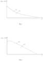
- FIG. 1is a schematic diagram showing the relationship between the capacity retention and the service life of a battery cell in an embodiment of a lithium-iron-phosphate chemical-system battery cell under some circumstances;
- FIG. 2is a schematic diagram showing the relationship between the capacity retention and the service life of a battery cell in an embodiment of a NCM chemical-system battery cell under some circumstances;
- FIG. 3is a schematic diagram showing the relationship between the capacity retention and the service life of a battery cell in a battery module in an embodiment in which a lithium-iron-phosphate chemical-system battery cell and a NCM chemical system battery cell are connected in series under some circumstances;
- FIG. 4is a schematic structural diagram of an embodiment of a battery of the present application.
- FIG. 5is a schematic diagram showing the relationship between the capacity retention and the service life of a battery cell in a battery module in an embodiment of the battery module of the present application;
- FIG. 6is a schematic structural diagram of another embodiment of a battery of the present application.
- FIG. 7is a schematic structural diagram of another embodiment of a battery of the present application.
- FIG. 8is a schematic structural diagram of an embodiment of an apparatus of the present application.
- FIG. 9is a schematic flow diagram of an embodiment of a method for manufacturing the battery of the present application.
- FIG. 10is a schematic structural diagram of an embodiment of a device for manufacturing the battery of the present application.
- the energy of the secondary batteryis often increased by increasing the number of battery cells of the secondary battery or developing battery cells with high volume energy density such as the NCM chemical-system battery cell.
- the mass and volume of the secondary batterywill be increased due to the increase of the battery cells, and the NCM chemical-system battery cell has worse safety performance. If the LFP chemical-system battery cell with a high safety factor is connected in series with the NCM chemical-system battery cell for use, the characteristic of high volume energy density of the NCM chemical-system battery cell cannot be exerted. How to improve the output energy of the secondary battery while considering the safety of the secondary battery is still a problem to be solved urgently in the industry.
- the capacity of the battery celldirectly determines the energy output of the battery cell.
- the battery cells of different chemical-system typeshave different service life decay modes.
- FIG. 1is a schematic diagram showing the relationship between the capacity retention and the service life of a battery cell in an embodiment of an LFP chemical-system battery cell
- the X axisrepresents the working time of the battery cell, i.e., represents the service life of the battery cell
- the Y axisrepresents the capacity of the battery cell (in Ah).
- L1represents a capacity decay curve of the LFP chemical-system battery cell, indicating that the service life of the LFP chemical-system battery cell decays faster in the early stage, then gradually slows down and approaches to a linear decay mode, and the flat linear slope changes from large to small in the later stage.
- FIG. 2is a schematic diagram showing the relationship between the capacity retention and the service life of a battery cell in an embodiment of a NCM chemical-system battery cell.
- L2represents the capacity decay curve of the NCM chemical-system battery cell, the NCM chemical-system battery cell decays slowly in the early stage, and decays faster and approaches to the linear decay mode in the later stage.
- S2represents the area from the lower side of L2 to the X axis region part, which indicates the total cumulative capacity of the NCM chemical-system battery cell throughout the life cycle, and S2 determines the total energy output of the NCM chemical-system battery cell throughout the life cycle.
- the output energy of the batteryis the sum of the energy corresponding to the capacity of the overlapping part of S1 in FIG. 1 and S2 in FIG. 2 , i.e., the energy corresponding to the capacity represented by the filling part S3 in FIG.
- the energy(it originally belongs to the energy contained in the NCM chemical-system battery cell) corresponding to the capacity represented by the filling part S4 does not exert the function, i.e., being wasted (wherein, when the battery is discharged, the LFP chemical-system battery cell and the NCM chemical-system battery cell use the respective common plateau voltages, for example, the plateau voltage of the LFP chemical-system battery cell is 3.22 v, and the plateau voltage of the NCM chemical-system battery cell is 3.68 v).
- the present applicationprovides a battery, comprising: a first-type battery cell group and a second-type battery cell group which are connected in series, wherein the battery comprises at least one first-type battery cell group and at least one second-type battery cell group,
- the volume energy density of the second-type battery cellis greater than that of the first-type battery cell, so that under the same volume condition, the second-type battery cell has more energy than the first-type battery cell. In the same way, under the same volume conditions, the second-type battery cell group has more energy than the first-type battery cell group.
- the capacity Cap1 of the first-type battery cell groupis greater than the capacity of the capacity Cap2 of the second-type battery cell group, so that during the charging and discharging cycle of the battery formed by the first-type battery cell group and the second-type battery cell group in series, the limitation of the first-type battery cell group to the second-type battery cell group's power release is reduced, thereby efficiently exerting the characteristics of the high volume energy density of the second-type battery cell group and improving the overall energy throughput and service life of the battery.
- FIG. 4is a schematic structural diagram of an embodiment of the present application.
- the battery provided in this embodimentcomprises one LFP chemical-system battery cell group 110 (as the first-type battery cell group), and one NCM chemical-system battery cell group 210 (as the second-type battery cell group).
- the LFP chemical-system battery cell group 110 and the NCM chemical-system battery cell group 210are connected in series.
- the LFP chemical-system battery cell group 110is composed of the LFP chemical-system battery cell 111 and the LFP chemical-system battery cell 112 connected in parallel, and the capacity of the LFP chemical-system battery cell group 110 is the sum of the capacity of the LFP chemical-system battery cell 111 and the capacity of the LFP chemical-system battery cell.
- the capacity of the LFP chemical-system battery cell group 110is greater than the capacity of the NCM chemical-system battery cell group 210 .
- the NCM chemical-system battery cell group 210has only one NCM chemical-system battery cell.
- the volume energy density of the NCM chemical-system battery cellis greater than that of the LFP chemical-system battery cells 111 and 112 .
- the LFP chemical-system battery cells 111 and 112have the same structure, and have the same volume energy density and capacity. It is worth noting that in other embodiments, the battery cells 111 and 112 may have different capacities, which does not affect the realization of the objectives of the technical solution of the present application.
- FIG. 5is a schematic diagram of accumulated energy output and life of the battery embodiment shown in FIG. 4 during operation.
- the plateau voltage of the LFP chemical-system battery cell groupis about 3.22V
- the plateau voltage of the NCM chemical-system battery cell groupis about 3.68V
- the line L11is the capacity retention rate curve of the LFP system battery cell group 110
- the line L21is the capacity retention rate curve of the NCM chemical-system battery cell group 210 .
- the capacity (initial capacity) of the LFP chemical-system battery cell group 110is greater than the capacity (initial capacity) of the NCM chemical-system battery cell group 210 .
- the initial capacity of the LFP chemical-system battery cell group 110decays faster, and the capacity of the NCM chemical-system battery cell group 210 decays more slowly in the early stage.
- the two types of chemical-system battery cell groupshave the same capacity value for the first time at point A; during this period, the capacity of the LFP chemical-system battery cell group 110 is greater than that of the NCM chemical-system battery cell group 210 , thus the total energy output of the LFP chemical-system batter cell group 110 and the NCM chemical-system battery cell group 210 depends on the capacity of the NCM chemical-system battery cell group 210 .
- the capacity decay of the LFP chemical-system cell battery group 110gradually slows down and approaches the linear decay mode, and the linear slope of the later flattening linearity changes from large to small, and the capacity of the NCM chemical-system battery cell group 210 decays faster in the later period, and approaches linear decay mode.
- the capacity values of the two types of battery cellsappear to be the same at point B for the second time.
- the overall energy throughput of the batterydepends on the capacity of the LFP chemical-system cell group 110 , even if the total theoretical capacity of the NCM chemical-system battery cell group 210 is greater than the total theoretical capacity of the LFP chemical-system battery cell group 110 .
- the overall energy throughput of the batterydepends on the capacity of the NCM chemical-system battery cell group 210 , even if the total theoretical capacity of the LFP chemical-system battery cell group 110 is greater than the total theoretical capacity of the NCM chemical-system battery cell group 210 .
- the energy corresponding to the capacity represented by the area S41 formed between the two points A and B of the curves L11 and L21is the unreleased energy of the NCM chemical-system battery cell group 210 .
- the area of S41 in FIG. 5is significantly smaller than that of S4 in FIG. 3 , i.e. effectively reducing the energy waste of the NCM chemical-system battery cell group 210 .
- the battery module provided in this embodimentmore efficiently releases the energy of the NCM chemical-system battery cell group 210 with high energy density, and fully utilizes the volume energy density characteristics of the NCM chemical-system battery cell group 210 (i.e., high-density capacity battery cells).
- the capacity of the LFP chemical-system battery cell group 110is adjusted so that the initial capacity of the LFP chemical-system battery cell group 110 is greater than that of the NCM chemical-system battery cell group 210 .
- the capacity Cap1 of the LFP chemical-system cell group and the capacity Cap1 of the NCM chemical-system cell groupmeet the following conditions: 0.01 ⁇ (Cap1/Cap2) ⁇ 1 ⁇ 0.5. In this way, the energy of the NCM chemical-system battery cell group can be effectively and fully released while reducing the energy waste of the LFP chemical-system battery cell group. In some embodiments, 0.02 ⁇ (Cap1/Cap2) ⁇ 1 ⁇ 0.25, in other embodiments, 0.04 ⁇ (Cap1/Cap2) ⁇ 1 ⁇ 0.15, and the specific value is determined according to actual needs.
- the capacity decay rate of the second-type battery cellis less than the capacity decay rate of the first-type battery cell, i.e., when the capacity retention rate of the first-type battery cell and the second-type battery cell decays to 80% of the capacity (initial capacity), the number of cycles of the second-type battery cell is greater than the number of cycles of the first-type battery cell.
- the batteryIn the vehicle application and other fields of the secondary battery, during the recycling process of the battery (referring to all battery cells or the entire battery pack on the vehicle), when the battery ages to a certain extent (for example, its capacity decays to be less than 80% of its initial capacity), the requirements of vehicle operation may not be satisfied. For this reason, in the present application, the capacity of the first-type battery cell under working conditions decays faster, and the capacity of the second-type battery cell decays more slowly.
- the initial capacity of the battery cell with faster decay rateis improved to prolong the overall service life of the battery module, i.e., increasing the number of cycles of the battery before the overall decay rate of the battery module reaches 80%.
- plateau voltage of the first-type battery cell and the second-type battery cellwill also affect the overall energy release efficiency of the battery.
- the plateau voltage V1 of the first-type battery cellis 3.15V ⁇ 0.05V ⁇ 4.75V ⁇ 0.05V; the plateau voltage V2 of the second-type battery cell is 3.60 ⁇ 3.80V ⁇ 0.05V.
- the LFP chemical-system battery cell 111 , the NCM chemical-system battery cell 210 (i.e., the NCM chemical-system battery cell group 210 ), the LFP chemical-system battery cell 112are arranged in a row, and the NCM chemical-system battery cell 210 is located between the LFP chemical-system battery cell 111 and the LFP chemical-system battery cell 112 , i.e. the LFP chemical-system battery cell and the NCM chemical-system battery cell are arranged alternately.
- each battery cell(including the LFP chemical-system battery cell 111 , 112 and the NCM chemical-system battery cell 210 , etc.) will produce gas, swell, and generate heat.
- the LFP chemical-system battery cell and the NCM chemical-system battery cell belonging to different chemical systemshave different cell density, specific heat capacity, and thermal conductivity, so they will have different degrees of expansion and thermal diffusion, and form stress differences in different areas of the battery. If the stress difference is too large, the safety performance and electrical performance of the battery will be affected.
- the alternative arrangement structure of LFP chemical-system battery cells and NCM chemical-system battery cellshelps to alleviate the problem of local stress concentration caused by the concentrated arrangement of battery cells based on the same chemical system, effectively releasing the internal stress of the battery, and promoting the balance of the stresses in different areas within the battery, thereby improving battery safety and electrical performance.
- the battery performancecan be optimized by further setting the cell density, specific heat capacity, and thermal conductivity of the LFP chemical-system battery cell and the NCM chemical-system battery cell.
- the ratio of the specific heat capacity C1 of the LFP chemical-system battery cell to the specific heat capacity C2 of the NCM chemical-system battery cellis 0.9 ⁇ C1/C2 ⁇ 10, in some examples it can be 1 ⁇ C1/C2 ⁇ 6, and in other examples it can be 1.5 ⁇ C1/C2 ⁇ 3.
- the ratio of the thermal conductivity ⁇ 1 of the LFP chemical-system battery cell to the thermal conductivity ⁇ 2 of the NCM chemical-system battery cellis 0.5 ⁇ 1/ ⁇ 2 ⁇ 3, in some examples it can be 0.7 ⁇ 1/ ⁇ 2 ⁇ 2, in other examples it can be 0.9 ⁇ 1/ ⁇ 2 ⁇ 1.5.
- the ratio of the cell density ⁇ 1 of the LFP chemical-system battery cell to the density ⁇ 2 of the NCM chemical-system battery cellis 0.6 ⁇ 1/ ⁇ 2 ⁇ 3, in some examples it can be 0.8 ⁇ 1/ ⁇ 2 ⁇ 2, and in other examples it can be 0.9 ⁇ 1/ ⁇ 2 ⁇ 1.5.
- FIG. 6is a schematic structural diagram of another embodiment of the battery provided by the present application.
- the battery provided in this embodimentcomprises one LFP chemical-system batter cell group 120 and two NCM chemical-system battery cell groups 220 and 230 .
- the LFP chemical-system battery cell group 120is connected in series with the NCM chemical-system battery cell groups 220 and 230 .
- the capacity of the LFP chemical-system battery cell group 120is greater than the capacities of the NCM chemical-system battery cell groups 220 and 230 , respectively.
- the LFP chemical-system battery cell group 110is composed of the LFP chemical-system battery cell 121 , the LFP chemical-system battery cell 122 and the LFP chemical-system battery cell 123 connected in parallel, and the capacity of the LFP chemical-system battery cell group 120 is the sum of the capacities of LFP chemical-system battery cells 121 , 122 and 123 .
- the capacities of the NCM chemical-system battery cell groups 220 and 230are equal.
- the NCM chemical-system battery cell group 220is composed of NCM chemical-system battery cells 221 and 222 connected in parallel, and the capacity of the NCM chemical-system cell battery group 220 is the sum of the capacities of the NCM chemical-system battery cells 221 and 222 .
- the NCM chemical-system battery cell group 230has a single battery cell structure.
- the capacities of the NCM chemical-system battery cell groups 220 and 230are equal, but compared to the single battery cell structure of the NCM chemical-system battery cell group 230 , the NCM chemical-system battery cell group is composed of two NCM chemical-system battery cells 221 and 222 .
- the volume of a single battery cell in the NCM chemical-system battery cell group 220is smaller than that of the NCM chemical-system batter cell group 230 .
- the small-volume battery cellhas a more concise and relaxed manufacturing process and conditions, thereby reducing the reducing the difficulty of manufacturing the first battery pack with large capacity; in addition, compared with large-volume battery cells, small-volume battery cells can have a higher charge and discharge rate, and the flexibility of battery cell arrangement to improve the performance and design flexibility of the battery cell.
- the NCM chemical-system battery cell 221 , the LFP chemical-system battery cell 121 , the NCM chemical-system battery cell 222 , the LFP chemical-system battery cell 122 , the NCM chemical-system battery cell 230 , and the LFP chemical-system battery cell 123are arranged in sequence.
- the capacities of the NCM chemical-system battery cell groups 220 and 230are equal, but in other embodiments, if there are multiple NCM chemical-system battery cell groups, the capacity of each NCM chemical-system battery cell group can be all the same, part of the same, or all different, which is designed according to the overall needs of the battery and does not limit the protection scope of the present application.
- FIG. 7is a schematic structural diagram of another embodiment of the battery provided by the present application.
- the battery provided in this embodimentcomprises two LFP chemical-system battery cell groups 130 and 140 , and four NCM chemical-system battery cell groups 240 , 250 , 260 , and 270 .
- the above-mentioned multiple battery cell groupsare connected in series.
- the capacity of the two LFP chemical-system battery cell groupsis greater than the capacity of the four NCM chemical-system battery cell groups.
- the capacities of the two LFP chemical-system battery cell groupsare the same or different, and the capacities of the four NCM chemical-system battery cell groups are the same or different, which does not limit the protection scope of the present application.
- the LFP chemical-system battery cell group 130is composed of LFP chemical-system battery cells 131 and LFP chemical-system battery cells 132 connected in parallel.
- the capacity of the LFP chemical-system battery cell group 130is the sum of the capacities of the LFP chemical-system battery cells 131 and 132 .
- the LFP chemical-system battery cell group 140has a single battery cell structure.
- the four NCM chemical-system battery cell groupshave the same capacity, and all have a single battery cell structure.
- the LFP chemical-system battery cell 131 , the NCM chemical-system battery cell 240 (i.e., the NCM chemical-system battery cell group 240 ), and the LFP chemical-system battery cell 132are arranged in a row.
- the NCM chemical-system battery cell 250i.e. NCM chemical-system battery cell group 250
- LFP chemical-system battery cell 140LFP chemical-system battery cell 140
- NCM chemical-system battery cell 260i.e. NCM chemical-system battery cell group 260
- NCM chemical-system battery cell 270i.e. NCM chemical-system battery cell group 270
- the above-mentioned embodimentuses the LFP chemical-system battery cell as the first-type battery cell, and the NCM chemical-system battery cell as the second-type battery cell, but the choice of the first-type battery cell and the second-type battery cell in other embodiments of the present application is not limited.
- the second-type battery cellmay be a NCM chemical-system battery cell, a NCA chemical-system battery cell, a lithium cobaltate chemical-system battery cell, or a lithium manganate chemical-system battery cell, and the like.
- the first-type battery cellmay be an LFP chemical-system battery cell, a lithium cobaltate chemical-system battery cell, or a lithium manganate chemical-system battery cell, etc.
- first-type battery cell and the second-type battery cellinclude, but are not limited to, lithium/sodium/magnesium ion battery cells, lithium/sodium/magnesium metal battery cells, lithium/sodium/magnesium-all-solid-state/semi-solid-state/quasi-solid-state/polymer/gel electrolyte-battery cells, and other rechargeable secondary battery cells.
- Battery preparationthe preparation methods of battery cells in various embodiments and comparative examples are as follows.
- a positive electrode material, conductive carbon Super P and a binder polyvinylidene fluoride (PVDF)were fully stirred and mixed in an appropriate amount of N-methylpyrrolidone (abbreviated as NMP) solvent at a weight ratio of 95:3:2 to form uniform and stable slurry with a viscosity of 3000 mPa ⁇ s to 20000 mPa ⁇ s, and the slurry generated no gelling, stratification or sedimentation and other phenomena within 24 to 48 hours.
- NMPN-methylpyrrolidone
- the positive electrode material slurrywas uniformly coated on a positive electrode current collector Al foil, the electrode plate was cold pressed to a designed pressing pressure after drying, and the positive electrode plate was obtained by slitting the electrode plate for later use.
- a negative electrode active materialsuch as graphite, conductive carbon, a binder polystyrene-butadiene copolymer (SBR), a thickener sodium carboxymethylcellulose (CMC) were fully stirred and mixed in an appropriate amount of water solvent at a weight ratio of 95:2:2:1 to form uniform and stable negative electrode slurry; and the slurry was evenly coated on a negative electrode current collector Cu foil, the electrode plate was cold pressed to the designed pressing pressure after drying, and was slit for later use.
- SBRbinder polystyrene-butadiene copolymer
- CMCthickener sodium carboxymethylcellulose
- PE or PPis selected as the separator.
- the positive electrode plate, the separator and the negative electrode platewere wound together by using the conventional battery cell manufacturing process to form a bare battery cell, then the bare battery cell was placed in a battery shell, the electrolyte was injected, then the procedures of forming and sealing were carried out, and a rechargeable power battery cell was obtained at last.
- the battery cell to be testedwas selected, and a battery cell charging and discharging machine and a high and low temperature box were used to test the full charging capacity and the discharging capacity of the battery cell at a standard rate at 25° C.
- the discharging capacitywas the nominal capacity value of the battery cell, wherein the charging and discharging rate was 0.33 C (C represents the rated capacity of the battery cell.
- the charging/discharging currentis the rate multiplied by the rated capacity of the battery cell, and the rated capacity is based on the battery cell capacity identified in the GBT certification document of the battery cell, or the battery module to which the battery cell belongs or the battery pack to which the battery cell belongs).
- the test procedures of the capacity of the battery cellwere as follows: 1) standing for 30 minutes at 25° C.; 2) discharging at constant current of 0.33 C to a discharging cut-off voltage (for example, the NCM chemical-system battery cell was set to 2.8V, and the LFP chemical-system battery cell was set to 2.5V), and then standing for 30 minutes; 3) charging at constant current of 0.33 C to a charging cut-off voltage (for example, the NCM chemical-system battery cell was set to 4.35 V and the like according to the specific battery cell type, the LFP chemical-system battery cell was 3.65 V), charging at a constant voltage until the current is ⁇ 0.05 C, and then standing for 5 minutes; and 4) discharging at constant current of 0.33 C to the discharging cut-off voltage.
- a discharging cut-off voltagefor example, the NCM chemical-system battery cell was set to 2.8V, and the LFP chemical-system battery cell was set to 2.5V
- charging cut-off voltagefor example, the NCM chemical-system battery cell was
- the measured discharging capacitywas the nominal capacity value of the battery cell.
- Related terms and test methodsrefer to GB/T 19596, GB/T 31484-2015, GB/T 31485-2015, GB/T 31486-2015 and “Safety Requirements for Power Storage Batteries for Electric Vehicles”.
- Step 1) to step 4)was a charging and discharging cycle of the battery cell.
- Whether a battery cell in the module will spread to the adjacent battery cell after heat runaway occurs due to heatingis tested.
- a test module composed of two or more battery cells to be testedwhether a heat insulation pad needs to be added between the battery cells and the thickness of the heat insulation pad are determined according to the specific scenario, and whether to turn on the water circulation is determined.
- a method for triggering heating heat runawayis selected, for example, a heating method of heating plate/heating sheet, the battery was fully charged, the simple module was fixed with a fixture, a heating sheet was placed close to the large surface of the first battery cell, and the simple module was fixed with two steel plate fixtures.
- the heating sheetwas connected to the power supply, the heating was started after a heating sheet power supply device was turned on, until the first battery cell generated heat runaway, the heating sheet was turned off, and the time when the second/Nth battery cell generated heat runaway was observed and recorded; and if the battery cell generating the heat runaway did not cause a fire or explosion to the adjacent battery cell, it was judged that heat spread barrier was realized, or otherwise, it was judged that the heat spread had occurred.
- test process referencewas as follows:
- a first-type A second-type battery cell group battery cell groupCapacity Capacity of a single of a single The first-type The second-type battery Number battery Number (Cap1/Cap2) battery cell battery cell cell cell [Ah] (a) cell [Ah] (b) a/b ⁇ 1
- Example 3 LiFePO 4 NCM-71230 5 144 1 5 4%
- Example 151% 450 203 85% Heat spread 1050 blocked Example 2 34% 445 210 86% Heat spread 1046 blocked Example 3 21% 458 222 89% Heat spread 1035 blocked Example 4 12% 465 230 89% Heat spread 1023 blocked Example 5 63% 443 200 91% Heat spread 980 blocked Example 6 50% 447 205 90% Heat spread 965 blocked Example 7 27% 435 200 90% Heat spread 1210 blocked Example 8 53% 435 200 91% Heat spread 1250 blocked Example 9 448 201 88% Heat spread 1030 blocked Example 10 56% 152 90 89% Heat spread 980 blocked Comparative / 340 160 73% Heat spread 800 Example 1 blocked Comparative / 470 238 88% Heat spread 1075 Example 2 Comparative / 420 195 84% Heat spread 995 Example 3 blocked Comparative / 420 195 71% Heat spread 990 Example 4 blocked Note: in Example 9, the LiFePO 4 group comprises two battery cells, and the capacities thereof are 40 and 60, respectively.
- the present applicationfurther provides an apparatus, including the above-mentioned battery module, and using the battery module as a power source.
- the apparatusis a car, and a battery 10 provided by the present application is installed in the car to serve as its power source.
- the above-mentioned apparatusincludes, but is not limited to: vehicles, ships, airplanes, and various energy storage devices.
- the type and scope of the apparatusare not limited in the present application.
- the present applicationfurther provides a method for manufacturing the battery module, including the following steps:
- Connecting a plurality of first-type battery cells in parallel to form a first-type battery cell groupincludes: connecting a plurality of first-type battery cells in parallel to form a first-type battery cell group, a is a natural number, and a ⁇ 1;
- the number of a and bis not limited, for example, a is 1, 2, 3 . . . 10 . . . 100 . . . 1000 . . . 10000, b is 1, 2, 3 . . . 10 . . . 100 . . . 1000 . . . 10000, and the arrangement of the first-type battery cell and the second-type battery cell is not limited.
- a plurality of first-type battery cells and at least one second-type battery cellare arranged in at least one row, making at least a part of the second-type battery cells between the two first-type battery cells.
- the spaced arrangement of the first-type battery cells and the second-type battery cellscan enhance the heat conduction between the first-type battery cells and the second-type battery cells, and reduce the stress generated based on expansion between the first-type battery cells and the second-type battery cells, thereby improving the overall performance of the battery cells.
- This embodimentfurther provides a device for manufacturing the battery module.
- the device for manufacturing the battery moduleincludes a processor 20 .
- the processor 20is adapted to controlling a clamping arm 21 to obtain a plurality of first-type battery cells 31 , 32 and 34 and at least one second-type battery cell 33 , wherein the first-type battery cells 31 , 32 and 34 and the second-type battery cell 33 are battery cells of different chemical systems; moreover, the volume energy density of the first-type battery cells 31 , 32 , and 34 is smaller than the volume energy density of the second-type battery cell 33 .
- the processor 20is also used to control the assembly component 22 , and is used to connect the first-type battery cells 31 , 32 , 34 and the second-type battery core 33 in series to form a battery module.
- each first-type battery cell groupincludes a plurality of first-type battery cells
- each second-type battery cell groupincludes a plurality of second-class battery cells.
- the processorconnects the first-type battery cells that belong to the same first-type battery cell group in parallel, and connects the second-type battery cells that belong to the same second-type battery cell group in parallel; and connects a plurality of first-type battery cell groups and a plurality of second-type battery cell groups in series.
- the assembling component 22arranges the plurality of first-type battery cells and at least one second-type battery cell in at least one row, and at least part of the second-type battery cells are located between the two first-type battery cells.
- the capacity Cap1 of a first-type battery cell groupis greater than the capacity Cap2 of a second-type battery cell group, and the capacity Cap1 of the first-type battery cell group is the sum of the capacities of the corresponding first-type battery cells.
- the capacity Cap2 of the second-type battery cell groupis the sum of the capacities of the corresponding second-type battery cells.
- the processor 20 , the clamping arm 21 and the assembly component 22 , and the method for the processor 20 to control the clamping arm 21 and the assembly component 22are related arts in the field, which do not limit the protection scope of the present application, and thus will not be repeated herein.
Landscapes
- Chemical & Material Sciences (AREA)
- Chemical Kinetics & Catalysis (AREA)
- Electrochemistry (AREA)
- General Chemical & Material Sciences (AREA)
- Engineering & Computer Science (AREA)
- Manufacturing & Machinery (AREA)
- Materials Engineering (AREA)
- Aviation & Aerospace Engineering (AREA)
- Secondary Cells (AREA)
- Battery Mounting, Suspending (AREA)
- Battery Electrode And Active Subsutance (AREA)
Abstract
Description
- obtaining multiple first-type battery cells and at least one second-type battery cell, wherein the first-type battery cell and the second-type battery cell are battery cells of different chemical systems, and the volume energy density of the first-type battery cell is less than that of second-type battery cell;
- connecting the multiple first-type battery cells in parallel to form a first-type battery cell group, and connecting the at least one second-type battery cell in parallel to form a second-type battery cell group,
- wherein, the capacity Cap1 of the first-type battery cell group is greater than the capacity Cap2 of the second-type battery cell group, the capacity Cap1 of the first-type battery cell group is the sum of the capacities of the corresponding first-type battery cells, and the capacity Cap2 of the second-type battery cell group is the sum of the capacities of the corresponding second-type battery cells; and
- connecting the first-type battery cell group and the second-type battery cell group in series.
- connecting at least one second-type battery cell in parallel to form a second-type battery cell group includes: connecting at least one second-type battery cell in parallel to form b second-type battery cell groups, b is a natural number, and b≥1, wherein, 0.1≤a/b≤3, and in some exemplary embodiments, 0.3≤a/b≤2.
- controlling a clamping arm to obtain a plurality of first-type battery cells and at least one second-type battery cell, wherein the first-type battery cell and the second-type battery cell are battery cells of different chemical systems and the volume energy density of the first-type battery cell is less than the volume energy density of the second-type battery cell; and
- further for controlling an assembly component to connect a plurality of the first-type battery cells in parallel to form a first-type battery cell group, and to connect at least one second-type battery cell in parallel to form a second-type battery cell, wherein the capacity Cap1 of the first-type battery cell group is greater than the capacity Cap2 of the second-type battery cell group, the capacity Cap1 of the first-type battery cell group is the sum of the capacities of the corresponding first-type battery cells, and the capacity Cap2 of the second-type battery cell group is the sum of the capacities of the corresponding second-type battery cells; and
- connecting the first-type battery cell group and the second-type battery cell group in series.
EKt=Σk=0zEk,
where z represents the total number of cycles, and min.Cap.(L,N) represents the capacity of the battery cell with the minimum capacity among the battery cells connected in series.
- wherein the first-type battery cell group is composed of a plurality of first-type battery cells connected in parallel, and the second-type battery cell group is composed of at least one or a plurality of second-type battery cells connected in parallel. The first-type battery cells and the second-type battery cells are different chemical-system battery cells, and the volume energy density of the first-type battery cell is less than the volume energy density of the second-type battery cell; and
- wherein the capacity Cap1 of the first-type battery cell group is greater than the capacity Cap2 of the second-type battery cell group, and the capacity Cap1 of the first-type battery cell group is the sum of the capacities of the corresponding first-type battery cells (i.e., all the first-type battery cells in the first-type battery cell group), the capacity Cap2 of the second-type battery cell group is the sum of the corresponding second-type battery cells (i.e., all the second-type battery cells in the second-type battery cell group).
Embodiment 1. A battery, comprising:- a first-type battery cell group and a second-type battery cell group which are connected in series,
- wherein the first-type battery cell group is composed of multiple first-type batteries connected in parallel, and the second type battery cell group is composed of at least one second type battery cell connected in parallel; the first-type battery cell and the second-type battery cell are battery cells of different chemical systems, and the volume energy density of the first-type battery cell is less than the volume energy density of the second-type battery cell; and
- the capacity Cap1 of the first-type battery cell group is greater than the capacity Cap2 of the second-type battery cell group, in which the capacity Cap1 of the first-type battery cell group is the sum of the capacities of the corresponding first-type battery cells, and the capacity Cap2 of the second-type battery cell group is the sum of the capacities of the corresponding second-type battery cells.
- Embodiment 2. The battery according to
embodiment 1, wherein the first-type battery cell group and the second-type battery core group are arranged in at least one row, and at least part of the second-type battery cell is located between the two first-type battery cells. - Embodiment 3. The battery according to
embodiment 1 or 2, wherein the capacity Cap1 of the first-type battery cell group and the capacity Cap2 of the second-type battery cell group satisfy the following condition:
0.01≤(Cap1/Cap2)−1≤0.5, optionally, 0.02≤(Cap1/Cap2)−1≤0.25, and further optionally, 0.04≤(Cap1/Cap2)−1≤0.15. Embodiment 4. The battery according toembodiment 1 or 3, wherein the ratio of the capacity of the first-type battery cell to the capacity of the second-type battery cell is from 10% to 150%.- Embodiment 5. The battery according to any one of
embodiment 1 to 4, wherein the first-type battery cell group comprises a first-type battery cells and the second-type battery cell group comprises b second-type battery cells; wherein a and b are natural numbers, and a≥1, b≥1. 0.1≤a/b≤50, optionally, 0.5≤a/b≤30, and further optionally, 1≤a/b≤10. - Embodiment 6. The battery according to embodiment 5, wherein when a>1, the capacity Cap1 of all the first-type battery cell groups is the same; and/or, when b>1, the capacity Cap2 of all the second-type battery cell groups is the same.
- Embodiment 7. The battery according to any one of
embodiments 1 to 6, wherein the first-type battery cell and the second-type battery cell satisfy at least one of the following conditions: - the ratio of the specific heat capacity C1 of the first-type battery cell to the specific heat capacity C2 of the second-type battery cell is 0.9≤C1/C2≤10, optionally, 1≤C1/C2≤6, and further optionally, 1.5≤C1/C2≤3;
- the ratio of the heat conductivity coefficient λ1 of the first-type battery cell to the heat conductivity coefficient λ2 of the second-type battery cell is 0.5≤λ1/λ2≤3, optionally, 0.7≤λ1/λ2≤2, and further optionally, 0.9≤λ1/λ2≤1.5;
- the plateau voltage V1 of the first-type battery cell is from 3.15 V±0.05 V to 4.75 V±0.05 V; the plateau voltage V2 of the second-type battery cell is from 3.60 to 3.80 V±0.05 V; and
- the ratio of the density ρ1 of the first-type battery cell to the density ρ2 of the second-type battery cell is 0.6≤ρ1/ρ2≤3, optionally, 0.8≤ρ1/ρ2≤2, and further optionally, 0.9≤ρ1/ρ2≤1.5.
- Embodiment 8. The battery according to any one of
embodiments 1 to 7, wherein the first-type battery cell is a lithium iron phosphate chemical-system battery cell. - Embodiment 9. The battery according to any one of
embodiments 1 to 8, wherein the second-type battery cell is a ternary material chemical-system battery cell. - Embodiment 10. An apparatus, comprising the battery according to any one of
embodiments 1 to 9, and using the battery as a power source. - Embodiment 11. A method for manufacturing a battery, comprising:
- obtaining multiple first-type battery cells and at least one second-type battery cell, wherein the first-type battery cell and the second-type battery cell are battery cells of different chemical systems and the volume energy density of the first-type battery cell is less than the volume energy density of the second-type battery cell;
- connecting the multiple first-type battery cells in parallel to form a first-type battery cell group, and connecting the at least one second-type battery cell in parallel to form a second-type battery cell group, wherein the capacity Cap1 of the first-type battery cell group is greater than the capacity Cap2 of the second-type battery cell group, the capacity Cap1 of the first-type battery cell group is the sum of the capacities of the corresponding first-type battery cells, and the capacity Cap2 of the second-type battery cell group is the sum of the capacities of the corresponding second-type battery cells; and
- connecting the first-type battery cell group and the second-type battery cell group in series.
- Embodiment 12. The method according to embodiment 11, wherein connecting the multiple first-type battery cells in parallel to form a first-type battery cell group includes: connecting a plurality of first-type battery cells in parallel to form a first-type battery cell groups, a is a natural number, and a≥1;
- connecting the at least one second-type battery cell in parallel to form a second-type battery cell group includes: connecting at least one second-type battery cell in parallel to form b second-type battery cell groups, b is a natural number, and b≥1,
- wherein 0.1≤a/b≤50, optionally, 0.5≤a/b≤30, and further optionally, 1≤a/b≤10.
- Embodiment 13. The method according to embodiment 11 or 12, further comprising:
- arranging the multiple first-type battery cells and the at least one second-type battery cell in at least one row, and locating at least a part of the second-type battery cells between the two first-type battery cells.
- Embodiment 14. A device for manufacturing a battery, comprising a processor for
- controlling a clamping arm to obtain multiple first-type battery cells and at least one second-type battery cell, wherein the first-type battery cell and the second-type battery cell are battery cells of different chemical systems and the volume energy density of the first-type battery cell is less than the volume energy density of the second-type battery cell; and
- further for controlling an assembly component to connect the multiple first-type battery cells in parallel to form a first-type battery cell group, and to connect the at least one second-type battery cell in parallel to form a second-type battery cell, wherein the capacity Cap1 of the first-type battery cell group is greater than the capacity Cap2 of the second-type battery cell group, the capacity Cap1 of the first-type battery cell group is the sum of the capacities of the corresponding first-type battery cells, and the capacity Cap2 of the second-type battery cell group is the sum of the capacities of the corresponding second-type battery cells; and
- connecting the first-type battery cell group and the second-type battery cell group in series.
- 1) holding a newly delivered battery cell at 25° C. for 30 minutes; 2) discharging at constant current of 0.33 C to the discharging cut-off voltage (C represented the rated capacity of the battery cell. The charging/discharging current is the rate multiplied by the rated capacity of the battery cell, and the rated capacity is based on the battery cell capacity identified in the GBT certification document of the battery cell, or the battery module to which the battery cell belongs or the battery pack to which the battery cell belongs), and then standing for 30 minutes; 3) charging at constant current of 0.33 C to the charging cut-off voltage, charging at a constant voltage until the current is <0.05 C, and then standing for 5 minutes; and 4) discharging at constant current of 0.33 C to the discharging cut-off voltage, and then standing for 5 minutes. The discharging capacity measured from step 3) to step 4) was counted as Cap0.
- Test 1: the module was heated to triggers a heat runaway test, referring to the document of the Ministry of Industry and Information Technology [2016] No. 377 on Safety Technical Conditions for Electric Motor Coaches.
- Test 2: the heat runaway test was triggered by module acupuncture, referring to GB/T 31485-2015. Specific test method was as follows:
- whether a battery cell in the module will spread to the adjacent battery cell after heat runaway occurs due to acupuncture is tested. For the test module composed of battery cells to be tested, whether a heat insulation pad needs to be added between the battery cells and the thickness of the heat insulation pad are determined according to the specific scenario, and whether to turn on the water circulation is determined. The battery cell was fully charged, and the simple module was fixed with two steel plate fixtures with holes. A Φ3-Φ8 mm high temperature resistant stainless steel needle (the conical angle of the needle angle was 20° to 60°, and the surface of the needle was smooth and clean and free of rust, oxide layer and oil stains) penetrated to the first battery cell from a direction perpendicular to the battery cell at a speed of 0.1-40 mm/s to trigger the heat runaway, and the time when the second/Nthbattery cell generated the heat runaway was observed and recorded; and if the battery cell generating the heat runaway did not cause a fire or explosion to the adjacent battery cell, it was judged that the heat spread barrier was realized, or otherwise, it was judged that the heat spread had occurred.
4. Discharge Power Test Method
- (1) Test the maximum discharge current of the battery cell (using the test current method), the steps were as follows:
- At room temperature, the discharge capacity Cap10 of the battery cell was tested; then, the battery cell was adjusted to the target state of charge (State of charge, SOC for short) (for example, 5% Cap10, 10% Cap10, 20% Cap10, 50% Cap10 or 90% Cap10, etc.), the temperature of the battery cell was adjusted to the target test temperature (for example, 25° C., 10° C., 0° C., −10° C., −20° C., and the test temperature accuracy was controlled at ±2° C.) and stood for 2 hours;
- the discharge current I of battery cell was re-adjusted to achieve the purpose of discharging within a specific time (for example, 5 seconds, 10 seconds, 30 seconds, 180 seconds) to the lower cut-off voltage of the battery cell (the control accuracy of the discharge cut-off voltage needs to be within ±5 mV), the current I measured at this time was the maximum discharge current.
- (2) Obtaining the maximum discharge power according to the formula P=I*Vend (Vend was the discharge cut-off voltage).
| A first-type | A second-type | |||||
| battery cell group | battery cell group | |||||
| Capacity | Capacity | |||||||
| of a single | of a single | |||||||
| The first-type | The second-type | battery | Number | battery | Number | (Cap1/Cap2) | ||
| battery cell | battery cell | cell [Ah] | (a) | cell [Ah] | (b) | a/b | −1 | |
| Example 1 | LiFePO4 | NCM-811 | 50 | 2 | 99 | 1 | 2 | 1% |
| Example 2 | LiFePO4 | NCM-721 | 40 | 3 | 118 | 1 | 3 | 2% |
| Example 3 | LiFePO4 | NCM-712 | 30 | 5 | 144 | 1 | 5 | 4% |
| Example 4 | LiFePO4 | NCM-622 | 15 | 10 | 130 | 1 | 10 | 15% |
| Example 5 | LiFePO4 | NCM-523 | 45 | 2 | 72 | 1 | 2 | 25% |
| Example 6 | LiMn0.7Fe0.3PO4 | NCM-514 | 70 | 3 | 140 | 1 | 3 | 50% |
| Example 7 | LiMnPO4 | NCMA | 48 | 4 | 180 | 1 | 4 | 7% |
| Example 8 | LiMnPO4 | NCMA | 48 | 4 | 90 | 2 | 2 | 7% |
| Example 9 | LiFePO4 | NCM-811 | 40 & 60 | 2 | 94 | 1 | 2 | 6% |
| Example 10 | Na3V2(PO4)2O2F | Na0.93Cu0.22Fe0.3 | 40 | 2 | 72 | 1 | 2 | 11% |
| Mn0.48O2 | ||||||||
| Comparative | LiFePO4single- | / | 50 | 2 | / | / | / | / |
| Example 1 | type battery cell | |||||||
| structure | ||||||||
| Comparative | / | NCM-721 single- | / | / | 40 | 2 | / | / |
| Example 2 | type battery cell | |||||||
| structure | ||||||||
| Comparative | LiFePO4 | NCM-811 | 100 | 1 | 99 | 1 | 1 | / |
| Example 3 | ||||||||
| Comparative | LiFePO4 | NCM-811 | 100 | 1 | 100 | 1 | 1 | / |
| Example 4 | ||||||||
| The ratio of the | ||||||
| capacity of a | Discharge power | |||||
| first-type | Average volume | Average weight | of a single | |||
| battery cell | energy density | energy density | Capacity | battery cell | ||
| to that of a | of a single | of a single | retention | for 30 s @50% | ||
| second-type | battery cell | battery cell | rate after | Safety test | SOC, 25° C. | |
| battery cell | [Wh/L] | [Wh/kg] | 1000 cycles | results | [W] | |
| Example 1 | 51% | 450 | 203 | 85% | Heat spread | 1050 |
| blocked | ||||||
| Example 2 | 34% | 445 | 210 | 86% | Heat spread | 1046 |
| blocked | ||||||
| Example 3 | 21% | 458 | 222 | 89% | Heat spread | 1035 |
| blocked | ||||||
| Example 4 | 12% | 465 | 230 | 89% | Heat spread | 1023 |
| blocked | ||||||
| Example 5 | 63% | 443 | 200 | 91% | Heat spread | 980 |
| blocked | ||||||
| Example 6 | 50% | 447 | 205 | 90% | Heat spread | 965 |
| blocked | ||||||
| Example 7 | 27% | 435 | 200 | 90% | Heat spread | 1210 |
| blocked | ||||||
| Example 8 | 53% | 435 | 200 | 91% | Heat spread | 1250 |
| blocked | ||||||
| Example 9 | 448 | 201 | 88% | Heat spread | 1030 | |
| blocked | ||||||
| Example 10 | 56% | 152 | 90 | 89% | Heat spread | 980 |
| blocked | ||||||
| Comparative | / | 340 | 160 | 73% | Heat spread | 800 |
| Example 1 | blocked | |||||
| Comparative | / | 470 | 238 | 88% | Heat spread | 1075 |
| Example 2 | ||||||
| Comparative | / | 420 | 195 | 84% | Heat spread | 995 |
| Example 3 | blocked | |||||
| Comparative | / | 420 | 195 | 71% | Heat spread | 990 |
| Example 4 | blocked | |||||
| Note: | ||||||
| in Example 9, the LiFePO4group comprises two battery cells, and the capacities thereof are 40 and 60, respectively. | ||||||
- Step S1: obtaining a plurality of first-type battery cells and at least one second-type battery cell, wherein the first-type battery cells and the second-type battery cell are battery cells of different chemical systems,
- wherein the volume energy density of the first-type battery cell is less than the volume energy density of the second-type battery cell; and
- the capacity Cap1 of the first-type battery cell is greater than the capacity Cap2 of the second-type battery cell.
- Step S2: connecting a plurality of first-type battery cells in parallel to form a first-type battery cell group, and connecting at least one second-type battery cell in parallel to form a second-type battery cell group;
- wherein the capacity Cap1 of the first-type battery cell group is greater than the capacity Cap2 of the second-type battery cell group, the capacity Cap1 of the first-type battery cell group is the sum of the capacities of the corresponding first-type battery cells, and the capacity Cap2 of the second-type battery cell group is the sum of the capacities of the corresponding second-type battery cells;
- Step S3: connecting the first-type battery cell group and the second-type battery cell group in series.
- connecting at least one second-type battery cell in parallel to form a second-type battery cell group includes: connecting at least one second-type battery cell in parallel to form b second-type battery cell groups, b is a natural number, and b≥1,
- wherein 0.1≤a/b≤3, in some examples, 0.3≤a/b≤2.
Claims (12)
0.02≤(Cap1/Cap2)−1≤0.25, and optionally, 0.04≤(Cap1/Cap2)−1≤0.15.
Applications Claiming Priority (5)
| Application Number | Priority Date | Filing Date | Title |
|---|---|---|---|
| CN202010367231 | 2020-04-30 | ||
| CN202010367231.1 | 2020-04-30 | ||
| CN202010786523.9 | 2020-08-07 | ||
| CN202010786523.9ACN113594636B (en) | 2020-04-30 | 2020-08-07 | Battery, device, and method and apparatus for manufacturing battery |
| PCT/CN2021/089319WO2021218814A1 (en) | 2020-04-30 | 2021-04-23 | Battery, apparatus, battery production method, and device |
Related Parent Applications (1)
| Application Number | Title | Priority Date | Filing Date |
|---|---|---|---|
| PCT/CN2021/089319ContinuationWO2021218814A1 (en) | 2020-04-30 | 2021-04-23 | Battery, apparatus, battery production method, and device |
Publications (2)
| Publication Number | Publication Date |
|---|---|
| US20220115686A1 US20220115686A1 (en) | 2022-04-14 |
| US12113162B2true US12113162B2 (en) | 2024-10-08 |
Family
ID=78237900
Family Applications (2)
| Application Number | Title | Priority Date | Filing Date |
|---|---|---|---|
| US17/556,991Active2041-08-21US12113162B2 (en) | 2020-04-30 | 2021-12-20 | Battery comprising first-type battery cell group and second-type battery cell group which are connected in series, apparatus, and method and device for manufacturing battery |
| US17/563,080Active2041-11-06US12272780B2 (en) | 2020-04-30 | 2021-12-28 | Battery module, apparatus, battery pack, and method and device for manufacturing battery module |
Family Applications After (1)
| Application Number | Title | Priority Date | Filing Date |
|---|---|---|---|
| US17/563,080Active2041-11-06US12272780B2 (en) | 2020-04-30 | 2021-12-28 | Battery module, apparatus, battery pack, and method and device for manufacturing battery module |
Country Status (4)
| Country | Link |
|---|---|
| US (2) | US12113162B2 (en) |
| EP (2) | EP3952001B1 (en) |
| CN (2) | CN113594637A (en) |
| WO (2) | WO2021218814A1 (en) |
Families Citing this family (19)
| Publication number | Priority date | Publication date | Assignee | Title |
|---|---|---|---|---|
| WO2022067809A1 (en) | 2020-09-30 | 2022-04-07 | 宁德时代新能源科技股份有限公司 | Battery, device, and preparation method and preparation device for battery |
| WO2022067810A1 (en) | 2020-09-30 | 2022-04-07 | 宁德时代新能源科技股份有限公司 | Battery, device, and production method and apparatus for battery |
| JP7466656B2 (en) | 2020-09-30 | 2024-04-12 | 寧徳時代新能源科技股▲分▼有限公司 | Battery, device, battery manufacturing method and manufacturing device |
| EP4064421A4 (en) | 2020-11-17 | 2023-09-13 | Contemporary Amperex Technology Co., Limited | BATTERY, DEVICE USING A BATTERY AND METHOD AND DEVICE FOR PRODUCING A BATTERY |
| WO2022133959A1 (en) | 2020-12-24 | 2022-06-30 | 宁德时代新能源科技股份有限公司 | Battery module and manufacturing method and device therefor, and battery pack and electrical apparatus |
| EP4113685A4 (en)* | 2021-04-26 | 2023-02-22 | Contemporary Amperex Technology Co., Limited | BATTERY ASSEMBLY, BATTERY PACK, ELECTRICAL DEVICE AND MANUFACTURING METHOD AND PRODUCTION DEVICE FOR BATTERY ASSEMBLY |
| CN113036242B (en)* | 2021-05-28 | 2021-09-24 | 蜂巢能源科技有限公司 | Battery Modules and Battery Packs |
| EP4228053A4 (en) | 2021-11-18 | 2025-03-12 | Contemporary Amperex Technology (Hong Kong) Limited | BATTERY PACK AND ELECTRICAL APPLIANCE USING SAME |
| CN114335837A (en)* | 2021-12-31 | 2022-04-12 | 远景动力技术(江苏)有限公司 | Battery pack |
| EP4246657A4 (en)* | 2022-01-04 | 2025-03-19 | Contemporary Amperex Technology (Hong Kong) Limited | Hybrid series-connected battery module, battery pack and electrical apparatus |
| KR102748501B1 (en)* | 2022-06-02 | 2024-12-30 | 컨템포러리 엠퍼렉스 테크놀로지 (홍콩) 리미티드 | Battery pack and electrical equipment |
| WO2023245657A1 (en)* | 2022-06-24 | 2023-12-28 | 宁德时代新能源科技股份有限公司 | Battery pack and electric device |
| CN115520021A (en)* | 2022-10-11 | 2022-12-27 | 广州小鹏汽车科技有限公司 | Battery charging method, battery pack, charging management device and system, vehicle |
| CN115763725A (en)* | 2022-11-01 | 2023-03-07 | 广汽埃安新能源汽车股份有限公司 | Positive active material, positive pole piece, battery core, battery pack and electric equipment |
| US20240170789A1 (en)* | 2022-11-16 | 2024-05-23 | Yu-Hung LI | Battery System |
| EP4567955A1 (en)* | 2023-01-09 | 2025-06-11 | Contemporary Amperex Technology (Hong Kong) Limited | Battery, and electric device having same |
| CN118572274A (en)* | 2023-02-28 | 2024-08-30 | 通用汽车环球科技运作有限责任公司 | Layout of battery packs with mixed chemistry cells |
| CN219393476U (en)* | 2023-03-14 | 2023-07-21 | 蔚来电池科技(安徽)有限公司 | Lithium battery |
| CN117790940A (en)* | 2023-12-26 | 2024-03-29 | 三一红象电池有限公司 | Electric equipment, battery module and manufacturing method of battery module |
Citations (147)
| Publication number | Priority date | Publication date | Assignee | Title |
|---|---|---|---|---|
| JPH07320775A (en) | 1994-05-27 | 1995-12-08 | Matsushita Electric Ind Co Ltd | Sealed nickel-hydrogen storage battery unit cells and unit cells |
| JPH11121041A (en) | 1997-10-14 | 1999-04-30 | Ngk Insulators Ltd | Lithium secondary battery |
| EP1265302A2 (en) | 2001-06-04 | 2002-12-11 | Hitachi, Ltd. | Lithium secondary battery positive electrode plate and lithium secondary battery |
| JP2003174734A (en) | 2001-12-06 | 2003-06-20 | Shin Kobe Electric Mach Co Ltd | Hybrid secondary battery |
| WO2004095611A1 (en) | 2003-04-21 | 2004-11-04 | Makita Corporation | Combination battery and battery pack using combination battery |
| JP2005071917A (en) | 2003-08-27 | 2005-03-17 | Toyota Motor Corp | Battery cover and secondary battery including the cover |
| JP2006079987A (en) | 2004-09-10 | 2006-03-23 | Nissan Motor Co Ltd | Hybrid battery system |
| US20060197496A1 (en) | 2005-02-04 | 2006-09-07 | Tdk Corporation | Combination of lithium ion batteries |
| JP2007059145A (en) | 2005-08-23 | 2007-03-08 | Toyota Motor Corp | Assembled battery design method, manufacturing method, and assembled battery |
| US20070072059A1 (en) | 2005-09-27 | 2007-03-29 | Hideki Kitao | Method of charging and discharging a non-aqueous electrolyte secondary battery |
| CN101242011A (en) | 2007-02-05 | 2008-08-13 | 三洋电机株式会社 | battery unit |
| CN101262049A (en) | 2007-03-09 | 2008-09-10 | 联想(新加坡)私人有限公司 | Battery pack and portable electronic device |
| JP2009021223A (en) | 2007-06-11 | 2009-01-29 | Panasonic Corp | Battery pack and battery-equipped equipment |
| CN101409369A (en) | 2008-11-14 | 2009-04-15 | 东莞市迈科科技有限公司 | High-capacity high-power polymer lithium iron phosphate power battery and preparation method thereof |
| US20090162751A1 (en) | 2007-12-25 | 2009-06-25 | Hitachi Vehicle Energy, Ltd. | Lithium ion secondary battery |
| CN101504977A (en) | 2009-03-19 | 2009-08-12 | 东莞新能源科技有限公司 | Multi-cell power supply system |
| WO2009113281A1 (en) | 2008-03-11 | 2009-09-17 | パナソニック株式会社 | Power apparatus and electronic apparatus using the same |
| CN101635372A (en) | 2009-06-04 | 2010-01-27 | 周金平 | Lithium-ion power battery |
| CN101675555A (en) | 2007-05-18 | 2010-03-17 | 松下电器产业株式会社 | Battery pack and battery system |
| US20100136391A1 (en) | 2009-09-12 | 2010-06-03 | Tesla Motors, Inc. | Active Thermal Runaway Mitigation System for Use Within a Battery Pack |
| JP2010250984A (en) | 2009-04-10 | 2010-11-04 | Sanyo Electric Co Ltd | Battery system for vehicle |
| CN201749897U (en) | 2010-05-27 | 2011-02-16 | 方正强 | battery pack |
| JP2011065906A (en) | 2009-09-18 | 2011-03-31 | Panasonic Corp | Battery module |
| US20110086248A1 (en) | 2008-06-04 | 2011-04-14 | Kensuke Nakura | Assembled battery |
| WO2011114349A2 (en) | 2010-03-15 | 2011-09-22 | Mahindra Reva Electric Vehicles Pvt. Ltd | Hybrid battery pack |
| WO2012014418A1 (en) | 2010-07-30 | 2012-02-02 | パナソニック株式会社 | Battery module |
| CN102447301A (en) | 2010-09-24 | 2012-05-09 | 光宝动力储能科技股份有限公司 | Hybrid battery module and battery management method |
| WO2012060031A1 (en) | 2010-11-05 | 2012-05-10 | パナソニック株式会社 | Battery module |
| US20120126753A1 (en) | 2009-08-02 | 2012-05-24 | Steve Carkner | Self Heating Battery System |
| JP2012113899A (en) | 2010-11-23 | 2012-06-14 | Denso Corp | Battery system |
| CN202308227U (en) | 2011-11-02 | 2012-07-04 | 佛山市顺德区精进能源有限公司 | Battery combination suitable for low-temperature environment |
| JP2012234696A (en) | 2011-04-28 | 2012-11-29 | Toyota Motor Corp | Battery system |
| WO2013011915A1 (en) | 2011-07-15 | 2013-01-24 | 株式会社 東芝 | Secondary battery |
| WO2013031613A1 (en) | 2011-08-26 | 2013-03-07 | 三洋電機株式会社 | Power supply device, vehicle provided with same, and power storage device |
| JP2013509688A (en) | 2009-11-04 | 2013-03-14 | エス・ビー リモーティブ カンパニー リミテッド | Battery with degassing system and method for discharging spilled material |
| WO2013069308A1 (en) | 2011-11-11 | 2013-05-16 | パナソニック株式会社 | Battery pack |
| WO2013099293A1 (en) | 2011-12-28 | 2013-07-04 | パナソニック株式会社 | Battery pack |
| CN103311562A (en) | 2012-03-12 | 2013-09-18 | 联想(北京)有限公司 | Charging battery, and charging control method and discharging control method thereof |
| US20130337310A1 (en) | 2011-02-28 | 2013-12-19 | Sanyo Electric Co., Ltd. | Cell module and manufacturing method for cell module |
| US20140020235A1 (en) | 2011-04-07 | 2014-01-23 | Nissan Motors Co., Ltd | Electrode stacking device and electrode stacking method |
| DE102012215495A1 (en) | 2012-08-31 | 2014-03-06 | Robert Bosch Gmbh | Device for serially arranging cell of battery e.g. lithium ion cell battery, that is utilized in motor car, has module cover mounted in battery cell, where capacity, internal resistance and cold start behavior of battery cell are adjusted |
| WO2014045569A1 (en) | 2012-09-24 | 2014-03-27 | 三洋電機株式会社 | Sealed secondary battery |
| US20140087227A1 (en) | 2012-09-25 | 2014-03-27 | Tung-Hsiu Shih | Solid state battery having mismatched battery cells |
| JP2014072025A (en) | 2012-09-28 | 2014-04-21 | Panasonic Corp | Nonaqueous electrolyte secondary battery and method for manufacturing the same |
| JP2014112463A (en) | 2011-03-25 | 2014-06-19 | Sanyo Electric Co Ltd | Battery pack |
| US20140181551A1 (en) | 2012-12-26 | 2014-06-26 | Tawfik M. Rahal-Arabi | Mixed cell type battery module and uses thereof |
| US20140186659A1 (en) | 2012-03-14 | 2014-07-03 | Energy Power Systems, LLC | Hybrid battery system for electric and hybrid electric vehicles |
| US20140342216A1 (en) | 2013-05-16 | 2014-11-20 | Robert Bosch Gmbh | Battery assembly of a battery having two different cell types |
| JP2015018706A (en) | 2013-07-11 | 2015-01-29 | 株式会社豊田自動織機 | Power storage device module |
| US8993140B2 (en) | 2010-06-18 | 2015-03-31 | Continental Automotive Gmbh | Rechargeable battery cell and battery |
| US20150188207A1 (en) | 2014-01-02 | 2015-07-02 | Johnson Controls Technology Company | Micro-hybrid battery module for a vehicle |
| US20150188188A1 (en) | 2014-01-02 | 2015-07-02 | Johnson Controls Technology Company | Combinatorial chemistries for matching multiple batteries |
| JP2015133169A (en) | 2012-04-27 | 2015-07-23 | 三洋電機株式会社 | Power supply device, and vehicle and power storage device provided with the same |
| JP2015170591A (en) | 2014-03-07 | 2015-09-28 | 永浦 千恵子 | set battery |
| US20150280276A1 (en) | 2014-03-28 | 2015-10-01 | Infineon Technologies Ag | Battery, a Battery Element and a Method for Forming a Battery |
| CN104979503A (en) | 2014-04-03 | 2015-10-14 | 株式会社Lg化学 | Battery packs and battery operating systems |
| JP2015530858A (en) | 2013-07-30 | 2015-10-15 | エルジー・ケム・リミテッド | Battery control apparatus and method {Batterymanagementapparatusandmethod} |
| CN105006586A (en) | 2014-04-17 | 2015-10-28 | 乾坤科技股份有限公司 | Battery device with high energy density and power density |
| JP2015204247A (en) | 2014-04-16 | 2015-11-16 | 住友電気工業株式会社 | Power storage device |
| JP2015211025A (en) | 2014-04-30 | 2015-11-24 | 株式会社Gsユアサ | Power storage device |
| US20150357687A1 (en) | 2014-06-04 | 2015-12-10 | Mahle International Gmbh | Temperature control device for controlling the temperature of a battery |
| US20150357688A1 (en) | 2014-06-04 | 2015-12-10 | Mahle International Gmbh | Temperature control device for controlling the temperature of a battery |
| US20160099451A1 (en) | 2014-10-01 | 2016-04-07 | Toyota Jidosha Kabushiki Kaisha | On-board power source device |
| US20160126546A1 (en) | 2006-09-15 | 2016-05-05 | Kabushiki Kaisha Toshiba | Power supply system and motor car |
| US20160200214A1 (en) | 2013-09-02 | 2016-07-14 | Sony Corporation | Battery pack and electric vehicle |
| JP2016139510A (en) | 2015-01-27 | 2016-08-04 | 株式会社デンソー | Battery pack |
| CN105849968A (en) | 2013-10-11 | 2016-08-10 | 美国电化学动力公司 | All climate battery and manufacturing and using same |
| CN105914804A (en) | 2015-02-19 | 2016-08-31 | 罗伯特·博世有限公司 | Battery pack energy storage system having different battery types |
| US20160301045A1 (en) | 2015-04-13 | 2016-10-13 | Johnson Controls Technology Company | Adhesive tape for positioning battery cells in a battery module |
| CN106207016A (en) | 2015-05-04 | 2016-12-07 | 宁德时代新能源科技股份有限公司 | Power battery |
| US20160380315A1 (en)* | 2015-06-23 | 2016-12-29 | Quantumscape Corporation | Battery systems having multiple independently controlled sets of battery cells |
| CN206225503U (en) | 2016-11-09 | 2017-06-06 | 宝沃汽车(中国)有限公司 | Battery, the battery pack with the battery and the battery bag with the battery pack |
| EP3193402A1 (en) | 2014-09-10 | 2017-07-19 | Kabushiki Kaisha Toshiba | Wound electrode group, electrode group, and non-aqueous electrolyte battery |
| CN107004920A (en) | 2014-12-26 | 2017-08-01 | 三洋电机株式会社 | Battery pack |
| JP2017139844A (en) | 2016-02-01 | 2017-08-10 | 川崎重工業株式会社 | Power storage device |
| CN107112603A (en) | 2015-09-16 | 2017-08-29 | 株式会社东芝 | Battery pack and battery bag |
| CN107256971A (en) | 2017-05-23 | 2017-10-17 | 马鞍山活力电动科技有限公司 | A kind of Soft Roll ternary electrokinetic cell and preparation method thereof |
| CN206567773U (en) | 2017-03-20 | 2017-10-20 | 马鞍山活力电动科技有限公司 | A kind of 90 ° of turning devices of battery modules assembling operation |
| WO2017191679A1 (en) | 2016-05-02 | 2017-11-09 | 株式会社 東芝 | Lithium ion battery pack |
| EP3261161A1 (en) | 2016-06-22 | 2017-12-27 | Siemens Aktiengesellschaft | Battery energy storage system |
| US20180034023A1 (en) | 2016-08-01 | 2018-02-01 | Nio Usa, Inc. | Battery module structural integration |
| EP3316391A1 (en) | 2016-10-26 | 2018-05-02 | Samsung SDI Co., Ltd. | Battery system, base plate for a battery system and electric vehicle |
| US20180138478A1 (en) | 2016-11-14 | 2018-05-17 | Anhui Xinen Technology Co., Ltd. | Alleviating explosion propagation in a battery module |
| US20180145383A1 (en) | 2015-06-04 | 2018-05-24 | Fluidic, Inc. | Hybrid electrochemical cell systems and methods of operation |
| US20180159101A1 (en) | 2014-10-17 | 2018-06-07 | Gp Batteries International Limited | Batteries |
| EP3358706A1 (en) | 2015-09-29 | 2018-08-08 | Murata Manufacturing Co., Ltd. | Power supply system |
| CN108598598A (en) | 2018-04-17 | 2018-09-28 | 浙江南都电源动力股份有限公司 | A kind of high-power lithium battery of high specific energy and its manufacturing method |
| DE202017104111U1 (en) | 2017-07-10 | 2018-10-15 | Kuka Industries Gmbh | Production technology for the production of battery modules and associated manufacturing station |
| US20180351219A1 (en) | 2017-05-31 | 2018-12-06 | NextEv USA, Inc. | Battery cell cooling plate with cell vents |
| JP2019003881A (en) | 2017-06-19 | 2019-01-10 | リチウム エナジー アンド パワー ゲゼルシャフト ミット ベシュレンクテル ハフッング ウント コンパニー コマンディトゲゼルシャフトLithium Energy and Power GmbH & Co. KG | Power storage element and power storage module |
| JP2019009042A (en) | 2017-06-27 | 2019-01-17 | 三洋電機株式会社 | Battery module |
| DE102017212223A1 (en) | 2017-07-18 | 2019-01-24 | Bayerische Motoren Werke Aktiengesellschaft | BATTERY OF AN ELECTRICALLY DRIVEN MOTOR VEHICLE |
| CN208507849U (en) | 2018-08-10 | 2019-02-15 | 宁德时代新能源科技股份有限公司 | Battery modules assemble device |
| US20190067658A1 (en) | 2017-08-22 | 2019-02-28 | Toyota Jidosha Kabushiki Kaisha | Power storage module |
| CN109428114A (en) | 2017-09-05 | 2019-03-05 | 罗伯特·博世有限公司 | The application of battery cell, battery module and the battery module |
| CN208674305U (en) | 2018-09-04 | 2019-03-29 | 东莞塔菲尔新能源科技有限公司 | A battery module |
| WO2019065110A1 (en) | 2017-09-29 | 2019-04-04 | 三洋電機株式会社 | Power supply device |
| US20190103625A1 (en) | 2016-03-25 | 2019-04-04 | Sanyo Electric Co., Ltd. | Cylindrical battery |
| CN109659465A (en) | 2019-01-30 | 2019-04-19 | 哈尔滨格瑞赛科新能源有限公司 | A kind of battery strings module of electric automobile power battery system |
| US20190157636A1 (en) | 2016-07-29 | 2019-05-23 | Apple Inc. | High-density battery pack |
| WO2019123903A1 (en) | 2017-12-19 | 2019-06-27 | 三洋電機株式会社 | Power supply device, and separator for power supply device |
| CN209071461U (en) | 2018-12-28 | 2019-07-05 | 宁德时代新能源科技股份有限公司 | Heat management device and battery pack |
| CN110048151A (en) | 2019-04-23 | 2019-07-23 | 深圳市麦格米特控制技术有限公司 | A kind of assemble method of battery pack, device, electronic equipment and storage medium |
| US20190225093A1 (en) | 2018-01-23 | 2019-07-25 | GM Global Technology Operations LLC | Vehicle battery pack assembly |
| US20190226859A1 (en) | 2018-01-23 | 2019-07-25 | GM Global Technology Operations LLC | Vehicle with hybrid battery pack and human-machine interface and method of monitoring |
| CN209183604U (en) | 2018-12-27 | 2019-07-30 | 宁德时代新能源科技股份有限公司 | battery box |
| JP2019129149A (en) | 2018-01-19 | 2019-08-01 | ハンオン システムズ | Cooling system for cooling battery cells, and battery module assembly |
| JP2019139879A (en) | 2018-02-07 | 2019-08-22 | 株式会社デンソー | Heat exchange device |
| WO2019161751A1 (en) | 2018-02-23 | 2019-08-29 | Ningbo Geely Automobile Research & Development Co., Ltd. | Electrical battery system |
| US20190267686A1 (en) | 2016-08-05 | 2019-08-29 | Panasonic Intellectual Property Management Co., Ltd. | Battery module |
| CN110265627A (en) | 2018-09-28 | 2019-09-20 | 宁德时代新能源科技股份有限公司 | Positive electrode and lithium ion secondary battery |
| CN110265591A (en) | 2018-08-31 | 2019-09-20 | 宁德时代新能源科技股份有限公司 | battery module |
| WO2019187313A1 (en) | 2018-03-30 | 2019-10-03 | 三洋電機株式会社 | Power supply device, electric vehicle provided with said power supply device, and electricity-storage device |
| CN110380144A (en) | 2019-06-12 | 2019-10-25 | 长沙理工大学 | A kind of retired LiFePO4 and ternary lithium battery mixing control method for coordinating and system |
| US20190334143A1 (en) | 2017-01-13 | 2019-10-31 | Murata Manufacturing Co., Ltd. | Lid for cell tray, lid-attached cell tray, and method for manufacturing battery |
| CN110444835A (en) | 2019-08-29 | 2019-11-12 | 蜂巢能源科技有限公司 | Battery pack and vehicle |
| CN110456275A (en) | 2019-08-26 | 2019-11-15 | 东莞塔菲尔新能源科技有限公司 | Method and system for judging lithium separation of battery cell |
| US20200014000A1 (en) | 2018-07-03 | 2020-01-09 | Daniel Francis Roddy | Portable modular energy storage |
| CN110678393A (en) | 2017-05-26 | 2020-01-10 | 小鹰公司 | Hybrid battery system for electric vehicle |
| CN110739424A (en) | 2019-10-28 | 2020-01-31 | 广州小鹏汽车科技有限公司 | Thermal runaway monitoring method for battery boxes and battery boxes |
| CN210040332U (en) | 2019-07-22 | 2020-02-07 | 宁德时代新能源科技股份有限公司 | Buffer member and battery module |
| US20200058968A1 (en) | 2018-08-18 | 2020-02-20 | Dell Products, Lp | System and method for temperature-adaptive thermal management using different temperature-optimized battery cells |
| JP2020035692A (en) | 2018-08-31 | 2020-03-05 | トヨタ自動車株式会社 | battery |
| US10587001B2 (en) | 2015-05-08 | 2020-03-10 | Samsung Sdi Co., Ltd. | Lithium battery |
| US20200106126A1 (en) | 2018-09-28 | 2020-04-02 | Taiyo Yuden Co., Ltd. | Electrochemical device and method of producing the same |
| CN210403875U (en) | 2019-08-29 | 2020-04-24 | 惠州比亚迪实业有限公司 | Battery module, power battery package and vehicle |
| US20200130511A1 (en) | 2018-10-26 | 2020-04-30 | Premergy, Inc. | Multiple chemistry battery systems for electric vehicles |
| CN111106277A (en) | 2018-12-29 | 2020-05-05 | 宁德时代新能源科技股份有限公司 | Battery pack |
| CN111106278A (en) | 2018-12-29 | 2020-05-05 | 宁德时代新能源科技股份有限公司 | Battery pack |
| WO2020134054A1 (en) | 2018-12-29 | 2020-07-02 | 比亚迪股份有限公司 | Power battery pack and vehicle |
| CN111446488A (en) | 2020-04-30 | 2020-07-24 | 宁德时代新能源科技股份有限公司 | Secondary battery and device thereof |
| CN211295236U (en) | 2020-02-27 | 2020-08-18 | 欣旺达电动汽车电池有限公司 | Battery module |
| CN111584792A (en) | 2020-04-21 | 2020-08-25 | 重庆金康动力新能源有限公司 | Battery module |
| JP2020527848A (en) | 2018-04-04 | 2020-09-10 | エルジー・ケム・リミテッド | Battery module |
| CN111668408A (en) | 2019-03-08 | 2020-09-15 | 比亚迪股份有限公司 | Battery trays, power battery packs and vehicles |
| CN111668409A (en) | 2019-03-08 | 2020-09-15 | 比亚迪股份有限公司 | Battery trays, power battery packs and vehicles |
| US20200313255A1 (en) | 2017-09-30 | 2020-10-01 | Byd Company Limited | Temperature adjustment method and temperature adjustment system for vehicle-mounted battery |
| CN211629259U (en) | 2020-04-20 | 2020-10-02 | 蜂巢能源科技有限公司 | Cooling system for battery pack |
| CN111900294A (en) | 2019-10-17 | 2020-11-06 | 朱大超 | Battery protection system |
| US20210050635A1 (en) | 2018-09-28 | 2021-02-18 | Lg Chem, Ltd. | Battery cell assembly, battery module including same battery cell assembly, battery pack including same battery module, and automobile including same battery pack |
| US20210074979A1 (en) | 2019-09-05 | 2021-03-11 | Samsung Sdi Co., Ltd. | Energy storage module |
| CN213584016U (en) | 2020-07-10 | 2021-06-29 | 宁德时代新能源科技股份有限公司 | Batteries, electrical devices and devices for producing batteries |
| US20210296721A1 (en) | 2018-07-31 | 2021-09-23 | Panasonic Intellectual Property Management Co., Ltd. | Battery module and battery pack |
| US20210391628A1 (en) | 2018-09-11 | 2021-12-16 | Webasto SE | Battery module and method for producing a battery module |
| EP3926724A2 (en) | 2020-06-15 | 2021-12-22 | Samsung SDI Co., Ltd. | Battery pack, battery module having the battery pack, power supply device having the battery module |
| JP2023509198A (en) | 2020-09-30 | 2023-03-07 | 寧徳時代新能源科技股▲分▼有限公司 | BATTERY, APPARATUS, BATTERY MANUFACTURING METHOD AND MANUFACTURING APPARATUS |
| JP2023509197A (en) | 2020-09-30 | 2023-03-07 | 寧徳時代新能源科技股▲分▼有限公司 | BATTERY, APPARATUS, BATTERY MANUFACTURING METHOD AND MANUFACTURING APPARATUS |
Family Cites Families (1)
| Publication number | Priority date | Publication date | Assignee | Title |
|---|---|---|---|---|
| CN109782182B (en) | 2019-01-14 | 2021-08-03 | 深圳大学 | A method and device for online estimation of energy state of a series battery pack |
- 2020
- 2020-08-07CNCN202010786641.XApatent/CN113594637A/enactivePending
- 2020-08-07CNCN202010786523.9Apatent/CN113594636B/enactiveActive
- 2021
- 2021-04-23WOPCT/CN2021/089319patent/WO2021218814A1/ennot_activeCeased
- 2021-04-23EPEP21790065.3Apatent/EP3952001B1/enactiveActive
- 2021-04-25EPEP21789597.8Apatent/EP3952000B8/enactiveActive
- 2021-04-25WOPCT/CN2021/089665patent/WO2021218865A1/ennot_activeCeased
- 2021-12-20USUS17/556,991patent/US12113162B2/enactiveActive
- 2021-12-28USUS17/563,080patent/US12272780B2/enactiveActive
Patent Citations (171)
| Publication number | Priority date | Publication date | Assignee | Title |
|---|---|---|---|---|
| JPH07320775A (en) | 1994-05-27 | 1995-12-08 | Matsushita Electric Ind Co Ltd | Sealed nickel-hydrogen storage battery unit cells and unit cells |
| JPH11121041A (en) | 1997-10-14 | 1999-04-30 | Ngk Insulators Ltd | Lithium secondary battery |
| EP1265302A2 (en) | 2001-06-04 | 2002-12-11 | Hitachi, Ltd. | Lithium secondary battery positive electrode plate and lithium secondary battery |
| JP2003174734A (en) | 2001-12-06 | 2003-06-20 | Shin Kobe Electric Mach Co Ltd | Hybrid secondary battery |
| WO2004095611A1 (en) | 2003-04-21 | 2004-11-04 | Makita Corporation | Combination battery and battery pack using combination battery |
| JP2004342580A (en) | 2003-04-21 | 2004-12-02 | Makita Corp | Compound battery and battery pack |
| JP2005071917A (en) | 2003-08-27 | 2005-03-17 | Toyota Motor Corp | Battery cover and secondary battery including the cover |
| JP2006079987A (en) | 2004-09-10 | 2006-03-23 | Nissan Motor Co Ltd | Hybrid battery system |
| US20060197496A1 (en) | 2005-02-04 | 2006-09-07 | Tdk Corporation | Combination of lithium ion batteries |
| JP2007059145A (en) | 2005-08-23 | 2007-03-08 | Toyota Motor Corp | Assembled battery design method, manufacturing method, and assembled battery |
| US20070072059A1 (en) | 2005-09-27 | 2007-03-29 | Hideki Kitao | Method of charging and discharging a non-aqueous electrolyte secondary battery |
| US20160126546A1 (en) | 2006-09-15 | 2016-05-05 | Kabushiki Kaisha Toshiba | Power supply system and motor car |
| US20080241666A1 (en) | 2007-02-05 | 2008-10-02 | Yasunori Baba | Battery unit |
| CN101242011A (en) | 2007-02-05 | 2008-08-13 | 三洋电机株式会社 | battery unit |
| CN101242011B (en) | 2007-02-05 | 2012-09-19 | 三洋电机株式会社 | battery unit |
| CN101262049A (en) | 2007-03-09 | 2008-09-10 | 联想(新加坡)私人有限公司 | Battery pack and portable electronic device |
| JP2008226518A (en) | 2007-03-09 | 2008-09-25 | Lenovo Singapore Pte Ltd | Battery pack and portable electronic device |
| CN101675555A (en) | 2007-05-18 | 2010-03-17 | 松下电器产业株式会社 | Battery pack and battery system |
| JP2009021223A (en) | 2007-06-11 | 2009-01-29 | Panasonic Corp | Battery pack and battery-equipped equipment |
| US20090162751A1 (en) | 2007-12-25 | 2009-06-25 | Hitachi Vehicle Energy, Ltd. | Lithium ion secondary battery |
| WO2009113281A1 (en) | 2008-03-11 | 2009-09-17 | パナソニック株式会社 | Power apparatus and electronic apparatus using the same |
| US20110086248A1 (en) | 2008-06-04 | 2011-04-14 | Kensuke Nakura | Assembled battery |
| CN102027617A (en) | 2008-06-04 | 2011-04-20 | 松下电器产业株式会社 | Battery pack |
| CN101409369A (en) | 2008-11-14 | 2009-04-15 | 东莞市迈科科技有限公司 | High-capacity high-power polymer lithium iron phosphate power battery and preparation method thereof |
| CN101504977A (en) | 2009-03-19 | 2009-08-12 | 东莞新能源科技有限公司 | Multi-cell power supply system |
| JP2010250984A (en) | 2009-04-10 | 2010-11-04 | Sanyo Electric Co Ltd | Battery system for vehicle |
| CN101635372A (en) | 2009-06-04 | 2010-01-27 | 周金平 | Lithium-ion power battery |
| US20120126753A1 (en) | 2009-08-02 | 2012-05-24 | Steve Carkner | Self Heating Battery System |
| US20100136391A1 (en) | 2009-09-12 | 2010-06-03 | Tesla Motors, Inc. | Active Thermal Runaway Mitigation System for Use Within a Battery Pack |
| US20120164490A1 (en) | 2009-09-18 | 2012-06-28 | Toshiki Itoi | Battery module |
| JP2011065906A (en) | 2009-09-18 | 2011-03-31 | Panasonic Corp | Battery module |
| JP2013509688A (en) | 2009-11-04 | 2013-03-14 | エス・ビー リモーティブ カンパニー リミテッド | Battery with degassing system and method for discharging spilled material |
| WO2011114349A2 (en) | 2010-03-15 | 2011-09-22 | Mahindra Reva Electric Vehicles Pvt. Ltd | Hybrid battery pack |
| CN201749897U (en) | 2010-05-27 | 2011-02-16 | 方正强 | battery pack |
| US8993140B2 (en) | 2010-06-18 | 2015-03-31 | Continental Automotive Gmbh | Rechargeable battery cell and battery |
| WO2012014418A1 (en) | 2010-07-30 | 2012-02-02 | パナソニック株式会社 | Battery module |
| US20120189885A1 (en) | 2010-07-30 | 2012-07-26 | Daisuke Kishii | Battery module |
| CN102447301A (en) | 2010-09-24 | 2012-05-09 | 光宝动力储能科技股份有限公司 | Hybrid battery module and battery management method |
| WO2012060031A1 (en) | 2010-11-05 | 2012-05-10 | パナソニック株式会社 | Battery module |
| JP2012113899A (en) | 2010-11-23 | 2012-06-14 | Denso Corp | Battery system |
| US20130337310A1 (en) | 2011-02-28 | 2013-12-19 | Sanyo Electric Co., Ltd. | Cell module and manufacturing method for cell module |
| JP2014112463A (en) | 2011-03-25 | 2014-06-19 | Sanyo Electric Co Ltd | Battery pack |
| US20140020235A1 (en) | 2011-04-07 | 2014-01-23 | Nissan Motors Co., Ltd | Electrode stacking device and electrode stacking method |
| JP2012234696A (en) | 2011-04-28 | 2012-11-29 | Toyota Motor Corp | Battery system |
| WO2013011915A1 (en) | 2011-07-15 | 2013-01-24 | 株式会社 東芝 | Secondary battery |
| WO2013031613A1 (en) | 2011-08-26 | 2013-03-07 | 三洋電機株式会社 | Power supply device, vehicle provided with same, and power storage device |
| US20140220391A1 (en) | 2011-08-26 | 2014-08-07 | Sanyo Electric Co., Ltd., | Power source apparatus, and vehicle and power storage device equipped with that power source apparatus |
| CN202308227U (en) | 2011-11-02 | 2012-07-04 | 佛山市顺德区精进能源有限公司 | Battery combination suitable for low-temperature environment |
| WO2013069308A1 (en) | 2011-11-11 | 2013-05-16 | パナソニック株式会社 | Battery pack |
| WO2013099293A1 (en) | 2011-12-28 | 2013-07-04 | パナソニック株式会社 | Battery pack |
| CN103311562A (en) | 2012-03-12 | 2013-09-18 | 联想(北京)有限公司 | Charging battery, and charging control method and discharging control method thereof |
| US20140186659A1 (en) | 2012-03-14 | 2014-07-03 | Energy Power Systems, LLC | Hybrid battery system for electric and hybrid electric vehicles |
| JP2015133169A (en) | 2012-04-27 | 2015-07-23 | 三洋電機株式会社 | Power supply device, and vehicle and power storage device provided with the same |
| DE102012215495A1 (en) | 2012-08-31 | 2014-03-06 | Robert Bosch Gmbh | Device for serially arranging cell of battery e.g. lithium ion cell battery, that is utilized in motor car, has module cover mounted in battery cell, where capacity, internal resistance and cold start behavior of battery cell are adjusted |
| US20150132625A1 (en) | 2012-09-24 | 2015-05-14 | Sanyo Electric Co., Ltd. | Sealed secondary battery |
| CN104126238A (en) | 2012-09-24 | 2014-10-29 | 三洋电机株式会社 | sealed secondary battery |
| WO2014045569A1 (en) | 2012-09-24 | 2014-03-27 | 三洋電機株式会社 | Sealed secondary battery |
| US20140087227A1 (en) | 2012-09-25 | 2014-03-27 | Tung-Hsiu Shih | Solid state battery having mismatched battery cells |
| JP2014072025A (en) | 2012-09-28 | 2014-04-21 | Panasonic Corp | Nonaqueous electrolyte secondary battery and method for manufacturing the same |
| US20140181551A1 (en) | 2012-12-26 | 2014-06-26 | Tawfik M. Rahal-Arabi | Mixed cell type battery module and uses thereof |
| US20140342216A1 (en) | 2013-05-16 | 2014-11-20 | Robert Bosch Gmbh | Battery assembly of a battery having two different cell types |
| US9799873B2 (en) | 2013-05-16 | 2017-10-24 | Robert Bosch Gmbh | Battery assembly of a battery having two different cell types |
| JP2015018706A (en) | 2013-07-11 | 2015-01-29 | 株式会社豊田自動織機 | Power storage device module |
| JP2015530858A (en) | 2013-07-30 | 2015-10-15 | エルジー・ケム・リミテッド | Battery control apparatus and method {Batterymanagementapparatusandmethod} |
| US20160200214A1 (en) | 2013-09-02 | 2016-07-14 | Sony Corporation | Battery pack and electric vehicle |
| CN105849968A (en) | 2013-10-11 | 2016-08-10 | 美国电化学动力公司 | All climate battery and manufacturing and using same |
| US20150188207A1 (en) | 2014-01-02 | 2015-07-02 | Johnson Controls Technology Company | Micro-hybrid battery module for a vehicle |
| US20150188188A1 (en) | 2014-01-02 | 2015-07-02 | Johnson Controls Technology Company | Combinatorial chemistries for matching multiple batteries |
| US10128528B2 (en) | 2014-01-02 | 2018-11-13 | Johnson Controls Technology Company | Combinatorial chemistries for matching multiple batteries |
| JP2015170591A (en) | 2014-03-07 | 2015-09-28 | 永浦 千恵子 | set battery |
| US20150280276A1 (en) | 2014-03-28 | 2015-10-01 | Infineon Technologies Ag | Battery, a Battery Element and a Method for Forming a Battery |
| CN104979503A (en) | 2014-04-03 | 2015-10-14 | 株式会社Lg化学 | Battery packs and battery operating systems |
| JP2015204247A (en) | 2014-04-16 | 2015-11-16 | 住友電気工業株式会社 | Power storage device |
| CN105006586A (en) | 2014-04-17 | 2015-10-28 | 乾坤科技股份有限公司 | Battery device with high energy density and power density |
| JP2015211025A (en) | 2014-04-30 | 2015-11-24 | 株式会社Gsユアサ | Power storage device |
| US20150357687A1 (en) | 2014-06-04 | 2015-12-10 | Mahle International Gmbh | Temperature control device for controlling the temperature of a battery |
| US20150357688A1 (en) | 2014-06-04 | 2015-12-10 | Mahle International Gmbh | Temperature control device for controlling the temperature of a battery |
| CN105186066A (en) | 2014-06-04 | 2015-12-23 | 马勒国际有限公司 | Temperature control device for controlling the temperature of battery |
| EP3193402A1 (en) | 2014-09-10 | 2017-07-19 | Kabushiki Kaisha Toshiba | Wound electrode group, electrode group, and non-aqueous electrolyte battery |
| US20160099451A1 (en) | 2014-10-01 | 2016-04-07 | Toyota Jidosha Kabushiki Kaisha | On-board power source device |
| US20180159101A1 (en) | 2014-10-17 | 2018-06-07 | Gp Batteries International Limited | Batteries |
| CN107004920A (en) | 2014-12-26 | 2017-08-01 | 三洋电机株式会社 | Battery pack |
| JP2016139510A (en) | 2015-01-27 | 2016-08-04 | 株式会社デンソー | Battery pack |
| CN105914804A (en) | 2015-02-19 | 2016-08-31 | 罗伯特·博世有限公司 | Battery pack energy storage system having different battery types |
| US20160301045A1 (en) | 2015-04-13 | 2016-10-13 | Johnson Controls Technology Company | Adhesive tape for positioning battery cells in a battery module |
| CN106207016A (en) | 2015-05-04 | 2016-12-07 | 宁德时代新能源科技股份有限公司 | Power battery |
| US10587001B2 (en) | 2015-05-08 | 2020-03-10 | Samsung Sdi Co., Ltd. | Lithium battery |
| US20180145383A1 (en) | 2015-06-04 | 2018-05-24 | Fluidic, Inc. | Hybrid electrochemical cell systems and methods of operation |
| US20160380315A1 (en)* | 2015-06-23 | 2016-12-29 | Quantumscape Corporation | Battery systems having multiple independently controlled sets of battery cells |
| CN107112603A (en) | 2015-09-16 | 2017-08-29 | 株式会社东芝 | Battery pack and battery bag |
| US20170365886A1 (en) | 2015-09-16 | 2017-12-21 | Kabushiki Kaisha Toshiba | Battery module, battery pack and vehicle |
| EP3358706A1 (en) | 2015-09-29 | 2018-08-08 | Murata Manufacturing Co., Ltd. | Power supply system |
| JP2017139844A (en) | 2016-02-01 | 2017-08-10 | 川崎重工業株式会社 | Power storage device |
| US20190103625A1 (en) | 2016-03-25 | 2019-04-04 | Sanyo Electric Co., Ltd. | Cylindrical battery |
| WO2017191679A1 (en) | 2016-05-02 | 2017-11-09 | 株式会社 東芝 | Lithium ion battery pack |
| EP3261161A1 (en) | 2016-06-22 | 2017-12-27 | Siemens Aktiengesellschaft | Battery energy storage system |
| US20190157636A1 (en) | 2016-07-29 | 2019-05-23 | Apple Inc. | High-density battery pack |
| US20180034023A1 (en) | 2016-08-01 | 2018-02-01 | Nio Usa, Inc. | Battery module structural integration |
| US20190267686A1 (en) | 2016-08-05 | 2019-08-29 | Panasonic Intellectual Property Management Co., Ltd. | Battery module |
| EP3316391A1 (en) | 2016-10-26 | 2018-05-02 | Samsung SDI Co., Ltd. | Battery system, base plate for a battery system and electric vehicle |
| CN206225503U (en) | 2016-11-09 | 2017-06-06 | 宝沃汽车(中国)有限公司 | Battery, the battery pack with the battery and the battery bag with the battery pack |
| US20180138478A1 (en) | 2016-11-14 | 2018-05-17 | Anhui Xinen Technology Co., Ltd. | Alleviating explosion propagation in a battery module |
| US20190334143A1 (en) | 2017-01-13 | 2019-10-31 | Murata Manufacturing Co., Ltd. | Lid for cell tray, lid-attached cell tray, and method for manufacturing battery |
| CN206567773U (en) | 2017-03-20 | 2017-10-20 | 马鞍山活力电动科技有限公司 | A kind of 90 ° of turning devices of battery modules assembling operation |
| CN107256971A (en) | 2017-05-23 | 2017-10-17 | 马鞍山活力电动科技有限公司 | A kind of Soft Roll ternary electrokinetic cell and preparation method thereof |
| CN110678393A (en) | 2017-05-26 | 2020-01-10 | 小鹰公司 | Hybrid battery system for electric vehicle |
| US20180351219A1 (en) | 2017-05-31 | 2018-12-06 | NextEv USA, Inc. | Battery cell cooling plate with cell vents |
| JP2019003881A (en) | 2017-06-19 | 2019-01-10 | リチウム エナジー アンド パワー ゲゼルシャフト ミット ベシュレンクテル ハフッング ウント コンパニー コマンディトゲゼルシャフトLithium Energy and Power GmbH & Co. KG | Power storage element and power storage module |
| JP2019009042A (en) | 2017-06-27 | 2019-01-17 | 三洋電機株式会社 | Battery module |
| DE202017104111U1 (en) | 2017-07-10 | 2018-10-15 | Kuka Industries Gmbh | Production technology for the production of battery modules and associated manufacturing station |
| DE102017212223A1 (en) | 2017-07-18 | 2019-01-24 | Bayerische Motoren Werke Aktiengesellschaft | BATTERY OF AN ELECTRICALLY DRIVEN MOTOR VEHICLE |
| US20190067658A1 (en) | 2017-08-22 | 2019-02-28 | Toyota Jidosha Kabushiki Kaisha | Power storage module |
| CN109428114A (en) | 2017-09-05 | 2019-03-05 | 罗伯特·博世有限公司 | The application of battery cell, battery module and the battery module |
| WO2019065110A1 (en) | 2017-09-29 | 2019-04-04 | 三洋電機株式会社 | Power supply device |
| US20200313255A1 (en) | 2017-09-30 | 2020-10-01 | Byd Company Limited | Temperature adjustment method and temperature adjustment system for vehicle-mounted battery |
| WO2019123903A1 (en) | 2017-12-19 | 2019-06-27 | 三洋電機株式会社 | Power supply device, and separator for power supply device |
| JP2019129149A (en) | 2018-01-19 | 2019-08-01 | ハンオン システムズ | Cooling system for cooling battery cells, and battery module assembly |
| US20190226859A1 (en) | 2018-01-23 | 2019-07-25 | GM Global Technology Operations LLC | Vehicle with hybrid battery pack and human-machine interface and method of monitoring |
| CN110071236A (en) | 2018-01-23 | 2019-07-30 | 通用汽车环球科技运作有限责任公司 | Vehicle battery packs component |
| US20190225093A1 (en) | 2018-01-23 | 2019-07-25 | GM Global Technology Operations LLC | Vehicle battery pack assembly |
| CN110065414A (en) | 2018-01-23 | 2019-07-30 | 通用汽车环球科技运作有限责任公司 | Vehicle and monitoring method with hybrid battery group and man-machine interface |
| JP2019139879A (en) | 2018-02-07 | 2019-08-22 | 株式会社デンソー | Heat exchange device |
| WO2019161751A1 (en) | 2018-02-23 | 2019-08-29 | Ningbo Geely Automobile Research & Development Co., Ltd. | Electrical battery system |
| US20210091428A1 (en) | 2018-03-30 | 2021-03-25 | Sanyo Electric Co., Ltd. | Power supply device, electric vehicle provided with said power supply device, and electricity-storage device |
| WO2019187313A1 (en) | 2018-03-30 | 2019-10-03 | 三洋電機株式会社 | Power supply device, electric vehicle provided with said power supply device, and electricity-storage device |
| JP2020527848A (en) | 2018-04-04 | 2020-09-10 | エルジー・ケム・リミテッド | Battery module |
| CN108598598A (en) | 2018-04-17 | 2018-09-28 | 浙江南都电源动力股份有限公司 | A kind of high-power lithium battery of high specific energy and its manufacturing method |
| US20200014000A1 (en) | 2018-07-03 | 2020-01-09 | Daniel Francis Roddy | Portable modular energy storage |
| US20210296721A1 (en) | 2018-07-31 | 2021-09-23 | Panasonic Intellectual Property Management Co., Ltd. | Battery module and battery pack |
| CN208507849U (en) | 2018-08-10 | 2019-02-15 | 宁德时代新能源科技股份有限公司 | Battery modules assemble device |
| US20200058968A1 (en) | 2018-08-18 | 2020-02-20 | Dell Products, Lp | System and method for temperature-adaptive thermal management using different temperature-optimized battery cells |
| CN110265591A (en) | 2018-08-31 | 2019-09-20 | 宁德时代新能源科技股份有限公司 | battery module |
| JP2020035692A (en) | 2018-08-31 | 2020-03-05 | トヨタ自動車株式会社 | battery |
| CN208674305U (en) | 2018-09-04 | 2019-03-29 | 东莞塔菲尔新能源科技有限公司 | A battery module |
| US20210391628A1 (en) | 2018-09-11 | 2021-12-16 | Webasto SE | Battery module and method for producing a battery module |
| US20210050635A1 (en) | 2018-09-28 | 2021-02-18 | Lg Chem, Ltd. | Battery cell assembly, battery module including same battery cell assembly, battery pack including same battery module, and automobile including same battery pack |
| CN110265627A (en) | 2018-09-28 | 2019-09-20 | 宁德时代新能源科技股份有限公司 | Positive electrode and lithium ion secondary battery |
| US20200106126A1 (en) | 2018-09-28 | 2020-04-02 | Taiyo Yuden Co., Ltd. | Electrochemical device and method of producing the same |
| US20200130511A1 (en) | 2018-10-26 | 2020-04-30 | Premergy, Inc. | Multiple chemistry battery systems for electric vehicles |
| WO2020135152A1 (en) | 2018-12-27 | 2020-07-02 | 宁德时代新能源科技股份有限公司 | Battery box |
| CN209183604U (en) | 2018-12-27 | 2019-07-30 | 宁德时代新能源科技股份有限公司 | battery box |
| CN209071461U (en) | 2018-12-28 | 2019-07-05 | 宁德时代新能源科技股份有限公司 | Heat management device and battery pack |
| EP3675218A1 (en) | 2018-12-28 | 2020-07-01 | Contemporary Amperex Technology Co., Limited | Thermal management device and battery pack |
| CN111106278A (en) | 2018-12-29 | 2020-05-05 | 宁德时代新能源科技股份有限公司 | Battery pack |
| EP3905377A1 (en) | 2018-12-29 | 2021-11-03 | BYD Company Limited | Power battery pack and vehicle |
| US20220123427A1 (en) | 2018-12-29 | 2022-04-21 | Byd Company Limited | Power battery pack and vehicle |
| WO2020133659A1 (en) | 2018-12-29 | 2020-07-02 | 宁德时代新能源科技股份有限公司 | Battery pack |
| WO2020133660A1 (en) | 2018-12-29 | 2020-07-02 | 宁德时代新能源科技股份有限公司 | Battery pack |
| WO2020134054A1 (en) | 2018-12-29 | 2020-07-02 | 比亚迪股份有限公司 | Power battery pack and vehicle |
| US20210328281A1 (en) | 2018-12-29 | 2021-10-21 | Contemporary Amperex Technology Co., Limited | Battery pack |
| CN111106277A (en) | 2018-12-29 | 2020-05-05 | 宁德时代新能源科技股份有限公司 | Battery pack |
| CN109659465A (en) | 2019-01-30 | 2019-04-19 | 哈尔滨格瑞赛科新能源有限公司 | A kind of battery strings module of electric automobile power battery system |
| CN111668408A (en) | 2019-03-08 | 2020-09-15 | 比亚迪股份有限公司 | Battery trays, power battery packs and vehicles |
| CN111668409A (en) | 2019-03-08 | 2020-09-15 | 比亚迪股份有限公司 | Battery trays, power battery packs and vehicles |
| CN110048151A (en) | 2019-04-23 | 2019-07-23 | 深圳市麦格米特控制技术有限公司 | A kind of assemble method of battery pack, device, electronic equipment and storage medium |
| CN110380144A (en) | 2019-06-12 | 2019-10-25 | 长沙理工大学 | A kind of retired LiFePO4 and ternary lithium battery mixing control method for coordinating and system |
| CN210040332U (en) | 2019-07-22 | 2020-02-07 | 宁德时代新能源科技股份有限公司 | Buffer member and battery module |
| CN110456275A (en) | 2019-08-26 | 2019-11-15 | 东莞塔菲尔新能源科技有限公司 | Method and system for judging lithium separation of battery cell |
| CN210403875U (en) | 2019-08-29 | 2020-04-24 | 惠州比亚迪实业有限公司 | Battery module, power battery package and vehicle |
| CN110444835A (en) | 2019-08-29 | 2019-11-12 | 蜂巢能源科技有限公司 | Battery pack and vehicle |
| US20210074979A1 (en) | 2019-09-05 | 2021-03-11 | Samsung Sdi Co., Ltd. | Energy storage module |
| CN111900294A (en) | 2019-10-17 | 2020-11-06 | 朱大超 | Battery protection system |
| CN110739424A (en) | 2019-10-28 | 2020-01-31 | 广州小鹏汽车科技有限公司 | Thermal runaway monitoring method for battery boxes and battery boxes |
| CN211295236U (en) | 2020-02-27 | 2020-08-18 | 欣旺达电动汽车电池有限公司 | Battery module |
| CN211629259U (en) | 2020-04-20 | 2020-10-02 | 蜂巢能源科技有限公司 | Cooling system for battery pack |
| CN111584792A (en) | 2020-04-21 | 2020-08-25 | 重庆金康动力新能源有限公司 | Battery module |
| CN111446488A (en) | 2020-04-30 | 2020-07-24 | 宁德时代新能源科技股份有限公司 | Secondary battery and device thereof |
| EP3926724A2 (en) | 2020-06-15 | 2021-12-22 | Samsung SDI Co., Ltd. | Battery pack, battery module having the battery pack, power supply device having the battery module |
| CN213584016U (en) | 2020-07-10 | 2021-06-29 | 宁德时代新能源科技股份有限公司 | Batteries, electrical devices and devices for producing batteries |
| JP2023509198A (en) | 2020-09-30 | 2023-03-07 | 寧徳時代新能源科技股▲分▼有限公司 | BATTERY, APPARATUS, BATTERY MANUFACTURING METHOD AND MANUFACTURING APPARATUS |
| JP2023509197A (en) | 2020-09-30 | 2023-03-07 | 寧徳時代新能源科技股▲分▼有限公司 | BATTERY, APPARATUS, BATTERY MANUFACTURING METHOD AND MANUFACTURING APPARATUS |
Non-Patent Citations (55)
| Title |
|---|
| General Rules For Analytical scanning electron microscopy. JYT 010-1996, 12 pages. |
| Particle Size Analysis-Laser Diffraction Methods. GBT 19077-2016, 47 pages. |
| The extended European search report for EP Application No. 20955828.7, dated Sep. 27, 2023, 6 pages. |
| The extended European search report for EP Application No. 20955829.5, dated Mar. 25, 2024, 8 pages. |
| The extended European search report for EP Application No. 20961838.8, dated Aug. 17, 2023, 10 pages. |
| The extended European search report for EP Application No. 21789597.8, dated Nov. 16, 2022, 11 pages. |
| The extended European search report for EP Application No. 21790065.3, dated Nov. 18, 2022, 11 pages. |
| The extended European search report for EP Application No. 21937198.6, dated Aug. 14, 2023, 6 pages. |
| The extended European search report for European Application No. 20947010.3, dated Jan. 25, 2023, 9 pages. |
| The extended European search report for European Application No. 20947817.1, dated Nov. 30, 2022, 7 pages. |
| The extended European search report for European Application No. 20955830.3, dated Mar. 30, 2023, 8 pages. |
| The Final Office Action for U.S. Appl. No. 17/985,813, dated Aug. 9, 2023, 24 pages. |
| The First Office Action for Chinese Application No. 202010786523.9, dated Oct. 24, 2022, 17 pages. |
| The First Office Action for Chinese Application No. 202010786641.X, dated Oct. 26, 2022, 16 pages. |
| The First Office Action for Chinese Application No. 202080054659.9, dated Jun. 24, 2023, 12 pages. |
| The First Office Action for Chinese Application No. 202080054687.0, dated Jul. 24, 2023, 8 pages. |
| The First Office Action for CN Application No. 202080102030.7, dated Jun. 18, 2024, 11 pages. |
| The First Office Action for CN Application No. 202080104131.8, dated Jun. 4, 2024, 12 pages. |
| The First Office Action for Indian Application No. 202217009095, dated Dec. 16, 2022, 6 pages. |
| The First Office Action for Japanese Application No. 2022-539699, dated Jul. 31, 2023, 8 pages. |
| The First Office Action for Japanese Application No. 2022-542009, dated Sep. 4, 2023, 6 pages. |
| The First Office Action for Japanese Application No. 2022-542013, dated Oct. 2, 2023, 9 pages. |
| The First Office Action for KR Application No. 10-2022-7021104, dated Jul. 31, 2024, 15 pages. |
| The International search report for PCT Application No. PCT/CN2020/105474, dated Apr. 26, 2021, 15 pages. |
| The International search report for PCT Application No. PCT/CN2020/119736, dated Apr. 28, 2021, 8 pages. |
| The International search report for PCT Application No. PCT/CN2020/119737, dated Jul. 2, 2021, 5 pages. |
| The International search report for PCT Application No. PCT/CN2020/119738, dated Jun. 25, 2021, 8 pages. |
| The International search report for PCT Application No. PCT/CN2020/129475, dated Aug. 16, 2021, 6 pages. |
| The International search report for PCT Application No. PCT/CN2020/139180, dated Sep. 29, 2021, 6 pages. |
| The International search report for PCT Application No. PCT/CN2021/089319, dated Jul. 26, 2021, 14 pages. |
| The International search report for PCT Application No. PCT/CN2021/089665, dated Jul. 30, 2021, 17 pages. |
| The International search report for PCT Application No. PCT/CN2021/109686, dated Apr. 25, 2022, 6 pages. |
| The Non-final Office Action for U.S. Appl. No. 17/892,621, dated Feb. 3, 2023, 6 pages. |
| The Non-Final Office Action for U.S. Appl. No. 17/970,603, dated Apr. 18, 2024, 17 pages. |
| The Non-final Office Action for U.S. Appl. No. 17/970,603, dated Jul. 19, 2023, 19 pages. |
| The Non-final Office Action for U.S. Appl. No. 17/985,813, dated Jun. 14, 2023, 19 pages. |
| The Non-final Office Action for U.S. Appl. No. 17/985,813, dated Mar. 8, 2023, 17 pages. |
| The Non-final Office Action for U.S. Appl. No. 17/985,851, dated Mar. 22, 2023, 9 pages. |
| The Non-final Office Action for U.S. Appl. No. 18/053,493, dated Jan. 29, 2024, 39 pages. |
| The Non-final Office Action for U.S. Appl. No. 18/053,493, dated Mar. 9, 2023, 28 pages. |
| The Non-final Office Action for U.S. Appl. No. 18/054,375, dated Aug. 24, 2023, 12 pages. |
| The Non-final Office Action for U.S. Appl. No. 18/149,672, dated May 30, 2023, 7 pages. |
| The Notice of Allowability for Japanese Application No. 2022-542013, dated Mar. 18, 2024, 6 pages. |
| The Notice of Allowability for U.S. Appl. No. 17/985,813, dated Dec. 12, 2023, 9 pages. |
| The Notice of Allowability for U.S. Appl. No. 17/985,813, dated Feb. 22, 2024, 12pages. |
| The Notice of Allowance for JP Application No. 2022-542009, dated Aug. 5, 2024, 6 pages. |
| The Notice of Allowance for KR Application No. 10-2022-7021878, dated May 10, 2024, 6 pages. |
| The partial supplementary extended European search report for EP Application No. 21789597.8, dated Aug. 12, 2022, 13 pages. |
| The partial supplementary extended European search report for EP Application No. 21790065.3, dated Aug. 18, 2022, 13 pages. |
| The Requirement for Restriction/Election for U.S. Appl. No. 18/054,375, dated Jul. 7, 2023, 8 pages. |
| The Search Report by Registered Search Organization for Japanese Application No. 2022-539699, dated Jul. 13, 2023, 25 pages. |
| The Search Report by Registered Search Organization for Japanese Application No. 2022-542009, dated Aug. 16, 2023, 37 pages. |
| The Search Report by Registered Search Organization for Japanese Application No. 2022-542013, dated Aug. 14, 2023, 48 pages. |
| The Second Office Action for Chinese Application No. 202010786523.9, dated Feb. 28, 2023, 10 pages. |
| The Second Office Action for Japanese Application No. 2022-542009, dated Feb. 5, 2024, 9 pages. |
Also Published As
| Publication number | Publication date |
|---|---|
| WO2021218814A1 (en) | 2021-11-04 |
| EP3952001A1 (en) | 2022-02-09 |
| EP3952000A4 (en) | 2022-12-14 |
| EP3952000B8 (en) | 2023-09-27 |
| EP3952000B1 (en) | 2023-08-02 |
| WO2021218865A1 (en) | 2021-11-04 |
| EP3952001B1 (en) | 2023-09-06 |
| EP3952000A1 (en) | 2022-02-09 |
| CN113594636B (en) | 2024-10-18 |
| CN113594636A (en) | 2021-11-02 |
| CN113594637A (en) | 2021-11-02 |
| US20220115686A1 (en) | 2022-04-14 |
| US12272780B2 (en) | 2025-04-08 |
| US20220123375A1 (en) | 2022-04-21 |
| EP3952001A4 (en) | 2022-12-21 |
Similar Documents
| Publication | Publication Date | Title |
|---|---|---|
| US12113162B2 (en) | Battery comprising first-type battery cell group and second-type battery cell group which are connected in series, apparatus, and method and device for manufacturing battery | |
| CN114982011B (en) | Battery module and manufacturing method and equipment thereof, battery pack and power-consuming device | |
| CN102948000B (en) | Electrolyte for electrochemical device, method for producing same, and electrochemical device comprising same | |
| JP7590414B2 (en) | Secondary battery, device including secondary battery, method for producing secondary battery, and adhesive composition | |
| CN114982035B (en) | Battery pack, battery pack, electric device, and method and apparatus for manufacturing battery pack | |
| CN114342173B (en) | Battery module, battery pack, device, and method and apparatus for manufacturing battery module | |
| WO2012132525A1 (en) | Pack battery | |
| CN105900276A (en) | Manufacturing method of lithium ion secondary battery | |
| CN101834325A (en) | Secondary battery pack | |
| CN114824154B (en) | Bipolar battery and preparation method and use thereof | |
| CN2433737Y (en) | Lithium ion power cell | |
| Xiong | Overview of battery and its management | |
| US20250316753A1 (en) | Battery cell and preparation method therefor, battery and electrical apparatus | |
| CN115552712B (en) | Battery pack, battery package, electric device, and manufacturing method and manufacturing equipment of battery pack | |
| JP7727822B2 (en) | Secondary battery and its manufacturing method, battery module, battery pack and power consumption device | |
| KR102812316B1 (en) | Positive electrode active material coated with lithium molybdenum compound for lithium secondary battery and method for manufacturing the same | |
| US20250167213A1 (en) | Positive electrode plate, lithium-ion battery, and electronic device | |
| US20250174731A1 (en) | Secondary battery and electronic apparatus | |
| CN2433736Y (en) | Lithium ion secondary battery | |
| CN201682007U (en) | Secondary battery pack | |
| Li | Electrochemical Power Systems | |
| WO2025156797A1 (en) | Negative electrode sheet, water-based negative electrode slurry, secondary battery and electric device | |
| CN119381398A (en) | Positive electrode sheet, preparation method, lithium ion battery and power-consuming device | |
| WO2025167046A1 (en) | Polymer gel electrolyte, secondary battery and electric device | |
| CN120709450A (en) | Secondary battery and electricity utilization device |
Legal Events
| Date | Code | Title | Description |
|---|---|---|---|
| FEPP | Fee payment procedure | Free format text:ENTITY STATUS SET TO UNDISCOUNTED (ORIGINAL EVENT CODE: BIG.); ENTITY STATUS OF PATENT OWNER: LARGE ENTITY | |
| STPP | Information on status: patent application and granting procedure in general | Free format text:DOCKETED NEW CASE - READY FOR EXAMINATION | |
| STPP | Information on status: patent application and granting procedure in general | Free format text:NON FINAL ACTION MAILED | |
| STPP | Information on status: patent application and granting procedure in general | Free format text:RESPONSE TO NON-FINAL OFFICE ACTION ENTERED AND FORWARDED TO EXAMINER | |
| STPP | Information on status: patent application and granting procedure in general | Free format text:NOTICE OF ALLOWANCE MAILED -- APPLICATION RECEIVED IN OFFICE OF PUBLICATIONS | |
| ZAAA | Notice of allowance and fees due | Free format text:ORIGINAL CODE: NOA | |
| ZAAB | Notice of allowance mailed | Free format text:ORIGINAL CODE: MN/=. | |
| STPP | Information on status: patent application and granting procedure in general | Free format text:AWAITING TC RESP., ISSUE FEE NOT PAID | |
| STPP | Information on status: patent application and granting procedure in general | Free format text:NOTICE OF ALLOWANCE MAILED -- APPLICATION RECEIVED IN OFFICE OF PUBLICATIONS | |
| AS | Assignment | Owner name:CONTEMPORARY AMPEREX TECHNOLOGY (HONG KONG) LIMITED, CHINA Free format text:ASSIGNMENT OF ASSIGNORS INTEREST;ASSIGNOR:CONTEMPORARY AMPEREX TECHNOLOGY CO., LIMITED;REEL/FRAME:068338/0402 Effective date:20240806 | |
| STPP | Information on status: patent application and granting procedure in general | Free format text:AWAITING TC RESP, ISSUE FEE PAYMENT VERIFIED | |
| STPP | Information on status: patent application and granting procedure in general | Free format text:PUBLICATIONS -- ISSUE FEE PAYMENT VERIFIED | |
| STCF | Information on status: patent grant | Free format text:PATENTED CASE |