US12109676B2 - Battery adapter assembly and hand-held power tool - Google Patents
Battery adapter assembly and hand-held power toolDownload PDFInfo
- Publication number
- US12109676B2 US12109676B2US17/765,673US202017765673AUS12109676B2US 12109676 B2US12109676 B2US 12109676B2US 202017765673 AUS202017765673 AUS 202017765673AUS 12109676 B2US12109676 B2US 12109676B2
- Authority
- US
- United States
- Prior art keywords
- power
- cord
- power tool
- battery
- battery adapter
- Prior art date
- Legal status (The legal status is an assumption and is not a legal conclusion. Google has not performed a legal analysis and makes no representation as to the accuracy of the status listed.)
- Active, expires
Links
- 230000005611electricityEffects0.000claimsdescription5
- 230000000717retained effectEffects0.000description8
- 238000005452bendingMethods0.000description7
- 238000002485combustion reactionMethods0.000description2
- 238000000034methodMethods0.000description2
- 230000000712assemblyEffects0.000description1
- 238000000429assemblyMethods0.000description1
- 238000010276constructionMethods0.000description1
- 238000006073displacement reactionMethods0.000description1
- 230000002940repellentEffects0.000description1
- 239000005871repellentSubstances0.000description1
Images


Classifications
- B—PERFORMING OPERATIONS; TRANSPORTING
- B25—HAND TOOLS; PORTABLE POWER-DRIVEN TOOLS; MANIPULATORS
- B25F—COMBINATION OR MULTI-PURPOSE TOOLS NOT OTHERWISE PROVIDED FOR; DETAILS OR COMPONENTS OF PORTABLE POWER-DRIVEN TOOLS NOT PARTICULARLY RELATED TO THE OPERATIONS PERFORMED AND NOT OTHERWISE PROVIDED FOR
- B25F5/00—Details or components of portable power-driven tools not particularly related to the operations performed and not otherwise provided for
- B25F5/02—Construction of casings, bodies or handles
- H—ELECTRICITY
- H01—ELECTRIC ELEMENTS
- H01M—PROCESSES OR MEANS, e.g. BATTERIES, FOR THE DIRECT CONVERSION OF CHEMICAL ENERGY INTO ELECTRICAL ENERGY
- H01M50/00—Constructional details or processes of manufacture of the non-active parts of electrochemical cells other than fuel cells, e.g. hybrid cells
- H01M50/20—Mountings; Secondary casings or frames; Racks, modules or packs; Suspension devices; Shock absorbers; Transport or carrying devices; Holders
- H01M50/267—Mountings; Secondary casings or frames; Racks, modules or packs; Suspension devices; Shock absorbers; Transport or carrying devices; Holders having means for adapting to batteries or cells of different types or different sizes
- H—ELECTRICITY
- H01—ELECTRIC ELEMENTS
- H01M—PROCESSES OR MEANS, e.g. BATTERIES, FOR THE DIRECT CONVERSION OF CHEMICAL ENERGY INTO ELECTRICAL ENERGY
- H01M2220/00—Batteries for particular applications
- H01M2220/30—Batteries in portable systems, e.g. mobile phone, laptop
- Y—GENERAL TAGGING OF NEW TECHNOLOGICAL DEVELOPMENTS; GENERAL TAGGING OF CROSS-SECTIONAL TECHNOLOGIES SPANNING OVER SEVERAL SECTIONS OF THE IPC; TECHNICAL SUBJECTS COVERED BY FORMER USPC CROSS-REFERENCE ART COLLECTIONS [XRACs] AND DIGESTS
- Y02—TECHNOLOGIES OR APPLICATIONS FOR MITIGATION OR ADAPTATION AGAINST CLIMATE CHANGE
- Y02E—REDUCTION OF GREENHOUSE GAS [GHG] EMISSIONS, RELATED TO ENERGY GENERATION, TRANSMISSION OR DISTRIBUTION
- Y02E60/00—Enabling technologies; Technologies with a potential or indirect contribution to GHG emissions mitigation
- Y02E60/10—Energy storage using batteries
Definitions
- the present disclosurerelates to a battery adapter assembly for an electrically driven hand-held power tool.
- the present disclosurefurther relates to a hand-held power tool.
- power toolsToday, there are many kinds of power tools available on the market. A common feature of power tools is that they comprise a tool which can be driven by a power source other than solely manual labour.
- the power sourcemay comprise an electric motor or a combustion engine.
- a main concernis safety. That is, when designing a power tool, one must ensure that a user can operate the power tool in a safe manner.
- Another concern that may be addressedis ergonomics.
- a power toolis usually and preferably designed to allow operation in different operational directions and angles, which puts requirements on the design of the power tool.
- a further concern that may be addressedis user-friendliness. For example, it is an advantage if the power tool is designed such that a user can operate the power tool in a simple and non-distractive manner.
- an ergonomic and user-friendly power toolusually is safer than a less ergonomic and user-friendly power tool, partly since the risk of incorrect use of such a power tool is reduced.
- Electrically driven power toolshave some advantages over power tools driven by a combustion engine, especially regarding emissions and noise generated by the power tool. However, they are also associated with some drawbacks.
- One drawbackis the supply of electricity to the electric motor. Many power tools operate at high power levels which requires a lot of electrical energy.
- Some power toolsare provided with a battery connection interface for connection of a battery to the power tool.
- Such power toolsare normally simple to use.
- the batteryadds weight to the power tool which may put extra strain on arms, hands, and back of a user during operation of the power tool.
- a batterycan store a limited amount of electrical energy which puts limitations on the available operational time of the power tool.
- Batteries adapted to be carried on the body of a userhave been developed in recent years. Such batteries have the advantage of moving the weight from the power tool to the body of the user. In this manner, the user may experience less strain on arms, hands, and back during operation of the power tool. Moreover, larger sized batteries can be used which increases the available operational time of the power tool.
- a battery adapter assemblycan be used to provide an electrical connection between such a battery and a battery connection interface of the power tool.
- a battery adapter assemblycomprises a battery adapter and a power cord, wherein the battery adapter is configured to be connected to the battery connection interface of the power tool.
- the power cordnormally comprises a first end connected to the battery adapter and a second end for connection to the battery.
- a usermay connect a battery directly to the battery connection interface and operate the power tool.
- the usermay connect the battery adapter to the battery connection interface and use a battery carried on the body of the user for operating the power tool. In this manner, the user may operate the power tool with less strain on arms, hands, and back.
- the objectis achieved by a battery adapter assembly for an electrically driven hand-held power tool.
- the battery adapter assemblycomprises a battery adapter configured to be connected to a battery connection interface of the power tool, and a power cord comprising a first end connected to the battery adapter and a second end for connection to a power supply.
- the power cordcomprises at least a first fixation element configured to fixate the power cord to a cord holding arrangement of the power tool.
- the power cordcomprises the at least first fixation element
- a battery adapter assemblyis provided capable of facilitating use of an electrically driven hand-held power tool. This because the at least first fixation element can fixate the power cord to the cord holding arrangement of the power tool to thereby reduce the disturbance caused by the power cord.
- a battery adapter assemblycapable of providing a more ergonomic use of an electrically driven hand-held power tool.
- the battery adapter assemblyis capable of facilitating use and providing a more ergonomic use of an electrically driven hand-held power tool, a battery adapter assembly is provided capable of improving safety during operation of an electrically driven power tool.
- a battery adapter assemblyis provided overcoming, or at least alleviating, at least some of the above-mentioned concerns and drawbacks. As a result, the above-mentioned object is achieved.
- the cord holding arrangementcomprises a groove.
- the power cordcan be protected from becoming damaged during use of the power tool.
- the power cordcan be held in a more secure manner in the cord holding arrangement. Thereby, the safety during operation of the power tool may be further improved.
- the first fixation elementis frustoconical.
- the power cordcan be fixated to the cord holding arrangement in a further secure manner.
- the power cordcomprises a second fixation element arranged at a distance from the first fixation element along the power cord so as to form a power cord section between the first and second fixation elements, and wherein the power cord section is configured to be held by the cord holding arrangement of the power tool.
- the power cordcan be fixated to the cord holding arrangement in a further secure manner which further reduces the risk of the power cord becoming loose during operation of the power tool.
- the second fixation elementis frustoconical.
- the power cordcan be fixated to the cord holding arrangement in a further secure manner.
- the power cord sectionis configured to be inserted into the groove.
- the power cord sectionis protected from becoming damaged during use of the power tool.
- the safety during operation of the power toolmay be further improved.
- the first fixation elementis arranged to abut against a first end portion of the cord holding arrangement and the second fixation element is arranged to abut against a second end portion of the cord holding arrangement.
- the power cordcan be fixated to the cord holding arrangement in a further secure manner which further reduces the risk of the power cord becoming loose during operation of the power tool.
- the second fixation elementis slidably attached to the power cord and is biased along the power cord in a direction towards the first fixation element.
- the power cordcan be fixated to the cord holding arrangement in a further secure manner which further reduces the risk of the power cord becoming loose during operation of the power tool.
- the biasing force of the second fixation element along the power cordmay fixate the first and second fixation elements in a further secure manner to the first and second end portions of the cord holding arrangement.
- a battery adapter assemblyis provided in which the power cord can be attached to, and removed from, the cord holding arrangement in a simpler and more user-friendly manner.
- the power cordcomprises a spring element configured to bias the second fixation element along the power cord in a direction towards the first fixation element.
- a simple, reliable, and efficient biasing of the second fixation elementis provided along the power cord.
- the battery adapter assemblyprovides conditions for attaching and removing the power cord to and from the cord holding arrangement in a still simpler and more user-friendly manner.
- the power cordcomprises a stopper rigidly attached to the power cord, and wherein the spring element is arranged to apply the biasing force between the stopper and the second fixation element.
- the spring elementis arranged to apply the biasing force between the stopper and the second fixation element.
- the spring elementis a coil spring.
- the coil springmay stabilize the power cord and may act as a grommet protecting the power cord from being bent over a maximum degree of bending where the power cord becomes damaged.
- a battery adapter assemblyis provided capable of further facilitating use of a power tool and providing conditions for a more ergonomic use of the power tool.
- the battery adapter assemblyprovides conditions for attaching and removing the power cord to and from the cord holding arrangement in a still simpler and more user-friendly manner.
- the spring elementhas a smaller pitch in a region of the second fixation element than in a region of the stopper.
- the spring elementprovides a greater resistance to bending at the region of the second fixation element which further protects the power cord from being bent over the maximum degree of bending.
- a lower resistance to bendingis provided at the region of the stopper, which may further improve ergonomics and user-friendliness of the power tool.
- the battery adaptercomprises a mechanical key arrangement configured to allow connection of the battery adapter only to certain types of battery connection interfaces of power tools.
- a battery adapter assemblyis provided significantly reducing the risk of incorrect use of the battery adapter assembly.
- the safety during use of the battery adapter assemblymay be further improved.
- the mechanical key arrangementis configured to allow connection of the battery adapter only to battery connection interfaces of power tools having an electric power consumption below a predetermined electric power consumption.
- a useris blocked from connecting the battery adapter to battery connection interfaces of power tools having an electric power consumption above the predetermined electric power consumption.
- components of the battery adapter assemblysuch as the power cord, is protected from becoming damaged by excessive electricity.
- a battery adapter assemblyis provided significantly reducing the risk of incorrect use of the battery adapter assembly which may further improve the safety during use of the battery adapter assembly.
- a second end of the power cordcomprises a connector for connecting the power cord to a battery.
- a user-friendly battery adapter assemblywhich provides conditions for a user to select a battery and connect the battery to the battery connection interface of the power tool using the battery adapter assembly.
- the batteryis a battery adapted to be carried on the body of a user, such as a backpack battery or a belt-mounted battery.
- a usercan perform operation with the power tool with a low amount of strain on arms, hands, and back, and conditions are provided for an extended operational time of the power tool.
- a hand-held power toolcomprising a tool, an electric motor configured to power the tool, and a battery connection interface configured to receive a battery adapter of a battery adapter assembly for transmitting electricity to the electric motor via the battery adapter assembly.
- the power toolcomprises a cord holding arrangement configured to hold a power cord section of a power cord of the battery adapter assembly.
- the power toolcomprises the cord holding arrangement
- a power toolis provided which can be used in a simple and ergonomic manner. This because the cord holding arrangement can hold the power cord section of the power cord of the battery adapter assembly to thereby reduce the disturbance caused by the power cord.
- the power toolcan be used in a simple and ergonomic manner, a power tool is provided having conditions for an improved safety during operation thereof.
- a power toolis provided overcoming, or at least alleviating, at least some of the above-mentioned concerns and drawbacks. As a result, the above-mentioned object is achieved.
- the cord holding arrangementcomprises a groove.
- the power cord section of the battery adapter assemblyis protected from becoming damaged during use of the power tool.
- the safety during operation of the power toolcan be further improved.
- At least one of the first and second end portionsis funnel-shaped.
- the power cordcan be fixated to the cord holding arrangement in a further secure manner which may reduce the risk of the power cord becoming loose during operation of the power tool.
- the second end portion of the cord holding arrangementis arranged at a rear portion of the power tool facing away from the tool.
- a power toolis provided which can be used in a still simpler and more ergonomic manner.
- a still safer power toolmay be provided. This because the power cord of the battery adapter assembly will be securely retained at the rear portion of the power tool and will extend from the power tool at a position being remote from the tool of the power tool.
- the power toolcomprises a first handle unit comprising a first grip portion, and wherein the cord holding arrangement is arranged on the first handle unit.
- a power toolis provided which can be used in a still simpler and more ergonomic manner.
- a still safer power toolmay be provided. This because the power cord of the battery adapter assembly will be securely retained at the first handle unit of the power tool and will extend from the power tool at a position being remote from the tool of the power tool.
- the first handle unitcomprises a shield section arranged at a distance from the first grip portion, and wherein the cord holding arrangement is arranged on the shield section.
- a power toolis provided which can be used in a still simpler and more ergonomic manner.
- a still safer power toolmay be provided. This because the power cord of the battery adapter assembly will be securely retained at the shield section of the first handle unit and will extend from the power tool at a position being remote from the tool of the power tool.
- the cord holding arrangementis arranged on a side of the shield section facing away from the first grip portion.
- a power toolis provided which can be used in a still simpler and more ergonomic manner. This because the power cord of the battery adapter assembly will be located at a position of the first handle unit where it has a low probability of disturbing a user of the power tool.
- the first grip portioncomprises a throttle actuator arranged on a side of the first grip portion facing the shield section.
- the throttle actuatorcan be actuated without being disturbed by the power cord.
- the safety during operation of the power toolcan be further improved.
- the power toolcomprises a main body comprising the electric motor, and wherein the first handle unit is pivotally attached to the main body.
- a power toolis provided which can be used in a still simpler and more ergonomic manner.
- a still safer power toolis provided.
- the first handle unit, to which the power cord of the battery adapter assembly may be securely retainedcan be pivoted relative to the main body so as to allow for different operational directions and angles of the tool of the power tool without assuming burdensome working positions.
- the first handle unitis pivotally attached to the main body between a first and a second end position, and wherein the angle between the first and second end positions is at least 90 degrees, or at least 170 degrees.
- a power toolis provided which can be used in a still simpler and more ergonomic manner.
- a still safer power toolmay be provided.
- the first handle unit, to which the power cord of the battery adapter assembly may be securely retainedcan be pivoted relative to the main body at least 90 degrees, or at least 170 degrees, so as to allow for different operational positions of the tool of the power tool without assuming burdensome working positions.
- the power toolcomprises a second handle unit arranged at a position of the power tool between the first handle unit and the tool.
- a power toolis provided which can be used in a still simpler and more ergonomic manner
- the power toolcomprises a battery adapter assembly according to some embodiments of the present disclosure.
- a power toolis provided which can be used in simple, ergonomic, and user-friendly manner.
- FIG. 1illustrates an electrically driven hand-held power tool according to some embodiments of the present disclosure
- FIG. 3illustrates the power tool according to the embodiments illustrated in FIG. 1 , with a first handle unit pivoted relative to a main body of the power tool to a first end position,
- FIG. 4illustrates the power tool according to the embodiments illustrated in FIG. 1 and FIG. 3 , with the first handle unit pivoted relative to the main body of the power tool to a second end position,
- FIG. 5illustrates the power tool according to the embodiments illustrated in FIG. 1 , FIG. 3 , and
- FIG. 4with a power cord section removed from a cord holding arrangement of the power tool
- FIG. 6illustrates the power tool according to the embodiments illustrated in FIG. 1 and FIG. 3 - FIG. 5 with a battery adapter removed from a battery connection interface of the power tool and a battery being connected to the battery connection interface,
- FIG. 7illustrates a top view of a power tool according to some further embodiments of the present disclosure.
- FIG. 8illustrates a side view of the power tool illustrated in FIG. 7 .
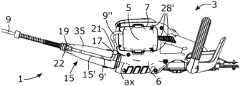
- FIG. 1illustrates an electrically driven hand-held power tool 3 according to some embodiments of the present disclosure.
- the electrically driven hand-held power tool 3is in some places herein referred to as “the hand-held power tool 3 ”, or simply “the power tool 3 ”.
- the power tool 3is a hedge trimmer. It is to be understood that the illustrated hedge trimmer constitutes example embodiments of the invention, which invention is defined only by the appended claims.
- the power tool 3may be another type of power tool than a hedge trimmer, which is further explained herein.
- the power tool 3comprises a tool 31 , which according to the illustrated example embodiments is a cutting tool for cutting vegetation. Moreover, the power tool 3 comprises a main body 6 comprising an electric motor 33 . The electric motor 33 is configured to power the tool 31 . Furthermore, the power tool 3 comprises a battery connection interface 7 .
- FIG. 1also illustrates a battery adapter assembly 1 according to some embodiments of the present disclosure.
- the battery adapter assembly 1comprises a battery adapter 5 and a power cord 9 .
- the power cord 9comprises a first end 11 connected to the battery adapter 5 and a second end 12 for connection to a power supply 27 , such as a battery 27 .
- the second end 12 of the power cord 9comprises a connector 25 for connecting the power cord 9 to the battery 27 .
- the battery 27may be a battery 27 adapted to be carried on the body of a user, such as a backpack battery or a belt-mounted battery, as is further explained herein.
- the battery adapter 5is connected to the battery connection interface 7 of the power tool 3 .
- the battery connection interface 7comprises electrical contacts connected to the electric motor 33 of the power tool 3 , via a control arrangement of the power tool 3 .
- the battery adapter 5comprises electrical contacts configured to abut against the electrical contacts of the battery connection interface 7 when the battery adapter 5 is connected to the battery connection interface 7 . In this manner, electrical energy can be transferred from a power supply 27 , such as a battery 27 , to the electric motor 33 , via the battery adapter assembly 1 .
- the electrical contacts and the control arrangement referred to aboveare not illustrated in FIG. 1 for the reason of brevity and clarity.
- the power tool 3comprises a cord holding arrangement 15 .
- the cord holding arrangement 15is configured to hold a power cord section 9 ′ of the power cord 9 of the battery adapter assembly 1 , as is further explained herein.
- the cord holding arrangement 15comprises a groove 15 ′ and the power cord section 9 ′ is configured to be inserted into the groove 15 ′.
- the power tool 3comprises a first handle unit 35 comprising a first grip portion 37 .
- the first handle unit 35is pivotally attached relative to the main body 6 .
- the first grip portion 37comprises a throttle actuator 43 for controlling the power of the electric motor 33 .
- the first handle unit 35is a rear handle unit arranged at a rear portion 41 of the power tool 3 facing away from the tool 31 of the power tool 3 .
- the power tool 3further comprises a second handle unit 45 arranged at a position of the power tool 3 between the first handle unit 35 and the tool 31 .
- the cord holding arrangement 15is arranged on the first handle unit 35 .
- the first handle unit 35comprises a shield section 39 arranged at a distance from the first grip portion 37 , and wherein the cord holding arrangement 15 is arranged on the shield section 39 of the first handle unit 35 .
- the throttle actuator 43is arranged on a side 37 ′ of the first grip portion 37 facing the shield section 39 .
- the cord holding arrangement 15is arranged on a side 39 ′ of the shield section 39 facing away from the first grip portion 37 . Due to these features, the power cord 9 of the battery adapter assembly 1 will not disturb a user of the power tool 3 during use of the power tool 3 and the power cord 9 will extend from the power tool 3 at a position being remote from the tool 31 of the power tool 3 .
- FIG. 2illustrates a battery adapter assembly 1 , according to the embodiments illustrated in FIG. 1 .
- the power cord 9comprises a first fixation element 21 configured to fixate the power cord 9 to the cord holding arrangement 15 of the power tool 3 .
- the power cord 9comprises a second fixation element 22 configured to fixate the power cord 9 to the cord holding arrangement 15 of the power tool 3 .
- the second fixation element 22is arranged at a distance d from the first fixation element 21 along the power cord 9 so as to form the power cord section 9 ′ between the first and second fixation elements 21 , 22 .
- each of the first and second fixation elements 21 , 22is frustoconical with the narrow part of the frustoconical fixation element 21 , 22 arranged adjacent to the power cord section 9 ′ between the first and second fixation elements 21 , 22 .
- at least one of the first and second fixation elements 21 , 22may be frustoconical with the narrow part of the frustoconical fixation element 21 , 22 arranged adjacent to the power cord section 9 ′.
- the first fixation element 21is arranged closer to the first end 11 of the power cord 9 , i.e. closer to the battery adapter 5 , than the second fixation element 22 along the power cord 9 .
- FIG. 3illustrates the power tool 3 according to the embodiments illustrated in FIG. 1 , with the first handle unit 35 pivoted relative to the main body 6 of the power tool 3 to a first end position.
- the first handle unit 35has been pivoted approximately 90 degrees counterclockwise relative to the position of the first handle unit 35 illustrated in FIG. 1 when seen in a direction towards the rear portion 41 of the power tool 3 .
- FIG. 4illustrates the power tool 3 according to the embodiments illustrated in FIG. 1 and FIG. 3 , with the first handle unit 35 pivoted relative to the main body 6 of the power tool 3 to a second end position.
- the first handle unit 35has been pivoted approximately 90 degrees clockwise relative to the position of the first handle unit 35 illustrated in FIG. 1 , i.e. approximately 180 degrees clockwise relative to the position of the first handle unit 35 illustrated in FIG. 3 when seen in a direction towards the rear portion of the power tool 3 .
- the first handle unit 35is pivotally attached to the main body 6 around a pivot axis ax between the first and the second end position, and according to the illustrated embodiments, the angle between the first and second end positions is approximately 180 degrees. According to further embodiments, the angle between the first and second end positions may be at least 90 degrees, or at least 170 degrees.
- the power cord 9comprises a second power cord section 9 ′′ between the first fixation element 21 and the battery adapter 5 .
- the length of the second power cord section 9 ′′allows the first handle unit 35 to be pivoted between the first and second end positions.
- the first fixation element 21is arranged to abut against a first end portion 17 of the cord holding arrangement 15 .
- the second fixation element 22is arranged to abut against a second end portion 19 of the cord holding arrangement 15 .
- the cord holding arrangement 15comprises a first and a second end portion 17 , 19 , and wherein at least one of the first and second end portions 17 , 19 is configured to receive a fixation element 21 , 22 of the power cord 9 .
- each of the first and second end portions 17 , 19is funnel-shaped. In this manner, the power cord 9 is further securely fixated to the cord holding arrangement 15 .
- at least one of the first and second end portions 17 , 19may be funnel-shaped.
- the second fixation element 22is slidably attached to the power cord 9 . Moreover, the second fixation element 22 is biased along the power cord 9 in a direction d 1 towards the first fixation element 21 .
- the power cord 9comprises a spring element 23 configured to bias the second fixation element 22 along the power cord 9 in the direction d 1 towards the first fixation element 21 .
- the power cord 9comprises a stopper 26 rigidly attached to the power cord 9 .
- the spring element 23is arranged to apply a repellent biasing force between the stopper 26 and the second fixation element 22 .
- the process of attaching the power cord section 9 ′ to the cord holding arrangementis significantly facilitated as well as the process of removing the cord section 9 ′ from the cord holding arrangement, as is further explained herein.
- the biasing force of the spring element 23ensures a contracting force between the first and second fixation elements 21 , 22 which further ensures fixation of the power cord section 9 ′ to the cord holding arrangement 15 .
- the first fixation element 21is rigidly attached to the power cord 9 .
- the distance d between the first and second fixation elements 21 , 22indicated in FIG. 2 , corresponds to a length of the cord holding arrangement 15 when the power cord section 9 ′ is arranged in the cord holding arrangement 15 .
- the spring element 23is a coil spring. As indicated in FIG. 1 , the second end portion 19 of the cord holding arrangement 15 is arranged at a rear portion 41 of the power tool 3 facing away from the tool 31 . As indicated in FIG. 1 and FIG. 2 , the spring element 23 has a smaller pitch in a region 23 ′′ of the second fixation element 22 than in a region 23 ′ of the stopper 26 . Accordingly, the distance between segments of the spring element 23 is smaller in the region 23 ′′ of the second fixation element 22 than in the region 23 ′ of the stopper 26 .
- the spring element 23provides a greater resistance to bending at the region 23 ′′ of the second fixation element 22 which further protects the power cord from being bent over the maximum degree of bending. Moreover, a lower resistance to bending is provided at the region 23 ′ of the stopper 26 , which may further improve ergonomics and user-friendliness of the power tool 3 .
- the battery adapter 5comprises a mechanical key arrangement 28 .
- the mechanical key arrangement 28is configured to allow connection of the battery adapter 5 only to certain types of battery connection interfaces 7 of power tools 3 .
- the mechanical key arrangement 28may be configured to allow connection of the battery adapter 5 only to battery connection interfaces 7 of power tools 3 having an electric power consumption below a predetermined electric power consumption.
- the mechanical key arrangement 28comprises a set of protrusions 28 .
- the battery connection interface 7 of the power tool 3comprises a mechanical key arrangement 28 ′ comprising a corresponding set of recesses 28 ′.
- the protrusions 28 of the mechanical key arrangement 28 of the battery adapter 5is configured to fit into the recesses 28 ′ of the mechanical key arrangement 28 ′ of the battery connection interface 7 of the power tool 3 .
- Battery connection interfaces of power tools having an electric power consumption above the predetermined electric power consumptionmay lack one or more of the recesses 28 ′. In this manner, the battery adapter 5 according to the embodiments illustrated in FIG. 2 cannot be connected to such a battery connection interface. Thereby, components of the battery adapter assembly 1 , such as the power cord 9 , is protected from becoming damaged by excessive electricity.
- the predetermined electric power consumptionmay be 1000 W or 800 W.
- the battery adapter assembly 1can comprise a thin power cord 9 , such as a power cord 9 with a cable area less than 2.5 mm 2 , which provides conditions for a flexible power cord 9 facilitating use of the power tool 3 .
- FIG. 5illustrates the power tool 3 according to the embodiments illustrated in FIG. 1 , FIG. 3 , and FIG. 4 , with the power cord section 9 ′ removed from the cord holding arrangement 15 of the power tool 3 .
- the second fixation element 22comprises a grip surface 22 ′ provided with a set of ridges configured to increase friction between fingers of a user and the second fixation element 22 .
- the grip surface 22 ′facilitates displacement of the second fixation element 22 along the power cord 9 in a direction d 2 away from the first fixation element 21 .
- the direction d 2 along the power cord 9 away from the first fixation element 21is indicated in FIG. 2 .
- a user of the power tool 3may grip the grip surface 22 ′ of the second fixation element 22 and pull the second fixation element 22 in a direction away from second end portion 19 of the cord holding arrangement 15 located at the rear portion 41 of the power tool 3 .
- the spring element 23is compressed and the distance d between the first and second fixation elements 21 , 22 , indicated in FIG. 2 , is increased.
- the second fixation element 22 and the power cord section 9 ′can be removed from the cord holding arrangement 15 in a quick and simple manner. When removed, the power cord 9 will assume a position as illustrated in FIG. 5 .
- FIG. 6illustrates the power tool 3 according to the embodiments illustrated in FIG. 1 and FIG. 3 - FIG. 5 with the battery adapter of the battery adapter assembly removed and a battery 27 ′ being connected to the battery connection interface 7 of the power tool 3 .
- a usermay thus replace the battery adapter assembly 1 with a battery 27 ′ for example when wanting to perform smaller tasks that is not as time and/or energy consuming.
- the battery 27 ′comprises a number of battery cells
- the battery 27 ′adds weight to the power tool 3 when connected to the battery connection interface 7 of the power tool 3 . The added weight puts more strain on arms, hands, and back of a user during operation of the power tool 3 .
- the usermay remove the battery 27 ′ from the battery connection interface 7 and connect the battery adapter 5 of the battery adapter assembly 1 to the battery connection interface 7 of the power tool 3 , as illustrated in FIG. 5 . Then, the user may position the first fixation element 21 into the first end portion 17 of the cord holding arrangement 15 and insert at least a portion of the power cord section 9 ′ into the cord holding arrangement 15 . Then, the user may grip the grip surface 22 ′ of the second fixation element 22 and pull the second fixation element 22 in a direction d 2 away from first fixation element 21 , indicated in FIG. 2 .
- the spring element 23is compressed and the distance d between the first and second fixation elements 21 , 22 is increased.
- the power cord section 9 ′can be fully inserted into the cord holding arrangement 15 and the second fixation element 22 can be positioned at the second end portion 19 in a quick and simple manner.
- the usermay then release the pulling force from the second fixation element 22 .
- the second fixation element 22is displaced towards the second end portion 19 of the cord holding arrangement 15 by the biasing force of the spring element 23 and the power cord section 9 ′ is securely retained in the cord holding arrangement 15 . Accordingly, in this manner, the power cord section 9 ′ can be attached to the cord holding arrangement 15 in a quick, reliable and simple manner.
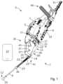
- FIG. 7illustrates a top view of a power tool 3 according to some further embodiments of the present disclosure.
- the power tool 3 according to the embodiments illustrated in FIG. 7comprises the same features, functions, and advantages as the power tool 3 according to the embodiments illustrated in FIG. 1 and FIG. 3 - FIG. 6 with some exceptions explained below.
- the power tool 3comprises a single sided rear handle unit 35 .
- the single sided rear handle unit 35may be pivotally attached to a main body 6 of the power tool 3 .
- the power tool 3 according to the embodiments illustrated in FIG. 7comprises a single sided front handle unit 45 arranged at a position of the power tool 3 between the rear handle unit 35 and a tool 31 of the power tool 3 .
- the power tool 3 illustrated in FIG. 7comprises a battery adapter assembly 1 attached to the power tool 3 .
- FIG. 8illustrates a side view of the power tool 3 illustrated in FIG. 7 .
- the battery adapter 5 of the battery adapter assembly 1is connected to a battery connection interface 7 of the power tool 3 .
- the power cord section 9 ′ of the battery adapter assembly 1is retained in a cord holding arrangement 15 of the power tool 3 .
- the battery adapter assembly 1 according to the embodiments illustrated in FIG. 7 and FIG. 8may comprise the same features, functions, and advantages as the battery adapter assembly 1 according to the embodiments illustrated in FIG. 1 - FIG. 6 , with some exceptions explained below.
- the cord holding arrangement 15 of the power tool 3 according to the embodiments illustrated in FIG. 7 and FIG. 8may comprise the same features, functions, and advantages as the cord holding arrangement 15 of the power tool 3 according to the embodiments illustrated in FIG. 1 and FIG. 3 - FIG. 6 , with some exceptions explained below.
- the power cord section 9 ′ of the battery adapter assembly 1is provided with a shorter length meaning that the distance between the first and second fixation elements 21 , 22 of the power cord 9 is shorter compared to the embodiments illustrated in FIG. 1 - FIG. 6 .
- the length of the cord holding arrangement 15is shorter than the length of the cord holding arrangement 15 according to the embodiments illustrated in FIG. 1 and FIG. 3 - FIG. 6 .
- the power tool 3is a hedge trimmer.
- the power tool 3may be another type of hand-held power tool than a hedge trimmer.
- the power toolmay be a garden tool, a rotary tool, a reciprocating tool, a multi tool, a leaf blower, a chainsaw, or the like.
Landscapes
- Engineering & Computer Science (AREA)
- Mechanical Engineering (AREA)
- Chemical & Material Sciences (AREA)
- Chemical Kinetics & Catalysis (AREA)
- Electrochemistry (AREA)
- General Chemical & Material Sciences (AREA)
- Battery Mounting, Suspending (AREA)
- Portable Power Tools In General (AREA)
Abstract
Description
The present disclosure relates to a battery adapter assembly for an electrically driven hand-held power tool. The present disclosure further relates to a hand-held power tool.
Today, there are many kinds of power tools available on the market. A common feature of power tools is that they comprise a tool which can be driven by a power source other than solely manual labour. The power source may comprise an electric motor or a combustion engine.
There are several concerns that may be addressed when designing a power tool. A main concern is safety. That is, when designing a power tool, one must ensure that a user can operate the power tool in a safe manner. Another concern that may be addressed is ergonomics. A power tool is usually and preferably designed to allow operation in different operational directions and angles, which puts requirements on the design of the power tool. A further concern that may be addressed is user-friendliness. For example, it is an advantage if the power tool is designed such that a user can operate the power tool in a simple and non-distractive manner.
The above-mentioned concerns are at least partially linked. That is, an ergonomic and user-friendly power tool usually is safer than a less ergonomic and user-friendly power tool, partly since the risk of incorrect use of such a power tool is reduced.
Electrically driven power tools have some advantages over power tools driven by a combustion engine, especially regarding emissions and noise generated by the power tool. However, they are also associated with some drawbacks. One drawback is the supply of electricity to the electric motor. Many power tools operate at high power levels which requires a lot of electrical energy.
Some power tools are provided with a battery connection interface for connection of a battery to the power tool. Such power tools are normally simple to use. However, the battery adds weight to the power tool which may put extra strain on arms, hands, and back of a user during operation of the power tool. Moreover, a battery can store a limited amount of electrical energy which puts limitations on the available operational time of the power tool.
Batteries adapted to be carried on the body of a user, such as a backpack batteries and belt-mounted batteries, have been developed in recent years. Such batteries have the advantage of moving the weight from the power tool to the body of the user. In this manner, the user may experience less strain on arms, hands, and back during operation of the power tool. Moreover, larger sized batteries can be used which increases the available operational time of the power tool.
A battery adapter assembly can be used to provide an electrical connection between such a battery and a battery connection interface of the power tool. Normally, a battery adapter assembly comprises a battery adapter and a power cord, wherein the battery adapter is configured to be connected to the battery connection interface of the power tool. The power cord normally comprises a first end connected to the battery adapter and a second end for connection to the battery. For smaller tasks, a user may connect a battery directly to the battery connection interface and operate the power tool. For larger tasks requiring more time and more electrical energy, the user may connect the battery adapter to the battery connection interface and use a battery carried on the body of the user for operating the power tool. In this manner, the user may operate the power tool with less strain on arms, hands, and back.
As indicated above, these types of power tools and these types of battery adapter assemblies provide many advantages. However, they are still associated with some concerns and drawbacks regarding ergonomics and user-friendliness.
It is an object of the present invention to overcome, or at least alleviate, at least some of the above-mentioned concerns and drawbacks.
According to a first aspect of the invention, the object is achieved by a battery adapter assembly for an electrically driven hand-held power tool. The battery adapter assembly comprises a battery adapter configured to be connected to a battery connection interface of the power tool, and a power cord comprising a first end connected to the battery adapter and a second end for connection to a power supply. The power cord comprises at least a first fixation element configured to fixate the power cord to a cord holding arrangement of the power tool.
Since the power cord comprises the at least first fixation element, a battery adapter assembly is provided capable of facilitating use of an electrically driven hand-held power tool. This because the at least first fixation element can fixate the power cord to the cord holding arrangement of the power tool to thereby reduce the disturbance caused by the power cord.
Moreover, as a further result, a battery adapter assembly is provided capable of providing a more ergonomic use of an electrically driven hand-held power tool.
In addition, since the battery adapter assembly is capable of facilitating use and providing a more ergonomic use of an electrically driven hand-held power tool, a battery adapter assembly is provided capable of improving safety during operation of an electrically driven power tool.
Accordingly, a battery adapter assembly is provided overcoming, or at least alleviating, at least some of the above-mentioned concerns and drawbacks. As a result, the above-mentioned object is achieved.
Optionally, the cord holding arrangement comprises a groove. Thereby, at least a portion of the power cord can be protected from becoming damaged during use of the power tool. Moreover, the power cord can be held in a more secure manner in the cord holding arrangement. Thereby, the safety during operation of the power tool may be further improved.
Optionally, the first fixation element is frustoconical. Thereby, the power cord can be fixated to the cord holding arrangement in a further secure manner.
Optionally, the power cord comprises a second fixation element arranged at a distance from the first fixation element along the power cord so as to form a power cord section between the first and second fixation elements, and wherein the power cord section is configured to be held by the cord holding arrangement of the power tool. Thereby, the power cord can be fixated to the cord holding arrangement in a further secure manner which further reduces the risk of the power cord becoming loose during operation of the power tool.
Optionally, the second fixation element is frustoconical. Thereby, the power cord can be fixated to the cord holding arrangement in a further secure manner.
Optionally, the power cord section is configured to be inserted into the groove. Thereby, the power cord section is protected from becoming damaged during use of the power tool. Thereby, the safety during operation of the power tool may be further improved.
Optionally, the first fixation element is arranged to abut against a first end portion of the cord holding arrangement and the second fixation element is arranged to abut against a second end portion of the cord holding arrangement. Thereby, the power cord can be fixated to the cord holding arrangement in a further secure manner which further reduces the risk of the power cord becoming loose during operation of the power tool.
Optionally, the second fixation element is slidably attached to the power cord and is biased along the power cord in a direction towards the first fixation element. Thereby, the power cord can be fixated to the cord holding arrangement in a further secure manner which further reduces the risk of the power cord becoming loose during operation of the power tool. This because the biasing force of the second fixation element along the power cord may fixate the first and second fixation elements in a further secure manner to the first and second end portions of the cord holding arrangement. Moreover, a battery adapter assembly is provided in which the power cord can be attached to, and removed from, the cord holding arrangement in a simpler and more user-friendly manner.
Optionally, the power cord comprises a spring element configured to bias the second fixation element along the power cord in a direction towards the first fixation element. Thereby, a simple, reliable, and efficient biasing of the second fixation element is provided along the power cord. Moreover, the battery adapter assembly provides conditions for attaching and removing the power cord to and from the cord holding arrangement in a still simpler and more user-friendly manner.
Optionally, the power cord comprises a stopper rigidly attached to the power cord, and wherein the spring element is arranged to apply the biasing force between the stopper and the second fixation element. Thereby, a simple, reliable, and efficient biasing of the second fixation element is provided along the power cord. Moreover, a battery adapter assembly is provided in which the power cord can be attached to, and removed from, the cord holding arrangement in a simpler and more user-friendly manner.
Optionally, the spring element is a coil spring. Thereby, a simple, reliable, and efficient biasing of the second fixation element is provided along the power cord. Moreover, the coil spring may stabilize the power cord and may act as a grommet protecting the power cord from being bent over a maximum degree of bending where the power cord becomes damaged. Thereby, the safety during operation of the power tool can be further improved. In addition, due to these features, a battery adapter assembly is provided capable of further facilitating use of a power tool and providing conditions for a more ergonomic use of the power tool. Moreover, the battery adapter assembly provides conditions for attaching and removing the power cord to and from the cord holding arrangement in a still simpler and more user-friendly manner.
Optionally, the spring element has a smaller pitch in a region of the second fixation element than in a region of the stopper. Thereby, the spring element provides a greater resistance to bending at the region of the second fixation element which further protects the power cord from being bent over the maximum degree of bending. Moreover, a lower resistance to bending is provided at the region of the stopper, which may further improve ergonomics and user-friendliness of the power tool.
Optionally, the battery adapter comprises a mechanical key arrangement configured to allow connection of the battery adapter only to certain types of battery connection interfaces of power tools. Thereby, a battery adapter assembly is provided significantly reducing the risk of incorrect use of the battery adapter assembly. As a result, the safety during use of the battery adapter assembly may be further improved.
Optionally, the mechanical key arrangement is configured to allow connection of the battery adapter only to battery connection interfaces of power tools having an electric power consumption below a predetermined electric power consumption. Thereby, due to these features, a user is blocked from connecting the battery adapter to battery connection interfaces of power tools having an electric power consumption above the predetermined electric power consumption. Thereby, components of the battery adapter assembly, such as the power cord, is protected from becoming damaged by excessive electricity. In addition, due to these features, a battery adapter assembly is provided significantly reducing the risk of incorrect use of the battery adapter assembly which may further improve the safety during use of the battery adapter assembly.
Optionally, a second end of the power cord comprises a connector for connecting the power cord to a battery. Thereby, a user-friendly battery adapter assembly is provided which provides conditions for a user to select a battery and connect the battery to the battery connection interface of the power tool using the battery adapter assembly.
Optionally, the battery is a battery adapted to be carried on the body of a user, such as a backpack battery or a belt-mounted battery. In this manner, the user can perform operation with the power tool with a low amount of strain on arms, hands, and back, and conditions are provided for an extended operational time of the power tool.
According to a second aspect of the invention, the object is achieved by a hand-held power tool comprising a tool, an electric motor configured to power the tool, and a battery connection interface configured to receive a battery adapter of a battery adapter assembly for transmitting electricity to the electric motor via the battery adapter assembly. The power tool comprises a cord holding arrangement configured to hold a power cord section of a power cord of the battery adapter assembly.
Since the power tool comprises the cord holding arrangement, a power tool is provided which can be used in a simple and ergonomic manner. This because the cord holding arrangement can hold the power cord section of the power cord of the battery adapter assembly to thereby reduce the disturbance caused by the power cord.
In addition, since the power tool can be used in a simple and ergonomic manner, a power tool is provided having conditions for an improved safety during operation thereof.
Accordingly, a power tool is provided overcoming, or at least alleviating, at least some of the above-mentioned concerns and drawbacks. As a result, the above-mentioned object is achieved.
Optionally, the cord holding arrangement comprises a groove. Thereby, the power cord section of the battery adapter assembly is protected from becoming damaged during use of the power tool. Thereby, the safety during operation of the power tool can be further improved.
Optionally, the cord holding arrangement comprises a first and a second end portion, and wherein at least one of the first and second end portions is configured to receive a fixation element of the power cord. Thereby, the power cord can be fixated to the cord holding arrangement in a further secure manner which may reduce the risk of the power cord becoming loose during operation of the power tool.
Optionally, at least one of the first and second end portions is funnel-shaped. Thereby, the power cord can be fixated to the cord holding arrangement in a further secure manner which may reduce the risk of the power cord becoming loose during operation of the power tool.
Optionally, the second end portion of the cord holding arrangement is arranged at a rear portion of the power tool facing away from the tool. Thereby, a power tool is provided which can be used in a still simpler and more ergonomic manner. Furthermore, a still safer power tool may be provided. This because the power cord of the battery adapter assembly will be securely retained at the rear portion of the power tool and will extend from the power tool at a position being remote from the tool of the power tool.
Optionally, the power tool comprises a first handle unit comprising a first grip portion, and wherein the cord holding arrangement is arranged on the first handle unit. Thereby, a power tool is provided which can be used in a still simpler and more ergonomic manner. Furthermore, a still safer power tool may be provided. This because the power cord of the battery adapter assembly will be securely retained at the first handle unit of the power tool and will extend from the power tool at a position being remote from the tool of the power tool.
Optionally, the first handle unit comprises a shield section arranged at a distance from the first grip portion, and wherein the cord holding arrangement is arranged on the shield section. Thereby, a power tool is provided which can be used in a still simpler and more ergonomic manner. Furthermore, a still safer power tool may be provided. This because the power cord of the battery adapter assembly will be securely retained at the shield section of the first handle unit and will extend from the power tool at a position being remote from the tool of the power tool.
Optionally, the cord holding arrangement is arranged on a side of the shield section facing away from the first grip portion. Thereby, a power tool is provided which can be used in a still simpler and more ergonomic manner. This because the power cord of the battery adapter assembly will be located at a position of the first handle unit where it has a low probability of disturbing a user of the power tool.
Optionally, the first grip portion comprises a throttle actuator arranged on a side of the first grip portion facing the shield section. Thereby, the throttle actuator can be actuated without being disturbed by the power cord. Thereby, the safety during operation of the power tool can be further improved.
Optionally, the first handle unit is a rear handle unit arranged at a rear portion of the power tool facing away from the tool. Thereby, a power tool is provided which can be used in a still simpler and more ergonomic manner. Furthermore, a still safer power tool may be provided. This because the power cord of the battery adapter assembly may be securely retained at the first handle unit and may extend from the power tool at a position being remote from the tool of the power tool.
Optionally, the power tool comprises a main body comprising the electric motor, and wherein the first handle unit is pivotally attached to the main body. Thereby, a power tool is provided which can be used in a still simpler and more ergonomic manner. As a further result thereof, a still safer power tool is provided. This because the first handle unit, to which the power cord of the battery adapter assembly may be securely retained, can be pivoted relative to the main body so as to allow for different operational directions and angles of the tool of the power tool without assuming burdensome working positions.
Optionally, the first handle unit is pivotally attached to the main body between a first and a second end position, and wherein the angle between the first and second end positions is at least 90 degrees, or at least 170 degrees. Thereby, a power tool is provided which can be used in a still simpler and more ergonomic manner. As a further result thereof, a still safer power tool may be provided. This because the first handle unit, to which the power cord of the battery adapter assembly may be securely retained, can be pivoted relative to the main body at least 90 degrees, or at least 170 degrees, so as to allow for different operational positions of the tool of the power tool without assuming burdensome working positions.
Optionally, the power tool comprises a second handle unit arranged at a position of the power tool between the first handle unit and the tool. Thereby, a power tool is provided which can be used in a still simpler and more ergonomic manner
Optionally, the power tool comprises a battery adapter assembly according to some embodiments of the present disclosure. Thereby, a power tool is provided which can be used in simple, ergonomic, and user-friendly manner.
Further features of, and advantages with, the present invention will become apparent when studying the appended claims and the following detailed description.
Various aspects of the invention, including its particular features and advantages, will be readily understood from the example embodiments discussed in the following detailed description and the accompanying drawings, in which:
Aspects of the present invention will now be described more fully. Like numbers refer to like elements throughout. Well-known functions or constructions will not necessarily be described in detail for brevity and/or clarity.
Thepower tool 3 comprises atool 31, which according to the illustrated example embodiments is a cutting tool for cutting vegetation. Moreover, thepower tool 3 comprises amain body 6 comprising anelectric motor 33. Theelectric motor 33 is configured to power thetool 31. Furthermore, thepower tool 3 comprises abattery connection interface 7.
InFIG.1 , thebattery adapter 5 is connected to thebattery connection interface 7 of thepower tool 3. Thebattery connection interface 7 comprises electrical contacts connected to theelectric motor 33 of thepower tool 3, via a control arrangement of thepower tool 3. Thebattery adapter 5 comprises electrical contacts configured to abut against the electrical contacts of thebattery connection interface 7 when thebattery adapter 5 is connected to thebattery connection interface 7. In this manner, electrical energy can be transferred from apower supply 27, such as abattery 27, to theelectric motor 33, via thebattery adapter assembly 1. The electrical contacts and the control arrangement referred to above are not illustrated inFIG.1 for the reason of brevity and clarity.
As indicated inFIG.1 , thepower tool 3 comprises acord holding arrangement 15. Thecord holding arrangement 15 is configured to hold apower cord section 9′ of thepower cord 9 of thebattery adapter assembly 1, as is further explained herein. According to the illustrated embodiments, thecord holding arrangement 15 comprises agroove 15′ and thepower cord section 9′ is configured to be inserted into thegroove 15′.
Thepower tool 3 comprises afirst handle unit 35 comprising afirst grip portion 37. According to the illustrated embodiments, and as is further explained herein, thefirst handle unit 35 is pivotally attached relative to themain body 6. Thefirst grip portion 37 comprises athrottle actuator 43 for controlling the power of theelectric motor 33. Thefirst handle unit 35 is a rear handle unit arranged at arear portion 41 of thepower tool 3 facing away from thetool 31 of thepower tool 3. Thepower tool 3 further comprises asecond handle unit 45 arranged at a position of thepower tool 3 between thefirst handle unit 35 and thetool 31. According to the illustrated embodiments, thecord holding arrangement 15 is arranged on thefirst handle unit 35. Moreover, thefirst handle unit 35 comprises ashield section 39 arranged at a distance from thefirst grip portion 37, and wherein thecord holding arrangement 15 is arranged on theshield section 39 of thefirst handle unit 35. Thethrottle actuator 43 is arranged on aside 37′ of thefirst grip portion 37 facing theshield section 39. In addition, thecord holding arrangement 15 is arranged on aside 39′ of theshield section 39 facing away from thefirst grip portion 37. Due to these features, thepower cord 9 of thebattery adapter assembly 1 will not disturb a user of thepower tool 3 during use of thepower tool 3 and thepower cord 9 will extend from thepower tool 3 at a position being remote from thetool 31 of thepower tool 3.
According to the illustrated embodiments, each of the first andsecond fixation elements frustoconical fixation element power cord section 9′ between the first andsecond fixation elements second fixation elements frustoconical fixation element power cord section 9′. According to the illustrated embodiments, thefirst fixation element 21 is arranged closer to thefirst end 11 of thepower cord 9, i.e. closer to thebattery adapter 5, than thesecond fixation element 22 along thepower cord 9.
Thus, thefirst handle unit 35 is pivotally attached to themain body 6 around a pivot axis ax between the first and the second end position, and according to the illustrated embodiments, the angle between the first and second end positions is approximately 180 degrees. According to further embodiments, the angle between the first and second end positions may be at least 90 degrees, or at least 170 degrees.
As indicated inFIG.2 -FIG.4 , thepower cord 9 comprises a secondpower cord section 9″ between thefirst fixation element 21 and thebattery adapter 5. The length of the secondpower cord section 9″ allows thefirst handle unit 35 to be pivoted between the first and second end positions.
As is best seen inFIG.3 , thefirst fixation element 21 is arranged to abut against afirst end portion 17 of thecord holding arrangement 15. Moreover, thesecond fixation element 22 is arranged to abut against asecond end portion 19 of thecord holding arrangement 15. In this manner, thepower cord 9 is securely fixated to thecord holding arrangement 15, as is further explained herein. Thus, according to the illustrated embodiments, thecord holding arrangement 15 comprises a first and asecond end portion second end portions fixation element power cord 9. Moreover, according to the illustrated embodiments, each of the first andsecond end portions power cord 9 is further securely fixated to thecord holding arrangement 15. According to further embodiments, at least one of the first andsecond end portions
The following will be explained with reference toFIG.2 . According to the illustrated embodiments, thesecond fixation element 22 is slidably attached to thepower cord 9. Moreover, thesecond fixation element 22 is biased along thepower cord 9 in a direction d1 towards thefirst fixation element 21. According to the illustrated embodiments, thepower cord 9 comprises aspring element 23 configured to bias thesecond fixation element 22 along thepower cord 9 in the direction d1 towards thefirst fixation element 21. Thepower cord 9 comprises astopper 26 rigidly attached to thepower cord 9. Thespring element 23 is arranged to apply a repellent biasing force between thestopper 26 and thesecond fixation element 22. In this manner, the process of attaching thepower cord section 9′ to the cord holding arrangement is significantly facilitated as well as the process of removing thecord section 9′ from the cord holding arrangement, as is further explained herein. In addition, the biasing force of thespring element 23 ensures a contracting force between the first andsecond fixation elements power cord section 9′ to thecord holding arrangement 15. According to the illustrated embodiments, thefirst fixation element 21 is rigidly attached to thepower cord 9. As understood from the above, the distance d between the first andsecond fixation elements FIG.2 , corresponds to a length of thecord holding arrangement 15 when thepower cord section 9′ is arranged in thecord holding arrangement 15.
According to the illustrated embodiments, thespring element 23 is a coil spring. As indicated inFIG.1 , thesecond end portion 19 of thecord holding arrangement 15 is arranged at arear portion 41 of thepower tool 3 facing away from thetool 31. As indicated inFIG.1 andFIG.2 , thespring element 23 has a smaller pitch in aregion 23″ of thesecond fixation element 22 than in aregion 23′ of thestopper 26. Accordingly, the distance between segments of thespring element 23 is smaller in theregion 23″ of thesecond fixation element 22 than in theregion 23′ of thestopper 26. Thereby, thespring element 23 provides a greater resistance to bending at theregion 23″ of thesecond fixation element 22 which further protects the power cord from being bent over the maximum degree of bending. Moreover, a lower resistance to bending is provided at theregion 23′ of thestopper 26, which may further improve ergonomics and user-friendliness of thepower tool 3.
As can be seen inFIG.2 , according to the illustrated embodiments, thebattery adapter 5 comprises a mechanicalkey arrangement 28. The mechanicalkey arrangement 28 is configured to allow connection of thebattery adapter 5 only to certain types ofbattery connection interfaces 7 ofpower tools 3. The mechanicalkey arrangement 28 may be configured to allow connection of thebattery adapter 5 only tobattery connection interfaces 7 ofpower tools 3 having an electric power consumption below a predetermined electric power consumption. According to the illustrated embodiments, the mechanicalkey arrangement 28 comprises a set ofprotrusions 28.
As indicated inFIG.3 , thebattery connection interface 7 of thepower tool 3 comprises a mechanicalkey arrangement 28′ comprising a corresponding set ofrecesses 28′. Theprotrusions 28 of the mechanicalkey arrangement 28 of thebattery adapter 5 is configured to fit into therecesses 28′ of the mechanicalkey arrangement 28′ of thebattery connection interface 7 of thepower tool 3. Battery connection interfaces of power tools having an electric power consumption above the predetermined electric power consumption may lack one or more of therecesses 28′. In this manner, thebattery adapter 5 according to the embodiments illustrated inFIG.2 cannot be connected to such a battery connection interface. Thereby, components of thebattery adapter assembly 1, such as thepower cord 9, is protected from becoming damaged by excessive electricity.
According to some embodiments, the predetermined electric power consumption may be 1000 W or 800 W. In this manner, according to these embodiments, thebattery adapter assembly 1 can comprise athin power cord 9, such as apower cord 9 with a cable area less than 2.5 mm2, which provides conditions for aflexible power cord 9 facilitating use of thepower tool 3.
The following is explained with reference toFIG.1 . A user of thepower tool 3 may grip thegrip surface 22′ of thesecond fixation element 22 and pull thesecond fixation element 22 in a direction away fromsecond end portion 19 of thecord holding arrangement 15 located at therear portion 41 of thepower tool 3. As a result thereof, thespring element 23 is compressed and the distance d between the first andsecond fixation elements FIG.2 , is increased. In this manner, thesecond fixation element 22 and thepower cord section 9′ can be removed from thecord holding arrangement 15 in a quick and simple manner. When removed, thepower cord 9 will assume a position as illustrated inFIG.5 .
If the user wants to perform larger tasks requiring more time and/or electrical energy, the user may remove thebattery 27′ from thebattery connection interface 7 and connect thebattery adapter 5 of thebattery adapter assembly 1 to thebattery connection interface 7 of thepower tool 3, as illustrated inFIG.5 . Then, the user may position thefirst fixation element 21 into thefirst end portion 17 of thecord holding arrangement 15 and insert at least a portion of thepower cord section 9′ into thecord holding arrangement 15. Then, the user may grip thegrip surface 22′ of thesecond fixation element 22 and pull thesecond fixation element 22 in a direction d2 away fromfirst fixation element 21, indicated inFIG.2 . As a result thereof, thespring element 23 is compressed and the distance d between the first andsecond fixation elements power cord section 9′ can be fully inserted into thecord holding arrangement 15 and thesecond fixation element 22 can be positioned at thesecond end portion 19 in a quick and simple manner. The user may then release the pulling force from thesecond fixation element 22. As a result thereof, thesecond fixation element 22 is displaced towards thesecond end portion 19 of thecord holding arrangement 15 by the biasing force of thespring element 23 and thepower cord section 9′ is securely retained in thecord holding arrangement 15. Accordingly, in this manner, thepower cord section 9′ can be attached to thecord holding arrangement 15 in a quick, reliable and simple manner.
According to the embodiments illustrated inFIG.7 , thepower tool 3 comprises a single sidedrear handle unit 35. The single sidedrear handle unit 35 may be pivotally attached to amain body 6 of thepower tool 3. Moreover, thepower tool 3 according to the embodiments illustrated inFIG.7 comprises a single sidedfront handle unit 45 arranged at a position of thepower tool 3 between therear handle unit 35 and atool 31 of thepower tool 3. Thepower tool 3 illustrated inFIG.7 comprises abattery adapter assembly 1 attached to thepower tool 3.
According to the embodiments illustrated inFIG.7 andFIG.8 , thepower cord section 9′ of thebattery adapter assembly 1 is provided with a shorter length meaning that the distance between the first andsecond fixation elements power cord 9 is shorter compared to the embodiments illustrated inFIG.1 -FIG.6 . Likewise according to the embodiments illustrated inFIG.7 andFIG.8 , the length of thecord holding arrangement 15 is shorter than the length of thecord holding arrangement 15 according to the embodiments illustrated inFIG.1 andFIG.3 -FIG.6 .
According to the illustrated embodiments, thepower tool 3 is a hedge trimmer. However, according to further embodiments, thepower tool 3, as referred to herein, may be another type of hand-held power tool than a hedge trimmer. Purely as examples, the power tool may be a garden tool, a rotary tool, a reciprocating tool, a multi tool, a leaf blower, a chainsaw, or the like.
It is to be understood that the foregoing is illustrative of various example embodiments and that the invention is defined only by the appended claims. A person skilled in the art will realize that the example embodiments may be modified, and that different features of the example embodiments may be combined to create embodiments other than those described herein, without departing from the scope of the present invention, as defined by the appended claims.
As used herein, the term “comprising” or “comprises” is open-ended, and includes one or more stated features, elements, steps, components, or functions but does not preclude the presence or addition of one or more other features, elements, steps, components, functions, or groups thereof.
Claims (23)
1. A battery adapter assembly for an electrically driven hand-held power tool, wherein the battery adapter assembly comprises:
a battery adapter configured to be connected to a battery connection interface of the power tool, and
a power cord comprising a first end connected to the battery adapter and a second end for connection to a power supply,
wherein the power cord comprises at least a first fixation element configured to fixate the power cord to a cord holding arrangement of the power tool,
wherein the power cord comprises a second fixation element arranged at a distance from the first fixation element along the power cord so as to form a power cord section between the first and second fixation elements, and
wherein the first fixation element is arranged to abut against a first end portion of the cord holding arrangement and the second fixation element is arranged to abut against a second end portion of the cord holding arrangement.
2. The battery adapter assembly according toclaim 1 , wherein the cord holding arrangement comprises a groove.
3. The battery adapter assembly according toclaim 2 , wherein the power cord section is configured to be held by the cord holding arrangement of the power tool.
4. The battery adapter assembly according toclaim 3 , wherein the first fixation element or the second fixation element is frustoconical.
5. The battery adapter assembly according toclaim 3 , wherein the power cord section is configured to be inserted into the groove.
6. The battery adapter assembly according toclaim 1 , wherein the battery adapter comprises a mechanical key arrangement configured to allow connection of the battery adapter only to certain types of battery connection interfaces of power tools.
7. The battery adapter assembly according toclaim 6 , wherein the mechanical key arrangement is configured to allow connection of the battery adapter only to battery connection interfaces of power tools having an electric power consumption below a predetermined electric power consumption.
8. The battery adapter assembly according toclaim 1 , wherein a second end of the power cord comprises a connector for connecting the power cord to a battery, and wherein the battery is adapted to be carried on a body of a user.
9. A battery adapter assembly for an electrically driven hand-held power tool, wherein the battery adapter assembly comprises:
a battery adapter configured to be connected to a battery connection interface of the power tool, and
a power cord comprising a first end connected to the battery adapter and a second end for connection to a power supply,
wherein the power cord comprises at least a first fixation element configured to fixate the power cord to a cord holding arrangement of the power tool,
wherein the cord holding arrangement comprises a groove,
wherein the power cord comprises a second fixation element arranged at a distance from the first fixation element along the power cord so as to form a power cord section between the first and second fixation elements, and wherein the power cord section is configured to be held by the cord holding arrangement of the power tool, and
wherein the second fixation element is slidably attached to the power cord and is biased along the power cord in a direction towards the first fixation element.
10. The battery adapter assembly according toclaim 9 , wherein the power cord comprises a spring element configured to bias the second fixation element along the power cord in a direction towards the first fixation element.
11. The battery adapter assembly according toclaim 10 , wherein the power cord comprises a stopper rigidly attached to the power cord, and wherein the spring element is arranged to apply the biasing force between the stopper and the second fixation element, and wherein the spring element is a coil spring.
12. The battery adapter assembly according toclaim 11 , wherein the spring element has a smaller pitch in a region of the second fixation element than in a region of the stopper.
13. A hand-held power tool comprising:
a tool,
an electric motor configured to power the tool, and
a battery connection interface configured to receive a battery adapter of a battery adapter assembly for transmitting electricity to the electric motor via the battery adapter assembly,
and wherein the power tool comprises a cord holding arrangement configured to hold a power cord section of a power cord of the battery adapter assembly, and
wherein the power cord of the battery adapter assembly enters the cord holding arrangement at a first end portion of the cord holding arrangement disposed proximate to the battery connection interface and exits the cord holding arrangement at a second end portion of the cord holding arrangement disposed at a rear portion of the power tool facing away from the tool.
14. The power tool according toclaim 13 , wherein the cord holding arrangement comprises a groove, wherein the cord holding arrangement comprises a first and a second end portion, and wherein at least one of the first and second end portions is configured to receive a fixation element of the power cord.
15. The power tool according toclaim 14 , wherein at least one of the first and second end portions is funnel-shaped.
16. The power tool according toclaim 13 , wherein the power tool comprises a first handle unit comprising a first grip portion, and wherein the cord holding arrangement is arranged on the first handle unit.
17. The power tool according toclaim 16 , wherein the first handle unit comprises a shield section arranged at a distance from the first grip portion, and wherein the cord holding arrangement is arranged on the shield section.
18. The power tool according toclaim 17 , wherein the cord holding arrangement is arranged on a side of the shield section facing away from the first grip portion.
19. The power tool according toclaim 18 , wherein the first grip portion comprises a throttle actuator arranged on a side of the first grip portion facing the shield section.
20. The power tool according toclaim 16 , wherein the first handle unit is a rear handle unit arranged at a rear portion of the power tool facing away from the tool.
21. The power tool according toclaim 16 , wherein the power tool comprises a main body comprising the electric motor, and wherein the first handle unit is pivotally attached to the main body.
22. The power tool according toclaim 21 , wherein the first handle unit is pivotally attached to the main body between a first and a second end position, and wherein the angle between the first and second end positions is at least 90 degrees.
23. The power tool according toclaim 16 , wherein the power tool comprises a second handle unit arranged at a position of the power tool between the first handle unit and the tool.
Applications Claiming Priority (3)
| Application Number | Priority Date | Filing Date | Title |
|---|---|---|---|
| SE1951121 | 2019-10-02 | ||
| SE1951121-1 | 2019-10-02 | ||
| PCT/EP2020/077480WO2021064086A1 (en) | 2019-10-02 | 2020-10-01 | Battery adapter assembly and hand-held power tool |
Publications (2)
| Publication Number | Publication Date |
|---|---|
| US20220339774A1 US20220339774A1 (en) | 2022-10-27 |
| US12109676B2true US12109676B2 (en) | 2024-10-08 |
Family
ID=72840483
Family Applications (1)
| Application Number | Title | Priority Date | Filing Date |
|---|---|---|---|
| US17/765,673Active2041-03-30US12109676B2 (en) | 2019-10-02 | 2020-10-01 | Battery adapter assembly and hand-held power tool |
Country Status (5)
| Country | Link |
|---|---|
| US (1) | US12109676B2 (en) |
| JP (1) | JP7497428B2 (en) |
| CN (1) | CN114502332B (en) |
| DE (1) | DE112020004755T5 (en) |
| WO (1) | WO2021064086A1 (en) |
Citations (87)
| Publication number | Priority date | Publication date | Assignee | Title |
|---|---|---|---|---|
| US2496612A (en) | 1946-03-22 | 1950-02-07 | Black & Decker Mfg Co | Suspension device |
| US2529567A (en) | 1948-11-30 | 1950-11-14 | Ludwig F Neck | Drill chuck key holder |
| US2617971A (en) | 1950-12-04 | 1952-11-11 | Crane Packing Co | Overload control for motors |
| US2945085A (en)* | 1958-09-15 | 1960-07-12 | Northern Union Inc | Through-wall divided connector |
| US3123662A (en)* | 1964-03-03 | Strain relief collet | ||
| DE2545838A1 (en) | 1975-10-14 | 1977-04-21 | Gardena Kress & Kastner Gmbh | ELECTRICAL DEVICE WITH PROTECTIVE DEVICE |
| US4723822A (en) | 1986-09-11 | 1988-02-09 | Merdic Louis A | Safety utility extension cord |
| US4835410A (en)* | 1988-02-26 | 1989-05-30 | Black & Decker Inc. | Dual-mode corded/cordless system for power-operated devices |
| US5172773A (en) | 1991-04-15 | 1992-12-22 | Ingersoll-Rand Company | Power cord diverter and suspension clamp for a power tool |
| US5394592A (en)* | 1994-02-02 | 1995-03-07 | Quick; Todd N. | Power tool cord strain relief arrangement |
| DE19505983A1 (en) | 1995-02-21 | 1996-08-22 | Rudolf P Fritsch | System to roll and hang wound cable etc. neatly stored without kinks |
| US5711055A (en)* | 1996-10-03 | 1998-01-27 | Quick; Todd N. | Electrical cord strain relief apparatus |
| US5993249A (en) | 1997-10-11 | 1999-11-30 | Benson, Jr.; Donald Owen | Electric cord protector |
| US6152639A (en)* | 1998-02-26 | 2000-11-28 | Mobiletron Electronics Co., Ltd. | Structure allowing free movement of a cable of an electric tool |
| US6240967B1 (en) | 1998-04-30 | 2001-06-05 | Kemp Corporation | Sleeve assembly for protecting conducting wires against damage by cutting implements |
| US20020158516A1 (en)* | 2001-04-06 | 2002-10-31 | Hitachi Koki Co.,Ltd. | DC power source unit with battery charging function |
| US20030011245A1 (en)* | 2000-03-28 | 2003-01-16 | Arnim Fiebig | Electric device |
| US6540545B1 (en)* | 1999-10-12 | 2003-04-01 | Makita Corporation | Portable tool motor housing with integral mount for electric components |
| US20030182749A1 (en)* | 2002-04-02 | 2003-10-02 | Boyer Christopher T. | Power tool and method of operating same |
| US6683439B2 (en)* | 2001-05-25 | 2004-01-27 | Hitachi Koki Co., Ltd. | DC power source unit with battery charging function |
| US6683396B2 (en) | 1999-07-02 | 2004-01-27 | Matsushita Electric Works, Ltd. | Portable motor powered device |
| US20040147160A1 (en)* | 2003-01-29 | 2004-07-29 | Weiss Paul J. | Lead retention bushing |
| US20040166730A1 (en) | 2002-03-12 | 2004-08-26 | Credo Technology Corporation | Extension cord retention and plug retention system |
| US20040232892A1 (en)* | 2003-05-23 | 2004-11-25 | Takao Aradachi | DC power source unit with battery charging function |
| US6826837B2 (en) | 2001-09-06 | 2004-12-07 | William M. Todd | Vented sleeve for power cords |
| US20050280394A1 (en)* | 2000-08-11 | 2005-12-22 | Mark Kubale | Adapter for a power tool battery |
| GB2417182A (en) | 2004-08-17 | 2006-02-22 | Brian Hartley | Hedge trimmer with extension handle |
| US20070114141A1 (en) | 2005-11-21 | 2007-05-24 | Castle Mountain Enterprises Llc | Tool containment system |
| US20070132428A1 (en)* | 2005-12-08 | 2007-06-14 | Robert Wise | Holstered cordless power tool |
| US20070224492A1 (en)* | 2000-08-11 | 2007-09-27 | Milwaukee Electric Tool Corporation | Adapter for a power tool battery |
| US20080012526A1 (en) | 2006-07-17 | 2008-01-17 | Bernard Sadow | Adapter system for battery-powered tools |
| US20080083079A1 (en)* | 2006-10-06 | 2008-04-10 | Starrette Reuben H | Portable buffing and waxing tool |
| DE102007013644A1 (en) | 2007-03-19 | 2008-09-25 | Mogatec Moderne Gartentechnik Gmbh | Strain relief for cable for electric motor operation, hand guided equipment, has support piece provided with passage opening for cable and hook is provided for hanging up loop of cable on inside of support piece |
| US20090000821A1 (en)* | 2006-10-30 | 2009-01-01 | James Parks | Cord protector for power tools |
| US20090004908A1 (en)* | 2006-10-30 | 2009-01-01 | Ceroll Warren A | Cord protector for power tools |
| US20090104861A1 (en)* | 2006-04-26 | 2009-04-23 | Demain Technology Pty Ltd. | Handle assembly for a power tool |
| GB2460696A (en) | 2008-06-06 | 2009-12-09 | Cocatalyst Ltd | Electrical cable protection |
| US20110121782A1 (en) | 2009-11-23 | 2011-05-26 | Marsh Douglas G | Powering a Cordless Drill from AC Line Power |
| US20110147031A1 (en)* | 2008-07-02 | 2011-06-23 | Robert Bosch Gmbh | Electric machine tool |
| US20110162219A1 (en)* | 2010-01-04 | 2011-07-07 | Makita Corporation | Handheld electric power tool |
| US20110197389A1 (en)* | 2010-02-12 | 2011-08-18 | Makita Corporation | Electric tool powered by a plurality of battery packs and adapter therefor |
| JP2011173219A (en) | 2010-02-25 | 2011-09-08 | Makita Corp | Power tools |
| US20110279090A1 (en)* | 2010-05-14 | 2011-11-17 | Bauer Donald L | Portable power supply |
| EP2424001A2 (en)* | 2010-08-25 | 2012-02-29 | Makita Corporation | Battery devices |
| US20120048588A1 (en) | 2010-08-31 | 2012-03-01 | Makita Corporation | Battery devices for power tools |
| US20120113571A1 (en)* | 2006-10-30 | 2012-05-10 | Black & Decker Inc. | Cord Protector for Power Tools |
| US20130025893A1 (en)* | 2010-04-12 | 2013-01-31 | Makita Corporation | Electric power tool powered by battery pack and adapter therefor |
| US20130068492A1 (en)* | 2010-06-08 | 2013-03-21 | Hitachi Koko Co., Ltd. | Power Tool |
| US20130154584A1 (en)* | 2010-08-04 | 2013-06-20 | Panasonic Corporation | Electric tool adaptor and electric tool system using same |
| CN103260804A (en) | 2010-08-18 | 2013-08-21 | 雅各布·库兹德 | Convertible zero clearance circular saw |
| US20130334898A1 (en)* | 2012-06-15 | 2013-12-19 | Standard Cable USA, Inc. | Ac power systems for powering cordless power tools |
| EP2712713A1 (en)* | 2012-10-01 | 2014-04-02 | Guido Valentini | Electronically driven mobile equipment comprising a battery pack and electronic power supply unit for use with such a mobile equipment |
| JP2014128856A (en) | 2012-12-28 | 2014-07-10 | Hitachi Koki Co Ltd | Voltage conversion adaptor |
| WO2014119174A1 (en) | 2013-02-01 | 2014-08-07 | 株式会社マキタ | Electric shearing device for gardening |
| US20140370743A1 (en)* | 2013-06-13 | 2014-12-18 | Jim Maesnor | External Power Supply |
| US20150042280A1 (en)* | 2012-03-19 | 2015-02-12 | Husqvarna Ab | Power adapter for cordless power tools |
| US20150050532A1 (en)* | 2012-03-05 | 2015-02-19 | Husqvarna Ab | Battery pack system |
| JP2015100328A (en) | 2013-11-27 | 2015-06-04 | 日立工機株式会社 | Trimming machine |
| JP2015193079A (en) | 2015-08-11 | 2015-11-05 | 株式会社マキタ | Electric tool powered by multiple battery packs |
| US9308637B2 (en) | 2010-02-25 | 2016-04-12 | Makita Corporation | Power tool |
| US20160144530A1 (en)* | 2014-11-20 | 2016-05-26 | Andreas Stihl Ag & Co. Kg | Power Saw System and Cable Assembly for a Power Saw |
| US9463564B2 (en)* | 2014-08-28 | 2016-10-11 | Tom Macauda | Electrical power cord with supplemental socket |
| EP2422611B1 (en) | 2010-08-24 | 2016-10-12 | Makita Corporation | Handheld power working machine |
| CN106181901A (en) | 2015-05-25 | 2016-12-07 | 南京德朔实业有限公司 | Backpack tool system |
| US20170069884A1 (en)* | 2015-09-08 | 2017-03-09 | Battery Pack Replacement System, LLC | Battery Pack Replacement System |
| JP2017202537A (en) | 2016-05-10 | 2017-11-16 | リョービ株式会社 | Battery adapter device |
| US20170358909A1 (en)* | 2016-06-08 | 2017-12-14 | Milwaukee Electric Tool Corporation | Tool Having an Inclined Handle |
| US20180021603A1 (en)* | 2015-01-26 | 2018-01-25 | Lukas Hydraulik Gmbh | Hydraulic implement |
| CN207104838U (en) | 2016-03-03 | 2018-03-16 | 布莱克和戴克公司 | Electric gardening instrument |
| US20180147713A1 (en)* | 2016-11-30 | 2018-05-31 | Ridge Tool Company | Hybrid power tools |
| US20180233936A1 (en)* | 2017-02-10 | 2018-08-16 | Makita Corporation | Power supply adapter and method for supplying electric power to electric working machine |
| US20180311807A1 (en)* | 2017-04-27 | 2018-11-01 | Black & Decker Inc. | Cordless Power Tool and Multi-Purpose Battery Pack System |
| US20190091848A1 (en)* | 2016-04-11 | 2019-03-28 | Festool Gmbh | Hand-Held Machine Tool Comprising a Drive Motor |
| US10328600B2 (en) | 2014-10-08 | 2019-06-25 | Makita Corporation | Electric chainsaw |
| US20190259985A1 (en)* | 2016-10-31 | 2019-08-22 | Koki Holdings Co., Ltd. | Battery pack, electrical device using battery pack, and electrical device system |
| US20190326716A1 (en)* | 2018-04-20 | 2019-10-24 | Milwaukee Electric Tool Corporation | Power adapter |
| US20200295659A1 (en)* | 2017-11-30 | 2020-09-17 | Koki Holdings Co., Ltd. | Dc power supply device |
| US20210210793A1 (en)* | 2018-05-31 | 2021-07-08 | Koki Holdings Co., Ltd. | Battery pack and wireless linking system |
| US20220123571A1 (en)* | 2020-10-19 | 2022-04-21 | Current Tools, Inc. | Device for adapting an external control device to a battery-operated power tool |
| US20220126122A1 (en)* | 2020-10-26 | 2022-04-28 | Snap-On Incorporated | Portable electric rescue tool |
| US20220173559A1 (en)* | 2020-11-28 | 2022-06-02 | Salvatore Naimo | Cordless Power Tool Battery Extension Connector |
| US20220190617A1 (en)* | 2020-12-16 | 2022-06-16 | Kenneth Roberts | Power Tool External Power Supply Assembly |
| US20220200300A1 (en)* | 2020-12-22 | 2022-06-23 | Emerson Professional Tools, LLC. | Charge adapter for power tools |
| US20220216799A1 (en)* | 2018-07-31 | 2022-07-07 | Koki Holdings Co., Ltd. | Dc power supply device |
| US20220266437A1 (en)* | 2021-02-24 | 2022-08-25 | Towa Industries, Llc | Power landscaping tool ensemble for using multiple tool heads |
| US20220389727A1 (en)* | 2019-11-07 | 2022-12-08 | Koki Holdings Co., Ltd. | Handheld power tool |
| US20230249331A1 (en)* | 2021-12-22 | 2023-08-10 | Festool Gmbh | Hand machine tool with handle housing part that can be mounted in angular positions |
Family Cites Families (2)
| Publication number | Priority date | Publication date | Assignee | Title |
|---|---|---|---|---|
| CN2724417Y (en)* | 2004-06-09 | 2005-09-14 | 贺建成 | Disc type fishing article with automatic turning-over type hook-string |
| CN201172009Y (en)* | 2008-04-09 | 2008-12-31 | 赵焕新 | Tension device of fine cathode ray for electrostatic precipitator |
- 2020
- 2020-10-01JPJP2022519134Apatent/JP7497428B2/enactiveActive
- 2020-10-01USUS17/765,673patent/US12109676B2/enactiveActive
- 2020-10-01CNCN202080069111.1Apatent/CN114502332B/enactiveActive
- 2020-10-01DEDE112020004755.5Tpatent/DE112020004755T5/enactivePending
- 2020-10-01WOPCT/EP2020/077480patent/WO2021064086A1/ennot_activeCeased
Patent Citations (93)
| Publication number | Priority date | Publication date | Assignee | Title |
|---|---|---|---|---|
| US3123662A (en)* | 1964-03-03 | Strain relief collet | ||
| US2496612A (en) | 1946-03-22 | 1950-02-07 | Black & Decker Mfg Co | Suspension device |
| US2529567A (en) | 1948-11-30 | 1950-11-14 | Ludwig F Neck | Drill chuck key holder |
| US2617971A (en) | 1950-12-04 | 1952-11-11 | Crane Packing Co | Overload control for motors |
| US2945085A (en)* | 1958-09-15 | 1960-07-12 | Northern Union Inc | Through-wall divided connector |
| DE2545838A1 (en) | 1975-10-14 | 1977-04-21 | Gardena Kress & Kastner Gmbh | ELECTRICAL DEVICE WITH PROTECTIVE DEVICE |
| US4723822A (en) | 1986-09-11 | 1988-02-09 | Merdic Louis A | Safety utility extension cord |
| US4835410A (en)* | 1988-02-26 | 1989-05-30 | Black & Decker Inc. | Dual-mode corded/cordless system for power-operated devices |
| US5172773A (en) | 1991-04-15 | 1992-12-22 | Ingersoll-Rand Company | Power cord diverter and suspension clamp for a power tool |
| US5394592A (en)* | 1994-02-02 | 1995-03-07 | Quick; Todd N. | Power tool cord strain relief arrangement |
| DE19505983A1 (en) | 1995-02-21 | 1996-08-22 | Rudolf P Fritsch | System to roll and hang wound cable etc. neatly stored without kinks |
| US5711055A (en)* | 1996-10-03 | 1998-01-27 | Quick; Todd N. | Electrical cord strain relief apparatus |
| US5993249A (en) | 1997-10-11 | 1999-11-30 | Benson, Jr.; Donald Owen | Electric cord protector |
| US6152639A (en)* | 1998-02-26 | 2000-11-28 | Mobiletron Electronics Co., Ltd. | Structure allowing free movement of a cable of an electric tool |
| US6240967B1 (en) | 1998-04-30 | 2001-06-05 | Kemp Corporation | Sleeve assembly for protecting conducting wires against damage by cutting implements |
| US6683396B2 (en) | 1999-07-02 | 2004-01-27 | Matsushita Electric Works, Ltd. | Portable motor powered device |
| US6540545B1 (en)* | 1999-10-12 | 2003-04-01 | Makita Corporation | Portable tool motor housing with integral mount for electric components |
| US20030011245A1 (en)* | 2000-03-28 | 2003-01-16 | Arnim Fiebig | Electric device |
| US20050280394A1 (en)* | 2000-08-11 | 2005-12-22 | Mark Kubale | Adapter for a power tool battery |
| US20070224492A1 (en)* | 2000-08-11 | 2007-09-27 | Milwaukee Electric Tool Corporation | Adapter for a power tool battery |
| US20020158516A1 (en)* | 2001-04-06 | 2002-10-31 | Hitachi Koki Co.,Ltd. | DC power source unit with battery charging function |
| US6683439B2 (en)* | 2001-05-25 | 2004-01-27 | Hitachi Koki Co., Ltd. | DC power source unit with battery charging function |
| US6826837B2 (en) | 2001-09-06 | 2004-12-07 | William M. Todd | Vented sleeve for power cords |
| US20040166730A1 (en) | 2002-03-12 | 2004-08-26 | Credo Technology Corporation | Extension cord retention and plug retention system |
| US20030182749A1 (en)* | 2002-04-02 | 2003-10-02 | Boyer Christopher T. | Power tool and method of operating same |
| US20040147160A1 (en)* | 2003-01-29 | 2004-07-29 | Weiss Paul J. | Lead retention bushing |
| US20040232892A1 (en)* | 2003-05-23 | 2004-11-25 | Takao Aradachi | DC power source unit with battery charging function |
| GB2417182A (en) | 2004-08-17 | 2006-02-22 | Brian Hartley | Hedge trimmer with extension handle |
| US20070114141A1 (en) | 2005-11-21 | 2007-05-24 | Castle Mountain Enterprises Llc | Tool containment system |
| US20070132428A1 (en)* | 2005-12-08 | 2007-06-14 | Robert Wise | Holstered cordless power tool |
| US20090104861A1 (en)* | 2006-04-26 | 2009-04-23 | Demain Technology Pty Ltd. | Handle assembly for a power tool |
| US20080012526A1 (en) | 2006-07-17 | 2008-01-17 | Bernard Sadow | Adapter system for battery-powered tools |
| US7629766B2 (en)* | 2006-07-17 | 2009-12-08 | Bbs Licensing, Inc. | Adapter system for battery-powered tools |
| US20080083079A1 (en)* | 2006-10-06 | 2008-04-10 | Starrette Reuben H | Portable buffing and waxing tool |
| US20090004908A1 (en)* | 2006-10-30 | 2009-01-01 | Ceroll Warren A | Cord protector for power tools |
| US20120113571A1 (en)* | 2006-10-30 | 2012-05-10 | Black & Decker Inc. | Cord Protector for Power Tools |
| US20090000821A1 (en)* | 2006-10-30 | 2009-01-01 | James Parks | Cord protector for power tools |
| DE102007013644A1 (en) | 2007-03-19 | 2008-09-25 | Mogatec Moderne Gartentechnik Gmbh | Strain relief for cable for electric motor operation, hand guided equipment, has support piece provided with passage opening for cable and hook is provided for hanging up loop of cable on inside of support piece |
| GB2460696A (en) | 2008-06-06 | 2009-12-09 | Cocatalyst Ltd | Electrical cable protection |
| US20110147031A1 (en)* | 2008-07-02 | 2011-06-23 | Robert Bosch Gmbh | Electric machine tool |
| US20110121782A1 (en) | 2009-11-23 | 2011-05-26 | Marsh Douglas G | Powering a Cordless Drill from AC Line Power |
| US20110162219A1 (en)* | 2010-01-04 | 2011-07-07 | Makita Corporation | Handheld electric power tool |
| US20110197389A1 (en)* | 2010-02-12 | 2011-08-18 | Makita Corporation | Electric tool powered by a plurality of battery packs and adapter therefor |
| CN102812612A (en) | 2010-02-12 | 2012-12-05 | 株式会社牧田 | Power supply interface and adapter for electric tools powered by multiple battery packs |
| JP2011173219A (en) | 2010-02-25 | 2011-09-08 | Makita Corp | Power tools |
| US9308637B2 (en) | 2010-02-25 | 2016-04-12 | Makita Corporation | Power tool |
| US20130025893A1 (en)* | 2010-04-12 | 2013-01-31 | Makita Corporation | Electric power tool powered by battery pack and adapter therefor |
| EP2559521A1 (en) | 2010-04-12 | 2013-02-20 | Makita Corporation | Electric power tool utilizing battery pack as power source, and adapter for same |
| CN102947056A (en) | 2010-04-12 | 2013-02-27 | 株式会社牧田 | Electric power tool utilizing battery pack as power source, and adapter for same |
| US20110279090A1 (en)* | 2010-05-14 | 2011-11-17 | Bauer Donald L | Portable power supply |
| US20130068492A1 (en)* | 2010-06-08 | 2013-03-21 | Hitachi Koko Co., Ltd. | Power Tool |
| US20130154584A1 (en)* | 2010-08-04 | 2013-06-20 | Panasonic Corporation | Electric tool adaptor and electric tool system using same |
| CN103260804A (en) | 2010-08-18 | 2013-08-21 | 雅各布·库兹德 | Convertible zero clearance circular saw |
| EP2422611B1 (en) | 2010-08-24 | 2016-10-12 | Makita Corporation | Handheld power working machine |
| CN102386348A (en) | 2010-08-25 | 2012-03-21 | 株式会社牧田 | Battery devices |
| EP2424001A2 (en)* | 2010-08-25 | 2012-02-29 | Makita Corporation | Battery devices |
| JP2012048885A (en) | 2010-08-25 | 2012-03-08 | Makita Corp | Battery device |
| US20120048588A1 (en) | 2010-08-31 | 2012-03-01 | Makita Corporation | Battery devices for power tools |
| US20150050532A1 (en)* | 2012-03-05 | 2015-02-19 | Husqvarna Ab | Battery pack system |
| US20150042280A1 (en)* | 2012-03-19 | 2015-02-12 | Husqvarna Ab | Power adapter for cordless power tools |
| US20130334898A1 (en)* | 2012-06-15 | 2013-12-19 | Standard Cable USA, Inc. | Ac power systems for powering cordless power tools |
| EP2712713A1 (en)* | 2012-10-01 | 2014-04-02 | Guido Valentini | Electronically driven mobile equipment comprising a battery pack and electronic power supply unit for use with such a mobile equipment |
| JP2014128856A (en) | 2012-12-28 | 2014-07-10 | Hitachi Koki Co Ltd | Voltage conversion adaptor |
| WO2014119174A1 (en) | 2013-02-01 | 2014-08-07 | 株式会社マキタ | Electric shearing device for gardening |
| US20140370743A1 (en)* | 2013-06-13 | 2014-12-18 | Jim Maesnor | External Power Supply |
| JP2015100328A (en) | 2013-11-27 | 2015-06-04 | 日立工機株式会社 | Trimming machine |
| US9463564B2 (en)* | 2014-08-28 | 2016-10-11 | Tom Macauda | Electrical power cord with supplemental socket |
| US10328600B2 (en) | 2014-10-08 | 2019-06-25 | Makita Corporation | Electric chainsaw |
| US20160144530A1 (en)* | 2014-11-20 | 2016-05-26 | Andreas Stihl Ag & Co. Kg | Power Saw System and Cable Assembly for a Power Saw |
| US20180021603A1 (en)* | 2015-01-26 | 2018-01-25 | Lukas Hydraulik Gmbh | Hydraulic implement |
| CN106181901A (en) | 2015-05-25 | 2016-12-07 | 南京德朔实业有限公司 | Backpack tool system |
| JP2015193079A (en) | 2015-08-11 | 2015-11-05 | 株式会社マキタ | Electric tool powered by multiple battery packs |
| US20170069884A1 (en)* | 2015-09-08 | 2017-03-09 | Battery Pack Replacement System, LLC | Battery Pack Replacement System |
| CN207104838U (en) | 2016-03-03 | 2018-03-16 | 布莱克和戴克公司 | Electric gardening instrument |
| US20190091848A1 (en)* | 2016-04-11 | 2019-03-28 | Festool Gmbh | Hand-Held Machine Tool Comprising a Drive Motor |
| JP2017202537A (en) | 2016-05-10 | 2017-11-16 | リョービ株式会社 | Battery adapter device |
| US20170358909A1 (en)* | 2016-06-08 | 2017-12-14 | Milwaukee Electric Tool Corporation | Tool Having an Inclined Handle |
| US20190259985A1 (en)* | 2016-10-31 | 2019-08-22 | Koki Holdings Co., Ltd. | Battery pack, electrical device using battery pack, and electrical device system |
| US20180147713A1 (en)* | 2016-11-30 | 2018-05-31 | Ridge Tool Company | Hybrid power tools |
| US20180233936A1 (en)* | 2017-02-10 | 2018-08-16 | Makita Corporation | Power supply adapter and method for supplying electric power to electric working machine |
| US20180311807A1 (en)* | 2017-04-27 | 2018-11-01 | Black & Decker Inc. | Cordless Power Tool and Multi-Purpose Battery Pack System |
| US20200295659A1 (en)* | 2017-11-30 | 2020-09-17 | Koki Holdings Co., Ltd. | Dc power supply device |
| US20190326716A1 (en)* | 2018-04-20 | 2019-10-24 | Milwaukee Electric Tool Corporation | Power adapter |
| US20210210793A1 (en)* | 2018-05-31 | 2021-07-08 | Koki Holdings Co., Ltd. | Battery pack and wireless linking system |
| US20220216799A1 (en)* | 2018-07-31 | 2022-07-07 | Koki Holdings Co., Ltd. | Dc power supply device |
| US20220389727A1 (en)* | 2019-11-07 | 2022-12-08 | Koki Holdings Co., Ltd. | Handheld power tool |
| US20220123571A1 (en)* | 2020-10-19 | 2022-04-21 | Current Tools, Inc. | Device for adapting an external control device to a battery-operated power tool |
| US20220126122A1 (en)* | 2020-10-26 | 2022-04-28 | Snap-On Incorporated | Portable electric rescue tool |
| US20220173559A1 (en)* | 2020-11-28 | 2022-06-02 | Salvatore Naimo | Cordless Power Tool Battery Extension Connector |
| US20220190617A1 (en)* | 2020-12-16 | 2022-06-16 | Kenneth Roberts | Power Tool External Power Supply Assembly |
| US20220200300A1 (en)* | 2020-12-22 | 2022-06-23 | Emerson Professional Tools, LLC. | Charge adapter for power tools |
| US20220266437A1 (en)* | 2021-02-24 | 2022-08-25 | Towa Industries, Llc | Power landscaping tool ensemble for using multiple tool heads |
| US20230249331A1 (en)* | 2021-12-22 | 2023-08-10 | Festool Gmbh | Hand machine tool with handle housing part that can be mounted in angular positions |
Non-Patent Citations (2)
| Title |
|---|
| International Search Report and Written Opinion in International patent application No. PCT/EP2020/077480, dated Nov. 5, 2020. |
| Swedish Search Report in Swedish patent application No. 1951121-1, dated Apr. 27, 2020. |
Also Published As
| Publication number | Publication date |
|---|---|
| WO2021064086A1 (en) | 2021-04-08 |
| CN114502332A (en) | 2022-05-13 |
| JP2022552106A (en) | 2022-12-15 |
| JP7497428B2 (en) | 2024-06-10 |
| US20220339774A1 (en) | 2022-10-27 |
| DE112020004755T5 (en) | 2022-06-15 |
| CN114502332B (en) | 2024-11-29 |
Similar Documents
| Publication | Publication Date | Title |
|---|---|---|
| CN210900437U (en) | Garden tool | |
| EP3533313B1 (en) | Coupler for split-boom power tool | |
| CN201830692U (en) | Hedge trimmer with rotary rear handle | |
| CA3059599A1 (en) | Handheld lawn maintenance tool | |
| CN112470737A (en) | Hand-held power tool with a tool | |
| EP3213627B1 (en) | Pole assembly for vegetation cutting tool | |
| US20180084731A1 (en) | Split power tool | |
| EP2615904B1 (en) | Handle arrangement for a power tool | |
| EP2845460B1 (en) | Grip for portable work machine and brush cutter comprising the same | |
| US6938587B2 (en) | Hand held power tool | |
| CN108666476B (en) | Battery pack components, power tools, assembly structures, gasoline engines and garden tools | |
| US12109676B2 (en) | Battery adapter assembly and hand-held power tool | |
| US6516522B2 (en) | Implement having a drive motor and a supporting device | |
| GB2483345A (en) | A hedge trimmer having improved operational balance | |
| US9078395B2 (en) | Folding arrangement for a handle assembly of a walk-behind power tool | |
| US12064860B2 (en) | Hand-guided work apparatus | |
| CN101636075B (en) | Grass shears with grip | |
| EP2481903A2 (en) | Throttle adjustment device for brush cutter | |
| US20240224851A1 (en) | Lock off assemblies for trimmers | |
| US20240251706A1 (en) | Clamp and electric working machine | |
| CN117894610A (en) | Power trigger mechanism, method of operating power trigger mechanism, and power tool having power trigger mechanism | |
| WO2025183607A1 (en) | Cable, power supply system for a handheld power tool, and power tool system | |
| CN120202087A (en) | Handheld Power Tools | |
| KR20120001520U (en) | Battery rechargeable mowers | |
| JPH0640329U (en) | Engine speed governor |
Legal Events
| Date | Code | Title | Description |
|---|---|---|---|
| FEPP | Fee payment procedure | Free format text:ENTITY STATUS SET TO UNDISCOUNTED (ORIGINAL EVENT CODE: BIG.); ENTITY STATUS OF PATENT OWNER: LARGE ENTITY | |
| AS | Assignment | Owner name:HUSQVARNA AB, SWEDEN Free format text:ASSIGNMENT OF ASSIGNORS INTEREST;ASSIGNORS:HJELM, JOHAN;MARTINSSON, PAER;STENOW, FILIP;REEL/FRAME:060651/0080 Effective date:20191003 | |
| STPP | Information on status: patent application and granting procedure in general | Free format text:DOCKETED NEW CASE - READY FOR EXAMINATION | |
| STPP | Information on status: patent application and granting procedure in general | Free format text:NON FINAL ACTION MAILED | |
| STPP | Information on status: patent application and granting procedure in general | Free format text:RESPONSE TO NON-FINAL OFFICE ACTION ENTERED AND FORWARDED TO EXAMINER | |
| STPP | Information on status: patent application and granting procedure in general | Free format text:NOTICE OF ALLOWANCE MAILED -- APPLICATION RECEIVED IN OFFICE OF PUBLICATIONS | |
| STPP | Information on status: patent application and granting procedure in general | Free format text:PUBLICATIONS -- ISSUE FEE PAYMENT RECEIVED | |
| STPP | Information on status: patent application and granting procedure in general | Free format text:PUBLICATIONS -- ISSUE FEE PAYMENT VERIFIED | |
| STCF | Information on status: patent grant | Free format text:PATENTED CASE |