US12109137B2 - Medical device delivery - Google Patents
Medical device deliveryDownload PDFInfo
- Publication number
- US12109137B2 US12109137B2US17/444,149US202117444149AUS12109137B2US 12109137 B2US12109137 B2US 12109137B2US 202117444149 AUS202117444149 AUS 202117444149AUS 12109137 B2US12109137 B2US 12109137B2
- Authority
- US
- United States
- Prior art keywords
- stent
- expandable member
- configuration
- core member
- radially
- Prior art date
- Legal status (The legal status is an assumption and is not a legal conclusion. Google has not performed a legal analysis and makes no representation as to the accuracy of the status listed.)
- Active, expires
Links
- 230000008878couplingEffects0.000claimsdescription37
- 238000010168coupling processMethods0.000claimsdescription37
- 238000005859coupling reactionMethods0.000claimsdescription37
- 239000000463materialSubstances0.000claimsdescription23
- 239000012781shape memory materialSubstances0.000claimsdescription5
- 238000005516engineering processMethods0.000description28
- 238000000034methodMethods0.000description18
- 206010002329AneurysmDiseases0.000description15
- 230000000452restraining effectEffects0.000description11
- 125000006850spacer groupChemical group0.000description9
- 238000011282treatmentMethods0.000description9
- 230000002829reductive effectEffects0.000description7
- 229910052751metalInorganic materials0.000description6
- 239000002184metalSubstances0.000description6
- 229920001343polytetrafluoroethylenePolymers0.000description6
- 239000004810polytetrafluoroethyleneSubstances0.000description6
- 230000002792vascularEffects0.000description5
- 238000013461designMethods0.000description4
- 230000007246mechanismEffects0.000description4
- 229920000642polymerPolymers0.000description4
- 208000031481Pathologic ConstrictionDiseases0.000description3
- 238000010276constructionMethods0.000description3
- 230000008602contractionEffects0.000description3
- 230000006870functionEffects0.000description3
- 239000007788liquidSubstances0.000description3
- HLXZNVUGXRDIFK-UHFFFAOYSA-Nnickel titaniumChemical compound[Ti].[Ti].[Ti].[Ti].[Ti].[Ti].[Ti].[Ti].[Ti].[Ti].[Ti].[Ni].[Ni].[Ni].[Ni].[Ni].[Ni].[Ni].[Ni].[Ni].[Ni].[Ni].[Ni].[Ni].[Ni]HLXZNVUGXRDIFK-UHFFFAOYSA-N0.000description3
- 229910001000nickel titaniumInorganic materials0.000description3
- 210000005166vasculatureAnatomy0.000description3
- 230000004913activationEffects0.000description2
- 210000001367arteryAnatomy0.000description2
- 210000004204blood vesselAnatomy0.000description2
- 210000004556brainAnatomy0.000description2
- 210000004004carotid artery internalAnatomy0.000description2
- 238000005520cutting processMethods0.000description2
- 230000006378damageEffects0.000description2
- 238000009472formulationMethods0.000description2
- 239000007943implantSubstances0.000description2
- 230000003902lesionEffects0.000description2
- 238000004519manufacturing processMethods0.000description2
- 239000003550markerSubstances0.000description2
- 239000000203mixtureSubstances0.000description2
- 229920000431shape-memory polymerPolymers0.000description2
- 230000036262stenosisEffects0.000description2
- 208000037804stenosisDiseases0.000description2
- 229910000684Cobalt-chromeInorganic materials0.000description1
- 208000032170Congenital AbnormalitiesDiseases0.000description1
- 201000008450Intracranial aneurysmDiseases0.000description1
- 208000031816Pathologic DilatationDiseases0.000description1
- FAPWRFPIFSIZLT-UHFFFAOYSA-MSodium chlorideChemical compound[Na+].[Cl-]FAPWRFPIFSIZLT-UHFFFAOYSA-M0.000description1
- 229920006362Teflon®Polymers0.000description1
- 208000027418Wounds and injuryDiseases0.000description1
- WAIPAZQMEIHHTJ-UHFFFAOYSA-N[Cr].[Co]Chemical compound[Cr].[Co]WAIPAZQMEIHHTJ-UHFFFAOYSA-N0.000description1
- 208000002223abdominal aortic aneurysmDiseases0.000description1
- 230000009471actionEffects0.000description1
- 239000000853adhesiveSubstances0.000description1
- 230000001070adhesive effectEffects0.000description1
- 210000003484anatomyAnatomy0.000description1
- 230000002490cerebral effectEffects0.000description1
- 239000010952cobalt-chromeSubstances0.000description1
- 238000007796conventional methodMethods0.000description1
- 201000010099diseaseDiseases0.000description1
- 208000037265diseases, disorders, signs and symptomsDiseases0.000description1
- 230000003073embolic effectEffects0.000description1
- 230000010102embolizationEffects0.000description1
- 238000002347injectionMethods0.000description1
- 239000007924injectionSubstances0.000description1
- 208000014674injuryDiseases0.000description1
- 230000001788irregularEffects0.000description1
- 238000003698laser cuttingMethods0.000description1
- 230000000670limiting effectEffects0.000description1
- 150000002739metalsChemical class0.000description1
- 238000012986modificationMethods0.000description1
- 230000004048modificationEffects0.000description1
- 238000012856packingMethods0.000description1
- 230000036961partial effectEffects0.000description1
- 230000002093peripheral effectEffects0.000description1
- -1polytetrafluoroethylenePolymers0.000description1
- 239000011148porous materialSubstances0.000description1
- 238000003825pressingMethods0.000description1
- 230000001681protective effectEffects0.000description1
- 230000009467reductionEffects0.000description1
- 238000004513sizingMethods0.000description1
- 239000007787solidSubstances0.000description1
- 239000010935stainless steelSubstances0.000description1
- 229910001220stainless steelInorganic materials0.000description1
- 229920001169thermoplasticPolymers0.000description1
- 229920001187thermosetting polymerPolymers0.000description1
- 239000004416thermosoftening plasticSubstances0.000description1
- 230000003313weakening effectEffects0.000description1
Images


Classifications
- A—HUMAN NECESSITIES
- A61—MEDICAL OR VETERINARY SCIENCE; HYGIENE
- A61F—FILTERS IMPLANTABLE INTO BLOOD VESSELS; PROSTHESES; DEVICES PROVIDING PATENCY TO, OR PREVENTING COLLAPSING OF, TUBULAR STRUCTURES OF THE BODY, e.g. STENTS; ORTHOPAEDIC, NURSING OR CONTRACEPTIVE DEVICES; FOMENTATION; TREATMENT OR PROTECTION OF EYES OR EARS; BANDAGES, DRESSINGS OR ABSORBENT PADS; FIRST-AID KITS
- A61F2/00—Filters implantable into blood vessels; Prostheses, i.e. artificial substitutes or replacements for parts of the body; Appliances for connecting them with the body; Devices providing patency to, or preventing collapsing of, tubular structures of the body, e.g. stents
- A61F2/95—Instruments specially adapted for placement or removal of stents or stent-grafts
- A61F2/9522—Means for mounting a stent or stent-graft onto or into a placement instrument
- A61F2/9526—Means for mounting a stent or stent-graft onto or into a placement instrument using a mandrel
- A—HUMAN NECESSITIES
- A61—MEDICAL OR VETERINARY SCIENCE; HYGIENE
- A61F—FILTERS IMPLANTABLE INTO BLOOD VESSELS; PROSTHESES; DEVICES PROVIDING PATENCY TO, OR PREVENTING COLLAPSING OF, TUBULAR STRUCTURES OF THE BODY, e.g. STENTS; ORTHOPAEDIC, NURSING OR CONTRACEPTIVE DEVICES; FOMENTATION; TREATMENT OR PROTECTION OF EYES OR EARS; BANDAGES, DRESSINGS OR ABSORBENT PADS; FIRST-AID KITS
- A61F2/00—Filters implantable into blood vessels; Prostheses, i.e. artificial substitutes or replacements for parts of the body; Appliances for connecting them with the body; Devices providing patency to, or preventing collapsing of, tubular structures of the body, e.g. stents
- A61F2/95—Instruments specially adapted for placement or removal of stents or stent-grafts
- A61F2/962—Instruments specially adapted for placement or removal of stents or stent-grafts having an outer sleeve
- A61F2/966—Instruments specially adapted for placement or removal of stents or stent-grafts having an outer sleeve with relative longitudinal movement between outer sleeve and prosthesis, e.g. using a push rod
- A—HUMAN NECESSITIES
- A61—MEDICAL OR VETERINARY SCIENCE; HYGIENE
- A61F—FILTERS IMPLANTABLE INTO BLOOD VESSELS; PROSTHESES; DEVICES PROVIDING PATENCY TO, OR PREVENTING COLLAPSING OF, TUBULAR STRUCTURES OF THE BODY, e.g. STENTS; ORTHOPAEDIC, NURSING OR CONTRACEPTIVE DEVICES; FOMENTATION; TREATMENT OR PROTECTION OF EYES OR EARS; BANDAGES, DRESSINGS OR ABSORBENT PADS; FIRST-AID KITS
- A61F2/00—Filters implantable into blood vessels; Prostheses, i.e. artificial substitutes or replacements for parts of the body; Appliances for connecting them with the body; Devices providing patency to, or preventing collapsing of, tubular structures of the body, e.g. stents
- A61F2/95—Instruments specially adapted for placement or removal of stents or stent-grafts
- A61F2002/9505—Instruments specially adapted for placement or removal of stents or stent-grafts having retaining means other than an outer sleeve, e.g. male-female connector between stent and instrument
- A61F2002/9511—Instruments specially adapted for placement or removal of stents or stent-grafts having retaining means other than an outer sleeve, e.g. male-female connector between stent and instrument the retaining means being filaments or wires
- A—HUMAN NECESSITIES
- A61—MEDICAL OR VETERINARY SCIENCE; HYGIENE
- A61F—FILTERS IMPLANTABLE INTO BLOOD VESSELS; PROSTHESES; DEVICES PROVIDING PATENCY TO, OR PREVENTING COLLAPSING OF, TUBULAR STRUCTURES OF THE BODY, e.g. STENTS; ORTHOPAEDIC, NURSING OR CONTRACEPTIVE DEVICES; FOMENTATION; TREATMENT OR PROTECTION OF EYES OR EARS; BANDAGES, DRESSINGS OR ABSORBENT PADS; FIRST-AID KITS
- A61F2/00—Filters implantable into blood vessels; Prostheses, i.e. artificial substitutes or replacements for parts of the body; Appliances for connecting them with the body; Devices providing patency to, or preventing collapsing of, tubular structures of the body, e.g. stents
- A61F2/95—Instruments specially adapted for placement or removal of stents or stent-grafts
- A61F2/962—Instruments specially adapted for placement or removal of stents or stent-grafts having an outer sleeve
- A61F2/966—Instruments specially adapted for placement or removal of stents or stent-grafts having an outer sleeve with relative longitudinal movement between outer sleeve and prosthesis, e.g. using a push rod
- A61F2002/9665—Instruments specially adapted for placement or removal of stents or stent-grafts having an outer sleeve with relative longitudinal movement between outer sleeve and prosthesis, e.g. using a push rod with additional retaining means
- A—HUMAN NECESSITIES
- A61—MEDICAL OR VETERINARY SCIENCE; HYGIENE
- A61F—FILTERS IMPLANTABLE INTO BLOOD VESSELS; PROSTHESES; DEVICES PROVIDING PATENCY TO, OR PREVENTING COLLAPSING OF, TUBULAR STRUCTURES OF THE BODY, e.g. STENTS; ORTHOPAEDIC, NURSING OR CONTRACEPTIVE DEVICES; FOMENTATION; TREATMENT OR PROTECTION OF EYES OR EARS; BANDAGES, DRESSINGS OR ABSORBENT PADS; FIRST-AID KITS
- A61F2210/00—Particular material properties of prostheses classified in groups A61F2/00 - A61F2/26 or A61F2/82 or A61F9/00 or A61F11/00 or subgroups thereof
- A61F2210/0014—Particular material properties of prostheses classified in groups A61F2/00 - A61F2/26 or A61F2/82 or A61F9/00 or A61F11/00 or subgroups thereof using shape memory or superelastic materials, e.g. nitinol
Definitions
- the present technologyrelates to medical device delivery devices, systems, and methods.
- Walls of the vasculaturemay develop areas of pathological dilatation called aneurysms that often have thin, weak walls that are prone to rupturing.
- Aneurysmsare generally caused by weakening of the vessel wall due to disease, injury, or a congenital abnormality. Aneurysms occur in different parts of the body, and the most common are abdominal aortic aneurysms and cerebral (e.g., brain) aneurysms in the neurovasculature. When the weakened wall of an aneurysm ruptures, it can result in death, especially if it is a cerebral aneurysm that ruptures.
- Aneurysmsare generally treated by excluding or at least partially isolating the weakened part of the vessel from the arterial circulation.
- conventional aneurysm treatmentsinclude: (i) surgical clipping, where a metal clip is secured around the base of the aneurysm; (ii) packing the aneurysm with small, flexible wire coils (micro-coils); (iii) using embolic materials to “fill” an aneurysm; (iv) using detachable balloons or coils to occlude the parent vessel that supplies the aneurysm; and (v) intravascular stenting.
- Intravascular stentsare well known in the medical arts for the treatment of vascular stenoses or aneurysms.
- Stentsare prostheses that expand radially or otherwise within a vessel or lumen to support the vessel from collapsing. Methods for delivering these intravascular stents are also well known.
- Conventional methods of introducing a compressed stent into a vessel and positioning it within an area of stenosis or an aneurysminclude percutaneously advancing a distal portion of a guiding catheter through the vascular system of a patient until the distal portion is proximate the stenosis or aneurysm.
- a second, inner catheter and a guidewire within the inner catheterare advanced through the distal region of the guiding catheter.
- the guidewireis then advanced out of the distal region of the guiding catheter into the vessel until the distal portion of the guidewire carrying the compressed stent is positioned at the point of the lesion within the vessel.
- the compressed stentis then released and expanded so that it supports the vessel at the point of the lesion.
- a stent delivery systemincludes a core member configured for advancement within a corporeal lumen and an expandable member positioned on the core member, wherein the expandable member is adapted to be radially expanded from a collapsed delivery configuration to an expanded configuration.
- the systemalso includes a stent extending along the core member and over the expandable member, the stent comprising a stent delivery configuration wherein the stent is radially compressed against the core member, the stent comprising a stent expanded configuration wherein the stent is radially expanded from the stent delivery configuration.
- the stenthas a primary set configuration toward which the stent is biased wherein the stent is radially larger than the stent expanded configuration, and a secondary set configuration toward which the stent is biased wherein the stent is radially compressed smaller than the stent delivery configuration.
- the expandable membercomprises a first end secured to the core member, a second end slidingly secured to the core member, wherein relative movement of the first end toward the second end causes the expandable member to shorten and radially expand, and wherein relative movement of the first end away from the second end causes the expandable member to lengthen and radially compress.
- the first endis fixedly secured to the core member.
- the first endis distal to the second end, or alternatively the first end can be proximal of the second end.
- the expandable membercan include a main body having a cylindrical shape when the expandable member is in the collapsed delivery configuration.
- the expandable membercomprises a slotted hypotube, a laser-cut structure, a braided structure, and/or is self-expanding or selectively expandable (e.g., via an actuator).
- the expandable membercontacts the stent along less than the entire length of the stent.
- the systemcan further include a catheter through which the core member and stent are configured to be slidably advanced.
- the stentcan be formed of a shape memory material (e.g., a shape-memory metal, a shape-memory polymer, etc.).
- the stentcan be heat-set into the primary set configuration and/or heat-set into the secondary stent configuration.
- a stent delivery systemin another aspect, includes a core member configured for advancement within a corporeal lumen, an expandable member coupled to the core member, and a stent extending along the core member and over the expandable member.
- the stenthas stent delivery configuration wherein the stent is radially compressed against the core member and comprises a maximum stent delivery diameter, wherein the stent is characterized by the memory material having a secondary set configuration wherein the stent is radially compressed and comprises a secondary stent maximum diameter which is no greater than the maximum stent delivery diameter, and wherein the stent is further characterized by the memory material having a primary set configuration wherein the stent is radially expanded and comprises a primary set maximum diameter which is greater than the maximum stent delivery diameter.
- the stentis adapted to be deployed within a body lumen, wherein the stent after deployment in the body lumen comprises a stent expanded configuration wherein the stent is radially expanded against a wall of the body lumen and wherein the stent comprises a maximum stent expanded diameter which is no greater than the primary set maximum diameter.
- the stentcan be formed of a shape memory material, a shape memory metal, and/or a shape memory polymer.
- the stentcan be heat-set into the primary set configuration and/or heat-set into the secondary set configuration.
- a method of manufacturing a stent delivery systemincludes providing a stent formed from a memory material, setting the stent into a primary set configuration, wherein the primary stent configuration has a primary set configuration minimum stent diameter, and setting the stent into a secondary set configuration.
- the stentIn the secondary stent configuration, the stent has a secondary set configuration minimum stent diameter, wherein the secondary set configuration minimum stent diameter is less than the primary set configuration minimum stent diameter.
- the methodfurther includes sliding the stent over a stent-receiving surface of an elongated core member, wherein the elongated core member is adapted to be distally advanced through a body lumen of a patient to thereby advance the stent-receiving surface to a desired treatment site in the patient, and securing the stent to the stent-receiving surface of the elongated core member.
- securing the stent to the stent-receiving surfacecomprises reducing the diameter of the stent until an inner surface of the stent engages the stent-receiving surface.
- Reducing the diameter of the stentcan include reducing the stent to a compressed minimum diameter which is larger than the secondary set configuration minimum stent diameter.
- reducing the diameter of the stentcan include applying a compressive force onto a radially outer surface of the stent to thereby radially compress the stent onto the stent-receiving surface of the core member.
- the methodfurther includes placing the stent over a hollow mandrel, wherein the hollow mandrel has a mandrel outer diameter sufficient to hold the stent in a configuration wherein the stent is biased toward the secondary stent configuration, and the hollow mandrel has a mandrel inner lumen of sufficient size to slidingly receive therein a portion of the core member on which the stent-receiving surface is positioned.
- Sliding the stent over the elongated core membercan include sliding the hollow mandrel over the stent-receiving surface of the elongated core member, and wherein reducing the diameter of the stent comprises slidingly removing the stent from off of the mandrel while simultaneously maintaining the stent in position over the stent-receiving surface and while also slidingly removing the mandrel from off of the stent-receiving surface of the elongated core member, whereupon the stent will radially collapse toward the secondary configuration minimum stent diameter until the inner surface of the stent engages the stent-receiving surface.
- the methodfurther includes mechanically deforming the stent into a stent mounting configuration wherein an inner lumen of the stent is adapted to slidingly receive the stent-receiving surface of the core member therein, wherein mechanically deforming the stent into the stent mounting configuration occurs prior to sliding the stent over the stent-receiving surface of the elongated core member.
- the methodcan further include exposing the stent to a temperature sufficient to cause the stent to be biased away from the stent mounting configuration and to be biased toward the stent secondary configuration.
- a stentincludes a stent main body formed from a shape memory material and configured to be percutaneously advanced through one or more body lumens of a patient to a target site in a patient's body.
- the stent main bodyhas a primary set configuration wherein the stent main body comprises a stent primary set maximum diameter and a secondary set configuration wherein the stent main body comprises a stent secondary set maximum outer diameter, wherein the stent primary set maximum outer diameter is greater than the stent secondary set maximum outer diameter.
- the memory materialcomprises a memory metal and/or a memory polymer.
- the stentcan be biased toward the primary set configuration when the stent is exposed to a temperature at least as high as a primary activation temperature.
- the stentcan be biased toward the secondary set configuration when the stent is exposed to a temperature at least as high as a secondary activation temperature.
- the stentis biased toward the primary set configuration when the stent is exposed to the temperature of the patient's body.
- the stent primary set maximum outer diameteris at least as large as a largest diameter of the target site in the patient's body.
- a method of delivering a stent to a treatment site in a patient's bodyincludes providing a medical device delivery system.
- the systemincludes an elongated core member having a core member distal portion with a medical device releasably secured to the core member distal portion, the medical device characterized in having a first set configuration wherein the medical device has a first set maximum diameter, and further characterized in having a second set configuration wherein the medical device has a second set maximum diameter, the medical device further characterized in having a delivery configuration in which the medical device is releasably secured to the core member distal portion.
- the methodfurther includes advancing the core member distal portion with stent thereon through one or more of the patient's body lumens to a treatment site in the patient's body, releasing the medical device from the core member distal portion, and radially expanding the medical device from the delivery configuration to a deployed configuration, whereby the medical device is deployed at the treatment site.
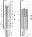
- FIGS. 1 A and 1 Bare side cross-sectional illustrations of a medical device delivery system configured in accordance with some embodiments.
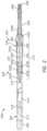
- FIG. 2is a side, cross-sectional view of a medical device delivery system, according to some embodiments.
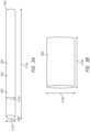
- FIGS. 3 A and 3 Bare side perspective views of a stent in accordance with some embodiments.
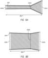
- FIGS. 4 A and 4 Bare side cross-sectional views of the stent of FIGS. 3 A and 3 B .
- FIG. 5is a side view of a stent in accordance with some embodiments.
- FIG. 6is a side view of a stent in accordance with some embodiments.
- FIG. 7is a side view of a stent in accordance with some embodiments.
- FIGS. 8 A and 8 Bare side cross-sectional views of a stent in accordance with some embodiments.
- FIG. 9is a side view of an expandable member in accordance with some embodiments.
- FIGS. 10 A and 10 Bare side views of an expandable member in accordance with some embodiments.
- FIGS. 11 A and 11 Bare side cross-sectional views of an expandable member in accordance with some embodiments.
- Self-expanding stentsmay be advanced into vascular vessels while mounted on a core member, but typically require radial restraint, such as provided by a restraining sheath or surrounding catheter, that prevents unwanted expansion of the self-expanding stent during advancement through a body lumen to a deployment site.
- radial restraintsuch as provided by a restraining sheath or surrounding catheter
- the stentcan be restrained onto the core member by the inner wall of a catheter through which the core member and stent are advanced.
- the radially outward force created by a self-expanding stent against the catheter inner wallcan make advancement of the stent and core member through and/or out of the catheter difficult due to the friction created by the self-expanding stent pressing radially outwardly toward the catheter inner wall.
- a stent formed from a memory materialmay have a primary set (e.g., heat set) of the stent that sets the stent in an expanded configuration, which permits the stent to radially expand and remain in a desired deployed configuration when deployed at a treatment site.
- a secondary set (e.g., heat set) of the stentmay be added in order to set the stent in a compressed configuration, which helps the stent remain compressed in a delivery configuration against the core member and reduces friction between the stent and the catheter walls through which the stent is advanced, thus reducing the delivery force (i.e., the “pushing” force needed to advance the stent and core member through and out of the catheter lumen).
- a radially expandable componentmay be positioned on the core member which may be selectively radially expanded. At least a portion of the stent may be mounted over the radially expandable member, with the radially expandable member adapted to radially expand the stent from the delivery configuration and into the deployed configuration, so that the deployed stent properly engages the body lumen walls upon and after deployment. Expansion of the radially expandable member may be selectively controlled, such as by a wire that when pulled can reduce the length of the radially expandable member, thereby increasing the diameter thereof.
- FIGS. 1 - 11 BSpecific details of several embodiments of the present technology are described herein with reference to FIGS. 1 - 11 B . Although many of the embodiments are described with respect to devices, systems, and methods for delivery of stents, tubular implants such as filters, shunts or stent-grafts and other medical devices, other applications and other embodiments in addition to those described herein are within the scope of the present technology, and can be employed in any of the embodiments of systems disclosed herein, in place of a stent as is typically disclosed. It should be noted that other embodiments in addition to those disclosed herein are within the scope of the present technology. Further, embodiments of the present technology can have different configurations, components, and/or procedures than those shown or described herein.
- embodiments of the present technologycan have configurations, components, and/or procedures in addition to those shown or described herein and that these and other embodiments may not have several of the configurations, components, and/or procedures shown or described herein without deviating from the present technology.
- distal and proximaldefine a position or direction with respect to a clinician or a clinician's control device (e.g., a handle of a delivery catheter).
- a clinician's control devicee.g., a handle of a delivery catheter.
- distal and distalrefer to a position distant from or in a direction away from a clinician or a clinician's control device along the length of device.
- proximal and proximallyrefer to a position near or in a direction toward a clinician or a clinician's control device along the length of device.
- the headings provided hereinare for convenience only and should not be construed as limiting the subject matter disclosed.
- FIGS. 1 A — 2depict embodiments of medical device delivery systems that may be used to deliver and/or deploy a medical device, such as but not limited to a stent, into a hollow anatomical structure such as a blood vessel.
- the stentcan comprise a braided stent or other form of stent such as a woven stent, knit stent, laser-cut stent, roll-up stent, etc.
- the stentcan optionally be configured to act as a “flow diverter” device for treatment of aneurysms, such as those found in blood vessels including arteries in the brain or within the cranium, or in other locations in the body such as peripheral arteries.
- the stentcan optionally be similar to any of the versions or sizes of the PIPELINETM Embolization Device marketed by Medtronic Neurovascular of Irvine, California USA.
- the stentcan alternatively comprise any suitable tubular medical device and/or other features, as described herein.
- the stentcan be any one of the stents described in U.S. application Ser. No. 15/892,268, filed Feb. 8, 2018, titled VASCULAR EXPANDABLE DEVICES, the entirety of which is hereby incorporated by reference herein and made a part of this specification.
- FIG. 1 Ais a schematic illustration of a medical device delivery system 100 configured in accordance with an embodiment of the present technology.
- the system 100can comprise an elongate tube or catheter 102 which slidably receives a core member or core assembly 104 configured to carry a stent 106 through the catheter 102 .
- the depicted stent 106has a stent proximal region 108 with a stent proximal end 110 , and an opposing stent distal region 112 with a stent distal end 114 .
- the depicted catheter 102has a catheter proximal region 116 and an opposing catheter distal region 118 which can be positioned at a treatment site within a patient, an internal lumen 120 extending from the catheter proximal region 116 to the catheter distal region 118 , and an inner wall surface 122 defining the internal lumen 120 .
- the catheter 102has a distal opening 124 through which the core member 104 may be advanced beyond the catheter distal region 118 to expand or deploy the stent 106 within the body lumen 126 so that the stent 106 engages the body lumen wall 128 .
- the catheter proximal region 116may include a catheter hub (not shown) or catheter handle (not shown).
- the catheter 102can define a generally longitudinal dimension extending between the catheter proximal region 116 and the catheter distal region 118 . When the delivery system 100 is in use, the longitudinal dimension of the catheter 102 need not be straight along some or any of its length.
- the core member 104is configured to extend generally longitudinally through the lumen 120 of the catheter 102 .
- the core member 104can generally comprise any member(s) with sufficient flexibility and column strength to move the stent 106 or other medical device through the catheter 102 .
- the core member 104can therefore comprise a wire, tube (e.g., hypotube), braid, coil, or other suitable member(s), or a combination of wire(s), tube(s), braid(s), coil(s), etc.
- An expandable member 130may be positioned on the core member 104 at a position under at least a portion of the stent 106 .
- the expandable member 130may be adapted to be selectively radially expanded from a smaller delivery diameter to a larger deployment diameter. Note that a user may be able to selectively vary the size of the larger deployment diameter, such as via controls on a proximal portion (e.g., handle) (not shown) of the core member 104 .
- the expandable member 130may be adapted to be selectively radially compressed from the larger deployment diameter back down to a smaller diameter, such as to the smaller delivery diameter.
- the radially expandable member 130may be adapted to radially expand outwardly against the stent 106 to radially engage and releasably expand the stent 106 from the core member 104 .
- the radially expandable member 130may be formed with a main body 140 having a compressed configuration where the main body 140 is substantially cylindrical and lies close to the core member 104 as depicted in FIG. 1 A .
- the radially expandable member 130may have an expandable member distal end 142 and an expandable member proximal end 144 .
- the expandable member 130may be adapted to be selectively radially expanded to engage outwardly against the overlying portion of the stent 106 .
- a portion(such as a stent distal portion 112 ) or all of the stent 106 may radially expand into contact with the wall 128 of the body lumen 126 .
- the distal restraining sheath 134has been removed from the stent 106 , which in the embodiment depicted involved sliding the distal restraining sheath 134 distally off of the stent 106 .
- Radial expansion of the stent portionmay be achieved by radial expansion of the radially expandable member 130 .
- the radially expandable member 130may not expand to the full width of the body lumen, but can instead expand only enough to cause the stent 106 to reach a diameter where the stent is biased toward a larger diameter which is at least as large as, and maybe larger than, the width of the body lumen 126 .
- the stent 106can be moved distally or proximally within the catheter 102 via the core member 104 .
- the core member 104is moved distally while the catheter 102 is held stationary, or the core member 104 is held stationary while the catheter 102 is withdrawn proximally, or the core member 104 is moved distally while the catheter 102 is withdrawn proximally.
- the core member 104is moved distally with respect to the catheter 102 , such that the stent 106 is advanced distally with respect to the catheter 102 , and ultimately out of the catheter distal region 118 and catheter distal opening 124 .
- the relative movement between the core member 104 and the catheter 102is reversed compared to moving the stent 106 out of the catheter 102 .
- the resulting proximal movement of the stent 106 relative to the catheter 102enables re-sheathing of the stent 106 back into the distal region 118 of the catheter 102 . This is useful when the stent 106 has been partially deployed and a portion of the stent 106 remains disposed with some portion of the system, such as a proximal sheath on the core member 104 .
- the stent 106can thus be withdrawn back into the distal opening 124 of the catheter 102 by moving the core member 104 proximally relative to the catheter 102 . Resheathing in this manner may remain possible until the entirety of the stent 106 is released from the core member and all other non-stent portions of the system.
- the stent 106can be coupled to the core member 104 using any suitable technique, including one or more restraining sheaths, one or more proximal bumpers or pushing elements configured to abut a proximal end of the stent 106 , and/or one or more underlying stent engagement members configured to interlock with or otherwise engage the stent 106 and retain the stent 106 in position with respect to the overlying catheter 102 .
- a distal restraining sheathmay be positioned distally of and extending over the stent distal portion 112 , restraining the stent distal portion 112 to the core member 104 .
- the distal restraining sheathmay have a distal sheath distal end, which may be secured to the core member 104 , and a distal sheath proximal end, which may be a free end and may be positioned over the stent distal portion 112 .
- the distal restraining sheathmay be adapted to be removed from the stent distal portion 112 , such as by sliding distally and/or everting the distal sheath proximal end (aka the free end) toward and potentially distally of the distal sheath distal end (aka the fixed end), thereby releasing the stent distal portion 112 to radially expand outwardly from the core member 104 .
- a proximal restraining sheathmay be included, in addition to or in lieu of a distal restraining sheath (depending on the particular application and system aspects).
- the proximal restraining sheathcan have similar features (e.g., proximal sheath proximal end secured to core member 104 , proximal sheath distal end as a free end positioned over stent proximal portion 108 , adapted to slide proximally or evert from off the stent 106 to release the stent to expand, etc.).
- Some embodiments of the medical delivery systemmay include spacers and/or stent engagement members and/or other elements such as those disclosed in U.S. patent application Ser. No. 15/951,779, filed Apr. 12, 2018, the entirety of which is hereby incorporated by reference herein and made a part of this specification.
- FIG. 2illustrates a side cross-sectional view of another embodiment of a medical device delivery system 200 configured in accordance with an embodiment of the present technology.
- the delivery system 200can be configured to carry a stent (or other vascular implant or device) 205 thereon to be advanced through a surrounding catheter to a target site in a patient, similar to the operation described above with respect to FIGS. 1 A- 1 B . (The surrounding catheter is omitted in FIG. 2 for clarity).
- the delivery system 200can be advanced distally with respect to a distal end of the catheter to expand or deploy the stent 205 at the target site.
- the delivery system 200can be used with any number of catheters.
- the cathetercan optionally comprise any of the various lengths of the MARKSMANTM catheter available from Medtronic Neurovascular of Irvine, California USA.
- the cathetercan optionally comprise a microcatheter having an inner diameter of about 0.030 inches or less, and/or an outer diameter of 3 French or less near the distal region.
- the cathetercan comprise a microcatheter which is configured to percutaneously access the internal carotid artery, or another location within the neurovasculature distal of the internal carotid artery.
- the delivery system 200can comprise a core member or core assembly 202 configured to extend generally longitudinally through the lumen of a catheter.
- the core member 202can have a proximal region 204 and a distal region 206 , which can optionally include a tip coil 208 .
- the core member 202can also comprise an intermediate portion 210 located between the proximal region 204 and the distal region 206 .
- the intermediate portion 210is the portion of the core member 202 onto or over which the stent 205 extends when the core member 202 is in the pre-deployment configuration as shown in FIG. 2 .
- the core member 202can generally comprise any member(s) with sufficient flexibility and column strength to move a stent or other medical device through a surrounding catheter.
- the core member 202can therefore comprise a wire, tube (e.g., hypotube), braid, coil, or other suitable member(s), or a combination of wire(s), tube(s), braid(s), coil(s), etc.
- the embodiment of the core member 202 depicted in FIG. 2is of multi-member construction, comprising a wire 212 with a tube 214 surrounding the wire 212 along at least a portion of its length.
- An outer layer 218which can comprise a layer of lubricious material such as PTFE (polytetrafluoroethylene or TEFLONTM) or other lubricious polymers, can cover some or all of the tube 214 and/or wire 212 .
- the wire 212may taper or vary in diameter along some or all of its length.
- the wire 212may include one or more fluorosafe markers (not shown), and such marker(s) may be located on a portion of the wire 212 that is not covered by the outer layer 218 (e.g., proximal of the outer layer 218 ). This portion of the wire 212 marked by the marker(s), and/or proximal of any outer layer 218 , can comprise a bare metal outer surface.
- the core member 202can further comprise a proximal coupling assembly 220 and/or a distal interface assembly 222 that can interconnect the stent 205 with the core member 202 .
- the proximal coupling assembly 220can comprise one or more stent engagement members 223 a - b (together “engagement members 223 ”) that are configured to mechanically engage or interlock with the stent 205 .
- the proximal coupling assembly 220cooperates with an overlying inner surface of a surrounding catheter (not shown) to grip the stent 205 such that the proximal coupling assembly 220 can move the stent 205 along and within the catheter, e.g., as the user pushes the core member 202 distally and/or pulls the core member proximally relative to the catheter, resulting in a corresponding distal and/or proximal movement of the stent 205 within the catheter lumen.
- the proximal coupling assembly 220can, in some embodiments, include proximal and distal restraints 219 , 221 that are fixed to the core member 202 (e.g., to the wire 212 thereof in the depicted embodiment) so as to be immovable relative to the core member 202 , either in a longitudinal/sliding manner or a radial/rotational manner.
- the proximal coupling assembly 220can also include a plurality of stent engagement members 223 separated by spacers 225 a — b (together “spacers 225 ”).
- the stent engagement members 223 and spacers 225can be coupled to (e.g., mounted on) the core member 202 so that the proximal coupling assembly 220 can rotate about the longitudinal axis of the core member 202 (e.g., of the intermediate portion 210 ), and/or move or slide longitudinally along the core member 202 .
- the proximal restraint 219comprises a substantially cylindrical body with an outer diameter that is greater than or equal to an outer diameter of the first spacer 225 a .
- the distal restraint 221can taper in the distal direction down towards the core member 202 .
- This taperingcan reduce the risk of the distal restraint 221 contacting an inner surface of the overlying stent 205 , particularly during navigation of tortuous vasculature, in which the system 200 can assume a highly curved configuration.
- the distal restraint 221can have an outside diameter or other radially outermost dimension that is smaller than the outside diameter or other radially outermost dimension of the overall proximal coupling assembly 220 , so that distal restraint 221 will tend not to contact the inner surface of the overlying stent 205 .
- the stent 205can be moved distally or proximally within an overlying catheter (not shown) via the proximal coupling assembly 220 .
- the stent 205can be resheathed via the proximal coupling assembly 220 after partial deployment of the stent 205 from a distal opening of the catheter.
- the coupling assembly 220can be configured to engage the stent 205 , such as via mechanical interlock with the pores and filaments of the stent 205 , abutment of the proximal end or edge of the stent 205 , frictional engagement with an inner wall of the stent 205 , or any combination of these modes of action.
- the coupling assembly 220can therefore cooperate with an overlying inner surface of a catheter (such as the inner wall surface 122 of the catheter 102 of FIGS.
- the proximal coupling assembly 220can be configured and function so that the proximal restraint 219 can be made to function as a pushing element by appropriately sizing the outer diameter of the proximal restraint 219 and the length of the first spacer 225 a , such that the distal face of the proximal restraint 219 abuts the proximal end or edge of the stent 205 .
- the proximal restraint 219can transmit at least some, or most or all, distally directed push force to the stent 205 during delivery, and the stent engagement member(s) 223 do not transmit any distally directed push force to the stent 205 during delivery (or transmit only a small portion of such force, or do so only intermittently).
- the stent engagement member(s) 223can transmit proximally directed pull force to the stent 205 during retraction or resheathing, and the proximal restraint 219 can transmit no proximally directed pull force to the stent (or it may do so occasionally or intermittently, for example when a portion of the stent 205 becomes trapped between the outer edge of the proximal restraint 219 and the inner wall of the catheter).
- the first spacer 225 acan optionally take the form of a solid tube when the proximal coupling assembly 220 includes a proximal restraint 219 configured as a pushing element.
- the coupling assembly 220may entail use of the stent engagement members 223 for both distal (delivery) and proximal (resheathing) movement of the stent 205 .
- the proximal edge of the proximal coupling assembly 220can be positioned just distal of the proximal edge of the stent 205 when in the delivery configuration. In some such embodiments, this enables the stent 205 to be re-sheathed when as little as a few millimeters of the stent remains in the catheter. Therefore, with stents of typical length, resheathability of 75% or more can be provided (i.e., the stent can be re-sheathed when 75% or more of it has been deployed).
- the distal interface assembly 222can comprise a distal engagement member 224 that can take the form of, for example, a distal device cover or distal stent cover (generically, a “distal cover”), though other configurations are contemplated.
- the distal engagement member 224can be configured to reduce friction between the stent 205 (e.g., a distal portion thereof) and the inner surface of a surrounding catheter.
- the distal engagement member 224can be configured as a lubricious, flexible structure having a free first end or section 224 a that can extend over at least a portion of the stent 205 and/or intermediate portion 210 of the core member 202 , and a fixed second end or section 224 b that can be coupled (directly or indirectly) to the core member 202 .
- the distal engagement member 224can have a first or delivery position, configuration, or orientation in which the distal cover can extend proximally relative to the distal tip, or proximally from the second section 224 b or its (direct or indirect) attachment to the core member 202 , and at least partially surround or cover a distal portion of the stent 205 .
- the distal engagement member 224can be movable from the first or delivery orientation to a second or resheathing position, configuration, or orientation (not shown) in which the distal cover can be everted such that the first end 224 a of the distal cover is positioned distally relative to the second end 224 b of the distal engagement member 224 to enable the resheathing of the core member 202 , either with the stent 205 carried thereby, or without the stent 205 .
- the first section 224 a of the distal engagement member 224can originate from the proximal end of the second section 224 b .
- the first section 224 acan originate from the distal end of the second section 224 b.
- the distal engagement member 224can be manufactured using a lubricious and/or hydrophilic material such as PTFE or Teflon®, but may be made from other suitable lubricious materials or lubricious polymers.
- the distal covercan also comprise a radiopaque material which can be blended into the main material (e.g., PTFE) to impart radiopacity.
- the distal engagement member 224can have a thickness of between about 0.0005′′ and about 0.003′′. In some embodiments, the distal cover can be one or more strips of PTFE having a thickness of about 0.001′′.
- the distal engagement member 224(e.g., the second end 224 b thereof) can be fixed to the core member 202 (e.g., to the wire 212 or distal tip thereof) so as to be immovable relative to the core member 202 , either in a longitudinal/sliding manner or a radial/rotational manner.
- the distal engagement member 224(e.g., the second end 224 b thereof) can be coupled to (e.g., mounted on) the core member 202 so that the distal engagement member 224 can rotate about a longitudinal axis of the core member 202 (e.g., of the wire 212 ), and/or move or slide longitudinally along the core member.
- the second end 224 bcan have an inner lumen that receives the core member 202 therein such that the distal engagement member 224 can slide and/or rotate relative to the core member 202 .
- the distal interface assembly 222can further comprise a proximal restraint 226 that is fixed to the core member 202 and located proximal of the (second end 224 b of the) distal engagement member 224 , and/or a distal restraint 228 that is fixed to the core member 202 and located distal of the (second end 224 b of the) distal engagement member 224 .
- the distal interface assembly 222can comprise a radial gap between the outer surface of the core member 202 (e.g., of the wire 212 ) and the inner surface of the second end 224 b .
- a radial gapcan be formed when the second end 224 b is constructed with an inner luminal diameter that is somewhat larger than the outer diameter of the corresponding portion of the core member 202 .
- the radial gapallows the distal engagement member 224 and/or second end 224 b to rotate about the longitudinal axis of the core member 202 between the restraints 226 , 228 .
- one or both of the proximal and distal restraints 226 , 228can have an outside diameter or other radially outermost dimension that is smaller than the (e.g., pre-deployment) outside diameter or other radially outermost dimension of the distal engagement member 224 , so that one or both of the restraints 226 , 228 will tend not to bear against or contact the inner surface of the catheter during operation of the core member 202 .
- the outer diameters of the restraints 226 and 228can be made larger than the largest radial dimension of the pre-deployment distal engagement member 224 , and/or make the outer diameter of the proximal restraint 226 larger than the outer diameter of the distal restraint 228 .
- This configurationallows easy and smooth retrieval of the distal engagement member 224 and the restraints 226 , 228 back into the catheter post stent deployment.
- the distal engagement member 224can generally cover and protect a distal region of the stent 205 as the stent 205 is moved distally through a surrounding catheter.
- the distal engagement member 224may serve as a bearing or buffer layer that, for example, inhibits filament ends of the distal region of the stent 205 (where the stent comprises a braided stent) from contacting an inner surface of the catheter, which could damage the stent 205 and/or catheter, or otherwise compromise the structural integrity of the stent 205 .
- the distal engagement member 224may be made of a lubricious material, the distal engagement member 224 may exhibit a low coefficient of friction that allows the distal region of the stent to slide axially within the catheter with relative ease.
- the coefficient of friction between the distal cover and the inner surface of the cathetercan be between about 0.02 and about 0.4.
- the coefficient of frictioncan be about 0.04.
- Such embodimentscan advantageously improve the ability of the core member 202 to pass through the catheter, especially in tortuous vasculature.
- distal engagement member 224may be used in the core member 202 and/or distal interface assembly 222 to cover or otherwise interface with the distal region of the stent 205 .
- a protective coil or other sleeve having a longitudinally oriented, proximally open lumenmay be employed.
- the distal interface assembly 222can omit the distal engagement member 224 , or the distal cover can be replaced with a component similar to the proximal coupling assembly 220 .
- distal engagement member 224it can be connected to the distal tip coil 208 (e.g., by being wrapped around and enclosing some or all of the winds of the coil 208 ) or being adhered to or coupled to the outer surface of the coil by an adhesive or a surrounding shrink tube.
- the distal engagement member 224can be coupled (directly or indirectly) to other portions of the core member 202 , such as the wire 212 .
- the stent 205can be rotatable with respect to the core member 202 about the longitudinal axis thereof, by virtue of the rotatable connections of the proximal coupling assembly 220 and distal engagement member 224 .
- the stent 205 , proximal coupling assembly 220 and distal engagement member 224can rotate together in this manner about the core member 202 .
- the core member 202can be advanced more easily through tortuous vessels as the tendency of the vessels to twist the stent 205 and/or core member 202 is negated by the rotation of the stent 205 , proximal coupling assembly 220 , and distal engagement member 224 about the core member 202 .
- the required push force or delivery forceis reduced, as the user's input push force is not diverted into torsion of the stent 205 and/or core member 202 .
- a twisted stent 205 and/or core member 202to untwist suddenly or “whip” upon exiting tortuosity or deployment of the stent 205 , and the tendency of a twisted stent to resist expansion upon deployment, are also reduced or eliminated.
- the usercan “steer” the core member 202 via the tip coil 208 , particularly if the coil 208 is bent at an angle in its unstressed configuration.
- Such a coil tipcan be rotated about a longitudinal axis of the system 200 relative to the stent, coupling assembly 220 and/or distal engagement member 224 by rotating the distal region 206 of the core member 202 .
- the usercan point the coil tip 208 in the desired direction of travel of the core member 202 , and upon advancement of the core member the tip will guide the core member in the chosen direction.
- An expandable member 240may be positioned on the core member 202 at a position under the stent.
- the expandable member 240is adapted to be radially expanded, thereby causing at least a portion of the stent 205 to radially expand.
- the expandable member 240may be positioned on the core member 202 so that the core member 240 underlies a distal portion 242 of the stent 205 (as in the example depicted in FIG. 2 ).
- the expandable member 240may alternatively underlie any portion or even the entirety of the stent, such as the proximal portion 244 of the stent 205 , an intermediate portion 246 of the stent 205 , the entirety of the stent 205 , etc.
- Multiple expandable membersmay be positioned under various portions of the stent 205 , such as a distal expandable member positioned on the core member at a position under the distal portion 242 of the stent 205 , a proximal expandable member positioned on the core member at a position under the proximal portion 244 of the stent 205 , an intermediate expandable member positioned on the core member at a position under an intermediate portion 246 of the stent 205 , etc.
- any of the disclosed embodiments of the expandable member 240 of the delivery system 200can be employed as the expandable member 130 of the delivery system 100 .
- Any of the embodiments of the coupling assembly 220can be employed with the delivery system 100 .
- any of the embodiments of the stent engagement members 223can be employed with the delivery system 100 , and/or any of the embodiments of the spacers 225 can be employed with the delivery system 100 .
- many embodiments discussed hereininclude two engagement members 223 , in other embodiments the delivery system 200 can include three, four, or more engagement members separated from one another by additional spacers.
- a third engagement membercan be provided at a position configured to engage a distal region of the overlying stent, while the first and second engagement members engage only a proximal region of the overlying stent.
- the stentscan take different forms.
- FIGS. 3 A- 8 Billustrate various alternative embodiments of stents.
- stentscan be incorporated into and combined with the systems and core members and stents described above with respect to FIGS. 1 A- 2 . Additionally, aspects of these stents can be combined and intermixed such that features of any one of these stents (e.g., the diameters, configuration, mechanism of expansion, etc.) can be combined with the features of any of the other delivery systems and/or expandable members disclosed herein (e.g., the type of expandable member, type of delivery system (such as core member), etc.).
- features of any one of these stentse.g., the diameters, configuration, mechanism of expansion, etc.
- the other delivery systems and/or expandable members disclosed hereine.g., the type of expandable member, type of delivery system (such as core member), etc.
- Stentsmay be self-expanding and may have a primary set configuration, and may also have a secondary set configuration.
- FIG. 3 Adepicts a stent 300 in a secondary set configuration, where the stent 300 is a substantially cylindrical main body 302 defined by a stent wall 304 , where the stent wall 304 can be porous, such as being formed from a mesh and/or with openings which permit the passage of liquid therethrough.
- the stent 300may be open at its distal end 306 and/or at its proximal end 308 .
- the stent 300has a secondary set outer diameter 312 a , a secondary set inner diameter 316 a , and a secondary set length 314 a .
- FIG. 3 Adepicts a stent 300 in a secondary set configuration, where the stent 300 is a substantially cylindrical main body 302 defined by a stent wall 304 , where the stent wall 304 can be porous, such as being formed
- the stent 300depicts the stent in a primary set configuration, where the stent 300 may be substantially cylindrical and has a primary outer diameter 312 b and a primary set length 314 b .
- the primary set outer diameter 312 bis larger than the secondary set outer diameter 312 a .
- the stent 300reduces in length as it radially expands, with the primary set length 314 b being shorter than the secondary set length 314 a .
- the stent 300may lengthen, shorten, or remain the same in length between the primary and secondary set configurations.
- FIG. 4 Adepicts the stent 300 of FIGS. 3 A- 3 B in a delivery configuration, wherein the stent 300 is positioned tightly on a core member 318 .
- the portion of the core member 318 on which the stent 300 is positionedmay have a core member outer diameter 320 which is at least as large as, and can be slightly larger than, the secondary set inner diameter 316 a (depicted in FIG. 3 A ) of the stent 300 , thereby causing the stent 300 when mounted on the core member 318 to be biased radially inwardly against the core member 318 (including any expandable member thereon which may underlie portion(s) of the stent).
- the stent 300 thus mounted on the core member 318has a minimum outer delivery diameter 322 min, a maximum outer delivery diameter 322 max, a minimum inner delivery diameter 324 min, and a delivery length 328 .
- Both the minimum and maximum outer delivery diameters 322 min, 322 maxcan be the same or larger than the secondary set outer diameter 312 a from FIG. 3 A , and may be small enough so that the inner surface 330 of the stent 300 engages closely to the outer surface 332 of the core member 318 , including the outer surface of an expandable member that may be thereon (not shown).
- the minimum and maximum outer delivery diameters 322 min, 322 maxcan be sufficiently small that the stent 300 during delivery is biased more strongly toward the secondary set configuration and secondary outer diameter 312 a of FIG. 3 A than to the primary set configuration and primary outer diameter 312 b of FIG. 3 A .
- the stent 300is thus radially exerting an inward force against, and thus held tightly against, the core member 318 , and does not exert a radially expansive force against an inner wall 334 of the surrounding catheter 336 .
- Friction between the catheter wall 334 /surrounding catheter 336 and the stent 300is thus reduced, which reduces the pushing and pulling forces needed to advance or withdraw the stent 300 and core member 318 within the catheter lumen 338 and/or out of the catheter distal opening 340 .
- the minimum delivery outer diameter 322 min and maximum delivery outer diameter 322 maxmay be equal to or smaller than the inner diameter 342 of the catheter 336 .
- the various stent diameters and lengthscan be selected according to the particular system and application, including the dimensions and shape of the particular lumen where the stent is to be deployed, the inner diameter of any surrounding catheter, the outer diameter of a core member, the diameter and/or length of an expandable member, etc.
- FIG. 4 Bdepicts the stent 300 of FIGS. 3 A- 3 B and 4 A in a deployed configuration in a body lumen 344 , wherein the stent 300 is released and radially expanded and the catheter and core member have been removed. Radial expansion of the stent 300 may be accomplished in part using radial expansion of an expandable member (not shown) on the core member. The stent 300 is radially expanded into contact with the wall 346 of the body lumen 344 . The stent 300 has a minimum deployed diameter 348 min, a maximum deployed diameter 348 max, and a deployed length 350 (with the length 350 measured along a longitudinal axis of the stent 300 , which may be curved to comport to curves in the body lumen 344 ).
- Both the minimum and maximum deployed dimensions 348 , 350are the same or smaller than the primary set diameter 312 b of FIG. 3 A , but the deployed dimensions 348 , 350 may be sufficiently large that the deployed stent 300 is biased more strongly toward the primary set diameter 312 b of FIG. 3 B than to the secondary set diameter 312 a of FIG. 3 A .
- This bias toward the primary set diameter 312 bkeeps the stent 300 radially expanded against the wall 346 of the body lumen 344 , and prevents the stent 300 from collapsing toward the secondary set diameter 312 a .
- the small portion of the stent 300 which is already expanded toward or at the primary set diameter 312 bmay pull outwardly on the remaining (contracted) portion(s) of the stent 300 with sufficient force to cause the entirety of the stent 300 to expand outwardly toward the primary set outer diameter 312 b .
- This biasprevents undesired narrow portions (e.g., bottlenecks) along the stent 300 when deployed, with the radially expanded portions pulling radially outwardly on any adjacent contracted sections to pull them into radially expanded configuration.
- FIG. 5depicts a braided stent 500 , such as that depicted in FIG. 5 .
- the stent 500has a central portion 502 formed from braided strand (e.g., wire-like) elements 504 , with the braided elements 504 extending from the stent distal end 506 to the stent proximal end 508 .
- FIG. 6depicts a stent 600 formed by cutting a desired pattern into a hypotube, with cutout areas 602 which are cut (e.g., using a laser) out of a cylindrical body 604 , with the remaining (non-cutout) portions 606 defining the lattice wall 608 of the stent 600 .
- a stent 700may be formed from wire 702 , which in the particular example of FIG. 7 is formed into a series of sinusoidal coils 704 defining the length of the stent 700 . Note that other types of stents may also be used.
- Stentsmay be formed from various materials, including metals (nitinol, stainless steel, cobalt-chromium, etc.), polymers (e.g., shape-memory thermoplastic and thermoset (covalently cross-linked) polymeric materials), bioresorbable materials, and other materials. Setting the primary and secondary stent configurations may be accomplished by forming the stent using memory materials (such as nitinol), which can be heat-set to one or more specific shapes. Set shapes may also be accomplished by using other stent manufacturing and design methods.
- a stentmay have one or more set shapes (primary and/or secondary) which have different diameters or other variations in dimensions along the length and/or width/diameter of the stent, including symmetrical and non-symmetrical shapes.
- a stent 800 in its secondary set shapehas a length 806 with different secondary set outer diameters 804 a , 804 b , 804 c along its length.
- the secondary set outer diameter 804 c at the distal end of the stentis relatively large compared to the smaller secondary set outer diameter 804 c at the proximal end the distal end and the even smaller secondary set outer diameter 804 b in a section proximal of the distal end of the stent 800 .
- the stent 800 in its primary set shapehas primary set outer diameters 808 a (distal), 808 b (proximal of distal), 808 c (proximal) along its length.
- the expandable memberscan take different forms.
- the length of the expandable member, the varying diameters of the expandable member, the position of the expandable member on the core member, the shape(s) of the expandable member, the mechanism by which the expandable member is expanded and/or contracted, the control of the expandable member, the material selected, and dimensionscan all vary to achieve desired operation of the expandable member.
- FIGS. 9 - 11 Billustrate various alternative embodiments of expandable members. These expandable members can be incorporated into and combined with the systems and core members and stents described above with respect to FIGS. 1 A- 8 B .
- aspects of these expandable memberscan be combined and intermixed such that features of any one of these expandable members (e.g., the diameters, configuration, mechanism of expansion, etc.) can be combined with the features of any of the other delivery systems and/or stents disclosed herein (e.g., the type of stent, type of delivery system (such as core member), etc.
- features of any one of these expandable memberse.g., the diameters, configuration, mechanism of expansion, etc.
- the other delivery systems and/or stents disclosed hereine.g., the type of stent, type of delivery system (such as core member), etc.
- An expandable membermay have a compressed/delivery diameter not significantly greater than the diameters of surrounding portions of the core member.
- the expandable membermay have an expanded diameter which is sufficient to radially expand the overlying portion of the stent to a diameter which is sufficiently large so that that portion of the stent when expanded by the expandable member is biased toward the primary (expanded) set configuration and not toward the secondary (smaller) set configuration.
- expandable memberscan have various lengths, diameters (expanded and contracted), shapes, designs, etc., depending on the particular application and parameters such as the deployment site, stent size/diameters/length, etc.
- FIG. 9illustrates, in partially expanded configuration, another embodiment of an expandable member 900 positioned on a core member 902 .
- the expandable member 900has a braided main body 904 formed from braided elements 905 and having a distal end 906 and a proximal end 908 , and a length 910 and maximum diameter 912 .
- the braided main body 904is secured at its distal end 906 to a distal collar 914 mounted around the core member central body 916
- the proximal end 908is secured to a proximal collar 918 mounted around the core member central body 916 .
- At least one of the distal collar 914 and the proximal collar 918are slidingly secured around the core member central body 916 , so that one of the collars 914 , 918 can be advanced toward the other collar and can also be moved away from the other collar. Movement of one of the collars 914 , 918 toward the other collar causes radial expansion/increased diameter 912 (and reduced length 910 ) of the expandable member 900 . Movement of one of the collars 914 , 918 away from the other collar causes radial contraction/reduced diameter 912 (and increased length 910 ) of the braided main body 904 .
- the expandable member 900can facilitate expansion and deployment of a stent (not shown), as discussed elsewhere in this application. Additionally or alternatively, the expandable member 900 can be self-expanding such that it is biased towards a radially expanded configuration, while being collapsible to the reduced-diameter configuration for delivery. In various embodiments, one or both of the collars 914 and 918 can be fixed or slidably coupled to the underlying core member 902 depending on the desired configuration.
- FIGS. 10 A and 10 Billustrate, in compressed and expanded configurations, respectively, another embodiment of an expandable member 1000 positioned on a core member 1002 .
- the expandable member 1000has a main body 1004 which includes openings therethrough.
- the main body 1004is a cylindrical form into which openings have been formed, such as by cutting openings therein (e.g., via laser cutting) such as the depicted longitudinal slots 1006 separating longitudinal slats 1008 .
- the expandable member distal end 1010is secured to a distal collar 1012 mounted around the core member central body 1014
- the expandable member proximal end 1016is secured to a proximal collar 1018 mounted around the core member central body 1014 .
- At least one of the distal collar 1012 and the proximal collar 1018are slidingly secured around the core member central body 1014 , so that one of the collars 1012 , 1018 can be advanced toward the other collar and can also be moved away from the other collar. Movement of one of the collars 1012 , 1018 toward the other collar causes the slats 1008 to bend and curve, resulting in radial expansion/increase of the diameter 1020 (and reduced length 1022 ) of the expandable member 1000 , as depicted in FIG. 10 B . Movement of one of the collars 1012 , 1018 away from the other collar causes radial contraction/reduced diameter 1020 (and increased length 1022 ) of the expandable member 1000 , as depicted in FIG.
- the expandable member 1000can facilitate expansion and deployment of a stent (not shown), as discussed elsewhere in this application. Additionally or alternatively, the expandable member 1000 can be self-expanding such that it is biased towards a radially expanded configuration, while being collapsible toward the compressed configuration to underlie the stent within the catheter. In various embodiments, one or both of the collars 1012 and 1018 can be fixed or slidably coupled to the underlying core member 1002 depending on the desired configuration.
- FIGS. 11 A and 11 Billustrate, in compressed and expanded configurations, respectively, another embodiment of an expandable member 1100 positioned on a core member 1102 .
- the expandable member 1100has a balloon 1104 which includes an inner reservoir 1106 has an outer diameter 1108 and length 1110 .
- the balloon 1104is uninflated, with the inner reservoir 1106 substantially or completely empty, so that the balloon 1104 is contracted against the core member inner element 1112 .
- a gase.g., air
- liquide.g., saline solution
- Subsequent removal of the gas and/or liquid from the inner reservoir 1106 of the balloon 1104will cause radial contraction/reduction in the diameter 1108 of the expandable member 1100 , as depicted in FIG. 11 A .
- Selective radial expansion of the expandable member 1100can facilitate expansion and deployment of a stent (not shown), as discussed elsewhere in this application.
Landscapes
- Health & Medical Sciences (AREA)
- Engineering & Computer Science (AREA)
- Biomedical Technology (AREA)
- Cardiology (AREA)
- Oral & Maxillofacial Surgery (AREA)
- Transplantation (AREA)
- Heart & Thoracic Surgery (AREA)
- Vascular Medicine (AREA)
- Life Sciences & Earth Sciences (AREA)
- Animal Behavior & Ethology (AREA)
- General Health & Medical Sciences (AREA)
- Public Health (AREA)
- Veterinary Medicine (AREA)
- Media Introduction/Drainage Providing Device (AREA)
Abstract
Description
Claims (19)
Priority Applications (1)
| Application Number | Priority Date | Filing Date | Title |
|---|---|---|---|
| US17/444,149US12109137B2 (en) | 2021-07-30 | 2021-07-30 | Medical device delivery |
Applications Claiming Priority (1)
| Application Number | Priority Date | Filing Date | Title |
|---|---|---|---|
| US17/444,149US12109137B2 (en) | 2021-07-30 | 2021-07-30 | Medical device delivery |
Publications (2)
| Publication Number | Publication Date |
|---|---|
| US20230029736A1 US20230029736A1 (en) | 2023-02-02 |
| US12109137B2true US12109137B2 (en) | 2024-10-08 |
Family
ID=85038970
Family Applications (1)
| Application Number | Title | Priority Date | Filing Date |
|---|---|---|---|
| US17/444,149Active2042-02-22US12109137B2 (en) | 2021-07-30 | 2021-07-30 | Medical device delivery |
Country Status (1)
| Country | Link |
|---|---|
| US (1) | US12109137B2 (en) |
Families Citing this family (1)
| Publication number | Priority date | Publication date | Assignee | Title |
|---|---|---|---|---|
| US11944558B2 (en) | 2021-08-05 | 2024-04-02 | Covidien Lp | Medical device delivery devices, systems, and methods |
Citations (465)
| Publication number | Priority date | Publication date | Assignee | Title |
|---|---|---|---|---|
| US3416531A (en) | 1964-01-02 | 1968-12-17 | Edwards Miles Lowell | Catheter |
| US4364391A (en) | 1980-11-14 | 1982-12-21 | Toye Frederic J | Tracheostomy apparatus and method |
| US4425919A (en) | 1981-07-27 | 1984-01-17 | Raychem Corporation | Torque transmitting catheter apparatus |
| US4516972A (en) | 1982-01-28 | 1985-05-14 | Advanced Cardiovascular Systems, Inc. | Guiding catheter and method of manufacture |
| US4723936A (en) | 1986-07-22 | 1988-02-09 | Versaflex Delivery Systems Inc. | Steerable catheter |
| US4877031A (en) | 1988-07-22 | 1989-10-31 | Advanced Cardiovascular Systems, Inc. | Steerable perfusion dilatation catheter |
| US4990151A (en) | 1988-09-28 | 1991-02-05 | Medinvent S.A. | Device for transluminal implantation or extraction |
| US5011478A (en) | 1989-01-31 | 1991-04-30 | Cook Incorporation | Recessed dilator-sheath assembly and method |
| US5026377A (en) | 1989-07-13 | 1991-06-25 | American Medical Systems, Inc. | Stent placement instrument and method |
| US5037427A (en)* | 1987-03-25 | 1991-08-06 | Terumo Kabushiki Kaisha | Method of implanting a stent within a tubular organ of a living body and of removing same |
| US5037404A (en) | 1988-11-14 | 1991-08-06 | Cordis Corporation | Catheter having sections of variable torsion characteristics |
| US5061275A (en) | 1986-04-21 | 1991-10-29 | Medinvent S.A. | Self-expanding prosthesis |
| US5098393A (en) | 1988-05-31 | 1992-03-24 | Kurt Amplatz | Medical introducer and valve assembly |
| US5108411A (en) | 1990-03-28 | 1992-04-28 | Cardiovascular Imaging Systems, Inc. | Flexible catheter drive cable |
| US5147370A (en) | 1991-06-12 | 1992-09-15 | Mcnamara Thomas O | Nitinol stent for hollow body conduits |
| US5178158A (en) | 1990-10-29 | 1993-01-12 | Boston Scientific Corporation | Convertible guidewire-catheter with soft tip |
| US5201316A (en) | 1991-03-18 | 1993-04-13 | Cardiovascular Imaging Systems, Inc. | Guide wire receptacle for catheters having rigid housings |
| US5209734A (en) | 1988-03-22 | 1993-05-11 | Brigham And Women's Hospital, Inc. | Continuous spinal anesthesia administering apparatus |
| US5279562A (en) | 1991-07-24 | 1994-01-18 | Advanced Cardiovascular Systems, Inc. | Low profile perfusion-type dilatation catheter |
| US5279596A (en) | 1990-07-27 | 1994-01-18 | Cordis Corporation | Intravascular catheter with kink resistant tip |
| US5292311A (en) | 1989-01-31 | 1994-03-08 | Cook Incorporated | Recessed dilator-sheath assembly and method |
| US5318529A (en) | 1989-09-06 | 1994-06-07 | Boston Scientific Corporation | Angioplasty balloon catheter and adaptor |
| US5318032A (en) | 1992-02-05 | 1994-06-07 | Devices For Vascular Intervention | Guiding catheter having soft tip |
| US5318525A (en) | 1992-04-10 | 1994-06-07 | Medtronic Cardiorhythm | Steerable electrode catheter |
| US5358493A (en) | 1993-02-18 | 1994-10-25 | Scimed Life Systems, Inc. | Vascular access catheter and methods for manufacture thereof |
| US5382259A (en) | 1992-10-26 | 1995-01-17 | Target Therapeutics, Inc. | Vasoocclusion coil with attached tubular woven or braided fibrous covering |
| US5389087A (en) | 1991-09-19 | 1995-02-14 | Baxter International Inc. | Fully exchangeable over-the-wire catheter with rip seam and gated side port |
| US5403292A (en) | 1994-05-18 | 1995-04-04 | Schneider (Usa) Inc. | Thin wall catheter having enhanced torqueability characteristics |
| US5437288A (en) | 1992-09-04 | 1995-08-01 | Mayo Foundation For Medical Education And Research | Flexible catheter guidewire |
| US5445646A (en) | 1993-10-22 | 1995-08-29 | Scimed Lifesystems, Inc. | Single layer hydraulic sheath stent delivery apparatus and method |
| US5454795A (en) | 1994-06-27 | 1995-10-03 | Target Therapeutics, Inc. | Kink-free spiral-wound catheter |
| US5458605A (en) | 1994-04-04 | 1995-10-17 | Advanced Cardiovascular Systems, Inc. | Coiled reinforced retractable sleeve for stent delivery catheter |
| US5474563A (en) | 1993-03-25 | 1995-12-12 | Myler; Richard | Cardiovascular stent and retrieval apparatus |
| US5478349A (en) | 1994-04-28 | 1995-12-26 | Boston Scientific Corporation | Placement of endoprostheses and stents |
| US5484444A (en) | 1992-10-31 | 1996-01-16 | Schneider (Europe) A.G. | Device for the implantation of self-expanding endoprostheses |
| US5496294A (en) | 1994-07-08 | 1996-03-05 | Target Therapeutics, Inc. | Catheter with kink-resistant distal tip |
| US5499975A (en) | 1989-01-31 | 1996-03-19 | Cook Incorporated | Smooth transitioned dilator-sheath assembly and method |
| US5531721A (en) | 1992-07-02 | 1996-07-02 | Scimed Life Systems, Inc. | Multiple member intravascular guide catheter |
| US5534007A (en) | 1995-05-18 | 1996-07-09 | Scimed Life Systems, Inc. | Stent deployment catheter with collapsible sheath |
| US5545209A (en) | 1993-09-30 | 1996-08-13 | Texas Petrodet, Inc. | Controlled deployment of a medical device |
| US5554139A (en) | 1993-12-24 | 1996-09-10 | Terumo Kabushiki Kaisha | Catheter |
| US5569220A (en) | 1991-01-24 | 1996-10-29 | Cordis Webster, Inc. | Cardiovascular catheter having high torsional stiffness |
| US5571135A (en) | 1993-10-22 | 1996-11-05 | Scimed Life Systems Inc. | Stent delivery apparatus and method |
| US5573520A (en) | 1991-09-05 | 1996-11-12 | Mayo Foundation For Medical Education And Research | Flexible tubular device for use in medical applications |
| US5584821A (en) | 1992-06-02 | 1996-12-17 | E-Z-Em, Inc. | Soft tip catheter |
| US5599326A (en) | 1994-12-20 | 1997-02-04 | Target Therapeutics, Inc. | Catheter with multi-layer section |
| US5601539A (en) | 1993-11-03 | 1997-02-11 | Cordis Corporation | Microbore catheter having kink-resistant metallic tubing |
| WO1997019713A2 (en) | 1995-11-27 | 1997-06-05 | Wayne State University | High pressure perfusion device |
| US5636641A (en) | 1994-07-25 | 1997-06-10 | Advanced Cardiovascular Systems, Inc. | High strength member for intracorporeal use |
| US5645559A (en) | 1992-05-08 | 1997-07-08 | Schneider (Usa) Inc | Multiple layer stent |
| US5658264A (en) | 1994-11-10 | 1997-08-19 | Target Therapeutics, Inc. | High performance spiral-wound catheter |
| US5662622A (en) | 1995-04-04 | 1997-09-02 | Cordis Corporation | Intravascular catheter |
| US5676659A (en) | 1993-11-12 | 1997-10-14 | Medtronic, Inc. | Small diameter, high torque catheter |
| US5695499A (en) | 1994-10-27 | 1997-12-09 | Schneider (Usa) Inc. | Medical device supported by spirally wound wire |
| US5702418A (en) | 1995-09-12 | 1997-12-30 | Boston Scientific Corporation | Stent delivery system |
| US5702373A (en) | 1995-08-31 | 1997-12-30 | Target Therapeutics, Inc. | Composite super-elastic alloy braid reinforced catheter |
| US5704926A (en) | 1994-11-23 | 1998-01-06 | Navarre Biomedical, Ltd. | Flexible catheter |
| US5709703A (en) | 1995-11-14 | 1998-01-20 | Schneider (Europe) A.G. | Stent delivery device and method for manufacturing same |
| US5716410A (en)* | 1993-04-30 | 1998-02-10 | Scimed Life Systems, Inc. | Temporary stent and method of use |
| US5725571A (en) | 1992-02-03 | 1998-03-10 | Schneider (Europe) A.G. | Catheter with a stent |
| US5728063A (en) | 1994-11-23 | 1998-03-17 | Micro International Systems, Inc. | High torque balloon catheter |
| US5741429A (en) | 1991-09-05 | 1998-04-21 | Cardia Catheter Company | Flexible tubular device for use in medical applications |
| US5743876A (en) | 1994-03-10 | 1998-04-28 | Schneider (Usa) Inc | Catheter having shaft of varying stiffness |
| WO1998020811A1 (en) | 1996-11-15 | 1998-05-22 | C.R. Bard, Inc. | Endoprosthesis delivery catheter with sequential stage control |
| US5755777A (en) | 1991-10-25 | 1998-05-26 | Cook Incorporated | Expandable transluminal graft prosthesis for repair of aneurysm |
| US5776141A (en) | 1995-08-28 | 1998-07-07 | Localmed, Inc. | Method and apparatus for intraluminal prosthesis delivery |
| US5782811A (en) | 1996-05-30 | 1998-07-21 | Target Therapeutics, Inc. | Kink-resistant braided catheter with distal side holes |
| US5791036A (en) | 1996-12-23 | 1998-08-11 | Schneider (Usa) Inc | Catheter transition system |
| US5824041A (en) | 1994-06-08 | 1998-10-20 | Medtronic, Inc. | Apparatus and methods for placement and repositioning of intraluminal prostheses |
| US5833632A (en) | 1995-12-07 | 1998-11-10 | Sarcos, Inc. | Hollow guide wire apparatus catheters |
| US5836925A (en) | 1996-04-03 | 1998-11-17 | Soltesz; Peter P. | Catheter with variable flexibility properties and method of manufacture |
| US5836926A (en) | 1996-05-13 | 1998-11-17 | Schneider (Usa) Inc | Intravascular catheter |
| US5851203A (en) | 1993-09-22 | 1998-12-22 | Cordis Corporation | Neuro-microcatheter |
| US5873866A (en) | 1995-01-13 | 1999-02-23 | Fuji Photo Optical Co., Ltd. | Flexible sheathing tube construction, and method for fabrication thereof |
| US5891112A (en) | 1995-04-28 | 1999-04-06 | Target Therapeutics, Inc. | High performance superelastic alloy braid reinforced catheter |
| US5897529A (en) | 1997-09-05 | 1999-04-27 | Cordis Webster, Inc. | Steerable deflectable catheter having improved flexibility |
| US5897537A (en) | 1994-02-14 | 1999-04-27 | Scimed Life Systems, Inc. | Guide catheter having a plurality of filled distal grooves |
| US5902290A (en) | 1994-03-14 | 1999-05-11 | Advanced Cardiovascular Systems, Inc. | Catheter providing intraluminal access |
| US5906605A (en) | 1997-01-10 | 1999-05-25 | Cardiac Pathways Corporation | Torquable guiding catheter for basket deployment and method |
| US5935161A (en) | 1993-11-04 | 1999-08-10 | C. R. Bard, Inc. | Non-migrating vascular prosthesis and minimally invasive placement system therefor |
| US5938653A (en) | 1997-06-09 | 1999-08-17 | Scimed Life Systems, Inc. | Catheter having controlled flexibility and method of manufacture |
| US5951539A (en) | 1997-06-10 | 1999-09-14 | Target Therpeutics, Inc. | Optimized high performance multiple coil spiral-wound vascular catheter |
| US5951494A (en) | 1995-02-28 | 1999-09-14 | Boston Scientific Corporation | Polymeric implements for torque transmission |
| US5961510A (en) | 1997-09-26 | 1999-10-05 | Medtronic, Inc. | Flexible catheter |
| US5968069A (en) | 1996-08-23 | 1999-10-19 | Scimed Life Systems, Inc. | Stent delivery system having stent securement apparatus |
| US5968053A (en) | 1997-01-31 | 1999-10-19 | Cardiac Assist Technologies, Inc. | Method and apparatus for implanting a graft in a vessel of a patient |
| US5971975A (en) | 1996-10-09 | 1999-10-26 | Target Therapeutics, Inc. | Guide catheter with enhanced guidewire tracking |
| US5984963A (en) | 1993-03-18 | 1999-11-16 | Medtronic Ave, Inc. | Endovascular stents |
| US6017323A (en) | 1997-04-08 | 2000-01-25 | Target Therapeutics, Inc. | Balloon catheter with distal infusion section |
| US6030371A (en) | 1996-08-23 | 2000-02-29 | Pursley; Matt D. | Catheters and method for nonextrusion manufacturing of catheters |
| US6045547A (en) | 1998-06-15 | 2000-04-04 | Scimed Life Systems, Inc. | Semi-continuous co-extruded catheter shaft |
| US6053904A (en) | 1996-04-05 | 2000-04-25 | Robert M. Scribner | Thin wall catheter introducer system |
| US6077295A (en) | 1996-07-15 | 2000-06-20 | Advanced Cardiovascular Systems, Inc. | Self-expanding stent delivery system |
| US6077258A (en) | 1997-10-03 | 2000-06-20 | Scimed Life Systems, Inc. | Braided angiography catheter having full length radiopacity and controlled flexibility |
| US6083152A (en) | 1999-01-11 | 2000-07-04 | Welch Allyn, Inc. | Endoscopic insertion tube |
| US6093177A (en) | 1997-03-07 | 2000-07-25 | Cardiogenesis Corporation | Catheter with flexible intermediate section |
| US6105651A (en) | 1998-08-28 | 2000-08-22 | Integrated Design Corp. | Rotary hot foil stamping apparatus |
| US6106540A (en) | 1996-01-22 | 2000-08-22 | Baxter International Inc. | Dilator and introducer assembly |
| US6106510A (en) | 1998-05-28 | 2000-08-22 | Medtronic, Inc. | Extruded guide catheter shaft with bump extrusion soft distal segment |
| US6123723A (en) | 1998-02-26 | 2000-09-26 | Board Of Regents, The University Of Texas System | Delivery system and method for depolyment and endovascular assembly of multi-stage stent graft |
| US6135992A (en) | 1994-04-20 | 2000-10-24 | Wang; James C. | Medical catheter |
| US6149680A (en) | 1998-06-04 | 2000-11-21 | Scimed Life Systems, Inc. | Stent loading tool |
| US6152944A (en) | 1997-03-05 | 2000-11-28 | Scimed Life Systems, Inc. | Catheter with removable balloon protector and stent delivery system with removable stent protector |
| US6152912A (en) | 1997-06-10 | 2000-11-28 | Target Therapeutics, Inc. | Optimized high performance spiral-wound vascular catheter |
| US6159219A (en) | 1997-05-16 | 2000-12-12 | Scimed Life Systems, Inc | Stent retrieval device |
| US6165163A (en) | 1997-09-30 | 2000-12-26 | Target Therapeutics, Inc. | Soft-tip performance braided catheter |
| US6165166A (en) | 1997-04-25 | 2000-12-26 | Schneider (Usa) Inc. | Trilayer, extruded medical tubing and medical devices incorporating such tubing |
| US6171297B1 (en) | 1998-06-30 | 2001-01-09 | Schneider (Usa) Inc | Radiopaque catheter tip |
| US6171295B1 (en) | 1999-01-20 | 2001-01-09 | Scimed Life Systems, Inc. | Intravascular catheter with composite reinforcement |
| US6171296B1 (en) | 1998-04-28 | 2001-01-09 | Microtherapeutics, Inc. | Flow directed catheter |
| US6186986B1 (en) | 1998-01-21 | 2001-02-13 | St. Jude Medical Cardiovascular Group, Inc. | Micro-catheters and methods of their manufacture |
| US6193739B1 (en) | 1994-04-21 | 2001-02-27 | B. Braun Celsa | Assembly comprising a blood filter for temporary or definitive use and a device for implanting it, corresponding filter and method of implanting such a filter |
| US6197015B1 (en) | 1998-12-09 | 2001-03-06 | Medi-Dyne Inc. | Angiography catheter with sections having different mechanical properties |
| US6217565B1 (en) | 1998-07-16 | 2001-04-17 | Mark Cohen | Reinforced variable stiffness tubing |
| US6217566B1 (en) | 1997-10-02 | 2001-04-17 | Target Therapeutics, Inc. | Peripheral vascular delivery catheter |
| US6251132B1 (en) | 1993-05-20 | 2001-06-26 | Boston Scientific Corporation | Prosthesis delivery |
| US6258080B1 (en) | 1997-07-01 | 2001-07-10 | Target Therapeutics, Inc. | Kink-free spiral-wound catheter |
| US6264683B1 (en) | 2000-03-17 | 2001-07-24 | Advanced Cardiovascular Systems, Inc. | Stent delivery catheter with bumpers for improved retention of balloon expandable stents |
| US20010020173A1 (en) | 1999-02-26 | 2001-09-06 | Klumb Katherine J. | Endoluminal prosthesis placing method |
| US6287315B1 (en) | 1995-10-30 | 2001-09-11 | World Medical Manufacturing Corporation | Apparatus for delivering an endoluminal prosthesis |
| US20010027310A1 (en) | 2000-02-28 | 2001-10-04 | David M. Crompton | Guide catheter with lubricious inner liner |
| US20010029362A1 (en) | 1991-05-15 | 2001-10-11 | Motasim M. Sirhan | Catheter shaft with an oblong transverse cross-section |
| US20010044591A1 (en) | 1991-07-16 | 2001-11-22 | Heartport, Inc. | System for cardiac procedures |
| US6325807B1 (en) | 1999-06-11 | 2001-12-04 | Scimed Life Systems, Inc. | Variable strength sheath |
| US20010049547A1 (en) | 2000-02-04 | 2001-12-06 | Moore Scott T. | Stent introducer apparatus |
| US20020029046A1 (en) | 1996-08-23 | 2002-03-07 | Lorentzen Cornelius Linda R. | Stent delivery system |
| US6355027B1 (en) | 1999-06-09 | 2002-03-12 | Possis Medical, Inc. | Flexible microcatheter |
| US6358238B1 (en) | 1999-09-02 | 2002-03-19 | Scimed Life Systems, Inc. | Expandable micro-catheter |
| US6358460B1 (en) | 1999-12-23 | 2002-03-19 | Tfx Medical Incorporation | Method for tip forming peelable PTFE tubing |
| US6368316B1 (en) | 1998-06-11 | 2002-04-09 | Target Therapeutics, Inc. | Catheter with composite stiffener |
| US6371953B1 (en) | 1993-03-30 | 2002-04-16 | Intratherapeutics, Inc. | Temporary stent system |
| US20020045929A1 (en) | 2000-10-13 | 2002-04-18 | Juan-Carlos Diaz | Stent delivery system with hydraulic deployment |
| US20020049412A1 (en) | 1999-07-07 | 2002-04-25 | Gilbert Madrid | Dual wire placement catheter |
| US6383171B1 (en) | 1999-10-12 | 2002-05-07 | Allan Will | Methods and devices for protecting a passageway in a body when advancing devices through the passageway |
| US6387118B1 (en) | 2000-04-20 | 2002-05-14 | Scimed Life Systems, Inc. | Non-crimped stent delivery system |
| US6389087B1 (en) | 1999-06-23 | 2002-05-14 | At&T Wireless Services, Inc. | Apparatus and method for synchronization in a multiple-carrier communication system by observing energy within a guard band |
| US6395008B1 (en) | 1996-08-23 | 2002-05-28 | Scimed Life Systems, Inc. | Stent delivery device using stent cups and mounting collars |
| US6398791B1 (en) | 1999-06-11 | 2002-06-04 | Scimed Life Systems Inc | Variable composite sheath with interrupted sections |
| US20020072789A1 (en) | 2000-12-12 | 2002-06-13 | Hackett Steven S. | Soc lubricant filler port |
| US6425898B1 (en) | 1998-03-13 | 2002-07-30 | Cordis Corporation | Delivery apparatus for a self-expanding stent |
| US6428552B1 (en) | 2001-01-22 | 2002-08-06 | Lumend, Inc. | Method and apparatus for crossing intravascular occlusions |
| US20020107526A1 (en) | 2000-11-03 | 2002-08-08 | Cook Incorporated | Medical grasping device |
| US20020111666A1 (en) | 2001-02-15 | 2002-08-15 | Scimed Life Systems, Inc. | Stent delivery catheter positioning device |
| US6443971B1 (en) | 1999-12-21 | 2002-09-03 | Advanced Cardiovascular Systems, Inc. | System for, and method of, blocking the passage of emboli through a vessel |
| US20020138128A1 (en) | 2001-03-23 | 2002-09-26 | Stiger Mark L. | Stent delivery catheter and method of making same |
| US6458075B1 (en) | 1999-04-27 | 2002-10-01 | Asahi Kogaku Kogyo Kabushiki Kaisha | Endoscopic flexible tube |
| US6464684B1 (en) | 1998-09-09 | 2002-10-15 | Scimed Life Systems, Inc. | Catheter having regions of differing braid densities and methods of manufacture therefor |
| US6468298B1 (en) | 2000-12-28 | 2002-10-22 | Advanced Cardiovascular Systems, Inc. | Gripping delivery system for self-expanding stents and method of using the same |
| US20020156459A1 (en) | 2001-04-20 | 2002-10-24 | Scimed Life Systems, Inc | Microcatheter with improved distal tip and transitions |
| US20020156460A1 (en) | 2001-04-20 | 2002-10-24 | Scimed Life Systems, Inc | Microcatheter with improved distal tip and transitions |
| US6475184B1 (en) | 2000-06-14 | 2002-11-05 | Scimed Life Systems, Inc. | Catheter shaft |
| US20020165523A1 (en) | 2000-03-02 | 2002-11-07 | Chin Albert C. C. | Multilayer medical device |
| US20020188342A1 (en) | 2001-06-01 | 2002-12-12 | Rykhus Robert L. | Short-term bioresorbable stents |
| US6494907B1 (en) | 1998-04-28 | 2002-12-17 | Intratherapeutics, Inc. | Braided stent |
| US20030004539A1 (en) | 2001-07-02 | 2003-01-02 | Linder Richard J. | Methods, systems, and devices for providing embolic protection and removing embolic material |
| US20030009208A1 (en) | 2001-07-05 | 2003-01-09 | Precision Vascular Systems, Inc. | Torqueable soft tip medical device and method of usage |
| US6508804B2 (en) | 1999-07-28 | 2003-01-21 | Scimed Life Systems, Inc. | Catheter having continuous lattice and coil reinforcement |
| US6508806B1 (en) | 2000-12-13 | 2003-01-21 | Advanced Cardiovascular Systems, Inc. | Catheter with multi-layer wire reinforced wall construction |
| US6517547B1 (en) | 1999-09-07 | 2003-02-11 | Angiomed Gmbh & Co. Medizintechnik Kg | Stent delivery system |
| US20030050600A1 (en) | 2001-05-01 | 2003-03-13 | Velocimed, L.L.C. | Emboli protection devices and related methods of use |
| US6554820B1 (en) | 2000-03-08 | 2003-04-29 | Scimed Life Systems, Inc. | Composite flexible tube for medical applications |
| US6562063B1 (en) | 1993-10-22 | 2003-05-13 | Scimed Life Systems, Inc. | Stent delivery apparatus and method |
| US6562021B1 (en) | 1997-12-22 | 2003-05-13 | Micrus Corporation | Variable stiffness electrically conductive composite, resistive heating catheter shaft |
| US6582460B1 (en) | 2000-11-20 | 2003-06-24 | Advanced Cardiovascular Systems, Inc. | System and method for accurately deploying a stent |
| US6589227B2 (en) | 2000-01-28 | 2003-07-08 | William Cook Europe Aps | Endovascular medical device with plurality of wires |
| US6602271B2 (en) | 2000-05-24 | 2003-08-05 | Medtronic Ave, Inc. | Collapsible blood filter with optimal braid geometry |
| US6607551B1 (en) | 1999-05-20 | 2003-08-19 | Scimed Life Systems, Inc. | Stent delivery system with nested stabilizer |
| EP1344502A2 (en) | 2002-03-15 | 2003-09-17 | Medtronic Ave, Inc. | Temporary distal embolic protection device |
| US6622367B1 (en) | 1998-02-03 | 2003-09-23 | Salient Interventional Systems, Inc. | Intravascular device and method of manufacture and use |
| US20030191451A1 (en) | 2002-04-05 | 2003-10-09 | Kevin Gilmartin | Reinforced catheter system |
| US6635047B2 (en) | 2001-08-06 | 2003-10-21 | Scimed Life Systems, Inc. | Integrated polymer and braid for intravascular catheters |
| US6638245B2 (en) | 2001-06-26 | 2003-10-28 | Concentric Medical, Inc. | Balloon catheter |
| US6641564B1 (en) | 2000-11-06 | 2003-11-04 | Medamicus, Inc. | Safety introducer apparatus and method therefor |
| US20030212410A1 (en) | 2002-05-08 | 2003-11-13 | Stenzel Eric B. | Method and device for providing full protection to a stent |
| US20030212430A1 (en) | 2002-03-06 | 2003-11-13 | Arani Bose | Medical retrieval device |
| US6648654B1 (en) | 1999-03-10 | 2003-11-18 | Micron Technology, Inc. | Electrical connector |
| US6652508B2 (en) | 2001-11-09 | 2003-11-25 | Scimed Life Systems, Inc. | Intravascular microcatheter having hypotube proximal shaft with transition |
| US6663614B1 (en) | 2000-11-06 | 2003-12-16 | Advanced Cardiovascular Systems, Inc. | Catheter shaft having variable thickness layers and method of making |
| US6669719B2 (en) | 1996-12-09 | 2003-12-30 | Microtherapeutics, Inc. | Intracranial stent and method of use |
| US20040024416A1 (en) | 2000-07-17 | 2004-02-05 | Ofer Yodfat | Implantable braided stroke preventing device and method of manufacturing |
| US6689120B1 (en) | 1999-08-06 | 2004-02-10 | Boston Scientific Scimed, Inc. | Reduced profile delivery system |
| US6699274B2 (en) | 2001-01-22 | 2004-03-02 | Scimed Life Systems, Inc. | Stent delivery system and method of manufacturing same |
| US6702782B2 (en) | 2001-06-26 | 2004-03-09 | Concentric Medical, Inc. | Large lumen balloon catheter |
| US6706055B2 (en) | 2001-04-03 | 2004-03-16 | Medtronic Ave Inc. | Guidewire apparatus for temporary distal embolic protection |
| US6716207B2 (en) | 2001-05-22 | 2004-04-06 | Scimed Life Systems, Inc. | Torqueable and deflectable medical device shaft |
| US6726659B1 (en) | 1999-12-09 | 2004-04-27 | John E. Stocking | Catheter assembly having a fenestrated dilator |
| US20040092868A1 (en) | 2002-11-12 | 2004-05-13 | Medtronic Ave, Inc. | Catheter with full-length core wire shaft for core wire interchangeability |
| US20040092879A1 (en) | 2000-11-06 | 2004-05-13 | Medamicus, Inc. | Safety introducer apparatus and method therefor |
| US20040111095A1 (en) | 2002-12-05 | 2004-06-10 | Cardiac Dimensions, Inc. | Medical device delivery system |
| US6764504B2 (en) | 2001-01-04 | 2004-07-20 | Scimed Life Systems, Inc. | Combined shaped balloon and stent protector |
| US20040143239A1 (en) | 2003-01-17 | 2004-07-22 | Scimed Life Systems, Inc. | Unbalanced reinforcement members for medical device |
| US20040147903A1 (en) | 2002-04-05 | 2004-07-29 | Lucas Latini | Microcatheter having tip relief region |
| US20040158230A1 (en) | 2001-04-06 | 2004-08-12 | Disetronic Licensing Ag, A Swiss Corporation | Soft Cannula |
| US20040181174A2 (en) | 2002-07-25 | 2004-09-16 | Precision Vascular Systems, Inc. | Medical device for navigation through anatomy and method of making same |
| US20040193243A1 (en) | 2003-03-31 | 2004-09-30 | Mangiardi Eric K. | Medical appliance optical delivery and deployment apparatus and method |
| US20040193140A1 (en) | 2003-03-27 | 2004-09-30 | Scimed Life Systems,Inc. | Medical device |
| US20040204749A1 (en) | 2003-04-11 | 2004-10-14 | Richard Gunderson | Stent delivery system with securement and deployment accuracy |
| US6808529B2 (en) | 2000-02-11 | 2004-10-26 | Edwards Lifesciences Corporation | Apparatus and methods for delivery of intraluminal prostheses |
| US20040220585A1 (en) | 2003-03-26 | 2004-11-04 | Cardiomind, Inc. | Implant delivery technologies |
| US6815325B2 (en) | 2000-09-29 | 2004-11-09 | Nec Electronics Corporation | Semiconductor device and test method for manufacturing same |
| US6814749B2 (en) | 1999-12-30 | 2004-11-09 | Advanced Cardiovascular Systems, Inc. | Stent designs for use in peripheral vessels |
| US6817995B1 (en) | 2000-04-20 | 2004-11-16 | Isotron ,Inc. | Reinforced catheter connector and system |
| US20040230285A1 (en) | 1999-10-12 | 2004-11-18 | Gifford Hanson S. | Methods and devices for protecting a passageway in a body when advancing devices through the passageway |
| US20040260384A1 (en) | 2003-06-17 | 2004-12-23 | Medtronic Ave | Superelastic coiled stent |
| US20040260271A1 (en) | 2003-06-18 | 2004-12-23 | Huyser Richard F. | Extended fenestration catheter with internal coil and method of making the same |
| US20040267348A1 (en) | 2003-04-11 | 2004-12-30 | Gunderson Richard C. | Medical device delivery systems |
| US6837890B1 (en) | 2001-12-26 | 2005-01-04 | Advanced Cardiovascular Systems, Inc. | Expanded UHMWPE for guiding catheter liners and other lubricious coatings |
| US6843802B1 (en) | 2000-11-16 | 2005-01-18 | Cordis Corporation | Delivery apparatus for a self expanding retractable stent |
| US20050033403A1 (en) | 2003-08-01 | 2005-02-10 | Vance Products, Inc. D/B/A Cook Urological Incorporated | Implant delivery device |
| US6858024B1 (en) | 1994-02-14 | 2005-02-22 | Scimed Life Systems, Inc. | Guide catheter having selected flexural modulus segments |
| US6866679B2 (en) | 2002-03-12 | 2005-03-15 | Ev3 Inc. | Everting stent and stent delivery system |
| US20050070794A1 (en) | 2003-07-31 | 2005-03-31 | Deal Stephen E. | System for introducing multiple medical devices |
| US20050090802A1 (en) | 2003-04-28 | 2005-04-28 | Connors John J.Iii | Flexible sheath with varying durometer |
| US20050125051A1 (en) | 2003-12-05 | 2005-06-09 | Scimed Life Systems, Inc. | Detachable segment stent |
| US20050131449A1 (en) | 2003-12-11 | 2005-06-16 | Scimed Life Systems, Inc. | Nose rider improvement for filter exchange and methods of use |
| US20050143773A1 (en) | 2001-09-10 | 2005-06-30 | Abrams Robert M. | Internal restraint for delivery of self-expanding stents |
| US20050149160A1 (en) | 2003-12-23 | 2005-07-07 | Scimed Life Systems, Inc. | Stent delivery catheter |
| US20050182475A1 (en) | 2003-09-02 | 2005-08-18 | Jimmy Jen | Delivery system for a medical device |
| US6932837B2 (en) | 2000-03-27 | 2005-08-23 | Aga Medical Corporation | Repositionable and recapturable vascular stent/graft |
| US6945970B2 (en) | 2001-12-27 | 2005-09-20 | Scimed Life Systems, Inc. | Catheter incorporating a curable polymer layer to control flexibility and method of manufacture |
| US20050228361A1 (en) | 2004-04-13 | 2005-10-13 | Anthony Tremaglio | Atraumatic ureteral access sheath |
| US20050240254A1 (en) | 2004-04-27 | 2005-10-27 | Michael Austin | Stent delivery system |
| US6960227B2 (en) | 2002-06-24 | 2005-11-01 | Cordis Neurovascular, Inc. | Expandable stent and delivery system |
| US20050267563A1 (en) | 2004-05-28 | 2005-12-01 | Case Brain C | Exchangeable delivery system for expandable prosthetic devices |
| US20050273149A1 (en) | 2004-06-08 | 2005-12-08 | Tran Thomas T | Bifurcated stent delivery system |
| US6984963B2 (en) | 2002-08-01 | 2006-01-10 | Stmicroelectronics S.R.L. | Device for the correction of the power factor in power supply units with forced switching operating in transition mode |
| US6989024B2 (en) | 2002-02-28 | 2006-01-24 | Counter Clockwise, Inc. | Guidewire loaded stent for delivery through a catheter |
| US20060030835A1 (en) | 2004-06-29 | 2006-02-09 | Sherman Darren R | Catheter shaft tubes and methods of making |
| US7011675B2 (en) | 2001-04-30 | 2006-03-14 | Boston Scientific Scimed, Inc. | Endoscopic stent delivery system and method |
| US20060058865A1 (en) | 2004-08-26 | 2006-03-16 | Case Brian C | Delivery system with controlled frictional properties |
| US20060064123A1 (en) | 1998-02-06 | 2006-03-23 | Possis Medical, Inc. | Rapid exchange fluid jet thrombectomy device and method |
| US20060074477A1 (en) | 2004-09-29 | 2006-04-06 | Medtronic Vascular, Inc. | Self-expanding stent delivery system |
| US20060089618A1 (en) | 2004-10-21 | 2006-04-27 | Mcferran Sean | Catheter with a pre-shaped distal tip |
| US20060095050A1 (en) | 2004-09-14 | 2006-05-04 | William A. Cook Australia Pty. Ltd. | Large diameter sheath |
| US20060100687A1 (en) | 2004-11-10 | 2006-05-11 | Creganna Technologies Limited | Elongate tubular member for use in medical device shafts |
| US20060100688A1 (en) | 2004-11-05 | 2006-05-11 | Scimed Life Systems, Inc. | Prosthesis anchoring and deploying device |
| US20060129166A1 (en) | 2004-12-15 | 2006-06-15 | Vance Products Incorporated, D/B/A Cook Urological Incorporated | Radiopaque manipulation devices |
| US7074236B2 (en) | 2002-12-31 | 2006-07-11 | Intek Technology L.L.C. | Stent delivery system |
| US20060178698A1 (en) | 2005-02-08 | 2006-08-10 | Mcintyre Jon T | Method and device for canulation and occlusion of uterine arteries |
| US20060184226A1 (en) | 2005-02-16 | 2006-08-17 | Michael Austin | Delivery system for self-expanding stent, a method of using the delivery system, and a method of producing the delivery system |
| US20060212042A1 (en) | 2005-03-17 | 2006-09-21 | Lamport Ronald B | Removal and repositioning device |
| US20060217682A1 (en) | 1998-10-23 | 2006-09-28 | Scimed Life Systems, Inc. | Catheter having improved bonding region |
| US20060235502A1 (en) | 2005-04-18 | 2006-10-19 | Medtronic Vascular, Inc. | Intravascular deployment device with improved deployment capability |
| US20060271093A1 (en)* | 2005-05-27 | 2006-11-30 | Holman Thomas J | Fiber mesh controlled expansion balloon catheter |
| US7147656B2 (en) | 2001-12-03 | 2006-12-12 | Xtent, Inc. | Apparatus and methods for delivery of braided prostheses |
| US7156860B2 (en) | 2000-05-26 | 2007-01-02 | Wallsten Medical S.A. | Balloon catheter |
| US7163523B2 (en) | 2003-02-26 | 2007-01-16 | Scimed Life Systems, Inc. | Balloon catheter |
| US7166100B2 (en) | 2004-06-29 | 2007-01-23 | Cordis Neurovascular, Inc. | Balloon catheter shaft design |
| US7166099B2 (en) | 2003-08-21 | 2007-01-23 | Boston Scientific Scimed, Inc. | Multilayer medical devices |
| US7166088B2 (en) | 2003-01-27 | 2007-01-23 | Heuser Richard R | Catheter introducer system |
| US20070027520A1 (en) | 2005-07-27 | 2007-02-01 | Sherburne Paul S | Stent removal from a body |
| US7172575B2 (en) | 2003-03-05 | 2007-02-06 | Advanced Cardiovascular Systems, Inc. | Catheter balloon having a lubricious coating |
| US20070078504A1 (en) | 2003-04-10 | 2007-04-05 | Claude Mialhe | Device for placing a vascular implant |
| US20070088323A1 (en) | 2003-01-17 | 2007-04-19 | Campbell Carey V | Catheter assembly |
| US20070100421A1 (en) | 2005-05-13 | 2007-05-03 | Alveolus, Inc. | Delivery device with anchoring features and associated method |
| US20070117645A1 (en) | 2005-11-21 | 2007-05-24 | Nakashima Golf, Inc. | Golf club and kit having interchangeable heads and shafts |
| US7223263B1 (en) | 1999-06-16 | 2007-05-29 | Medi-Tech Co., Ltd. | Catheter |
| US20070129706A1 (en) | 2005-09-21 | 2007-06-07 | Osamu Katoh | Reagent injection apparatus and method of producing the same |
| US7228878B2 (en) | 2002-12-04 | 2007-06-12 | Boston Scientific Scimed, Inc. | Catheter tubing with improved stress-strain characteristics |
| US20070149927A1 (en) | 2003-12-15 | 2007-06-28 | Terumo Kabushiki Kaisha | Catheter assembly |
| US20070185446A1 (en) | 2006-02-06 | 2007-08-09 | Accisano Nicholas G Iii | Microcatheter tip |
| US20070203563A1 (en) | 2006-02-13 | 2007-08-30 | Stephen Hebert | System for delivering a stent |
| US20070233224A1 (en) | 2006-03-30 | 2007-10-04 | Alexander Leynov | Implantable medical endoprosthesis delivery system |
| US20070239261A1 (en) | 2006-04-07 | 2007-10-11 | Arani Bose | Aneurysm occlusion system and method |
| US20070239254A1 (en) | 2006-04-07 | 2007-10-11 | Chris Chia | System for percutaneous delivery and removal of a prosthetic valve |
| US20070250040A1 (en) | 2006-04-19 | 2007-10-25 | Medtronic Vascular, Inc. | Composite laminated catheter with flexible segment and method of making same |
| US20070250039A1 (en) | 2006-04-19 | 2007-10-25 | Medtronic Vascular, Inc | Composite Laminated Catheter with Flexible Segment and Method of Making Same |
| US20070255388A1 (en) | 2004-03-31 | 2007-11-01 | Merlin Md Pte Ltd | Endovascular device with membrane |
| US20070255255A1 (en) | 2006-04-27 | 2007-11-01 | Sonar Shah | Transvenous Medical Device Delivery System |
| US20070270779A1 (en) | 2006-04-21 | 2007-11-22 | Abbott Laboratories | Support Catheter |
| US7306624B2 (en) | 2001-07-09 | 2007-12-11 | Surpass Medical Ltd. | Implantable intraluminal device and method of using same in treating aneurysms |
| US20070299424A1 (en) | 2006-05-16 | 2007-12-27 | Sarah Cumming | Steerable catheter using flat pull wires and method of making same |
| US20080009934A1 (en) | 2006-07-07 | 2008-01-10 | Boston Scientific Scimed, Inc. | Endoprosthesis delivery system with stent holder |
| US20080015558A1 (en) | 2006-04-04 | 2008-01-17 | The Spectranetics Corporation | Laser-assisted guidewire having a variable stiffness shaft |
| US20080015678A1 (en) | 2004-10-13 | 2008-01-17 | Tryton Medical, Inc. | Prosthesis for placement at a luminal os |
| US7323000B2 (en) | 1999-10-30 | 2008-01-29 | Dendron Gmbh | Device for implanting of occlusion spirals |
| US20080027528A1 (en) | 2006-07-31 | 2008-01-31 | Boston Scientific Scimed, Inc. | Stent retaining mechanisms |
| US20080033528A1 (en) | 2006-08-01 | 2008-02-07 | Alveolus, Inc. | Stent, stent removal and repositioning device, and associated methods |
| US7331948B2 (en) | 2004-06-18 | 2008-02-19 | Medtronic, Inc. | Catheter and catheter fabrication method |
| US20080051761A1 (en) | 2006-08-23 | 2008-02-28 | Slazas Robert R | Unfused catheter body feature and methods of manufacture |
| US20080051705A1 (en) | 2006-08-18 | 2008-02-28 | Randolf Von Oepen | Bifurcation stent delivery catheter and method |
| US20080071301A1 (en) | 1999-09-20 | 2008-03-20 | Nuvasive, Inc. | Annulotomy closure device and related methods |
| US20080077229A1 (en) | 2004-06-28 | 2008-03-27 | Xtent, Inc. | Custom-length self-expanding stent delivery systems with stent bumpers |
| US20080082083A1 (en) | 2006-09-28 | 2008-04-03 | Forde Sean T | Perforated expandable implant recovery sheath |
| US20080091169A1 (en) | 2006-05-16 | 2008-04-17 | Wayne Heideman | Steerable catheter using flat pull wires and having torque transfer layer made of braided flat wires |
| US20080097398A1 (en) | 2006-07-31 | 2008-04-24 | Vladimir Mitelberg | Interventional medical device component having an interrupted spiral section and method of making the same |
| US20080108974A1 (en) | 2006-10-20 | 2008-05-08 | Vital Signs, Inc. | Reinforced catheter with radiopaque distal tip and process of manufacture |
| US7371248B2 (en) | 2003-10-14 | 2008-05-13 | Medtronic Vascular, Inc. | Steerable distal protection guidewire and methods of use |
| US20080132933A1 (en) | 2006-11-30 | 2008-06-05 | Medtronic, Inc. | Flexible introducer |
| US20080132989A1 (en)* | 2004-06-28 | 2008-06-05 | Xtent, Inc. | Devices and methods for controlling expandable prostheses during deployment |
| US20080140180A1 (en) | 2006-12-07 | 2008-06-12 | Medtronic Vascular, Inc. | Vascular Position Locating Apparatus and Method |
| US20080147001A1 (en) | 2002-03-22 | 2008-06-19 | Laila Al-Marashi | Rapid-exchange balloon catheter shaft and method |
| US7402151B2 (en) | 2004-12-17 | 2008-07-22 | Biocardia, Inc. | Steerable guide catheters and methods for their use |
| US20080177249A1 (en) | 2007-01-22 | 2008-07-24 | Heuser Richard R | Catheter introducer system |
| US7404820B2 (en) | 1994-07-08 | 2008-07-29 | Ev3 Inc. | Method and device for filtering body fluid |
| US20080188865A1 (en) | 2006-07-21 | 2008-08-07 | John Miller | Devices and methods for removing obstructions from a cerebral vessel |
| US20080188928A1 (en) | 2005-09-16 | 2008-08-07 | Amr Salahieh | Medical device delivery sheath |
| US20080221666A1 (en) | 2006-12-15 | 2008-09-11 | Cardiomind, Inc. | Stent systems |
| US7427288B2 (en) | 2005-06-09 | 2008-09-23 | Medtronic Vascular, Inc. | Mechanically expandable distal protection apparatus and method of use |
| US20080234795A1 (en) | 2007-03-22 | 2008-09-25 | Xtent, Inc. | Devices and methods for controlling expandable prostheses during deployment |
| US20080243225A1 (en) | 2004-10-25 | 2008-10-02 | Pankaj Satasiya | Stent Removal And Repositioning Device And Associated Method |
| US20080255541A1 (en) | 2007-04-11 | 2008-10-16 | Brent Hoffman | Percutaneous access system |
| US20080255653A1 (en) | 2007-04-13 | 2008-10-16 | Medtronic Vascular, Inc. | Multiple Stent Delivery System and Method |
| US20080255654A1 (en) | 2007-03-22 | 2008-10-16 | Bay Street Medical | System for delivering a stent |
| US7438712B2 (en) | 2003-03-05 | 2008-10-21 | Scimed Life Systems, Inc. | Multi-braid exterior tube |
| US20080262471A1 (en) | 2007-04-17 | 2008-10-23 | Medtronic Vascular, Inc. | Catheter with braided and coiled reinforcing layer |
| US20080262592A1 (en) | 2007-04-23 | 2008-10-23 | Boston Scientific Scimed, Inc. | Intraluminary stent relocating apparatus |
| US20080262472A1 (en) | 2007-04-17 | 2008-10-23 | Medtronic Vascular, Inc. | Catheter With Reinforcing Layer Having Variable Strand Construction |
| US7445684B2 (en) | 2003-12-11 | 2008-11-04 | Pursley Matt D | Catheter having fibrous reinforcement and method of making the same |
| US20080275426A1 (en) | 2007-05-03 | 2008-11-06 | Boston Scientific Scimed, Inc. | Flexible and Durable Tip |
| US20080300667A1 (en) | 2007-05-31 | 2008-12-04 | Bay Street Medical | System for delivering a stent |
| US20080312639A1 (en) | 2007-06-13 | 2008-12-18 | Jan Weber | Hardened polymeric lumen surfaces |
| US7473272B2 (en) | 2005-08-17 | 2009-01-06 | Medtronic Vascular, Inc. | Recapturable stent with minimum crossing profile |
| US20090012500A1 (en) | 2005-02-10 | 2009-01-08 | Kaneka Corporation | Medical Catheter Tube and Method of Producing the Same |
| US7507229B2 (en) | 2002-10-10 | 2009-03-24 | Micro Therapeutics, Inc. | Wire braid-reinforced microcatheter |
| US20090082609A1 (en) | 1997-02-19 | 2009-03-26 | Jose Antonio Condado | Multi-purpose catheters, catheter systems, and radiation treatment |
| US20090105802A1 (en) | 2004-01-23 | 2009-04-23 | Boston Scientific Scimed, Inc. | Stent delivery catheter |
| US7524322B2 (en) | 2001-08-27 | 2009-04-28 | Dendron Gmbh | Device for the implantation of occlusion means |
| US20090125053A1 (en) | 2007-11-12 | 2009-05-14 | Mindframe, Inc. | Aneurysm neck bridging processes with revascularization systems methods and products thereby |
| US20090132019A1 (en) | 2007-11-15 | 2009-05-21 | Medtronic Vascular, Inc. | Bifurcate Stent Delivery Catheter |
| US20090138066A1 (en) | 1996-12-23 | 2009-05-28 | Leopold Eric W | Implant Deployment Apparatus |
| US20090143849A1 (en) | 2007-12-03 | 2009-06-04 | Olympus Medical Systems Corp. | Stent delivery system, stent placement method, and stent attachment method |
| US20090149835A1 (en) | 2007-10-29 | 2009-06-11 | Velasco Regina | Medical device including a metallic substrate component attached to a polymeric component and associated methods |
| US20090157048A1 (en) | 2007-12-18 | 2009-06-18 | Boston Scientific Scimed, Inc. | Spiral cut hypotube |
| US20090160112A1 (en) | 2007-12-19 | 2009-06-25 | Boston Scientific Scimed, Inc. | Structure for use as part of a medical device |
| US20090171319A1 (en) | 2007-12-30 | 2009-07-02 | Xiaoping Guo | Catheter Shaft with Multiple Reinforcing Layers and Method of its Manufacture |
| US7556710B2 (en) | 2005-10-04 | 2009-07-07 | Ilh, Llc | Catheters with lubricious linings and methods for making and using them |
| US7556634B2 (en) | 2001-09-19 | 2009-07-07 | Advanced Cardiovascular Systems, Inc. | Catheter with a multilayered shaft section having a polyimide layer |
| US7569046B2 (en) | 2001-12-27 | 2009-08-04 | Scimed Life Systems, Inc. | Guide-in-guide catheter system |
| US20090204196A1 (en) | 2008-02-11 | 2009-08-13 | Boston Scientific Scimed, Inc. | Self-expandable stent with a constrictive coating and method of use |
| US20090240235A1 (en) | 2004-12-09 | 2009-09-24 | Kaneka Corporation | Medical catheter tube and process for producing the same |
| US7597830B2 (en) | 2003-07-09 | 2009-10-06 | Boston Scientific Scimed, Inc. | Method of forming catheter distal tip |
| US20090264985A1 (en) | 2008-04-17 | 2009-10-22 | Medtronic Vascular, Inc. | Branch Vessel Suture Stent System and Method |
| US20090287187A1 (en) | 2008-05-07 | 2009-11-19 | Guided Delivery Systems Inc. | Deflectable guide |
| US20090287183A1 (en) | 2008-05-14 | 2009-11-19 | Onset Medical Corporation | Expandable transapical sheath and method of use |
| US20090287292A1 (en) | 2008-05-13 | 2009-11-19 | Becking Frank P | Braid Implant Delivery Systems |
| US20090299449A1 (en) | 2005-05-19 | 2009-12-03 | Mikolaj Witold Styrc | Kit for inserting a cavity-treatment element and method for preparing an associated treatment element |
| US20090318947A1 (en) | 2005-05-25 | 2009-12-24 | Chestnut Medical Technologies, Inc. | System and method for delivering and deploying an occluding device within a vessel |
| US7641646B2 (en) | 2006-02-15 | 2010-01-05 | Wilson-Cook Medical Inc. | Catheter aperture with attachable structure |
| US7651520B2 (en) | 2006-05-30 | 2010-01-26 | Ostial Solutions, Llc | Means and method for the accurate placement of a stent at the ostium of an artery |
| US20100020354A1 (en) | 2008-07-23 | 2010-01-28 | Canon Kabushiki Kaisha | Image forming apparatus |
| US7655031B2 (en) | 2006-04-28 | 2010-02-02 | Codman & Shurtleff, Inc. | Stent delivery system with improved retraction member |
| US20100036363A1 (en) | 2006-09-13 | 2010-02-11 | Kawasumi Laboratories , Inc. | Microcatheter |
| US20100049297A1 (en) | 2008-08-21 | 2010-02-25 | C.R. Bard, Inc. | Method of loading a stent into a sheath |
| US20100049293A1 (en) | 2008-06-04 | 2010-02-25 | Zukowski Stanislaw L | Controlled deployable medical device and method of making the same |
| US20100057184A1 (en) | 2008-08-29 | 2010-03-04 | Cook Incorporated | Intraluminal system for retrieving an implantable medical device |
| US20100057185A1 (en) | 2008-09-04 | 2010-03-04 | Cook Incorporated | Sliding Split-Sleeve Implant Compressor |
| US20100069852A1 (en) | 2008-09-17 | 2010-03-18 | Gregory Scott Kelley | Delivery system for deployment of medical devices |
| US20100087913A1 (en) | 2001-12-03 | 2010-04-08 | Intek Technology L.L.C. | Temporary, Repositionable Or Retrievable Intraluminal Devices |
| US20100094395A1 (en) | 2008-10-13 | 2010-04-15 | Boston Scientific Scimed, Inc. | Vaso-occlusive coil delivery system |
| US20100094394A1 (en) | 2008-10-06 | 2010-04-15 | Bradley Beach | Reconstrainable stent delivery system |
| US20100094258A1 (en) | 2008-10-11 | 2010-04-15 | Asahi Intecc Co., Ltd. | Catheter |
| US20100100106A1 (en) | 2008-04-11 | 2010-04-22 | Mindframe, Inc. | Monorail neuro-microcatheter for delivery of medical devices to treat stroke, processes and products thereby |
| US7740652B2 (en) | 2005-03-30 | 2010-06-22 | Boston Scientific Scimed, Inc. | Catheter |
| US20100160863A1 (en) | 2003-01-27 | 2010-06-24 | Heuser Richard R | Catheter Introducer System |
| US7758624B2 (en) | 2000-11-13 | 2010-07-20 | C. R. Bard, Inc. | Implant delivery device |
| US7766896B2 (en) | 2006-04-25 | 2010-08-03 | Boston Scientific Scimed, Inc. | Variable stiffness catheter assembly |
| US7766820B2 (en) | 2002-10-25 | 2010-08-03 | Nmt Medical, Inc. | Expandable sheath tubing |
| US20100204770A1 (en) | 2009-02-10 | 2010-08-12 | Medtronic Vascular, Inc. | Stent Delivery System Permitting in Vivo Stent Repositioning |
| US20100217235A1 (en) | 2007-02-15 | 2010-08-26 | Thorstenson Chad A | Catheter and method of manufacture |
| US20100256602A1 (en) | 2009-04-03 | 2010-10-07 | Scientia Vascular, Llc | Micro-fabricated Guidewire Devices Formed With Hybrid Materials |
| US20100256603A1 (en) | 2009-04-03 | 2010-10-07 | Scientia Vascular, Llc | Micro-fabricated Catheter Devices Formed Having Elastomeric Fill Compositions |
| US20100262157A1 (en) | 2009-04-14 | 2010-10-14 | Medtronic Vascular, Inc. | Methods and Systems for Loading a Stent |
| US7815608B2 (en) | 2007-04-02 | 2010-10-19 | William Cook Australia Pty. Ltd. | High flex introducer assembly |
| US20100268243A1 (en) | 2009-04-15 | 2010-10-21 | Cook Incorporated | Flexible sheath with polymer coil |
| US20100268328A1 (en) | 2009-04-20 | 2010-10-21 | Medtronic Vascular, Inc. | Endovascular Delivery System Having Textile Component for Implant Restraint and Delivery |
| US20100274270A1 (en) | 2009-04-28 | 2010-10-28 | Patel Himanshu N | Guidewire support catheter |
| US7828790B2 (en) | 2004-12-03 | 2010-11-09 | Boston Scientific Scimed, Inc. | Selectively flexible catheter and method of use |
| WO2010127838A2 (en) | 2009-05-05 | 2010-11-11 | Acandis Gmbh & Co. Kg | Device for releasing a self-expandable medical functional element |
| US20100298931A1 (en) | 2009-04-15 | 2010-11-25 | Arshad Quadri | Vascular implant and delivery system |
| US20100331951A1 (en) | 2007-04-25 | 2010-12-30 | Abbott Cardiovascular Systems Inc. | Stent delivery catheter system and method of implanting a self-expanding stent with embolic protection |
| US20110009943A1 (en) | 2009-07-09 | 2011-01-13 | Paul Ram H | Delivery system with medical device release by evertable sleeve |
| US20110022157A1 (en) | 2007-10-25 | 2011-01-27 | Jacques Essinger | Stents, Valved-Stents, and Methods and Systems for Delivery Thereof |
| US20110029065A1 (en) | 2009-07-30 | 2011-02-03 | Boston Scientific Scimed, Inc | Reconstrainment Band with Reduced Removal Interference |
| US20110034987A1 (en) | 2009-08-04 | 2011-02-10 | Kennedy Kenneth C | Roll sleeve mechanism for proximal release stent |
| US20110054586A1 (en) | 2009-04-28 | 2011-03-03 | Endologix, Inc. | Apparatus and method of placement of a graft or graft system |
| US20110093055A1 (en) | 2002-05-22 | 2011-04-21 | Boston Scientific Scimed, Inc. | Stent with segmented graft |
| US20110098804A1 (en) | 2009-09-21 | 2011-04-28 | Hubert Yeung | Stented transcatheter prosthetic heart valve delivery system and method |
| US20110106235A1 (en) | 2002-02-22 | 2011-05-05 | Boston Scientific Scimed, Inc. | Method and apparatus for deployment of an endoluminal device |
| US20110112623A1 (en) | 2009-11-10 | 2011-05-12 | Schatz Richard A | System and Method for Placing a Coronary Stent at the Ostium of a Blood Vessel |
| US7955370B2 (en) | 2004-08-06 | 2011-06-07 | Boston Scientific Scimed, Inc. | Stent delivery system |
| US20110137403A1 (en) | 2008-07-18 | 2011-06-09 | Rasmussen Erick E | Introducer for endovascular implants |
| US20110152760A1 (en) | 2009-12-22 | 2011-06-23 | Cook Incorporated | Deployment and Dilation With An Expandable Roll Sock Delivery System |
| WO2011076408A1 (en) | 2009-12-23 | 2011-06-30 | Acandis Gmbh & Co. Kg | Stent with flaps |
| US20110160763A1 (en) | 2007-10-17 | 2011-06-30 | Mindframe, Inc. | Blood flow restoration and thrombus management methods |
| WO2011081997A1 (en) | 2009-12-30 | 2011-07-07 | Wilson-Cook Medical Inc. | Proximal release delivery device |
| US7981148B2 (en) | 2007-05-16 | 2011-07-19 | Boston Scientific Scimed, Inc. | Stent delivery catheter |
| US20110178588A1 (en) | 2008-09-05 | 2011-07-21 | Kenneth Haselby | Apparatus and methods for improved stent deployment |
| US20110190865A1 (en) | 2010-01-29 | 2011-08-04 | Cook Medical Technologies Llc | Mechanically Expandable Delivery and Dilation Systems |
| US20110190862A1 (en) | 2009-07-30 | 2011-08-04 | Boston Scientific Scimed, Inc. | Stent delivery system |
| US7993385B2 (en) | 2002-11-01 | 2011-08-09 | Counter Clockwise, Inc. | Method and apparatus for caged stent delivery |
| US20110208292A1 (en) | 2010-02-19 | 2011-08-25 | Abbott Laboratories | Hinged sheath assembly and method of use |
| US20110224650A1 (en) | 2010-03-12 | 2011-09-15 | Terumo Kabushiki Kaisha | Catheter |
| US8025692B2 (en) | 2001-10-02 | 2011-09-27 | Angiomed Gmbh & Co. Medizintechnik Kg | Stent delivery system |
| WO2011122444A1 (en) | 2010-03-30 | 2011-10-06 | テルモ株式会社 | Stent delivery system |
| US20110257720A1 (en) | 2010-04-20 | 2011-10-20 | Medtronic Vascular, Inc. | Controlled Tip Release Stent Graft Delivery System and Method |
| US8042720B2 (en) | 2007-03-29 | 2011-10-25 | Es Vascular Ltd. | Device for affixing of tubular medical accessory to a body passage |
| US8048104B2 (en) | 2000-10-30 | 2011-11-01 | Dendron Gmbh | Device for the implantation of occlusion spirals |
| US20110288626A1 (en) | 2010-05-20 | 2011-11-24 | Helmut Straubinger | Catheter system for introducing an expandable heart valve stent into the body of a patient, insertion system with a catheter system and medical device for treatment of a heart valve defect |
| US8066754B2 (en) | 2005-03-03 | 2011-11-29 | Boston Scientific Scimed, Inc. | Rolling membrane with hydraulic recapture means for self expanding stent |
| US8083791B2 (en) | 2003-04-14 | 2011-12-27 | Tryton Medical, Inc. | Method of treating a lumenal bifurcation |
| US20110319904A1 (en) | 2010-06-23 | 2011-12-29 | Boston Scientific Scimed, Inc. | Delivery system having stent retention structure |
| US8088140B2 (en) | 2008-05-19 | 2012-01-03 | Mindframe, Inc. | Blood flow restorative and embolus removal methods |
| US20120029607A1 (en) | 2010-07-30 | 2012-02-02 | Mchugo Vincent | Controlled release and recapture prosthetic deployment device |
| US8109987B2 (en) | 2003-04-14 | 2012-02-07 | Tryton Medical, Inc. | Method of treating a lumenal bifurcation |
| US20120035700A1 (en) | 2010-08-04 | 2012-02-09 | Boston Scientific Scimed, Inc. | Stent delivery system |
| US20120053681A1 (en) | 2010-08-24 | 2012-03-01 | St. Jude Medical, Inc. | Repositioning of prosthetic heart valve and deployment |
| US20120059449A1 (en) | 2009-01-29 | 2012-03-08 | C. R. Bard | Delivery device for delivering a stent device |
| US8133266B2 (en) | 2007-04-12 | 2012-03-13 | Medtronic Vascular, Inc. | Expandable tip delivery system and method |
| US20120065660A1 (en) | 2007-10-17 | 2012-03-15 | Mindframe, Inc. | Expandable tip assembly for thrombus management |
| US8147534B2 (en) | 2005-05-25 | 2012-04-03 | Tyco Healthcare Group Lp | System and method for delivering and deploying an occluding device within a vessel |
| US20120123511A1 (en) | 2010-11-17 | 2012-05-17 | Cook Critical Care Incorporated | Prosthesis deployment system for vascular repair |
| US8257432B2 (en) | 2003-04-14 | 2012-09-04 | Tryton Medical, Inc. | Vascular bifurcation prosthesis with at least one frond |
| US20120226343A1 (en) | 2011-03-04 | 2012-09-06 | Stryker Nv Operations Limited | Stent delivery system |
| US20120253447A1 (en) | 2009-12-28 | 2012-10-04 | Terumo Kabushiki Kaisha | Balloon catheter |
| WO2012158152A1 (en) | 2011-05-13 | 2012-11-22 | Spiration, Inc. | Deployment catheter |
| US20120316638A1 (en) | 2010-02-08 | 2012-12-13 | Surpass Medical Ltd. | Method and device for treating cerebrovascular pathologies and delivery system therefor |
| US8366763B2 (en) | 2009-07-02 | 2013-02-05 | Tryton Medical, Inc. | Ostium support for treating vascular bifurcations |
| US20130085562A1 (en) | 2010-06-24 | 2013-04-04 | Cordis Corporation | Apparatus for and method of pulling a tensile member from a medical device |
| US20130131775A1 (en) | 2011-11-22 | 2013-05-23 | Cook Medical Technologies Llc | Endoluminal prosthesis introducer |
| US20130172979A1 (en) | 2012-01-04 | 2013-07-04 | Biotronik Ag | Medical Implant |
| US8480701B2 (en) | 2004-01-21 | 2013-07-09 | Dendron Gmbh | Device for implanting electrically isolated occlusion helixes |
| JP2013158647A (en) | 2012-02-02 | 2013-08-19 | Covidien Lp | Stent retaining system |
| US20130226276A1 (en) | 2012-02-23 | 2013-08-29 | Covidien Lp | Methods and apparatus for luminal stenting |
| US20130261730A1 (en) | 2006-04-07 | 2013-10-03 | Penumbra, Inc. | Aneurysm occlusion system and method |
| US20130274859A1 (en) | 2012-04-13 | 2013-10-17 | Medtronic Vascular, Inc. | Stent-graft delivery system having a rotatable single shaft tip capture mechanism |
| US20130274618A1 (en) | 2012-04-17 | 2013-10-17 | Boston Scientific Scimed, Inc. | Guidewire system for use in transcatheter aortic valve implantation procedures |
| US20130274855A1 (en) | 2012-04-17 | 2013-10-17 | Medtronic CV Luxembourg S.a.r.l. | Transcatheter Prosthetic Heart Valve Delivery Device With Release Features |
| US20130282099A1 (en) | 2012-04-23 | 2013-10-24 | Tyco Healthcare Group Lp | Delivery system with hooks for resheathability |
| US20140025150A1 (en) | 2012-07-20 | 2014-01-23 | Tyco Healthcare Group Lp | Resheathable stent delivery system |
| US20140094929A1 (en)* | 2012-09-28 | 2014-04-03 | Taewoong Medical Co., Ltd. | Insertion device for plastic stent |
| WO2014074462A2 (en) | 2012-11-09 | 2014-05-15 | Medtronic CV Luxembourg S.a.r.l. | Medical device delivery system and methods of delivering medical devices |
| US20140172067A1 (en) | 2012-02-23 | 2014-06-19 | Covidien Lp | Luminal stenting |
| US20140171826A1 (en) | 2012-12-19 | 2014-06-19 | Merit Medical Systems, Inc. | Biopsy device and method of use |
| US20140194919A1 (en) | 2013-01-09 | 2014-07-10 | Covidien Lp | Connection of an endovascular intervention device to a manipulation member |
| US20140200648A1 (en) | 2013-01-17 | 2014-07-17 | Covidien Lp | Methods and apparatus for luminal stenting |
| US8790387B2 (en) | 2008-10-10 | 2014-07-29 | Edwards Lifesciences Corporation | Expandable sheath for introducing an endovascular delivery device into a body |
| US20140276541A1 (en) | 2013-03-15 | 2014-09-18 | Prabhat K. Ahluwalia | Content inflation and delivery system |
| US20140277332A1 (en) | 2013-03-13 | 2014-09-18 | DePuy Synthes Products, LLC | Braided stent with expansion ring and method of delivery |
| US8858613B2 (en) | 2010-09-20 | 2014-10-14 | Altura Medical, Inc. | Stent graft delivery systems and associated methods |
| US20150032198A1 (en) | 2013-07-25 | 2015-01-29 | Covidien Lp | Methods and apparatus for luminal stenting |
| US8968383B1 (en) | 2013-08-27 | 2015-03-03 | Covidien Lp | Delivery of medical devices |
| US20150080937A1 (en) | 2013-09-13 | 2015-03-19 | Covidien Lp | Endovascular device engagement |
| US20150133990A1 (en) | 2013-11-13 | 2015-05-14 | Covidien Lp | Galvanically assisted attachment of medical devices to thrombus |
| US20150164666A1 (en) | 2013-08-27 | 2015-06-18 | Covidien Lp | Vascular intervention system |
| CN105232195A (en) | 2011-03-01 | 2016-01-13 | 恩朵罗杰克斯股份有限公司 | Catheter system and methods of using same |
| US9241782B2 (en)* | 1997-01-24 | 2016-01-26 | Celonova Stent, Inc. | Bistable spring construction for a stent and other medical apparatus |
| US20160113793A1 (en) | 2014-10-22 | 2016-04-28 | Asahi Intecc Co., Ltd. | Guide wire |
| US20160206454A1 (en) | 2009-03-25 | 2016-07-21 | Svelte Medical Systems, Inc. | Stent Delivery Catheter With Balloon Control Bands |
| US9433520B2 (en)* | 2015-01-29 | 2016-09-06 | Intact Vascular, Inc. | Delivery device and method of delivery |
| US9439795B2 (en) | 2010-09-17 | 2016-09-13 | St. Jude Medical, Cardiology Division, Inc. | Retainers for transcatheter heart valve delivery systems |
| US20170252161A1 (en) | 2016-03-03 | 2017-09-07 | Medtronic Vascular, Inc. | Stented prosthesis delivery system having a bumper |
| US20180200092A1 (en) | 2017-01-19 | 2018-07-19 | Covidien Lp | Coupling units for medical device delivery systems |
| US20180263799A1 (en) | 2017-03-15 | 2018-09-20 | Merit Medical Systems, Inc. | Transluminal delivery devices and related kits and methods |
| US20180311061A1 (en) | 2017-04-26 | 2018-11-01 | Boston Scientific Scimed, Inc. | Proximal and distal release delivery system |
| US20190151124A1 (en)* | 2005-06-08 | 2019-05-23 | Dan J. Hammersmark | Apparatus and methods for deployment of multiple custom-length prostheses (iii) |
| US20190314177A1 (en) | 2018-04-12 | 2019-10-17 | Covidien Lp | Medical device delivery |
| US20190314175A1 (en) | 2018-04-12 | 2019-10-17 | Covidien Lp | Medical device delivery |
| US20190314179A1 (en) | 2018-04-12 | 2019-10-17 | Covidien Lp | Medical device delivery |
| US20190314176A1 (en) | 2018-04-12 | 2019-10-17 | Covidien Lp | Medical device delivery |
| US20190374358A1 (en) | 2018-06-06 | 2019-12-12 | Covidien Lp | Core assembly for medical device delivery systems |
| WO2020072268A1 (en) | 2018-10-04 | 2020-04-09 | Stryker Corporation | Medical implant delivery system |
| US20200405517A1 (en) | 2019-06-26 | 2020-12-31 | Covidien Lp | Core assembly for medical device delivery systems |
| US20220257396A1 (en) | 2021-02-17 | 2022-08-18 | Covidien Lp | Medical device delivery devices, systems, and methods |
| US20230038177A1 (en) | 2021-08-05 | 2023-02-09 | Covidien Lp | Medical device delivery devices, systems, and methods |
- 2021
- 2021-07-30USUS17/444,149patent/US12109137B2/enactiveActive
Patent Citations (565)
| Publication number | Priority date | Publication date | Assignee | Title |
|---|---|---|---|---|
| US3416531A (en) | 1964-01-02 | 1968-12-17 | Edwards Miles Lowell | Catheter |
| US4364391A (en) | 1980-11-14 | 1982-12-21 | Toye Frederic J | Tracheostomy apparatus and method |
| US4425919A (en) | 1981-07-27 | 1984-01-17 | Raychem Corporation | Torque transmitting catheter apparatus |
| US4516972A (en) | 1982-01-28 | 1985-05-14 | Advanced Cardiovascular Systems, Inc. | Guiding catheter and method of manufacture |
| US5061275A (en) | 1986-04-21 | 1991-10-29 | Medinvent S.A. | Self-expanding prosthesis |
| US4723936A (en) | 1986-07-22 | 1988-02-09 | Versaflex Delivery Systems Inc. | Steerable catheter |
| US5037427A (en)* | 1987-03-25 | 1991-08-06 | Terumo Kabushiki Kaisha | Method of implanting a stent within a tubular organ of a living body and of removing same |
| US5209734A (en) | 1988-03-22 | 1993-05-11 | Brigham And Women's Hospital, Inc. | Continuous spinal anesthesia administering apparatus |
| US5098393A (en) | 1988-05-31 | 1992-03-24 | Kurt Amplatz | Medical introducer and valve assembly |
| US4877031A (en) | 1988-07-22 | 1989-10-31 | Advanced Cardiovascular Systems, Inc. | Steerable perfusion dilatation catheter |
| US4990151A (en) | 1988-09-28 | 1991-02-05 | Medinvent S.A. | Device for transluminal implantation or extraction |
| US5037404A (en) | 1988-11-14 | 1991-08-06 | Cordis Corporation | Catheter having sections of variable torsion characteristics |
| US5499975A (en) | 1989-01-31 | 1996-03-19 | Cook Incorporated | Smooth transitioned dilator-sheath assembly and method |
| US5011478A (en) | 1989-01-31 | 1991-04-30 | Cook Incorporation | Recessed dilator-sheath assembly and method |
| US5292311A (en) | 1989-01-31 | 1994-03-08 | Cook Incorporated | Recessed dilator-sheath assembly and method |
| US5026377A (en) | 1989-07-13 | 1991-06-25 | American Medical Systems, Inc. | Stent placement instrument and method |
| US5318529A (en) | 1989-09-06 | 1994-06-07 | Boston Scientific Corporation | Angioplasty balloon catheter and adaptor |
| US5108411A (en) | 1990-03-28 | 1992-04-28 | Cardiovascular Imaging Systems, Inc. | Flexible catheter drive cable |
| US5279596A (en) | 1990-07-27 | 1994-01-18 | Cordis Corporation | Intravascular catheter with kink resistant tip |
| US5178158A (en) | 1990-10-29 | 1993-01-12 | Boston Scientific Corporation | Convertible guidewire-catheter with soft tip |
| US5569220A (en) | 1991-01-24 | 1996-10-29 | Cordis Webster, Inc. | Cardiovascular catheter having high torsional stiffness |
| US5201316A (en) | 1991-03-18 | 1993-04-13 | Cardiovascular Imaging Systems, Inc. | Guide wire receptacle for catheters having rigid housings |
| US20010029362A1 (en) | 1991-05-15 | 2001-10-11 | Motasim M. Sirhan | Catheter shaft with an oblong transverse cross-section |
| US5147370A (en) | 1991-06-12 | 1992-09-15 | Mcnamara Thomas O | Nitinol stent for hollow body conduits |
| US20010044591A1 (en) | 1991-07-16 | 2001-11-22 | Heartport, Inc. | System for cardiac procedures |
| US5279562A (en) | 1991-07-24 | 1994-01-18 | Advanced Cardiovascular Systems, Inc. | Low profile perfusion-type dilatation catheter |
| US5741429A (en) | 1991-09-05 | 1998-04-21 | Cardia Catheter Company | Flexible tubular device for use in medical applications |
| US5573520A (en) | 1991-09-05 | 1996-11-12 | Mayo Foundation For Medical Education And Research | Flexible tubular device for use in medical applications |
| US5389087A (en) | 1991-09-19 | 1995-02-14 | Baxter International Inc. | Fully exchangeable over-the-wire catheter with rip seam and gated side port |
| US5755777A (en) | 1991-10-25 | 1998-05-26 | Cook Incorporated | Expandable transluminal graft prosthesis for repair of aneurysm |
| US5725571A (en) | 1992-02-03 | 1998-03-10 | Schneider (Europe) A.G. | Catheter with a stent |
| US5318032A (en) | 1992-02-05 | 1994-06-07 | Devices For Vascular Intervention | Guiding catheter having soft tip |
| US5318525A (en) | 1992-04-10 | 1994-06-07 | Medtronic Cardiorhythm | Steerable electrode catheter |
| US5645559A (en) | 1992-05-08 | 1997-07-08 | Schneider (Usa) Inc | Multiple layer stent |
| US5584821A (en) | 1992-06-02 | 1996-12-17 | E-Z-Em, Inc. | Soft tip catheter |
| US5531721A (en) | 1992-07-02 | 1996-07-02 | Scimed Life Systems, Inc. | Multiple member intravascular guide catheter |
| US5437288A (en) | 1992-09-04 | 1995-08-01 | Mayo Foundation For Medical Education And Research | Flexible catheter guidewire |
| US5382259A (en) | 1992-10-26 | 1995-01-17 | Target Therapeutics, Inc. | Vasoocclusion coil with attached tubular woven or braided fibrous covering |
| US5522822A (en) | 1992-10-26 | 1996-06-04 | Target Therapeutics, Inc. | Vasoocclusion coil with attached tubular woven or braided fibrous covering |
| US5484444A (en) | 1992-10-31 | 1996-01-16 | Schneider (Europe) A.G. | Device for the implantation of self-expanding endoprostheses |
| US5358493A (en) | 1993-02-18 | 1994-10-25 | Scimed Life Systems, Inc. | Vascular access catheter and methods for manufacture thereof |
| US5984963A (en) | 1993-03-18 | 1999-11-16 | Medtronic Ave, Inc. | Endovascular stents |
| US5474563A (en) | 1993-03-25 | 1995-12-12 | Myler; Richard | Cardiovascular stent and retrieval apparatus |
| US6371953B1 (en) | 1993-03-30 | 2002-04-16 | Intratherapeutics, Inc. | Temporary stent system |
| US5716410A (en)* | 1993-04-30 | 1998-02-10 | Scimed Life Systems, Inc. | Temporary stent and method of use |
| US6251132B1 (en) | 1993-05-20 | 2001-06-26 | Boston Scientific Corporation | Prosthesis delivery |
| US5851203A (en) | 1993-09-22 | 1998-12-22 | Cordis Corporation | Neuro-microcatheter |
| US5545209A (en) | 1993-09-30 | 1996-08-13 | Texas Petrodet, Inc. | Controlled deployment of a medical device |
| US5445646A (en) | 1993-10-22 | 1995-08-29 | Scimed Lifesystems, Inc. | Single layer hydraulic sheath stent delivery apparatus and method |
| US6562063B1 (en) | 1993-10-22 | 2003-05-13 | Scimed Life Systems, Inc. | Stent delivery apparatus and method |
| US5571135A (en) | 1993-10-22 | 1996-11-05 | Scimed Life Systems Inc. | Stent delivery apparatus and method |
| US5601539A (en) | 1993-11-03 | 1997-02-11 | Cordis Corporation | Microbore catheter having kink-resistant metallic tubing |
| US5935161A (en) | 1993-11-04 | 1999-08-10 | C. R. Bard, Inc. | Non-migrating vascular prosthesis and minimally invasive placement system therefor |
| US6077297A (en) | 1993-11-04 | 2000-06-20 | C. R. Bard, Inc. | Non-migrating vascular prosthesis and minimally invasive placement system therefor |
| US5676659A (en) | 1993-11-12 | 1997-10-14 | Medtronic, Inc. | Small diameter, high torque catheter |
| US5554139A (en) | 1993-12-24 | 1996-09-10 | Terumo Kabushiki Kaisha | Catheter |
| US7674411B2 (en) | 1994-02-14 | 2010-03-09 | Boston Scientific Scimed, Inc. | Guide catheter having selected flexural modulus segments |
| US5897537A (en) | 1994-02-14 | 1999-04-27 | Scimed Life Systems, Inc. | Guide catheter having a plurality of filled distal grooves |
| US6858024B1 (en) | 1994-02-14 | 2005-02-22 | Scimed Life Systems, Inc. | Guide catheter having selected flexural modulus segments |
| US5743876A (en) | 1994-03-10 | 1998-04-28 | Schneider (Usa) Inc | Catheter having shaft of varying stiffness |
| US5902290A (en) | 1994-03-14 | 1999-05-11 | Advanced Cardiovascular Systems, Inc. | Catheter providing intraluminal access |
| US5458605A (en) | 1994-04-04 | 1995-10-17 | Advanced Cardiovascular Systems, Inc. | Coiled reinforced retractable sleeve for stent delivery catheter |
| US6135992A (en) | 1994-04-20 | 2000-10-24 | Wang; James C. | Medical catheter |
| US6193739B1 (en) | 1994-04-21 | 2001-02-27 | B. Braun Celsa | Assembly comprising a blood filter for temporary or definitive use and a device for implanting it, corresponding filter and method of implanting such a filter |
| US5478349A (en) | 1994-04-28 | 1995-12-26 | Boston Scientific Corporation | Placement of endoprostheses and stents |
| US5599325A (en) | 1994-05-18 | 1997-02-04 | Schneider (Usa) Inc | Thin wall catheter with reinforcing sleeve |
| US5403292A (en) | 1994-05-18 | 1995-04-04 | Schneider (Usa) Inc. | Thin wall catheter having enhanced torqueability characteristics |
| US5725513A (en) | 1994-05-18 | 1998-03-10 | Schneider (Usa) Inc | Thin wall catheter with reinforcing sleeve |
| US5824041A (en) | 1994-06-08 | 1998-10-20 | Medtronic, Inc. | Apparatus and methods for placement and repositioning of intraluminal prostheses |
| US6126685A (en) | 1994-06-08 | 2000-10-03 | Medtronic, Inc. | Apparatus and methods for placement and repositioning of intraluminal prostheses |
| US6350278B1 (en) | 1994-06-08 | 2002-02-26 | Medtronic Ave, Inc. | Apparatus and methods for placement and repositioning of intraluminal prostheses |
| US5695483A (en) | 1994-06-27 | 1997-12-09 | Target Therapeutics Inc. | Kink-free spiral-wound catheter |
| US5876386A (en) | 1994-06-27 | 1999-03-02 | Target Therapeutics, Inc. | Kink-free spiral-wound catheter |
| US5454795A (en) | 1994-06-27 | 1995-10-03 | Target Therapeutics, Inc. | Kink-free spiral-wound catheter |
| US5496294A (en) | 1994-07-08 | 1996-03-05 | Target Therapeutics, Inc. | Catheter with kink-resistant distal tip |
| US7404820B2 (en) | 1994-07-08 | 2008-07-29 | Ev3 Inc. | Method and device for filtering body fluid |
| US6419693B1 (en) | 1994-07-25 | 2002-07-16 | Advanced Cardiovascular Systems, Inc. | High strength member for intracorporeal use |
| US5636641A (en) | 1994-07-25 | 1997-06-10 | Advanced Cardiovascular Systems, Inc. | High strength member for intracorporeal use |
| US5695499A (en) | 1994-10-27 | 1997-12-09 | Schneider (Usa) Inc. | Medical device supported by spirally wound wire |
| US5853400A (en) | 1994-11-10 | 1998-12-29 | Target Therapeutics, Inc. | High performance spiral-wound catheter |
| US6053903A (en) | 1994-11-10 | 2000-04-25 | Target Therapeutics, Inc. | High performance spiral-wound catheter |
| US5658264A (en) | 1994-11-10 | 1997-08-19 | Target Therapeutics, Inc. | High performance spiral-wound catheter |
| US5704926A (en) | 1994-11-23 | 1998-01-06 | Navarre Biomedical, Ltd. | Flexible catheter |
| US5759173A (en) | 1994-11-23 | 1998-06-02 | Micro Interventional Systems | High torque balloon catheter |
| US5728063A (en) | 1994-11-23 | 1998-03-17 | Micro International Systems, Inc. | High torque balloon catheter |
| US5599326A (en) | 1994-12-20 | 1997-02-04 | Target Therapeutics, Inc. | Catheter with multi-layer section |
| US5873866A (en) | 1995-01-13 | 1999-02-23 | Fuji Photo Optical Co., Ltd. | Flexible sheathing tube construction, and method for fabrication thereof |
| US5951494A (en) | 1995-02-28 | 1999-09-14 | Boston Scientific Corporation | Polymeric implements for torque transmission |
| US5711909A (en) | 1995-04-04 | 1998-01-27 | Cordis Corporation | Intravascular catheter and method of manufacturing |
| US5662622A (en) | 1995-04-04 | 1997-09-02 | Cordis Corporation | Intravascular catheter |
| US5891112A (en) | 1995-04-28 | 1999-04-06 | Target Therapeutics, Inc. | High performance superelastic alloy braid reinforced catheter |
| US5534007A (en) | 1995-05-18 | 1996-07-09 | Scimed Life Systems, Inc. | Stent deployment catheter with collapsible sheath |
| US5776141A (en) | 1995-08-28 | 1998-07-07 | Localmed, Inc. | Method and apparatus for intraluminal prosthesis delivery |
| US5702373A (en) | 1995-08-31 | 1997-12-30 | Target Therapeutics, Inc. | Composite super-elastic alloy braid reinforced catheter |
| US5702418A (en) | 1995-09-12 | 1997-12-30 | Boston Scientific Corporation | Stent delivery system |
| US6287315B1 (en) | 1995-10-30 | 2001-09-11 | World Medical Manufacturing Corporation | Apparatus for delivering an endoluminal prosthesis |
| US5709703A (en) | 1995-11-14 | 1998-01-20 | Schneider (Europe) A.G. | Stent delivery device and method for manufacturing same |
| WO1997019713A2 (en) | 1995-11-27 | 1997-06-05 | Wayne State University | High pressure perfusion device |
| US5833632A (en) | 1995-12-07 | 1998-11-10 | Sarcos, Inc. | Hollow guide wire apparatus catheters |
| US6106540A (en) | 1996-01-22 | 2000-08-22 | Baxter International Inc. | Dilator and introducer assembly |
| US5836925A (en) | 1996-04-03 | 1998-11-17 | Soltesz; Peter P. | Catheter with variable flexibility properties and method of manufacture |
| US6053904A (en) | 1996-04-05 | 2000-04-25 | Robert M. Scribner | Thin wall catheter introducer system |
| US5836926A (en) | 1996-05-13 | 1998-11-17 | Schneider (Usa) Inc | Intravascular catheter |
| US5782811A (en) | 1996-05-30 | 1998-07-21 | Target Therapeutics, Inc. | Kink-resistant braided catheter with distal side holes |
| US6576006B2 (en) | 1996-07-15 | 2003-06-10 | Advanced Cardiovascular Systems, Inc. | Self-expanding stent delivery system |
| US6077295A (en) | 1996-07-15 | 2000-06-20 | Advanced Cardiovascular Systems, Inc. | Self-expanding stent delivery system |
| US5968069A (en) | 1996-08-23 | 1999-10-19 | Scimed Life Systems, Inc. | Stent delivery system having stent securement apparatus |
| US6395008B1 (en) | 1996-08-23 | 2002-05-28 | Scimed Life Systems, Inc. | Stent delivery device using stent cups and mounting collars |
| US20020029046A1 (en) | 1996-08-23 | 2002-03-07 | Lorentzen Cornelius Linda R. | Stent delivery system |
| US6030371A (en) | 1996-08-23 | 2000-02-29 | Pursley; Matt D. | Catheters and method for nonextrusion manufacturing of catheters |
| US5971975A (en) | 1996-10-09 | 1999-10-26 | Target Therapeutics, Inc. | Guide catheter with enhanced guidewire tracking |
| US6395017B1 (en) | 1996-11-15 | 2002-05-28 | C. R. Bard, Inc. | Endoprosthesis delivery catheter with sequential stage control |
| WO1998020811A1 (en) | 1996-11-15 | 1998-05-22 | C.R. Bard, Inc. | Endoprosthesis delivery catheter with sequential stage control |
| JP2001504016A (en) | 1996-11-15 | 2001-03-27 | シー・アール・バード・インク | Sequential step-controllable endoprosthesis delivery catheter |
| US6669719B2 (en) | 1996-12-09 | 2003-12-30 | Microtherapeutics, Inc. | Intracranial stent and method of use |
| US20050119719A1 (en) | 1996-12-09 | 2005-06-02 | Micro Therapeutics, Inc. | Intracranial stent and method of use |
| US20090138066A1 (en) | 1996-12-23 | 2009-05-28 | Leopold Eric W | Implant Deployment Apparatus |
| US5791036A (en) | 1996-12-23 | 1998-08-11 | Schneider (Usa) Inc | Catheter transition system |
| US5906605A (en) | 1997-01-10 | 1999-05-25 | Cardiac Pathways Corporation | Torquable guiding catheter for basket deployment and method |
| US9241782B2 (en)* | 1997-01-24 | 2016-01-26 | Celonova Stent, Inc. | Bistable spring construction for a stent and other medical apparatus |
| US5968053A (en) | 1997-01-31 | 1999-10-19 | Cardiac Assist Technologies, Inc. | Method and apparatus for implanting a graft in a vessel of a patient |
| US20090082609A1 (en) | 1997-02-19 | 2009-03-26 | Jose Antonio Condado | Multi-purpose catheters, catheter systems, and radiation treatment |
| US6152944A (en) | 1997-03-05 | 2000-11-28 | Scimed Life Systems, Inc. | Catheter with removable balloon protector and stent delivery system with removable stent protector |
| US6093177A (en) | 1997-03-07 | 2000-07-25 | Cardiogenesis Corporation | Catheter with flexible intermediate section |
| US6017323A (en) | 1997-04-08 | 2000-01-25 | Target Therapeutics, Inc. | Balloon catheter with distal infusion section |
| US6165166A (en) | 1997-04-25 | 2000-12-26 | Schneider (Usa) Inc. | Trilayer, extruded medical tubing and medical devices incorporating such tubing |
| US6159219A (en) | 1997-05-16 | 2000-12-12 | Scimed Life Systems, Inc | Stent retrieval device |
| US5938653A (en) | 1997-06-09 | 1999-08-17 | Scimed Life Systems, Inc. | Catheter having controlled flexibility and method of manufacture |
| US5951539A (en) | 1997-06-10 | 1999-09-14 | Target Therpeutics, Inc. | Optimized high performance multiple coil spiral-wound vascular catheter |
| US6152912A (en) | 1997-06-10 | 2000-11-28 | Target Therapeutics, Inc. | Optimized high performance spiral-wound vascular catheter |
| US6258080B1 (en) | 1997-07-01 | 2001-07-10 | Target Therapeutics, Inc. | Kink-free spiral-wound catheter |
| US5897529A (en) | 1997-09-05 | 1999-04-27 | Cordis Webster, Inc. | Steerable deflectable catheter having improved flexibility |
| US5961510A (en) | 1997-09-26 | 1999-10-05 | Medtronic, Inc. | Flexible catheter |
| US6165163A (en) | 1997-09-30 | 2000-12-26 | Target Therapeutics, Inc. | Soft-tip performance braided catheter |
| US6217566B1 (en) | 1997-10-02 | 2001-04-17 | Target Therapeutics, Inc. | Peripheral vascular delivery catheter |
| US6077258A (en) | 1997-10-03 | 2000-06-20 | Scimed Life Systems, Inc. | Braided angiography catheter having full length radiopacity and controlled flexibility |
| US6562021B1 (en) | 1997-12-22 | 2003-05-13 | Micrus Corporation | Variable stiffness electrically conductive composite, resistive heating catheter shaft |
| US6186986B1 (en) | 1998-01-21 | 2001-02-13 | St. Jude Medical Cardiovascular Group, Inc. | Micro-catheters and methods of their manufacture |
| US6622367B1 (en) | 1998-02-03 | 2003-09-23 | Salient Interventional Systems, Inc. | Intravascular device and method of manufacture and use |
| US7879022B2 (en) | 1998-02-06 | 2011-02-01 | Medrad, Inc. | Rapid exchange fluid jet thrombectomy device and method |
| US20060064123A1 (en) | 1998-02-06 | 2006-03-23 | Possis Medical, Inc. | Rapid exchange fluid jet thrombectomy device and method |
| US6123723A (en) | 1998-02-26 | 2000-09-26 | Board Of Regents, The University Of Texas System | Delivery system and method for depolyment and endovascular assembly of multi-stage stent graft |
| US6425898B1 (en) | 1998-03-13 | 2002-07-30 | Cordis Corporation | Delivery apparatus for a self-expanding stent |
| US6171296B1 (en) | 1998-04-28 | 2001-01-09 | Microtherapeutics, Inc. | Flow directed catheter |
| US6494907B1 (en) | 1998-04-28 | 2002-12-17 | Intratherapeutics, Inc. | Braided stent |
| US6106510A (en) | 1998-05-28 | 2000-08-22 | Medtronic, Inc. | Extruded guide catheter shaft with bump extrusion soft distal segment |
| US6149680A (en) | 1998-06-04 | 2000-11-21 | Scimed Life Systems, Inc. | Stent loading tool |
| US6368316B1 (en) | 1998-06-11 | 2002-04-09 | Target Therapeutics, Inc. | Catheter with composite stiffener |
| US20070049903A1 (en) | 1998-06-11 | 2007-03-01 | Target Therapeutics, Inc. | Catheter with composite stiffener |
| US7104979B2 (en) | 1998-06-11 | 2006-09-12 | Target Therapeutics, Inc. | Catheter with composite stiffener |
| US6045547A (en) | 1998-06-15 | 2000-04-04 | Scimed Life Systems, Inc. | Semi-continuous co-extruded catheter shaft |
| US6171297B1 (en) | 1998-06-30 | 2001-01-09 | Schneider (Usa) Inc | Radiopaque catheter tip |
| US6217565B1 (en) | 1998-07-16 | 2001-04-17 | Mark Cohen | Reinforced variable stiffness tubing |
| US6105651A (en) | 1998-08-28 | 2000-08-22 | Integrated Design Corp. | Rotary hot foil stamping apparatus |
| US6464684B1 (en) | 1998-09-09 | 2002-10-15 | Scimed Life Systems, Inc. | Catheter having regions of differing braid densities and methods of manufacture therefor |
| US20060217682A1 (en) | 1998-10-23 | 2006-09-28 | Scimed Life Systems, Inc. | Catheter having improved bonding region |
| US6197015B1 (en) | 1998-12-09 | 2001-03-06 | Medi-Dyne Inc. | Angiography catheter with sections having different mechanical properties |
| US6083152A (en) | 1999-01-11 | 2000-07-04 | Welch Allyn, Inc. | Endoscopic insertion tube |
| US20050182388A1 (en) | 1999-01-20 | 2005-08-18 | Scimed Life Systems, Inc. | Intravascular catheter with composite reinforcement |
| US6171295B1 (en) | 1999-01-20 | 2001-01-09 | Scimed Life Systems, Inc. | Intravascular catheter with composite reinforcement |
| US6866660B2 (en) | 1999-01-20 | 2005-03-15 | Scimed Life Systems, Inc. | Intravascular catheter with composite reinforcement |
| US6508805B1 (en) | 1999-01-20 | 2003-01-21 | Scimed Life Systems, Inc. | Intravascular catheter with composite reinforcement |
| US20010020173A1 (en) | 1999-02-26 | 2001-09-06 | Klumb Katherine J. | Endoluminal prosthesis placing method |
| US6648654B1 (en) | 1999-03-10 | 2003-11-18 | Micron Technology, Inc. | Electrical connector |
| US6458075B1 (en) | 1999-04-27 | 2002-10-01 | Asahi Kogaku Kogyo Kabushiki Kaisha | Endoscopic flexible tube |
| US6607551B1 (en) | 1999-05-20 | 2003-08-19 | Scimed Life Systems, Inc. | Stent delivery system with nested stabilizer |
| US7867267B2 (en) | 1999-05-20 | 2011-01-11 | Boston Scientific Scimed, Inc. | Stent delivery system with nested stabilizer and method of loading and using same |
| US6355027B1 (en) | 1999-06-09 | 2002-03-12 | Possis Medical, Inc. | Flexible microcatheter |
| US6325807B1 (en) | 1999-06-11 | 2001-12-04 | Scimed Life Systems, Inc. | Variable strength sheath |
| US6939353B2 (en) | 1999-06-11 | 2005-09-06 | Boston Scientific Scimed. Inc. | Variable composite sheath with interrupted sections |
| US20050277949A1 (en) | 1999-06-11 | 2005-12-15 | Boston Scientific Scimed, Inc. | Variable composite sheath with interrupted sections |
| US6398791B1 (en) | 1999-06-11 | 2002-06-04 | Scimed Life Systems Inc | Variable composite sheath with interrupted sections |
| US7223263B1 (en) | 1999-06-16 | 2007-05-29 | Medi-Tech Co., Ltd. | Catheter |
| US6389087B1 (en) | 1999-06-23 | 2002-05-14 | At&T Wireless Services, Inc. | Apparatus and method for synchronization in a multiple-carrier communication system by observing energy within a guard band |
| US20020049412A1 (en) | 1999-07-07 | 2002-04-25 | Gilbert Madrid | Dual wire placement catheter |
| US6508804B2 (en) | 1999-07-28 | 2003-01-21 | Scimed Life Systems, Inc. | Catheter having continuous lattice and coil reinforcement |
| US6689120B1 (en) | 1999-08-06 | 2004-02-10 | Boston Scientific Scimed, Inc. | Reduced profile delivery system |
| US6358238B1 (en) | 1999-09-02 | 2002-03-19 | Scimed Life Systems, Inc. | Expandable micro-catheter |
| US6517547B1 (en) | 1999-09-07 | 2003-02-11 | Angiomed Gmbh & Co. Medizintechnik Kg | Stent delivery system |
| US20080071301A1 (en) | 1999-09-20 | 2008-03-20 | Nuvasive, Inc. | Annulotomy closure device and related methods |
| US6383171B1 (en) | 1999-10-12 | 2002-05-07 | Allan Will | Methods and devices for protecting a passageway in a body when advancing devices through the passageway |
| US20040230285A1 (en) | 1999-10-12 | 2004-11-18 | Gifford Hanson S. | Methods and devices for protecting a passageway in a body when advancing devices through the passageway |
| US8597321B2 (en) | 1999-10-30 | 2013-12-03 | Covidien Lp | Device for the implantation of occlusion spirals |
| US7323000B2 (en) | 1999-10-30 | 2008-01-29 | Dendron Gmbh | Device for implanting of occlusion spirals |
| US6726659B1 (en) | 1999-12-09 | 2004-04-27 | John E. Stocking | Catheter assembly having a fenestrated dilator |
| US6443971B1 (en) | 1999-12-21 | 2002-09-03 | Advanced Cardiovascular Systems, Inc. | System for, and method of, blocking the passage of emboli through a vessel |
| US6358460B1 (en) | 1999-12-23 | 2002-03-19 | Tfx Medical Incorporation | Method for tip forming peelable PTFE tubing |
| US6814749B2 (en) | 1999-12-30 | 2004-11-09 | Advanced Cardiovascular Systems, Inc. | Stent designs for use in peripheral vessels |
| US6589227B2 (en) | 2000-01-28 | 2003-07-08 | William Cook Europe Aps | Endovascular medical device with plurality of wires |
| US7025758B2 (en) | 2000-01-28 | 2006-04-11 | William Cook Europe Aps | Endovascular medical device with plurality of wires |
| US20010049547A1 (en) | 2000-02-04 | 2001-12-06 | Moore Scott T. | Stent introducer apparatus |
| US6808529B2 (en) | 2000-02-11 | 2004-10-26 | Edwards Lifesciences Corporation | Apparatus and methods for delivery of intraluminal prostheses |
| US20010027310A1 (en) | 2000-02-28 | 2001-10-04 | David M. Crompton | Guide catheter with lubricious inner liner |
| US6648874B2 (en) | 2000-02-28 | 2003-11-18 | Scimed Life Systems, Inc. | Guide catheter with lubricious inner liner |
| US20020165523A1 (en) | 2000-03-02 | 2002-11-07 | Chin Albert C. C. | Multilayer medical device |
| US7582079B2 (en) | 2000-03-08 | 2009-09-01 | Boston Scientific Scimed, Inc. | Composite flexible tube for medical applications |
| US20090299333A1 (en) | 2000-03-08 | 2009-12-03 | Boston Scientific Scimed, Inc. | Composite flexible tube for medical applications |
| US6554820B1 (en) | 2000-03-08 | 2003-04-29 | Scimed Life Systems, Inc. | Composite flexible tube for medical applications |
| US6264683B1 (en) | 2000-03-17 | 2001-07-24 | Advanced Cardiovascular Systems, Inc. | Stent delivery catheter with bumpers for improved retention of balloon expandable stents |
| US6932837B2 (en) | 2000-03-27 | 2005-08-23 | Aga Medical Corporation | Repositionable and recapturable vascular stent/graft |
| US6817995B1 (en) | 2000-04-20 | 2004-11-16 | Isotron ,Inc. | Reinforced catheter connector and system |
| US6387118B1 (en) | 2000-04-20 | 2002-05-14 | Scimed Life Systems, Inc. | Non-crimped stent delivery system |
| US6602271B2 (en) | 2000-05-24 | 2003-08-05 | Medtronic Ave, Inc. | Collapsible blood filter with optimal braid geometry |
| US7156860B2 (en) | 2000-05-26 | 2007-01-02 | Wallsten Medical S.A. | Balloon catheter |
| US6475184B1 (en) | 2000-06-14 | 2002-11-05 | Scimed Life Systems, Inc. | Catheter shaft |
| US20040024416A1 (en) | 2000-07-17 | 2004-02-05 | Ofer Yodfat | Implantable braided stroke preventing device and method of manufacturing |
| US6815325B2 (en) | 2000-09-29 | 2004-11-09 | Nec Electronics Corporation | Semiconductor device and test method for manufacturing same |
| US20020045929A1 (en) | 2000-10-13 | 2002-04-18 | Juan-Carlos Diaz | Stent delivery system with hydraulic deployment |
| US8048104B2 (en) | 2000-10-30 | 2011-11-01 | Dendron Gmbh | Device for the implantation of occlusion spirals |
| US20020107526A1 (en) | 2000-11-03 | 2002-08-08 | Cook Incorporated | Medical grasping device |
| US6641564B1 (en) | 2000-11-06 | 2003-11-04 | Medamicus, Inc. | Safety introducer apparatus and method therefor |
| US6663614B1 (en) | 2000-11-06 | 2003-12-16 | Advanced Cardiovascular Systems, Inc. | Catheter shaft having variable thickness layers and method of making |
| US20040092879A1 (en) | 2000-11-06 | 2004-05-13 | Medamicus, Inc. | Safety introducer apparatus and method therefor |
| US7758624B2 (en) | 2000-11-13 | 2010-07-20 | C. R. Bard, Inc. | Implant delivery device |
| US6843802B1 (en) | 2000-11-16 | 2005-01-18 | Cordis Corporation | Delivery apparatus for a self expanding retractable stent |
| US6582460B1 (en) | 2000-11-20 | 2003-06-24 | Advanced Cardiovascular Systems, Inc. | System and method for accurately deploying a stent |
| US20020072789A1 (en) | 2000-12-12 | 2002-06-13 | Hackett Steven S. | Soc lubricant filler port |
| US6508806B1 (en) | 2000-12-13 | 2003-01-21 | Advanced Cardiovascular Systems, Inc. | Catheter with multi-layer wire reinforced wall construction |
| US6468298B1 (en) | 2000-12-28 | 2002-10-22 | Advanced Cardiovascular Systems, Inc. | Gripping delivery system for self-expanding stents and method of using the same |
| US6764504B2 (en) | 2001-01-04 | 2004-07-20 | Scimed Life Systems, Inc. | Combined shaped balloon and stent protector |
| US20070043430A1 (en) | 2001-01-22 | 2007-02-22 | Stinson Jonathan S | Stent delivery system and method of manufacturing same |
| US6699274B2 (en) | 2001-01-22 | 2004-03-02 | Scimed Life Systems, Inc. | Stent delivery system and method of manufacturing same |
| US6428552B1 (en) | 2001-01-22 | 2002-08-06 | Lumend, Inc. | Method and apparatus for crossing intravascular occlusions |
| US20020111666A1 (en) | 2001-02-15 | 2002-08-15 | Scimed Life Systems, Inc. | Stent delivery catheter positioning device |
| US20020138128A1 (en) | 2001-03-23 | 2002-09-26 | Stiger Mark L. | Stent delivery catheter and method of making same |
| US6706055B2 (en) | 2001-04-03 | 2004-03-16 | Medtronic Ave Inc. | Guidewire apparatus for temporary distal embolic protection |
| US20080033399A1 (en) | 2001-04-06 | 2008-02-07 | Disetronic Licensing Ag | Soft cannula |
| US20040158230A1 (en) | 2001-04-06 | 2004-08-12 | Disetronic Licensing Ag, A Swiss Corporation | Soft Cannula |
| US20020156459A1 (en) | 2001-04-20 | 2002-10-24 | Scimed Life Systems, Inc | Microcatheter with improved distal tip and transitions |
| US20020156460A1 (en) | 2001-04-20 | 2002-10-24 | Scimed Life Systems, Inc | Microcatheter with improved distal tip and transitions |
| US7011675B2 (en) | 2001-04-30 | 2006-03-14 | Boston Scientific Scimed, Inc. | Endoscopic stent delivery system and method |
| US20030050600A1 (en) | 2001-05-01 | 2003-03-13 | Velocimed, L.L.C. | Emboli protection devices and related methods of use |
| US6716207B2 (en) | 2001-05-22 | 2004-04-06 | Scimed Life Systems, Inc. | Torqueable and deflectable medical device shaft |
| US7780646B2 (en) | 2001-05-22 | 2010-08-24 | Boston Scientific Scimed, Inc. | Torqueable and deflectable medical device shaft |
| US20020188342A1 (en) | 2001-06-01 | 2002-12-12 | Rykhus Robert L. | Short-term bioresorbable stents |
| US6638245B2 (en) | 2001-06-26 | 2003-10-28 | Concentric Medical, Inc. | Balloon catheter |
| US6702782B2 (en) | 2001-06-26 | 2004-03-09 | Concentric Medical, Inc. | Large lumen balloon catheter |
| US20030004539A1 (en) | 2001-07-02 | 2003-01-02 | Linder Richard J. | Methods, systems, and devices for providing embolic protection and removing embolic material |
| US20030009208A1 (en) | 2001-07-05 | 2003-01-09 | Precision Vascular Systems, Inc. | Torqueable soft tip medical device and method of usage |
| US7306624B2 (en) | 2001-07-09 | 2007-12-11 | Surpass Medical Ltd. | Implantable intraluminal device and method of using same in treating aneurysms |
| US7572290B2 (en) | 2001-07-09 | 2009-08-11 | Surpass Medical Ltd. | Implantable intraluminal device and method of using same in treating aneurysms |
| US7942925B2 (en) | 2001-07-09 | 2011-05-17 | Surpass Medical Ltd. | Implantable intraluminal device and method of using same in treating aneurysms |
| US6635047B2 (en) | 2001-08-06 | 2003-10-21 | Scimed Life Systems, Inc. | Integrated polymer and braid for intravascular catheters |
| US7524322B2 (en) | 2001-08-27 | 2009-04-28 | Dendron Gmbh | Device for the implantation of occlusion means |
| US20050143773A1 (en) | 2001-09-10 | 2005-06-30 | Abrams Robert M. | Internal restraint for delivery of self-expanding stents |
| US7556634B2 (en) | 2001-09-19 | 2009-07-07 | Advanced Cardiovascular Systems, Inc. | Catheter with a multilayered shaft section having a polyimide layer |
| US8025692B2 (en) | 2001-10-02 | 2011-09-27 | Angiomed Gmbh & Co. Medizintechnik Kg | Stent delivery system |
| US6652508B2 (en) | 2001-11-09 | 2003-11-25 | Scimed Life Systems, Inc. | Intravascular microcatheter having hypotube proximal shaft with transition |
| US20100198334A1 (en) | 2001-11-23 | 2010-08-05 | Surpass Medical Ltd. | Implantable intraluminal device and method of using same in treating aneurysms |
| US20100087913A1 (en) | 2001-12-03 | 2010-04-08 | Intek Technology L.L.C. | Temporary, Repositionable Or Retrievable Intraluminal Devices |
| US20080147162A1 (en) | 2001-12-03 | 2008-06-19 | Xtent, Inc. | Apparatus and methods for delivery of braided prostheses |
| US7147656B2 (en) | 2001-12-03 | 2006-12-12 | Xtent, Inc. | Apparatus and methods for delivery of braided prostheses |
| US7357812B2 (en) | 2001-12-03 | 2008-04-15 | Xtent, Inc. | Apparatus and methods for delivery of braided prostheses |
| US6837890B1 (en) | 2001-12-26 | 2005-01-04 | Advanced Cardiovascular Systems, Inc. | Expanded UHMWPE for guiding catheter liners and other lubricious coatings |
| US7569046B2 (en) | 2001-12-27 | 2009-08-04 | Scimed Life Systems, Inc. | Guide-in-guide catheter system |
| US6945970B2 (en) | 2001-12-27 | 2005-09-20 | Scimed Life Systems, Inc. | Catheter incorporating a curable polymer layer to control flexibility and method of manufacture |
| US20110106235A1 (en) | 2002-02-22 | 2011-05-05 | Boston Scientific Scimed, Inc. | Method and apparatus for deployment of an endoluminal device |
| US20060116750A1 (en) | 2002-02-28 | 2006-06-01 | Counter Clockwise, Inc. | Guidewire loaded stent for delivery through a catheter |
| US6989024B2 (en) | 2002-02-28 | 2006-01-24 | Counter Clockwise, Inc. | Guidewire loaded stent for delivery through a catheter |
| US20060036309A1 (en) | 2002-02-28 | 2006-02-16 | Counter Clockwise, Inc. | Guidewire loaded stent for delivery through a catheter |
| US20070299502A1 (en) | 2002-02-28 | 2007-12-27 | Counter Clockwise, Inc. | Guidewire loaded stent for delivery through a catheter |
| US20070299500A1 (en) | 2002-02-28 | 2007-12-27 | Counter Clockwise, Inc. | Guidewire loaded stent for delivery through a catheter |
| US20070299501A1 (en) | 2002-02-28 | 2007-12-27 | Counter Clockwise, Inc. | Guidewire loaded stent for delivery through a catheter |
| US20030212430A1 (en) | 2002-03-06 | 2003-11-13 | Arani Bose | Medical retrieval device |
| US20140148893A1 (en) | 2002-03-12 | 2014-05-29 | Covidien Lp | Medical device delivery |
| US8579958B2 (en) | 2002-03-12 | 2013-11-12 | Covidien Lp | Everting stent and stent delivery system |
| US8317850B2 (en) | 2002-03-12 | 2012-11-27 | Tyco Healthcare Group Lp | Everting stent and stent delivery system |
| US6866679B2 (en) | 2002-03-12 | 2005-03-15 | Ev3 Inc. | Everting stent and stent delivery system |
| EP1344502A2 (en) | 2002-03-15 | 2003-09-17 | Medtronic Ave, Inc. | Temporary distal embolic protection device |
| US20080147001A1 (en) | 2002-03-22 | 2008-06-19 | Laila Al-Marashi | Rapid-exchange balloon catheter shaft and method |
| US7815600B2 (en) | 2002-03-22 | 2010-10-19 | Cordis Corporation | Rapid-exchange balloon catheter shaft and method |
| US20040147903A1 (en) | 2002-04-05 | 2004-07-29 | Lucas Latini | Microcatheter having tip relief region |
| US20030191451A1 (en) | 2002-04-05 | 2003-10-09 | Kevin Gilmartin | Reinforced catheter system |
| US7691138B2 (en) | 2002-05-08 | 2010-04-06 | Boston Scientific Scimed, Inc. | Method and device for providing full protection to a stent |
| US20030212410A1 (en) | 2002-05-08 | 2003-11-13 | Stenzel Eric B. | Method and device for providing full protection to a stent |
| US20050096724A1 (en) | 2002-05-08 | 2005-05-05 | Scimed Life Systems, Inc. | Method and device for providing full protection to a stent |
| US6830575B2 (en) | 2002-05-08 | 2004-12-14 | Scimed Life Systems, Inc. | Method and device for providing full protection to a stent |
| US20110093055A1 (en) | 2002-05-22 | 2011-04-21 | Boston Scientific Scimed, Inc. | Stent with segmented graft |
| US6960227B2 (en) | 2002-06-24 | 2005-11-01 | Cordis Neurovascular, Inc. | Expandable stent and delivery system |
| US20040181174A2 (en) | 2002-07-25 | 2004-09-16 | Precision Vascular Systems, Inc. | Medical device for navigation through anatomy and method of making same |
| US6984963B2 (en) | 2002-08-01 | 2006-01-10 | Stmicroelectronics S.R.L. | Device for the correction of the power factor in power supply units with forced switching operating in transition mode |
| US7507229B2 (en) | 2002-10-10 | 2009-03-24 | Micro Therapeutics, Inc. | Wire braid-reinforced microcatheter |
| US7766820B2 (en) | 2002-10-25 | 2010-08-03 | Nmt Medical, Inc. | Expandable sheath tubing |
| US7993385B2 (en) | 2002-11-01 | 2011-08-09 | Counter Clockwise, Inc. | Method and apparatus for caged stent delivery |
| US20040092868A1 (en) | 2002-11-12 | 2004-05-13 | Medtronic Ave, Inc. | Catheter with full-length core wire shaft for core wire interchangeability |
| US7228878B2 (en) | 2002-12-04 | 2007-06-12 | Boston Scientific Scimed, Inc. | Catheter tubing with improved stress-strain characteristics |
| US20040111095A1 (en) | 2002-12-05 | 2004-06-10 | Cardiac Dimensions, Inc. | Medical device delivery system |
| US7074236B2 (en) | 2002-12-31 | 2006-07-11 | Intek Technology L.L.C. | Stent delivery system |
| US20070088323A1 (en) | 2003-01-17 | 2007-04-19 | Campbell Carey V | Catheter assembly |
| US20040143239A1 (en) | 2003-01-17 | 2004-07-22 | Scimed Life Systems, Inc. | Unbalanced reinforcement members for medical device |
| US20100160863A1 (en) | 2003-01-27 | 2010-06-24 | Heuser Richard R | Catheter Introducer System |
| US7166088B2 (en) | 2003-01-27 | 2007-01-23 | Heuser Richard R | Catheter introducer system |
| US20070161956A1 (en) | 2003-01-27 | 2007-07-12 | Heuser Richard R | Catheter introducer system |
| US7163523B2 (en) | 2003-02-26 | 2007-01-16 | Scimed Life Systems, Inc. | Balloon catheter |
| US7438712B2 (en) | 2003-03-05 | 2008-10-21 | Scimed Life Systems, Inc. | Multi-braid exterior tube |
| US7172575B2 (en) | 2003-03-05 | 2007-02-06 | Advanced Cardiovascular Systems, Inc. | Catheter balloon having a lubricious coating |
| US20040220585A1 (en) | 2003-03-26 | 2004-11-04 | Cardiomind, Inc. | Implant delivery technologies |
| US7001369B2 (en) | 2003-03-27 | 2006-02-21 | Scimed Life Systems, Inc. | Medical device |
| US20040193140A1 (en) | 2003-03-27 | 2004-09-30 | Scimed Life Systems,Inc. | Medical device |
| US20040193243A1 (en) | 2003-03-31 | 2004-09-30 | Mangiardi Eric K. | Medical appliance optical delivery and deployment apparatus and method |
| US20070078504A1 (en) | 2003-04-10 | 2007-04-05 | Claude Mialhe | Device for placing a vascular implant |
| US7473271B2 (en) | 2003-04-11 | 2009-01-06 | Boston Scientific Scimed, Inc. | Stent delivery system with securement and deployment accuracy |
| US20040204749A1 (en) | 2003-04-11 | 2004-10-14 | Richard Gunderson | Stent delivery system with securement and deployment accuracy |
| US20040267348A1 (en) | 2003-04-11 | 2004-12-30 | Gunderson Richard C. | Medical device delivery systems |
| US8257432B2 (en) | 2003-04-14 | 2012-09-04 | Tryton Medical, Inc. | Vascular bifurcation prosthesis with at least one frond |
| US8083791B2 (en) | 2003-04-14 | 2011-12-27 | Tryton Medical, Inc. | Method of treating a lumenal bifurcation |
| US8187314B2 (en) | 2003-04-14 | 2012-05-29 | Tryton Medical, Inc. | Prothesis and deployment catheter for treating vascular bifurcations |
| US8109987B2 (en) | 2003-04-14 | 2012-02-07 | Tryton Medical, Inc. | Method of treating a lumenal bifurcation |
| US20050090802A1 (en) | 2003-04-28 | 2005-04-28 | Connors John J.Iii | Flexible sheath with varying durometer |
| US20040260384A1 (en) | 2003-06-17 | 2004-12-23 | Medtronic Ave | Superelastic coiled stent |
| US20040260271A1 (en) | 2003-06-18 | 2004-12-23 | Huyser Richard F. | Extended fenestration catheter with internal coil and method of making the same |
| US7597830B2 (en) | 2003-07-09 | 2009-10-06 | Boston Scientific Scimed, Inc. | Method of forming catheter distal tip |
| US20050070794A1 (en) | 2003-07-31 | 2005-03-31 | Deal Stephen E. | System for introducing multiple medical devices |
| US20050033403A1 (en) | 2003-08-01 | 2005-02-10 | Vance Products, Inc. D/B/A Cook Urological Incorporated | Implant delivery device |
| US7481804B2 (en) | 2003-08-21 | 2009-01-27 | Boston Scientific Scimed, Inc. | Multilayer medical devices |
| US7166099B2 (en) | 2003-08-21 | 2007-01-23 | Boston Scientific Scimed, Inc. | Multilayer medical devices |
| US7815628B2 (en) | 2003-08-21 | 2010-10-19 | Boston Scientific Scimed, Inc. | Multilayer medical devices |
| US20050182475A1 (en) | 2003-09-02 | 2005-08-18 | Jimmy Jen | Delivery system for a medical device |
| US7371248B2 (en) | 2003-10-14 | 2008-05-13 | Medtronic Vascular, Inc. | Steerable distal protection guidewire and methods of use |
| US20050125051A1 (en) | 2003-12-05 | 2005-06-09 | Scimed Life Systems, Inc. | Detachable segment stent |
| US20050131449A1 (en) | 2003-12-11 | 2005-06-16 | Scimed Life Systems, Inc. | Nose rider improvement for filter exchange and methods of use |
| US7445684B2 (en) | 2003-12-11 | 2008-11-04 | Pursley Matt D | Catheter having fibrous reinforcement and method of making the same |
| US20070149927A1 (en) | 2003-12-15 | 2007-06-28 | Terumo Kabushiki Kaisha | Catheter assembly |
| US20050149160A1 (en) | 2003-12-23 | 2005-07-07 | Scimed Life Systems, Inc. | Stent delivery catheter |
| US8480701B2 (en) | 2004-01-21 | 2013-07-09 | Dendron Gmbh | Device for implanting electrically isolated occlusion helixes |
| US20090105802A1 (en) | 2004-01-23 | 2009-04-23 | Boston Scientific Scimed, Inc. | Stent delivery catheter |
| US20070255388A1 (en) | 2004-03-31 | 2007-11-01 | Merlin Md Pte Ltd | Endovascular device with membrane |
| US20050228361A1 (en) | 2004-04-13 | 2005-10-13 | Anthony Tremaglio | Atraumatic ureteral access sheath |
| US20050240254A1 (en) | 2004-04-27 | 2005-10-27 | Michael Austin | Stent delivery system |
| US20050267563A1 (en) | 2004-05-28 | 2005-12-01 | Case Brain C | Exchangeable delivery system for expandable prosthetic devices |
| US20050273149A1 (en) | 2004-06-08 | 2005-12-08 | Tran Thomas T | Bifurcated stent delivery system |
| US7331948B2 (en) | 2004-06-18 | 2008-02-19 | Medtronic, Inc. | Catheter and catheter fabrication method |
| US20080132989A1 (en)* | 2004-06-28 | 2008-06-05 | Xtent, Inc. | Devices and methods for controlling expandable prostheses during deployment |
| US20080077229A1 (en) | 2004-06-28 | 2008-03-27 | Xtent, Inc. | Custom-length self-expanding stent delivery systems with stent bumpers |
| US20060030835A1 (en) | 2004-06-29 | 2006-02-09 | Sherman Darren R | Catheter shaft tubes and methods of making |
| US7166100B2 (en) | 2004-06-29 | 2007-01-23 | Cordis Neurovascular, Inc. | Balloon catheter shaft design |
| US7955370B2 (en) | 2004-08-06 | 2011-06-07 | Boston Scientific Scimed, Inc. | Stent delivery system |
| US20060058865A1 (en) | 2004-08-26 | 2006-03-16 | Case Brian C | Delivery system with controlled frictional properties |
| US20060095050A1 (en) | 2004-09-14 | 2006-05-04 | William A. Cook Australia Pty. Ltd. | Large diameter sheath |
| US20060074477A1 (en) | 2004-09-29 | 2006-04-06 | Medtronic Vascular, Inc. | Self-expanding stent delivery system |
| US20080015678A1 (en) | 2004-10-13 | 2008-01-17 | Tryton Medical, Inc. | Prosthesis for placement at a luminal os |
| US7717953B2 (en) | 2004-10-13 | 2010-05-18 | Tryton Medical, Inc. | Delivery system for placement of prosthesis at luminal OS |
| US20060089618A1 (en) | 2004-10-21 | 2006-04-27 | Mcferran Sean | Catheter with a pre-shaped distal tip |
| US7621904B2 (en) | 2004-10-21 | 2009-11-24 | Boston Scientific Scimed, Inc. | Catheter with a pre-shaped distal tip |
| US20080243225A1 (en) | 2004-10-25 | 2008-10-02 | Pankaj Satasiya | Stent Removal And Repositioning Device And Associated Method |
| US8337543B2 (en) | 2004-11-05 | 2012-12-25 | Boston Scientific Scimed, Inc. | Prosthesis anchoring and deploying device |
| US20060100688A1 (en) | 2004-11-05 | 2006-05-11 | Scimed Life Systems, Inc. | Prosthesis anchoring and deploying device |
| JP2008518717A (en) | 2004-11-05 | 2008-06-05 | ボストン サイエンティフィック リミテッド | Prosthesis fixation and deployment device |
| US20060100687A1 (en) | 2004-11-10 | 2006-05-11 | Creganna Technologies Limited | Elongate tubular member for use in medical device shafts |
| US7828790B2 (en) | 2004-12-03 | 2010-11-09 | Boston Scientific Scimed, Inc. | Selectively flexible catheter and method of use |
| US20090240235A1 (en) | 2004-12-09 | 2009-09-24 | Kaneka Corporation | Medical catheter tube and process for producing the same |
| US20060129166A1 (en) | 2004-12-15 | 2006-06-15 | Vance Products Incorporated, D/B/A Cook Urological Incorporated | Radiopaque manipulation devices |
| US7402151B2 (en) | 2004-12-17 | 2008-07-22 | Biocardia, Inc. | Steerable guide catheters and methods for their use |
| US20060178698A1 (en) | 2005-02-08 | 2006-08-10 | Mcintyre Jon T | Method and device for canulation and occlusion of uterine arteries |
| US20090012500A1 (en) | 2005-02-10 | 2009-01-08 | Kaneka Corporation | Medical Catheter Tube and Method of Producing the Same |
| US20060184226A1 (en) | 2005-02-16 | 2006-08-17 | Michael Austin | Delivery system for self-expanding stent, a method of using the delivery system, and a method of producing the delivery system |
| US8066754B2 (en) | 2005-03-03 | 2011-11-29 | Boston Scientific Scimed, Inc. | Rolling membrane with hydraulic recapture means for self expanding stent |
| US20060212042A1 (en) | 2005-03-17 | 2006-09-21 | Lamport Ronald B | Removal and repositioning device |
| US9393141B2 (en) | 2005-03-30 | 2016-07-19 | Boston Scientific Scimed, Inc. | Catheter |
| US7740652B2 (en) | 2005-03-30 | 2010-06-22 | Boston Scientific Scimed, Inc. | Catheter |
| US20060235502A1 (en) | 2005-04-18 | 2006-10-19 | Medtronic Vascular, Inc. | Intravascular deployment device with improved deployment capability |
| US20070100421A1 (en) | 2005-05-13 | 2007-05-03 | Alveolus, Inc. | Delivery device with anchoring features and associated method |
| US7935140B2 (en) | 2005-05-13 | 2011-05-03 | Merit Medical Systems, Inc. | Delivery device with anchoring features and associated method |
| US20090299449A1 (en) | 2005-05-19 | 2009-12-03 | Mikolaj Witold Styrc | Kit for inserting a cavity-treatment element and method for preparing an associated treatment element |
| US8147534B2 (en) | 2005-05-25 | 2012-04-03 | Tyco Healthcare Group Lp | System and method for delivering and deploying an occluding device within a vessel |
| US20090318947A1 (en) | 2005-05-25 | 2009-12-24 | Chestnut Medical Technologies, Inc. | System and method for delivering and deploying an occluding device within a vessel |
| US20060271093A1 (en)* | 2005-05-27 | 2006-11-30 | Holman Thomas J | Fiber mesh controlled expansion balloon catheter |
| US20190151124A1 (en)* | 2005-06-08 | 2019-05-23 | Dan J. Hammersmark | Apparatus and methods for deployment of multiple custom-length prostheses (iii) |
| US7427288B2 (en) | 2005-06-09 | 2008-09-23 | Medtronic Vascular, Inc. | Mechanically expandable distal protection apparatus and method of use |
| US20070027520A1 (en) | 2005-07-27 | 2007-02-01 | Sherburne Paul S | Stent removal from a body |
| US7473272B2 (en) | 2005-08-17 | 2009-01-06 | Medtronic Vascular, Inc. | Recapturable stent with minimum crossing profile |
| US20080188928A1 (en) | 2005-09-16 | 2008-08-07 | Amr Salahieh | Medical device delivery sheath |
| US20070129706A1 (en) | 2005-09-21 | 2007-06-07 | Osamu Katoh | Reagent injection apparatus and method of producing the same |
| US7556710B2 (en) | 2005-10-04 | 2009-07-07 | Ilh, Llc | Catheters with lubricious linings and methods for making and using them |
| US20070117645A1 (en) | 2005-11-21 | 2007-05-24 | Nakashima Golf, Inc. | Golf club and kit having interchangeable heads and shafts |
| US20070185446A1 (en) | 2006-02-06 | 2007-08-09 | Accisano Nicholas G Iii | Microcatheter tip |
| US20070203563A1 (en) | 2006-02-13 | 2007-08-30 | Stephen Hebert | System for delivering a stent |
| US7641646B2 (en) | 2006-02-15 | 2010-01-05 | Wilson-Cook Medical Inc. | Catheter aperture with attachable structure |
| US20070233224A1 (en) | 2006-03-30 | 2007-10-04 | Alexander Leynov | Implantable medical endoprosthesis delivery system |
| US8092508B2 (en) | 2006-03-30 | 2012-01-10 | Stryker Corporation | Implantable medical endoprosthesis delivery system |
| US20120116494A1 (en) | 2006-03-30 | 2012-05-10 | Stryker Nv Operations Limited | Implantable medical endoprosthesis delivery system |
| US20080015558A1 (en) | 2006-04-04 | 2008-01-17 | The Spectranetics Corporation | Laser-assisted guidewire having a variable stiffness shaft |
| US20070239261A1 (en) | 2006-04-07 | 2007-10-11 | Arani Bose | Aneurysm occlusion system and method |
| US20070239254A1 (en) | 2006-04-07 | 2007-10-11 | Chris Chia | System for percutaneous delivery and removal of a prosthetic valve |
| US20130261730A1 (en) | 2006-04-07 | 2013-10-03 | Penumbra, Inc. | Aneurysm occlusion system and method |
| US20070250040A1 (en) | 2006-04-19 | 2007-10-25 | Medtronic Vascular, Inc. | Composite laminated catheter with flexible segment and method of making same |
| US20070250039A1 (en) | 2006-04-19 | 2007-10-25 | Medtronic Vascular, Inc | Composite Laminated Catheter with Flexible Segment and Method of Making Same |
| US20070270779A1 (en) | 2006-04-21 | 2007-11-22 | Abbott Laboratories | Support Catheter |
| US7766896B2 (en) | 2006-04-25 | 2010-08-03 | Boston Scientific Scimed, Inc. | Variable stiffness catheter assembly |
| US20070255255A1 (en) | 2006-04-27 | 2007-11-01 | Sonar Shah | Transvenous Medical Device Delivery System |
| US7655031B2 (en) | 2006-04-28 | 2010-02-02 | Codman & Shurtleff, Inc. | Stent delivery system with improved retraction member |
| US20080234660A2 (en) | 2006-05-16 | 2008-09-25 | Sarah Cumming | Steerable Catheter Using Flat Pull Wires and Method of Making Same |
| US20080091169A1 (en) | 2006-05-16 | 2008-04-17 | Wayne Heideman | Steerable catheter using flat pull wires and having torque transfer layer made of braided flat wires |
| US20070299424A1 (en) | 2006-05-16 | 2007-12-27 | Sarah Cumming | Steerable catheter using flat pull wires and method of making same |
| US7651520B2 (en) | 2006-05-30 | 2010-01-26 | Ostial Solutions, Llc | Means and method for the accurate placement of a stent at the ostium of an artery |
| US20080009934A1 (en) | 2006-07-07 | 2008-01-10 | Boston Scientific Scimed, Inc. | Endoprosthesis delivery system with stent holder |
| JP2009542357A (en) | 2006-07-07 | 2009-12-03 | ボストン サイエンティフィック リミテッド | Endoprosthesis delivery system with stent holder |
| US20080188865A1 (en) | 2006-07-21 | 2008-08-07 | John Miller | Devices and methods for removing obstructions from a cerebral vessel |
| US20080027528A1 (en) | 2006-07-31 | 2008-01-31 | Boston Scientific Scimed, Inc. | Stent retaining mechanisms |
| US20080097398A1 (en) | 2006-07-31 | 2008-04-24 | Vladimir Mitelberg | Interventional medical device component having an interrupted spiral section and method of making the same |
| US7708704B2 (en) | 2006-07-31 | 2010-05-04 | Codman & Shurtleff, Pc | Interventional medical device component having an interrupted spiral section and method of making the same |
| US20080033528A1 (en) | 2006-08-01 | 2008-02-07 | Alveolus, Inc. | Stent, stent removal and repositioning device, and associated methods |
| US20080051705A1 (en) | 2006-08-18 | 2008-02-28 | Randolf Von Oepen | Bifurcation stent delivery catheter and method |
| US20080051761A1 (en) | 2006-08-23 | 2008-02-28 | Slazas Robert R | Unfused catheter body feature and methods of manufacture |
| US20100036363A1 (en) | 2006-09-13 | 2010-02-11 | Kawasumi Laboratories , Inc. | Microcatheter |
| US20080082083A1 (en) | 2006-09-28 | 2008-04-03 | Forde Sean T | Perforated expandable implant recovery sheath |
| US20080108974A1 (en) | 2006-10-20 | 2008-05-08 | Vital Signs, Inc. | Reinforced catheter with radiopaque distal tip and process of manufacture |
| US20080132933A1 (en) | 2006-11-30 | 2008-06-05 | Medtronic, Inc. | Flexible introducer |
| US20080140180A1 (en) | 2006-12-07 | 2008-06-12 | Medtronic Vascular, Inc. | Vascular Position Locating Apparatus and Method |
| US20080221666A1 (en) | 2006-12-15 | 2008-09-11 | Cardiomind, Inc. | Stent systems |
| US20080177249A1 (en) | 2007-01-22 | 2008-07-24 | Heuser Richard R | Catheter introducer system |
| US20100217235A1 (en) | 2007-02-15 | 2010-08-26 | Thorstenson Chad A | Catheter and method of manufacture |
| US20080255654A1 (en) | 2007-03-22 | 2008-10-16 | Bay Street Medical | System for delivering a stent |
| US20080234795A1 (en) | 2007-03-22 | 2008-09-25 | Xtent, Inc. | Devices and methods for controlling expandable prostheses during deployment |
| US8042720B2 (en) | 2007-03-29 | 2011-10-25 | Es Vascular Ltd. | Device for affixing of tubular medical accessory to a body passage |
| US7815608B2 (en) | 2007-04-02 | 2010-10-19 | William Cook Australia Pty. Ltd. | High flex introducer assembly |
| US20080255541A1 (en) | 2007-04-11 | 2008-10-16 | Brent Hoffman | Percutaneous access system |
| US8133266B2 (en) | 2007-04-12 | 2012-03-13 | Medtronic Vascular, Inc. | Expandable tip delivery system and method |
| US20080255653A1 (en) | 2007-04-13 | 2008-10-16 | Medtronic Vascular, Inc. | Multiple Stent Delivery System and Method |
| US20080262472A1 (en) | 2007-04-17 | 2008-10-23 | Medtronic Vascular, Inc. | Catheter With Reinforcing Layer Having Variable Strand Construction |
| US20080262471A1 (en) | 2007-04-17 | 2008-10-23 | Medtronic Vascular, Inc. | Catheter with braided and coiled reinforcing layer |
| US20080262592A1 (en) | 2007-04-23 | 2008-10-23 | Boston Scientific Scimed, Inc. | Intraluminary stent relocating apparatus |
| US20100331951A1 (en) | 2007-04-25 | 2010-12-30 | Abbott Cardiovascular Systems Inc. | Stent delivery catheter system and method of implanting a self-expanding stent with embolic protection |
| US20080275426A1 (en) | 2007-05-03 | 2008-11-06 | Boston Scientific Scimed, Inc. | Flexible and Durable Tip |
| US7981148B2 (en) | 2007-05-16 | 2011-07-19 | Boston Scientific Scimed, Inc. | Stent delivery catheter |
| US20080300667A1 (en) | 2007-05-31 | 2008-12-04 | Bay Street Medical | System for delivering a stent |
| US20080312639A1 (en) | 2007-06-13 | 2008-12-18 | Jan Weber | Hardened polymeric lumen surfaces |
| US20110160763A1 (en) | 2007-10-17 | 2011-06-30 | Mindframe, Inc. | Blood flow restoration and thrombus management methods |
| US20120065660A1 (en) | 2007-10-17 | 2012-03-15 | Mindframe, Inc. | Expandable tip assembly for thrombus management |
| US20110022157A1 (en) | 2007-10-25 | 2011-01-27 | Jacques Essinger | Stents, Valved-Stents, and Methods and Systems for Delivery Thereof |
| US20090149835A1 (en) | 2007-10-29 | 2009-06-11 | Velasco Regina | Medical device including a metallic substrate component attached to a polymeric component and associated methods |
| US20090125053A1 (en) | 2007-11-12 | 2009-05-14 | Mindframe, Inc. | Aneurysm neck bridging processes with revascularization systems methods and products thereby |
| US20090132019A1 (en) | 2007-11-15 | 2009-05-21 | Medtronic Vascular, Inc. | Bifurcate Stent Delivery Catheter |
| US20090143849A1 (en) | 2007-12-03 | 2009-06-04 | Olympus Medical Systems Corp. | Stent delivery system, stent placement method, and stent attachment method |
| US8298276B2 (en) | 2007-12-03 | 2012-10-30 | Olympus Medical Systems Corp. | Stent delivery system, stent placement method, and stent attachment method |
| US20090157048A1 (en) | 2007-12-18 | 2009-06-18 | Boston Scientific Scimed, Inc. | Spiral cut hypotube |
| US20090160112A1 (en) | 2007-12-19 | 2009-06-25 | Boston Scientific Scimed, Inc. | Structure for use as part of a medical device |
| US20090171319A1 (en) | 2007-12-30 | 2009-07-02 | Xiaoping Guo | Catheter Shaft with Multiple Reinforcing Layers and Method of its Manufacture |
| US20090204196A1 (en) | 2008-02-11 | 2009-08-13 | Boston Scientific Scimed, Inc. | Self-expandable stent with a constrictive coating and method of use |
| US20100100106A1 (en) | 2008-04-11 | 2010-04-22 | Mindframe, Inc. | Monorail neuro-microcatheter for delivery of medical devices to treat stroke, processes and products thereby |
| US20090264985A1 (en) | 2008-04-17 | 2009-10-22 | Medtronic Vascular, Inc. | Branch Vessel Suture Stent System and Method |
| US20090287187A1 (en) | 2008-05-07 | 2009-11-19 | Guided Delivery Systems Inc. | Deflectable guide |
| US20090287292A1 (en) | 2008-05-13 | 2009-11-19 | Becking Frank P | Braid Implant Delivery Systems |
| US20090287183A1 (en) | 2008-05-14 | 2009-11-19 | Onset Medical Corporation | Expandable transapical sheath and method of use |
| US20090287182A1 (en) | 2008-05-14 | 2009-11-19 | Onset Medical Corporation | Expandable iliac sheath and method of use |
| US8088140B2 (en) | 2008-05-19 | 2012-01-03 | Mindframe, Inc. | Blood flow restorative and embolus removal methods |
| US20100049293A1 (en) | 2008-06-04 | 2010-02-25 | Zukowski Stanislaw L | Controlled deployable medical device and method of making the same |
| US20110137403A1 (en) | 2008-07-18 | 2011-06-09 | Rasmussen Erick E | Introducer for endovascular implants |
| US20100020354A1 (en) | 2008-07-23 | 2010-01-28 | Canon Kabushiki Kaisha | Image forming apparatus |
| US20100049297A1 (en) | 2008-08-21 | 2010-02-25 | C.R. Bard, Inc. | Method of loading a stent into a sheath |
| US20100057184A1 (en) | 2008-08-29 | 2010-03-04 | Cook Incorporated | Intraluminal system for retrieving an implantable medical device |
| US8034095B2 (en) | 2008-08-29 | 2011-10-11 | Cook Medical Technologies Llc | Intraluminal system for retrieving an implantable medical device |
| US20100057185A1 (en) | 2008-09-04 | 2010-03-04 | Cook Incorporated | Sliding Split-Sleeve Implant Compressor |
| US20110178588A1 (en) | 2008-09-05 | 2011-07-21 | Kenneth Haselby | Apparatus and methods for improved stent deployment |
| US20100069852A1 (en) | 2008-09-17 | 2010-03-18 | Gregory Scott Kelley | Delivery system for deployment of medical devices |
| US20100094394A1 (en) | 2008-10-06 | 2010-04-15 | Bradley Beach | Reconstrainable stent delivery system |
| US8790387B2 (en) | 2008-10-10 | 2014-07-29 | Edwards Lifesciences Corporation | Expandable sheath for introducing an endovascular delivery device into a body |
| US20100094258A1 (en) | 2008-10-11 | 2010-04-15 | Asahi Intecc Co., Ltd. | Catheter |
| US20100094395A1 (en) | 2008-10-13 | 2010-04-15 | Boston Scientific Scimed, Inc. | Vaso-occlusive coil delivery system |
| US8679172B2 (en) | 2009-01-29 | 2014-03-25 | C. R. Bard, Inc. | Delivery device for delivering a stent device |
| US20120059449A1 (en) | 2009-01-29 | 2012-03-08 | C. R. Bard | Delivery device for delivering a stent device |
| US20100204770A1 (en) | 2009-02-10 | 2010-08-12 | Medtronic Vascular, Inc. | Stent Delivery System Permitting in Vivo Stent Repositioning |
| US20160206454A1 (en) | 2009-03-25 | 2016-07-21 | Svelte Medical Systems, Inc. | Stent Delivery Catheter With Balloon Control Bands |
| US20100256603A1 (en) | 2009-04-03 | 2010-10-07 | Scientia Vascular, Llc | Micro-fabricated Catheter Devices Formed Having Elastomeric Fill Compositions |
| US20100256602A1 (en) | 2009-04-03 | 2010-10-07 | Scientia Vascular, Llc | Micro-fabricated Guidewire Devices Formed With Hybrid Materials |
| US20100262157A1 (en) | 2009-04-14 | 2010-10-14 | Medtronic Vascular, Inc. | Methods and Systems for Loading a Stent |
| US20100298931A1 (en) | 2009-04-15 | 2010-11-25 | Arshad Quadri | Vascular implant and delivery system |
| US20100268243A1 (en) | 2009-04-15 | 2010-10-21 | Cook Incorporated | Flexible sheath with polymer coil |
| US8636760B2 (en) | 2009-04-20 | 2014-01-28 | Covidien Lp | System and method for delivering and deploying an occluding device within a vessel |
| US20130172925A1 (en) | 2009-04-20 | 2013-07-04 | Tyco Healthcare Group Lp | System and method for delivering and deploying an occluding device within a vessel |
| US20100268328A1 (en) | 2009-04-20 | 2010-10-21 | Medtronic Vascular, Inc. | Endovascular Delivery System Having Textile Component for Implant Restraint and Delivery |
| US20110054586A1 (en) | 2009-04-28 | 2011-03-03 | Endologix, Inc. | Apparatus and method of placement of a graft or graft system |
| US20100274270A1 (en) | 2009-04-28 | 2010-10-28 | Patel Himanshu N | Guidewire support catheter |
| WO2010127838A2 (en) | 2009-05-05 | 2010-11-11 | Acandis Gmbh & Co. Kg | Device for releasing a self-expandable medical functional element |
| US8382818B2 (en) | 2009-07-02 | 2013-02-26 | Tryton Medical, Inc. | Ostium support for treating vascular bifurcations |
| US8366763B2 (en) | 2009-07-02 | 2013-02-05 | Tryton Medical, Inc. | Ostium support for treating vascular bifurcations |
| US20110009943A1 (en) | 2009-07-09 | 2011-01-13 | Paul Ram H | Delivery system with medical device release by evertable sleeve |
| US20110029065A1 (en) | 2009-07-30 | 2011-02-03 | Boston Scientific Scimed, Inc | Reconstrainment Band with Reduced Removal Interference |
| JP2013500777A (en) | 2009-07-30 | 2013-01-10 | ボストン サイエンティフィック サイムド,インコーポレイテッド | Restraint band with reduced interference during removal |
| US20110190862A1 (en) | 2009-07-30 | 2011-08-04 | Boston Scientific Scimed, Inc. | Stent delivery system |
| US20110034987A1 (en) | 2009-08-04 | 2011-02-10 | Kennedy Kenneth C | Roll sleeve mechanism for proximal release stent |
| US20110098804A1 (en) | 2009-09-21 | 2011-04-28 | Hubert Yeung | Stented transcatheter prosthetic heart valve delivery system and method |
| US20110112623A1 (en) | 2009-11-10 | 2011-05-12 | Schatz Richard A | System and Method for Placing a Coronary Stent at the Ostium of a Blood Vessel |
| US20110152760A1 (en) | 2009-12-22 | 2011-06-23 | Cook Incorporated | Deployment and Dilation With An Expandable Roll Sock Delivery System |
| WO2011076408A1 (en) | 2009-12-23 | 2011-06-30 | Acandis Gmbh & Co. Kg | Stent with flaps |
| US20120253447A1 (en) | 2009-12-28 | 2012-10-04 | Terumo Kabushiki Kaisha | Balloon catheter |
| WO2011081997A1 (en) | 2009-12-30 | 2011-07-07 | Wilson-Cook Medical Inc. | Proximal release delivery device |
| US20110190865A1 (en) | 2010-01-29 | 2011-08-04 | Cook Medical Technologies Llc | Mechanically Expandable Delivery and Dilation Systems |
| US20120316638A1 (en) | 2010-02-08 | 2012-12-13 | Surpass Medical Ltd. | Method and device for treating cerebrovascular pathologies and delivery system therefor |
| US20110208292A1 (en) | 2010-02-19 | 2011-08-25 | Abbott Laboratories | Hinged sheath assembly and method of use |
| US20110224650A1 (en) | 2010-03-12 | 2011-09-15 | Terumo Kabushiki Kaisha | Catheter |
| WO2011122444A1 (en) | 2010-03-30 | 2011-10-06 | テルモ株式会社 | Stent delivery system |
| US20110257720A1 (en) | 2010-04-20 | 2011-10-20 | Medtronic Vascular, Inc. | Controlled Tip Release Stent Graft Delivery System and Method |
| US20110288626A1 (en) | 2010-05-20 | 2011-11-24 | Helmut Straubinger | Catheter system for introducing an expandable heart valve stent into the body of a patient, insertion system with a catheter system and medical device for treatment of a heart valve defect |
| US20110319904A1 (en) | 2010-06-23 | 2011-12-29 | Boston Scientific Scimed, Inc. | Delivery system having stent retention structure |
| US20130085562A1 (en) | 2010-06-24 | 2013-04-04 | Cordis Corporation | Apparatus for and method of pulling a tensile member from a medical device |
| US20120029607A1 (en) | 2010-07-30 | 2012-02-02 | Mchugo Vincent | Controlled release and recapture prosthetic deployment device |
| US20120035700A1 (en) | 2010-08-04 | 2012-02-09 | Boston Scientific Scimed, Inc. | Stent delivery system |
| US20120053681A1 (en) | 2010-08-24 | 2012-03-01 | St. Jude Medical, Inc. | Repositioning of prosthetic heart valve and deployment |
| US9439795B2 (en) | 2010-09-17 | 2016-09-13 | St. Jude Medical, Cardiology Division, Inc. | Retainers for transcatheter heart valve delivery systems |
| US8858613B2 (en) | 2010-09-20 | 2014-10-14 | Altura Medical, Inc. | Stent graft delivery systems and associated methods |
| US20120123511A1 (en) | 2010-11-17 | 2012-05-17 | Cook Critical Care Incorporated | Prosthesis deployment system for vascular repair |
| CN105232195A (en) | 2011-03-01 | 2016-01-13 | 恩朵罗杰克斯股份有限公司 | Catheter system and methods of using same |
| US20120226343A1 (en) | 2011-03-04 | 2012-09-06 | Stryker Nv Operations Limited | Stent delivery system |
| WO2012158152A1 (en) | 2011-05-13 | 2012-11-22 | Spiration, Inc. | Deployment catheter |
| US20130131775A1 (en) | 2011-11-22 | 2013-05-23 | Cook Medical Technologies Llc | Endoluminal prosthesis introducer |
| US20130172979A1 (en) | 2012-01-04 | 2013-07-04 | Biotronik Ag | Medical Implant |
| JP2013158647A (en) | 2012-02-02 | 2013-08-19 | Covidien Lp | Stent retaining system |
| CN104582643A (en) | 2012-02-23 | 2015-04-29 | 柯惠有限合伙公司 | Methods and devices for endoluminal stents |
| US20130304185A1 (en) | 2012-02-23 | 2013-11-14 | Covidien Lp | Methods and apparatus for luminal stenting |
| US8591566B2 (en) | 2012-02-23 | 2013-11-26 | Covidien Lp | Methods and apparatus for luminal stenting |
| US20130226278A1 (en) | 2012-02-23 | 2013-08-29 | Tyco Healthcare Group Lp | Methods and apparatus for luminal stenting |
| US20140172067A1 (en) | 2012-02-23 | 2014-06-19 | Covidien Lp | Luminal stenting |
| US20130226276A1 (en) | 2012-02-23 | 2013-08-29 | Covidien Lp | Methods and apparatus for luminal stenting |
| US20140031918A1 (en) | 2012-02-23 | 2014-01-30 | Covidien Lp | Luminal stenting |
| US20130274859A1 (en) | 2012-04-13 | 2013-10-17 | Medtronic Vascular, Inc. | Stent-graft delivery system having a rotatable single shaft tip capture mechanism |
| US20130274855A1 (en) | 2012-04-17 | 2013-10-17 | Medtronic CV Luxembourg S.a.r.l. | Transcatheter Prosthetic Heart Valve Delivery Device With Release Features |
| US20130274618A1 (en) | 2012-04-17 | 2013-10-17 | Boston Scientific Scimed, Inc. | Guidewire system for use in transcatheter aortic valve implantation procedures |
| US20130282099A1 (en) | 2012-04-23 | 2013-10-24 | Tyco Healthcare Group Lp | Delivery system with hooks for resheathability |
| US20140025150A1 (en) | 2012-07-20 | 2014-01-23 | Tyco Healthcare Group Lp | Resheathable stent delivery system |
| US20140094929A1 (en)* | 2012-09-28 | 2014-04-03 | Taewoong Medical Co., Ltd. | Insertion device for plastic stent |
| WO2014074462A2 (en) | 2012-11-09 | 2014-05-15 | Medtronic CV Luxembourg S.a.r.l. | Medical device delivery system and methods of delivering medical devices |
| US20140171826A1 (en) | 2012-12-19 | 2014-06-19 | Merit Medical Systems, Inc. | Biopsy device and method of use |
| US20140194919A1 (en) | 2013-01-09 | 2014-07-10 | Covidien Lp | Connection of an endovascular intervention device to a manipulation member |
| US20140200648A1 (en) | 2013-01-17 | 2014-07-17 | Covidien Lp | Methods and apparatus for luminal stenting |
| US20140277332A1 (en) | 2013-03-13 | 2014-09-18 | DePuy Synthes Products, LLC | Braided stent with expansion ring and method of delivery |
| US20140276541A1 (en) | 2013-03-15 | 2014-09-18 | Prabhat K. Ahluwalia | Content inflation and delivery system |
| US20150032198A1 (en) | 2013-07-25 | 2015-01-29 | Covidien Lp | Methods and apparatus for luminal stenting |
| US20150066128A1 (en) | 2013-08-27 | 2015-03-05 | Covidien Lp | Delivery of medical devices |
| US20170035592A1 (en) | 2013-08-27 | 2017-02-09 | Covidien Lp | Delivery of medical devices |
| US20150238336A1 (en) | 2013-08-27 | 2015-08-27 | Covidien Lp | Delivery of medical devices |
| US8968383B1 (en) | 2013-08-27 | 2015-03-03 | Covidien Lp | Delivery of medical devices |
| US20150164666A1 (en) | 2013-08-27 | 2015-06-18 | Covidien Lp | Vascular intervention system |
| US20180042745A1 (en) | 2013-08-27 | 2018-02-15 | Covidien Lp | Delivery of medical devices |
| US20150066129A1 (en) | 2013-08-27 | 2015-03-05 | Covidien Lp | Delivery of medical devices |
| US20150066131A1 (en) | 2013-08-27 | 2015-03-05 | Covidien Lp | Delivery of medical devices |
| US9827126B2 (en) | 2013-08-27 | 2017-11-28 | Covidien Lp | Delivery of medical devices |
| US20150066130A1 (en) | 2013-08-27 | 2015-03-05 | Covidien Lp | Delivery of medical devices |
| US9474639B2 (en) | 2013-08-27 | 2016-10-25 | Covidien Lp | Delivery of medical devices |
| US9782186B2 (en) | 2013-08-27 | 2017-10-10 | Covidien Lp | Vascular intervention system |
| US9775733B2 (en) | 2013-08-27 | 2017-10-03 | Covidien Lp | Delivery of medical devices |
| US20150080937A1 (en) | 2013-09-13 | 2015-03-19 | Covidien Lp | Endovascular device engagement |
| US20150133990A1 (en) | 2013-11-13 | 2015-05-14 | Covidien Lp | Galvanically assisted attachment of medical devices to thrombus |
| US20160113793A1 (en) | 2014-10-22 | 2016-04-28 | Asahi Intecc Co., Ltd. | Guide wire |
| US9433520B2 (en)* | 2015-01-29 | 2016-09-06 | Intact Vascular, Inc. | Delivery device and method of delivery |
| US20170252161A1 (en) | 2016-03-03 | 2017-09-07 | Medtronic Vascular, Inc. | Stented prosthesis delivery system having a bumper |
| US20190336312A1 (en) | 2017-01-19 | 2019-11-07 | Covidien Lp | Coupling units for medical device delivery systems |
| US20180200092A1 (en) | 2017-01-19 | 2018-07-19 | Covidien Lp | Coupling units for medical device delivery systems |
| US10945867B2 (en) | 2017-01-19 | 2021-03-16 | Covidien Lp | Coupling units for medical device delivery systems |
| US20180263799A1 (en) | 2017-03-15 | 2018-09-20 | Merit Medical Systems, Inc. | Transluminal delivery devices and related kits and methods |
| US20180311061A1 (en) | 2017-04-26 | 2018-11-01 | Boston Scientific Scimed, Inc. | Proximal and distal release delivery system |
| US20210196490A1 (en) | 2018-04-12 | 2021-07-01 | Covidien Lp | Medical device delivery |
| US20190314179A1 (en) | 2018-04-12 | 2019-10-17 | Covidien Lp | Medical device delivery |
| US20190314175A1 (en) | 2018-04-12 | 2019-10-17 | Covidien Lp | Medical device delivery |
| US20200375769A1 (en) | 2018-04-12 | 2020-12-03 | Covidien Lp | Medical device delivery |
| US10786377B2 (en) | 2018-04-12 | 2020-09-29 | Covidien Lp | Medical device delivery |
| US20190314177A1 (en) | 2018-04-12 | 2019-10-17 | Covidien Lp | Medical device delivery |
| US11071637B2 (en) | 2018-04-12 | 2021-07-27 | Covidien Lp | Medical device delivery |
| US20190314176A1 (en) | 2018-04-12 | 2019-10-17 | Covidien Lp | Medical device delivery |
| US20190374358A1 (en) | 2018-06-06 | 2019-12-12 | Covidien Lp | Core assembly for medical device delivery systems |
| WO2020072268A1 (en) | 2018-10-04 | 2020-04-09 | Stryker Corporation | Medical implant delivery system |
| US20200405517A1 (en) | 2019-06-26 | 2020-12-31 | Covidien Lp | Core assembly for medical device delivery systems |
| US20220257396A1 (en) | 2021-02-17 | 2022-08-18 | Covidien Lp | Medical device delivery devices, systems, and methods |
| US20230038177A1 (en) | 2021-08-05 | 2023-02-09 | Covidien Lp | Medical device delivery devices, systems, and methods |
| US11944558B2 (en) | 2021-08-05 | 2024-04-02 | Covidien Lp | Medical device delivery devices, systems, and methods |
Non-Patent Citations (5)
| Title |
|---|
| Dieter Stoeckel, et al., Self-expanding nitinol stents: material and design considerations, Sep. 3, 2003, Springer-Verlag, pp. 292-301. (Year: 2003).* |
| International Search Report and Written Opinion mailed May 23, 2022, International Application No. PCT/US2022/012747, 15 pages. |
| International Search Report and Written Opinion mailed Oct. 15, 2020, International Application No. PCT/US20/70151, 110 pages. |
| Search Report dated Mar. 24, 2020, CN Application No. 201880007614.9, 10 pages. |
| Stoeckel et al., "Self-expanding nitinol stents: material and design considerations", Eur Radiol (2004) 14:292-301. (Year: 2003).* |
Also Published As
| Publication number | Publication date |
|---|---|
| US20230029736A1 (en) | 2023-02-02 |
Similar Documents
| Publication | Publication Date | Title |
|---|---|---|
| US11833069B2 (en) | Coupling units for medical device delivery systems | |
| US11259946B2 (en) | Luminal stenting | |
| US20240390170A1 (en) | Method And Apparatus For Stent Delivery | |
| KR102476823B1 (en) | Self-expanding device delivery apparatus with dual function bump | |
| EP3038570B1 (en) | Luminal stenting | |
| CN112218601B (en) | Core assembly of a medical device delivery system | |
| WO2014113142A1 (en) | Deployment apparatus for luminal stenting | |
| JP6324764B2 (en) | Distal capture device for self-expanding stents | |
| US20220257396A1 (en) | Medical device delivery devices, systems, and methods | |
| US12109137B2 (en) | Medical device delivery | |
| US20180125687A1 (en) | Retrieval of medical devices | |
| JP7198272B2 (en) | Implant delivery system | |
| EP4070767A1 (en) | Delivery of medical devices | |
| US20210259866A1 (en) | Tapered multilayer core member for medical device delivery systems | |
| WO2024119436A1 (en) | Stent pusher devices, systems, and methods | |
| US20230285030A1 (en) | Medical device delivery |
Legal Events
| Date | Code | Title | Description |
|---|---|---|---|
| FEPP | Fee payment procedure | Free format text:ENTITY STATUS SET TO UNDISCOUNTED (ORIGINAL EVENT CODE: BIG.); ENTITY STATUS OF PATENT OWNER: LARGE ENTITY | |
| AS | Assignment | Owner name:COVIDIEN LP, MASSACHUSETTS Free format text:ASSIGNMENT OF ASSIGNORS INTEREST;ASSIGNORS:DEEN, DANIEL;NAGESWARAN, ASHOK;REEL/FRAME:057054/0404 Effective date:20210506 | |
| STPP | Information on status: patent application and granting procedure in general | Free format text:DOCKETED NEW CASE - READY FOR EXAMINATION | |
| STPP | Information on status: patent application and granting procedure in general | Free format text:NON FINAL ACTION MAILED | |
| STPP | Information on status: patent application and granting procedure in general | Free format text:RESPONSE TO NON-FINAL OFFICE ACTION ENTERED AND FORWARDED TO EXAMINER | |
| STPP | Information on status: patent application and granting procedure in general | Free format text:FINAL REJECTION MAILED | |
| STPP | Information on status: patent application and granting procedure in general | Free format text:DOCKETED NEW CASE - READY FOR EXAMINATION | |
| STPP | Information on status: patent application and granting procedure in general | Free format text:NON FINAL ACTION MAILED | |
| STPP | Information on status: patent application and granting procedure in general | Free format text:RESPONSE TO NON-FINAL OFFICE ACTION ENTERED AND FORWARDED TO EXAMINER | |
| STPP | Information on status: patent application and granting procedure in general | Free format text:NOTICE OF ALLOWANCE MAILED -- APPLICATION RECEIVED IN OFFICE OF PUBLICATIONS | |
| STPP | Information on status: patent application and granting procedure in general | Free format text:PUBLICATIONS -- ISSUE FEE PAYMENT VERIFIED | |
| STCF | Information on status: patent grant | Free format text:PATENTED CASE |