US12109006B2 - Optical speckle receiver - Google Patents
Optical speckle receiverDownload PDFInfo
- Publication number
- US12109006B2 US12109006B2US17/703,920US202217703920AUS12109006B2US 12109006 B2US12109006 B2US 12109006B2US 202217703920 AUS202217703920 AUS 202217703920AUS 12109006 B2US12109006 B2US 12109006B2
- Authority
- US
- United States
- Prior art keywords
- speckle
- optical
- lenses
- apertures
- receiver
- Prior art date
- Legal status (The legal status is an assumption and is not a legal conclusion. Google has not performed a legal analysis and makes no representation as to the accuracy of the status listed.)
- Active, expires
Links
- 230000003287optical effectEffects0.000titleclaimsabstractdescription95
- 230000001427coherent effectEffects0.000claimsdescription22
- 239000000463materialSubstances0.000claimsdescription4
- 239000000835fiberSubstances0.000description7
- 238000012360testing methodMethods0.000description6
- 210000000707wristAnatomy0.000description6
- 239000001828GelatineSubstances0.000description5
- 230000005540biological transmissionEffects0.000description5
- 229920000159gelatinPolymers0.000description5
- 235000019322gelatineNutrition0.000description5
- 230000001965increasing effectEffects0.000description3
- 230000002123temporal effectEffects0.000description3
- 230000008901benefitEffects0.000description2
- 238000002474experimental methodMethods0.000description2
- 230000010354integrationEffects0.000description2
- 238000000034methodMethods0.000description2
- 239000013307optical fiberSubstances0.000description2
- 210000002321radial arteryAnatomy0.000description2
- 238000005070samplingMethods0.000description2
- 238000002371ultraviolet--visible spectrumMethods0.000description2
- 238000012935AveragingMethods0.000description1
- WQZGKKKJIJFFOK-GASJEMHNSA-NGlucoseNatural productsOC[C@H]1OC(O)[C@H](O)[C@@H](O)[C@@H]1OWQZGKKKJIJFFOK-GASJEMHNSA-N0.000description1
- 238000013459approachMethods0.000description1
- 238000003491arrayMethods0.000description1
- 239000000090biomarkerSubstances0.000description1
- 230000017531blood circulationEffects0.000description1
- 150000001875compoundsChemical class0.000description1
- 230000002708enhancing effectEffects0.000description1
- 210000003743erythrocyteAnatomy0.000description1
- 230000007717exclusionEffects0.000description1
- 239000008103glucoseSubstances0.000description1
- 230000036541healthEffects0.000description1
- 230000003993interactionEffects0.000description1
- 238000005259measurementMethods0.000description1
- 238000012986modificationMethods0.000description1
- 230000004048modificationEffects0.000description1
- 238000012544monitoring processMethods0.000description1
- 230000008569processEffects0.000description1
- 238000012545processingMethods0.000description1
- 230000009467reductionEffects0.000description1
- 238000002798spectrophotometry methodMethods0.000description1
- 239000000758substrateSubstances0.000description1
Images


Classifications
- A—HUMAN NECESSITIES
- A61—MEDICAL OR VETERINARY SCIENCE; HYGIENE
- A61B—DIAGNOSIS; SURGERY; IDENTIFICATION
- A61B5/00—Measuring for diagnostic purposes; Identification of persons
- A61B5/0002—Remote monitoring of patients using telemetry, e.g. transmission of vital signals via a communication network
- A61B5/0026—Remote monitoring of patients using telemetry, e.g. transmission of vital signals via a communication network characterised by the transmission medium
- A61B5/0028—Body tissue as transmission medium, i.e. transmission systems where the medium is the human body
- G—PHYSICS
- G01—MEASURING; TESTING
- G01B—MEASURING LENGTH, THICKNESS OR SIMILAR LINEAR DIMENSIONS; MEASURING ANGLES; MEASURING AREAS; MEASURING IRREGULARITIES OF SURFACES OR CONTOURS
- G01B9/00—Measuring instruments characterised by the use of optical techniques
- G01B9/02—Interferometers
- G01B9/02055—Reduction or prevention of errors; Testing; Calibration
- G01B9/02075—Reduction or prevention of errors; Testing; Calibration of particular errors
- G01B9/02082—Caused by speckles
- G—PHYSICS
- G02—OPTICS
- G02B—OPTICAL ELEMENTS, SYSTEMS OR APPARATUS
- G02B27/00—Optical systems or apparatus not provided for by any of the groups G02B1/00 - G02B26/00, G02B30/00
- G02B27/42—Diffraction optics, i.e. systems including a diffractive element being designed for providing a diffractive effect
- G02B27/46—Systems using spatial filters
- G—PHYSICS
- G02—OPTICS
- G02B—OPTICAL ELEMENTS, SYSTEMS OR APPARATUS
- G02B27/00—Optical systems or apparatus not provided for by any of the groups G02B1/00 - G02B26/00, G02B30/00
- G02B27/48—Laser speckle optics
- G—PHYSICS
- G02—OPTICS
- G02B—OPTICAL ELEMENTS, SYSTEMS OR APPARATUS
- G02B3/00—Simple or compound lenses
- G02B3/0006—Arrays
Definitions
- the present inventionrelates to an optical speckle receiver, comprising an optical detector and an aperture array or a lens array, an optical transceiver, and a wearable device.
- obtaining optical datafor example spectrophotometric data from tissue of a subject may be advantageous, e.g., to sense levels of chemical compounds (for example glucose) in the tissue, to measure other characteristics (for example temperature) of the tissue, or to distinguish different kinds of tissue (for example healthy from diseased tissue).
- chemical compoundsfor example glucose
- other characteristicsfor example temperature
- tissuefor example healthy from diseased tissue
- the spectrophotometric dataincludes speckle data as obtained by a speckleplethysmography device.
- Speckle fluctuations due to the interaction of coherent light with dynamic scattererscan be quantified to monitor various physiological parameters (for example blood flow).
- Speckle size-to-sensor pixel size matchingis typically achieved via single mode fiber for photodiodes or an aperture or multimode fiber with or without a lens system for image sensors.
- Wearable spectrophotometric devicesbroaden the applications of spectrophotometry and improve compliance in monitoring. There is a desire then to facilitate the integration of optical receivers suitable for receiving speckle signals with miniaturized, wearable devices.
- the present inventionprovides an optical speckle receiver, which may be referred to as an optical receiver, for receiving a speckle signal from a sample or surface, the optical speckle receiver comprising an optical detector and an aperture array and/or a lens array, wherein, the aperture array and/or lens array respectively comprise a plurality of apertures or lenses and is located between, or in-between, the surface or sample and the optical detector such that the received speckle pattern is obtained from multiple discrete sample locations.
- Receiving a speckle pattern from multiple sample locationsmay be counterintuitive as adding M uncorrelated speckle patterns on an intensity basis reduces speckle contrast by 1/sqrt(M), which is undesirable.
- Mthe speckle contrast
- the speckle patternsare generated by the same coherent source and are physically separated by a distance larger than the correlation distance such that the patterns generated are independent, then the speckle patterns add on a complex amplitude basis, not intensity, and the speckle contrast is not reduced.
- sampling of a speckle patterncan be undertaken by a compact sensor with a reduced height from the sample or surface whilst maintaining an acceptable signal-to-noise ratio. Further, the aperture array or lens array can ensure that only light which has more deeply interacted with the sample, and not just the surface, is detected.
- the plurality of apertures or lensesincludes an element of ordering or structure but in yet other examples the apertures or lenses in the respective arrays may be unordered or unstructured.
- apertureit may be meant an inlet or opening for light in the otherwise opaque plate.
- lensit may be meant an optical element with focal length designed to produce optimal speckle size as compared to sensor pixel size based on the distance between the optical element(s) and the sensor.
- the aperture array or lens array being located between, or in-between, the surface of the sample and the optical detectormay be such that the speckle pattern at the surface can be viewed by the optical detector through each of the apertures.
- the sample or surfacemay be tissue.
- tissueit is meant biological tissue such as human skin.
- the surfacemay be the skin of a patient who is to have a biomarker value derived from the speckle signal.
- the skinmay be skin on or around the wrist, specifically a dorsal portion of the wrist or ulnar or radial portion of the wrist.
- the aperture arraymay be a plate, and the plate may define or include within it a plurality of holes, each hole corresponding to an aperture of the aperture array.
- the holesmay have a uniform cross-section as they extend through the plate, or may have a cross-section which varies as a function of depth.
- the aperture arraymay include an array of single mode or multi-mode fibers, each single mode or multi-mode fiber corresponding to an aperture of the aperture array. That is, each aperture in the aperture array may be provided with an end of an optical fiber.
- the aperture arraymay be a plate in which each of the optical fibers are integrally formed.
- the optical detectormay be a photodiode or a pixel array such as an image sensor.
- the optical detectormay include a plurality of photodiodes or may, in some examples, be a charge-coupled device.
- wavelength of lightit may be meant the wavelength of the light which is forming the speckle.
- All of the apertures in the aperture arraymay have a same cross-sectional shape, for example a circle, square, rectangle, or triangle. In other examples, some of the apertures in the aperture array may have different cross-sections to other apertures in the aperture array.
- the apertures in the aperture arraymay be identically dimensioned (e.g. having a same diameter where circular), or some apertures in the aperture array may have dimensions which are different to other apertures in the aperture array.
- lens f #magnification (M) and the distance (Z) between the tissue or surface and the optical detector is governed by S ⁇ 1.2(1+M) ⁇ f # where f # is the ratio between the lens focal distance and the effective aperture of the lens.
- the parametersmay be chosen such that Z has a value of less than 5 cm, less than 2 cm, less than 1 cm, less than 0.5 cm, or less than 0.1 cm.
- wavelength of lightit may be meant the wavelength of the light which forms the speckle.
- the lenses in the lens arraymay be spherical, aspherical, cylindrical, or may be customized to any particular shape that serves the purpose of projecting light onto the detector with desired speckle size.
- embodiments of the inventionprovide an optical transceiver comprising the optical speckle receiver of the first aspect and a coherent light source.
- the optical transceivermay have any one, or any combination insofar as they are compatible, of the optional features as set out with reference to the first aspect.
- the coherent light sourcemay operate at one or more ultraviolet to far infrared (IR) wavelengths.
- the wavelength rangemay be understood as being between 280 nm and 1 mm.
- the coherent light sourcemay operate at 1300 nm.
- the coherent light sourcemay be a laser.
- the coherent light sourcemay include a coherent light source operating at one or more visible wavelengths.
- the optical transmitter and optical speckle receivertogether make an optical transceiver which may be arranged in a reflection mode such that light from the coherent light source interacts with the tissue and produces speckle at the tissue which is captured by the detector.
- the aperture array and/or lens arrayplaced between the tissue and detector, receives speckle from the tissue (both the surface and tissue beneath the surface) and passes this light through its apertures or lenses to the optical detector.
- the aperture array and/or lens arrayalso helps manipulate the size of the speckles received by the detector.
- the relationship between the aperture array or lens array, the tissue, and the light sourcecan be designed to prevent specular reflectance (that is, to ensure that light interacts with dynamic scatterers in the tissue).
- the transceivermay be arranged in a transmission mode, such that light from the coherent light source produces speckle through the tissue, the aperture positioned to receive light transmitted through the tissue, through its apertures or lenses, to the optical detector.
- embodiments of the inventionprovide a wearable device including the optical receiver of the first aspect or the optical transceiver of the second aspect.
- the optical receivermay have any one, or insofar as they are compatible, any combination of the optional features as set out with reference to the first aspect.
- the optical transceivermay have any one, or insofar as they are compatible, any combination of the optional features as set out with reference to the second aspect.
- the aperture plate and/or lens arraymay form a portion of an outer casing of the wearable device.
- the lens array and aperture arraymay operate independently or together in the same device.
- embodiments of the inventionprovide an aperture array or lens array respectively comprising a plurality of apertures or lenses, the aperture array or lens array configured to be located in-between tissue and a photodiode or optical detector such that speckle patterns at the tissue can be acquired by the optical detector through the plurality of apertures or lenses (that is, combined on the photodiode or optical detector).
- the inventionincludes the combination of the aspects and preferred features described except where such a combination is clearly impermissible or expressly avoided.
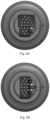
- FIGS. 1 A and 1 Bshow an aperture array from a perspective and front-on view respectively
- FIGS. 2 A, 2 B, and 2 Cshow the aperture array in various configurations as used during testing
- FIG. 3shows an experimental setup used for testing the aperture array
- FIG. 4shows plots of intensity (upper) and contrast (lower) against frame number for the one, two, and four aperture configurations
- FIGS. 5 A, 5 B, and 5 Cshow respective sample frames for each of the one, two, and four aperture configurations
- FIG. 6 Ashows a schematic setup of an aperture array, provided on a plate, and FIG. 6 B shows how light passes through the system;
- FIG. 7 Ashows a schematic setup of a lens array and FIG. 7 B shows how light passes through the system
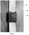
- FIG. 8shows a wearable device including an aperture array
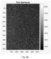
- FIG. 9shows a raw speckle image as acquired by the optical receiver through the aperture array
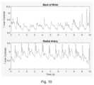
- FIG. 10shows plots of 1 over contrast against time where the optical receiver is located on the back of a person's wrist (upper) and over their radial artery (lower);
- FIG. 11 A- 11 Cshow CAD images for a wearable from a sensor top side, sensor bottom side, and sensor top side (angle) respectively;
- FIG. 12shows an alternative arrangement for a wearable including an optical receiver and aperture array
- FIG. 13shows a plot of 1/contrast (upper) and ⁇ log(intensity) (lower) against time for data collected from the arrangement in FIG. 12 .
- FIGS. 1 A and 1 Bshow an aperture array 100 from a perspective and front-on view respectively.
- the aperture array in this exampleincludes a plurality of apertures 102 .
- the aperturesare located on a flange or protrusion 104 spaced from a base 106 via a neck 108 .
- the apertureshave an outer diameter of 1 mm.
- the flange or protrusionhas a diameter of around 15 mm.
- the aperturesare arranged in an array, in this example being formed of 23 apertures. Apertures within a row are spaced by 2 mm (centre to centre).
- An input aperture 110is provided, offset both vertically and horizontally from the aperture array, and through which a sample is illuminated.
- FIGS. 2 A, 2 B, and 2 Cshow the aperture array in various configurations as used during testing.
- the first configurationshown in FIG. 2 A and referred to as the ‘one aperture’ configuration
- all apertures bar oneare blocked off so that light can only pass through the single aperture.
- the second configurationshow in FIG. 2 B and referred to as the ‘two aperture’ configuration
- all apertures bar twoare blocked off.
- the two unblocked aperturesare symmetrically disposed in the array with respect to a line passing horizontally through the aperture array.
- FIG. 2 B and referred to as the ‘four aperture’ configurationall apertures bar four are blocked off.
- the four unblocked aperturesare symmetrically disposed in the array with respect to a line passing horizontally through the aperture array.
- FIG. 3shows an experimental setup used for testing the aperture array in each of the three configurations.
- a Keysight power supplywas used to drive a Q-Photonics DFB laser with an operating wavelength 1300 nm and operating power of 10 mW. Data was acquired through a National Instruments DAQ.
- the optical receiverwas an WiDy SEnS 640V-STEP gated mode camera, and the aperture array was connected to it such that light from the laser passed through a gelatine phantom and back through the aperture array to the camera.
- the camera's pixelshad an active area of around 15 ⁇ m, and the apertures in the aperture array had a diameter of 1 mm.
- the camera sensorwas positioned 2.5 cm from the gelatine phantom, and as discussed the operating wavelength of the laser was 1300 nm.
- the specklestherefore had a size which was approximately twice the active area of the pixels.
- a 7 ⁇ 7 sliding windowwas used to calculate speckle contrast (using the MATLAB function colfilt).
- the contrast, Kwas calculated as
- Kstd ⁇ of ⁇ window mean ⁇ of ⁇ window .
- the average speckle contrastwas determined from the whole frame, and the average intensity was calculated by averaging the pixel intensities from the whole frame.
- the camera modewas set to linear with gain set as high.
- a 20 ms exposure timewas used for the one aperture configuration.
- a 10 ms exposure timewas used for the two aperture configuration.
- a 5 ms exposure timewas used for the four aperture configuration.
- the datawas acquired as a 16-bit TIFF image via Snapshot.
- FIG. 4shows plots of intensity (upper) and contrast (lower) against frame number for the one, two, and four aperture configurations (shown in a first curve 401 , a second curve 402 , and a third curve 403 , respectively, in each of the two plots) as processed through the experimental setup discussed above.
- the average intensityis similar for the different configurations with different exposure times, and increasing the number of apertures does not result in a reduction of contrast. Therefore, it can be understood that the aperture provides more light to the optical receiver and can also reduce the distance needed from the sample (e.g. skin) to the detector.
- FIGS. 5 A, 5 B, and 5 Cshow respective sample frames for each of the one, two, and four aperture configurations.
- CSDis the coefficient of Speckle Dynamics, and is calculated using the equation
- FIG. 6 Ashows a schematic setup of an optical transceiver using an optical speckle receiver with aperture array
- FIG. 6 Bshows how light passes through the system.
- Coherent light with a wavelength of around 820 nmilluminates the tissue.
- the lighttraverses an ensemble of paths, creating speckle at the output of the tissue surface.
- An aperture platecomprised of 150 micron diameter holes collects light from different regions of the tissue.
- the aperture arrayhere is provided as a plurality of holes (which are voids (e.g. unfilled), or holes filled with a light-transmitting material) in a material, but could also be provided as an array of fibres (e.g. an array of fibre optic cables).
- the image sensormay be placed in close proximity to tissue, for example only 1.1 mm from the aperture plate.
- FIG. 7 Ashows a schematic setup of an optical transceiver using an optical speckle receiver with lens array and FIG. 7 B shows how light passes through the system.
- a microlens arraycollects light from different regions of the tissue.
- the microlens arraymay be comprised of individual lenses (i.e. physically discrete) or be a monolithic block.
- the material surrounding the lensesmay be clear or opaque to reduce background light.
- Each microlenshas a diameter of 150 microns and a focal length of 0.32 mm.
- the substrate thicknessis such that the distance to the tissue surface is effectively 0.5 mm. From the lens equation, the image is formed at 0.9 mm with magnification of 1.8.
- the calculated speckle sizeis 6.1 microns, which is sufficiently large for a sensor with 3 micron pixels.
- FIG. 8shows a wearable device 800 including an aperture array 802 .
- the aperture arrayis mounted on the rear of the wearable device, which in this example is a wristband including the main device housing and a wrist strap.
- the aperture arraywill be pressed against the skin of the user with a gap between the coherent light source 804 and the skin of the user. That is, the aperture array 802 projects further from the wearable, in a direction towards the skin of the user, than the coherent light source 804 .
- FIG. 9shows a raw speckle image as acquired by the optical receiver through the aperture array.
- FIG. 10shows plots of 1 over contrast against time where the optical receiver is located on the back of a person's wrist (upper) and over their radial artery (lower). The data for the plots was arrived at after processing the raw speckle image. As can be seen, pulsating components are visible which indicates the speckle image is suitable to derive the heart rate of the user.
- FIG. 11 A- 11 Cshow CAD images for a wearable from a sensor top side, sensor bottom side, and sensor top side (angle) respectively.
- the light source and/or apertures for the sensormay be designed to protrude so that they make better contact with the skin. Improved contact may enhance the speckle measurements by reducing specular reflectance.
- FIG. 12shows an alternative arrangement for a wearable including an optical receiver and aperture array.
- This arrangementis referred to as a transmission arrangement or transmission mode (as opposed to the arrangement shown in FIGS. 6 A and 6 B which are reflection arrangements or reflection modes).
- the wearablemay be a ring or similar such that it at least partially encloses a portion of the user.
- the coherent light sourceis located across a testing region from the aperture array and detector. Tissue of interest, for example a patient's finger, is positioned in the testing region and so the coherent light passes through it to the multi-aperture array and on to the detector.
- the transmission arrangementis provided as a finger-clip type device where two generally planar elements are hingedly connected at one end to allow them to move towards and away from each other.
- the patientintroduces their finger between the planar elements and spectrophotonic sampling is performed.
- FIG. 13shows a plot of 1/contrast (upper) and ⁇ log(intensity) (lower) against time for data collected from the arrangement in FIG. 12 . Again, as can be seen, pulsating components are visible which indicates the speckle image is suitable to derive the heart rate of the user.
- increasing the number of holes or apertures in the aperture arraymay provide increased power as compared to the use of a single mode fiber.
- the aperture array disclosed hereinmay be more robust to dirt and hair. Additionally, the multi-aperture approach adopted in the aperture array can require less precise alignment between any given aperture and the optical receiver.
Landscapes
- Physics & Mathematics (AREA)
- Life Sciences & Earth Sciences (AREA)
- Health & Medical Sciences (AREA)
- General Physics & Mathematics (AREA)
- Engineering & Computer Science (AREA)
- Optics & Photonics (AREA)
- Pathology (AREA)
- Biophysics (AREA)
- Computer Networks & Wireless Communication (AREA)
- Biomedical Technology (AREA)
- Heart & Thoracic Surgery (AREA)
- Medical Informatics (AREA)
- Molecular Biology (AREA)
- Surgery (AREA)
- Animal Behavior & Ethology (AREA)
- General Health & Medical Sciences (AREA)
- Public Health (AREA)
- Veterinary Medicine (AREA)
- Investigating Or Analysing Materials By Optical Means (AREA)
Abstract
Description
((1300×10−9m)·(2.5×10⁻²m))/(1×10−3m)=32.5 μm
The average speckle contrast was determined from the whole frame, and the average intensity was calculated by averaging the pixel intensities from the whole frame.
| TABLE 1 | |||||
| Mean | Spatial SC | Temporal SC | |||
| Sample | Apertures | Intensity | (KS) | (Kt) | |
| Gelatine |
| 1 | 3201 | 0.2569 | 0.0732 | 0.4433 | |
| 4 | 3230 | 0.2429 | 0.0561 | 0.3755 | |
| 1 | 2002 | 0.1421 | 0.1477 | 1.0194 | |
| 4 | 3167 | 0.1916 | 0.2004 | 1.0225 | |
Claims (20)
Priority Applications (6)
| Application Number | Priority Date | Filing Date | Title |
|---|---|---|---|
| US17/703,920US12109006B2 (en) | 2021-09-10 | 2022-03-24 | Optical speckle receiver |
| US17/822,419US12201396B2 (en) | 2021-09-10 | 2022-08-25 | Optical speckle receiver |
| PCT/EP2022/074876WO2023036827A1 (en) | 2021-09-10 | 2022-09-07 | Optical speckle receiver |
| CN202280061110.1ACN117915830A (en) | 2021-09-10 | 2022-09-07 | Optical speckle receiver |
| EP22776935.3AEP4398791A1 (en) | 2021-09-10 | 2022-09-07 | Optical speckle receiver |
| US18/983,330US20250169696A1 (en) | 2021-09-10 | 2024-12-16 | Optical speckle receiver |
Applications Claiming Priority (2)
| Application Number | Priority Date | Filing Date | Title |
|---|---|---|---|
| US202163243021P | 2021-09-10 | 2021-09-10 | |
| US17/703,920US12109006B2 (en) | 2021-09-10 | 2022-03-24 | Optical speckle receiver |
Related Child Applications (1)
| Application Number | Title | Priority Date | Filing Date |
|---|---|---|---|
| US17/822,419ContinuationUS12201396B2 (en) | 2021-09-10 | 2022-08-25 | Optical speckle receiver |
Publications (2)
| Publication Number | Publication Date |
|---|---|
| US20230085179A1 US20230085179A1 (en) | 2023-03-16 |
| US12109006B2true US12109006B2 (en) | 2024-10-08 |
Family
ID=85478828
Family Applications (1)
| Application Number | Title | Priority Date | Filing Date |
|---|---|---|---|
| US17/703,920Active2042-12-30US12109006B2 (en) | 2021-09-10 | 2022-03-24 | Optical speckle receiver |
Country Status (1)
| Country | Link |
|---|---|
| US (1) | US12109006B2 (en) |
Cited By (1)
| Publication number | Priority date | Publication date | Assignee | Title |
|---|---|---|---|---|
| US12396648B1 (en) | 2024-11-27 | 2025-08-26 | Rockley Photonics Limited | Wearable device with light source and optical sensor |
Families Citing this family (1)
| Publication number | Priority date | Publication date | Assignee | Title |
|---|---|---|---|---|
| US12201396B2 (en) | 2021-09-10 | 2025-01-21 | Rockley Photonics Limited | Optical speckle receiver |
Citations (62)
| Publication number | Priority date | Publication date | Assignee | Title |
|---|---|---|---|---|
| US4674011A (en) | 1986-09-10 | 1987-06-16 | The United States Of America As Represented By The Secretary Of The Air Force | Alignment reference device |
| US5497769A (en) | 1993-12-16 | 1996-03-12 | I.S.S. (Usa) Inc. | Photosensor with multiple light sources |
| US5532860A (en)* | 1995-03-20 | 1996-07-02 | General Electric Company | Spatial synchronization for optical communication system |
| US6154259A (en) | 1996-11-27 | 2000-11-28 | Photera Technologies, Inc. | Multi-beam laser scanning display system with speckle elimination |
| US6243601B1 (en) | 1998-09-18 | 2001-06-05 | Abund Ottokar Wist | Transillumination imaging instrumentation with scattered light discrimination |
| US6256016B1 (en) | 1997-06-05 | 2001-07-03 | Logitech, Inc. | Optical detection system, device, and method utilizing optical matching |
| US20020195496A1 (en) | 1999-06-07 | 2002-12-26 | Metrologic Instruments, Inc. | Planar LED-based illumination array (PLIA) chips |
| US20030052169A1 (en) | 1999-06-07 | 2003-03-20 | Metrologic Instruments, Inc. | Planar laser illumination and imaging (PLIIM) based camera system for producing high-resolution 3-D images of moving 3-D objects |
| US20030137669A1 (en) | 2001-08-03 | 2003-07-24 | Rollins Andrew M. | Aspects of basic OCT engine technologies for high speed optical coherence tomography and light source and other improvements in optical coherence tomography |
| US20060132790A1 (en) | 2003-02-20 | 2006-06-22 | Applied Science Innovations, Inc. | Optical coherence tomography with 3d coherence scanning |
| US20070051601A1 (en) | 2004-10-20 | 2007-03-08 | Hu-Sen Wang | Closeable electronics device |
| US20070057182A1 (en) | 2003-04-28 | 2007-03-15 | Hans-Peter Feuerbaum | Apparatus and method for inspecting a sample of a specimen by means of an electron beam |
| US7202466B2 (en)* | 2003-08-25 | 2007-04-10 | Cadent Ltd. | Apparatus and method for providing high intensity non-coherent light and for speckle reduction |
| US20070093702A1 (en) | 2005-10-26 | 2007-04-26 | Skyline Biomedical, Inc. | Apparatus and method for non-invasive and minimally-invasive sensing of parameters relating to blood |
| US20080154126A1 (en) | 2006-12-22 | 2008-06-26 | Washington University | High Performance Imaging System for Diffuse Optical Tomography and Associated Method of Use |
| US20090177094A1 (en) | 2008-01-08 | 2009-07-09 | Oncoscope, Inc. | Systems and methods for tissue examination, diagnostic, treatment, and/or monitoring |
| US20090284748A1 (en) | 2007-02-13 | 2009-11-19 | Paul Melman | Speckle Noise Reduction in Coherent Imaging Systems |
| US20100004741A1 (en) | 2008-07-03 | 2010-01-07 | Ocular Optics, Inc. | Sensor for detecting accommodative trigger |
| US20100046234A1 (en) | 2008-01-16 | 2010-02-25 | Abu-Ageel Nayef M | Illumination Systems Utilizing Wavelength Conversion Materials |
| US20100226646A1 (en) | 2009-03-04 | 2010-09-09 | The Boeing Company | Fiber cable distortion detection system and method |
| US20120232402A1 (en) | 2011-03-02 | 2012-09-13 | Macfarlane Duncan | Functional Near Infrared Spectroscopy Imaging System and Method |
| US20130204112A1 (en) | 2012-02-07 | 2013-08-08 | Laser Associated Sciences, LLC | Perfusion assessment using transmission laser speckle imaging |
| US20130278631A1 (en) | 2010-02-28 | 2013-10-24 | Osterhout Group, Inc. | 3d positioning of augmented reality information |
| US20140118695A1 (en) | 2012-10-30 | 2014-05-01 | Canon Kabushiki Kaisha | Ophthalmologic apparatus |
| US20140120319A1 (en) | 2012-11-01 | 2014-05-01 | Benjamin E. Joseph | 3d mapping using structured light and formation of custom surface contours |
| US20140313524A1 (en)* | 2011-09-08 | 2014-10-23 | Sirona Dental Systems Gmbh | Method and Device for Three-Dimensional Confocal Measurement |
| US20160183882A1 (en)* | 2013-03-15 | 2016-06-30 | DePuy Synthes Products, Inc. | System and method for removing speckle from a scene lit by a coherent light source |
| US20160195473A1 (en) | 2015-01-06 | 2016-07-07 | Masayuki Fujiwara | Optical sensor, optical inspection device, and optical property detection method |
| US20160242647A1 (en) | 2013-09-30 | 2016-08-25 | Ricoh Company, Ltd. | Optical sensor, optical testing device, and optical characteristic detection method |
| US20160360966A1 (en) | 2015-06-15 | 2016-12-15 | Ricoh Company, Ltd. | Optical examination method and optical examination device |
| US20170105618A1 (en) | 2014-06-10 | 2017-04-20 | Carl Zeiss Meditec, Inc. | Improved frequency-domain interferometric based imaging systems and methods |
| US20170164878A1 (en) | 2012-06-14 | 2017-06-15 | Medibotics Llc | Wearable Technology for Non-Invasive Glucose Monitoring |
| US9851298B1 (en) | 2015-09-25 | 2017-12-26 | Apple Inc. | Light-based shielding detection |
| US20180020962A1 (en) | 2016-07-21 | 2018-01-25 | University Of Kentucky Research Foundation | Compact low-cost fiberless diffuse speckle contrast flow-oximeter |
| US20180228363A1 (en) | 2015-05-28 | 2018-08-16 | Cylite Pty Ltd | High resolution 3-d spectral domain optical imaging apparatus and method |
| US20190041736A1 (en) | 2018-06-29 | 2019-02-07 | Intel Corporation | Led pattern projector for 3d camera platforms |
| US20190053721A1 (en) | 2016-02-24 | 2019-02-21 | The General Hospital Corporation | Systems and methods for path length selected diffuse correlation spectroscopy |
| US20190094564A1 (en) | 2015-11-24 | 2019-03-28 | The Board Of Trustees Of The University Of Illinois | Low-speckle light source and imaging devices with micro-refractive element stabilized laser array |
| US20190369650A1 (en) | 2018-01-11 | 2019-12-05 | Eric Swanson | Imaging Optical Probe |
| US20200011995A1 (en) | 2017-03-16 | 2020-01-09 | Trinamix Gmbh | Detector for optically detecting at least one object |
| US20200143534A1 (en) | 2017-06-29 | 2020-05-07 | Sony Corporation | Medical imaging system, method and computer program product |
| US20200158548A1 (en) | 2016-04-20 | 2020-05-21 | Laser Associated Sciences, Inc. | Systems and methods for calibrating and correcting a speckle contrast flowmeter |
| US20200237272A1 (en) | 2019-01-25 | 2020-07-30 | The General Hospital Corporation | Systems, methods, and apparatus for differential phase contrast microscopy by transobjective differential epi-detection of forward scattered light |
| US20200249492A1 (en) | 2017-02-03 | 2020-08-06 | Barco N.V. | System and method for enhanced image projection |
| US10813597B2 (en) | 2017-04-14 | 2020-10-27 | The Regents Of The University Of California | Non-invasive hemodynamic assessment via interrogation of biological tissue using a coherent light source |
| CA2861089C (en)* | 2011-11-02 | 2021-01-12 | Seno Medical Instruments, Inc. | Dual modality imaging system for coregistered functional and anatomical mapping |
| US10895525B2 (en) | 2013-06-23 | 2021-01-19 | Eric Swanson | Optical measurement system using multicore optical fiber |
| CN112639582A (en)* | 2018-09-05 | 2021-04-09 | 赛莱特私人有限公司 | Hyperspectral apparatus and method |
| US20210161408A1 (en) | 2018-04-24 | 2021-06-03 | Sony Corporation | Scattered light signal measuring apparatus and information processing apparatus |
| US20210321887A1 (en) | 2018-08-28 | 2021-10-21 | Sony Corporation | Medical system, information processing apparatus, and information processing method |
| US20210338083A1 (en)* | 2020-04-30 | 2021-11-04 | Facebook Technologies, Llc | Multi-speckle diffuse correlation spectroscopy and imaging |
| US20210405518A1 (en) | 2008-05-19 | 2021-12-30 | Peter Lablans | Camera system with a plurality of image sensors |
| US20220018762A1 (en) | 2020-07-17 | 2022-01-20 | The Board of Regents for the Oklahoma Agricultural and Mechanical Colleges | System and method of non-contact glucose sensing |
| US20220061644A1 (en) | 2020-08-27 | 2022-03-03 | Nokia Technologies Oy | Holographic endoscope |
| US20220104822A1 (en) | 2020-10-02 | 2022-04-07 | Ethicon Llc | Method for operating tiered operation modes in a surgical system |
| CN114466549A (en)* | 2022-03-15 | 2022-05-10 | Oppo广东移动通信有限公司 | Cover plate and preparation method thereof, shell and electronic equipment |
| US20220196557A1 (en)* | 2019-04-05 | 2022-06-23 | Cytoveris Inc. | Angular depth resolved raman spectroscopy apparatus and method |
| US20230048766A1 (en) | 2020-01-16 | 2023-02-16 | Commissariat A L'energie Atomique Et Aux Energies Alternatives | Coherent lidar imaging system |
| US20230064006A1 (en) | 2020-02-06 | 2023-03-02 | Lg Innotek Co., Ltd. | Camera device |
| US20230164444A1 (en) | 2020-11-13 | 2023-05-25 | Honor Device Co., Ltd. | Electronic Device and In-Screen Optical Detection Assembly |
| US20230296510A1 (en) | 2022-03-16 | 2023-09-21 | Meta Platforms Technologies, Llc | System and method for separating volumetric and surface scattering of optical component |
| US20240032790A1 (en) | 2021-03-22 | 2024-02-01 | The Medical College Of Wisconsin, Inc. | Laser-Speckle Contrast Imaging System and Method |
- 2022
- 2022-03-24USUS17/703,920patent/US12109006B2/enactiveActive
Patent Citations (65)
| Publication number | Priority date | Publication date | Assignee | Title |
|---|---|---|---|---|
| US4674011A (en) | 1986-09-10 | 1987-06-16 | The United States Of America As Represented By The Secretary Of The Air Force | Alignment reference device |
| US5497769A (en) | 1993-12-16 | 1996-03-12 | I.S.S. (Usa) Inc. | Photosensor with multiple light sources |
| US5532860A (en)* | 1995-03-20 | 1996-07-02 | General Electric Company | Spatial synchronization for optical communication system |
| US6154259A (en) | 1996-11-27 | 2000-11-28 | Photera Technologies, Inc. | Multi-beam laser scanning display system with speckle elimination |
| US6256016B1 (en) | 1997-06-05 | 2001-07-03 | Logitech, Inc. | Optical detection system, device, and method utilizing optical matching |
| US6243601B1 (en) | 1998-09-18 | 2001-06-05 | Abund Ottokar Wist | Transillumination imaging instrumentation with scattered light discrimination |
| US20020195496A1 (en) | 1999-06-07 | 2002-12-26 | Metrologic Instruments, Inc. | Planar LED-based illumination array (PLIA) chips |
| US20030052169A1 (en) | 1999-06-07 | 2003-03-20 | Metrologic Instruments, Inc. | Planar laser illumination and imaging (PLIIM) based camera system for producing high-resolution 3-D images of moving 3-D objects |
| US20030137669A1 (en) | 2001-08-03 | 2003-07-24 | Rollins Andrew M. | Aspects of basic OCT engine technologies for high speed optical coherence tomography and light source and other improvements in optical coherence tomography |
| US20060132790A1 (en) | 2003-02-20 | 2006-06-22 | Applied Science Innovations, Inc. | Optical coherence tomography with 3d coherence scanning |
| US7474407B2 (en) | 2003-02-20 | 2009-01-06 | Applied Science Innovations | Optical coherence tomography with 3d coherence scanning |
| US20070057182A1 (en) | 2003-04-28 | 2007-03-15 | Hans-Peter Feuerbaum | Apparatus and method for inspecting a sample of a specimen by means of an electron beam |
| US7202466B2 (en)* | 2003-08-25 | 2007-04-10 | Cadent Ltd. | Apparatus and method for providing high intensity non-coherent light and for speckle reduction |
| US20070051601A1 (en) | 2004-10-20 | 2007-03-08 | Hu-Sen Wang | Closeable electronics device |
| US20070093702A1 (en) | 2005-10-26 | 2007-04-26 | Skyline Biomedical, Inc. | Apparatus and method for non-invasive and minimally-invasive sensing of parameters relating to blood |
| US20080154126A1 (en) | 2006-12-22 | 2008-06-26 | Washington University | High Performance Imaging System for Diffuse Optical Tomography and Associated Method of Use |
| US20090284748A1 (en) | 2007-02-13 | 2009-11-19 | Paul Melman | Speckle Noise Reduction in Coherent Imaging Systems |
| US20090177094A1 (en) | 2008-01-08 | 2009-07-09 | Oncoscope, Inc. | Systems and methods for tissue examination, diagnostic, treatment, and/or monitoring |
| US20100046234A1 (en) | 2008-01-16 | 2010-02-25 | Abu-Ageel Nayef M | Illumination Systems Utilizing Wavelength Conversion Materials |
| US20210405518A1 (en) | 2008-05-19 | 2021-12-30 | Peter Lablans | Camera system with a plurality of image sensors |
| US20100004741A1 (en) | 2008-07-03 | 2010-01-07 | Ocular Optics, Inc. | Sensor for detecting accommodative trigger |
| US20100226646A1 (en) | 2009-03-04 | 2010-09-09 | The Boeing Company | Fiber cable distortion detection system and method |
| US20130278631A1 (en) | 2010-02-28 | 2013-10-24 | Osterhout Group, Inc. | 3d positioning of augmented reality information |
| US20120232402A1 (en) | 2011-03-02 | 2012-09-13 | Macfarlane Duncan | Functional Near Infrared Spectroscopy Imaging System and Method |
| US20140313524A1 (en)* | 2011-09-08 | 2014-10-23 | Sirona Dental Systems Gmbh | Method and Device for Three-Dimensional Confocal Measurement |
| CA2861089C (en)* | 2011-11-02 | 2021-01-12 | Seno Medical Instruments, Inc. | Dual modality imaging system for coregistered functional and anatomical mapping |
| US20130204112A1 (en) | 2012-02-07 | 2013-08-08 | Laser Associated Sciences, LLC | Perfusion assessment using transmission laser speckle imaging |
| US9848787B2 (en) | 2012-02-07 | 2017-12-26 | Laser Associated Sciences, Inc. | Perfusion assessment using transmission laser speckle imaging |
| US20170164878A1 (en) | 2012-06-14 | 2017-06-15 | Medibotics Llc | Wearable Technology for Non-Invasive Glucose Monitoring |
| US20140118695A1 (en) | 2012-10-30 | 2014-05-01 | Canon Kabushiki Kaisha | Ophthalmologic apparatus |
| US20140120319A1 (en) | 2012-11-01 | 2014-05-01 | Benjamin E. Joseph | 3d mapping using structured light and formation of custom surface contours |
| US20160183882A1 (en)* | 2013-03-15 | 2016-06-30 | DePuy Synthes Products, Inc. | System and method for removing speckle from a scene lit by a coherent light source |
| US10895525B2 (en) | 2013-06-23 | 2021-01-19 | Eric Swanson | Optical measurement system using multicore optical fiber |
| US20160242647A1 (en) | 2013-09-30 | 2016-08-25 | Ricoh Company, Ltd. | Optical sensor, optical testing device, and optical characteristic detection method |
| US20170105618A1 (en) | 2014-06-10 | 2017-04-20 | Carl Zeiss Meditec, Inc. | Improved frequency-domain interferometric based imaging systems and methods |
| US20160195473A1 (en) | 2015-01-06 | 2016-07-07 | Masayuki Fujiwara | Optical sensor, optical inspection device, and optical property detection method |
| US20180228363A1 (en) | 2015-05-28 | 2018-08-16 | Cylite Pty Ltd | High resolution 3-d spectral domain optical imaging apparatus and method |
| US20160360966A1 (en) | 2015-06-15 | 2016-12-15 | Ricoh Company, Ltd. | Optical examination method and optical examination device |
| US9851298B1 (en) | 2015-09-25 | 2017-12-26 | Apple Inc. | Light-based shielding detection |
| US20180202927A1 (en) | 2015-09-25 | 2018-07-19 | Apple Inc. | Light-based shielding detection |
| US20190094564A1 (en) | 2015-11-24 | 2019-03-28 | The Board Of Trustees Of The University Of Illinois | Low-speckle light source and imaging devices with micro-refractive element stabilized laser array |
| US20190053721A1 (en) | 2016-02-24 | 2019-02-21 | The General Hospital Corporation | Systems and methods for path length selected diffuse correlation spectroscopy |
| US20200158548A1 (en) | 2016-04-20 | 2020-05-21 | Laser Associated Sciences, Inc. | Systems and methods for calibrating and correcting a speckle contrast flowmeter |
| US20180020962A1 (en) | 2016-07-21 | 2018-01-25 | University Of Kentucky Research Foundation | Compact low-cost fiberless diffuse speckle contrast flow-oximeter |
| US20200249492A1 (en) | 2017-02-03 | 2020-08-06 | Barco N.V. | System and method for enhanced image projection |
| US20200011995A1 (en) | 2017-03-16 | 2020-01-09 | Trinamix Gmbh | Detector for optically detecting at least one object |
| US10813597B2 (en) | 2017-04-14 | 2020-10-27 | The Regents Of The University Of California | Non-invasive hemodynamic assessment via interrogation of biological tissue using a coherent light source |
| US20200143534A1 (en) | 2017-06-29 | 2020-05-07 | Sony Corporation | Medical imaging system, method and computer program product |
| US20190369650A1 (en) | 2018-01-11 | 2019-12-05 | Eric Swanson | Imaging Optical Probe |
| US20210161408A1 (en) | 2018-04-24 | 2021-06-03 | Sony Corporation | Scattered light signal measuring apparatus and information processing apparatus |
| US20190041736A1 (en) | 2018-06-29 | 2019-02-07 | Intel Corporation | Led pattern projector for 3d camera platforms |
| US20210321887A1 (en) | 2018-08-28 | 2021-10-21 | Sony Corporation | Medical system, information processing apparatus, and information processing method |
| CN112639582A (en)* | 2018-09-05 | 2021-04-09 | 赛莱特私人有限公司 | Hyperspectral apparatus and method |
| US20200237272A1 (en) | 2019-01-25 | 2020-07-30 | The General Hospital Corporation | Systems, methods, and apparatus for differential phase contrast microscopy by transobjective differential epi-detection of forward scattered light |
| US20220196557A1 (en)* | 2019-04-05 | 2022-06-23 | Cytoveris Inc. | Angular depth resolved raman spectroscopy apparatus and method |
| US20230048766A1 (en) | 2020-01-16 | 2023-02-16 | Commissariat A L'energie Atomique Et Aux Energies Alternatives | Coherent lidar imaging system |
| US20230064006A1 (en) | 2020-02-06 | 2023-03-02 | Lg Innotek Co., Ltd. | Camera device |
| US20210338083A1 (en)* | 2020-04-30 | 2021-11-04 | Facebook Technologies, Llc | Multi-speckle diffuse correlation spectroscopy and imaging |
| US20220018762A1 (en) | 2020-07-17 | 2022-01-20 | The Board of Regents for the Oklahoma Agricultural and Mechanical Colleges | System and method of non-contact glucose sensing |
| US20220061644A1 (en) | 2020-08-27 | 2022-03-03 | Nokia Technologies Oy | Holographic endoscope |
| US20220104822A1 (en) | 2020-10-02 | 2022-04-07 | Ethicon Llc | Method for operating tiered operation modes in a surgical system |
| US20230164444A1 (en) | 2020-11-13 | 2023-05-25 | Honor Device Co., Ltd. | Electronic Device and In-Screen Optical Detection Assembly |
| US20240032790A1 (en) | 2021-03-22 | 2024-02-01 | The Medical College Of Wisconsin, Inc. | Laser-Speckle Contrast Imaging System and Method |
| CN114466549A (en)* | 2022-03-15 | 2022-05-10 | Oppo广东移动通信有限公司 | Cover plate and preparation method thereof, shell and electronic equipment |
| US20230296510A1 (en) | 2022-03-16 | 2023-09-21 | Meta Platforms Technologies, Llc | System and method for separating volumetric and surface scattering of optical component |
Non-Patent Citations (16)
| Title |
|---|
| Bi, R. et al., "Fast pulsatile blood flow measurement in deep tissue through a multimode detection fiber", Journal of Biomedical Optics, May 13, 2020, pp. 055003-1 through 055003-10, vol. 25(5), SPIE. |
| Goodman, J. W., "Some fundamental properties of speckle", Journal of the Optical Society of America, Nov. 1976, pp. 1145-1150, vol. 66, No. 11, Optical Society of America. |
| International Search Report and Written Opinion of the International Searching Authority, mailed Jan. 2, 2023, corresponding to PCT/EP2022/074876, 13 pages. |
| Robinson, M. B. et al., "Interferometric diffuse correlation spectroscopy improves measurements at long source-detector separation and low photon count rate", Journal of Biomedical Optics, Sep. 30, 2020, pp. 097004-1 through 097004-12, vol. 25(9), SPIE. |
| Sdobnov, A. Y. et al. "Speckle dynamics under ergodicity breaking", Journal of Physics D: Applied Physics, Mar. 26, 2018, pp. 1-21, vol. 51, No. 15, IOP Publishing Ltd. |
| U.S. Advisory Action for U.S. Appl. No. 17/822,419, dated May 2, 2024, 5 pages. |
| U.S. Advisory Action for U.S. Appl. No. 17/822,419, dated Oct. 10, 2023, 6 pages. |
| U.S. Appl. No. 17/822,419, filed Aug. 25, 2022. |
| U.S. Office Action for U.S. Appl. No. 17/822,419, dated Feb. 20, 2024, 12 pages. |
| U.S. Office Action for U.S. Appl. No. 17/822,419, dated Nov. 3, 2023, 18 pages. |
| U.S. Office Action from U.S. Appl. No. 17/822,419, dated Jul. 20, 2023, 21 pages. |
| U.S. Office Action from U.S. Appl. No. 17/822,419, dated Mar. 10, 2023, 17 pages. |
| Website: "0.07mm Dia., TO-46 Package, InGaAs Photodiode", 2022, printed Dec. 7, 2022, 1 page, Edmund Optics Inc., https://www.edmundoptics.com/p/ingaas-detector-70mum-dia-to-46/12571/. |
| Website: "FlowMet Peripheral Blood Flow Monitoring System", updated Oct. 2022, printed Dec. 7, 2022, 7 pages, https://www.medtronic.com/us-en/healthcare-professionals/products/cardiovascular/intraprocedural-monitoring/flowmet.html. |
| Xu, J. et al., "Interferometric speckle visibility spectroscopy (ISVS) for human cerebral blood flow monitoring", APL Photonics, Dec. 4, 2020, pp. 126102-1 through 126102-10, vol. 5. AIP Publishing. |
| Zalevsky, Z. et al., "Novel Approaches for Near and Far Field Super Resolved Imaging", 22nd Congress of the International Commision for Optics: Light for the Development of the World, Proc. of SPIE, Sep. 15, 2011, pp. 80116M-1 through 80116M-11, vol. 8011, No. 1, SPIE. |
Cited By (1)
| Publication number | Priority date | Publication date | Assignee | Title |
|---|---|---|---|---|
| US12396648B1 (en) | 2024-11-27 | 2025-08-26 | Rockley Photonics Limited | Wearable device with light source and optical sensor |
Also Published As
| Publication number | Publication date |
|---|---|
| US20230085179A1 (en) | 2023-03-16 |
Similar Documents
| Publication | Publication Date | Title |
|---|---|---|
| US12201396B2 (en) | Optical speckle receiver | |
| EP1051106B1 (en) | Method and device for tissue modulation | |
| US12109006B2 (en) | Optical speckle receiver | |
| US6571117B1 (en) | Capillary sweet spot imaging for improving the tracking accuracy and SNR of noninvasive blood analysis methods | |
| US7809418B2 (en) | Optical device components | |
| US20090116017A1 (en) | Optical device components | |
| US9545223B2 (en) | Functional near infrared spectroscopy imaging system and method | |
| US7961304B2 (en) | Optical device components | |
| EP1221035B1 (en) | System and method for tomographic imaging of dynamic properties of a scattering medium | |
| US20230225643A1 (en) | Architecture of a photonic integrated circuit (pic) and method for operating the same as well as an optical coupler | |
| Zhao et al. | Extraction of tissue optical property and blood flow from speckle contrast diffuse correlation tomography (scDCT) measurements | |
| JP7601101B2 (en) | Biometric sensor and method for determining biological condition | |
| CN117915830A (en) | Optical speckle receiver | |
| KR102697425B1 (en) | Spectrometer and apparatus for measuring substance in body | |
| KR20220133129A (en) | Scattering Camera | |
| NL2034027B1 (en) | Multi-frequency speckle sensing | |
| RU2839510C1 (en) | Optical sensor of short-wave infrared spectrum for biomedical applications | |
| Langri | Monitoring Cerebral Functional Response using sCMOS-based High Density Near Infrared Spectroscopic Imaging | |
| CN116648645A (en) | Optical Sensing Module |
Legal Events
| Date | Code | Title | Description |
|---|---|---|---|
| FEPP | Fee payment procedure | Free format text:ENTITY STATUS SET TO UNDISCOUNTED (ORIGINAL EVENT CODE: BIG.); ENTITY STATUS OF PATENT OWNER: LARGE ENTITY | |
| STPP | Information on status: patent application and granting procedure in general | Free format text:DOCKETED NEW CASE - READY FOR EXAMINATION | |
| AS | Assignment | Owner name:WILMINGTON SAVINGS FUND SOCIETY, FSB, AS COLLATERAL AGENT, DELAWARE Free format text:SECURITY INTEREST;ASSIGNOR:ROCKLEY PHOTONICS LIMITED;REEL/FRAME:061435/0367 Effective date:20221014 | |
| AS | Assignment | Owner name:WILMINGTON SAVINGS FUND SOCIETY, FSB, AS COLLATERAL AGENT, DELAWARE Free format text:SECURITY INTEREST - SUPER SENIOR INDENTURE;ASSIGNOR:ROCKLEY PHOTONICS LIMITED;REEL/FRAME:061768/0082 Effective date:20221025 | |
| AS | Assignment | Owner name:ROCKLEY PHOTONICS LIMITED, UNITED KINGDOM Free format text:RELEASE OF SECURITY INTEREST - REEL/FRAME 061435/0367;ASSIGNOR:WILMINGTON SAVINGS FUND SOCIETY, FSB, AS COLLATERAL AGENT;REEL/FRAME:064036/0035 Effective date:20230314 Owner name:ROCKLEY PHOTONICS LIMITED, UNITED KINGDOM Free format text:RELEASE OF PATENT SECURITY INTEREST - SUPER SENIOR INDENTURE - REEL/FRAME 061768/0082;ASSIGNOR:WILMINGTON SAVINGS FUND SOCIETY, FSB, AS COLLATERAL AGENT;REEL/FRAME:063264/0416 Effective date:20230314 Owner name:WILMINGTON SAVINGS FUND SOCIETY, FSB, AS COLLATERAL AGENT, DELAWARE Free format text:SECURITY INTEREST;ASSIGNOR:ROCKLEY PHOTONICS LIMITED;REEL/FRAME:063287/0879 Effective date:20230314 | |
| STPP | Information on status: patent application and granting procedure in general | Free format text:NON FINAL ACTION MAILED | |
| STPP | Information on status: patent application and granting procedure in general | Free format text:RESPONSE TO NON-FINAL OFFICE ACTION ENTERED AND FORWARDED TO EXAMINER | |
| STPP | Information on status: patent application and granting procedure in general | Free format text:NOTICE OF ALLOWANCE MAILED -- APPLICATION RECEIVED IN OFFICE OF PUBLICATIONS | |
| AS | Assignment | Owner name:ROCKLEY PHOTONICS LIMITED, UNITED KINGDOM Free format text:ASSIGNMENT OF ASSIGNORS INTEREST;ASSIGNORS:DUNN, CODY;BECHTEL, KATE LEEANN;SIGNING DATES FROM 20220527 TO 20230609;REEL/FRAME:068488/0412 | |
| STPP | Information on status: patent application and granting procedure in general | Free format text:PUBLICATIONS -- ISSUE FEE PAYMENT VERIFIED | |
| STCF | Information on status: patent grant | Free format text:PATENTED CASE |