US12105517B2 - Planar-beam, light detection and ranging system - Google Patents
Planar-beam, light detection and ranging systemDownload PDFInfo
- Publication number
- US12105517B2 US12105517B2US18/170,841US202318170841AUS12105517B2US 12105517 B2US12105517 B2US 12105517B2US 202318170841 AUS202318170841 AUS 202318170841AUS 12105517 B2US12105517 B2US 12105517B2
- Authority
- US
- United States
- Prior art keywords
- laser
- photodetector
- pladar
- lidar system
- photodetectors
- Prior art date
- Legal status (The legal status is an assumption and is not a legal conclusion. Google has not performed a legal analysis and makes no representation as to the accuracy of the status listed.)
- Active
Links
- 238000001514detection methodMethods0.000titleclaimsabstractdescription14
- 230000007423decreaseEffects0.000claimsdescription16
- 230000001133accelerationEffects0.000claimsdescription7
- 239000000835fiberSubstances0.000claimsdescription5
- 238000012545processingMethods0.000description34
- 238000000034methodMethods0.000description18
- 238000010586diagramMethods0.000description7
- 238000003860storageMethods0.000description7
- 238000004891communicationMethods0.000description4
- 230000003247decreasing effectEffects0.000description4
- 238000013507mappingMethods0.000description4
- 230000008569processEffects0.000description4
- 230000008901benefitEffects0.000description3
- 230000000694effectsEffects0.000description3
- 238000005516engineering processMethods0.000description3
- 230000006870functionEffects0.000description3
- 230000003287optical effectEffects0.000description3
- 230000035945sensitivityEffects0.000description3
- 241001465754MetazoaSpecies0.000description2
- 230000001413cellular effectEffects0.000description2
- 230000004044responseEffects0.000description2
- 238000005070samplingMethods0.000description2
- 230000003595spectral effectEffects0.000description2
- 230000003068static effectEffects0.000description2
- 238000003491arrayMethods0.000description1
- 238000004364calculation methodMethods0.000description1
- 230000008859changeEffects0.000description1
- 238000004590computer programMethods0.000description1
- 238000005520cutting processMethods0.000description1
- 230000007613environmental effectEffects0.000description1
- 231100001261hazardousToxicity0.000description1
- 230000036541healthEffects0.000description1
- 230000004807localizationEffects0.000description1
- 238000004519manufacturing processMethods0.000description1
- 230000005055memory storageEffects0.000description1
- 239000002184metalSubstances0.000description1
- 238000012986modificationMethods0.000description1
- 230000004048modificationEffects0.000description1
- 239000011435rockSubstances0.000description1
- 239000004065semiconductorSubstances0.000description1
- 238000012163sequencing techniqueMethods0.000description1
- 239000007787solidSubstances0.000description1
- 238000012360testing methodMethods0.000description1
- 239000002699waste materialSubstances0.000description1
Images


Classifications
- G—PHYSICS
- G05—CONTROLLING; REGULATING
- G05D—SYSTEMS FOR CONTROLLING OR REGULATING NON-ELECTRIC VARIABLES
- G05D1/00—Control of position, course, altitude or attitude of land, water, air or space vehicles, e.g. using automatic pilots
- G05D1/02—Control of position or course in two dimensions
- G05D1/021—Control of position or course in two dimensions specially adapted to land vehicles
- G05D1/0231—Control of position or course in two dimensions specially adapted to land vehicles using optical position detecting means
- G05D1/0238—Control of position or course in two dimensions specially adapted to land vehicles using optical position detecting means using obstacle or wall sensors
- G05D1/024—Control of position or course in two dimensions specially adapted to land vehicles using optical position detecting means using obstacle or wall sensors in combination with a laser
- G—PHYSICS
- G01—MEASURING; TESTING
- G01C—MEASURING DISTANCES, LEVELS OR BEARINGS; SURVEYING; NAVIGATION; GYROSCOPIC INSTRUMENTS; PHOTOGRAMMETRY OR VIDEOGRAMMETRY
- G01C21/00—Navigation; Navigational instruments not provided for in groups G01C1/00 - G01C19/00
- G01C21/26—Navigation; Navigational instruments not provided for in groups G01C1/00 - G01C19/00 specially adapted for navigation in a road network
- G01C21/34—Route searching; Route guidance
- G—PHYSICS
- G01—MEASURING; TESTING
- G01S—RADIO DIRECTION-FINDING; RADIO NAVIGATION; DETERMINING DISTANCE OR VELOCITY BY USE OF RADIO WAVES; LOCATING OR PRESENCE-DETECTING BY USE OF THE REFLECTION OR RERADIATION OF RADIO WAVES; ANALOGOUS ARRANGEMENTS USING OTHER WAVES
- G01S17/00—Systems using the reflection or reradiation of electromagnetic waves other than radio waves, e.g. lidar systems
- G01S17/88—Lidar systems specially adapted for specific applications
- G01S17/93—Lidar systems specially adapted for specific applications for anti-collision purposes
- G01S17/931—Lidar systems specially adapted for specific applications for anti-collision purposes of land vehicles
- G—PHYSICS
- G01—MEASURING; TESTING
- G01S—RADIO DIRECTION-FINDING; RADIO NAVIGATION; DETERMINING DISTANCE OR VELOCITY BY USE OF RADIO WAVES; LOCATING OR PRESENCE-DETECTING BY USE OF THE REFLECTION OR RERADIATION OF RADIO WAVES; ANALOGOUS ARRANGEMENTS USING OTHER WAVES
- G01S7/00—Details of systems according to groups G01S13/00, G01S15/00, G01S17/00
- G01S7/48—Details of systems according to groups G01S13/00, G01S15/00, G01S17/00 of systems according to group G01S17/00
- G01S7/481—Constructional features, e.g. arrangements of optical elements
- G01S7/4814—Constructional features, e.g. arrangements of optical elements of transmitters alone
- G01S7/4815—Constructional features, e.g. arrangements of optical elements of transmitters alone using multiple transmitters
- G—PHYSICS
- G01—MEASURING; TESTING
- G01S—RADIO DIRECTION-FINDING; RADIO NAVIGATION; DETERMINING DISTANCE OR VELOCITY BY USE OF RADIO WAVES; LOCATING OR PRESENCE-DETECTING BY USE OF THE REFLECTION OR RERADIATION OF RADIO WAVES; ANALOGOUS ARRANGEMENTS USING OTHER WAVES
- G01S7/00—Details of systems according to groups G01S13/00, G01S15/00, G01S17/00
- G01S7/48—Details of systems according to groups G01S13/00, G01S15/00, G01S17/00 of systems according to group G01S17/00
- G01S7/481—Constructional features, e.g. arrangements of optical elements
- G01S7/4816—Constructional features, e.g. arrangements of optical elements of receivers alone
- G—PHYSICS
- G01—MEASURING; TESTING
- G01S—RADIO DIRECTION-FINDING; RADIO NAVIGATION; DETERMINING DISTANCE OR VELOCITY BY USE OF RADIO WAVES; LOCATING OR PRESENCE-DETECTING BY USE OF THE REFLECTION OR RERADIATION OF RADIO WAVES; ANALOGOUS ARRANGEMENTS USING OTHER WAVES
- G01S7/00—Details of systems according to groups G01S13/00, G01S15/00, G01S17/00
- G01S7/48—Details of systems according to groups G01S13/00, G01S15/00, G01S17/00 of systems according to group G01S17/00
- G01S7/481—Constructional features, e.g. arrangements of optical elements
- G01S7/4817—Constructional features, e.g. arrangements of optical elements relating to scanning
- G—PHYSICS
- G01—MEASURING; TESTING
- G01S—RADIO DIRECTION-FINDING; RADIO NAVIGATION; DETERMINING DISTANCE OR VELOCITY BY USE OF RADIO WAVES; LOCATING OR PRESENCE-DETECTING BY USE OF THE REFLECTION OR RERADIATION OF RADIO WAVES; ANALOGOUS ARRANGEMENTS USING OTHER WAVES
- G01S7/00—Details of systems according to groups G01S13/00, G01S15/00, G01S17/00
- G01S7/48—Details of systems according to groups G01S13/00, G01S15/00, G01S17/00 of systems according to group G01S17/00
- G01S7/497—Means for monitoring or calibrating
- G01S7/4972—Alignment of sensor
- G—PHYSICS
- G05—CONTROLLING; REGULATING
- G05D—SYSTEMS FOR CONTROLLING OR REGULATING NON-ELECTRIC VARIABLES
- G05D1/00—Control of position, course, altitude or attitude of land, water, air or space vehicles, e.g. using automatic pilots
- G05D1/0088—Control of position, course, altitude or attitude of land, water, air or space vehicles, e.g. using automatic pilots characterized by the autonomous decision making process, e.g. artificial intelligence, predefined behaviours
- G—PHYSICS
- G05—CONTROLLING; REGULATING
- G05D—SYSTEMS FOR CONTROLLING OR REGULATING NON-ELECTRIC VARIABLES
- G05D1/00—Control of position, course, altitude or attitude of land, water, air or space vehicles, e.g. using automatic pilots
- G05D1/02—Control of position or course in two dimensions
- G05D1/021—Control of position or course in two dimensions specially adapted to land vehicles
- G05D1/0231—Control of position or course in two dimensions specially adapted to land vehicles using optical position detecting means
- G05D1/0246—Control of position or course in two dimensions specially adapted to land vehicles using optical position detecting means using a video camera in combination with image processing means
- G05D1/0251—Control of position or course in two dimensions specially adapted to land vehicles using optical position detecting means using a video camera in combination with image processing means extracting 3D information from a plurality of images taken from different locations, e.g. stereo vision
- G—PHYSICS
- G05—CONTROLLING; REGULATING
- G05D—SYSTEMS FOR CONTROLLING OR REGULATING NON-ELECTRIC VARIABLES
- G05D1/00—Control of position, course, altitude or attitude of land, water, air or space vehicles, e.g. using automatic pilots
- G05D1/20—Control system inputs
- G05D1/22—Command input arrangements
- G05D1/221—Remote-control arrangements
- G05D1/227—Handing over between remote control and on-board control; Handing over between remote control arrangements
- G—PHYSICS
- G05—CONTROLLING; REGULATING
- G05D—SYSTEMS FOR CONTROLLING OR REGULATING NON-ELECTRIC VARIABLES
- G05D1/00—Control of position, course, altitude or attitude of land, water, air or space vehicles, e.g. using automatic pilots
- G05D1/20—Control system inputs
- G05D1/24—Arrangements for determining position or orientation
- G05D1/243—Means capturing signals occurring naturally from the environment, e.g. ambient optical, acoustic, gravitational or magnetic signals
- G05D1/2435—Extracting 3D information
- G—PHYSICS
- G05—CONTROLLING; REGULATING
- G05D—SYSTEMS FOR CONTROLLING OR REGULATING NON-ELECTRIC VARIABLES
- G05D1/00—Control of position, course, altitude or attitude of land, water, air or space vehicles, e.g. using automatic pilots
- G05D1/20—Control system inputs
- G05D1/24—Arrangements for determining position or orientation
- G05D1/247—Arrangements for determining position or orientation using signals provided by artificial sources external to the vehicle, e.g. navigation beacons
- G—PHYSICS
- G05—CONTROLLING; REGULATING
- G05D—SYSTEMS FOR CONTROLLING OR REGULATING NON-ELECTRIC VARIABLES
- G05D1/00—Control of position, course, altitude or attitude of land, water, air or space vehicles, e.g. using automatic pilots
- G05D1/80—Arrangements for reacting to or preventing system or operator failure
- G05D1/81—Handing over between on-board automatic and on-board manual control
Definitions
- Light detection, and ranging (LIDAR or LADAR) systemsutilize a number of laser beams to detect reflectance or backscatter from the laser beams to map surface features or for remote sensing.
- LIDARLight detection, and ranging
- each beamis precisely configured with a dedicated photodetector that detects the reflectance and/or backscatter from that particular beam. As the beam count increases, so do cost and space requirements for the individual lasers and photodetectors.
- FIG. 1is a diagram illustrating an example planar-beam, light detection and ranging (PLADAR) system, as described herein;
- PADARplanar-beam, light detection and ranging
- FIG. 2is a block diagram illustrating an example autonomous vehicle (AV) including a PLADAR system, as described herein;
- AVautonomous vehicle
- FIG. 3is a flow chart describing an example method of processing PLADAR data, according to one or more examples described herein;
- FIGS. 4 A and 4 Bare a flow chart describing example methods of configuring a PLADAR system, as described herein;
- FIG. 5is a block diagram illustrating an example computing system upon which examples described herein may be implemented.
- LIDAR technologyinvolves fixed-beam LIDAR systems that include laser sources, scanners, optical systems (e.g., beam splitters and/or collimators), and photodetectors.
- cutting edge LIDAR systemscan include pulse rates on the order of one million pulses per second producing a detailed point cloud map of an autonomous vehicle's surroundings at ranges upwards of one hundred-plus meters.
- These LIDAR systemsrequire precision pulse sequencing for the laser beams for multiple reasons, such as power constraints, sampling and/or processing constraints, and the like.
- operational speedmay be limited by the nature of the beam pattern produced by the LIDAR system.
- a LIDAR systemmay require several separate beams to readily detect potential hazards with sufficient granularity to decelerate, maneuver, and/or stop the autonomous vehicle accordingly.
- a fixed-beam LIDAR systemmay require well over seventy separate beams.
- LIDARLow-power laser desorption spectroscopy
- the LIDAR systemwill require more power, greater processing capability, larger or more sensitive photodetector and receiving equipment, constrained optics, and generally greater weight and more space.
- cost and wastequickly become an issue when increasing the number of fixed-beams, since the beam pattern for the fixed-beam LIDAR system must be tuned for a maximum operational speed of the autonomous vehicle. If autonomous vehicles are to operate safely with LIDAR technology on public highways at high speed, then alternative arrangements may be necessary to avoid spiraling costs, wasted power, additional equipment, and increased processing requirements.
- the PLADAR systemcan include a laser scanner that emits a planar-beam, and a detector array to detect reflected light (e.g., backscatter) from the planar beam.
- the laser scannercan include a collimation component that collimates a laser beam generated by the laser scanner into the planar beam.
- the laser scannercan utilize a single laser collimated on an axis (e.g., a vertical axis) to generate the planar beam, which can extend from the laser scanner approximately triangularly as opposed to linearly.
- the laser scannercan include a fiber laser that generates the laser beam for axial collimation.
- Fiber laserscan offer vibrational stability, ideal optical quality, and compact size in addition to other desirable qualities.
- any type of laser with appropriate emission characteristicsmay be used, such as certain types of gas lasers, excimer lasers, dye lasers, other forms of solid state lasers, semi-conductor based lasers, metal vapor lasers, etc. utilizing continuous wave or pulsed emissions.
- wavelengths on the order of 1000 nanometers (nm)e.g., 1200-1550 nm
- nmnanometers
- the detector array of the PLADAR systemcan include at least one set of photodetectors, such as one or more linear rows of photodetectors, which can be included on a circuit board of the PLADAR system.
- the circuit boardcan include a number of adjustment components for the photodetector array(s) to calibrate the photodetectors in concert.
- the PLADAR systemcan further include an adjustment controller to dynamically adjust the adjustment components to optimally configure the row(s) of photodetectors in response to a command signal.
- the command signalmay be generated by a calibration system pre-implementation, or dynamically when the PLADAR system is in use.
- the adjustment componentscan be tuned manually by a user or technician when calibrating the photodetector array to the planar beam.
- the PLADAR systemcan be implemented on an autonomous vehicle to provide sensor data to an on-board data processing system of the autonomous vehicle.
- the PLADAR systemcan include an analog-to-digital converter (ADC) chain coupled to the photodetector array.
- ADCanalog-to-digital converter
- the ADC chaincan generate output from all of the photodetectors simultaneously, and the outputted data can be processed (e.g., by the on-board data processing system of the autonomous vehicle) accordingly.
- the pulse rate of the planar beamcan be significantly reduced compared to fixed-beam LIDAR systems.
- examples described hereincan transmit a single (or multiple) beam planes with the same or similar data quality at ⁇ 1/100th the pulse rate.
- a PLADAR systemcan maintain or increase data quality while reducing cost and complexity, which are increasing concerns in autonomous vehicle technology and currently function as hindrances in the rollout of autonomous vehicles for common use.
- PLADARimplements remote sensing using planar beams as opposed to linear beams.
- PADARis used herein to represent any light detection and ranging system that uses two-dimensional beam planes for remote sensing.
- a computing devicerefers to devices corresponding to desktop computers, cellular devices or smartphones, personal digital assistants (PDAs), field programmable gate arrays (FPGAS), laptop computers, tablet devices, television (IP Television), etc., that can provide network connectivity and processing resources for communicating with the system over a network.
- PDAspersonal digital assistants
- FPGASfield programmable gate arrays
- a computing devicecan also correspond to custom hardware, in-vehicle devices, or on-board computers, etc.
- the computing devicecan also operate a designated application configured to communicate with the network service.
- One or more examples described hereinprovide that methods, techniques, and actions performed by a computing device are performed programmatically, or as a computer-implemented method.
- Programmaticallymeans through the use of code or computer-executable instructions. These instructions can be stored in one or more memory resources of the computing device.
- a programmatically performed stepmay or may not be automatic.
- a programmatic module, engine, or componentcan include a program, a sub-routine, a portion of a program, or a software component or a hardware component capable of performing one or more stated tasks or functions.
- a module or componentcan exist on a hardware component independently of other modules or components. Alternatively, a module or component can be a shared element or process of other modules, programs or machines.
- computing devicesincluding processing and memory resources.
- one or more examples described hereinmay be implemented, in whole or in part, on computing devices such as servers, desktop computers, cellular or smartphones, personal digital assistants (e.g., PDAs), laptop computers, printers, digital picture frames, network equipment (e.g., routers) and tablet devices.
- PDAspersonal digital assistants
- Memory, processing, and network resourcesmay all be used in connection with the establishment, use, or performance of any example described herein (including with the performance of any method or with the implementation of any system).
- one or more examples described hereinmay be implemented through the use of instructions that are executable by one or more processors. These instructions may be carried on a computer-readable medium.
- Machines shown or described with figures belowprovide examples of processing resources and computer-readable mediums on which instructions for implementing examples disclosed herein can be carried and/or executed.
- the numerous machines shown with examples of the inventioninclude processor(s) and various forms of memory for holding data and instructions.
- Examples of computer-readable mediumsinclude permanent memory storage devices, such as hard drives on personal computers or servers.
- Other examples of computer storage mediumsinclude portable storage units, such as CD or DVD units, flash memory (such as carried on smartphones, multifunctional devices or tablets), and magnetic memory.
- Computers, terminals, network enabled devicesare all examples of machines and devices that utilize processors, memory, and instructions stored on computer-readable mediums. Additionally, examples may be implemented in the form of computer-programs, or a computer usable carrier medium capable of carrying such a program.
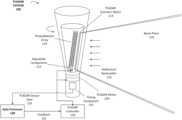
- FIG. 1is a block diagram illustrating an example planar-beam, light detection and ranging (PLADAR) system, as described herein.
- the PLADAR system 100can include a PLADAR scanner and optics 114 that generate a two-dimensional beam plane 118 .
- the scanner/optics 114can include a single laser source (or multiple laser sources) that generates a laser beam.
- the laser source of the beam plane 118can be a fiber laser emitting in the near to mid infrared spectral range.
- the optics of the scanner/optics 114can include a number mirrors and/or a collimation component that collimates the laser beam axially to form the beam plane 118 .
- the collimation componentcan include a number of lenses, spatial filters, mirrors, fiber optics, and/or gratings, which can filter, amplify, and/or narrow a resultant planar beam 118 . Accordingly, the collimation component of the scanner/optics 114 collimates the laser beam on a single axis to generate the beam plane 118 .
- the PLADAR system 100can include a photodetector array 119 including a number of individual photodetectors.
- the photodetector array 119can comprise a linear arrangement (e.g., as a one or more linear rows of photodetectors) to correlate with the beam plane 118 emitted by the PLADAR system 100 .
- the individual photodetectorscan be included and calibrated on a circuit board to be aligned with the beam plane 118 .
- the photodetector array 119can include a number of adjustable components 123 (e.g., calibration screws) that can allow for straightforward calibration of the photodetector array 119 with the beam plane 118 .
- the photodetector array 119can include a sufficient number of individual photodetectors (e.g., tens to hundreds) for generating sensor data with sufficient granularity to detect any possible road hazards (e.g., objects with size on the order of feet or inches) for operating an autonomous vehicle on public roads.
- the photodetector array 119can include as many or more photodetectors as current or future state of the art fixed-beam LIDAR systems.
- the photodetector array 119can include multiple linear arrangements of photodetectors, and/or interleaved detectors across the multiple linear arrangements.
- the photodetector array 119can include two or more lines of photodetectors to take advantage of the beam spread of the beam plane 118 .
- the nature of the beam plane 118can allow for any suitable arrangement for the photodetector array 119 , such as separate staggered photodetector lines of varying lengths, a wider central arrangement, a narrower central arrangement, and the like.
- the photodetector arraycan include a plurality of photodetector rows aligned in a manner corresponding to the beam plane 118 .
- the photodetector array 119detects reflection and/or backscatter 126 from the beam plane 118 , and a timing component 135 is utilized to perform ranging operations for the PLADAR system 100 . Accordingly, the PLADAR system 100 actively transmits the beam plane 118 , light from the beam plane 118 is reflected off objects and surfaces, and this reflection/backscatter 126 is detected by the individual receivers of the photodetector array 119 . Data from the detected light is precisely timed to perform the ranging operations (e.g., dynamic calculations of distance to each surface) and generate a dynamic point cloud map of the situational environment of the PLADAR system 100 .
- the ranging operationse.g., dynamic calculations of distance to each surface
- LIDAR systemssequence the individual beams and detectors in order to decrease power and processing loads, which can constrain data quality.
- the PLADAR system 100can utilize a single beam plane 118 at a single pulse rate, which may be increased or decreased accordingly depending on the situational environment (e.g., a crowded city environment, a rural road with little or no traffic, etc.).
- PLADAR sensor data 129 from the photodetectors of the photodetector array 119may be sampled simultaneously from all photodetectors by a local or external data processor 130 .
- the data processor 130can be included as a component of the PLADAR system 100 .
- the data processor 130may be remote, and/or can be included as a part of, for example, an on-board data processing system of an autonomous vehicle.
- Each detector of the photodetector array 119can include an analog-to-digital converter (ADC), which converts the detected light signal from the reflection/backscatter 126 of the beam plane 118 into a digital signal for processing.
- ADCanalog-to-digital converter
- the photodetector array 119can include an ADC chain, similar to certain LIDAR systems.
- the combined data from the ADC chaini.e., PLADAR sensor data 129
- the data processor 130e.g., simultaneously or near-simultaneously for each pulse
- Feedback 132can be provided by the data processor 130 to a PLADAR controller 150 , or adjustment controller, which can make adjustments to the configurable parameters of the PLADAR system 100 .
- the individual detectors of the photodetector array 119can be adjusted in concert using the adjustable components 123 .
- the photodetector array 119can be pre-calibrated and aligned with the beam plane 118 during the manufacturing process. Additionally or alternatively, when a misalignment is detected (e.g., by the data processor 130 ), the photodetector array 119 may be manually calibrated during servicing. Additionally or alternatively still, the feedback 132 provided by the data processor 130 can indicate the misalignment, and can be processed by the PLADAR controller 150 .
- the PLADAR controller 150can determine a number of adjustments based on the feedback 132 , and can utilize the adjustable components 123 to re-calibrate the photodetector array 119 automatically and on the fly.
- the PLADAR controller 150can further operate the PLADAR motor 120 , which can, for example, control a rotational rate of the PLADAR system 100 .
- the PLADAR controllercan further control the timing component 135 and the PLADAR scanner/optics 114 to increase or decrease the pulse rate when, for example, finer granularity in the generated point cloud is needed (e.g., in pedestrian rich environments).
- the pulse rate of the beam plane 118can be far less (e.g., 100 ⁇ less) than those of typical LIDAR systems, since the PLADAR system 100 utilizes a single light source.
- the PLADAR scanner/optics 114can generate the beam plane 118 along with one or more linear beams having dedicated detectors.
- the PLADAR scanner/optics 114can generate multiple beam planes 118 .
- the embodiment illustrated in FIG. 1shows a rotational PLADAR system 100 operated by a PLADAR motor 120 .
- example PLADAR systems 100 described hereincan include a scanning motor that uses a beam plane 118 to scan a certain directional aspect (e.g., directly in front of an autonomous vehicle).
- the beam plane 118is axially collimated on a single axis, and can be collimated vertically, horizontally, in a slanted manner (as shown), and can provide almost any desired vertical field of view (e.g., a 45° VFOV at 25 meters).
- FIG. 2is a block diagram illustrating an example autonomous vehicle including a PLADAR system, as described herein.
- the PLADAR system 205 of the autonomous vehicle (AV) 200can provide PLADAR data 202 to an on-board data processing system 210 of the autonomous vehicle 200 .
- the PLADAR system 205can comprise a light source (e.g., a laser), a photodetector, scanner components (e.g., which can include one or more lens(es), mirror(s), motor(s), actuator(s), etc.), and circuitry to couple to various components of the autonomous vehicle 200 .
- the data processing system 210can utilize the PLADAR data 202 to detect the situational conditions of the autonomous vehicle 200 as the AV 100 travels along a current route. For example, the data processing system 210 can identify potential obstacles or road hazards-such as pedestrians, bicyclists, objects on the road, road cones, road signs, animals, etc.—in order to enable an AV control system 220 to react accordingly.
- the data processing system 210can utilize sub-maps 233 stored in a database 230 of the autonomous vehicle 200 in order to perform localization and pose operations to determine a current location and orientation of the autonomous vehicle 200 in relation to a given region (e.g., a city).
- the sub-maps 233can comprise previously recorded sensor data, such as stereo camera data, radar maps, and/or point cloud LIDAR maps that enable the data processing system 210 to compare the PLADAR data 202 from the PLADAR system 205 with a current sub-map 234 to identify such obstacles and potential road hazards in real time.
- the data processing system 210can provide the processed sensor data 213 —identifying such obstacles and road hazards—to AV control system 220 , which can react accordingly by operating the steering, braking, and acceleration systems 225 of the autonomous vehicle 200 .
- the autonomous vehicle 200further includes a number of stereo cameras 260 that generate dynamic image data 262 of the autonomous vehicle's 200 surroundings.
- the autonomous vehicle 200can include stereo cameras 260 with fields of view showing a 360 o panorama (or forward and rearward directions) of the autonomous vehicle 200 .
- the on-board data processing system 210can further process the dynamic image data 262 to identify features or potential hazards along the current route traveled.
- the processed data 213can include processed image data from the stereo cameras 260 , which can be utilized by the AV control system 220 to perform low level maneuvering.
- the AV control system 220can receive a destination 219 from, for example, an interface system 215 of the autonomous vehicle 200 .
- the interface system 215can include any number of touch-screens, voice sensors, mapping resources, etc. that enable a passenger 239 to provide a passenger input 241 indicating the destination 219 .
- the passenger 239can type the destination 219 into a mapping engine 275 of the autonomous vehicle 200 , or can speak the destination 219 into the interface system 215 .
- the interface system 215can include a wireless communication module that can connect the autonomous vehicle 200 to a network 280 to communicate with a backend transport arrangement system 290 to receive invitations 282 to service a pick-up or drop-off request.
- Such invitations 282can include destination 219 (e.g., a pick-up location), and can be received by the autonomous vehicle 200 as a communication over the network 280 from the backend transport arrangement system 290 .
- the backend transport arrangement system 290can manage routes and/or facilitate transportation for users using a fleet of autonomous vehicles throughout a given region.
- the backend transport arrangement system 290can be operative to facilitate passenger pick-ups and drop-offs to generally service pick-up requests, facilitate delivery such as packages, food, or animals, and the like.
- the AV control system 220can utilize the mapping engine 275 to receive route data 232 indicating a route to the destination 219 .
- the mapping engine 275can also generate map content 226 dynamically indicating the route traveled to the destination 219 .
- the route data 232 and/or map content 226can be utilized by the AV control system 220 to maneuver the autonomous vehicle 200 to the destination 219 along the selected route.
- the AV control system 220can dynamically generate control commands 221 for the autonomous vehicle's steering, braking, and acceleration system 225 to actively drive the autonomous vehicle 200 to the destination 219 along the selected route.
- the map content 226 showing the current route traveledcan be streamed to the interior interface system 215 so that the passenger(s) 239 can view the route and route progress in real time.
- the processed data 213 provided to the AV control system 220can indicate low level occurrences, such as obstacles and potential hazards to which the AV control system 220 can make decisions and react.
- the processed data 213can indicate a pedestrian crossing the road, traffic signals, stop signs, other vehicles, road conditions, traffic conditions, bicycle lanes, crosswalks, pedestrian activity (e.g., a crowded adjacent sidewalk), and the like.
- the AV control system 220can respond to the processed data 213 by generating control commands 221 to reactively operate the steering, braking, and acceleration systems 225 accordingly.
- the autonomous vehicle 200can include a PLADAR controller 235 to receive feedback data 223 from the data processing system 210 in order to configure various adjustable parameters of the PLADAR system 205 .
- the feedback data 223can include information indicating data quality, such as errors or uncertainty in the data from certain individual photodetectors, which can be extrapolated by the PLADAR controller 235 to determine a number of adjustment commands 237 for the PLADAR system 205 that can correct the error(s).
- the PLADAR controller 235can identify a pattern in the feedback data 223 indicating a misalignment of the photodetector array with respect to the PLADAR beam 207 .
- the PLADAR controller 235can identify the misalignment and generate the adjustment commands 237 for execution on the adjustable components of the photodetector array to re-calibrate the PLADAR system 205 .
- the adjustment commands 237can be executed on the adjustable components dynamically as the autonomous vehicle 200 travels along a current route, or during garage servicing of the autonomous vehicle 200 .
- the feedback data 223can include requests from the data processing system 210 for the PLADAR controller 235 to configure the PLADAR system 205 for increased or decreased granularity.
- the data processing system 210can identify a substantial decrease in potential hazards (e.g., when the autonomous vehicle 200 leaves a city and enters open rural road with little traffic).
- the feedback data 223can include a request to save power in such conditions by decreasing the pulse rate and/or scan rate of the PLADAR system 205 .
- the adjustment commands 237can be generated by the PLADAR controller 235 to adjust a rotational parameter 209 (e.g., decrease a rotational rate) and/or decrease the pulse rate of the PLADAR beam 207 —thereby enabling a decrease in sample rate by the data processing system 210 .
- a rotational parameter 209e.g., decrease a rotational rate
- the pulse rate of the PLADAR beam 207thereby enabling a decrease in sample rate by the data processing system 210 .
- the on-board data processing system 210can identify an increase in potential hazards (e.g., entering an area of increased pedestrian activity) or an increased probability of experiencing hazards (e.g., when traveling at high speeds), and request that the PLADAR controller 235 generate adjustment commands 237 to increase the sample rate.
- Such commands 237can be executed on the adjustable parameters of the PLADAR system 205 to increase a pulse rate of the PLADAR beam 207 and/or increase the rotational rate—thereby enabling the data processing system 210 to increase the sample rate and bolster point cloud granularity.
- FIG. 3is a flow chart describing an example method of processing PLADAR data, according to one or more examples described herein.
- the method described with respect to FIG. 3may be performed by an example data processor 130 shown and described with respect to FIG. 1 , or an on-board data processing system 230 shown and described with respect to FIG. 2 .
- the data processor 130can sample data from each detector of the PLADAR system 100 simultaneously ( 300 ).
- the data processor 130can monitor each ADC of an ADC chain coupled to the photodetector array 119 .
- return light signalse.g., reflection/backscatter 126
- each detectorcan include an ADC that converts the detected light signal into a digital signal, and a timing component 135 can be utilized by the data processor 130 to precisely perform ranging for each ADC of the ADC chain and for every beam plane 118 pulse.
- the data processor 130can process the PLADAR data 129 to perform ranging and identify potential hazards ( 305 ).
- the data processor 130can be programmed to identify aspects of the autonomous vehicle's situational environment that causes the autonomous vehicle 200 to operate safely on public roads. Such aspects can include pedestrians, bicyclists, hazardous objects on the road (e.g., rocks), stop lights, signs, other vehicles, and the like.
- the processor 130can identify such aspects by, for example, comparing the PLADAR data 129 to a stored sub-map including prerecorded data on the same current route, as described with respect to FIG. 2 .
- the data processor 130transmits the processed sensor data 213 to an AV control system 220 , which can control the autonomous vehicle's 200 steering braking, and acceleration systems 225 to make decisions and react to each processed object for low level maneuvering ( 310 ). Additionally, the AV control system 220 can further utilize dynamic image data 262 from a stereo camera system 260 of the autonomous vehicle 200 for low level maneuvering.
- the data processor 130can identify, in the PLADAR data 129 , a misalignment between the photodetector array 119 and the beam plane 118 ( 315 ).
- the PLADAR data 129can indicate unreliable data for the top detectors and the bottom detectors, which can indicate a diagonal misalignment of the photodetector array 118 .
- the data processor 130can determine the nature of the misalignment based on the sampled PLADAR data 129 .
- the data processor 130can generally identify the error in the data, and generate feedback 132 requesting the PLADAR controller 150 to perform a diagnostics test.
- the data processor 130can generate feedback 132 indicating the misalignment ( 320 ), and transmit the feedback to the PLADAR controller 150 to re-calibrate the photodetector array 119 to the planar beam 118 ( 325 ).
- the data processor 130can determine a condition change in the situational environment of the autonomous vehicle 200 ( 330 ). As an example, the data processor 130 can identify that the autonomous vehicle 200 is traveling at higher speeds, and that more detailed data from a forward direction of the autonomous vehicle 200 is desired. The data processor 130 can generate a request to adjust the PLADAR system 100 configurations to, for example, increase a pulse rate, scan rate, detector sensitivity, and/or a laser intensity to increase the data quality ( 335 ). Conversely, to optimize power and processing resources, in certain circumstances (e.g., low speed operation), the data processor 130 can generate a request to decrease such configurable parameters when situational conditions are conducive to such decreases ( 335 ). These requests can be transmitted to the PLADAR controller 150 ( 340 ), which can execute adjustment commands 237 on the configurable components of the PLADAR system 100 accordingly.
- the PLADAR controller 150340
- FIGS. 4 A and 4 Bare a flow chart describing example methods of configuring a PLADAR system, as described herein.
- the methods described with respect to FIGS. 4 A and 4 Bmay be performed by an example PLADAR controller 150 , 235 shown and described with respect to FIGS. 1 and 2 .
- the PLADAR controller 150can receive feedback 132 from the data processor 130 indicating a misalignment ( 400 ).
- the feedback 132identifies the specific misalignment (e.g., leftward, rightward, topward, downward, clockwise or counterclockwise diagonal misalignments or any combination of the foregoing).
- the feedback 132can include samplings of the PLADAR data 129 , which the PLADAR controller 150 can analyze to identify a data pattern that describes or details the misalignment ( 405 ).
- data from the photodetector array 119can indicate a consistent pattern of bad or unreliable data from any number of individual detectors in the array 119 .
- the PLADAR controller 150can perform an initial set of adjustments on the adjustable components 123 to diagnose the misalignment. In other situations, the misalignment may be readily identified by the PLADAR controller 150 , and the calibration can be made directly.
- the PLADAR controller 150can generate and execute adjustment commands 237 on the adjustable components 123 of the photodetector array 119 to realign or re-calibrate the photodetector array 119 to the beam plane 118 ( 410 ).
- the PLADAR controller 150can receive a request from the data processor 130 to adjust PLADAR system 100 configurations ( 450 ). For example, based on changing situational conditions (e.g., changing weather such as rain or snow, changing speed, changing environmental complexity or potential hazard count, etc.), the data processor 130 can determine that an increased or decreased pulse rate ( 451 ) and/or scan rate ( 452 ) is preferable. Additionally or alternatively, the data processor 130 may determine that conditions require an increase in laser intensity ( 453 ) to enhance reflectance, or an increase in detector sensitivity ( 454 ). Alternatively, the data processor 130 may determine that conditions are conducive to power savings (e.g., in low speed uncrowded situations), and may request to decrease such configurations.
- changing situational conditionse.g., changing weather such as rain or snow, changing speed, changing environmental complexity or potential hazard count, etc.
- the data processor 130can determine that an increased or decreased pulse rate ( 451 ) and/or scan rate ( 452 ) is preferable. Additionally or alternative
- the PLADAR controller 150can generate adjustment commands 237 based on the requests from the data processor 130 ( 455 ). The PLADAR controller 150 can then execute the adjustment commands 237 on the relevant components of the PLADAR system 100 to configure the PLADAR system 100 accordingly ( 460 ). For example, the PLADAR controller 150 can execute commands 237 on the PLADAR motor 120 to increase or decrease the scan rate ( 461 ). As another example, the PLADAR controller 150 can execute commands 237 on the timing component 135 to increase or decrease a pulse rate of the laser ( 462 ). Further, the PLADAR controller 150 can execute commands 237 on the laser source itself to increase or decrease laser intensity (e.g., increase or decrease power or beam frequency) ( 463 ). Still further, in some implementations, the PLADAR controller 150 can execute commands 237 on the detector array 119 to increase or decrease detector sensitivity ( 464 ).
- the PLADAR controller 150can execute commands 237 on the detector array 119 to increase or decrease detector sensitivity ( 464 ).
- data processor 130 and PLADAR controller 150are shown as separate components in FIGS. 1 and 2 , it is contemplated that certain embodiments can include a single component (e.g., one or more blade computers of an autonomous vehicle 200 that perform all of the operations described with respect to FIG. 3 and FIGS. 4 A and 4 B .
- FIG. 5is a block diagram that illustrates a computer system upon which examples described herein may be implemented.
- a computer system 500can be implemented on, for example, a server or combination of servers.
- the computer system 500may be implemented as part of a data processing system 130 , which itself may be implemented as a part of the AV's on-board data processing system 210 .
- the data processing system 130may be implemented with the PLADAR controller 150 as a single computer system 500 , or using a combination of multiple computer systems as described in connection with FIG. 5 .
- the computer system 500includes processing resources 510 , a main memory 520 , a read-only memory (ROM) 530 , a storage device 540 , and a communication interface 550 .
- the computer system 500includes at least one processor 510 for processing information stored in the main memory 520 , such as provided by a random access memory (RAM) or other dynamic storage device, for storing information and instructions which are executable by the processor 510 .
- the main memory 520also may be used for storing temporary variables or other intermediate information during execution of instructions to be executed by the processor 510 .
- the computer system 500may also include the ROM 530 or other static storage device for storing static information and instructions for the processor 510 .
- a storage device 540such as a magnetic disk or optical disk, is provided for storing information and instructions.
- the communication interface 550enables the computer system 500 to communicate with the PLADAR system 580 over a network link (e.g., a wireless or wired link).
- the computer system 500receives PLADAR data 582 from the PLADAR system 580 .
- the executable instructions stored in the memory 530can include configuration instructions 522 , which the processor 510 executes to generate a set of adjustment commands 554 to configure the adjustable parameters of the autonomous vehicle's PLADAR system 580 based on the PLADAR data 582 and the situational conditions of the autonomous vehicle 200 .
- the processor 510is configured with software and/or other logic to perform one or more processes, steps and other functions described with implementations, such as described by FIGS. 1 through 4 B , and elsewhere in the present application.
- Examples described hereinare related to the use of the computer system 500 for implementing the techniques described herein. According to one example, those techniques are performed by the computer system 500 in response to the processor 510 executing one or more sequences of one or more instructions contained in the main memory 520 . Such instructions may be read into the main memory 520 from another machine-readable medium, such as the storage device 540 . Execution of the sequences of instructions contained in the main memory 520 causes the processor 510 to perform the process steps described herein. In alternative implementations, hard-wired circuitry may be used in place of or in combination with software instructions to implement examples described herein. Thus, the examples described are not limited to any specific combination of hardware circuitry and software.
Landscapes
- Engineering & Computer Science (AREA)
- Physics & Mathematics (AREA)
- Radar, Positioning & Navigation (AREA)
- Remote Sensing (AREA)
- General Physics & Mathematics (AREA)
- Automation & Control Theory (AREA)
- Computer Networks & Wireless Communication (AREA)
- Aviation & Aerospace Engineering (AREA)
- Electromagnetism (AREA)
- Computer Vision & Pattern Recognition (AREA)
- Optics & Photonics (AREA)
- Multimedia (AREA)
- Business, Economics & Management (AREA)
- Evolutionary Computation (AREA)
- Game Theory and Decision Science (AREA)
- Medical Informatics (AREA)
- Artificial Intelligence (AREA)
- Health & Medical Sciences (AREA)
- Optical Radar Systems And Details Thereof (AREA)
- Traffic Control Systems (AREA)
- Indole Compounds (AREA)
Abstract
Description
Claims (20)
Priority Applications (2)
| Application Number | Priority Date | Filing Date | Title |
|---|---|---|---|
| US18/170,841US12105517B2 (en) | 2016-03-03 | 2023-02-17 | Planar-beam, light detection and ranging system |
| US18/812,632US20240411311A1 (en) | 2016-03-03 | 2024-08-22 | Planar-Beam, Light Detection and Ranging System |
Applications Claiming Priority (5)
| Application Number | Priority Date | Filing Date | Title |
|---|---|---|---|
| US201662303013P | 2016-03-03 | 2016-03-03 | |
| US15/446,953US10281923B2 (en) | 2016-03-03 | 2017-03-01 | Planar-beam, light detection and ranging system |
| US16/242,657US10942524B2 (en) | 2016-03-03 | 2019-01-08 | Planar-beam, light detection and ranging system |
| US17/171,660US11604475B2 (en) | 2016-03-03 | 2021-02-09 | Planar-beam, light detection and ranging system |
| US18/170,841US12105517B2 (en) | 2016-03-03 | 2023-02-17 | Planar-beam, light detection and ranging system |
Related Parent Applications (1)
| Application Number | Title | Priority Date | Filing Date |
|---|---|---|---|
| US17/171,660ContinuationUS11604475B2 (en) | 2016-03-03 | 2021-02-09 | Planar-beam, light detection and ranging system |
Related Child Applications (1)
| Application Number | Title | Priority Date | Filing Date |
|---|---|---|---|
| US18/812,632ContinuationUS20240411311A1 (en) | 2016-03-03 | 2024-08-22 | Planar-Beam, Light Detection and Ranging System |
Publications (2)
| Publication Number | Publication Date |
|---|---|
| US20230205222A1 US20230205222A1 (en) | 2023-06-29 |
| US12105517B2true US12105517B2 (en) | 2024-10-01 |
Family
ID=59722176
Family Applications (5)
| Application Number | Title | Priority Date | Filing Date |
|---|---|---|---|
| US15/446,953ActiveUS10281923B2 (en) | 2016-03-03 | 2017-03-01 | Planar-beam, light detection and ranging system |
| US16/242,657Active2037-06-18US10942524B2 (en) | 2016-03-03 | 2019-01-08 | Planar-beam, light detection and ranging system |
| US17/171,660Active2037-10-01US11604475B2 (en) | 2016-03-03 | 2021-02-09 | Planar-beam, light detection and ranging system |
| US18/170,841ActiveUS12105517B2 (en) | 2016-03-03 | 2023-02-17 | Planar-beam, light detection and ranging system |
| US18/812,632PendingUS20240411311A1 (en) | 2016-03-03 | 2024-08-22 | Planar-Beam, Light Detection and Ranging System |
Family Applications Before (3)
| Application Number | Title | Priority Date | Filing Date |
|---|---|---|---|
| US15/446,953ActiveUS10281923B2 (en) | 2016-03-03 | 2017-03-01 | Planar-beam, light detection and ranging system |
| US16/242,657Active2037-06-18US10942524B2 (en) | 2016-03-03 | 2019-01-08 | Planar-beam, light detection and ranging system |
| US17/171,660Active2037-10-01US11604475B2 (en) | 2016-03-03 | 2021-02-09 | Planar-beam, light detection and ranging system |
Family Applications After (1)
| Application Number | Title | Priority Date | Filing Date |
|---|---|---|---|
| US18/812,632PendingUS20240411311A1 (en) | 2016-03-03 | 2024-08-22 | Planar-Beam, Light Detection and Ranging System |
Country Status (8)
| Country | Link |
|---|---|
| US (5) | US10281923B2 (en) |
| EP (2) | EP3423912B1 (en) |
| CN (1) | CN109074073B (en) |
| AU (1) | AU2017225790B2 (en) |
| CA (1) | CA3015894C (en) |
| IL (1) | IL261434B (en) |
| SG (1) | SG11201807249YA (en) |
| WO (1) | WO2017151943A1 (en) |
Families Citing this family (28)
| Publication number | Priority date | Publication date | Assignee | Title |
|---|---|---|---|---|
| US11446550B2 (en) | 2017-10-10 | 2022-09-20 | Christopher DeCarlo | Entertainment forum digital video camera, audio microphone, speaker and display device enabling entertainment participant and remote virtual spectator interaction, apparatus, system, method, and computer program product |
| US12377317B2 (en) | 2014-04-25 | 2025-08-05 | Christopher DeCarlo | Sporting sensor-based apparatus, system, method, and computer program product |
| US10821345B2 (en) | 2014-04-25 | 2020-11-03 | Christopher DeCarlo | Sporting device for analyzing an element in a tunnel, apparatus, system, method, and computer program product |
| US11370422B2 (en)* | 2015-02-12 | 2022-06-28 | Honda Research Institute Europe Gmbh | Method and system in a vehicle for improving prediction results of an advantageous driver assistant system |
| US10338225B2 (en)* | 2015-12-15 | 2019-07-02 | Uber Technologies, Inc. | Dynamic LIDAR sensor controller |
| US10281923B2 (en) | 2016-03-03 | 2019-05-07 | Uber Technologies, Inc. | Planar-beam, light detection and ranging system |
| US10234856B2 (en)* | 2016-05-12 | 2019-03-19 | Caterpillar Inc. | System and method for controlling a machine |
| US9952317B2 (en) | 2016-05-27 | 2018-04-24 | Uber Technologies, Inc. | Vehicle sensor calibration system |
| US11889393B2 (en)* | 2017-06-23 | 2024-01-30 | Veniam, Inc. | Methods and systems for detecting anomalies and forecasting optimizations to improve urban living management using networks of autonomous vehicles |
| US10558224B1 (en)* | 2017-08-10 | 2020-02-11 | Zoox, Inc. | Shared vehicle obstacle data |
| US10775488B2 (en) | 2017-08-17 | 2020-09-15 | Uatc, Llc | Calibration for an autonomous vehicle LIDAR module |
| US10746858B2 (en) | 2017-08-17 | 2020-08-18 | Uatc, Llc | Calibration for an autonomous vehicle LIDAR module |
| WO2019131002A1 (en)* | 2017-12-25 | 2019-07-04 | 日立オートモティブシステムズ株式会社 | Vehicle control device and electronic control system |
| US10914820B2 (en) | 2018-01-31 | 2021-02-09 | Uatc, Llc | Sensor assembly for vehicles |
| US10627487B2 (en)* | 2018-02-10 | 2020-04-21 | Delphi Technologies, Llc | Enclosure |
| US11143760B2 (en)* | 2018-02-19 | 2021-10-12 | Motional Ad Llc | Object-detector configuration based on human-override of automated vehicle control |
| US10331128B1 (en)* | 2018-04-20 | 2019-06-25 | Lyft, Inc. | Control redundancy |
| CN112074759B (en) | 2018-04-28 | 2024-11-05 | 深圳市大疆创新科技有限公司 | Light detection and ranging sensor with multiple transmitters and multiple receivers and associated systems and methods |
| US11079492B1 (en)* | 2018-09-28 | 2021-08-03 | Zoox, Inc. | Condition dependent parameters for large-scale localization and/or mapping |
| US20200133270A1 (en)* | 2018-10-31 | 2020-04-30 | Baidu Usa Llc | Lidar device with cylindrical lens for autonomous driving vehicles |
| DE102018220932A1 (en)* | 2018-12-04 | 2020-06-04 | Osram Gmbh | Method for determining the distance and retroreflectivity of an object surface |
| FR3096788B1 (en)* | 2019-05-29 | 2021-06-11 | Thales Sa | LIDAR SYSTEM INCLUDING AN INTERFERENTIAL DIFFRACTIVE ELEMENT AND LIDAR IMAGING PROCESS |
| FR3103219B1 (en)* | 2019-11-19 | 2021-10-08 | Vitesco Technologies | Method for managing sporadic anomalies of a motor vehicle system |
| JP7452044B2 (en) | 2020-01-31 | 2024-03-19 | 株式会社デンソー | light detection device |
| JP7406432B2 (en)* | 2020-03-31 | 2023-12-27 | 本田技研工業株式会社 | Mobile object control device, mobile object control method, and program |
| CN114089311B (en)* | 2022-01-19 | 2022-05-17 | 探维科技(北京)有限公司 | Laser radar system |
| US11702096B1 (en)* | 2022-03-25 | 2023-07-18 | GM Global Technology Operations LLC | Systems and methods for providing a graphical representation of following distances to an augmented reality vehicle heads-up display system |
| US20250259540A1 (en)* | 2024-02-12 | 2025-08-14 | GM Global Technology Operations LLC | Identifying roadway safety events in remote vehicles |
Citations (174)
| Publication number | Priority date | Publication date | Assignee | Title |
|---|---|---|---|---|
| US4567347A (en) | 1983-12-15 | 1986-01-28 | Ntt Gijutsu Iten Kabushiki Kaisha | Measurement head for welding machines |
| EP0185816A1 (en) | 1984-12-27 | 1986-07-02 | THE GENERAL ELECTRIC COMPANY, p.l.c. | A vehicle guidance and control system |
| US4706773A (en) | 1981-07-01 | 1987-11-17 | Imperial Chemical Industries Plc | Vehicle guidance system particularly for use in agriculture |
| US5012745A (en) | 1989-03-08 | 1991-05-07 | Koyo Jidoki Company Limited | Vehicle turn-table |
| US5170458A (en) | 1990-11-26 | 1992-12-08 | Mitsubishi Denki Kabushiki Kaisha | Optical fiber light-amplifier system |
| US5590604A (en) | 1995-06-07 | 1997-01-07 | Autran Corp. | Transportation system with high speed vehicles and automatic control |
| US5598783A (en) | 1995-06-07 | 1997-02-04 | Autran Corp. | Integrated transportation system including transfer vehicles |
| JPH09163197A (en) | 1995-12-09 | 1997-06-20 | Sony Corp | Video camera equipment |
| JPH09326032A (en) | 1996-06-06 | 1997-12-16 | Fuji Heavy Ind Ltd | Vehicle peripheral three-dimensional object recognizing device |
| US5726647A (en) | 1995-04-05 | 1998-03-10 | Bayersche Motoren Werke Aktiengesellscaft | Method and apparatus for avoiding a collision of a motor vehicle |
| US6122040A (en) | 1997-11-06 | 2000-09-19 | Omron Corporation | System and method of detecting deviation of an axis and adjusting the axis of a range finder |
| JP2001088623A (en) | 1999-09-22 | 2001-04-03 | Fuji Heavy Ind Ltd | In-vehicle camera mounting structure |
| US20020072869A1 (en) | 1999-12-24 | 2002-06-13 | Christoph Stiller | Method of calibrating a sensor system |
| US6434302B1 (en) | 1998-03-04 | 2002-08-13 | Jds Uniphase Corporation | Optical couplers for multimode fibers |
| US20020135468A1 (en) | 1997-09-22 | 2002-09-26 | Donnelly Corporation, A Corporation Of The State Of Michigan | Vehicle imaging system with accessory control |
| US20020145042A1 (en) | 1998-03-24 | 2002-10-10 | Knowles C. Harry | Internet-based remote monitoring, configuration and service (RMCS) system capable of monitoring, configuring and servicing a planar laser illumination and imaging (PLIIM) based network |
| US20020196424A1 (en)* | 2001-06-20 | 2002-12-26 | Naoki Sano | Distance measuring apparatus |
| US20030019931A1 (en) | 1998-03-24 | 2003-01-30 | Metrologic Instruments, Inc. | Method of speckle-noise pattern reduction and apparatus therefor based on reducing the temporal-coherence of the planar laser illumination beam (PLIB) after it illuminates the target by applying temoporal intensity modulation techniques during the detection of the reflected/scattered PLIB |
| US20030043058A1 (en) | 2001-09-04 | 2003-03-06 | Jamieson James R. | Distributed laser obstacle awareness system |
| US20030042303A1 (en) | 1999-06-07 | 2003-03-06 | Metrologic Instruments, Inc. | Automatic vehicle identification (AVI) system employing planar laser illumination imaging (PLIIM) based subsystems |
| US20030052169A1 (en) | 1999-06-07 | 2003-03-20 | Metrologic Instruments, Inc. | Planar laser illumination and imaging (PLIIM) based camera system for producing high-resolution 3-D images of moving 3-D objects |
| US20040030474A1 (en) | 2002-08-05 | 2004-02-12 | Samuel Stepen Varghese | Method and system for correcting sensor offsets |
| DE10244638A1 (en) | 2002-09-25 | 2004-04-08 | Ibeo Automobile Sensor Gmbh | Position monitoring system for use on road vehicle uses pulsed lasers, sensor module and mechanical scanner with mirror set at angle on shaft with calibration disk driven by electric motor |
| US6727849B1 (en)* | 1998-10-22 | 2004-04-27 | Trimble Navigation Limited | Seamless surveying system |
| US6732051B1 (en)* | 1998-10-22 | 2004-05-04 | Trimble Navigation Limited | Seamless surveying system |
| US20040148093A1 (en) | 2003-01-27 | 2004-07-29 | Denso Corporation | Vehicle behavior detector, in-vehicle processing system, detection information calibrator, and in-vehicle processor |
| US20040174537A1 (en) | 2001-07-16 | 2004-09-09 | Detlef Ferger | Method for measuring surface properties and co-ordinate measuring device |
| JP2005024463A (en) | 2003-07-04 | 2005-01-27 | Fuji Heavy Ind Ltd | Stereo wide-field image processor |
| US6860350B2 (en) | 2002-12-20 | 2005-03-01 | Motorola, Inc. | CMOS camera with integral laser ranging and velocity measurement |
| US20050095092A1 (en) | 2000-07-20 | 2005-05-05 | Maurice Segal | Multi-level, automated vehicle parking structure |
| US20050185846A1 (en) | 2004-02-24 | 2005-08-25 | Trw Automotive U.S. Llc | Method and apparatus for controlling classification and classification switching in a vision system |
| US20050196035A1 (en) | 2004-03-03 | 2005-09-08 | Trw Automotive U.S. Llc | Method and apparatus for producing classifier training images |
| US20050196015A1 (en) | 2004-03-02 | 2005-09-08 | Trw Automotive U.S. Llc | Method and apparatus for tracking head candidate locations in an actuatable occupant restraining system |
| US6956227B2 (en) | 2002-10-07 | 2005-10-18 | Omron Corporation | Object detecting device and method with means for controlling direction of scan by electromagnetic waves |
| US20060089765A1 (en) | 2004-10-22 | 2006-04-27 | Pack Robert T | System and method for behavior based control of an autonomous vehicle |
| US7064817B1 (en) | 2003-11-04 | 2006-06-20 | Sandia Corporation | Method to determine and adjust the alignment of the transmitter and receiver fields of view of a LIDAR system |
| US20060149134A1 (en) | 2003-12-12 | 2006-07-06 | University Of Washington | Catheterscope 3D guidance and interface system |
| US20060158423A1 (en) | 2002-10-12 | 2006-07-20 | Leica Geosystems Ag | Electronic display and control device for a measuring device |
| US20060227317A1 (en) | 2005-04-06 | 2006-10-12 | Henderson Sammy W | Efficient lidar with flexible target interrogation pattern |
| EP1808711A2 (en) | 2006-01-16 | 2007-07-18 | Omron Corporation | Object detector |
| US7248342B1 (en) | 2003-02-14 | 2007-07-24 | United States Of America As Represented By The Administrator Of The National Aeronautics And Space Administration | Three-dimension imaging lidar |
| EP1816514A1 (en) | 2004-11-15 | 2007-08-08 | Hitachi, Ltd. | Stereo camera |
| US20070200064A1 (en) | 2003-07-15 | 2007-08-30 | Ford Global Technologies, Llc | Active night vision thermal control system using wavelength-temperature characteristic of light source |
| US20070212006A1 (en) | 2006-03-07 | 2007-09-13 | Wysocki Paul F | Tapered fiber bundle apparatus with monitoring capability |
| US20070219720A1 (en) | 2006-03-16 | 2007-09-20 | The Gray Insurance Company | Navigation and control system for autonomous vehicles |
| JP2007249632A (en) | 2006-03-16 | 2007-09-27 | Fujitsu Ltd | A mobile robot that moves autonomously in an environment with obstacles and a method for controlling the mobile robot |
| US20070237449A1 (en) | 2006-03-27 | 2007-10-11 | Fujitsu Limited | Optical module, optical transmission system, and fabrication method for optical module |
| US20080002427A1 (en) | 2006-05-15 | 2008-01-03 | Miroslav Kropac | Variable planar light guide module |
| US20080039991A1 (en) | 2006-08-10 | 2008-02-14 | May Reed R | Methods and systems for providing accurate vehicle positioning |
| JP2008104254A (en) | 2006-10-17 | 2008-05-01 | Tsubaki Emerson Co | Sealed rotation sensor built-in motor |
| US20080112028A1 (en) | 2006-11-10 | 2008-05-15 | Infocus Corporation | Color laser image generation |
| US20080136626A1 (en) | 2006-10-02 | 2008-06-12 | Edison Hudson | Threat detection sensor suite |
| US20080161986A1 (en) | 1997-10-22 | 2008-07-03 | Intelligent Technologies International, Inc. | Autonomous Vehicle Travel Control Systems and Methods |
| US7406220B1 (en) | 2006-03-09 | 2008-07-29 | Lockheed Martin Coherent Technologies, Inc. | Beam steering and combination |
| US20080215184A1 (en) | 2006-12-07 | 2008-09-04 | Electronics And Telecommunications Research Institute | Method for searching target object and following motion thereof through stereo vision processing and home intelligent service robot using the same |
| US20090103577A1 (en) | 2007-09-14 | 2009-04-23 | Sanyo Electric Co., Ltd. | Beam irradiation apparatus |
| US20090115994A1 (en) | 2005-12-08 | 2009-05-07 | Roger Stettner | Laser ranging, tracking and designation using 3-d focal planes |
| US20090312906A1 (en) | 2007-01-04 | 2009-12-17 | Continental Automotive Gmbh | Vertical alignment of a lidar sensor |
| US20090319112A1 (en) | 2007-09-28 | 2009-12-24 | Honeywell International Inc. | Automatic planning and regulation of the speed of autonomous vehicles |
| US7650239B2 (en) | 2004-11-16 | 2010-01-19 | Denso Corporation | Object recognition apparatus for motor vehicle |
| US20100013615A1 (en) | 2004-03-31 | 2010-01-21 | Carnegie Mellon University | Obstacle detection having enhanced classification |
| US20100020306A1 (en) | 2006-07-13 | 2010-01-28 | Velodyne Acoustics, Inc. | High definition lidar system |
| US20100053715A1 (en) | 2006-10-30 | 2010-03-04 | O'neill James | Scanning system for lidar |
| US20100110192A1 (en) | 1998-04-09 | 2010-05-06 | Johnston Gregory E | Mobile Surveillance System |
| US20100165323A1 (en) | 2008-12-29 | 2010-07-01 | Reinhold Fiess | Adaptive angle and power adaptation in 3d-micro-mirror lidar |
| US20100185335A1 (en) | 2007-04-19 | 2010-07-22 | Ikuhisa Sawada | Work machine control device |
| US20100182587A1 (en) | 2009-01-21 | 2010-07-22 | Raytheon Company | Energy Efficient Laser Detection and Ranging System |
| US20100185353A1 (en) | 2009-01-17 | 2010-07-22 | Boomerang Systems, Inc. | Variable offset positioning antenna array for enhanced guidance of automated guided vehicles (agvs) |
| US20100194890A1 (en) | 2000-03-02 | 2010-08-05 | Donnelly Corporation | Video mirror system suitable for use in a vehicle |
| US20100208244A1 (en) | 2008-05-09 | 2010-08-19 | Ball Aerospace & Technologies Corp. | Flash ladar system |
| US20100208034A1 (en) | 2009-02-17 | 2010-08-19 | Autoliv Asp, Inc. | Method and system for the dynamic calibration of stereovision cameras |
| CN101959022A (en) | 2009-07-17 | 2011-01-26 | 深圳泰山在线科技有限公司 | Synchronous circuit, and image pick-up device and synchronous exposure control method thereof |
| US20110050855A1 (en) | 2006-07-26 | 2011-03-03 | Guenter Nobis | Optical measuring device with two camera units |
| US20110134249A1 (en) | 2009-12-04 | 2011-06-09 | Lockheed Martin Corporation | Optical Detection and Ranging Sensor System For Sense and Avoid, and Related Methods |
| US20110166757A1 (en) | 2010-01-04 | 2011-07-07 | Gm Global Technology Operations, Inc. | Closed-loop feedback control and reduction of the torque converter clutch slip for enhanced drivability for heavy tip-in maneuvers |
| US20110184605A1 (en) | 2006-11-29 | 2011-07-28 | Neff Ryan A | Driverless vehicle |
| WO2011104706A1 (en) | 2010-02-23 | 2011-09-01 | Ben-Gurion University Of The Negev Research And Development Authority | A system and method for providing 3d imaging |
| US20110241845A1 (en) | 2010-04-06 | 2011-10-06 | Sullivan Robert P | Automated Material Handling System with Identification Features |
| US20110245964A1 (en) | 2010-04-06 | 2011-10-06 | Sullivan Robert P | Self Aligning Automated Material Handling System |
| CN102230962A (en) | 2011-04-08 | 2011-11-02 | 哈尔滨工业大学 | Laser radar coaxial transmitting and receiving system and coaxial adjustment method thereof |
| US20110301786A1 (en) | 2010-05-12 | 2011-12-08 | Daniel Allis | Remote Vehicle Control System and Method |
| US20110317993A1 (en) | 2010-06-23 | 2011-12-29 | Outwest Systems, Inc. | Apparatus for Mounting a Webcam to Another Optical Instrument |
| US20120008129A1 (en) | 2007-11-07 | 2012-01-12 | Magna Electronics, Inc. | Object detection system |
| US20120033196A1 (en) | 2010-03-12 | 2012-02-09 | Vanek Michael D | Method for Enhancing a Three Dimensional Image from a Plurality of Frames of Flash Lidar Data |
| US20120038903A1 (en) | 2010-08-16 | 2012-02-16 | Ball Aerospace & Technologies Corp. | Electronically steered flash lidar |
| US20120140061A1 (en) | 2010-12-02 | 2012-06-07 | GM Global Technology Operations LLC | Multi-Object Appearance-Enhanced Fusion of Camera and Range Sensor Data |
| CN102494609A (en) | 2011-11-18 | 2012-06-13 | 李志扬 | Three-dimensional photographing process based on laser probe array and device utilizing same |
| US20120154785A1 (en) | 2010-11-01 | 2012-06-21 | Patrick Gilliland | Flash Ladar Collision Avoidance System |
| US8208716B2 (en) | 2007-09-03 | 2012-06-26 | Electronics And Telecommunications Research Institute | Stereo vision system and stereo vision processing method |
| EP2500748A2 (en) | 2011-03-18 | 2012-09-19 | Ricoh Company, Ltd. | Stereo camera apparatus and method of obtaining image |
| US20120239238A1 (en) | 2011-03-18 | 2012-09-20 | Harvey Dean S | Communication technique by which an autonomous guidance system controls an industrial vehicle |
| US8344940B2 (en) | 2009-01-22 | 2013-01-01 | Mando Corporation | Apparatus and sensor for adjusting sensor vertical alignment |
| CN102857592A (en) | 2011-06-01 | 2013-01-02 | Lg电子株式会社 | Mobile terminal and 3D image display method thereof |
| CN103001428A (en) | 2012-12-26 | 2013-03-27 | 上海摩软通讯技术有限公司 | Flat motor and mobile terminal |
| US20130078063A1 (en) | 2011-09-22 | 2013-03-28 | Unitronics Parking Solutions Ltd. | Vehicle positioning system |
| CN103146355A (en) | 2011-12-07 | 2013-06-12 | 北京中石伟业科技股份有限公司 | Heat-absorbing material |
| CN103152518A (en) | 2011-12-01 | 2013-06-12 | 索尼公司 | Image processing system and method |
| CN103179339A (en) | 2011-12-01 | 2013-06-26 | 索尼公司 | Image processing system and method |
| US20130166105A1 (en) | 2011-12-22 | 2013-06-27 | Park Plus, Inc. | Automated parking garage/self-storage apparatus |
| US20130190963A1 (en) | 2011-03-18 | 2013-07-25 | The Raymond Corporation | System and Method for Gathering Video Data Related to Operation of an Autonomous Industrial Vehicle |
| US20130226431A1 (en) | 2012-02-27 | 2013-08-29 | Jianbo Lu | Smart adaptive cruise control |
| RU2493988C2 (en) | 2009-06-10 | 2013-09-27 | Сканиа Св Аб | Module and system for definition of reference magnitudes for vehicle control system |
| US20130317649A1 (en) | 2012-05-25 | 2013-11-28 | United States Of America As Represented By The Secretary Of The Navy | Nodding Mechanism For A Single-Scan Sensor |
| US8610881B2 (en) | 2009-07-28 | 2013-12-17 | Applied Concepts, Inc. | Lidar measurement device with target tracking and method for use of same |
| CN203353019U (en) | 2013-05-28 | 2013-12-18 | 东莞劲胜精密组件股份有限公司 | Graphene metal cooling fin and electronic product cooling structure |
| US20140041966A1 (en) | 2010-02-12 | 2014-02-13 | Snap-On Incorporated | Apparatus for guiding a vehicle onto a service lift using a machine vision wheel alignment system |
| US20140111812A1 (en) | 2012-05-22 | 2014-04-24 | Korea Institute Of Industrial Technology | 3d scanning system and method of obtaining 3d image |
| US20140136414A1 (en) | 2006-03-17 | 2014-05-15 | Raj Abhyanker | Autonomous neighborhood vehicle commerce network and community |
| US20140168631A1 (en) | 2012-12-18 | 2014-06-19 | Pouch Holdings LLC | Multi-clad Fiber Based Optical Apparatus and Methods for Light Detection and Ranging Sensors |
| RU2012154453A (en) | 2012-12-06 | 2014-06-20 | Александр ГУРЕВИЧ | METHOD FOR DETERMINING THE BOUNDARIES OF THE ROAD, FORM AND POSITION OF OBJECTS ON THE ROAD, AND THE DEVICE FOR ITS PERFORMANCE |
| US8797828B1 (en) | 2010-02-15 | 2014-08-05 | Soreq NRC | Remote optical seismic surveying and detection and imaging of underground objects |
| EP2767846A1 (en) | 2013-02-18 | 2014-08-20 | Volvo Car Corporation | Method for calibrating a sensor cluster in a motor vehicle |
| US20140231647A1 (en) | 2010-11-23 | 2014-08-21 | United States Of America, As Represented By The Secretary Of The Army | Compact fiber-based scanning laser detection and ranging system |
| US20140277691A1 (en) | 2013-03-15 | 2014-09-18 | Cybernet Systems Corporation | Automated warehousing using robotic forklifts |
| US20140286744A1 (en) | 2013-03-21 | 2014-09-25 | Unitronics Parking Solutions Ltd. | Vehicle centering system |
| CN104133473A (en) | 2008-10-24 | 2014-11-05 | 格瑞股份公司 | Control method of autonomously driven vehicle |
| US8899903B1 (en) | 2010-05-18 | 2014-12-02 | The Boeing Company | Vehicle base station |
| US20150025731A1 (en) | 2013-07-17 | 2015-01-22 | Toyota Motor Engineering & Manufacturing North America, Inc. | Interactive automated driving system |
| US8964028B2 (en) | 2009-12-21 | 2015-02-24 | Mesa Imaging Ag | Stray light compensation method and system for time of flight camera systems |
| US8994581B1 (en) | 2012-09-25 | 2015-03-31 | Adam Brown | Direction of arrival (DOA) estimation using multiple offset receive channels |
| US8996224B1 (en) | 2013-03-15 | 2015-03-31 | Google Inc. | Detecting that an autonomous vehicle is in a stuck condition |
| US20150091374A1 (en) | 2013-09-30 | 2015-04-02 | Google Inc. | Contactless Electrical Coupling for a Rotatable LIDAR Device |
| US9086273B1 (en) | 2013-03-08 | 2015-07-21 | Google Inc. | Microrod compression of laser beam in combination with transmit lens |
| US20150202939A1 (en) | 2013-03-08 | 2015-07-23 | Advanced Scientific Concepts, Inc. | Ladar enabled impact mitigation system |
| US9126595B2 (en) | 2012-07-24 | 2015-09-08 | Hyundai Mobis Co., Ltd. | Apparatus and method for calculating inter-vehicle distance |
| US20150293228A1 (en) | 2014-04-11 | 2015-10-15 | Facet Technology Corp. | Methods and apparatus for object detection and identification in a multiple detector lidar array |
| US20150293225A1 (en) | 2014-04-14 | 2015-10-15 | The Boeing Company | Aerial positioning systems and methods |
| EP2940489A1 (en) | 2014-05-02 | 2015-11-04 | Ricoh Company, Ltd. | Object detection device and sensing apparatus |
| US20150334269A1 (en) | 2014-05-19 | 2015-11-19 | Soichiro Yokota | Processing apparatus, processing system, and processing method |
| US9201424B1 (en) | 2013-08-27 | 2015-12-01 | Google Inc. | Camera calibration using structure from motion techniques |
| US9224053B1 (en) | 2013-07-31 | 2015-12-29 | Google Inc. | Combining multiple estimates of an environment into a consolidated estimate for an autonomous vehicle |
| US9228833B2 (en) | 2012-06-28 | 2016-01-05 | GM Global Technology Operations LLC | Wide baseline binocular object matching method using minimal cost flow network |
| US9231998B2 (en) | 2014-01-22 | 2016-01-05 | Ford Global Technologies, Llc | Vehicle-specific computation management system for cloud computing |
| US20160003946A1 (en) | 2014-07-03 | 2016-01-07 | Advanced Scientific Concepts, Inc. | Ladar sensor for a dense environment |
| CN204990755U (en) | 2015-09-29 | 2016-01-20 | 成都川睿科技有限公司 | Intelligent transportation car -mounted device based on laser radar |
| US9247211B2 (en) | 2012-01-17 | 2016-01-26 | Avigilon Fortress Corporation | System and method for video content analysis using depth sensing |
| US20160129917A1 (en) | 2014-11-07 | 2016-05-12 | Clearpath Robotics, Inc. | Self-calibrating sensors and actuators for unmanned vehicles |
| RU2014146890A (en) | 2013-11-22 | 2016-06-10 | Форд Глобал Технолоджис, ЛЛК | VEHICLE SYSTEM FOR CONFIGURING ITS OFFLINE OPERATION MODES |
| US20160167514A1 (en) | 2014-12-10 | 2016-06-16 | Yoshiaki Nishizaki | Information provision device, information provision method, and recording medium storing information provision program |
| US20160170487A1 (en) | 2014-12-10 | 2016-06-16 | Kenichiroh Saisho | Information provision device and information provision method |
| US20160170202A1 (en) | 2014-12-10 | 2016-06-16 | Stanley Electric Co., Ltd. | Biaxial optical deflector including multiple mirror units, radar system and its manufacturing method |
| US9383753B1 (en) | 2012-09-26 | 2016-07-05 | Google Inc. | Wide-view LIDAR with areas of special attention |
| US20160223671A1 (en) | 2011-06-30 | 2016-08-04 | The Regents Of The University Of Colorado | Remote measurement of shallow depths in semi-transparent media |
| US20160227193A1 (en) | 2013-03-15 | 2016-08-04 | Uber Technologies, Inc. | Methods, systems, and apparatus for multi-sensory stereo vision for robotics |
| US20160231746A1 (en) | 2015-02-06 | 2016-08-11 | Delphi Technologies, Inc. | System And Method To Operate An Automated Vehicle |
| US9453914B2 (en) | 2011-09-08 | 2016-09-27 | Continental Advanced Lidar Solutions Us, Inc. | Terrain mapping LADAR system |
| US20160282468A1 (en) | 2015-03-25 | 2016-09-29 | Google Inc. | Vehicle with Multiple Light Detection and Ranging Devices (LIDARs) |
| US20160291134A1 (en) | 2015-04-06 | 2016-10-06 | Google Inc. | Long Range Steerable LIDAR System |
| US20160318415A1 (en) | 2015-04-29 | 2016-11-03 | General Electric Company | Apparatus and method for automated positioning of a vehicle |
| US20160349746A1 (en) | 2015-05-29 | 2016-12-01 | Faro Technologies, Inc. | Unmanned aerial vehicle having a projector and being tracked by a laser tracker |
| US9529079B1 (en) | 2015-03-26 | 2016-12-27 | Google Inc. | Multiplexed multichannel photodetector |
| CN106313078A (en) | 2016-10-27 | 2017-01-11 | 上海思岚科技有限公司 | Mobile robot platform |
| CA3027331A1 (en) | 2015-06-12 | 2017-02-23 | Reza Miremadi | Rotating lidar |
| US20170096138A1 (en) | 2015-10-06 | 2017-04-06 | Ford Global Technologies, Llc | Collision Avoidance Using Auditory Data Augmented With Map Data |
| US20170146639A1 (en) | 2015-11-20 | 2017-05-25 | Texas Instruments Incorporated | Compact chip scale lidar solution |
| US20170155225A1 (en) | 2015-11-30 | 2017-06-01 | Luminar Technologies, Inc. | Pulsed laser for lidar system |
| US9669827B1 (en) | 2014-10-02 | 2017-06-06 | Google Inc. | Predicting trajectories of objects based on contextual information |
| US20170168146A1 (en) | 2015-12-15 | 2017-06-15 | Uber Technologies, Inc. | Dynamic lidar sensor controller |
| US20170184399A1 (en) | 2011-06-30 | 2017-06-29 | The Regents Of The University Of Colorado | Remote measurement of shallow depths in semi-transparent media |
| US9696722B1 (en) | 2013-03-06 | 2017-07-04 | Waymo Llc | Light steering device with an array of oscillating reflective slats |
| US9719801B1 (en) | 2013-07-23 | 2017-08-01 | Waymo Llc | Methods and systems for calibrating sensors using road map data |
| US9720415B2 (en) | 2015-11-04 | 2017-08-01 | Zoox, Inc. | Sensor-based object-detection optimization for autonomous vehicles |
| US20170226765A1 (en) | 2016-02-09 | 2017-08-10 | Park Plus, Inc. | Vehicle parking with automated guided vehicles, vertically reciprocating conveyors and safety barriers |
| US9746323B2 (en) | 2014-07-25 | 2017-08-29 | Lockheed Martin Corporation | Enhanced optical detection and ranging |
| US20170255199A1 (en) | 2016-03-03 | 2017-09-07 | Uber Technologies, Inc. | Planar-beam, light detection and ranging system |
| US9841763B1 (en) | 2015-12-16 | 2017-12-12 | Uber Technologies, Inc. | Predictive sensor array configuration system for an autonomous vehicle |
| US9841495B2 (en) | 2015-11-05 | 2017-12-12 | Luminar Technologies, Inc. | Lidar system with improved scanning speed for high-resolution depth mapping |
| US9840256B1 (en) | 2015-12-16 | 2017-12-12 | Uber Technologies, Inc. | Predictive sensor array configuration system for an autonomous vehicle |
| US9869754B1 (en) | 2017-03-22 | 2018-01-16 | Luminar Technologies, Inc. | Scan patterns for lidar systems |
| US9869753B2 (en) | 2014-08-15 | 2018-01-16 | Quanergy Systems, Inc. | Three-dimensional-mapping two-dimensional-scanning lidar based on one-dimensional-steering optical phased arrays and method of using same |
| US20180070804A1 (en) | 2012-06-27 | 2018-03-15 | Camplex, Inc. | Interface for viewing video from cameras on a surgical visualization system |
| CN207908673U (en) | 2018-01-04 | 2018-09-25 | 北京汽车股份有限公司 | Autonomous driving vehicle laser radar component and autonomous driving vehicle |
| US20190235054A1 (en) | 2018-01-31 | 2019-08-01 | Uber Technologies, Inc. | Sensor assembly for vehicles |
| US20210402477A1 (en) | 2020-01-30 | 2021-12-30 | Sodick Co., Ltd. | Lamination molding apparatus and method for producing three-dimensional molded object |
Family Cites Families (8)
| Publication number | Priority date | Publication date | Assignee | Title |
|---|---|---|---|---|
| JP5462110B2 (en) | 2009-09-22 | 2014-04-02 | 日本車輌製造株式会社 | Dampers for vibration control of railway vehicles |
| CN102540195B (en)* | 2011-12-29 | 2014-06-25 | 东风汽车公司 | Five-path laser radar for vehicle and control method thereof |
| DE202012013188U1 (en)* | 2012-05-04 | 2015-07-14 | STABILA Messgeräte Gustav Ullrich GmbH | Arrangement for detecting and displaying a laser radiation |
| CN103293531B (en)* | 2013-05-23 | 2016-01-06 | 奇瑞汽车股份有限公司 | A kind of laser radar |
| DE102013211877B4 (en)* | 2013-06-24 | 2025-03-20 | Bayerische Motoren Werke Aktiengesellschaft | motor vehicle |
| US9606235B2 (en)* | 2014-01-16 | 2017-03-28 | The Boeing Company | Laser metrology system and method |
| CN103760567B (en)* | 2014-01-27 | 2016-06-15 | 中国科学院半导体研究所 | A kind of passive imaging system with distance measurement function and distance-finding method thereof |
| US9831630B2 (en)* | 2014-02-06 | 2017-11-28 | GM Global Technology Operations LLC | Low cost small size LiDAR for automotive |
- 2017
- 2017-03-01USUS15/446,953patent/US10281923B2/enactiveActive
- 2017-03-02WOPCT/US2017/020483patent/WO2017151943A1/ennot_activeCeased
- 2017-03-02AUAU2017225790Apatent/AU2017225790B2/enactiveActive
- 2017-03-02SGSG11201807249YApatent/SG11201807249YA/enunknown
- 2017-03-02EPEP17760835.3Apatent/EP3423912B1/enactiveActive
- 2017-03-02CNCN201780022918.8Apatent/CN109074073B/enactiveActive
- 2017-03-02EPEP21208121.0Apatent/EP3971673B1/enactiveActive
- 2017-03-02CACA3015894Apatent/CA3015894C/enactiveActive
- 2018
- 2018-08-28ILIL261434Apatent/IL261434B/enactiveIP Right Grant
- 2019
- 2019-01-08USUS16/242,657patent/US10942524B2/enactiveActive
- 2021
- 2021-02-09USUS17/171,660patent/US11604475B2/enactiveActive
- 2023
- 2023-02-17USUS18/170,841patent/US12105517B2/enactiveActive
- 2024
- 2024-08-22USUS18/812,632patent/US20240411311A1/enactivePending
Patent Citations (205)
| Publication number | Priority date | Publication date | Assignee | Title |
|---|---|---|---|---|
| US4706773A (en) | 1981-07-01 | 1987-11-17 | Imperial Chemical Industries Plc | Vehicle guidance system particularly for use in agriculture |
| US4567347A (en) | 1983-12-15 | 1986-01-28 | Ntt Gijutsu Iten Kabushiki Kaisha | Measurement head for welding machines |
| EP0185816A1 (en) | 1984-12-27 | 1986-07-02 | THE GENERAL ELECTRIC COMPANY, p.l.c. | A vehicle guidance and control system |
| US5012745A (en) | 1989-03-08 | 1991-05-07 | Koyo Jidoki Company Limited | Vehicle turn-table |
| US5170458A (en) | 1990-11-26 | 1992-12-08 | Mitsubishi Denki Kabushiki Kaisha | Optical fiber light-amplifier system |
| US5726647A (en) | 1995-04-05 | 1998-03-10 | Bayersche Motoren Werke Aktiengesellscaft | Method and apparatus for avoiding a collision of a motor vehicle |
| US5590604A (en) | 1995-06-07 | 1997-01-07 | Autran Corp. | Transportation system with high speed vehicles and automatic control |
| US5598783A (en) | 1995-06-07 | 1997-02-04 | Autran Corp. | Integrated transportation system including transfer vehicles |
| JPH09163197A (en) | 1995-12-09 | 1997-06-20 | Sony Corp | Video camera equipment |
| JPH09326032A (en) | 1996-06-06 | 1997-12-16 | Fuji Heavy Ind Ltd | Vehicle peripheral three-dimensional object recognizing device |
| US20020135468A1 (en) | 1997-09-22 | 2002-09-26 | Donnelly Corporation, A Corporation Of The State Of Michigan | Vehicle imaging system with accessory control |
| US20080161986A1 (en) | 1997-10-22 | 2008-07-03 | Intelligent Technologies International, Inc. | Autonomous Vehicle Travel Control Systems and Methods |
| US6122040A (en) | 1997-11-06 | 2000-09-19 | Omron Corporation | System and method of detecting deviation of an axis and adjusting the axis of a range finder |
| US6434302B1 (en) | 1998-03-04 | 2002-08-13 | Jds Uniphase Corporation | Optical couplers for multimode fibers |
| US20020145042A1 (en) | 1998-03-24 | 2002-10-10 | Knowles C. Harry | Internet-based remote monitoring, configuration and service (RMCS) system capable of monitoring, configuring and servicing a planar laser illumination and imaging (PLIIM) based network |
| US6827265B2 (en) | 1998-03-24 | 2004-12-07 | Metrologic Instruments, Inc. | Automatic vehicle identification and classification (AVIC) system employing a tunnel-arrangement of PLIIM-based subsystems |
| US20030019931A1 (en) | 1998-03-24 | 2003-01-30 | Metrologic Instruments, Inc. | Method of speckle-noise pattern reduction and apparatus therefor based on reducing the temporal-coherence of the planar laser illumination beam (PLIB) after it illuminates the target by applying temoporal intensity modulation techniques during the detection of the reflected/scattered PLIB |
| US20100110192A1 (en) | 1998-04-09 | 2010-05-06 | Johnston Gregory E | Mobile Surveillance System |
| US6727849B1 (en)* | 1998-10-22 | 2004-04-27 | Trimble Navigation Limited | Seamless surveying system |
| US6732051B1 (en)* | 1998-10-22 | 2004-05-04 | Trimble Navigation Limited | Seamless surveying system |
| US20030042303A1 (en) | 1999-06-07 | 2003-03-06 | Metrologic Instruments, Inc. | Automatic vehicle identification (AVI) system employing planar laser illumination imaging (PLIIM) based subsystems |
| US20030052169A1 (en) | 1999-06-07 | 2003-03-20 | Metrologic Instruments, Inc. | Planar laser illumination and imaging (PLIIM) based camera system for producing high-resolution 3-D images of moving 3-D objects |
| US6957775B2 (en) | 1999-06-07 | 2005-10-25 | Metrologic Instruments, Inc. | Internet-based method of and system for remotely monitoring, configuring and servicing planar laser illumination and imaging (pliim) based networks with nodes for supporting object identification and attribute information acquisition functions |
| JP2001088623A (en) | 1999-09-22 | 2001-04-03 | Fuji Heavy Ind Ltd | In-vehicle camera mounting structure |
| US20020072869A1 (en) | 1999-12-24 | 2002-06-13 | Christoph Stiller | Method of calibrating a sensor system |
| US20100194890A1 (en) | 2000-03-02 | 2010-08-05 | Donnelly Corporation | Video mirror system suitable for use in a vehicle |
| US20050095092A1 (en) | 2000-07-20 | 2005-05-05 | Maurice Segal | Multi-level, automated vehicle parking structure |
| US20020196424A1 (en)* | 2001-06-20 | 2002-12-26 | Naoki Sano | Distance measuring apparatus |
| US6657705B2 (en) | 2001-06-20 | 2003-12-02 | Denso Corporation | Distance measuring apparatus |
| US20040174537A1 (en) | 2001-07-16 | 2004-09-09 | Detlef Ferger | Method for measuring surface properties and co-ordinate measuring device |
| US20030043058A1 (en) | 2001-09-04 | 2003-03-06 | Jamieson James R. | Distributed laser obstacle awareness system |
| US20040030474A1 (en) | 2002-08-05 | 2004-02-12 | Samuel Stepen Varghese | Method and system for correcting sensor offsets |
| DE10244638A1 (en) | 2002-09-25 | 2004-04-08 | Ibeo Automobile Sensor Gmbh | Position monitoring system for use on road vehicle uses pulsed lasers, sensor module and mechanical scanner with mirror set at angle on shaft with calibration disk driven by electric motor |
| US6956227B2 (en) | 2002-10-07 | 2005-10-18 | Omron Corporation | Object detecting device and method with means for controlling direction of scan by electromagnetic waves |
| US20060158423A1 (en) | 2002-10-12 | 2006-07-20 | Leica Geosystems Ag | Electronic display and control device for a measuring device |
| US6860350B2 (en) | 2002-12-20 | 2005-03-01 | Motorola, Inc. | CMOS camera with integral laser ranging and velocity measurement |
| US20040148093A1 (en) | 2003-01-27 | 2004-07-29 | Denso Corporation | Vehicle behavior detector, in-vehicle processing system, detection information calibrator, and in-vehicle processor |
| US7248342B1 (en) | 2003-02-14 | 2007-07-24 | United States Of America As Represented By The Administrator Of The National Aeronautics And Space Administration | Three-dimension imaging lidar |
| JP2005024463A (en) | 2003-07-04 | 2005-01-27 | Fuji Heavy Ind Ltd | Stereo wide-field image processor |
| US20070200064A1 (en) | 2003-07-15 | 2007-08-30 | Ford Global Technologies, Llc | Active night vision thermal control system using wavelength-temperature characteristic of light source |
| US7064817B1 (en) | 2003-11-04 | 2006-06-20 | Sandia Corporation | Method to determine and adjust the alignment of the transmitter and receiver fields of view of a LIDAR system |
| US20060149134A1 (en) | 2003-12-12 | 2006-07-06 | University Of Washington | Catheterscope 3D guidance and interface system |
| US20050185846A1 (en) | 2004-02-24 | 2005-08-25 | Trw Automotive U.S. Llc | Method and apparatus for controlling classification and classification switching in a vision system |
| US20050196015A1 (en) | 2004-03-02 | 2005-09-08 | Trw Automotive U.S. Llc | Method and apparatus for tracking head candidate locations in an actuatable occupant restraining system |
| US20050196035A1 (en) | 2004-03-03 | 2005-09-08 | Trw Automotive U.S. Llc | Method and apparatus for producing classifier training images |
| US20100013615A1 (en) | 2004-03-31 | 2010-01-21 | Carnegie Mellon University | Obstacle detection having enhanced classification |
| US20060089765A1 (en) | 2004-10-22 | 2006-04-27 | Pack Robert T | System and method for behavior based control of an autonomous vehicle |
| JP2011123078A (en) | 2004-11-15 | 2011-06-23 | Hitachi Automotive Systems Ltd | Stereo camera |
| EP1816514A1 (en) | 2004-11-15 | 2007-08-08 | Hitachi, Ltd. | Stereo camera |
| US7650239B2 (en) | 2004-11-16 | 2010-01-19 | Denso Corporation | Object recognition apparatus for motor vehicle |
| US7532311B2 (en) | 2005-04-06 | 2009-05-12 | Lockheed Martin Coherent Technologies, Inc. | Efficient lidar with flexible target interrogation pattern |
| US20060227317A1 (en) | 2005-04-06 | 2006-10-12 | Henderson Sammy W | Efficient lidar with flexible target interrogation pattern |
| US20090115994A1 (en) | 2005-12-08 | 2009-05-07 | Roger Stettner | Laser ranging, tracking and designation using 3-d focal planes |
| EP1808711A2 (en) | 2006-01-16 | 2007-07-18 | Omron Corporation | Object detector |
| US20070212006A1 (en) | 2006-03-07 | 2007-09-13 | Wysocki Paul F | Tapered fiber bundle apparatus with monitoring capability |
| US7406220B1 (en) | 2006-03-09 | 2008-07-29 | Lockheed Martin Coherent Technologies, Inc. | Beam steering and combination |
| JP2007249632A (en) | 2006-03-16 | 2007-09-27 | Fujitsu Ltd | A mobile robot that moves autonomously in an environment with obstacles and a method for controlling the mobile robot |
| US20070219720A1 (en) | 2006-03-16 | 2007-09-20 | The Gray Insurance Company | Navigation and control system for autonomous vehicles |
| US20140136414A1 (en) | 2006-03-17 | 2014-05-15 | Raj Abhyanker | Autonomous neighborhood vehicle commerce network and community |
| US7609922B2 (en) | 2006-03-27 | 2009-10-27 | Fujitsu Limited | Optical module, optical transmission system, and fabrication method for optical module |
| US20090317035A1 (en) | 2006-03-27 | 2009-12-24 | Fujitsu Limited | Optical module,optical transmission system, and fabrication method for optical module |
| US20070237449A1 (en) | 2006-03-27 | 2007-10-11 | Fujitsu Limited | Optical module, optical transmission system, and fabrication method for optical module |
| US20080002427A1 (en) | 2006-05-15 | 2008-01-03 | Miroslav Kropac | Variable planar light guide module |
| US20100020306A1 (en) | 2006-07-13 | 2010-01-28 | Velodyne Acoustics, Inc. | High definition lidar system |
| US20110050855A1 (en) | 2006-07-26 | 2011-03-03 | Guenter Nobis | Optical measuring device with two camera units |
| US20080039991A1 (en) | 2006-08-10 | 2008-02-14 | May Reed R | Methods and systems for providing accurate vehicle positioning |
| US20080136626A1 (en) | 2006-10-02 | 2008-06-12 | Edison Hudson | Threat detection sensor suite |
| JP2008104254A (en) | 2006-10-17 | 2008-05-01 | Tsubaki Emerson Co | Sealed rotation sensor built-in motor |
| US20100053715A1 (en) | 2006-10-30 | 2010-03-04 | O'neill James | Scanning system for lidar |
| US20080112028A1 (en) | 2006-11-10 | 2008-05-15 | Infocus Corporation | Color laser image generation |
| US7993005B2 (en) | 2006-11-10 | 2011-08-09 | Seiko Epson Corporation | Color laser image generation |
| US20110184605A1 (en) | 2006-11-29 | 2011-07-28 | Neff Ryan A | Driverless vehicle |
| US20080215184A1 (en) | 2006-12-07 | 2008-09-04 | Electronics And Telecommunications Research Institute | Method for searching target object and following motion thereof through stereo vision processing and home intelligent service robot using the same |
| US20090312906A1 (en) | 2007-01-04 | 2009-12-17 | Continental Automotive Gmbh | Vertical alignment of a lidar sensor |
| US20100185335A1 (en) | 2007-04-19 | 2010-07-22 | Ikuhisa Sawada | Work machine control device |
| US8208716B2 (en) | 2007-09-03 | 2012-06-26 | Electronics And Telecommunications Research Institute | Stereo vision system and stereo vision processing method |
| US20090103577A1 (en) | 2007-09-14 | 2009-04-23 | Sanyo Electric Co., Ltd. | Beam irradiation apparatus |
| US20090319112A1 (en) | 2007-09-28 | 2009-12-24 | Honeywell International Inc. | Automatic planning and regulation of the speed of autonomous vehicles |
| US20120008129A1 (en) | 2007-11-07 | 2012-01-12 | Magna Electronics, Inc. | Object detection system |
| US8767186B2 (en) | 2007-11-07 | 2014-07-01 | Magna Electronics Inc. | Object detection system |
| US20100208244A1 (en) | 2008-05-09 | 2010-08-19 | Ball Aerospace & Technologies Corp. | Flash ladar system |
| US7961301B2 (en) | 2008-05-09 | 2011-06-14 | Ball Aerospace & Technologies Corp. | Flash LADAR system |
| CN104133473A (en) | 2008-10-24 | 2014-11-05 | 格瑞股份公司 | Control method of autonomously driven vehicle |
| US20100165323A1 (en) | 2008-12-29 | 2010-07-01 | Reinhold Fiess | Adaptive angle and power adaptation in 3d-micro-mirror lidar |
| US20100185353A1 (en) | 2009-01-17 | 2010-07-22 | Boomerang Systems, Inc. | Variable offset positioning antenna array for enhanced guidance of automated guided vehicles (agvs) |
| US20100182587A1 (en) | 2009-01-21 | 2010-07-22 | Raytheon Company | Energy Efficient Laser Detection and Ranging System |
| US8344940B2 (en) | 2009-01-22 | 2013-01-01 | Mando Corporation | Apparatus and sensor for adjusting sensor vertical alignment |
| US20100208034A1 (en) | 2009-02-17 | 2010-08-19 | Autoliv Asp, Inc. | Method and system for the dynamic calibration of stereovision cameras |
| RU2493988C2 (en) | 2009-06-10 | 2013-09-27 | Сканиа Св Аб | Module and system for definition of reference magnitudes for vehicle control system |
| CN101959022A (en) | 2009-07-17 | 2011-01-26 | 深圳泰山在线科技有限公司 | Synchronous circuit, and image pick-up device and synchronous exposure control method thereof |
| US8610881B2 (en) | 2009-07-28 | 2013-12-17 | Applied Concepts, Inc. | Lidar measurement device with target tracking and method for use of same |
| US20110134249A1 (en) | 2009-12-04 | 2011-06-09 | Lockheed Martin Corporation | Optical Detection and Ranging Sensor System For Sense and Avoid, and Related Methods |
| US8964028B2 (en) | 2009-12-21 | 2015-02-24 | Mesa Imaging Ag | Stray light compensation method and system for time of flight camera systems |
| US20110166757A1 (en) | 2010-01-04 | 2011-07-07 | Gm Global Technology Operations, Inc. | Closed-loop feedback control and reduction of the torque converter clutch slip for enhanced drivability for heavy tip-in maneuvers |
| US20140041966A1 (en) | 2010-02-12 | 2014-02-13 | Snap-On Incorporated | Apparatus for guiding a vehicle onto a service lift using a machine vision wheel alignment system |
| US8797828B1 (en) | 2010-02-15 | 2014-08-05 | Soreq NRC | Remote optical seismic surveying and detection and imaging of underground objects |
| WO2011104706A1 (en) | 2010-02-23 | 2011-09-01 | Ben-Gurion University Of The Negev Research And Development Authority | A system and method for providing 3d imaging |
| US20120033196A1 (en) | 2010-03-12 | 2012-02-09 | Vanek Michael D | Method for Enhancing a Three Dimensional Image from a Plurality of Frames of Flash Lidar Data |
| US20110245964A1 (en) | 2010-04-06 | 2011-10-06 | Sullivan Robert P | Self Aligning Automated Material Handling System |
| US20110241845A1 (en) | 2010-04-06 | 2011-10-06 | Sullivan Robert P | Automated Material Handling System with Identification Features |
| US20110301786A1 (en) | 2010-05-12 | 2011-12-08 | Daniel Allis | Remote Vehicle Control System and Method |
| US8899903B1 (en) | 2010-05-18 | 2014-12-02 | The Boeing Company | Vehicle base station |
| US20110317993A1 (en) | 2010-06-23 | 2011-12-29 | Outwest Systems, Inc. | Apparatus for Mounting a Webcam to Another Optical Instrument |
| US20120038903A1 (en) | 2010-08-16 | 2012-02-16 | Ball Aerospace & Technologies Corp. | Electronically steered flash lidar |
| US8736818B2 (en) | 2010-08-16 | 2014-05-27 | Ball Aerospace & Technologies Corp. | Electronically steered flash LIDAR |
| US8692980B2 (en) | 2010-11-01 | 2014-04-08 | Advanced Scientific Concepts, Inc. | Flash LADAR collision avoidance system |
| US20170357260A1 (en) | 2010-11-01 | 2017-12-14 | Continental Advanced Lidar Solutions Us, Llc. | Flash ladar collision avoidance system |
| US20120154785A1 (en) | 2010-11-01 | 2012-06-21 | Patrick Gilliland | Flash Ladar Collision Avoidance System |
| US20140231647A1 (en) | 2010-11-23 | 2014-08-21 | United States Of America, As Represented By The Secretary Of The Army | Compact fiber-based scanning laser detection and ranging system |
| US20120140061A1 (en) | 2010-12-02 | 2012-06-07 | GM Global Technology Operations LLC | Multi-Object Appearance-Enhanced Fusion of Camera and Range Sensor Data |
| US20120239238A1 (en) | 2011-03-18 | 2012-09-20 | Harvey Dean S | Communication technique by which an autonomous guidance system controls an industrial vehicle |
| US20130190963A1 (en) | 2011-03-18 | 2013-07-25 | The Raymond Corporation | System and Method for Gathering Video Data Related to Operation of an Autonomous Industrial Vehicle |
| EP2500748A2 (en) | 2011-03-18 | 2012-09-19 | Ricoh Company, Ltd. | Stereo camera apparatus and method of obtaining image |
| CN102230962A (en) | 2011-04-08 | 2011-11-02 | 哈尔滨工业大学 | Laser radar coaxial transmitting and receiving system and coaxial adjustment method thereof |
| CN102857592A (en) | 2011-06-01 | 2013-01-02 | Lg电子株式会社 | Mobile terminal and 3D image display method thereof |
| US20160223671A1 (en) | 2011-06-30 | 2016-08-04 | The Regents Of The University Of Colorado | Remote measurement of shallow depths in semi-transparent media |
| US20170184399A1 (en) | 2011-06-30 | 2017-06-29 | The Regents Of The University Of Colorado | Remote measurement of shallow depths in semi-transparent media |
| US9453914B2 (en) | 2011-09-08 | 2016-09-27 | Continental Advanced Lidar Solutions Us, Inc. | Terrain mapping LADAR system |
| US20130078063A1 (en) | 2011-09-22 | 2013-03-28 | Unitronics Parking Solutions Ltd. | Vehicle positioning system |
| US9328526B2 (en) | 2011-09-22 | 2016-05-03 | Unitronics Automated Solutions Ltd | Vehicle positioning system |
| CN102494609A (en) | 2011-11-18 | 2012-06-13 | 李志扬 | Three-dimensional photographing process based on laser probe array and device utilizing same |
| CN103152518A (en) | 2011-12-01 | 2013-06-12 | 索尼公司 | Image processing system and method |
| CN103179339A (en) | 2011-12-01 | 2013-06-26 | 索尼公司 | Image processing system and method |
| CN103146355A (en) | 2011-12-07 | 2013-06-12 | 北京中石伟业科技股份有限公司 | Heat-absorbing material |
| US20130166105A1 (en) | 2011-12-22 | 2013-06-27 | Park Plus, Inc. | Automated parking garage/self-storage apparatus |
| US9247211B2 (en) | 2012-01-17 | 2016-01-26 | Avigilon Fortress Corporation | System and method for video content analysis using depth sensing |
| US20130226431A1 (en) | 2012-02-27 | 2013-08-29 | Jianbo Lu | Smart adaptive cruise control |
| US20140111812A1 (en) | 2012-05-22 | 2014-04-24 | Korea Institute Of Industrial Technology | 3d scanning system and method of obtaining 3d image |
| US20130317649A1 (en) | 2012-05-25 | 2013-11-28 | United States Of America As Represented By The Secretary Of The Navy | Nodding Mechanism For A Single-Scan Sensor |
| US8909375B2 (en) | 2012-05-25 | 2014-12-09 | The United States Of America, As Represented By The Secretary Of The Navy | Nodding mechanism for a single-scan sensor |
| US20180070804A1 (en) | 2012-06-27 | 2018-03-15 | Camplex, Inc. | Interface for viewing video from cameras on a surgical visualization system |
| US9228833B2 (en) | 2012-06-28 | 2016-01-05 | GM Global Technology Operations LLC | Wide baseline binocular object matching method using minimal cost flow network |
| US9126595B2 (en) | 2012-07-24 | 2015-09-08 | Hyundai Mobis Co., Ltd. | Apparatus and method for calculating inter-vehicle distance |
| US8994581B1 (en) | 2012-09-25 | 2015-03-31 | Adam Brown | Direction of arrival (DOA) estimation using multiple offset receive channels |
| US9383753B1 (en) | 2012-09-26 | 2016-07-05 | Google Inc. | Wide-view LIDAR with areas of special attention |
| RU2012154453A (en) | 2012-12-06 | 2014-06-20 | Александр ГУРЕВИЧ | METHOD FOR DETERMINING THE BOUNDARIES OF THE ROAD, FORM AND POSITION OF OBJECTS ON THE ROAD, AND THE DEVICE FOR ITS PERFORMANCE |
| US20140168631A1 (en) | 2012-12-18 | 2014-06-19 | Pouch Holdings LLC | Multi-clad Fiber Based Optical Apparatus and Methods for Light Detection and Ranging Sensors |
| US20140176933A1 (en) | 2012-12-18 | 2014-06-26 | Pouch Holdings LLC | Light detecting and ranging sensing apparatus and methods |
| CN103001428A (en) | 2012-12-26 | 2013-03-27 | 上海摩软通讯技术有限公司 | Flat motor and mobile terminal |
| EP2767846A1 (en) | 2013-02-18 | 2014-08-20 | Volvo Car Corporation | Method for calibrating a sensor cluster in a motor vehicle |
| US9696722B1 (en) | 2013-03-06 | 2017-07-04 | Waymo Llc | Light steering device with an array of oscillating reflective slats |
| US20150202939A1 (en) | 2013-03-08 | 2015-07-23 | Advanced Scientific Concepts, Inc. | Ladar enabled impact mitigation system |
| US9086273B1 (en) | 2013-03-08 | 2015-07-21 | Google Inc. | Microrod compression of laser beam in combination with transmit lens |
| US8996224B1 (en) | 2013-03-15 | 2015-03-31 | Google Inc. | Detecting that an autonomous vehicle is in a stuck condition |
| US20160227193A1 (en) | 2013-03-15 | 2016-08-04 | Uber Technologies, Inc. | Methods, systems, and apparatus for multi-sensory stereo vision for robotics |
| US20140277691A1 (en) | 2013-03-15 | 2014-09-18 | Cybernet Systems Corporation | Automated warehousing using robotic forklifts |
| US20140286744A1 (en) | 2013-03-21 | 2014-09-25 | Unitronics Parking Solutions Ltd. | Vehicle centering system |
| CN203353019U (en) | 2013-05-28 | 2013-12-18 | 东莞劲胜精密组件股份有限公司 | Graphene metal cooling fin and electronic product cooling structure |
| US20150025731A1 (en) | 2013-07-17 | 2015-01-22 | Toyota Motor Engineering & Manufacturing North America, Inc. | Interactive automated driving system |
| US9454150B2 (en) | 2013-07-17 | 2016-09-27 | Toyota Motor Engineering & Manufacturing North America, Inc. | Interactive automated driving system |
| US9719801B1 (en) | 2013-07-23 | 2017-08-01 | Waymo Llc | Methods and systems for calibrating sensors using road map data |
| US9224053B1 (en) | 2013-07-31 | 2015-12-29 | Google Inc. | Combining multiple estimates of an environment into a consolidated estimate for an autonomous vehicle |
| US9201424B1 (en) | 2013-08-27 | 2015-12-01 | Google Inc. | Camera calibration using structure from motion techniques |
| US20150091374A1 (en) | 2013-09-30 | 2015-04-02 | Google Inc. | Contactless Electrical Coupling for a Rotatable LIDAR Device |
| RU2014146890A (en) | 2013-11-22 | 2016-06-10 | Форд Глобал Технолоджис, ЛЛК | VEHICLE SYSTEM FOR CONFIGURING ITS OFFLINE OPERATION MODES |
| US9231998B2 (en) | 2014-01-22 | 2016-01-05 | Ford Global Technologies, Llc | Vehicle-specific computation management system for cloud computing |
| US20150293228A1 (en) | 2014-04-11 | 2015-10-15 | Facet Technology Corp. | Methods and apparatus for object detection and identification in a multiple detector lidar array |
| US9360554B2 (en) | 2014-04-11 | 2016-06-07 | Facet Technology Corp. | Methods and apparatus for object detection and identification in a multiple detector lidar array |
| US20150293225A1 (en) | 2014-04-14 | 2015-10-15 | The Boeing Company | Aerial positioning systems and methods |
| EP2940489A1 (en) | 2014-05-02 | 2015-11-04 | Ricoh Company, Ltd. | Object detection device and sensing apparatus |
| US9637118B2 (en) | 2014-05-19 | 2017-05-02 | Ricoh Company, Ltd. | Processing apparatus, processing system, and processing method |
| US20150334269A1 (en) | 2014-05-19 | 2015-11-19 | Soichiro Yokota | Processing apparatus, processing system, and processing method |
| US20160003946A1 (en) | 2014-07-03 | 2016-01-07 | Advanced Scientific Concepts, Inc. | Ladar sensor for a dense environment |
| US9746323B2 (en) | 2014-07-25 | 2017-08-29 | Lockheed Martin Corporation | Enhanced optical detection and ranging |
| US9869753B2 (en) | 2014-08-15 | 2018-01-16 | Quanergy Systems, Inc. | Three-dimensional-mapping two-dimensional-scanning lidar based on one-dimensional-steering optical phased arrays and method of using same |
| US9669827B1 (en) | 2014-10-02 | 2017-06-06 | Google Inc. | Predicting trajectories of objects based on contextual information |
| US20160129917A1 (en) | 2014-11-07 | 2016-05-12 | Clearpath Robotics, Inc. | Self-calibrating sensors and actuators for unmanned vehicles |
| US20160167514A1 (en) | 2014-12-10 | 2016-06-16 | Yoshiaki Nishizaki | Information provision device, information provision method, and recording medium storing information provision program |
| US10330922B2 (en) | 2014-12-10 | 2019-06-25 | Stanley Electric Co., Ltd. | Biaxial optical deflector including multiple mirror units, laser radar system, and manufacturing method |
| US20160170487A1 (en) | 2014-12-10 | 2016-06-16 | Kenichiroh Saisho | Information provision device and information provision method |
| US20160170202A1 (en) | 2014-12-10 | 2016-06-16 | Stanley Electric Co., Ltd. | Biaxial optical deflector including multiple mirror units, radar system and its manufacturing method |
| US20160231746A1 (en) | 2015-02-06 | 2016-08-11 | Delphi Technologies, Inc. | System And Method To Operate An Automated Vehicle |
| US9625582B2 (en) | 2015-03-25 | 2017-04-18 | Google Inc. | Vehicle with multiple light detection and ranging devices (LIDARs) |
| US20160282468A1 (en) | 2015-03-25 | 2016-09-29 | Google Inc. | Vehicle with Multiple Light Detection and Ranging Devices (LIDARs) |
| US9529079B1 (en) | 2015-03-26 | 2016-12-27 | Google Inc. | Multiplexed multichannel photodetector |
| US20160291134A1 (en) | 2015-04-06 | 2016-10-06 | Google Inc. | Long Range Steerable LIDAR System |
| US9880263B2 (en) | 2015-04-06 | 2018-01-30 | Waymo Llc | Long range steerable LIDAR system |
| US20180149732A1 (en) | 2015-04-06 | 2018-05-31 | Waymo Llc | Long Range Steerable LIDAR System |
| US20160318415A1 (en) | 2015-04-29 | 2016-11-03 | General Electric Company | Apparatus and method for automated positioning of a vehicle |
| US20160349746A1 (en) | 2015-05-29 | 2016-12-01 | Faro Technologies, Inc. | Unmanned aerial vehicle having a projector and being tracked by a laser tracker |
| CA3027331A1 (en) | 2015-06-12 | 2017-02-23 | Reza Miremadi | Rotating lidar |
| CN204990755U (en) | 2015-09-29 | 2016-01-20 | 成都川睿科技有限公司 | Intelligent transportation car -mounted device based on laser radar |
| US20170096138A1 (en) | 2015-10-06 | 2017-04-06 | Ford Global Technologies, Llc | Collision Avoidance Using Auditory Data Augmented With Map Data |
| US9720415B2 (en) | 2015-11-04 | 2017-08-01 | Zoox, Inc. | Sensor-based object-detection optimization for autonomous vehicles |
| US9897687B1 (en) | 2015-11-05 | 2018-02-20 | Luminar Technologies, Inc. | Lidar system with improved scanning speed for high-resolution depth mapping |
| US9841495B2 (en) | 2015-11-05 | 2017-12-12 | Luminar Technologies, Inc. | Lidar system with improved scanning speed for high-resolution depth mapping |
| US20170146639A1 (en) | 2015-11-20 | 2017-05-25 | Texas Instruments Incorporated | Compact chip scale lidar solution |
| US9804264B2 (en) | 2015-11-30 | 2017-10-31 | Luminar Technologies, Inc. | Lidar system with distributed laser and multiple sensor heads |
| US9823353B2 (en) | 2015-11-30 | 2017-11-21 | Luminar Technologies, Inc. | Lidar system |
| US9857468B1 (en) | 2015-11-30 | 2018-01-02 | Luminar Technologies, Inc. | Lidar system |
| US20170155225A1 (en) | 2015-11-30 | 2017-06-01 | Luminar Technologies, Inc. | Pulsed laser for lidar system |
| US9874635B1 (en) | 2015-11-30 | 2018-01-23 | Luminar Technologies, Inc. | Lidar system |
| US10338225B2 (en) | 2015-12-15 | 2019-07-02 | Uber Technologies, Inc. | Dynamic LIDAR sensor controller |
| US20180329067A1 (en) | 2015-12-15 | 2018-11-15 | Uber Technologies, Inc. | Adjustable beam pattern for lidar sensor |
| US20170168146A1 (en) | 2015-12-15 | 2017-06-15 | Uber Technologies, Inc. | Dynamic lidar sensor controller |
| US9840256B1 (en) | 2015-12-16 | 2017-12-12 | Uber Technologies, Inc. | Predictive sensor array configuration system for an autonomous vehicle |
| US9841763B1 (en) | 2015-12-16 | 2017-12-12 | Uber Technologies, Inc. | Predictive sensor array configuration system for an autonomous vehicle |
| US20170226765A1 (en) | 2016-02-09 | 2017-08-10 | Park Plus, Inc. | Vehicle parking with automated guided vehicles, vertically reciprocating conveyors and safety barriers |
| US20170255199A1 (en) | 2016-03-03 | 2017-09-07 | Uber Technologies, Inc. | Planar-beam, light detection and ranging system |
| US20190146505A1 (en) | 2016-03-03 | 2019-05-16 | Uber Technologies, Inc. | Planar-beam, light detection and ranging system |
| CN106313078A (en) | 2016-10-27 | 2017-01-11 | 上海思岚科技有限公司 | Mobile robot platform |
| US9869754B1 (en) | 2017-03-22 | 2018-01-16 | Luminar Technologies, Inc. | Scan patterns for lidar systems |
| CN207908673U (en) | 2018-01-04 | 2018-09-25 | 北京汽车股份有限公司 | Autonomous driving vehicle laser radar component and autonomous driving vehicle |
| US20190235054A1 (en) | 2018-01-31 | 2019-08-01 | Uber Technologies, Inc. | Sensor assembly for vehicles |
| US20210402477A1 (en) | 2020-01-30 | 2021-12-30 | Sodick Co., Ltd. | Lamination molding apparatus and method for producing three-dimensional molded object |
Non-Patent Citations (15)
| Title |
|---|
| Examination Report No. 1 in AU2017225790 dated Sep. 3, 2018. |
| Extended European Search Report for EP17760835.3, dated May 3, 2019. |
| Extended European Search Report for EP21208121, dated Feb. 18, 2022, 8 pages. |
| International Preliminary Report on Patentability for PCT/2017/020483 dated Sep. 13, 2018. |
| International Search Report and Written Opinion for PCT/US2017/020483 dated Jun. 29, 2017. |
| ISR and Written Opinion in PCT/US2018/023885 dated Aug. 16, 2018. |
| ISR and Written Opinion in PCT/US2019/015882, dated May 16, 2019. |
| Notice of Allowance in CA 3,015,894 dated Sep. 14, 2018. |
| Office Action in CA2902430 dated Dec. 15, 2017. |
| Office Action in CN201480022190.5 dated Aug. 22, 2017. |
| Office Action in CN201780022918.8 dated Aug. 16, 2019. |
| Office Action in CN201780022918.8 dated Feb. 21, 2020. |
| Office Action in EP14770009.0 dated Apr. 24, 2019. |
| Office Action in JP2016502343 dated Jan. 18, 2018. |
| Partial European Search Report in EP17760835.3, dated Jan. 24, 2019. |
Also Published As
| Publication number | Publication date |
|---|---|
| CN109074073B (en) | 2020-09-01 |
| EP3423912B1 (en) | 2021-12-01 |
| US10281923B2 (en) | 2019-05-07 |
| AU2017225790A1 (en) | 2018-09-13 |
| US10942524B2 (en) | 2021-03-09 |
| AU2017225790B2 (en) | 2019-02-14 |
| EP3423912A4 (en) | 2019-05-29 |
| IL261434A (en) | 2018-10-31 |
| EP3971673B1 (en) | 2024-09-04 |
| EP3423912A1 (en) | 2019-01-09 |
| US20190146505A1 (en) | 2019-05-16 |
| US20210181746A1 (en) | 2021-06-17 |
| WO2017151943A1 (en) | 2017-09-08 |
| US20240411311A1 (en) | 2024-12-12 |
| CA3015894A1 (en) | 2017-09-08 |
| CA3015894C (en) | 2019-02-26 |
| IL261434B (en) | 2020-07-30 |
| US20230205222A1 (en) | 2023-06-29 |
| US11604475B2 (en) | 2023-03-14 |
| SG11201807249YA (en) | 2018-09-27 |
| EP3971673A1 (en) | 2022-03-23 |
| US20170255199A1 (en) | 2017-09-07 |
| CN109074073A (en) | 2018-12-21 |
Similar Documents
| Publication | Publication Date | Title |
|---|---|---|
| US12105517B2 (en) | Planar-beam, light detection and ranging system | |
| US20220276352A1 (en) | Optical package for a lidar sensor system and lidar sensor system technical field | |
| US20230358886A1 (en) | Adjustable Beam Pattern for LIDAR Sensor | |
| CN108427123B (en) | LIDAR device and method for operating a LIDAR device | |
| CN112703418B (en) | Photodetector array with corresponding optical element array | |
| US12204033B2 (en) | Multimodal detection with integrated sensors | |
| CN116249913B (en) | Dynamic compensation of polygon and motor tolerances using galvo control curves | |
| CN118974594A (en) | Real-time monitoring of DC offset of LiDAR system ADC data | |
| CN119213332A (en) | Dynamic calibration method of avalanche photodiode in lidar | |
| WO2024049500A2 (en) | Multimodal detection with integrated sensors | |
| US20250123366A1 (en) | Laser output array, reception optics, and lidar device using same | |
| RU2829904C1 (en) | Lidar system and method of calibrating lidar system | |
| RU2829088C1 (en) | Lidar system and method of calibrating lidar system | |
| RU2842879C2 (en) | Method and server for updating map view | |
| CN120390889A (en) | Detector alignment method for LiDAR production | |
| CN120569647A (en) | Method and system for tracking zero angle of galvo mirror | |
| CN118805099A (en) | A method to calculate the precise time of flight of saturated and unsaturated LiDAR received pulse data | |
| CN120188067A (en) | Unevenly distributed illumination for depth sensors |
Legal Events
| Date | Code | Title | Description |
|---|---|---|---|
| AS | Assignment | Owner name:UBER TECHNOLOGIES, INC., CALIFORNIA Free format text:ASSIGNMENT OF ASSIGNORS INTEREST;ASSIGNOR:BOEHMKE, SCOTT K.;REEL/FRAME:062733/0315 Effective date:20160909 | |
| FEPP | Fee payment procedure | Free format text:ENTITY STATUS SET TO UNDISCOUNTED (ORIGINAL EVENT CODE: BIG.); ENTITY STATUS OF PATENT OWNER: LARGE ENTITY | |
| AS | Assignment | Owner name:APPARATE INTERNATIONAL C.V., BERMUDA Free format text:ASSIGNMENT OF ASSIGNORS INTEREST;ASSIGNOR:UBER TECHNOLOGIES, INC.;REEL/FRAME:062883/0660 Effective date:20160920 | |
| STPP | Information on status: patent application and granting procedure in general | Free format text:DOCKETED NEW CASE - READY FOR EXAMINATION | |
| AS | Assignment | Owner name:APPARATE INTERNATIONAL C.V., BERMUDA Free format text:ASSIGNMENT OF ASSIGNORS INTEREST;ASSIGNOR:UBER TECHNOLOGIES, INC.;REEL/FRAME:063054/0306 Effective date:20160920 | |
| AS | Assignment | Owner name:UBER TECHNOLOGIES, INC., CALIFORNIA Free format text:ASSIGNMENT OF ASSIGNORS INTEREST;ASSIGNOR:APPARATE INTERNATIONAL C.V.;REEL/FRAME:063544/0134 Effective date:20161026 | |
| AS | Assignment | Owner name:UATC, LLC, CALIFORNIA Free format text:ASSIGNMENT OF ASSIGNORS INTEREST;ASSIGNOR:UBER TECHNOLOGIES, INC.;REEL/FRAME:064782/0381 Effective date:20210119 | |
| STPP | Information on status: patent application and granting procedure in general | Free format text:NON FINAL ACTION MAILED | |
| STPP | Information on status: patent application and granting procedure in general | Free format text:RESPONSE TO NON-FINAL OFFICE ACTION ENTERED AND FORWARDED TO EXAMINER | |
| STPP | Information on status: patent application and granting procedure in general | Free format text:NOTICE OF ALLOWANCE MAILED -- APPLICATION RECEIVED IN OFFICE OF PUBLICATIONS | |
| AS | Assignment | Owner name:AURORA OPERATIONS, INC., PENNSYLVANIA Free format text:ASSIGNMENT OF ASSIGNORS INTEREST;ASSIGNOR:UATC, LLC;REEL/FRAME:067733/0001 Effective date:20240321 | |
| STPP | Information on status: patent application and granting procedure in general | Free format text:PUBLICATIONS -- ISSUE FEE PAYMENT VERIFIED | |
| STCF | Information on status: patent grant | Free format text:PATENTED CASE |