US12102569B2 - Medical technology station and method of use - Google Patents
Medical technology station and method of useDownload PDFInfo
- Publication number
- US12102569B2 US12102569B2US17/942,288US202217942288AUS12102569B2US 12102569 B2US12102569 B2US 12102569B2US 202217942288 AUS202217942288 AUS 202217942288AUS 12102569 B2US12102569 B2US 12102569B2
- Authority
- US
- United States
- Prior art keywords
- drawers
- drawer
- cassette
- cart
- proximity sensors
- Prior art date
- Legal status (The legal status is an assumption and is not a legal conclusion. Google has not performed a legal analysis and makes no representation as to the accuracy of the status listed.)
- Active
Links
Images


Classifications
- A—HUMAN NECESSITIES
- A47—FURNITURE; DOMESTIC ARTICLES OR APPLIANCES; COFFEE MILLS; SPICE MILLS; SUCTION CLEANERS IN GENERAL
- A47B—TABLES; DESKS; OFFICE FURNITURE; CABINETS; DRAWERS; GENERAL DETAILS OF FURNITURE
- A47B31/00—Service or tea tables, trolleys, or wagons
- A—HUMAN NECESSITIES
- A61—MEDICAL OR VETERINARY SCIENCE; HYGIENE
- A61G—TRANSPORT, PERSONAL CONVEYANCES, OR ACCOMMODATION SPECIALLY ADAPTED FOR PATIENTS OR DISABLED PERSONS; OPERATING TABLES OR CHAIRS; CHAIRS FOR DENTISTRY; FUNERAL DEVICES
- A61G12/00—Accommodation for nursing, e.g. in hospitals, not covered by groups A61G1/00 - A61G11/00, e.g. trolleys for transport of medicaments or food; Prescription lists
- A61G12/001—Trolleys for transport of medicaments, food, linen, nursing supplies
- A—HUMAN NECESSITIES
- A61—MEDICAL OR VETERINARY SCIENCE; HYGIENE
- A61J—CONTAINERS SPECIALLY ADAPTED FOR MEDICAL OR PHARMACEUTICAL PURPOSES; DEVICES OR METHODS SPECIALLY ADAPTED FOR BRINGING PHARMACEUTICAL PRODUCTS INTO PARTICULAR PHYSICAL OR ADMINISTERING FORMS; DEVICES FOR ADMINISTERING FOOD OR MEDICINES ORALLY; BABY COMFORTERS; DEVICES FOR RECEIVING SPITTLE
- A61J7/00—Devices for administering medicines orally, e.g. spoons; Pill counting devices; Arrangements for time indication or reminder for taking medicine
- A61J7/0076—Medicament distribution means
- A61J7/0084—Medicament distribution means for multiple medicaments
- G—PHYSICS
- G16—INFORMATION AND COMMUNICATION TECHNOLOGY [ICT] SPECIALLY ADAPTED FOR SPECIFIC APPLICATION FIELDS
- G16H—HEALTHCARE INFORMATICS, i.e. INFORMATION AND COMMUNICATION TECHNOLOGY [ICT] SPECIALLY ADAPTED FOR THE HANDLING OR PROCESSING OF MEDICAL OR HEALTHCARE DATA
- G16H20/00—ICT specially adapted for therapies or health-improving plans, e.g. for handling prescriptions, for steering therapy or for monitoring patient compliance
- G16H20/10—ICT specially adapted for therapies or health-improving plans, e.g. for handling prescriptions, for steering therapy or for monitoring patient compliance relating to drugs or medications, e.g. for ensuring correct administration to patients
- G16H20/13—ICT specially adapted for therapies or health-improving plans, e.g. for handling prescriptions, for steering therapy or for monitoring patient compliance relating to drugs or medications, e.g. for ensuring correct administration to patients delivered from dispensers
- G—PHYSICS
- G16—INFORMATION AND COMMUNICATION TECHNOLOGY [ICT] SPECIALLY ADAPTED FOR SPECIFIC APPLICATION FIELDS
- G16H—HEALTHCARE INFORMATICS, i.e. INFORMATION AND COMMUNICATION TECHNOLOGY [ICT] SPECIALLY ADAPTED FOR THE HANDLING OR PROCESSING OF MEDICAL OR HEALTHCARE DATA
- G16H40/00—ICT specially adapted for the management or administration of healthcare resources or facilities; ICT specially adapted for the management or operation of medical equipment or devices
- G16H40/60—ICT specially adapted for the management or administration of healthcare resources or facilities; ICT specially adapted for the management or operation of medical equipment or devices for the operation of medical equipment or devices
- G16H40/63—ICT specially adapted for the management or administration of healthcare resources or facilities; ICT specially adapted for the management or operation of medical equipment or devices for the operation of medical equipment or devices for local operation
- A—HUMAN NECESSITIES
- A47—FURNITURE; DOMESTIC ARTICLES OR APPLIANCES; COFFEE MILLS; SPICE MILLS; SUCTION CLEANERS IN GENERAL
- A47B—TABLES; DESKS; OFFICE FURNITURE; CABINETS; DRAWERS; GENERAL DETAILS OF FURNITURE
- A47B31/00—Service or tea tables, trolleys, or wagons
- A47B2031/003—Service or tea tables, trolleys, or wagons with drawers, trays or shelves
- A—HUMAN NECESSITIES
- A47—FURNITURE; DOMESTIC ARTICLES OR APPLIANCES; COFFEE MILLS; SPICE MILLS; SUCTION CLEANERS IN GENERAL
- A47B—TABLES; DESKS; OFFICE FURNITURE; CABINETS; DRAWERS; GENERAL DETAILS OF FURNITURE
- A47B31/00—Service or tea tables, trolleys, or wagons
- A47B2031/006—Medication carts
- A—HUMAN NECESSITIES
- A47—FURNITURE; DOMESTIC ARTICLES OR APPLIANCES; COFFEE MILLS; SPICE MILLS; SUCTION CLEANERS IN GENERAL
- A47B—TABLES; DESKS; OFFICE FURNITURE; CABINETS; DRAWERS; GENERAL DETAILS OF FURNITURE
- A47B67/00—Chests; Dressing-tables; Medicine cabinets or the like; Cabinets characterised by the arrangement of drawers
- A47B67/02—Cabinets for shaving tackle, medicines, or the like
- A47B2067/025—Cabinets for shaving tackle, medicines, or the like having safety means
- A—HUMAN NECESSITIES
- A47—FURNITURE; DOMESTIC ARTICLES OR APPLIANCES; COFFEE MILLS; SPICE MILLS; SUCTION CLEANERS IN GENERAL
- A47B—TABLES; DESKS; OFFICE FURNITURE; CABINETS; DRAWERS; GENERAL DETAILS OF FURNITURE
- A47B67/00—Chests; Dressing-tables; Medicine cabinets or the like; Cabinets characterised by the arrangement of drawers
- A47B67/02—Cabinets for shaving tackle, medicines, or the like
- A—HUMAN NECESSITIES
- A61—MEDICAL OR VETERINARY SCIENCE; HYGIENE
- A61G—TRANSPORT, PERSONAL CONVEYANCES, OR ACCOMMODATION SPECIALLY ADAPTED FOR PATIENTS OR DISABLED PERSONS; OPERATING TABLES OR CHAIRS; CHAIRS FOR DENTISTRY; FUNERAL DEVICES
- A61G2203/00—General characteristics of devices
- A61G2203/10—General characteristics of devices characterised by specific control means, e.g. for adjustment or steering
- A61G2203/16—Touchpads
- A—HUMAN NECESSITIES
- A61—MEDICAL OR VETERINARY SCIENCE; HYGIENE
- A61G—TRANSPORT, PERSONAL CONVEYANCES, OR ACCOMMODATION SPECIALLY ADAPTED FOR PATIENTS OR DISABLED PERSONS; OPERATING TABLES OR CHAIRS; CHAIRS FOR DENTISTRY; FUNERAL DEVICES
- A61G2203/00—General characteristics of devices
- A61G2203/10—General characteristics of devices characterised by specific control means, e.g. for adjustment or steering
- A61G2203/20—Displays or monitors
- A—HUMAN NECESSITIES
- A61—MEDICAL OR VETERINARY SCIENCE; HYGIENE
- A61G—TRANSPORT, PERSONAL CONVEYANCES, OR ACCOMMODATION SPECIALLY ADAPTED FOR PATIENTS OR DISABLED PERSONS; OPERATING TABLES OR CHAIRS; CHAIRS FOR DENTISTRY; FUNERAL DEVICES
- A61G2205/00—General identification or selection means
- A61G2205/60—General identification or selection means using magnetic or electronic identifications, e.g. chips, RFID, electronic tags
- G—PHYSICS
- G16—INFORMATION AND COMMUNICATION TECHNOLOGY [ICT] SPECIALLY ADAPTED FOR SPECIFIC APPLICATION FIELDS
- G16H—HEALTHCARE INFORMATICS, i.e. INFORMATION AND COMMUNICATION TECHNOLOGY [ICT] SPECIALLY ADAPTED FOR THE HANDLING OR PROCESSING OF MEDICAL OR HEALTHCARE DATA
- G16H40/00—ICT specially adapted for the management or administration of healthcare resources or facilities; ICT specially adapted for the management or operation of medical equipment or devices
- G16H40/20—ICT specially adapted for the management or administration of healthcare resources or facilities; ICT specially adapted for the management or operation of medical equipment or devices for the management or administration of healthcare resources or facilities, e.g. managing hospital staff or surgery rooms
Definitions
- Prescriptionsare dispensed in hospitals, nursing homes and other institutions generally by hand. Nurses and medical staff will collect the needed medication at an internal pharmacy, such as at an automated dispensing cabinet (an “ADC,” a vending machine-style cabinet located in a ward that dispenses medication to nurses once it is prescribed for a patient). The nurse will collect the medications for each patient for distribution. The medications can be temporarily stored in a cup for dispensing, or other temporary storage device. The nurse will then dispense the medication to patients when doing his/her rounds.
- ADCautomated dispensing cabinet
- the medicationscan be temporarily stored in a cup for dispensing, or other temporary storage device.
- the nursewill then dispense the medication to patients when doing his/her rounds.
- the invention disclosed hereinis directed to a medical technology station for prescription dispensing and a method of using the station.
- the stationuses a mobile wheeled cart that includes a number of assorted and reconfigurable drawers, where each drawer will generally be assigned to a single patient for a given medication distribution workflow.
- the drawers on the cartare electronically recognizable, by employing a unique identifier, such as inclusion of an RFID tag in each drawer, or another electronic identification device.
- the station's drawersare generally kept in a locked inaccessible state, unless electronically opened in response to certain preset activation signals.
- the stationincludes a display device, such as a monitor or tablet interface.
- the stationalso includes an input device, such as a keyboard, mouse, or touch screen.
- the systemcan include a reader or scanner for barcodes or hash tags.
- the systemalso includes a processor and computer memory to interface the station equipment.
- the processor and equipmentmay be located at the station, such as a tablet or laptop.
- the computer memorymay be located on the cart, remote from the cart, or both.
- the processoris in communication with the memory.
- the dispensing stationuses a novel cassette system to accommodate the drawers within the mobile station.
- each patient along a distribution workflowwill be assigned one or more particular drawers on the cart, such as by entry of the patient identifier and/or an associated drawer identifier into the system's memory.
- the medical staffwill preferably take an unloaded cart to a dispensing station (such as the ADC internal pharmacy). The staff loads the drawers with medication to be delivered. For instance, at the pharmacy, the medical staff will log into the cart station. The staff will enter a patient ID to access that patient's drawer, open that patient's drawer, and load the predetermined patient medication. This process is repeated until all patients' drawers are each loaded with their medications.
- all drawerscan be opened at once, or all drawers in a particular cassette will be opened, and the staff will load each drawer with the medication for the patient assigned to each drawer. To dispense the medications, the staff will then roll the loaded station to particular patient's location, access the drawer using one of the input devices (to identify the patient or drawer), and dispense that patient's medication.
- the systemincludes safety features, for instance, the drawers lack pulls or handles and can only be opened electronically by a credentialed (authorized) user and, in some embodiments), one or more patient identifiers are required to open specific drawers; an authorized user's inability to access different patient's drawers at the same time; and the automatic retraction and closure of a drawer that has not been fully opened within a predetermined period of time.
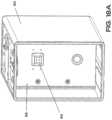
- FIG. 1is a perspective view of one embodiment of the dispensing station.
- FIG. 1 Ais a perspective view of another embodiment of the dispensing station.
- FIG. 2 Ais a detailed perspective view of one embodiment of the dispensing station depicting a drawer in the almost closed position.
- FIG. 2 Bis a detailed perspective view of one embodiment of the dispensing station depicting a drawer in a fully opened position.
- FIG. 2 Cis a rear perspective view of one embodiment of a cassette.
- FIG. 3 Ais a front perspective view of one embodiment of a cassette with a handle open or deployed and pivoted upwardly.
- FIG. 3 Bis a front perspective view of one embodiment of a cassette with a handle closed.
- FIG. 3 Cis a front perspective view of the embodiment of the cassette in FIG. 3 B with the drawers removed.
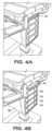
- FIG. 4 Ais a detailed perspective side view of one embodiment of a cassette mounted in a housing with the cassette handle closed.
- FIG. 4 Bis a detailed perspective side view of FIG. 4 A with the cassette handle ejected or deployed.
- FIG. 4 Cis a detailed perspective side view of FIG. 4 B with the cassette partially removed from the housing.
- FIG. 4 Dis a detailed perspective side view of FIG. 4 A with the cassette removed from the station.
- FIG. 5is a rear perspective view of a cassette with the rear panel removed.
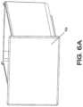
- FIG. 6 Ais a perspective front view of a small drawer.
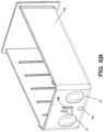
- FIG. 6 Bis a perspective rear view of a small drawer.
- FIG. 7is a perspective rear view of a medium drawer.
- FIG. 8is a perspective rear view of a large drawer.
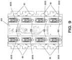
- FIG. 9is a front elevation view of one embodiment of the cassette rear partition.
- FIG. 10is a rear elevation view of one embodiment of the cassette rear partition.
- FIG. 11is another embodiment of the station.
- FIG. 12is a screenshot depicting system configuration.
- FIG. 13is a screenshot depicting drawer assignment.
- FIG. 14is a screenshot depicting monitoring drawer open status.
- FIG. 15 Ais a table depicting one sequence of steps to eject a cassette.
- FIG. 15 Bis a table depicting another sequence of steps to eject a cassette.
- FIG. 16 Ais a table depicting one sequence of steps to open a drawer.
- FIG. 16 Bis a table depicting another sequence of steps to open a drawer.
- FIG. 17 Ais a table one sequence of steps to assign identifiers to a drawer.
- FIG. 17 Bis a table another sequence of steps to assign identifiers to a drawer.
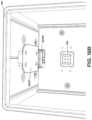
- FIG. 18 Ais a front perspective view of one embodiment of the hollow housing.
- FIG. 18 Bis a detailed view of the housing of FIG. 18 A depicting the cassette handle actuator.
- FIG. 18 Cis a side elevation of the one embodiment of a cassette handle actuator.
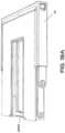
- FIG. 19 Ais a perspective view of one embodiment of an actuatable cassette handle.
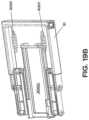
- FIG. 19 Bis a perspective view of the handle of FIG. 19 A with the top cover removed.
- FIG. 20is a rear perspective view of one embodiment of the center partition of a housing.
- FIG. 21is a prospective view a cart with a battery bridging station attached.
- the terms “a” or “an”are defined as one or more than one.
- the term “plurality,” as used herein,is defined as two or more than two.
- the term “another,” as used herein,is defined as at least a second or more.
- the terms “comprises,” “comprising.” or any other variation thereofare intended to cover a non-exclusive inclusion, such that a process, method, article, or apparatus that comprises a list of elements does not include only those elements, but may include other elements not expressly listed or inherent to such process, method, article, or apparatus.
- An element proceeded by “comprises . . . a”does not, without more constraints, preclude the existence of additional identical elements in the process, method, article, or apparatus that comprises the element.
- the station 1preferably includes a movable cart, such as a rollable cart 10 , where movement is provided by wheels or casters at the base of the cart.
- a movable cartsuch as a rollable cart 10
- movementis provided by wheels or casters at the base of the cart.
- One preferred cartis a Humanscale T7 cart, which is based on the adjustable features described in U.S. Pat. No. 9,038,549, hereby incorporated by reference in its entirety.
- the T7 cartincludes a portable power source 100 , such as a rechargeable battery, generally stored in the bottom of the cart.
- a power stationincluding a battery, and a battery bridge station 99 containing an internal battery, such as an Elora battery interface available from Anton Bauer of Vitec Group Plc, of Richmond UK, can be mounted to the back of the station or cart. See FIG. 21 .
- the battery bridgeallows a user to swap out a discharged battery without losing power to the cart (via the internal battery of the bridge) during the swap.
- the T7 cartis height adjustable (generally electronically adjustable via system software) with a center telescoping support stand 9 .
- a computer systemcomprising one or more input devices 20 , a local onboard processor 30 and computer memory, and a visual display device 40 .
- the input device 20 , a local onboard processor 30 , the computer memory and visual display device 40can be a single unit, such as a tablet or laptop, or separate units.
- a movable cartis not used, and the station (including the computer system, housing and cassette, as later described, is a stand-alone device generally located at a fixed location (such as in a pharmacy).
- the cart 10includes a work surface 11 and a keyboard mount or shelf 12 extending outwardly from the main body of the cart 10 .
- a monitor 41is mounted on a pivotable arm 15 above the work surface 11 .
- a computerincluding a processor, local computer memory, input/output and display device.
- input devicessuch as a keyboard 21 and mouse 22 .
- a laptop or tabletcan be located on the work surface or below the work surface.
- a second processing device, display, and input devicerepresented by a tablet 25 with a touch screen interface.
- the cassette housing 90is a hollow rectangular shell having two opposing open sides (a right and a left open side, the right side is shown in FIG. 4 D ).
- FIG. 18 Apositioned in the interior center of the housing 90 are center vertical dividers 93 separating the housing interior into at least two sections, a left housing section associated with a left center divider 93 , and a right housing section associated with right center divider 93 .
- a removable cassette 50(see FIG. 3 A ) can be inserted into each housing section.
- Two housingsmay be mounted on the cart, an upper housing 90 and a lower housing 95 , such as shown in FIG. 1 A .
- the chassis of the carthas a telescoping height adjustable support column 9 , and with a telescoping support column, the upper housing 90 is generally mounted to the underside of the work surface 11 to avoid interference with the movement of the telescoping arm 9 .
- a lower housing 95is preferably mounted to the underside of the upper housing 90 . With two housings, the cart 10 is able to accommodate four cassettes 50 , next described. Power and communications to the lower cassette housing 95 is provided by a wiring harness that may be coupled to the housing wiring harness in the first or upper cassette housing 90 .
- each housingrepresents a separate node on a bus system, and each receives all housing communications but only responds to communications addressed to that particular housing.
- Each housing 90(upper or lower), and housing sections (right or left) are addressable on the communications bus, and the address is imbedded in instructions/commands/queries and is interpreted in microcontroller firmware mounted on a printed circuit board (PCB) 300 positioned on a center divider 93 for each respective housing 95 and 90 . (See FIG. 20 ).
- PCBprinted circuit board
- This micro-controlled firmwarein conjunction with the system software contained in or accessible on the system processor 30 and microcontroller firmware located in the cassette (such as on a cassette PCB), will direct instructions and commands from the user, via the system processor, to the proper housing, via a common power and communications bus (such as wiring harness or harnesses, and from the housing to the proper cassette and cassette component, as later described.
- a common power and communications bussuch as wiring harness or harnesses, and from the housing to the proper cassette and cassette component, as later described.
- Each center divider 93includes an electronic interface device 94 that is coupled to the power and communications bus, and each interface device 94 will couple or interface with a cassette electronic interface device 64 on the rear of a cassette 50 (see FIG. 2 C ).
- the housing electronic interface device 93is a six prong male connector
- the cassette interface device 64is a corresponding inter-mating female plug (see FIG. 2 C ).
- the housing electrical interface device 94is coupled to a housing wiring harness (not shown) that interfaces the housing firmware on the PCB 300 .
- An additional wiring harnesscouples the firmware to a plug at the top of the housing 90 (see FIG. 20 ) for connection to the cart's computer system and cart power supply.
- These wiring harnesseswill supply power and control/communications from the station's battery and processor, to the components and equipment located in the individual cassettes 50 .
- the systemis thus able to route communications to the appropriate component by using an address scheme for each component (as interpreted by the firmware in the cassette, if present).
- the firmwaremay have an internal database of the components positioned on the cassette board, and these components may be associated, at the cassette board level, with a drawer identifier or drawer location.
- the firmwaremay also have access to a modifiable memory table on the PCB to store a local map or image of the drawer identities and associated positions in the cassette that can be filled in response to a read ID command).
- the overall equipment configuration (and equipment addresses) for each cassetteis preferably maintained, or partially maintained, in a system database, which may be stored in local memory for use by the system processor or in a remote server memory, or in both locations.
- FIGS. 3 A- 3 COne embodiment of the cassette 50 is shown in FIGS. 3 A- 3 C .
- the cassette 50is a six sided hollow rectangular frame 53 with one open side, into which a number of drawers 70 may be slidably positioned in the interior of the frame 53 .
- the cassette frame 53 shown in FIG. 3 Cis closed on five sides (rear, top, bottom, side 1 and side 2 ) and open in the front.
- the cassette frame 53has three horizontal dividers 56 that separate the interior of the cassette frame 53 into four separate spaces, each space containing two compartments (two compartments per divided space, for a total of eight compartments per cassette).
- each horizontal divider 56slide in slits on the frame 53 interior side walls, and can be repositioned on the frame 53 to allow customization of the drawer configuration of the cassette 50 to accommodate 2-8 drawers 70 in each cassette.
- the top facing surface of each divider 56may have one or more shoulders or channels to interface a comparable channel or shoulder on a drawer bottom, to act as a drawer guide.
- a rear vertical partition 63Located in the interior rear of the cassette frame 53 , is a rear vertical partition 63 , on which equipment may be mounted (see FIG. 5 ). For instance, mounted on this partition 63 are a series of actuators 200 and actuator latches 201 . In a preferred embodiment, each compartment is associated with one actuator 200 and associated actuator latch 201 .
- the rear panel of the cassette frame 53is removably attached to the body of the frame to allow user access to the drawer actuators 200 , actuator latches 201 , and drawer sensors positioned on the rear vertical partition 63 .
- the front terminating end 203 of an actuator latch 201is U-shaped, with the open end of the U-shape upwardly facing, but other shapes could be used.
- a spring loaded U-shaped handle 51Coupled to the top front surface of the frame 53 is a spring loaded U-shaped handle 51 (see FIGS. 3 A and 3 B and 5 ).
- the handle 51is pivotably mounted to the top of the frame 53 . Note that the handle 51 is flush with the frame 53 sides and frame front.
- the handle 51in a retracted or closed position, cannot be grasped by an operator, that is, the handle is inaccessible in the closed position (see FIG. 4 A ). Consequently, the cassette 53 cannot be removed from the housing 90 until the handle is electronically unlatched/ejected by a user.
- the handle 51is pivotally connected to a slidable spring loaded latching plate 2000 (see FIGS.
- the latch member 3000is a dual actuatable latch member having a left latch 3001 and a right latch 3002 , separately actuatable.
- the left latch member 3001will latch and lock to the slidable plate 2000 on the left cassette 50
- the right latch member 3002will latch and lock to the slidable plate 2000 in the right cassette 50 .
- the handle 51is in the retracted position (flush with the cassette drawers). To eject a handle 51 to a released or deployed position, as shown in FIG.
- the userwill activate an eject command from the input device.
- This commandwill activate the servo or solenoid or other actuator associated with the selected cassette, to activate the appropriate left or right latch 3001 or 3002 .
- the latch 3001 or 3002will disengage from the sliding handle plate 2000 , allowing the plate 2000 and attached handle 51 to slide forward by action of springs 2001 , which deploys the handle to a position where the handle extends past the front of the cassette frame 53 and allows a user to grasp the handle 51 , as shown in FIG. 4 B .
- One sequence of steps to eject a cassette handle, in one version of the station(the Medlink lite version), is shown in the table of FIG.
- FIG. 15 AAnother sequence of steps to eject a cassette handle in another version of the station (the Medlink Pro version) is shown in the table of FIG. 15 B .
- the handle 51To reposition the handle 51 in the closed state, the handle 51 is pushed inwardly until it is flush with the cassette front surface, where the handle latch will reengage the sliding plate 2000 .
- the usermay also deploy the handle 51 manually in the event of a power failure, by inserting a key in the housing, which turns a linkage to manually move the latch actuators to a released position.
- Switches in the housingmay be associated with each cassette, and the switch state can be used as an indicator of the presence or absence of a cassette.
- the handle 51Once the handle 51 has been deployed, the user can grasp and pull the handle 51 , sliding the cassette 50 toward the user and out of the housing 90 (see FIGS. 4 C and 4 D ). The handle 51 may then be used to transport the cassette 50 , as the handle 51 is pivotably attached to the frame 53 and sliding plate (see FIG. 3 A ). In the embodiment shown, the handle 51 may not be repositioned into the retracted position once the cassette 50 is removed from the housing 90 , as the locking latches 3001 and 3002 are located in the housing 90 .
- the top exterior facing portion of the cassette frame 50has a channel 57 defined therein, which is shaped to slidably inter-mate with a downwardly facing shoulder 3007 in the interior of the housing 90 , for sliding the frame 53 into the cassette housing 90 to allow the latch actuators 3000 to interact with the slidable plates 2000 (see FIG. 18 B ).
- the cassette 50Since the cassette 50 connects into the center divider 93 of the housing 90 , communications/control and power is provided from the cart 10 , through the housing 90 to the vertical partition 63 in the cassette 50 .
- the wiring harness from the cassette plug 64 on the rear of the cassette 50is attached to a PCB (printed circuit board), and from this board, wires connect to the separate components mounted on this rear partition 63 in the cassette 50 . Communications and control of the components are accounted for by micro-controlled firmware. This firmware may be mounted on the PCB in the housing center divider 930 , in the cassette rear partition 63 , or both.
- the addressable command from the processoris passed to the firmware in the housing located on a housing printed circuit board, which, if addressed to a cassette in the housing, will pass the command to the appropriate cassette (the housing firmware may strip off the cassette address, leaving the component address (such as actuator address 0-31), and the firmware in the cassette located on the cassette printed circuit board will respond to the command with the appropriate response) (such as actuate activator 16 , or read RFID 00 ), and communicate status of the command (if needed, such as respond with RFID tag value) back to the housing, which passes the response to the processor.
- the systemhas distributed intelligence with high level user interface functionality located in the cart processor, and the component level interface functionality located in firmware in the housing and the cassette.
- the cassette microcontroller firmwareis used to route power and communications signals from the common power and communications bus via the six wire plug (two wires for power, two wires for addressable communications, and two wires used to differentiate the upper housing from the lower housing), for distribution of actions or commands to the equipment on the rear partition 63 of a cassette (such as actuators, proximity sensors, RFID reader and antennas).
- the firmware on the housing 90will direct communications to the proper cassette 50 (right or left) based on the addresses provided in the instructions from the system processor.
- the processorcan access the drawer location which is stored on computer memory, where the computer memory is either located on the cart or remotely located, such as on a system server (in a client/server relationship where the cart processor is the client in communication with and a remote server computer) with drawer information stored on the server computer memory).
- the computer memoryincludes a database which generally has stored drawer identifiers, which may include drawer size/drawer location in the cassette interior, where drawer location can be specified in a variety of different ways, such as by specifying a compartment(s), or other associated locations, such as actuator locations (e.g., actuator address 0-15), sensor address, or other addresses or locations associated with a compartment or with the drawer.
- the database with the configuration mapmay contain RFID tag or the unique drawer identifier information (such as on the Medlink Pro version, described later), and associate each RFID information with all other patient identifiers assigned to the particular drawer, which information can be stored in computer memory located remote for the cart, such as in a server computer, the hospital HIS system computer memory).
- the server systemis accessed with either a wireless or a wired communication channel.
- the systemwill use this configuration map or database for routing instructions and control signals, based on input from a user (e.g., open drawer A5).
- the firmware on the cassettewill decode the instruction from the processor/housing and route the instruction to the final destination, to the appropriate equipment on the cassette partition for action or communication (e.g., power actuator 8 , for instance, or query status of proximity sensor 3 ).
- Each componentis also addressable (e.g., such as 0-31).
- the specific type equipment addressedmay not be specified in the command, as the instruction can inform the cassette firmware of the equipment addressed (e.g., an open command is addressed to actuators; a read ID command is addressed to RFID sensors, etc.).
- Drawers 70are slidably positioned in one or more drawer compartments in the interior of the frame 53 .
- drawers 70are available in three sizes, a small drawer that occupies a single cassette compartment, a medium drawer that occupies two side-by-side cassette compartments, and a large drawer that occupies four cassette contiguous compartments (two side-by-side compartments one on top of the other).
- FIGS. 6 A and 6 BOne embodiment of a single drawer is shown in FIGS. 6 A and 6 B .
- the front of the drawer 70lacks drawer handles or a grip or graspable feature, and when closed, the drawer front surface is flush with the outer frame of the cassette.
- Each drawer 70is a rectangular enclosure with an open top.
- sensors or sensor targetsincluding a proximity sensor target 72 (here a permanent magnet to interact with a magnetic proximity sensor) and an electronically readable drawer identifier tag 71 .
- the readable identifier tagis a passive RFID tag containing an ID which is used to uniquely identify the drawer, and to also identify drawer size, (such as by having the first readable alphanumeric character in the stored tag identifier specify drawer size).
- proximity sensorsare actuatable switches c (such as two position switches), mounted preferably in the cassette frame, one per compartment.
- the “proximity sensor target” 72can be the drawer back.
- a single small drawerincludes two RFID tags 71 but a single proximity sensor target (magnet) 72 .
- a half drawercan be located in the right side (adjacent to the rear of the cart) or left side (adjacent to the front of the cart). By placing RFID tags 71 on each rear side of the half drawer, a half drawer is not sensitive to whether it is positioned in the front or rear portion of the cassette.
- the rear of the drawerfaces the front facing portion of the cassette rear partition 63 .
- a series of proximity sensors 62such as a hall effect sensor or reed magnetic proximity sensors
- a series of reading devices 61to read the drawer electronic readable identifier (also with at least one device 61 per compartment).
- the reading devices 61are RFID antennas 61 , each positioned to interface and read an RFID tag 71 on a closed drawer 70 .
- the antennasare used in conjunction with a RFID interrogation device, such as located on the cassette PCB board e.g., using a common interrogation device to interrogate a RFID tag via the associated antenna.
- a RFID interrogation devicesuch as located on the cassette PCB board e.g., using a common interrogation device to interrogate a RFID tag via the associated antenna.
- each antennacould be associated with a separate RFID interrogation device.
- the devices 61 and proximity sensors 62communicate status with the system processor via the communications bus and firmware on the cassette and on the housing.
- Each drawer 70preferably also has at least one latch 69 extending outwardly from the drawer's rear exterior surface, that will couple with corresponding actuator latches 201 on the interior partition 63 of the cassette, as later described.
- a preferred drawer latchis a downwardly shaped hooked latch, that will inter-mate with the “U” shaped actuator latch 201 on the rear partition 63 , for closing and opening a drawer.
- a drawer 70can be opened only by action of the cart processor 30 or by manual override, later described). To open a drawer 70 , the operator will select a drawer 70 to open (the selection process is later described) via one of the cart's input devices.
- the open commandis used to actuate or power one or more actuators 200 (generally a servo) associated with the drawer to be opened on the cassette partition 63 , which results in a movement of the associated actuator latches 201 that are coupled to the actuators 200 .
- a userenters the open command with a drawer label identifier (which can be patient identifier, drawer location, or other identifier), and the processor places the drawer open command on the communications bus.
- a drawer label identifierwhich can be patient identifier, drawer location, or other identifier
- Each housingreceives the command, and determines if it is directed to a cassette in that housing.
- the proper housingvia firmware on the housing PCB) will forward a possibly modify command to the proper cassette.
- actuatorsservo motors
- the path the actuator latch 201 follows during actuationcan be controlled by a shape of the linkage connecting the actuator latch to the actuator, or the linkage can be guided by a shaped structure (such as a channel), or the actuator servo itself may have a shaft that follows an eccentric path, suitably moving the linkage coupled to the servo shaft.
- the actuator 200may communicate its status to a servo manager, (as open, closed, in motion), such as to the firmware, for use by the system computer on interrogation.
- the actuator latch 201moves forward towards the drawer 70 , it remains engaged with the drawer latch 61 , thereby pushing the drawer 70 slightly forward with the forward motion of the actuator latch 201 .
- the final downward movement of the actuator latch 201allows the actuator latch 201 to disengage from the drawer latch, that is, the actuator latch “U” shaped hook clears the downward hook portion of the drawer latch 69 , thereby separating the latches and unlocking the drawer, allowing the drawer 70 to be opened by a user.
- This open action of the actuator latchesplaces the drawer 70 front slightly beyond the front edge of the corresponding cassette frame 53 , such as shown in FIG. 2 A .
- This position of a drawer 70is termed “almost closed.” In this almost closed position, drawer 70 is unlatched from the actuator but within such proximity to the actuator that the actuator can retract the actuator, reengage the latches and close the drawer. In the almost closed position, an operator can grasp the drawer front top edge and slide the drawer fully opened to access the drawer interior.
- the drawersare slidably positioned or mounted in the cassette frame 53 .
- An opened drawer 70is considered any position of the drawer 70 past almost closed position, providing access to the drawer interior. Until the drawer reaches the almost closed position, it cannot be opened, as the drawer is locked, that is, the cassette latch and drawer latch are inter-mated.
- Medium and large drawershave two drawer latches (such as shown in FIGS.
- the systemmust activate two actuator latches simultaneously to unlock and open these size drawers.
- the cartmust “know” the size of the drawers (which may be contained in the configuration map in the computer memory or in memory on the cassette PCB) to allow proper control for opening, closing and locating the sensors that interface with the drawer 70 .
- the system processor 30can monitor the period of time the drawer remains in the unlocked almost closed position, and if a predetermined time is met, the system can reverse the actuator latch 201 (e.g., the servo reverses) to close the drawer 70 .
- the drawer 70 assigned to “Richard Robin”a patient identifier
- the systemis tracking the amount of time until the drawer will be automatically closed.
- the actuator latch 201will retrace its path, first moving upwardly to reengage the drawer latch 69 , then moving in a rearward direction, thereby pulling the almost closed drawer into fully closed and locked configuration, that is, the system automatically closes a drawer.
- the system processorknows when a drawer has been opened (by tracking the command status, or by the proximity sensors). For instance, the proximity sensor can relay status such as “closed” (the drawer is flush with the cassette frame and locked by the actuator), “open” (the drawer is out of range of the proximity sensor) or almost closed as defined herein).
- the system processorcan detect how long a drawer 70 is in the almost closed position, by, for instance, polling the status of the proximity, which status may be stored on the PCB board, or directly queried based on the poll instruction.
- the proximity sensorsare used to detect drawer open, closed and almost closed position.
- One sequence of steps to open and close a drawer in one version of the station(the Medlink lite version) is shown in the table of FIG. 16 A .
- Another sequence of steps to open and close a drawer in a version of the station(the Medlink Pro version) is shown in the table of FIG. 16 B
- each drawerhas at least one unique identifier established in the RFID tag 71 , and that tag is readable by an RFID reader/antenna 61 positioned on the cassette rear partition 63 .
- the RFID antenna 61is positioned adjacent to the drawer RFID tag 71 , allowing the RFID reader to interrogate the RFID tag 71 , receive the stored information and communicate the stored information to the system processor for use.
- Each RFID reader or antenna 61has a unique location on a cassette 50 , and can be electronically addressable by the system processor to initiate a query of the associated RFID tag. The system processor may request the RFID reader to query the RFID tag on a drawer.
- the processorknows or can determine which drawer location(s) is associated with the tag that was read. Armed with this information, and the information on drawer size from the RFID tag, the system can determine the configuration of the drawers in the cassette (e.g., query each antenna for information, and map the responses). Consequently, the system (via the processor and software and computer memory) knows what drawers 70 are present in each cassette 50 in the cart 10 , the specific location of each drawer 70 in each cassette 50 , the size of the drawer 70 , and in some embodiments, may have stored the RFID information or additional sensor or actuator addresses associated with each drawer in the cassette 50 .
- the configuration of the station(number of housings, number of cassettes in each housing, and the identity of the drawers in each cassette, such as patient identifier) is preferably stored in the associated system memory (either local and/or remote on a server) as part of the database configuration map describing the station configuration.
- the station configurationcan be displayed on the system display device (such as a GUI interface) as a visual map of the cart's cassettes, for use by an operator.
- the stored configuration informationis limited, and consequently, the configuration map displayed will be limited.
- the system processorwill interrogate or poll a drawer or the equipment to verify/update the system configuration. For instance, if a cassette has been removed, the system knows the cassette has been removed (from the ejection sequence, and in some embodiments, from a sensor reading (such as a switch output)). If a cassette has been recently installed, that event can trigger an interrogation sequence of all RFID antennas 61 . In this event, the system processor can interrogate the newly installed cassette to determine the identity of the drawers in that cassette, and update the configuration map with the new drawer identifiers, sizes and locations.
- the system processorcan determine the RFID tag information in an installed cassette, pass the RFID information to the server, and download the patient identifiers stored in the server to repopulate the configuration map to be displayed on the cart's display device.
- multiple stationsmay have drawer information stored on the server memory (and the server may also have a cart or cassette identifier stored and associated with each station/cassette). In this fashion, the system updates its configuration data to stay current.
- the systemgenerally loses communication with the drawer 70 , as the RFID tag 71 and magnet 72 are too remote from the RFID reader/antenna 61 and proximity sensor 62 for interaction with the associated sensors.
- the systemmay confirm/update the identity of the drawer 70 , and if a drawer 70 has been swapped out with another drawer 70 , update the configuration map with the new drawer data and may download the associated patient identifiers from the server, or a HIS system, later described.
- the display devicegenerally will indicate that the drawer is open when a drawer has been opened or removed, reflecting the status of the drawer.
- the systemwill not allow a second patient drawer to be opened (absent, for instance, an override command, administrator access, or pharmacy access, for instance, where an “open all drawers” command may be utilized).
- the control of the drawersis undertaken by users interacting with the system software via the system input devices.
- the system softwaregenerally provides for a “System Administrator” user, such as a supervising nurse, to log into the system and configure the system.
- a “System Administrator” usersuch as a supervising nurse
- Configuration of the system for multiple usersis preferably undertaken by the System Administrator.
- Other configuration actionsare preferably undertaken by the System Administrator, or another user that has been granted access to such actions by a System Administrator. For instance, when the cart is shared among users, specific configurations can be associated for each UserID, or groups of UserIDs, to customize cart operation according to each user or user group preferences.
- certain UserIDsmay only be provided access to designated drawers having specific identifiers (such as ward identifiers), or only provided access to the system at designated locations.
- the System Administrator or other properly credentialed usercan provide different rights to the different users, or different groups of users, and store these access rights, or group rights, in system memory (generally local cart memory).
- system memorygenerally local cart memory.
- a userOnce logged in, a user may be denied access to certain cart functionality, such as denied access to certain drawers, denied the ability to eject cassettes, or denied other station functionality. For instance, a particular user group may be denied or granted rights to open all drawers at one time.
- the system, as described,is highly configurable.
- Additional informationmay be associated with specific drawers in system or server memory. For instance, a particular drawer may be assigned to a particular patient.
- a properly credentialed userselects the drawer to assign (the user may first have to select the cassette on which the drawer is to be assigned in some versions), and then activate the assign function from the input device. See the screen shot of FIG. 13 .
- the usermay select a drawer by clicking on an image of a drawer, or touching an image from a touch screen input, or inputting a specified drawer identifier (such as A1, A2, A3, A4).
- the usercan then input additional information to be associated with the drawer in the configuration map (and replace previously stored information), such as patient ID, patient DOB, ward location, patient bar code or hash code identifier, location identifier (e.g., patient room), location bar code or hash code identifier, or other pertinent information.
- patient IDpatient ID
- patient DOBward location
- patient bar code or hash code identifierlocation identifier (e.g., patient room)
- location bar code or hash code identifiere.g., patient room
- multiple patient identifierscan be associated with a particular drawer, such as patient ID, bar code, location, etc.
- designated identified characteristicssuch as patient name
- the information displayedin some embodiments, can be controlled via system configuration by the System Administrator.
- These patient identifiersmay be transmitted and stored on a local or remote memory (a server database).
- FIG. 12shown in the screenshot depicted in FIG. 12 , is the configuration of a particular cart containing three cassettes.
- certain drawers(reference 124 ) are associated with specific patients, while one drawer is not assigned.
- certain drawers(references 125 ) are associated with specific patients, one drawer is identified as a storage drawer, and one drawer is not assigned.
- all drawers(references 126 ) are assigned to specific patients.
- a drawercan also be assigned as a “common” supply drawer, where various supplies will be located that may be applicable to multiple patients on a given distribution workflow. From the assign/re-assign screen or command, stored drawer parameters can be edited, modified, or deleted, or a drawer de-assigned (wipe all identifiers) or reassigned. In some embodiments, to reassign a drawer, the system may require the user to have Administrator status. The complete set of patient identifiers associated with a specific drawer may also be viewed, for instance, via the assign command.
- the cassette components identified with a particular drawerare generally not displayed for a user, as there is little need for such by the user—these identifiers are used by the station during station functions (open drawer, close drawers, interrogate status, etc.).
- One sequence of steps to assign a drawer for one version of the station(the Medlink Lite version) is shown in the table of FIG. 17 A
- One sequence of steps to assign a drawer in another version of the station(the Medlink Pro version) is shown in the table of FIG. 17 B .
- the display devicemay display a picture of the current installed cassettes, and once a cassette is selected by the user, display drawer configurations for the selected cassette alone (such as using a zoom feature, to allow a user to zoom in or view only the information associated with the selected cassette and to interact with the selected cassette).
- This featureis useful if screen size on the display device is limited (for instance, in a wireless environment, a cart may be monitored remotely by, for instance, a ward nurse via a handheld tablet, or via an application on a smart phone).
- displayed drawer informationmay be limited to drawer standard identifiers (without patient identifiers), such as drawer A1, or B2, such as where the letter (A, B, C. or D) reflects cassette identifier, and the number (1-8) reflects compartment identifier in the cassette).
- drawersmay be displayed for selection by a list.
- the system's display outputis configurable.
- patient datamay be downloaded into the system memory from the hospitals information system (HIS) network (connected via a wireless connection between the system and HIS, for instance, similarly to the system in a client/server embodiment).
- HIShospitals information system
- To assign a drawerthe user selects a drawer, then requests a list of patients from the HIS, and the system displays the list received from the HIS on the cart display device.
- the usercould select the patient to be assigned from the displayed list (e.g., mouse click on the selected patient, or touch the screen in a touch screen environment), and the system would then request the HIS to transmit certain of the patient's information (e.g., DOB, patient bracelet bar code; patient room, etc.).
- DOBpatient bracelet bar code
- patient roometc.
- the system processorwould receive the information and associate the patient information with the drawer and enter this information in the configuration map with the selected drawer (and, for instance retransmit the information to the server, if present).
- the cartcan utilize the HL7 integration to access the patient-related information stored on HIS. Interfacing of the cart with the hospital's information system can be achieved using currently available software. Alternatively, the user could scan a patient's identifier, or enter a patient ID, and have the system query the HIS system (or server in some embodiment) for other patient information.
- the userselects the drawer to open (again, in some embodiments, select cassette first).
- the selectioncan be undertaken by various procedures, depending on the cart's configuration and the preferences of the particular user (UserID), the system capabilities, or configurations established at the work location.
- the userscans the patient bar code bracelet with a bar code reader located on the cart (see, for instance the screenshot of FIG. 12 ).
- the scanned IDis then compared with stored information to see if a drawer on the cart has a matching patient ID associated. If so, the system would identify the drawer location in the cart, and actuate the actuator latches associated with the drawer location (accomplished in conjunction with the firmware on the system). This operation allows the selected drawer to move to the almost closed position to allow the user to grasp the front of the drawer and pull it fully open.
- the nursecan interact with the drawer contents—load the drawer, remove prescriptions from the drawer, etc.
- the nursemay indicate which drawer to open, for instance selecting from a list displayed on the display device, or selecting from a displayed map of a cassette by touching the drawer on the displayed map of the cassette configuration, in a touch screen environment, or entering a drawer number (for instance “A8”) in an input device.
- the inputmay be via keyboard, mouse, touch screen or other input device.
- all drawersmay be selected to be opened (or closed) at one time. The selection can be made on entry of a specific “open all” command, or, for instance, by entry of a specific location code (such as the pharmacy location code). In some embodiments, only drawers associated with a particular identifier may be opened at any given time, to provide for secure distribution of medication. For instance, all drawers for a given user group or patient could be opened at once for a common distribution at a nursing station.
- a particular patient's associated drawerif a particular patient's associated drawer is opened, another patient's drawers (e.g., assigned to a different patient) on the cart may not be opened concurrently.
- a drawer identified as a common supply drawermay be opened while any other drawer is opened.
- a supply drawermay be associated with a set of specific patients (or a subset of other drawers), and only opened when the associated patient's drawer is selected.
- the systemis flexible, allowing the user to configure a subset of drawers that can be opened concurrently, based on user supplied parameters.
- the drawers 70 in a cassette 50can be opened from the cart processor.
- the cassette 50may be removed from a cart, and transported to a remote location and inserted into a remote cart or docking station (such as a fixed station located in the pharmacy area) for filling or emptying of the drawers.
- a docking stationcan be another cart, or fixed cart (not movable), where the cassette can be inserted into a housing 90 .
- the housing 90may be dispensed with, and a simple communications plug, coupled to the cassettes' firmware to exercise control/communication with the cassette drawers, could be used.
- the docking stationhas a display device and input device to display and/or modify the configuration of the docked cassette.
- the usermay simply push the drawer back into the drawer slot until the actuator latch(es) 201 hook portion contacts the drawer latch(es) 69 , and on further rearward movement rearward, two latches are positioned in an inter-mating latched relationship, thereby latching or locking the drawer in a closed position.
- the operatormay push the drawer 70 into the drawer slot until the drawer is in the almost closed configuration.
- the system processoron detecting the drawer 70 (via proximity sensor 62 ), will (in conjunction with the firmware in the cassette) activate the actuators 200 associated with the drawer after a predetermined time (which can be set by the System Administrator), allowing the actuator latch 201 to pivot upwardly and re-engage the drawer latch 69 , then pulling the drawer 70 into a closed, latched configuration.
- the usermay activate a close drawer command, possibly after selection (or before selection) of the drawer 70 to be closed, and the system would then cause the appropriate actuator(s) 200 to operate (for instance, in reverse) to allow the associated actuator latches 201 to re-engage latches 69 to close and lock the drawer.
- the systemmay allow for a command to close all drawers, allowing activation of all actuators at substantially the same time (or two latches at a time to reduce the power draw on the system's battery).
- the system softwaremay interface with the hospital's information system (HIS) network.
- HIShospital's information system
- the cart's computer systemwill have wireless communication capability, but a hardwired interface with the processor can also be used (such as via Ethernet cable) to interface with the HIS.
- the systemincludes a laptop, preferably the laptop has wireless capability.
- each cart 10can exchange information with the HIS, similar to the exchange in a client/server embodiment. For instance, if a particular drawer 70 has been assigned to a particular patient, the patient information can be downloaded to the system from the HIS for population of the patient identifiers (DOB, Bracelet number, etc).
- DOBpatient identifiers
- drawer informationcan be communicated to the HIS and stored in the HIS system, such as cart identity or name, drawer identity (such as drawer unique RFID) and some of all patient identifiers.
- the second cartcould query the HIS system for stored drawer assigned information (based on providing drawer RFID identifiers to the HIS and requesting transmission of associated patient identifiers), and receive the stored patient identifiers from the HIS.
- Thisallows drawers to be moved from cart to cart (or to a remote loading docking station) without the need to manually enter drawer assignments or drawer patient configurations.
- patient informationcan be shared between the cart and HIS using, for instance HL7 protocol.
- the sequence of steps in the table in FIG. 17 Balso depicts populating patient identifiers from remote computer memory, such as the server memory in a client/server embodiment of the station, or the HIS system memory.
- the cartcan also store cart or drawer activity, either in local memory, server memory, or in other embodiments, to transmit activity information to the HIS, in order to run reports of cart usage (user usage), drawer activity, and other relevant statistics. Reports may be compiled from the cart system, or in other embodiments, from the server or HIS with suitable software in the HIS and server. In one embodiment, once installed in the cart, the processor may inform the HIS of the drawer's present location, for tracking of the drawer history.
- the cartcan utilize the HL7 protocol to access the patient-related information stored on the HIS. This interfacing of the cart with the hospital system can be achieved using currently available software.
- the cart systemincludes manual overrides to allow a cassette to be removed or ejected, and for the drawers to be opened, for instance, in the event of a power failure.
- one manual override for a lockable cassette handleis to have the handle lock activated by a manual hardware key on the housing for manual removal of a cassette from a housing.
- a similar hardware keycould also be used on the cassette, to manually unlatch all of the activator latches (via a linkage system coupled to the lock) to allow all drawers (e.g., manually actuate all eight activator latches) to open.
- manual activationmay be needed in the event of a power failure, or when the cassette is transported outside of the housing and thus not in electrical communication with the cart.
- the System Administratorsets up and configures each cart, that is, the administrator can initialize the data fields and configure the system as desired, set up the user ids/passwords, assign the cart an identity or reference code (if it is to network into the hospital system (e.g., client identifier for use in a client/server system)), establish user groups to control access to the drawers for refilling; identify and label drawer information fields to be associated with each drawer and RFID tag (patient bar code; room ID: DOB, etc.).
- an identity or reference codeif it is to network into the hospital system (e.g., client identifier for use in a client/server system)
- establish user groups to control access to the drawers for refillingidentify and label drawer information fields to be associated with each drawer and RFID tag (patient bar code; room ID: DOB, etc.).
- the staffmay also initialize the drawers by assigning patient values or identifiers to them, particularly when the system networks into the HIS, such as by choosing a patient to be assigned to a drawer, preferably from a list received from the HIS system, and receiving the patient identifiers (such as from the HIS system) and populating the appropriate data fields for display on the cart.
- the staffmay identify some drawers as a common supply drawer; identify relevant location codes (pharmacy or ADC location, patient room code, etc.) as needed.
- the cart systemcan be used.
- the usertakes the cart (or just the cassette) to the ADC, and can open all drawers in a cassette (possibly after scanning in the location code of the ADC or pharmacy) and the system may display a picture showing drawer locations and drawer identifiers, to allow the user to properly open and fill the drawers with medications as needed for each patient, and for the common supply drawer if one is assigned.
- the usercan open each drawer individually and sequentially to fill the drawers using the configuration map displayed on the visual display device.
- the userwill move the cart to the first location on his-her distribution workflow route, and for each patient at that first location; open that patient's drawer(s) (such as by entering the patient ID or scanning the patient's wristband with bar code reader), distributing the proper drawer contents, and closing the drawer.
- the userthen moves the cart to the next patient location for distribution. This process continues at the second location, and then repeats until all patients at a specific area (such as a ward) are served. The user will then move the cart to the next location, and repeat the process.
- FIG. 11One particular embodiment of the invention is shown in FIG. 11 , sometimes referred to as the T7 MedLink Lite or MedLink Lite embodiment (“Lite”).
- Liteuses a T7 cart, but does not necessarily include a separate monitor, keyboard, or laptop. Instead, a tablet, such as the computer tablet built into the T7 work surface may function as the system processor, and memory display and input device (a touch screen). Additional devices may be coupled to the tablet, such as a mouse or scanner.
- the cassette's drawersare configured with RFID tags, but proximity sensors are not necessarily needed, unless the Lite embodiment is to be configured for automatic door closure (the sensors may be included, but auto closing functioning may be disabled by the System Administrator).
- the Lite systemcan be designed for a single user, so access in this instance is generally by a PIN number or other access code means known to those of ordinary skill in the art.
- the usercan open any drawer, or all drawers, by using the touch screen on the tablet to select the drawer(s) to open.
- the Lite versionmay only use limited patient identifiers, and is usually not used in a client/server mode.
- the Lite versionis also generally not configured to interface with the hospital's information system network, and thus moving a drawer from one cart to another requires reentry of drawer identifiers in the new cart.
- T7 MedLink Pro versionAnother particular embodiment is referred to as the T7 MedLink Pro version, such as shown in FIG. 1 .
- a separate monitoris used as the primary display device, and input devices can include a keyboard, mouse and bar or hash code scanner.
- the system processorincludes a laptop located on the cart, but the cart's computer system may also be configured with wireless interaction with the hospital's network system and a system server. Consequently, certain of the system's software functionality can be running on the hospital server or system server (such as the report generation capability).
- the preferred T7 cartincludes a tablet that controls cart height adjustment, but operation of the cassette functionality in the MedLink Pro version, and interaction with the cassette equipment (proximity sensors, latches, RFID) will normally occur from the cart processor, not the T7 tablet.
- the Pro versionis designed to accommodate multiple UserID/passwords and includes the ability to generate detailed reports on the use of the system, such as UserID usage, patient usage, drawer history, etc.
- all drawersmay not be accessible to all users, as some drawers may be assigned to specific UserIDs or user groups.
- the drawerspreferably auto close, and can be opened by selecting a drawer associated patient identifier through interaction with the software, or preferably, by scanning a patient's wristband, where the patient wristband code is associated with a particular drawer or drawers in the configuration map. Multiple identifiers or information items can be associated with each assigned drawer.
- the medical cartmay have at least two protection layers for drawers that might contain Schedule II controlled substances.
- the two or more layer protectionmay include two layers of security, including one or more locking mechanisms, one or more digital authorization requirements (dual factor authorization), and may require one or more people involved in the authorization process.
- the authorization processcan include a combination of personnel, logical processes, authorizations, physical devices or electronic locking protection.
- a special narcotics cassette drawer or cassette housingcould be used to accommodate narcotics.
- a drawerFor instance, if a drawer is to contain heavily regulated narcotics, that drawer could have an additional patient identifier indicating that “narcotics” are contained in the drawer. This identifier could be manually input by the user during operation, or the identifier could be embedded into the RFID tag such that unique RFID tags are used for narcotics drawers.
- a “narcotics” drawermay be identified as such by the drawer identifier and recognizable as such by reading the identifier (a narcotics drawer may have an identifier that starts with a designated alpha-numeric character), or by receiving the drawer status as a “narcotics” drawer from the server computer.
- This “narcotics” identifierwould indicate to the cart that dual layer protection or dual layer authorization is required to open this particular drawer, requiring a second authorization tool be deployed.
- a second password or PINmay be required to access the drawer
- the systemcould require the user to verify the user's identify by requiring the user to meet a second identification or credential test, such as fingertip scan, retinal scan, voice identifier or other biometric scan, or to require the user to have a physical authorization identifier or readable token present (such as a RFID tag with a readable userID, a nurse id bracelet with bar code or a hash id that can be scanned by the system: a fob, a badge reader, or other device, such as a digital certificate stored on a smart phone, or a readable card or USB token).
- the tokenmust be present (e.g. detectable) by the system before access is granted.
- These tokens or biometric tokensmay be held by the same person, or by different persons such that two or more users need to be present to access the narcotics drawer.
- the systemmay employ two factor authentication, where the system sends an electronic authorization code to the user's electronic account (such as that user's smart device or hospital email account), and that user has to receive this dynamically assigned authorization code and then enter this authorization code into the cart to provide access.
- Dual layer physical electronic/mechanical protectionmay also be used.
- a “narcotics” drawermay have a second physical layer of protection, such as a separate lock (electronic or physical lock, such as a keyed lock) requiring the user to have the key to the second lock
- the cassettescould have one or more additional separately actuatable latches that are used for narcotics drawers, requiring a two-step unlatching sequence before access is provided.
- This second latch layercan be combined with separate authorization, e.g. the additional one or more latches is only actuatable by a second properly credentialed user.
- the second one or more latcheswould not open the drawer, but would simply unlock to allow the second one or more mechanical latches to open the drawer.
- the second latch or latcheswould unlock first, thereby allowing the first latch or latches described above to unlock and partially open the narcotics drawer.
- a separate cassettemay be used with all drawers labeled as narcotics drawers, with the cassette backplane and cassette firmware modified to accommodate separate latches.
- a similar spring-loaded latchthat is used for the ejectable handle for the cassette could be used for the second latching mechanism.
- the cassette identifiercould be labeled as a “narcotics” cassette to allow a cart to recognize this cassette and all drawers as “narcotics” and to required dual authorization as specified in the system.
- the separate cassettecould situated beneath the non-narcotics housing(s) and could be in communication with the computer system in the same manner as the non-narcotics housing(s).
- the RFID tagsmay be replaced with a bar code or hash code
- the RFID readerreplaced with a scanner
- the proximity sensormay be a capacitance sensor, photo sensor, optical sensor, ultrasonic sensor, or other type of proximity sensor.
- each peripheral sensor or devicecould have a dedicated communications path, eliminating the need for an addressing scheme and a common bus, but increasing the wiring harness size.
- “electronic communication”encompasses both common bus communication and dedicated individual communications path, or a combination thereof.
- the stationis generally described as a movable cart, however the station may be a fixed station, such as a docking station used in a fixed location described above.
- the cassette componentsrespond after being polled by the processor.
- Alternative communications schemesare included in the scope of the invention, such as using an interrupt requests by the peripheral devices to establish communications. Accordingly, it should be appreciated that variations to those embodiments can be made by those skilled in the art without departing from the scope of the invention.
Landscapes
- Health & Medical Sciences (AREA)
- Engineering & Computer Science (AREA)
- General Health & Medical Sciences (AREA)
- Public Health (AREA)
- Biomedical Technology (AREA)
- Life Sciences & Earth Sciences (AREA)
- Veterinary Medicine (AREA)
- Animal Behavior & Ethology (AREA)
- Epidemiology (AREA)
- Medical Informatics (AREA)
- Primary Health Care (AREA)
- General Business, Economics & Management (AREA)
- Business, Economics & Management (AREA)
- Nursing (AREA)
- Medicinal Chemistry (AREA)
- Bioinformatics & Cheminformatics (AREA)
- Chemical & Material Sciences (AREA)
- Accommodation For Nursing Or Treatment Tables (AREA)
- Warehouses Or Storage Devices (AREA)
Abstract
Description
- ADC—Automated Dispensing Cabinet. A vending machine-style cabinet located in a ward that dispenses medication to nurses once it is prescribed for a patient. A common brand of ADC is Pyxis—ADCs are often referred to as Pyxis machines.
- BCMA—Bar Code Medication Administration. A term used to describe a system where medication is bar coded and scanned prior to being administered to a patient to ensure it is the right drug/dosage.
- Closed loop system—used to describe any workflow where there is end to end traceability and accountability throughout the medication distribution process.
- HIS—Healthcare Information System. An umbrella term used to refer to software that stores hospital and patient information, usually accessed via the hospital's communications network.
- HL7 integration—one software communications protocol for sharing patient information between different software applications. The disclosed station can use HL7 to retrieve patient information from a hospital's HIS.
- Unit dose—A single pill, syringe or vial of medication, individually packaged in its lowest common dosage. This is increasingly the type of medication used in hospitals and stored in medication drawers.
- Workflow—the series of steps necessary to complete a specific process, such as getting medication from an ADC to a patient.
- Drawer—A removable storage cubicle that is contained in a cassette. A drawer will occupy one or more compartments. In one embodiment each drawer may be assigned to a single patient, or designated as a storage drawer. Each drawer can be opened individually through commands entered in the system by an authorized user. In a preferred embodiment, each drawer contains at least one electronically readable identifier, such as contained in an RFID tag or bar code, which is used to electronically identify the drawers. In one embodiment, there are 3 sizes of drawers.
- Cassette—A cassette is a storage frame into which drawers are loaded. Cassettes are removable from the station, and in one embodiment, the cassette is removable from the cart through commands to eject the cassette handle. Cassettes are in electronic communication with the station's processor. The interior of each cassette is subdivided into compartments. Drawers inserted into the cassette occupy one or more compartments. In one embodiment, each cassette has shelves which can be removed to allow for different drawer configurations.
- Compartment—a portion of the interior of a cassette that is adapted to accommodate the smallest drawer size. The cassette embodiments depicted have eight compartments, but could have more or less.
- Housing—The housing is the large hollow module fixedly attached to the cart. In one embodiment, cassettes are loaded or mounted in the housing from the left and right hand sides of the station. A lower housing can be attached to an upper housing for a high capacity station, such as shown in
FIG.1A . - Location bar code—a bar code or hash code that can be placed in the hospital in specific areas. Some areas may be designated as “safe areas” to fill and restock medication drawers. For instance, a location bar code may be placed next to an ADC. Within the station's software, users can be prompted to scan location bar codes to unlock the drawers to initiate the filling or restocking process.
- Each housing assembly has a left and a right cassette of drawers (left and right from viewpoint of T7 operator).
- Within a cassette, the drawer compartments are numbered, by rows, starting from the upper left position: (0, 1), (2, 3), (4, 5), (6, 7).
- The base address of a left cassette is 0.
- The base address of a right cassette is 8.
- The base address of the upper housing is 0.
- The base address of the lower housing is 16.
- The absolute address of a drawer position is: housing base address+cassette base address+drawer position number.
- The absolute address of a cassette is: housing base address+cassette base address.
Claims (19)
Priority Applications (1)
| Application Number | Priority Date | Filing Date | Title |
|---|---|---|---|
| US17/942,288US12102569B2 (en) | 2015-11-13 | 2022-09-12 | Medical technology station and method of use |
Applications Claiming Priority (5)
| Application Number | Priority Date | Filing Date | Title |
|---|---|---|---|
| US201562255336P | 2015-11-13 | 2015-11-13 | |
| PCT/US2016/061911WO2017083863A2 (en) | 2015-11-13 | 2016-11-14 | A medical technology station and method of use |
| US15/975,860US10751239B2 (en) | 2015-11-13 | 2018-05-10 | Medical technology station and method of use |
| US16/910,988US11439555B2 (en) | 2015-11-13 | 2020-06-24 | Medical technology station and method of use |
| US17/942,288US12102569B2 (en) | 2015-11-13 | 2022-09-12 | Medical technology station and method of use |
Related Parent Applications (1)
| Application Number | Title | Priority Date | Filing Date |
|---|---|---|---|
| US16/910,988DivisionUS11439555B2 (en) | 2015-11-13 | 2020-06-24 | Medical technology station and method of use |
Publications (2)
| Publication Number | Publication Date |
|---|---|
| US20230000707A1 US20230000707A1 (en) | 2023-01-05 |
| US12102569B2true US12102569B2 (en) | 2024-10-01 |
Family
ID=57539610
Family Applications (8)
| Application Number | Title | Priority Date | Filing Date |
|---|---|---|---|
| US15/975,860Active2037-03-05US10751239B2 (en) | 2015-11-13 | 2018-05-10 | Medical technology station and method of use |
| US16/910,988ActiveUS11439555B2 (en) | 2015-11-13 | 2020-06-24 | Medical technology station and method of use |
| US17/942,315Active2036-11-16US12171695B2 (en) | 2015-11-13 | 2022-09-12 | Medical technology station and method of use |
| US17/942,328PendingUS20230066529A1 (en) | 2015-11-13 | 2022-09-12 | Medical technology station and method of use |
| US17/942,321ActiveUS12011395B2 (en) | 2015-11-13 | 2022-09-12 | Medical technology station and method of use |
| US17/942,303PendingUS20230000708A1 (en) | 2015-11-13 | 2022-09-12 | Medical technology station and method of use |
| US17/942,288ActiveUS12102569B2 (en) | 2015-11-13 | 2022-09-12 | Medical technology station and method of use |
| US18/999,987PendingUS20250143945A1 (en) | 2015-11-13 | 2024-12-23 | Medical technology station and method of use |
Family Applications Before (6)
| Application Number | Title | Priority Date | Filing Date |
|---|---|---|---|
| US15/975,860Active2037-03-05US10751239B2 (en) | 2015-11-13 | 2018-05-10 | Medical technology station and method of use |
| US16/910,988ActiveUS11439555B2 (en) | 2015-11-13 | 2020-06-24 | Medical technology station and method of use |
| US17/942,315Active2036-11-16US12171695B2 (en) | 2015-11-13 | 2022-09-12 | Medical technology station and method of use |
| US17/942,328PendingUS20230066529A1 (en) | 2015-11-13 | 2022-09-12 | Medical technology station and method of use |
| US17/942,321ActiveUS12011395B2 (en) | 2015-11-13 | 2022-09-12 | Medical technology station and method of use |
| US17/942,303PendingUS20230000708A1 (en) | 2015-11-13 | 2022-09-12 | Medical technology station and method of use |
Family Applications After (1)
| Application Number | Title | Priority Date | Filing Date |
|---|---|---|---|
| US18/999,987PendingUS20250143945A1 (en) | 2015-11-13 | 2024-12-23 | Medical technology station and method of use |
Country Status (11)
| Country | Link |
|---|---|
| US (8) | US10751239B2 (en) |
| EP (2) | EP3373883B1 (en) |
| CN (2) | CN113081601A (en) |
| AU (2) | AU2016354610B2 (en) |
| CA (1) | CA3004620C (en) |
| DK (1) | DK3373883T3 (en) |
| ES (2) | ES2904497T3 (en) |
| PL (1) | PL3373883T3 (en) |
| PT (1) | PT3373883T (en) |
| SA (4) | SA521422588B1 (en) |
| WO (1) | WO2017083863A2 (en) |
Cited By (1)
| Publication number | Priority date | Publication date | Assignee | Title |
|---|---|---|---|---|
| US20230066529A1 (en)* | 2015-11-13 | 2023-03-02 | Capsa Solutions Llc | Medical technology station and method of use |
Families Citing this family (66)
| Publication number | Priority date | Publication date | Assignee | Title |
|---|---|---|---|---|
| US11871901B2 (en) | 2012-05-20 | 2024-01-16 | Cilag Gmbh International | Method for situational awareness for surgical network or surgical network connected device capable of adjusting function based on a sensed situation or usage |
| AU2014292968B2 (en) | 2013-07-26 | 2019-06-20 | Helmer Scientific, Llc | Medical products storage device including access control |
| US20180021104A1 (en)* | 2016-07-20 | 2018-01-25 | Biolase, Inc. | Dental laser system and method |
| WO2018064260A1 (en)* | 2016-09-28 | 2018-04-05 | AdhereTech Inc. | Medication apparatus |
| US12213813B2 (en) | 2017-09-06 | 2025-02-04 | Covidien Lp | Mobile surgical control console |
| EP4531014A3 (en) | 2017-10-17 | 2025-06-25 | Helmer Scientific, LLC | Undercounter refrigerator with access control |
| US11925373B2 (en) | 2017-10-30 | 2024-03-12 | Cilag Gmbh International | Surgical suturing instrument comprising a non-circular needle |
| US11510741B2 (en) | 2017-10-30 | 2022-11-29 | Cilag Gmbh International | Method for producing a surgical instrument comprising a smart electrical system |
| US11291510B2 (en) | 2017-10-30 | 2022-04-05 | Cilag Gmbh International | Method of hub communication with surgical instrument systems |
| US10592861B2 (en)* | 2017-12-09 | 2020-03-17 | Elizabeth Kemp | Active shooter response system for initiating silent alert and deploying tactical tools |
| US11896322B2 (en) | 2017-12-28 | 2024-02-13 | Cilag Gmbh International | Sensing the patient position and contact utilizing the mono-polar return pad electrode to provide situational awareness to the hub |
| US11311306B2 (en) | 2017-12-28 | 2022-04-26 | Cilag Gmbh International | Surgical systems for detecting end effector tissue distribution irregularities |
| US11633237B2 (en) | 2017-12-28 | 2023-04-25 | Cilag Gmbh International | Usage and technique analysis of surgeon / staff performance against a baseline to optimize device utilization and performance for both current and future procedures |
| US11304699B2 (en) | 2017-12-28 | 2022-04-19 | Cilag Gmbh International | Method for adaptive control schemes for surgical network control and interaction |
| US20190201112A1 (en) | 2017-12-28 | 2019-07-04 | Ethicon Llc | Computer implemented interactive surgical systems |
| US11026751B2 (en) | 2017-12-28 | 2021-06-08 | Cilag Gmbh International | Display of alignment of staple cartridge to prior linear staple line |
| US11013563B2 (en) | 2017-12-28 | 2021-05-25 | Ethicon Llc | Drive arrangements for robot-assisted surgical platforms |
| US11324557B2 (en) | 2017-12-28 | 2022-05-10 | Cilag Gmbh International | Surgical instrument with a sensing array |
| US11179175B2 (en) | 2017-12-28 | 2021-11-23 | Cilag Gmbh International | Controlling an ultrasonic surgical instrument according to tissue location |
| WO2019133144A1 (en) | 2017-12-28 | 2019-07-04 | Ethicon Llc | Detection and escalation of security responses of surgical instruments to increasing severity threats |
| US11202570B2 (en) | 2017-12-28 | 2021-12-21 | Cilag Gmbh International | Communication hub and storage device for storing parameters and status of a surgical device to be shared with cloud based analytics systems |
| US11076921B2 (en) | 2017-12-28 | 2021-08-03 | Cilag Gmbh International | Adaptive control program updates for surgical hubs |
| US11969216B2 (en) | 2017-12-28 | 2024-04-30 | Cilag Gmbh International | Surgical network recommendations from real time analysis of procedure variables against a baseline highlighting differences from the optimal solution |
| US11857152B2 (en) | 2017-12-28 | 2024-01-02 | Cilag Gmbh International | Surgical hub spatial awareness to determine devices in operating theater |
| US11864728B2 (en) | 2017-12-28 | 2024-01-09 | Cilag Gmbh International | Characterization of tissue irregularities through the use of mono-chromatic light refractivity |
| US11896443B2 (en) | 2017-12-28 | 2024-02-13 | Cilag Gmbh International | Control of a surgical system through a surgical barrier |
| US11969142B2 (en) | 2017-12-28 | 2024-04-30 | Cilag Gmbh International | Method of compressing tissue within a stapling device and simultaneously displaying the location of the tissue within the jaws |
| US11464559B2 (en) | 2017-12-28 | 2022-10-11 | Cilag Gmbh International | Estimating state of ultrasonic end effector and control system therefor |
| US20190206569A1 (en) | 2017-12-28 | 2019-07-04 | Ethicon Llc | Method of cloud based data analytics for use with the hub |
| US11832899B2 (en) | 2017-12-28 | 2023-12-05 | Cilag Gmbh International | Surgical systems with autonomously adjustable control programs |
| US11109866B2 (en) | 2017-12-28 | 2021-09-07 | Cilag Gmbh International | Method for circular stapler control algorithm adjustment based on situational awareness |
| US12396806B2 (en) | 2017-12-28 | 2025-08-26 | Cilag Gmbh International | Adjustment of a surgical device function based on situational awareness |
| US12127729B2 (en) | 2017-12-28 | 2024-10-29 | Cilag Gmbh International | Method for smoke evacuation for surgical hub |
| US20190201090A1 (en) | 2017-12-28 | 2019-07-04 | Ethicon Llc | Capacitive coupled return path pad with separable array elements |
| US12062442B2 (en) | 2017-12-28 | 2024-08-13 | Cilag Gmbh International | Method for operating surgical instrument systems |
| US12096916B2 (en) | 2017-12-28 | 2024-09-24 | Cilag Gmbh International | Method of sensing particulate from smoke evacuated from a patient, adjusting the pump speed based on the sensed information, and communicating the functional parameters of the system to the hub |
| US11257589B2 (en) | 2017-12-28 | 2022-02-22 | Cilag Gmbh International | Real-time analysis of comprehensive cost of all instrumentation used in surgery utilizing data fluidity to track instruments through stocking and in-house processes |
| US11998193B2 (en) | 2017-12-28 | 2024-06-04 | Cilag Gmbh International | Method for usage of the shroud as an aspect of sensing or controlling a powered surgical device, and a control algorithm to adjust its default operation |
| US11612444B2 (en) | 2017-12-28 | 2023-03-28 | Cilag Gmbh International | Adjustment of a surgical device function based on situational awareness |
| US11534196B2 (en) | 2018-03-08 | 2022-12-27 | Cilag Gmbh International | Using spectroscopy to determine device use state in combo instrument |
| US11259830B2 (en) | 2018-03-08 | 2022-03-01 | Cilag Gmbh International | Methods for controlling temperature in ultrasonic device |
| US11986233B2 (en) | 2018-03-08 | 2024-05-21 | Cilag Gmbh International | Adjustment of complex impedance to compensate for lost power in an articulating ultrasonic device |
| US20190276062A1 (en)* | 2018-03-09 | 2019-09-12 | Jeffrey K. Jackson | Work surface for athletic trainer cart |
| US11090047B2 (en) | 2018-03-28 | 2021-08-17 | Cilag Gmbh International | Surgical instrument comprising an adaptive control system |
| US20210193284A1 (en)* | 2018-05-28 | 2021-06-24 | Newicon Oy | A method and a system for monitoring and controlling the use of drugs and/or medical supplies in a pharmaceutical distribution process |
| WO2019241282A1 (en) | 2018-06-11 | 2019-12-19 | Rightis Technology, LLC | Smart medication dispensing system and method |
| US10417847B1 (en)* | 2018-11-30 | 2019-09-17 | S&S X-Ray Products, Inc. | Secure unlock of room medications cabinet |
| US20200155401A1 (en)* | 2018-12-18 | 2020-05-21 | Fanping Wang | Intelligent code cart |
| US10925394B2 (en)* | 2019-01-31 | 2021-02-23 | Intermetro Industries Corporation | Height adjustment apparatus for workstations, work tables, shelf systems and rack systems |
| US10629016B1 (en)* | 2019-02-05 | 2020-04-21 | Toyota Motor Engineering & Manufacturing North America, Inc. | Vehicle cargo carrier with multi-user accessibility |
| US11331100B2 (en) | 2019-02-19 | 2022-05-17 | Cilag Gmbh International | Staple cartridge retainer system with authentication keys |
| CN110051489A (en)* | 2019-05-28 | 2019-07-26 | 金慧玉 | Electronic control first aid trammer based on RFID |
| US11607038B2 (en) | 2019-10-11 | 2023-03-21 | Ergotron, Inc. | Configuration techniques for an appliance with changeable components |
| DE202019105743U1 (en)* | 2019-10-17 | 2021-01-20 | Grass Gmbh | Furniture part control module |
| TWI719886B (en)* | 2020-04-13 | 2021-02-21 | 達詳自動化股份有限公司 | Intelligent tool cart and tool changing method |
| CN113523867B (en)* | 2020-04-13 | 2022-09-20 | 黄晧伦 | Intelligent tool car and its tool changing method |
| CN111870460B (en)* | 2020-07-24 | 2021-06-01 | 浙江大学 | Intelligent nursing vehicle suitable for continuous nursing work in ward |
| US12429905B2 (en)* | 2020-09-29 | 2025-09-30 | Bailey Hill, LLC | Charting cabinet |
| CN112107372A (en)* | 2020-09-30 | 2020-12-22 | 佛山市第一人民医院(中山大学附属佛山医院) | Special transfer car (buggy) of soft scope |
| JP2022070069A (en)* | 2020-10-26 | 2022-05-12 | グローリー株式会社 | Currency processing device and currency processing method |
| US20220226180A1 (en)* | 2021-01-20 | 2022-07-21 | Carr Innovations, LLC | Cart for Medical Equipment with Built-In Power Supply |
| US12136334B2 (en)* | 2021-08-09 | 2024-11-05 | William J. Hoofe, IV | Security system |
| US20230290470A1 (en)* | 2022-03-14 | 2023-09-14 | Rxsafe Llc | Prescription administration cart |
| US11980288B2 (en)* | 2022-04-19 | 2024-05-14 | Ford Global Technologies, Llc | Locking system for retractable and removable delivery bin |
| WO2024039291A1 (en)* | 2022-08-15 | 2024-02-22 | Medlyves Pte Ltd | A portable telemedicine kiosk |
| CN117954066B (en)* | 2024-02-22 | 2024-09-03 | 杭州迈尔科技有限公司 | Endoscope scheduling method, device, equipment and storage medium |
Citations (136)
| Publication number | Priority date | Publication date | Assignee | Title |
|---|---|---|---|---|
| US3896744A (en) | 1972-06-12 | 1975-07-29 | Adolf Otto Goebl | Height-adjustable desk |
| US4258825A (en) | 1978-05-18 | 1981-03-31 | Collins Pat L | Powered manlift cart |
| US4510779A (en) | 1982-07-16 | 1985-04-16 | Adams Rite Products, Inc. | Aircraft door lock actuating mechanism |
| US4511015A (en) | 1983-06-15 | 1985-04-16 | Purdy Paul J | Manlift |
| US4664584A (en) | 1985-03-21 | 1987-05-12 | The Braun Corporation | Rotary wheelchair lift |
| US4694930A (en) | 1985-04-03 | 1987-09-22 | Kabushiki Kaisha Hikoma Seisakusho | Lifting apparatus |
| EP0321137A2 (en) | 1987-12-18 | 1989-06-21 | HILL-ROM COMPANY, INC. (an Indiana corporation) | Computer cart |
| FR2625718A1 (en) | 1988-01-12 | 1989-07-13 | Sagem | Foldable trolley making it possible to support office equipment, computer equipment or the like in a functional way |
| US5399007A (en) | 1993-04-15 | 1995-03-21 | Reliance Medical Products, Inc. | Medical treatment cabinet |
| US5450800A (en) | 1994-03-15 | 1995-09-19 | Leonard; Joseph W. | Ergonomically adjustable computer workstation |
| DE19540058C1 (en) | 1995-10-27 | 1996-06-13 | Arnold L & C | Combined hospital bed and night table |
| US5553550A (en) | 1994-03-30 | 1996-09-10 | Suspa Incorporated | Telescoping upright |
| US5601037A (en) | 1995-06-09 | 1997-02-11 | Haworth, Inc. | Table with recessed height-adjusting crank |
| US5740887A (en) | 1996-01-18 | 1998-04-21 | Jlg Industries, Inc. | Drive system for vertical mast personnel lift |
| US5806943A (en) | 1996-09-12 | 1998-09-15 | Sculptor Developmental Technologies, Inc. | Mobile workstation |
| US5941182A (en) | 1997-05-29 | 1999-08-24 | Knoll, Inc. | Self-braking height adjustment mechanism |
| DE19822121A1 (en) | 1998-05-08 | 1999-11-18 | Hinz Fabrik Gmbh | Trolley for data processing device facilitating use of portable data processing equipment, e.g. laptops |
| US6021722A (en) | 1998-09-28 | 2000-02-08 | Raycraft; Marc E. | Vertically adjustable desk lifting device |
| US6024427A (en) | 1998-04-21 | 2000-02-15 | Kimball International, Inc. | Mobile office furniture pedestal unit with handle and auxiliary worksurface and storage |
| US6101956A (en) | 1997-12-16 | 2000-08-15 | Keil; Charles C. | Mobile veterinary treatment prep table |
| DE20011786U1 (en) | 2000-07-06 | 2000-12-14 | Robert, Franz Josef, 48477 Hörstel | Prophylaxis - Cart for medical practices |
| US6175779B1 (en) | 1998-09-29 | 2001-01-16 | J. Todd Barrett | Computerized unit dose medication dispensing cart |
| DE20018317U1 (en) | 2000-10-26 | 2001-02-22 | Doerrer, Christoph, Dipl.-Ing., 64293 Darmstadt | Business car |
| US6241047B1 (en) | 1995-10-05 | 2001-06-05 | Crown Equipment Corporation | Personnel carrying vehicle |
| US6360675B1 (en) | 2000-05-17 | 2002-03-26 | Suspa Incorporated | Adjustable table cord storage assembly |
| US6443543B1 (en) | 2001-04-06 | 2002-09-03 | Wayne Chiang | Mobile personal computer |
| US6481808B2 (en) | 2000-06-26 | 2002-11-19 | Antonio Enrique Cinese | Device for carrying, displaying and dispensing medical articles |
| US6493217B1 (en) | 2000-10-31 | 2002-12-10 | Harris L. Jenkins, Jr. | Mobile workstation with power supply system |
| US6546880B2 (en) | 1999-06-09 | 2003-04-15 | Baker Manufacturing Company | Height adjustable table |
| US6595144B1 (en) | 2000-05-17 | 2003-07-22 | Suspa Incorporated | Adjustable leg assembly |
| US20030142468A1 (en) | 2002-01-25 | 2003-07-31 | Enlight Corporation | Computer and wheeled carrier combination structure |
| US6636780B1 (en) | 2000-11-07 | 2003-10-21 | Mdg Medical Inc. | Medication dispensing system including medicine cabinet and tray therefor |
| US6682030B2 (en) | 2001-03-08 | 2004-01-27 | Lista International Corporation | Workstation with adjustable height frame |
| USD486915S1 (en) | 2002-10-07 | 2004-02-17 | Ohio Medical Instrument Company, Inc. | Surgical cart |
| US6721178B1 (en) | 1998-09-18 | 2004-04-13 | Fhs Acquisition, Llc | Mobile clinical workstation |
| US20040186357A1 (en) | 2002-08-20 | 2004-09-23 | Welch Allyn, Inc. | Diagnostic instrument workstation |
| US20050278630A1 (en) | 2004-06-14 | 2005-12-15 | Bracey William M | Tracking user operations |
| WO2006020862A2 (en) | 2004-08-13 | 2006-02-23 | Welch Allyn, Inc. | Mobile medical workstation |
| US20060053047A1 (en) | 2004-08-30 | 2006-03-09 | Garcia Rita M | System and method for selecting targets for sales and marketing campaigns |
| US20060079994A1 (en) | 2004-10-08 | 2006-04-13 | Chu Woei C | Unit-dose medication dispensing cart and method of operating the same |
| US20060125356A1 (en) | 2004-12-03 | 2006-06-15 | Mckesson Automation Inc. | Mobile point of care system and associated method and computer program product |
| US20060220507A1 (en) | 2005-02-08 | 2006-10-05 | Intermetro Industries Corporation | Cassette assembly and unit dose medication cart using the cassette assembly |
| US20060281397A1 (en) | 2003-04-30 | 2006-12-14 | Encopim Sl | Lifo storage device which is used to receive and dispense coins or tokens |
| US20070135965A1 (en) | 2005-12-09 | 2007-06-14 | Cardinal Health 301, Inc. | System and method for storing items and tracking item usage |
| US20070288359A1 (en) | 2006-04-18 | 2007-12-13 | Susan Amadio | Processing of credit applications |
| CN201070133Y (en) | 2007-04-24 | 2008-06-11 | 谢世忠 | Electric drawer |
| US7440818B2 (en) | 2004-09-13 | 2008-10-21 | Animatronics, Inc. | Medicament tray inventory system and method |
| CN201174189Y (en) | 2007-10-15 | 2008-12-31 | 余琪 | Cart type health maintenance and first aid simulation system device for medical teaching |
| WO2009009698A2 (en) | 2007-07-10 | 2009-01-15 | Cardinal Health 303, Inc. | Point-of-care medication dispensing |
| US20090037020A1 (en) | 2007-08-03 | 2009-02-05 | Cardinal Health 303, Inc. | Patient-specific medication dispensing and notification system |
| TW200911198A (en) | 2007-09-14 | 2009-03-16 | Ostar Meditech Corp | The E - Nursing Cart |
| US7534211B2 (en) | 2002-03-29 | 2009-05-19 | Sonosite, Inc. | Modular apparatus for diagnostic ultrasound |
| US7594668B2 (en) | 2003-02-24 | 2009-09-29 | Rubbermaid Commercial Products Llc | Medical cart, medication module, height adjustment mechanism, and method of medication transport |
| US20100037158A1 (en) | 2008-08-07 | 2010-02-11 | International Business Machines Corporation | Managing gui control auto-advancing |
| US20100042437A1 (en) | 2008-06-17 | 2010-02-18 | Omnicell, Inc. | Cabinet with remote integration |
| US7693603B2 (en) | 2007-01-22 | 2010-04-06 | John David Higham | Pharmaceutical dispensing system with coordinate guidance |
| US7719420B2 (en) | 2008-02-14 | 2010-05-18 | Mckesson Automation Inc. | Lock status notification and next case medication method, apparatus and corresponding medication storage device |
| US7739431B2 (en) | 2004-07-14 | 2010-06-15 | Keyghost Limited | Keystroke monitoring apparatus and method |
| US7860583B2 (en) | 2004-08-25 | 2010-12-28 | Carefusion 303, Inc. | System and method for dynamically adjusting patient therapy |
| US7862534B2 (en) | 2008-06-11 | 2011-01-04 | Bracco Diagnostics Inc. | Infusion circuit subassemblies |
| US20110006724A1 (en)* | 2006-08-21 | 2011-01-13 | Omnicell, Inc. | Solar charged mobile working stations |
| USD632797S1 (en) | 2008-12-12 | 2011-02-15 | Nellcor Puritan Bennett Llc | Medical cart |
| US7919246B2 (en) | 2005-04-07 | 2011-04-05 | Novartis Vaccines And Diagnostics, Inc. | SEMA4D in cancer diagnosis, detection and treatment |
| EP2312509A1 (en) | 2009-10-14 | 2011-04-20 | Grifols, S.A. | Electronic system for the management of the replenishment and filling of plant stores in hospitals |
| US8027749B2 (en) | 2007-06-19 | 2011-09-27 | Omnicell, Inc. | Handling of patient's own medicine systems, methods, and devices |
| US20110234419A1 (en) | 2010-03-29 | 2011-09-29 | Mckesson Automation Inc. | Medication storage device usage status notifications |
| US8037402B2 (en) | 2006-02-13 | 2011-10-11 | Oracle International Corporation | Method and system for flexible creation and publication of forms |
| EP2384731A1 (en) | 2010-05-07 | 2011-11-09 | Decide Life International SA | Hospital treatment cart |
| US8103379B2 (en) | 2009-01-09 | 2012-01-24 | Automed Technologies, Inc. | Medication cabinetry |
| US8180485B2 (en)* | 2006-02-11 | 2012-05-15 | Omnicell, Inc. | Medication dispensing cart |
| CN202236074U (en) | 2011-08-09 | 2012-05-30 | 深圳市普仁科技有限公司 | A multifunctional mobile nurse station |
| US20120143958A1 (en) | 2010-12-07 | 2012-06-07 | Microsoft Corporation | Populating documents with user-related information |
| US8196939B2 (en) | 2008-02-21 | 2012-06-12 | Rubbermaid Incorporated | Medical cart and drawer assembly and lock |
| US8210548B1 (en) | 2008-08-15 | 2012-07-03 | June Agyemang | Portable nursing service cart and associated method |
| US20120232692A1 (en) | 2011-03-11 | 2012-09-13 | Jane Win-Shih Liu | Local access delivery control system |
| CN202478056U (en) | 2012-01-18 | 2012-10-10 | 中山市泰然智盛电子有限公司 | Smart Medicine Cart |
| US20120259458A1 (en) | 2008-10-31 | 2012-10-11 | Advantage Pharmacy Services Llc | Administering of Medication |
| CN202515778U (en) | 2012-01-18 | 2012-11-07 | 深圳市纽泰克电子有限公司 | Movable on-site consultation trolley |
| US20120283871A1 (en) | 2011-05-02 | 2012-11-08 | Omnicell, Inc. | System and method for user access of dispensing unit |
| CN202568713U (en) | 2012-04-13 | 2012-12-05 | 南宁同展拓电子科技有限责任公司 | Movable nurse station |
| US8335588B2 (en) | 2010-06-30 | 2012-12-18 | Carefusion 303, Inc. | Multi-lidded dispensing cartridge system |
| US20120323362A1 (en) | 2011-05-02 | 2012-12-20 | Omnicell, Inc. | Dispensing cabinet with articulating arm |
| CN202618804U (en) | 2012-05-16 | 2012-12-26 | 深圳市纽泰克电子有限公司 | Mobile on-spot consultation trolley with single-screen structure |
| US8353456B2 (en) | 2008-08-08 | 2013-01-15 | Snap-On Incorporated | Image-based inventory control system |
| US20130018505A1 (en)* | 2011-07-15 | 2013-01-17 | Advantage Pharmacy Services Llc | Electromechanical Latch and Ejector |
| US8376478B2 (en) | 2011-01-24 | 2013-02-19 | Carefusion 303, Inc. | Tamper-evident fastener |
| US8380346B2 (en) | 2008-02-20 | 2013-02-19 | Chundy Group, LLC | System and apparatus for item management |
| US8384545B2 (en) | 2009-12-07 | 2013-02-26 | Meps Real-Time, Inc. | System and method of identifying tagged articles |
| US20130070090A1 (en) | 2011-09-16 | 2013-03-21 | Mckesson Automation Inc. | Systems, methods and computer program product for monitoring interactions with a medication storage device |
| US20130069498A1 (en)* | 2010-03-19 | 2013-03-21 | Jeffery Morgan | Storage system for supplying articles |
| US20130079924A1 (en) | 2011-09-23 | 2013-03-28 | Mckesson Automation Inc. | Systems, methods and computer program product for streamlined medication dispensing |
| US20130127185A1 (en) | 2011-11-23 | 2013-05-23 | GM Global Technology Operations LLC | Flush door handle assembly with normal deployment |
| US20130200586A1 (en) | 2012-02-03 | 2013-08-08 | Scott Trish | Computing cart with sliding work surface |
| US8517215B2 (en) | 2008-06-19 | 2013-08-27 | Aaron Shafir | Dispensing system for items |
| US8554365B2 (en) | 2011-03-31 | 2013-10-08 | Mckesson Automation Inc. | Storage devices, systems, and methods for facilitating medication dispensing and restocking |
| US8558659B2 (en) | 2009-07-29 | 2013-10-15 | Carefusion 303, Inc. | Urgent access medication dispensing station |
| US8588966B2 (en) | 2009-01-09 | 2013-11-19 | Automed Technologies, Inc. | Cabinet system |
| US8588964B2 (en) | 2011-03-30 | 2013-11-19 | Mckesson Automation Inc. | Storage devices, systems, and methods for dispensing medications |
| US20130312066A1 (en) | 2012-05-18 | 2013-11-21 | Carefusion 303, Inc. | Mobile device access for medical devices |
| US20130331983A1 (en) | 2012-06-07 | 2013-12-12 | Advantage Pharmacy Services Llc | Medication Administering Apparatus |
| US20140001930A1 (en) | 2010-12-03 | 2014-01-02 | Intermetro Industries Corporation | Storage device with locking mechanism |
| US20140084558A1 (en) | 2012-09-26 | 2014-03-27 | Ergotron, Inc. | Work Surface Opening Mechanism |
| US8700210B2 (en) | 2011-09-29 | 2014-04-15 | Aesynt Incorporated | Systems, methods and computer program products for visually emphasizing portions of a medication storage device |
| US8701921B2 (en) | 2011-02-25 | 2014-04-22 | Carlos Acedo Morono | Locking arrangement for a container closure |
| US20140110913A1 (en) | 2012-10-23 | 2014-04-24 | Spinesmith Partners, L.P. | Automated work station for point-of-care cell and biological fluid processing |
| US8708352B2 (en) | 2008-06-11 | 2014-04-29 | Bracco Diagnostics Inc. | Cabinet structure configurations for infusion systems |
| US20140145822A1 (en) | 2012-11-27 | 2014-05-29 | S & S X-Ray Products, Inc. | Anesthesia Cart with RFID Keyless Entry |
| US8744621B2 (en) | 2009-01-09 | 2014-06-03 | Automed Technologies, Inc. | Medical cabinet access belt optimization system |
| US20140172812A1 (en) | 2012-12-14 | 2014-06-19 | Microsoft Corporation | Utilizing keystroke logging to determine items for presentation |
| US20140184038A1 (en) | 2012-11-27 | 2014-07-03 | S&S X-Ray Products, Inc. | Anesthesia Cart with Keyless Entry and Automatic Re-Locking |
| US8773270B2 (en) | 2010-12-06 | 2014-07-08 | Omnicell, Inc. | Computer controlled and monitored medical storage system |
| US8770479B1 (en) | 2013-01-11 | 2014-07-08 | S&S X-Ray Products, Inc. | Medical storage cabinet with RFID inventory |
| US20140197954A1 (en) | 2009-12-07 | 2014-07-17 | Meps Real-Time, Inc. | Mobile dispensing system for medical articles |
| US20140214199A1 (en) | 2013-01-30 | 2014-07-31 | Carefusion 303, Inc. | Variable dose dispensing system |
| US20140222194A1 (en) | 2011-05-02 | 2014-08-07 | Mv Circuit Design, Inc. | Medication dispensing cabinet systems and methods |
| US20140225491A1 (en) | 2011-11-08 | 2014-08-14 | Norman A. Shoenfeld | Locking Bin Drawer with Slide-out Trays for Medications Cabinet |
| US8818522B2 (en) | 2007-08-31 | 2014-08-26 | Cardiac Pacemakers, Inc. | Wireless patient communicator for use in a life critical network |
| CN104003048A (en) | 2014-05-20 | 2014-08-27 | 无锡瑞巴斯医疗器械有限公司 | Movable medicine box |
| US20140246964A1 (en) | 2013-03-04 | 2014-09-04 | Logiquip, Llc | Mobile cart for dispensing medicine |
| WO2014143810A1 (en) | 2013-03-15 | 2014-09-18 | Intermetro Industries Corporation | Medication storage and dispensing apparatus |
| US20140277709A1 (en) | 2013-03-15 | 2014-09-18 | Intermetro Industries Corporation | Medication storage and dispensing apparatus having linear drawer assembly including discrete storage modules |
| US8842183B2 (en) | 2008-08-08 | 2014-09-23 | Snap-On Incorporated | Image-based inventory control system with automatic calibration and image correction |
| US20140343418A1 (en) | 2008-06-11 | 2014-11-20 | Bracco Diagnostics Inc. | Infusion system configurations |
| US20150042217A1 (en) | 2012-03-20 | 2015-02-12 | Intermetro Industries Corporation | Medication dispensing apparatus having drawer assembly with discrete compartments |
| US20150081521A1 (en) | 2013-09-17 | 2015-03-19 | Myles Kenneth Leighton | Systems, methods and computer program products for managing credit application data |
| US20150205776A1 (en) | 2014-01-21 | 2015-07-23 | Linkedin Corporation | Method and system for auto-populating electronic forms |
| US20150227127A1 (en) | 2014-02-07 | 2015-08-13 | Enovate Medical, Llc | Medical cart for dispensing medication |
| US9342687B2 (en) | 2014-08-07 | 2016-05-17 | International Business Machines Corporation | Detecting synthetic keystrokes |
| US9367984B2 (en) | 2011-04-14 | 2016-06-14 | GCX Corporation | Enhanced modular drawer structures, systems, and methods |
| US9474670B2 (en) | 2014-12-18 | 2016-10-25 | Krz, S.L. | Cart for dispensing health products |
| US20170373723A1 (en)* | 2014-12-23 | 2017-12-28 | Rollock Oy | Door lock and arrangement for transferring power to door lock |
| US20180094455A1 (en)* | 2015-04-24 | 2018-04-05 | Invue Security Products Inc. | Self-locking lock for merchandise security |
| US20180213819A1 (en)* | 2017-01-27 | 2018-08-02 | Food & Beverage Innovations, Llc | Device and methods for preparation of gelatin-based products |
| WO2019050883A1 (en) | 2017-09-06 | 2019-03-14 | Covidien Lp | Mobile surgical control console |
| US10751239B2 (en) | 2015-11-13 | 2020-08-25 | Humanscale Corporation | Medical technology station and method of use |
| EP3895849A1 (en) | 2020-04-13 | 2021-10-20 | Hao-Lun Huang | Smart cutting tool cart and cutting tool changing method thereof |
Family Cites Families (26)
| Publication number | Priority date | Publication date | Assignee | Title |
|---|---|---|---|---|
| US337412A (en)* | 1886-03-09 | William long | ||
| JP2500458Y2 (en)* | 1986-06-30 | 1996-06-05 | 株式会社東芝 | Portable electronic devices |
| JPH0715232Y2 (en)* | 1989-04-07 | 1995-04-10 | 三菱電機株式会社 | Fax machine |
| JPH0734737A (en)* | 1993-07-26 | 1995-02-03 | Takigen Mfg Co Ltd | Lock handle device for drawer revolving door |
| US6011999A (en)* | 1997-12-05 | 2000-01-04 | Omnicell Technologies, Inc. | Apparatus for controlled dispensing of pharmaceutical and medical supplies |
| JP3427254B2 (en)* | 1998-09-29 | 2003-07-14 | コクヨ株式会社 | Handle device |
| CN2443647Y (en)* | 2000-09-20 | 2001-08-22 | 乔工科技股份有限公司 | Safe device of drag bearing for travelling case |
| US20030201697A1 (en)* | 2002-04-30 | 2003-10-30 | Richardson William R. | Storage device for health care facility |
| GB0512931D0 (en)* | 2005-06-24 | 2005-08-03 | Purdy Paul D | Improvements relating to storage units |
| TW200723153A (en)* | 2005-11-18 | 2007-06-16 | Murata Machinery Ltd | Storage system |
| CN2870602Y (en)* | 2005-12-16 | 2007-02-21 | 倪潮锋 | Storing cabinet |
| US9962316B2 (en)* | 2007-10-30 | 2018-05-08 | Carefusion 303, Inc. | Managing medications at the bedside |
| CN201150369Y (en)* | 2007-12-24 | 2008-11-19 | 北京欧迈世纪科技有限公司 | Medicine shelf |
| US8140187B2 (en)* | 2008-10-23 | 2012-03-20 | Automated Merchandising Systems, Inc. | Multiple drawer and compartment vending |
| CN201948403U (en)* | 2010-11-16 | 2011-08-31 | 陈栎坛 | Desk with automatic closing drawer |
| EP2359735A3 (en)* | 2011-05-26 | 2011-11-30 | V-Zug AG | Household appliance with door and handle |
| CN202113346U (en)* | 2011-06-24 | 2012-01-18 | 李振国 | Dispensing cart for pharmacy |
| JP6173311B2 (en)* | 2011-07-13 | 2017-08-02 | ホワイト セル アールエックス ホールディングス ピーティーワイ リミテッド | Drug management system |
| CN102240252B (en)* | 2011-07-27 | 2012-10-24 | 北京华兴长泰物联网技术研究院有限责任公司 | Medicament set control method of medicament access system |
| DE202012101860U1 (en)* | 2012-05-22 | 2012-07-05 | Optiplan Gesellschaft für optische Planungsgeräte mbH | Station trolley, in particular visiting and nursing carts |
| US9038549B1 (en) | 2012-06-01 | 2015-05-26 | Humanscale Corporation | Height adjustable table |
| CN103031983B (en)* | 2013-01-08 | 2014-12-17 | 合肥华凌股份有限公司 | Door handle module as well as drawer and refrigerator provided with same |
| WO2014160489A1 (en)* | 2013-03-13 | 2014-10-02 | Meps Real-Time, Inc. | Mobile dispensing system for medical articles |
| US20150195946A1 (en)* | 2014-01-06 | 2015-07-09 | International Business Machines Corporation | Lift handles having safety interlocks for a rack-mounted enclosure |
| US9365315B2 (en)* | 2014-01-28 | 2016-06-14 | Omnicell, Inc. | Versatile lighting system for dispensing cabinets |
| CN204219272U (en)* | 2014-11-17 | 2015-03-25 | 李宪强 | A kind of blood station blood bag access boxes |
- 2016
- 2016-11-14AUAU2016354610Apatent/AU2016354610B2/enactiveActive
- 2016-11-14CNCN202110373060.8Apatent/CN113081601A/enactivePending
- 2016-11-14WOPCT/US2016/061911patent/WO2017083863A2/ennot_activeCeased
- 2016-11-14ESES16809578Tpatent/ES2904497T3/enactiveActive
- 2016-11-14PLPL16809578.4Tpatent/PL3373883T3/enunknown
- 2016-11-14EPEP16809578.4Apatent/EP3373883B1/enactiveActive
- 2016-11-14CACA3004620Apatent/CA3004620C/enactiveActive
- 2016-11-14ESES21206562Tpatent/ES2987815T3/enactiveActive
- 2016-11-14PTPT168095784Tpatent/PT3373883T/enunknown
- 2016-11-14CNCN201680077770.3Apatent/CN108472189B/ennot_activeExpired - Fee Related
- 2016-11-14DKDK16809578.4Tpatent/DK3373883T3/enactive
- 2016-11-14EPEP21206562.7Apatent/EP3970680B1/enactiveActive
- 2018
- 2018-05-10SASA521422588Apatent/SA521422588B1/enunknown
- 2018-05-10SASA521422590Apatent/SA521422590B1/enunknown
- 2018-05-10SASA521422589Apatent/SA521422589B1/enunknown
- 2018-05-10USUS15/975,860patent/US10751239B2/enactiveActive
- 2018-05-10SASA518391558Apatent/SA518391558B1/enunknown
- 2020
- 2020-06-24USUS16/910,988patent/US11439555B2/enactiveActive
- 2021
- 2021-05-12AUAU2021203026Apatent/AU2021203026B2/enactiveActive
- 2022
- 2022-09-12USUS17/942,315patent/US12171695B2/enactiveActive
- 2022-09-12USUS17/942,328patent/US20230066529A1/enactivePending
- 2022-09-12USUS17/942,321patent/US12011395B2/enactiveActive
- 2022-09-12USUS17/942,303patent/US20230000708A1/enactivePending
- 2022-09-12USUS17/942,288patent/US12102569B2/enactiveActive
- 2024
- 2024-12-23USUS18/999,987patent/US20250143945A1/enactivePending
Patent Citations (192)
| Publication number | Priority date | Publication date | Assignee | Title |
|---|---|---|---|---|
| US3896744A (en) | 1972-06-12 | 1975-07-29 | Adolf Otto Goebl | Height-adjustable desk |
| US4258825A (en) | 1978-05-18 | 1981-03-31 | Collins Pat L | Powered manlift cart |
| US4510779A (en) | 1982-07-16 | 1985-04-16 | Adams Rite Products, Inc. | Aircraft door lock actuating mechanism |
| US4511015A (en) | 1983-06-15 | 1985-04-16 | Purdy Paul J | Manlift |
| US4664584A (en) | 1985-03-21 | 1987-05-12 | The Braun Corporation | Rotary wheelchair lift |
| US4694930A (en) | 1985-04-03 | 1987-09-22 | Kabushiki Kaisha Hikoma Seisakusho | Lifting apparatus |
| EP0321137A2 (en) | 1987-12-18 | 1989-06-21 | HILL-ROM COMPANY, INC. (an Indiana corporation) | Computer cart |
| FR2625718A1 (en) | 1988-01-12 | 1989-07-13 | Sagem | Foldable trolley making it possible to support office equipment, computer equipment or the like in a functional way |
| US5399007A (en) | 1993-04-15 | 1995-03-21 | Reliance Medical Products, Inc. | Medical treatment cabinet |
| US5450800A (en) | 1994-03-15 | 1995-09-19 | Leonard; Joseph W. | Ergonomically adjustable computer workstation |
| US5553550A (en) | 1994-03-30 | 1996-09-10 | Suspa Incorporated | Telescoping upright |
| US5601037A (en) | 1995-06-09 | 1997-02-11 | Haworth, Inc. | Table with recessed height-adjusting crank |
| US6241047B1 (en) | 1995-10-05 | 2001-06-05 | Crown Equipment Corporation | Personnel carrying vehicle |
| DE19540058C1 (en) | 1995-10-27 | 1996-06-13 | Arnold L & C | Combined hospital bed and night table |
| US5740887A (en) | 1996-01-18 | 1998-04-21 | Jlg Industries, Inc. | Drive system for vertical mast personnel lift |
| US5806943A (en) | 1996-09-12 | 1998-09-15 | Sculptor Developmental Technologies, Inc. | Mobile workstation |
| US6435109B1 (en) | 1996-09-12 | 2002-08-20 | Sculptor Developmental Technologies, Inc. | Mobile workstation |
| US5941182A (en) | 1997-05-29 | 1999-08-24 | Knoll, Inc. | Self-braking height adjustment mechanism |
| US6101956A (en) | 1997-12-16 | 2000-08-15 | Keil; Charles C. | Mobile veterinary treatment prep table |
| US6024427A (en) | 1998-04-21 | 2000-02-15 | Kimball International, Inc. | Mobile office furniture pedestal unit with handle and auxiliary worksurface and storage |
| DE19822121A1 (en) | 1998-05-08 | 1999-11-18 | Hinz Fabrik Gmbh | Trolley for data processing device facilitating use of portable data processing equipment, e.g. laptops |
| US6721178B1 (en) | 1998-09-18 | 2004-04-13 | Fhs Acquisition, Llc | Mobile clinical workstation |
| US6021722A (en) | 1998-09-28 | 2000-02-08 | Raycraft; Marc E. | Vertically adjustable desk lifting device |
| US6175779B1 (en) | 1998-09-29 | 2001-01-16 | J. Todd Barrett | Computerized unit dose medication dispensing cart |
| US6546880B2 (en) | 1999-06-09 | 2003-04-15 | Baker Manufacturing Company | Height adjustable table |
| US6360675B1 (en) | 2000-05-17 | 2002-03-26 | Suspa Incorporated | Adjustable table cord storage assembly |
| US6595144B1 (en) | 2000-05-17 | 2003-07-22 | Suspa Incorporated | Adjustable leg assembly |
| US6481808B2 (en) | 2000-06-26 | 2002-11-19 | Antonio Enrique Cinese | Device for carrying, displaying and dispensing medical articles |
| DE20011786U1 (en) | 2000-07-06 | 2000-12-14 | Robert, Franz Josef, 48477 Hörstel | Prophylaxis - Cart for medical practices |
| DE20018317U1 (en) | 2000-10-26 | 2001-02-22 | Doerrer, Christoph, Dipl.-Ing., 64293 Darmstadt | Business car |
| US6493217B1 (en) | 2000-10-31 | 2002-12-10 | Harris L. Jenkins, Jr. | Mobile workstation with power supply system |
| US6636780B1 (en) | 2000-11-07 | 2003-10-21 | Mdg Medical Inc. | Medication dispensing system including medicine cabinet and tray therefor |
| US7155306B2 (en) | 2000-11-07 | 2006-12-26 | Mdg Medical, Inc. | Medication administration system |
| US6682030B2 (en) | 2001-03-08 | 2004-01-27 | Lista International Corporation | Workstation with adjustable height frame |
| US6443543B1 (en) | 2001-04-06 | 2002-09-03 | Wayne Chiang | Mobile personal computer |
| US20030142468A1 (en) | 2002-01-25 | 2003-07-31 | Enlight Corporation | Computer and wheeled carrier combination structure |
| US7534211B2 (en) | 2002-03-29 | 2009-05-19 | Sonosite, Inc. | Modular apparatus for diagnostic ultrasound |
| US20040186357A1 (en) | 2002-08-20 | 2004-09-23 | Welch Allyn, Inc. | Diagnostic instrument workstation |
| US20130002420A1 (en) | 2002-08-20 | 2013-01-03 | Welch Allyn, Inc. | Mobile medical workstation |
| US8292807B2 (en) | 2002-08-20 | 2012-10-23 | Welch Allyn, Inc. | Mobile medical workstation |
| USD486915S1 (en) | 2002-10-07 | 2004-02-17 | Ohio Medical Instrument Company, Inc. | Surgical cart |
| US8215650B2 (en) | 2003-02-24 | 2012-07-10 | Rubbermaid Incorporated | Medical cart, medication module, height adjustment mechanism, and method of medication transport |
| US7594668B2 (en) | 2003-02-24 | 2009-09-29 | Rubbermaid Commercial Products Llc | Medical cart, medication module, height adjustment mechanism, and method of medication transport |
| US20060281397A1 (en) | 2003-04-30 | 2006-12-14 | Encopim Sl | Lifo storage device which is used to receive and dispense coins or tokens |
| US20050278630A1 (en) | 2004-06-14 | 2005-12-15 | Bracey William M | Tracking user operations |
| US7739431B2 (en) | 2004-07-14 | 2010-06-15 | Keyghost Limited | Keystroke monitoring apparatus and method |
| WO2006020862A2 (en) | 2004-08-13 | 2006-02-23 | Welch Allyn, Inc. | Mobile medical workstation |
| EP1786350A2 (en) | 2004-08-13 | 2007-05-23 | Welch Allyn, Inc. | Mobile medical workstation |
| US8340792B2 (en) | 2004-08-25 | 2012-12-25 | Carefusion 303, Inc. | System and method for dynamically adjusting patient therapy |
| US7860583B2 (en) | 2004-08-25 | 2010-12-28 | Carefusion 303, Inc. | System and method for dynamically adjusting patient therapy |
| US8630722B2 (en) | 2004-08-25 | 2014-01-14 | Carefusion 303, Inc. | System and method for dynamically adjusting patient therapy |
| US8761906B2 (en) | 2004-08-25 | 2014-06-24 | Carefusion 303, Inc. | System and method for dynamically adjusting patient therapy |
| US20060053047A1 (en) | 2004-08-30 | 2006-03-09 | Garcia Rita M | System and method for selecting targets for sales and marketing campaigns |
| US8560117B2 (en) | 2004-09-13 | 2013-10-15 | Michael Handfield | Medicament dispensing system |
| US7721914B2 (en) | 2004-09-13 | 2010-05-25 | Michael Handfield | Container for dispensing medicaments having a compressible medium therein |
| US8112175B2 (en) | 2004-09-13 | 2012-02-07 | Michael Handfield | Methods and apparatus for medicament tracking |
| US20140288698A1 (en) | 2004-09-13 | 2014-09-25 | Michael Handfield | Medicament inventory system and method |
| US7908030B2 (en) | 2004-09-13 | 2011-03-15 | Michael Handfield | Smart tray for dispensing medicaments |
| US7630790B2 (en) | 2004-09-13 | 2009-12-08 | Michael Handfield | Medicament inventory system and method |
| US8027748B2 (en) | 2004-09-13 | 2011-09-27 | Michael Handfield | Medicament container |
| US7996105B2 (en) | 2004-09-13 | 2011-08-09 | Michael Handfield | Medicament dispensing authorization |
| US7949426B2 (en) | 2004-09-13 | 2011-05-24 | Michael Handfield | Medicaments container with display component |
| US7909207B2 (en) | 2004-09-13 | 2011-03-22 | Michael Handfield | Smart tray for dispensing medicaments |
| US7440818B2 (en) | 2004-09-13 | 2008-10-21 | Animatronics, Inc. | Medicament tray inventory system and method |
| US7886931B2 (en) | 2004-09-13 | 2011-02-15 | Michael Handfield | Medicament container system and method |
| US8712587B2 (en) | 2004-09-13 | 2014-04-29 | Michael Handfield | Medicament container |
| US7735683B2 (en) | 2004-09-13 | 2010-06-15 | Michael Handfield | Smart tray for dispensing medicaments |
| US7735681B2 (en) | 2004-09-13 | 2010-06-15 | Handfield Michael | Medicament container locking system and method |
| US7751933B2 (en) | 2004-09-13 | 2010-07-06 | Michael Handfield | Smart tray for dispensing medicaments |
| US7844362B2 (en) | 2004-09-13 | 2010-11-30 | Michael Handfield | Method of intelligently dispensing medicaments |
| US7860603B2 (en) | 2004-09-13 | 2010-12-28 | Michael Handfield | Medicaments container with medicament authentication mechanism |
| US20060079994A1 (en) | 2004-10-08 | 2006-04-13 | Chu Woei C | Unit-dose medication dispensing cart and method of operating the same |
| US20060125356A1 (en) | 2004-12-03 | 2006-06-15 | Mckesson Automation Inc. | Mobile point of care system and associated method and computer program product |
| US20060220507A1 (en) | 2005-02-08 | 2006-10-05 | Intermetro Industries Corporation | Cassette assembly and unit dose medication cart using the cassette assembly |
| US7919246B2 (en) | 2005-04-07 | 2011-04-05 | Novartis Vaccines And Diagnostics, Inc. | SEMA4D in cancer diagnosis, detection and treatment |
| US20070135965A1 (en) | 2005-12-09 | 2007-06-14 | Cardinal Health 301, Inc. | System and method for storing items and tracking item usage |
| US7630791B2 (en) | 2005-12-09 | 2009-12-08 | CareFusion 303 Inc. | System and method for storing items and tracking item usage |
| US20130345861A1 (en) | 2006-02-11 | 2013-12-26 | Mv Circuit Design Inc. | Medication dispensing cart |
| US8180485B2 (en)* | 2006-02-11 | 2012-05-15 | Omnicell, Inc. | Medication dispensing cart |
| US20150100154A1 (en) | 2006-02-11 | 2015-04-09 | Omnicell, Inc. | Medication dispensing cart |
| US8812153B2 (en) | 2006-02-11 | 2014-08-19 | Omnicell, Inc. | Medication dispensing cart |
| US8037402B2 (en) | 2006-02-13 | 2011-10-11 | Oracle International Corporation | Method and system for flexible creation and publication of forms |
| US20070288359A1 (en) | 2006-04-18 | 2007-12-13 | Susan Amadio | Processing of credit applications |
| US20110006724A1 (en)* | 2006-08-21 | 2011-01-13 | Omnicell, Inc. | Solar charged mobile working stations |
| US8090473B2 (en) | 2007-01-22 | 2012-01-03 | John David Higham | Pharmaceutical dispensing system for securely dispensing single doses |
| US7693603B2 (en) | 2007-01-22 | 2010-04-06 | John David Higham | Pharmaceutical dispensing system with coordinate guidance |
| CN201070133Y (en) | 2007-04-24 | 2008-06-11 | 谢世忠 | Electric drawer |
| US8155786B2 (en) | 2007-06-19 | 2012-04-10 | Omnicell, Inc. | Status designation for dispensing device systems and methods |
| US8239062B2 (en) | 2007-06-19 | 2012-08-07 | Omnicell, Inc. | Removal or return of items associated with a patient-specific bin systems and methods |
| US8073563B2 (en) | 2007-06-19 | 2011-12-06 | Omnicell, Inc. | Handling of multi-use item systems, methods, and devices |
| US8126590B2 (en) | 2007-06-19 | 2012-02-28 | Omnicell, Inc. | Patient-specific bin systems, methods, and devices |
| US8131397B2 (en) | 2007-06-19 | 2012-03-06 | Omnicell, Inc. | Identifying items for restocking of a dispensing device systems and methods |
| US8140186B2 (en) | 2007-06-19 | 2012-03-20 | Omnicell, Inc. | Bin allocation systems, methods, and devices |
| US8027749B2 (en) | 2007-06-19 | 2011-09-27 | Omnicell, Inc. | Handling of patient's own medicine systems, methods, and devices |
| US8818552B2 (en) | 2007-07-10 | 2014-08-26 | Carefusion 303, Inc. | Point-of-care medication dispensing |
| WO2009009698A2 (en) | 2007-07-10 | 2009-01-15 | Cardinal Health 303, Inc. | Point-of-care medication dispensing |
| US20140365000A1 (en) | 2007-07-10 | 2014-12-11 | Carefusion 303, Inc. | Point-of-care medication dispensing |
| EP2174251A2 (en) | 2007-08-03 | 2010-04-14 | Cardinal Health 303 Inc. | Patient-specific medication dispensing and notification system |
| US20090037020A1 (en) | 2007-08-03 | 2009-02-05 | Cardinal Health 303, Inc. | Patient-specific medication dispensing and notification system |
| WO2009020879A2 (en) | 2007-08-03 | 2009-02-12 | Cardinal Health 303, Inc. | Patient-specific medication dispensing and notification system |
| US8818522B2 (en) | 2007-08-31 | 2014-08-26 | Cardiac Pacemakers, Inc. | Wireless patient communicator for use in a life critical network |
| TW200911198A (en) | 2007-09-14 | 2009-03-16 | Ostar Meditech Corp | The E - Nursing Cart |
| US20140180475A1 (en) | 2007-09-24 | 2014-06-26 | Mv Circuit Design, Inc. | Cabinet with remote integration |
| CN201174189Y (en) | 2007-10-15 | 2008-12-31 | 余琪 | Cart type health maintenance and first aid simulation system device for medical teaching |
| US7719420B2 (en) | 2008-02-14 | 2010-05-18 | Mckesson Automation Inc. | Lock status notification and next case medication method, apparatus and corresponding medication storage device |
| US8380346B2 (en) | 2008-02-20 | 2013-02-19 | Chundy Group, LLC | System and apparatus for item management |
| US20130218330A1 (en) | 2008-02-20 | 2013-08-22 | Chudy Group, LLC | System and Apparatus for Item Management |
| US8196939B2 (en) | 2008-02-21 | 2012-06-12 | Rubbermaid Incorporated | Medical cart and drawer assembly and lock |
| US7862534B2 (en) | 2008-06-11 | 2011-01-04 | Bracco Diagnostics Inc. | Infusion circuit subassemblies |
| US8708352B2 (en) | 2008-06-11 | 2014-04-29 | Bracco Diagnostics Inc. | Cabinet structure configurations for infusion systems |
| US20140343418A1 (en) | 2008-06-11 | 2014-11-20 | Bracco Diagnostics Inc. | Infusion system configurations |
| US20100042437A1 (en) | 2008-06-17 | 2010-02-18 | Omnicell, Inc. | Cabinet with remote integration |
| US8280550B2 (en) | 2008-06-17 | 2012-10-02 | Omnicell, Inc. | Cabinet with remote integration |
| US8517215B2 (en) | 2008-06-19 | 2013-08-27 | Aaron Shafir | Dispensing system for items |
| US20100037158A1 (en) | 2008-08-07 | 2010-02-11 | International Business Machines Corporation | Managing gui control auto-advancing |
| US20140358740A1 (en) | 2008-08-08 | 2014-12-04 | Snap-On Incorporated | Image-based inventory control system with automatic calibration and image correction |
| US8353456B2 (en) | 2008-08-08 | 2013-01-15 | Snap-On Incorporated | Image-based inventory control system |
| US8842183B2 (en) | 2008-08-08 | 2014-09-23 | Snap-On Incorporated | Image-based inventory control system with automatic calibration and image correction |
| US8210548B1 (en) | 2008-08-15 | 2012-07-03 | June Agyemang | Portable nursing service cart and associated method |
| US8731958B2 (en) | 2008-10-31 | 2014-05-20 | Advantage Pharmacy Services Llc | Administering of medication |
| US20120259458A1 (en) | 2008-10-31 | 2012-10-11 | Advantage Pharmacy Services Llc | Administering of Medication |
| USD632797S1 (en) | 2008-12-12 | 2011-02-15 | Nellcor Puritan Bennett Llc | Medical cart |
| USD652521S1 (en) | 2008-12-12 | 2012-01-17 | Nellcor Puritan Bennett Llc | Medical cart |
| US20140222196A1 (en) | 2009-01-09 | 2014-08-07 | Automed Technologies, Inc. | Medical cabinet access belt optimization system |
| US8103379B2 (en) | 2009-01-09 | 2012-01-24 | Automed Technologies, Inc. | Medication cabinetry |
| US8744621B2 (en) | 2009-01-09 | 2014-06-03 | Automed Technologies, Inc. | Medical cabinet access belt optimization system |
| US8588966B2 (en) | 2009-01-09 | 2013-11-19 | Automed Technologies, Inc. | Cabinet system |
| US8558659B2 (en) | 2009-07-29 | 2013-10-15 | Carefusion 303, Inc. | Urgent access medication dispensing station |
| EP2312509A1 (en) | 2009-10-14 | 2011-04-20 | Grifols, S.A. | Electronic system for the management of the replenishment and filling of plant stores in hospitals |
| US20140197954A1 (en) | 2009-12-07 | 2014-07-17 | Meps Real-Time, Inc. | Mobile dispensing system for medical articles |
| US8686859B2 (en) | 2009-12-07 | 2014-04-01 | Meps Real-Time, Inc. | Method of identifying tagged articles |
| US8384545B2 (en) | 2009-12-07 | 2013-02-26 | Meps Real-Time, Inc. | System and method of identifying tagged articles |
| US20130069498A1 (en)* | 2010-03-19 | 2013-03-21 | Jeffery Morgan | Storage system for supplying articles |
| US20110234419A1 (en) | 2010-03-29 | 2011-09-29 | Mckesson Automation Inc. | Medication storage device usage status notifications |
| US8593278B2 (en) | 2010-03-29 | 2013-11-26 | Mckesson Automation Inc. | Medication storage device usage status notifications |
| EP2384731A1 (en) | 2010-05-07 | 2011-11-09 | Decide Life International SA | Hospital treatment cart |
| US8706294B2 (en) | 2010-06-30 | 2014-04-22 | Carefusion 303, Inc. | Multi-lidded dispensing cartridge system |
| US8335588B2 (en) | 2010-06-30 | 2012-12-18 | Carefusion 303, Inc. | Multi-lidded dispensing cartridge system |
| US20140001930A1 (en) | 2010-12-03 | 2014-01-02 | Intermetro Industries Corporation | Storage device with locking mechanism |
| US20140368346A1 (en) | 2010-12-06 | 2014-12-18 | Omnicell, Inc. | Computer Controlled And Monitored Medical Storage System |
| US8773270B2 (en) | 2010-12-06 | 2014-07-08 | Omnicell, Inc. | Computer controlled and monitored medical storage system |
| US20120143958A1 (en) | 2010-12-07 | 2012-06-07 | Microsoft Corporation | Populating documents with user-related information |
| US8376478B2 (en) | 2011-01-24 | 2013-02-19 | Carefusion 303, Inc. | Tamper-evident fastener |
| US8701921B2 (en) | 2011-02-25 | 2014-04-22 | Carlos Acedo Morono | Locking arrangement for a container closure |
| US20120232692A1 (en) | 2011-03-11 | 2012-09-13 | Jane Win-Shih Liu | Local access delivery control system |
| TW201237800A (en) | 2011-03-11 | 2012-09-16 | Win Shih Liu Jane | Local dispensing control system |
| US8588964B2 (en) | 2011-03-30 | 2013-11-19 | Mckesson Automation Inc. | Storage devices, systems, and methods for dispensing medications |
| US8554365B2 (en) | 2011-03-31 | 2013-10-08 | Mckesson Automation Inc. | Storage devices, systems, and methods for facilitating medication dispensing and restocking |
| US9367984B2 (en) | 2011-04-14 | 2016-06-14 | GCX Corporation | Enhanced modular drawer structures, systems, and methods |
| US20120323362A1 (en) | 2011-05-02 | 2012-12-20 | Omnicell, Inc. | Dispensing cabinet with articulating arm |
| US20140222194A1 (en) | 2011-05-02 | 2014-08-07 | Mv Circuit Design, Inc. | Medication dispensing cabinet systems and methods |
| US20120283871A1 (en) | 2011-05-02 | 2012-11-08 | Omnicell, Inc. | System and method for user access of dispensing unit |
| US20130018505A1 (en)* | 2011-07-15 | 2013-01-17 | Advantage Pharmacy Services Llc | Electromechanical Latch and Ejector |
| CN202236074U (en) | 2011-08-09 | 2012-05-30 | 深圳市普仁科技有限公司 | A multifunctional mobile nurse station |
| US20130070090A1 (en) | 2011-09-16 | 2013-03-21 | Mckesson Automation Inc. | Systems, methods and computer program product for monitoring interactions with a medication storage device |
| US20130079924A1 (en) | 2011-09-23 | 2013-03-28 | Mckesson Automation Inc. | Systems, methods and computer program product for streamlined medication dispensing |
| US8700210B2 (en) | 2011-09-29 | 2014-04-15 | Aesynt Incorporated | Systems, methods and computer program products for visually emphasizing portions of a medication storage device |
| US20140225491A1 (en) | 2011-11-08 | 2014-08-14 | Norman A. Shoenfeld | Locking Bin Drawer with Slide-out Trays for Medications Cabinet |
| US20130127185A1 (en) | 2011-11-23 | 2013-05-23 | GM Global Technology Operations LLC | Flush door handle assembly with normal deployment |
| CN202515778U (en) | 2012-01-18 | 2012-11-07 | 深圳市纽泰克电子有限公司 | Movable on-site consultation trolley |
| CN202478056U (en) | 2012-01-18 | 2012-10-10 | 中山市泰然智盛电子有限公司 | Smart Medicine Cart |
| US20130200586A1 (en) | 2012-02-03 | 2013-08-08 | Scott Trish | Computing cart with sliding work surface |
| US20150042217A1 (en) | 2012-03-20 | 2015-02-12 | Intermetro Industries Corporation | Medication dispensing apparatus having drawer assembly with discrete compartments |
| CN202568713U (en) | 2012-04-13 | 2012-12-05 | 南宁同展拓电子科技有限责任公司 | Movable nurse station |
| CN202618804U (en) | 2012-05-16 | 2012-12-26 | 深圳市纽泰克电子有限公司 | Mobile on-spot consultation trolley with single-screen structure |
| US20130312066A1 (en) | 2012-05-18 | 2013-11-21 | Carefusion 303, Inc. | Mobile device access for medical devices |
| US20130331983A1 (en) | 2012-06-07 | 2013-12-12 | Advantage Pharmacy Services Llc | Medication Administering Apparatus |
| US20140084558A1 (en) | 2012-09-26 | 2014-03-27 | Ergotron, Inc. | Work Surface Opening Mechanism |
| US20140110913A1 (en) | 2012-10-23 | 2014-04-24 | Spinesmith Partners, L.P. | Automated work station for point-of-care cell and biological fluid processing |
| US20140184038A1 (en) | 2012-11-27 | 2014-07-03 | S&S X-Ray Products, Inc. | Anesthesia Cart with Keyless Entry and Automatic Re-Locking |
| US20140145822A1 (en) | 2012-11-27 | 2014-05-29 | S & S X-Ray Products, Inc. | Anesthesia Cart with RFID Keyless Entry |
| US20140172812A1 (en) | 2012-12-14 | 2014-06-19 | Microsoft Corporation | Utilizing keystroke logging to determine items for presentation |
| US8770479B1 (en) | 2013-01-11 | 2014-07-08 | S&S X-Ray Products, Inc. | Medical storage cabinet with RFID inventory |
| US20140214199A1 (en) | 2013-01-30 | 2014-07-31 | Carefusion 303, Inc. | Variable dose dispensing system |
| US9155682B2 (en) | 2013-03-04 | 2015-10-13 | Scott-Clark, L.P. | Mobile cart for dispensing medicine |
| US20140246964A1 (en) | 2013-03-04 | 2014-09-04 | Logiquip, Llc | Mobile cart for dispensing medicine |
| US20140277709A1 (en) | 2013-03-15 | 2014-09-18 | Intermetro Industries Corporation | Medication storage and dispensing apparatus having linear drawer assembly including discrete storage modules |
| WO2014143810A1 (en) | 2013-03-15 | 2014-09-18 | Intermetro Industries Corporation | Medication storage and dispensing apparatus |
| US20150081521A1 (en) | 2013-09-17 | 2015-03-19 | Myles Kenneth Leighton | Systems, methods and computer program products for managing credit application data |
| US20150205776A1 (en) | 2014-01-21 | 2015-07-23 | Linkedin Corporation | Method and system for auto-populating electronic forms |
| US20150227127A1 (en) | 2014-02-07 | 2015-08-13 | Enovate Medical, Llc | Medical cart for dispensing medication |
| CN104003048A (en) | 2014-05-20 | 2014-08-27 | 无锡瑞巴斯医疗器械有限公司 | Movable medicine box |
| US20160310361A1 (en) | 2014-05-20 | 2016-10-27 | Wuxi Robust Medical Co., Ltd. | Movable medical case |
| US9342687B2 (en) | 2014-08-07 | 2016-05-17 | International Business Machines Corporation | Detecting synthetic keystrokes |
| US9474670B2 (en) | 2014-12-18 | 2016-10-25 | Krz, S.L. | Cart for dispensing health products |
| US20170373723A1 (en)* | 2014-12-23 | 2017-12-28 | Rollock Oy | Door lock and arrangement for transferring power to door lock |
| US20180094455A1 (en)* | 2015-04-24 | 2018-04-05 | Invue Security Products Inc. | Self-locking lock for merchandise security |
| US10751239B2 (en) | 2015-11-13 | 2020-08-25 | Humanscale Corporation | Medical technology station and method of use |
| US11439555B2 (en)* | 2015-11-13 | 2022-09-13 | Capsa Solutions Llc | Medical technology station and method of use |
| US20180213819A1 (en)* | 2017-01-27 | 2018-08-02 | Food & Beverage Innovations, Llc | Device and methods for preparation of gelatin-based products |
| WO2019050883A1 (en) | 2017-09-06 | 2019-03-14 | Covidien Lp | Mobile surgical control console |
| EP3895849A1 (en) | 2020-04-13 | 2021-10-20 | Hao-Lun Huang | Smart cutting tool cart and cutting tool changing method thereof |
Non-Patent Citations (3)
| Title |
|---|
| CareDirect—Medication Dispensing Cabinets, retrieved from https://caredirectllc.com/ on Jun. 19, 2019, pp. 1-6. |
| InnerSpace, "System 100 User Guide." Publication No. SYUG-1, pp. 1-14. |
| International Search Report and Written Opinion by the International Searching Authority for PCT Application PCT/US2016/61911 issued May 15, 2017. |
Cited By (1)
| Publication number | Priority date | Publication date | Assignee | Title |
|---|---|---|---|---|
| US20230066529A1 (en)* | 2015-11-13 | 2023-03-02 | Capsa Solutions Llc | Medical technology station and method of use |
Also Published As
Similar Documents
| Publication | Publication Date | Title |
|---|---|---|
| US12102569B2 (en) | Medical technology station and method of use | |
| EP2827740B1 (en) | Medication dispensing apparatus having drawer assembly with discrete compartments | |
| CA2690417C (en) | Patient-specific medication dispensing and notification system | |
| NZ742542B2 (en) | A medical technology station and method of use | |
| HK1261219B (en) | A medical technology station and method of use | |
| HK1261219A1 (en) | A medical technology station and method of use | |
| HK40055425A (en) | A medical technology station and method of use |
Legal Events
| Date | Code | Title | Description |
|---|---|---|---|
| AS | Assignment | Owner name:CAPSA SOLUTIONS LLC, OHIO Free format text:ASSIGNMENT OF ASSIGNORS INTEREST;ASSIGNOR:HUMANSCALE CORPORATION;REEL/FRAME:061059/0984 Effective date:20220325 Owner name:HUMANSCALE CORPORATION, NEW YORK Free format text:ASSIGNMENT OF ASSIGNORS INTEREST;ASSIGNORS:VOLEK, ROBERT;FINNERTY, JACK;CHEN, JIN;AND OTHERS;SIGNING DATES FROM 20170113 TO 20200618;REEL/FRAME:061059/0438 | |
| FEPP | Fee payment procedure | Free format text:ENTITY STATUS SET TO UNDISCOUNTED (ORIGINAL EVENT CODE: BIG.); ENTITY STATUS OF PATENT OWNER: SMALL ENTITY | |
| FEPP | Fee payment procedure | Free format text:ENTITY STATUS SET TO SMALL (ORIGINAL EVENT CODE: SMAL); ENTITY STATUS OF PATENT OWNER: SMALL ENTITY | |
| STPP | Information on status: patent application and granting procedure in general | Free format text:DOCKETED NEW CASE - READY FOR EXAMINATION | |
| STPP | Information on status: patent application and granting procedure in general | Free format text:NON FINAL ACTION MAILED | |
| STPP | Information on status: patent application and granting procedure in general | Free format text:RESPONSE TO NON-FINAL OFFICE ACTION ENTERED AND FORWARDED TO EXAMINER | |
| STPP | Information on status: patent application and granting procedure in general | Free format text:NOTICE OF ALLOWANCE MAILED -- APPLICATION RECEIVED IN OFFICE OF PUBLICATIONS | |
| STPP | Information on status: patent application and granting procedure in general | Free format text:DOCKETED NEW CASE - READY FOR EXAMINATION | |
| STPP | Information on status: patent application and granting procedure in general | Free format text:NOTICE OF ALLOWANCE MAILED -- APPLICATION RECEIVED IN OFFICE OF PUBLICATIONS | |
| STPP | Information on status: patent application and granting procedure in general | Free format text:PUBLICATIONS -- ISSUE FEE PAYMENT VERIFIED | |
| STCF | Information on status: patent grant | Free format text:PATENTED CASE |