US12102511B2 - Dressing with variable contraction zones - Google Patents
Dressing with variable contraction zonesDownload PDFInfo
- Publication number
- US12102511B2 US12102511B2US17/500,136US202117500136AUS12102511B2US 12102511 B2US12102511 B2US 12102511B2US 202117500136 AUS202117500136 AUS 202117500136AUS 12102511 B2US12102511 B2US 12102511B2
- Authority
- US
- United States
- Prior art keywords
- manifold
- tissue site
- dressing assembly
- interconnected pores
- reduced pressure
- Prior art date
- Legal status (The legal status is an assumption and is not a legal conclusion. Google has not performed a legal analysis and makes no representation as to the accuracy of the status listed.)
- Active, expires
Links
- 230000008602contractionEffects0.000titleclaimsdescription94
- 230000002829reductive effectEffects0.000claimsabstractdescription78
- 239000011148porous materialSubstances0.000claimsdescription63
- 230000003014reinforcing effectEffects0.000claimsdescription49
- 238000007789sealingMethods0.000claimsdescription49
- 239000012530fluidSubstances0.000claimsdescription33
- 230000007423decreaseEffects0.000claimsdescription29
- 239000006260foamSubstances0.000claimsdescription15
- 238000004891communicationMethods0.000claimsdescription9
- 230000008859changeEffects0.000claimsdescription3
- 238000000034methodMethods0.000abstractdescription28
- 230000000712assemblyEffects0.000abstract1
- 238000000429assemblyMethods0.000abstract1
- 210000001519tissueAnatomy0.000description149
- 239000010410layerSubstances0.000description79
- 239000000463materialSubstances0.000description29
- 210000002615epidermisAnatomy0.000description15
- 239000000853adhesiveSubstances0.000description14
- 230000001070adhesive effectEffects0.000description14
- 230000000670limiting effectEffects0.000description14
- 206010052428WoundDiseases0.000description7
- 230000008901benefitEffects0.000description7
- 239000000499gelSubstances0.000description7
- 238000012360testing methodMethods0.000description7
- 208000027418Wounds and injuryDiseases0.000description6
- 239000004814polyurethaneSubstances0.000description6
- 239000000126substanceSubstances0.000description6
- 238000002560therapeutic procedureMethods0.000description6
- 230000002745absorbentEffects0.000description5
- 239000002250absorbentSubstances0.000description5
- 239000003522acrylic cementSubstances0.000description4
- 238000000576coating methodMethods0.000description4
- 229920002635polyurethanePolymers0.000description4
- 239000003566sealing materialSubstances0.000description4
- 239000013598vectorSubstances0.000description4
- 239000011248coating agentSubstances0.000description3
- 238000001514detection methodMethods0.000description3
- 230000000977initiatory effectEffects0.000description3
- 239000007788liquidSubstances0.000description3
- 229920001296polysiloxanePolymers0.000description3
- 230000004044responseEffects0.000description3
- 238000012546transferMethods0.000description3
- GJCOSYZMQJWQCA-UHFFFAOYSA-N9H-xantheneChemical compoundC1=CC=C2CC3=CC=CC=C3OC2=C1GJCOSYZMQJWQCA-UHFFFAOYSA-N0.000description2
- 244000007835Cyamopsis tetragonolobaSpecies0.000description2
- 239000004952PolyamideSubstances0.000description2
- 239000004721Polyphenylene oxideSubstances0.000description2
- 229920006397acrylic thermoplasticPolymers0.000description2
- 239000001913celluloseSubstances0.000description2
- 229920002678cellulosePolymers0.000description2
- 238000011161developmentMethods0.000description2
- 229920001971elastomerPolymers0.000description2
- 239000000416hydrocolloidSubstances0.000description2
- 230000006872improvementEffects0.000description2
- 238000005259measurementMethods0.000description2
- 239000012528membraneSubstances0.000description2
- 238000012544monitoring processMethods0.000description2
- 206010033675panniculitisDiseases0.000description2
- 230000037361pathwayEffects0.000description2
- 229920003229poly(methyl methacrylate)Polymers0.000description2
- 229920002647polyamidePolymers0.000description2
- 229920000728polyesterPolymers0.000description2
- 229920000570polyetherPolymers0.000description2
- 229920000642polymerPolymers0.000description2
- 230000008569processEffects0.000description2
- 239000005060rubberSubstances0.000description2
- 229910052709silverInorganic materials0.000description2
- 239000004332silverSubstances0.000description2
- 210000004304subcutaneous tissueAnatomy0.000description2
- ISXSCDLOGDJUNJ-UHFFFAOYSA-Ntert-butyl prop-2-enoateChemical compoundCC(C)(C)OC(=O)C=CISXSCDLOGDJUNJ-UHFFFAOYSA-N0.000description2
- 239000004753textileSubstances0.000description2
- 230000037303wrinklesEffects0.000description2
- 229920001285xanthan gumPolymers0.000description2
- 229920002134Carboxymethyl cellulosePolymers0.000description1
- 229920002943EPDM rubberPolymers0.000description1
- 239000004593EpoxySubstances0.000description1
- 229920000181Ethylene propylene rubberPolymers0.000description1
- 206010063560Excessive granulation tissueDiseases0.000description1
- 244000043261Hevea brasiliensisSpecies0.000description1
- 229920000459Nitrile rubberPolymers0.000description1
- 239000005062PolybutadieneSubstances0.000description1
- 229920002614Polyether block amidePolymers0.000description1
- 239000004372Polyvinyl alcoholSubstances0.000description1
- 239000004820Pressure-sensitive adhesiveSubstances0.000description1
- 206010040830Skin discomfortDiseases0.000description1
- 206010040880Skin irritationDiseases0.000description1
- 238000010521absorption reactionMethods0.000description1
- 230000004075alterationEffects0.000description1
- 230000000845anti-microbial effectEffects0.000description1
- 239000004599antimicrobialSubstances0.000description1
- 230000005540biological transmissionEffects0.000description1
- 239000008280bloodSubstances0.000description1
- 210000004369bloodAnatomy0.000description1
- 230000017531blood circulationEffects0.000description1
- JEDYYFXHPAIBGR-UHFFFAOYSA-NbutafenacilChemical compoundO=C1N(C)C(C(F)(F)F)=CC(=O)N1C1=CC=C(Cl)C(C(=O)OC(C)(C)C(=O)OCC=C)=C1JEDYYFXHPAIBGR-UHFFFAOYSA-N0.000description1
- 229920005549butyl rubberPolymers0.000description1
- 210000004027cellAnatomy0.000description1
- 230000001413cellular effectEffects0.000description1
- 230000008878couplingEffects0.000description1
- 238000010168coupling processMethods0.000description1
- 238000005859coupling reactionMethods0.000description1
- 230000003247decreasing effectEffects0.000description1
- 210000004207dermisAnatomy0.000description1
- 239000013013elastic materialSubstances0.000description1
- 230000002708enhancing effectEffects0.000description1
- 210000000981epitheliumAnatomy0.000description1
- 238000001125extrusionMethods0.000description1
- 210000000416exudates and transudateAnatomy0.000description1
- 230000009969flowable effectEffects0.000description1
- 239000006261foam materialSubstances0.000description1
- 210000001126granulation tissueAnatomy0.000description1
- 230000035876healingEffects0.000description1
- 239000000017hydrogelSubstances0.000description1
- 230000002209hydrophobic effectEffects0.000description1
- 230000002706hydrostatic effectEffects0.000description1
- 229920002681hypalonPolymers0.000description1
- 208000015181infectious diseaseDiseases0.000description1
- 230000002401inhibitory effectEffects0.000description1
- 208000014674injuryDiseases0.000description1
- 238000007726management methodMethods0.000description1
- 238000004519manufacturing processMethods0.000description1
- 230000005012migrationEffects0.000description1
- 238000013508migrationMethods0.000description1
- 229920003052natural elastomerPolymers0.000description1
- 229920001206natural gumPolymers0.000description1
- 229920001194natural rubberPolymers0.000description1
- 238000009581negative-pressure wound therapyMethods0.000description1
- 230000035699permeabilityEffects0.000description1
- 229920001084poly(chloroprene)Polymers0.000description1
- 229920002857polybutadienePolymers0.000description1
- 229920001195polyisoprenePolymers0.000description1
- 229920000098polyolefinPolymers0.000description1
- 229920001021polysulfidePolymers0.000description1
- 239000005077polysulfideSubstances0.000description1
- 150000008117polysulfidesPolymers0.000description1
- 229920002451polyvinyl alcoholPolymers0.000description1
- 229920000036polyvinylpyrrolidonePolymers0.000description1
- 239000001267polyvinylpyrrolidoneSubstances0.000description1
- 235000013855polyvinylpyrrolidoneNutrition0.000description1
- 238000005381potential energyMethods0.000description1
- 230000009467reductionEffects0.000description1
- 229920005573silicon-containing polymerPolymers0.000description1
- 239000013464silicone adhesiveSubstances0.000description1
- 229920002379silicone rubberPolymers0.000description1
- 239000002356single layerSubstances0.000description1
- 210000003491skinAnatomy0.000description1
- 230000036556skin irritationEffects0.000description1
- 231100000475skin irritationToxicity0.000description1
- -1stripSubstances0.000description1
- 229920003048styrene butadiene rubberPolymers0.000description1
- 238000006467substitution reactionMethods0.000description1
- 239000000758substrateSubstances0.000description1
- 238000001356surgical procedureMethods0.000description1
- 230000000699topical effectEffects0.000description1
- 230000008733traumaEffects0.000description1
- XLYOFNOQVPJJNP-UHFFFAOYSA-NwaterSubstancesOXLYOFNOQVPJJNP-UHFFFAOYSA-N0.000description1
Images


Classifications
- A—HUMAN NECESSITIES
- A61—MEDICAL OR VETERINARY SCIENCE; HYGIENE
- A61F—FILTERS IMPLANTABLE INTO BLOOD VESSELS; PROSTHESES; DEVICES PROVIDING PATENCY TO, OR PREVENTING COLLAPSING OF, TUBULAR STRUCTURES OF THE BODY, e.g. STENTS; ORTHOPAEDIC, NURSING OR CONTRACEPTIVE DEVICES; FOMENTATION; TREATMENT OR PROTECTION OF EYES OR EARS; BANDAGES, DRESSINGS OR ABSORBENT PADS; FIRST-AID KITS
- A61F13/00—Bandages or dressings; Absorbent pads
- A61F13/00051—Accessories for dressings
- A61F13/00063—Accessories for dressings comprising medicaments or additives, e.g. odor control, PH control, debriding, antimicrobic
- A—HUMAN NECESSITIES
- A61—MEDICAL OR VETERINARY SCIENCE; HYGIENE
- A61F—FILTERS IMPLANTABLE INTO BLOOD VESSELS; PROSTHESES; DEVICES PROVIDING PATENCY TO, OR PREVENTING COLLAPSING OF, TUBULAR STRUCTURES OF THE BODY, e.g. STENTS; ORTHOPAEDIC, NURSING OR CONTRACEPTIVE DEVICES; FOMENTATION; TREATMENT OR PROTECTION OF EYES OR EARS; BANDAGES, DRESSINGS OR ABSORBENT PADS; FIRST-AID KITS
- A61F13/00—Bandages or dressings; Absorbent pads
- A61F13/01—Non-adhesive bandages or dressings
- A61F13/01021—Non-adhesive bandages or dressings characterised by the structure of the dressing
- A61F13/01029—Non-adhesive bandages or dressings characterised by the structure of the dressing made of multiple layers
- A—HUMAN NECESSITIES
- A61—MEDICAL OR VETERINARY SCIENCE; HYGIENE
- A61F—FILTERS IMPLANTABLE INTO BLOOD VESSELS; PROSTHESES; DEVICES PROVIDING PATENCY TO, OR PREVENTING COLLAPSING OF, TUBULAR STRUCTURES OF THE BODY, e.g. STENTS; ORTHOPAEDIC, NURSING OR CONTRACEPTIVE DEVICES; FOMENTATION; TREATMENT OR PROTECTION OF EYES OR EARS; BANDAGES, DRESSINGS OR ABSORBENT PADS; FIRST-AID KITS
- A61F13/00—Bandages or dressings; Absorbent pads
- A61F13/05—Bandages or dressings; Absorbent pads specially adapted for use with sub-pressure or over-pressure therapy, wound drainage or wound irrigation, e.g. for use with negative-pressure wound therapy [NPWT]
- A—HUMAN NECESSITIES
- A61—MEDICAL OR VETERINARY SCIENCE; HYGIENE
- A61F—FILTERS IMPLANTABLE INTO BLOOD VESSELS; PROSTHESES; DEVICES PROVIDING PATENCY TO, OR PREVENTING COLLAPSING OF, TUBULAR STRUCTURES OF THE BODY, e.g. STENTS; ORTHOPAEDIC, NURSING OR CONTRACEPTIVE DEVICES; FOMENTATION; TREATMENT OR PROTECTION OF EYES OR EARS; BANDAGES, DRESSINGS OR ABSORBENT PADS; FIRST-AID KITS
- A61F13/00—Bandages or dressings; Absorbent pads
- A61F13/15—Absorbent pads, e.g. sanitary towels, swabs or tampons for external or internal application to the body; Supporting or fastening means therefor; Tampon applicators
- A61F13/51—Absorbent pads, e.g. sanitary towels, swabs or tampons for external or internal application to the body; Supporting or fastening means therefor; Tampon applicators characterised by the outer layers of the pads
- A61F13/511—Topsheet, i.e. the permeable cover or layer facing the skin
- A61F13/512—Topsheet, i.e. the permeable cover or layer facing the skin characterised by its apertures, e.g. perforations
- A—HUMAN NECESSITIES
- A61—MEDICAL OR VETERINARY SCIENCE; HYGIENE
- A61F—FILTERS IMPLANTABLE INTO BLOOD VESSELS; PROSTHESES; DEVICES PROVIDING PATENCY TO, OR PREVENTING COLLAPSING OF, TUBULAR STRUCTURES OF THE BODY, e.g. STENTS; ORTHOPAEDIC, NURSING OR CONTRACEPTIVE DEVICES; FOMENTATION; TREATMENT OR PROTECTION OF EYES OR EARS; BANDAGES, DRESSINGS OR ABSORBENT PADS; FIRST-AID KITS
- A61F13/00—Bandages or dressings; Absorbent pads
- A61F13/15—Absorbent pads, e.g. sanitary towels, swabs or tampons for external or internal application to the body; Supporting or fastening means therefor; Tampon applicators
- A61F13/51—Absorbent pads, e.g. sanitary towels, swabs or tampons for external or internal application to the body; Supporting or fastening means therefor; Tampon applicators characterised by the outer layers of the pads
- A61F13/514—Backsheet, i.e. the impermeable cover or layer furthest from the skin
- A61F13/51456—Backsheet, i.e. the impermeable cover or layer furthest from the skin characterised by its properties
- A—HUMAN NECESSITIES
- A61—MEDICAL OR VETERINARY SCIENCE; HYGIENE
- A61M—DEVICES FOR INTRODUCING MEDIA INTO, OR ONTO, THE BODY; DEVICES FOR TRANSDUCING BODY MEDIA OR FOR TAKING MEDIA FROM THE BODY; DEVICES FOR PRODUCING OR ENDING SLEEP OR STUPOR
- A61M1/00—Suction or pumping devices for medical purposes; Devices for carrying-off, for treatment of, or for carrying-over, body-liquids; Drainage systems
- A61M1/90—Negative pressure wound therapy devices, i.e. devices for applying suction to a wound to promote healing, e.g. including a vacuum dressing
- A—HUMAN NECESSITIES
- A61—MEDICAL OR VETERINARY SCIENCE; HYGIENE
- A61F—FILTERS IMPLANTABLE INTO BLOOD VESSELS; PROSTHESES; DEVICES PROVIDING PATENCY TO, OR PREVENTING COLLAPSING OF, TUBULAR STRUCTURES OF THE BODY, e.g. STENTS; ORTHOPAEDIC, NURSING OR CONTRACEPTIVE DEVICES; FOMENTATION; TREATMENT OR PROTECTION OF EYES OR EARS; BANDAGES, DRESSINGS OR ABSORBENT PADS; FIRST-AID KITS
- A61F13/00—Bandages or dressings; Absorbent pads
- A61F2013/00089—Wound bandages
- A61F2013/0028—Wound bandages applying of mechanical pressure; passive massage
- A—HUMAN NECESSITIES
- A61—MEDICAL OR VETERINARY SCIENCE; HYGIENE
- A61F—FILTERS IMPLANTABLE INTO BLOOD VESSELS; PROSTHESES; DEVICES PROVIDING PATENCY TO, OR PREVENTING COLLAPSING OF, TUBULAR STRUCTURES OF THE BODY, e.g. STENTS; ORTHOPAEDIC, NURSING OR CONTRACEPTIVE DEVICES; FOMENTATION; TREATMENT OR PROTECTION OF EYES OR EARS; BANDAGES, DRESSINGS OR ABSORBENT PADS; FIRST-AID KITS
- A61F13/00—Bandages or dressings; Absorbent pads
- A61F13/15—Absorbent pads, e.g. sanitary towels, swabs or tampons for external or internal application to the body; Supporting or fastening means therefor; Tampon applicators
- A61F13/51—Absorbent pads, e.g. sanitary towels, swabs or tampons for external or internal application to the body; Supporting or fastening means therefor; Tampon applicators characterised by the outer layers of the pads
- A61F13/511—Topsheet, i.e. the permeable cover or layer facing the skin
- A61F13/51121—Topsheet, i.e. the permeable cover or layer facing the skin characterised by the material
- A61F2013/5113—Topsheet, i.e. the permeable cover or layer facing the skin characterised by the material being foams
- A—HUMAN NECESSITIES
- A61—MEDICAL OR VETERINARY SCIENCE; HYGIENE
- A61F—FILTERS IMPLANTABLE INTO BLOOD VESSELS; PROSTHESES; DEVICES PROVIDING PATENCY TO, OR PREVENTING COLLAPSING OF, TUBULAR STRUCTURES OF THE BODY, e.g. STENTS; ORTHOPAEDIC, NURSING OR CONTRACEPTIVE DEVICES; FOMENTATION; TREATMENT OR PROTECTION OF EYES OR EARS; BANDAGES, DRESSINGS OR ABSORBENT PADS; FIRST-AID KITS
- A61F13/00—Bandages or dressings; Absorbent pads
- A61F13/15—Absorbent pads, e.g. sanitary towels, swabs or tampons for external or internal application to the body; Supporting or fastening means therefor; Tampon applicators
- A61F13/51—Absorbent pads, e.g. sanitary towels, swabs or tampons for external or internal application to the body; Supporting or fastening means therefor; Tampon applicators characterised by the outer layers of the pads
- A61F13/511—Topsheet, i.e. the permeable cover or layer facing the skin
- A61F13/51121—Topsheet, i.e. the permeable cover or layer facing the skin characterised by the material
- A61F2013/51139—Topsheet, i.e. the permeable cover or layer facing the skin characterised by the material being woven or knitted fabrics
- A—HUMAN NECESSITIES
- A61—MEDICAL OR VETERINARY SCIENCE; HYGIENE
- A61F—FILTERS IMPLANTABLE INTO BLOOD VESSELS; PROSTHESES; DEVICES PROVIDING PATENCY TO, OR PREVENTING COLLAPSING OF, TUBULAR STRUCTURES OF THE BODY, e.g. STENTS; ORTHOPAEDIC, NURSING OR CONTRACEPTIVE DEVICES; FOMENTATION; TREATMENT OR PROTECTION OF EYES OR EARS; BANDAGES, DRESSINGS OR ABSORBENT PADS; FIRST-AID KITS
- A61F13/00—Bandages or dressings; Absorbent pads
- A61F13/15—Absorbent pads, e.g. sanitary towels, swabs or tampons for external or internal application to the body; Supporting or fastening means therefor; Tampon applicators
- A61F13/51—Absorbent pads, e.g. sanitary towels, swabs or tampons for external or internal application to the body; Supporting or fastening means therefor; Tampon applicators characterised by the outer layers of the pads
- A61F13/511—Topsheet, i.e. the permeable cover or layer facing the skin
- A61F13/51121—Topsheet, i.e. the permeable cover or layer facing the skin characterised by the material
- A61F2013/51147—Topsheet, i.e. the permeable cover or layer facing the skin characterised by the material being polymeric films
Definitions
- This disclosurerelates generally to medical treatment systems and, more particularly, but not by way of limitation, to reduced pressure dressings, systems, and methods for treating a tissue site.
- Reduced-pressure therapymay provide a number of benefits for both open and incisional wounds, including migration of cells and epithelial and subcutaneous tissues, improved blood flow, and micro-deformation of tissue at a tissue site. Together, these benefits can increase development of granulation tissue and reduce healing times. For incision management, the apposition of incisional faces or off-loading of incisional closing devices, such as sutures, may improve outcomes.
- Cost and complexitycan limit the application of reduced-pressure therapy systems. Development and operation of therapy systems, components, and processes may benefit manufacturers, healthcare providers, and patients.
- a dressing configured to treat a tissue sitemay include a manifold, a first contraction zone, and a second contraction zone.
- the manifoldmay be configured to distribute reduced pressure to the tissue site.
- the manifoldmay include a first side, a second side opposite the first side, and a thickness between the first side and the second side.
- the second side of the manifoldmay be configured to face the tissue site.
- the first contraction zonemay extend from the first side of the manifold into the thickness of the manifold and toward the second side of the manifold.
- the first contraction zonemay be configured to contract a first amount.
- the second contraction zonemay extend from the first contraction zone into the thickness of the manifold and toward the second side of the manifold.
- the second contraction zonemay be configured to contract a second amount that is greater or different than the first amount when a reduced pressure is applied to the manifold.
- a system for treating a tissue sitemay include a dressing bolster, a comfort layer, and a sealing member.
- the dressing bolstermay include a first side and a second side. The second side of the dressing bolster may be configured to face the tissue site. Further, the dressing bolster may be configured to contract a first amount in a lateral direction relative to the tissue site when exposed to a reduced pressure.
- the comfort layermay include a first side and a second side. The first side of the comfort layer may be positioned on the second side of the dressing bolster. The comfort layer may be configured to contract a second amount in a lateral direction relative to the tissue site when exposed to the reduced pressure. The second amount of contraction of the comfort layer may be greater than the first amount of contraction of the dressing bolster.
- the sealing membermay be configured to cover the dressing bolster and to create a sealed space relative to the tissue site.
- a dressing configured to treat a tissue sitemay include a manifold and a reinforcing member.
- the manifoldmay include a porous material configured to contract and to distribute a reduced pressure to the tissue site. Further, the manifold may include a first side, a second side opposite the first side, and a thickness between the first side and the second side. The second side of the manifold may be configured to face the tissue site.
- the reinforcing membermay be coupled at the first side of the manifold and may be configured to support the first side of the manifold such that the second side of the manifold is configured to contract a greater amount than the first side when the manifold is exposed to the reduced pressure.
- a dressing configured to treat a tissue sitemay include a manifold and a reinforcing member.
- the manifoldmay include a foam and may be configured to contract and to distribute a reduced pressure to the tissue site. Further, the manifold may include a first side, a second side opposite the first side, and a thickness between the first side and the second side. The second side of the manifold may be configured to face the tissue site.
- the reinforcing membermay be configured to support the manifold such that the second side of the manifold is configured to contract a greater amount than the first side of the manifold when the manifold is exposed to the reduced pressure.
- a dressing configured to treat a tissue sitemay include a manifold and a reinforcing member.
- the manifoldmay be configured to contract and to distribute a reduced pressure to the tissue site.
- the manifoldmay include a first side and a second side opposite the first side. The second side may be configured to face the tissue site.
- the reinforcing membermay be configured to support the manifold such that the second side of the manifold is configured to contract a greater amount than the first side of the manifold when the manifold is exposed to the reduced pressure.
- a manifold configured to distribute a reduced pressure to a tissue sitemay include a first side configured to contract a first amount and a second side opposite the first side.
- the second side of the manifoldmay be configured to contract a second amount that is greater than the first amount when the manifold is exposed to the reduced pressure.
- a dressing configured to treat a tissue sitemay include a manifold and a reinforcing member.
- the manifoldmay include a flexible foam including a plurality of interconnected pores proximate to a first side and a second side of the manifold.
- the first side of the manifoldmay be positioned opposite the second side and may be separated from the second side by a thickness of the manifold.
- the second sidemay be configured to face the tissue site.
- the reinforcing membermay be configured to support the manifold such that the interconnected pores proximate to the second side of the manifold decrease in size more than the interconnected pores proximate to the first side of the manifold when the manifold is exposed to a reduced pressure.
- a method for treating a tissue sitemay include providing a manifold comprising a first side, a second side opposite the first side, and a thickness between the first side and the second side. Further, the method may include positioning the second side of the manifold proximate to the tissue site, and sealing the manifold at the tissue site with a sealing member to create a sealed space between the sealing member and the tissue site. Further, the method may include contracting at least a portion of the manifold by exposing the manifold to a reduced pressure in the sealed space. Further, the method may include supporting the manifold with a reinforcing member such that the second side of the manifold contracts more than the first side of the manifold.
- a method for treating a tissue sitemay include providing a manifold comprising a first contraction zone and a second contraction zone. Further, the method may include positioning the second contraction zone proximate to the tissue site, and sealing the manifold at the tissue site with a sealing member to create a sealed space between the sealing member and the tissue site. Further, the method may include delivering a reduced pressure from a reduced pressure source to the sealed space, and distributing the reduced pressure to the tissue site through the manifold. Further, the method may include contracting the second contraction zone an amount greater than the first contraction zone.
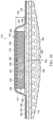
- FIG. 1is a perspective view of an illustrative example of a system and a dressing assembly for treating a tissue site;
- FIG. 2 Ais a cross-section of a portion of an illustrative example of a dressing assembly taken along line 2 A- 2 A in FIG. 1 ;
- FIG. 2 Bis a cross-section of a portion of another illustrative example of a dressing assembly taken along line 2 B- 2 B in FIG. 1 ;
- FIG. 2 Cis a cross-section of a portion of another illustrative example of a dressing assembly taken along line 2 C- 2 C in FIG. 1 ;
- FIGS. 3 A- 3 Care perspective, cross-sectional views of a portion of an illustrative example of a dressing assembly for treating a tissue site being deployed at the tissue site;
- FIG. 4 Adepicts a cross-section of a portion of an illustrative example of a dressing assembly in a relaxed state prior to operation or application of reduced pressure
- FIG. 4 Bdepicts a cross-section of a portion of an illustrative example of a dressing assembly in a contracted state during operation or application of reduced pressure
- FIG. 5 Adepicts multiple locations along an incision used to measure a width of the incision during a test of an illustrative example of a dressing assembly
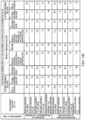
- FIG. 5 Bis a table illustrating an improved decrease in the incision width at the stated times and locations during the test of the dressing assembly compared to a baseline dressing.
- FIGS. 1 and 2 Apresented is an illustrative, non-limiting embodiment of a treatment system 100 for treating a tissue site 102 , such as a linear wound or an incision 104 .
- the incision 104is shown extending through or involving an epidermis 106 , a dermis 108 , and a subcutaneous tissue 110 .
- the treatment system 100may also be used with other tissue sites, and may be used with or without reduced pressure.
- the treatment system 100may include a dressing assembly 112 .
- the dressing assembly 112may include, without limitation, a dressing bolster 114 .
- the dressing bolster 114may be a manifold 114 .
- elements of the dressing bolster 114may be applicable to the manifold 114 , and the dressing bolster 114 may be interchangeably referred to herein as the manifold 114 .
- the treatment system 100may include a sealing member 116 and a reduced-pressure subsystem 118 . While the treatment system 100 is shown in the context of a reduced-pressure dressing over an incision 104 , the treatment system 100 may be used on other tissue sites, including open wounds.
- the sealing member 116may be a drape 116 , and the sealing member 116 or the drape 116 may form part of the dressing assembly 112 .
- the sealing member 116may be configured to cover the dressing bolster 114 and to create a sealed space 120 relative to the tissue site 102 , for example, between the sealing member 116 and the tissue site 102 . Further, the sealing member 116 may cover other tissue, such as a portion of the epidermis 106 , around or surrounding the tissue site 102 to provide the sealed space 120 between the sealing member 116 and the tissue site 102 .
- the dressing bolster 114may be positioned in the sealed space 120 .
- the sealing member 116may have a periphery 122 and a central region 124 . In some embodiments, a portion of the periphery 122 of the sealing member 116 may extend beyond a periphery 126 of the dressing bolster 114 and into direct contact with tissue surrounding the tissue site 102 . Further, in some embodiments, the sealing member 116 may be configured to cover at least a portion of a first side 128 of the dressing bolster 114 and to extend beyond the periphery 126 of the dressing bolster 114 .
- the sealing member 116may be formed from any material that allows for a fluid seal.
- a fluid sealmay be a seal adequate to maintain reduced pressure at a desired site given the particular reduced pressure source or system involved.
- the sealing member 116may comprise, for example, one or more of the following materials: hydrophilic polyurethane; cellulosics; hydrophilic polyamides; polyvinyl alcohol; polyvinyl pyrrolidone; hydrophilic acrylics; hydrophilic silicone elastomers; an INSPIRE 2301 material from Expopack Advanced Coatings of Wrexham, United Kingdom having, for example, an MVTR (inverted cup technique) of 14400 g/m 2 /24 hours and a thickness of about 30 microns; a thin, uncoated polymer drape; natural rubbers; polyisoprene; styrene butadiene rubber; chloroprene rubber; polybutadiene; nitrile rubber; butyl rubber; ethylene propylene rubber; ethylene propy
- the sealing member 116may be vapor permeable and liquid impermeable, thereby allowing vapor and inhibiting liquids from exiting the sealed space 120 .
- the sealing member 116may be a flexible, breathable film, membrane, or sheet having a high moisture vapor transfer rate (MVTR) of, for example, at least about 300 g/m 2 per 24 hours. In other embodiments, a low or no vapor transfer drape might be used.
- the sealing member 116may comprise a range of medically suitable films having a thickness between about 15 microns ( ⁇ m) to about 50 microns ( ⁇ m).
- An adhesive 136may be positioned at least between the periphery 122 of the sealing member 116 and tissue, such as the epidermis 106 , surrounding the tissue site 102 .
- the adhesive 136may be disposed on a surface of the sealing member 116 adapted to face the tissue site 102 .
- the adhesive 136may be a medically-acceptable adhesive.
- the adhesive 136may also be flowable.
- the adhesive 136may comprise an acrylic adhesive, rubber adhesive, high-tack silicone adhesive, polyurethane, or other adhesive substance.
- the adhesive 136may be a pressure-sensitive adhesive comprising an acrylic adhesive with coating weight of 15 grams/m 2 (gsm) to 70 grams/m 2 (gsm).
- the adhesive 136may be continuous layer. In other embodiments, the adhesive 136 may be discontinuous.
- the adhesive 136may be a patterned coating on a carrier layer, such as, for example, a side of the sealing member 116 adapted to face the epidermis 106 .
- the discontinuities in the adhesive 136may also be sized to enhance the Moisture Vapor Transfer Rate (MVTR) of the dressing assembly 112 .
- MVTRMoisture Vapor Transfer Rate
- the reduced-pressure subsystem 118may include a reduced-pressure source 142 .
- the reduced-pressure source 142may provide reduced pressure as a part of the treatment system 100 , and may be configured to be coupled in fluid communication with the sealed space 120 to provide reduced pressure to the sealed space 120 .
- the reduced-pressure source 142may be fluidly coupled to a conduit interface 144 by a delivery conduit 146 .
- An aperture(not shown) may be formed on a portion of the sealing member 116 to allow fluid communication between the sealed space 120 and the reduced-pressure source 142 through the conduit interface 144 and the delivery conduit 146 .
- reduced pressuremay refer to a pressure less than the ambient pressure at a tissue site being subjected to treatment, such as the tissue site 102 .
- the reduced pressuremay be less than the atmospheric pressure.
- the reduced pressuremay also be less than a hydrostatic pressure at a tissue site. Unless otherwise indicated, quantitative values of pressure stated herein are gauge pressures.
- the reduced pressure delivered to the sealed space 120 and the dressing bolster 114may be constant or varied, patterned or random, and may be delivered continuously or intermittently.
- vacuumand “negative pressure” may be used to describe the pressure applied to a tissue site, the actual pressure applied to the tissue site may be more than the pressure normally associated with a complete vacuum. Consistent with the use herein, unless otherwise indicated, an increase in reduced pressure or vacuum pressure may refer to a relative reduction in absolute pressure.
- the reduced-pressure source 142may include a reservoir region 148 , or canister region.
- An interposed membrane filter(not shown), such as a hydrophobic or oleophobic filter, may be interspersed between the reduced-pressure delivery conduit 146 and the reduced-pressure source 142 .
- One or more devicessuch as a representative device 150 , may be fluidly coupled to the reduced-pressure delivery conduit 146 .
- the representative device 150may be, for example, another fluid reservoir, a collection member to hold exudates and other fluids removed, a pressure-feedback device, a volume detection system, a blood detection system, an infection detection system, a flow monitoring system, or a temperature monitoring system. Multiple representative devices 150 may be included.
- One or more of the representative devices 150may be formed integrally with the reduced-pressure source 142 .
- the reduced-pressure source 142may be any device for supplying a reduced pressure, such as a vacuum pump, wall suction, or other source. While the amount and nature of reduced pressure applied to a tissue site may vary according to the application, the reduced pressure may be, for example, between about ⁇ 5 mm Hg ( ⁇ 667 Pa) to about ⁇ 500 mm Hg ( ⁇ 66.7 kPa). In some embodiments, the reduced pressure may be between about ⁇ 75 mm Hg ( ⁇ 9.9 kPa) to about ⁇ 300 mm Hg ( ⁇ 39.9 kPa).
- the reduced pressure developed by the reduced-pressure source 142may be delivered through the delivery conduit 146 to the conduit interface 144 .
- the conduit interface 144may allow the reduced pressure to be delivered through the sealing member 116 to the dressing bolster 114 .
- the conduit interface 144may provide fluid communication external to the sealing member 116 without the application of reduced pressure.
- the dressing bolster 114may include the first side 128 , the periphery 126 , and a second side 152 .
- the second side 152 of the dressing bolster 114may be configured to face the tissue site 102 .
- the first side 128 of the dressing bolster 114may be opposite the second side 152 such that the first side 128 may be configured to face outward or away from the tissue site 102 .
- the dressing bolster 114may have a thickness 154 between the first side 128 and the second side 152 .
- the thickness 154 of the dressing bolster 114may define at least a portion of a thickness of the dressing assembly 112 .
- the periphery 126 of the dressing bolster 114may define an outer boundary or lateral boundary of the dressing bolster 114 and the first side 128 and the second side 152 of the dressing bolster 114 .
- the periphery 126 of the dressing bolster 114may be an edge 126 of the dressing bolster 114 .
- the edge 126 of the dressing bolster 114may be a lateral edge positioned orthogonal relative to the second side 152 of the dressing bolster 114 .
- the edge 126 of the dressing bolster 114may also be a beveled edge or an angled edge. The angled or beveled edge may help distribute shear stress between the dressing bolster 114 and the epidermis 106 of a patient.
- the dressing bolster 114may include one or more notches, recesses, or cuts, such as a notch 156 .
- the notch 156may be a lateral or longitudinal cut in the dressing bolster 114 on the first side 128 .
- the notch 156may enhance the flexibility of the dressing bolster 114 . Enhanced flexibility may be particularly useful for application of the dressing assembly 112 over a joint or other area of movement on a patient.
- the notch 156may also take various shapes without limitation, such as, for example, hexagons, slits, or squares.
- the dressing bolster 114may be formed from any bolster material or manifold material capable of providing a vacuum space or treatment space.
- the dressing bolster 114may be formed from a porous material such as a permeable foam or foam-like material, a flexible foam, a member formed with pathways, a graft, a gauze, or any combination thereof. Reduced pressure applied to the dressing bolster 114 may enhance the permeability of the dressing bolster 114 .
- the dressing bolster 114may be formed of or include a wicking material configured to wick fluid or communicate fluid through the dressing bolster 114 with or without the application of reduced pressure.
- manifoldmay refer to a substance or structure that may assist in applying or distributing reduced pressure to, delivering fluids to, or removing fluids from a tissue site.
- a manifoldmay include a plurality of flow channels or pathways. The plurality of flow channels may be interconnected to improve distribution of fluids provided to and removed from an area of tissue around the manifold.
- manifoldsmay include, without limitation, devices that have structural elements arranged to form flow channels, cellular foam, such as open-cell foam, porous tissue collections, and liquids, gels, and foams that include or cure to include flow channels.
- the dressing bolster 114may include a plurality of interconnected pores 158 proximate to the first side 128 and the second side 152 of the dressing bolster 114 .
- the interconnected pores 158may have different sizes including one or more small interconnected pores 158 a and one or more large interconnected pores 158 b .
- the dressing bolster 114may be a reticulated, open-cell polyurethane or polyether foam that may be fluid permeable.
- One such foam materialmay be a V.A.C.TM GRANUFOAMTM material available from Kinetic Concepts, Inc. (KCITM) of San Antonio, Texas.
- the reticulated pores of the GRANUFOAMTM materialmay be helpful in carrying out the manifold function, but as stated above, other materials may be utilized.
- a material with a higher or lower density than the GRANUFOAMTM materialmay be desirable in some embodiments. This material may have, for example, a smaller pore size than the GRANUFOAMTM material.
- the followingmay be used without limitation: GRANUFOAMTM material, FXI technical foam (www.fxi.com), gauze, a flexible channel-containing member, a graft, and other similar materials.
- ionic silvermay be added to the material, such as, for example, by a micro bonding process.
- Other substances, such as antimicrobial agentsmay also be added to the material.
- the treatment system 100 or the dressing assembly 112may include a comfort layer 160 having a first side 162 , a periphery 164 , and a second side 166 .
- the comfort layer 160may be an interface layer 160 .
- elements of the comfort layer 160may be applicable to the interface layer 160 , and the comfort layer 160 may be interchangeably referred to herein as the interface layer 160 .
- the comfort layer 160may be configured to be positioned between the second side 152 of the dressing bolster 114 and the tissue site 102 .
- the second side 166 of the comfort layer 160may be configured to face the tissue site 102 .
- the first side 162 of the comfort layer 160may be opposite the second side 166 of the comfort layer 160 such that the first side 162 may be configured to face outward or away from the tissue site 102 .
- the periphery 164 of the comfort layer 160may define an outer boundary or lateral boundary of the comfort layer 160 and the first side 162 and the second side 166 of the comfort layer 160 .
- the periphery 164 of the comfort layer 160may be at least one edge 164 of the comfort layer 160 .
- the first side 162 of the comfort layer 160may be positioned on the second side 152 of the dressing bolster 114 .
- the first side 162 of the comfort layer 160may be coupled, for example, by a heat bond or other suitable technique to the second side 152 of the dressing bolster 114 .
- the sealing member 116may be directly or indirectly coupled to a portion of the comfort layer 160 , such as, for example, the periphery 164 of the comfort layer 160 .
- the periphery 164 of the comfort layer 160may substantially correspond to, or be substantially aligned with, the periphery 126 of the dressing bolster 114 .
- the periphery 164 or the at least one edge 164 of the comfort layer 160may not be coupled to the dressing bolster 114 or may be free of connection to the dressing bolster 114 . Further, other portions of the comfort layer 160 or the entire comfort layer 160 may not be coupled to the dressing bolster 114 . At least a portion of the comfort layer 160 may be moveable independent of the dressing bolster 114 . For example, the comfort layer 160 may be coupled to the dressing bolster 114 lengthwise along a longitudinal axis or midline of the dressing bolster 114 , and the at least one edge 164 of the comfort layer 160 may not be coupled to the dressing bolster 114 such that the at least one edge 164 is moveable relative to the dressing bolster 114 .
- the comfort layer 160may enhance patient comfort when the dressing bolster 114 is adjacent to the epidermis 106 of a patient.
- at least a portion of the second side 166 of the comfort layer 160may be configured to directly contact the tissue site 102 .
- the comfort layer 160may be any material suitable for preventing skin irritation and discomfort while allowing fluid transmission through the comfort layer 160 .
- a woven material, an elastic material, a wicking material, a polyester knit textile substrate, a non-woven material, or a fenestrated filmmay be used.
- an INTERDRYTM textile material from Milliken Chemical, a division of Milliken & Company, Inc. of Spartanburg, South Carolinamay be used.
- the comfort layer 160may include antimicrobial materials or substances, such as silver.
- the treatment system 100 or the dressing assembly 112may include an optional interface seal 168 .
- the interface seal 168may be a sealing ring 168 . Elements of the interface seal 168 may be applicable to the sealing ring 168 , and the interface seal 168 may be interchangeably referred to herein as the sealing ring 168 .
- the interface seal 168may enhance or otherwise provide a fluid seal at or around the tissue site 102 , such as the incision 104 .
- a surface of the epidermis 106may have recesses, cracks, wrinkles, or other discontinuities that may cause leaks.
- folds, buckles, wrinkles, or other discontinuitiesmay form in the sealing member 116 that can cause leaks.
- the interface seal 168may help seal any such skin or sealing member discontinuities at or around the tissue site 102 . Further, the interface seal 168 may also enhance the ability of the dressing assembly 112 to impart an apposition force to the tissue site 102 , for example, for closing the incision 104 , or otherwise moving portions of tissue toward one another at the tissue site 102 .
- the interface seal 168may function as a two-sided gasket that may provide a seal between the dressing assembly 112 and the tissue site 102 or the epidermis 106 .
- the interface seal 168may provide a seal between the dressing bolster 114 , the comfort layer 160 , or the sealing member 116 and the tissue site 102 or the epidermis 106 .
- the interface seal 168may also absorb perspiration or other fluids from the tissue site 102 . Further, the interface seal 168 may distribute shear forces created, for example, by the application of reduced pressure at the interface of the dressing bolster 114 and the tissue site 102 or the epidermis 106 .
- the interface seal 168may be configured to be positioned between the dressing bolster 114 and the tissue site 102 .
- the interface seal 168may be positioned between the second side 152 of the dressing bolster 114 and the tissue site 102 .
- the interface seal 168may be coupled to the second side 152 of the dressing bolster 114 .
- the interface seal 168may be positioned at the periphery 126 of the dressing bolster 114 , or coupled to the periphery 126 of the dressing bolster 114 . Further, the interface seal 168 may be positioned between the dressing bolster 114 and tissue at or around the tissue site 102 , such as the epidermis 106 . Thus, in some embodiments, at least a portion of the interface seal 168 may be positioned around the periphery 126 of the dressing bolster 114 and a periphery of the tissue site 102 . Further, in some embodiments, at least a portion of the interface seal 168 may substantially surround the periphery 126 of the dressing bolster 114 and a periphery of the tissue site 102 .
- the comfort layer 160may be included with the dressing assembly 112 and positioned between the dressing bolster 114 and the interface seal 168 .
- at least a portion of the second side 152 of the dressing bolster 114 and/or the second side 166 of the comfort layer 160may be free of the interface seal 168 and configured to be positioned in fluid communication with the tissue site 102 .
- the interface seal 168may be formed, as an illustrative example, by applying or bonding sealing material to the dressing bolster 114 .
- the sealing material that may be used for the interface seal 168may include hydrocolloids, hydrogels, silicone polymers (both crosslinked and uncrosslinked gels), and natural gums (xanthan, guar, cellulose).
- the sealing materialmay include other soft polymer gels, such as, for example, those based on polyurethanes, polyolefin gels, and acrylics.
- the interface seal 168may have a durometer, such as a material softness or hardness, between about 20 Shore 00 to about 90 Shore OO. In some embodiments, the durometer of the interface seal 168 may be between about 70 Shore 00 to about 80 Shore OO. Further, the interface seal 168 may have a modulus of elasticity that falls between a modulus of elasticity of the sealing member 116 and a modulus of elasticity of the tissue site 102 and/or the epidermis 106 .
- the interface seal 168may have a width between about 10 millimeters to about 30 millimeters. In some embodiments, the width of the interface seal 168 may be about 20 millimeters. The width of the interface seal 168 may be directed, oriented, or adapted for positioning along a surface of the tissue site 102 . In some embodiments, the width of the interface seal 168 may extend beyond the edge 126 of the dressing bolster 114 by about 10 millimeters and also overlap the second side 152 of the dressing bolster 114 by about 10 millimeters. Thus, the interface seal 168 may straddle the edge or the periphery 126 of the dressing bolster 114 , or otherwise extend beyond the periphery 126 of the dressing bolster 114 . In other embodiments (not shown), the dressing bolster 114 may entirely overlap the interface seal 168 .
- the interface seal 168may have a thickness between about 0.3 millimeters to about 2.5 millimeters. In some embodiments, the thickness of the interface seal 168 may be between about 0.7 millimeters to about 1.25 millimeters. The thickness of the interface seal 168 may be perpendicular to the width of the interface seal 168 and the tissue site 102 . Other dimensions for the interface seal 168 are possible.
- the interface seal 168may be deployed by hand or extruded from an applicator, such as a syringe, prior to application of the dressing assembly 112 to the tissue site 102 .
- Sealing materials suitable for application by extrusionmay include water soluble gums such as xanthan, guar, or cellulose, and thick greases, such as silicones.
- the interface seal 168may be bonded in any suitable manner, such as, for example, by a heat bond, to the dressing assembly 112 during manufacture.
- the interface seal 168may have a ring-like or annular shape.
- the interface seal 168may be linear.
- the interface seal 168may comprise one or more discrete members, including linear members, which may be formed into a ring-like or annular shape.
- the interface seal 168may be positioned on or coupled directly to the dressing assembly 112 , or coupled with an attachment device, such as an acrylic adhesive, cement, or other coupling device. In some embodiments, the interface seal 168 may be positioned on or coupled to the second side 152 of the dressing bolster 114 and/or to an adjacent layer, such as the second side 166 of the comfort layer 160 . Further, in some embodiments, the interface seal 168 may be adapted to be positioned between the comfort layer 160 and the tissue site 102 , and/or tissue around the tissue site 102 , such as the epidermis 106 . Thus, in some embodiments, the comfort layer 160 may be coupled between the dressing bolster 114 and the interface seal 168 .
- the interface seal 168may include an absorbent.
- the interface seal 168may be a hydrocolloid comprising an absorbent, such as carboxy methyl cellulose (CMC).
- CMCcarboxy methyl cellulose
- the absorbentmay permit the interface seal 168 to absorb fluid from the tissue site 102 in addition to enhancing the fluid seal around the tissue site 102 .
- the interface seal 168 including the absorbentmay enhance the ability of the dressing assembly 112 to manage and direct fluid away from the tissue site 102 for keeping the tissue site 102 dry.
- the interface seal 168may be adapted to be positioned between the dressing assembly 112 and the tissue site 102 , as described above, and around or surrounding a circumference, perimeter, or periphery of the tissue site 102 .
- the interface seal 168may be positioned, for example, around, on, or at the edge or the periphery 126 of the dressing bolster 114 or the edge or the periphery 164 of the comfort layer 160 . Further, the interface seal 168 may be positioned around or surrounding a circumference of the dressing bolster 114 or the comfort layer 160 . Further, the interface seal 168 may be positioned around at least a portion of the dressing bolster 114 or the comfort layer 160 that is configured to be positioned directly against or in direct contact with the tissue site 102 .
- At least a portion of the dressing bolster 114 or the comfort layer 160may be exposed and configured to be positioned directly against the tissue site 102 when the interface seal 168 is positioned on the dressing assembly 112 . Further, in such embodiments, the interface seal 168 may surround the exposed portion of the dressing bolster 114 or the comfort layer 160 .
- the absorbent in the interface seal 168may wick or draw fluid in a lateral direction within the dressing assembly 112 , normal to the thickness 154 of the dressing bolster 114 , and toward the edge or the periphery 126 of the dressing bolster 114 for absorption in the interface seal 168 .
- fluid from the tissue site 102may be wicked or otherwise drawn in a lateral direction along the surface of the tissue site 102 toward the edge or the periphery 126 of the dressing bolster 114 and into the interface seal 168 .
- fluid from the tissue site 102may also flow through the thickness 154 of the dressing assembly 112 and the dressing bolster 114 at least by operation of the manifold material comprising the dressing bolster 114 , described above.
- the dressing assembly 112may include a first contraction zone 170 and a second contraction zone 172 .
- the first contraction zone 170may extend from the first side 128 of the dressing bolster 114 into the thickness 154 of the dressing bolster 114 and toward the second side 152 of the dressing bolster 114 .
- the first contraction zone 170may be configured to contract a first amount.
- the first contraction zone 170may include or form at least a portion of the first side 128 of the dressing bolster 114 such that the first side 128 of the dressing bolster 114 is configured to contract a first amount.
- the first contraction zone 170may have a planar shape extending across or through a width of the dressing bolster 114 .
- the second contraction zone 172may extend from the first contraction zone 170 into the thickness 154 of the dressing bolster 114 and toward the second side 152 of the dressing bolster 114 .
- the second contraction zone 172may have a planar shape extending across or through a width of the dressing bolster 114 .
- the second contraction zone 172may be configured to contract a second amount that is greater than the first amount when a compressive force is applied to the dressing bolster 114 .
- the second contraction zone 172may include or form at least a portion of the second side 152 of the dressing bolster 114 such that the second side 152 of the dressing bolster 114 is configured to contract the second amount.
- the compressive force applied to the dressing bolster 114may be generated by a reduced pressure.
- the first contraction zone 170may be configured to contract the first amount and the second contraction zone 172 may be configured to contract the second amount in a direction substantially perpendicular to the thickness 154 of the dressing bolster 114 . Further, the first contraction zone 170 may be configured to contract the first amount and the second contraction zone 172 may be configured to contract the second amount in a lateral direction relative to the tissue site 102 and relative to a longitudinal axis or midline of the dressing bolster 114 . The first amount of contraction in the first contraction zone 170 and the second amount of contraction in the second contraction zone 172 may reduce a dimension of the dressing bolster 114 in a direction substantially perpendicular to the thickness 154 of the dressing bolster 114 .
- the second side 152 of the dressing bolster 114may be configured to form a concave shape for facing the tissue site 102 when the first contraction zone 170 contracts the first amount and the second contraction zone 172 contracts the second amount.
- at least a portion of the second contraction zone 172may be positioned at the second side 152 of the dressing bolster 114 .
- the second contraction zone 172may be configured to be positioned between the first contraction zone 170 and the tissue site 102 .
- the second contraction zone 172may extend into the thickness 154 of the dressing bolster 114 to a depth greater than a depth of the first contraction zone 170 .
- the first contraction zone 170 and the second contraction zone 172 of the dressing bolster 114 or the dressing assembly 112may include or be formed of multiple layers coupled or positioned as described herein.
- the dressing bolster 114may be a single layer or body configured to contract the first amount in the first contraction zone 170 and the second amount in the second contraction zone 172 .
- the first contraction zone 170may have a greater stiffness or rigidity than the second contraction zone 172 .
- the first contraction zone 170 and the second contraction zone 172may each comprise a portion of the manifold or the dressing bolster 114 configured, treated, or modified to have different mechanical properties.
- the first contraction zone 170 and the second contraction zone 172may comprise a foam having a porosity in the second contraction zone 172 that is greater than a porosity of the foam in the first contraction zone 170 .
- the foammay have the plurality of interconnected pores 158 in at least one of the first contraction zone 170 and the second contraction zone 172 .
- the plurality of interconnected pores 158 in the second contraction zone 172may be larger in size than the plurality of interconnected pores 158 in the first contraction zone 170 of the dressing bolster 114 when the dressing bolster 114 is in a relaxed state.
- the interconnected pores 158 having a comparatively large sizemay decrease in size or volume a greater percentage than the interconnected pores 158 having a comparatively small size when exposed to the same compressive force, such as the same amount or level of reduced pressure.
- the interconnected pores 158 having comparatively large sizesuch as the large interconnected pores 158 b , may have, without limitation, a larger volume, a larger opening, or less resistance to fluid flow compared to the small interconnected pores 158 a .
- a portion of the dressing bolster 114 where the interconnected pores 158 are comparatively largemay have a lower density than another portion of the dressing bolster 114 where the interconnected pores 158 are comparatively small.
- the first contraction zone 170may be configured to contract the first amount and the second contraction zone 172 may be configured to contract the second amount when the dressing bolster 114 is exposed to a reduced pressure. In some embodiments, the first contraction zone 170 may be configured to contract the first amount and the second contraction zone 172 may be configured to contract the second amount when the first contraction zone 170 and the second contraction zone 172 are exposed to equal amounts of a reduced pressure. In some embodiments, the first contraction zone 170 may be configured to contract the first amount and the second contraction zone 172 may be configured to contract the second amount in response to an electrical charge or in response to a mechanical force.
- mechanical or electrical componentsmay include, without limitation, springs, solenoids, or other suitable components capable of releasing potential energy or differentially changing length in response to a direct or indirect electrical input.
- the first contraction zone 170may be a first layer 170 a of the dressing assembly 112 and the second contraction zone 172 may be a second layer 172 a of the dressing assembly 112 .
- the first layer 170 amay be the dressing bolster 114 and the second layer 172 b may be the comfort layer 160 .
- the dressing bolster 114may be configured to contract a first amount in a lateral direction relative to the tissue site 102 when exposed to a compressive force, such as, for example, a reduced pressure.
- the comfort layer 160may be configured to contract a second amount in a lateral direction relative to the tissue site 102 when exposed to the compressive force.
- the second amount of contraction of the comfort layer 160may be greater than the first amount of contraction of the dressing bolster 114 .
- the dressing bolster 114may be configured to contract the first amount in a direction substantially perpendicular to the thickness 154 of the dressing bolster 114 , or in a direction that is lateral, perpendicular, or orthogonal relative to a longitudinal axis or midline of the dressing bolster 114 .
- the comfort layer 160may be configured to contract the second amount in a direction substantially perpendicular to a thickness of the comfort layer 160 or the thickness 154 of the dressing bolster 114 , or in a direction that is lateral, perpendicular, or orthogonal relative to a longitudinal axis or midline of the comfort layer 160 or the dressing bolster 114 .
- the first amount of contraction in the dressing bolster 114 and the second amount of contraction in the comfort layer 160may reduce a dimension of the dressing bolster 114 and the comfort layer 160 in a direction substantially perpendicular to the thickness 154 of the dressing bolster 114 or a thickness of the comfort layer 160 , or in a direction that is lateral, perpendicular, or orthogonal relative to a longitudinal axis or midline of the dressing bolster 114 or the comfort layer 160 .
- the second side 166 of the comfort layer 160may be configured to form a concave shape when the dressing bolster 114 contracts the first amount and the comfort layer 160 contracts the second amount.
- the dressing assembly 112may include a reinforcing member 178 configured to support the manifold 114 .
- the reinforcing member 178may support the manifold 114 such that the second side 152 of the manifold 114 is configured to contract a greater amount than the first side 128 of the manifold 114 when the manifold 114 is exposed to a compressive force.
- the compressive forcemay be, for example, a reduced pressure.
- the reinforcing member 178may be coupled at the first side 128 of the manifold 114 and configured to support the first side 128 of the manifold 114 .
- the reinforcing member 178may be configured to reduce an amount of contraction at the first side 128 of the manifold 114 relative to the second side 152 of the manifold 114 . In some embodiments, the reinforcing member 178 may be configured to preclude contraction at the first side 128 of the manifold 114 .
- At least a portion of the manifold 114may be configured to be positioned between the reinforcing member 178 and the tissue site 102 .
- the reinforcing member 178may be positioned to cover at least a portion of the first side 128 of the manifold 114 .
- the reinforcing member 178may be positioned across the first side 128 of the manifold 114 .
- the reinforcing member 178may be positioned at the periphery 126 of the first side 128 of the manifold 114 .
- the reinforcing member 178may be incorporated within at least a portion of the manifold 114 .
- the reinforcing member 178may comprise a stiffness, hardness, or rigidity that is greater than a stiffness, hardness, or rigidity of the manifold 114 . Although the reinforcing member 178 may have a greater stiffness, hardness, or rigidity than the manifold 114 , in some embodiments, the reinforcing member 178 may retain enough flexibility to suitably conform to challenging anatomical surfaces at a particular tissue site.
- the first side 128 and the second side 152 of the manifold 114may be configured to decrease in size in a direction substantially perpendicular to the thickness 154 of the manifold 114 when the manifold 114 is exposed to a reduced pressure.
- the first side 128 and the second side 152 of the manifold 114may be configured to decrease in size in a lateral direction relative to the tissue site 102 .
- the second side 152 of the manifold 114may be configured to decrease in size more than the first side 128 of the manifold 114 .
- the manifold 114may decrease in size when exposed to a compressive force, such as, for example, a reduced pressure.
- the manifold 114may be flexible and may include the plurality of interconnected pores 158 .
- the plurality of interconnected pores 158may be configured to decrease in size when the manifold 114 is exposed to a reduced pressure.
- the plurality of interconnected pores 158may be positioned proximate to the first side 128 and the second side 152 of the manifold 114 .
- the plurality of interconnected pores 158 proximate to the second side 152 of the manifold 114may decrease in size more than the plurality of interconnected pores 158 proximate to the first side 128 of the manifold 114 .
- the reinforcing member 178may be configured to support the interconnected pores 158 proximate the first side 128 of the manifold 114 such that the interconnected pores 158 proximate to the second side 152 decrease in size more than the interconnected pores 158 proximate to the first side 128 .
- the reinforcing member 178may substantially preclude a deformation or a change in size of at least a portion of the interconnected pores 158 proximate to the first side 152 of the manifold 114 .
- the reinforcing member 178may fill at least a portion of the interconnected pores 158 proximate to the first side 128 of the manifold 114 .
- the reinforcing member 178may be a coating, strip, layer, or frame of a material suitable for supporting the manifold 114 as described herein.
- FIGS. 3 A- 3 Cprovide an illustrative embodiment of a method for assembling the dressing assembly 112 in stages at the tissue site 102 , such as the incision 104 .
- a closure device 502such as, for example, stitches 504 , may close the incision 104 .
- Other closure devices 502such as epoxy or staples may be utilized to close the incision 104 .
- the tissue site 102may include a first portion 180 and second portion 182 . The first portion 180 of the tissue site 102 may be positioned on an opposite side of the incision 104 from the second portion 182 of the tissue site 102 .
- the dressing assembly 112may be disposed proximate to the incision 104 .
- the dressing bolster 114 of the dressing assembly 112may be positioned across the incision 104 between the first portion 180 and the second portion 182 of the tissue site 102 .
- the comfort layer 160may be positioned in contact with the tissue site 102 between the dressing bolster 114 and the tissue site 102 .
- the dressing bolster 114may be in fluid communication with the tissue site 102 through the comfort layer 160 .
- the interface seal 168may be positioned at the periphery 126 of the dressing bolster 114 and between the dressing bolster 114 and the tissue site 102 .
- the interface seal 168may be positioned around a portion of the comfort layer 160 positioned in direct contact with the tissue site 102 .
- the portion of the comfort layer 160 in direct contact with the tissue site 102may be free of the interface seal 168 such that fluid communication is permitted through the comfort layer 160 to the dressing bolster 114 .
- elementsmay be added or omitted as desired.
- the comfort layer 160may be omitted and the dressing bolster 114 may be positioned at the tissue site 102 as described herein.
- the sealing member 116may be disposed over or covering the dressing bolster 114 and a portion of the epidermis 106 to form the sealed space 120 between the sealing member 116 and the incision 104 .
- the sealing member 116 and the adhesive 136may be deployed together at the tissue site 102 as an assembly or kit.
- An aperture(not shown) may be formed or preformed in the sealing member 116 to provide fluid communication between the sealed space 120 and the reduced-pressure source 142 , such as, for example, through the conduit interface 144 and the delivery conduit 146 previously introduced in FIG. 1 .
- reduced pressuremay be applied to the tissue site 102 , and fluid may be extracted from the tissue site 102 and into the dressing assembly 112 .
- a portion of the fluid from the tissue site 102may be absorbed into the interface seal 168 .
- the fluid from the tissue site 102may be wicked or otherwise communicated in a lateral direction within the dressing assembly 112 toward the interface seal 168 .
- FIG. 4 Adepicts an illustrative embodiment of the dressing assembly 112 in a relaxed state positioned at the tissue site 102 prior to operation or application of reduced pressure.
- FIG. 4 Bdepicts the dressing assembly 112 in a contracted state during operation or application of reduced pressure to the sealed space 120 .
- the dressing assembly 112 of FIGS. 4 A- 4 Bis shown with the comfort layer 160 .
- any embodiments within the scope of this disclosure, including those that do not use the comfort layer 160may be suitable, applicable, substituted, or operable in an analogous manner.
- the dressing bolster 114may contract, bend, or curl about a longitudinal axis of the dressing bolster 114 into a convex shape on the first side 128 of the dressing bolster 114 and a concave shape on the second side 152 of the dressing bolster 114 facing the tissue site 102 .
- the longitudinal axis of the dressing bolster 114may extend into the page in the view shown in FIGS. 4 A- 4 B and be centered along the length of the dressing bolster 114 over the incision 104 , for example.
- FIG. 4 Bdoes not illustrate the concave shape of the second side 152 of the dressing bolster 114 during operation.
- contraction force vectors (A, B) in FIG. 4 Billustrate a direction of a force that may be applied by the dressing assembly 112 during operation.
- contraction force vector (A)illustrates the direction of the force that may be applied to the tissue site 102 by the second side 152 of the dressing bolster 114 .
- Contraction force vector (B)illustrates the direction of the force that may be applied to the tissue site 102 by the sealing member 116 , for example, by the periphery 122 of the sealing member 116 coupled on the epidermis 106 around the tissue site 102 .
- the contraction of the dressing bolster 114may cause at least one of the edges 126 of the dressing bolster 114 to move toward or closer to one another.
- the contraction of the dressing bolster 114may permit the dressing assembly 112 to impart an inward force or an apposition force to the tissue site 102 that may move the first portion 180 of the tissue site 102 toward the second portion 182 of the tissue site 102 as shown by the contraction force vectors (A, B).
- the movement of the first portion 180 toward or closer to the second portion 182may provide closure of the incision 104 at the tissue site 102 .
- a method for treating the tissue site 102may include providing the manifold 114 including the first side 128 , the second side 152 opposite the first side 128 , and the thickness 154 between the first side 128 and the second side 152 . Further, the method may include positioning the second side 152 of the manifold 114 proximate to the tissue site 102 . Further, the method may include covering the manifold 114 at the tissue site 102 with a sealing member 116 to create the sealed space 120 between the sealing member 116 and the tissue site 102 . Further, the method may include contracting at least a portion of the manifold 114 by exposing the manifold 114 to a reduced pressure in the sealed space 120 . Further, the method may include supporting the manifold 114 with a reinforcing member 178 such that the second side 152 of the manifold 114 contracts more than the first side 128 of the manifold 114 .
- the manifold 114may be flexible and may include a plurality of interconnected pores 158 proximate to the first side 128 and the second side 152 of the manifold 114 . Contracting at least a portion of the manifold 114 may include decreasing a size of at least a portion of the plurality of interconnected pores 158 such as, for example, by evacuating a fluid from at least a portion of the interconnected pores 158 .
- supporting the manifold 114may include supporting the interconnected pores 158 such that the interconnected pores 158 proximate to the second side 152 of the manifold 114 decrease in size more than the interconnected pores 158 proximate to the first side 128 of the manifold 114 .
- Supporting the manifold 114may include supporting the first side 128 of the manifold 114 or the interconnected pores 158 proximate to the first side 152 of the manifold 114 .
- a method for treating the tissue site 102may include providing the manifold 114 including the first contraction zone 170 and the second contraction zone 172 . Further, the method may include positioning the second contraction zone 172 proximate to the tissue site 102 . Further, the method may include covering the manifold 114 at the tissue site 102 with the sealing member 116 to create the sealed space 120 between the sealing member 116 and the tissue site 102 . Further, the method may include delivering a reduced pressure from the reduced pressure source 142 to the sealed space 120 . Further, the method may include distributing the reduced pressure to the tissue site 102 through the manifold 114 .
- the methodmay include contracting the second contraction zone 172 an amount greater than the first contraction zone 170 .
- the first contraction zone 170may be configured to contract a first amount and the second contraction zone 172 may be configured to contract a second amount when the reduced pressure is delivered to the sealed space 120 .
- the second amount of contractionmay be greater than the first amount of contraction. Contracting the second contraction zone 172 may impart a force on the tissue site 102 .
- the methodmay include positioning the interface layer 160 between the manifold 114 and the tissue site 102 . Further, in some embodiments, the second contraction zone 172 may be positioned between the first contraction zone 170 and the tissue site 102 . Further, in some embodiments, the manifold 114 may include or be formed of foam.
- testing results for the dressing assembly 112may provide a 40% to a 100% improvement in closure of an incision, such as the incision 104 , compared to a conventional dressing used to establish a baseline comparison.
- an incisionsuch as the incision 104
- a conventional dressingused to establish a baseline comparison.
- a 6 millimeter wide, 36 centimeter long simulated incisionwas formed in a 3 millimeter thick gel sheet having a thin polymeric film surface.
- the gel sheet selected for the testingis available under the tradename DERMASOL DS-302.
- FIG. 5 Areferences the measurement locations along the incision 104 relative to the dressing assembly 112 as locations ⁇ 4, ⁇ 3, ⁇ 2, ⁇ 1, 0, 1, 2, 3, and 4.
- the same testwas performed with a conventional baseline dressing for comparison.
- the measurement data for the dressing assembly 112 and the baseline dressingare tabulated and compared in FIG. 5 B at the stated times and locations.
- SEMean and Standard Error
- FIG. 5 Billustrates a Mean Ratio ranging from 1.4 to 2.0, corresponding to a 40% to 100% percent improvement in the closure or decrease of the incision width using the dressing assembly 112 .
Landscapes
- Health & Medical Sciences (AREA)
- Heart & Thoracic Surgery (AREA)
- General Health & Medical Sciences (AREA)
- Veterinary Medicine (AREA)
- Engineering & Computer Science (AREA)
- Public Health (AREA)
- Life Sciences & Earth Sciences (AREA)
- Animal Behavior & Ethology (AREA)
- Vascular Medicine (AREA)
- Biomedical Technology (AREA)
- Epidemiology (AREA)
- Chemical & Material Sciences (AREA)
- Hematology (AREA)
- Dermatology (AREA)
- Medicinal Chemistry (AREA)
- Anesthesiology (AREA)
- Media Introduction/Drainage Providing Device (AREA)
- Surgical Instruments (AREA)
- Dispersion Chemistry (AREA)
- Materials Engineering (AREA)
Abstract
Description
Claims (27)
Priority Applications (1)
| Application Number | Priority Date | Filing Date | Title |
|---|---|---|---|
| US17/500,136US12102511B2 (en) | 2017-02-14 | 2021-10-13 | Dressing with variable contraction zones |
Applications Claiming Priority (3)
| Application Number | Priority Date | Filing Date | Title |
|---|---|---|---|
| US201762458916P | 2017-02-14 | 2017-02-14 | |
| US15/895,851US11291587B2 (en) | 2017-02-14 | 2018-02-13 | Dressing with variable contraction zones |
| US17/500,136US12102511B2 (en) | 2017-02-14 | 2021-10-13 | Dressing with variable contraction zones |
Related Parent Applications (1)
| Application Number | Title | Priority Date | Filing Date |
|---|---|---|---|
| US15/895,851DivisionUS11291587B2 (en) | 2017-02-14 | 2018-02-13 | Dressing with variable contraction zones |
Publications (2)
| Publication Number | Publication Date |
|---|---|
| US20220031520A1 US20220031520A1 (en) | 2022-02-03 |
| US12102511B2true US12102511B2 (en) | 2024-10-01 |
Family
ID=61283377
Family Applications (2)
| Application Number | Title | Priority Date | Filing Date |
|---|---|---|---|
| US15/895,851Active2040-06-19US11291587B2 (en) | 2017-02-14 | 2018-02-13 | Dressing with variable contraction zones |
| US17/500,136Active2039-01-28US12102511B2 (en) | 2017-02-14 | 2021-10-13 | Dressing with variable contraction zones |
Family Applications Before (1)
| Application Number | Title | Priority Date | Filing Date |
|---|---|---|---|
| US15/895,851Active2040-06-19US11291587B2 (en) | 2017-02-14 | 2018-02-13 | Dressing with variable contraction zones |
Country Status (6)
| Country | Link |
|---|---|
| US (2) | US11291587B2 (en) |
| EP (1) | EP3582731B1 (en) |
| JP (1) | JP7376357B2 (en) |
| CN (1) | CN110290770B (en) |
| CA (1) | CA3049463A1 (en) |
| WO (1) | WO2018152127A1 (en) |
Families Citing this family (17)
| Publication number | Priority date | Publication date | Assignee | Title |
|---|---|---|---|---|
| GB2543544A (en) | 2015-10-21 | 2017-04-26 | Brightwake Ltd | Wound dressing |
| AU2017243601A1 (en) | 2016-03-30 | 2018-11-22 | Acib Gmbh | Detecting microbial infection in wounds |
| JP7376357B2 (en)* | 2017-02-14 | 2023-11-08 | スリーエム イノベイティブ プロパティズ カンパニー | Dressing with variable contraction zones |
| WO2019199849A1 (en)* | 2018-04-13 | 2019-10-17 | Kci Licensing, Inc. | Dressing bolster with area pressure indicator |
| EP3829515A1 (en) | 2018-08-01 | 2021-06-09 | KCI Licensing, Inc. | Soft-tissue treatment with negative pressure |
| WO2020051089A1 (en)* | 2018-09-04 | 2020-03-12 | Kci Licensing, Inc. | Wound therapy device and kit |
| WO2020205449A1 (en) | 2019-03-29 | 2020-10-08 | Kci Licensing, Inc. | Negative-pressure treatment with area stabilization |
| WO2020205445A1 (en) | 2019-03-29 | 2020-10-08 | Kci Licensing, Inc. | Negative-pressure treatment with area stabilization |
| EP3946502A1 (en) | 2019-03-29 | 2022-02-09 | KCI Licensing, Inc. | Dressing with integrated pump and releasably coupled pump actuator |
| EP4051201B1 (en)* | 2019-11-01 | 2024-05-29 | KCI Manufacturing Unlimited Company | Decompression therapy treatment system |
| US12274636B2 (en) | 2019-11-01 | 2025-04-15 | Kci Manufacturing Unlimited Company | Decompression therapy treatment system |
| BR112022012120A2 (en) | 2019-12-23 | 2022-08-30 | Convatec Ltd | POINT OF CARE DEVICES TO DETECT INFECTION STATUS OF A WOUND |
| CA3171933A1 (en) | 2020-02-20 | 2021-08-26 | Convatec Limited | A wound dressing and a wound therapy apparatus |
| US20230256156A1 (en)* | 2020-08-14 | 2023-08-17 | Kci Manufacturing Unlimited Company | Decompression wrap |
| US20220072216A1 (en)* | 2020-09-08 | 2022-03-10 | Kci Manufacturing Unlimited Company | Shoulder dressing for negative pressure therapy |
| USD1014764S1 (en)* | 2021-11-16 | 2024-02-13 | Raymond Lovell Francis | Skin-attachable block set that provides no-touch protection for skin insults |
| WO2024206121A2 (en)* | 2023-03-24 | 2024-10-03 | University Of Maine System Board Of Trustees | Vacuum-assisted integration of implants |
Citations (145)
| Publication number | Priority date | Publication date | Assignee | Title |
|---|---|---|---|---|
| US1355846A (en) | 1920-02-06 | 1920-10-19 | David A Rannells | Medical appliance |
| US2547758A (en) | 1949-01-05 | 1951-04-03 | Wilmer B Keeling | Instrument for treating the male urethra |
| US2632443A (en) | 1949-04-18 | 1953-03-24 | Eleanor P Lesher | Surgical dressing |
| GB692578A (en) | 1949-09-13 | 1953-06-10 | Minnesota Mining & Mfg | Improvements in or relating to drape sheets for surgical use |
| US2682873A (en) | 1952-07-30 | 1954-07-06 | Johnson & Johnson | General purpose protective dressing |
| US2910763A (en) | 1955-08-17 | 1959-11-03 | Du Pont | Felt-like products |
| US2969057A (en) | 1957-11-04 | 1961-01-24 | Brady Co W H | Nematodic swab |
| US3066672A (en) | 1960-09-27 | 1962-12-04 | Jr William H Crosby | Method and apparatus for serial sampling of intestinal juice |
| US3367332A (en) | 1965-08-27 | 1968-02-06 | Gen Electric | Product and process for establishing a sterile area of skin |
| US3520300A (en) | 1967-03-15 | 1970-07-14 | Amp Inc | Surgical sponge and suction device |
| US3568675A (en) | 1968-08-30 | 1971-03-09 | Clyde B Harvey | Fistula and penetrating wound dressing |
| US3648692A (en) | 1970-12-07 | 1972-03-14 | Parke Davis & Co | Medical-surgical dressing for burns and the like |
| US3682180A (en) | 1970-06-08 | 1972-08-08 | Coilform Co Inc | Drain clip for surgical drain |
| US3826254A (en) | 1973-02-26 | 1974-07-30 | Verco Ind | Needle or catheter retaining appliance |
| DE2640413A1 (en) | 1976-09-08 | 1978-03-09 | Wolf Gmbh Richard | CATHETER MONITORING DEVICE |
| US4080970A (en) | 1976-11-17 | 1978-03-28 | Miller Thomas J | Post-operative combination dressing and internal drain tube with external shield and tube connector |
| US4096853A (en) | 1975-06-21 | 1978-06-27 | Hoechst Aktiengesellschaft | Device for the introduction of contrast medium into an anus praeter |
| US4139004A (en) | 1977-02-17 | 1979-02-13 | Gonzalez Jr Harry | Bandage apparatus for treating burns |
| US4165748A (en) | 1977-11-07 | 1979-08-28 | Johnson Melissa C | Catheter tube holder |
| US4184510A (en) | 1977-03-15 | 1980-01-22 | Fibra-Sonics, Inc. | Valued device for controlling vacuum in surgery |
| WO1980002182A1 (en) | 1979-04-06 | 1980-10-16 | J Moss | Portable suction device for collecting fluids from a closed wound |
| US4233969A (en) | 1976-11-11 | 1980-11-18 | Lock Peter M | Wound dressing materials |
| US4245630A (en) | 1976-10-08 | 1981-01-20 | T. J. Smith & Nephew, Ltd. | Tearable composite strip of materials |
| US4256109A (en) | 1978-07-10 | 1981-03-17 | Nichols Robert L | Shut off valve for medical suction apparatus |
| US4261363A (en) | 1979-11-09 | 1981-04-14 | C. R. Bard, Inc. | Retention clips for body fluid drains |
| US4275721A (en) | 1978-11-28 | 1981-06-30 | Landstingens Inkopscentral Lic, Ekonomisk Forening | Vein catheter bandage |
| US4284079A (en) | 1979-06-28 | 1981-08-18 | Adair Edwin Lloyd | Method for applying a male incontinence device |
| US4297995A (en) | 1980-06-03 | 1981-11-03 | Key Pharmaceuticals, Inc. | Bandage containing attachment post |
| US4333468A (en) | 1980-08-18 | 1982-06-08 | Geist Robert W | Mesentery tube holder apparatus |
| US4373519A (en) | 1981-06-26 | 1983-02-15 | Minnesota Mining And Manufacturing Company | Composite wound dressing |
| US4382441A (en) | 1978-12-06 | 1983-05-10 | Svedman Paul | Device for treating tissues, for example skin |
| US4392853A (en) | 1981-03-16 | 1983-07-12 | Rudolph Muto | Sterile assembly for protecting and fastening an indwelling device |
| US4392858A (en) | 1981-07-16 | 1983-07-12 | Sherwood Medical Company | Wound drainage device |
| US4419097A (en) | 1981-07-31 | 1983-12-06 | Rexar Industries, Inc. | Attachment for catheter tube |
| EP0100148A1 (en) | 1982-07-06 | 1984-02-08 | Dow Corning Limited | Medical-surgical dressing and a process for the production thereof |
| US4465485A (en) | 1981-03-06 | 1984-08-14 | Becton, Dickinson And Company | Suction canister with unitary shut-off valve and filter features |
| EP0117632A2 (en) | 1983-01-27 | 1984-09-05 | Johnson & Johnson Products Inc. | Adhesive film dressing |
| US4475909A (en) | 1982-05-06 | 1984-10-09 | Eisenberg Melvin I | Male urinary device and method for applying the device |
| US4480638A (en) | 1980-03-11 | 1984-11-06 | Eduard Schmid | Cushion for holding an element of grafted skin |
| US4525374A (en) | 1984-02-27 | 1985-06-25 | Manresa, Inc. | Treating hydrophobic filters to render them hydrophilic |
| US4525166A (en) | 1981-11-21 | 1985-06-25 | Intermedicat Gmbh | Rolled flexible medical suction drainage device |
| US4540412A (en) | 1983-07-14 | 1985-09-10 | The Kendall Company | Device for moist heat therapy |
| US4543100A (en) | 1983-11-01 | 1985-09-24 | Brodsky Stuart A | Catheter and drain tube retainer |
| US4548202A (en) | 1983-06-20 | 1985-10-22 | Ethicon, Inc. | Mesh tissue fasteners |
| US4551139A (en) | 1982-02-08 | 1985-11-05 | Marion Laboratories, Inc. | Method and apparatus for burn wound treatment |
| EP0161865A2 (en) | 1984-05-03 | 1985-11-21 | Smith and Nephew Associated Companies p.l.c. | Adhesive wound dressing |
| US4569348A (en) | 1980-02-22 | 1986-02-11 | Velcro Usa Inc. | Catheter tube holder strap |
| AU550575B2 (en) | 1981-08-07 | 1986-03-27 | Richard Christian Wright | Wound drainage device |
| US4605399A (en) | 1984-12-04 | 1986-08-12 | Complex, Inc. | Transdermal infusion device |
| US4608041A (en) | 1981-10-14 | 1986-08-26 | Frese Nielsen | Device for treatment of wounds in body tissue of patients by exposure to jets of gas |
| US4640688A (en) | 1985-08-23 | 1987-02-03 | Mentor Corporation | Urine collection catheter |
| US4655754A (en) | 1984-11-09 | 1987-04-07 | Stryker Corporation | Vacuum wound drainage system and lipids baffle therefor |
| US4664662A (en) | 1984-08-02 | 1987-05-12 | Smith And Nephew Associated Companies Plc | Wound dressing |
| WO1987004626A1 (en) | 1986-01-31 | 1987-08-13 | Osmond, Roger, L., W. | Suction system for wound and gastro-intestinal drainage |
| US4710165A (en) | 1985-09-16 | 1987-12-01 | Mcneil Charles B | Wearable, variable rate suction/collection device |
| US4733659A (en) | 1986-01-17 | 1988-03-29 | Seton Company | Foam bandage |
| GB2195255A (en) | 1986-09-30 | 1988-04-07 | Vacutec Uk Limited | Method and apparatus for vacuum treatment of an epidermal surface |
| US4743232A (en) | 1986-10-06 | 1988-05-10 | The Clinipad Corporation | Package assembly for plastic film bandage |
| GB2197789A (en) | 1986-11-28 | 1988-06-02 | Smiths Industries Plc | Anti-foaming disinfectants used in surgical suction apparatus |
| US4758220A (en) | 1985-09-26 | 1988-07-19 | Alcon Laboratories, Inc. | Surgical cassette proximity sensing and latching apparatus |
| US4787888A (en) | 1987-06-01 | 1988-11-29 | University Of Connecticut | Disposable piezoelectric polymer bandage for percutaneous delivery of drugs and method for such percutaneous delivery (a) |
| US4826494A (en) | 1984-11-09 | 1989-05-02 | Stryker Corporation | Vacuum wound drainage system |
| US4838883A (en) | 1986-03-07 | 1989-06-13 | Nissho Corporation | Urine-collecting device |
| US4840187A (en) | 1986-09-11 | 1989-06-20 | Bard Limited | Sheath applicator |
| US4863449A (en) | 1987-07-06 | 1989-09-05 | Hollister Incorporated | Adhesive-lined elastic condom cathether |
| US4872450A (en) | 1984-08-17 | 1989-10-10 | Austad Eric D | Wound dressing and method of forming same |
| US4878901A (en) | 1986-10-10 | 1989-11-07 | Sachse Hans Ernst | Condom catheter, a urethral catheter for the prevention of ascending infections |
| GB2220357A (en) | 1988-05-28 | 1990-01-10 | Smiths Industries Plc | Medico-surgical containers |
| US4897081A (en) | 1984-05-25 | 1990-01-30 | Thermedics Inc. | Percutaneous access device |
| US4906233A (en) | 1986-05-29 | 1990-03-06 | Terumo Kabushiki Kaisha | Method of securing a catheter body to a human skin surface |
| US4906240A (en) | 1988-02-01 | 1990-03-06 | Matrix Medica, Inc. | Adhesive-faced porous absorbent sheet and method of making same |
| US4919654A (en) | 1988-08-03 | 1990-04-24 | Kalt Medical Corporation | IV clamp with membrane |
| CA2005436A1 (en) | 1988-12-13 | 1990-06-13 | Glenda G. Kalt | Transparent tracheostomy tube dressing |
| US4941882A (en) | 1987-03-14 | 1990-07-17 | Smith And Nephew Associated Companies, P.L.C. | Adhesive dressing for retaining a cannula on the skin |
| US4953565A (en) | 1986-11-26 | 1990-09-04 | Shunro Tachibana | Endermic application kits for external medicines |
| WO1990010424A1 (en) | 1989-03-16 | 1990-09-20 | Smith & Nephew Plc | Absorbent devices and precursors therefor |
| US4969880A (en) | 1989-04-03 | 1990-11-13 | Zamierowski David S | Wound dressing and treatment method |
| US4985019A (en) | 1988-03-11 | 1991-01-15 | Michelson Gary K | X-ray marker |
| GB2235877A (en) | 1989-09-18 | 1991-03-20 | Antonio Talluri | Closed wound suction apparatus |
| US5037397A (en) | 1985-05-03 | 1991-08-06 | Medical Distributors, Inc. | Universal clamp |
| US5086170A (en) | 1989-01-16 | 1992-02-04 | Roussel Uclaf | Process for the preparation of azabicyclo compounds |
| US5092858A (en) | 1990-03-20 | 1992-03-03 | Becton, Dickinson And Company | Liquid gelling agent distributor device |
| US5100396A (en) | 1989-04-03 | 1992-03-31 | Zamierowski David S | Fluidic connection system and method |
| US5134994A (en) | 1990-02-12 | 1992-08-04 | Say Sam L | Field aspirator in a soft pack with externally mounted container |
| US5149331A (en) | 1991-05-03 | 1992-09-22 | Ariel Ferdman | Method and device for wound closure |
| US5167613A (en) | 1992-03-23 | 1992-12-01 | The Kendall Company | Composite vented wound dressing |
| US5176663A (en) | 1987-12-02 | 1993-01-05 | Pal Svedman | Dressing having pad with compressibility limiting elements |
| WO1993009727A1 (en) | 1991-11-14 | 1993-05-27 | Wake Forest University | Method and apparatus for treating tissue damage |
| US5215522A (en) | 1984-07-23 | 1993-06-01 | Ballard Medical Products | Single use medical aspirating device and method |
| US5232453A (en) | 1989-07-14 | 1993-08-03 | E. R. Squibb & Sons, Inc. | Catheter holder |
| US5261893A (en) | 1989-04-03 | 1993-11-16 | Zamierowski David S | Fastening system and method |
| US5278100A (en) | 1991-11-08 | 1994-01-11 | Micron Technology, Inc. | Chemical vapor deposition technique for depositing titanium silicide on semiconductor wafers |
| US5279550A (en) | 1991-12-19 | 1994-01-18 | Gish Biomedical, Inc. | Orthopedic autotransfusion system |
| US5298015A (en) | 1989-07-11 | 1994-03-29 | Nippon Zeon Co., Ltd. | Wound dressing having a porous structure |
| US5342376A (en) | 1993-05-03 | 1994-08-30 | Dermagraphics, Inc. | Inserting device for a barbed tissue connector |
| US5344415A (en) | 1993-06-15 | 1994-09-06 | Deroyal Industries, Inc. | Sterile system for dressing vascular access site |
| DE4306478A1 (en) | 1993-03-02 | 1994-09-08 | Wolfgang Dr Wagner | Drainage device, in particular pleural drainage device, and drainage method |
| WO1994020041A1 (en) | 1993-03-09 | 1994-09-15 | Wake Forest University | Wound treatment employing reduced pressure |
| US5358494A (en) | 1989-07-11 | 1994-10-25 | Svedman Paul | Irrigation dressing |
| US5437651A (en) | 1993-09-01 | 1995-08-01 | Research Medical, Inc. | Medical suction apparatus |
| US5437622A (en) | 1992-04-29 | 1995-08-01 | Laboratoire Hydrex (Sa) | Transparent adhesive dressing with reinforced starter cuts |
| DE29504378U1 (en) | 1995-03-15 | 1995-09-14 | MTG Medizinisch, technische Gerätebau GmbH, 66299 Friedrichsthal | Electronically controlled low-vacuum pump for chest and wound drainage |
| WO1996005873A1 (en) | 1994-08-22 | 1996-02-29 | Kinetic Concepts Inc. | Wound drainage equipment |
| US5527293A (en) | 1989-04-03 | 1996-06-18 | Kinetic Concepts, Inc. | Fastening system and method |
| US5549584A (en) | 1994-02-14 | 1996-08-27 | The Kendall Company | Apparatus for removing fluid from a wound |
| US5556375A (en) | 1994-06-16 | 1996-09-17 | Hercules Incorporated | Wound dressing having a fenestrated base layer |
| US5607388A (en) | 1994-06-16 | 1997-03-04 | Hercules Incorporated | Multi-purpose wound dressing |
| WO1997018007A1 (en) | 1995-11-14 | 1997-05-22 | Kci Medical Limited | Portable wound treatment apparatus |
| GB2329127A (en) | 1997-09-12 | 1999-03-17 | Kci Medical Ltd | Suction head and drape wound treatment assembly |
| US6071267A (en) | 1998-02-06 | 2000-06-06 | Kinetic Concepts, Inc. | Medical patient fluid management interface system and method |
| US6135116A (en) | 1997-07-28 | 2000-10-24 | Kci Licensing, Inc. | Therapeutic method for treating ulcers |
| US6241747B1 (en) | 1993-05-03 | 2001-06-05 | Quill Medical, Inc. | Barbed Bodily tissue connector |
| US6287316B1 (en) | 1999-03-26 | 2001-09-11 | Ethicon, Inc. | Knitted surgical mesh |
| US20020077661A1 (en) | 2000-12-20 | 2002-06-20 | Vahid Saadat | Multi-barbed device for retaining tissue in apposition and methods of use |
| US20020115951A1 (en) | 2001-02-22 | 2002-08-22 | Core Products International, Inc. | Ankle brace providing upper and lower ankle adjustment |
| US20020120185A1 (en) | 2000-05-26 | 2002-08-29 | Kci Licensing, Inc. | System for combined transcutaneous blood gas monitoring and vacuum assisted wound closure |
| US20020143286A1 (en) | 2001-03-05 | 2002-10-03 | Kci Licensing, Inc. | Vacuum assisted wound treatment apparatus and infection identification system and method |
| US6488643B1 (en) | 1998-10-08 | 2002-12-03 | Kci Licensing, Inc. | Wound healing foot wrap |
| US6493568B1 (en) | 1994-07-19 | 2002-12-10 | Kci Licensing, Inc. | Patient interface system |
| AU755496B2 (en) | 1997-09-12 | 2002-12-12 | Kci Licensing, Inc. | Surgical drape and suction head for wound treatment |
| JP4129536B2 (en) | 2000-02-24 | 2008-08-06 | ヴェネテック インターナショナル,インコーポレイテッド | Highly compatible catheter anchoring system |
| US7569742B2 (en)* | 2005-09-07 | 2009-08-04 | Tyco Healthcare Group Lp | Self contained wound dressing with micropump |
| US7625362B2 (en) | 2003-09-16 | 2009-12-01 | Boehringer Technologies, L.P. | Apparatus and method for suction-assisted wound healing |
| WO2009146441A1 (en) | 2008-05-30 | 2009-12-03 | Kci Licensing, Inc. | Super-absorbent, reduced-pressure wound dressing and systems |
| US20100191196A1 (en)* | 2009-01-26 | 2010-07-29 | Heagle David G | Fibrous Wound Filler Material for Negative Pressure Wound Therapy |
| US7846141B2 (en) | 2002-09-03 | 2010-12-07 | Bluesky Medical Group Incorporated | Reduced pressure treatment system |
| US8216198B2 (en) | 2009-01-09 | 2012-07-10 | Tyco Healthcare Group Lp | Canister for receiving wound exudate in a negative pressure therapy system |
| US20120209226A1 (en) | 2011-02-14 | 2012-08-16 | Kci Licensing, Inc. | Reduced-pressure dressings, systems, and methods for use with linear wounds |
| US8251979B2 (en) | 2009-05-11 | 2012-08-28 | Tyco Healthcare Group Lp | Orientation independent canister for a negative pressure wound therapy device |
| US8257327B2 (en) | 2003-10-28 | 2012-09-04 | Smith & Nephew Plc | Wound cleansing apparatus with actives |
| US8298200B2 (en)* | 2009-06-01 | 2012-10-30 | Tyco Healthcare Group Lp | System for providing continual drainage in negative pressure wound therapy |
| US8398614B2 (en) | 2002-10-28 | 2013-03-19 | Smith & Nephew Plc | Apparatus for aspirating, irrigating and cleansing wounds |
| US20130131564A1 (en) | 2011-11-18 | 2013-05-23 | Christopher Brian Locke | Tissue treatment systems and methods having a porous substrate with a compressed region and an expanded region |
| US8449509B2 (en) | 2004-04-05 | 2013-05-28 | Bluesky Medical Group Incorporated | Flexible reduced pressure treatment appliance |
| US8529548B2 (en) | 2004-04-27 | 2013-09-10 | Smith & Nephew Plc | Wound treatment apparatus and method |
| US8551060B2 (en) | 2008-07-17 | 2013-10-08 | Smith & Nephew, Inc. | Subatmospheric pressure mechanism for wound therapy system and related methods therefor |
| WO2014022400A1 (en) | 2012-07-30 | 2014-02-06 | Kci Licensing, Inc. | Reduced-pressure absorbent dressing, system for treating a tissue site, and method of manufacturing the dressing |
| US8926592B2 (en) | 2003-10-28 | 2015-01-06 | Smith & Nephew Plc | Wound cleansing apparatus with heat |
| US9017302B2 (en) | 2008-07-21 | 2015-04-28 | Smith & Nephew, Inc. | Thin film wound dressing |
| AU2013270493B2 (en) | 2007-01-25 | 2015-09-10 | Solventum Intellectual Properties Company | Biocompatible wound dressing |
| US9456928B2 (en) | 2005-09-07 | 2016-10-04 | Smith & Nephew, Inc. | Wound dressing with vacuum reservoir |
| AU2014277788B2 (en) | 2008-03-05 | 2016-11-03 | Solventum Intellectual Properties Company | Dressing and method for applying reduced pressure to and collecting and storing fluid from a tissue site |
| JP2016195765A (en)* | 2008-05-30 | 2016-11-24 | ケーシーアイ ライセンシング インコーポレイテッド | Linear wound closure cushion and system under reduced pressure |
| US20160361205A1 (en) | 2011-07-14 | 2016-12-15 | Smith & Nephew Plc | Wound dressing and method of treatment |
| US11291587B2 (en)* | 2017-02-14 | 2022-04-05 | Kci Licensing, Inc. | Dressing with variable contraction zones |
Family Cites Families (2)
| Publication number | Priority date | Publication date | Assignee | Title |
|---|---|---|---|---|
| ES1070675Y (en)* | 2009-05-20 | 2010-01-14 | Canada Juan Marquez | IMPROVED VACUUM TANK APPLICABLE AS POSTOPERATIVE COMPRESSION TREATMENT |
| US8529526B2 (en)* | 2009-10-20 | 2013-09-10 | Kci Licensing, Inc. | Dressing reduced-pressure indicators, systems, and methods |
- 2018
- 2018-02-13JPJP2019543383Apatent/JP7376357B2/enactiveActive
- 2018-02-13CACA3049463Apatent/CA3049463A1/enactivePending
- 2018-02-13EPEP18707552.8Apatent/EP3582731B1/enactiveActive
- 2018-02-13CNCN201880011363.1Apatent/CN110290770B/enactiveActive
- 2018-02-13WOPCT/US2018/018054patent/WO2018152127A1/ennot_activeCeased
- 2018-02-13USUS15/895,851patent/US11291587B2/enactiveActive
- 2021
- 2021-10-13USUS17/500,136patent/US12102511B2/enactiveActive
Patent Citations (166)
| Publication number | Priority date | Publication date | Assignee | Title |
|---|---|---|---|---|
| US1355846A (en) | 1920-02-06 | 1920-10-19 | David A Rannells | Medical appliance |
| US2547758A (en) | 1949-01-05 | 1951-04-03 | Wilmer B Keeling | Instrument for treating the male urethra |
| US2632443A (en) | 1949-04-18 | 1953-03-24 | Eleanor P Lesher | Surgical dressing |
| GB692578A (en) | 1949-09-13 | 1953-06-10 | Minnesota Mining & Mfg | Improvements in or relating to drape sheets for surgical use |
| US2682873A (en) | 1952-07-30 | 1954-07-06 | Johnson & Johnson | General purpose protective dressing |
| US2910763A (en) | 1955-08-17 | 1959-11-03 | Du Pont | Felt-like products |
| US2969057A (en) | 1957-11-04 | 1961-01-24 | Brady Co W H | Nematodic swab |
| US3066672A (en) | 1960-09-27 | 1962-12-04 | Jr William H Crosby | Method and apparatus for serial sampling of intestinal juice |
| US3367332A (en) | 1965-08-27 | 1968-02-06 | Gen Electric | Product and process for establishing a sterile area of skin |
| US3520300A (en) | 1967-03-15 | 1970-07-14 | Amp Inc | Surgical sponge and suction device |
| US3568675A (en) | 1968-08-30 | 1971-03-09 | Clyde B Harvey | Fistula and penetrating wound dressing |
| US3682180A (en) | 1970-06-08 | 1972-08-08 | Coilform Co Inc | Drain clip for surgical drain |
| US3648692A (en) | 1970-12-07 | 1972-03-14 | Parke Davis & Co | Medical-surgical dressing for burns and the like |
| US3826254A (en) | 1973-02-26 | 1974-07-30 | Verco Ind | Needle or catheter retaining appliance |
| US4096853A (en) | 1975-06-21 | 1978-06-27 | Hoechst Aktiengesellschaft | Device for the introduction of contrast medium into an anus praeter |
| DE2640413A1 (en) | 1976-09-08 | 1978-03-09 | Wolf Gmbh Richard | CATHETER MONITORING DEVICE |
| US4245630A (en) | 1976-10-08 | 1981-01-20 | T. J. Smith & Nephew, Ltd. | Tearable composite strip of materials |
| US4233969A (en) | 1976-11-11 | 1980-11-18 | Lock Peter M | Wound dressing materials |
| US4080970A (en) | 1976-11-17 | 1978-03-28 | Miller Thomas J | Post-operative combination dressing and internal drain tube with external shield and tube connector |
| US4139004A (en) | 1977-02-17 | 1979-02-13 | Gonzalez Jr Harry | Bandage apparatus for treating burns |
| US4184510A (en) | 1977-03-15 | 1980-01-22 | Fibra-Sonics, Inc. | Valued device for controlling vacuum in surgery |
| US4165748A (en) | 1977-11-07 | 1979-08-28 | Johnson Melissa C | Catheter tube holder |
| US4256109A (en) | 1978-07-10 | 1981-03-17 | Nichols Robert L | Shut off valve for medical suction apparatus |
| US4275721A (en) | 1978-11-28 | 1981-06-30 | Landstingens Inkopscentral Lic, Ekonomisk Forening | Vein catheter bandage |
| US4382441A (en) | 1978-12-06 | 1983-05-10 | Svedman Paul | Device for treating tissues, for example skin |
| WO1980002182A1 (en) | 1979-04-06 | 1980-10-16 | J Moss | Portable suction device for collecting fluids from a closed wound |
| US4284079A (en) | 1979-06-28 | 1981-08-18 | Adair Edwin Lloyd | Method for applying a male incontinence device |
| US4261363A (en) | 1979-11-09 | 1981-04-14 | C. R. Bard, Inc. | Retention clips for body fluid drains |
| US4569348A (en) | 1980-02-22 | 1986-02-11 | Velcro Usa Inc. | Catheter tube holder strap |
| US4480638A (en) | 1980-03-11 | 1984-11-06 | Eduard Schmid | Cushion for holding an element of grafted skin |
| US4297995A (en) | 1980-06-03 | 1981-11-03 | Key Pharmaceuticals, Inc. | Bandage containing attachment post |
| US4333468A (en) | 1980-08-18 | 1982-06-08 | Geist Robert W | Mesentery tube holder apparatus |
| US4465485A (en) | 1981-03-06 | 1984-08-14 | Becton, Dickinson And Company | Suction canister with unitary shut-off valve and filter features |
| US4392853A (en) | 1981-03-16 | 1983-07-12 | Rudolph Muto | Sterile assembly for protecting and fastening an indwelling device |
| US4373519A (en) | 1981-06-26 | 1983-02-15 | Minnesota Mining And Manufacturing Company | Composite wound dressing |
| US4392858A (en) | 1981-07-16 | 1983-07-12 | Sherwood Medical Company | Wound drainage device |
| US4419097A (en) | 1981-07-31 | 1983-12-06 | Rexar Industries, Inc. | Attachment for catheter tube |
| AU550575B2 (en) | 1981-08-07 | 1986-03-27 | Richard Christian Wright | Wound drainage device |
| US4608041A (en) | 1981-10-14 | 1986-08-26 | Frese Nielsen | Device for treatment of wounds in body tissue of patients by exposure to jets of gas |
| US4525166A (en) | 1981-11-21 | 1985-06-25 | Intermedicat Gmbh | Rolled flexible medical suction drainage device |
| US4551139A (en) | 1982-02-08 | 1985-11-05 | Marion Laboratories, Inc. | Method and apparatus for burn wound treatment |
| US4475909A (en) | 1982-05-06 | 1984-10-09 | Eisenberg Melvin I | Male urinary device and method for applying the device |
| EP0100148A1 (en) | 1982-07-06 | 1984-02-08 | Dow Corning Limited | Medical-surgical dressing and a process for the production thereof |
| EP0117632A2 (en) | 1983-01-27 | 1984-09-05 | Johnson & Johnson Products Inc. | Adhesive film dressing |
| US4548202A (en) | 1983-06-20 | 1985-10-22 | Ethicon, Inc. | Mesh tissue fasteners |
| US4540412A (en) | 1983-07-14 | 1985-09-10 | The Kendall Company | Device for moist heat therapy |
| US4543100A (en) | 1983-11-01 | 1985-09-24 | Brodsky Stuart A | Catheter and drain tube retainer |
| US4525374A (en) | 1984-02-27 | 1985-06-25 | Manresa, Inc. | Treating hydrophobic filters to render them hydrophilic |
| EP0161865A2 (en) | 1984-05-03 | 1985-11-21 | Smith and Nephew Associated Companies p.l.c. | Adhesive wound dressing |
| US4897081A (en) | 1984-05-25 | 1990-01-30 | Thermedics Inc. | Percutaneous access device |
| US5215522A (en) | 1984-07-23 | 1993-06-01 | Ballard Medical Products | Single use medical aspirating device and method |
| US4664662A (en) | 1984-08-02 | 1987-05-12 | Smith And Nephew Associated Companies Plc | Wound dressing |
| US4872450A (en) | 1984-08-17 | 1989-10-10 | Austad Eric D | Wound dressing and method of forming same |
| US4655754A (en) | 1984-11-09 | 1987-04-07 | Stryker Corporation | Vacuum wound drainage system and lipids baffle therefor |
| US4826494A (en) | 1984-11-09 | 1989-05-02 | Stryker Corporation | Vacuum wound drainage system |
| US4605399A (en) | 1984-12-04 | 1986-08-12 | Complex, Inc. | Transdermal infusion device |
| US5037397A (en) | 1985-05-03 | 1991-08-06 | Medical Distributors, Inc. | Universal clamp |
| US4640688A (en) | 1985-08-23 | 1987-02-03 | Mentor Corporation | Urine collection catheter |
| US4710165A (en) | 1985-09-16 | 1987-12-01 | Mcneil Charles B | Wearable, variable rate suction/collection device |
| US4758220A (en) | 1985-09-26 | 1988-07-19 | Alcon Laboratories, Inc. | Surgical cassette proximity sensing and latching apparatus |
| US4733659A (en) | 1986-01-17 | 1988-03-29 | Seton Company | Foam bandage |
| WO1987004626A1 (en) | 1986-01-31 | 1987-08-13 | Osmond, Roger, L., W. | Suction system for wound and gastro-intestinal drainage |
| US4838883A (en) | 1986-03-07 | 1989-06-13 | Nissho Corporation | Urine-collecting device |
| US4906233A (en) | 1986-05-29 | 1990-03-06 | Terumo Kabushiki Kaisha | Method of securing a catheter body to a human skin surface |
| US4840187A (en) | 1986-09-11 | 1989-06-20 | Bard Limited | Sheath applicator |
| GB2195255A (en) | 1986-09-30 | 1988-04-07 | Vacutec Uk Limited | Method and apparatus for vacuum treatment of an epidermal surface |
| US4743232A (en) | 1986-10-06 | 1988-05-10 | The Clinipad Corporation | Package assembly for plastic film bandage |
| US4878901A (en) | 1986-10-10 | 1989-11-07 | Sachse Hans Ernst | Condom catheter, a urethral catheter for the prevention of ascending infections |
| US4953565A (en) | 1986-11-26 | 1990-09-04 | Shunro Tachibana | Endermic application kits for external medicines |
| GB2197789A (en) | 1986-11-28 | 1988-06-02 | Smiths Industries Plc | Anti-foaming disinfectants used in surgical suction apparatus |
| US4941882A (en) | 1987-03-14 | 1990-07-17 | Smith And Nephew Associated Companies, P.L.C. | Adhesive dressing for retaining a cannula on the skin |
| US4787888A (en) | 1987-06-01 | 1988-11-29 | University Of Connecticut | Disposable piezoelectric polymer bandage for percutaneous delivery of drugs and method for such percutaneous delivery (a) |
| US4863449A (en) | 1987-07-06 | 1989-09-05 | Hollister Incorporated | Adhesive-lined elastic condom cathether |
| US5176663A (en) | 1987-12-02 | 1993-01-05 | Pal Svedman | Dressing having pad with compressibility limiting elements |
| US4906240A (en) | 1988-02-01 | 1990-03-06 | Matrix Medica, Inc. | Adhesive-faced porous absorbent sheet and method of making same |
| US4985019A (en) | 1988-03-11 | 1991-01-15 | Michelson Gary K | X-ray marker |
| EP0358302A2 (en) | 1988-05-28 | 1990-03-14 | Smiths Industries Public Limited Company | Medico-surgical suction container |
| GB2220357A (en) | 1988-05-28 | 1990-01-10 | Smiths Industries Plc | Medico-surgical containers |
| US4919654A (en) | 1988-08-03 | 1990-04-24 | Kalt Medical Corporation | IV clamp with membrane |
| CA2005436A1 (en) | 1988-12-13 | 1990-06-13 | Glenda G. Kalt | Transparent tracheostomy tube dressing |
| US5086170A (en) | 1989-01-16 | 1992-02-04 | Roussel Uclaf | Process for the preparation of azabicyclo compounds |
| WO1990010424A1 (en) | 1989-03-16 | 1990-09-20 | Smith & Nephew Plc | Absorbent devices and precursors therefor |
| US5100396A (en) | 1989-04-03 | 1992-03-31 | Zamierowski David S | Fluidic connection system and method |
| US5527293A (en) | 1989-04-03 | 1996-06-18 | Kinetic Concepts, Inc. | Fastening system and method |
| US4969880A (en) | 1989-04-03 | 1990-11-13 | Zamierowski David S | Wound dressing and treatment method |
| US5261893A (en) | 1989-04-03 | 1993-11-16 | Zamierowski David S | Fastening system and method |
| US5298015A (en) | 1989-07-11 | 1994-03-29 | Nippon Zeon Co., Ltd. | Wound dressing having a porous structure |
| US5358494A (en) | 1989-07-11 | 1994-10-25 | Svedman Paul | Irrigation dressing |
| US5232453A (en) | 1989-07-14 | 1993-08-03 | E. R. Squibb & Sons, Inc. | Catheter holder |
| GB2235877A (en) | 1989-09-18 | 1991-03-20 | Antonio Talluri | Closed wound suction apparatus |
| US5134994A (en) | 1990-02-12 | 1992-08-04 | Say Sam L | Field aspirator in a soft pack with externally mounted container |
| US5092858A (en) | 1990-03-20 | 1992-03-03 | Becton, Dickinson And Company | Liquid gelling agent distributor device |
| US5149331A (en) | 1991-05-03 | 1992-09-22 | Ariel Ferdman | Method and device for wound closure |
| US5278100A (en) | 1991-11-08 | 1994-01-11 | Micron Technology, Inc. | Chemical vapor deposition technique for depositing titanium silicide on semiconductor wafers |
| US5636643A (en) | 1991-11-14 | 1997-06-10 | Wake Forest University | Wound treatment employing reduced pressure |
| WO1993009727A1 (en) | 1991-11-14 | 1993-05-27 | Wake Forest University | Method and apparatus for treating tissue damage |
| US5645081A (en) | 1991-11-14 | 1997-07-08 | Wake Forest University | Method of treating tissue damage and apparatus for same |
| US5279550A (en) | 1991-12-19 | 1994-01-18 | Gish Biomedical, Inc. | Orthopedic autotransfusion system |
| US5167613A (en) | 1992-03-23 | 1992-12-01 | The Kendall Company | Composite vented wound dressing |
| US5437622A (en) | 1992-04-29 | 1995-08-01 | Laboratoire Hydrex (Sa) | Transparent adhesive dressing with reinforced starter cuts |
| DE4306478A1 (en) | 1993-03-02 | 1994-09-08 | Wolfgang Dr Wagner | Drainage device, in particular pleural drainage device, and drainage method |
| WO1994020041A1 (en) | 1993-03-09 | 1994-09-15 | Wake Forest University | Wound treatment employing reduced pressure |
| US6241747B1 (en) | 1993-05-03 | 2001-06-05 | Quill Medical, Inc. | Barbed Bodily tissue connector |
| US5342376A (en) | 1993-05-03 | 1994-08-30 | Dermagraphics, Inc. | Inserting device for a barbed tissue connector |
| US5344415A (en) | 1993-06-15 | 1994-09-06 | Deroyal Industries, Inc. | Sterile system for dressing vascular access site |
| US5437651A (en) | 1993-09-01 | 1995-08-01 | Research Medical, Inc. | Medical suction apparatus |
| US5549584A (en) | 1994-02-14 | 1996-08-27 | The Kendall Company | Apparatus for removing fluid from a wound |
| US5556375A (en) | 1994-06-16 | 1996-09-17 | Hercules Incorporated | Wound dressing having a fenestrated base layer |
| US5607388A (en) | 1994-06-16 | 1997-03-04 | Hercules Incorporated | Multi-purpose wound dressing |
| US6493568B1 (en) | 1994-07-19 | 2002-12-10 | Kci Licensing, Inc. | Patient interface system |
| WO1996005873A1 (en) | 1994-08-22 | 1996-02-29 | Kinetic Concepts Inc. | Wound drainage equipment |
| DE29504378U1 (en) | 1995-03-15 | 1995-09-14 | MTG Medizinisch, technische Gerätebau GmbH, 66299 Friedrichsthal | Electronically controlled low-vacuum pump for chest and wound drainage |
| WO1997018007A1 (en) | 1995-11-14 | 1997-05-22 | Kci Medical Limited | Portable wound treatment apparatus |
| US6135116A (en) | 1997-07-28 | 2000-10-24 | Kci Licensing, Inc. | Therapeutic method for treating ulcers |
| AU745271B2 (en) | 1997-09-12 | 2002-03-14 | Kci Licensing, Inc. | Surgical drape and suction head for wound treatment |
| GB2333965A (en) | 1997-09-12 | 1999-08-11 | Kci Medical Ltd | Surgical drape |
| GB2329127A (en) | 1997-09-12 | 1999-03-17 | Kci Medical Ltd | Suction head and drape wound treatment assembly |
| US6345623B1 (en) | 1997-09-12 | 2002-02-12 | Keith Patrick Heaton | Surgical drape and suction head for wound treatment |
| WO1999013793A1 (en) | 1997-09-12 | 1999-03-25 | Kci Medical Limited | Surgical drape and suction head for wound treatment |
| US6553998B2 (en) | 1997-09-12 | 2003-04-29 | Kci Licensing, Inc. | Surgical drape and suction head for wound treatment |
| US6814079B2 (en) | 1997-09-12 | 2004-11-09 | Kci Licensing, Inc. | Surgical drape and suction head for wound treatment |
| AU755496B2 (en) | 1997-09-12 | 2002-12-12 | Kci Licensing, Inc. | Surgical drape and suction head for wound treatment |
| EP1018967A1 (en) | 1997-09-12 | 2000-07-19 | KCI Medical Ltd. | Surgical drape and suction head for wound treatment |
| US6071267A (en) | 1998-02-06 | 2000-06-06 | Kinetic Concepts, Inc. | Medical patient fluid management interface system and method |
| US6488643B1 (en) | 1998-10-08 | 2002-12-03 | Kci Licensing, Inc. | Wound healing foot wrap |
| US6287316B1 (en) | 1999-03-26 | 2001-09-11 | Ethicon, Inc. | Knitted surgical mesh |
| JP4129536B2 (en) | 2000-02-24 | 2008-08-06 | ヴェネテック インターナショナル,インコーポレイテッド | Highly compatible catheter anchoring system |
| US20020120185A1 (en) | 2000-05-26 | 2002-08-29 | Kci Licensing, Inc. | System for combined transcutaneous blood gas monitoring and vacuum assisted wound closure |
| US20020077661A1 (en) | 2000-12-20 | 2002-06-20 | Vahid Saadat | Multi-barbed device for retaining tissue in apposition and methods of use |
| US20020115951A1 (en) | 2001-02-22 | 2002-08-22 | Core Products International, Inc. | Ankle brace providing upper and lower ankle adjustment |
| US20020143286A1 (en) | 2001-03-05 | 2002-10-03 | Kci Licensing, Inc. | Vacuum assisted wound treatment apparatus and infection identification system and method |
| US9211365B2 (en) | 2002-09-03 | 2015-12-15 | Bluesky Medical Group, Inc. | Reduced pressure treatment system |
| US7846141B2 (en) | 2002-09-03 | 2010-12-07 | Bluesky Medical Group Incorporated | Reduced pressure treatment system |
| US8062273B2 (en) | 2002-09-03 | 2011-11-22 | Bluesky Medical Group Incorporated | Reduced pressure treatment system |
| US8834451B2 (en) | 2002-10-28 | 2014-09-16 | Smith & Nephew Plc | In-situ wound cleansing apparatus |
| US8535296B2 (en) | 2002-10-28 | 2013-09-17 | Smith & Nephew Plc | Apparatus for aspirating, irrigating and cleansing wounds |
| US8398614B2 (en) | 2002-10-28 | 2013-03-19 | Smith & Nephew Plc | Apparatus for aspirating, irrigating and cleansing wounds |
| US7625362B2 (en) | 2003-09-16 | 2009-12-01 | Boehringer Technologies, L.P. | Apparatus and method for suction-assisted wound healing |
| US9289542B2 (en) | 2003-10-28 | 2016-03-22 | Smith & Nephew Plc | Wound cleansing apparatus |
| US8257327B2 (en) | 2003-10-28 | 2012-09-04 | Smith & Nephew Plc | Wound cleansing apparatus with actives |
| US8926592B2 (en) | 2003-10-28 | 2015-01-06 | Smith & Nephew Plc | Wound cleansing apparatus with heat |
| US9198801B2 (en) | 2004-04-05 | 2015-12-01 | Bluesky Medical Group, Inc. | Flexible reduced pressure treatment appliance |
| US8449509B2 (en) | 2004-04-05 | 2013-05-28 | Bluesky Medical Group Incorporated | Flexible reduced pressure treatment appliance |
| US20150080788A1 (en) | 2004-04-27 | 2015-03-19 | Smith & Nephew Plc | Wound treatment apparatus and method |
| US8529548B2 (en) | 2004-04-27 | 2013-09-10 | Smith & Nephew Plc | Wound treatment apparatus and method |
| US9456928B2 (en) | 2005-09-07 | 2016-10-04 | Smith & Nephew, Inc. | Wound dressing with vacuum reservoir |
| US7569742B2 (en)* | 2005-09-07 | 2009-08-04 | Tyco Healthcare Group Lp | Self contained wound dressing with micropump |
| AU2013270493B2 (en) | 2007-01-25 | 2015-09-10 | Solventum Intellectual Properties Company | Biocompatible wound dressing |
| AU2014277788B2 (en) | 2008-03-05 | 2016-11-03 | Solventum Intellectual Properties Company | Dressing and method for applying reduced pressure to and collecting and storing fluid from a tissue site |
| JP2016195765A (en)* | 2008-05-30 | 2016-11-24 | ケーシーアイ ライセンシング インコーポレイテッド | Linear wound closure cushion and system under reduced pressure |
| WO2009146441A1 (en) | 2008-05-30 | 2009-12-03 | Kci Licensing, Inc. | Super-absorbent, reduced-pressure wound dressing and systems |
| US8551060B2 (en) | 2008-07-17 | 2013-10-08 | Smith & Nephew, Inc. | Subatmospheric pressure mechanism for wound therapy system and related methods therefor |
| US20140163491A1 (en) | 2008-07-17 | 2014-06-12 | Smith & Nephew, Inc. | Subatmospheric pressure mechanism for wound therapy system and related methods therefor |
| US9017302B2 (en) | 2008-07-21 | 2015-04-28 | Smith & Nephew, Inc. | Thin film wound dressing |
| US8679081B2 (en) | 2009-01-09 | 2014-03-25 | Smith & Nephew, Inc. | Canister for receiving wound exudate in a negative pressure therapy system |
| US8216198B2 (en) | 2009-01-09 | 2012-07-10 | Tyco Healthcare Group Lp | Canister for receiving wound exudate in a negative pressure therapy system |
| US20100191196A1 (en)* | 2009-01-26 | 2010-07-29 | Heagle David G | Fibrous Wound Filler Material for Negative Pressure Wound Therapy |
| US8251979B2 (en) | 2009-05-11 | 2012-08-28 | Tyco Healthcare Group Lp | Orientation independent canister for a negative pressure wound therapy device |
| US8568386B2 (en) | 2009-05-11 | 2013-10-29 | Smith & Nephew, Inc. | Orientation independent canister for a negative pressure wound therapy device |
| US8298200B2 (en)* | 2009-06-01 | 2012-10-30 | Tyco Healthcare Group Lp | System for providing continual drainage in negative pressure wound therapy |
| WO2012112204A1 (en) | 2011-02-14 | 2012-08-23 | Kci Licensing, Inc. | Reduced-pressure dressings, systems, and methods for use with linear wounds |
| US20120209226A1 (en) | 2011-02-14 | 2012-08-16 | Kci Licensing, Inc. | Reduced-pressure dressings, systems, and methods for use with linear wounds |
| US20160361205A1 (en) | 2011-07-14 | 2016-12-15 | Smith & Nephew Plc | Wound dressing and method of treatment |
| US20130131564A1 (en) | 2011-11-18 | 2013-05-23 | Christopher Brian Locke | Tissue treatment systems and methods having a porous substrate with a compressed region and an expanded region |
| WO2014022400A1 (en) | 2012-07-30 | 2014-02-06 | Kci Licensing, Inc. | Reduced-pressure absorbent dressing, system for treating a tissue site, and method of manufacturing the dressing |
| US11291587B2 (en)* | 2017-02-14 | 2022-04-05 | Kci Licensing, Inc. | Dressing with variable contraction zones |
Non-Patent Citations (43)
| Title |
|---|
| A.A. Safronov, Dissertation Abstract, Vacuum Therapy of Trophic Ulcers of the Lower Leg with Simultaneous Autoplasty of the Skin (Central Scientific Research Institute of Traumatology and Orthopedics, Moscow, U.S.S.R. 1967) (copy and certified translation). |
| Arnljots, Bjöm et al.: "Irrigation Treatment in Split-Thickness Skin Grafting of Intractable Leg Ulcers", Scand J. Plast Reconstr. Surg., No. 19, 1985, pp. 211-213. |
| C.E. Tennants, "The Use of Hypermia in the Postoperative Treatment of Lesions of the Extremities and Thorax," Journal of the American Medical Association 64 (1915), pp. 1548-1549. |
| Chariker, Mark E., M.D., et al; "Effective Management of incisional and cutaneous fistulae with closed suction wound drainage"; Contemporary Surgery, vol. 34, Jun. 1989, pp. 59-63. |
| Chinese First Office Action Corresponding to Application No. 2018800113631, mailed Mar. 2, 2021. |
| Chinn, Steven D. et al.: "Closed Wound Suction Drainage", The Journal of Foot Surgery, vol. 24, No. 1, 1985, pp. 76-81. |
| D.E. Tribble, An Improved Sump Drain-Irrigation Device of Simple Construction, Archives of Surgery 105 (1972) pp. 511-513. |
| Dattilo, Philip P., Jr., et al; "Medical Textiles: Application of an Absorbable Barbed Bi-directional Surgical Suture"; Journal of Textile and Apparel, Technology and Management, vol. 2, Issue 2, Spring 2002, pp. 1-5. |
| Davydov, Yu. A., et al; "Vacuum Therapy in the Treatment of Purulent Lactation Mastitis"; Vestnik Khirurgi, May 14, 1986, pp. 66-70, and 9 page English translation thereof. |
| Davydov, Yu.A., et al; "Bacteriological and Cytological Assessment of Vacuum Therapy for Purulent Wounds"; Vestnik Khirugi, Oct. 1988, pp. 48-52, and 8 page English translation thereof. |
| Davydov, Yu.A., et al; "Concepts for the Clinical-Biological Management of the Wound Process in the Treatment of Purulent Wounds by Means of Vacuum Therapy"; Vestnik Khirurgi, Jul. 7, 1980, pp. 132-136, and 8 page English translation thereof. |
| Egnell Minor, Instruction Book, First Edition, 300 7502, Feb. 1975, pp. 24. |
| Egnell Minor: Addition to the Users Manual Concerning Overflow Protection—Concerns all Egnell Pumps, Feb. 3, 1983, pp. 2. |
| F.E. Johnson, "An Improved Technique for Skin Graft Placement Using a Suction Drain," Surgery, Gynecology, and Obstetrics 159 (1984), pp. 584-585. |
| G. {hacek over (Z)}ivadinovi?, V. ?uki?, {hacek over (Z)}. Maksimovi?, ?. Radak, and P. Pe{hacek over (s)}ka, "Vacuum Therapy in the Treatment of Peripheral Blood Vessels," Timok Medical Journal 11 (1986), pp. 161-164 (copy and certified translation). |
| George V. Letsou, MD., et al; "Stimulation of Adenylate Cyclase Activity in Cultured Endothelial Cells Subjected to Cyclic Stretch"; Journal of Cardiovascular Surgery, 31, 1990, pp. 634-639. |
| International Search Report and Written Opinion for corresponding Application No. PCT/US2018/018054, mailed May 2, 2018. |
| International Search Report for PCT International Application PCT/GB95/01983; Nov. 23, 1995. |
| James H. Blackburn II, MD et al.: Negative-Pressure Dressings as a Bolster for Skin Grafts; Annals of Plastic Surgery, vol. 40, No. 5, May 1998, pp. 453-457; Lippincott Williams & Wilkins, Inc., Philidelphia, PA, USA. |
| Japanese Notice of Rejection Corresponding to Application No. 2019543383, mailed Nov. 24, 2021. |
| John Masters; "Reliable, Inexpensive and Simple Suction Dressings"; Letter to the Editor, British Journal of Plastic Surgery, 1998, vol. 51 (3), p. 267; Elsevier Science/The British Association of Plastic Surgeons, UK. |
| K.F. Jeter, T.E. Tintle, and M. Chariker, "Managing Draining Wounds and Fistulae: New and Established Methods," Chronic Wound Care, edited by D. Krasner (Health Management Publications, Inc., King of Prussia, PA 1990), pp. 240-246. |
| Kostyuchenok, B.M., et al; "Vacuum Treatment in the Surgical Management of Purulent Wounds"; Vestnik Khirurgi, Sep. 1986, pp. 18-21 and 6 page English translation thereof. |
| Louis C. Argenta, MD and Michael J. Morykwas, PhD; Vacuum-Assisted Closure: A New Method for Wound Control and Treatment: Clinical Experience; Annals of Plastic Surgery; vol. 38, No. 6, Jun. 1997; pp. 563-576. |
| M. Schein, R. Saadia, J.R. Jamieson, and G.A.G. Decker, "The ‘Sandwich Technique’ in the Management of the Open Abdomen," British Journal of Surgery 73 (1986), pp. 369-370. |
| M.J. Morykwas, L.C. Argenta, E.I. Shelton-Brown, and W. McGuirt, "Vacuum-Assisted Closure: A New Method for Wound Control and Treatment: Animal Studies and Basic Foundation," Annals of Plastic Surgery 38 (1997), pp. 553-562 (Morykwas I). |
| N.A. Bagautdinov, "Variant of External Vacuum Aspiration in the Treatment of Purulent Diseases of Soft Tissues," Current Problems in Modern Clinical Surgery: Interdepartmental Collection, edited by V. Ye Volkov et al. (Chuvashia State University, Cheboksary, U.S.S.R. 1986); pp. 94-96 (copy and certified translation). |
| Orringer, Jay, et al; "Management of Wounds in Patients with Complex Enterocutaneous Fistulas"; Surgery, Gynecology & Obstetrics, Jul. 1987, vol. 165, pp. 79-80. |
| PCT International Examination and Search Report, PCT International Application PCT/GB96/02802; Jan. 15, 1998 & Apr. 29, 1997. |
| PCT International Search Report for PCT International Application PCT/GB98/02713; Jan. 8, 1999. |
| PCT Written Opinion, PCT International Application PCT/GB96/02802; Sep. 3, 1997. |
| PCT Written Opinion; PCT International Application PCT/GB98/02713; Jun. 8, 1999. |
| S.E. Greer, et al. "The Use of Subatmospheric Pressure Dressing Therapy to Close Lymphocutaneous Fistulas of the Groin" British Journal of Plastic Surgery (2000), 53, pp. 484-487. |
| Selections from W. Meyer and V. Schmieden, Bier's Hyperemic Treatment in Surgery, Medicine, and the Specialties: A Manual of Its Practical Application, (W.B. Saunders Co., Philadelphia, PA 1909), pp. 17-25, 44-64, 90-96, 167-170, and 210-211. |
| Susan Mendez-Eatmen, RN; "When wounds Won't Heal" RN Jan. 1998, vol. 61 (1); Medical Economics Company, Inc., Montvale, NJ, USA; pp. 20-24. |
| Svedman, P. et al: "A Dressing System Providing Fluid Supply and Suction Drainage Used for Continuous of Intermittent Irrigation", Annals of Plastic Surgery, vol. 17, No. 2, Aug. 1986, pp. 125-133. |
| Svedman, P.: "A Dressing Allowing Continuous Treatment of a Biosurface", IRCS Medical Science: Biomedical Technology, Clinical Medicine, Surgery and Transplantation, vol. 7, 1979, p. 221. |
| Svedman, P.: "Irrigation Treatment of Leg Ulcers", The Lancet, Sep. 3, 1983, pp. 532-534. |
| V.A. Kuznetsov & N.a. Bagautdinov, "Vacuum and Vacuum-Sorption Treatment of Open Septic Wounds," in II All-Union Conference on Wounds and Wound Infections: Presentation Abstracts, edited by B.M. Kostyuchenok et al. (Moscow, U.S.S.R. Oct. 28-29, 1986) pp. 91-92 ("Bagautdinov II"). |
| V.A. Solovev et al., Guidelines, The Method of Treatment of Immature External Fistulas in the Upper Gastrointestinal Tract, editor-in-chief Prov. V.I. Parahonyak (S.M. Kirov Gorky State Medical Institute, Gorky, U.S.S.R. 1987) ("Solovev Guidelines"). |
| V.A. Solovev, Dissertation Abstract, Treatment and Prevention of Suture Failures after Gastric Resection (S.M. Kirov Gorky State Medical Institute, Gorky, U.S.S.R. 1988) ("Solovev Abstract"). |
| V.A.C. ® Therapy Clinical Guidelines: A Reference Source for Clinicians; Jul. 2007. |
| Yusupov. Yu.N., et al; "Active Wound Drainage", Vestnki Khirurgi, vol. 138, Issue 4, 1987, and 7 page English translation thereof. |
Also Published As
| Publication number | Publication date |
|---|---|
| US20220031520A1 (en) | 2022-02-03 |
| US20180228653A1 (en) | 2018-08-16 |
| US11291587B2 (en) | 2022-04-05 |
| JP7376357B2 (en) | 2023-11-08 |
| WO2018152127A1 (en) | 2018-08-23 |
| CN110290770A (en) | 2019-09-27 |
| CA3049463A1 (en) | 2018-08-23 |
| CN110290770B (en) | 2022-03-29 |
| JP2020506015A (en) | 2020-02-27 |
| EP3582731B1 (en) | 2022-08-17 |
| EP3582731A1 (en) | 2019-12-25 |
Similar Documents
| Publication | Publication Date | Title |
|---|---|---|
| US12102511B2 (en) | Dressing with variable contraction zones | |
| US12220302B2 (en) | Dressing with increased apposition force | |
| US11786413B2 (en) | Medical drapes and methods for reducing trauma on removal | |
| EP3541336B1 (en) | Medical system and dressing for use under compression | |
| US10548777B2 (en) | Medical system and dressing for use under compression | |
| US10117978B2 (en) | Dressing interface with moisture controlling feature and sealing function | |
| EP2968012B1 (en) | Absorbent dressing with hybrid drape | |
| US20120209226A1 (en) | Reduced-pressure dressings, systems, and methods for use with linear wounds | |
| JP2016510632A (en) | Multi-porous conduit | |
| US12156788B2 (en) | Dressing with epithelialization and scar reduction feature | |
| US20240099897A1 (en) | Medical System And Dressing For Use Under Compression |
Legal Events
| Date | Code | Title | Description |
|---|---|---|---|
| FEPP | Fee payment procedure | Free format text:ENTITY STATUS SET TO UNDISCOUNTED (ORIGINAL EVENT CODE: BIG.); ENTITY STATUS OF PATENT OWNER: LARGE ENTITY | |
| STPP | Information on status: patent application and granting procedure in general | Free format text:DOCKETED NEW CASE - READY FOR EXAMINATION | |
| AS | Assignment | Owner name:3M INNOVATIVE PROPERTIES COMPANY, MINNESOTA Free format text:ASSIGNMENT OF ASSIGNORS INTEREST;ASSIGNOR:KCI LICENSING, INC.;REEL/FRAME:064730/0636 Effective date:20230824 | |
| STPP | Information on status: patent application and granting procedure in general | Free format text:NON FINAL ACTION MAILED | |
| AS | Assignment | Owner name:SOLVENTUM INTELLECTUAL PROPERTIES COMPANY, MINNESOTA Free format text:ASSIGNMENT OF ASSIGNORS INTEREST;ASSIGNOR:3M INNOVATIVE PROPERTIES COMPANY;REEL/FRAME:066436/0225 Effective date:20240201 | |
| STPP | Information on status: patent application and granting procedure in general | Free format text:RESPONSE TO NON-FINAL OFFICE ACTION ENTERED AND FORWARDED TO EXAMINER | |
| STPP | Information on status: patent application and granting procedure in general | Free format text:NOTICE OF ALLOWANCE MAILED -- APPLICATION RECEIVED IN OFFICE OF PUBLICATIONS | |
| ZAAB | Notice of allowance mailed | Free format text:ORIGINAL CODE: MN/=. | |
| STPP | Information on status: patent application and granting procedure in general | Free format text:PUBLICATIONS -- ISSUE FEE PAYMENT RECEIVED | |
| STPP | Information on status: patent application and granting procedure in general | Free format text:PUBLICATIONS -- ISSUE FEE PAYMENT VERIFIED | |
| STCF | Information on status: patent grant | Free format text:PATENTED CASE |