US12102348B2 - Percutaneous lateral recess resection methods and instruments - Google Patents
Percutaneous lateral recess resection methods and instrumentsDownload PDFInfo
- Publication number
- US12102348B2 US12102348B2US17/724,409US202217724409AUS12102348B2US 12102348 B2US12102348 B2US 12102348B2US 202217724409 AUS202217724409 AUS 202217724409AUS 12102348 B2US12102348 B2US 12102348B2
- Authority
- US
- United States
- Prior art keywords
- lamina
- elongate member
- bone
- opening
- slot
- Prior art date
- Legal status (The legal status is an assumption and is not a legal conclusion. Google has not performed a legal analysis and makes no representation as to the accuracy of the status listed.)
- Active, expires
Links
Images


Classifications
- A—HUMAN NECESSITIES
- A61—MEDICAL OR VETERINARY SCIENCE; HYGIENE
- A61B—DIAGNOSIS; SURGERY; IDENTIFICATION
- A61B17/00—Surgical instruments, devices or methods
- A61B17/32—Surgical cutting instruments
- A61B17/320016—Endoscopic cutting instruments, e.g. arthroscopes, resectoscopes
- A—HUMAN NECESSITIES
- A61—MEDICAL OR VETERINARY SCIENCE; HYGIENE
- A61B—DIAGNOSIS; SURGERY; IDENTIFICATION
- A61B17/00—Surgical instruments, devices or methods
- A61B17/16—Instruments for performing osteoclasis; Drills or chisels for bones; Trepans
- A61B17/1662—Instruments for performing osteoclasis; Drills or chisels for bones; Trepans for particular parts of the body
- A61B17/1671—Instruments for performing osteoclasis; Drills or chisels for bones; Trepans for particular parts of the body for the spine
- A—HUMAN NECESSITIES
- A61—MEDICAL OR VETERINARY SCIENCE; HYGIENE
- A61B—DIAGNOSIS; SURGERY; IDENTIFICATION
- A61B17/00—Surgical instruments, devices or methods
- A61B17/16—Instruments for performing osteoclasis; Drills or chisels for bones; Trepans
- A61B17/1695—Trepans or craniotomes, i.e. specially adapted for drilling thin bones such as the skull
- A—HUMAN NECESSITIES
- A61—MEDICAL OR VETERINARY SCIENCE; HYGIENE
- A61B—DIAGNOSIS; SURGERY; IDENTIFICATION
- A61B17/00—Surgical instruments, devices or methods
- A61B17/32—Surgical cutting instruments
- A61B17/320016—Endoscopic cutting instruments, e.g. arthroscopes, resectoscopes
- A61B17/32002—Endoscopic cutting instruments, e.g. arthroscopes, resectoscopes with continuously rotating, oscillating or reciprocating cutting instruments
- A—HUMAN NECESSITIES
- A61—MEDICAL OR VETERINARY SCIENCE; HYGIENE
- A61B—DIAGNOSIS; SURGERY; IDENTIFICATION
- A61B17/00—Surgical instruments, devices or methods
- A61B17/32—Surgical cutting instruments
- A61B17/3205—Excision instruments
- A61B17/32053—Punch like cutting instruments, e.g. using a cylindrical or oval knife
- A—HUMAN NECESSITIES
- A61—MEDICAL OR VETERINARY SCIENCE; HYGIENE
- A61B—DIAGNOSIS; SURGERY; IDENTIFICATION
- A61B17/00—Surgical instruments, devices or methods
- A61B17/34—Trocars; Puncturing needles
- A61B17/3403—Needle locating or guiding means
- A—HUMAN NECESSITIES
- A61—MEDICAL OR VETERINARY SCIENCE; HYGIENE
- A61B—DIAGNOSIS; SURGERY; IDENTIFICATION
- A61B17/00—Surgical instruments, devices or methods
- A61B17/34—Trocars; Puncturing needles
- A61B17/3417—Details of tips or shafts, e.g. grooves, expandable, bendable; Multiple coaxial sliding cannulas, e.g. for dilating
- A61B17/3421—Cannulas
- B—PERFORMING OPERATIONS; TRANSPORTING
- B25—HAND TOOLS; PORTABLE POWER-DRIVEN TOOLS; MANIPULATORS
- B25B—TOOLS OR BENCH DEVICES NOT OTHERWISE PROVIDED FOR, FOR FASTENING, CONNECTING, DISENGAGING OR HOLDING
- B25B23/00—Details of, or accessories for, spanners, wrenches, screwdrivers
- B25B23/14—Arrangement of torque limiters or torque indicators in wrenches or screwdrivers
- A—HUMAN NECESSITIES
- A61—MEDICAL OR VETERINARY SCIENCE; HYGIENE
- A61B—DIAGNOSIS; SURGERY; IDENTIFICATION
- A61B17/00—Surgical instruments, devices or methods
- A61B17/16—Instruments for performing osteoclasis; Drills or chisels for bones; Trepans
- A61B17/1637—Hollow drills or saws producing a curved cut, e.g. cylindrical
- A—HUMAN NECESSITIES
- A61—MEDICAL OR VETERINARY SCIENCE; HYGIENE
- A61B—DIAGNOSIS; SURGERY; IDENTIFICATION
- A61B17/00—Surgical instruments, devices or methods
- A61B17/00234—Surgical instruments, devices or methods for minimally invasive surgery
- A61B2017/00238—Type of minimally invasive operation
- A61B2017/00261—Discectomy
- A—HUMAN NECESSITIES
- A61—MEDICAL OR VETERINARY SCIENCE; HYGIENE
- A61B—DIAGNOSIS; SURGERY; IDENTIFICATION
- A61B17/00—Surgical instruments, devices or methods
- A61B2017/00743—Type of operation; Specification of treatment sites
- A—HUMAN NECESSITIES
- A61—MEDICAL OR VETERINARY SCIENCE; HYGIENE
- A61B—DIAGNOSIS; SURGERY; IDENTIFICATION
- A61B17/00—Surgical instruments, devices or methods
- A61B17/32—Surgical cutting instruments
- A61B2017/320056—Tunnelers
- A—HUMAN NECESSITIES
- A61—MEDICAL OR VETERINARY SCIENCE; HYGIENE
- A61B—DIAGNOSIS; SURGERY; IDENTIFICATION
- A61B17/00—Surgical instruments, devices or methods
- A61B17/32—Surgical cutting instruments
- A61B2017/320064—Surgical cutting instruments with tissue or sample retaining means
- A—HUMAN NECESSITIES
- A61—MEDICAL OR VETERINARY SCIENCE; HYGIENE
- A61B—DIAGNOSIS; SURGERY; IDENTIFICATION
- A61B17/00—Surgical instruments, devices or methods
- A61B17/34—Trocars; Puncturing needles
- A61B17/3417—Details of tips or shafts, e.g. grooves, expandable, bendable; Multiple coaxial sliding cannulas, e.g. for dilating
- A61B17/3421—Cannulas
- A61B17/3423—Access ports, e.g. toroid shape introducers for instruments or hands
- A61B2017/3425—Access ports, e.g. toroid shape introducers for instruments or hands for internal organs, e.g. heart ports
- A—HUMAN NECESSITIES
- A61—MEDICAL OR VETERINARY SCIENCE; HYGIENE
- A61B—DIAGNOSIS; SURGERY; IDENTIFICATION
- A61B17/00—Surgical instruments, devices or methods
- A61B17/34—Trocars; Puncturing needles
- A61B2017/348—Means for supporting the trocar against the body or retaining the trocar inside the body
- A61B2017/3482—Means for supporting the trocar against the body or retaining the trocar inside the body inside
- A61B2017/3484—Anchoring means, e.g. spreading-out umbrella-like structure
- A61B2017/3488—Fixation to inner organ or inner body tissue
- A—HUMAN NECESSITIES
- A61—MEDICAL OR VETERINARY SCIENCE; HYGIENE
- A61B—DIAGNOSIS; SURGERY; IDENTIFICATION
- A61B90/00—Instruments, implements or accessories specially adapted for surgery or diagnosis and not covered by any of the groups A61B1/00 - A61B50/00, e.g. for luxation treatment or for protecting wound edges
- A61B90/03—Automatic limiting or abutting means, e.g. for safety
- A61B2090/033—Abutting means, stops, e.g. abutting on tissue or skin
- A61B2090/034—Abutting means, stops, e.g. abutting on tissue or skin abutting on parts of the device itself
- A—HUMAN NECESSITIES
- A61—MEDICAL OR VETERINARY SCIENCE; HYGIENE
- A61B—DIAGNOSIS; SURGERY; IDENTIFICATION
- A61B90/00—Instruments, implements or accessories specially adapted for surgery or diagnosis and not covered by any of the groups A61B1/00 - A61B50/00, e.g. for luxation treatment or for protecting wound edges
- A61B90/08—Accessories or related features not otherwise provided for
- A61B2090/0801—Prevention of accidental cutting or pricking
- A61B2090/08021—Prevention of accidental cutting or pricking of the patient or his organs
- A—HUMAN NECESSITIES
- A61—MEDICAL OR VETERINARY SCIENCE; HYGIENE
- A61B—DIAGNOSIS; SURGERY; IDENTIFICATION
- A61B90/00—Instruments, implements or accessories specially adapted for surgery or diagnosis and not covered by any of the groups A61B1/00 - A61B50/00, e.g. for luxation treatment or for protecting wound edges
- A61B90/36—Image-producing devices or illumination devices not otherwise provided for
- A61B90/37—Surgical systems with images on a monitor during operation
- A61B2090/376—Surgical systems with images on a monitor during operation using X-rays, e.g. fluoroscopy
Definitions
- This disclosurerelates generally to the field of minimally invasive surgery. More specifically, the disclosure relates to methods and devices for treating spinal stenosis using percutaneous procedures.
- Spinal stenosiscan occur when the spinal canal narrows to compress the spinal cord or associated nerves roots. Spinal degeneration often occurs with aging, but may also be caused by disc herniation, osteoporosis, cancerous growth, or arise as a congenital condition. Spinal stenosis may also be caused by subluxation, facet joint hypertrophy, osteophyte formation, underdevelopment of spinal canal, spondylosis deformans, degenerative intervertebral discs, degenerative spondylolisthesis, degenerative arthritis, ossification of the vertebral accessory ligaments, or thickening of the ligamentum flavum.
- a less common cause of spinal stenosiswhich usually affects patients with morbid obesity or patients on oral corticosteroids, is excess fat in the epidural space.
- the excessive epidural fatcompresses the dural sac, nerve roots and blood vessels contained therein, often resulting in back and leg pain, or weakness and numbness of the legs.
- Spinal stenosismay affect the cervical, thoracic, or lumbar regions of the spine. In some cases, spinal stenosis may be present in all three regions. Lumbar spinal stenosis can cause lower back pain, abnormal sensations in the legs or buttocks, and loss of bladder or bowel control.
- Patients suffering from spinal stenosisare typically first treated with exercise therapy, analgesics, or anti-inflammatory medications. If these conservative treatment options fail, surgery may be required to decompress the spinal cord or nerve roots.
- Spinal stenosiscan also occur due to compression of the intervertebral foramina, the passages between vertebrae through which nerves pass laterally from the spinal cord to the body.
- Foramina compressionis often due to unwanted bone, ligament, or scar tissue formation in the passages.
- a foraminotomycan relieve the symptoms of nerve compression caused by foramen constriction.
- Traditional treatmentsinclude making an incision in the back of the patient's neck, then peeling away muscle to reveal the bone underneath, and cutting a small hole in the vertebra. Through this hole, using an arthroscope, the foramen can be visualized, and the impinging bone or disk material removed.
- Minimally invasive techniquesoffer the potential for less post-operative pain and faster recovery compared to traditional open surgery.
- Percutaneous spinal procedurescan be performed with local anesthesia, thereby sparing the patient the risks and recovery time required with general anesthesia.
- Microdiscectomyis performed by making a small incision in the skin and deep tissues to create a portal to the spine. A microscope is then used to aid in the dissection of the adjacent structures prior to discectomy. The recovery for this procedure is much shorter than traditional open discectomies.
- Percutaneous discectomy devices with fluoroscopic guidancehave been used successfully to treat disorders of the disc but not to treat spinal stenosis directly.
- Arthroscopy or direct visualization of the spinal structures using a catheter or optical systemhave also been proposed to treat disorders of the spine including spinal stenosis, however these devices still use miniaturized standard surgical instruments and direct visualization of the spine similar to open surgical procedures.
- These devices and techniquesare limited by the small size of the spinal canal and these operations are difficult to perform and master.
- these proceduresare painful and often require general anesthesia.
- arthroscopy proceduresare time consuming and the fiber optic systems are expensive to purchase and maintain.
- One aim of at least certain embodiments of the present disclosureis to treat symptoms of lumbar spinal stenosis by decompressing a nerve root.
- the procedurecan be performed percutaneously with fluoroscopic imaging using anatomical landmarks to guide the instruments.
- Bone removalcan be performed in a lateral recess area of a lamina, adjacent to the location of the nerve root. By removing at least part of the boney area, the nerve root can be decompressed to alleviate pain associated with lumbar spinal stenosis.
- the instrument set described hereincan be specifically configured for use with the percutaneous procedure to safely access and remove bone from the lateral recess area of the lamina.
- One aspect of the present disclosureis directed to a method for treating lumbar spinal stenosis by at least partially decompressing a compressed nerve root.
- the methodmay comprise identifying the compressed nerve root and percutaneously accessing a region of a lamina located adjacent to the compressed nerve root.
- the methodmay also comprise forming a channel having a longitudinal axis through the region of the lamina, wherein the channel can be formed medial to a lateral border of the lamina.
- the methodmay comprise laterally extending the channel in at least one direction generally perpendicular to the longitudinal axis of the channel.
- the region of the laminamay include a lateral recess area and the method may further include extending the channel to breach the lateral border of the lamina.
- the at least one of forming the channel and laterally extending the channelmay be performed without direct visualization.
- the methodmay further comprise identifying at least one of a center of and an inferior border of a superior pedicle using fluoroscopic imaging.
- the methodmay further include making an incision at the intersection of a vertical line associated with the center of the superior pedicle and a horizontal line associated with the interior border of the superior pedicle.
- the methodmay further include inserting a device through the incision, aligning the device substantially parallel to the superior pedicle, and anchoring the device to the lamina at a plurality of anchoring locations. Methods may further comprise forming the channel generally between at least two of the plurality of anchoring locations.
- the devicemay further comprise an access lumen
- the methodmay further comprise moving the access lumen to a different position without moving the plurality of anchoring locations. Moving the access lumen may also be performed without changing an orientation of the access lumen. Further, the access lumen may be restricted to a linear movement substantially orthogonal to the longitudinal axis of the channel. In some instances, the method may further comprise releasably engaging a lock to maintain a position of the access lumen relative to the anchoring locations.
- the present disclosureis directed to a method for resecting tissue from a lateral recess of a spine of a patient, whereby the spine can include a vertebrae having a lamina.
- the methodmay comprise anchoring a plurality of docking pins to the lamina, and slidably engaging an access portal with the plurality of docking pins.
- the access portalmay have a distal end, a proximal end, first and second elongate members each configured to receive one of the plurality of docking pins, and a third elongate member configured to receive a surgical instrument.
- the methodmay further comprise sliding a first surgical device into the third elongate member, at least partially forming a hole in the lamina using the first surgical device, removing the first surgical device from the third elongate member, and inserting a second surgical device into the third elongate member.
- the methodmay further comprise removing at least part of the lamina surrounding the hole using the second instrument while at least part of the plurality of docking pins resides within the first and second elongate members, and removing the second instrument, the access portal, and the plurality of docking pins from the patient.
- the methodmay further comprise aligning at least one of the plurality of docking pins parallel to a superior pedicle of the spine.
- the methodmay further comprise, prior to slidably engaging the access portal with the plurality of docking pins, sliding a stylet into the third elongate member, sliding the access portal over at least one of the plurality of docking pins until the distal end of the stylet contacts the lamina, and removing the stylet from the third elongate member.
- the methodmay further comprise slidably engaging the access portal with at least two of the plurality of docking pins.
- the methodmay further comprise automatically disengaging the first surgical device when an anterior surface of the lamina is breached, and/or, in variations in which the first surgical device includes a trephine, coupling the trephine to a power source, sliding the trephine into the third elongate member of the trephine guide, and rotating the trephine relative to the third elongate member to form the hole in the lamina.
- the methodmay further comprise using a feeler probe to verify that the hole extends generally through the lamina or to remove bone captured in the trephine and/or passing the second surgical device through the hole, wherein the second surgical device includes a rotating rongeur.
- At least one of the plurality of docking pinsmay be engaged to the lamina before slidably engaging the access portal with the plurality of docking pins, and at least one of the plurality of docking pins may be engaged to the lamina after slidably engaging the access portal with the plurality of docking pins.
- Methodsmay further comprise restricting movement of the third elongate member along a linear path orthogonal to the plurality of docking pins and/or restricting orientation of the third elongate member to orientations parallel to at least one of the plurality of docking pins.
- the present disclosureis directed to a method of percutaneously decompressing a spinal nerve root of a patient.
- the methodmay comprise creating a single incision in the patient's back and accessing a posterior surface of a region of a vertebra located adjacent to the spinal nerve root via the single incision.
- the methodmay also comprise docking a plurality of anchoring pins to the region of the vertebra and creating a channel in the vertebra generally between at least two of the plurality of anchoring pins.
- the channelmay have a first cross section and may be extended generally from the posterior surface to an anterior surface of the region of the vertebra.
- the methodmay also include selectively enlarging less than the whole first cross section of the channel to form a second cross section larger than the first cross section.
- the first cross sectionmay be symmetrical and the second cross section may be asymmetrical and/or the single incision may be located using an anatomical feature of a vertebra located superior to the vertebra located adjacent to the spinal nerve root.
- the present disclosureis directed to an access portal for use with a surgical procedure, the access portal having a distal end, and a proximal end.
- the access portalmay comprise a housing, first and second elongate members, and a third elongate member.
- Each of the first and second elongate membersmay comprise a lumen therethrough and may be configured to receive a docking pin.
- the longitudinal axes of the first and second elongate membersmay be parallel to one another and a proximal end of each of the first and second elongate members may be coupled to the housing.
- the third elongate membermay comprise a lumen therethrough and may be configured to receive a surgical instruction.
- a proximal end of the third elongate membermay be moveably coupled to the housing.
- the third elongate membermay be moveable laterally relative to the first and second elongate members such that a longitudinal axis of the third elongate member may be translatable in at least one lateral direction relative to the longitudinal axes of the first and second elongate members.
- a part of the access portalmay comprise radiolucent material and/or the first and second elongate members may each comprise a steel alloy.
- the access portalmay further comprise a guide adjuster configured to adjust the length of the surgical instrument extending beyond the third elongate member.
- the surgical instrumentmay include at least one of a stylet, a trephine, and a feeler probe.
- the surgical instrumentmay be a rongeur having a rotatable outer cannula surrounding a longitudinally displaceable rod having a distally located hook.
- the access portalmay further comprise a longitudinal axis, and the longitudinal axis of the access portal and the longitudinal axis of the third elongate member may be co-linear.
- the present disclosureis directed to an access portal for use in a surgical procedure, and the access portal may comprise a housing comprising a body and an actuator, a first elongate member, a second elongate member, and a third elongate member.
- a proximal end of the first elongate membermay be coupled to the housing and the first elongate member may be configured to receive a first docking pin.
- a proximal end of the second elongate membermay be coupled to the housing and a second docking pin may be positioned within the second elongate member and releasably coupled to the housing.
- the third elongate membermay be coupled to the actuator, and the actuator may comprise a first position in which the third elongate member is fixed relative to the body and a second position in which the third elongate member is moveable relative to the body.
- the bodymay further comprise first and second slots and the third elongate member may be positioned through the first and second slots.
- the bodymay further comprise a third slot, and the actuator may be at least partially positioned through the third slot.
- the bodymay further comprise a proximal surface, a distal surface, and a side surface, and the first, second, and third slots may be formed in the proximal, distal, and side surfaces, respectively.
- the first slotmay be configured to allow movement of the third elongate member in a lateral direction, in a medial direction, or in both lateral and medial directions.
- the actuatormay comprise a disc-shaped dial.
- rotation of the actuatormay move the actuator between the first and second positions.
- the second docking pinmay be releasably coupled to the housing using a fastener.
- the bodymay comprise a proximal surface and a distal surface, and the first and second elongate members may extend distally from the distal surface.
- the bodymay further comprise a slot on the distal surface, and the first and second elongate members may be coupled to the housing on opposite sides of the slot.
- the access portalmay further comprise a depth guide adjuster.
- the present disclosureis directed to a kit for use in a surgical procedure.
- the kitmay comprise an access portal and a trephine.
- the access portalmay comprise a first elongate member, a second elongate member, a third elongate member, and a depth guide adjuster.
- the first and second elongate members of the access portalmay be configured to receive first and second docking pins and the third elongate member may be configured to receive a surgical tool.
- the trephinemay comprise an elongate member, a hub, and a two-way clutch operably coupling the elongate member and the hub. Rotational movement may be transmitted from the hub to the elongate member through the two-way clutch when a compressive force is applied to the hub and when a tensile force is applied to the hub.
- the two-way clutchmay comprise a neutral configuration, a first engaged configuration, and a second engaged configuration, and rotational movement may not be transmitted from the hub to the elongate member when the clutch is in the neutral configuration.
- the two-way clutchmay be in the first engaged configuration when a compressive force is applied to the hub and/or in the second engaged configuration when a tensile force is applied to the hub.
- the kitmay further comprise a bone ejector, a feeler probe and a ronguer, and the bone ejector, the feeler probe and the rongeur may be configured to be at least partially slideably positioned within the third elongate member of the access portal.
- the kitmay further comprise first and second docking pins.
- the present disclosureis directed to a kit for use in a surgical procedure and the kit may comprise an access portal, a trephine, a bone ejector and a rongeur.
- the access portalmay comprise a housing and an elongate member coupled to the housing.
- the housingmay comprise a body and an actuator and the elongate member may be rotatably coupled to the actuator. Rotation of the actuator in a first direction may lock the position of the elongate member relative to the body and rotation of the actuator in a second, opposite direction may allow lateral movement of the elongate member relative to the body.
- the access portalmay further comprise first and second docking pin guides configured to receive first and second docking pins.
- rotation of the actuator in the second, opposite directionmay allow lateral movement of the elongate member relative to the first and second docking pin guides.
- the elongate membermay be configured to receive at least a portion of the trephine, the bone ejector, the feeler probe, or the rongeur.
- FIG. 1shows a cross-sectional view of a spine viewed from the space between two adjacent vertebrae, showing an upper surface of one vertebra and the spinal canal;
- FIG. 2shows a partial cross-sectional lateral view of a segment of a vertebral column
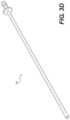
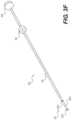
- FIGS. 3 A, 3 B, 3 C, 3 D, 3 E, 3 F, and 3 Gshow various instruments, according to exemplary embodiments
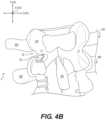
- FIGS. 4 A and 4 Bshow posterior views of a segment of a vertebral column, according to an exemplary embodiment
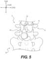
- FIG. 5shows a posterior view of a segment of a vertebral column, showing an instrument location according to an exemplary embodiment
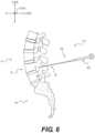
- FIG. 6shows a lateral view of a segment of a vertebral column, showing an instrument location according to an exemplary embodiment
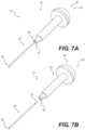
- FIGS. 7 A and 7 Bshow, respectively, an attached and a detached docking pin, according to an exemplary embodiment
- FIG. 8shows a plurality of detached docking pins anchored to a vertebra, according to an exemplary embodiment
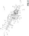
- FIG. 9shows a perspective view of an access portal, according to an exemplary embodiment
- FIGS. 10 A and 10 Bshow side and cut-away side views, respectively, of an access portal, according to an exemplary embodiment
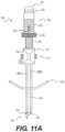
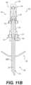
- FIGS. 11 A and 11 Bshow side and cut-away side views, respectively, of an access portal, according to an exemplary embodiment
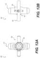
- FIGS. 12 A and 12 Bshow above and below views, respectively, of an access portal, according to an exemplary embodiment
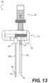
- FIG. 13shows a side view of a laterally translated access portal, according to an exemplary embodiment
- FIG. 14shows a stylet, according to an exemplary embodiment
- FIG. 15shows an access portal slid over a plurality of docking pins, according to an exemplary embodiment
- FIG. 16shows an access portal detached from a trephine and a power source, according to an exemplary embodiment
- FIG. 17shows an access portal containing a trephine guide having a clutch, according to an exemplary embodiment
- FIGS. 18 A, 18 B, and 18 Cshow side views of a partially cut-way clutch and trephine, according to an exemplary embodiment.
- FIG. 18 Dshows a schematic cross-sectional view of a portion of the clutch in FIGS. 18 A- 18 C ;
- FIG. 19shows an access portal containing a rotating rongeur attached to a vertebra and separate from a power source, according to an exemplary embodiment
- FIG. 20shows a rongeur, according to an exemplary embodiment
- FIG. 21shows an enlarged view of a distal end of a rongeur, according to an exemplary embodiment
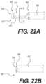
- FIG. 22 Ashows an enlarged side view of a distal end of a rongeur in an open configuration, according to an exemplary embodiment
- FIG. 22 Bshows an enlarged side view of a distal end of a rongeur in a closed configuration, according to an exemplary embodiment
- FIG. 23 Ashows a cross-sectional view of a rongeur, according to an exemplary embodiment
- FIG. 23 Bshows an enlarged cross-sectional view of a rongeur, according to an exemplary embodiment
- FIG. 24depicts a cross-sectional view of a distal end of a rongeur, according to an exemplary embodiment
- FIG. 25 Ashows a partial view of a vertebra containing a channel with a rongeur located therein, according to an exemplary embodiment
- FIG. 25 Bshows a partial cut-away view of a vertebra containing a channel with a rongeur located therein, according to an exemplary embodiment
- FIG. 25 Cshows a view into a channel containing a rongeur, according to an exemplary embodiment
- FIGS. 26 A, 26 B, 26 C, and 26 Dshow various slots formed within a lamina, according to exemplary embodiments
- FIG. 27shows, on the left side, a posterior view of a vertebral column including a vertebra containing a channel and, on the right side, a fluoroscopic image of a posterior view of the vertebral column including a vertebra containing a channel, according to exemplary embodiments.
- the vertebral column(spine, spinal column, backbone) forms the main part of the axial skeleton, provides a strong yet flexible support for the head and body, and protects the spinal cord disposed in the spinal canal, which is formed within the vertebral column.
- the vertebral columncomprises a stack of vertebrae with an intervertebral disc between adjacent vertebra. The vertebrae are stabilized by muscles and ligaments that hold each vertebra in place and limit their movements relative to adjacent vertebra.
- each vertebra 10includes a vertebral body 12 that supports a vertebral arch 14 .
- Vertebral body 12has the general shape of a short cylinder and is located anterior to vertebral arch 14 .
- Vertebral arch 14 together with vertebral body 12encloses a space termed a vertebral foramen 15 .
- a series of vertebral foramen 15 in adjacent vertebrae 10 along the vertebral columndefine the spinal canal.
- a median plane 13generally divides vertebra 10 into two substantially equal lateral sides.
- Vertebral arch 14is formed by two pedicles 24 which project posteriorly to meet two laminae 16 .
- the two laminae 16meet posteriomedially to form a spinous process 18 .
- six processesarise.
- Two transverse processes 20project posterolaterally
- two superior articular processes 22project generally superiorly and are positioned superior to two inferior articular processes 25 that generally project inferiorly.
- Vertebral foramen 15is generally an oval shaped space that contains and protects a spinal cord 28 .
- Spinal cord 28comprises a plurality of nerves 34 surrounded by cerebrospinal fluid (CSF) and an outermost membrane called a dural sac 32 .
- CSFcerebrospinal fluid
- the CSF-filled dural sac 32 containing nerves 34is relatively compressible.
- Posterior to the spinal cord 28 within vertebral foramen 15is the ligamentum flavum 26 .
- Laminae 16 of adjacent vertebral arches 14 in the vertebral columnare joined by the relatively broad, elastic ligamentum flavum 26 .
- FIG. 2is a partial cross-sectional lateral view of a segment of a vertebral column 8 , including a patient's back 5 .
- the segment of vertebral column 8 illustrated in FIG. 2includes three vertebrae 10 a , 10 b , and 10 c .
- Each vertebra 10 a , 10 b , 10 cincludes a vertebral body 12 a , 12 b , 12 c , that supports a vertebral arch 14 a , 14 b , 14 c , respectively.
- Vertebral body 12 a , 12 b , 12 cis anterior to vertebral arch 14 a , 14 b , 14 c , respectively.
- Spinal canal 35contains a spinal cord (not shown).
- each vertebral arch 14 a , 14 b , 14 cincludes two pedicles 24 a , 24 b , 24 c , which project in generally posterior directions to meet two lamina 16 a , 16 b , 16 c , respectively.
- one pediclehas been removed from each vertebra 10 a , 10 b , 10 c and only the cross-section of one lamina 16 a , 16 b , 16 c is visible.
- the two lamina 16 a , 16 b , 16 cmeet posteriomedially to form the spinous process 18 a , 18 b , 18 c , respectively.
- Lamina 16 a , 16 b , 16 c of adjacent vertebra 10 a , 10 b , 10 care connected by ligamentum flavum 26 (shown in cross-section).
- the relatively elastic ligamentum flavum 26extends almost vertically from superior lamina to inferior lamina of adjacent vertebrae.
- ligamentum flavum 26spans an interlaminar space 36 (i.e., space between laminae of adjacent vertebrae).
- Each lamina 16 a , 16 b , 16 ccomprises a relatively broad flat plate of bone that extends posteromedially and slightly inferiorly from pedicles 24 a , 24 b , 24 c , respectively.
- the lamina 16 a , 16 b , 16 ccan overlap, with each lamina substantially parallel to and at least partially overlapping the adjacent inferior lamina.
- the adjacent substantially parallel laminaeare separated by the intervening ligamentum flavum 26 and interlaminar space 36 .
- lamina 16 ais substantially parallel to and partially overlaps adjacent inferior lamina 16 b and is separated from lamina 16 b by ligamentum flavum 26 and interlaminar space 36 .
- Intervertebral foramen 38 bresides between vertebrae 10 a and 10 b .
- Intervertebral foramina 38 a , 38 b , 38 care also called neural foramina and can be abbreviated as IV foramina.
- Intervertebral foramina 38 a , 38 b , 38 callow for the passage of various organs (not shown) into and out of spinal canal 35 .
- These organscan include nerves (e.g., nerve root, dorsal root ganglion, recurrent meningeal (sinu-vertebral) nerves), blood vessels (e.g., spinal artery of the segmental artery, communicating veins between the internal and external plexuses), or ligaments (e.g., transforaminal).
- nervese.g., nerve root, dorsal root ganglion, recurrent meningeal (sinu-vertebral) nerves
- blood vesselse.g., spinal artery of the segmental artery, communicating veins between the internal and external plexuses
- ligamentse.g., transforaminal
- intervertebral foramina 38 a , 38 b , 38 ccan vary along the vertebral column due to location (e.g. cervical, thoracic, lumbar) along vertebral column 8 , pathology, spinal loading, or posture.
- foramina 38can be at least partially occluded by arthritic degenerative changes and space-occupying lesions like tumors, metastases and spinal disc herniations. Some degenerative conditions of the spine cause narrowing of foramina 38 .
- One aim of certain embodiments of the present disclosureis to provide a method and a device for treating foraminal stenosis using lateral recess resection.
- the procedurecan use anatomical landmarks to safely couple an access portal to a posterior aspect of the lamina, away from any vital nerves that could be accidentally damaged.
- the access portalcan be generally anchored in place using a plurality of anchoring pins, as described below in more detail.
- the access portalcan be translated laterally, in one or more directions, generally over the posterior aspect of the lamina.
- the access portalcan allow one or more instruments to be selectively relocated generally within defined bounds at the surgical site.
- the current methodcan use a medial to lateral or “inside-out” approach.
- an initial instrumentcan be used to form a channel 60 through lamina 16 a starting on the posterior side of lamina 16 a and just medial to the lateral border of lamina 16 a , as shown in FIG. 4 B .
- a predictable geometrycan be created whereby subsequent instrument(s) can enter channel 60 and grasp, cut, or remove bone laterally. Such steps can be repeated until the lateral aspect of the lamina 16 a is breached, forming a slot 62 .
- the instruments used in the procedurecan safely access the surgical site and remove bone from the lateral aspect of the lamina.
- the instrumentscan include a docking pin 250 , a handle 240 for docking pin 250 , an access portal 260 , a trephine 530 , a bone ejector 550 , a feeler probe 555 , and a rongeur 560 , as shown respectively in FIGS. 3 A- 3 G . Structural and functional descriptions of these instruments will be provided below in the context of a surgical method contemplated by the present disclosure.
- a patientmay be positioned to permit surgical access to their vertebral column 8 via their back 5 .
- An imaging modalitymay then be used to visualize at least part of vertebral column 8 .
- Imaging modalitiescan include PET, CAT, MRI, or other non-invasive imaging techniques.
- fluoroscopymay be used to image at least part of vertebral column 8 .
- an imaging modalitycan be used to generate an image of part of vertebral column 8 .
- a fluoroscopic C-Arm(not shown) may be used to image a part of vertebral column 8 .
- the imagemay, or may not, include a part of sacrum 40 .
- a center 44 of a superior pedicle 46can be identified, as shown in FIG. 4 A .
- a vertical line 48 lateral to center 44can be generated. It is contemplated that vertical line 48 could be created by placing an elongate device (not shown) medial to center 44 . Vertical line 48 could be created using an edge of the elongate device.
- an inferior border 50 of the superior pediclemay be identified.
- an elongate device(not shown) could be placed inferior to inferior border 50 .
- a line 52could be provided, as shown in FIG. 4 A .
- a C-Armmay be adjusted to provide an image of a lower endplate of a superior vertebra that appears as line 52 .
- the lower endplate of L4can appear as single line 52 , wherein line 52 is substantially horizontal.
- an incisionin the skin of back 5 can be located.
- a single incisioncan be located at an intersection 54 of line 48 and line 52 .
- one or more instrumentsmay be inserted through the incision to access vertebral column 8 .
- the incisionmay include a single cut having a length approximately equal to the outer diameter of the largest instrument to be passed through the incision. Smaller incisions may also be used.
- the lumbar spinal region of a patientmay be surgically prepared with the patient positioned prone on a surgical table. Following fluoroscopic identification of the target spinal level, a stab incision approximately 12 mm in length may be made in the skin and through the underlying lumbar fascia. In other embodiments, a mark on the skin inferior and medial of a pedicle may be made. For example, the incision can extend about 6 mm superior and about 6 mm inferior from the mark. The rest of the procedure may be performed under live fluoroscopic imaging. As such, direct visualization of the bone, channel 60 , slot 62 , or other anatomical features may not be required for the methods of the present disclosure. It is also contemplated that another part of the spine or other bone structure could be treated using at least part of the following devices or methods.
- a docking pin assembly 210may be located at intersection 54 . Docking pin assembly 210 may also be passed through the incision. In some embodiments, docking pin assembly 210 can be used to gain initial access to a posterior aspect of lamina 16 of vertebra 10 . As described below, channel 60 may be created in lamina 16 , wherein channel 60 may have a diameter of about 6 mm. In some embodiments, channel 60 may be enlarged toward a lateral recess, forming slot 62 , undercutting the medial facet joint and decompressing the lamina.
- two or more docking pin assemblies 210may be used.
- a primary pin 211may be anchored to a superior portion of lamina 16 while a secondary pin 212 may be anchored to an inferior portion of lamina 16 ( FIG. 8 ).
- two or more docking pin assemblies 210may each be located along a common straight line, such as, vertical line 48 ( FIG. 4 A ). Such anchoring at multiple locations can provide a strong anchoring force sufficient to permit creation of slot 62 within lamina 16 ( FIG. 4 B ).
- slot 62can be located between the anchoring points of docking pin assemblies 210 ( FIG. 26 A ). As shown in FIG. 4 B , slot 62 can extend generally laterally and through an edge of lamina 16 .
- the slotmay be about 3, 4, 5, 6, 7 or 8 mm wide, or in the range of about 3 mm (0.118 inches) to about 8 mm (0.315 inches), about 4 mm (0.157 inches) to about 6 mm (0.236 inches), or about 6 mm (0.236 inches) to about 8 mm (0.315 inches), for example, and in use may be positioned as close as possible to the spinous process.
- the first docking pinmay be positioned during the procedure in the runout of the spinous process, or in the transitional area between the spinous process in the lamina, such that the slot position is just lateral to the first docking pin.
- the slot lengthmay be in the range of about 5 mm (0.197 inches) to about 22 mm (0.866 inches), about 10 mm (0.394 inches) to about 18 mm (0.709 inches), or about 12 mm (0.472 inches) to about 16 mm (0.630 inches), for example.
- the slot dimensionsare approximately 5 mm (0.197 inches) ⁇ 15 mm (0.591 inches) or more depending on laminal size.
- one or more docking pin assemblies 210may be aligned with one or more anatomical features.
- one or more docking pin assemblies 210could be located inferior to a superior pedicle.
- one or more docking pin assemblies 210could be aligned substantially parallel to a superior pedicle, as shown in FIG. 6 .
- one docking pin assembly 210may be located superior or inferior to another docking pin (not shown) or pin 250 . If necessary, the location or alignment of one or more docking pin assemblies 210 relative to one or more anatomical feature could be adjusted. Once properly located and aligned, additional force may be applied to one or more docking pin assemblies 210 to ensure that they are firmly anchored into lamina 16 .
- docking pin assembly 210can be detachable.
- Docking pin assembly 210can include a handle 240 and a pin 250 , wherein handle 240 and pin 250 can be configured to detach from each other.
- Handle 240 and pin 250may each comprise a proximal end 242 , 252 and a distal end 244 , 254 .
- distal end 244 of handle 240may be configured to detach from proximal end 252 of pin 250 .
- distal end 244 and proximal end 252could be configured for repeatedly releasably coupling, whereby handle 240 and pin 250 could be detached and attached one or more times.
- the handle 240may comprise a lumen or opening on a distal end 244 thereof into which proximal end 252 of pin 250 may be advanced.
- proximal end 252 of pin 250may comprise a notch or indentation that may engage with a raised portion or latch in the lumen of handle 240 to releasably couple pin 250 and handle 240 .
- the lumenmay comprise threads that receive a threaded portion of proximal end 252 of pin 250 .
- handle 240 or pin 250may include a locking system (not shown) configured to limit relative movement between handle 240 and pin 250 .
- proximal end 242 of handle 240can be configured to engage a mallet, a screwdriver, or other device to drive pin 250 into a boney structure.
- a proximal surface of handle 240may comprise an indentation, recess, or one or more slots sized and shaped to mate with or receive a mallet, distal tip of a screwdriver, or other pin driving device.
- Distal end 254 of pin 250can be configured for bone penetration or anchoring in a boney structure.
- distal end 254may be sharp or include a barbed structure.
- distal end 254may comprise a plurality of facets, for example, two, three, four or more, and the facets may be short to facilitate stable anchoring.
- the distal end 254may comprise a different anchoring tip structure, for example, a screw tip.
- Handle 240 and pin 250can be manufactured using various techniques and formed from a range of materials.
- handle 240could include a radiopaque material or a radiolucent material, such as, ABS plastic. Such a material can permit viewing of the surgical site under fluoroscopy with minimal obstruction.
- Pin 250may be formed from hardened stainless steel.
- handle 240 and pin 250may have any dimensions suitable for accessing and anchoring to bone.
- handle 240may be between about 2 cm (0.79 inches) and about 3 cm (1.18 inches) in length, and in some variations, about 2.5 cm (0.98 inches), while pin 250 may be between about 7.3 cm (2.87 inches) and about 12 cm (4.72 inches) in length or between about 8 cm (3.15 inches) and about 10 cm (3.94 inches).
- pin 250may be about 8.3 cm (3.27 inches) in length. Moreover, pin 250 may have a diameter between about 1.5 mm (0.06 inches) and about 3.2 mm (0.13 inches) or between about 2 mm (0.08 inches) and 3 mm (0.11 inches). In some variations, pin 250 may have a diameter of about 2.2 mm (0.09 inches). In other variations, one or more K-wires may be used in lieu of docking pins.
- access portal 260may be slid over pins 250 , as shown in FIG. 15 .
- Access portal 260may be slid over pins 250 until access portal 260 makes contact with vertebra 10 or lamina 16 .
- access portal 260may provide controlled lateral access to vertebra 10 or lamina 16 .
- Pins 250could be provided as a single device with a proximal coupling (not shown) providing lateral separation between pins 250 .
- Pins 250may also be coupled to lamina 16 using a template (not shown), similar to a docking pin guide 300 described below.
- Other devices and methodsmay be used to anchor a plurality of pins 250 to lamina 16 .
- one or more pins 250may be docketed to vertebra 10 and access portal 260 may then be slid over the one or more anchored pins 250 .
- one or more additional pins 250may be anchored into vertebra 10 to provide additional stability and anchoring of access portal 260 to vertebra 10 .
- one docking pin assembly 210may be located in a superior region of lamina 16 .
- handle 240may be removed from pin 250 , as explained above. This can leave pin 250 , as shown in FIG. 6 , positioned similarly to the location of primary pin 211 in FIG. 8 .
- Access portal 260could be provided with one or more additional pin assemblies 210 .
- one pin 250could be fixedly coupled to access portal 260 , wherein this pin 250 could function as secondary pin 212 shown in FIG. 8 .
- Access portal 260containing secondary pin 212 , could then be slid over primary pin 211 while it is anchored to lamina 16 .
- Secondary pin 212could then be anchored to lamina 16 by applying a force to access portal 260 .
- access portal 260may optionally be fixedly coupled to a proximal region of primary pin 211 .
- Such dual anchoringcould provide access portal 260 with sufficient fixation relative to lamina 16 to perform the procedures described herein.
- access portal 260may be first passed through an incision, followed by anchoring of pins 250 to vertebra 10 .
- a dilatormay also be used to provide suitable access to vertebra 10 .
- the present disclosureuses a plurality of anchoring points to provide significantly enhanced anchoring. This enhanced anchoring allows for more efficient and effective bone removal to precisely form channel 60 as desired.
- FIG. 9depicts access portal 260 , according to an exemplary embodiment.
- Access portal 260can include an elongate structure configured for use with a percutaneous procedure.
- Access portal 260may be used for procedures within or adjacent to various body organs, such as, for example, vertebral column 8 . Accordingly, access portal 260 can be shaped and sized for placement into a patient via a single incision.
- Access portal 260can have a proximal end 270 , a distal end 280 , and a longitudinal axis 290 .
- Access portal 260may comprise a one or more elongate members or docking pin guides configured to receive pins 250 , for example, first and second elongate members 295 A, 296 B comprising first and second lumens therethrough respectively, and one or more elongate members configured to receive various types of surgical instruments, for example, third elongate member 340 comprising third lumen therethrough.
- Access portal 260may also comprise a docking pin guide 300 , a housing 310 comprising a body 316 and an actuator 315 , and a depth guide adjuster 320 . As shown in FIG.
- access portal 260may receive an obturator 330 , which may be at least partially positioned within the lumen of the third elongate member 340 , and secondary pin 212 , which may be at least partially positioned within the lumen of one of the first or second elongate members 295 A, 295 B (depicted within lumen of first elongate member 295 A).
- third elongate member 340may include an access cannula configured to receive various types of surgical instruments.
- the first and second elongate members 295 A, 295 Bmay be coupled to a distal end or surface of body 316 of housing 310 and may extend distally therefrom.
- the first and second elongate members 295 A, 295 Bmay be fixedly coupled to the body 316
- one or both of the first and second elongate members 295 A, 295 Bmay be releasably coupled to the body 316 .
- Third elongate member 340may be moveably coupled to body 316 of housing 310 (e.g., at a proximal portion of third elongate member 340 ) such that the third elongate member 340 may move relative to the body 316 .
- the housing 310may comprise a lock configured to temporarily limit movement of third elongate member 340 relative to body 316 .
- the third elongate member 340when the lock is engaged, the third elongate member 340 may be fixed or otherwise prevented from moving relative to the housing 310 , whereas when the lock is disengaged, the third elongate member 340 may slide or otherwise move relative to housing 310 .
- the third elongate member 340may comprise a flattened surface 318 ( FIG. 13 ) near a proximal end thereof (e.g., adjacent to body 316 ), which may allow the third elongate member 340 to be released from the docking pin guide 300 , as will be described in more detail below.
- Flattened surface 318may be positioned such that it is facing or adjacent the first or second elongate member 295 A, 295 and an elongate edge of the second slot 309 in body 316 .
- pin 250 and/or first and/or second elongate member 295 A, 295 Bmay be fixedly coupled to housing 310 (e.g., body 316 ) and third elongate member 340 may be configured to move laterally relative to longitudinal axis 290 while pin 250 , first elongate member 295 A, second elongate member 295 B, and/or body 316 remain essentially stationary (see FIG. 13 ). As explained below, such lateral movement can allow formation of slot 62 within a bone of the patient.
- Pin 250 or first and/or second elongate members 295 A, 295 Bcan be releasably coupled to housing 310 (e.g., body 316 ) and thus to access portal 260 .
- first elongate member 295 Amay be fixedly attached to body 316 and pin 250 may be releasably coupled to first elongate member 295 A, body 316 , or both.
- housing 310may further comprise a lock or other attachment mechanism that couples either or both docking pin 250 and first elongate member 295 A to body 316 .
- housing 310may comprise a fastener 305 that fixedly couples either or both docking pin 250 and first elongate member 295 A to body 316 .
- the fastener 305may be a locking nut, a set screw, a latch, a cam, a magnet, a ball detent, or the like.
- a friction fit, adhesive, or other attachment mechanismmay be used. Any of the aforementioned attachment mechanisms may be used to couple the first elongate member 295 A, the second elongate member 295 B, pin 250 , or any additional elongate members to the housing 310 of the access portal 260 , and the same attachment mechanism need not be used for each elongate member.
- Such mechanismscould be coupled to a surface of body 316 , embedded with the body 316 , or housed within the body 316 .
- first and second elongate members 295 A, 295 Bmay be fixedly coupled to housing 310 and secondary docking pin 212 may be positioned within a lumen of first elongate member 295 A and releasably coupled to housing 310 via fastener 305 before advancement to a treatment site.
- the access portal 260may be then be advanced to a treatment site and second elongate member 295 A may be slid or otherwise advanced over primary docking pin 211 such that primary docking pin 211 may be slideably positioned within the lumen of second elongate member 295 B.
- loosening, disengaging, or otherwise removing fastener 305may release secondary docking pin 212 from housing 310 , which may allow access portal 260 to be withdrawn or removed from the treatment site without removing docking pins 211 , 212 .
- Thismay allow a surgeon or user to image the area (e.g., using X-ray) without access portal 260 blocking or otherwise interfering with the image, while still allowing access portal 260 to be re-advanced to or repositioned at the same treatment location.
- access portal 260may comprise only a single elongate member 295 A, while in other variations and as described above, the access portal 260 may comprise a plurality of elongate members (e.g., first and second elongate members 295 A, 295 B, however, additional elongate members may also be included).
- First and second elongate members 295 A, 295 Bcan be configured to receive a plurality of pins 250 , wherein a specific pin 250 may extend at least partially through one of the first and second elongate members 295 A, 295 B.
- Elongate members 295 A, 295 Bcould be variously sized and have the same or different dimensions.
- the first and/or second elongate member 295 A, 295 Bmay comprise a diameter of between about 2.1 mm (0.08 inches) and about 3.8 mm (0.15 inches), between about 2.5 mm (0.10 inches) and about 3.5 mm (0.14 inches), or between about 2.7 mm (0.106 inches) and about 3 mm (0.12 inches).
- the first and/or second elongate member 295 A, 295 Bmay comprise a diameter of about 2.8 mm (0.11 inches).
- first and/or second elongate member 295 A, 295 Bmay comprise a length of between about 6.9 cm (2.72 inches) and about 11.6 cm (4.57 inches), between about 7 cm (2.76 inches) and about 10 cm (3.94 inches), or between about 7.5 cm (2.95 inches) and about 8.5 cm (3.35 inches). In some variations, the first and/or second elongate member 295 A, 295 B may comprise a length of about 7.9 cm (3.11 inches).
- first and/or second elongate member 295 A, 295 Bmay comprise a length of between about 8 cm (3.15 inches) and about 12 cm (4.72 inches), between about 9.0 cm (3.54 inches) and about 11.0 cm (4.33 inches), or between about 9.5 cm (3.74 inches) and about 10.5 cm (4.13 inches). In some variations, the first and/or second elongate members 295 A, 295 B may comprise a length of about 10.414 cm (4.10 inches).
- the elongate members 295 A, 295 Bmay have any cross-sectional shape suitable for receiving a pin 250 , for example, oval, square, rectangular, triangular, hexagonal, or the like.
- First and second elongate members 295 A, 295 Bmay be formed from any suitable materials.
- one or both of the first and second elongate members 295 A, 295 Bmay be formed from or comprise a metal alloy.
- first and second elongate members 295 A, 295 Bmay be formed from the same material, while in other variations, they may be formed from different materials.
- first and second elongate members 295 A, 295 Bmay comprise more than one material, for example, one or more portions may be formed from a first material and one or more portions may be formed from a second, different material.
- first and second elongate members 295 A, 295 Bmay be rigid to provide stationary support for access portal 260 relative to a vertebra
- first and/or second elongate member 295 A, 295 Bmay be selectively flexible to permit some controlled movement of portal 260 (e.g., body 316 , third elongate member 340 ) relative to the vertebra.
- first and/or second elongate member 295 A, 295 B, or a portion thereofmay be formed from or comprise a flexible polymer (e.g., PC/ABS blend, ABS, or the like) or other material that allows for movement of housing 310 and/or third elongate member 340 relative to elongate members 295 A, 295 B when a force is applied.
- a flexible polymere.g., PC/ABS blend, ABS, or the like
- one or more of elongate members 295 A, 295 Bmay comprise sections along its length with different flexural properties such that a distal end of the elongate member 295 A, 295 B may be more flexible than a central or proximal portion of the elongate member 295 A, 295 B.
- an elongate member 295 A, 295 Bmay be constructed (e.g., using sections formed from materials with different properties) such that flexibility of the elongate member 295 A, 295 B decreases from a distal end of elongate member 295 A, 295 B to a proximal end, which may provide flexibility to move a distal end of elongate member 340 or a tool position therein while providing enough rigidity to dock secondary pin 212 and/or maintain the general positioning of the access device 260 .
- First, second, and third elongate members 295 A, 295 A, 340may be parallel to one another (e.g., longitudinal axes of the first, second and/or elongate members may be parallel), aligned generally along longitudinal axis 290 , and distributed generally along a common lateral axis extending perpendicular to longitudinal axis 290 .
- the third elongate member 340may be aligned generally along longitudinal axis 290 (e.g., the longitudinal axis of the third elongate member may be co-linear with longitudinal axis 290 ) in a first, initial configuration (e.g., during advancement of the portal 260 and/or during the portion of a procedure leading up to slot formation) and may be moved to a second configuration (e.g., during slot formation) in which a longitudinal axis of the third elongate member 340 may be off-set or laterally shifted from longitudinal axis 290 .
- first, initial configuratione.g., during advancement of the portal 260 and/or during the portion of a procedure leading up to slot formation
- a second configuratione.g., during slot formation
- the longitudinal axis of the third elongate member 340may also be laterally shifted from the longitudinal axes of the first and second elongate members 295 A, 295 B in the second configuration.
- elongate members 295 A, 295 B, 340may be differently positioned relative to one another.
- first and second elongate members 295 A, 295 Bmay be positioned on the same side of third elongate member 340 , as opposed to on opposite sides as depicted.
- portal 260may comprise more than one third elongate member 340 (e.g., two, three, four, or more).
- the first and/or second elongate members 295 A, 295 Bmay also be fixedly, moveably, or releasably coupled to docking pin guide 300 . Such coupling may permit movement of guide 300 up or down a longitudinal axis of one or more elongate members 295 A, 295 B, and in some variations, may allow for removal of docking pin guide 300 from access portal 260 . Relative longitudinal movement may facilitate appropriate positioning of guide 300 on a patient's skin.
- docking pin guide 300may be axially adjustable to account for different patient anatomy, e.g., different amounts of tissue between the target lamina and a skin surface. Additionally, docking pin guide 300 may be adjustable to allow for movement across lamina laterally or medially.
- Docking pin guide 300may include angled or contoured surfaces configured for contact with skin.
- docking pin guide 300may comprise two surfaces angled inward toward a central surface.
- the central surfacemay be transverse and in some variations, generally perpendicular, to longitudinal axis 290 .
- docking pin guide 300may be more curved, for example, it may be arcuate or semi-circular.
- the central surfacemay comprise first and second openings and a recess 302 .
- the first and second elongate members 295 A, 295 Bmay be positioned through first and second openings and the third elongate member 340 may be positioned within recess 302 .
- Recess 302may be configured to permit movement of third elongate member 340 relative to docking pin guide 300 when docking pin guide 300 is aligned with flattened surface 318 of third elongate member 340 .
- recess 302may have a longitudinal axis that is perpendicular to a longitudinal axis of docking pin guide 300 and may extend through a sidewall of the docking pin guide 300 such that an opening is formed for passage of the third elongate member 340 therethrough.
- docking pin guide 300may be withdrawn or retracted proximally toward body 316 to align docking pin guide 300 with flattened surface 318 such that third elongate member 340 may be moved laterally.
- docking pin guide 300may hold elongate members 295 A, 295 B, 340 stationary (i.e., it constrains translational and/or rotational movement of elongate members 295 A, 295 B, 340 relative to one another and body 316 ) to facilitate placement of access portal 260 in the appropriate location on the vertebrae (
- first and second openings on docking pin guide 300may comprise slots (as opposed to holes), which may allow the first and second elongate members 295 A, 295 B to be released from docking pin guide 300 .
- Thismay allow third elongate member 340 to be moved in a first direction from its initial (central) position and in a second, opposite direction from its initial position (e.g., left-of-center and right-of-center, laterally and medially).
- first and second slots in docking pin guide 300may be offset, which may help hold first and second elongate members 295 A, 295 B in the docking pin guide 300 .
- Third elongate member 340may also assist in positioning the first and second elongate members 295 A, 295 B within the slots and may hold the first and second elongate members 295 A, 295 B within the slots when it is positioned centrally between them.
- the first and second elongate members 295 A, 295 Bmay be squeezed together or otherwise moved toward one another to disengage them from docking pin guide 300 .
- Docking pin guide 300may then be removed from access portal 260 altogether.
- docking pin guidemay be rotated 180 degrees and first and second elongate members 295 A, 295 B may be reinserted into slots in docking pin guide 300 .
- the opening in recess 302may face the opposite direction, and thus the third elongate member 340 may move from its initial central position, through recess 302 to extend the channel in the bone in a second, opposite direction.
- the third elongate member 340may move medially, but not laterally, from its initial position. After the docking pin guide 300 is removed and optionally rotated and reinstalled, the third elongate member 340 may move laterally but not medially from its initial position. In variations in which the docking pin guide 300 is not reinstalled, the third elongate member 340 may freely move both laterally and medially from its initial position.
- Docking pin guide 300may be formed from a suitable medical grade material and formed to contact a patient's skin. Pin guide 300 may be curved to facilitate correct positioning of access portal 260 relative to a lamina (not shown) or other anatomical feature. Such positioning can ensure appropriate alignment of cutting tools and correct formation of channels and slots within a bone of a patient. For example, as shown in FIG. 13 and explained above, docking pin guide 300 can be configured to slide up and down elongate members 295 A, 295 B.
- Housing 310can be configured to permit relative movement between one or more of the first and second elongate members 295 A, 295 B and third elongate member 340 , wherein this relative movement can be lateral and/or medial or generally perpendicular to longitudinal axis 290 .
- housing 310may comprise a body 316 and an actuator 315 .
- Actuator 315may be coupled to the third elongate member 340 and may be configured to move or allow movement of third elongate member 340 relative to one or more of first and second elongate members 295 A, 295 B and body 316 .
- actuator 315may function as a lock.
- actuator 315may comprise first and second positions.
- actuator 315When actuator 315 is in the first position, it may prevent relative movement between third elongate member 340 and body 316 (and first and/or second elongate member 295 A, 295 B). When actuator 315 is in the second position, it may allow relative movement between third elongate member 340 and body 316 (and first and/or second elongate member 295 A, 295 B.
- actuator 315may comprise a disk-shaped dial.
- the disk-shaped dialmay be rotatably coupled to elongate member 340 such that when the dial is rotated in a first direction (e.g., anticlockwise), the dial moves to a first locked position and constrains the position of the third elongate member 340 .
- a first directione.g., anticlockwise
- the dialmoves to a first locked position and constrains the position of the third elongate member 340 .
- the dialWhen the dial is rotated in a second, opposite direction (i.e., clockwise), the dial moves to a second unlocked position in which third elongate member 340 may be moved laterally.
- actuator 315may comprise a latch, cam, slider, or other mechanism suitable for moving or allowing movement of third elongate member 340 .
- third elongate member 340may releasably couple to the housing 310 (e.g., friction fit, slot, adhesive, magnetic, or other attachment mechanism) such that the third elongate member 340 may be released from the housing 310 , moved, and recoupled to the housing 310 in a different location.
- Housing 310e.g., body 316
- Housing 310may be formed of a metal alloy, polymer, or other material.
- body 316 of housing 310may comprise an internal chamber 306 and a plurality of slots that may facilitate movement of the third elongate member 340 relative to the body 316 .
- body 316may comprise a first slot or opening 308 on a proximal surface of the body 316 ( FIG. 9 ), a second slot or opening 309 on a distal surface of the body 316 ( FIG. 16 ), and third a slot or opening 312 on a first side surface of the body 316 ( FIG. 9 ).
- the body 316may comprise a fourth slot or opening on a second, opposite side surface of the body 316 .
- the third elongate member 340may be positioned within and through the first and second slots 308 , 309 such that the third elongate member 340 extends distally through the body 316 .
- Actuator 315e.g., dial
- the first and second slots 308 , 309may be aligned such that they form a passageway through body 316 . Additionally, in variations comprising a fourth slot, the third and fourth slots 312 may be also be aligned such that they also form a passageway through body 316 . The passageway formed by the third 312 and fourth slots may be generally perpendicular to the passageway formed by the first and second slots 308 , 309 . In some variations, the first and second slots 308 , 309 may be centrally positioned on the proximal and distal surfaces of the body 316 .
- the second slot 309may be positioned between the first and second elongate members 295 A, 295 B (i.e., the first and second elongate members 295 A, 295 B may be coupled to body 316 on opposite sides of the second slot 309 ).
- First and second slots 308 , 309may be configured for lateral movement, medial movement, or both lateral and medial movement of third elongate member 340 .
- each slotmay have a first end and a second end and may be oriented orthogonally or at an angle to a line that intersects the first and/or second docking pin.
- the slots 308 , 309may be symmetrically or asymmetrically positioned with respect to the intersecting line.
- first and second slots 308 , 309may be configured for lateral or medial movement (but not both)
- first end of first and second slots 308 , 309may be generally centrally positioned on body 316 and/or aligned with longitudinal axis 290 and the first and second slots 308 , 309 may extend in one direction (e.g., medially or laterally, right or left).
- first and second slotsmay be configured for both lateral and medial movement
- a midpoint of first and second slots 308 , 309may be aligned with longitudinal axis 290 such that the first and second slots 308 , 309 may extend from the midpoint in two directions (e.g., medially and laterally, right and left) between first and second ends, which are positioned on either side of longitudinal axis 290 .
- slots 308 , 309may be offset (shifted) relative to longitudinal axis 290 such that a different point along the length of first and second slots 308 , 309 may be aligned with longitudinal axis 290 .
- lateral and medial travel pathsmay not be equal lengths.
- first and second slots 308 , 309may have the same cross-sectional shape (e.g., rectangular, oval, or the like) and dimensions (e.g., length and width), while in other variations, the first and second slots 308 , 309 may have different cross-sectional shapes and/or dimensions (e.g., the second slot 309 may be wider, which may allow for additional movement at the distal end of the third elongate member 340 ).
- the first and second slots 308 , 309may be configured (e.g., dimensioned and positioned) to allow the third elongate member 340 to move medially or laterally, but not both medially and laterally.
- the first and second slots 308 , 309may have a shorter length than in variations in which the third elongate member 340 may move both medially and laterally (body 310 depicted in FIGS. 9 and 16 is configured for both medial and lateral movement).
- first and/or second slot 308 , 309may have a length between about 1.3 cm (0.51 inches) and about 2.0 cm (0.79 inches), between about 1.5 cm (0.59 inches) and about 1.8 cm (0.71 inches), or about 1.6 cm (0.63 inches).
- first and/or second slotmay have a length between about 2.6 cm (1.02 inches) and about 4.0 cm (1.57 inches) or between about 3.0 cm (1.81 inches) and about 3.5 cm (1.38 inches). In some variations, the first and/or second slot 308 , 309 may have a length of about 3.2 cm (1.26 inches).
- the width of the first and/or second slotmay be about equal to or just slightly larger than the diameter of the third elongate member 340 .
- the widthmay be between about 5 mm (0.197 inches) and about 6 mm (0.236 inches) or between about 5.2 mm (0.205 inches) and about 5.5 mm (0.217 inches).
- the width of the first and/or second slotmay be about 5.4 mm (0.213 inches).
- the third 312 and fourth slotsmay also have the same cross-sectional shape (e.g., rectangular) and dimensions, and may have the same or different cross-sectional shapes and dimensions as the first and second slots 308 , 309 .
- the third 312 and/or fourth slotmay have the same length as the first and/or second slots 308 , 309 , while in other variations, the third 312 and/or fourth slot may be longer or shorter than the first and/or second slots 308 , 309 .
- the third 312 and/or fourth slotmay have a larger or smaller width than the first and/or second slots 308 , 309 . For example, as depicted in FIG.
- the third slot 312may have a longer length and a shorter width than the first slot 308 .
- the third slot 312may have a rectangular or oval cross-sectional shape to accommodate the disk-shaped dial, this need not be in the case.
- the third slot 312(and optional fourth slot) may have a circular cross-sectional shape, which may accommodate a spherical or ball shaped actuator.
- third elongate member 340may be positioned through the first and second slots 308 , 309 and the actuator 315 may extend from within the body 316 through the third slot 312 .
- first and second slots 308 , 309may act as guides or tracks for the third elongate member 340
- third slot 312 (and fourth slot)may act as a guide or track for actuator 315 .
- first and second slots 308 , 309 and third slot 312may allow for movement of the third elongate member 340 and actuator 315 (e.g., dial) respectively in along one axis (e.g., along a longitudinal axis of the slot, perpendicular to longitudinal axis 290 ), while constraining movement of elongate member 340 and actuator 315 respectively along other axes.
- Movement of actuator 315 (e.g., rotational, translational) within third slot 315moves and/or allows movement of third elongate member 340 within first and second slots 308 , 309 , thus allowing formation of a slot in bone, as will be described in more detail below.
- Free-form movementis also contemplated whereby a surgeon may move third elongate member 340 relative to housing 310 freely in one or more lateral directions.
- access portal 260may further include one or more stops, movement assist, dampening, or other movement related mechanism.
- a usermay encounter resistance when moving or sliding third elongate member 340 laterally from, for example, muscle or other anatomical structures of the patient.
- housing 310may further comprise a rack and pinion coupled to third elongate member 340 , which may provide a user leverage in moving third elongate member 340 .
- the rack and pinionmay additionally include a friction or lock screw.
- housing 310may further comprise wire or cable coupled to third elongate member 340 and rolled around a drum. The wire or cable may be used to pull third elongate member 340 laterally.
- housing 310may comprise a ratchet and pawl or a cam that may assist in moving the third elongate member 340 .
- the housing 310e.g., slots 308 and/or 309
- the housing 310may also comprise ball detents such that when third elongate member 340 is moved laterally, it may stop in the ball detent locations.
- the ball detent locationsmay correspond to desired drilling locations and thus may assist a user in identifying when third elongate member 340 reaches the next drilling location. This may increase repeatability of the procedure, for example, by demarcating the various positions of the third elongate member 340 and may enable a user to move the third elongate member 340 to the same location more easily.
- Depth guide adjuster 320may be configured to control the relative depth of one or more elongate members or devices positioned within lumens of one or more elongate members of access portal 260 and may be configured to transfer rotational movement into linear movement along longitudinal axis 290 .
- guide adjuster 320may comprise a handle or outer housing 321 , a central member 322 , a pin 323 , and an adjusting dial 325 .
- outer housing 321may comprise an elongate tubular member with a lumen 326 therethrough, a proximal end 304 , and a longitudinal through wall slot 324 connecting lumen 326 to an outer surface of outer housing 321 .
- Central member 322may comprise a threaded rod comprising a lumen therethrough (depicted in FIG. 10 B with a tool within the lumen).
- Outer housing 321may be operably coupled to adjusting dial 325 (e.g., it may abut or otherwise rest on a proximal surface of adjusting dial 325 ), which may be rotatably coupled to central member 322 .
- Central member 322may be positioned within lumen 323 of outer housing and may advance or retract within lumen 323 as adjusting dial 325 is rotated.
- Pin 323may be fixedly coupled to central member 322 and may be slideably positioned within longitudinal slot 324 , which may both couple outer housing 321 and central member 322 and provide an indication of the depth of a tool positioned within lumen 326 and lumen of central member 322 .
- Outer housing 321 of guide adjuster 320may comprise markings, indicia, or other indicators of absolute or relative depth.
- guide adjuster 320can be configured to adjust the height of an instrument in increments, such as, for example, 0.5, 1, 2, or 4 mm.
- Manipulating guide adjuster 320can permit a surgeon to precisely control the depth of one or more components within a patient. Precise depth control can be critical to ensure that a nerve is not inadvertently severed.
- a proximal end 304 of guide adjuster 320can be configured to engage a handle or distal facing surface of obturator 330 . It is also contemplated that proximal end 304 could be configured to engage other types of surgical instrument.
- access portal 260could operate without the use of guide adjuster 320 .
- One or more components of access portal 260can be formed from a suitable medical grade material. Further, one or more parts of access portal 260 may include a metal alloy or material with similar properties. For example, in some embodiments, one or more elongate members 295 A, 295 B, 340 can be at least partially formed using a metal alloy, such as stainless steel. In other embodiments, first and second elongate members 295 A, 295 B can be made of a material having additional rigidity or other features providing additional strength. For example, in some variations, first and/or second elongate members 295 A, 295 B may be formed from or comprise PC/ABS plastic and/or comprise stainless steel portions or structures. These or other components of portal 260 can be formed of or comprise a radiopaque or radiolucent material, such as ABS plastic, to provide markers for guidance during a procedure.
- a radiopaque or radiolucent materialsuch as ABS plastic
- FIGS. 10 A- 12 Billustrate different views of access portal 260 , according to an exemplary embodiment.
- FIG. 10 Aillustrates a side view of portal 260 wherein one pin 250 is positioned directly behind another pin (not shown) and third elongate member 340 is configured to move left or right relative to housing 310 .
- third elongate member 340can translate left and right within first slot 308 and internal chamber 306 . Accordingly, the entire third elongate member 340 (both proximal and distal ends) can move left as indicated by an arrow 342 or right as indicated by an arrow 344 .
- Guide adjuster 320 and a medical instrumentcan also be translated in one or more vertical directions relative to housing 310 , such that longitudinal axes of the third elongate member 340 and the medical instrument are translated to a position parallel to, but shifted from, their initial positions. This translation can occur while body 316 remains fixedly anchored relative to a patient.
- FIG. 11 Aillustrates another side view of access portal 260 , according to an exemplary embodiment.
- Docking pin guide 300can be fixedly or moveably coupled to one or more elongate members 295 A, 295 B, 340 .
- pin guide 300may not be required or other devices could be configured to perform one or more functions of pin guide 300 .
- FIGS. 10 B and 11 Bdepict cut-away side views of access portal 260 , according to an exemplary embodiment.
- access portal 260can be configured to adjust the height of a medical instrument located within third elongate member 340 relative to first and second elongate members 295 A, 295 B, housing 310 , or guide adjuster 320 .
- proximal end 304 of guide adjuster 320can be moved proximally or distally relative to the patient to vary the height of an instrument and to raise or lower a position of the instrument relative to portal 260 .
- Such height adjustmentcan increase or decrease the extent to which an instrument extends into the patient's body.
- Guide adjuster 320may be configured to move relative to one or more parts of portal 260 . As explained below, guide adjuster 320 can be used to limit the movement of one or more instruments relative to vertebra 10 . For example, guide adjuster 320 could be used to limit ventral or distal movement of trephine 530 , feeler probe 555 , rongeur 560 , or other device associated with portal 260 . Guide adjuster 320 could be adjusted before or while an instrument is being used. Limiting instrument movement can serve to protect tissue, such as, for example, spinal cord 28 , from accidental contact.
- guide adjuster 320may comprise adjusting dial 325 .
- Adjusting dial 325may be rotatably coupled, e.g., using threads, to central member 322 .
- Rotational movement of adjusting dial 325 relative to central member 322may raise or lower outer housing 321 relative to housing 310 and third elongate member 340 .
- rotational movement of adjusting dial 325e.g., clockwise, anticlockwise
- central member 322may move relative to housing 310 to adjust a relative height of outer housing 321 .
- Components of portal 260can also include one or more threads, or other connectors, to couple various components together.
- obturator 330is shown engaged with guide adjuster 320 via a threaded couple 346 .
- Dials 315 , 325are shown engaged with central member 322 of guide adjuster 320 using threads.
- Dial 315may be rotated to lock or unlock third elongate member 340 relative to body 316 .
- Dial 325may be rotated to move obturator 330 , or another type of instrument located within third elongate member 340 , up or down relative to housing 310 .
- dial 325may be rotated clockwise to raise outer housing 321 relative to housing 310 and distal end of third elongate member 340 and/or rotated anticlockwise to lower outer housing 321 relative to housing 310 and distal end of third elongate member 340 .
- FIGS. 10 B and 11 Bshow various threads moveably or fixedly coupling components
- various other types of connections between one or more components of access portal 260are contemplated.
- Other types of connectorscould include a button, a lever, a cam, a rack and a pawl, a tab, a snap-connect, or a thumb-wheel and a gear.
- Various componentscould also be connected using a luer lock, a collet, a ball and socket, a 1 ⁇ 4 turn fastener, or a magnetic element.
- Access portal 260can be configured to receive one or more surgical instruments, such as, for example, obturator 330 .
- Obturator 330can be configured to aid insertion of access portal 260 into a patient.
- Obturator 330can at least partially reside within guide adjuster 320 , housing 310 , and/or third elongate member 340 .
- obturator 330can include a proximal end 332 and a distal end 334 .
- proximal end 332can include a handle 350 configured to aid removal of obturator 330 from portal 260 .
- Proximal end 332could also be configured to limit distal movement of obturator 330 relative to guide adjuster 320 or portal 260 .
- Distal end 334can include a blunt tip configured to part soft tissue and not penetrate bone. Distal end 334 may extend beyond distal end 280 of portal 260 .
- Obturator 330can also be configured to attach to or detach from guide adjuster 320 or portal 260 .
- Obturator 330can include a stylet shaft 370 having distal end 334 .
- Distal end 334can be cone shaped to provide dilation of soft tissue as access portal 260 is slid over one or more pins 250 . It is also contemplated that distal end 334 could include a sharp tip configured to pierce or cut tissue.
- third elongate member 340can be configured to receive at least part of obturator 330 .
- the lumen of third elongate member 340may be shaped and sized to receive distal end 334 of obturator 330 .
- the lumen of third elongate member 340may be configured to receive at least part of a surgical instrument.
- third elongate member 340can be centered on longitudinal axis 290 .
- Third elongate member 340can include a proximal end 402 and a distal end 404 .
- elongate members 295 A, 295 Bcan be configured to move relative to third elongate member 340 .
- distal end 394 of first and/or second elongate members 295 A, 295 Bcan be configured to move laterally relative to distal end 404 of third elongate member 340 (see FIG. 13 ).
- One or more of first, second, and third elongate members 295 A, 295 B, 340can remain generally parallel relative to each other and move laterally relative to each other.
- one or more elongate members 295 A, 295 B, 340could be flexible or their respective attachment to housing 310 could be flexible to permit some selective lateral movement of their distal ends 394 , 404 .
- lateral movement between distal ends 394 , 404can permit formation of an appropriately sized slot 62 within lamina 16 .
- access portal 260may be slid over one or more pins 250 .
- obturator 330may be located within third elongate member 340 such that distal end 334 of obturator 330 at least partially extends beyond distal end 404 of third elongate member 340 .
- Distal end 334may assist dilation of tissue during access to a surgical site or may cut tissue to assist locating distal end 404 at the surgical site.
- one or more pins 250 associated with access portal 260may be anchored to lamina 16 .
- secondary pin 212may be anchored to lamina 16 by tapping on obturator 330 .
- both primary pin 211 and secondary pin 212can be anchored to lamina 16 using access portal 260 .
- Other possible sequences for anchoring a plurality of pins 250are also contemplated.
- obturator 330can be removed from access portal 260 and third elongate member 340 . Appropriate positioning can occur when obturator 330 makes contact with lamina 16 . Once obturator 330 is removed, portal 260 may be moved slightly, in an anterior direction, to ensure that distal end 404 resides above lamina 16 .
- trephine 530may be inserted through access portal 260 (e.g., third elongate member 340 ), as shown in FIG. 16 .
- guide adjuster 320can be moved proximally and distally relative to housing 310 . As explained below, such height adjustment can at least partially limit distal movement of trephine 530 relative to access portal 260 .
- Trephine 530can include an elongate member 540 comprising distal end 534 and a lumen therethrough, and a proximal end 532 .
- Proximal end 532can be configured to engage access portal 260 to at least partially limit distal movement of trephine 530 relative to access portal 260 .
- proximal end 532could include a hub 536 configured to engage guide adjuster 320 (e.g., outer housing 321 ).
- hub 536may comprise a cylindrical distal end (e.g., a washer) and a hexagonal proximal end, which may be integrally formed or formed separately and coupled to one another using, for example, laser welding, soldering, a press-fit connection, or the like.
- hub 536may comprise a shank (e.g., with a beveled edge) or a quick release connector (e.g., a trinkle or AO connector).
- the cylindrical distal endmay couple or otherwise rest on a proximal surface of outer housing 321 of guide adjuster 320 and the proximal end may couple to or engage a power source 700 (e.g., a surgical drill powered by an electric motor, or a pneumatic drive) or similar device configured to rotate trephine 530 .
- a power source 700e.g., a surgical drill powered by an electric motor, or a pneumatic drive
- hub 536may be rotated by hand.
- Trephine 530may be cordless and powered by a battery.
- Distal end 534 of trephine 530can be configured to cut bone.
- distal end 534can include unidirectional teeth to rotatably cut bone during clockwise or anticlockwise rotation.
- Distal end 534can also include an undercut helical spiral (not shown) to retain bone fragments during cutting of the bone.
- the helical spiralmay be contained on an elongate member 540 extending generally from distal end 534 to proximal end 532 .
- Trephine 530may also be coated with a coating to aid removal, such as, for example, a lubricous coating.
- elongate member 540may be coated with a lubricious coating (e.g., on an inner and/or outer diameter thereof), which may reduce friction between bone within elongate member 540 and/or between the outer surface of elongate member 540 and surrounding bone.
- a cooling fluide.g., saline
- Trephine 530may also be tapered or have a reduced diameter within a region of distal end 534 to reduce friction with surrounding tissue.
- One or more other featuresmay be included on a distal region of trephine 530 to aid removal from lamina 16 .
- trephine 530can be placed within a lumen of third elongate member 340 of access portal 260 such that distal end 534 of trephine 530 extends beyond distal end 404 of third elongate member 340 .
- the distance between distal ends 534 and 404can be controlled to provide appropriate spacing between distal end 534 of trephine 530 and distal end 404 .
- Such relative depth controlcan ensure that trephine 530 does not extend too far into vertebra 10 .
- guide adjuster 320can be used to control the relative spacing of distal ends 534 or 404 .
- moving guide adjuster 320 proximally or distallycan move outer housing 321 proximally or distally, which may in turn move hub 536 and elongate member 540 proximally or distally.
- guide adjuster 320can be used to limit the longitudinal movement of trephine 530 relative to housing 310 .
- dial 325may be used to adjust the relative height of guide adjuster 320 .
- a distance between distal end 534 of trephine 530 and guide adjuster 320can be adjusted so that when hub 536 makes contact with guide adjuster 320 , distal end 534 may make contact with vertebra 10 .
- Dial 325can then be used to move guide adjuster 320 distally by a known distance.
- guide adjuster 320can prevent unwanted distal displacement of trephine 530 beyond the known distance. Movement of trephine 530 beyond the known distance could damage spinal cord 28 or other tissue located beyond an anterior surface of vertebra 10 .
- trephine 530could also be used to limit the movement of trephine 530 relative to access portal 260 .
- one or more wedges or blockscould be added to access portal 260 to provide an adjustable limit to distal movement of trephine 530 .
- Levers or cams of variable heightmay be used to limit movement of trephine 530 .
- a channel of suitable depthmay be bored into lamina 16 .
- Guide adjuster 320may be adjusted so that distal end 534 of trephine 530 is located at the same position as distal end 404 of third elongate member 340 . Then, guide adjuster 320 may be incrementally moved ventrally or distally to incrementally deepen a channel within lamina 16 .
- Such controlled ventral or distal movement of trephine 530can provide precise control over channel depth to ensure that tissue located within vertebral foramen 15 is not inadvertently damaged.
- hub 536may engage power source 700 configured to provide rotational movement of trephine 530 .
- a channel in lamina 16can be bored out by rotating trephine 530 and incrementally deepening the channel until an anterior aspect of lamina 16 is breached by trephine 530 .
- Fluoroscopic guidancecould be used to confirm the depth of trephine 530 relative to lamina 16 .
- Feeler probe 555as shown in FIG. 3 F , can be used to probe the channel to verify that lamina 16 has been breached.
- a clutch 800can be used to ensure that trephine 530 does not continue to cut too far beyond an anterior aspect of lamina 16 .
- clutch 800may form part of trephine 530 and couple to access portal 260 . The operation of clutch 800 will now be described in detail.
- FIGS. 18 A, 18 B, and 18 Cillustrate side views of three different configurations of clutch 800 , according to an exemplary embodiment.
- FIGS. 18 A- 18 Cinclude a cut-away window such that some of the internal structures may be seen.
- FIG. 18 Ddepicts a schematic cross-sectional view of a portion of clutch 800 providing additional detail.
- Clutch 800can include a two-way clutch mechanism whereby rotational movement may be transmitted when clutch 800 is compressed and tensioned.
- Clutch 800could also include a one-way clutch mechanism to transmit rotational movement in one of compression or tension.
- FIG. 18 Ashows clutch 800 in a neutral configuration 810 , wherein rotation of hub 536 (coupled to or integral with proximal end of proximal member 840 ) is not transferred into rotational movement of elongate member 540 .
- Clutch 800may achieve neutral configuration 810 when no compressive or tensile forces are applied to hub 536 or elongate member 540 along a longitudinal axis 802 .
- Clutch 800may generally comprise a proximal member 840 , an intermediate member 830 , and a distal member 820 .
- proximal membermay comprise an outer member 841 (e.g., an elongate tubular or cylindrical element) comprising a cavity 843 and an inner member 844 (e.g., a tubular or disc-shaped element) comprising a coupling element 842 .
- Inner member 844may be housed or otherwise positioned within cavity 843 of outer member 841 may move proximally and distally within cavity 843 .
- a gap 846between a proximal end of inner member 844 and a proximal end of cavity 843 .
- a proximal end of outer member 841may be fixedly coupled to or formed integrally with hub 536 (depicted in FIG. 16 ), and a proximal region of outer member 841 may comprise a lumen therethrough, which may fluidly couple a proximal end of hub 536 and the proximal surface of cavity 843 .
- Inner member 844may be fixedly coupled to a proximal end of elongate member 540 (e.g., a proximal end of elongate member 540 may be fixed within a lumen of inner member 844 ).
- Inner member 844 and elongate member 540may be attached using any suitable means, for example, welding (e.g., laser welding), a press-fit connection, adhesive, a mechanical connection (e.g., screwed), a combination thereof, or the like.
- Inner member 844may comprise a coupling element 842 on a distal end thereof, which as described in more detail below, may be configured to mate, engage, or otherwise releasably couple with a corresponding coupling element on intermediate member 830 .
- Intermediate member 830may comprise a proximal end, a distal end, and a lumen therethrough.
- intermediate member 830may comprise a tubular or cylindrical element.
- Intermediate member 830may comprise a first coupling element 831 on a proximal end thereof and a second coupling element 832 on a distal end thereof.
- the first coupling element 831may be configured to mate, engage, or otherwise releasably couple with coupling element 842 on inner member 844 of proximal member 840
- the second coupling element 842may be configured to mate, engage, or otherwise releasably couple with a corresponding coupling element on distal member 820 (not depicted in FIG. 18 D , see FIG. 18 A ).
- intermediate member 830may comprise a proximal region with a first diameter and a distal region with a second, larger diameter.
- a proximal portion 833 of proximal region of intermediate member 830may be positioned within a distal portion of cavity 843 of outer member 841 , and may be fixedly coupled thereto using any suitable means, for example, welding (e.g., laser welding), a press-fit connection, adhesive, a mechanical connection (e.g., screwed), a combination thereof, or the like.
- the second diameter of intermediate member 830may be larger than the first diameter, and in some variations, may be equal to a diameter of the proximal and distal members 840 , 820 .
- Elongate member 540may be slideably positioned within a lumen of intermediate member 830 , such that it may move freely (e.g., translate, rotate) within intermediate member 830 .
- Distal member 820may also comprise a proximal end, a distal end, and a lumen therethrough.
- Proximal end of distal member 820may comprise coupling element 822 , which may be configured to mate, engage, or otherwise releasably couple with coupling element 832 on distal end of intermediate member 830 .
- Elongate member 540may be positioned within lumen of distal member 820 , and distal end (or a distal end portion) of distal member 820 may be fixedly coupled to elongate member 540 using any suitable means, for example, welding (e.g., laser welding), a press-fit connection, adhesive, a mechanical connection (e.g., screwed), a combination thereof, or the like.
- clutch 800may further comprise a spring 824 , which may circumferentially surround elongate member 540 and may be positioned between intermediate member 830 and distal member 820 .
- Proximal, intermediate, and distal members 840 , 830 , 820may be formed of any suitable material.
- proximal, intermediate, and/or distal member 840 , 830 , 820may be formed from brass and/or stainless steel and elongate member 540 may comprise a stainless steel rod or tube.
- coupling elements 822 , 832 , 831 , and 842may be configured to selectively engage to permit transmission of rotational movement.
- coupling members 822 , 832 , 831 , and 842may each include a set of one way teeth.
- the teethmay be angled or ramped.
- the teethmay act as gears that can transmit rotation in a first direction, e.g., clockwise, and limit rotational transfer in a second direction, e.g., anticlockwise.
- Various other cogs, belts, plates, and fluidscould be configured to provide selective rotational transmission.
- Clutch 800may comprise a neutral configuration 810 (depicted in FIG. 18 A ), a first engaged configuration 850 (depicted in FIG. 18 B ), and a second engaged configuration 860 (depicted in FIG. 18 C ).
- neutral configuration 810distal member 820 , intermediate member 830 , and proximal member 840 may be generally free to rotate independently of some of the other clutch members.
- any rotational movement of inner member 844 of proximal member 840may not be transferred to intermediate member 830
- any rotational movement of distal member 820may not be transferred to intermediate member 830 . Consequently, proximal and distal members 840 , 820 may be free to rotate relative to one another.
- distal and intermediate members 820 , 830may become engaged such that selective rotation of hub 536 rotates elongate member 540 .
- inner member 844 of proximal member 840may become engaged with intermediate member 830 such that selective rotation of hub 536 may be transmitted to elongate member 540 .
- Neutral configuration 810may be achieved by biasing one or more members (e.g., distal member 820 , intermediate member 830 ) of clutch 800 .
- One or more springsmay be used to selectively bias one or more clutch members relative to each other or clutch 800 .
- spring 824may bias distal member 820 and intermediate member 830 away from one another. While depicted positioned between distal member 820 and intermediate member 830 , in some variations, spring 824 may be positioned in gap 846 between inner member 844 and outer member 841 of proximal member 840 .
- clutch 800may comprise a plurality of springs, for example, a first spring positioned between distal member 820 and intermediate member 830 and a second spring positioned within gap 846 between inner member 844 and outer member 841 .
- Spring 824may be any type of spring, for example, a flat spring, a coil spring, or the like. It is also contemplated that another type of biasing mechanism could be used, such as, for example, a washer, an elastomer, or a similar device.
- FIG. 18 Aillustrates clutch 800 in the neutral configuration 810 .
- coupling member 822 on distal member 820is disengaged or spaced apart from coupling member 832 on distal end of intermediate member 830 .
- coupling member 831 on proximal end of intermediate member 830is disengaged or spaced apart from coupling member 842 on inner member 844 of proximal member 840 .
- FIG. 18 Billustrates clutch 800 in the first engaged configuration 850 , wherein a compressive force 852 (indicated by arrow 852 ) is applied to hub 536 (not depicted) on proximal end of proximal member 840 .
- force 852When force 852 is applied, force may be transmitted through outer member 841 of proximal member 840 to the proximal portion 833 of intermediate member 830 through the connection of outer member 841 and intermediate member 830 .
- Inner member 844may move proximally toward proximal surface of cavity 843 of outer member 841 .
- Thismay decrease the gap 846 formed between proximal surface of cavity 843 and inner member 844 such that a proximal end of inner member 844 abuts, contacts, or otherwise temporarily couples with proximal surface of cavity 843 , and thus outer member 841 .
- the force 852may move outer member 841 distally toward inner member 844 , and intermediate member 830 distally toward distal member 820 , which may collapse or compress spring 824 .
- Coupling members 832 and 822may then become engaged. Once coupling members 832 and 822 are engaged, rotation of hub 536 may be transferred to elongate member 540 through the fixed connection of elongate member 540 and distal member 820 .
- rotational transfercan be one-way. In other embodiments, clockwise or anticlockwise movement could be transferred.
- FIG. 18 Cillustrates clutch 800 in a second engaged configuration 860 , wherein a tensile force 854 (indicated by arrow 854 ) is applied to hub 536 (not depicted) on proximal end of proximal member 840 .
- force 854When force 854 is applied, force may also be transmitted through outer member 841 of proximal member 840 to the proximal portion 833 of intermediate member 830 through the connection of outer member 841 and intermediate member 830 .
- the force 854may move intermediate member 830 proximally toward inner member 844 of proximal member 840 , and coupling members 831 and 842 may engage.
- rotation of hub 536 (not depicted) coupled to proximal end of outer member 841may be transmitted to elongate member 540 .
- clutch 800can provide a safety feature to limit rotation of distal end 534 after distal end 534 passes through lamina 16 .
- compression force 852can be applied to drill trephine 530 through lamina 16 .
- clutch 800can assume configuration 850 as shown in FIG. 18 B .
- clutch 800can transfer rotational movement when distal end 534 is in contact with bone or encounters a certain level of force opposing compression force 852 .
- Such forces on distal end 534can be encountered as trephine 530 is drilling through bone.
- Configuration 850permits trephine 530 to drill through bone.
- a force acting on distal end 534 and opposing compression force 852can significantly decrease.
- the reduced forcecan permit clutch 800 to assume neutral configuration 810 ( FIG. 18 A ).
- elongate member 540may no longer rotate relative to hub 536 . Reducing rotation of distal end 534 limits the cutting action of trephine 530 , reducing the risk of inadvertently cutting much beyond lamina 16 .
- Such inadvertent cuttingcould damage tissue located about lamina 16 .
- tensile force 854can be applied to hub 536 .
- intermediate member 830 and inner member 844 of proximal member 840can engage. Such engagement can permit transfer of rotational movement from hub 536 to elongate member 540 , allowing a surgeon to more easily remove elongate member 540 from the bone structure.
- clutch 800could include a one-way clutch. That is, have only one engagement configuration, such as, for example, as shown in FIG. 18 B . It is also contemplated that trephine 530 could include additional features to facilitate insertion or extraction of elongate member 540 into or from a bone structure. For example, elongate member 540 could include a thread, surface feature, taper, or lubricous coating to aid insertion or extraction. In addition, clutch 800 could include a pin, button, cam or similar device configured to provide an “active” reverse clutch, as opposed to the passive reverse clutch described above and shown in FIG. 18 C .
- Bone ejector 550( FIG. 3 E ) can be configured for placement within the lumen of elongate member 540 of trephine 530 and may be used to push or otherwise remove bone captured within trephine 530 .
- Bone ejector 550may comprise an elongate member 552 (e.g., a solid rod, a sleeve) and a handle or knob 554 .
- the elongate member 552may comprise a lumen therethrough, but need not.
- the elongate member 552may be coupled to the handle or knob 554 at a proximal end thereof such that a user may apply force to bone ejector 550 using handle 554 to advance (e.g., slide or push) bone ejector 550 relative to trephine 530 to remove bone within trephine 530 .
- a usermay push on handle 554 while the bone ejector 550 is positioned within the lumen of the trephine 530 such that the elongate member 552 contacts bone captured within lumen of trephine 530 and removes it therefrom.
- bone ejector 550may further comprise a spring (e.g., along a length of elongate member 552 , between handle 554 and elongate member 552 ), which may assist in circumstances in which bone is difficult to remove from trephine 530 .
- the springmay be pre-loaded. While depicted as a separate tool, in some variations, bone ejector 550 may be integrated into or integral with the trephine 530 .
- Feeler probe 555may comprise an elongate member 556 with a recess 557 in a distal end region thereof, a handle or knob 558 coupled to a proximal end of elongate member 556 , and a stopper 559 , positioned between the handle 558 and the recess 557 .
- a distal end surface of the elongate member 556may be blunt or otherwise atraumatic.
- the recess 557may comprise a flat central surface 557 A transverse (e.g., substantially perpendicular) to the distal end surface of the elongate member 556 , a curved proximal side surface 557 B, and a curved distal side surface 557 C, and may be configured to at least partially engage a surface of lamina 16 .
- feeler probe 555may be used to confirm that an anterior surface of lamina 16 has been breached, for example, by contacting distal side surface 557 B of recess 557 with an underside or edge of lamina 16 within channel 60 .
- recess 557may have a length of between about 1.96 cm (0.77 inches) and about 3.00 cm (1.18 inches), between about 2.00 cm (0.79 inches) and about 2.7 cm (1.06 inches), or between about 2.3 cm (0.91 inches) and about 2.7 cm (1.06 inches). In some instances, recess 557 may have a length of about 2.54 cm (1.00 inch). Additionally, in some variations, recess 557 may have a maximum depth of between about 1.5 mm (0.06 inches) and about 2.8 mm (0.11 inches), between about 2.00 mm (0.08 inches) and about 2.7 mm (0.106 inches), or between about 2.3 mm (0.09 inches) and about 2.6 mm (0.102 inches). In some variations, recess 557 may have a maximum depth of about 2.5 mm (0.98 inches).
- Stopper 559may be positioned along elongate member 556 such that it prevents the distal end of elongate member 556 from advancing distally beyond or otherwise protruding from a distal end of trephine 530 beyond a specified distance, which may assist in preventing nerve root damage.
- stopper 559may be positioned such that it prevents the distal end of elongate member 556 from protruding more than about 1.27 mm (0.05 inches), 3.05 mm (0.12 inches), or between about 1.27 mm (0.05 inches) and about 3.05 mm (0.12 inches inches) from the distal end of trephine 530 .
- the distal end of elongate member 556may protrude about 2.27 mm (0.09 inches) from the distal end of trephine 530 .
- Stopper 559may have any suitable form, for example, it may comprise a disk-shaped or cylindrical element circumferentially surrounding elongate member 556 . Stopper 559 may be formed separately from the elongate member 556 and may be coupled thereto, or it may be integrally formed with elongate member 556 .
- rongeur 560may be placed within access portal 260 , as shown in FIG. 19 .
- one or more cutting or anchoring components of rongeur 560can be configured to rotate. Rotational movement can be provided by power source 700 .
- FIG. 20depicts rongeur 560 , according to an exemplary embodiment.
- Rongeur 560can include a proximal end 562 and a distal end 564 .
- Rongeur 560can also include a hub 660 , a handle 570 , and a shaft 580 .
- Hub 660can releasably couple with power source 700 ( FIG. 19 ).
- Shaft 580can include a proximal end 582 , a distal end 584 , and a lumen 590 extending generally from distal end 584 to proximal end 582 .
- Distal end 584can include serrated teeth. In some embodiments, distal end 584 can be configured to cut bone.
- Rongeur 560can also include a rod 600 configured to at least partially reside within lumen 590 . Relative movement can occur between rod 600 and lumen 590 . As explained below, rod 600 and shaft 580 can move longitudinally and/or rotationally relative to each other. For example, shaft 580 can rotate and move longitudinally relative to handle 570 while rod 600 remains stationary relative to handle 570 .
- Rod 600can include a distal end 604 configured to anchor bone, such as, for example, vertebra 10 .
- Rongeur 560could also include clutch 800 as described above.
- FIG. 21depicts an enlarged view of distal end 564 of rongeur 560 , according to an exemplary embodiment. As shown, distal end 604 of rod 600 may extend beyond distal end 584 of shaft 580 . Rod 600 may also include a recess or cavity 610 configured to anchor to tissue or capture tissue, such as, for example, bone.
- distal end 584can move relative to distal end 604 .
- distal end 584can be located proximal to distal end 604 .
- Such an “open configuration” 630can expose cavity 610 to surrounding tissue such that tissue may be anchored or captured by rongeur 560 .
- Distal end 584may move relative to distal end 604 such that cavity 610 is at least partially enclosed by shaft 580 , as shown in FIG. 22 B . This may represent a “closed configuration” 640 of rongeur 560 .
- relative movement between rod 600 and shaft 580can function to capture tissue within cavity 610 .
- FIG. 24shows a cross-sectional view of cavity 610 , wherein cavity 610 can be surrounded by rod 600 or shaft 580 . As explained below, relative movement between rod 600 and shaft 580 can capture bone within cavity 610 .
- rongeur 560can be configured to cut bone.
- shaft 580may include a sharp edge, a serrated surface, or other feature configured to cut bone.
- Rongeur 560can also be configured to anchor to a boney structure.
- rod 600can include a hook 620 , or similar structure, configured to at least partially anchor to bone tissue. Bone could be anchored using a proximal or a distal end of cavity 610 .
- rongeur 560can be configured to both cut and anchor bone.
- rongeur 560can cut or anchor bone using one or more relative movements of cutting or anchoring components of rongeur 560 .
- bone and/or tissue removal devicesmay be used to remove bone using a different mechanism, such as ultrasound, a laser, a water jet device, or a wire saw (e.g., a flexible wire (or plurality of wires twisted or otherwise coupled together) with a handle on each end).
- a different mechanismsuch as ultrasound, a laser, a water jet device, or a wire saw (e.g., a flexible wire (or plurality of wires twisted or otherwise coupled together) with a handle on each end).
- Rongeur 560can include one or more components configured to move relative to one or more other components.
- shaft 580may be configured to move longitudinally and/or rotationally relative to rod 600 .
- distal end 584 of shaft 580can move longitudinally relative to distal end 604 of rod 600 .
- rod 600can be moved distally or proximally while shaft 580 remains stationary relative to handle 570 .
- shaft 580can be moved distally or proximally while rod 600 remains stationary relative to handle 570 .
- both rod 600 and shaft 580can simultaneously move relative to handle 570 .
- Rongeur 560can also be configured to provide rotational movement of one component relative to another component.
- shaft 580may be configured to rotate relative to rod 600 .
- shaft 580can be rotated clockwise or anticlockwise while rod 600 remains stationary relative to handle 570 .
- rongeur 560can be configured to provide longitudinal and rotational movements of one component relative to another component.
- shaft 580may be configured to move longitudinally and rotate relative to rod 600 .
- rod 600can be moved distally or proximally while shaft 580 can be rotated clockwise or anticlockwise.
- shaft 580can be moved distally or proximally and rotated clockwise or anticlockwise while rod 600 remains stationary relative to handle 570 .
- Various methods of cutting bonecan be effective depending on the particular requirements of the surgical procedure and patient anatomy. For example, where relatively low density bone requires removal, axial compression between shaft 580 and rod 600 may be sufficient. In situations where the bone is denser, or hardened, additional mechanical advantage could be obtained by providing rotational movement. If even more force is required, compressive and rotational forces can be applied to aid bone removal.
- Longitudinal and/or rotational movementcan be controlled using one or more control members.
- a lever 650could provide longitudinal movement of shaft 580 relative to rod 600 and a hub 660 could provide rotational movement of shaft 580 relative to rod 600 .
- Lever 650could be manually operated by a user, using, for example, pressure from a finger or a thumb.
- rongeur 560could be coupled to an electric motor, a pneumatic system, or other mechanism configured to provide relative movement of hub 660 .
- these powered devicescould be integral with rongeur 560 .
- Hub 660could also be flexible or include a flexible coupling to permit relative movement between rongeur 560 and power source 700 while power source 700 supplies power to rongeur 560 .
- FIGS. 23 A and 23 Bdepict cross-sectional views of rongeur 560 , according to an exemplary embodiment.
- shaft 580can be rotationally coupled to hub 660 , wherein both may be configured for rotational movement relative to handle 570 .
- hub 660can be coupled to a shaft 662 that may include a gear 664 .
- hub 660may be coupled to shaft 580 using any suitable coupling configured to transmit movement.
- Shaft 580can include a gear 666 .
- Gears 664 , 666can be configured for rotational and longitudinal movement.
- hub 660can be rotated by power source 700 (not shown) to rotate shaft 662 . Such rotation may cause rotation of gears 664 , 666 in one or more ratios. While not shown, gears 664 , 666 could include different ratios, a clutch mechanism, or other system configured to regulate transfer of rotational movement.
- Gears 664 , 666can also be configured for relative longitudinal movement.
- lever 650may be actuated to slide gear 666 in a longitudinal direction relative to gear 664 .
- longitudinal movementcan cause relative movement between rod 600 and shaft 580 .
- distal end 584 of shaft 580can move relative to bone anchored in cavity 610 of rod 600 .
- rod 600may be fixedly coupled to handle 570 via a fastener 572 (e.g., a pin, screw, bolt, or the like) and lever 650 may be operably coupled to shaft 580 via, for example, spacers 685 A, 685 B (e.g., sleeves, collars) that may be positioned on either side of a proximal end of lever 650 .
- spacers 685 A, 685 Be.g., sleeves, collars
- Lever 650may be biased using a spring 680 .
- Lever 650may be moved via movement of an operator's hand, digit, or other operator action.
- Lever 650may move in one or more directions relative to handle 570 .
- Shaft 580may be configured to move longitudinally within handle 570 when lever 650 is actuated. In other embodiments, rotational movement of lever 650 may be converted into longitudinal movement of shaft 580 relative to handle 570 .
- Shaft 580 and rod 600can be variously coupled to handle 570 for relative longitudinal and/or rotational movement. Various other movement mechanisms are contemplated.
- Rongeur 560can be configured to provide tactile feedback to a surgeon during operation.
- Depressing lever 650can provide automated rotation and/or longitudinal movement of shaft 580 relative to rod 600 while rod 600 provides anchoring to the underside of lamina 16 .
- bonecan be captured within shaft 580 for removal.
- FIG. 24depicts a cross-sectional view of distal end 564 of rongeur 560 , according to an exemplary embodiment.
- cavity 610can be at least partially surrounded by shaft 580 and rod 600 .
- Rod 600may also include a surface 706 facing toward cavity 610 .
- Surface 706can be shaped or sized to mimic an engagement profile of part of channel formed in vertebra 10 .
- surface 706may be curved to engage a curved wall of the channel.
- surface 706may include a curved surface 704 having a radius about equal to half the outer diameter of shaft 580 . Such dimensions may assist bone removal, as explained with regard to FIGS. 25 A- 25 C .
- FIG. 25 Adepicts a portion of vertebra 10 including a channel 710 formed as previously described. Also shown is distal end 584 of shaft 580 located on a posterior surface of vertebra 10 , with distal end 604 of rod 600 located on an anterior surface of vertebra 10 .
- FIG. 25 Bdepicts a partial cut-away view of vertebra 10 shown in FIG. 25 A , illustrating rod 600 within channel 710 .
- Rod 600can also include a surface 702 located generally opposite surface 706 .
- Rongeur 560can be variously oriented within channel 710 .
- rongeur 560may be oriented such that cavity 610 is facing toward a lateral border of lamina 16 .
- a portion of vertebra 10can be located within cavity 610 of rod 600 , whereby surface 706 of rod 600 can be located to closely engage part of the wall of channel 710 .
- one or more components of rongeur 560can move to anchor rongeur 560 within channel 710 .
- rod 600can move longitudinally relative to shaft 580 to locate a portion of lamina 16 between distal end 584 of shaft 580 and distal end 604 of rod 600 .
- Such anchoringcan substantially maintain a position of rongeur 560 while a portion of lamina is cut by rongeur 560 .
- hook 620may contact an anterior surface of vertebra 10 .
- Other features of rongeur 560may also provide stabilization during cutting of vertebra 10 . Such stabilization features should be configured to minimize disruption to surrounding tissue during the resection procedure.
- a portion of lamina 16may be removed by rotating knob 660 in one or more directions, while applying pressure to lever 650 to maintain the position of distal end 604 within channel 710 .
- Multiple passes with rongeur 560may be required to breach a lateral aspect of lamina 16 . Each pass may require removing rongeur 560 from access portal 260 to eject one or more bone fragments.
- a combination of lateral and anterior-posterior viewsmay be used to verify the position of rongeur 560 or the amount of bone removed.
- FIG. 25 Cdepicts rod 600 located within channel 710 .
- surface 706can be located against part of an inner surface 730 of channel 710 .
- Channel 710can include a radius 720 .
- Surface 706can include a radius of curvature substantially similar to radius 720 such that surface 706 can fit against inner surface 730 . Because rod 600 can be shaped to engage inner surface 730 , the likelihood that rongeur 560 will detach from vertebra 10 during bone removal can be reduced. Thus, rod 600 can be configured to permit better anchoring and engagement with vertebra 10 .
- distal end 564 of rongeur 560may be moved laterally relative to distal end 254 of pin 250 that may be anchored to vertebra 10 .
- Such relative lateral movementcan be achieved if third elongate member 340 is displaced laterally relative to first and second elongate members 295 A, 295 B, permitting increased lateral separation between rongeur 560 and anchored pins 250 .
- Distal end 564 of rongeur 560can be moved and extended relative to distal end 404 of third elongate member 340 to enlarge channel 710 and for slot 62 if required. Such movement can continue until a border of lamina 16 has been breached ( FIG. 4 B ).
- FIGS. 26 A-Dshow various slots 62 formed within vertebra 10 , using the system of the present disclosure.
- the relative locations of pins 250 (not shown) in a bone structureare shown at locations 292 .
- itis the lateral movement of third elongate member 340 (and any instrument within third elongate member 340 ) relative to anchored pins 250 at locations 292 that allows the formation of slots 62 shown in FIGS. 26 A-D .
- FIG. 26 Aillustrates slot 62 formed by moving a cutting device laterally in a single direction left and away from pin locations 292 .
- FIG. 26 Billustrates slot 62 formed by moving cutting device laterally in more than one direction away from pin locations 292 .
- FIG. 26 Cillustrates slot 62 formed by moving cutting device laterally in both a left and a right direction away from pin locations 292 and then moving the cutting device in both superior and inferior directions.
- FIG. 26 Dillustrates slot 62 formed by moving a cutting device in two directions away from pin locations 292 and angled relative to a lateral plane. Other configurations of slot 62 are also contemplated.
- FIG. 27shows a posterior image of vertebral column 8 aligned with a fluoroscopic image of vertebral column 8 , wherein vertebra 10 has undergone a surgical procedure according to an exemplary embodiment.
- part of third elongate member 340is shown with dashed lines and pin locations 292 are shown.
- the corresponding fluoroscopic image on the rightshows channel 710 as a whitened section.
- Tilting a C-Arm to an ipsilateral oblique viewmay yield a better view.
- bone removal breaching a lateral border of vertebra 10can be verified using fluoroscopy.
- Feeler probe 555may also be used to tactilely verify that a lateral border of vertebra 10 has been breached.
- one or more channels 710can be created in vertebra 10 .
- two channels 710can be separately created. Following their formation, lateral resection of bone located between the two channels could be used to create single slot 62 .
- Various other modifications to the surgical procedureare also contemplated within the scope of the present disclosure.
- a plurality of the devices described heremay be packaged together as a kit.
- a kitmay comprise any combination of one or more docking pins 250 , one or more handles 240 for docking pin(s) 250 , an access portal 260 , a trephine 530 , a bone ejector 550 , a feeler probe 555 , and a rongeur 560 .
- a kitmay comprise primary and secondary docking pins, an access portal, and a trephine.
- a kitmay comprise a docking pin, an access portal, a trephine and a bone ejector.
- a kitmay comprise all of the above-mentioned tools, i.e., a docking pin and a handle, an access portal, a trephine, a bone ejector, a feeler probe, and a rongeur. It should be appreciated that a kit may comprise docking pins, handles, access portals, trephines, bone ejectors, feeler probes, and/or rongeurs with any of the features described herein. In some variations, the kit may further comprise instructions for using one or more of docking pin, access portal, trephine, bone ejector, feeler probe and rongeur, and/or instructions for a surgical procedure using one or more of the aforementioned tools. Additionally, in some variations, the kit may comprise one or more K-wires in lieu of or in addition to docking pins 250 .
- a kitmay comprise an access portal 260 and a trephine 530 .
- Access portal 260may comprise first elongate member 295 A, second elongate member 295 B, third elongate member 340 , and depth guide adjuster 320 .
- First and second elongate members 295 A, 295 Bmay be configured to receive first and second docking pins 250 respectively, and third elongate member 340 may be configured to receive a surgical tool (e.g., trephine 530 , bone ejector 550 , feeler probe 555 , and/or rongeur 560 ).
- a surgical toole.g., trephine 530 , bone ejector 550 , feeler probe 555 , and/or rongeur 560 .
- Trephine 530may comprise elongate member 540 , hub 536 , and two-way clutch 800 operably coupling elongate member 540 and hub 536 .
- rotational movementmay be transmitted from hub 536 to a distal end of elongate member 540 through two-way clutch 800 when both a compressive force and a tensile force is applied to hub 536 .
- the kitmay further comprise bone ejector 550 , feeler probe 555 , and rongeur 560 and each of the aforementioned tools may be configured to be slideably positioned within third elongate member 340 of access portal 260 .
- the kitmay further comprise first and second docking pins 250 .
- kits described heremay comprise access portal 260 , trephine 530 , bone ejector 550 , feeler probe 555 , and rongeur 560
- the access portal 260may comprise housing 310 and elongate member 340 coupled to the housing 310
- housing 310may comprise body 316 and actuator 315
- actuator 315may be coupled to elongate member 340
- rotation of actuator 315 in a first directionmay lock the position of elongate member 340 relative to body 316 and rotation of actuator 315 in a second, opposite direction may allow lateral movement of elongate member 340 relative to body 316 .
- access portal 260may further comprise first and second docking pin guides or elongate members 295 A, 295 B, which may be configured to receive first and second docking pins 250 .
- rotation of actuator 315 in the second directionmay also allow lateral movement of elongate member 340 relative to first and second docking pin guides.
- Elongate member 340may be configured to receive at least a portion of trephine 530 , bone ejector 550 , feeler probe 555 , and/or rongeur 560 .
- a surgery or procedure for treating a patient with lumbar spinal stenosis, radiculopathy or spinal conditionis provided.
- the patient selection and one or more treatment sitesmay be determined based on patient symptoms, clinical effects from local anesthetic and/or steroidal injections, and/or radiographic imaging, including but not limited MRI, CT scan, and fluoroscopic studies, such as an epidurogram.
- the patientmay be positioned on the surgical or procedure table in a prone or lateral decubitis position, with one or both legs in a straight or in a knee-chest position.
- the patientis then draped and prepped in the usual sterile fashion.
- Anesthesiamay be achieved using local, regional and/or general anesthesia.
- the target lamina(e) on the patientmay be identified before, during, and/or after the desired anesthesia is achieved, and may be marked with ink and/or an inserted radiographic marker or wire. Fluoroscopy and/or surface landmarks may also be used to identify one or more target laminae.
- An epidurogram, myelogram, or other nerve highlighting, using contrast media or other suitable material,may be performed under radiography to identify the anatomy.
- a stab incisionmay be made in the skin, and optionally extended in a cephalad, caudal, lateral and/or medial direction up to 1 cm, 2 cm, 3 cm or 4 cm, 5 cm or 10 cm in length. The incision may be dissected down to the underlying fascia.
- a tissue dilatormay be used to further dissect the tissue, such as the paraspinal muscles, until the targeted hemilamina is identified.
- a first docking pins or K-wiremay be positioned and inserted into a superior, inferior, medial or lateral region of the hemilamina, followed by the optional positioning and insertion of a second docking pin or K-wire.
- a mallet and/or a handle instrumentmay be used to insert the docking pin or K-wire into the lamina, and/or may be detached from the pin or K-wire after insertion.
- the second pin or K-wire, or any other additional pins or K-wiresmay be inserted into a different hemilamina that may or may not be adjacent to the first hemilamina.
- An access cannula or devicemay then be coupled to the one or more pins or wires, and then is advanced distally along the pin(s) or wire(s) so that the distal tip of the access cannula is in contact or otherwise adjacent to the target location on the hemilamina.
- the positioning of the access cannulamay be confirmed with live fluoroscopy and locked into position using the locking mechanism, e.g. locking screw, if provided on the access cannula system.
- the position and/or orientation of the cannulais confirmed to make sure that the longitudinal path or volume extending distally from the distal end of the cannula does not intersect the superior edge and/or inferior edge of lamina, or the spinous process medial to the target location or the facet joint lateral to the target location.
- the cannula position and/or orientationmay be further adjusted based on the distance from the superior edge, inferior edge, spinous process and/or facet joint of the lamina.
- An elongate trephine devicemay be selected and then inserted into the access cannula to create an opening from the posterior surface of the hemilamina through the anterior surface of the hemilamina.
- an opening with a diameter or cross-section dimension of 1 mm, 2 mm, 3 mmm, 4 mm, 5 mm, 6 mm, 7 mm, 8 mm, 9 mm, or 10 mm, or between 2 mm to 10 mm, 4 mm to 8 mm, or 5 mm to 10 mmmay be formed in the lamina.
- the initial openingmay be further supplemented or modified by translating, pivoting and/or longitudinally displacing the access cannula relative to the one or more pins or wires, and removing additional bony material from a cannula position that overlaps or contacted the perimeter of the existing opening.
- the initial openingmay also be modified by removing the trephine and inserting a different trephine or a bone rongeur to remove additional bone or other tissue, with or without moving the access cannula.
- the bone rongeur or other directional tissue removal toolmay also be rotated to remove tissue at different circumferential locations, with or without further displacement of the access cannula.
- an elongate slot in the laminamay be formed using the trephine by laterally translating or pivoting the access cannula along a single movement axis.
- symmetrical enlargement, angled slots, and/or other complex shaped opening or openingsmay be formed in the lamina by translating, pivoting, and/or rotating the access cannula along two or more movement axes.
- each usemay be at a lamina position may or may not overlap with one or more other lamina positions.
- a multiple discrete, non-overlapping openingsmay be formed in a single lamina.
- each of the bone removal locationsis located within the boundaries formed by the superior edge and inferior edges of lamina, the spinous process and facet joint of the hemilamina, but in other examples, one or more bone removal location may involve the superior edge and inferior edges of lamina, the spinous process and facet joint of the hemilamina.
- the removal of bone from any of these four anatomical locationsmay be pre-planned or may be determined during the procedure based on radiographic imaging, e.g. an epidurogram, myelogram, or other nerve highlighting. Radiographic imaging may be performed before a procedure, during a procedure, and/or after a procedure (e.g., at procedure completion).
- the access cannulamay be incrementally moved or translated laterally toward the medial facet joint or superior articular process until or just before bone from the medial facet joint or superior articular process is removed and/or confirmed by imaging.
- a stab incision of approximately 4 cm, or 2 cm to 5 cm in lengthis made in the skin and down to the fascia of the overlying the targeted spinal nerve root or impingement site.
- a dilatoris advanced through the overlying muscle until the target hemilamina is reached.
- a first docking pinis then inserted into a superior location on the hemilamina using a releasably coupled pin handle, which is then decoupled from the first docking pin once the desired insertion depth and location is confirmed.
- a second docking pinis then inserted into an inferior portion of the hemilamina using the same or different pin handle. The pin handle is then decoupled from the second docking pin.
- An access instrumentin then inserted over the two docking pins, followed by insertion of a trephine through the access instrument.
- a rotatable bone rongeuris then inserted into the access instrument to remove bone and/or tissue enlarge the opening toward the lateral recess.
- the bone rongeur and/or access instrumentis moved laterally and the bone and/or tissue removal is repeated until the medial facet joint is undercut.
- An epidurogram, myelogram, or other nerve highlighting along with fluoroscopy or other imaging modalityis performed to confirm decompression of the corresponding impingement site or nerve root by injection of contrast or imaging agent, typically but not always 1 to 2 ml, at the target location to assess agent flow and/or to identify the exiting nerve root. If adequate flow is confirmed, the bone rongeur and access system may be removed, and the targeted location may then be closed at one or more anatomical layers using sutures, staples and/or tissue glue.
- the patientmay be positioned in on the table, and draped and prepped in the usual sterile fashion.
- the present disclosurecould include the following procedure. Initially, in an Anterior-Posterior view, the lamina to be treated can be identified. A mark may be made on the patient's skin inferior and medial of the pedicle. A longitudinal incision may be made having about 12 mm in length. This incision may include about 6 mm superior incision and about 6 mm inferior extension from the mark, but in other embodiments, may extend 2 mm to 10 mm, or 4 mm to 8 mm in either or both longitudinal directions.
- a docking pin or K-wiremay be tapped to hold an initial position.
- a C-arm and/or the patient's tablemay be rotated to a contralateral oblique view and the pin may be pivoted to align it generally perpendicular to the lamina's surface.
- the desired oblique view or projectionmay be achieved by positioning the superior articulating process midway or generally between the anterior and posterior aspects of the corresponding vertebral body, such that the endplate of the vertebral body is aligned with the projection axis, e.g. the appearance of the endplate is a single line, or closest to a single line.
- the pinmay then be further inserted or forced down until it reaches the lamina's underside.
- the docking pin handleif any, may be removed from the docking pin.
- the access portalincluding a second pin, may be placed over the docked pin and moved down until the tip of the obturator contacts the surface of the lamina.
- the second pinmay be anchored to the lamina.
- the one or both docking pinsmay be pre-coupled to the access device and are inserted into the lamina with the access device already coupled.
- a templatemay be used with the first docking pin to identify the location for the second docking pin, or the position and/or orientation of the access device.
- the templatemay comprise an optically transparent material, and may include an opening for the first docking pin and/or second docking pin, and an opening or other indicia to align the template to one or more anatomical features, e.g.
- the obturatormay then be removed and replaced with a trephine.
- the teeth of the trephinemay contact the lamina surface.
- the adjustermay be set for a 5 mm gap, or in the range of 3 mm to 7 mm, or 4 mm to 6 mm. Drilling can begin until the trephine reaches the adjuster. Drilling can be continued in 2 mm increments, or in increments in the range of 1 mm to 4 mm, or 2 mm to 3 mm. Drilling may be stopped when the surgeon feels a loss of resistance. If a clutch is used, transmission of movement to the trephine's cutting element may be interrupted.
- Various mechanismscould be used to indicate disengagement of the clutch, such as, for example, visual, audio, or other types of indicators.
- the trephinemay then be removed from the access portal.
- a bone ejector rod or plungercan be used to push bone out of the internal diameter of the trephine's cutter.
- a feeler probecan be used to confirm that the lamina has been completely cut through. This can include hooking the feeler probe to an underside of the lamina.
- the pin guidemay be slid up to or near the housing, which may permit translation or other movement or displacement of the third elongate member of access device, and the actuator (e.g., dial 315 ) may be unlocked.
- the drillmay be switched into reverse and attached to the rotating rongeur.
- the rongeurmay be oriented such that the lateral opening of the rongeur is facing the desired cutting direction, e.g. toward the medial facet joint or toward the superior articular process.
- the rongeurmay then be inserted in the access portal until the handle of the rongeur contacts the guide adjuster.
- the lumen containing the rongeur and the rongeurmay be slid laterally.
- the distal end or lateral opening of the rongeurmay then be hooked to the underside of the lamina.
- the rongeurmay be activated. Bone may be cut by depressing the rongeur's lever with a “pecking action.” Cutting may be stopped and the rongeur removed after the end of travel on the actuator plate. Then, the rongeur's cutter may be carefully retracted to collect bone sample.
- One or more of the above stepsmay be repeated until the rongeur has cut through an edge of the lamina.
- the access procedure abovemay be repeated at or more other locations on the patient, and either ipsilateral or contralateral from the first location.
- the skin mark or target locationmay be determined by first obtaining an Anterior-Posterior view of the spine, and adjusting the fluoroscopy arm and/or patient table so that the appearance of the lower endplate of the superior vertebral body is a single line or as close to a single line as possible.
- the center of the superior pedicle and the inferior border of the superior pediclemay be identified, and corresponding vertical line and horizontal line, respectively, may be marked on the patient's back.
- the lateral border of the trephine cannulamay be aligned with the medial side of the vertical line, and another vertical line may be drawn approximately 1.5 times the width of the cannula spaced medially from the first vertical line.
- the superior border of the trephineis also oriented or aligned horizontally inferior to the horizontal line, and a horizontal line is drawn along the inferior border of the trephine cannula.
- the intersection of the second vertical and horizontal linesis the incision point, and may be additionally marked to avoid or reduce any confusion with the other three intersection points.
- a separate ruler or other elongate measurement or marking tool with a width that is 1.5 times the diameter of the corresponding trephine cannulamay also be provided to draw the second vertical line.
- a plurality of corresponding rulers or marking toolsmay be provided.
- a T, L or X shaped marking toolmay be provided that has a 1.5 ⁇ vertical element and a 1.0 ⁇ horizontal element to facilitate the marking, and may have indicia on its surface to indicate the superior/inferior and/or medial/lateral directions.
- the access device and docking pinsare not used, and the trephine and rongeurs may be used with a different minimally invasive spinal access system or a manual cannula at the identified incision point.
- the tools and proceduresmay also be used with robotic tool holding systems and/or robotic or computer navigation systems such that the skin markings procedures herein are not required, and the imaging modalities of the navigation system are used.
Landscapes
- Health & Medical Sciences (AREA)
- Surgery (AREA)
- Life Sciences & Earth Sciences (AREA)
- Engineering & Computer Science (AREA)
- Medical Informatics (AREA)
- General Health & Medical Sciences (AREA)
- Veterinary Medicine (AREA)
- Public Health (AREA)
- Biomedical Technology (AREA)
- Heart & Thoracic Surgery (AREA)
- Nuclear Medicine, Radiotherapy & Molecular Imaging (AREA)
- Molecular Biology (AREA)
- Animal Behavior & Ethology (AREA)
- Orthopedic Medicine & Surgery (AREA)
- Dentistry (AREA)
- Oral & Maxillofacial Surgery (AREA)
- Pathology (AREA)
- Mechanical Engineering (AREA)
- Neurosurgery (AREA)
- Surgical Instruments (AREA)
- Electrotherapy Devices (AREA)
- Medicinal Preparation (AREA)
Abstract
Description
Claims (26)
Priority Applications (2)
| Application Number | Priority Date | Filing Date | Title |
|---|---|---|---|
| US17/724,409US12102348B2 (en) | 2016-09-07 | 2022-04-19 | Percutaneous lateral recess resection methods and instruments |
| US18/825,408US20240423660A1 (en) | 2016-09-07 | 2024-09-05 | Percutaneous lateral recess resection methods and instruments |
Applications Claiming Priority (4)
| Application Number | Priority Date | Filing Date | Title |
|---|---|---|---|
| US201662384435P | 2016-09-07 | 2016-09-07 | |
| US15/698,584US10617441B2 (en) | 2016-09-07 | 2017-09-07 | Percutaneous lateral recess resection methods and instruments |
| US16/843,572US11317934B2 (en) | 2016-09-07 | 2020-04-08 | Percutaneous lateral recess resection methods and instruments |
| US17/724,409US12102348B2 (en) | 2016-09-07 | 2022-04-19 | Percutaneous lateral recess resection methods and instruments |
Related Parent Applications (1)
| Application Number | Title | Priority Date | Filing Date |
|---|---|---|---|
| US16/843,572ContinuationUS11317934B2 (en) | 2016-09-07 | 2020-04-08 | Percutaneous lateral recess resection methods and instruments |
Related Child Applications (1)
| Application Number | Title | Priority Date | Filing Date |
|---|---|---|---|
| US18/825,408ContinuationUS20240423660A1 (en) | 2016-09-07 | 2024-09-05 | Percutaneous lateral recess resection methods and instruments |
Publications (2)
| Publication Number | Publication Date |
|---|---|
| US20220346822A1 US20220346822A1 (en) | 2022-11-03 |
| US12102348B2true US12102348B2 (en) | 2024-10-01 |
Family
ID=59923573
Family Applications (4)
| Application Number | Title | Priority Date | Filing Date |
|---|---|---|---|
| US15/698,584Active2038-01-05US10617441B2 (en) | 2016-09-07 | 2017-09-07 | Percutaneous lateral recess resection methods and instruments |
| US16/843,572Active2038-02-09US11317934B2 (en) | 2016-09-07 | 2020-04-08 | Percutaneous lateral recess resection methods and instruments |
| US17/724,409Active2037-10-08US12102348B2 (en) | 2016-09-07 | 2022-04-19 | Percutaneous lateral recess resection methods and instruments |
| US18/825,408PendingUS20240423660A1 (en) | 2016-09-07 | 2024-09-05 | Percutaneous lateral recess resection methods and instruments |
Family Applications Before (2)
| Application Number | Title | Priority Date | Filing Date |
|---|---|---|---|
| US15/698,584Active2038-01-05US10617441B2 (en) | 2016-09-07 | 2017-09-07 | Percutaneous lateral recess resection methods and instruments |
| US16/843,572Active2038-02-09US11317934B2 (en) | 2016-09-07 | 2020-04-08 | Percutaneous lateral recess resection methods and instruments |
Family Applications After (1)
| Application Number | Title | Priority Date | Filing Date |
|---|---|---|---|
| US18/825,408PendingUS20240423660A1 (en) | 2016-09-07 | 2024-09-05 | Percutaneous lateral recess resection methods and instruments |
Country Status (7)
| Country | Link |
|---|---|
| US (4) | US10617441B2 (en) |
| EP (3) | EP4368128A3 (en) |
| DK (1) | DK3509506T3 (en) |
| ES (2) | ES2870603T3 (en) |
| PL (1) | PL3509506T3 (en) |
| PT (1) | PT3509506T (en) |
| WO (1) | WO2018049078A1 (en) |
Families Citing this family (15)
| Publication number | Priority date | Publication date | Assignee | Title |
|---|---|---|---|---|
| US8740949B2 (en) | 2011-02-24 | 2014-06-03 | Spinal Elements, Inc. | Methods and apparatus for stabilizing bone |
| US9839450B2 (en) | 2013-09-27 | 2017-12-12 | Spinal Elements, Inc. | Device and method for reinforcement of a facet |
| US11478275B2 (en) | 2014-09-17 | 2022-10-25 | Spinal Elements, Inc. | Flexible fastening band connector |
| EP3232956B1 (en)* | 2014-12-11 | 2019-02-20 | Sudhir Srivastava | Minimally invasive surgical cannula |
| US10743891B2 (en)* | 2016-07-13 | 2020-08-18 | Washington University | Discectomy instrument |
| EP4368128A3 (en) | 2016-09-07 | 2024-07-17 | Vertos Medical, Inc. | Percutaneous lateral recess resection methods and instruments |
| IT201900003917A1 (en)* | 2019-03-18 | 2020-09-18 | Alessandro Melozzi | SURGICAL FORCEPS WITH ROTARY TIP. |
| WO2021163313A1 (en) | 2020-02-14 | 2021-08-19 | Spinal Elements, Inc. | Bone tie methods |
| US12347100B2 (en) | 2020-11-19 | 2025-07-01 | Mazor Robotics Ltd. | Systems and methods for generating virtual images |
| CN113244517A (en)* | 2021-07-05 | 2021-08-13 | 真实维度科技控股(珠海)有限公司 | Bone tissue puncture needle for particle implantation |
| US12369952B2 (en) | 2021-12-10 | 2025-07-29 | Spinal Elements, Inc. | Bone tie and portal |
| US20230404561A1 (en) | 2022-06-16 | 2023-12-21 | Vertos Medical, Inc. | Integrated instrument assembly |
| US12201309B2 (en) | 2023-02-03 | 2025-01-21 | Travis Greenhalgh | Decompression system and methods of use |
| WO2025096629A1 (en)* | 2023-10-30 | 2025-05-08 | Beth Israel Deaconess Medical Center, Inc. | Image guided spinal decompression with contralateral oblique view |
| WO2025137205A1 (en)* | 2023-12-20 | 2025-06-26 | Vertos Medical, Inc. | Integrated instrument assembly |
Citations (615)
| Publication number | Priority date | Publication date | Assignee | Title |
|---|---|---|---|---|
| US1493240A (en) | 1923-02-15 | 1924-05-06 | Frank J Bohn | Surgical bone cutter and extractor |
| US2670519A (en) | 1951-10-24 | 1954-03-02 | Charles F Recklitis | Drainage tube with clot extractor |
| US2842131A (en) | 1957-05-27 | 1958-07-08 | George W Smith | Automatic drill |
| US3001522A (en) | 1957-12-26 | 1961-09-26 | Silverman Irving | Biopsy device |
| US3628524A (en) | 1969-02-28 | 1971-12-21 | Khosrow Jamshidi | Biopsy needle |
| US3683892A (en) | 1970-07-13 | 1972-08-15 | Battelle Development Corp | Device for the extraction of core samples |
| US3732858A (en) | 1968-09-16 | 1973-05-15 | Surgical Design Corp | Apparatus for removing blood clots, cataracts and other objects from the eye |
| US3893445A (en) | 1974-01-09 | 1975-07-08 | Becton Dickinson Co | Bone marrow biopsy instrument |
| US3902498A (en) | 1974-03-04 | 1975-09-02 | Minnesota Mining & Mfg | Surgical cutting instrument |
| US3929123A (en) | 1973-02-07 | 1975-12-30 | Khosrow Jamshidi | Muscle biopsy needle |
| US3945372A (en) | 1973-06-01 | 1976-03-23 | Milan Albert R | Medical tissue-obtaining system |
| US3989033A (en) | 1973-12-06 | 1976-11-02 | David Marcos Halpern | Surgical instrument for biopsies |
| US4103690A (en) | 1977-03-21 | 1978-08-01 | Cordis Corporation | Self-suturing cardiac pacer lead |
| US4174715A (en) | 1977-03-28 | 1979-11-20 | Hasson Harrith M | Multi-pronged laparoscopy forceps |
| US4200111A (en) | 1978-09-21 | 1980-04-29 | Harris Arthur M | Specimen removal instrument |
| US4201213A (en) | 1978-01-30 | 1980-05-06 | Codman & Shurtleff, Inc. | Surgical tool |
| US4283129A (en) | 1979-08-03 | 1981-08-11 | Quality Craft, Inc. | Camera for recording the output of an instrument |
| US4355931A (en) | 1979-09-24 | 1982-10-26 | Roland Leuenberger | Tapping drill |
| US4425908A (en) | 1981-10-22 | 1984-01-17 | Beth Israel Hospital | Blood clot filter |
| US4519794A (en) | 1983-10-11 | 1985-05-28 | Sneider Vincent R | Valve control of nozzle flow from disposable syringe |
| US4522206A (en) | 1983-01-26 | 1985-06-11 | Dyonics, Inc. | Surgical instrument |
| US4535773A (en) | 1982-03-26 | 1985-08-20 | Inbae Yoon | Safety puncturing instrument and method |
| US4603694A (en) | 1983-03-08 | 1986-08-05 | Richards Medical Company | Arthroscopic shaver |
| GB2177307A (en) | 1985-06-27 | 1987-01-21 | Barry Keith Ambrose | Tissue sampler for biopsy |
| US4651752A (en) | 1985-03-08 | 1987-03-24 | Fuerst Erwin J | Biopsy needle |
| US4682606A (en) | 1986-02-03 | 1987-07-28 | Decaprio Vincent H | Localizing biopsy apparatus |
| US4708147A (en) | 1985-02-25 | 1987-11-24 | Haaga John R | Universal biopsy needle |
| US4733663A (en) | 1986-07-02 | 1988-03-29 | Farley Daniel K | Medical instrument for removing bone |
| US4777948A (en) | 1984-01-16 | 1988-10-18 | Wright David W | Surgical tool |
| US4782833A (en) | 1987-02-19 | 1988-11-08 | Thomas A. Einhorn | Bone boring instrument |
| US4801293A (en) | 1985-10-09 | 1989-01-31 | Anthony Jackson | Apparatus and method for detecting probe penetration of human epidural space and injecting a therapeutic substance thereinto |
| US4811734A (en) | 1987-08-13 | 1989-03-14 | Baxter Travenol Laboratories, Inc. | Surgical cutting instrument |
| US4834729A (en) | 1986-12-30 | 1989-05-30 | Dyonics, Inc. | Arthroscopic surgical instrument |
| US4844064A (en) | 1987-09-30 | 1989-07-04 | Baxter Travenol Laboratories, Inc. | Surgical cutting instrument with end and side openings |
| US4850354A (en) | 1987-08-13 | 1989-07-25 | Baxter Travenol Laboratories, Inc. | Surgical cutting instrument |
| US4867157A (en) | 1987-08-13 | 1989-09-19 | Baxter Travenol Laboratories, Inc. | Surgical cutting instrument |
| US4911600A (en) | 1984-01-20 | 1990-03-27 | Perkins Manufacturing Company | Lifting device |
| US4926877A (en) | 1989-04-24 | 1990-05-22 | Bookwalter John R | Biopsy needle with completely closable cutting end bore |
| US4931059A (en) | 1986-11-24 | 1990-06-05 | Markham Charles W | Needle/stylet combination |
| US4986825A (en) | 1988-10-11 | 1991-01-22 | Concept, Inc. | Surgical cutting instrument |
| US4991600A (en) | 1987-04-15 | 1991-02-12 | Anchor Products Company | Sampling device |
| US4994072A (en) | 1988-08-31 | 1991-02-19 | Meadox Medicals, Inc. | Dilation catheter |
| US5026386A (en) | 1988-12-23 | 1991-06-25 | Michelson Gary K | Flaval separator |
| US5026375A (en) | 1989-10-25 | 1991-06-25 | Origin Medsystems, Inc. | Surgical cutting instrument |
| US5040542A (en) | 1990-03-05 | 1991-08-20 | Norman Gray | Bone biopsy needle |
| US5061269A (en) | 1989-02-07 | 1991-10-29 | Joseph J. Berke | Surgical rongeur power grip structure and method |
| US5098435A (en) | 1990-11-21 | 1992-03-24 | Alphatec Manufacturing Inc. | Cannula |
| US5108403A (en) | 1990-11-09 | 1992-04-28 | Stern Mark S | Bone waxing device |
| US5127916A (en) | 1991-01-22 | 1992-07-07 | Medical Device Technologies, Inc. | Localization needle assembly |
| US5172702A (en) | 1989-11-24 | 1992-12-22 | Medical Device Technologies, Inc. | Disposable spring-loaded soft tissue biopsy apparatus |
| US5180393A (en) | 1990-09-21 | 1993-01-19 | Polyclinique De Bourgogne & Les Hortensiad | Artificial ligament for the spine |
| US5190759A (en) | 1989-02-21 | 1993-03-02 | Kabi Pharmacia Ab | Composition and method for prevention of adhesions between body tissues |
| US5215105A (en) | 1989-11-14 | 1993-06-01 | Custom Medical Concepts, Inc. | Method of treating epidural lesions |
| US5224488A (en) | 1992-08-31 | 1993-07-06 | Neuffer Francis H | Biopsy needle with extendable cutting means |
| US5226426A (en) | 1990-12-18 | 1993-07-13 | Inbae Yoon | Safety penetrating instrument |
| US5226910A (en) | 1989-07-05 | 1993-07-13 | Kabushiki Kaisha Topcon | Surgical cutter |
| US5269785A (en) | 1990-06-28 | 1993-12-14 | Bonutti Peter M | Apparatus and method for tissue removal |
| US5273519A (en) | 1990-11-02 | 1993-12-28 | Tibor Koros | Bongeur surgical instrument |
| US5281230A (en) | 1991-05-02 | 1994-01-25 | Harald Heidmueller | Extractor |
| US5282822A (en) | 1993-01-19 | 1994-02-01 | Sherwood Medical Company | Lancet ejector for lancet injector |
| US5286255A (en) | 1991-07-29 | 1994-02-15 | Linvatec Corporation | Surgical forceps |
| US5290303A (en) | 1990-06-22 | 1994-03-01 | Vance Products Incorporated D/B/A Cook Urological Incorporated | Surgical cutting instrument |
| US5295974A (en) | 1991-01-07 | 1994-03-22 | Laughlin D Michael O | Shielded hypodermic needle with I.V. cannula |
| US5300045A (en) | 1993-04-14 | 1994-04-05 | Plassche Jr Walter M | Interventional needle having an automatically capping stylet |
| USD347474S (en) | 1991-10-11 | 1994-05-31 | Ethicon, Inc. | Endoscopic stapler |
| US5320110A (en) | 1991-10-29 | 1994-06-14 | Wang Ko P | Pleural biopsy syringe-needles |
| US5327896A (en) | 1993-06-30 | 1994-07-12 | Arthrex, Inc. | Suction downbiter |
| US5354266A (en) | 1992-07-06 | 1994-10-11 | Catheter Imaging Systems | Method of epidural surgery |
| US5356421A (en) | 1992-10-07 | 1994-10-18 | United States Surgical Corporation | Safety trocar with locking handles |
| US5366477A (en) | 1991-10-17 | 1994-11-22 | American Cyanamid Company | Actuating forces transmission link and assembly for use in surgical instruments |
| US5372583A (en) | 1992-11-25 | 1994-12-13 | Cardiopulmonary Specialities, Inc. | Bone marrow infuser and method of use |
| US5373854A (en) | 1993-07-15 | 1994-12-20 | Kolozsi; William Z. | Biopsy apparatus for use in endoscopy |
| US5385570A (en)* | 1993-01-12 | 1995-01-31 | R. J. Surgical Instruments, Inc. | Surgical cutting instrument |
| USD358645S (en) | 1993-11-01 | 1995-05-23 | Symbiosis Corporation | Bone marrow biopsy needle |
| US5429138A (en) | 1993-06-03 | 1995-07-04 | Kormed, Inc. | Biopsy needle with sample retaining means |
| US5429136A (en) | 1993-04-21 | 1995-07-04 | Devices For Vascular Intervention, Inc. | Imaging atherectomy apparatus |
| US5437645A (en) | 1993-10-08 | 1995-08-01 | United States Surgical Corporation | Surgical instrument positioning device |
| US5439464A (en) | 1993-03-09 | 1995-08-08 | Shapiro Partners Limited | Method and instruments for performing arthroscopic spinal surgery |
| US5445639A (en) | 1989-05-10 | 1995-08-29 | Spine-Tech, Inc. | Intervertebral reamer construction |
| US5451227A (en) | 1989-04-24 | 1995-09-19 | Michaelson; Gary K. | Thin foot plate multi bite rongeur |
| US5458112A (en) | 1994-08-15 | 1995-10-17 | Arrow Precision Products, Inc. | Biliary biopsy device |
| US5462062A (en) | 1991-12-13 | 1995-10-31 | Rubinstein; Daniel B. | Bone marrow biopsy needle with cutting and/or retaining device at distal end |
| US5484437A (en) | 1988-06-13 | 1996-01-16 | Michelson; Gary K. | Apparatus and method of inserting spinal implants |
| US5484446A (en) | 1994-06-27 | 1996-01-16 | Zimmer, Inc. | Alignment guide for use in orthopaedic surgery |
| US5514379A (en) | 1992-08-07 | 1996-05-07 | The General Hospital Corporation | Hydrogel compositions and methods of use |
| US5522825A (en) | 1993-03-25 | 1996-06-04 | Ferromec S.A. | Medical instrument for the removal of deposits formed on the inner walls of the arteries or veins |
| US5531749A (en) | 1993-06-10 | 1996-07-02 | Gary K. Michelson | Spinal bone waxer |
| US5538008A (en) | 1993-01-18 | 1996-07-23 | Crowe; John | Forceps for endoscopes |
| WO1996022056A1 (en) | 1995-01-20 | 1996-07-25 | Inbae Yoon | Multifunctional instrument with interchangeable operating units for performing endoscopic procedures |
| US5540693A (en) | 1992-02-12 | 1996-07-30 | Sierra Surgical, Inc. | Surgical instrument for cutting hard tissue and method of use |
| WO1996029936A1 (en) | 1995-03-28 | 1996-10-03 | Symbiosis Corporation | Endoscopic multiple sample bioptome with enhanced biting action |
| US5562102A (en) | 1994-11-21 | 1996-10-08 | Taylor; Thomas V. | Multiple biopsy device |
| US5569258A (en) | 1995-06-22 | 1996-10-29 | Logan Instruments, Inc. | Laminectomy rongeurs |
| US5569284A (en) | 1994-09-23 | 1996-10-29 | United States Surgical Corporation | Morcellator |
| US5575794A (en) | 1993-02-12 | 1996-11-19 | Walus; Richard L. | Tool for implanting a fiducial marker |
| US5578030A (en) | 1994-11-04 | 1996-11-26 | Levin; John M. | Biopsy needle with cauterization feature |
| US5595186A (en) | 1992-04-06 | 1997-01-21 | Alan I. Rubinstein | Bone marrow biopsy needle |
| US5601585A (en) | 1994-02-08 | 1997-02-11 | Boston Scientific Corporation | Multi-motion side-cutting biopsy sampling device |
| US5613972A (en) | 1992-07-15 | 1997-03-25 | The University Of Miami | Surgical cutting heads with curled cutting wings |
| DE29703947U1 (en) | 1996-03-12 | 1997-06-05 | Plus-Endoprothetik Ag, Rotkreuz | Device for percutaneous joint screwing |
| US5637096A (en) | 1990-12-27 | 1997-06-10 | Yoon; Inbae | Safety needle |
| US5638827A (en) | 1994-02-01 | 1997-06-17 | Symbiosis Corporation | Super-elastic flexible jaws assembly for an endoscopic multiple sample bioptome |
| US5645075A (en) | 1992-02-18 | 1997-07-08 | Symbiosis Corporation | Jaw assembly for an endoscopic instrument |
| US5649547A (en) | 1994-03-24 | 1997-07-22 | Biopsys Medical, Inc. | Methods and devices for automated biopsy and collection of soft tissue |
| WO1997034536A2 (en) | 1996-03-22 | 1997-09-25 | Sdgi Holdings, Inc. | Devices and methods for percutaneous surgery |
| US5681337A (en) | 1995-06-07 | 1997-10-28 | Bray Jr.; Robert S. | Bone shaver |
| US5705485A (en) | 1987-09-18 | 1998-01-06 | Ethicon, Inc. | Gel formulations containing growth factors |
| US5709697A (en) | 1995-11-22 | 1998-01-20 | United States Surgical Corporation | Apparatus and method for removing tissue |
| US5714997A (en) | 1995-01-06 | 1998-02-03 | Anderson; David P. | Virtual reality television system |
| US5718237A (en) | 1993-11-15 | 1998-02-17 | Haaga; John R. | Biopsy needle |
| US5722977A (en) | 1996-01-24 | 1998-03-03 | Danek Medical, Inc. | Method and means for anterior lumbar exact cut with quadrilateral osteotome and precision guide/spacer |
| US5730754A (en) | 1995-01-10 | 1998-03-24 | Obenchain; Theodore G. | Nerve deflecting conduit needle and method |
| US5735865A (en) | 1995-12-19 | 1998-04-07 | Richard Wolf Gmbh | Instrument for endoscopic therapy |
| US5755448A (en) | 1995-05-31 | 1998-05-26 | Power Tool Holders Incorporated | Quick release chuck device |
| WO1998022022A1 (en) | 1996-11-19 | 1998-05-28 | Iti Medical Technologies, Inc. | Fiber composite invasive medical instruments and methods for use in interventional imaging procedures |
| US5759185A (en) | 1994-10-24 | 1998-06-02 | Smith & Nephew, Inc. | Surgical instrument |
| US5762639A (en) | 1995-04-07 | 1998-06-09 | Gibbs; David E. | Device for targeted, catherized delivery of medications |
| US5772597A (en) | 1992-09-14 | 1998-06-30 | Sextant Medical Corporation | Surgical tool end effector |
| US5776075A (en) | 1996-08-09 | 1998-07-07 | Symbiosis Corporation | Endoscopic bioptome jaw assembly having three or more jaws and an endoscopic instrument incorporating same |
| US5775333A (en) | 1994-03-24 | 1998-07-07 | Ethicon Endo-Surgery, Inc. | Apparatus for automated biopsy and collection of soft tissue |
| US5782849A (en) | 1993-05-07 | 1998-07-21 | Sdgi Holdings, Inc. | Surgical cutting instrument |
| US5792044A (en) | 1996-03-22 | 1998-08-11 | Danek Medical, Inc. | Devices and methods for percutaneous surgery |
| US5797939A (en) | 1989-12-05 | 1998-08-25 | Yoon; Inbae | Endoscopic scissors with longitudinal operating channel |
| US5797936A (en) | 1994-01-05 | 1998-08-25 | Kleihues; Hein | Microsurgical instrument |
| US5797958A (en) | 1989-12-05 | 1998-08-25 | Yoon; Inbae | Endoscopic grasping instrument with scissors |
| WO1998040015A2 (en) | 1997-03-13 | 1998-09-17 | Biomax Technologies, Inc. | Catheters and endoscopes comprising optical probes and bioptomes and methods of using the same |
| US5823970A (en) | 1996-03-22 | 1998-10-20 | Medical Device Technologies, Inc. | Biopsy needle set |
| US5827305A (en) | 1996-01-24 | 1998-10-27 | Gordon; Mark G. | Tissue sampling device |
| US5827289A (en) | 1994-01-26 | 1998-10-27 | Reiley; Mark A. | Inflatable device for use in surgical protocols relating to treatment of fractured or diseased bones |
| US5836948A (en) | 1997-01-02 | 1998-11-17 | Saint Francis Medical Technologies, Llc | Spine distraction implant and method |
| US5840338A (en) | 1994-07-18 | 1998-11-24 | Roos; Eric J. | Loading of biologically active solutes into polymer gels |
| US5843121A (en) | 1989-12-05 | 1998-12-01 | Yoon; Inbae | Multi-functional surgical forceps instrument |
| US5851214A (en)* | 1994-10-07 | 1998-12-22 | United States Surgical Corporation | Surgical instrument useful for endoscopic procedures |
| US5853366A (en) | 1996-07-08 | 1998-12-29 | Kelsey, Inc. | Marker element for interstitial treatment and localizing device and method using same |
| US5857996A (en) | 1992-07-06 | 1999-01-12 | Catheter Imaging Systems | Method of epidermal surgery |
| US5860991A (en) | 1992-12-10 | 1999-01-19 | Perclose, Inc. | Method for the percutaneous suturing of a vascular puncture site |
| US5868745A (en) | 1992-11-12 | 1999-02-09 | Alleyne; Neville | Spinal protection device |
| US5871453A (en) | 1994-02-08 | 1999-02-16 | Boston Scientific Corporation | Moveable sample tube multiple biopsy sampling device |
| US5873886A (en) | 1995-04-04 | 1999-02-23 | United States Surgical Corporation | Surgical cutting apparatus |
| US5876405A (en) | 1997-09-17 | 1999-03-02 | The Anspach Effort, Inc. | Perforator |
| US5879365A (en) | 1995-04-04 | 1999-03-09 | United States Surgical Corporation | Surgical cutting apparatus |
| US5879353A (en) | 1995-01-17 | 1999-03-09 | Gore Enterprise Holdings, Inc. | Guided bone rasp |
| US5904699A (en) | 1997-09-19 | 1999-05-18 | Ethicon Endo-Surgery, Inc. | Trocar for penetration and skin incision |
| US5916858A (en) | 1996-07-19 | 1999-06-29 | Samsung Electronics Co., Ltd. | Liquid and method to clean metal masks for surface mounting technology |
| US5925056A (en) | 1996-04-12 | 1999-07-20 | Surgical Dynamics, Inc. | Surgical cutting device removably connected to a rotary drive element |
| US5925050A (en) | 1997-08-15 | 1999-07-20 | The University Of Iowa Research Foundation | Self-clearing bone biting instrument |
| US5931855A (en) | 1997-05-21 | 1999-08-03 | Frank Hoffman | Surgical methods using one-way suture |
| US5954739A (en) | 1990-03-02 | 1999-09-21 | General Surgical Innovations, Inc. | Method of dissecting tissue layers |
| US5964782A (en) | 1997-09-18 | 1999-10-12 | Scimed Life Systems, Inc. | Closure device and method |
| US5980493A (en) | 1995-10-20 | 1999-11-09 | United States Surgical Corporation | Modular trocar system and methods and assembly |
| US5980525A (en) | 1997-10-27 | 1999-11-09 | Bristol-Myers Squibb Company | Bone reamer with impeller |
| US5984939A (en) | 1989-12-05 | 1999-11-16 | Yoon; Inbae | Multifunctional grasping instrument with cutting member and operating channel for use in endoscopic and non-endoscopic procedures |
| US5985320A (en) | 1996-03-04 | 1999-11-16 | The Penn State Research Foundation | Materials and methods for enhancing cellular internalization |
| USD420132S (en) | 1997-11-03 | 2000-02-01 | Surgical Navigation Technologies | Drill guide |
| US6019765A (en) | 1998-05-06 | 2000-02-01 | Johnson & Johnson Professional, Inc. | Morsellized bone allograft applicator device |
| US6022354A (en) | 1998-12-04 | 2000-02-08 | Mercuri; Gregory M. | Bone harvesting collection and delivery system |
| US6022362A (en) | 1998-09-03 | 2000-02-08 | Rubicor Medical, Inc. | Excisional biopsy devices and methods |
| US6037724A (en) | 1997-05-01 | 2000-03-14 | Osteomed Corporation | Electronic controlled surgical power tool |
| US6045580A (en) | 1996-09-06 | 2000-04-04 | Osteotech, Inc. | Fusion implant device and method of use |
| US6083237A (en) | 1998-10-23 | 2000-07-04 | Ethico Endo-Surgery, Inc. | Biopsy instrument with tissue penetrating spiral |
| US6096053A (en) | 1996-05-03 | 2000-08-01 | Scimed Life Systems, Inc. | Medical retrieval basket |
| WO2000045868A1 (en) | 1999-02-05 | 2000-08-10 | The Regents Of The University Of California | Thermo-reversible polymer for intralumenal implant |
| WO2000046868A1 (en) | 1999-02-04 | 2000-08-10 | Bolder Technologies Corporation | Lead-tin alloy current collectors, batteries made thereof and methods for manufacturing same |
| US6110127A (en) | 1998-02-17 | 2000-08-29 | Olympus Optical, Co., Ltd. | Medical instrument for use in combination with an endoscope |
| US6139608A (en) | 1996-05-10 | 2000-10-31 | Hunt Technology Limited | Process for producing meltblown polyolefin fibers for mechanical filtration |
| US6139508A (en) | 1998-08-04 | 2000-10-31 | Endonetics, Inc. | Articulated medical device |
| US6142957A (en) | 1993-09-20 | 2000-11-07 | Boston Scientific Corporation | Multiple biopsy sampling device |
| US6142997A (en) | 1989-04-24 | 2000-11-07 | Gary Karlin Michelson | Surgical rongeur |
| WO2001008571A1 (en) | 1999-08-01 | 2001-02-08 | Disc-O-Tech Medical Technologies Ltd. | Method and apparatus for spinal procedures |
| US6214010B1 (en) | 1999-11-04 | 2001-04-10 | Thompson Surgical Instruments, Inc. | Rongeur surgical instrument |
| US6221006B1 (en) | 1998-02-10 | 2001-04-24 | Artemis Medical Inc. | Entrapping apparatus and method for use |
| US6238407B1 (en) | 1993-09-07 | 2001-05-29 | Neosurg Technologies, Inc. | Safety shielded reusable trocar |
| US6241747B1 (en) | 1993-05-03 | 2001-06-05 | Quill Medical, Inc. | Barbed Bodily tissue connector |
| US20010005778A1 (en) | 1999-12-22 | 2001-06-28 | Asahi Kogaku Kogyo Kabushiki Kaisha | Endoscopic tissue collecting instrument |
| US6258093B1 (en) | 1999-02-01 | 2001-07-10 | Garland U. Edwards | Surgical reamer cutter |
| US6261582B1 (en) | 1996-10-15 | 2001-07-17 | C. R. Bard, Inc. | Surgical method and composition therefor |
| US6261294B1 (en) | 1998-01-22 | 2001-07-17 | Karl Storz Gmbh & Co. Kg | Medical sliding-shaft instrument |
| US6264617B1 (en) | 1977-09-12 | 2001-07-24 | Symbiosis Corporation | Radial jaw biopsy forceps |
| US6264087B1 (en) | 1999-07-12 | 2001-07-24 | Powermed, Inc. | Expanding parallel jaw device for use with an electromechanical driver device |
| US6268405B1 (en) | 1999-05-04 | 2001-07-31 | Porex Surgical, Inc. | Hydrogels and methods of making and using same |
| US6273862B1 (en) | 1998-10-23 | 2001-08-14 | Ethicon Endo-Surgery, Inc | Surgical device for the collection of soft tissue |
| US6287304B1 (en) | 1999-10-15 | 2001-09-11 | Neothermia Corporation | Interstitial cauterization of tissue volumes with electrosurgically deployed electrodes |
| US6296639B1 (en) | 1999-02-12 | 2001-10-02 | Novacept | Apparatuses and methods for interstitial tissue removal |
| US6299131B1 (en) | 1998-10-05 | 2001-10-09 | Rymed Technologies, Inc. | Swabbable needleless injection port system having low reflux |
| US20010029370A1 (en) | 1995-06-07 | 2001-10-11 | Arthrocare Corporation | Method for electrosurgical treatment of intervertebral discs |
| US6306156B1 (en) | 1997-11-20 | 2001-10-23 | Ron Clark | Meniscus repair anchor system |
| WO2001082998A2 (en) | 2000-05-04 | 2001-11-08 | Rubicor Medical, Inc. | Excisional biopsy devices and methods |
| US20010044635A1 (en) | 1998-11-20 | 2001-11-22 | William L. Androlia | Tissue excision and cutting apparatus and its forceps |
| US6332886B1 (en) | 1999-02-03 | 2001-12-25 | Synthes (Usa) | Surgical reamer and method of using same |
| WO2001097721A2 (en) | 2000-06-20 | 2001-12-27 | Kyphon Inc. | Systems and methods for treating vertebral bodies |
| US20020022764A1 (en) | 1996-03-22 | 2002-02-21 | Smith Maurice M. | Devices and methods for percutaneous surgery |
| US6358254B1 (en) | 2000-09-11 | 2002-03-19 | D. Greg Anderson | Method and implant for expanding a spinal canal |
| US6358217B1 (en) | 2000-01-31 | 2002-03-19 | Hugh Bourassa | Automatic and semi-automatic disposable biopsy needle device |
| USD454951S1 (en) | 2001-02-27 | 2002-03-26 | Visionary Biomedical, Inc. | Steerable catheter |
| US6371968B1 (en) | 1996-05-09 | 2002-04-16 | Olympus Optical Co., Ltd. | Cavity retaining tool for bone surgery, a cavity retaining tool for general surgery, an endoscopic surgery system involving the use of a cavity retaining tool, and a procedure for surgery |
| US6375659B1 (en) | 2001-02-20 | 2002-04-23 | Vita Licensing, Inc. | Method for delivery of biocompatible material |
| US20020054915A1 (en) | 1997-07-02 | 2002-05-09 | Paul Goldenheim | Prolonged anesthesia in joints and body spaces |
| US20020091387A1 (en) | 1999-06-16 | 2002-07-11 | Thomas Hoogland | Method of and apparatus for decompressing herniated intervertebral discs |
| US6419661B1 (en) | 1999-03-05 | 2002-07-16 | Roche Diagnostics Gmbh | Device for withdrawing blood for diagnostic applications |
| USD460553S1 (en) | 2001-08-02 | 2002-07-16 | Tibor Koros | Ejector plus rongeur |
| US6419684B1 (en) | 2000-05-16 | 2002-07-16 | Linvatec Corporation | End-cutting shaver blade for axial resection |
| US6423332B1 (en) | 2000-05-26 | 2002-07-23 | Ethicon, Inc. | Method and composition for deforming soft tissues |
| US6428498B2 (en) | 1998-04-14 | 2002-08-06 | Renan Uflacker | Suction catheter for rapidly debriding abscesses |
| US6443910B1 (en) | 2000-04-18 | 2002-09-03 | Allegiance Corporation | Bone marrow biopsy needle |
| USD465281S1 (en) | 1999-09-21 | 2002-11-05 | Karl Storz Gmbh & Co. Kg | Endoscopic medical instrument |
| US6478805B1 (en) | 1999-04-16 | 2002-11-12 | Nuvasive, Inc. | System for removing cut tissue from the inner bore of a surgical instrument |
| USD466209S1 (en) | 2001-02-27 | 2002-11-26 | Visionary Biomedical, Inc. | Steerable catheter |
| US6488636B2 (en) | 1997-09-19 | 2002-12-03 | United States Surgical Corporation | Biopsy apparatus |
| US6490467B1 (en) | 1990-10-19 | 2002-12-03 | Surgical Navigation Technologies, Inc. | Surgical navigation systems including reference and localization frames |
| USD466609S1 (en) | 2001-03-30 | 2002-12-03 | Neil David Glossop | Tracking device |
| US6494892B1 (en) | 1998-10-20 | 2002-12-17 | Suros Surgical Systems, Inc. | Disposable hub for a surgical cutting instrument |
| US20030004528A1 (en) | 2000-12-12 | 2003-01-02 | Olympus Optical Co., Ltd. | Trocar and trocar system |
| US20030009125A1 (en) | 1991-01-11 | 2003-01-09 | Henry Nita | Ultrasonic devices and methods for ablating and removing obstructive matter from anatomical passageways and blood vessels |
| US6506190B1 (en) | 1998-05-21 | 2003-01-14 | Christopher J. Walshe | Tissue anchor system |
| US6514256B2 (en) | 1997-01-02 | 2003-02-04 | St. Francis Medical Technologies, Inc. | Spine distraction implant and method |
| FR2828088A1 (en) | 2001-08-03 | 2003-02-07 | Artbois Sarl | Instrument to take sample of brain tissue, from brain cavity of sheep, has tube to be inserted through hole into cavity with extending tool structure of alignment arms and cutting tools |
| US6530933B1 (en) | 1998-12-31 | 2003-03-11 | Teresa T. Yeung | Methods and devices for fastening bulging or herniated intervertebral discs |
| US20030050574A1 (en) | 2000-04-18 | 2003-03-13 | John Krueger | Bone biopsy instrument having improved sample retention |
| US6533795B1 (en) | 2000-04-11 | 2003-03-18 | Opus Medical, Inc | Dual function suturing apparatus and method |
| US20030077225A1 (en) | 2000-04-25 | 2003-04-24 | X-Bio | Hydrophilic polymer biomaterial having a specific magnetic resonance imaging signal and process for the preparation of said biomaterial |
| US6565583B1 (en) | 1999-07-08 | 2003-05-20 | Acumen Vascular, Inc. | Endarterectomy apparatus and method |
| US6575978B2 (en) | 2001-04-05 | 2003-06-10 | Spineology, Inc. | Circumferential resecting reamer tool |
| US6575919B1 (en) | 1999-10-19 | 2003-06-10 | Kyphon Inc. | Hand-held instruments that access interior body regions |
| US6575968B1 (en) | 1992-01-07 | 2003-06-10 | Arthrocare Corp. | Electrosurgical system for treating the spine |
| US6579291B1 (en) | 2000-10-10 | 2003-06-17 | Spinalabs, Llc | Devices and methods for the treatment of spinal disorders |
| US6599310B2 (en) | 2001-06-29 | 2003-07-29 | Quill Medical, Inc. | Suture method |
| US6602248B1 (en) | 1995-06-07 | 2003-08-05 | Arthro Care Corp. | Methods for repairing damaged intervertebral discs |
| US6605294B2 (en) | 1998-08-14 | 2003-08-12 | Incept Llc | Methods of using in situ hydration of hydrogel articles for sealing or augmentation of tissue or vessels |
| USD478986S1 (en) | 2002-03-22 | 2003-08-26 | Gyrus Ent L.L.C. | Surgical tool |
| US20030165555A1 (en) | 1999-07-09 | 2003-09-04 | Trimeris, Inc. | Methods and compositions for administration of therapeutic reagents |
| US20030171681A1 (en) | 2000-02-25 | 2003-09-11 | Anders Weilandt | Disposable needle guide system |
| US6620185B1 (en) | 2000-06-27 | 2003-09-16 | Smith & Nephew, Inc. | Surgical procedures and instruments |
| US6632182B1 (en) | 1998-10-23 | 2003-10-14 | The Trustees Of Columbia University In The City Of New York | Multiple bit, multiple specimen endoscopic biopsy forceps |
| US6645213B2 (en) | 1997-08-13 | 2003-11-11 | Kyphon Inc. | Systems and methods for injecting flowable materials into bones |
| US6652558B2 (en) | 2000-10-20 | 2003-11-25 | Angiodynamics, Inc. | Convertible blood clot filter |
| US20030220650A1 (en) | 2002-03-18 | 2003-11-27 | Major Eric D. | Minimally invasive bone manipulation device and method of use |
| US6669729B2 (en) | 2002-03-08 | 2003-12-30 | Kingsley Richard Chin | Apparatus and method for the replacement of posterior vertebral elements |
| USD484597S1 (en) | 2002-09-23 | 2003-12-30 | Tibor B. Koros | Tissue grasper rongeur instrument |
| US20040002724A1 (en) | 2002-05-23 | 2004-01-01 | Falahee Mark H. | Navigable trocar with safety tip |
| USD484975S1 (en) | 2002-07-25 | 2004-01-06 | Paul Belokin | Mobile base |
| US20040024398A1 (en) | 1996-07-16 | 2004-02-05 | Arthrocare Corporation | Systems and methods for electrosurgical intervertebral disc replacement |
| US6692445B2 (en) | 1999-07-27 | 2004-02-17 | Scimed Life Systems, Inc. | Biopsy sampler |
| US20040044359A1 (en) | 2002-09-04 | 2004-03-04 | Incept Llc | Sheath tip |
| US20040049217A1 (en) | 1996-06-07 | 2004-03-11 | Rod Ross | Apparatus and method for performing ophthalmic procedures |
| US20040059370A1 (en) | 1999-10-04 | 2004-03-25 | Greene George R. | Filamentous embolization device with expansible elements |
| US6733218B2 (en) | 2001-09-25 | 2004-05-11 | The Anspach Effort, Inc. | High speed surgical instrument |
| US6746451B2 (en) | 2001-06-01 | 2004-06-08 | Lance M. Middleton | Tissue cavitation device and method |
| US6746093B2 (en) | 2001-06-08 | 2004-06-08 | Raul Martinez | Methods and apparatus for image transfer to non-planar surfaces |
| WO2004052180A2 (en) | 2002-12-10 | 2004-06-24 | Hamel Ross J | Surgical retractor system |
| US20040133201A1 (en) | 2000-08-01 | 2004-07-08 | Alan Shluzas | Methods and apparatuses for treating the spine through an access device |
| US20040138701A1 (en) | 1999-08-24 | 2004-07-15 | The Penn State Research Foundation | Laparoscopic surgical instrument and method |
| USD493527S1 (en) | 2002-06-07 | 2004-07-27 | Karl Storz Gmbh & Co. Kg | Handle for medical instruments |
| US6772012B2 (en) | 1995-06-07 | 2004-08-03 | Arthrocare Corporation | Methods for electrosurgical treatment of spinal tissue |
| US6783534B2 (en) | 2002-07-29 | 2004-08-31 | Hamid M. Mehdizadeh | Bone wax applicator |
| US20040193112A1 (en) | 2003-03-26 | 2004-09-30 | Medamicus, Inc. | Safety introducer assembly and method |
| USD497427S1 (en) | 2002-12-19 | 2004-10-19 | Alcon, Inc. | Microsurgical instrument |
| US6818001B2 (en) | 2000-04-05 | 2004-11-16 | Pathway Medical Technologies, Inc. | Intralumenal material removal systems and methods |
| US20040243146A1 (en) | 2002-11-18 | 2004-12-02 | Chesbrough Richard M | Method and apparatus for supporting a medical device |
| US20040260312A1 (en) | 2002-09-05 | 2004-12-23 | Anders Magnusson | Guide for a medical device |
| US6852095B1 (en) | 1997-07-09 | 2005-02-08 | Charles D. Ray | Interbody device and method for treatment of osteoporotic vertebral collapse |
| US20050038432A1 (en) | 2003-04-25 | 2005-02-17 | Shaolian Samuel M. | Articulating spinal fixation rod and system |
| US20050038466A1 (en) | 2001-11-26 | 2005-02-17 | O'heeron Peter T. | Trocar |
| US20050037079A1 (en) | 2003-08-14 | 2005-02-17 | Taewon Son | Temperature sensitive state-changing hydrogel composition and method for preparation |
| US20050038447A1 (en) | 2003-08-12 | 2005-02-17 | Scimed Life Systems, Inc. | Laser-cut clot puller |
| US20050038465A1 (en) | 2003-08-15 | 2005-02-17 | Stat Medical Devices, Inc. | Adjustable lancet device and method |
| US6858229B1 (en) | 1999-04-26 | 2005-02-22 | California Institute Of Technology | In situ forming hydrogels |
| USD502541S1 (en) | 2002-12-24 | 2005-03-01 | Photocure Asa | Trolley stand base for medical lamp |
| US20050070913A1 (en) | 2003-09-29 | 2005-03-31 | Milbocker Michael T. | Devices and methods for spine repair |
| US20050075630A1 (en) | 2000-08-01 | 2005-04-07 | Dfine, Inc. | Voltage threshold ablation apparatus |
| US20050080441A1 (en) | 2003-10-10 | 2005-04-14 | Duke University | Surgical instruments which are especially useful for ophthalmic surgical procedures, and methods of making the same |
| US6896686B2 (en) | 2001-03-23 | 2005-05-24 | Arthrex, Inc. | Arthroscopic suture passing instrument |
| US20050131442A1 (en) | 2002-03-14 | 2005-06-16 | Daniel Yachia | Insertion and retrieval system for inflatable devices |
| US20050137602A1 (en) | 2003-10-23 | 2005-06-23 | Assell Robert L. | Method and apparatus for spinal distraction |
| US20050163850A1 (en) | 2003-10-31 | 2005-07-28 | Wong Patrick S. | Administration of levodopa and carbidopa |
| US6939351B2 (en) | 2002-01-17 | 2005-09-06 | Concept Matrix, Llc | Diskectomy instrument and method |
| US20050197661A1 (en) | 2004-03-03 | 2005-09-08 | Scimed Life Systems, Inc. | Tissue removal probe with sliding burr in cutting window |
| US20050209610A1 (en) | 2004-03-03 | 2005-09-22 | Scimed Life Systems, Inc. | Radially adjustable tissue removal device |
| US20050228403A1 (en) | 2004-03-31 | 2005-10-13 | Manoa Medical, Inc., A Delaware Corporation | Tissue cutting devices and methods |
| US20050261692A1 (en) | 2004-05-21 | 2005-11-24 | Scimed Life Systems, Inc. | Articulating tissue removal probe and methods of using the same |
| US20050267503A1 (en) | 2004-05-11 | 2005-12-01 | Hunstad David L | Tissue removal device |
| US20050273167A1 (en)* | 2004-06-02 | 2005-12-08 | Triplett Daniel J | Surgical measurement and resection framework |
| US20060004369A1 (en)* | 2004-06-17 | 2006-01-05 | Scimed Life Systems, Inc. | Slidable sheaths for tissue removal devices |
| US6991633B2 (en) | 2001-10-10 | 2006-01-31 | Codman & Shurtleff, Inc. | Rongeur with detachable crossbar |
| US20060030785A1 (en) | 2004-05-11 | 2006-02-09 | Inrad, Inc. | Core biopsy device |
| WO2006015302A1 (en) | 2004-07-29 | 2006-02-09 | X-Sten, Corp. | Spinal ligament modification devices |
| US7008433B2 (en) | 2001-02-15 | 2006-03-07 | Depuy Acromed, Inc. | Vertebroplasty injection device |
| US20060052811A1 (en) | 2002-03-08 | 2006-03-09 | Erblan Surgical Inc. | Surgical actuator and locking system |
| US7011663B2 (en) | 1989-08-28 | 2006-03-14 | Gary Karlin Michelson | Surgical rongeur having a removable storage member |
| US7025771B2 (en) | 2000-06-30 | 2006-04-11 | Spineology, Inc. | Tool to direct bone replacement material |
| US20060089633A1 (en) | 2004-10-15 | 2006-04-27 | Baxano, Inc. | Devices and methods for tissue access |
| US20060089609A1 (en) | 2004-10-15 | 2006-04-27 | Baxano, Inc. | Devices and methods for tissue modification |
| US7041050B1 (en) | 2004-07-19 | 2006-05-09 | Ronald Medical Ltd. | System for performing a surgical procedure inside a body |
| US20060111723A1 (en) | 2002-09-26 | 2006-05-25 | Chapolini Robert J | Orthopedic medical device with unitary components |
| US20060122535A1 (en) | 2004-12-08 | 2006-06-08 | Wolfgang Daum | Method and device to obtain percutaneous tissue samples |
| US20060122458A1 (en) | 2004-10-15 | 2006-06-08 | Baxano, Inc. | Devices and methods for tissue access |
| US7066942B2 (en) | 2002-10-03 | 2006-06-27 | Wright Medical Technology, Inc. | Bendable needle for delivering bone graft material and method of use |
| US7070596B1 (en) | 2000-08-09 | 2006-07-04 | Arthrocare Corporation | Electrosurgical apparatus having a curved distal section |
| US20060178682A1 (en) | 2005-02-04 | 2006-08-10 | Raimar Boehlke | Percutaneous suture path tracking device with cutting blade |
| US20060184192A1 (en) | 2005-02-11 | 2006-08-17 | Markworth Aaron D | Systems and methods for providing cavities in interior body regions |
| US7101382B2 (en) | 2002-11-12 | 2006-09-05 | Samuel George | Retractable scalpel |
| US20060206178A1 (en) | 2005-03-11 | 2006-09-14 | Kim Daniel H | Percutaneous endoscopic access tools for the spinal epidural space and related methods of treatment |
| US20060224160A1 (en) | 2005-04-01 | 2006-10-05 | Trieu Hai H | Instruments and methods for aggressive yet continuous tissue removal |
| US7118576B2 (en) | 2002-05-15 | 2006-10-10 | Nevmet Corporation | Multiportal device with linked cannulae and method for percutaneous surgery |
| US20060235422A1 (en) | 2004-04-19 | 2006-10-19 | Arnold Keller | Bone seperator |
| US20060235334A1 (en) | 1999-08-19 | 2006-10-19 | Tim Corvi | Apparatus and methods for material capture and removal |
| USD531310S1 (en) | 2004-08-13 | 2006-10-31 | Thomas Jorn Wolter | Dental instrument handle |
| US7131951B2 (en) | 2002-03-20 | 2006-11-07 | Board Of Regents, The University Of Texas System | Biopsy needle |
| USD532515S1 (en) | 2004-01-19 | 2006-11-21 | Synthes Usa | Basis for surgical aiming device |
| US7137956B2 (en) | 1999-09-28 | 2006-11-21 | Boston Scientific Scimed, Inc. | Endoscopic submucosal core biopsy device |
| USD533664S1 (en) | 2004-01-19 | 2006-12-12 | Hfsc Company | Surgical aiming device |
| US20070005084A1 (en) | 2004-06-16 | 2007-01-04 | Clague Cynthia T | Minimally invasive coring vein harvester |
| US20070010843A1 (en) | 2005-07-07 | 2007-01-11 | Stryker Corporation | Medical apparatus with cannula and releasable handle assembly for accessing remote anatomical sites |
| US7169155B2 (en) | 2001-12-14 | 2007-01-30 | Scimed Life Systems, Inc. | Methods and apparatus for guiding a needle |
| US20070027464A1 (en) | 2005-07-29 | 2007-02-01 | X-Sten, Corp. | Device for resecting spinal tissue |
| US7181289B2 (en) | 2000-03-20 | 2007-02-20 | Pflueger D Russell | Epidural nerve root access catheter and treatment methods |
| JP3884046B2 (en) | 2005-05-13 | 2007-02-21 | テルモ株式会社 | Surgical instruments |
| US20070055263A1 (en) | 2005-07-29 | 2007-03-08 | X-Sten Corp. | Tools for Percutaneous Spinal Ligament Decompression and Device for Supporting Same |
| US7189206B2 (en) | 2003-02-24 | 2007-03-13 | Senorx, Inc. | Biopsy device with inner cutter |
| US20070060935A1 (en) | 2005-07-11 | 2007-03-15 | Schwardt Jeffrey D | Apparatus and methods of tissue removal within a spine |
| US20070066987A1 (en) | 2005-09-09 | 2007-03-22 | Scanlan Donald L Jr | Bone navigation probes |
| USD541418S1 (en) | 2004-10-06 | 2007-04-24 | Sherwood Services Ag | Lung sealing device |
| US7211100B2 (en) | 2001-08-01 | 2007-05-01 | Zimmer Spine, Inc. | Surgical implant instrument and method |
| US20070106283A1 (en) | 2005-11-07 | 2007-05-10 | Garcia Saddy R | Driver assembly and fastener apparatus |
| US20070123891A1 (en) | 2005-10-26 | 2007-05-31 | Joimax Gmbh | Facet joint reamer |
| US20070123890A1 (en) | 2005-11-04 | 2007-05-31 | X-Sten, Corp. | Tissue retrieval devices and methods |
| US20070123888A1 (en) | 2004-10-15 | 2007-05-31 | Baxano, Inc. | Flexible tissue rasp |
| US7226444B1 (en) | 2004-08-19 | 2007-06-05 | Ellman Alan G | Position-controllable laser surgical instrument |
| US20070162061A1 (en) | 2005-11-04 | 2007-07-12 | X-Sten, Corp. | Tissue excision devices and methods |
| USD547451S1 (en) | 2006-02-02 | 2007-07-24 | Asfora Ip, Llc | Surgical knife |
| WO2007085628A1 (en) | 2006-01-30 | 2007-08-02 | Zimmer Gmbh | Rongeur |
| US20070213735A1 (en) | 2004-10-15 | 2007-09-13 | Vahid Saadat | Powered tissue modification devices and methods |
| US20070225703A1 (en) | 2005-10-15 | 2007-09-27 | Baxano, Inc. | Flexible Tissue Removal Devices and Methods |
| US7276032B2 (en) | 2004-09-29 | 2007-10-02 | Ethicon Endo-Surgery, Inc. | Biopsy apparatus and method |
| WO2007113808A1 (en) | 2006-04-05 | 2007-10-11 | Impliant Ltd. | Spinal reamer with cutter elements on track |
| US20070260253A1 (en) | 2003-05-05 | 2007-11-08 | Alexandria Research Technologies, Llc | Apparatus and Method for Sculpting the Surface of a Joint |
| US20070270775A1 (en) | 2004-11-12 | 2007-11-22 | Miller Larry J | Intraosseous Device And Methods For Accessing Bone Marrow In The Sternum And Other Target Areas |
| US20070276390A1 (en) | 2006-05-09 | 2007-11-29 | X-Sten, Inc. | Ipsilateral Approach to Minimally Invasive Ligament Decompression Procedure |
| US7309338B2 (en) | 2000-02-16 | 2007-12-18 | Trans1 Inc. | Methods and apparatus for performing therapeutic procedures in the spine |
| US20070299459A1 (en) | 2006-06-26 | 2007-12-27 | X-Sten Corp. | Percutaneous Tissue Access Device |
| US7322978B2 (en) | 2004-06-22 | 2008-01-29 | Hs West Investments, Llc | Bone anchors for use in attaching soft tissue to a bone |
| US7329402B2 (en) | 1995-06-07 | 2008-02-12 | Imarx Pharmaceutical Corp. | Methods of imaging and treatment |
| WO2008042793A2 (en) | 2006-10-03 | 2008-04-10 | Baxano, Inc. | Articulating tissue cutting device |
| USD568993S1 (en) | 2007-05-15 | 2008-05-13 | Karl Storz Gmbh & Co. Kg | Transgastric endoscope system |
| WO2008070867A2 (en) | 2006-12-07 | 2008-06-12 | Baxano, Inc. | Tissue removal devices and methods |
| USD573252S1 (en) | 2006-03-10 | 2008-07-15 | Karl Storz Gmbh & Co. Kg | Medical instrument |
| US7404822B2 (en) | 2001-10-30 | 2008-07-29 | Orthotec, Llc | Surgical instrument |
| DE10162933B4 (en) | 2001-12-20 | 2008-08-14 | Fraunhofer-Gesellschaft zur Förderung der angewandten Forschung e.V. | Device for tissue extraction |
| USD575273S1 (en) | 2007-01-23 | 2008-08-19 | Audioformz, Inc. | Speaker housing |
| US20080200941A1 (en) | 2007-02-16 | 2008-08-21 | Miro Mitusina | Rotary surgical instruments having curved cutting teeth |
| US20080200798A1 (en) | 2007-02-19 | 2008-08-21 | Radi Medical Systems Ab | Medical guide for guiding a medical instrument |
| USD576273S1 (en) | 2007-12-17 | 2008-09-02 | Scott A. McClintok | Hand held manual ergonomic syringe dispenser pistol |
| US20080221383A1 (en) | 2007-02-12 | 2008-09-11 | Vertos Medical, Inc. | Tissue excision devices and methods |
| US20080243117A1 (en)* | 2003-05-13 | 2008-10-02 | Arthrocare Corporation | Systems and methods for electrosurgical prevention of disc herniations |
| US7431342B2 (en) | 2004-04-16 | 2008-10-07 | Ciret Holdings Ag | Threaded connection |
| US7445634B2 (en) | 2000-10-27 | 2008-11-04 | Warsaw Orthopedic, Inc. | Annulus repair systems and methods |
| WO2008139260A2 (en) | 2006-12-15 | 2008-11-20 | The Adelman Research Ltd. | Technique and device for laminar osteotomy and laminoplasty |
| USD583051S1 (en) | 2008-02-25 | 2008-12-16 | Cambridge Endoscopic Devices, Inc. | Medical instrument |
| USD583941S1 (en) | 2006-09-13 | 2008-12-30 | Karl Storz Gmbh & Co. Kg | Medical instrument |
| EP2022414A1 (en) | 2007-07-31 | 2009-02-11 | Medicon Eg Chirurgiemechaniker-Genossenschaft | Skull drill |
| US20090054898A1 (en) | 2007-03-26 | 2009-02-26 | Joe Gleason | Articulating Shaper |
| US7500811B2 (en) | 2005-02-18 | 2009-03-10 | Zettl Gmbh | Thread cutting tap retainer |
| WO2009036467A1 (en) | 2007-09-14 | 2009-03-19 | Crosstrees Medical, Inc. | Method and apparatus for bone removal |
| US7517358B2 (en) | 2004-11-22 | 2009-04-14 | Orthopedic Development Corporation | Implant device used in minimally invasive facet joint hemi-arthroplasty |
| US20090112261A1 (en)* | 2007-10-29 | 2009-04-30 | Barry Richard J | Minimally invasive spine internal fixation system |
| US20090118709A1 (en) | 2007-11-06 | 2009-05-07 | Vertos Medical, Inc. A Delaware Corporation | Tissue Excision Tool, Kits and Methods of Using the Same |
| US20090143807A1 (en) | 2007-12-03 | 2009-06-04 | Vertos Medical, Inc., A Delaware Corporation | Percutaneous Devices for Separating Tissue, Kits and Methods of Using the Same |
| US20090200406A1 (en) | 2006-07-07 | 2009-08-13 | Maximilian Kronberger | Injection system and method for producing an injection system |
| US20090247859A1 (en) | 2002-02-14 | 2009-10-01 | Daum Wolfgang R | Method and apparatus for mr-guided biopsy |
| US20090287221A1 (en) | 2008-05-14 | 2009-11-19 | Vertos Medical, Inc. | Tissue Modification Device and Methods of Using the Same |
| USD606654S1 (en) | 2006-07-31 | 2009-12-22 | Vertos Medical, Inc. | Tissue excision device |
| WO2009152919A1 (en) | 2008-05-26 | 2009-12-23 | Joimax Gmbh | Device for removing bone tissue during endoscopic surgery |
| WO2010011348A1 (en) | 2008-07-23 | 2010-01-28 | Alphatec Spine, Inc. | Curvilinear spinal access method and device |
| US20100030232A1 (en) | 2006-09-25 | 2010-02-04 | Eli Zehavi | System for positioning of surgical inserts and tools |
| USD610259S1 (en) | 2008-10-23 | 2010-02-16 | Vertos Medical, Inc. | Tissue modification device |
| US20100042111A1 (en) | 2008-08-15 | 2010-02-18 | Monteris Medical, Inc. | Trajectory guide |
| USD611146S1 (en) | 2008-10-23 | 2010-03-02 | Vertos Medical, Inc. | Tissue modification device |
| US20100094231A1 (en) | 2004-10-15 | 2010-04-15 | Bleich Jeffery L | Devices and methods for tissue modification |
| US7699849B2 (en) | 2002-01-17 | 2010-04-20 | Concept Matrix, Llc | Diskectomy instrument with disposable blade head |
| US20100130983A1 (en) | 2008-11-26 | 2010-05-27 | Osteomed L.P. | Drill Guide for Angled Trajectories |
| USD618796S1 (en) | 2009-07-28 | 2010-06-29 | Vertos Medical, Inc. | Lockable articulating base plate |
| USD619252S1 (en) | 2008-10-23 | 2010-07-06 | Vertos Medical, Inc. | Tissue modification device |
| USD619253S1 (en) | 2008-10-23 | 2010-07-06 | Vertos Medical, Inc. | Tissue modification device |
| US7758581B2 (en) | 2005-03-28 | 2010-07-20 | Facet Solutions, Inc. | Polyaxial reaming apparatus and method |
| USD620593S1 (en) | 2006-07-31 | 2010-07-27 | Vertos Medical, Inc. | Tissue excision device |
| US7763074B2 (en) | 2004-10-20 | 2010-07-27 | The Board Of Trustees Of The Leland Stanford Junior University | Systems and methods for posterior dynamic stabilization of the spine |
| USD621939S1 (en) | 2008-10-23 | 2010-08-17 | Vertos Medical, Inc. | Tissue modification device |
| US7776094B2 (en) | 1998-05-27 | 2010-08-17 | Nuvasive, Inc. | Spinal implants and methods for inserting spinal implants into intervertebral spaces |
| USD627461S1 (en) | 2008-09-16 | 2010-11-16 | Vertos Medical, Inc. | Surgical depth gauge |
| US7837713B2 (en) | 2004-11-22 | 2010-11-23 | Minsurg International, Inc. | Methods and surgical kits for minimally-invasive facet joint fusion |
| US20100312103A1 (en)* | 2007-10-24 | 2010-12-09 | Josef Gorek | Surgical Trajectory Monitoring System and Related Methods |
| US20100331883A1 (en)* | 2004-10-15 | 2010-12-30 | Schmitz Gregory P | Access and tissue modification systems and methods |
| US7862589B2 (en) | 2005-05-24 | 2011-01-04 | Lanx, Inc. | Facet replacement |
| US7887538B2 (en) | 2005-10-15 | 2011-02-15 | Baxano, Inc. | Methods and apparatus for tissue modification |
| US7892174B2 (en) | 2006-07-19 | 2011-02-22 | Zimmer Spine, Inc. | Surgical access system and method of using the same |
| USD635671S1 (en) | 2008-10-23 | 2011-04-05 | Vertos Medical, Inc. | Tissue modification device |
| US7922727B2 (en) | 2005-02-23 | 2011-04-12 | Pioneer Surgical Technology, Inc. | Minimally invasive surgical system |
| US20110084971A1 (en) | 2009-10-08 | 2011-04-14 | Chunghwa Picture Tubes, Ltd. | Adaptive frame rate modulation system and method thereof |
| US7976464B2 (en) | 2003-08-26 | 2011-07-12 | Zimmer Spine, Inc. | Access systems and methods for minimally invasive surgery |
| US8007517B2 (en) | 2004-10-25 | 2011-08-30 | Lanx, Inc. | Interspinous distraction devices and associated methods of insertion |
| US8007492B2 (en) | 2001-05-15 | 2011-08-30 | Zimmer Spine, Inc. | Cannula for receiving surgical instruments |
| US8012207B2 (en) | 2004-10-20 | 2011-09-06 | Vertiflex, Inc. | Systems and methods for posterior dynamic stabilization of the spine |
| US8021392B2 (en) | 2004-11-22 | 2011-09-20 | Minsurg International, Inc. | Methods and surgical kits for minimally-invasive facet joint fusion |
| USRE42757E1 (en) | 2000-02-15 | 2011-09-27 | Spineology, Inc. | Expandable reamer |
| US8038699B2 (en) | 2006-09-26 | 2011-10-18 | Ebi, Llc | Percutaneous instrument assembly |
| US8052728B2 (en) | 2007-07-31 | 2011-11-08 | Zimmer Spine, Inc. | Method for stabilizing a facet joint |
| US8062300B2 (en) | 2006-05-04 | 2011-11-22 | Baxano, Inc. | Tissue removal with at least partially flexible devices |
| US20110301647A1 (en)* | 2008-10-01 | 2011-12-08 | Sherwin Hua | Systems and methods for pedicle screw stabilization of spinal vertebrae |
| US8088148B2 (en) | 2006-02-24 | 2012-01-03 | Medical Design, LLC | Dynamic/static facet fixation device and method |
| US8092456B2 (en) | 2005-10-15 | 2012-01-10 | Baxano, Inc. | Multiple pathways for spinal nerve root decompression from a single access point |
| US8123807B2 (en) | 2004-10-20 | 2012-02-28 | Vertiflex, Inc. | Systems and methods for posterior dynamic stabilization of the spine |
| US8123782B2 (en) | 2004-10-20 | 2012-02-28 | Vertiflex, Inc. | Interspinous spacer |
| US8128662B2 (en) | 2004-10-20 | 2012-03-06 | Vertiflex, Inc. | Minimally invasive tooling for delivery of interspinous spacer |
| US8152837B2 (en) | 2004-10-20 | 2012-04-10 | The Board Of Trustees Of The Leland Stanford Junior University | Systems and methods for posterior dynamic stabilization of the spine |
| US20120101511A1 (en) | 2010-10-21 | 2012-04-26 | Myungji You | Medical Apparatus for Dissociation of Epidural Adhesion and Diminution of Stenosis of Intervertebral Foramen |
| US8206292B2 (en) | 2004-10-26 | 2012-06-26 | Concept Matrix, Llc | Working channel for minimally invasive spine surgery |
| US8246654B2 (en) | 2008-06-16 | 2012-08-21 | U.S. Spine, Inc. | Transfacet fixation assembly and related surgical methods |
| US20120215229A1 (en) | 2007-02-09 | 2012-08-23 | Alphatec Spine, Inc. | Curvilinear spinal access method and device |
| US8257356B2 (en) | 2004-10-15 | 2012-09-04 | Baxano, Inc. | Guidewire exchange systems to treat spinal stenosis |
| US20120226301A1 (en) | 2011-03-01 | 2012-09-06 | Wyatt Drake Geist | Depth Controlled Jamshidi Needle |
| US8308728B2 (en) | 2005-04-27 | 2012-11-13 | Globus Medical, Inc. | Percutaneous vertebral stabilization system |
| US20130053834A1 (en) | 2011-08-30 | 2013-02-28 | Alphatec Spine, Inc. | Instrument for manipulating surgical implants |
| US8394102B2 (en) | 2009-06-25 | 2013-03-12 | Baxano, Inc. | Surgical tools for treatment of spinal stenosis |
| US8398641B2 (en) | 2008-07-01 | 2013-03-19 | Baxano, Inc. | Tissue modification devices and methods |
| US8409206B2 (en) | 2008-07-01 | 2013-04-02 | Baxano, Inc. | Tissue modification devices and methods |
| US8419738B2 (en) | 2010-03-12 | 2013-04-16 | Southern Spine, Llc | Implantation tools for interspinous process spacing device |
| US8430881B2 (en) | 2004-10-15 | 2013-04-30 | Baxano, Inc. | Mechanical tissue modification devices and methods |
| US8449546B2 (en) | 2009-05-12 | 2013-05-28 | Joimax Gmbh | Spine cutter |
| US8460300B2 (en) | 2007-06-12 | 2013-06-11 | Zimmer Spine, Inc. | Instrumentation and associated techniques for minimally invasive vertebral rod installation |
| DE102011088252A1 (en) | 2011-12-12 | 2013-06-13 | Schünke GmbH | Ratchet attachment e.g. rectilinear attachment for driving fastening tools e.g. screw driver used for loosening and tightening screwing elements, has fixed carriers that are provided with receiving openings for inserting fastening tool |
| US8475461B2 (en) | 2009-06-10 | 2013-07-02 | Life Spine, Inc. | Instruments for installing multi-section intervertebral spinal implants |
| US8480680B2 (en) | 2007-12-07 | 2013-07-09 | Adam Lewis | Spinal decompression system and method |
| US8523865B2 (en) | 2005-07-22 | 2013-09-03 | Exactech, Inc. | Tissue splitter |
| US8540746B2 (en) | 1998-08-20 | 2013-09-24 | Zimmer Spine, Inc. | Cannula for receiving surgical instruments |
| US20130289399A1 (en)* | 2012-04-27 | 2013-10-31 | Vertiflex, Inc. | Decompression systems and methods of using the same |
| US8574266B2 (en) | 2002-10-10 | 2013-11-05 | Us Spine, Inc. | Percutaneous facet fixation system |
| US8608651B2 (en) | 2003-05-16 | 2013-12-17 | Zimmer Spine, Inc. | Access device for minimally invasive surgery |
| US8623021B2 (en) | 2005-10-26 | 2014-01-07 | Joimax Gmbh | Facet joint reamer |
| US8641609B2 (en) | 2007-10-23 | 2014-02-04 | Zimmer Spine, Inc. | Surgical access system and method of using the same |
| US8696706B2 (en) | 2009-02-06 | 2014-04-15 | Medical Designs, Llc | Percutaneous locking bone fixation system |
| US8702709B2 (en) | 2007-09-14 | 2014-04-22 | Said G. Osman | Intervertebral disc reamer |
| US20140114315A1 (en) | 2012-10-23 | 2014-04-24 | Roy Leguidleguid | Tissue modification devices |
| US8728162B2 (en) | 2010-04-15 | 2014-05-20 | Osteomed, Llc | Direct lateral spine system instruments, implants and associated methods |
| US20140172029A1 (en) | 2009-11-11 | 2014-06-19 | Alphatec Spine, Inc. | Methods and Devices for Portal Fixation to the Spine |
| US8758409B2 (en) | 2006-01-23 | 2014-06-24 | Pioneer Surgical Technology, Inc. | Interlaminar stabilizing system |
| US8764754B2 (en) | 2008-03-21 | 2014-07-01 | Life Spine, Inc. | Systems and methods for spinal rod insertion and reduction |
| US8801739B2 (en) | 2009-04-17 | 2014-08-12 | Spine View, Inc. | Devices and methods for arched roof cutters |
| US8808307B2 (en) | 2010-10-13 | 2014-08-19 | Pioneer Surgical Technology, Inc. | Driver for a surgical device |
| US8821378B2 (en) | 2006-11-27 | 2014-09-02 | Joimax Gmbh | Device and method for minimally invasive spinal intervention |
| US8821502B2 (en) | 2007-10-23 | 2014-09-02 | Alphatec Spine, Inc. | Instrument and method for spinal compression and distraction |
| US8845639B2 (en) | 2008-07-14 | 2014-09-30 | Baxano Surgical, Inc. | Tissue modification devices |
| US20140336716A1 (en) | 2013-05-07 | 2014-11-13 | Osteomed Llc | Medical spring deployment device and insertion tool |
| EP2810606A1 (en) | 2013-06-07 | 2014-12-10 | Stryker Trauma GmbH | Sleeve clamp |
| US8945184B2 (en) | 2009-03-13 | 2015-02-03 | Spinal Simplicity Llc. | Interspinous process implant and fusion cage spacer |
| US20150038973A1 (en) | 2013-08-02 | 2015-02-05 | Osteomed Llc | Methods and Devices for Implementing an Improved Rongeur |
| US20150066042A1 (en) | 2012-01-25 | 2015-03-05 | Spinal Usa, Inc. | Minimally invasive devices and methods for delivering fixation devices and implants into a spine |
| US8992524B1 (en) | 2010-10-07 | 2015-03-31 | Alan G. Ellman | Electrosurgical Cobb elevator instrument |
| US8998906B2 (en) | 2012-07-09 | 2015-04-07 | X-Spine Systems, Inc. | Surgical implant inserter compressor |
| US9017389B2 (en) | 2009-07-24 | 2015-04-28 | Zyga Technology, Inc. | Methods for facet joint treatment |
| US9078707B2 (en) | 2009-12-01 | 2015-07-14 | Osteomed Llc | Polyaxial facet fixation screw system with cannula inserter |
| CH709203A1 (en) | 2014-01-29 | 2015-07-31 | Hl Technology Sa | clamping or screwing instrument parts, in particular orthopedic or dental prosthesis. |
| US9101386B2 (en) | 2004-10-15 | 2015-08-11 | Amendia, Inc. | Devices and methods for treating tissue |
| US9101369B2 (en) | 2009-12-23 | 2015-08-11 | Joimax Gmbh | Surgical instrument for detachably connecting a handpiece to a surgical tool |
| US9113854B2 (en) | 2012-10-22 | 2015-08-25 | Alan G Ellman | Tissue retractor |
| US20150245925A1 (en) | 2014-02-28 | 2015-09-03 | Bacterin International, Inc. | Cutting assembly and method of use |
| US9125682B2 (en) | 2005-10-15 | 2015-09-08 | Amendia, Inc. | Multiple pathways for spinal nerve root decompression from a single access point |
| US20150257784A1 (en) | 2014-03-11 | 2015-09-17 | Stryker European Holdings I, Llc | Endoscopic surgical systems and methods |
| US20150272650A1 (en) | 2014-04-01 | 2015-10-01 | Alphatec Spine, Inc. | Punch instrument |
| US9204896B2 (en) | 2011-07-14 | 2015-12-08 | Alphatec Spine, Inc. | Instrument for removal of material from within a body |
| US20150359570A1 (en) | 2013-08-14 | 2015-12-17 | Joimax Gmbh | Surgical kit for placing an access tube in the intervertebral disk of a patient |
| US9220543B2 (en) | 2010-07-26 | 2015-12-29 | Spinal Usa, Inc. | Minimally invasive surgical tower access devices and related methods |
| US9233006B2 (en) | 2010-06-15 | 2016-01-12 | Zyga Technology, Inc. | Systems and methods for facet joint treatment |
| US20160015415A1 (en) | 2014-07-17 | 2016-01-21 | Spineology Inc. | Articulating tissue dissector |
| US9247952B2 (en) | 2004-10-15 | 2016-02-02 | Amendia, Inc. | Devices and methods for tissue access |
| US9265491B2 (en) | 2004-12-29 | 2016-02-23 | U.S. Spine, Inc. | Minimally-invasive portal methods for performing lumbar decompression, instrumented fusion/stabilization, and the like |
| US9265517B2 (en) | 2012-01-31 | 2016-02-23 | Globus Medical, Inc. | Surgical disc removal tool |
| US9265540B2 (en) | 2010-07-20 | 2016-02-23 | X-Spine Systems, Inc. | Minimally invasive spinal facet compression screw and system for bone joint fusion and fixation |
| WO2016043711A1 (en) | 2014-09-15 | 2016-03-24 | Globus Medical, Inc. | Surgical probe incorporating a dilator |
| US20160081775A1 (en) | 2014-09-18 | 2016-03-24 | Metal Industries Research & Development Centre | Bone Implant Drill |
| US9314253B2 (en) | 2008-07-01 | 2016-04-19 | Amendia, Inc. | Tissue modification devices and methods |
| US9314277B2 (en) | 2010-06-15 | 2016-04-19 | Zyga Technology, Inc. | Systems and methods for facet joint treatment |
| US9326777B2 (en) | 2013-03-14 | 2016-05-03 | Amendia, Inc. | Decorticating surgical instruments and guidance systems with tactile feedback |
| US20160135862A1 (en) | 2014-11-17 | 2016-05-19 | Spinal Elements, Inc. | Curved surgical tools |
| US9351739B2 (en) | 2013-12-31 | 2016-05-31 | Amendia, Inc. | Tunneling device |
| US9357985B2 (en) | 2008-05-15 | 2016-06-07 | Spinal Elements, Inc. | Method for accessing a spinal facet joint |
| US9358048B2 (en) | 2010-12-01 | 2016-06-07 | Facet-Link Inc. | Fusion implant for facet joints |
| US9370348B2 (en) | 2012-10-23 | 2016-06-21 | Amendia, Inc. | Dilator delivered nerve shield |
| US9370379B2 (en) | 2009-10-05 | 2016-06-21 | Amendia, Inc. | Endoscopic soft tissue working space creation |
| US9393057B2 (en) | 2013-10-08 | 2016-07-19 | Pioneer Surgical Technology, Inc. | Surgical system and method |
| US9421020B2 (en) | 2006-03-30 | 2016-08-23 | Spinal Elements, Inc. | Drill guide with rotating handle |
| US9456829B2 (en) | 2004-10-15 | 2016-10-04 | Amendia, Inc. | Powered tissue modification devices and methods |
| US9456830B2 (en) | 2011-06-01 | 2016-10-04 | Surgical Device Exchange, LLC | Bone graft delivery system and method for using same |
| US9456846B2 (en) | 2012-12-19 | 2016-10-04 | Life Spine, Inc. | Directional sequential dilation system with neuro monitoring |
| US9463029B2 (en) | 2007-12-07 | 2016-10-11 | Amendia, Inc. | Tissue modification devices |
| US9480472B2 (en) | 2011-07-08 | 2016-11-01 | Spineology Inc. | Minimally invasive portal system |
| US9517077B2 (en) | 2007-02-22 | 2016-12-13 | Spinal Elements, Inc. | Vertebral facet joint drill and method of use |
| US9526536B2 (en) | 2013-10-16 | 2016-12-27 | Spineology Inc. | Articulating rod holder |
| US20170035468A1 (en) | 2008-06-06 | 2017-02-09 | Providence Medical Technology, Inc. | Vertebral joint implants and delivery tools |
| US9610095B2 (en) | 2008-08-27 | 2017-04-04 | Spine View, Inc. | Retractor cannula system for accessing and visualizing spine and related methods |
| US9649138B2 (en) | 2012-02-23 | 2017-05-16 | Neurostructures, Inc. | Facet screw and method for spinal stabilization |
| US9649129B2 (en) | 2012-12-11 | 2017-05-16 | Kyung-Woo Park | Percutaneous extraforaminotomy with foraminal ligament resection and instrument tool used for the same |
| WO2017089594A1 (en) | 2015-11-27 | 2017-06-01 | Nes-Med Gmbh | Device for removing bone and connective tissue, in particular for decompression of the vertebral channel in a spinal stenosis |
| US9681889B1 (en) | 2015-06-09 | 2017-06-20 | Surgentec, Llc | Depth controlled needle assembly |
| US20170172586A1 (en) | 2011-12-29 | 2017-06-22 | Amendia, Inc. | Devices, systems and methods for tissue modification |
| US20170200315A1 (en) | 2016-01-07 | 2017-07-13 | Brendan Lockhart | Live stereoscopic panoramic virtual reality streaming system |
| US20170224325A1 (en) | 2014-07-10 | 2017-08-10 | Amendia, Inc. | Endoscopic portal protective shield assembly |
| US9743937B2 (en) | 2007-02-22 | 2017-08-29 | Spinal Elements, Inc. | Vertebral facet joint drill and method of use |
| US9801641B2 (en) | 2012-11-30 | 2017-10-31 | Ebi, Llc | Adjustable drill depth guide |
| US9814494B2 (en) | 2009-09-03 | 2017-11-14 | Minsurg International, Inc. | Surgical implant device and surgical implant insertion assembly for the translation and fusion of a facet joint of the spine |
| US9861399B2 (en) | 2009-03-13 | 2018-01-09 | Spinal Simplicity, Llc | Interspinous process implant having a body with a removable end portion |
| US9867605B2 (en) | 2016-05-20 | 2018-01-16 | Choicespine, Lp | Access instruments to extend a surgical working channel |
| US20180064461A1 (en) | 2016-09-07 | 2018-03-08 | Vertos Medical, Inc. | Percutaneous lateral recess resection methods and instruments |
| US9956011B2 (en) | 2004-10-20 | 2018-05-01 | Vertiflex, Inc. | Interspinous spacer |
| US9962211B2 (en) | 2015-12-03 | 2018-05-08 | Amendia, Inc. | Handheld instrument assembly |
| US9968381B2 (en) | 2011-02-06 | 2018-05-15 | Paradigm Spine, Llc | Translaminar interspinous stabilization system |
| US10004542B2 (en) | 2012-11-16 | 2018-06-26 | Southern Spine, Llc | Interspinous process spacing device |
| US20180256021A1 (en) | 2016-12-16 | 2018-09-13 | Beth Israel Deaconess Medical Center | Laser surgical instrument for spinal endoscopic decompression |
| US10123810B2 (en) | 2015-09-02 | 2018-11-13 | Life Spine, Inc. | Medical instrument set and method of use for treating bony aberrations of the calcaneus |
| EP3412231A1 (en) | 2008-06-06 | 2018-12-12 | Providence Medical Technology, Inc. | Facet joint implants and delivery tools |
| US20190008656A1 (en) | 2017-07-10 | 2019-01-10 | Paradigm Spine, Llc | Delivery systems for interspinous, interlaminar stabilization devices and methods of use |
| US20190053814A1 (en) | 2017-08-18 | 2019-02-21 | Hoogland Spine Products Gmbh | Surgical reamer for removing bone |
| US20190105062A1 (en) | 2014-07-31 | 2019-04-11 | Amendia, Inc. | Vertical cutter and method of use |
| US10285747B2 (en) | 2008-06-18 | 2019-05-14 | Alphatec Spine, Inc. | Implant deployment system and methods of use |
| US10342677B2 (en) | 2013-03-22 | 2019-07-09 | Joimax Gmbh | Instrument set and method for inserting a cage into the intervertebral disk space between two vertebral bodies |
| US10357374B2 (en) | 2007-09-13 | 2019-07-23 | Globus Medical, Inc. | Transcorporeal spinal decompression and repair systems and related methods |
| US10390968B2 (en) | 2015-09-23 | 2019-08-27 | Joimax Gmbh | Device for spinal surgery, corresponding guide sleeve and kit with guide sleeve |
| US10398478B2 (en) | 2015-07-31 | 2019-09-03 | Paradigm Spine, Llc | Interspinous stabilization and fusion device |
| US10492801B2 (en) | 2016-09-20 | 2019-12-03 | Osteomed Llc | Power driven surgical tool |
| US10524772B2 (en) | 2014-05-07 | 2020-01-07 | Vertiflex, Inc. | Spinal nerve decompression systems, dilation systems, and methods of using the same |
| US10532197B2 (en) | 2012-12-19 | 2020-01-14 | Life Spine, Inc. | Directional sequential dilation system with neuro monitoring |
| WO2020018873A1 (en) | 2018-07-20 | 2020-01-23 | Spinefrontier, Inc. | System amd method for bone fusing implants |
| US10543004B2 (en) | 2015-12-23 | 2020-01-28 | Osteomed Llc | Bone centering drill guide |
| US10588663B2 (en) | 2006-10-18 | 2020-03-17 | Vertiflex, Inc. | Dilator |
| US10595911B1 (en) | 2017-07-12 | 2020-03-24 | NuTech Spine, Inc. | Surgical implant and method of using same |
| US10610267B2 (en) | 2004-10-20 | 2020-04-07 | Vertiflex, Inc. | Spacer insertion instrument |
| US20200121177A1 (en) | 2017-03-16 | 2020-04-23 | Joimax Gmbh | Device for access to the interior of a body |
| US10653458B2 (en) | 2015-05-11 | 2020-05-19 | Providence Medical Technology, Inc. | Methods for implanting a bone screw |
| US10682243B2 (en) | 2015-10-13 | 2020-06-16 | Providence Medical Technology, Inc. | Spinal joint implant delivery device and system |
| US10687828B2 (en) | 2018-04-13 | 2020-06-23 | Surgentec, Llc | Bone graft delivery system and method for using same |
| US20200305949A1 (en) | 2019-03-26 | 2020-10-01 | Elliquence | Malleable electrosurgical instrument |
| US10842554B2 (en) | 2014-11-13 | 2020-11-24 | Alan Ellman | Electrosurgical electrode |
| US10856910B2 (en) | 2008-02-05 | 2020-12-08 | Zimmer Spine, Inc. | System and method for insertion of flexible spinal stabilization element |
| US10874447B2 (en) | 2015-05-11 | 2020-12-29 | Providence Medical Technology, Inc. | Bone screw and implant delivery device |
| US10893954B2 (en) | 2011-10-21 | 2021-01-19 | Zimmer Biomet Spine, Inc. | Curved spacer and inserter |
| US20210059691A1 (en) | 2019-08-29 | 2021-03-04 | Osteomed Llc | Surgical cutting guides designed for anatomical landmarks |
| US10939934B2 (en) | 2008-06-23 | 2021-03-09 | Microfabrica Inc. | Miniature shredding tools for use in medical applications, methods for making, and procedures for using |
| US20210085359A1 (en) | 2019-09-20 | 2021-03-25 | Spineology Inc. | Articulating curette |
| US20210113252A1 (en) | 2017-03-22 | 2021-04-22 | Benvenue Medical, Inc. | Minimal Impact Access System To Disc Space |
| US20210137684A1 (en) | 2019-11-08 | 2021-05-13 | Spinal Elements, Inc. | Post-coating machining |
| US20210137537A1 (en) | 2019-11-12 | 2021-05-13 | Osteomed Llc | Surgical guides with removable inserts |
| US20210145490A1 (en) | 2013-05-06 | 2021-05-20 | Life Spine, Inc. | Systems and methods for spinal rod insertion and reduction |
| US20210186584A1 (en) | 2019-12-20 | 2021-06-24 | Paradigm Spine, Llc | Bone fastener assembly instrument |
| US20210212833A1 (en) | 2019-07-18 | 2021-07-15 | Kicventures, Llc | System amd method for bone fusing implants |
| US11065045B2 (en) | 2007-08-31 | 2021-07-20 | Globus Medical, Inc. | Devices and methods for treating bone |
| US11090068B2 (en) | 2018-11-08 | 2021-08-17 | Ctl Medical Corporation | Vertebral body reaming method |
| US11096709B1 (en) | 2020-06-04 | 2021-08-24 | Sing-Fatt Chin | Surgical devices controllable by surgical robotic systems |
| US20210386434A1 (en) | 2018-09-21 | 2021-12-16 | Providence Medical Technology, Inc. | Vertebral joint access and decortication devices and methods of using |
| US11219498B2 (en) | 2014-10-28 | 2022-01-11 | Spinal Elements, Inc. | Tissue protector and method of use |
| US20220008058A1 (en) | 2014-03-14 | 2022-01-13 | Globus Medical, Inc. | Surgical devices for access to surgical sites |
| US11224465B2 (en) | 2018-12-04 | 2022-01-18 | Spinewelding Ag | Surgical methods for the treatment of spinal stenosis |
| US20220031297A1 (en) | 2008-06-06 | 2022-02-03 | Providence Medical Technology, Inc. | Facet joint implants and delivery tools |
| US20220061894A1 (en) | 2006-10-18 | 2022-03-03 | Vertiflex, Inc. | Interspinous spacer |
| US20220071668A1 (en) | 2005-02-23 | 2022-03-10 | Pioneer Surgical Technology, Inc. | Minimally Invasive Surgical System |
| US11298160B2 (en) | 2018-03-23 | 2022-04-12 | QFUSION SPINE S.r.l. | Interspinous fusion device |
| US20220125444A1 (en) | 2020-10-22 | 2022-04-28 | Spinal Simplicity, Llc | Combined bone tap and rasp |
| US20220142679A1 (en) | 2013-05-29 | 2022-05-12 | Spinal Simplicity, Llc | Instrument for inserting an interspinous process implant |
| US20220142709A1 (en) | 2020-11-12 | 2022-05-12 | Mazor Robotics Ltd. | Surgical path planning using artificial intelligence for feature detection |
| US11331199B2 (en) | 2019-04-29 | 2022-05-17 | Aurora Spine, Inc. | Spinal implant for motion preservation or fusion |
| US11331108B2 (en) | 2017-10-27 | 2022-05-17 | Joimax Gmbh | Medical device |
| US20220160375A1 (en) | 2020-11-20 | 2022-05-26 | Kic Ventures, Llc | Devices and methods for spinal decompression surgery |
| US11376135B2 (en) | 2015-04-01 | 2022-07-05 | Zimmer Biomet Spine, Inc. | Insertion instrument with articulating wrist |
| US20220241091A1 (en) | 2015-01-12 | 2022-08-04 | Surgentec, Llc | Bone graft delivery system and method for using same |
| US20220241015A1 (en) | 2021-02-02 | 2022-08-04 | Mazor Robotics Ltd. | Methods and systems for planning a surgical procedure |
| US11413163B2 (en) | 2016-04-05 | 2022-08-16 | Alphatec Spine, Inc. | Inserter with impact and rotational drive advancement and implant holder with implant auto release |
| US20220257387A1 (en) | 2018-04-13 | 2022-08-18 | Surgentec, Llc | Bone graft delivery system and method for using same |
| US20220273283A1 (en) | 2013-04-17 | 2022-09-01 | Alphatec Spine, Inc. | Systems and Methods for Tissue Retraction |
| WO2022207105A1 (en) | 2021-03-31 | 2022-10-06 | Hoogland Spine Products Gmbh | Set of surgical tools for spinal facet therapy |
| US20220323117A1 (en) | 2019-06-21 | 2022-10-13 | Providence Medical Technology, Inc. | Spinal facet implant and delivery tools |
| US20220361807A1 (en) | 2020-04-10 | 2022-11-17 | Warsaw Orthopedic, Inc. | Assessment of spinal column integrity |
| US11510704B2 (en) | 2005-04-27 | 2022-11-29 | Globus Medical, Inc. | Percutaneous vertebral stabilization system |
| WO2022250191A1 (en) | 2021-05-25 | 2022-12-01 | 유앤아이 주식회사 | Medical resection device |
| US11547424B2 (en) | 2018-03-21 | 2023-01-10 | Joimax Gmbh | Instrument set for spinal operations |
| US11547578B2 (en) | 2015-02-06 | 2023-01-10 | Alphatec Spine, Inc. | Implant insertion instrument |
| US20230012760A1 (en) | 2013-03-15 | 2023-01-19 | Globus Medical, Inc. | Surgical probe incorporating a dilator |
| US20230039562A1 (en) | 2017-07-07 | 2023-02-09 | Elliquence | Optical cannula lock |
| US20230051745A1 (en) | 2018-03-16 | 2023-02-16 | Spinal Elements, Inc. | Articulated instrumentation and methods of using the same |
| US11583419B2 (en) | 2018-03-21 | 2023-02-21 | LifeSpine, Inc. | Steerable implant, installer, and method of installation |
| US20230121290A1 (en) | 2019-09-20 | 2023-04-20 | Spineology Inc. | Percutaneous discectomy kit and method |
| US11648128B2 (en) | 2018-01-04 | 2023-05-16 | Providence Medical Technology, Inc. | Facet screw and delivery device |
| US11653962B2 (en) | 2011-08-24 | 2023-05-23 | Pioneer Surgical Technology, Inc. | Apparatus for immobilization and fusion of a synovial joint |
| US20230157689A1 (en) | 2021-11-23 | 2023-05-25 | Life Spine, Inc. | Articulating pituitary rongeur for use with a cannula |
| US20230157711A1 (en) | 2021-11-22 | 2023-05-25 | Life Spine, Inc. | Vertebral endplate shaver with height adjustable blades |
| US20230157710A1 (en) | 2021-11-23 | 2023-05-25 | Life Spine, Inc. | Articulating curette for decorticating a vertebral endplate via a cannula |
| US20230210508A1 (en) | 2016-08-29 | 2023-07-06 | Life Spine, Inc. | Surgical system |
| US11696786B2 (en) | 2011-12-23 | 2023-07-11 | Pioneer Surgical Technology, Inc. | Instrument for inserting a spinal device |
| US11696838B2 (en) | 2013-03-15 | 2023-07-11 | Pioneer Surgical Technology, Inc. | Systems and methods for inserting an expandable intervertebral device |
| US20230225881A1 (en) | 2022-01-19 | 2023-07-20 | Life Spine, Inc. | Two-Piece Spine Implant Installation Instrument For Use With An Endoscope And Method Of Use |
| EP4223241A1 (en) | 2022-02-07 | 2023-08-09 | Hoogland Spine Products GmbH | Dilator for spinal surgery |
| US20230255672A1 (en) | 2013-03-15 | 2023-08-17 | Surgentec, Llc | Bone graft delivery system and method for using same |
| US20230270436A1 (en) | 2022-02-25 | 2023-08-31 | Life Spine, Inc. | Vertebral Disc Auger |
| US11751861B2 (en) | 2013-07-09 | 2023-09-12 | Globus Medical, Inc. | Surgical access system and methods |
| US20230293313A1 (en) | 2020-10-15 | 2023-09-21 | Spineology Inc. | Surgical access system and method |
| US11826055B2 (en) | 2019-10-17 | 2023-11-28 | Osteomed Llc | Surgical guides including removable struts |
| US11826268B2 (en) | 2018-12-07 | 2023-11-28 | Globus Medical Inc. | Trial inserter and trial head |
| US20230404561A1 (en) | 2022-06-16 | 2023-12-21 | Vertos Medical, Inc. | Integrated instrument assembly |
| US11849931B2 (en) | 2006-06-09 | 2023-12-26 | Zimmer Biomet Spine, Inc. | Methods and apparatus for access to and/or treatment of the spine |
| US20240032974A1 (en) | 2017-05-19 | 2024-02-01 | Providence Medical Technology, Inc. | Spinal fixation access and delivery system |
| US20240032906A1 (en) | 2014-10-21 | 2024-02-01 | Globus Medical, Inc. | Orthopedic tools for implantation |
| US20240050240A1 (en) | 2013-03-15 | 2024-02-15 | Surgentec, Llc | Bone graft delivery system and method for using same |
| US20240058045A1 (en) | 2020-05-11 | 2024-02-22 | Alphatec Spine, Inc. | Stimulating targeting needle |
| US11925341B2 (en) | 2013-07-09 | 2024-03-12 | Globus Medical, Inc. | Surgical access systems and methods |
| US20240081874A1 (en) | 2021-02-22 | 2024-03-14 | Aurora Spine, Inc. | Hybrid radiolucent surgical operating tube |
| US20240108373A1 (en) | 2021-06-15 | 2024-04-04 | Joimax Gmbh | Medical instrument set, medical device and medical method |
| US11957362B2 (en) | 2021-04-14 | 2024-04-16 | Globus Medical, Inc. | Discectomy instruments and methods thereof |
| WO2024081280A2 (en) | 2022-10-11 | 2024-04-18 | Providence Medical Technology, Inc. | Spinal decortication and grafting |
| WO2024081209A1 (en) | 2022-10-11 | 2024-04-18 | Providence Medical Technology, Inc. | Lateral mass drill guide system |
Family Cites Families (9)
| Publication number | Priority date | Publication date | Assignee | Title |
|---|---|---|---|---|
| DE1541103C3 (en)* | 1966-07-04 | 1975-11-20 | Howmedica International, Inc. Zweigniederlassung Kiel, 2300 Kiel | trepan |
| US3742787A (en)* | 1971-07-26 | 1973-07-03 | Creative Tools | Reversible drive ratchet hand tool with spherical handle |
| US3797497A (en)* | 1972-02-28 | 1974-03-19 | Stryker Corp | Drill like driving device |
| US4509518A (en)* | 1982-02-17 | 1985-04-09 | United States Surgical Corporation | Apparatus for applying surgical clips |
| US4600006A (en)* | 1984-01-31 | 1986-07-15 | Baker John W | Cranial perforator |
| US7326203B2 (en)* | 2002-09-30 | 2008-02-05 | Depuy Acromed, Inc. | Device for advancing a functional element through tissue |
| US9060770B2 (en)* | 2003-05-20 | 2015-06-23 | Ethicon Endo-Surgery, Inc. | Robotically-driven surgical instrument with E-beam driver |
| US20070055259A1 (en)* | 2005-08-17 | 2007-03-08 | Norton Britt K | Apparatus and methods for removal of intervertebral disc tissues |
| JP5481194B2 (en)* | 2006-10-05 | 2014-04-23 | コヴィディエン リミテッド パートナーシップ | Flexible endoscopic suturing device |
- 2017
- 2017-09-07EPEP23206817.1Apatent/EP4368128A3/enactivePending
- 2017-09-07ESES17771638Tpatent/ES2870603T3/enactiveActive
- 2017-09-07PTPT177716388Tpatent/PT3509506T/enunknown
- 2017-09-07DKDK17771638.8Tpatent/DK3509506T3/enactive
- 2017-09-07USUS15/698,584patent/US10617441B2/enactiveActive
- 2017-09-07ESES21159776Tpatent/ES2971910T3/enactiveActive
- 2017-09-07PLPL17771638Tpatent/PL3509506T3/enunknown
- 2017-09-07EPEP17771638.8Apatent/EP3509506B1/enactiveActive
- 2017-09-07EPEP21159776.0Apatent/EP3881780B1/enactiveActive
- 2017-09-07WOPCT/US2017/050560patent/WO2018049078A1/ennot_activeCeased
- 2020
- 2020-04-08USUS16/843,572patent/US11317934B2/enactiveActive
- 2022
- 2022-04-19USUS17/724,409patent/US12102348B2/enactiveActive
- 2024
- 2024-09-05USUS18/825,408patent/US20240423660A1/enactivePending
Patent Citations (720)
| Publication number | Priority date | Publication date | Assignee | Title |
|---|---|---|---|---|
| US1493240A (en) | 1923-02-15 | 1924-05-06 | Frank J Bohn | Surgical bone cutter and extractor |
| US2670519A (en) | 1951-10-24 | 1954-03-02 | Charles F Recklitis | Drainage tube with clot extractor |
| US2842131A (en) | 1957-05-27 | 1958-07-08 | George W Smith | Automatic drill |
| US3001522A (en) | 1957-12-26 | 1961-09-26 | Silverman Irving | Biopsy device |
| US3732858A (en) | 1968-09-16 | 1973-05-15 | Surgical Design Corp | Apparatus for removing blood clots, cataracts and other objects from the eye |
| US3628524A (en) | 1969-02-28 | 1971-12-21 | Khosrow Jamshidi | Biopsy needle |
| US3683892A (en) | 1970-07-13 | 1972-08-15 | Battelle Development Corp | Device for the extraction of core samples |
| US3929123A (en) | 1973-02-07 | 1975-12-30 | Khosrow Jamshidi | Muscle biopsy needle |
| US3945372A (en) | 1973-06-01 | 1976-03-23 | Milan Albert R | Medical tissue-obtaining system |
| US3989033A (en) | 1973-12-06 | 1976-11-02 | David Marcos Halpern | Surgical instrument for biopsies |
| US3893445A (en) | 1974-01-09 | 1975-07-08 | Becton Dickinson Co | Bone marrow biopsy instrument |
| US3902498A (en) | 1974-03-04 | 1975-09-02 | Minnesota Mining & Mfg | Surgical cutting instrument |
| US4103690A (en) | 1977-03-21 | 1978-08-01 | Cordis Corporation | Self-suturing cardiac pacer lead |
| US4174715A (en) | 1977-03-28 | 1979-11-20 | Hasson Harrith M | Multi-pronged laparoscopy forceps |
| US6264617B1 (en) | 1977-09-12 | 2001-07-24 | Symbiosis Corporation | Radial jaw biopsy forceps |
| US4201213A (en) | 1978-01-30 | 1980-05-06 | Codman & Shurtleff, Inc. | Surgical tool |
| US4200111A (en) | 1978-09-21 | 1980-04-29 | Harris Arthur M | Specimen removal instrument |
| US4283129A (en) | 1979-08-03 | 1981-08-11 | Quality Craft, Inc. | Camera for recording the output of an instrument |
| US4355931A (en) | 1979-09-24 | 1982-10-26 | Roland Leuenberger | Tapping drill |
| US4425908A (en) | 1981-10-22 | 1984-01-17 | Beth Israel Hospital | Blood clot filter |
| US4535773A (en) | 1982-03-26 | 1985-08-20 | Inbae Yoon | Safety puncturing instrument and method |
| US4522206A (en) | 1983-01-26 | 1985-06-11 | Dyonics, Inc. | Surgical instrument |
| US4603694A (en) | 1983-03-08 | 1986-08-05 | Richards Medical Company | Arthroscopic shaver |
| US4519794A (en) | 1983-10-11 | 1985-05-28 | Sneider Vincent R | Valve control of nozzle flow from disposable syringe |
| US4777948A (en) | 1984-01-16 | 1988-10-18 | Wright David W | Surgical tool |
| US4911600A (en) | 1984-01-20 | 1990-03-27 | Perkins Manufacturing Company | Lifting device |
| US4708147A (en) | 1985-02-25 | 1987-11-24 | Haaga John R | Universal biopsy needle |
| US4651752A (en) | 1985-03-08 | 1987-03-24 | Fuerst Erwin J | Biopsy needle |
| GB2177307A (en) | 1985-06-27 | 1987-01-21 | Barry Keith Ambrose | Tissue sampler for biopsy |
| US4801293A (en) | 1985-10-09 | 1989-01-31 | Anthony Jackson | Apparatus and method for detecting probe penetration of human epidural space and injecting a therapeutic substance thereinto |
| US4682606A (en) | 1986-02-03 | 1987-07-28 | Decaprio Vincent H | Localizing biopsy apparatus |
| US4733663A (en) | 1986-07-02 | 1988-03-29 | Farley Daniel K | Medical instrument for removing bone |
| US4931059A (en) | 1986-11-24 | 1990-06-05 | Markham Charles W | Needle/stylet combination |
| US4834729A (en) | 1986-12-30 | 1989-05-30 | Dyonics, Inc. | Arthroscopic surgical instrument |
| US4782833A (en) | 1987-02-19 | 1988-11-08 | Thomas A. Einhorn | Bone boring instrument |
| US4991600A (en) | 1987-04-15 | 1991-02-12 | Anchor Products Company | Sampling device |
| US4867157A (en) | 1987-08-13 | 1989-09-19 | Baxter Travenol Laboratories, Inc. | Surgical cutting instrument |
| US4811734A (en) | 1987-08-13 | 1989-03-14 | Baxter Travenol Laboratories, Inc. | Surgical cutting instrument |
| US4850354A (en) | 1987-08-13 | 1989-07-25 | Baxter Travenol Laboratories, Inc. | Surgical cutting instrument |
| US5705485A (en) | 1987-09-18 | 1998-01-06 | Ethicon, Inc. | Gel formulations containing growth factors |
| US4844064A (en) | 1987-09-30 | 1989-07-04 | Baxter Travenol Laboratories, Inc. | Surgical cutting instrument with end and side openings |
| US5484437A (en) | 1988-06-13 | 1996-01-16 | Michelson; Gary K. | Apparatus and method of inserting spinal implants |
| US4994072A (en) | 1988-08-31 | 1991-02-19 | Meadox Medicals, Inc. | Dilation catheter |
| US4986825A (en) | 1988-10-11 | 1991-01-22 | Concept, Inc. | Surgical cutting instrument |
| US5026386A (en) | 1988-12-23 | 1991-06-25 | Michelson Gary K | Flaval separator |
| US5061269A (en) | 1989-02-07 | 1991-10-29 | Joseph J. Berke | Surgical rongeur power grip structure and method |
| US5190759A (en) | 1989-02-21 | 1993-03-02 | Kabi Pharmacia Ab | Composition and method for prevention of adhesions between body tissues |
| US5451227A (en) | 1989-04-24 | 1995-09-19 | Michaelson; Gary K. | Thin foot plate multi bite rongeur |
| US6142997A (en) | 1989-04-24 | 2000-11-07 | Gary Karlin Michelson | Surgical rongeur |
| US6575977B1 (en) | 1989-04-24 | 2003-06-10 | Gary Karlin Michelson | Surgical rongeur |
| US4926877A (en) | 1989-04-24 | 1990-05-22 | Bookwalter John R | Biopsy needle with completely closable cutting end bore |
| US5445639A (en) | 1989-05-10 | 1995-08-29 | Spine-Tech, Inc. | Intervertebral reamer construction |
| US5226910A (en) | 1989-07-05 | 1993-07-13 | Kabushiki Kaisha Topcon | Surgical cutter |
| US7297147B2 (en) | 1989-08-28 | 2007-11-20 | Gary Karlin Michelson | Method for cutting bone or cartilage with a rongeur |
| US7011663B2 (en) | 1989-08-28 | 2006-03-14 | Gary Karlin Michelson | Surgical rongeur having a removable storage member |
| US5026375A (en) | 1989-10-25 | 1991-06-25 | Origin Medsystems, Inc. | Surgical cutting instrument |
| US5215105A (en) | 1989-11-14 | 1993-06-01 | Custom Medical Concepts, Inc. | Method of treating epidural lesions |
| US5172702A (en) | 1989-11-24 | 1992-12-22 | Medical Device Technologies, Inc. | Disposable spring-loaded soft tissue biopsy apparatus |
| US5797939A (en) | 1989-12-05 | 1998-08-25 | Yoon; Inbae | Endoscopic scissors with longitudinal operating channel |
| US5984939A (en) | 1989-12-05 | 1999-11-16 | Yoon; Inbae | Multifunctional grasping instrument with cutting member and operating channel for use in endoscopic and non-endoscopic procedures |
| US5797958A (en) | 1989-12-05 | 1998-08-25 | Yoon; Inbae | Endoscopic grasping instrument with scissors |
| US5843121A (en) | 1989-12-05 | 1998-12-01 | Yoon; Inbae | Multi-functional surgical forceps instrument |
| US5954739A (en) | 1990-03-02 | 1999-09-21 | General Surgical Innovations, Inc. | Method of dissecting tissue layers |
| US5040542A (en) | 1990-03-05 | 1991-08-20 | Norman Gray | Bone biopsy needle |
| US5290303A (en) | 1990-06-22 | 1994-03-01 | Vance Products Incorporated D/B/A Cook Urological Incorporated | Surgical cutting instrument |
| US5269785A (en) | 1990-06-28 | 1993-12-14 | Bonutti Peter M | Apparatus and method for tissue removal |
| US5180393A (en) | 1990-09-21 | 1993-01-19 | Polyclinique De Bourgogne & Les Hortensiad | Artificial ligament for the spine |
| US6490467B1 (en) | 1990-10-19 | 2002-12-03 | Surgical Navigation Technologies, Inc. | Surgical navigation systems including reference and localization frames |
| US5273519A (en) | 1990-11-02 | 1993-12-28 | Tibor Koros | Bongeur surgical instrument |
| US5108403A (en) | 1990-11-09 | 1992-04-28 | Stern Mark S | Bone waxing device |
| US5098435A (en) | 1990-11-21 | 1992-03-24 | Alphatec Manufacturing Inc. | Cannula |
| US5226426A (en) | 1990-12-18 | 1993-07-13 | Inbae Yoon | Safety penetrating instrument |
| US5637096A (en) | 1990-12-27 | 1997-06-10 | Yoon; Inbae | Safety needle |
| US5295974A (en) | 1991-01-07 | 1994-03-22 | Laughlin D Michael O | Shielded hypodermic needle with I.V. cannula |
| US20030009125A1 (en) | 1991-01-11 | 2003-01-09 | Henry Nita | Ultrasonic devices and methods for ablating and removing obstructive matter from anatomical passageways and blood vessels |
| US5127916A (en) | 1991-01-22 | 1992-07-07 | Medical Device Technologies, Inc. | Localization needle assembly |
| US5281230A (en) | 1991-05-02 | 1994-01-25 | Harald Heidmueller | Extractor |
| US5286255A (en) | 1991-07-29 | 1994-02-15 | Linvatec Corporation | Surgical forceps |
| USD347474S (en) | 1991-10-11 | 1994-05-31 | Ethicon, Inc. | Endoscopic stapler |
| US5366477A (en) | 1991-10-17 | 1994-11-22 | American Cyanamid Company | Actuating forces transmission link and assembly for use in surgical instruments |
| US5320110A (en) | 1991-10-29 | 1994-06-14 | Wang Ko P | Pleural biopsy syringe-needles |
| US5462062A (en) | 1991-12-13 | 1995-10-31 | Rubinstein; Daniel B. | Bone marrow biopsy needle with cutting and/or retaining device at distal end |
| US6575968B1 (en) | 1992-01-07 | 2003-06-10 | Arthrocare Corp. | Electrosurgical system for treating the spine |
| US5540693A (en) | 1992-02-12 | 1996-07-30 | Sierra Surgical, Inc. | Surgical instrument for cutting hard tissue and method of use |
| US5645075A (en) | 1992-02-18 | 1997-07-08 | Symbiosis Corporation | Jaw assembly for an endoscopic instrument |
| US5595186A (en) | 1992-04-06 | 1997-01-21 | Alan I. Rubinstein | Bone marrow biopsy needle |
| US5496269A (en) | 1992-07-06 | 1996-03-05 | Catheter Imaging Systems, Inc. | Method of epidural surgery |
| US6925323B2 (en) | 1992-07-06 | 2005-08-02 | Phillip Jack Snoke | System for enhancing visibility in the epidural space |
| US6470209B2 (en) | 1992-07-06 | 2002-10-22 | Catheter Imaging Systems, Inc. | System for enhancing visibility in the epidural space |
| US6010493A (en) | 1992-07-06 | 2000-01-04 | Catheter Imaging Systems | Method of epidural surgery |
| US5857996A (en) | 1992-07-06 | 1999-01-12 | Catheter Imaging Systems | Method of epidermal surgery |
| US5354266A (en) | 1992-07-06 | 1994-10-11 | Catheter Imaging Systems | Method of epidural surgery |
| US6464682B1 (en) | 1992-07-06 | 2002-10-15 | Catheter Imaging Systems, Inc. | Method of epidural surgery |
| US5613972A (en) | 1992-07-15 | 1997-03-25 | The University Of Miami | Surgical cutting heads with curled cutting wings |
| US5514379A (en) | 1992-08-07 | 1996-05-07 | The General Hospital Corporation | Hydrogel compositions and methods of use |
| US5224488A (en) | 1992-08-31 | 1993-07-06 | Neuffer Francis H | Biopsy needle with extendable cutting means |
| US5772597A (en) | 1992-09-14 | 1998-06-30 | Sextant Medical Corporation | Surgical tool end effector |
| US5356421A (en) | 1992-10-07 | 1994-10-18 | United States Surgical Corporation | Safety trocar with locking handles |
| US5868745A (en) | 1992-11-12 | 1999-02-09 | Alleyne; Neville | Spinal protection device |
| US6454767B2 (en) | 1992-11-12 | 2002-09-24 | Neville Alleyne | Protection device |
| US5372583A (en) | 1992-11-25 | 1994-12-13 | Cardiopulmonary Specialities, Inc. | Bone marrow infuser and method of use |
| US5860991A (en) | 1992-12-10 | 1999-01-19 | Perclose, Inc. | Method for the percutaneous suturing of a vascular puncture site |
| US5385570A (en)* | 1993-01-12 | 1995-01-31 | R. J. Surgical Instruments, Inc. | Surgical cutting instrument |
| US5582618A (en) | 1993-01-12 | 1996-12-10 | R.J. Surgical Instruments, Inc. | Surgical cutting instrument |
| US5538008A (en) | 1993-01-18 | 1996-07-23 | Crowe; John | Forceps for endoscopes |
| US5282822A (en) | 1993-01-19 | 1994-02-01 | Sherwood Medical Company | Lancet ejector for lancet injector |
| US5575794A (en) | 1993-02-12 | 1996-11-19 | Walus; Richard L. | Tool for implanting a fiducial marker |
| US5439464A (en) | 1993-03-09 | 1995-08-08 | Shapiro Partners Limited | Method and instruments for performing arthroscopic spinal surgery |
| US5522825A (en) | 1993-03-25 | 1996-06-04 | Ferromec S.A. | Medical instrument for the removal of deposits formed on the inner walls of the arteries or veins |
| US5300045A (en) | 1993-04-14 | 1994-04-05 | Plassche Jr Walter M | Interventional needle having an automatically capping stylet |
| US5429136A (en) | 1993-04-21 | 1995-07-04 | Devices For Vascular Intervention, Inc. | Imaging atherectomy apparatus |
| US6241747B1 (en) | 1993-05-03 | 2001-06-05 | Quill Medical, Inc. | Barbed Bodily tissue connector |
| US5782849A (en) | 1993-05-07 | 1998-07-21 | Sdgi Holdings, Inc. | Surgical cutting instrument |
| US5429138A (en) | 1993-06-03 | 1995-07-04 | Kormed, Inc. | Biopsy needle with sample retaining means |
| US5531749A (en) | 1993-06-10 | 1996-07-02 | Gary K. Michelson | Spinal bone waxer |
| US5327896A (en) | 1993-06-30 | 1994-07-12 | Arthrex, Inc. | Suction downbiter |
| US5373854A (en) | 1993-07-15 | 1994-12-20 | Kolozsi; William Z. | Biopsy apparatus for use in endoscopy |
| US6238407B1 (en) | 1993-09-07 | 2001-05-29 | Neosurg Technologies, Inc. | Safety shielded reusable trocar |
| US6142957A (en) | 1993-09-20 | 2000-11-07 | Boston Scientific Corporation | Multiple biopsy sampling device |
| US5437645A (en) | 1993-10-08 | 1995-08-01 | United States Surgical Corporation | Surgical instrument positioning device |
| USD358645S (en) | 1993-11-01 | 1995-05-23 | Symbiosis Corporation | Bone marrow biopsy needle |
| US5718237A (en) | 1993-11-15 | 1998-02-17 | Haaga; John R. | Biopsy needle |
| US5797936A (en) | 1994-01-05 | 1998-08-25 | Kleihues; Hein | Microsurgical instrument |
| US5827289A (en) | 1994-01-26 | 1998-10-27 | Reiley; Mark A. | Inflatable device for use in surgical protocols relating to treatment of fractured or diseased bones |
| US5638827A (en) | 1994-02-01 | 1997-06-17 | Symbiosis Corporation | Super-elastic flexible jaws assembly for an endoscopic multiple sample bioptome |
| US5871453A (en) | 1994-02-08 | 1999-02-16 | Boston Scientific Corporation | Moveable sample tube multiple biopsy sampling device |
| US5601585A (en) | 1994-02-08 | 1997-02-11 | Boston Scientific Corporation | Multi-motion side-cutting biopsy sampling device |
| US5961534A (en) | 1994-02-08 | 1999-10-05 | Boston Scientific Corporation | Multi-motion side cutting biopsy sampling device |
| US6053877A (en) | 1994-02-08 | 2000-04-25 | Boston Scientific Corporation | Movable sample tube multiple biopsy sampling device |
| US7226424B2 (en) | 1994-03-24 | 2007-06-05 | Ethicon Endo-Surgery, Inc. | Methods and devices for automated biopsy and collection of soft tissue |
| US5928164A (en) | 1994-03-24 | 1999-07-27 | Ethicon Endo-Surgery, Inc. | Apparatus for automated biopsy and collection of soft tissue |
| US5649547A (en) | 1994-03-24 | 1997-07-22 | Biopsys Medical, Inc. | Methods and devices for automated biopsy and collection of soft tissue |
| US6428486B2 (en) | 1994-03-24 | 2002-08-06 | Ethicon Endo-Surgery, Inc. | Methods and devices for automated biopsy and collection of soft tissue |
| US5775333A (en) | 1994-03-24 | 1998-07-07 | Ethicon Endo-Surgery, Inc. | Apparatus for automated biopsy and collection of soft tissue |
| US5484446A (en) | 1994-06-27 | 1996-01-16 | Zimmer, Inc. | Alignment guide for use in orthopaedic surgery |
| US5840338A (en) | 1994-07-18 | 1998-11-24 | Roos; Eric J. | Loading of biologically active solutes into polymer gels |
| US5458112A (en) | 1994-08-15 | 1995-10-17 | Arrow Precision Products, Inc. | Biliary biopsy device |
| US5569284A (en) | 1994-09-23 | 1996-10-29 | United States Surgical Corporation | Morcellator |
| US5851214A (en)* | 1994-10-07 | 1998-12-22 | United States Surgical Corporation | Surgical instrument useful for endoscopic procedures |
| US5759185A (en) | 1994-10-24 | 1998-06-02 | Smith & Nephew, Inc. | Surgical instrument |
| US5578030A (en) | 1994-11-04 | 1996-11-26 | Levin; John M. | Biopsy needle with cauterization feature |
| US5562102A (en) | 1994-11-21 | 1996-10-08 | Taylor; Thomas V. | Multiple biopsy device |
| US5714997A (en) | 1995-01-06 | 1998-02-03 | Anderson; David P. | Virtual reality television system |
| US5730754A (en) | 1995-01-10 | 1998-03-24 | Obenchain; Theodore G. | Nerve deflecting conduit needle and method |
| US5879353A (en) | 1995-01-17 | 1999-03-09 | Gore Enterprise Holdings, Inc. | Guided bone rasp |
| WO1996022056A1 (en) | 1995-01-20 | 1996-07-25 | Inbae Yoon | Multifunctional instrument with interchangeable operating units for performing endoscopic procedures |
| WO1996029936A1 (en) | 1995-03-28 | 1996-10-03 | Symbiosis Corporation | Endoscopic multiple sample bioptome with enhanced biting action |
| US5873886A (en) | 1995-04-04 | 1999-02-23 | United States Surgical Corporation | Surgical cutting apparatus |
| US5879365A (en) | 1995-04-04 | 1999-03-09 | United States Surgical Corporation | Surgical cutting apparatus |
| US5762639A (en) | 1995-04-07 | 1998-06-09 | Gibbs; David E. | Device for targeted, catherized delivery of medications |
| US5755448A (en) | 1995-05-31 | 1998-05-26 | Power Tool Holders Incorporated | Quick release chuck device |
| US20010029370A1 (en) | 1995-06-07 | 2001-10-11 | Arthrocare Corporation | Method for electrosurgical treatment of intervertebral discs |
| US6772012B2 (en) | 1995-06-07 | 2004-08-03 | Arthrocare Corporation | Methods for electrosurgical treatment of spinal tissue |
| US6602248B1 (en) | 1995-06-07 | 2003-08-05 | Arthro Care Corp. | Methods for repairing damaged intervertebral discs |
| US7329402B2 (en) | 1995-06-07 | 2008-02-12 | Imarx Pharmaceutical Corp. | Methods of imaging and treatment |
| US5681337A (en) | 1995-06-07 | 1997-10-28 | Bray Jr.; Robert S. | Bone shaver |
| US5569258A (en) | 1995-06-22 | 1996-10-29 | Logan Instruments, Inc. | Laminectomy rongeurs |
| US5980493A (en) | 1995-10-20 | 1999-11-09 | United States Surgical Corporation | Modular trocar system and methods and assembly |
| US5782764A (en) | 1995-11-07 | 1998-07-21 | Iti Medical Technologies, Inc. | Fiber composite invasive medical instruments and methods for use in interventional imaging procedures |
| US5709697A (en) | 1995-11-22 | 1998-01-20 | United States Surgical Corporation | Apparatus and method for removing tissue |
| US5735865A (en) | 1995-12-19 | 1998-04-07 | Richard Wolf Gmbh | Instrument for endoscopic therapy |
| US5722977A (en) | 1996-01-24 | 1998-03-03 | Danek Medical, Inc. | Method and means for anterior lumbar exact cut with quadrilateral osteotome and precision guide/spacer |
| US5827305A (en) | 1996-01-24 | 1998-10-27 | Gordon; Mark G. | Tissue sampling device |
| US5985320A (en) | 1996-03-04 | 1999-11-16 | The Penn State Research Foundation | Materials and methods for enhancing cellular internalization |
| DE29703947U1 (en) | 1996-03-12 | 1997-06-05 | Plus-Endoprothetik Ag, Rotkreuz | Device for percutaneous joint screwing |
| US5792044A (en) | 1996-03-22 | 1998-08-11 | Danek Medical, Inc. | Devices and methods for percutaneous surgery |
| US7993378B2 (en)* | 1996-03-22 | 2011-08-09 | Warsaw Orthopedic, IN. | Methods for percutaneous spinal surgery |
| US6520907B1 (en) | 1996-03-22 | 2003-02-18 | Sdgi Holdings, Inc. | Methods for accessing the spinal column |
| US6425859B1 (en) | 1996-03-22 | 2002-07-30 | Sdgi Holdings, Inc. | Cannula and a retractor for percutaneous surgery |
| US20020022764A1 (en) | 1996-03-22 | 2002-02-21 | Smith Maurice M. | Devices and methods for percutaneous surgery |
| US6162170A (en) | 1996-03-22 | 2000-12-19 | Sdgi Holdings, Inc. | Devices and methods for percutaneous surgery |
| US5823970A (en) | 1996-03-22 | 1998-10-20 | Medical Device Technologies, Inc. | Biopsy needle set |
| WO1997034536A2 (en) | 1996-03-22 | 1997-09-25 | Sdgi Holdings, Inc. | Devices and methods for percutaneous surgery |
| US5925056A (en) | 1996-04-12 | 1999-07-20 | Surgical Dynamics, Inc. | Surgical cutting device removably connected to a rotary drive element |
| US6096053A (en) | 1996-05-03 | 2000-08-01 | Scimed Life Systems, Inc. | Medical retrieval basket |
| US6371968B1 (en) | 1996-05-09 | 2002-04-16 | Olympus Optical Co., Ltd. | Cavity retaining tool for bone surgery, a cavity retaining tool for general surgery, an endoscopic surgery system involving the use of a cavity retaining tool, and a procedure for surgery |
| US6139608A (en) | 1996-05-10 | 2000-10-31 | Hunt Technology Limited | Process for producing meltblown polyolefin fibers for mechanical filtration |
| US20040049217A1 (en) | 1996-06-07 | 2004-03-11 | Rod Ross | Apparatus and method for performing ophthalmic procedures |
| US5853366A (en) | 1996-07-08 | 1998-12-29 | Kelsey, Inc. | Marker element for interstitial treatment and localizing device and method using same |
| US20040024398A1 (en) | 1996-07-16 | 2004-02-05 | Arthrocare Corporation | Systems and methods for electrosurgical intervertebral disc replacement |
| US7104986B2 (en) | 1996-07-16 | 2006-09-12 | Arthrocare Corporation | Intervertebral disc replacement method |
| US5916858A (en) | 1996-07-19 | 1999-06-29 | Samsung Electronics Co., Ltd. | Liquid and method to clean metal masks for surface mounting technology |
| US5776075A (en) | 1996-08-09 | 1998-07-07 | Symbiosis Corporation | Endoscopic bioptome jaw assembly having three or more jaws and an endoscopic instrument incorporating same |
| US6045580A (en) | 1996-09-06 | 2000-04-04 | Osteotech, Inc. | Fusion implant device and method of use |
| US6261582B1 (en) | 1996-10-15 | 2001-07-17 | C. R. Bard, Inc. | Surgical method and composition therefor |
| WO1998022022A1 (en) | 1996-11-19 | 1998-05-28 | Iti Medical Technologies, Inc. | Fiber composite invasive medical instruments and methods for use in interventional imaging procedures |
| US6514256B2 (en) | 1997-01-02 | 2003-02-04 | St. Francis Medical Technologies, Inc. | Spine distraction implant and method |
| US5836948A (en) | 1997-01-02 | 1998-11-17 | Saint Francis Medical Technologies, Llc | Spine distraction implant and method |
| WO1998040015A2 (en) | 1997-03-13 | 1998-09-17 | Biomax Technologies, Inc. | Catheters and endoscopes comprising optical probes and bioptomes and methods of using the same |
| US6037724A (en) | 1997-05-01 | 2000-03-14 | Osteomed Corporation | Electronic controlled surgical power tool |
| US5931855A (en) | 1997-05-21 | 1999-08-03 | Frank Hoffman | Surgical methods using one-way suture |
| US20020054915A1 (en) | 1997-07-02 | 2002-05-09 | Paul Goldenheim | Prolonged anesthesia in joints and body spaces |
| US6852095B1 (en) | 1997-07-09 | 2005-02-08 | Charles D. Ray | Interbody device and method for treatment of osteoporotic vertebral collapse |
| US6645213B2 (en) | 1997-08-13 | 2003-11-11 | Kyphon Inc. | Systems and methods for injecting flowable materials into bones |
| US5925050A (en) | 1997-08-15 | 1999-07-20 | The University Of Iowa Research Foundation | Self-clearing bone biting instrument |
| US5876405A (en) | 1997-09-17 | 1999-03-02 | The Anspach Effort, Inc. | Perforator |
| US5964782A (en) | 1997-09-18 | 1999-10-12 | Scimed Life Systems, Inc. | Closure device and method |
| US6488636B2 (en) | 1997-09-19 | 2002-12-03 | United States Surgical Corporation | Biopsy apparatus |
| US5904699A (en) | 1997-09-19 | 1999-05-18 | Ethicon Endo-Surgery, Inc. | Trocar for penetration and skin incision |
| US5980525A (en) | 1997-10-27 | 1999-11-09 | Bristol-Myers Squibb Company | Bone reamer with impeller |
| USD420132S (en) | 1997-11-03 | 2000-02-01 | Surgical Navigation Technologies | Drill guide |
| US6306156B1 (en) | 1997-11-20 | 2001-10-23 | Ron Clark | Meniscus repair anchor system |
| US6261294B1 (en) | 1998-01-22 | 2001-07-17 | Karl Storz Gmbh & Co. Kg | Medical sliding-shaft instrument |
| US6221006B1 (en) | 1998-02-10 | 2001-04-24 | Artemis Medical Inc. | Entrapping apparatus and method for use |
| US6110127A (en) | 1998-02-17 | 2000-08-29 | Olympus Optical, Co., Ltd. | Medical instrument for use in combination with an endoscope |
| US6428498B2 (en) | 1998-04-14 | 2002-08-06 | Renan Uflacker | Suction catheter for rapidly debriding abscesses |
| US6019765A (en) | 1998-05-06 | 2000-02-01 | Johnson & Johnson Professional, Inc. | Morsellized bone allograft applicator device |
| US6506190B1 (en) | 1998-05-21 | 2003-01-14 | Christopher J. Walshe | Tissue anchor system |
| US7776094B2 (en) | 1998-05-27 | 2010-08-17 | Nuvasive, Inc. | Spinal implants and methods for inserting spinal implants into intervertebral spaces |
| US6139508A (en) | 1998-08-04 | 2000-10-31 | Endonetics, Inc. | Articulated medical device |
| US6716216B1 (en) | 1998-08-14 | 2004-04-06 | Kyphon Inc. | Systems and methods for treating vertebral bodies |
| US6605294B2 (en) | 1998-08-14 | 2003-08-12 | Incept Llc | Methods of using in situ hydration of hydrogel articles for sealing or augmentation of tissue or vessels |
| US20040210231A1 (en) | 1998-08-14 | 2004-10-21 | Kyphon Inc. | Systems and methods for treating vertebral bodies |
| US8540746B2 (en) | 1998-08-20 | 2013-09-24 | Zimmer Spine, Inc. | Cannula for receiving surgical instruments |
| US6022362A (en) | 1998-09-03 | 2000-02-08 | Rubicor Medical, Inc. | Excisional biopsy devices and methods |
| US6299131B1 (en) | 1998-10-05 | 2001-10-09 | Rymed Technologies, Inc. | Swabbable needleless injection port system having low reflux |
| US6494892B1 (en) | 1998-10-20 | 2002-12-17 | Suros Surgical Systems, Inc. | Disposable hub for a surgical cutting instrument |
| US6083237A (en) | 1998-10-23 | 2000-07-04 | Ethico Endo-Surgery, Inc. | Biopsy instrument with tissue penetrating spiral |
| US6273862B1 (en) | 1998-10-23 | 2001-08-14 | Ethicon Endo-Surgery, Inc | Surgical device for the collection of soft tissue |
| US6632182B1 (en) | 1998-10-23 | 2003-10-14 | The Trustees Of Columbia University In The City Of New York | Multiple bit, multiple specimen endoscopic biopsy forceps |
| US20010044635A1 (en) | 1998-11-20 | 2001-11-22 | William L. Androlia | Tissue excision and cutting apparatus and its forceps |
| US6022354A (en) | 1998-12-04 | 2000-02-08 | Mercuri; Gregory M. | Bone harvesting collection and delivery system |
| US6626916B1 (en) | 1998-12-31 | 2003-09-30 | Teresa T. Yeung | Tissue fastening devices and methods for sustained holding strength |
| US6530933B1 (en) | 1998-12-31 | 2003-03-11 | Teresa T. Yeung | Methods and devices for fastening bulging or herniated intervertebral discs |
| US6258093B1 (en) | 1999-02-01 | 2001-07-10 | Garland U. Edwards | Surgical reamer cutter |
| US6332886B1 (en) | 1999-02-03 | 2001-12-25 | Synthes (Usa) | Surgical reamer and method of using same |
| WO2000046868A1 (en) | 1999-02-04 | 2000-08-10 | Bolder Technologies Corporation | Lead-tin alloy current collectors, batteries made thereof and methods for manufacturing same |
| WO2000045868A1 (en) | 1999-02-05 | 2000-08-10 | The Regents Of The University Of California | Thermo-reversible polymer for intralumenal implant |
| US6296639B1 (en) | 1999-02-12 | 2001-10-02 | Novacept | Apparatuses and methods for interstitial tissue removal |
| US6419661B1 (en) | 1999-03-05 | 2002-07-16 | Roche Diagnostics Gmbh | Device for withdrawing blood for diagnostic applications |
| US6478805B1 (en) | 1999-04-16 | 2002-11-12 | Nuvasive, Inc. | System for removing cut tissue from the inner bore of a surgical instrument |
| US6858229B1 (en) | 1999-04-26 | 2005-02-22 | California Institute Of Technology | In situ forming hydrogels |
| US6268405B1 (en) | 1999-05-04 | 2001-07-31 | Porex Surgical, Inc. | Hydrogels and methods of making and using same |
| US6682535B2 (en) | 1999-06-16 | 2004-01-27 | Thomas Hoogland | Apparatus for decompressing herniated intervertebral discs |
| US20020091387A1 (en) | 1999-06-16 | 2002-07-11 | Thomas Hoogland | Method of and apparatus for decompressing herniated intervertebral discs |
| US6565583B1 (en) | 1999-07-08 | 2003-05-20 | Acumen Vascular, Inc. | Endarterectomy apparatus and method |
| US20030165555A1 (en) | 1999-07-09 | 2003-09-04 | Trimeris, Inc. | Methods and compositions for administration of therapeutic reagents |
| US6264087B1 (en) | 1999-07-12 | 2001-07-24 | Powermed, Inc. | Expanding parallel jaw device for use with an electromechanical driver device |
| US6692445B2 (en) | 1999-07-27 | 2004-02-17 | Scimed Life Systems, Inc. | Biopsy sampler |
| WO2001008571A1 (en) | 1999-08-01 | 2001-02-08 | Disc-O-Tech Medical Technologies Ltd. | Method and apparatus for spinal procedures |
| US7189240B1 (en) | 1999-08-01 | 2007-03-13 | Disc-O-Tech Medical Technologies Ltd. | Method and apparatus for spinal procedures |
| US20060235334A1 (en) | 1999-08-19 | 2006-10-19 | Tim Corvi | Apparatus and methods for material capture and removal |
| US20040138701A1 (en) | 1999-08-24 | 2004-07-15 | The Penn State Research Foundation | Laparoscopic surgical instrument and method |
| USD465281S1 (en) | 1999-09-21 | 2002-11-05 | Karl Storz Gmbh & Co. Kg | Endoscopic medical instrument |
| US7137956B2 (en) | 1999-09-28 | 2006-11-21 | Boston Scientific Scimed, Inc. | Endoscopic submucosal core biopsy device |
| US20040059370A1 (en) | 1999-10-04 | 2004-03-25 | Greene George R. | Filamentous embolization device with expansible elements |
| US6287304B1 (en) | 1999-10-15 | 2001-09-11 | Neothermia Corporation | Interstitial cauterization of tissue volumes with electrosurgically deployed electrodes |
| US6575919B1 (en) | 1999-10-19 | 2003-06-10 | Kyphon Inc. | Hand-held instruments that access interior body regions |
| US6214010B1 (en) | 1999-11-04 | 2001-04-10 | Thompson Surgical Instruments, Inc. | Rongeur surgical instrument |
| US20010005778A1 (en) | 1999-12-22 | 2001-06-28 | Asahi Kogaku Kogyo Kabushiki Kaisha | Endoscopic tissue collecting instrument |
| US6572563B2 (en) | 1999-12-22 | 2003-06-03 | Pentax Corporation | Endoscopic tissue collecting instrument |
| US6358217B1 (en) | 2000-01-31 | 2002-03-19 | Hugh Bourassa | Automatic and semi-automatic disposable biopsy needle device |
| USRE42757E1 (en) | 2000-02-15 | 2011-09-27 | Spineology, Inc. | Expandable reamer |
| US7309338B2 (en) | 2000-02-16 | 2007-12-18 | Trans1 Inc. | Methods and apparatus for performing therapeutic procedures in the spine |
| US20030171681A1 (en) | 2000-02-25 | 2003-09-11 | Anders Weilandt | Disposable needle guide system |
| US7181289B2 (en) | 2000-03-20 | 2007-02-20 | Pflueger D Russell | Epidural nerve root access catheter and treatment methods |
| US6818001B2 (en) | 2000-04-05 | 2004-11-16 | Pathway Medical Technologies, Inc. | Intralumenal material removal systems and methods |
| US6533795B1 (en) | 2000-04-11 | 2003-03-18 | Opus Medical, Inc | Dual function suturing apparatus and method |
| US6443910B1 (en) | 2000-04-18 | 2002-09-03 | Allegiance Corporation | Bone marrow biopsy needle |
| US7201722B2 (en) | 2000-04-18 | 2007-04-10 | Allegiance Corporation | Bone biopsy instrument having improved sample retention |
| US20030050574A1 (en) | 2000-04-18 | 2003-03-13 | John Krueger | Bone biopsy instrument having improved sample retention |
| US20030077225A1 (en) | 2000-04-25 | 2003-04-24 | X-Bio | Hydrophilic polymer biomaterial having a specific magnetic resonance imaging signal and process for the preparation of said biomaterial |
| WO2001082998A2 (en) | 2000-05-04 | 2001-11-08 | Rubicor Medical, Inc. | Excisional biopsy devices and methods |
| US6419684B1 (en) | 2000-05-16 | 2002-07-16 | Linvatec Corporation | End-cutting shaver blade for axial resection |
| US6423332B1 (en) | 2000-05-26 | 2002-07-23 | Ethicon, Inc. | Method and composition for deforming soft tissues |
| WO2001097721A2 (en) | 2000-06-20 | 2001-12-27 | Kyphon Inc. | Systems and methods for treating vertebral bodies |
| US6620185B1 (en) | 2000-06-27 | 2003-09-16 | Smith & Nephew, Inc. | Surgical procedures and instruments |
| US7025771B2 (en) | 2000-06-30 | 2006-04-11 | Spineology, Inc. | Tool to direct bone replacement material |
| US20050075630A1 (en) | 2000-08-01 | 2005-04-07 | Dfine, Inc. | Voltage threshold ablation apparatus |
| US20040133201A1 (en) | 2000-08-01 | 2004-07-08 | Alan Shluzas | Methods and apparatuses for treating the spine through an access device |
| US7985247B2 (en) | 2000-08-01 | 2011-07-26 | Zimmer Spine, Inc. | Methods and apparatuses for treating the spine through an access device |
| US7070596B1 (en) | 2000-08-09 | 2006-07-04 | Arthrocare Corporation | Electrosurgical apparatus having a curved distal section |
| US6358254B1 (en) | 2000-09-11 | 2002-03-19 | D. Greg Anderson | Method and implant for expanding a spinal canal |
| US6579291B1 (en) | 2000-10-10 | 2003-06-17 | Spinalabs, Llc | Devices and methods for the treatment of spinal disorders |
| US6652558B2 (en) | 2000-10-20 | 2003-11-25 | Angiodynamics, Inc. | Convertible blood clot filter |
| US7445634B2 (en) | 2000-10-27 | 2008-11-04 | Warsaw Orthopedic, Inc. | Annulus repair systems and methods |
| US20030004528A1 (en) | 2000-12-12 | 2003-01-02 | Olympus Optical Co., Ltd. | Trocar and trocar system |
| US7008433B2 (en) | 2001-02-15 | 2006-03-07 | Depuy Acromed, Inc. | Vertebroplasty injection device |
| US6375659B1 (en) | 2001-02-20 | 2002-04-23 | Vita Licensing, Inc. | Method for delivery of biocompatible material |
| USD466209S1 (en) | 2001-02-27 | 2002-11-26 | Visionary Biomedical, Inc. | Steerable catheter |
| USD454951S1 (en) | 2001-02-27 | 2002-03-26 | Visionary Biomedical, Inc. | Steerable catheter |
| WO2002076311A2 (en) | 2001-03-23 | 2002-10-03 | Sdgi Holdings, Inc. | Devices and methods for percutaneous surgery |
| US6896686B2 (en) | 2001-03-23 | 2005-05-24 | Arthrex, Inc. | Arthroscopic suture passing instrument |
| USD466609S1 (en) | 2001-03-30 | 2002-12-03 | Neil David Glossop | Tracking device |
| US6575978B2 (en) | 2001-04-05 | 2003-06-10 | Spineology, Inc. | Circumferential resecting reamer tool |
| US8007492B2 (en) | 2001-05-15 | 2011-08-30 | Zimmer Spine, Inc. | Cannula for receiving surgical instruments |
| US6746451B2 (en) | 2001-06-01 | 2004-06-08 | Lance M. Middleton | Tissue cavitation device and method |
| US6746093B2 (en) | 2001-06-08 | 2004-06-08 | Raul Martinez | Methods and apparatus for image transfer to non-planar surfaces |
| US6599310B2 (en) | 2001-06-29 | 2003-07-29 | Quill Medical, Inc. | Suture method |
| US7211100B2 (en) | 2001-08-01 | 2007-05-01 | Zimmer Spine, Inc. | Surgical implant instrument and method |
| USD460553S1 (en) | 2001-08-02 | 2002-07-16 | Tibor Koros | Ejector plus rongeur |
| FR2828088A1 (en) | 2001-08-03 | 2003-02-07 | Artbois Sarl | Instrument to take sample of brain tissue, from brain cavity of sheep, has tube to be inserted through hole into cavity with extending tool structure of alignment arms and cutting tools |
| US6733218B2 (en) | 2001-09-25 | 2004-05-11 | The Anspach Effort, Inc. | High speed surgical instrument |
| US6991633B2 (en) | 2001-10-10 | 2006-01-31 | Codman & Shurtleff, Inc. | Rongeur with detachable crossbar |
| US7404822B2 (en) | 2001-10-30 | 2008-07-29 | Orthotec, Llc | Surgical instrument |
| US20050038466A1 (en) | 2001-11-26 | 2005-02-17 | O'heeron Peter T. | Trocar |
| US7169155B2 (en) | 2001-12-14 | 2007-01-30 | Scimed Life Systems, Inc. | Methods and apparatus for guiding a needle |
| DE10162933B4 (en) | 2001-12-20 | 2008-08-14 | Fraunhofer-Gesellschaft zur Förderung der angewandten Forschung e.V. | Device for tissue extraction |
| US6939351B2 (en) | 2002-01-17 | 2005-09-06 | Concept Matrix, Llc | Diskectomy instrument and method |
| US7699849B2 (en) | 2002-01-17 | 2010-04-20 | Concept Matrix, Llc | Diskectomy instrument with disposable blade head |
| US20090247859A1 (en) | 2002-02-14 | 2009-10-01 | Daum Wolfgang R | Method and apparatus for mr-guided biopsy |
| US6669729B2 (en) | 2002-03-08 | 2003-12-30 | Kingsley Richard Chin | Apparatus and method for the replacement of posterior vertebral elements |
| US20060052811A1 (en) | 2002-03-08 | 2006-03-09 | Erblan Surgical Inc. | Surgical actuator and locking system |
| US20050131442A1 (en) | 2002-03-14 | 2005-06-16 | Daniel Yachia | Insertion and retrieval system for inflatable devices |
| US20030220650A1 (en) | 2002-03-18 | 2003-11-27 | Major Eric D. | Minimally invasive bone manipulation device and method of use |
| US7131951B2 (en) | 2002-03-20 | 2006-11-07 | Board Of Regents, The University Of Texas System | Biopsy needle |
| USD478986S1 (en) | 2002-03-22 | 2003-08-26 | Gyrus Ent L.L.C. | Surgical tool |
| US7118576B2 (en) | 2002-05-15 | 2006-10-10 | Nevmet Corporation | Multiportal device with linked cannulae and method for percutaneous surgery |
| US20040002724A1 (en) | 2002-05-23 | 2004-01-01 | Falahee Mark H. | Navigable trocar with safety tip |
| USD493527S1 (en) | 2002-06-07 | 2004-07-27 | Karl Storz Gmbh & Co. Kg | Handle for medical instruments |
| USD484975S1 (en) | 2002-07-25 | 2004-01-06 | Paul Belokin | Mobile base |
| US6783534B2 (en) | 2002-07-29 | 2004-08-31 | Hamid M. Mehdizadeh | Bone wax applicator |
| US20040044359A1 (en) | 2002-09-04 | 2004-03-04 | Incept Llc | Sheath tip |
| US20040260312A1 (en) | 2002-09-05 | 2004-12-23 | Anders Magnusson | Guide for a medical device |
| USD484597S1 (en) | 2002-09-23 | 2003-12-30 | Tibor B. Koros | Tissue grasper rongeur instrument |
| US20060111723A1 (en) | 2002-09-26 | 2006-05-25 | Chapolini Robert J | Orthopedic medical device with unitary components |
| US7066942B2 (en) | 2002-10-03 | 2006-06-27 | Wright Medical Technology, Inc. | Bendable needle for delivering bone graft material and method of use |
| US8574266B2 (en) | 2002-10-10 | 2013-11-05 | Us Spine, Inc. | Percutaneous facet fixation system |
| US7101382B2 (en) | 2002-11-12 | 2006-09-05 | Samuel George | Retractable scalpel |
| US20040243146A1 (en) | 2002-11-18 | 2004-12-02 | Chesbrough Richard M | Method and apparatus for supporting a medical device |
| WO2004052180A2 (en) | 2002-12-10 | 2004-06-24 | Hamel Ross J | Surgical retractor system |
| USD497427S1 (en) | 2002-12-19 | 2004-10-19 | Alcon, Inc. | Microsurgical instrument |
| USD502541S1 (en) | 2002-12-24 | 2005-03-01 | Photocure Asa | Trolley stand base for medical lamp |
| US7189206B2 (en) | 2003-02-24 | 2007-03-13 | Senorx, Inc. | Biopsy device with inner cutter |
| US7001396B2 (en) | 2003-03-26 | 2006-02-21 | Enpath Medical, Inc. | Safety introducer assembly and method |
| US20040193112A1 (en) | 2003-03-26 | 2004-09-30 | Medamicus, Inc. | Safety introducer assembly and method |
| US20050038432A1 (en) | 2003-04-25 | 2005-02-17 | Shaolian Samuel M. | Articulating spinal fixation rod and system |
| US20070260253A1 (en) | 2003-05-05 | 2007-11-08 | Alexandria Research Technologies, Llc | Apparatus and Method for Sculpting the Surface of a Joint |
| US20080243117A1 (en)* | 2003-05-13 | 2008-10-02 | Arthrocare Corporation | Systems and methods for electrosurgical prevention of disc herniations |
| US8608651B2 (en) | 2003-05-16 | 2013-12-17 | Zimmer Spine, Inc. | Access device for minimally invasive surgery |
| US20050038447A1 (en) | 2003-08-12 | 2005-02-17 | Scimed Life Systems, Inc. | Laser-cut clot puller |
| US20050037079A1 (en) | 2003-08-14 | 2005-02-17 | Taewon Son | Temperature sensitive state-changing hydrogel composition and method for preparation |
| US20050038465A1 (en) | 2003-08-15 | 2005-02-17 | Stat Medical Devices, Inc. | Adjustable lancet device and method |
| US7976464B2 (en) | 2003-08-26 | 2011-07-12 | Zimmer Spine, Inc. | Access systems and methods for minimally invasive surgery |
| US20050070913A1 (en) | 2003-09-29 | 2005-03-31 | Milbocker Michael T. | Devices and methods for spine repair |
| US20050080441A1 (en) | 2003-10-10 | 2005-04-14 | Duke University | Surgical instruments which are especially useful for ophthalmic surgical procedures, and methods of making the same |
| US20050137602A1 (en) | 2003-10-23 | 2005-06-23 | Assell Robert L. | Method and apparatus for spinal distraction |
| US20050163850A1 (en) | 2003-10-31 | 2005-07-28 | Wong Patrick S. | Administration of levodopa and carbidopa |
| USD532515S1 (en) | 2004-01-19 | 2006-11-21 | Synthes Usa | Basis for surgical aiming device |
| USD533664S1 (en) | 2004-01-19 | 2006-12-12 | Hfsc Company | Surgical aiming device |
| US20050197661A1 (en) | 2004-03-03 | 2005-09-08 | Scimed Life Systems, Inc. | Tissue removal probe with sliding burr in cutting window |
| US20050209610A1 (en) | 2004-03-03 | 2005-09-22 | Scimed Life Systems, Inc. | Radially adjustable tissue removal device |
| US20050228403A1 (en) | 2004-03-31 | 2005-10-13 | Manoa Medical, Inc., A Delaware Corporation | Tissue cutting devices and methods |
| US7431342B2 (en) | 2004-04-16 | 2008-10-07 | Ciret Holdings Ag | Threaded connection |
| US20060235422A1 (en) | 2004-04-19 | 2006-10-19 | Arnold Keller | Bone seperator |
| US20050267503A1 (en) | 2004-05-11 | 2005-12-01 | Hunstad David L | Tissue removal device |
| US20060030785A1 (en) | 2004-05-11 | 2006-02-09 | Inrad, Inc. | Core biopsy device |
| US20050261692A1 (en) | 2004-05-21 | 2005-11-24 | Scimed Life Systems, Inc. | Articulating tissue removal probe and methods of using the same |
| US20050273167A1 (en)* | 2004-06-02 | 2005-12-08 | Triplett Daniel J | Surgical measurement and resection framework |
| WO2005120401A2 (en) | 2004-06-02 | 2005-12-22 | Facet Solutions, Inc. | Surgical measurement and resection framework |
| US20070005084A1 (en) | 2004-06-16 | 2007-01-04 | Clague Cynthia T | Minimally invasive coring vein harvester |
| US20060004369A1 (en)* | 2004-06-17 | 2006-01-05 | Scimed Life Systems, Inc. | Slidable sheaths for tissue removal devices |
| US7322978B2 (en) | 2004-06-22 | 2008-01-29 | Hs West Investments, Llc | Bone anchors for use in attaching soft tissue to a bone |
| US7041050B1 (en) | 2004-07-19 | 2006-05-09 | Ronald Medical Ltd. | System for performing a surgical procedure inside a body |
| US20060036272A1 (en) | 2004-07-29 | 2006-02-16 | X-Sten, Inc. | Spinal ligament modification |
| US20060235452A1 (en) | 2004-07-29 | 2006-10-19 | X-Sten | Ligament Decompression Tool with Tissue Removal Device |
| WO2006015302A1 (en) | 2004-07-29 | 2006-02-09 | X-Sten, Corp. | Spinal ligament modification devices |
| US20060206115A1 (en) | 2004-07-29 | 2006-09-14 | X-Sten | Ligament decompression kit with contrast |
| US20060036271A1 (en) | 2004-07-29 | 2006-02-16 | X-Sten, Inc. | Spinal ligament modification devices |
| US7896879B2 (en) | 2004-07-29 | 2011-03-01 | Vertos Medical, Inc. | Spinal ligament modification |
| US20060264994A1 (en) | 2004-07-29 | 2006-11-23 | X-Sten | Spinal Decompression Method Using Tissue Retraction |
| US20060235451A1 (en) | 2004-07-29 | 2006-10-19 | X-Sten | Ligament Decompression Tool with Tissue Engaging Device |
| US20070198019A1 (en) | 2004-07-29 | 2007-08-23 | X-Sten Corp. | Spinal ligament modification devices |
| US20060184175A1 (en) | 2004-07-29 | 2006-08-17 | X-Sten, Inc. | Spinal ligament modification devices |
| US20060036211A1 (en) | 2004-07-29 | 2006-02-16 | X-Sten, Inc. | Spinal ligament modification kit |
| USD531310S1 (en) | 2004-08-13 | 2006-10-31 | Thomas Jorn Wolter | Dental instrument handle |
| US7226444B1 (en) | 2004-08-19 | 2007-06-05 | Ellman Alan G | Position-controllable laser surgical instrument |
| US7276032B2 (en) | 2004-09-29 | 2007-10-02 | Ethicon Endo-Surgery, Inc. | Biopsy apparatus and method |
| USD541418S1 (en) | 2004-10-06 | 2007-04-24 | Sherwood Services Ag | Lung sealing device |
| US20060089633A1 (en) | 2004-10-15 | 2006-04-27 | Baxano, Inc. | Devices and methods for tissue access |
| US20070123888A1 (en) | 2004-10-15 | 2007-05-31 | Baxano, Inc. | Flexible tissue rasp |
| US9456829B2 (en) | 2004-10-15 | 2016-10-04 | Amendia, Inc. | Powered tissue modification devices and methods |
| US9345491B2 (en) | 2004-10-15 | 2016-05-24 | Amendia, Inc. | Flexible tissue rasp |
| US9320618B2 (en) | 2004-10-15 | 2016-04-26 | Amendia, Inc. | Access and tissue modification systems and methods |
| US9463041B2 (en) | 2004-10-15 | 2016-10-11 | Amendia, Inc. | Devices and methods for tissue access |
| US20070213735A1 (en) | 2004-10-15 | 2007-09-13 | Vahid Saadat | Powered tissue modification devices and methods |
| US20100094231A1 (en) | 2004-10-15 | 2010-04-15 | Bleich Jeffery L | Devices and methods for tissue modification |
| US20060089609A1 (en) | 2004-10-15 | 2006-04-27 | Baxano, Inc. | Devices and methods for tissue modification |
| US9247952B2 (en) | 2004-10-15 | 2016-02-02 | Amendia, Inc. | Devices and methods for tissue access |
| US10052116B2 (en) | 2004-10-15 | 2018-08-21 | Amendia, Inc. | Devices and methods for treating tissue |
| US20100331883A1 (en)* | 2004-10-15 | 2010-12-30 | Schmitz Gregory P | Access and tissue modification systems and methods |
| WO2006044727A2 (en) | 2004-10-15 | 2006-04-27 | Baxano, Inc. | Devices and methods for tissue removal |
| US9101386B2 (en) | 2004-10-15 | 2015-08-11 | Amendia, Inc. | Devices and methods for treating tissue |
| US20060089640A1 (en) | 2004-10-15 | 2006-04-27 | Baxano, Inc. | Devices and methods for tissue modification |
| US11382647B2 (en) | 2004-10-15 | 2022-07-12 | Spinal Elements, Inc. | Devices and methods for treating tissue |
| US7938830B2 (en) | 2004-10-15 | 2011-05-10 | Baxano, Inc. | Powered tissue modification devices and methods |
| US7553307B2 (en) | 2004-10-15 | 2009-06-30 | Baxano, Inc. | Devices and methods for tissue modification |
| US8579902B2 (en) | 2004-10-15 | 2013-11-12 | Baxano Signal, Inc. | Devices and methods for tissue modification |
| US7963915B2 (en) | 2004-10-15 | 2011-06-21 | Baxano, Inc. | Devices and methods for tissue access |
| US20060095059A1 (en) | 2004-10-15 | 2006-05-04 | Baxano, Inc. | Devices and methods for tissue modification |
| US8430881B2 (en) | 2004-10-15 | 2013-04-30 | Baxano, Inc. | Mechanical tissue modification devices and methods |
| US20060094976A1 (en) | 2004-10-15 | 2006-05-04 | Baxano, Inc. | Devices and methods for selective surgical removal of tissue |
| US20060095028A1 (en) | 2004-10-15 | 2006-05-04 | Baxano, Inc. | Devices and methods for tissue access |
| US20060100651A1 (en) | 2004-10-15 | 2006-05-11 | Baxano, Inc. | Devices and methods for tissue access |
| US8257356B2 (en) | 2004-10-15 | 2012-09-04 | Baxano, Inc. | Guidewire exchange systems to treat spinal stenosis |
| US20060122458A1 (en) | 2004-10-15 | 2006-06-08 | Baxano, Inc. | Devices and methods for tissue access |
| US20060135882A1 (en) | 2004-10-15 | 2006-06-22 | Baxano, Inc. | Devices and methods for selective surgical removal of tissue |
| US8123782B2 (en) | 2004-10-20 | 2012-02-28 | Vertiflex, Inc. | Interspinous spacer |
| US10610267B2 (en) | 2004-10-20 | 2020-04-07 | Vertiflex, Inc. | Spacer insertion instrument |
| US7763074B2 (en) | 2004-10-20 | 2010-07-27 | The Board Of Trustees Of The Leland Stanford Junior University | Systems and methods for posterior dynamic stabilization of the spine |
| US8152837B2 (en) | 2004-10-20 | 2012-04-10 | The Board Of Trustees Of The Leland Stanford Junior University | Systems and methods for posterior dynamic stabilization of the spine |
| US8123807B2 (en) | 2004-10-20 | 2012-02-28 | Vertiflex, Inc. | Systems and methods for posterior dynamic stabilization of the spine |
| US8128662B2 (en) | 2004-10-20 | 2012-03-06 | Vertiflex, Inc. | Minimally invasive tooling for delivery of interspinous spacer |
| US8012207B2 (en) | 2004-10-20 | 2011-09-06 | Vertiflex, Inc. | Systems and methods for posterior dynamic stabilization of the spine |
| US9956011B2 (en) | 2004-10-20 | 2018-05-01 | Vertiflex, Inc. | Interspinous spacer |
| US8007517B2 (en) | 2004-10-25 | 2011-08-30 | Lanx, Inc. | Interspinous distraction devices and associated methods of insertion |
| US8206292B2 (en) | 2004-10-26 | 2012-06-26 | Concept Matrix, Llc | Working channel for minimally invasive spine surgery |
| US20070270775A1 (en) | 2004-11-12 | 2007-11-22 | Miller Larry J | Intraosseous Device And Methods For Accessing Bone Marrow In The Sternum And Other Target Areas |
| US7517358B2 (en) | 2004-11-22 | 2009-04-14 | Orthopedic Development Corporation | Implant device used in minimally invasive facet joint hemi-arthroplasty |
| US7837713B2 (en) | 2004-11-22 | 2010-11-23 | Minsurg International, Inc. | Methods and surgical kits for minimally-invasive facet joint fusion |
| US8021392B2 (en) | 2004-11-22 | 2011-09-20 | Minsurg International, Inc. | Methods and surgical kits for minimally-invasive facet joint fusion |
| US20060122535A1 (en) | 2004-12-08 | 2006-06-08 | Wolfgang Daum | Method and device to obtain percutaneous tissue samples |
| US9265491B2 (en) | 2004-12-29 | 2016-02-23 | U.S. Spine, Inc. | Minimally-invasive portal methods for performing lumbar decompression, instrumented fusion/stabilization, and the like |
| US20060178682A1 (en) | 2005-02-04 | 2006-08-10 | Raimar Boehlke | Percutaneous suture path tracking device with cutting blade |
| US20060184192A1 (en) | 2005-02-11 | 2006-08-17 | Markworth Aaron D | Systems and methods for providing cavities in interior body regions |
| US7500811B2 (en) | 2005-02-18 | 2009-03-10 | Zettl Gmbh | Thread cutting tap retainer |
| US20220071668A1 (en) | 2005-02-23 | 2022-03-10 | Pioneer Surgical Technology, Inc. | Minimally Invasive Surgical System |
| US7922727B2 (en) | 2005-02-23 | 2011-04-12 | Pioneer Surgical Technology, Inc. | Minimally invasive surgical system |
| US20060206178A1 (en) | 2005-03-11 | 2006-09-14 | Kim Daniel H | Percutaneous endoscopic access tools for the spinal epidural space and related methods of treatment |
| US7758581B2 (en) | 2005-03-28 | 2010-07-20 | Facet Solutions, Inc. | Polyaxial reaming apparatus and method |
| US20060224160A1 (en) | 2005-04-01 | 2006-10-05 | Trieu Hai H | Instruments and methods for aggressive yet continuous tissue removal |
| US11510704B2 (en) | 2005-04-27 | 2022-11-29 | Globus Medical, Inc. | Percutaneous vertebral stabilization system |
| US8308728B2 (en) | 2005-04-27 | 2012-11-13 | Globus Medical, Inc. | Percutaneous vertebral stabilization system |
| JP3884046B2 (en) | 2005-05-13 | 2007-02-21 | テルモ株式会社 | Surgical instruments |
| US7862589B2 (en) | 2005-05-24 | 2011-01-04 | Lanx, Inc. | Facet replacement |
| US20070010843A1 (en) | 2005-07-07 | 2007-01-11 | Stryker Corporation | Medical apparatus with cannula and releasable handle assembly for accessing remote anatomical sites |
| US20070060935A1 (en) | 2005-07-11 | 2007-03-15 | Schwardt Jeffrey D | Apparatus and methods of tissue removal within a spine |
| US8523865B2 (en) | 2005-07-22 | 2013-09-03 | Exactech, Inc. | Tissue splitter |
| US20070027464A1 (en) | 2005-07-29 | 2007-02-01 | X-Sten, Corp. | Device for resecting spinal tissue |
| US20070055215A1 (en) | 2005-07-29 | 2007-03-08 | X-Sten Corp. | Percutaneous Tissue Excision Devices and Methods |
| US20070055263A1 (en) | 2005-07-29 | 2007-03-08 | X-Sten Corp. | Tools for Percutaneous Spinal Ligament Decompression and Device for Supporting Same |
| US20140005671A1 (en) | 2005-07-29 | 2014-01-02 | Vertos Medical Inc. | Percutaneous Tissue Excision Devices And Methods |
| US20140024933A1 (en) | 2005-07-29 | 2014-01-23 | Vertos Medical Inc. | Percutaneous Tissue Excision Devices And Methods |
| US8696671B2 (en) | 2005-07-29 | 2014-04-15 | Vertos Medical Inc. | Percutaneous tissue excision devices |
| US8882772B2 (en) | 2005-07-29 | 2014-11-11 | Vertos Medical, Inc. | Percutaneous tissue excision devices and methods |
| US8894653B2 (en) | 2005-07-29 | 2014-11-25 | Vertos Medical, Inc. | Percutaneous tissue excision devices and methods |
| US20070066987A1 (en) | 2005-09-09 | 2007-03-22 | Scanlan Donald L Jr | Bone navigation probes |
| US20150342591A1 (en)* | 2005-10-15 | 2015-12-03 | Amendia, Inc. | Multiple pathways for spinal nerve root decompression from a single access point |
| US9492151B2 (en) | 2005-10-15 | 2016-11-15 | Amendia, Inc. | Multiple pathways for spinal nerve root decompression from a single access point |
| US9125682B2 (en) | 2005-10-15 | 2015-09-08 | Amendia, Inc. | Multiple pathways for spinal nerve root decompression from a single access point |
| US20070225703A1 (en) | 2005-10-15 | 2007-09-27 | Baxano, Inc. | Flexible Tissue Removal Devices and Methods |
| US7887538B2 (en) | 2005-10-15 | 2011-02-15 | Baxano, Inc. | Methods and apparatus for tissue modification |
| US8092456B2 (en) | 2005-10-15 | 2012-01-10 | Baxano, Inc. | Multiple pathways for spinal nerve root decompression from a single access point |
| US8623021B2 (en) | 2005-10-26 | 2014-01-07 | Joimax Gmbh | Facet joint reamer |
| US20070123891A1 (en) | 2005-10-26 | 2007-05-31 | Joimax Gmbh | Facet joint reamer |
| US20070123890A1 (en) | 2005-11-04 | 2007-05-31 | X-Sten, Corp. | Tissue retrieval devices and methods |
| US20070162061A1 (en) | 2005-11-04 | 2007-07-12 | X-Sten, Corp. | Tissue excision devices and methods |
| US20070106283A1 (en) | 2005-11-07 | 2007-05-10 | Garcia Saddy R | Driver assembly and fastener apparatus |
| US8758409B2 (en) | 2006-01-23 | 2014-06-24 | Pioneer Surgical Technology, Inc. | Interlaminar stabilizing system |
| WO2007085628A1 (en) | 2006-01-30 | 2007-08-02 | Zimmer Gmbh | Rongeur |
| USD547451S1 (en) | 2006-02-02 | 2007-07-24 | Asfora Ip, Llc | Surgical knife |
| US8088148B2 (en) | 2006-02-24 | 2012-01-03 | Medical Design, LLC | Dynamic/static facet fixation device and method |
| USD573252S1 (en) | 2006-03-10 | 2008-07-15 | Karl Storz Gmbh & Co. Kg | Medical instrument |
| US9421020B2 (en) | 2006-03-30 | 2016-08-23 | Spinal Elements, Inc. | Drill guide with rotating handle |
| WO2007113808A1 (en) | 2006-04-05 | 2007-10-11 | Impliant Ltd. | Spinal reamer with cutter elements on track |
| US8062300B2 (en) | 2006-05-04 | 2011-11-22 | Baxano, Inc. | Tissue removal with at least partially flexible devices |
| US9351741B2 (en) | 2006-05-04 | 2016-05-31 | Amendia, Inc. | Flexible tissue removal devices and methods |
| US8734477B2 (en) | 2006-05-09 | 2014-05-27 | Vertos Medical, Inc. | Translaminar approach to minimally invasive ligament decompression procedure |
| US20090036936A1 (en) | 2006-05-09 | 2009-02-05 | Vertos Medical, Inc. | Translaminar approach to minimally invasive ligament decompression procedure |
| US8608762B2 (en) | 2006-05-09 | 2013-12-17 | Vertos Medical, Inc. | Translaminar approach to minimally invasive ligament decompression procedure |
| US20140018674A1 (en) | 2006-05-09 | 2014-01-16 | Vertos Medical, Inc. | Translaminar Approach To Minimally Invasive Ligament Decompression Procedure |
| US7942830B2 (en) | 2006-05-09 | 2011-05-17 | Vertos Medical, Inc. | Ipsilateral approach to minimally invasive ligament decompression procedure |
| US20070276390A1 (en) | 2006-05-09 | 2007-11-29 | X-Sten, Inc. | Ipsilateral Approach to Minimally Invasive Ligament Decompression Procedure |
| US11849931B2 (en) | 2006-06-09 | 2023-12-26 | Zimmer Biomet Spine, Inc. | Methods and apparatus for access to and/or treatment of the spine |
| US20070299459A1 (en) | 2006-06-26 | 2007-12-27 | X-Sten Corp. | Percutaneous Tissue Access Device |
| US20090200406A1 (en) | 2006-07-07 | 2009-08-13 | Maximilian Kronberger | Injection system and method for producing an injection system |
| US7892174B2 (en) | 2006-07-19 | 2011-02-22 | Zimmer Spine, Inc. | Surgical access system and method of using the same |
| USD620593S1 (en) | 2006-07-31 | 2010-07-27 | Vertos Medical, Inc. | Tissue excision device |
| USD606654S1 (en) | 2006-07-31 | 2009-12-22 | Vertos Medical, Inc. | Tissue excision device |
| USD583941S1 (en) | 2006-09-13 | 2008-12-30 | Karl Storz Gmbh & Co. Kg | Medical instrument |
| US20100030232A1 (en) | 2006-09-25 | 2010-02-04 | Eli Zehavi | System for positioning of surgical inserts and tools |
| US8038699B2 (en) | 2006-09-26 | 2011-10-18 | Ebi, Llc | Percutaneous instrument assembly |
| WO2008042793A2 (en) | 2006-10-03 | 2008-04-10 | Baxano, Inc. | Articulating tissue cutting device |
| US20080161809A1 (en) | 2006-10-03 | 2008-07-03 | Baxano, Inc. | Articulating Tissue Cutting Device |
| US20220061894A1 (en) | 2006-10-18 | 2022-03-03 | Vertiflex, Inc. | Interspinous spacer |
| US10588663B2 (en) | 2006-10-18 | 2020-03-17 | Vertiflex, Inc. | Dilator |
| US20210322063A1 (en) | 2006-10-18 | 2021-10-21 | Vertiflex, Inc. | Devices and methods for treating a patient's spine |
| US8821378B2 (en) | 2006-11-27 | 2014-09-02 | Joimax Gmbh | Device and method for minimally invasive spinal intervention |
| WO2008070867A2 (en) | 2006-12-07 | 2008-06-12 | Baxano, Inc. | Tissue removal devices and methods |
| WO2008139260A2 (en) | 2006-12-15 | 2008-11-20 | The Adelman Research Ltd. | Technique and device for laminar osteotomy and laminoplasty |
| USD575273S1 (en) | 2007-01-23 | 2008-08-19 | Audioformz, Inc. | Speaker housing |
| US20120215229A1 (en) | 2007-02-09 | 2012-08-23 | Alphatec Spine, Inc. | Curvilinear spinal access method and device |
| US20080221383A1 (en) | 2007-02-12 | 2008-09-11 | Vertos Medical, Inc. | Tissue excision devices and methods |
| US20080200941A1 (en) | 2007-02-16 | 2008-08-21 | Miro Mitusina | Rotary surgical instruments having curved cutting teeth |
| US20080200798A1 (en) | 2007-02-19 | 2008-08-21 | Radi Medical Systems Ab | Medical guide for guiding a medical instrument |
| US9743937B2 (en) | 2007-02-22 | 2017-08-29 | Spinal Elements, Inc. | Vertebral facet joint drill and method of use |
| US9517077B2 (en) | 2007-02-22 | 2016-12-13 | Spinal Elements, Inc. | Vertebral facet joint drill and method of use |
| US20090054898A1 (en) | 2007-03-26 | 2009-02-26 | Joe Gleason | Articulating Shaper |
| USD568993S1 (en) | 2007-05-15 | 2008-05-13 | Karl Storz Gmbh & Co. Kg | Transgastric endoscope system |
| US8460300B2 (en) | 2007-06-12 | 2013-06-11 | Zimmer Spine, Inc. | Instrumentation and associated techniques for minimally invasive vertebral rod installation |
| US8052728B2 (en) | 2007-07-31 | 2011-11-08 | Zimmer Spine, Inc. | Method for stabilizing a facet joint |
| EP2022414A1 (en) | 2007-07-31 | 2009-02-11 | Medicon Eg Chirurgiemechaniker-Genossenschaft | Skull drill |
| US11065045B2 (en) | 2007-08-31 | 2021-07-20 | Globus Medical, Inc. | Devices and methods for treating bone |
| US10357374B2 (en) | 2007-09-13 | 2019-07-23 | Globus Medical, Inc. | Transcorporeal spinal decompression and repair systems and related methods |
| WO2009036467A1 (en) | 2007-09-14 | 2009-03-19 | Crosstrees Medical, Inc. | Method and apparatus for bone removal |
| US8702709B2 (en) | 2007-09-14 | 2014-04-22 | Said G. Osman | Intervertebral disc reamer |
| US8821502B2 (en) | 2007-10-23 | 2014-09-02 | Alphatec Spine, Inc. | Instrument and method for spinal compression and distraction |
| US8641609B2 (en) | 2007-10-23 | 2014-02-04 | Zimmer Spine, Inc. | Surgical access system and method of using the same |
| US20100312103A1 (en)* | 2007-10-24 | 2010-12-09 | Josef Gorek | Surgical Trajectory Monitoring System and Related Methods |
| US20090112261A1 (en)* | 2007-10-29 | 2009-04-30 | Barry Richard J | Minimally invasive spine internal fixation system |
| US20090118709A1 (en) | 2007-11-06 | 2009-05-07 | Vertos Medical, Inc. A Delaware Corporation | Tissue Excision Tool, Kits and Methods of Using the Same |
| US20090143807A1 (en) | 2007-12-03 | 2009-06-04 | Vertos Medical, Inc., A Delaware Corporation | Percutaneous Devices for Separating Tissue, Kits and Methods of Using the Same |
| US8480680B2 (en) | 2007-12-07 | 2013-07-09 | Adam Lewis | Spinal decompression system and method |
| US9924953B2 (en) | 2007-12-07 | 2018-03-27 | Amendia, Inc. | Tissue modification devices |
| US9463029B2 (en) | 2007-12-07 | 2016-10-11 | Amendia, Inc. | Tissue modification devices |
| USD576273S1 (en) | 2007-12-17 | 2008-09-02 | Scott A. McClintok | Hand held manual ergonomic syringe dispenser pistol |
| US10856910B2 (en) | 2008-02-05 | 2020-12-08 | Zimmer Spine, Inc. | System and method for insertion of flexible spinal stabilization element |
| USD583051S1 (en) | 2008-02-25 | 2008-12-16 | Cambridge Endoscopic Devices, Inc. | Medical instrument |
| US8764754B2 (en) | 2008-03-21 | 2014-07-01 | Life Spine, Inc. | Systems and methods for spinal rod insertion and reduction |
| US20090287221A1 (en) | 2008-05-14 | 2009-11-19 | Vertos Medical, Inc. | Tissue Modification Device and Methods of Using the Same |
| US9357985B2 (en) | 2008-05-15 | 2016-06-07 | Spinal Elements, Inc. | Method for accessing a spinal facet joint |
| WO2009152919A1 (en) | 2008-05-26 | 2009-12-23 | Joimax Gmbh | Device for removing bone tissue during endoscopic surgery |
| US20220031297A1 (en) | 2008-06-06 | 2022-02-03 | Providence Medical Technology, Inc. | Facet joint implants and delivery tools |
| US20170035468A1 (en) | 2008-06-06 | 2017-02-09 | Providence Medical Technology, Inc. | Vertebral joint implants and delivery tools |
| US20240122629A1 (en) | 2008-06-06 | 2024-04-18 | Providence Medical Technology, Inc. | Vertebral joint implants and delivery tools |
| US20240099746A1 (en) | 2008-06-06 | 2024-03-28 | Providence Medical Technology, Inc. | Vertebral joint implants and delivery tools |
| EP3412231A1 (en) | 2008-06-06 | 2018-12-12 | Providence Medical Technology, Inc. | Facet joint implants and delivery tools |
| US8246654B2 (en) | 2008-06-16 | 2012-08-21 | U.S. Spine, Inc. | Transfacet fixation assembly and related surgical methods |
| US10285747B2 (en) | 2008-06-18 | 2019-05-14 | Alphatec Spine, Inc. | Implant deployment system and methods of use |
| US10939934B2 (en) | 2008-06-23 | 2021-03-09 | Microfabrica Inc. | Miniature shredding tools for use in medical applications, methods for making, and procedures for using |
| US9314253B2 (en) | 2008-07-01 | 2016-04-19 | Amendia, Inc. | Tissue modification devices and methods |
| US8398641B2 (en) | 2008-07-01 | 2013-03-19 | Baxano, Inc. | Tissue modification devices and methods |
| US8409206B2 (en) | 2008-07-01 | 2013-04-02 | Baxano, Inc. | Tissue modification devices and methods |
| US8845639B2 (en) | 2008-07-14 | 2014-09-30 | Baxano Surgical, Inc. | Tissue modification devices |
| EP2315550B1 (en) | 2008-07-23 | 2015-11-25 | Alphatec Spine, Inc. | Curvilinear spinal access method and device |
| WO2010011348A1 (en) | 2008-07-23 | 2010-01-28 | Alphatec Spine, Inc. | Curvilinear spinal access method and device |
| US20100042111A1 (en) | 2008-08-15 | 2010-02-18 | Monteris Medical, Inc. | Trajectory guide |
| US9610095B2 (en) | 2008-08-27 | 2017-04-04 | Spine View, Inc. | Retractor cannula system for accessing and visualizing spine and related methods |
| USD627461S1 (en) | 2008-09-16 | 2010-11-16 | Vertos Medical, Inc. | Surgical depth gauge |
| US20110301647A1 (en)* | 2008-10-01 | 2011-12-08 | Sherwin Hua | Systems and methods for pedicle screw stabilization of spinal vertebrae |
| USD619252S1 (en) | 2008-10-23 | 2010-07-06 | Vertos Medical, Inc. | Tissue modification device |
| USD635671S1 (en) | 2008-10-23 | 2011-04-05 | Vertos Medical, Inc. | Tissue modification device |
| USD619253S1 (en) | 2008-10-23 | 2010-07-06 | Vertos Medical, Inc. | Tissue modification device |
| USD611146S1 (en) | 2008-10-23 | 2010-03-02 | Vertos Medical, Inc. | Tissue modification device |
| USD621939S1 (en) | 2008-10-23 | 2010-08-17 | Vertos Medical, Inc. | Tissue modification device |
| USD610259S1 (en) | 2008-10-23 | 2010-02-16 | Vertos Medical, Inc. | Tissue modification device |
| USD676964S1 (en) | 2008-10-23 | 2013-02-26 | Vertos Medical, Inc. | Tissue modification device |
| US20100130983A1 (en) | 2008-11-26 | 2010-05-27 | Osteomed L.P. | Drill Guide for Angled Trajectories |
| EP3326556A1 (en) | 2008-12-23 | 2018-05-30 | Providence Medical Technology, Inc. | Vertebral joint implants and delivery tools |
| US8696706B2 (en) | 2009-02-06 | 2014-04-15 | Medical Designs, Llc | Percutaneous locking bone fixation system |
| US9861399B2 (en) | 2009-03-13 | 2018-01-09 | Spinal Simplicity, Llc | Interspinous process implant having a body with a removable end portion |
| US9314276B2 (en) | 2009-03-13 | 2016-04-19 | Spinal Simplicity Llc. | Interspinous process implant and fusion cage spacer |
| US9907581B2 (en) | 2009-03-13 | 2018-03-06 | Spinal Simplicity Llc. | Interspinous process implant and fusion cage spacer |
| US8945184B2 (en) | 2009-03-13 | 2015-02-03 | Spinal Simplicity Llc. | Interspinous process implant and fusion cage spacer |
| US8801739B2 (en) | 2009-04-17 | 2014-08-12 | Spine View, Inc. | Devices and methods for arched roof cutters |
| US8449546B2 (en) | 2009-05-12 | 2013-05-28 | Joimax Gmbh | Spine cutter |
| US8475461B2 (en) | 2009-06-10 | 2013-07-02 | Life Spine, Inc. | Instruments for installing multi-section intervertebral spinal implants |
| US8394102B2 (en) | 2009-06-25 | 2013-03-12 | Baxano, Inc. | Surgical tools for treatment of spinal stenosis |
| US9017389B2 (en) | 2009-07-24 | 2015-04-28 | Zyga Technology, Inc. | Methods for facet joint treatment |
| USD618796S1 (en) | 2009-07-28 | 2010-06-29 | Vertos Medical, Inc. | Lockable articulating base plate |
| US9814494B2 (en) | 2009-09-03 | 2017-11-14 | Minsurg International, Inc. | Surgical implant device and surgical implant insertion assembly for the translation and fusion of a facet joint of the spine |
| US9370379B2 (en) | 2009-10-05 | 2016-06-21 | Amendia, Inc. | Endoscopic soft tissue working space creation |
| US20110084971A1 (en) | 2009-10-08 | 2011-04-14 | Chunghwa Picture Tubes, Ltd. | Adaptive frame rate modulation system and method thereof |
| US20140172029A1 (en) | 2009-11-11 | 2014-06-19 | Alphatec Spine, Inc. | Methods and Devices for Portal Fixation to the Spine |
| US9078707B2 (en) | 2009-12-01 | 2015-07-14 | Osteomed Llc | Polyaxial facet fixation screw system with cannula inserter |
| US9101369B2 (en) | 2009-12-23 | 2015-08-11 | Joimax Gmbh | Surgical instrument for detachably connecting a handpiece to a surgical tool |
| US9561061B2 (en) | 2010-03-12 | 2017-02-07 | Southern Spine, Llc | Interspinous process spacing device |
| US8591547B2 (en) | 2010-03-12 | 2013-11-26 | Southern Spine, Llc | Interspinous process spacing device |
| US20210204986A1 (en) | 2010-03-12 | 2021-07-08 | Southern Spine, Llc | Interspinous Process Spacing Device |
| US9883894B2 (en) | 2010-03-12 | 2018-02-06 | Southern Spine, Llc | Implantation tools for interspinous process spacing device |
| US8623024B2 (en) | 2010-03-12 | 2014-01-07 | Southern Spine, Llc | Implantation tools for interspinous process spacing device |
| US10022163B2 (en) | 2010-03-12 | 2018-07-17 | Southern Spine, Llc | Interspinous process spacing device |
| US9226781B2 (en) | 2010-03-12 | 2016-01-05 | Southern Spine, Llc | Implantation tools for interspinous process spacing device |
| US8419738B2 (en) | 2010-03-12 | 2013-04-16 | Southern Spine, Llc | Implantation tools for interspinous process spacing device |
| US10022162B2 (en) | 2010-03-12 | 2018-07-17 | Southern Spine, Llc | Interspinous process spacing device |
| US8728162B2 (en) | 2010-04-15 | 2014-05-20 | Osteomed, Llc | Direct lateral spine system instruments, implants and associated methods |
| US9233006B2 (en) | 2010-06-15 | 2016-01-12 | Zyga Technology, Inc. | Systems and methods for facet joint treatment |
| US9314277B2 (en) | 2010-06-15 | 2016-04-19 | Zyga Technology, Inc. | Systems and methods for facet joint treatment |
| US9265540B2 (en) | 2010-07-20 | 2016-02-23 | X-Spine Systems, Inc. | Minimally invasive spinal facet compression screw and system for bone joint fusion and fixation |
| US9220543B2 (en) | 2010-07-26 | 2015-12-29 | Spinal Usa, Inc. | Minimally invasive surgical tower access devices and related methods |
| US8992524B1 (en) | 2010-10-07 | 2015-03-31 | Alan G. Ellman | Electrosurgical Cobb elevator instrument |
| US8808307B2 (en) | 2010-10-13 | 2014-08-19 | Pioneer Surgical Technology, Inc. | Driver for a surgical device |
| US20120101511A1 (en) | 2010-10-21 | 2012-04-26 | Myungji You | Medical Apparatus for Dissociation of Epidural Adhesion and Diminution of Stenosis of Intervertebral Foramen |
| US9358048B2 (en) | 2010-12-01 | 2016-06-07 | Facet-Link Inc. | Fusion implant for facet joints |
| US9968381B2 (en) | 2011-02-06 | 2018-05-15 | Paradigm Spine, Llc | Translaminar interspinous stabilization system |
| US20120226301A1 (en) | 2011-03-01 | 2012-09-06 | Wyatt Drake Geist | Depth Controlled Jamshidi Needle |
| US9456830B2 (en) | 2011-06-01 | 2016-10-04 | Surgical Device Exchange, LLC | Bone graft delivery system and method for using same |
| US9480472B2 (en) | 2011-07-08 | 2016-11-01 | Spineology Inc. | Minimally invasive portal system |
| US9204896B2 (en) | 2011-07-14 | 2015-12-08 | Alphatec Spine, Inc. | Instrument for removal of material from within a body |
| US11653962B2 (en) | 2011-08-24 | 2023-05-23 | Pioneer Surgical Technology, Inc. | Apparatus for immobilization and fusion of a synovial joint |
| US20130053834A1 (en) | 2011-08-30 | 2013-02-28 | Alphatec Spine, Inc. | Instrument for manipulating surgical implants |
| US10893954B2 (en) | 2011-10-21 | 2021-01-19 | Zimmer Biomet Spine, Inc. | Curved spacer and inserter |
| DE102011088252A1 (en) | 2011-12-12 | 2013-06-13 | Schünke GmbH | Ratchet attachment e.g. rectilinear attachment for driving fastening tools e.g. screw driver used for loosening and tightening screwing elements, has fixed carriers that are provided with receiving openings for inserting fastening tool |
| US11696786B2 (en) | 2011-12-23 | 2023-07-11 | Pioneer Surgical Technology, Inc. | Instrument for inserting a spinal device |
| US20170172586A1 (en) | 2011-12-29 | 2017-06-22 | Amendia, Inc. | Devices, systems and methods for tissue modification |
| US20150066042A1 (en) | 2012-01-25 | 2015-03-05 | Spinal Usa, Inc. | Minimally invasive devices and methods for delivering fixation devices and implants into a spine |
| US9265517B2 (en) | 2012-01-31 | 2016-02-23 | Globus Medical, Inc. | Surgical disc removal tool |
| US9649138B2 (en) | 2012-02-23 | 2017-05-16 | Neurostructures, Inc. | Facet screw and method for spinal stabilization |
| US20130289399A1 (en)* | 2012-04-27 | 2013-10-31 | Vertiflex, Inc. | Decompression systems and methods of using the same |
| US8998906B2 (en) | 2012-07-09 | 2015-04-07 | X-Spine Systems, Inc. | Surgical implant inserter compressor |
| US9113854B2 (en) | 2012-10-22 | 2015-08-25 | Alan G Ellman | Tissue retractor |
| US20140114315A1 (en) | 2012-10-23 | 2014-04-24 | Roy Leguidleguid | Tissue modification devices |
| US9370348B2 (en) | 2012-10-23 | 2016-06-21 | Amendia, Inc. | Dilator delivered nerve shield |
| US10010354B2 (en) | 2012-11-16 | 2018-07-03 | Southern Spine, Llc | Interspinous process spacing device |
| US20210169532A1 (en) | 2012-11-16 | 2021-06-10 | Southern Spine, Llc | Interspinous Process Spacing Device |
| US10004542B2 (en) | 2012-11-16 | 2018-06-26 | Southern Spine, Llc | Interspinous process spacing device |
| US9801641B2 (en) | 2012-11-30 | 2017-10-31 | Ebi, Llc | Adjustable drill depth guide |
| US9649129B2 (en) | 2012-12-11 | 2017-05-16 | Kyung-Woo Park | Percutaneous extraforaminotomy with foraminal ligament resection and instrument tool used for the same |
| US10532197B2 (en) | 2012-12-19 | 2020-01-14 | Life Spine, Inc. | Directional sequential dilation system with neuro monitoring |
| US9456846B2 (en) | 2012-12-19 | 2016-10-04 | Life Spine, Inc. | Directional sequential dilation system with neuro monitoring |
| US9326777B2 (en) | 2013-03-14 | 2016-05-03 | Amendia, Inc. | Decorticating surgical instruments and guidance systems with tactile feedback |
| US20240050240A1 (en) | 2013-03-15 | 2024-02-15 | Surgentec, Llc | Bone graft delivery system and method for using same |
| US20230012760A1 (en) | 2013-03-15 | 2023-01-19 | Globus Medical, Inc. | Surgical probe incorporating a dilator |
| US20230255672A1 (en) | 2013-03-15 | 2023-08-17 | Surgentec, Llc | Bone graft delivery system and method for using same |
| US11696838B2 (en) | 2013-03-15 | 2023-07-11 | Pioneer Surgical Technology, Inc. | Systems and methods for inserting an expandable intervertebral device |
| US10342677B2 (en) | 2013-03-22 | 2019-07-09 | Joimax Gmbh | Instrument set and method for inserting a cage into the intervertebral disk space between two vertebral bodies |
| US20220273283A1 (en) | 2013-04-17 | 2022-09-01 | Alphatec Spine, Inc. | Systems and Methods for Tissue Retraction |
| US20210145490A1 (en) | 2013-05-06 | 2021-05-20 | Life Spine, Inc. | Systems and methods for spinal rod insertion and reduction |
| US20140336716A1 (en) | 2013-05-07 | 2014-11-13 | Osteomed Llc | Medical spring deployment device and insertion tool |
| US20220142679A1 (en) | 2013-05-29 | 2022-05-12 | Spinal Simplicity, Llc | Instrument for inserting an interspinous process implant |
| US20140364863A1 (en) | 2013-06-07 | 2014-12-11 | Stryker Trauma Gmbh | Sleeve clamp |
| EP2810606A1 (en) | 2013-06-07 | 2014-12-10 | Stryker Trauma GmbH | Sleeve clamp |
| US11925341B2 (en) | 2013-07-09 | 2024-03-12 | Globus Medical, Inc. | Surgical access systems and methods |
| US11751861B2 (en) | 2013-07-09 | 2023-09-12 | Globus Medical, Inc. | Surgical access system and methods |
| US20150038973A1 (en) | 2013-08-02 | 2015-02-05 | Osteomed Llc | Methods and Devices for Implementing an Improved Rongeur |
| US20150359570A1 (en) | 2013-08-14 | 2015-12-17 | Joimax Gmbh | Surgical kit for placing an access tube in the intervertebral disk of a patient |
| US9393057B2 (en) | 2013-10-08 | 2016-07-19 | Pioneer Surgical Technology, Inc. | Surgical system and method |
| US9526536B2 (en) | 2013-10-16 | 2016-12-27 | Spineology Inc. | Articulating rod holder |
| US9351739B2 (en) | 2013-12-31 | 2016-05-31 | Amendia, Inc. | Tunneling device |
| CH709203A1 (en) | 2014-01-29 | 2015-07-31 | Hl Technology Sa | clamping or screwing instrument parts, in particular orthopedic or dental prosthesis. |
| US20150245925A1 (en) | 2014-02-28 | 2015-09-03 | Bacterin International, Inc. | Cutting assembly and method of use |
| US20150257784A1 (en) | 2014-03-11 | 2015-09-17 | Stryker European Holdings I, Llc | Endoscopic surgical systems and methods |
| US20220008058A1 (en) | 2014-03-14 | 2022-01-13 | Globus Medical, Inc. | Surgical devices for access to surgical sites |
| US20150272650A1 (en) | 2014-04-01 | 2015-10-01 | Alphatec Spine, Inc. | Punch instrument |
| US10524772B2 (en) | 2014-05-07 | 2020-01-07 | Vertiflex, Inc. | Spinal nerve decompression systems, dilation systems, and methods of using the same |
| US20220265258A1 (en) | 2014-05-07 | 2022-08-25 | Vertiflex, Inc. | Spinal nerve decompression systems, dilation systems, and methods of using the same |
| US20220370061A1 (en) | 2014-07-10 | 2022-11-24 | Spinal Elements, Inc. | Endoscopic portal protective shield assembly |
| US11596393B2 (en) | 2014-07-10 | 2023-03-07 | Spinal Elements, Inc. | Endoscopic portal protective shield assembly |
| US20170224325A1 (en) | 2014-07-10 | 2017-08-10 | Amendia, Inc. | Endoscopic portal protective shield assembly |
| US20160015415A1 (en) | 2014-07-17 | 2016-01-21 | Spineology Inc. | Articulating tissue dissector |
| US20190105062A1 (en) | 2014-07-31 | 2019-04-11 | Amendia, Inc. | Vertical cutter and method of use |
| WO2016043711A1 (en) | 2014-09-15 | 2016-03-24 | Globus Medical, Inc. | Surgical probe incorporating a dilator |
| EP3035860A1 (en) | 2014-09-15 | 2016-06-29 | Globus Medical, Inc. | Surgical probe incorporating a dilator |
| US20160081775A1 (en) | 2014-09-18 | 2016-03-24 | Metal Industries Research & Development Centre | Bone Implant Drill |
| US20240032906A1 (en) | 2014-10-21 | 2024-02-01 | Globus Medical, Inc. | Orthopedic tools for implantation |
| US11219498B2 (en) | 2014-10-28 | 2022-01-11 | Spinal Elements, Inc. | Tissue protector and method of use |
| US10842554B2 (en) | 2014-11-13 | 2020-11-24 | Alan Ellman | Electrosurgical electrode |
| US20160135862A1 (en) | 2014-11-17 | 2016-05-19 | Spinal Elements, Inc. | Curved surgical tools |
| US20220241091A1 (en) | 2015-01-12 | 2022-08-04 | Surgentec, Llc | Bone graft delivery system and method for using same |
| US11547578B2 (en) | 2015-02-06 | 2023-01-10 | Alphatec Spine, Inc. | Implant insertion instrument |
| US11376135B2 (en) | 2015-04-01 | 2022-07-05 | Zimmer Biomet Spine, Inc. | Insertion instrument with articulating wrist |
| US10653458B2 (en) | 2015-05-11 | 2020-05-19 | Providence Medical Technology, Inc. | Methods for implanting a bone screw |
| US10874447B2 (en) | 2015-05-11 | 2020-12-29 | Providence Medical Technology, Inc. | Bone screw and implant delivery device |
| US9681889B1 (en) | 2015-06-09 | 2017-06-20 | Surgentec, Llc | Depth controlled needle assembly |
| US10398478B2 (en) | 2015-07-31 | 2019-09-03 | Paradigm Spine, Llc | Interspinous stabilization and fusion device |
| US10123810B2 (en) | 2015-09-02 | 2018-11-13 | Life Spine, Inc. | Medical instrument set and method of use for treating bony aberrations of the calcaneus |
| US10390968B2 (en) | 2015-09-23 | 2019-08-27 | Joimax Gmbh | Device for spinal surgery, corresponding guide sleeve and kit with guide sleeve |
| US10682243B2 (en) | 2015-10-13 | 2020-06-16 | Providence Medical Technology, Inc. | Spinal joint implant delivery device and system |
| WO2017089594A1 (en) | 2015-11-27 | 2017-06-01 | Nes-Med Gmbh | Device for removing bone and connective tissue, in particular for decompression of the vertebral channel in a spinal stenosis |
| US9962211B2 (en) | 2015-12-03 | 2018-05-08 | Amendia, Inc. | Handheld instrument assembly |
| US10543004B2 (en) | 2015-12-23 | 2020-01-28 | Osteomed Llc | Bone centering drill guide |
| US20170200315A1 (en) | 2016-01-07 | 2017-07-13 | Brendan Lockhart | Live stereoscopic panoramic virtual reality streaming system |
| US11413163B2 (en) | 2016-04-05 | 2022-08-16 | Alphatec Spine, Inc. | Inserter with impact and rotational drive advancement and implant holder with implant auto release |
| US9867605B2 (en) | 2016-05-20 | 2018-01-16 | Choicespine, Lp | Access instruments to extend a surgical working channel |
| US20230210508A1 (en) | 2016-08-29 | 2023-07-06 | Life Spine, Inc. | Surgical system |
| US20180064461A1 (en) | 2016-09-07 | 2018-03-08 | Vertos Medical, Inc. | Percutaneous lateral recess resection methods and instruments |
| US10617441B2 (en)* | 2016-09-07 | 2020-04-14 | Vertos Medical, Inc. | Percutaneous lateral recess resection methods and instruments |
| US11317934B2 (en)* | 2016-09-07 | 2022-05-03 | Vertos Medical, Inc. | Percutaneous lateral recess resection methods and instruments |
| US20200297374A1 (en) | 2016-09-07 | 2020-09-24 | Vertos Medical, Inc. | Percutaneous lateral recess resection methods and instruments |
| US10492801B2 (en) | 2016-09-20 | 2019-12-03 | Osteomed Llc | Power driven surgical tool |
| US20180256021A1 (en) | 2016-12-16 | 2018-09-13 | Beth Israel Deaconess Medical Center | Laser surgical instrument for spinal endoscopic decompression |
| US20200121177A1 (en) | 2017-03-16 | 2020-04-23 | Joimax Gmbh | Device for access to the interior of a body |
| US20210113252A1 (en) | 2017-03-22 | 2021-04-22 | Benvenue Medical, Inc. | Minimal Impact Access System To Disc Space |
| US20240032974A1 (en) | 2017-05-19 | 2024-02-01 | Providence Medical Technology, Inc. | Spinal fixation access and delivery system |
| US20230039562A1 (en) | 2017-07-07 | 2023-02-09 | Elliquence | Optical cannula lock |
| US20190008656A1 (en) | 2017-07-10 | 2019-01-10 | Paradigm Spine, Llc | Delivery systems for interspinous, interlaminar stabilization devices and methods of use |
| US11931269B2 (en) | 2017-07-10 | 2024-03-19 | Xtant Medical, Inc. | Delivery systems for interspinous, interlaminar stabilization devices and methods of use |
| US10595911B1 (en) | 2017-07-12 | 2020-03-24 | NuTech Spine, Inc. | Surgical implant and method of using same |
| US20190053814A1 (en) | 2017-08-18 | 2019-02-21 | Hoogland Spine Products Gmbh | Surgical reamer for removing bone |
| US11331108B2 (en) | 2017-10-27 | 2022-05-17 | Joimax Gmbh | Medical device |
| US11648128B2 (en) | 2018-01-04 | 2023-05-16 | Providence Medical Technology, Inc. | Facet screw and delivery device |
| US20230051745A1 (en) | 2018-03-16 | 2023-02-16 | Spinal Elements, Inc. | Articulated instrumentation and methods of using the same |
| US11583419B2 (en) | 2018-03-21 | 2023-02-21 | LifeSpine, Inc. | Steerable implant, installer, and method of installation |
| US11547424B2 (en) | 2018-03-21 | 2023-01-10 | Joimax Gmbh | Instrument set for spinal operations |
| US11298160B2 (en) | 2018-03-23 | 2022-04-12 | QFUSION SPINE S.r.l. | Interspinous fusion device |
| US20220257387A1 (en) | 2018-04-13 | 2022-08-18 | Surgentec, Llc | Bone graft delivery system and method for using same |
| US10687828B2 (en) | 2018-04-13 | 2020-06-23 | Surgentec, Llc | Bone graft delivery system and method for using same |
| WO2020018873A1 (en) | 2018-07-20 | 2020-01-23 | Spinefrontier, Inc. | System amd method for bone fusing implants |
| US11129655B2 (en) | 2018-07-20 | 2021-09-28 | Kic Ventures, Llc | System and method for bone fusing implants |
| US20210386434A1 (en) | 2018-09-21 | 2021-12-16 | Providence Medical Technology, Inc. | Vertebral joint access and decortication devices and methods of using |
| US11090068B2 (en) | 2018-11-08 | 2021-08-17 | Ctl Medical Corporation | Vertebral body reaming method |
| US11224465B2 (en) | 2018-12-04 | 2022-01-18 | Spinewelding Ag | Surgical methods for the treatment of spinal stenosis |
| US11826268B2 (en) | 2018-12-07 | 2023-11-28 | Globus Medical Inc. | Trial inserter and trial head |
| US20200305949A1 (en) | 2019-03-26 | 2020-10-01 | Elliquence | Malleable electrosurgical instrument |
| US20220304818A1 (en) | 2019-04-29 | 2022-09-29 | Aurora Spine, Inc. | Spinal implant for motion preservation or fusion |
| US11331199B2 (en) | 2019-04-29 | 2022-05-17 | Aurora Spine, Inc. | Spinal implant for motion preservation or fusion |
| US20220323117A1 (en) | 2019-06-21 | 2022-10-13 | Providence Medical Technology, Inc. | Spinal facet implant and delivery tools |
| US20210212833A1 (en) | 2019-07-18 | 2021-07-15 | Kicventures, Llc | System amd method for bone fusing implants |
| US20210059691A1 (en) | 2019-08-29 | 2021-03-04 | Osteomed Llc | Surgical cutting guides designed for anatomical landmarks |
| US20210085359A1 (en) | 2019-09-20 | 2021-03-25 | Spineology Inc. | Articulating curette |
| US20230121290A1 (en) | 2019-09-20 | 2023-04-20 | Spineology Inc. | Percutaneous discectomy kit and method |
| US11826055B2 (en) | 2019-10-17 | 2023-11-28 | Osteomed Llc | Surgical guides including removable struts |
| US20210137684A1 (en) | 2019-11-08 | 2021-05-13 | Spinal Elements, Inc. | Post-coating machining |
| US20210137537A1 (en) | 2019-11-12 | 2021-05-13 | Osteomed Llc | Surgical guides with removable inserts |
| US20210186584A1 (en) | 2019-12-20 | 2021-06-24 | Paradigm Spine, Llc | Bone fastener assembly instrument |
| US20220361807A1 (en) | 2020-04-10 | 2022-11-17 | Warsaw Orthopedic, Inc. | Assessment of spinal column integrity |
| US20240058045A1 (en) | 2020-05-11 | 2024-02-22 | Alphatec Spine, Inc. | Stimulating targeting needle |
| US11096709B1 (en) | 2020-06-04 | 2021-08-24 | Sing-Fatt Chin | Surgical devices controllable by surgical robotic systems |
| US20230293313A1 (en) | 2020-10-15 | 2023-09-21 | Spineology Inc. | Surgical access system and method |
| WO2022086808A1 (en) | 2020-10-22 | 2022-04-28 | Spinal Simplicity, Llc | Combined bone tap and rasp |
| US20220125444A1 (en) | 2020-10-22 | 2022-04-28 | Spinal Simplicity, Llc | Combined bone tap and rasp |
| US20220142709A1 (en) | 2020-11-12 | 2022-05-12 | Mazor Robotics Ltd. | Surgical path planning using artificial intelligence for feature detection |
| US20220160375A1 (en) | 2020-11-20 | 2022-05-26 | Kic Ventures, Llc | Devices and methods for spinal decompression surgery |
| US20220241015A1 (en) | 2021-02-02 | 2022-08-04 | Mazor Robotics Ltd. | Methods and systems for planning a surgical procedure |
| US20240081874A1 (en) | 2021-02-22 | 2024-03-14 | Aurora Spine, Inc. | Hybrid radiolucent surgical operating tube |
| WO2022207105A1 (en) | 2021-03-31 | 2022-10-06 | Hoogland Spine Products Gmbh | Set of surgical tools for spinal facet therapy |
| EP4312821A1 (en) | 2021-03-31 | 2024-02-07 | Hoogland Spine Products GmbH | Set of surgical tools for spinal facet therapy |
| US11957362B2 (en) | 2021-04-14 | 2024-04-16 | Globus Medical, Inc. | Discectomy instruments and methods thereof |
| WO2022250191A1 (en) | 2021-05-25 | 2022-12-01 | 유앤아이 주식회사 | Medical resection device |
| US20240108373A1 (en) | 2021-06-15 | 2024-04-04 | Joimax Gmbh | Medical instrument set, medical device and medical method |
| US20230157711A1 (en) | 2021-11-22 | 2023-05-25 | Life Spine, Inc. | Vertebral endplate shaver with height adjustable blades |
| US20230157710A1 (en) | 2021-11-23 | 2023-05-25 | Life Spine, Inc. | Articulating curette for decorticating a vertebral endplate via a cannula |
| US20230157689A1 (en) | 2021-11-23 | 2023-05-25 | Life Spine, Inc. | Articulating pituitary rongeur for use with a cannula |
| US20230225881A1 (en) | 2022-01-19 | 2023-07-20 | Life Spine, Inc. | Two-Piece Spine Implant Installation Instrument For Use With An Endoscope And Method Of Use |
| WO2023148423A1 (en) | 2022-02-07 | 2023-08-10 | Hoogland Spine Products Gmbh | Dilator for spinal surgery |
| EP4223241A1 (en) | 2022-02-07 | 2023-08-09 | Hoogland Spine Products GmbH | Dilator for spinal surgery |
| US20230270436A1 (en) | 2022-02-25 | 2023-08-31 | Life Spine, Inc. | Vertebral Disc Auger |
| US20230404561A1 (en) | 2022-06-16 | 2023-12-21 | Vertos Medical, Inc. | Integrated instrument assembly |
| WO2024081280A2 (en) | 2022-10-11 | 2024-04-18 | Providence Medical Technology, Inc. | Spinal decortication and grafting |
| WO2024081209A1 (en) | 2022-10-11 | 2024-04-18 | Providence Medical Technology, Inc. | Lateral mass drill guide system |
Non-Patent Citations (25)
| Title |
|---|
| Basu, S., "Mild Procedure: Single-site Prospective IRB Study" Clinical Journal of Pain, [online], www.clinicalpain.com, Ahead-of-Print publication, doi: 10.1097/AJP.0b013e31822bb344, 2011 (5 pages). Final publication in vol. 28, Issue 3, pp. 254-258, Mar./Apr. 2012. |
| Brown, L., "A Double-blind, Randomized, Prospective Study of Epidural Steroid Injection vs. The mild. RTM., Procedure in Patients with Symptomatic Lumbar Spinal Stenosis" Pain Practice, 12(5):333-341 (2012). |
| Brunette, J. et al., "Comparative Rheology of Low- and Iso-Osmolarity Contrast Agents at Different Temperatures," Catherization and Cardiovascular Interventions, 71:78-83 (2008). |
| Chen, H. et al., "mild Procedure for Lumbar Decompression: A Review" Pain Practice, 13(2): 146-153 (2013). |
| Chopko, B. et al., "MiDAS I (mild.RTM. Decompression Alternative to Open Surgery): A Preliminary Report of a Prospective, Multi-Center Clinical Study" Pain Physician, 13:369-378 (2010). |
| Chopko, B., "A novel method for treatment of lumbar spinal stenosis in high-risk surgical candidates: pilot study experience with percutaneous remodeling of ligamenturn flavum and lamina" J. Neurosurg. Spine, 14:46-50 (2011). |
| Chopko, B., "Long-term Results of Percutaneous Lumbar Decompression for LSS: Two-Year Outcomes" Clinical Journal of Pain, [online]. Retrieved from: www.clinicalpain.com, Ahead-of-Print publication, doi: 10.1097/AJP.0b013e31827fb803, Feb. 26, 2013 (5 pages). |
| Deer, T et al., "Minimally Invasive Lumbar Decompression for Spinal Stenosis" , Jnr, 1(S1):29-32 (2011). |
| Deer, T. et al., "New Image-Guided Ultra-Minimally Invasive Lumbar Decompression Method: The mild. RTM. Procedure" Proceure Pain Physician, 13:35-41 (2010). |
| Deer, T. et al., "Study of Percutaneous Lumbar Decompression and Treatment Algorithm for Patients Suffering from Neurogenic Claudication" Pain Physician, 15:451-460 (2012). |
| Deer, T., "Minimally invasive lumbar decompression for the treatment of spinal stenosis of the lumbar spine" Pain Management, 2(5): 457-465 (2012). |
| Extended European Search Report dated Jul. 26, 2021, for EP Application No. 21 159 776.0, filed on Sep. 7, 2017, 8 pages. |
| Fong, Sy et al. "Thoracic Myelopathy Secondary to Ligamentum Flavum Ossification," (Ann. Acad. Med. Singapore) 33:340-6 (2004). |
| International Search Report dated Jan. 31, 2018, for PCT Application No. PCT/US2017/050560, filed on Sep. 7, 2017, 7 pages. |
| Kashiwagi, K., "Histological Changes of the Lumbar Ligamentum Flavum with Age," (J. Jpn. Orthop. Assoc.) 67:221-229 (1993). |
| Levy, R. et al., "Systematic Safety Review and Meta-Analysis of Procedural Experience Using Percutaneous Access to Treat Symptomatic Lumbar Spina Stenosis" Pain Medicine, [online], http://onlinelibary.wiley.com/doi/10.1111/j.1526-4637.2012.01504.x, published online Nov. 8, 2012 (8 pages). Final publication in vol. 13, Issue 12, pp. 1554-1561, Dec. 2012. |
| Lingreen, R. et al., "Retrospective Review of Patient Self-Reported Improvement and Post-Procedure Findings for mild.RTM. (Minimally Invasive Lumbar Decompression)" Pain Physician, 13:555-560 (2010). |
| Mekhail, N. et al. "Functional and Patient Reported Outcomes in Symptomatic Lumbar Spinal Stenosis Following Percutaneous Decompression" Pain Practice, [online], http://onlinelibrary.wiley.com/doi/10.1111/j.1533-2500.2012.00565.x, published online Jun. 1, 2012 (9 pages). Final publication in vol. 12, Issue 6, pp. 417-425, Jul. 2012. |
| Mekhail, N. et al., "Long-Term Results of Percutaneous Lumbar Decompression mild. RTM. for Spinal Stenosis" Pain Practice, [online], http://onlinelibrary.wiley.com/doi/10.111/j.1533-2500.2011.00481.x, published online Jun. 16, 2011 (10 pages). Final publication in vol. 12, Issue 3, pp. 184-193, Mar. 2012. |
| Non-Final office action dated Aug. 16, 2019, for U.S. Appl. No. 15/698,584, filed Sep. 7, 2017, 11 pages. |
| Notice of Allowance dated Dec. 24, 2021, for U.S. Appl. No. 16/843,572, filed Apr. 8, 2020, 13 pages. |
| Notice of Allowance dated Nov. 27, 2019, for U.S. Appl. No. 15/698,584, filed Sep. 7, 2017, 10 pages. |
| Schomer, D. et al., "mild.RTM. Lumbar Decompression for the Treatment of Lumbar Spinal Stenosis" The Neuroradiclogy Journal, 24:620-626 (2011). |
| Wong, W., "mild Interlaminar Decompression for the Treatment of Lumbar Spinal Stenosis" Clinical Journal of Pain, 28(6):534-538 (2012). |
| Written Opinion of the International Searching Authority dated Jan. 31, 2018, for PCT Application No. PCT/US2017/050560, filed on Sep. 7, 2017, 11 pages. |
Also Published As
| Publication number | Publication date |
|---|---|
| ES2870603T3 (en) | 2021-10-27 |
| EP4368128A3 (en) | 2024-07-17 |
| US10617441B2 (en) | 2020-04-14 |
| EP3881780B1 (en) | 2023-11-01 |
| US11317934B2 (en) | 2022-05-03 |
| US20200297374A1 (en) | 2020-09-24 |
| DK3509506T3 (en) | 2021-05-25 |
| PT3509506T (en) | 2021-05-04 |
| ES2971910T3 (en) | 2024-06-10 |
| US20240423660A1 (en) | 2024-12-26 |
| EP4368128A2 (en) | 2024-05-15 |
| US20220346822A1 (en) | 2022-11-03 |
| PL3509506T3 (en) | 2021-10-25 |
| US20180064461A1 (en) | 2018-03-08 |
| EP3881780A1 (en) | 2021-09-22 |
| WO2018049078A1 (en) | 2018-03-15 |
| EP3509506A1 (en) | 2019-07-17 |
| EP3509506B1 (en) | 2021-03-03 |
Similar Documents
| Publication | Publication Date | Title |
|---|---|---|
| US12102348B2 (en) | Percutaneous lateral recess resection methods and instruments | |
| US11723697B2 (en) | Patient-mounted surgical support | |
| US12349945B2 (en) | Patient-mounted surgical support | |
| US8236006B2 (en) | One step entry pedicular preparation device and disc access system | |
| AU2013251305B2 (en) | Spinal nerve decompression system | |
| US20070299459A1 (en) | Percutaneous Tissue Access Device | |
| US8075579B2 (en) | Pedicle dart system | |
| US20150342450A1 (en) | Cannulotome | |
| US20050171551A1 (en) | Instrument and method for preparing a bone to receive an implant | |
| US12324572B2 (en) | Integrated instrument assembly | |
| HK40061446A (en) | Trephine for percutaneous lateral recess resection. | |
| HK40061446B (en) | Trephine for percutaneous lateral recess resection. | |
| WO2025137205A1 (en) | Integrated instrument assembly |
Legal Events
| Date | Code | Title | Description |
|---|---|---|---|
| FEPP | Fee payment procedure | Free format text:ENTITY STATUS SET TO UNDISCOUNTED (ORIGINAL EVENT CODE: BIG.); ENTITY STATUS OF PATENT OWNER: SMALL ENTITY | |
| FEPP | Fee payment procedure | Free format text:ENTITY STATUS SET TO SMALL (ORIGINAL EVENT CODE: SMAL); ENTITY STATUS OF PATENT OWNER: SMALL ENTITY | |
| AS | Assignment | Owner name:VERTOS MEDICAL, INC., CALIFORNIA Free format text:ASSIGNMENT OF ASSIGNORS INTEREST;ASSIGNORS:TRAN, MINH;WOODGRIFT, RANDEL;CORBETT, JAMES M.;AND OTHERS;SIGNING DATES FROM 20171027 TO 20180226;REEL/FRAME:060599/0209 | |
| STPP | Information on status: patent application and granting procedure in general | Free format text:DOCKETED NEW CASE - READY FOR EXAMINATION | |
| AS | Assignment | Owner name:SLR INVESTMENT CORP., AS COLLATERAL AGENT, NEW YORK Free format text:INTELLECTUAL PROPERTY SECURITY AGREEMENT;ASSIGNOR:VERTOS MEDICAL, INC.;REEL/FRAME:063992/0192 Effective date:20230614 Owner name:GEMINO HEALTHCARE FINANCE, LLC, PENNSYLVANIA Free format text:SECURITY INTEREST;ASSIGNOR:VERTOS MEDICAL, INC.;REEL/FRAME:063946/0384 Effective date:20230614 | |
| STPP | Information on status: patent application and granting procedure in general | Free format text:NON FINAL ACTION MAILED | |
| STPP | Information on status: patent application and granting procedure in general | Free format text:RESPONSE TO NON-FINAL OFFICE ACTION ENTERED AND FORWARDED TO EXAMINER | |
| STPP | Information on status: patent application and granting procedure in general | Free format text:NOTICE OF ALLOWANCE MAILED -- APPLICATION RECEIVED IN OFFICE OF PUBLICATIONS | |
| STPP | Information on status: patent application and granting procedure in general | Free format text:DOCKETED NEW CASE - READY FOR EXAMINATION | |
| STPP | Information on status: patent application and granting procedure in general | Free format text:NOTICE OF ALLOWANCE MAILED -- APPLICATION RECEIVED IN OFFICE OF PUBLICATIONS | |
| STPP | Information on status: patent application and granting procedure in general | Free format text:NOTICE OF ALLOWANCE MAILED -- APPLICATION RECEIVED IN OFFICE OF PUBLICATIONS | |
| STPP | Information on status: patent application and granting procedure in general | Free format text:PUBLICATIONS -- ISSUE FEE PAYMENT VERIFIED | |
| STCF | Information on status: patent grant | Free format text:PATENTED CASE | |
| AS | Assignment | Owner name:VERTOS MEDICAL, INC., CALIFORNIA Free format text:RELEASE BY SECURED PARTY;ASSIGNOR:GEMINO HEALTHCARE FINANCE LLC D/B/A SLR HEALTHCARE ABL;REEL/FRAME:068717/0846 Effective date:20240924 Owner name:VERTOS MEDICAL, INC., CALIFORNIA Free format text:RELEASE BY SECURED PARTY;ASSIGNOR:SLR INVESTMENT CORP.;REEL/FRAME:068717/0857 Effective date:20240924 |