US12099660B2 - User-defined virtual interaction space and manipulation of virtual cameras in the interaction space - Google Patents
User-defined virtual interaction space and manipulation of virtual cameras in the interaction spaceDownload PDFInfo
- Publication number
- US12099660B2 US12099660B2US17/984,964US202217984964AUS12099660B2US 12099660 B2US12099660 B2US 12099660B2US 202217984964 AUS202217984964 AUS 202217984964AUS 12099660 B2US12099660 B2US 12099660B2
- Authority
- US
- United States
- Prior art keywords
- control
- space
- virtual
- gesture
- interaction
- Prior art date
- Legal status (The legal status is an assumption and is not a legal conclusion. Google has not performed a legal analysis and makes no representation as to the accuracy of the status listed.)
- Active
Links
Images


Classifications
- G—PHYSICS
- G06—COMPUTING OR CALCULATING; COUNTING
- G06F—ELECTRIC DIGITAL DATA PROCESSING
- G06F3/00—Input arrangements for transferring data to be processed into a form capable of being handled by the computer; Output arrangements for transferring data from processing unit to output unit, e.g. interface arrangements
- G06F3/01—Input arrangements or combined input and output arrangements for interaction between user and computer
- G06F3/017—Gesture based interaction, e.g. based on a set of recognized hand gestures
- G—PHYSICS
- G06—COMPUTING OR CALCULATING; COUNTING
- G06F—ELECTRIC DIGITAL DATA PROCESSING
- G06F3/00—Input arrangements for transferring data to be processed into a form capable of being handled by the computer; Output arrangements for transferring data from processing unit to output unit, e.g. interface arrangements
- G06F3/01—Input arrangements or combined input and output arrangements for interaction between user and computer
- G06F3/011—Arrangements for interaction with the human body, e.g. for user immersion in virtual reality
- G—PHYSICS
- G06—COMPUTING OR CALCULATING; COUNTING
- G06F—ELECTRIC DIGITAL DATA PROCESSING
- G06F3/00—Input arrangements for transferring data to be processed into a form capable of being handled by the computer; Output arrangements for transferring data from processing unit to output unit, e.g. interface arrangements
- G06F3/01—Input arrangements or combined input and output arrangements for interaction between user and computer
- G06F3/03—Arrangements for converting the position or the displacement of a member into a coded form
- G06F3/0304—Detection arrangements using opto-electronic means
- G—PHYSICS
- G06—COMPUTING OR CALCULATING; COUNTING
- G06F—ELECTRIC DIGITAL DATA PROCESSING
- G06F3/00—Input arrangements for transferring data to be processed into a form capable of being handled by the computer; Output arrangements for transferring data from processing unit to output unit, e.g. interface arrangements
- G06F3/01—Input arrangements or combined input and output arrangements for interaction between user and computer
- G06F3/048—Interaction techniques based on graphical user interfaces [GUI]
- G06F3/0481—Interaction techniques based on graphical user interfaces [GUI] based on specific properties of the displayed interaction object or a metaphor-based environment, e.g. interaction with desktop elements like windows or icons, or assisted by a cursor's changing behaviour or appearance
- G06F3/04815—Interaction with a metaphor-based environment or interaction object displayed as three-dimensional, e.g. changing the user viewpoint with respect to the environment or object
- G—PHYSICS
- G06—COMPUTING OR CALCULATING; COUNTING
- G06F—ELECTRIC DIGITAL DATA PROCESSING
- G06F3/00—Input arrangements for transferring data to be processed into a form capable of being handled by the computer; Output arrangements for transferring data from processing unit to output unit, e.g. interface arrangements
- G06F3/01—Input arrangements or combined input and output arrangements for interaction between user and computer
- G06F3/048—Interaction techniques based on graphical user interfaces [GUI]
- G06F3/0484—Interaction techniques based on graphical user interfaces [GUI] for the control of specific functions or operations, e.g. selecting or manipulating an object, an image or a displayed text element, setting a parameter value or selecting a range
- G06F3/04842—Selection of displayed objects or displayed text elements
- G—PHYSICS
- G06—COMPUTING OR CALCULATING; COUNTING
- G06F—ELECTRIC DIGITAL DATA PROCESSING
- G06F3/00—Input arrangements for transferring data to be processed into a form capable of being handled by the computer; Output arrangements for transferring data from processing unit to output unit, e.g. interface arrangements
- G06F3/01—Input arrangements or combined input and output arrangements for interaction between user and computer
- G06F3/048—Interaction techniques based on graphical user interfaces [GUI]
- G06F3/0484—Interaction techniques based on graphical user interfaces [GUI] for the control of specific functions or operations, e.g. selecting or manipulating an object, an image or a displayed text element, setting a parameter value or selecting a range
- G06F3/04845—Interaction techniques based on graphical user interfaces [GUI] for the control of specific functions or operations, e.g. selecting or manipulating an object, an image or a displayed text element, setting a parameter value or selecting a range for image manipulation, e.g. dragging, rotation, expansion or change of colour
- G—PHYSICS
- G06—COMPUTING OR CALCULATING; COUNTING
- G06T—IMAGE DATA PROCESSING OR GENERATION, IN GENERAL
- G06T15/00—3D [Three Dimensional] image rendering
- G06T15/10—Geometric effects
- G06T15/20—Perspective computation
- G—PHYSICS
- G06—COMPUTING OR CALCULATING; COUNTING
- G06F—ELECTRIC DIGITAL DATA PROCESSING
- G06F2203/00—Indexing scheme relating to G06F3/00 - G06F3/048
- G06F2203/048—Indexing scheme relating to G06F3/048
- G06F2203/04806—Zoom, i.e. interaction techniques or interactors for controlling the zooming operation
Definitions
- the technology describedrelates to machine user interfaces, and more specifically to the use of virtual objects as user input to machines.
- aspects of the systems and methods describedprovide for improved control of machines or other computing resources based at least in part on determining whether positions and/or motions of an object (e.g., hand, tool, hand and tool combinations, other detectable objects or combinations thereof) might be interpreted as an interaction with one or more virtual objects, controls or content.
- Implementationscan enable modeling of physical objects, created objects and interactions with various combinations thereof for machine control or other purposes.
- a methodfor creating user-defined interface modalities in a three dimensional (3D) sensor space.
- the methodincludes detecting a control gesture of a control object, calculating gesture parameters of the control gesture that was detected, and defining spatial attributes of an interaction modality in the 3D sensor space responsive to the gesture parameters of the control gesture.
- the gesture parametersinclude at least length and width of the control gesture.
- the gesture parametersalso can include at least structure, scale, orientation, or density of the control object.
- the spatial attributesinclude at least height and width of an interaction space.
- the spatial attributescan also include at least numerosity of elements in the interaction modality.
- a context-setting control gesturecan be detected, which identifies a context for interpreting a subsequent control gesture that defines spatial attributes of the interaction modality.
- the context-setting control gesturecan be a voice, visual, or device command. Subsequent control gestures can apply to an entire interaction space. Subsequent control gestures can also apply to an element of the interaction space.
- Context-aware elements of the interaction modalitycan be created that automatically interpret a context-setting control gesture and subsequent control gestures to define spatial attributes of the interaction modality.
- the control gesturecan be a stroke of a user appendage.
- the control objectis a detectable object and the control gesture defines a collection of continuous points that have at least one parameter in common within a threshold deviation.
- the threshold deviationcan be determined by a variation in angle along velocity vectors that are continuous in time.
- the control gesturecan also be a circular sweep that defines a collection of points within a radial distance to a fixed point.
- a methodfor creating user-defined interface modalities in a 3D sensor space using a stroke of a control object that manipulate controls in a physical interaction space.
- the methodincludes detecting a vertical sweep of a control object responsive to a first control gesture in a 3D sensor space, defining a vertical extent of a virtual interaction space in proportion to length of vertical sweep of the control object, detecting a horizontal sweep of the control object responsive to a second control gesture in the 3D sensor space, defining a horizontal extent of the virtual interaction space in proportion to width of horizontal sweep of the control object, and manipulating controls in a physical interaction space by superimposing the virtual interaction space on the physical interaction space responsive to the vertical extent and horizontal extent.
- a methodcan be described for creating user-defined interface modalities in a 3D sensor space using a stroke of a control object that manipulate controls in a synthetic interaction space.
- the methodincludes detecting a vertical sweep of a control object responsive to a first control gesture in a 3D sensor space, defining a vertical extent of a virtual interaction space in proportion to length of vertical sweep of the control object, detecting a horizontal sweep of the control object responsive to a second control gesture in the 3D sensor space, defining a horizontal extent of the virtual interaction space in proportion to width of horizontal sweep of the control object, and manipulating controls in a synthetic interaction space by linking the virtual interaction space to an image responsive to the vertical extent and horizontal extent
- a methodalso can be described for creating user-defined interface modalities in a 3D sensor space using a circular sweep of a control object that manipulate controls in a physical interaction space.
- the methodincludes circular sweep of a control object responsive to a control gesture in a 3D sensor space, calculating a radius of the circular sweep based on a found point that is equidistant to a plurality of points defined on contour of the control gesture, constructing a radial-based virtual interaction modality in the 3D sensor space that is in proportion to the radius of the circular sweep, and manipulating controls in a physical interaction space by superimposing the radial-based virtual interaction modality on the physical interaction space responsive to the circular sweep.
- a methodcan further be described for creating user-defined interface modalities in a 3D sensor space using a circular sweep of a control object that manipulate controls in a synthetic interaction space.
- the methodincludes circular sweep of a control object responsive to a control gesture in a 3D sensor space, calculating a radius of the circular sweep based on a found point that is equidistant to a plurality of points defined on contour of the control gesture, constructing a radial-based virtual interaction modality in the 3D sensor space that is in proportion to the radius of the circular sweep, and manipulating controls in a synthetic interaction space by linking the radial-based virtual interaction modality to an image responsive to the vertical extent and horizontal extent.
- a methodfor creating user-defined interface modalities in a 3D sensor space using lateral outward movement of control objects.
- the methodincludes identifying a pair of starting points in respective centers of two control objects that are detected in a 3D sensor space, wherein the pair of starting points are fixed distance apart, detecting an outward expanding movement of the control objects in the 3D sensor space, identifying a pair of resting points in respective centers of the two control objects when the control objects come to rest, defining a horizontal extent of a virtual interaction space in proportion to distance between the starting points and the resting points, defining a vertical extent of the virtual interaction space in proportion to width of the control objects, and presenting the interaction space responsive to the vertical extent and horizontal extent.
- the two control objectsare two user appendages.
- a methodcan be described for creating user-defined interface modalities in a 3D sensor space using lateral outward movement of control points of control objects.
- the methodincludes identifying a pair of starting points in respective centers of control points of one or more control objects that are detected in a 3D sensor space.
- the pair of starting pointsis a fixed distance apart. It also includes detecting an outward expanding movement of the control points in the 3D sensor space, identifying a pair of resting points in respective centers of the control points when the control points come to rest, defining a horizontal extent of a virtual interaction space in proportion to distance between the starting points and the resting points, defining a vertical extent of the virtual interaction space in proportion to width of the control objects, and presenting the interaction space responsive to the vertical extent and horizontal extent.
- the control objectsare hands and control points are finger tips.
- a methodfor interacting with a virtual vector field in a 3D sensor space.
- the methodincludes defining a vector field at least responsive to curling of fingers of a hand and degrees of freedom between fingers of the curled fingers.
- the vector fieldis centered with respect to a fixed point proximate to the hand and magnitude of the vector field is calculated at least in part by a scale of curling of the fingers and degrees of freedom between the fingers.
- Italso includes constructing a virtual sphere along a plurality of points on contour of curled fingers in the 3D sensor space, extending radially, inward or outward, one or more interaction vectors on the virtual sphere, wherein magnitudes of the interaction vectors are determined by radius of the virtual sphere, and compounding interactions of the vector field with the interaction vector based on their respective magnitudes, wherein the interactions include at least one of adding, multiplying, or taking dot-product of at least one vector in the vector field and the interaction vector.
- a methodfor creating a virtual spring in a 3D sensor space.
- the methodincludes detecting a lateral movement of a control object responsive to a lateral movement of a hand in a 3D sensor space, defining a static length of a virtual spring that is in proportion to length of the lateral movement, and defining a spring constant of the virtual spring at least responsive to curling of fingers of the hand and degrees of freedom between fingers of the hand.
- the spring constantis centered with respect to a fixed point proximate to the curled fingers and magnitude of the spring constant is calculated at least in part by a scale of curling of the fingers and degrees of freedom between the fingers. It further includes compounding interactions of the virtual spring with other virtual elements of the 3D sensor space.
- a method for controlling a virtual camera in a 3D sensor spaceincludes detecting a circular sweep around a virtual object responsive to a control gesture of a control object in a 3D sensor space, calculating a radius of the circular sweep responsive to a found point that is equidistant to a plurality of points defined on contour of the control gesture, determining a focal length of a virtual camera towards the virtual object responsive to the radius of the circular sweep by constructing a virtual sphere in the 3D sensor space that is in proportion to the radius of the circular sweep, defining a vector from the virtual camera to the center of the virtual sphere, and determining a point of intersection between the sphere and the vector. It also includes defining a field of view and orientation of the virtual camera responsive to orientation of the control object and interpolating the virtual camera through time to a new position that coincides with the point of intersection.
- a methodalso can be described for spring-zooming a virtual camera in a 3D sensor space.
- the methodincludes detecting a circular sweep responsive to a first control gesture of a control object in a 3D sensor space and calculating a radius of the circular sweep responsive to a found point that is equidistant to a plurality of points defined on contour of the control gesture.
- the radius of the circular sweepdefines a spring constant of a virtual camera launcher of a virtual camera and a first distance between center of the circular sweep and the virtual camera defines a static length of the spring movement.
- Italso includes detecting a backward pull of the virtual camera launcher to a second distance in response to a second control gesture of the control object in the 3D space and accelerating the virtual camera through time responsive to releasing the virtual camera launcher by a third control gesture.
- the control objectis a hand and orientation of the virtual camera is responsive to orientation of at least one finger of the hand.
- a methodcan further be described for defining and controlling multiple virtual cameras in a 3D sensor space.
- the methodincludes detecting circular sweeps in response to control gestures of a control object in a 3D sensor space, wherein the circular sweeps have respective center points and direction vectors, constructing multiple virtual cameras in the 3D space with different fields of view that are proportional to respective direction vectors of the circular sweeps, assigning each of the virtual cameras a virtual camera checkpoint from an array of virtual camera selectors created in the 3D space by one or more control gestures, and selecting and controlling visual parameters of a particular virtual camera in response to selection of corresponding camera selector.
- the visual parametersinclude at least position, orientation, focal length, deviation relative to the virtual camera, or maximum aperture.
- Some methodsfurther include linking the virtual camera selectors to one or more real camera in a physical space and selecting and controlling visual parameters of a particular real camera in response to selection of corresponding camera selector.
- a methodfor manipulating a virtual camera in a 3D sensor space.
- the methodincludes determining a focal length of a virtual camera in a 3D sensor space responsive to at least one of radius of a circular sweep of hands, distance between midpoints of the hands, scale of curling of fingers of the hands, and degree of freedom between fingers.
- Italso includes defining a field of view and orientation of the virtual camera responsive to orientation of the hands, constructing a virtual sphere along a plurality of points on a non-intersecting contour of the hands, defining a view vector from the center of the virtual sphere to a point on virtual sphere's surface that is equidistant to a plurality of points on the hands, and manipulating the virtual camera by at least rotating, translating, compressing, or scaling the view vector responsive to subsequent control gestures of the hands.
- a methodfor manipulating a virtual camera in a 3D sensor space. The method includes detecting a first control gesture of a control object that defines a starting point of a virtual camera in a 3D sensor space, detecting a second control gesture of the control object that defines a continuous contour through time in the 3D sensor space, detecting a third control gesture of the control object that defines a finishing point of the virtual camera in the 3D sensor space, and moving the virtual camera along the continuous contour between the starting point and the finishing point.
- the methodalso can include determining a focal length of the virtual camera responsive to distance of a finger of the hand from the continuous contour.
- the methodalso includes defining a field of view and orientation of the virtual camera responsive to orientation of the finger.
- the methodcan further include mapping the continuous contour to a straight line and moving the virtual camera along the straight line.
- the methodfurther includes defining a plurality of points on the continuous contour to construct a Bezier curve responsive to respective sizes and directions of the points.
- a methodfor manipulating virtual objects in a 3D sensor space.
- the methodincludes creating a virtual vector field in response to a control gesture that makes swirling motions in a 3D sensor space, creating a plurality of virtual objects in response to subsequent control gestures that make circular sweeps in the 3D sensor space and define object vectors on respective virtual objects, and compounding interactions of the vector field with the object vectors based on their respective magnitudes, wherein the interactions include at least one of adding, multiplying, or taking dot-product of at least one vector in the vector field and an object vectors.
- the virtual vector fieldis a vortex.
- the size of the vortexis directly proportional to scale of the swirling motions in the 3D space.
- a methodfor performing augmented interactions with virtual objects in a 3D sensor space.
- the methodincludes creating a synthetic space by overlaying a virtual space on a physical space, defining vectors on portions of the synthetic, virtual, and physical space, and compounding augmented interactions of vectors in the physical space with vectors in the synthetic space, wherein the augmented interactions modify at least one of positional, material, or other property of virtual objects in synthetic space.
- the interactionsinclude at least one of adding, multiplying, or taking dot-product of at least one vector in the physical space and at least one vector in the synthetic space.
- implementationscan enable improved control of machines or other computing resources based at least in part upon determining whether positions and/or motions of an object (e.g., hand, tool, hand and tool combinations, other detectable objects or combinations thereof) might be interpreted as an interaction with one or more virtual objects.
- Implementationscan enable modeling of physical objects, created objects and interactions with combinations thereof for interfacing with a variety of machines (e.g., a computing systems, including desktop, laptop, tablet computing devices, special purpose computing machinery, including graphics processors, embedded microcontrollers, gaming consoles, audio mixers, or the like; wired or wirelessly coupled networks of one or more of the foregoing, and/or combinations thereof).
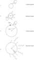
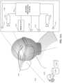
- FIG. 1illustrates a three-dimensional multi-stroke user-defined interaction widget.
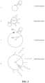
- FIG. 2illustrates an interaction space whose size is defined in proportion to a radius of a user's stroke.
- FIG. 3shows an interaction space that is defined in response to outward expanding movement of hands.
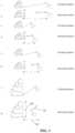
- FIG. 4 Aillustrates a vector field defined by the curvature of a user's hand.
- FIG. 4 Billustrates potential gravitational attractors in accordance with an implementation.
- FIG. 5illustrates a user-defined spring interaction element in a three dimensional (3D) sensor space.
- FIGS. 6 A, 6 B, 6 C, 6 D, and 6 Eshow one implementation of controlling a virtual camera in a three dimensional (3D) sensor space.
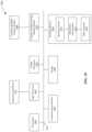
- FIGS. 7 A, 7 B, 7 C, 8 A, 8 B, 8 C, 8 D, and 8 Eillustrate an example machine sensory and control system according to implementations.
- FIG. 9illustrates a sensory augmentation system to add simulated sensory information to a virtual reality input according to an implementation.
- FIG. 10illustrates an example computing system according to an implementation.
- FIGS. 11 A, 11 B, 11 C, and 11 Dillustrate one implementation of a spring zooming camera movement of a virtual camera in a three dimensional (3D) sensor space.
- FIGS. 12 A, 12 B, and 12 Cillustrate defining and controlling multiple virtual cameras in a three dimensional (3D) sensor space.
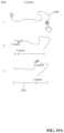
- FIG. 13illustrates pluck and release camera controls in a three dimensional (3D) sensor space.
- FIG. 14illustrates a sphere grabbing camera manipulation in a three dimensional (3D) sensor space.
- FIGS. 15 A, 15 B, and 15 Cillustrate path creation camera controls in a three dimensional (3D) sensor space.
- FIG. 16illustrates an implementation where vectors on a control portion of a user's hand interact with vectors in the virtual field.
- FIG. 17illustrates an augmented reality application where a virtual space is overlaid on a physical space to create a synthetic space.
- FIG. 18illustrates an augmented interaction that is used to navigate a menu system.
- Techniques described hereincan be implemented as one or a combination of methods, systems or processor executed code to form implementations capable of improved control of machines or other computing resources based at least in part upon determining whether positions and/or motions of an object (e.g., hand, tool, hand and tool combinations, other detectable objects or combinations thereof) might be interpreted as an interaction with one or more virtual objects. Implementations can enable modeling of physical objects, created objects and interactions with combinations thereof for machine control or other purposes.
- a usercan interact with a device incorporating a 3D sensor such as described in U.S. Prov. App. No. 61/816,487 and U.S. Prov. App. No. 61/872,538 by using gestures in a 3D sensor space monitored by the 3D sensor. Interacting with the device often requires the control object (e.g., a hand) exiting the 3D sensor space (a “resetting” gesture) to specify a control (or engagement of a control) of the device.
- the technology disclosedrelates to methods for interpreting gestures of a control object in a 3D sensor space, without requiring the control object exiting the 3D sensor space.
- a 3D interaction spaceis part of a sensor space.
- a sensor spaceis a 3D volume in which a sensor, such as an upward looking binocular sensor, can track gestures of a control object.
- a control objectcan be a hand, including the palm, fingers and thumb.
- Another control objectcan be a pointer.
- Gesture trackinginvolves tracking multiple dimensions of gestures made with the control object.
- the overall path of the control object through three-dimensional spaceis tracked.
- the speed and acceleration with which the control object movesis tracked.
- the control objectis a hand or other object with appendages, multiple degrees of freedom for orientation of the hand and of the individual fingers are tracked.
- Gesture trackingcan involve measuring additional parameters of the gesture.
- the sections that followidentify parameters of various gestures.
- gesture parameters for a control object such as a handthat can be characterized include a twist of the wrist, an orientation of the hand relative to the control surface, an orientation of the palm or back of the hand, positions of fingers relative to the palm, and positions of fingers relative to one another.
- a thumbcan be considered one of the fingers or an opposable thumb may have a special meaning distinct from the meaning of fingers. Individual fingers can have individual meanings.
- Gestureslink to controls or content that can be visualized with a visual display.
- the visual displaybegins with controls that become connected to gestures.
- a graphic user interface that has controlscan be connected to gestures in the interaction space that manipulate the controls.
- gesturescause controls to appear on the visual display and then allow the user to interact with those new controls.
- applying gestures and interaction spaces to augmented realitycan involve users superimposing controls or content over real scenes—creating controls or display areas in thin air. The position of the superimposed controls can remain constant as the viewer looks around.
- augmented virtual realitymay involve users superimposing controls over virtual scenes.
- Gesturestake on meaning in context.
- contextis set before the gesture is made.
- Contextcan be selected with keystrokes, spoken commands, eye movement, facial expressions, gestures of control objects and the like.
- contextis inferred from the gesture.
- some of the gesturescan be dedicated to setting a context for subsequent gestures.
- Gesturescan also link to virtual cameras in the sensor space.
- a virtual camera's propertiessuch as focal length, position, orientation, or movement can be connected to the gestures.
- curling of the fingers of a handcan be used to define zoom level of a virtual camera in the sensor space.
- This general frameworkcan be, but is not necessary, to the various gesture implementations described below.
- FIG. 1illustrates a three-dimensional multi-stroke user-defined interaction widget.
- a strokeis represented by a collection of points output by a Machine Sensory and Control System (MSCS) FIGS. 7 A, 7 B, 7 C, 8 A, 8 D, and 8 E .
- This collection of pointshas at least one parameter in common within some threshold deviation.
- a strokecan be defined by a group of points which are continuous in time with velocity vectors within a threshold angle of each other.
- such velocity vectorscan represent the difference vector between successive positions of the control object at points in time.
- a strokecan include a collection of points within a given radial distance to a fixed point.
- FIG. 1shows an implementation where the height 180 of an interaction space is defined in proportion to the height of a stroke sensed in an interaction space defining context.
- any spatial attribute of an interaction spacecan be defined in proportion to any defining characteristic of a stroke.
- At least one parameter of a second strokecan defines a further attribute of the interaction space, such as its width 182 , so that the first stroke defines the height and the second stroke the width of an interaction space.
- At least one parameter of a third strokecan define a further attribute of the interaction space, such as its depth 181 .
- Interaction elementse.g. but without limitation buttons, dials, panels etc. placed within such a user-defined interaction space can expand or shrink in a predetermined way in proportion to the dimensions of the interaction space.
- Density of a control objectcan refer to concentration of skin color pigments on a user appendage such as a hand.
- scale of the control objectrefers to level of relative separation of control points in a control object like fingertips in a hand.
- Interactionincludes a location in virtual space; in implementations this virtual space may be associated with a physical space for example as described in commonly owned U.S. Provisional Patent Applications, entitled “Velocity Field Interaction for Free Space Gesture Interface and Control” to Isaac Cohen (61/891,880).
- An interactioncan include one or more quantities representing various attributes, such as for example a manipulation point “strength” attribute.
- FIG. 2illustrates in frame 1 a creation gesture to create an interaction space.
- an interaction spaceis specified to include one or more elements (saw tooth lines).
- an interaction spacewhose size is defined in proportion to a radius of a user's stroke 230 in a creation gesture.
- radiuscan refer to a radius about a found point that is equidistant to a plurality of points defined on the stroke contour 228 .
- a radial dialcan be defined in relation to the stroke contour and subsequently manipulated.
- the radial gesturedefines a circular window that is superimposed over a real scene and populated with content or controls.
- Implementationscan permit the use of two-handed manipulations of virtual objects.
- a usercan hold a virtual object in place with one hand while manipulating the object with the other hand. Users can stretch, shrink, contort and otherwise transform virtual objects in the same ways as the virtual object manipulations.
- a virtual constructi.e., plane
- a virtual constructcan be defined in proximity to the virtual object to enable engagements with the object.
- Real and/or virtual objectscan be used in conjunction with a manipulated object. For example a real or virtual keyboard can be used with a virtual screen.
- FIG. 3illustrates an implementation where two user appendages 310 , 312 , as identified by an MSCS, start at a fixed distance apart, expand outward, and then come to rest.
- the length at which they come to restdefines at least one parameter of a user interaction space.
- points defined at the center of the users palmsare used to measure the outward expanding gesture.
- the two appendagesare two fingertips of one hand.
- a creation gesture 320comprising drawing apart of hands 310 , 312 defines one dimension of an interaction space 330 , in this example the horizontal or (“length”) dimension.
- Other dimensionscan be specified gesturally using similar motions of hands 310 , 312 to specify different dimensions of the interaction space.
- a creation gesture 328comprising a pointing on by a single finger of hand 310 creates a new virtual object 340 in the interaction space 330 .
- creation of virtual objectscan include describing a perimeter or circumference using a pointing finger, or first or the like.
- virtual objects of a particular set sizecan be created by a tapping of a finger or fist.
- FIG. 4 Aillustrates a vector field defined at least in part by the curvature of a user's hand 476 and centered with respect to some point proximate to the hand.
- the vectoris defined in response to curling of fingers of a hand and degrees of freedom or separation between fingers of the curled fingers.
- a sphere of best-fitis fit to a plurality of points on a user's hand as detected by the MSCS. The radius of this sphere 474 is used, along with other optional parameters, to define the magnitude of a vector on the sphere.
- at least one vectorextends radially outward or inward between the center and surface of the sphere.
- user-hand defined vector fieldscan enable compound interactions with the vector fields in interaction spaces is further described in commonly owned U.S. patent application Ser. No. 14/516,493, filed 16 Oct. 2014.
- such interactionsinclude adding, multiplying, or taking the dot-product of at least one vector on the sphere and at least one vector in an interaction space.
- These vector operationscan be applied to tensors represented by vectors.
- Tensorscan be a kind of vector and tensor spaces can be implementations of vector spaces.
- a tensorcan include stress, strain, shear, or other object properties which can describe complex interactions with virtual objects.
- the vectorscan include tensors. Such tensors can describe material properties of object portions in the virtual, physical, synthetic space, or any combination, such as stress, strain, shear, or other material properties.
- a vector fieldcan be based upon virtual forces (e.g., virtual gravity, virtual electromagnetism, virtual charisma, etc.) enabling interactions with virtual objects over distances.
- virtual forcese.g., virtual gravity, virtual electromagnetism, virtual charisma, etc.
- a “gravity grab” interaction in an astronomy genre gaming engine or physics teaching implementationsincludes emulating the force of gravity by selecting a function in which the strength is proportional to a “virtual mass” of the virtual object but declines with the square of the distance between the hand and the virtual object.
- virtual flexibility/rigidityenable interactions with virtual objects emulating one type of material to have different interactions than virtual objects emulating another type of material.
- a virtual steel spherewill behave differently to a virtual “squeeze” than a virtual rubber sphere.
- Virtual propertiese.g., virtual mass, virtual distance, virtual flexibility/rigidity, etc.
- virtual forcese.g., virtual gravity, virtual electromagnetism, virtual charisma, etc.
- Normal vectors or gradientscan be used.
- FIG. 4 Billustrates potential gravitational attractors in accordance with an implementation.
- frame 1 of FIG. 4 Bis depicted an implementation in which depending on the direction of the creation gesture, the sign of the force from the gravitation may be reversed.
- clockwise 474 and counter clockwise 476 spiral gesturescan be used to specify for example a positive (e.g., inward) gravitation G1 478 and a negative (e.g., outward) gravitation G2 480 , respectively.
- G1 478e.g., inward gravitation G1 478
- a negative gravitation G2 480e.g., outward gravitation G2 480
- frame 2another possible implementation places a gravitational attractor G 484 at the tip of the active finger 486 .
- frame 3an implementation is depicted wherein when the camera 492 is moved, the user may also move their finger 494 to alter the force on the camera. This means as the camera is moved, the user may also move their finger to alter the force on the
- FIG. 5illustrates a user-defined virtual system that reflects properties of physical systems.
- a spring interaction elementis defined virtually in a three dimensional (3D) sensor space.
- one stroke 510is used to define the length of the spring 516 .
- one stroke 530the opening of the fingers from the thumb, is used to define at least one other parameter of the spring, e.g., a stiffness of the spring 536 which, in this example, is designated as ‘k’.
- kstiffness of the spring
- FIGS. 6 A- 6 Eshow one implementation of controlling a virtual camera in a three dimensional (3D) sensor space.
- FIG. 6 Aillustrates a “tween” function for camera movement in 4 Frames.
- Frame 1an object of interest 606 is disposed in view of camera 608 .
- Frame 2a user defines a stroke 616 relative to the movement of at least one parameter of a hand through time, as captured by a MSCS, around the object of interest 606 identified in Frame 1.
- a userdescribes any non-intersecting contour around an object of interest.
- a circle of best-fitis fit to a plurality of points on this contour.
- Frame 3illustrates the placement of a camera 622 on the edge of the sphere defined in Frame 2.
- Frame 4illustrates how the radius of the circle 616 can be used to control the precession of the camera 622 around the object of interest 606 .
- FIG. 6 Billustrates how the radius of a stroke determines the “zoom” level and orientation of a camera control in 4 Frames.
- a circleis drawn around an object of interest 640 in Frame 1.
- a userdescribes any non-intersecting contour around an object of interest.
- a circle of best-fitis fit to a plurality of points on this contour.
- Frame 2from the circle an equator is determined for a sphere 644 , which encloses the object of interest 640 .
- a vector 648is defined from the camera's current position to the center of the enclosing sphere.
- a point I on the circle with radius r 642can then be calculated by solving the integration point of vector a 648 and the sphere equation.
- FIG. 6 Cshown is the “tween” function in frames 5, 6, which illustrate how a camera's position is interpolated through time as it moves “tween” two points, beginning with a fore point 664 and eventually reaches the intersection point I 662 on the sphere's surface.
- the camerainstantly moves from one location to a new location.
- Frame 6depending on the size of the circle drawn, the radius of the sphere 672 and the fore point 664 , the intersection point ‘I’ 674 will be further away or closer to the object 640 , which allows a definition of camera position relative to the object as closely as the user desires to specify it.
- FIGS. 6 D- 6 Eshow another example of controlling a virtual camera in a three dimensional space.
- more than one hand attribute(velocity vector, palm normal, curvature of a finger, rotation matrix of hand, etc., and combinations) in the 3D sensor space can be mapped to more than one context hierarchy at the same time by the computing device with the 3D sensor.
- frames 1-3illustrate moving a camera from position P 676 to position O 677 by “stroking” a vector field with the palm as if pushing water.
- the userpositions their palm normal vector n approximately matching the palm velocity vector v, and strokes the field as if pushing water so that the object O moves closer to point P.
- point Pis actually moved, however, the result is the same whether point P or object O is moved.
- the palm normalmatches the palm velocity.
- frame 2the user's palm normal vector n is positioned approximately perpendicular to the palm velocity vector v, when the user simply slides their hand back through the field, making sure the palm normal does not match the direction of the palm velocity in order to reset the position of the hand.
- the palm normalis approximately perpendicular to the palm velocity.
- frame 3it is shown that the combination of the movement types in frames 1 and 2 provide an overall trajectory (e.g., the palm engages the field when gesture input is desired, disengages from the field when returning to a starting position within the view of the camera.
- the usercan stroke their way through the field moving point P to object O or conversely moving object O to point P without ever moving their hand from the field.
- FIG. 6 Eillustrates the application of the technology disclosed, where the computing device automatically interprets a gesture of a control object 687 in a 3D sensor space by discerning a control plane 684 of the control object 687 , according to one implementation.
- the computing devicefirst senses a control object such as a user's hand 687 in the 3D sensor space.
- the computing devicethen senses an orientation of the control object 687 and determines a surface of the control object 687 .
- a surface of a hand 687can be the palm back of the hand 687 .
- the computing devicedefines a palm normal plane 685 that has an orientation to the surface of the control object 687 .
- the computing deviceinterprets a gesture in the 3D sensor space based on whether the movement of the palm normal plane 685 is more normal to the control plane 686 or more parallel to the control plane 686 .
- the computing devicecalculates a trajectory (an angular trajectory) of the movement of the palm normal plane, and determines whether the gesture engages a virtual control based on whether the trajectory is more normal or more parallel to the control plane 686 .
- FIG. 6 Dillustrates in frame 1 that the palm normal plane 679 is more normal to the control object's trajectory 678 .
- the palm normal plane 679is more normal to the trajectory 687 of FIG. 6 E when a normal vector of the palm normal plane 679 is within a pre-determined range from a tangent vector of the trajectory 678 intersecting the palm normal plane 679 .
- the control plane 679is more normal to the trajectory 678 when the normal vector of the palm normal plane 679 is within +/ ⁇ 10 degrees from the tangent vector of the trajectory 678 .
- the palm normal plane 679is more normal to the trajectory 678 when the normal vector of the palm normal plane 679 is within +/ ⁇ 20 degrees or within +/ ⁇ 30 degrees from the tangent vector of the trajectory 678 .
- FIG. 6 Ddepicts in frame 2 that the palm normal plane 681 is more perpendicular to the control object's trajectory 680 .
- the palm normal plane 681is more perpendicular to the trajectory 680 when the palm normal plane 681 is within a pre-determined range from a perpendicular vector of the trajectory 680 intersecting the palm normal plane 681 .
- the palm normal plane 681is more perpendicular to the trajectory 680 when the palm normal plane 681 is within +/ ⁇ 10 degrees from the perpendicular vector of the trajectory 680 .
- the palm normal plane 681is more perpendicular to the trajectory 680 when the palm normal plane 681 is within +/ ⁇ 20 degrees or within +/ ⁇ 30 degrees from the perpendicular vector of the trajectory 680 .
- Additional examplesinclude traversing menus with one hand and traversing menu paths with more than one hand. For example, a user can use one hand to change channel and the other hand to set volume at the same time. Another example has a user can changing channel by pushing with one hand, while turning down the volume by rotation motion of a finger on the one hand.
- FIGS. 7 A, 7 B, 7 C, 8 A, 8 D, and 8 Eillustrate an example machine sensory and control system in embodiments.
- a motion sensing and controller systemprovides for detecting that some variation(s) in one or more portions of interest of a user has occurred, for determining that an interaction with one or more machines corresponds to the variation(s), for determining if the interaction should occur, and, if so, for affecting the interaction.
- the Machine Sensory and Control Systemtypically includes a portion detection system, a variation determination system, an interaction system and an application control system.
- one detection system 90 A embodimentincludes an emission module 91 , a detection module 92 , a controller 96 , a processing module 94 and a machine control module 95 .
- the emission module 91includes one or more emitter(s) 181 A, 181 B (e.g., LEDs or other devices emitting light in the IR, visible, or other spectrum regions, or combinations thereof; radio and/or other electromagnetic signal emitting devices) that are controllable via emitter parameters (e.g., frequency, activation state, firing sequences and/or patterns, etc.) by the controller 96 .
- emitter parameterse.g., frequency, activation state, firing sequences and/or patterns, etc.
- other existing/emerging emission mechanisms and/or some combination thereofcan also be utilized in accordance with the requirements of a particular implementation.
- the emitters 180 A, 180 Bcan be individual elements coupled with materials or devices 182 (and/or materials) (e.g., lenses 182 , multi-lenses (of FIG. 7 A ), image directing film (IDF) 182 C (of FIG. 7 B ), liquid lenses, combinations thereof, and/or others) with varying or variable optical properties to direct the emission, one or more arrays 180 C of emissive elements (combined on a die or otherwise), with or without the addition of devices 182 C for directing the emission, or combinations thereof, and positioned within an emission region 181 (of FIG.
- materials or devices 182e.g., lenses 182 , multi-lenses (of FIG. 7 A ), image directing film (IDF) 182 C (of FIG. 7 B ), liquid lenses, combinations thereof, and/or others
- IDFimage directing film
- emitter parametersi.e., either statically (e.g., fixed, parallel, orthogonal or forming other angles with a work surface, one another or a display or other presentation mechanism) or dynamically (e.g., pivot, rotate and/or translate) mounted, embedded (e.g., within a machine or machinery under control) or otherwise coupleable using an interface (e.g., wired or wireless)).
- structured lighting techniquescan provide improved surface feature capture capability by casting illumination according to a reference pattern onto the object 98 .
- Image capture techniques described in further detail hereincan be applied to capture and analyze differences in the reference pattern and the pattern as reflected by the object 98 .
- detection system 90 Amay omit emission module 91 altogether (e.g., in favor of ambient lighting).
- the detection module 92includes one or more capture device(s) 190 A, 190 B (e.g., light (or other electromagnetic radiation sensitive devices) that are controllable via the controller 96 .
- the capture device(s) 190 A, 190 Bcan comprise individual or multiple arrays of image capture elements 190 A (e.g., pixel arrays, CMOS or CCD photo sensor arrays, or other imaging arrays) or individual or arrays of photosensitive elements 190 B (e.g., photodiodes, photo sensors, single detector arrays, multi-detector arrays, or other configurations of photo sensitive elements) or combinations thereof.
- Arrays of image capture device(s) 190 C(of FIG.
- Capture device(s) 190 A, 190 Beach can include a particular vantage point 190 - 1 from which objects 98 within area of interest 5 are sensed and can be positioned within a detection region 191 (of FIG. 7 C ) according to one or more detector parameters (i.e., either statically (e.g., fixed, parallel, orthogonal or forming other angles with a work surface, one another or a display or other presentation mechanism) or dynamically (e.g.
- Capture devices 190 A, 190 Bcan be coupled with devices 192 (and/or materials) (of FIG. 7 C ) (e.g., lenses 192 A (of FIG. 7 C ), multi-lenses 192 B (of FIG. 7 C ), image directing film (IDF) 192 C (of FIG. 7 C ), liquid lenses, combinations thereof, and/or others) with varying or variable optical properties for directing the reflectance to the capture device for controlling or adjusting resolution, sensitivity and/or contrast.
- Capture devices 190 A, 190 Bcan be designed or adapted to operate in the IR, visible, or other spectrum regions, or combinations thereof; or alternatively operable in conjunction with radio and/or other electromagnetic signal emitting devices in various applications.
- capture devices 190 A, 190 Bcan capture one or more images for sensing objects 98 and capturing information about the object (e.g., position, motion, etc.).
- particular vantage points of capture devices 190 A, 190 Bcan be directed to area of interest 5 so that fields of view 190 - 2 of the capture devices at least partially overlap. Overlap in the fields of view 190 - 2 provides capability to employ stereoscopic vision techniques (see, e.g., FIG. 7 - 2 ), including those known in the art to obtain information from a plurality of images captured substantially contemporaneously.
- Controller 96comprises control logic (hardware, software or combinations thereof) to conduct selective activation/de-activation of emitter(s) 180 A, 180 B (and/or control of active directing devices) in on-off, or other activation states or combinations thereof to produce emissions of varying intensities in accordance with a scan pattern which can be directed to scan an area of interest 5.
- Controller 96can comprise control logic (hardware, software or combinations thereof) to conduct selection, activation and control of capture device(s) 190 A, 190 B (and/or control of active directing devices) to capture images or otherwise sense differences in reflectance or other illumination.
- Signal processing module 94determines whether captured images and/or sensed differences in reflectance and/or other sensory—perceptible phenomena indicate a possible presence of one or more objects of interest 98 , including control objects 99 , the presence and/or variations thereof can be used to control machines and/or other applications 95 .
- the variation of one or more portions of interest of a usercan correspond to a variation of one or more attributes (position, motion, appearance, surface patterns) of a user hand 99 , finger(s), points of interest on the hand 99 , facial portion 98 other control objects (e.g., styli, tools) and so on (or some combination thereof) that is detectable by, or directed at, but otherwise occurs independently of the operation of the machine sensory and control system.
- attributesposition, motion, appearance, surface patterns
- the systemis configurable to ‘observe’ ordinary user locomotion (e.g., motion, translation, expression, flexing, deformation, and so on), locomotion directed at controlling one or more machines (e.g., gesturing, intentionally system-directed facial contortion, etc.), attributes thereof (e.g., rigidity, deformation, fingerprints, veins, pulse rates and/or other biometric parameters).
- locomotione.g., motion, translation, expression, flexing, deformation, and so on
- locomotion directed at controlling one or more machinese.g., gesturing, intentionally system-directed facial contortion, etc.
- attributes thereofe.g., rigidity, deformation, fingerprints, veins, pulse rates and/or other biometric parameters.
- the systemprovides for detecting that some variation(s) in one or more portions of interest (e.g., fingers, fingertips, or other control surface portions) of a user has occurred, for determining that an interaction with one or more machines corresponds to the variation(s), for determining if the interaction should occur, and, if so, for at least one of initiating, conducting, continuing, discontinuing and/or modifying the interaction and/or a corresponding interaction.
- portions of intereste.g., fingers, fingertips, or other control surface portions
- a variation determination system 90 B embodimentcomprises a model management module 197 that provides functionality to build, modify, customize one or more models to recognize variations in objects, positions, motions and attribute state and/or change in attribute state (of one or more attributes) from sensory information obtained from detection system 90 A.
- a motion capture and sensory analyzer 197 Efinds motions (i.e., translational, rotational), conformations, and presence of objects within sensory information provided by detection system 90 A.
- the findings of motion capture and sensory analyzer 197 Eserve as input of sensed (e.g., observed) information from the environment with which model refiner 197 F can update predictive information (e.g., models, model portions, model attributes, etc.).
- FIG. 8 Billustrates prediction information including a model 197 B- 1 of a control object (e.g., FIG. 7 A : 99 ) constructed from one or more model subcomponents 197 - 2 , 197 - 3 selected and/or configured to represent at least a portion of a surface of control object 99 , a virtual surface portion 194 and one or more attributes 197 - 5 .
- Other componentscan be included in prediction information 197 B- 1 not shown in FIG. 8 B for clarity sake.
- One or more attributes 197 - 5can define characteristics of a model subcomponent 197 - 3 .
- Attributescan include e.g., attach points, neighbors, sizes (e.g., length, width, depth), rigidity, flexibility, torsion, zero or more degrees of freedom of motion with respect to one or more defined points, which can include endpoints for example, and other attributes defining a salient characteristic or property of a portion of control object 99 being modeled by predictive information 197 B- 1 .
- predictive information about the control objectcan include a model of the control object together with attributes defining the model and values of those attributes.
- updating predictive information to observed informationcomprises selecting one or more sets of points (e.g., FIG. 8 C : 193 A, 193 B) in space surrounding or bounding the control object within a field of view of one or more image capture device(s).
- points 193can be determined using one or more sets of lines 195 A, 195 B, 195 C, and 195 D originating at vantage point(s) (e.g., FIG. 7 A : 190 - 1 , 190 - 2 ) associated with the image capture device(s) (e.g., FIG.
- model refiner 197 Fdetermines to model subcomponent 197 - 1 of an object portion (happens to be a finger) using a virtual solid, an ellipse in this illustration, or any of a variety of 3D shapes (e.g., ellipsoid, sphere, or custom shape) and/or 2D slice(s) that are added together to form a 3D volume.
- 3D shapese.g., ellipsoid, sphere, or custom shape
- 2D slice(s)e.g., 2D slice(s) that are added together to form a 3D volume.
- the ellipse equation (1)is solved for ⁇ , subject to the constraints that: (1) (x C , y C ) must lie on the centerline determined from the four tangents 195 A, 195 B, 195 C, and 195 D (i.e., centerline 920 of FIG. 8 C ) which joins midpoints 916 , 918 of diagonal line segments 912 , 914 that connect opposite corners of the bounding region determined from the tangent lines 195 A, 195 B, 195 C, and 195 D); and (2) is fixed at the assumed value a 0 .
- the ellipse equationcan either be solved for ⁇ analytically or solved using an iterative numerical solver (e.g., a Newtonian solver as is known in the art).
- equations (2) for four tangent lines in the x-y plane (of the slice), in which coefficients A i , B i and D i (for i1 to 4) are determined from the tangent lines 195 A, 195 B, 195 C, and 195 D identified in an image slice as described above.
- a 1 x+B 1 y+D 10
- a 2 x+B 2 y+D 20
- a 3 x+B 3 y+D 30
- a 4 x+B 4 y+D 40
- v[ G 2 2 G 3 2 G 4 2 ( G 2 ⁇ H 2 ) 2 ( G 3 ⁇ H 3 ) 2 ( G 4 ⁇ H 4 ) 2 H 2 2 H 3 2 H 4 2 ] ⁇ ⁇ [ 0 0 1 ]
- w[ G 2 2 G 3 2 G 4 2 ( G 2 ⁇ H 2 ) 2 ( G 3 ⁇ H 3 ) 2 ( G 4 ⁇ H 4 ) 2 H 2 2 H 3 2 H 4 2 ] ⁇ ⁇ [ 0 1 0 ]
- 0Q 8 t 8 +Q 7 t 7 +Q 6 t 6 +Q 5 t 5 +Q 4 t 4 +Q 3 t 3 +Q 2 t 2 +Q 1 t+Q 0 (6)
- Equations (1)-(4)The parameters A 1 , B 1 , G 1 , H 1 , v A2 , v AB , v B2 , w A2 , w AB , and w B2 used in equations (7)-(15) are defined as shown in equations (1)-(4).
- Q 84 A 1 2 n 2 v 2 B2 +4 v B2 B 1 2 (1 ⁇ n 2 v A2 ) ⁇ ( G 1 (1 ⁇ n 2 v A2 ) w B2 +n 2 v B2 w A2 +2 H 1 v B2 ) 2 (7)
- Q 7⁇ (2(2 n 2 v AB w A2 +4 H 1 v AB +2 G 1 n 2 v AB w B2 +2 G 1 (1 ⁇ n 2 v A2 ) w AB ))( G 1 (1 ⁇ n 2 v A2 ) w B2 +n 2 v B2 w A2 +2 H 1 v B2 ) ⁇ 8 A 1 B 1 n 2 v B2 2 +16 A 1 2 n 2 v AB v B2 +(4(2 A 1 B 1 (1 ⁇ n 2 v A2 )+2 B 1 2 n 2 v AB )) v B2 +8 B 1
- a model builder 197 C and model updater 197 Dprovide ( FIG. 8 A ) functionality to define, build and/or customize model(s) 197 B using one or more components in object library 197 A.
- model refiner 197 Fupdates and refines the model, bringing the predictive information of the model in line with observed information from the detection system 90 A.
- control objectwhen the control object morphs, conforms, and/or translates, motion information reflecting such motion(s) is included into the observed information.
- Points in spacecan be recomputed based on the new observation information.
- the model subcomponentscan be scaled, sized, selected, rotated, translated, moved, or otherwise re-ordered to enable portions of the model corresponding to the virtual surface(s) to conform within the set of points in space.
- motion(s) of the control objectcan be rigid transformation, in which case, points on the virtual surface(s) remain at the same distance(s) from one another through the motion.
- Motion(s)can be non-rigid transformations, in which points on the virtual surface(s) can vary in distance(s) from one another during the motion.
- observation informationcan be used to adjust (and/or recomputed) predictive information thereby enabling “tracking” the control object.
- control objectcan be tracked by determining whether a rigid transformation or a non-rigid transformation occurs.
- a transformation matrixis applied to each point of the model uniformly.
- a non-rigid transformationwhen a non-rigid transformation occurs, an error indication can be determined, and an error minimization technique such as described herein above can be applied.
- rigid transformations and/or non-rigid transformationscan be composed.
- One example composition embodimentincludes applying a rigid transformation to predictive information. Then an error indication can be determined, and an error minimization technique such as described herein above can be applied.
- determining a transformationcan include calculating a rotation matrix that provides a reduced RMSD (root mean squared deviation) between two paired sets of points.
- RMSDroot mean squared deviation
- One embodimentcan include using Kabsch Algorithm to produce a rotation matrix.
- one or more force linescan be determined from one or more portions of a virtual surface.
- predictive informationcan include collision information concerning two or more capsoloids.
- a relationship between neighboring capsoloids, each having one or more attributescan be determined.
- determining a relationship between a first capsoloid having a first set of attributes and a second capsoloid having a second set of attributesincludes detecting and resolving conflicts between first attribute and second attributes.
- a conflictcan include a capsoloid having one type of angle value with a neighbor having a second type of angle value incompatible with the first type of angle value. Attempts to attach a capsoloid with a neighboring capsoloid having attributes such that the combination will exceed what is allowed in the observed—or to pair incompatible angles, lengths, shapes, or other such attributes—can be removed from the predicted information without further consideration.
- predictive informationcan be artificially constrained to capsoloids positioned in a subset of the observed information—thereby enabling creation of a “lean model”.
- capsoloid 197 - 3could be used to denote the portion of the observed without addition of capsoloids 197 - 2 .
- connectionscan be made using artificial constructs to link together capsoloids of a lean model.
- the predictive informationcan be constrained to a subset of topological information about the observed information representing the control object to form a lean model.
- a lean modelcan be associated with a full predictive model.
- the lean model(or topological information, or properties described above) can be extracted from the predictive model to form a constraint. Then, the constraint can be imposed on the predictive information thereby enabling the predictive information to be constrained in one or more of behavior, shape, total (system) energy, structure, orientation, compression, shear, torsion, other properties, and/or combinations thereof.
- the observedcan include components reflecting portions of the control object which are occluded from view of the device (“occlusions” or “occluded components”).
- the predictive informationcan be “fit” to the observed as described herein above with the additional constraint(s) that some total property of the predictive information (e.g., potential energy) be minimized or maximized (or driven to lower or higher value(s) through iteration or solution). Properties can be derived from nature, properties of the control object being viewed, others, and/or combinations thereof.
- a deformation of the predictive informatione.g., model subcomponent 197 - 2 , 197 - 3 can be allowed subject to an overall permitted value of compression, deformation, flexibility, others, and/or combinations thereof.
- a “friction constraint”is applied on the model 197 B- 1 .
- a “friction constraint”is applied on the model 197 B- 1 .
- a “friction constraint”is applied on the model 197 B- 1 .
- fingers of a hand being modeledare close together (in position or orientation)
- corresponding portions of the modelwill have more “friction”.
- the more friction a model subcomponent has in the modelthe less the subcomponent moves in response to new observed information. Accordingly the model is enabled to mimic the way portions of the hand that are physically close together move together, and move less overall.
- An environmental filter 197 Hreduces extraneous noise in sensed information received from the detection system 90 A using environmental information to eliminate extraneous elements from the sensory information.
- Environmental filter 197 Hemploys contrast enhancement, subtraction of a difference image from an image, software filtering, and background subtraction (using background information provided by objects of interest determiner 198 H (see below) to enable model refiner 197 F to build, refine, manage and maintain model(s) 197 B of objects of interest from which control inputs can be determined.
- a model analyzer 197 Idetermines that a reconstructed shape of a sensed object portion matches an object model in an object library; and interprets the reconstructed shape (and/or variations thereon) as user input. Model analyzer 197 I provides output in the form of object, position, motion and attribute information to an interaction system 90 C.
- an interaction system 90 Cincludes an interaction interpretation module 198 that provides functionality to recognize command and other information from object, position, motion and attribute information obtained from variation system 90 B.
- An interaction interpretation module 198 embodimentcomprises a recognition engine 198 F to recognize command information such as command inputs (i.e., gestures and/or other command inputs (e.g., speech, etc.)), related information (i.e., biometrics), environmental information (i.e., context, noise, etc.) and other information discernable from the object, position, motion and attribute information that might be useful in controlling a machine.
- command inputsi.e., gestures and/or other command inputs (e.g., speech, etc.)
- related informationi.e., biometrics
- environmental informationi.e., context, noise, etc.
- Recognition engine 198 Femploys gesture properties 198 A (e.g., path, velocity, acceleration, etc.), control objects determined from the object, position, motion and attribute information by an objects of interest determiner 198 H and optionally one or more virtual constructs 198 B (see e.g., FIGS. 8 D, 8 E : 198 B- 1 , 198 B- 2 ) to recognize variations in control object presence or motion indicating command information, related information, environmental information and other information discernable from the object, position, motion and attribute information that might be useful in controlling a machine.
- gesture properties 198 Ae.g., path, velocity, acceleration, etc.
- control objects determined from the object, position, motion and attribute information by an objects of interest determiner 198 Hoptionally one or more virtual constructs 198 B (see e.g., FIGS. 8 D, 8 E : 198 B- 1 , 198 B- 2 ) to recognize variations in control object presence or motion indicating command information, related information, environmental information and other information discernable from the object
- virtual construct 198 B- 1 , 198 B- 2implement an engagement target with which a control object 99 interacts—enabling MSCS 189 to discern variations in control object (i.e., motions into, out of or relative to virtual construct 198 B) as indicating control or other useful information.
- a gesture trainer 198 C and gesture properties extractor 198 Dprovide functionality to define, build and/or customize gesture properties 198 A.
- a context determiner 198 G and object of interest determiner 198 Hprovide functionality to determine from the object, position, motion and attribute information objects of interest (e.g., control objects, or other objects to be modeled and analyzed), objects not of interest (e.g., background) based upon a detected context. For example, when the context is determined to be an identification context, a human face will be determined to be an object of interest to the system and will be determined to be a control object. On the other hand, when the context is determined to be a fingertip control context, the finger tips will be determined to be object(s) of interest and will be determined to be a control objects whereas the user's face will be determined not to be an object of interest (i.e., background).
- objects of intereste.g., control objects, or other objects to be modeled and analyzed
- objects not of intereste.g., background
- the tool tipwill be determined to be object of interest and a control object whereas the user's fingertips might be determined not to be objects of interest (i.e., background).
- Background objectscan be included in the environmental information provided to environmental filter 197 H of model management module 197 .
- a virtual environment manager 198 Eprovides creation, selection, modification and de-selection of one or more virtual constructs 198 B (see FIGS. 8 D, 8 E ).
- virtual constructse.g., a virtual object defined in space; such that variations in real objects relative to the virtual construct, when detected, can be interpreted for control or other purposes (see FIGS. 8 D, 8 E )
- variationsi.e., virtual “contact” with the virtual construct, breaking of virtual contact, motion relative to a construct portion, etc.
- Interaction interpretation module 198provides as output the command information, related information and other information discernable from the object, position, motion and attribute information that might be useful in controlling a machine from recognition engine 198 F to an application control system 90 D.
- an application control system 90 Dincludes a control module 199 that provides functionality to determine and authorize commands based upon the command and other information obtained from interaction system 90 C.
- a control module 199 embodimentcomprises a command engine 199 F to determine whether to issue command(s) and what command(s) to issue based upon the command information, related information and other information discernable from the object, position, motion and attribute information, as received from an interaction interpretation module 198 .
- Command engine 199 Femploys command/control repository 199 A (e.g., application commands, OS commands, commands to MSCS, misc. commands) and related information indicating context received from the interaction interpretation module 198 to determine one or more commands corresponding to the gestures, context, etc. indicated by the command information.
- command/control repository 199 Ae.g., application commands, OS commands, commands to MSCS, misc. commands
- related information indicating context received from the interaction interpretation module 198to determine one or more commands corresponding to the gestures, context, etc. indicated by the command information.
- engagement gesturescan be mapped to one or more controls, or a control-less screen location, of a presentation device associated with a machine under control.
- Controlscan include imbedded controls (e.g., sliders, buttons, and other control objects in an application), or environmental level controls (e.g., windowing controls, scrolls within a window, and other controls affecting the control environment).
- controlsmay be displayed using 2D presentations (e.g., a cursor, cross-hairs, icon, graphical representation of the control object, or other displayable object) on display screens and/or presented in 3D forms using holography, projectors or other mechanisms for creating 3D presentations, or audible (e.g., mapped to sounds, or other mechanisms for conveying audible information) and/or touchable via haptic techniques.
- an authorization engine 199 Gemploys biometric profiles 199 B (e.g., users, identification information, privileges, etc.) and biometric information received from the interaction interpretation module 198 to determine whether commands and/or controls determined by the command engine 199 F are authorized.
- a command builder 199 C and biometric profile builder 199 Dprovide functionality to define, build and/or customize command/control repository 199 A and biometric profiles 199 B.
- Selected authorized commandsare provided to machine(s) under control (i.e., “client”) via interface layer 196 .
- Commands/controls to the virtual environmenti.e., interaction control
- Commands/controls to the emission/detection systemsi.e., sensory control
- emission module 91 and/or detection module 92are provided as appropriate.
- a Machine Sensory Controller System 189can be embodied as a standalone unit(s) 189 - 1 coupleable via an interface (e.g., wired or wireless)), embedded (e.g., within a machine 188 - 1 , 188 - 2 or machinery under control) (e.g., FIG. 8 D : 189 - 2 , 189 - 3 , FIG. 8 E : 189 B) or combinations thereof.
- FIG. 9illustrates a sensory augmentation system to add simulated sensory information to a virtual reality input.
- the systemis adapted to receive a virtual reality input including a primitive ( 901 ).
- Virtual reality primitivescan include e.g., virtual character, virtual environment, others, or properties thereof.
- the primitiveis simulated by a service side simulation engine ( 902 ).
- Information about a physical environmentis sensed and analyzed ( 905 ). See also FIGS. 7 A, 7 B, 7 C, 8 A, 8 D, and 8 E .
- a predictive informatione.g., model, etc.
- FIGS. 8 B, 8 CPredictive information and processes for rendering predictive models are described in further detail with reference to FIGS. 8 B, 8 C .
- Hands and/or other object typesare simulated ( 903 ) based upon results of the object primitive simulation in the service side simulation engine and the results of the prediction information rendered in an internal simulation engine. (See also FIG. 8 A : 197 I).
- various simulation mechanisms 910 - 920are employed alone or in conjunction with one another as well as other existing/emerging simulation mechanisms and/or some combination thereof can also be utilized in accordance with the requirements of a particular implementation.
- the servicereturns as a result a subset of object primitive properties to the client ( 904 ).
- Object primitive propertiescan be determined from the simulation mechanisms 910 - 920 , the predictive information, or combinations thereof.
- a simulation mechanismcomprises simulating the effect of a force ( 914 ). In an embodiment, a simulation mechanism comprises minimizing a cost function ( 912 ).
- a simulation mechanismcomprises detecting a collision ( 910 ).
- a simulation mechanismcomprises determining a meaning in context ( 916 ).
- determining a meaning in contextfurther comprises eye tracking.
- determining a meaning in contextfurther comprises recognizing at least one parameter of the human voice.
- a simulation mechanismcomprises recognizing an object property dependence (e.g., understanding how scale and orientation of primitive affects interaction.
- a simulation mechanismcomprises vector or tensor mechanics ( 920 ).
- FIG. 10illustrates an example computing system 1000 , such as a PC (or other suitable “processing” system), that can comprise one or more of the MSCS elements shown in FIGS. 7 A, 7 B, 7 C, 8 A, 8 D, and 8 E according to an embodiment. While other application-specific device/process alternatives might be utilized, such as those already noted, it will be presumed for clarity sake that systems 90 A— 90 D elements ( FIGS. 7 A, 7 B, 7 C, 8 A, 8 D, and 8 E ) are implemented by one or more processing systems consistent therewith, unless otherwise indicated.
- systems 90 A— 90 D elementsFIGS. 7 A, 7 B, 7 C, 8 A, 8 D, and 8 E
- FIGS. 7 A, 7 B, 7 C, 8 A, 8 D, and 8 Eare implemented by one or more processing systems consistent therewith, unless otherwise indicated.
- computer system 1000comprises elements coupled via communication channels (e.g. bus 1001 ) including one or more general or special purpose processors 1002 , such as a Pentium® or Power PC®, digital signal processor (“DSP”), or other processing.
- System 1000 elementsalso include one or more input devices 1003 (such as a mouse, keyboard, joystick, microphone, remote control unit, tactile, biometric or other sensors 93 , and so on), and one or more output devices 1004 , such as a suitable display, joystick feedback components, speakers, biometric or other actuators, and so on, in accordance with a particular application.
- input devices 1003such as a mouse, keyboard, joystick, microphone, remote control unit, tactile, biometric or other sensors 93 , and so on
- output devices 1004such as a suitable display, joystick feedback components, speakers, biometric or other actuators, and so on, in accordance with a particular application.
- System 1000 elementsalso include a computer readable storage media reader 1005 coupled to a computer readable storage medium 1006 , such as a storage/memory device or hard or removable storage/memory media; examples are further indicated separately as storage device 1008 and non-transitory memory 1009 , which can include hard disk variants, floppy/compact disk variants, digital versatile disk (“DVD”) variants, smart cards, read only memory, random access memory, cache memory or others, in accordance with a particular application (e.g. see data store(s) 197 A, 198 A, 199 A and 199 B of FIG. 8 A ).
- One or more suitable communication devices 1007can also be included, such as a modem, DSL, infrared, etc.
- Working memory 1009is further indicated as including an operating system (“OS”) 1091 , interaction discriminator 1013 and other programs 1092 , such as application programs, mobile code, data, or other information for implementing systems 90 A- 90 D elements, which might be stored or loaded therein during use.
- OSoperating system
- interaction discriminator 1013interaction discriminator 1013
- other programs 1092such as application programs, mobile code, data, or other information for implementing systems 90 A- 90 D elements, which might be stored or loaded therein during use.
- System 1000 element implementationscan include hardware, software, firmware or a suitable combination.
- a system 1000 elementWhen implemented in software (e.g. as an application program, object, downloadable, servlet, and so on, in whole or part), a system 1000 element can be communicated transitionally or more persistently from local or remote storage to memory for execution, or another suitable mechanism can be utilized, and elements can be implemented in compiled, simulated, interpretive or other suitable forms.
- Input, intermediate or resulting data or functional elementscan further reside more transitionally or more persistently in a storage media or memory, (e.g. storage device 1008 or memory 1009 ) in accordance with a particular application.
- Certain potential interaction determination, virtual object selection, authorization issuances and other aspects enabled by input/output processors and other element embodiments disclosed hereincan also be provided in a manner that enables a high degree of broad or even global applicability; these can also be suitably implemented at a lower hardware/software layer. Note, however, that aspects of such elements can also be more closely linked to a particular application type or machine, or might benefit from the use of mobile code, among other considerations; a more distributed or loosely coupled correspondence of such elements with OS processes might thus be more desirable in such cases.
- System 1100is preferably coupled to a wearable device 1101 that can be a personal head mounted display (HMD) having a goggle form factor such as shown in FIG. 11 A , a helmet form factor, or can be incorporated into or coupled with a watch, smartphone, or other type of portable device.
- HMDpersonal head mounted display
- a head-mounted device 1101can include an optical assembly that displays a surrounding environment or a virtual environment to the user; incorporation of the motion-capture system 1100 in the head-mounted device 1101 allows the user to interactively control the displayed environment.
- a virtual environmentcan include virtual objects that can be manipulated by the user's hand gestures, which are tracked by the motion-capture system 1100 .
- the motion-capture system 1100 integrated with the head-mounted device 1101detects a position and shape of user's hand and projects it on the display of the head-mounted device 1100 such that the user can see her gestures and interactively control the objects in the virtual environment. This can be applied in, for example, gaming or Internet browsing.
- information about the interaction with a virtual objectcan be shared by a first HMD user with a HMD of a second user. For instance, a team of surgeons can collaborate by sharing with each other virtual incisions to be performed on a patient. In some embodiments, this is achieved by sending to the second user the information about the virtual object, including primitive(s) indicating at least one of a type, size, and/or features and other information about the calculation point(s) used to detect the interaction. In other embodiments, this is achieved by sending to the second user information about the predictive model used to track the interaction.
- System 1100includes any number of cameras 1102 , 1104 coupled to sensory processing system 1106 .
- Cameras 1102 , 1104can be any type of camera, including cameras sensitive across the visible spectrum or with enhanced sensitivity to a confined wavelength band (e.g., the infrared (IR) or ultraviolet bands); more generally, the term “camera” herein refers to any device (or combination of devices) capable of capturing an image of an object and representing that image in the form of digital data. For example, line sensors or line cameras rather than conventional devices that capture a two-dimensional (2D) image can be employed.
- the term “light”is used generally to connote any electromagnetic radiation, which may or may not be within the visible spectrum, and may be broadband (e.g., white light) or narrowband (e.g., a single wavelength or narrow band of wavelengths).
- Cameras 1102 , 1104are preferably capable of capturing video images (i.e., successive image frames at a constant rate of at least 15 frames per second); although no particular frame rate is required.
- the capabilities of cameras 1102 , 1104are not critical to the technology disclosed, and the cameras can vary as to frame rate, image resolution (e.g., pixels per image), color or intensity resolution (e.g., number of bits of intensity data per pixel), focal length of lenses, depth of field, etc.
- image resolutione.g., pixels per image
- color or intensity resolutione.g., number of bits of intensity data per pixel
- focal length of lensese.g., depth of field, etc.
- any cameras capable of focusing on objects within a spatial volume of interestcan be used.
- the volume of interestmight be defined as a cube approximately one meter on a side.
- cameras 1102 , 1104can be oriented toward portions of a region of interest 1112 by motion of the device 1101 , in order to view a virtually rendered or virtually augmented view of the region of interest 1112 that can include a variety of virtual objects 1116 as well as contain an object of interest 1114 (in this example, one or more hands) moves within the region of interest 1112 .
- One or more sensors 1108 , 1110capture motions of the device 1101 .
- one or more light sources 1115 , 1117are arranged to illuminate the region of interest 1112 .
- one or more of the cameras 1102 , 1104are disposed opposite the motion to be detected, e.g., where the hand 1114 is expected to move.
- Sensory processing system 1106which can be, e.g., a computer system, can control the operation of cameras 1102 , 1104 to capture images of the region of interest 1112 and sensors 1108 , 1110 to capture motions of the device 1101 .
- Information from sensors 1108 , 1110can be applied to models of images taken by cameras 1102 , 1104 to cancel out the effects of motions of the device 1101 , providing greater accuracy to the virtual experience rendered by device 1101 .
- sensory processing system 1106determines the position and/or motion of object 1114 .
- sensory processing system 1106can determine which pixels of various images captured by cameras 1102 , 1104 contain portions of object 1114 .
- any pixel in an imagecan be classified as an “object” pixel or a “background” pixel depending on whether that pixel contains a portion of object 1114 or not.
- Object pixelscan thus be readily distinguished from background pixels based on brightness. Further, edges of the object can also be readily detected based on differences in brightness between adjacent pixels, allowing the position of the object within each image to be determined.
- the silhouettes of an objectare extracted from one or more images of the object that reveal information about the object as seen from different vantage points.
- silhouettescan be obtained using a number of different techniques
- the silhouettesare obtained by using cameras to capture images of the object and analyzing the images to detect object edges. Correlating object positions between images from cameras 1102 , 1104 and cancelling out captured motions of the device 1101 from sensors 1108 , 1110 allows sensory processing system 1106 to determine the location in 3D space of object 1114 , and analyzing sequences of images allows sensory processing system 1106 to reconstruct 3D motion of object 1114 using conventional motion algorithms or other techniques. See, e.g., U.S. patent application Ser. No. 13/414,485 (filed on Mar. 7, 2012) and U.S. Provisional Patent Application Nos. 61/724,091 (filed on Nov. 8, 2012) and 61/587,554 (filed on Jan. 7, 2012), the entire disclosures of which are hereby incorporated by reference.
- Presentation interface 1120employs projection techniques in conjunction with the sensory based tracking in order to present virtual (or virtualized real) objects (visual, audio, haptic, and so forth) created by applications loadable to, or in cooperative implementation with, the device 1101 to provide a user of the device with a personal virtual experience.
- Projectioncan include an image or other visual representation of an object.
- One implementationuses motion sensors and/or other types of sensors coupled to a motion-capture system to monitor motions within a real environment.
- a virtual object integrated into an augmented rendering of a real environmentcan be projected to a user of a portable device 1101 .
- Motion information of a user body portioncan be determined based at least in part upon sensory information received from imaging 1102 , 1104 or acoustic or other sensory devices.
- Control informationis communicated to a system based in part on a combination of the motion of the portable device 1101 and the detected motion of the user determined from the sensory information received from imaging 1102 , 1104 or acoustic or other sensory devices.
- the virtual device experiencecan be augmented in some implementations by the addition of haptic, audio and/or other sensory information projectors.
- an optional video projector 1120can project an image of a page (e.g., virtual device) from a virtual book object superimposed upon a real world object, e.g., desk 1116 being displayed to a user via live video feed; thereby creating a virtual device experience of reading an actual book, or an electronic book on a physical e-reader, even though no book nor e-reader is present.
- Optional haptic projectorcan project the feeling of the texture of the “virtual paper” of the book to the reader's finger.
- Optional audio projectorcan project the sound of a page turning in response to detecting the reader making a swipe to turn the page. Because it is a virtual reality world, the back side of hand 1114 is projected to the user, so that the scene looks to the user as if the user is looking at the user's own hand(s).
- Sensors 1108 , 1110can be any type of sensor useful for obtaining signals from various parameters of motion (acceleration, velocity, angular acceleration, angular velocity, position/locations); more generally, the term “motion detector” herein refers to any device (or combination of devices) capable of converting mechanical motion into an electrical signal. Such devices can include, alone or in various combinations, accelerometers, gyroscopes, and magnetometers, and are designed to sense motions through changes in orientation, magnetism or gravity. Many types of motion sensors exist and implementation alternatives vary widely.
- the illustrated system 1100can include any of various other sensors not shown in FIG. 11 A for clarity, alone or in various combinations, to enhance the virtual experience provided to the user of device 1101 .
- system 1106may switch to a touch mode in which touch gestures are recognized based on acoustic or vibrational sensors.
- system 1106may switch to the touch mode, or supplement image capture and processing with touch sensing, when signals from acoustic or vibrational sensors are sensed.
- a tap or touch gesturemay act as a “wake up” signal to bring the image and audio analysis system 1106 from a standby mode to an operational mode.
- the system 1106may enter the standby mode if optical signals from the cameras 1102 , 1104 are absent for longer than a threshold interval.
- FIG. 11 Athe objects shown in FIG. 11 A are illustrative. In some implementations, it may be desirable to house the system 1100 in a differently shaped enclosure or integrated within a larger component or assembly. Furthermore, the number and type of image sensors, motion detectors, illumination sources, and so forth are shown schematically for the clarity, but neither the size nor the number is the same in all implementations.
- FIGS. 11 B, 11 C, and 11 Dillustrate an example of a “spring zooming” camera movement of a virtual camera in a three dimensional (3D) sensor space.
- a usercan “pull” the virtual camera 1142 (as enabled by MSCS), using manipulation points, analytic fits, or other type of mechanics that emulate spring dynamics.
- the cameracan then move as if it were a bob of constant mass on a spring.
- the camera movementstops after a fixed number of oscillations of this virtual spring.
- such spring movementdescribes a one-directional camera trajectory from one fixed point to another.
- FIG. 11 Billustrates the configuration of an example “slingshot” in 4 frames, where the slingshot moves the camera from a one-directional camera trajectory from one fixed point to another. This motion is calculated by both the radius of the control circle and the “pull back” of the camera.
- the first frameindicates the creation of a control circle 1102 , which defines a starting point and strength of the “slingshot”.
- the userpulls back the camera 1104 to provide an input of force to be applied to the camera 1104 .
- release of the camera 1104applies the virtual force to the camera thereby moving the camera to a new position in space.
- frame 4depicted is where the radius of the control circle 1106 as well as the distance of the pullback 1108 of the camera 1104 identifies the force that will be applied to the camera 1104 when the camera is released.
- FIG. 11 Cillustrates an alternative example of a slingshot camera movement implementation in which a virtual spring is employed where the camera moves as if it were a bob of constant mass on a spring.
- a user stroke 1132defines some contour relative to the camera 1134 .
- a circle of best-fitis fit to a plurality of points on this contour.
- the radius 1136 of the circle 1132defines at least one parameter of a spring, the spring constant k.
- the static length of a spring 1is defined by a length 1138 which extends from the center of the circle to the current position of the camera 1134 .
- the spring constant k 1140is equal to the radius of the circle 1136 .
- FIG. 11 Dillustrates in frame 4 a slingshot camera movement result where the camera is released once it traverses the vector created by the pull back.
- the distance X 1144 of FIG. 11 Cwhich can be defined as the distance of the camera from the center of the circle ‘d’ minus the starting point of the camera ‘1’ 1162 the spring is effectively removed from the force equation, allowing the camera to move as it would if no other forces were applied.
- Solving Hooke's lawresults in a force equation that will be applied to the camera as it is released. As the camera pass its original position of when the circle was originally drawn, the spring is removed from the force equation, allowing the camera to move as it would if no other forces were applied.
- the spring constant ‘k’can be multiplied by a relationship between the spring constant and the radius of the circle 1164 , where a larger radius signifies a larger number of springs.
- a radius of 2can indicate 1 spring
- a radius of 4can indicate 2 springs, and so on.
- Another embodimentincludes connecting springs in the same fashion, but having the spring constant k remain fixed, and connecting a number of identical springs, the number of which is proportional to the radius.
- FIGS. 12 A- 12 Cillustrate defining and controlling multiple virtual cameras in a three dimensional (3D) sensor space.
- a userafter setting the context to creating a camera, a user defines at least one point with a direction vector in virtual space 1208 . This point and vector defines a “camera selector.” The user can iterate through a plurality of such pre-defined camera controls 1218 .
- iteration through checkpointscan be enabled by a visual interaction element, which represents at least one such-defined camera selector.
- interactions with camera selectorscan be enabled by vector-space interactions with interaction elements.
- camerascan be created or destroyed by circle gestures around the cameras in virtual space, their visual representation, or combinations thereof.
- circle gesturescan be defined as the circle of best fit to contours as described herein.
- FIG. 12 Aillustrates checkpoint camera controls in three frames.
- a so-called checkpointsets a camera perspective, including location, view direction, focal length of the camera, and a selector box in an array of selector boxes.
- perspective 1208is defined by a circle gesture in frame 1.
- the anchoris at the center of the circle.
- a menufor instance, allows the user to further define the view direction and the focal length of a lens position at the center of the circle.
- Gesturesprovide alternatives for setting camera controls.
- FIG. 12 A frame 2further illustrates using selector boxes 1218 to select among the four checkpoints or perspectives created in this example.
- FIG. 12 A frame 3further illustrates adding a fifth checkpoint to the first four.
- an additional selector boxcan be provided as part of the array of selector boxes.
- FIG. 12 Billustrates the manipulations of the camera in 4 frames.
- the first frameshows the creation of a circle with a center point and a direction.
- the second frameshows the creation of additional cameras for the example.
- the third framedemonstrates the selector boxes 1218 created as part of an array of selector boxes for this example.
- Frame 4 in FIG. 12 Billustrates the selection of a camera 1244 via a selection box 1218 for manipulation.
- the cameracan be moved to a new point in space, its focal length can be modified, its vector can be changed, and any other attributes that have been assigned to it can be changed by the gestures identified in the technology disclosed.
- FIG. 12 Cillustrates examples of other manipulations possible using the technology disclosed.
- Frame 5is an example of selecting and modifying a different camera 1262 than the camera selected in FIG. 12 B .
- the active cameracan easily and discretely be moved from point to point, by selection a new point in the array.
- Frame 6illustrates the creation of a new camera 1272 while camera 2 1262 remains as the selected camera. New points can be dynamically created by circling a new point in space.
- Frame 7 of FIG. 12 Cillustrates the removal of a camera 1272 .
- a circleis drawn around the virtual camera 1282 in the opposite direction of the circle used to create the camera 1272 .
- its selector box 1218 ais deleted from the selector box array 1218 .
- FIG. 13illustrates in 4 Frames a camera set in motion by pluck and release camera controls in a three dimensional (3D) sensor space.
- a userdefines a central location with reference to a salient property of a stroke.
- the userdefines a center location that will be a “neutral area”.
- the cameracan be freely moved if the user has “plucked” it.
- the restorative forcedirects the camera back towards the user defined origin.
- New originscan be defined on the fly.
- this propertycan be a location in virtual space of the center of a circle of best fit to the stroke 1308 .
- this pointcan be the new center point of a camera.
- the usercan grab and manipulate the camera as if it were a bob of uniform mass attached to a spring 1328 , as shows in Frame 2. As illustrated in Frame 3, releasing the camera returns it to the center point 1338 .
- Frame 4illustrates an example of the selection of the origin 1348 , and its movement to a new location 1350 .
- FIG. 14in 4 Frames, illustrates a sphere grabbing camera manipulation in a three dimensional (3D) sensor space.
- the userdefines an object they are holding onto by moving their hands, the camera moves as if the object is being moved by the hands.
- the objectcan be scaled up and down by compressing or expanding your hands.
- a userdescribes a sphere in virtual space 1408 .
- this sphereis the sphere of best fit, which is fit to a plurality of points on one hand. In other implementations this sphere is fit to a plurality of points on two hands.
- the sphereis defined in relation to the hand at the initialization of some “sensory” control, for example saying to the computer “define sphere” via voice controls, or looking at a predefined space in a predefined way (e.g. via eye-tracking controls); disengagement gestures may be defined likewise.
- a camera viewis defined in relation to the sphere.
- the camerais defined at the center of the sphere, with view vector extending from the center of the sphere to the point on the surface of the sphere that is equidistant to a plurality of points on the user's hand(s).
- the spherecan be rotated, translated, and scaled to corresponds to movements of at least one camera control 1408 , 1418 , 1428 , 1438 .
- sphereincludes any three-dimensional solid that can be fit to a plurality of points input from an MSCS FIGS. 7 A, 7 B, 7 C, 8 A, 8 D, and 8 E .
- FIG. 15 A- 15 Cillustrate path creation camera controls in a three dimensional (3D) sensor space.
- the userdefines a 3D path using a finger tip, After path as been created, the user can move along the path to view object from different areas. Any part of the path can be accessed by movement along the path.
- a userdefines a continuous contour 1508 through time as described above with respect to the MSCS.
- the contouris defined by the movement of a user's finger through three-dimensional space during a delimited time window; in another implementation the contour is defined by the movement of the center of the user's palm.
- the cameratraverses the defined contour 1508 at a fixed or varying speed from end to end; in frame 3, a user may perform a second gesture, for example a swipe from the left of the screen to the right, to position the camera at any point on the predefined contour 1528 .
- a second gesturefor example a swipe from the left of the screen to the right
- FIG. 15 Bmovement of a camera along a specified path is shown with reference to an implementation alternative.
- the usercreates a starting point of a path with a creation gesture, e.g., a circle, voice command or other gesture.
- a creation gesturee.g., a circle, voice command or other gesture.
- the userindicates a path they wish to define by moving their hand (or portion thereof) through 3D space.
- the userends the path with the same (or different) creation gesture.
- the cameracan move along the path or 2D object in 3D space.
- FIG. 15 Cmovement of a camera along a specified path is shown with reference to a yet further implementation alternatives.
- the pathis mapped to a straight line that the user can move easily along, thereby freeing the user from having to trace out the intricacies of the path in space.
- the cameraremains attached to the path, but a force is applied in the direction of the tip of the user's index finger.
- the camerais not rigidly attached to the path, but is subject to a restorative force acting on it (F p ).
- the useris enabled to create a force proportional to the distance to the hand (F n ).
- the pathis defined by a series of user created circles (or other shapes) that construct a Bezier curve based on a circle size and vector direction.
- FIG. 16illustrates an implementation where vectors on a control portion of a user's hand interact with vectors in the virtual field.
- the useris enabled to define the area, direction, strength and velocity of a whirlpool. This interaction creates a field disturbance.
- this field disturbanceis a vortex 1602 .
- the interaction of the field disturbance with a vector defined on a virtual objectcreates field disturbance control information.
- FIG. 16shows a hand creating a field disturbance by making swirling motions in a virtual space.
- Directionality of the swirling motioncan control the direction of the whirlpool, and whether objects caught up in the whirlpool converge to the center or spin off away from the center.
- the field disturbanceinteracts with vectors defined on objects in the virtual field, and moves them once the objects have entered the event horizon of the whirlpool.
- field disturbancesthemselves can be manipulated as virtual objects within the space.
- FIG. 17illustrates an augmented reality application where a virtual space 1702 is overlaid on a physical space 1704 to create a synthetic space 1700 .
- virtual space 1702includes chess game and timers 1706 (and/or other game information not shown in FIG. 17 for clarity sake) and is overlaid on physical space 1704 , e.g., the table, to provide an augmented reality environment 1700 .
- vectorscan be defined on portions of the virtual space, the physical space, the synthetic space, or any combination thereof.
- An augmented interactionrefers to an interaction between vectors defined on at least a physical object portion of a user (e.g., the hand) and vectors defined on the synthetic space.
- an augmented interactioncan modify positional, material, or other properties of object portions in synthetic space.
- vectorscan be defined to extend outward on the user's thumb and index finger.
- radial vectorscan be defined to extend out of the virtual chess pieces.
- an augmented interactiontakes place, as shows in FIG. 17 .
- one or more vectorscan indicate potential directions of motion of the selected chess piece to the user.
- the hand's motioncan be described using vectors as well.
- the interaction of the two sets of vectorscan determine whether the user is making a “legal” move and use this derived information to change the presentation from green (ok) to red (illegal).
- FIG. 18illustrates an implementation where an augmented interaction can be used to navigate a menu system.
- a virtual interaction spaceis defined by a user in the physical space and linked to other images created by a computer vision.
- the example shows in FIG. 18shows a user creating radial-shape “interaction bubbles” with menu elements inside them 1802 , 1804 , 1806 , which are response to user's gestures.
- the usercan select a recipe for a desired dish for dinner from menu 1802 .
- a display window 1804pulls up contents of the refrigerator and pantry, enabling the user to cross reference ingredients needed with foodstuffs on hand.
- a menu 1806can be formed by the user based upon a difference between items in menu 1802 and 1804 , generating a shopping list that can be downloaded to the user's personal device, uploaded to the cloud for access later, transmitted to the user's spouse for procuring on the way home from the office or various combinations thereof.
Landscapes
- Engineering & Computer Science (AREA)
- Theoretical Computer Science (AREA)
- General Engineering & Computer Science (AREA)
- Physics & Mathematics (AREA)
- General Physics & Mathematics (AREA)
- Human Computer Interaction (AREA)
- Computing Systems (AREA)
- Geometry (AREA)
- Computer Graphics (AREA)
- User Interface Of Digital Computer (AREA)
Abstract
Description
A1x+B1y+D1=0
A2x+B2y+D2=0
A3x+B3y+D3=0
A4x+B4y+D4=0 (2)
c1=(r13+r24)/2
c2=(r14+r23)/2
δ1=c21−c11
δ2=c22−c12
p=δ1/δ2
q=c11−c12*p
G=Ap+B
H=Aq+D (4)
0=Q8t8+Q7t7+Q6t6+Q5t5+Q4t4+Q3t3+Q2t2+Q1t+Q0 (6)
Q8=4A12n2v2B2+4vB2B12(1−n2vA2)−(G1(1−n2vA2)wB2+n2vB2wA2+2H1vB2)2 (7)
Q7=−(2(2n2vABwA2+4H1vAB+2G1n2vABwB2+2G1(1−n2vA2)wAB))(G1(1−n2vA2)wB2+n2vB2wA2+2H1vB2)−8A1B1n2vB22+16A12n2vABvB2+(4(2A1B1(1−n2vA2)+2B12n2vAB))vB2+8B12(1−n2vA2)vAB (8)
Q6=−(2(2H1vB2+2H1vA2+n2vA2wA2+n2vB2(−2wAB+wB2)+G1(n2vB2+1)wB2+4G1n2vABwAB+G1(1−n2vA2)vA2))×(G1(1−n2vA2)wB2+n2vB2wA2+2H1vB2)−(2n2vABwA2+4H1vAB+2G1n2vABwB2+2G1(1−n2vA2)wAB)2+4B1n2vB22−32A1B1n2vABvB2+4A12n2(2vA2vB2+4v2AB)+4A12n2vB22+(4(A12(1−n2vA2)+4A1B1n2vAB+B12(−n2vB2+1)+B12(1−n2vA2)))vB2+(8(2A1B1(1−n2vA2)+2B12n2vAB))vAB+4B12(1−n2vA2)vA2 (9)
Q5=(2(4H1vAB2G1(−n2vB2+1)wAB+2G1n2vABvA2+2n2vA(−2wAB+wB2)))(G1(1−n2vA2)wB2+n2vB2wA2+2H1vB2)−(2(2H1vB2+2H1vA2+n2vA2wA2+n2vB2(−2wAB+wB2)+G1(−n2vB2+1)wB2+4G1n2vABwAB+G1(1−n2vA2)vA2))×(2n2vABwA2+4H1vAB+2G1n2vA2wB2+2G1(1−n2vA2)wAB)+16B12n2vABvB2−8A1B1n2(2vA2vB2+4vAB)+16A12n2vA2vAB−8A1B1n2vB22+16A12n2vABvB2+(4(2A12n2vAB+2A1B1(1−n2vB2+1)+2A1B1(1−n2vA2)+2B12n2vAB))vB2+(8(A(1−n2vA2)+4A1B1n2vAB+B12(−n2vB2+1)+B12(1−n2vA2)))vAB+(4(2A1B1(1−n2vA2)+2B12n2vAB))vA2 (10)
Q4=(4(A12(−n2vB2)+A12(1−n2vA2)+4A1B1n2vAB+B12(−n2vB2+1)))vB2+(8(2A12n2vAB+2A1B1(−n2vB2+1)+2A1B1(1−n2vA2)+2B12n2vAB))vAB+(4(A12(1−n2vA2)+4A1B1n2vAB+B12(−n2vB2+1)+B12(1−n2vA2)))vA2+4B12n2(2vA2vB2+4v2AB)−32A1B1n2vA2vAB+4A12n2v2A2+4B12n2v2B2−32A1B1n2vABvB2+4A12n2(2vA2vB2+4v2AB)−(2(G1(−n2vB2+1)vA2+n2vA2(−2wAB+wB2)+2H1vA2))(G1(1−n2vA2)wB2+n2vB2wA2+2H1vB2)−(2(4H1vAB+2G1(−n2vB2+1)wAB+2G1n2vABvA2+2n2vAB(2wAB+wB2)))×(2n2vABwA2+4H1vAB+2G1n2vABwB2+2G1(1−n2vA2)wAB)−(2H1vB2+2H1vA2+n2vA2wA2+n2vB2(−2wAB+wB2)+G1(−n2vB2+1)wB2+4G1n2vABwAB+G1(1−n2vA2)vA2)2 (11)
Q3=(2(G1(−n2vB2+1)vA2+n2vA2(−2wAB+wB2)+2H1vA2))(2n2vABwA2+4H1vAB+2G1n2vABwB2+2G1(1−n2vA2)wAB)−(2(4H1vAB+2G1(−n2vB2+1)wAB+2G1n2vABvA2+2n2vAB(−2wAB+wB2)))×(2H1vB2+2H1vA2+n2vA2wA2+n2vB2(−2wAB+wB2)+G1(−n2vB2+1)wB2+4G1n2vABwAB+G1(1−n2vA2)vA2)+16B12n2vA2vAB−8A1B1n2vA22+16B12n2vABvB2−8A1B1n2(2vA2vB2+4v2AB)+16A12n2vA2vAB+(4(2A12n2vAB+2A1B1(−n2vB2+1)))vB2+(8(A12(−n2vB2+1)+A12(1−n2vA2)+4A1B1n2vAB+B1(−n2vB2+1)))vAB+(4(2A12n2vAB+2A1B1(−n2vB2+1)+2A1B1(1−n2vA2)+2B12n2vAB))vA2 (12)
Q2=4A12(−n2vB2+1)vB2+(8(2A12n2vAB+2A1B1(−n2vB2+1)))vAB+(4(A12(−n2vB2+1)+A12(1−n2vA2)+4A1B1n2vABB12(−n2vB2+1)))vA2+4B12n2vA2+4B12n2(2vA2vB2+4vAB2)−32A1B1n2vA2vAB+4A12n2vA2−(2(G1(−n2vB2+1)vA2+n2vA2(−2wAB+wB2)+2H1vA2))×(2H1vB2+2H1vA2+n2vA2wA2+n2vB2(−2wAB+wB2)+G1(−n2vB2+1)wB2+4G1n2vABwAB+G1(1−n2vA2)vA2)−(4H1vAB+2G1(−n2vB2+1)wAB+2G1n2vABvA2+2n2vAB(−2wAB+wB2))2 (13)
Q1=8A12(−n2vB2+1)vAB+(4(2A12n2vAB+2A1B1(−n2vB2+1)))vA2+16B12n2vA2vAB−8A1B1n2v2A2−(2(G1(−n2vB2+1)vA2+n2vA2(−2wAB+wB2)+2H1vA2))(4H1vAB+2G1(−n2vB2+1)wAB+2G1n2vABvA2+2n2vAB(−2wAB+wB2)) (14))
Q0=4A12(−n2vB2+1)vA2−(G1(−n2vB2+1)vA2+n2vA2(−2wAB+wB2)+2H1vA2)2+4B12n2v2A2 (15)
Claims (20)
Priority Applications (2)
| Application Number | Priority Date | Filing Date | Title |
|---|---|---|---|
| US17/984,964US12099660B2 (en) | 2013-12-16 | 2022-11-10 | User-defined virtual interaction space and manipulation of virtual cameras in the interaction space |
| US18/893,916US20250013314A1 (en) | 2013-12-16 | 2024-09-23 | User-defined virtual interaction space and manipulation of virtual cameras in the interaction space |
Applications Claiming Priority (6)
| Application Number | Priority Date | Filing Date | Title |
|---|---|---|---|
| US201361916790P | 2013-12-16 | 2013-12-16 | |
| US14/572,668US9740296B2 (en) | 2013-12-16 | 2014-12-16 | User-defined virtual interaction space and manipulation of virtual cameras in the interaction space |
| US15/681,149US10275039B2 (en) | 2013-12-16 | 2017-08-18 | User-defined virtual interaction space and manipulation of virtual cameras in the interaction space |
| US16/398,130US10901518B2 (en) | 2013-12-16 | 2019-04-29 | User-defined virtual interaction space and manipulation of virtual cameras in the interaction space |
| US17/155,064US11500473B2 (en) | 2013-12-16 | 2021-01-21 | User-defined virtual interaction space and manipulation of virtual cameras in the interaction space |
| US17/984,964US12099660B2 (en) | 2013-12-16 | 2022-11-10 | User-defined virtual interaction space and manipulation of virtual cameras in the interaction space |
Related Parent Applications (1)
| Application Number | Title | Priority Date | Filing Date |
|---|---|---|---|
| US17/155,064ContinuationUS11500473B2 (en) | 2013-12-16 | 2021-01-21 | User-defined virtual interaction space and manipulation of virtual cameras in the interaction space |
Related Child Applications (1)
| Application Number | Title | Priority Date | Filing Date |
|---|---|---|---|
| US18/893,916ContinuationUS20250013314A1 (en) | 2013-12-16 | 2024-09-23 | User-defined virtual interaction space and manipulation of virtual cameras in the interaction space |
Publications (2)
| Publication Number | Publication Date |
|---|---|
| US20230072748A1 US20230072748A1 (en) | 2023-03-09 |
| US12099660B2true US12099660B2 (en) | 2024-09-24 |
Family
ID=53368396
Family Applications (19)
| Application Number | Title | Priority Date | Filing Date |
|---|---|---|---|
| US14/572,704Active2036-06-16US10126822B2 (en) | 2013-12-16 | 2014-12-16 | User-defined virtual interaction space and manipulation of virtual configuration |
| US14/572,690Active2035-01-08US9891712B2 (en) | 2013-12-16 | 2014-12-16 | User-defined virtual interaction space and manipulation of virtual cameras with vectors |
| US14/572,668Active2036-02-08US9740296B2 (en) | 2013-12-16 | 2014-12-16 | User-defined virtual interaction space and manipulation of virtual cameras in the interaction space |
| US15/681,149ActiveUS10275039B2 (en) | 2013-12-16 | 2017-08-18 | User-defined virtual interaction space and manipulation of virtual cameras in the interaction space |
| US15/861,578ActiveUS10281992B2 (en) | 2013-12-16 | 2018-01-03 | User-defined virtual interaction space and manipulation of virtual cameras with vectors |
| US16/189,046Active2035-01-02US11132064B2 (en) | 2013-12-16 | 2018-11-13 | User-defined virtual interaction space and manipulation of virtual configuration |
| US16/398,130ActiveUS10901518B2 (en) | 2013-12-16 | 2019-04-29 | User-defined virtual interaction space and manipulation of virtual cameras in the interaction space |
| US16/404,641ActiveUS10579155B2 (en) | 2013-12-16 | 2019-05-06 | User-defined virtual interaction space and manipulation of virtual cameras with vectors |
| US16/805,639ActiveUS11068070B2 (en) | 2013-12-16 | 2020-02-28 | User-defined virtual interaction space and manipulation of virtual cameras with vectors |
| US17/155,064Active2034-12-25US11500473B2 (en) | 2013-12-16 | 2021-01-21 | User-defined virtual interaction space and manipulation of virtual cameras in the interaction space |
| US17/378,428ActiveUS11460929B2 (en) | 2013-12-16 | 2021-07-16 | User-defined virtual interaction space and manipulation of virtual cameras with vectors |
| US17/486,755ActiveUS11567583B2 (en) | 2013-12-16 | 2021-09-27 | User-defined virtual interaction space and manipulation of virtual configuration |
| US17/959,269ActiveUS11775080B2 (en) | 2013-12-16 | 2022-10-03 | User-defined virtual interaction space and manipulation of virtual cameras with vectors |
| US17/984,964ActiveUS12099660B2 (en) | 2013-12-16 | 2022-11-10 | User-defined virtual interaction space and manipulation of virtual cameras in the interaction space |
| US18/099,779ActiveUS11995245B2 (en) | 2013-12-16 | 2023-01-20 | User-defined virtual interaction space and manipulation of virtual configuration |
| US18/373,243ActiveUS12086328B2 (en) | 2013-12-16 | 2023-09-26 | User-defined virtual interaction space and manipulation of virtual cameras with vectors |
| US18/674,697PendingUS20240310923A1 (en) | 2013-12-16 | 2024-05-24 | User-defined virtual interaction space and manipulation of virtual configuration |
| US18/827,206ActiveUS12405674B2 (en) | 2013-12-16 | 2024-09-06 | User-defined virtual interaction space and manipulation of virtual cameras with vectors |
| US18/893,916PendingUS20250013314A1 (en) | 2013-12-16 | 2024-09-23 | User-defined virtual interaction space and manipulation of virtual cameras in the interaction space |
Family Applications Before (13)
| Application Number | Title | Priority Date | Filing Date |
|---|---|---|---|
| US14/572,704Active2036-06-16US10126822B2 (en) | 2013-12-16 | 2014-12-16 | User-defined virtual interaction space and manipulation of virtual configuration |
| US14/572,690Active2035-01-08US9891712B2 (en) | 2013-12-16 | 2014-12-16 | User-defined virtual interaction space and manipulation of virtual cameras with vectors |
| US14/572,668Active2036-02-08US9740296B2 (en) | 2013-12-16 | 2014-12-16 | User-defined virtual interaction space and manipulation of virtual cameras in the interaction space |
| US15/681,149ActiveUS10275039B2 (en) | 2013-12-16 | 2017-08-18 | User-defined virtual interaction space and manipulation of virtual cameras in the interaction space |
| US15/861,578ActiveUS10281992B2 (en) | 2013-12-16 | 2018-01-03 | User-defined virtual interaction space and manipulation of virtual cameras with vectors |
| US16/189,046Active2035-01-02US11132064B2 (en) | 2013-12-16 | 2018-11-13 | User-defined virtual interaction space and manipulation of virtual configuration |
| US16/398,130ActiveUS10901518B2 (en) | 2013-12-16 | 2019-04-29 | User-defined virtual interaction space and manipulation of virtual cameras in the interaction space |
| US16/404,641ActiveUS10579155B2 (en) | 2013-12-16 | 2019-05-06 | User-defined virtual interaction space and manipulation of virtual cameras with vectors |
| US16/805,639ActiveUS11068070B2 (en) | 2013-12-16 | 2020-02-28 | User-defined virtual interaction space and manipulation of virtual cameras with vectors |
| US17/155,064Active2034-12-25US11500473B2 (en) | 2013-12-16 | 2021-01-21 | User-defined virtual interaction space and manipulation of virtual cameras in the interaction space |
| US17/378,428ActiveUS11460929B2 (en) | 2013-12-16 | 2021-07-16 | User-defined virtual interaction space and manipulation of virtual cameras with vectors |
| US17/486,755ActiveUS11567583B2 (en) | 2013-12-16 | 2021-09-27 | User-defined virtual interaction space and manipulation of virtual configuration |
| US17/959,269ActiveUS11775080B2 (en) | 2013-12-16 | 2022-10-03 | User-defined virtual interaction space and manipulation of virtual cameras with vectors |
Family Applications After (5)
| Application Number | Title | Priority Date | Filing Date |
|---|---|---|---|
| US18/099,779ActiveUS11995245B2 (en) | 2013-12-16 | 2023-01-20 | User-defined virtual interaction space and manipulation of virtual configuration |
| US18/373,243ActiveUS12086328B2 (en) | 2013-12-16 | 2023-09-26 | User-defined virtual interaction space and manipulation of virtual cameras with vectors |
| US18/674,697PendingUS20240310923A1 (en) | 2013-12-16 | 2024-05-24 | User-defined virtual interaction space and manipulation of virtual configuration |
| US18/827,206ActiveUS12405674B2 (en) | 2013-12-16 | 2024-09-06 | User-defined virtual interaction space and manipulation of virtual cameras with vectors |
| US18/893,916PendingUS20250013314A1 (en) | 2013-12-16 | 2024-09-23 | User-defined virtual interaction space and manipulation of virtual cameras in the interaction space |
Country Status (1)
| Country | Link |
|---|---|
| US (19) | US10126822B2 (en) |
Families Citing this family (146)
| Publication number | Priority date | Publication date | Assignee | Title |
|---|---|---|---|---|
| DE102009037835B4 (en) | 2009-08-18 | 2012-12-06 | Metaio Gmbh | Method for displaying virtual information in a real environment |
| US10228242B2 (en) | 2013-07-12 | 2019-03-12 | Magic Leap, Inc. | Method and system for determining user input based on gesture |
| US11019258B2 (en) | 2013-08-21 | 2021-05-25 | Verizon Patent And Licensing Inc. | Aggregating images and audio data to generate content |
| US9451162B2 (en) | 2013-08-21 | 2016-09-20 | Jaunt Inc. | Camera array including camera modules |
| CN110379019A (en)* | 2013-09-24 | 2019-10-25 | 苹果公司 | The method and mobile device of point of interest are indicated in the view of true environment |
| US10152136B2 (en) | 2013-10-16 | 2018-12-11 | Leap Motion, Inc. | Velocity field interaction for free space gesture interface and control |
| US10168873B1 (en) | 2013-10-29 | 2019-01-01 | Leap Motion, Inc. | Virtual interactions for machine control |
| US9996797B1 (en) | 2013-10-31 | 2018-06-12 | Leap Motion, Inc. | Interactions with virtual objects for machine control |
| US9645654B2 (en)* | 2013-12-04 | 2017-05-09 | Leap Motion, Inc. | Initializing predictive information for free space gesture control and communication |
| US10126822B2 (en) | 2013-12-16 | 2018-11-13 | Leap Motion, Inc. | User-defined virtual interaction space and manipulation of virtual configuration |
| US9740923B2 (en)* | 2014-01-15 | 2017-08-22 | Lenovo (Singapore) Pte. Ltd. | Image gestures for edge input |
| US9911454B2 (en) | 2014-05-29 | 2018-03-06 | Jaunt Inc. | Camera array including camera modules |
| US9646201B1 (en) | 2014-06-05 | 2017-05-09 | Leap Motion, Inc. | Three dimensional (3D) modeling of a complex control object |
| KR102209354B1 (en)* | 2014-06-20 | 2021-01-29 | 엘지전자 주식회사 | Video display device and operating method thereof |
| EP3170162B1 (en)* | 2014-07-17 | 2018-12-12 | Philips Lighting Holding B.V. | Method of obtaining gesture zone definition data for a control system based on user input |
| US11108971B2 (en) | 2014-07-25 | 2021-08-31 | Verzon Patent and Licensing Ine. | Camera array removing lens distortion |
| US10440398B2 (en) | 2014-07-28 | 2019-10-08 | Jaunt, Inc. | Probabilistic model to compress images for three-dimensional video |
| US9774887B1 (en) | 2016-09-19 | 2017-09-26 | Jaunt Inc. | Behavioral directional encoding of three-dimensional video |
| US9363569B1 (en) | 2014-07-28 | 2016-06-07 | Jaunt Inc. | Virtual reality system including social graph |
| US10701426B1 (en)* | 2014-07-28 | 2020-06-30 | Verizon Patent And Licensing Inc. | Virtual reality system including social graph |
| US20160063877A1 (en)* | 2014-09-03 | 2016-03-03 | Google, Inc. | Interactive Page Turning |
| KR101636460B1 (en)* | 2014-11-05 | 2016-07-05 | 삼성전자주식회사 | Electronic device and method for controlling the same |
| EP3800532B1 (en)* | 2014-12-24 | 2024-06-19 | Nokia Technologies Oy | Automated monitoring of a scene |
| US9696795B2 (en) | 2015-02-13 | 2017-07-04 | Leap Motion, Inc. | Systems and methods of creating a realistic grab experience in virtual reality/augmented reality environments |
| US10429923B1 (en) | 2015-02-13 | 2019-10-01 | Ultrahaptics IP Two Limited | Interaction engine for creating a realistic experience in virtual reality/augmented reality environments |
| US9857939B2 (en)* | 2015-02-27 | 2018-01-02 | Accenture Global Services Limited | Three-dimensional virtualization |
| EP3177005B1 (en)* | 2015-03-30 | 2023-09-27 | Rakuten Group, Inc. | Display control system, display control device, display control method, and program |
| DE102015006614A1 (en)* | 2015-05-21 | 2016-11-24 | Audi Ag | Method for operating an operating device and operating device for a motor vehicle |
| CN107533373B (en)* | 2015-08-04 | 2020-09-08 | 谷歌有限责任公司 | Input via context-sensitive collision of hands with objects in virtual reality |
| US10437415B2 (en)* | 2015-08-18 | 2019-10-08 | Sony Corporation | System, method, and device for controlling a display |
| EP3133469B1 (en)* | 2015-08-18 | 2019-11-13 | Sikorsky Aircraft Corporation | System and method for digitization of vehicular components |
| US9886086B2 (en)* | 2015-08-21 | 2018-02-06 | Verizon Patent And Licensing Inc. | Gesture-based reorientation and navigation of a virtual reality (VR) interface |
| CN105159539B (en)* | 2015-09-10 | 2018-06-01 | 京东方科技集团股份有限公司 | Touch-control response method, device and the wearable device of wearable device |
| US10139902B2 (en)* | 2015-09-16 | 2018-11-27 | Colopl, Inc. | Method and apparatus for changing a field of view without synchronization with movement of a head-mounted display |
| US10607081B2 (en)* | 2016-01-06 | 2020-03-31 | Orcam Technologies Ltd. | Collaboration facilitator for wearable devices |
| US10067636B2 (en)* | 2016-02-09 | 2018-09-04 | Unity IPR ApS | Systems and methods for a virtual reality editor |
| US11841920B1 (en) | 2016-02-17 | 2023-12-12 | Ultrahaptics IP Two Limited | Machine learning based gesture recognition |
| US11854308B1 (en) | 2016-02-17 | 2023-12-26 | Ultrahaptics IP Two Limited | Hand initialization for machine learning based gesture recognition |
| US11714880B1 (en) | 2016-02-17 | 2023-08-01 | Ultrahaptics IP Two Limited | Hand pose estimation for machine learning based gesture recognition |
| US10019131B2 (en)* | 2016-05-10 | 2018-07-10 | Google Llc | Two-handed object manipulations in virtual reality |
| US10192258B2 (en)* | 2016-08-23 | 2019-01-29 | Derek A Devries | Method and system of augmented-reality simulations |
| US10114733B1 (en)* | 2016-08-29 | 2018-10-30 | Cadence Design Systems, Inc. | System and method for automated testing of user interface software for visual responsiveness |
| US11032535B2 (en) | 2016-09-19 | 2021-06-08 | Verizon Patent And Licensing Inc. | Generating a three-dimensional preview of a three-dimensional video |
| US10681341B2 (en) | 2016-09-19 | 2020-06-09 | Verizon Patent And Licensing Inc. | Using a sphere to reorient a location of a user in a three-dimensional virtual reality video |
| US11032536B2 (en) | 2016-09-19 | 2021-06-08 | Verizon Patent And Licensing Inc. | Generating a three-dimensional preview from a two-dimensional selectable icon of a three-dimensional reality video |
| CN111610858B (en)* | 2016-10-26 | 2023-09-19 | 创新先进技术有限公司 | Interaction method and device based on virtual reality |
| US11204643B2 (en)* | 2016-12-21 | 2021-12-21 | Telefonaktiebolaget Lm Ericsson (Publ) | Method and arrangement for handling haptic feedback |
| US11048407B1 (en)* | 2017-02-08 | 2021-06-29 | Michelle M Kassatly | Interface and method for self-correcting a travel path of a physical object |
| US11435739B2 (en)* | 2017-02-08 | 2022-09-06 | L. Samuel A Kassatly | Interface and method for controlling the operation of an autonomously travelling object |
| US10627910B2 (en)* | 2017-02-21 | 2020-04-21 | Adobe Inc. | Stroke operation prediction for three-dimensional digital content |
| US10638124B2 (en)* | 2017-04-10 | 2020-04-28 | Intel Corporation | Using dynamic vision sensors for motion detection in head mounted displays |
| US10657682B2 (en) | 2017-04-12 | 2020-05-19 | Adobe Inc. | Drawing curves in space guided by 3-D objects |
| US10824293B2 (en)* | 2017-05-08 | 2020-11-03 | International Business Machines Corporation | Finger direction based holographic object interaction from a distance |
| AU2017204643B2 (en) | 2017-07-07 | 2020-05-14 | Canon Kabushiki Kaisha | Method, apparatus and system for encoding and decoding video data |
| US10817128B2 (en)* | 2017-07-11 | 2020-10-27 | Logitech Europe S.A. | Input device for VR/AR applications |
| US11184574B2 (en) | 2017-07-17 | 2021-11-23 | Facebook, Inc. | Representing real-world objects with a virtual reality environment |
| WO2019032967A1 (en) | 2017-08-10 | 2019-02-14 | Google Llc | Context-sensitive hand interaction |
| US11113885B1 (en) | 2017-09-13 | 2021-09-07 | Lucasfilm Entertainment Company Ltd. | Real-time views of mixed-reality environments responsive to motion-capture data |
| EP3502835B1 (en)* | 2017-12-20 | 2025-05-14 | Nokia Technologies Oy | Gesture control of a data processing apparatus |
| US11875012B2 (en) | 2018-05-25 | 2024-01-16 | Ultrahaptics IP Two Limited | Throwable interface for augmented reality and virtual reality environments |
| US10831280B2 (en)* | 2018-10-09 | 2020-11-10 | International Business Machines Corporation | Augmented reality system for efficient and intuitive document classification |
| US11100210B2 (en) | 2018-10-26 | 2021-08-24 | International Business Machines Corporation | Holographic object and user action combination-based authentication mechanism |
| US11288733B2 (en)* | 2018-11-14 | 2022-03-29 | Mastercard International Incorporated | Interactive 3D image projection systems and methods |
| KR102203933B1 (en)* | 2018-11-26 | 2021-01-15 | 재단법인 실감교류인체감응솔루션연구단 | Method and apparatus for motion capture interface using multiple fingers |
| US10694167B1 (en) | 2018-12-12 | 2020-06-23 | Verizon Patent And Licensing Inc. | Camera array including camera modules |
| US11301110B2 (en)* | 2018-12-27 | 2022-04-12 | Home Box Office, Inc. | Pull locomotion in a virtual reality environment |
| US11204735B2 (en)* | 2019-02-14 | 2021-12-21 | International Business Machines Corporation | Receiving audio from a listening device associated with a selected geographic area |
| JP7307568B2 (en)* | 2019-03-20 | 2023-07-12 | 任天堂株式会社 | Image display system, image display program, display control device, and image display method |
| US10824247B1 (en)* | 2019-04-03 | 2020-11-03 | Facebook Technologies, Llc | Head-coupled kinematic template matching for predicting 3D ray cursors |
| US11256342B2 (en) | 2019-04-03 | 2022-02-22 | Facebook Technologies, Llc | Multimodal kinematic template matching and regression modeling for ray pointing prediction in virtual reality |
| US10890983B2 (en) | 2019-06-07 | 2021-01-12 | Facebook Technologies, Llc | Artificial reality system having a sliding menu |
| US11334212B2 (en) | 2019-06-07 | 2022-05-17 | Facebook Technologies, Llc | Detecting input in artificial reality systems based on a pinch and pull gesture |
| US11307647B2 (en) | 2019-09-11 | 2022-04-19 | Facebook Technologies, Llc | Artificial reality triggered by physical object |
| US11086406B1 (en) | 2019-09-20 | 2021-08-10 | Facebook Technologies, Llc | Three-state gesture virtual controls |
| US10991163B2 (en) | 2019-09-20 | 2021-04-27 | Facebook Technologies, Llc | Projection casting in virtual environments |
| US11176745B2 (en) | 2019-09-20 | 2021-11-16 | Facebook Technologies, Llc | Projection casting in virtual environments |
| US11189099B2 (en) | 2019-09-20 | 2021-11-30 | Facebook Technologies, Llc | Global and local mode virtual object interactions |
| US10802600B1 (en)* | 2019-09-20 | 2020-10-13 | Facebook Technologies, Llc | Virtual interactions at a distance |
| US11170576B2 (en) | 2019-09-20 | 2021-11-09 | Facebook Technologies, Llc | Progressive display of virtual objects |
| US11275453B1 (en) | 2019-09-30 | 2022-03-15 | Snap Inc. | Smart ring for manipulating virtual objects displayed by a wearable device |
| US11086476B2 (en)* | 2019-10-23 | 2021-08-10 | Facebook Technologies, Llc | 3D interactions with web content |
| US11175730B2 (en) | 2019-12-06 | 2021-11-16 | Facebook Technologies, Llc | Posture-based virtual space configurations |
| US11475639B2 (en) | 2020-01-03 | 2022-10-18 | Meta Platforms Technologies, Llc | Self presence in artificial reality |
| US20230341936A1 (en)* | 2020-03-05 | 2023-10-26 | Sony Group Corporation | Information processing device, information processing method, computer program, and augmented reality system |
| US11237641B2 (en)* | 2020-03-27 | 2022-02-01 | Lenovo (Singapore) Pte. Ltd. | Palm based object position adjustment |
| US11277597B1 (en) | 2020-03-31 | 2022-03-15 | Snap Inc. | Marker-based guided AR experience |
| US11798429B1 (en) | 2020-05-04 | 2023-10-24 | Snap Inc. | Virtual tutorials for musical instruments with finger tracking in augmented reality |
| US11520399B2 (en) | 2020-05-26 | 2022-12-06 | Snap Inc. | Interactive augmented reality experiences using positional tracking |
| US11257280B1 (en) | 2020-05-28 | 2022-02-22 | Facebook Technologies, Llc | Element-based switching of ray casting rules |
| EP4158648A1 (en) | 2020-05-29 | 2023-04-05 | Medtronic, Inc. | Intelligent assistance (ia) ecosystem |
| US11256336B2 (en) | 2020-06-29 | 2022-02-22 | Facebook Technologies, Llc | Integration of artificial reality interaction modes |
| US11176755B1 (en) | 2020-08-31 | 2021-11-16 | Facebook Technologies, Llc | Artificial reality augments and surfaces |
| US11227445B1 (en) | 2020-08-31 | 2022-01-18 | Facebook Technologies, Llc | Artificial reality augments and surfaces |
| US11178376B1 (en) | 2020-09-04 | 2021-11-16 | Facebook Technologies, Llc | Metering for display modes in artificial reality |
| EP4211547A4 (en) | 2020-09-08 | 2024-09-18 | Medtronic, Inc. | IMAGE DISCOVERY SERVICE TO ENHANCE CLINICAL IMAGE MANAGEMENT |
| US11925863B2 (en) | 2020-09-18 | 2024-03-12 | Snap Inc. | Tracking hand gestures for interactive game control in augmented reality |
| US11113893B1 (en) | 2020-11-17 | 2021-09-07 | Facebook Technologies, Llc | Artificial reality environment with glints displayed by an extra reality device |
| EP4268066A1 (en) | 2020-12-22 | 2023-11-01 | Snap Inc. | Media content player on an eyewear device |
| US12223104B2 (en) | 2020-12-22 | 2025-02-11 | Meta Platforms Technologies, Llc | Partial passthrough in virtual reality |
| US11409405B1 (en) | 2020-12-22 | 2022-08-09 | Facebook Technologies, Llc | Augment orchestration in an artificial reality environment |
| US11461973B2 (en) | 2020-12-22 | 2022-10-04 | Meta Platforms Technologies, Llc | Virtual reality locomotion via hand gesture |
| US12229342B2 (en) | 2020-12-22 | 2025-02-18 | Snap Inc. | Gesture control on an eyewear device |
| KR20230124732A (en) | 2020-12-29 | 2023-08-25 | 스냅 인코포레이티드 | Fine hand gestures to control virtual and graphical elements |
| KR20230124077A (en) | 2020-12-30 | 2023-08-24 | 스냅 인코포레이티드 | Augmented reality precision tracking and display |
| US11294475B1 (en) | 2021-02-08 | 2022-04-05 | Facebook Technologies, Llc | Artificial reality multi-modal input switching model |
| US11531402B1 (en) | 2021-02-25 | 2022-12-20 | Snap Inc. | Bimanual gestures for controlling virtual and graphical elements |
| US12183035B1 (en) | 2021-03-08 | 2024-12-31 | Meta Platforms, Inc. | System and method for positioning a 3D eyeglasses model |
| EP4320502A1 (en)* | 2021-04-08 | 2024-02-14 | Snap, Inc. | Bimanual interactions between mapped hand regions for controlling virtual and graphical elements |
| US11861070B2 (en) | 2021-04-19 | 2024-01-02 | Snap Inc. | Hand gestures for animating and controlling virtual and graphical elements |
| CN113325952A (en)* | 2021-05-27 | 2021-08-31 | 百度在线网络技术(北京)有限公司 | Method, apparatus, device, medium and product for presenting virtual objects |
| US11676348B2 (en) | 2021-06-02 | 2023-06-13 | Meta Platforms Technologies, Llc | Dynamic mixed reality content in virtual reality |
| US11762952B2 (en) | 2021-06-28 | 2023-09-19 | Meta Platforms Technologies, Llc | Artificial reality application lifecycle |
| US11295503B1 (en) | 2021-06-28 | 2022-04-05 | Facebook Technologies, Llc | Interactive avatars in artificial reality |
| US11521361B1 (en) | 2021-07-01 | 2022-12-06 | Meta Platforms Technologies, Llc | Environment model with surfaces and per-surface volumes |
| US12008717B2 (en) | 2021-07-07 | 2024-06-11 | Meta Platforms Technologies, Llc | Artificial reality environment control through an artificial reality environment schema |
| US20230013884A1 (en)* | 2021-07-14 | 2023-01-19 | Cilag Gmbh International | Endoscope with synthetic aperture multispectral camera array |
| US12056268B2 (en) | 2021-08-17 | 2024-08-06 | Meta Platforms Technologies, Llc | Platformization of mixed reality objects in virtual reality environments |
| CN113852838B (en)* | 2021-09-24 | 2023-08-11 | 北京字跳网络技术有限公司 | Video data generation method, device, electronic device and readable storage medium |
| US11748944B2 (en) | 2021-10-27 | 2023-09-05 | Meta Platforms Technologies, Llc | Virtual object structures and interrelationships |
| US11798247B2 (en) | 2021-10-27 | 2023-10-24 | Meta Platforms Technologies, Llc | Virtual object structures and interrelationships |
| US12093447B2 (en) | 2022-01-13 | 2024-09-17 | Meta Platforms Technologies, Llc | Ephemeral artificial reality experiences |
| US20230260239A1 (en)* | 2022-02-14 | 2023-08-17 | Meta Platforms, Inc. | Turning a Two-Dimensional Image into a Skybox |
| US12067688B2 (en) | 2022-02-14 | 2024-08-20 | Meta Platforms Technologies, Llc | Coordination of interactions of virtual objects |
| US20230297161A1 (en)* | 2022-03-16 | 2023-09-21 | Snap Inc. | Augmented reality visual or acoustic feedback |
| US12164741B2 (en) | 2022-04-11 | 2024-12-10 | Meta Platforms Technologies, Llc | Activating a snap point in an artificial reality environment |
| US11836205B2 (en) | 2022-04-20 | 2023-12-05 | Meta Platforms Technologies, Llc | Artificial reality browser configured to trigger an immersive experience |
| US12026527B2 (en) | 2022-05-10 | 2024-07-02 | Meta Platforms Technologies, Llc | World-controlled and application-controlled augments in an artificial-reality environment |
| US20230419617A1 (en) | 2022-06-22 | 2023-12-28 | Meta Platforms Technologies, Llc | Virtual Personal Interface for Control and Travel Between Virtual Worlds |
| US12277301B2 (en) | 2022-08-18 | 2025-04-15 | Meta Platforms Technologies, Llc | URL access to assets within an artificial reality universe on both 2D and artificial reality interfaces |
| US12236512B2 (en) | 2022-08-23 | 2025-02-25 | Snap Inc. | Avatar call on an eyewear device |
| US12097427B1 (en) | 2022-08-26 | 2024-09-24 | Meta Platforms Technologies, Llc | Alternate avatar controls |
| US20240087244A1 (en)* | 2022-09-09 | 2024-03-14 | Snap Inc. | Cursor functionality for augmented reality content in messaging systems |
| US11995780B2 (en) | 2022-09-09 | 2024-05-28 | Snap Inc. | Shooting interaction using augmented reality content in a messaging system |
| US20240087242A1 (en)* | 2022-09-09 | 2024-03-14 | Snap Inc. | 3d cursor functionality for augmented reality content in messaging systems |
| US12374055B2 (en) | 2022-09-09 | 2025-07-29 | Snap Inc. | Trigger gesture for selection of augmented reality content in messaging systems |
| US12380925B2 (en) | 2022-09-09 | 2025-08-05 | Snap Inc. | Auto trimming for augmented reality content in messaging systems |
| US12175603B2 (en) | 2022-09-29 | 2024-12-24 | Meta Platforms Technologies, Llc | Doors for artificial reality universe traversal |
| US12218944B1 (en) | 2022-10-10 | 2025-02-04 | Meta Platform Technologies, LLC | Group travel between artificial reality destinations |
| US20240161419A1 (en)* | 2022-11-14 | 2024-05-16 | Rockwell Automation Technologies, Inc. | Virtual object interaction in augmented reality |
| US11947862B1 (en) | 2022-12-30 | 2024-04-02 | Meta Platforms Technologies, Llc | Streaming native application content to artificial reality devices |
| US12400414B2 (en) | 2023-02-08 | 2025-08-26 | Meta Platforms Technologies, Llc | Facilitating system user interface (UI) interactions in an artificial reality (XR) environment |
| US12387449B1 (en) | 2023-02-08 | 2025-08-12 | Meta Platforms Technologies, Llc | Facilitating system user interface (UI) interactions in an artificial reality (XR) environment |
| US11991222B1 (en) | 2023-05-02 | 2024-05-21 | Meta Platforms Technologies, Llc | Persistent call control user interface element in an artificial reality environment |
| JP2025035219A (en)* | 2023-09-01 | 2025-03-13 | キヤノン株式会社 | Information processing device, head-mounted display device, and information processing method |
| US12326971B1 (en) | 2024-10-03 | 2025-06-10 | Bansen Labs, Llc | System and method for facilitating adaptive recentering in virtual reality environments |
| CN119597156B (en)* | 2025-02-10 | 2025-06-10 | 湖南芒果数智艺术科技有限责任公司 | Customized gesture interaction method and related device on iOS system |
Citations (130)
| Publication number | Priority date | Publication date | Assignee | Title |
|---|---|---|---|---|
| US5454043A (en) | 1993-07-30 | 1995-09-26 | Mitsubishi Electric Research Laboratories, Inc. | Dynamic and static hand gesture recognition through low-level image analysis |
| US5554980A (en) | 1993-03-12 | 1996-09-10 | Mitsubishi Denki Kabushiki Kaisha | Remote control system |
| US5594469A (en) | 1995-02-21 | 1997-01-14 | Mitsubishi Electric Information Technology Center America Inc. | Hand gesture machine control system |
| US5616078A (en) | 1993-12-28 | 1997-04-01 | Konami Co., Ltd. | Motion-controlled video entertainment system |
| US6002808A (en) | 1996-07-26 | 1999-12-14 | Mitsubishi Electric Information Technology Center America, Inc. | Hand gesture control system |
| US6084979A (en) | 1996-06-20 | 2000-07-04 | Carnegie Mellon University | Method for creating virtual reality |
| US6160899A (en) | 1997-07-22 | 2000-12-12 | Lg Electronics Inc. | Method of application menu selection and activation using image cognition |
| US6191773B1 (en) | 1995-04-28 | 2001-02-20 | Matsushita Electric Industrial Co., Ltd. | Interface apparatus |
| US6222465B1 (en) | 1998-12-09 | 2001-04-24 | Lucent Technologies Inc. | Gesture-based computer interface |
| US20020041327A1 (en) | 2000-07-24 | 2002-04-11 | Evan Hildreth | Video-based image control system |
| US20020064382A1 (en) | 2000-10-03 | 2002-05-30 | Evan Hildreth | Multiple camera control system |
| US20030138130A1 (en) | 1998-08-10 | 2003-07-24 | Charles J. Cohen | Gesture-controlled interfaces for self-service machines and other applications |
| US20040046736A1 (en) | 1997-08-22 | 2004-03-11 | Pryor Timothy R. | Novel man machine interfaces and applications |
| US6788809B1 (en) | 2000-06-30 | 2004-09-07 | Intel Corporation | System and method for gesture recognition in three dimensions using stereo imaging and color vision |
| US20040193413A1 (en) | 2003-03-25 | 2004-09-30 | Wilson Andrew D. | Architecture for controlling a computer using hand gestures |
| US20040207597A1 (en) | 2002-07-27 | 2004-10-21 | Sony Computer Entertainment Inc. | Method and apparatus for light input device |
| US20050071864A1 (en) | 2003-09-26 | 2005-03-31 | Fuji Xerox Co., Ltd. | Systems and methods for using interaction information to deform representations of digital content |
| US6943774B2 (en) | 2001-04-02 | 2005-09-13 | Matsushita Electric Industrial Co., Ltd. | Portable communication terminal, information display device, control input device and control input method |
| US20050285845A1 (en) | 2004-06-28 | 2005-12-29 | Microsoft Corporation | Orienting information presented to users located at different sides of a display surface |
| US20060035710A1 (en) | 2003-02-21 | 2006-02-16 | Festejo Ronald J | Control of data processing |
| US7030861B1 (en) | 2001-02-10 | 2006-04-18 | Wayne Carl Westerman | System and method for packing multi-touch gestures onto a hand |
| US7071914B1 (en) | 2000-09-01 | 2006-07-04 | Sony Computer Entertainment Inc. | User input device and method for interaction with graphic images |
| US7095401B2 (en) | 2000-11-02 | 2006-08-22 | Siemens Corporate Research, Inc. | System and method for gesture interface |
| US20060239471A1 (en) | 2003-08-27 | 2006-10-26 | Sony Computer Entertainment Inc. | Methods and apparatus for targeted sound detection and characterization |
| US20060252477A1 (en) | 2002-07-27 | 2006-11-09 | Sony Computer Entertainment Inc. | Method and system for applying gearing effects to mutlti-channel mixed input |
| US7170492B2 (en) | 2002-05-28 | 2007-01-30 | Reactrix Systems, Inc. | Interactive video display system |
| US20070092118A1 (en) | 2005-09-28 | 2007-04-26 | Aruze Corp. | Input device |
| US20070120834A1 (en) | 2005-11-29 | 2007-05-31 | Navisense, Llc | Method and system for object control |
| US20070216894A1 (en) | 2006-02-27 | 2007-09-20 | Javier Garcia | Range mapping using speckle decorrelation |
| US20070220444A1 (en) | 2006-03-20 | 2007-09-20 | Microsoft Corporation | Variable orientation user interface |
| US20080056561A1 (en) | 2006-08-30 | 2008-03-06 | Fujifilm Corporation | Image processing device |
| US7379563B2 (en) | 2004-04-15 | 2008-05-27 | Gesturetek, Inc. | Tracking bimanual movements |
| US20080141181A1 (en) | 2006-12-07 | 2008-06-12 | Kabushiki Kaisha Toshiba | Information processing apparatus, information processing method, and program |
| US20080244465A1 (en) | 2006-09-28 | 2008-10-02 | Wang Kongqiao | Command input by hand gestures captured from camera |
| US20090031240A1 (en) | 2007-07-27 | 2009-01-29 | Gesturetek, Inc. | Item selection using enhanced control |
| US20090040215A1 (en) | 2007-08-10 | 2009-02-12 | Nitin Afzulpurkar | Interpreting Sign Language Gestures |
| US20090085881A1 (en) | 2007-09-28 | 2009-04-02 | Microsoft Corporation | Detecting finger orientation on a touch-sensitive device |
| US20090103780A1 (en) | 2006-07-13 | 2009-04-23 | Nishihara H Keith | Hand-Gesture Recognition Method |
| US20090217211A1 (en) | 2008-02-27 | 2009-08-27 | Gesturetek, Inc. | Enhanced input using recognized gestures |
| US20090228841A1 (en) | 2008-03-04 | 2009-09-10 | Gesture Tek, Inc. | Enhanced Gesture-Based Image Manipulation |
| US7598942B2 (en) | 2005-02-08 | 2009-10-06 | Oblong Industries, Inc. | System and method for gesture based control system |
| US20090265671A1 (en) | 2008-04-21 | 2009-10-22 | Invensense | Mobile devices with motion gesture recognition |
| US7652679B2 (en) | 2004-03-03 | 2010-01-26 | Canon Kabushiki Kaisha | Image display method, program, image display apparatus and image display system |
| US20100050134A1 (en) | 2008-07-24 | 2010-02-25 | Gesturetek, Inc. | Enhanced detection of circular engagement gesture |
| US20100066667A1 (en) | 2008-09-12 | 2010-03-18 | Gesturetek, Inc. | Orienting a displayed element relative to a user |
| US20100083109A1 (en) | 2008-09-29 | 2010-04-01 | Smart Technologies Ulc | Method for handling interactions with multiple users of an interactive input system, and interactive input system executing the method |
| US20100234094A1 (en) | 2007-11-09 | 2010-09-16 | Wms Gaming Inc. | Interaction with 3d space in a gaming system |
| US20100230494A1 (en) | 2008-09-30 | 2010-09-16 | Kohei Okui | Magnetic card reader and magnetic data read method |
| US20100235786A1 (en) | 2009-03-13 | 2010-09-16 | Primesense Ltd. | Enhanced 3d interfacing for remote devices |
| US20100275159A1 (en) | 2009-04-23 | 2010-10-28 | Takashi Matsubara | Input device |
| US20100303291A1 (en) | 2009-05-29 | 2010-12-02 | Microsoft Corporation | Virtual Object |
| US7849421B2 (en) | 2005-03-19 | 2010-12-07 | Electronics And Telecommunications Research Institute | Virtual mouse driving apparatus and method using two-handed gestures |
| US20100315336A1 (en) | 2009-06-16 | 2010-12-16 | Microsoft Corporation | Pointing Device Using Proximity Sensing |
| US7874917B2 (en) | 2003-09-15 | 2011-01-25 | Sony Computer Entertainment Inc. | Methods and systems for enabling depth and direction detection when interfacing with a computer program |
| US20110018795A1 (en) | 2009-07-27 | 2011-01-27 | Samsung Electronics Co., Ltd. | Method and apparatus for controlling electronic device using user interaction |
| US20110066984A1 (en) | 2009-09-16 | 2011-03-17 | Google Inc. | Gesture Recognition on Computing Device |
| US20110107270A1 (en) | 2009-10-30 | 2011-05-05 | Bai Wang | Treatment planning in a virtual environment |
| US20110157026A1 (en) | 2009-12-30 | 2011-06-30 | Hong Kong Applied Science and Technology Research Institute Company Limited | Coordinate locating method, coordinate locating device, and display apparatus comprising the coordinate locating device |
| US20110173204A1 (en) | 2010-01-08 | 2011-07-14 | Microsoft Corporation | Assigning gesture dictionaries |
| US20110234840A1 (en) | 2008-10-23 | 2011-09-29 | Fraunhofer-Gesellschaft Zur Foerderung Der Angewandten Forschung E.V. | Apparatus, method and computer program for recognizing a gesture in a picture, and apparatus, method and computer program for controlling a device |
| US20110254765A1 (en) | 2010-04-18 | 2011-10-20 | Primesense Ltd. | Remote text input using handwriting |
| US20110289456A1 (en) | 2010-05-18 | 2011-11-24 | Microsoft Corporation | Gestures And Gesture Modifiers For Manipulating A User-Interface |
| US20120038549A1 (en) | 2004-01-30 | 2012-02-16 | Mandella Michael J | Deriving input from six degrees of freedom interfaces |
| US20120062558A1 (en) | 2010-09-15 | 2012-03-15 | Lg Electronics Inc. | Mobile terminal and method for controlling operation of the mobile terminal |
| US20120069168A1 (en) | 2010-09-17 | 2012-03-22 | Sony Corporation | Gesture recognition system for tv control |
| US8144148B2 (en) | 2007-02-08 | 2012-03-27 | Edge 3 Technologies Llc | Method and system for vision-based interaction in a virtual environment |
| US8144121B2 (en) | 2006-10-11 | 2012-03-27 | Victor Company Of Japan, Limited | Method and apparatus for controlling electronic appliance |
| US20120079420A1 (en) | 2010-09-29 | 2012-03-29 | Sony Corporation | Electronic device system with process continuation mechanism and method of operation thereof |
| US8150102B2 (en) | 2008-08-27 | 2012-04-03 | Samsung Electronics Co., Ltd. | System and method for interacting with a media device using faces and palms of video display viewers |
| US20120086729A1 (en) | 2009-05-08 | 2012-04-12 | Sony Computer Entertainment Europe Limited | Entertainment device, system, and method |
| US8166421B2 (en) | 2008-01-14 | 2012-04-24 | Primesense Ltd. | Three-dimensional user interface |
| US20120121185A1 (en) | 2010-11-12 | 2012-05-17 | Eric Zavesky | Calibrating Vision Systems |
| US20120179970A1 (en) | 2011-01-06 | 2012-07-12 | Tivo Inc. | Method and Apparatus For Controls Based on Concurrent Gestures |
| US20120194517A1 (en) | 2011-01-31 | 2012-08-02 | Microsoft Corporation | Using a Three-Dimensional Environment Model in Gameplay |
| US20120204133A1 (en) | 2009-01-13 | 2012-08-09 | Primesense Ltd. | Gesture-Based User Interface |
| US20120206339A1 (en) | 2009-07-07 | 2012-08-16 | Elliptic Laboratories As | Control using movements |
| US20120223882A1 (en) | 2010-12-08 | 2012-09-06 | Primesense Ltd. | Three Dimensional User Interface Cursor Control |
| US20120257035A1 (en) | 2011-04-08 | 2012-10-11 | Sony Computer Entertainment Inc. | Systems and methods for providing feedback by tracking user gaze and gestures |
| US20120268410A1 (en) | 2010-01-05 | 2012-10-25 | Apple Inc. | Working with 3D Objects |
| US8311370B2 (en) | 2004-11-08 | 2012-11-13 | Samsung Electronics Co., Ltd | Portable terminal and data input method therefor |
| US8325214B2 (en) | 2007-09-24 | 2012-12-04 | Qualcomm Incorporated | Enhanced interface for voice and video communications |
| US20120313848A1 (en) | 2010-12-13 | 2012-12-13 | Primesense Ltd. | Three Dimensional User Interface Session Control |
| US20120322527A1 (en) | 2011-06-15 | 2012-12-20 | Wms Gaming Inc. | Gesture sensing enhancement system for a wagering game |
| US20120324332A1 (en) | 2011-06-16 | 2012-12-20 | Microsoft Corporation | Using Gestures to Generate Code, Including for Text Flow |
| US20130007616A1 (en) | 2011-06-29 | 2013-01-03 | International Business Machines Corporation | Guide mode for gesture spaces |
| US20130016896A1 (en) | 2011-07-12 | 2013-01-17 | Raytheon Company | 3D Visualization of Light Detection and Ranging Data |
| US20130033483A1 (en) | 2011-08-01 | 2013-02-07 | Soungmin Im | Electronic device for displaying three-dimensional image and method of using the same |
| US8373654B2 (en) | 2010-04-29 | 2013-02-12 | Acer Incorporated | Image based motion gesture recognition method and system thereof |
| US8379101B2 (en) | 2009-05-29 | 2013-02-19 | Microsoft Corporation | Environment and/or target segmentation |
| US20130135218A1 (en) | 2011-11-30 | 2013-05-30 | Arbitron Inc. | Tactile and gestational identification and linking to media consumption |
| US8488246B2 (en) | 2010-02-28 | 2013-07-16 | Osterhout Group, Inc. | See-through near-eye display glasses including a curved polarizing film in the image source, a partially reflective, partially transmitting optical element and an optically flat film |
| US8487871B2 (en) | 2009-06-01 | 2013-07-16 | Microsoft Corporation | Virtual desktop coordinate transformation |
| US20130182897A1 (en) | 2012-01-17 | 2013-07-18 | David Holz | Systems and methods for capturing motion in three-dimensional space |
| US20130182902A1 (en) | 2012-01-17 | 2013-07-18 | David Holz | Systems and methods for capturing motion in three-dimensional space |
| US8502789B2 (en) | 2010-01-11 | 2013-08-06 | Smart Technologies Ulc | Method for handling user input in an interactive input system, and interactive input system executing the method |
| US20130278499A1 (en) | 2011-11-23 | 2013-10-24 | Glen J. Anderson | Gesture input with multiple views, displays and physics |
| US20130293454A1 (en) | 2012-05-04 | 2013-11-07 | Samsung Electronics Co. Ltd. | Terminal and method for controlling the same based on spatial interaction |
| US20130293683A1 (en) | 2012-05-03 | 2013-11-07 | Harman International (Shanghai) Management Co., Ltd. | System and method of interactively controlling a virtual camera |
| US8593402B2 (en) | 2010-04-30 | 2013-11-26 | Verizon Patent And Licensing Inc. | Spatial-input-based cursor projection systems and methods |
| US20130321401A1 (en) | 2012-06-05 | 2013-12-05 | Apple Inc. | Virtual Camera for 3D Maps |
| US20130342459A1 (en) | 2012-06-20 | 2013-12-26 | Amazon Technologies, Inc. | Fingertip location for gesture input |
| US20140089849A1 (en) | 2012-09-24 | 2014-03-27 | Lg Electronics Inc. | Image display apparatus and method for operating the same |
| US20140137039A1 (en) | 2012-03-30 | 2014-05-15 | Google Inc. | Systems and Methods for Object Selection on Presence Sensitive Devices |
| US20140192206A1 (en) | 2013-01-07 | 2014-07-10 | Leap Motion, Inc. | Power consumption in motion-capture systems |
| US20140201666A1 (en) | 2013-01-15 | 2014-07-17 | Raffi Bedikian | Dynamic, free-space user interactions for machine control |
| US20140201690A1 (en) | 2013-01-15 | 2014-07-17 | Leap Motion, Inc. | Dynamic user interactions for display control and scaling responsiveness of display objects |
| US20140267019A1 (en) | 2013-03-15 | 2014-09-18 | Microth, Inc. | Continuous directional input method with related system and apparatus |
| US20140300584A1 (en) | 2013-04-08 | 2014-10-09 | Funai Electric Co., Ltd. | Spatial input device |
| US20140317576A1 (en) | 2011-12-06 | 2014-10-23 | Thomson Licensing | Method and system for responding to user's selection gesture of object displayed in three dimensions |
| US8881051B2 (en) | 2011-07-05 | 2014-11-04 | Primesense Ltd | Zoom-based gesture user interface |
| US8963867B2 (en) | 2012-01-27 | 2015-02-24 | Panasonic Intellectual Property Management Co., Ltd. | Display device and display method |
| US20150103004A1 (en) | 2013-10-16 | 2015-04-16 | Leap Motion, Inc. | Velocity field interaction for free space gesture interface and control |
| US20150135132A1 (en) | 2012-11-15 | 2015-05-14 | Quantum Interface, Llc | Selection attractive interfaces, systems and apparatuses including such interfaces, methods for making and using same |
| US20150169176A1 (en) | 2013-12-16 | 2015-06-18 | Leap Motion, Inc. | User-defined virtual interaction space and manipulation of virtual configuration |
| US20150220776A1 (en) | 2012-08-03 | 2015-08-06 | Crunchfish Ab | Identification of a gesture |
| US9128552B2 (en) | 2013-07-17 | 2015-09-08 | Lenovo (Singapore) Pte. Ltd. | Organizing display data on a multiuser display |
| US9134800B2 (en) | 2010-07-20 | 2015-09-15 | Panasonic Intellectual Property Corporation Of America | Gesture input device and gesture input method |
| US20150277583A1 (en) | 2012-11-09 | 2015-10-01 | Sony Corporation | Information processing apparatus, information processing method, and computer-readable recording medium |
| US20150338998A1 (en) | 2014-05-22 | 2015-11-26 | Ubi interactive inc. | System and methods for providing a three-dimensional touch screen |
| US20150346820A1 (en) | 2014-06-03 | 2015-12-03 | Google Inc. | Radar-Based Gesture-Recognition through a Wearable Device |
| US20150355827A1 (en) | 2012-12-19 | 2015-12-10 | Willem Morkel Van Der Westhuizen | User control of the trade-off between rate of navigation and ease of acquisition in a graphical user interface |
| US20150370416A1 (en) | 2014-06-20 | 2015-12-24 | Funai Electric Co., Ltd. | Input device |
| US9256282B2 (en) | 2009-03-20 | 2016-02-09 | Microsoft Technology Licensing, Llc | Virtual object manipulation |
| US9256288B2 (en) | 2010-11-22 | 2016-02-09 | Samsung Electronics Co., Ltd. | Apparatus and method for selecting item using movement of object |
| US9299013B1 (en) | 2014-03-27 | 2016-03-29 | Amazon Technologies, Inc. | Visual task feedback for workstations in materials handling facilities |
| US9310891B2 (en) | 2012-09-04 | 2016-04-12 | Aquifi, Inc. | Method and system enabling natural user interface gestures with user wearable glasses |
| US9398243B2 (en) | 2011-01-06 | 2016-07-19 | Samsung Electronics Co., Ltd. | Display apparatus controlled by motion and motion control method thereof |
| US9600078B2 (en) | 2012-02-03 | 2017-03-21 | Aquifi, Inc. | Method and system enabling natural user interface gestures with an electronic system |
| US20170102829A1 (en) | 2015-10-08 | 2017-04-13 | Funai Electric Co., Ltd. | Input device |
| US9798388B1 (en) | 2013-07-31 | 2017-10-24 | Aquifi, Inc. | Vibrotactile system to augment 3D input systems |
- 2014
- 2014-12-16USUS14/572,704patent/US10126822B2/enactiveActive
- 2014-12-16USUS14/572,690patent/US9891712B2/enactiveActive
- 2014-12-16USUS14/572,668patent/US9740296B2/enactiveActive
- 2017
- 2017-08-18USUS15/681,149patent/US10275039B2/enactiveActive
- 2018
- 2018-01-03USUS15/861,578patent/US10281992B2/enactiveActive
- 2018-11-13USUS16/189,046patent/US11132064B2/enactiveActive
- 2019
- 2019-04-29USUS16/398,130patent/US10901518B2/enactiveActive
- 2019-05-06USUS16/404,641patent/US10579155B2/enactiveActive
- 2020
- 2020-02-28USUS16/805,639patent/US11068070B2/enactiveActive
- 2021
- 2021-01-21USUS17/155,064patent/US11500473B2/enactiveActive
- 2021-07-16USUS17/378,428patent/US11460929B2/enactiveActive
- 2021-09-27USUS17/486,755patent/US11567583B2/enactiveActive
- 2022
- 2022-10-03USUS17/959,269patent/US11775080B2/enactiveActive
- 2022-11-10USUS17/984,964patent/US12099660B2/enactiveActive
- 2023
- 2023-01-20USUS18/099,779patent/US11995245B2/enactiveActive
- 2023-09-26USUS18/373,243patent/US12086328B2/enactiveActive
- 2024
- 2024-05-24USUS18/674,697patent/US20240310923A1/enactivePending
- 2024-09-06USUS18/827,206patent/US12405674B2/enactiveActive
- 2024-09-23USUS18/893,916patent/US20250013314A1/enactivePending
Patent Citations (140)
| Publication number | Priority date | Publication date | Assignee | Title |
|---|---|---|---|---|
| US5554980A (en) | 1993-03-12 | 1996-09-10 | Mitsubishi Denki Kabushiki Kaisha | Remote control system |
| US5454043A (en) | 1993-07-30 | 1995-09-26 | Mitsubishi Electric Research Laboratories, Inc. | Dynamic and static hand gesture recognition through low-level image analysis |
| US5616078A (en) | 1993-12-28 | 1997-04-01 | Konami Co., Ltd. | Motion-controlled video entertainment system |
| US5594469A (en) | 1995-02-21 | 1997-01-14 | Mitsubishi Electric Information Technology Center America Inc. | Hand gesture machine control system |
| US6191773B1 (en) | 1995-04-28 | 2001-02-20 | Matsushita Electric Industrial Co., Ltd. | Interface apparatus |
| US6084979A (en) | 1996-06-20 | 2000-07-04 | Carnegie Mellon University | Method for creating virtual reality |
| US6002808A (en) | 1996-07-26 | 1999-12-14 | Mitsubishi Electric Information Technology Center America, Inc. | Hand gesture control system |
| US6160899A (en) | 1997-07-22 | 2000-12-12 | Lg Electronics Inc. | Method of application menu selection and activation using image cognition |
| US20040046736A1 (en) | 1997-08-22 | 2004-03-11 | Pryor Timothy R. | Novel man machine interfaces and applications |
| US20030138130A1 (en) | 1998-08-10 | 2003-07-24 | Charles J. Cohen | Gesture-controlled interfaces for self-service machines and other applications |
| US6222465B1 (en) | 1998-12-09 | 2001-04-24 | Lucent Technologies Inc. | Gesture-based computer interface |
| US6788809B1 (en) | 2000-06-30 | 2004-09-07 | Intel Corporation | System and method for gesture recognition in three dimensions using stereo imaging and color vision |
| US20020041327A1 (en) | 2000-07-24 | 2002-04-11 | Evan Hildreth | Video-based image control system |
| US7071914B1 (en) | 2000-09-01 | 2006-07-04 | Sony Computer Entertainment Inc. | User input device and method for interaction with graphic images |
| US20020064382A1 (en) | 2000-10-03 | 2002-05-30 | Evan Hildreth | Multiple camera control system |
| US7095401B2 (en) | 2000-11-02 | 2006-08-22 | Siemens Corporate Research, Inc. | System and method for gesture interface |
| US7030861B1 (en) | 2001-02-10 | 2006-04-18 | Wayne Carl Westerman | System and method for packing multi-touch gestures onto a hand |
| US6943774B2 (en) | 2001-04-02 | 2005-09-13 | Matsushita Electric Industrial Co., Ltd. | Portable communication terminal, information display device, control input device and control input method |
| US7170492B2 (en) | 2002-05-28 | 2007-01-30 | Reactrix Systems, Inc. | Interactive video display system |
| US20060252477A1 (en) | 2002-07-27 | 2006-11-09 | Sony Computer Entertainment Inc. | Method and system for applying gearing effects to mutlti-channel mixed input |
| US20040207597A1 (en) | 2002-07-27 | 2004-10-21 | Sony Computer Entertainment Inc. | Method and apparatus for light input device |
| US20060035710A1 (en) | 2003-02-21 | 2006-02-16 | Festejo Ronald J | Control of data processing |
| US20040193413A1 (en) | 2003-03-25 | 2004-09-30 | Wilson Andrew D. | Architecture for controlling a computer using hand gestures |
| US20060239471A1 (en) | 2003-08-27 | 2006-10-26 | Sony Computer Entertainment Inc. | Methods and apparatus for targeted sound detection and characterization |
| US7874917B2 (en) | 2003-09-15 | 2011-01-25 | Sony Computer Entertainment Inc. | Methods and systems for enabling depth and direction detection when interfacing with a computer program |
| US20050071864A1 (en) | 2003-09-26 | 2005-03-31 | Fuji Xerox Co., Ltd. | Systems and methods for using interaction information to deform representations of digital content |
| US20120038549A1 (en) | 2004-01-30 | 2012-02-16 | Mandella Michael J | Deriving input from six degrees of freedom interfaces |
| US7652679B2 (en) | 2004-03-03 | 2010-01-26 | Canon Kabushiki Kaisha | Image display method, program, image display apparatus and image display system |
| US7379563B2 (en) | 2004-04-15 | 2008-05-27 | Gesturetek, Inc. | Tracking bimanual movements |
| US20050285845A1 (en) | 2004-06-28 | 2005-12-29 | Microsoft Corporation | Orienting information presented to users located at different sides of a display surface |
| US8311370B2 (en) | 2004-11-08 | 2012-11-13 | Samsung Electronics Co., Ltd | Portable terminal and data input method therefor |
| US7598942B2 (en) | 2005-02-08 | 2009-10-06 | Oblong Industries, Inc. | System and method for gesture based control system |
| US7849421B2 (en) | 2005-03-19 | 2010-12-07 | Electronics And Telecommunications Research Institute | Virtual mouse driving apparatus and method using two-handed gestures |
| US20070092118A1 (en) | 2005-09-28 | 2007-04-26 | Aruze Corp. | Input device |
| US20070120834A1 (en) | 2005-11-29 | 2007-05-31 | Navisense, Llc | Method and system for object control |
| US20070216894A1 (en) | 2006-02-27 | 2007-09-20 | Javier Garcia | Range mapping using speckle decorrelation |
| US20070220444A1 (en) | 2006-03-20 | 2007-09-20 | Microsoft Corporation | Variable orientation user interface |
| US20090103780A1 (en) | 2006-07-13 | 2009-04-23 | Nishihara H Keith | Hand-Gesture Recognition Method |
| US20080056561A1 (en) | 2006-08-30 | 2008-03-06 | Fujifilm Corporation | Image processing device |
| US20080244465A1 (en) | 2006-09-28 | 2008-10-02 | Wang Kongqiao | Command input by hand gestures captured from camera |
| US8144121B2 (en) | 2006-10-11 | 2012-03-27 | Victor Company Of Japan, Limited | Method and apparatus for controlling electronic appliance |
| US20080141181A1 (en) | 2006-12-07 | 2008-06-12 | Kabushiki Kaisha Toshiba | Information processing apparatus, information processing method, and program |
| US8144148B2 (en) | 2007-02-08 | 2012-03-27 | Edge 3 Technologies Llc | Method and system for vision-based interaction in a virtual environment |
| US20090031240A1 (en) | 2007-07-27 | 2009-01-29 | Gesturetek, Inc. | Item selection using enhanced control |
| US20090040215A1 (en) | 2007-08-10 | 2009-02-12 | Nitin Afzulpurkar | Interpreting Sign Language Gestures |
| US8325214B2 (en) | 2007-09-24 | 2012-12-04 | Qualcomm Incorporated | Enhanced interface for voice and video communications |
| US20090085881A1 (en) | 2007-09-28 | 2009-04-02 | Microsoft Corporation | Detecting finger orientation on a touch-sensitive device |
| US20100234094A1 (en) | 2007-11-09 | 2010-09-16 | Wms Gaming Inc. | Interaction with 3d space in a gaming system |
| US8166421B2 (en) | 2008-01-14 | 2012-04-24 | Primesense Ltd. | Three-dimensional user interface |
| US20090217211A1 (en) | 2008-02-27 | 2009-08-27 | Gesturetek, Inc. | Enhanced input using recognized gestures |
| US20090228841A1 (en) | 2008-03-04 | 2009-09-10 | Gesture Tek, Inc. | Enhanced Gesture-Based Image Manipulation |
| US20090265671A1 (en) | 2008-04-21 | 2009-10-22 | Invensense | Mobile devices with motion gesture recognition |
| US20100050134A1 (en) | 2008-07-24 | 2010-02-25 | Gesturetek, Inc. | Enhanced detection of circular engagement gesture |
| US8150102B2 (en) | 2008-08-27 | 2012-04-03 | Samsung Electronics Co., Ltd. | System and method for interacting with a media device using faces and palms of video display viewers |
| US20100066667A1 (en) | 2008-09-12 | 2010-03-18 | Gesturetek, Inc. | Orienting a displayed element relative to a user |
| US20100083109A1 (en) | 2008-09-29 | 2010-04-01 | Smart Technologies Ulc | Method for handling interactions with multiple users of an interactive input system, and interactive input system executing the method |
| US20100230494A1 (en) | 2008-09-30 | 2010-09-16 | Kohei Okui | Magnetic card reader and magnetic data read method |
| US20110234840A1 (en) | 2008-10-23 | 2011-09-29 | Fraunhofer-Gesellschaft Zur Foerderung Der Angewandten Forschung E.V. | Apparatus, method and computer program for recognizing a gesture in a picture, and apparatus, method and computer program for controlling a device |
| US20120204133A1 (en) | 2009-01-13 | 2012-08-09 | Primesense Ltd. | Gesture-Based User Interface |
| US20100235786A1 (en) | 2009-03-13 | 2010-09-16 | Primesense Ltd. | Enhanced 3d interfacing for remote devices |
| US9256282B2 (en) | 2009-03-20 | 2016-02-09 | Microsoft Technology Licensing, Llc | Virtual object manipulation |
| US20100275159A1 (en) | 2009-04-23 | 2010-10-28 | Takashi Matsubara | Input device |
| US20120086729A1 (en) | 2009-05-08 | 2012-04-12 | Sony Computer Entertainment Europe Limited | Entertainment device, system, and method |
| US8379101B2 (en) | 2009-05-29 | 2013-02-19 | Microsoft Corporation | Environment and/or target segmentation |
| US20100303291A1 (en) | 2009-05-29 | 2010-12-02 | Microsoft Corporation | Virtual Object |
| US8487871B2 (en) | 2009-06-01 | 2013-07-16 | Microsoft Corporation | Virtual desktop coordinate transformation |
| US20100315336A1 (en) | 2009-06-16 | 2010-12-16 | Microsoft Corporation | Pointing Device Using Proximity Sensing |
| US20120206339A1 (en) | 2009-07-07 | 2012-08-16 | Elliptic Laboratories As | Control using movements |
| US20110018795A1 (en) | 2009-07-27 | 2011-01-27 | Samsung Electronics Co., Ltd. | Method and apparatus for controlling electronic device using user interaction |
| US20110066984A1 (en) | 2009-09-16 | 2011-03-17 | Google Inc. | Gesture Recognition on Computing Device |
| US20110107270A1 (en) | 2009-10-30 | 2011-05-05 | Bai Wang | Treatment planning in a virtual environment |
| US20110157026A1 (en) | 2009-12-30 | 2011-06-30 | Hong Kong Applied Science and Technology Research Institute Company Limited | Coordinate locating method, coordinate locating device, and display apparatus comprising the coordinate locating device |
| US20120268410A1 (en) | 2010-01-05 | 2012-10-25 | Apple Inc. | Working with 3D Objects |
| US20110173204A1 (en) | 2010-01-08 | 2011-07-14 | Microsoft Corporation | Assigning gesture dictionaries |
| US8502789B2 (en) | 2010-01-11 | 2013-08-06 | Smart Technologies Ulc | Method for handling user input in an interactive input system, and interactive input system executing the method |
| US8488246B2 (en) | 2010-02-28 | 2013-07-16 | Osterhout Group, Inc. | See-through near-eye display glasses including a curved polarizing film in the image source, a partially reflective, partially transmitting optical element and an optically flat film |
| US20110254765A1 (en) | 2010-04-18 | 2011-10-20 | Primesense Ltd. | Remote text input using handwriting |
| US8373654B2 (en) | 2010-04-29 | 2013-02-12 | Acer Incorporated | Image based motion gesture recognition method and system thereof |
| US8593402B2 (en) | 2010-04-30 | 2013-11-26 | Verizon Patent And Licensing Inc. | Spatial-input-based cursor projection systems and methods |
| US20110289456A1 (en) | 2010-05-18 | 2011-11-24 | Microsoft Corporation | Gestures And Gesture Modifiers For Manipulating A User-Interface |
| US8457353B2 (en) | 2010-05-18 | 2013-06-04 | Microsoft Corporation | Gestures and gesture modifiers for manipulating a user-interface |
| US9134800B2 (en) | 2010-07-20 | 2015-09-15 | Panasonic Intellectual Property Corporation Of America | Gesture input device and gesture input method |
| US20120062558A1 (en) | 2010-09-15 | 2012-03-15 | Lg Electronics Inc. | Mobile terminal and method for controlling operation of the mobile terminal |
| US20120069168A1 (en) | 2010-09-17 | 2012-03-22 | Sony Corporation | Gesture recognition system for tv control |
| US9213890B2 (en) | 2010-09-17 | 2015-12-15 | Sony Corporation | Gesture recognition system for TV control |
| US20120079420A1 (en) | 2010-09-29 | 2012-03-29 | Sony Corporation | Electronic device system with process continuation mechanism and method of operation thereof |
| US20120121185A1 (en) | 2010-11-12 | 2012-05-17 | Eric Zavesky | Calibrating Vision Systems |
| US9256288B2 (en) | 2010-11-22 | 2016-02-09 | Samsung Electronics Co., Ltd. | Apparatus and method for selecting item using movement of object |
| US20120223882A1 (en) | 2010-12-08 | 2012-09-06 | Primesense Ltd. | Three Dimensional User Interface Cursor Control |
| US8933876B2 (en) | 2010-12-13 | 2015-01-13 | Apple Inc. | Three dimensional user interface session control |
| US20120313848A1 (en) | 2010-12-13 | 2012-12-13 | Primesense Ltd. | Three Dimensional User Interface Session Control |
| US20120179970A1 (en) | 2011-01-06 | 2012-07-12 | Tivo Inc. | Method and Apparatus For Controls Based on Concurrent Gestures |
| US9398243B2 (en) | 2011-01-06 | 2016-07-19 | Samsung Electronics Co., Ltd. | Display apparatus controlled by motion and motion control method thereof |
| US20120194517A1 (en) | 2011-01-31 | 2012-08-02 | Microsoft Corporation | Using a Three-Dimensional Environment Model in Gameplay |
| US20120257035A1 (en) | 2011-04-08 | 2012-10-11 | Sony Computer Entertainment Inc. | Systems and methods for providing feedback by tracking user gaze and gestures |
| US20120322527A1 (en) | 2011-06-15 | 2012-12-20 | Wms Gaming Inc. | Gesture sensing enhancement system for a wagering game |
| US20120324332A1 (en) | 2011-06-16 | 2012-12-20 | Microsoft Corporation | Using Gestures to Generate Code, Including for Text Flow |
| US20130007616A1 (en) | 2011-06-29 | 2013-01-03 | International Business Machines Corporation | Guide mode for gesture spaces |
| US8881051B2 (en) | 2011-07-05 | 2014-11-04 | Primesense Ltd | Zoom-based gesture user interface |
| US20130016896A1 (en) | 2011-07-12 | 2013-01-17 | Raytheon Company | 3D Visualization of Light Detection and Ranging Data |
| US20130033483A1 (en) | 2011-08-01 | 2013-02-07 | Soungmin Im | Electronic device for displaying three-dimensional image and method of using the same |
| US20130278499A1 (en) | 2011-11-23 | 2013-10-24 | Glen J. Anderson | Gesture input with multiple views, displays and physics |
| US20130135218A1 (en) | 2011-11-30 | 2013-05-30 | Arbitron Inc. | Tactile and gestational identification and linking to media consumption |
| US20140317576A1 (en) | 2011-12-06 | 2014-10-23 | Thomson Licensing | Method and system for responding to user's selection gesture of object displayed in three dimensions |
| US20130182902A1 (en) | 2012-01-17 | 2013-07-18 | David Holz | Systems and methods for capturing motion in three-dimensional space |
| US20130182897A1 (en) | 2012-01-17 | 2013-07-18 | David Holz | Systems and methods for capturing motion in three-dimensional space |
| US8963867B2 (en) | 2012-01-27 | 2015-02-24 | Panasonic Intellectual Property Management Co., Ltd. | Display device and display method |
| US9600078B2 (en) | 2012-02-03 | 2017-03-21 | Aquifi, Inc. | Method and system enabling natural user interface gestures with an electronic system |
| US20140137039A1 (en) | 2012-03-30 | 2014-05-15 | Google Inc. | Systems and Methods for Object Selection on Presence Sensitive Devices |
| US20130293683A1 (en) | 2012-05-03 | 2013-11-07 | Harman International (Shanghai) Management Co., Ltd. | System and method of interactively controlling a virtual camera |
| US20130293454A1 (en) | 2012-05-04 | 2013-11-07 | Samsung Electronics Co. Ltd. | Terminal and method for controlling the same based on spatial interaction |
| US20130321401A1 (en) | 2012-06-05 | 2013-12-05 | Apple Inc. | Virtual Camera for 3D Maps |
| US20130342459A1 (en) | 2012-06-20 | 2013-12-26 | Amazon Technologies, Inc. | Fingertip location for gesture input |
| US20150220776A1 (en) | 2012-08-03 | 2015-08-06 | Crunchfish Ab | Identification of a gesture |
| US9310891B2 (en) | 2012-09-04 | 2016-04-12 | Aquifi, Inc. | Method and system enabling natural user interface gestures with user wearable glasses |
| US20140089849A1 (en) | 2012-09-24 | 2014-03-27 | Lg Electronics Inc. | Image display apparatus and method for operating the same |
| US9250707B2 (en) | 2012-09-24 | 2016-02-02 | Lg Electronics Inc. | Image display apparatus and method for operating the same |
| US20150277583A1 (en) | 2012-11-09 | 2015-10-01 | Sony Corporation | Information processing apparatus, information processing method, and computer-readable recording medium |
| US20150135132A1 (en) | 2012-11-15 | 2015-05-14 | Quantum Interface, Llc | Selection attractive interfaces, systems and apparatuses including such interfaces, methods for making and using same |
| US20150355827A1 (en) | 2012-12-19 | 2015-12-10 | Willem Morkel Van Der Westhuizen | User control of the trade-off between rate of navigation and ease of acquisition in a graphical user interface |
| US20140192206A1 (en) | 2013-01-07 | 2014-07-10 | Leap Motion, Inc. | Power consumption in motion-capture systems |
| US20140201666A1 (en) | 2013-01-15 | 2014-07-17 | Raffi Bedikian | Dynamic, free-space user interactions for machine control |
| US20140201690A1 (en) | 2013-01-15 | 2014-07-17 | Leap Motion, Inc. | Dynamic user interactions for display control and scaling responsiveness of display objects |
| US20140267019A1 (en) | 2013-03-15 | 2014-09-18 | Microth, Inc. | Continuous directional input method with related system and apparatus |
| US20140300584A1 (en) | 2013-04-08 | 2014-10-09 | Funai Electric Co., Ltd. | Spatial input device |
| US9128552B2 (en) | 2013-07-17 | 2015-09-08 | Lenovo (Singapore) Pte. Ltd. | Organizing display data on a multiuser display |
| US9798388B1 (en) | 2013-07-31 | 2017-10-24 | Aquifi, Inc. | Vibrotactile system to augment 3D input systems |
| US20150103004A1 (en) | 2013-10-16 | 2015-04-16 | Leap Motion, Inc. | Velocity field interaction for free space gesture interface and control |
| US20150169175A1 (en) | 2013-12-16 | 2015-06-18 | Leap Motion, Inc. | User-defined virtual interaction space and manipulation of virtual cameras in the interaction space |
| US20150169076A1 (en) | 2013-12-16 | 2015-06-18 | Leap Motion, Inc. | User-defined virtual interaction space and manipulation of virtual cameras with vectors |
| US20150169176A1 (en) | 2013-12-16 | 2015-06-18 | Leap Motion, Inc. | User-defined virtual interaction space and manipulation of virtual configuration |
| US10275039B2 (en) | 2013-12-16 | 2019-04-30 | Leap Motion, Inc. | User-defined virtual interaction space and manipulation of virtual cameras in the interaction space |
| US10901518B2 (en) | 2013-12-16 | 2021-01-26 | Ultrahaptics IP Two Limited | User-defined virtual interaction space and manipulation of virtual cameras in the interaction space |
| US11500473B2 (en)* | 2013-12-16 | 2022-11-15 | Ultrahaptics IP Two Limited | User-defined virtual interaction space and manipulation of virtual cameras in the interaction space |
| US11567583B2 (en) | 2013-12-16 | 2023-01-31 | Ultrahaptics IP Two Limited | User-defined virtual interaction space and manipulation of virtual configuration |
| US9299013B1 (en) | 2014-03-27 | 2016-03-29 | Amazon Technologies, Inc. | Visual task feedback for workstations in materials handling facilities |
| US20150338998A1 (en) | 2014-05-22 | 2015-11-26 | Ubi interactive inc. | System and methods for providing a three-dimensional touch screen |
| US20150346820A1 (en) | 2014-06-03 | 2015-12-03 | Google Inc. | Radar-Based Gesture-Recognition through a Wearable Device |
| US20150370416A1 (en) | 2014-06-20 | 2015-12-24 | Funai Electric Co., Ltd. | Input device |
| US20170102829A1 (en) | 2015-10-08 | 2017-04-13 | Funai Electric Co., Ltd. | Input device |
Non-Patent Citations (17)
| Title |
|---|
| Bowman, Doug A., et al., "3D User Interfaces: New Directions and Perspectives", Nov /Dec. 2008, IEEE Computer Society 17pages. |
| Pavlovic, V.I., et al., "Visual Interpretation of Hand Gestures for Human-Computer Interaction: A Review," IEEE Transactions on Pattern Analysis and Machine Intelligence, vol. 19, No. 7, Jul. 1997, pp. 677-695. |
| U.S. Appl. No. 14/516,493, filed Oct. 16, 2014. |
| U.S. Appl. No. 14/572,690, filed Dec. 16, 2014 Feb. 13, 2018. |
| U.S. Appl. No. 15/861,578, filed Jan. 3, 2018 May 7, 2019. |
| U.S. Appl. No. 16/213,952, filed Dec. 7, 2018 Oct. 22, 2019. |
| U.S. Appl. No. 16/404,641, filed May 6, 2019 Mar. 3, 2020. |
| U.S. Appl. No. 16/570,914, filed Sep. 13, 2019 Apr. 28, 2020. |
| U.S. Appl. No. 16/805,639, filed Feb. 28, 2020 Jul. 20, 2021. |
| U.S. Appl. No. 16/860,024, filed Apr. 27, 2020 Jul. 20, 2021. |
| U.S. Appl. No. 17/378,428, filed Jul. 16, 2021 Oct. 4, 2022. |
| U.S. Appl. No. 17/379,915, filed Jul. 19, 2021 Aug. 15, 2023. |
| U.S. Appl. No. 17/959,269, filed Oct. 3, 2022 Oct. 3, 2023. |
| U.S. Appl. No. 18/099,779—Office Action dated Jul. 20, 2023, 30 pages. |
| U.S. Appl. No. 18/213,729, filed Jun. 23, 2023 Oct. 19, 2023. |
| U.S. Appl. No. 18/373,243, filed Sep. 26, 2023 Jan. 25, 2024. |
| Wu, Y., et al., "Vision-Based Gesture Recognition: A Review," Beckman Institute, Copyright 1999, pp. 103-115. |
Also Published As
Similar Documents
| Publication | Publication Date | Title |
|---|---|---|
| US12099660B2 (en) | User-defined virtual interaction space and manipulation of virtual cameras in the interaction space | |
| US12164694B2 (en) | Interactions with virtual objects for machine control | |
| US12131011B2 (en) | Virtual interactions for machine control | |
| US9659403B1 (en) | Initializing orientation in space for predictive information for free space gesture control and communication | |
| US20200004403A1 (en) | Interaction strength using virtual objects for machine control | |
| US9645654B2 (en) | Initializing predictive information for free space gesture control and communication |
Legal Events
| Date | Code | Title | Description |
|---|---|---|---|
| FEPP | Fee payment procedure | Free format text:ENTITY STATUS SET TO UNDISCOUNTED (ORIGINAL EVENT CODE: BIG.); ENTITY STATUS OF PATENT OWNER: LARGE ENTITY | |
| STPP | Information on status: patent application and granting procedure in general | Free format text:DOCKETED NEW CASE - READY FOR EXAMINATION | |
| AS | Assignment | Owner name:ULTRAHAPTICS IP TWO LIMITED, UNITED KINGDOM Free format text:ASSIGNMENT OF ASSIGNORS INTEREST;ASSIGNOR:LMI LIQUIDATING CO. LLC;REEL/FRAME:062662/0031 Effective date:20190930 Owner name:LMI LIQUIDATING CO. LLC, CALIFORNIA Free format text:ASSIGNMENT OF ASSIGNORS INTEREST;ASSIGNOR:LEAP MOTION, INC.;REEL/FRAME:062661/0952 Effective date:20190930 Owner name:LEAP MOTION, INC., CALIFORNIA Free format text:ASSIGNMENT OF ASSIGNORS INTEREST;ASSIGNORS:COHEN, ISAAC;SILLS, MAXWELL;SIGNING DATES FROM 20151029 TO 20170708;REEL/FRAME:062661/0883 | |
| STPP | Information on status: patent application and granting procedure in general | Free format text:NON FINAL ACTION MAILED | |
| STPP | Information on status: patent application and granting procedure in general | Free format text:RESPONSE TO NON-FINAL OFFICE ACTION ENTERED AND FORWARDED TO EXAMINER | |
| STPP | Information on status: patent application and granting procedure in general | Free format text:FINAL REJECTION MAILED | |
| STPP | Information on status: patent application and granting procedure in general | Free format text:RESPONSE AFTER FINAL ACTION FORWARDED TO EXAMINER | |
| STPP | Information on status: patent application and granting procedure in general | Free format text:NOTICE OF ALLOWANCE MAILED -- APPLICATION RECEIVED IN OFFICE OF PUBLICATIONS | |
| STPP | Information on status: patent application and granting procedure in general | Free format text:DOCKETED NEW CASE - READY FOR EXAMINATION | |
| STPP | Information on status: patent application and granting procedure in general | Free format text:NOTICE OF ALLOWANCE MAILED -- APPLICATION RECEIVED IN OFFICE OF PUBLICATIONS | |
| STPP | Information on status: patent application and granting procedure in general | Free format text:PUBLICATIONS -- ISSUE FEE PAYMENT VERIFIED | |
| STCF | Information on status: patent grant | Free format text:PATENTED CASE |