US12097379B2 - Wearable cardioverter defibrillator (WCD) system making shock/no shock determinations from multiple patient parameters - Google Patents
Wearable cardioverter defibrillator (WCD) system making shock/no shock determinations from multiple patient parametersDownload PDFInfo
- Publication number
- US12097379B2 US12097379B2US17/829,156US202217829156AUS12097379B2US 12097379 B2US12097379 B2US 12097379B2US 202217829156 AUS202217829156 AUS 202217829156AUS 12097379 B2US12097379 B2US 12097379B2
- Authority
- US
- United States
- Prior art keywords
- aspects
- detected
- aggregated
- patient
- aggregate
- Prior art date
- Legal status (The legal status is an assumption and is not a legal conclusion. Google has not performed a legal analysis and makes no representation as to the accuracy of the status listed.)
- Active, expires
Links
Images


Classifications
- A—HUMAN NECESSITIES
- A61—MEDICAL OR VETERINARY SCIENCE; HYGIENE
- A61B—DIAGNOSIS; SURGERY; IDENTIFICATION
- A61B5/00—Measuring for diagnostic purposes; Identification of persons
- A61B5/02—Detecting, measuring or recording for evaluating the cardiovascular system, e.g. pulse, heart rate, blood pressure or blood flow
- A61B5/0205—Simultaneously evaluating both cardiovascular conditions and different types of body conditions, e.g. heart and respiratory condition
- A—HUMAN NECESSITIES
- A61—MEDICAL OR VETERINARY SCIENCE; HYGIENE
- A61B—DIAGNOSIS; SURGERY; IDENTIFICATION
- A61B5/00—Measuring for diagnostic purposes; Identification of persons
- A61B5/24—Detecting, measuring or recording bioelectric or biomagnetic signals of the body or parts thereof
- A61B5/25—Bioelectric electrodes therefor
- A61B5/279—Bioelectric electrodes therefor specially adapted for particular uses
- A61B5/28—Bioelectric electrodes therefor specially adapted for particular uses for electrocardiography [ECG]
- A61B5/282—Holders for multiple electrodes
- A—HUMAN NECESSITIES
- A61—MEDICAL OR VETERINARY SCIENCE; HYGIENE
- A61B—DIAGNOSIS; SURGERY; IDENTIFICATION
- A61B5/00—Measuring for diagnostic purposes; Identification of persons
- A61B5/24—Detecting, measuring or recording bioelectric or biomagnetic signals of the body or parts thereof
- A61B5/316—Modalities, i.e. specific diagnostic methods
- A61B5/318—Heart-related electrical modalities, e.g. electrocardiography [ECG]
- A61B5/346—Analysis of electrocardiograms
- A61B5/349—Detecting specific parameters of the electrocardiograph cycle
- A61B5/363—Detecting tachycardia or bradycardia
- A—HUMAN NECESSITIES
- A61—MEDICAL OR VETERINARY SCIENCE; HYGIENE
- A61B—DIAGNOSIS; SURGERY; IDENTIFICATION
- A61B5/00—Measuring for diagnostic purposes; Identification of persons
- A61B5/48—Other medical applications
- A61B5/4836—Diagnosis combined with treatment in closed-loop systems or methods
- A—HUMAN NECESSITIES
- A61—MEDICAL OR VETERINARY SCIENCE; HYGIENE
- A61B—DIAGNOSIS; SURGERY; IDENTIFICATION
- A61B5/00—Measuring for diagnostic purposes; Identification of persons
- A61B5/68—Arrangements of detecting, measuring or recording means, e.g. sensors, in relation to patient
- A61B5/6801—Arrangements of detecting, measuring or recording means, e.g. sensors, in relation to patient specially adapted to be attached to or worn on the body surface
- A61B5/6802—Sensor mounted on worn items
- A61B5/6804—Garments; Clothes
- A61B5/6805—Vests, e.g. shirts or gowns
- A—HUMAN NECESSITIES
- A61—MEDICAL OR VETERINARY SCIENCE; HYGIENE
- A61N—ELECTROTHERAPY; MAGNETOTHERAPY; RADIATION THERAPY; ULTRASOUND THERAPY
- A61N1/00—Electrotherapy; Circuits therefor
- A61N1/02—Details
- A—HUMAN NECESSITIES
- A61—MEDICAL OR VETERINARY SCIENCE; HYGIENE
- A61N—ELECTROTHERAPY; MAGNETOTHERAPY; RADIATION THERAPY; ULTRASOUND THERAPY
- A61N1/00—Electrotherapy; Circuits therefor
- A61N1/02—Details
- A61N1/04—Electrodes
- A61N1/0404—Electrodes for external use
- A61N1/0472—Structure-related aspects
- A61N1/0484—Garment electrodes worn by the patient
- A—HUMAN NECESSITIES
- A61—MEDICAL OR VETERINARY SCIENCE; HYGIENE
- A61N—ELECTROTHERAPY; MAGNETOTHERAPY; RADIATION THERAPY; ULTRASOUND THERAPY
- A61N1/00—Electrotherapy; Circuits therefor
- A61N1/18—Applying electric currents by contact electrodes
- A61N1/32—Applying electric currents by contact electrodes alternating or intermittent currents
- A61N1/38—Applying electric currents by contact electrodes alternating or intermittent currents for producing shock effects
- A61N1/39—Heart defibrillators
- A61N1/3904—External heart defibrillators [EHD]
- A—HUMAN NECESSITIES
- A61—MEDICAL OR VETERINARY SCIENCE; HYGIENE
- A61N—ELECTROTHERAPY; MAGNETOTHERAPY; RADIATION THERAPY; ULTRASOUND THERAPY
- A61N1/00—Electrotherapy; Circuits therefor
- A61N1/18—Applying electric currents by contact electrodes
- A61N1/32—Applying electric currents by contact electrodes alternating or intermittent currents
- A61N1/38—Applying electric currents by contact electrodes alternating or intermittent currents for producing shock effects
- A61N1/39—Heart defibrillators
- A61N1/3918—Heart defibrillators characterised by shock pathway, e.g. by electrode configuration
- A—HUMAN NECESSITIES
- A61—MEDICAL OR VETERINARY SCIENCE; HYGIENE
- A61N—ELECTROTHERAPY; MAGNETOTHERAPY; RADIATION THERAPY; ULTRASOUND THERAPY
- A61N1/00—Electrotherapy; Circuits therefor
- A61N1/18—Applying electric currents by contact electrodes
- A61N1/32—Applying electric currents by contact electrodes alternating or intermittent currents
- A61N1/38—Applying electric currents by contact electrodes alternating or intermittent currents for producing shock effects
- A61N1/39—Heart defibrillators
- A61N1/3925—Monitoring; Protecting
- A—HUMAN NECESSITIES
- A61—MEDICAL OR VETERINARY SCIENCE; HYGIENE
- A61N—ELECTROTHERAPY; MAGNETOTHERAPY; RADIATION THERAPY; ULTRASOUND THERAPY
- A61N1/00—Electrotherapy; Circuits therefor
- A61N1/18—Applying electric currents by contact electrodes
- A61N1/32—Applying electric currents by contact electrodes alternating or intermittent currents
- A61N1/38—Applying electric currents by contact electrodes alternating or intermittent currents for producing shock effects
- A61N1/39—Heart defibrillators
- A61N1/3987—Heart defibrillators characterised by the timing or triggering of the shock
- A—HUMAN NECESSITIES
- A61—MEDICAL OR VETERINARY SCIENCE; HYGIENE
- A61B—DIAGNOSIS; SURGERY; IDENTIFICATION
- A61B5/00—Measuring for diagnostic purposes; Identification of persons
- A61B5/02—Detecting, measuring or recording for evaluating the cardiovascular system, e.g. pulse, heart rate, blood pressure or blood flow
- A61B5/021—Measuring pressure in heart or blood vessels
- A—HUMAN NECESSITIES
- A61—MEDICAL OR VETERINARY SCIENCE; HYGIENE
- A61B—DIAGNOSIS; SURGERY; IDENTIFICATION
- A61B5/00—Measuring for diagnostic purposes; Identification of persons
- A61B5/145—Measuring characteristics of blood in vivo, e.g. gas concentration or pH-value ; Measuring characteristics of body fluids or tissues, e.g. interstitial fluid or cerebral tissue
- A61B5/14542—Measuring characteristics of blood in vivo, e.g. gas concentration or pH-value ; Measuring characteristics of body fluids or tissues, e.g. interstitial fluid or cerebral tissue for measuring blood gases
- A—HUMAN NECESSITIES
- A61—MEDICAL OR VETERINARY SCIENCE; HYGIENE
- A61B—DIAGNOSIS; SURGERY; IDENTIFICATION
- A61B5/00—Measuring for diagnostic purposes; Identification of persons
- A61B5/24—Detecting, measuring or recording bioelectric or biomagnetic signals of the body or parts thereof
- A61B5/316—Modalities, i.e. specific diagnostic methods
- A61B5/318—Heart-related electrical modalities, e.g. electrocardiography [ECG]
- A61B5/346—Analysis of electrocardiograms
- A61B5/349—Detecting specific parameters of the electrocardiograph cycle
- A61B5/366—Detecting abnormal QRS complex, e.g. widening
- A—HUMAN NECESSITIES
- A61—MEDICAL OR VETERINARY SCIENCE; HYGIENE
- A61N—ELECTROTHERAPY; MAGNETOTHERAPY; RADIATION THERAPY; ULTRASOUND THERAPY
- A61N1/00—Electrotherapy; Circuits therefor
- A61N1/02—Details
- A61N1/04—Electrodes
- A61N1/0404—Electrodes for external use
- A61N1/0408—Use-related aspects
- A61N1/046—Specially adapted for shock therapy, e.g. defibrillation
- A—HUMAN NECESSITIES
- A61—MEDICAL OR VETERINARY SCIENCE; HYGIENE
- A61N—ELECTROTHERAPY; MAGNETOTHERAPY; RADIATION THERAPY; ULTRASOUND THERAPY
- A61N1/00—Electrotherapy; Circuits therefor
- A61N1/18—Applying electric currents by contact electrodes
- A61N1/32—Applying electric currents by contact electrodes alternating or intermittent currents
- A61N1/38—Applying electric currents by contact electrodes alternating or intermittent currents for producing shock effects
- A61N1/39—Heart defibrillators
- A61N1/3925—Monitoring; Protecting
- A61N1/3937—Monitoring output parameters
Definitions
- No. 14/941,591is also a continuation-in-part of U.S. application Ser. No. 14/743,882 filed on Jun. 18, 2015 (abandoned), a continuation of U.S. application Ser. No. 14/189,789 filed Feb. 25, 2014, now U.S. Pat. No. 9,089,685, which in turn claims the benefit of U.S. Provisional Application No. 61/769,098 filed on Feb. 25, 2013.
- Said application Ser. No. 14/941,591also claims the benefit of U.S. Provisional Patent Application No. 62/165,166 filed on May 21, 2015.
- Said application Ser. No. 16/774,852said application Ser. No. 16/001,816, said application Ser. No.
- SCAsudden cardiac arrest
- ICDimplantable cardioverter defibrillator
- a WCD systemtypically includes a harness, vest, or other garment that the patient is to wear.
- the WCD systemincludes a defibrillator and electrodes, coupled to the harness, vest, or other garment.
- the external electrodesmay then make good electrical contact with the patient's skin, and therefore can help determine the patient's ECG. If a shockable heart arrhythmia is detected, then the defibrillator delivers the appropriate electric shock through the patient's body, and thus through the heart.
- WCDwearable cardioverter defibrillator
- a WCD systemincludes one or more transducers that may sense patient parameters from different parts of the patient's body, and thus render physiological inputs from those parameters.
- Individual analysis scoresmay be determined from the physiological inputs, and an aggregate analysis score may be determined from the individual analysis scores.
- a shock/no shock determinationmay be made depending on whether or not the aggregate analysis score meets an aggregate shock criterion.
- a WCD systemincludes one or more transducers that may sense patient parameters from different parts of the patient's body, and thus render physiological inputs from those parameters.
- First aspects and second aspectsmay be detected from the physiological inputs.
- An aggregated first aspectmay be generated from the detected first aspects, and an aggregated second aspect may be generated from the detected second aspects.
- An aggregate analysis scoremay be determined from the aggregated first aspect and the aggregated second aspect.
- a shock/no shock determinationmay be made depending on whether or not the aggregate analysis score meets an aggregate shock criterion. Accordingly, such a WCD system can make shock/no shock determinations by aggregating aspects of multiple patient parameters. Accordingly, multiple inputs are considered in making the shock/no shock determination.
- FIG. 1is a diagram of components of a sample wearable cardioverter defibrillator (“WCD”) system, made according to embodiments.
- WCDwearable cardioverter defibrillator
- FIG. 2is a diagram showing sample components of an external defibrillator, such as the one belonging in the system of FIG. 1 , and which is made according to embodiments.
- FIG. 3is a conceptual diagram of a section of a patient's torso, to which multiple electrodes are attached according to embodiments.
- FIG. 4is a diagram of a sample NIBP cuff applied to a patient's arm according to embodiments.
- FIG. 5is a diagram of a sample pulse oximeter applied to a patient's finger according to embodiments.
- FIG. 6is a flowchart for illustrating methods according to embodiments.
- FIG. 7is a sample diagram of how measurements can be aggregated for making determinations according to embodiments, and which can result from the flowchart of FIG. 6 .
- FIG. 8is another sample diagram of how measurements can be aggregated for making determinations according to embodiments, and which can result from the flowchart of FIG. 6 .
- FIG. 9is a flowchart for illustrating methods according to embodiments.
- FIG. 10is a sample diagram of how measurements can be aggregated for making determinations according to embodiments, and which can result from the flowchart of FIG. 9 .
- FIG. 11is another sample diagram of how measurements can be aggregated for making determinations according to embodiments, and which can result from the flowchart of FIG. 9 .
- a wearable cardioverter defibrillator (“WCD”) systemmade according to embodiments has a number of components. These components can be provided separately as modules that can be interconnected, or can be combined with other components, etc.
- a component of a WCD systemcan be a support structure, which is configured to be worn by the patient.
- the support structurecan be any structure suitable for wearing, such as a harness, a vest, a half-vest—for example over the left side of the torso that positions electrodes on opposite sides of the heart, one or more belts that are configured to be worn horizontally or possibly vertically over a shoulder, another garment, and so on.
- the support structurecan be implemented in a single component or multiple components.
- a support structuremay have a top component resting on the shoulders, for ensuring that the defibrillation electrodes will be in the appropriate positions for defibrillating, and a bottom component resting on the hips, for carrying the bulk of the weight of the defibrillator.
- a single component embodimentcould be with a belt around at least the torso.
- Other embodimentscould use an adhesive structure or another way for attaching to the patient, without encircling any part of the body. There can be other examples.
- FIG. 1depicts components of a WCD system made according to embodiments, as it might be worn by a patient 82 .
- a patientsuch as patient 82 may also be referred to as a person and/or wearer, since that patient wears components of the WCD system.
- a generic support structure 170is shown relative to the body of patient 82 , and thus also relative to his or her heart 85 .
- Structure 170could be a harness, a vest, a half-vest, one or more belts, or a garment, etc., as per the above.
- Structure 170could be implemented in a single component, or multiple components, and so on.
- Structure 170is wearable by patient 82 , but the manner of wearing it is not depicted, as structure 170 is depicted only generically in FIG. 1 .
- a WCD systemis configured to defibrillate a patient who is wearing it, by delivering an electrical charge to the patient's body in the form of an electric shock delivered in one or more pulses.
- FIG. 1shows a sample external defibrillator 100 , and sample defibrillation electrodes 104 , 108 , which are coupled to external defibrillator 100 via electrode leads 105 .
- Defibrillator 100 and defibrillation electrodes 104 , 108are coupled to support structure 170 . As such, many of the components of defibrillator 100 can be therefore coupled to support structure 170 .
- defibrillator 100can administer, via electrodes 104 , 108 , a brief, strong electric pulse 111 through the body.
- Pulse 111also known as a defibrillation shock or therapy shock, is intended to go through and restart heart 85 , in an effort to save the life of patient 82 .
- Pulse 111can further include one or more pacing pulses, and so on.
- a prior art defibrillatortypically decides whether to defibrillate or not based on an ECG signal of the patient.
- defibrillator 100can defibrillate, or not defibrillate, also based on other inputs.
- the WCD systemmay optionally include an outside monitoring device 180 .
- Device 180is called an “outside” device because it is provided as a standalone device, for example not within the housing of defibrillator 100 .
- Device 180can be configured to sense or monitor at least one local parameter.
- a local parametercan be a parameter of patient 82 , or a parameter of the WCD system, or a parameter of the environment, as will be described later in this document.
- Device 180may include one or more transducers that are configured to render one or more physiological inputs from one or more patient parameters that it senses.
- device 180is physically coupled to support structure 170 .
- device 180can be communicatively coupled with other components, which are coupled to support structure 170 .
- Such communicationcan be implemented by a communication module, as will be deemed applicable by a person skilled in the art in view of this disclosure.
- FIG. 2is a diagram showing components of an external defibrillator 200 , made according to embodiments. These components can be, for example, included in external defibrillator 100 of FIG. 1 .
- the components shown in FIG. 2can be provided in a housing 201 , which is also known as casing 201 .
- External defibrillator 200is intended for a patient who would be wearing it, such as patient 82 of FIG. 1 .
- Defibrillator 200may further include a user interface 270 for a user 282 .
- User 282can be patient 82 , also known as wearer 82 .
- user 282can be a local rescuer at the scene, such as a bystander who might offer assistance, or a trained person.
- user 282might be a remotely located trained caregiver in communication with the WCD system.
- User interface 270can be made in any number of ways.
- User interface 270may include output devices, which can be visual, audible or tactile, for communicating to a user.
- an output devicecan be a light, or a screen to display what is sensed, detected and/or measured, and provide visual feedback to rescuer 282 for their resuscitation attempts, and so on.
- Another output devicecan be a speaker, which can be configured to issue voice prompts, etc. Sounds, images, vibrations, and anything that can be perceived by user 282 can also be called human perceptible indications.
- User interface 270may also include input devices for receiving inputs from users. Such input devices may additionally include various controls, such as pushbuttons, keyboards, touchscreens, a microphone, and so on.
- An input devicecan be a cancel switch, which is sometimes called a “live-man” switch. In some embodiments, actuating the cancel switch can prevent the impending delivery of a shock.
- Defibrillator 200may include an internal monitoring device 281 .
- Device 281is called an “internal” device because it is incorporated within housing 201 .
- Monitoring device 281can sense or monitor patient parameters such as patient physiological parameters, system parameters and/or environmental parameters, all of which can be called patient data.
- internal monitoring device 281can be complementary or an alternative to outside monitoring device 180 of FIG. 1 . Allocating which of the system parameters are to be monitored by which monitoring device can be done according to design considerations.
- Device 281may include one or more transducers that are configured to render one or more physiological inputs from one or more patient parameters that it senses.
- Patient physiological parametersinclude, for example, those physiological parameters that can be of any help in detecting by the wearable defibrillation system whether the patient is in need of a shock, plus optionally their medical history and/or event history.
- physiological parametersinclude the patient's ECG, blood oxygen level, blood flow, blood pressure, blood perfusion, pulsatile change in light transmission or reflection properties of perfused tissue, heart sounds, heart wall motion, breathing sounds and pulse.
- the monitoring devicecould include a perfusion sensor, a pulse oximeter, a Doppler device for detecting blood flow, a cuff for detecting blood pressure, an optical sensor, illumination detectors and perhaps sources for detecting color change in tissue, a motion sensor, a device that can detect heart wall movement, a sound sensor, a device with a microphone, an SpO2 sensor, and so on.
- Pulse detectionis taught at least in Physio-Control's U.S. Pat. No. 8,135,462, which is hereby incorporated by reference in its entirety.
- the transducerincludes an appropriate sensor, and the physiological input is a measurement by the sensor of that patient parameter.
- the appropriate sensor for a heart soundmay include a microphone, etc.
- the local parameteris a trend that can be detected in a monitored physiological parameter of patient 82 .
- a trendcan be detected by comparing values of parameters at different times.
- Parameters whose detected trends can particularly help a cardiac rehabilitation programinclude: a) cardiac function (e.g. ejection fraction, stroke volume, cardiac output, etc.); b) heart rate variability at rest or during exercise; c) heart rate profile during exercise and measurement of activity vigor, such as from the profile of an accelerometer signal and informed from adaptive rate pacemaker technology; d) heart rate trending; e) perfusion, such as from SpO2 or CO2; f) respiratory function, respiratory rate, etc.; g) motion, level of activity; and so on.
- cardiac functione.g. ejection fraction, stroke volume, cardiac output, etc.
- c) heart rate profile during exercise and measurement of activity vigorsuch as from the profile of an accelerometer signal and informed from adaptive rate pacemaker technology
- dheart rate
- Patient state parametersinclude recorded aspects of patient 82 , such as motion, posture, whether they have spoken recently plus maybe also what they said, and so on, plus optionally the history of these parameters.
- one of these monitoring devicescould include a location sensor such as a global positioning system (“GPS”) location sensor.
- GPSglobal positioning system
- Such a sensorcan detect the location, plus a speed can be detected as a rate of change of location over time.
- Many motion detectorsoutput a motion signal that is indicative of the motion of the detector, and thus of the patient's body. Patient state parameters can be very helpful in narrowing down the determination of whether SCA is indeed taking place.
- a WCD system made according to embodimentsmay include a motion detector.
- a motion detectorcan be implemented within monitoring device 180 or monitoring device 281 .
- Such a motion detectorcan be configured to detect a motion event.
- the motion detectormay render or generate from the detected motion event a motion detection input that can be received by a subsequent device or functionality.
- a motion eventcan be defined as is convenient, for example a change in motion from a baseline motion or rest, etc.
- Such a motion detectorcan be made in many ways as is known in the art, for example by using an accelerometer.
- the patient parameteris a motion
- the transducerincludes a motion detector
- the physiological inputis a motion measurement.
- System parameters of a WCD systemcan include system identification, battery status, system date and time, reports of self-testing, records of data entered, records of episodes and intervention, and so on.
- Environmental parameterscan include ambient temperature and pressure.
- a humidity sensormay provide information as to whether it is likely raining. Presumed patient location could also be considered an environmental parameter. The patient location could be presumed if monitoring device 180 or 281 includes a GPS location sensor as per the above.
- Defibrillator 200typically includes a defibrillation port 210 , such as a socket in housing 201 .
- Defibrillation port 210includes electrical nodes 214 , 218 .
- Leads of defibrillation electrodes 204 , 208can be plugged into defibrillation port 210 , so as to make electrical contact with nodes 214 , 218 , respectively. It is also possible that defibrillation electrodes 204 , 208 are connected continuously to defibrillation port 210 , instead.
- defibrillation port 210can be used for guiding, via electrodes, to the wearer the electrical charge that has been stored in energy storage module 250 .
- the electric chargewill be the shock for defibrillation, pacing, and so on.
- Defibrillator 200may optionally also have an ECG port 219 in housing 201 , for plugging in sensing electrodes 209 , which are also known as ECG electrodes and ECG leads. It is also possible that sensing electrodes 209 can be connected continuously to ECG port 219 , instead. Sensing electrodes 209 are types of transducers that can help sense an ECG signal, e.g. a 12-lead signal, or a signal from a different number of leads, especially if they make good electrical contact with the body of the patient. Sensing electrodes 209 can be attached to the inside of support structure 170 for making good electrical contact with the patient, similarly as defibrillation electrodes 204 , 208 .
- a WCD systemalso includes a fluid that it can deploy automatically between the electrodes and the patient skin.
- the fluidcan be conductive, such as by including an electrolyte, for making a better electrical contact between the electrode and the skin. Electrically speaking, when the fluid is deployed, the electrical impedance between the electrode and the skin is reduced. Mechanically speaking, the fluid may be in the form of a low-viscosity gel, so that it does not flow away, after it has been deployed.
- the fluidcan be used for both defibrillation electrodes 204 , 208 , and sensing electrodes 209 .
- a WCD systemaccording to embodiments further includes a fluid deploying mechanism 274 .
- Fluid deploying mechanism 274can be configured to cause at least some of the fluid to be released from the reservoir, and be deployed near one or both of the patient locations, to which the electrodes are configured to be attached to the patient.
- fluid deploying mechanism 274is activated responsive to receiving activation signal AS from processor 230 , prior to the electrical discharge.
- defibrillator 200also includes a transducer that includes a measurement circuit 220 .
- Measurement circuit 220senses one or more electrical physiological signal of the patient from ECG port 219 , if provided. Even if defibrillator 200 lacks ECG port 219 , measurement circuit 220 can obtain physiological signals through nodes 214 , 218 instead, when defibrillation electrodes 204 , 208 are attached to the patient. In these cases, the physiological input reflects an ECG measurement.
- the parametercan be an ECG, which can be sensed as a voltage difference between electrodes 204 , 208 .
- the parametercan be an impedance, which can be sensed between electrodes 204 , 208 and/or the connections of ECG port 219 . Sensing the impedance can be useful for detecting, among other things, whether these electrodes 204 , 208 and/or sensing electrodes 209 are not making good electrical contact with the patient's body. These patient physiological signals can be sensed, when available. Measurement circuit 220 can then render or generate information about them as physiological inputs, data, other signals, etc. More strictly speaking, the information rendered by measurement circuit 220 is output from it, but this information can be called an input because it is received by a subsequent device or functionality as an input.
- Defibrillator 200also includes a processor 230 .
- Processor 230may be implemented in any number of ways. Such ways include, by way of example and not of limitation, digital and/or analog processors such as microprocessors and digital signal processors (“DSP”s); controllers such as microcontrollers; software running in a machine; programmable circuits such as field programmable gate arrays (“FPGA”s), field-programmable analog arrays (“FPAA”s), programmable logic devices (“PLD”s), application specific integrated circuits (“ASIC”s), any combination of one or more of these, and so on.
- DSPdigital signal processors
- controllerssuch as microcontrollers
- software running in a machineprogrammable circuits such as field programmable gate arrays (“FPGA”s), field-programmable analog arrays (“FPAA”s), programmable logic devices (“PLD”s), application specific integrated circuits (“ASIC”s), any combination of one or more of these, and so on.
- FPGAfield programmable
- Processor 230can be considered to have a number of modules.
- One such modulecan be a detection module 232 .
- Detection module 232can include a ventricular fibrillation (“VF”) detector.
- the patient's sensed ECG from measurement circuit 220which can be available as physiological inputs, data, or other signals, may be used by the VF detector to determine whether the patient is experiencing VF. Detecting VF is useful, because VF results in SCA.
- Detection module 232can also include a ventricular tachycardia (“VT”) detector, and so on.
- VTventricular tachycardia
- Another such module in processor 230can be an advice module 234 , which generates advice for what to do.
- the advicecan be based on outputs of detection module 232 .
- the adviceis a shock/no shock determination that processor 230 can make, for example via advice module 234 .
- the shock/no shock determinationcan be made by executing a stored Shock Advisory Algorithm.
- a Shock Advisory Algorithmcan make a shock/no shock determination from one or more of ECG signals that are captured according to embodiments, and determining whether a shock criterion is met. The determination can be made from a rhythm analysis of the captured ECG signal or otherwise.
- an electrical chargeis delivered to the patient. Delivering the electrical charge is also known as discharging. Shocking can be for defibrillation, pacing, and so on.
- Processor 230can include additional modules, such as other module 236 , for other functions.
- additional modulessuch as other module 236 , for other functions.
- internal monitoring device 281it may be operated in part by processor 230 , etc.
- Defibrillator 200optionally further includes a memory 238 , which can work together with processor 230 .
- Memory 238may be implemented in any number of ways. Such ways include, by way of example and not of limitation, volatile memories, nonvolatile memories (“NVM”), read-only memories (“ROM”), random access memories (“RAM”), magnetic disk storage media, optical storage media, smart cards, flash memory devices, any combination of these, and so on. Memory 238 is thus a non-transitory storage medium.
- Memory 238if provided, can include programs for processor 230 , which processor 230 may be able to read and execute. More particularly, the programs can include sets of instructions in the form of code, which processor 230 may be able to execute upon reading.
- Executingis performed by physical manipulations of physical quantities, and may result in functions, processes, actions and/or methods to be performed, and/or the processor to cause other devices or components or blocks to perform such functions, processes, actions and/or methods.
- the programscan be operational for the inherent needs of processor 230 , and can also include protocols and ways that decisions can be made by advice module 234 .
- memory 238can store prompts for user 282 , if this user is a local rescuer.
- memory 238can store data.
- the datacan include patient data, system data and environmental data, for example as learned by internal monitoring device 281 and outside monitoring device 180 .
- the datacan be stored in memory 238 before it is transmitted out of defibrillator 200 , or stored there after it is received by defibrillator 200 .
- Defibrillator 200may also include a power source 240 .
- power source 240typically includes a battery. Such a battery is typically implemented as a battery pack, which can be rechargeable or not. Sometimes a combination is used of rechargeable and non-rechargeable battery packs.
- Other embodiments of power source 240can include an AC power override, for where AC power will be available, an energy storage capacitor, and so on.
- power source 240is controlled by processor 230 .
- Defibrillator 200additionally includes an energy storage module 250 , which can thus be coupled to the support structure of the WCD system.
- Module 250is where some electrical energy is stored in the form of an electrical charge, when preparing it for discharge to administer a shock.
- Module 250can be charged from power source 240 to the right amount of energy, as controlled by processor 230 .
- module 250includes a capacitor 252 , which can be a single capacitor or a system of capacitors, and so on. As described above, capacitor 252 can store the energy in the form of an electrical charge, for delivering to the patient.
- Defibrillator 200moreover includes a discharge circuit 255 .
- processor 230can be configured to control discharge circuit 255 to discharge through the patient the electrical charge stored in energy storage module 250 .
- circuit 255can permit the energy stored in module 250 to be discharged to nodes 214 , 218 , and from there also to defibrillation electrodes 204 , 208 , so as to cause a shock to be delivered to the patient.
- Circuit 255can include one or more switches 257 . Switches 257 can be made in a number of ways, such as by an H-bridge, and so on. Circuit 255 can also be controlled via user interface 270 .
- Defibrillator 200can optionally include a communication module 290 , for establishing one or more wired or wireless communication links with other devices of other entities, such as a remote assistance center, Emergency Medical Services (“EMS”), and so on.
- Module 290may also include an antenna, portions of a processor, and other sub-components as may be deemed necessary by a person skilled in the art. This way, data and commands can be communicated, such as patient data, event information, therapy attempted, CPR performance, system data, environmental data, and so on.
- Defibrillator 200can optionally include other components.
- one or more of the components of the shown WCD systemhave been customized for patient 82 .
- This customizationmay include a number of aspects.
- support structure 170can be fitted to the body of patient 82 .
- baseline physiological parameters of patient 82can be measured, such as the heart rate of patient 82 while resting, while walking, motion detector outputs while walking, etc.
- Such baseline physiological parameterscan be used to customize the WCD system, in order to make its diagnoses more accurate, since bodies behave differently.
- such parameterscan be stored in a memory of the WCD system, and so on.
- a programming interfacecan be made according to embodiments, which receives such measured baseline physiological parameters.
- Such a programming interfacemay input automatically in the WCD system the baseline physiological parameters, along with other data.
- a WCD systemincludes one or more transducers that may sense patient parameters from different parts of the patient's body, and thus render physiological inputs.
- a shock/no shock determinationmay be made ultimately depending on the physiological inputs. Examples are now described.
- the patient parameteris one or more electrical patient physiological signals.
- the one or more transducersmay include at least three Electrocardiogram (ECG) electrodes that are configured to contact the patient.
- ECGElectrocardiogram
- FIG. 3is a conceptual diagram of a section of a patient's torso 382 .
- the sectionis parallel to the plane of the drawing.
- ECG electrodes 304 , 308 , 314 , 318are shown attached to torso 382 .
- These ECG electrodesare shown with their main surfaces parallel to the plane of the drawing, but this is done only for easier recognition. In fact these main surfaces contact the skin and are perpendicular to the plane of the drawing, and could have been drawn as thick lines hugging torso 382 .
- ECG electrodes 304 , 308 , 314 , 318contact torso 382 of the patient at different places. Accordingly, when these ECG electrodes are considered in pairs, they define different vectors 341 , 342 , 343 , 344 , 345 , 346 between each pair. Accordingly, the patient parameters are electrical patient physiological signals measured along these vectors.
- the transducermay further include measurement circuit 220 , and the physiological inputs may reflect ECG measurements measured along these vectors, or impedance measurements measured along these vectors. Only two such physiological inputs 321 , 322 are shown for vectors 341 , 342 , so as not to clutter the drawing. When done this way, the ECG measurements along the different vectors are said to be on different respective channels.
- ECG noiseDistinguishing the desired ECG signal from noise can be difficult. Indeed, VF is a random signal, and appears very much like noise itself. Patient movement generates noise that can interfere with ECG interpretation, and not all patient movement is voluntary. The noise problem for a WCD system may be further exacerbated by the desire to use dry, non-adhesive monitoring electrodes.
- Dry, non-adhesive electrodesare thought to be more comfortable for the patient to wear, but may produce more noise than a conventional ECG monitoring electrode that includes adhesive to hold the electrode in place, plus an electrolyte gel to reduce the impedance of the electrode-skin interface.
- a problemis when the different channels, from the different vectors, result in physiological inputs that give determinations that conflict with each other as to whether the patient should be shocked or not.
- the prior arthas addressed this problem by defining one of the channels as preferred, and defaulting to it, while ignoring the rest.
- the patient parameteris a blood pressure of the patient.
- the one or more transducersmay include one or more blood pressure sensors, and the physiological inputs may include blood pressure measurements. Such may be implemented in a number of ways.
- FIG. 4is a diagram of a sample non-invasive blood pressure (“NIBP”) cuff 401 according to embodiments.
- NIBP cuff 401can be part of the transducer, and be part of outside monitoring device 180 .
- NIBP cuff 401is worn on the arm 482 of the patient, even though other locations are possible.
- a physiological input 421can be rendered from NIBP cuff 401 .
- Input 421can be one or more blood pressure measurements.
- a WCD systemmakes shock/no shock determinations from multiple patient physiological parameters. This could mean that such determinations are made either from input 421 taken multiple times, or from such inputs from multiple locations taken together.
- the one or more transducerscould include two blood pressure sensors that are applied to different parts of the patient's body, etc.
- the patient parameteris a blood oxygen saturation of the patient.
- the one or more transducersinclude one or more pulse oximeters that sense blood oxygen saturation, and the physiological inputs may include blood oxygen saturation measurements. Such may be implemented in a number of ways.
- FIG. 5is a diagram of a sample pulse oximeter 501 according to embodiments.
- Sensor 501can be part of the transducer, and be part of outside monitoring device 180 .
- sensor 501is worn on the finger 582 of the patient, even though other locations are possible.
- a physiological input 521can be rendered from sensor 501 .
- Input 521can be one or more blood oxygen saturation measurements.
- a WCD systemmakes shock/no shock determinations from multiple patient physiological parameters. This could mean that such determinations are made either from input 521 taken multiple times, or from such inputs from multiple locations taken together.
- the one or more transducerscould include two pulse oximeters that are applied to different parts of the patient's body, etc.
- transducersmay also be used, and different parameters could be combined.
- the analysismight include environmental parameters such as an accelerometer or impedance waveform signal. These parameters could be evaluated together with the ECG signal or instead of the ECG signal, so as to provide an overall indication of the patient's condition.
- the devices and/or systems mentioned in this documentperform functions, processes and/or methods. These functions, processes and/or methods may be implemented by one or more devices that include logic circuitry. Such a device can be alternately called a computer, and so on. It may be a standalone device or computer, such as a general purpose computer, or part of a device that has one or more additional functions.
- the logic circuitrymay include a processor and non-transitory computer-readable storage media, such as memories, of the type described elsewhere in this document. Often, for the sake of convenience only, it is preferred to implement and describe a program as various interconnected distinct software modules or features. These, along with data are individually and also collectively known as software. In some instances, software is combined with hardware, in a mix called firmware.
- FIG. 6shows a flowchart 600 for describing methods according to embodiments.
- FIG. 7is a sample diagram of how measurements can be aggregated or grouped for making determinations according to embodiments.
- FIG. 7can result from flowchart 600 , or from other methods.
- one or more patient parameterscan be sensed by the one or more transducers.
- the sensingcan be from different parts of the patient's body.
- the sensingcan be from different vectors, which span different parts of the patient's body, even if these vectors share an electrode.
- a plurality of physiological inputscan be rendered from the one or more patient parameters that are sensed at operation 610 .
- a corresponding sample group 702includes inputs 721 , 722 , 723 .
- a plurality of individual analysis scorescan be determined from the physiological inputs of operation 620 .
- a corresponding sample group 706includes individual analysis scores 761 , 762 , 763 , which are ultimately determined from inputs 721 , 722 , 723 respectively.
- Operation 650can be performed in a number of ways.
- one or more of the individual analysis scoresare binary and reflect whether or not one or more individual shock criteria are met.
- these individual analysis scorescan either take the value of either “SHOCK” or “NO SHOCK”, depending on whether or not one or more individual shock criteria are met.
- advice module 234can be implemented, for example, by advice module 234 , for each of the individual analysis scores.
- one or more of the individual analysis scores 761 , 762 , 763include number values. Such values can reflect respective likelihoods that a shock is needed. This can be done without any of them reaching an individual decision.
- a group 703includes optional individual aspects detected from inputs 721 , 722 , 723 .
- aspects 731 A, 731 B and 731 Care detected from input 721 ;
- aspects 732 A, 732 B and 732 Care detected from input 722 ;
- aspects 733 A, 733 B and 733 Care detected from input 723 . Examples of such detected aspects ( 731 A, 731 B, 731 C, 732 A, 732 B, 732 C, 733 A, 733 B, 733 C) are described later in this document.
- Each of the individual analysis scores 761 , 762 , 763can be determined from the detected individual aspects.
- These optional individual aspects of group 703are shown in FIG. 7 to better differentiate the methods of flowchart 600 from methods described later in this document.
- the individual aspects of group 703could be aspects of an ECG waveform.
- inputs 721 , 722 , 723are blood pressure measurements and/or blood oxygen saturation measurements, then such measurements may be used without detecting individual aspects from them.
- an aggregate analysis scoremay be determined from a plurality of individual analysis scores, such as those of operation 650 .
- an aggregate analysis score 777is determined from all three individual analysis scores 761 , 762 , 763 . Some of the individual analysis scores, however, may be dropped if they are deemed unreliable, for example due to noise detected in the ECG measurement, etc.
- Operation 670can be performed in a number of ways.
- the individual analysis scoresare binary (“SHOCK” or “NO SHOCK”)
- the aggregate analysis scorecan be determined by summing those of the individual analysis scores that have similar values. In other words, the individual analysis scores can be counted as votes to shock or to not shock.
- the individual analysis scoresinclude number values, and the aggregate analysis score is determined by summing the individual analysis scores, while applying equal or different weights to them.
- the aggregate analysis score of operation 670meets an aggregate shock criterion.
- Thiscan be performed in a number of ways. For example, where the individual analysis scores are binary and the aggregate analysis score is determined like voting as above, the aggregate shock criterion of operation 680 can be a determination as to whether the aggregate analysis score of operation 670 exceeds a shock threshold.
- a potential challenge with this approachis that out of, say, three channels from three ECG vectors, only one might strongly point towards the proper recommendation, while two might weakly point towards the wrong recommendation. The first one may be outvoted.
- This riskcan be mitigated, however, if the other sample approach is used, where the individual analysis scores include number values.
- the aggregate analysis scorecan be determined by summing the individual analysis scores as described above. Then the aggregate analysis score will be more immune to error, as it is being compared to a shock threshold.
- executionmay return to an earlier operation, such as operation 610 .
- the discharge circuitcan be controlled to not discharge the electrical charge through the patient for at least 27 min (minutes) from when the determination of operation 680 is performed.
- the discharge circuitcan be controlled to discharge the electrical charge through the patient. This can happen within a convenient time, such as within 5 min from when the determination of operation 680 is performed.
- the shock thresholdcan be, for example, 50%, and exceeding it can mean to shock instead of not shocking.
- operation 690is performed the first time it is encountered. In other embodiments, operations performed previously to operation 690 (such as operation 680 ) are performed at least twice within a time interval (such as 4.5 minutes), and operation 690 takes place in response to the last time operation 680 is performed.
- the discharge circuitcan be controlled to discharge the electrical charge through the patient within 5 min from when it is determined that the aggregate shock criterion is met, but only if: a) additional physiological inputs have been rendered from the one or more patient parameters that are sensed from the different parts of the patient's body, b) additional individual analysis scores have been determined from the additional physiological inputs, and c) characteristic analysis scores have been determined from at least some of the additional individual analysis scores for respective ones of the different parts of the patient's body.
- the aggregate analysis scoremay have been determined from the characteristic analysis scores.
- FIG. 8is another sample diagram of how measurements can be aggregated for making determinations according to embodiments, where operations have been performed previously additional times, and gather additional data and results for a better informed shock/no shock decision.
- a group 802shows physiological inputs 721 , 821 , 722 , 822 , 723 , 823 , which include not just one input 721 , 722 , 723 for each part of the body (first shown in FIG. 7 ), but also include additional physiological inputs 821 , 822 , 823 , which may have been rendered from the one or more patient parameters that are sensed from the different parts of the patient's body.
- a group 806shows individual analysis scores 761 , 762 , 763 , plus additional individual analysis scores 861 , 862 , 863 , which may have been determined from additional physiological inputs 821 , 822 , 823 respectively.
- these additional individual analysis scores 861 , 862 , 863are organized in sets to indicate that they are ultimately derived from the different parts of the body.
- characteristic analysis scores 881 , 882 , 883show characteristic analysis scores 881 , 882 , 883 . These may have been determined from at least some of individual analysis scores 761 , 762 , 763 and/or additional individual analysis scores 861 , 862 , 863 , for respective ones of the different parts of the patient's body. Accordingly, characteristic analysis scores 881 , 882 , 883 can be characteristic of the part of the body. If the physiological inputs reflect ECG measurements, characteristic analysis scores 881 , 882 , 883 can be characteristic of the different ECG channels along different vectors. Characteristic analysis scores 881 , 882 , 883 can be more reliable than individual analysis scores 761 , 762 , 763 , as they are accumulated over a longer time.
- an aggregate analysis scorewhich, in the example of FIG. 8 is indicated as 877 , may have been determined from at least two of the characteristic analysis scores.
- Aggregate analysis score 877may be used as described above for aggregate analysis score 777 . It will be appreciated that more time is spent in arriving at aggregate analysis score 877 than in aggregate analysis score 777 . A more reliable shock/no shock decision may be rendered.
- FIG. 9shows a flowchart 900 for describing methods according to embodiments.
- FIG. 10is a sample diagram of how measurements can be aggregated for making determinations according to embodiments.
- FIG. 10can result from flowchart 900 , or from other methods.
- one or more patient parameterscan be sensed by the one or more transducers.
- the sensingcan be from different parts of the patient's body.
- a plurality of physiological inputscan be rendered from the one or more patient parameters that are sensed at operation 910 .
- a corresponding sample group 1002includes inputs 1021 , 1022 , 1023 .
- first aspectsmay be detected from each of at least some of the physiological inputs.
- second aspectsare detected from each of at least some of the physiological inputs.
- third aspectsare further detected from each of at least some of the physiological inputs.
- a group 1003includes individual aspects detected from inputs 1021 , 1022 , 1023 .
- aspects 1031 A, 1031 B and 1031 Care detected from input 1021 ;
- aspects 1032 A, 1032 B and 1032 Care detected from input 1022 ;
- aspects 1033 A, 1033 B and 1033 Care detected from input 1023 .
- the individual aspects of group 1003could be aspects of an ECG waveform.
- the detected aspectscan be for subgroups of features similar to each other.
- the detected first aspectscan be for a subgroup of first features that are similar to each other
- the detected second aspectscan be for another subgroup of second features that are similar to each other, and so on.
- the detected aspects of the ECG measurementscan be about values the heart rate, the amplitude of the ECG waveform or a feature of it, such as a QRS complex, a width of such QRS complex that is measured at a suitable location of the ECG waveform such as the base of the QRS complex, QRS organization, and so on. Examples of these detected aspects are now described individually in more detail, while sample values for them are provided later in this document.
- the detected first aspectsmay include respective values for a heart rate.
- Heart ratemay be very probative as to whether a patient should be shocked or not.
- Heart ratemay be determined by detecting QRS complexes and measuring the time interval between complexes, or by using Fast Fourier Transforms, autocorrelation methods, etc.
- the detected first aspectsmay include respective values for a width of one or more QRS complexes, a quantity that is often called “QRS width”. QRS width may be determined by measuring the time required to return to baseline, for detected QRS complexes. QRS width could also be determined approximately from a duty cycle of an ECG signal.
- the detected first aspectsmay include respective values for a measure of QRS organization.
- QRS organizationmay be determined by examining detected QRS complexes for similarities between them. Similarity can be assessed in a number of ways, for example by looking at a Root Mean Square difference between two QRS complexes, cross-correlating QRS complexes, etc.
- the detected aspectscan further include values for features of these inputs.
- aspects of the ECG measurementscan include values for a heart rate, an amplitude of the waveform, a width of the QRS complex, and so on.
- an aggregated first aspectis generated from at least two of the detected first aspects.
- an aggregated first aspect 1047 Ais generated from detected first aspects 1031 A, 1032 A, 1033 A. There is a number of ways of generating this aggregated first aspect 1047 A, which are described later in this document.
- an aggregated second aspectis generated from at least one of the detected second aspects.
- an aggregated second aspect 1047 Bis generated from detected second aspects 1031 B, 1032 B, 1033 B.
- Operation 945is optional because a decision can be based on a single aspect (the first aspect) which can be, for example the heart rate.
- an aggregated third aspectis generated from at least one of the detected third aspects.
- an aggregated third aspect 1047 Cis generated from detected third aspects 1031 C, 1032 C, 1033 C.
- one of the aggregated aspectsis generated from a first statistic of values of at least two of the corresponding individual detected aspects.
- the aggregated aspectcan be generated by averaging values of at least two of the corresponding detected aspects.
- the aggregated aspectcan be generated by averaging values of at least two aspects, after the highest and lowest values are removed; such removal can help guard against outliers.
- the aggregated aspectcan be generated by choosing a median value of values of at least three of the detected corresponding aspects. Choosing a median value requires less processing than averaging, and may implicitly guard against outliers.
- the detected aspectsmay have values that appear valid, yet these are discarded in view of the other available values for the same aspect.
- the detected aspectsmay include at least two values for a heart rate, and the aggregated corresponding aspect can be generated by choosing a minimum value of the at least two values for the heart rate.
- the detected aspectsmay include at least two values for a width of one or more QRS complexes, and the aggregated corresponding aspect can be generated by choosing a maximum value of the at least two values for the width of the one or more QRS complexes.
- One way of aggregating heart rate across channelsis to look for agreement in the heart rates detected by the available channels. With multiple channels, agreement is unlikely to happen randomly. If multiple channels agree then that value is probably correct.
- Heart ratecan become harder.
- Channelscan be discounted according to a noise assessment.
- Common methods of noise assessmentinclude looking for low-frequency noise by baseline shift, looking for amplitudes outside of the expected range, or looking for high-frequency noise with an FFT or zero crossings. Channels derived from electrodes that are measured to be high-impedance could be discounted.
- the aggregate analysis score of operation 950is determined also from the aggregated second aspect of operation 945 .
- the aggregate analysis scorecan be determined also from the aggregated third aspect. For example, in FIG. 10 an aggregate analysis score 1077 is determined from aggregated first aspect 1047 A, aggregated second aspect 1047 B, and aggregated third aspect 1047 C.
- the aggregate analysis scoreincludes a vector of logical values as to whether its aspects meet certain intermediate criteria, or as to whether values of these aspects meet some thresholds.
- the aggregate analysis scoreincludes a vector of numerical values for its aspects, and/or combinations of these numerical values.
- the aggregate analysis scoremay include a single numerical parameter, which can be called shock index.
- any one or more logical values in a vectormay meet the aggregate shock criterion.
- the aggregate shock criterioncould use an AND function, for example requiring a heart rate greater than a maximum (e.g. HR>170 beats per minute), an amplitude greater than a maximum (e.g. A>200 ⁇ V), and a QRS width greater than a maximum (e.g. QRSW>120 msec).
- the aggregate shock criterioncan be met if a numerical condition is met, such as by numerical values for its aspects in a vector or the Shock Index, etc.
- Operation 980can be implemented, for example, by advice module 234 .
- executionmay return to an earlier operation, such as operation 910 .
- the discharge circuitcan be controlled to not discharge the electrical charge through the patient for at least 19 min from when the determination of operation 980 is performed.
- the discharge circuitcan be controlled to discharge the electrical charge through the patient. This can happen within a convenient time, such as within 6 min from when the determination of operation 980 is performed.
- the shock thresholdcan be, for example, 50%, and exceeding it can mean to shock.
- operation 990is performed the first time it is encountered. In other embodiments, operations performed previously to operation 990 (such as operation 980 ) are performed at least twice within a time interval (such as 4.7 minutes), and operation 990 takes place in response to the last time operation 980 is performed.
- a time intervalsuch as 4.7 minutes
- the discharge circuitcan be controlled to discharge the electrical charge through the patient within 6 min from when it is determined that the aggregate shock criterion is met, but only if: a) additional physiological inputs have been rendered from the one or more patient parameters that are sensed from the different parts of the patient's body, b) additional first aspects and additional second aspects have been detected from each of at least some of the additional physiological inputs, c) a plurality of characteristic first aspects have been determined from at least some of the additional detected first aspects for respective ones of the different parts of the patient's body, and d) a plurality of characteristic second aspects have been determined from at least some of the additional detected second aspects for respective ones of the different parts of the patient's body.
- the aggregated first aspectmay have been determined from at least two of the characteristic first aspects
- the aggregated second aspectmay have been determined from at least two of the characteristic second aspects.
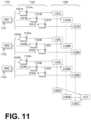
- FIG. 11is another sample diagram of how measurements can be aggregated for making determinations according to embodiments, where operations have been performed previously additional times, and gather additional data and results for a better informed shock/no shock decision.
- a group 1102shows physiological inputs 1021 , 1121 , 1022 , 1122 , 1023 , 1123 , which include not just one input 1021 , 1022 , 1023 for each part of the body (first shown in FIG. 10 ), but also include additional physiological inputs 1121 , 1122 , 1123 , which may have been rendered from the one or more patient parameters that are sensed from the different parts of the patient's body.
- group 1103shows detected first aspects 1031 A, 1031 B, 1031 C, detected second aspects 1032 A, 1032 B, 1032 C, and detected third aspects 1033 A, 1033 B, 1033 C.
- Group 1103also shows additional detected first aspects 1131 A, 1131 B, 1131 C, additional detected second aspects 1132 A, 1132 B, 1132 C, and additional detected third aspects 1133 A, 1133 B, 1133 C, any and all of which may have been detected from each of at least some of additional physiological inputs 1121 , 1122 , 1123 .
- a group 1108shows characteristic first aspects 1131 L, 1132 L, 1133 L, characteristic second aspects 1131 M, 1132 M, 1133 M, and characteristic third aspects 1131 N, 1132 N, 1133 N.
- Characteristic first aspects 1131 L, 1132 L, 1133 Lmay have been determined from at least two of additional detected first aspects 1131 A, 1131 B, 1131 C for respective ones of the different parts of the patient's body.
- Characteristic second aspects 1131 M, 1132 M, 1133 Mmay have been determined from at least two of additional detected second aspects 1132 A, 1132 B, 1132 C for respective ones of the different parts of the patient's body.
- Characteristic third aspects 1131 N, 1132 N, 1133 MNmay have been determined from at least two of additional detected third aspects 1133 A, 1133 B, 1133 C for respective ones of the different parts of the patient's body.
- the characteristic first, second and third aspectsmay be determined in a number of ways. In many embodiments, one of these is determined as a value from a statistic of values of the additional detected first aspects from which it is determined.
- the statisticcan be an average, a maximum, a minimum and so on.
- aggregated first aspect 1187 Amay have been determined from at least two of characteristic first aspects 1131 L, 1132 L 1133 L.
- aggregated second aspect 1187 Bmay have been determined from at least two of characteristic second aspects 1131 M, 1132 M, 1133 M.
- aggregated third aspect 1187 Cmay have been determined from at least two of characteristic second aspects 1131 N, 1132 N, 1133 N.
- Aggregated first, second and third aspects 1187 A, 1187 B, 1187 Cmay be used instead of aggregated first, second and third aspects 1047 A, 1047 B, 1047 C. It will be appreciated that more time is spent in arriving at aggregate analysis score 1177 than in aggregate analysis score 1077 . A more reliable shock/no shock decision may be rendered.
- At least some of the detected aspects of groups 1103 , 1108may be retained over time, for example using memory 238 . This could help where the shock recommendation may change over time.
- the above-described aggregationcan be performed from filtered values of corresponding aspects over time, to determine the corresponding values. For example, at least some of the detected first aspects, second aspects, etc., plus the additional detected first aspects, etc. can be filtered over time.
- an additional aggregate analysis scorecan be determined after the original aggregate analysis score is determined, the original aggregate analysis score and the additional aggregate analysis score can be filtered over time, and the aggregate analysis score can be updated by the filtering, before it is determined whether or not the aggregate shock criterion is met. For example, one could take individual heart rate and QRS width values, determine a shock result, and aggregate the shock results over time.
- Filteringcan be performed conventionally, or by a suitable numerical combination of values. When a new value is received the older value can discarded, and the new value can take its place in a table.
- the filtercould be either an IIR or an FIR filter.
- a filtermay be chosen to give a good combination of step response and noise rejection.
- a FIR filtercould be implemented using a stream of ECG data, while an IIR filter also requires a history of the filtered values. The transient response of an FIR filter may be better behaved than an IIR filter, but the IIR filter will have more noise attenuation for a given number of taps.
- An example FIR filtermight use a Hamming window to determine the coefficients, while an example IIR filter would be a Butterworth filter.
- a median filtermay also be used to combine values over time.
- a median filterhas the advantage that it is substantially insensitive to outliers.
- a single median filtercould be used for an entire memory block.
- median filters of different lengthsmay be combined to give a single value with the desired time response. For example, the output of a 60 second median filter may be combined with a 15 second median filter and a 5 second median filter using linear weighting factors. Such a combination could be designed to give a relatively fast time response while still gaining some of the noise rejection from a longer memory.
- History valuescould be flushed and replaced with new values upon certain predetermined events. For example, after delivering a shock it might be reasonably assumed that the patient's rhythm has changed, in which case the values in memory could be replaced with new measurements before they are utilized.
- each operationcan be performed as an affirmative step of doing, or causing to happen, what is written that can take place. Such doing or causing to happen can be by the whole system or device, or just one or more components of it.
- the methods and the operationsmay be implemented in a number of ways, including using systems, devices and implementations described above.
- the order of operationsis not constrained to what is shown, and different orders may be possible according to different embodiments. Examples of such alternate orderings may include overlapping, interleaved, interrupted, reordered, incremental, preparatory, supplemental, simultaneous, reverse, or other variant orderings, unless context dictates otherwise.
- new operationsmay be added, or individual operations may be modified or deleted. The added operations can be, for example, from what is mentioned while primarily describing a different system, apparatus, device or method.
- the phrases “constructed to” and/or “configured to”denote one or more actual states of construction and/or configuration that is fundamentally tied to physical characteristics of the element or feature preceding these phrases and, as such, reach well beyond merely describing an intended use. Any such elements or features can be implemented in a number of ways, as will be apparent to a person skilled in the art after reviewing the present disclosure, beyond any examples shown in this document.
- a single reference numeralmay be used consistently to denote a single item, aspect, component, or process.
- a further effortmay have been made in the drafting of this description to use similar though not identical reference numerals to denote other versions or embodiments of an item, aspect, component or process that are identical or at least similar or related. Where made, such a further effort was not required, but was nevertheless made gratuitously so as to accelerate comprehension by the reader. Even where made in this document, such a further effort might not have been made completely consistently for all of the versions or embodiments that are made possible by this description. Accordingly, the description controls in defining an item, aspect, component or process, rather than its reference numeral. Any similarity in reference numerals may be used to infer a similarity in the text, but not to confuse aspects where the text or other context indicates otherwise.
Landscapes
- Health & Medical Sciences (AREA)
- Life Sciences & Earth Sciences (AREA)
- Cardiology (AREA)
- General Health & Medical Sciences (AREA)
- Public Health (AREA)
- Veterinary Medicine (AREA)
- Animal Behavior & Ethology (AREA)
- Biomedical Technology (AREA)
- Engineering & Computer Science (AREA)
- Heart & Thoracic Surgery (AREA)
- Pathology (AREA)
- Medical Informatics (AREA)
- Molecular Biology (AREA)
- Surgery (AREA)
- Biophysics (AREA)
- Physics & Mathematics (AREA)
- Nuclear Medicine, Radiotherapy & Molecular Imaging (AREA)
- Radiology & Medical Imaging (AREA)
- Physiology (AREA)
- Pulmonology (AREA)
- Electrotherapy Devices (AREA)
Abstract
Description
Claims (20)
Priority Applications (2)
| Application Number | Priority Date | Filing Date | Title |
|---|---|---|---|
| US17/829,156US12097379B2 (en) | 2013-02-25 | 2022-05-31 | Wearable cardioverter defibrillator (WCD) system making shock/no shock determinations from multiple patient parameters |
| US18/893,291US20250010088A1 (en) | 2013-02-25 | 2024-09-23 | Wearable cardioverter defibrillator (wcd) system making shock/no shock determinations from multiple patient parameters |
Applications Claiming Priority (11)
| Application Number | Priority Date | Filing Date | Title |
|---|---|---|---|
| US201361769098P | 2013-02-25 | 2013-02-25 | |
| US14/189,789US9089685B2 (en) | 2013-02-25 | 2014-02-25 | Wearable defibrillator with a multivector shock waveform |
| US201461992841P | 2014-05-13 | 2014-05-13 | |
| US14/461,670US20150328472A1 (en) | 2014-05-13 | 2014-08-18 | Wearable cardioverter defibrillator components discarding ecg signals prior to making shock/no shock determination |
| US201562165166P | 2015-05-21 | 2015-05-21 | |
| US14/743,882US20150283390A1 (en) | 2013-02-25 | 2015-06-18 | Wearable Defibrillator With A Multivector Shock Waveform |
| US14/941,591US9592403B2 (en) | 2013-02-25 | 2015-11-14 | Wearable cardioverter defibrillator (WCD) system making shock/no shock determinations from multiple patient parameters |
| US15/421,165US10016614B2 (en) | 2013-02-25 | 2017-01-31 | Wearable cardioverter defibrillator (WCD) system making shock/no shock determinations by aggregating aspects of multiple patient parameters |
| US16/001,816US10543377B2 (en) | 2013-02-25 | 2018-06-06 | Wearable cardioverter defibrillator (WCD) system making shock/no shock determinations by aggregating aspects of patient parameters |
| US16/774,852US11351391B2 (en) | 2013-02-25 | 2020-01-28 | Wearable cardioverter defibrillator (WCD) system making shock/no shock determinations from multiple patient parameters |
| US17/829,156US12097379B2 (en) | 2013-02-25 | 2022-05-31 | Wearable cardioverter defibrillator (WCD) system making shock/no shock determinations from multiple patient parameters |
Related Parent Applications (1)
| Application Number | Title | Priority Date | Filing Date |
|---|---|---|---|
| US16/774,852ContinuationUS11351391B2 (en) | 2013-02-25 | 2020-01-28 | Wearable cardioverter defibrillator (WCD) system making shock/no shock determinations from multiple patient parameters |
Related Child Applications (1)
| Application Number | Title | Priority Date | Filing Date |
|---|---|---|---|
| US18/893,291ContinuationUS20250010088A1 (en) | 2013-02-25 | 2024-09-23 | Wearable cardioverter defibrillator (wcd) system making shock/no shock determinations from multiple patient parameters |
Publications (2)
| Publication Number | Publication Date |
|---|---|
| US20220314013A1 US20220314013A1 (en) | 2022-10-06 |
| US12097379B2true US12097379B2 (en) | 2024-09-24 |
Family
ID=83448674
Family Applications (2)
| Application Number | Title | Priority Date | Filing Date |
|---|---|---|---|
| US17/829,156Active2034-07-18US12097379B2 (en) | 2013-02-25 | 2022-05-31 | Wearable cardioverter defibrillator (WCD) system making shock/no shock determinations from multiple patient parameters |
| US18/893,291PendingUS20250010088A1 (en) | 2013-02-25 | 2024-09-23 | Wearable cardioverter defibrillator (wcd) system making shock/no shock determinations from multiple patient parameters |
Family Applications After (1)
| Application Number | Title | Priority Date | Filing Date |
|---|---|---|---|
| US18/893,291PendingUS20250010088A1 (en) | 2013-02-25 | 2024-09-23 | Wearable cardioverter defibrillator (wcd) system making shock/no shock determinations from multiple patient parameters |
Country Status (1)
| Country | Link |
|---|---|
| US (2) | US12097379B2 (en) |
Citations (112)
| Publication number | Priority date | Publication date | Assignee | Title |
|---|---|---|---|---|
| US3724455A (en) | 1970-06-02 | 1973-04-03 | P Unger | Cardiac warning device |
| US4291699A (en) | 1978-09-21 | 1981-09-29 | Purdue Research Foundation | Method of and apparatus for automatically detecting and treating ventricular fibrillation |
| US4583524A (en) | 1984-11-21 | 1986-04-22 | Hutchins Donald C | Cardiopulmonary resuscitation prompting |
| US4619265A (en) | 1984-03-08 | 1986-10-28 | Physio-Control Corporation | Interactive portable defibrillator including ECG detection circuit |
| US4895151A (en) | 1987-07-20 | 1990-01-23 | Telectronics N.V. | Apparatus and method for therapy adjustment in implantable |
| US4928690A (en) | 1988-04-25 | 1990-05-29 | Lifecor, Inc. | Portable device for sensing cardiac function and automatically delivering electrical therapy |
| US4955381A (en) | 1988-08-26 | 1990-09-11 | Cardiotronics, Inc. | Multi-pad, multi-function electrode |
| US5078134A (en) | 1988-04-25 | 1992-01-07 | Lifecor, Inc. | Portable device for sensing cardiac function and automatically delivering electrical therapy |
| US5228449A (en) | 1991-01-22 | 1993-07-20 | Athanasios G. Christ | System and method for detecting out-of-hospital cardiac emergencies and summoning emergency assistance |
| US5348008A (en) | 1991-11-25 | 1994-09-20 | Somnus Corporation | Cardiorespiratory alert system |
| US5394892A (en) | 1990-04-02 | 1995-03-07 | K J Mellet Nominees Pty Ltd | CPR prompting apparatus |
| US5405362A (en) | 1991-04-29 | 1995-04-11 | The Board Of Regents For The University Of Texas System | Interactive external defibrillation and drug injection system |
| US5425749A (en) | 1993-09-16 | 1995-06-20 | Angeion Corporation | Preemptive cardioversion therapy in an implantable cardioverter defibrillator |
| US5474574A (en) | 1992-06-24 | 1995-12-12 | Cardiac Science, Inc. | Automatic external cardioverter/defibrillator |
| US5601612A (en) | 1993-08-06 | 1997-02-11 | Heartstream, Inc. | Method for applying a multiphasic waveform |
| US5630834A (en) | 1995-05-03 | 1997-05-20 | Medtronic, Inc. | Atrial defibrillator with means for delivering therapy in response to a determination that the patient is likely asleep |
| US5662690A (en) | 1994-12-08 | 1997-09-02 | Heartstream, Inc. | Defibrillator with training features and pause actuator |
| US5769872A (en) | 1996-12-18 | 1998-06-23 | Zmd Corporation | Electrotherapy circuit and method for shaping current waveforms |
| US5782878A (en) | 1994-12-07 | 1998-07-21 | Heartstream, Inc. | External defibrillator with communications network link |
| US5792204A (en) | 1996-05-08 | 1998-08-11 | Pacesetter, Inc. | Methods and apparatus for controlling an implantable device programmer using voice commands |
| US5803927A (en) | 1993-08-06 | 1998-09-08 | Heartstream, Inc. | Electrotherapy method and apparatus for external defibrillation |
| WO1998039061A2 (en) | 1997-03-07 | 1998-09-11 | Cadent Medical Corporation | Wearable defibrillation system |
| US5902249A (en) | 1995-03-03 | 1999-05-11 | Heartstream, Inc. | Method and apparatus for detecting artifacts using common-mode signals in differential signal detectors |
| US5913685A (en) | 1996-06-24 | 1999-06-22 | Hutchins; Donald C. | CPR computer aiding |
| US5944669A (en) | 1997-11-20 | 1999-08-31 | Lifecor, Inc. | Apparatus and method for sensing cardiac function |
| US6047203A (en) | 1997-03-17 | 2000-04-04 | Nims, Inc. | Physiologic signs feedback system |
| US6065154A (en) | 1998-04-07 | 2000-05-23 | Lifecor, Inc. | Support garments for patient-worn energy delivery apparatus |
| US6068651A (en) | 1998-03-26 | 2000-05-30 | Pacesetter, Inc. | Atrial defibrillation lock out feature |
| US6108197A (en) | 1992-05-15 | 2000-08-22 | Via, Inc. | Flexible wearable computer |
| US6201992B1 (en) | 1999-04-01 | 2001-03-13 | Agilent Technologies, Inc. | Defibrillator interface capable of generating video images |
| US6263238B1 (en) | 1998-04-16 | 2001-07-17 | Survivalink Corporation | Automatic external defibrillator having a ventricular fibrillation detector |
| US6287328B1 (en) | 1999-04-08 | 2001-09-11 | Agilent Technologies, Inc. | Multivariable artifact assessment |
| US6319011B1 (en) | 1995-04-06 | 2001-11-20 | Michael J. Motti | Automatic training defibrillator simulator and method |
| US6334070B1 (en) | 1998-11-20 | 2001-12-25 | Medtronic Physio-Control Manufacturing Corp. | Visual and aural user interface for an automated external defibrillator |
| US6351671B1 (en) | 1998-12-11 | 2002-02-26 | Laerdal Medical As | System for measuring and analyzing cardio-pulmonary-resuscitation (CPR) parameters for use with and by an external defibrillator (AED) or a training defibrillator |
| US6356785B1 (en) | 1997-11-06 | 2002-03-12 | Cecily Anne Snyder | External defibrillator with CPR prompts and ACLS prompts and methods of use |
| US6529875B1 (en) | 1996-07-11 | 2003-03-04 | Sega Enterprises Ltd. | Voice recognizer, voice recognizing method and game machine using them |
| US20030158593A1 (en) | 2002-02-19 | 2003-08-21 | Heilman Marlin S. | Cardiac garment |
| US6681003B2 (en) | 1999-10-05 | 2004-01-20 | Lifecor, Inc. | Data collection and system management for patient-worn medical devices |
| US6694187B1 (en) | 2000-06-23 | 2004-02-17 | Koninklijke Philips Electronics N.V. | External defibrillator instruction system and method |
| US6762917B1 (en) | 2001-06-12 | 2004-07-13 | Novx Corporation | Method of monitoring ESC levels and protective devices utilizing the method |
| US20040220623A1 (en) | 2003-04-30 | 2004-11-04 | Medtronic, Inc. | Configurable cardioversion and defibrillation therapies in the presence of coexisting atrial and ventricular arrhythmia |
| US20050107834A1 (en) | 2003-11-13 | 2005-05-19 | Freeman Gary A. | Multi-path transthoracic defibrillation and cardioversion |
| US6941168B2 (en) | 2001-12-12 | 2005-09-06 | Cardiac Pacemakers, Inc. | System and method for treating an adverse cardiac condition using combined pacing and drug delivery |
| US20060017575A1 (en) | 2004-07-20 | 2006-01-26 | Medtronic, Inc. | Alert system and method for an implantable medical device |
| US7065401B2 (en) | 2002-05-08 | 2006-06-20 | Michael Worden | Method of applying electrical signals to a patient and automatic wearable external defibrillator |
| US20060173499A1 (en) | 2005-01-31 | 2006-08-03 | Medtronic Emergency Response Systems, Inc. | System and method for using diagnostic pulses in connection with defibrillation therapy |
| US7149576B1 (en) | 2000-07-10 | 2006-12-12 | Cardiodynamics International Corporation | Apparatus and method for defibrillation of a living subject |
| US20070179539A1 (en) | 2006-01-31 | 2007-08-02 | Degroot Paul J | Method and apparatus for controlling arrhythmia detection and treatment based on patient posture |
| US7336994B2 (en) | 2004-01-16 | 2008-02-26 | Medtronic, Inc. | Control of atrial defibrillation therapy based on hemodynamic sensor feedback |
| US20080208070A1 (en) | 2005-06-23 | 2008-08-28 | Koninklijke Philips Electronics N.V. | Defibrillator with Automatic Shock First/Cpr First Algorithm |
| US20080215103A1 (en) | 2005-06-24 | 2008-09-04 | Koninklijke Philips Electronics N.V. | Aed Having Mandatory Pause for Administrating Cpr |
| US20080275519A1 (en) | 2007-05-01 | 2008-11-06 | Ghanem Raja N | Method and apparatus for detecting arrhythmias in a medical device |
| US20080306560A1 (en) | 2007-06-06 | 2008-12-11 | Macho John D | Wearable defibrillator with audio input/output |
| US20080312708A1 (en) | 2005-12-16 | 2008-12-18 | Koninklijke Philips Electronics, N.V. | Automatic External Defibrillator with Increased Cpr Administration Time |
| US20080312709A1 (en) | 2007-06-13 | 2008-12-18 | Volpe Shane S | Wearable medical treatment device with motion/position detection |
| US20090005827A1 (en) | 2007-06-26 | 2009-01-01 | David Weintraub | Wearable defibrillator |
| US20090018595A1 (en) | 2007-07-11 | 2009-01-15 | Pacesetter, Inc. | Systems and methods for employing multiple filters to detect t-wave oversensing and to improve tachyarrhythmia detection within an implantable medical device |
| US7559902B2 (en) | 2003-08-22 | 2009-07-14 | Foster-Miller, Inc. | Physiological monitoring garment |
| US20100007413A1 (en) | 2006-11-10 | 2010-01-14 | Koninklijke Philips Electronics N.V. | Ecg electrode contact quality measurement system |
| US20100298899A1 (en) | 2007-06-13 | 2010-11-25 | Donnelly Edward J | Wearable medical treatment device |
| US20100331904A1 (en) | 2009-06-29 | 2010-12-30 | Cameron Health, Inc. | Adaptive Confirmation of Treatable Arrhythmia in Implantable Cardiac Stimulus Devices |
| US7865238B2 (en) | 2004-09-29 | 2011-01-04 | Koninklijke Philips Electronics N.V. | High-voltage module for an external defibrillator |
| US7870761B2 (en) | 2002-05-14 | 2011-01-18 | Koninklijke Philips Electronics N.V. | Garment and method for producing the same |
| US7894894B2 (en) | 2006-03-29 | 2011-02-22 | Medtronic, Inc. | Method and apparatus for detecting arrhythmias in a subcutaneous medical device |
| US8036746B2 (en) | 2003-10-30 | 2011-10-11 | Cardiac Pacemakers, Inc. | Temporary disablement feature for implantable device with anti-tachyarrhythmia functions |
| US20110288604A1 (en) | 2010-05-18 | 2011-11-24 | Kaib Thomas E | Wearable therapeutic device |
| US20110288605A1 (en) | 2010-05-18 | 2011-11-24 | Zoll Medical Corporation | Wearable ambulatory medical device with multiple sensing electrodes |
| US8135462B2 (en) | 2002-08-26 | 2012-03-13 | Physio-Control, Inc. | Pulse detection using patient physiological signals |
| US20120112903A1 (en) | 2010-11-08 | 2012-05-10 | Zoll Medical Corporation | Remote medical device alarm |
| US20120144551A1 (en) | 2010-12-09 | 2012-06-14 | Eric Guldalian | Conductive Garment |
| US20120150008A1 (en) | 2010-12-09 | 2012-06-14 | Kaib Thomas E | Electrode with redundant impedance reduction |
| US20120158075A1 (en) | 2010-12-16 | 2012-06-21 | Kaib Thomas E | Water resistant wearable medical device |
| US20120265265A1 (en) | 2011-04-13 | 2012-10-18 | Mehdi Razavi | Automated External Defibrillator Pad System |
| US20120283794A1 (en) | 2011-05-02 | 2012-11-08 | Kaib Thomas E | Patient-worn energy delivery apparatus and techniques for sizing same |
| US20120293323A1 (en) | 2011-03-25 | 2012-11-22 | Zoll Medical Corporation | System and method for adapting alarms in a wearable medical device |
| US20120302860A1 (en) | 2011-03-25 | 2012-11-29 | Zoll Medical Corporation | Selection of optimal channel for rate determination |
| US20120310315A1 (en) | 2009-03-17 | 2012-12-06 | Savage Walter T | Device and method for reducing patient transthoracic impedance for the purpose of delivering a therapeutic current |
| US20130085538A1 (en) | 2011-09-01 | 2013-04-04 | Zoll Medical Corporation | Wearable monitoring and treatment device |
| US20130231711A1 (en) | 2012-03-02 | 2013-09-05 | Thomas E. Kaib | Systems and methods for configuring a wearable medical monitoring and/or treatment device |
| US20130245388A1 (en) | 2011-09-01 | 2013-09-19 | Mc10, Inc. | Electronics for detection of a condition of tissue |
| US8548557B2 (en) | 2010-08-12 | 2013-10-01 | Covidien Lp | Medical electrodes |
| US20130274565A1 (en) | 2012-04-13 | 2013-10-17 | Alois Antonin Langer | Outpatient health emergency warning system |
| US20130317852A1 (en) | 2012-05-22 | 2013-11-28 | Geneva Healthcare, LLC | Medical device information portal |
| US20130325078A1 (en) | 2012-05-31 | 2013-12-05 | Zoll Medical Corporation | Medical monitoring and treatment device with external pacing |
| US8615295B2 (en) | 2009-03-17 | 2013-12-24 | Cardiothrive, Inc. | External defibrillator |
| US20140012144A1 (en) | 2012-07-09 | 2014-01-09 | William E. Crone | Perfusion detection system |
| US20140025131A1 (en) | 2012-07-20 | 2014-01-23 | Physio-Control, Inc. | Wearable defibrillator with voice prompts and voice recognition |
| US20140025132A1 (en) | 2012-07-20 | 2014-01-23 | Cyberonics, Inc. | Implantable neurostimulator-implemented method for managing bradycardia through vagus nerve stimulation |
| US20140046391A1 (en) | 2012-08-10 | 2014-02-13 | Physio-Control, Inc. | Wearable defibrillator system communicating via mobile communication device |
| US20140070957A1 (en) | 2012-09-11 | 2014-03-13 | Gianluigi LONGINOTTI-BUITONI | Wearable communication platform |
| US20140091937A1 (en) | 2012-10-02 | 2014-04-03 | At&T Intellectual Property I, L.P. | Notification system for providing awareness of an interactive surface |
| US20140150781A1 (en) | 2012-11-30 | 2014-06-05 | Christopher A. Di Capua | Automated ventilator with assisted compressions |
| US20140163663A1 (en) | 2012-12-11 | 2014-06-12 | Piyush Poddar | Method and system for switching shock vectors and decreasing transthoracic impedance for cardioversion and defibrillation |
| US8825154B2 (en) | 2011-03-23 | 2014-09-02 | Koninklijke Philips N.V. | Defibrillator with protocol for selectively interrupting CPR |
| US20140276160A1 (en) | 2013-03-15 | 2014-09-18 | Medtronic, Inc. | System and method for avoiding undersensing of ventricular fibrillation |
| US8904214B2 (en) | 2010-07-09 | 2014-12-02 | Zoll Medical Corporation | System and method for conserving power in a medical device |
| US20140378812A1 (en) | 2011-12-20 | 2014-12-25 | Sensible Medical Innovatons | Thoracic garment of positioning electromagnetic (em) transducers and methods of using such thoracic garment |
| US20150039053A1 (en) | 2013-06-28 | 2015-02-05 | Zoll Medical Corporation | Systems and methods of delivering therapy using an ambulatory medical device |
| US8996101B2 (en) | 2012-03-12 | 2015-03-31 | Medtronic, Inc. | Heart sound sensing to reduce inappropriate tachyarrhythmia therapy |
| US9089685B2 (en) | 2013-02-25 | 2015-07-28 | West Affum Holdings Corp. | Wearable defibrillator with a multivector shock waveform |
| US9132267B2 (en) | 2013-03-04 | 2015-09-15 | Zoll Medical Corporation | Flexible therapy electrode system |
| US20150297107A1 (en) | 2012-03-27 | 2015-10-22 | Physio-Control, Inc. | System and method for electrocardiogram analysis and optimization of cardiopulmonary resuscitation and therapy delivery |
| US20150328472A1 (en) | 2014-05-13 | 2015-11-19 | Physio-Control, Inc. | Wearable cardioverter defibrillator components discarding ecg signals prior to making shock/no shock determination |
| US20160004831A1 (en) | 2014-07-07 | 2016-01-07 | Zoll Medical Corporation | Medical device with natural language processor |
| US20160000349A1 (en) | 2014-07-07 | 2016-01-07 | Zoll Medical Corporation | System and Method for Distinguishing a Cardiac Event From Noise in an Electrocardiogram (ECG) Signal |
| US20160015329A1 (en) | 2013-03-06 | 2016-01-21 | Koninklijke Philips N.V. | Systems and methods for reducing the impact of alarm sounds on patients |
| US20160082277A1 (en) | 2013-02-25 | 2016-03-24 | West Affum Holdings Corp. | Wearable cardioverter defibrillator (wcd) system informing patient that it is validating just-detected cardiac arrhythmia |
| US20160278698A1 (en) | 2015-03-24 | 2016-09-29 | Zoll Medical Corporation | Using ph and smo2 from a spectral sensor as an indication of subject down time |
| US20170056682A1 (en) | 2014-02-24 | 2017-03-02 | Element Science, Inc. | External defibrillator |
| US9592403B2 (en) | 2013-02-25 | 2017-03-14 | West Affum Holdings Corp. | Wearable cardioverter defibrillator (WCD) system making shock/no shock determinations from multiple patient parameters |
| US11351391B2 (en)* | 2013-02-25 | 2022-06-07 | West Affum Holdings Corp. | Wearable cardioverter defibrillator (WCD) system making shock/no shock determinations from multiple patient parameters |
- 2022
- 2022-05-31USUS17/829,156patent/US12097379B2/enactiveActive
- 2024
- 2024-09-23USUS18/893,291patent/US20250010088A1/enactivePending
Patent Citations (137)
| Publication number | Priority date | Publication date | Assignee | Title |
|---|---|---|---|---|
| US3724455A (en) | 1970-06-02 | 1973-04-03 | P Unger | Cardiac warning device |
| US4291699A (en) | 1978-09-21 | 1981-09-29 | Purdue Research Foundation | Method of and apparatus for automatically detecting and treating ventricular fibrillation |
| US4619265A (en) | 1984-03-08 | 1986-10-28 | Physio-Control Corporation | Interactive portable defibrillator including ECG detection circuit |
| USRE34800E (en) | 1984-11-21 | 1994-11-29 | Hutchins; Donald C. | Cardiopulmonary resuscitation prompting |
| US4583524A (en) | 1984-11-21 | 1986-04-22 | Hutchins Donald C | Cardiopulmonary resuscitation prompting |
| US4895151A (en) | 1987-07-20 | 1990-01-23 | Telectronics N.V. | Apparatus and method for therapy adjustment in implantable |
| US4928690A (en) | 1988-04-25 | 1990-05-29 | Lifecor, Inc. | Portable device for sensing cardiac function and automatically delivering electrical therapy |
| US5078134A (en) | 1988-04-25 | 1992-01-07 | Lifecor, Inc. | Portable device for sensing cardiac function and automatically delivering electrical therapy |
| US4955381A (en) | 1988-08-26 | 1990-09-11 | Cardiotronics, Inc. | Multi-pad, multi-function electrode |
| US5394892A (en) | 1990-04-02 | 1995-03-07 | K J Mellet Nominees Pty Ltd | CPR prompting apparatus |
| US5228449A (en) | 1991-01-22 | 1993-07-20 | Athanasios G. Christ | System and method for detecting out-of-hospital cardiac emergencies and summoning emergency assistance |
| US5405362A (en) | 1991-04-29 | 1995-04-11 | The Board Of Regents For The University Of Texas System | Interactive external defibrillation and drug injection system |
| US5353793A (en) | 1991-11-25 | 1994-10-11 | Oishi-Kogyo Company | Sensor apparatus |
| US5348008A (en) | 1991-11-25 | 1994-09-20 | Somnus Corporation | Cardiorespiratory alert system |
| US6108197A (en) | 1992-05-15 | 2000-08-22 | Via, Inc. | Flexible wearable computer |
| US5474574A (en) | 1992-06-24 | 1995-12-12 | Cardiac Science, Inc. | Automatic external cardioverter/defibrillator |
| US5803927A (en) | 1993-08-06 | 1998-09-08 | Heartstream, Inc. | Electrotherapy method and apparatus for external defibrillation |
| US5601612A (en) | 1993-08-06 | 1997-02-11 | Heartstream, Inc. | Method for applying a multiphasic waveform |
| US5425749A (en) | 1993-09-16 | 1995-06-20 | Angeion Corporation | Preemptive cardioversion therapy in an implantable cardioverter defibrillator |
| US5782878A (en) | 1994-12-07 | 1998-07-21 | Heartstream, Inc. | External defibrillator with communications network link |
| US5662690A (en) | 1994-12-08 | 1997-09-02 | Heartstream, Inc. | Defibrillator with training features and pause actuator |
| US5902249A (en) | 1995-03-03 | 1999-05-11 | Heartstream, Inc. | Method and apparatus for detecting artifacts using common-mode signals in differential signal detectors |
| US6319011B1 (en) | 1995-04-06 | 2001-11-20 | Michael J. Motti | Automatic training defibrillator simulator and method |
| US5630834A (en) | 1995-05-03 | 1997-05-20 | Medtronic, Inc. | Atrial defibrillator with means for delivering therapy in response to a determination that the patient is likely asleep |
| US5792204A (en) | 1996-05-08 | 1998-08-11 | Pacesetter, Inc. | Methods and apparatus for controlling an implantable device programmer using voice commands |
| US5913685A (en) | 1996-06-24 | 1999-06-22 | Hutchins; Donald C. | CPR computer aiding |
| US6529875B1 (en) | 1996-07-11 | 2003-03-04 | Sega Enterprises Ltd. | Voice recognizer, voice recognizing method and game machine using them |
| US5769872A (en) | 1996-12-18 | 1998-06-23 | Zmd Corporation | Electrotherapy circuit and method for shaping current waveforms |
| US6304780B1 (en) | 1997-03-07 | 2001-10-16 | Cardiac Science Inc. | External defibrillator system with diagnostic module |
| US6671545B2 (en) | 1997-03-07 | 2003-12-30 | Cardiac Science, Inc. | Defibrillator with controller operating in a low power mode |
| US6148233A (en) | 1997-03-07 | 2000-11-14 | Cardiac Science, Inc. | Defibrillation system having segmented electrodes |
| WO1998039061A2 (en) | 1997-03-07 | 1998-09-11 | Cadent Medical Corporation | Wearable defibrillation system |
| US6546285B1 (en) | 1997-03-07 | 2003-04-08 | Cardiac Science, Inc. | Long term wear electrode for defibrillation system |
| US6427083B1 (en) | 1997-03-07 | 2002-07-30 | Cardiac Science, Inc. | Defibrillation system |
| US20110022105A9 (en) | 1997-03-07 | 2011-01-27 | Owen James M | Defibrillation system |
| US6047203A (en) | 1997-03-17 | 2000-04-04 | Nims, Inc. | Physiologic signs feedback system |
| US6356785B1 (en) | 1997-11-06 | 2002-03-12 | Cecily Anne Snyder | External defibrillator with CPR prompts and ACLS prompts and methods of use |
| US5944669A (en) | 1997-11-20 | 1999-08-31 | Lifecor, Inc. | Apparatus and method for sensing cardiac function |
| US6068651A (en) | 1998-03-26 | 2000-05-30 | Pacesetter, Inc. | Atrial defibrillation lock out feature |
| US6065154A (en) | 1998-04-07 | 2000-05-23 | Lifecor, Inc. | Support garments for patient-worn energy delivery apparatus |
| US6263238B1 (en) | 1998-04-16 | 2001-07-17 | Survivalink Corporation | Automatic external defibrillator having a ventricular fibrillation detector |
| US6334070B1 (en) | 1998-11-20 | 2001-12-25 | Medtronic Physio-Control Manufacturing Corp. | Visual and aural user interface for an automated external defibrillator |
| US6351671B1 (en) | 1998-12-11 | 2002-02-26 | Laerdal Medical As | System for measuring and analyzing cardio-pulmonary-resuscitation (CPR) parameters for use with and by an external defibrillator (AED) or a training defibrillator |
| US6201992B1 (en) | 1999-04-01 | 2001-03-13 | Agilent Technologies, Inc. | Defibrillator interface capable of generating video images |
| US6287328B1 (en) | 1999-04-08 | 2001-09-11 | Agilent Technologies, Inc. | Multivariable artifact assessment |
| US6681003B2 (en) | 1999-10-05 | 2004-01-20 | Lifecor, Inc. | Data collection and system management for patient-worn medical devices |
| US6694187B1 (en) | 2000-06-23 | 2004-02-17 | Koninklijke Philips Electronics N.V. | External defibrillator instruction system and method |
| US7149576B1 (en) | 2000-07-10 | 2006-12-12 | Cardiodynamics International Corporation | Apparatus and method for defibrillation of a living subject |
| US6762917B1 (en) | 2001-06-12 | 2004-07-13 | Novx Corporation | Method of monitoring ESC levels and protective devices utilizing the method |
| US6941168B2 (en) | 2001-12-12 | 2005-09-06 | Cardiac Pacemakers, Inc. | System and method for treating an adverse cardiac condition using combined pacing and drug delivery |
| US20030158593A1 (en) | 2002-02-19 | 2003-08-21 | Heilman Marlin S. | Cardiac garment |
| US7065401B2 (en) | 2002-05-08 | 2006-06-20 | Michael Worden | Method of applying electrical signals to a patient and automatic wearable external defibrillator |
| US7870761B2 (en) | 2002-05-14 | 2011-01-18 | Koninklijke Philips Electronics N.V. | Garment and method for producing the same |
| US8135462B2 (en) | 2002-08-26 | 2012-03-13 | Physio-Control, Inc. | Pulse detection using patient physiological signals |
| US20040220623A1 (en) | 2003-04-30 | 2004-11-04 | Medtronic, Inc. | Configurable cardioversion and defibrillation therapies in the presence of coexisting atrial and ventricular arrhythmia |
| US7559902B2 (en) | 2003-08-22 | 2009-07-14 | Foster-Miller, Inc. | Physiological monitoring garment |
| US8036746B2 (en) | 2003-10-30 | 2011-10-11 | Cardiac Pacemakers, Inc. | Temporary disablement feature for implantable device with anti-tachyarrhythmia functions |
| US20050107833A1 (en) | 2003-11-13 | 2005-05-19 | Freeman Gary A. | Multi-path transthoracic defibrillation and cardioversion |
| US20050107834A1 (en) | 2003-11-13 | 2005-05-19 | Freeman Gary A. | Multi-path transthoracic defibrillation and cardioversion |
| US7336994B2 (en) | 2004-01-16 | 2008-02-26 | Medtronic, Inc. | Control of atrial defibrillation therapy based on hemodynamic sensor feedback |
| US20060017575A1 (en) | 2004-07-20 | 2006-01-26 | Medtronic, Inc. | Alert system and method for an implantable medical device |
| US7865238B2 (en) | 2004-09-29 | 2011-01-04 | Koninklijke Philips Electronics N.V. | High-voltage module for an external defibrillator |
| US20060173499A1 (en) | 2005-01-31 | 2006-08-03 | Medtronic Emergency Response Systems, Inc. | System and method for using diagnostic pulses in connection with defibrillation therapy |
| US20080208070A1 (en) | 2005-06-23 | 2008-08-28 | Koninklijke Philips Electronics N.V. | Defibrillator with Automatic Shock First/Cpr First Algorithm |
| US20080215103A1 (en) | 2005-06-24 | 2008-09-04 | Koninklijke Philips Electronics N.V. | Aed Having Mandatory Pause for Administrating Cpr |
| US20080312708A1 (en) | 2005-12-16 | 2008-12-18 | Koninklijke Philips Electronics, N.V. | Automatic External Defibrillator with Increased Cpr Administration Time |
| US20070179539A1 (en) | 2006-01-31 | 2007-08-02 | Degroot Paul J | Method and apparatus for controlling arrhythmia detection and treatment based on patient posture |
| US7894894B2 (en) | 2006-03-29 | 2011-02-22 | Medtronic, Inc. | Method and apparatus for detecting arrhythmias in a subcutaneous medical device |
| US20100007413A1 (en) | 2006-11-10 | 2010-01-14 | Koninklijke Philips Electronics N.V. | Ecg electrode contact quality measurement system |
| US20080275519A1 (en) | 2007-05-01 | 2008-11-06 | Ghanem Raja N | Method and apparatus for detecting arrhythmias in a medical device |
| US8369944B2 (en) | 2007-06-06 | 2013-02-05 | Zoll Medical Corporation | Wearable defibrillator with audio input/output |
| US20140324112A1 (en) | 2007-06-06 | 2014-10-30 | Zoll Medical Corporation | Wearable defibrillator with audio input/output |
| US8965500B2 (en) | 2007-06-06 | 2015-02-24 | Zoll Medical Corporation | Wearable defibrillator with audio input/output |
| US20080306560A1 (en) | 2007-06-06 | 2008-12-11 | Macho John D | Wearable defibrillator with audio input/output |
| US20100298899A1 (en) | 2007-06-13 | 2010-11-25 | Donnelly Edward J | Wearable medical treatment device |
| US20080312709A1 (en) | 2007-06-13 | 2008-12-18 | Volpe Shane S | Wearable medical treatment device with motion/position detection |
| US8140154B2 (en) | 2007-06-13 | 2012-03-20 | Zoll Medical Corporation | Wearable medical treatment device |
| US8676313B2 (en) | 2007-06-13 | 2014-03-18 | Zoll Medical Corporation | Wearable medical treatment device with motion/position detection |
| US7974689B2 (en) | 2007-06-13 | 2011-07-05 | Zoll Medical Corporation | Wearable medical treatment device with motion/position detection |
| US20090005827A1 (en) | 2007-06-26 | 2009-01-01 | David Weintraub | Wearable defibrillator |
| US20090018595A1 (en) | 2007-07-11 | 2009-01-15 | Pacesetter, Inc. | Systems and methods for employing multiple filters to detect t-wave oversensing and to improve tachyarrhythmia detection within an implantable medical device |
| US20120310315A1 (en) | 2009-03-17 | 2012-12-06 | Savage Walter T | Device and method for reducing patient transthoracic impedance for the purpose of delivering a therapeutic current |
| US8615295B2 (en) | 2009-03-17 | 2013-12-24 | Cardiothrive, Inc. | External defibrillator |
| US20100331904A1 (en) | 2009-06-29 | 2010-12-30 | Cameron Health, Inc. | Adaptive Confirmation of Treatable Arrhythmia in Implantable Cardiac Stimulus Devices |
| US9008801B2 (en) | 2010-05-18 | 2015-04-14 | Zoll Medical Corporation | Wearable therapeutic device |
| US20110288605A1 (en) | 2010-05-18 | 2011-11-24 | Zoll Medical Corporation | Wearable ambulatory medical device with multiple sensing electrodes |
| US20110288604A1 (en) | 2010-05-18 | 2011-11-24 | Kaib Thomas E | Wearable therapeutic device |
| US9454219B2 (en) | 2010-07-09 | 2016-09-27 | Zoll Medical Corporation | System and method for conserving power in a medical device |
| US8904214B2 (en) | 2010-07-09 | 2014-12-02 | Zoll Medical Corporation | System and method for conserving power in a medical device |
| US8548557B2 (en) | 2010-08-12 | 2013-10-01 | Covidien Lp | Medical electrodes |
| WO2012064604A1 (en) | 2010-11-08 | 2012-05-18 | Zoll Medical Corporation | Remote medical device alarm |
| US20120112903A1 (en) | 2010-11-08 | 2012-05-10 | Zoll Medical Corporation | Remote medical device alarm |
| US20120150008A1 (en) | 2010-12-09 | 2012-06-14 | Kaib Thomas E | Electrode with redundant impedance reduction |
| US20120144551A1 (en) | 2010-12-09 | 2012-06-14 | Eric Guldalian | Conductive Garment |
| US20120158075A1 (en) | 2010-12-16 | 2012-06-21 | Kaib Thomas E | Water resistant wearable medical device |
| US8825154B2 (en) | 2011-03-23 | 2014-09-02 | Koninklijke Philips N.V. | Defibrillator with protocol for selectively interrupting CPR |
| US20120302860A1 (en) | 2011-03-25 | 2012-11-29 | Zoll Medical Corporation | Selection of optimal channel for rate determination |
| US8897860B2 (en) | 2011-03-25 | 2014-11-25 | Zoll Medical Corporation | Selection of optimal channel for rate determination |
| US20120293323A1 (en) | 2011-03-25 | 2012-11-22 | Zoll Medical Corporation | System and method for adapting alarms in a wearable medical device |
| US9408548B2 (en) | 2011-03-25 | 2016-08-09 | Zoll Medical Corporation | Selection of optimal channel for rate determination |
| US20120265265A1 (en) | 2011-04-13 | 2012-10-18 | Mehdi Razavi | Automated External Defibrillator Pad System |
| US20120283794A1 (en) | 2011-05-02 | 2012-11-08 | Kaib Thomas E | Patient-worn energy delivery apparatus and techniques for sizing same |
| US9131901B2 (en) | 2011-09-01 | 2015-09-15 | Zoll Medical Corporation | Wearable monitoring and treatment device |
| US8644925B2 (en) | 2011-09-01 | 2014-02-04 | Zoll Medical Corporation | Wearable monitoring and treatment device |
| US20130085538A1 (en) | 2011-09-01 | 2013-04-04 | Zoll Medical Corporation | Wearable monitoring and treatment device |
| US20130245388A1 (en) | 2011-09-01 | 2013-09-19 | Mc10, Inc. | Electronics for detection of a condition of tissue |
| US20140378812A1 (en) | 2011-12-20 | 2014-12-25 | Sensible Medical Innovatons | Thoracic garment of positioning electromagnetic (em) transducers and methods of using such thoracic garment |
| US20130231711A1 (en) | 2012-03-02 | 2013-09-05 | Thomas E. Kaib | Systems and methods for configuring a wearable medical monitoring and/or treatment device |
| US8996101B2 (en) | 2012-03-12 | 2015-03-31 | Medtronic, Inc. | Heart sound sensing to reduce inappropriate tachyarrhythmia therapy |
| US20150297107A1 (en) | 2012-03-27 | 2015-10-22 | Physio-Control, Inc. | System and method for electrocardiogram analysis and optimization of cardiopulmonary resuscitation and therapy delivery |
| US20130274565A1 (en) | 2012-04-13 | 2013-10-17 | Alois Antonin Langer | Outpatient health emergency warning system |
| US20130317852A1 (en) | 2012-05-22 | 2013-11-28 | Geneva Healthcare, LLC | Medical device information portal |
| US20130325078A1 (en) | 2012-05-31 | 2013-12-05 | Zoll Medical Corporation | Medical monitoring and treatment device with external pacing |
| US20140012144A1 (en) | 2012-07-09 | 2014-01-09 | William E. Crone | Perfusion detection system |
| US20140025132A1 (en) | 2012-07-20 | 2014-01-23 | Cyberonics, Inc. | Implantable neurostimulator-implemented method for managing bradycardia through vagus nerve stimulation |
| US20140025131A1 (en) | 2012-07-20 | 2014-01-23 | Physio-Control, Inc. | Wearable defibrillator with voice prompts and voice recognition |
| US20140046391A1 (en) | 2012-08-10 | 2014-02-13 | Physio-Control, Inc. | Wearable defibrillator system communicating via mobile communication device |
| US20140070957A1 (en) | 2012-09-11 | 2014-03-13 | Gianluigi LONGINOTTI-BUITONI | Wearable communication platform |
| US20140091937A1 (en) | 2012-10-02 | 2014-04-03 | At&T Intellectual Property I, L.P. | Notification system for providing awareness of an interactive surface |
| US20140150781A1 (en) | 2012-11-30 | 2014-06-05 | Christopher A. Di Capua | Automated ventilator with assisted compressions |
| US20140163663A1 (en) | 2012-12-11 | 2014-06-12 | Piyush Poddar | Method and system for switching shock vectors and decreasing transthoracic impedance for cardioversion and defibrillation |
| US9089685B2 (en) | 2013-02-25 | 2015-07-28 | West Affum Holdings Corp. | Wearable defibrillator with a multivector shock waveform |
| US11351391B2 (en)* | 2013-02-25 | 2022-06-07 | West Affum Holdings Corp. | Wearable cardioverter defibrillator (WCD) system making shock/no shock determinations from multiple patient parameters |
| US10426966B2 (en) | 2013-02-25 | 2019-10-01 | West Affum Holdings Corp. | Wearable cardioverter defibrillator (WCD) system informing patient that it will not shock responsive to just-self-terminated cardiac arrhythmia |
| US10016614B2 (en) | 2013-02-25 | 2018-07-10 | West Affum Holdings Corp. | Wearable cardioverter defibrillator (WCD) system making shock/no shock determinations by aggregating aspects of multiple patient parameters |
| US9757579B2 (en) | 2013-02-25 | 2017-09-12 | West Affum Holdings Corp. | Wearable cardioverter defibrillator (WCD) system informing patient that it is validating just-detected cardiac arrhythmia |
| US9592403B2 (en) | 2013-02-25 | 2017-03-14 | West Affum Holdings Corp. | Wearable cardioverter defibrillator (WCD) system making shock/no shock determinations from multiple patient parameters |
| US20160082277A1 (en) | 2013-02-25 | 2016-03-24 | West Affum Holdings Corp. | Wearable cardioverter defibrillator (wcd) system informing patient that it is validating just-detected cardiac arrhythmia |
| US9132267B2 (en) | 2013-03-04 | 2015-09-15 | Zoll Medical Corporation | Flexible therapy electrode system |
| US20160015329A1 (en) | 2013-03-06 | 2016-01-21 | Koninklijke Philips N.V. | Systems and methods for reducing the impact of alarm sounds on patients |
| US20140276160A1 (en) | 2013-03-15 | 2014-09-18 | Medtronic, Inc. | System and method for avoiding undersensing of ventricular fibrillation |
| US20150039053A1 (en) | 2013-06-28 | 2015-02-05 | Zoll Medical Corporation | Systems and methods of delivering therapy using an ambulatory medical device |
| US20170056682A1 (en) | 2014-02-24 | 2017-03-02 | Element Science, Inc. | External defibrillator |
| US20150328472A1 (en) | 2014-05-13 | 2015-11-19 | Physio-Control, Inc. | Wearable cardioverter defibrillator components discarding ecg signals prior to making shock/no shock determination |
| US20160000349A1 (en) | 2014-07-07 | 2016-01-07 | Zoll Medical Corporation | System and Method for Distinguishing a Cardiac Event From Noise in an Electrocardiogram (ECG) Signal |
| US20160004831A1 (en) | 2014-07-07 | 2016-01-07 | Zoll Medical Corporation | Medical device with natural language processor |
| US20160278698A1 (en) | 2015-03-24 | 2016-09-29 | Zoll Medical Corporation | Using ph and smo2 from a spectral sensor as an indication of subject down time |
Non-Patent Citations (8)
| Title |
|---|
| Heartstart MRx and XL AED Algorithm-Application Note, Jul. 2001, Edition 2 Philips Healthcare, USA. |
| Klein, H. U., Goldenberg I., & Moss, A. J., Risk Stratification for Implantable Cardioverter Defibrillator Therapy: The Role of the Wearable Cardioverter-Defibrillator, Clinical update, European Heart Journal, May 31, 2013, pp. 1-14, doi:10.1093/eurheartj/eht167, European Society of Cardiology. |
| Lifecor LifeVest System Model WCD 3100 Operator's Manual, 2006, PN 20B0040 Rev FI, Zoll Lifecor Corporation, Pittsburgh, PA. |
| LifeVest Model 4000 Patient Manual, Zoll, 2009, PN 20B0047 Rev B. |
| Non-Final Office action mailed on Nov. 12, 2021, to U.S. Appl. No. 16/774,852. |
| Pagan-Carlo, et al., "Encircling Overlapping Multipulse Shock Waveforms for Transthoracic Defibrillation," JACC Journals, Dec. 1998, vol. 32 Issue 7, p. 2065-2071. |
| The LifeVest Network/Patient Data Management System, Zoll, 2015, 2000503 Rev A. |
| Zoll LifeVest Model 4000 Patient Manual Pn 20B0047 Rev B, (C) 2009-2012. |
Also Published As
| Publication number | Publication date |
|---|---|
| US20220314013A1 (en) | 2022-10-06 |
| US20250010088A1 (en) | 2025-01-09 |
Similar Documents
| Publication | Publication Date | Title |
|---|---|---|
| US10016614B2 (en) | Wearable cardioverter defibrillator (WCD) system making shock/no shock determinations by aggregating aspects of multiple patient parameters | |
| US12023510B2 (en) | Wearable cardioverter defibrillator (WCD) system reacting to high-frequency ECG noise | |
| US9757581B2 (en) | Wearable cardioverter defibrillator components making aggregate shock/no shock determination from two or more ECG signals | |
| US11351391B2 (en) | Wearable cardioverter defibrillator (WCD) system making shock/no shock determinations from multiple patient parameters | |
| US12434067B2 (en) | Wearable cardioverter defibrillator (WCD) system computing heart rate from noisy ECG signal | |
| US11351390B2 (en) | Wearable monitor system computing patient heart rate by multiplying ECG signals from different channels | |
| US11865351B2 (en) | Medical device with enhanced electrocardiogram channel selection | |
| US20240058596A1 (en) | Multichannel posture dependent template based rhythm discrimination in a wearable cardioverter defibrillator | |
| US12179031B2 (en) | Heart rate calculator with reduced overcounting | |
| US12232879B2 (en) | Atrial fibrillation detection | |
| US12097379B2 (en) | Wearable cardioverter defibrillator (WCD) system making shock/no shock determinations from multiple patient parameters | |
| US11865354B1 (en) | Methods and systems for distinguishing VT from VF |
Legal Events
| Date | Code | Title | Description |
|---|---|---|---|
| FEPP | Fee payment procedure | Free format text:ENTITY STATUS SET TO UNDISCOUNTED (ORIGINAL EVENT CODE: BIG.); ENTITY STATUS OF PATENT OWNER: LARGE ENTITY | |
| STPP | Information on status: patent application and granting procedure in general | Free format text:DOCKETED NEW CASE - READY FOR EXAMINATION | |
| AS | Assignment | Owner name:PHYSIO-CONTROL DEVELOPMENT CO., LLC, WASHINGTON Free format text:ASSIGNMENT OF ASSIGNORS INTEREST;ASSIGNOR:SULLIVAN, JOSEPH L.;REEL/FRAME:062073/0420 Effective date:20151119 Owner name:WEST AFFUM HOLDINGS CORP., CAYMAN ISLANDS Free format text:ASSIGNMENT OF ASSIGNORS INTEREST;ASSIGNOR:PHYSIO-CONTROL DEVELOPMENT CO., LLC;REEL/FRAME:062073/0561 Effective date:20171108 Owner name:WEST AFFUM HOLDINGS DESIGNATED ACTIVITY COMPANY, IRELAND Free format text:ASSIGNMENT OF ASSIGNORS INTEREST;ASSIGNOR:WEST AFFUM HOLDINGS CORP.;REEL/FRAME:062073/0821 Effective date:20220427 Owner name:WEST AFFUM HOLDINGS CORP., CAYMAN ISLANDS Free format text:ASSIGNMENT OF ASSIGNORS INTEREST;ASSIGNOR:PHYSIO-CONTROL DEVELOPMENT CO., LLC;REEL/FRAME:062073/0766 Effective date:20151119 | |
| AS | Assignment | Owner name:PERCEPTIVE CREDIT HOLDINGS IV, LP, NEW YORK Free format text:SECURITY AGREEMENT;ASSIGNOR:WEST AFFUM HOLDINGS DESIGNATED ACTIVITY COMPANY;REEL/FRAME:065116/0049 Effective date:20230929 | |
| STPP | Information on status: patent application and granting procedure in general | Free format text:NON FINAL ACTION MAILED | |
| STPP | Information on status: patent application and granting procedure in general | Free format text:RESPONSE TO NON-FINAL OFFICE ACTION ENTERED AND FORWARDED TO EXAMINER | |
| STPP | Information on status: patent application and granting procedure in general | Free format text:NOTICE OF ALLOWANCE MAILED -- APPLICATION RECEIVED IN OFFICE OF PUBLICATIONS | |
| STCF | Information on status: patent grant | Free format text:PATENTED CASE |