US12097325B2 - Systems and devices for preventing occlusion of a suction line resident in a medical device - Google Patents
Systems and devices for preventing occlusion of a suction line resident in a medical deviceDownload PDFInfo
- Publication number
- US12097325B2 US12097325B2US16/686,031US201916686031AUS12097325B2US 12097325 B2US12097325 B2US 12097325B2US 201916686031 AUS201916686031 AUS 201916686031AUS 12097325 B2US12097325 B2US 12097325B2
- Authority
- US
- United States
- Prior art keywords
- tube
- spacer
- suction line
- tube system
- port
- Prior art date
- Legal status (The legal status is an assumption and is not a legal conclusion. Google has not performed a legal analysis and makes no representation as to the accuracy of the status listed.)
- Active, expires
Links
- 125000006850spacer groupChemical group0.000claimsabstractdescription111
- 239000012080ambient airSubstances0.000claimsdescription6
- 210000003437tracheaAnatomy0.000description28
- 239000003570airSubstances0.000description21
- 239000012530fluidSubstances0.000description10
- 239000000463materialSubstances0.000description10
- 239000007788liquidSubstances0.000description8
- 239000007789gasSubstances0.000description7
- 239000007787solidSubstances0.000description7
- 210000001519tissueAnatomy0.000description7
- 239000000126substanceSubstances0.000description6
- 230000028327secretionEffects0.000description5
- 210000004072lungAnatomy0.000description4
- 238000000034methodMethods0.000description4
- 244000052769pathogenSpecies0.000description4
- 238000004891communicationMethods0.000description3
- 238000003780insertionMethods0.000description3
- 230000037431insertionEffects0.000description3
- 238000004519manufacturing processMethods0.000description3
- 210000005092tracheal tissueAnatomy0.000description3
- 206010035664PneumoniaDiseases0.000description2
- 208000009470Ventilator-Associated PneumoniaDiseases0.000description2
- 210000003484anatomyAnatomy0.000description2
- 201000010099diseaseDiseases0.000description2
- 208000037265diseases, disorders, signs and symptomsDiseases0.000description2
- 238000002347injectionMethods0.000description2
- 239000007924injectionSubstances0.000description2
- 239000002245particleSubstances0.000description2
- 230000002485urinary effectEffects0.000description2
- 238000009423ventilationMethods0.000description2
- FAPWRFPIFSIZLT-UHFFFAOYSA-MSodium chlorideChemical compound[Na+].[Cl-]FAPWRFPIFSIZLT-UHFFFAOYSA-M0.000description1
- 238000005299abrasionMethods0.000description1
- 230000000903blocking effectEffects0.000description1
- -1but not limited toSubstances0.000description1
- 230000005465channelingEffects0.000description1
- 238000005520cutting processMethods0.000description1
- 238000002059diagnostic imagingMethods0.000description1
- 239000003814drugSubstances0.000description1
- 229940079593drugDrugs0.000description1
- 238000012377drug deliveryMethods0.000description1
- 238000005516engineering processMethods0.000description1
- 238000001125extrusionMethods0.000description1
- 230000007794irritationEffects0.000description1
- 238000002595magnetic resonance imagingMethods0.000description1
- 230000007246mechanismEffects0.000description1
- 238000002483medicationMethods0.000description1
- 239000002184metalSubstances0.000description1
- 230000037361pathwayEffects0.000description1
- 229920003023plasticPolymers0.000description1
- 238000011176poolingMethods0.000description1
- 238000003825pressingMethods0.000description1
- 229910052710siliconInorganic materials0.000description1
- 239000010703siliconSubstances0.000description1
- 239000011780sodium chlorideSubstances0.000description1
- 210000005177subglottisAnatomy0.000description1
- 125000000391vinyl groupChemical group[H]C([*])=C([H])[H]0.000description1
- 229920002554vinyl polymerPolymers0.000description1
Images


Classifications
- A—HUMAN NECESSITIES
- A61—MEDICAL OR VETERINARY SCIENCE; HYGIENE
- A61M—DEVICES FOR INTRODUCING MEDIA INTO, OR ONTO, THE BODY; DEVICES FOR TRANSDUCING BODY MEDIA OR FOR TAKING MEDIA FROM THE BODY; DEVICES FOR PRODUCING OR ENDING SLEEP OR STUPOR
- A61M16/00—Devices for influencing the respiratory system of patients by gas treatment, e.g. ventilators; Tracheal tubes
- A61M16/04—Tracheal tubes
- A61M16/0475—Tracheal tubes having openings in the tube
- A61M16/0477—Tracheal tubes having openings in the tube with incorporated means for delivering or removing fluids
- A61M16/0479—Tracheal tubes having openings in the tube with incorporated means for delivering or removing fluids above the cuff, e.g. giving access to the upper trachea
- A—HUMAN NECESSITIES
- A61—MEDICAL OR VETERINARY SCIENCE; HYGIENE
- A61M—DEVICES FOR INTRODUCING MEDIA INTO, OR ONTO, THE BODY; DEVICES FOR TRANSDUCING BODY MEDIA OR FOR TAKING MEDIA FROM THE BODY; DEVICES FOR PRODUCING OR ENDING SLEEP OR STUPOR
- A61M16/00—Devices for influencing the respiratory system of patients by gas treatment, e.g. ventilators; Tracheal tubes
- A61M16/04—Tracheal tubes
- A61M16/0463—Tracheal tubes combined with suction tubes, catheters or the like; Outside connections
- A—HUMAN NECESSITIES
- A61—MEDICAL OR VETERINARY SCIENCE; HYGIENE
- A61M—DEVICES FOR INTRODUCING MEDIA INTO, OR ONTO, THE BODY; DEVICES FOR TRANSDUCING BODY MEDIA OR FOR TAKING MEDIA FROM THE BODY; DEVICES FOR PRODUCING OR ENDING SLEEP OR STUPOR
- A61M16/00—Devices for influencing the respiratory system of patients by gas treatment, e.g. ventilators; Tracheal tubes
- A61M16/04—Tracheal tubes
- A61M16/0434—Cuffs
- A—HUMAN NECESSITIES
- A61—MEDICAL OR VETERINARY SCIENCE; HYGIENE
- A61M—DEVICES FOR INTRODUCING MEDIA INTO, OR ONTO, THE BODY; DEVICES FOR TRANSDUCING BODY MEDIA OR FOR TAKING MEDIA FROM THE BODY; DEVICES FOR PRODUCING OR ENDING SLEEP OR STUPOR
- A61M16/00—Devices for influencing the respiratory system of patients by gas treatment, e.g. ventilators; Tracheal tubes
- A61M16/04—Tracheal tubes
- A61M16/0465—Tracheostomy tubes; Devices for performing a tracheostomy; Accessories therefor, e.g. masks, filters
- A—HUMAN NECESSITIES
- A61—MEDICAL OR VETERINARY SCIENCE; HYGIENE
- A61M—DEVICES FOR INTRODUCING MEDIA INTO, OR ONTO, THE BODY; DEVICES FOR TRANSDUCING BODY MEDIA OR FOR TAKING MEDIA FROM THE BODY; DEVICES FOR PRODUCING OR ENDING SLEEP OR STUPOR
- A61M16/00—Devices for influencing the respiratory system of patients by gas treatment, e.g. ventilators; Tracheal tubes
- A61M16/04—Tracheal tubes
- A61M16/0486—Multi-lumen tracheal tubes
- A—HUMAN NECESSITIES
- A61—MEDICAL OR VETERINARY SCIENCE; HYGIENE
- A61M—DEVICES FOR INTRODUCING MEDIA INTO, OR ONTO, THE BODY; DEVICES FOR TRANSDUCING BODY MEDIA OR FOR TAKING MEDIA FROM THE BODY; DEVICES FOR PRODUCING OR ENDING SLEEP OR STUPOR
- A61M2205/00—General characteristics of the apparatus
- A61M2205/32—General characteristics of the apparatus with radio-opaque indicia
Definitions
- This specificationgenerally relates to the field of medical devices and, more specifically to devices that prevent occlusion of a suction line as may be deployed by and/or resident in a medical device such as a tracheal tube, a laryngeal mask airway, a tracheostomy tube, a laparoscopic tool, and a cystopic tool such as a urinary catheter.
- a medical devicesuch as a tracheal tube, a laryngeal mask airway, a tracheostomy tube, a laparoscopic tool, and a cystopic tool such as a urinary catheter.
- Tracheal tubes with inflatable balloons with suction meansare broadly known in the prior art.
- the suctioning means of such prior artsare inefficient with suctioning secretions above and around the balloon, therefore allowing secretions and/or pathogens to travel through the balloon and tracheal walls and into the airflow of the tracheal tube.
- the secretions/pathogensget aerosolized by the high velocity of the ventilated air traveling through the tracheal tube and into the patient's lungs. Aerosolized pathogens traveling at high velocity may send the pathogens deep into the lungs, which may cause ventilator associated pneumonia (VAP) as well as other diseases.
- VAPventilator associated pneumonia
- One embodiment of the present inventionutilizes a tube system that may include a tube that is flexible and hollow with a first open end and a second open end, a suction line configured to be coupled to a suction device that applies negative pressure to the suction line, a suction line port, and a spacer that extends from an exterior surface of the tube and is positioned proximate to the suction line port.
- the first open end of the tubemay be configured to be coupled to an artificial ventilation device.
- the negative pressure created by the suction devicemay suck fluid from the trachea through the suction line port when the tube system is placed in a patient's trachea and the suction device is active.
- the tubemay further include an inflatable balloon affixed to, and circumferentially surrounding an exterior portion of the tube.
- the inflatable balloonmay be positioned between the first open end and the second open end of the tube and may be inflated via an inflation line lumen coupled to an air supply.
- the spacermay be configured and/or positioned to prevent occlusion of the suction line port and may be affixed to the tube via a bond, a sleeve, a clip, a strap, and/or a clamp.
- the spacermay be flexible or otherwise deformable so as to, for example, adapt to a patient's anatomy and/or ease insertion of the tube system into a patient's trachea.
- the tube systemmay include a plurality of spacers positioned proximate to the suction line port. Additionally, or alternatively, the spacer(s) may extend longitudinally along a portion of a length of the tube. Additionally, or alternatively, the spacer(s) may extend circumferentially around a portion of a circumference of the tube.
- the spacermay not touch the exterior surface of the tube and may, instead, extend above the exterior surface of the tube.
- the portion of the spacer that does not touch the exterior surface of the tubemay be flexible and may be configured to compress toward the exterior surface of the tube when a force is exerted thereon during, for example, insertion of the tube system into the trachea of a patient and/or when resident within the patient's trachea.
- the spacer(s)may be coupled to the tube via an extension that extends between the spacer and the exterior surface of the tube.
- the spacermay include a ring that extends circumferentially around a circumference of the tube and a plurality of extensions that extend between the ring and the exterior surface of the tube.
- the tube systemmay include a first ring that extends circumferentially around a circumference of the tube that is positioned between the balloon and the suction line port and coupled to the tube via a first plurality of extensions that extend between the first ring and the exterior surface of the tube.
- the tube systemmay further include a second ring that extends circumferentially around a circumference of the tube that is positioned between the suction line port and the second end of the tube and may be coupled to the tube via a second plurality of extensions that extend between the second ring and the exterior surface of the tube.
- An inner circumference of the first and/or second ringsmay be between 100% and 150% of an outer circumference of the tube.
- An outer circumference of the first and/or second ringsmay be between 100.1% and 200% of an outer circumference of the tube.
- the tubemay further include an volume replacement channel that may be configured to introduce ambient air (or another substance flowing through volume replacement channel) into the patient's trachea such that, for example, a distance between the first and second ports of the volume replacement channel allows for ambient air (or another fluid) to flow into the first port and exit the second port. This may aid in the suction of air and fluid from the patient's trachea.
- the volume replacement channelmay include a first port positioned proximate to the inflatable balloon and a second port positioned near the second open end of the tube.
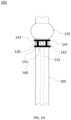
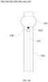
- FIG. 1 Aprovides a front view of a portion of an exemplary tube system, consistent with an embodiment of the present invention
- FIGS. 1 B- 1 Eprovide a cross-sectional views of exemplary tube systems, consistent with embodiments of the present invention
- FIGS. 1 F- 1 Hprovide front views of portions of exemplary tube systems, consistent with embodiments of the present invention
- FIG. 2 Aprovides a cross-section view of another exemplary tube system, consistent with an embodiment of the present invention
- FIG. 2 Bprovides a side view of the exemplary tube system of FIG. 2 A , consistent with an embodiment of the present invention
- FIGS. 3 A- 3 Fshow cross-section views of different embodiments of exemplary tube systems, consistent with embodiments of the present invention
- FIGS. 3 G and 3 Hprovide front views of portions of exemplary tube systems like the exemplary tube systems shown in FIGS. 3 A-F , consistent with an embodiment of the present invention
- FIGS. 3 I and 3 Jprovide front views of portions of exemplary tube systems like the exemplary tube systems, consistent with an embodiment of the present invention
- FIG. 4 Aprovides side view of a portions of exemplary tube systems like the exemplary tube systems shown in FIGS. 3 A and 3 B , consistent with an embodiment of the present invention.
- FIG. 4 Bshows a cross-section view of the embodiment of the exemplary tube system shown in FIG. 4 A , consistent with an embodiment of the present invention.
- Medical devices like tracheal tubes, tracheostomy tubes, laryngeal mask airways, laparoscopic tools, and a cystopic toolssuch as urinary catheters may include a suction line that may be used to evacuate air, liquid (e.g., secretions), and/or other materials from a patient undergoing a medical procedure using one of these medical devices. Evacuation of the air, liquid, or other materials may improve the functionality of the medical device and/or may decrease irritation and/or risk of disease or complications for the patient undergoing a procedure using the medical device. For example, if the liquid and/or other materials are not evacuated from an intubated patient's trachea then, they may begin to pool in the patient's trachea.
- pooling secretionsmay, for example, interfere with the operation of a tracheal tube or tracheostomy tube because, for example, liquid, tissue, and/or foreign matter within a patient's trachea or throat that may occlude a suction line port by, for example, pressing against a suction line port and/or forming a seal around the suction line port thereby preventing the application of negative pressure (i.e., suction) to the patient's trachea.
- negative pressurei.e., suction
- Exemplary medical devices, or tube systems, disclosed hereinmay include one or more spacers affixed to an external surface of tube (e.g., tracheal or tracheostomy) or other portion of the medical device.
- the spacersmay be arranged and/or configured to prevent occlusion of the suction line port by, for example, preventing large (i.e., larger than a portion of a diameter of the suction line port) pieces of material, or bodies from being sucked into, and thereby blocking, the suction line port.
- spacersmay be of differing height and incorporate channels for the passage of air and/or fluid.
- the spacersare smooth and form a smooth seal with the tube of, for example, a tracheal tube and/or tracheostomy tube system.
- the spacersmay provide space (e.g., 0.025 cm-1 cm) between the tube and a patient's tissue (e.g., trachea or airway) by pushing the tissue away from the tube and/or a suction line port of the tube.
- the spacermay prevent patient's tissue from pushing against, or otherwise occlude, the suction line port thereby leaving space in the trachea for fluid and air to be sucked into the suction line port upon application of negative pressure thereto.
- the spacersmay be radio opaque so that they appear on, for example, an X-ray image of the patient's tissue (e.g., trachea).
- tissuee.g., trachea
- the spacers and/or medical devicesare compatible with medical imaging technologies such as magnetic resonance imaging (MRI) and, as such, may not include any significant metal portion.
- MRImagnetic resonance imaging
- FIG. 1 Aprovides a front view of a portion of an exemplary tube system 100 that includes a tube 105 , a suction line 115 that extends down a portion of tube 105 , a spacer 120 , an inflatable balloon 125 , and a suction line port or orifice 130 .
- Tube system 100may be a portion of, for example, a tracheal tube system and/or a tracheostomy tube system.
- Tube 105may be configured to allow air or other gases provided by an artificial ventilation device (coupled to an end of tube 105 ) to flow through tube 105 into the lungs of an intubated (with tube system 100 ) patient.
- Inflatable balloon 125may be inflated via air or another gas passing through an inflation line lumen (not shown) that is coupled to an air supply.
- tube system 100may include a communication line 145 with a first port 150 and a second port 150 .
- Tube system 100may be configured so that first port 150 is outside of an intubated patient's trachea.
- Communication line 145may be configured to have a lumen along its length that allows for the passage of, for example, a material (e.g., gas, chemicals, medications, and/or fluid) therethrough through passive (e.g., exchange of ambient air) or active (e.g., an injection) means.
- the materialmay enter the first port 150 and exit the second port 155 and may thereby enter a subglottic region of an intubated patient.
- Inflatable balloon 125may be positioned between a first end and a second end of tube 105 and may circumferentially surround portion of tube 105 . Inflatable balloon 125 may remain un-inflated, or deflated, until tube system 100 is inserted into a patient's trachea and positioned appropriately therein. Once tube system 100 is properly positioned within the patient's trachea, inflatable balloon 125 may be inflated using air, or another gas, passed through an inflation line (not shown) from an inflation pump (not shown).
- Inflating inflatable balloon 125 to a desired degree of inflation while positioned within the patient's tracheamay serve to stabilize tube system's 100 positioning within the patient's trachea/throat and may also serve to prevent an unintentional, or undesired, gas and/or liquid exchange between the patient's lungs and the patient's trachea and/or outside environment while the patient is intubated.
- Spacer 120may be configured to position tracheal tissue of an intubated patient and/or other foreign matter (e.g., fluid or solids) present in the trachea away from the surface of tube 105 by, for example, exerting a pressure or force thereon. In this way, spacer 120 may serve to prevent, or reduce, occlusion of suction line port 130 by the tracheal tissue and/or foreign matter.
- Spacer 120may be any appropriate shape or combination of shapes including, but not limited to, a circular ring, a semi-circular portion of a ring, and/or an extension projecting from an exterior surface of tube 105 .
- the extensionmay be, for example of a circular, semi-circular, triangular, linear, and/or rectangular shape.
- Spacer 120may have a solid or hollow cross section. At times, spacer 120 may be flexible but, this may not always be the case. Spacer 120 may be made from any appropriate material including, but not limited to, silicon, plastic, and vinyl. Spacer 120 may be an integrated part (i.e., manufactured as, for example, tube 105 is extruded from a fabrication device) of tube system 100 and/or may be affixed to tube 105 following its manufacture via, for example, a chemical, mechanical, and/or heat bonding process. In some instances, spacer 120 may incorporate a smooth tissue facing side to prevent abrasion of an intubated patient's tissue.
- an exemplary spacer 120may be bonded directly to an exterior surface of tube 105 so that portion of an exterior surface of the exemplary spacer is in contact with the exterior surface of tube 105 (see e.g., FIGS. 1 B and 1 C ) and, in other instances, a space (e.g., open area) between spacer 120 and tube 105 may be present (see e.g., FIGS. 1 D and 1 E ).
- spacer 120may be fixed in its configuration and/or position and, in other circumstances, it may be movable and/or deformable.
- Spacer 120may have a cross-sectional width or diameter within the range of 0.1-1.5 cm so that when positioned on, or adjacent to, tube 105 , it extends 0.1-1.5 cm above the exterior surface of tube 105 .
- Spacer 120may be positioned adjacent to and/or above suction line port 130 .
- a spacer 120may include one or more mechanisms (e.g., curves, notches, and/or openings) that assist with the flow of materials (e.g., liquids or solids) into suction line port 130 by, for example, redirecting the negative pressure supplied by the suction line and/or channeling fluids and other material into the suction line opening.
- spacer 120may act as a sieve or screen that prevents relatively large particles from entering (and potentially occluding) suction line port 130 and/or suction line 115 .
- Spacer 120may cover and/or be proximate to all or a portion of suction line port 130 .
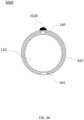
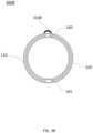
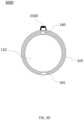
- FIGS. 1 B- 1 Eprovide cross-sectional views of different embodiments of tube system 100 , 100 A, 100 B, 100 C, 100 D, respectively, taken at position A (shown in FIG. 1 A with dashed lines), that employ different exemplary spacers 120 B- 120 E, respectively. Also shown in FIGS. 1 B- 1 E are a central lumen 110 for tube 105 as well as a suction line lumen 160 , an inflation line lumen 165 , and a communication line lumen 170 .
- Suction line lumen 160serves as a lumen through which air, liquid, and other materials may be sucked out of an intubated patient's trachea and inflation line 135 is configured to allow the passage of air therethrough to inflate and/or deflate inflatable balloon 125 .
- Spacer 120 B of FIG. 1 Bis curved in a substantially semi-circular fashion with a shape that aligns with the curved shape of the exterior surface of tube 105 and wraps around a portion of tube 105 .
- Spacer 120 Bmay be configured to and/or positioned on tube 105 to align with a posterior portion of an intubated patient's trachea so that it is present in a place where fluid is more likely to pool in the trachea due to gravitational force on the fluid.
- Spacer 120 C of FIG. 1 Cis circular, or ring-like, in shape and encircles the circumference of tube 105 .
- spacer 120may be bonded to tube 105 in one or more locations and a portion of these spacers 120 may extend away from (e.g., not abut) an exterior surface of tube 105 .
- spacer 120 D of FIG. 1 Dis substantially semi-circular in shape and is bonded to tube 105 on the left and right side of tube 105 (as shown in FIG. 1 D ) so that a portion of spacer 120 D extends away from a portion of the exterior surface of tube 105 with a space therebetween.
- spacer 120 Dmay be flexible so that it may be, for example, compressed toward tube 105 in some circumstances (e.g., when inserting tube system 100 into a patient and/or residing within an intubated patient).
- a spacer 120 E of FIG. 1 Ehas an outer ring 121 that is substantially circular in shape. Outer ring 121 is bonded to tube 105 at multiple locations via a plurality of extensions that extend between outer ring 121 and an exterior surface of tube 105 as shown in FIG. 1 E so that there is empty space between outer ring 121 and tube 105 . Outer ring 121 and/or the extensions connecting outer ring 121 to tube 105 may be flexible in order to, for example, ease insertion of system 100 into a patient's trachea and/or adapt to the anatomy of the patient's tracheal walls. On some occasions, the extensions connecting outer ring 121 to tube 105 may act as a sieve or screen that prohibits suctioning of a particle above a particular size into suction line port 130 .
- a spacer such as spacers 120 , 120 A, 120 B, 120 C, 120 D, and/or 120 Emay be positioned at any appropriate location on tube system 100 .
- spacer 120 , 120 A, 120 B, 120 C, 120 D, and/or 120 Emay be positioned above suction line port 130 (i.e., between suction line port 130 and an end of tube system 100 configured to be positioned outside the body when used) as shown in FIG. 1 A .
- a spacer 120may be positioned below suction line port 130 so that it is positioned between suction line port 130 and an upper portion of inflatable balloon 125 as shown in FIG.
- FIG. 1 Hwhich illustrates an exemplary tube system 101 that may be a portion of, for example, a tracheal tube system and/or a tracheostomy tube system.
- a tube system 102may include two spacers 120 with a first spacer 120 positioned above suction line port 130 and a second spacer positioned below suction line port 130 as shown with exemplary tube system 102 of FIG. 1 G .
- Tube system 102may be a portion of, for example, a tracheal tube system and/or a tracheostomy tube system.
- FIG. 1 Hprovides an additional exemplary tube system 103 that includes an exemplary spacer 140 .
- Tube system 103may be a portion of, for example, a tracheal tube system and/or a tracheostomy tube system.
- Spacer 140includes two rings 141 that encircle tube 105 that are connected to one another by a plurality of extensions 142 . Rings 141 are substantially parallel to one another and are substantially perpendicular to tube 105 . Extensions 142 are substantially perpendicular to rings 141 and substantially parallel to tube 105 . Extensions 142 may be positioned so as to not interfere with suction line port. For example, as shown in FIG. 1 H , extensions 142 are positioned on the left and right sides of suction line port 130 and connect rings 141 to form a shape that looks like a horizontally-oriented extension ladder.
- FIG. 2 Ashows a cross-section view
- FIG. 2 Bshows a front view of another exemplary tube system 200 that includes a longitudinal spacer 210 that is positioned on, and extends longitudinally along a length of, a portion of tube 105 as shown in FIG. 2 B , central lumen 110 for tube 105 , suction line lumen 160 , inflatable balloon 125 , suction line port 130 , and inflation line lumen 165 .
- Tube system 200may be a portion of, for example, a tracheal tube system and/or a tracheostomy tube system.
- Inflatable balloon 125may be inflated via air or another gas passing through an inflation line lumen (not shown) that is coupled to an air supply.
- Longitudinal spacer 210may be molded as part of the manufacturing process (e.g., extrusion of tube 105 including longitudinal spacer 210 ) for tube system 200 . Additionally, or alternatively, longitudinal spacer 210 may be affixed to an exterior surface of tube 105 via a chemical, mechanical, and/or thermal bonding process. Longitudinal spacer 210 may have any appropriate cross-sectional shape including, but not limited to, circular, oval, square, hexagonal, and trapezoidal. Longitudinal spacer 210 may be posited so that it acts prevent, or reduce, occlusion of suction line port 130 . Although longitudinal spacer 210 is show as a continuous spacer, this need not always be the case.
- longitudinal spacer 210may include an array of multiple longitudinal spacers 210 arranged around the exterior surface of tube 105 in a linear, circular, and/or spiral pattern.
- tube system 200may include two or more longitudinal spacers 210 positioned on an exterior surface of tube 105 .
- a first longitudinal spacer 210may be positioned on a left side of a suction line port and a second longitudinal spacer 210 may be positioned on a right side of suction line port 130 . In this way, the two longitudinal spacers 210 may prevent blockage of suction line port 130 by a foreign object being sucked therein.
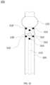
- FIGS. 3 A- 3 Fshow cross-section views of tube systems 300 A, 300 B, 300 C, 300 D, 300 E, and 300 F, respectively and FIGS. 3 G and 3 H show a side view of exemplary tube systems 300 A, 300 B, 300 C, 300 D, 300 E, and 300 F, 301 , 302 , and 303 .
- Tube systems 300 A, 300 B, 300 C, 300 D, 300 E, and 300 F, 301 , 302 , and 303include one or more spacers 310 positioned on and extending from an external surface of tube 105 .
- spacers 310may resemble dimples. At times, spacers 310 may be flexible, compressible, or otherwise deformable.
- Tube systems 300 A, 300 B, 300 C, 300 D, 300 E, and 300 F, 301 , 302 , and 303may be a portion of, for example, a tracheal tube system and/or a tracheostomy tube system.
- One or more spacers 310may be positioned proximate to suction line port 130 .
- Tube systems 300 , 301 , 302 , and 303also include tube 105 , central lumen 110 for tube 105 , suction line lumen 160 , inflatable balloon 125 , suction line port 130 , and inflation line lumen 165 .
- spacer(s) 310may be flexible and/or deformable.
- Inflatable balloon 125may be inflated via air or another gas passing through an inflation line lumen (not shown) that is coupled to an air supply.
- Spacers 310may be positioned on an exterior surface of tube 105 proximate to suction line port 130 in order to, for example, prevent, or reduce a likelihood of, occlusion of suction line port 130 .
- Spacers 310may be of any appropriate shape including, but not limited to, circular, oval, square, hexagonal, and trapezoidal and may be solid or hollow.
- FIG. 3 Aprovides a tube system 300 A with a semi-circularly-shaped spacer 310 A that is solid and
- FIG. 3 Bprovides a tube system 300 B with a semi-circularly-shaped spacer 310 B that is hollow;
- FIG. 3 Cprovides a tube system 300 C with a trapezoid-shaped spacer 310 C that is solid and
- FIG. 3 Dprovides a tube system 300 D with a trapezoid-shaped spacer 310 D that is hollow;
- FIG. 3 Eprovides a tube system 300 E with a rectangularly-shaped spacer 310 E that is solid and
- FIG. 3 Fprovides a tube system 300 F with a rectangularly-shaped spacer 310 F that is hollow.
- tube systems 300 A- 300 Finclude a single spacer 310 A, 310 B, 310 C, 310 D, 310 E, or 310 F, respectively.
- FIGS. 3 H, 3 I, and 3 Jillustrate tube systems 301 , 302 , and 303 , respectively, that include a plurality of spacers 310 (which may resemble, for example, spacers 310 A, 310 B, 310 C, 310 D, 310 E, and/or 310 F).
- the array of spacers 310may extend wholly around the circumference of tube 105 and, in other instances, the array of spacers 310 may extend around a portion (e.g., 30%, 50%, 75%, etc.) of the circumference of tube 105 .
- tube system 301includes a plurality of spacers 310 arranged in a line that is substantially perpendicular to tube 105 and positioned between the upper portion of inflatable balloon 125 and suction line port 130 .
- tube system 302includes a plurality of spacers 310 arranged in two lines that are substantially perpendicular to tube 105 with a first line of spacers 310 being positioned below suction line port 130 (i.e., between the upper portion of inflatable balloon 125 and suction line port 130 ) and a second line of spacers being positioned above suction line port 130 .
- first line of spacers 310being positioned below suction line port 130 (i.e., between the upper portion of inflatable balloon 125 and suction line port 130 ) and a second line of spacers being positioned above suction line port 130 .
- tube system 303includes a plurality of spacers 310 arranged in two zig-zag-like lines that are substantially perpendicular to tube 105 with a first zig-zag line of spacers 310 being positioned below suction line port 130 (i.e., between the upper portion of inflatable balloon 125 and suction line port 130 ) and a second zig-zag line of spacers being positioned above suction line port 130 .
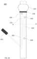
- FIGS. 4 A and 4 Bshow a tube system 400 that includes an volume replacement channel 410 with a first port 415 positioned near inflatable balloon 125 and a second port 420 positioned so that it will be outside of an intubated patient's trachea and, in many instances, outside the patient's body so that ambient air may enter second port 420 , pass through volume replacement channel 410 , and exit through first port 415 .
- the ambient air passing through volume replacement channel 410 and exiting through first port 415may serve as an air supply that may improve the efficacy of suctioning air, liquid, and other matter from the patient's trachea, especially in cases where tracheal tissue or other matter forms an air-tight, or nearly air-tight, seal around tube 105 thereby cutting off a supply of air to be suctioned out via application of negative air pressure to suction line 115 and suction line port 130 .
- Tube system 400also includes tube 105 , central lumen 110 for tube 105 , suction line lumen 160 , inflatable balloon 125 , suction line port 130 , and inflation line lumen 165 , a suction line adapter 425 , and an optional such as spacer 120 .
- volume replacement channel 410may be used as a delivery pathway for a substance (e.g., a pharmaceutical or saline) introduced into second port 420 via, for example, injection into same.
- the substancemay be used to, for example, clean the trachea, clean the endotracheal tube, and/or provide drug delivery to the tracheal area.
Landscapes
- Health & Medical Sciences (AREA)
- Pulmonology (AREA)
- Emergency Medicine (AREA)
- Engineering & Computer Science (AREA)
- Anesthesiology (AREA)
- Biomedical Technology (AREA)
- Heart & Thoracic Surgery (AREA)
- Hematology (AREA)
- Life Sciences & Earth Sciences (AREA)
- Animal Behavior & Ethology (AREA)
- General Health & Medical Sciences (AREA)
- Public Health (AREA)
- Veterinary Medicine (AREA)
- Media Introduction/Drainage Providing Device (AREA)
- Surgical Instruments (AREA)
- Prostheses (AREA)
Abstract
Description
Claims (15)
Priority Applications (1)
| Application Number | Priority Date | Filing Date | Title |
|---|---|---|---|
| US16/686,031US12097325B2 (en) | 2018-11-15 | 2019-11-15 | Systems and devices for preventing occlusion of a suction line resident in a medical device |
Applications Claiming Priority (2)
| Application Number | Priority Date | Filing Date | Title |
|---|---|---|---|
| US201862767939P | 2018-11-15 | 2018-11-15 | |
| US16/686,031US12097325B2 (en) | 2018-11-15 | 2019-11-15 | Systems and devices for preventing occlusion of a suction line resident in a medical device |
Publications (2)
| Publication Number | Publication Date |
|---|---|
| US20200155780A1 US20200155780A1 (en) | 2020-05-21 |
| US12097325B2true US12097325B2 (en) | 2024-09-24 |
Family
ID=70728685
Family Applications (1)
| Application Number | Title | Priority Date | Filing Date |
|---|---|---|---|
| US16/686,031Active2041-09-26US12097325B2 (en) | 2018-11-15 | 2019-11-15 | Systems and devices for preventing occlusion of a suction line resident in a medical device |
Country Status (1)
| Country | Link |
|---|---|
| US (1) | US12097325B2 (en) |
Citations (63)
| Publication number | Priority date | Publication date | Assignee | Title |
|---|---|---|---|---|
| US3583404A (en) | 1969-06-23 | 1971-06-08 | Kendall & Co | Nonblocking catheter |
| US3995643A (en) | 1975-01-13 | 1976-12-07 | Merav Abraham D | Intratracheal tube |
| US4278081A (en) | 1978-02-21 | 1981-07-14 | Jones James W | Tracheal tube |
| US4327721A (en) | 1978-07-07 | 1982-05-04 | George Hanover | Endotracheal tube with topical agent delivery system and method of using the same |
| US4437856A (en) | 1981-02-09 | 1984-03-20 | Alberto Valli | Peritoneal catheter device for dialysis |
| US4693243A (en) | 1983-01-14 | 1987-09-15 | Buras Sharon Y | Conduit system for directly administering topical anaesthesia to blocked laryngeal-tracheal areas |
| US4840173A (en) | 1988-02-22 | 1989-06-20 | Porter Iii John W | Endotracheal tube combination |
| US4973305A (en) | 1989-12-08 | 1990-11-27 | David Goltzer | Method and apparatus for inserting and retaining an epidural catheter |
| US5146916A (en) | 1990-01-05 | 1992-09-15 | Catalani Angelo S | Endotracheal tube incorporating a drug-irrigation device |
| WO1993021816A1 (en) | 1992-05-01 | 1993-11-11 | Shturman Cardiology Systems, Inc. | Inflatable sheath for introduction of ultrasonic catheter |
| US5311864A (en) | 1992-12-11 | 1994-05-17 | Huerta Christine M | Tracheas evacuation and transmittal tube |
| US5389074A (en) | 1993-10-27 | 1995-02-14 | The Regents Of The University Of California | Body insertion tube with anesthetic jacket |
| US5501215A (en) | 1995-05-16 | 1996-03-26 | Huerta; Christine M. | Ventilation tube with evacuation sheath |
| US5513627A (en) | 1995-01-27 | 1996-05-07 | Flam; Gary H. | Esophageal tracheal intubator airway |
| WO1996040339A1 (en) | 1995-06-07 | 1996-12-19 | Mallinckrodt Medical, Inc. | Improved tracheostomy tubes |
| US5715816A (en) | 1993-12-06 | 1998-02-10 | Sensor Devices, Inc. | Oximeter probes and methods for the invasive use thereof |
| US5819723A (en) | 1994-03-02 | 1998-10-13 | Thomas Jefferson University | Methods and apparatus for reducing tracheal infection |
| US6048332A (en) | 1998-10-09 | 2000-04-11 | Ave Connaught | Dimpled porous infusion balloon |
| US6460540B1 (en) | 1999-04-05 | 2002-10-08 | Mark S. Klepper | Endotracheal tube sump |
| US20040116898A1 (en) | 2002-12-05 | 2004-06-17 | Hawk William D. | Endotracheal tube assembly and methods of using same |
| US20040255951A1 (en) | 2003-02-07 | 2004-12-23 | Christopher Grey | Endotrachael tube with suction catheter and system |
| US6837868B1 (en)* | 1998-12-03 | 2005-01-04 | Aleksander Fajnsztajn | Indwelling urinary catheter with base drainage port |
| WO2007130579A2 (en) | 2006-05-04 | 2007-11-15 | Stewart Fermin V G | Endotracheal tube with suction attachment |
| EP1889636A1 (en) | 2005-05-24 | 2008-02-20 | Vladimir Anatolievich Pervak | V. a. pervak antireflexive endotracheal tube |
| US20080047562A1 (en)* | 2004-05-12 | 2008-02-28 | Nellcor Puritan Bennett Incorporated | Endotracheal Tube Having Improved Suction Lumen |
| US20080172120A1 (en) | 2007-01-12 | 2008-07-17 | Calvin Fenn | Endoprosthesis delivery systems and related methods |
| US20080283052A1 (en)* | 2004-05-27 | 2008-11-20 | Young Peter J | Artificial Airway Apparatus |
| US20090260632A1 (en)* | 2008-04-22 | 2009-10-22 | Freddy Abnousi | Endotracheal Tube |
| DE202009016034U1 (en) | 2009-11-24 | 2010-02-18 | Neubauer, Norbert | tracheostomy |
| US7669600B2 (en) | 1996-03-11 | 2010-03-02 | Orlando Morejon | Endotracheal tube cleaning apparatus |
| US20100147309A1 (en) | 2008-12-12 | 2010-06-17 | Cuevas Brian J | Tracheal Catheter With a Flexible Lumen for Subglottic Suctioning |
| US20100269830A1 (en) | 2009-04-24 | 2010-10-28 | Sage Products, Inc. | Fluid Removing Apparatus for Respiratory Tract |
| US20110023884A1 (en) | 2009-07-31 | 2011-02-03 | Cuevas Brian J | Subglottic Suctioning System |
| US20110139159A1 (en) | 2006-11-10 | 2011-06-16 | Nellcor Puritan Bennett Llc | Method and apparatus for preventing occlusion of a tracheal tube suction lumen |
| US20110190737A1 (en)* | 2008-10-20 | 2011-08-04 | Francesco Rocco | Catheter structure |
| US20120000471A1 (en) | 2010-06-30 | 2012-01-05 | Nellcor Puritan Bennett Llc | Tracheal tubes with improved secretion removal systems |
| US20120022380A1 (en) | 2010-01-19 | 2012-01-26 | Chernomorsky Ary S | Methods and apparatus for assesment and treatment of body cavities |
| US20120024293A1 (en) | 2010-07-30 | 2012-02-02 | Nellcor Puritan Bennett Llc | Medical device tube having suction lumen and an associated suctioning system |
| US20120143006A1 (en) | 2009-03-25 | 2012-06-07 | Rafi Avitsian | Endoscopic sheath assembly |
| US8196584B2 (en) | 2006-06-22 | 2012-06-12 | Nellcor Puritan Bennett Llc | Endotracheal cuff and technique for using the same |
| WO2012087837A1 (en) | 2010-12-21 | 2012-06-28 | C. R. Bard, Inc. | Endotracheal tube having a recessed cuff, one or more suction apertures arranged therein, and/or a cuff having stiffeners and method of making and/or using the same |
| US20120215198A1 (en) | 2011-02-18 | 2012-08-23 | Cheney Ronald A | Apparatus and system for administering medication |
| US8357118B2 (en) | 2008-08-26 | 2013-01-22 | Cook Medical Technologies Llc | Balloon catheters having a plurality of needles for the injection of one or more therapeutic agents |
| CN202699807U (en) | 2012-06-28 | 2013-01-30 | 复旦大学附属上海市第五人民医院 | Supraglottic and subglottic secretion suction tracheal catheter |
| US20130060273A1 (en) | 1994-06-29 | 2013-03-07 | Covidien Lp | Extraluminal balloon dissection |
| US20130092171A1 (en)* | 2011-10-17 | 2013-04-18 | Nellcor Puritan Bennett Llc | Multi-lumen tracheal tube with pressure distribution |
| US20130112207A1 (en) | 2011-11-09 | 2013-05-09 | Teleflex Medical Incorporated | Endotracheal tube with dual port subglottic secretion suctioning |
| US20130190706A1 (en) | 2010-12-01 | 2013-07-25 | Daniel Eduard Kleiner | Device for use in endoluminal vacuum therapy |
| US20130211385A1 (en)* | 2010-03-11 | 2013-08-15 | Harrison M. Lazarus | Body cavity drainage devices and related methods |
| US8535265B2 (en) | 2009-12-22 | 2013-09-17 | Kimberly-Clark Worldwide, Inc. | Tracheal catheter with suction lumen port in close proximity to the cuff |
| US20140033455A1 (en) | 2009-02-06 | 2014-02-06 | Endoclear Llc | Visualization systems and methods |
| US20140041665A1 (en)* | 2011-04-28 | 2014-02-13 | Yonsei University Wonju Industry-Academic Cooperation Foundation | Curvature-adjustable endotracheal tube |
| CN203763615U (en) | 2014-03-20 | 2014-08-13 | 牡丹江医学院 | Trachea cannula |
| CN203763616U (en) | 2014-03-20 | 2014-08-13 | 牡丹江医学院 | Sputum scab cleaning machine |
| US20150034078A1 (en)* | 2013-07-31 | 2015-02-05 | Shannon Sovndal | Gum elastic bougie introducer with tactile depth and orientation indicator |
| WO2015042607A1 (en) | 2013-09-23 | 2015-03-26 | Nalini Vadivelu | Medical apparatus with hypopharyngeal suctioning capability |
| US20150101611A1 (en) | 2013-10-10 | 2015-04-16 | Benjamin R. Wang | Tracheal tube |
| US20150101598A1 (en) | 2013-10-10 | 2015-04-16 | NevAp, Inc. | Tracheal tube and suction device |
| US20150101612A1 (en) | 2013-10-10 | 2015-04-16 | Benjamin R. Wang | Tracheal tube |
| US20150209239A1 (en)* | 2012-08-17 | 2015-07-30 | Chris Salvino | Nasogastric tube |
| US20180126106A1 (en)* | 2015-08-10 | 2018-05-10 | Kaipan GUAN | Endotracheal tube comprising pharyngeal suction catheter |
| US10071212B1 (en) | 2011-08-29 | 2018-09-11 | Michael V. Riesberg | Endotracheal tube apparatus and method |
| US20190201662A1 (en)* | 2016-08-10 | 2019-07-04 | Duke University | Occlusion-resistant catheter with occlusion-resistant tip |
- 2019
- 2019-11-15USUS16/686,031patent/US12097325B2/enactiveActive
Patent Citations (67)
| Publication number | Priority date | Publication date | Assignee | Title |
|---|---|---|---|---|
| US3583404A (en) | 1969-06-23 | 1971-06-08 | Kendall & Co | Nonblocking catheter |
| US3995643A (en) | 1975-01-13 | 1976-12-07 | Merav Abraham D | Intratracheal tube |
| US4278081A (en) | 1978-02-21 | 1981-07-14 | Jones James W | Tracheal tube |
| US4327721A (en) | 1978-07-07 | 1982-05-04 | George Hanover | Endotracheal tube with topical agent delivery system and method of using the same |
| US4437856A (en) | 1981-02-09 | 1984-03-20 | Alberto Valli | Peritoneal catheter device for dialysis |
| US4693243A (en) | 1983-01-14 | 1987-09-15 | Buras Sharon Y | Conduit system for directly administering topical anaesthesia to blocked laryngeal-tracheal areas |
| US4840173A (en) | 1988-02-22 | 1989-06-20 | Porter Iii John W | Endotracheal tube combination |
| US4973305A (en) | 1989-12-08 | 1990-11-27 | David Goltzer | Method and apparatus for inserting and retaining an epidural catheter |
| US5146916A (en) | 1990-01-05 | 1992-09-15 | Catalani Angelo S | Endotracheal tube incorporating a drug-irrigation device |
| WO1993021816A1 (en) | 1992-05-01 | 1993-11-11 | Shturman Cardiology Systems, Inc. | Inflatable sheath for introduction of ultrasonic catheter |
| US5311864A (en) | 1992-12-11 | 1994-05-17 | Huerta Christine M | Tracheas evacuation and transmittal tube |
| US5389074A (en) | 1993-10-27 | 1995-02-14 | The Regents Of The University Of California | Body insertion tube with anesthetic jacket |
| US5715816A (en) | 1993-12-06 | 1998-02-10 | Sensor Devices, Inc. | Oximeter probes and methods for the invasive use thereof |
| US5819723A (en) | 1994-03-02 | 1998-10-13 | Thomas Jefferson University | Methods and apparatus for reducing tracheal infection |
| US20130060273A1 (en) | 1994-06-29 | 2013-03-07 | Covidien Lp | Extraluminal balloon dissection |
| US5513627A (en) | 1995-01-27 | 1996-05-07 | Flam; Gary H. | Esophageal tracheal intubator airway |
| US5501215A (en) | 1995-05-16 | 1996-03-26 | Huerta; Christine M. | Ventilation tube with evacuation sheath |
| WO1996040339A1 (en) | 1995-06-07 | 1996-12-19 | Mallinckrodt Medical, Inc. | Improved tracheostomy tubes |
| US7669600B2 (en) | 1996-03-11 | 2010-03-02 | Orlando Morejon | Endotracheal tube cleaning apparatus |
| US6048332A (en) | 1998-10-09 | 2000-04-11 | Ave Connaught | Dimpled porous infusion balloon |
| US6837868B1 (en)* | 1998-12-03 | 2005-01-04 | Aleksander Fajnsztajn | Indwelling urinary catheter with base drainage port |
| US6460540B1 (en) | 1999-04-05 | 2002-10-08 | Mark S. Klepper | Endotracheal tube sump |
| US20040116898A1 (en) | 2002-12-05 | 2004-06-17 | Hawk William D. | Endotracheal tube assembly and methods of using same |
| US20040255951A1 (en) | 2003-02-07 | 2004-12-23 | Christopher Grey | Endotrachael tube with suction catheter and system |
| US20080047562A1 (en)* | 2004-05-12 | 2008-02-28 | Nellcor Puritan Bennett Incorporated | Endotracheal Tube Having Improved Suction Lumen |
| US20080283052A1 (en)* | 2004-05-27 | 2008-11-20 | Young Peter J | Artificial Airway Apparatus |
| EP1889636A1 (en) | 2005-05-24 | 2008-02-20 | Vladimir Anatolievich Pervak | V. a. pervak antireflexive endotracheal tube |
| US20080011304A1 (en) | 2006-05-04 | 2008-01-17 | Stewart Fermin V G | Endotracheal tube with suction attachment |
| WO2007130579A2 (en) | 2006-05-04 | 2007-11-15 | Stewart Fermin V G | Endotracheal tube with suction attachment |
| US8196584B2 (en) | 2006-06-22 | 2012-06-12 | Nellcor Puritan Bennett Llc | Endotracheal cuff and technique for using the same |
| US20110139159A1 (en) | 2006-11-10 | 2011-06-16 | Nellcor Puritan Bennett Llc | Method and apparatus for preventing occlusion of a tracheal tube suction lumen |
| US20080172120A1 (en) | 2007-01-12 | 2008-07-17 | Calvin Fenn | Endoprosthesis delivery systems and related methods |
| US20090260632A1 (en)* | 2008-04-22 | 2009-10-22 | Freddy Abnousi | Endotracheal Tube |
| US8357118B2 (en) | 2008-08-26 | 2013-01-22 | Cook Medical Technologies Llc | Balloon catheters having a plurality of needles for the injection of one or more therapeutic agents |
| US20110190737A1 (en)* | 2008-10-20 | 2011-08-04 | Francesco Rocco | Catheter structure |
| US20100147309A1 (en) | 2008-12-12 | 2010-06-17 | Cuevas Brian J | Tracheal Catheter With a Flexible Lumen for Subglottic Suctioning |
| US20140033455A1 (en) | 2009-02-06 | 2014-02-06 | Endoclear Llc | Visualization systems and methods |
| US20120143006A1 (en) | 2009-03-25 | 2012-06-07 | Rafi Avitsian | Endoscopic sheath assembly |
| US20100269830A1 (en) | 2009-04-24 | 2010-10-28 | Sage Products, Inc. | Fluid Removing Apparatus for Respiratory Tract |
| US20110023884A1 (en) | 2009-07-31 | 2011-02-03 | Cuevas Brian J | Subglottic Suctioning System |
| DE202009016034U1 (en) | 2009-11-24 | 2010-02-18 | Neubauer, Norbert | tracheostomy |
| US8535265B2 (en) | 2009-12-22 | 2013-09-17 | Kimberly-Clark Worldwide, Inc. | Tracheal catheter with suction lumen port in close proximity to the cuff |
| US20120022380A1 (en) | 2010-01-19 | 2012-01-26 | Chernomorsky Ary S | Methods and apparatus for assesment and treatment of body cavities |
| US20130211385A1 (en)* | 2010-03-11 | 2013-08-15 | Harrison M. Lazarus | Body cavity drainage devices and related methods |
| US20120000471A1 (en) | 2010-06-30 | 2012-01-05 | Nellcor Puritan Bennett Llc | Tracheal tubes with improved secretion removal systems |
| US20120024293A1 (en) | 2010-07-30 | 2012-02-02 | Nellcor Puritan Bennett Llc | Medical device tube having suction lumen and an associated suctioning system |
| US20130190706A1 (en) | 2010-12-01 | 2013-07-25 | Daniel Eduard Kleiner | Device for use in endoluminal vacuum therapy |
| WO2012087837A1 (en) | 2010-12-21 | 2012-06-28 | C. R. Bard, Inc. | Endotracheal tube having a recessed cuff, one or more suction apertures arranged therein, and/or a cuff having stiffeners and method of making and/or using the same |
| US20120215198A1 (en) | 2011-02-18 | 2012-08-23 | Cheney Ronald A | Apparatus and system for administering medication |
| US20140041665A1 (en)* | 2011-04-28 | 2014-02-13 | Yonsei University Wonju Industry-Academic Cooperation Foundation | Curvature-adjustable endotracheal tube |
| US10071212B1 (en) | 2011-08-29 | 2018-09-11 | Michael V. Riesberg | Endotracheal tube apparatus and method |
| US20130092171A1 (en)* | 2011-10-17 | 2013-04-18 | Nellcor Puritan Bennett Llc | Multi-lumen tracheal tube with pressure distribution |
| US20130112207A1 (en) | 2011-11-09 | 2013-05-09 | Teleflex Medical Incorporated | Endotracheal tube with dual port subglottic secretion suctioning |
| CN202699807U (en) | 2012-06-28 | 2013-01-30 | 复旦大学附属上海市第五人民医院 | Supraglottic and subglottic secretion suction tracheal catheter |
| US20150209239A1 (en)* | 2012-08-17 | 2015-07-30 | Chris Salvino | Nasogastric tube |
| US20150034078A1 (en)* | 2013-07-31 | 2015-02-05 | Shannon Sovndal | Gum elastic bougie introducer with tactile depth and orientation indicator |
| WO2015042607A1 (en) | 2013-09-23 | 2015-03-26 | Nalini Vadivelu | Medical apparatus with hypopharyngeal suctioning capability |
| US20150101611A1 (en) | 2013-10-10 | 2015-04-16 | Benjamin R. Wang | Tracheal tube |
| US20150101598A1 (en) | 2013-10-10 | 2015-04-16 | NevAp, Inc. | Tracheal tube and suction device |
| US20150101612A1 (en) | 2013-10-10 | 2015-04-16 | Benjamin R. Wang | Tracheal tube |
| US9327091B2 (en) | 2013-10-10 | 2016-05-03 | Nev Ap, Inc. | Tracheal tube and suction device |
| US9446213B2 (en) | 2013-10-10 | 2016-09-20 | NevAp, Inc. | Tracheal tube |
| US9579475B2 (en) | 2013-10-10 | 2017-02-28 | NevAp, Inc. | Tracheal tube |
| CN203763616U (en) | 2014-03-20 | 2014-08-13 | 牡丹江医学院 | Sputum scab cleaning machine |
| CN203763615U (en) | 2014-03-20 | 2014-08-13 | 牡丹江医学院 | Trachea cannula |
| US20180126106A1 (en)* | 2015-08-10 | 2018-05-10 | Kaipan GUAN | Endotracheal tube comprising pharyngeal suction catheter |
| US20190201662A1 (en)* | 2016-08-10 | 2019-07-04 | Duke University | Occlusion-resistant catheter with occlusion-resistant tip |
Non-Patent Citations (6)
| Title |
|---|
| Covidien, TaperGuard Endotracheal and Specialty Tubes, 2014, Date Retrieved Oct. 29, 2 pages. |
| International Search Report and Written Opinion of the International Searching Authority, Patent Cooperation Treaty (Jan. 16, 2018), PCT/US2017/056393, 15 pgs. |
| International Search Report and Written Opinion of the International Searching Authority, Patent Cooperation Treaty (Jan. 28, 2015), PCT/US2014/059958, 13 pgs. |
| Kimberly-Clark Worldwide, Inc, Kimvent Closed Suction Systems, Date Retrieved Oct. 29, 2014, 4 pages. |
| Smiths Medical, SACETT Suction Above Cuff ET Tube, Date Retrieved Oct. 29, 2014, 9 pages. |
| Teleflex, Inc, Teleflex ISIS HVT, the First Convertible Endotracheal Tube, Date Retrieved Oct. 29, 2014, 2 pages. |
Also Published As
| Publication number | Publication date |
|---|---|
| US20200155780A1 (en) | 2020-05-21 |
Similar Documents
| Publication | Publication Date | Title |
|---|---|---|
| US20210386949A1 (en) | Secretion clearing patient airway management system | |
| US8535265B2 (en) | Tracheal catheter with suction lumen port in close proximity to the cuff | |
| US9480537B2 (en) | Self positioning tracheal tube clearance mechanism using a collar | |
| US20100147309A1 (en) | Tracheal Catheter With a Flexible Lumen for Subglottic Suctioning | |
| EP0592442B1 (en) | Endotracheal tube having ventilation means | |
| US11607513B2 (en) | Suction devices for medical devices and medical device systems including suction devices | |
| US20160136374A1 (en) | Tracheal tube positioning devices and methods | |
| CN109475668B (en) | catheter dynamic end occlusion | |
| US9987449B2 (en) | Suction catheter device and method | |
| JPH09108354A (en) | Trachea system | |
| US20150209536A1 (en) | Endotracheal tube with dual port subglottic secretion suctioning | |
| US20100269830A1 (en) | Fluid Removing Apparatus for Respiratory Tract | |
| US12097325B2 (en) | Systems and devices for preventing occlusion of a suction line resident in a medical device | |
| US20110265798A1 (en) | Medical device tube having spaced lumens and an associated ported adapter | |
| KR102215835B1 (en) | Intubation tube having self cleaning property | |
| HK1147451A1 (en) | Medical apparatus with hypopharyngeal suctioning capability |
Legal Events
| Date | Code | Title | Description |
|---|---|---|---|
| FEPP | Fee payment procedure | Free format text:ENTITY STATUS SET TO UNDISCOUNTED (ORIGINAL EVENT CODE: BIG.); ENTITY STATUS OF PATENT OWNER: SMALL ENTITY | |
| FEPP | Fee payment procedure | Free format text:ENTITY STATUS SET TO SMALL (ORIGINAL EVENT CODE: SMAL); ENTITY STATUS OF PATENT OWNER: SMALL ENTITY | |
| STPP | Information on status: patent application and granting procedure in general | Free format text:APPLICATION DISPATCHED FROM PREEXAM, NOT YET DOCKETED | |
| STPP | Information on status: patent application and granting procedure in general | Free format text:DOCKETED NEW CASE - READY FOR EXAMINATION | |
| STPP | Information on status: patent application and granting procedure in general | Free format text:NON FINAL ACTION MAILED | |
| STPP | Information on status: patent application and granting procedure in general | Free format text:RESPONSE TO NON-FINAL OFFICE ACTION ENTERED AND FORWARDED TO EXAMINER | |
| STPP | Information on status: patent application and granting procedure in general | Free format text:NON FINAL ACTION MAILED | |
| STPP | Information on status: patent application and granting procedure in general | Free format text:FINAL REJECTION MAILED | |
| STPP | Information on status: patent application and granting procedure in general | Free format text:RESPONSE AFTER FINAL ACTION FORWARDED TO EXAMINER | |
| STPP | Information on status: patent application and granting procedure in general | Free format text:DOCKETED NEW CASE - READY FOR EXAMINATION | |
| STPP | Information on status: patent application and granting procedure in general | Free format text:NON FINAL ACTION MAILED | |
| STPP | Information on status: patent application and granting procedure in general | Free format text:RESPONSE TO NON-FINAL OFFICE ACTION ENTERED AND FORWARDED TO EXAMINER | |
| STPP | Information on status: patent application and granting procedure in general | Free format text:NOTICE OF ALLOWANCE MAILED -- APPLICATION RECEIVED IN OFFICE OF PUBLICATIONS | |
| AS | Assignment | Owner name:NEVAP, INC., CALIFORNIA Free format text:ASSIGNMENT OF ASSIGNORS INTEREST;ASSIGNOR:HANLON, BRENTON;REEL/FRAME:067710/0939 Effective date:20240611 | |
| AS | Assignment | Owner name:NEVAP, INC., CALIFORNIA Free format text:ASSIGNMENT OF ASSIGNORS INTEREST;ASSIGNOR:WANG, BENJAMIN R.;REEL/FRAME:068035/0789 Effective date:20240719 | |
| STCF | Information on status: patent grant | Free format text:PATENTED CASE |