US12096955B2 - Intravascular catheter having an expandable incising portion and abrasive surfaces - Google Patents
Intravascular catheter having an expandable incising portion and abrasive surfacesDownload PDFInfo
- Publication number
- US12096955B2 US12096955B2US17/728,214US202217728214AUS12096955B2US 12096955 B2US12096955 B2US 12096955B2US 202217728214 AUS202217728214 AUS 202217728214AUS 12096955 B2US12096955 B2US 12096955B2
- Authority
- US
- United States
- Prior art keywords
- expandable portion
- struts
- inner sleeve
- catheter device
- blood vessel
- Prior art date
- Legal status (The legal status is an assumption and is not a legal conclusion. Google has not performed a legal analysis and makes no representation as to the accuracy of the status listed.)
- Active, expires
Links
- 210000004204blood vesselAnatomy0.000claimsabstractdescription41
- 238000000034methodMethods0.000claimsabstractdescription11
- 239000000463materialSubstances0.000claimsdescription33
- 230000003143atherosclerotic effectEffects0.000claimsdescription32
- 238000002399angioplastyMethods0.000claimsdescription7
- 230000002792vascularEffects0.000claimsdescription3
- 229910003460diamondInorganic materials0.000claimsdescription2
- 239000010432diamondSubstances0.000claimsdescription2
- 239000000428dustSubstances0.000claimsdescription2
- 210000001367arteryAnatomy0.000claims1
- 230000002093peripheral effectEffects0.000claims1
- 230000001681protective effectEffects0.000description24
- 239000000853adhesiveSubstances0.000description7
- 230000001070adhesive effectEffects0.000description7
- 239000010935stainless steelSubstances0.000description7
- 229910001220stainless steelInorganic materials0.000description7
- -1but not limited toSubstances0.000description6
- 239000004698PolyethyleneSubstances0.000description5
- HLXZNVUGXRDIFK-UHFFFAOYSA-Nnickel titaniumChemical compound[Ti].[Ti].[Ti].[Ti].[Ti].[Ti].[Ti].[Ti].[Ti].[Ti].[Ti].[Ni].[Ni].[Ni].[Ni].[Ni].[Ni].[Ni].[Ni].[Ni].[Ni].[Ni].[Ni].[Ni].[Ni]HLXZNVUGXRDIFK-UHFFFAOYSA-N0.000description5
- 229910001000nickel titaniumInorganic materials0.000description5
- 229920000573polyethylenePolymers0.000description5
- 229920002554vinyl polymerPolymers0.000description5
- 201000001320AtherosclerosisDiseases0.000description4
- 238000005299abrasionMethods0.000description4
- 239000000560biocompatible materialSubstances0.000description4
- 230000000694effectsEffects0.000description3
- 230000003902lesionEffects0.000description3
- 230000000007visual effectEffects0.000description3
- 208000007536ThrombosisDiseases0.000description2
- 238000004891communicationMethods0.000description2
- 238000013467fragmentationMethods0.000description2
- 238000006062fragmentation reactionMethods0.000description2
- 238000003780insertionMethods0.000description2
- 230000037431insertionEffects0.000description2
- 239000000126substanceSubstances0.000description2
- 208000037260Atherosclerotic PlaqueDiseases0.000description1
- 208000017667Chronic DiseaseDiseases0.000description1
- 229910000677High-carbon steelInorganic materials0.000description1
- 229920002614Polyether block amidePolymers0.000description1
- 229910000831SteelInorganic materials0.000description1
- 238000005452bendingMethods0.000description1
- 230000015572biosynthetic processEffects0.000description1
- 230000017531blood circulationEffects0.000description1
- 210000000748cardiovascular systemAnatomy0.000description1
- 239000000919ceramicSubstances0.000description1
- 239000011248coating agentSubstances0.000description1
- 238000000576coating methodMethods0.000description1
- 230000003247decreasing effectEffects0.000description1
- 239000012634fragmentSubstances0.000description1
- 238000012978minimally invasive surgical procedureMethods0.000description1
- 238000012986modificationMethods0.000description1
- 229920000642polymerPolymers0.000description1
- 239000012858resilient materialSubstances0.000description1
- 238000007788rougheningMethods0.000description1
- 239000007787solidSubstances0.000description1
- 239000010959steelSubstances0.000description1
- 238000004381surface treatmentMethods0.000description1
- 238000001356surgical procedureMethods0.000description1
Images


Classifications
- A—HUMAN NECESSITIES
- A61—MEDICAL OR VETERINARY SCIENCE; HYGIENE
- A61B—DIAGNOSIS; SURGERY; IDENTIFICATION
- A61B17/00—Surgical instruments, devices or methods
- A61B17/32—Surgical cutting instruments
- A61B17/3205—Excision instruments
- A61B17/3207—Atherectomy devices working by cutting or abrading; Similar devices specially adapted for non-vascular obstructions
- A61B17/320725—Atherectomy devices working by cutting or abrading; Similar devices specially adapted for non-vascular obstructions with radially expandable cutting or abrading elements
- A—HUMAN NECESSITIES
- A61—MEDICAL OR VETERINARY SCIENCE; HYGIENE
- A61B—DIAGNOSIS; SURGERY; IDENTIFICATION
- A61B17/00—Surgical instruments, devices or methods
- A61B17/32—Surgical cutting instruments
- A61B17/3205—Excision instruments
- A61B17/3207—Atherectomy devices working by cutting or abrading; Similar devices specially adapted for non-vascular obstructions
- A61B17/32075—Pullback cutting; combined forward and pullback cutting, e.g. with cutters at both sides of the plaque
- A—HUMAN NECESSITIES
- A61—MEDICAL OR VETERINARY SCIENCE; HYGIENE
- A61B—DIAGNOSIS; SURGERY; IDENTIFICATION
- A61B17/00—Surgical instruments, devices or methods
- A61B17/32—Surgical cutting instruments
- A61B17/3209—Incision instruments
- A—HUMAN NECESSITIES
- A61—MEDICAL OR VETERINARY SCIENCE; HYGIENE
- A61B—DIAGNOSIS; SURGERY; IDENTIFICATION
- A61B17/00—Surgical instruments, devices or methods
- A61B2017/00982—General structural features
- A61B2017/00986—Malecots, e.g. slotted tubes, of which the distal end is pulled to deflect side struts
- A—HUMAN NECESSITIES
- A61—MEDICAL OR VETERINARY SCIENCE; HYGIENE
- A61B—DIAGNOSIS; SURGERY; IDENTIFICATION
- A61B17/00—Surgical instruments, devices or methods
- A61B17/32—Surgical cutting instruments
- A61B2017/320004—Surgical cutting instruments abrasive
- A—HUMAN NECESSITIES
- A61—MEDICAL OR VETERINARY SCIENCE; HYGIENE
- A61B—DIAGNOSIS; SURGERY; IDENTIFICATION
- A61B90/00—Instruments, implements or accessories specially adapted for surgery or diagnosis and not covered by any of the groups A61B1/00 - A61B50/00, e.g. for luxation treatment or for protecting wound edges
- A61B90/06—Measuring instruments not otherwise provided for
- A61B2090/061—Measuring instruments not otherwise provided for for measuring dimensions, e.g. length
- A—HUMAN NECESSITIES
- A61—MEDICAL OR VETERINARY SCIENCE; HYGIENE
- A61B—DIAGNOSIS; SURGERY; IDENTIFICATION
- A61B90/00—Instruments, implements or accessories specially adapted for surgery or diagnosis and not covered by any of the groups A61B1/00 - A61B50/00, e.g. for luxation treatment or for protecting wound edges
- A61B90/08—Accessories or related features not otherwise provided for
- A61B2090/0807—Indication means
- A61B2090/0811—Indication means for the position of a particular part of an instrument with respect to the rest of the instrument, e.g. position of the anvil of a stapling instrument
Definitions
- This inventionrelates in general to intravascular catheters, such as can be used during minimally invasive surgical procedures.
- this inventionrelates to an intravascular catheter having an expandable incising portion.
- Atherosclerosisis a chronic condition in which atheromatous plaque accumulates on the inner walls of a blood vessel. As a result, the blood vessel walls can become inflamed and, over time, may harden to form atherosclerotic lesions that cause a narrowing of the vessel lumen. In severe cases, the atherosclerotic lesions can rupture and induce the formation of thrombus (i.e., blood clots), which can prevent blood flow through the narrowed vessel lumen.
- thrombusi.e., blood clots
- an angioplastyis a procedure in which a balloon catheter is inserted into a narrowed region of the vessel lumen via a delivery catheter.
- the balloon catheterincludes a flexible tube having an inflatable balloon at an end thereof. Once positioned in the narrowed region, the balloon is inflated in order to dilate the narrowed vessel lumen.
- the pressure in the balloonis generally sufficient to compress the accumulated plaque.
- an intravascular catheterhaving an expandable portion that can be selectively controlled by a user and adapted to create incisions in atherosclerotic material to facilitate fragmentation of the material during an angioplasty procedure.
- the catheter deviceincludes a catheter tube having an expandable portion with a plurality of struts each defining an outer surface.
- the expandable portionis operable between a closed position, wherein the expandable portion has a first diameter, and an opened position, wherein the expandable portion has a second diameter that is larger than the first diameter.
- An incising elementis provided on the outer surface of at least one of the struts. The incising element has a sharpened edge that extends outwardly in a radial direction from the outer surface of the strut for creating an incision in atherosclerotic material located within a blood vessel when the expandable portion is in the opened position.
- This inventionalso relates to an intravascular catheter having an expandable portion and also having abrasive surfaces.
- the abrasive surfacesmay be located on the outer surface of the struts and may be configured to score, roughen, or remove through micro-abrasion of atherosclerotic material when the expandable portion is in the opened position and moved longitudinally within a blood vessel.
- the abrasive surfacemay be located on any portion of one or more struts and may be used with or without the incising elements.
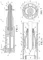
- FIG. 1is a plan view of a catheter device that includes a handle assembly and a catheter tube having an expandable incising portion, in accordance with a first embodiment of this invention.
- FIG. 2is a cross-sectional side view of the handle assembly taken along section line 2 - 2 shown in FIG. 1 when the catheter device is in a first operating mode.
- FIG. 3is an enlarged cross-sectional side view of the catheter tube taken along section line 3 - 3 shown in FIG. 1 illustrating the expandable incising portion disposed within a blood vessel.
- FIG. 4is a cross-sectional end view of the expandable incising portion taken along section line 4 - 4 shown in FIG. 3 .
- FIG. 5is a cross-sectional side view of the handle assembly taken along section line 2 - 2 shown in FIG. 1 when the catheter device is in a second operating mode.
- FIG. 6is an enlarged cross-sectional side view of the catheter tube taken along section line 3 - 3 shown in FIG. 1 illustrating the expandable incising portion in an opened position.
- FIG. 7is a cross-sectional end view of the expandable incising portion taken along section line 7 - 7 shown in FIG. 6 .
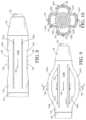
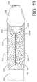
- FIG. 8is an enlarged side view of a catheter tube having an expandable incising portion, in accordance with a second embodiment of this invention.
- FIG. 9is a side view of the catheter tube shown in FIG. 8 illustrating the expandable incising portion in an opened position.
- FIG. 10is a cross-sectional end view of the expandable incising portion taken along section line 10 - 10 shown in FIG. 9 .
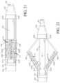
- FIG. 11is an enlarged side view of a catheter tube having an expandable incising portion, in accordance with a third embodiment of this invention.
- FIG. 12is a side view of the catheter tube shown in FIG. 11 illustrating the expandable incising portion in an opened position.
- FIG. 13is an end view of the catheter tube as shown in FIG. 12 .
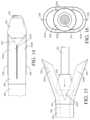
- FIG. 14is an enlarged side view of a catheter tube having an expandable incising portion, in accordance with a fourth embodiment of this invention.
- FIG. 15is a side view of the catheter tube shown in FIG. 14 illustrating the expandable incising portion in an opened position.
- FIG. 16is an end view of the catheter tube as shown in FIG. 15 .
- FIG. 17is a side view of another exemplary embodiment of the device of FIG. 8 .
- FIG. 18is a side view of the device of FIG. 17 illustrated in an opened position.
- FIG. 19is a side view of another exemplary embodiment of the device of FIG. 8 .
- FIG. 20is a side view of the device of FIG. 19 illustrated in an opened position.
- FIG. 23is a side view of another exemplary embodiment of the device of FIG. 14 .
- FIG. 1a catheter device, indicated generally at 10 , in accordance with this invention.
- the illustrated catheter device 10is configured to treat or reduce the risks associated with atherosclerosis.
- the catheter device 10includes an expandable incising portion that can be inserted into a blood vessel and expanded to create incisions in atherosclerotic material that has accumulated on inner walls of the blood vessel. The incisions facilitate the fragmentation of the atherosclerotic material during a subsequent angioplasty or atherectomy procedure.
- the catheter device 10will be described and illustrated in the context of treating atherosclerosis, it should be appreciated that the catheter device 10 can be used in any desired environment and for any desired purpose.
- the illustrated catheter device 10includes a handle assembly, indicated generally at 20 .
- the illustrated handle assembly 20includes an elongated, cylindrical handle body 21 .
- the handle body 21may alternatively have any other shape that is suitable for easy handling by a surgeon.
- the handle body 21can be made from any suitably rigid material including, but not limited to, stainless steel or polymers.
- the illustrated handle body 21defines an internal chamber 22 .
- a passage 23extends into an end portion of the handle body 21 for communication with the internal chamber 22 .
- the handle body 21further includes a slot 24 that extends through a side wall thereof for communication with the internal chamber 22 .
- the illustrated slot 24may have any length or width as desired.
- an indicator 24 Amay be provided on the handle body 21 adjacent to the slot 24 .
- the indicator 24 Acan be a visual scale or any other indicating means, the purpose of which will be explained below.
- the illustrated handle assembly 20also includes a control member 25 that is supported on the handle body 21 for sliding movement within the slot 24 .
- the control member 25is movable between a forward position (shown in FIG. 2 ), a rearward position (shown in FIG. 5 ), or any position therebetween, which will be further explained below.
- the illustrated control member 25includes a base portion 26 that is disposed within the internal chamber 22 of the handle body 21 .
- the base portion 26may define an outer cross-sectional shape that generally corresponds with a cross-sectional shape of the internal chamber 22 , although such is not required.
- control member 25may be movably supported on the handle body 21 by a bearing, a bushing, a guide rail, or any other structural means.
- control member 25may be supported for rotational movement, pivotal movement, or any other type of movement relative to the handle body 21 , the purpose of which will become apparent below.
- the visual indicator 24 Ais configured to identify the relative position of the control member 25 with respect to the handle body 21 .
- the illustrated handle assembly 20also includes a locking mechanism 27 that is configured to temporarily secure the control member 25 in a desired position, although such is not required.
- the illustrated locking mechanism 27includes a plurality of protrusions that are spaced apart from one another along an inner surface of the slot 24 .
- the control member 25frictionally engages the protrusions to hold the control member 25 in the desired position.
- the locking mechanism 27may be a threaded fastener, a pivotal latch, a push-button release, or any other mechanism that is configured to secure the control member 25 in a desired position.
- the illustrated catheter device 10also includes a catheter tube 30 that extends from the handle assembly 20 .
- the catheter tube 30is an elongated, flexible member having a proximal end that is secured to the handle assembly 20 and a distal end that extends therefrom.
- the catheter tube 30can be made from any biocompatible material including, but not limited to, polyvinyl, polyethylene, nitinol, or stainless steel. Further, the catheter tube 30 can have any outer diameter, length, or wall thickness.
- the proximal end of the catheter tube 30is secured to the handle body 21 and communicates with the internal cavity 22 through the passage 23 .
- the catheter tube 30may be secured to the handle body 21 using a flanged connection, a fused connection, an adhesive, a press-fit connection, a threaded connection, or any other securing means.
- the catheter tube 30may be secured to the handle body 21 using a connector or any other type of attachment device.
- an expandable portion 32is provided on the distal end of the catheter tube 30 .
- the illustrated expandable portion 32is a cylindrical member having a longitudinal axis.
- the expandable portion 32can be made from a generally resilient material that is able to flex between various positions, such as polyvinyl, polyethylene, nitinol, or stainless steel.
- the expandable portion 32can be secured to the catheter tube 30 in any manner including, but not limited to, a fused connection, an adhesive, a press-fit connection, a threaded connection, or any other securing means.
- the expandable portion 32can be integrally formed from the catheter tube 30 .
- the expandable portion 32can have any outer diameter, length, or wall thickness.
- the illustrated expandable portion 32has a pair of struts 34 A and 34 B.
- the illustrated struts 34 A and 34 Bare separated by a pair of longitudinally extending slits 35 A and 35 B that extend through side walls of the expandable portion 32 .
- the slits 35 A and 35 Bare equally spaced apart from one another around the circumference of the expandable portion 32 such that the struts 34 A and 34 B have the same circumferential widths, although such is not required.
- the struts 34 A and 34 Bmay have any length, circumferential width, or cross-sectional shape as desired.
- the illustrated expandable portion 32also includes a pair of incising elements 36 that are respectively provided along outer surfaces of the struts 34 A and 34 B.
- the incising elements 36can be atherotomes or other incising members having arcuate shaped sharpened edges, for example, that are configured to create incisions in atherosclerotic material as will be explained below.
- the illustrated incising elements 36extend parallel with the longitudinal axis of the expandable portion 32 and outwardly in a radial direction therefrom.
- the incising elements 36are equally spaced apart from one another around the circumference of the expandable portion 32 .
- the expandable portion 32may, however, have any number or configuration of incising elements 36 provided around the circumference thereof.
- the incising elements 36can have any cross-sectional shape, longitudinal length, or height and can be made from any suitable material including, but not limited to, tempered steel, stainless steel, high carbon steel, or ceramics.
- the incising elements 36can be molded with the struts 34 A and 34 B or may otherwise be secured thereto in any manner such as, for example, using a welded or soldered connection, an adhesive, or any other fastening means.
- the distal end of the expandable portion 32may optionally include a tip member 38 .
- the illustrated tip member 38has a generally conical shape that facilitates insertion of the catheter tube 30 within a blood vessel 50 (see FIGS. 3 and 4 ) and subsequent travel therethrough.
- the tip member 38may, however, have any desired shape.
- An aperturemay axially extend through the tip member 38 , the purpose of which will be explained below.
- the tip member 38can be integrally formed with the expandable portion 32 or may be secured thereto, such as with an adhesive or the like. Further, the tip member 38 can be made from any biocompatible material including, but not limited to, polyvinyl, polyethylene, nitinol, stainless steel, or polyether block amide.
- the illustrated catheter device 10also includes an inner sleeve 40 , although such is not required.
- the inner sleeve 40is a flexible, tubular member that is supported for sliding movement within the catheter tube 30 , the purpose of which will be explained below.
- the inner sleeve 40can be made from any biocompatible material including, but not limited to, polyvinyl, polyethylene, nitinol, stainless steel, or a woven material. Further, the inner sleeve 40 can have any outer diameter, length, or wall thickness.
- the inner sleeve 40need not be a tubular member but may alternatively be a solid wire, a braided wire, or the like.
- a proximal end of the inner sleeve 40extends from the catheter tube 30 and into the internal chamber 22 of the handle body 21 .
- the proximal end of the inner sleeve 40is secured to the base portion 26 of the control member 25 for sliding movement therewith, the purpose of which will be explained below.
- the inner sleeve 40can be secured to the base portion 26 by a flanged connection, a fused connection, an adhesive, a threaded connection, or any other securing means.
- the inner sleeve 40extends through an entire length of the catheter tube 30 .
- a distal end of the inner sleeve 40 that is opposite the handle assembly 20is secured to the tip member 38 , which is in turn secured to the expandable portion 32 .
- the inner sleeve 40may be secured to the tip member 38 in any manner including, but not limited to, a fused connection, an adhesive, a fastener, or the like.
- the illustrated catheter device 10also includes a protective sheath 42 that is supported for sliding movement along an outer surface of the catheter tube 30 , although such is not required.
- the protective sheath 42can be made from any biocompatible material including, but not limited to, polyvinyl, polyethylene, nitinol, or stainless steel. Further, the protective sheath 42 can have any outer diameter, length, or wall thickness. The purpose of the protective sheath 42 will be explained below.
- the illustrated protective sheath 42includes a flange 44 that facilitates sliding movement of the protective sheath 42 relative to the catheter tube 30 .
- the illustrated flange 44is an annular member that is located at an end of the protective sheath 42 nearest the handle assembly 20 .
- the flange 44can be integrally formed with the protective sheath 42 or may otherwise be secured thereto in any manner, such as with an adhesive or the like. It should be appreciated that the flange 44 can have any shape or may alternatively be configured in any manner to accomplish the functions described herein and below.
- the catheter device 10is illustrated in a first operating mode.
- the control member 25 on the handle assembly 20is located in the forward position relative to the handle body 21 .
- the inner sleeve 40fully extends into the catheter tube 30 such that the expandable portion 32 is in a closed position, as shown in FIGS. 3 and 4 .
- the struts 34 A and 34 Bare generally parallel with one another and with the inner sleeve 40 .
- the slits 35 A and 35 B(illustrated by the dashed lines in FIG. 3 ) remain in a generally closed configuration.
- the expandable portion 32defines an initial diameter D 1 , which is generally the same diameter as the remaining length of the catheter tube 30 .
- the initial diameter D 1 of the expandable portion 32may, however, be any desired dimension.
- the distal end of the catheter tube 30can be percutaneously inserted into a blood vessel 50 , as shown in FIGS. 3 and 4 .
- the illustrated catheter tube 30is then advanced through the blood vessel 50 along a guide wire 52 , which extends through the catheter device 10 .
- the guide wire 52may fully extend through the inner sleeve 40 , into the internal chamber 22 of the handle body 21 , and exit a rear end of the handle assembly 20 (see FIG. 2 ).
- the catheter tube 30is advanced along the guide wire 52 until the expandable portion 32 is positioned in a narrowed region of the blood vessel 50 caused by atherosclerotic material 54 .
- the catheter tube 30can be inserted into the blood vessel 50 and guided therethrough by a delivery catheter (not shown) or any other suitable procedure.
- the optional protective sheath 42is preferably positioned over the expandable portion 32 , thereby preventing the incising elements 36 from coming into contact with inner walls of the blood vessel 50 .
- the incising elements 36can be exposed by sliding the protective sheath 42 back from the distal end of the catheter tube 30 , as indicated by the direction arrows in FIG. 3 .
- the illustrated protective sheath 42can be moved in this manner by pulling the flange 44 towards the handle assembly 20 , which is indicated by the direction arrows in FIG. 2 .
- the catheter device 10is illustrated in a second operating mode.
- the control member 25is moved from the forward position to the rearward position, as indicated by the direction arrow in FIG. 5 .
- the inner sleeve 40is drawn within the catheter tube 30 thereby reducing the relative length of the inner sleeve 40 with respect to the catheter tube 30 .
- the distal end of the inner sleeve 40is attached to the tip member 38 , as described above, causing the expandable portion 32 to become axially compressed between the tip member 38 and the distal end of the catheter tube 30 .
- the struts 34 A and 34 Bbow or expand outwardly in a generally arcuate fashion thereby defining an opened position.
- the expandable portion 32defines a second diameter D 2 that is larger than the initial diameter D 1 when the expandable portion 32 is in the closed position.
- the incising elements 36are respectively positioned along the radially outer most surfaces of the struts 34 A and 34 B.
- the outer most surfaces of the struts 34 A and 34 Bmay define a generally flat portion along a length thereof in the opened position, the purpose of which will be explained below, although such is not required.
- the struts 34 A and 34 Bcan have any lengths such that the expandable portion 32 can achieve a desired overall second diameter D 2 in the opened position.
- the second diameter D 2can be increased or decreased by selective movement of the control member 25 between the forward and rearward positions. For example, a larger second diameter D 2 can be achieved by moving the control member 25 further towards the rearward position. Conversely, a smaller second diameter D 2 can be achieved by moving the control member 25 further towards the forward position.
- the visual indicator 24 Acan be used to identify the instantaneous second diameter D 2 of the expandable portion 32 .
- the struts 34 A and 34 Bmay be biased in the opened position so as to automatically expand outwardly to the second diameter D 2 when the protective sheath 42 is slid back from the expandable portion 32 .
- sliding movement of the protective sheath 42 relative to the struts 34 A and 34 Bcan be used to selectively control the second diameter D 2 .
- the inner sleeve 40 and the movable components of the handle assembly 20may not be necessary.
- the expandable portion 32can be pulled along the guide wire 52 through the narrowed region of the blood vessel 50 . This can be accomplished by pulling on the handle assembly 20 . In doing so, the incising elements 36 engage the atherosclerotic material 54 and create longitudinal incisions 56 therein. As shown in FIGS. 6 and 7 , the outer surface area of the arcuate shaped struts 34 A and 34 B, which is adjacent to the incising element 36 , is configured to ride along a surface of the atherosclerotic material 54 , thereby limiting the depth of the incisions 56 and preventing the incising members 36 from cutting the walls of the blood vessel 50 .
- the expandable portion 32can be moved any distance along the guide wire 52 to create incisions 56 having any desired length. After the incisions 56 are made in the atherosclerotic material 54 , the catheter device 10 can be returned to the first operating mode (shown in FIGS. 1 through 4 ) by moving the control member 25 to the forward position. In doing so, the expandable portion 32 returns to the closed position.
- the protective sheath 42can be slid over the expandable portion 32 and the catheter tube 30 may be removed from the blood vessel 50 .
- the catheter device 10can be used to create additional incisions 56 in the atherosclerotic material 54 .
- the expandable portion 32can be relocated within the narrowed region of the blood vessel 50 .
- the catheter tube 30can then be rotated within the blood vessel 50 by rotating the handle assembly 20 so as to align the incising elements 36 with other portions of the atherosclerotic material 54 .
- the previous stepscan then be repeated any number of times to make multiple passes through the narrowed region of the blood vessel 50 and create additional incisions in the atherosclerotic material 54 .
- the illustrated catheter device 10is advantageous in many respects.
- the second diameter D 2 of the expandable portion 32can be selectively controlled by operation of the handle assembly 20 or by sliding movement of the protective sheath 42 .
- Thisenables the catheter device 10 to be adapted for use in blood vessels 50 of different sizes or varying diameters.
- the illustrated catheter device 10can apply varying magnitudes of radial forces to the atherosclerotic material 54 by controlling the amount of force being applied to the control member 25 on the handle assembly 20 .
- Thisenables the catheter device 10 to generate sufficient radial force to create incisions 56 in atherosclerotic material 54 while reducing the potential for tearing the walls of the blood vessel 50 .
- the catheter device 10can be used to make any number of passes during a single procedure to make multiple incisions 56 in atherosclerotic material 54 of varying lengths and shapes.
- FIGS. 8 through 10there is illustrated a catheter tube 130 having an expandable portion 132 , in accordance with a second embodiment of this invention.
- the catheter tube 130 and the expandable portion 132may include any structural features as described and illustrated above in the previous embodiment, although such is not required. Similar features have been numbered with common reference numerals but have been increased by 100 (i.e., 110, 120, 130, etc.). It should be appreciated that similar features are structured similarly, operate similarly, and/or have the same function unless otherwise indicated by the drawings or this specification.
- the catheter tube 130may extend from a handle assembly (not shown) as described above in the first embodiment.
- the expandable portion 132is provided on a distal end of the catheter tube 130 and may include a tip member 138 .
- the catheter tube 130may also include an inner sleeve 140 and a protective sheath (not shown), which is also described above in the first embodiment.
- the expandable portion 132includes four struts 134 A, 134 B, 134 C, and 134 D that are respectively separated by four longitudinally extending slits 135 A, 135 B, 135 C, and 135 D.
- the illustrated struts 134 A, 134 B, 134 C, and 134 Deach include an incising element 136 , although such is not required. It should be appreciated that the expandable portion 132 may have any number or configuration of struts and incising elements as desired.
- the illustrated expandable portion 132further includes recessed portions 160 that respectively extend into the outer surfaces of the struts 134 A, 134 B, 134 C, and 134 D.
- the struts 134 A, 134 B, 134 C, and 134 Dcan be slightly bowed inwardly toward the inner sleeve 140 when in the closed position or, alternatively, may have a reduced thickness along a central portion thereof to create the recessed portions 160 .
- the illustrated incising elements 136are respectively disposed within the recessed portions 160 .
- the recessed portions 160help to prevent the incising elements 136 from coming into contact with inner walls of the blood vessel.
- the incising elements 136become exposed from the recessed portions 160 .
- the recessed portions 160can eliminate or reduce the need for the protective sheath (not shown).
- the guide wire 152may extend through the entire device.
- the expandable portion 132can be operated between a closed position (shown in FIG. 8 ) and an opened position (shown in FIGS. 9 and 10 ) by selective movement of the inner sleeve 140 relative to the catheter tube 130 , as described above in the first embodiment.
- the struts 134 A, 134 B, 134 C, and 134 Dcan be biased in the opened position.
- the protective sheath(not shown) can be used to effect movement of the expandable portion 132 between the closed position and the opened position.
- FIGS. 11 through 13there is illustrated a catheter tube 230 having an expandable portion 232 , in accordance with a third embodiment of this invention.
- the catheter tube 230 and the expandable portion 232may include any structural features as described and illustrated above in the previous embodiments, although such is not required. Similar features have been numbered with common reference numerals but have been increased by 200 (i.e., 210, 220, 230, etc.). It should be appreciated that similar features are structured similarly, operate similarly, and/or have the same function unless otherwise indicated by the drawings or this specification.
- the catheter tube 230may extend from a handle assembly (not shown) as described above in the first embodiment.
- the expandable portion 232is provided on a distal end of the catheter tube 230 and includes a pair of struts 234 A and 234 B that are separated by a pair of longitudinally extending slits 235 A and 235 B.
- the catheter tube 230may also include a tip member 238 , an inner sleeve 240 , and a protective sheath (not shown), which is described above in the first embodiment.
- the guide wire 252may extend through the entire device.
- the expandable portion 232includes a first pair of weakened regions 237 A, 237 B and a second pair of weakened regions 239 A, 239 B that are respectively located at opposite ends of the struts 234 A and 234 B.
- the illustrated weakened regions 237 A, 237 B and 239 A, 239 Bare formed by enlarged apertures that extend through side walls of the expandable portion 232 that function as hinges.
- the weakened regions 237 A, 237 B and 239 A, 239 Bmay help reduce the amount of bending stress in the side walls of the expandable portion 232 when the struts 234 A and 234 B are moved to an opened position.
- the struts 234 A and 234 Bmay include any number or configuration of weakened regions. Further, it should be appreciated that any of the other embodiments in this disclosure may also include weakened regions 237 A, 237 B and 239 A, 239 B.
- the illustrated struts 234 A and 234 Bremain generally flat along respective lengths thereof in both a closed position (shown in FIG. 11 ) and an opened position (shown in FIGS. 12 and 13 ) so as to form an apex, although such a configuration is not required.
- the incising elements 236are provided along the generally flat portion of the respective struts 234 A and 234 B. As such, the incising elements 236 may also function as stiffening members for increasing the strength of the struts 234 A and 234 B. Further, this configuration can reduce the amount of stress in the connection between the incising elements 236 and the struts 234 A and 234 B, which may otherwise be caused by bowing of the struts 234 A and 234 B.
- end portions of the incising elements 236may extend beyond the apex that is formed by each of the respective struts 234 A and 234 B.
- This configurationcan increase the effective height of the incising elements 236 when the expandable portion 232 is in the opened position.
- the incising elements 236may have a reduced height when the expandable portion 232 is in the closed position, which may eliminate the need for the protective sheath (not shown).
- the expandable portion 232can be operated between the closed position and the opened position by selective movement of the inner sleeve 240 relative to the catheter tube 230 , as described above in the first embodiment.
- the struts 234 A and 234 Bcan be biased in the opened position.
- the protective sheath(not shown) can be used to effect movement of the expandable portion 232 between the closed position and the opened position.
- FIGS. 14 through 16there is illustrated a catheter tube 330 having an expandable portion 332 , in accordance with a fourth embodiment of this invention.
- the catheter tube 330 and the expandable portion 332may include any structural features as described and illustrated above in the previous embodiments, although such is not required. Similar features have been numbered with common reference numerals but have been increased by 300 (i.e., 310, 320, 330, etc.). It should be appreciated that similar features are structured similarly, operate similarly, and/or have the same function unless otherwise indicated by the drawings or this specification.
- the catheter tube 330may extend from a handle assembly (not shown) as described above in the first embodiment.
- the expandable portion 332is provided on a distal end of the catheter tube 330 and may include a tip member 338 .
- the catheter tube 330may also include an inner sleeve 340 that is attached to the tip member 338 and a protective sheath (not shown), which is also described above in the first embodiment.
- the guide wire 352may extend through the entire device.
- the expandable portion 332includes a pair of struts 334 A and 334 B that are supported thereon in a cantilevered manner (i.e., not attached to one another or to the tip member 338 at their distal ends), the purpose of which will be explained below.
- the struts 334 A and 334 Bare separated by a pair of longitudinally extending slits 335 A and 335 B that extend from the end of the expandable portion 332 .
- a pair of incising elements 336is respectively provided along outer surfaces of the struts 334 A and 334 B. It should be appreciated, however, that the expandable portion 332 may have any number or configuration of struts and incising elements as desired.
- the illustrated struts 334 A and 334 Bare supported on the expandable portion 332 so that they can be splayed open in a Y-shaped configuration.
- the struts 334 A and 334 Bcan be splayed open by drawing the inner sleeve 340 within the catheter tube 330 , as described above in the first embodiment. In doing so, the tip member 338 slides along the inner surfaces of the struts 334 A and 334 B and pivots them outwardly.
- the struts 334 A and 334 Bcan be biased in the splayed open position.
- the protective sheath(not shown) can be used to effect movement of the expandable portion 332 between a closed position and the splayed open position.
- the struts 334 A and 334 Bremain generally flat along their respective lengths in both a closed position (shown in FIG. 14 ) and the splayed open position, although such is not required.
- the incising elements 336may also function as stiffening members for increasing the strength of the struts 334 A and 334 B. Further, this configuration can reduce the amount of stress in the connection between the incising elements 336 and the struts 334 A and 334 B, which may otherwise be caused by bowing of the struts 334 A and 334 B.
- end portions of the incising elements 336may extend beyond the distal ends of the respective struts 334 A and 334 B. This configuration can increase the effective height of the incising elements 336 when the expandable portion 332 is in the splayed open position. As such, the incising elements 336 may have a reduced height when the expandable portion 332 is in the closed position, which may eliminate the need for the protective sheath (not shown).
- FIGS. 17 - 28illustrate various exemplary embodiments of the present invention comprising an abrasive surface 142 .
- FIGS. 17 - 18for example, illustrate the device of FIGS. 8 - 9 , respectively, but additionally comprising the abrasive surface 142 .
- the abrasive surface 142may be any abrasive substance added to the surface of the struts 134 A-C.
- the abrasive surface 142may be a coating or a surface treatment (for example, roughening) performed on the surface of the struts 134 A-C.
- diamond dustmay be added to the surface of the struts 134 A-C or the surface of the struts 134 A-C may be roughened to produce burrs.
- the abrasive surface 142may be of any grit size, though exemplary embodiments may be a 30-70 micron grit, inclusive.
- the abrasive surface 142may extend over the entire length or over any portion of the struts 134 A-C.
- the abrasive surface 142may be limited to the area around the incising element 136 , the proximal half of the struts 134 A-C, or the distal half of the struts 134 A-C.
- the abrasive surface 142may be located on any number of the struts 134 A-C.
- the abrasive surface 142may be configured to contact and score, roughen, move, micro-abrade and/or otherwise abrade atherosclerotic material 54 located in the blood vessel 50 when the expandable portion 132 is placed in the opened position and moved axially forwards and/or backwards through the blood vessel 50 .
- Any type of abrasion where a substance is broken into smaller particulateis contemplated.
- the atherosclerotic material 54is abraded into very fine particulate, preferably on the micron order of magnitude though any type of abrasion into any size particulate is contemplated.
- the present inventionmay additionally be configured and/or used to abrade other structures or blockages located within or that form a part of the vascular system. More specifically, the incising element 136 may enter the atherosclerotic material 54 , thus fragmenting it, while the struts 134 A-C and the abrasive surface 142 thereon may ride across the surface of the atherosclerotic material 54 , thus abrading it. In other exemplary embodiments of the present invention where the incising elements 136 are not used, the abrasive surface 142 may simply abrade the surface of the atherosclerotic material 54 by lateral movement of the expandable portion 132 .
- the abrasive surface 142may abrade the atherosclerotic material 54 into sufficiently small pieces that it can be reabsorbed by the body, such as but not limited to through the blood vessel 50 wall, or travel safely through the vascular system.
- the abrasive surface 142may abrade the atherosclerotic material 54 to facilitate and enhance the effectiveness of further treatment, such as but not limited, angioplasty.
- the abrasive surface 142may break the surface tension on the atherosclerotic material 54 , thus making subsequent angioplasty more effective.
- FIGS. 19 - 20illustrate that the abrasive surface 142 may be used without the incising element 136 .
- FIGS. 21 - 22illustrate an exemplary use of the abrasive surface 242 on the embodiments illustrated in FIGS. 11 - 13 .
- the abrasive surface 242is only illustrated on the proximal end of the struts 234 A-B where the incising element 236 is located, though as previously discussed, the abrasive surface 242 may be located on any portion of the struts 234 A-B and may be used with or without the incising element 236 .
- FIG. 23illustrates an exemplary use of the abrasive surface 342 with the cantilevered embodiment illustrated in FIGS. 14 - 16 .
- the abrasive surface 342covers substantially all of the struts 334 A and 334 B, though as previously discussed, the abrasive surfaces 342 may cover any portion of any number of the struts 334 A and 334 B and may be used with or without the incising element 336 .
- FIGS. 17 - 23incorporating the abrasive surface 142 , 242 , and 342 , respectively are merely exemplary. It is contemplated that the abrasive surface 142 , 242 , and 342 may be used with any of the embodiments shown and described herein.
Landscapes
- Health & Medical Sciences (AREA)
- Surgery (AREA)
- Life Sciences & Earth Sciences (AREA)
- Medical Informatics (AREA)
- Nuclear Medicine, Radiotherapy & Molecular Imaging (AREA)
- Engineering & Computer Science (AREA)
- Biomedical Technology (AREA)
- Heart & Thoracic Surgery (AREA)
- Molecular Biology (AREA)
- Animal Behavior & Ethology (AREA)
- General Health & Medical Sciences (AREA)
- Public Health (AREA)
- Veterinary Medicine (AREA)
- Vascular Medicine (AREA)
- Surgical Instruments (AREA)
- Media Introduction/Drainage Providing Device (AREA)
Abstract
Description
Claims (20)
Priority Applications (1)
| Application Number | Priority Date | Filing Date | Title |
|---|---|---|---|
| US17/728,214US12096955B2 (en) | 2017-02-24 | 2022-04-25 | Intravascular catheter having an expandable incising portion and abrasive surfaces |
Applications Claiming Priority (2)
| Application Number | Priority Date | Filing Date | Title |
|---|---|---|---|
| US15/441,398US11357533B2 (en) | 2011-09-13 | 2017-02-24 | Intravascular catheter having an expandable incising portion and abrasive surfaces |
| US17/728,214US12096955B2 (en) | 2017-02-24 | 2022-04-25 | Intravascular catheter having an expandable incising portion and abrasive surfaces |
Related Parent Applications (1)
| Application Number | Title | Priority Date | Filing Date |
|---|---|---|---|
| US15/441,398ContinuationUS11357533B2 (en) | 2011-09-13 | 2017-02-24 | Intravascular catheter having an expandable incising portion and abrasive surfaces |
Publications (2)
| Publication Number | Publication Date |
|---|---|
| US20220240974A1 US20220240974A1 (en) | 2022-08-04 |
| US12096955B2true US12096955B2 (en) | 2024-09-24 |
Family
ID=61256859
Family Applications (1)
| Application Number | Title | Priority Date | Filing Date |
|---|---|---|---|
| US17/728,214Active2038-02-03US12096955B2 (en) | 2017-02-24 | 2022-04-25 | Intravascular catheter having an expandable incising portion and abrasive surfaces |
Country Status (3)
| Country | Link |
|---|---|
| US (1) | US12096955B2 (en) |
| EP (1) | EP3366239B1 (en) |
| ES (1) | ES2831026T3 (en) |
Families Citing this family (6)
| Publication number | Priority date | Publication date | Assignee | Title |
|---|---|---|---|---|
| EP3600090B1 (en)* | 2017-03-20 | 2021-09-15 | Covidien LP | Tissue-removing catheter with abrasive burr having portion free from abrasive exterior surface |
| EP4018946A1 (en) | 2017-05-03 | 2022-06-29 | Medtronic Vascular, Inc. | Tissue-removing catheter |
| US11690645B2 (en) | 2017-05-03 | 2023-07-04 | Medtronic Vascular, Inc. | Tissue-removing catheter |
| US11819236B2 (en) | 2019-05-17 | 2023-11-21 | Medtronic Vascular, Inc. | Tissue-removing catheter |
| CN111759364B (en)* | 2020-06-17 | 2023-11-10 | 复旦大学附属华山医院 | A vascular chronic occlusive lesion positioning system |
| CN113331919B (en)* | 2021-07-13 | 2022-09-06 | 迈得诺医疗科技集团有限公司 | Device and system for removing blood vessel caking |
Citations (179)
| Publication number | Priority date | Publication date | Assignee | Title |
|---|---|---|---|---|
| US2655154A (en) | 1952-12-05 | 1953-10-13 | Richter Bruno | Valvulotome |
| US3557794A (en) | 1968-07-30 | 1971-01-26 | Us Air Force | Arterial dilation device |
| US3704711A (en) | 1971-06-30 | 1972-12-05 | Sang C Park | Catheter |
| US4273128A (en) | 1980-01-14 | 1981-06-16 | Lary Banning G | Coronary cutting and dilating instrument |
| WO1981002109A1 (en) | 1980-01-30 | 1981-08-06 | T Fogarty | Variable length dilatation catheter apparatus and method |
| US4292974A (en) | 1980-01-30 | 1981-10-06 | Thomas J. Fogarty | Dilatation catheter apparatus and method |
| US4654027A (en) | 1985-10-30 | 1987-03-31 | Dragan William B | Vascular dilating device |
| US5030201A (en) | 1989-11-24 | 1991-07-09 | Aubrey Palestrant | Expandable atherectomy catheter device |
| US5074817A (en) | 1989-09-07 | 1991-12-24 | Samsung Electron Devices Co., Ltd. | Method for manufacturing an electroluminescence display |
| US5074871A (en) | 1989-12-07 | 1991-12-24 | Evi Corporation | Catheter atherotome |
| US5100425A (en) | 1989-09-14 | 1992-03-31 | Medintec R&D Limited Partnership | Expandable transluminal atherectomy catheter system and method for the treatment of arterial stenoses |
| US5154724A (en) | 1990-05-14 | 1992-10-13 | Andrews Winston A | Atherectomy catheter |
| US5156610A (en) | 1989-08-18 | 1992-10-20 | Evi Corporation | Catheter atherotome |
| US5178625A (en) | 1989-12-07 | 1993-01-12 | Evi Corporation | Catheter atherotome |
| US5211651A (en) | 1989-08-18 | 1993-05-18 | Evi Corporation | Catheter atherotome |
| US5224945A (en) | 1992-01-13 | 1993-07-06 | Interventional Technologies, Inc. | Compressible/expandable atherectomy cutter |
| US5244619A (en) | 1991-05-03 | 1993-09-14 | Burnham Warren R | Method of making catheter with irregular inner and/or outer surfaces to reduce travelling friction |
| US5246421A (en) | 1992-02-12 | 1993-09-21 | Saab Mark A | Method of treating obstructed regions of bodily passages |
| US5250060A (en) | 1992-06-26 | 1993-10-05 | Carbo Paul L | Angioplasty apparatus |
| US5282484A (en) | 1989-08-18 | 1994-02-01 | Endovascular Instruments, Inc. | Method for performing a partial atherectomy |
| US5312427A (en) | 1992-10-16 | 1994-05-17 | Shturman Cardiology Systems, Inc. | Device and method for directional rotational atherectomy |
| US5318576A (en) | 1992-12-16 | 1994-06-07 | Plassche Jr Walter M | Endovascular surgery systems |
| US5376100A (en) | 1991-12-23 | 1994-12-27 | Lefebvre; Jean-Marie | Rotary atherectomy or thrombectomy device with centrifugal transversal expansion |
| WO1995002370A2 (en) | 1993-07-15 | 1995-01-26 | Aws Shakir Mustafa Salim | Tunnelling catheter |
| US5514093A (en) | 1994-05-19 | 1996-05-07 | Scimed Life Systems, Inc. | Variable length balloon dilatation catheter |
| EP0727194A1 (en) | 1995-02-20 | 1996-08-21 | Schneider (Europe) Ag | Balloon catheter and stent delivery system. |
| WO1996039997A2 (en) | 1995-06-07 | 1996-12-19 | Stentco, Inc. | Device and method for delivering and deploying intraluminal devices |
| US5591194A (en) | 1994-02-18 | 1997-01-07 | C. R. Bard, Inc. | Telescoping balloon catheter and method of use |
| US5658309A (en) | 1995-05-01 | 1997-08-19 | C. R. Bard, Inc. | Guidewire/inflation tube locking apparatus and method of use |
| US5665098A (en) | 1992-11-09 | 1997-09-09 | Endovascular Instruments, Inc. | Unitary removal of plaque |
| US5697948A (en) | 1994-05-13 | 1997-12-16 | Endovascular Systems, Inc. | Device for delivering and deploying intraluminal devices |
| US5697944A (en) | 1995-11-15 | 1997-12-16 | Interventional Technologies Inc. | Universal dilator with expandable incisor |
| US5728123A (en) | 1995-04-26 | 1998-03-17 | Lemelson; Jerome H. | Balloon actuated catheter |
| US5728067A (en) | 1989-01-30 | 1998-03-17 | C. R. Bard, Inc. | Rapidly exchangeable coronary catheter |
| US5733296A (en) | 1996-02-06 | 1998-03-31 | Devices For Vascular Intervention | Composite atherectomy cutter |
| US5766192A (en) | 1995-10-20 | 1998-06-16 | Zacca; Nadim M. | Atherectomy, angioplasty and stent method and apparatus |
| US5792158A (en) | 1995-11-15 | 1998-08-11 | Lary; Banning Gray | University dilator with expandable incisor |
| US5800450A (en) | 1996-10-03 | 1998-09-01 | Interventional Technologies Inc. | Neovascularization catheter |
| US5836868A (en) | 1992-11-13 | 1998-11-17 | Scimed Life Systems, Inc. | Expandable intravascular occlusion material removal devices and methods of use |
| US5876448A (en) | 1992-05-08 | 1999-03-02 | Schneider (Usa) Inc. | Esophageal stent |
| WO1999018862A1 (en) | 1997-10-10 | 1999-04-22 | Hearten Medical, Inc. | A catheter device for abrading a patent foramen ovale and method of using the device |
| US5961536A (en) | 1997-10-14 | 1999-10-05 | Scimed Life Systems, Inc. | Catheter having a variable length balloon and method of using the same |
| US5968064A (en) | 1997-02-28 | 1999-10-19 | Lumend, Inc. | Catheter system for treating a vascular occlusion |
| US6071287A (en) | 1998-12-23 | 2000-06-06 | Medtronic, Inc. | Introducer for single operator stent delivery system |
| US6129708A (en) | 1989-01-30 | 2000-10-10 | Medtronic Ave, Inc. | Rapidly exchangeable coronary catheter |
| US6165187A (en) | 1989-08-18 | 2000-12-26 | Endo Vascular Instruments, Inc. | Method of enlarging a lumen of an artery |
| US6217549B1 (en) | 1997-02-28 | 2001-04-17 | Lumend, Inc. | Methods and apparatus for treating vascular occlusions |
| US20010007059A1 (en) | 1999-07-13 | 2001-07-05 | Daryush Mirzaee | Local drug delivery injection catheter daryush mirzaee |
| US6258108B1 (en) | 1996-09-13 | 2001-07-10 | Interventional Technologies, Inc. | Incisor-dilator with tapered balloon |
| US6270489B1 (en) | 1999-07-01 | 2001-08-07 | Catheter Innovations, Inc. | Anti-clotting methods and apparatus for indwelling catheter tubes |
| US20020010489A1 (en) | 2000-07-24 | 2002-01-24 | Jeffrey Grayzel | Stiffened balloon catheter for dilatation and stenting |
| US20020029052A1 (en) | 2000-04-07 | 2002-03-07 | Bacchus Vascular, Inc. | Methods and device for percutaneous remote endarterectomy |
| US20020143362A1 (en) | 1997-09-26 | 2002-10-03 | Macoviak John A. | Cerebral embolic protection assembly and method of use |
| US20020143350A1 (en) | 1998-04-10 | 2002-10-03 | Heitzmann Harold A. | Rotational atherectomy system with stationary cutting elements |
| WO2002078511A2 (en) | 2001-03-30 | 2002-10-10 | Nanopass Ltd. | Inflatable medical device with combination cutting elements and drug delivery conduits |
| US20020161394A1 (en) | 1997-09-26 | 2002-10-31 | Macoviak John A. | Aortic filter catheter |
| US6527740B1 (en) | 1999-12-22 | 2003-03-04 | Advanced Cardiovascular Systems, Inc. | Medical regrooming and drug delivery device |
| US20030069547A1 (en) | 2001-10-09 | 2003-04-10 | Bertrand Gonon | Catheter with retractable perforating or injecting end tool |
| US20030125756A1 (en) | 2001-10-19 | 2003-07-03 | Leonid Shturman | Rotational angioplasty device with abrasive crown |
| US6599267B1 (en) | 2000-12-22 | 2003-07-29 | Advanced Cardiovascular Systems, Inc. | Transluminal injection device for intravascular drug delivery |
| US20030144677A1 (en) | 2002-01-25 | 2003-07-31 | Lary Banning Gray | Reciprocating cutting and dilating balloon |
| US20030208215A1 (en) | 2002-05-06 | 2003-11-06 | Renan Uflacker | Intraluminal cutter for vascular, biliary and other applications |
| US6692466B1 (en) | 2000-12-21 | 2004-02-17 | Advanced Cardiovascular Systems, Inc. | Drug delivery catheter with retractable needle |
| US20040034384A1 (en) | 2001-08-08 | 2004-02-19 | Kohei Fukaya | Expansion catheter |
| US6695863B1 (en) | 1995-06-07 | 2004-02-24 | Advanced Cardiovascular Systems, Inc. | Sheath for an adjustable length balloon |
| US6719773B1 (en) | 1998-06-01 | 2004-04-13 | Kyphon Inc. | Expandable structures for deployment in interior body regions |
| US20040122457A1 (en) | 2002-12-23 | 2004-06-24 | Scimed Life Systems, Inc. | Medical cutting devices and methods of use |
| US20040204738A1 (en) | 2003-04-10 | 2004-10-14 | Scimed Life Systems, Inc. | Vessel occluding material extractor |
| US20040267345A1 (en) | 2003-06-30 | 2004-12-30 | Lorenzo Juan A. | Balloon catheter with self-centering tip |
| US20050055077A1 (en) | 2003-09-05 | 2005-03-10 | Doron Marco | Very low profile medical device system having an adjustable balloon |
| US6884257B1 (en) | 2000-11-28 | 2005-04-26 | Advanced Cardiovascular Systems, Inc. | Stent delivery system with adjustable length balloon |
| US20050149159A1 (en) | 2003-12-23 | 2005-07-07 | Xtent, Inc., A Delaware Corporation | Devices and methods for controlling and indicating the length of an interventional element |
| US20050149102A1 (en) | 2003-12-22 | 2005-07-07 | Radisch Herbert R.Jr. | Medical device systems |
| US20050151304A1 (en) | 2004-01-08 | 2005-07-14 | Abbott Laboratories Vascular Enterprises Limited | Method of trimming a balloon of a balloon catheter |
| US20050240176A1 (en) | 2002-10-25 | 2005-10-27 | Regents Of The University Of Michigan | Ablation catheters |
| US20060020285A1 (en) | 2004-07-22 | 2006-01-26 | Volker Niermann | Method for filtering blood in a vessel with helical elements |
| US20060089637A1 (en) | 2004-10-14 | 2006-04-27 | Werneth Randell L | Ablation catheter |
| US20060111736A1 (en) | 2004-11-23 | 2006-05-25 | Kelley Greg S | Serpentine cutting blade for cutting balloon |
| US20060116701A1 (en) | 2004-11-29 | 2006-06-01 | Crow Loren M | Balloon catheter with controlled depth incising blade |
| US20060184191A1 (en) | 2005-02-11 | 2006-08-17 | Boston Scientific Scimed, Inc. | Cutting balloon catheter having increased flexibility regions |
| US7108704B2 (en) | 1992-04-07 | 2006-09-19 | Johns Hopkins University | Percutaneous mechanical fragmentation catheter system |
| US7131981B2 (en) | 2003-03-25 | 2006-11-07 | Angiodynamics, Inc. | Device and method for converting a balloon catheter into a cutting balloon catheter |
| US20060253148A1 (en) | 2005-05-04 | 2006-11-09 | Leone James E | Apparatus and method of using an occluder for embolic protection |
| US20070005093A1 (en) | 2005-07-01 | 2007-01-04 | Cox John A | System for tissue dissection and retraction |
| US7172614B2 (en) | 2002-06-27 | 2007-02-06 | Advanced Cardiovascular Systems, Inc. | Support structures for embolic filtering devices |
| US20070060863A1 (en) | 2005-09-15 | 2007-03-15 | Kara Goeken | Multi-layer medical balloons |
| US20070083194A1 (en) | 2005-06-20 | 2007-04-12 | Kunis Christopher G | Ablation catheter |
| US20070106215A1 (en) | 2005-11-01 | 2007-05-10 | Cook Incorporated | Angioplasty cutting device and method for treating a stenotic lesion in a body vessel |
| US20070156225A1 (en) | 2003-12-23 | 2007-07-05 | Xtent, Inc. | Automated control mechanisms and methods for custom length stent apparatus |
| US20070181157A1 (en) | 2006-02-07 | 2007-08-09 | Dadourian Daniel G | Apparatus and methods for flushing medical devices |
| WO2007095125A2 (en) | 2006-02-14 | 2007-08-23 | C. R. Bard, Inc. | Coaxial pta balloon |
| US7279002B2 (en) | 2003-04-25 | 2007-10-09 | Boston Scientific Scimed, Inc. | Cutting stent and balloon |
| US7303572B2 (en) | 2004-12-30 | 2007-12-04 | Cook Incorporated | Catheter assembly with plaque cutting balloon |
| US20080140051A1 (en) | 2006-12-06 | 2008-06-12 | Guidant Endovascular Solutions | Highly trackable balloon catheter system and method for collapsing an expanded medical device |
| US20080294116A1 (en) | 2005-11-18 | 2008-11-27 | Wolter James T | Coatable Compositions, Coatings Derived Therefrom and Microarrays Having Such Coatings |
| US20080300610A1 (en) | 2007-05-31 | 2008-12-04 | Cook Incorporated | Device for treating hardened lesions and method of use thereof |
| US20080300594A1 (en) | 2007-05-31 | 2008-12-04 | Olympus Medical Systems Corp. | Incision tool |
| US20090099583A1 (en) | 2007-10-11 | 2009-04-16 | Keith Butterfield | Pleurabrade device |
| US20090105686A1 (en) | 2007-06-29 | 2009-04-23 | Xtent, Inc. | Adjustable-length drug delivery balloon |
| US20090192508A1 (en) | 1997-04-07 | 2009-07-30 | Asthmatx, Inc. | Modification of airways by application of mechanical energy |
| US20090204068A1 (en) | 2007-12-06 | 2009-08-13 | Abbott Cardiovascular Systems Inc. | Agent delivery catheter having an inflation bridge between two axially spaced balloons |
| US20090254172A1 (en) | 2008-04-03 | 2009-10-08 | Grewe David D | Self cleaning devices, systems and methods of use |
| US20090306690A1 (en)* | 2008-06-05 | 2009-12-10 | Cardiovascular Systems, Inc. | Abrasive nose cone with expandable cutting and sanding region for rotational atherectomy device |
| US20090312807A1 (en) | 2008-06-13 | 2009-12-17 | The Foundry, Llc | Methods and apparatus for joint distraction |
| US20100010521A1 (en) | 2008-07-10 | 2010-01-14 | Cook Incorporated | Cutting balloon with movable member |
| US20100023035A1 (en) | 2008-07-22 | 2010-01-28 | Cook Incorporated | Multi-stranded apparatus for treating a medical condition |
| US20100076482A1 (en) | 2008-09-25 | 2010-03-25 | Shu Mark C S | Emboli guarding device |
| US7686824B2 (en) | 2003-01-21 | 2010-03-30 | Angioscore, Inc. | Apparatus and methods for treating hardened vascular lesions |
| US7691086B2 (en) | 2005-06-14 | 2010-04-06 | Tengiz Tkebuchava | Catheter for introduction of medications to the tissues of a heart or other organ |
| US7708753B2 (en) | 2005-09-27 | 2010-05-04 | Cook Incorporated | Balloon catheter with extendable dilation wire |
| US20100121270A1 (en) | 2008-11-12 | 2010-05-13 | Gunday Erhan H | Resector Balloon System |
| US20100168778A1 (en) | 2007-06-08 | 2010-07-01 | Braido Peter N | Devices for transcatheter prosthetic heart valve implantation and access closure |
| US20100168737A1 (en) | 2008-12-30 | 2010-07-01 | Debby Esther Grunewald | Catheter with multiple electrode assemblies for use at or near tubular regions of the heart |
| US7850710B2 (en) | 2006-05-23 | 2010-12-14 | St. Jude Medical Puerto Rico Llc | Puncture closure apparatuses, sealing plugs, and related methods |
| US20100330147A1 (en) | 2009-06-26 | 2010-12-30 | Abbott Cardiovascular Systems Inc. | Drug Delivery Compositions Including Nanoshells For Triggered Drug Release |
| US7887557B2 (en) | 2003-08-14 | 2011-02-15 | Boston Scientific Scimed, Inc. | Catheter having a cutting balloon including multiple cavities or multiple channels |
| US20110060182A1 (en) | 2007-04-27 | 2011-03-10 | Cvdevices, Llc | Systems for engaging a bodily tissue and methods of using the same |
| US7914549B2 (en) | 2007-01-05 | 2011-03-29 | Hesham Morsi | Mechanical embolectomy and suction catheter |
| US20110152683A1 (en) | 2011-03-01 | 2011-06-23 | Gerrans Lawrence J | Abrading Balloon Catheter for Extravasated Drug Delivery |
| US20110160645A1 (en) | 2009-12-31 | 2011-06-30 | Boston Scientific Scimed, Inc. | Cryo Activated Drug Delivery and Cutting Balloons |
| US20110184447A1 (en) | 2010-01-26 | 2011-07-28 | Warsaw Orthopedic, Inc. | Surgical cutting tool and method |
| US20110288479A1 (en) | 2010-05-18 | 2011-11-24 | Cook, Incorporated | Balloon With Integral Retention of A Dilation Element |
| US20120053485A1 (en) | 2010-09-01 | 2012-03-01 | Salient Surgical Technologies, Inc. | Catheter Having Needle And Expandable Support Member And Methods Of Use |
| US20120143054A1 (en) | 2009-04-13 | 2012-06-07 | Eaton Elizabeth A | Coated balloon catheter |
| US20120150142A1 (en) | 2010-12-08 | 2012-06-14 | Boston Scientific Scimed, Inc. | Drug Eluting Balloons with Ability for Double Treatment |
| US20120157988A1 (en) | 2005-03-28 | 2012-06-21 | Vessix Vascular, Inc. | Tuned rf energy for selective treatment of atheroma and other target tissues and/or structures |
| US20120172901A1 (en) | 2010-12-29 | 2012-07-05 | Boston Scientific Scimed, Inc. | Cutting balloon catheter |
| US8308754B2 (en) | 2002-08-27 | 2012-11-13 | Emboline, Inc. | Embolic protection device |
| US8323307B2 (en) | 2007-02-13 | 2012-12-04 | Cook Medical Technologies Llc | Balloon catheter with dilating elements |
| US8328829B2 (en) | 1999-08-19 | 2012-12-11 | Covidien Lp | High capacity debulking catheter with razor edge cutting window |
| US8348987B2 (en) | 2009-12-22 | 2013-01-08 | Cook Medical Technologies Llc | Balloon with scoring member |
| US8366661B2 (en) | 2009-12-18 | 2013-02-05 | Boston Scientific Scimed, Inc. | Medical device with expandable body for drug delivery by capsules |
| US20130066346A1 (en)* | 2011-09-13 | 2013-03-14 | John P. Pigott | Intravascular Catheter Having An Expandable Incising Portion |
| US8398662B2 (en) | 2008-06-10 | 2013-03-19 | Bavaria Medizin Technologie Gmbh | Scoring catheter and method for treating diseased heart valves |
| US20130116715A1 (en) | 2011-11-09 | 2013-05-09 | Boston Scientific Scimed, Inc. | Medical cutting devices and methods of use |
| US20130131594A1 (en) | 2010-08-03 | 2013-05-23 | Michael J. Bonnette | Balloon catheter with external delivery tube |
| US8454636B2 (en) | 2003-01-21 | 2013-06-04 | Angioscore, Inc. | Apparatus and methods for treating hardened vascular lesions |
| US20130150874A1 (en) | 2011-12-12 | 2013-06-13 | Kassab Kughn Endovascular Devices Llc | Catheter system with balloon-mounted plaque-modifying elements |
| US8500789B2 (en) | 2007-07-11 | 2013-08-06 | C. R. Bard, Inc. | Device for catheter sheath retraction |
| US20130237950A1 (en) | 2010-09-17 | 2013-09-12 | Abbott Cardiovascular Systems Inc. | Length and diameter adjustable balloon catheter |
| US20130253467A1 (en) | 2010-09-17 | 2013-09-26 | Abbott Cardiovascular Systems Inc. | Length and diameter adjustable balloon catheter |
| WO2013159066A1 (en) | 2012-04-19 | 2013-10-24 | Fractyl Laboratories, Inc. | Tissue expansion devices, system and methods |
| WO2013169596A1 (en) | 2012-05-08 | 2013-11-14 | The Curators Of The University Of Missouri | Embolic protection system |
| US8685049B2 (en) | 2010-11-18 | 2014-04-01 | Rex Medical L.P. | Cutting wire assembly for use with a catheter |
| US8685050B2 (en) | 2010-10-06 | 2014-04-01 | Rex Medical L.P. | Cutting wire assembly for use with a catheter |
| US8702736B2 (en) | 2010-11-22 | 2014-04-22 | Rex Medical L.P. | Cutting wire assembly for use with a catheter |
| US20140121672A1 (en) | 2012-10-31 | 2014-05-01 | Covidien Lp | Thrombectomy device with distal protection |
| US8740849B1 (en) | 2012-10-29 | 2014-06-03 | Ablative Solutions, Inc. | Peri-vascular tissue ablation catheter with support structures |
| WO2014106226A2 (en) | 2012-12-31 | 2014-07-03 | C.R. Bard, Inc. | Balloon catheter with adjustable inner member |
| US20140257368A1 (en) | 2008-09-04 | 2014-09-11 | Swat Medical Ab | Temporary Embolic Protection Device And Medical Procedure For Delivery Thereof |
| WO2014142801A1 (en) | 2013-03-12 | 2014-09-18 | Abbott Cardiovascular Systems Inc. | Length and diameter adjustable balloon catheter for drug delivery |
| US20140277002A1 (en) | 2013-03-13 | 2014-09-18 | The Spectranetics Corporation | Assisted cutting balloon |
| US20140350523A1 (en) | 2013-05-13 | 2014-11-27 | Edwards Lifesciences Corporation | Aortic occlusion device |
| US20140364896A1 (en) | 2013-06-07 | 2014-12-11 | Abott Cardiovascular Systems, Inc. | Device, system, and method for thrombus retrieval |
| US8968354B2 (en) | 2011-10-26 | 2015-03-03 | Boston Scientific Scimed, Inc. | Extended protection embolic filter |
| US20150133978A1 (en) | 2013-11-11 | 2015-05-14 | Cook Medical Technologies Llc | Devices and methods for modifying veins and other bodily vessels |
| US9039727B2 (en) | 1999-09-21 | 2015-05-26 | Covidien Lp | Temporary vascular filter |
| US20150182324A1 (en) | 2005-06-10 | 2015-07-02 | Keystone Heart Ltd. | Implant device particularly useful for implantation in the intravascular system for diverting emboli |
| US9079000B2 (en) | 2011-10-18 | 2015-07-14 | Boston Scientific Scimed, Inc. | Integrated crossing balloon catheter |
| WO2015190578A1 (en) | 2014-06-13 | 2015-12-17 | テルモ株式会社 | Medical device |
| WO2015195606A1 (en) | 2014-06-16 | 2015-12-23 | Pigott John P | Intravascular catheter having an expandable incising portion and drug delivery mechanism |
| US9282991B2 (en) | 2010-10-06 | 2016-03-15 | Rex Medical, L.P. | Cutting wire assembly with coating for use with a catheter |
| US9314329B2 (en) | 2013-03-08 | 2016-04-19 | Limflow Gmbh | Methods and systems for providing or maintaining fluid flow through body passages |
| US20160143721A1 (en) | 2013-07-12 | 2016-05-26 | Inceptus Medical, Llc | Methods and apparatus for treating pulmonary embolism |
| US9364284B2 (en) | 2011-10-12 | 2016-06-14 | Boston Scientific Scimed, Inc. | Method of making an off-wall spacer cage |
| US9510901B2 (en) | 2003-09-12 | 2016-12-06 | Vessix Vascular, Inc. | Selectable eccentric remodeling and/or ablation |
| WO2016210167A1 (en) | 2015-06-25 | 2016-12-29 | Covidien Lp | Tissue-removing catheter with adjustable cross-sectional dimension |
| US9545263B2 (en) | 2014-06-19 | 2017-01-17 | Limflow Gmbh | Devices and methods for treating lower extremity vasculature |
| US20170056048A1 (en) | 2015-08-31 | 2017-03-02 | Gefässpraxis Dr. Erpen AG | Device for the treatment of varicose veins |
| US9592386B2 (en) | 2011-12-23 | 2017-03-14 | Vessix Vascular, Inc. | Methods and apparatuses for remodeling tissue of or adjacent to a body passage |
| US9604036B2 (en) | 2008-03-13 | 2017-03-28 | Cook Medical Technologies Llc | Cutting balloon with connector and dilation element |
| US20180177985A1 (en) | 2015-08-27 | 2018-06-28 | Goodman Co., Ltd. | Balloon for Catheter, Balloon Catheter, and Molding Die |
| US10463387B2 (en) | 2011-09-13 | 2019-11-05 | John P. Pigott | Intravascular catheter having an expandable incising portion for incising atherosclerotic material located in a blood vessel |
| US10610255B2 (en) | 2011-09-13 | 2020-04-07 | John P. Pigott | Intravascular catheter having an expandable incising portion and medication delivery system |
| US20200289102A1 (en) | 2014-12-16 | 2020-09-17 | Intervene, Inc. | Intravascular devices, systems, and methods for the controlled dissection of body lumens |
| US20200297376A1 (en) | 2017-09-11 | 2020-09-24 | Thrombx Medical, Inc. | Intravascular thromboembolectomy devices and methods |
| US10842971B2 (en) | 2014-10-30 | 2020-11-24 | Goodman Co., Ltd. | Balloon catheter |
| US10874837B2 (en) | 2015-04-10 | 2020-12-29 | Goodman Co., Ltd. | Balloon catheter |
| US20210220008A1 (en) | 2011-09-13 | 2021-07-22 | Venturemed Group, Inc. | Intravascular catheter having an expandable incising portion |
- 2018
- 2018-02-22ESES18158211Tpatent/ES2831026T3/enactiveActive
- 2018-02-22EPEP18158211.5Apatent/EP3366239B1/enactiveActive
- 2022
- 2022-04-25USUS17/728,214patent/US12096955B2/enactiveActive
Patent Citations (199)
| Publication number | Priority date | Publication date | Assignee | Title |
|---|---|---|---|---|
| US2655154A (en) | 1952-12-05 | 1953-10-13 | Richter Bruno | Valvulotome |
| US3557794A (en) | 1968-07-30 | 1971-01-26 | Us Air Force | Arterial dilation device |
| US3704711A (en) | 1971-06-30 | 1972-12-05 | Sang C Park | Catheter |
| US4273128A (en) | 1980-01-14 | 1981-06-16 | Lary Banning G | Coronary cutting and dilating instrument |
| WO1981002109A1 (en) | 1980-01-30 | 1981-08-06 | T Fogarty | Variable length dilatation catheter apparatus and method |
| US4292974A (en) | 1980-01-30 | 1981-10-06 | Thomas J. Fogarty | Dilatation catheter apparatus and method |
| US4654027A (en) | 1985-10-30 | 1987-03-31 | Dragan William B | Vascular dilating device |
| US5728067A (en) | 1989-01-30 | 1998-03-17 | C. R. Bard, Inc. | Rapidly exchangeable coronary catheter |
| US6129708A (en) | 1989-01-30 | 2000-10-10 | Medtronic Ave, Inc. | Rapidly exchangeable coronary catheter |
| US6165187A (en) | 1989-08-18 | 2000-12-26 | Endo Vascular Instruments, Inc. | Method of enlarging a lumen of an artery |
| US5156610A (en) | 1989-08-18 | 1992-10-20 | Evi Corporation | Catheter atherotome |
| US5282484A (en) | 1989-08-18 | 1994-02-01 | Endovascular Instruments, Inc. | Method for performing a partial atherectomy |
| US5211651A (en) | 1989-08-18 | 1993-05-18 | Evi Corporation | Catheter atherotome |
| US5074817A (en) | 1989-09-07 | 1991-12-24 | Samsung Electron Devices Co., Ltd. | Method for manufacturing an electroluminescence display |
| US5100425A (en) | 1989-09-14 | 1992-03-31 | Medintec R&D Limited Partnership | Expandable transluminal atherectomy catheter system and method for the treatment of arterial stenoses |
| US5030201A (en) | 1989-11-24 | 1991-07-09 | Aubrey Palestrant | Expandable atherectomy catheter device |
| US5178625A (en) | 1989-12-07 | 1993-01-12 | Evi Corporation | Catheter atherotome |
| US5074871A (en) | 1989-12-07 | 1991-12-24 | Evi Corporation | Catheter atherotome |
| US5154724A (en) | 1990-05-14 | 1992-10-13 | Andrews Winston A | Atherectomy catheter |
| US5244619A (en) | 1991-05-03 | 1993-09-14 | Burnham Warren R | Method of making catheter with irregular inner and/or outer surfaces to reduce travelling friction |
| US5376100A (en) | 1991-12-23 | 1994-12-27 | Lefebvre; Jean-Marie | Rotary atherectomy or thrombectomy device with centrifugal transversal expansion |
| US5224945A (en) | 1992-01-13 | 1993-07-06 | Interventional Technologies, Inc. | Compressible/expandable atherectomy cutter |
| US5246421A (en) | 1992-02-12 | 1993-09-21 | Saab Mark A | Method of treating obstructed regions of bodily passages |
| US7108704B2 (en) | 1992-04-07 | 2006-09-19 | Johns Hopkins University | Percutaneous mechanical fragmentation catheter system |
| US5876448A (en) | 1992-05-08 | 1999-03-02 | Schneider (Usa) Inc. | Esophageal stent |
| US5250060A (en) | 1992-06-26 | 1993-10-05 | Carbo Paul L | Angioplasty apparatus |
| US5312427A (en) | 1992-10-16 | 1994-05-17 | Shturman Cardiology Systems, Inc. | Device and method for directional rotational atherectomy |
| US5665098A (en) | 1992-11-09 | 1997-09-09 | Endovascular Instruments, Inc. | Unitary removal of plaque |
| US5836868A (en) | 1992-11-13 | 1998-11-17 | Scimed Life Systems, Inc. | Expandable intravascular occlusion material removal devices and methods of use |
| US5318576A (en) | 1992-12-16 | 1994-06-07 | Plassche Jr Walter M | Endovascular surgery systems |
| WO1995002370A2 (en) | 1993-07-15 | 1995-01-26 | Aws Shakir Mustafa Salim | Tunnelling catheter |
| US5591194A (en) | 1994-02-18 | 1997-01-07 | C. R. Bard, Inc. | Telescoping balloon catheter and method of use |
| US5697948A (en) | 1994-05-13 | 1997-12-16 | Endovascular Systems, Inc. | Device for delivering and deploying intraluminal devices |
| US5676654A (en) | 1994-05-19 | 1997-10-14 | Scimed Life Systems, Inc. | Variable length balloon dilatation catheter |
| US5514093A (en) | 1994-05-19 | 1996-05-07 | Scimed Life Systems, Inc. | Variable length balloon dilatation catheter |
| EP0727194A1 (en) | 1995-02-20 | 1996-08-21 | Schneider (Europe) Ag | Balloon catheter and stent delivery system. |
| US5728123A (en) | 1995-04-26 | 1998-03-17 | Lemelson; Jerome H. | Balloon actuated catheter |
| US5658309A (en) | 1995-05-01 | 1997-08-19 | C. R. Bard, Inc. | Guidewire/inflation tube locking apparatus and method of use |
| US6695863B1 (en) | 1995-06-07 | 2004-02-24 | Advanced Cardiovascular Systems, Inc. | Sheath for an adjustable length balloon |
| WO1996039997A2 (en) | 1995-06-07 | 1996-12-19 | Stentco, Inc. | Device and method for delivering and deploying intraluminal devices |
| US5766192A (en) | 1995-10-20 | 1998-06-16 | Zacca; Nadim M. | Atherectomy, angioplasty and stent method and apparatus |
| US5792158A (en) | 1995-11-15 | 1998-08-11 | Lary; Banning Gray | University dilator with expandable incisor |
| US5697944A (en) | 1995-11-15 | 1997-12-16 | Interventional Technologies Inc. | Universal dilator with expandable incisor |
| US5733296A (en) | 1996-02-06 | 1998-03-31 | Devices For Vascular Intervention | Composite atherectomy cutter |
| US6120515A (en) | 1996-02-06 | 2000-09-19 | Devices For Vascular Intervention, Inc. | Composite atherectomy cutter |
| US6258108B1 (en) | 1996-09-13 | 2001-07-10 | Interventional Technologies, Inc. | Incisor-dilator with tapered balloon |
| US5800450A (en) | 1996-10-03 | 1998-09-01 | Interventional Technologies Inc. | Neovascularization catheter |
| US5968064A (en) | 1997-02-28 | 1999-10-19 | Lumend, Inc. | Catheter system for treating a vascular occlusion |
| US6217549B1 (en) | 1997-02-28 | 2001-04-17 | Lumend, Inc. | Methods and apparatus for treating vascular occlusions |
| US20090192508A1 (en) | 1997-04-07 | 2009-07-30 | Asthmatx, Inc. | Modification of airways by application of mechanical energy |
| US20020143362A1 (en) | 1997-09-26 | 2002-10-03 | Macoviak John A. | Cerebral embolic protection assembly and method of use |
| US20020161394A1 (en) | 1997-09-26 | 2002-10-31 | Macoviak John A. | Aortic filter catheter |
| WO1999018862A1 (en) | 1997-10-10 | 1999-04-22 | Hearten Medical, Inc. | A catheter device for abrading a patent foramen ovale and method of using the device |
| US5961536A (en) | 1997-10-14 | 1999-10-05 | Scimed Life Systems, Inc. | Catheter having a variable length balloon and method of using the same |
| US20020143350A1 (en) | 1998-04-10 | 2002-10-03 | Heitzmann Harold A. | Rotational atherectomy system with stationary cutting elements |
| US6719773B1 (en) | 1998-06-01 | 2004-04-13 | Kyphon Inc. | Expandable structures for deployment in interior body regions |
| US6071287A (en) | 1998-12-23 | 2000-06-06 | Medtronic, Inc. | Introducer for single operator stent delivery system |
| US6270489B1 (en) | 1999-07-01 | 2001-08-07 | Catheter Innovations, Inc. | Anti-clotting methods and apparatus for indwelling catheter tubes |
| US20010007059A1 (en) | 1999-07-13 | 2001-07-05 | Daryush Mirzaee | Local drug delivery injection catheter daryush mirzaee |
| US6283947B1 (en) | 1999-07-13 | 2001-09-04 | Advanced Cardiovascular Systems, Inc. | Local drug delivery injection catheter |
| US8328829B2 (en) | 1999-08-19 | 2012-12-11 | Covidien Lp | High capacity debulking catheter with razor edge cutting window |
| US9039727B2 (en) | 1999-09-21 | 2015-05-26 | Covidien Lp | Temporary vascular filter |
| US6527740B1 (en) | 1999-12-22 | 2003-03-04 | Advanced Cardiovascular Systems, Inc. | Medical regrooming and drug delivery device |
| US20020029052A1 (en) | 2000-04-07 | 2002-03-07 | Bacchus Vascular, Inc. | Methods and device for percutaneous remote endarterectomy |
| US7517352B2 (en) | 2000-04-07 | 2009-04-14 | Bacchus Vascular, Inc. | Devices for percutaneous remote endarterectomy |
| US20020010489A1 (en) | 2000-07-24 | 2002-01-24 | Jeffrey Grayzel | Stiffened balloon catheter for dilatation and stenting |
| US6884257B1 (en) | 2000-11-28 | 2005-04-26 | Advanced Cardiovascular Systems, Inc. | Stent delivery system with adjustable length balloon |
| US6692466B1 (en) | 2000-12-21 | 2004-02-17 | Advanced Cardiovascular Systems, Inc. | Drug delivery catheter with retractable needle |
| US6599267B1 (en) | 2000-12-22 | 2003-07-29 | Advanced Cardiovascular Systems, Inc. | Transluminal injection device for intravascular drug delivery |
| US20040098014A1 (en) | 2001-03-30 | 2004-05-20 | Moshe Flugelman | Inflatable medical device with combination cutting elements and drug delivery conduits |
| WO2002078511A2 (en) | 2001-03-30 | 2002-10-10 | Nanopass Ltd. | Inflatable medical device with combination cutting elements and drug delivery conduits |
| US20040034384A1 (en) | 2001-08-08 | 2004-02-19 | Kohei Fukaya | Expansion catheter |
| US20030069547A1 (en) | 2001-10-09 | 2003-04-10 | Bertrand Gonon | Catheter with retractable perforating or injecting end tool |
| US20030125756A1 (en) | 2001-10-19 | 2003-07-03 | Leonid Shturman | Rotational angioplasty device with abrasive crown |
| US20030144677A1 (en) | 2002-01-25 | 2003-07-31 | Lary Banning Gray | Reciprocating cutting and dilating balloon |
| US20030208215A1 (en) | 2002-05-06 | 2003-11-06 | Renan Uflacker | Intraluminal cutter for vascular, biliary and other applications |
| US7172614B2 (en) | 2002-06-27 | 2007-02-06 | Advanced Cardiovascular Systems, Inc. | Support structures for embolic filtering devices |
| US8430904B2 (en) | 2002-08-27 | 2013-04-30 | Emboline, Inc. | Embolic protection device |
| US8308754B2 (en) | 2002-08-27 | 2012-11-13 | Emboline, Inc. | Embolic protection device |
| US20050240176A1 (en) | 2002-10-25 | 2005-10-27 | Regents Of The University Of Michigan | Ablation catheters |
| US7329267B2 (en) | 2002-12-23 | 2008-02-12 | Boston Scientific Scimed, Inc. | Medical cutting devices and methods of use |
| US20040122457A1 (en) | 2002-12-23 | 2004-06-24 | Scimed Life Systems, Inc. | Medical cutting devices and methods of use |
| US7955350B2 (en) | 2003-01-21 | 2011-06-07 | Angioscore, Inc. | Apparatus and methods for treating hardened vascular lesions |
| US7686824B2 (en) | 2003-01-21 | 2010-03-30 | Angioscore, Inc. | Apparatus and methods for treating hardened vascular lesions |
| US8454636B2 (en) | 2003-01-21 | 2013-06-04 | Angioscore, Inc. | Apparatus and methods for treating hardened vascular lesions |
| US7131981B2 (en) | 2003-03-25 | 2006-11-07 | Angiodynamics, Inc. | Device and method for converting a balloon catheter into a cutting balloon catheter |
| US20040204738A1 (en) | 2003-04-10 | 2004-10-14 | Scimed Life Systems, Inc. | Vessel occluding material extractor |
| US7279002B2 (en) | 2003-04-25 | 2007-10-09 | Boston Scientific Scimed, Inc. | Cutting stent and balloon |
| US20040267345A1 (en) | 2003-06-30 | 2004-12-30 | Lorenzo Juan A. | Balloon catheter with self-centering tip |
| US7887557B2 (en) | 2003-08-14 | 2011-02-15 | Boston Scientific Scimed, Inc. | Catheter having a cutting balloon including multiple cavities or multiple channels |
| US20050055077A1 (en) | 2003-09-05 | 2005-03-10 | Doron Marco | Very low profile medical device system having an adjustable balloon |
| US9510901B2 (en) | 2003-09-12 | 2016-12-06 | Vessix Vascular, Inc. | Selectable eccentric remodeling and/or ablation |
| US20050149102A1 (en) | 2003-12-22 | 2005-07-07 | Radisch Herbert R.Jr. | Medical device systems |
| US20070156225A1 (en) | 2003-12-23 | 2007-07-05 | Xtent, Inc. | Automated control mechanisms and methods for custom length stent apparatus |
| US20050149159A1 (en) | 2003-12-23 | 2005-07-07 | Xtent, Inc., A Delaware Corporation | Devices and methods for controlling and indicating the length of an interventional element |
| US20050151304A1 (en) | 2004-01-08 | 2005-07-14 | Abbott Laboratories Vascular Enterprises Limited | Method of trimming a balloon of a balloon catheter |
| US20060020285A1 (en) | 2004-07-22 | 2006-01-26 | Volker Niermann | Method for filtering blood in a vessel with helical elements |
| US20060089637A1 (en) | 2004-10-14 | 2006-04-27 | Werneth Randell L | Ablation catheter |
| US20060111736A1 (en) | 2004-11-23 | 2006-05-25 | Kelley Greg S | Serpentine cutting blade for cutting balloon |
| US20060116701A1 (en) | 2004-11-29 | 2006-06-01 | Crow Loren M | Balloon catheter with controlled depth incising blade |
| US7303572B2 (en) | 2004-12-30 | 2007-12-04 | Cook Incorporated | Catheter assembly with plaque cutting balloon |
| US20060184191A1 (en) | 2005-02-11 | 2006-08-17 | Boston Scientific Scimed, Inc. | Cutting balloon catheter having increased flexibility regions |
| US20120157988A1 (en) | 2005-03-28 | 2012-06-21 | Vessix Vascular, Inc. | Tuned rf energy for selective treatment of atheroma and other target tissues and/or structures |
| US20060253148A1 (en) | 2005-05-04 | 2006-11-09 | Leone James E | Apparatus and method of using an occluder for embolic protection |
| US20150182324A1 (en) | 2005-06-10 | 2015-07-02 | Keystone Heart Ltd. | Implant device particularly useful for implantation in the intravascular system for diverting emboli |
| US7691086B2 (en) | 2005-06-14 | 2010-04-06 | Tengiz Tkebuchava | Catheter for introduction of medications to the tissues of a heart or other organ |
| US7850685B2 (en) | 2005-06-20 | 2010-12-14 | Medtronic Ablation Frontiers Llc | Ablation catheter |
| US20070083194A1 (en) | 2005-06-20 | 2007-04-12 | Kunis Christopher G | Ablation catheter |
| US20070005093A1 (en) | 2005-07-01 | 2007-01-04 | Cox John A | System for tissue dissection and retraction |
| US20070060863A1 (en) | 2005-09-15 | 2007-03-15 | Kara Goeken | Multi-layer medical balloons |
| US7708753B2 (en) | 2005-09-27 | 2010-05-04 | Cook Incorporated | Balloon catheter with extendable dilation wire |
| US20070106215A1 (en) | 2005-11-01 | 2007-05-10 | Cook Incorporated | Angioplasty cutting device and method for treating a stenotic lesion in a body vessel |
| US20080294116A1 (en) | 2005-11-18 | 2008-11-27 | Wolter James T | Coatable Compositions, Coatings Derived Therefrom and Microarrays Having Such Coatings |
| US20070181157A1 (en) | 2006-02-07 | 2007-08-09 | Dadourian Daniel G | Apparatus and methods for flushing medical devices |
| WO2007095125A2 (en) | 2006-02-14 | 2007-08-23 | C. R. Bard, Inc. | Coaxial pta balloon |
| US7850710B2 (en) | 2006-05-23 | 2010-12-14 | St. Jude Medical Puerto Rico Llc | Puncture closure apparatuses, sealing plugs, and related methods |
| US20080140051A1 (en) | 2006-12-06 | 2008-06-12 | Guidant Endovascular Solutions | Highly trackable balloon catheter system and method for collapsing an expanded medical device |
| US7914549B2 (en) | 2007-01-05 | 2011-03-29 | Hesham Morsi | Mechanical embolectomy and suction catheter |
| US9192747B2 (en) | 2007-02-13 | 2015-11-24 | Cook Medical Technologies Llc | Balloon catheter with dilating elements |
| US8323307B2 (en) | 2007-02-13 | 2012-12-04 | Cook Medical Technologies Llc | Balloon catheter with dilating elements |
| US20110060182A1 (en) | 2007-04-27 | 2011-03-10 | Cvdevices, Llc | Systems for engaging a bodily tissue and methods of using the same |
| US8870816B2 (en) | 2007-05-31 | 2014-10-28 | Cook Medical Technologies Llc | Device for treating hardened lesions |
| US20080300594A1 (en) | 2007-05-31 | 2008-12-04 | Olympus Medical Systems Corp. | Incision tool |
| US20080300610A1 (en) | 2007-05-31 | 2008-12-04 | Cook Incorporated | Device for treating hardened lesions and method of use thereof |
| US20100168778A1 (en) | 2007-06-08 | 2010-07-01 | Braido Peter N | Devices for transcatheter prosthetic heart valve implantation and access closure |
| US20090105686A1 (en) | 2007-06-29 | 2009-04-23 | Xtent, Inc. | Adjustable-length drug delivery balloon |
| US8500789B2 (en) | 2007-07-11 | 2013-08-06 | C. R. Bard, Inc. | Device for catheter sheath retraction |
| US20090099583A1 (en) | 2007-10-11 | 2009-04-16 | Keith Butterfield | Pleurabrade device |
| US20090204068A1 (en) | 2007-12-06 | 2009-08-13 | Abbott Cardiovascular Systems Inc. | Agent delivery catheter having an inflation bridge between two axially spaced balloons |
| US9604036B2 (en) | 2008-03-13 | 2017-03-28 | Cook Medical Technologies Llc | Cutting balloon with connector and dilation element |
| US20090254172A1 (en) | 2008-04-03 | 2009-10-08 | Grewe David D | Self cleaning devices, systems and methods of use |
| US20090306690A1 (en)* | 2008-06-05 | 2009-12-10 | Cardiovascular Systems, Inc. | Abrasive nose cone with expandable cutting and sanding region for rotational atherectomy device |
| US8398662B2 (en) | 2008-06-10 | 2013-03-19 | Bavaria Medizin Technologie Gmbh | Scoring catheter and method for treating diseased heart valves |
| US20090312807A1 (en) | 2008-06-13 | 2009-12-17 | The Foundry, Llc | Methods and apparatus for joint distraction |
| US20100010521A1 (en) | 2008-07-10 | 2010-01-14 | Cook Incorporated | Cutting balloon with movable member |
| US20100023035A1 (en) | 2008-07-22 | 2010-01-28 | Cook Incorporated | Multi-stranded apparatus for treating a medical condition |
| US8974490B2 (en) | 2008-09-04 | 2015-03-10 | Swat Medical Ab | Temporary embolic protection device and medical procedure for delivery thereof |
| US20140257367A1 (en) | 2008-09-04 | 2014-09-11 | Swat Medical Ab | Temporary Embolic Protection Device And Medical Procedure For Delivery Thereof |
| US20140257368A1 (en) | 2008-09-04 | 2014-09-11 | Swat Medical Ab | Temporary Embolic Protection Device And Medical Procedure For Delivery Thereof |
| US20140371783A1 (en) | 2008-09-25 | 2014-12-18 | Medtronic, Inc. | Emboli guarding device |
| US20100076482A1 (en) | 2008-09-25 | 2010-03-25 | Shu Mark C S | Emboli guarding device |
| US20100121270A1 (en) | 2008-11-12 | 2010-05-13 | Gunday Erhan H | Resector Balloon System |
| US20100168737A1 (en) | 2008-12-30 | 2010-07-01 | Debby Esther Grunewald | Catheter with multiple electrode assemblies for use at or near tubular regions of the heart |
| US20120143054A1 (en) | 2009-04-13 | 2012-06-07 | Eaton Elizabeth A | Coated balloon catheter |
| US20100330147A1 (en) | 2009-06-26 | 2010-12-30 | Abbott Cardiovascular Systems Inc. | Drug Delivery Compositions Including Nanoshells For Triggered Drug Release |
| US8366661B2 (en) | 2009-12-18 | 2013-02-05 | Boston Scientific Scimed, Inc. | Medical device with expandable body for drug delivery by capsules |
| US8348987B2 (en) | 2009-12-22 | 2013-01-08 | Cook Medical Technologies Llc | Balloon with scoring member |
| US20110160645A1 (en) | 2009-12-31 | 2011-06-30 | Boston Scientific Scimed, Inc. | Cryo Activated Drug Delivery and Cutting Balloons |
| US20110184447A1 (en) | 2010-01-26 | 2011-07-28 | Warsaw Orthopedic, Inc. | Surgical cutting tool and method |
| US20110288479A1 (en) | 2010-05-18 | 2011-11-24 | Cook, Incorporated | Balloon With Integral Retention of A Dilation Element |
| US20130131594A1 (en) | 2010-08-03 | 2013-05-23 | Michael J. Bonnette | Balloon catheter with external delivery tube |
| US20120053485A1 (en) | 2010-09-01 | 2012-03-01 | Salient Surgical Technologies, Inc. | Catheter Having Needle And Expandable Support Member And Methods Of Use |
| US20130253467A1 (en) | 2010-09-17 | 2013-09-26 | Abbott Cardiovascular Systems Inc. | Length and diameter adjustable balloon catheter |
| US20130237950A1 (en) | 2010-09-17 | 2013-09-12 | Abbott Cardiovascular Systems Inc. | Length and diameter adjustable balloon catheter |
| US8685050B2 (en) | 2010-10-06 | 2014-04-01 | Rex Medical L.P. | Cutting wire assembly for use with a catheter |
| US9282991B2 (en) | 2010-10-06 | 2016-03-15 | Rex Medical, L.P. | Cutting wire assembly with coating for use with a catheter |
| US9532798B2 (en) | 2010-10-06 | 2017-01-03 | Rex Medical, L.P. | Cutting wire assembly for use with a catheter |
| US8685049B2 (en) | 2010-11-18 | 2014-04-01 | Rex Medical L.P. | Cutting wire assembly for use with a catheter |
| US8702736B2 (en) | 2010-11-22 | 2014-04-22 | Rex Medical L.P. | Cutting wire assembly for use with a catheter |
| US20120150142A1 (en) | 2010-12-08 | 2012-06-14 | Boston Scientific Scimed, Inc. | Drug Eluting Balloons with Ability for Double Treatment |
| US20120172901A1 (en) | 2010-12-29 | 2012-07-05 | Boston Scientific Scimed, Inc. | Cutting balloon catheter |
| US20110152683A1 (en) | 2011-03-01 | 2011-06-23 | Gerrans Lawrence J | Abrading Balloon Catheter for Extravasated Drug Delivery |
| US10610255B2 (en) | 2011-09-13 | 2020-04-07 | John P. Pigott | Intravascular catheter having an expandable incising portion and medication delivery system |
| US10463387B2 (en) | 2011-09-13 | 2019-11-05 | John P. Pigott | Intravascular catheter having an expandable incising portion for incising atherosclerotic material located in a blood vessel |
| US20210220008A1 (en) | 2011-09-13 | 2021-07-22 | Venturemed Group, Inc. | Intravascular catheter having an expandable incising portion |
| US9615848B2 (en) | 2011-09-13 | 2017-04-11 | John P. Pigott | Intravascular catheter having an expandable incising portion |
| US20130066346A1 (en)* | 2011-09-13 | 2013-03-14 | John P. Pigott | Intravascular Catheter Having An Expandable Incising Portion |
| US10485572B2 (en) | 2011-09-13 | 2019-11-26 | John P. Pigott | Intravascular catheter having an expandable incising portion |
| US9364284B2 (en) | 2011-10-12 | 2016-06-14 | Boston Scientific Scimed, Inc. | Method of making an off-wall spacer cage |
| US9079000B2 (en) | 2011-10-18 | 2015-07-14 | Boston Scientific Scimed, Inc. | Integrated crossing balloon catheter |
| US8968354B2 (en) | 2011-10-26 | 2015-03-03 | Boston Scientific Scimed, Inc. | Extended protection embolic filter |
| US20130116715A1 (en) | 2011-11-09 | 2013-05-09 | Boston Scientific Scimed, Inc. | Medical cutting devices and methods of use |
| US9364255B2 (en) | 2011-11-09 | 2016-06-14 | Boston Scientific Scimed, Inc. | Medical cutting devices and methods of use |
| US20130150874A1 (en) | 2011-12-12 | 2013-06-13 | Kassab Kughn Endovascular Devices Llc | Catheter system with balloon-mounted plaque-modifying elements |
| US9592386B2 (en) | 2011-12-23 | 2017-03-14 | Vessix Vascular, Inc. | Methods and apparatuses for remodeling tissue of or adjacent to a body passage |
| WO2013159066A1 (en) | 2012-04-19 | 2013-10-24 | Fractyl Laboratories, Inc. | Tissue expansion devices, system and methods |
| WO2013169596A1 (en) | 2012-05-08 | 2013-11-14 | The Curators Of The University Of Missouri | Embolic protection system |
| US8740849B1 (en) | 2012-10-29 | 2014-06-03 | Ablative Solutions, Inc. | Peri-vascular tissue ablation catheter with support structures |
| US20140121672A1 (en) | 2012-10-31 | 2014-05-01 | Covidien Lp | Thrombectomy device with distal protection |
| WO2014106226A2 (en) | 2012-12-31 | 2014-07-03 | C.R. Bard, Inc. | Balloon catheter with adjustable inner member |
| US9314329B2 (en) | 2013-03-08 | 2016-04-19 | Limflow Gmbh | Methods and systems for providing or maintaining fluid flow through body passages |
| WO2014142801A1 (en) | 2013-03-12 | 2014-09-18 | Abbott Cardiovascular Systems Inc. | Length and diameter adjustable balloon catheter for drug delivery |
| US20140277002A1 (en) | 2013-03-13 | 2014-09-18 | The Spectranetics Corporation | Assisted cutting balloon |
| US20140350523A1 (en) | 2013-05-13 | 2014-11-27 | Edwards Lifesciences Corporation | Aortic occlusion device |
| US20140364896A1 (en) | 2013-06-07 | 2014-12-11 | Abott Cardiovascular Systems, Inc. | Device, system, and method for thrombus retrieval |
| US20160143721A1 (en) | 2013-07-12 | 2016-05-26 | Inceptus Medical, Llc | Methods and apparatus for treating pulmonary embolism |
| US20150133978A1 (en) | 2013-11-11 | 2015-05-14 | Cook Medical Technologies Llc | Devices and methods for modifying veins and other bodily vessels |
| WO2015190578A1 (en) | 2014-06-13 | 2015-12-17 | テルモ株式会社 | Medical device |
| US20170238960A1 (en) | 2014-06-13 | 2017-08-24 | Terumo Kabushiki Kaisha | Medical device and treatment method |
| WO2015195606A1 (en) | 2014-06-16 | 2015-12-23 | Pigott John P | Intravascular catheter having an expandable incising portion and drug delivery mechanism |
| US9545263B2 (en) | 2014-06-19 | 2017-01-17 | Limflow Gmbh | Devices and methods for treating lower extremity vasculature |
| US10842971B2 (en) | 2014-10-30 | 2020-11-24 | Goodman Co., Ltd. | Balloon catheter |
| US20210023347A1 (en) | 2014-10-30 | 2021-01-28 | Goodman Co., Ltd. | Balloon Catheter |
| US20200289102A1 (en) | 2014-12-16 | 2020-09-17 | Intervene, Inc. | Intravascular devices, systems, and methods for the controlled dissection of body lumens |
| US10874837B2 (en) | 2015-04-10 | 2020-12-29 | Goodman Co., Ltd. | Balloon catheter |
| WO2016210167A1 (en) | 2015-06-25 | 2016-12-29 | Covidien Lp | Tissue-removing catheter with adjustable cross-sectional dimension |
| US20180177985A1 (en) | 2015-08-27 | 2018-06-28 | Goodman Co., Ltd. | Balloon for Catheter, Balloon Catheter, and Molding Die |
| US20170056048A1 (en) | 2015-08-31 | 2017-03-02 | Gefässpraxis Dr. Erpen AG | Device for the treatment of varicose veins |
| US20200297376A1 (en) | 2017-09-11 | 2020-09-24 | Thrombx Medical, Inc. | Intravascular thromboembolectomy devices and methods |
Non-Patent Citations (8)
| Title |
|---|
| Alexander, J., CO2 Angiography in Lower Extremity Arterial Disease, Endovascular Today, Sep. 2011, pp. 27-34. |
| Boston Scientific Corporation, FilterWire EZ, Embolic Protection System for Carotid Arteries, Sep. 2015, http://www.bostonscientific.com/en-US/products/embolic-protection/filterwire-ez-embolic-protection-system.html. |
| Boston Scientific, Rotablator Rotational Atherectomy System, http://www.bostonscientific.com/en-US/products/plaque-modification/rotablator-rotational-atherectomy-system.html, 2017. |
| Boston Scientific, Sterling 0.018″ Balloon Catheter, Jun. 2015. |
| Cardiovascular Systems Inc., Diamondback 360 Coronary Orbital Atherectomy System, http://www.csi360.com/products/coronary-diamondback-360-coronary-orbital-atherectomy-system-crowns/, 2016. |
| Covidien, SpiderFX Embolic Protection Device, 2015, https://www.ev3.net/peripheral/US/embolic-protection/spiderfxtrade-embolic-protection-device.htm. |
| Ham, S. et al., Safety of Carbon Dioxide Digital Subtraction Angiography, Archives of Surgery, Dec. 2011. |
| International Search Report, Application No. PCT/US2012/055079, dated Jan. 31, 2013. |
Also Published As
| Publication number | Publication date |
|---|---|
| ES2831026T3 (en) | 2021-06-07 |
| EP3366239A1 (en) | 2018-08-29 |
| US20220240974A1 (en) | 2022-08-04 |
| EP3366239B1 (en) | 2020-08-12 |
Similar Documents
| Publication | Publication Date | Title |
|---|---|---|
| US11331118B2 (en) | Intravascular catheter having an expandable incising portion | |
| US12096955B2 (en) | Intravascular catheter having an expandable incising portion and abrasive surfaces | |
| US5792158A (en) | University dilator with expandable incisor | |
| US9931166B2 (en) | Offset catheter | |
| CA2157697C (en) | Vascular incisor/dilator | |
| US10463387B2 (en) | Intravascular catheter having an expandable incising portion for incising atherosclerotic material located in a blood vessel | |
| EP0829238B1 (en) | Incisor-dilator with tapered balloon | |
| US5697944A (en) | Universal dilator with expandable incisor | |
| US11357533B2 (en) | Intravascular catheter having an expandable incising portion and abrasive surfaces | |
| US12324603B2 (en) | Intravascular catheter having an expandable incising portion | |
| WO2015195606A1 (en) | Intravascular catheter having an expandable incising portion and drug delivery mechanism | |
| US12408942B2 (en) | Intravascular catheter having an expandable incising portion and embolic protection device | |
| US11559325B2 (en) | Intravascular catheter having an expandable incising portion and grating tool | |
| US20090281564A1 (en) | Pre-Clot Vessel Dilator |
Legal Events
| Date | Code | Title | Description |
|---|---|---|---|
| FEPP | Fee payment procedure | Free format text:ENTITY STATUS SET TO UNDISCOUNTED (ORIGINAL EVENT CODE: BIG.); ENTITY STATUS OF PATENT OWNER: SMALL ENTITY | |
| FEPP | Fee payment procedure | Free format text:ENTITY STATUS SET TO SMALL (ORIGINAL EVENT CODE: SMAL); ENTITY STATUS OF PATENT OWNER: SMALL ENTITY | |
| STPP | Information on status: patent application and granting procedure in general | Free format text:DOCKETED NEW CASE - READY FOR EXAMINATION | |
| AS | Assignment | Owner name:VENTUREMED GROUP, INC., MINNESOTA Free format text:ASSIGNMENT OF ASSIGNORS INTEREST;ASSIGNOR:PIGOTT, JOHN P.;REEL/FRAME:059892/0402 Effective date:20220425 | |
| AS | Assignment | Owner name:RIVERVEST VENTURE FUND III (OHIO), L.P., OHIO Free format text:SECURITY INTEREST;ASSIGNOR:VENTUREMED GROUP, INC.;REEL/FRAME:065991/0794 Effective date:20231221 Owner name:RIVERVEST VENTURE FUND III, L.P., OHIO Free format text:SECURITY INTEREST;ASSIGNOR:VENTUREMED GROUP, INC.;REEL/FRAME:065991/0794 Effective date:20231221 Owner name:ENDEAVOUR MEDTECH GROWTH LP, GUERNSEY Free format text:SECURITY INTEREST;ASSIGNOR:VENTUREMED GROUP, INC.;REEL/FRAME:065991/0794 Effective date:20231221 | |
| STPP | Information on status: patent application and granting procedure in general | Free format text:NOTICE OF ALLOWANCE MAILED -- APPLICATION RECEIVED IN OFFICE OF PUBLICATIONS | |
| STCF | Information on status: patent grant | Free format text:PATENTED CASE |