US12095416B2 - Solar power generation system equipment mounting using cable-clips - Google Patents
Solar power generation system equipment mounting using cable-clipsDownload PDFInfo
- Publication number
- US12095416B2 US12095416B2US17/709,503US202217709503AUS12095416B2US 12095416 B2US12095416 B2US 12095416B2US 202217709503 AUS202217709503 AUS 202217709503AUS 12095416 B2US12095416 B2US 12095416B2
- Authority
- US
- United States
- Prior art keywords
- solar panel
- housing
- control module
- electronic control
- cables
- Prior art date
- Legal status (The legal status is an assumption and is not a legal conclusion. Google has not performed a legal analysis and makes no representation as to the accuracy of the status listed.)
- Active, expires
Links
Images


Classifications
- H—ELECTRICITY
- H02—GENERATION; CONVERSION OR DISTRIBUTION OF ELECTRIC POWER
- H02S—GENERATION OF ELECTRIC POWER BY CONVERSION OF INFRARED RADIATION, VISIBLE LIGHT OR ULTRAVIOLET LIGHT, e.g. USING PHOTOVOLTAIC [PV] MODULES
- H02S40/00—Components or accessories in combination with PV modules, not provided for in groups H02S10/00 - H02S30/00
- H02S40/30—Electrical components
- H02S40/34—Electrical components comprising specially adapted electrical connection means to be structurally associated with the PV module, e.g. junction boxes
- H—ELECTRICITY
- H02—GENERATION; CONVERSION OR DISTRIBUTION OF ELECTRIC POWER
- H02G—INSTALLATION OF ELECTRIC CABLES OR LINES, OR OF COMBINED OPTICAL AND ELECTRIC CABLES OR LINES
- H02G3/00—Installations of electric cables or lines or protective tubing therefor in or on buildings, equivalent structures or vehicles
- H02G3/02—Details
- H02G3/08—Distribution boxes; Connection or junction boxes
- H02G3/10—Distribution boxes; Connection or junction boxes for surface mounting on a wall
- H—ELECTRICITY
- H02—GENERATION; CONVERSION OR DISTRIBUTION OF ELECTRIC POWER
- H02S—GENERATION OF ELECTRIC POWER BY CONVERSION OF INFRARED RADIATION, VISIBLE LIGHT OR ULTRAVIOLET LIGHT, e.g. USING PHOTOVOLTAIC [PV] MODULES
- H02S40/00—Components or accessories in combination with PV modules, not provided for in groups H02S10/00 - H02S30/00
- H02S40/30—Electrical components
- H02S40/36—Electrical components characterised by special electrical interconnection means between two or more PV modules, e.g. electrical module-to-module connection
- H—ELECTRICITY
- H05—ELECTRIC TECHNIQUES NOT OTHERWISE PROVIDED FOR
- H05K—PRINTED CIRCUITS; CASINGS OR CONSTRUCTIONAL DETAILS OF ELECTRIC APPARATUS; MANUFACTURE OF ASSEMBLAGES OF ELECTRICAL COMPONENTS
- H05K5/00—Casings, cabinets or drawers for electric apparatus
- H05K5/02—Details
- H05K5/0247—Electrical details of casings, e.g. terminals, passages for cables or wiring
- H—ELECTRICITY
- H02—GENERATION; CONVERSION OR DISTRIBUTION OF ELECTRIC POWER
- H02G—INSTALLATION OF ELECTRIC CABLES OR LINES, OR OF COMBINED OPTICAL AND ELECTRIC CABLES OR LINES
- H02G3/00—Installations of electric cables or lines or protective tubing therefor in or on buildings, equivalent structures or vehicles
- H02G3/30—Installations of cables or lines on walls, floors or ceilings
- H02G3/32—Installations of cables or lines on walls, floors or ceilings using mounting clamps
- Y—GENERAL TAGGING OF NEW TECHNOLOGICAL DEVELOPMENTS; GENERAL TAGGING OF CROSS-SECTIONAL TECHNOLOGIES SPANNING OVER SEVERAL SECTIONS OF THE IPC; TECHNICAL SUBJECTS COVERED BY FORMER USPC CROSS-REFERENCE ART COLLECTIONS [XRACs] AND DIGESTS
- Y02—TECHNOLOGIES OR APPLICATIONS FOR MITIGATION OR ADAPTATION AGAINST CLIMATE CHANGE
- Y02E—REDUCTION OF GREENHOUSE GAS [GHG] EMISSIONS, RELATED TO ENERGY GENERATION, TRANSMISSION OR DISTRIBUTION
- Y02E10/00—Energy generation through renewable energy sources
- Y02E10/50—Photovoltaic [PV] energy
Definitions
- the field of representative embodiments of this disclosurerelates generally to mounting systems and techniques for electronic modules, and in particular, to a cable-clip based mounting of solar power generation system equipment, e.g., control modules, to solar panels in a solar power generation system.
- solar power generation system equipmente.g., control modules
- Photo-voltaic (PV) power systemsare implemented to combine large numbers of solar panels or photo-voltaic arrays (PVAs) having a relatively low output voltage, e.g., 12V, 24V, or 48V and a relatively high output current.
- Cut-off devices and other control modulesmay be associated with individual panels or with groups of solar panels and are typically mounted to a back side of a corresponding panel.
- Typical mounting configurations for such solar power generation system componentsinclude providing threaded mounting studs at a predetermined location on the rear side of the solar panel, or attachment of the control module to the frame of a solar panel using attachment clips or other securing means.
- attachment mechanismsrequire either pre-configured mounting locations on the solar panels, or specialized mounting clips, plates, frames, or other fasteners that are adapted to mechanically connect the solar power generation system components to the frame of a solar panel.
- Such mounting structuresdecrease flexibility of mounting location and/or increase the cost and number of different parts required of installation of the solar power generation components and solar array installations.
- the methodsinclude electrically connecting at least one electrical connection of the electronic control module to the solar power generation system with one or more cables extending from a housing of the electronic control module, providing a pair of identical cable clips configured for attachment of a standard cable to a frame of the solar panel, first securing a first one of the cables or a first protrusion extending from the housing, to a frame of the solar panel with a first one of the cable clips, and second securing a second one of the cables or a second protrusion extending from the housing to a frame of the solar panel with a second one of the cable clips.
- the electronic control modulemay include an electronic circuit, a housing forming an enclosure surrounding the electronic circuit, one or more cables extending from the electronic circuit and through the housing to provided electrical interconnection to the electronic circuit, and a pair of protrusions extending from the housing and having a cross-sectional profile configured to approximate a cross-sectional profile of a standard cable, whereby the housing may be secured to a frame of the solar panel with a standard cable clip.
- FIG. 1is a block diagram showing an example solar power generation system 10 , in accordance with an embodiment of the disclosure, and including plurality of cut-off devices 20 .
- FIG. 3 Ais a top view and FIG. 3 B is an exploded perspective view showing details of the example installation of FIG. 2 and an example cut-off device 20 , in accordance with an embodiment of the disclosure.
- FIG. 3 Cis a left side perspective view
- FIG. 3 Dis a top view
- FIG. 3 Eis a front-left perspective view, of example cut-off device 20 of FIG. 2 , FIG. 3 A and FIG. 3 B , in accordance with an embodiment of the disclosure.
- FIG. 3 Fis a right-side perspective view of another example cut-off device 20 A that may be used in place of cut-off device 20 of FIG. 2 , FIG. 3 A and FIG. 3 B in accordance with another embodiment of the disclosure.
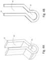
- FIG. 4 Cis a perspective view
- FIG. 4 Dis a side view, of a prior art cable clip 22 A that may be used in installations in accordance with the embodiments of the disclosure.
- FIG. 4 Eis a perspective view
- FIG. 4 Fis a side view, of a prior art cable clip 22 B that may be used in installations in accordance with the embodiments of the disclosure.
- FIG. 4 Iis a perspective view
- FIG. 4 Jis a side view, of another prior art cable clip 22 D that may be used in installations in accordance with the embodiments of the disclosure.
- FIG. 4 Kis a side view
- FIG. 4 Lis a perspective view
- FIG. 4 Mis a front-end view, of another prior art cable clip 22 E that may be used in installations in accordance with the embodiments of the disclosure.
- FIG. 4 Nis a side view and FIG. 4 O is a perspective view, of another prior art cable clip 22 F that may be used in installations in accordance with the embodiments of the disclosure.
- FIG. 4 Pis a side view and FIG. 4 Q is a perspective view, of another example cable clip 22 G that may be used in installations in accordance with the embodiments of the disclosure.
- FIG. 6 Ais an installed right side perspective view
- FIG. 6 Bis a left-side perspective view showing a position of cable clip 22
- FIG. 6 Cis a bare left side view, of another example cut-off device 20 C that may be used in place of example cut-off device in FIG. 2 , FIG. 3 A and FIG. 3 B in accordance with another embodiment of the disclosure.
- FIG. 7 Ais an installed right side perspective view
- FIG. 7 Bis a bare upper right-side perspective view
- FIG. 7 Cis a bare top view
- FIG. 7 Dis a bare left side view, of another example cut-off device 20 D that may be used in place of example cut-off device in FIG. 2 , FIG. 3 A and FIG. 3 B in accordance with another embodiment of the disclosure.
- FIG. 8 Ais a right-side perspective view
- FIG. 8 Bis a right side view, of another example cut-off device 20 E that may be used in place of example cut-off device in FIG. 2 , FIG. 3 A and FIG. 3 B in accordance with another embodiment of the disclosure.
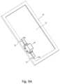
- FIG. 9 Ais a perspective view
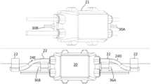
- FIG. 9 Bis a detailed perspective view, showing another example installation of example cut-off device 20 to a frame 13 of a solar panel 12 within solar power generation system 10 , in accordance with another embodiment of the disclosure.
- the present disclosureillustrates solar power generation systems and installation methods in which a housing of an electronic module, such as the electronic cut-off modules described in U.S. patent application Ser. No. 17/569,970 filed on Jan. 6, 2022 entitled “MAINS POWER-OPERATED DISTRIBUTED DISCONNECT FOR SOLAR POWER SYSTEM RAPID SHUTDOWN”, the disclosure of which is incorporated herein by reference.
- the modulesare installed by securing protrusions provided on the exterior surface of the housing that have cross-sections configured to approximate a cross-sectional profile of a standard cable with standard cable clips and/or the modules are secured by cables extending from the housing with the standard cable clips.
- FIG. 1a block diagram of an example solar power generation system 10 is shown, in accordance with an embodiment of the disclosure.
- Multiple strings of photovoltaic arrays (PVAs) 12are connected together in parallel to provide a DC input to an inverter 18 that provides an AC output.
- Multiple cut-off devices (electronic control modules) 20are provided to isolate sub-groups 14 of PVAs 12 , so that the greatest voltage present in solar power generation system 10 is only the voltage of the series-connected panels in the sub-groups 14 .
- Cut-off device 20includes a housing 21 that encloses the electronic components of cut-off device 20 , and which includes a plurality of cables 24 A- 24 D that extend through housing 21 for interconnection with other PVAs 12 and to power bus 17 and that receive control power signals as described in the above-incorporated U.S. patent application.
- Cut-off device 20is only one example of a device that may be secured to a frame of a PVA, and other devices may be secured in a similar manner.
- Cut-off device 20is secured using standard cable clips 22 that are used in other locations in solar power generation system, which in the depicted example, attach cut-off device 20 by mechanically coupling frame 13 to two protrusions 30 A, 30 B, that have a cross-section profile configured to approximate a cross-sectional profile of a standard interconnect cable, for example, cables 24 A and 24 B, for example, a circular profile of, e.g., 6 mm.
- a length of protrusions 30 A, 30 Bis sufficient to ensure that they will extend through the width of cable clips 22 , e.g., 20-25 mm in length.
- Cable clips 22may be any of a variety of standard cable clips in use in solar power generation system 10 , which reduces the number of different items that must be supplied in inventory to install solar power generation system 10 , and are configured for attachment of a standard cable to frame 13 . By providing protrusions 30 A, 30 B, cut-off device is thereby configured to also attach to a standard cable clip.
- FIG. 3 A and FIG. 3 Ba top view and an exploded perspective view, respectively, show details of the example installation of FIG. 2 and an example cut-off device 20 , in accordance with an embodiment of the disclosure.
- FIG. 3 Aprovides an expanded illustration of the mounting configuration of cut-off device, as described above.
- FIG. 3 Bshows an example housing 21 formed by a separable base portion 21 B and cover portion 21 A, in which a printed circuit board (PCB) 27 interconnects electronic components 26 of cut-off device and cables 24 A- 24 D.
- PCBprinted circuit board
- housing 21provides an example of a separable housing
- housings as used hereinmay be formed as a single piece and/or potted assemblies may provide the housing.
- Housings disclosed hereinmay be injection-molded, cast or machined plastic or metal, or may be 3D printed enclosures that are printed, in any of the embodiments disclosed herein.
- FIG. 3 Fa right-side perspective view of another example cut-off device 20 A that may be used in place of cut-off device 20 of FIG. 2 , FIG. 3 A and FIG. 3 B is shown, in accordance with another embodiment of the disclosure.
- Cut-off device 20 Ais similar to cut-off device 20 as described above with reference to FIGS. 3 A- 3 E , so only differences between them will be described below.
- a housing 31 of cut-off device 20 Aincludes protrusions 36 A and 36 B (not shown, but which has an identical cross-sectional profile) that are similar to protrusions 30 A, 30 B as described above with reference to FIGS. 3 A- 3 E , but that is rotated, to form the shape of a “X”, formed by two rotated extensions that have a width that matches the diameter of a standard cable.
- a central void of example cable clip 22includes two segments: a semicircular cross-section segment 42 that is configured to accept and secure, by compression, a standard round cable, and a rectangular cross-section segment 44 that accepts an edge of a frame, such as frame 13 of FIG. 2 .
- FIG. 4 Cis a perspective view
- FIG. 4 Dis a side view, of a prior art cable clip 22 A that may be used in installations in accordance with the embodiments of the disclosure.
- Depicted cable clip 22 Aexpands to accept a circular profile cable on one side thereof, and has a short clip on the other side for engaging with frame 13 of a solar panel.
- FIG. 4 Eis a perspective view
- FIG. 4 Fis a side view, of a prior art cable clip 22 B that may be used in installations in accordance with the embodiments of the disclosure.
- Depicted cable clip 22 Bhas a semi-circular recess and also expands to accept a circular profile cable on one side thereof, and has a wide clip on the other side for engaging with frame 13 of a solar panel.
- FIG. 4 Gis a perspective view
- FIG. 4 His a side view, of another prior art cable clip 22 C that may be used in installations in accordance with the embodiments of the disclosure.
- Depicted cable clip 22 Chas an internal tang that expands to accept a circular profile cable on one side thereof, and has a short clip on the other side for engaging with frame 13 of a solar panel.
- FIG. 4 Iis a perspective view
- FIG. 4 Jis a side view, of another prior art cable clip 22 D that may be used in installations in accordance with the embodiments of the disclosure.
- Depicted cable clip 22 Dhas a bent extension to accept a circular profile cable on one side thereof, and has a wide clip on the other side for engaging with frame 13 of a solar panel.
- the direction of the recessesare perpendicular to each other, in contrast to the above-described cable clips, which makes clip 22 D suitable for use near corners of frame 13 or for suspension via cables, where the cable direction is perpendicular to the direction of the protrusions on the housing of cut-off device 20 .
- FIG. 4 Kis a side view
- FIG. 4 Lis a perspective view
- FIG. 4 Mis a front-end view, of another prior art cable clip 22 E that may be used in installations in accordance with the embodiments of the disclosure.
- Clip 22 Ealso has a perpendicular orientation between the cable recess and the frame-accepting recess.
- FIG. 4 Nis a side view and FIG. 4 O is a perspective view, of another prior art cable clip 22 F that may be used in installations in accordance with the embodiments of the disclosure.
- FIG. 4 Pis a side view and FIG. 4 Q is a perspective view, of another cable clip 22 G that may be used in installations in accordance with the embodiments of the disclosure.
- Clip 22 Gaccepts a frame edge and one or more cables/protrusions in the same recess.
- Cut-off device 20 Bis similar to cut-off device 20 as described above with reference to FIGS. 3 A- 3 E , so only differences between them will be described below.
- Cut-off device 20 Bhas protrusions 30 C, 30 D with a circular cross-sectional profile, directly simulating a standard cable of the same diameter.
- FIG. 6 Ais an installed right side perspective view
- FIG. 6 Bis a left-side perspective view showing a position of cable clip 22
- FIG. 6 Cis a bare left side view, of another example cut-off device 20 C that may be used in place of example cut-off device in FIG. 2 , FIG. 3 A and FIG. 3 B in accordance with another embodiment of the disclosure.
- Cut-off device 20 Cis similar to cut-off device 20 as described above with reference to FIGS. 3 A- 3 E , so only differences between them will be described below.
- Cut-off device 20 Chas protrusions 30 E, 30 E with a square cross-sectional profile, simulating a standard cable having a diameter that is ⁇ 2 times the length of the sides of the square cross-sectional profile.
- FIG. 7 Ais an installed right side perspective view
- FIG. 7 Bis a bare upper right-side perspective view
- FIG. 7 Cis a bare top view
- FIG. 7 Dis a bare left side view, of another example cut-off device 20 D that may be used in place of example cut-off device in FIG. 2 , FIG. 3 A and FIG. 3 B in accordance with another embodiment of the disclosure.
- Cut-off device 20 Dis similar to cut-off device 20 as described above with reference to FIGS. 3 A- 3 E , so only differences between them will be described below.
- Cut-off device 20 Dhas protrusions 30 G with a rectangular cross-sectional profile in a proximal section 74 thereof and that terminates in an expanded distal portion 72 . Rectangular proximal section 74 is sized to cause cable clips 22 to expand and capture protrusions 30 G, and expanded distal portion 72 prevents lateral movement that might cause protrusions 30 G to exit cable clips 22
- FIG. 8 Ais a right side perspective view
- FIG. 8 Bis a right side view, of another example cut-off device 20 E that may be used in place of example cut-off device in FIG. 2 , FIG. 3 A and FIG. 3 B in accordance with another embodiment of the disclosure.
- Cut-off device 20 Eis similar to cut-off device 20 as described above with reference to FIGS. 3 A- 3 E , so only differences between them will be described below.
- Cut-off device 20 Fhas protrusions 3011 with a circular cross-sectional profile similar to cut-off device 20 B of FIGS. 5 A- 5 C , directly simulating a standard cable of the same diameter, but having walls defining a central cylindrical void 80 to provide a hollow tube, that may improve bending strength, depending on the material, and reducing weight.
- FIG. 9 Ais a perspective view
- FIG. 9 Bis a detailed perspective view, showing another example installation of example cut-off device 20 to a frame 13 of a solar panel 12 within solar power generation system 10 , in accordance with another embodiment of the disclosure.
- example installation of FIG. 9 Auses standard cable clamps 22 to secure cut-off device 20 to frame 13 by securing cables 24 C and 24 D to frame 13 . Protrusions are not required on housing 21 of cut-off device 20 .
- one protrusionmay be secured and a cable secured on the other side of cut-off-device 20 , providing flexibility of installation depending on the proximity of frame 12 to the sides of cut-off-device 20 , and depending on where cables are located.
- a cut-off device, or other electronic device to be secured to frame 13may have cables extending from one side, which may be secured with a cable clip, and the other side of the electronic device may be secured by a protrusion that simulates a cable, using a standard cable clip.
- FIG. 10 Ais a perspective view
- FIG. 10 Bis a detailed top view, showing another example installation of example cut-off device 20 to a frame 13 of a solar panel 12 within solar power generation system 10 , in accordance with another embodiment of the disclosure.
- the example installation of FIG. 10 A and FIG. 10 Buses multiple sets of standard cable clamps 22 to secure cut-off device 20 to frame 13 by securing both protrusions 30 A and 30 B, as well as cables 24 C and 24 D to frame 13 with individual cable clamps 22 .
- the systemis a system installed by the method, and may include an electronic control module having a housing that has protrusions having a cross-sectional profile configured to approximate a cross-sectional profile of a standard cable, so that the housing may be secured to a frame of a solar panel with a standard cable clip.
- the installation methodsmay include electrically connecting at least one electrical connection of the electronic control module to the solar power generation system with one or more cables extending from a housing of the electronic control module, providing a pair of identical cable clips configured for attachment of a standard cable to a frame of the solar panel, first securing a first one of the one or more cables or a first protrusion extending from the housing to the frame of the solar panel with a first one of the pair of cable clips, and second securing a second one of the one or more cables or a second protrusion extending from the housing to the frame of the solar panel with a second one of the pair of cable clips.
- the first securingmay secure the first protrusion of the housing to the frame of the solar panel with the first one of the pair of cable clips
- the second securingmay secure the second protrusion of the housing to the frame of the solar panel with the second one of the pair of cable clips.
- the first securingmay secure the first one of the one or more cables to the frame of the solar panel with the first one of the pair of cable clips
- the second securingmay secure the second one of the one or more cables to the frame of the solar panel with the second one of the pair of cable clips, so that the housing is secured to the frame of the solar panel via attachment to the first and second one of the one or more cables.
- the methodmay include providing another pair of cable clips configured for attachment of cables to a solar panel, third securing a first protrusion extending from the housing to a frame of the solar panel with a first one of the other pair of cable clips, and fourth securing a second protrusion extending from the housing to a frame of the solar panel with a second one of the other pair of cable clips.
- the housingmay be a formed plastic housing, with the first protrusion and the second protrusion formed as extensions on either end of the housing.
- the housingmay include a base portion securing an electronic circuit of the electronic control module, and a removable cover portion detachable from the base portion, and wherein the first protrusion and the second protrusion are formed as extensions of the base portion, one on each side thereof.
- the protrusionsmay have circular cross-sections conformed to a diameter of the one or more cables.
- the protrusionsmay have an annular cross-section, so that the protrusions are hollow, and an outer diameter of the annular cross-section may be conformed to the diameter of the one or more cables.
- the protrusionsmay have cross-sections formed by two extensions perpendicular to each other in a cross-sectional plane thereof, and the extensions may have a length conformed to a diameter of the one or more cables.
- the protrusionsmay have a rectangular cross-section having an expanded distal portion, whereby the expanded portion of the protrusions have a width greater than a diameter of the one or more cables, so that a proximal edge of the expanded portion of the protrusions prevents lateral movement of the module with respect to the pair of cable clips.
Landscapes
- Engineering & Computer Science (AREA)
- Microelectronics & Electronic Packaging (AREA)
- Architecture (AREA)
- Civil Engineering (AREA)
- Structural Engineering (AREA)
- Installation Of Indoor Wiring (AREA)
Abstract
Description
Claims (22)
Priority Applications (1)
| Application Number | Priority Date | Filing Date | Title |
|---|---|---|---|
| US17/709,503US12095416B2 (en) | 2022-03-31 | 2022-03-31 | Solar power generation system equipment mounting using cable-clips |
Applications Claiming Priority (1)
| Application Number | Priority Date | Filing Date | Title |
|---|---|---|---|
| US17/709,503US12095416B2 (en) | 2022-03-31 | 2022-03-31 | Solar power generation system equipment mounting using cable-clips |
Publications (2)
| Publication Number | Publication Date |
|---|---|
| US20230318527A1 US20230318527A1 (en) | 2023-10-05 |
| US12095416B2true US12095416B2 (en) | 2024-09-17 |
Family
ID=88192415
Family Applications (1)
| Application Number | Title | Priority Date | Filing Date |
|---|---|---|---|
| US17/709,503Active2042-11-22US12095416B2 (en) | 2022-03-31 | 2022-03-31 | Solar power generation system equipment mounting using cable-clips |
Country Status (1)
| Country | Link |
|---|---|
| US (1) | US12095416B2 (en) |
Citations (44)
| Publication number | Priority date | Publication date | Assignee | Title |
|---|---|---|---|---|
| US3606223A (en) | 1969-03-21 | 1971-09-20 | Spring Steel Fasteners Inc | Outlet box mounting clip |
| KR100870705B1 (en) | 2008-07-21 | 2008-11-27 | 일강알앤비(주) | Wire terminal box structure for apartment house. |
| US20100288554A1 (en) | 2009-05-14 | 2010-11-18 | Afshin Jafari | Universal adjustable support bracket for electrical junction boxes |
| US8472220B2 (en) | 2011-11-01 | 2013-06-25 | Enecsys Limited | Photovoltaic power conditioning units |
| US8542512B2 (en) | 2011-03-22 | 2013-09-24 | Enecsys Limited | Solar photovoltaic inverters |
| US20140366931A1 (en)* | 2013-06-18 | 2014-12-18 | Au Optronics Corp. | Bracket and photovoltaic apparatus having the same |
| US9035491B2 (en) | 2009-11-16 | 2015-05-19 | Omron Corporation | Voltage setting device, photovoltaic power generation system, and control method of voltage setting device |
| US9099849B2 (en) | 2009-05-25 | 2015-08-04 | Solaredge Technologies Ltd. | Bracket for connection of a junction box to photovoltaic panels |
| US20150236638A1 (en) | 2013-04-13 | 2015-08-20 | Solexel, Inc. | Solar photovoltaic module power control and status monitoring system utilizing laminateembedded remote access module switch |
| US9197154B2 (en)* | 2012-08-15 | 2015-11-24 | T-Conn Precision Corporation | Detachable junction box base |
| CN105515520A (en) | 2016-01-06 | 2016-04-20 | 莱尼电气线缆(中国)有限公司 | Solar conjunction box |
| US9337771B2 (en) | 2013-01-18 | 2016-05-10 | Delta Electronics, Inc. | Mounting bracket for junction box, junction box with the mounting bracket, and solar cell module |
| US20160211797A1 (en) | 2015-01-16 | 2016-07-21 | Delta Electronics, Inc. | Photovoltaic power generation system and shut-down device |
| US9525286B2 (en) | 2013-01-03 | 2016-12-20 | Tyco Electronics Corporation | Shutdown system and method for photovoltaic system |
| US9706660B1 (en) | 2016-08-31 | 2017-07-11 | Te Connectivity Corporation | Solar junction box |
| US20170207743A1 (en) | 2014-07-22 | 2017-07-20 | Wencon Development, Inc. Dba Quick Mount Pv | Photovoltaic module accessory clamp |
| USD798231S1 (en) | 2014-08-15 | 2017-09-26 | Hirschmann Automotive Gmbh | Photovoltaic connection box |
| US9876360B2 (en) | 2015-02-02 | 2018-01-23 | Technology Research, Llc | Interface for renewable energy system |
| US9977452B2 (en) | 2014-03-07 | 2018-05-22 | Board Of Trustees Of The University Of Alabama | Multi-input or multi-output energy system architectures and control methods |
| US10090701B2 (en) | 2013-03-20 | 2018-10-02 | Fuji Electric Co., Ltd. | Solar power generation system |
| US10103547B2 (en) | 2014-02-21 | 2018-10-16 | Solarlytics, Inc. | Method and system for applying electric fields to multiple solar panels |
| US20180309301A1 (en) | 2017-04-21 | 2018-10-25 | Fan Wang | Solar array communications |
| US10134933B2 (en) | 2010-11-22 | 2018-11-20 | D B Bones Pty. Ltd. | System for isolating portions of a power supply array |
| US10178789B2 (en) | 2014-09-26 | 2019-01-08 | Sgi Matrix, Llc | Enclosure mounting system |
| US10224870B2 (en) | 2016-05-31 | 2019-03-05 | Ironridge, Inc. | Bracket mounting assembly for securing junction boxes to solar panel arrays |
| US20190074684A1 (en) | 2016-06-17 | 2019-03-07 | Celestica International Lp | System and Method for Controlling a String-Level Rapid Shutdown Device for a Solar Panel Array |
| US20190140589A1 (en) | 2017-11-03 | 2019-05-09 | Institute For Information Industry | Computer device and method for determining whether a solar energy panel array is abnormal |
| US10305273B2 (en) | 2016-01-18 | 2019-05-28 | Delta Electronics (Shanghai) Co., Ltd | Photovoltaic system and rapid shutdown method thereof |
| US10355638B2 (en) | 2016-01-06 | 2019-07-16 | LEONI Cable (China) Co., Ltd. | Solar junction box |
| US10587220B2 (en) | 2017-02-08 | 2020-03-10 | Esdec B.V. | Device and method for attaching electronic auxiliary components to a support structure for solar panels |
| WO2020174657A1 (en) | 2019-02-28 | 2020-09-03 | オムロン株式会社 | Solar power generation system |
| US20200382053A1 (en)* | 2019-05-31 | 2020-12-03 | Sunpower Corporation | Junction box for a photovoltaic module mounting assembly |
| WO2021000253A1 (en) | 2019-07-02 | 2021-01-07 | Marich Holdings The Netherlands B.V. | Photovoltaic system and control method thereof |
| WO2021024339A1 (en) | 2019-08-05 | 2021-02-11 | オムロン株式会社 | Solar power generation system |
| WO2021038916A1 (en) | 2019-08-27 | 2021-03-04 | オムロン株式会社 | Solar power generation network shut-off unit and solar power generation network shut-off system equipped with same |
| US10998761B2 (en) | 2017-07-05 | 2021-05-04 | Sunpower Corporation | Rapid shutdown of photovoltaic systems |
| US20210328545A1 (en) | 2018-07-25 | 2021-10-21 | Lg Electronics Inc. | Photovoltaic module |
| US11171491B2 (en) | 2017-05-30 | 2021-11-09 | Solaredge Technologies Ltd. | Routing power in a power system |
| US11177770B2 (en) | 2019-06-14 | 2021-11-16 | Changshu Friends Connector Technology Co., Ltd. | Controllable system for shutting down connection between photovoltaic panels |
| US20210408964A1 (en) | 2017-04-21 | 2021-12-30 | Fan Wang | Solar array monitoring and safety disconnect with a remote controller |
| US11689011B2 (en) | 2019-09-23 | 2023-06-27 | 1st Step Solar | Methods and systems for electrical system monitoring and/or control |
| US11728844B2 (en) | 2017-03-10 | 2023-08-15 | Intel Corporation | Partial echo cancellation duplexing |
| US11866217B2 (en) | 2019-05-17 | 2024-01-09 | Illinois Tool Works Inc. | Packaging machine for arrangement of elements, preferably cartons, on pallets, and method for this |
| US11929607B2 (en) | 2022-01-06 | 2024-03-12 | Monitek, Llc | Mains power-operated distributed disconnect for solar power system rapid shutdown |
- 2022
- 2022-03-31USUS17/709,503patent/US12095416B2/enactiveActive
Patent Citations (46)
| Publication number | Priority date | Publication date | Assignee | Title |
|---|---|---|---|---|
| US3606223A (en) | 1969-03-21 | 1971-09-20 | Spring Steel Fasteners Inc | Outlet box mounting clip |
| KR100870705B1 (en) | 2008-07-21 | 2008-11-27 | 일강알앤비(주) | Wire terminal box structure for apartment house. |
| US20100288554A1 (en) | 2009-05-14 | 2010-11-18 | Afshin Jafari | Universal adjustable support bracket for electrical junction boxes |
| US9099849B2 (en) | 2009-05-25 | 2015-08-04 | Solaredge Technologies Ltd. | Bracket for connection of a junction box to photovoltaic panels |
| US9035491B2 (en) | 2009-11-16 | 2015-05-19 | Omron Corporation | Voltage setting device, photovoltaic power generation system, and control method of voltage setting device |
| US10134933B2 (en) | 2010-11-22 | 2018-11-20 | D B Bones Pty. Ltd. | System for isolating portions of a power supply array |
| US8542512B2 (en) | 2011-03-22 | 2013-09-24 | Enecsys Limited | Solar photovoltaic inverters |
| US8472220B2 (en) | 2011-11-01 | 2013-06-25 | Enecsys Limited | Photovoltaic power conditioning units |
| US9197154B2 (en)* | 2012-08-15 | 2015-11-24 | T-Conn Precision Corporation | Detachable junction box base |
| US9525286B2 (en) | 2013-01-03 | 2016-12-20 | Tyco Electronics Corporation | Shutdown system and method for photovoltaic system |
| US9337771B2 (en) | 2013-01-18 | 2016-05-10 | Delta Electronics, Inc. | Mounting bracket for junction box, junction box with the mounting bracket, and solar cell module |
| US10090701B2 (en) | 2013-03-20 | 2018-10-02 | Fuji Electric Co., Ltd. | Solar power generation system |
| US20150236638A1 (en) | 2013-04-13 | 2015-08-20 | Solexel, Inc. | Solar photovoltaic module power control and status monitoring system utilizing laminateembedded remote access module switch |
| US20140366931A1 (en)* | 2013-06-18 | 2014-12-18 | Au Optronics Corp. | Bracket and photovoltaic apparatus having the same |
| US10103547B2 (en) | 2014-02-21 | 2018-10-16 | Solarlytics, Inc. | Method and system for applying electric fields to multiple solar panels |
| US9977452B2 (en) | 2014-03-07 | 2018-05-22 | Board Of Trustees Of The University Of Alabama | Multi-input or multi-output energy system architectures and control methods |
| US20170207743A1 (en) | 2014-07-22 | 2017-07-20 | Wencon Development, Inc. Dba Quick Mount Pv | Photovoltaic module accessory clamp |
| USD798231S1 (en) | 2014-08-15 | 2017-09-26 | Hirschmann Automotive Gmbh | Photovoltaic connection box |
| US10178789B2 (en) | 2014-09-26 | 2019-01-08 | Sgi Matrix, Llc | Enclosure mounting system |
| US20160211797A1 (en) | 2015-01-16 | 2016-07-21 | Delta Electronics, Inc. | Photovoltaic power generation system and shut-down device |
| US9876360B2 (en) | 2015-02-02 | 2018-01-23 | Technology Research, Llc | Interface for renewable energy system |
| US10355638B2 (en) | 2016-01-06 | 2019-07-16 | LEONI Cable (China) Co., Ltd. | Solar junction box |
| CN105515520A (en) | 2016-01-06 | 2016-04-20 | 莱尼电气线缆(中国)有限公司 | Solar conjunction box |
| US10305273B2 (en) | 2016-01-18 | 2019-05-28 | Delta Electronics (Shanghai) Co., Ltd | Photovoltaic system and rapid shutdown method thereof |
| US10224870B2 (en) | 2016-05-31 | 2019-03-05 | Ironridge, Inc. | Bracket mounting assembly for securing junction boxes to solar panel arrays |
| US20190074684A1 (en) | 2016-06-17 | 2019-03-07 | Celestica International Lp | System and Method for Controlling a String-Level Rapid Shutdown Device for a Solar Panel Array |
| US9706660B1 (en) | 2016-08-31 | 2017-07-11 | Te Connectivity Corporation | Solar junction box |
| US10587220B2 (en) | 2017-02-08 | 2020-03-10 | Esdec B.V. | Device and method for attaching electronic auxiliary components to a support structure for solar panels |
| US11728844B2 (en) | 2017-03-10 | 2023-08-15 | Intel Corporation | Partial echo cancellation duplexing |
| US20210408964A1 (en) | 2017-04-21 | 2021-12-30 | Fan Wang | Solar array monitoring and safety disconnect with a remote controller |
| US20180309301A1 (en) | 2017-04-21 | 2018-10-25 | Fan Wang | Solar array communications |
| US11171491B2 (en) | 2017-05-30 | 2021-11-09 | Solaredge Technologies Ltd. | Routing power in a power system |
| US10998761B2 (en) | 2017-07-05 | 2021-05-04 | Sunpower Corporation | Rapid shutdown of photovoltaic systems |
| US20190140589A1 (en) | 2017-11-03 | 2019-05-09 | Institute For Information Industry | Computer device and method for determining whether a solar energy panel array is abnormal |
| US20210328545A1 (en) | 2018-07-25 | 2021-10-21 | Lg Electronics Inc. | Photovoltaic module |
| WO2020174657A1 (en) | 2019-02-28 | 2020-09-03 | オムロン株式会社 | Solar power generation system |
| US20220109399A1 (en) | 2019-02-28 | 2022-04-07 | Omron Corporation | Solar power generation system |
| US11866217B2 (en) | 2019-05-17 | 2024-01-09 | Illinois Tool Works Inc. | Packaging machine for arrangement of elements, preferably cartons, on pallets, and method for this |
| US20200382053A1 (en)* | 2019-05-31 | 2020-12-03 | Sunpower Corporation | Junction box for a photovoltaic module mounting assembly |
| US11177770B2 (en) | 2019-06-14 | 2021-11-16 | Changshu Friends Connector Technology Co., Ltd. | Controllable system for shutting down connection between photovoltaic panels |
| WO2021000253A1 (en) | 2019-07-02 | 2021-01-07 | Marich Holdings The Netherlands B.V. | Photovoltaic system and control method thereof |
| WO2021024339A1 (en) | 2019-08-05 | 2021-02-11 | オムロン株式会社 | Solar power generation system |
| US20220255500A1 (en) | 2019-08-05 | 2022-08-11 | Omron Corporation | Solar power generation system |
| WO2021038916A1 (en) | 2019-08-27 | 2021-03-04 | オムロン株式会社 | Solar power generation network shut-off unit and solar power generation network shut-off system equipped with same |
| US11689011B2 (en) | 2019-09-23 | 2023-06-27 | 1st Step Solar | Methods and systems for electrical system monitoring and/or control |
| US11929607B2 (en) | 2022-01-06 | 2024-03-12 | Monitek, Llc | Mains power-operated distributed disconnect for solar power system rapid shutdown |
Non-Patent Citations (9)
| Title |
|---|
| AP Smart, AP Smart product literature, downloaded from https://apsmartglobal.com/ on Jan. 13, 2022, 9 pages (pp. 1-9 in pdf). |
| Final Office Action in U.S. Appl. No. 17/569,970 mailed on Jun. 20, 2023 (pp. 1-13 in pdf). |
| IMO, Product Catalog, downloaded from https://www.imoautomation.com/products/73000000 on Jan. 13, 2022, 5 pages (pp. 1-5 in pdf). |
| Northern Electric "Rapid Shutdown Solutions (RSD) PVG-Guard", downloaded from https://northernep.com/products/rapid-shutdown-solutions/ on Jan. 13, 2022, 7 pages (pp. 1-7 in pdf). |
| Notice of Allowance in U.S. Appl. No. 17/569,970 mailed on Jan. 19, 2024 (pp. 1-8 in pdf). |
| Office Action in U.S. Appl. 17/569,970 mailed on Dec. 2, 2022 (pp. 1-18 in pdf). |
| Tesla Solar Inverter and Solar Shutdown Device Datasheet Feb. 2, 2022, North America. |
| Tigo, "Tigo TS4-A-2F", downloaded from https://www.tigoenergy.com/products/ts4-a-2f on Jan. 13, 2022, 7 pages (pp. 1-7 in pdf). |
| Tigo, Tigo TS4 Brochure, downloaded from https://assets-global.website-files.com/5fad551d7419c7a0e9e4aba4/61b2a5eba1a8735c590e8b44_TS4-A-F(700W) (Fire Safety Add-on) Datasheet EN_12092021.pdf on Jan. 13, 2022, 3 pages (pp. 1-3 in pdf). |
Also Published As
| Publication number | Publication date |
|---|---|
| US20230318527A1 (en) | 2023-10-05 |
Similar Documents
| Publication | Publication Date | Title |
|---|---|---|
| CA1065041A (en) | Mounting apparatus for a telephone exchange unit | |
| JP4162523B2 (en) | Inverter | |
| US7570487B2 (en) | Patch panel module and chassis | |
| US8922972B2 (en) | Integral module power conditioning system | |
| US20140216530A1 (en) | Photovoltaic mounting system with grounding bars and method of installing same | |
| US10511258B2 (en) | Photovoltaic assembly having corner-facing electrical connector port | |
| CN102882083A (en) | Power supply device and cabinet power supply system with power supply device | |
| US6545850B1 (en) | Backplane power landing system | |
| TW201317759A (en) | Power supply unit and power supply system for servers | |
| US20140196770A1 (en) | Photovoltaic module and system | |
| US5752838A (en) | Terminal block and control unit using same | |
| CN107864685A (en) | General Photovoltaic Laminates | |
| US20120024337A1 (en) | Apparatus facilitating wiring of multiple solar panels | |
| US9615470B2 (en) | Wiring combiner box | |
| KR102146064B1 (en) | Connecting bracket of distribution panel and distribution panel having the same | |
| US12095416B2 (en) | Solar power generation system equipment mounting using cable-clips | |
| US8422203B2 (en) | Low-resistance telecommunications power distribution panel | |
| US7008248B2 (en) | Jumper with integral receptacle bracket | |
| JP2002305318A (en) | Solar power system | |
| CN215911767U (en) | Integrated form module installation bracket | |
| JP2003257516A (en) | Bus bar and power supply using it | |
| US5789908A (en) | Lighting dimmer rack with removable connector modules | |
| CN216794038U (en) | Power connector and power | |
| JP7531763B1 (en) | Electrical Equipment | |
| CN220254369U (en) | Inverter and power supply system |
Legal Events
| Date | Code | Title | Description |
|---|---|---|---|
| AS | Assignment | Owner name:MONITEK L.L.C., RHODE ISLAND Free format text:ASSIGNMENT OF ASSIGNORS INTEREST;ASSIGNORS:AKSOY, OEZGUER;EMANET, NAHIT;SIGNING DATES FROM 20220330 TO 20220331;REEL/FRAME:059453/0235 | |
| FEPP | Fee payment procedure | Free format text:ENTITY STATUS SET TO UNDISCOUNTED (ORIGINAL EVENT CODE: BIG.); ENTITY STATUS OF PATENT OWNER: MICROENTITY | |
| FEPP | Fee payment procedure | Free format text:ENTITY STATUS SET TO MICRO (ORIGINAL EVENT CODE: MICR); ENTITY STATUS OF PATENT OWNER: MICROENTITY | |
| STPP | Information on status: patent application and granting procedure in general | Free format text:DOCKETED NEW CASE - READY FOR EXAMINATION | |
| AS | Assignment | Owner name:MONITEK L.L.C., FLORIDA Free format text:ENTITY CONVERSION;ASSIGNOR:MONITEK L.L.C.;REEL/FRAME:065220/0424 Effective date:20230912 | |
| STPP | Information on status: patent application and granting procedure in general | Free format text:NON FINAL ACTION MAILED | |
| STPP | Information on status: patent application and granting procedure in general | Free format text:RESPONSE TO NON-FINAL OFFICE ACTION ENTERED AND FORWARDED TO EXAMINER | |
| STPP | Information on status: patent application and granting procedure in general | Free format text:NOTICE OF ALLOWANCE MAILED -- APPLICATION RECEIVED IN OFFICE OF PUBLICATIONS | |
| STPP | Information on status: patent application and granting procedure in general | Free format text:PUBLICATIONS -- ISSUE FEE PAYMENT VERIFIED | |
| STCF | Information on status: patent grant | Free format text:PATENTED CASE |