US12095244B2 - Composite cable seal - Google Patents
Composite cable sealDownload PDFInfo
- Publication number
- US12095244B2 US12095244B2US17/763,469US202017763469AUS12095244B2US 12095244 B2US12095244 B2US 12095244B2US 202017763469 AUS202017763469 AUS 202017763469AUS 12095244 B2US12095244 B2US 12095244B2
- Authority
- US
- United States
- Prior art keywords
- sealing
- sealing unit
- cable
- flanges
- unit
- Prior art date
- Legal status (The legal status is an assumption and is not a legal conclusion. Google has not performed a legal analysis and makes no representation as to the accuracy of the status listed.)
- Active, expires
Links
- 239000002131composite materialSubstances0.000titleclaimsabstractdescription19
- 238000007789sealingMethods0.000claimsabstractdescription389
- 239000003566sealing materialSubstances0.000claimsabstractdescription124
- 239000000463materialSubstances0.000claimsabstractdescription117
- 125000006850spacer groupChemical group0.000claimsdescription62
- 230000002093peripheral effectEffects0.000claimsdescription39
- 238000010276constructionMethods0.000claimsdescription33
- 229920001971elastomerPolymers0.000claimsdescription22
- 239000000314lubricantSubstances0.000claimsdescription22
- 239000005060rubberSubstances0.000claimsdescription22
- 239000000203mixtureSubstances0.000claimsdescription17
- -1polyethylenePolymers0.000claimsdescription16
- 229920002725thermoplastic elastomerPolymers0.000claimsdescription15
- 239000004033plasticSubstances0.000claimsdescription14
- 229920003023plasticPolymers0.000claimsdescription14
- 229920000642polymerPolymers0.000claimsdescription10
- 239000004698PolyethyleneSubstances0.000claimsdescription6
- 239000004743PolypropyleneSubstances0.000claimsdescription6
- 229920000573polyethylenePolymers0.000claimsdescription6
- 229920001155polypropylenePolymers0.000claimsdescription6
- 229920001169thermoplasticPolymers0.000claimsdescription6
- 229920001187thermosetting polymerPolymers0.000claimsdescription6
- 239000004416thermosoftening plasticSubstances0.000claimsdescription6
- 230000000903blocking effectEffects0.000claimsdescription5
- 229920006132styrene block copolymerPolymers0.000claimsdescription5
- 230000007423decreaseEffects0.000claimsdescription3
- 230000007935neutral effectEffects0.000claimsdescription3
- 239000012812sealant materialSubstances0.000description11
- 239000004519greaseSubstances0.000description8
- 239000004205dimethyl polysiloxaneSubstances0.000description6
- 238000000034methodMethods0.000description6
- 229920000435poly(dimethylsiloxane)Polymers0.000description6
- 238000007906compressionMethods0.000description4
- 238000000465mouldingMethods0.000description4
- 230000006835compressionEffects0.000description3
- 239000000835fiberSubstances0.000description3
- 238000003780insertionMethods0.000description3
- 230000037431insertionEffects0.000description3
- 238000009434installationMethods0.000description3
- 239000002991molded plasticSubstances0.000description3
- 239000004721Polyphenylene oxideSubstances0.000description2
- 239000004793PolystyreneSubstances0.000description2
- 239000000356contaminantSubstances0.000description2
- 238000013461designMethods0.000description2
- 239000013536elastomeric materialSubstances0.000description2
- 238000004519manufacturing processMethods0.000description2
- 229920000058polyacrylatePolymers0.000description2
- 229920000570polyetherPolymers0.000description2
- 229920002223polystyrenePolymers0.000description2
- 230000000717retained effectEffects0.000description2
- 229920000468styrene butadiene styrene block copolymerPolymers0.000description2
- GOXQRTZXKQZDDN-UHFFFAOYSA-N2-Ethylhexyl acrylateChemical compoundCCCCC(CC)COC(=O)C=CGOXQRTZXKQZDDN-UHFFFAOYSA-N0.000description1
- HWSSEYVMGDIFMH-UHFFFAOYSA-N2-[2-[2-(2-methylprop-2-enoyloxy)ethoxy]ethoxy]ethyl 2-methylprop-2-enoateChemical compoundCC(=C)C(=O)OCCOCCOCCOC(=O)C(C)=CHWSSEYVMGDIFMH-UHFFFAOYSA-N0.000description1
- 239000004970Chain extenderSubstances0.000description1
- 239000004971Cross linkerSubstances0.000description1
- 239000004606Fillers/ExtendersSubstances0.000description1
- 239000005062PolybutadieneSubstances0.000description1
- NIXOWILDQLNWCW-UHFFFAOYSA-Nacrylic acid groupChemical groupC(C=C)(=O)ONIXOWILDQLNWCW-UHFFFAOYSA-N0.000description1
- 230000032683agingEffects0.000description1
- 150000001336alkenesChemical class0.000description1
- 230000000712assemblyEffects0.000description1
- 238000000429assemblyMethods0.000description1
- CQEYYJKEWSMYFG-UHFFFAOYSA-Nbutyl acrylateChemical compoundCCCCOC(=O)C=CCQEYYJKEWSMYFG-UHFFFAOYSA-N0.000description1
- 238000004891communicationMethods0.000description1
- 230000008878couplingEffects0.000description1
- 238000010168coupling processMethods0.000description1
- 238000005859coupling reactionMethods0.000description1
- 230000006378damageEffects0.000description1
- 239000000428dustSubstances0.000description1
- 230000000694effectsEffects0.000description1
- 238000011900installation processMethods0.000description1
- 125000005395methacrylic acid groupChemical group0.000description1
- JRZJOMJEPLMPRA-UHFFFAOYSA-NolefinNatural productsCCCCCCCC=CJRZJOMJEPLMPRA-UHFFFAOYSA-N0.000description1
- 150000002978peroxidesChemical class0.000description1
- 229920002857polybutadienePolymers0.000description1
- 229920000728polyesterPolymers0.000description1
- 229920001195polyisoprenePolymers0.000description1
- 229920002635polyurethanePolymers0.000description1
- 239000004814polyurethaneSubstances0.000description1
- 239000002243precursorSubstances0.000description1
- 230000003014reinforcing effectEffects0.000description1
- SCPYDCQAZCOKTP-UHFFFAOYSA-NsilanolChemical compound[SiH3]OSCPYDCQAZCOKTP-UHFFFAOYSA-N0.000description1
- 239000000126substanceSubstances0.000description1
- 238000012546transferMethods0.000description1
- 230000007704transitionEffects0.000description1
Images


Classifications
- G—PHYSICS
- G02—OPTICS
- G02B—OPTICAL ELEMENTS, SYSTEMS OR APPARATUS
- G02B6/00—Light guides; Structural details of arrangements comprising light guides and other optical elements, e.g. couplings
- G02B6/44—Mechanical structures for providing tensile strength and external protection for fibres, e.g. optical transmission cables
- G02B6/4439—Auxiliary devices
- G02B6/4471—Terminating devices ; Cable clamps
- G02B6/44775—Cable seals e.g. feed-through
- G—PHYSICS
- G02—OPTICS
- G02B—OPTICAL ELEMENTS, SYSTEMS OR APPARATUS
- G02B6/00—Light guides; Structural details of arrangements comprising light guides and other optical elements, e.g. couplings
- G02B6/44—Mechanical structures for providing tensile strength and external protection for fibres, e.g. optical transmission cables
- G02B6/4439—Auxiliary devices
- G02B6/444—Systems or boxes with surplus lengths
- G02B6/4441—Boxes
- G02B6/4442—Cap coupling boxes
- G02B6/4444—Seals
- H—ELECTRICITY
- H02—GENERATION; CONVERSION OR DISTRIBUTION OF ELECTRIC POWER
- H02G—INSTALLATION OF ELECTRIC CABLES OR LINES, OR OF COMBINED OPTICAL AND ELECTRIC CABLES OR LINES
- H02G15/00—Cable fittings
- H02G15/013—Sealing means for cable inlets
Definitions
- Telecommunications systemstypically employ a network of telecommunications cables capable of transmitting large volumes of data and voice signals over relatively long distances.
- the telecommunications cablescan include fiber optic cables, electrical cables, or combinations of electrical and fiber optic cables.
- a typical telecommunications networkalso includes a plurality of telecommunications enclosures integrated throughout the network of telecommunications cables.
- the telecommunications enclosuresare adapted to house and protect telecommunications components such as splices, termination panels, power splitters, and wavelength division multiplexers. It is often preferred for the telecommunications enclosures to be re-enterable.
- re-enterablemeans that the telecommunications enclosures can be re-opened to allow access to the telecommunications components housed therein without requiring the removal and destruction of the telecommunications enclosures.
- certain telecommunications enclosurescan include separate access panels that can be opened to access the interiors of the enclosures and then closed to re-seal the enclosures.
- Other telecommunications enclosurestake the form of elongated sleeves formed by wrap-around covers or half-shells having longitudinal edges that are joined by clamps or other retainers.
- Still other telecommunications enclosuresinclude two half-pieces that are joined together through clamps, or other structures. Further enclosures include domes attached to bases via clamps.
- Telecommunications enclosuresare typically sealed to inhibit the intrusion of moisture or other contaminants.
- An example sealed enclosureis disclosed by PCT International Publication Number WO 2017/167819.
- the cable sealcan be adapted for sealing a cable port and for providing sealing with respect to a housing of the enclosure.
- the cable sealhas a composite construction adapted to effectively seal a triple point of the telecommunications enclosure located at an interface between two pieces of the housing.
- the triple pointcan include a gasket such as an O-ring that provides a perimeter seal between the housing pieces of the enclosure and that extends across a portion of the cable seal.
- the cable sealcan have a composite construction which includes first and second different materials.
- the first and second different materialscan include a frame material and a sealing material.
- the frame materialcan be configured to provide stored energy when compressed, to control positioning of the sealing material, and to prevent the sealing material from being over-compressed when pressurized between housing pieces.
- the sealing materialcan be configured to provide effective sealing at a cable port and to also provide effective sealing with respect to the enclosure (e.g., at a triple point of the enclosure).
- the sealing materialcan be molded over and through the frame material.
- the frame materialis an elastomeric material that is harder than the sealing material.
- the frame materialcan include an elastomeric rubber construction.
- the sealing materialcan include an elastomeric rubber construction or a gel construction.
- the sealing materialhas a hardness of 15 Shore A or softer
- the frame materialhas an elastomeric construction having a hardness of 30 Shore A or harder.
- the cable sealdefines at least one cable port.
- the cable portis lined by the sealing material which defines a circumferential rib within the cable port.
- the cable sealcan include flanges having a composite construction and includes both the frame material and the sealing material.
- the frame materialcan define at least a portion of a peripheral surface of the cable seal that is intended to contact a sealing gasket of a telecommunications enclosure.
- the composite construction of the flangesassists in maintaining proper positioning of the sealing material at a triple point of the enclosure, and prevents the sealing material from being over-compressed or torn when the cable seal is compressed during closing of the enclosure.
- the cable sealcan include a tapered access slit for providing a wrap-around configuration that allows a fiber optic cable to be inserted into a cable port of the cable seal.
- the slitis predefined during forming of the cable seal and optionally can have a tapered, wedge shape.
- the cable sealcan provide effective sealing without the use of a lubricant such as grease.
- the cable sealcan be used in combination with lubricant and can include a peripheral surface defined by the sealing material which includes a groove for providing effective containment and positioning of lubricant (e.g., factory installed lubricant) relative to the cable seal.
- the cable sealcan be configured to ensure the effective positioning of grease adjacent a triple point of the enclosure during insertion of the cable seal into the enclosure.
- cable seals in accordance with the principles of the present disclosurecan be configured to be mounted in a side-by-side arrangement within a telecommunications enclosure and can be adapted such that the flanges of adjacent ones of the cable seals contact one another to provide a continuous seal that extends between the adjacent cable seals.
- the contact regions between the adjacent cable sealscan be provided exclusively by the sealing material.
- the frame material of the cable sealsdefine peripheral surfaces that are contacted by the gasket as the gasket extends across the top sides of the cable seals. The frame material can provide reinforcing that prevents the sealing gasket from over-compressing, tearing, displacing or otherwise damaging the sealing material when the telecommunications enclosure is closed.
- the cables sealing surfaces that are not physically contactedare defined by sealing ribs located within the cable ports.
- the cable portsinclude enlarged inner and outer pockets separated by the sealing rib, and the plugs seal against circumferential surfaces corresponding to the enlarged inner and outer pockets.
- the plugsinclude enlarged sealing heads that are co-axially aligned and connected at a fixed axial spacing by a plug-head spacer having a reduced cross-dimension as compared to the enlarged sealing heads.
- the cable sealing surfaces of the ribsdefine cable openings having cross-dimensions larger than the cross-dimensions of the plug-head spacers, and the plug-head spacers extend through the cable openings and do not physically contact the sealing surfaces.
- an assemblyincluding a cable seal defining cable ports, plugs for temporarily blocking the cable ports and a cable spacer for use in maintaining spacing between cables routed through the cable ports.
- the plugsinclude exterior spacer holders for securing the cable spacer to the cable seal then the plugs are installed in the cable ports of the cable seal.
- the plugincludes first and second enlarged heads that are co-axially aligned and connected together at a fixed axial spacing by a plug-head spacer.
- the plug-head spacerhas a smaller cross-dimension as compared to the first and second enlarged heads.
- the plugis dumbbell shaped.
- each of the enlarged headsincludes one or more disk-shaped sealing flanges.
- the enlarged headsinclude disk-shaped axial stop flanges having a larger cross-dimension that corresponding cross-dimensions of the sealing flanges.
- a cable spacerincluding parallel first and second cable-receiving channels arrangement back-to-back with open sides of the channels facing in opposite directions.
- the cableincludes a first part that defines a first half of the first and second channels and a second part that defines a second half of the first and second channels.
- the channelsextend along a length of the spacer between first and second opposite ends, and the first and second parts are pivotally connected by a hinge located at one of the ends.
- the spacerhas a composite construction with each of the first and second parts including a plastic frame supporting an elastomeric material that defines the cable-receiving channels.
- FIG. 1is a perspective view of a cable seal in accordance with the principles of the present disclosure
- FIG. 2is a front view of the cable seal of FIG. 1 ;
- FIG. 3is a perspective view a frame material of the cable seal of FIG. 1 ;
- FIG. 4is a perspective view of a sealing material of the cable seal of FIG. 1 , the sealing material is molded over and through the frame material of FIG. 2 ;
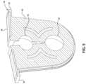
- FIG. 5is a cross-sectional view of the cable seal of FIG. 1 ;
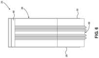
- FIG. 6is a side view of the cable seal of FIG. 1 ;
- FIG. 7depicts a telecommunications enclosure in accordance with the principles of the present disclosure with a plurality of the cable seals of FIG. 1 mounted therein;
- FIG. 8is a cross-sectional view through the cable ports of the cable seal of FIG. 1 with a cable shown sealed within one of the cable ports;
- FIG. 9is a perspective view of an alternative configuration for the sealing material of FIG. 3 ;
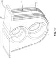
- FIG. 10shows the sealing material of FIG. 9 molded over and through the frame material of FIG. 3 ;
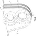
- FIG. 11is a cross-sectional view cut through the cable seal of FIG. 10 ;
- FIG. 12is a side view of the cable seal of FIG. 10 ;
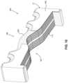
- FIG. 13is a perspective view of another cable sealing unit in accordance with the principles of the present disclosure.
- FIG. 14is a front view of the cable sealing unit of FIG. 13 ;
- FIG. 15is a top view of the cable sealing unit of FIG. 13 .
- FIG. 16is another perspective view of the cable sealing unit of FIG. 13 ;
- FIG. 17is a cross-sectional view taken along section line 17 - 17 of FIG. 13 ;
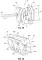
- FIG. 18depicts a plug in accordance with the principles of the present disclosure for temporarily blocking a cable port of a cable sealing unit in accordance with the principles of the present disclosure
- FIG. 19depicts a cable spacer in accordance with the principles of the present disclosure for use in spacing cable routed through a cable sealing unit in accordance with the principles of the present disclosure
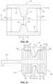
- FIG. 20is a cross-sectional view through a cable port of the cable seal of FIG. 1 ;
- FIG. 21is a cross-sectional view depicting the cable port of FIG. 20 with the plug of FIG. 18 mounted therein;
- FIG. 22is a cross-sectional view depicting the cable spacer of FIG. 19 retained between retainers of plugs of the type shown at FIG. 18 ;
- FIG. 23is a cross-sectional view depicting the spacer of FIG. 19 being used to maintain parallel spacing between cables routed through ports of the cable seal of FIG. 1 .
- FIG. 1depicts an example cable seal 20 in accordance with the principles of the present disclosure.
- the cable seal 20can be adapted for sealing a cable entrance/exit location 22 (see FIG. 7 ) of a telecommunications enclosure 24 .
- the cable seal 20includes a sealing unit 26 having a first major side 28 positioned opposite from a second major side 30 .
- the first and second major sides 28 , 30are separated by a thickness T of the sealing unit 26 .
- the sealing unithas a profile P (see FIG. 2 ) defining a major axis D 1 and a minor axis D 2 .
- the sealing unit profile Pdefines a length L that extends along the major axis D 1 between opposite first and second ends 32 , 34 of the sealing unit 28 .
- the profile Pdefines a width W that extends along the minor axis D 2 between opposite first and second sides 36 , 38 of the sealing unit 26 .
- the sealing unit 26includes first and second sealing flanges 40 , 42 adjacent the second end 34 of the sealing unit that respectively project outwardly from the first and second sides 36 , 38 of the sealing unit 26 in an orientation along the minor axis D 2 .
- Each of the first and second flanges 40 , 42includes a base end integral with a main body of the sealing unit 26 and a free end 46 located at an outermost extent portion 48 of each of the flanges 40 , 42 .
- the sealing unit 26further includes at least one cable port that extends through the thickness T of the sealing unit between the first and second major sides 28 , 30 .
- the sealing unit 26includes first and second cable ports 50 , 52 that are aligned along the major axis D 1 of the profile P and that extend through the thickness T of the sealing unit 26 .
- the sealing unit 26further includes a peripheral surface 54 that extends about a perimeter of the sealing unit 26 . The perimeter of the sealing unit 26 extends around the first and second ends 32 , 34 as well as the first and second sides 36 , 38 of the sealing unit 26 .
- the sealing unit 26has a composite construction including a frame material 60 and a sealing material 62 .
- the sealing material 62is molded over and through the frame material 60 .
- the frame materialis harder than the sealing material 62 .
- the frame materialcan have an elastomeric construction.
- the sealing material 62preferably lines the first and second cable ports 50 , 52 and defines at least a portion of the peripheral surface 54 that extends along the first and second sides 36 , 38 and the first end 32 of the sealing unit 26 .
- the frame material 60 and the sealing material 62cooperate to define each of the first and second sealing flanges 40 , 42 .
- the frame material 60 and the sealing material 62both have an elastomeric construction, with the frame material 60 being harder than the sealing material 62 .
- the construction of the frame material 60is adapted to provide stored energy when compressed, to control positioning of the sealing material 62 , to provide containment and protection of the sealing material 62 , and to prevent the sealing material 62 from being over-compressed when the sealing unit is installed within the telecommunications enclosure 24 .
- the construction of the sealing material 62can be configured to provide effective sealing at the cable ports 50 , 52 and to also provide effective sealing about the periphery of the sealing unit 26 with respect to housing of the telecommunications enclosure 24 .
- the configuration of the flanges 40 , 42which include a composite construction including both the frame material 60 and the sealing material 62 , provides effective sealing at a triple point location of the enclosure 24 where a gasket extends over the second end 34 of the cable seal 20 .
- the gasketis adapted to provide perimeter sealing between first and second housing pieces 64 , 66 (e.g., a base and a cover of a housing of the telecommunications enclosure 24 ) that meet at an interface that corresponds with the second ends 34 of cable seals 20 installed within the telecommunications enclosure 24 .
- the sealing material 62has hardness of 15 Shore A or softer. In certain examples, the sealing material 62 has a hardness in the range of 5-15 Shore A. In certain examples, sealing material 62 can include an elastomeric gel or an elastomeric rubber. In certain examples, the sealing material includes a thermoplastic elastomeric rubber, a thermoset elastomeric rubber, a thermoplastic elastomeric gel or a thermoset elastomeric gel. In certain examples, the sealing material is a thermoplastic elastomer (e.g., rubber, gel) having a hardness in the range of 5-25 Shore A, or in the range of 5-20 Shore A, or in the range of 10-15 Shore A.
- a thermoplastic elastomere.g., rubber, gel
- the frame material 60includes a thermoplastic or thermoset elastomeric rubber. In certain examples, the frame material 60 has a hardness of 30 Shore A or harder. In certain examples, the frame material has a hardness in the range of 30-60 Shore A. In certain example, the frame material can have a molded plastic construction and can have a hardness of at least 40 Shore A, or at least 50 Shore A, or at least 60 Shore A, or at least 70 Shore A, or at least 80 Shore A, or at least 90 Shore A, or at least 100 Shore A, or at least 70 Shore D, or in the range of 50 Shore A to 70 Shore D, or in the range of 60-100 Shore A.
- the frame material 60has a plastic composition that include a polymer such as polyethylene or polypropylene.
- the frame material 60has a composition that includes a plastic polymer such as polyethylene or polypropylene and a thermoplastic elastomer such as a styrenic block copolymer.
- the compositioncan be a blend of the plastic polymer such as polyethylene or polypropylene and the thermoplastic elastomer such as a styrenic block copolymer.
- the frame material 60has a composition that includes 70-95 percent plastic polymer and 5-30 percent thermoplastic elastomer. In another example, the frame material 60 has a composition that includes 80-95 percent plastic polymer and 5-20 percent thermoplastic elastomer. In a further example, the frame material 60 has a composition that includes 85-95 percent plastic polymer and 5-15 percent thermoplastic elastomer. In certain examples, the frame material having the blended composition can have a hardness greater than 30 or 40 Shore A.
- the cable seal 20it is preferred for the cable seal 20 to provide effective sealing without the need for using a lubricant such as grease.
- a lubricantsuch as grease
- the peripheral surface 54 defined by the sealing material 62includes a peripheral groove 68 that extends about at least a portion of the perimeter of the sealing unit 26 for holding grease or other lubricant or sealing material.
- the lubricantcan be placed in the groove 68 in the factory as part of the manufacturing process, to eliminate the need for applying the lubricant in the field.
- An example lubricantincludes Molycote® brand lubricant sold by Dow Corning.
- the peripheral groove 68extends from the first sealing flange 40 , along the first side 36 , around the first end 32 , and along the second side 38 to the second flange 42 . It will be appreciated that when the sealing unit 26 is mounted within a corresponding pocket defined by a housing of a telecommunications enclosure, grease or other lubricant that has been preinstalled within the peripheral groove 68 assists in inserting the sealing unit 26 into the pocket. Additionally, during the insertion process, lubricant within the peripheral groove 68 is forced upwardly toward the flanges 40 , 42 such that a supply of lubricant is provided beneath the flanges 40 , 42 for effectively providing triple point sealing of the enclosure.
- the sealing unit 26can be configured with a tapered configuration such that the width W decreases as the sealing unit 26 extends toward the first end 32 of the sealing unit 26 .
- the tapered configuration of the sealing unit 26assists in providing compression of the sealing unit 26 when the sealing unit 26 is installed within a pocket of the telecommunications enclosure 24 . Compression of the sealing unit 26 can result in the frame material 60 being pressurized to provide stored energy for maintaining sealing at the periphery of the sealing unit 26 and at the cable ports 50 , 52 .
- the tapered configuration of the sealing unit 26assists in forcing lubricant toward the region beneath the flanges 40 , 42 during the seal insertion process.
- the sealing material 62can include structures that enhance cable sealing at the cable sealing ports 50 , 52 and also provide cable range-taking functionality that allows the cable ports 50 , 52 to accommodate cables having different diameters or sizes.
- the sealing material 62defines circumferential cable sealing ribs 70 at each of the first and second cable ports 50 , 52 .
- the cable sealing ribs 70encircle port axes 72 of the cable ports 50 , 52 .
- the cable sealing ribs 70are adapted to project radially inwardly toward the cable axes 72 .
- the cable sealing ribs 70are configured to deflect radially outwardly from the axes 72 to accommodate cables of different sizes.
- the second cable port 52is shown receiving a cable 74 and the corresponding cable sealing rib 70 is shown outwardly deflected so as to accommodate the cable 74 while maintaining sealing contact about the circumference of the cable 74 .
- the cable ports 50 , 52are vacant, the cable ports can be enclosed by plugs that engage the sealing ribs 70 .
- Example plugs 76are shown at FIG. 7 .
- the first and second flanges 40 , 42have a composite construction that assists in effectively providing sealing within a telecommunications enclosure 24 , particularly at triple points of telecommunications enclosures 24 .
- the outermost extent portions 48 of the first and second sealing flanges 40 , 42are defined only by the sealing material 62 .
- the outermost extent portions 48are formed only by the sealing material 62 and have an outermost extent dimension dl along the minor axis D 2 that is less than or equal to 2 mm, or is less than or equal to 1 mm.
- the provision of the frame material 60 within the first and second flanges 40 , 42assists in preventing the sealing material 62 of the flanges 40 , 42 from being over-compressed, displaced, torn or otherwise damaged during the installation process within the telecommunications enclosure 24 .
- portions of the frame material 60are adapted to absorb or transfer compression load which occurs when the housing pieces 64 , 66 of the telecommunications enclosure 24 are secured together to prevent the sealing material 62 from being over-compressed.
- first and second flanges 40 , 42each include a flange height H that extends in an orientation along the major axis D 1 of the sealing unit 26 , and each of the first and second flanges 40 , 42 includes a region 78 in which the frame material 60 defines the full flange height h.
- the regions 78can include rails between which the sealing material 62 is contained. The regions 78 (e.g., rails or other regions) are adapted to prevent excessive deformation of the outermost extent portions 48 .
- the railsextend from the base ends 44 of the first and second flanges 40 , 42 along the minor axis D 2 of the sealing unit 26 to the outermost extent portions 48 of the first and second flanges 40 , 42 .
- the sealing unit 26includes a predefined access slit 80 that extends along the major axis D 1 of the sealing unit 26 from the second end 34 of the sealing unit, through the second port 52 and into the first port 50 .
- the slit 80provides the sealing unit 26 with a wrap-around configuration that allows the sealing unit 26 to be wrapped around cables desired to be inserted into either one of the cable ports 50 , 52 thereby eliminating the need for axially threading the cable through the cable ports.
- the sealing unit 26can flex about a hinge location adjacent the first end 32 to move between a closed position and an open position. FIG.
- FIG. 2shows the sealing unit 26 partially flexed open about the hinge location such that the access slit 80 has a tapered wedge shape such that a width of the access slit 80 measured along the minor axis D 2 of the sealing unit 26 decreases as the access slit 80 extends from the second end 34 of the sealing unit 26 toward the first end 32 of the sealing unit 26 .
- cablescan be loaded into the ports 50 , 52 through the slit 80 .
- the sealing unit 26is compressed closed such that the access slit 80 is forced closed.
- the framecan include a flexible living hinge a the first end, or can be split into two half parts which are interconnected only by the sealing material 62 at a joint at the first end such that the sealing material 62 forms a hinge for allowing the sealing unit 26 to be flexed open.
- the sealing unit 26can be manufactured by a molding process.
- the molding processcan include an insert molding process.
- the frame material 60can initially be molded within a mold cavity having an insert provided within the mold cavity for defining a precursor of the slit 80 defined by the frame material 60 . Thereafter, the frame material 60 can be loaded into another mold cavity and the sealing material 62 can be molded over and through the frame material 60 .
- An insert for the slit 80can be provided within the second mold cavity.
- the frame material 60is molded with an open interior region for allowing the sealing material 62 to flow into the interior of the frame material 60 .
- the open configuration of frame 60allows communication to be maintained between the sealing material 62 at the peripheral surface 54 of the sealing unit 26 and a lining portion 82 of the sealing material 62 which lines the first and second cable ports 50 , 52 and the access slit 80 .
- the sealing material 62also flows between the rails 78 (see FIG. 3 ) of the flanges 40 , 42 and defines the outer extant portions 48 .
- the slit 80can be cut into the sealing unit after molding.
- the slit 80can be molded with a slight taper along its length, but is can be configured to close when the sealing unit is compressed within a pocket of an enclosure.
- the frame 60includes perimeter portions 61 (e.g., walls, rails, etc.) on opposite sides of the sealing material 62 that extend about the peripheral surface 54 .
- the perimeter portions 61extend along the first and second sides 36 , 38 and along the first end 32 of the sealing unit 26 .
- the sealing material 62 and the frame material 60cooperate to define the peripheral surface 54 .
- the perimeter portions 61 of the frame material 60can form rail or wall-like structures that assist in protecting the sealing material 62 from the outside environment and for containing the sealing material 62 when the sealing unit 26 is inserted within a pocket of the telecommunications enclosure 24 .
- the frame material 60also defines a section 86 of the peripheral surface 54 that extends along the minor axis D 2 of the sealing unit 26 at the second end 34 of the sealing unit 26 .
- the section 86 of the peripheral surface defined by the frame material 60extends along a majority of the width W of the sealing unit 26 and is adapted for contacting a gasket (e.g., an O-ring seal) of the telecommunications enclosure 24 that is routed across the second end 34 of the sealing unit 26 when the sealing unit 26 is installed within the telecommunications enclosure.
- a gaskete.g., an O-ring seal
- FIG. 7shows the enclosure 24 with the plurality of the sealing units 26 mounted within pockets 90 of the enclosure.
- the telecommunications enclosure 24includes a housing including the first housing piece 64 and the second housing piece 66 .
- the first and second housing pieces 64 , 66meet at an interface 92 sealed by a gasket 94 such as an O-ring seal or other seal (e.g., square, oval, etc.).
- the sealing units 26are mounted within the pockets 90 with the second ends 34 located at the interface.
- the flanges 40 , 42overhang a seal support surface 91 defined by the first housing piece 64 (e.g., the base).
- the gasket 94is routed over the second ends 34 of the sealing unit 26 .
- the relatively soft nature of the sealing material 62provides effective sealing at the transition (e.g., the triple point) where the gasket extends from the gasket support surface 91 to the second ends 34 of the sealing units 26 .
- the flanges 40 , 42are sized and configured such that the flanges 40 , 42 of adjacent ones of the sealing units 26 contact one another when installed within the housing.
- the gasket 94extends across the outermost extent portions 48 of the flanges 40 , 42 and also extends across and contacts the peripheral surface defined by the frame material 60 .
- the contact between the peripheral surface 86 of the frame material 60causes compressive loading to be transferred through the frame material 60 rather than over-compressing the outermost extent portions 48 of the flanges 40 , 42 .
- the outermost extent portions 48are prevented from being over-compressed, torn or improperly displaced by the gasket 94 during the seal compression process.
- the slits 80 of the sealing units 26close and the sealing material conforms about the cables when the sealing units are compressed within the pockets of the enclosure.
- FIGS. 10 - 12depict another cable seal 20 a in accordance with the principles of the present disclosure.
- Cable seal 20 ahas the same frame material 60 as the cable seal 20 , but has a sealing material 62 a (see FIG. 9 ) that has been modified to define the entire thickness of the peripheral surface 54 a of the portion of the peripheral surface that extends along the sides 36 , 38 and along the first end 32 of the cable seal 20 a.
- FIGS. 13 - 17depict a further cable seal 20 b in accordance with the principles of the present disclosure.
- the cable seal 20 bincludes a sealing unit 21 having a sealing material 62 b and frame material 60 b that can have compositions and material properties of any of the types previously described herein.
- the frame material 60 bpreferably has a multi-piece construction with pieces that are separate from one another or connected by a living hinge section of the frame material.
- the frame material 60 bincludes first and second frame pieces 161 , 163 positioned on opposite sides of a centerline 164 (see FIG. 14 ) that bisects the sealing unit 21 .
- the frame pieces 161 , 163are half-pieces and are symmetric about the centerline 164 .
- the sealing unit 21itself is also symmetric about the centerline 164 .
- the sealing material 62 bis preferably molded over and through the frame pieces 161 , 163 of the frame material 60 b .
- the sealing material 62 bdefines a flexation region 165 located between the frame pieces 161 , 163 adjacent the centerline 164 .
- the flexation region 165is configured to allow the sealing unit 21 to be flexed about the centerline from an open orientation (shown at FIGS. 13 and 14 ) to a closed orientation similar to the configuration of the seal 20 shown at FIG. 1 .
- the flexation region 165is at a rounded first end of the unit 21 and opposite flanged ends 180 , 181 of the sealing unit 21 are brought together to form a flanged second end of the sealing unit 21 .
- the sealing unit 21is configured to be wrapped around cables when moved from the open orientation to the closed orientation during installation in the pocket of an enclosure such as the enclosure 24 of FIG. 7 .
- the sealing material 62 bis initially molded in a flat configuration (see FIGS. 13 and 14 ) with the first and second separate frame pieces 161 , 163 being overmolded by the sealing material 62 b as the sealing material 62 b is molded in the flat configuration.
- the flat configurationcorresponds to the open orientation of the sealing unit 21 . Since the sealing unit is molded in the flat, open configuration, this configuration corresponds to a neutral or at rest state of the unit 21 .
- the unitis flexed from the open, neutral state to the closed state during installation in an enclosure and the enclosure retains the unit 21 in the closed state when the unit 21 is installed in a pocket of the enclosure.
- the sealing unit 21includes cable port-defining portions 167 a , 167 b and a cable port-defining portion 169 .
- the cable port-defining portions 167 a , 167 bcooperate to define one cable port and the cable port-defining portion 169 defines another cable port.
- the sealing unit 21has a wrap-around configuration that allows the unit 21 to be wrapped around cables as the unit 21 is flexed from the opening orientation to the closed orientation such that the cables are captured within the cable ports as the sealing unit 21 is moved from the open, flat orientation to the closed orientation.
- the sealing material 62 bincludes a plurality of axially spaced-apart cable sealing ribs 170 positioned at the cable port-defining portions 167 a , 167 b , 169 that extend circumferentially around the cable ports defined by the cable port-defining portions when the sealing unit is in the closed orientation.
- Inner grooves 172are defined between the cable sealing ribs 170 .
- the ribscan provide labyrinth type sealing about cables and can allow a wide range of cable sizes (e.g., a 5 millimeter range) to be accommodated. In one example, cables ranging from 11-16 millimeters in diameter can be accommodated.
- the sealing material 62 balso includes a plurality of axially spaced-apart peripheral sealing ribs 174 that extend along opposite first and second sides and around the curved first end of the sealing unit when the sealing unit is in the closed orientation.
- the ribs 170are on one major side 186 of the sealing unit 21 and the ribs 174 are at an opposite major side 187 of the sealing unit 21 .
- Outer grooves 176are defined between the peripheral sealing ribs 174 .
- the inner and peripheral groovescontain a lubricant 178 (e.g., see FIG. 17 ) such as grease.
- a lubricant 178e.g., see FIG. 17
- the lubricantis factory installed in the grooves 172 , 176 prior to shipment of the sealing unit 21 to the field and prior to installation of the sealing unit 21 .
- FIG. 18depicts an alternative plug design in accordance with the principles of the present disclosure for use in protecting and sealing cable ports of a sealing unit such as the cable ports 50 , 52 of the sealing unit 26 .
- the plug designis depicted as a plug 76 a which can be manufactured in different sizes to correspond with different sized ports (e.g., ports 50 , 52 ).
- the plug 76 ahas a generally dumbbell-shaped configuration and includes inner and outer sealing heads 220 , 222 interconnected by a plug-head spacer 224 .
- Each of the sealing heads 220 , 222has a cross-dimension CD 1 (e.g., an outer diameter) that is larger than a corresponding cross-dimension CD 2 of the plug-head spacer 224 .
- the plug-head spacer 224extends along an axis 226 and maintains a fixed axial spacing S 1 between the sealing heads 220 , 222 .
- Each of the sealing heads 220 , 222includes an axial stop feature and a port sealing feature.
- each of the sealing heads 220 , 222includes an axial stop flange 228 defining the cross-dimension CD 1 and at least one radial sealing flange 230 defining a cross-dimension CD 3 larger than the cross-dimension CD 2 of the plug-head spacer 224 and smaller than the cross-dimension CD 1 of the axial stop flanges 228 .
- each of the sealing heads 220 , 222includes at least two of the radial sealing flanges 230 .
- the axial stop flanges 228 and the radial sealing flanges 230are shown as circular disks separated by axial gaps.
- the plug 76 ais a one-piece molded plastic body.
- FIG. 19depicts a cable spacer 240 in accordance with the principles of the present disclosure for use in maintaining a preferred spacing between cables routed through cable ports of a sealing unit such as the cable ports 50 , 52 of the sealing unit 26 .
- the cable spacer 240includes first and second parts 240 a , 240 b (e.g., half-pieces) connected at a hinge 242 located at an end of the spacer 240 .
- the first and second parts 240 a , 240 bare secured together (e.g., by a snap-fit connection, a latch, a fastener, a press-fit, or other mechanical connection arrangement) in a closed position.
- the hinge 242allows the first and second parts 240 a , 240 b to be pivoted relative to one another about a pivot axis 244 between the closed position and an open position.
- the cable spacer 240is elongate along a longitudinal axis 246 that extends between opposite first and second ends 248 , 250 of the cable spacer 240 .
- the hinge 242is located at the first end 248 .
- Each of the parts 240 a , 240 bdefines a cable channel 252 a , 252 b having a length that extends along the longitudinal axis 246 .
- the cable channels 252 a , 252 bhave open sides 254 a , 254 b that face in opposite directions.
- the open sides 254 a , 254 bhave lengths that extend along the longitudinal axis 246 .
- the cable spacer 240can have a composite construction including a frame portion and a cable gripping portion.
- the frame portionis made of a material that is harder than the cable gripping portion.
- the frame portionhas a molded plastic construction and the cable gripping portion has an elastomeric construction (e.g., an elastomeric rubber).
- the frame portioncan include first and second frame parts 256 a , 256 b connected by the hinge 242 .
- the first and second frame parts 256 a , 256 bcan respectively correspond to the first and second parts 240 a , 240 b .
- the gripping portioncan include first and second gripping parts 258 a , 258 b respectively supported by the first and second frame parts 256 a , 256 b .
- the cable gripping parts 258 a , 258 bcan respectively line or define the cable channels 252 a , 252 b and can be adapted for gripping cables routed longitudinally through the channels 252 a , 252 b .
- the channels 252 a , 252 bcan have different sizes for accommodating different sized cables.
- the sizes of the channels 252 a , 252 bcan correspond to the sizes of the cable ports 50 , 52 .
- the cable spacer 240can be configured to assist in maintaining cables routed through the ports 50 , 52 in parallel, spaced-apart relation with respect to one another.
- the cable spacer 240also assists in keeping sections of the cables straight and in co-axial alignment with their respective cable ports 50 , 52 .
- FIG. 23shows the cable spacer 240 positioned directly outside the sealing unit 26 (e.g., on the outside of the enclosure in which the sealing unit is installed) for maintaining spacing and parallelism between cables 261 , 263 routed through the cable ports 50 , 52 .
- sections of the cables 261 , 263 located immediately outside the sealing unit 26are retained in co-axial alignment with their respective cable ports 50 , 52 .
- FIG. 20is a cross-sectional view of one of the cable ports 50 , 52 of the sealing unit 26 .
- the cable sealing rib 70 of the depicted port 50 , 52includes a cable sealing surface 270 that surrounds the port axis 72 and that faces radially toward the port axis 72 .
- the cable sealing surface 270defines a cable opening 272 having a cross-dimension CD 4 (e.g., a diameter).
- the port 50 , 52includes enlarged inner and outer pockets 274 , 276 positioned on opposite side of the sealing rib 70 .
- the inner and outer pockets 274 , 276are co-axially aligned with each other and with the cable opening 272 .
- the sealing rib 70is positioned axially between the inner and outer pockets 274 , 276 and separates the inner and outer pockets 274 , 276 from one another.
- Each of the inner and outer pockets 274 , 276includes a circumferential pocket surface 277 that surrounds the port axis 72 and that faces radially toward the port axis 72 .
- the circumferential pocket surfaces 277each define a cross-dimension CD 5 (e.g., a diameter).
- the cross-dimension CD 4 of the cable opening 272is larger than the cross-dimension CD 2 of the plug-head spacer 224 and smaller than the cross-dimension CD 5 defined by the inner and outer pockets 274 , 276 .
- the cross-dimension CD 5 defined by the inner and outer pockets 274 , 276is slightly smaller than the cross-dimension CD 3 of the radial sealing flanges 230 .
- the cable sealing surface 270 and the circumferential pocket surfaces 277are defined by the sealing material 62 of the sealing unit 26 .
- plugs 76 acan be installed into the cable sealing unit 26 by moving the sealing unit 26 from the closed position to the open position, loading the plug 76 a into the ports 50 , 52 while the sealing unit is in the open position, and then moving the sealing unit from the open position to the closed position to capture the plugs 76 a within the ports 50 , 52 . Once the plugs 76 a are installed in the ports 50 , 52 , the sealing unit 26 can be installed in its corresponding enclosure.
- the plugs 76 acan include exterior securing members 279 (e.g., arms, hooks, fasteners, snap-fit elements, tethers, straps, links, etc.) for coupling the cable spacer 240 to the sealing unit 26 when no cables have been routed through the sealing unit 26 .
- the securing members 279can project axially in an outward direction from the centers of the outer sealing heads 222 of the plugs 76 a .
- the securing members 279can fit within the channels 252 a , 252 b of the cable spacer 240 such that a mid-region of the cable spacer 240 is captured between the securing members thereby securing the cable spacer 240 to the sealing unit 26 via the plugs 76 a (see FIG. 22 ).
- the sealing unit 26is mounted in the enclosure, the cable spacer 240 remains coupled to the sealing unit 26 and is thus also coupled to the enclosure thereby eliminating loose parts.
- the enclosureis opened and the sealing unit 26 is removed. Once the sealing unit 26 is removed, the sealing unit 26 can be opened to remove the plugs 76 a and the cable spacer 240 is detached from the sealing unit 26 .
- Cablesare then routed through the ports 50 , 52 and the sealing unit 26 can be re-installed in the enclosure.
- the cable spacer 240can then be mounted on the cables adjacent to the cable sealing unit 26 (see FIG. 23 ) to maintain co-axial alignment of portions of the cables with the ports 50 , 52 of the cable sealing unit 26 .
- FIG. 21shows the plug 76 a installed within one of the cable ports 50 , 52 .
- the inner sealing head 220fits within the inner pocket 274
- the outer sealing head 222fits within the outer pocket 276
- the plug-head spacer 224extends through the cable opening 272 defined by the sealing rib 70 .
- the fixed axial spacing S 1 defined between the sealing heads 220 , 222is preferably larger than an axial thickness X of the sealing rib 70 to prevent contact between the sealing heads 220 , 222 and the sealing rib 70 .
- the axial stop flanges 228oppose inner and outer axial faces of the sealing unit 28 to limit axial movement of the plug 76 a within the port 50 , 52 and to prevent the sealing heads 220 , 222 from contacting the sealing rib 70 .
- Outer circumferential surfaces of the radial sealing flanges 230press within the circumferential pocket surfaces 277 of the inner and outer pockets 274 , 276 to form radial seals within the inner and outer pockets 274 , 276 for preventing moisture, dust or other contaminants from intruding through the port 50 , 52 of the sealing unit.
- the sealing flanges 230also assist in maintaining co-axial alignment of the plug 76 a within the port 50 , 52 .
- the cross-dimension CD 2 of the plug-head spacer 224is smaller than the cross-dimension CD 4 of the cable opening 272 such that the plug-head spacer 224 does not contact the cable sealing surface 270 of the cable sealing rib 70 .
- the plug 76 adoes not physically contact the sealing rib 70 or the cable sealing surface 270 so that the sealing rib 70 and cable sealing surface 270 are protected and remain in their original shape and physical/chemical state over time.
- the plug configurationpreferably limits the effect of seal aging and preserves seal integrity so that the sealing surface 270 and the sealing rib 70 do not experience degraded sealing properties over time.
- sealant material for use in applications of the type disclosed hereinincludes a hydrolyzation cured vinyl-terminated polydimethylsiloxane (PDMS) gel or rubber. Additional information on such a material can be found in U.S. Pat. No. 8,642,891, the disclosure of which is hereby incorporated herein by reference in its entirety.
- the sealing materialcan be made by reacting a cross-linker, a chain extender and a vinyl-terminated polydimethylsiloxane (PDMS).
- sealant material for use in applications of the type disclosed hereininclude peroxide or heat cured vinyl-terminated PDMS material.
- sealant material for use in applications of the type disclosed hereinincludes moisture (and/or UV) cured PDMS material (various terminations possible, including silanol).
- sealant material for use in applications of the type disclosed hereinincludes moisture (and/or UV) cured, silylated polyether (commonly “MS polymer”) material.
- the materialincludes polyether or polyester based polyurethane.
- sealant material for use in applications of the type disclosed hereinincludes chemically cross-linked polyacrylate (acrylic or methacrylic) e.g. n-butyl acrylate or ethyl-hexyl acrylate with triethylene glycol dimethacrylate.
- sealant material for use in applications of the type disclosed hereinincludes ionically cross-linked rubber.
- sealant material for use in applications of the type disclosed hereinincludes chemically cross-linked SBS (poly(styrene-butadiene-styrene) family TPE gel (crosslinks in polystyrene phase only) or SBS family TPE rubber.
- sealant material for use in applications of the type disclosed hereinincludes physically cross-linked triblock polyacrylate material (e.g. Kurarity®).
- sealant material for use in applications of the type disclosed hereinincludes physically cross-linked triblock olefin material (e.g. Infuse).
- the sealant materialcan include a thermoplastic elastomer such as a styrenic block copolymer including polystyrene blocks and rubber blocks with an extender such as oil.
- rubber blockscan include polybutadiene, polyisoprene or their hydrogenated equivalents.
- sealant material for use in applications of the type disclosed hereinincludes hybrids and/or multiple combinations of above chemistries.
Landscapes
- Physics & Mathematics (AREA)
- General Physics & Mathematics (AREA)
- Optics & Photonics (AREA)
- Installation Of Indoor Wiring (AREA)
- Cable Accessories (AREA)
Abstract
Description
Claims (47)
Priority Applications (1)
| Application Number | Priority Date | Filing Date | Title |
|---|---|---|---|
| US17/763,469US12095244B2 (en) | 2019-09-24 | 2020-09-24 | Composite cable seal |
Applications Claiming Priority (6)
| Application Number | Priority Date | Filing Date | Title |
|---|---|---|---|
| US201962904956P | 2019-09-24 | 2019-09-24 | |
| US201962951422P | 2019-12-20 | 2019-12-20 | |
| US202062967417P | 2020-01-29 | 2020-01-29 | |
| US202063025683P | 2020-05-15 | 2020-05-15 | |
| PCT/US2020/052498WO2021061988A1 (en) | 2019-09-24 | 2020-09-24 | Composite cable seal |
| US17/763,469US12095244B2 (en) | 2019-09-24 | 2020-09-24 | Composite cable seal |
Publications (2)
| Publication Number | Publication Date |
|---|---|
| US20220337044A1 US20220337044A1 (en) | 2022-10-20 |
| US12095244B2true US12095244B2 (en) | 2024-09-17 |
Family
ID=75167130
Family Applications (1)
| Application Number | Title | Priority Date | Filing Date |
|---|---|---|---|
| US17/763,469Active2041-05-29US12095244B2 (en) | 2019-09-24 | 2020-09-24 | Composite cable seal |
Country Status (4)
| Country | Link |
|---|---|
| US (1) | US12095244B2 (en) |
| EP (1) | EP4035241A4 (en) |
| BR (1) | BR112022004688A2 (en) |
| WO (1) | WO2021061988A1 (en) |
Cited By (2)
| Publication number | Priority date | Publication date | Assignee | Title |
|---|---|---|---|---|
| US20220368119A1 (en)* | 2019-08-16 | 2022-11-17 | Huawei Technologies Co., Ltd. | Gateway device |
| US20230280540A1 (en)* | 2022-03-03 | 2023-09-07 | Ppc Broadband, Inc. | Cable enclosure assembly having receiving area configured to alternatively receive cable retainer and cable adapter to allow plurality of configurations |
Families Citing this family (9)
| Publication number | Priority date | Publication date | Assignee | Title |
|---|---|---|---|---|
| US12372219B2 (en)* | 2014-05-30 | 2025-07-29 | Cree Lighting Usa Llc | LED luminaire with a cavity, finned interior, and a curved outer wall extending from a surface on which the light source is mounted |
| WO2020127276A1 (en)* | 2018-12-18 | 2020-06-25 | CommScope Connectivity Belgium BVBA | Cable sealing assembly for an enclosure |
| US12124098B2 (en) | 2019-11-11 | 2024-10-22 | Commscope Technologies Llc | Cable sealing arrangement for an enclosure |
| EP4097527B1 (en)* | 2020-01-31 | 2024-11-27 | CommScope Connectivity Belgium BV | Cable sealing unit with multiple configurations |
| DE102020104994A1 (en)* | 2020-02-26 | 2021-08-26 | Harting Electric Gmbh & Co. Kg | Cable inlet device for a control cabinet and arrangement and method for operating the same |
| US20230161127A1 (en)* | 2020-04-15 | 2023-05-25 | CommScope Connectivity Belgium BV | Device and method for sealing cables in telecommunications enclosures |
| US20240310594A1 (en)* | 2021-06-30 | 2024-09-19 | Preformed Line Products Co. | A grommet for a splice enclosure and a splice enclosure including a grommet |
| EP4551981A1 (en)* | 2022-07-08 | 2025-05-14 | AFL Telecommunications LLC | Telecommunication enclosures |
| EP4478102A1 (en)* | 2023-06-15 | 2024-12-18 | Corning Research & Development Corporation | Rib-based fiber optic sealing |
Citations (78)
| Publication number | Priority date | Publication date | Assignee | Title |
|---|---|---|---|---|
| US1851940A (en)* | 1929-11-13 | 1932-03-29 | Orr H Williams | Closure for conduits and the like |
| US3339011A (en)* | 1965-02-19 | 1967-08-29 | Jr William A Ewers | Pneumatically sealable enclosure for electrical conduit splices |
| US3946144A (en)* | 1973-06-28 | 1976-03-23 | Wilhelm Quante Spezialmaschinenfabrik Fur Apparate Der Fernmeldetechnik | Sealed cable junction |
| US4079193A (en)* | 1976-12-02 | 1978-03-14 | Channell William H | Central office cable splice enclosure |
| US4103911A (en)* | 1975-06-06 | 1978-08-01 | Siemens Aktiengesellschaft | Sealing member for cable inlets |
| US4117259A (en)* | 1975-04-11 | 1978-09-26 | Siemens Aktiengesellschaft | Cable sleeve |
| US4179319A (en)* | 1977-01-24 | 1979-12-18 | Raychem Corporation | Heat recoverable article and methods using same |
| US4232184A (en)* | 1979-03-14 | 1980-11-04 | Bell Telephone Laboratories, Incorporated | Cable adapter for converting a cable closure nozzle to a two cable entrance |
| US4715571A (en)* | 1984-12-13 | 1987-12-29 | Messerschmitt-Boelkow-Blohm Gesellschaft Mit Beschraenkter Haftung | Device for securing a plurality of electrical conductors or cables |
| GB2195840A (en)* | 1986-10-02 | 1988-04-13 | Egerton A C Ltd | Plug for retaining and sealing cables |
| US4769513A (en)* | 1986-06-10 | 1988-09-06 | Raychem Corporation | Splice closure system |
| US4880676A (en)* | 1988-04-05 | 1989-11-14 | Raychem Corporation | Cable sealing apparatus |
| US4888070A (en)* | 1987-12-01 | 1989-12-19 | Raychem Corporation | Environmental sealing of a substrate |
| EP0408967A2 (en)* | 1989-07-18 | 1991-01-23 | Siemens Aktiengesellschaft | Sealing body for longitudinally split cable fittings |
| EP0243222B1 (en)* | 1986-03-24 | 1991-03-13 | Michel Kerboul | Protection device of a cable splice |
| DE4028570A1 (en)* | 1990-09-08 | 1992-03-12 | Schenck Ag Carl | Sealing system for cables or pipes led through wall - uses lead=in two=partgrommet insertable in wall passageway |
| US5109458A (en)* | 1990-10-30 | 1992-04-28 | At&T Bell Laboratories | Cable seal |
| US5198620A (en)* | 1990-11-08 | 1993-03-30 | Rxs Schrumpftechnik-Garnituren Gmbh | Cap sleeve |
| US5254808A (en)* | 1990-07-11 | 1993-10-19 | Thomas & Betts Corporation | Enclosure for an electrical terminal block including barrier means for a cable entry opening |
| US5331114A (en)* | 1991-10-17 | 1994-07-19 | Howard W. Rudolph | Method and apparatus to pressure seal cable splices |
| US5442140A (en)* | 1993-10-05 | 1995-08-15 | Homac Mfg. Company | Conduit and cable sealer |
| US5443232A (en)* | 1993-05-24 | 1995-08-22 | Kesinger; Donald A. | Apparatus for hanging TV cable and the like |
| US5498839A (en)* | 1993-05-27 | 1996-03-12 | Rxs Schrumpftechnik-Garnituren Gmbh | Cable sleeve composed of a pipe section and seal members at the face end |
| WO1996009671A1 (en)* | 1994-09-21 | 1996-03-28 | N.V. Raychem S.A. | Cable sealing |
| WO1996026566A1 (en)* | 1995-02-21 | 1996-08-29 | Nv Raychem S.A. | Cable seal insert |
| WO1997002635A1 (en)* | 1995-06-30 | 1997-01-23 | N.V. Raychem S.A. | Apparatus for enclosing part of an elongate object |
| WO1997002637A1 (en) | 1995-06-30 | 1997-01-23 | N.V. Raychem S.A. | Cable seal insert |
| FR2748867A1 (en)* | 1996-05-15 | 1997-11-21 | Alcatel Cable Interface | Seal for mechanical actuating cables entering chamber |
| JPH1042439A (en) | 1996-07-22 | 1998-02-13 | Nippon Tsushin Denzai Kk | Sleeve for holding communication cable and connection box |
| US5738147A (en)* | 1994-05-06 | 1998-04-14 | Ipex Inc. | Modular, conduit-engaging end-frame |
| US5775702A (en)* | 1994-03-07 | 1998-07-07 | N.V. Raychem S.A. | Sealing arrangement |
| US5816736A (en)* | 1997-03-20 | 1998-10-06 | Flex-Cable, Inc. | Robot arm assembly |
| US5886300A (en)* | 1996-04-30 | 1999-03-23 | The Whitaker Corporation | Plug for a sealing grommet |
| US5912433A (en)* | 1997-01-17 | 1999-06-15 | Minnesota Mining And Manufacturing Company | Cable closure injection sealed with low surface energy adhesive |
| US6046406A (en)* | 1996-05-15 | 2000-04-04 | Alcatel Cable Interface | Sealed cable joint box |
| US6107571A (en)* | 1995-06-30 | 2000-08-22 | N.V. Raychem S.A. | Cable seal |
| US6376777B1 (en)* | 1999-05-27 | 2002-04-23 | Sumitomo Wiring Systems, Ltd. | Grommet |
| US6462275B1 (en)* | 1999-12-17 | 2002-10-08 | Avaya Technology Corp. | Cable sealing device and system |
| US20020180163A1 (en)* | 1999-12-02 | 2002-12-05 | Thorsten Muller | Sealing body for longitudinally split cable fittings |
| US6533472B1 (en)* | 1999-10-19 | 2003-03-18 | Alcoa Fujikura Limited | Optical fiber splice closure assembly |
| US6578800B2 (en)* | 2000-06-15 | 2003-06-17 | Kuka Roboter Gmbh | Apparatus for fixing a cable guidance hose |
| US6672900B2 (en)* | 2000-10-23 | 2004-01-06 | Robert Bosch Corporation | Universal aftermarket connector |
| US6730846B1 (en)* | 1999-08-13 | 2004-05-04 | Ccs Technology, Inc. | Universal cable fitting |
| US20050116122A1 (en)* | 2003-11-12 | 2005-06-02 | Newfrey Llc | Holder for elongated objects |
| US20050227535A1 (en)* | 2004-04-09 | 2005-10-13 | Siemens Information And Communication Networks, Inc. | Cable sealing device |
| JP2006004843A (en) | 2004-06-18 | 2006-01-05 | Sumitomo Wiring Syst Ltd | Seal member for water proof connector |
| JP2006294417A (en) | 2005-04-11 | 2006-10-26 | Mitsubishi Cable Ind Ltd | Seal component for connector terminal and its push-in mechanism |
| EP1760506A2 (en)* | 2005-08-31 | 2007-03-07 | CCS Technology, Inc. | Device for sealing of micro-ducts and/or micro-cables |
| US7316518B2 (en)* | 1995-11-06 | 2008-01-08 | Japan Recom Ltd. | Closure for cable connection |
| US7316591B2 (en)* | 2005-12-22 | 2008-01-08 | Harting Electric Gmbh & Co. Kg | Holding frame for connector modules |
| US7442884B2 (en)* | 2004-08-30 | 2008-10-28 | 3M Innovative Properties Company | Sealing member for enclosures |
| US7446267B2 (en)* | 2001-12-14 | 2008-11-04 | Roxtec Ab | Cable transit device |
| US7668431B2 (en)* | 2007-04-10 | 2010-02-23 | Corning Cable Systems Llc | Grommet and plate assembly for sealing fiber optic closures |
| EP2216867A2 (en)* | 2009-02-10 | 2010-08-11 | Fibox Oy Ab | Seal, casing provided with seal, and method for inserting optical fibre cable into casing |
| US8152559B1 (en)* | 2011-03-31 | 2012-04-10 | John Mezzalingua Associates, Inc. | Split compression mid-span ground clamp |
| US8152537B1 (en)* | 2011-03-31 | 2012-04-10 | John Mezzalingua Associates, Inc. | Split conductive mid-span ground clamp |
| US8232474B2 (en)* | 2008-06-09 | 2012-07-31 | Yribarren Richard J | Apparatuses, systems, and methods for inhibiting the removal of cable from conduit |
| EP2523287A1 (en)* | 2011-05-10 | 2012-11-14 | Tyco Electronics Raychem BVBA | Cable sealing device having a seal containment wall having movable portions for accomodating cables of different sizes |
| US20130146720A1 (en)* | 2011-12-13 | 2013-06-13 | Jason A. Meyers | Two Shot Tube Retention Fastener with Anti Material Peeling Feature |
| US8636524B2 (en)* | 2011-03-31 | 2014-01-28 | John Mezzalingua Associates, LLC | Split conductive mid-span ground clamp |
| US8642891B2 (en) | 2011-06-20 | 2014-02-04 | Tyco Electronics Amp Gmbh | Closure and interconnect systems and methods of using dry silicone gels in closure and interconnect systems |
| US20140077409A1 (en)* | 2011-05-20 | 2014-03-20 | Fujikura Rubber Ltd. | Cable-sealing member and its producing method |
| US9175791B2 (en) | 2012-08-02 | 2015-11-03 | Underground Devices, Inc. | Low EMF compact duct spacer |
| US20150357809A1 (en)* | 2012-07-02 | 2015-12-10 | Tyco Electronics Raychem Bvba | Seal actuator with actuation level indicator |
| WO2016071394A2 (en) | 2014-11-04 | 2016-05-12 | Tyco Electronics Raychem Bvba | Enclosure for use in a fiber optic distribution network |
| US20160268719A1 (en) | 2015-03-13 | 2016-09-15 | Technologies Holdings Corp. | Connector plug with flexible ridges and having a hook with a beveled surface |
| US9765908B2 (en)* | 2009-02-04 | 2017-09-19 | Roxtec Ab | Eccentric part of a pipe or cable lead-through |
| WO2017167819A1 (en) | 2016-04-01 | 2017-10-05 | CommScope Connectivity Belgium BVBA | Multi-component seal and enclosure |
| US9837806B1 (en)* | 2014-12-25 | 2017-12-05 | Autonetworks Technologies, Ltd. | Seal structure for multicore cable, and seal member |
| US20180003910A1 (en) | 2016-07-01 | 2018-01-04 | 3M Innovative Properties Company | Multi-purpose sealing device |
| US20180157002A1 (en)* | 2015-06-19 | 2018-06-07 | Commscope Technologies Llc | Optical termination enclosure |
| US10094491B1 (en)* | 2017-10-17 | 2018-10-09 | Wanho T Manufacturing Co., Ltd. | Organizing device for cable and wire |
| US20180301883A1 (en)* | 2015-05-05 | 2018-10-18 | Conta-Clip Verbindungstechnik Gmbh | Method for the Production of a Wall Lead-Through for Several Cables as Well as Arrangement |
| US20190237954A1 (en)* | 2016-08-05 | 2019-08-01 | Harting Electric Gmbh & Co. Kg | Device and method for leading cables through a wall opening |
| US10461463B2 (en)* | 2018-01-26 | 2019-10-29 | Harting Electric Gmbh & Co. Kg | Sealing insert |
| WO2020061283A1 (en) | 2018-09-21 | 2020-03-26 | Commscope Technologies Llc | Fiber optic cable sealing device |
| WO2020086942A1 (en)* | 2018-10-26 | 2020-04-30 | Commscope Technologies Llc | Cable sealing module |
| US10656356B2 (en)* | 2016-06-03 | 2020-05-19 | CommScope Connectivity Belgium BVBA | Sealing enclosure arrangements for optical fiber cables |
- 2020
- 2020-09-24USUS17/763,469patent/US12095244B2/enactiveActive
- 2020-09-24EPEP20869049.5Apatent/EP4035241A4/enactivePending
- 2020-09-24BRBR112022004688Apatent/BR112022004688A2/enunknown
- 2020-09-24WOPCT/US2020/052498patent/WO2021061988A1/ennot_activeCeased
Patent Citations (81)
| Publication number | Priority date | Publication date | Assignee | Title |
|---|---|---|---|---|
| US1851940A (en)* | 1929-11-13 | 1932-03-29 | Orr H Williams | Closure for conduits and the like |
| US3339011A (en)* | 1965-02-19 | 1967-08-29 | Jr William A Ewers | Pneumatically sealable enclosure for electrical conduit splices |
| US3946144A (en)* | 1973-06-28 | 1976-03-23 | Wilhelm Quante Spezialmaschinenfabrik Fur Apparate Der Fernmeldetechnik | Sealed cable junction |
| US4117259A (en)* | 1975-04-11 | 1978-09-26 | Siemens Aktiengesellschaft | Cable sleeve |
| US4103911A (en)* | 1975-06-06 | 1978-08-01 | Siemens Aktiengesellschaft | Sealing member for cable inlets |
| US4079193A (en)* | 1976-12-02 | 1978-03-14 | Channell William H | Central office cable splice enclosure |
| US4179319A (en)* | 1977-01-24 | 1979-12-18 | Raychem Corporation | Heat recoverable article and methods using same |
| US4232184A (en)* | 1979-03-14 | 1980-11-04 | Bell Telephone Laboratories, Incorporated | Cable adapter for converting a cable closure nozzle to a two cable entrance |
| US4715571A (en)* | 1984-12-13 | 1987-12-29 | Messerschmitt-Boelkow-Blohm Gesellschaft Mit Beschraenkter Haftung | Device for securing a plurality of electrical conductors or cables |
| EP0243222B1 (en)* | 1986-03-24 | 1991-03-13 | Michel Kerboul | Protection device of a cable splice |
| US4769513A (en)* | 1986-06-10 | 1988-09-06 | Raychem Corporation | Splice closure system |
| GB2195840A (en)* | 1986-10-02 | 1988-04-13 | Egerton A C Ltd | Plug for retaining and sealing cables |
| US4888070A (en)* | 1987-12-01 | 1989-12-19 | Raychem Corporation | Environmental sealing of a substrate |
| US4880676A (en)* | 1988-04-05 | 1989-11-14 | Raychem Corporation | Cable sealing apparatus |
| EP0408967A2 (en)* | 1989-07-18 | 1991-01-23 | Siemens Aktiengesellschaft | Sealing body for longitudinally split cable fittings |
| US5006669A (en)* | 1989-07-18 | 1991-04-09 | Siemens Aktiengesellschaft | End member for a longitudinally divided cable sleeve |
| US5254808A (en)* | 1990-07-11 | 1993-10-19 | Thomas & Betts Corporation | Enclosure for an electrical terminal block including barrier means for a cable entry opening |
| DE4028570A1 (en)* | 1990-09-08 | 1992-03-12 | Schenck Ag Carl | Sealing system for cables or pipes led through wall - uses lead=in two=partgrommet insertable in wall passageway |
| US5109458A (en)* | 1990-10-30 | 1992-04-28 | At&T Bell Laboratories | Cable seal |
| US5198620A (en)* | 1990-11-08 | 1993-03-30 | Rxs Schrumpftechnik-Garnituren Gmbh | Cap sleeve |
| US5331114A (en)* | 1991-10-17 | 1994-07-19 | Howard W. Rudolph | Method and apparatus to pressure seal cable splices |
| US5443232A (en)* | 1993-05-24 | 1995-08-22 | Kesinger; Donald A. | Apparatus for hanging TV cable and the like |
| US5498839A (en)* | 1993-05-27 | 1996-03-12 | Rxs Schrumpftechnik-Garnituren Gmbh | Cable sleeve composed of a pipe section and seal members at the face end |
| US5442140A (en)* | 1993-10-05 | 1995-08-15 | Homac Mfg. Company | Conduit and cable sealer |
| US5775702A (en)* | 1994-03-07 | 1998-07-07 | N.V. Raychem S.A. | Sealing arrangement |
| US5738147A (en)* | 1994-05-06 | 1998-04-14 | Ipex Inc. | Modular, conduit-engaging end-frame |
| WO1996009671A1 (en)* | 1994-09-21 | 1996-03-28 | N.V. Raychem S.A. | Cable sealing |
| WO1996026566A1 (en)* | 1995-02-21 | 1996-08-29 | Nv Raychem S.A. | Cable seal insert |
| WO1997002635A1 (en)* | 1995-06-30 | 1997-01-23 | N.V. Raychem S.A. | Apparatus for enclosing part of an elongate object |
| WO1997002637A1 (en) | 1995-06-30 | 1997-01-23 | N.V. Raychem S.A. | Cable seal insert |
| US6107571A (en)* | 1995-06-30 | 2000-08-22 | N.V. Raychem S.A. | Cable seal |
| US6118076A (en)* | 1995-06-30 | 2000-09-12 | N.V. Raychem S.A. | Cable seal insert |
| US7316518B2 (en)* | 1995-11-06 | 2008-01-08 | Japan Recom Ltd. | Closure for cable connection |
| US5886300A (en)* | 1996-04-30 | 1999-03-23 | The Whitaker Corporation | Plug for a sealing grommet |
| FR2748867A1 (en)* | 1996-05-15 | 1997-11-21 | Alcatel Cable Interface | Seal for mechanical actuating cables entering chamber |
| US6046406A (en)* | 1996-05-15 | 2000-04-04 | Alcatel Cable Interface | Sealed cable joint box |
| JPH1042439A (en) | 1996-07-22 | 1998-02-13 | Nippon Tsushin Denzai Kk | Sleeve for holding communication cable and connection box |
| US5912433A (en)* | 1997-01-17 | 1999-06-15 | Minnesota Mining And Manufacturing Company | Cable closure injection sealed with low surface energy adhesive |
| US5816736A (en)* | 1997-03-20 | 1998-10-06 | Flex-Cable, Inc. | Robot arm assembly |
| US6376777B1 (en)* | 1999-05-27 | 2002-04-23 | Sumitomo Wiring Systems, Ltd. | Grommet |
| US6730846B1 (en)* | 1999-08-13 | 2004-05-04 | Ccs Technology, Inc. | Universal cable fitting |
| US6533472B1 (en)* | 1999-10-19 | 2003-03-18 | Alcoa Fujikura Limited | Optical fiber splice closure assembly |
| US20020180163A1 (en)* | 1999-12-02 | 2002-12-05 | Thorsten Muller | Sealing body for longitudinally split cable fittings |
| US6462275B1 (en)* | 1999-12-17 | 2002-10-08 | Avaya Technology Corp. | Cable sealing device and system |
| US6578800B2 (en)* | 2000-06-15 | 2003-06-17 | Kuka Roboter Gmbh | Apparatus for fixing a cable guidance hose |
| US6672900B2 (en)* | 2000-10-23 | 2004-01-06 | Robert Bosch Corporation | Universal aftermarket connector |
| US7446267B2 (en)* | 2001-12-14 | 2008-11-04 | Roxtec Ab | Cable transit device |
| US20050116122A1 (en)* | 2003-11-12 | 2005-06-02 | Newfrey Llc | Holder for elongated objects |
| US7355130B2 (en)* | 2004-04-09 | 2008-04-08 | Siemens Information And Communication Networks, Inc. | Cable sealing device |
| US20050227535A1 (en)* | 2004-04-09 | 2005-10-13 | Siemens Information And Communication Networks, Inc. | Cable sealing device |
| JP2006004843A (en) | 2004-06-18 | 2006-01-05 | Sumitomo Wiring Syst Ltd | Seal member for water proof connector |
| US7442884B2 (en)* | 2004-08-30 | 2008-10-28 | 3M Innovative Properties Company | Sealing member for enclosures |
| JP2006294417A (en) | 2005-04-11 | 2006-10-26 | Mitsubishi Cable Ind Ltd | Seal component for connector terminal and its push-in mechanism |
| EP1760506A2 (en)* | 2005-08-31 | 2007-03-07 | CCS Technology, Inc. | Device for sealing of micro-ducts and/or micro-cables |
| US7316591B2 (en)* | 2005-12-22 | 2008-01-08 | Harting Electric Gmbh & Co. Kg | Holding frame for connector modules |
| US7668431B2 (en)* | 2007-04-10 | 2010-02-23 | Corning Cable Systems Llc | Grommet and plate assembly for sealing fiber optic closures |
| US8232474B2 (en)* | 2008-06-09 | 2012-07-31 | Yribarren Richard J | Apparatuses, systems, and methods for inhibiting the removal of cable from conduit |
| US9765908B2 (en)* | 2009-02-04 | 2017-09-19 | Roxtec Ab | Eccentric part of a pipe or cable lead-through |
| EP2216867A2 (en)* | 2009-02-10 | 2010-08-11 | Fibox Oy Ab | Seal, casing provided with seal, and method for inserting optical fibre cable into casing |
| US8152559B1 (en)* | 2011-03-31 | 2012-04-10 | John Mezzalingua Associates, Inc. | Split compression mid-span ground clamp |
| US8152537B1 (en)* | 2011-03-31 | 2012-04-10 | John Mezzalingua Associates, Inc. | Split conductive mid-span ground clamp |
| US8636524B2 (en)* | 2011-03-31 | 2014-01-28 | John Mezzalingua Associates, LLC | Split conductive mid-span ground clamp |
| EP2523287A1 (en)* | 2011-05-10 | 2012-11-14 | Tyco Electronics Raychem BVBA | Cable sealing device having a seal containment wall having movable portions for accomodating cables of different sizes |
| US20140077409A1 (en)* | 2011-05-20 | 2014-03-20 | Fujikura Rubber Ltd. | Cable-sealing member and its producing method |
| US8642891B2 (en) | 2011-06-20 | 2014-02-04 | Tyco Electronics Amp Gmbh | Closure and interconnect systems and methods of using dry silicone gels in closure and interconnect systems |
| US20130146720A1 (en)* | 2011-12-13 | 2013-06-13 | Jason A. Meyers | Two Shot Tube Retention Fastener with Anti Material Peeling Feature |
| US20150357809A1 (en)* | 2012-07-02 | 2015-12-10 | Tyco Electronics Raychem Bvba | Seal actuator with actuation level indicator |
| US9175791B2 (en) | 2012-08-02 | 2015-11-03 | Underground Devices, Inc. | Low EMF compact duct spacer |
| WO2016071394A2 (en) | 2014-11-04 | 2016-05-12 | Tyco Electronics Raychem Bvba | Enclosure for use in a fiber optic distribution network |
| US9837806B1 (en)* | 2014-12-25 | 2017-12-05 | Autonetworks Technologies, Ltd. | Seal structure for multicore cable, and seal member |
| US20160268719A1 (en) | 2015-03-13 | 2016-09-15 | Technologies Holdings Corp. | Connector plug with flexible ridges and having a hook with a beveled surface |
| US20180301883A1 (en)* | 2015-05-05 | 2018-10-18 | Conta-Clip Verbindungstechnik Gmbh | Method for the Production of a Wall Lead-Through for Several Cables as Well as Arrangement |
| US20180157002A1 (en)* | 2015-06-19 | 2018-06-07 | Commscope Technologies Llc | Optical termination enclosure |
| WO2017167819A1 (en) | 2016-04-01 | 2017-10-05 | CommScope Connectivity Belgium BVBA | Multi-component seal and enclosure |
| US10656356B2 (en)* | 2016-06-03 | 2020-05-19 | CommScope Connectivity Belgium BVBA | Sealing enclosure arrangements for optical fiber cables |
| US20180003910A1 (en) | 2016-07-01 | 2018-01-04 | 3M Innovative Properties Company | Multi-purpose sealing device |
| US20190237954A1 (en)* | 2016-08-05 | 2019-08-01 | Harting Electric Gmbh & Co. Kg | Device and method for leading cables through a wall opening |
| US10094491B1 (en)* | 2017-10-17 | 2018-10-09 | Wanho T Manufacturing Co., Ltd. | Organizing device for cable and wire |
| US10461463B2 (en)* | 2018-01-26 | 2019-10-29 | Harting Electric Gmbh & Co. Kg | Sealing insert |
| WO2020061283A1 (en) | 2018-09-21 | 2020-03-26 | Commscope Technologies Llc | Fiber optic cable sealing device |
| WO2020086942A1 (en)* | 2018-10-26 | 2020-04-30 | Commscope Technologies Llc | Cable sealing module |
Non-Patent Citations (3)
| Title |
|---|
| English_Translation_FR3002376. France. (Year: 2014).* |
| Extended European Search Report for Application No. 20869049.5 mailed Sep. 20, 2023. |
| International Search Report and Written Opinion of the International Searching Authority for International Patent Application No. PCT/US2020/052498 mailed Jan. 12, 2021, 15 pages. |
Cited By (3)
| Publication number | Priority date | Publication date | Assignee | Title |
|---|---|---|---|---|
| US20220368119A1 (en)* | 2019-08-16 | 2022-11-17 | Huawei Technologies Co., Ltd. | Gateway device |
| US12348019B2 (en)* | 2019-08-16 | 2025-07-01 | Huawei Technologies Co., Ltd. | Waterproof gateway device |
| US20230280540A1 (en)* | 2022-03-03 | 2023-09-07 | Ppc Broadband, Inc. | Cable enclosure assembly having receiving area configured to alternatively receive cable retainer and cable adapter to allow plurality of configurations |
Also Published As
| Publication number | Publication date |
|---|---|
| BR112022004688A2 (en) | 2022-06-14 |
| EP4035241A4 (en) | 2023-10-18 |
| WO2021061988A1 (en) | 2021-04-01 |
| US20220337044A1 (en) | 2022-10-20 |
| EP4035241A1 (en) | 2022-08-03 |
Similar Documents
| Publication | Publication Date | Title |
|---|---|---|
| US12095244B2 (en) | Composite cable seal | |
| AU2017200085B2 (en) | Enclosure and method for installing | |
| EP1127396B1 (en) | Cable closure | |
| RU2632929C2 (en) | Termination tool with multiple sealing modules | |
| US9632268B2 (en) | Pressure actuated sealant assembly | |
| US10208859B2 (en) | Cam lever actuated cable sealing device | |
| US11287039B2 (en) | Multi-component seal and enclosure | |
| US9250407B2 (en) | Cable sealing device having autonomous seal containment | |
| CN101218728A (en) | Sealing element for an access port | |
| US12124098B2 (en) | Cable sealing arrangement for an enclosure | |
| US11499578B2 (en) | Fiber optic enclosure with retention clip for securing a perimeter seal | |
| EP0637767A2 (en) | An enclosure for multifilament cables | |
| US20250164732A1 (en) | Cable sealing arrangement for an enclosure | |
| US20220171136A1 (en) | Butt closures and bases therefor | |
| NZ614050B2 (en) | Cam lever actuated cable sealing device |
Legal Events
| Date | Code | Title | Description |
|---|---|---|---|
| AS | Assignment | Owner name:COMMSCOPE TECHNOLOGIES LLC, NORTH CAROLINA Free format text:ASSIGNMENT OF ASSIGNORS INTEREST;ASSIGNORS:VASTMANS, KRISTOF;ZAVREL, JIRI;SIGNING DATES FROM 20210512 TO 20210515;REEL/FRAME:059391/0781 | |
| FEPP | Fee payment procedure | Free format text:ENTITY STATUS SET TO UNDISCOUNTED (ORIGINAL EVENT CODE: BIG.); ENTITY STATUS OF PATENT OWNER: LARGE ENTITY | |
| STPP | Information on status: patent application and granting procedure in general | Free format text:DOCKETED NEW CASE - READY FOR EXAMINATION | |
| STPP | Information on status: patent application and granting procedure in general | Free format text:NON FINAL ACTION MAILED | |
| AS | Assignment | Owner name:JPMORGAN CHASE BANK, N.A., AS COLLATERAL AGENT, NEW YORK Free format text:PATENT SECURITY AGREEMENT (ABL);ASSIGNORS:ARRIS ENTERPRISES LLC;COMMSCOPE TECHNOLOGIES LLC;COMMSCOPE, INC. OF NORTH CAROLINA;REEL/FRAME:067252/0657 Effective date:20240425 Owner name:JPMORGAN CHASE BANK, N.A., AS COLLATERAL AGENT, NEW YORK Free format text:PATENT SECURITY AGREEMENT (TERM);ASSIGNORS:ARRIS ENTERPRISES LLC;COMMSCOPE TECHNOLOGIES LLC;COMMSCOPE, INC. OF NORTH CAROLINA;REEL/FRAME:067259/0697 Effective date:20240425 | |
| STPP | Information on status: patent application and granting procedure in general | Free format text:RESPONSE TO NON-FINAL OFFICE ACTION ENTERED AND FORWARDED TO EXAMINER | |
| STPP | Information on status: patent application and granting procedure in general | Free format text:NOTICE OF ALLOWANCE MAILED -- APPLICATION RECEIVED IN OFFICE OF PUBLICATIONS | |
| STCF | Information on status: patent grant | Free format text:PATENTED CASE | |
| AS | Assignment | Owner name:APOLLO ADMINISTRATIVE AGENCY LLC, NEW YORK Free format text:SECURITY INTEREST;ASSIGNORS:ARRIS ENTERPRISES LLC;COMMSCOPE TECHNOLOGIES LLC;COMMSCOPE INC., OF NORTH CAROLINA;AND OTHERS;REEL/FRAME:069889/0114 Effective date:20241217 | |
| AS | Assignment | Owner name:COMMSCOPE TECHNOLOGIES LLC, NORTH CAROLINA Free format text:RELEASE OF SECURITY INTEREST AT REEL/FRAME 067259/0697;ASSIGNOR:JPMORGAN CHASE BANK, N.A., AS COLLATERAL AGENT;REEL/FRAME:069790/0575 Effective date:20241217 Owner name:COMMSCOPE, INC. OF NORTH CAROLINA, NORTH CAROLINA Free format text:RELEASE OF SECURITY INTEREST AT REEL/FRAME 067259/0697;ASSIGNOR:JPMORGAN CHASE BANK, N.A., AS COLLATERAL AGENT;REEL/FRAME:069790/0575 Effective date:20241217 Owner name:ARRIS ENTERPRISES LLC (F/K/A ARRIS ENTERPRISES, INC.), NORTH CAROLINA Free format text:RELEASE OF SECURITY INTEREST AT REEL/FRAME 067259/0697;ASSIGNOR:JPMORGAN CHASE BANK, N.A., AS COLLATERAL AGENT;REEL/FRAME:069790/0575 Effective date:20241217 |