US12094195B2 - Identifying stairs from footfalls - Google Patents
Identifying stairs from footfallsDownload PDFInfo
- Publication number
- US12094195B2 US12094195B2US16/877,680US202016877680AUS12094195B2US 12094195 B2US12094195 B2US 12094195B2US 202016877680 AUS202016877680 AUS 202016877680AUS 12094195 B2US12094195 B2US 12094195B2
- Authority
- US
- United States
- Prior art keywords
- footfall
- robot
- location
- stairs
- stair
- Prior art date
- Legal status (The legal status is an assumption and is not a legal conclusion. Google has not performed a legal analysis and makes no representation as to the accuracy of the status listed.)
- Active, expires
Links
Images


Classifications
- B—PERFORMING OPERATIONS; TRANSPORTING
- B62—LAND VEHICLES FOR TRAVELLING OTHERWISE THAN ON RAILS
- B62D—MOTOR VEHICLES; TRAILERS
- B62D57/00—Vehicles characterised by having other propulsion or other ground- engaging means than wheels or endless track, alone or in addition to wheels or endless track
- B62D57/02—Vehicles characterised by having other propulsion or other ground- engaging means than wheels or endless track, alone or in addition to wheels or endless track with ground-engaging propulsion means, e.g. walking members
- B62D57/024—Vehicles characterised by having other propulsion or other ground- engaging means than wheels or endless track, alone or in addition to wheels or endless track with ground-engaging propulsion means, e.g. walking members specially adapted for moving on inclined or vertical surfaces
- B—PERFORMING OPERATIONS; TRANSPORTING
- B62—LAND VEHICLES FOR TRAVELLING OTHERWISE THAN ON RAILS
- B62B—HAND-PROPELLED VEHICLES, e.g. HAND CARTS OR PERAMBULATORS; SLEDGES
- B62B9/00—Accessories or details specially adapted for children's carriages or perambulators
- B62B9/02—Accessories or details specially adapted for children's carriages or perambulators providing for travelling up or down a flight of stairs
- B—PERFORMING OPERATIONS; TRANSPORTING
- B62—LAND VEHICLES FOR TRAVELLING OTHERWISE THAN ON RAILS
- B62D—MOTOR VEHICLES; TRAILERS
- B62D57/00—Vehicles characterised by having other propulsion or other ground- engaging means than wheels or endless track, alone or in addition to wheels or endless track
- B62D57/02—Vehicles characterised by having other propulsion or other ground- engaging means than wheels or endless track, alone or in addition to wheels or endless track with ground-engaging propulsion means, e.g. walking members
- B62D57/032—Vehicles characterised by having other propulsion or other ground- engaging means than wheels or endless track, alone or in addition to wheels or endless track with ground-engaging propulsion means, e.g. walking members with alternately or sequentially lifted supporting base and legs; with alternately or sequentially lifted feet or skid
- G—PHYSICS
- G06—COMPUTING OR CALCULATING; COUNTING
- G06F—ELECTRIC DIGITAL DATA PROCESSING
- G06F18/00—Pattern recognition
- G06F18/20—Analysing
- G06F18/23—Clustering techniques
- G—PHYSICS
- G06—COMPUTING OR CALCULATING; COUNTING
- G06V—IMAGE OR VIDEO RECOGNITION OR UNDERSTANDING
- G06V10/00—Arrangements for image or video recognition or understanding
- G06V10/40—Extraction of image or video features
- G06V10/44—Local feature extraction by analysis of parts of the pattern, e.g. by detecting edges, contours, loops, corners, strokes or intersections; Connectivity analysis, e.g. of connected components
- G—PHYSICS
- G06—COMPUTING OR CALCULATING; COUNTING
- G06V—IMAGE OR VIDEO RECOGNITION OR UNDERSTANDING
- G06V10/00—Arrangements for image or video recognition or understanding
- G06V10/70—Arrangements for image or video recognition or understanding using pattern recognition or machine learning
- G06V10/762—Arrangements for image or video recognition or understanding using pattern recognition or machine learning using clustering, e.g. of similar faces in social networks
- G—PHYSICS
- G06—COMPUTING OR CALCULATING; COUNTING
- G06V—IMAGE OR VIDEO RECOGNITION OR UNDERSTANDING
- G06V20/00—Scenes; Scene-specific elements
- G06V20/10—Terrestrial scenes
Definitions
- This disclosurerelates to identifying stairs from footfalls.
- a robotis generally defined as a reprogrammable and multifunctional manipulator designed to move material, parts, tools, or specialized devices through variable programmed motions for a performance of tasks.
- Robotsmay be manipulators that are physically anchored (e.g., industrial robotic arms), mobile robots that move throughout an environment (e.g., using legs, wheels, or traction based mechanisms), or some combination of a manipulator and a mobile robot.
- Robotsare utilized in a variety of industries including, for example, manufacturing, transportation, hazardous environments, exploration, and healthcare. As such, the ability of robots to traverse environments with obstacles or features requiring various means of coordinated leg movement provides additional benefits to such industries.
- the methodincludes receiving, at data processing hardware, a plurality of footfall locations of a robot traversing an environment.
- each respective footfall locationindicates a location where a leg of the robot contacted a support surface beneath the robot.
- the methodalso includes determining, by the data processing hardware, a plurality of candidate footfall location pairs based on the plurality of footfall locations.
- the candidate footfall location pairmay also include a respective first candidate footfall location and a respective second candidate footfall location.
- the methodalso includes clustering, by the data processing hardware, the respective first candidate footfall location into a first respective cluster group based on a height of the respective first candidate footfall location.
- the methodfurther includes clustering, by the data processing hardware, the respective second candidate footfall location into a second respective cluster group based on a height of the respective second candidate footfall location.
- the methodadditionally includes generating, by the data processing hardware, a stair model by representing each of the cluster groups as a corresponding stair among a set of stairs in the robot environment and delineating each stair based on a respective midpoint between each adjacent cluster group.
- Implementations of the disclosuremay include one or more of the following optional features.
- the methodmay further include for each pair of adjacent footfall locations defined by a respective first footfall location and a respective second footfall location adjacent to the respective first footfall location in position among the plurality of footfall locations, determining, by the data processing hardware, whether a vertical distance between the respective first footfall location and the respective second footfall location satisfies a stair height threshold, the stair height threshold corresponding to a height of a stair riser.
- the methodalso includes determining, by the data processing hardware, whether a horizontal distance between the respective first footfall location and the respective second footfall location satisfies a stair depth threshold where the stair depth threshold corresponds to a depth of a stair tread.
- the methodmay include identifying, by the data processing hardware, the respective pair of adjacent footfall locations as a respective one of the plurality of candidate footfall location pairs.
- a plurality of cluster groupsindicate an orientation for the stair model, the orientation corresponding to a vector direction that a set of stairs ascend or descend within the environment.
- the methodmay include identifying, by the data processing hardware, among the respective cluster groups, a first cluster group and a second cluster group adjacent to the first cluster group, the identified first and second clustered groups each may include one or more respective candidate footfall locations.
- the methodfurther includes determining, by the data processing hardware, a respective first candidate footfall location among the one or more candidate footfall locations in the first cluster group and a respective second candidate footfall location among the one or more candidate footfall locations in the second cluster group, the respective first candidate footfall location separated by a minimum horizontal distance from the respective second candidate footfall location, and generating, by the data processing hardware, a stair edge for the stair model at a horizontal midpoint between the identified respective first candidate footfall location in the first cluster group and the identified respective second candidate footfall location in the second cluster group.
- a plurality of cluster groupsindicate an orientation for the stair model, the orientation corresponding to a vector direction that a set of stairs ascend or descend within the environment, and the stair edge extending in a direction perpendicular to the vector direction of the orientation for the plurality of cluster groups.
- the methodmay include communicating, by the data processing hardware, the stair model to a control system for the robot to navigate the stairs represented by the stair model in an autonomous drive mode.
- the methodfurther includes, after generating the stair model, while the robot traverses the environment, detecting, by the data processing hardware, that the robot is approaching a location represented by the stair model and orienting, by the data processing hardware, the robot to an orientation for the stair model, the orientation corresponding to a vector direction that the set of stairs ascend or descend within the environment.
- orienting the robotmay include directing sensors on the robot to face the vector direction defined by the stair model.
- the methodmay include augmenting, by the data processing hardware, a perception map of the environment with the stair model.
- the robotis a quadruped robot.
- the robotconfigured to identify stairs from footfalls.
- the robotincludes a body, two or more legs coupled to the body and configured to traverse an environment, and a stair modeling system in communication with the robot.
- the modeling systemincludes data processing hardware and memory hardware in communication with the data processing hardware, the memory hardware storing instructions that when executed on the data processing hardware cause the data processing hardware to perform operations.
- the operationsinclude receiving a plurality of footfall locations of the two or more legs traversing the environment, each respective footfall location indicating a location where one of the two of more legs of the robot contacted a support surface beneath the robot.
- the operationsalso include determining a plurality of candidate footfall location pairs based on the plurality of footfall locations, each candidate footfall location pair including a respective first candidate footfall location and a respective second candidate footfall location. For each candidate footfall location pair of the plurality of candidate footfall location pairs, the operations additionally include clustering the respective first candidate footfall location into a first respective cluster group based on a height of the respective first candidate footfall location and clustering the respective second candidate footfall location into a second respective cluster group based on a height of the respective second candidate footfall location.
- the operationsalso includes generating a stair model by representing each of the cluster groups as a corresponding stair among a set of stairs in the robot environment and delineating each stair based on a respective midpoint between each adjacent cluster group.
- Implementations of the disclosuremay include one or more optional features.
- the operationsinclude determining whether a vertical distance between the respective first footfall location and the respective second footfall location satisfies a stair height threshold, the stair height threshold corresponding to a height of a stair riser.
- the operationsalso include determining whether a horizontal distance between the respective first footfall location and the respective second footfall location satisfies a stair depth threshold, the stair depth threshold corresponding to a depth of a stair tread and when both (i) the vertical distance satisfies the stair height threshold and (ii) the horizontal distance satisfies the stair depth threshold, identifying the respective pair of adjacent footfall locations as a respective one of the plurality of candidate footfall location pairs.
- a plurality of cluster groupsindicate an orientation for the stair model where the orientation corresponding to a vector direction that a set of stairs ascend or descend within the environment.
- the operationsafter clustering each of the respective first and second footfall locations into the respective cluster groups for each candidate footfall location pair of the plurality of candidate pairs, the operations also include identifying among the respective cluster groups, a first cluster group and a second cluster group adjacent to the first cluster group.
- the identified first and second clustered groupseach may include one or more respective candidate footfall locations.
- the operationsmay further include determining a respective first candidate footfall location among the one or more candidate footfall locations in the first cluster group and a respective second candidate footfall location among the one or more candidate footfall locations in the second cluster group.
- the operationsmay also include a respective first candidate footfall location separated by a minimum horizontal distance from the respective second candidate footfall location and generating a stair edge for the stair model at a horizontal midpoint between the identified respective first candidate footfall location in the first cluster group and the identified respective second candidate footfall location in the second cluster group.
- a plurality of cluster groupsindicate an orientation for the stair model where the orientation corresponds to a vector direction that a set of stairs ascend or descend within the environment.
- the stair edgeextends in a direction perpendicular to the vector direction of the orientation for the plurality of cluster groups.
- the operationsfurther may include communicating the stair model to a control system for the robot to navigate the stairs represented by the stair model in an autonomous drive mode.
- the operationsfurther may include, after generating the stair model, while the robot traverses the environment, detecting that the robot is approaching a location represented by the stair model and orienting the robot to an orientation for the stair model, the orientation corresponding to a vector direction that the set of stairs ascend or descend within the environment.
- Orienting the robotmay include directing sensors on the robot to face the vector direction defined by the stair model.
- the operationsmay include augmenting a perception map of the environment with the stair model.
- the two or more legsmay include four legs defining a quadruped robot.
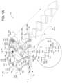
- FIG. 1 Ais a perspective view of an example robot standing atop a landing of a staircase.
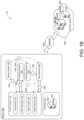
- FIG. 1 Bis a schematic view of example systems of the robot of FIG. 1 A .
- FIG. 1 Cis a perspective view of an example environment traversed by the robot of FIG. 1 A .
- FIGS. 2 A- 2 Care schematic views of example stair detectors of the robot of FIG. 1 A .
- FIG. 3is a flow chart of an example arrangement of operations for a method of identifying stairs from footfalls.
- FIG. 4is a schematic view of an example computing device that may be used to implement the systems and methods described herein.
- the robotsmay encounter terrain (e.g., human-made structures) that requires precise leg movement and foot placement (i.e., distal end placement).
- terraine.g., human-made structures
- leg movement and foot placementi.e., distal end placement
- the movement control systems of the robotmay constrain the robot's movement to traverse the terrain in order to prevent mistakes, even small mistakes, which may lead to catastrophic issues for the robot.
- this taskrequires a degree of coordination (e.g., eye-to-foot coordination). Without the coordination, a human may misstep, slip, trip, or fall on the stairs.
- Robotsmay encounter the same misfortunes, but lack natural coordination. Therefore, robots need systems and methods to coordinate precise leg movements.
- FIG. 1 Ais an example of an environment 10 for a robot 100 .
- the environment 10generally refers to a spatial area associated with some type of terrain including stairs 20 , 20 a - n or stair-like terrain that may be traversed by the robot 100 (e.g., using a control system 170 as shown in FIG. 1 B ).
- Systems of the robot 100are responsible for coordinating and/or moving the robot 100 about the environment 10 .
- systems of the robot 100may analyze the terrain, plan motion trajectories for the robot 100 (e.g., with a path generator 174 , a step planner 176 , a body planner 178 ), and/or instruct the robot 100 to perform various movements (e.g., with a controller 172 ).
- the robot 100may use various systems of the robot 100 together to attempt to successfully traverse the environment 10 while avoiding collisions C and/or damage to the robot 100 or the robot's environment 10 .
- Stairs 20 , 20 a - ngenerally refer to a group of more than one stair 20 (i.e., a group of n stairs 20 ) designed to bridge a vertical distance.
- stairs 20 a - ntypically run a horizontal distance with a given rise in vertical height over a pitch (or pitch line).
- Each stair 20traditionally includes a tread 22 and a riser 24 .
- the tread 22 of a stair 20refers to a horizontal part of the stair 20 that is stepped on while a riser 24 refers to a vertical portion of the stair 20 between each tread 22 .
- each stair 20spans a tread depth “d” measuring from an outer edge 26 of a stair 20 to the riser 24 between stairs 20 .
- some stairs 20also include nosing as part of the edge 26 for safety purposes. Nosing, as shown in FIG. 1 A , is a part of the tread 22 that protrudes over a riser 24 beneath the tread 22 .
- the nosing(shown as edge 26 a ) is part of the tread 22 a and protrudes over the riser 24 a.
- a set of stairs 20may be preceded by or include a platform or support surface 12 (e.g., a level support surface).
- a landingrefers to a level platform or support surface 12 at a top of a set of stairs 20 or at a location between stairs 20 .
- a landingoccurs where a direction of the stairs 20 change or between a particular number of stairs 20 (i.e., a flight of stairs 20 that connects two floors).
- FIG. 1 Aillustrates the robot 100 standing on a landing at the top of a set of stairs 20 .
- Stair-like terrainmore generally refers to terrain that varies in height over some distance. Stair-like terrain may resemble stairs in terms of a change in elevation (e.g., an inclined pitch with a gain in elevation or a declined pitch with a loss in elevation). However, with stair-like terrain the delineation of treads 22 and risers 24 is not as obvious. Rather, stair-like terrain may refer to terrain with tread-like portions that allow a robot to have enough traction to plant a stance limb and sequentially or simultaneously use a leading limb to ascend or to descend over an adjacent vertical obstruction (resembling a riser) within the terrain. For example, stair-like terrain my include rubble, an inclined rock scramble, damaged or deteriorating traditional stairs, etc.
- the robot 100includes a body 110 with locomotion based structures such as legs 120 a - d coupled to the body 110 that enable the robot 100 to move about the environment 10 .
- each leg 120is an articulable structure such that one or more joints J permit members 122 of the leg 120 to move.
- each leg 120includes a hip joint J H coupling an upper member 122 , 122 U of the leg 120 to the body 110 and a knee joint J K coupling the upper member 122 U of the leg 120 to a lower member 122 L of the leg 120 .
- the hip joint J Hmay be further broken down into abduction-adduction rotation of the hip joint J H designated as “J Hx ” for occurring in a frontal plane of the robot 100 (i.e., a X-Z plane extending in directions of a x-direction axis A x and the z-direction axis A Z ) and a flexion-extension rotation of the hip joint J H designated as “J Hy ” for occurring in a sagittal plane of the robot 100 (i.e., a Y-Z plane extending in directions of a y-direction axis A Y and the z-direction axis A Z ).
- the robot 100may include any number of legs or locomotive based structures (e.g., a biped or humanoid robot with two legs) that provide a means to traverse the terrain within the environment 10 .
- legs or locomotive based structurese.g., a biped or humanoid robot with two legs
- each leg 120has a distal end 124 that contacts a surface 12 of the terrain (i.e., a traction surface).
- the distal end 124 of the leg 120is the end of the leg 120 used by the robot 100 to pivot, plant, or generally provide traction during movement of the robot 100 .
- the distal end 124 of a leg 120corresponds to a foot of the robot 100 .
- the distal end 124 of the leg 120includes an ankle joint J A such that the distal end 124 is articulable with respect to the lower member 122 L of the leg 120 .
- the robot 100has a vertical gravitational axis (e.g., shown as a Z-direction axis A Z ) along a direction of gravity, and a center of mass CM, which is a point where the weighted relative position of the distributed mass of the robot 100 sums to zero.
- the robot 100further has a pose P based on the CM relative to the vertical gravitational axis A Z (i.e., the fixed reference frame with respect to gravity) to define a particular attitude or stance assumed by the robot 100 .
- the attitude of the robot 100can be defined by an orientation or an angular position of the robot 100 in space.
- a heightgenerally refers to a distance along (e.g., parallel to) the z-direction (i.e., z-axis A Z ).
- the sagittal plane of the robot 100corresponds to the Y-Z plane extending in directions of a y-direction axis A Y and the z-direction axis A Z . In other words, the sagittal plane bisects the robot 100 into a left and right side.
- a ground plane(also referred to as a transverse plane) spans the X-Y plane by extending in directions of the x-direction axis A X and the y-direction axis A Y .
- the ground planerefers to a support surface 12 where distal ends 124 of the legs 120 of the robot 100 may generate traction to help the robot 100 move about the environment 10 .
- Another anatomical plane of the robot 100is the frontal plane that extends across the body 110 of the robot 100 (e.g., from a left side of the robot 100 with a first leg 120 a to a right side of the robot 100 with a second leg 120 b ).
- the frontal planespans the X-Z plane by extending in directions of the x-direction axis A X and the z-direction axis A z .
- a gait cyclebegins when a leg 120 touches down or contacts a support surface 12 and ends when that same leg 120 once again contacts the ground surface 12 .
- touchdownis also referred to as a footfall defining a point or position where the distal end 124 of a locomotion-based structure 120 falls into contact with the support surface 12 .
- the gait cyclemay predominantly be divided into two phases, a swing phase and a stance phase.
- a leg 120performs (i) lift-off from the support surface 12 (also sometimes referred to as toe-off and the transition between the stance phase and swing phase), (ii) flexion at a knee joint J K of the leg 120 , (iii) extension of the knee joint J K of the leg 120 , and (iv) touchdown (or footfall) back to the support surface 12 .
- a leg 120 in the swing phaseis referred to as a swing leg 120 SW .
- the swing leg 120 SWproceeds through the movement of the swing phase 120 SW , another leg 120 performs the stance phase.
- the stance phaserefers to a period of time where a distal end 124 (e.g., a foot) of the leg 120 is on the support surface 12 .
- a leg 120performs (i) initial support surface contact which triggers a transition from the swing phase to the stance phase, (ii) loading response where the leg 120 dampens support surface contact, (iii) mid-stance support for when the contralateral leg (i.e., the swing leg 120 SW ) lifts-off and swings to a balanced position (about halfway through the swing phase), and (iv) terminal-stance support from when the robot's COM is over the leg 120 until the contralateral leg 120 touches down to the support surface 12 .
- a leg 120 in the stance phaseis referred to as a stance leg 120 ST .
- the robot 100includes a sensor system 130 with one or more sensors 132 , 132 a - n (e.g., shown as a first sensor 132 , 132 a and a second sensor 132 , 132 b ).
- the sensors 132may include vision/image sensors, inertial sensors (e.g., an inertial measurement unit (IMU)), force sensors, and/or kinematic sensors.
- IMUinertial measurement unit
- sensors 132include a camera such as a stereo camera, a scanning light-detection and ranging (LIDAR) sensor, or a scanning laser-detection and ranging (LADAR) sensor.
- LIDARscanning light-detection and ranging
- LADARscanning laser-detection and ranging
- the robot 100includes two stereo cameras as sensors 132 at a front end of the body 110 of the robot 100 (i.e., a head of the robot 100 adjacent the front legs 120 a - b of the robot 100 ) and one stereo camera as a sensor 132 at a back end of the body 110 of the robot 100 adjacent rear legs 120 c - d of the robot 100 .
- the sensor 132has a corresponding field(s) of view F v defining a sensing range or region corresponding to the sensor 132 .
- FIG. 1 Adepicts a field of a view F V for the robot 100 .
- Each sensor 132may be pivotable and/or rotatable such that the sensor 132 may, for example, change the field of view F V about one or more axis (e.g., an x-axis, a y-axis, or a z-axis in relation to a ground plane).
- axise.g., an x-axis, a y-axis, or a z-axis in relation to a ground plane.
- the sensor system 130includes sensor(s) 132 coupled to a joint J.
- these sensors 132couple to a motor that operates a joint J of the robot 100 (e.g., sensors 132 , 132 a - b ).
- these sensors 132generate joint dynamics 134 , 134 JD in the form of joint-based sensor data 134 .
- Joint dynamics 134 JD collected as joint-based sensor data 134may include joint angles (e.g., an upper member 122 U relative to a lower member 122 L ), joint speed (e.g., joint angular velocity or joint angular acceleration), and/or joint torques experienced at a joint J (also referred to as joint forces).
- joint-based sensor data 134 generated by one or more sensors 132may be raw sensor data, data that is further processed to form different types of joint dynamics 134 JD , or some combination of both.
- a sensor 132measures joint position (or a position of member(s) 122 coupled at a joint J) and systems of the robot 100 perform further processing to derive velocity and/or acceleration from the positional data.
- a sensor 132is configured to measure velocity and/or acceleration directly.
- the sensor system 130When surveying a field of view F V with a sensor 132 , the sensor system 130 generates sensor data 134 (also referred to as image data) corresponding to the field of view F V .
- the sensor data 134is image data that corresponds to a three-dimensional volumetric point cloud generated by a three-dimensional volumetric image sensor 132 .
- the sensor system 130gathers pose data for the robot 100 that includes inertial measurement data (e.g., measured by an IMU).
- the pose dataincludes kinematic data and/or orientation data about the robot 100 , for instance, kinematic data and/or orientation data about joints J or other portions of a leg 120 of the robot 100 .
- a perception system 180 of the robot 100may generate maps 182 for the terrain about the environment 10 .
- the sensor system 130gathers sensor data 134 relating to the terrain of the environment 10 and/or structure of the robot 100 (e.g., joint dynamics and/or odometry of the robot 100 ).
- FIG. 1 Adepicts the robot 100 standing on a landing (i.e., level support surface) of a set of stairs 20 as the environment 10 of the robot 100 .
- the sensor system 130gathering sensor data 134 about the set of stairs 20 .
- a computing system 140is configured to store, to process, and/or to communicate the sensor data 134 to various systems of the robot 100 (e.g., the control system 170 , the perception system 180 , an odometry system 190 , and/or a stair modeler 200 ).
- the computing system 140 of the robot 100includes data processing hardware 142 and memory hardware 144 .
- the data processing hardware 142is configured to execute instructions stored in the memory hardware 144 to perform computing tasks related to activities (e.g., movement and/or movement based activities) for the robot 100 .
- the computing system 140refers to one or more locations of data processing hardware 142 and/or memory hardware 144 .
- the computing system 140is a local system located on the robot 100 .
- the computing system 140may be centralized (i.e., in a single location/area on the robot 100 , for example, the body 110 of the robot 100 ), decentralized (i.e., located at various locations about the robot 100 ), or a hybrid combination of both (e.g., where a majority of centralized hardware and a minority of decentralized hardware).
- a decentralized computing system 140may allow processing to occur at an activity location (e.g., at motor that moves a joint of a leg 120 ) while a centralized computing system 140 may allow for a central processing hub that communicates to systems located at various positions on the robot 100 (e.g., communicate to the motor that moves the joint of the leg 120 ).
- the computing system 140includes computing resources that are located remotely from the robot 100 .
- the computing system 140may communicate via a network 150 with a remote system 160 (e.g., a remote computer/server or a cloud-based environment).
- the remote system 160includes remote computing resources such as remote data processing hardware 162 and remote memory hardware 164 .
- sensor data 134 or other processed datae.g., data processing locally by the computing system 140
- the computing system 140is configured to utilize the remote resources 162 , 164 as extensions of the computing resources 142 , 144 such that resources of the computing system 140 may reside on resources of the remote system 160 .
- the robot 100includes a control system 170 and a perception system 180 .
- the perception system 180is configured to receive the sensor data 134 from the sensor system 130 and process the sensor data 134 to generate maps 182 . With the maps 182 generated by the perception system 180 , the perception system 180 may communicate the maps 182 to the control system 170 in order to perform controlled actions for the robot 100 , such as moving the robot 100 about the environment 10 .
- processing for the control system 170may focus on controlling the robot 100 while the processing for the perception system 180 focuses on interpreting the sensor data 134 gathered by the sensor system 130 . For instance, these systems 170 , 180 execute their processing in parallel to ensure accurate, fluid movement of the robot 100 in an environment 10 .
- control system 170includes at least one controller 172 , a path generator 174 , a step locator 176 , and a body planner 178 .
- the control system 170may be configured to communicate with at least one sensor system 130 and any other system of the robot 100 (e.g., the perception system 180 , the odometry system 190 , and/or the stair modeler 200 ).
- the control system 170performs operations and other functions using hardware 140 .
- the controller 172is configured to control movement of the robot 100 to traverse about the environment 10 based on input or feedback from the systems of the robot 100 (e.g., the control system 170 , the perception system 180 , the odometry system 190 , and/or the stair modeler 200 ). This may include movement between poses and/or behaviors of the robot 100 .
- the controller 172controls different footstep patterns, leg patterns, body movement patterns, or vision system sensing patterns.
- the control system 170includes specialty controllers 172 that are dedicated to a particular control purpose.
- the control system 170may include one or more stair controllers 172 dedicated to planning and coordinating the robot's movement to traverse a set of stairs 20 .
- a stair controller 172may ensure the footpath for a swing leg 120 SW maintains a swing height to clear a riser 24 and/or edge 26 of a stair 20 .
- Other specialty controllers 172may include the path generator 174 , the step locator 176 , and/or the body planner 178 . Referring to FIG. 1 B , the path generator 174 is configured to determine horizontal motion for the robot 100 .
- the horizontal motionrefers to translation (i.e., movement in the X-Y plane) and/or yaw (i.e., rotation about the Z-direction axis A Z ) of the robot 100 .
- the path generator 174determines obstacles within the environment 10 about the robot 100 based on the sensor data 134 .
- the path generator 174communicates the obstacles to the step locator 176 such that the step locator 176 may identify foot placements for legs 120 of the robot 100 (e.g., locations to place the distal ends 124 of the legs 120 of the robot 100 ).
- the step locator 176generates the foot placements (i.e., locations where the robot 100 should step) using inputs from the perceptions system 180 (e.g., map(s) 182 ).
- the body planner 178receives inputs from the perceptions system 180 (e.g., map(s) 182 ).
- the body planner 178is configured to adjust dynamics of the body 110 of the robot 100 (e.g., rotation, such as pitch or yaw and/or height of COM) to successfully move about the environment 10 .
- the perception system 180is a system of the robot 100 that helps the robot 100 to move more precisely in a terrain with various obstacles. As the sensors 132 collect sensor data 134 for the space about the robot 100 (i.e., the robot's environment 10 ), the perception system 180 uses the sensor data 134 to form one or more maps 182 for the environment 10 . Once the perception system 180 generates a map 182 , the perception system 180 is also configured to add information to the map 182 (e.g., by projecting sensor data 134 on a preexisting map) and/or to remove information from the map 182 .
- the odometry system 190is configured to measure where the robot 100 is located within a world reference frame (e.g., the environment 10 ) and how fast the robot 100 is moving in that world reference frame. In other words, the odometry system 190 generates odometry information 192 as one or more estimations (e.g., measurements) for a characteristic of the robot 100 relative to a world reference frame. In some examples, the odometry system 190 receives sensor data 134 from a sensor 132 such as an IMU (e.g., accelerometer(s) and/or gyro(s)).
- a sensor 132such as an IMU (e.g., accelerometer(s) and/or gyro(s)).
- the odometry system 190may generate odometry information 192 based on an assumption that when a distal end 124 of a leg 120 is in contact with the ground surface 12 and not slipping, the distal end 124 is stationary. By combining this assumption with the sensor data 134 , the odometry system 190 generates odometry information 192 regarding robot motion relative to the world reference frame (e.g., the environment 10 ). In other words, the odometry system 190 accounts for kinematics and inertial measurements to produce estimations about the robot 100 with respect to the world reference frame.
- the world reference framee.g., the environment 10
- the robot 100is configured to traverse the environment 10 autonomously.
- the robot 100has an autonomous mode that, when engaged (e.g., by an operator of the robot 100 ), allows the system(s) of the robot 100 to operate the robot 100 to move about the environment 10 and/or perform actions within the environment 10 without further input from an external source (e.g., an entity that operates or supervisors the robot 100 by providing inputs to the robot 100 ).
- the robot 100first surveys the environment 10 to generate one or more maps 182 using the perception system 180 .
- the robot 100undertakes a mapping process to collect sensor data 134 of the environment 10 that will be autonomously or semi-autonomously traversed.
- an operatormanually drives the robot 100 (i.e., moves the robot 100 by user input) through the environment 10 (e.g., using a remote controller 172 ).
- the mapping processprovides environmental context to systems of the robot 100 to enable the systems to autonomously operate the robot 100 .
- the mapping processcalibrates the robot 100 to features in the environment 10 ; allowing the robot 100 to have the ability to autonomously or semi-autonomously operate subsequent to the mapping process.
- semi-autonomouslyrefers to the ability of the robot 100 to perform certain tasks (e.g., specialized tasks) independent of external inputs.
- the robot 100has a stair mode where the robot 100 is able to traverse stairs without external inputs or a palletizing mode where the robot 100 packs or unpacks boxes in an independent manner.
- an operator of the robot 100identifies (e.g., turns on a mode of the robot 100 ) that he or she wishes to operate the robot 100 autonomously or semi-autonomously (e.g., for specialized autonomous activities). Once the robot 100 receives such an identification, systems associated with the robot 100 may prompt the operator to perform the initial mapping process if it has not been previously performed by the robot 100 .
- stairs 20are a feature that may affect the robot's navigation of an environment 10 .
- stairs 20may pose a sudden hazard to the robot 100 when the robot 100 encounters stairs 20 . If the robot 100 approaches the stairs 20 from above and did not know ahead of time that the stairs 20 existed, the robot 100 may not have much time to decide whether the sudden perceived drop-off in elevation is actually safe for the robot 100 to navigate. For example, the robot 100 while navigating a hallway suddenly approaches the end of the hallway and first perceives that stairs 20 ascend/descend from a doorway perpendicular to the end of the hallway.
- the robot 100may prepare to navigate the stairs 20 ; increasing the robot's ability to navigate the stairs 20 successfully.
- the robot 100may position its body 110 , legs 120 , or structure to improve navigation of the stairs 20 .
- the robot 100may change the angles or heights of its sensors 132 to increase its capabilities to perceive the stairs 20 (e.g., avoid potential occlusions).
- the robot 100with its sensors 132 , may peer upwards, downwards, and/or change its body height to optimize its perception of the stair structure.
- the robot 100is configured to navigate the stairs 20 at a particular orientation or pose P (e.g., alignment) such that the robot 100 minimizes structural collisions with the stairs 20 themselves.
- the robot 100descends stairs backwards (e.g., head up and rear legs 120 first) to prevent articulation of its locomotion structures 120 from colliding with the risers 24 of the stairs 20 .
- the robot 100may need to turn around.
- the robot 100may be configured to center itself with respect to the stairs 20 in order to provide the robot 100 with the greatest lateral space as the robot 100 ascends/descends stairs 20 .
- Each of these particular alignments, used to improve the ability of the robot 100 to navigate the stairs 20may be planned in advance when the initial mapping process identifies stairs 20 in the environment 10 .
- the robot 100is able to automatically engage a stair mode for the robot 100 .
- the robot 100activates the stair mode when the robot 100 is adjacent to or within a threshold distance of the stairs 20 .
- the robot 100is configured to prevent or to warn a user or operator from engaging the stair mode when, based on the initial mapping process, the robot 100 is aware that the robot 100 is not within a particular range of stairs 20 .
- the robot 100may conserve processing resources (e.g., CPU usage) and/or intelligently use computing resources.
- the robot 100is aware that the robot 100 does not need to detect stairs 20 and optimizes its detection for other features in the environment 10 .
- the robot 100establishes waypoints Wp, Wp 1-i in the environment 10 .
- These waypointsmay incorporate odometry information from the odemetry system 190 along with information about the robot 100 such as pose P and other kinematics of the robot 100 .
- the robot 100establishes waypoints Wp periodically (e.g., every couple meters or when the robot 100 changes direction).
- An edge Econnects each waypoint Wp to its neighboring waypoints Wp along the traversal path taken by the robot 100 .
- Each edge Emay serve as storage for information about the robot 100 that occurred while the robot 100 travels along the edge E between two waypoints Wp. For instance, the edge E stores footfalls 128 that occurred by the robot 100 when the robot 100 moved between the waypoints Wp along the edge E.
- a footfall 128refers to a spatial location where a distal end 124 of a locomotion structure 120 of the robot 100 contacted the support surface 12 .
- a footfall 128may also be referred to interchangeably as a footfall location.
- the footfall 128corresponds to a touchdown for a foot 124 of a leg 120 of the robot 100 . Since a footfall 128 includes a spatial location in the environment 10 where a touchdown occurred, the footfall 128 includes coordinate/odometry information to identify the location in the environment 10 .
- the location information corresponding to a footfall 128may be relative location information (e.g., relative to a position of a waypoint Wp or other feature in the environment 10 ) or global location information.
- the footfall 128has a three dimensional coordinate position relative to the global world reference frame (e.g., corresponds to an x, y, z location).
- systemse.g., the sensor system 130 , perception system 180 , and/or odometry system 190 ) of the robot 100 are able to determine that a footfall 128 occurs and to store the footfall 128 (e.g., locational/contact information about the footfall 128 and/or the robot 100 at the time of the footfall 128 ).
- the footfall 128e.g., locational/contact information about the footfall 128 and/or the robot 100 at the time of the footfall 128 .
- each time a foot 124 of the robot 100 contacts a support surface 12one or more sensors 132 of the robot 100 detect the contact as a footfall 128 .
- systemse.g., the perception system 180 and/or odometry system 190 of the robot 100 record footfalls 128 by querying sensor data 134 from contact detection sensors 132 (e.g., sensors 132 that measure forces experienced at the legs/feet 120 , 124 of the robot 100 ) to determine whether a particular foot 124 of the robot 100 is in contact with a support surface 12 at the time of the query.
- contact detection sensors 132e.g., sensors 132 that measure forces experienced at the legs/feet 120 , 124 of the robot 100
- the systems of the robot 100determine the location of the contact (e.g., in the world reference frame) and store this information along with the footfall 128 .
- the perception system 180stores footfalls 128 in data structures associated with edges E for a map 182 generated during the initial mapping process.
- FIG. 1 Cillustrates an initial map 182 of the environment 10 generated by the perception system 180 during execution of the initial mapping process.
- the robot 100was driven in a loop that ascended two sets of stairs 20 and descended two sets of stairs 20 .
- systems of the robot 100determine footfalls 128 that occur.
- the sets of footfalls 128 , 128 a - nare associated (e.g., stored in data structures) with edges E, E 1-n (e.g., shown as ten edges E 1-10 ) between the waypoints Wp, Wp 1-14 , but the footfalls 128 may be stored in any data location accessible to systems of the robot 100 .
- a stair detector 200is configured to determine whether a set of stairs 20 exists based on the footfalls 128 .
- the stair detector 200identifies four stair models 202 , 202 a - d along the path traveled by the robot 100 .
- a stair detector 200functions at or in conjunction with the initial mapping process to receive footfalls 128 as inputs and generate one or more stair models 202 as outputs.
- the stair detector 200may be configured to first determine footfalls 128 from sensor data 134 and then generate one or more stair models 202 when the footfalls 128 indicate a strong likelihood that stairs 20 exist within the environment 10 .
- the stair detector 200may be part of other systems of the robot 100 (e.g., the perception system 180 ) or its own dedicated system of the robot 100 (e.g., includes its own dedicated processing resources).
- the stair detector 200includes a candidate identifier 210 and a stair recognizer 220 .
- the candidate identifier 210is configured to determine a pair of footfalls 128 defined as a candidate pair 212 of footfalls 128 .
- a candidate pair 212refers to two footfalls 128 nearby in position that have a spatial relationship indicative of a structure of a stair 20 .
- the identifier 210is configured to identify two footfalls 128 whose vertical and horizontal spacing appears to correspond to a foot 124 of the robot 100 moving from a first stair 20 a to a second stair 20 b to clear a riser 24 .
- the identifier 210is configured with parameters set to correspond to threshold distances (e.g., a thresholds for a vertical distance and a horizontal distance) that are typical of a stair structure and/or movement patterns for the legs 120 of the robot 100 .
- the parametersinclude a stair height threshold 214 and a stair depth threshold 216 .
- the identifier 210determines whether the footfalls 128 satisfy each threshold 214 , 216 before classifying the footfalls 128 as a candidate pair 212 . For instance, The identifier 210 may determine whether the footfalls 128 satisfy these thresholds 214 , 216 in either order (e.g., first the stair height threshold 214 and then the stair depth threshold 216 or vice versa).
- the identifier 210determines a locational position of each footfall 128 (e.g., x, y, z coordinate position) and determines a distance between each footfall 128 (e.g., with respect to each coordinate— ⁇ x, ⁇ y, ⁇ z).
- a height(e.g., vertical distance) generally refers to a measurement (e.g., ⁇ z) in the z-direction along an axis parallel to a gravitational axis of the robot 100 while the depth (e.g., horizontal distance) refers to a measurement in the XY plane (e.g., ⁇ x or ⁇ y) that occurs perpendicular to the gravitation axis of the robot 100 .
- the identifier 210compares these distances to the appropriate thresholds 214 , 216 . For instance, the identifier 210 compares the height distance measurement between the footfalls 128 to the stair height threshold 214 and a depth distance measurement between the footfalls 128 to the stair depth threshold 216 .
- the stair height threshold 214corresponds to a height range between a particular stair height minimum 204 min and a stair height maximum 204 max .
- the stair detector 200may be configured to ignore modeling a stair 20 when the height change is lower than the height minimum 204 min . That is, although shallow stairs 20 with riser heights less than the height minimum 204 min exist, these stairs 20 do not pose much of a navigability risk to the robot 100 and/or need special gait instructions.
- the robot 100due to range of motion limitations and/or gait limitations, there is a particular height above which the robot 100 cannot step without a more powerful movement (e.g., a jump). In other words, the robot 100 has a maximum swing height that ensures its feet 124 clear an object below this height. As such, a height greater than this height (i.e., the stair height maximum 204 max ), even if the height of a stair riser 24 (e.g., a large amphitheater stair), is an outlier height that stair detector 200 may be configured to ignore when modeling a stair 20 .
- the identifier 210may configure the stair height threshold 214 as a range of height values between the stair height minimum 204 min and the stair height maximum 204 max .
- the height measurementsatisfies the stair height threshold 214 .
- the height measurementfails to satisfy the stair height threshold 214 .
- the identifier 210when the identifier 210 evaluates a potential candidate pair of footfalls 128 , the identifier 210 , in a general sense, determines whether footfalls 128 (e.g., shown as a first footfall 128 , 128 a and a second footfall 128 , 128 b ) near each other in location satisfy the thresholds 214 , 216 while also determining whether another footfall 128 does not invalidate the pair of footfalls 128 , 128 a - b as a candidate pair 212 . For example, although two footfalls 128 may be near each other, a third footfall 128 may occur between the two footfalls 128 . For instance, FIG.
- FIG. 2 Billustrates, in the upper right-hand corner, the identifier 210 evaluating a potential candidate pair 128 a - b with a dotted line segment between two footfalls 128 (e.g., shown as grey shaded ovals).
- no intervening footfall 128exists between these two footfalls 128 a - b .
- an intervening footfall 128exists between the two footfalls 128 being evaluated by the identifier 210 ; invalidating the pair of footfalls 128 as a candidate pair 212 .
- the identifier 210tries to best alleviate the issue of an intervening invalidating footfalls 128 between a potential candidate pair by performing the candidate pair determination on footfalls 128 that are most adjacent to each other (e.g., based on coordinate position).
- the examples outlined with a darker boxrefer to footfalls 128 that the identifier 210 has determined to be candidate pairs 212
- the examples with a dotted boxoutline potential candidate pairs that the identifier 210 determined to not be a candidate pair 212 .
- the second examplefails to satisfy the stair height threshold 214 .
- the third examplehas an intervening footfall 128 .
- the sixth exampleis an evaluation of the third example with respect to adjacent footfalls 128 , but the potential candidate pair does not satisfy either threshold 214 , 216 (and is below the stair height minimum 204 min ).
- the stair detector 200also includes a stair recognizer 220 .
- the stair recognizer 220is configured to, based on candidate pairs 212 of footfalls 128 , determine stairs 20 corresponding to the footfalls 128 of the candidate pairs 212 .
- the identifier 210 of the detector 200is tasked with identifying footfalls 128 that occur on treads 22 of a stair 20 based positional data while the recognizer 220 is then configured to model each stair 20 for a stair model 202 based on clusters of footfalls 128 corresponding to candidate pairs 212 .
- the identifier 210serves as a form of a filter that filters out footfalls 128 that likely do not exist on stairs 20 and the recognizer 220 constructs the model 202 based on the remaining filtered footfall data.
- the stair recognizer 220is configured to identify that each footfall 128 of a candidate pair 212 corresponds to an adjacent stair 20 on a set of stairs 20 .
- a first footfall 128 of a candidate pair 212occurs on a first stair 20 a while a second footfall 128 of the candidate pair 212 occurs on a second stair 20 b (e.g., above or below the first stair 20 a ).
- the recognizer 220is configured to cluster footfalls 128 of the candidate pairs 212 communicated from the identifier 210 .
- the recognizer 220clusters the footfalls 128 based on a height (e.g., z-coordinate) corresponding to each footfall 128 . For example, the recognizer 220 clusters each footfall 128 of the candidate pairs 212 that is within a particular height tolerance of each other. In some examples, the recognizer 220 determines average height intervals corresponding to all footfalls 128 of candidate pairs 212 .
- the recognizer 220identifies three bands of heights (e.g., three discrete height range intervals) within all the footfalls 128 of the candidate pairs 212 ; a first band that corresponds to a first stair 20 a, a second band that corresponds to a second stair 20 b, and a third band that corresponds to a third stair 20 c. From this identification, the recognizer 220 defines each band as a cluster group 222 corresponding to a stair 20 for the model 202 . Here, the recognizer 220 generates a stair 20 for the model 202 for each cluster group 222 .
- three bands of heightse.g., three discrete height range intervals
- the recognizer 220may define the stair 20 in the model 202 to exist at a z-coordinate height corresponding to the average height for all footfalls 128 within a given cluster group 222 .
- the recognizer 220helps ensure that some flexion in the stair structure from a foot contact during footfall generation does not lead to inaccuracies for the actual z-height of a top surface of a tread 22 of a stair 20 .
- the recognizer 220has established where it believes top surfaces for treads 22 of the stairs 20 to be, but the stair model 202 still lacks some form of horizontal delineation between each stair 20 in the model 202 .
- the recognizer 220defines an edge 26 of each stair 20 to be where one cluster group 222 changes to its neighboring cluster group 222 .
- FIG. 2 Cdepicts a first line 224 , 224 a as a stair edge 26 for the model 202 between the first cluster group 222 , 222 a and a second cluster group 222 b.
- the recognizer 220determines the center of each cluster group 222 (e.g., the centroids of the collection of footfalls 128 included in a cluster group 222 ).
- the recognizer 220define the vector direction V D as a vector extending from a cluster group 222 at a first end of a stair model 202 to a cluster group 222 at a second end of the stair model 202 .
- FIG. 2 Ctherefore, depicts the vector direction V D extending through center points of the first, second, and third cluster groups 222 a - c .
- the method 300generates a stair model 202 by representing each of the cluster groups 222 as a corresponding stair 20 among a set of stairs 20 , 20 a - n in the robot environment 10 and delineating each stair 20 based on a respective midpoint MP between each adjacent cluster group 222 .
- FIG. 4is schematic view of an example computing device 400 that may be used to implement the systems and methods described in this document.
- the computing device 400is intended to represent various forms of digital computers, such as laptops, desktops, workstations, personal digital assistants, servers, blade servers, mainframes, and other appropriate computers.
- the components shown here, their connections and relationships, and their functions,are meant to be exemplary only, and are not meant to limit implementations of the inventions described and/or claimed in this document.
- the computing device 400includes a processor 410 (e.g., data processing hardware), memory 420 (e.g., memory hardware), a storage device 430 , a high-speed interface/controller 440 connecting to the memory 420 and high-speed expansion ports 450 , and a low speed interface/controller 460 connecting to a low speed bus 470 and a storage device 430 .
- a processor 410e.g., data processing hardware
- memory 420e.g., memory hardware
- storage device 430e.g., a high-speed interface/controller 440 connecting to the memory 420 and high-speed expansion ports 450
- a low speed interface/controller 460connecting to a low speed bus 470 and a storage device 430 .
- Each of the components 410 , 420 , 430 , 440 , 450 , and 460are interconnected using various busses, and may be mounted on a common motherboard or in other manners as appropriate.
- the processor 410can process instructions for execution within the computing device 400 , including instructions stored in the memory 420 or on the storage device 430 to display graphical information for a graphical user interface (GUI) on an external input/output device, such as display 480 coupled to high speed interface 440 .
- GUIgraphical user interface
- multiple processors and/or multiple busesmay be used, as appropriate, along with multiple memories and types of memory.
- multiple computing devices 400may be connected, with each device providing portions of the necessary operations (e.g., as a server bank, a group of blade servers, or a multi-processor system).
- the memory 420stores information non-transitorily within the computing device 400 .
- the memory 420may be a computer-readable medium, a volatile memory unit(s), or non-volatile memory unit(s).
- the non-transitory memory 420may be physical devices used to store programs (e.g., sequences of instructions) or data (e.g., program state information) on a temporary or permanent basis for use by the computing device 400 .
- non-volatile memoryexamples include, but are not limited to, flash memory and read-only memory (ROM)/programmable read-only memory (PROM)/erasable programmable read-only memory (EPROM)/electronically erasable programmable read-only memory (EEPROM) (e.g., typically used for firmware, such as boot programs).
- volatile memoryexamples include, but are not limited to, random access memory (RAM), dynamic random access memory (DRAM), static random access memory (SRAM), phase change memory (PCM) as well as disks or tapes.
- the storage device 430is capable of providing mass storage for the computing device 400 .
- the storage device 430is a computer-readable medium.
- the storage device 430may be a floppy disk device, a hard disk device, an optical disk device, or a tape device, a flash memory or other similar solid state memory device, or an array of devices, including devices in a storage area network or other configurations.
- a computer program productis tangibly embodied in an information carrier.
- the computer program productcontains instructions that, when executed, perform one or more methods, such as those described above.
- the information carrieris a computer- or machine-readable medium, such as the memory 420 , the storage device 430 , or memory on processor 410 .
- the high speed controller 440manages bandwidth-intensive operations for the computing device 400 , while the low speed controller 460 manages lower bandwidth-intensive operations. Such allocation of duties is exemplary only.
- the high-speed controller 440is coupled to the memory 420 , the display 480 (e.g., through a graphics processor or accelerator), and to the high-speed expansion ports 450 , which may accept various expansion cards (not shown).
- the low-speed controller 460is coupled to the storage device 430 and a low-speed expansion port 490 .
- the low-speed expansion port 490which may include various communication ports (e.g., USB, Bluetooth, Ethernet, wireless Ethernet), may be coupled to one or more input/output devices, such as a keyboard, a pointing device, a scanner, or a networking device such as a switch or router, e.g., through a network adapter.
- input/output devicessuch as a keyboard, a pointing device, a scanner, or a networking device such as a switch or router, e.g., through a network adapter.
- the computing device 400may be implemented in a number of different forms, as shown in the figure. For example, it may be implemented as a standard server 400 a or multiple times in a group of such servers 400 a, as a laptop computer 400 b, as part of a rack server system 400 c, or as part of the robot 100 .
- implementations of the systems and techniques described hereincan be realized in digital electronic and/or optical circuitry, integrated circuitry, specially designed ASICs (application specific integrated circuits), computer hardware, firmware, software, and/or combinations thereof.
- ASICsapplication specific integrated circuits
- These various implementationscan include implementation in one or more computer programs that are executable and/or interpretable on a programmable system including at least one programmable processor, which may be special or general purpose, coupled to receive data and instructions from, and to transmit data and instructions to, a storage system, at least one input device, and at least one output device.
- the processes and logic flows described in this specificationcan be performed by one or more programmable processors executing one or more computer programs to perform functions by operating on input data and generating output.
- the processes and logic flowscan also be performed by special purpose logic circuitry, e.g., an FPGA (field programmable gate array) or an ASIC (application specific integrated circuit).
- processors suitable for the execution of a computer programinclude, by way of example, both general and special purpose microprocessors, and any one or more processors of any kind of digital computer.
- a processorwill receive instructions and data from a read only memory or a random access memory or both.
- the essential elements of a computerare a processor for performing instructions and one or more memory devices for storing instructions and data.
- a computerwill also include, or be operatively coupled to receive data from or transfer data to, or both, one or more mass storage devices for storing data, e.g., magnetic, magneto optical disks, or optical disks.
- mass storage devicesfor storing data
- a computerneed not have such devices.
- Computer readable media suitable for storing computer program instructions and datainclude all forms of non-volatile memory, media and memory devices, including by way of example semiconductor memory devices, e.g., EPROM, EEPROM, and flash memory devices; magnetic disks, e.g., internal hard disks or removable disks; magneto optical disks; and CD ROM and DVD-ROM disks.
- the processor and the memorycan be supplemented by, or incorporated in, special purpose logic circuitry.
- one or more aspects of the disclosurecan be implemented on a computer having a display device, e.g., a CRT (cathode ray tube), LCD (liquid crystal display) monitor, or touch screen for displaying information to the user and optionally a keyboard and a pointing device, e.g., a mouse or a trackball, by which the user can provide input to the computer.
- a display devicee.g., a CRT (cathode ray tube), LCD (liquid crystal display) monitor, or touch screen for displaying information to the user and optionally a keyboard and a pointing device, e.g., a mouse or a trackball, by which the user can provide input to the computer.
- Other kinds of devicescan be used to provide interaction with a user as well; for example, feedback provided to the user can be any form of sensory feedback, e.g., visual feedback, auditory feedback, or tactile feedback; and input from the user can be received in any form, including acoustic, speech, or tactile input
Landscapes
- Engineering & Computer Science (AREA)
- Theoretical Computer Science (AREA)
- Physics & Mathematics (AREA)
- General Physics & Mathematics (AREA)
- Computer Vision & Pattern Recognition (AREA)
- Data Mining & Analysis (AREA)
- Multimedia (AREA)
- Mechanical Engineering (AREA)
- Transportation (AREA)
- Combustion & Propulsion (AREA)
- Chemical & Material Sciences (AREA)
- Evolutionary Computation (AREA)
- Artificial Intelligence (AREA)
- Health & Medical Sciences (AREA)
- Life Sciences & Earth Sciences (AREA)
- Software Systems (AREA)
- Bioinformatics & Cheminformatics (AREA)
- Bioinformatics & Computational Biology (AREA)
- Evolutionary Biology (AREA)
- General Engineering & Computer Science (AREA)
- General Health & Medical Sciences (AREA)
- Databases & Information Systems (AREA)
- Computing Systems (AREA)
- Medical Informatics (AREA)
- Public Health (AREA)
- Manipulator (AREA)
Abstract
Description
Claims (24)
Priority Applications (5)
| Application Number | Priority Date | Filing Date | Title |
|---|---|---|---|
| US16/877,680US12094195B2 (en) | 2020-04-20 | 2020-05-19 | Identifying stairs from footfalls |
| EP21725847.4AEP4139193A1 (en) | 2020-04-20 | 2021-03-18 | Identifying stairs from footfalls |
| PCT/US2021/022953WO2021216235A1 (en) | 2020-04-20 | 2021-03-18 | Identifying stairs from footfalls |
| CN202180040462.4ACN115667061A (en) | 2020-04-20 | 2021-03-18 | Identifying steps from footsteps |
| US18/444,491US20240193936A1 (en) | 2020-04-20 | 2024-02-16 | Identifying stairs from footfalls |
Applications Claiming Priority (2)
| Application Number | Priority Date | Filing Date | Title |
|---|---|---|---|
| US202063012614P | 2020-04-20 | 2020-04-20 | |
| US16/877,680US12094195B2 (en) | 2020-04-20 | 2020-05-19 | Identifying stairs from footfalls |
Related Child Applications (1)
| Application Number | Title | Priority Date | Filing Date |
|---|---|---|---|
| US18/444,491ContinuationUS20240193936A1 (en) | 2020-04-20 | 2024-02-16 | Identifying stairs from footfalls |
Publications (2)
| Publication Number | Publication Date |
|---|---|
| US20210323618A1 US20210323618A1 (en) | 2021-10-21 |
| US12094195B2true US12094195B2 (en) | 2024-09-17 |
Family
ID=78082562
Family Applications (2)
| Application Number | Title | Priority Date | Filing Date |
|---|---|---|---|
| US16/877,680Active2042-03-10US12094195B2 (en) | 2020-04-20 | 2020-05-19 | Identifying stairs from footfalls |
| US18/444,491PendingUS20240193936A1 (en) | 2020-04-20 | 2024-02-16 | Identifying stairs from footfalls |
Family Applications After (1)
| Application Number | Title | Priority Date | Filing Date |
|---|---|---|---|
| US18/444,491PendingUS20240193936A1 (en) | 2020-04-20 | 2024-02-16 | Identifying stairs from footfalls |
Country Status (4)
| Country | Link |
|---|---|
| US (2) | US12094195B2 (en) |
| EP (1) | EP4139193A1 (en) |
| CN (1) | CN115667061A (en) |
| WO (1) | WO2021216235A1 (en) |
Cited By (5)
| Publication number | Priority date | Publication date | Assignee | Title |
|---|---|---|---|---|
| USD1055129S1 (en)* | 2023-04-28 | 2024-12-24 | Hengzhi Future (Chongqing) Innovation Technology Co., Ltd. | Robot dog |
| USD1056983S1 (en)* | 2022-10-19 | 2025-01-07 | Hangzhou Yushu Technology Co., Ltd. | Quadruped robot |
| USD1064015S1 (en)* | 2023-03-06 | 2025-02-25 | Hangzhou Yushu Technology Co., Ltd. | Quadruped robot |
| USD1094505S1 (en)* | 2024-05-30 | 2025-09-23 | Limx Dynamics Technology Co., Ltd. | Robot |
| USD1098230S1 (en)* | 2024-09-20 | 2025-10-14 | Limx Dynamics Technology Co., Ltd. | Robot |
Families Citing this family (10)
| Publication number | Priority date | Publication date | Assignee | Title |
|---|---|---|---|---|
| US11548151B2 (en) | 2019-04-12 | 2023-01-10 | Boston Dynamics, Inc. | Robotically negotiating stairs |
| US11599128B2 (en) | 2020-04-22 | 2023-03-07 | Boston Dynamics, Inc. | Perception and fitting for a stair tracker |
| US12094195B2 (en) | 2020-04-20 | 2024-09-17 | Boston Dynamics, Inc. | Identifying stairs from footfalls |
| US12077229B2 (en) | 2020-04-22 | 2024-09-03 | Boston Dynamics, Inc. | Stair tracking for modeled and perceived terrain |
| CN114489092B (en)* | 2020-10-26 | 2023-07-18 | 腾讯科技(深圳)有限公司 | Foot robot motion control method, device, equipment and medium |
| US12304082B2 (en) | 2021-06-04 | 2025-05-20 | Boston Dynamics, Inc. | Alternate route finding for waypoint-based navigation maps |
| EP4348380A1 (en) | 2021-06-04 | 2024-04-10 | Boston Dynamics, Inc. | Directed exploration for navigation in dynamic environments |
| US20230418297A1 (en)* | 2022-06-23 | 2023-12-28 | Boston Dynamics, Inc. | Ground clutter avoidance for a mobile robot |
| US20230415343A1 (en) | 2022-06-23 | 2023-12-28 | Boston Dynamics, Inc. | Automatically trasitioning a robot to an operational mode optimized for particular terrain |
| US20240315910A1 (en)* | 2023-03-20 | 2024-09-26 | Boston Dynamics, Inc. | Perception system for a lower body powered exoskeleton |
Citations (119)
| Publication number | Priority date | Publication date | Assignee | Title |
|---|---|---|---|---|
| US3533483A (en) | 1967-02-10 | 1970-10-13 | Atomic Energy Authority Uk | Vehicle with vertically angularly adjustable asymmetrical wheeled frames |
| JPS5318342U (en) | 1976-07-28 | 1978-02-16 | ||
| JPS61257375A (en) | 1985-05-07 | 1986-11-14 | Mitsubishi Heavy Ind Ltd | Control method of leg type moving machine |
| JPS63176720A (en) | 1986-10-29 | 1988-07-21 | Mazda Motor Corp | Sun roof device for automobile |
| US5378969A (en) | 1992-04-15 | 1995-01-03 | Honda Giken Kogyo Kabushiki Kaisha | Navigation control system for mobile robot |
| US5402050A (en) | 1992-08-18 | 1995-03-28 | Honda Giken Kogyo Kabushiki Kaisha | Locomotion control system for mobile robot |
| US5416393A (en) | 1992-05-20 | 1995-05-16 | Honda Giken Kogyo Kabushiki Kaisha | Legged mobile robot foot structure |
| JPH07166974A (en) | 1993-12-17 | 1995-06-27 | Nippondenso Co Ltd | Abnormality detecting device for fuel evaporation on control mechanism |
| US5737217A (en) | 1993-12-30 | 1998-04-07 | Honda Giken Kogyo Kabushiki Kaisha | System for detecting and controlling the position of a mobile robot |
| US5838130A (en) | 1996-01-25 | 1998-11-17 | Honda Giken Kogyo Kabushiki Kaisha | Locomotion control system of legged mobile robot |
| US5872893A (en) | 1996-07-25 | 1999-02-16 | Honda Giken Kogyo Kabushiki Kaisha | Gait generation system of legged mobile robot |
| US5974366A (en) | 1996-12-18 | 1999-10-26 | Honda Giken Kogyo Kabushiki Kaisha | Apparatus for detecting the landing position of foot sole of legged moving robot |
| US6177776B1 (en) | 1997-06-20 | 2001-01-23 | Honda Giken Kogyo Kabushiki Kaisha | Apparatus for recognizing the landed state of foot of legged moving robot |
| US6317652B1 (en) | 1998-09-14 | 2001-11-13 | Honda Giken Kogyo Kabushiki Kaisha | Legged mobile robot |
| US6438454B1 (en) | 1999-11-25 | 2002-08-20 | Sony Corporation | Robot failure diagnosing system |
| US6527071B1 (en) | 1998-01-06 | 2003-03-04 | Commissariat A L'energie Atomique | Appliance stabilized by a gyroscope, in particular a two-wheeled robot |
| JP2003236781A (en) | 2002-02-15 | 2003-08-26 | Sony Corp | Legged mobile robot and control method for movement of the robot |
| WO2003090982A1 (en) | 2002-04-26 | 2003-11-06 | Honda Giken Kogyo Kabushiki Kaisha | Control device and footstep determination device for legged mobile robot |
| JP2003340763A (en) | 2002-05-24 | 2003-12-02 | Mitsubishi Heavy Ind Ltd | Biped walking robot step elevating/lowering method and biped walking robot |
| US6718231B2 (en) | 2000-09-28 | 2004-04-06 | Sony Corporation | Authoring system and authoring method, and storage medium |
| JP2004181600A (en) | 2002-12-05 | 2004-07-02 | Sony Corp | Leg type moving robot |
| EP1502843A2 (en) | 2003-07-31 | 2005-02-02 | Rheinmetall Landsysteme GmbH | Unmanned special offroad vehicle |
| US20050131581A1 (en) | 2003-09-19 | 2005-06-16 | Sony Corporation | Environment recognizing device, environment recognizing method, route planning device, route planning method and robot |
| WO2005087452A1 (en) | 2004-03-17 | 2005-09-22 | Sony Corporation | Robot device, behavior control method for the robot device, and moving device |
| US7053577B2 (en) | 2003-12-17 | 2006-05-30 | Sony Corporation | Robot and motion control method of robot |
| US20060185911A1 (en) | 2005-02-22 | 2006-08-24 | Gamma Two, Inc. | Stair climbing platform apparatus and method |
| US7127326B2 (en) | 2002-11-15 | 2006-10-24 | Iguana Robotics, Inc. | Certain principles of biomorphic robots including foot placement selection using non-geometric visual properties |
| JP2007041656A (en) | 2005-07-29 | 2007-02-15 | Sony Corp | Moving body control method, and moving body |
| US7219064B2 (en) | 2000-10-23 | 2007-05-15 | Sony Corporation | Legged robot, legged robot behavior control method, and storage medium |
| JP2007175831A (en) | 2005-12-28 | 2007-07-12 | Kawada Kogyo Kk | Walking robot |
| US20070257910A1 (en) | 2004-03-17 | 2007-11-08 | Steffen Gutmann | Method and Apparatus for Detecting Plane, and Robot Apparatus Having Apparatus for Detecting Plane |
| US7319918B2 (en) | 2001-12-28 | 2008-01-15 | Honda Giken Kogyo Kabushiki Kaisha | Gait generation device for legged mobile robot |
| US20080086241A1 (en) | 2006-10-06 | 2008-04-10 | Irobot Corporation | Autonomous Behaviors for a Remove Vehicle |
| US7482775B2 (en) | 2005-12-27 | 2009-01-27 | Fujitsu Limited | Robot controller |
| US20090321150A1 (en) | 2008-06-27 | 2009-12-31 | Samsung Electronics Co., Ltd. | Walking robot and method of controlling the same |
| US7653216B2 (en) | 2003-12-23 | 2010-01-26 | Carnegie Mellon University | Polyhedron recognition system |
| JP4476468B2 (en) | 2000-11-13 | 2010-06-09 | 本田技研工業株式会社 | Legged mobile robot |
| KR20100093833A (en) | 2009-02-17 | 2010-08-26 | 동아대학교 산학협력단 | Optimal Trajectory Design Method for Stepping Down the Stairs of Biped Humanoid Robots |
| KR20100093834A (en) | 2009-02-17 | 2010-08-26 | 동아대학교 산학협력단 | Method for generating optimal trajectory of a biped robot for walking up a staircase |
| JP4613692B2 (en) | 2005-05-23 | 2011-01-19 | コベルコ建機株式会社 | Self-propelled working machine |
| US7878276B2 (en) | 2005-07-08 | 2011-02-01 | H. Phillip Limbacher, Jr. | Ambulatory vehicle |
| US20110054690A1 (en) | 2009-08-25 | 2011-03-03 | Ehud Gal | Electro-mechanism for extending the capabilities of bilateral robotic platforms and a method for performing the same |
| US7912583B2 (en) | 2004-06-25 | 2011-03-22 | Sony Corporation | Environment map building method, environment map building apparatus and mobile robot apparatus |
| US20110208444A1 (en) | 2006-07-21 | 2011-08-25 | Solinsky James C | System and method for measuring balance and track motion in mammals |
| US20110231050A1 (en) | 2010-03-22 | 2011-09-22 | Goulding John R | In-Line Legged Robot Vehicle and Method for Operating |
| WO2012086604A1 (en) | 2010-12-24 | 2012-06-28 | 住友重機械工業株式会社 | Cleaning device |
| US20120215355A1 (en) | 2009-08-06 | 2012-08-23 | The Regents Of The University Of California | Multimodal Dynamic Robotic Systems |
| US8410732B2 (en) | 2006-03-03 | 2013-04-02 | Kristian Kassow | Programmable robot and user interface |
| JP2013072813A (en) | 2011-09-28 | 2013-04-22 | Honda Motor Co Ltd | Level difference part recognition device |
| US20130116820A1 (en) | 2011-11-03 | 2013-05-09 | Samsung Electronics Co., Ltd. | Walking robot and control method thereof |
| CN103273985A (en) | 2013-06-18 | 2013-09-04 | 辰星(天津)自动化设备有限公司 | Quadruped stair climbing robot mechanism |
| CN103273984A (en) | 2013-06-18 | 2013-09-04 | 辰星(天津)自动化设备有限公司 | Quadruped-imitating stair-climbing robot |
| JP5318342B2 (en) | 2006-10-31 | 2013-10-16 | 旭化成ケミカルズ株式会社 | Highly safe nitramine propellant with nitrocellulose binder |
| JP2013237126A (en) | 2012-05-15 | 2013-11-28 | Nsk Ltd | Device and method for generating gait data |
| US8688273B2 (en) | 2010-01-18 | 2014-04-01 | Samsung Electronics Co., Ltd. | Walking control apparatus of robot and method of controlling the same |
| US8737692B2 (en) | 2011-09-07 | 2014-05-27 | Honda Motor Co., Ltd. | Contact state estimating apparatus and trajectory generation apparatus |
| JP2014100767A (en) | 2012-11-20 | 2014-06-05 | Toshiba Corp | Level difference walking control device and method of multileg walking robot |
| US20140277718A1 (en) | 2013-03-15 | 2014-09-18 | Eugene Izhikevich | Adaptive predictor apparatus and methods |
| US20150073592A1 (en) | 2013-09-06 | 2015-03-12 | Honda Motor Co., Ltd. | Control device for legged mobile robot |
| JP2015054391A (en) | 2013-09-13 | 2015-03-23 | 本田技研工業株式会社 | Control device for legged mobile robot |
| JP2015080832A (en) | 2013-10-22 | 2015-04-27 | 本田技研工業株式会社 | Control system for leg type mobile robot |
| CN205034207U (en) | 2015-05-26 | 2016-02-17 | 上海大学 | Small -size bionical four -footed robot of electric drive |
| KR20160055731A (en) | 2016-04-01 | 2016-05-18 | 명지대학교 산학협력단 | Stair-climbing robot and control method thereof |
| US20160174459A1 (en) | 2014-12-22 | 2016-06-23 | Irobot Corporation | Robotic Mowing of Separated Lawn Areas |
| US9446518B1 (en) | 2014-11-11 | 2016-09-20 | Google Inc. | Leg collision avoidance in a robotic device |
| US20160297072A1 (en) | 2015-04-09 | 2016-10-13 | Irobot Corporation | Restricting movement of a mobile robot |
| US9499218B1 (en) | 2014-12-30 | 2016-11-22 | Google Inc. | Mechanically-timed footsteps for a robotic device |
| US9552640B2 (en) | 2011-11-23 | 2017-01-24 | Samsung Electronics Co., Ltd. | Method of recognizing stairs in three dimensional data image |
| US9561592B1 (en) | 2015-05-15 | 2017-02-07 | Google Inc. | Ground plane compensation for legged robots |
| US9594377B1 (en) | 2015-05-12 | 2017-03-14 | Google Inc. | Auto-height swing adjustment |
| CN106547206A (en) | 2016-06-29 | 2017-03-29 | 中南大学 | A kind of multi-foot robot dynamic stability based on strength of one's legs algorithm for estimating quantitatively judges method |
| US9630319B2 (en) | 2015-03-18 | 2017-04-25 | Irobot Corporation | Localization and mapping using physical features |
| US20170243365A1 (en) | 2014-08-22 | 2017-08-24 | Handicare Stairlifts B.V. | Method and system for designing a stair lift rail assembly |
| US9849926B2 (en) | 2014-07-23 | 2017-12-26 | Boston Dynamics, Inc. | Predictively adjustable hydraulic pressure rails |
| US9862095B2 (en) | 2014-09-24 | 2018-01-09 | Honda Motor Co., Ltd. | Control device for mobile robot |
| US9868210B1 (en) | 2015-12-30 | 2018-01-16 | Google Inc. | Methods and systems for planning a body position of a robotic device |
| US9878751B1 (en) | 2015-10-08 | 2018-01-30 | Boston Dynamics, Inc. | Three-piston ankle mechanism of a legged robot and associated control system |
| US20180035606A1 (en) | 2016-08-05 | 2018-02-08 | Romello Burdoucci | Smart Interactive and Autonomous Robotic Property Maintenance Apparatus, System, and Method |
| WO2018035320A1 (en) | 2016-08-18 | 2018-02-22 | The Trustees Of The University Of Pennsylvania | Systems and methods for controlling robotic behaviors |
| US9926025B1 (en) | 2014-08-25 | 2018-03-27 | Boston Dynamics, Inc. | Slip avoidance |
| CN107943021A (en) | 2017-10-19 | 2018-04-20 | 布法罗机器人科技(成都)有限公司 | A kind of adaptive stair activity control system and method |
| US9989970B1 (en) | 2016-08-03 | 2018-06-05 | X Development Llc | Systems and methods for robots having an adjustable multi-wheel |
| CN207780600U (en) | 2017-11-02 | 2018-08-28 | 常熟理工学院 | A kind of six sufficient search and rescue robots of wireless control |
| US10081098B1 (en) | 2014-08-25 | 2018-09-25 | Boston Dynamics, Inc. | Generalized coordinate surrogates for integrated estimation and control |
| US10099378B2 (en) | 2014-10-06 | 2018-10-16 | Honda Motor Co., Ltd. | Mobile robot |
| US10102429B2 (en) | 2014-12-16 | 2018-10-16 | Irobot Corporation | Systems and methods for capturing images and annotating the captured images with information |
| US10144342B2 (en) | 2014-09-03 | 2018-12-04 | Dyson Technology Limited | Mobile robot |
| US10179619B1 (en) | 2016-03-30 | 2019-01-15 | Schaft Inc. | Robotic foot sensor |
| CN109202901A (en) | 2018-08-29 | 2019-01-15 | 厦门理工学院 | A kind of biped robot's stair climbing gait planning method, apparatus and robot |
| US10196104B1 (en)* | 2016-05-04 | 2019-02-05 | Schaft Inc. | Terrain Evaluation for robot locomotion |
| CN109434795A (en) | 2018-10-29 | 2019-03-08 | 华中科技大学 | A kind of loading stair climbing robot with target following and automatic obstacle-avoiding |
| US20190156472A1 (en) | 2017-11-17 | 2019-05-23 | Kodak Alaris Inc. | Automated in-line object inspection |
| US10327969B2 (en) | 2015-11-30 | 2019-06-25 | Ford Global Technologies, Llc | Mobile transport device |
| US20190256159A1 (en) | 2017-06-30 | 2019-08-22 | Boe Technology Group Co., Ltd. | Image processing method and system, storage medium and moving system |
| US10414318B2 (en) | 2016-04-28 | 2019-09-17 | Rakkatec Oy | Arrangement for optimizing load position in relation to transportation vehicle |
| US10434651B1 (en) | 2014-08-26 | 2019-10-08 | Boston Dynamics, Inc. | Failure mode |
| US20190325763A1 (en) | 2018-04-22 | 2019-10-24 | Intel Corporation | Real and virtual collision-free movement of autonomous vehicles in mixed-reality environments |
| CN209615483U (en) | 2018-10-29 | 2019-11-12 | 华中科技大学 | A Stair Climbing Robot with Object Tracking and Automatic Obstacle Avoidance |
| US20190351555A1 (en)* | 2014-08-25 | 2019-11-21 | Boston Dynamics, Inc. | Handling Gait Disturbances with Asynchronous Timing |
| US20200117198A1 (en)* | 2018-10-12 | 2020-04-16 | Boston Dynamics, Inc. | Terrain Aware Step Planning System |
| US20200150655A1 (en) | 2017-03-02 | 2020-05-14 | RobArt GmbH | Method for controlling an autonomous, mobile robot |
| US10688667B1 (en) | 2016-01-25 | 2020-06-23 | Boston Dynamics, Inc. | Continuous slip recovery |
| US20200324412A1 (en) | 2019-04-12 | 2020-10-15 | Boston Dynamics, Inc. | Robotically Negotiating Stairs |
| US20200397202A1 (en) | 2017-11-17 | 2020-12-24 | RobArt GmbH | Floor treatment by means of an autonomous mobile robot |
| US10908612B2 (en) | 2018-03-29 | 2021-02-02 | Toyota Research Institute, Inc. | Systems and methods for an autonomous cart robot |
| US20210041887A1 (en) | 2019-08-06 | 2021-02-11 | Boston Dynamics, Inc. | Constrained Mobility Mapping |
| US20210096560A1 (en) | 2019-09-30 | 2021-04-01 | Irobot Corporation | Image capture devices for autonomous mobile robots and related systems and methods |
| US11059532B1 (en) | 2016-06-27 | 2021-07-13 | Boston Dynamics, Inc. | Control of robotic devices with non-constant body pitch |
| US11073842B1 (en) | 2020-04-22 | 2021-07-27 | Boston Dynamics, Inc. | Perception and fitting for a stair tracker |
| WO2021216235A1 (en) | 2020-04-20 | 2021-10-28 | Boston Dynamics, Inc. | Identifying stairs from footfalls |
| WO2021216231A1 (en) | 2020-04-22 | 2021-10-28 | Boston Dynamics, Inc. | Stair tracking for modeled and perceived terrain |
| US11298826B1 (en) | 2016-02-05 | 2022-04-12 | Boston Dynamics, Inc. | Modular robot system |
| US11383381B2 (en) | 2019-08-06 | 2022-07-12 | Boston Dynamics, Inc. | Footstep contact detection |
| US11413570B2 (en) | 2018-06-29 | 2022-08-16 | Munters Corporation | Rotary bed sorption system including recycled isolation loop and purge/regeneration loop |
| US11447195B2 (en) | 2019-08-06 | 2022-09-20 | Boston Dynamics, Inc. | Leg swing trajectories |
| US20220390952A1 (en) | 2021-06-04 | 2022-12-08 | Boston Dynamics, Inc. | Detecting negative obstacles |
| US20220388170A1 (en) | 2021-06-04 | 2022-12-08 | Boston Dynamics, Inc. | Alternate Route Finding for Waypoint-based Navigation Maps |
| US20220410390A1 (en) | 2019-10-14 | 2022-12-29 | Boston Dynamics, Inc. | Dynamic Planning Controller |
| US20230415343A1 (en) | 2022-06-23 | 2023-12-28 | Boston Dynamics, Inc. | Automatically trasitioning a robot to an operational mode optimized for particular terrain |
Family Cites Families (1)
| Publication number | Priority date | Publication date | Assignee | Title |
|---|---|---|---|---|
| KR100988960B1 (en)* | 2008-04-23 | 2010-10-20 | 한국도로공사 | Bridge inspection robot capable of climbing over obstacles |
- 2020
- 2020-05-19USUS16/877,680patent/US12094195B2/enactiveActive
- 2021
- 2021-03-18EPEP21725847.4Apatent/EP4139193A1/enactivePending
- 2021-03-18WOPCT/US2021/022953patent/WO2021216235A1/ennot_activeCeased
- 2021-03-18CNCN202180040462.4Apatent/CN115667061A/enactivePending
- 2024
- 2024-02-16USUS18/444,491patent/US20240193936A1/enactivePending
Patent Citations (157)
| Publication number | Priority date | Publication date | Assignee | Title |
|---|---|---|---|---|
| US3533483A (en) | 1967-02-10 | 1970-10-13 | Atomic Energy Authority Uk | Vehicle with vertically angularly adjustable asymmetrical wheeled frames |
| JPS5318342U (en) | 1976-07-28 | 1978-02-16 | ||
| JPS61257375A (en) | 1985-05-07 | 1986-11-14 | Mitsubishi Heavy Ind Ltd | Control method of leg type moving machine |
| JPS63176720A (en) | 1986-10-29 | 1988-07-21 | Mazda Motor Corp | Sun roof device for automobile |
| US5378969A (en) | 1992-04-15 | 1995-01-03 | Honda Giken Kogyo Kabushiki Kaisha | Navigation control system for mobile robot |
| US5416393A (en) | 1992-05-20 | 1995-05-16 | Honda Giken Kogyo Kabushiki Kaisha | Legged mobile robot foot structure |
| US5402050A (en) | 1992-08-18 | 1995-03-28 | Honda Giken Kogyo Kabushiki Kaisha | Locomotion control system for mobile robot |
| JPH07166974A (en) | 1993-12-17 | 1995-06-27 | Nippondenso Co Ltd | Abnormality detecting device for fuel evaporation on control mechanism |
| US6021363A (en) | 1993-12-30 | 2000-02-01 | Honda Giken Kogyo Kabushiki Kaisha | System for detecting and controlling the position of a mobile robot |
| US5737217A (en) | 1993-12-30 | 1998-04-07 | Honda Giken Kogyo Kabushiki Kaisha | System for detecting and controlling the position of a mobile robot |
| US5838130A (en) | 1996-01-25 | 1998-11-17 | Honda Giken Kogyo Kabushiki Kaisha | Locomotion control system of legged mobile robot |
| US5872893A (en) | 1996-07-25 | 1999-02-16 | Honda Giken Kogyo Kabushiki Kaisha | Gait generation system of legged mobile robot |
| US5974366A (en) | 1996-12-18 | 1999-10-26 | Honda Giken Kogyo Kabushiki Kaisha | Apparatus for detecting the landing position of foot sole of legged moving robot |
| US6177776B1 (en) | 1997-06-20 | 2001-01-23 | Honda Giken Kogyo Kabushiki Kaisha | Apparatus for recognizing the landed state of foot of legged moving robot |
| US6527071B1 (en) | 1998-01-06 | 2003-03-04 | Commissariat A L'energie Atomique | Appliance stabilized by a gyroscope, in particular a two-wheeled robot |
| US6317652B1 (en) | 1998-09-14 | 2001-11-13 | Honda Giken Kogyo Kabushiki Kaisha | Legged mobile robot |
| US6438454B1 (en) | 1999-11-25 | 2002-08-20 | Sony Corporation | Robot failure diagnosing system |
| US6718231B2 (en) | 2000-09-28 | 2004-04-06 | Sony Corporation | Authoring system and authoring method, and storage medium |
| US7219064B2 (en) | 2000-10-23 | 2007-05-15 | Sony Corporation | Legged robot, legged robot behavior control method, and storage medium |
| JP4476468B2 (en) | 2000-11-13 | 2010-06-09 | 本田技研工業株式会社 | Legged mobile robot |
| US7319918B2 (en) | 2001-12-28 | 2008-01-15 | Honda Giken Kogyo Kabushiki Kaisha | Gait generation device for legged mobile robot |
| JP2003236781A (en) | 2002-02-15 | 2003-08-26 | Sony Corp | Legged mobile robot and control method for movement of the robot |
| JP4295947B2 (en) | 2002-02-15 | 2009-07-15 | ソニー株式会社 | Legged mobile robot and its movement control method |
| WO2003090982A1 (en) | 2002-04-26 | 2003-11-06 | Honda Giken Kogyo Kabushiki Kaisha | Control device and footstep determination device for legged mobile robot |
| JP2003340763A (en) | 2002-05-24 | 2003-12-02 | Mitsubishi Heavy Ind Ltd | Biped walking robot step elevating/lowering method and biped walking robot |
| US7127326B2 (en) | 2002-11-15 | 2006-10-24 | Iguana Robotics, Inc. | Certain principles of biomorphic robots including foot placement selection using non-geometric visual properties |
| JP2004181600A (en) | 2002-12-05 | 2004-07-02 | Sony Corp | Leg type moving robot |
| EP1502843A2 (en) | 2003-07-31 | 2005-02-02 | Rheinmetall Landsysteme GmbH | Unmanned special offroad vehicle |
| US20050131581A1 (en) | 2003-09-19 | 2005-06-16 | Sony Corporation | Environment recognizing device, environment recognizing method, route planning device, route planning method and robot |
| US7053577B2 (en) | 2003-12-17 | 2006-05-30 | Sony Corporation | Robot and motion control method of robot |
| US7653216B2 (en) | 2003-12-23 | 2010-01-26 | Carnegie Mellon University | Polyhedron recognition system |
| WO2005087452A1 (en) | 2004-03-17 | 2005-09-22 | Sony Corporation | Robot device, behavior control method for the robot device, and moving device |
| US20070257910A1 (en) | 2004-03-17 | 2007-11-08 | Steffen Gutmann | Method and Apparatus for Detecting Plane, and Robot Apparatus Having Apparatus for Detecting Plane |
| US8289321B2 (en) | 2004-03-17 | 2012-10-16 | Sony Corporation | Method and apparatus for detecting plane, and robot apparatus having apparatus for detecting plane |
| US7912583B2 (en) | 2004-06-25 | 2011-03-22 | Sony Corporation | Environment map building method, environment map building apparatus and mobile robot apparatus |
| US20060185911A1 (en) | 2005-02-22 | 2006-08-24 | Gamma Two, Inc. | Stair climbing platform apparatus and method |
| JP4613692B2 (en) | 2005-05-23 | 2011-01-19 | コベルコ建機株式会社 | Self-propelled working machine |
| US7878276B2 (en) | 2005-07-08 | 2011-02-01 | H. Phillip Limbacher, Jr. | Ambulatory vehicle |
| JP2007041656A (en) | 2005-07-29 | 2007-02-15 | Sony Corp | Moving body control method, and moving body |
| US7482775B2 (en) | 2005-12-27 | 2009-01-27 | Fujitsu Limited | Robot controller |
| JP2007175831A (en) | 2005-12-28 | 2007-07-12 | Kawada Kogyo Kk | Walking robot |
| US8779715B2 (en) | 2006-03-03 | 2014-07-15 | Universal Robots Aps | Programmable robot and user interface |
| US8410732B2 (en) | 2006-03-03 | 2013-04-02 | Kristian Kassow | Programmable robot and user interface |
| US8614559B2 (en) | 2006-03-03 | 2013-12-24 | Universal Robots Aps | Programmable robot and user interface |
| US20110208444A1 (en) | 2006-07-21 | 2011-08-25 | Solinsky James C | System and method for measuring balance and track motion in mammals |
| US20080086241A1 (en) | 2006-10-06 | 2008-04-10 | Irobot Corporation | Autonomous Behaviors for a Remove Vehicle |
| JP5318342B2 (en) | 2006-10-31 | 2013-10-16 | 旭化成ケミカルズ株式会社 | Highly safe nitramine propellant with nitrocellulose binder |
| US20090321150A1 (en) | 2008-06-27 | 2009-12-31 | Samsung Electronics Co., Ltd. | Walking robot and method of controlling the same |
| KR20100093834A (en) | 2009-02-17 | 2010-08-26 | 동아대학교 산학협력단 | Method for generating optimal trajectory of a biped robot for walking up a staircase |
| KR20100093833A (en) | 2009-02-17 | 2010-08-26 | 동아대학교 산학협력단 | Optimal Trajectory Design Method for Stepping Down the Stairs of Biped Humanoid Robots |
| US20120215355A1 (en) | 2009-08-06 | 2012-08-23 | The Regents Of The University Of California | Multimodal Dynamic Robotic Systems |
| US20110054690A1 (en) | 2009-08-25 | 2011-03-03 | Ehud Gal | Electro-mechanism for extending the capabilities of bilateral robotic platforms and a method for performing the same |
| US8688273B2 (en) | 2010-01-18 | 2014-04-01 | Samsung Electronics Co., Ltd. | Walking control apparatus of robot and method of controlling the same |
| US9488987B2 (en) | 2010-03-22 | 2016-11-08 | John R. Goulding | Controlling roll and pitch of a single-track legged vehicle |
| US10126757B2 (en) | 2010-03-22 | 2018-11-13 | John R. Goulding | Single track legged vehicle |
| US8457830B2 (en) | 2010-03-22 | 2013-06-04 | John R. Goulding | In-line legged robot vehicle and method for operating |
| US9089968B2 (en) | 2010-03-22 | 2015-07-28 | John R. Goulding | Operating an in-line legged robot vehicle in ballistic flight |
| US20110231050A1 (en) | 2010-03-22 | 2011-09-22 | Goulding John R | In-Line Legged Robot Vehicle and Method for Operating |
| US8630763B2 (en) | 2010-03-22 | 2014-01-14 | John R. Goulding | Method of operating an in-line legged robot vehicle |
| WO2012086604A1 (en) | 2010-12-24 | 2012-06-28 | 住友重機械工業株式会社 | Cleaning device |
| US8737692B2 (en) | 2011-09-07 | 2014-05-27 | Honda Motor Co., Ltd. | Contact state estimating apparatus and trajectory generation apparatus |
| JP2013072813A (en) | 2011-09-28 | 2013-04-22 | Honda Motor Co Ltd | Level difference part recognition device |
| US20130116820A1 (en) | 2011-11-03 | 2013-05-09 | Samsung Electronics Co., Ltd. | Walking robot and control method thereof |
| US9552640B2 (en) | 2011-11-23 | 2017-01-24 | Samsung Electronics Co., Ltd. | Method of recognizing stairs in three dimensional data image |
| JP2013237126A (en) | 2012-05-15 | 2013-11-28 | Nsk Ltd | Device and method for generating gait data |
| JP2014100767A (en) | 2012-11-20 | 2014-06-05 | Toshiba Corp | Level difference walking control device and method of multileg walking robot |
| US20140277718A1 (en) | 2013-03-15 | 2014-09-18 | Eugene Izhikevich | Adaptive predictor apparatus and methods |
| CN103273984A (en) | 2013-06-18 | 2013-09-04 | 辰星(天津)自动化设备有限公司 | Quadruped-imitating stair-climbing robot |
| CN103273985A (en) | 2013-06-18 | 2013-09-04 | 辰星(天津)自动化设备有限公司 | Quadruped stair climbing robot mechanism |
| US9527538B2 (en) | 2013-09-06 | 2016-12-27 | Honda Motor Co., Ltd. | Control device for legged mobile robot |
| US20150073592A1 (en) | 2013-09-06 | 2015-03-12 | Honda Motor Co., Ltd. | Control device for legged mobile robot |
| JP2015051483A (en) | 2013-09-06 | 2015-03-19 | 本田技研工業株式会社 | Control device for legged mobile robot |
| JP2015054391A (en) | 2013-09-13 | 2015-03-23 | 本田技研工業株式会社 | Control device for legged mobile robot |
| JP2015080832A (en) | 2013-10-22 | 2015-04-27 | 本田技研工業株式会社 | Control system for leg type mobile robot |
| US11077898B2 (en) | 2014-07-23 | 2021-08-03 | Boston Dynamics, Inc. | Predictively adjustable hydraulic pressure rails |
| US9849926B2 (en) | 2014-07-23 | 2017-12-26 | Boston Dynamics, Inc. | Predictively adjustable hydraulic pressure rails |
| US20170243365A1 (en) | 2014-08-22 | 2017-08-24 | Handicare Stairlifts B.V. | Method and system for designing a stair lift rail assembly |
| US10081098B1 (en) | 2014-08-25 | 2018-09-25 | Boston Dynamics, Inc. | Generalized coordinate surrogates for integrated estimation and control |
| US20190351555A1 (en)* | 2014-08-25 | 2019-11-21 | Boston Dynamics, Inc. | Handling Gait Disturbances with Asynchronous Timing |
| US9926025B1 (en) | 2014-08-25 | 2018-03-27 | Boston Dynamics, Inc. | Slip avoidance |
| US10434651B1 (en) | 2014-08-26 | 2019-10-08 | Boston Dynamics, Inc. | Failure mode |
| US10144342B2 (en) | 2014-09-03 | 2018-12-04 | Dyson Technology Limited | Mobile robot |
| US9862095B2 (en) | 2014-09-24 | 2018-01-09 | Honda Motor Co., Ltd. | Control device for mobile robot |
| US10099378B2 (en) | 2014-10-06 | 2018-10-16 | Honda Motor Co., Ltd. | Mobile robot |
| US9446518B1 (en) | 2014-11-11 | 2016-09-20 | Google Inc. | Leg collision avoidance in a robotic device |
| US10102429B2 (en) | 2014-12-16 | 2018-10-16 | Irobot Corporation | Systems and methods for capturing images and annotating the captured images with information |
| US20160174459A1 (en) | 2014-12-22 | 2016-06-23 | Irobot Corporation | Robotic Mowing of Separated Lawn Areas |
| US9499218B1 (en) | 2014-12-30 | 2016-11-22 | Google Inc. | Mechanically-timed footsteps for a robotic device |
| US9630319B2 (en) | 2015-03-18 | 2017-04-25 | Irobot Corporation | Localization and mapping using physical features |
| US20160297072A1 (en) | 2015-04-09 | 2016-10-13 | Irobot Corporation | Restricting movement of a mobile robot |
| US9594377B1 (en) | 2015-05-12 | 2017-03-14 | Google Inc. | Auto-height swing adjustment |
| US10528051B1 (en) | 2015-05-12 | 2020-01-07 | Boston Dynamics, Inc. | Auto-height swing adjustment |
| US9908240B1 (en) | 2015-05-15 | 2018-03-06 | Boston Dynamics, Inc. | Ground plane compensation for legged robots |
| US9561592B1 (en) | 2015-05-15 | 2017-02-07 | Google Inc. | Ground plane compensation for legged robots |
| CN205034207U (en) | 2015-05-26 | 2016-02-17 | 上海大学 | Small -size bionical four -footed robot of electric drive |
| US9878751B1 (en) | 2015-10-08 | 2018-01-30 | Boston Dynamics, Inc. | Three-piston ankle mechanism of a legged robot and associated control system |
| US10327969B2 (en) | 2015-11-30 | 2019-06-25 | Ford Global Technologies, Llc | Mobile transport device |
| US9975245B1 (en) | 2015-12-30 | 2018-05-22 | Boston Dynamics, Inc. | Methods and systems for planning a body position of a robotic device |
| US9868210B1 (en) | 2015-12-30 | 2018-01-16 | Google Inc. | Methods and systems for planning a body position of a robotic device |
| US11247344B2 (en) | 2016-01-25 | 2022-02-15 | Boston Dynamics, Inc. | Continuous slip recovery |
| US10688667B1 (en) | 2016-01-25 | 2020-06-23 | Boston Dynamics, Inc. | Continuous slip recovery |
| US11298826B1 (en) | 2016-02-05 | 2022-04-12 | Boston Dynamics, Inc. | Modular robot system |
| US10179619B1 (en) | 2016-03-30 | 2019-01-15 | Schaft Inc. | Robotic foot sensor |
| KR20160055731A (en) | 2016-04-01 | 2016-05-18 | 명지대학교 산학협력단 | Stair-climbing robot and control method thereof |
| US10414318B2 (en) | 2016-04-28 | 2019-09-17 | Rakkatec Oy | Arrangement for optimizing load position in relation to transportation vehicle |
| US10196104B1 (en)* | 2016-05-04 | 2019-02-05 | Schaft Inc. | Terrain Evaluation for robot locomotion |
| US11059532B1 (en) | 2016-06-27 | 2021-07-13 | Boston Dynamics, Inc. | Control of robotic devices with non-constant body pitch |
| CN106547206B (en) | 2016-06-29 | 2019-08-06 | 中南大学 | A Quantitative Judgment Method for Dynamic Stability of Multi-legged Robot Based on Foot Force Estimation Algorithm |
| CN106547206A (en) | 2016-06-29 | 2017-03-29 | 中南大学 | A kind of multi-foot robot dynamic stability based on strength of one's legs algorithm for estimating quantitatively judges method |
| US9989970B1 (en) | 2016-08-03 | 2018-06-05 | X Development Llc | Systems and methods for robots having an adjustable multi-wheel |
| US20180035606A1 (en) | 2016-08-05 | 2018-02-08 | Romello Burdoucci | Smart Interactive and Autonomous Robotic Property Maintenance Apparatus, System, and Method |
| WO2018035320A1 (en) | 2016-08-18 | 2018-02-22 | The Trustees Of The University Of Pennsylvania | Systems and methods for controlling robotic behaviors |
| US20200150655A1 (en) | 2017-03-02 | 2020-05-14 | RobArt GmbH | Method for controlling an autonomous, mobile robot |
| US20190256159A1 (en) | 2017-06-30 | 2019-08-22 | Boe Technology Group Co., Ltd. | Image processing method and system, storage medium and moving system |
| CN107943021A (en) | 2017-10-19 | 2018-04-20 | 布法罗机器人科技(成都)有限公司 | A kind of adaptive stair activity control system and method |
| CN207780600U (en) | 2017-11-02 | 2018-08-28 | 常熟理工学院 | A kind of six sufficient search and rescue robots of wireless control |
| US20200397202A1 (en) | 2017-11-17 | 2020-12-24 | RobArt GmbH | Floor treatment by means of an autonomous mobile robot |
| US20190156472A1 (en) | 2017-11-17 | 2019-05-23 | Kodak Alaris Inc. | Automated in-line object inspection |
| US10908612B2 (en) | 2018-03-29 | 2021-02-02 | Toyota Research Institute, Inc. | Systems and methods for an autonomous cart robot |
| US20190325763A1 (en) | 2018-04-22 | 2019-10-24 | Intel Corporation | Real and virtual collision-free movement of autonomous vehicles in mixed-reality environments |
| US11413570B2 (en) | 2018-06-29 | 2022-08-16 | Munters Corporation | Rotary bed sorption system including recycled isolation loop and purge/regeneration loop |
| CN109202901A (en) | 2018-08-29 | 2019-01-15 | 厦门理工学院 | A kind of biped robot's stair climbing gait planning method, apparatus and robot |
| US20200117198A1 (en)* | 2018-10-12 | 2020-04-16 | Boston Dynamics, Inc. | Terrain Aware Step Planning System |
| US11287826B2 (en) | 2018-10-12 | 2022-03-29 | Boston Dynamics, Inc. | Terrain aware step planning system |
| CN209615483U (en) | 2018-10-29 | 2019-11-12 | 华中科技大学 | A Stair Climbing Robot with Object Tracking and Automatic Obstacle Avoidance |
| CN109434795A (en) | 2018-10-29 | 2019-03-08 | 华中科技大学 | A kind of loading stair climbing robot with target following and automatic obstacle-avoiding |
| US20230008677A1 (en) | 2019-04-12 | 2023-01-12 | Boston Dynamics, Inc. | Robotically negotiating stairs |
| US11123869B2 (en) | 2019-04-12 | 2021-09-21 | Boston Dynamics, Inc. | Robotically negotiating stairs |
| US11548151B2 (en) | 2019-04-12 | 2023-01-10 | Boston Dynamics, Inc. | Robotically negotiating stairs |
| US11660752B2 (en) | 2019-04-12 | 2023-05-30 | Boston Dynamics, Inc. | Perception and fitting for a stair tracker |
| WO2020209888A1 (en) | 2019-04-12 | 2020-10-15 | Boston Dynamics, Inc. | Robotically negotiating stairs |
| US20210331317A1 (en) | 2019-04-12 | 2021-10-28 | Boston Dynamics, Inc. | Perception and Fitting for a Stair Tracker |
| JP7351920B2 (en) | 2019-04-12 | 2023-09-27 | ボストン ダイナミクス,インコーポレイテッド | Method & Robot |
| US20200324412A1 (en) | 2019-04-12 | 2020-10-15 | Boston Dynamics, Inc. | Robotically Negotiating Stairs |
| CN113661462A (en) | 2019-04-12 | 2021-11-16 | 波士顿动力公司 | Robot passes through stairs |
| US11383381B2 (en) | 2019-08-06 | 2022-07-12 | Boston Dynamics, Inc. | Footstep contact detection |
| US20210041887A1 (en) | 2019-08-06 | 2021-02-11 | Boston Dynamics, Inc. | Constrained Mobility Mapping |
| US11416003B2 (en) | 2019-08-06 | 2022-08-16 | Boston Dynamics, Inc. | Constrained mobility mapping |
| US11447195B2 (en) | 2019-08-06 | 2022-09-20 | Boston Dynamics, Inc. | Leg swing trajectories |
| US20210096560A1 (en) | 2019-09-30 | 2021-04-01 | Irobot Corporation | Image capture devices for autonomous mobile robots and related systems and methods |
| US20220410390A1 (en) | 2019-10-14 | 2022-12-29 | Boston Dynamics, Inc. | Dynamic Planning Controller |
| WO2021216235A1 (en) | 2020-04-20 | 2021-10-28 | Boston Dynamics, Inc. | Identifying stairs from footfalls |
| CN115667061A (en) | 2020-04-20 | 2023-01-31 | 波士顿动力公司 | Identifying steps from footsteps |
| US20210333804A1 (en) | 2020-04-22 | 2021-10-28 | Boston Dynamics, Inc. | Perception and Fitting for a Stair Tracker |
| CN115702405A (en) | 2020-04-22 | 2023-02-14 | 波士顿动力公司 | Stair tracking for modeling and terrain awareness |
| KR20230006507A (en) | 2020-04-22 | 2023-01-10 | 보스턴 다이나믹스, 인크. | Recognition and fitting for stair trackers |
| US20210331754A1 (en) | 2020-04-22 | 2021-10-28 | Boston Dynamics, Inc. | Stair Tracking for Modeled and Perceived Terrain |
| US11073842B1 (en) | 2020-04-22 | 2021-07-27 | Boston Dynamics, Inc. | Perception and fitting for a stair tracker |
| WO2021216264A1 (en) | 2020-04-22 | 2021-10-28 | Boston Dynamics, Inc. | Perception and fitting for a stair tracker |
| CN115702445A (en) | 2020-04-22 | 2023-02-14 | 波士顿动力公司 | Sensing and adaptation for stair trackers |
| WO2021216231A1 (en) | 2020-04-22 | 2021-10-28 | Boston Dynamics, Inc. | Stair tracking for modeled and perceived terrain |
| US11599128B2 (en) | 2020-04-22 | 2023-03-07 | Boston Dynamics, Inc. | Perception and fitting for a stair tracker |
| US20230143315A1 (en) | 2020-04-22 | 2023-05-11 | Boston Dynamics, Inc. | Perception and fitting for a stair tracker |
| US20220388170A1 (en) | 2021-06-04 | 2022-12-08 | Boston Dynamics, Inc. | Alternate Route Finding for Waypoint-based Navigation Maps |
| US20220390952A1 (en) | 2021-06-04 | 2022-12-08 | Boston Dynamics, Inc. | Detecting negative obstacles |
| US20230415343A1 (en) | 2022-06-23 | 2023-12-28 | Boston Dynamics, Inc. | Automatically trasitioning a robot to an operational mode optimized for particular terrain |
| WO2024058844A2 (en) | 2022-06-23 | 2024-03-21 | Boston Dynamics, Inc. | Automatically trasitioning a robot to an operational mode optimized for particular terrain |
Non-Patent Citations (114)
| Title |
|---|
| "ANYmal climbing stairs at Oxford Robotics," video screen shots taken from https://www.youtube.com/watch?v=MrZIWzrGb_g, Jun. 28, 2018, downloaded Nov. 6, 2023, 8 pages. |
| "Behold The Future", The Wayback Machine,|http://web.archive.org/web/20161003004018/http://beholdthefuture.com/, Feb. 21, 2016, downloaded Jul. 31, 2023, 3 pages. |
| "Boston Dynamics Spot Mini at MIT AGI lecture," video screen shots taken from https://www.youtube.com/watch?v=I_16-iwyKvc, Feb. 18, 2018, downloaded Apr. 17, 2024, 3 pages. |
| "Boston Dynamics: The Coming Robot Revolution—Marc Raibert," video screen shots taken from https://www.youtube.com/watch?v=FahbCJ330Vg, Nov. 14, 2017, downloaded Jan. 31, 2024, 7 pages. |
| "Dynamic Locomotion in the MIT Cheetah 3 Through Convex Model Predictive Control," video screen shots taken from https://www.youtube.com/watch?v=q6zxCvCxhic, Sep. 9, 2019, downloaded Nov. 6, 2023, 16 pages. |
| "Google-owned robot lab Boston Dynamics shows off its Spot Mini prototype at TechCrunch Disrupt,"video screen shots taken from https://www.youtube.com/watch?v=qNo-muuj128, Dec. 5, 2016, downloaded Apr. 17, 2024, 4 pages. |
| "Hey Buddy, Can You Give Me A Hand?", https://www.youtube.com/watch?v=fUyU3IKzoio, Feb. 12, 2018, downloaded Jul. 31, 2023. |
| "Honda's Asimo Robot buckling on the stairs", https://www.youtube.com/watch?v=VTIV0Y5yAww, Dec. 12, 2006. |
| "Introducing Spot (Previously SpotMini)", https://www.youtube.com/watch?v=tf7IEVTDjng, Jun. 23, 2016, downloaded Jul. 31, 2023. |
| "Introducing Spot Classic (previously Spot)", https://www.youtube.com/watch?v=M8YjvHYbZ9w, Feb. 9, 2015, downloaded Aug. 10, 2023. |
| "Introducing Spot Classic (Previously Spot)", video screen shots taken from https://www.youtube.com/watch?v=M8YjvHYbZ9w, Feb. 9, 2015, downloaded Aug. 10, 2023, 14 pages. |
| "Legged Robot ANYmal Climbing Stairs in Zurich," video screen shots taken from https://www.youtube.com/watch?v=vSveQrJLRTo, Jan. 17, 2018, downloaded Nov. 6, 2023, 6 pages. |
| "Meet Spot, the robot dog that can run, hop and open doors | Marc Raibert," video screen shots taken from https://www.youtube.com/watch?v=AO4In7d6X-c, Aug. 14, 2017, downloaded Jan. 31, 2024, 5 pages. |
| "Robust Rough-Terrain Locomotion with a Quadrupedal Robot (ANYmal)," video screen shots taken from https://www.youtube.com/watch?v=CpzQu25iLa0, Sep. 19, 2017, downloaded Nov. 6, 2023, 14 pages. |
| "Silicon Valley—Erlich hits the robotic deer," video screen shots taken from https://www.youtube.com/watch?v =-mHYoXedZ10, Apr. 30, 2016, downloaded Apr. 17, 2024, 8 pages. |
| "Spot Autonomous Navigation", https://www.youtube.com/watch?v=Ve9kWX_KXus, May 10, 2018, pp. 3, 5, 6, 11, 13, and 14 correspond to screenshots received from the USPTO on Jun. 6, 2023 during prosecution of U.S. Appl. No. 17/933,066, pp. 1, 2, 4, 7-10, 12, and 15-17 downloaded on Jul. 31, 2023. |
| "SpotMini", The Wayback Machine, http://web.archive.org/web/20171118145237/https://bostondynamics.com/spot-mini, Nov. 18, 2017, downloaded Jul. 31, 2023, 3 pages. |
| "Testing Robustness", https://www.youtube.com/watch?v=aFuA50H9uek, Feb. 20, 2018, downloaded Jul. 31, 2023. |
| "The New Spot", https://www.youtube.com/watch?v=kgaO45SyaO4, Nov. 13, 2017, downloaded Jul. 31, 2023. |
| "The Spot by Boston Dynamics comes on stage at Disrupt SF," video screen shots taken from https://www.youtube.com/watch?v=3Q0ZC_wDoGI, Sep. 14, 2016, downloaded Jan. 31, 2024, 4 pages. |
| "Vision-free MIT Cheetah," video screen shots taken from https://www.youtube.com/watch?v=QZ1DaQgg3IE, Jul. 5, 2018, downloaded Jan. 16, 2024, 25 pages. |
| Amended Answer in Boston Dynamics, Inc. v. Ghost Robotics Corporation, Case No. 1.22-cv-01483-UNA (D. Del.), Mar. 3, 2023, 25 pages (involving U.S. Pat. Nos. 9,308,648, 9,662,791, 11,123,869, 9,387,588, 11,073,842, 10,253,855, 11,131,368). |
| Answer in Boston Dynamics, Inc. v. Ghost Robotics Corporation, Case No. 1.22-cv-01483-UNA (D. Del.), Feb. 10, 2023, 28 pages (involving U.S. Pat. Nos. 9,308,648, 9,662,791, 11,123,869, 9,387,588, 11,073,842, 10,253,855, 11,131,368). |
| AOI et al., "Adaptive Control Strategies for Interlimb Coordination in Legged Robots: A Review," Frontiers in Neurorobotics, Aug. 2017, 21 pages, https://doi.org/10.3389/fnbot.2017.00039. |
| Battaglia, "Design of the Scout II Quadruped with Preliminary Stair-Climbing," McGill University, May 1999, 143 pages, https://escholarship.mcgill.ca/downloads/4f16c4825?locale=en. |
| Bazeille et al., "Vision Enhanced Reactive Locomotion Control for Trotting on Rough Terrain", In 2013 IEEE Conference on Technologies for Practical Robot Applications (TePRA) Apr. 22, 2013; pp. 1-6. |
| Bazeille, et al., "Quadruped Robot Trotting Over Irregular Terrain Assisted by Stereo-Vision," Intelligent Service Robotics, Mar. 2014, 12 pages, https://iit-dlslab.github.io/papers/bazeille14isr.pdf. |
| Bellicoso et al., "Dynamic locomotion through online nonlinear motion optimization for quadrupedal robots," IEEE Robotics and Automation Letters, Jul. 2018, vol. 3, No. 3, pp. 2261-2268, doi: 10.1109/LRA.2018.2794620. |
| Bellicoso et al., "Perception-less Terrain Adaptation through Whole Body Control and Hierarchical Optimization.," 2016 IEEE-RAS 16th International Conference on Humanoid Robots (Humanoids), Nov. 2016, pp. 558-564, doi: 10.1109/HUMANOIDS.2016.7803330. |
| Brewer, "Development Of A Quadruped Robot And Parameterized Stair-Climbing Behavior," University of Maryland, Jan. 2011, 132 pages, https://drum.lib.umd.edu/bitstreams/023eee39-6342-4d49-b7b3-cfc95077d988/download. |
| C. Fu and K. Chen, "Gait Synthesis and Sensory Control of Stair Climbing for a Humanoid Robot," in IEEE Transactions on Industrial Electronics, May 2008, pp. 2111-2120 vol. 55, No. 5, doi: 10.1109/TIE.2008.921205. (Year: 2008). |
| Camurri M., "Multisensory State Estimation and Mapping on Dynamic Legged Robots", Thesis for Doctor of Philosophy, University of Genova, Italy, Mar. 2017, 1-145 pages. |
| Communication Relating to the Results of the Partial International Search for PCT/US2023/025760, dated Apr. 9, 2024, 15 pages. |
| Complaint filed Nov. 11, 2022, Boston Dynamics, Inc. v. Ghost Robotics Corporation, Case No. 1.22-cv-01483-UNA (D. Del.), 110 pages (involving U.S. Pat. Nos. 9,308,648, 9,662,791, 11,123,869, 9,387,588, 11,073,842, 10,253,855, 11,131,368). |
| Declaration of Dr. Darwin Caldwell in Support of Ex Parte Reexamination in U.S. Pat. No. 11660752, filed Dec. 31, 2023, 27 pages. |
| Defendant Ghost Robotics Corporation's Final Invalidity Contentions in Boston Dynamics, Inc. v. Ghost Robotics Corporation, Case No. 1.22-cv-01483-UNA (D. Del.), Mar. 7, 2024, 81 pages (involving U.S. Pat. Nos. 9,308,648, 9,662,791, 11,123,869, 9,387,588, 11,073,842, 10,253,855, 11,131,368). |
| Defendant Ghost Robotics Corporation's Initial Invalidity Contentions in Boston Dynamics, Inc. v. Ghost Robotics Corporation, Case No. 1.22-cv-01483-UNA (D. Del.), Sep. 19, 2023, 48 pages (involving U.S. Pat. Nos. 9,308,648, 9,662,791, 11,123,869, 9,387,588, 11,073,842, 10,253,855, 11,131,368). |
| Defendant Ghost Robotics Corporation's Supplemental Identification of Invalidity References in Boston Dynamics, Inc. v. Ghost Robotics Corporation, Case No. 1.22-cv-01483-UNA (D. Del.), Jan. 19, 2024, 23 pages (involving U.S. Pat. Nos. 9,308,648, 9,662,791, 11,123,869, 9,387,588, 11,073,842, 10,253,855, 11,131,368). |
| Di Carlo et al., "Dynamic Locomotion in the MIT Cheetah 3 Through Convex Model-Predictive Control," 2018 IEEE/RSJ International Conference on Intelligent Robots and Systems (IROS), Madrid, Spain, 2018, pp. 1-9, doi: 10.1109/IROS.2018.8594448. |
| Dornhege et al., "Behavior maps for online planning of obstacle negotiation and climbing on rough terrain", 2007 IEEE/RSJ International Conference on Intelligent Robots and Systems, San Diego, CA, USA, 2007, pp. 3005-3011. |
| Eich et al., "Adaptive compliance control of a multi-legged stair-climbing robot based on proprioceptive data," Industrial Robot, Jun. 2009, vol. 36 No. 4, pp. 331-339. https://doi.org/10.1108/01439910910957084. |
| Ellenberg, "A Stability-Estimator to Unify Humanoid Locomotion: Walking, Stair-Climbing and Ladder-Climbing," Drexel University, Jun. 2014, 106 pages, DOI: https://doi.org/10.17918/etd-4538. |
| Exhibit C1 (Redacted) in Boston Dynamics, Inc. v. Ghost Robotics Corporation, Case No. 1.22-cv-01483-UNA (D. Del.), Sep. 19, 2023, 42 pages (involving U.S. Pat. Nos. 9,308,648, 9,662,791, 11,123,869, 9,387,588, 11,073,842, 10,253,855, 11,131,368). |
| Exhibit C1(i) (Redacted), Boston Dynamics, Inc. v. Ghost Robotics Corporation, Case No. 1.22-cv-01483-UNA (D. Del.), Mar. 7, 2024, 44 pages (involving U.S. Pat. Nos. 9,308,648, 9,662,791, 11,123,869, 9,387,588, 11,073,842, 10,253,855, 11,131,368). |
| Exhibit C1(ii) (Redacted), Boston Dynamics, Inc. v. Ghost Robotics Corporation, Case No. 1.22-cv-01483-UNA (D. Del.), Mar. 7, 2024, 54 pages (involving U.S. Pat. Nos. 9,308,648, 9,662,791, 11,123,869, 9,387,588, 11,073,842, 10,253,855, 11,131,368). |
| Exhibit C1(iii) (Redacted), Boston Dynamics, Inc. v. Ghost Robotics Corporation, Case No. 1.22-cv-01483-UNA (D. Del.), Mar. 7, 2024, 86 pages (involving U.S. Pat. Nos. 9,308,648, 9,662,791, 11,123,869, 9,387,588, 11,073,842, 10,253,855, 11,131,368). |
| Exhibit C2 (Redacted), Boston Dynamics, Inc. v. Ghost Robotics Corporation, Case No. 1.22-cv-01483-UNA (D. Del.), Mar. 7, 2024, 38 pages (involving U.S. Pat. Nos. 9,308,648, 9,662,791, 11,123,869, 9,387,588, 11,073,842, 10,253,855, 11,131,368). |
| Exhibit C2 in Boston Dynamics, Inc. v. Ghost Robotics Corporation, Case No. 1.22-cv-01483-UNA (D. Del.), Sep. 19, 2023, 36 pages (involving U.S. Pat. Nos. 9,308,648, 9,662,791, 11, 123,869, 9,387,588, 11,073,842, 10,253,855, 11,131,368). |
| Exhibit C3 (Redacted), Boston Dynamics, Inc. v. Ghost Robotics Corporation, Case No. 1.22-cv-01483-UNA (D. Del.), Mar. 7, 2024, 44 pages (involving U.S. Pat. Nos. 9,308,648, 9,662,791, 11,123,869, 9,387,588, 11,073,842, 10,253,855, 11,131,368). |
| Exhibit C3 in Boston Dynamics, Inc. v. Ghost Robotics Corporation, Case No. 1.22-cv-01483-UNA (D.Del.) Sep. 19, 2023, 42 pages (involving U.S. Pat. Nos. 9,308,648, 9,662,791, 11,123,869, 9,387,588, 11,073,842, 10,253,855, 11,131,368). |
| Exhibit E1 in Boston Dynamics, Inc. v. Ghost Robotics Corporation, Case No. 1.22-cv-01483-UNA (D.Del.), Sep. 19, 2023, 90 pages (involving U.S. Pat. Nos. 9,308,648, 9,662,791, 11,123,869, 9,387,588, 11,073,842, 10,253,855, 11,131,368). |
| Exhibit E1, Boston Dynamics, Inc. v. Ghost Robotics Corporation, Case No. 1.22-cv-01483-UNA (D. Del.), Mar. 7, 2024, 115 pages (involving U.S. Pat. Nos. 9,308,648, 9,662,791, 11,123,869, 9,387,588, 11,073,842, 10,253,855, 11,131,368). |
| Exhibit E2 in Boston Dynamics, Inc. v. Ghost Robotics Corporation, Case No. 1.22-cv-01483-UNA (D. Del.), Sep. 19, 2023, 80 pages (involving U.S. Pat. Nos. 9,308,648, 9,662,791, 11,123,869, 9,387,588, 11,073,842, 10,253,855, 11,131,368). |
| Exhibit E2, Boston Dynamics, Inc. v. Ghost Robotics Corporation, Case No. 1.22-cv-01483-UNA (D. Del.), Mar. 7, 2024, 63 pages (involving U.S. Pat. Nos. 9,308,648, 9,662,791, 11,123,869, 9,387,588, 11,073,842, 10,253,855, 11,131,368). |
| Exhibit E3 in Boston Dynamics, Inc. v. Ghost Robotics Corporation, Case No. 1.22-cv-01483-UNA (D. Del.), Sep. 19, 2023, 75 pages (involving U.S. Pat. Nos. 9,308,648, 9,662,791, 11,123,869, 9,387,588, 11,073,842, 10,253,855, 11,131,368). |
| Exhibit E3, Boston Dynamics, Inc. v. Ghost Robotics Corporation, Case No. 1.22-cv-01483-UNA (D. Del.), Mar. 7, 2024, 84 pages (involving U.S. Pat. Nos. 9,308,648, 9,662,791, 11,123,869, 9,387,588, 11,073,842, 10,253,855, 11,131,368). |
| Exhibit E4, Boston Dynamics, Inc. v. Ghost Robotics Corporation, Case No. 1.22-cv-01483-UNA (D. Del.), Mar. 7, 2024, 93 pages (involving U.S. Pat. Nos. 9,308,648, 9,662,791, 11,123,869, 9,387,588, 11,073,842, 10,253,855, 11,131,368). |
| Fankhauser et al., "Free Gait—An Architecture for the Versatile Control of Legged Robots," 2016 IEEE-RAS 16th International Conference on Humanoid Robots (Humanoids), Nov. 2016, pp. 1052-1058, doi: 10.1109/HUMANOIDS.2016.7803401. |
| Fankhauser et al., "Robot-Centric Elevation Mapping with Uncertainty Estimates", In Mobile Service Robotics Apr. 17, 2014; pp. 433-440. |
| Fankhauser et al., "Robust Rough-Terrain Locomotion with a Quadrupedal Robot," 2018 IEEE International Conference on Robotics and Automation (ICRA), Brisbane, QLD, Australia, 2018, pp. 5761-5768, doi: 10.1109/ICRA.2018.8460731. |
| Focchi et al., "Heuristic Planning for Rough Terrain Locomotion in Presence of External Disturbances and Variable Perception Quality", Advances in Robotics Research: From Lab to Market: ECHORD++: Robotic Science Supporting Innovation. 2020; pp. 165-209. |
| Gehring et al., "Quadrupedal Locomotion using Trajectory Optimization and Hierarchical Whole Body|Control," 2017 IEEE International Conference on Robotics and Automation (ICRA), May 2017, pp. 4788-4794, doi: 10.1109/ICRA.2017.7989557. |
| Gutmann et al., "A Modular Architecture for Humanoid Robot Navigation," 5th IEEE—RAS International Conference on Humanoid Robots, Tsukuba, Japan, 2005, pp. 26-31. |
| Gutmann et al., "Real-Time Path Planning for Humanoid Robot Navigation," IJCAI, pp. 1232-1237. 2005, https://www.ijcai.org/Proceedings/05/Papers/0974.pdf. |
| Gutmann et al., "Stair Climbing for humanoid robots using stereo vision," 2004 IEEE/RSJ International Conference on Intelligent Robots and Systems (IROS) (IEEE Cat. No. 04CH37566), Sep. 28, 2004, pp. 1407-1413 vol. 2, doi: 10.1109/IROS.2004.1389593. (Year: 2004). |
| Haynes et al., "Multistable Phase Regulation for Robust Steady and Transitional Legged Gaits.," The International Journal of Robotics Research, Sep. 2012, vol. 31, Issue 14, pp. 1712-1738, https://doi.org/10.1177/0278364912458463. |
| Hodgins et al., "Adjusting Step Length for Rough Terrain Locomotion," IEEE Transactions on Robotics and Automation, Jun. 1991, vol. 7, No. 3, pp. 289-298, doi: 10.1109/70.88138. |
| Hutter et al., "ANYmal—A Highly Mobile and Dynamic Quadrupedal Robot", In2016 IEEE/RSJ international conference on intelligent robots and systems (IROS) Oct. 9, 2016; pp. 38-44. |
| Ilyas et al., "Design of sTetro: A Modular, Reconfigurable, and Autonomous Staircase Cleaning Robot," Journal of Sensors, Jul. 2018, 25 pages, https://doi.org/10.1155/2018/8190802. |
| International Preliminary Report on Patentability, PCT/US2021/022869, dated Oct. 25, 2022, 7 pages. |
| International Preliminary Report on Patentability, PCT/US2021/025302, dated Oct. 25, 2022, 10 pages. |
| International Preliminary Report on Patentability, PCT/US2022/022953, dated Oct. 25, 2022, 9 pages. |
| International Search Report & Written Opinion, Application No. PCT/US2021/022953, dated Jul. 23, 2021, 15 pages. |
| International Search Report, Application No. PCT/US2019/047928, dated Jan. 3, 2020, 15 pages. |
| International Search Report, Application No. PCT/US2021/022869, dated Jun. 14, 2021, 17 pages. |
| International Search Report, Application No. PCT/US2021/022953, dated Jul. 23, 2021, 15 pages. |
| International Search Report, Application No. PCT/US2021/025302, dated Aug. 11, 2021, 17 pages. |
| J. A. Delmerico, et al., "Ascending Stairway Modeling from Dense Depth Imagery for Traversability Analysis," 2013 IEEE International Conference on Robotics and Automation, May 6, 2013, pp. 2283-2290, doi: 10.1109/ICRA.2013.6630886 (Year: 2013). |
| J. Gutmann, M. Fukuchi and M. Fujita, "A Floor and Obstacle Height Map for 3D Navigation of a Humanoid Robot," Proceedings of the 2005 IEEE International Conference on Robotics and Automation, Apr. 2005, pp. 1066-1071, doi: 10.1109/ROBOT.2005.1570257. (Year: 2005). |
| J. Gutmann, M. Fukuchi and M. Fujita, "Stair Climbing for humanoid robots using stereo vision," 2004 IEEE/RSJ International Conference on Intelligent Robots and Systems (IROS) (IEEE Cat. No. 04CH37566), Sep. 28, 2004, pp. 1407-1413 vol. 2, doi: 10.1109/IROS.2004.1389593. (Year: 2004). |
| Kaslin et al., "Towards a Passive Adaptive Planar Foot with Ground Orientation and Contact Force Sensing for Legged Robots," 2018 IEEE/RSJ International Conference on Intelligent Robots and Systems (IROS), Oct. 2018, pp. 2707-2714, doi: 10.1109/IROS.2018.8593875. |
| Kim et al., "Realization of Dynamic Stair Climbing for Biped Humanoid Robot Using Force/Torque Sensors," Journal of Intelligent and Robotic Systems, Apr. 2009, vol. 56, pp. 389-423, DOI:10.1007/s10846-009-9324-z. |
| Ko, et al., "Trajectory Planning and Four-Leg Coordination for Stair Climbing in a Quadruped Robot," 2010 IEEE/RSJ International Conference on Intelligent Robots and Systems, Oct. 2010, 6 pages, http://peichunlin.me.ntu.edu.tw/homepage/research/Publication/2010%20IROS.pdf. |
| Kolter et al., "Stereo Vision and Terrain Modeling for Quadruped Robots," 2009 IEEE International Conference on Robotics and Automation, Kobe, 2009, pp. 1557-1564, doi: 10.1109/ROBOT.2009.5152795. |
| Kolter et al., "The Stanford Little Dog: A Learning and Rapid Replanning Approach to Quadruped Locomotion," International Journal of Robotics Research (First published online Jan. 25, 2011), https://journals.sagepub.com/doi/10.1177/0278364910390537. |
| Lan et al., "Novel design of a wheeled robot with double swing arms capable of autonomous stair climbing," Proceedings of the 2018 International Conference on Mechatronic Systems and Robots May 25, 2018 (pp. 110-114) https://doi.org/10.1145/3230876.3230899. |
| Lee et al., "Robust Recovery Controller for a Quadrupedal Robot using Deep Reinforcement Learning," arXiv.org, Jan. 2019, 8 pages, https://doi.org/10.48550/arXiv.1901.07517. |
| Li et al., "A Kinect-sensor-based Tracked Robot for Exploring and Climbing Stairs," International Journal of Advanced Robotic Systems, Jan. 2014, 11(5), 11 pages, doi:10.5772/58583. |
| Marion, et al., "Director: A User Interface Designed for Robot Operation with Shared Autonomy," Journal of Field Robotics, Dec. 2016, 25 pages, https://groups.csail.mit.edu/robotics-center/public_papers/Marion16.pdf. |
| Michel et al., "GPU-Accelerated Real-Time 3D Tracking for Humanoid Locomotion and Stair Climbing," 2007 IEEE/RSJ International Conference on Intelligent Robots and Systems, San Diego, CA, USA, 2007, pp. 463-469, doi: 10.1109/IROS.2007.4399104. |
| Obringer, et al., "How Asimo Works", https://science.howstuffworks.com/asimo.htm#pt1, printed Jan. 3, 2023 in 20 pages. |
| Office Action in European Application No. 19766387.5-1205, dated Dec. 20, 2022, 5 pages. |
| Office Action in Japanese No. 2021-553786, dated Jan. 5, 2023, 5 pages. |
| Order Granting Request for Ex Parte Reexamination in U.S. Pat. No. 11,660,752 by Ghost Robotics Corporation, mailed Feb. 20, 2024, 18 pages. |
| Orsolino, et al., "Feasible Region: an Actuation-Aware Extension of the Support Region," IEEE Transactions on Robotics (TRO) 2020, Mar. 19, 2019, 19 pages, doi: 10.48550/arXiv.1903.07999 (Year: 2019). |
| Pack D.J., "Sensor-Based Planning And Control For A Quadruped Walking Robot," Purdue University, 1996, 190 pages; https://dl.acm.org/doi/book/10.5555/240733. |
| Qi et al., "Perceptive autonomous stair climbing for quadrupedal robots," 2021 IEEE/RSJ InternationalConference on Intelligent Robots and Systems (IROS) Sep. 27, 2021 (pp. 2313-2320) https://doi.org/10.1109/IROS51168.2021.9636302. |
| R. Heydari and M. Farrokhi, "Model predictive control for biped robots in climbing stairs," 2014 22nd Iranian Conference on Electrical Engineering (ICEE), May 2014, pp. 1209-1214, doi: 10.1109/IranianCEE.2014.6999719. (Year: 2014). |
| Raibert et al., "Dynamically Stable Legged Locomotion," The Leg Laboratory, Report LL-6, Sep. 1989, 207 pages, https://apps.dtic.mil/sti/tr/pdf/ADA225713.pdf. |
| Ren et al., "Toward Robust Stair Climbing of the Quadruped using Proprioceptive Sensing," Technical Report Carnegie Mellon University Robotics Institute Summer Scholars Working Papers Journal, vol. 6, Fall 2018, pp. 112-118, https://bibbase.org/network/publication/ren-johnson-towardrobuststairclimbingofthequadrupedusingproprioceptivesensing-2018. |
| Request for Ex Parte Reexamination in U.S. Pat. No. 11660752 by Ghost Robotics Corporation, filed Dec. 31, 2023, 49 pages. |
| Santos et al. "Step modeling and safe path planning for a lower limb exoskeleton", 2019 19th International Conference on Advanced Robotics (ICAR), Belo Horizonte, Brazil, 2019, pp. 560-565. (Year: 2019). |
| Second Amended Answer in Boston Dynamics, Inc. v. Ghost Robotics Corporation, Case No. 1.22-cv-01483-UNA (D. Del.), Oct. 18, 2023, 83 pages (involving U.S. Pat. Nos. 9,308,648, 9,662,791, 11,123,869, 9,387,588, 11,073,842, 10,253,855, 11,131,368). |
| Shih et al., "Ascending and Descending Stairs for a Biped Robot," IEEE Transactions on Systems, Man, and Cybernetics—Part A: Systems and Humans, May 1999, vol. 29, No. 3, pp. 255-268, doi: 10.1109/3468.759271. |
| Shkolnik et al., "Bounding on rough terrain with the LittleDog robot," The International Journal of Robotics Research, Dec. 2010, 30(2) pp. 192-215, doi:10.1177/0278364910388315. |
| Stefan Oswald, et al., "Autonomous Climbing of Spiral Staircases with Humanoids," 2011 IEEE/RSJ International Conference on Intelligent Robots and Systems (IROS), Sep. 25, 2011, pp. 4844-4849, doi: 10.1109/IROS.2011.6048209 (Year: 2011). |
| Stefan Oswald, et al., "From 3D Point Clouds to Climbing Stairs: A Comparison of Plane Segmentation Approaches for Humanoids," 11th IEEE RAS International Conference on Humanoid Robots (Humanoids), Oct. 26, 2011, pp. 93-98, doi: 10.1109/HUMANOIDS.2011.6100836 (Year: 2011). |
| Stoeter et al., "Autonomous Stair-Climbing with Miniature Jumping Robots," IEEE Transactions on Systems, Man, and Cybernetics, Part B (Cybernetics), Apr. 2005, vol. 35, No. 2, pp. 313-325, doi: 10.1109/TSMCB.2004.843270. |
| Suganuma, et al., "A Remote Operated Quadruped Robot System for Investigation of Reactor Building," 2014 22nd International Conference on Nuclear Engineering, Jul. 2014, 4 pages, https://citeseerx.ist.psu.edu/document?repid=rep1&type=pdf&doi=fdade07033b9a6cfaeb3f414261317e4967f8c03. |
| T. Ishikawa et al., "Bipedal walking control against swing foot collision using swing foot trajectory regeneration and impact mitigation," Sep. 2017 IEEE/RSJ International Conference on Intelligent Robots and Systems (IROS), Sep. 2017, pp. 4531-4537, doi: 10.1109/IROS.2017.8206320. (Year: 2017). |
| Thu et al., "Autonomous stairs ascending and descending algorithm for tri-star wheeled robot," 2018 3rd International Conference on Advanced Robotics and Mechatronics (ICARM) Jul. 18, 2018 (pp. 328-333) https://doi.org/10.1109/ICARM.2018.8610676. |
| Tong et al., "Real-Time Map Building for Path Planning of a Humanoid Robot", 2009 Asia-Pacific Conference on Information Processing, Shenzhen, China, 2009, pp. 211-214, doi: 10.1109/APCIP.2009.60 (Year: 2009). |
| Vatankhah M., "Synergy Pattern Identification Of Hip, Knee, Ankle Joints During Human Stair Ascent As A Bio-Inspired Model For Humanoid Robots," Stevens Institute of Technology, 2018, 104 pages, ISBN: 9780438259966. |
| Zeng et al., "Leg Trajectory Planning for Quadruped Robots with High-Speed Trot Gait," Applied Sciences, Apr. 2019, 21 pages, doi: 10.3390/app9071508. |
Cited By (5)
| Publication number | Priority date | Publication date | Assignee | Title |
|---|---|---|---|---|
| USD1056983S1 (en)* | 2022-10-19 | 2025-01-07 | Hangzhou Yushu Technology Co., Ltd. | Quadruped robot |
| USD1064015S1 (en)* | 2023-03-06 | 2025-02-25 | Hangzhou Yushu Technology Co., Ltd. | Quadruped robot |
| USD1055129S1 (en)* | 2023-04-28 | 2024-12-24 | Hengzhi Future (Chongqing) Innovation Technology Co., Ltd. | Robot dog |
| USD1094505S1 (en)* | 2024-05-30 | 2025-09-23 | Limx Dynamics Technology Co., Ltd. | Robot |
| USD1098230S1 (en)* | 2024-09-20 | 2025-10-14 | Limx Dynamics Technology Co., Ltd. | Robot |
Also Published As
| Publication number | Publication date |
|---|---|
| US20240193936A1 (en) | 2024-06-13 |
| CN115667061A (en) | 2023-01-31 |
| EP4139193A1 (en) | 2023-03-01 |
| US20210323618A1 (en) | 2021-10-21 |
| WO2021216235A1 (en) | 2021-10-28 |
Similar Documents
| Publication | Publication Date | Title |
|---|---|---|
| US12094195B2 (en) | Identifying stairs from footfalls | |
| US11660752B2 (en) | Perception and fitting for a stair tracker | |
| US12077229B2 (en) | Stair tracking for modeled and perceived terrain | |
| US11073842B1 (en) | Perception and fitting for a stair tracker | |
| US12263597B2 (en) | Robot localization using variance sampling | |
| US20230415343A1 (en) | Automatically trasitioning a robot to an operational mode optimized for particular terrain | |
| US20240316762A1 (en) | Environmental feature-specific actions for robot navigation | |
| WO2025128869A1 (en) | Robot localization using data with variable data types |
Legal Events
| Date | Code | Title | Description |
|---|---|---|---|
| FEPP | Fee payment procedure | Free format text:ENTITY STATUS SET TO UNDISCOUNTED (ORIGINAL EVENT CODE: BIG.); ENTITY STATUS OF PATENT OWNER: LARGE ENTITY | |
| AS | Assignment | Owner name:BOSTON DYNAMICS, INC., MASSACHUSETTS Free format text:ASSIGNMENT OF ASSIGNORS INTEREST;ASSIGNOR:KOMOROSKI, ADAM;REEL/FRAME:052937/0318 Effective date:20200615 | |
| STPP | Information on status: patent application and granting procedure in general | Free format text:DOCKETED NEW CASE - READY FOR EXAMINATION | |
| AS | Assignment | Owner name:BOSTON DYNAMICS, INC., DELAWARE Free format text:CHANGE OF NAME;ASSIGNOR:BOSTON DYNAMICS, INC.;REEL/FRAME:057711/0202 Effective date:20210614 | |
| AS | Assignment | Owner name:BOSTON DYNAMICS, INC., DELAWARE Free format text:CORRECTIVE ASSIGNMENT TO CORRECT THE REMOVE APPLICATIONS NUMBERS 63127573 AND 11/302759 AND THE CITY OF THE ASSIGNEE PREVIOUSLY RECORDED AT REEL: 057111 FRAME: 0202. ASSIGNOR(S) HEREBY CONFIRMS THE ASSIGNMENT;ASSIGNOR:BOSTON DYNAMICS, INC.;REEL/FRAME:057964/0415 Effective date:20210614 | |
| STPP | Information on status: patent application and granting procedure in general | Free format text:RESPONSE TO NON-FINAL OFFICE ACTION ENTERED AND FORWARDED TO EXAMINER | |
| STPP | Information on status: patent application and granting procedure in general | Free format text:FINAL REJECTION MAILED | |
| STPP | Information on status: patent application and granting procedure in general | Free format text:RESPONSE AFTER FINAL ACTION FORWARDED TO EXAMINER | |
| STPP | Information on status: patent application and granting procedure in general | Free format text:NOTICE OF ALLOWANCE MAILED -- APPLICATION RECEIVED IN OFFICE OF PUBLICATIONS | |
| ZAAB | Notice of allowance mailed | Free format text:ORIGINAL CODE: MN/=. | |
| STPP | Information on status: patent application and granting procedure in general | Free format text:DOCKETED NEW CASE - READY FOR EXAMINATION | |
| ZAAB | Notice of allowance mailed | Free format text:ORIGINAL CODE: MN/=. | |
| STPP | Information on status: patent application and granting procedure in general | Free format text:AWAITING TC RESP., ISSUE FEE NOT PAID | |
| STPP | Information on status: patent application and granting procedure in general | Free format text:NOTICE OF ALLOWANCE MAILED -- APPLICATION RECEIVED IN OFFICE OF PUBLICATIONS | |
| STPP | Information on status: patent application and granting procedure in general | Free format text:PUBLICATIONS -- ISSUE FEE PAYMENT VERIFIED | |
| STCF | Information on status: patent grant | Free format text:PATENTED CASE |