US12092336B2 - Turbine engine assembly including a rotating detonation combustor - Google Patents
Turbine engine assembly including a rotating detonation combustorDownload PDFInfo
- Publication number
- US12092336B2 US12092336B2US17/195,131US202117195131AUS12092336B2US 12092336 B2US12092336 B2US 12092336B2US 202117195131 AUS202117195131 AUS 202117195131AUS 12092336 B2US12092336 B2US 12092336B2
- Authority
- US
- United States
- Prior art keywords
- sidewall
- wall
- flow
- air
- flow passage
- Prior art date
- Legal status (The legal status is an assumption and is not a legal conclusion. Google has not performed a legal analysis and makes no representation as to the accuracy of the status listed.)
- Active, expires
Links
Images


Classifications
- F—MECHANICAL ENGINEERING; LIGHTING; HEATING; WEAPONS; BLASTING
- F02—COMBUSTION ENGINES; HOT-GAS OR COMBUSTION-PRODUCT ENGINE PLANTS
- F02C—GAS-TURBINE PLANTS; AIR INTAKES FOR JET-PROPULSION PLANTS; CONTROLLING FUEL SUPPLY IN AIR-BREATHING JET-PROPULSION PLANTS
- F02C7/00—Features, components parts, details or accessories, not provided for in, or of interest apart form groups F02C1/00 - F02C6/00; Air intakes for jet-propulsion plants
- F02C7/22—Fuel supply systems
- F—MECHANICAL ENGINEERING; LIGHTING; HEATING; WEAPONS; BLASTING
- F02—COMBUSTION ENGINES; HOT-GAS OR COMBUSTION-PRODUCT ENGINE PLANTS
- F02C—GAS-TURBINE PLANTS; AIR INTAKES FOR JET-PROPULSION PLANTS; CONTROLLING FUEL SUPPLY IN AIR-BREATHING JET-PROPULSION PLANTS
- F02C5/00—Gas-turbine plants characterised by the working fluid being generated by intermittent combustion
- F02C5/02—Gas-turbine plants characterised by the working fluid being generated by intermittent combustion characterised by the arrangement of the combustion chamber in the chamber in the plant
- F02C5/04—Gas-turbine plants characterised by the working fluid being generated by intermittent combustion characterised by the arrangement of the combustion chamber in the chamber in the plant the combustion chambers being formed at least partly in the turbine rotor
- F—MECHANICAL ENGINEERING; LIGHTING; HEATING; WEAPONS; BLASTING
- F02—COMBUSTION ENGINES; HOT-GAS OR COMBUSTION-PRODUCT ENGINE PLANTS
- F02C—GAS-TURBINE PLANTS; AIR INTAKES FOR JET-PROPULSION PLANTS; CONTROLLING FUEL SUPPLY IN AIR-BREATHING JET-PROPULSION PLANTS
- F02C6/00—Plural gas-turbine plants; Combinations of gas-turbine plants with other apparatus; Adaptations of gas-turbine plants for special use
- F02C6/18—Plural gas-turbine plants; Combinations of gas-turbine plants with other apparatus; Adaptations of gas-turbine plants for special use using the waste heat of gas-turbine plants outside the plants themselves, e.g. gas-turbine power heat plants
- F—MECHANICAL ENGINEERING; LIGHTING; HEATING; WEAPONS; BLASTING
- F23—COMBUSTION APPARATUS; COMBUSTION PROCESSES
- F23R—GENERATING COMBUSTION PRODUCTS OF HIGH PRESSURE OR HIGH VELOCITY, e.g. GAS-TURBINE COMBUSTION CHAMBERS
- F23R7/00—Intermittent or explosive combustion chambers
- F—MECHANICAL ENGINEERING; LIGHTING; HEATING; WEAPONS; BLASTING
- F05—INDEXING SCHEMES RELATING TO ENGINES OR PUMPS IN VARIOUS SUBCLASSES OF CLASSES F01-F04
- F05D—INDEXING SCHEME FOR ASPECTS RELATING TO NON-POSITIVE-DISPLACEMENT MACHINES OR ENGINES, GAS-TURBINES OR JET-PROPULSION PLANTS
- F05D2220/00—Application
- F05D2220/60—Application making use of surplus or waste energy
- F05D2220/62—Application making use of surplus or waste energy with energy recovery turbines
- F—MECHANICAL ENGINEERING; LIGHTING; HEATING; WEAPONS; BLASTING
- F23—COMBUSTION APPARATUS; COMBUSTION PROCESSES
- F23R—GENERATING COMBUSTION PRODUCTS OF HIGH PRESSURE OR HIGH VELOCITY, e.g. GAS-TURBINE COMBUSTION CHAMBERS
- F23R3/00—Continuous combustion chambers using liquid or gaseous fuel
- F23R3/02—Continuous combustion chambers using liquid or gaseous fuel characterised by the air-flow or gas-flow configuration
- F23R3/16—Continuous combustion chambers using liquid or gaseous fuel characterised by the air-flow or gas-flow configuration with devices inside the flame tube or the combustion chamber to influence the air or gas flow
- F—MECHANICAL ENGINEERING; LIGHTING; HEATING; WEAPONS; BLASTING
- F23—COMBUSTION APPARATUS; COMBUSTION PROCESSES
- F23R—GENERATING COMBUSTION PRODUCTS OF HIGH PRESSURE OR HIGH VELOCITY, e.g. GAS-TURBINE COMBUSTION CHAMBERS
- F23R3/00—Continuous combustion chambers using liquid or gaseous fuel
- F23R3/28—Continuous combustion chambers using liquid or gaseous fuel characterised by the fuel supply
- F23R3/286—Continuous combustion chambers using liquid or gaseous fuel characterised by the fuel supply having fuel-air premixing devices
- F—MECHANICAL ENGINEERING; LIGHTING; HEATING; WEAPONS; BLASTING
- F23—COMBUSTION APPARATUS; COMBUSTION PROCESSES
- F23R—GENERATING COMBUSTION PRODUCTS OF HIGH PRESSURE OR HIGH VELOCITY, e.g. GAS-TURBINE COMBUSTION CHAMBERS
- F23R3/00—Continuous combustion chambers using liquid or gaseous fuel
- F23R3/42—Continuous combustion chambers using liquid or gaseous fuel characterised by the arrangement or form of the flame tubes or combustion chambers
- F23R3/425—Combustion chambers comprising a tangential or helicoidal arrangement of the flame tubes
Definitions
- the present disclosurerelates generally to rotating detonation combustion systems and, more specifically, to rotating detonation combustion systems that provide increased mixing of fuel and air to more efficiently combust the fuel within the rotating detonation combustor.
- a mixture of fuel and an oxidizeris ignited such that combustion products are formed.
- the combustion processbegins when the fuel-oxidizer mixture in a tube or a pipe structure is ignited via a spark or another suitable ignition source to generate a compression wave.
- the compression waveis followed by a chemical reaction that transitions the compression wave to a detonation wave.
- the detonation waveenters a combustion chamber of the rotating detonation combustor and travels along the combustion chamber. Air and fuel are fed into the rotating detonation combustion chamber and are consumed by the detonation wave.
- the detonation waveconsumes air and fuel, combustion products traveling along the combustion chamber accelerate and are discharged from the combustion chamber.
- fuel and airare channeled to the combustion chamber from at least one inlet. More specifically, at least some known fuel and air inlets discharge fluid across a flat surface into the combustion chamber. As such, the fuel and air may not completely intermix before combustion occurs, which may result in less than ideal turbine operating efficiencies.
- forces from the detonation wave passing over the air and fuel inletsmay expel hot combustion gases through either or both of the air and fuel inlets and into the associated air and fuel plenums. Inhalation of combustion gases into either the air or fuel plenums is undesirable as it may cause operating inefficiencies and/or a decrease in the service lifetime of the combustor.
- a rotating detonation combustorin one aspect, includes a combustion chamber configured for a rotating detonation process to produce a flow of combustion gas and an air plenum configured to contain a volume of air.
- the rotating detonation combustoralso includes a flow passage coupled in flow communication between the combustion chamber and the air plenum and configured to channel an airflow from the air plenum.
- the rotating detonation combustoralso includes at least one fuel inlet coupled in flow communication with the flow passage and configured to channel a fuel flow into the flow passage.
- the flow passageincludes a plurality of fuel mixing mechanisms configured to mix the airflow and the fuel flow within the combustion chamber.
- a rotating detonation combustorin another aspect, includes a combustion chamber configured for a rotating detonation process to produce a flow of combustion gas and an air plenum configured to contain a volume of air.
- the rotating detonation chamberalso includes a first sidewall and a second sidewall that define a flow passage therebetween such that the flow passage is coupled in flow communication between the combustion chamber and the air plenum and is configured to channel an airflow from the air plenum.
- the rotating detonation chamberfurther includes an air flow splitter positioned within the flow passage between the first sidewall and the second sidewall and a plurality of fuel mixing mechanisms coupled to at least one of the splitter and the first and second sidewalls
- a plurality of fuel inletsare coupled in flow communication with the flow passage and configured to channel a fuel flow into the flow passage, wherein the plurality of fuel mixing mechanisms are configured to mix the airflow and the fuel flow within the combustion chamber.
- a turbine engine assemblyin yet another aspect, includes a plurality of rotating detonation combustors configured for a rotating detonation process to produce a flow of combustion gas and a turbine coupled downstream from the plurality of rotating detonation combustors and configured to receive the flow of combustion gas.
- Each rotating detonation combustorincludes a combustion chamber, an air plenum configured to contain a volume of air, and a flow passage coupled in flow communication between the combustion chamber and the air plenum.
- the flow passageincludes a plurality of fuel mixing mechanisms and is configured to channel an airflow from the air plenum.
- Each rotating detonation combustoralso includes at least one fuel inlet coupled in flow communication with the flow passage and configured to channel a fuel flow into the flow passage.
- the plurality of fuel mixing mechanismsare configured to mix the airflow and the fuel flow within the combustion chamber.
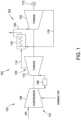
- FIG. 1is a schematic illustration of an exemplary combined cycle power generation system
- FIG. 2is a schematic illustration of an exemplary rotating detonation combustion system that may be used in the combined cycle power generation system shown in FIG. 1 ;
- FIG. 3is a schematic cross-sectional illustration of an exemplary rotating detonation combustor that may be used in the rotating detonation combustion system shown in FIG. 2 ;
- FIG. 4is an enlarged illustration of the rotating detonation combustor shown in FIG. 3 .
- FIG. 5is another enlarged illustration of the rotating detonation combustor shown in FIG. 3 .
- FIG. 6is a schematic cross-sectional illustration of an alternative rotating detonation combustor that may be used in the rotating detonation combustion system shown in FIG. 2 .
- FIG. 7is an enlarged illustration of the rotating detonation combustor shown in FIG. 6 .
- FIG. 8is another enlarged illustration of the rotating detonation combustor shown in FIG. 6 .
- FIG. 9is a schematic side cross-sectional illustration of another alternative rotating detonation combustor that may be used in the rotating detonation combustion system shown in FIG. 2 .
- FIG. 10is a schematic end cross-sectional illustration of the rotating detonation combustor shown in FIG. 9 .
- FIG. 11is a side cross-sectional illustration of yet another alternative rotating detonation combustor that may be used in the rotating detonation combustion system shown in FIG. 2 .
- FIG. 12is an end cross-sectional illustration of the rotating detonation combustor shown in FIG. 11 .
- FIG. 13is a top illustration of a portion of the rotating detonation combustor shown in FIG. 11 .
- Approximating languagemay be applied to modify any quantitative representation that could permissibly vary without resulting in a change in the basic function to which it is related. Accordingly, a value modified by a term or terms, such as “about”, “approximately”, and “substantially”, are not to be limited to the precise value specified. In at least some instances, the approximating language may correspond to the precision of an instrument for measuring the value.
- range limitationsmay be combined and/or interchanged. Such ranges are identified and include all the sub-ranges contained therein unless context or language indicates otherwise.
- the terms “axial” and “axially”refer to directions and orientations that extend substantially parallel to a centerline of the turbine engine assembly or the rotating detonation combustor.
- the terms “radial” and “radially”refer to directions and orientations that extend substantially perpendicular to the centerline of the turbine engine assembly or the rotating detonation combustor.
- the terms “circumferential” and “circumferentially”refer to directions and orientations that extend arcuately about the centerline of the turbine engine assembly or the rotating detonation combustor.
- the terms “tangential” and “tangentially”refer to directions and orientations that extend substantially perpendicular relative to a radial axis of the turbine engine assembly or the rotating detonation combustor.
- Embodiments of the present disclosurerelate to a turbine engine assembly that efficiently converts the energy of exhaust gas produced by detonative combustion into shaft mechanical work via a turbine.
- the turbine engine assembly described hereinincludes a rotating detonation combustor that includes a combustion chamber, an air plenum, and a flow passage coupled in flow communication between the combustion chamber and the air plenum and configured to channel an airflow from the air plenum.
- a fuel inletchannels a fuel flow into the flow passage, and the flow passage includes a plurality of fuel mixing mechanisms configured to mix the airflow and the fuel flow within the combustion chamber.
- the fuel mixing mechanismsinclude, but are not limited to, corrugations, dimples, protrusions, or obstructions.
- the flow passage corrugationsintroduce a more complete and faster mixing of the fuel and air in the combustion chamber, resulting in a shorter mixing distance and stronger detonations.
- the shape of the air plenum in each RDCis designed such that the pressure wave created by the passing combustion wave reflects off an end wall and reaches the flow passage at the same time as the combustion wave comes back around.
- the air plenumis designed to create an opposing pressure wave that stiffens the air within the flow passage to prevent the combustion wave from channeling fluid into air plenum and to push unburnt air back into the combustion chamber, resulting in a stronger combustion.
- detonationand “quasi-detonation” may be used interchangeably.
- Typical embodiments of detonation chambersinclude a means of igniting a fuel/oxidizer mixture, for example a fuel/air mixture, and a confining chamber, in which pressure wave fronts initiated by the ignition process coalesce to produce a detonation wave.
- Each detonation or quasi-detonationis initiated either by external ignition, such as spark discharge or laser pulse, or by gas dynamic processes, such as shock focusing, autoignition or by another detonation via cross-firing.
- detonation chamberThe geometry of the detonation chamber is such that the pressure rise of the detonation wave expels combustion products out the detonation chamber exhaust to produce a thrust force.
- rotating detonation combustorsare designed such that a substantially continuous detonation wave is produced and discharged therefrom.
- detonationmay be accomplished in a number of types of detonation chambers, including detonation tubes, shock tubes, resonating detonation cavities, and annular detonation chambers.
- FIG. 1is a schematic illustration of an exemplary combined cycle power generation system 100 .
- Power generation system 100includes a gas turbine engine assembly 102 and a steam turbine engine assembly 104 .
- Gas turbine engine assembly 102includes a compressor 106 , a combustor 108 , and a first turbine 110 powered by expanding hot gas produced in combustor 108 for driving an electrical generator 112 .
- Gas turbine engine assembly 102may be used in a stand-alone simple cycle configuration for power generation or mechanical drive applications.
- exhaust gas 114is channeled from first turbine 110 towards a heat recovery steam generator (HRSG) 116 for recovering waste heat from exhaust gas 114 .
- HRSGheat recovery steam generator
- HRSG 116transfers heat from exhaust gas 114 to water/steam 118 channeled through HRSG 116 to produce steam 120 .
- Steam turbine engine assembly 104includes a second turbine 122 that receives steam 120 , which powers second turbine 122 for further driving electrical generator 112 .
- Compressor 106compresses the air and the highly compressed air is channeled from compressor 106 towards combustor 108 and mixed with fuel.
- the fuel-air mixtureis combusted within combustor 108 .
- High temperature combustion gas generated by combustor 108is channeled towards first turbine 110 .
- Exhaust gas 114is subsequently discharged from first turbine 110 through an exhaust 123 .
- FIG. 2is a perspective illustration of an exemplary rotating detonation combustion (RDC) system 124 that may be used in combined cycle power generation system 100 (shown in FIG. 1 ).
- RDC system 124includes a plurality of rotating detonation combustors 126 and a plurality of flow conduits 128 coupled to the plurality of rotating detonation combustors 126 .
- the plurality of rotating detonation combustors 126combust a fuel-air mixture (not shown in FIG. 2 ) to produce a flow of combustion gas 130 .
- the plurality of rotating detonation combustors 126are oriented such that the flow of combustion gas 130 discharged therefrom flows in a partially circumferential direction relative to an axial centerline 132 of gas turbine engine assembly 102 (shown in FIG. 1 ). More specifically, each rotating detonation combustor 126 has a longitudinal centerline 134 , and each rotating detonation combustor 126 is oriented such that longitudinal centerline 134 is oriented tangentially relative to a radial axis 136 of gas turbine engine assembly 102 . As such, orienting rotating detonation combustors 126 with a circumferential or tangential component facilitates satisfying turbine inlet flow angle requirements for first turbine 110 (shown in FIG. 1 ) coupled downstream from the plurality of rotating detonation combustors 126 . As used herein, “flow angle” is defined as a ratio of circumferential or tangential velocity to axial velocity of a flow of fluid.
- rotating detonation combustors 126may be oriented at other angles relative to the radial axis 136 .
- the angle defined between longitudinal centerline 134 and radial axis 136is defined within a range between about 0 degrees and about 180 degrees, between about 30 degrees and about 150 degrees, between about 60 degrees and about 120 degrees, between about 60 degrees and about 90 degrees, or between about 75 degrees and about 90 degrees.
- FIG. 3is a cross-sectional schematic illustration of an exemplary rotating detonation combustor (RDC) 200 that may be used in RDC system 124 (shown in FIG. 2 ).
- RDCrotating detonation combustor
- FIG. 4is an enlarged illustration of RDC 200
- FIG. 5is another enlarged illustration of RDC 200 .
- Rotating detonation combustor 200is one example of rotating detonation combustor 126 (shown in FIG. 2 ) that may be used in RDC system 124 .
- RDC 200includes an air plenum 202 that contains a volume of air and a fuel plenum 204 that contains a volume of fuel.
- a flow passage 206couples air plenum 202 and fuel plenum 204 in flow communication with a combustion chamber 208 of RDC 200 .
- flow passage 206is coupled in flow communication between air plenum 202 and combustion chamber 208 and channels an airflow from air plenum 202 toward combustion chamber 208 .
- air plenum 202is oriented perpendicular to combustion chamber 208 and flow passage 206 is oriented perpendicular to centerline axis 134 .
- air plenum 202is axially aligned with combustion chamber 208 and flow passage 206 is oriented parallel with centerline axis 134 .
- RDC 200includes a fuel inlet 210 that couples fuel plenum 204 in flow communication with flow passage 206 and channels a fuel flow into flow passage 206 .
- flow passage 206includes a plurality of fuel mixing mechanisms 212 over which the airflow and fuel flow are channeled.
- Fuel mixing mechanisms 212cause the air from air plenum 202 and the fuel from fuel inlet 210 to mix within combustion chamber 208 .
- fuel mixing mechanisms 212include, but are not limited to, corrugations, dimples, protrusions, or obstructions.
- fuel mixing mechanisms 212include any mechanism that facilities mixing of air and fuel to enable operation of the rotating detonation combustors described herein.
- the fuel mixing mechanismsare shown in the figures and described hereafter as corrugations. Although only shown and described hereafter as corrugations, the fuel mixing mechanisms are not limited embodying only corrugations and may include any type of fuel mixing mechanism.
- air plenum 202includes a first sidewall 214 and a second sidewall 216 that converge to form a throat portion 218 at an inlet of flow passage 206 between air plenum 202 and flow passage 206 .
- air plenum 202includes an end wall 220 coupled between sidewalls 214 and 216 opposite throat portion 218 .
- end wall 220is curved for the entire arc length between sidewalls 214 and 216 .
- end wall 220is substantially flat or planar for at least a partial distance between sidewalls 214 and 216 .
- Air plenum 202also includes an air inlet 222 that channels air into air plenum 202 .
- air inlet 222is oriented parallel to centerline axis 134 and is defined in second sidewall 216 . In other embodiments, air inlet 222 is oriented perpendicular to centerline axis 134 and is defined in end wall 220 .
- flow passage 206includes a first sidewall 224 and an opposing second sidewall 226 that define flow passage 206 therebetween.
- fuel inlet 210is defined through second sidewall 226 and is positioned downstream, with respect to fluid flow through RDC 200 , of throat portion 218 .
- second sidewall 226is a portion of a wall 228 of combustion chamber 208 such that a portion of wall 228 at least partially defines flow passage 206 .
- combustion chamber 208also includes a sidewall 330 that is oriented perpendicular to first and second sidewalls 224 and 226 of flow passage.
- second sidewall 226is a portion of sidewall 230 such that a portion of sidewall 230 at least partially defines flow passage 206 and end wall 228 is oriented perpendicular to first and second sidewalls 224 and 226 of flow passage 206 .
- corrugations 212are positioned downstream from fuel inlet 210 in flow passage 206 and include a first subset of corrugations 232 formed in first sidewall 224 and a second subset of corrugations 234 formed in second sidewall 226 .
- corrugations 212are positioned upstream from fuel inlet 210 in flow passage 206 .
- corrugations 212are positioned at any location that facilitates operation of RDC 200 as described herein.
- a combustion waveis traveling circumferentially around combustion chamber 208 and is continuously fed by the air and fuel being channeled from plenums 202 and 204 through flow passage 206 .
- Corrugations 212 at the outlet of flow passage 208introduce a more complete and faster mixing of the fuel and air in combustion chamber 208 , resulting in a shorter mixing distance and stronger detonations within combustion chamber 208 .
- corrugations 212introduce both flow direction variation and flow velocity variation, which enhances the mixing of the fuel and air such that when the mixture exits flow passage 206 into combustion chamber 208 , the flow is already partially mixed and corrugations 212 cause further turbulence in combustion chamber 208 to provide additional mixing.
- air plenum 202When the combustion wave passes over a point in flow passage 206 , it sends a pressure wave down into air plenum 202 through flow passage 206 .
- the shape of air plenum 202is designed such that the pressure wave created by the passing combustion wave reflects off end wall 220 and reaches flow passage 206 at the same time as the combustion wave comes back around to the same point in flow passage 206 .
- air plenum 202is designed to create an opposing pressure wave that stiffens the air within flow passage 206 to prevent the combustion wave from channeling fluid into air plenum. More specifically, air plenum 202 reflects the pressure wave and uses it to push unburnt air back into combustion chamber 208 , resulting in a stronger combustion.
- the length of end wall 220includes any length that facilitates operation of RDC 200 as described herein.
- air inlet 222is located approximately midway through air plenum 202 in the radial direction between end wall 220 and flow passage 206 . As such, air inlet 222 is positioned to be in the anti-node of the pressure wave as it travels through air plenum 202 .
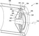
- FIG. 6is a schematic cross-sectional illustration of an alternative RDC 300 that may be used in the rotating detonation combustion system 124 (shown in FIG. 2 ).
- FIG. 7is an enlarged illustration of RDC 300
- FIG. 8is another enlarged illustration of RDC 300 .
- RDC 300is substantially similar to RDC 200 (shown in FIGS. 3 - 5 ) in operation and structure with the exception that RDC 300 includes a splitter 350 positioned in the flow passage between the air plenum and the combustion chamber.
- components of RDC 300 shown in FIGS. 6 - 8are labeled with similar reference numbers as those used to describe RDC 200 in FIGS. 3 - 5 with the exception that the reference numbers are in the 300 series.
- RDC 300 with splitter 350may be substituted for RDC 200 without a splitter within rotating detonation combustion system 124 .
- splitter 350is at least partially positioned in flow passage 306 and includes a first end 352 coupled to end wall 320 and a second end 354 positioned in flow passage 306 between sidewalls 324 and 326 of flow passage 306 .
- first end 352may be coupled to one or both of sidewalls 314 and 316 of air plenum 302 .
- First end 352 of splitter 350is substantially planar and second end 354 of splitter 350 includes a plurality of splitter corrugations 356 that facilitate mixing the airflow from air plenum 302 and the fuel flow from fuel inlet 310 within combustion chamber 308 , as described herein.
- splitter 350includes a plurality of openings 358 defined therethrough upstream of flow passage 306 and positioned within air plenum 302 . Openings 358 enable airflow from air inlet 322 to flow through splitter 350 and fill air plenum 302 .
- splitter 350includes a first sidewall 360 with a first subset 362 of corrugations 356 .
- splitter 350includes a second sidewall 364 with a second subset 366 of corrugations 356 .
- First subset 332 of flow passage corrugations 312 and first subset 362 of splitter corrugations 356combine to form a first wave-shaped slot 368 through which a mixture of air and fuel is channeled and further mixed within combustion chamber 308 .
- second subset 334 of flow passage corrugations 312 and second subset 366 of splitter corrugations 356combine to form a second wave-shaped slot 370 through which a mixture of air and fuel is channeled and further mixed within combustion chamber 308 .
- a combustion waveis traveling circumferentially around combustion chamber 308 and is continuously fed by the air and fuel being channeled from plenums 302 and 304 through flow passage 306 .
- Flow passage corrugations 312 and splitter corrugations 356 at the outlet of flow passage 306introduce a more complete and faster mixing of the fuel and air in combustion chamber 308 , resulting in a shorter mixing distance and stronger detonations within combustion chamber 308 .
- corrugations 312 and 356introduce both flow direction variation and flow velocity variation, which enhances the mixing of the fuel and air such that when the mixture exits flow passage 306 into combustion chamber 308 , the flow is already partially mixed and corrugations 312 cause further turbulence in combustion chamber 308 to provide additional mixing.
- air plenum 302When the combustion wave passes over a point in flow passage 306 , it sends a pressure wave down into air plenum 302 through flow passage 306 .
- the shape of air plenum 302is designed such that the pressure wave created by the passing combustion wave reflects off end wall 320 and reaches flow passage 306 at the same time as the combustion wave comes back around to the same point in flow passage 306 .
- air plenum 302is designed to create an opposing pressure wave that stiffens the air within flow passage 306 to prevent the combustion wave from channeling fluid into air plenum. More specifically, air plenum 302 reflects the pressure wave and uses it to push unburnt air back into combustion chamber 308 , resulting in a stronger combustion.
- the length of end wall 320includes any length that facilitates operation of RDC 300 as described herein.
- air inlet 322is located approximately midway through air plenum 302 in the radial direction between end wall 320 and flow passage 306 . As such, air inlet 322 is positioned to be in the anti-node of the pressure wave as it travels through air plenum 302 .
- FIG. 9is a schematic side cross-sectional illustration of another alternative RDC 400 that may be used in rotating detonation combustion system 124 (shown in FIG. 2 )
- FIG. 10is a schematic end cross-sectional illustration of RDC 400 .
- RDC 400is one example of rotating detonation combustor 126 (shown in FIG. 2 ) that may be used in RDC system 124 .
- RDC 400includes an air plenum 402 that contains a volume of air and a fuel plenum (not shown) that contains a volume of fuel.
- a flow passage 406couples air plenum 402 and fuel plenum in flow communication with a combustion chamber 408 of RDC 400 .
- flow passage 406is coupled in flow communication between air plenum 402 and combustion chamber 408 and channels an airflow from air plenum 402 toward combustion chamber 408 .
- air plenum 402is axially aligned with combustion chamber 408 and flow passage 406 is oriented parallel with centerline axis 134 .
- RDC 400includes at least one fuel inlet 410 that couples fuel plenum in flow communication with flow passage 406 and channels a fuel flow into flow passage 406 .
- flow passage 406includes a plurality of corrugations 412 over which the airflow and fuel flow are channeled. Corrugations 412 cause the air from air plenum 402 and the fuel from fuel inlet 410 to mix within combustion chamber 408 .
- air plenum 402includes a first sidewall 414 and a second sidewall 416 that converge to form a throat portion 418 at an inlet of flow passage 406 between air plenum 402 and flow passage 406 .
- air plenum 402includes an end wall 420 coupled between sidewalls 414 and 416 opposite throat portion 418 .
- end wall 420is curved for the entire arc length between sidewalls 414 and 416 .
- end wall 420is substantially flat or planar for at least a partial distance between sidewalls 414 and 416 .
- Air plenum 402also includes an air inlet 422 that channels air into air plenum 402 .
- air inlet 422is oriented perpendicular to centerline axis 134 and is defined in first sidewall 414 . In other embodiments, air inlet 422 is oriented parallel with centerline axis 134 and is defined in end wall 420 .
- Flow passage 406includes a first sidewall 424 and an opposing second sidewall 426 that define flow passage 406 therebetween.
- at least one fuel inlet 410is defined through first sidewall 424 and is positioned downstream, with respect to fluid flow through RDC 400 , of throat portion 418 .
- at least one fuel inlet 410is defined through second sidewall 426 and is also positioned downstream, with respect to fluid flow through RDC 400 , of throat portion 418 .
- RDC 400is illustrated as having fuel inlets 410 defined through both sidewalls 424 and 426 , it is contemplated that only one of sidewalls 424 or 426 includes fuel inlets 410 .
- first sidewall 424is a portion of a first sidewall 428 of combustion chamber 408 such that a portion of sidewall 428 at least partially defines flow passage 406 .
- second sidewall 426is a portion of a second sidewall 430 of combustion chamber 208 such that a portion of second sidewall 430 at least partially defines flow passage 406 .
- corrugations 412are positioned downstream from fuel inlet 410 in flow passage 406 and include a first subset of corrugations 432 formed in first sidewall 424 and a second subset of corrugations 434 formed in second sidewall 426 .
- corrugations 412are positioned upstream from fuel inlet 410 in flow passage 406 .
- corrugations 412are positioned at any location that facilitates operation of RDC 400 as described herein.
- a combustion waveis traveling circumferentially around combustion chamber 408 and is continuously fed by the air and fuel being channeled from plenums 402 and 404 through flow passage 406 .
- Corrugations 412 at the outlet of flow passage 406introduce a more complete and faster mixing of the fuel and air in combustion chamber 408 , resulting in a shorter mixing distance and stronger detonations within combustion chamber 408 .
- corrugations 412introduce both flow direction variation and flow velocity variation, which enhances the mixing of the fuel and air such that when the mixture exits flow passage 406 into combustion chamber 408 , the flow is already partially mixed and corrugations 412 cause further turbulence in combustion chamber 408 to provide additional mixing.
- air plenum 402When the combustion wave passes over a point in flow passage 406 , it sends a pressure wave down into air plenum 402 through flow passage 406 .
- the shape of air plenum 402is designed such that the pressure wave created by the passing combustion wave reflects off end wall 420 and reaches flow passage 406 at the same time as the combustion wave comes back around to the same point in flow passage 406 .
- air plenum 402is designed to create an opposing pressure wave that stiffens the air within flow passage 406 to prevent the combustion wave from channeling fluid into air plenum. More specifically, air plenum 402 reflects the pressure wave and uses it to push unburnt air back into combustion chamber 408 , resulting in a stronger combustion.
- the length of end wall 420includes any length that facilitates operation of RDC 400 as described herein.
- air inlet 422is located approximately midway through air plenum 402 in the axial direction between end wall 420 and flow passage 406 . As such, air inlet 422 is positioned to be in the anti-node of the pressure wave as it travels through air plenum 402 .
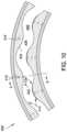
- FIG. 11is a side cross-sectional illustration of another alternative RDC 500 that may be used in the rotating detonation combustion system 124 (shown in FIG. 2 ).
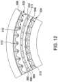
- FIG. 12is an end cross-sectional illustration of RDC 500 .
- FIG. 13is a top illustration of a portion of RDC 500 .
- RDC 500includes an air plenum 502 that contains a volume of air and a fuel plenum (not shown) that contains a volume of fuel.
- a flow passage 506couples air plenum 502 and fuel plenum in flow communication with a combustion chamber 508 of RDC 500 .
- flow passage 506is coupled in flow communication between air plenum 502 and combustion chamber 508 and channels an airflow from air plenum 502 toward combustion chamber 508 .
- air plenum 502is axially aligned with combustion chamber 508 and flow passage 506 is oriented parallel with centerline axis 134 .
- RDC 500includes at least one fuel inlet 510 that couples fuel plenum in flow communication with flow passage 506 and channels a fuel flow into flow passage 506 .
- flow passage 506includes a plurality of corrugations 512 over which the airflow and fuel flow are channeled. Corrugations 512 cause the air from air plenum 502 and the fuel from fuel inlet 510 to mix within combustion chamber 508 .
- air plenum 502includes a first sidewall 514 and a second sidewall 516 that converge to form a throat portion 518 at an inlet of flow passage 506 between air plenum 502 and flow passage 506 .
- air plenum 502includes an end wall 520 coupled between sidewalls 514 and 516 opposite throat portion 518 .
- end wall 520is curved for the entire arc length between sidewalls 514 and 516 .
- end wall 520is substantially flat or planar for at least a partial distance between sidewalls 514 and 516 .
- Air plenum 502also includes an air inlet 522 that channels air into air plenum 502 .
- air inlet 522is oriented perpendicular to centerline axis 134 and is defined in first sidewall 514 . In other embodiments, air inlet 522 is oriented parallel with centerline axis 134 and is defined in end wall 520 .
- Flow passage 506includes a first sidewall 524 and an opposing second sidewall 526 that define flow passage 506 therebetween.
- at least one fuel inlet 510is defined through first sidewall 524 and is positioned downstream, with respect to fluid flow through RDC 500 , of throat portion 518 .
- at least one fuel inlet 510is defined through second sidewall 526 and is also positioned downstream, with respect to fluid flow through RDC 500 , of throat portion 518 .
- RDC 500is illustrated as having fuel inlets 510 defined through both sidewalls 524 and 526 , it is contemplated that only one of sidewalls 524 or 526 may include fuel inlets 510 .
- first sidewall 524is a portion of a first sidewall 528 of combustion chamber 508 such that a portion of sidewall 528 at least partially defines flow passage 506 .
- second sidewall 526is a portion of a second sidewall 530 of combustion chamber 508 such that a portion of second sidewall 530 at least partially defines flow passage 506 .
- corrugations 512are positioned downstream from fuel inlet 510 in flow passage 506 and include a first subset of corrugations 532 formed in first sidewall 524 and a second subset of corrugations 534 formed in second sidewall 526 .
- corrugations 512are positioned upstream from fuel inlet 410 in flow passage 506 .
- corrugations 512are positioned at any location that facilitates operation of RDC 500 as described herein.
- RDC 500also includes a splitter 550 positioned in the flow passage 506 between the air plenum 502 and the combustion chamber 508 .
- splitter 550is at least partially positioned in flow passage 506 and includes a first end 552 coupled to end wall 520 and a second end 554 positioned in flow passage 506 between sidewalls 524 and 526 of flow passage 506 .
- first end 552may be coupled to one or both of sidewalls 514 and 516 of air plenum 502 .
- splitter 550includes a plurality of openings 558 defined therethrough upstream of flow passage 506 and positioned within air plenum 502 . Openings 558 enable airflow from air inlet 522 to flow through splitter 550 and fill air plenum 502 .
- Splitter 550includes a first sidewall 560 and an opposing second sidewall 564 that is substantially parallel to first sidewall 560 . More specifically, sidewalls 560 and 564 are parallel for an entirety of the length of splitter 550 between first end 552 and 554 . Additionally, sidewalls 560 and 564 at second end 554 of splitter 550 are substantially planar, or smooth, such that splitter 550 does not include corrugations or other fuel mixing mechanism.
- fuel inlets 510 in first sidewall 524are formed radially from the peaks of first subset 532 of corrugations 512 . That is, fuel inlets 650 are formed in sidewall 524 at a point where the distance between sidewall 524 and sidewall 560 is shortest.
- fuel inlets 510 in second sidewall 526are formed radially from the peaks of second subset 534 of corrugations 512 . That is, fuel inlets 510 are formed in sidewall 526 at a point where the distance between sidewall 526 and sidewall 564 is shortest. Locating fuel inlets 510 at such locations positions fuel inlets 510 at the point of lowest pressure within flow passage 506 . And therefore protects the fuel from the combustion wave that travels around chamber 508 .
- splitter 550includes a plurality of fuel inlets 511 defined therein. More specifically, splitter fuel inlets 511 are located approximately midway between first sidewall 560 and second sidewall 564 . In one embodiment, splitter fuel inlets 511 are used in combination with fuel inlets 510 to provide fuel in two different locations. In other embodiments, RDC 500 does not include fuel inlets 510 , and splitter fuel inlets 511 provide all of the fuel necessary for combustion. Additionally, as shown in FIG. 13 , at least one splitter fuel inlet 511 is obliquely oriented with respect to centerline 134 such that at least one splitter fuel inlet 511 discharges fuel at an angle relative to centerline 134 .
- each splitter fuel inlet 511is oriented at the same angle relative to centerline 134 such that fuel is injected into combustion chamber 508 at the same angle relative to centerline 134 about the circumference of splitter 550 . Injecting fuel into combustion chamber 508 at an angle relative to centerline 134 orients the fuel flow in the direction of the traveling combustion wave and also prevents or reduces the likelihood of the pressure wave traveling back down the splitter fuel inlets 511 .
- a combustion waveis traveling circumferentially around combustion chamber 508 and is continuously fed by the air and fuel being channeled from plenums 502 and 504 through flow passage 506 .
- Corrugations 512 at the outlet of flow passage 508introduce a more complete and faster mixing of the fuel and air in combustion chamber 508 , resulting in a shorter mixing distance and stronger detonations within combustion chamber 508 .
- corrugations 512introduce both flow direction variation and flow velocity variation, which enhances the mixing of the fuel and air such that when the mixture exits flow passage 506 into combustion chamber 508 , the flow is already partially mixed.
- air plenum 502When the combustion wave passes over a point in flow passage 506 , it sends a pressure wave down into air plenum 502 through flow passage 506 .
- the shape of air plenum 502is designed such that the pressure wave created by the passing combustion wave reflects off end wall 520 and reaches flow passage 506 at the same time as the combustion wave comes back around to the same point in flow passage 506 .
- air plenum 502is designed to create an opposing pressure wave that stiffens the air within flow passage 506 to prevent the combustion wave from channeling fluid into air plenum. More specifically, air plenum 502 reflects the pressure wave and uses it to push unburnt air back into combustion chamber 508 , resulting in a stronger combustion.
- the length of end wall 220includes any length that facilitates operation of RDC 500 as described herein.
- air inlet 522is located approximately midway through air plenum 502 in the radial direction between end wall 520 and flow passage 506 . As such, air inlet 522 is positioned to be in the anti-node of the pressure wave as it travels through air plenum 502 .
- the RDC systems described hereininclude a plurality of rotating detonation combustors that each include a plurality of corrugations between and air plenum and the combustion chamber.
- the flow passage corrugationsintroduce a more complete and faster mixing of the fuel and air in the combustion chamber, resulting in a shorter mixing distance and stronger detonations.
- the shape of the air plenum in each RDCis designed such that the pressure wave created by the passing combustion wave reflects off an end wall and reaches the flow passage at the same time as the combustion wave comes back around.
- the air plenumis designed to create an opposing pressure wave that stiffens the air within the flow passage to prevent the combustion wave from channeling fluid into air plenum and to push unburnt air back into the combustion chamber, resulting in a stronger combustion.
- An exemplary technical effect of the systems and methods described hereinincludes at least one of: (a) preserving the kinetic energy of high velocity RDC combustion products; and (b) increasing the efficiency of each RDC by both improving fuel and air mixing and by preventing inhalation of combustion products into the air plenum.
- RDC systemsare provided herein.
- the systems and methodsare not limited to the specific embodiments described herein, but rather, components of systems and/or steps of the methods may be utilized independently and separately from other components and/or steps described herein.
- the configuration of components described hereinmay also be used in combination with other processes, and is not limited to practice with only ground-based, combined cycle power generation systems, as described herein. Rather, the exemplary embodiment can be implemented and utilized in connection with many applications where a RDC system may be implemented.
Landscapes
- Engineering & Computer Science (AREA)
- Chemical & Material Sciences (AREA)
- Combustion & Propulsion (AREA)
- Mechanical Engineering (AREA)
- General Engineering & Computer Science (AREA)
Abstract
Description
Claims (18)
Priority Applications (1)
| Application Number | Priority Date | Filing Date | Title |
|---|---|---|---|
| US17/195,131US12092336B2 (en) | 2017-09-15 | 2021-03-08 | Turbine engine assembly including a rotating detonation combustor |
Applications Claiming Priority (2)
| Application Number | Priority Date | Filing Date | Title |
|---|---|---|---|
| US15/705,954US10969107B2 (en) | 2017-09-15 | 2017-09-15 | Turbine engine assembly including a rotating detonation combustor |
| US17/195,131US12092336B2 (en) | 2017-09-15 | 2021-03-08 | Turbine engine assembly including a rotating detonation combustor |
Related Parent Applications (1)
| Application Number | Title | Priority Date | Filing Date |
|---|---|---|---|
| US15/705,954DivisionUS10969107B2 (en) | 2017-09-15 | 2017-09-15 | Turbine engine assembly including a rotating detonation combustor |
Publications (2)
| Publication Number | Publication Date |
|---|---|
| US20210190320A1 US20210190320A1 (en) | 2021-06-24 |
| US12092336B2true US12092336B2 (en) | 2024-09-17 |
Family
ID=65719968
Family Applications (2)
| Application Number | Title | Priority Date | Filing Date |
|---|---|---|---|
| US15/705,954Active2038-10-05US10969107B2 (en) | 2017-09-15 | 2017-09-15 | Turbine engine assembly including a rotating detonation combustor |
| US17/195,131Active2037-09-27US12092336B2 (en) | 2017-09-15 | 2021-03-08 | Turbine engine assembly including a rotating detonation combustor |
Family Applications Before (1)
| Application Number | Title | Priority Date | Filing Date |
|---|---|---|---|
| US15/705,954Active2038-10-05US10969107B2 (en) | 2017-09-15 | 2017-09-15 | Turbine engine assembly including a rotating detonation combustor |
Country Status (1)
| Country | Link |
|---|---|
| US (2) | US10969107B2 (en) |
Families Citing this family (5)
| Publication number | Priority date | Publication date | Assignee | Title |
|---|---|---|---|---|
| US10697368B1 (en)* | 2019-06-18 | 2020-06-30 | Tilahun Anshu | Hyperbaric power plant |
| CN111927625B (en)* | 2020-07-13 | 2022-08-19 | 西安航天动力研究所 | Two-phase rotary detonation combustion cavity structure capable of stably and controllably unidirectionally spreading rotary detonation wave |
| CN113739207B (en)* | 2021-09-22 | 2022-04-29 | 西北工业大学 | Rotary detonation combustion chamber adopting pneumatic inner column |
| CN114183773A (en)* | 2021-12-22 | 2022-03-15 | 北京化工大学 | A combustion chamber capable of generating multiple rotating detonation waves |
| US12253050B2 (en) | 2022-04-12 | 2025-03-18 | General Electric Company | Combined cycle propulsion system for hypersonic flight |
Citations (68)
| Publication number | Priority date | Publication date | Assignee | Title |
|---|---|---|---|---|
| US45396A (en) | 1864-12-13 | Affixing knives to straw-cutters | ||
| US2435557A (en)* | 1942-11-05 | 1948-02-03 | Rolls Royce | Air-cooler for internal-combustion turbines |
| US2611241A (en)* | 1946-03-19 | 1952-09-23 | Packard Motor Car Co | Power plant comprising a toroidal combustion chamber and an axial flow gas turbine with blade cooling passages therein forming a centrifugal air compressor |
| US2774629A (en) | 1950-09-08 | 1956-12-18 | Thompson Prod Inc | Variable area fuel nozzles |
| US2796734A (en) | 1955-11-14 | 1957-06-25 | Jr Albert G Bodine | Sonic burner heat engine with acoustic reflector for augmentation of the second harmonic |
| US2807931A (en) | 1951-06-16 | 1957-10-01 | Jr Albert G Bodine | Control of combustion instability in jet engines |
| US2888803A (en) | 1954-08-30 | 1959-06-02 | Pon Lemuel | Intermittent combustion turbine engine |
| US2936577A (en) | 1952-08-06 | 1960-05-17 | Univ Michigan | Rocket motor throttling injector |
| GB1069217A (en)* | 1965-03-29 | 1967-05-17 | Rolls Royce | Improvements relating to engines |
| US3588298A (en) | 1968-06-14 | 1971-06-28 | Rolls Royce | Detonation wave combustion |
| US3646761A (en) | 1961-03-07 | 1972-03-07 | Garrett Corp | Method and apparatus for starting detonation combustion engines |
| US3777488A (en) | 1961-06-23 | 1973-12-11 | Garrett Corp | Method and apparatus for reaction propulsion |
| US3811796A (en) | 1971-10-21 | 1974-05-21 | Gen Power Corp | Integral turbo-compressor wave engine |
| US3879937A (en) | 1972-10-25 | 1975-04-29 | Bbc Brown Boveri & Cie | Aerodynamic pressure-wave machine |
| US3958899A (en) | 1971-10-21 | 1976-05-25 | General Power Corporation | Staged expansion system as employed with an integral turbo-compressor wave engine |
| US4397613A (en) | 1980-03-17 | 1983-08-09 | Bbc Brown, Boveri & Company, Limited | Compression wave machine |
| US5000004A (en)* | 1988-08-16 | 1991-03-19 | Kabushiki Kaisha Toshiba | Gas turbine combustor |
| US5207064A (en) | 1990-11-21 | 1993-05-04 | General Electric Company | Staged, mixed combustor assembly having low emissions |
| US5247792A (en)* | 1992-07-27 | 1993-09-28 | General Electric Company | Reducing thermal deposits in propulsion systems |
| US5658358A (en)* | 1993-04-08 | 1997-08-19 | Abb Management Ag | Fuel supply system for combustion chamber |
| US5800153A (en) | 1995-07-07 | 1998-09-01 | Mark DeRoche | Repetitive detonation generator |
| US5850732A (en) | 1997-05-13 | 1998-12-22 | Capstone Turbine Corporation | Low emissions combustion system for a gas turbine engine |
| US6494034B2 (en) | 1999-07-15 | 2002-12-17 | Mcdonnell Douglas Corporation | Pulsed detonation engine with backpressure |
| US6526936B2 (en) | 2000-07-06 | 2003-03-04 | Advanced Research And Technology Institute | Partitioned multi-channel combustor |
| US6584764B2 (en) | 2000-01-12 | 2003-07-01 | Allison Advanced Development Company | Propulsion module |
| US6584765B1 (en) | 2001-12-21 | 2003-07-01 | United Technologies Corporation | Pulse detonation engine having an aerodynamic valve |
| US6668542B2 (en) | 1999-10-27 | 2003-12-30 | Allison Advanced Development Company | Pulse detonation bypass engine propulsion pod |
| US6758032B2 (en) | 2002-02-07 | 2004-07-06 | Lockheed Martin Corporation | System of pulsed detonation injection for fluid flow control of inlets, nozzles, and lift fans |
| US20040237504A1 (en)* | 2003-05-30 | 2004-12-02 | General Electric Company | Detonation damper for pulse detonation engines |
| US20090266047A1 (en) | 2007-11-15 | 2009-10-29 | General Electric Company | Multi-tube, can-annular pulse detonation combustor based engine with tangentially and longitudinally angled pulse detonation combustors |
| US20090272117A1 (en)* | 2006-06-12 | 2009-11-05 | Nigel Wilbraham | Burner |
| US7614211B2 (en) | 2005-12-15 | 2009-11-10 | General Electric Company | Swirling flows and swirler to enhance pulse detonation engine operation |
| US7669406B2 (en) | 2006-02-03 | 2010-03-02 | General Electric Company | Compact, low pressure-drop shock-driven combustor and rocket booster, pulse detonation based supersonic propulsion system employing the same |
| US7784267B2 (en) | 2004-06-29 | 2010-08-31 | Mitsubishi Heavy Industries, Ltd. | Detonation engine and flying object provided therewith |
| US20100275601A1 (en)* | 2009-05-01 | 2010-11-04 | General Electric Company | Turbine air flow conditioner |
| US20110126511A1 (en) | 2009-11-30 | 2011-06-02 | General Electric Company | Thrust modulation in a multiple combustor pulse detonation engine using cross-combustor detonation initiation |
| US20110146232A1 (en) | 2009-12-23 | 2011-06-23 | General Electric Company | Control system for a pulse detonation turbine engine |
| US8082728B2 (en) | 2008-02-01 | 2011-12-27 | General Electric Company | System and method of continuous detonation in a gas turbine engine |
| US8146371B2 (en) | 2007-12-21 | 2012-04-03 | United Technologies Corporation | Direct induction combustor/generator |
| CN102588145A (en) | 2012-03-09 | 2012-07-18 | 董国光 | Air-breathing rotary detonation wave injection and multimode ram detonation coupled circulating propulsion system |
| WO2012142485A2 (en) | 2011-04-15 | 2012-10-18 | Rolls-Royce North American Technologies Inc. | Continuous detonation combustion engine and system |
| US20120297787A1 (en)* | 2011-05-11 | 2012-11-29 | Alstom Technology Ltd | Flow straightener and mixer |
| US8438833B2 (en) | 2009-02-13 | 2013-05-14 | General Electric Company | Partial filling of a pulse detonation combustor in a pulse detonation combustor based hybrid engine |
| US8443583B2 (en) | 2006-06-15 | 2013-05-21 | Indiana University Research And Technology Corp. | Pilot fuel injection for a wave rotor engine |
| US8544280B2 (en) | 2008-08-26 | 2013-10-01 | Board Of Regents, The University Of Texas System | Continuous detonation wave engine with quenching structure |
| US20130263569A1 (en) | 2009-03-30 | 2013-10-10 | Alliant Techsystems Inc. | Helical cross flow (hcf) pulse detonation engine |
| US20140109588A1 (en) | 2012-10-23 | 2014-04-24 | Alstom Technology Ltd | Burner for a can combustor |
| US20140182295A1 (en) | 2011-05-16 | 2014-07-03 | Mdba France | Continuous detonation wave engine and aircraft provided with such an engine |
| US20140196460A1 (en) | 2011-05-16 | 2014-07-17 | Mbda France | Ramjet including a detonation chamber and aircraft comprising such a ramjet |
| WO2014129920A1 (en)* | 2013-02-19 | 2014-08-28 | Некоммерческое Партнерство По Научной, Образовательной И Инновационной Деятельности "Центр Импульсного Детонационного Горения" | Device for fuel combustion in a continuous detonation wave |
| WO2014178746A1 (en) | 2013-04-30 | 2014-11-06 | Некоммерческое Партнерство По Научной, Образовательной И Инновационной Деятельности "Центр Импульсного Детонационного Горения" | Detonation method and device for use in a gas turbine engine combustion chamber |
| USRE45396E1 (en) | 2004-11-12 | 2015-03-03 | Board Of Trustees Of Michigan State University | Wave rotor apparatus |
| US9027324B2 (en) | 2010-12-28 | 2015-05-12 | Rolls-Royce North American Technologies, Inc. | Engine and combustion system |
| US9046058B2 (en) | 2009-09-23 | 2015-06-02 | Aerojet Rocketdyne Of De, Inc. | System and method of combustion for sustaining a continuous detonation wave with transient plasma |
| US20150167544A1 (en) | 2013-12-12 | 2015-06-18 | General Electric Company | Tuned cavity rotating detonation combustion system |
| US20150308348A1 (en) | 2013-05-22 | 2015-10-29 | United Technologies Corporation | Continuous detonation wave turbine engine |
| US20150323184A1 (en) | 2014-05-07 | 2015-11-12 | General Electric Company | Ultra compact combustor |
| WO2016018172A1 (en)* | 2014-08-01 | 2016-02-04 | Общество С Ограниченной Ответственностью "Еадс Русский Технологический Офис Ск" | Method for burning fuel and detonation apparatus for carrying out same |
| WO2016060581A1 (en) | 2014-10-16 | 2016-04-21 | Некоммерческое Партнерство По Научной, Образовательной И Инновационной Деятельности "Центр Импульсного Детонационного Горения" | Device and method for organizing the operating process of a jet engine |
| CN105736178A (en) | 2016-04-11 | 2016-07-06 | 清华大学 | Combined cycle engine |
| US20160290143A1 (en) | 2013-11-04 | 2016-10-06 | Mbda France, Sas | Axial fluid machine and method for power extraction |
| US9512805B2 (en) | 2013-03-15 | 2016-12-06 | Rolls-Royce North American Technologies, Inc. | Continuous detonation combustion engine and system |
| CN106285945A (en) | 2016-10-28 | 2017-01-04 | 清华大学 | Rotate pinking electromotor continuously |
| US9556794B2 (en) | 2011-05-16 | 2017-01-31 | Mbda France | Turbine engine including a continuous wave detonation chamber and cooling bypass flow and aircraft provided with such a turbine engine |
| US20170108224A1 (en) | 2014-04-03 | 2017-04-20 | Siemens Aktiengesellschaft | Burner, gas turbine having such a burner, and fuel nozzle |
| US20170146244A1 (en) | 2015-11-20 | 2017-05-25 | University Of Washington | Continuous rotating detonation engines and associated systems and methods |
| US20180274442A1 (en)* | 2017-03-27 | 2018-09-27 | United Technologies Corporation | Rotating detonation engine upstream wave arrestor |
| US20180355795A1 (en)* | 2017-06-09 | 2018-12-13 | General Electric Company | Rotating detonation combustor with fluid diode structure |
- 2017
- 2017-09-15USUS15/705,954patent/US10969107B2/enactiveActive
- 2021
- 2021-03-08USUS17/195,131patent/US12092336B2/enactiveActive
Patent Citations (70)
| Publication number | Priority date | Publication date | Assignee | Title |
|---|---|---|---|---|
| US45396A (en) | 1864-12-13 | Affixing knives to straw-cutters | ||
| US2435557A (en)* | 1942-11-05 | 1948-02-03 | Rolls Royce | Air-cooler for internal-combustion turbines |
| US2611241A (en)* | 1946-03-19 | 1952-09-23 | Packard Motor Car Co | Power plant comprising a toroidal combustion chamber and an axial flow gas turbine with blade cooling passages therein forming a centrifugal air compressor |
| US2774629A (en) | 1950-09-08 | 1956-12-18 | Thompson Prod Inc | Variable area fuel nozzles |
| US2807931A (en) | 1951-06-16 | 1957-10-01 | Jr Albert G Bodine | Control of combustion instability in jet engines |
| US2936577A (en) | 1952-08-06 | 1960-05-17 | Univ Michigan | Rocket motor throttling injector |
| US2888803A (en) | 1954-08-30 | 1959-06-02 | Pon Lemuel | Intermittent combustion turbine engine |
| US2796734A (en) | 1955-11-14 | 1957-06-25 | Jr Albert G Bodine | Sonic burner heat engine with acoustic reflector for augmentation of the second harmonic |
| US3646761A (en) | 1961-03-07 | 1972-03-07 | Garrett Corp | Method and apparatus for starting detonation combustion engines |
| US3777488A (en) | 1961-06-23 | 1973-12-11 | Garrett Corp | Method and apparatus for reaction propulsion |
| GB1069217A (en)* | 1965-03-29 | 1967-05-17 | Rolls Royce | Improvements relating to engines |
| US3588298A (en) | 1968-06-14 | 1971-06-28 | Rolls Royce | Detonation wave combustion |
| US3811796A (en) | 1971-10-21 | 1974-05-21 | Gen Power Corp | Integral turbo-compressor wave engine |
| US3958899A (en) | 1971-10-21 | 1976-05-25 | General Power Corporation | Staged expansion system as employed with an integral turbo-compressor wave engine |
| US3879937A (en) | 1972-10-25 | 1975-04-29 | Bbc Brown Boveri & Cie | Aerodynamic pressure-wave machine |
| US4397613A (en) | 1980-03-17 | 1983-08-09 | Bbc Brown, Boveri & Company, Limited | Compression wave machine |
| US5000004A (en)* | 1988-08-16 | 1991-03-19 | Kabushiki Kaisha Toshiba | Gas turbine combustor |
| US5207064A (en) | 1990-11-21 | 1993-05-04 | General Electric Company | Staged, mixed combustor assembly having low emissions |
| US5247792A (en)* | 1992-07-27 | 1993-09-28 | General Electric Company | Reducing thermal deposits in propulsion systems |
| US5658358A (en)* | 1993-04-08 | 1997-08-19 | Abb Management Ag | Fuel supply system for combustion chamber |
| US5800153A (en) | 1995-07-07 | 1998-09-01 | Mark DeRoche | Repetitive detonation generator |
| US5850732A (en) | 1997-05-13 | 1998-12-22 | Capstone Turbine Corporation | Low emissions combustion system for a gas turbine engine |
| US6494034B2 (en) | 1999-07-15 | 2002-12-17 | Mcdonnell Douglas Corporation | Pulsed detonation engine with backpressure |
| US6668542B2 (en) | 1999-10-27 | 2003-12-30 | Allison Advanced Development Company | Pulse detonation bypass engine propulsion pod |
| US6584764B2 (en) | 2000-01-12 | 2003-07-01 | Allison Advanced Development Company | Propulsion module |
| US6526936B2 (en) | 2000-07-06 | 2003-03-04 | Advanced Research And Technology Institute | Partitioned multi-channel combustor |
| US6584765B1 (en) | 2001-12-21 | 2003-07-01 | United Technologies Corporation | Pulse detonation engine having an aerodynamic valve |
| US6758032B2 (en) | 2002-02-07 | 2004-07-06 | Lockheed Martin Corporation | System of pulsed detonation injection for fluid flow control of inlets, nozzles, and lift fans |
| US20040237504A1 (en)* | 2003-05-30 | 2004-12-02 | General Electric Company | Detonation damper for pulse detonation engines |
| US7784267B2 (en) | 2004-06-29 | 2010-08-31 | Mitsubishi Heavy Industries, Ltd. | Detonation engine and flying object provided therewith |
| USRE45396E1 (en) | 2004-11-12 | 2015-03-03 | Board Of Trustees Of Michigan State University | Wave rotor apparatus |
| US7614211B2 (en) | 2005-12-15 | 2009-11-10 | General Electric Company | Swirling flows and swirler to enhance pulse detonation engine operation |
| US7669406B2 (en) | 2006-02-03 | 2010-03-02 | General Electric Company | Compact, low pressure-drop shock-driven combustor and rocket booster, pulse detonation based supersonic propulsion system employing the same |
| US20090272117A1 (en)* | 2006-06-12 | 2009-11-05 | Nigel Wilbraham | Burner |
| US8443583B2 (en) | 2006-06-15 | 2013-05-21 | Indiana University Research And Technology Corp. | Pilot fuel injection for a wave rotor engine |
| US20090266047A1 (en) | 2007-11-15 | 2009-10-29 | General Electric Company | Multi-tube, can-annular pulse detonation combustor based engine with tangentially and longitudinally angled pulse detonation combustors |
| US8146371B2 (en) | 2007-12-21 | 2012-04-03 | United Technologies Corporation | Direct induction combustor/generator |
| US8082728B2 (en) | 2008-02-01 | 2011-12-27 | General Electric Company | System and method of continuous detonation in a gas turbine engine |
| US8544280B2 (en) | 2008-08-26 | 2013-10-01 | Board Of Regents, The University Of Texas System | Continuous detonation wave engine with quenching structure |
| US8438833B2 (en) | 2009-02-13 | 2013-05-14 | General Electric Company | Partial filling of a pulse detonation combustor in a pulse detonation combustor based hybrid engine |
| US20130263569A1 (en) | 2009-03-30 | 2013-10-10 | Alliant Techsystems Inc. | Helical cross flow (hcf) pulse detonation engine |
| US20100275601A1 (en)* | 2009-05-01 | 2010-11-04 | General Electric Company | Turbine air flow conditioner |
| US9046058B2 (en) | 2009-09-23 | 2015-06-02 | Aerojet Rocketdyne Of De, Inc. | System and method of combustion for sustaining a continuous detonation wave with transient plasma |
| US20110126511A1 (en) | 2009-11-30 | 2011-06-02 | General Electric Company | Thrust modulation in a multiple combustor pulse detonation engine using cross-combustor detonation initiation |
| US20110146232A1 (en) | 2009-12-23 | 2011-06-23 | General Electric Company | Control system for a pulse detonation turbine engine |
| US9027324B2 (en) | 2010-12-28 | 2015-05-12 | Rolls-Royce North American Technologies, Inc. | Engine and combustion system |
| WO2012142485A2 (en) | 2011-04-15 | 2012-10-18 | Rolls-Royce North American Technologies Inc. | Continuous detonation combustion engine and system |
| US8938971B2 (en)* | 2011-05-11 | 2015-01-27 | Alstom Technology Ltd | Flow straightener and mixer |
| US20120297787A1 (en)* | 2011-05-11 | 2012-11-29 | Alstom Technology Ltd | Flow straightener and mixer |
| US20140196460A1 (en) | 2011-05-16 | 2014-07-17 | Mbda France | Ramjet including a detonation chamber and aircraft comprising such a ramjet |
| US9556794B2 (en) | 2011-05-16 | 2017-01-31 | Mbda France | Turbine engine including a continuous wave detonation chamber and cooling bypass flow and aircraft provided with such a turbine engine |
| US20140182295A1 (en) | 2011-05-16 | 2014-07-03 | Mdba France | Continuous detonation wave engine and aircraft provided with such an engine |
| CN102588145A (en) | 2012-03-09 | 2012-07-18 | 董国光 | Air-breathing rotary detonation wave injection and multimode ram detonation coupled circulating propulsion system |
| US20140109588A1 (en) | 2012-10-23 | 2014-04-24 | Alstom Technology Ltd | Burner for a can combustor |
| WO2014129920A1 (en)* | 2013-02-19 | 2014-08-28 | Некоммерческое Партнерство По Научной, Образовательной И Инновационной Деятельности "Центр Импульсного Детонационного Горения" | Device for fuel combustion in a continuous detonation wave |
| US9512805B2 (en) | 2013-03-15 | 2016-12-06 | Rolls-Royce North American Technologies, Inc. | Continuous detonation combustion engine and system |
| WO2014178746A1 (en) | 2013-04-30 | 2014-11-06 | Некоммерческое Партнерство По Научной, Образовательной И Инновационной Деятельности "Центр Импульсного Детонационного Горения" | Detonation method and device for use in a gas turbine engine combustion chamber |
| US20150308348A1 (en) | 2013-05-22 | 2015-10-29 | United Technologies Corporation | Continuous detonation wave turbine engine |
| US20160290143A1 (en) | 2013-11-04 | 2016-10-06 | Mbda France, Sas | Axial fluid machine and method for power extraction |
| US20150167544A1 (en) | 2013-12-12 | 2015-06-18 | General Electric Company | Tuned cavity rotating detonation combustion system |
| US20170108224A1 (en) | 2014-04-03 | 2017-04-20 | Siemens Aktiengesellschaft | Burner, gas turbine having such a burner, and fuel nozzle |
| US20150323185A1 (en) | 2014-05-07 | 2015-11-12 | General Electric Compamy | Turbine engine and method of assembling thereof |
| US20150323184A1 (en) | 2014-05-07 | 2015-11-12 | General Electric Company | Ultra compact combustor |
| WO2016018172A1 (en)* | 2014-08-01 | 2016-02-04 | Общество С Ограниченной Ответственностью "Еадс Русский Технологический Офис Ск" | Method for burning fuel and detonation apparatus for carrying out same |
| WO2016060581A1 (en) | 2014-10-16 | 2016-04-21 | Некоммерческое Партнерство По Научной, Образовательной И Инновационной Деятельности "Центр Импульсного Детонационного Горения" | Device and method for organizing the operating process of a jet engine |
| US20170146244A1 (en) | 2015-11-20 | 2017-05-25 | University Of Washington | Continuous rotating detonation engines and associated systems and methods |
| CN105736178A (en) | 2016-04-11 | 2016-07-06 | 清华大学 | Combined cycle engine |
| CN106285945A (en) | 2016-10-28 | 2017-01-04 | 清华大学 | Rotate pinking electromotor continuously |
| US20180274442A1 (en)* | 2017-03-27 | 2018-09-27 | United Technologies Corporation | Rotating detonation engine upstream wave arrestor |
| US20180355795A1 (en)* | 2017-06-09 | 2018-12-13 | General Electric Company | Rotating detonation combustor with fluid diode structure |
Non-Patent Citations (2)
| Title |
|---|
| U.S. Appl. No. 15/390,024, filed Dec. 23, 2016. |
| U.S. Appl. No. 15/390,120, filed Dec. 23, 2016. |
Also Published As
| Publication number | Publication date |
|---|---|
| US10969107B2 (en) | 2021-04-06 |
| US20190086091A1 (en) | 2019-03-21 |
| US20210190320A1 (en) | 2021-06-24 |
Similar Documents
| Publication | Publication Date | Title |
|---|---|---|
| US12092336B2 (en) | Turbine engine assembly including a rotating detonation combustor | |
| US11149954B2 (en) | Multi-can annular rotating detonation combustor | |
| US10641169B2 (en) | Hybrid combustor assembly and method of operation | |
| US7836682B2 (en) | Methods and apparatus for operating a pulse detonation engine | |
| US7784265B2 (en) | Multiple tube pulse detonation engine turbine apparatus and system | |
| US6928804B2 (en) | Pulse detonation system for a gas turbine engine | |
| US9027324B2 (en) | Engine and combustion system | |
| US20180180289A1 (en) | Turbine engine assembly including a rotating detonation combustor | |
| CN109028144B (en) | Integral vortex rotary detonation propulsion system | |
| US10221763B2 (en) | Combustor for rotating detonation engine and method of operating same | |
| KR102126882B1 (en) | Nozzle assembly, combustor and gas turbine including the same | |
| US20180231256A1 (en) | Rotating Detonation Combustor | |
| JP6086391B2 (en) | Annular cylindrical combustor with graded and tangential fuel-air nozzles for use in gas turbine engines | |
| JP2010085052A (en) | Combustor tail pipe, designing method therefor, and gas turbine | |
| US20180355792A1 (en) | Annular throats rotating detonation combustor | |
| US20190017437A1 (en) | Continuous detonation gas turbine engine | |
| JP2014524562A (en) | Tangential annular combustor with premixed fuel air for use in gas turbine engines | |
| CN110529876B (en) | Rotary detonation combustion system | |
| US20180179950A1 (en) | Turbine engine assembly including a rotating detonation combustor | |
| EP3056713B1 (en) | Exhaust mixer for wave rotor assembly | |
| CN110168205B (en) | Gas turbine engine | |
| US20190242582A1 (en) | Thermal Attenuation Structure For Detonation Combustion System | |
| CN117795253A (en) | Combustion chamber in a gas turbine engine | |
| US20180179951A1 (en) | Rotating detonation engine including supplemental combustor and method of operating same | |
| JP5934795B2 (en) | Annular and flameless annular combustor for use in gas turbine engines |
Legal Events
| Date | Code | Title | Description |
|---|---|---|---|
| FEPP | Fee payment procedure | Free format text:ENTITY STATUS SET TO UNDISCOUNTED (ORIGINAL EVENT CODE: BIG.); ENTITY STATUS OF PATENT OWNER: LARGE ENTITY | |
| STPP | Information on status: patent application and granting procedure in general | Free format text:APPLICATION DISPATCHED FROM PREEXAM, NOT YET DOCKETED | |
| STPP | Information on status: patent application and granting procedure in general | Free format text:DOCKETED NEW CASE - READY FOR EXAMINATION | |
| STPP | Information on status: patent application and granting procedure in general | Free format text:NON FINAL ACTION MAILED | |
| STPP | Information on status: patent application and granting procedure in general | Free format text:RESPONSE TO NON-FINAL OFFICE ACTION ENTERED AND FORWARDED TO EXAMINER | |
| STPP | Information on status: patent application and granting procedure in general | Free format text:NON FINAL ACTION MAILED | |
| STPP | Information on status: patent application and granting procedure in general | Free format text:ADVISORY ACTION MAILED | |
| STPP | Information on status: patent application and granting procedure in general | Free format text:DOCKETED NEW CASE - READY FOR EXAMINATION | |
| STPP | Information on status: patent application and granting procedure in general | Free format text:NON FINAL ACTION MAILED | |
| STPP | Information on status: patent application and granting procedure in general | Free format text:RESPONSE TO NON-FINAL OFFICE ACTION ENTERED AND FORWARDED TO EXAMINER | |
| STPP | Information on status: patent application and granting procedure in general | Free format text:NOTICE OF ALLOWANCE MAILED -- APPLICATION RECEIVED IN OFFICE OF PUBLICATIONS | |
| AS | Assignment | Owner name:GENERAL ELECTRIC COMPANY, OHIO Free format text:ASSIGNMENT OF ASSIGNORS INTEREST;ASSIGNORS:RICKEY, OWEN JAMES SULLIVAN;TANGIRALA, VENKAT ESWARLU;JOSHI, NARENDRA DIGAMBER;AND OTHERS;REEL/FRAME:067996/0792 Effective date:20170914 | |
| STPP | Information on status: patent application and granting procedure in general | Free format text:PUBLICATIONS -- ISSUE FEE PAYMENT VERIFIED | |
| STPP | Information on status: patent application and granting procedure in general | Free format text:PUBLICATIONS -- ISSUE FEE PAYMENT VERIFIED | |
| STCF | Information on status: patent grant | Free format text:PATENTED CASE |