US12090795B2 - Systems and methods for monitoring vehicles with tires - Google Patents
Systems and methods for monitoring vehicles with tiresDownload PDFInfo
- Publication number
- US12090795B2 US12090795B2US17/272,635US201917272635AUS12090795B2US 12090795 B2US12090795 B2US 12090795B2US 201917272635 AUS201917272635 AUS 201917272635AUS 12090795 B2US12090795 B2US 12090795B2
- Authority
- US
- United States
- Prior art keywords
- tire
- vehicle
- information
- electronic device
- tires
- Prior art date
- Legal status (The legal status is an assumption and is not a legal conclusion. Google has not performed a legal analysis and makes no representation as to the accuracy of the status listed.)
- Active, expires
Links
Images


Classifications
- B—PERFORMING OPERATIONS; TRANSPORTING
- B60—VEHICLES IN GENERAL
- B60C—VEHICLE TYRES; TYRE INFLATION; TYRE CHANGING; CONNECTING VALVES TO INFLATABLE ELASTIC BODIES IN GENERAL; DEVICES OR ARRANGEMENTS RELATED TO TYRES
- B60C11/00—Tyre tread bands; Tread patterns; Anti-skid inserts
- B60C11/24—Wear-indicating arrangements
- B60C11/246—Tread wear monitoring systems
- G—PHYSICS
- G01—MEASURING; TESTING
- G01M—TESTING STATIC OR DYNAMIC BALANCE OF MACHINES OR STRUCTURES; TESTING OF STRUCTURES OR APPARATUS, NOT OTHERWISE PROVIDED FOR
- G01M17/00—Testing of vehicles
- G01M17/007—Wheeled or endless-tracked vehicles
- G01M17/013—Wheels
- G—PHYSICS
- G01—MEASURING; TESTING
- G01M—TESTING STATIC OR DYNAMIC BALANCE OF MACHINES OR STRUCTURES; TESTING OF STRUCTURES OR APPARATUS, NOT OTHERWISE PROVIDED FOR
- G01M17/00—Testing of vehicles
- G01M17/007—Wheeled or endless-tracked vehicles
- G01M17/02—Tyres
- G—PHYSICS
- G01—MEASURING; TESTING
- G01M—TESTING STATIC OR DYNAMIC BALANCE OF MACHINES OR STRUCTURES; TESTING OF STRUCTURES OR APPARATUS, NOT OTHERWISE PROVIDED FOR
- G01M17/00—Testing of vehicles
- G01M17/007—Wheeled or endless-tracked vehicles
- G01M17/02—Tyres
- G01M17/027—Tyres using light, e.g. infrared, ultraviolet or holographic techniques
- G—PHYSICS
- G06—COMPUTING OR CALCULATING; COUNTING
- G06T—IMAGE DATA PROCESSING OR GENERATION, IN GENERAL
- G06T7/00—Image analysis
- G06T7/0002—Inspection of images, e.g. flaw detection
- G06T7/0004—Industrial image inspection
- G06T7/001—Industrial image inspection using an image reference approach
- B—PERFORMING OPERATIONS; TRANSPORTING
- B60—VEHICLES IN GENERAL
- B60C—VEHICLE TYRES; TYRE INFLATION; TYRE CHANGING; CONNECTING VALVES TO INFLATABLE ELASTIC BODIES IN GENERAL; DEVICES OR ARRANGEMENTS RELATED TO TYRES
- B60C25/00—Apparatus or tools adapted for mounting, removing or inspecting tyres
- B60C25/002—Inspecting tyres
- B60C25/007—Inspecting tyres outside surface
- G—PHYSICS
- G06—COMPUTING OR CALCULATING; COUNTING
- G06T—IMAGE DATA PROCESSING OR GENERATION, IN GENERAL
- G06T2207/00—Indexing scheme for image analysis or image enhancement
- G06T2207/20—Special algorithmic details
- G06T2207/20081—Training; Learning
- G—PHYSICS
- G06—COMPUTING OR CALCULATING; COUNTING
- G06T—IMAGE DATA PROCESSING OR GENERATION, IN GENERAL
- G06T2207/00—Indexing scheme for image analysis or image enhancement
- G06T2207/20—Special algorithmic details
- G06T2207/20084—Artificial neural networks [ANN]
- G—PHYSICS
- G06—COMPUTING OR CALCULATING; COUNTING
- G06T—IMAGE DATA PROCESSING OR GENERATION, IN GENERAL
- G06T2207/00—Indexing scheme for image analysis or image enhancement
- G06T2207/30—Subject of image; Context of image processing
- G06T2207/30248—Vehicle exterior or interior
- G06T2207/30252—Vehicle exterior; Vicinity of vehicle
Definitions
- This disclosurerelates to tires, including pneumatic and non-pneumatic tires (NPTs), for vehicles, including road vehicles and off-road vehicles and, more particularly, to monitoring wheels comprising tires of such vehicles.
- NPTspneumatic and non-pneumatic tires
- Wheels for vehiclescomprise tires, which may be pneumatic tires or non-pneumatic tires. Tires are subject to various forces and environments that cause them to wear and sometimes fail. Road vehicles and off-road vehicles equipped with tires are used on soft, slippery and/or irregular grounds (e.g., soil, mud, sand, ice, snow, etc.) for work and/or other purposes. In some cases, off-road vehicles may also be operable on paved roads.
- tiresmay be pneumatic tires or non-pneumatic tires. Tires are subject to various forces and environments that cause them to wear and sometimes fail.
- Road vehicles and off-road vehicles equipped with tiresare used on soft, slippery and/or irregular grounds (e.g., soil, mud, sand, ice, snow, etc.) for work and/or other purposes. In some cases, off-road vehicles may also be operable on paved roads.
- a vehiclee.g., a road vehicle or an off-road vehicle
- wheelscan be monitored to obtain information regarding the vehicle, including information regarding a given one of the wheels, such as an indication of deterioration of a tire and/or another component of the given one of the wheels (e.g., an indication of a level of wear, a rupture like a break, a puncture, chunking, de-bonding, etc.
- an identifier of the tire and/or another component of the given one of the wheels, and/or other parameters of the tire and/or another component of the given one of the wheelswhich can be used for various purposes, such as, for example, to: convey the information to a user (e.g., an operator of the vehicle); control the vehicle (e.g., a speed of the vehicle); transmit the information to a remote party (e.g., a provider such as a manufacturer or distributor of the tire and/or another component of the given one of the wheels, and/or of the vehicle; etc.).
- a usere.g., an operator of the vehicle
- control the vehiclee.g., a speed of the vehicle
- transmit the information to a remote partye.g., a provider such as a manufacturer or distributor of the tire and/or another component of the given one of the wheels, and/or of the vehicle; etc.
- this disclosurerelates to a system for monitoring a tire for traction of a vehicle.
- the systemcomprises an interface configured to receive data regarding at least one image of the tire.
- the systemalso comprises a processor configured to process the data regarding the at least one image of the tire to obtain an indication of a physical state of the tire, and to generate a signal based on the indication of the physical state of the tire.
- this disclosurerelates to a method of monitoring a tire for traction of a vehicle.
- the methodcomprises receiving data regarding at least one image of the tire.
- the methodalso comprises processing the data regarding the at least one image of the tire to obtain an indication of a physical state of the tire.
- the methodalso comprises generating a signal based on the indication of the physical state of the tire.
- this disclosurerelates to a wheel monitoring system.
- the systemcomprises an image data capture device configured to capture image data relating to a wheel component (e.g. tire, rim, etc.).
- the systemalso comprises an image processing device, in data communication with the image capture device.
- the image processing deviceis configured to receive captured image data from the image data capture device and process the captured image data to determine at least one physical characteristic of the wheel component.
- this disclosurerelates to wheel monitoring system.
- the systemcomprises a 3D scanning device configured to generate a 3D scan relating to a wheel component.
- the systemalso comprises a processing device, in data communication with the 3D scanning device.
- the processing deviceis configured to receive the 3D scan from the 3D scanning device and process the 3D scan to determine at least one physical characteristic of the wheel component.
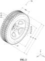
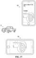
- FIG. 1shows an example of an embodiment of a vehicle comprising a wheel including a pneumatic tire in accordance with an embodiment
- FIG. 2shows a perspective view of a pneumatic tire in accordance with an embodiment
- FIG. 3shows a cutaway view of the pneumatic tire of FIG. 2 ;
- FIG. 4shows a diagram of an image processing system according to one embodiment
- FIG. 5shows a schematic network diagram of a system for monitoring road vehicles and off road vehicles, according to one embodiment
- FIG. 6shows a diagram of a computer of a vehicle according to one embodiment
- FIG. 7shows a schematic network diagram of a system for monitoring road vehicles and off road vehicles, according to another embodiment
- FIG. 8 A to Cillustrate representations of different databases according to various embodiments
- FIGS. 9 to 15show flowcharts of the use of a monitoring system, according to various embodiments.
- FIGS. 16 to 19show data capture for a system according to various embodiments
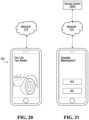
- FIG. 20shows the communication of a result in a system according to one embodiment
- FIG. 21shows scheduling of maintenance according to one embodiment
- FIG. 22shows a system capable of facilitating the purchase of parts according to one embodiment
- FIG. 23shows a system able schedule a maintenance request according to one embodiment
- FIG. 24shows a system able to connect two electronic devices, according to one embodiment
- FIGS. 25 to 27show a system that can determine that the vehicle has a critical malfunction according to various embodiments
- FIG. 28shows an example of a camera station for inspecting tires
- FIG. 29shows an example of a laser line scanner station for inspecting tires
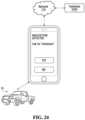
- FIG. 30shows an embodiment of a drone device for inspecting the tire
- FIG. 31shows the drone device for inspecting the tire
- FIG. 32shows an example of a vehicle-mounted inspection device for inspecting tires
- FIG. 33shows an example of an embodiment of a computing apparatus
- FIG. 34shows an example 3D tire model generated using the system described herein
- FIGS. 35 to 38show example 3D tire models of used and/or damaged tires generated using the system described herein, overlaid by 3D tire models of unused and/or undamaged tires;
- FIGS. 39 and 40show examples of wear/damage being detected and characterized using 2D recognition techniques.
- FIGS. 41 to 43shows flowcharts of the use of a monitoring system, according to various embodiments.
- FIG. 1shows an example of an embodiment of a vehicle 10 comprising wheels 20 1 - 20 4 on a ground surface 11 .
- Each of the wheels 20 1 - 20 4comprises a tire 34 for contacting the ground surface 11 .
- the vehicle 10can be monitored (e.g., during operation of the vehicle 10 ) to obtain information regarding the vehicle 10 , including information regarding the wheels 20 1 - 20 4 , such as an indication of deterioration of the tire 34 and/or another component of a given one of the wheels 20 1 - 20 4 (e.g., an indication of a level of wear, a rupture like a break, a puncture, chunking, de-bonding, etc.
- an indication of deterioration of the tire 34 and/or another component of a given one of the wheels 20 1 - 20 4e.g., an indication of a level of wear, a rupture like a break, a puncture, chunking, de-bonding, etc.
- an identifier of the tire 34 and/or another component of the given one of the wheels 20 1 - 20 4 , and/or other parameters of the tire 34 and/or another component of the given one of the wheels 20 1 - 20 4which can be used for various purposes, such as, for example, to: convey the information to a user (e.g., an operator of the vehicle 10 ); control the vehicle 10 (e.g., a speed of the vehicle 10 ); transmit the information to a remote party (e.g., a provider such as a manufacturer or distributor of the tire 34 and/or another component of the given one of the wheels 20 1 - 20 4 , and/or of the vehicle 10 ; etc.); etc.
- a remote partye.g., a provider such as a manufacturer or distributor of the tire 34 and/or another component of the given one of the wheels 20 1 - 20 4 , and/or of the vehicle 10 ; etc.
- Thismay be useful, for example, to gain knowledge about the vehicle 10 , including the wheels 20 1 - 20 4 , to enhance efficiency of the vehicle 10 , help prevent rapid wear or other deterioration of the wheels 20 1 - 20 4 , facilitate maintenance (e.g., replacement or repair) of the tire 34 and/or another component of each of the wheels 20 1 - 20 4 , and/or for various other reasons.
- maintenancee.g., replacement or repair
- the powertrainis configured to generate power for the vehicle 10 , including motive power for respective ones of the wheels 20 1 - 20 4 to propel the vehicle 10 on the ground surface 11 .
- the powertraincomprises a power source (e.g., a primer mover) that includes one or more motors.
- the power sourcemay comprise an internal combustion engine, an electric motor (e.g., powered by a battery), or a combination of different types of motor (e.g., an internal combustion engine and an electric motor).
- the powertraincan transmit power from the power source to one or more of the wheels 20 1 - 20 4 in any suitable way (e.g., via a transmission, a differential, a shaft engaging (i.e., directly connecting) a motor and a given one of the wheels 20 1 - 20 4 , etc.).
- the steering systemis configured to steer the vehicle 10 on the ground surface 11 .
- the steering systemis configured to turn front ones of the wheels 20 1 - 20 4 to change their orientation relative to the frame of the vehicle 10 in order to cause the vehicle 10 to move in a desired direction.
- the suspensionis connected between the frame and the wheels 20 1 - 20 4 to allow relative motion between the frame and the wheels 20 1 - 20 4 as the vehicle 10 travels on the ground surface 11 .
- the suspensionmay enhance handling of the vehicle 10 on the ground surface 11 by absorbing shocks and helping to maintain traction between the wheels 20 1 - 20 4 and the ground surface 11 .
- the suspensionmay comprise an arrangement of springs and dampers.
- a springmay be a coil spring, a leaf spring, a gas spring (e.g., an air spring), or any other elastic object used to store mechanical energy.
- a dampermay be a fluidic damper (e.g., a pneumatic damper, a hydraulic damper, etc.), a magnetic damper, or any other object which absorbs or dissipates kinetic energy to decrease oscillations.
- a single devicemay itself constitute both a spring and a damper (e.g., a hydropneumatic device).
- the cabinis configured to be occupied by one or more occupants of the vehicle 10 .
- the cabincomprises a user interface configured to interact with one or more occupants of the vehicle 10 , including, in this example, the operator (e.g., a driver) of the vehicle 10 .
- the user interfacecomprises an input portion including one or more input devices (e.g., a set of buttons, levers, dials, etc., a touchscreen, a microphone, etc.) allowing an occupant of the vehicle 10 to input commands and/or other information into the vehicle 10 and an output portion including one or more output devices (e.g., a display, a speaker, etc.) to provide information to an occupant of the vehicle 10 .
- the output portion of the user interfacewhich may comprise an instrument panel (e.g., a dashboard) which provides indicators (e.g., a speedometer indicator, a tachometer indicator, etc.) related to operation of the vehicle 10 .
- Each wheel 20 icomprises its tire 34 for contacting the ground surface 11 and a hub 32 for connecting the wheel 20 i to an axle.
- the wheel 20 ihas an axis of rotation 35 , which defines an axial direction (also referred to as a “Y” direction) parallel to the axis of rotation 35 of the wheel 20 i , a vertical direction (also referred to as a “Z” direction) that is normal to the axis of rotation 35 of the wheel 20 i , and a horizontal direction (also referred to as a “X” direction) that is normal to the axis of rotation 35 of the wheel 20 i and the vertical direction and can be viewed as corresponding to a heading direction of the wheel 20 i .
- the axial direction of the wheel 20 ican also be referred to as a lateral or widthwise direction of the wheel 20 i , while each of the vertical direction and the horizontal direction of the wheel 20 i can also be referred to as radial direction of the wheel 20 i (also referred to as a “R” direction).
- the wheel 20 ialso has a circumferential direction (also referred to as a “C” direction).
- the wheel 20 ihas an outer diameter D W and a width W W . It comprises an inboard lateral side 47 for facing towards a center of the vehicle 10 in the widthwise direction of the vehicle 10 and an outboard lateral side 49 opposite its inboard lateral side 47 .
- the tire 34has an axial direction, a vertical direction and a horizontal direction that each are a radial direction, and a circumferential direction, which respectively correspond to the axial direction, the vertical direction and the horizontal direction that each are the radial direction, and the circumferential direction of the wheel 20 i , has an inner diameter D TI , an outer diameter D T , and a width W T , and comprises an inboard lateral side 53 and an outboard lateral side 57 , which are respectively part of the inboard lateral side 47 and the outboard lateral side 49 of the wheel 20 i .
- the tire 34When it is in contact with the ground surface 11 , the tire 34 has an area of contact with the ground surface 11 , which may be referred to as a “contact patch” of the tire 34 with the ground surface 11 .
- the tire 34is a pneumatic tire, which comprises a body 40 to define a cavity 42 containing pressurized gas (e.g., air) to support loading on the tire 34 and allow the tire 34 to be resiliently deformable (i.e., changeable in configuration) as it contacts the ground surface 11 .
- the tire 34is configured to be mounted to a rim 44 of the hub 32 to form the cavity 42 containing the pressurized gas. Inflation pressure of the tire 34 is suitable for use of the vehicle 10 .
- the tire 34comprises a tread 50 , a shoulder 52 , a sidewall 54 , and a bead 56 .
- the tread 50is configured to contact the ground surface 11 and enhance traction.
- the tread 50may comprise a plurality of tread recesses 23 1 - 23 R and a plurality of tread projections 27 1 - 27 P such that each of the tread recesses 23 1 - 23 R is disposed between adjacent ones of the tread projections 27 1 - 27 P .
- the tread 50may be implemented in any suitable way in other embodiments (e.g., may have a smooth outer surface without tread recesses or projections).
- the bead 56is configured to engage the rim 44 .
- the sidewall 54extends between the tread 50 and the bead 56 and contains the pressurized gas within the cavity 42 .
- the shoulder 52is a transition between the tread 50 and the sidewall 54 .
- the tire 34comprises elastomeric material 45 to allow the tire 34 to be resiliently deformable.
- the elastomeric material 45can include any polymeric material with suitable elasticity.
- the elastomeric material 45includes rubber.
- Various rubber compoundsmay be used and, in some cases, different rubber compounds may be present in different areas of the tire 34 .
- the elastomeric material 45may include another elastomer in addition to or instead of rubber (e.g., polyurethane elastomer).
- the tire 34comprises reinforcement 40 disposed within (e.g., embedded in) the elastomeric material 45 to reinforce the tire 34 .
- the reinforcement 40comprises a plurality of reinforcing members 46 1 - 46 R each of which can be stiffer and stronger than the elastomeric material 45 to reinforce the tire 34 in one or more directions.
- a given one of the reinforcement members 46 1 - 46 Rmay be metallic in that it is at least mainly (i.e., mainly or entirely) made of metal.
- a given one of the reinforcing members 46 1 - 46 Rmay be polymeric but non-elastomeric in that it is at least mainly made of polymeric but non-elastomeric material (e.g., nylon, polyester, aramid, etc.).
- each of the reinforcing members 46 1 , 46 2is a belt running in the circumferential direction of the tire 34 .
- each of the belts 46 1 , 46 2comprises a layer of reinforcing cables 37 1 - 37 M that extend generally parallel to one another.
- the reinforcing cables 37 1 - 37 M of the belt 46 2extend diagonally to the circumferential direction tire, and in the general direction of outboard lateral side 49 of the tire 34 to reinforce the tire 34 in that direction, whereas the reinforcing cables 37 1 - 37 M of the belt 46 1 extend diagonally to the circumferential direction tire, and in the general direction of the inboard lateral side 47 of tire 34 to reinforce the tire 34 in that direction.
- each of the reinforcing cables 37 1 - 37 M of the belt 46 1extend in the circumferential direction of the tire 34 to reinforce the tire 34 in that direction
- the reinforcing cables 37 1 - 37 M of the belt 46 2extend transversally to the circumferential direction of the tire 34 to reinforce the tire 34 in that direction.
- each of the reinforcing cables 37 1 - 37 M of the each of belts 46 1 , 46 2is a cord including a plurality of strands (e.g., metallic fibers or wires).
- each of the reinforcing members 46 1 , 46 2is a metallic (e.g., steel) belt in which the reinforcing cables 37 1 - 37 M are metallic.
- the belts 46 1 , 46 2are separated by belt edge wedges 55 1 and 55 2 extending circumferentially around the tire 34 between the edges of the belts 46 1 , 46 2 .
- the belt edge wedges 55 1 and 55 2are configured to suppress the formation of cracks at the edges of the belts 46 1 , 46 2 .
- each of the reinforcing members 46 3 , 46 4is a layer of reinforcing fabric.
- Each of the layers of reinforcing fabric 46 3 , 46 4comprises thin pliable material made usually by weaving, felting, knitting, interlacing, or otherwise crossing natural or synthetic elongated fabric elements, such as fibers, filaments, strands and/or others, such that some elongated fabric elements extend transversally others.
- each of the layers of reinforcing fabric 46 3 , 46 4may comprise a ply of reinforcing woven fibers (e.g., nylon, polyester, aramid, and/or other synthetic fibers).
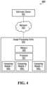
- FIG. 4shows a schematic block diagram of an image processing system 500 for use with a system 100 for monitoring road vehicles and off-road vehicles such as one or more vehicles like the vehicle 10 .
- one or more images captured by an electronic device 501can be processed using the image processing system 500 .
- the electronic device 501may transmit image information relating to a tire 34 of a vehicle, such as the tires 34 1 to 34 4 of the vehicle 10 , through a communication network 502 , to an image processing entity 505 over a communication link, which may be implemented over a cellular network, a WiFi network or other wireless LAN, a WiMAX network or other wireless WAN, etc.
- the electronic device 501can be a smartphone, a tablet, a smartwatch, a computer, etc., of a user, who may be the operator of the vehicle or another person having access to the vehicle. In other examples, the electronic device 501 may be integrated with the vehicle.
- the image processing entity 505can be an application running on a server. In other embodiments, the image processing entity 505 can be a dedicated network appliance. In yet other embodiments, the image processing entity 505 may be an application running on the electronic device 501 .
- the image processing entity 505comprises a memory 506 for storing image information and instructions for processing images, a processor 507 implementing a plurality of computing modules 508 x (for example, Artificial Intelligence, or “AI”, modules) for performing image recognition, pattern recognition and 3D model matching in order to assess a level and nature of wear, degradation and/or other deterioration of the tire 34 .
- the computing modules 508 xcan be implemented using a processor 507 .
- the computing modules 508 xmay be implemented by way of an Application Program Interface (API) that results in the computing modules 508 x being implemented on a separate device or system.
- APIApplication Program Interface
- Computing modules 508 xmay for example be implemented using known computer vision products, such as, AutoML VisionTM and/or Vision APITM, each provided by GoogleTM. In other embodiments, computing modules 508 x may comprise standalone AI or machine-learning solutions forming part of image processing entity 505 .
- AIrefers to some implementation of artificial intelligence and/or machine learning (e.g., heuristics, support vector machines, artificial neural networks, convolutional neural networks, any types of deep neural networks, etc.) in software, hardware or some combination of both.
- complex algorithmslike artificial intelligence, are used to categorize what may be considered uncategorizable data.
- the system 100can be configured for generating conclusions about a physical state of a tire based on one or more images of the tire itself. This analysis can include whether or not there is a defect in the tire, according to some embodiments. In some embodiments, this can include indications as to the physical state of the tire and/or useful life remaining.
- a machine learning algorithmmay be trained to identify a defect or other characteristic in a tire by way of image analysis.
- computing modules 508 xare first taught how to identify parameters in a training mode (sometimes referred to as supervised learning mode). This is done by analyzing a given set of values, making quantitative comparisons, and cross-referencing conclusions with known results. Iterative refinement of these analyses and comparisons allows an algorithm to achieve greater predictive certainty. This process is continued iteratively until the solution converges or reaches a desired accuracy.
- a training modesometimes referred to as supervised learning mode
- computing modules 508 xcan compare image data for a given tire to a previously-analyzed mass of known data.
- informationcan be generated from already populated tire data provided to the computing modules 508 x .
- this datacould contain images of tires, along with determinations of the remaining life of the tires.
- both the inputs and the outputsare provided to the system 100 .
- the system 100can process the given inputs and compare the calculated outputs according to its algorithm to the provided outputs. Based on this comparison, the system 100 can determine a metric to represent the percentage of error between calculated and provided outputs. Using this error metric, the system 100 can adjust its method of calculating an output.
- the system 100can continuously repeat analysis of different inputs and provided outputs in order to fine-tune its method of determining tire information.
- the computing modules 508 xmay require initial supervised learning, as the computing modules 508 x continue to gain access to data, they may be able to further refine their predictive analytics based on new inputs. For example, if a user is able to confirm that an assessment (e.g. wheel imbalance) or prediction (e.g. 6 months of use left in a given tire) made by the system 100 is/was incorrect, the user can upload to the system 100 what the correct conclusion/prediction was. This allows the computing modules 508 x to continue to improve accuracy in their analysis.
- an assessmente.g. wheel imbalance
- predictione.g. 6 months of use left in a given tire
- multiple computing modules 508 xcan be configured to determine different characteristics of a given tire. Each of these modules can offer a different analysis for a given input.
- the processormay direct these modules to be used independently or concurrently based on an operational parameter determined by a given user. For example, the system 100 may use a different analytical technique to determine tires life compared to wheel imbalance. Based on an image communicated to the system 100 from an electronic device, the system 100 may analyze a given for tires life, wheel imbalance, or other forms of wear and/or damage.
- the computing modules 508 xare configured to assess a level of wear, damage and/or other deterioration of the tire 34 .
- a computing module 508 xcan be configured to determine that the tread projections 27 1 - 27 P are worn to 30% of the level of wear that would require replacement of the tires.
- the computing modules 508 xare configured to assess the nature of damage to the tire 34 .
- a computing module 508 xcan be configured to determine that any other component of the given one of wheels 20 1 - 20 4 is damaged or missing.
- the computing modules 508 xare further configured to predict the cause of the wear and/or damage to the tire 34 .
- a computing module 508 1is configured to predict whether a specific wear pattern of the elastomeric material of a tire 34 i is caused by imbalanced wheel.
- a computing module 508 2is configured to predict whether a specific wear pattern of the elastomeric material of a tread projections 27 1 - 27 P is caused by incorrectly installed tire.
- another computing module 508 3is configured to predict whether a specific wear pattern of the tires is caused by a categorized or uncategorized event.
- each computing module 508 xcan be implemented using a combination of deep learning, supervised or unsupervised machine learning, image recognition and/or machine vision.
- the system 100is configured to capture one or more 2D images to detect specific patterns of wear and/or damage.
- the system 100may be configured to implement one or more computer vision (CV) models to detect specific visible wear/damage features.
- CVcomputer vision
- visible wear/damage featuresinclude, but are not limited to, the presents of nails, or other road debris capable of piercing tires, as well as cracks in tire sidewalls.
- the image processing system 500may produce a three-dimensional (3D) scan to generate a 3D model of at least part of the tire 34 .
- the image data received by the electronic device 501 or any other image capture meansare processed by way of photogrammetry in order to create the 3D model of the tire 34 and/or another component of a given one of the wheels 20 1 - 20 4 .
- laser line scannersare instead used to generate the 3D model of the tire 34 and/or another component of a given one of the wheels 20 1 - 20 4 .
- Such precise 3D modelscan be compared to 3D models of unworn and/or undamaged tires in order to precisely measure wear, damage and/or other deterioration. For example, by comparing the 3D model of a worn tire 34 i to the 3D model of a new, unworn tire, it is possible to precisely measure a volumetric loss of material of the worn tire 34 i and thereby assess the wear and/or other deterioration of the worn tire 34 i , very precisely.
- the system 100may generate a 3D model 55 of a tire 34 i , using any of the above methods, or a combination thereof.
- the system 100can then be superimposed onto an image of the tire 34 i captured by electronic device 501 .
- Such superimpositionmay be achieved using known augmented reality (AR) techniques and processes.
- ARaugmented reality
- the system 100can implement a 2D recognition technique.
- the system 100can implement a 3D recognition technique.
- the system 100can implement a combination of a 2D recognition technique and a 3D recognition technique.
- the 3D recognition technique usedis based on generating a 3D model using a point cloud.
- method 4000can be used to identify tire wear/damage and/or the extent thereof.
- a plurality of images of the tirecan be acquired using the electronic device 501 , before sending the images to the image processing entity 505 at step 4002 .
- the system 100generates a 3D point cloud using the plurality of images. This can be accomplished by system 100 using, for example, open source algorithms, such as those available from Point Cloud Library (PCL).
- the point cloudcan be generated a third party, through use of an Application Program Interface (API) by system 100 .
- APIApplication Program Interface
- the system 100uses the generated 3D point cloud to generate a 3D model of the tire.
- the 3D modelis matched to known 3D models of tires in a tire database at step 4005 .
- wear, damage and/or the extent thereofcan be identified by comparing the generated 3D model to the known 3D model, as described in more detail below.
- 2D recognition techniquesinclude four basic steps, namely image acquisition, image processing, feature extraction and classification.
- Such techniquesinclude, but are not limited to, Optical Character Recognition (OCR), feature detection, image gradient analysis, pattern recognition algorithms and feature/pattern classification algorithms.
- OCROptical Character Recognition
- the system 100can be configured to implement the method of FIG. 42 .
- the electronic device 501can acquire one or more images of a tire, before sending the images to the image processing entity 505 at step 4102 .
- the image processing entity 505can perform image processing steps prior to feature extraction.
- the image processing entity 505can be configured to perform image processing including the use of fiducial markers.
- the image processing entity 505can perform feature extraction in order to detect and isolate various portions or shapes (features) of the image or images.
- Feature extractioncan include, but is not limited to, edge detection, corner detection, blob detection, ridge detection, scale-invariant feature transform, thresholding, blob extraction, Haar-like feature extraction, template matching, Hough transforms and generalized Hough transforms.
- the system 100can perform feature classification.
- feature classificationcan include, but is not limited to, the use of nearest neighbor classification, cascading classifiers, neural networks, statistical classification techniques and/or Bayesian classification techniques.
- featureswhich represent undamaged/unused parts of the tire, and features (e.g. cracks, exposed cables, etc.) which represent patterns of wear or damage.
- features relating to patterns of wear or damagehave been detected, it is possible for the system 100 to perform further feature classification on the wear or damage pattern.
- system 100is configured to use the system of FIG. 42 in order to detect damage or wear patterns in tires.
- system 100can be configured to detect partially embedded nails 55 A using the 2D analysis method described with reference to FIG. 42 .
- system 100can be configured to recognize narrow (though potentially deep) cracks 55 B in sidewalls of a tire.
- such patternsare difficult to detect using volumetric analysis alone.
- the 3D recognition techniques of the present disclosurecan be combined with any of the 2D recognition techniques in order to facilitate tire matching, as well as wear and/or damage recognition and characterization.
- the 2D recognition techniques of the present disclosurecan be used on images generated by the system 100 of various views of the 3D model generated using the 3D recognition techniques of the present disclosure.
- the system 100can sequentially use 3D recognition at step 4202 and then 2D recognition at step 4203 in order to detect patterns of wear and/or damage on a tire.
- 2D recognitionmay be performed before 3D recognition.
- the system 100may be configured to superimpose 2D features onto 3D models, thereby allowing a more precise classification of the type of wear and/or damage.
- the system 100is configured to generate a 3D model 55 of a used and/or damaged tire and compare it to a 3D model 77 of an unused and undamaged tire.
- the 3D model 77 of an unused and undamaged tiremay be generated by the system 100 based on a previously-scanned tire, may be acquired by the system 100 from a database of 3D models of tires, or may be acquired by the system in any other suitable way.
- Once the 3D model 77 of an unused and undamaged tire is acquired or generated by the system 100it can be compared to the 3D model 55 of a used and/or damaged tire generated by the system 100 using various volumetric comparison techniques.
- the system 100may compare the models by calculating the amount of missing material of a given tire feature (e.g. tread projections 27 1 - 27 P ). For example, volumetric comparison of the 3D model 55 of a used and/or damaged tire and a 3D model 77 of an unused and undamaged tire can establish that a given tread projection 27 x has been worn to 78% of its original volume.
- a given tread projection 27 xhas been worn to 78% of its original volume.
- the cause and/or nature of the wear and/or damage of the tire 34can be established by the system 100 performing a volumetric comparison of the 3D model 55 of a used and/or damaged tire and a 3D model 77 of an unused and undamaged tire.
- the system 100can determine a pattern of damage that is indicative of the cause and/or nature of the damage.
- the chunking detected by the system 100 in the tread projections 27 1 - 27 P of FIG. 35is typically caused by using the tire on abrasive ground and/or on ground containing oil or some other form of contaminant.
- the system 100can determine a pattern of tread wear that is indicative of the cause and/or nature of the tread wear.
- the uneven tread wear detected by the system 100 in the tread projections 27 1 - 27 P of FIG. 36is typically caused by an abnormal camber angle and/or a misaligned axle.
- the system 100can determine a pattern of damage that is indicative of the cause and/or nature of the damage.
- the radial cracks detected by the system 100 between the tread projections 27 1 - 27 P and the sidewall 54 of FIG. 37is typically caused by inadequate installation of the tire on the wheel and/or overloading of the vehicle 10 .
- the concentric crack damage detected by the system 100 on the side wall of the tire above the rim of FIG. 38is typically caused by an overloading of the vehicle 10 .
- system 100can use the 2D recognition technique described above to recognize and characterize the presence of partially embedded nails 55 A. Also, as shown in FIG. 40 , the system 100 can use the 2D recognition technique described above to recognize and characterize the presence of cracks 55 B in the sidewall of a tire.
- the image processing entity 505may send data relating to the cause, level and/or nature of the wear and/or damage of the tire 34 back to electronic device 501 for further processing and/or notification to a user.
- electronic device 501may determine that an event arising from usage of the tire 34 , such as a usage threshold event (e.g. an amount of tread wear, an amount of time such as a number of hours the tire 34 has been used), wear threshold event (e.g. the number of exposed radial cracks between the projection treads 27 1 - 27 P and the sidewall 54 ) and/or damage event (e.g. minor delamination damage and/or “chunking” damage), has occurred.
- a usage threshold evente.g. an amount of tread wear, an amount of time such as a number of hours the tire 34 has been used
- wear threshold evente.g. the number of exposed radial cracks between the projection treads 27 1 - 27 P and the sidewall 54
- damage evente.g. minor delamination damage and
- the computing modules 508 xmay have access to information stored elsewhere on the internet.
- the computing modules 508 xmay be configured to query databases stored on external servers by sending requests over the network in order to analyze the image based on pertinent cross-referential data. This may include weather, humidity, or information about the vehicle or tires that can be periodically updated.
- FIG. 5illustrates a schematic network diagram of a system 100 for monitoring vehicles such as one or more road vehicles and off-road vehicles like the vehicle 10 , according to one embodiment.
- the system 100includes an electronic device 501 , a network 124 , and a system server 1142 that can implement the image processing entity 505 of FIG. 4 .
- the serverincludes a memory 1146 , processor 1144 , and network interface 1148 .
- the electronic device 501may include elements such as a processor, a memory, a display, a data input module, and a network interface.
- the electronic device 501may include other components, but these have been omitted for the sake of brevity.
- the electronic device 501is configured to perform the operations described herein.
- the electronic device 501 processormay be configured to execute instructions stored in memory. The instructions, when executed, cause the electronic device 501 to perform the operations described herein.
- the instructionsmay be part of a software application downloaded into memory by the electronic device 501 .
- some or all of the functionality described hereinmay be implemented using dedicated circuitry, such as an ASIC, a GPU, or a programmed FPGA for performing the operations of the processor.
- an application(“app”, i.e., software) may be installed on the electronic device 501 to interact with the system server 1142 and or the vehicle 10 .
- the usere.g., the operator
- a repositorye.g., Apple's App Store, iTunes, Google Play, Android Market, etc.
- the usermay access certain features relating to the system server 1142 and/or the vehicle 10 locally on the electronic device 501 .
- a usercan use the electronic device 501 to generate data about the vehicle 10 .
- the electronic deviceis a smart phone equipped with a camera
- the usercan take one or more images of a tire 34 of the vehicle 10 .
- the system 100may then take the image data captured by the electronic device 501 and transmit the image data over a network 124 to a system server 1142 .
- the electronic device 501may be a portable electronic device with multiple uses such as a mobile phone, tablet or laptop. According to other embodiments, the electronic device may be a single-use electronic device, such that the device is designed to only be used in operation with the system 100 . Further, the electronic device 501 may also be capable of establishing a communicable link with an accessory device. This communicable link be may be wireless, wired, or partly wireless and partly wired (e.g., Bluetooth or other short-range or near-field wireless connection, WiFi or other wireless LAN, WiMAX or other wireless WAN, cellular, Universal Serial Bus (USB), etc.).
- This communicable linkbe may be wireless, wired, or partly wireless and partly wired (e.g., Bluetooth or other short-range or near-field wireless connection, WiFi or other wireless LAN, WiMAX or other wireless WAN, cellular, Universal Serial Bus (USB), etc.).
- the electronic device 501may integrated into an internal computer 1342 in the vehicle (as shown in FIG. 6 ).
- the internal computer 1342may have a vehicle memory 1346 , processor 1344 , network interface 1348 , and internal sensor network 1350 .
- vehicle internal computer 1342can communicate and upload images to system server 1142 independently.
- the internal sensor network 1350can include sensors to provide information about the vehicle or the tires of the vehicle. For example, this may include a camera positioned to take images of the tires.
- the system 100may be configured to continuously monitor the tires. This can be achieved by continuously capturing data, for example, images of the vehicle tires, at various intervals.
- the electronic device 501can then automatically upload the data over the network 124 to the system server 1142 for image processing. After processing, the image processing entity 505 can automatically communicate over the network 124 if a fault state has been determined.
- the electronic device 501can also send additional data to the image processing entity 505 over the network 124 .
- thiscan include (but is not limited to) GPS location, date and time, or any information from an onboard computer within the vehicle.
- This datacan be cross-referenced and analyzed within the computing modules 508 x .
- the computing modules 508 xcan access the specific weather and weather history for the vehicle location.
- such informationmay be used in, for example, determining the end-of-life of a tire (i.e. the amount of time until a tire is expected to fail or until the likelihood of tires failure rises above a predetermined threshold).
- the internal computer 1342may periodically receive and record information relating to the vehicle 10 and/or the tires 34 1 - 34 4 determined by the internal sensor network 1350 .
- the information received from the internal sensor network 1350may include an image taken of the tires or information about the vehicle 10 , such as the speed of the vehicle 10 .
- the electronic device 501may communicate a unique identifier for a specific tire under inspection.
- the unique identifiercan be a serial number of the tire. This allows the server 1146 and/or internal computer 1342 to catalog the inspection and produce a history of a given tire.
- the internal computer 1342 and/or the server 1146may store data about the serial numbers of the tires installed on the vehicle 10 .
- the electronic device 501may be capable of determining a serial number from a tire based on an image of the tire. This can be done by the electronic device 501 capturing an image of an embossed serial number on a surface of the tires, and using the image processing entity 505 to determine the specific characters of the serial number. This can be cross-referenced with a database stored in server memory 1146 (or otherwise accessible by system server 1142 ) to determine elements such as the model and date of manufacture of the tire.
- Serial number analysismay be performed using AI techniques employed by the computing modules 508 x , may be performed using techniques such as optical character recognition (OCR), or a combination thereof. These techniques may include preprocessing of an image in order to improve the ability to analyze the target components, such as de-skewing, layout analysis, and binarization.
- OCRoptical character recognition
- a tire and/or another component of a given one of the wheels 20 1 - 20 4can be identified by way of another marking or tag suitable for communicating information relating to the tires.
- markings or tagscan include, but are not limited to, barcodes, Quick Response (QR) codes or other matrix barcodes and Radio Frequency Identification (RFID) tags.
- the electronic device 501may be configured to analyze the tread pattern and measure tire width to determine a number of characteristics about the tire. The electronic device 501 may then send this data and information to the system server 1142 for further data analysis to identify the type of tire.
- the type of tiremay be a tire brand, model number, or any other suitable information capable of identifying a tire.
- the vehiclemay be capable of communicating all the necessary data over the network without the use of an external electronic device 501 such as a mobile phone.
- the vehicle 10may be equipped with a network interface capable of independently communicating with the system server 1142 over the network 124 .
- a system server 1142hosts the image processing entity 505 .
- Server processor 1144is able to access instructions stored in the memory 1146 that can initialize the image processing entity 505 . This initialization can include operational parameters that include which computing module 508 x to use.
- Image processing entity 505can store instructions relating to a specific computing module 508 x within the memory 1146 .
- the processor 1144may instruct the server to save the data received from the network via the network interface 1148 in memory 1146 .
- the processor 1144may analyze the data in memory 1146 and determine information about the tire 34 . Based on the data analysis, the processor 1144 may send a communication to the electronic device 501 over the network 124 via the network interface 1148 .
- FIG. 7illustrates a schematic network diagram of a system 100 for monitoring road vehicles and off-road vehicles, according to another embodiment.
- the system 100can communicate with multiple vehicles 10 A - 10 N . While this figure shows the vehicles 10 A - 10 N communicating independently with the system server 1142 over the network 124 , the vehicles may alternatively each be communicably linked with an electronic device 501 as described with reference to FIG. 5 .
- the system server 1142may communicate with an electronic device 501 located at a dispatch center 1102 , a service center 1104 , or a parts supplier 1107 .
- the system server 1142may communicate with the user via an electronic device 501 or the vehicle 10 , a dispatch center 1102 , a service center 1104 , or a parts supplier 1106 .
- the system 100may also communicate with any combination of these, or any other suitable device registered within the system 100 .
- This communicationcan contain information such as that indicating the determination of tire wear and/or damage concluded by the image processing entity 505 .
- the dispatch center 1502 or usermay schedule maintenance with the service center 1104 .
- the system 100can determine the amount of time required or parts available at the service center 1104 and facilitate scheduling a maintenance appointment or a shipment from the parts supplier 1106 . This can be done by maintaining a database of inventory at the service center, along with a calendar.
- FIG. 8 A to Cillustrate representations of different databases that may be generated by the server processor 1144 based on information stored in memory 1146 .
- the server memory 1146can store a history of all information necessary for performance of the system 100 , including a record of all inspections and conclusions made.
- These databases, or the information stored within them,may be accessible to users and administrators of the system 100 , or to software able to interact with the system 100 through the use of an application programming interface (API).
- APIapplication programming interface
- FIG. 8 Ashows an example of a visual representation of a database that can be generated by the system 100 according to an embodiment directed towards a specific tire manufacturer. This includes an indication of tire model, a serial number for the tire, the date of an inspection, the type of inspection, along with the registered owner. This database representation gives the manufacturer access to all registered tires sold and registered within the system 100 , and allows access to information on tire wear and damage.
- FIG. 8 Bshows an example of a visual representation of a database that can be generated by the system 100 according to an embodiment directed towards a vehicle fleet manager.
- the databaseincludes an indication of tire model, a unique identifier for the vehicle itself, the date of an inspection, tire status, and an additional field for manager notes.
- This database representationgives the fleet manager access to all vehicles registered within the system 100 , and allows them to access a history of information on tire wear and/or damage.
- FIG. 8 Cshows an example of a visual representation of a database that can be generated by the system 100 according to an embodiment directed towards a specific vehicle manufacturer. This includes an indication of vehicle model, tire model, a date of an inspection, tire status, and an additional field for manager notes.
- This database representationgives the vehicle manufacturer access to all of their vehicles registered within the system 100 , and allows them to access a history of information on tire wear and/or damage.
- database representationsare structured merely by way of example for illustrative purposes, and a skilled reader would know that these visual representations can be changed to include more or less information available to the system 100 .
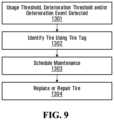
- FIG. 9shows an example flowchart of the use of the system 100 which could be used (e.g., by the operator of the vehicle 10 , in a rental market, etc.) to monitor usage of tires.
- a usercan use the electronic device 501 to generate image data relating to the tire 34 of the vehicle 10 .
- the electronic device 501may also access internal information stored on the vehicle onboard computer 1342 .
- the electronic device 501may then communicate both the data captured and the information retrieved by the electronic device 501 over the network 124 to the system server 1142 to be stored in memory 1146 .
- the processor 1144may determine information about the tire 34 . Based on the data analysis, the processor 1144 may send a communication to the electronic device 501 over the network 124 via the network interface 1148 .
- the system 100determines that an event arising from use of a tire 34 , such as a usage threshold event (e.g. an amount of time such as a number of hours the tire 34 has been used) or a deterioration threshold event (e.g. the number of exposed radial cracks between the projection treads 27 1 - 27 P and the sidewall 54 ) and/or deterioration event (e.g. minor delamination damage and the “chunking” damage), has occurred.
- a usage threshold evente.g. an amount of time such as a number of hours the tire 34 has been used
- a deterioration threshold evente.g. the number of exposed radial cracks between the projection treads 27 1 - 27 P and the sidewall 54
- deterioration evente.g. minor delamination damage and the “chunking” damage
- the system 100identifies the tire for which the usage threshold event or deterioration threshold event has occurred.
- the tire information and information relating to the usage threshold event and deterioration threshold eventis conveyed to the operator of the vehicle by the system 100 in order to facilitate scheduling of tire servicing and/or other maintenance.
- the usage threshold event or deterioration threshold eventis for the tire 34 .
- the system 100may issue a notification conveying this information to the operator via the user interface of the operator of the vehicle 10 and/or the electronic device 501 .
- the electronic device 501is a mobile phone
- the system 100conveys the tire information and information relating to the usage threshold event and deterioration threshold event to an organization providing maintenance services.
- the system 100may issue a notification conveying this information to a system server 1142 associated with the organization via a network 124 (e.g. which may be implemented by the Internet, a cellular connection, and/or any other network infrastructure).
- a network 124e.g. which may be implemented by the Internet, a cellular connection, and/or any other network infrastructure.
- the system 100may allow organizations to provide tire-as-a-service type payment/usage models, in which tires are not purchased, but are rather provided as a service to vehicle operators in exchange for a subscription fee. For example, for a monthly fee, an organization may provide vehicle operators with tires, as well as usage rights to the system 100 described herein which will allow the organization to ensure that the vehicle operator is never without an operable/functional tires, regardless of how much and how (i.e. under what circumstances) the vehicle operator uses the tires.
- the system 100determines that an event arising from usage of a tire, such as a usage threshold event (e.g. an amount of tread wear, an amount of time such as a number of hours the tire 34 has been used), deterioration threshold event (e.g. the number of exposed radial cracks between the projection treads 27 1 - 27 P and the sidewall 54 ) and/or deterioration event (e.g. minor delamination damage and the “chunking” damage), has occurred.
- a usage threshold evente.g. an amount of tread wear, an amount of time such as a number of hours the tire 34 has been used
- deterioration threshold evente.g. the number of exposed radial cracks between the projection treads 27 1 - 27 P and the sidewall 54
- deterioration evente.g. minor delamination damage and the “chunking” damage
- vehicle location information relating to the geographic location of the vehicleis determined. This can be achieved by any suitable means including, but not limited to, Global Positioning System (GPS) receivers.
- GPSGlobal Positioning System
- the system 100conveys the tire information, vehicle location information and information relating to the usage threshold event, deterioration threshold event and/or deterioration event to the tire-as-a-service organization.
- the system 100may communicate with the system server 1142 of the tire-as-a-service organization over a network 124 (e.g. which may be implemented by the Internet, a cellular connection, and/or any other network infrastructure).
- a network 124e.g. which may be implemented by the Internet, a cellular connection, and/or any other network infrastructure.
- the tire-as-a-service organizationships a replacement tire to a location related to the geographic location of the vehicle.
- the tire-as-a-service locationcould ship the replacement tire to the nearest maintenance service dispatch location or third party maintenance organization.
- the tire-as-a-service organizationcan schedule a maintenance of the tires.
- the tire-as-a-service organizationschedules a third party mobile maintenance team to perform onsite maintenance based on the geographic location of the vehicle.
- the tire-as-a-service organizationreplaces the tire. In some embodiments, this can be performed onsite, based at least in part on the vehicle location information received from the tire-as-a-service organization.
- FIG. 11shows an example flowchart of the use of the system 100 which could be used, for example, by a fleet manager to monitor usage of tires.
- the preferences of a given fleet managercan be included in any part purchase or system maintenance request. For example, a fleet manager may consider a specific tire to be superior to all other on the market. The fleet manager may want to only purchase that specific brand of tire. Another example of purchase preferences may include only to purchase a specific tire if the supplier inventory and price database indicates that the part is available with a discount. Further, if there is no supply of a first preferred tire in the inventory, the user may store a preference for an alternate tire to be purchased.
- steps 1501 and 1502are the same as those described in steps 1301 , 1401 , and 1302 , 1402 respectively.
- the system 100will query the memory to determine if the specific user has a purchase preference stored in the system 100 . If the system 100 has a purchase preference stored for the given user, the system 100 will order the tire for replacement based on the saved preference at step 1506 . If the system 100 does not find a purchase preference for the given user, the system 100 may send a communication to the user's electronic device 501 with information indicating the part purchase options and information about the parts (for example the various options of price and part characteristics). The system 100 may also send a communication instructing the electronic device 501 to prompt the user to store a purchase preference. Based on this information, the system 100 will order the tire at step 1507 .
- the system 100may schedule maintenance with a given service center or technician.
- user preferencesmay also be considered. For example, a user may be able to store in their profile a preference for scheduling. This may include a preference for the first available time to service the vehicle. Alternatively, a fleet manager may try and coordinate scheduling of maintenance with other vehicles within a fleet. This could include wanting all vehicles to be serviced at the same time, or to stagger vehicle services. Scheduling preferences may also include a time of day preference for the user to have maintenance scheduled. Based on these preferences, the user may be automatically scheduled for maintenance.
- the system 100may prompt the user via a date and time entry interface, such as a calendar interface, on the electronic device 501 to input a date and time for maintenance. Based on this input data, the system 100 can schedule maintenance with a technician or service center.
- a date and time entry interfacesuch as a calendar interface
- the tire-as-a-service organizationreplaces the tire. In some embodiments, this can be performed onsite, based at least in part on the vehicle 10 location information received from the tire-as-a-service organization.
- FIG. 16shows an example flowchart of the use of the system 100 which could be used, for example, by a fleet manager to monitor usage of tires.
- inventory of the tires at a given service centercan be monitored.
- the system 100allows organizations managing large fleets (e.g. vehicle rental companies, construction companies, forestry companies, etc.) to ensure that maintenance operations can be scheduled and carried out effectively and efficiently. For example, by monitoring the wear of tires, it is possible to more precisely predict when a tire will fail and/or when a replacement tire should be ordered and/or shipped.
- the system 100determines that an event arising from usage of a tire 34 , such as a usage threshold event (e.g. an amount of tread wear, an amount of time such as a number of hours the tire 34 has been used), deterioration threshold event (e.g. the number of exposed radial cracks between the projection treads 27 1 - 27 P and the sidewall 54 ) and/or deterioration event (e.g. minor delamination damage and the “chunking” damage), has occurred.
- a usage threshold evente.g. an amount of tread wear, an amount of time such as a number of hours the tire 34 has been used
- deterioration threshold evente.g. the number of exposed radial cracks between the projection treads 27 1 - 27 P and the sidewall 54
- deterioration evente.g. minor delamination damage and the “chunking” damage
- the system 100identifies the tire for which the usage threshold event, deterioration threshold event and/or deterioration event has occurred.
- the system 100conveys the tire information and information relating to the usage threshold event, deterioration threshold event and/or deterioration event to an automated fleet management system.
- the system 100may communicate with the automated fleet management system over a network 124 (e.g. which may be implemented by the Internet, a cellular connection, and/or any other network infrastructure).
- the automated feet management systemqueries a tire supply database to determine whether the identified tire is available or needs to be ordered.
- the tire supply databasecan be managed by the fleet management system, or can be managed by a third-party tire supplier. If the identified tire is available, the vehicle can be scheduled for maintenance. If, on the other hand, the tire is not available, the fleet management system can cause the tire to be ordered at step 1604 , before scheduling maintenance of the vehicle at step 1605 . This system may also include ordering based on stored user preference as previously described.
- the scheduling of the vehicle maintenanceis at least in part based on the estimated delivery time for an ordered tire.
- the dispatching of the vehicle relating to the identified tirecan, at least partially, be based on a pre-scheduled maintenance.
- This system 100may also include scheduling based on stored user preference as previously described.
- FIG. 13shows an example flowchart of the use of the system 100 which could be used, for example, by a vehicle operator to monitor usage of tires.
- the system 100has determined a critical error to have taken place or imminent.
- steps 1701 and 1702are similar to those described in steps 1301 , 1401 , and 1302 , 1402 respectively.
- the system 100can prompt the user to establish an audiovisual and/or textual connection with a technician at 1703 .
- Thiscould be achieved by using a Voice Over IP (VoIP) system, a phone call over a cellular network, or any other means of text, audio or video communication.
- VoIPVoice Over IP
- the technicianmay instruct the user to drive the vehicle to a safe location and wait for the technician to arrive.
- the technicianmay be able to instruct the user to point the camera of the electronic device at a specific component of the vehicle 10 in order to provide the technician with more information about the vehicle status.
- FIG. 14shows an example flowchart of the use of the system 100 which could be used, for example, by a vehicle operator to monitor usage of tires.
- the system 100has determined a critical status of the tire and/or another component of a given one of the wheels 20 1 - 20 4 .
- steps 1801 and 1802are similar to those described in steps 1301 , 1401 , and 1302 , 1402 respectively.
- the system 100alerts relevant parties of the critical status. This can include fleet managers, technicians or other operators.
- the system 100may send a text message, email or app push notification to any interested party that the status and operability of a given vehicle with a unique identifier has reached a certain threshold of wear or damage.
- the vehicle operator or fleet managermay override the decision determined by the system 100 and continue to operate the vehicle.
- the system 100may have the capability to safely disable the vehicle given specific parameters. For example, the system 100 may only allow the vehicle to operate for another specific distance or time, or may not allow the vehicle to restart after it has switched off without an appointment with a technician.
- FIG. 15shows an example flowchart of the use of the system 100 by, for example, a vehicle operator to monitor usage of tires.
- the system 100is able to determine a specific tire brand or type, and cross-reference this brand or type with a database of compatible brands stored in a memory.
- steps 1901 and 1902are similar to those described in steps 1301 , 1401 , and 1302 , 1402 respectively.
- the system 100is able to identify the tire characteristics 1903 . These characteristics may include thickness, length, weight, width, tread pattern, etc. Based on an analysis of the vehicle's tires, the system 100 can determine tire alternatives at step 1904 . This can be done using a pre-populated database stored on a server of all major available tire brands and products, along with compatible alternatives. Once the system 100 has determined the tire and tire characteristics, it can query the database to find all other products that could be used for the vehicle.
- the system 100can then communicate the tires to the user at step 1905 . This can be done by sending the information over the network to the electronic device.
- the usermay determine that an alternative tire could be used for the vehicle. If the user selects the alternative tire, the system 100 will send that message back to the server over the network and proceed to organize any part replacement using the user's selection.
- the electronic device 501can display an instruction to the user to position and/or move the electronic device 501 in order to optimally capture the image.
- FIG. 16shows an embodiment in which the system 100 may instruct the user to take an image of the vehicle 10 .
- the electronic device 501will communicate this image along with any other information to be communicated to the system server 1142 for analysis, as described above.
- the system 100may also or instead instruct the user to take a video of the tire 34 .
- the electronic device 501may then communicate this video along with any other information to be communicated to the system server 1142 for data analysis, as described above.
- the system 100can instruct the user to use an accessory device 2202 in conjunction with the vehicle 10 in order to generate data about the tire 34 .
- the accessory device 2202can be an optical sensor communicatively linked to the electronic device 501 .
- the accessory device 2202can communicate the image data captured to the electronic device 501 .
- the electronic device 501may communicate this data along with any other information to be communicated to the system server 1142 for analysis, as described above.
- the electronic device 501can be communicably linked to the vehicle, according to some embodiments.
- the electronic device 501communicates with an onboard computer 1342 in the vehicle 10 in order to generate data about the vehicle.
- the electronic device 501may communicate this data along with any other information to be communicated to the system server 1142 for analysis, as described above.
- the information determined about the vehicle based on the analysis conducted by the system 100is communicated to the electronic device 501 over the network 124 .
- the informationwas a length of time before the tires needed to be replaced.
- the system 100has already communicated to the electronic device that based on the data analysis, vehicle maintenance is required.
- the electronic device 501can then prompt the user to schedule the maintenance. If the user decides to schedule the maintenance, the electronic device 501 can communicate directly with a service center 2604 in order to schedule the maintenance over the network 124 .
- the usermay have access to a booking calendar for the service center and select a time. Based on this selection, the parties will be notified that maintenance has been booked.
- the system 100may have access to information about the service center 2604 , such as parts inventory. Based on this inventory, the system 100 can calculate any lead time if required that can be factored into the booking span.
- the system 100can order new parts through the network 124 by creating a request to a retailer or parts center 2704 .
- the system 100may create a request to the parts center to ship the part to the service center in advance of the booked maintenance time.
- the system 100may have access to pricing information or alternative replacement parts available at the parts center 2704 .
- the system 100may present the user with pricing options, sale information for different components they may require ordering for replacement. The user may then inform the system 100 of their preference and the system 100 will submit the order to the parts center accordingly.
- the system 100is configured to schedule a maintenance request over the network 124 without requiring a user to select a time. This time may be based on a user preference saved in the server memory for a given vehicle owner. For example, an owner may have a preference that all vehicles are scheduled for maintenance one month before the system 100 determined date. Accordingly, the system 100 can notify the user of scheduled maintenance as it is automatically scheduled.
- the system 100is able to make purchase requests over the network 124 without requiring the user to select a part component. This choice may be based on a user preference saved in the server memory for a given vehicle owner. For example, an owner may have a preference for a specific brand of vehicle parts. Accordingly the system 100 can notify the user of the part purchase as it is automatically scheduled.
- the electronic devicemay be communicably linked to a technician 3204 .
- the techniciancan also be notified over the network 124 of any determined vehicle information, scheduled maintenance, parts purchased, location of maintenance etc. Based on the user selection the user can be connected to a technician 3204 via the network 124 .
- This connectioncould be by way of a telephone call, wherein the system 100 communicates a phone number over the network for the electronic device.
- the system 100may use a Voice Over IP (VoIP) connection between the user and the technician.
- VoIPVoice Over IP
- the communication between user and technician establishedcould be a video call, wherein the technician is able to view a feed coming from a camera module within the user's electronic device.
- the system 100may determine that the vehicle has a critical malfunction. This could be determined through information captured form the onboard computer's internal sensor network or through data captured via the electronic device. For example, the vehicle tires may have been damaged to the point where further driving would cause greater permanent damage to the vehicle and may endanger the safety of the driver.
- the system 100can instruct the electronic device to prompt a user with a notification of the critical malfunction and request instruction for whether or not the vehicle should be allowed to continue to operate. Based on this decision, the electronic device can instruct an onboard computer in the vehicle that the vehicle should not be operated again until the system 100 has determined the vehicle is no longer in a critical malfunction state.
- the electronic devicemay offer the user a choice to immediately disable the vehicle. Based on this decision, the electronic device can instruct an onboard computer in the vehicle that the vehicle should not be operated again until the system 100 has determined that the vehicle and/or the tires is no longer in a critical state.
- the electronic devicemay not offer the user a choice and immediately disable the vehicle. Based on this decision, the electronic device can instruct an onboard computer in the vehicle that the vehicle should not be operated again until the system 100 has determined the vehicle and/or the tires is no longer in a critical state.
- the electronic devicemay not offer the user a choice and may disable the vehicle once the vehicle has been returned to a specific location. This can be done by using a location coordinate determined by either the electronic device 501 or in the vehicle itself. While the vehicle may be continued to be used to complete the current job, when the location coordinate of the vehicle is determined to be the same as a specific location such as a storage facility, the electronic device can instruct an onboard computer in the vehicle that the vehicle should not be operated again until the system 100 has determined that the vehicle and/or the tires is no longer in a critical state.
- the system server 1142may receive image data from an inspection station for inspecting vehicles such as the vehicle 10 when they are in proximity.
- the system 100may include a imaging inspection station 463 for inspecting tires of vehicles 461 x .
- the imaging inspection station 463comprises camera systems 462 x arranged to capture images of each of the tires 34 1 to 34 4 and their environment. The captured images can then be optionally processed and analyzed locally or remotely in system 100 .
- the camera systems 462 xcan include directional cameras having any configuration of lenses suitable for inspecting the tires 34 1 to 34 4 and their environment.
- the system server 1142may receive image data from a scanning inspection station 473 for inspecting tires of vehicles 471 x .
- the inspection station 473comprises laser line scanner and/or laser area scanner systems 472 x arranged to scan each of the tires 34 1 to 34 4 and their environment as each vehicle 471 , moves past the inspection station 473 .
- the information generated by the laser line scanner and/or laser area scanner systems 472 xcan then be optionally processed and analyzed locally or remotely by system server 1142 . This embodiment is particularly advantageous for producing 3D scanning data suitable for subsequent volumetric analysis, as described in more detail above.
- the system server 1142may receive image data from a drone 3201 for inspecting the tire 34 and/or other components of each of the wheels 20 1 to 20 4 and/or their environment (e.g., detecting the presence of debris, etc.), so that information derived from the drone 3210 may be relayed to the operator of the vehicle 10 and/or another remote device or person.
- the vehicle 10may comprise a drone mount 3220 configured to mount the drone 3220 to the vehicle 10 and release the drone 3201 when the drone 3201 is to monitor the vehicle 10 by moving around it.
- the drone 3201is arranged to follow the vehicle, capture and analyze images of each of the tires 34 1 to 34 4 and their environment.
- the drone 3201is equipped with a laser line scanner for scanning the tires 34 1 to 34 4 and their environment.
- Communication between the drone 3201 and the vehicle 10can be provided for by any suitable means, including but not limited to any combination of Global Positioning System (GPS) signals, Radio Frequency (RF) signals, Bluetooth signals, LIDAR, and RADAR signals. This embodiment is particularly advantageous for producing 3D scanning data suitable for subsequent volumetric analysis, as described in more detail above.
- GPSGlobal Positioning System
- RFRadio Frequency
- the drone 3210is an aerial drone configured to fly about the vehicle 10 . While the drone 3201 shown in FIG. 30 is a multi-rotor flying drone, other drones are possible, including but not limited to fixed-wing drones, or any other type of unmanned aerial vehicle. Also, in other embodiments, the drone 3210 may be a land drone configured to travel on the ground about the vehicle 10 (e.g., on wheels or on tracks).
- the system server 1142may receive image data from a vehicle-mounted inspection device 4801 for inspecting the tire 34 of the vehicle 10 .
- the system 100may include one or more vehicle-mounted inspection device 4801 for inspecting tire 34 of vehicles by way of image data.
- each tire 34 1 to 34 4is provided with a vehicle-mounted inspection device 4801 .
- the vehicle-mounted inspection device 4801comprises a camera system arranged to capture images of the tire 34 and its environment as the tire 34 rotates. The information generated by the camera system can then be optionally processed and analyzed locally or remotely by the system server 1142 .
- the vehicle-mounted inspection device 4801comprises a laser line scanner system and/or a laser area scanner system arranged to scan the tire 34 and its environment as the tire 34 rotates.
- the information generated by the laser line scanner and/or laser area scanner systemscan then be optionally processed and analyzed locally or remotely by system server 1142 .
- This embodimentis particularly advantageous for producing 3D scanning data suitable for subsequent volumetric analysis, as described in more detail above.
- a given component mentioned hereinmay comprise a computing system 1500 comprising suitable hardware and/or software (e.g., firmware) configured to implement functionality of that given component.
- the computing system 1500comprises an interface 1520 , a processor 1540 , and a memory 1560 .
- the interface 1520comprises one or more inputs and outputs allowing the computing system 1500 to receive signals from and send signals to other components to which the computing system 1500 is connected (i.e., directly or indirectly connected).
- the processor 1540comprises one or more processing devices for performing processing operations that implement functionality of the computing system 1500 .
- a processing device of the processor 1540may be a general-purpose processor executing program code stored in the memory 1560 .
- a processing device of the processor 1540may be a specific-purpose processor comprising one or more preprogrammed hardware or firmware elements (e.g., application-specific integrated circuits (ASICs), electrically erasable programmable read-only memories (EEPROMs), etc.) or other related elements).
- ASICsapplication-specific integrated circuits
- EEPROMselectrically erasable programmable read-only memories
- the memory 1560comprises one or more memory elements for storing program code executed by the processor 1540 and/or data used during operation of the processor 1540 .
- a memory element of the memory portion 1560may be a semiconductor medium (including, e.g., a solid state memory), a magnetic storage medium, an optical storage medium, and/or any other suitable type of memory element.
- a memory element of the memory portion 1560may be read-only memory (ROM) and/or random-access memory (RAM), for example.
- two or more elements of the computing system 1500may be implemented by devices that are physically distinct from one another (e.g., located in a common site or in remote sites) and may be connected to one another via a bus (e.g., one or more electrical conductors or any other suitable bus) or via a communication link which may be wired, wireless, or both and which may traverse one or more networks (e.g., the Internet or any other computer network such as a local-area network (LAN) or wide-area network (WAN), a cellular network, etc.).
- LANlocal-area network
- WANwide-area network
- cellular networke.g., cellular network
- the vehicle 10may be another type of work vehicle (such as a tractor, etc.) for performing forestry work, or a military vehicle (e.g., reconnaissance vehicle, military light utility vehicle, etc.) for performing military work, a carrier (e.g. carrying a boom, a rig, and/or other equipment), or may be any other type of vehicle operable on paved road.
- a carriere.g. carrying a boom, a rig, and/or other equipment
- the vehicle 10may be an unmanned ground vehicle (e.g., a teleoperated or autonomous unmanned ground vehicle).
Landscapes
- Engineering & Computer Science (AREA)
- Physics & Mathematics (AREA)
- General Physics & Mathematics (AREA)
- Mechanical Engineering (AREA)
- Quality & Reliability (AREA)
- Computer Vision & Pattern Recognition (AREA)
- Theoretical Computer Science (AREA)
- Length Measuring Devices By Optical Means (AREA)
- Tires In General (AREA)
Abstract
Description
Claims (15)
Priority Applications (1)
| Application Number | Priority Date | Filing Date | Title |
|---|---|---|---|
| US17/272,635US12090795B2 (en) | 2018-08-30 | 2019-08-30 | Systems and methods for monitoring vehicles with tires |
Applications Claiming Priority (4)
| Application Number | Priority Date | Filing Date | Title |
|---|---|---|---|
| US201862724853P | 2018-08-30 | 2018-08-30 | |
| US201962861684P | 2019-06-14 | 2019-06-14 | |
| US17/272,635US12090795B2 (en) | 2018-08-30 | 2019-08-30 | Systems and methods for monitoring vehicles with tires |
| PCT/CA2019/051219WO2020041899A1 (en) | 2018-08-30 | 2019-08-30 | Systems and methods for monitoring vehicles with tires |
Publications (2)
| Publication Number | Publication Date |
|---|---|
| US20210197625A1 US20210197625A1 (en) | 2021-07-01 |
| US12090795B2true US12090795B2 (en) | 2024-09-17 |
Family
ID=69644819
Family Applications (1)
| Application Number | Title | Priority Date | Filing Date |
|---|---|---|---|
| US17/272,635Active2041-09-30US12090795B2 (en) | 2018-08-30 | 2019-08-30 | Systems and methods for monitoring vehicles with tires |
Country Status (4)
| Country | Link |
|---|---|
| US (1) | US12090795B2 (en) |
| EP (1) | EP3844473A4 (en) |
| CA (1) | CA3111042A1 (en) |
| WO (1) | WO2020041899A1 (en) |
Cited By (1)
| Publication number | Priority date | Publication date | Assignee | Title |
|---|---|---|---|---|
| US20220339969A1 (en)* | 2021-04-21 | 2022-10-27 | Volta Charging, Llc | System and method for automatic treadwear classification |
Families Citing this family (30)
| Publication number | Priority date | Publication date | Assignee | Title |
|---|---|---|---|---|
| US8967737B2 (en) | 2010-06-30 | 2015-03-03 | Camoplast Solideal Inc. | Wheel of a track assembly of a tracked vehicle |
| US8985250B1 (en) | 2010-12-14 | 2015-03-24 | Camoplast Solideal Inc. | Track drive mode management system and methods |
| US12112464B2 (en)* | 2014-09-17 | 2024-10-08 | Gary B. Levin | Apparatus and method for onboard stereoscopic inspection of vehicle tires |
| ES2830047T3 (en) | 2015-03-04 | 2021-06-02 | Camso Inc | Track system for traction of a vehicle |
| EP3812249B1 (en) | 2015-06-29 | 2023-10-11 | Camso Inc. | Systems and methods for monitoring a track system for traction of a vehicle |
| US10789773B2 (en) | 2016-03-04 | 2020-09-29 | TIREAUDIT.COM, Inc. | Mesh registration system and method for diagnosing tread wear |
| CA3085012A1 (en) | 2017-12-08 | 2018-12-07 | Camso Inc. | Systems and methods for monitoring off-road vehicles |
| WO2020041897A1 (en) | 2018-08-30 | 2020-03-05 | Camso Inc. | Systems and methods for monitoring tracked vehicles |
| US12090795B2 (en) | 2018-08-30 | 2024-09-17 | Camso Inc. | Systems and methods for monitoring vehicles with tires |
| US12131297B2 (en)* | 2018-12-12 | 2024-10-29 | Streem, Llc | Automatic detection and recognition of visual tags |
| JP6788291B1 (en)* | 2019-06-03 | 2020-11-25 | 株式会社イクシス | Inspection support system |
| US11660913B2 (en)* | 2019-07-31 | 2023-05-30 | Centred Technology LLC | Systems and methods for tire valuation |
| US12063882B2 (en) | 2019-10-31 | 2024-08-20 | Deere & Company | Volumetric metering system with improved roller detection |
| US11579590B2 (en) | 2019-10-31 | 2023-02-14 | Deere & Company | Wireless mobile work machine component detection and control system |
| US12374135B2 (en)* | 2019-12-02 | 2025-07-29 | Click-Ins, Ltd. | Systems, methods and programs for generating damage print in a vehicle |
| US11465453B2 (en)* | 2020-02-21 | 2022-10-11 | Moj.Io, Inc. | Computer system with tire wear measurement mechanism and method of operation thereof |
| DE102020122304A1 (en) | 2020-08-26 | 2022-03-03 | Deere & Company | Method for checking the status of a mobile user unit or a maintenance station |
| DE102020127739A1 (en) | 2020-10-21 | 2022-04-21 | Deere & Company | Method for checking an error status of a mobile user unit |
| DE102020127743A1 (en) | 2020-10-21 | 2022-04-21 | Deere & Company | Method for supplying a mobile unit with a consumable |
| JP7734191B2 (en)* | 2020-11-17 | 2025-09-04 | イエスピー コーポレーション | A system for tire identification and ongoing communication regarding tire safety issues |
| US12284936B2 (en) | 2021-03-08 | 2025-04-29 | Deere & Company | Row unit plugging detection and control system |
| US11906959B2 (en) | 2021-04-07 | 2024-02-20 | Bridgestone Americas Tire Operations, Llc | Off the road tire maintenance using machine learning |
| US20230011981A1 (en)* | 2021-07-08 | 2023-01-12 | Volvo Car Corporation | Real-time tire monitoring system |
| JP7020581B1 (en)* | 2021-10-06 | 2022-02-16 | 住友ゴム工業株式会社 | How to estimate the condition of the tire |
| CN114872623B (en)* | 2022-06-02 | 2024-07-05 | 天津主线科技有限公司 | Vehicle control method, device, equipment and medium |
| US12263868B2 (en)* | 2022-10-26 | 2025-04-01 | GM Global Technology Operations LLC | Unified self-supervisory learnable vehicle motion control policy |
| US12172657B2 (en) | 2022-10-26 | 2024-12-24 | GM Global Technology Operations LLC | Machine learning-based predictive dynamics for vehicle motion control |
| JP2024080169A (en)* | 2022-12-01 | 2024-06-13 | 株式会社ブリヂストン | Tire state estimation device and tire state estimation program |
| DE102023203614A1 (en)* | 2023-04-20 | 2024-10-24 | Continental Reifen Deutschland Gmbh | Method for determining a tread depth of a vehicle tire |
| CN118641230B (en)* | 2024-07-10 | 2024-12-13 | 重庆迈奥汽车设计有限公司 | Tire tread anti-extrusion system using state analysis |
Citations (321)
| Publication number | Priority date | Publication date | Assignee | Title |
|---|---|---|---|---|
| US1539582A (en) | 1924-04-19 | 1925-05-26 | Landry Joseph Adalbert | Traction device |
| US1673541A (en) | 1924-12-17 | 1928-06-12 | Thew Shovel Co | Endless track-propelled vehicle |
| US2025999A (en) | 1932-01-25 | 1935-12-31 | Edward C Myers | Rubber covered flexible track |
| US2040696A (en) | 1934-08-11 | 1936-05-12 | Int Harvester Co | Track for track type tractors |
| US2369130A (en) | 1942-03-03 | 1945-02-13 | Arthur E Benson | Reinforced rubber tread for track shoes |
| US2461150A (en) | 1944-06-15 | 1949-02-08 | Theodore P Flynn | Endless track |
| US2523182A (en) | 1947-08-27 | 1950-09-19 | Battaglia Robert | Steelflex tire |
| US2562264A (en) | 1949-03-14 | 1951-07-31 | Product Miniature Company | Tread for crawler models |
| US2596919A (en) | 1948-03-23 | 1952-05-13 | Goodrich Co B F | Band track |
| US2854294A (en) | 1955-02-02 | 1958-09-30 | Schield Bantam Company | Crawler tumbler and track shoe |
| US3019061A (en) | 1958-03-20 | 1962-01-30 | William H Schomers | Track mechanism for vehicles |
| US3118709A (en) | 1960-02-25 | 1964-01-21 | Us Rubber Co | Track for track-laying vehicles |
| US3464476A (en) | 1966-09-21 | 1969-09-02 | Beteiligungs & Patentverw Gmbh | Anti-skid element |
| US3582154A (en) | 1968-06-03 | 1971-06-01 | Gates Rubber Co | Endless track for multiterrain vehicles |
| US3612626A (en) | 1969-09-12 | 1971-10-12 | Stanley F Fuchs | Snowmobile traction belt |
| US3747996A (en) | 1972-01-05 | 1973-07-24 | Dayco Corp | Track section and endless track using same |
| US3747995A (en) | 1971-07-12 | 1973-07-24 | Gates Rubber Co | Reinforcement for endless track |
| US3767275A (en) | 1972-04-19 | 1973-10-23 | Gates Rubber Co | Stiffener and traction element for endless track |
| US3781067A (en) | 1972-09-21 | 1973-12-25 | Goodyear Tire & Rubber | Belt track structure |
| US3858948A (en) | 1973-04-30 | 1975-01-07 | Goodyear Tire & Rubber | Belt track for vehicles |
| US3887244A (en) | 1973-11-30 | 1975-06-03 | Caterpillar Tractor Co | Resilient mid-pitch lug for an endless track |
| US3914990A (en) | 1974-07-18 | 1975-10-28 | Us Army | Dynamic terrain simulator |
| US3944006A (en) | 1974-08-15 | 1976-03-16 | Outboard Marine Corporation | Endless cleated track |
| US3981943A (en) | 1973-04-13 | 1976-09-21 | Bridgestone Fire Company Limited | Rubber compositions of polyisoprene α-methylstyrene, divinylbenzene and dialkyl peroxide |
| US4059313A (en) | 1976-09-27 | 1977-11-22 | Caterpillar Tractor Co. | Track belt assembly |
| US4150858A (en) | 1978-01-16 | 1979-04-24 | Caterpillar Tractor Co. | Tensioned cushioning lug for track-type vehicles |
| US4218101A (en) | 1978-04-03 | 1980-08-19 | De Lorean Manufacturing Company | Low disturbance track cleat and ice calk structure for firm or icy snow |
| US4279449A (en) | 1978-07-20 | 1981-07-21 | The Goodyear Tire & Rubber Company | Slide surface compound for track-driven vehicle |
| US4538860A (en) | 1981-03-05 | 1985-09-03 | Gkn Technology Limited | Wear resistant wheel for track laying vehicle |
| US4583791A (en) | 1984-03-13 | 1986-04-22 | Kabushiki Kaisha Komatsu Seisakusho | Crawler vehicle undercarriage |
| US4586757A (en) | 1982-02-23 | 1986-05-06 | H. Bloechlinger Ag | Track shoe for treaded vehicles |
| US4587280A (en) | 1983-03-04 | 1986-05-06 | Budd Company | Tank tread pad and composition for making |
| US4607892A (en) | 1984-04-12 | 1986-08-26 | Motor Wheel Corporation | Tracked vehicle road wheel |
| US4614508A (en) | 1985-03-01 | 1986-09-30 | Precision Handling Devices Inc. | Drive mechanism especially for web feed tractors |
| US4696520A (en) | 1985-05-03 | 1987-09-29 | Hoesch Aktiengesellschaft | Running wheel for track vehicles |
| US4721498A (en) | 1986-04-14 | 1988-01-26 | Caterpillar Inc. | Endless elastomeric drive belt |
| USD298018S (en) | 1985-05-16 | 1988-10-11 | Tracker Industries, Inc. | Crawler-track attachment for an all-terrain vehicle |
| SU1446017A2 (en) | 1987-06-10 | 1988-12-23 | Белорусский Политехнический Институт | Crawler tractor |
| US4843114A (en) | 1988-01-29 | 1989-06-27 | The United States Of America As Represented By The Secretary Of The Army | Rubber compound for tracked vehicle track pads |
| US4844561A (en) | 1987-11-30 | 1989-07-04 | General Motors Corporation | Composite tread for track-laying vehicles |
| US4880283A (en) | 1988-01-11 | 1989-11-14 | General Motors Corporation | Composite tread for track-laying vehicles |
| JPH0274476A (en) | 1988-09-07 | 1990-03-14 | Ohtsu Tire & Rubber Co Ltd :The | Elastic crawler |
| US4953921A (en) | 1985-11-15 | 1990-09-04 | Altrack Limited | Ground engaging surface for endless tracks, wheels and tires |
| US4953919A (en) | 1989-02-15 | 1990-09-04 | Phoenix Engineering, Inc. | Track suspension system |
| GB2229410A (en) | 1989-03-18 | 1990-09-26 | Fukuyama Rubber Ind | Rubber crawler tracks with urethane inserts |
| US4981188A (en) | 1988-02-09 | 1991-01-01 | K. S. M. Innovations, Inc. | All terrain off road vehicle |
| US5018591A (en) | 1990-04-24 | 1991-05-28 | Caterpillar Inc. | Track laying work vehicle |
| US5050710A (en) | 1990-04-10 | 1991-09-24 | Caterpillar Inc. | Wet disc brake mechanism |
| US5117930A (en) | 1989-10-31 | 1992-06-02 | Compagnie Generale D'electricite | Intervention vehicle for rough ground with supporting force sensors |
| US5145242A (en) | 1989-02-23 | 1992-09-08 | Bridgestone Corporation | Elastic endless crawler |
| US5190363A (en) | 1991-05-07 | 1993-03-02 | Deere & Company | Drive wheel for a belted track crawler |
| EP0578504A2 (en) | 1992-07-10 | 1994-01-12 | Bridgestone Corporation | Rubber track assembly |
| US5299860A (en) | 1992-05-07 | 1994-04-05 | Anderson Lynn J | Snowmobile stud fastener |
| US5320585A (en) | 1989-11-06 | 1994-06-14 | Fukuyama Gomu Kogyo Kabushiki Kaisha | Endless track belt assembly |
| US5352029A (en) | 1989-11-13 | 1994-10-04 | Warane Pty. Ltd. | Positively driven elastomeric tracked work vehicle |
| US5362142A (en) | 1990-04-17 | 1994-11-08 | Fukuyama Gomu Kogyo Kabushiki Gaisha | Combination linkage type rubber crawler |
| US5368115A (en) | 1992-09-25 | 1994-11-29 | Caterpillar Inc. | Undercarriage assembly for a vehicle |
| US5380076A (en) | 1990-02-14 | 1995-01-10 | Kabushiki Kaisha Komatsu Seisakusho | Rubber crawler belt of a tracked vehicle |
| US5452949A (en) | 1993-12-13 | 1995-09-26 | Kelderman; Gary L. | Track system for vehicles |
| US5482364A (en) | 1991-08-26 | 1996-01-09 | Edwards, Harper, Mcnew & Company | Replacement endless vehicle tracks |
| US5498188A (en) | 1995-01-05 | 1996-03-12 | Deahr; Christine M. | Child-constructable toys that are assembled using a system of color-coordinated components and tools |
| US5511869A (en) | 1991-08-26 | 1996-04-30 | Edwards, Harper, Mcnew & Company | Replacement endless vehicle tracks |
| US5513683A (en) | 1994-07-01 | 1996-05-07 | The Goodyear Tire & Rubber Company | Tires made using elastomers containing springy fibers |
| US5529267A (en) | 1995-07-21 | 1996-06-25 | Union Switch & Signal Inc. | Railway structure hazard predictor |
| US5632537A (en) | 1993-06-04 | 1997-05-27 | Honda Giken Kogyo Kabushiki Kaisha | Crawler belt for crawler motor vehicle |
| US5707123A (en) | 1995-09-21 | 1998-01-13 | Caterpillar Inc. | Positive drive rubber belted track system |
| US5722745A (en) | 1994-09-23 | 1998-03-03 | Centre De Recherches Camoplast Inc. | Track-belt for track driven vehicles |
| US5813733A (en) | 1994-04-26 | 1998-09-29 | Komatsu Ltd. | Metal core member for rubber crawler belt, the rubber crawler belt and method of winding the same |
| US5866265A (en) | 1996-03-08 | 1999-02-02 | The Goodyear Tire & Rubber Company | Rubber article having a surface design for high abrasion resistance |
| US5894900A (en) | 1993-06-18 | 1999-04-20 | Honda Giken Kogyo Kabushiki Kaisha | Motor vehicle with rear crawler belts |
| JPH11129946A (en) | 1997-11-04 | 1999-05-18 | Toyota Autom Loom Works Ltd | Crawlers and vehicles |
| US5904217A (en) | 1996-02-16 | 1999-05-18 | Honda Giken Kogyo Kabushiki Kaisha | Snowmobile |
| US5984438A (en) | 1996-05-16 | 1999-11-16 | Bridgestone Corporation | Rubber track |
| US5997109A (en) | 1997-09-19 | 1999-12-07 | Caterpillar Paving Products Inc. | Undercarriage assembly for a belted work machine |
| US6000766A (en) | 1996-06-25 | 1999-12-14 | Honda Giken Kogyo Kabushiki Kaisha | Crawler belt apparatus |
| US6024183A (en) | 1997-10-24 | 2000-02-15 | Caterpillar Inc. | Track belt tension management system |
| JP2000053037A (en) | 1998-08-12 | 2000-02-22 | Yokohama Rubber Co Ltd:The | Snow vehicular rubber crawler |
| US6030057A (en) | 1996-06-19 | 2000-02-29 | Fikse; Tyman H. | Tractor endless tread |
| US6056656A (en) | 1997-03-04 | 2000-05-02 | Bando Chemical Industries, Ltd. | V-ribbed belt |
| US6065818A (en) | 1998-07-02 | 2000-05-23 | Caterpillar, Inc. | Rubber track belt with improved traction and durability |
| US6068354A (en) | 1998-06-05 | 2000-05-30 | Bridgestone/Firestone, Inc. | Non vibration tread angle for rubber track |
| US6074025A (en) | 1998-07-10 | 2000-06-13 | Agtracks, Inc. | Track apparatus incorporating cantilever mounted wheels |
| EP1008509A1 (en) | 1997-09-05 | 2000-06-14 | Komatsu Ltd | Elastic flat tread |
| US6079802A (en) | 1997-07-23 | 2000-06-27 | Bridgestone Corporation | Rubber crawler |
| US6095275A (en) | 1995-12-19 | 2000-08-01 | Shaw; Charles T. | Conversion system for all terrain vehicles |
| US6120405A (en) | 1998-01-06 | 2000-09-19 | Caterpillar Inc. | Drive sprocket which has rotating members which are engaged by drive lugs of a track |
| US6129426A (en) | 1998-02-25 | 2000-10-10 | Tucker Sno-Cat Corporation | Tracked vehicle with improved guide wheel assembly |
| US6139121A (en) | 1995-05-10 | 2000-10-31 | Bridgestone/Firestone, Inc. | Positive drive rubber track |
| US6153686A (en) | 1997-03-13 | 2000-11-28 | The Goodyear Tire & Rubber Company | High modulus belt composition and belts made therewith |
| US6170925B1 (en) | 1997-10-29 | 2001-01-09 | Bridgestone Corporation | Rubber crawler |
| US6176557B1 (en) | 1998-01-10 | 2001-01-23 | Bridgestone Corporation | Inner periphery driving type rubber crawler |
| US6186604B1 (en) | 1996-06-19 | 2001-02-13 | Tyman H. Fikse | Tractor endless tread |
| US6193335B1 (en) | 1999-07-06 | 2001-02-27 | John W. Edwards | Endless drive track with improved drive lug configuration |
| US6206492B1 (en) | 1999-07-20 | 2001-03-27 | Caterpillar Inc. | Mid-roller for endless track laying work machine |
| US6224172B1 (en) | 1998-03-20 | 2001-05-01 | Cedarapids | Tensioning device for a tracked vehicle |
| US6241327B1 (en) | 1999-11-05 | 2001-06-05 | Torvec, Inc. | Endless track for high speed multi-terrain vehicles |
| US6259361B1 (en) | 1998-07-13 | 2001-07-10 | Prince Corporation | Tire monitoring system |
| GB2360501A (en) | 2000-03-23 | 2001-09-26 | Caterpillar Inc | Apparatus for measuring misalignment and realigning a belt on an endless belt-laying work machine |
| US6296329B1 (en) | 1999-05-12 | 2001-10-02 | The Goodyear Tire & Rubber Company | Endless rubber track and vehicle containing such track |
| US6299264B1 (en) | 1999-01-27 | 2001-10-09 | Caterpillar Inc. | Heat shielded mid-roller |
| US6300396B1 (en) | 1995-12-19 | 2001-10-09 | Bridgestone Corporation | Rubber composition for the guide lug of rubber track |
| US6352320B1 (en) | 2000-06-19 | 2002-03-05 | The Goodyear Tire & Rubber Company | Directional annular elastic track |
| US6386652B1 (en) | 1998-09-02 | 2002-05-14 | The Goodyear Tire & Rubber Company | Pneumatic driver tire for tracked vehicle |
| US6386654B1 (en) | 1998-12-08 | 2002-05-14 | Caterpillar Inc. | Protective cover for guide blocks |
| EP1211169A2 (en) | 2000-12-01 | 2002-06-05 | The Ohtsu Tire & Rubber Co., Ltd. | Resilient crawler and method of manufacturing the same |
| US20020070607A1 (en) | 2000-12-08 | 2002-06-13 | Edwards John W. | Endless drive track system with guiding brace and method |
| US6416142B1 (en) | 2000-04-20 | 2002-07-09 | Caterpillar Inc. | Reduced sound transmitting idler for track-type vehicles |
| DE20207342U1 (en) | 2002-05-08 | 2002-08-22 | Felasto-PUR GmbH & Co. KG, 27616 Beverstedt | Drive wheel for a crawler belt vehicle drive |
| US20020140288A1 (en) | 2001-02-01 | 2002-10-03 | Herberger James Robert | Tire with minimal-marking tread and skid steering, fixed axle, tire/wheel or vehicular track assembly where said tire or track has a minimal-marking tread |
| US20020145335A1 (en) | 2000-09-18 | 2002-10-10 | Gilles Soucy | Rubber-band track with various hardness |
| US6474756B2 (en) | 2000-08-30 | 2002-11-05 | Komatsu Ltd. | Rubber crawler belt |
| EP1260429A2 (en) | 2001-05-23 | 2002-11-27 | The Ohtsu Tire & Rubber Co., Ltd. | Elastic crawler |
| US6494548B2 (en) | 2000-04-13 | 2002-12-17 | Camoplast Inc. | Snowmobile track belt |
| EP1273504A1 (en) | 2001-07-03 | 2003-01-08 | The Ohtsu Tire & Rubber Co., Ltd. | Elastic crawler traveling apparatus and sprocket for crawler belt used in the same |
| US20030019133A1 (en) | 2001-07-24 | 2003-01-30 | Kazutoshi Hori | Elastic-bodied crawler |
| EP1283152A1 (en) | 2000-05-15 | 2003-02-12 | Fukuyama Gomu Kogyo Kabushiki Kaisha | Rubber crawler |
| US20030034690A1 (en) | 1999-12-24 | 2003-02-20 | Kazutoshi Hori | Elastic crawler shoe |
| US20030034189A1 (en) | 2001-06-07 | 2003-02-20 | Gary Lemke | Slick track |
| US6536853B2 (en) | 2001-04-20 | 2003-03-25 | Caterpillar Inc | Arrangement for supporting a track chain of a track type work machine |
| JP2003089366A (en) | 2001-09-18 | 2003-03-25 | Ohtsu Tire & Rubber Co Ltd :The | Elastic crawler |
| US20030080618A1 (en) | 2001-09-12 | 2003-05-01 | Krishnan Ram Murthy | Cold environment endless rubber track and vehicle containing such track |
| US20030089534A1 (en) | 2001-10-30 | 2003-05-15 | Helmut Kanzler | Tracked vehicle with a drive system |
| US6581449B1 (en) | 1999-09-15 | 2003-06-24 | The Goodyear Tire & Rubber Company | Low pressure warning system for pneumatic tires with RF tags and monitors for each tire |
| USD476599S1 (en) | 2002-08-06 | 2003-07-01 | Peter C. Whittington | Vehicle design |
| US6588862B1 (en) | 1999-02-07 | 2003-07-08 | Koenraad Pringiers | Rubber crawler track |
| US20030161687A1 (en) | 2000-08-10 | 2003-08-28 | Toshinori Kirihata | Mobile agricultural machinery |
| US6637276B2 (en) | 2000-11-28 | 2003-10-28 | Michelin Recherche Et Technique S.A. | Tire sensor and method |
| US6652043B2 (en) | 2000-04-20 | 2003-11-25 | Caterpillar Inc | Reduced sound transmitting idler for track-type vehicles |
| US6671609B2 (en) | 2000-12-05 | 2003-12-30 | Lear Corporation | Tire pressure vehicle speed limiting |
| US20040004395A1 (en) | 2000-09-18 | 2004-01-08 | Gilles Soucy | Endless track for a vehicle |
| USD488171S1 (en) | 2002-03-18 | 2004-04-06 | Agtracks, Inc. | Track apparatus for use in place of a vehicle wheel |
| US6716012B2 (en) | 2001-07-19 | 2004-04-06 | The Goodyear Tire & Rubber Company | Mold for a rubber track |
| US20040070273A1 (en) | 2002-06-28 | 2004-04-15 | Cary Safe | Track and drive mechanism for a vehicle |
| US20040084962A1 (en) | 2002-10-01 | 2004-05-06 | Camoplast Inc. | Track for all terrain vehicle |
| US6733093B2 (en) | 2002-07-25 | 2004-05-11 | Soucy International Inc. | Split wheel and method for installing endless track |
| US6733091B2 (en) | 2001-02-22 | 2004-05-11 | Soucy International Inc. | Variable pitch track |
| US20040130212A1 (en) | 2001-04-16 | 2004-07-08 | Masaru Ishibashi | Elastic endless crawler |
| US20040135433A1 (en) | 2003-01-10 | 2004-07-15 | Kubota Corporation | Crawler traveling apparatus |
| US6769746B2 (en) | 2001-08-10 | 2004-08-03 | The Goodyear Tire & Rubber Company | Endless two part rubber track comprised of polyurethane based tread component and rubber carcass component and vehicle containing such track |
| EP1325820B1 (en) | 2001-12-17 | 2004-09-01 | Pacific Industrial Co., Ltd. | Apparatus and method for monitoring tire condition |
| US6800236B1 (en) | 1998-03-03 | 2004-10-05 | Bridgestone Corporation | Crawler molding method |
| JP2004330830A (en) | 2003-05-02 | 2004-11-25 | Sumitomo Rubber Ind Ltd | Elastic crawler |
| EP1506913A1 (en) | 2002-05-22 | 2005-02-16 | Fukuyama Gomu Kogyo Kabushiki Gaisha | Rubber crawler track |
| US20050035654A1 (en) | 2003-03-31 | 2005-02-17 | Komatsu Ltd. | Crawler track tension adjusting device |
| US20050056468A1 (en) | 2003-09-17 | 2005-03-17 | Tucker Sno-Cat Corporation | Tracked vehicle with improved track drive unit |
| US6874586B2 (en) | 2002-02-27 | 2005-04-05 | A & D Boivin Design Inc. | Track assembly for an all-terrain vehicle |
| USD505136S1 (en) | 2003-01-21 | 2005-05-17 | Glen Brazier | Belted track assembly |
| US20050103540A1 (en) | 2003-11-19 | 2005-05-19 | Denys Lavoie | Track with low friction reinforced guide blocks |
| US20050104449A1 (en) | 2003-11-19 | 2005-05-19 | Denys Lavoie | Mid-roller wheels for endless drive track system |
| US20050104450A1 (en) | 2002-11-20 | 2005-05-19 | Lucie Gagne | Endless track for industrial or agricultural vehicles |
| US6904986B2 (en) | 2003-01-21 | 2005-06-14 | Glen Brazier | Terrain conforming track assembly |
| US6913329B1 (en) | 2000-10-10 | 2005-07-05 | The Goodyear Tire & Rubber Company | Endless rubber track having guide lugs with guide lug support layer, and vehicle containing such track |
| US6921197B2 (en) | 2001-07-24 | 2005-07-26 | Thomas Aubel | Method and system for measuring temperature and monitoring vehicle tire operation, and vehicle tire and method for introducing a temperature sensor into a vehicle tire |
| US6923515B2 (en) | 2003-02-24 | 2005-08-02 | Arctic Cat Inc. | Low noise track profile |
| US20050168069A1 (en) | 2004-02-04 | 2005-08-04 | Sumitomo Rubber Industries, Ltd. | Rubber crawler |
| US6932442B2 (en) | 2001-07-23 | 2005-08-23 | Komatsu Ltd. | Elastic-bodied crawler |
| US6948784B2 (en) | 2002-03-06 | 2005-09-27 | Deere & Company | Track pin bushing having a metallurgically bonded coating |
| US6964462B2 (en) | 2000-05-25 | 2005-11-15 | Fukuyama Gomu Kogyo Kabushiki Gaishi | Rubber crawler |
| US7001294B2 (en) | 1998-12-18 | 2006-02-21 | Shimano, Inc. | Method of using a motion sensor with a bicycle sprocket assembly |
| US20060060395A1 (en) | 2004-06-09 | 2006-03-23 | Denis Boivin | Track assembly for an all-terrain vehicle |
| JP2006103482A (en) | 2004-10-05 | 2006-04-20 | Sumitomo Rubber Ind Ltd | Elastic crawler |
| US7032636B2 (en) | 2001-03-08 | 2006-04-25 | Turvanasta Development Oy | Stud for a tyre |
| US20060090558A1 (en) | 2004-10-28 | 2006-05-04 | Raskas Eric J | Tire wear sensor |
| US20060103236A1 (en) | 2001-09-11 | 2006-05-18 | Gilles Soucy | Sprocket wheel for heavy high speed multi-terrain vehicles |
| US20060124366A1 (en) | 2003-06-02 | 2006-06-15 | Hmc2 Developpement | Powered wheeled vehicle capable of travelling on level ground, over uneven surfaces and on stairs |
| US20060144480A1 (en) | 2001-06-07 | 2006-07-06 | Komatsu, Ltd. | Track bushing and method and apparatus for producing the same |
| US7077216B2 (en) | 2003-10-21 | 2006-07-18 | Ati, Inc. | Earth scraper with track apparatus |
| US20060175108A1 (en) | 2005-02-03 | 2006-08-10 | Takahiko Kubota | Snowmobile |
| USD528133S1 (en) | 2005-11-01 | 2006-09-12 | Glen Brazier | Belted track assembly |
| US7114788B2 (en) | 2003-05-19 | 2006-10-03 | Soucy International Inc. | Angled traction lugs for endless band |
| US20060220456A1 (en) | 2003-08-19 | 2006-10-05 | Shingo Sugahara | Rubber crawler traveling device |
| US20060248484A1 (en) | 2005-04-14 | 2006-11-02 | International Business Machines Corporation | Method for preserving constraints during sequential reparameterization |
| US7137675B1 (en) | 2003-09-19 | 2006-11-21 | Gs Engineering, Inc. | Road wheel for tracked vehicles |
| US20060273660A1 (en) | 2005-06-02 | 2006-12-07 | Jules Dandurand | Drive track for snowmobile or tracked vehicle |
| JP2007022304A (en) | 2005-07-15 | 2007-02-01 | Bridgestone Corp | Driving protrusion structure for crawler |
| US20070046100A1 (en) | 2005-08-31 | 2007-03-01 | The Goodyear Tire & Rubber Company | Rubber track |
| US7197922B2 (en) | 2005-05-17 | 2007-04-03 | Gm Global Technology Operations, Inc. | Tire rotation detection using tire temperature profiling |
| US20070075456A1 (en) | 2005-10-05 | 2007-04-05 | Feldmann Thomas B | Method to cure endless track belts |
| US7202777B2 (en) | 2004-01-09 | 2007-04-10 | Denso Corporation | Tire condition monitoring system |
| US7222924B2 (en) | 2003-11-11 | 2007-05-29 | Fargo Products, Llc | Track system for a ground engaging vehicle |
| US20070126286A1 (en) | 2005-12-02 | 2007-06-07 | Feldmann Thomas B | Endless track belt |
| US7229141B2 (en) | 2004-01-16 | 2007-06-12 | Tatou Inc. | Manoeuvrable traction track |
| US20070159004A1 (en) | 2006-01-06 | 2007-07-12 | Pascal St-Amant | Traction band with improved ground-engaging lugs |
| US7252348B2 (en) | 2004-04-06 | 2007-08-07 | Camoplast Inc. | Wheel assembly for a tracked vehicle |
| US20070252433A1 (en) | 2004-01-29 | 2007-11-01 | Bridgestone Corporation | Coreless Rubber Crawler Traveling Device |
| US20070251621A1 (en) | 2004-09-29 | 2007-11-01 | Pascal Prost | Vehicle Tire, Method for Estimating Adherence Properties of a Vehicle Tire and a Vehicle Drive Assisting Method |
| US7316251B2 (en) | 2003-08-26 | 2008-01-08 | The Yokohama Rubber Co., Ltd. | Tire breakdown warning device and pneumatic tire |
| US20080007118A1 (en) | 2004-12-02 | 2008-01-10 | Bridgestone Corporation | Coreless Rubber Crawler |
| EP1882627A1 (en) | 2005-05-19 | 2008-01-30 | Bridgestone Corporation | Core-less crawler track |
| US7325888B2 (en) | 2003-05-28 | 2008-02-05 | Bridgestone Corporation | Rubber crawler having excellent straight driving property |
| US20080073971A1 (en) | 2006-09-22 | 2008-03-27 | Camoplasrt Inc. | Noiseless rubber tracks for tracked vehicles |
| US20080084111A1 (en) | 2004-08-11 | 2008-04-10 | Johann Rainer | Traveling Mechanism for Agricultural Machines and Off-Road Vehicles Having an Endless Belt -Band Traveling Gear and a Corresponding Belt-Band Traveling Gear |
| US20080100134A1 (en) | 2004-03-03 | 2008-05-01 | Gilles Soucy | Elastomeric Track with Guide Lug Reinforcements |
| US7367637B2 (en) | 2005-06-15 | 2008-05-06 | Torvec, Inc. | Endless track for high speed multi-terrain vehicles |
| KR100829059B1 (en) | 2007-08-30 | 2008-05-16 | 현대로템 주식회사 | Pad management system of tank track |
| US20080136255A1 (en) | 2006-12-12 | 2008-06-12 | Veyance Technologies, Inc. | Endless track belt and method of making same |
| US20080169147A1 (en) | 2007-01-11 | 2008-07-17 | Glen Brazier | Motorized snowboard |
| WO2008088355A1 (en) | 2007-01-16 | 2008-07-24 | Polaris Industries Inc. | Light weight track for a snowmobile |
| US20080179124A1 (en) | 2007-01-31 | 2008-07-31 | Caterpillar Inc. | Acceleration based automated slip control system |
| US7407236B2 (en) | 2004-03-09 | 2008-08-05 | Sumitomo Rubber Industries, Ltd. | Elastic crawler |
| EP1953070A1 (en) | 2005-11-24 | 2008-08-06 | Bridgestone Corporation | Coreless rubber crawler track |
| US7413268B2 (en) | 2003-07-02 | 2008-08-19 | Fukuyama Gomu Kogyo Kabushiki Gaisha | Rubber crawler track and method of producing metal core for rubber track |
| US20080203813A1 (en) | 2007-02-28 | 2008-08-28 | Mclaren Group Holdings Pte. Ltd. | Offset Track |
| US20080211301A1 (en) | 2007-03-01 | 2008-09-04 | Srj, Inc. | Tread pattern |
| WO2008108439A1 (en) | 2007-03-06 | 2008-09-12 | Bridgestone Corporation | Rubber track |
| EP2014542A1 (en) | 2006-05-02 | 2009-01-14 | Bridgestone Corporation | Coreless rubber crawler track |
| US7497530B2 (en) | 2005-01-28 | 2009-03-03 | Soucy International Inc. | Traction assembly for a vehicle |
| JP2009061829A (en) | 2007-09-04 | 2009-03-26 | Bridgestone Corp | Rubber crawler and core for rubber crawler |
| US20090085398A1 (en) | 2007-09-28 | 2009-04-02 | Bombardier Recreational Products Inc. | Vehicle track and track system |
| CA2606039A1 (en) | 2007-10-03 | 2009-04-03 | Camoplast Inc. | A track assembly for an all-terrain vehicle |
| US20090102283A1 (en) | 2003-12-04 | 2009-04-23 | Xenith Track Co., Ltd | Elastic crawler |
| US20090166101A1 (en) | 2007-12-27 | 2009-07-02 | Urs Wenger | Skid steered all terrain vehicle |
| US7567171B2 (en) | 2000-09-15 | 2009-07-28 | Dufournier Technologies Sas | Method and device or system to monitor the state of tires, and detection of snow chains or spikes use, on a vehicle |
| US20090195062A1 (en) | 2006-01-24 | 2009-08-06 | Bridgestone Corporation | Coreless rubber crawler and traveling device |
| WO2009105892A1 (en) | 2008-02-28 | 2009-09-03 | Camoplast Inc. | Endless track for an off-road work vehicle to produce a net non-null lateral force |
| WO2009106617A1 (en) | 2008-02-27 | 2009-09-03 | Solideal Holding Sa | Rubber crawler, method for making rubber crawler, lug for rubber crawler and vehicle provided with rubber crawler |
| US7597161B2 (en) | 2003-01-21 | 2009-10-06 | Glen Brazier | Terrain conforming track assembly |
| JP2009248924A (en) | 2008-04-10 | 2009-10-29 | Bridgestone Corp | Rubber crawler |
| USD603880S1 (en) | 2009-02-13 | 2009-11-10 | Glen Brazier | Conversion track assembly |
| EP2119620A1 (en) | 2007-02-05 | 2009-11-18 | Bridgestone Corporation | Rubber crawler track |
| US7625050B2 (en) | 2006-07-28 | 2009-12-01 | Bair Products, Inc. | Individual drive lug for an endless rubber track |
| US20090302677A1 (en) | 2006-06-22 | 2009-12-10 | Bridgestone Corporation | Structure of rubber crawler track |
| US20090302676A1 (en) | 2008-06-06 | 2009-12-10 | Glen Brazier | Track drive assembly |
| US20090309415A1 (en) | 2006-07-06 | 2009-12-17 | Nobuo Shimozono | Rubber crawler |
| US20090326109A1 (en) | 2008-06-30 | 2009-12-31 | The Yokohama Rubber Co., Ltd. | Tire rubber composition |
| US20100012399A1 (en) | 2006-12-11 | 2010-01-21 | Loegering Mfg. Inc. | Apparatus for converting a wheeled vehicle to a tracked vehicle |
| JP2010018091A (en) | 2008-07-09 | 2010-01-28 | Sumitomo Rubber Ind Ltd | Rubber crawler |
| JP2010047040A (en) | 2008-08-19 | 2010-03-04 | Bridgestone Corp | Rubber crawler |
| US7676307B2 (en) | 2001-11-05 | 2010-03-09 | Ford Global Technologies | System and method for controlling a safety system of a vehicle in response to conditions sensed by tire sensors related applications |
| US20100079238A1 (en) | 2008-09-29 | 2010-04-01 | Tc License Ltd. | Rfid tag with piezoelectric sensor for power and input data |
| JP2010089729A (en) | 2008-10-10 | 2010-04-22 | Bridgestone Corp | Coreless rubber crawler |
| US7708092B2 (en) | 2006-07-12 | 2010-05-04 | Despres Jean | Endless track suspension |
| US20100121644A1 (en) | 2006-08-15 | 2010-05-13 | Avery Glasser | Adaptive tuning of biometric engines |
| US7729823B2 (en) | 2000-11-30 | 2010-06-01 | Pirelli Pneumatici S.P.A. | Method and system for monitoring tyres |
| US20100133019A1 (en) | 2008-11-28 | 2010-06-03 | Philipp Muemken | Agricultural tractor |
| US20100139994A1 (en) | 2008-12-09 | 2010-06-10 | Hansen Ronald S | Apparatus for converting a wheeled vehicle to a tracked vehicle |
| US7740094B2 (en) | 2007-05-25 | 2010-06-22 | Rolic Invest S.A.R.L. | Snow groomer |
| US20100191417A1 (en) | 2009-01-28 | 2010-07-29 | Hitachi Construction Machinery Co., Ltd. | Travel drive apparatus for a working vehicle |
| US20100194553A1 (en) | 2007-09-06 | 2010-08-05 | Toyota Jidosha Kabushiki Kaisha | Hybrid vehicle |
| US7778741B2 (en) | 2007-03-29 | 2010-08-17 | Ford Global Technologies | Vehicle stability control system with tire monitoring |
| US20100230185A1 (en) | 2004-12-21 | 2010-09-16 | Bombardier Recreational Products Inc. | Endless belt drive for a vehicle |
| US7798260B2 (en) | 2007-08-22 | 2010-09-21 | Clark Equipment Company | Track vehicle having drive and suspension systems |
| US20100256946A1 (en) | 2007-11-30 | 2010-10-07 | Volvo Lastvagnar Ab | Wheel-monitoring module |
| US20110068620A1 (en) | 2009-09-18 | 2011-03-24 | Marc Delisle | Wear protectors for protecting guide and/or drive lugs of an endless track for traction of an off-road vehicle |
| US20110121644A1 (en) | 2009-11-25 | 2011-05-26 | Veyance Technologies, Inc. | Vehicle track |
| US20110148189A1 (en) | 2004-01-29 | 2011-06-23 | Camoplast Inc. | Reinforced stud mount |
| USD644670S1 (en) | 2010-06-21 | 2011-09-06 | Claas Kgaa Mbh | Vehicle crawler mechanism |
| US20110301825A1 (en) | 2010-06-03 | 2011-12-08 | Polaris Industries Inc. | Electronic throttle control |
| US20110315459A1 (en) | 2010-06-28 | 2011-12-29 | Zuchoski Jeremie | All-terrain vehicle (atv) propellable on wheels or endless tracks |
| US20120001478A1 (en) | 2010-06-30 | 2012-01-05 | Zuchoski Jeremie | Wheel of a track assembly of a tracked vehicle |
| US8122581B1 (en) | 2004-10-12 | 2012-02-28 | Syron Engineering & Manufacturing, Llc | Bar mounted tool adaptor |
| US20120056473A1 (en) | 2009-06-01 | 2012-03-08 | Komatsu Ltd. | Roller wheel for track-type travelling vehicle |
| US20120104840A1 (en) | 2010-11-02 | 2012-05-03 | Zuchoski Jeremie | Track assembly for providing traction to an off-road vehicle such as an all-terrain vehicle (atv) or a snowmobile |
| KR20120055071A (en) | 2010-11-23 | 2012-05-31 | 주식회사 훼카 | State inspection apparatus and method for automobile tire |
| US20120242143A1 (en) | 2011-03-21 | 2012-09-27 | Veyance Technologies, Inc. | Vehicle track |
| US20120242142A1 (en) | 2009-10-01 | 2012-09-27 | Camoplast Solideal Inc. | Track Assembly for Traction of a Vehicle |
| US20120253590A1 (en) | 2009-12-21 | 2012-10-04 | Continental Automotive Gmbh | Wheel electronics unit, vehicle wheel and vehicle |
| US20120306916A1 (en) | 2010-02-10 | 2012-12-06 | Komatsu Ltd. | Wear amount measuring device, wear amount measuring method, wear amount measuring program and storage medium |
| US8327960B2 (en) | 2006-10-06 | 2012-12-11 | Irobot Corporation | Robotic vehicle |
| US8342257B2 (en) | 2000-05-02 | 2013-01-01 | Camoplast Solideal Inc. | Vehicle track assembly |
| WO2013002781A1 (en) | 2011-06-29 | 2013-01-03 | Bombardier Recreational Products Inc. | Drive track for a tracked vehicle |
| US20130033271A1 (en) | 2011-08-01 | 2013-02-07 | U.S.A. as represented by the Administrator of the National Aeronautics and Space | Wireless Open-Circuit In-Plane Strain and Displacement Sensor Requiring No Electrical Connections |
| US20130073157A1 (en) | 2011-09-19 | 2013-03-21 | Hb Performance Systems, Inc. | Enhanced torque model for vehicle having a cvt |
| US20130082846A1 (en) | 2011-09-30 | 2013-04-04 | Timothy Allen McKinley | Sensor system and method |
| USD680561S1 (en) | 2012-10-11 | 2013-04-23 | Camoplast Solideal Inc. | Endless track of an off-road vehicle |
| USD681071S1 (en) | 2012-10-11 | 2013-04-30 | Camoplast Solidcal Inc. | Endless track of an off-road vehicle |
| KR20130043954A (en) | 2011-10-21 | 2013-05-02 | 현대모비스 주식회사 | Alarm device and method for detecting the state of vehicles' tires using sensors |
| USD683371S1 (en) | 2012-10-26 | 2013-05-28 | Camoplast Solideal Inc. | Endless track of an off-road vehicle |
| US20130134772A1 (en) | 2011-11-29 | 2013-05-30 | Camoplast Solideal Inc. | Track system for traction of an off-road vehicle such as a snowmobile or an all-terrain vehicle (atv) |
| USD683769S1 (en) | 2012-10-26 | 2013-06-04 | Camoplast Solideal Inc. | Endless track of an off-road vehicle |
| US20130162016A1 (en) | 2009-12-11 | 2013-06-27 | Hugues Lajoie | Endless Track for Propelling a Vehicle, with Edge-Cutting Resistance |
| US20130245911A1 (en) | 2012-03-19 | 2013-09-19 | Honda Motor Co., Ltd. | Vehicle controller and method for controlling vehicle |
| US20130255354A1 (en) | 2012-03-27 | 2013-10-03 | Wearpro Incorporated | Wear Monitoring Device and Method of Monitoring Undercarriage and Roller Wear |
| US20130325266A1 (en) | 2012-05-31 | 2013-12-05 | Christopher A. PADILLA | Drive system having ongoing pull-slip learning |
| US8628152B2 (en) | 2009-07-17 | 2014-01-14 | Camoplast Solideal Inc. | Endless track for traction of a vehicle, with enhanced elastomeric material curing capability |
| US20140105481A1 (en) | 2012-10-17 | 2014-04-17 | Caterpillar Inc. | Methods and systems for determining part wear based on digital image of part |
| WO2014056089A1 (en) | 2012-10-12 | 2014-04-17 | Camoplast Solideal Inc. | Track assembly for an off-road vehicle |
| US20140125117A1 (en) | 2012-11-02 | 2014-05-08 | Caterpillar, Inc. | Roller Collar Configured to Reduce Seal Packing |
| US8736147B1 (en) | 2010-08-29 | 2014-05-27 | Daniel Wang | Sound and vibration harnessing energy generator |
| US20140180534A1 (en) | 2012-12-21 | 2014-06-26 | Continental Automotive Systems, Inc. | Tire tread temperature sensor and diagnostics for in-vehicle display |
| USD711928S1 (en) | 2013-09-10 | 2014-08-26 | Glen Brazier | Track assembly |
| US20140288763A1 (en) | 2013-03-25 | 2014-09-25 | Polaris Industries Inc. | Tracked all-terrain vehicle |
| WO2014168851A1 (en) | 2013-04-11 | 2014-10-16 | Google Inc. | Methods and systems for detecting weather conditions using vehicle onboard sensors |
| US20140324301A1 (en) | 2013-04-25 | 2014-10-30 | Caterpillar Inc. | Wear monitoring system for track type machine |
| KR20150004969A (en) | 2013-07-03 | 2015-01-14 | 동의대학교 산학협력단 | System for checking tire status using a internet connection device and method of the same |
| US20150042152A1 (en) | 2010-12-14 | 2015-02-12 | Alain Lussier | Endless track for traction of a vehicle |
| US20150042153A1 (en) | 2010-12-14 | 2015-02-12 | Alain Lussier | Drive sprocket, drive lug configuration and track drive arrangement for an endless track vehicle |
| US8985250B1 (en) | 2010-12-14 | 2015-03-24 | Camoplast Solideal Inc. | Track drive mode management system and methods |
| US20150107975A1 (en) | 2013-10-18 | 2015-04-23 | Primax Electronics Ltd. | Illuminated keyboard |
| WO2015059457A1 (en) | 2013-10-24 | 2015-04-30 | Wheelright Limited | Method and device for tyre condition analysis |
| US20150129329A1 (en) | 2013-11-14 | 2015-05-14 | Moorend Ltd. | Continuous track system |
| CN104981685A (en)* | 2012-11-15 | 2015-10-14 | 安德罗伊德工业有限公司 | System and method for determining uniformity of tire |
| US20160052572A1 (en) | 2014-08-23 | 2016-02-25 | Caterpillar Inc. | Track link having a wear sensing device |
| US20160059779A1 (en) | 2014-09-03 | 2016-03-03 | Cnh Industrial America Llc | Controller For A Vehicle |
| US20160121945A1 (en) | 2014-10-29 | 2016-05-05 | Caterpillar Inc. | Track roller assembly with a wear measurement system |
| US20160129954A1 (en) | 2014-11-06 | 2016-05-12 | Caterpilar Inc. | Track assembly having a wear monitoring system |
| US20160236733A1 (en) | 2015-02-18 | 2016-08-18 | Ati, Inc. | Track-module bogie-suspension system |
| CA3064100A1 (en) | 2015-03-04 | 2016-09-09 | Camso Inc. | Track system for traction of a vehicle |
| CA2991072A1 (en) | 2015-06-29 | 2017-01-05 | Camso Inc. | Systems and methods for monitoring a track system for traction of a vehicle |
| US20170036714A1 (en) | 2015-08-04 | 2017-02-09 | Camso Inc. | Track system for traction of an agricultural vehicle travelling on fields and roads |
| WO2017049393A1 (en) | 2015-09-21 | 2017-03-30 | Soucy International Inc. | Smart track system having embedded sensors and method of using the same |
| US20170087987A1 (en) | 2015-09-30 | 2017-03-30 | CBH Industrial America, LLC | System and method for automatically controlling vehicle speed based on track-related temperatures of a work vehicle |
| US20170094894A1 (en) | 2015-10-02 | 2017-04-06 | Deere & Company | Controlling an agricultural vehicle based on sensed inputs |
| CA2947575A1 (en) | 2015-11-03 | 2017-05-03 | Camso Inc. | Track system for traction of a vehicle |
| US20170177011A1 (en) | 2015-12-22 | 2017-06-22 | Deere & Company | Vehicle control system with track temperature sensing |
| US9805697B1 (en) | 2012-06-01 | 2017-10-31 | Hunter Engineering Company | Method for tire tread depth modeling and image annotation |
| US9855843B2 (en) | 2016-02-24 | 2018-01-02 | Cnh Industrial America Llc | System and method for controlling the speed of a track-driven work vehicle based on monitored loads to avoid track overheating |
| US9880075B2 (en) | 2016-02-11 | 2018-01-30 | Caterpillar Inc. | Wear measurement system using a computer model |
| US20180172557A1 (en) | 2015-06-30 | 2018-06-21 | Pirelli Tyre S.P.A. | Method and apparatus for analysing a surface of a tyre |
| US10006836B2 (en) | 2014-12-22 | 2018-06-26 | Pirelli Tyre S.P.A. | Method and apparatus for detecting defects on tyres in a tyre production process |
| US10267710B2 (en)* | 2013-12-23 | 2019-04-23 | Pirelli Tyre S.P.A | Method and apparatus for detecting defects on tyres in a tyre production process |
| WO2019109191A1 (en) | 2017-12-08 | 2019-06-13 | Camso Inc. | Systems and methods for monitoring off-road vehicles |
| WO2019225752A1 (en) | 2018-05-24 | 2019-11-28 | 株式会社ブリヂストン | System for measuring temperature of crawler traveling apparatus, and crawler vehicle |
| CN110588813A (en) | 2019-10-21 | 2019-12-20 | 庄锦程 | Easy-to-adjust shape crawler traveling device |
| WO2020041897A1 (en) | 2018-08-30 | 2020-03-05 | Camso Inc. | Systems and methods for monitoring tracked vehicles |
| US20200070906A1 (en) | 2018-08-30 | 2020-03-05 | Camso Inc. | Systems and methods for monitoring vehicles |
| WO2020041899A1 (en) | 2018-08-30 | 2020-03-05 | Camso Inc. | Systems and methods for monitoring vehicles with tires |
| WO2020049532A2 (en) | 2018-09-07 | 2020-03-12 | Soucy International Inc. | Track system |
| US10745069B2 (en) | 2015-11-05 | 2020-08-18 | Agco Corporation | Tracked vehicle with articulating frame |
| WO2021189154A1 (en) | 2020-03-27 | 2021-09-30 | Camso Inc. | Monitoring of track system for traction of a vehicle |
| US20220055699A1 (en) | 2020-08-18 | 2022-02-24 | Camso Inc. | Monitoring of track system for traction of a vehicle |
Family Cites Families (1)
| Publication number | Priority date | Publication date | Assignee | Title |
|---|---|---|---|---|
| MX2016017148A (en)* | 2014-06-19 | 2017-05-03 | Neomatix Ltd | System and method for multiple feature detection and analysis of a rotating tire. |
- 2019
- 2019-08-30USUS17/272,635patent/US12090795B2/enactiveActive
- 2019-08-30CACA3111042Apatent/CA3111042A1/enactivePending
- 2019-08-30EPEP19855857.9Apatent/EP3844473A4/enactivePending
- 2019-08-30WOPCT/CA2019/051219patent/WO2020041899A1/ennot_activeCeased
Patent Citations (398)
| Publication number | Priority date | Publication date | Assignee | Title |
|---|---|---|---|---|
| US1539582A (en) | 1924-04-19 | 1925-05-26 | Landry Joseph Adalbert | Traction device |
| US1673541A (en) | 1924-12-17 | 1928-06-12 | Thew Shovel Co | Endless track-propelled vehicle |
| US2025999A (en) | 1932-01-25 | 1935-12-31 | Edward C Myers | Rubber covered flexible track |
| US2040696A (en) | 1934-08-11 | 1936-05-12 | Int Harvester Co | Track for track type tractors |
| US2369130A (en) | 1942-03-03 | 1945-02-13 | Arthur E Benson | Reinforced rubber tread for track shoes |
| US2461150A (en) | 1944-06-15 | 1949-02-08 | Theodore P Flynn | Endless track |
| US2523182A (en) | 1947-08-27 | 1950-09-19 | Battaglia Robert | Steelflex tire |
| US2596919A (en) | 1948-03-23 | 1952-05-13 | Goodrich Co B F | Band track |
| US2562264A (en) | 1949-03-14 | 1951-07-31 | Product Miniature Company | Tread for crawler models |
| US2854294A (en) | 1955-02-02 | 1958-09-30 | Schield Bantam Company | Crawler tumbler and track shoe |
| US3019061A (en) | 1958-03-20 | 1962-01-30 | William H Schomers | Track mechanism for vehicles |
| US3118709A (en) | 1960-02-25 | 1964-01-21 | Us Rubber Co | Track for track-laying vehicles |
| US3464476A (en) | 1966-09-21 | 1969-09-02 | Beteiligungs & Patentverw Gmbh | Anti-skid element |
| US3582154A (en) | 1968-06-03 | 1971-06-01 | Gates Rubber Co | Endless track for multiterrain vehicles |
| US3612626A (en) | 1969-09-12 | 1971-10-12 | Stanley F Fuchs | Snowmobile traction belt |
| US3747995A (en) | 1971-07-12 | 1973-07-24 | Gates Rubber Co | Reinforcement for endless track |
| US3747996A (en) | 1972-01-05 | 1973-07-24 | Dayco Corp | Track section and endless track using same |
| US3767275A (en) | 1972-04-19 | 1973-10-23 | Gates Rubber Co | Stiffener and traction element for endless track |
| US3781067A (en) | 1972-09-21 | 1973-12-25 | Goodyear Tire & Rubber | Belt track structure |
| US3981943A (en) | 1973-04-13 | 1976-09-21 | Bridgestone Fire Company Limited | Rubber compositions of polyisoprene α-methylstyrene, divinylbenzene and dialkyl peroxide |
| US3858948A (en) | 1973-04-30 | 1975-01-07 | Goodyear Tire & Rubber | Belt track for vehicles |
| US3887244A (en) | 1973-11-30 | 1975-06-03 | Caterpillar Tractor Co | Resilient mid-pitch lug for an endless track |
| USRE29718E (en) | 1973-11-30 | 1978-08-01 | Caterpillar Tractor Co. | Resilient mid-pitch lug for an endless track |
| US3914990A (en) | 1974-07-18 | 1975-10-28 | Us Army | Dynamic terrain simulator |
| US3944006A (en) | 1974-08-15 | 1976-03-16 | Outboard Marine Corporation | Endless cleated track |
| US4059313A (en) | 1976-09-27 | 1977-11-22 | Caterpillar Tractor Co. | Track belt assembly |
| US4150858A (en) | 1978-01-16 | 1979-04-24 | Caterpillar Tractor Co. | Tensioned cushioning lug for track-type vehicles |
| US4218101A (en) | 1978-04-03 | 1980-08-19 | De Lorean Manufacturing Company | Low disturbance track cleat and ice calk structure for firm or icy snow |
| US4279449A (en) | 1978-07-20 | 1981-07-21 | The Goodyear Tire & Rubber Company | Slide surface compound for track-driven vehicle |
| US4538860A (en) | 1981-03-05 | 1985-09-03 | Gkn Technology Limited | Wear resistant wheel for track laying vehicle |
| US4586757A (en) | 1982-02-23 | 1986-05-06 | H. Bloechlinger Ag | Track shoe for treaded vehicles |
| US4587280A (en) | 1983-03-04 | 1986-05-06 | Budd Company | Tank tread pad and composition for making |
| US4583791A (en) | 1984-03-13 | 1986-04-22 | Kabushiki Kaisha Komatsu Seisakusho | Crawler vehicle undercarriage |
| US4607892A (en) | 1984-04-12 | 1986-08-26 | Motor Wheel Corporation | Tracked vehicle road wheel |
| US4614508A (en) | 1985-03-01 | 1986-09-30 | Precision Handling Devices Inc. | Drive mechanism especially for web feed tractors |
| US4696520A (en) | 1985-05-03 | 1987-09-29 | Hoesch Aktiengesellschaft | Running wheel for track vehicles |
| USD298018S (en) | 1985-05-16 | 1988-10-11 | Tracker Industries, Inc. | Crawler-track attachment for an all-terrain vehicle |
| US4953921A (en) | 1985-11-15 | 1990-09-04 | Altrack Limited | Ground engaging surface for endless tracks, wheels and tires |
| US4721498A (en) | 1986-04-14 | 1988-01-26 | Caterpillar Inc. | Endless elastomeric drive belt |
| SU1446017A2 (en) | 1987-06-10 | 1988-12-23 | Белорусский Политехнический Институт | Crawler tractor |
| US4844561A (en) | 1987-11-30 | 1989-07-04 | General Motors Corporation | Composite tread for track-laying vehicles |
| US4880283A (en) | 1988-01-11 | 1989-11-14 | General Motors Corporation | Composite tread for track-laying vehicles |
| US4843114A (en) | 1988-01-29 | 1989-06-27 | The United States Of America As Represented By The Secretary Of The Army | Rubber compound for tracked vehicle track pads |
| US4981188A (en) | 1988-02-09 | 1991-01-01 | K. S. M. Innovations, Inc. | All terrain off road vehicle |
| JPH0274476A (en) | 1988-09-07 | 1990-03-14 | Ohtsu Tire & Rubber Co Ltd :The | Elastic crawler |
| US4953919A (en) | 1989-02-15 | 1990-09-04 | Phoenix Engineering, Inc. | Track suspension system |
| US5145242A (en) | 1989-02-23 | 1992-09-08 | Bridgestone Corporation | Elastic endless crawler |
| GB2229410A (en) | 1989-03-18 | 1990-09-26 | Fukuyama Rubber Ind | Rubber crawler tracks with urethane inserts |
| US5117930A (en) | 1989-10-31 | 1992-06-02 | Compagnie Generale D'electricite | Intervention vehicle for rough ground with supporting force sensors |
| US5320585A (en) | 1989-11-06 | 1994-06-14 | Fukuyama Gomu Kogyo Kabushiki Kaisha | Endless track belt assembly |
| US5352029A (en) | 1989-11-13 | 1994-10-04 | Warane Pty. Ltd. | Positively driven elastomeric tracked work vehicle |
| US5380076A (en) | 1990-02-14 | 1995-01-10 | Kabushiki Kaisha Komatsu Seisakusho | Rubber crawler belt of a tracked vehicle |
| US5050710A (en) | 1990-04-10 | 1991-09-24 | Caterpillar Inc. | Wet disc brake mechanism |
| US5362142A (en) | 1990-04-17 | 1994-11-08 | Fukuyama Gomu Kogyo Kabushiki Gaisha | Combination linkage type rubber crawler |
| US5018591A (en) | 1990-04-24 | 1991-05-28 | Caterpillar Inc. | Track laying work vehicle |
| US5190363A (en) | 1991-05-07 | 1993-03-02 | Deere & Company | Drive wheel for a belted track crawler |
| US5482364A (en) | 1991-08-26 | 1996-01-09 | Edwards, Harper, Mcnew & Company | Replacement endless vehicle tracks |
| US5511869A (en) | 1991-08-26 | 1996-04-30 | Edwards, Harper, Mcnew & Company | Replacement endless vehicle tracks |
| US5540489A (en) | 1992-03-08 | 1996-07-30 | Bridgestone Corporation | Rubber track assembly |
| US5299860A (en) | 1992-05-07 | 1994-04-05 | Anderson Lynn J | Snowmobile stud fastener |
| US5447365A (en) | 1992-07-10 | 1995-09-05 | Bridgestone Corporation | Rubber track assembly |
| EP0578504A2 (en) | 1992-07-10 | 1994-01-12 | Bridgestone Corporation | Rubber track assembly |
| US5368115A (en) | 1992-09-25 | 1994-11-29 | Caterpillar Inc. | Undercarriage assembly for a vehicle |
| US5632537A (en) | 1993-06-04 | 1997-05-27 | Honda Giken Kogyo Kabushiki Kaisha | Crawler belt for crawler motor vehicle |
| US5894900A (en) | 1993-06-18 | 1999-04-20 | Honda Giken Kogyo Kabushiki Kaisha | Motor vehicle with rear crawler belts |
| US5452949A (en) | 1993-12-13 | 1995-09-26 | Kelderman; Gary L. | Track system for vehicles |
| US5813733A (en) | 1994-04-26 | 1998-09-29 | Komatsu Ltd. | Metal core member for rubber crawler belt, the rubber crawler belt and method of winding the same |
| US5513683A (en) | 1994-07-01 | 1996-05-07 | The Goodyear Tire & Rubber Company | Tires made using elastomers containing springy fibers |
| US5722745A (en) | 1994-09-23 | 1998-03-03 | Centre De Recherches Camoplast Inc. | Track-belt for track driven vehicles |
| US5498188A (en) | 1995-01-05 | 1996-03-12 | Deahr; Christine M. | Child-constructable toys that are assembled using a system of color-coordinated components and tools |
| US6139121A (en) | 1995-05-10 | 2000-10-31 | Bridgestone/Firestone, Inc. | Positive drive rubber track |
| US5529267A (en) | 1995-07-21 | 1996-06-25 | Union Switch & Signal Inc. | Railway structure hazard predictor |
| US5707123A (en) | 1995-09-21 | 1998-01-13 | Caterpillar Inc. | Positive drive rubber belted track system |
| US6300396B1 (en) | 1995-12-19 | 2001-10-09 | Bridgestone Corporation | Rubber composition for the guide lug of rubber track |
| US6095275A (en) | 1995-12-19 | 2000-08-01 | Shaw; Charles T. | Conversion system for all terrain vehicles |
| US5904217A (en) | 1996-02-16 | 1999-05-18 | Honda Giken Kogyo Kabushiki Kaisha | Snowmobile |
| US5866265A (en) | 1996-03-08 | 1999-02-02 | The Goodyear Tire & Rubber Company | Rubber article having a surface design for high abrasion resistance |
| US5984438A (en) | 1996-05-16 | 1999-11-16 | Bridgestone Corporation | Rubber track |
| US6186604B1 (en) | 1996-06-19 | 2001-02-13 | Tyman H. Fikse | Tractor endless tread |
| US6030057A (en) | 1996-06-19 | 2000-02-29 | Fikse; Tyman H. | Tractor endless tread |
| US6000766A (en) | 1996-06-25 | 1999-12-14 | Honda Giken Kogyo Kabushiki Kaisha | Crawler belt apparatus |
| US6056656A (en) | 1997-03-04 | 2000-05-02 | Bando Chemical Industries, Ltd. | V-ribbed belt |
| US6153686A (en) | 1997-03-13 | 2000-11-28 | The Goodyear Tire & Rubber Company | High modulus belt composition and belts made therewith |
| US6079802A (en) | 1997-07-23 | 2000-06-27 | Bridgestone Corporation | Rubber crawler |
| EP1008509A1 (en) | 1997-09-05 | 2000-06-14 | Komatsu Ltd | Elastic flat tread |
| US6568769B1 (en) | 1997-09-05 | 2003-05-27 | Komatsu Ltd. | Elastic flat tread |
| US5997109A (en) | 1997-09-19 | 1999-12-07 | Caterpillar Paving Products Inc. | Undercarriage assembly for a belted work machine |
| US6024183A (en) | 1997-10-24 | 2000-02-15 | Caterpillar Inc. | Track belt tension management system |
| US6170925B1 (en) | 1997-10-29 | 2001-01-09 | Bridgestone Corporation | Rubber crawler |
| JPH11129946A (en) | 1997-11-04 | 1999-05-18 | Toyota Autom Loom Works Ltd | Crawlers and vehicles |
| US6120405A (en) | 1998-01-06 | 2000-09-19 | Caterpillar Inc. | Drive sprocket which has rotating members which are engaged by drive lugs of a track |
| US6176557B1 (en) | 1998-01-10 | 2001-01-23 | Bridgestone Corporation | Inner periphery driving type rubber crawler |
| US6129426A (en) | 1998-02-25 | 2000-10-10 | Tucker Sno-Cat Corporation | Tracked vehicle with improved guide wheel assembly |
| US6800236B1 (en) | 1998-03-03 | 2004-10-05 | Bridgestone Corporation | Crawler molding method |
| US6224172B1 (en) | 1998-03-20 | 2001-05-01 | Cedarapids | Tensioning device for a tracked vehicle |
| US6068354A (en) | 1998-06-05 | 2000-05-30 | Bridgestone/Firestone, Inc. | Non vibration tread angle for rubber track |
| US6065818A (en) | 1998-07-02 | 2000-05-23 | Caterpillar, Inc. | Rubber track belt with improved traction and durability |
| US6074025A (en) | 1998-07-10 | 2000-06-13 | Agtracks, Inc. | Track apparatus incorporating cantilever mounted wheels |
| US6259361B1 (en) | 1998-07-13 | 2001-07-10 | Prince Corporation | Tire monitoring system |
| JP2000053037A (en) | 1998-08-12 | 2000-02-22 | Yokohama Rubber Co Ltd:The | Snow vehicular rubber crawler |
| US6386652B1 (en) | 1998-09-02 | 2002-05-14 | The Goodyear Tire & Rubber Company | Pneumatic driver tire for tracked vehicle |
| US6386654B1 (en) | 1998-12-08 | 2002-05-14 | Caterpillar Inc. | Protective cover for guide blocks |
| US7001294B2 (en) | 1998-12-18 | 2006-02-21 | Shimano, Inc. | Method of using a motion sensor with a bicycle sprocket assembly |
| US6299264B1 (en) | 1999-01-27 | 2001-10-09 | Caterpillar Inc. | Heat shielded mid-roller |
| US6588862B1 (en) | 1999-02-07 | 2003-07-08 | Koenraad Pringiers | Rubber crawler track |
| US6296329B1 (en) | 1999-05-12 | 2001-10-02 | The Goodyear Tire & Rubber Company | Endless rubber track and vehicle containing such track |
| US6193335B1 (en) | 1999-07-06 | 2001-02-27 | John W. Edwards | Endless drive track with improved drive lug configuration |
| US6206492B1 (en) | 1999-07-20 | 2001-03-27 | Caterpillar Inc. | Mid-roller for endless track laying work machine |
| US6581449B1 (en) | 1999-09-15 | 2003-06-24 | The Goodyear Tire & Rubber Company | Low pressure warning system for pneumatic tires with RF tags and monitors for each tire |
| US6241327B1 (en) | 1999-11-05 | 2001-06-05 | Torvec, Inc. | Endless track for high speed multi-terrain vehicles |
| US20030034690A1 (en) | 1999-12-24 | 2003-02-20 | Kazutoshi Hori | Elastic crawler shoe |
| US6386653B1 (en) | 2000-03-23 | 2002-05-14 | Caterpillar Paving Products Inc. | Apparatus and method for measuring and realigning track misalignment |
| GB2360501A (en) | 2000-03-23 | 2001-09-26 | Caterpillar Inc | Apparatus for measuring misalignment and realigning a belt on an endless belt-laying work machine |
| US6494548B2 (en) | 2000-04-13 | 2002-12-17 | Camoplast Inc. | Snowmobile track belt |
| US6416142B1 (en) | 2000-04-20 | 2002-07-09 | Caterpillar Inc. | Reduced sound transmitting idler for track-type vehicles |
| US6652043B2 (en) | 2000-04-20 | 2003-11-25 | Caterpillar Inc | Reduced sound transmitting idler for track-type vehicles |
| US20130126196A1 (en) | 2000-05-02 | 2013-05-23 | Camoplast Solideal Inc. | Vehicle track assembly |
| US8342257B2 (en) | 2000-05-02 | 2013-01-01 | Camoplast Solideal Inc. | Vehicle track assembly |
| EP1283152A1 (en) | 2000-05-15 | 2003-02-12 | Fukuyama Gomu Kogyo Kabushiki Kaisha | Rubber crawler |
| US6964462B2 (en) | 2000-05-25 | 2005-11-15 | Fukuyama Gomu Kogyo Kabushiki Gaishi | Rubber crawler |
| US6352320B1 (en) | 2000-06-19 | 2002-03-05 | The Goodyear Tire & Rubber Company | Directional annular elastic track |
| US6962222B2 (en) | 2000-08-10 | 2005-11-08 | Yanmar Agricultural Equipment Co., Ltd. | Mobile agricultural machinery |
| US20030161687A1 (en) | 2000-08-10 | 2003-08-28 | Toshinori Kirihata | Mobile agricultural machinery |
| US6474756B2 (en) | 2000-08-30 | 2002-11-05 | Komatsu Ltd. | Rubber crawler belt |
| US7567171B2 (en) | 2000-09-15 | 2009-07-28 | Dufournier Technologies Sas | Method and device or system to monitor the state of tires, and detection of snow chains or spikes use, on a vehicle |
| US20020145335A1 (en) | 2000-09-18 | 2002-10-10 | Gilles Soucy | Rubber-band track with various hardness |
| US20040004395A1 (en) | 2000-09-18 | 2004-01-08 | Gilles Soucy | Endless track for a vehicle |
| US6913329B1 (en) | 2000-10-10 | 2005-07-05 | The Goodyear Tire & Rubber Company | Endless rubber track having guide lugs with guide lug support layer, and vehicle containing such track |
| US6637276B2 (en) | 2000-11-28 | 2003-10-28 | Michelin Recherche Et Technique S.A. | Tire sensor and method |
| US7729823B2 (en) | 2000-11-30 | 2010-06-01 | Pirelli Pneumatici S.P.A. | Method and system for monitoring tyres |
| EP1211169A2 (en) | 2000-12-01 | 2002-06-05 | The Ohtsu Tire & Rubber Co., Ltd. | Resilient crawler and method of manufacturing the same |
| US6536852B2 (en) | 2000-12-01 | 2003-03-25 | Ohtsu Tire & Rubber Co., Ltd. | Resilient crawler and method of manufacture the same |
| US6671609B2 (en) | 2000-12-05 | 2003-12-30 | Lear Corporation | Tire pressure vehicle speed limiting |
| US20020070607A1 (en) | 2000-12-08 | 2002-06-13 | Edwards John W. | Endless drive track system with guiding brace and method |
| US20020140288A1 (en) | 2001-02-01 | 2002-10-03 | Herberger James Robert | Tire with minimal-marking tread and skid steering, fixed axle, tire/wheel or vehicular track assembly where said tire or track has a minimal-marking tread |
| US6733091B2 (en) | 2001-02-22 | 2004-05-11 | Soucy International Inc. | Variable pitch track |
| US7032636B2 (en) | 2001-03-08 | 2006-04-25 | Turvanasta Development Oy | Stud for a tyre |
| US20040130212A1 (en) | 2001-04-16 | 2004-07-08 | Masaru Ishibashi | Elastic endless crawler |
| US6536853B2 (en) | 2001-04-20 | 2003-03-25 | Caterpillar Inc | Arrangement for supporting a track chain of a track type work machine |
| EP1260429A2 (en) | 2001-05-23 | 2002-11-27 | The Ohtsu Tire & Rubber Co., Ltd. | Elastic crawler |
| US20030034189A1 (en) | 2001-06-07 | 2003-02-20 | Gary Lemke | Slick track |
| US20060144480A1 (en) | 2001-06-07 | 2006-07-06 | Komatsu, Ltd. | Track bushing and method and apparatus for producing the same |
| JP2003011860A (en) | 2001-07-03 | 2003-01-15 | Ohtsu Tire & Rubber Co Ltd :The | Elastic crawler unit and sprocket for crawler used in this elastic crawler unit |
| EP1273504A1 (en) | 2001-07-03 | 2003-01-08 | The Ohtsu Tire & Rubber Co., Ltd. | Elastic crawler traveling apparatus and sprocket for crawler belt used in the same |
| US6698850B2 (en) | 2001-07-03 | 2004-03-02 | Sumitomo Rubber Industries, Ltd. | Elastic crawler traveling apparatus and sprocket for crawler belt used in the same |
| US6848757B2 (en) | 2001-07-03 | 2005-02-01 | Sumitomo Rubber Industries, Ltd. | Elastic crawler traveling apparatus and sprocket for crawler belt used in the same |
| US6716012B2 (en) | 2001-07-19 | 2004-04-06 | The Goodyear Tire & Rubber Company | Mold for a rubber track |
| US6932442B2 (en) | 2001-07-23 | 2005-08-23 | Komatsu Ltd. | Elastic-bodied crawler |
| US20030019133A1 (en) | 2001-07-24 | 2003-01-30 | Kazutoshi Hori | Elastic-bodied crawler |
| US6921197B2 (en) | 2001-07-24 | 2005-07-26 | Thomas Aubel | Method and system for measuring temperature and monitoring vehicle tire operation, and vehicle tire and method for introducing a temperature sensor into a vehicle tire |
| US6769746B2 (en) | 2001-08-10 | 2004-08-03 | The Goodyear Tire & Rubber Company | Endless two part rubber track comprised of polyurethane based tread component and rubber carcass component and vehicle containing such track |
| US7416266B2 (en) | 2001-09-11 | 2008-08-26 | Soucy International Inc. | Sprocket wheel for heavy high speed multi-terrain vehicles |
| US20060103236A1 (en) | 2001-09-11 | 2006-05-18 | Gilles Soucy | Sprocket wheel for heavy high speed multi-terrain vehicles |
| US20030080618A1 (en) | 2001-09-12 | 2003-05-01 | Krishnan Ram Murthy | Cold environment endless rubber track and vehicle containing such track |
| JP2003089366A (en) | 2001-09-18 | 2003-03-25 | Ohtsu Tire & Rubber Co Ltd :The | Elastic crawler |
| US20030089534A1 (en) | 2001-10-30 | 2003-05-15 | Helmut Kanzler | Tracked vehicle with a drive system |
| US7676307B2 (en) | 2001-11-05 | 2010-03-09 | Ford Global Technologies | System and method for controlling a safety system of a vehicle in response to conditions sensed by tire sensors related applications |
| EP1325820B1 (en) | 2001-12-17 | 2004-09-01 | Pacific Industrial Co., Ltd. | Apparatus and method for monitoring tire condition |
| US6874586B2 (en) | 2002-02-27 | 2005-04-05 | A & D Boivin Design Inc. | Track assembly for an all-terrain vehicle |
| US6948784B2 (en) | 2002-03-06 | 2005-09-27 | Deere & Company | Track pin bushing having a metallurgically bonded coating |
| USD488171S1 (en) | 2002-03-18 | 2004-04-06 | Agtracks, Inc. | Track apparatus for use in place of a vehicle wheel |
| DE20207342U1 (en) | 2002-05-08 | 2002-08-22 | Felasto-PUR GmbH & Co. KG, 27616 Beverstedt | Drive wheel for a crawler belt vehicle drive |
| EP1506913A1 (en) | 2002-05-22 | 2005-02-16 | Fukuyama Gomu Kogyo Kabushiki Gaisha | Rubber crawler track |
| US7293844B2 (en) | 2002-05-22 | 2007-11-13 | Fukuyama Gomu Kogyo Kabushiki Gaisha | Rubber crawler track |
| US20040070273A1 (en) | 2002-06-28 | 2004-04-15 | Cary Safe | Track and drive mechanism for a vehicle |
| US6733093B2 (en) | 2002-07-25 | 2004-05-11 | Soucy International Inc. | Split wheel and method for installing endless track |
| USD476599S1 (en) | 2002-08-06 | 2003-07-01 | Peter C. Whittington | Vehicle design |
| US6935708B2 (en) | 2002-10-01 | 2005-08-30 | Camoplast Inc. | Track for all terrain vehicle |
| US20040084962A1 (en) | 2002-10-01 | 2004-05-06 | Camoplast Inc. | Track for all terrain vehicle |
| US20050104450A1 (en) | 2002-11-20 | 2005-05-19 | Lucie Gagne | Endless track for industrial or agricultural vehicles |
| US6974196B2 (en) | 2002-11-20 | 2005-12-13 | Camoplast Inc. | Endless track for industrial or agricultural vehicles |
| US20040135433A1 (en) | 2003-01-10 | 2004-07-15 | Kubota Corporation | Crawler traveling apparatus |
| USD505136S1 (en) | 2003-01-21 | 2005-05-17 | Glen Brazier | Belted track assembly |
| USD556791S1 (en) | 2003-01-21 | 2007-12-04 | Glen Brazier | Belted track assembly |
| US7597161B2 (en) | 2003-01-21 | 2009-10-06 | Glen Brazier | Terrain conforming track assembly |
| US6904986B2 (en) | 2003-01-21 | 2005-06-14 | Glen Brazier | Terrain conforming track assembly |
| US7131508B2 (en) | 2003-01-21 | 2006-11-07 | Glen Brazier | Terrain conforming track assembly |
| US6923515B2 (en) | 2003-02-24 | 2005-08-02 | Arctic Cat Inc. | Low noise track profile |
| US20050035654A1 (en) | 2003-03-31 | 2005-02-17 | Komatsu Ltd. | Crawler track tension adjusting device |
| JP2004330830A (en) | 2003-05-02 | 2004-11-25 | Sumitomo Rubber Ind Ltd | Elastic crawler |
| US7114788B2 (en) | 2003-05-19 | 2006-10-03 | Soucy International Inc. | Angled traction lugs for endless band |
| US7325888B2 (en) | 2003-05-28 | 2008-02-05 | Bridgestone Corporation | Rubber crawler having excellent straight driving property |
| US20060124366A1 (en) | 2003-06-02 | 2006-06-15 | Hmc2 Developpement | Powered wheeled vehicle capable of travelling on level ground, over uneven surfaces and on stairs |
| US7413268B2 (en) | 2003-07-02 | 2008-08-19 | Fukuyama Gomu Kogyo Kabushiki Gaisha | Rubber crawler track and method of producing metal core for rubber track |
| US20060220456A1 (en) | 2003-08-19 | 2006-10-05 | Shingo Sugahara | Rubber crawler traveling device |
| US7316251B2 (en) | 2003-08-26 | 2008-01-08 | The Yokohama Rubber Co., Ltd. | Tire breakdown warning device and pneumatic tire |
| US20050056468A1 (en) | 2003-09-17 | 2005-03-17 | Tucker Sno-Cat Corporation | Tracked vehicle with improved track drive unit |
| US7137675B1 (en) | 2003-09-19 | 2006-11-21 | Gs Engineering, Inc. | Road wheel for tracked vehicles |
| US7077216B2 (en) | 2003-10-21 | 2006-07-18 | Ati, Inc. | Earth scraper with track apparatus |
| US7222924B2 (en) | 2003-11-11 | 2007-05-29 | Fargo Products, Llc | Track system for a ground engaging vehicle |
| US20050103540A1 (en) | 2003-11-19 | 2005-05-19 | Denys Lavoie | Track with low friction reinforced guide blocks |
| US20050104449A1 (en) | 2003-11-19 | 2005-05-19 | Denys Lavoie | Mid-roller wheels for endless drive track system |
| US20090102283A1 (en) | 2003-12-04 | 2009-04-23 | Xenith Track Co., Ltd | Elastic crawler |
| US7202777B2 (en) | 2004-01-09 | 2007-04-10 | Denso Corporation | Tire condition monitoring system |
| US7229141B2 (en) | 2004-01-16 | 2007-06-12 | Tatou Inc. | Manoeuvrable traction track |
| US20070252433A1 (en) | 2004-01-29 | 2007-11-01 | Bridgestone Corporation | Coreless Rubber Crawler Traveling Device |
| US20110148189A1 (en) | 2004-01-29 | 2011-06-23 | Camoplast Inc. | Reinforced stud mount |
| US20050168069A1 (en) | 2004-02-04 | 2005-08-04 | Sumitomo Rubber Industries, Ltd. | Rubber crawler |
| US7784884B2 (en) | 2004-03-03 | 2010-08-31 | Soucy International Inc. | Elastomeric track with guide lug reinforcements |
| US20100283317A1 (en) | 2004-03-03 | 2010-11-11 | Gilles Soucy | Elastomeric Track With Guide Lug Reinforcements |
| US20080100134A1 (en) | 2004-03-03 | 2008-05-01 | Gilles Soucy | Elastomeric Track with Guide Lug Reinforcements |
| US7407236B2 (en) | 2004-03-09 | 2008-08-05 | Sumitomo Rubber Industries, Ltd. | Elastic crawler |
| US7252348B2 (en) | 2004-04-06 | 2007-08-07 | Camoplast Inc. | Wheel assembly for a tracked vehicle |
| US20060060395A1 (en) | 2004-06-09 | 2006-03-23 | Denis Boivin | Track assembly for an all-terrain vehicle |
| US20080084111A1 (en) | 2004-08-11 | 2008-04-10 | Johann Rainer | Traveling Mechanism for Agricultural Machines and Off-Road Vehicles Having an Endless Belt -Band Traveling Gear and a Corresponding Belt-Band Traveling Gear |
| US20070251621A1 (en) | 2004-09-29 | 2007-11-01 | Pascal Prost | Vehicle Tire, Method for Estimating Adherence Properties of a Vehicle Tire and a Vehicle Drive Assisting Method |
| JP2006103482A (en) | 2004-10-05 | 2006-04-20 | Sumitomo Rubber Ind Ltd | Elastic crawler |
| US8122581B1 (en) | 2004-10-12 | 2012-02-28 | Syron Engineering & Manufacturing, Llc | Bar mounted tool adaptor |
| US20060090558A1 (en) | 2004-10-28 | 2006-05-04 | Raskas Eric J | Tire wear sensor |
| US20080007118A1 (en) | 2004-12-02 | 2008-01-10 | Bridgestone Corporation | Coreless Rubber Crawler |
| US20100230185A1 (en) | 2004-12-21 | 2010-09-16 | Bombardier Recreational Products Inc. | Endless belt drive for a vehicle |
| US7497530B2 (en) | 2005-01-28 | 2009-03-03 | Soucy International Inc. | Traction assembly for a vehicle |
| US20060175108A1 (en) | 2005-02-03 | 2006-08-10 | Takahiko Kubota | Snowmobile |
| US20060248484A1 (en) | 2005-04-14 | 2006-11-02 | International Business Machines Corporation | Method for preserving constraints during sequential reparameterization |
| US7197922B2 (en) | 2005-05-17 | 2007-04-03 | Gm Global Technology Operations, Inc. | Tire rotation detection using tire temperature profiling |
| EP1882627A1 (en) | 2005-05-19 | 2008-01-30 | Bridgestone Corporation | Core-less crawler track |
| US20080211300A1 (en) | 2005-05-19 | 2008-09-04 | Bridgestone Corporation | Core-Less Crawler Track |
| US20060273660A1 (en) | 2005-06-02 | 2006-12-07 | Jules Dandurand | Drive track for snowmobile or tracked vehicle |
| US7823987B2 (en) | 2005-06-02 | 2010-11-02 | Camoplast Inc. | Drive track for snowmobile or tracked vehicle |
| US7367637B2 (en) | 2005-06-15 | 2008-05-06 | Torvec, Inc. | Endless track for high speed multi-terrain vehicles |
| JP2007022304A (en) | 2005-07-15 | 2007-02-01 | Bridgestone Corp | Driving protrusion structure for crawler |
| US20070046100A1 (en) | 2005-08-31 | 2007-03-01 | The Goodyear Tire & Rubber Company | Rubber track |
| US20070075456A1 (en) | 2005-10-05 | 2007-04-05 | Feldmann Thomas B | Method to cure endless track belts |
| USD528133S1 (en) | 2005-11-01 | 2006-09-12 | Glen Brazier | Belted track assembly |
| EP1953070A1 (en) | 2005-11-24 | 2008-08-06 | Bridgestone Corporation | Coreless rubber crawler track |
| US20070126286A1 (en) | 2005-12-02 | 2007-06-07 | Feldmann Thomas B | Endless track belt |
| US20070159004A1 (en) | 2006-01-06 | 2007-07-12 | Pascal St-Amant | Traction band with improved ground-engaging lugs |
| US20090195062A1 (en) | 2006-01-24 | 2009-08-06 | Bridgestone Corporation | Coreless rubber crawler and traveling device |
| EP2014542A1 (en) | 2006-05-02 | 2009-01-14 | Bridgestone Corporation | Coreless rubber crawler track |
| US20090302677A1 (en) | 2006-06-22 | 2009-12-10 | Bridgestone Corporation | Structure of rubber crawler track |
| US20090309415A1 (en) | 2006-07-06 | 2009-12-17 | Nobuo Shimozono | Rubber crawler |
| US7708092B2 (en) | 2006-07-12 | 2010-05-04 | Despres Jean | Endless track suspension |
| US20100253138A1 (en) | 2006-07-12 | 2010-10-07 | Despres Jean | Endless track suspension |
| US20100095506A1 (en) | 2006-07-28 | 2010-04-22 | Bair Products, Inc. | Individual drive lug for an endless rubber track |
| US20100096917A1 (en) | 2006-07-28 | 2010-04-22 | Bair Products, Inc. | Individual drive lug for an endless rubber track |
| US7625050B2 (en) | 2006-07-28 | 2009-12-01 | Bair Products, Inc. | Individual drive lug for an endless rubber track |
| US7914089B2 (en) | 2006-07-28 | 2011-03-29 | Bair Products, Inc. | Method for replacing a drive lug of an endless rubber track |
| US7914088B2 (en) | 2006-07-28 | 2011-03-29 | Bair Products, Inc. | Individual drive lug for an endless rubber track |
| US20100121644A1 (en) | 2006-08-15 | 2010-05-13 | Avery Glasser | Adaptive tuning of biometric engines |
| US20080073971A1 (en) | 2006-09-22 | 2008-03-27 | Camoplasrt Inc. | Noiseless rubber tracks for tracked vehicles |
| US8327960B2 (en) | 2006-10-06 | 2012-12-11 | Irobot Corporation | Robotic vehicle |
| US20100012399A1 (en) | 2006-12-11 | 2010-01-21 | Loegering Mfg. Inc. | Apparatus for converting a wheeled vehicle to a tracked vehicle |
| US20080136255A1 (en) | 2006-12-12 | 2008-06-12 | Veyance Technologies, Inc. | Endless track belt and method of making same |
| US20080169147A1 (en) | 2007-01-11 | 2008-07-17 | Glen Brazier | Motorized snowboard |
| WO2008088355A1 (en) | 2007-01-16 | 2008-07-24 | Polaris Industries Inc. | Light weight track for a snowmobile |
| US7866766B2 (en) | 2007-01-16 | 2011-01-11 | Polaris Industries Inc. | Light weight track for a snowmobile |
| US20080179124A1 (en) | 2007-01-31 | 2008-07-31 | Caterpillar Inc. | Acceleration based automated slip control system |
| US7779947B2 (en) | 2007-01-31 | 2010-08-24 | Caterpillar Inc | Acceleration based automated slip control system |
| EP2119620A1 (en) | 2007-02-05 | 2009-11-18 | Bridgestone Corporation | Rubber crawler track |
| US20100096915A1 (en) | 2007-02-05 | 2010-04-22 | Bridgestone Corporation | Rubber crawler track |
| US20080203813A1 (en) | 2007-02-28 | 2008-08-28 | Mclaren Group Holdings Pte. Ltd. | Offset Track |
| US20080211301A1 (en) | 2007-03-01 | 2008-09-04 | Srj, Inc. | Tread pattern |
| WO2008108439A1 (en) | 2007-03-06 | 2008-09-12 | Bridgestone Corporation | Rubber track |
| US20100033010A1 (en) | 2007-03-06 | 2010-02-11 | Bridgestone Corporation | Rubber track |
| US7778741B2 (en) | 2007-03-29 | 2010-08-17 | Ford Global Technologies | Vehicle stability control system with tire monitoring |
| US7740094B2 (en) | 2007-05-25 | 2010-06-22 | Rolic Invest S.A.R.L. | Snow groomer |
| US7798260B2 (en) | 2007-08-22 | 2010-09-21 | Clark Equipment Company | Track vehicle having drive and suspension systems |
| KR100829059B1 (en) | 2007-08-30 | 2008-05-16 | 현대로템 주식회사 | Pad management system of tank track |
| JP2009061829A (en) | 2007-09-04 | 2009-03-26 | Bridgestone Corp | Rubber crawler and core for rubber crawler |
| US20100194553A1 (en) | 2007-09-06 | 2010-08-05 | Toyota Jidosha Kabushiki Kaisha | Hybrid vehicle |
| US20090085398A1 (en) | 2007-09-28 | 2009-04-02 | Bombardier Recreational Products Inc. | Vehicle track and track system |
| CA2606039A1 (en) | 2007-10-03 | 2009-04-03 | Camoplast Inc. | A track assembly for an all-terrain vehicle |
| US20100256946A1 (en) | 2007-11-30 | 2010-10-07 | Volvo Lastvagnar Ab | Wheel-monitoring module |
| US20090166101A1 (en) | 2007-12-27 | 2009-07-02 | Urs Wenger | Skid steered all terrain vehicle |
| WO2009106617A1 (en) | 2008-02-27 | 2009-09-03 | Solideal Holding Sa | Rubber crawler, method for making rubber crawler, lug for rubber crawler and vehicle provided with rubber crawler |
| WO2009105892A1 (en) | 2008-02-28 | 2009-09-03 | Camoplast Inc. | Endless track for an off-road work vehicle to produce a net non-null lateral force |
| JP2009248924A (en) | 2008-04-10 | 2009-10-29 | Bridgestone Corp | Rubber crawler |
| US20090302676A1 (en) | 2008-06-06 | 2009-12-10 | Glen Brazier | Track drive assembly |
| US20090326109A1 (en) | 2008-06-30 | 2009-12-31 | The Yokohama Rubber Co., Ltd. | Tire rubber composition |
| JP2010018091A (en) | 2008-07-09 | 2010-01-28 | Sumitomo Rubber Ind Ltd | Rubber crawler |
| JP2010047040A (en) | 2008-08-19 | 2010-03-04 | Bridgestone Corp | Rubber crawler |
| US20100079238A1 (en) | 2008-09-29 | 2010-04-01 | Tc License Ltd. | Rfid tag with piezoelectric sensor for power and input data |
| JP2010089729A (en) | 2008-10-10 | 2010-04-22 | Bridgestone Corp | Coreless rubber crawler |
| US20100133019A1 (en) | 2008-11-28 | 2010-06-03 | Philipp Muemken | Agricultural tractor |
| US20100139994A1 (en) | 2008-12-09 | 2010-06-10 | Hansen Ronald S | Apparatus for converting a wheeled vehicle to a tracked vehicle |
| US20100191417A1 (en) | 2009-01-28 | 2010-07-29 | Hitachi Construction Machinery Co., Ltd. | Travel drive apparatus for a working vehicle |
| USD603880S1 (en) | 2009-02-13 | 2009-11-10 | Glen Brazier | Conversion track assembly |
| US20120056473A1 (en) | 2009-06-01 | 2012-03-08 | Komatsu Ltd. | Roller wheel for track-type travelling vehicle |
| US8628152B2 (en) | 2009-07-17 | 2014-01-14 | Camoplast Solideal Inc. | Endless track for traction of a vehicle, with enhanced elastomeric material curing capability |
| US20110068620A1 (en) | 2009-09-18 | 2011-03-24 | Marc Delisle | Wear protectors for protecting guide and/or drive lugs of an endless track for traction of an off-road vehicle |
| US20120242142A1 (en) | 2009-10-01 | 2012-09-27 | Camoplast Solideal Inc. | Track Assembly for Traction of a Vehicle |
| US8567876B2 (en) | 2009-11-25 | 2013-10-29 | Veyance Technologies, Inc. | Vehicle track |
| US20110121644A1 (en) | 2009-11-25 | 2011-05-26 | Veyance Technologies, Inc. | Vehicle track |
| US20130162016A1 (en) | 2009-12-11 | 2013-06-27 | Hugues Lajoie | Endless Track for Propelling a Vehicle, with Edge-Cutting Resistance |
| US20120253590A1 (en) | 2009-12-21 | 2012-10-04 | Continental Automotive Gmbh | Wheel electronics unit, vehicle wheel and vehicle |
| US20120306916A1 (en) | 2010-02-10 | 2012-12-06 | Komatsu Ltd. | Wear amount measuring device, wear amount measuring method, wear amount measuring program and storage medium |
| US20110301825A1 (en) | 2010-06-03 | 2011-12-08 | Polaris Industries Inc. | Electronic throttle control |
| USD644670S1 (en) | 2010-06-21 | 2011-09-06 | Claas Kgaa Mbh | Vehicle crawler mechanism |
| US20110315459A1 (en) | 2010-06-28 | 2011-12-29 | Zuchoski Jeremie | All-terrain vehicle (atv) propellable on wheels or endless tracks |
| US10272959B2 (en) | 2010-06-30 | 2019-04-30 | Camso Inc. | Track assembly for an off-road vehicle |
| US20190351957A1 (en) | 2010-06-30 | 2019-11-21 | Camso Inc. | Track assembly for an off-road vehicle |
| US9033431B1 (en) | 2010-06-30 | 2015-05-19 | Camoplast Solideal Inc | Track assembly for an off-road vehicle |
| US20150321710A1 (en) | 2010-06-30 | 2015-11-12 | Camoplast Solideal, Inc. | Track assembly for an off-road vehicle |
| US11186330B2 (en) | 2010-06-30 | 2021-11-30 | Camso Inc. | Track assembly for an off-road vehicle |
| US20170174277A1 (en) | 2010-06-30 | 2017-06-22 | Camso Inc. | Track assembly for an off-road vehicle |
| US20120001478A1 (en) | 2010-06-30 | 2012-01-05 | Zuchoski Jeremie | Wheel of a track assembly of a tracked vehicle |
| US8736147B1 (en) | 2010-08-29 | 2014-05-27 | Daniel Wang | Sound and vibration harnessing energy generator |
| US20120104840A1 (en) | 2010-11-02 | 2012-05-03 | Zuchoski Jeremie | Track assembly for providing traction to an off-road vehicle such as an all-terrain vehicle (atv) or a snowmobile |
| KR20120055071A (en) | 2010-11-23 | 2012-05-31 | 주식회사 훼카 | State inspection apparatus and method for automobile tire |
| US20150042153A1 (en) | 2010-12-14 | 2015-02-12 | Alain Lussier | Drive sprocket, drive lug configuration and track drive arrangement for an endless track vehicle |
| US20150191173A1 (en) | 2010-12-14 | 2015-07-09 | Camoplast Solideal, Inc. | Track drive mode management system and methods |
| US10328982B2 (en) | 2010-12-14 | 2019-06-25 | Camso Inc. | Drive sprocket, drive lug configuration and track drive arrangement for an endless track vehicle |
| US20150042152A1 (en) | 2010-12-14 | 2015-02-12 | Alain Lussier | Endless track for traction of a vehicle |
| US10933877B2 (en) | 2010-12-14 | 2021-03-02 | Camso Inc. | Track drive mode management system and methods |
| US20180237020A1 (en) | 2010-12-14 | 2018-08-23 | Camso Inc. | Track drive mode management system and methods |
| US8985250B1 (en) | 2010-12-14 | 2015-03-24 | Camoplast Solideal Inc. | Track drive mode management system and methods |
| US9975554B2 (en) | 2010-12-14 | 2018-05-22 | Camso Inc. | Track drive mode management system and methods |
| US9067631B1 (en) | 2010-12-14 | 2015-06-30 | Camoplast Solideal Inc. | Endless track for traction of a vehicle |
| US9878750B2 (en) | 2010-12-14 | 2018-01-30 | Camso Inc. | Endless track for traction of a vehicle |
| US20210213954A1 (en) | 2010-12-14 | 2021-07-15 | Camso Inc. | Track Drive Mode Management System and Methods |
| US20160332682A1 (en) | 2010-12-14 | 2016-11-17 | Camso Inc. | Drive sprocket, drive lug configuration and track drive arrangement for an endless track vehicle |
| US20190359270A1 (en) | 2010-12-14 | 2019-11-28 | Camso Inc. | Drive sprocket, drive lug configuration and track drive arrangement for an endless track vehicle |
| US9334001B2 (en) | 2010-12-14 | 2016-05-10 | Camso Inc. | Drive sprocket, drive lug configuration and track drive arrangement for an endless track vehicle |
| US20120242143A1 (en) | 2011-03-21 | 2012-09-27 | Veyance Technologies, Inc. | Vehicle track |
| US20140182960A1 (en) | 2011-06-29 | 2014-07-03 | Bombardier Recreational Products Inc. | Drive track for a tracked vehicle |
| WO2013002781A1 (en) | 2011-06-29 | 2013-01-03 | Bombardier Recreational Products Inc. | Drive track for a tracked vehicle |
| CA2838935A1 (en) | 2011-06-29 | 2013-01-03 | Bombardier Recreational Products Inc. | Drive track for a tracked vehicle |
| US20130033271A1 (en) | 2011-08-01 | 2013-02-07 | U.S.A. as represented by the Administrator of the National Aeronautics and Space | Wireless Open-Circuit In-Plane Strain and Displacement Sensor Requiring No Electrical Connections |
| US20130073157A1 (en) | 2011-09-19 | 2013-03-21 | Hb Performance Systems, Inc. | Enhanced torque model for vehicle having a cvt |
| US20130082846A1 (en) | 2011-09-30 | 2013-04-04 | Timothy Allen McKinley | Sensor system and method |
| KR20130043954A (en) | 2011-10-21 | 2013-05-02 | 현대모비스 주식회사 | Alarm device and method for detecting the state of vehicles' tires using sensors |
| US20130134772A1 (en) | 2011-11-29 | 2013-05-30 | Camoplast Solideal Inc. | Track system for traction of an off-road vehicle such as a snowmobile or an all-terrain vehicle (atv) |
| US20130134773A1 (en) | 2011-11-29 | 2013-05-30 | Camoplast Solideal Inc. | Track system for traction of an off-road vehicle such as a snowmobile or an all-terrain vehicle (atv) |
| US20130245911A1 (en) | 2012-03-19 | 2013-09-19 | Honda Motor Co., Ltd. | Vehicle controller and method for controlling vehicle |
| US20130255354A1 (en) | 2012-03-27 | 2013-10-03 | Wearpro Incorporated | Wear Monitoring Device and Method of Monitoring Undercarriage and Roller Wear |
| US20130325266A1 (en) | 2012-05-31 | 2013-12-05 | Christopher A. PADILLA | Drive system having ongoing pull-slip learning |
| US9805697B1 (en) | 2012-06-01 | 2017-10-31 | Hunter Engineering Company | Method for tire tread depth modeling and image annotation |
| USD680561S1 (en) | 2012-10-11 | 2013-04-23 | Camoplast Solideal Inc. | Endless track of an off-road vehicle |
| USD681071S1 (en) | 2012-10-11 | 2013-04-30 | Camoplast Solidcal Inc. | Endless track of an off-road vehicle |
| WO2014056089A1 (en) | 2012-10-12 | 2014-04-17 | Camoplast Solideal Inc. | Track assembly for an off-road vehicle |
| US20140105481A1 (en) | 2012-10-17 | 2014-04-17 | Caterpillar Inc. | Methods and systems for determining part wear based on digital image of part |
| USD683769S1 (en) | 2012-10-26 | 2013-06-04 | Camoplast Solideal Inc. | Endless track of an off-road vehicle |
| USD683371S1 (en) | 2012-10-26 | 2013-05-28 | Camoplast Solideal Inc. | Endless track of an off-road vehicle |
| US20140125117A1 (en) | 2012-11-02 | 2014-05-08 | Caterpillar, Inc. | Roller Collar Configured to Reduce Seal Packing |
| CN104981685A (en)* | 2012-11-15 | 2015-10-14 | 安德罗伊德工业有限公司 | System and method for determining uniformity of tire |
| US20140180534A1 (en) | 2012-12-21 | 2014-06-26 | Continental Automotive Systems, Inc. | Tire tread temperature sensor and diagnostics for in-vehicle display |
| US20140288763A1 (en) | 2013-03-25 | 2014-09-25 | Polaris Industries Inc. | Tracked all-terrain vehicle |
| WO2014168851A1 (en) | 2013-04-11 | 2014-10-16 | Google Inc. | Methods and systems for detecting weather conditions using vehicle onboard sensors |
| US20140324301A1 (en) | 2013-04-25 | 2014-10-30 | Caterpillar Inc. | Wear monitoring system for track type machine |
| KR20150004969A (en) | 2013-07-03 | 2015-01-14 | 동의대학교 산학협력단 | System for checking tire status using a internet connection device and method of the same |
| USD711928S1 (en) | 2013-09-10 | 2014-08-26 | Glen Brazier | Track assembly |
| US20150107975A1 (en) | 2013-10-18 | 2015-04-23 | Primax Electronics Ltd. | Illuminated keyboard |
| WO2015059457A1 (en) | 2013-10-24 | 2015-04-30 | Wheelright Limited | Method and device for tyre condition analysis |
| US20150129329A1 (en) | 2013-11-14 | 2015-05-14 | Moorend Ltd. | Continuous track system |
| US10267710B2 (en)* | 2013-12-23 | 2019-04-23 | Pirelli Tyre S.P.A | Method and apparatus for detecting defects on tyres in a tyre production process |
| US20160052572A1 (en) | 2014-08-23 | 2016-02-25 | Caterpillar Inc. | Track link having a wear sensing device |
| US20160059779A1 (en) | 2014-09-03 | 2016-03-03 | Cnh Industrial America Llc | Controller For A Vehicle |
| US20160121945A1 (en) | 2014-10-29 | 2016-05-05 | Caterpillar Inc. | Track roller assembly with a wear measurement system |
| US20160129954A1 (en) | 2014-11-06 | 2016-05-12 | Caterpilar Inc. | Track assembly having a wear monitoring system |
| US10006836B2 (en) | 2014-12-22 | 2018-06-26 | Pirelli Tyre S.P.A. | Method and apparatus for detecting defects on tyres in a tyre production process |
| US20160236733A1 (en) | 2015-02-18 | 2016-08-18 | Ati, Inc. | Track-module bogie-suspension system |
| CA2978482A1 (en) | 2015-03-04 | 2016-09-09 | Camso Inc. | Track system for traction of a vehicle |
| EP3265368A1 (en) | 2015-03-04 | 2018-01-10 | Camso Inc. | Track system for traction of a vehicle |
| US11046377B2 (en) | 2015-03-04 | 2021-06-29 | Camso Inc. | Track system for traction of a vehicle |
| WO2016138592A1 (en) | 2015-03-04 | 2016-09-09 | Camso Inc. | Track system for traction of a vehicle |
| US20180043949A1 (en) | 2015-03-04 | 2018-02-15 | Camso Inc. | Track system for traction of a vehicle |
| US20180093724A1 (en) | 2015-03-04 | 2018-04-05 | Camso Inc. | Track system for traction of a vehicle |
| CA3064100A1 (en) | 2015-03-04 | 2016-09-09 | Camso Inc. | Track system for traction of a vehicle |
| US20220063740A1 (en) | 2015-03-04 | 2022-03-03 | Camso Inc. | Track system for traction of a vehicle |
| US11167810B2 (en) | 2015-03-04 | 2021-11-09 | Camso Inc. | Track system for traction of a vehicle |
| EP3747746A1 (en) | 2015-03-04 | 2020-12-09 | Camso Inc. | Track system for traction of a vehicle |
| US20210024150A1 (en) | 2015-03-04 | 2021-01-28 | Camso Inc. | Track system for traction of a vehicle |
| CA2991072A1 (en) | 2015-06-29 | 2017-01-05 | Camso Inc. | Systems and methods for monitoring a track system for traction of a vehicle |
| US10783723B2 (en) | 2015-06-29 | 2020-09-22 | Camso Inc. | Systems and methods for monitoring a track system for traction of a vehicle |
| WO2017000068A1 (en) | 2015-06-29 | 2017-01-05 | Camso Inc. | Systems and methods for monitoring a track system for traction of a vehicle |
| US20180190045A1 (en) | 2015-06-29 | 2018-07-05 | Camso Inc. | Systems and methods for monitoring a track system for traction of a vehicle |
| EP3313717A1 (en) | 2015-06-29 | 2018-05-02 | Camso Inc. | Systems and methods for monitoring a track system for traction of a vehicle |
| EP3812249A1 (en) | 2015-06-29 | 2021-04-28 | Camso Inc. | Systems and methods for monitoring a track system for traction of a vehicle |
| US20210074089A1 (en) | 2015-06-29 | 2021-03-11 | Camso Inc. | Systems and methods for monitoring a track system for traction of a vehicle |
| US20180172557A1 (en) | 2015-06-30 | 2018-06-21 | Pirelli Tyre S.P.A. | Method and apparatus for analysing a surface of a tyre |
| US20170036714A1 (en) | 2015-08-04 | 2017-02-09 | Camso Inc. | Track system for traction of an agricultural vehicle travelling on fields and roads |
| WO2017049393A1 (en) | 2015-09-21 | 2017-03-30 | Soucy International Inc. | Smart track system having embedded sensors and method of using the same |
| US20180265145A1 (en) | 2015-09-21 | 2018-09-20 | Soucy International Inc. | Smart track system having embedded sensors and method of using the same |
| US20170087987A1 (en) | 2015-09-30 | 2017-03-30 | CBH Industrial America, LLC | System and method for automatically controlling vehicle speed based on track-related temperatures of a work vehicle |
| US20170094894A1 (en) | 2015-10-02 | 2017-04-06 | Deere & Company | Controlling an agricultural vehicle based on sensed inputs |
| CA2947575A1 (en) | 2015-11-03 | 2017-05-03 | Camso Inc. | Track system for traction of a vehicle |
| US10745069B2 (en) | 2015-11-05 | 2020-08-18 | Agco Corporation | Tracked vehicle with articulating frame |
| US20170177011A1 (en) | 2015-12-22 | 2017-06-22 | Deere & Company | Vehicle control system with track temperature sensing |
| US20180364744A1 (en) | 2015-12-22 | 2018-12-20 | Deere And Company | Vehicle control system with track temperature sensing |
| EP3185097A1 (en) | 2015-12-22 | 2017-06-28 | Deere & Company | Vehicle control system with track temperature sensing |
| US9880075B2 (en) | 2016-02-11 | 2018-01-30 | Caterpillar Inc. | Wear measurement system using a computer model |
| US9855843B2 (en) | 2016-02-24 | 2018-01-02 | Cnh Industrial America Llc | System and method for controlling the speed of a track-driven work vehicle based on monitored loads to avoid track overheating |
| EP3721200A1 (en) | 2017-12-08 | 2020-10-14 | Camso Inc. | Systems and methods for monitoring off-road vehicles |
| US20210173399A1 (en) | 2017-12-08 | 2021-06-10 | Camso Inc. | Systems and methods for monitoring off-road vehicles |
| WO2019109191A1 (en) | 2017-12-08 | 2019-06-13 | Camso Inc. | Systems and methods for monitoring off-road vehicles |
| WO2019225752A1 (en) | 2018-05-24 | 2019-11-28 | 株式会社ブリヂストン | System for measuring temperature of crawler traveling apparatus, and crawler vehicle |
| EP3844474A1 (en) | 2018-08-30 | 2021-07-07 | Camso Inc. | Systems and methods for monitoring tracked vehicles |
| EP3844473A1 (en) | 2018-08-30 | 2021-07-07 | Camso Inc. | Systems and methods for monitoring vehicles with tires |
| WO2020041899A1 (en) | 2018-08-30 | 2020-03-05 | Camso Inc. | Systems and methods for monitoring vehicles with tires |
| US20200070906A1 (en) | 2018-08-30 | 2020-03-05 | Camso Inc. | Systems and methods for monitoring vehicles |
| US20210339758A1 (en) | 2018-08-30 | 2021-11-04 | Camso Inc. | Systems and methods for monitoring tracked vehicles |
| WO2020041897A1 (en) | 2018-08-30 | 2020-03-05 | Camso Inc. | Systems and methods for monitoring tracked vehicles |
| CA3110606A1 (en) | 2018-09-07 | 2020-03-12 | Soucy International Inc. | Track system |
| WO2020049532A2 (en) | 2018-09-07 | 2020-03-12 | Soucy International Inc. | Track system |
| CN110588813A (en) | 2019-10-21 | 2019-12-20 | 庄锦程 | Easy-to-adjust shape crawler traveling device |
| WO2021189154A1 (en) | 2020-03-27 | 2021-09-30 | Camso Inc. | Monitoring of track system for traction of a vehicle |
| US20220055699A1 (en) | 2020-08-18 | 2022-02-24 | Camso Inc. | Monitoring of track system for traction of a vehicle |
| EP3960593A1 (en) | 2020-08-18 | 2022-03-02 | Camso Inc. | Monitoring of track system for traction of a vehicle |
Non-Patent Citations (100)
| Title |
|---|
| Bair Products, Inc. "Larry Lugs—Patented Bolt-On-Replacement Drive Lugs", http://www.bairproductsinc.com/products/larry_lugs.html, Jan. 1, 2011, 2 pages. |
| Bridgestone Industrial Products America Inc. "Stay on the Right Track. New Generation Features Rubber Tracks for Excavators", Brochure 2009, 12 pages. |
| Bridgestone Industrial Products America Inc., "Stay on the Right Track. Rubber Tracks for Track Loaders", Brochure 2009, 6 pages. |
| Camoplast Inc. "ATV/UTV Track Systems", 2009-2010 Catalog, 8 pages. |
| CAN-AM BRP, "Parts & Accessories—Track Systems", Parts, Accessories & Riding Gear Catalogue, p. 66 (2011). |
| Communication pursuant to Article 94 (3) EPC issued on Aug. 22, 2019, in connection with European Patent Application No. 16816886.2, 4 pages. |
| Communication pursuant to Rule 63(1) EPC issued on Nov. 8, 2018 in connection with European Patent Application No. 16758408.5, 4 pages. |
| Communication under Rule 71(3) EPC issued on Mar. 16, 2020, in connection with European Patent Application 16758408.5, 7 pages. |
| Communication under Rule 71(3) EPC issued on May 6, 2020, in connection with European Patent Application No. 16816886.2, 7 pages. |
| European Extended Search Report issued on Aug. 18, 2021, in connection with European Patent Application No. 18887057.0, 8 pages. |
| European Extended Search Report issued on Mar. 20, 2019 in connection with European Patent Application No. 16758408.5, 8 pages. |
| European Extended Search Report issued on Nov. 6, 2020, in connection with European Patent Application No. 20187079.7, 15 pages. |
| Ex Parte Quayle issued on Sep. 11, 2018, in connection with U.S. Appl. No. 15/139,572, 7 pages. |
| Examiners Report issued on Apr. 7, 2020, in connection with Canadian Patent Application 3,064,100, 3 pages. |
| Examiners report issued on Aug. 28, 2018, in connection with Canadian Patent application No. 2,991,072, 4 pages. |
| Examiners Report issued on Feb. 1, 2018 in connection with Canadian Patent Application No. 2,991,072, 3 pages. |
| Examiners Report issued on Jan. 11, 2018 in connection with Canadian Patent Application No. 2,978,482, 3 pages. |
| Examiners report issued on Jan. 16, 2019 in connection with Canadian Patent Application No. 2,991,072, 3 pages. |
| Examiner's report issued on Jan. 22, 2021, in connection with Canadian Patent Application No. 2,991,072, 3 pages. |
| Examiners Report issued on Jul. 9, 2020, in connection with Canadian Patent Application 3,064,100, 3 pages. |
| Examiners Report issued on Oct. 14, 2020, in connection with Canadian Patent Application 3,042,780, 4 pages. |
| Extended European Search Report and Written Opinion issued on Sep. 13, 2013 in connection, with European Patent Application No. 10835318.6, 8 pages. |
| Extended European Search Report issued on Feb. 1, 2022, in connection with European Patent Application No. 21191893.3, 11 pages. |
| Extended European Search Report issued on Jan. 9, 2019 in connection with European Patent Application No. 16816886.2, 7 pages. |
| Extended European Search Report issued on Mar. 20, 2019 in connection with European Patent Application No. 16758408.5, 8 pages. |
| Extended European Search Report issued on Mar. 30, 2021, in connection with European Patent Application No. 20201638.2, 10 pages. |
| Final Office Action issued on Aug. 19, 2019, in connection with U.S. Appl. No. 15/724,733, 18 pages. |
| Final Office Action issued on Aug. 24, 2018 in connection with U.S. Appl. No. 15/454,881, 30 pages. |
| Final Office Action issued on Dec. 23, 2014 in connection with U.S. Appl. No. 13/326,132, 15 pages. |
| Final Office Action issued on Dec. 31, 2015 in connection with U.S. Appl. No. 13/326,132, 15 pages. |
| Final Office Action issued on Jan. 12, 2017 in connection with U.S. Appl. No. 14/665,075, 11 pages. |
| Final Office Action issued on Jul. 6, 2020, in connection with U.S. Appl. No. 15/555,148, 20 pages. |
| Final Office Action issued on Jun. 26, 2015 in connection with U.S. Appl. No. 13/326,278, 15 pages. |
| Final Office Action issued on Mar. 27, 2014 in connection with U.S. Appl. No. 13/170,753, 16 pages. |
| Final Office Action issued on Mar. 5, 2015 in connection with U.S. Appl. No. 13/325,796, 33 pages. |
| Final Office Action issued on Mar. 9, 2021, in connection with U.S. Appl. No. 15/555,148, 14 pages. |
| Final Office Action issued on Nov. 9, 2021 in connection with U.S. Appl. No. 16/419,760, 57 pages. |
| Final Office Action issued on Sep. 8, 2017 in connection with U.S. Appl. No. 15/139,572, 14 pages. |
| International Search Report and Written Opinion issued on Jun. 21, 2021 in connection with International PCT application No. PCT/CA2021/050404, 8 pages. |
| International Search Report and Written Opinion issued on Nov. 12, 2019, in connection with International PCT Application No. PCT/CA2019/051217, 8 pages. |
| International Search Report and Written Opinion issued on Nov. 3, 2021 in connection with International PCT application No. PCT/CA2021/051143, 17 pages. |
| International Search Report and Written Opinion issued on Oct. 29, 2019 in connection with International PCT Application No. PCT/CA2019/051219, 9 pages. |
| International Search Report and Written Opinion issued on Sep. 29, 2016 in connection with PCT/CA2016/050760, 8 pages. |
| International Search Report issued on Jun. 29, 2016 in connection with International Patent Application No. PCT/CA2016/050234, 3 pages. |
| International Search Report issued on Mar. 5, 2019, in connection with International PCT application No. PCT/CA2018/051567, 4 pages. |
| Interview Summary issued on Dec. 10, 2018 in connection with U.S. Appl. No. 15/139,572, 3 pages. |
| Interview Summary issued on Nov. 2, 2018 in connection with U.S. Appl. No. 15/454,881, 3 pages. |
| Interview Summary Report issued on Sep. 12, 2015 in connection with U.S. Appl. No. 13/326,278, 3 pages. |
| Non-Final Office Action issued on Apr. 5, 2016 in connection with U.S. Appl. No. 14/665,075, 5 pages. |
| Non-Final Office Action issued on Apr. 9, 2019 in connection with U.S. Appl. No. 15/724,733, 56 pages. |
| Non-Final Office Action issued on Dec. 1, 2016 in connection with U.S. Appl. No. 15/139,572, 5 pages. |
| Non-Final Office Action issued on Dec. 14, 2020, in connection with U.S. Appl. No. 15/555,148, 9 pages. |
| Non-Final Office Action issued on Dec. 30, 2019 in connection with U.S. Appl. No. 15/740,976, 16 pages. |
| Non-Final Office Action issued on Feb. 2, 2021, in connection with U.S. Appl. No. 16/360,060, 55 pages. |
| Non-Final Office Action issued on Feb. 21, 2017 in connection with U.S. Appl. No. 14/721,326, 12 pages. |
| Non-Final Office Action issued on Jan. 11, 2017 in connection with U.S. Appl. No. 14/886,327, 11 pages. |
| Non-Final Office Action issued on Jan. 24, 2020 in connection with U.S. Appl. No. 15/555,148, 57 pages. |
| Non-Final Office Action issued on Jul. 10, 2014 in connection with U.S. Appl. No. 13/326,110, 16 pages. |
| Non-Final Office Action issued on Jul. 10, 2014 in connection with U.S. Appl. No. 13/424,459, 11 pages. |
| Non-Final Office Action issued on Jul. 14, 2014 in connection with U.S. Appl. No. 13/112,840, 16 pages. |
| Non-Final Office Action issued on Jun. 12, 2017 in connection with U.S. Appl. No. 14/665,075, 9 pages. |
| Non-Final Office Action issued on Jun. 2, 2014 in connection with U.S. Appl. No. 13/326,010, 6 pages. |
| Non-Final Office Action issued on Jun. 24, 2015 in connection with U.S. Appl. No. 13/326,132, 17 pages. |
| Non-Final Office Action issued on Mar. 11, 2021 in connection with U.S. Appl. No. 16/419,760, 28 pages. |
| Non-Final Office Action issued on Mar. 20, 2018 in connection with U.S. Appl. No. 15/139,572, 7 pages. |
| Non-Final Office Action issued on Mar. 6, 2015 in connection with U.S. Appl. No. 13/326,278, 16 pages. |
| Non-Final Office Action issued on May 17, 2018 in connection with U.S. Appl. No. 15/454,881, 8 pages. |
| Non-Final Office Action issued on May 29, 2020, in connection with U.S. Appl. No. 15/958,156, 45 pages. |
| Non-Final Office Action issued on Nov. 9, 2012, in connection with U.S. Appl. No. 29/405,414, 9 pages. |
| Non-Final Office Action issued on Nov. 9, 2012, in connection with U.S. Appl. No. 29/405,416, 9 pages. |
| Non-Final Office Action issued on Nov. 9, 2012, in connection with U.S. Appl. No. 29/405,417, 10 pages. |
| Non-Final Office Action issued on Oct. 11, 2017 in connection with U.S. Appl. No. 14/665,075, 6 pages. |
| Non-Final Office Action issued on Oct. 2, 2013 in connection with U.S. Appl. No. 13/170,753, 15 pages. |
| Non-final Office Action issued on Oct. 5, 2020, in connection with U.S. Appl. No. 15/724,733, 7 pages. |
| Non-Final Office Action issued on Sep. 22, 2014 in connection with U.S. Appl. No. 13/325,796, 25 pages. |
| Non-Final Office Action issued on Sep. 29, 2014 in connection with U.S. Appl. No. 13/325,783, 27 pages. |
| Notice of Allowance issued on Apr. 2, 2020, in connection with U.S. Appl. No. 15/724,733, 5 pages. |
| Notice of Allowance issued on Dec. 17, 2018 in connection with U.S. Appl. No. 15/454,881, 5 pages. |
| Notice of Allowance issued on Feb. 15, 2019 in connection with U.S. Appl. No. 15/139,572, 7 pages. |
| Notice of Allowance issued on Feb. 23, 2021 in connection with U.S. Appl. No. 15/724,733, 18 pages. |
| Notice of Allowance issued on Jan. 11, 2016 in connection with U.S. Appl. No. 13/326,278, 7 pages. |
| Notice of Allowance issued on Jan. 19, 2018 in connection with U.S. Appl. No. 14/665,075, 8 pages. |
| Notice of Allowance issued on Jan. 21, 2015 in connection with U.S. Appl. No. 13/326,110, 6 pages. |
| Notice of Allowance issued on Jul. 26, 2021, in connection with U.S. Appl. No. 16/360,060, 14 pages. |
| Notice of Allowance issued on Jul. 9, 2021, in connection with U.S. Appl. No. 15/555,148, 6 pages. |
| Notice of Allowance issued on Mar. 4, 2015 in connection with U.S. Appl. No. 13/325,783, 13 pages. |
| Notice of Allowance issued on May 20, 2020 in connection with U.S. Appl. No. 15/740,976, 12 pages. |
| Notice of Allowance issued on May 30, 2018 in connection with U.S. Appl. No. 15/139,572, 10 pages. |
| Notice of Allowance issued on Nov. 14, 2014 in connection with U.S. Appl. No. 13/326,010, 7 pages. |
| Notice of Allowance issued on Oct. 24, 2014 in connection with U.S. Appl. No. 13/170,753, 5 pages. |
| Notice of Allowance issued on Oct. 30, 2020, in connection with U.S. Appl. No. 15/958,156, 30 pages. |
| Red Roo Solutions Pty Ltd—World Class Solutions for the Earth Moving Industry, "Save thousands of dollars and add thousands of hours to your tracks with Larry Lugs", http://www.redroosolutions.com.au/larrylugs.html, Jun. 8, 2009, 3 pages. |
| Restriction Requirement issued on Jan. 27, 2014 in connection with U.S. Appl. No. 13/326,010, 5 pages. |
| Restriction Requirement issued on Jun. 9, 2014 in connection with U.S. Appl. No. 13/326,278, 7 pages. |
| Restriction Requirement issued on Oct. 25, 2019 in connection with U.S. Appl. No. 15/555,148, 7 pages. |
| Restriction Requirement issued on Sep. 26, 2013 in connection with U.S. Appl. No. 13/326,010, 6 pages. |
| Story by Staff, BRP upgrades Apache ATV track system for Outlander—Apache system features larger footprint and power steering mode, atv.com, http://www.atc.com/news/brp-upgrades-apache-atv-track-system-for-outlander-1481.html 2 pages (Nov. 24, 2009). |
| Supplementary Search Report issued on Jan. 2, 2019 in connection with the European Patent Application No. 16816886, 1 page. |
| Written Opinion issued on Jun. 29, 2016 in connection with International Patent Application No. PCT/CA2016/050234, 3 pages. |
| Written Opinion issued on Mar. 5, 2019 in connection with International PCT application No. PCT/CA2018/051567, 6 pages. |
Cited By (1)
| Publication number | Priority date | Publication date | Assignee | Title |
|---|---|---|---|---|
| US20220339969A1 (en)* | 2021-04-21 | 2022-10-27 | Volta Charging, Llc | System and method for automatic treadwear classification |
Also Published As
| Publication number | Publication date |
|---|---|
| US20210197625A1 (en) | 2021-07-01 |
| CA3111042A1 (en) | 2020-03-05 |
| EP3844473A1 (en) | 2021-07-07 |
| WO2020041899A1 (en) | 2020-03-05 |
| EP3844473A4 (en) | 2022-06-08 |
Similar Documents
| Publication | Publication Date | Title |
|---|---|---|
| US12090795B2 (en) | Systems and methods for monitoring vehicles with tires | |
| EP3844474B1 (en) | Systems and methods for monitoring tracked vehicles | |
| US20230356792A1 (en) | Systems and methods for monitoring vehicles | |
| JP6416400B2 (en) | Tire with radio frequency identification device for monitoring structural health | |
| US10673948B2 (en) | Trailer identification, inspection, and verification using a vehicle gateway | |
| US20210272208A1 (en) | System and Method for Predicting Total Loss of a Vehicle Prior to a Crash | |
| US20140129076A1 (en) | High volume vehicle inspection system and methods | |
| US12254721B2 (en) | Robotic vehicle inspection | |
| CN104036359A (en) | Fleet management system | |
| US20250209859A1 (en) | Process and system for estimating the remaining useful life of transport vehicle tires on the basis of telematic data | |
| EP3699872A1 (en) | Vehicle and road assessment | |
| JP2022554182A (en) | System and method for verifying machine availability on the job site | |
| SE1650346A1 (en) | Method and control unit for vehicle self-diagnosis | |
| GB2501291A (en) | Diagnostic system with predicted problem cause feedback | |
| CN114859768A (en) | System and method for remote operation of a work machine including an implement | |
| AU2022413419A1 (en) | Systems and methods for identifying modifications to terrain characteristics of a worksite for battery performance | |
| CN114845885B (en) | Method for monitoring tires larger than 30 inches by video | |
| US20230360417A1 (en) | System for Identification of Tires and Ongoing Communication Concerning Safety Issues Therewith | |
| US20220003553A1 (en) | System and method for determining compliant routes for repetitive trips | |
| EP4488900A1 (en) | A transport asset monitoring system for monitoring operating states of one or more transport assets and a method to be executed in the transport asset monitoring system |
Legal Events
| Date | Code | Title | Description |
|---|---|---|---|
| FEPP | Fee payment procedure | Free format text:ENTITY STATUS SET TO UNDISCOUNTED (ORIGINAL EVENT CODE: BIG.); ENTITY STATUS OF PATENT OWNER: LARGE ENTITY | |
| STPP | Information on status: patent application and granting procedure in general | Free format text:APPLICATION DISPATCHED FROM PREEXAM, NOT YET DOCKETED | |
| STPP | Information on status: patent application and granting procedure in general | Free format text:DOCKETED NEW CASE - READY FOR EXAMINATION | |
| AS | Assignment | Owner name:CAMOPLAST INC., CANADA Free format text:EMPLOYMENT AGREEMENT;ASSIGNOR:GINGRAS, DAVID;REEL/FRAME:065347/0312 Effective date:20091204 | |
| AS | Assignment | Owner name:CAMOPLAST SOLIDEAL INC., CANADA Free format text:CHANGE OF NAME;ASSIGNOR:CAMOPLAST INC.;REEL/FRAME:065371/0664 Effective date:20101102 | |
| AS | Assignment | Owner name:CAMSO INC., CANADA Free format text:CHANGE OF NAME;ASSIGNOR:CAMOPLAST SOLIDEAL INC.;REEL/FRAME:065456/0586 Effective date:20150703 | |
| STPP | Information on status: patent application and granting procedure in general | Free format text:NON FINAL ACTION MAILED | |
| AS | Assignment | Owner name:CAMSO INC., CANADA Free format text:ASSIGNMENT OF ASSIGNORS INTEREST;ASSIGNOR:LAPERLE, GHISLAIN;REEL/FRAME:065631/0278 Effective date:20230817 | |
| STPP | Information on status: patent application and granting procedure in general | Free format text:RESPONSE TO NON-FINAL OFFICE ACTION ENTERED AND FORWARDED TO EXAMINER | |
| STPP | Information on status: patent application and granting procedure in general | Free format text:NON FINAL ACTION MAILED | |
| STPP | Information on status: patent application and granting procedure in general | Free format text:RESPONSE TO NON-FINAL OFFICE ACTION ENTERED AND FORWARDED TO EXAMINER | |
| STPP | Information on status: patent application and granting procedure in general | Free format text:NOTICE OF ALLOWANCE MAILED -- APPLICATION RECEIVED IN OFFICE OF PUBLICATIONS | |
| STPP | Information on status: patent application and granting procedure in general | Free format text:PUBLICATIONS -- ISSUE FEE PAYMENT RECEIVED | |
| STCF | Information on status: patent grant | Free format text:PATENTED CASE |