US12090332B2 - Multi-sensory alarm for a wearable cardiac defibrillator - Google Patents
Multi-sensory alarm for a wearable cardiac defibrillatorDownload PDFInfo
- Publication number
- US12090332B2 US12090332B2US17/547,641US202117547641AUS12090332B2US 12090332 B2US12090332 B2US 12090332B2US 202117547641 AUS202117547641 AUS 202117547641AUS 12090332 B2US12090332 B2US 12090332B2
- Authority
- US
- United States
- Prior art keywords
- alarm
- wcd
- patient
- sensory
- communication device
- Prior art date
- Legal status (The legal status is an assumption and is not a legal conclusion. Google has not performed a legal analysis and makes no representation as to the accuracy of the status listed.)
- Active
Links
Images


Classifications
- A—HUMAN NECESSITIES
- A61—MEDICAL OR VETERINARY SCIENCE; HYGIENE
- A61N—ELECTROTHERAPY; MAGNETOTHERAPY; RADIATION THERAPY; ULTRASOUND THERAPY
- A61N1/00—Electrotherapy; Circuits therefor
- A61N1/18—Applying electric currents by contact electrodes
- A61N1/32—Applying electric currents by contact electrodes alternating or intermittent currents
- A61N1/38—Applying electric currents by contact electrodes alternating or intermittent currents for producing shock effects
- A61N1/39—Heart defibrillators
- A61N1/3904—External heart defibrillators [EHD]
- A—HUMAN NECESSITIES
- A61—MEDICAL OR VETERINARY SCIENCE; HYGIENE
- A61B—DIAGNOSIS; SURGERY; IDENTIFICATION
- A61B5/00—Measuring for diagnostic purposes; Identification of persons
- A61B5/24—Detecting, measuring or recording bioelectric or biomagnetic signals of the body or parts thereof
- A61B5/316—Modalities, i.e. specific diagnostic methods
- A61B5/318—Heart-related electrical modalities, e.g. electrocardiography [ECG]
- A61B5/346—Analysis of electrocardiograms
- A61B5/349—Detecting specific parameters of the electrocardiograph cycle
- A61B5/361—Detecting fibrillation
- A—HUMAN NECESSITIES
- A61—MEDICAL OR VETERINARY SCIENCE; HYGIENE
- A61B—DIAGNOSIS; SURGERY; IDENTIFICATION
- A61B5/00—Measuring for diagnostic purposes; Identification of persons
- A61B5/74—Details of notification to user or communication with user or patient; User input means
- A61B5/746—Alarms related to a physiological condition, e.g. details of setting alarm thresholds or avoiding false alarms
- A—HUMAN NECESSITIES
- A61—MEDICAL OR VETERINARY SCIENCE; HYGIENE
- A61N—ELECTROTHERAPY; MAGNETOTHERAPY; RADIATION THERAPY; ULTRASOUND THERAPY
- A61N1/00—Electrotherapy; Circuits therefor
- A61N1/18—Applying electric currents by contact electrodes
- A61N1/32—Applying electric currents by contact electrodes alternating or intermittent currents
- A61N1/38—Applying electric currents by contact electrodes alternating or intermittent currents for producing shock effects
- A61N1/39—Heart defibrillators
- A61N1/3993—User interfaces for automatic external defibrillators
- A—HUMAN NECESSITIES
- A61—MEDICAL OR VETERINARY SCIENCE; HYGIENE
- A61B—DIAGNOSIS; SURGERY; IDENTIFICATION
- A61B5/00—Measuring for diagnostic purposes; Identification of persons
- A61B5/48—Other medical applications
- A61B5/4836—Diagnosis combined with treatment in closed-loop systems or methods
- A—HUMAN NECESSITIES
- A61—MEDICAL OR VETERINARY SCIENCE; HYGIENE
- A61B—DIAGNOSIS; SURGERY; IDENTIFICATION
- A61B5/00—Measuring for diagnostic purposes; Identification of persons
- A61B5/68—Arrangements of detecting, measuring or recording means, e.g. sensors, in relation to patient
- A61B5/6801—Arrangements of detecting, measuring or recording means, e.g. sensors, in relation to patient specially adapted to be attached to or worn on the body surface
- A61B5/6813—Specially adapted to be attached to a specific body part
- A61B5/6823—Trunk, e.g., chest, back, abdomen, hip
- A—HUMAN NECESSITIES
- A61—MEDICAL OR VETERINARY SCIENCE; HYGIENE
- A61B—DIAGNOSIS; SURGERY; IDENTIFICATION
- A61B5/00—Measuring for diagnostic purposes; Identification of persons
- A61B5/72—Signal processing specially adapted for physiological signals or for diagnostic purposes
- A61B5/7203—Signal processing specially adapted for physiological signals or for diagnostic purposes for noise prevention, reduction or removal
- A—HUMAN NECESSITIES
- A61—MEDICAL OR VETERINARY SCIENCE; HYGIENE
- A61B—DIAGNOSIS; SURGERY; IDENTIFICATION
- A61B5/00—Measuring for diagnostic purposes; Identification of persons
- A61B5/72—Signal processing specially adapted for physiological signals or for diagnostic purposes
- A61B5/7271—Specific aspects of physiological measurement analysis
- A61B5/7282—Event detection, e.g. detecting unique waveforms indicative of a medical condition
- A—HUMAN NECESSITIES
- A61—MEDICAL OR VETERINARY SCIENCE; HYGIENE
- A61B—DIAGNOSIS; SURGERY; IDENTIFICATION
- A61B5/00—Measuring for diagnostic purposes; Identification of persons
- A61B5/74—Details of notification to user or communication with user or patient; User input means
- A61B5/7405—Details of notification to user or communication with user or patient; User input means using sound
- A—HUMAN NECESSITIES
- A61—MEDICAL OR VETERINARY SCIENCE; HYGIENE
- A61B—DIAGNOSIS; SURGERY; IDENTIFICATION
- A61B5/00—Measuring for diagnostic purposes; Identification of persons
- A61B5/74—Details of notification to user or communication with user or patient; User input means
- A61B5/742—Details of notification to user or communication with user or patient; User input means using visual displays
- A—HUMAN NECESSITIES
- A61—MEDICAL OR VETERINARY SCIENCE; HYGIENE
- A61B—DIAGNOSIS; SURGERY; IDENTIFICATION
- A61B5/00—Measuring for diagnostic purposes; Identification of persons
- A61B5/74—Details of notification to user or communication with user or patient; User input means
- A61B5/7455—Details of notification to user or communication with user or patient; User input means characterised by tactile indication, e.g. vibration or electrical stimulation
- A—HUMAN NECESSITIES
- A61—MEDICAL OR VETERINARY SCIENCE; HYGIENE
- A61N—ELECTROTHERAPY; MAGNETOTHERAPY; RADIATION THERAPY; ULTRASOUND THERAPY
- A61N1/00—Electrotherapy; Circuits therefor
- A61N1/18—Applying electric currents by contact electrodes
- A61N1/32—Applying electric currents by contact electrodes alternating or intermittent currents
- A61N1/38—Applying electric currents by contact electrodes alternating or intermittent currents for producing shock effects
- A61N1/39—Heart defibrillators
- A61N1/3918—Heart defibrillators characterised by shock pathway, e.g. by electrode configuration
- A—HUMAN NECESSITIES
- A61—MEDICAL OR VETERINARY SCIENCE; HYGIENE
- A61N—ELECTROTHERAPY; MAGNETOTHERAPY; RADIATION THERAPY; ULTRASOUND THERAPY
- A61N1/00—Electrotherapy; Circuits therefor
- A61N1/18—Applying electric currents by contact electrodes
- A61N1/32—Applying electric currents by contact electrodes alternating or intermittent currents
- A61N1/38—Applying electric currents by contact electrodes alternating or intermittent currents for producing shock effects
- A61N1/39—Heart defibrillators
- A61N1/3925—Monitoring; Protecting
Definitions
- Heart arrhythmiasmay reduce blood flow to various parts of the body.
- arrhythmiasresult in a Sudden Cardiac Arrest (SCA) where a person's heart suddenly and unexpectedly stops beating. If this occurs, blood may stop flowing to the brain and other vital organs. SCA can lead to death very quickly, within minutes, unless action is taken quickly.
- SCASudden Cardiac Arrest
- a wearable cardioverter defibrillator(WCD) is described.
- the WCDincludes a support structure that may be worn by a patient.
- a processoris coupled to the support structure.
- the wearable cardioverter defibrillatoralso includes a discharge circuit configured to discharge a stored electrical charge through a body of the patient, the discharge circuit in communication with the processor.
- the processormay be configured to detect an event occurring at the WCD and determine a severity of the event occurring at the WCD.
- the processormay activate a multi-sensory alarm based at least in part on the determined event severity.
- the multi-sensory alarmmay be a combination of at least two of a visual alarm, audible alarm, and haptic alarm.
- a patient alert buttonmay be coupled to the support structure.
- the patient alert buttonmay include an audible output and a patient input button.
- the WCDmay also include a communication device coupled to the support structure wherein the communication device includes an alarm module and a monitor, light, haptic motor, and audible output in communication with the alarm module.
- the multi-sensory alarmincludes of a visual alarm, a haptic alarm, and an audible alarm.
- the processoris further configured to synchronize the visual alarm, haptic alarm, and audible alarm to harmonize the alarm output.
- the audible alertincludes a combination of a voice alert and a tone.
- the visual alarmincludes at least one of a blinking light, a written message, or an image.
- the audible alarmvaries in at least one of a pitch, tone, or timbre based at least in part on the severity of the multi-sensory alarm.
- a WCD systemmay include a support structure for wearing by a patient.
- the WCDalso may include a defibrillator housing coupled to the support structure and a discharge circuit in communication with the defibrillator housing.
- the discharge circuitmay be configured to discharge a stored electrical charge through a body of the patient.
- the WCDmay also include a processor within the defibrillator housing, the processor in communication with the discharge circuit.
- At least one communication devicemay be in communication with the processor.
- the communication devicemay include a visual output, an audible output, and a haptic output.
- the processormay be configured to detect an event occurring at the WCD and determine a severity of the event occurring at the WCD.
- the processormay activate a multi-sensory alarm at the communication device based at least in part on the determined event severity.
- a WCD systemmay include a support structure for wearing by a patient.
- the WCDmay include one or more electrodes for delivering a charge to the patient while the patient is wearing the support structure.
- a discharge circuitmay be coupled to the electrodes, the discharge circuit configured to store an electrical charge.
- the WCDmay include a processor for activating the discharge circuit, the processor in communication with the discharge circuit.
- At least one physiological sensor modulemay be in communication with the processor.
- the at least one physiological sensor modulemay be configured to monitor a physiological parameter of the patient while the patient wears the support structure and to transmit a first signal that communicates the physiological parameter.
- the WCD systemmay include at least one motion sensor module in communication with the processor, the at least one motion sensor module configured to monitor a motion parameter of the patient while the patient wears the support structure and to transmit a second signal that communicates the motion parameter.
- FIG. 1is a diagram of a sample WCD system in accordance with the present disclosure
- FIG. 2is a diagram of an example communication system shown in FIG. 1 ;
- FIG. 3is diagram of an example of a communication system in accordance with one example of present disclosure
- FIG. 4is a block diagram of an example defibrillator in accordance with one example of the present disclosure
- FIG. 5is a block diagram of an example communication system in accordance with one example of the present disclosure.
- FIG. 6is a flow diagram illustrating an example of a method for alerting a patient in accordance with the present disclosure
- FIG. 7is a flow diagram illustrating another example of a method for alerting a patient in accordance with the present disclosure.
- FIG. 8is a flow diagram illustrating another example of a method for alerting a patient in accordance with the present disclosure.
- WCDsWearable Cardioverter Defibrillators
- a patientwears a WCD, it may need to alert the patient throughout its use.
- the patientmay not be alerted without some sort of alert mechanism.
- the patientmay not check the status of the WCD system during regular intervals and may require an alert to gain their attention. This is especially true when the status of the WCD is critical or there is an impending shock.
- some alertsmay not be commanding enough for the situation while other alerts may be too commanding. Therefore, the present disclosure relates to a system and method for gaining the attention of the patient in manners relating to the severity of the situation.
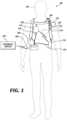
- FIG. 1illustrates a system 100 with a patient 102 wearing an example of a WCD system 104 according to embodiments described herein.
- the WCD systemmay include one or more communication devices 106 , a support structure 110 , an external defibrillator 108 connected to defibrillation electrodes 114 , 116 , among other components.
- the support structure 110may be worn by the patient 102 .
- the support structure 110may include a vest, shirt, series of straps, or other system enabling the patient 102 to carry at least a portion of the WCD system 104 on the patient's body.
- the support structure 110may comprise a single component.
- the support structure 110may comprise a vest or shirt that properly locates the WCD system 104 on a torso 112 of the patient 102 .
- the single component of the support structure 110may additionally carry or couple to all of the various components of the WCD system 104 .
- the support structure 110may comprise multiple components.
- the support structure 110may include a first component resting on a patient's shoulders.
- the first componentmay properly locate a series of defibrillation electrodes 114 , 116 on the torso 112 of the patient 102 .
- a second componentmay rest more towards a patient's hips, whereby the second component may be positioned such that the patient's hips support the heavier components of the WCD system 104 .
- the heavier components of the WCD system 104may be carried via a shoulder strap, or may be kept close to the patient 102 such as in a cart, bag, stroller, wheelchair, or other vehicle.
- the external defibrillator 108may be coupled to the support structure 110 or may be carried remotely from the patient 102 .
- the external defibrillator 108may be triggered to deliver an electric shock to the patient 102 when patient 102 wears WCD system 104 . For example, if certain thresholds are exceeded or met, the external defibrillator 108 may be engaged and deliver a shock to the patient 102 .
- the WCD system 104may defibrillate the patient 102 by delivering an electrical charge to the patient 102 through a series of electrodes 114 , 116 positioned on the torso 112 .
- the electrodes 114 , 116may be electrically coupled to the external defibrillator 108 via a series of electrode leads 118 .
- the defibrillator 108may administer an electric shock to the body of the patient 102 when the defibrillation electrodes 114 , 116 are in good electrical contact with the torso 112 of patient 102 .
- devicesproximate the electrodes 114 , 116 may emit a conductive fluid to encourage electrical contact between the patient 102 and the electrodes 114 , 116 .
- the electric shockmay be a defibrillation shock, which may go through a heart 122 of the patient 102 in an attempt to restart the heart 122 .
- the brief, strong electric pulsemay work to restart the heart 122 which may save the patient's life.
- the WCD system 104may also include either an external or internal monitoring device or some combination thereof.
- FIG. 1displays an external monitoring device 124 which may also be known as an outside monitoring device.
- the monitoring device 124may monitor at least one local parameter. Local parameters may include physical state of the patient 102 such as ECG, movement, heartrate, pulse, temperature, and the like. Local parameters may also include a parameter of the WCD 104 , environmental parameters, or the like.
- the monitoring device 124may be physically coupled to the support structure 110 or may be proximate the support structure 110 . In either location, the monitoring device 124 is communicatively coupled with other components of the WCD 104 .
- a communication device 106may enable the patient to interact with, and garnish data from, the WCD system 104 .
- the communication devices 106may enable a patient or third party to view patient data, dismiss a shock if the patient is still conscious, turn off an alarm, and otherwise engage with the WCD system 104 .
- the communication device 106may be a separable part of an external defibrillator 108 .
- the communication device 106may be a separate device coupled to the external defibrillator 108 .
- the communication device 106may be wired, or wirelessly linked to the external defibrillator 108 and may be removable from the defibrillator 108 .
- the communication device 106may form an inseparable assembly and share internal components with the external defibrillator 108 .
- the WCD system 104may include more than one communication device.
- the defibrillator 108may include components able to communicate to the patient and the WCD system 104 may include a separate communication device 106 remote from the defibrillator 108 .
- the communication device 106may be communicatively coupled to an alert button 128 .
- the alert button 128may be removably coupled to the support structure 110 .
- the patient 102may couple the alert button 128 to the support structure 110 or may couple the alert button 128 to an article of clothing.
- the alert button 128may be wiredly or wirelessly connected to the communication device 106 .
- the communication device 106 or the defibrillator 108may connect with one or more external devices 124 .
- the communication device 106 or the defibrillator 108may connect to various external devices 120 such as a cloud, a remote desktop, a laptop, a mobile device, or other external device using a network such as the Internet, local area networks, wide area networks, virtual private networks (VPN), other communication networks or channels, or any combination thereof.
- VPNvirtual private networks
- FIG. 2is an example of a communication system 200 according to embodiments described herein.
- the communication system 200may include a communication device 106 and an alert button 128 .
- the communication device 106may be a part of the defibrillator 108 or may be a separate device.
- the alert button 128may be wired or wirelessly connected to the communication device 106 .
- the communication device 106may include a screen 204 , a visual indicator 206 , a battery 208 , and an audio output 210 .
- the screen 204may include any variation of a screen to display text and images to a patient and/or user.
- the screenmay be an LED display, plasma display panel (PDP), liquid crystal display (LCD), organic light emitting diode display (OLED), e-paper, and the like.
- the screenmay be monochromatic, that is, the screen may display in black, white, and grayscale, or the screen may be a color screen.
- the screenmay display text, images, scrolling text, alerts, or some combination thereof.
- the screenmay additionally be touch sensitive, allowing the user to interact directly with the communication device 106 by touching the screen 204 .
- the communication device 106may include one or more input buttons (not shown).
- the visual indicator 206may include a single light source as shown or may include a number of light sources.
- the visual indicator 206may use color and/or lighting patterns to communicate various alerts or conditions of the WCD system 104 to the patient or third party.
- the visual indicator 206may include one or more multi-color LEDs which may be capable of emitting two or more different colors, or combinations of those colors.
- the visual indicator 206may comprise a red/green/blue (RBG) LED.
- the RBG LEDmay emit a red, blue, or green color. However, the RBG may also emit purple by engaging both the red and blue color.
- Other types of multi-color LEDsmay also be used.
- each visual indicator 206may comprise either a single-color LED or a multi-color LED.
- the lighting pattern of the visual indicator 206may comprise a multitude of patterns.
- the patternsmay be simplistic for patient understanding.
- a low-level alert or statusmay include a slow-blinking light pattern.
- a more urgent alertmay be a medium-duration blinking light.
- a fast-blinking alertmay be an emergency or pressing situation.
- the lighting patternmay follow a Morse code. This may enable a third party to recognize codes such as an SOS Morse code lighting pattern and determine the patient is in trouble.
- the lighting patternmay change between various patterns. For example, if a shockable event is detected, the visual indicator 206 may emit a fast-blinking pattern. After a shock is delivered, the visual indicator 206 may change to an SOS lighting pattern to indicate the patient may need help.
- the audio output 210may include a speaker.
- the output of the audio output 210may be loud enough to be heard over nominal background noise.
- the audio output 210may have a decibel output in the range of 35-90 dB (SPL).
- the output of the audio output 210may be 1-8 watts. These ranges may be further narrowed.
- the audio output 210may be in a louder range such as 50-100 dB (SPL).
- the audio output 210might have an adjustable volume range. This may enable the patient to adjust the volume of the communication device 106 depending upon the patient's environment.
- the communication device 106may include a microphone (not shown).
- the microphonemay detect ambient noise and automatically adjust the audio output 210 volume. This will help ensure the volume of the audio output 210 is at a preferred level for the particular patient and the particular setting.
- the volume of the audio output 210may increase as the alarm duration continues. For example, if a patient does not provide feedback to the communication device, the audio output 210 volume may increase to either gain the attention of the user or potentially alert bystanders or other third parties.
- the alert button 128may include a visual output 212 , an audio output 214 and a user input 216 .
- the visual output 212may be similar to the visual output 206 of the communication device 106 .
- the audio output 214may be similar to the audio output 210 of the communication device 106 .
- the output of the audio output 214may be loud enough to be heard over nominal background noise.
- the audio output 214may have a decibel output in the range of 35-90 dB(SPL).
- the output of the audio output 214may be 1-8 watts. These ranges may be further narrowed.
- the audio output 214may be in a louder range such as 50-100 dB(SPL).
- the audio output 214might have an adjustable volume range. This may enable the patient to adjust the volume of the alert button 128 depending upon the patient's environment.
- the alert button 128may include a microphone (not shown). The microphone may detect ambient noise and automatically adjust the audio output 214 volume. This may ensure the volume of the audio output 214 is at a preferred level for the particular patient and the particular setting.
- the audio output 214 of the alert button 128may be coupled to the audio output 210 . As the volume of audio output 210 is adjusted, either manually or automatically, the volume of the audio output 214 may be similarly adjusted. In some embodiments, the volume of the audio output 214 may increase as the alarm duration continues similar to the audio output 210 .
- FIG. 3is a block diagram illustrating functional components of one example of a communication device 106 .
- the communication device 106may be an example of the communication device 106 described with reference to FIGS. 1 and 2 .
- the communication device 106has detection module 302 , an alert module 304 , and a user input module 306 .
- the alert module 304may further include an auditory alert module 308 , visual alert module 310 , and a tactile alert module 312 .
- the detection module 302may detect one or more conditions of the WCD system 104 or the patient 102 .
- the detection module 302may be a logic device or algorithm to determine if any or a variety of thresholds are exceeded which may require action of the defibrillator 108 .
- the detection module 302may receive and interpret signals from an ECG port, a defibrillation port, and the like.
- the detection module 302may process the information to ensure the patient is still conscious and healthy.
- the detection module 302may additionally determine if the sensors, electrodes, and other system components are properly functioning. If any parameter indicates the patient 102 may be experiencing distress or a component of the WCD system 104 is malfunctioning, the detection module 340 may activate the alert module 304 .
- the detection module 302may synchronize with another detection module proximate the defibrillator.
- the communication device 106may be a part of the defibrillator 108 and utilize the same detection module 302 .
- the alert module 304may receive an input from the detection module 302 and determine an alert threshold.
- the alert thresholdmay vary depending on the WCD mode, WCD state, and user-input responses.
- the alert module 304may activate a multi-sensory alarm.
- the multi-sensory alarmmay consist of a visual, auditory, and tactile alert.
- the alert module 304may determine when and what sequence to provide visual, auditory, and tactile feedback.
- the alert module 304may initially provide discreet feedback to the user and await a response, if no response is received, the alert module 304 may escalate the alert as necessary.
- the auditory alert module 308may provide a variety of audible alerts to the user.
- the audible alertsmay include audio tones and voice messages.
- the audio tonesmay comprise a short duration of harmonically rich tones.
- the tonesmay direct the patient's attention to the WCD system 104 where further messages may be displayed.
- a variety of different tonesmay be used to impart varying levels of alarm urgency.
- the auditory alert module 308may play the same series of tones but in varying pitches to denote varying levels of alarm urgency.
- the auditory alert module 308may additionally change the tempo of the tones depending on the varying levels of alarm urgency.
- the actual tonemight completely change depending on the alarm urgency.
- Each eventmay have a distinct alarm tone or each level of alarm may have a distinct alarm tone.
- the auditory alert module 308may change tempo and pitch of an alarm tone.
- the patientmay personalize the tones.
- the auditory alert module 308may also change the volume of the audible alert.
- the alertmay escalate in volume, pitch, tone, and/or timbre to gradually alert the patient.
- a gradual alarm approachmay reduce patient anxiety and fear and allow the patient to calmly respond to the alarm.
- the duration of escalationmay change depending on the urgency of the alert.
- a lower urgency alarmmay have a slower rate of change whereas a high urgency alarm may have a much shorter duration but still gradually increase in pitch, tone, and/or volume.
- the auditory alert module 308may also provide voice messages.
- the voice messagesmay comprise informative messages to the patient, or potentially bystanders.
- the messagesmay include system alerts or patient health alerts. For example, if the patient is experiencing a cardiac event, the audible alert may announce the event in a loud tone to alert persons near the patient. This may enable the persons to take action such as CPR, or other first aid measures.
- the audible alertmay additionally request further action such as a bystander to call an ambulance or other first responder. If the WCD system itself is experiencing maladies, the audible alert may be communicating such to the patient. This could include low battery alerts, poor connectivity, and the like.
- the voice messages and tonesmay layer over each other, for example, be played at the same time, or may alternate.
- the auditory alert module 308may utilize either the audio output 210 or the audio output 214 or both.
- the visual alert module 310may provide visual feedback to the user. This may be viewed as either a blinking light on the visual indicator 206 or may be an image or text displayed on the screen 204 .
- the blinking light on the visual indicator 206may mimic the auditory alert module 308 .
- the lightmay synchronize the tone being played by the auditory alert module 308 .
- the visual indicator 206may not synchronize as the light cannot connote pitch and volume changes. Instead, the visual indicator may have a blinking light alert system where the frequency of the blinking changes with the urgency of the alarm.
- the blinking light alertmay change to known communication mediums such as Morse code using an SOS blinking light pattern if an urgent, life threatening situation may arise.
- the image or textmay provide more detailed information to the patient. For example, if the battery is lower, a blinking no battery image may appear on the screen. Similarly, if an electrode is not connected properly, an electrode symbol may appear on the screen. If a shockable event is detected, a shock symbol may appear on the screen. In some embodiments, images and text may alternate to provide more complete information to the user. In still further embodiments, both image and text may appear on the screen.
- the tactile alert module 312may provide haptic feedback to the patient.
- the haptic feedbackmay present as vibrational patterns or waveforms emitting from the communication device 106 , the alert button 128 , or both.
- the haptic feedbackmay mimic the auditory alert module 308 .
- the haptic feedbackmight mimic the sound the auditory alert module 308 produces.
- the increase in pitch and tonemay be translated to vibrational outputs.
- the vibrationscan match the length and intensity of a pitch and tone and gradually increase in strength as the alarm duration continues.
- the tactile alert module 312may output varying types of haptic response. For example, lower priority level alarms may result in short vibrational patterns. These short vibrational patterns may direct the patient's attention to lower priority events.
- High priority eventssuch as high priority physiological conditions may result in escalating vibrations.
- the escalating vibrational patternmay have a longer time duration and begin gently but increase in intensity to quickly direct the patient's attention to the WCD system.
- the time durationmay shorten to eventually becoming a high vibrational pulse.
- the user input module 306may determine if user feedback is provided.
- the patientmay have a button (e.g., user input 216 ) proximate the alert button (e.g., alert button 128 ).
- the alert module 304triggers an alert, the patient may silence the alert via the user input device.
- the patientmay be in a meeting, a public place, or some other location where the user does not wish for the alert to be heard.
- the alert module 304may receive an indication from the user input module 306 that the patient silenced an alarm. The alert module 304 then may take one of several actions. If the alert is a low urgency alert, the alert module 304 may snooze the alarm for a predetermined length of time. The predetermined length of time may vary depending upon the need for patient action. If the alert module 304 triggers a medium level alert, the alert module 304 may quiet the auditory alert module 308 preventing any sound output to the patient. However, the visual alert module 310 and the tactile alert module 312 may continue to alert the user as necessary. The auditory alert module 308 may activate again after a predetermined length of time.
- the alert module 304may continue to operate modules 308 , 310 , 312 despite user input detected by the user input module 306 . This may alert the patient or a bystander to an emergency situation requiring immediate attention. If the patient is conscious and does not require medical attention, the patient may need to provide input to the WCD system 104 to prevent the defibrillator 108 from emitting a shock. If the patient is not conscious, the alert module 304 may alert bystanders to the severity of the situation and either provide direction to the bystanders of potential action to be taken or, in some instances, enable bystanders to contact medical support or emergency support as needed.
- FIG. 4is a diagram displaying various components of an example external defibrillator 108 .
- the external defibrillator 108may be an example of the defibrillator 108 described with reference to FIG. 1 .
- the components shown in FIG. 4may be contained within a single unit or may be separated amongst two or more units in communication with each other.
- the defibrillator 108may include a communication device 106 , processor 402 , memory 404 , defibrillation port 408 , and ECG port 410 , among other components.
- the componentsare contained within a housing 412 or casing.
- the housing 412may comprise a hard shell around the components or may comprise a softer shell for increased patient comfort.
- the communication device 106 , processor 402 , memory 404 (including software/firmware code (SW) 414 ), defibrillation port 408 , ECG port 410 , communication module 416 , measurement circuit 418 , monitoring device 420 , and energy storage module 422may communicate, directly or indirectly, with one another via one or more buses 424 .
- the one or more buses 424may allow data communication between the elements and/or modules of the defibrillator 108 .
- the defibrillator 108may include a communication device 106 .
- the communication device 106may enable the patient to view one or metrics concerning the defibrillator 108 .
- the communication device 106may include the components described with reference to FIG. 2 .
- the communication device 106may be a part of the defibrillator 108 and share one or more internal components of the defibrillator.
- the communication device 106may be a removable component or separate component.
- the defibrillatormay include a separate user interface 406 .
- the user interface 406may be in addition to the communication device 106 .
- the user interface 406may display an ECG of the patient, a status of the defibrillator 108 , a status of a charge (e.g., a battery charge or an energy storage module), and the like.
- the defibrillator 108may include a defibrillation port 408 .
- the defibrillation port 408may comprise a socket, opening, or electrical connection in the housing 412 .
- the defibrillation port 408may include two or more nodes 426 , 428 .
- the two or more nodes 426 , 428may accept two or more defibrillation electrodes (e.g., defibrillation electrodes 114 , 116 , FIG. 1 ).
- the nodes 426 , 428may provide an electrical connection between the defibrillation electrodes 114 , 116 and the defibrillator 108 .
- the defibrillation electrodes 114 , 116may plug into the two or more nodes 426 , 428 via one or more leads (e.g., leads 118 ), or, in some instances, the defibrillation electrodes 114 , 116 may be hardwired to the nodes 426 , 428 . Once an electrical connection is established between the defibrillation port 408 and the electrodes 114 , 116 , the defibrillator 108 may be able to deliver an electric shock to the patient 102 .
- the defibrillator 108may include an ECG port 410 in the housing 412 .
- the ECG port 410may accept one or more ECG electrodes 430 or ECG leads.
- the ECG electrodes 430sense a patient's ECG signal.
- the ECG electrodes 430may record electrical activity generated by heart muscle depolarization.
- the ECG electrodes 430may utilize 4 -leads to 12 -leads or multichannel ECG, or the like.
- the ECG electrodes 430may connect with the patient's skin.
- the defibrillator 108may include a measurement circuit 418 .
- the measurement circuit 418may be in communication with the ECG port 410 .
- the measurement circuit 418may receive physiological signals from ECG port 410 .
- the measurement circuit 418may additionally or alternatively receive physiological signals via the defibrillation port 408 when defibrillation electrodes 114 , 116 are attached to the patient 102 .
- the measurement circuit 418may determine a patient's ECG signal from a difference in voltage between the defibrillation electrodes 114 , 116 .
- the measurement circuit 418may monitor the electrical connection between the defibrillation electrodes 114 , 116 and the skin of the patient 102 .
- the measurement circuit 418can detect impedance between electrodes 114 , 116 .
- the impedancemay indicate the effective resistance of an electric circuit.
- An impedance calculationmay determine when the electrodes 114 , 116 have a good electrical connection with the patient's body.
- the defibrillator 108may include an internal monitoring device 420 within the housing 412 .
- the monitoring device 420may monitor at least one local parameter.
- Local parametersmay include physical state of the patient such as ECG, movement, heartrate, pulse, temperature, and the like. Local parameters may also include a parameter of the WCD system (e.g., WCD 104 , FIG. 1 ), defibrillator 108 , environmental parameters, or the like.
- the WCD system 104may include an internal monitoring device 420 and an external monitoring device (e.g., external monitoring device 124 ). If both monitoring devices 124 , 420 are present, the monitoring devices 124 , 420 may work together to parse out specific parameters depending on position, location, and other factors. For example, the external monitoring device 124 may monitor environmental parameters while the internal monitoring device 420 may monitor patient and system parameters.
- an external monitoring devicee.g., external monitoring device 124 .
- the external monitoring device 124may monitor environmental parameters while the internal monitoring device 420 may monitor patient and system parameters.
- the defibrillator 108may include a power source 432 .
- the power source 432may comprise a battery or battery pack, which may be rechargeable.
- the power source 432may comprise a series of different batteries to ensure the defibrillator 108 has power.
- the power source 432may include a series of rechargeable batteries as a prime power source and a series of non-rechargeable batteries as a secondary source. If the patient 102 is proximate an AC power source, such as when sitting down, sleeping, or the like, the power source 432 may include an AC override wherein the power source 432 draws power from the AC source.
- the defibrillator 108may include an energy storage module 422 .
- the energy storage module 422may store electrical energy in preparation or anticipation of providing a sudden discharge of electrical energy to the patient.
- the energy storage module 422may have its own power source and/or battery pack.
- the energy storage module 422may pull power from the power source 432 .
- the energy storage module 422may include one or more capacitors 434 .
- the one or more capacitors 434may store an electrical charge, which may be administered to the patient.
- the processor 402may be communicatively coupled to the energy storage module 422 to trigger the amount and timing of electrical energy to provide to the defibrillation port 408 and, subsequently, the patient.
- the defibrillator 108may include a discharge circuit 436 .
- the discharge circuit 436may control the energy stored in the energy storage module 422 .
- the discharge circuit 436may either electrical couple or decouple the energy storage module 422 to the defibrillation port 408 .
- the discharge circuit 436may be communicatively coupled to the processor 402 to control when the energy storage module 422 and the defibrillation port 408 should or should not be coupled to either administer or prevent a charge from emitting from the defibrillator 108 .
- the discharge circuit 436may include one or more switches 438 .
- the one or more switches 438may include an H-bridge.
- the defibrillator 108may include a communication module 416 .
- the communication module 416may establish one or more communication links with either local hardware and/or software to the WCD system 104 and defibrillator 108 or to remote hardware separate from the WCD system 104 .
- the communication module 416may include one or more antennas, processors, and the like.
- the communication module 416may communicate wirelessly via radio frequency, electromagnetics, local area networks (LAN), wide area networks (WAN), virtual private networks (VPN), RFID, Bluetooth, cellular networks, and the like.
- the communication module 416may facilitate communication of data and commands such as patient data, episode information, therapy attempted, CPR performance, system data, environmental data, and so on.
- the processor 402may execute one or more modules.
- the processor 402may execute a detection module 440 and/or an action module 442 .
- the detection module 440may be a logic device or algorithm to determine if any or a variety of thresholds are exceeded which may require action of the defibrillator 108 .
- the detection module 440may receive and interpret all of the signals from the ECG port 410 , the defibrillation port 408 , the monitoring device 420 , an external monitoring device, and the like.
- the detection module 440may process the information to ensure the patient is still conscious and healthy.
- the detection module 440may communicate with the communication device 106 or be a part of the communication device 106 .
- the detection module 440may be the same as detection module 302 or may communicate with the detection module 302 . If any parameter indicates the patient 102 may be experiencing distress or indicating a cardiac episode, the detection module 440 may activate the action module 442 . Similarly, either detection module 440 , or detection module 302 may trigger the alert module 304 .
- the action module 442may receive data from the detection module 440 and perform a series of actions. For example, an episode may merely be a loss of batter power at the power source 432 or the energy storage module 422 , or one or more electrodes (e.g., ECG electrodes, defibrillation electrodes) may have lost connection. In such instances, the action module 442 may trigger an alert to the patient or to an outside source of the present situation. This may include activating the alert module 304 of the communication device 106 if the alert module 304 has not already been activated. If an episode is a health risk, such as a cardiac event, the action module 442 may begin a series of steps.
- an episodemay merely be a loss of batter power at the power source 432 or the energy storage module 422 , or one or more electrodes (e.g., ECG electrodes, defibrillation electrodes) may have lost connection.
- the action module 442may trigger an alert to the patient or to an outside source of the present situation. This may
- FIG. 5is a diagram displaying various components of an example communication system 200 for use with a WCD system 104 .
- the communication system 200may include a communication device 106 and an alert button 128 .
- the communication device 106 and alert button 128may be an example of the communication device 106 and alert button 128 described with reference to FIGS. 1 and 2 .
- the communication system 200may be coupled to the defibrillator 108 or may include separate components communicatively coupled to the defibrillator 108 .
- the communication device 106may include a controller 502 , memory 504 , I/O controller 506 , and the like.
- the controller 502may control one or more operations of the communication device 106 .
- the controller 502may include one or more processors, implemented as a Central Processing Unit (CPU), a digital signal processor, a microprocessor, a microcontroller, an application-specific integrated circuit (ASIC), a programmable logic device (PLD), or other implementation.
- the controller 502may include a single chip combined with memory controller and a peripherals interface.
- the audio outputs 210 , 214may each include a speaker.
- the output of the audio outputs 210 , 214may be loud enough to be heard over nominal background noise.
- the visual indicator 206may include one or more light sources.
- the visual indicator 206may indicate an alarm presence and severity using colors and patterns with optical communication.
- the screen 204may include any variation of a screen to display text and images to a patient and/or user.
- the motors 522 , 524may be one of a flat coin vibrating vibration motor, DC vibration motor, haptic actuator, eccentric rotating mass (ERM) vibration motor, cylindrical vibration motor, q-coin vibration motors, PCB vibration motor, pancake vibration motor, linear resonant actuator (LRA), piezo actuator, and the like.
- the motor 522 of the communication device 106 and the motor 524 of the alert button 128need not be the same in size or programming. The motor selected for each case may be best suited for the size of the device requiring vibration and the output necessary given the size of the device.
- the motor 524 coupled to the alert button 128may be smaller than the motor 522 for the communication device 106 because the alert button 128 is smaller.
- the motors 522 , 524may be the same. In either situation, the motors 522 , 524 may be programmed alike or differently. For example, the force of the vibration at the communication device 106 may be different than the force at the alert button 128 . While the overall output may appear similar to the patient, the input may be different to achieve that result.
- the detection module 302 , alert module 304 , and user input module 306may perform similar functions as the detection module 302 , alert module 304 , and user input module 306 described with reference to FIG. 2 .
- the communication device 106may include a battery 208 .
- the battery 208may be a single battery or battery pack, which may be rechargeable. In some instances, the battery 208 may comprise a series of different batteries to ensure the communication device 106 has power.
- the battery 208may include a series of rechargeable batteries as a prime power source and a series of non-rechargeable batteries as a secondary source. If the patient 102 is proximate an AC power source, such as when sitting down, sleeping, or the like, the battery 208 may include an AC override wherein the battery 208 draws power from the AC source.
- FIG. 6is a flow chart illustrating an example of a method 600 for WCD systems, in accordance with various aspects of the present disclosure. For clarity, the method 600 is described below with reference to aspects of one or more of the systems described herein.
- the method 600may include detecting an event.
- the eventmay be any type of event or disruption at the WCD systems.
- the eventmay be one that requires patient intervention, such as adjusting a sensor, electrode, or other component of the WCD system.
- the eventmay require charging the system or the defibrillator.
- the eventmay also be more serious such as detection of a cardiac event, irregular heartbeat, arrhythmia, or the like.
- the method 600may include determining a severity of the detected event.
- the severitymay be measured on a predetermined basis.
- potential failure modes of the WCD system 104may be preprogrammed into a severity event chart. This made include potential consequences if the event is not remedied and a duration that remedy needs to occur.
- a low batterymay not be immediately severe but as a time duration of low battery power lengthens, the severity of charging the unit becomes higher.
- limited ECG sensor contactmay not be an emergency but may need remediation to garnish accurate ECG readings.
- a first detection of limited contactmay be a lower or medium level alert.
- a continued detectionmay increase the severity level of the alert.
- the method 600may include activating an alarm to a patient.
- the severity and amount of alarm componentsmay vary based on the severity level of the detected event.
- the alarmmay include one of an audible alarm, visual alarm, tactile alarm, or a combination thereof.
- the alarmitself may be a collective combination of the audible, visual, and tactile alarm distributed to the patient.
- the alarmmay begin with one of the three types of alarms and then slowly increase the perceptibility of the alarm.
- the visual alarmmay activate first for a predetermined period of time.
- the visual alarmmay include a blinking light and a visual message to the patient.
- the tactile alarmmay combine with the visual alarm to increase the perceptibility of the alarm.
- the alarmmay add an audible component.
- the three alarm componentsmay continue to increase in severity until the patient acknowledges the alarm.
- the severitymay include a volume of the alarm, a brightness of the light, an increase in vibrational energy, or a combination thereof.
- the predetermined time period between activating various alarm components and increasing the perceptibility of the componentsmay vary based on the severity of the event. For example, in a low-level priority event, the predetermined time period may be longer than for a high priority event.
- the low-level priority eventmay have a predetermined time period ranging from thirty seconds to several minutes.
- the duration of the predetermined time periodmay be personalized to the user.
- the duration of the predetermined time periodmay be negligible.
- each component of the alarmmay activate at once and a severity of the alarm components may increase quickly.
- Medium priority eventsmay vary somewhere in between the low-level priority events and the high-priority events.
- emergency situationsmay have more urgent alarm protocols. Emergency situations may arise when a cardiac event is detected, an impending shock is being prepared, a high alert alarm has gone unanswered or other situations that may occur.
- the emergency alarmsmay be a higher discernibility than the rest of the alarms.
- a high discernibilitymay be a higher volume, higher tactile strength, brighter visual aids.
- a high discernibilitymay also comprise a completely separate alarm which may indicate to the user or to bystanders that a distinct emergency event is occurring.
- the emergency alarmmay provide commands or announcements to surrounding bystanders to aid in the safety of the patient. For example, if a shock is impending, the alarm may announce the shock and ask bystanders to clear the patient. The alarm may provide additional information dependent upon the situation.
- the method 600may provide for alerting a patient. It should be noted that the method 600 is just one implementation and that the operations of the method 600 may be rearranged or otherwise modified such that other implementations are possible.
- FIG. 7is a flow chart illustrating an example of another method 700 for WCD systems, in accordance with various aspects of the present disclosure. For clarity, the method 700 is described below with reference to aspects of one or more of the systems described herein.
- the method 700may include activating an alarm to the patient.
- the method 700may include determining if patient input is received.
- the patient inputmay include a patient snoozing or deactivating an alarm. For example, if a patient does not wish for a noise to be heard, the patient may silence the alarm.
- the method 700may include continuing alarm protocol. In various embodiments, the alarm protocol depends upon the alarm severity.
- the method 700may include determining if a shock is eminent. If a shock is eminent, but the patient has snoozed the alarm, the method 700 , at block 704 , may continue the alarm protocol. For example, the patient may be conscious and experiencing a false positive shock criterion. If the patient has snoozed the alarm, the patient may not be aware that a shock is imminent and may experience the shock. However, if the alarm protocol is continued, the patient may be alerted to a more pressing alarm situation, if the patient is conscious. Similarly, if the alarm snooze button has been activated either accidentally or by a third party, the alarm protocol may alert the patient, or the bystander that the alarm severity is high.
- the method 700may cease one or more of the alarm components for a predetermined length of time.
- the predetermined length of timemay depend upon event severity. Similarly, if the event severity increases, the predetermined length of time may be truncated. Once the predetermined amount of time has passed, at block 704 , the method 700 may continue alarm protocols.
- the method 700may provide for alerting a patient. It should be noted that the method 700 is just one implementation and that the operations of the method 700 may be rearranged or otherwise modified such that other implementations are possible.
- FIG. 8is a flow chart illustrating an example of a method 800 for WCD systems, in accordance with various aspects of the present disclosure. For clarity, the method 800 is described below with reference to aspects of one or more of the systems described herein.
- the method 800may include determining if an event has passed or been remedied. If the event has been remedied, or has passed, the method 800 may, at block 602 , continue detecting or searching for an event.
- the method 800may determine if a duration of the alarm has exceeded a threshold.
- the thresholdmay be a predetermined amount of time or may be a predetermined number of times the alarm has been snoozed.
- the thresholdmay vary depending on event severity. For example, a more severe event may have a shorter time threshold than a lower priority event.
- the method 800may increase an alarm severity. This may include increasing the perceptibility of the alarm. This may mean increasing the volume of the sound, pitch, or tone of the audible alarm. In some embodiments, the method 800 may change the actual sound itself to a more urgent note. The haptic alarm may increase in strength. The visual alarm may become brighter.
- the method 800may continue alarm protocols.
- the alarm protocolsmay be ordinary protocols to follow given the severity of the alarm.
- the method 800may provide for alerting a patient. It should be noted that the method 800 is just one implementation and that the operations of the method 800 may be rearranged or otherwise modified such that other implementations are possible.
- This documentmay include references to directions, such as “forward,” “rearward,” “front,” “rear,” “upward,” “downward,” “top,” “bottom,” “right hand,” “left hand,” “lateral,” “medial,” “in,” “out,” “extended,” etc. These references, and other similar references, are only to assist in helping describe and to understand the particular embodiments and are not intended to limit the present disclosure to these directions or locations.
- the present documentmay also reference quantities and numbers. Unless specifically stated, such quantities and numbers are not to be considered restrictive, but exemplary of the possible quantities or numbers associated with the present application. Also, in this regard, the present application may use the term “plurality” to reference a quantity or number. The terms “about,” “approximately,” “near,” etc., mean plus or minus 5% of the stated value. For the purposes of the present disclosure, the phrase “at least one of A, B, and C,” for example, means (A), (B), (C), (A and B), (A and C), (B and C), or (A, B, and C), including all further possible permutations when greater than three elements are listed.
Landscapes
- Health & Medical Sciences (AREA)
- Life Sciences & Earth Sciences (AREA)
- Engineering & Computer Science (AREA)
- Cardiology (AREA)
- General Health & Medical Sciences (AREA)
- Veterinary Medicine (AREA)
- Heart & Thoracic Surgery (AREA)
- Animal Behavior & Ethology (AREA)
- Biomedical Technology (AREA)
- Public Health (AREA)
- Nuclear Medicine, Radiotherapy & Molecular Imaging (AREA)
- Radiology & Medical Imaging (AREA)
- Medical Informatics (AREA)
- Physics & Mathematics (AREA)
- Biophysics (AREA)
- Pathology (AREA)
- Molecular Biology (AREA)
- Surgery (AREA)
- Physiology (AREA)
- Human Computer Interaction (AREA)
- Electrotherapy Devices (AREA)
Abstract
Description
Claims (20)
Priority Applications (2)
| Application Number | Priority Date | Filing Date | Title |
|---|---|---|---|
| US17/547,641US12090332B2 (en) | 2018-04-26 | 2021-12-10 | Multi-sensory alarm for a wearable cardiac defibrillator |
| US18/885,875US20250010084A1 (en) | 2018-04-26 | 2024-09-16 | Multi-sensory alarm for a wearable cardiac defibrillator |
Applications Claiming Priority (3)
| Application Number | Priority Date | Filing Date | Title |
|---|---|---|---|
| US201862662899P | 2018-04-26 | 2018-04-26 | |
| US16/394,979US11198015B2 (en) | 2018-04-26 | 2019-04-25 | Multi-sensory alarm for a wearable cardiac defibrillator |
| US17/547,641US12090332B2 (en) | 2018-04-26 | 2021-12-10 | Multi-sensory alarm for a wearable cardiac defibrillator |
Related Parent Applications (1)
| Application Number | Title | Priority Date | Filing Date |
|---|---|---|---|
| US16/394,979ContinuationUS11198015B2 (en) | 2018-04-26 | 2019-04-25 | Multi-sensory alarm for a wearable cardiac defibrillator |
Related Child Applications (1)
| Application Number | Title | Priority Date | Filing Date |
|---|---|---|---|
| US18/885,875ContinuationUS20250010084A1 (en) | 2018-04-26 | 2024-09-16 | Multi-sensory alarm for a wearable cardiac defibrillator |
Publications (2)
| Publication Number | Publication Date |
|---|---|
| US20220096851A1 US20220096851A1 (en) | 2022-03-31 |
| US12090332B2true US12090332B2 (en) | 2024-09-17 |
Family
ID=68290911
Family Applications (3)
| Application Number | Title | Priority Date | Filing Date |
|---|---|---|---|
| US16/394,979Active2039-08-30US11198015B2 (en) | 2018-04-26 | 2019-04-25 | Multi-sensory alarm for a wearable cardiac defibrillator |
| US17/547,641ActiveUS12090332B2 (en) | 2018-04-26 | 2021-12-10 | Multi-sensory alarm for a wearable cardiac defibrillator |
| US18/885,875PendingUS20250010084A1 (en) | 2018-04-26 | 2024-09-16 | Multi-sensory alarm for a wearable cardiac defibrillator |
Family Applications Before (1)
| Application Number | Title | Priority Date | Filing Date |
|---|---|---|---|
| US16/394,979Active2039-08-30US11198015B2 (en) | 2018-04-26 | 2019-04-25 | Multi-sensory alarm for a wearable cardiac defibrillator |
Family Applications After (1)
| Application Number | Title | Priority Date | Filing Date |
|---|---|---|---|
| US18/885,875PendingUS20250010084A1 (en) | 2018-04-26 | 2024-09-16 | Multi-sensory alarm for a wearable cardiac defibrillator |
Country Status (1)
| Country | Link |
|---|---|
| US (3) | US11198015B2 (en) |
Families Citing this family (5)
| Publication number | Priority date | Publication date | Assignee | Title |
|---|---|---|---|---|
| US12300368B1 (en)* | 2019-03-07 | 2025-05-13 | West Affum Holdings Dac | Analysis and presentation of aggregated patient and device data within a system that includes a medical device |
| US12121329B2 (en) | 2019-03-08 | 2024-10-22 | West Affum Holdings Dac | Wearable vital signs monitor with selective signal acquisition |
| US10957453B2 (en) | 2019-08-15 | 2021-03-23 | West Affum Holdings Corp. | WCD system alert issuance and resolution |
| US12220256B2 (en)* | 2020-08-24 | 2025-02-11 | West Affum Holdings Dac | Autonomous event assistant device |
| WO2024059101A1 (en)* | 2022-09-14 | 2024-03-21 | Medtronic, Inc. | Adaptive user verification of acute health events |
Citations (137)
| Publication number | Priority date | Publication date | Assignee | Title |
|---|---|---|---|---|
| US3724355A (en) | 1970-06-12 | 1973-04-03 | K Schranz | Apparatus for processing exposed photographic film or the like |
| US4583524A (en) | 1984-11-21 | 1986-04-22 | Hutchins Donald C | Cardiopulmonary resuscitation prompting |
| US4619265A (en) | 1984-03-08 | 1986-10-28 | Physio-Control Corporation | Interactive portable defibrillator including ECG detection circuit |
| US4666432A (en) | 1985-09-13 | 1987-05-19 | Mcneish Kenneth | Catheter retaining means and method |
| US4698848A (en) | 1986-09-26 | 1987-10-13 | Buckley Mary C | Blouse for cardiac patients |
| US4928690A (en) | 1988-04-25 | 1990-05-29 | Lifecor, Inc. | Portable device for sensing cardiac function and automatically delivering electrical therapy |
| US4955381A (en) | 1988-08-26 | 1990-09-11 | Cardiotronics, Inc. | Multi-pad, multi-function electrode |
| US5078134A (en) | 1988-04-25 | 1992-01-07 | Lifecor, Inc. | Portable device for sensing cardiac function and automatically delivering electrical therapy |
| US5228449A (en) | 1991-01-22 | 1993-07-20 | Athanasios G. Christ | System and method for detecting out-of-hospital cardiac emergencies and summoning emergency assistance |
| US5348008A (en) | 1991-11-25 | 1994-09-20 | Somnus Corporation | Cardiorespiratory alert system |
| US5394892A (en) | 1990-04-02 | 1995-03-07 | K J Mellet Nominees Pty Ltd | CPR prompting apparatus |
| US5405362A (en) | 1991-04-29 | 1995-04-11 | The Board Of Regents For The University Of Texas System | Interactive external defibrillation and drug injection system |
| US5429593A (en) | 1993-12-23 | 1995-07-04 | Matory; Yvedt L. | Post-surgical, drainage accommodating, compression dressing |
| US5474574A (en) | 1992-06-24 | 1995-12-12 | Cardiac Science, Inc. | Automatic external cardioverter/defibrillator |
| US5618208A (en) | 1994-06-03 | 1997-04-08 | Siemens Medical Systems, Inc. | Fully insulated, fully shielded electrical connector arrangement |
| US5662690A (en) | 1994-12-08 | 1997-09-02 | Heartstream, Inc. | Defibrillator with training features and pause actuator |
| US5708978A (en) | 1994-08-17 | 1998-01-20 | Johnsrud; Anna C. | Medical vest |
| US5741306A (en) | 1996-05-23 | 1998-04-21 | Lifecor, Inc. | Patient-worn energy delivery apparatus |
| US5782878A (en) | 1994-12-07 | 1998-07-21 | Heartstream, Inc. | External defibrillator with communications network link |
| US5792204A (en) | 1996-05-08 | 1998-08-11 | Pacesetter, Inc. | Methods and apparatus for controlling an implantable device programmer using voice commands |
| WO1998039061A2 (en) | 1997-03-07 | 1998-09-11 | Cadent Medical Corporation | Wearable defibrillation system |
| US5902249A (en) | 1995-03-03 | 1999-05-11 | Heartstream, Inc. | Method and apparatus for detecting artifacts using common-mode signals in differential signal detectors |
| US5913685A (en) | 1996-06-24 | 1999-06-22 | Hutchins; Donald C. | CPR computer aiding |
| US5944669A (en) | 1997-11-20 | 1999-08-31 | Lifecor, Inc. | Apparatus and method for sensing cardiac function |
| US6047203A (en) | 1997-03-17 | 2000-04-04 | Nims, Inc. | Physiologic signs feedback system |
| US6065154A (en) | 1998-04-07 | 2000-05-23 | Lifecor, Inc. | Support garments for patient-worn energy delivery apparatus |
| US6108197A (en) | 1992-05-15 | 2000-08-22 | Via, Inc. | Flexible wearable computer |
| US6201992B1 (en) | 1999-04-01 | 2001-03-13 | Agilent Technologies, Inc. | Defibrillator interface capable of generating video images |
| US6263238B1 (en) | 1998-04-16 | 2001-07-17 | Survivalink Corporation | Automatic external defibrillator having a ventricular fibrillation detector |
| US6280461B1 (en) | 1996-05-23 | 2001-08-28 | Lifecor, Inc. | Patient-worn energy delivery apparatus |
| US6287328B1 (en) | 1999-04-08 | 2001-09-11 | Agilent Technologies, Inc. | Multivariable artifact assessment |
| US6319011B1 (en) | 1995-04-06 | 2001-11-20 | Michael J. Motti | Automatic training defibrillator simulator and method |
| US6334070B1 (en) | 1998-11-20 | 2001-12-25 | Medtronic Physio-Control Manufacturing Corp. | Visual and aural user interface for an automated external defibrillator |
| US6356785B1 (en) | 1997-11-06 | 2002-03-12 | Cecily Anne Snyder | External defibrillator with CPR prompts and ACLS prompts and methods of use |
| US6437083B1 (en) | 2001-12-06 | 2002-08-20 | General Electric Company | Process for preparing branched aromatic polycarbonates |
| US6450942B1 (en) | 1999-08-20 | 2002-09-17 | Cardiorest International Ltd. | Method for reducing heart loads in mammals |
| US20020181680A1 (en) | 1999-10-05 | 2002-12-05 | Marshal Linder | Data collection and system management for patient-worn medical devices |
| US6529875B1 (en) | 1996-07-11 | 2003-03-04 | Sega Enterprises Ltd. | Voice recognizer, voice recognizing method and game machine using them |
| US20030158593A1 (en) | 2002-02-19 | 2003-08-21 | Heilman Marlin S. | Cardiac garment |
| US6762917B1 (en) | 2001-06-12 | 2004-07-13 | Novx Corporation | Method of monitoring ESC levels and protective devices utilizing the method |
| US20050107833A1 (en) | 2003-11-13 | 2005-05-19 | Freeman Gary A. | Multi-path transthoracic defibrillation and cardioversion |
| US7065401B2 (en) | 2002-05-08 | 2006-06-20 | Michael Worden | Method of applying electrical signals to a patient and automatic wearable external defibrillator |
| US20060173499A1 (en) | 2005-01-31 | 2006-08-03 | Medtronic Emergency Response Systems, Inc. | System and method for using diagnostic pulses in connection with defibrillation therapy |
| DE102005060985A1 (en) | 2005-12-20 | 2007-06-28 | Oestreich, Wolfgang, Dr.med. | System for mobile monitoring of heart functions has electrodes which are connected to central administrative unit through electrical conductors and these conductors are arranged in clothing |
| US20080312709A1 (en) | 2007-06-13 | 2008-12-18 | Volpe Shane S | Wearable medical treatment device with motion/position detection |
| US20090005827A1 (en) | 2007-06-26 | 2009-01-01 | David Weintraub | Wearable defibrillator |
| US7559902B2 (en) | 2003-08-22 | 2009-07-14 | Foster-Miller, Inc. | Physiological monitoring garment |
| JP4320257B2 (en) | 2001-11-05 | 2009-08-26 | キャメロン ヘルス、 インコーポレイテッド | Flexible subcutaneous implantable defibrillator |
| US20100007413A1 (en) | 2006-11-10 | 2010-01-14 | Koninklijke Philips Electronics N.V. | Ecg electrode contact quality measurement system |
| US7753759B2 (en) | 2007-10-22 | 2010-07-13 | Tammy Pintor | Article of apparel for concealing objects |
| US20100298899A1 (en) | 2007-06-13 | 2010-11-25 | Donnelly Edward J | Wearable medical treatment device |
| US7865238B2 (en) | 2004-09-29 | 2011-01-04 | Koninklijke Philips Electronics N.V. | High-voltage module for an external defibrillator |
| US7870761B2 (en) | 2002-05-14 | 2011-01-18 | Koninklijke Philips Electronics N.V. | Garment and method for producing the same |
| US20110288605A1 (en) | 2010-05-18 | 2011-11-24 | Zoll Medical Corporation | Wearable ambulatory medical device with multiple sensing electrodes |
| WO2011146448A1 (en) | 2010-05-18 | 2011-11-24 | Zoll Medical Corporation | Wearable therapeutic device |
| US8135462B2 (en) | 2002-08-26 | 2012-03-13 | Physio-Control, Inc. | Pulse detection using patient physiological signals |
| US20120112903A1 (en) | 2010-11-08 | 2012-05-10 | Zoll Medical Corporation | Remote medical device alarm |
| US20120144551A1 (en) | 2010-12-09 | 2012-06-14 | Eric Guldalian | Conductive Garment |
| US20120150008A1 (en) | 2010-12-09 | 2012-06-14 | Kaib Thomas E | Electrode with redundant impedance reduction |
| US20120158075A1 (en) | 2010-12-16 | 2012-06-21 | Kaib Thomas E | Water resistant wearable medical device |
| US20120191476A1 (en) | 2011-01-20 | 2012-07-26 | Reid C Shane | Systems and methods for collection, organization and display of ems information |
| US20120265265A1 (en) | 2011-04-13 | 2012-10-18 | Mehdi Razavi | Automated External Defibrillator Pad System |
| US20120283794A1 (en) | 2011-05-02 | 2012-11-08 | Kaib Thomas E | Patient-worn energy delivery apparatus and techniques for sizing same |
| US20120293323A1 (en) | 2011-03-25 | 2012-11-22 | Zoll Medical Corporation | System and method for adapting alarms in a wearable medical device |
| US20120302860A1 (en) | 2011-03-25 | 2012-11-29 | Zoll Medical Corporation | Selection of optimal channel for rate determination |
| US20120310315A1 (en) | 2009-03-17 | 2012-12-06 | Savage Walter T | Device and method for reducing patient transthoracic impedance for the purpose of delivering a therapeutic current |
| US8369944B2 (en) | 2007-06-06 | 2013-02-05 | Zoll Medical Corporation | Wearable defibrillator with audio input/output |
| US20130085538A1 (en) | 2011-09-01 | 2013-04-04 | Zoll Medical Corporation | Wearable monitoring and treatment device |
| US20130165809A1 (en)* | 2010-07-29 | 2013-06-27 | Digisense Ltd. | Monitoring physiological condition of a subject |
| US8527028B2 (en) | 2007-05-16 | 2013-09-03 | Medicomp, Inc. | Harness with sensors |
| US20130231711A1 (en) | 2012-03-02 | 2013-09-05 | Thomas E. Kaib | Systems and methods for configuring a wearable medical monitoring and/or treatment device |
| US20130245388A1 (en) | 2011-09-01 | 2013-09-19 | Mc10, Inc. | Electronics for detection of a condition of tissue |
| US8548557B2 (en) | 2010-08-12 | 2013-10-01 | Covidien Lp | Medical electrodes |
| US8560044B2 (en) | 2007-05-16 | 2013-10-15 | Medicomp, Inc. | Garment accessory with electrocardiogram sensors |
| US20130274565A1 (en) | 2012-04-13 | 2013-10-17 | Alois Antonin Langer | Outpatient health emergency warning system |
| US20130307685A1 (en) | 2012-05-16 | 2013-11-21 | Jason A. Sholder | Ecg-enabled personal emergency response systems |
| US20130317852A1 (en) | 2012-05-22 | 2013-11-28 | Geneva Healthcare, LLC | Medical device information portal |
| US20130325078A1 (en) | 2012-05-31 | 2013-12-05 | Zoll Medical Corporation | Medical monitoring and treatment device with external pacing |
| US8615295B2 (en) | 2009-03-17 | 2013-12-24 | Cardiothrive, Inc. | External defibrillator |
| US20140012144A1 (en) | 2012-07-09 | 2014-01-09 | William E. Crone | Perfusion detection system |
| US20140025131A1 (en) | 2012-07-20 | 2014-01-23 | Physio-Control, Inc. | Wearable defibrillator with voice prompts and voice recognition |
| US20140046391A1 (en) | 2012-08-10 | 2014-02-13 | Physio-Control, Inc. | Wearable defibrillator system communicating via mobile communication device |
| US20140070957A1 (en) | 2012-09-11 | 2014-03-13 | Gianluigi LONGINOTTI-BUITONI | Wearable communication platform |
| US8706255B2 (en) | 2006-04-28 | 2014-04-22 | Medtronic, Inc. | Holster for charging pectorally implanted medical devices |
| US8742349B2 (en) | 2011-09-21 | 2014-06-03 | Carestream Health, Inc. | Portable radiographic detector exterior battery latch and methods for using the same |
| US20140163663A1 (en) | 2012-12-11 | 2014-06-12 | Piyush Poddar | Method and system for switching shock vectors and decreasing transthoracic impedance for cardioversion and defibrillation |
| US8904214B2 (en) | 2010-07-09 | 2014-12-02 | Zoll Medical Corporation | System and method for conserving power in a medical device |
| US20140378812A1 (en) | 2011-12-20 | 2014-12-25 | Sensible Medical Innovatons | Thoracic garment of positioning electromagnetic (em) transducers and methods of using such thoracic garment |
| US20150039053A1 (en) | 2013-06-28 | 2015-02-05 | Zoll Medical Corporation | Systems and methods of delivering therapy using an ambulatory medical device |
| WO2015056262A1 (en) | 2013-10-18 | 2015-04-23 | Healthwatch Ltd. | Independent wearable health monitoring system, adapted to interface with a treatment device |
| US20150161554A1 (en) | 2013-12-11 | 2015-06-11 | Uber Technologies, Inc. | Intelligent dispatch system for selecting service providers |
| US9084583B2 (en) | 2007-09-14 | 2015-07-21 | Medtronic Monitoring, Inc. | Medical device with automatic start-up upon contact to patient tissue |
| US9089685B2 (en) | 2013-02-25 | 2015-07-28 | West Affum Holdings Corp. | Wearable defibrillator with a multivector shock waveform |
| US9119547B2 (en) | 2005-12-20 | 2015-09-01 | Cardiac Pacemakers, Inc. | Arrhythmia discrimination based on determination of rate dependency |
| US9132267B2 (en) | 2013-03-04 | 2015-09-15 | Zoll Medical Corporation | Flexible therapy electrode system |
| US20150297135A1 (en) | 2012-11-24 | 2015-10-22 | Healthwatch Ltd. | Float loop textile electrodes and methods of knitting thereof |
| US20150328472A1 (en) | 2014-05-13 | 2015-11-19 | Physio-Control, Inc. | Wearable cardioverter defibrillator components discarding ecg signals prior to making shock/no shock determination |
| US20160004831A1 (en) | 2014-07-07 | 2016-01-07 | Zoll Medical Corporation | Medical device with natural language processor |
| US9265432B2 (en) | 2008-05-07 | 2016-02-23 | Cameron Health, Inc. | Methods and devices for accurately classifying cardiac activity |
| US20160076175A1 (en) | 2014-09-11 | 2016-03-17 | Myant Capital Partners Inc. | Compression fabrics with tailored comfort |
| US20160076176A1 (en) | 2014-09-17 | 2016-03-17 | Myant Capital Partners Inc. | Seamless silhouette with engineered insulation property |
| US20160082277A1 (en) | 2013-02-25 | 2016-03-24 | West Affum Holdings Corp. | Wearable cardioverter defibrillator (wcd) system informing patient that it is validating just-detected cardiac arrhythmia |
| US20160113581A1 (en) | 2013-06-07 | 2016-04-28 | Healthwatch Ltd. | Docking station for smart garments |
| US9345898B2 (en) | 2013-01-23 | 2016-05-24 | West Affum Holdings Corp. | Wearable cardiac defibrillator system controlling conductive fluid deployment |
| US9445719B2 (en) | 2008-12-15 | 2016-09-20 | Medtronic Monitoring, Inc. | Patient monitoring systems and methods |
| US20160283900A1 (en) | 2015-03-24 | 2016-09-29 | Zoll Medical Corporation | Low-power signaling for medical devices and medical device personnel |
| US20160328529A1 (en)* | 2011-03-25 | 2016-11-10 | Zoll Medical Corporation | System and method for adapting alarms in a wearable medical device |
| US20170014073A1 (en) | 2014-03-09 | 2017-01-19 | Healthwatch Ltd. | Elastic conductive stripe and methods of utilizing thereof |
| US20170027469A1 (en) | 2014-04-17 | 2017-02-02 | Healthwatch Ltd. | Devices and methods for obtaining workable ecg signals using dry knitted electrodes |
| US20170036066A1 (en) | 2015-08-05 | 2017-02-09 | Tony CHAHINE | Garment with stretch sensors |
| US20170040758A1 (en) | 2014-04-18 | 2017-02-09 | Healthwatch Ltd | Connector and cable assembly for smart garments |
| US9579020B2 (en) | 2007-09-14 | 2017-02-28 | Medtronic Monitoring, Inc. | Adherent cardiac monitor with advanced sensing capabilities |
| US9592403B2 (en) | 2013-02-25 | 2017-03-14 | West Affum Holdings Corp. | Wearable cardioverter defibrillator (WCD) system making shock/no shock determinations from multiple patient parameters |
| US9598799B2 (en) | 2013-02-13 | 2017-03-21 | Healthwatch Ltd. | Methods for stabilizing physical dimensions and positioning of knitted electrodes of a knitted garment |
| US20170162840A1 (en) | 2011-04-28 | 2017-06-08 | Zoll Circulation, Inc. | Latch mechanism for battery retention |
| US20170319862A1 (en) | 2013-02-25 | 2017-11-09 | West Affum Holdings Corp. | Wcd system validating detected cardiac arrhythmias thoroughly so as to not sound loudly due to some quickly self-terminating cardiac arrhythmias |
| US20170367591A1 (en) | 2014-12-18 | 2017-12-28 | Koninklijke Philips N.V. | Wearable cardioverter defibrillator (wcd) apparatus and method for improved comfort and longer wear |
| US9895105B2 (en) | 2011-06-20 | 2018-02-20 | Healthwatch Ltd. | Independent non-interfering wearable health monitoring and alert system |
| US9901741B2 (en) | 2015-05-11 | 2018-02-27 | Physio-Control, Inc. | Wearable cardioverter defibrillator (WCD) system using sensor modules with reassurance code for confirmation before shock |
| US20180117299A1 (en) | 2016-11-03 | 2018-05-03 | West Affum Holdings Corp. | Wearable cardioverter defibrillator (wcd) system measuring patient's respiration |
| US20180116537A1 (en) | 2014-07-07 | 2018-05-03 | Zoll Medical Corporation | System and Method for Distinguishing a Cardiac Event From Noise in an Electrocardiogram (ECG) Signal |
| US20180144600A1 (en)* | 2016-11-22 | 2018-05-24 | General Electric Company | Peripheral alarm devices for generating alarms and monitoring systems including alarm devices |
| USRE46926E1 (en) | 2007-09-14 | 2018-07-03 | Medtronic Monitoring, Inc. | Adherent device with multiple physiological sensors |
| US20180184933A1 (en) | 2017-01-05 | 2018-07-05 | West Affum Holdings Corp. | Wearable cardioverter defibrillator having reduced noise prompts |
| US20180185662A1 (en) | 2017-01-05 | 2018-07-05 | West Affum Holdings Corp. | Wearable cardioverter defibrillator having adjustable alarm time |
| US10016613B2 (en) | 2013-04-02 | 2018-07-10 | West Affum Holdings Corp. | Wearable cardiac defibrillator system long-term monitoring alternating patient parameters other than ECG |
| US20180243578A1 (en) | 2017-02-27 | 2018-08-30 | Zoll Medical Corporation | Ambulatory medical device interaction |
| US10076656B2 (en) | 2005-11-16 | 2018-09-18 | Bioness Neuromodulation Ltd. | Gait modulation system and method |
| US20180361165A1 (en) | 2007-09-20 | 2018-12-20 | Boston Scientific Neuromodulation Corporation | Apparatus and Methods for Charging an Implanted Medical Device Power Source |
| US10192387B2 (en) | 2016-10-12 | 2019-01-29 | Uber Technologies, Inc. | Facilitating direct rider driver pairing for mass egress areas |
| US20190030352A1 (en) | 2017-07-28 | 2019-01-31 | West Affum Holdings Corp. | Wearable cardioverter defibrillator (wcd) system reacting to high-amplitude ecg noise |
| US20190076666A1 (en) | 2017-09-12 | 2019-03-14 | West Affum Holdings Corp. | Wearable cardioverter defibrillator (wcd) system warning ambulatory patient by weak alerting shock |
| US20190116896A1 (en) | 2013-10-25 | 2019-04-25 | Armour Technologies, Inc. | Apparatus, system, and method for reducing head or neck trauma |
| US10307133B2 (en) | 2013-06-26 | 2019-06-04 | Zoll Medical Corporation | Therapeutic device including acoustic sensor |
| US20190321650A1 (en) | 2013-06-14 | 2019-10-24 | Cardiothrive, Inc. | Wearable multiphasic cardioverter defibrillator system and method |
| US10589110B2 (en) | 2010-12-10 | 2020-03-17 | Zoll Medical Corporation | Wearable therapeutic device |
| US10599814B2 (en) | 2007-09-14 | 2020-03-24 | Medtronic Monitoring, Inc. | Dynamic pairing of patients to data collection gateways |
- 2019
- 2019-04-25USUS16/394,979patent/US11198015B2/enactiveActive
- 2021
- 2021-12-10USUS17/547,641patent/US12090332B2/enactiveActive
- 2024
- 2024-09-16USUS18/885,875patent/US20250010084A1/enactivePending
Patent Citations (169)
| Publication number | Priority date | Publication date | Assignee | Title |
|---|---|---|---|---|
| US3724355A (en) | 1970-06-12 | 1973-04-03 | K Schranz | Apparatus for processing exposed photographic film or the like |
| US4619265A (en) | 1984-03-08 | 1986-10-28 | Physio-Control Corporation | Interactive portable defibrillator including ECG detection circuit |
| USRE34800E (en) | 1984-11-21 | 1994-11-29 | Hutchins; Donald C. | Cardiopulmonary resuscitation prompting |
| US4583524A (en) | 1984-11-21 | 1986-04-22 | Hutchins Donald C | Cardiopulmonary resuscitation prompting |
| US4666432A (en) | 1985-09-13 | 1987-05-19 | Mcneish Kenneth | Catheter retaining means and method |
| US4698848A (en) | 1986-09-26 | 1987-10-13 | Buckley Mary C | Blouse for cardiac patients |
| US4928690A (en) | 1988-04-25 | 1990-05-29 | Lifecor, Inc. | Portable device for sensing cardiac function and automatically delivering electrical therapy |
| US5078134A (en) | 1988-04-25 | 1992-01-07 | Lifecor, Inc. | Portable device for sensing cardiac function and automatically delivering electrical therapy |
| US4955381A (en) | 1988-08-26 | 1990-09-11 | Cardiotronics, Inc. | Multi-pad, multi-function electrode |
| US5394892A (en) | 1990-04-02 | 1995-03-07 | K J Mellet Nominees Pty Ltd | CPR prompting apparatus |
| US5228449A (en) | 1991-01-22 | 1993-07-20 | Athanasios G. Christ | System and method for detecting out-of-hospital cardiac emergencies and summoning emergency assistance |
| US5405362A (en) | 1991-04-29 | 1995-04-11 | The Board Of Regents For The University Of Texas System | Interactive external defibrillation and drug injection system |
| US5353793A (en) | 1991-11-25 | 1994-10-11 | Oishi-Kogyo Company | Sensor apparatus |
| US5348008A (en) | 1991-11-25 | 1994-09-20 | Somnus Corporation | Cardiorespiratory alert system |
| US6108197A (en) | 1992-05-15 | 2000-08-22 | Via, Inc. | Flexible wearable computer |
| US5474574A (en) | 1992-06-24 | 1995-12-12 | Cardiac Science, Inc. | Automatic external cardioverter/defibrillator |
| US5429593A (en) | 1993-12-23 | 1995-07-04 | Matory; Yvedt L. | Post-surgical, drainage accommodating, compression dressing |
| US5618208A (en) | 1994-06-03 | 1997-04-08 | Siemens Medical Systems, Inc. | Fully insulated, fully shielded electrical connector arrangement |
| US5708978A (en) | 1994-08-17 | 1998-01-20 | Johnsrud; Anna C. | Medical vest |
| US5782878A (en) | 1994-12-07 | 1998-07-21 | Heartstream, Inc. | External defibrillator with communications network link |
| US5662690A (en) | 1994-12-08 | 1997-09-02 | Heartstream, Inc. | Defibrillator with training features and pause actuator |
| US5902249A (en) | 1995-03-03 | 1999-05-11 | Heartstream, Inc. | Method and apparatus for detecting artifacts using common-mode signals in differential signal detectors |
| US6319011B1 (en) | 1995-04-06 | 2001-11-20 | Michael J. Motti | Automatic training defibrillator simulator and method |
| US5792204A (en) | 1996-05-08 | 1998-08-11 | Pacesetter, Inc. | Methods and apparatus for controlling an implantable device programmer using voice commands |
| US5741306A (en) | 1996-05-23 | 1998-04-21 | Lifecor, Inc. | Patient-worn energy delivery apparatus |
| US6280461B1 (en) | 1996-05-23 | 2001-08-28 | Lifecor, Inc. | Patient-worn energy delivery apparatus |
| US5913685A (en) | 1996-06-24 | 1999-06-22 | Hutchins; Donald C. | CPR computer aiding |
| US6529875B1 (en) | 1996-07-11 | 2003-03-04 | Sega Enterprises Ltd. | Voice recognizer, voice recognizing method and game machine using them |
| WO1998039061A2 (en) | 1997-03-07 | 1998-09-11 | Cadent Medical Corporation | Wearable defibrillation system |
| US6148233A (en) | 1997-03-07 | 2000-11-14 | Cardiac Science, Inc. | Defibrillation system having segmented electrodes |
| US20110022105A9 (en) | 1997-03-07 | 2011-01-27 | Owen James M | Defibrillation system |
| US6546285B1 (en) | 1997-03-07 | 2003-04-08 | Cardiac Science, Inc. | Long term wear electrode for defibrillation system |
| US6671545B2 (en) | 1997-03-07 | 2003-12-30 | Cardiac Science, Inc. | Defibrillator with controller operating in a low power mode |
| US6304780B1 (en) | 1997-03-07 | 2001-10-16 | Cardiac Science Inc. | External defibrillator system with diagnostic module |
| US6427083B1 (en) | 1997-03-07 | 2002-07-30 | Cardiac Science, Inc. | Defibrillation system |
| EP2305110A1 (en) | 1997-03-17 | 2011-04-06 | Adidas AG | Physiologic signs feedback system |
| US6047203A (en) | 1997-03-17 | 2000-04-04 | Nims, Inc. | Physiologic signs feedback system |
| US6356785B1 (en) | 1997-11-06 | 2002-03-12 | Cecily Anne Snyder | External defibrillator with CPR prompts and ACLS prompts and methods of use |
| US5944669A (en) | 1997-11-20 | 1999-08-31 | Lifecor, Inc. | Apparatus and method for sensing cardiac function |
| US6065154A (en) | 1998-04-07 | 2000-05-23 | Lifecor, Inc. | Support garments for patient-worn energy delivery apparatus |
| US6263238B1 (en) | 1998-04-16 | 2001-07-17 | Survivalink Corporation | Automatic external defibrillator having a ventricular fibrillation detector |
| US6334070B1 (en) | 1998-11-20 | 2001-12-25 | Medtronic Physio-Control Manufacturing Corp. | Visual and aural user interface for an automated external defibrillator |
| US6201992B1 (en) | 1999-04-01 | 2001-03-13 | Agilent Technologies, Inc. | Defibrillator interface capable of generating video images |
| US6287328B1 (en) | 1999-04-08 | 2001-09-11 | Agilent Technologies, Inc. | Multivariable artifact assessment |
| US6450942B1 (en) | 1999-08-20 | 2002-09-17 | Cardiorest International Ltd. | Method for reducing heart loads in mammals |
| US6681003B2 (en) | 1999-10-05 | 2004-01-20 | Lifecor, Inc. | Data collection and system management for patient-worn medical devices |
| US20020181680A1 (en) | 1999-10-05 | 2002-12-05 | Marshal Linder | Data collection and system management for patient-worn medical devices |
| US6762917B1 (en) | 2001-06-12 | 2004-07-13 | Novx Corporation | Method of monitoring ESC levels and protective devices utilizing the method |
| JP4320257B2 (en) | 2001-11-05 | 2009-08-26 | キャメロン ヘルス、 インコーポレイテッド | Flexible subcutaneous implantable defibrillator |
| US6437083B1 (en) | 2001-12-06 | 2002-08-20 | General Electric Company | Process for preparing branched aromatic polycarbonates |
| US20030158593A1 (en) | 2002-02-19 | 2003-08-21 | Heilman Marlin S. | Cardiac garment |
| US7065401B2 (en) | 2002-05-08 | 2006-06-20 | Michael Worden | Method of applying electrical signals to a patient and automatic wearable external defibrillator |
| US7870761B2 (en) | 2002-05-14 | 2011-01-18 | Koninklijke Philips Electronics N.V. | Garment and method for producing the same |
| US8135462B2 (en) | 2002-08-26 | 2012-03-13 | Physio-Control, Inc. | Pulse detection using patient physiological signals |
| US7559902B2 (en) | 2003-08-22 | 2009-07-14 | Foster-Miller, Inc. | Physiological monitoring garment |
| US20050107834A1 (en) | 2003-11-13 | 2005-05-19 | Freeman Gary A. | Multi-path transthoracic defibrillation and cardioversion |
| US20050107833A1 (en) | 2003-11-13 | 2005-05-19 | Freeman Gary A. | Multi-path transthoracic defibrillation and cardioversion |
| US7865238B2 (en) | 2004-09-29 | 2011-01-04 | Koninklijke Philips Electronics N.V. | High-voltage module for an external defibrillator |
| US20060173499A1 (en) | 2005-01-31 | 2006-08-03 | Medtronic Emergency Response Systems, Inc. | System and method for using diagnostic pulses in connection with defibrillation therapy |
| US10076656B2 (en) | 2005-11-16 | 2018-09-18 | Bioness Neuromodulation Ltd. | Gait modulation system and method |
| DE102005060985A1 (en) | 2005-12-20 | 2007-06-28 | Oestreich, Wolfgang, Dr.med. | System for mobile monitoring of heart functions has electrodes which are connected to central administrative unit through electrical conductors and these conductors are arranged in clothing |
| US9119547B2 (en) | 2005-12-20 | 2015-09-01 | Cardiac Pacemakers, Inc. | Arrhythmia discrimination based on determination of rate dependency |
| US8706255B2 (en) | 2006-04-28 | 2014-04-22 | Medtronic, Inc. | Holster for charging pectorally implanted medical devices |
| US20100007413A1 (en) | 2006-11-10 | 2010-01-14 | Koninklijke Philips Electronics N.V. | Ecg electrode contact quality measurement system |
| US8560044B2 (en) | 2007-05-16 | 2013-10-15 | Medicomp, Inc. | Garment accessory with electrocardiogram sensors |
| US8527028B2 (en) | 2007-05-16 | 2013-09-03 | Medicomp, Inc. | Harness with sensors |
| US20140324112A1 (en) | 2007-06-06 | 2014-10-30 | Zoll Medical Corporation | Wearable defibrillator with audio input/output |
| US8965500B2 (en) | 2007-06-06 | 2015-02-24 | Zoll Medical Corporation | Wearable defibrillator with audio input/output |
| US20130144355A1 (en) | 2007-06-06 | 2013-06-06 | Zoll Medical Corporation | Wearable defibrillator with audio input/output |
| US8369944B2 (en) | 2007-06-06 | 2013-02-05 | Zoll Medical Corporation | Wearable defibrillator with audio input/output |
| US20100298899A1 (en) | 2007-06-13 | 2010-11-25 | Donnelly Edward J | Wearable medical treatment device |
| US7974689B2 (en) | 2007-06-13 | 2011-07-05 | Zoll Medical Corporation | Wearable medical treatment device with motion/position detection |
| US8140154B2 (en) | 2007-06-13 | 2012-03-20 | Zoll Medical Corporation | Wearable medical treatment device |
| US20080312709A1 (en) | 2007-06-13 | 2008-12-18 | Volpe Shane S | Wearable medical treatment device with motion/position detection |
| US8676313B2 (en) | 2007-06-13 | 2014-03-18 | Zoll Medical Corporation | Wearable medical treatment device with motion/position detection |
| US20090005827A1 (en) | 2007-06-26 | 2009-01-01 | David Weintraub | Wearable defibrillator |
| US10599814B2 (en) | 2007-09-14 | 2020-03-24 | Medtronic Monitoring, Inc. | Dynamic pairing of patients to data collection gateways |
| USRE46926E1 (en) | 2007-09-14 | 2018-07-03 | Medtronic Monitoring, Inc. | Adherent device with multiple physiological sensors |
| US9579020B2 (en) | 2007-09-14 | 2017-02-28 | Medtronic Monitoring, Inc. | Adherent cardiac monitor with advanced sensing capabilities |
| US9084583B2 (en) | 2007-09-14 | 2015-07-21 | Medtronic Monitoring, Inc. | Medical device with automatic start-up upon contact to patient tissue |
| US20180361165A1 (en) | 2007-09-20 | 2018-12-20 | Boston Scientific Neuromodulation Corporation | Apparatus and Methods for Charging an Implanted Medical Device Power Source |
| US7753759B2 (en) | 2007-10-22 | 2010-07-13 | Tammy Pintor | Article of apparel for concealing objects |
| US9265432B2 (en) | 2008-05-07 | 2016-02-23 | Cameron Health, Inc. | Methods and devices for accurately classifying cardiac activity |
| US9445719B2 (en) | 2008-12-15 | 2016-09-20 | Medtronic Monitoring, Inc. | Patient monitoring systems and methods |
| US20120310315A1 (en) | 2009-03-17 | 2012-12-06 | Savage Walter T | Device and method for reducing patient transthoracic impedance for the purpose of delivering a therapeutic current |
| US8615295B2 (en) | 2009-03-17 | 2013-12-24 | Cardiothrive, Inc. | External defibrillator |
| US9008801B2 (en) | 2010-05-18 | 2015-04-14 | Zoll Medical Corporation | Wearable therapeutic device |
| US20110288604A1 (en) | 2010-05-18 | 2011-11-24 | Kaib Thomas E | Wearable therapeutic device |
| WO2011146448A1 (en) | 2010-05-18 | 2011-11-24 | Zoll Medical Corporation | Wearable therapeutic device |
| US20110288605A1 (en) | 2010-05-18 | 2011-11-24 | Zoll Medical Corporation | Wearable ambulatory medical device with multiple sensing electrodes |
| US9454219B2 (en) | 2010-07-09 | 2016-09-27 | Zoll Medical Corporation | System and method for conserving power in a medical device |
| US8904214B2 (en) | 2010-07-09 | 2014-12-02 | Zoll Medical Corporation | System and method for conserving power in a medical device |
| US20130165809A1 (en)* | 2010-07-29 | 2013-06-27 | Digisense Ltd. | Monitoring physiological condition of a subject |
| US8548557B2 (en) | 2010-08-12 | 2013-10-01 | Covidien Lp | Medical electrodes |
| US20120112903A1 (en) | 2010-11-08 | 2012-05-10 | Zoll Medical Corporation | Remote medical device alarm |
| WO2012064604A1 (en) | 2010-11-08 | 2012-05-18 | Zoll Medical Corporation | Remote medical device alarm |
| JP5963767B2 (en) | 2010-12-09 | 2016-08-03 | ゾール メディカル コーポレイションZOLL Medical Corporation | Electrode assembly |
| US20120144551A1 (en) | 2010-12-09 | 2012-06-14 | Eric Guldalian | Conductive Garment |
| US20120150008A1 (en) | 2010-12-09 | 2012-06-14 | Kaib Thomas E | Electrode with redundant impedance reduction |
| US10589110B2 (en) | 2010-12-10 | 2020-03-17 | Zoll Medical Corporation | Wearable therapeutic device |
| US20120158075A1 (en) | 2010-12-16 | 2012-06-21 | Kaib Thomas E | Water resistant wearable medical device |
| US10463867B2 (en) | 2010-12-16 | 2019-11-05 | Zoll Medical Corporation | Water resistant wearable medical device |
| US20120191476A1 (en) | 2011-01-20 | 2012-07-26 | Reid C Shane | Systems and methods for collection, organization and display of ems information |
| US20120293323A1 (en) | 2011-03-25 | 2012-11-22 | Zoll Medical Corporation | System and method for adapting alarms in a wearable medical device |
| US20160328529A1 (en)* | 2011-03-25 | 2016-11-10 | Zoll Medical Corporation | System and method for adapting alarms in a wearable medical device |
| US8897860B2 (en) | 2011-03-25 | 2014-11-25 | Zoll Medical Corporation | Selection of optimal channel for rate determination |
| US9408548B2 (en) | 2011-03-25 | 2016-08-09 | Zoll Medical Corporation | Selection of optimal channel for rate determination |
| US20120302860A1 (en) | 2011-03-25 | 2012-11-29 | Zoll Medical Corporation | Selection of optimal channel for rate determination |
| US20120265265A1 (en) | 2011-04-13 | 2012-10-18 | Mehdi Razavi | Automated External Defibrillator Pad System |
| US20170162840A1 (en) | 2011-04-28 | 2017-06-08 | Zoll Circulation, Inc. | Latch mechanism for battery retention |
| US20120283794A1 (en) | 2011-05-02 | 2012-11-08 | Kaib Thomas E | Patient-worn energy delivery apparatus and techniques for sizing same |
| WO2012151160A1 (en) | 2011-05-02 | 2012-11-08 | Zoll Medical Corporation | Patient-worn energy delivery apparatus and techniques for sizing same |
| US9895105B2 (en) | 2011-06-20 | 2018-02-20 | Healthwatch Ltd. | Independent non-interfering wearable health monitoring and alert system |
| US20130085538A1 (en) | 2011-09-01 | 2013-04-04 | Zoll Medical Corporation | Wearable monitoring and treatment device |
| US9131901B2 (en) | 2011-09-01 | 2015-09-15 | Zoll Medical Corporation | Wearable monitoring and treatment device |
| JP2014526282A (en) | 2011-09-01 | 2014-10-06 | ゾール メディカル コーポレイション | Wearable monitoring and treatment device |
| US20130245388A1 (en) | 2011-09-01 | 2013-09-19 | Mc10, Inc. | Electronics for detection of a condition of tissue |
| US8644925B2 (en) | 2011-09-01 | 2014-02-04 | Zoll Medical Corporation | Wearable monitoring and treatment device |
| US8742349B2 (en) | 2011-09-21 | 2014-06-03 | Carestream Health, Inc. | Portable radiographic detector exterior battery latch and methods for using the same |
| US20140378812A1 (en) | 2011-12-20 | 2014-12-25 | Sensible Medical Innovatons | Thoracic garment of positioning electromagnetic (em) transducers and methods of using such thoracic garment |
| US20130231711A1 (en) | 2012-03-02 | 2013-09-05 | Thomas E. Kaib | Systems and methods for configuring a wearable medical monitoring and/or treatment device |
| US9878171B2 (en) | 2012-03-02 | 2018-01-30 | Zoll Medical Corporation | Systems and methods for configuring a wearable medical monitoring and/or treatment device |
| US20130274565A1 (en) | 2012-04-13 | 2013-10-17 | Alois Antonin Langer | Outpatient health emergency warning system |
| US20130307685A1 (en) | 2012-05-16 | 2013-11-21 | Jason A. Sholder | Ecg-enabled personal emergency response systems |
| US20130317852A1 (en) | 2012-05-22 | 2013-11-28 | Geneva Healthcare, LLC | Medical device information portal |
| US20130325078A1 (en) | 2012-05-31 | 2013-12-05 | Zoll Medical Corporation | Medical monitoring and treatment device with external pacing |
| US9675804B2 (en) | 2012-05-31 | 2017-06-13 | Zoll Medical Corporation | Medical monitoring and treatment device with external pacing |
| US20140012144A1 (en) | 2012-07-09 | 2014-01-09 | William E. Crone | Perfusion detection system |
| US20140025131A1 (en) | 2012-07-20 | 2014-01-23 | Physio-Control, Inc. | Wearable defibrillator with voice prompts and voice recognition |
| US20140046391A1 (en) | 2012-08-10 | 2014-02-13 | Physio-Control, Inc. | Wearable defibrillator system communicating via mobile communication device |
| US20140070957A1 (en) | 2012-09-11 | 2014-03-13 | Gianluigi LONGINOTTI-BUITONI | Wearable communication platform |
| US20150297135A1 (en) | 2012-11-24 | 2015-10-22 | Healthwatch Ltd. | Float loop textile electrodes and methods of knitting thereof |
| US20140163663A1 (en) | 2012-12-11 | 2014-06-12 | Piyush Poddar | Method and system for switching shock vectors and decreasing transthoracic impedance for cardioversion and defibrillation |
| US9345898B2 (en) | 2013-01-23 | 2016-05-24 | West Affum Holdings Corp. | Wearable cardiac defibrillator system controlling conductive fluid deployment |
| US9598799B2 (en) | 2013-02-13 | 2017-03-21 | Healthwatch Ltd. | Methods for stabilizing physical dimensions and positioning of knitted electrodes of a knitted garment |
| US9592403B2 (en) | 2013-02-25 | 2017-03-14 | West Affum Holdings Corp. | Wearable cardioverter defibrillator (WCD) system making shock/no shock determinations from multiple patient parameters |
| US20170319862A1 (en) | 2013-02-25 | 2017-11-09 | West Affum Holdings Corp. | Wcd system validating detected cardiac arrhythmias thoroughly so as to not sound loudly due to some quickly self-terminating cardiac arrhythmias |
| US9089685B2 (en) | 2013-02-25 | 2015-07-28 | West Affum Holdings Corp. | Wearable defibrillator with a multivector shock waveform |
| US20160082277A1 (en) | 2013-02-25 | 2016-03-24 | West Affum Holdings Corp. | Wearable cardioverter defibrillator (wcd) system informing patient that it is validating just-detected cardiac arrhythmia |
| US9132267B2 (en) | 2013-03-04 | 2015-09-15 | Zoll Medical Corporation | Flexible therapy electrode system |
| US10016613B2 (en) | 2013-04-02 | 2018-07-10 | West Affum Holdings Corp. | Wearable cardiac defibrillator system long-term monitoring alternating patient parameters other than ECG |
| US20160113581A1 (en) | 2013-06-07 | 2016-04-28 | Healthwatch Ltd. | Docking station for smart garments |
| US20190321650A1 (en) | 2013-06-14 | 2019-10-24 | Cardiothrive, Inc. | Wearable multiphasic cardioverter defibrillator system and method |
| US10307133B2 (en) | 2013-06-26 | 2019-06-04 | Zoll Medical Corporation | Therapeutic device including acoustic sensor |
| US20150039053A1 (en) | 2013-06-28 | 2015-02-05 | Zoll Medical Corporation | Systems and methods of delivering therapy using an ambulatory medical device |
| US20160256104A1 (en) | 2013-10-18 | 2016-09-08 | Healthwatch Ltd. | Independent wearable health monitoring system, adapted to interface with a treatment device |
| WO2015056262A1 (en) | 2013-10-18 | 2015-04-23 | Healthwatch Ltd. | Independent wearable health monitoring system, adapted to interface with a treatment device |
| US20190116896A1 (en) | 2013-10-25 | 2019-04-25 | Armour Technologies, Inc. | Apparatus, system, and method for reducing head or neck trauma |
| US20150161554A1 (en) | 2013-12-11 | 2015-06-11 | Uber Technologies, Inc. | Intelligent dispatch system for selecting service providers |
| US20170014073A1 (en) | 2014-03-09 | 2017-01-19 | Healthwatch Ltd. | Elastic conductive stripe and methods of utilizing thereof |
| US20170027469A1 (en) | 2014-04-17 | 2017-02-02 | Healthwatch Ltd. | Devices and methods for obtaining workable ecg signals using dry knitted electrodes |
| US20170040758A1 (en) | 2014-04-18 | 2017-02-09 | Healthwatch Ltd | Connector and cable assembly for smart garments |
| US20150328472A1 (en) | 2014-05-13 | 2015-11-19 | Physio-Control, Inc. | Wearable cardioverter defibrillator components discarding ecg signals prior to making shock/no shock determination |
| US20180116537A1 (en) | 2014-07-07 | 2018-05-03 | Zoll Medical Corporation | System and Method for Distinguishing a Cardiac Event From Noise in an Electrocardiogram (ECG) Signal |
| US20160004831A1 (en) | 2014-07-07 | 2016-01-07 | Zoll Medical Corporation | Medical device with natural language processor |
| US20160076175A1 (en) | 2014-09-11 | 2016-03-17 | Myant Capital Partners Inc. | Compression fabrics with tailored comfort |
| US20160076176A1 (en) | 2014-09-17 | 2016-03-17 | Myant Capital Partners Inc. | Seamless silhouette with engineered insulation property |
| US20170367591A1 (en) | 2014-12-18 | 2017-12-28 | Koninklijke Philips N.V. | Wearable cardioverter defibrillator (wcd) apparatus and method for improved comfort and longer wear |
| US20160283900A1 (en) | 2015-03-24 | 2016-09-29 | Zoll Medical Corporation | Low-power signaling for medical devices and medical device personnel |
| US9901741B2 (en) | 2015-05-11 | 2018-02-27 | Physio-Control, Inc. | Wearable cardioverter defibrillator (WCD) system using sensor modules with reassurance code for confirmation before shock |
| US20170036066A1 (en) | 2015-08-05 | 2017-02-09 | Tony CHAHINE | Garment with stretch sensors |
| US10192387B2 (en) | 2016-10-12 | 2019-01-29 | Uber Technologies, Inc. | Facilitating direct rider driver pairing for mass egress areas |
| US20180117299A1 (en) | 2016-11-03 | 2018-05-03 | West Affum Holdings Corp. | Wearable cardioverter defibrillator (wcd) system measuring patient's respiration |
| US20180144600A1 (en)* | 2016-11-22 | 2018-05-24 | General Electric Company | Peripheral alarm devices for generating alarms and monitoring systems including alarm devices |
| US20180185662A1 (en) | 2017-01-05 | 2018-07-05 | West Affum Holdings Corp. | Wearable cardioverter defibrillator having adjustable alarm time |
| US20180184933A1 (en) | 2017-01-05 | 2018-07-05 | West Affum Holdings Corp. | Wearable cardioverter defibrillator having reduced noise prompts |
| US20180243578A1 (en) | 2017-02-27 | 2018-08-30 | Zoll Medical Corporation | Ambulatory medical device interaction |
| US20190030352A1 (en) | 2017-07-28 | 2019-01-31 | West Affum Holdings Corp. | Wearable cardioverter defibrillator (wcd) system reacting to high-amplitude ecg noise |
| US20190076666A1 (en) | 2017-09-12 | 2019-03-14 | West Affum Holdings Corp. | Wearable cardioverter defibrillator (wcd) system warning ambulatory patient by weak alerting shock |
Non-Patent Citations (8)
| Title |
|---|
| Heartstart MRx and XL AED Algorithm—Application Note, Jul. 2001, Edition 2 Philips Healthcare, USA. |
| International Search Report and Written Opinion for PCT Application No. PCT/US2015/051726, dated May 20, 2016, European Patent Office, Rijswijk, 11 pages. |
| Klein, H. U., Goldenberg, I., and Moss, A. J., "Risk Stratification for Implantable Cardioverter Defibrillator Therapy: The Role of the Wearable Cardioverter-Defibrillator, Clinical update," European Heart Journal, May 31, 2013, pp. 1-14, doi:10.1093/eurheartj/eht167, European Society of Cardiology. |
| LIFECOR LifeVest System Model WCD 3100 Operator's Manual, 2006, PN 20B0040 Rev FI, Zoll Lifecor Corporation, Pittsburgh, PA. |
| LifeVest Model 4000 Patient Manual, Zoll, 2009, PN 20B0047 Rev B. |
| Pagan-Carlo, et al., "Encircling Overlapping Multipulse Shock Waveforms for Transthoracic Defibrillation," JACC Journals, Dec. 1998, vol. 32 Issue 7, p. 2065-2071. |
| The LifeVest Network/Patient Data Management System, Zoll, 2015, 2000503 Rev A. |
| Zoll, LifeVest, Proven protection from Sudden Cardiac Death, issued Mar. 27, 2018, 4 pages. Pittsburgh PA, USA. |
Also Published As
| Publication number | Publication date |
|---|---|
| US11198015B2 (en) | 2021-12-14 |
| US20250010084A1 (en) | 2025-01-09 |
| US20220096851A1 (en) | 2022-03-31 |
| US20190329054A1 (en) | 2019-10-31 |
Similar Documents
| Publication | Publication Date | Title |
|---|---|---|
| US12090332B2 (en) | Multi-sensory alarm for a wearable cardiac defibrillator | |
| US12214214B2 (en) | Remote medical device alarm | |
| CN108379741B (en) | Wearable cardiac defibrillator system and method and software for contacting non-witness responders | |
| US9079045B2 (en) | Wearable defibrillator system communicating via mobile communication device | |
| US11880792B2 (en) | WCD system prioritization of alerts based on severity and/or required timeliness of user response | |
| US11160991B2 (en) | Medical device with lack-of-readiness alarm | |
| US9789327B2 (en) | Wearable cardiac defibrillator receiving inputs by being deliberately tapped and methods | |
| US9757576B2 (en) | Reliable readiness indication for a wearable defibrillator | |
| CN109843375B (en) | Disposable detector for an Automatic External Defibrillator (AED) | |
| EP3957360B1 (en) | Positive system alerts | |
| US20250010083A1 (en) | Managing alerts in a wcd system | |
| US20250161702A1 (en) | Wearable defibrillator system forwarding patient information based on recipient profile and/or event type | |
| US11950174B2 (en) | Detailed alarm messages and support | |
| JP7343556B2 (en) | positive system alert | |
| AU2021218162A1 (en) | Positive system alerts | |
| US12121737B2 (en) | Wearable cardioverter defibrillator system with remote alerts based on proximity |
Legal Events
| Date | Code | Title | Description |
|---|---|---|---|
| AS | Assignment | Owner name:WEST AFFUM HOLDINGS CORP., CAYMAN ISLANDS Free format text:ASSIGNMENT OF ASSIGNORS INTEREST;ASSIGNORS:KESTRA MEDICAL TECHNOLOGIES, INC.;WEST AFFUM DEVELOPMENT CO., INC.;WEST AFFUM DEVELOPMENT CO., LLC;AND OTHERS;REEL/FRAME:058362/0552 Effective date:20190606 Owner name:KESTRA MEDICAL TECHNOLOGIES, INC., WASHINGTON Free format text:ASSIGNMENT OF ASSIGNORS INTEREST;ASSIGNOR:SAGE MEDICAL SOLUTIONS, INC.;REEL/FRAME:058362/0388 Effective date:20190531 Owner name:WEST AFFUM HOLDINGS CORP., CAYMAN ISLANDS Free format text:ASSIGNMENT OF ASSIGNORS INTEREST;ASSIGNOR:PHYSIO-CONTROL, INC.;REEL/FRAME:058362/0860 Effective date:20200728 Owner name:KESTRA MEDICAL TECHNOLOGIES, INC., WASHINGTON Free format text:ASSIGNMENT OF ASSIGNORS INTEREST;ASSIGNOR:EDWORTHY, JUDY REED;REEL/FRAME:058360/0338 Effective date:20190606 Owner name:SAGE MEDICAL SOLUTIONS, WASHINGTON Free format text:ASSIGNMENT OF ASSIGNORS INTEREST;ASSIGNOR:BRESKE, PAMELA F.;REEL/FRAME:058360/0264 Effective date:20190528 Owner name:STRYKER CORPORATION, MICHIGAN Free format text:ASSIGNMENT OF ASSIGNORS INTEREST;ASSIGNORS:ENGMAN, ZOIE R.;HALL, AMANDA K.;SIGNING DATES FROM 20190530 TO 20190604;REEL/FRAME:058359/0882 | |
| FEPP | Fee payment procedure | Free format text:ENTITY STATUS SET TO UNDISCOUNTED (ORIGINAL EVENT CODE: BIG.); ENTITY STATUS OF PATENT OWNER: LARGE ENTITY | |
| STPP | Information on status: patent application and granting procedure in general | Free format text:DOCKETED NEW CASE - READY FOR EXAMINATION | |
| AS | Assignment | Owner name:WEST AFFUM HOLDINGS DAC, IRELAND Free format text:ASSIGNMENT OF ASSIGNORS INTEREST;ASSIGNOR:WEST AFFUM HOLDINGS CORP.;REEL/FRAME:060389/0694 Effective date:20220427 | |
| STPP | Information on status: patent application and granting procedure in general | Free format text:RESPONSE TO NON-FINAL OFFICE ACTION ENTERED AND FORWARDED TO EXAMINER | |
| STPP | Information on status: patent application and granting procedure in general | Free format text:FINAL REJECTION COUNTED, NOT YET MAILED | |
| STPP | Information on status: patent application and granting procedure in general | Free format text:FINAL REJECTION MAILED | |
| STPP | Information on status: patent application and granting procedure in general | Free format text:RESPONSE AFTER FINAL ACTION FORWARDED TO EXAMINER | |
| STPP | Information on status: patent application and granting procedure in general | Free format text:ADVISORY ACTION MAILED | |
| AS | Assignment | Owner name:PERCEPTIVE CREDIT HOLDINGS IV, LP, NEW YORK Free format text:SECURITY AGREEMENT;ASSIGNOR:WEST AFFUM HOLDINGS DESIGNATED ACTIVITY COMPANY;REEL/FRAME:065116/0049 Effective date:20230929 | |
| STPP | Information on status: patent application and granting procedure in general | Free format text:DOCKETED NEW CASE - READY FOR EXAMINATION | |
| STPP | Information on status: patent application and granting procedure in general | Free format text:NON FINAL ACTION MAILED | |
| STPP | Information on status: patent application and granting procedure in general | Free format text:RESPONSE TO NON-FINAL OFFICE ACTION ENTERED AND FORWARDED TO EXAMINER | |
| STPP | Information on status: patent application and granting procedure in general | Free format text:NOTICE OF ALLOWANCE MAILED -- APPLICATION RECEIVED IN OFFICE OF PUBLICATIONS | |
| STPP | Information on status: patent application and granting procedure in general | Free format text:PUBLICATIONS -- ISSUE FEE PAYMENT VERIFIED | |
| STCF | Information on status: patent grant | Free format text:PATENTED CASE |