US12090308B2 - Syringe adapter with lock mechanism - Google Patents
Syringe adapter with lock mechanismDownload PDFInfo
- Publication number
- US12090308B2 US12090308B2US15/871,363US201815871363AUS12090308B2US 12090308 B2US12090308 B2US 12090308B2US 201815871363 AUS201815871363 AUS 201815871363AUS 12090308 B2US12090308 B2US 12090308B2
- Authority
- US
- United States
- Prior art keywords
- lock mechanism
- housing
- seal arrangement
- collet
- syringe adapter
- Prior art date
- Legal status (The legal status is an assumption and is not a legal conclusion. Google has not performed a legal analysis and makes no representation as to the accuracy of the status listed.)
- Active, expires
Links
Images


Classifications
- G—PHYSICS
- G10—MUSICAL INSTRUMENTS; ACOUSTICS
- G10D—STRINGED MUSICAL INSTRUMENTS; WIND MUSICAL INSTRUMENTS; ACCORDIONS OR CONCERTINAS; PERCUSSION MUSICAL INSTRUMENTS; AEOLIAN HARPS; SINGING-FLAME MUSICAL INSTRUMENTS; MUSICAL INSTRUMENTS NOT OTHERWISE PROVIDED FOR
- G10D3/00—Details of, or accessories for, stringed musical instruments, e.g. slide-bars
- G10D3/06—Necks; Fingerboards, e.g. fret boards
- A—HUMAN NECESSITIES
- A61—MEDICAL OR VETERINARY SCIENCE; HYGIENE
- A61J—CONTAINERS SPECIALLY ADAPTED FOR MEDICAL OR PHARMACEUTICAL PURPOSES; DEVICES OR METHODS SPECIALLY ADAPTED FOR BRINGING PHARMACEUTICAL PRODUCTS INTO PARTICULAR PHYSICAL OR ADMINISTERING FORMS; DEVICES FOR ADMINISTERING FOOD OR MEDICINES ORALLY; BABY COMFORTERS; DEVICES FOR RECEIVING SPITTLE
- A61J1/00—Containers specially adapted for medical or pharmaceutical purposes
- A61J1/14—Details; Accessories therefor
- A61J1/1406—Septums, pierceable membranes
- A—HUMAN NECESSITIES
- A61—MEDICAL OR VETERINARY SCIENCE; HYGIENE
- A61J—CONTAINERS SPECIALLY ADAPTED FOR MEDICAL OR PHARMACEUTICAL PURPOSES; DEVICES OR METHODS SPECIALLY ADAPTED FOR BRINGING PHARMACEUTICAL PRODUCTS INTO PARTICULAR PHYSICAL OR ADMINISTERING FORMS; DEVICES FOR ADMINISTERING FOOD OR MEDICINES ORALLY; BABY COMFORTERS; DEVICES FOR RECEIVING SPITTLE
- A61J1/00—Containers specially adapted for medical or pharmaceutical purposes
- A61J1/14—Details; Accessories therefor
- A61J1/18—Arrangements for indicating condition of container contents, e.g. sterile condition
- A—HUMAN NECESSITIES
- A61—MEDICAL OR VETERINARY SCIENCE; HYGIENE
- A61J—CONTAINERS SPECIALLY ADAPTED FOR MEDICAL OR PHARMACEUTICAL PURPOSES; DEVICES OR METHODS SPECIALLY ADAPTED FOR BRINGING PHARMACEUTICAL PRODUCTS INTO PARTICULAR PHYSICAL OR ADMINISTERING FORMS; DEVICES FOR ADMINISTERING FOOD OR MEDICINES ORALLY; BABY COMFORTERS; DEVICES FOR RECEIVING SPITTLE
- A61J1/00—Containers specially adapted for medical or pharmaceutical purposes
- A61J1/14—Details; Accessories therefor
- A61J1/20—Arrangements for transferring or mixing fluids, e.g. from vial to syringe
- A61J1/2003—Accessories used in combination with means for transfer or mixing of fluids, e.g. for activating fluid flow, separating fluids, filtering fluid or venting
- A61J1/2006—Piercing means
- A61J1/201—Piercing means having one piercing end
- A—HUMAN NECESSITIES
- A61—MEDICAL OR VETERINARY SCIENCE; HYGIENE
- A61J—CONTAINERS SPECIALLY ADAPTED FOR MEDICAL OR PHARMACEUTICAL PURPOSES; DEVICES OR METHODS SPECIALLY ADAPTED FOR BRINGING PHARMACEUTICAL PRODUCTS INTO PARTICULAR PHYSICAL OR ADMINISTERING FORMS; DEVICES FOR ADMINISTERING FOOD OR MEDICINES ORALLY; BABY COMFORTERS; DEVICES FOR RECEIVING SPITTLE
- A61J1/00—Containers specially adapted for medical or pharmaceutical purposes
- A61J1/14—Details; Accessories therefor
- A61J1/20—Arrangements for transferring or mixing fluids, e.g. from vial to syringe
- A61J1/2003—Accessories used in combination with means for transfer or mixing of fluids, e.g. for activating fluid flow, separating fluids, filtering fluid or venting
- A61J1/2048—Connecting means
- A61J1/2055—Connecting means having gripping means
- A—HUMAN NECESSITIES
- A61—MEDICAL OR VETERINARY SCIENCE; HYGIENE
- A61J—CONTAINERS SPECIALLY ADAPTED FOR MEDICAL OR PHARMACEUTICAL PURPOSES; DEVICES OR METHODS SPECIALLY ADAPTED FOR BRINGING PHARMACEUTICAL PRODUCTS INTO PARTICULAR PHYSICAL OR ADMINISTERING FORMS; DEVICES FOR ADMINISTERING FOOD OR MEDICINES ORALLY; BABY COMFORTERS; DEVICES FOR RECEIVING SPITTLE
- A61J1/00—Containers specially adapted for medical or pharmaceutical purposes
- A61J1/14—Details; Accessories therefor
- A61J1/20—Arrangements for transferring or mixing fluids, e.g. from vial to syringe
- A61J1/2003—Accessories used in combination with means for transfer or mixing of fluids, e.g. for activating fluid flow, separating fluids, filtering fluid or venting
- A61J1/2048—Connecting means
- A61J1/2058—Connecting means having multiple connecting ports
- A—HUMAN NECESSITIES
- A61—MEDICAL OR VETERINARY SCIENCE; HYGIENE
- A61J—CONTAINERS SPECIALLY ADAPTED FOR MEDICAL OR PHARMACEUTICAL PURPOSES; DEVICES OR METHODS SPECIALLY ADAPTED FOR BRINGING PHARMACEUTICAL PRODUCTS INTO PARTICULAR PHYSICAL OR ADMINISTERING FORMS; DEVICES FOR ADMINISTERING FOOD OR MEDICINES ORALLY; BABY COMFORTERS; DEVICES FOR RECEIVING SPITTLE
- A61J1/00—Containers specially adapted for medical or pharmaceutical purposes
- A61J1/14—Details; Accessories therefor
- A61J1/20—Arrangements for transferring or mixing fluids, e.g. from vial to syringe
- A61J1/2003—Accessories used in combination with means for transfer or mixing of fluids, e.g. for activating fluid flow, separating fluids, filtering fluid or venting
- A61J1/2048—Connecting means
- A61J1/2065—Connecting means having aligning and guiding means
- A—HUMAN NECESSITIES
- A61—MEDICAL OR VETERINARY SCIENCE; HYGIENE
- A61J—CONTAINERS SPECIALLY ADAPTED FOR MEDICAL OR PHARMACEUTICAL PURPOSES; DEVICES OR METHODS SPECIALLY ADAPTED FOR BRINGING PHARMACEUTICAL PRODUCTS INTO PARTICULAR PHYSICAL OR ADMINISTERING FORMS; DEVICES FOR ADMINISTERING FOOD OR MEDICINES ORALLY; BABY COMFORTERS; DEVICES FOR RECEIVING SPITTLE
- A61J1/00—Containers specially adapted for medical or pharmaceutical purposes
- A61J1/14—Details; Accessories therefor
- A61J1/20—Arrangements for transferring or mixing fluids, e.g. from vial to syringe
- A61J1/2089—Containers or vials which are to be joined to each other in order to mix their contents
- A—HUMAN NECESSITIES
- A61—MEDICAL OR VETERINARY SCIENCE; HYGIENE
- A61J—CONTAINERS SPECIALLY ADAPTED FOR MEDICAL OR PHARMACEUTICAL PURPOSES; DEVICES OR METHODS SPECIALLY ADAPTED FOR BRINGING PHARMACEUTICAL PRODUCTS INTO PARTICULAR PHYSICAL OR ADMINISTERING FORMS; DEVICES FOR ADMINISTERING FOOD OR MEDICINES ORALLY; BABY COMFORTERS; DEVICES FOR RECEIVING SPITTLE
- A61J1/00—Containers specially adapted for medical or pharmaceutical purposes
- A61J1/14—Details; Accessories therefor
- A61J1/20—Arrangements for transferring or mixing fluids, e.g. from vial to syringe
- A61J1/2096—Combination of a vial and a syringe for transferring or mixing their contents
- A—HUMAN NECESSITIES
- A61—MEDICAL OR VETERINARY SCIENCE; HYGIENE
- A61M—DEVICES FOR INTRODUCING MEDIA INTO, OR ONTO, THE BODY; DEVICES FOR TRANSDUCING BODY MEDIA OR FOR TAKING MEDIA FROM THE BODY; DEVICES FOR PRODUCING OR ENDING SLEEP OR STUPOR
- A61M39/00—Tubes, tube connectors, tube couplings, valves, access sites or the like, specially adapted for medical use
- A61M39/10—Tube connectors; Tube couplings
- A61M39/1011—Locking means for securing connection; Additional tamper safeties
- A—HUMAN NECESSITIES
- A61—MEDICAL OR VETERINARY SCIENCE; HYGIENE
- A61M—DEVICES FOR INTRODUCING MEDIA INTO, OR ONTO, THE BODY; DEVICES FOR TRANSDUCING BODY MEDIA OR FOR TAKING MEDIA FROM THE BODY; DEVICES FOR PRODUCING OR ENDING SLEEP OR STUPOR
- A61M5/00—Devices for bringing media into the body in a subcutaneous, intra-vascular or intramuscular way; Accessories therefor, e.g. filling or cleaning devices, arm-rests
- A61M5/178—Syringes
- A61M5/31—Details
- A61M5/32—Needles; Details of needles pertaining to their connection with syringe or hub; Accessories for bringing the needle into, or holding the needle on, the body; Devices for protection of needles
- A61M5/34—Constructions for connecting the needle, e.g. to syringe nozzle or needle hub
- G—PHYSICS
- G10—MUSICAL INSTRUMENTS; ACOUSTICS
- G10D—STRINGED MUSICAL INSTRUMENTS; WIND MUSICAL INSTRUMENTS; ACCORDIONS OR CONCERTINAS; PERCUSSION MUSICAL INSTRUMENTS; AEOLIAN HARPS; SINGING-FLAME MUSICAL INSTRUMENTS; MUSICAL INSTRUMENTS NOT OTHERWISE PROVIDED FOR
- G10D1/00—General design of stringed musical instruments
- G10D1/04—Plucked or strummed string instruments, e.g. harps or lyres
- G10D1/05—Plucked or strummed string instruments, e.g. harps or lyres with fret boards or fingerboards
- G10D1/08—Guitars
- A—HUMAN NECESSITIES
- A61—MEDICAL OR VETERINARY SCIENCE; HYGIENE
- A61J—CONTAINERS SPECIALLY ADAPTED FOR MEDICAL OR PHARMACEUTICAL PURPOSES; DEVICES OR METHODS SPECIALLY ADAPTED FOR BRINGING PHARMACEUTICAL PRODUCTS INTO PARTICULAR PHYSICAL OR ADMINISTERING FORMS; DEVICES FOR ADMINISTERING FOOD OR MEDICINES ORALLY; BABY COMFORTERS; DEVICES FOR RECEIVING SPITTLE
- A61J1/00—Containers specially adapted for medical or pharmaceutical purposes
- A61J1/05—Containers specially adapted for medical or pharmaceutical purposes for collecting, storing or administering blood, plasma or medical fluids ; Infusion or perfusion containers
- A61J1/10—Bag-type containers
- A—HUMAN NECESSITIES
- A61—MEDICAL OR VETERINARY SCIENCE; HYGIENE
- A61J—CONTAINERS SPECIALLY ADAPTED FOR MEDICAL OR PHARMACEUTICAL PURPOSES; DEVICES OR METHODS SPECIALLY ADAPTED FOR BRINGING PHARMACEUTICAL PRODUCTS INTO PARTICULAR PHYSICAL OR ADMINISTERING FORMS; DEVICES FOR ADMINISTERING FOOD OR MEDICINES ORALLY; BABY COMFORTERS; DEVICES FOR RECEIVING SPITTLE
- A61J2200/00—General characteristics or adaptations
- A61J2200/70—Device provided with specific sensor or indicating means
- A—HUMAN NECESSITIES
- A61—MEDICAL OR VETERINARY SCIENCE; HYGIENE
- A61J—CONTAINERS SPECIALLY ADAPTED FOR MEDICAL OR PHARMACEUTICAL PURPOSES; DEVICES OR METHODS SPECIALLY ADAPTED FOR BRINGING PHARMACEUTICAL PRODUCTS INTO PARTICULAR PHYSICAL OR ADMINISTERING FORMS; DEVICES FOR ADMINISTERING FOOD OR MEDICINES ORALLY; BABY COMFORTERS; DEVICES FOR RECEIVING SPITTLE
- A61J2205/00—General identification or selection means
- A61J2205/20—Colour codes
- A—HUMAN NECESSITIES
- A61—MEDICAL OR VETERINARY SCIENCE; HYGIENE
- A61M—DEVICES FOR INTRODUCING MEDIA INTO, OR ONTO, THE BODY; DEVICES FOR TRANSDUCING BODY MEDIA OR FOR TAKING MEDIA FROM THE BODY; DEVICES FOR PRODUCING OR ENDING SLEEP OR STUPOR
- A61M5/00—Devices for bringing media into the body in a subcutaneous, intra-vascular or intramuscular way; Accessories therefor, e.g. filling or cleaning devices, arm-rests
- A61M5/178—Syringes
- A61M5/31—Details
- A61M2005/3103—Leak prevention means for distal end of syringes, i.e. syringe end for mounting a needle
- A—HUMAN NECESSITIES
- A61—MEDICAL OR VETERINARY SCIENCE; HYGIENE
- A61M—DEVICES FOR INTRODUCING MEDIA INTO, OR ONTO, THE BODY; DEVICES FOR TRANSDUCING BODY MEDIA OR FOR TAKING MEDIA FROM THE BODY; DEVICES FOR PRODUCING OR ENDING SLEEP OR STUPOR
- A61M39/00—Tubes, tube connectors, tube couplings, valves, access sites or the like, specially adapted for medical use
- A61M39/10—Tube connectors; Tube couplings
- A61M2039/1072—Tube connectors; Tube couplings with a septum present in the connector
Definitions
- the present disclosurerelates generally to a system for the closed transfer of fluids. More particularly, the present disclosure relates to a system that provides leak-proof sealing during fluid transfer from a first container to a second container.
- Health care providersreconstituting, transporting, and administering hazardous drugs, such as cancer treatments, can put health care providers at risk of exposure to these medications and present a major hazard in the health care environment. For example, nurses treating cancer patients risk being exposed to chemotherapy drugs and their toxic effects. Unintentional chemotherapy exposure can affect the nervous system, impair the reproductive system, and bring an increased risk of developing blood cancers in the future. In order to reduce the risk of health care providers being exposed to toxic drugs, the closed transfer of these drugs becomes important.
- Some drugsmust be dissolved or diluted before they are administered, which involves transferring a solvent from one container to a sealed vial containing the drug in powder or liquid form, by means of a needle. Drugs may be inadvertently released into the atmosphere in gas form or by way of aerosolization, during the withdrawal of the needle from the vial and while the needle is inside the vial if any pressure differential between the interior of the vial and the surrounding atmosphere exists.
- a syringe adapterincluding a housing having a first end and a second end with the first end configured to be secured to a first container, a cannula having a first end and a second end with the second end of the cannula positioned within the housing, and a seal arrangement positioned within the housing with the seal arrangement movable within the housing between a first position where the seal arrangement is disengaged from a mating connector and a second position where the seal arrangement is engaged with a mating connector, the seal arrangement comprising a membrane.
- the syringe adapterincluding a lock mechanism movable between an unlocked position and a locked position, where the seal arrangement includes a lock interface that is configured to engage the lock mechanism when the seal arrangement is in the second position and when the lock mechanism is in the locked position, and where the lock mechanism is disengaged from the lock interface when the seal arrangement is in the second position and when the lock mechanism is in the unlocked position.
- the lock mechanismmay have a first end and a second end, where, when the lock mechanism is in the unlocked position, the first end of the lock mechanism protrudes from the housing and the second end of the lock mechanism is received within the housing.
- the second end of the lock mechanismmay include an indicator.
- the seal arrangementmay be a collet having a first end and a second end, with at least a portion of the collet received within the housing.
- the colletmay include a body and a locking member connected to the body, with the body defining a passageway that receives the membrane of the seal arrangement.
- the colletmay be movable from a first position where the locking member is open to receive a mating connector to a second position where radially outward movement of the locking member is restricted.
- the first end of the lock mechanismmay include a first color and the second end of the lock mechanism may include a second color, with the first color different than the second color.
- the lock mechanismmay be manually movable between the locked and unlocked positions.
- the lock mechanismmay have a first end and a second end and define an opening configured to receive the collet, where, when the lock mechanism is in the unlocked position, the first end of the lock mechanism protrudes from the housing and the second end of the lock mechanism is received within the housing, and where, when the lock mechanism is in the locked position, the first end of the lock mechanism is received within the housing and the second end of the lock mechanism protrudes from the housing.
- the lock mechanismmay be received within a transverse opening of the housing, with the lock mechanism retained within the housing via retention portions of the lock mechanism positioned intermediate the first and second ends of the lock mechanism that engage the housing.
- a system for closed transfer of fluidsincludes a syringe adapter including a housing having a first end and a second end with the first end configured to be secured to a first container, a cannula having a first end and second end with the second end of the cannula positioned within the housing, and a seal arrangement positioned within the housing, where the seal arrangement is movable within the housing and includes a membrane.
- the syringe adapterincluding a lock mechanism moveable between an unlocked position and a locked position.
- the systemincluding a second component including a membrane configured to engage the membrane of the seal arrangement to move the seal arrangement between a first position where the seal arrangement is disengaged from the second component and a second position where the seal arrangement is engaged with the second component.
- the seal arrangementincludes a lock interface that is configured to engage the lock mechanism when the seal arrangement is in the second position and when the lock mechanism is in the locked position, and where the lock mechanism is disengaged from the lock interface when the seal arrangement is in the second position and when the lock mechanism is in the unlocked position.
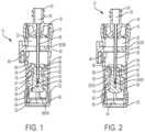
- FIG. 1is a cross-sectional view of a syringe adapter according to one aspect of the present invention.
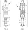
- FIG. 2is a cross-sectional view of a syringe adapter according to one aspect of the present invention.
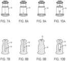
- FIG. 3is a perspective view of a collet according to one aspect of the present invention.
- FIG. 4is a cross-sectional view of the collet of FIG. 3 .
- FIG. 5is a front view of a system for the closed transfer of fluids according to one aspect of the present invention.
- FIG. 6is a cross-sectional view of the system of FIG. 5 .
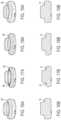
- FIG. 7 Ais a front view of a first membrane according to one aspect of the present invention.
- FIG. 7 Bis a cross-sectional view of the first membrane of FIG. 7 A .
- FIG. 8 Ais a front view of a first membrane according to one aspect of the present invention.
- FIG. 8 Bis a cross-sectional view of the first membrane of FIG. 8 A .
- FIG. 9 Ais a front view of a first membrane according to one aspect of the present invention.
- FIG. 9 Bis a cross-sectional view of the first membrane of FIG. 9 A .
- FIG. 10 Ais a front view of a first membrane according to one aspect of the present invention.
- FIG. 10 Bis a cross-sectional view of the first membrane of FIG. 10 A .
- FIG. 11 Ais a front view of a first membrane according to one aspect of the present invention.
- FIG. 11 Bis a cross-sectional view of the first membrane of FIG. 11 A .
- FIG. 12 Ais a front view of a first membrane according to one aspect of the present invention.
- FIG. 12 Bis a cross-sectional view of the first membrane of FIG. 12 A .
- FIG. 13 Ais a front view of a first membrane according to one aspect of the present invention.
- FIG. 13 Bis a cross-sectional view of the first membrane of FIG. 13 A .
- FIG. 14 Ais a front view of a second membrane according to one aspect of the present invention.
- FIG. 14 Bis a cross-sectional view of the second membrane of FIG. 14 A .
- FIG. 15 Ais a front view of a second membrane according to one aspect of the present invention.
- FIG. 15 Bis a cross-sectional view of the second membrane of FIG. 15 A .
- FIG. 16 Ais a front view of a second membrane according to one aspect of the present invention.
- FIG. 16 Bis a cross-sectional view of the second membrane of FIG. 16 A .
- FIG. 17 Ais a front view of a second membrane according to one aspect of the present invention.
- FIG. 17 Bis a cross-sectional view of the second membrane of FIG. 17 A .
- FIG. 18 Ais a front view of a second membrane according to one aspect of the present invention.
- FIG. 18 Bis a cross-sectional view of the second membrane of FIG. 18 A .
- FIG. 19 Ais a front view of a second membrane according to one aspect of the present invention.
- FIG. 19 Bis a cross-sectional view of the second membrane of FIG. 19 A .
- FIG. 20is a front view of a system for the closed transfer of fluids according to one aspect of the present invention.
- FIG. 21is a cross-sectional view of system shown in FIG. 20 .
- FIG. 22is a cross-sectional view of a syringe adapter according to one aspect of the present invention.
- FIG. 23is a cross-sectional view of a syringe adapter according to one aspect of the present invention.
- FIG. 24is a front view of a syringe adapter according to one aspect of the present invention.
- FIG. 25is a front view of a system for the closed transfer of fluids according to one aspect of the present invention.
- FIG. 26is a cross-sectional view of the system of FIG. 25 .
- FIG. 27is a cross-sectional view of the system of FIG. 25 , showing a patient connector secured to a syringe adapter.
- FIG. 28is a top view of the patient connector of FIG. 25 according to one aspect of the present invention.
- FIG. 29is an enlarged cross-sectional view of the system of FIG. 25 , showing a patient connector secured to a syringe adapter.
- FIG. 30is a perspective view of a system for the closed transfer of fluids according to one aspect of the present invention.
- FIG. 31is a cross-sectional view of the system of FIG. 30 .
- FIG. 32is a cross-sectional view of the system of FIG. 30 , showing a patient connector secured to a syringe adapter with a lock mechanism in an unlocked position.
- FIG. 33is a perspective view of the system of FIG. 30 , showing a patient connector secured to a syringe adapter with a lock mechanism in a locked position.
- FIG. 34is a cross-sectional view of the system of FIG. 30 , showing a patient connector secured to a syringe adapter with a lock mechanism in a locked position.
- FIG. 35is an exploded, perspective view of the system of FIG. 30 according to one aspect of the present invention.
- the syringe adapter 12is one component of a system for the closed transfer of fluids.
- the syringe adapter 12is configured to connect to a syringe (not shown) to another medical device or fluid container.
- the medical devicecan be, for example, a patient line, vial adapter, fluid container, or infusion adapter.
- the containercan be a medical vial, syringe barrel, IV bag, or similar container for holding a fluid to be administered to a patient.
- the syringe adapter 12can be used to facilitate the closed transfer of fluids between the syringe and medical device or fluid container.
- the syringe adapter 12is similar to and operates in a similar manner as the syringe adapter shown and described in United States Patent Application Publication No. 2015/0297454, which is hereby incorporated by reference in its entirety.
- the syringe adapter 12includes a housing 16 having a first end 18 and a second end 20 and defining an interior space 22 .
- the first end 18 of the housing 16 of the syringe adapter 12includes a syringe attachment 24 , such as a female luer connector, that defines a passageway 26 .
- a female luer connectoris shown for connection with a corresponding male luer connector of a syringe (not shown), other suitable connection arrangements may be utilized for connection to a syringe, container, or any other medical device.
- a cannula 28 having a distal end 30is secured to the syringe attachment 24 and in fluid communication with the passageway 26 of the syringe attachment 24 .
- the syringe adapter 12further includes a seal arrangement positioned within the housing 16 of the syringe adapter 12 .
- the seal arrangementincludes a collet 32 that receives a first membrane 34 .
- the collet 32is configured to move within the interior space 22 of the housing 16 of the syringe adapter 12 as discussed in more detail below.
- the housing 16 of the syringe adapter 12may include structure to enhance gripping of the syringe adapter 12 by a user. Additional or alternative grip structures and surfaces may be provided to assist a user in gripping the body of the syringe adapter 12 .
- the syringe adapter 12includes a first connection interface 36 positioned intermediate the first and second ends 18 , 20 of the housing 16 of the syringe adapter 12 that includes a lock member 38 that is received within a transverse opening 40 in the housing 16 of the syringe adapter 12 .
- the lock member 38is configured to move between a closed position and an open position.
- the lock member 38further includes a cantilever spring 46 that extends in a longitudinal direction of the syringe adapter 12 .
- the lock member 38is configured to engage a cam surface that extends radially outward from the housing 16 of the syringe adapter 12 .
- the lock member 38is configured to be provided in the closed position, where a portion of the lock member 38 adjacent to a central opening of the lock member 38 is positioned within the interior space 22 of the syringe adapter 12 when no external forces are applied to the lock member 38 .
- the cantilever spring 46engages the cam surface to create a biasing force that urges the lock member 38 back towards the closed position.
- lock member 38when the lock member 38 is moved to the open position, the lock member 38 will be urged back to the closed position when the external force acting on the lock member 38 is released.
- any other suitable biasing membermay be provided including, but not limited to, compression springs, extension springs, elastomeric material, etc.
- the collet 32has a body 52 with a first end 54 and a second end 56 .
- the body 52defines a passageway 58 that extends through the body 52 .
- the body 52is generally cylindrical, although other suitable shaped collets may be utilized.
- the collet 32further includes a locking member 60 connected to the body 52 of the collet 32 .
- the collet 32is movable from a first position where the locking member 60 is open to receive a mating connector, such as a patient connector, to a second position where radially outward movement of the locking member 60 is restricted.
- the locking member 60is connected to the body 52 via a plurality of arms 62 .
- the locking member 60is arcuate and resilient as a result of the connection of the locking member 60 to the body 52 via the plurality of arms 62 . More specifically, the plurality of arms 62 are flexible and allow the locking member 60 to expand radially outward or radially inward. In one aspect, the locking member 60 is configured to expand radially outward when a mating connector, such as a patient connector, is inserted into the locking member 60 and subsequently moving radially inward as the collet 32 is transitioned from the first position to the second position.
- a mating connectorsuch as a patient connector
- the locking member 60may not move radially inward or outward when a mating connector is inserted into the locking member 60 and may subsequently move radially inward as the collet 32 is transitioned from the first position to the second position.
- the second end 20 of the housing 16 of the syringe adapter 12defines an annular recess 64 adjacent to the interior space 22 that receives the locking member 60 when the collet 32 is in the first position.
- the annular recess 64 of the housing 16provides the space for the locking member 60 to expand radially outward.
- the collet 32When the collet 32 is transitioned from the first position to the second position, the collet 32 moves axially toward the first end 18 of the syringe adapter 12 with the locking member 60 being biased radially inward due to the engagement of the locking member 60 with the housing 16 of the syringe adapter 12 .
- the locking member 60 of the collet 32defines a pair of openings 66 that extend in a direction perpendicular to a longitudinal axis of the collet 32 .
- the openings 66bifurcate the locking member 60 into two arcuate portions that are each connected to the body 52 of the collet 32 by two arms 62 .
- Other suitable arrangements and shapes for the collet 32 and the locking member 60may be utilized.
- the locking member 60 of the collet 32protrudes radially inward and radially outward relative to the plurality of arms 62 .
- the body 52 of the collet 32includes a second connection interface 70 that is configured to mate with and lock with the first connection interface 36 of the syringe adapter 12 .
- the second connection interface 70is defined by the body 52 of the collet 32 .
- the first end 54 of the collet 32is configured to be received within the interior space 22 of the syringe adapter 12 when the lock member 38 of the first connection interface 36 is in the open position and restricted from moving within the interior space 22 of the syringe adapter 12 when the lock member 38 is in the closed position.
- the lock member 38 of the first connection interface 36is configured to be in the closed position to lock the first connection interface 36 from longitudinal and transverse movement relative to the second connection interface 70 , but still allowing rotational movement relative thereto.
- the passageway 58 of the body 52 of the collet 32includes a first counterbore 68 , a second counterbore 74 , positioned opposite the first counterbore 68 , and an intermediate portion 76 positioned between the first and second counterbores 68 , 74 .
- the body of the collet 32also includes a plurality of ribs 78 positioned intermediate the first end 54 and the second end 56 .
- the ribs 78extending longitudinally, although other suitable configurations may be utilized.
- a plurality of recesses 80are positioned between adjacent ribs 78 .
- the passageway 58 of the body of the collet 32includes a narrowed portion 79 configured to compress a portion of the first membrane 34 .
- the intermediate portion 76 of the passageway 58 of the body 52 of the collet 32includes the narrowed portion 79 .
- the narrowed portion 79 of the passageway 58has a smaller diameter than a remaining portion of the intermediate portion 76 of the passageway 58 .
- the first membrane 34includes a body 82 having a first end 84 and a second end 86 .
- the first end 84 and the second end 86 of the body 82 of the first membrane 34include a first head portion 88 and a second head portion 90 , respectively.
- the body 82 of the first membrane 34defines a passageway 92 extending from the first end 84 towards the second end 86 of the body 82 .
- the passageway 92terminates at a position intermediate the first and second ends 84 , 86 of the body 82 .
- the body 82 of the first membrane 34also defines an annular recessed portion 87 positioned intermediate the first and second ends 84 , 86 .
- the body 82 of the first membrane 34is received by the passageway 58 of the collet 32 and is secured to the collet 32 .
- the first head portion 88 of the first membrane 34engages the first counterbore 68 of the collet 32 .
- the second head portion 90extends beyond the passageway 58 of the body 52 of the collet 32 with the second head portion 90 engaging the body 52 of the collet 32 .
- the annular recessed portion 87 of the first member 34is received by the intermediate portion 76 of the collet 32 with the narrowed portion 79 engaging and compressing the annular recessed portion 87 of the first member 34 .
- the second head portion 90defines a convex surface, although other suitable membrane arrangements may be provided as discussed in more detail below.
- the cannula 28is received within the passageway 92 of the first membrane 34 with the distal end 30 of the cannula 28 positioned within the passageway 92 when the collet 32 is in the first position.
- the distal end 30 of the cannula 28is configured to pierce the first membrane 34 and extend through the first membrane 34 when the collet 32 is transitioned from the first position to the second position.
- the first membrane 34is configured to engage and seal an intermediate portion of the cannula 28 during use of the syringe adapter 12 to maintain a sealed and leak-free connection with a mating component.
- the collet 32Upon engagement of the first membrane 34 by a corresponding membrane during use, such as a second membrane 94 from the patient connector 96 , a vial adapter, or IV bag spike, the collet 32 is configured to move toward the first end 18 of the syringe adapter 12 and transition from the first position to the second position such that the distal end 30 of the cannula 28 pierces the first membrane 34 to place the syringe adapter 12 in fluid communication with corresponding devices secured to the syringe adapter 12 .
- a corresponding membranesuch as a second membrane 94 from the patient connector 96 , a vial adapter, or IV bag spike
- the first membrane 34can be disengaged from the corresponding membrane thereby positioning the distal end 30 of the cannula 28 within the passageways 58 , 92 of the collet 32 and the first membrane 34 .
- Such an arrangementshields the distal end 30 of the cannula 28 to prevent accidental needle sticks and also prevents the leakage of any fluid during transfer of fluids when using the syringe adapter 12 .
- the patient connector 96includes a body 102 having a first end 104 and a second end 106 and defining a passageway 108 that extends therethrough.
- the first end 104 of the patient connector 96also includes a collet interface 110 .
- the collet interface 110is defined by a portion of the body 102 of the patient connector 96 that is recessed relative to the first end 104 of the body 102 of the patient connector 96 .
- the first end 104 of the body 102 of the patient connector 96also includes a membrane seat 112 that receives a second membrane 94 .
- the second membrane 94 of the patient connector 96is configured to engage the first membrane 34 of the syringe adapter 12 and provide a substantially leak-free connection with the syringe adapter 12 during fluid transfer.
- the second end 106 of the patient connector 96includes an IV line attachment, such as a male luer connector, although any other suitable connection arrangement may be utilized.
- the narrowed portion 79 of the passageway of the body 52 of the collet 32compresses the first membrane 34 .
- the narrowed portion 79compresses the annular recessed portion 89 of the first membrane 34 .
- back pressure acting on the first membrane 34could potentially unseat the first membrane 34 from the collet 32 .
- the narrowed portion 79acts as a back pressure resistance feature by applying additional compression between the collet 32 and the first membrane 34 .
- FIGS. 7 A- 13 Bfurther aspects of the first membrane 34 are shown.
- various shapes, configurations, and cavitiesmay be utilized for the first membrane 34 .
- the geometries shown in FIGS. 7 A- 13 Bmay be pushed or pulled into a mating component and retained without the need for secondary assembly processes or multi-piece housings.
- the passageway 92 of the first membranemay include various shapes, lengths, widths, and configurations.
- the first end 84 of the first membrane 34may not include a head portion or radial projections.
- the second membrane 94may include an annular recess 98 .
- a syringe adapter 120 and patient connector 122according to a further aspect of the present invention is shown.
- the syringe adapter 120is similar to the syringe adapter 12 shown in FIG. 1 and operates in a similar manner.
- the syringe adapter 120 and patient connector 122 of FIGS. 21 - 24include a different connection arrangement.
- the patient connector 122includes a locking mechanism 124 having a biasing member 126 and an engagement member 128 positioned on the biasing member 126 .
- the engagement member 128is configured to engage a portion of the housing 16 of the syringe adapter 120 to secure the patient connector 122 to the syringe adapter 120 when the patient connector 122 is received by the syringe adapter 120 .
- the locking mechanism 124is shown in connection with the patient connector 122 , the locking mechanism 124 may be provided on any suitable component of a system for the closed transfer of fluids, including, but not limited to, vial adapters, infusion adapters, etc.
- the biasing member 126 of the locking mechanism 124is a cantilever arm, although other suitable biasing arrangements may be utilized.
- the engagement member 128is a projection extending radially outwards from the patient connector 122 , although other suitable projections may be utilized.
- the engagement member 128is configured to engage a portion of the housing 16 of the syringe adapter 120 to bias the engagement member 128 radially inward via the cantilever arm during insertion of the patient connector 122 into the syringe adapter 120 .
- the engagement member 128is also configured to return to a non-biased position when the patient connector 122 has been fully inserted into the syringe adapter 120 to secure the patient connector 122 to the syringe adapter 120 .
- the biasing member 126upon inserting the patient connector 122 into the housing 16 of the syringe adapter 120 , the biasing member 126 is deflected radially inward through engagement of the engagement member 128 with the housing 16 of the syringe adapter 120 . Once fully inserted, the biasing member 126 returns to the non-biased position with the engagement member 128 retaining the patient connector 122 in the syringe adapter 120 with the collet 32 engaged with the collet interface 110 of the patient connector 122 .
- a userapplies an axial force to the patient connector 122 in a direction away from the syringe adapter 120 such that the biasing member 126 is again deflected radially inward through engagement of the engagement member 128 with the housing 16 of the syringe adapter 120 until the engagement member 128 is axially displaced beyond the housing 16 of the syringe adapter 120 .
- the collet 32will also release from the patient connector 122 in the same manner as discussed above in connection with syringe adapter 12 .
- the syringe adapter 120may also include a collet drive member 132 configured to bias the collet 32 toward the second end 20 of the syringe adapter 120 to maintain the collet 32 in the first position.
- the syringe adapter 120operates in the same manner as discussed above in connection with syringe adapter 12 , but the collet drive member 132 requires a user to overcome the biasing force of the collet drive member 132 to move the collet 32 from the first position to the second position when the syringe adapter 120 is mated with a mating connector, such as the patient connector 122 .
- the collet drive member 132may be a spring, although other suitable biasing arrangements may be utilized. Further, as shown in FIGS. 21 - 23 , the collet 32 may not include the first counterbore 68 with the first end 54 of the collet defining a planar surface 134 .
- a syringe adapter 150 and patient connector 152according to a further aspect of the present invention is shown.
- the syringe adapter 150is similar to the syringe adapter 12 shown in FIG. 1 and operates in a similar manner.
- the syringe adapter 150 and patient connector 152 of FIGS. 25 - 29include a different connection arrangement.
- the patient connector 152includes a connection member 154 .
- connection member 154is configured to engage a portion of the housing 16 of the syringe adapter 150 to secure the patient connector 152 to the syringe adapter 150 when the patient connector 152 is received by the syringe adapter 150 .
- connection member 154may be provided on any suitable component of a system for the closed transfer of fluids, including, but not limited to, vial adapters, infusion adapters, etc.
- connection member 154is a projection extending radially outward from the patient connector 152 .
- the connection member 154is received by a recessed portion 156 of the housing 16 of the syringe adapter 150 to secure the patient connector 152 to the syringe adapter 150 when the patient connector 152 is received by the syringe adapter 150 .
- the connection member 154is semi-spherical, although other suitable shapes and configurations may be utilized. As shown in FIG. 28 , three equally spaced-apart connection members 154 are provided on the patient connector 152 , although one or more connection members 154 may be provided.
- the second membrane 94 of the patient connector 152engages the first membrane 34 of the collet 32 and moves the collet 32 to the second position as described above in connection with syringe adapter 12 .
- the connection member(s) 154engage the housing 16 of the syringe adapter 150 and are received within the recessed portion 156 of the housing 16 to further secure the patient connector 152 to the syringe adapter 150 .
- connection member(s) 154snap out of the recessed portion 156 of the housing 16 of the syringe adapter 150 .
- the collet 32will also release from the patient connector 152 in the same manner as discussed above.
- a syringe adapter 170 and patient connector 172according to a further aspect of the present invention is shown.
- the syringe adapter 170is similar to the syringe adapter 12 shown in FIG. 1 and operates in a similar manner.
- the syringe adapter 170 of FIGS. 25 - 29includes a different connection arrangement.
- the syringe adapter 170includes a lock mechanism 174 movable between an unlocked position (shown in FIGS. 31 and 32 ) and a locked position (shown in FIGS. 33 and 34 ).
- the collet 32includes a lock interface 174 that is configured to engage the lock mechanism 174 when the collet 32 is in the second position and when the lock mechanism 174 is in the locked position.
- the lock mechanism 174is disengaged from the lock interface 176 when the collet 32 is in the second position and when the lock mechanism 174 is in the unlocked position.
- the lock mechanism 174is manually movable between the locked and unlocked positions by a user, although other suitable arrangements may be utilized.
- the lock mechanism 174has a first end 178 and a second end 180 and defines an opening 182 that is configured to receive the collet 32 .
- the first end 178 of the lock mechanism 174protrudes from the housing 16 and the second end 180 of the lock mechanism 174 is received within the housing 16 .
- the first end 178 of the lock mechanism 174is received within the housing 16 and the second end 180 of the lock mechanism 174 protrudes from the housing 16 .
- the second end 180 of the lock mechanismincludes an indicator 184 .
- the indicator 184may be a colored portion of the lock mechanism 174 that is different than the remaining portion of the lock mechanism 174 .
- the colored portionmay be a dominant color, such as red.
- the lock mechanism 174is received within the transverse opening 40 of the housing 16 of the syringe adapter 170 and is retained within the housing 16 via retention portions 186 of the lock mechanism 174 positioned intermediate the first and second ends 178 , 180 of the lock mechanism 174 that engage the housing 16 .
- the lock mechanism 174is transitioned to the locked position such that the lock mechanism 174 engages the lock interface 176 of the collet 32 with the indicator 184 providing an indication of the locked status of the syringe adapter 170 .
Landscapes
- Health & Medical Sciences (AREA)
- Life Sciences & Earth Sciences (AREA)
- Animal Behavior & Ethology (AREA)
- General Health & Medical Sciences (AREA)
- Public Health (AREA)
- Veterinary Medicine (AREA)
- Pharmacology & Pharmacy (AREA)
- Heart & Thoracic Surgery (AREA)
- Physics & Mathematics (AREA)
- Engineering & Computer Science (AREA)
- Fluid Mechanics (AREA)
- Biomedical Technology (AREA)
- Hematology (AREA)
- Anesthesiology (AREA)
- Pulmonology (AREA)
- Vascular Medicine (AREA)
- Acoustics & Sound (AREA)
- Multimedia (AREA)
- Infusion, Injection, And Reservoir Apparatuses (AREA)
- Medical Preparation Storing Or Oral Administration Devices (AREA)
- Stringed Musical Instruments (AREA)
Abstract
Description
Claims (10)
Priority Applications (1)
| Application Number | Priority Date | Filing Date | Title |
|---|---|---|---|
| US15/871,363US12090308B2 (en) | 2017-01-17 | 2018-01-15 | Syringe adapter with lock mechanism |
Applications Claiming Priority (2)
| Application Number | Priority Date | Filing Date | Title |
|---|---|---|---|
| US201762447059P | 2017-01-17 | 2017-01-17 | |
| US15/871,363US12090308B2 (en) | 2017-01-17 | 2018-01-15 | Syringe adapter with lock mechanism |
Publications (2)
| Publication Number | Publication Date |
|---|---|
| US20180200148A1 US20180200148A1 (en) | 2018-07-19 |
| US12090308B2true US12090308B2 (en) | 2024-09-17 |
Family
ID=61163799
Family Applications (2)
| Application Number | Title | Priority Date | Filing Date |
|---|---|---|---|
| US15/871,363Active2041-07-29US12090308B2 (en) | 2017-01-17 | 2018-01-15 | Syringe adapter with lock mechanism |
| US15/937,846ActiveUS10559287B2 (en) | 2017-01-17 | 2018-03-27 | Stringed musical instrument adjustable neck joint |
Family Applications After (1)
| Application Number | Title | Priority Date | Filing Date |
|---|---|---|---|
| US15/937,846ActiveUS10559287B2 (en) | 2017-01-17 | 2018-03-27 | Stringed musical instrument adjustable neck joint |
Country Status (9)
| Country | Link |
|---|---|
| US (2) | US12090308B2 (en) |
| EP (2) | EP3570931B1 (en) |
| JP (3) | JP7053631B2 (en) |
| CN (2) | CN108324564B (en) |
| AU (1) | AU2018210219B2 (en) |
| CA (1) | CA3050463A1 (en) |
| ES (1) | ES2950440T3 (en) |
| IL (2) | IL268050B2 (en) |
| WO (1) | WO2018136364A1 (en) |
Families Citing this family (26)
| Publication number | Priority date | Publication date | Assignee | Title |
|---|---|---|---|---|
| ES2935418T3 (en) | 2011-08-10 | 2023-03-06 | Fisher & Paykel Healthcare Ltd | Conduit connector for a patient breathing device |
| USD747471S1 (en) | 2012-08-10 | 2016-01-12 | Fisher & Paykel Healthcare Limited | Connector |
| US11446462B2 (en) | 2015-03-31 | 2022-09-20 | Fisher & Paykel Healthcare Limited | Apparatus for use in a respiratory support system |
| WO2017037660A1 (en) | 2015-09-04 | 2017-03-09 | Fisher & Paykel Healthcare Limited | Connectors for conduits |
| USD809656S1 (en) | 2016-06-10 | 2018-02-06 | Fisher & Paykel Healthcare Limited | Connector for a breathing circuit |
| EP3570931B1 (en)* | 2017-01-17 | 2023-06-07 | Becton Dickinson and Company Limited | Syringe adapter with lock mechanism |
| USD888945S1 (en) | 2018-04-04 | 2020-06-30 | Becton Dickinson and Company Limited | Medical connector |
| USD877900S1 (en) | 2018-04-04 | 2020-03-10 | Becton Dickinson and Company Limited | Medical infusion adapter |
| USD873996S1 (en) | 2018-04-04 | 2020-01-28 | Becton Dickinson and Company Limited | Medical syringe adapter |
| USD908872S1 (en) | 2018-04-04 | 2021-01-26 | Becton Dickinson and Company Limited | Medical vial access device |
| US10984762B2 (en) | 2019-02-01 | 2021-04-20 | Microtone Guitars, Llc | Detachable fretboard with customized frets |
| US10643584B1 (en)* | 2019-02-01 | 2020-05-05 | Microtone Guitars, Llc | Detachable fretboard with customized frets |
| USD1006981S1 (en) | 2019-09-06 | 2023-12-05 | Fisher & Paykel Healthcare Limited | Breathing conduit |
| USD948027S1 (en) | 2019-09-10 | 2022-04-05 | Fisher & Paykel Healthcare Limited | Connector for a breathing conduit |
| USD940861S1 (en) | 2020-03-03 | 2022-01-11 | Fisher & Paykel Healthcare Limited | Connector for a respiratory system conduit |
| DE102020202939A1 (en) | 2020-03-06 | 2021-09-09 | B. Braun Melsungen Aktiengesellschaft | Coupling element for a closed fluid transfer system, mating coupling element for such a coupling element and coupling system |
| DE102020202935A1 (en) | 2020-03-06 | 2021-09-09 | B. Braun Melsungen Aktiengesellschaft | Coupling element for a closed fluid transfer system, mating coupling element for such a coupling element and coupling system |
| DE102020202941A1 (en) | 2020-03-06 | 2021-09-09 | B. Braun Melsungen Aktiengesellschaft | Coupling element and coupling system for a closed fluid transfer system |
| CN111297683B (en)* | 2020-03-20 | 2021-05-07 | 江苏苏云医疗器材有限公司 | Safe type liquid medicine translator |
| US11151968B1 (en)* | 2020-05-06 | 2021-10-19 | Christopher LAI | Guitar neck and body joint |
| EP4237047A4 (en)* | 2020-10-28 | 2024-08-28 | Becton, Dickinson and Company | MEMBRANE WITH CONDUCTIVE SURFACE |
| USD974551S1 (en) | 2020-12-09 | 2023-01-03 | Fisher & Paykel Healthcare Limited | Connector assembly and connector |
| USD1073919S1 (en) | 2021-05-17 | 2025-05-06 | Fisher & Paykel Healthcare Limited | Respiratory system conduit with connector |
| USD995758S1 (en) | 2021-06-11 | 2023-08-15 | Fisher & Paykel Healthcare Limited | Tube assembly and connector |
| US11538445B1 (en)* | 2021-09-15 | 2022-12-27 | Journey Instruments Limited Hong Kong | Detachable neck mechanism for solid or hollow body guitar |
| US20250108174A1 (en)* | 2023-09-29 | 2025-04-03 | Becton, Dickinson And Company | Closed System Transfer Device Injection System |
Citations (47)
| Publication number | Priority date | Publication date | Assignee | Title |
|---|---|---|---|---|
| US4436125A (en) | 1982-03-17 | 1984-03-13 | Colder Products Company | Quick connect coupling |
| US4564054A (en) | 1983-03-03 | 1986-01-14 | Bengt Gustavsson | Fluid transfer system |
| US4576211A (en) | 1984-02-24 | 1986-03-18 | Farmitalia Carlo Erba S.P.A. | Safety device for connection of a syringe with the mouth or opening of a bottle containing a drug or a small tube for drug delivery from the syringe |
| US4986322A (en)* | 1987-03-24 | 1991-01-22 | Societe Semco | System of packaging for ready to use preparations |
| US5104158A (en) | 1989-03-13 | 1992-04-14 | Colder Products Company | Two piece molded female coupling |
| US5554044A (en)* | 1994-07-13 | 1996-09-10 | Sumitomo Wiring Systems, Ltd. | Connector |
| US5810792A (en) | 1996-04-03 | 1998-09-22 | Icu Medical, Inc. | Locking blunt cannula |
| US20050107739A1 (en)* | 2003-11-17 | 2005-05-19 | Angiodynamics, Inc. | Locking catheter hub |
| JP2007510479A (en) | 2003-11-10 | 2007-04-26 | フレゼニウス メディカル ケア ドイッチェランド ゲゼルシャフト ミット ベシュレンクテル ハフツング | Dialyzer port connector |
| US20090069783A1 (en) | 2007-09-11 | 2009-03-12 | Anna Ellstrom | Piercing member protection device |
| US7648491B2 (en) | 2005-05-13 | 2010-01-19 | Bob Rogers | Medical substance transfer system |
| US20110106046A1 (en) | 2008-05-02 | 2011-05-05 | Terumo Kabushiki Kaisha | Connector assembly |
| US7975733B2 (en) | 2007-05-08 | 2011-07-12 | Carmel Pharma Ab | Fluid transfer device |
| US8122923B2 (en) | 2003-10-30 | 2012-02-28 | Teva Medical Ltd. | Safety drug handling device |
| US8196614B2 (en) | 2007-04-23 | 2012-06-12 | Plastmed Ltd. | Method and apparatus for contamination-free transfer of a hazardous drug |
| US20130006211A1 (en) | 2010-03-30 | 2013-01-03 | Terumo Kabushiki Kaisha | Connector and connector assembly |
| US8511399B2 (en)* | 2004-09-22 | 2013-08-20 | Black & Decker Inc. | Hammer drill with mode lock on |
| US20140074038A1 (en) | 2012-09-11 | 2014-03-13 | Becton Dickinson and Company Limited | Adapter Cap for Drug Transfer Assembly |
| USD708518S1 (en) | 2012-09-11 | 2014-07-08 | Becton Dickinson and Company Limited | Soft cap for a connector |
| USD710196S1 (en) | 2012-09-11 | 2014-08-05 | Becton Dickinson and Company Limited | Soft cap for a connector |
| US20140246616A1 (en)* | 2011-09-09 | 2014-09-04 | Icu Medical, Inc. | Medical connectors with fluid-resistant mating interfaces |
| US20140276649A1 (en) | 2013-03-15 | 2014-09-18 | Becton Dickinson and Company Limited | Connection System for Medical Device Components |
| US20140303601A1 (en)* | 2008-12-19 | 2014-10-09 | Icu Medical, Inc. | Medical connector with closeable luer connector |
| JP2015055357A (en) | 2013-09-13 | 2015-03-23 | ノードソン コーポレーションNordson Corporation | Quick connect fluid conduit connector with latch including integral spring arm for button release |
| US20150126974A1 (en)* | 2013-11-06 | 2015-05-07 | Becton Dickinson and Company Limited | System for Closed Transfer of Fluids Having Connector |
| US20150216764A1 (en)* | 2012-08-03 | 2015-08-06 | Becton Dickinson France | Closing System for a Container |
| US9126029B2 (en) | 2005-07-06 | 2015-09-08 | Icu Medical, Inc. | Medical connector |
| US20150297459A1 (en)* | 2014-04-21 | 2015-10-22 | Becton Dickinson and Company Limited | Syringe Adapter with Disconnection Feedback Mechanism |
| US20150297456A1 (en) | 2014-04-21 | 2015-10-22 | Becton Dickinson and Company Limited | System with Adapter for Closed Transfer of Fluids |
| US20150297839A1 (en)* | 2014-04-21 | 2015-10-22 | Becton Dickinson and Company Limited | System for Closed Transfer of Fluids and Membrane Arrangements for Use Thereof |
| US20150297454A1 (en)* | 2014-04-21 | 2015-10-22 | Becton Dickinson and Company Limited | System for Closed Transfer of Fluids |
| US20150297881A1 (en)* | 2014-04-21 | 2015-10-22 | Becton Dickinson and Company Limited | Fluid Transfer Device and Packaging Therefor |
| US20160136412A1 (en) | 2013-11-06 | 2016-05-19 | Becton Dickinson and Company Limited | Connection Apparatus for a Medical Device |
| US9381137B2 (en) | 2010-05-27 | 2016-07-05 | J & J Solutions, Inc. | Closed fluid transfer system with syringe adapter |
| JP2016130582A (en) | 2015-01-14 | 2016-07-21 | ノーマ ユー.エス.ホールディング リミティド ライアビリティ カンパニー | Conduit connector with first and second latches |
| US9414991B2 (en) | 2013-11-06 | 2016-08-16 | Becton Dickinson and Company Limited | Medical connector having locking engagement |
| US9414990B2 (en) | 2013-03-15 | 2016-08-16 | Becton Dickinson and Company Ltd. | Seal system for cannula |
| US20160271017A1 (en) | 2013-11-06 | 2016-09-22 | Becton Dickinson and Company Limited | System with Adapter for Closed Transfer of Fluids |
| US9510997B2 (en) | 2013-02-07 | 2016-12-06 | Equashield Medical Ltd. | Closed drug transfer system |
| US20160361504A1 (en) | 2015-06-12 | 2016-12-15 | Becton Dickinson and Company Limited | Syringe Adapter with Spinning Connector |
| US9636278B2 (en) | 2013-11-06 | 2017-05-02 | Becton Dickinson and Company Limited | System for closed transfer of fluids with a locking member |
| US9724269B2 (en) | 2012-11-30 | 2017-08-08 | Becton Dickinson and Company Ltd. | Connector for fluid communication |
| US9750926B2 (en) | 2010-05-17 | 2017-09-05 | Icu Medical, Inc. | Medical connectors and methods of use |
| US20170258682A1 (en) | 2014-09-18 | 2017-09-14 | Equashield Medical Ltd. | Improved needle valve and connectors for use in liquid transfer apparatuses |
| US9855192B2 (en) | 2014-04-21 | 2018-01-02 | Becton Dickinson and Company Limited | Syringe adapter with compound motion disengagement |
| US20180028402A1 (en) | 2015-03-16 | 2018-02-01 | Equashield Medical Ltd. | Septum holders for use in syringe connectors |
| JP2020503980A (en) | 2017-01-17 | 2020-02-06 | ベクトン ディキンソン アンド カンパニー リミテッド | Syringe adapter with lock mechanism |
Family Cites Families (6)
| Publication number | Priority date | Publication date | Assignee | Title |
|---|---|---|---|---|
| US3658351A (en)* | 1970-04-03 | 1972-04-25 | Erickson Tool Co | Instant change tool holder |
| GB2170855B (en)* | 1985-02-12 | 1988-05-05 | Martin D Solomon | Lock assembly |
| US6305963B1 (en)* | 1996-08-16 | 2001-10-23 | Agilent Technologies, Inc. | Push-lock BNC connector |
| CN2581645Y (en)* | 2002-04-22 | 2003-10-22 | 林荣革 | Button type lock for door and window |
| US7157634B1 (en)* | 2003-07-30 | 2007-01-02 | Babicz Jeffrey T | String instrument |
| US9368092B2 (en)* | 2014-07-24 | 2016-06-14 | Stuart A. HOOKER | Neck adjustment mechanism for string instrument |
- 2018
- 2018-01-15EPEP18703405.3Apatent/EP3570931B1/enactiveActive
- 2018-01-15EPEP23176034.9Apatent/EP4218895A1/enactivePending
- 2018-01-15CACA3050463Apatent/CA3050463A1/enactivePending
- 2018-01-15ESES18703405Tpatent/ES2950440T3/enactiveActive
- 2018-01-15WOPCT/US2018/013729patent/WO2018136364A1/ennot_activeCeased
- 2018-01-15ILIL268050Apatent/IL268050B2/enunknown
- 2018-01-15JPJP2019538518Apatent/JP7053631B2/enactiveActive
- 2018-01-15ILIL307599Apatent/IL307599A/enunknown
- 2018-01-15USUS15/871,363patent/US12090308B2/enactiveActive
- 2018-01-15AUAU2018210219Apatent/AU2018210219B2/enactiveActive
- 2018-01-17CNCN201810041978.0Apatent/CN108324564B/enactiveActive
- 2018-01-17CNCN201820071041.3Upatent/CN209108087U/enactiveActive
- 2018-03-27USUS15/937,846patent/US10559287B2/enactiveActive
- 2022
- 2022-03-31JPJP2022059966Apatent/JP7510967B2/enactiveActive
- 2024
- 2024-03-13JPJP2024038959Apatent/JP7515759B2/enactiveActive
Patent Citations (59)
| Publication number | Priority date | Publication date | Assignee | Title |
|---|---|---|---|---|
| US4436125A (en) | 1982-03-17 | 1984-03-13 | Colder Products Company | Quick connect coupling |
| US4564054A (en) | 1983-03-03 | 1986-01-14 | Bengt Gustavsson | Fluid transfer system |
| US4576211A (en) | 1984-02-24 | 1986-03-18 | Farmitalia Carlo Erba S.P.A. | Safety device for connection of a syringe with the mouth or opening of a bottle containing a drug or a small tube for drug delivery from the syringe |
| US4986322A (en)* | 1987-03-24 | 1991-01-22 | Societe Semco | System of packaging for ready to use preparations |
| US5104158A (en) | 1989-03-13 | 1992-04-14 | Colder Products Company | Two piece molded female coupling |
| US5554044A (en)* | 1994-07-13 | 1996-09-10 | Sumitomo Wiring Systems, Ltd. | Connector |
| US5810792A (en) | 1996-04-03 | 1998-09-22 | Icu Medical, Inc. | Locking blunt cannula |
| US8122923B2 (en) | 2003-10-30 | 2012-02-28 | Teva Medical Ltd. | Safety drug handling device |
| US8087702B2 (en) | 2003-11-10 | 2012-01-03 | Fresenius Medical Care Deutschland Gmbh | Connector for a dialysis port |
| JP2007510479A (en) | 2003-11-10 | 2007-04-26 | フレゼニウス メディカル ケア ドイッチェランド ゲゼルシャフト ミット ベシュレンクテル ハフツング | Dialyzer port connector |
| US20050107739A1 (en)* | 2003-11-17 | 2005-05-19 | Angiodynamics, Inc. | Locking catheter hub |
| US8511399B2 (en)* | 2004-09-22 | 2013-08-20 | Black & Decker Inc. | Hammer drill with mode lock on |
| US7648491B2 (en) | 2005-05-13 | 2010-01-19 | Bob Rogers | Medical substance transfer system |
| US9126029B2 (en) | 2005-07-06 | 2015-09-08 | Icu Medical, Inc. | Medical connector |
| US8196614B2 (en) | 2007-04-23 | 2012-06-12 | Plastmed Ltd. | Method and apparatus for contamination-free transfer of a hazardous drug |
| US8267127B2 (en) | 2007-04-23 | 2012-09-18 | Plastmed, Ltd. | Method and apparatus for contamination-free transfer of a hazardous drug |
| US7975733B2 (en) | 2007-05-08 | 2011-07-12 | Carmel Pharma Ab | Fluid transfer device |
| US20090069783A1 (en) | 2007-09-11 | 2009-03-12 | Anna Ellstrom | Piercing member protection device |
| US20110106046A1 (en) | 2008-05-02 | 2011-05-05 | Terumo Kabushiki Kaisha | Connector assembly |
| US9168366B2 (en) | 2008-12-19 | 2015-10-27 | Icu Medical, Inc. | Medical connector with closeable luer connector |
| US20140303601A1 (en)* | 2008-12-19 | 2014-10-09 | Icu Medical, Inc. | Medical connector with closeable luer connector |
| US20130006211A1 (en) | 2010-03-30 | 2013-01-03 | Terumo Kabushiki Kaisha | Connector and connector assembly |
| US8790327B2 (en) | 2010-03-30 | 2014-07-29 | Terumo Kabushiki Kaisha | Connector and connector assembly |
| US9750926B2 (en) | 2010-05-17 | 2017-09-05 | Icu Medical, Inc. | Medical connectors and methods of use |
| US9381137B2 (en) | 2010-05-27 | 2016-07-05 | J & J Solutions, Inc. | Closed fluid transfer system with syringe adapter |
| US20140246616A1 (en)* | 2011-09-09 | 2014-09-04 | Icu Medical, Inc. | Medical connectors with fluid-resistant mating interfaces |
| US20150216764A1 (en)* | 2012-08-03 | 2015-08-06 | Becton Dickinson France | Closing System for a Container |
| USD710196S1 (en) | 2012-09-11 | 2014-08-05 | Becton Dickinson and Company Limited | Soft cap for a connector |
| US20140074038A1 (en) | 2012-09-11 | 2014-03-13 | Becton Dickinson and Company Limited | Adapter Cap for Drug Transfer Assembly |
| USD708518S1 (en) | 2012-09-11 | 2014-07-08 | Becton Dickinson and Company Limited | Soft cap for a connector |
| US9724269B2 (en) | 2012-11-30 | 2017-08-08 | Becton Dickinson and Company Ltd. | Connector for fluid communication |
| US9510997B2 (en) | 2013-02-07 | 2016-12-06 | Equashield Medical Ltd. | Closed drug transfer system |
| US9610222B2 (en) | 2013-02-07 | 2017-04-04 | Equashield Medical Ltd. | Closed drug transfer system |
| US9414990B2 (en) | 2013-03-15 | 2016-08-16 | Becton Dickinson and Company Ltd. | Seal system for cannula |
| US20140276649A1 (en) | 2013-03-15 | 2014-09-18 | Becton Dickinson and Company Limited | Connection System for Medical Device Components |
| US9597260B2 (en) | 2013-03-15 | 2017-03-21 | Becton Dickinson and Company Ltd. | System for closed transfer of fluids |
| JP2015055357A (en) | 2013-09-13 | 2015-03-23 | ノードソン コーポレーションNordson Corporation | Quick connect fluid conduit connector with latch including integral spring arm for button release |
| US9636278B2 (en) | 2013-11-06 | 2017-05-02 | Becton Dickinson and Company Limited | System for closed transfer of fluids with a locking member |
| US20160136412A1 (en) | 2013-11-06 | 2016-05-19 | Becton Dickinson and Company Limited | Connection Apparatus for a Medical Device |
| US9414991B2 (en) | 2013-11-06 | 2016-08-16 | Becton Dickinson and Company Limited | Medical connector having locking engagement |
| US9642775B2 (en) | 2013-11-06 | 2017-05-09 | Becton Dickinson and Company Limited | System for closed transfer of fluids having connector |
| US20160271017A1 (en) | 2013-11-06 | 2016-09-22 | Becton Dickinson and Company Limited | System with Adapter for Closed Transfer of Fluids |
| US20160331637A1 (en) | 2013-11-06 | 2016-11-17 | Becton Dickinson and Company Limited | Medical Connector Having Locking Engagement |
| US20150126974A1 (en)* | 2013-11-06 | 2015-05-07 | Becton Dickinson and Company Limited | System for Closed Transfer of Fluids Having Connector |
| US20150297456A1 (en) | 2014-04-21 | 2015-10-22 | Becton Dickinson and Company Limited | System with Adapter for Closed Transfer of Fluids |
| US20180085286A1 (en) | 2014-04-21 | 2018-03-29 | Becton Dickinson and Company Limited | Syringe Adapter with Compound Motion Disengagement |
| US20150297839A1 (en)* | 2014-04-21 | 2015-10-22 | Becton Dickinson and Company Limited | System for Closed Transfer of Fluids and Membrane Arrangements for Use Thereof |
| US20180071506A1 (en) | 2014-04-21 | 2018-03-15 | Becton Dickinson and Company Limited | Fluid Transfer Device and Packaging Therefor |
| US20150297459A1 (en)* | 2014-04-21 | 2015-10-22 | Becton Dickinson and Company Limited | Syringe Adapter with Disconnection Feedback Mechanism |
| US20150297881A1 (en)* | 2014-04-21 | 2015-10-22 | Becton Dickinson and Company Limited | Fluid Transfer Device and Packaging Therefor |
| US20150297454A1 (en)* | 2014-04-21 | 2015-10-22 | Becton Dickinson and Company Limited | System for Closed Transfer of Fluids |
| US9833605B2 (en) | 2014-04-21 | 2017-12-05 | Becton Dickinson and Company Limited | Fluid transfer device and packaging therefor |
| US9855192B2 (en) | 2014-04-21 | 2018-01-02 | Becton Dickinson and Company Limited | Syringe adapter with compound motion disengagement |
| US20170258682A1 (en) | 2014-09-18 | 2017-09-14 | Equashield Medical Ltd. | Improved needle valve and connectors for use in liquid transfer apparatuses |
| JP2016130582A (en) | 2015-01-14 | 2016-07-21 | ノーマ ユー.エス.ホールディング リミティド ライアビリティ カンパニー | Conduit connector with first and second latches |
| US10422459B2 (en) | 2015-01-14 | 2019-09-24 | Norma U.S. Holding Llc | Conduit connector with a primary and secondary latch |
| US20180028402A1 (en) | 2015-03-16 | 2018-02-01 | Equashield Medical Ltd. | Septum holders for use in syringe connectors |
| US20160361504A1 (en) | 2015-06-12 | 2016-12-15 | Becton Dickinson and Company Limited | Syringe Adapter with Spinning Connector |
| JP2020503980A (en) | 2017-01-17 | 2020-02-06 | ベクトン ディキンソン アンド カンパニー リミテッド | Syringe adapter with lock mechanism |
Non-Patent Citations (6)
| Title |
|---|
| Definition of "into" Merriam Webster Dictionary https://www.merriam-webster.com/dictionary/into (Year: 2023).* |
| Definition of automatic (Year: 2021).* |
| Merriam-Webster definition of end as accessed Jun. 3, 2024; http://www.merriam-webster.com/dictionary/end. |
| Merriam-Webster definition of indicates as accessed Jun. 3, 2024; http://www.merriam-webster.com/dictionary/indicates. |
| Merriam-Webster definition of indicator as accessed Jun. 3, 2024; http://www.merriam-webster.com/dictionary/indicator. |
| Opposition Notice re EP 3570931, dated Mar. 13, 2024. |
Also Published As
| Publication number | Publication date |
|---|---|
| JP2024060062A (en) | 2024-05-01 |
| CN209108087U (en) | 2019-07-16 |
| JP7053631B2 (en) | 2022-04-12 |
| IL307599A (en) | 2023-12-01 |
| AU2018210219B2 (en) | 2023-02-02 |
| US10559287B2 (en) | 2020-02-11 |
| US20180200148A1 (en) | 2018-07-19 |
| IL268050A (en) | 2019-09-26 |
| JP2022079666A (en) | 2022-05-26 |
| WO2018136364A1 (en) | 2018-07-26 |
| AU2018210219A1 (en) | 2019-08-15 |
| JP2020503980A (en) | 2020-02-06 |
| EP3570931B1 (en) | 2023-06-07 |
| EP4218895A1 (en) | 2023-08-02 |
| EP3570931C0 (en) | 2023-06-07 |
| IL268050B1 (en) | 2023-11-01 |
| IL268050B2 (en) | 2024-03-01 |
| JP7515759B2 (en) | 2024-07-12 |
| CA3050463A1 (en) | 2018-07-26 |
| JP7510967B2 (en) | 2024-07-04 |
| EP3570931A1 (en) | 2019-11-27 |
| BR112019014739A2 (en) | 2020-03-03 |
| CN108324564A (en) | 2018-07-27 |
| CN108324564B (en) | 2022-06-14 |
| US20180218717A1 (en) | 2018-08-02 |
| US20190139517A9 (en) | 2019-05-09 |
| ES2950440T3 (en) | 2023-10-10 |
Similar Documents
| Publication | Publication Date | Title |
|---|---|---|
| US12427297B2 (en) | Connector for system for closed transfer of fluids | |
| US12090308B2 (en) | Syringe adapter with lock mechanism | |
| US11986441B2 (en) | Syringe adapter for closed transfer of fluids |
Legal Events
| Date | Code | Title | Description |
|---|---|---|---|
| AS | Assignment | Owner name:BECTON DICKINSON AND COMPANY LIMITED, IRELAND Free format text:ASSIGNMENT OF ASSIGNORS INTEREST;ASSIGNOR:SANDERS, LAURIE;REEL/FRAME:044622/0001 Effective date:20170207 | |
| FEPP | Fee payment procedure | Free format text:ENTITY STATUS SET TO UNDISCOUNTED (ORIGINAL EVENT CODE: BIG.); ENTITY STATUS OF PATENT OWNER: LARGE ENTITY | |
| STPP | Information on status: patent application and granting procedure in general | Free format text:DOCKETED NEW CASE - READY FOR EXAMINATION | |
| STPP | Information on status: patent application and granting procedure in general | Free format text:RESPONSE TO NON-FINAL OFFICE ACTION ENTERED AND FORWARDED TO EXAMINER | |
| STPP | Information on status: patent application and granting procedure in general | Free format text:FINAL REJECTION MAILED | |
| STPP | Information on status: patent application and granting procedure in general | Free format text:RESPONSE AFTER FINAL ACTION FORWARDED TO EXAMINER | |
| STPP | Information on status: patent application and granting procedure in general | Free format text:ADVISORY ACTION MAILED | |
| STPP | Information on status: patent application and granting procedure in general | Free format text:DOCKETED NEW CASE - READY FOR EXAMINATION | |
| STPP | Information on status: patent application and granting procedure in general | Free format text:NON FINAL ACTION MAILED | |
| STPP | Information on status: patent application and granting procedure in general | Free format text:RESPONSE TO NON-FINAL OFFICE ACTION ENTERED AND FORWARDED TO EXAMINER | |
| STPP | Information on status: patent application and granting procedure in general | Free format text:FINAL REJECTION MAILED | |
| STCV | Information on status: appeal procedure | Free format text:NOTICE OF APPEAL FILED | |
| STCV | Information on status: appeal procedure | Free format text:APPEAL BRIEF (OR SUPPLEMENTAL BRIEF) ENTERED AND FORWARDED TO EXAMINER | |
| STCV | Information on status: appeal procedure | Free format text:EXAMINER'S ANSWER TO APPEAL BRIEF MAILED | |
| STCV | Information on status: appeal procedure | Free format text:ON APPEAL -- AWAITING DECISION BY THE BOARD OF APPEALS | |
| STCV | Information on status: appeal procedure | Free format text:BOARD OF APPEALS DECISION RENDERED | |
| STPP | Information on status: patent application and granting procedure in general | Free format text:NOTICE OF ALLOWANCE MAILED -- APPLICATION RECEIVED IN OFFICE OF PUBLICATIONS | |
| STPP | Information on status: patent application and granting procedure in general | Free format text:PUBLICATIONS -- ISSUE FEE PAYMENT RECEIVED | |
| STCF | Information on status: patent grant | Free format text:PATENTED CASE |