US12090039B2 - Biomimetic artificial bladder and method for controlling same - Google Patents
Biomimetic artificial bladder and method for controlling sameDownload PDFInfo
- Publication number
- US12090039B2 US12090039B2US17/262,551US201917262551AUS12090039B2US 12090039 B2US12090039 B2US 12090039B2US 201917262551 AUS201917262551 AUS 201917262551AUS 12090039 B2US12090039 B2US 12090039B2
- Authority
- US
- United States
- Prior art keywords
- reservoir portion
- wall
- fluid
- sensor
- urine
- Prior art date
- Legal status (The legal status is an assumption and is not a legal conclusion. Google has not performed a legal analysis and makes no representation as to the accuracy of the status listed.)
- Active, expires
Links
- 238000000034methodMethods0.000titleclaimsdescription29
- 230000003592biomimetic effectEffects0.000titledescription2
- 210000002700urineAnatomy0.000claimsabstractdescription78
- 230000036961partial effectEffects0.000claimsabstractdescription7
- 239000012530fluidSubstances0.000claimsdescription121
- 239000000463materialSubstances0.000claimsdescription29
- 230000002401inhibitory effectEffects0.000claimsdescription14
- 239000002086nanomaterialSubstances0.000claimsdescription14
- 206010016654FibrosisDiseases0.000claimsdescription12
- 230000002308calcificationEffects0.000claimsdescription12
- 230000004761fibrosisEffects0.000claimsdescription12
- 239000000758substrateSubstances0.000claimsdescription10
- 229920000642polymerPolymers0.000claimsdescription9
- 238000007599dischargingMethods0.000claimsdescription8
- 239000002210silicon-based materialSubstances0.000claimsdescription7
- 230000008859changeEffects0.000claimsdescription6
- 239000002131composite materialSubstances0.000claimsdescription6
- 239000002202Polyethylene glycolSubstances0.000description17
- 229920001223polyethylene glycolPolymers0.000description17
- 230000027939micturitionEffects0.000description14
- 239000000017hydrogelSubstances0.000description12
- 238000010586diagramMethods0.000description10
- 210000000626ureterAnatomy0.000description7
- 206010005003Bladder cancerDiseases0.000description6
- 208000007097Urinary Bladder NeoplasmsDiseases0.000description6
- 239000004205dimethyl polysiloxaneSubstances0.000description6
- 229920000435poly(dimethylsiloxane)Polymers0.000description6
- 210000000813small intestineAnatomy0.000description6
- 201000005112urinary bladder cancerDiseases0.000description6
- 238000004519manufacturing processMethods0.000description5
- 230000004048modificationEffects0.000description5
- 238000012986modificationMethods0.000description5
- -1polydimethylsiloxanePolymers0.000description5
- 239000010409thin filmSubstances0.000description5
- 210000003708urethraAnatomy0.000description5
- KIUKXJAPPMFGSW-DNGZLQJQSA-N(2S,3S,4S,5R,6R)-6-[(2S,3R,4R,5S,6R)-3-Acetamido-2-[(2S,3S,4R,5R,6R)-6-[(2R,3R,4R,5S,6R)-3-acetamido-2,5-dihydroxy-6-(hydroxymethyl)oxan-4-yl]oxy-2-carboxy-4,5-dihydroxyoxan-3-yl]oxy-5-hydroxy-6-(hydroxymethyl)oxan-4-yl]oxy-3,4,5-trihydroxyoxane-2-carboxylic acidChemical compoundCC(=O)N[C@H]1[C@H](O)O[C@H](CO)[C@@H](O)[C@@H]1O[C@H]1[C@H](O)[C@@H](O)[C@H](O[C@H]2[C@@H]([C@@H](O[C@H]3[C@@H]([C@@H](O)[C@H](O)[C@H](O3)C(O)=O)O)[C@H](O)[C@@H](CO)O2)NC(C)=O)[C@@H](C(O)=O)O1KIUKXJAPPMFGSW-DNGZLQJQSA-N0.000description4
- 230000000694effectsEffects0.000description4
- 239000010408filmSubstances0.000description4
- 230000006870functionEffects0.000description4
- 229920002674hyaluronanPolymers0.000description4
- 229960003160hyaluronic acidDrugs0.000description4
- 229920003229poly(methyl methacrylate)Polymers0.000description4
- 239000004926polymethyl methacrylateSubstances0.000description4
- 230000002485urinary effectEffects0.000description4
- OKTJSMMVPCPJKN-UHFFFAOYSA-NCarbonChemical compound[C]OKTJSMMVPCPJKN-UHFFFAOYSA-N0.000description3
- 229920002125Sokalan®Polymers0.000description3
- 230000007423decreaseEffects0.000description3
- 230000008021depositionEffects0.000description3
- 230000006866deteriorationEffects0.000description3
- 238000005516engineering processMethods0.000description3
- 229920001059synthetic polymerPolymers0.000description3
- XLYOFNOQVPJJNP-UHFFFAOYSA-NwaterSubstancesOXLYOFNOQVPJJNP-UHFFFAOYSA-N0.000description3
- 206010028980NeoplasmDiseases0.000description2
- 239000011248coating agentSubstances0.000description2
- 238000000576coating methodMethods0.000description2
- 238000009799cystectomyMethods0.000description2
- 208000015181infectious diseaseDiseases0.000description2
- 230000003907kidney functionEffects0.000description2
- 239000000203mixtureSubstances0.000description2
- 239000000178monomerSubstances0.000description2
- 210000000056organAnatomy0.000description2
- 239000004584polyacrylic acidSubstances0.000description2
- 108090000623proteins and genesProteins0.000description2
- 102000004169proteins and genesHuman genes0.000description2
- 230000002829reductive effectEffects0.000description2
- 229920002050silicone resinPolymers0.000description2
- 238000001356surgical procedureMethods0.000description2
- FHVDTGUDJYJELY-UHFFFAOYSA-N6-{[2-carboxy-4,5-dihydroxy-6-(phosphanyloxy)oxan-3-yl]oxy}-4,5-dihydroxy-3-phosphanyloxane-2-carboxylic acidChemical compoundO1C(C(O)=O)C(P)C(O)C(O)C1OC1C(C(O)=O)OC(OP)C(O)C1OFHVDTGUDJYJELY-UHFFFAOYSA-N0.000description1
- 241000894006BacteriaSpecies0.000description1
- 208000035143Bacterial infectionDiseases0.000description1
- OYPRJOBELJOOCE-UHFFFAOYSA-NCalciumChemical compound[Ca]OYPRJOBELJOOCE-UHFFFAOYSA-N0.000description1
- 208000002249Diabetes ComplicationsDiseases0.000description1
- 206010012655Diabetic complicationsDiseases0.000description1
- 208000027418Wounds and injuryDiseases0.000description1
- 230000003187abdominal effectEffects0.000description1
- 238000002679ablationMethods0.000description1
- 229940072056alginateDrugs0.000description1
- 229920000615alginic acidPolymers0.000description1
- 235000010443alginic acidNutrition0.000description1
- 239000007864aqueous solutionSubstances0.000description1
- 208000022362bacterial infectious diseaseDiseases0.000description1
- 239000000560biocompatible materialSubstances0.000description1
- 229920000249biocompatible polymerPolymers0.000description1
- 230000015572biosynthetic processEffects0.000description1
- 229910052791calciumInorganic materials0.000description1
- 239000011575calciumSubstances0.000description1
- 201000011510cancerDiseases0.000description1
- 229910052799carbonInorganic materials0.000description1
- 239000002041carbon nanotubeSubstances0.000description1
- 229910021393carbon nanotubeInorganic materials0.000description1
- 230000021164cell adhesionEffects0.000description1
- 230000006378damageEffects0.000description1
- 238000011161developmentMethods0.000description1
- 229940079593drugDrugs0.000description1
- 239000003814drugSubstances0.000description1
- 229920005839ecoflex®Polymers0.000description1
- 239000013013elastic materialSubstances0.000description1
- 239000003792electrolyteSubstances0.000description1
- 229910021389grapheneInorganic materials0.000description1
- 229910052739hydrogenInorganic materials0.000description1
- 239000001257hydrogenSubstances0.000description1
- 229920001477hydrophilic polymerPolymers0.000description1
- 230000028709inflammatory responseEffects0.000description1
- 208000014674injuryDiseases0.000description1
- 238000003780insertionMethods0.000description1
- 230000037431insertionEffects0.000description1
- 230000002427irreversible effectEffects0.000description1
- 210000003734kidneyAnatomy0.000description1
- 238000005259measurementMethods0.000description1
- 230000004630mental healthEffects0.000description1
- 238000002715modification methodMethods0.000description1
- 210000003205muscleAnatomy0.000description1
- 239000002105nanoparticleSubstances0.000description1
- 239000002070nanowireSubstances0.000description1
- 229920005615natural polymerPolymers0.000description1
- 210000000653nervous systemAnatomy0.000description1
- 230000002232neuromuscularEffects0.000description1
- 230000035479physiological effects, processes and functionsEffects0.000description1
- 229920000867polyelectrolytePolymers0.000description1
- 239000002861polymer materialSubstances0.000description1
- 229920001296polysiloxanePolymers0.000description1
- 239000004814polyurethaneSubstances0.000description1
- 230000008569processEffects0.000description1
- 230000009103reabsorptionEffects0.000description1
- 230000004044responseEffects0.000description1
- 230000035945sensitivityEffects0.000description1
- 238000001179sorption measurementMethods0.000description1
- 208000020431spinal cord injuryDiseases0.000description1
- 210000004003subcutaneous fatAnatomy0.000description1
- 239000000126substanceSubstances0.000description1
- 210000001519tissueAnatomy0.000description1
- 239000002441uremic toxinSubstances0.000description1
Images


Classifications
- A—HUMAN NECESSITIES
- A61—MEDICAL OR VETERINARY SCIENCE; HYGIENE
- A61B—DIAGNOSIS; SURGERY; IDENTIFICATION
- A61B5/00—Measuring for diagnostic purposes; Identification of persons
- A61B5/20—Measuring for diagnostic purposes; Identification of persons for measuring urological functions restricted to the evaluation of the urinary system
- A61B5/202—Assessing bladder functions, e.g. incontinence assessment
- A—HUMAN NECESSITIES
- A61—MEDICAL OR VETERINARY SCIENCE; HYGIENE
- A61B—DIAGNOSIS; SURGERY; IDENTIFICATION
- A61B5/00—Measuring for diagnostic purposes; Identification of persons
- A61B5/48—Other medical applications
- A61B5/4851—Prosthesis assessment or monitoring
- A—HUMAN NECESSITIES
- A61—MEDICAL OR VETERINARY SCIENCE; HYGIENE
- A61F—FILTERS IMPLANTABLE INTO BLOOD VESSELS; PROSTHESES; DEVICES PROVIDING PATENCY TO, OR PREVENTING COLLAPSING OF, TUBULAR STRUCTURES OF THE BODY, e.g. STENTS; ORTHOPAEDIC, NURSING OR CONTRACEPTIVE DEVICES; FOMENTATION; TREATMENT OR PROTECTION OF EYES OR EARS; BANDAGES, DRESSINGS OR ABSORBENT PADS; FIRST-AID KITS
- A61F2/00—Filters implantable into blood vessels; Prostheses, i.e. artificial substitutes or replacements for parts of the body; Appliances for connecting them with the body; Devices providing patency to, or preventing collapsing of, tubular structures of the body, e.g. stents
- A61F2/0077—Special surfaces of prostheses, e.g. for improving ingrowth
- A—HUMAN NECESSITIES
- A61—MEDICAL OR VETERINARY SCIENCE; HYGIENE
- A61F—FILTERS IMPLANTABLE INTO BLOOD VESSELS; PROSTHESES; DEVICES PROVIDING PATENCY TO, OR PREVENTING COLLAPSING OF, TUBULAR STRUCTURES OF THE BODY, e.g. STENTS; ORTHOPAEDIC, NURSING OR CONTRACEPTIVE DEVICES; FOMENTATION; TREATMENT OR PROTECTION OF EYES OR EARS; BANDAGES, DRESSINGS OR ABSORBENT PADS; FIRST-AID KITS
- A61F2/00—Filters implantable into blood vessels; Prostheses, i.e. artificial substitutes or replacements for parts of the body; Appliances for connecting them with the body; Devices providing patency to, or preventing collapsing of, tubular structures of the body, e.g. stents
- A61F2/02—Prostheses implantable into the body
- A61F2/04—Hollow or tubular parts of organs, e.g. bladders, tracheae, bronchi or bile ducts
- A61F2/042—Urinary bladders
- A—HUMAN NECESSITIES
- A61—MEDICAL OR VETERINARY SCIENCE; HYGIENE
- A61F—FILTERS IMPLANTABLE INTO BLOOD VESSELS; PROSTHESES; DEVICES PROVIDING PATENCY TO, OR PREVENTING COLLAPSING OF, TUBULAR STRUCTURES OF THE BODY, e.g. STENTS; ORTHOPAEDIC, NURSING OR CONTRACEPTIVE DEVICES; FOMENTATION; TREATMENT OR PROTECTION OF EYES OR EARS; BANDAGES, DRESSINGS OR ABSORBENT PADS; FIRST-AID KITS
- A61F2/00—Filters implantable into blood vessels; Prostheses, i.e. artificial substitutes or replacements for parts of the body; Appliances for connecting them with the body; Devices providing patency to, or preventing collapsing of, tubular structures of the body, e.g. stents
- A61F2/02—Prostheses implantable into the body
- A61F2/48—Operating or control means, e.g. from outside the body, control of sphincters
- A61F2/482—Electrical means
- A—HUMAN NECESSITIES
- A61—MEDICAL OR VETERINARY SCIENCE; HYGIENE
- A61M—DEVICES FOR INTRODUCING MEDIA INTO, OR ONTO, THE BODY; DEVICES FOR TRANSDUCING BODY MEDIA OR FOR TAKING MEDIA FROM THE BODY; DEVICES FOR PRODUCING OR ENDING SLEEP OR STUPOR
- A61M1/00—Suction or pumping devices for medical purposes; Devices for carrying-off, for treatment of, or for carrying-over, body-liquids; Drainage systems
- A61M1/71—Suction drainage systems
- A61M1/73—Suction drainage systems comprising sensors or indicators for physical values
- A—HUMAN NECESSITIES
- A61—MEDICAL OR VETERINARY SCIENCE; HYGIENE
- A61F—FILTERS IMPLANTABLE INTO BLOOD VESSELS; PROSTHESES; DEVICES PROVIDING PATENCY TO, OR PREVENTING COLLAPSING OF, TUBULAR STRUCTURES OF THE BODY, e.g. STENTS; ORTHOPAEDIC, NURSING OR CONTRACEPTIVE DEVICES; FOMENTATION; TREATMENT OR PROTECTION OF EYES OR EARS; BANDAGES, DRESSINGS OR ABSORBENT PADS; FIRST-AID KITS
- A61F2/00—Filters implantable into blood vessels; Prostheses, i.e. artificial substitutes or replacements for parts of the body; Appliances for connecting them with the body; Devices providing patency to, or preventing collapsing of, tubular structures of the body, e.g. stents
- A61F2/0077—Special surfaces of prostheses, e.g. for improving ingrowth
- A61F2002/009—Special surfaces of prostheses, e.g. for improving ingrowth for hindering or preventing attachment of biological tissue
- A—HUMAN NECESSITIES
- A61—MEDICAL OR VETERINARY SCIENCE; HYGIENE
- A61F—FILTERS IMPLANTABLE INTO BLOOD VESSELS; PROSTHESES; DEVICES PROVIDING PATENCY TO, OR PREVENTING COLLAPSING OF, TUBULAR STRUCTURES OF THE BODY, e.g. STENTS; ORTHOPAEDIC, NURSING OR CONTRACEPTIVE DEVICES; FOMENTATION; TREATMENT OR PROTECTION OF EYES OR EARS; BANDAGES, DRESSINGS OR ABSORBENT PADS; FIRST-AID KITS
- A61F2250/00—Special features of prostheses classified in groups A61F2/00 - A61F2/26 or A61F2/82 or A61F9/00 or A61F11/00 or subgroups thereof
- A61F2250/0003—Special features of prostheses classified in groups A61F2/00 - A61F2/26 or A61F2/82 or A61F9/00 or A61F11/00 or subgroups thereof having an inflatable pocket filled with fluid, e.g. liquid or gas
- A—HUMAN NECESSITIES
- A61—MEDICAL OR VETERINARY SCIENCE; HYGIENE
- A61F—FILTERS IMPLANTABLE INTO BLOOD VESSELS; PROSTHESES; DEVICES PROVIDING PATENCY TO, OR PREVENTING COLLAPSING OF, TUBULAR STRUCTURES OF THE BODY, e.g. STENTS; ORTHOPAEDIC, NURSING OR CONTRACEPTIVE DEVICES; FOMENTATION; TREATMENT OR PROTECTION OF EYES OR EARS; BANDAGES, DRESSINGS OR ABSORBENT PADS; FIRST-AID KITS
- A61F2250/00—Special features of prostheses classified in groups A61F2/00 - A61F2/26 or A61F2/82 or A61F9/00 or A61F11/00 or subgroups thereof
- A61F2250/0004—Special features of prostheses classified in groups A61F2/00 - A61F2/26 or A61F2/82 or A61F9/00 or A61F11/00 or subgroups thereof adjustable
- A61F2250/0013—Special features of prostheses classified in groups A61F2/00 - A61F2/26 or A61F2/82 or A61F9/00 or A61F11/00 or subgroups thereof adjustable for adjusting fluid pressure
Definitions
- the present disclosurerelates to a biomimetic artificial bladder, and more particularly, to a biocompatible artificial bladder capable of replacing the human bladder and a method of controlling the same.
- Bladder canceris the seventh most common cancer among males, the mortality rate of bladder cancer is the ninth highest among mortality rates of all cancers, and the number of bladder cancer patients is increasing by 10% or more every year in South Korea. Surgical treatment is absolutely necessary for the cure of bladder cancer, and cystectomy is performed on one-third of all bladder cancer patients.
- Existing methods of replacing an injured bladderinclude urinary diversion and forming a reservoir to store urine using a small intestine.
- urinary diversioni.e., a method in which the bladder is removed, the ureter is taken out of the body, and then urine is made to flow into a urinary drainage bag, may cause a change in an appearance of a patient and thus lead to a deterioration in the quality of life in terms of mental health.
- the case of forming a reservoir using a small intestineincludes a method in which, by causing the small intestine of the patient to have a round shape and forming a reservoir, urine is stored in the body and indirectly induced to rise in the reservoir using abdominal pressure so that the urine is discharged.
- the small intestineis an organ that performs an absorbing function in terms of physiology, and thus, in the case in which an artificial bladder is formed using the small intestine, a problem may occur due to reabsorption of uremic toxins and electrolytes in urine upon urine storage.
- the small intestine itselfis unable to generate contractile force and thus there is no pressure rise in the reservoir, bladder fullness cannot be detected, effective urination is not performed, and thus there is a problem in that complications such as renal function deterioration or infection may occur.
- Such limits of the existing bladder replacement techniquesmay, for bladder cancer patients, cause rejection or delay of bladder ablation during treatment process and deteriorate treatment results and, for patients with a nonfunctioning bladder, cause renal function deterioration and infection due to using a Foley catheter for a long period of time.
- the present disclosureprovides a biocompatible artificial bladder, which is capable of replacing the human bladder in order to overcome limits of existing bladder replacement techniques, and a method of controlling the same.
- an artificial bladderincluding: a main body which includes an inlet port, an outlet port, an inner wall that forms a first reservoir portion configured to store urine between the inlet port and the outlet port and that is provided to be expandable and contractible, and an outer wall that forms a second reservoir portion configured to surround at least a partial region of the inner wall; a sensor which is attached to the inner wall, has a surface having a wrinkled structure, and is provided so that, when a volume of the first reservoir portion increases, the wrinkled structure stretches out and resistance of the sensor changes; and a control unit which is provided to discharge the urine in the first reservoir portion through the outlet port according to a result detected by the sensor.
- the outer wallmay have a fluid port provided to introduce a fluid into the second reservoir portion or discharge the fluid from the second reservoir portion to the outside.
- the artificial bladdermay include a fluid storage tank that has a predetermined reservoir, a fluid flow path configured to connect the fluid storage tank and the fluid port, and a pump provided to allow the fluid to flow to the fluid flow path.
- the control unitmay be provided to operate the pump according to the result detected by the sensor.
- the control unitmay control the pump to introduce the fluid from the fluid storage tank into the second reservoir portion such that the inner wall contracts.
- the control unitmay control the pump to introduce the fluid from the second reservoir portion into the fluid storage tank such that the inner wall expands.
- the pumpmay be a two-way pump provided to allow the fluid to flow to any one of the fluid storage tank or the second reservoir portion.
- the inner wallmay include a first layer that faces the second reservoir portion and a second layer that faces the first reservoir portion.
- the first layermay be made of a silicone-based material so as to be expandable and contractible, and the second layer may be formed to include a material for inhibiting calcification.
- the outer wallmay be formed to include a material for inhibiting fibrosis.
- the sensormay include a strain sensor provided to measure a change in the volume of the first reservoir portion.
- the strain sensormay be provided so that resistance thereof changes when strain of a predetermined value or more is applied.
- the strain sensormay be provided to detect a pre-loading region to which strain of less than the predetermined value is applied and an operating region to which the strain of the predetermined value or more is applied and may be provided to measure an amount of urine stored in the first reservoir portion only in the operating region.
- the strain sensormay include an elastic substrate that has a wrinkled structure and a piezoresistor that is formed of a nanomaterial film or a nanomaterial polymer composite.
- a method of controlling the artificial bladder according to one embodiment of the present disclosuremay include, when the expansion of the inner wall is detected by the sensor, injecting the fluid into the second reservoir portion to discharge urine.
- the methodmay further include, when the discharge of urine is completed, discharging the fluid in the second reservoir portion to the fluid storage tank.
- An exemplary artificial bladder of the present disclosurecan provide, to patients who underwent cystectomy or patients with nonfunctioning bladder, an artificial bladder that is biocompatible and allows active urination.
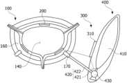
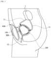
- FIG. 1is a schematic diagram illustrating a state in which an artificial bladder according to an embodiment of the present disclosure is inserted into the body.
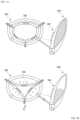
- FIGS. 2 , 3 A, and 3 Bare schematic diagrams illustrating a main body according to an embodiment of the present disclosure.
- FIGS. 4 A and 4 Bis a schematic diagram illustrating a sensor according to an embodiment of the present disclosure.
- FIG. 5is a view for describing an operation of the sensor according to an embodiment of the present disclosure.
- FIG. 6is a schematic diagram illustrating a control unit and a fluid supply unit according to an embodiment of the present disclosure.
- FIGS. 7 A, 7 B, 8 A, and 8 Bare schematic diagrams for describing a method of storing and discharging urine using the artificial bladder according to an embodiment of the present disclosure.
- the present disclosurerelates to an artificial bladder.
- an exemplary artificial bladder according to the present disclosureit is possible to provide an artificial bladder that is biocompatible and allows active urination.
- FIG. 1is a schematic diagram illustrating a state in which an artificial bladder 10 according to an embodiment of the present disclosure is inserted into the human body
- FIGS. 2 , 3 A, and 3 Bare schematic diagrams illustrating a main body 100 according to an embodiment of the present disclosure.
- the artificial bladder 10 of the present disclosuremay include the main body 100 , a sensor 200 , and a control unit 300 .
- the main body 100may include an inlet port 120 , an outlet port 130 , and an inner wall 110 that forms a first reservoir portion 140 configured to store urine between the inlet port 120 and the outlet port 130 and that is provided to be expandable and contractible.
- the first reservoir portion 140may be provided so that the volume of the first reservoir portion 140 changes according to the amount of urine.
- the main body 100may include an outer wall 150 that forms a second reservoir portion 160 configured to surround at least a partial region of the inner wall 110 .
- the outer wall 150 forming the second reservoir portion 160may be provided to surround the first reservoir portion 140 , and the outer wall 150 may be provided to support the shape of the second reservoir portion 160 .
- the senor 200may be attached to the inner wall 110 , have a surface having a wrinkled structure, and be provided so that, when the volume of the first reservoir portion 140 increases, the wrinkled structure stretches out and resistance of the sensor 200 changes.
- control unit 300may be provided to discharge the urine in the first reservoir portion 140 through the outlet port 130 according to a result detected by the sensor 200 .
- the inlet port 120may be an inlet provided to store urine in the first reservoir portion 140
- the outlet port 130may be an outlet provided to discharge the urine stored in the first reservoir portion 140 to the outside.
- the inlet port 120may be provided as a pair of inlet ports 120 and 120 ′ to be connected to each ureter 11 connected to one of a pair of kidneys 1 in the human body.
- the pair of inlet ports 120 and 120 ′may perform a function of the human ureter.
- the outlet port 130may be provided to be connected to a urethra 12 in the human body, and for example, may perform a function of the human urethra.
- the inner wall 110may be provided to be expandable and contractible so that the volume of the first reservoir portion 140 changes according to the amount of urine introduced through the inlet ports 120 and 120 ′.
- the outer wall 150may include a fluid port 170 provided to introduce a fluid into the second reservoir portion 160 and discharge the fluid from the second reservoir portion 160 to the outside.
- the outer wall 150may include one or more fluid ports 170 and 170 ′ so that the fluid flows into the second reservoir portion 160 .
- the fluid ports 170 and 170 ′may be provided at both sides of the outlet port 130 , but the present disclosure is not limited thereto.
- the pair of fluid ports 170 and 170 ′may be provided on the outer wall 150 , but the present disclosure is not limited thereto.
- the outer wall 150may include first through-holes 121 and 121 ′ through which the inlet ports 120 and 120 ′ respectively pass and a second through-hole 131 through which the outlet port 130 passes.
- the inlet port 120 provided on the inner wall 110may pass through the first through-hole 121 to be connected to the human ureter, and the outlet port 130 may pass through the second through-hole 131 to be connected to the human urethra.
- the inner wall 110 and the outer wall 150may be made of a biocompatible polymer material.
- the inner wall 110may include a first layer 111 that faces the second reservoir portion 160 and a second layer 112 that faces the first reservoir portion 140 .
- the second layer 112may be provided on the first layer 111 .
- the first layer 111may be made of a silicone-based material so as to be expandable and contractible.
- the silicone-based materialmay be any one of silicone resins made of polydimethylsiloxane (PDMS) and oligosiloxane molecules and synthetic polymers of one or more selected therefrom but is not limited thereto.
- PDMSpolydimethylsiloxane
- oligosiloxane moleculesand synthetic polymers of one or more selected therefrom but is not limited thereto.
- the second layer 112may be formed to include a material for inhibiting calcification.
- the second layer 112may include a material for inhibiting calcification to suppress calcification upon contact with urine.
- the material for inhibiting calcificationmay be any one of polyethylene glycol (PEG), polyacrylic acid (PAA), hyaluronic acid (HA), alginate, and natural or synthetic polymer mixtures of one or more selected therefrom but is not limited thereto.
- PEGpolyethylene glycol
- PAApolyacrylic acid
- HAhyaluronic acid
- alginatenatural or synthetic polymer mixtures of one or more selected therefrom but is not limited thereto.
- the inner wall 110so that the second layer includes the material for inhibiting calcification as described above, there is an effect of suppressing calcification and suppressing formation of biofilms (to which bacteria are attached) due to bacterial infection.
- a surface of a poly(methylmethacrylate) (PMMA)-based base material layermay be coated with a PEG hydrogel using a grafting-based surface modification technology to coat the surface of the PMMA-based base material layer with a PEG hydrogel thin film and manufacture the inner wall 110 .
- PMMApoly(methylmethacrylate)
- the inner wall 110may be manufactured by combining the second layer, in which the PMMA-based base material layer is coated with the PEG hydrogel thin film, with a silicone surface which is the first layer.
- PEGis widely known to form strong hydrogen bonds with water and prevent non-specific adsorption of other materials on the surface. Therefore, coating with PEG has an effect of suppressing calcification and biofilms. Coating may also be performed with the above-mentioned materials for inhibiting calcification other than PEG.
- a highly compliant hydrogel materialmay be synthesized using PEG to form a predetermined base material layer.
- the base material layer formed as described abovemay be directly used as an inner wall material.
- the PEG hydrogelmay be formed as a hydrogel having a double network structure in which PEG and another hydrophilic polymer are combined, but the present disclosure is not limited thereto.
- a PEG macromermay be exposed to ultraviolet (UV) light to generate the PEG hydrogel, and then the PEG hydrogel may be irradiated with UV light to form a cross-link with another hydrophilic monomer (second monomer) so that an interpenetration hydrogel, i.e., the hydrogel having a double network structure, is manufactured.
- UVultraviolet
- second monomeranother hydrophilic monomer
- the base material layermay be used as a material of the inner wall 110 without the inner wall 110 being divided into a first layer and a second layer.
- the outer wall 150may be formed to include a material for inhibiting fibrosis.
- the outer wall 150may be provided to maintain a predetermined shape of the second reservoir portion 160 and may be formed to include a material for inhibiting fibrosis in order to, upon being inserted into the body, suppress fibrosis of the surrounding organs and tissues in the body.
- the material for inhibiting fibrosismay be any one of PEG, PAA, HA, alignate, and mixtures of one or more selected therefrom but is not limited thereto.
- the outer wall 150 that comes in direct contact with the inside of the human bodymay cause an immune-inflammatory response due to foreign substances and thus cause fibrosis.
- the outer wall 150to include the material for inhibiting fibrosis as above, there is an effect of suppressing fibrosis.
- a base material layer including a silicone-based materialmay be coated with a polymer thin film, which is formed using a layer-by-layer deposition (LbL deposition)-based surface modification technology, to manufacture the outer wall 150 .
- LbL depositionlayer-by-layer deposition
- oppositely-charged layersmay be stacked alternately and repeatedly and form a thin film.
- a polymer such as PAA, HA, and PEGmay be controlled to be stacked on the last layer of the thin film to suppress fibrosis.
- the fibrosisoccurs due to proteins and cells that take part in inflammatory response, and in the present disclosure, by using the above-described materials, cell adhesion is prevented and generation of various protein factors is reduced to suppress fibrosis.
- the silicone-based materialmay be any one of silicone resins made of PDMS and oligosiloxane molecules and synthetic polymers of one or more selected therefrom but is not limited thereto.
- the outer wall 150may not only be manufactured using the above-described LbL deposition-based surface modification technology but may also be manufactured using the hydrogel grafting-based surface modification method described above with regards to the inner wall 110 .
- the second reservoir portion 160may be defined as a reservoir between the inner wall 110 and the outer wall 150 .
- the second reservoir portion 160may be defined as a reservoir between the second layer 112 of the inner wall 110 and the outer wall 150 .
- FIGS. 4 A and 4 Bare schematic diagrams illustrating the sensor 200 according to an embodiment of the present disclosure
- FIG. 5is a view for describing an operation of the sensor 200 according to an embodiment of the present disclosure.
- the senor 200may be attached to the inner wall 110 of the main body, have a surface having a wrinkled structure, and be provided so that, when the volume of the first reservoir portion 140 increases, the wrinkled structure stretches out and resistance of the sensor 200 changes.
- the senor 200may be attached to the second layer 112 of the inner wall 110 .
- one or more sensors 200may be attached to the inner wall 110 , and for example, three sensors 200 may be attached as illustrated in the drawing, but the present disclosure is not limited thereto.
- the senor 200may be a strain sensor 210 configured to measure expansion and a volume change of the inner wall 110 .
- the strain sensor 210may include a piezoresistor 212 that is made of a nanomaterial film or a nanomaterial polymer composite and an elastic substrate 211 that has a wrinkled structure.
- the strain sensor 210may have a form in which the piezoresistor 212 is placed on the elastic substrate 211 having the wrinkled structure.
- the elastic substrate 211may be manufactured using an elastic material such as PDMS and Ecoflex.
- a carbon nanomaterial, a nanomaterial film, or a nanomaterial polymer compositemay be used to manufacture the piezoresistor 212 so that the piezoresistor 212 has high sensitivity to detect even slight vibrations.
- the nanomaterial filmmay include a carbon nanotube, graphene, a nanowire, and nanoparticles, but the present disclosure is not limited thereto.
- the nanomaterial polymer compositemay be any one or more selected from combinations of polymers such as PDMS and polyurethane (PU) and the above-mentioned nanomaterials, but the present disclosure is not limited thereto.
- a partial region of one surface of the elastic substrate 211may be coated with the piezoresistor 212 to manufacture the strain sensor 210 .
- the strain sensor 210 manufactured as described abovemay be provided to be attached to the inner wall 110 so that, when the volume of the first reservoir portion 140 increases, the elastic substrate 211 having the wrinkled structure, which has the piezoresistor 212 placed thereon, stretches out and resistance of the strain sensor 210 changes.
- the strain sensor 210may be provided so that the resistance thereof changes when strain of a predetermined value or more is applied.
- the strain sensor 210may be provided to detect a pre-loading region P to which strain of less than the predetermined value is applied and an operating region O to which the strain of the predetermined value or more is applied and may be provided to measure an amount of urine stored in the first reservoir portion 140 only in the operating region.
- the elastic substrate 211 having the wrinkled structurestretches out, but strain is not applied to the piezoresistor 212 .
- strainbegins to be applied to the piezoresistor 212 simultaneously as the elastic substrate 211 having the wrinkled structure stretches out such that the amount of urine stored in the first reservoir portion 140 may be measured from a change in resistance according to the applied strain, and a timing of urination may be determined.
- the senormay be provided to, when the amount of urine stored in the first reservoir portion 140 is in a range of 300 ml to 400 ml, determine that a timing of urination is reached and discharge urine to the outside.
- the amount of urine in the first reservoir portionmay be stably measured to detect a timing of urination, and the control unit 300 , which will be described below, may allow urine to be discharged according to the detected result.
- the artificial bladder 10further includes the control unit 300 and a fluid supply unit 400 .
- FIG. 6is a schematic diagram illustrating the control unit 300 and the fluid supply unit 400 according to an embodiment of the present disclosure.
- control unit 300may be provided to operate a pump 430 according to a result detected by the sensor 200 .
- control unit 300may control the pump 430 to introduce a fluid from a fluid storage tank 410 to the second reservoir portion 160 such that the inner wall 110 contracts.
- control unit 300may control the pump 430 to introduce the fluid from the second reservoir portion 160 to the fluid storage tank 410 such that the inner wall 110 expands.
- control unit 300may include a controller 310 configured to operate the pump 430 according to a result detected by the sensor 200 .
- the fluid supply unit 400 of the present disclosureincludes the fluid storage tank 410 that has a predetermined reservoir, a fluid flow path 420 configured to connect the fluid storage tank 410 and the fluid port 170 , and the pump 430 provided to cause the fluid to flow to the fluid flow path 420 .
- the pump 430may be operated by the controller 310 according to a result detected by the sensor 200 .
- a fluide.g., water
- the fluid flow path 420may include a first flow path 421 and a second flow path 422 to connect the fluid storage tank 410 and the fluid port 170 .
- the pump 430may be provided to allow the fluid to flow to the first and second flow paths 421 and 422 .
- the pump 430may be provided so that the fluid stored in the fluid storage tank 410 sequentially passes through the first flow path 421 and the second flow path 422 and flows into the second reservoir portion 160 .
- the pump 430may be provided so that the fluid stored in the second reservoir portion 160 sequentially passes through the second flow path 422 and the first flow path 421 and flows into the fluid storage tank 410 .
- control unit 300may further include a charger (not illustrated) provided to supply power to the controller 310 and the pump 430 , and the charger may be a wireless charger that allows wireless charging.
- the controller 310may be electrically connected to each of the sensor 200 and the pump 430 .
- the controller 310may be interconnected to the sensor 200 and the pump 430 , and through the controller 310 , the amount of urine stored in the first reservoir portion 140 may be precisely monitored in real time, and urine may be controlled to be discharged according to active determination on a timing of urination.
- the controller 310may operate the pump 430 according to the detected result so that the urine inside the first reservoir portion 140 is discharged through the outlet port 130 .
- the predetermined valuemay indicate the amount of urine in the first reservoir portion 140 and may be 250 ml or more or 300 ml or more but is not limited thereto.
- the pump 430may be a two-way pump provided to allow the fluid to flow into any one of the fluid storage tank 410 and the second reservoir portion 160 .
- the two-way pumpmay allow the fluid to flow in a first direction or a second direction according to a signal transmitted from the controller 310 .
- the first directionindicates a direction in which the fluid flows from the fluid storage tank 410 to the second reservoir portion 160
- the second directionindicates a direction in which the fluid flows from the second reservoir portion 160 to the fluid storage tank 410 .
- controller 310may control the pump to introduce the fluid from the fluid storage tank 410 to the second reservoir portion 160 such that the inner wall 110 contracts.
- the controller 310may control the pump 430 to allow the fluid to flow from the fluid storage tank 410 to the second reservoir portion 160 and control the urine stored in the first reservoir portion 140 to be discharged through the outlet port 130 as a pressure is applied to the inner wall 110 and the inner wall 110 contracts due to the flowing fluid and thus the volume of the first reservoir portion 140 decreases.
- the controller 310may be provided to control the pump 430 to allow the fluid to flow in the first direction so that, as the inner wall contracts due to the flowing fluid (fluid pressure) and thus the volume of the first reservoir portion 140 decreases, the urine stored in the first reservoir portion 140 is discharged through the outlet port 130 .
- the senor 200may transmit a detected signal to the controller 310 electrically connected to the sensor 200 , and the controller 310 that receives the signal may operate the pump 430 , which is electrically connected to the controller, according to the detected result.
- the operated pump 430allows the fluid to flow from the fluid storage tank 410 to the second reservoir portion 160 , a pressure is applied to the inner wall 110 due to the fluid, and thus the inner wall 110 contracts, the volume of the first reservoir portion 140 may decrease, and the urine stored in the first reservoir portion 140 may be discharged through the outlet 130 .
- controller 310may control the pump 430 to introduce the fluid from the second reservoir portion 160 into the fluid storage tank 410 such that the inner wall 110 expands.
- the controller 310may control the pump 430 to allow the fluid flowing in the second reservoir portion 160 to flow into the fluid storage tank 410 so that the pressure applied to the inner wall 110 is released and the inner wall 110 expands again.
- controller 310may be provided to control the pump 430 to allow the fluid to flow in the second direction so that, as the inner wall 110 from which a fluid pressure is released expands causing the volume of the first reservoir portion 140 to increase, urine is stored in the first reservoir portion 140 again.
- the senor 200may transmit a detected signal to the controller 310 electrically connected to the sensor 200 , and the controller 310 that receives the signal may operate the pump 430 , which is electrically connected to the controller 310 , according to the detected result.
- the operated pump 430allows the fluid flowing in the second reservoir portion 160 to flow into the fluid storage tank 410 such that the pressure applied to the inner wall 110 is released and the inner wall 110 expands again, urine may be stored in the first reservoir portion 140 .
- control unit 300 and the fluid supply unit 400may be inserted into the human body like the above-described main body 100 , and thus, the control unit and the fluid supply unit may be made of the same biocompatible material as the above-described outer wall 150 .
- control unit 300 and the fluid supply unit 400may be disposed to be inserted into subcutaneous fat of the human body.
- the present disclosurealso provides a method of storing and discharging urine using the above-described artificial bladder 10 .
- the above description of the artificial bladder 10may identically apply to the method of storing and discharging urine that will be described below.
- An exemplary method of controlling the artificial bladder 10 according to an embodiment of the present disclosureis an artificial bladder control method using the above-described artificial bladder 10 .
- the artificial bladder control methodmay include, when the expansion of the inner wall 110 is detected by the sensor 200 , injecting a fluid into the second reservoir portion 160 to discharge urine.
- the artificial bladder control methodmay include, when the discharge of urine is completed, discharging the fluid in the second reservoir portion 160 to the fluid storage tank 410 .
- the control unitmay operate according to a result detected by the sensor 200 and discharge urine.
- the senor 200may operate only when the amount of urine stored in the first reservoir portion 140 is a predetermined amount or more.
- the artificial bladder control methodmay further include, when the inner wall 110 expands and the sensor 200 detects that a timing of urination is reached, operating the pump 430 by the controller 310 to allow the fluid to flow from the fluid storage tank 410 to the second reservoir portion 160 .
- the artificial bladder control methodmay further include, as a pressure is applied to the inner wall 110 due to the fluid flowing to the second reservoir portion 160 and thus the first reservoir portion 140 contracts, discharging urine.
- the artificial bladder control methodmay further include, after the discharge of urine is completed, operating the pump 430 by the controller 310 to allow the fluid to flow from the second reservoir portion 160 to the fluid storage tank 410 .
- the artificial bladder control methodmay further include allowing the pressure applied to the inner wall 110 to be released by the fluid flowing to the fluid storage tank 410 such that the first reservoir portion 140 expands.
- FIGS. 7 A, 7 B, 8 A and 8 Bare schematic diagrams for describing a method of storing and discharging urine using the artificial bladder 10 inserted into the body according to an embodiment of the present disclosure.
- FIGS. 7 A, 7 B, 8 A, and 8 Bthe artificial bladder control method using the artificial bladder 10 will be described in more detail with reference to FIGS. 7 A, 7 B, 8 A, and 8 B .
- the inlet port 120 and the outlet port 130 of the artificial bladder 10may be respectively connected to the ureter and urethra in the body.
- Urine that passes through the inlet port 120 along the ureteris stored in the first reservoir portion 140 of the artificial bladder 10 inserted into the body.
- the inner wall 110expands.
- the sensor 200 attached to the inner wall 110detects the amount of urine stored in the first reservoir portion 140 in the operating region O to which strain of a predetermined value or more is applied.
- the control unitoperates according to a result detected as above and allows urine to be discharged.
- the detected signal (detected result) of the sensoris transmitted to the controller, and according to the transmitted detected signal (detected result), the controller controls the pump 430 to be operated to allow the fluid stored in the fluid storage tank 410 to flow into the second reservoir portion 160 .
- the fluidpasses through the first flow path 421 from the fluid storage tank 410 , flows to the second flow path 422 via the pump, and then is introduced into the second reservoir portion 160 through the fluid port 170 .
- the detected signal (detected result) of the sensoris transmitted to the controller, and according to the transmitted detected signal (detected result), the controller controls the pump 430 to be operated to allow the fluid stored in the second reservoir portion 160 to flow into the fluid storage tank 410 .
- the artificial bladder 10may continuously serve as the human bladder.
Landscapes
- Health & Medical Sciences (AREA)
- Life Sciences & Earth Sciences (AREA)
- Heart & Thoracic Surgery (AREA)
- Veterinary Medicine (AREA)
- Biomedical Technology (AREA)
- Animal Behavior & Ethology (AREA)
- General Health & Medical Sciences (AREA)
- Public Health (AREA)
- Engineering & Computer Science (AREA)
- Vascular Medicine (AREA)
- Transplantation (AREA)
- Oral & Maxillofacial Surgery (AREA)
- Cardiology (AREA)
- Urology & Nephrology (AREA)
- Pulmonology (AREA)
- Gastroenterology & Hepatology (AREA)
- Hematology (AREA)
- Anesthesiology (AREA)
- Pathology (AREA)
- Medical Informatics (AREA)
- Molecular Biology (AREA)
- Surgery (AREA)
- Biophysics (AREA)
- Physics & Mathematics (AREA)
- Physiology (AREA)
- Prostheses (AREA)
Abstract
Description
Claims (16)
Applications Claiming Priority (3)
| Application Number | Priority Date | Filing Date | Title |
|---|---|---|---|
| KR10-2018-0086354 | 2018-07-25 | ||
| KR1020180086354AKR102271744B1 (en) | 2018-07-25 | 2018-07-25 | Biomimetic artficial bladder and control method thereof |
| PCT/KR2019/009240WO2020022805A1 (en) | 2018-07-25 | 2019-07-25 | Biomimetic artificial bladder and method for controlling same |
Publications (2)
| Publication Number | Publication Date |
|---|---|
| US20210353402A1 US20210353402A1 (en) | 2021-11-18 |
| US12090039B2true US12090039B2 (en) | 2024-09-17 |
Family
ID=69182046
Family Applications (1)
| Application Number | Title | Priority Date | Filing Date |
|---|---|---|---|
| US17/262,551Active2042-01-18US12090039B2 (en) | 2018-07-25 | 2019-07-25 | Biomimetic artificial bladder and method for controlling same |
Country Status (3)
| Country | Link |
|---|---|
| US (1) | US12090039B2 (en) |
| KR (1) | KR102271744B1 (en) |
| WO (1) | WO2020022805A1 (en) |
Families Citing this family (9)
| Publication number | Priority date | Publication date | Assignee | Title |
|---|---|---|---|---|
| KR102271744B1 (en)* | 2018-07-25 | 2021-07-01 | 가톨릭대학교 산학협력단 | Biomimetic artficial bladder and control method thereof |
| CN113491596B (en)* | 2020-04-02 | 2024-10-15 | 林青海 | Artificial smart bladder |
| KR102475827B1 (en)* | 2020-09-15 | 2022-12-09 | (주)메디띵스 | Urine drainage system |
| KR102597890B1 (en)* | 2021-02-18 | 2023-11-02 | 인제대학교 산학협력단 | Smart Artificial Bladder Using FSR Sensor |
| KR102428397B1 (en)* | 2021-02-19 | 2022-08-02 | 재단법인 대구경북첨단의료산업진흥재단 | peristaltic organ mimetic ex vivo system |
| US12383392B2 (en)* | 2021-04-14 | 2025-08-12 | Ernesto Andrade | Artificial bladder |
| KR102681983B1 (en)* | 2021-12-28 | 2024-07-08 | 연세대학교 산학협력단 | Artificial bladder system having dual space divided by partition and wireless, non-powered urine fullness sensor using RFID technology |
| KR102676851B1 (en)* | 2021-12-29 | 2024-06-21 | 영남대학교 산학협력단 | Artificial bladder system comprising hand actuator and control valve for urination |
| KR20240012011A (en) | 2022-07-20 | 2024-01-29 | 연세대학교 산학협력단 | Apparatus and Method for Sensing RFID-based Cavity Fullness |
Citations (55)
| Publication number | Priority date | Publication date | Assignee | Title |
|---|---|---|---|---|
| US3750194A (en)* | 1971-03-16 | 1973-08-07 | Fairchild Industries | Apparatus and method for reversibly closing a natural or implanted body passage |
| US3810259A (en)* | 1971-01-25 | 1974-05-14 | Fairchild Industries | Implantable urinary control apparatus |
| US3863622A (en)* | 1973-01-09 | 1975-02-04 | Robert Enno Buuck | Incontinence system and methods of implanting and using same |
| US3953897A (en)* | 1973-12-28 | 1976-05-04 | Rhone-Poulenc, S.A. | Vesical prosthesis |
| US3958562A (en)* | 1974-05-30 | 1976-05-25 | Hakim Company Limited | Implantable pressure sensor |
| US4044401A (en)* | 1975-08-04 | 1977-08-30 | Jacques Guiset | Artificial bladder |
| US4228550A (en)* | 1979-06-29 | 1980-10-21 | Henry Salkind | Distal urinary replacement prosthesis |
| US4961747A (en)* | 1988-12-05 | 1990-10-09 | General Electric Company | Implantable articifical bladder system |
| US4969474A (en)* | 1988-10-11 | 1990-11-13 | Schwarz Gerald R | Incontinence bladder control method and apparatus |
| US4969902A (en)* | 1987-02-20 | 1990-11-13 | Biagio Ravo | Implantable device |
| US4976735A (en)* | 1989-04-20 | 1990-12-11 | Griffith Donald P | Prosthetic bladder and method of prosthesis implantation |
| US5041136A (en)* | 1989-10-27 | 1991-08-20 | General Electric Company | Implantable artificial soft bladder system |
| US5108430A (en)* | 1987-02-20 | 1992-04-28 | Biagio Ravo | Implantable reservoir adapted to receive and store structural devices therein |
| US5370690A (en)* | 1992-02-28 | 1994-12-06 | Mayo Foundation For Medical Education And Research | Artificial bladder |
| WO2001058503A1 (en) | 2000-02-09 | 2001-08-16 | The Children's Hospital Of Philadelphia | Stabilization of implantable bioprosthetic tissue |
| US20020045868A1 (en)* | 2000-09-20 | 2002-04-18 | Kenneth Reever | Apparatus and methods for treating the urinary bladder |
| US20020065563A1 (en)* | 1999-01-13 | 2002-05-30 | Roland Gerlach | Implantable artificial bladder |
| US20020193884A1 (en)* | 1999-03-18 | 2002-12-19 | Helmut Wasserman | Artificial urinary diversion device |
| US20030144648A1 (en)* | 2000-02-14 | 2003-07-31 | Peter Forsell | Hydraulic urinary incontinence treatment apparatus |
| US20040147871A1 (en)* | 2002-02-25 | 2004-07-29 | Burnett Daniel R. | Implantable fluid management system for the removal of excess fluid |
| US20060047269A1 (en)* | 2004-08-30 | 2006-03-02 | Kenneth Reever | Urethral sealing method and device |
| US20060100478A1 (en)* | 2000-04-14 | 2006-05-11 | Connors Kevin G | High vapor pressure attenuation device |
| US20060105010A1 (en)* | 2002-10-12 | 2006-05-18 | Martin Rahe | Bladder implant |
| US7648455B2 (en)* | 2000-02-10 | 2010-01-19 | Obtech Medical Ag | Controlled urinary incontinence treatment |
| US20110004117A1 (en) | 2009-07-01 | 2011-01-06 | Medtronic, Inc. | Implant parameter selection based on compressive force |
| US20110196194A1 (en)* | 2008-10-10 | 2011-08-11 | Milux Holding Sa | Implantable device for internal urinary control |
| JP2011173900A (en) | 2005-01-24 | 2011-09-08 | Kringle Pharma Inc | Fibrosis inhibitor for implanted organ |
| US20110270409A1 (en)* | 2009-01-07 | 2011-11-03 | Antonio Sambusseti | Orthotopic artificial bladder prosthesis |
| US20130172664A1 (en)* | 2011-12-30 | 2013-07-04 | DUALIS MedTech GmbH and Childrens Hospital Boston Dept. of Urology | Device for supporting the emptying of the bladder of a patient and method for operating such a device |
| US20160135942A1 (en)* | 2014-05-19 | 2016-05-19 | 3D Urologic, Llc | Urinary flow control device and method |
| KR20160103852A (en) | 2015-02-25 | 2016-09-02 | 한국패션산업연구원 | Stretchable strain sensor and sensing methode of vital siganl by using the same |
| US9456915B2 (en)* | 2004-11-19 | 2016-10-04 | Fulfilium, Inc. | Methods, devices, and systems for obesity treatment |
| US20160287373A1 (en)* | 2013-12-12 | 2016-10-06 | Antonio Sambusseti | Orthotopic artificial bladder endoprosthesis |
| US20170079761A1 (en)* | 2000-04-14 | 2017-03-23 | Attenuex Technologies, Inc. | Method of removing an inflated implant from a bladder |
| US20170165047A1 (en)* | 2014-04-14 | 2017-06-15 | Antonio Sambusseti | Orthotopic artificial bladder endoprosthesis |
| US20170216012A1 (en)* | 2014-09-30 | 2017-08-03 | Antonio Sambusseti | Orthotopic artificial bladder endoprosthesis |
| US20170231748A1 (en)* | 2014-09-30 | 2017-08-17 | Antonio Sambusseti | Orthotopic artificial bladder endoprosthesis |
| US9750591B1 (en)* | 2016-07-29 | 2017-09-05 | Sam Sultan | Systems and methods for assisting patients in emptying their bladder efficiently |
| US20170348507A1 (en)* | 2015-07-20 | 2017-12-07 | Strataca Systems, LLC | Ureteral and Bladder Catheters and Methods of Inducing Negative Pressure to Increase Renal Perfusion |
| US20180104408A1 (en)* | 2016-10-17 | 2018-04-19 | MicroMED Co., Ltd. | Micro delivery device |
| US20180193618A1 (en)* | 2015-07-20 | 2018-07-12 | Strataca Systems, LLC | Systems, Kits and Methods for Inducing Negative Pressure to Increase Renal Function |
| US20180289307A1 (en)* | 2013-03-04 | 2018-10-11 | Andromeda Medizinische Systeme Gmbh | Device For Measuring Pressure In A Fluid |
| US20190091003A1 (en)* | 2008-10-10 | 2019-03-28 | Peter Forsell | Implantable device for internal urinary control |
| US20190099584A1 (en)* | 2015-07-20 | 2019-04-04 | Strataca Systems Limited | Ureteral Catheters, Bladder Catheters, Systems, Kits and Methods for Inducing Negative Pressure to Increase Renal Function |
| US20190254804A1 (en)* | 2018-02-20 | 2019-08-22 | Boston Scientific Scimed, Inc. | Drainage device |
| US20190388212A1 (en)* | 2017-01-26 | 2019-12-26 | The Catholic University Of Korea Industry-Academic Cooperation Foundation | Biomimetic artificial bladder |
| US20210353402A1 (en)* | 2018-07-25 | 2021-11-18 | The Catholic University Of Korea Industry-Academic Cooperation Foundation | Biomimetic artificial bladder and method for controlling same |
| US11202700B1 (en)* | 2021-03-15 | 2021-12-21 | Ken Pettlon, Sr. | Artificial bladder system |
| US20220117716A1 (en)* | 2018-12-24 | 2022-04-21 | Innoventions Ltd. | Intravesicular device for controlling urinary incontinence |
| US20220167921A1 (en)* | 2019-03-07 | 2022-06-02 | Procept Biorobotics Corporation | Implant for continuous patient monitoring and intelligent treatment |
| US20220203077A1 (en)* | 2020-12-29 | 2022-06-30 | Boston Scientific Scimed, Inc. | Drainage devices and methods of use |
| US20220296866A1 (en)* | 2019-06-10 | 2022-09-22 | Poly-Med, Inc. | Methods, devices and compositions for local delivery |
| US20230200974A1 (en)* | 2021-12-28 | 2023-06-29 | Yonsei University Industry Foundation (Yonsei Uif) | Artificial bladder system having dual space divided by partition and wireless, non-powered urine fullness sensor using rfid technology |
| US20230218378A1 (en)* | 2020-06-12 | 2023-07-13 | Nowwell As | Flow Control Device |
| US20230293316A1 (en)* | 2022-03-16 | 2023-09-21 | Boston Scientific Scimed, Inc. | Leak detection for implantable inflation devices |
Family Cites Families (1)
| Publication number | Priority date | Publication date | Assignee | Title |
|---|---|---|---|---|
| HUE055437T2 (en)* | 2007-10-11 | 2021-11-29 | Implantica Patent Ltd | Device for male contraception |
- 2018
- 2018-07-25KRKR1020180086354Apatent/KR102271744B1/enactiveActive
- 2019
- 2019-07-25WOPCT/KR2019/009240patent/WO2020022805A1/ennot_activeCeased
- 2019-07-25USUS17/262,551patent/US12090039B2/enactiveActive
Patent Citations (57)
| Publication number | Priority date | Publication date | Assignee | Title |
|---|---|---|---|---|
| US3810259A (en)* | 1971-01-25 | 1974-05-14 | Fairchild Industries | Implantable urinary control apparatus |
| US3750194A (en)* | 1971-03-16 | 1973-08-07 | Fairchild Industries | Apparatus and method for reversibly closing a natural or implanted body passage |
| US3863622A (en)* | 1973-01-09 | 1975-02-04 | Robert Enno Buuck | Incontinence system and methods of implanting and using same |
| US3953897A (en)* | 1973-12-28 | 1976-05-04 | Rhone-Poulenc, S.A. | Vesical prosthesis |
| US3958562A (en)* | 1974-05-30 | 1976-05-25 | Hakim Company Limited | Implantable pressure sensor |
| US4044401A (en)* | 1975-08-04 | 1977-08-30 | Jacques Guiset | Artificial bladder |
| US4228550A (en)* | 1979-06-29 | 1980-10-21 | Henry Salkind | Distal urinary replacement prosthesis |
| US5108430A (en)* | 1987-02-20 | 1992-04-28 | Biagio Ravo | Implantable reservoir adapted to receive and store structural devices therein |
| US4969902A (en)* | 1987-02-20 | 1990-11-13 | Biagio Ravo | Implantable device |
| US4969474A (en)* | 1988-10-11 | 1990-11-13 | Schwarz Gerald R | Incontinence bladder control method and apparatus |
| US4961747A (en)* | 1988-12-05 | 1990-10-09 | General Electric Company | Implantable articifical bladder system |
| US4976735A (en)* | 1989-04-20 | 1990-12-11 | Griffith Donald P | Prosthetic bladder and method of prosthesis implantation |
| US5041136A (en)* | 1989-10-27 | 1991-08-20 | General Electric Company | Implantable artificial soft bladder system |
| US5370690A (en)* | 1992-02-28 | 1994-12-06 | Mayo Foundation For Medical Education And Research | Artificial bladder |
| US20020065563A1 (en)* | 1999-01-13 | 2002-05-30 | Roland Gerlach | Implantable artificial bladder |
| US20020193884A1 (en)* | 1999-03-18 | 2002-12-19 | Helmut Wasserman | Artificial urinary diversion device |
| WO2001058503A1 (en) | 2000-02-09 | 2001-08-16 | The Children's Hospital Of Philadelphia | Stabilization of implantable bioprosthetic tissue |
| JP2003522001A (en) | 2000-02-09 | 2003-07-22 | ザ・チルドレンズ・ホスピタル・オブ・フィラデルフィア | Stabilization of implantable bioprosthetic tissue |
| US7648455B2 (en)* | 2000-02-10 | 2010-01-19 | Obtech Medical Ag | Controlled urinary incontinence treatment |
| US20030144648A1 (en)* | 2000-02-14 | 2003-07-31 | Peter Forsell | Hydraulic urinary incontinence treatment apparatus |
| US20170079761A1 (en)* | 2000-04-14 | 2017-03-23 | Attenuex Technologies, Inc. | Method of removing an inflated implant from a bladder |
| US20060100478A1 (en)* | 2000-04-14 | 2006-05-11 | Connors Kevin G | High vapor pressure attenuation device |
| US20020045868A1 (en)* | 2000-09-20 | 2002-04-18 | Kenneth Reever | Apparatus and methods for treating the urinary bladder |
| US20040147871A1 (en)* | 2002-02-25 | 2004-07-29 | Burnett Daniel R. | Implantable fluid management system for the removal of excess fluid |
| US20060105010A1 (en)* | 2002-10-12 | 2006-05-18 | Martin Rahe | Bladder implant |
| US20060047269A1 (en)* | 2004-08-30 | 2006-03-02 | Kenneth Reever | Urethral sealing method and device |
| US9456915B2 (en)* | 2004-11-19 | 2016-10-04 | Fulfilium, Inc. | Methods, devices, and systems for obesity treatment |
| JP2011173900A (en) | 2005-01-24 | 2011-09-08 | Kringle Pharma Inc | Fibrosis inhibitor for implanted organ |
| US20190091003A1 (en)* | 2008-10-10 | 2019-03-28 | Peter Forsell | Implantable device for internal urinary control |
| US20110196194A1 (en)* | 2008-10-10 | 2011-08-11 | Milux Holding Sa | Implantable device for internal urinary control |
| JP2017185366A (en) | 2008-10-10 | 2017-10-12 | ミルックス・ホールディング・エスエイ | Implantable device for controlling urology in the body |
| US20110270409A1 (en)* | 2009-01-07 | 2011-11-03 | Antonio Sambusseti | Orthotopic artificial bladder prosthesis |
| US20110004117A1 (en) | 2009-07-01 | 2011-01-06 | Medtronic, Inc. | Implant parameter selection based on compressive force |
| US20130172664A1 (en)* | 2011-12-30 | 2013-07-04 | DUALIS MedTech GmbH and Childrens Hospital Boston Dept. of Urology | Device for supporting the emptying of the bladder of a patient and method for operating such a device |
| US20180289307A1 (en)* | 2013-03-04 | 2018-10-11 | Andromeda Medizinische Systeme Gmbh | Device For Measuring Pressure In A Fluid |
| US20160287373A1 (en)* | 2013-12-12 | 2016-10-06 | Antonio Sambusseti | Orthotopic artificial bladder endoprosthesis |
| US20170165047A1 (en)* | 2014-04-14 | 2017-06-15 | Antonio Sambusseti | Orthotopic artificial bladder endoprosthesis |
| US20160135942A1 (en)* | 2014-05-19 | 2016-05-19 | 3D Urologic, Llc | Urinary flow control device and method |
| US20170216012A1 (en)* | 2014-09-30 | 2017-08-03 | Antonio Sambusseti | Orthotopic artificial bladder endoprosthesis |
| US20170231748A1 (en)* | 2014-09-30 | 2017-08-17 | Antonio Sambusseti | Orthotopic artificial bladder endoprosthesis |
| KR20160103852A (en) | 2015-02-25 | 2016-09-02 | 한국패션산업연구원 | Stretchable strain sensor and sensing methode of vital siganl by using the same |
| US20170348507A1 (en)* | 2015-07-20 | 2017-12-07 | Strataca Systems, LLC | Ureteral and Bladder Catheters and Methods of Inducing Negative Pressure to Increase Renal Perfusion |
| US20190099584A1 (en)* | 2015-07-20 | 2019-04-04 | Strataca Systems Limited | Ureteral Catheters, Bladder Catheters, Systems, Kits and Methods for Inducing Negative Pressure to Increase Renal Function |
| US20180193618A1 (en)* | 2015-07-20 | 2018-07-12 | Strataca Systems, LLC | Systems, Kits and Methods for Inducing Negative Pressure to Increase Renal Function |
| US9750591B1 (en)* | 2016-07-29 | 2017-09-05 | Sam Sultan | Systems and methods for assisting patients in emptying their bladder efficiently |
| US20180104408A1 (en)* | 2016-10-17 | 2018-04-19 | MicroMED Co., Ltd. | Micro delivery device |
| US20190388212A1 (en)* | 2017-01-26 | 2019-12-26 | The Catholic University Of Korea Industry-Academic Cooperation Foundation | Biomimetic artificial bladder |
| US20190254804A1 (en)* | 2018-02-20 | 2019-08-22 | Boston Scientific Scimed, Inc. | Drainage device |
| US20210353402A1 (en)* | 2018-07-25 | 2021-11-18 | The Catholic University Of Korea Industry-Academic Cooperation Foundation | Biomimetic artificial bladder and method for controlling same |
| US20220117716A1 (en)* | 2018-12-24 | 2022-04-21 | Innoventions Ltd. | Intravesicular device for controlling urinary incontinence |
| US20220167921A1 (en)* | 2019-03-07 | 2022-06-02 | Procept Biorobotics Corporation | Implant for continuous patient monitoring and intelligent treatment |
| US20220296866A1 (en)* | 2019-06-10 | 2022-09-22 | Poly-Med, Inc. | Methods, devices and compositions for local delivery |
| US20230218378A1 (en)* | 2020-06-12 | 2023-07-13 | Nowwell As | Flow Control Device |
| US20220203077A1 (en)* | 2020-12-29 | 2022-06-30 | Boston Scientific Scimed, Inc. | Drainage devices and methods of use |
| US11202700B1 (en)* | 2021-03-15 | 2021-12-21 | Ken Pettlon, Sr. | Artificial bladder system |
| US20230200974A1 (en)* | 2021-12-28 | 2023-06-29 | Yonsei University Industry Foundation (Yonsei Uif) | Artificial bladder system having dual space divided by partition and wireless, non-powered urine fullness sensor using rfid technology |
| US20230293316A1 (en)* | 2022-03-16 | 2023-09-21 | Boston Scientific Scimed, Inc. | Leak detection for implantable inflation devices |
Non-Patent Citations (1)
| Title |
|---|
| Int'l Search Report and Written Opinion issued Oct. 29, 2019 in Int'l Application No. PCT/KR2019/009240, English translation of Int'l Search Report only. |
Also Published As
| Publication number | Publication date |
|---|---|
| KR102271744B1 (en) | 2021-07-01 |
| US20210353402A1 (en) | 2021-11-18 |
| WO2020022805A1 (en) | 2020-01-30 |
| KR20200011653A (en) | 2020-02-04 |
Similar Documents
| Publication | Publication Date | Title |
|---|---|---|
| US12090039B2 (en) | Biomimetic artificial bladder and method for controlling same | |
| US11510772B2 (en) | Biomimetic artificial bladder | |
| US10751280B2 (en) | Implantable cellular and biotherapeutic agent delivery canister | |
| US10881537B2 (en) | Structural hydrogel polymer device | |
| AU2015351547B2 (en) | Medical device, and method for producing medical device | |
| CA2505821A1 (en) | Control of polymer surface molecular architecture via amphipathic endgroups | |
| CA2493479A1 (en) | Multi-material incontinence treatment constriction device | |
| JP2020531157A (en) | Ureter and bladder catheters and methods that induce negative pressure and increase renal perfusion | |
| TWI762521B (en) | Micro delivery device | |
| JP6878429B2 (en) | Delivery device | |
| KR20200062491A (en) | human body mimicking bladder | |
| WO2020217214A1 (en) | Pump assembly and system for inducing negative pressure in a portion of a urinary tract of a patient | |
| Nath et al. | Dynamic luminal topography: A potential strategy to prevent vascular graft thrombosis | |
| Watson et al. | Performance of a hydrogel coated nitinol with Oligonucleotide-modified nanoparticles within Turbulent conditions of blood-Contacting devices | |
| US20220241554A1 (en) | Implantable catheter | |
| EP2326360A2 (en) | Medical devices having a coating for electromagnetically-controlled release of therapeutic agents | |
| Semproni et al. | A fully implantable sensorized artificial urinary bladder to restore continence and fullness monitoring | |
| Ihara | Medical Applications | |
| Aguilar | Nanotechnology in improving medical devices for smart drug delivery | |
| Tamadon et al. | A Robotic Urinary Bladder Enabling Volume Monitoring and Assisted Micturition | |
| Hu et al. | A magnetic soft robotic system for intelligent bladder volume control | |
| Singh et al. | Pharmaceuticals Polymers in Medicine | |
| Roth et al. | Fully implantable alloplastic urinary bladder | |
| Montero Suárez | Tailoring Surfaces to improve Biomaterials performance: piCVD & iCVD approaches | |
| KR20240149944A (en) | Detection of atrophy in tissue occluded by implantable expandable devices |
Legal Events
| Date | Code | Title | Description |
|---|---|---|---|
| FEPP | Fee payment procedure | Free format text:ENTITY STATUS SET TO UNDISCOUNTED (ORIGINAL EVENT CODE: BIG.); ENTITY STATUS OF PATENT OWNER: SMALL ENTITY | |
| FEPP | Fee payment procedure | Free format text:ENTITY STATUS SET TO SMALL (ORIGINAL EVENT CODE: SMAL); ENTITY STATUS OF PATENT OWNER: SMALL ENTITY | |
| AS | Assignment | Owner name:RESEARCH COOPERATION FOUNDATION OF YEUNGNAM UNIVERSITY, KOREA, REPUBLIC OF Free format text:ASSIGNMENT OF ASSIGNORS INTEREST;ASSIGNORS:HA, U-SYN;KIM, JONGBAEG;KOH, WON GUN;AND OTHERS;SIGNING DATES FROM 20210111 TO 20210119;REEL/FRAME:055200/0945 Owner name:UNIVERSITY-INDUSTRY FOUNDATION, YONSEI UNIVERSITY, KOREA, REPUBLIC OF Free format text:ASSIGNMENT OF ASSIGNORS INTEREST;ASSIGNORS:HA, U-SYN;KIM, JONGBAEG;KOH, WON GUN;AND OTHERS;SIGNING DATES FROM 20210111 TO 20210119;REEL/FRAME:055200/0945 Owner name:THE CATHOLIC UNIVERSITY OF KOREA INDUSTRY-ACADEMIC COOPERATION FOUNDATION, KOREA, REPUBLIC OF Free format text:ASSIGNMENT OF ASSIGNORS INTEREST;ASSIGNORS:HA, U-SYN;KIM, JONGBAEG;KOH, WON GUN;AND OTHERS;SIGNING DATES FROM 20210111 TO 20210119;REEL/FRAME:055200/0945 | |
| STPP | Information on status: patent application and granting procedure in general | Free format text:DOCKETED NEW CASE - READY FOR EXAMINATION | |
| STPP | Information on status: patent application and granting procedure in general | Free format text:NON FINAL ACTION MAILED | |
| STPP | Information on status: patent application and granting procedure in general | Free format text:RESPONSE TO NON-FINAL OFFICE ACTION ENTERED AND FORWARDED TO EXAMINER | |
| STPP | Information on status: patent application and granting procedure in general | Free format text:NOTICE OF ALLOWANCE MAILED -- APPLICATION RECEIVED IN OFFICE OF PUBLICATIONS | |
| STPP | Information on status: patent application and granting procedure in general | Free format text:PUBLICATIONS -- ISSUE FEE PAYMENT VERIFIED | |
| STCF | Information on status: patent grant | Free format text:PATENTED CASE |