US12090025B2 - Orthodontic appliance with non-sliding archform - Google Patents
Orthodontic appliance with non-sliding archformDownload PDFInfo
- Publication number
- US12090025B2 US12090025B2US17/303,860US202117303860AUS12090025B2US 12090025 B2US12090025 B2US 12090025B2US 202117303860 AUS202117303860 AUS 202117303860AUS 12090025 B2US12090025 B2US 12090025B2
- Authority
- US
- United States
- Prior art keywords
- bracket
- archform
- male fastener
- orthodontic
- variants
- Prior art date
- Legal status (The legal status is an assumption and is not a legal conclusion. Google has not performed a legal analysis and makes no representation as to the accuracy of the status listed.)
- Active, expires
Links
Images


Classifications
- A—HUMAN NECESSITIES
- A61—MEDICAL OR VETERINARY SCIENCE; HYGIENE
- A61C—DENTISTRY; APPARATUS OR METHODS FOR ORAL OR DENTAL HYGIENE
- A61C7/00—Orthodontics, i.e. obtaining or maintaining the desired position of teeth, e.g. by straightening, evening, regulating, separating, or by correcting malocclusions
- A61C7/02—Tools for manipulating or working with an orthodontic appliance
- A61C7/04—Tools for manipulating or working with an orthodontic appliance plier-type, e.g. pincers
- A—HUMAN NECESSITIES
- A61—MEDICAL OR VETERINARY SCIENCE; HYGIENE
- A61C—DENTISTRY; APPARATUS OR METHODS FOR ORAL OR DENTAL HYGIENE
- A61C7/00—Orthodontics, i.e. obtaining or maintaining the desired position of teeth, e.g. by straightening, evening, regulating, separating, or by correcting malocclusions
- A61C7/12—Brackets; Arch wires; Combinations thereof; Accessories therefor
- A61C7/14—Brackets; Fixing brackets to teeth
- A61C7/148—Brackets; Fixing brackets to teeth with occlusal or gingival archwire slot opening
- A—HUMAN NECESSITIES
- A61—MEDICAL OR VETERINARY SCIENCE; HYGIENE
- A61C—DENTISTRY; APPARATUS OR METHODS FOR ORAL OR DENTAL HYGIENE
- A61C7/00—Orthodontics, i.e. obtaining or maintaining the desired position of teeth, e.g. by straightening, evening, regulating, separating, or by correcting malocclusions
- A61C7/12—Brackets; Arch wires; Combinations thereof; Accessories therefor
- A61C7/20—Arch wires
- A61C7/22—Tension adjusting means
- A—HUMAN NECESSITIES
- A61—MEDICAL OR VETERINARY SCIENCE; HYGIENE
- A61C—DENTISTRY; APPARATUS OR METHODS FOR ORAL OR DENTAL HYGIENE
- A61C7/00—Orthodontics, i.e. obtaining or maintaining the desired position of teeth, e.g. by straightening, evening, regulating, separating, or by correcting malocclusions
- A61C7/12—Brackets; Arch wires; Combinations thereof; Accessories therefor
- A61C7/28—Securing arch wire to bracket
- A61C7/30—Securing arch wire to bracket by resilient means; Dispensers therefor
- A—HUMAN NECESSITIES
- A61—MEDICAL OR VETERINARY SCIENCE; HYGIENE
- A61C—DENTISTRY; APPARATUS OR METHODS FOR ORAL OR DENTAL HYGIENE
- A61C7/00—Orthodontics, i.e. obtaining or maintaining the desired position of teeth, e.g. by straightening, evening, regulating, separating, or by correcting malocclusions
- A61C7/12—Brackets; Arch wires; Combinations thereof; Accessories therefor
- A61C7/28—Securing arch wire to bracket
- A61C7/34—Securing arch wire to bracket using lock pins
Definitions
- This inventionrelates in some aspects to orthodontic appliances, including orthodontic brackets and non-sliding archforms.
- an orthodontic bracketis disclosed herein that can be disposed on a patient's tooth.
- the orthodontic bracketcan include a slot that can receive a male fastener of an archform.
- the orthodontic bracketcan include a stop that can be disposed on a gingival side of the bracket that can prevent movement of the male fastener in the gingival direction.
- the orthodontic bracketcan include a retainer disposed on an occlusal side of the bracket that can prevent movement of the male fastener in the occlusal, mesial, and/or distal directions.
- the retainercan include a locking pin that can deflect to facilitate the male fastener being inserted into or removed from the slot.
- the stopcan include an overhang that can retain the male fastener within the slot.
- the retainercan include walls that can be disposed on mesial and distal sides of the orthodontic bracket.
- the locking pincan include a fixed end in one of the walls of the retainer and a free end that can be moveably disposed within an aperture of the other wall of the retainer.
- the free endcan deflect in the occlusal direction to permit the male fastener to be positioned thereunder or to permit the male fastener to be removed from thereunder.
- the aperture of the wall of the retainercan include a locking portion that can retain the free end of the locking pin therein when the male fastener is disposed under the locking pin.
- the bracketcan include a face and a protrusion.
- the protrusioncan extend away from the face and can push the male fastener against the retainer and locking pin to prevent sliding between the archform and the bracket.
- the male fastenercan include arms that are configured to flex under a load.
- the male fastenercan include a space separating the arms.
- the orthodontic bracketcan include a block extending into the space and between the arms.
- the blockcan prevent excessive deflection of the arms.
- the archformcan include interproximal loops on opposing sides of the male fastener.
- the male fastenercan include a tab that can be positioned under the locking pin.
- the male fastenercan include a groove that can interface with a tool for insertion and removal of the male fastener from within a slot of the bracket.
- a method of coupling an archform to a bracketcan include angling a male fastener of the archform relative to a face of the bracket.
- the methodcan include inserting a portion of the male fastener into a slot of the bracket and against a stop disposed on a gingival side of the bracket.
- the methodcan include positioning a tab portion of the male fastener onto a locking pin supported by a retainer disposed on an occlusal side of the bracket.
- the methodcan include inserting a tool between the locking pin and a groove disposed on the tab of the male fastener.
- the methodcan include rotating the tool toward the stop of the bracket such that the locking pin deflects to enable the tab portion of the male fastener to be positioned thereunder.
- rotating the tool toward the stop of the bracketrotates the male fastener toward the face of the bracket.
- rotating the tool toward the stop of the bracketapplies a force to the groove disposed on the tab to deflect arms of the male fastener.
- an orthodontic bracketis disclosed herein that can be disposed on a patient's tooth.
- the orthodontic bracketcan include a slot that can receive a male fastener of an archform.
- the orthodontic bracketcan include a stop disposed on a gingival side of the bracket that can prevent movement of the male fastener in the gingival direction.
- the orthodontic bracketcan include a retainer disposed on an occlusal side of the bracket that can prevent movement of the male fastener in the occlusal, mesial, and/or distal directions.
- the retainercan include a C spring that can deflect to facilitate the male fastener being inserted into or removed from the slot.
- a central axis of the C springextends in the mesio-distal direction.
- an end of the C springcan be fixedly positioned within a slot of the retainer and a free end of the C spring can be free to deflect.
- the free end of the C springcan retain a tab of the male fastener thereunder.
- the retainercan include a groove that can provide access to the C spring.
- bracketcan include a face and a protrusion.
- the protrusioncan extend away from the face and can push the male fastener against the free end of the C spring and an overhang of the stop.
- the male fastenercan include arms that can flex under a load.
- the male fastenercan include a space separating the arms.
- the archformcan include interproximal loops on opposing sides of the male fastener.
- the male fastenercan include a groove that can interface with a tool for insertion and removal of the male fastener from within the slot of the bracket.
- the bracketcan include a protrusion that can push the male fastener against a free end of the C spring and an overhang of the stop to reduce sliding between the archform and the bracket.
- a method of coupling an archform to a bracketcan include angling a male fastener of the archform relative to a face of the bracket.
- the methodcan include inserting a portion of the male fastener into a slot of the bracket and against a stop disposed on a gingival side of the bracket.
- the methodcan include positioning a tab portion of the male fastener against a portion of a C spring disposed within a retainer on an occlusal side of the bracket.
- the methodcan include inserting a tool between a groove disposed on the tab of the male fastener and a groove disposed on the retainer such that the tool is contact the C spring.
- the methodcan include pushing the tool toward a surface of the bracket and into the C spring while rotating the tool toward the stop of the bracket such that a free end of the C spring deflects to enable the tab portion of the male fastener to be positioned thereunder.
- rotating the tool toward the stop of the bracketrotates the male fastener toward the face of the bracket.
- rotating the tool toward the stop of the bracketapplies a force to the groove disposed on the tab to deflect arms of the male fastener.
- an orthodontic bracketis disclosed herein that can be disposed on a patient's tooth.
- the orthodontic bracketcan include a slot that can receive a male fastener of an archform.
- the orthodontic bracketcan include a retainer that can be disposed on a gingival side of the bracket.
- the retainercan include a C spring that can deflect to facilitate the male fastener being retained within or removed from the slot.
- the orthodontic bracketcan include a stop disposed on an occlusal side of the bracket that can prevent movement of the male fastener in an occlusal direction.
- the C springcan be oriented perpendicular to a face of the bracket.
- the C springcan be within an opening of the retainer that can facilitate flexing of the C spring.
- the C springcan be retained on a guide.
- the openingcan be oval shaped and can prevent over deflection of the C spring.
- the C springcan provide a force to the male fastener to secure the male fastener within the slot of the bracket.
- the stopcan include undercuts that can receive portions of the male fastener.
- the C springcan apply a force to the male fastener to secure the portion of the male fastener within the undercuts.
- the portions of the male fastenercan be wedges.
- the wedgescan be formed by waterjet cutting the male fastener.
- the male fastenercan include angled surfaces and/or recesses that can enable the male fastener to be positioned within the slot at an angle.
- the male fastenercan include a handle that can be gripped by pliers.
- the handleif damaged by the pliers, may not negatively affect performance of the archform.
- the handlecan include a hole that can receive a tool for maneuvering the male fastener.
- the archformcan include interproximal loops on opposing sides of the male fastener.
- portions of the archform that are proximate the male fastenercan interface with mesial and distal sides of the bracket.
- the portions of the archform that are proximate the male fastenercan prevent lateral sliding between the male fastener and the archform.
- a method of coupling an archform to a bracketcan include angling a male fastener of the archform relative to a face of the bracket.
- the methodcan include inserting a portion of the male fastener into a slot of the bracket and against a C spring disposed within a retainer.
- the retainercan be positioned on a gingival side of the bracket.
- the methodcan include applying a force to the male fastener such that the male fastener pushes against the C spring such that the C spring flexes.
- the methodcan include rotating the male fastener toward a face of the bracket.
- the methodcan include ceasing to apply a force to the male fastener such that the C spring pushes portions of the male fastener into cut outs in stops disposed on the occlusal side of the bracket such that the male fastener is secured within the bracket.
- the methodcan include grasping a handle of the male fastener to manipulate the male fastener.
- the methodcan include inserting a tool into a hole within a handle of the male fastener to manipulate the male fastener.
- an orthodontic archformis disclosed herein.
- the orthodontic archformcan include a plurality of bracket connectors that can connect to respective brackets.
- the orthodontic archformcan include a plurality of interproximal structures in between at least 50% of adjacent pairs of the plurality of bracket connectors. The plurality of interproximal structures can deflect when the bracket connectors are connected to the respective brackets, thus causing orthodontic tooth movement.
- the bracket connectorscan include a plurality of struts joined by a central member and circumscribing a void region.
- the central membercan include a handle element extending away from the central member. The handle element can allow a tool to grip the handle and insert the archform into respective brackets.
- the handle elementcan include an aperture.
- the interproximal structurescan include loop(s).
- the central segmentcan include a curved surface opposite a surface from which the handle element extends.
- the handle elementcan be arch-shaped.
- At least two of the plurality of interproximal structurescan include different geometries.
- the archformcan be formed from a ribbon-shaped material.
- an orthodontic bracketis disclosed herein that can be disposed on a patient's tooth.
- the orthodontic bracketcan include a channel that can be disposed between a mesial wall and distal wall of the bracket.
- the orthodontic bracketcan include a slot at least partially formed by a stop disposed on a gingival side of the bracket.
- the channelcan guide a male fastener into the slot.
- the orthodontic bracketcan include a deflectable tab disposed on a surface of the bracket. The deflectable tab can interface with one or more surfaces of a male fastener of an archform to secure the male fastener to the archform.
- the stopcan include an overhang that can retain the male fastener within the slot.
- the stophas recesses and/or angled surfaces that can allow the male fastener to be rotated within the slot during insertion and/or removal.
- the bracketcan have more than one engagement stage such that the male fastener can be retained within the slot at different positions.
- the deflectable tabcan engage with different surfaces of the male fastener to retain the male fastener at varied depths.
- the male fastenercan be retained at varied depths within the slot.
- a method of coupling an archform to a bracketcan include positioning a male fastener of an archform on the face of a bracket between mesial and distal walls.
- the methodcan include advancing the male fastener toward a slot at least partially defined by a stop disposed on a gingival side of the bracket such that a tab disposed on the face of the bracket engages with surfaces of a guiding channel within the male fastener of the archform to engage a holding surface such that the male fastener is securely retained within the slot.
- the methodcan include engaging the male fastener with a wedge disposed on an overhang of the slot to secure the male fastener therein to eliminate and/or reduce play between the male fastener and the bracket.
- the methodcan include positioning the male fastener at one of a plurality of engagement stages.
- the clinicianselects between the plurality of engagement stages based on desired tooth control.
- the methodcan include a method of decoupling an archform from a bracket.
- the methodcan include inserting a tool into a tool receiving recess disposed on a face of the bracket and moving the tool in a generally occlusal direction through a tool receiving channel of a male fastener of the archform.
- the toolcan be guided to engage with and deflect a tab of the bracket away from a holding surface of the male fastener of the archform such that the male fastener can be moved in an occlusal direction.
- the toolcan engage with a periphery of the tool receiving channel to move the male fastener in the occlusal direction and out of a slot of the bracket.
- a tool for installing and removing a male fastener of an archform into or from a bracketcan include a shaft and conical tip that can be disposed on a distal end of the shaft.
- the shaft and conical tipcan apply equal and opposite forces to the male fastener and bracket during installation and removal.
- an orthodontic bracket assemblycan be disposed on a patient's tooth.
- the orthodontic bracket assemblycan include a pad that can be bonded to the patient's tooth.
- the padcan include a pocket that can receive a bracket.
- the bracketcan be coupled to the pad.
- the bracketcan include a slot that can receive a male fastener of an archform.
- the bracketcan include a retainer disposed on a gingival side of the bracket.
- the retainercan include a C spring that can deflect to facilitate the male fastener being retained within or removed from the slot.
- the bracketcan include one or more stops disposed on an occlusal side of the bracket that can prevent movement of the male fastener in an occlusal direction.
- the padcan include undercuts that can be disposed on an opposing side of the pad relative to the pocket.
- the undercutscan facilitate bonding the pad to a tooth of the patient.
- the padcan include filling material that can be used to laser weld the bracket to the pad.
- the one or more stopscan include ramps that can contact wedges of the male fastener when the male fastener is positioned within the slot of the bracket.
- the one or more stopscan include cutouts that can receive at least a portion of wedges of the male fastener.
- the padcan include a protrusion that can be inserted through an aperture of the bracket and welded to the bracket.
- the bracketcan include a protrusion disposed on a face of the bracket that can push a male fastener against the retainer to retain the male fastener within the slot of the bracket.
- the padcan include bumps that are disposed on opposing sides of the pocket that can push the male fastener against the retainer.
- the padcan include inclined surfaces configured to engage portions of the male fastener to provide rotational control.
- the padcan angle the bracket such that the male fastener is angled relative to the surface of the patient's tooth with the male fastener retained in the bracket.
- the male fastenercan be angled at ten degrees relative to the surface of the patient's tooth with the male fastener retained in the bracket.
- the male fastenercan be angled at five degrees relative to the surface of the patient's tooth with the male fastener retained in the bracket.
- the padcan be customized to the patient's tooth and the bracket may not be customized.
- the archformcan include hooks that can interface with elastics.
- the bracketcan include features that can prevent the C spring from deflecting past an elastic limit of the C spring.
- the C springcan be disposed around a guide that orients the C spring and prevents deflection past the elastic limit.
- a surface of the bracketcan engage with a surface of the male fastener to prevent deflection past the elastic limit of the C spring.
- a method of treating malocclusioncan include forming pads customized to teeth of a patient.
- the methodcan include coupling the customized pads to the teeth of the patient.
- the methodcan include coupling one of a plurality of first style brackets to each of the customized pads coupled to lower anterior teeth of the patient.
- the methodcan include coupling one of a plurality of second style brackets to the customized pads coupled to other teeth of the patient.
- the methodcan include coupling a male fastener of an archform to each of the plurality of first style brackets and each of the plurality of second style brackets.
- the methodcan include forming hooks in the archform for use with elastics.
- coupling a male fastener of the archform to each of the plurality of first style brackets and each of the plurality of second style bracketscan include grasping a handle of the male fastener with forceps; positioning a portion of the male fastener opposite the handle against an oval spring of the bracket such that the male fastener is angled relative to the bracket; gripping an occlusal surface of the male fastener and gingival surface of the bracket between forceps; squeezing the forceps to push the male fastener against the oval spring of the bracket such that the oval spring deflects; rotating the male fastener towards the bracket; and/or releasing the forceps to allow the oval spring to push the male fastener against and under stops of the bracket to securely retain the male fastener in the bracket.
- an orthodontic bracketthat can be disposed on a patient's tooth.
- the orthodontic bracketcan include a slot that can receive a male fastener of an archform.
- the orthodontic bracketcan include a retainer that can be disposed on a gingival side of the bracket.
- the retainercan include a C spring that can deflect to facilitate the male fastener being retained within or removed from the slot and a protrusion that can engage with an installation tool.
- the retainercan include one or more stops disposed on an occlusal side of the bracket that can prevent movement of the male fastener in an occlusal direction.
- the orthodontic bracketcan include undercuts that can facilitate bonding the bracket to a tooth of the patient.
- the one or more stopscan include ramps that can contact wedges of the male fastener when the male fastener is positioned within the slot of the bracket.
- the one or more stopscan include cutouts that can receive at least a portion of the male fastener.
- the bracketcan include a protrusion that can be disposed on a face of the bracket that can push a male fastener against the retainer to retain the male fastener within the slot of the bracket.
- the archformcan include interproximal loops configured to interface with elastics.
- the archformcan include a tongue that can be disposed between the one or more stops of the bracket.
- the archformcan include two arms that can engage with mesial and distal sides of the retainer of the bracket.
- the archformcan include curves that can engage with the retainer of the bracket to provide rotational control of the patient's tooth.
- an archformconfigured to be disposed around at least a portion of an arch of a patient's mouth.
- the archformcan include a plurality of male fasteners that can be positioned within brackets disposed on teeth of the patient.
- the male fastenercan include a tongue configured to be disposed between stops of the bracket and two arms disposed on mesial and distal sides of the male fastener and extending in a direction opposite the tongue. The two arms can engage features of the bracket to secure the male fastener relative to the bracket.
- the archformcan include a plurality of interproximal loops. The interproximal loops can be disposed between adjacent male fasteners of the plurality of male fasteners.
- the archformcan include curves disposed on mesial and distal sides of the male fastener.
- the two armscan each include flanges that can extend inward to engage the features of the bracket.
- the archformcan include one or more symbols disposed on the interproximal loops.
- the symbolscan be letters configured to convey a message.
- an orthodontic appliancethat can be disposed around at least a portion of an arch of a patient's mouth is disclosed herein.
- the orthodontic appliancecan include an archform that can include a plurality of male fasteners that can be coupled to respective teeth of the patient and interproximal loops. The interproximal loops can be disposed between adjacent male fasteners.
- the orthodontic appliancecan include a mounting pad that can be disposed between one of the plurality of male fasteners and one of the respective teeth of the patient.
- the mounting padcan include a first adhesive surface and a second adhesive surface. The first adhesive surface can be adhered to the one of the plurality of male fasteners and the second adhesive surface can be adhered to the one of the respective teeth of the patient such that the male fastener can be coupled to the one of the respective teeth of the patient.
- the orthodontic appliancecan include a protective layer that can be removably disposed on the second adhesive surface to protect the second adhesive surface from contamination before installation of the orthodontic appliance around at least a portion of the arch of the patient's mouth.
- an adhesive bond between the second adhesive surface of the mounting pad and the one of the respective teeth of the patientcan be broken when the mounting pad is pulled.
- the adhesive bond between the second adhesive surface of the mounting pad and the one of the respective teeth of the patientcan be broken when the mounting pad is pulled in a lingual direction.
- the adhesive bond between the second adhesive surface of the mounting pad and the one of the respective teeth of the patientcan be broken when the mounting pad is pulled in a direction parallel to a surface of the one of the respective teeth.
- a portion of the mounting padcan extend beyond a periphery of the male fastener. The portion being configured to be pulled.
- the portion of the mounting padcan include a hole that can interface with a tool to facilitate pulling of the mounting pad.
- the archformcan include symbols that can be seen by an observer after installation in the mouth of the patient.
- the orthodontic appliancecan include caps that can be coupled to a labial surface of the teeth of the patient to conceal features of the orthodontic appliance.
- an adhesive on the second adhesive surface of the mounting padcan include a whitening solution to whiten the teeth of the patient.
- the capscan be adhered to the labial surface of the teeth with an adhesive.
- the adhesivecan include a whitening solution to whiten the teeth of the patient.
- the orthodontic appliancecan include a soluble tray that can hold the archform in a configuration for installation in the mouth of the patient.
- the soluble traycan be dissolved after the archform is installed in the mouth of the patient.
- the archformcan be formed based on 3D scans of the patient's mouth.
- the 3D scanscan be performed by a mobile device.
- a deviceconfigured to operatively connect to the mobile device of the user facilitates performing the 3D scan.
- the archformcan become malleable when exposed to temperatures below or above body temperature.
- Estimated body temperaturecan be a single temperature or range of temperatures (e.g., upper and lower limits).
- the archformcan become malleable at and/or above ninety-nine, one hundred, one hundred and one, or one hundred and two or more degrees Fahrenheit.
- the archformcan become malleable at and/or below ninety-seven, ninety-six, or ninety-five or less degrees Fahrenheit.
- a method of installing an orthodontic appliance configured to be disposed around at least a portion of an arch of a patient's mouthis disclosed herein.
- the methodcan include removing a protective layer to expose an adhesive surface of a mounting pad.
- the mounting padcan be coupled to one of a plurality of male fasteners of an archform.
- the methodcan include positioning the adhesive surface against a surface of a tooth of the patient such that the adhesive surface of the mounting pad adheres to the surface of the tooth of the patient.
- the methodcan include inserting the archform into the mouth of the patient with the archform in a soluble tray that can hold the archform in a configuration for installation.
- the methodcan include flushing the mouth of the patient with a liquid to dissolve the soluble tray.
- the methodcan include adhering caps to labial surfaces of teeth of the patient to conceal features of the archform.
- the methodcan be performed by the patient.
- a method of manufacturing an archformcan include performing a 3D scan of a mouth of a patient with a mobile device of the patient.
- the methodcan include sending data from the 3D scan of the mouth of the patient to a data center of a designer of orthodontic appliances.
- the methodcan include forming an archform based on the data from the 3D scan of the mouth of the patient.
- the archformcan be shaped corresponding to a maloccluded state of teeth of the patient.
- the archformcan move the teeth of the patient from the maloccluded state to another state.
- the methodcan include disposing the archform in a soluble tray that can maintain the archform in the shape corresponding to the maloccluded state.
- the soluble traycan dissolve in a liquid.
- the methodcan include adhering a mounting pad to a male fastener of the archform.
- the mounting padcan include an adhesive surface that can adhere to a surface of the teeth of the patient.
- the methodcan include covering the adhesive surface with a removable protective layer.
- an orthodontic bracketthat can be disposed on a patient's tooth.
- the orthodontic bracketcan have a slot that can receive a connector of an archform such that the connector does not slide in a mesial-distal direction relative to the orthodontic bracket.
- the orthodontic bracketcan have a stop that can be disposed on an occlusal side of the slot that can prevent movement of the connector in at least an occlusal direction.
- the orthodontic bracketcan have a retainer that can be disposed on a gingival side of the slot that can prevent movement of the connector in at least a gingival direction.
- the retainercan include a spring that that can deflect to facilitate the connector being inserted into or removed from the slot. The spring can apply a force to the connector to lock the connector within the slot of the bracket.
- the springis a C spring.
- the springcan be disposed within an opening of the retainer.
- the orthodontic bracketcan include two stops disposed on the occlusal side of the bracket.
- the two stopscan be separated by a gap.
- the gapcan receive a tab of the connector.
- the orthodontic bracketcan include a protrusion that can be disposed on a face of the bracket.
- the protrusioncan push the connector against an overhang of the retainer.
- the orthodontic bracketcan include a ramp that can be disposed on a face of the bracket.
- the rampcan push the connector against an overhang of the stop.
- the orthodontic bracketcan include a textured surface that can bond to a surface of a tooth.
- the orthodontic bracketcan include lateral wings extending in a mesial-distal directions.
- the lateral wingscan bond to a surface of a tooth to facilitate rotational control.
- an orthodontic appliancecan include a plurality of orthodontic brackets.
- Each orthodontic bracket of the plurality of orthodontic bracketscan be disposed on a tooth of the patient.
- Each orthodontic bracketcan include a slot, a stop disposed on an occlusal side of the slot, and/or a retainer disposed on a gingival side of the slot.
- the retainercan have a spring.
- the orthodontic appliancecan include an archform that can move the patient's teeth from a first position to a second positon.
- the archformcan include a plurality of connectors.
- Each connector of the plurality of connectorscan be placed within the slot between the stop and the retainer of one orthodontic bracket of the plurality of orthodontic brackets such that the spring applies a force against the connector to push the connector against the stop, securing at least a portion of the connector behind the stop and retainer in a locked configuration.
- the archformcan include a plurality of interproximal structures. At least one interproximal structure of the plurality of interproximal structures can be positioned between at least some adjacent connectors of the plurality of connectors. The plurality of connectors do not slide in a mesial-distal direction relative to the plurality of orthodontic brackets when the plurality of connectors are in locked configurations within the slots of the plurality of orthodontic brackets.
- the plurality of interproximal structurescan apply a force to adjacent connectors of the plurality of connectors to move one or more teeth of the patient.
- the springis a C spring.
- the springis disposed within an opening of the retainer.
- each orthodontic bracket of the plurality of orthodontic bracketscan include two stops disposed on the occlusal side of the bracket. The two stops can be separated by a gap.
- the gapcan receive a tab of one connector of the plurality of connectors.
- each orthodontic bracket of the plurality of orthodontic bracketscan include a protrusion that can be disposed on a face thereof.
- the protrusioncan push the connector received within the slot against an overhang of the retainer.
- each orthodontic bracket of the plurality of orthodontic bracketscan include a ramp that can be disposed on a face thereof. The ramp can push the connector received within the slot against an overhang of the stop.
- each orthodontic bracket of the plurality of orthodontic bracketscan include a textured surface that can bond to a surface of a tooth.
- At least one orthodontic bracket of the plurality of orthodontic bracketscan include lateral wings that can extend in a mesial-distal directions.
- the lateral wingscan bond to a surface of a tooth to facilitate rotational control.
- At least one connector of the plurality of connectorscan include a pair of arms that can grip mesial and distal sides of the retainer.
- each orthodontic bracket of the plurality of orthodontic bracketscan include two stops that can be disposed on the occlusal side of the bracket. The two stops can be separated by a gap.
- Each connector of the plurality of connectorscan include a tab that can be placed within the gap.
- the tabcan include a groove that can contact a tool to facilitate insertion and/or removal of the plurality connectors from the slots of the plurality of orthodontic brackets.
- a rigidity of the interproximal structurescan be greater at distal ends of the archform compared to a central portion.
- the plurality of interproximal structurescan include interproximal loops.
- the archformcan be formed from a sheet of material.
- opposing sides of the archformcan be parallel to each other.
- a method of coupling an archform to a bracketcan include angling a connector of the archform relative to a face of the bracket.
- the methodcan include inserting a portion of the connector into a slot of the bracket and against a C spring disposed within a retainer.
- the retainercan be positioned on a gingival side of the bracket.
- the methodcan include applying a force to the connector such that the connector pushes against the C spring so that the C spring flexes.
- the methodcan include rotating the connector toward a face of the bracket.
- the methodcan include ceasing to apply a force to the connector such that the C spring pushes portions of the connector against stops of the bracket such that the connector is secured under at least a portion of the stops and the retainer.
- a method of moving a patient's teethcan include bonding one or more brackets to a patient's teeth.
- the methodcan include coupling a first archform to the one or more brackets.
- the first archformcan have a first plurality of interproximal loops.
- a first interproximal loop of the plurality of first interproximal loopscan have a first width.
- the methodcan include decoupling the first archform from the one or more brackets.
- the methodcan include coupling a second archform to the one or more brackets.
- the second archformcan have a second plurality of interproximal loops corresponding to the first plurality of interproximal loops.
- a second interproximal loop of the plurality of second interproximal loops, corresponding to the first interproximal loopcan have a second width that can be greater than the first width.
- the methodcan include cutting the first and second archforms from a flat sheet of material.
- an orthodontic bracketconfigured to be disposed on a patient's tooth.
- the orthodontic bracketcan include a slot that can receive a connector of an archform such that the connector does not slide in a mesial-distal direction relative to the orthodontic bracket.
- the orthodontic bracketcan include a stop disposed on a first side of the slot that can prevent movement of the connector in at least a first direction.
- the orthodontic bracketcan include a retainer disposed on a second side of the slot that can prevent movement of the connector in at least a second direction.
- the retainercan include a spring that can deflect to facilitate the connector being inserted into or removed from the slot. The spring can apply a force to the connector to lock the connector within the slot of the bracket.
- the springis a C spring.
- the springcan be disposed within an opening of the retainer.
- the bracketcan include two stops disposed on the second side of the bracket.
- the two stopscan be separated by a gap.
- the gapcan receive a tab of the connector.
- the bracketcan include a protrusion disposed on a face of the bracket.
- the protrusioncan push the connector against an overhang of the retainer.
- the bracketcan include a ramp that can be disposed on a face of the bracket. The ramp can push the connector against an overhang of the stop.
- the bracketcan include a textured surface that can bond to a surface of a tooth.
- the bracketcan include lateral wings extending in a mesial-distal directions.
- the lateral wingscan bond to a surface of a tooth to facilitate rotational control.
- an orthodontic applianceis disclosed herein.
- the orthodontic applicationcan include a plurality of orthodontic brackets.
- Each orthodontic bracket of the plurality of orthodontic bracketscan be disposed on a tooth of the patient.
- Each orthodontic bracketcan include a slot.
- Each orthodontic bracketcan include a stop disposed on a first side of the slot.
- Each orthodontic bracketcan include a retainer disposed on a second side of the slot.
- the retainercan include a spring.
- the orthodontic appliancecan include an archform that can move the patient's teeth from a first position to a second positon.
- the archformcan include a plurality of connectors.
- Each connector of the plurality of connectorscan be placed within the slot between the stop and the retainer of one orthodontic bracket of the plurality of orthodontic brackets such that the spring applies a force against the connector to push the connector against the stop, securing at least a portion of the connector behind the stop and retainer in a locked configuration.
- the archformcan include a plurality of interproximal structures. At least one interproximal structure of the plurality of interproximal structures can be positioned between at least some adjacent connectors of the plurality of connectors.
- the plurality of connectorsmay not slide in a mesial-distal direction relative to the plurality of orthodontic brackets when the plurality of connectors are in locked configurations within the slots of the plurality of orthodontic brackets.
- the plurality of interproximal structurescan apply a force to adjacent connectors of the plurality of connectors to move one or more teeth of the patient.
- the springcan be a C spring.
- the springcan be disposed within an opening of the retainer.
- each orthodontic bracket of the plurality of orthodontic bracketscan include two stops that can be disposed on the second side of the bracket. The two stops can be separated by a gap.
- the gapcan receive a tab of one connector of the plurality of connectors.
- each orthodontic bracket of the plurality of orthodontic bracketscan include a protrusion disposed on a face thereof.
- the protrusioncan push the connector received within the slot against an overhang of the retainer.
- each orthodontic bracket of the plurality of orthodontic bracketscan include a ramp that can be disposed on a face thereof. The ramp can push the connector received within the slot against an overhang of the stop.
- each orthodontic bracket of the plurality of orthodontic bracketscan include a textured surface that can bond to a surface of a tooth.
- At least one orthodontic bracket of the plurality of orthodontic bracketscan include lateral wings that can extend in mesial-distal directions.
- the lateral wingscan bond to a surface of a tooth to facilitate rotational control.
- At least one connector of the plurality of connectorscan include a pair of arms configured to grip mesial and distal sides of the retainer.
- each orthodontic bracket of the plurality of orthodontic bracketscan include two stops disposed on the second side of the bracket. The two stops can be separated by a gap.
- Each connector of the plurality of connectorscan include a tab that can be placed within the gap.
- the tabcan include a groove that can contact a tool to facilitate insertion and/or removal of the plurality connectors from the slots of the plurality of orthodontic brackets.
- a rigidity of the interproximal structurescan be greater at distal ends of the archform compared to a central portion.
- the plurality of interproximal structurescan include interproximal loops.
- the archformcan be formed from a sheet of material.
- opposing sides of the archformare parallel to each other.
- a method of coupling an archform to a bracketcan include angling a connector of the archform relative to a face of the bracket.
- the methodcan include inserting a portion of the connector into a slot of the bracket and against a C spring disposed within a retainer.
- the retainercan be positioned on a first side of the bracket.
- the methodcan include applying a force to the connector such that the connector pushes against the C spring so that the C spring flexes.
- the methodcan include rotating the connector toward a face of the bracket.
- the methodcan include ceasing to apply a force to the connector such that the C spring pushes portions of the connector against stops of the bracket such that the connector is secured under at least a portion of the stops and the retainer.
- a method of moving a patient's teethcan include bonding one or more brackets to a patient's teeth.
- the methodcan include coupling a first archform to the one or more brackets.
- the first archformcan have a first plurality of interproximal loops.
- a first interproximal loop of the plurality of first interproximal loopscan have a first width.
- the methodcan include decoupling the first archform from the one or more brackets.
- the methodcan include coupling a second archform to the one or more brackets.
- the second archformhaving a second plurality of interproximal loops corresponding to the first plurality of interproximal loops.
- a second interproximal loop of the plurality of second interproximal loops, corresponding to the first interproximal loopcan have a second width. The second width can be greater than the first width.
- the methodcan include cutting the first and second archforms from a flat sheet of material.
- FIG. 1 Aillustrates an archform retained within a bracket.
- FIG. 1 Billustrates another view of the archform and bracket of FIG. 1 A .
- FIG. 2 Aillustrates an archform retained within a bracket.
- FIG. 2 Billustrates another view of the archform and bracket of FIG. 2 A .
- FIG. 2 Cillustrates a sectioned view of the archform and bracket of FIG. 2 A .
- FIG. 2 Dillustrates a side view of the archform and bracket of FIG. 2 A .
- FIGS. 2 E- 2 Gillustrate views of the archform and bracket of FIG. 2 A being coupled together with a tool.
- FIGS. 2 H and 2 Iillustrate views of the archform and bracket of FIG. 2 A being decoupled with the tool.
- FIGS. 3 A and 3 Billustrate an archform retained within a bracket.
- FIG. 4illustrates an archform retained within a bracket.
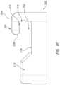
- FIG. 5illustrates an archform retained within a bracket.
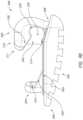
- FIG. 6 Aillustrates an archform with a bracket.
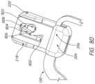
- FIG. 6 Billustrates the archform coupled within the bracket of 6 A.
- FIGS. 6 C and 6 Dillustrate sectioned views of 6 B.
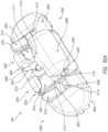
- FIG. 6 Eillustrates a tool flexing a spring within the bracket of 6 A.
- FIG. 7 Aillustrates a bracket
- FIG. 7 Billustrates the bracket of 7 A retaining an archform.
- FIG. 7 Cillustrates another view of FIG. 7 B .
- FIG. 7 Dillustrates the archform being inserted into the bracket of FIG. 7 B .
- FIG. 7 Eillustrates side view of 7 B.
- FIG. 7 Fillustrates a view of 7 B.
- FIG. 7 Gillustrates a view of a bracket and a male fastener of an archform for a lower anterior bracket.
- FIG. 8 Aillustrates an archform being positioned within a bracket.
- FIG. 8 Billustrates the archform retained within the bracket of 8 A.
- FIG. 8 Cillustrates the bracket of FIG. 8 A .
- FIG. 8 Dillustrates the bracket of FIG. 8 A .
- FIGS. 9 A and 9 Billustrate various views of a multi-part bracket.
- FIG. 10 Aillustrates a multi-part bracket that can be placed on a molar of a patient.
- FIGS. 10 B and 10 Cillustrate the multi-part bracket of FIG. 10 A with a male fastener of an archform placed therein.
- FIG. 11 Aillustrates a multi-part bracket.
- FIG. 11 Billustrates a portion of the multi-part bracket of FIG. 11 A .
- FIG. 11 Cillustrates a section view of the multi-part bracket of FIG. 11 A .
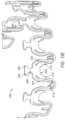
- FIG. 12illustrates a plurality of multi-part brackets coupled to an archform.
- FIG. 13 Aillustrates a bracket
- FIG. 13 Billustrates a rear view of the bracket of FIG. 13 A .
- FIG. 13 Cillustrates the bracket of FIG. 13 A coupled to an archform.
- FIG. 13 Dillustrates an archform
- FIG. 13 Eillustrates an archform with customized features.
- FIG. 14 Aillustrates a tool grasping a portion of an archform disposed within a bracket.
- FIG. 14 Billustrates an enlarged view of a portion of the tool of FIG. 14 A grasping the bracket.
- FIG. 14 Cillustrates a tool, such as a hemostat, that can be used for archform insertion into a mouth of a patient.
- FIG. 15 Aillustrates an archform that can be adhered or otherwise fixed to teeth of a patient.
- FIG. 15 Billustrates caps that can be attached or otherwise incorporated into an archform that can be applied to teeth of a patient.
- FIG. 15 Cillustrates a soluble tray that can be used to apply an archform to teeth of a patient.
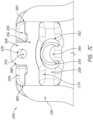
- FIG. 16 Aillustrates a bracket, which can at least be attached to a molar.
- FIG. 16 Billustrates a section view of the bracket illustrated in FIG. 16 A .
- FIG. 16 Cillustrates a rear view of the bracket illustrated in FIG. 16 A .
- FIG. 16 Dillustrates a male connector of an archform.
- FIG. 16 Eillustrates the male connector illustrated in FIG. 16 D coupled to the bracket illustrated in FIG. 16 A .
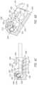
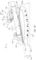
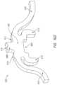
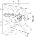
- FIG. 17 Aillustrates a bracket, which can at least be attached to a lower anterior tooth, coupled to a male connector of an archform.
- FIG. 17 Billustrates the male connector of the archform illustrated in FIG. 17 A .
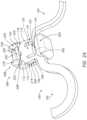
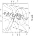
- FIG. 18illustrates a bracket, which can at least be attached to a upper central tooth, coupled to a male connector of an archform.
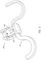
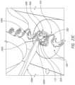
- FIG. 19illustrates a bracket, which can at least be attached to a bicuspid, coupled to a male connector of an archform.
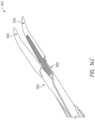
- FIG. 20 Aillustrates an upper initial archform
- FIG. 20 Billustrates an upper intermediate archform
- FIG. 20 Cillustrates an upper final archform
- FIG. 21 Aillustrates a lower initial archform
- FIG. 21 Billustrates an upper intermediate archform
- FIG. 21 Cillustrates an upper final archform
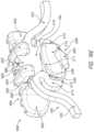
- FIG. 22illustrates an orthodontic appliance for a patient with crowded teeth.
- FIG. 23 Aillustrates a tool for installing or removing a male connector from a bracket.
- FIG. 23 Billustrates a male connector inserted into a slot of a bracket at an angle.
- FIG. 23 Cillustrates the tool illustrated in FIG. 23 A applying a force against the male connector to compress a spring and rotate the male connector toward the bracket.
- FIG. 23 Dillustrates the male connector within the slot of the bracket.
- FIG. 23 Eillustrates the tool in FIG. 23 A reoriented.
- FIG. 23 Fillustrates the tool illustrated in FIG. 23 E applying a force against the male connector to compress the spring and rotate the male connector away from the bracket.
- FIG. 23 Gillustrates the male connector rotated out of the slot of the bracket.
- FIG. 24illustrates an archform with indicia corresponding to a patient.
- the edgewise applianceis the traditional orthodontic bracket that includes a rectangular slot that a round, square, or rectangular straight-wire segment can be inserted into.
- the edgewise appliancetraditionally holds the straight archwire in the slot with an elastomeric or steel tie. This process of tying the archwire into each bracket can be a time-consuming procedure, especially for lingual braces.
- the edgewise applianceuses sliding mechanics between the orthodontic bracket and archwire for orthodontic tooth movement.
- a downside of the use of sliding mechanics in some casesis that friction occurs between the bracket and archwire. The amount of friction is often unpredictable and must be overcome for tooth movement to occur. Because of the variability in the amount of friction, errors in tooth movement may occur leading to more appointments required to finish orthodontic treatment.
- Friction-free mechanicswhich solve the issue of friction in tooth movement, have been developed using an orthodontic bracket with a snap-fitted, non-sliding archwire. These snap-fitted connections, however, in some cases can be difficult to connect, unreliable, vary from tooth to tooth within a patient's mouth, and even permit sliding, which can impair the performance of the archwire. Disclosed herein are improved archform and bracket solutions.
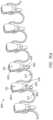
- FIGS. 1 A and 1 Billustrates an orthodontic bracket and archform system that uses friction-free mechanics.
- FIG. 1 Aillustrates an archform 100 , which can also be referred to as an archwire, retained in a bracket 200 .
- a male fastener 106which can also be referred to as a male connector, connector, fastener, or male structure, of the archform 100 can be retained within a slot 202 of the bracket 200 .
- the archformcould include a wire with a circular, oval, rectangular, square, or other cross-section, or combinations of the foregoing.
- the archformcan include a constant or variable dimension, such as a width and/or thickness for example.
- the archformcan be made from a sheet of material, such as a shape memory material, and laser-cut, waterjet cut, or otherwise derived from the sheet of material.
- the archform 100can have a plurality of interproximal structures, e.g., loops 102 , 104 .
- the interproximal structurescould include incomplete loops that do not form a full circle.
- the interproximal structurescould also include V shaped or other structures with a vertex that do not necessarily include an arcuate surface.
- the interproximal structurescan also include complex 3D structures that traverse multiple planes.
- the interproximal loops 102 , 104can be varying sizes and configurations.
- the interproximal loops 102 , 104can be bends in the archform 100 .
- the interproximal loop 102can be wider (e.g., in the occlusal-gingival direction) than the interproximal loop 104 , which can result in the interproximal loop 102 exerting larger forces on a patient's teeth than the interproximal loop 104 .
- the interproximal loop 102can be the same thickness (e.g., in the lingual-buccal direction) as the interproximal loop 104 while being different widths.
- a single interproximal loop 102 , 104is disposed between adjacent male fasteners 106 .
- one or more interproximal loops 102 , 104are disposed between adjacent male fasteners 106 .
- one, two, or more interproximal loops 102 , 104 and/or straight segmentsare disposed between male fasteners 106 .
- the interproximal loops 102 , 104can have the same or differing curvatures, extend in the gingival and/or occlusal direction, and/or extend to differing lengths in the gingival and/or occlusal directions.
- interproximal structuresare present in between each and every male fastener and/or tooth.
- interproximal structuresare present in between a majority of adjacent male fasteners but not all adjacent male fasteners, such as about, at least about, or no more than about 50%, 60%, 70%, 80%, 90%, 95%, or more or less of the adjacent male fasteners, or ranges including any two of the foregoing values.
- the archform 100can include a male fastener 106 .
- the junctions between the male fastener 106 and the interproximal structures, e.g., loops 102 , 104can be curved, which can help to reduce stress concentrators that could lead to cracking, breaking, etc.
- the male fastener 106can, optionally, be the same thickness (e.g., in the lingual-buccal direction) as the interproximal loops 102 , 104 . This can advantageously enable the interproximal loops 102 , 104 and male fastener 106 to be cut from material having a uniform thickness (e.g., flat ribbon) during the fabrication process.
- the male fastener 106can have a different thicknesses (e.g., in the lingual-buccal direction) as the interproximal loops 102 , 104 .
- the male fastener 106can be positioned between interproximal loops 102 , 104 .
- the male fastener 106can include arms 108 , 110 .
- the arms 108 , 110can flex to allow the male fastener 106 to be locked within the bracket 200 .
- the arms 108 , 110can flex under a compressive load to temporarily reduce the length of the male fastener 106 .
- Thiscan advantageously enable the male fastener 106 to be positioned and retained within the slot 202 of the bracket 200 , which is described in more detail herein.
- the arms 108 , 110can be curved inward (e.g., curved toward a central plane of the male fastener 106 ) such that the arms 108 , 110 deflect inward when the male fastener 106 is under a compressive load.
- the arms 108 , 110can be the same size and/or configuration such that the arms 108 , 110 flex (e.g., deflect) to substantially the same amount when under the same load.
- An opening 120e.g., void, space, aperture
- the opening 120can be disposed between the arms 108 , 110 .
- the arms 108 , 110can flex into the opening 120 when under a compressive load.
- the voidis entirely circumscribed along its periphery by the arms 108 , 110 and other features of the archform 100 .
- the surface area or volume of the voidis about or at least about 30%, 40%, 50%, 60%, 70%, 80%, 90%, or more or less of the entire surface area or volume of each male fastener component, or ranges including any two of the foregoing values.
- the male fastener 106can have a groove 112 .
- the groove 112(e.g., tool receptacle, tool receiver, opening, tool interface) can be configured to engage a tool.
- the toolcan engage with the groove 112 to apply a force to the male fastener 106 such that the arms 108 , 110 flex such that the male fastener 106 can be inserted into or removed from the slot 202 of the bracket 200 , as described in more detail herein.
- the groove 112can be disposed on an end of the male fastener 106 .
- the groove 112can be disposed on the occlusal side of the male fastener 106 .
- the groove 112can be centered on a central plane of the male fastener 106 .
- the archform 100can be made from nickel titanium, stainless steel, titanium-molybdenum alloy, shape memory alloy, super elastic metals, and/or other suitable alloys, or combinations thereof.
- the archform 100can be cut, e.g., laser cut, waterjet cut, etc. from a flat ribbon, sheet of material, or the like.
- the bracket 200can have a stop 204 .
- the stop 204can be disposed on an end of the bracket 200 . Specifically, optionally, the stop 204 can be positioned on the gingival side of the bracket 200 .
- the stop 204can define a portion of the slot 202 .
- the stop 204can have an overhang 206 that retains the male fastener 106 within the slot 202 of the bracket 200 .
- the stop 204and/or other features disclosed herein, can have curved surfaces that help to alleviate tongue irritation.
- the bracket 200can have a retainer 208 .
- the retainer 208can be disposed on an end of the bracket 200 . Specifically, optionally, the retainer 208 can be positioned on the occlusal side of the bracket 200 . The retainer 208 can be positioned on an opposing end of the bracket 200 that is opposite the stop 204 .
- the retainer 208can define a portion of the slot 202 .
- the retainer 208can have an overhang 210 that retains the male fastener 106 within the slot of the bracket 200 .
- the retainer 208can have curved surfaces that help to alleviate tongue irritation.
- the retainer 208can have a groove 212 .
- the groove 212can assist in placing the male fastener 106 within the slot 202 of the bracket 200 and removing the male fastener 106 therefrom.
- the groove 212can engage with a tool that is used to impart a force on the male fastener 106 to flex the arms 108 , 110 when placing the male fastener 106 in the slot 202 of the bracket 200 or removing the male fastener 106 therefrom.
- the groove 212can properly position and retain (e.g., help to prevent sliding) the tool for applying a force to the male fastener 106 .
- the groove 212can act as the fulcrum for the tool as the tool applies a force to the male fastener 106 during insertion or removal.
- a face 214 of the bracket 200 , the retainer 208 , and/or the stop 204can cooperate to define the slot 202 of the bracket 200 that is configured to receive the male fastener 106 .
- the groove 212can curve in an opposite direction relative to the groove 112 .
- the groove 212can allow a tool to reach the groove 112 when the male fastener 106 is retained within the slot 202 of the bracket.
- the groove 212can be centered on a central plane of the bracket 200 .
- an end of the male fastener 106 opposite the groove 112can be placed against the stop 204 and/or under the overhang 206 such that the male fastener 106 is angled relative to the face 214 of the bracket 200 .
- a toolsuch as the tools disclosed elsewhere herein, can engage the groove 212 and groove 112 and be rotated in the direction of the stop 204 , pushing (e.g., compressing) the male fastener 106 against the stop 204 while rotating the male fastener 106 toward the face 214 of the bracket 200 such that the groove 112 slides along the tool and toward the bracket 200 .
- the force applied to the male fastener 106can cause the arms 108 , 110 to flex such that the male fastener 106 is maneuvered around the retainer 208 .
- the toolcan be removed such that the arms 108 , 110 deflect (e.g., spring) back into an uncompressed configuration, locking the male fastener 106 under the overhangs 210 , 206 .
- the protrusion 216described below, can push the male fastener 106 against the overhangs 206 , 210 .
- the protrusion 216can cause the male fastener 106 to flex against the overhangs 206 , 110 .
- the bracket 200can have a protrusion (e.g., bump) 216 .
- the protrusion 216can be positioned on and extend from the face 214 of the bracket 200 .
- the protrusion 216can be rounded.
- the protrusion 216can push the male fastener 106 against the overhangs 206 , 210 to prevent sliding between the archform 100 (e.g., male fastener 106 ) and the bracket 200 .
- the protrusion 216can cause the male fastener 106 to flex against the overhands 206 , 210 when the male fastener 106 is positioned within the slot 202 of the bracket 200 .
- the protrusion 216can extend across the entire or a portion of the face 214 of the bracket 200 in the mesio-distal direction.
- the protrusion 216can be positioned between the stop 204 and the retainer 208 .
- the toolcan be inserted through the groove 212 and into the groove 112 .
- the toolcan be rotated away from the stop 204 , with the groove 212 acting as the fulcrum, such that the tool applies a force to the groove 112 that flexes the arms 108 , 110 and rotates the end of the male fastener 106 with the groove 112 away from the face 214 of the bracket 200 such that the groove 112 slides along the tool away from the bracket 200 .
- the flexing of the arms 108 , 110can allow the male fastener 106 to be moved out from under the retainer 208 such that the end of the male fastener 106 with the groove 112 is free from the slot 202 of the bracket 200 .
- the male fastener 106can then be entirely removed from the slot 202 of the bracket 200 .
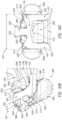
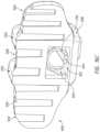
- FIGS. 2 A- 2 Iillustrate an orthodontic bracket and archform system that uses friction-free mechanics.
- FIG. 2 Aillustrates an archform 100 retained in a bracket 200 .
- a male fastener 106 of the archform 100is retained under a locking pin 226 and within a slot 202 of the bracket 200 .
- the archform 100can have a plurality of interproximal structures, e.g., loops 102 , 104 .
- the archform 100can have a male fastener 106 .
- the male fastener 106can include arms 108 , 110 .
- the arms 108 , 110can flex to allow the male fastener 106 to be locked (e.g., retained) within the bracket 200 .
- the male fastener 106can have an opening 120 .
- the opening 120can be disposed between the arms 108 , 110 .
- the male fastener 106can have a block 114 (e.g., stopper).
- the block 114can be disposed between the arms 108 , 110 .
- the block 114can extend into the opening 120 .
- the block 114can extend from one side of the periphery of the opening 120 to proximate another side 124 (e.g., surface) of the periphery of the opening 120 .
- the block 114can extend from the occlusal side of the periphery of the opening 120 to proximate, but offset from, the gingival-side surface 124 of the periphery of the opening 120 . As illustrated in FIG.
- a gap 122can space apart the block 114 from the surface 124 that forms a portion of the periphery of the opening 120 (e.g., the gingival side of the periphery of the opening 120 ).
- the block 114can move closer to the surface 124 , shrinking the gap 122 .
- the block 114can prevent the male fastener 106 from being compressed excessively.
- the block 114can move toward and ultimately contact the surface 124 to prevent further flexing of the arms 108 , 110 .
- the arms 108 , 110can flex inward and ultimately contact the block 114 to prevent further flexing of the arms 108 , 110 .
- the male fastener 106can have engagement surfaces 116 , 118 .
- the engagement surfaces 116 , 118can engage with retaining surfaces 222 , 224 of the bracket 200 , described in more detail elsewhere herein.
- the engagement surfaces 116 , 118can help to prevent sliding (e.g., reduce or eliminate slop, etc.) between the archform 100 and the bracket 200 .
- the engagement surfaces 116 , 118can help to prevent lateral movement of the male fastener 106 in the mesio-distal direction.
- the engagement surfaces 116 , 118can be angled relative to a central plane of the male fastener 106 .
- the engagement surfaces 116 , 118can be the same, which can include the same size, angle, etc.
- the male fastener 106can have a groove 112 .
- the groove 112(e.g., tool receptacle, tool receiver, opening, tool interface) can be configured to receive a tool.
- the groove 112can be disposed in a tab 126 (e.g., flange) that can be positioned under the locking pin 226 to retain the male fastener 106 within the bracket 200 .
- the engagement surfaces 116 , 118can form a portion of the tab 126 .
- the toolcan engage with the groove 112 to apply a force to the male fastener 106 such that the arms 108 , 110 flex such that the male fastener 106 can be inserted into or removed from the slot 202 of the bracket 200 , as described in more detail herein.
- the groove 112can be disposed on an end of the male fastener 106 .
- the groove 112can be disposed on the tab 126 .
- the groove 112can be disposed on the occlusal side of the male fastener 106 .
- the groove 112can be centered on a central plane of the male fastener 106 .
- the bracket 200can have a stop 204 .
- the stop 204can have an overhang 206 .
- the overhang 206can define an upper surface of the slot 202 of the bracket 200 that receives the male fastener 106 .
- the overhang 206can have a chamfer 238 (e.g., angled surface).
- the chamfer 238can enable (e.g., facilitate) the male fastener 106 to rotate out of or into the slot 202 of the bracket 200 without being prohibited by the overhang 206 .
- the stop 204can have a recess 240 (e.g., undercut), as detailed elsewhere herein.
- the recess 240can enable (e.g., facilitate) the male fastener 106 to rotate out of or into the slot 202 of the bracket 200 without being prohibited by the stop 206 , as detailed elsewhere herein.
- the bracket 200can have a retainer 208 .
- the retainer 208can be disposed on an end of the bracket 200 . Specifically, optionally, the retainer 208 can be positioned on the occlusal side of the bracket 200 . The retainer 208 can be positioned on an end of the bracket 200 that is opposite the stop 204 . The retainer 208 can define a portion of the slot 202 . The retainer 208 can have curved surfaces to alleviate tongue irritation.
- the retainer 208can have walls 218 , 220 .
- the walls 218 , 220can be positioned on the mesial and distal sides of the bracket 200 .
- the walls 218 , 220can be spaced apart from each other with a wall 232 extending therebetween.
- the wall 232can be perpendicularly oriented relative to the walls 218 , 220 .
- the wall 232can help to prevent adhesive from entering the slot 202 of the bracket 200 .
- the wall 232can be disposed on an end of the bracket 200 .
- the wall 232optionally, can be disposed on the occlusal end of the bracket 200 .
- the walls 218 , 220can be parallel to each other.
- the walls 218 , 220can, respectively, have retaining surfaces 222 , 224 , as clearly shown in FIG. 2 A .
- the retaining surfaces 222 , 224can engage with the engagement surfaces 116 , 118 .
- the retaining surfaces 222 , 224can be disposed on interior sides of the walls 218 , 220 .
- the retaining surfaces 222 , 224can be disposed on and/or proximate ends of the walls 218 , 220 .
- the wall 218can have an aperture 228 .
- the aperture 228can be sized and configured to receive an end of a locking pin 226 (e.g., rod, bar).
- the aperture 228can be sized and configured to fixedly receive the locking pin 226 .
- the locking pin 226is staked (e.g., press-fit, friction fit, etc.) into the aperture 228 such that the locking pin 226 is substantially fixed therein.
- the wall 220can have an aperture 230 .
- the aperture 230can be sized and configured to moveably receive the locking pin 226 .
- the aperture 230can have a locking portion 234 (e.g., detent, recess) and enlarged portion 236 .
- the enlarged portion 236can be closer to the occlusal end of the bracket 200 than the locking portion 234 .
- the enlarged portion 236can allow the locking pin 226 to deflect while still being retained within the aperture 230 during insertion and removal of the male fastener 106 from the slot 202 of the bracket 200 .
- the locking portion 234can receive the locking pin 226 when the locking pin 226 is not being deflected during insertion and removal of the male fastener 106 .
- the locking portion 234can retain the locking pin 226 when the male fastener 106 is disposed in the slot 202 of the bracket 200 .
- the locking portion 234can prevent the inadvertent deflection of the locking pin 226 during teeth brushing, etc., which could cause the inadvertent removal of the male fastener 106 from the slot 202 of the bracket 200 .
- the locking pin 226can retain the male fastener 106 within the slot 202 of the bracket 200 .
- the locking pin 226can extend between the walls 218 , 220 .
- An end of the locking pin 226can be fixedly disposed within the aperture 228 , while an opposing end of the locking pin 226 can be moveably disposed within the aperture 230 .
- the locking pin 226can deflect (e.g., flex) when a tool applies a force thereto.
- the end of the locking pin 226can be fixed within the aperture 228 while the end of the locking pin 226 within the aperture 230 can move due to deflection of the locking pin 226 .
- the locking pin 226can deflect from the locking portion 234 to the enlarged portion 236 , allowing the male fastener 106 to be inserted into or removed from the slot 202 of the bracket 200 .
- the end of the locking pin 226 within the aperture 230is deflected up by the male fastener 106 and into the locking portion 234 of the aperture 230 when the male fastener 106 is retained within the slot 202 of the bracket 200 .
- the bracket 200can have a protrusion 216 (e.g., bump).
- the protrusion 216can be rounded.
- the protrusion 216can extend from mesial to distal sides of the bracket 200 .
- the protrusion 216can extend from the face 214 .
- the protrusion 216as clearly shown in FIG. 2 C , can be positioned between the retainer 208 and the stop 204 .
- a portion of the protrusion 216can be disposed under the overhang 206 .
- the protrusion 216can push the male fastener 106 into the overhang 206 and the locking pin 226 such that the male fastener 106 is securely retained within the slot 202 of the bracket 200 , which can reduce and/or eliminate sliding between the archform 100 (e.g., male fastener 106 ) and the bracket 200 .
- an end of the male fastener 106 opposite the groove 112 and/or tab 126can be placed against the stop 204 and/or under the overhang 206 such that the male fastener 106 is angled relative to the face 214 of the bracket 200 , as illustrated in FIGS. 2 E and 2 F .
- a tool 300e.g., explorer tool, explorer
- a tip 306e.g., pointed tip, conical tip
- a tip 306e.g., pointed tip, conical tip
- the tool 300can be rotated in a first direction 304 (e.g., toward the retainer 204 , toward the male fastener 106 ), deflecting the locking pin 226 into the enlarged portion 236 of the aperture 230 and rotating the portion of the male fastener 106 with the groove 112 under the locking pin 226 and into the slot 202 , as shown in FIG. 2 G .
- the tool 300can be removed from between the locking pin 226 and the groove 112 , allowing the locking pin 226 to flex into the locking portion 234 of the aperture 230 , as shown in FIG. 2 B .
- the male fastener 106can be pushed by the protrusion 216 into the overhang 206 and the locking pin 226 , helping to reduce and/or eliminate sliding (e.g., slop) between the archform 100 and the bracket 200 .
- the engagement surfaces 116 , 118 of the male fastener 106can engage the retaining surfaces 222 , 224 of the retainer 208 of the bracket 200 , helping to reduce and/or eliminate sliding (e.g., slop) between the archform 100 and the bracket 200 .
- the tool 300can apply equal and opposite forces against one or more component(s) of the bracket 200 and/or male fastener 106 (or the bracket itself) during installation and removal. Equal and opposite forces can be important to reduce discomfort to the patient when inserting or removing the male fastener 106 from the bracket 200 .
- the tool 300can apply equal forces to the locking pin 126 and groove 112 during installation or removal.
- the tool 300can be inserted between the locking pin 226 and the groove 112 , as shown in FIGS. 2 H and 2 I .
- a downward force 310can be applied to the tool 300 with the tip 306 of the shaft portion 302 between the locking pin 226 and the groove 112 .
- the tool 300can be rotated in a second direction 308 , deflecting the locking pin 126 into the enlarged portion 236 of the aperture 230 and rotating the portion of the male fastener 106 with the groove 112 and/or tab 126 away from the face 214 of the bracket 200 and out from under the locking pin 126 .
- the male fastener 106can then be removed from under the overhang 206 of the stop 204 .
- FIGS. 3 A and 3 Billustrate an orthodontic bracket and archform system that uses friction-free mechanics.
- the bracket 200can have grip surfaces 242 , 244 (e.g., purchase points).
- the grip surfaces 242 , 244can be gripped by a tool, such as pliers, debonding pliers, and/or lingual debonding pliers, for handling.
- the grip surfaces 242 , 244can be gripped by a tool to remove the bracket 200 from being bonded to a patient's teeth.
- the grip surfaces 242 , 244can be gripped by a tool to position the bracket 200 onto the lingual or labial side of a patient's teeth for bonding.
- the grip surfaces 242 , 244can be positioned on opposing ends of the bracket 200 .
- the grip surface 242can be positioned on the occlusal side of the bracket 200 and the grip surface 244 can be positioned on the gingival side of the bracket 200 .
- the grip surfaces 242 , 244can be angled relative to each other.
- the grip surfaces 242 , 244can be proximate the retainer 208 and stop 204 , respectively.
- the grip surfaces 242 , 244can be angled relative to a central plane of the bracket 200 .
- the grip surfaces 242 , 244can be angled relative to a back surface 246 of the bracket 200 , as shown in FIG. 3 B .
- the back surface 246 of the bracketcan be bonded to a patient's tooth, such as the lingual or labial side of the patient's tooth.
- a distance 248can extend between the back surface 246 and the face 214 of the bracket 200 .
- FIG. 4illustrates an orthodontic bracket and archform system that uses friction-free mechanics.
- the bracket 200has walls 250 .
- the walls 250can be positioned on the mesial and distal sides of the bracket 200 .
- the walls 250can help prevent adhesion intrusion onto the face 214 and/or into the slot 202 of the bracket 200 .
- the walls 250can help prevent sliding between the archform 100 (e.g., male fastener 106 ) and the bracket 200 .
- the walls 250can be part of the retainer 208 and/or walls 218 , 220 .
- a covere.g., roof, top
- the portion of the bracket 200 with the stop 204can be raised, as shown in FIG. 4 , which can help prevent adhesive intrusion into the slot 202 .
- the gingival end of the bracket 200can be raised.
- the face 214can be angled relative to the back surface 246 such that a distance 248 between the face 214 and the back surface 246 is greater closer to the stop 200 (e.g., closer to the gingival side) than the retainer 208 (e.g., occlusal side).
- FIG. 5illustrates an orthodontic bracket and archform system that uses friction-free mechanics.
- the bracket 200has walls 250 , as described above, that can prevent adhesive instruction.
- the walls 250can also help to prevent the male fastener 106 and/or archform 100 from sliding in the bracket 200 .
- the bracket 200illustrated in FIG. 5 , can be narrower in the mesio-distal direction than some other brackets shown herein, which can accommodate teeth of different dimensions.
- FIG. 6 A- 6 Eillustrate an orthodontic bracket and archform system that uses friction-free mechanics.
- the bracket 200has a retainer 208 .
- the retainer 208can be positioned on the occlusal side of the bracket 200 .
- the retainer 208releasably retains the male fastener 106 of the archform 100 within a slot 202 of the bracket 200 .
- the retainer 208has walls 218 , 220 .
- the walls 218 , 220can be respectively positioned on the mesial and distal sides of the bracket 200 .
- the walls 218 , 220can secure the male fastener 106 therebetween to prohibit or reduce lateral movement of the male fastener 106 and/or sliding of the archform 100 with respect to the bracket 200 .
- the walls, 218 , 220can prevent the intrusion of adhesive.
- the retainer 200can have a C spring 256 (e.g., spring, leaf spring, spring locking pin).
- the C spring 256can retain the male fastener 106 .
- the C spring 256can retain the tab 126 of the male fastener 106 to releasably prevent the male fastener 106 from being removed from the slot 202 of the bracket 200 .
- the C spring 256can deflect (e.g., flex) under a load and, upon removal of the load, spring back to an undeflected configuration.
- the C spring 256can compress onto itself, deflect/flex inward, etc., and return to an uncompressed, deflected, and/or flexed state.
- the C spring 256can be oriented in a mesio-distal direction. A central axis of the C spring 256 can be oriented in the mesio-distal direction. The C spring 256 can be oriented perpendicularly relative to the longitudinal axis of the male fastener 106 when the male fastener 106 is retained within the slot 202 of the bracket 200 and/or a longitudinal axis of the bracket 200 . One end of the C spring 256 can be retained, which can include fixedly retained, within a slot 258 of the retainer 200 . Another end of the C spring 256 (e.g., a free end) can extend out of the slot 258 and into an opening 252 of the retainer 208 .
- a recess 254can extend a portion of the opening 252 to provide space for the C spring 256 to deflect when a force is applied thereto.
- the free end of the C spring 256can deflect under a force, which can cause the C spring 256 to flex into the recess 254 and/or flex in a direction that is away from the applied force. This can enable the male fastener 106 to be rotated under the C spring 256 .
- the C spring 256can spring, which can include returning to an undeflected state, to retain the male fastener 106 (e.g., tab 126 ) in place.
- the free end of the C spring 256can engage the male fastener 106 (e.g., tab 126 ) and apply a force thereto.
- This C spring arrangementcan be beneficial for narrow brackets because the effectiveness of the spring may not depend on the length thereof.
- the retainer 200can have a groove 212 .
- the groove 212can provide access to at least a portion of the C spring 256 .
- the groove 212can enable a tool to reach the C spring 256 and apply a force thereto.
- the groove 212can enable the tab 126 of the male fastener 106 to be rotated to contact the C spring 256 .
- the groove 212can be oriented in an opposite direction relative to the groove 112 of the male fastener 106 .
- the bracket 200can have a stop 204 .
- the stop 204can prevent movement of the male fastener in a direction, which can include the gingival direction.
- the stop 204can be positioned on a side of the bracket 200 that is opposite the retainer 208 .
- the stop 204can be positioned on the gingival side of the bracket 200 .
- the stop 204can have an overhang 206 .
- the overhang 206can extend over a portion of the slot 202 that can receive the male fastener 206 .
- the overhang 206can retain the male fastener 106 within the slot 202 of the bracket.
- the stop 204can have a recess 240 , as shown in FIG. 6 A .
- the recess 240can enable the male fastener 106 to be rotated while a portion of the male fastener 106 is positioned under the overhang 206 .
- the stop 204can have an angled surface 238 that enables a portion of the male fastener 106 to be conveniently positioned under the overhang 206 , as shown in FIG. 6 B .
- the stop 204optionally, can have a hole 264 extending therethrough. Optionally, the stop 204 does not include the hole 264 .
- the bracket 200can include a face 214 that forms a portion (e.g., a side) of the slot 202 of the bracket.
- the bracketcan include a protrusion 216 (e.g., bump) extending from the face 214 .
- the protrusion 216can, when the male fastener 106 is retained under the C spring 256 , push the male fastener 106 against an edge of the C spring 256 and the overhang 206 .
- the bracket 200can include a raised face 215 .
- the raised face 215can be positioned farther away from a back surface 246 of the bracket 200 than the face 214 .
- the protrusion 216can be positioned between the raised face 215 and the face 214 .
- a channel 260can separate mesial and distal portions of the protrusion 216 , face 214 , and raised face 215 .
- the channel 260can extend along a longitudinal axis of the bracket 200 .
- the channel 260can be positioned between mesial and distal sides of the bracket 200 .
- the archform 100can have a male fastener 106 .
- the male fastener 106can have arms 108 , 110 .
- the arms 108 , 110can be on opposing sides of the male fastener 106 .
- the arms 108 , 110can be on the mesial and distal sides of the male fastener 106 .
- the arms 108 , 110as described elsewhere herein can flex (e.g., deflect) under a force (e.g., load).
- the arms 108 , 110as described elsewhere herein can return to an undeflected configuration absent the application of a force.
- the arms 108 , 110can be separated by a space 120 .
- the arms 108 , 110can curve inward toward the space 120 .
- the arms 108 , 110can flex into the space 120 .
- the archform 100can have a tab 126 .
- the tab 126can be retained under the C spring 256 .
- the tab 126can have a groove 112 that can engage a tool.
- the toolcan apply a force to the groove 112 that deflects the arms 108 , 110 , thereby decreasing the length of the male fastener 106 such that the male fastener 106 can be rotated under the C spring or rotated out from under the C spring.
- the groove 112can decrease the likelihood that the tool will slip when applying a load to the male fastener 106 .
- the portion of the male fastener 106 opposite the tab 126can be positioned into the slot 202 and under the overhang 206 , such that the male fastener 106 is angled relative to the face 214 and/or raised face 215 .
- the tab 126can contact the C spring 256 .
- the tab 126can be at least partially within the groove 212 .
- the toolcan be positioned between and/or within the groove 212 and the groove 112 . The tool can be pushed toward the C spring 256 and/or rotated toward the stop 204 , causing the C spring 256 to deflect, the arms 108 , 110 to deflect, and/or the male fastener 106 to be rotated under the C spring 256 .
- the C spring 256can flex into the recess 254 and back into the opening 252 .
- the toolcan be removed.
- the C spring 256can return to an undeflected state and/or deflect to apply a retaining force to the male fastener 106 at interface 262 , shown in FIG. 6 C .
- the free ende.g., edge of the C spring 256
- the male fastener 106can be retained under the overhang 206 and C spring 256 .
- the protrusion 216can push the male fastener 106 against the C spring 256 and the overhang 206 , which can prevent sliding between the archform 100 (e.g., male fastener 106 ) and the bracket 200 .
- the toolcan be positioned between the groove 212 and the C spring 256 .
- the toolcan be rotated away from the stop 204 , causing the C spring 256 to deflect, the arms 108 , 110 to deflect, and/or the male fastener 106 (e.g., the tab 126 ) to be rotated out from under the C spring 256 (e.g., out from under the free end of the C spring 256 ).
- the C spring 256can return to an undeflected state.
- the male fastener 106can be removed from the slot 202 and from under the overhang 206 . During insertion and removal of the male fastener 106 , forces can be concentrated on the C spring 256 and the tool 300 , while the remainder of the bracket 200 can experience relatively small forces.
- FIGS. 7 A- 7 Eillustrate an orthodontic bracket and archform system that uses friction-free mechanics.
- the orthodontic bracket 200can include a slot 202 that can receive a male fastener 106 of an archform 100 .
- At least a portion of the slot 202can be defined by a face 214 of the bracket 200 .
- At least a portion of the slot 202can be defined by a retainer 208 .
- the retainer 208can have an overhang 210 , similar to the overhangs described elsewhere herein.
- the overhang 210can extend over the slot 202 and help to retain the male fastener 106 therein.
- the retainer 208can be on the gingival side of the bracket 200 .
- the retainer 208can have an opening 352 that holds a C spring 256 (e.g., spring, leaf spring).
- the opening 352can be an oval shape to allow the C spring 256 to flex (e.g., deflect). The periphery of the opening 352 can prevent the C spring 256 from flexing beyond a desired range.
- the opening 352can be oriented perpendicularly to the face 214 of the bracket.
- the retainer 208can have a guide 366 (e.g., guide rail, protrusion, longitudinal protrusion, bar) that can orient the C spring 256 within the opening 352 .
- the guide 366can prevent the C spring 256 from twisting and/or otherwise being inadvertently removed from the bracket 200 and/or opening 352 .
- the guide 366can extend through and/or within the opening 352 .
- the guide 366can be oriented perpendicularly relative to the face 214 of the bracket 200 .
- the C spring 256can be positioned through the opening 352 and over the guide 366 . Opposing ends of the C spring 256 can be positioned on opposing sides of the guide 366 .
- the C spring 256as shown in FIGS. 7 D and 7 E , can be exposed to at least a portion of the slot 202 .
- the male fastener 106when inserted into the slot 202 , can contact and flex the C spring 256 .
- the C spring 256can apply a force to the male fastener 106 , which can retain the male fastener 106 within the slot 202 of the bracket 200 .
- the C spring 256can be positioned away from a handle 380 of the male fastener 106 during installation, reducing the risk that the C spring 256 will be damaged by tools, such as pliers, explorer tools, etc.
- the bracket 200can include stops 204 , 205 .
- the stops 204 , 205can be separated by a gap 368 therebetween.
- the stops 204 , 205can have cutouts 374 , 375 (e.g., recesses, voids, spaces) that receive wedges 382 , 383 (e.g., fingers) of the male fastener 106 , as shown in FIGS. 7 B, 7 D, and 7 E .
- the cutouts 374 , 375 and wedges 382 , 383can cooperate to prevent sliding (e.g., reduce lateral movement) between the archform 100 (e.g., male fastener 106 ) and the bracket 200 .
- the stops 204 , 205can have angled surfaces 384 , as shown in FIG. 7 D , that enable the male fastener 106 to be inserted into the slot 202 of the bracket 200 at an angle.
- the gap 368can receive a handle 380 (e.g., tab, tongue) of the male fastener 106 .
- the handle 380positioned between the stops 204 , 205 , can prevent sliding between the archform 100 (e.g., male fastener 106 ) and the bracket.
- a raised surface 372can extend the gap 362 and between the stops 204 , 205 . The raised surface 372 can support the handle 380 off the face 214 of the bracket 200 .
- An aperture 370can be positioned between the stops 204 , 205 .
- the aperture 370can be sized and shaped to receive at least a portion of a tool during installation and removal of the male fastener 106 within the bracket.
- the aperture 370can extend through at least a portion of the raised surface 372 and/or the face 214 .
- the bracket 200can have a protrusion 216 that is similar to the other protrusions 216 described herein.
- the protrusion 216can extend from the face 214 of the bracket 200 .
- the protrusioncan extend from proximate or at the mesial and distal sides of the bracket 200 .
- the protrusion 216can push the male fastener 206 against the overhang 210 and the cutouts 374 , 375 when positioned within the bracket 200 .
- the bracket 200can have inclined surfaces 376 that facilitate inserting the male fastener 106 within the bracket 200 .
- the inclined surface 376can be positioned on opposing sides of the retainer 208 . As shown in FIG. 7 D , the inclined surfaces 376 can facilitate the male fastener 106 being positioned within the slot 202 of the bracket 200 at an angle before being securely retained within or removed from the bracket 200 .
- the retainer 208 and/or overhang 210can have an angled surface 238 that can facilitate the male fastener 106 being positioned within the slot of the bracket 200 at an angle before being securely retained within or removed from the bracket 200 .
- the archform 100can have a male fastener 100 , as shown in FIG. 7 B .
- the male fastener 100can be inserted into and retained by the bracket 200 (e.g., slot 202 ).
- the male fastener 106can have a handle 380 (e.g., tab).
- the handle 380can allow the archform 100 to be gripped, such as with pliers, to insert the male fastener 106 into the bracket 200 .
- the handle 380can provide a purchase point for pliers.
- the handle 380optionally, is configured such that it does not add additional strength to the archform 100 such that, if damaged, the archform 100 will perform as intended.
- the handle 380can include a hole 378 .
- the hole 378can receive at least a portion of a tool (e.g., explorer, explorer tool) to position the male fastener 106 .
- the male fastener 106can include wedges 382 , 383 (e.g., fingers).
- the wedges 382 , 383can be formed by laser cutting and/or waterjet cutting the male fastener 106 to create the edge 286 , defining at least a portion of the wedges 382 , 383 .
- the male fastener 106can be inserted at an angle 390 relative to the face 214 and/or back surface 246 , which can be referred to as the insertion/removal angle of attack.
- the wedges 382 , 383with the edge 286 , can reduce the insertion/removal angle of attack, which can improve the ease of male fastener 106 insertion within the bracket 200 .
- the wedges 382 , 383can be positioned within the cutouts 282 , 283 of the stops 204 , 205 .
- the male fastener 106can be inserted at an angle 390 into the slot 202 of the bracket 200 .
- the inclined surfaces 376 , angled surfaces 384 , edges 286 of the wedges 382 , 383 , and/or angled surface 238can ease insertion (e.g., reduce the insertion angle 390 ) of the male fastener 106 into the slot 202 of the bracket 200 .
- a forcecan be applied to the male fastener 106 , which can be with a tool interfacing with the handle 380 , such that the C spring 256 is compressed.
- the male fastener 106can be rotated toward the face 214 such that the male fastener 106 is parallel with the face 214 .
- the force applied to the male fastener 106can be removed, allowing the C spring 256 to push the wedges 382 , 383 into the cutouts 374 , 375 , as shown in FIG. 7 E .
- the protrusion 216can push the male fastener 106 into the overhang 210 and/or push the wedges 382 , 383 against respective surfaces of the cutouts 374 , 375 .
- portions of the archform 100 proximate the male fastener 106can interface with sides of the bracket 200 (e.g., mesial and distal sides) to reduce and/or prevent lateral movement between the archform 100 (e.g., male fastener 106 ) and the bracket 200 .
- a toolcan be inserted into the hole 378 of the handle 380 .
- the toolcan be inserted through the hole 378 of the handle 380 and at least partially into the hole 370 .
- the toolcan be tilted (e.g., rotated) in the direction of the retainer 208 , which can compress the C spring 256 , remove the wedges 382 , 383 from the cutouts 374 , 375 , and rotate the side of the male fastener 106 with the handle 380 out of the slot 202 of the bracket 200 .
- the male fastener 106can then be removed from the bracket 200 at an angle.
- the bracket 200can include a stop 204 .
- the stop 204can include cutouts and/or an overhang as described elsewhere herein. The cutouts and/or overhang can receive wedges 382 , 383 of the male fastener 106 .
- the bracket 200can include a retainer 208 .
- the retainer 208can have an overhang 210 .
- the retainer 208can have an opening 352 that houses a C spring 256 .
- One end of the C spring 256can be coupled, which can include fixed, to a flange 367 to help prevent unintentional removal of the C spring 256 .
- the other end of the C spring 256can be free, allowing the C spring 256 to flex under the application of a force and return to an unflexed configuration absent the application of the force.
- At least a portion of the C spring 256can be accessible via the slot 202 of the bracket 200 such that a male fastener 106 inserted into the slot 202 can compress the C spring 256 .
- the archform 100can have a male fastener 106 .
- the male fastener 106can have a handle 288 .
- the handle 288can be gripped by tools, such as pliers, to manipulate the archform 100 without negatively impacting the performance of the archform 100 .
- the male fastener 106can include wedges 382 , 383 that can be separated by a groove 112 .
- the groove 112can receive a tool that can apply a force thereto such that the male fastener 106 compresses the C spring 256 and enables the wedges 382 , 383 to maneuver around the stop 204 during insertion and/or removal of the male fastener 106 .
- the male fastener 106can be inserted and removed from the bracket 200 using similar techniques to those described elsewhere herein.
- FIGS. 8 A- 8 Dillustrate an orthodontic bracket and archform system that uses friction-free mechanics.
- the archform 100can have a male fastener 106 .
- the male fastener 106can include a guiding channel 802 (e.g., recess, channel).
- the guiding channel 802can guide a tab 804 of a bracket 200 .
- the guiding channel 802can guide a tab 804 to flex around the surface(s) of the guiding channel 804 to engage with a holding surface 806 (e.g., surface).
- the tab 804can be made of a variety of material such as sheet metal.
- the tab 804can hold the male fastener 106 within the slot of the bracket 200 .
- the bracket 200can include a tool receiving channel 808 that can receive a tool to deflect the tab 804 from the holding surface 806 to decouple the male fastener 106 from the bracket.
- the bracket 200can have walls 218 , 220 .
- the walls 218 , 220can align the male fastener 106 within the bracket 200 .
- the walls 218 , 220can prevent sliding (e.g., slop) between the archform 100 and the bracket 200 .
- the walls 218 , 220can be positioned on distal and mesial sides of the bracket 200 .
- the walls 218 , 220can define a channel 820 to guide the male fastener 106 into the slot 202 of the bracket 200 as the male fastener 106 moves in the direction 816 .
- the bracket 200can have a stop 204 .
- the stop 204can be disposed on an end of the bracket 200 , which can include the gingival end of the bracket 200 .
- the stop 204can have an overhang 206 .
- the overhand 206can be configured to retain the male fastener 106 within a slot 202 .
- the stop 204can include a recess 810 to enable the male fastener 106 to rotate within the slot 202 .
- the overhang 206can have a chamfer 238 which can help enable the male fastener 106 to rotate within the slot 202 .
- the overhang 206can have a wedge 812 (e.g., angled surface, tapered surface, protrusion) that is similar to the protrusions 812 .
- the wedge 812can extend from the overhang 206 in the direction of the face 214 .
- the wedge 812can push the male fastener 106 into the face 214 to prevent and/or reduce sliding (e.g., slop) between the archform 100 (e.g., male fastener 106 ) and the bracket 200 .
- the bracket 200can have a face 214 .
- the face 214as shown in FIG. 8 D , can have a tool receiving recess 822 (e.g., recess) that can receive a tool, which is moved through the tool receiving channel 808 to deflect the tab 804 from the holding surface 806 .
- the male fastener 806can be removed from the slot 202 .
- the male fastener 106is positioned on the face 214 (e.g., parallel to the face 214 ) of the bracket 200 between the walls 218 , 220 .
- the male fastener 106is moved in the direction 816 .
- the guiding channel 802guides the tab 804 of the bracket 202 .
- the male fastener 106is angled relative to the face 214 until the tab 804 can be positioned within the guiding channel 802 .
- the guiding channel 802can guide a tab 804 to flex around the surface(s) of the guiding channel 804 to engage with the holding surface 806 , retaining the male fastener 106 within the slot 202 .
- the wedge 812can push the male fastener 106 into the surface 214 .
- a toole.g., explorer tool
- the toolis moved through the tool receiving channel 808 toward the tab 804 .
- the tooldeflects the tab 804 from the holding surface 804 such that the male fastener 106 can be removed from the slot 202 .
- the toolcan, which can include simultaneously, engage a periphery of the tool receiving channel 808 to remove the male fastener 106 from the bracket 200 and/or slot 202 .
- the tab 8040can have more than one engagement stages (e.g., more than one feature that can engage with the holding surface 806 and/or another surface of the male fastener 106 , such that a clinician can choose the depth into which the male fastener 106 is inserted into the slot 202 .
- the flexible locking mechanism 804e.g., tab
- the flexible locking mechanism 804may have more than one engagement stages. For example, for severely maloccluded teeth, a clinician may want the archform partially engaged into the slot 202 . This will allow maximum articulation and flexibility of the archform 100 which can allow the archform 100 to be more easily connected to the displaced teeth.
- the clinicianmay push and lock the archform 100 further into the slot 202 to get the full expression of the archform 100 .
- the slot 202can have one or more tapered sides that, when the male fastener 106 is slid into the slot 202 , contacts the male fastener 106 . This can eliminate play between the archform 100 (e.g., male fastener 106 ) and the bracket 200 , which can provide improved tooth control.
- brackets describedare positioned on a lingual or labial side of a patient's teeth.
- the brackets and non-sliding archforms described hereincan cooperate to cause translational movement of a patient's teeth.
- the same locking mechanismcan be used for molars and lower anterior teeth.
- the archform profilescan have enough flexibility and stretch to level and align a patient's teeth during the initial stages of malocclusion treatment.
- the bracket and archforms disclosed hereincan be designed reduce the risk of inadvertent coupling between brackets and the archform, for example, when removing the archform from neighboring brackets.
- the brackets and archformreduce the amount of sliding (e.g., slop) between the archform and brackets.
- the archformincludes features, such as handles, tabs, etc., that can be used to maneuver the archform, reducing deformation and/or damage of the archform.
- the bracketis bonded to the patient's teeth with sufficient shear strength and tensile strength to reduce the likelihood of inadvertent debonding.
- the bracketscan be debonded from teeth using lingual debonding pliers or debonding pliers without damaging the enamel of a patient's teeth.
- archformsmade of nickel titanium, stainless steel, titanium-molybdenum alloy, shape memory alloy, super elastic metals, and/or other suitable alloys can be used.
- the bracketscan reduce adhesive intrusion into the brackets.
- the same litigating mechanismcan be used for all teeth.
- the surfaces (e.g., lingual surfaces), and/or other surfaces, of the bracketare rounded, which can include a radius of greater than 0.050-0.010, 0.010-0.015, 0.015-0.020, 0.020-0.025, and/or greater than 0.025 inches.
- the bracketsdo not open inadvertently when a patient is brushing teeth.
- tie wingscan be used in addition to the locking mechanisms disclosed herein.
- interproximal loops of the archformdo not dig into the gum line of the patient during installation of the archform.
- an archformmay be activated by deflecting it away from its default position and inserting into a snapped position within an orthodontic bracket that is bonded to a tooth.
- the archformmay exert a reaction force in the direction that returns the archform to the designed configuration, thereby transferring forces to the tooth and causing orthodontic tooth movement.
- This archform activationmay completely control any tooth movement in three-dimensional space.
- snap fitting an archwire into an orthodontic bracketmay cause an interproximal structure to deform in one or more directions, which may cause the archform to be activated, leading to closing of space in the mesial-distal direction.
- archform snap fitting into an orthodontic bracketmay cause an interproximal structure to deform in a different direction, which may cause the archwire also to be activated, this time leading to opening of space in the mesial-distal direction.
- an archform snap fitting into an orthodontic bracketmay cause connecting archwire connectors and interproximal structures to deflect in a slanted manner which may cause the archform to be activated, leading to tooth correction in the occlusal-gingival direction.
- archform snap fitting into an orthodontic bracketmay cause the wire to be pushed away from its original position which may cause the archform to be activated, leading to tooth correction in the facio-lingual direction.
- the vertical male connectormay offer a longer arm for coupling forces to the orthodontic bracket when compared to the rectangular dimensions of an edgewise appliance.
- the spread of the two parallel side bars of some male connectorsmay make them function like a twin orthodontic bracket in providing a force couple in dealing with any axial rotation.
- the interproximal structuresmay allow the operator to adjust the rigidity of the archform, which may provide versatility for the same archform cross-sectional configuration to be used in a wide array of cases.
- the interproximal structurescan be designed to allow patients to easily floss while undergoing orthodontic treatment.
- the interproximal structuresmay be designed to have a certain type of shape (including loops, and complex 3D shapes). These shapes can be used to hold elastic rubber bands.
- the archformmay be designed such that it can be activated to move the teeth. This type activation may be self-activating and self-limiting because it may not require use of external forces such as power chain and coil springs to move the teeth. This type of activation may also be self-limiting because the archform may only exert forces that return the archform to its original shape, negating the need for frequent appointments.
- This approachmay also not permit sliding of the archform with respect to the orthodontic bracket, thus making movement of the teeth much more predictable.
- FIGS. 9 A and 9 Billustrate a bracket assembly 201 (e.g., two piece bracket assembly).
- the bracket assembly 201can include a pad (receiving pad, receiving base, base) 500 that can receive an orthodontic bracket 200 , which can be coupled to the male fastener of an archform to facilitate tooth movement.
- the pad 500can be bonded to a patient's tooth (e.g., on the lingual side or labial side of a patient's tooth) and receive the bracket 200 .
- the pad 500can be modified for attachment to various teeth depending on tooth size and/or desired control. For example, a wider pad 500 can be used to improve tooth rotational control without increasing the width of the bracket 200 .
- the pad 500can be modified or different pads 500 used to enable the same style bracket 200 (e.g., a common bracket) to be more widely used amongst different teeth. This can reduce the number of varieties of brackets needed for a treatment plan, which can reduce cost and/or complexity.
- the shape and/or contour of the pad 500can be economically changed because the pad 500 is separate from the bracket 200 .
- the bracket 200 and pad 500can be formed together.
- the pad 500can be manufactured via a variety of techniques such as injection molding, casting, machining, additive manufacturing, etc. In some instances, metal injection molding may be preferred.
- the pad 500can include a pocket (opening, void, depression, hole, receiving space) 502 to receive the bracket 200 .
- a portion of the periphery of the pocket 502can include filler material 504 that can be used to weld (e.g., laser weld) the bracket 200 to the pad 500 .
- the filler material 504can be disposed on the sides (e.g., mesial and distal sides) of the periphery of the pocket 502 , such that the sides (e.g., mesial and distal sides) of the periphery of the pocket 502 can be welded (e.g., laser welded) to the sides (e.g., mesial and distal sides) of the bracket 200 .
- the pad 500 and bracket 200can be tack welded together prior to laser welding.
- the pad 500can include undercut(s) (cut(s), gap(s), textured surface, void(s), slot(s)) 506 to facilitate improved bonding between the pad 500 and the patient's teeth.
- the undercut(s) 506can be molded into the pad 500 .
- the undercuts 506can be machined into the pad 500 .
- the undercut(s) 506can be disposed on a side of the pad 500 that is opposite the pocket 502 .
- the undercut(s) 506can extend the width of the pad 500 .
- the undercut(s) 506can extend between the mesial and distal sides of the pad 500 .
- the pad 500being separate from the bracket 200 , can have undercut(s) 506 conveniently molded therein.
- the pad 500can have inclined surfaces 508 , 509 , similar to inclined surfaces 376 described elsewhere herein, that can facilitate inserting the male fastener 106 within the bracket 200 .
- the inclined surface 508 , 509can be positioned on opposing sides of the retainer 208 .
- the inclined surfaces 376can facilitate the male fastener 106 being positioned within the slot 202 of the bracket 200 at an angle before being securely retained within, which can include being parallel to the face 214 of the bracket 200 , or removed from the bracket 200 .
- the bracket 200can be disposed within the pocket 502 of the pad 500 during use.
- the bracket 200can be used independently of the pad 500 and bonded to a patient's tooth.
- the bracket 200can be manufactured via a variety of techniques such as injection molding, casting, machining, additive manufacturing, etc. In some instances, metal injection molding may be preferred.
- the bracket 200can be used with an archform 100 to move a patient's teeth utilizing non-sliding mechanics.
- the orthodontic bracket 200can include a slot 202 that can receive a male fastener of an archform. At least a portion of the slot 202 can be defined by a face 214 of the bracket 200 . At least a portion of the slot 202 can be defined by a retainer 208 .
- the retainer 208can have an overhang 210 , similar to the overhangs described elsewhere herein.
- the overhang 210can include a curved portion 211 that extends over the face 214 of the bracket 200 .
- the curved portion 211can help to retain a male fastener 106 within the bracket 200 .
- the overhang 210can extend over the slot 202 and help to retain a male fastener therein.
- the retainer 208can be on the gingival side of the bracket 200 .
- the retainer 208can be disposed on the occlusal side of the bracket 200 .
- the retainer 208 and/or overhang 210can include an angled surface 238 that can facilitate a male fastener being positioned within the slot 202 of the bracket 200 at an angle before being securely retained within or removed from the bracket 200 .
- the retainer 208can have a recess 240 (e.g., undercut), as detailed elsewhere herein.
- the recess 240can enable (e.g., facilitate) a male fastener to rotate out of or into the slot 202 of the bracket 200 without being prohibited by the retainer 208 , as detailed elsewhere herein.
- the retainer 208can include a C spring 256 (e.g., spring, leaf spring). As described elsewhere herein, the C spring 256 can help to securely retain a male fastener within the bracket 200 .
- the retainer 208can have an opening 352 that holds the C spring 256 .
- the opening 352can be an oval shape to allow the C spring 256 to flex (e.g., deflect). The periphery of the opening 352 can prevent the C spring 256 from flexing beyond a desired range.
- the opening 352can be oriented perpendicularly to the face 214 of the bracket 200 .
- the C spring 256can be perpendicularly oriented relative to the face 214 of the bracket 200 .
- the C spring 256can extend between and/or partially through the retainer 208 and the face 214 of the bracket 200
- the C spring 256can be exposed to at least a portion of the slot 202 .
- the male fastener 106when inserted into the slot 202 , can contact and flex the C spring 256 .
- the C spring 256can apply a force to the male fastener 106 to push the male fastener 106 into stops 204 , 205 , which can retain the male fastener 106 within the slot 202 of the bracket 200 .
- the C spring 256can be positioned away from a handle 380 of the male fastener 106 during installation, reducing the risk that the C spring 256 will be damaged by tools, such as pliers, explorer tools, etc.
- the C spring 256can extend through the protrusion 216 .
- the protrusion 216can be offset from the C spring 256 .
- the bracket 200can include stops 204 , 205 .
- the stops 204 , 205can be separated by a gap 368 therebetween.
- the stops 204 , 205can have cutouts 374 , 375 (e.g., recesses, voids, spaces) that receive wedges 382 , 383 (e.g., fingers) of the male fastener 106 .
- the cutouts 374 , 375 and wedges 382 , 383can cooperate to prevent sliding (e.g., reduce lateral movement) between the archform 100 (e.g., male fastener 106 ) and the bracket 200 .
- the stops 204 , 205can include ramps (inclined surface, angled surface, ramp) 392 , 393 .
- the ramps 392 , 393can extend from the face 214 to the cutouts 374 , 375 .
- the ramps 392 , 393can be angled to interface with the wedges 382 , 383 .
- the stops 204 , 205can be positioned proximate the sides (e.g., longitudinal sides, mesial and distal sides) of the bracket 200 .
- the stops 204 , 205can be disposed on an opposing side of the bracket 200 relative to the retainer 208 .
- the gap 368can receive a handle 380 (e.g., tab) of the male fastener 106 .
- the handle 380positioned between the stops 204 , 205 , can help to prevent sliding between the archform 100 (e.g., male fastener 106 ) and the bracket.
- the bracket 200can have a protrusion 216 that is similar to the other protrusions 216 described herein.
- the protrusion 216can extend from the face 214 of the bracket 200 .
- the protrusion 216can extend between longitudinal sides (e.g., mesial and distal sides) of the bracket 200 .
- the protrusion 216can push the male fastener 206 against the overhang 210 and/or the cutouts 374 , 375 when positioned within the slot 202 of the bracket 200 for secure retention.
- FIG. 10 Aillustrates a bracket assembly 201 with a pad 500 and bracket 200 .
- the bracket assembly 201 , pad 500 , and/or bracket 200 illustrated in FIG. 10 Acan include the same or similar features as the bracket assembly 201 , pad 500 , and/or bracket 200 illustrated in FIGS. 9 A and 9 B .
- the bracket 200 illustrated in FIGS. 9 A and 9 Bcan be used for the lower anterior teeth of a patient while the bracket 200 illustrated in FIG. 10 A can be used for all other teeth of the patient (e.g., molars, etc.).
- the bracket 200 illustrated in FIG. 10 Acan be referred to as the common bracket because the bracket 200 can be used with most of the teeth of the patient.
- the bracket 200 illustrated in FIG. 10 Acan include an aperture (hole, void, opening) 394 .
- the aperture 394can receive a protrusion (cylinder, projection, pillar, pin) 510 of the pad 500 .
- the protrusion 510can be inserted through the aperture 394 .
- the bracket 200can be tack welded to the pad 500 before laser welding during coupling.
- the protrusion 510can be inserted into the aperture 394 and laser welded to bracket 200 to remove the process of tack welding before laser welding. Laser welding the protrusion 510 to the bracket 200 when positioned within the aperture 394 can prevent the bracket 200 from lifting out of the pocket 502 when one of the longitudinal sides (e.g., mesial or distal sides) of the bracket 200 is laser welded.
- the bracket 200 illustrated in FIG. 10 Amay be narrow enough to be used on most teeth of a patient but not wide enough (e.g., insufficient distance between longitudinal sides, insufficient distance between mesial and distal sides) for effective rotation control for molar teeth. Accordingly, the pad 500 can have a width that provides effective rotation control for molar teeth without requiring the bracket 200 to be widened.
- the pad 500 illustrated in FIG. 10 Acan be wider, for improved rotational control, compared to the pad 500 illustrated in FIGS. 9 A and 9 B .
- the pad 500 illustrated in FIG. 10 Acan include features similar to the bracket 200 (e.g., carry over bracket features) to improve rotational control while still using a narrow bracket 200 .
- the pad 500can include protrusions (bumps) 514 , 515 , which can be similar to the protrusion 216 of the bracket 200 .
- the protrusions 514 , 515can be distributed on opposing sides of the bracket 200 .
- the protrusions 514 , 515can be distributed on opposing sides of the protrusion 216 of the bracket 200 .
- the protrusions 514 , 515can be aligned with the protrusion 216 of the bracket 200 .
- the protrusions 514 , 515can help to retain the male fastener 106 of the archform 100 within the bracket 200 to facilitate non-sliding mechanics.
- the protrusions 514 , 515can, similar to the protrusion 216 of the bracket 200 , push the male fastener 106 of the archform 100 against the overhang 210 and/or stops 204 , 205 .
- the protrusions 514 , 515can effectively be an extension of the protrusion 216 .
- the pad 500 illustrated in FIG. 10 Acan include inclined surfaces (angled surface, ramp) 512 , 513 , which can be similar to ramps 392 , 393 .
- the inclined surfaces 512 , 513can be distributed on opposing sides of the bracket 200 .
- the inclined surface 512can be positioned proximate the ramp 392 .
- the inclined surface 513can be positioned proximate the ramp 393 .
- the inclined surfaces 512 , 513can interface with the wedges 382 , 383 of the male fastener 106 .
- the inclined surfaces 512 , 513can interface with the wedges 382 , 383 to prevent sliding (e.g., reduce lateral movement) between the archform 100 (e.g., male fastener 106 ) and the bracket 200 and/or control rotational movement of the tooth.
- the inclined surfaces 512 , 513can be offset from the wedges 382 , 383 in a neutral position but contact the wedges 382 , 383 with rotational movement.
- the inclined surfaces 512 , 513can effectively be an extension of the ramps 392 , 393 .
- FIGS. 10 B and 10 Cillustrate the male fastener 106 of an archform 100 positioned within the slot 202 of the bracket 200 .
- the male fastener 106can include a handle 380 , which can be grasped to manipulate the male fastener 106 .
- the handle 308can be positioned in the gap 368 between the stops 204 , 205 .
- the handle 308can include flange(s) (tab(s)) 396 .
- the flange(s) 396can be positioned on an end of the male fastener 106 and/or handle 308 .
- the flange(s) 396can be positioned on opposing sides of the handle 380 .
- the flange(s) 396can include two flanges, as illustrated.
- the male fastener 106can be inserted into the slot 202 of the bracket 200 at an angle, which can be facilitated by the angled surface 238 of the overhang 210 and/or the inclined surface(s) 508 , 509 .
- the male fastener 106can be pushed against the C spring 256 , which can deflect the C spring 256 , and rotated toward the face 214 of the bracket 200 .
- the male fastener 106can include a recess 402 (e.g., curved recess, groove) which can interface with the C spring 256 , as shown in FIG. 10 B .
- the recess 402can be positioned opposite the handle 380 .
- the male fastener 106With the male fastener 106 substantially parallel with the face 214 of the bracket 200 , the male fastener 106 can be pushed by the C spring 256 against the stops 204 , 205 .
- the wedges 282 , 283can be positioned within the cutouts 374 , 375 and/or contact the ramps 392 , 393 .
- the protrusion 216as described elsewhere herein, can push the male fastener 106 against the overhang 210 and/or stops 204 , 205 .
- the protrusions 514 , 515can push the male fastener 106 against the overhang 210 and/or stops 204 , 205 .
- the ramps 392 , 393can contact the wedge(s) 282 , 283 , which can include pushing the wedge(s) 282 , 283 against the stops 204 , 205 .
- the ramps 392 , 393can push the wedges 282 , 283 into the cutouts 374 , 375 .
- the inclined surfaces 512 , 513 of the pad 500can interface with the wedges 382 , 383 .
- the inclined surfaces 512 , 513can be offset from the wedges 382 , 383 in a neutral position but interface upon rotational movement.
- the features of the pad 500can enlarge the effective bracket width of the bracket 200 compared to the actual width of the bracket 200 .
- the inclined surface(s) 512 , 513 and/or protrusion(s) 514 , 515can increase the effective bracket width of the bracket 200 , which can include providing increased rotational control.
- the bracket assembly 201 with the separate pad 500 and bracket 200can, as described elsewhere herein, reduce the variety of brackets 200 needed to treat a patient.
- one bracket designcan be used for lower anterior teeth while another bracket design can be used for molars and all other teeth.
- MIMmetal injection molding
- the bracket assembly 201can improve tooth rotational control (on any given tooth) without increasing the width of the bracket 200 .
- FIG. 11 Aillustrates a bracket assembly 201 (e.g., two piece bracket assembly).
- the bracket assembly 201can include the pad 500 with the orthodontic bracket 200 coupled thereto.
- the orthodontic bracket 200can receive the male fastener 106 of the archform to facilitate tooth movement. As illustrated, the male fastener 106 is securely retained by the bracket 200 via the stops 204 , 205 and retainer 208 (e.g., overhang 210 ).
- the handle 380can include flange(s) 396 , which can be described as forming a hammerhead type shape.
- the handle 380can be disposed between the stops 204 , 205 to help prevent relative movement between the bracket 200 and the male fastener 106 .
- the handle 380can be used to remove the male fastener 106 from the bracket 200 and/or place the male fastener 106 in the bracket 200 .
- the handle 380can extend from the bracket 200 in the occlusal direction.
- the handle 380can extend from the bracket 200 in the gingival direction.
- an opening/closing toolthat uses equal and opposite forces can be used to place and/or remove the male fastener 106 of the archform 100 .
- a hemostat or forceps type toolcan be used to place and/or remove the male fastener 106 of the archform 100 .
- one side of the forcepscan grip the handle 380 at surface 532 (e.g., occlusal side, surface) while the other side of the forceps can grip the retainer 208 at surface 354 (e.g., gingival side or gingival surface).
- the operatorcan squeeze the forceps together to push the male fastener 106 against the C-spring 256 (e.g., oval spring), shown in FIG. 11 B , which can move the male fastener 106 (e.g., occlusal edges disposed on opposing sides of the handle 380 ) out from under the stops 204 , 205 of the bracket 200 as the C-spring 256 is compressed.
- the forcepscan be rotated away from the stops 204 , 205 to rotate the male fastener 106 such that the male fastener 106 is decoupled from the bracket 200 .
- the bracket 200 and/or male fastener 106can include features to prevent over travel (e.g., excessive deflection) of the C-spring 256 (e.g., oval spring).
- the bracket 200can include the guide 366 (e.g., guide rail, protrusion, longitudinal protrusion, bar).
- the guide 366can maintain the position of the C-spring 256 within the opening 352 and/or prevent the C-spring 256 from being excessively deflected (e.g., prevent from being deflected past an elastic limit).
- the C-spring 256in some variants, can be deflected until contacting the guide 366 .
- the periphery of the opening 352can restrict deflection of the C-spring 256 to protect against over travel.
- the opening 352can be disposed in the retainer 208 and/or the portion of the bracket 200 opposite the retainer 200 .
- surface(s) 130 of the male fastener 106can engage with the surface(s) 520 of the bracket 200 (e.g., retainer 208 ) to help prevent over travel of the C-spring 256 during compression.
- the surface(s) 130 of the male fastener 106can be displaced toward the surface(s) 520 of the bracket 200 until contract, which can prevent further deflection of the C-spring 256 (e.g., prevent over travel of the oval spring 256 ).
- the one or more of the features detailed abovecan prevent the oval spring 256 from over travel or being compressed beyond the elastic limit of the oval spring 256 even when the operator may squeeze the forceps excessively.
- the portion of the male fastener 106 opposite the handle 380can be disposed under the overhang 210 of the retainer 208 of the bracket 200 to contact and/or be positioned proximate the C-spring 256 such that the male fastener 106 is angled relative to the bracket 200 .
- the recess 402 of the male fastener 106can contact the C-spring 256 .
- the operatorcan grab the handle 380 of the male fastener 106 to position the male fastener 106 as described above.
- the inclined surfaces 508 , 509 and/or chamfer 238can assist the operator in positioning the male fastener 106 as described above.
- one side of the forcepscan grip the handle 380 at surface 532 while the other side of the forceps can grip the retainer 208 at surface 354 .
- the operatorcan squeeze the forceps together to push the male fastener 106 against the C-spring 256 which can enable the operator to pivot the male fastener 106 toward the bracket 200 and around the stops 204 , 205 as the C-spring 256 is compressed.
- the operatorcan stop squeezing (e.g., applying a compressive force) with the forceps, or similar tool, which can release the C-spring 256 to apply a force against the male fastener 106 such that the male fastener 106 is pushed against and/or under the stops 204 , 205 .
- the C-spring 256can be protected against over travel or deflection past an elastic limit via at least the features described elsewhere herein.
- the bracket assembly 201 with the pad 500 and bracket 200can enable a single bracket design to be used across several teeth.
- the pad 500can be altered as needed from tooth to tooth.
- the pad 500can be different sizes and/or have different features depending on the tooth to which the pad 500 will be bonded while still being able to receive and/or bond to the bracket 200 .
- Thiscan reduce cost.
- the number of styles (e.g., SKUs) of brackets 200can be reduced, which can result in higher volume manufacturing runs of brackets 200 to reduce cost.
- the pad 500can also be cheaper to manufacture than brackets 200 because pad molds can be less expensive than bracket molds, which can result in cheaper manufacturing cost due to more pad variations than bracket variations.
- a lower anterior bracketsuch as the bracket 200 illustrated in FIGS. 11 A- 11 C
- pads 500 on the lower 3 - 3can be used with another style bracket 200 (e.g., illustrated in FIG. 12 , can be used with a pad 500 (which may vary from tooth to tooth) on all other teeth of the patient.
- Thiscan enable two bracket designs to be used during orthodontic treatment with various style pads 500 .
- pads 500may vary from tooth to tooth.
- different “torque”may be added to some pads 500 to help keep the interproximal loops 103 of the archform 100 away from the gingiva of the patient.
- the “torque”can be implemented in the pads 500 instead of the brackets 200 because, as explained above, the pads 500 can be varied from tooth to tooth while receiving the same style bracket 200 .
- the “torque”can be implemented in the pads 500 instead of the brackets 200 because the amount of “torque” can be individually tailored for each particular tooth of a patient.
- the “torque”can be the angle A, as illustrated in FIG.
- the pads 500 for lower 3 - 3 teethcan have ten degrees of torque (as shown in FIG. 11 C ) but other torque angles are contemplated, such as 5, 6, 7, 8, 9, 10, 11, 12, 13, 14, 15, 16, 17, 18, 19, 20, or more than 20 degrees.
- the pads 500 for molarscan have zero degrees of torque but other torque angles are contemplated, such as 1, 2, 3, 4, 5, or more degrees.
- the pads 500 for other teeth besides molars and the lower 3 - 3can have five degrees of torque but other torque angles are contemplated, such as 5, 6, 7, 8, 9, and 10 degrees or more.
- FIG. 12illustrates a plurality of bracket assemblies 201 coupled to an archform 100 .
- the pads 500have widths to increase rotational control of the tooth onto which a given pad 500 is coupled.
- the archform 100e.g., archwire
- hooks 107e.g., loops
- Thiscan facilitate treatment of class II and class III malocclusions.
- FIGS. 13 A and 13 Billustrate a bracket 600 .
- the bracket 600can include some or all of the features described in reference to other brackets or assemblies described herein.
- the bracket 600can include undercut(s) (cut(s), gap(s), textured surface, void(s), slot(s)) 506 , similar to those described in reference to the foregoing pads.
- the undercuts 506can facilitate improved bonding between the bracket 600 and the teeth of a patient (e.g., adhesive can flow into the undercuts 506 ).
- the bracket 600may, in some variations, not have a separate pad but, instead, include the undercuts 506 on a side of the bracket 600 .
- the bracket 600can be referred to as a one-piece bracket or one-piece bracket/pad assembly.
- the bracket 600can include a C spring 256 (e.g., spring, leaf spring, spring locking pin, locking spring, round locking spring).
- the C spring 256can be positioned within an opening 352 of the bracket 600 and under the overhang 210 of the bracket 600 .
- the opening 352can extend through a bottom of the bracket 600 (e.g., side of the bracket 600 of the undercuts 506 ).
- the C spring 256can be installed through the opening 352 extending through the bottom of the bracket 600 .
- the C spring 256can include one or more tabs 608 (i.e., flanges) that can engage with a periphery of the opening 352 to facilitate positioning the C spring 256 therein.
- the opening 352on the bottom side of the bracket 600 , can be covered to help secure the C spring 256 in place and/or to impede adhesive from flowing into the opening 352 .
- the opening 352can be covered via a variety of techniques, such as with sheet metal, a mesh pad, and/or others.
- the sheet metal covering the opening 352can be welded at one or more locations 604 .
- the mesh padcan facilitate improved bonding with the surface of the tooth upon which the bracket 600 is located.
- the bracket 600can include a groove 606 (i.e., channel) that can facilitate positioning or removing the cover over the opening 352 .
- the groove 606can enable a tool to have access to the cover over the opening 352 and/or enable the tool to place the cover over the opening 352 .
- the bracket 600can include a protuberance 602 , also referred to as a bump, engagement region, protrusion, etc.
- the protuberance 602can be disposed on the retainer 208 , which can include being formed as part of the retainer 208 .
- the protuberance 602can be engaged by a tool (e.g., opening/closing tool) to install or remove the male fastener 106 from the bracket 600 .
- FIG. 13 Cillustrates a segment of an archform 100 coupled with brackets 600 .
- the segment of the archform 100 illustratedcan correspond to specific teeth or a specific portion of the arch of the patient, such as the anterior teeth.
- the archform 100includes a male fastener 106 that can be coupled to the bracket 600 .
- the male fastener 106can include a tongue 380 (i.e., tab, handle) that can be disposed between the stops 204 , 205 . Stated differently, the tongue 380 can be disposed in the gap 368 between the stops 204 , 205 .
- the handle 308can include flange(s) 396 (tab(s)) that can help secure the male fastener 106 to the bracket 600 .
- the male fastener 106can include arms 612 that can help secure the male fastener 106 and bracket 600 together.
- the male fastener 106can include arms 612 .
- the male fastener 106can include two arms.
- the male fastener 106can include one, three, four, or more arms 216 .
- the arms 612can grip, hold, grasp, hug, snap around, and/or otherwise interface with the bracket 600 (e.g., mesial and distal sides of the retainer 208 ) to provide improved grip control.
- the arms 612can snap around the lateral sides (e.g., me of the retainer 208 .
- the arms 612can extend in a direction that is opposite the tongue 380 .
- the arms 612can curve outward away from a central longitudinal axis of the male fastener 106 .
- the arms 612can hold the archform 100 (e.g., male fastener 106 ) in place on the bracket 600 as an operator positions a tool (e.g., open/closing tool) to secure the archform 100 to the bracket 600 , as described herein.
- the arms 612can hold, which can include lightly hold, the male fastener 106 to the bracket 600 during the installation process and further secure the male fastener 106 to the bracket 600 after installation.
- the arms 612can hold the archform 100 in position (e.g., couple the male fastener 106 to the bracket 600 ) while a clinician positions a tool (e.g., opening/closing tool) to secure the archform 100 to the bracket 600 (e.g., position the male fastener 106 within the bracket 600 ).
- a clinicianpositions a tool (e.g., opening/closing tool) to secure the archform 100 to the bracket 600 (e.g., position the male fastener 106 within the bracket 600 ).
- the arms 612can couple to the retainer 208 of the bracket 600 .
- the arms 612can extend to engage, which can include couple to, contact, grip, etc., the mesial and distal sides of the retainer 208 .
- the arms 612can apply a force to the retainer 208 when secured there around.
- the arms 612can be offset from the interproximal loops 103 extending from the male fastener 106 .
- the arms 612can have a curvature that corresponds to a portion of the interproximal loops.
- FIG. 13 Dillustrates a segment of an archform 100 , which can include at least some or all of the features of the archforms described elsewhere herein.
- the segment of the archform 100illustrated in FIG. 13 D , can be used with molars.
- the male fastener 106can include a recess 402 (e.g., curved recess, groove) which can couple to the retainer 208 of the bracket 600 .
- the male fastener 106can be disposed in the bracket 600 such that the recess 402 receives the C spring 256 .
- the male fastener 106can include curves 614 , also referred to as hips.
- the curves 614can be disposed on opposing lateral sides of the male fastener 106 (e.g., mesial and distal sides).
- the curves 614can engage with features of the bracket 600 , which can facilitate rotational control.
- the curves 614can engage with the retainer 208 and/or other portions of the bracket 600 .
- the archform 100can include arms 612 .
- the arms 612can extend in a direction opposite of the tongue 380 .
- the arms 612can be varying lengths.
- the arms 612can be straight, curved, and/or in other configurations.
- the arms 612can include engagement features 613 (also referred to as tabs, flanges, etc.) which can engage with features of the bracket 600 , such as the retainer 208 , to hold the male fastener 106 to the bracket 600 .
- the engagement features 613can be disposed proximate an end of the arms 612 .
- the engagement features 613can extend inward, which can include toward a central longitudinal axis of the male fastener 106 .
- a cliniciancan engage the archform 100 with molar brackets first.
- the arms 612can secure the archform 100 to one or more brackets 600 , which can prevent the archform 100 from disengaging with the brackets 600 as the clinician repositions an opening/closing tool to place a male fastener 106 in the bracket 600 .
- the archform 100can be conveniently cut to a desired length, as illustrated in FIG. 13 D .
- the bracket 600can shield the patient from discomfort burrs from the cutting operation.
- the interproximal loops 103can be engaged by elastics as part of a treatment plan. In some variants, the interproximal loops 103 can act as hooks to engage elastics.
- FIG. 13 Eillustrates an archform 100 with customized features 616 .
- the archform and bracketscan be positioned on the labial or lingual side of a patient's teeth.
- the customized features 616can be aesthetically pleasing (e.g., stylized) or convey a message.
- the archform 100 with the customized features 616can be disposed on the labial side of the teeth.
- the customized features 616can include letter(s), logo(s), symbol(s), and/or other features.
- the customized features 616include letters conveying a message, which can enable the patient to display the message upon smiling.
- the customized features 616can be part of and/or disposed at the interproximal loops 103 .
- the customized features 616can be positioned on other portions of the archform 100 .
- the customized featurescan be a different color than other portions of the archform 100 to enable easier identification.
- FIGS. 14 A- 14 Billustrate a tool 700 , also referred to as an opening/closing tool, which can be used to position a male fastener 106 of an archform 100 in a bracket 600 .
- the tool 700can be used to grab portions of the archform 100 , including the male fastener 106 , during installation and removal.
- the tool 700can include two members 702 that pivot relative to each other at pivot 704 .
- Each member 702can include loops 703 , also referred to as grasping portions, which can be gripped by the clinician to rotate the members 702 relative to each other to grab or release a portion of the archform 100 .
- FIG. 14 Aillustrates the tool 700 gripping a male fastener 106 within a bracket 600 .
- each of the members 702can include a groove 706 that can facilitate a secure grip of the male fastener 106 and/or bracket 600 , which can include the protuberance 602 .
- the groove 706 of one member 702can engage with the tongue 708 of the male fastener 106 and the groove 706 of the other member 702 can engage with the protuberance 602 of the bracket 600 .
- the tool 700can engage/disengage the archform 100 in the occlusal/gingival direction.
- the tool 700can use equal and opposite force to insert/remove the archform 100 from the bracket 600 , which can reduce discomfort to the patient.
- the tool 700in some variants, can be molded as one. FIG.
- the tool 701can be used to grasp, such as grasp portions of the archform 100 , including the male fastener 106 , during installation and removal.
- the tool 701can include two members 702 that can pivot relative to each other to grasp.
- the tool 701can include tips 703 .
- the tips 703can be formed via a variety of techniques, which can include by way of metal injection molding (MIM) manufacturing.
- the tips 703can be attached to the two members 702 —e.g., one tip 703 to each member 702 .
- the tips 703can be attached (e.g., laser or brazed) onto the two members, respectively.
- the tips 703can be attached (e.g., laser or brazed) onto ends of the two members, respectively.
- the tool 701can be bought off the shelf and the tips 703 manufactured and attached thereto.
- the cliniciancan grip, which can be via the tool 700 , a segment of the archform 100 that is to be coupled with the molars or other portion of the arch of the patient.
- the cliniciancan engage the arms 216 of the male fastener 106 with the bracket 600 disposed on the molar or other tooth of the patient, which can include positioning the arms 216 on opposing sides (e.g., mesial and distal) of the retainer 208 of the bracket 600 .
- the male fastener 106can be positioned at an angle relative to the face 214 of the bracket 600 , as described elsewhere herein.
- the inclined surfaces 508 , 509 and/or angled surface 238can enable the male fastener 106 to be positioned at an angle relative to the face 214 of the bracket 600 .
- the cliniciancan release the grip of the tool 700 on the male fastener 106 to reposition the tool 700 .
- the tool 700can be repositioned such that one member 702 engages the tongue 380 of the male fastener 106 and the other member 702 engages the protuberance 602 of the bracket 600 , which can include engaging the groove(s) 706 as illustrated in FIG. 14 B .
- the cliniciancan squeeze the loops 703 together to apply opposite and equal forces onto the male fastener 106 and the protuberance 602 of the retainer 208 with the members 702 , which can compress the C spring 256 .
- the cliniciancan rotate the male fastener 106 towards the face 214 of the bracket 600 , which can include positioning the male fastener 106 parallel to the face 214 of the bracket 600 .
- the cliniciancan release the members 702 to allow the C spring 256 to push the male fastener 106 into the cutouts 374 , 375 (also referred to as spaces or pockets) of the stops 204 , 205 , securing the male fastener 106 within the slot 202 of the bracket 600 .
- the protrusion 216(bump) can push the male fastener 106 against the overhang 210 to secure the male fastener 106 within the slot 202 of the bracket 600 .
- the cliniciancan grip, which can be via the tool 700 , the male fastener 106 and the bracket 600 such that one member 702 engages the tongue 380 of the male fastener 106 and the other member 702 engages the protuberance 602 of the bracket 600 , which can include engaging the groove(s) 706 as illustrated in FIG. 14 B .
- the cliniciancan squeeze the loops 703 together to apply opposite and equal forces onto the male fastener 106 and the protuberance 602 of the retainer 208 with the members 702 , which can compress the C spring 256 . With the C spring 256 compressed, the male fastener 106 can be moved out from the cutouts 374 , 375 of the stops 204 , 205 .
- the cliniciancan rotate the male fastener 106 away from the face 214 of the bracket 600 , which can include positioning the male fastener 106 at an angle relative to the face 214 of the bracket 600 .
- the inclined surfaces 508 , 509 and/or angled surface 238can enable the male fastener 106 to be positioned at an angle relative to the face 214 of the bracket 600 .
- the cliniciancan release the grip of the tool 700 on the male fastener 106 and protuberance 602 and reposition to grip the male fastener 106 for removal from the bracket 600 .
- the bracket 600does not have a protuberance 602 and the member 702 can engage another feature of the bracket 600 .
- FIG. 15 Aillustrates a segment of an archform 800 .
- the archform 800can have a configuration that is set for an individual patient.
- the archform 800can be installed on the labial or lingual side of a patient's teeth.
- the archform 800can be installed in the mouth of a patient by the patient or a clinician. Installation by the patient can advantageously reduce or eliminate the need to visit an orthodontic office in person.
- the archform 800can be installed on the teeth of the patient without brackets.
- the archform 800can include a reduced profile, which can improve a patient's comfort.
- the small profile (i.e., low profile) of the archform 800can reduce or eliminate occlusions with the opposite arch.
- the archform 800can be adhered to the teeth of the patient as described below, which can reduce chair time at a clinician's office to prepare teeth for bonding.
- the archform 800can include a small profile, which may reduce speech impediments.
- the small profile of the archform 800can prevent or lessen bulging out of the lips of the patient after installation.
- the archform 800may not need to be removed from the mouth of the patient for eating or drinking, reducing compliance issues that may occur with trays.
- the archform 800can be configured to ease flossing.
- the archform 800can include a plurality of male fasteners 106 .
- the male fasteners 106can be flat.
- the male fasteners 106can be a variety of shapes, which can include having four rounded corners with one side being larger than the other.
- Adjacent male fasteners 106can be separated by an interproximal loop 103 , which can apply a force on the teeth of the patient and/or be coupled with elastics according to a treatment plan. In some variants, a straight segment or other configuration can separate adjacent male fasteners 106 .
- the interproximal loops 103can extend in the gingival or occlusal directions.
- the male fasteners 106can be coupled, which can include attached, adhered, and/or otherwise fixed, to an mounting pad 803 , also referred to as an adhesive foam layer, foam release tab, tab, foam mounting pad, mounting element, etc.
- the mounting pad 803includes an adhesive on opposing sides, one side adhered to the male fastener 106 and the other adhered to a protective layer 802 , also referred to as a protective peel layer.
- the mounting pad 803can be referred to as double-sided tape.
- the mounting pad 803can be various shapes, which may vary depending on tooth size. For example, a larger mounting pad 803 may be desired for a larger tooth while a smaller mounting pad 803 may be desired for a smaller tooth.
- a larger mounting pad 803may provide increased rotational control.
- the mounting pad 803can include a shape with three curved corners, with one side of the mounting pad 803 being larger than the other.
- the mounting pad 803can have a periphery that is the same as a portion of the male fastener 106 .
- the larger end of the mounting pad 803can have a periphery that is the same or similar to the male fastener 106 .
- the mounting pad 803can include a hole 378 , which can be engaged by a tool to manipulate the mounting pad 803 and/or archform 800 .
- the hole 378can receive at least a portion of a tool (e.g., explorer, explorer tool) to manipulate the mounting pad 803 .
- the protective layer 802can be removed to expose an adhesive surface of the mounting pad 803 .
- the protective layer 802can have a portion 805 (also referred to as a tab) that extends beyond the periphery of the mounting pad 803 when positioned thereon.
- the portion 805can extend in an occlusal, gingival, or other direction. In some variants, the portion 805 extends away from the male fastener 106 , which can be in the same direction as the interproximal loops 103 .
- the archform 800can be formed per a patient treatment plan.
- the archform 800can be configured to be placed on the maloccluded teeth of the patient, such that the archform 800 can exert forces on the teeth to move the teeth from a first position to a second position.
- the archform 800can be formed via scans and digital models of the patient's teeth.
- the archform 800can become soft and/or more pliable when immersed in fluid, such as water, that is either above or below body temperature, depending on the material properties of the archform 800 . This can make manipulation of the archform 800 easier during installation.
- the protective layer 802can be removed to expose the adhesive surface of the mounting pad 803 that is attached to a male fastener 106 .
- the mounting pad(s) 803 with the adhesive surface exposedcan be pressed against respective teeth of the patient according to a treatment plan to adhere the mounting pad 803 to the respective surface of the teeth of the patient.
- the clinician or patientcan pull the mounting pad 803 , which can stretch the mounting pad 803 , by the portion that extends beyond the periphery of the male fastener 106 such that the adhesive bond between the adhesive surface of the mounting pad 803 and the tooth is broken.
- the clinician or patientcan pull the mounting pad 803 , which can stretch the mounting pad 803 , in a direction that is parallel to the surface of the tooth upon which the mounting pad 803 is adhered to break the adhesive bond between the mounting pad 803 and the tooth of the patient.
- the clinician or patientcan pull the mounting pad 803 in the lingual and/or occlusal direction to break the adhesive bond, which can include stretching and breaking the adhesive bond and/or mounting pad 803 .
- the clinician or usercan interface with the hole 378 , which can be via a tool, to pull the mounting pad 803 to break the adhesive bond.
- the clinician or usercan pull the mounting pad 803 in the lingual direction to stretch and break the foam adhesive layer between the archform 800 and the tooth.
- the archform 800can be supplied to a patient or clinician with extra mounting pads 803 , such that a mounting pad 803 can be replaced if compromised (e.g., archform 800 is dropped to a contaminated surface with an adhesive surface of the mounting pad 803 exposed) to facilitate multiple installation attempts.
- FIG. 15 Billustrates caps 804 .
- the caps 804can, in some variants, be referred to as veneers or porcelain veneers.
- the caps 804can be thin.
- the caps 804can be incorporated into the archform 800 to conceal features of the archform 800 and/or facilitate an aesthetic look.
- the back surface of the caps 804(or other surface) can be coupled, which can include at least adhered, fixed, attached, etc., to the male fasteners 106 , other features of the archform 800 , and/or tooth of the patient, which can be via a mounting pad similar to the mounting pad 803 , to conceal features of the archform 800 and/or facilitate an aesthetic look.
- a protective layercan be removed, by the patient or clinician, from a mounting pad adhered to the cap 804 to expose an adhesive surface which can be pushed against the surface of the patient's respective tooth and/or male fastener 106 to couple the cap 804 to the patient's tooth.
- a portion of the mounting pad adhered to the cap 804which can be a transparent tab or portion, can protrude beyond the periphery of the cap 804 when the cap 804 is adhered to the surface of the patient's tooth and/or male fastener 106 .
- the portion of the mounting pad protruding beyond the periphery of the cap 804which can be a transparent tab or portion, can be pulled and/or stretched by the patient or clinician to break the adhesive bond between the surface of the patient's tooth and the adhesive surface of the mounting pad.
- the adhesivecan include a whitening solution to whiten the patient's teeth while the patient wears the appliance.
- the back surface of the caps 804can include disinfectant or other solution to prevent decalcification.
- the mounting pad on the back surface of the cap(s) 804can prevent or reduce the existence of gaps (e.g., nooks and crannies) between the caps 804 and the tooth surface, which may eliminate or reduce the need to include a disinfectant or other solution to prevent decalcification.
- the archform 800can be part of a treatment plan using multiple archforms 800 , as described elsewhere herein. An initial archform 800 can be removed as described herein and a second archform 800 can be installed as needed to further move maloccluded teeth. In some variants, a third, fourth, or more archforms 800 can be installed and removed in series as part of a treatment plan.
- the caps 804can be tooth-shaped in three dimensions, which can provide a superior fit on a respective tooth.
- the caps 804can be shaped to correspond to a respective tooth of the patient, which can be based on digital scans and/or models of the patient's teeth.
- the caps 804can be generically shaped to correspond to a variety of teeth.
- the caps 804can be colored and/or shaped to provide aesthetic qualities to a patient's smile once installed
- the caps 804can include various color(s), design(s), logo(s), letter(s), symbol(s), etc. to customize the caps 804 .
- the color of the caps 804can match the color of the patient's teeth.
- the archform 800can be installed using a soluble structure 808 , such as a soluble tray or IDB tray, as shown in FIG. 15 C .
- the soluble structure 808can be water-soluble, which can include being made of melted/dried (caramelized) sugar or cellulose.
- the soluble structurecan be structurally stiff when dry to hold the archform 800 incorporated therewith in the shape of the current patient malocclusion, which can enable the patient or clinician to easily install the archform 800 .
- the patient or cliniciancan rinse the patient's mouth with water after installation-dissolving the soluble structure 808 .
- the soluble structure 808can dissolve without leaving solid waste.
- the soluble structure 808can be easier to use than the typical IDB trap, which can facilitate patient installation.
- the soluble structure 808can provide an appearance that is more consumer oriented.
- the protective layers 805 covering adhesive surfaces of mounting pads 803 that are attached to respective male fasteners 106 of an archform 800can be removed.
- the archform 800With the archform 800 held in the shape of a patient's current malocclusion by the soluble structure 808 , the archform 800 can be placed on the patient's teeth with the soluble structure 808 .
- the patient's mouthcan be rinsed with a liquid, such as water-causing the soluble structure 808 to dissolve.
- the caps 804can be adhered to the male fasteners 106 and/or patient's teeth.
- FIG. 16 Aillustrates a bracket 900 .
- the bracket 900can include some or all of the features described in reference to other brackets or assemblies described herein. Some features of the bracket 900 may be replaced with features described in reference to other brackets or assemblies described herein.
- the bracket 900can be disposed on the lingual or buccal side of a patient's teeth.
- the bracket 900 illustrated in FIGS. 16 A- 16 C and 16 Ecan be attached to any tooth of the patient but may be particularly suited for a molar.
- the bracket 900can couple with an archform to facilitate moving a patient's teeth using non-sliding mechanics. In some variants, sliding and/or non-sliding mechanics can be used. In some variants, the bracket 900 , and the other brackets described herein, can have utility when used with archforms of different configurations than those described herein.
- the bracket 900can include a slot 202 , also referred to as a receiving region or receiving space, that can receive a connector (e.g., male connector) of an archform therein such that the connector is prevented from sliding relative to the bracket 900 when installed in a patient's mouth.
- the slot 202can be positioned between a retainer 208 and stops 204 , 205 .
- the slot 202can be at least partially defined between the retainer 208 , stops 204 , 205 , and a face 214 of the bracket 900 .
- the retainer 208can help to retain a male connector within the slot 202 .
- the retainer 208can at least be positioned proximate or at a gingival or occlusal side of the bracket 900 .
- the retainer 208can extend from the face 214 of the bracket 900 .
- the retainer 208can include one or more features to improve handling the bracket 900 .
- the retainer 208can have a protuberance 602 , also referred to as a bump, protrusion, or engagement region, that can be gripped by a tool during handling of the bracket 900 .
- the protuberance 602can extend in a gingival or occlusal direction.
- the retainer 208can include one or more features to improve retention of the male connector received in the slot 202 of the bracket.
- the retainer 208can include an extension 210 , e.g., overhang.
- the overhang 210help hold the male connector within the slot 202 .
- the overhang 210can be offset from the face 214 .
- the overhang 210can extend over the slot 202 and/or face 214 .
- the overhang 210can include a curved portion 211 that extends over the face 214 of the bracket 900 .
- the retainer 208 and/or overhang 210can include an angled surface 238 that can facilitate a male connector being positioned within the slot 202 of the bracket 900 at an angle before being rotated toward the face 214 of the bracket and being locked within the bracket 900 , such as in the slot 202 .
- the retainer 208can include a recess 240 , also referred to as a gap, undercut, cutout, space, etc., that can facilitate the male connector being rotated in and out of the slot 202 of the bracket 900 as detailed herein.
- the bracket 900can include a spring 256 (e.g., lock spring) that can facilitate locking the male fastener of the archform within the bracket 900 .
- the spring 256can be a compressible material with resilient properties that can be biased to a certain position.
- the spring 256can be a C spring, rounded spring, leaf spring, etc.
- the spring 256can be housed within an opening 352 .
- the opening 352can be disposed through at least a portion of the retainer 208 . As illustrated in FIGS. 16 B and 16 C , the C spring 256 can be inserted into the opening 352 by way of the face of the bracket 900 that is opposite the face 214 .
- the C spring 256can be exposed to the slot 202 such that the male connector can contact the C spring 256 when positioned within the slot 202 .
- the C spring 256can be oriented with a longitudinal axis thereof oriented perpendicularly relative to the plane of the face 214 .
- the opening 352can be contoured and/or shaped to prevent titling and/or rattling of the C spring 256 within the opening 352 .
- the opening 352can be bounded by a periphery that can help to prevent the C spring 256 from deflecting beyond a desired range (e.g., beyond elastic deformation).
- the C spring 256can be positioned around a guide 366 (e.g., guide rail, protrusion, longitudinal protrusion, bar), as shown in FIGS. 16 B and 16 C .
- a guide 366e.g., guide rail, protrusion, longitudinal protrusion, bar
- the longitudinal free ends of the C spring 256can be positioned on opposing sides of the guide 366 such that the longitudinal free ends apply a compressive force thereon to secure the C spring 256 in position.
- the gap of the C spring 256 between the longitudinal free endscan be positioned over the guide 366 .
- the guide 366can be disposed on a periphery of the opening 352 . The guide 366 can help to maintain the position of the C spring 256 within the opening 356 .
- the guide 366can include a periphery and/or cross-sectional size that increases in size as the guide extends farther into the opening 356 . This increasing profile can help secure the C spring 256 to the guide 366 . For example, the longitudinal free ends of the C spring 366 can more securely grip the larger periphery of the guide 366 as the C spring 366 is inserted into the opening 352 .
- the spring 366in some variants, can be made of a superelastic material (e.g., NiTi).
- the spring 366can be heat treated to raise or lower the transformation temperature of the material forming the spring 366 .
- the spring rate of the spring 366can be modified (e.g., optimized) via heat treating, which can alter the amount of force that a clinician needs to provide to insert or remove the male connector 106 from within the slot 202 of the bracket 900 .
- heat treating the spring 366 to raise the transformation temperaturecan reduce the spring rate, making insertion and removal of the male connector 106 easier (e.g., require less force from the clinician).
- exposing the spring 366 to cold temperaturescan reduce the spring rate of the spring 366 .
- Cold temperaturesin some variants, can be at least those temperatures lower than body temperature.
- the exposure to cold temperaturesin some variants, can change the spring 366 from an austentite phase into the martensite phase.
- Body temperaturecan warm the spring 366 , returning the spring rate to a pre-cold-exposure level.
- a sheetcan be secured over the opening 352 to help prevent adhesive, such as a bonding agent, from entering into the opening 352 .
- a meshcan be applied over the sheet to increase bonding strength between the bracket 900 and a tooth surface.
- the sheetcan be coupled to the bracket 900 via a variety of techniques which can include laser welding, adhesive, etc.
- the C spring 366can apply a force to the male connector that pushes the male connector against and/or at least partially under the stops 204 , 205 such that the male connector is locked within the slot 202 of the bracket 900 .
- the stops 204 , 205can be proximate an opposite end of the bracket 900 relative to the retainer 602 . In some variants, the stops 204 , 205 can be in a mirrored configuration about a central plane of the bracket 900 .
- the stops 204 , 205can include receiving spaces 374 , 375 , respectively.
- the receiving spaces 374 , 375can be at least partially bounded by extensions (e.g., overhangs) of the stops 204 , 205 .
- the receiving spaces 374 , 375which can also be referred to as pockets or cutouts, can receive, respectively, a portion of the male connector therein to secure the male connector within the slot 202 .
- the bracket 900can include two stops 204 , 205 . In some variants, the bracket 900 may include one, three, or four or more stops that can help retain the male connector of the archform within the bracket.
- the stops 204 , 205can be spaced apart from each other, which can be in the mesial-distal direction.
- a gap 368can separate the stops 204 , 205 .
- the gap 368can receive a portion of the male connector, as described herein.
- the portion of the face 214 spanning the gap 368can be at least flat, angled, or curved.
- the portion of the face 214 spanning the gap 368can be angled relative to other portions of the face 214 and curved at an end of the bracket 900 .
- the bracket 900can include ramps 392 , 393 .
- the ramps 392 , 393can also be referred to as inclined surfaces, protrusions, angled surfaces, wedges, bumps, etc.
- the ramps 392 , 393can extend away from the face 214 of the bracket 900 .
- the ramps 392 , 393can push the male connector against the stops 204 , 205 to help secure the male connector within the slot 202 .
- the ramps 392 , 393can push the male connector against the overhangs of the stops 204 , 205 .
- the ramps 392 , 393can include a flat surface that can engage the male connector when the male connector is secured within the slot 202 .
- the ramps 392 , 393can extend beyond a width of the stops 204 , 205 , respectively, which can help improve rotational control of a tooth.
- the bracket 900can include a protrusion 216 (e.g., bump).
- the protrusion 216can extend from the face 214 .
- the protrusion 216apply a force against the male connector, when positioned within the slot 202 , to push the male connector against the stops 204 , 205 and/or overhang 210 of the retainer 208 to help secure the male connector.
- the protrusion 216can extend laterally beyond a width of the retainer 208 .
- the protrusion 216can extend laterally beyond the stops 204 , 205 .
- the opening 352can disrupt a portion of the protrusion 216 , which can help improve rotational control of a tooth.
- the bracket 900can include inclined surfaces 508 , 509 that can facilitate inserting a male connector within the slot 202 of the bracket 200 before rotating the male connector toward the face 214 of the bracket 900 to lock the male connector into place.
- the inclined surfaces 508 , 509can be positioned on opposing sides of the retainer 208 .
- the bracket 900can include lateral extensions 902 , 903 , which can also be referred to as lateral wings.
- the lateral extensions 902 , 903can help the bracket 900 to better control movement of a molar.
- the lateral extensions 902 , 903can facilitate better rotational control.
- the lateral extensions 902 , 903can also provide more surface area for a textured surface 506 for improved bonding.
- the bracket 900can include a textured surface 506 , also referred to as a surface with undercuts, cuts, gaps, voids, and/or slots, which is illustrated in FIG. 16 C .
- the textured surface 506can be disposed on a side of the bracket 900 that is opposite the face 214 .
- the textured surface 506can facilitate bonding the bracket 900 to a surface of the patient's teeth.
- an adhesive applied to the textured surface 506can bond the textured surface 506 to the surface of the patient's tooth.
- the textured surface 506can provide an increased surface area to facilitate improved bonding compared to an un-textured surface.
- FIG. 16 Dillustrates a male connector 106 of an archform 100 .
- the male connector 106can also be referred to as a connector, fastener, male fastener, etc.
- the male connector 106 and/or archform 100can include some all of the features described in reference to other brackets or assemblies described herein. Some features of the male connector 106 and/or archform 100 may be replaced with features described in reference to other male connectors 106 and/or archforms 100 .
- the male connector 106can be retained within the slot 202 of a bracket 900 as described herein.
- the male connector 106can be oriented in different orientations to move a tooth of a patient.
- the male connector 106can be disposed between interproximal structures 103 , which can also be referred to as interproximal loops, bends, angles, features, etc.
- the interproximal structures 103as described herein, can apply forces to adjacent male connector(s) 106 to move teeth of a patient.
- the interproximal structures 103can have varying widths, lengths, curvatures, bends, etc. to apply varying forces as desired.
- the male connector 106can have arms 612 .
- the arms 612can extend in a direction that is opposite that of a tab 380 (e.g., tongue).
- the arms 612can extend in at least an occlusal or gingival direction.
- the arms 612can grip one or more features of the bracket 900 to help secure the male fastener 106 and/or provide improved control of a tooth of the patient.
- the arms 612can grip the retainer 208 .
- the arms 612can grip, hold, grasp, hug, snap around, and/or otherwise interface with the mesial and distal sides of the retainer 208 .
- the arms 612can hold the archform 100 (e.g., male fastener 106 ) in place on the bracket 900 as an operator positions a tool to secure the archform 100 to the bracket 900 , as described herein.
- the arms 612can include outer sides that are curved, which can help the arms 612 better grip the retainer 208 .
- a recess 402also referred to as a gap, can be disposed between the arms 612 .
- the recess 402can receive the C spring 256 when the male connector 106 is locked into the slot 202 of the bracket 900 .
- the periphery defining at least a portion of the recess 402can contact the C spring 256 .
- the C spring 256can apply a force against the periphery of the recess 402 to push the male connector 106 against the stops 204 , 205 , which can position a portion of the male connector 106 under overhangs of the stops 204 , 205 .
- the male connector 106can include contact surfaces 910 , 911 which can contact the stops 204 , 205 .
- the contact surfaces 910 , 911can be flat to provide a secure point of contact with the stops 204 , 205 .
- the stops 204 , 205can have corresponding flat surfaces.
- the contact surfaces 910 , 911can be disposed on a side of the male fastener 106 that is opposite the arms 612 and/or recess 402 .
- the contact surfaces 910 , 911can be disposed on opposing sides of a tab 380 .
- the tab 380can be disposed on a side of the male connector 106 that is opposite the arms 612 and/or recess 402 .
- the tab 380can be disposed in the gap 368 between the stops 204 , 205 when the male connector 106 is disposed in the slot 202 of the bracket 900 .
- the tab 380can contact inner sides of the stops 204 , 205 , which can help to prevent sliding of the male connector 106 in a mesial-distal direction relative to the bracket 900 .
- the tab 380can extend in a gingival or occlusal direction, depending on the desired orientation.
- the tab 380can include a groove 112 .
- the groove 112can be disposed on an end of the tab 380 .
- the groove 112can receive a tool to facilitate positioning the male connector 106 into the slot 202 of the bracket 900 or removing the male connector 106 therefrom.
- the groove 112can help to prevent inadvertent sliding of a tool being used to place the male connector 106 into the slot 202 .
- the male connector 106can include curves to reduce stress concentrators.
- the archform 100can be formed with a variety of techniques.
- the archform 100is cut from a sheet of material, which can include shape memory materials and/or others.
- the sheet of materialcan be flat having two opposing parallel sides.
- the archform 100can be cut via a variety of techniques (e.g., laser cut, waterjet cut, plasma cut, punching, etc.) from the sheet of material.
- the sheet of materialcan have a uniform thickness but features of the archform 100 can be cut to have varying widths to apply different forces to teeth according to a treatment plan.
- the archform 100can have more rigid features as a patient progresses through a treatment plan.
- the archform 100can have interproximal loops 103 with narrower widths at the beginning of a treatment plan to improve user comfort.
- the archform 100can have interproximal loops 103 with wider widths at the middle or end of a treatment plan.
- the archform 100can have male connectors 106 and interproximal structures 103 in an alternating pattern. In some variants, more than one interproximal structure 103 is disposed between adjacent male connectors 106 . In some variants, no interproximal structure(s) 103 are disposed between adjacent male connectors 106 .
- the archform 100can include separate segments corresponding to different portions of a patient's dental arch. In some variants, the archform 100 is not coupled to all teeth of the patient. In some variants, the archform 100 is coupled to every tooth of the patient. In some variants, the archform 100 can include straight sections.
- FIG. 16 Eillustrates the male connector 106 coupled to the bracket 900 .
- the C spring 256pushes the male connector 106 against the stops 204 , 205 and/or under at least a portion of the stops 204 , 205 .
- the contact surfaces 910 , 911can contact the stops 204 , 205 .
- the force applied by the C spring 256can lock the male connector 106 under the overhangs of the stops 204 , 205 and the overhang 210 of the retainer 208 .
- the bracket 900 and/or male fastener 106 of the archform 100can include modifications to accommodate the various teeth of the patient, such as the molars, bicuspids, lower anterior, and upper central teeth.
- FIG. 17 Aillustrates the bracket 900 that can be attached to any tooth of the patient but may be particularly suited for a lower anterior tooth.
- the bracket 900may omit the lateral extensions to accommodate for the narrow width of the lower anterior teeth.
- the bracket 900 configured for the lower anterior teethmay have a narrower overall width compared to the bracket 900 configured for molars or other larger teeth.
- the width of the retainer 208can be narrowed compared to a configuration for molars.
- the stops 204 , 205can be spaced inward from an edge of the bracket 900 , which can be from a gingival or occlusal edge of the bracket 900 .
- the male connector 106can include one or more features to indicate that the male connector 106 is configured to be positioned on the lower teeth of a patient.
- the male connector 106can include an aperture 912 .
- the male connector 106can include other modifications to facilitate coupling with a bracket 900 configured for use on a specific tooth of the patient, such as the size of the tab 380 , distance between the arms 612 , size of the recess 402 , and/or others.
- FIG. 18illustrates the bracket 900 that can be attached to any tooth of the patient but may be particularly suited for an upper central tooth of the patient.
- the bracket 900may omit the lateral extensions to accommodate for the narrower width of the upper central teeth compared to molars.
- the stops 204 , 205can be spaced inward from an edge of the bracket 900 , which can be from a gingival or occlusal edge of the bracket 900 .
- the stops 204 , 205may be spaced inward to a greater extent than on the lower anterior teeth.
- FIG. 19illustrates the bracket 900 that can be attached to any tooth of the patient but may be particularly suited for bicuspids of the patient.
- the bracket 900may include later extensions 902 , 903 , but the later extensions 902 , 903 may extend laterally to a lesser extent than for a molar, which can be due to the smaller width of a bicuspid.
- the stops 204 , 205may be positioned at or proximate the edge of the bracket 900 , which can be on the gingival or occlusal edge of the bracket 900 .
- the interproximal loops 103can extend more horizontally (e.g., in a more mesial-distal direction) proximate the male connector 106 .
- a treatment plan for a patientcan include staged archforms 100 .
- multiple archforms 100can be used in a staged sequence to move the patient's teeth from maloccluded positions to a planned position.
- FIGS. 20 A- 20 Cillustrate three upper archforms 100 that can be used during a treatment plan.
- FIG. 20 Aillustrates an upper initial archform 100 a
- FIG. 20 Billustrates an upper intermediate archform 100 b
- FIG. 20 Cillustrates an upper final archform 100 c .
- fewer archforms 100may be used, which can include one or two.
- more archforms 100can be used, which can include four, five, six, or more.
- the treatment plancan begin with installation of the upper initial archform 100 a to move teeth.
- the initial archform 100 acan be removed after a duration of time and replaced with the upper intermediate archform 100 b .
- the intermediate archform 100 bcan be removed after a duration of time and replaced with the upper final archform 100 c to move the patient's teeth into a final configuration.
- the interproximal structures 103 of the archforms 100can increase in rigidity as a patient progresses through a treatment plan (e.g., the upper final archform 100 c can be more rigid than the initial archform 100 a ).
- thiscan occur via increasing the width (e.g., dimension 920 ) of the interproximal structures 103 as a patient progresses through a treatment plan.
- a treatment planmay begin with an intermediate or final archform.
- a treatment planmay end with an initial or intermediate archform.
- the male connectors 106remain the same size and/or shape. In some variants, the orientation of the male connectors 106 may change during treatment. In some variants, the interproximal structures 103 may change between staged archforms 100 of a treatment plan, which can include changing in curvature, width, length, etc. For example, the interproximal structures 103 may become increasingly wider (e.g., wider in the dimension 920 ) from one stage to the next.
- the widths (e.g., dimension 920 ) of the interproximal loops 103 in the upper initial archform 100 acan be the smallest of a treatment plan
- the upper intermediate archform 100 bcan include intermediate widths
- the upper final archform 100 ccan include the largest widths.
- a staged approachcan improve a patient's comfort during treatment-gradually moving the patient's teeth.
- the interproximal loops 103 in an archform 103can vary in width (e.g., dimension 920 ) to change forces applied to adjacent teeth. For example, a greater width can correspond with greater forces.
- the interproximal loops 103may be wider in the portion of the archform 100 corresponding to the molar portion of the dental arch due to the greater forces that may be desired for moving molars compared to an anterior tooth.
- FIGS. 21 A- 21 Cillustrate lower archforms 100 that can be used in staged succession according to a treatment plan of a patient.
- the lower archforms 100can include indicia, such as apertures 912 , in male connectors 106 , as described herein, to differentiate an upper archform 100 from a lower archform 100 .
- FIG. 21 Aillustrates a lower initial archform 100 a ′.
- FIG. 21 Billustrates a lower intermediate archform 100 b ′.
- FIG. 21 Cillustrates a lower final archform 100 c ′.
- the lower archforms 100can include alterations between different stages to apply different forces on a patient's teeth, which can improve a user's comfort during a treatment plan.
- the interproximal structures 103can be altered as described herein to impart different forces (e.g., increase in rigidity by increasing the width across dimension 920 ) on a patient's teeth.
- FIG. 22illustrates an archform 100 configured for a patient with crowded teeth.
- the male connectors 106may not include the arms, described herein, to grip the mesial and distal sides of the retainer 208 .
- the portions of the interproximal bends 103 proximate the male connectors 106can extend away from the male connectors 106 in a gingival or occlusal direction such that the portions of the interproximal bends 103 proximate the male connectors 106 can grip the mesial and distal sides of the retainer 208 .
- FIGS. 23 A- 23 Gillustrate an end of a tool 1000 , which can be referred to as a director or director, that can be used to assist in installing and/or removing a male connector 106 .
- the tool 100can include an angled surface 1002 , which can also be referred to as an inclined surface.
- the angled surface 1002can be straight and/or curved.
- the angled surface 1002can extend from a free end to a curved portion 1004 .
- the angled surface 1002 and curved portion 1004can contact (e.g., engage with) the groove 112 disposed on the tab 380 of a male fastener 106 and/or other features to help install the male connector 106 into a bracket 900 and/or remove the male connector 106 from a bracket 900 .
- the tool 1000can include a solid handle.
- the tool 1000can include a hollow handle. The hollow handle of the tool 1000 can amplify an audible sound (e.g., clicking sound) that can be emitted when the male connector 106 is inserted or removed from within the slot of the bracket (e.g., coupled to the bracket). The emitted sound can indicate to a clinician that the male connector 109 is locked within the bracket 900 .
- the male connector 106can be inserted into the slot 202 of a bracket 900 at an angle (e.g., angled relative to the face 214 ), as described herein and as illustrated in FIG. 23 B .
- the recess 402 of the male connector 106can be positioned under the overhang 210 of the retainer 208 such that the periphery of the recess 402 contacts the C spring 256 .
- the angled surface 1002 of the tool 100can face toward the bracket 900 when installing a male connector 106 , as shown in FIG. 23 B .
- the curved portion 1004can be brought into contact with the groove 112 .
- the angled surface 1002can help guide the groove 112 into the curved portion 1004 .
- the clinician manipulating the tool 100can apply, by way of the tool 100 , a force against groove 112 toward the C spring 256 and the face 214 of the bracket 900 .
- the C spring 256can be compressed such that the male connector 106 can be rotated past the stops 204 , 205 and toward the face 214 of the bracket 900 until the male connector 106 is positioned within the slot 202 (e.g., parallel with the face 214 ), as illustrated in FIG. 23 D .
- the cliniciancan cease applying the force to the male connector 106 by way of the tool 100 such that the C spring 256 applies a force to the male connector 106 in the direction of the stops 204 , 205 so that the male connector 106 is pushed against and/or under a portion of the stops 204 , 205 —locking the male connector 106 within the slot 202 of the bracket 900 .
- the force of the C spring 256 against the male connector 106can securely retain the male connector 106 within the slot of the bracket 900 .
- one or more portions of the male connector 106can be positioned within the receiving spaces 374 , 375 of the stops 204 , 205 , which can be behind the overhangs of the stops 204 , 205 .
- contact surfaces 910 , 911 of the male connector 106can contact the stops 204 , 205 , which can include corresponding contact surfaces of the stops 204 , 205 .
- the male connector 106can be placed behind the overhang 210 of the retainer 208 .
- the placement of the male connector 900 within the slot 202 of the bracket 900 in the locked configurationcan emit an audible sound (e.g., a clicking sound).
- the tool 1000can have a hollow handle which can amplify the audible sound. The emitted sound can indicate to a clinician that the male connector 900 is locked within the bracket 900 .
- the tool 1000can be reoriented such that the angled surface 1002 is facing away from the bracket 900 , as illustrated in FIGS. 23 E and 23 F .
- the tool 1000can be positioned such that the curved portion 1004 contacts the groove 112 and the angled surface is positioned behind the tab 380 of the male connector 106 , as illustrated in FIG. 23 F .
- the clinician manipulating the tool 1000can apply a force, by way of the tool 1000 , to the male connector 106 such that the male connector 106 moves in the direction of the C spring 256 .
- the C spring 256can be compressed and the male connector 106 moved from behind the extensions (e.g., overhangs) of the stops 204 , 205 (e.g., disengage from the stops 204 , 205 ).
- the cliniciancan apply a force to the male connector 106 with the tool 1000 away from the bracket 900 , which can include applying a force via the angled surface 1002 against the male connector 106 . This can rotate the male connector 106 away from the face 214 and out of the slot 202 of the bracket 900 , as illustrated in FIG. 23 G .
- movement of the tool 1000 toward the C spring 256can cause the male connector 106 to slide up the angled surface 1002 and rotate out of the slot 202 .
- the removal of the male connector 106 from the locked configuration within the slot 202 of the bracket 900can emit an audible sound (e.g., a clicking sound) that can indicate to a clinician that the male connector 106 has been removed.
- the hollow handle of the tool 1000can amplify the audible sound.
- the male connector 106can then be grasped by a tool, such as a hemostat, to remove the male connector 106 from within the slot 202 .
- a kit and/or systemcan include one or more components (e.g., bracket(s), archform(s), tray(s), tool(s), etc.) described herein.
- a kit and/or systemcan include a plurality of brackets (e.g., molar brackets, lower anterior brackets, bicuspid brackets, and/or upper central brackets), one or more archforms (e.g., an upper initial, lower initial, upper intermediate, lower intermediate, upper final, and/or lower final archform), a tool for handling and/or installing the brackets and/or archforms, a tray (e.g., indirect bonding tray) for positioning the plurality of brackets on teeth of the patient for bonding, and/or an adhesive (e.g., bonding agent) for attaching the plurality of brackets to the teeth of the patient.
- bracketse.g., molar brackets, lower anterior brackets, bicuspid brackets, and/or upper central brackets
- one or more archformse
- the kit and/or systemcan include the components to install an orthodontic appliance (e.g., brackets and archform) in the mouth of the patient.
- an orthodontic appliancee.g., brackets and archform
- the kitin some variants, can include all the components for a treatment plan, which can at least include those components not readily found at an orthodontic clinic and/or components custom designed for the patient.
- the kitin some variants, can include a plurality of archforms to be used in sequence according to a treatment plan to move the patient's teeth from maloccluded positions to planned positions.
- the archforms, brackets, caps, and/or trays described hereincan be made via 3D oral scans of a patient's mouth.
- a 3D scan of the patient's mouthcan be taken, enabling an archform, bracket, cap, and/or tray to be designed and manufactured.
- the archformcan be designed to fit the patient's teeth in the shape of the patient's current malocclusion and move the patient's teeth to a second state.
- one archformcan change the configuration of the patient's teeth from a maloccluded state to a finished state.
- multiple archformsare used in sequence to move the patient's teeth from a maloccluded stat to a finished state.
- the 3D scans described hereincan be performed using a mobile device of a patient or clinician, such as a smartphone, or computer.
- an applicationcan be used to perform the 3D scans-providing the patient with instructions on how to perform the scan and when a scan is successful.
- the scancan be performed using the mobile device's built-in camera or via an attachment that operatively connects to the mobile device or computer.
- the data from the 3D scancan be used to design and manufacture an archform, bracket, cap, and/or tray.
- the data from the 3D scancan be uploaded into a data center (i.e., cloud) of the designer and/or manufacturer of archforms, brackets, caps, and/or trays to create a case for the patient.
- the archforms described hereincan be cut (e.g., laser, waterjet, etc.) from a sheet of material, such as a shape memory material (e.g., nitinol).
- the sheet of materialcan be flat.
- a 3D scan of a patient's mouthe.g., teeth, archform
- a virtual setupe.g., 3D model
- the teethcan be digitally reconfigured to a planned configuration.
- Digital bracketscan be disposed on the teeth in the planned configuration.
- a fixturecan be manufactured (e.g., 3D printed, machined, cast, etc.) based on the virtual setup of the teeth in the planned configuration.
- the fixturecan include retention features (e.g., hooks, slots, etc.) disposed at positions corresponding to the positions of the digital brackets in the virtual setup.
- An archformcan be deflected to be disposed on the fixture.
- connectorse.g., male connectors, male fasteners, etc.
- the archformcan be custom shaped via heat setting (e.g., exposure to heat) such that the deflected configuration of the archform is the default configuration of the archform.
- Orthodontic bracketswhich can include at least those described herein, can be bonded to the teeth of the patient (e.g., at positions corresponding to the positions of the digital brackets in the virtual setup).
- the custom shaped archformcan be deflected to be disposed in the orthodontic brackets.
- the connectors of the custom shaped archformcan be coupled to the orthodontic brackets as described herein.
- the deflected custom shaped archformcan apply one or more forces to the teeth of the patient to move the one or more teeth toward the planned configuration as the custom shaped archform moves back toward the default configuration.
- a treatment plancan incorporate multiple archforms with varying characteristics.
- a treatment plancan involve sequentially installing multiple archforms in the mouth of the patient.
- the multiple archformscan increase in rigidity as a patient progresses through a treatment plan.
- the archformscan be custom cut based on the scans of the patient's mouth, which can account for abnormalities such as missing teeth.
- FIG. 24illustrates an archform 100 with indicia 1300 corresponding to a patient.
- the indicia 1300can include letters, numbers, signs, illustrations, marks, and/or other features that correspond to a patient.
- the indicia 1300can include a patient ID associated with a patient.
- the indicia 1300can be used by systems and/or clinicians to ensure that the correct archform 100 is installed in a patient's mouth.
- the indicia 1300can include other information, such as whether the archform is for installation on the upper or lower arch.
- the indicia 1300can include computer readable features.
- the indicia 1300can be disposed on one or more of the male connectors 106 (e.g., locking connectors).
- the indicia 1300can be laser etched, laser engraved, formed into the archform 100 , painted on the archform 100 , and/or otherwise disposed on the archform 100 .
- the archformscan move toward a default position and move the patient's teeth from a first position to a second position.
- the archforms described hereincan be installed in sequence to move the patient's teeth.
- the orthodontic brackets described hereincan be bonded to the teeth of the patient in various orientations, which can include orienting the orthodontic bracket in a first gingival-occlusal orientation and reorienting the orthodontic bracket one hundred and eighty degrees to a second gingival-occlusal orientation (e.g., rotating the orthodontic bracket one hundred and eighty degrees).
- Methods of using the orthodontic brackets and/or archformsare included herein; the methods of use can include using or assembling any one or more of the features disclosed herein to achieve functions and/or features of the system(s) as discussed in this disclosure.
- Methods of manufacturing the foregoing system(s)are included; the methods of manufacture can include providing, making, connecting, assembling, and/or installing any one or more of the features of the system(s) disclosed herein to achieve functions and/or features of the system(s) as discussed in this disclosure.
- actions such as “tying a tie onto an orthodontic bracket”includes “instructing the tying of a tie onto an orthodontic bracket.”
- the ranges disclosed hereinalso encompass any and all overlap, sub-ranges, and combinations thereof.
- the terms “approximately”, “about”, and “substantially”may refer to an amount that is within less than 10% of, within less than 5% of, within less than 1% of, within less than 0.1% of, and within less than 0.01% of the stated amount.
Landscapes
- Health & Medical Sciences (AREA)
- Oral & Maxillofacial Surgery (AREA)
- Dentistry (AREA)
- Epidemiology (AREA)
- Life Sciences & Earth Sciences (AREA)
- Animal Behavior & Ethology (AREA)
- General Health & Medical Sciences (AREA)
- Public Health (AREA)
- Veterinary Medicine (AREA)
- Dental Tools And Instruments Or Auxiliary Dental Instruments (AREA)
Abstract
Description
Claims (20)
Priority Applications (2)
| Application Number | Priority Date | Filing Date | Title |
|---|---|---|---|
| US17/303,860US12090025B2 (en) | 2020-06-11 | 2021-06-09 | Orthodontic appliance with non-sliding archform |
| US18/799,265US20240398513A1 (en) | 2020-06-11 | 2024-08-09 | Orthodontic appliance with non-sliding archform |
Applications Claiming Priority (4)
| Application Number | Priority Date | Filing Date | Title |
|---|---|---|---|
| US202063037974P | 2020-06-11 | 2020-06-11 | |
| US202163148263P | 2021-02-11 | 2021-02-11 | |
| US202163160222P | 2021-03-12 | 2021-03-12 | |
| US17/303,860US12090025B2 (en) | 2020-06-11 | 2021-06-09 | Orthodontic appliance with non-sliding archform |
Related Child Applications (1)
| Application Number | Title | Priority Date | Filing Date |
|---|---|---|---|
| US18/799,265ContinuationUS20240398513A1 (en) | 2020-06-11 | 2024-08-09 | Orthodontic appliance with non-sliding archform |
Publications (2)
| Publication Number | Publication Date |
|---|---|
| US20210401548A1 US20210401548A1 (en) | 2021-12-30 |
| US12090025B2true US12090025B2 (en) | 2024-09-17 |
Family
ID=78846569
Family Applications (2)
| Application Number | Title | Priority Date | Filing Date |
|---|---|---|---|
| US17/303,860Active2042-04-28US12090025B2 (en) | 2020-06-11 | 2021-06-09 | Orthodontic appliance with non-sliding archform |
| US18/799,265PendingUS20240398513A1 (en) | 2020-06-11 | 2024-08-09 | Orthodontic appliance with non-sliding archform |
Family Applications After (1)
| Application Number | Title | Priority Date | Filing Date |
|---|---|---|---|
| US18/799,265PendingUS20240398513A1 (en) | 2020-06-11 | 2024-08-09 | Orthodontic appliance with non-sliding archform |
Country Status (8)
| Country | Link |
|---|---|
| US (2) | US12090025B2 (en) |
| EP (1) | EP4164542B1 (en) |
| JP (1) | JP2023529942A (en) |
| KR (1) | KR20230051157A (en) |
| CN (1) | CN116075279A (en) |
| AU (1) | AU2021286568A1 (en) |
| CA (1) | CA3186703A1 (en) |
| WO (1) | WO2021252675A1 (en) |
Cited By (1)
| Publication number | Priority date | Publication date | Assignee | Title |
|---|---|---|---|---|
| US12370021B2 (en) | 2017-01-31 | 2025-07-29 | Swift Health Systems Inc. | Hybrid orthodontic archwires |
Families Citing this family (17)
| Publication number | Priority date | Publication date | Assignee | Title |
|---|---|---|---|---|
| ES2874777T3 (en) | 2012-10-30 | 2021-11-05 | Univ Southern California | Non-slip snap-in archwire orthodontic appliance |
| WO2018102588A1 (en) | 2016-12-02 | 2018-06-07 | Swift Health Systems Inc. | Indirect orthodontic bonding systems and methods for bracket placement |
| US11612458B1 (en) | 2017-03-31 | 2023-03-28 | Swift Health Systems Inc. | Method of tongue preconditioning in preparation for lingual orthodontic treatment |
| EP4282376A3 (en) | 2017-04-21 | 2024-01-24 | Swift Health Systems Inc. | Indirect bonding tray having several handles |
| EP3930622A4 (en) | 2019-03-01 | 2022-11-16 | Swift Health Systems Inc. | INDIRECT BOND TRAYS WITH BISSTURBO AND ORTHODONTIC AID INTEGRATION |
| CN120392347A (en)* | 2019-05-02 | 2025-08-01 | 布瑞斯技术有限公司 | Orthodontic treatment system, orthodontic appliance and orthodontic fixed component |
| MX2021013328A (en) | 2019-05-02 | 2022-01-24 | Brius Tech Inc | DENTAL DEVICES AND ASSOCIATED MANUFACTURING METHODS. |
| WO2021087158A1 (en) | 2019-10-31 | 2021-05-06 | Swift Health Systems Inc. | Indirect orthodontic bonding systems and methods |
| USD1028249S1 (en)* | 2019-12-18 | 2024-05-21 | American Orthodontics Corporation | Orthodontic hook |
| US12090025B2 (en) | 2020-06-11 | 2024-09-17 | Swift Health Systems Inc. | Orthodontic appliance with non-sliding archform |
| US12144700B2 (en) | 2020-11-05 | 2024-11-19 | Brius Technologies, Inc. | Dental appliances and associated systems and methods |
| EP4304519A4 (en) | 2021-03-12 | 2025-01-15 | Swift Health Systems Inc. | INDIRECT ORTHODONTIC BONDING SYSTEMS AND METHODS |
| EP4395688A4 (en) | 2021-09-03 | 2025-07-02 | Swift Health Systems Inc | Method for administering adhesive for bonding orthodontic brackets |
| WO2023033869A1 (en)* | 2021-09-03 | 2023-03-09 | Swift Health Systems Inc. | Orthodontic appliance with non-sliding archform |
| USD1043994S1 (en)* | 2022-01-06 | 2024-09-24 | Swift Health Systems Inc. | Archwire |
| CN120187381A (en)* | 2022-09-15 | 2025-06-20 | 斯威夫特健康系统有限公司 | Non-sliding orthodontic arches |
| CN119745543A (en)* | 2023-10-02 | 2025-04-04 | 1092228 B.C.有限公司 | Orthodontic hook |
Citations (695)
| Publication number | Priority date | Publication date | Assignee | Title |
|---|---|---|---|---|
| US1005131A (en) | 1910-12-28 | 1911-10-10 | Edward H Angle | Dental tooth-regulating appliance. |
| US1108493A (en) | 1914-07-02 | 1914-08-25 | Blue Island Specialty Company | Orthodontia-pliers. |
| US1307382A (en) | 1919-06-24 | stanton and g | ||
| US1323141A (en) | 1919-11-25 | Orthodontia | ||
| US1429749A (en) | 1921-10-08 | 1922-09-19 | Baker & Co Inc | Lock for orthodontic appliances |
| US1638006A (en) | 1926-02-26 | 1927-08-09 | Jelenko & Co Inc J F | Fracture splint |
| US2257069A (en) | 1941-01-27 | 1941-09-23 | Peak Joseph Dayton | Orthodontic bracket |
| US2495692A (en) | 1946-09-09 | 1950-01-31 | Rocky Mountain Metal Products | Orthodontic arch wire and mounting |
| US2524763A (en) | 1945-04-16 | 1950-10-10 | Archie B Brusse | Lingual tube for orthodontia |
| US2582230A (en) | 1949-06-30 | 1952-01-15 | Rocky Mountain Metal Products | Orthodontic bracket |
| US3256602A (en) | 1963-03-01 | 1966-06-21 | Garfford J Broussard | Orthodontic appliance |
| US3262207A (en) | 1964-05-06 | 1966-07-26 | Peter C Kesling | Orthodontic torquing arch wire lock |
| US3374542A (en) | 1965-10-23 | 1968-03-26 | George P. Moylan Jr. | Orthodontic bracket |
| US3464113A (en)* | 1966-08-03 | 1969-09-02 | Elliott Silverman | Orthodontic appliance |
| US3593421A (en) | 1967-11-15 | 1971-07-20 | Allen C Brader | Multihelical omniarch |
| US3600808A (en) | 1970-01-22 | 1971-08-24 | James Jackson Reeve | Anterior root-torquing auxiliary wire |
| US3683502A (en) | 1970-09-14 | 1972-08-15 | Melvin Wallshein | Orthodontic systems |
| US3691635A (en) | 1971-02-22 | 1972-09-19 | Melvin Wallshein | Orthodontic system for turning a tooth |
| US3762050A (en) | 1971-05-03 | 1973-10-02 | Pont G Dal | Preformed universal orthodontic arch |
| US3765091A (en) | 1972-07-31 | 1973-10-16 | M Northcutt | Orthodontic onlay for light-wire technique |
| US3878610A (en) | 1973-11-19 | 1975-04-22 | William Alfred Coscina | Low profile dental impression tray and set of such trays |
| US3936938A (en) | 1974-05-17 | 1976-02-10 | Aledyne Corporation | Orthodontic spring appliance and spring clip therefor |
| US3946488A (en)* | 1974-10-25 | 1976-03-30 | Miller Frank R | Removable orthodontic appliance |
| US3949477A (en) | 1974-11-18 | 1976-04-13 | Morton Cohen | Orthodontic method and apparatus |
| US3975823A (en) | 1975-01-21 | 1976-08-24 | Alan Jay Sosnay | Orthodontic torquing system |
| US4103423A (en) | 1977-03-04 | 1978-08-01 | Kessel Stanley P | Orthodontic bracket |
| US4171568A (en) | 1977-01-17 | 1979-10-23 | Firma Bernhard Forster | Arch wire retainer |
| US4192070A (en) | 1978-01-16 | 1980-03-11 | Chong Ian M | Orthodontic devices |
| US4193195A (en) | 1978-07-20 | 1980-03-18 | American Orthodontics Corporation | Orthodontic appliance |
| US4197643A (en) | 1978-03-14 | 1980-04-15 | University Of Connecticut | Orthodontic appliance of titanium alloy |
| US4268250A (en) | 1977-05-18 | 1981-05-19 | Reeve James J | Orthodontic appliance |
| US4330273A (en) | 1980-07-21 | 1982-05-18 | Kesling Peter C | Orthodontic appliance and method for producing occlusion |
| US4354834A (en) | 1978-02-21 | 1982-10-19 | Wilson William L | Modular orthodontic appliances |
| US4354833A (en) | 1980-08-08 | 1982-10-19 | Kinya Fujita | Orthodontic appliance |
| US4382781A (en) | 1981-10-13 | 1983-05-10 | Grossman Richard C | Dental appliance |
| US4385890A (en) | 1982-06-21 | 1983-05-31 | Modcom, Inc. | Applicator tool for orthodontic loops |
| FR2525469A1 (en) | 1982-04-22 | 1983-10-28 | Chateau Michel | Dental orthopaedic instrument - has elastic wire with loop fitting in tooth attachment parallel to major axis |
| US4412819A (en) | 1982-09-15 | 1983-11-01 | Cannon James L | Orthodontic arch wire |
| US4424033A (en) | 1982-08-02 | 1984-01-03 | Wool Arthur L | Orthodontic appliance |
| US4436510A (en) | 1982-08-25 | 1984-03-13 | Modcom, Inc. | Orthodontic chain application tool |
| US4479779A (en) | 1983-09-30 | 1984-10-30 | Wool Arthur L | Orthodontic arch wire |
| US4483674A (en) | 1982-05-07 | 1984-11-20 | Schuetz Winfried | Device for orthodontic tooth regulation |
| US4490112A (en) | 1982-09-02 | 1984-12-25 | Kabushiki Kaisha Suwa Seikosha | Orthodontic system and method |
| US4501554A (en) | 1983-07-25 | 1985-02-26 | Hickham John H | Two tray indirect bonding system for labial and lingual brackets |
| US4516938A (en) | 1984-01-31 | 1985-05-14 | Tp Laboratories, Inc. | Bondable lingual retainer |
| US4533320A (en) | 1984-07-26 | 1985-08-06 | Jack Piekarsky | Stabilizing retainer system |
| US4561844A (en) | 1984-10-09 | 1985-12-31 | Bates Lyn V | Orthodontic bracket |
| US4580976A (en) | 1984-07-24 | 1986-04-08 | Meara Anthony J O | Orthodontic spring |
| US4582487A (en) | 1984-03-29 | 1986-04-15 | Thomas D. Creekmore | Lingual orthodontic appliance system for edgewise therapy |
| US4585414A (en) | 1983-06-06 | 1986-04-29 | Kottemann William J | Orthodontic arch wire |
| US4592725A (en) | 1985-04-29 | 1986-06-03 | Goshgarian Robert A | Orthodontic palatal arch bar and method of using same |
| US4634662A (en) | 1986-02-03 | 1987-01-06 | Farel Rosenberg | Orthodontic bracket having archwire seating and locking mechanism |
| US4656860A (en) | 1984-04-19 | 1987-04-14 | Wolfgang Orthuber | Dental apparatus for bending and twisting wire pieces |
| US4659310A (en) | 1985-01-22 | 1987-04-21 | Kottemann William J | Orthodontic archwire |
| US4664626A (en) | 1985-03-19 | 1987-05-12 | Kesling Peter C | System for automatically preventing overtipping and/or overuprighting in the begg technique |
| US4674978A (en) | 1986-06-04 | 1987-06-23 | Raul Acevedo | Orthodontic appliance |
| US4676747A (en) | 1986-08-06 | 1987-06-30 | Tp Orthodontics, Inc. | Torquing auxiliary |
| US4725229A (en) | 1986-06-18 | 1988-02-16 | Ormco Corporation | Orthodontic bracket |
| US4797093A (en) | 1987-10-19 | 1989-01-10 | Bergersen Earl Olaf | Muscular expansion bumper and head-gear appliance |
| US4797095A (en) | 1984-05-11 | 1989-01-10 | Unitek Corporation | Orthodontic hook mounting |
| US4838787A (en) | 1987-09-15 | 1989-06-13 | Harry Lerner | Orthodontic bracket and lock pin |
| US4842514A (en) | 1988-01-07 | 1989-06-27 | Tp Orthodontics, Inc. | Uprighting spring |
| US4872449A (en) | 1987-09-16 | 1989-10-10 | Medical Products & Research | Quick-release device for jaw stabilization |
| US4881896A (en) | 1987-10-19 | 1989-11-21 | Bergersen Earl Olaf | Muscular expansion bumper and head-gear appliance |
| US4892479A (en) | 1988-10-11 | 1990-01-09 | Mckenna John C | Orthodontic arch wire |
| US4897035A (en) | 1988-08-29 | 1990-01-30 | Green William A | Connector appliance for orthodontic appliance systems |
| US4900251A (en) | 1988-04-29 | 1990-02-13 | University Of Iowa Research Foundation | Orthodontic archwire, apparatus, package and method |
| DE3915807A1 (en) | 1989-05-13 | 1990-11-15 | Winkelstroeter Dentaurum | Brace for correcting positions of teeth - is D=shaped and formed from single piece of wire attached to two molars |
| US4978323A (en) | 1989-08-10 | 1990-12-18 | George Freedman | System and method for preventing closure of passageways |
| US5011405A (en) | 1989-01-24 | 1991-04-30 | Dolphin Imaging Systems | Method for determining orthodontic bracket placement |
| US5017133A (en) | 1989-06-20 | 1991-05-21 | Gac International, Inc. | Orthodontic archwire |
| US5044947A (en) | 1990-06-29 | 1991-09-03 | Ormco Corporation | Orthodontic archwire and method of moving teeth |
| US5055039A (en) | 1988-10-06 | 1991-10-08 | Great Lakes Orthodontics, Ltd. | Orthodontic positioner and methods of making and using same |
| US5092768A (en) | 1991-04-18 | 1992-03-03 | Marcel Korn | Wire lip bumper |
| US5114339A (en) | 1990-12-18 | 1992-05-19 | Orthodontie Research B.V. | Method of applying an orthodontic aid, and mold therefor |
| US5123838A (en) | 1990-12-13 | 1992-06-23 | Cannon James L | Orthodontic bracket |
| US5127828A (en) | 1989-12-05 | 1992-07-07 | Jobert Suzanne | Orthodontic appliance |
| US5131843A (en) | 1991-05-06 | 1992-07-21 | Ormco Corporation | Orthodontic archwire |
| US5154606A (en) | 1988-09-21 | 1992-10-13 | Wildman Alexander J | Laminated orthodontic brackets |
| US5174754A (en) | 1991-11-13 | 1992-12-29 | Johnson & Johnson Consumer Products, Inc. | Self-ligating, self-locking dental bracket with T-shaped archwire slot |
| US5176618A (en) | 1989-08-10 | 1993-01-05 | George Freedman | System for preventing closure of passageways |
| US5176514A (en) | 1991-07-03 | 1993-01-05 | Viazis Anthony D | Orthodontic appliance for preventing thumbsucking |
| US5238404A (en) | 1992-04-27 | 1993-08-24 | Ormco Corporation | Orthodontic brace for positioning teeth |
| US5242304A (en) | 1991-10-24 | 1993-09-07 | Tru-Tain, Inc. | Dental appliance including surface-mounted undercuts and method of manufacture |
| US5248257A (en) | 1990-12-13 | 1993-09-28 | Cannon James L | Orthodontic bracket system |
| US5259760A (en) | 1991-12-07 | 1993-11-09 | Tomy K.K. | Orthodontic arch wire |
| US5312247A (en) | 1992-05-21 | 1994-05-17 | Ormco Corporation | Transpalatal orthodontic appliance of superelastic or shape-memory alloy |
| US5344315A (en) | 1993-12-02 | 1994-09-06 | Hamilton Ortho Inc. | Multi-strand orthodontic arch wires and methods for use thereof |
| US5368478A (en) | 1990-01-19 | 1994-11-29 | Ormco Corporation | Method for forming jigs for custom placement of orthodontic appliances on teeth |
| US5380197A (en) | 1993-03-24 | 1995-01-10 | Hanson; G. Herbert | Orthodontic arch wire sleeves for use with orthodontic arch wires and brackets |
| US5399087A (en) | 1991-02-27 | 1995-03-21 | Arndt; Wendell V. | Ni-Ti orthodontic palatal expansion arch with cast lingual sheath and insert |
| US5431562A (en) | 1990-01-19 | 1995-07-11 | Ormco Corporation | Method and apparatus for designing and forming a custom orthodontic appliance and for the straightening of teeth therewith |
| US5447432A (en) | 1990-01-19 | 1995-09-05 | Ormco Corporation | Custom orthodontic archwire forming method and apparatus |
| US5454717A (en) | 1990-01-19 | 1995-10-03 | Ormco Corporation | Custom orthodontic brackets and bracket forming method and apparatus |
| US5516284A (en) | 1988-09-26 | 1996-05-14 | Wildman; Alexander J. | Lingual orthodontic bracket with hinged closure |
| US5556277A (en) | 1995-05-01 | 1996-09-17 | Ormco Corporation | Flared buccal tube having an internally tapered mesial section |
| US5624258A (en) | 1995-01-12 | 1997-04-29 | Wool; Arthur L. | Orthodontic arch wire and appliance employing the same |
| US5630715A (en) | 1993-01-21 | 1997-05-20 | Voudouris; John C. | Orthodontic bracket with an engagement mechanism for retaining an archwire |
| EP0778008A2 (en) | 1995-12-04 | 1997-06-11 | Minnesota Mining And Manufacturing Company | Low force square cross-section orthodontic archwires near body temperature activated |
| US5683243A (en) | 1992-11-09 | 1997-11-04 | Ormco Corporation | Custom orthodontic appliance forming apparatus |
| US5683245A (en) | 1995-05-30 | 1997-11-04 | Ormco Corporation | Shape memory orthodontic archwire having variable recovery stresses |
| US5722827A (en) | 1996-02-23 | 1998-03-03 | Ortho Specialties | Torqued titanium-based archwire |
| US5727941A (en) | 1997-04-04 | 1998-03-17 | Tp Orthodontics, Inc. | Archwire buccal tube |
| US5816800A (en) | 1995-10-26 | 1998-10-06 | Ortho Organizers, Inc. | Palatal arch expander assembly and method of adjusting |
| US5820370A (en) | 1993-11-08 | 1998-10-13 | Ortho Specialties | Preadjusted orthodontic bracket system and method |
| US5863198A (en) | 1996-09-23 | 1999-01-26 | Doyle; Walter A. | Orthodontic bracket placement jig |
| US5890893A (en)* | 1998-02-26 | 1999-04-06 | Heiser; Wolfgang | Orthodontic bracket |
| JPH11221235A (en) | 1998-02-10 | 1999-08-17 | Toshiaki Ko | Bracket positioning cap and bracket attaching method of dental corrective tool |
| US5971754A (en) | 1998-07-30 | 1999-10-26 | Sondhi; Anoop | Indirect bonding method and adhesive for orthodontic treatment |
| US5975893A (en) | 1997-06-20 | 1999-11-02 | Align Technology, Inc. | Method and system for incrementally moving teeth |
| US5993208A (en) | 1995-05-06 | 1999-11-30 | Jonjic; Leo | Method for precisely fixing a uniform predetermined thickness of a palatal prostheses |
| US6036489A (en) | 1999-07-23 | 2000-03-14 | Ortho Specialties, Inc. | Torqued titanium-based archwire |
| US6042374A (en) | 1998-01-14 | 2000-03-28 | Ormco Corporation | Self ligating orthodontic bracket |
| US6086364A (en) | 1997-10-24 | 2000-07-11 | Rmo, Inc. | Fixation mechanism for post and tube dental appliance |
| US6089861A (en) | 1997-10-08 | 2000-07-18 | 3M Innovative Properties Company | Carrier for supporting orthodontic appliances |
| US6095809A (en) | 1998-09-09 | 2000-08-01 | 3M Innovative Properties Company | Orthodontic archwire having reduced stiffness |
| US6099304A (en) | 1999-09-22 | 2000-08-08 | Carter; David D. | Intraoral growth appliance |
| US6123544A (en) | 1998-12-18 | 2000-09-26 | 3M Innovative Properties Company | Method and apparatus for precise bond placement of orthodontic appliances |
| US6183250B1 (en) | 1995-12-27 | 2001-02-06 | Shofu, Inc. | Lock for orthodontic treatment |
| US6190166B1 (en)* | 1999-01-28 | 2001-02-20 | Hitoshi Sasakura | Orthodontic device |
| US6196839B1 (en) | 1999-01-29 | 2001-03-06 | Robert Gregg Ross | Continuous use orthodontic cooling appliance |
| US6213767B1 (en) | 1999-08-19 | 2001-04-10 | Ormco Corporation | Individual dose adhesive delivery and orthodontic appliance system |
| US6227850B1 (en) | 1999-05-13 | 2001-05-08 | Align Technology, Inc. | Teeth viewing system |
| US6250918B1 (en) | 1999-11-30 | 2001-06-26 | Orametrix, Inc. | Method and apparatus for simulating tooth movement for an orthodontic patient |
| US6258118B1 (en) | 1998-11-25 | 2001-07-10 | Israel Aircraft Industries Ltd. | Removable support device |
| EP1139902A1 (en) | 1998-12-22 | 2001-10-10 | RISSE, Georg | Orthodontic arch |
| WO2001080761A2 (en) | 2000-04-19 | 2001-11-01 | Orametrix, Inc. | Interactive orthodontic care system based on intra-oral scanning of teeth |
| US6315553B1 (en) | 1999-11-30 | 2001-11-13 | Orametrix, Inc. | Method and apparatus for site treatment of an orthodontic patient |
| WO2001085047A2 (en) | 2000-04-19 | 2001-11-15 | Orametrix, Inc. | Method and system for placement of orthodontic apparatus |
| US6318994B1 (en) | 1999-05-13 | 2001-11-20 | Align Technology, Inc | Tooth path treatment plan |
| US6318995B1 (en) | 2000-04-19 | 2001-11-20 | Drametrix, Inc. | Method and apparatus for bonding a bracket to a tooth |
| US20010055741A1 (en) | 1999-08-19 | 2001-12-27 | Dixon Daniel R. | Individual dose dental adhesive delivery system and method |
| US6334853B1 (en) | 1997-05-22 | 2002-01-01 | Cadent Ltd | Method for obtaining a dental occlusion map |
| US20020010568A1 (en) | 1999-11-30 | 2002-01-24 | Rudger Rubbert | Orthodontic treatment planning with user-specified simulation of tooth movement |
| US6350120B1 (en) | 1999-11-30 | 2002-02-26 | Orametrix, Inc. | Method and apparatus for designing an orthodontic apparatus to provide tooth movement |
| US6358045B1 (en) | 1998-01-14 | 2002-03-19 | Ormco Corporation | Self ligating orthodontic bracket |
| US6371761B1 (en) | 2000-03-30 | 2002-04-16 | Align Technology, Inc. | Flexible plane for separating teeth models |
| US6375458B1 (en) | 1999-05-17 | 2002-04-23 | Memry Corporation | Medical instruments and devices and parts thereof using shape memory alloys |
| US6394801B2 (en) | 1998-12-04 | 2002-05-28 | Align Technology, Inc. | Manipulable dental model system for fabrication of dental appliances |
| US6413084B1 (en) | 2000-04-28 | 2002-07-02 | Ora Metrix, Inc. | Method and system of scanning |
| US6431870B1 (en) | 1999-11-30 | 2002-08-13 | Ora Metrix, Inc. | Method and apparatus for generating a desired three-dimensional digital model of an orthodontic structure |
| US6450807B1 (en) | 1997-06-20 | 2002-09-17 | Align Technology, Inc. | System and method for positioning teeth |
| CN1372872A (en) | 2001-02-28 | 2002-10-09 | 拓美株式会社 | Orthodontic support |
| US6464495B1 (en) | 2000-08-29 | 2002-10-15 | Orthoarm, Inc. | Gnathological bite opener |
| US6464496B1 (en) | 1999-11-30 | 2002-10-15 | Orametrix, Inc. | Method and apparatus for determining and monitoring orthodontic treatment |
| US6471512B1 (en) | 1999-11-30 | 2002-10-29 | Ora Metrix, Inc. | Method and apparatus for determining and monitoring orthodontic treatment |
| US6471511B1 (en) | 1997-06-20 | 2002-10-29 | Align Technology, Inc. | Defining tooth-moving appliances computationally |
| US20020192617A1 (en) | 2000-04-25 | 2002-12-19 | Align Technology, Inc. | Embedded features and methods of a dental appliance |
| US6512994B1 (en) | 1999-11-30 | 2003-01-28 | Orametrix, Inc. | Method and apparatus for producing a three-dimensional digital model of an orthodontic patient |
| US6514074B1 (en) | 1999-05-14 | 2003-02-04 | Align Technology, Inc. | Digitally modeling the deformation of gingival |
| US6532299B1 (en) | 2000-04-28 | 2003-03-11 | Orametrix, Inc. | System and method for mapping a surface |
| US20030049582A1 (en) | 2001-09-12 | 2003-03-13 | Norbert Abels | Self-ligating orthodontic brackets that provide spring action from ligation cover to arch wire for dynamic active ligation |
| US6540512B1 (en) | 1999-11-30 | 2003-04-01 | Orametrix, Inc. | Method and apparatus for treating an orthodontic patient |
| US20030070468A1 (en) | 2001-04-13 | 2003-04-17 | Werner Butscher | Robot and method for bending orthodontic archwires and other medical devices |
| US6554613B1 (en) | 2000-04-19 | 2003-04-29 | Ora Metrix, Inc. | Method and apparatus for generating an orthodontic template that assists in placement of orthodontic apparatus |
| US6554611B2 (en) | 1997-06-20 | 2003-04-29 | Align Technology, Inc. | Method and system for incrementally moving teeth |
| US6572693B1 (en) | 1999-10-28 | 2003-06-03 | 3M Innovative Properties Company | Aesthetic dental materials |
| WO2003045266A1 (en) | 2001-11-26 | 2003-06-05 | Yann Sofian Taddei | Orthodontic bracket |
| US6582226B2 (en) | 1999-09-27 | 2003-06-24 | 3M Innovative Properties Company | Orthodontic appliance with self-releasing latch |
| US6587828B1 (en) | 1999-11-30 | 2003-07-01 | Ora Metrix, Inc. | Method and apparatus for automated generation of a patient treatment plan |
| US6602070B2 (en) | 1999-05-13 | 2003-08-05 | Align Technology, Inc. | Systems and methods for dental treatment planning |
| US20030180689A1 (en) | 2000-08-16 | 2003-09-25 | Arx Thomas Von | Dental splint |
| US20030207224A1 (en) | 2002-05-01 | 2003-11-06 | Lotte Brian Walter | Patient specific bite positioner |
| US6648640B2 (en) | 1999-11-30 | 2003-11-18 | Ora Metrix, Inc. | Interactive orthodontic care system based on intra-oral scanning of teeth |
| US6663385B2 (en) | 2001-12-20 | 2003-12-16 | Harry W. Tepper | Orthodontic snap-in bracket |
| US6679700B2 (en) | 2002-01-16 | 2004-01-20 | Progressive America, Inc. | Archwire system |
| US6682344B1 (en) | 2002-03-27 | 2004-01-27 | Mcg Research Institute | Orthodontic bracket placement device and coordinated bracket placement system |
| US6685469B2 (en) | 1999-05-13 | 2004-02-03 | Align Technology, Inc. | System for determining final position of teeth |
| US6688885B1 (en) | 1999-11-30 | 2004-02-10 | Orametrix, Inc | Method and apparatus for treating an orthodontic patient |
| US6702575B2 (en) | 2002-04-03 | 2004-03-09 | Jack Keith Hilliard | Orthodontic aligner auxiliary system |
| US20040048222A1 (en) | 2000-09-07 | 2004-03-11 | Rolf Forster | Compound palatinal arch for correcting tooth positions |
| US6705863B2 (en) | 1997-06-20 | 2004-03-16 | Align Technology, Inc. | Attachment devices and methods for a dental appliance |
| US20040072120A1 (en) | 2002-06-12 | 2004-04-15 | Lauren Mark D. | Mass-customized wire forming system |
| US6722878B2 (en) | 2002-04-10 | 2004-04-20 | Neil John Graham | Lingual archwire forming appliance |
| US6728423B1 (en) | 2000-04-28 | 2004-04-27 | Orametrix, Inc. | System and method for mapping a surface |
| US20040083611A1 (en) | 2002-11-06 | 2004-05-06 | Ruedger Rubbert | Method and system for customizing an orthodontic archwire |
| US6733287B2 (en) | 2002-03-06 | 2004-05-11 | Michael K. Wilkerson | Molar tube lock |
| US6733288B2 (en) | 2002-04-29 | 2004-05-11 | Stick Tech Oy | Orthodontic appliance |
| US6733285B2 (en) | 2001-12-14 | 2004-05-11 | 3M Innovative Properties Company | Orthodontic appliance with lingual retaining groove |
| US6738508B1 (en) | 2000-04-28 | 2004-05-18 | Orametrix, Inc. | Method and system for registering data |
| US6736638B1 (en) | 2000-04-19 | 2004-05-18 | Orametrix, Inc. | Method and apparatus for orthodontic appliance optimization |
| US6739869B1 (en) | 1997-12-30 | 2004-05-25 | Cadent Ltd. | Virtual orthodontic treatment |
| US6744932B1 (en) | 2000-04-28 | 2004-06-01 | Orametrix, Inc. | System and method for mapping a surface |
| US6744914B1 (en) | 2000-04-28 | 2004-06-01 | Orametrix, Inc. | Method and system for generating a three-dimensional object |
| US6746241B2 (en) | 1998-10-27 | 2004-06-08 | Shelly Townsend-Hansen | Orthodontic bracket |
| US6771809B1 (en) | 2000-04-28 | 2004-08-03 | Orametrix, Inc. | Method and system for registering data |
| US6776614B2 (en) | 2002-02-13 | 2004-08-17 | Lingualcare, Inc. | Modular system for customized orthodontic appliances |
| US20040166459A1 (en) | 1994-03-07 | 2004-08-26 | Orthoarm, Inc. | Orthodontic bracket |
| US20040168752A1 (en) | 2001-06-11 | 2004-09-02 | Julien Gerald J. | Shape memory parts of 60 Nitinol |
| US20040199177A1 (en) | 1996-06-14 | 2004-10-07 | Ducksoo Kim | Catheter apparatus having an improved shape-memory alloy cuff and inflatable on-demand balloon for creating a bypass graft in-vivo |
| US20040219471A1 (en) | 2003-05-02 | 2004-11-04 | Cleary James D. | Method and apparatus for indirect bonding of orthodontic appliances |
| US6830450B2 (en) | 2002-04-18 | 2004-12-14 | Align Technology, Inc. | Systems and methods for improved engagement between aligners and teeth |
| US6845175B2 (en) | 1998-11-01 | 2005-01-18 | Cadent Ltd. | Dental image processing method and system |
| US6846179B2 (en) | 1999-12-29 | 2005-01-25 | Ormco Corporation | Custom orthodontic appliance forming method and apparatus |
| WO2005008441A2 (en) | 2003-07-14 | 2005-01-27 | Orametrix, Inc. | Unified workstation for orthdontic treatment |
| US6851949B1 (en) | 1999-11-30 | 2005-02-08 | Orametrix, Inc. | Method and apparatus for generating a desired three-dimensional digital model of an orthodontic structure |
| US20050043837A1 (en) | 1999-11-30 | 2005-02-24 | Rudger Rubbert | Interactive orthodontic care system based on intra-oral scanning of teeth |
| US20050074716A1 (en) | 2003-10-03 | 2005-04-07 | 3M Innovative Properties Company | Apparatus for indirect bonding of orthodontic appliances and method of making the same |
| US6893257B2 (en) | 2002-12-19 | 2005-05-17 | 3M Innovative Properties Company | Orthodontic appliance with placement enhancement structure |
| US20050106529A1 (en) | 2003-11-19 | 2005-05-19 | Align Technology, Inc. | Dental impression tray with detachable portions |
| US20050181332A1 (en) | 2002-09-20 | 2005-08-18 | Dentaurum J. P. Winkelstroeter Kg | Lingual retainer |
| US20050191592A1 (en) | 2004-03-01 | 2005-09-01 | Ormco Corporation | Archwire assembly with stops |
| WO2005094716A1 (en) | 2004-04-01 | 2005-10-13 | Innobrace Orthodontics Pte Ltd | Orthodontic bracket with mesial and distal tie wing undercuts |
| US20050233276A1 (en) | 2004-04-15 | 2005-10-20 | Avi Kopelman | Dental targetting device and method |
| US6960079B2 (en) | 2002-04-18 | 2005-11-01 | 3M Innovative Properties Company | Orthodontic adhesives and appliances including an adhesive on the base of the appliance |
| US20050244790A1 (en) | 2004-04-30 | 2005-11-03 | Lester Kuperman | Method and apparatus for indirect bonding of orthodontic appliances to teeth |
| US20050244780A1 (en) | 2004-04-30 | 2005-11-03 | Norbert Abels | Torque spring for double wire orthodontic treatment |
| US20050244781A1 (en) | 2004-04-29 | 2005-11-03 | Norbert Abels | Orthodontic treatment method for concurrent correction of multiple conditions |
| US6971873B2 (en) | 2000-04-19 | 2005-12-06 | Orametrix, Inc. | Virtual bracket library and uses thereof in orthodontic treatment planning |
| US6976627B1 (en) | 2004-11-12 | 2005-12-20 | Align Technology, Inc. | Identification of units in customized production |
| US20060006092A1 (en) | 2004-07-01 | 2006-01-12 | Dubos William J | Artificial fingernail mounting method |
| US20060014116A1 (en)* | 2004-07-16 | 2006-01-19 | Rolf Maijer | Orthodontic bracket system |
| US6988889B2 (en) | 2003-03-04 | 2006-01-24 | Norbert Abels | Custom-fitted orthodontic bracket manufactured by computerized and selective removal of portions of a bracket |
| KR100549294B1 (en) | 2005-05-10 | 2006-02-03 | (주)덴토스 | Orthodontic Elastic Support Device |
| US20060068354A1 (en) | 2004-09-24 | 2006-03-30 | Norbert Jeckel | Orthodontic device |
| US7033171B2 (en) | 2002-03-06 | 2006-04-25 | Wilkerson Michael K | Molar tube lock |
| US7037107B2 (en) | 2001-10-12 | 2006-05-02 | Saburo Yamamoto | Orthodontic archwire, archwire elements and wire cutting tool |
| US7056115B2 (en) | 2003-02-26 | 2006-06-06 | Align Technology, Inc. | Systems and methods for fabricating a dental template |
| US20060127834A1 (en) | 2004-12-09 | 2006-06-15 | 3M Innovative Properties Company | Orthodontic kits and methods |
| US7068836B1 (en) | 2000-04-28 | 2006-06-27 | Orametrix, Inc. | System and method for mapping a surface |
| US7077646B2 (en) | 2003-08-29 | 2006-07-18 | Jack Keith Hilliard | Automated method for producing improved orthodontic aligners |
| US7077647B2 (en) | 2002-08-22 | 2006-07-18 | Align Technology, Inc. | Systems and methods for treatment analysis by teeth matching |
| US7080979B2 (en) | 2001-04-13 | 2006-07-25 | Orametrix, Inc. | Method and workstation for generating virtual tooth models from three-dimensional tooth data |
| US20060175209A1 (en) | 2004-02-18 | 2006-08-10 | Ormco Corporation | Orthodontic appliance organizer |
| US7092107B2 (en) | 1998-08-05 | 2006-08-15 | Cadent Ltd. | Method and apparatus for imaging three-dimensional structure |
| US7094053B2 (en) | 2002-05-28 | 2006-08-22 | Ormco Corporation | Custom jig for placing orthodontic brackets and methods of making and using same |
| US7112065B2 (en) | 2002-07-22 | 2006-09-26 | Cadent Ltd. | Method for defining a finish line of a dental prosthesis |
| US20060223031A1 (en) | 2005-04-04 | 2006-10-05 | 3M Innovative Properties Company | Method of making indirect bonding apparatus for orthodontic therapy |
| US20060223021A1 (en) | 2005-04-04 | 2006-10-05 | 3M Innovative Properties Company | Orthodontic indirect bonding apparatus with occlusal positioning stop members |
| US20060257813A1 (en) | 2005-05-16 | 2006-11-16 | Highland Kenneth J | Orthodontic spring |
| US20060257821A1 (en) | 2005-05-13 | 2006-11-16 | 3M Innovative Properties Company | Method of making an indirect bonding tray for orthodontic treatment |
| US7155373B2 (en) | 2002-02-22 | 2006-12-26 | 3M Innovative Properties Company | Selection of orthodontic brackets |
| US7156661B2 (en) | 2002-08-22 | 2007-01-02 | Align Technology, Inc. | Systems and methods for treatment analysis by teeth matching |
| US7160110B2 (en) | 1999-11-30 | 2007-01-09 | Orametrix, Inc. | Three-dimensional occlusal and interproximal contact detection and display using virtual tooth models |
| US20070015103A1 (en) | 2004-02-20 | 2007-01-18 | Dentaurum J. P. Winkelstroeter Kg | Lingual bracket |
| US7168950B2 (en) | 2004-10-18 | 2007-01-30 | 3M Innovative Properties Company | Orthodontic methods and apparatus for applying a composition to a patient's teeth |
| US20070031775A1 (en) | 2002-05-28 | 2007-02-08 | Ormco Corporation | Custom orthodontic bracket placement jig and jig making method and apparatus |
| US20070031773A1 (en) | 2003-07-21 | 2007-02-08 | Giuseppe Scuzzo | Bracket for orthodontics |
| US7175428B2 (en) | 2004-07-02 | 2007-02-13 | Nicholson James A | Shape memory self-ligating orthodontic brackets |
| EP1379193B1 (en) | 2001-01-26 | 2007-02-21 | Schaulin AG | Orthodontic appliance |
| US7186115B2 (en) | 2002-07-03 | 2007-03-06 | University Of Connecticut | Advanced thermoplastics for orthodontics |
| US7188421B2 (en) | 2003-05-02 | 2007-03-13 | 3M Innovative Properties Company | Orthodontic appliances having a contoured bonding surface |
| US7201574B1 (en) | 2005-11-30 | 2007-04-10 | Wiley Steven M | Method for measuring orthodontic arch wires |
| US7204690B2 (en)* | 2003-07-22 | 2007-04-17 | Augusta Developments Inc. | Orthodontic devices for use with arch wires |
| US20070087302A1 (en) | 2002-12-31 | 2007-04-19 | Reising Brian C | Orthodontic bracket and method of attaching orthodontic brackets to teeth |
| US20070107745A1 (en) | 2005-11-15 | 2007-05-17 | Naoaki Kiyomoto | Adhesive sheet for artificial nail |
| US20070111154A1 (en) | 2003-03-17 | 2007-05-17 | Guido Sampermans | Method for the placement of orthodontic brackets |
| US20070118215A1 (en) | 2005-11-16 | 2007-05-24 | Micardia Corporation | Magnetic engagement of catheter to implantable device |
| US7229282B2 (en) | 2002-05-31 | 2007-06-12 | Ormco Corporation | Providing custom orthodontic treatment with appliance components from inventory |
| US20070134612A1 (en) | 2005-12-09 | 2007-06-14 | Bernard Contencin | Dento-facial orthopedic treatment and orthodontic arch wire for implementing the same |
| WO2007069286A1 (en) | 2005-12-12 | 2007-06-21 | Daniele Cantarella | Differential archwire |
| US20070141525A1 (en) | 2005-12-16 | 2007-06-21 | Cinader Jr David K | Registering banded appliances for digital orthodontics treatment planning |
| US7234934B2 (en) | 2002-10-04 | 2007-06-26 | Farel Rosenberg | Computer configured appliance for orthodontic correction of malocclusions |
| US7234937B2 (en) | 1999-11-30 | 2007-06-26 | Orametrix, Inc. | Unified workstation for virtual craniofacial diagnosis, treatment planning and therapeutics |
| US7234936B2 (en) | 2004-11-08 | 2007-06-26 | 3M Innovative Properties Company | Orthodontic systems with resilient appliances |
| US20070154859A1 (en) | 2006-01-04 | 2007-07-05 | Hilliard Jack K | Method for localized heat treatment of orthodontic wires |
| KR100737442B1 (en) | 2006-09-18 | 2007-07-10 | 임승민 | Posterior hook for orthodontics |
| US7240528B2 (en) | 2004-11-22 | 2007-07-10 | Lingualcare, Inc. | Method and device for shaping an orthodontic archwire |
| US7245977B1 (en) | 2000-07-20 | 2007-07-17 | Align Technology, Inc. | Systems and methods for mass customization |
| US7244121B2 (en) | 2005-01-04 | 2007-07-17 | Brosius David J | Torqued titanium-based archwire |
| US20070172788A1 (en) | 2006-01-20 | 2007-07-26 | Hill Ii Charles F | Hybrid orthodontic archwire |
| US7252506B2 (en) | 2004-06-10 | 2007-08-07 | 3M Innovative Properties Company | Arch member for an orthodontic brace |
| US7267545B2 (en) | 2005-01-11 | 2007-09-11 | Ormco Corporation | Self-ligating orthodontic bracket |
| US20070231768A1 (en) | 2006-04-03 | 2007-10-04 | Hutchinson Arnoldo C | System and method for orthodontic retention |
| US20070235051A1 (en) | 2006-03-28 | 2007-10-11 | Pacific World Corporation | Artificial nail kit and fluid dispenser |
| US7296996B2 (en) | 1999-11-30 | 2007-11-20 | Orametrix, Inc. | Virtual bracket placement and evaluation |
| US20070287121A1 (en) | 2006-06-07 | 2007-12-13 | 3M Innovative Properties Company | Orthodontic indirect bonding tray with moisture control |
| US7335021B2 (en) | 2003-09-22 | 2008-02-26 | Stephen Gerard Nikodem | Methods and apparatus to facilitate orthodontic alignment of teeth |
| US20080057460A1 (en) | 2006-08-30 | 2008-03-06 | Hicks Craig S | Anchor-based fixed retainers |
| US7354268B2 (en) | 2004-10-06 | 2008-04-08 | 3M Innovative Properties Company | Movement of orthodontic objects along a virtual archwire within a three-dimensional (3D) environment |
| US7357634B2 (en) | 2004-11-05 | 2008-04-15 | Align Technology, Inc. | Systems and methods for substituting virtual dental appliances |
| WO2008051774A1 (en) | 2006-10-20 | 2008-05-02 | 3M Innovative Properties Company | Digital orthodontic treatment planning |
| US20080131831A1 (en) | 2006-11-30 | 2008-06-05 | Norbert Abels | Dual cylindrical arch wire assembly for applying torque |
| CN201079455Y (en) | 2007-09-19 | 2008-07-02 | 中国人民解放军第四军医大学 | Arch wire for teeth orthodontic device |
| US20080160475A1 (en) | 2004-06-03 | 2008-07-03 | Pablos Rojas-Pardini | Method of orthodontic treatment |
| US20080199825A1 (en) | 2007-02-20 | 2008-08-21 | Ingolf Jahn | Orthodontic bracket |
| US7416408B2 (en) | 2002-08-19 | 2008-08-26 | Ormco Corporation | Aesthetic self-ligating orthodontic bracket |
| US20080227049A1 (en) | 2005-08-04 | 2008-09-18 | Habib Sevinc | Lingual Retainer |
| US20080233528A1 (en) | 2007-03-22 | 2008-09-25 | 3M Innovative Properties Company | Indirect bonding trays for orthodontic treatment and methods for making the same |
| US20080233531A1 (en) | 2007-03-22 | 2008-09-25 | 3M Innovative Properties Company | Methods and assemblies for making an orthodontic bonding tray using rapid prototyping |
| US20080233530A1 (en) | 2007-03-22 | 2008-09-25 | 3M Innovative Properties Company | Methods and apparatus for bonding orthodontic appliances using photocurable adhesive material |
| US20080248439A1 (en) | 2007-04-08 | 2008-10-09 | Griffith Richard J | Orthodontic apparatus and method |
| US20080254403A1 (en) | 2007-04-10 | 2008-10-16 | Jack Keith Hilliard | System for cnc-machining fixtures to set orthodontic archwires |
| US20080286711A1 (en) | 2007-05-16 | 2008-11-20 | Ormco Corporation | Orthodontic hook device and appliance system |
| US20080305450A1 (en) | 2007-06-06 | 2008-12-11 | Gestenco International Ab | Placement jig for an orthodontic device |
| US7469783B2 (en) | 2006-11-30 | 2008-12-30 | Tp Orthodontics, Inc. | Package for prepasted brackets |
| US7471821B2 (en) | 2000-04-28 | 2008-12-30 | Orametrix, Inc. | Method and apparatus for registering a known digital object to scanned 3-D model |
| US20090004619A1 (en) | 2007-06-28 | 2009-01-01 | Ormco Corporation | Self-ligating orthodontic bracket and devices for deploying same |
| US7473097B2 (en) | 2004-12-17 | 2009-01-06 | 3M Innovative Properties Company | RFID tracking of patient-specific orthodontic materials |
| US20090019698A1 (en) | 2007-07-19 | 2009-01-22 | 3M Innovative Properties Company | Methods of manufacturing an adhesive precoated orthodontic appliance |
| US20090042160A1 (en) | 2007-08-10 | 2009-02-12 | Alon Ofir | Orthodontic arch wire |
| ES2315046A1 (en) | 2005-04-05 | 2009-03-16 | Eloy Antonio Martinez Albal | Individualizable, self-containable orthodontic arc device and method of preparation and application. (Machine-translation by Google Translate, not legally binding) |
| US20090088838A1 (en) | 2006-05-12 | 2009-04-02 | Shaolian Samuel M | Adjustable annuloplasty ring and activation system |
| US20090191502A1 (en) | 2008-01-29 | 2009-07-30 | Align Technology, Inc. | Orthodontic repositioning appliances having improved geometry, methods and systems |
| US20090197217A1 (en) | 2001-04-13 | 2009-08-06 | Orametrix, Inc. | Robot and method for bending orthodontic archwires and other medical devices |
| US7578673B2 (en) | 2003-02-26 | 2009-08-25 | Align Technology, Inc. | System and methods for combination treatments of dental patients |
| US20090216322A1 (en) | 2007-08-10 | 2009-08-27 | Le Le | Adjustable annuloplasty ring and activation system |
| US20090220907A1 (en) | 2006-05-02 | 2009-09-03 | Hajime Suyama | Bracket for Orthodontic |
| US20090222075A1 (en) | 2005-03-25 | 2009-09-03 | Gordon Richard F | Method for Producing Strain Induced Austenite |
| US20090220920A1 (en) | 2005-03-01 | 2009-09-03 | Primus Carolyn M | Methods for indirect bonding of orthodontic appliances |
| JP2009205330A (en) | 2008-02-27 | 2009-09-10 | Nec Corp | Portable telephone device, dental care system, dental care method, dental care program and program recording medium |
| CN201320224Y (en) | 2008-12-01 | 2009-10-07 | 陈启锋 | Orthodontic appliance |
| US7604181B2 (en) | 2006-12-28 | 2009-10-20 | Align Technology, Inc. | System for processing mass-fabricated items with three-dimensional codes |
| KR100925286B1 (en) | 2007-10-29 | 2009-11-05 | 조선대학교산학협력단 | Bracket for correction of irregular teeth |
| US7621743B2 (en) | 2002-11-26 | 2009-11-24 | Orthodontic Research And Development, S.L. | Orthodontic bracket |
| US7641473B2 (en) | 2005-05-20 | 2010-01-05 | Orametrix, Inc. | Method and apparatus for digitally evaluating insertion quality of customized orthodontic arch wire |
| US7674110B2 (en) | 2006-03-23 | 2010-03-09 | Ormco Corporation | Low profile self-ligating orthodontic brackets and methods of using such orthodontic brackets |
| US7677887B2 (en) | 2004-07-02 | 2010-03-16 | Nicholson James A | Shape memory self-ligating orthodontic brackets |
| US20100092903A1 (en) | 2006-10-10 | 2010-04-15 | Ormco Corporation | Tooth bonding pad with wire retaining portions and related methods |
| US20100092905A1 (en) | 2008-10-10 | 2010-04-15 | Martin Laurel R | Orthodontic power arm |
| US7704072B2 (en) | 2006-04-19 | 2010-04-27 | Ormco Corporation | Orthodontic bracket |
| US20100105000A1 (en) | 2007-03-22 | 2010-04-29 | Gabriele Scommegna | Orthodontic bracket |
| US7717708B2 (en) | 2001-04-13 | 2010-05-18 | Orametrix, Inc. | Method and system for integrated orthodontic treatment planning using unified workstation |
| US7722354B1 (en) | 2006-09-29 | 2010-05-25 | John Joseph Dumas | Orthodontic connector assembly and a method for treating teeth |
| US20100129766A1 (en) | 2006-10-10 | 2010-05-27 | Ormco Corporation | Orthodontic retraction arch and spring |
| US20100129765A1 (en) | 2008-11-21 | 2010-05-27 | Ormco Corporation | Orthodontic apparatus and orthodontic member |
| US7726470B2 (en) | 2007-05-18 | 2010-06-01 | 3M Innovative Properties Company | Packaged orthodontic appliance and adhesive material |
| US7751925B2 (en) | 2006-01-27 | 2010-07-06 | 3M Innovative Properties Company | System to manufacture custom orthodontic appliances, program product, and related methods |
| US20100178628A1 (en) | 2006-09-08 | 2010-07-15 | Ok Kyoung Kim | Orthodontic device and orthodontic method |
| US20100241120A1 (en) | 2004-10-04 | 2010-09-23 | Saint Louis University | Intramedullary nail device and method for repairing long bone |
| US20100279243A1 (en) | 2007-11-29 | 2010-11-04 | Cinader Jr David K | Methods and apparatus for applying dental sealant to an orthodontic patient's teeth |
| US7837464B2 (en) | 2002-01-22 | 2010-11-23 | Geodigm Corporation | Determining bracket locations on electronic models of teeth |
| US20100304321A1 (en) | 2007-12-17 | 2010-12-02 | Vishnu Jagdishbhai Patel | Five segment orthodontic arch wire and orthodontic apparatus made thereof |
| US20110008745A1 (en) | 2008-02-01 | 2011-01-13 | Mcquillan Paul | Orthodontic bone anchor plate with mesh pad |
| US7878806B2 (en) | 2007-05-24 | 2011-02-01 | Lemchen Marc S | Apparatus and method for indirect orthodontic bonding of brackets and/or tubes |
| US20110027743A1 (en) | 2008-04-09 | 2011-02-03 | Cinader Jr David K | Lingual Orthodontic Appliance with Removable Section |
| US20110059414A1 (en) | 2008-03-14 | 2011-03-10 | Pbd, Patent & Business Development Ag | Orthodontic bracket |
| WO2011034522A1 (en) | 2009-09-15 | 2011-03-24 | John Eichelberger | Metal mesh on ceramic bracket; ceramic bracket with metal insert; metal bracket with tooth-colored coating; self-legating, low profile, metal bracket; and methods of making same |
| USD636085S1 (en) | 2009-10-20 | 2011-04-12 | Troester Dominik A | Spring for dental displacement |
| USD636084S1 (en) | 2010-04-19 | 2011-04-12 | Troester Dominik A | Spring for dental displacement |
| US20110091832A1 (en) | 2008-06-26 | 2011-04-21 | Sung Kim | Rapid prototyped transfer tray for orthodontic appliances |
| US7950131B2 (en) | 2006-12-19 | 2011-05-31 | Jack Keith Hilliard | Robotic system for forming features in orthodontic aligners |
| WO2011090502A1 (en) | 2010-01-22 | 2011-07-28 | Ultradent Products, Inc. | Customized orthodontic arch wire manufactured using model of patient's teeth |
| WO2011103669A1 (en) | 2010-02-25 | 2011-09-01 | Jean Beaudoin | Bracket with front opening and orthodontic bracket system with inter-bracket adjoining mechanism |
| US20110220612A1 (en) | 2008-11-21 | 2011-09-15 | Seongsuk Choe | Method for Manufacturing Wire for Dental Correction |
| US8021146B2 (en) | 2006-06-07 | 2011-09-20 | 3M Innovative Properties Company | Apparatus and methods for controlling moisture during orthodontic indirect bonding procedures |
| US8029275B2 (en) | 2009-04-30 | 2011-10-04 | Tp Orthodontics, Inc. | Self-ligating orthodontic bracket |
| US20110250556A1 (en) | 2010-04-08 | 2011-10-13 | Wolfgang Heiser | Mounting Arrangement with Mounting Aid and Orthodontic Bracket |
| US8038444B2 (en) | 2006-08-30 | 2011-10-18 | Align Technology, Inc. | Automated treatment staging for teeth |
| US20110270583A1 (en) | 2010-05-01 | 2011-11-03 | Phillip Getto | Compensation orthodontic archwire design |
| US20110287376A1 (en) | 2010-05-22 | 2011-11-24 | Walther Russell B | Device For Circumdental Wiring Intraoral Objects And Related Oral Structures |
| US20110314891A1 (en) | 2010-06-28 | 2011-12-29 | Alfredo Gilbert | Robot for the elaboration of lingual archwires |
| US8092215B2 (en) | 2008-05-23 | 2012-01-10 | Align Technology, Inc. | Smile designer |
| EP1073378B1 (en) | 1998-04-23 | 2012-01-18 | Michael O. Williams | Mandibular and maxillary arch expander and jaw repositioner including pivotal mounting boss |
| US8102538B2 (en) | 2004-06-17 | 2012-01-24 | Cadent Ltd. | Method and apparatus for colour imaging a three-dimensional structure |
| US8113828B1 (en) | 2010-09-14 | 2012-02-14 | Greenfield Raphael L | Orthodontic bracket |
| US20120048432A1 (en) | 2010-08-24 | 2012-03-01 | Alfred David Johnson | Shape setting a shape memory alloy dental arch |
| US8142187B2 (en) | 2005-09-23 | 2012-03-27 | Orametrix, Inc. | Method and apparatus for digitally evaluating insertion quality of customized orthodontic arch wire |
| US8152519B1 (en) | 2007-03-14 | 2012-04-10 | John Joseph Dumas | Orthodontic connector assembly and a method for treating teeth |
| US8194067B2 (en) | 2004-02-04 | 2012-06-05 | 3M Innovative Properties Company | Planar guides to visually aid orthodontic appliance placement within a three-dimensional (3D) environment |
| US8192196B2 (en) | 2008-10-16 | 2012-06-05 | Gurdev Dave Singh | Osteogenetic-pneumopedic appliance, system, and method |
| US20120148972A1 (en) | 2009-06-24 | 2012-06-14 | Ultradent Products, Inc. | Low Force Orthodontic Arch Wire Having Blocks for Improved Treatment |
| WO2012089735A1 (en) | 2010-12-28 | 2012-07-05 | H 32 | Assembly formed by a self-ligating bracket and an elastic clip, for an orthodontic apparatus |
| CN202365955U (en) | 2011-12-16 | 2012-08-08 | 吉林大学 | Tooth orthodontic arch wire with nano coating |
| US20120208144A1 (en) | 2009-10-02 | 2012-08-16 | Michele Recchia | Orthodontic archwire with integral elements exerting force on the teeth |
| US8266940B2 (en) | 2009-05-04 | 2012-09-18 | Orametrix, Inc. | Apparatus and method for customized shaping of orthodontic archwires and other medical devices |
| WO2012140021A2 (en) | 2011-04-10 | 2012-10-18 | 3Shape A/S | Modeling and manufacturing orthodontic appliances |
| US20120266419A1 (en) | 2008-03-19 | 2012-10-25 | GM Global Technology Operations LLC | Active material based fasteners including cable ties and twist ties |
| US8297970B2 (en) | 2008-03-18 | 2012-10-30 | Dentsply-Sankin K. K. | Orthodontic bracket |
| EP2522298A2 (en) | 2011-05-12 | 2012-11-14 | Bernhard Förster GmbH | Method for composing a set of devices for correcting a malocclusion of teeth and set produced according to the method |
| US8313327B1 (en) | 2011-11-11 | 2012-11-20 | Joon Won | Orthodontic devices |
| US8359115B2 (en) | 2005-07-15 | 2013-01-22 | Cadent Ltd. | Method for manipulating a dental virtual model, method for creating physical entities based on a dental virtual model thus manipulated, and dental models thus created |
| US8366440B2 (en) | 2010-09-14 | 2013-02-05 | World Class Technology Corporation | Rotating orthodontic bracket with locking mechanism |
| WO2013019398A1 (en) | 2011-07-29 | 2013-02-07 | 3M Innovative Properties Company | Orthodontic archwires with reduced interference and related methods |
| US8376739B2 (en) | 2011-05-12 | 2013-02-19 | Rmo, Inc. | Self ligating orthodontic bracket having a rotatable member |
| US8382917B2 (en) | 2007-12-03 | 2013-02-26 | Ormco Corporation | Hyperelastic shape setting devices and fabrication methods |
| US20130065193A1 (en) | 2010-05-17 | 2013-03-14 | H 32 | Method for producing an orthodontic arch or retaining arch, device for performing said method, resulting orthodontic arch or retaining arch, and orthodontic appliance comprising same |
| CN202892116U (en) | 2012-10-15 | 2013-04-24 | 广州瑞通生物科技有限公司 | Lingual straight wire appliance for teeth |
| US8439672B2 (en) | 2008-01-29 | 2013-05-14 | Align Technology, Inc. | Method and system for optimizing dental aligner geometry |
| US20130122443A1 (en) | 2010-09-10 | 2013-05-16 | Guangzhou Riton Biomaterial Co., Ltd. | Method for Manufacturing Positioning Tray and Bracket with Positioning Hook for Manufacturing Positioning Tray |
| US8454364B2 (en) | 2002-10-03 | 2013-06-04 | Cadent Ltd. | Method for preparing a physical plaster model |
| US8465279B2 (en) | 2010-09-14 | 2013-06-18 | World Class Technology Corporation | Orthodontic bracket |
| US8469704B2 (en) | 2007-06-28 | 2013-06-25 | Ormco Corporation | Self-ligating orthodontic bracket and devices for deploying same |
| US8479393B2 (en) | 2005-01-25 | 2013-07-09 | Ormco Corporation | Method of manufacturing an orthodontic bracket having a laser shaped green body |
| US8485816B2 (en) | 2009-03-16 | 2013-07-16 | Rmo, Inc. | Orthodontic bracket having an archwire channel and archwire retaining mechanism |
| US8491306B2 (en) | 2005-08-03 | 2013-07-23 | 3M Innovative Properties Company | Registering physical and virtual tooth structures with pedestals |
| CN203074896U (en) | 2013-02-25 | 2013-07-24 | 王天丛 | Labial arch |
| EP2617383A1 (en) | 2010-09-17 | 2013-07-24 | Tomy Incorporated | Orthodontic bracket |
| US20130196281A1 (en) | 2012-01-23 | 2013-08-01 | Justin D. Thornton | Devices, systems, and methods for orthodontic hardware |
| US8500445B2 (en) | 2010-11-04 | 2013-08-06 | Franco Borri | Orthodontic braces |
| USD688803S1 (en) | 2011-06-10 | 2013-08-27 | Alfredo Gilbert | Robot for the elaboration of lingual archwires |
| US8517727B2 (en) | 2004-07-30 | 2013-08-27 | 3M Innovative Properties Company | Automatic adjustment of an orthodontic bracket to a desired occlusal height within a three-dimensional (3D) environment |
| KR101301886B1 (en) | 2013-05-06 | 2013-08-29 | 김기수 | Clip device for set of teeth care |
| US20130260329A1 (en) | 2012-03-28 | 2013-10-03 | Orthoarm Inc. | Active Self-Ligating Bracket |
| US8550814B1 (en)* | 2012-08-16 | 2013-10-08 | Monte Collins | Multi-component orthodontic bracket assembly |
| RU133408U1 (en) | 2013-05-21 | 2013-10-20 | Ларби Хаким | BRACKET |
| US8562337B2 (en) | 2007-03-19 | 2013-10-22 | Align Technology, Inc. | Active attachments for interacting with a polymeric shell dental appliance |
| US8573972B2 (en) | 2006-07-19 | 2013-11-05 | Align Technology, Inc. | System and method for automatic construction of orthodontic reference objects |
| US8591225B2 (en) | 2008-12-12 | 2013-11-26 | Align Technology, Inc. | Tooth movement measurement by automatic impression matching |
| US20130315595A1 (en) | 2012-05-23 | 2013-11-28 | Entropic Communications, Inc. | TIME DIVISION DUPLEXING FOR EPoC |
| CN103505293A (en) | 2013-09-18 | 2014-01-15 | 蔡斌 | Orthodontic draw hook for bodily movement of teeth and orthodontic device |
| US8636505B2 (en) | 2005-06-01 | 2014-01-28 | Sirona Dental Systems Gmbh | Carrier for a fastening element to be fabricated and a method for production thereof, particularly as an orthodontic bracket |
| CN203506900U (en) | 2013-10-25 | 2014-04-02 | 重庆医科大学附属第二医院 | Safe orthodontic archwire |
| US8708697B2 (en) | 2009-12-08 | 2014-04-29 | Align Technology, Inc. | Tactile objects for orthodontics, systems and methods |
| US8714972B2 (en) | 2009-07-31 | 2014-05-06 | Tena Eichenberg | Self-ligating bracket |
| EP2726049A2 (en) | 2011-06-29 | 2014-05-07 | 3M Innovative Properties Company | Dental compositions comprising a fatty mono(meth)acrylate |
| WO2014070920A1 (en) | 2012-10-30 | 2014-05-08 | University Of Southern California | Orthodontic appliance with snap fitted, non-sliding archwire |
| US8734690B2 (en) | 2009-06-01 | 2014-05-27 | Gc Corporation | Production method of orthodontic bracket with positioning guide |
| US20140170586A1 (en) | 2012-12-19 | 2014-06-19 | Daniele Cantarella | Connector for orthodontic arch-wires |
| US8780106B2 (en) | 1997-06-20 | 2014-07-15 | Align Technology, Inc. | Clinician review of an orthodontic treatment plan and appliance |
| US8805048B2 (en) | 2010-04-01 | 2014-08-12 | Mark Batesole | Method and system for orthodontic diagnosis |
| US8807995B2 (en) | 2010-02-20 | 2014-08-19 | World Class Technology Corporation | Tooth top part |
| US20140234794A1 (en) | 2011-08-17 | 2014-08-21 | Dw Lingual Systems Gmbh | Method for shaping an orthodontic wire made of a shape-memory material, and associated wire |
| US20140255864A1 (en) | 2013-03-06 | 2014-09-11 | American Orthodontics Corporation | Indirect Bonding Tray and Method of Manufacture Thereof |
| US20140287376A1 (en) | 2013-03-13 | 2014-09-25 | Bruce Willard Hultgren | Orthodontic bracket placement using bracket guide features |
| US8871132B2 (en) | 2005-01-25 | 2014-10-28 | Ormco Corporation | Methods for shaping green bodies and articles made by such methods |
| CN204049881U (en) | 2014-08-11 | 2014-12-31 | 孙艳梅 | Arch wire traction apparatus |
| US20150010879A1 (en) | 2013-01-16 | 2015-01-08 | Evolve Dental Technologies, Inc. | Hydraulic pressure bite-down dental impression |
| US8932054B1 (en) | 2013-11-19 | 2015-01-13 | Farel Rosenberg Living Trust | Dental occlusion correcting system |
| US8936464B2 (en) | 2009-02-24 | 2015-01-20 | Cadent Ltd. | Method, system and model for indirect bonding |
| US8968365B2 (en) | 2007-09-14 | 2015-03-03 | DePuy Synthes Products, LLC | Interspinous spacer |
| US20150064641A1 (en) | 2013-08-29 | 2015-03-05 | Steven N. Gardner | Indirect bonding trays and methods of making and using the same |
| US20150072299A1 (en) | 2013-09-06 | 2015-03-12 | Ormco Corporation | Orthodontic appliances and methods of making and using same |
| US8979528B2 (en) | 2006-09-07 | 2015-03-17 | Rmo, Inc. | Customized orthodontic appliance method and system |
| US9022781B2 (en) | 2012-02-15 | 2015-05-05 | Align Technology, Inc. | Orthodontic appliances that accommodate incremental and continuous tooth movement, systems and methods |
| US20150140501A1 (en) | 2011-08-17 | 2015-05-21 | E-Clear International Co., Ltd. | Clear aligner and manufacturing method thereof, traction device for clear aligner, and aid for traction device for clear aligner |
| USD731659S1 (en) | 2013-03-19 | 2015-06-09 | Gurdev Dave Singh | Sleep appliance |
| US9066775B2 (en) | 2011-02-15 | 2015-06-30 | King Saud University | Orthodontic system |
| US20150201943A1 (en) | 2013-12-30 | 2015-07-23 | BioStruxs, LLC | Expandable Device Useful for Anastomosis |
| US9089386B2 (en) | 2012-11-16 | 2015-07-28 | World Class Technology Corporation | Self-ligating bracket with sliding cover |
| US9119689B2 (en) | 2011-02-08 | 2015-09-01 | World Class Technology Corporation | Manipulator tool for low-profile bracket |
| US20150265376A1 (en) | 2014-03-21 | 2015-09-24 | Align Technology, Inc. | Segmented orthodontic appliance with elastics |
| US9161823B2 (en) | 2008-11-20 | 2015-10-20 | Align Technology, Inc. | Orthodontic systems and methods including parametric attachments |
| US20150305833A1 (en) | 2014-04-25 | 2015-10-29 | Christopher C. Cosse | Electromechanical systems, methods, orthodontic brackets, and tools for adjusting orthodontic prescriptions of orthodontic brackets with adjustable archwire passages |
| US20150313687A1 (en) | 2012-12-11 | 2015-11-05 | 3M Innovative Properties Company | Mockup representing a dental arch including analogs approximating orthodontic brackets and method of making the mockup |
| US20150351872A1 (en) | 2012-12-31 | 2015-12-10 | Yong-min Jo | Method And Tools For Indirect Bracket Positioning |
| US20150359610A1 (en) | 2014-06-11 | 2015-12-17 | Roberto J. Carrillo Gonzalez | Orthodontic indirect bonding tray including stabilization features |
| US20150366638A1 (en) | 2014-06-20 | 2015-12-24 | Align Technology, Inc. | Elastic-coated orthodontic appliance |
| KR101584737B1 (en) | 2015-08-06 | 2016-01-21 | 유대현 | Auxiliary apparatus for taking oral picture attached to smartphone |
| KR101583547B1 (en) | 2015-07-24 | 2016-01-21 | 윤형의 | System of orthodontic treatment using smartphone |
| US20160074139A1 (en) | 2014-03-06 | 2016-03-17 | American Orthodontics Corporation | Indirect Bonding Tray and Method of Manufacture Thereof |
| US9299192B2 (en) | 2010-07-19 | 2016-03-29 | Align Technology, Inc. | Methods and systems for creating and interacting with three dimensional virtual models |
| CN205126459U (en) | 2015-11-09 | 2016-04-06 | 武广增 | Bow is assisted in extension of foldable elasticity |
| US20160095670A1 (en) | 2014-10-07 | 2016-04-07 | Orametrix, Inc. | Tooth attachment placement device |
| US9329675B2 (en) | 2010-12-06 | 2016-05-03 | 3Shape A/S | System with 3D user interface integration |
| US9339352B2 (en) | 2007-12-13 | 2016-05-17 | 3M Innovative Properties Company | Orthodontic article having partially hardened composition and related method |
| EP3019141A1 (en) | 2013-07-08 | 2016-05-18 | 3M Innovative Properties Company | Hardenable dental composition containing a mixture of agglomerated and aggregated nano-particles, kit of parts and use thereof |
| US20160135926A1 (en) | 2013-06-17 | 2016-05-19 | Sonnenberg Consulting AG | Arrangement, device and method for producing an orthodontic apparatus and device for indirect adhesion of an orthodontic apparatus |
| CN105596098A (en) | 2016-02-19 | 2016-05-25 | 广州瑞通生物科技有限公司 | Combined tooth headgear |
| CN105662615A (en) | 2016-03-14 | 2016-06-15 | 赵计林 | Orthodontic bracket indirect bonding precise positioning system and application method |
| US20160166357A1 (en) | 2014-12-15 | 2016-06-16 | Richard Portalupi | Method And Apparatus For Orthodontic Attachment Fabrication And Placement |
| US20160175073A1 (en) | 2014-12-19 | 2016-06-23 | Ormco Corporation | Biased pivoting slide orthodontic bracket |
| US20160206403A1 (en) | 2014-10-14 | 2016-07-21 | Paul Ouellette | Integrated braces with veneers, crowns, or bridges |
| US9402695B2 (en) | 2010-05-17 | 2016-08-02 | H32 | Individualized jig for orthodontic braces, assembly formed by that jig, a base and a bracket, and its design methods |
| US20160228214A1 (en) | 2014-10-07 | 2016-08-11 | Orametrix, Inc. | Customized orthodontic interface attachment method and device |
| US20160242871A1 (en) | 2015-02-23 | 2016-08-25 | Align Technology, Inc. | Primer aligner stages for lag issue resolution in low-stage clear aligner treatments |
| US9433477B2 (en) | 2011-10-10 | 2016-09-06 | Align Technology, Inc. | Automatic placement of precision cuts |
| CN205569100U (en) | 2016-03-10 | 2016-09-14 | 常州宁新医疗科技有限公司 | Take just abnormal arch wire of locate function |
| WO2016149008A1 (en) | 2015-03-13 | 2016-09-22 | 3M Innovative Properties Company | Orthodontic appliance including arch member |
| WO2016148961A1 (en) | 2015-03-13 | 2016-09-22 | 3M Innovative Properties Company | Orthodontic appliance including arch member |
| US20160270885A1 (en) | 2015-03-16 | 2016-09-22 | Soon Yong Kwon | Dental wire supporter for orthodontic treatment and orthodontic device having the same |
| US9451873B1 (en) | 2015-03-06 | 2016-09-27 | Align Technology, Inc. | Automatic selection and locking of intraoral images |
| US20160278883A1 (en) | 2015-03-24 | 2016-09-29 | Acme Monaco Corporation | Multiforce Orthodontic Archwire |
| US20160287354A1 (en) | 2015-04-06 | 2016-10-06 | Smarter Alloys Inc. | Systems and methods for orthodontic archwires for malocclusions |
| CN106029002A (en) | 2013-12-18 | 2016-10-12 | 3M创新有限公司 | Method of making a transfer tray |
| US9492246B2 (en) | 2011-04-19 | 2016-11-15 | 3M Innovative Properties Company | Self-ligating orthodontic appliance and related methods |
| US9498302B1 (en) | 2014-04-28 | 2016-11-22 | Ruchir Ramesh Patel | Magnetic orthodontic assembly |
| CN106137419A (en) | 2016-07-25 | 2016-11-23 | 李福军 | Correction of ntognathic deformity skeletal class Ⅲ malocclusion and correction of ntognathic deformity method |
| US9510757B2 (en) | 2014-05-07 | 2016-12-06 | Align Technology, Inc. | Identification of areas of interest during intraoral scans |
| USD774193S1 (en) | 2015-08-24 | 2016-12-13 | Align Technology, Inc. | Sleeve for an intraoral scanner |
| US9517112B2 (en) | 2010-02-20 | 2016-12-13 | World Class Technology Corporation | Low profile bracket with elastomeric chain |
| WO2016199972A1 (en) | 2015-06-12 | 2016-12-15 | 이종호 | Orthodontic arch wire having variable cross-sectional structure |
| US9529970B2 (en) | 2006-02-28 | 2016-12-27 | Ormco Corporation | Software and methods for dental treatment planning |
| WO2016210402A1 (en) | 2015-06-26 | 2016-12-29 | University Of Florida Research Foundation, Inc. | Guided orthodontic bracket application |
| WO2017007079A1 (en) | 2015-07-07 | 2017-01-12 | 주식회사 링구얼라인 | Variable cross-sectioned archwire having integrated hook |
| US9554875B2 (en) | 2006-09-07 | 2017-01-31 | Rmo, Inc. | Method for producing a customized orthodontic appliance |
| US9566134B2 (en) | 2010-02-20 | 2017-02-14 | World Class Technology Corporation | Orthodontic applicance with radiused wire slot |
| US9585733B2 (en) | 2012-03-28 | 2017-03-07 | Orthoarm, Inc. | Orthodontic bracket with angled, curved shutter |
| US9585734B2 (en) | 2008-07-30 | 2017-03-07 | 3M Innovative Properties Company | Low profile self-ligating orthodontic appliance with clip |
| US20170086948A1 (en)* | 2014-03-18 | 2017-03-30 | Christoph Von Mandach | Kit for an orthodontic bracket |
| US9610628B2 (en) | 2009-05-04 | 2017-04-04 | Orametrix, Inc. | Apparatus and method for customized shaping of orthodontic archwires and other medical devices |
| KR101723674B1 (en) | 2016-12-09 | 2017-04-05 | 정유미 | Lingual orthodontic system |
| US9622835B2 (en) | 2011-02-18 | 2017-04-18 | 3M Innovative Properties Company | Orthodontic digital setups |
| US20170105817A1 (en) | 2015-10-20 | 2017-04-20 | Hankookin, Inc. | Detachable Orthodontic Bracket And Wire System |
| US20170105816A1 (en) | 2015-10-20 | 2017-04-20 | Robert Ward | Stents for Placement of Orthodontic Attachments, and Methods of Producing and Using Such Stents |
| US9629694B2 (en) | 2013-06-10 | 2017-04-25 | Hankookin, Inc. | Precision configuration of a component |
| US9629551B2 (en) | 2011-07-15 | 2017-04-25 | 3Shape A/S | Detection of a movable object when 3D scanning a rigid object |
| US9642678B2 (en) | 2008-12-30 | 2017-05-09 | Align Technology, Inc. | Method and system for dental visualization |
| US20170140381A1 (en) | 2015-11-13 | 2017-05-18 | Ingenico Group | Method of assistance in the authentication of a user, corresponding server and computer program |
| US20170135793A1 (en) | 2015-11-12 | 2017-05-18 | Align Technology, Inc. | Dental attachment formation structures |
| US20170156823A1 (en) | 2015-12-06 | 2017-06-08 | Seyed Mehdi Roein Peikar | Teeth repositioning systems and methods |
| US9675435B2 (en) | 2013-12-31 | 2017-06-13 | Dentsply Sirona Inc. | Dental compositions containing upconversion phosphors and methods of use |
| US20170165532A1 (en) | 2014-07-14 | 2017-06-15 | Smarter Alloys Inc. | Multiple memory materials and systems, methods and applications therefor |
| US20170165032A1 (en) | 2015-12-09 | 2017-06-15 | Align Technology, Inc. | Dental attachment placement structure |
| WO2017112004A1 (en) | 2015-12-21 | 2017-06-29 | Premier Orthodontic Designs, Lllp | Archwire for use with a passive self-ligation orthodontic bracket |
| US20170181813A1 (en) | 2015-12-28 | 2017-06-29 | N2 Biomedical Llc | Ion implantation modification of archwires |
| US20170224444A1 (en) | 2015-04-06 | 2017-08-10 | Smarter Alloys Inc. | Systems and methods for orthodontic archwires for malocclusions |
| US20170231721A1 (en) | 2016-01-19 | 2017-08-17 | Hadi Akeel | Automated Placement of Dental Orthodontic Attachments |
| US20170246682A1 (en) | 2015-09-21 | 2017-08-31 | Thomas Duerig | Superelastic devices made from nitihf alloys using powder metallurgical techniques |
| US20170252140A1 (en) | 2014-10-14 | 2017-09-07 | Techderm, Llc | Dental appliance having sensing capabilities |
| WO2017172537A1 (en) | 2016-03-28 | 2017-10-05 | Align Technology, Inc. | Systems, methods, and devices for predictable orthodontic treatment |
| US20170281314A1 (en) | 2014-09-02 | 2017-10-05 | Andreas Freimuller | Method for prducing a positioning tray and the device therefor |
| US20170281313A1 (en) | 2016-04-05 | 2017-10-05 | eClear International Co., Ltd. | Method and system for providing remote teeth alignment services and computer-readable medium on which the method is recorded |
| US9788917B2 (en) | 2010-03-17 | 2017-10-17 | ClearCorrect Holdings, Inc. | Methods and systems for employing artificial intelligence in automated orthodontic diagnosis and treatment planning |
| US20170296304A1 (en)* | 2016-04-18 | 2017-10-19 | Swift Health Systems, Inc. | Orthodontic appliance with non-sliding, tied archwire |
| US20170296253A1 (en) | 2016-04-14 | 2017-10-19 | Theresa Brandner | Medical devices utilizing shape memory alloys and associated systems and methods |
| US20170312052A1 (en) | 2008-12-18 | 2017-11-02 | Align Technology, Inc. | Reduced registration bonding template |
| US20170318881A1 (en) | 2016-05-09 | 2017-11-09 | Arthrex, Inc. | Shape memory material garments |
| US9814543B2 (en) | 2013-02-16 | 2017-11-14 | Ormco Corporation | Methods for fabrication of orthodontic appliances and orthodontic appliances made thereby |
| US20170325911A1 (en) | 2016-05-12 | 2017-11-16 | American Orthodontics Corporation | Bonding Guide with Living Hinge Pins |
| WO2017194478A1 (en) | 2016-05-10 | 2017-11-16 | Schumacher Pascal Roman | Device for correcting misaligned teeth and method for the production thereof |
| WO2017198640A1 (en) | 2016-05-18 | 2017-11-23 | D & D | Orthodontic shape memory band |
| US20170340777A1 (en) | 2014-11-14 | 2017-11-30 | The Texas A&M University System | Shape Memory Alloy Orthopedic Implant |
| US9844420B2 (en) | 2006-10-20 | 2017-12-19 | Align Technology, Inc. | System and method for positioning three-dimensional brackets on teeth |
| US9848958B2 (en) | 2009-11-02 | 2017-12-26 | Align Technology, Inc. | Generating a dynamic three-dimensional occlusogram |
| US20180014915A1 (en) | 2015-02-06 | 2018-01-18 | Orthoarm, Inc. | Low Profile Orthodontic Bracket |
| US9877804B2 (en) | 2010-12-08 | 2018-01-30 | Strite Industries Limited | Orthodontic gripping device |
| EP3285678A1 (en) | 2015-04-24 | 2018-02-28 | Align Technology, Inc. | Comparative orthodontic treatment planning tool |
| US20180071057A1 (en) | 2017-09-12 | 2018-03-15 | Robert T Rudman | Programmable orthodontic indexing guide and bracket pin assembly and method of use |
| US9937020B2 (en) | 2006-08-30 | 2018-04-10 | Anatomage Inc. | Patient-specific three-dimensional dentition model |
| US9937018B2 (en) | 2013-12-11 | 2018-04-10 | Martin G. Martz | Tooth positioning appliance with curved interconnecting elements |
| US20180110589A1 (en) | 2016-10-26 | 2018-04-26 | Fei Gao | Orthodontic process with dynamic planning and incremental implementation |
| US9962244B2 (en) | 2013-02-13 | 2018-05-08 | 3Shape A/S | Focus scanning apparatus recording color |
| US20180132974A1 (en) | 2014-06-12 | 2018-05-17 | Robert T. Rudman | Pocket orthodontic bonding pad |
| WO2018102588A1 (en) | 2016-12-02 | 2018-06-07 | Swift Health Systems Inc. | Indirect orthodontic bonding systems and methods for bracket placement |
| US20180161121A1 (en) | 2016-12-13 | 2018-06-14 | Cook Medical Technologies Llc | Radiopaque composite wire for medical applications and method of making a radiopaque composite wire |
| US20180161126A1 (en) | 2013-12-16 | 2018-06-14 | American Orthodontics Corporation | Orthodontic Bonding Guide |
| US20180168788A1 (en) | 2016-12-16 | 2018-06-21 | Align Technology, Inc. | Dental appliance etch template |
| US20180185120A1 (en) | 2015-09-01 | 2018-07-05 | Suzanne Wool | Crimpable Retraction Loop |
| US20180185121A1 (en) | 2017-01-03 | 2018-07-05 | World Class Technology Corporation | Orthodontic System with Variably-sized Archwire Slot |
| WO2018122862A1 (en) | 2016-12-28 | 2018-07-05 | Singhal Monisha | Space maintainer |
| US10028804B2 (en) | 2015-06-01 | 2018-07-24 | Orthodontec Inc. | System for producing a one-piece orthodontic jig and attachments |
| US20180206941A1 (en) | 2015-07-17 | 2018-07-26 | Jong Ho Lee | Kit for manufacturing customized orthodontic arch wire and method for manufacturing orthodontic arch wire using same |
| WO2018144634A1 (en) | 2017-01-31 | 2018-08-09 | Swift Health Systems Inc. | Hybrid orthodontic archwires |
| DE202018003574U1 (en) | 2018-07-21 | 2018-08-16 | Uta Denzel | Anchoring apparatus for adjusting palatally displaced upper canines |
| US20180235437A1 (en) | 2017-02-17 | 2018-08-23 | Align Technology, Inc. | Longitudinal analysis and visualization under limited accuracy system |
| US10058401B2 (en) | 2014-03-31 | 2018-08-28 | Innobrace Orthodontics Pte Ltd | Orthodontic device |
| US20180243052A1 (en) | 2015-08-26 | 2018-08-30 | Jong Ho Lee | Method for manufacturing customized orthodontic square wire |
| US10064706B2 (en) | 2013-05-10 | 2018-09-04 | Todd Evan Dickerson | Orthodontic appliance |
| FR3056393B1 (en) | 2016-09-23 | 2018-10-12 | Jerome Jean Michel | ORTHESIS OF EXTENSION OF JAWS |
| US10098709B1 (en) | 2014-06-24 | 2018-10-16 | Ormco Corporation | Constrained optimization of orthodontic bracket placement and archwire smoothing |
| CN108690967A (en) | 2018-05-04 | 2018-10-23 | 深圳市中科摩方科技有限公司 | Nitinol medical instrument with face coat and coating production |
| WO2018195356A1 (en) | 2017-04-21 | 2018-10-25 | Swift Health Systems Inc. | Indirect bonding trays, non-sliding orthodontic appliances, and registration systems for use thereof |
| US10136966B2 (en) | 2013-09-05 | 2018-11-27 | Dentbend Bvba | Orthodontic appliance |
| US10149738B2 (en) | 2011-09-15 | 2018-12-11 | Sue S. Lee | Apparatus for applying corrective forces to shape palate |
| CN109009504A (en) | 2018-08-23 | 2018-12-18 | 广州欧欧医疗科技有限责任公司 | orthodontic tray and its manufacturing method |
| US10179035B2 (en) | 2015-03-04 | 2019-01-15 | Real 3D Polymers Group Llc | Direct 3D-printed orthodontic aligners with torque, rotation, and full control anchors |
| US20190019187A1 (en) | 2017-07-17 | 2019-01-17 | Align Technology, Inc. | Method and apparatuses for interactive ordering of dental aligners |
| US20190053876A1 (en) | 2017-08-17 | 2019-02-21 | Align Technology, Inc. | Systems, methods, and apparatus for correcting malocclusions of teeth |
| US10241499B1 (en) | 2015-02-11 | 2019-03-26 | Lightforce Orthodontics, Inc. | Ceramic processing for the direct manufacture of customized labial and lingual orthodontic brackets |
| US20190090989A1 (en) | 2016-06-02 | 2019-03-28 | Yong-min Jo | Bracket for an orthodontic device |
| US20190125494A1 (en) | 2017-10-27 | 2019-05-02 | Align Technology, Inc. | Alternative bite adjustment structures |
| US10278791B2 (en) | 2013-03-13 | 2019-05-07 | Retaintechnology Ug | Retainer and method for production thereof |
| US20190142551A1 (en) | 2016-05-09 | 2019-05-16 | Digital Orthodontic Solutions Ltd | Method and apparatus for positioning a dental bracket element |
| US20190159871A1 (en) | 2016-07-28 | 2019-05-30 | Dentech Orthodontics Limited | Teeth Aligner System |
| US20190163060A1 (en) | 2016-06-30 | 2019-05-30 | 3M Innovative Properties Company | Printable compositions including highly viscous components and methods of creating 3d articles therefrom |
| US10307221B2 (en) | 2007-12-21 | 2019-06-04 | 3M Innovative Properties Company | Orthodontic treatment monitoring based on reduced images |
| US10314673B2 (en) | 2015-06-01 | 2019-06-11 | Orthodontec Inc. | System for producing a one-piece orthodontic jig and brackets |
| US20190175304A1 (en) | 2017-10-31 | 2019-06-13 | Align Technology, Inc. | Dental appliance having selective occlusal loading and controlled intercuspation |
| US10327867B2 (en) | 2015-02-25 | 2019-06-25 | James R. Glidewell Dental Ceramics, Inc. | Arch form placement for dental restoration design |
| US10342640B2 (en) | 2013-04-05 | 2019-07-09 | Benjamin Cassalia | Orthodontic wire alignment system and method |
| WO2019135504A1 (en) | 2018-01-02 | 2019-07-11 | 주식회사 링구얼라인 | Customized orthodontic three-dimensional arch wire fabricating method |
| US20190231488A1 (en) | 2018-01-26 | 2019-08-01 | Todd Evan Dickerson | Orthodontic anterior bite plate |
| US20190252065A1 (en) | 2017-06-21 | 2019-08-15 | SmileDirectClub LLC | Arrangements for intraoral scanning |
| US20190247147A1 (en) | 2018-02-09 | 2019-08-15 | Ormco Corporation | Orthodontic devices and methods for using those devices |
| USD859663S1 (en) | 2018-03-07 | 2019-09-10 | TH!NK Innovations, LLC | Orthodontic elastic attachment for use with dental aligners |
| US20190276921A1 (en) | 2016-10-21 | 2019-09-12 | Confluent Medical Technologies, Inc. | Materials having superelastic properties including related methods of fabrication and design for medical devices |
| US10413386B2 (en) | 2018-01-31 | 2019-09-17 | Won Moon | Hybrid orthodontic appliance |
| US10426575B1 (en) | 2018-09-17 | 2019-10-01 | 3D Med Ag | Systems and methods for determining an orthodontic treatment |
| US20190321136A1 (en) | 2013-12-11 | 2019-10-24 | Martz Inc. | Tooth-positioning appliance, systems and methods of producing and using the same |
| US20190328491A1 (en) | 2016-11-21 | 2019-10-31 | Juerg Hostettler | Three-dimensional orthodontic retainer and method for making a three-dimensional orthodontic retainer |
| US20190328487A1 (en) | 2018-04-30 | 2019-10-31 | Align Technology, Inc. | Systems and methods for treatment using domain-specific treatment protocols |
| US20190343606A1 (en) | 2018-05-11 | 2019-11-14 | Align Technology, Inc. | Devices, systems, and computer-implemented methods for dental attachment templates |
| US10478271B2 (en) | 2015-09-18 | 2019-11-19 | Vishnu Jagdishbhai Patel | Orthodontic appliance for distalization and/or space closure |
| US20190350682A1 (en) | 2010-12-30 | 2019-11-21 | 3M Innovative Properties Company | Bondable dental assemblies and methods including a compressible material |
| US10485638B2 (en) | 2014-10-27 | 2019-11-26 | Dental Monitoring | Method for monitoring dentition |
| US10492890B2 (en) | 2006-10-23 | 2019-12-03 | 3M Innovative Properties Company | Assemblies, methods, and kits including a compressible material |
| US20190388189A1 (en) | 2015-03-04 | 2019-12-26 | Real 3D Polymers, LLC | Direct 3d-printed orthodontic aligners with torque, rotation, and full control anchors |
| US20200000551A1 (en) | 2018-06-29 | 2020-01-02 | Align Technology, Inc. | Providing a simulated outcome of dental treatment on a patient |
| DE102018005769A1 (en) | 2018-07-21 | 2020-01-23 | Uta Denzel | Anchoring apparatus for the adjustment of palatally displaced upper canines |
| US10555792B2 (en) | 2014-01-31 | 2020-02-11 | Align Technology, Inc. | Direct fabrication of orthodontic appliances with elastics |
| US20200066391A1 (en) | 2018-08-24 | 2020-02-27 | Rohit C. Sachdeva | Patient -centered system and methods for total orthodontic care management |
| US20200078137A1 (en) | 2018-09-07 | 2020-03-12 | Align Technology, Inc. | Laser marking of dental appliances |
| US10595966B2 (en) | 2016-11-04 | 2020-03-24 | Align Technology, Inc. | Methods and apparatuses for dental images |
| US10603137B2 (en) | 2015-08-31 | 2020-03-31 | Ormco Corporation | Orthodontic aligners and devices, methods, systems, and computer programs utilizing same |
| US10639134B2 (en) | 2017-06-26 | 2020-05-05 | Align Technology, Inc. | Biosensor performance indicator for intraoral appliances |
| US20200146791A1 (en) | 2018-11-12 | 2020-05-14 | Ivoclar Vivadent Ag | Dental Prosthesis Manufacturing Method |
| US20200146779A1 (en) | 2019-07-30 | 2020-05-14 | Zhengpu ZHANG | Mounting Device for Directly Bonding Brackets to the Tooth Surface |
| WO2020095182A1 (en) | 2018-11-05 | 2020-05-14 | Gilbert Reisman Alfredo | Device and method for designing and manufacturing segmented orthodontic archwires |
| US20200197131A1 (en) | 2016-08-24 | 2020-06-25 | Align Technology, Inc. | Method to visualize and manufacture aligner by modifying tooth position |
| DE102018133705A1 (en) | 2018-12-29 | 2020-07-02 | Jens Reimann | Computer-aided procedure for the design of an orthodontic treatment apparatus |
| US20200214806A1 (en) | 2019-01-04 | 2020-07-09 | Cheng-Hsiang Hung | Indirect bonding method or orthodontic bracket |
| US10717208B1 (en) | 2019-12-04 | 2020-07-21 | Oxilio Ltd | Methods and systems for thermoforming orthodontic aligners |
| US20200229903A1 (en) | 2019-01-22 | 2020-07-23 | Dean UltraThin Retainer, LLC | Orthodontic appliance with apertured bonding pad |
| EP3691559A2 (en) | 2017-10-06 | 2020-08-12 | 3M Innovative Properties Company | Automated process for intermediate orthodontic digital setup generation |
| US10758323B2 (en) | 2014-01-31 | 2020-09-01 | Align Technology, Inc. | Orthodontic appliances with elastics |
| US20200275996A1 (en) | 2019-03-01 | 2020-09-03 | Swift Health Systems Inc. | Indirect bonding trays with bite turbo and orthodontic auxiliary integration |
| US20200281611A1 (en) | 2019-03-04 | 2020-09-10 | Neuravi Limited | Actuated clot retrieval catheter |
| WO2020178353A1 (en) | 2019-03-05 | 2020-09-10 | Ca-Digital Gmbh | Bonded retainer |
| US10809697B2 (en) | 2017-03-20 | 2020-10-20 | Advanced Orthodontic Solutions | Wire path design tool |
| US10806376B2 (en) | 2016-03-02 | 2020-10-20 | Dror Ortho Design LTD (Aerodentis) | Orthodontic system with tooth movement and position measuring, monitoring, and control |
| US20200338706A1 (en) | 2019-04-25 | 2020-10-29 | Mockit Science, LLC | Fastener Extraction Tool |
| WO2020223744A1 (en) | 2019-05-02 | 2020-11-05 | Brius Technologies, Inc. | Dental appliances and associated methods of manufacturing |
| WO2020223745A1 (en) | 2019-05-02 | 2020-11-05 | Brius Technologies, Inc. | Orthodontic appliances |
| US20200345459A1 (en) | 2019-04-30 | 2020-11-05 | uLab Systems, Inc. | Indirect bonding tray system |
| US20200352765A1 (en) | 2019-05-08 | 2020-11-12 | Yi-Yueh Lin | Oral Appliance As Swallow Training Auxiliary Device With Open Occlusal Surface Of Teeth And Production Method Thereof |
| US20200360109A1 (en) | 2019-05-14 | 2020-11-19 | Align Technology, Inc. | Visual presentation of gingival line generated based on 3d tooth model |
| US10849723B1 (en) | 2019-05-07 | 2020-12-01 | Sdc U.S. Smilepay Spv | Scanning device |
| US20200375270A1 (en) | 2017-11-29 | 2020-12-03 | Regents Of The University Of Minnesota | Active fabrics, garments, and materials |
| US20200390535A1 (en) | 2019-06-14 | 2020-12-17 | The Procter & Gamble Company | Kit For Applying Emulsion Compositions |
| US20200405452A1 (en) | 2017-06-08 | 2020-12-31 | Korea Institute Of Machinery & Materials | System of manufacturing orthodontic wire, method for manufacturing the orthodontic wire using the same, and orthodontic wire bending machine for performing the same |
| US20210045701A1 (en) | 2018-05-10 | 2021-02-18 | 3M Innovative Properties Company | Simulated orthodontic treatment via augmented visualization in real-time |
| US10932887B2 (en) | 2018-06-21 | 2021-03-02 | Cheng-Hsiang Hung | Removable orthodontic device |
| US10935958B2 (en) | 2018-10-23 | 2021-03-02 | Ormco Corporation | Systems and methods for designing and manufacturing an orthodontic appliance |
| US20210077227A1 (en) | 2019-09-18 | 2021-03-18 | Lightforce Orthodontics, Inc | Process for fabricating a digital bite opening appliance during orthodontic treatment |
| US10984549B2 (en) | 2018-06-21 | 2021-04-20 | 3D Med Ag | Systems and methods for forming a desired bend angle in an orthodontic appliance |
| US10996813B2 (en) | 2018-06-29 | 2021-05-04 | Align Technology, Inc. | Digital treatment planning by modeling inter-arch collisions |
| US10993782B1 (en) | 2020-09-08 | 2021-05-04 | Oxilio Ltd | Systems and methods for determining a tooth trajectory |
| US20210128275A1 (en) | 2019-10-31 | 2021-05-06 | Swift Health Systems Inc. | Indirect orthodontic bonding systems and methods |
| US20210137644A1 (en) | 2018-04-09 | 2021-05-13 | D & D | Dental device |
| EP3823813A1 (en) | 2018-07-20 | 2021-05-26 | 3M Innovative Properties Company | A method of layerwise building up an object and a 3d printing device for performing such a method |
| WO2021105878A1 (en) | 2019-11-26 | 2021-06-03 | 3M Innovative Properties Company | A dental template for direct bonding orthodontic appliances and methods of making and using the same |
| US11045281B2 (en) | 2016-04-22 | 2021-06-29 | Ormco Corporation | Digital orthodontic setup using a prescribed ideal arch form |
| US20210205049A1 (en) | 2016-04-14 | 2021-07-08 | 3M Innovative Properties Company | Orthodontic appliances promoting coordinated movement of teeth |
| US11083411B2 (en) | 2019-09-06 | 2021-08-10 | Sdc U.S. Smilepay Spv | Systems and methods for user monitoring |
| US20210244502A1 (en) | 2020-02-11 | 2021-08-12 | Align Technology, Inc. | At home progress tracking using phone camera |
| US20210244507A1 (en) | 2018-06-12 | 2021-08-12 | 3C | An orthodontic system for the orthodontic treatment of a patient's teeth, a method for the placement of an appliance for the orthodontic treatment of a patient's teeth, and a use of the appliance of such an orthodontic system |
| US20210251730A1 (en) | 2018-06-12 | 2021-08-19 | 3C | A method of manufacturing an orthodontic system |
| US20210259808A1 (en) | 2018-07-31 | 2021-08-26 | 3M Innovative Properties Company | Method for automated generation of orthodontic treatment final setups |
| US11103330B2 (en) | 2015-12-09 | 2021-08-31 | Align Technology, Inc. | Dental attachment placement structure |
| US11147652B2 (en) | 2014-11-13 | 2021-10-19 | Align Technology, Inc. | Method for tracking, predicting, and proactively correcting malocclusion and related issues |
| US11154382B2 (en) | 2014-06-20 | 2021-10-26 | Align Technology, Inc. | Aligners with elastic layer |
| WO2021214613A1 (en) | 2020-04-24 | 2021-10-28 | 3M Innovative Properties Company | An indirect bonding tray for bonding orthodontic appliances and methods of making and using the same |
| US20210338380A1 (en) | 2018-07-04 | 2021-11-04 | Jingsung PARK | Retainer for maintaining teeth alignment of wearer |
| EP3905986A1 (en) | 2018-12-31 | 2021-11-10 | 3M Innovative Properties Company | Orthodontic indirect bonding apparatus |
| WO2021226618A1 (en) | 2020-05-02 | 2021-11-11 | Brius Technologies, Inc. | Dental appliances and associated systems and methods of use |
| WO2021225916A2 (en) | 2020-05-02 | 2021-11-11 | Brius Technologies, Inc. | Dental appliances and associated methods of manufacturing |
| US20210369413A1 (en) | 2015-07-07 | 2021-12-02 | Align Technology, Inc. | Methods for Direct Fabrication of Appliances for Palate Expansion |
| US20210378792A1 (en) | 2017-11-01 | 2021-12-09 | Align Technology, Inc. | Methods of manufacturing dental aligners |
| WO2021245484A1 (en) | 2020-06-03 | 2021-12-09 | 3M Innovative Properties Company | Display of multiple automated orthodontic treatment options |
| WO2021252675A1 (en) | 2020-06-11 | 2021-12-16 | Swift Health Systems Inc. | Orthodontic appliance with non-sliding archform |
| US20210393375A1 (en) | 2018-05-21 | 2021-12-23 | Align Technology, Inc. | Photo realistic rendering of smile image after treatment |
| US20210401546A1 (en) | 2020-06-25 | 2021-12-30 | Orthoselect, Llc | Orthodontics treatment systems and methods |
| US20220008169A1 (en) | 2018-11-26 | 2022-01-13 | Alfredo GILBERT REISMAN | Orthodontic wire-bending robot for lingual orthodontic technique |
| US11234794B2 (en) | 2017-03-20 | 2022-02-01 | Align Technology, Inc. | Restorative smile visualization through digital treatment planning |
| US20220039922A1 (en) | 2019-01-07 | 2022-02-10 | Shuji Yamaguchi | Tooth moving device |
| EP3954320A1 (en) | 2018-11-16 | 2022-02-16 | Align Technology, Inc. | Dental analysis with missing teeth prediction |
| DE102015017301B3 (en) | 2014-07-24 | 2022-03-31 | Jens Reimann | Orthodontic treatment apparatus and method of making same |
| US20220133438A1 (en) | 2020-11-05 | 2022-05-05 | Brius Technologies, Inc. | Dental appliances and associated systems and methods |
| US20220137592A1 (en) | 2017-03-31 | 2022-05-05 | Align Technology, Inc. | Orthodontic appliances including at least partially un-erupted teeth and method of forming them |
| WO2022099267A1 (en) | 2020-11-05 | 2022-05-12 | Brius Technologies, Inc. | Devices for treating teeth and associated systems and methods |
| WO2022099263A1 (en) | 2020-11-05 | 2022-05-12 | Brius Technologies, Inc. | Dental appliances for treating impacted teeth and associated systems and methods |
| US11331165B2 (en) | 2018-03-27 | 2022-05-17 | Klowen Braces, Inc. | Orthodontic treatment system |
| US11357598B2 (en) | 2019-04-03 | 2022-06-14 | Align Technology, Inc. | Dental arch analysis and tooth numbering |
| WO2022123402A1 (en) | 2020-12-11 | 2022-06-16 | 3M Innovative Properties Company | Automated processing of dental scans using geometric deep learning |
| WO2022137109A1 (en) | 2020-12-23 | 2022-06-30 | 3M Innovative Properties Company | Indirect bonding device and method of use thereof |
| WO2022145602A1 (en) | 2020-12-29 | 2022-07-07 | 주식회사 디오코 | Method for manufacturing patient-customized dental indirect bonding tray, patient-customized dental indirect bonding tray, and dental simulator for generating patient-customized virtual guide related to same |
| US11382720B2 (en) | 2017-01-24 | 2022-07-12 | Align Technology, Inc. | Correcting digital treatment plans with image data of a dental condition |
| WO2022159738A1 (en) | 2021-01-22 | 2022-07-28 | Brius Technologies, Inc. | Devices for treating teeth and associated systems and methods |
| EP4035649A1 (en) | 2017-05-15 | 2022-08-03 | 3M Innovative Properties Company | Dental adhesive composition |
| EP4034077A1 (en) | 2019-09-26 | 2022-08-03 | 3M Innovative Properties Company | Oral care composition with ammonium alkyl sulfonate or carbonate components for treating caries |
| WO2022162528A1 (en) | 2021-01-28 | 2022-08-04 | 3M Innovative Properties Company | Microstructured surface with increased microorganism removal when cleaned, articles and methods |
| WO2022162488A1 (en) | 2021-01-29 | 2022-08-04 | 3M Innovative Properties Company | Dental appliances from multilayer films having discrete structures covered by an ion permeable release layer |
| WO2022162614A1 (en) | 2021-01-28 | 2022-08-04 | 3M Innovative Properties Company | Antimicrobial compositions and articles and related methods |
| WO2022167995A1 (en) | 2021-02-08 | 2022-08-11 | 3M Innovative Properties Company | Orthodontic appliance, orthodontic system and method of use |
| WO2022167899A1 (en) | 2021-02-03 | 2022-08-11 | 3M Innovative Properties Company | Orthodontic appliance, orthodontic system and method of use |
| US20220249201A1 (en) | 2018-07-31 | 2022-08-11 | 3M Innovative Properties Company | Dashboard for visualizing orthodontic metrics during setup design |
| US11413117B2 (en) | 2018-06-12 | 2022-08-16 | LightForce Orthodontics Inc. | Ceramic processing and design for the direct manufacture of customized labial and lingual orthodontic clear aligner attachments |
| US20220257344A1 (en) | 2021-02-16 | 2022-08-18 | Ormco Corporation | Orthodontic appliance with bite structures and methods of making same |
| US20220257341A1 (en) | 2019-07-18 | 2022-08-18 | 3M Innovative Properties Company | Virtual articulation in orthodontic and dental treatment planning |
| US11419701B2 (en) | 2017-12-29 | 2022-08-23 | Align Technology, Inc. | Augmented reality enhancements for dental practitioners |
| EP4044959A1 (en) | 2019-10-16 | 2022-08-24 | 3M Innovative Properties Company | System and method for determining a force vector on a virtual dentition |
| EP4048196A1 (en) | 2019-10-23 | 2022-08-31 | 3M Innovative Properties Company | Force sensor system |
| WO2022180466A1 (en) | 2021-02-23 | 2022-09-01 | 3M Innovative Properties Company | Medical articles with microstructured surface having increased microorganism removal when cleaned and methods thereof |
| US11435142B2 (en) | 2015-12-16 | 2022-09-06 | 3M Innovative Properties Company | Microwave furnace and a method of sintering |
| US11433658B2 (en) | 2017-07-26 | 2022-09-06 | 3M Innovative Properties Company | Method of making a physical object by additive manufacturing |
| EP4056144A2 (en) | 2006-10-23 | 2022-09-14 | 3M Innovative Properties Company | Dental articles, methods, and kits including a compressible material |
| US20220287804A1 (en) | 2021-03-12 | 2022-09-15 | Swift Health Systems Inc. | Indirect orthodontic bonding systems and methods |
| WO2022189906A1 (en) | 2021-03-10 | 2022-09-15 | 3M Innovative Properties Company | Dental restoration and method of forming thereof |
| US11446117B2 (en) | 2017-10-06 | 2022-09-20 | 3M Innovative Properties Company | Removable dental appliance including positioning member |
| US11446219B2 (en) | 2016-10-20 | 2022-09-20 | 3M Innovative Properties Company | Methods and kits for removing calculus using a non-enzymatic, hydrogen peroxide decomposition catalyst |
| WO2022195391A1 (en) | 2021-03-19 | 2022-09-22 | 3M Innovative Properties Company | Warmer for dental materials |
| US20220304773A1 (en) | 2021-03-25 | 2022-09-29 | Brius Technologies, Inc. | Orthodontic treatment and associated devices, systems, and methods |
| EP4065647A1 (en) | 2019-11-29 | 2022-10-05 | Viavi Solutions Inc. | A composition including a color shifting pigment having a different particle size |
| US20220314508A1 (en) | 2019-09-05 | 2022-10-06 | 3M Innovative Properties Company | Method and system of delivering additives for molding |
| US11464604B2 (en) | 2018-06-29 | 2022-10-11 | Align Technology, Inc. | Dental arch width measurement tool |
| WO2022217269A1 (en) | 2021-04-09 | 2022-10-13 | Align Technology, Inc. | Capturing true bite and occlusion contacts |
| US20220323183A1 (en) | 2019-09-18 | 2022-10-13 | 3M Innovative Properties Company | Transfer apparatus including gingivally extending channels and related methods of manufacturing |
| WO2022214895A1 (en) | 2021-04-05 | 2022-10-13 | 3M Innovative Properties Company | Dental model, dental kit, and method |
| US11471254B2 (en) | 2013-09-20 | 2022-10-18 | Klowen Braces, Inc. | Bracket system |
| WO2022219459A1 (en) | 2021-04-12 | 2022-10-20 | 3M Innovative Properties Company | Color management process for customized dental restorations |
| US11478337B2 (en) | 2018-04-25 | 2022-10-25 | Lightforce Orthodontics, Inc. | Manufacture of patient-specific orthodontic brackets with improved base and retentive features |
| US11478335B2 (en) | 2015-11-02 | 2022-10-25 | 3M Innovative Properties Company | Orthodontic appliance having continuous shape memory |
| US20220338960A1 (en) | 2021-04-26 | 2022-10-27 | Brian C. Reising | Orthodontic appliance and method of forming and applying same |
| WO2022229739A1 (en) | 2021-04-29 | 2022-11-03 | 3M Innovative Properties Company | Calcium and fluorine ions releasing dental composition |
| WO2022229734A1 (en) | 2021-04-29 | 2022-11-03 | 3M Innovative Properties Company | Initiator system with polymerizable thiourea component, dental composition and use thereof |
| WO2022236287A1 (en) | 2021-05-04 | 2022-11-10 | Brius Technologies, Inc. | Orthodontic devices and methods of use |
| USD972732S1 (en) | 2020-02-24 | 2022-12-13 | Patrick Wayne Villanueva | Pair of cosmetic orthodontic braces |
| US20230070165A1 (en) | 2021-09-03 | 2023-03-09 | Swift Health Systems Inc. | Method of administering adhesive to bond orthodontic brackets |
| WO2023034876A2 (en) | 2021-09-03 | 2023-03-09 | Swift Health Systems Inc. | Non-sliding archform directly bonded to a patient's teeth |
| US20230072074A1 (en) | 2021-09-03 | 2023-03-09 | Swift Health Systems Inc. | Orthodontic appliance with non-sliding archform |
| US11612458B1 (en) | 2017-03-31 | 2023-03-28 | Swift Health Systems Inc. | Method of tongue preconditioning in preparation for lingual orthodontic treatment |
| US20230100466A1 (en) | 2021-09-24 | 2023-03-30 | Swift Health Systems Inc. | Method of forming terminal end of an archform |
| US20240061966A1 (en) | 2022-08-16 | 2024-02-22 | Swift Health Systems Inc. | Systems for and methods of shaping non-sliding orthodontic archforms |
| WO2024059653A2 (en) | 2022-09-15 | 2024-03-21 | Swift Health Systems Inc. | Non-sliding orthodontic archforms |
- 2021
- 2021-06-09USUS17/303,860patent/US12090025B2/enactiveActive
- 2021-06-09AUAU2021286568Apatent/AU2021286568A1/enactivePending
- 2021-06-09JPJP2022576487Apatent/JP2023529942A/enactivePending
- 2021-06-09CNCN202180058665.6Apatent/CN116075279A/enactivePending
- 2021-06-09EPEP21821520.0Apatent/EP4164542B1/enactiveActive
- 2021-06-09CACA3186703Apatent/CA3186703A1/enactivePending
- 2021-06-09WOPCT/US2021/036675patent/WO2021252675A1/ennot_activeCeased
- 2021-06-09KRKR1020237001182Apatent/KR20230051157A/enactivePending
- 2024
- 2024-08-09USUS18/799,265patent/US20240398513A1/enactivePending
Patent Citations (954)
| Publication number | Priority date | Publication date | Assignee | Title |
|---|---|---|---|---|
| US1307382A (en) | 1919-06-24 | stanton and g | ||
| US1323141A (en) | 1919-11-25 | Orthodontia | ||
| US1005131A (en) | 1910-12-28 | 1911-10-10 | Edward H Angle | Dental tooth-regulating appliance. |
| US1108493A (en) | 1914-07-02 | 1914-08-25 | Blue Island Specialty Company | Orthodontia-pliers. |
| US1429749A (en) | 1921-10-08 | 1922-09-19 | Baker & Co Inc | Lock for orthodontic appliances |
| US1638006A (en) | 1926-02-26 | 1927-08-09 | Jelenko & Co Inc J F | Fracture splint |
| US2257069A (en) | 1941-01-27 | 1941-09-23 | Peak Joseph Dayton | Orthodontic bracket |
| US2524763A (en) | 1945-04-16 | 1950-10-10 | Archie B Brusse | Lingual tube for orthodontia |
| US2495692A (en) | 1946-09-09 | 1950-01-31 | Rocky Mountain Metal Products | Orthodontic arch wire and mounting |
| US2582230A (en) | 1949-06-30 | 1952-01-15 | Rocky Mountain Metal Products | Orthodontic bracket |
| US3256602A (en) | 1963-03-01 | 1966-06-21 | Garfford J Broussard | Orthodontic appliance |
| US3262207A (en) | 1964-05-06 | 1966-07-26 | Peter C Kesling | Orthodontic torquing arch wire lock |
| US3374542A (en) | 1965-10-23 | 1968-03-26 | George P. Moylan Jr. | Orthodontic bracket |
| US3464113A (en)* | 1966-08-03 | 1969-09-02 | Elliott Silverman | Orthodontic appliance |
| US3593421A (en) | 1967-11-15 | 1971-07-20 | Allen C Brader | Multihelical omniarch |
| US3600808A (en) | 1970-01-22 | 1971-08-24 | James Jackson Reeve | Anterior root-torquing auxiliary wire |
| US3683502A (en) | 1970-09-14 | 1972-08-15 | Melvin Wallshein | Orthodontic systems |
| US3691635A (en) | 1971-02-22 | 1972-09-19 | Melvin Wallshein | Orthodontic system for turning a tooth |
| US3762050A (en) | 1971-05-03 | 1973-10-02 | Pont G Dal | Preformed universal orthodontic arch |
| US3765091A (en) | 1972-07-31 | 1973-10-16 | M Northcutt | Orthodontic onlay for light-wire technique |
| US3878610A (en) | 1973-11-19 | 1975-04-22 | William Alfred Coscina | Low profile dental impression tray and set of such trays |
| US3936938A (en) | 1974-05-17 | 1976-02-10 | Aledyne Corporation | Orthodontic spring appliance and spring clip therefor |
| US3946488A (en)* | 1974-10-25 | 1976-03-30 | Miller Frank R | Removable orthodontic appliance |
| US3949477A (en) | 1974-11-18 | 1976-04-13 | Morton Cohen | Orthodontic method and apparatus |
| US3975823A (en) | 1975-01-21 | 1976-08-24 | Alan Jay Sosnay | Orthodontic torquing system |
| US4171568A (en) | 1977-01-17 | 1979-10-23 | Firma Bernhard Forster | Arch wire retainer |
| US4103423A (en) | 1977-03-04 | 1978-08-01 | Kessel Stanley P | Orthodontic bracket |
| US4268250A (en) | 1977-05-18 | 1981-05-19 | Reeve James J | Orthodontic appliance |
| US4192070A (en) | 1978-01-16 | 1980-03-11 | Chong Ian M | Orthodontic devices |
| US4354834A (en) | 1978-02-21 | 1982-10-19 | Wilson William L | Modular orthodontic appliances |
| US4197643A (en) | 1978-03-14 | 1980-04-15 | University Of Connecticut | Orthodontic appliance of titanium alloy |
| US4193195A (en) | 1978-07-20 | 1980-03-18 | American Orthodontics Corporation | Orthodontic appliance |
| US4330273A (en) | 1980-07-21 | 1982-05-18 | Kesling Peter C | Orthodontic appliance and method for producing occlusion |
| US4354833A (en) | 1980-08-08 | 1982-10-19 | Kinya Fujita | Orthodontic appliance |
| US4382781A (en) | 1981-10-13 | 1983-05-10 | Grossman Richard C | Dental appliance |
| FR2525469A1 (en) | 1982-04-22 | 1983-10-28 | Chateau Michel | Dental orthopaedic instrument - has elastic wire with loop fitting in tooth attachment parallel to major axis |
| US4483674A (en) | 1982-05-07 | 1984-11-20 | Schuetz Winfried | Device for orthodontic tooth regulation |
| US4385890A (en) | 1982-06-21 | 1983-05-31 | Modcom, Inc. | Applicator tool for orthodontic loops |
| US4424033A (en) | 1982-08-02 | 1984-01-03 | Wool Arthur L | Orthodontic appliance |
| US4436510A (en) | 1982-08-25 | 1984-03-13 | Modcom, Inc. | Orthodontic chain application tool |
| US4490112A (en) | 1982-09-02 | 1984-12-25 | Kabushiki Kaisha Suwa Seikosha | Orthodontic system and method |
| US4412819A (en) | 1982-09-15 | 1983-11-01 | Cannon James L | Orthodontic arch wire |
| US4585414A (en) | 1983-06-06 | 1986-04-29 | Kottemann William J | Orthodontic arch wire |
| US4501554A (en) | 1983-07-25 | 1985-02-26 | Hickham John H | Two tray indirect bonding system for labial and lingual brackets |
| US4479779A (en) | 1983-09-30 | 1984-10-30 | Wool Arthur L | Orthodontic arch wire |
| US4516938A (en) | 1984-01-31 | 1985-05-14 | Tp Laboratories, Inc. | Bondable lingual retainer |
| US4582487A (en) | 1984-03-29 | 1986-04-15 | Thomas D. Creekmore | Lingual orthodontic appliance system for edgewise therapy |
| US4656860A (en) | 1984-04-19 | 1987-04-14 | Wolfgang Orthuber | Dental apparatus for bending and twisting wire pieces |
| US4797095A (en) | 1984-05-11 | 1989-01-10 | Unitek Corporation | Orthodontic hook mounting |
| US4580976A (en) | 1984-07-24 | 1986-04-08 | Meara Anthony J O | Orthodontic spring |
| US4533320A (en) | 1984-07-26 | 1985-08-06 | Jack Piekarsky | Stabilizing retainer system |
| US4561844A (en) | 1984-10-09 | 1985-12-31 | Bates Lyn V | Orthodontic bracket |
| US4659310A (en) | 1985-01-22 | 1987-04-21 | Kottemann William J | Orthodontic archwire |
| US4664626A (en) | 1985-03-19 | 1987-05-12 | Kesling Peter C | System for automatically preventing overtipping and/or overuprighting in the begg technique |
| US4592725A (en) | 1985-04-29 | 1986-06-03 | Goshgarian Robert A | Orthodontic palatal arch bar and method of using same |
| US4634662A (en) | 1986-02-03 | 1987-01-06 | Farel Rosenberg | Orthodontic bracket having archwire seating and locking mechanism |
| US4674978A (en) | 1986-06-04 | 1987-06-23 | Raul Acevedo | Orthodontic appliance |
| US4725229A (en) | 1986-06-18 | 1988-02-16 | Ormco Corporation | Orthodontic bracket |
| US4676747A (en) | 1986-08-06 | 1987-06-30 | Tp Orthodontics, Inc. | Torquing auxiliary |
| US4838787A (en) | 1987-09-15 | 1989-06-13 | Harry Lerner | Orthodontic bracket and lock pin |
| US4872449A (en) | 1987-09-16 | 1989-10-10 | Medical Products & Research | Quick-release device for jaw stabilization |
| US4797093A (en) | 1987-10-19 | 1989-01-10 | Bergersen Earl Olaf | Muscular expansion bumper and head-gear appliance |
| US4881896A (en) | 1987-10-19 | 1989-11-21 | Bergersen Earl Olaf | Muscular expansion bumper and head-gear appliance |
| US4842514A (en) | 1988-01-07 | 1989-06-27 | Tp Orthodontics, Inc. | Uprighting spring |
| US4900251A (en) | 1988-04-29 | 1990-02-13 | University Of Iowa Research Foundation | Orthodontic archwire, apparatus, package and method |
| US4897035A (en) | 1988-08-29 | 1990-01-30 | Green William A | Connector appliance for orthodontic appliance systems |
| US5154606A (en) | 1988-09-21 | 1992-10-13 | Wildman Alexander J | Laminated orthodontic brackets |
| US5516284A (en) | 1988-09-26 | 1996-05-14 | Wildman; Alexander J. | Lingual orthodontic bracket with hinged closure |
| US5055039A (en) | 1988-10-06 | 1991-10-08 | Great Lakes Orthodontics, Ltd. | Orthodontic positioner and methods of making and using same |
| US4892479A (en) | 1988-10-11 | 1990-01-09 | Mckenna John C | Orthodontic arch wire |
| US5011405A (en) | 1989-01-24 | 1991-04-30 | Dolphin Imaging Systems | Method for determining orthodontic bracket placement |
| USRE35169E (en) | 1989-01-24 | 1996-03-05 | Ormco Corporation | Method for determining orthodontic bracket placement |
| DE3915807A1 (en) | 1989-05-13 | 1990-11-15 | Winkelstroeter Dentaurum | Brace for correcting positions of teeth - is D=shaped and formed from single piece of wire attached to two molars |
| US5017133A (en) | 1989-06-20 | 1991-05-21 | Gac International, Inc. | Orthodontic archwire |
| US4978323A (en) | 1989-08-10 | 1990-12-18 | George Freedman | System and method for preventing closure of passageways |
| US5176618A (en) | 1989-08-10 | 1993-01-05 | George Freedman | System for preventing closure of passageways |
| US5127828A (en) | 1989-12-05 | 1992-07-07 | Jobert Suzanne | Orthodontic appliance |
| US5368478A (en) | 1990-01-19 | 1994-11-29 | Ormco Corporation | Method for forming jigs for custom placement of orthodontic appliances on teeth |
| US5431562A (en) | 1990-01-19 | 1995-07-11 | Ormco Corporation | Method and apparatus for designing and forming a custom orthodontic appliance and for the straightening of teeth therewith |
| US5447432A (en) | 1990-01-19 | 1995-09-05 | Ormco Corporation | Custom orthodontic archwire forming method and apparatus |
| US5454717A (en) | 1990-01-19 | 1995-10-03 | Ormco Corporation | Custom orthodontic brackets and bracket forming method and apparatus |
| US5044947A (en) | 1990-06-29 | 1991-09-03 | Ormco Corporation | Orthodontic archwire and method of moving teeth |
| US5248257A (en) | 1990-12-13 | 1993-09-28 | Cannon James L | Orthodontic bracket system |
| US5123838A (en) | 1990-12-13 | 1992-06-23 | Cannon James L | Orthodontic bracket |
| US5114339A (en) | 1990-12-18 | 1992-05-19 | Orthodontie Research B.V. | Method of applying an orthodontic aid, and mold therefor |
| US5399087A (en) | 1991-02-27 | 1995-03-21 | Arndt; Wendell V. | Ni-Ti orthodontic palatal expansion arch with cast lingual sheath and insert |
| US5092768A (en) | 1991-04-18 | 1992-03-03 | Marcel Korn | Wire lip bumper |
| US5131843A (en) | 1991-05-06 | 1992-07-21 | Ormco Corporation | Orthodontic archwire |
| US5176514A (en) | 1991-07-03 | 1993-01-05 | Viazis Anthony D | Orthodontic appliance for preventing thumbsucking |
| US5242304A (en) | 1991-10-24 | 1993-09-07 | Tru-Tain, Inc. | Dental appliance including surface-mounted undercuts and method of manufacture |
| US5174754A (en) | 1991-11-13 | 1992-12-29 | Johnson & Johnson Consumer Products, Inc. | Self-ligating, self-locking dental bracket with T-shaped archwire slot |
| US5259760A (en) | 1991-12-07 | 1993-11-09 | Tomy K.K. | Orthodontic arch wire |
| US5238404A (en) | 1992-04-27 | 1993-08-24 | Ormco Corporation | Orthodontic brace for positioning teeth |
| US5312247A (en) | 1992-05-21 | 1994-05-17 | Ormco Corporation | Transpalatal orthodontic appliance of superelastic or shape-memory alloy |
| US5683243A (en) | 1992-11-09 | 1997-11-04 | Ormco Corporation | Custom orthodontic appliance forming apparatus |
| US6616444B2 (en) | 1992-11-09 | 2003-09-09 | Ormco Corporation | Custom orthodontic appliance forming method and apparatus |
| US6015289A (en) | 1992-11-09 | 2000-01-18 | Ormco Corporation | Custom orthodontic appliance forming method and apparatus |
| US6244861B1 (en) | 1992-11-09 | 2001-06-12 | Ormco Corporation | Custom orthodontic appliance forming method and apparatus |
| US20020006597A1 (en) | 1992-11-09 | 2002-01-17 | Ormco Corporation | Custom orthodontic appliance forming method and apparatus |
| US5630715A (en) | 1993-01-21 | 1997-05-20 | Voudouris; John C. | Orthodontic bracket with an engagement mechanism for retaining an archwire |
| US5380197A (en) | 1993-03-24 | 1995-01-10 | Hanson; G. Herbert | Orthodontic arch wire sleeves for use with orthodontic arch wires and brackets |
| US5820370A (en) | 1993-11-08 | 1998-10-13 | Ortho Specialties | Preadjusted orthodontic bracket system and method |
| US5344315A (en) | 1993-12-02 | 1994-09-06 | Hamilton Ortho Inc. | Multi-strand orthodontic arch wires and methods for use thereof |
| US20040166459A1 (en) | 1994-03-07 | 2004-08-26 | Orthoarm, Inc. | Orthodontic bracket |
| US5624258A (en) | 1995-01-12 | 1997-04-29 | Wool; Arthur L. | Orthodontic arch wire and appliance employing the same |
| US5556277A (en) | 1995-05-01 | 1996-09-17 | Ormco Corporation | Flared buccal tube having an internally tapered mesial section |
| US5993208A (en) | 1995-05-06 | 1999-11-30 | Jonjic; Leo | Method for precisely fixing a uniform predetermined thickness of a palatal prostheses |
| US5683245A (en) | 1995-05-30 | 1997-11-04 | Ormco Corporation | Shape memory orthodontic archwire having variable recovery stresses |
| US9622834B2 (en) | 1995-06-02 | 2017-04-18 | Ormco Corporation | Custom orthodontic appliance forming method and apparatus |
| US5816800A (en) | 1995-10-26 | 1998-10-06 | Ortho Organizers, Inc. | Palatal arch expander assembly and method of adjusting |
| EP0778008A2 (en) | 1995-12-04 | 1997-06-11 | Minnesota Mining And Manufacturing Company | Low force square cross-section orthodontic archwires near body temperature activated |
| US6183250B1 (en) | 1995-12-27 | 2001-02-06 | Shofu, Inc. | Lock for orthodontic treatment |
| US5722827A (en) | 1996-02-23 | 1998-03-03 | Ortho Specialties | Torqued titanium-based archwire |
| US20040199177A1 (en) | 1996-06-14 | 2004-10-07 | Ducksoo Kim | Catheter apparatus having an improved shape-memory alloy cuff and inflatable on-demand balloon for creating a bypass graft in-vivo |
| US5863198A (en) | 1996-09-23 | 1999-01-26 | Doyle; Walter A. | Orthodontic bracket placement jig |
| US5727941A (en) | 1997-04-04 | 1998-03-17 | Tp Orthodontics, Inc. | Archwire buccal tube |
| US6334853B1 (en) | 1997-05-22 | 2002-01-01 | Cadent Ltd | Method for obtaining a dental occlusion map |
| US6554611B2 (en) | 1997-06-20 | 2003-04-29 | Align Technology, Inc. | Method and system for incrementally moving teeth |
| US6629840B2 (en) | 1997-06-20 | 2003-10-07 | Align Technology, Inc. | Method and system for incrementally moving teeth |
| US7125248B2 (en) | 1997-06-20 | 2006-10-24 | Align Technology, Inc. | Attachment devices and methods for a dental appliance |
| US5975893A (en) | 1997-06-20 | 1999-11-02 | Align Technology, Inc. | Method and system for incrementally moving teeth |
| US6398548B1 (en) | 1997-06-20 | 2002-06-04 | Align Technology, Inc. | Method and system for incrementally moving teeth |
| US6722880B2 (en) | 1997-06-20 | 2004-04-20 | Align Technology, Inc. | Method and system for incrementally moving teeth |
| US6705863B2 (en) | 1997-06-20 | 2004-03-16 | Align Technology, Inc. | Attachment devices and methods for a dental appliance |
| US6217325B1 (en) | 1997-06-20 | 2001-04-17 | Align Technology, Inc. | Method and system for incrementally moving teeth |
| US8780106B2 (en) | 1997-06-20 | 2014-07-15 | Align Technology, Inc. | Clinician review of an orthodontic treatment plan and appliance |
| US8070487B2 (en) | 1997-06-20 | 2011-12-06 | Align Technology, Inc. | System and method for positioning teeth |
| US6699037B2 (en) | 1997-06-20 | 2004-03-02 | Align Technology, Inc. | Method and system for incrementally moving teeth |
| US6450807B1 (en) | 1997-06-20 | 2002-09-17 | Align Technology, Inc. | System and method for positioning teeth |
| US6626666B2 (en) | 1997-06-20 | 2003-09-30 | Align Technology, Inc. | Method and system for incrementally moving teeth |
| US7134874B2 (en) | 1997-06-20 | 2006-11-14 | Align Technology, Inc. | Computer automated development of an orthodontic treatment plan and appliance |
| US6471511B1 (en) | 1997-06-20 | 2002-10-29 | Align Technology, Inc. | Defining tooth-moving appliances computationally |
| US6089861A (en) | 1997-10-08 | 2000-07-18 | 3M Innovative Properties Company | Carrier for supporting orthodontic appliances |
| US6086364A (en) | 1997-10-24 | 2000-07-11 | Rmo, Inc. | Fixation mechanism for post and tube dental appliance |
| US6739869B1 (en) | 1997-12-30 | 2004-05-25 | Cadent Ltd. | Virtual orthodontic treatment |
| US20080032250A1 (en) | 1997-12-30 | 2008-02-07 | Avi Kopelman | Virtual orthodontic treatment |
| US6042374A (en) | 1998-01-14 | 2000-03-28 | Ormco Corporation | Self ligating orthodontic bracket |
| US20020098460A1 (en) | 1998-01-14 | 2002-07-25 | Ormco Corporation | Self ligating orthodontic bracket |
| US6358045B1 (en) | 1998-01-14 | 2002-03-19 | Ormco Corporation | Self ligating orthodontic bracket |
| JPH11221235A (en) | 1998-02-10 | 1999-08-17 | Toshiaki Ko | Bracket positioning cap and bracket attaching method of dental corrective tool |
| US5890893A (en)* | 1998-02-26 | 1999-04-06 | Heiser; Wolfgang | Orthodontic bracket |
| EP1073378B1 (en) | 1998-04-23 | 2012-01-18 | Michael O. Williams | Mandibular and maxillary arch expander and jaw repositioner including pivotal mounting boss |
| US5971754A (en) | 1998-07-30 | 1999-10-26 | Sondhi; Anoop | Indirect bonding method and adhesive for orthodontic treatment |
| US7092107B2 (en) | 1998-08-05 | 2006-08-15 | Cadent Ltd. | Method and apparatus for imaging three-dimensional structure |
| US9615901B2 (en) | 1998-08-05 | 2017-04-11 | Align Technology, Inc. | Method and apparatus for imaging three-dimensional structure |
| US8638447B2 (en) | 1998-08-05 | 2014-01-28 | Cadent Ltd. | Method and apparatus for imaging three-dimensional structure |
| US8638448B2 (en) | 1998-08-05 | 2014-01-28 | Cadent Ltd. | Method and apparatus for imaging three-dimensional structure |
| US6095809A (en) | 1998-09-09 | 2000-08-01 | 3M Innovative Properties Company | Orthodontic archwire having reduced stiffness |
| US6746241B2 (en) | 1998-10-27 | 2004-06-08 | Shelly Townsend-Hansen | Orthodontic bracket |
| US6845175B2 (en) | 1998-11-01 | 2005-01-18 | Cadent Ltd. | Dental image processing method and system |
| US6258118B1 (en) | 1998-11-25 | 2001-07-10 | Israel Aircraft Industries Ltd. | Removable support device |
| US7578674B2 (en) | 1998-12-04 | 2009-08-25 | Align Technology, Inc. | Methods for correcting tooth movements midcourse in treatment |
| US6394801B2 (en) | 1998-12-04 | 2002-05-28 | Align Technology, Inc. | Manipulable dental model system for fabrication of dental appliances |
| US6123544A (en) | 1998-12-18 | 2000-09-26 | 3M Innovative Properties Company | Method and apparatus for precise bond placement of orthodontic appliances |
| US6595774B1 (en) | 1998-12-22 | 2003-07-22 | Georg Risse | Orthodontic arch |
| EP1139902A1 (en) | 1998-12-22 | 2001-10-10 | RISSE, Georg | Orthodontic arch |
| US6190166B1 (en)* | 1999-01-28 | 2001-02-20 | Hitoshi Sasakura | Orthodontic device |
| US6196839B1 (en) | 1999-01-29 | 2001-03-06 | Robert Gregg Ross | Continuous use orthodontic cooling appliance |
| US20020081546A1 (en) | 1999-05-13 | 2002-06-27 | Align Technology, Inc. | Method and kits for forming pontics in polymeric shell aligners |
| US6729876B2 (en) | 1999-05-13 | 2004-05-04 | Align Technology, Inc. | Tooth path treatment plan |
| US6227850B1 (en) | 1999-05-13 | 2001-05-08 | Align Technology, Inc. | Teeth viewing system |
| US6318994B1 (en) | 1999-05-13 | 2001-11-20 | Align Technology, Inc | Tooth path treatment plan |
| US6685469B2 (en) | 1999-05-13 | 2004-02-03 | Align Technology, Inc. | System for determining final position of teeth |
| US6602070B2 (en) | 1999-05-13 | 2003-08-05 | Align Technology, Inc. | Systems and methods for dental treatment planning |
| US6685470B2 (en) | 1999-05-14 | 2004-02-03 | Align Technology, Inc. | Digitally modeling the deformation of gingival tissue during orthodontic treatment |
| US6948931B2 (en) | 1999-05-14 | 2005-09-27 | Align Technology, Inc. | Digitally modeling the deformation of gingival tissue during orthodontic treatment |
| US6514074B1 (en) | 1999-05-14 | 2003-02-04 | Align Technology, Inc. | Digitally modeling the deformation of gingival |
| US6375458B1 (en) | 1999-05-17 | 2002-04-23 | Memry Corporation | Medical instruments and devices and parts thereof using shape memory alloys |
| US6036489A (en) | 1999-07-23 | 2000-03-14 | Ortho Specialties, Inc. | Torqued titanium-based archwire |
| US6213767B1 (en) | 1999-08-19 | 2001-04-10 | Ormco Corporation | Individual dose adhesive delivery and orthodontic appliance system |
| US20010055741A1 (en) | 1999-08-19 | 2001-12-27 | Dixon Daniel R. | Individual dose dental adhesive delivery system and method |
| US6099304A (en) | 1999-09-22 | 2000-08-08 | Carter; David D. | Intraoral growth appliance |
| US6582226B2 (en) | 1999-09-27 | 2003-06-24 | 3M Innovative Properties Company | Orthodontic appliance with self-releasing latch |
| US6572693B1 (en) | 1999-10-28 | 2003-06-03 | 3M Innovative Properties Company | Aesthetic dental materials |
| US7160110B2 (en) | 1999-11-30 | 2007-01-09 | Orametrix, Inc. | Three-dimensional occlusal and interproximal contact detection and display using virtual tooth models |
| US8998608B2 (en) | 1999-11-30 | 2015-04-07 | Orametrix, Inc. | Three-dimensional occlusal and interproximal contact detection and display using virtual tooth models |
| US6632089B2 (en) | 1999-11-30 | 2003-10-14 | Orametrix, Inc. | Orthodontic treatment planning with user-specified simulation of tooth movement |
| US20050043837A1 (en) | 1999-11-30 | 2005-02-24 | Rudger Rubbert | Interactive orthodontic care system based on intra-oral scanning of teeth |
| US8113829B2 (en) | 1999-11-30 | 2012-02-14 | Orametrix, Inc. | Unified workstation for virtual craniofacial diagnosis, treatment planning and therapeutics |
| US6648640B2 (en) | 1999-11-30 | 2003-11-18 | Ora Metrix, Inc. | Interactive orthodontic care system based on intra-oral scanning of teeth |
| US7585172B2 (en) | 1999-11-30 | 2009-09-08 | Orametrix, Inc. | Orthodontic treatment planning with user-specified simulation of tooth movement |
| US7458812B2 (en) | 1999-11-30 | 2008-12-02 | Orametrix, Inc. | Three-dimensional occlusal and interproximal contact detection and display using virtual tooth models |
| US6587828B1 (en) | 1999-11-30 | 2003-07-01 | Ora Metrix, Inc. | Method and apparatus for automated generation of a patient treatment plan |
| US6540512B1 (en) | 1999-11-30 | 2003-04-01 | Orametrix, Inc. | Method and apparatus for treating an orthodontic patient |
| US7699606B2 (en) | 1999-11-30 | 2010-04-20 | Orametrix, Inc. | Method and apparatus for generating an orthodontic template that assists in placement of orthodontic apparatus |
| US6688885B1 (en) | 1999-11-30 | 2004-02-10 | Orametrix, Inc | Method and apparatus for treating an orthodontic patient |
| US6250918B1 (en) | 1999-11-30 | 2001-06-26 | Orametrix, Inc. | Method and apparatus for simulating tooth movement for an orthodontic patient |
| US7442041B2 (en) | 1999-11-30 | 2008-10-28 | Orametrix, Inc. | Three-dimensional occlusal and interproximal contact detection and display using virtual tooth models |
| US8121718B2 (en) | 1999-11-30 | 2012-02-21 | Orametrix, Inc. | Interactive orthodontic care system based on intra-oral scanning of teeth |
| US7590462B2 (en) | 1999-11-30 | 2009-09-15 | Orametrix, Inc. | Interactive orthodontic care system based on intra-oral scanning of teeth |
| US6851949B1 (en) | 1999-11-30 | 2005-02-08 | Orametrix, Inc. | Method and apparatus for generating a desired three-dimensional digital model of an orthodontic structure |
| US7013191B2 (en) | 1999-11-30 | 2006-03-14 | Orametrix, Inc. | Interactive orthodontic care system based on intra-oral scanning of teeth |
| US6350120B1 (en) | 1999-11-30 | 2002-02-26 | Orametrix, Inc. | Method and apparatus for designing an orthodontic apparatus to provide tooth movement |
| US6512994B1 (en) | 1999-11-30 | 2003-01-28 | Orametrix, Inc. | Method and apparatus for producing a three-dimensional digital model of an orthodontic patient |
| US7029275B2 (en) | 1999-11-30 | 2006-04-18 | Orametrix, Inc. | Interactive orthodontic care system based on intra-oral scanning of teeth |
| US6464496B1 (en) | 1999-11-30 | 2002-10-15 | Orametrix, Inc. | Method and apparatus for determining and monitoring orthodontic treatment |
| US7296996B2 (en) | 1999-11-30 | 2007-11-20 | Orametrix, Inc. | Virtual bracket placement and evaluation |
| US20020010568A1 (en) | 1999-11-30 | 2002-01-24 | Rudger Rubbert | Orthodontic treatment planning with user-specified simulation of tooth movement |
| US7234937B2 (en) | 1999-11-30 | 2007-06-26 | Orametrix, Inc. | Unified workstation for virtual craniofacial diagnosis, treatment planning and therapeutics |
| US6431870B1 (en) | 1999-11-30 | 2002-08-13 | Ora Metrix, Inc. | Method and apparatus for generating a desired three-dimensional digital model of an orthodontic structure |
| US7172417B2 (en) | 1999-11-30 | 2007-02-06 | Orametrix, Inc. | Three-dimensional occlusal and interproximal contact detection and display using virtual tooth models |
| US6471512B1 (en) | 1999-11-30 | 2002-10-29 | Ora Metrix, Inc. | Method and apparatus for determining and monitoring orthodontic treatment |
| US6315553B1 (en) | 1999-11-30 | 2001-11-13 | Orametrix, Inc. | Method and apparatus for site treatment of an orthodontic patient |
| US8992215B2 (en) | 1999-12-29 | 2015-03-31 | Ormco Corporation | Custom orthodontic appliance forming method and apparatus |
| US6846179B2 (en) | 1999-12-29 | 2005-01-25 | Ormco Corporation | Custom orthodontic appliance forming method and apparatus |
| US8690568B2 (en) | 1999-12-29 | 2014-04-08 | Ormco Corporation | Custom orthodontic appliance forming method and apparatus |
| US6371761B1 (en) | 2000-03-30 | 2002-04-16 | Align Technology, Inc. | Flexible plane for separating teeth models |
| WO2001080761A2 (en) | 2000-04-19 | 2001-11-01 | Orametrix, Inc. | Interactive orthodontic care system based on intra-oral scanning of teeth |
| EP1276433A2 (en) | 2000-04-19 | 2003-01-22 | Orametrix, Inc. | Method and system for placement of orthodontic apparatus |
| US6736638B1 (en) | 2000-04-19 | 2004-05-18 | Orametrix, Inc. | Method and apparatus for orthodontic appliance optimization |
| US7361017B2 (en) | 2000-04-19 | 2008-04-22 | Orametrix, Inc. | Virtual bracket library and uses thereof in orthodontic treatment planning |
| US6971873B2 (en) | 2000-04-19 | 2005-12-06 | Orametrix, Inc. | Virtual bracket library and uses thereof in orthodontic treatment planning |
| WO2001085047A2 (en) | 2000-04-19 | 2001-11-15 | Orametrix, Inc. | Method and system for placement of orthodontic apparatus |
| US6318995B1 (en) | 2000-04-19 | 2001-11-20 | Drametrix, Inc. | Method and apparatus for bonding a bracket to a tooth |
| US6554613B1 (en) | 2000-04-19 | 2003-04-29 | Ora Metrix, Inc. | Method and apparatus for generating an orthodontic template that assists in placement of orthodontic apparatus |
| US20030194677A1 (en) | 2000-04-19 | 2003-10-16 | Orametrix, Inc. | Method and apparatus for generating an orthodontic template that assists in placement of orthodontic apparatus |
| US20020192617A1 (en) | 2000-04-25 | 2002-12-19 | Align Technology, Inc. | Embedded features and methods of a dental appliance |
| US6728423B1 (en) | 2000-04-28 | 2004-04-27 | Orametrix, Inc. | System and method for mapping a surface |
| US6744932B1 (en) | 2000-04-28 | 2004-06-01 | Orametrix, Inc. | System and method for mapping a surface |
| US6532299B1 (en) | 2000-04-28 | 2003-03-11 | Orametrix, Inc. | System and method for mapping a surface |
| US6771809B1 (en) | 2000-04-28 | 2004-08-03 | Orametrix, Inc. | Method and system for registering data |
| US7471821B2 (en) | 2000-04-28 | 2008-12-30 | Orametrix, Inc. | Method and apparatus for registering a known digital object to scanned 3-D model |
| US7068836B1 (en) | 2000-04-28 | 2006-06-27 | Orametrix, Inc. | System and method for mapping a surface |
| US6413084B1 (en) | 2000-04-28 | 2002-07-02 | Ora Metrix, Inc. | Method and system of scanning |
| US6744914B1 (en) | 2000-04-28 | 2004-06-01 | Orametrix, Inc. | Method and system for generating a three-dimensional object |
| US6738508B1 (en) | 2000-04-28 | 2004-05-18 | Orametrix, Inc. | Method and system for registering data |
| US7245977B1 (en) | 2000-07-20 | 2007-07-17 | Align Technology, Inc. | Systems and methods for mass customization |
| US20030180689A1 (en) | 2000-08-16 | 2003-09-25 | Arx Thomas Von | Dental splint |
| US6464495B1 (en) | 2000-08-29 | 2002-10-15 | Orthoarm, Inc. | Gnathological bite opener |
| US20040048222A1 (en) | 2000-09-07 | 2004-03-11 | Rolf Forster | Compound palatinal arch for correcting tooth positions |
| EP1379193B1 (en) | 2001-01-26 | 2007-02-21 | Schaulin AG | Orthodontic appliance |
| CN1372872A (en) | 2001-02-28 | 2002-10-09 | 拓美株式会社 | Orthodontic support |
| US20100179789A1 (en) | 2001-04-13 | 2010-07-15 | Rohit Sachdeva | Method and system for integrated orthodontic treatment planning using unified workstation |
| US6755064B2 (en) | 2001-04-13 | 2004-06-29 | Orametrix, Inc. | Robot and method for bending orthodontic archwires and other medical devices |
| US8177551B2 (en) | 2001-04-13 | 2012-05-15 | Orametrix, Inc. | Method and system for comprehensive evaluation of orthodontic treatment using unified workstation |
| US7717708B2 (en) | 2001-04-13 | 2010-05-18 | Orametrix, Inc. | Method and system for integrated orthodontic treatment planning using unified workstation |
| US20030070468A1 (en) | 2001-04-13 | 2003-04-17 | Werner Butscher | Robot and method for bending orthodontic archwires and other medical devices |
| US8047034B2 (en) | 2001-04-13 | 2011-11-01 | Orametrix, Inc. | Robot and method for bending orthodontic archwires and other medical devices |
| US6612143B1 (en) | 2001-04-13 | 2003-09-02 | Orametrix, Inc. | Robot and method for bending orthodontic archwires and other medical devices |
| US8082769B2 (en) | 2001-04-13 | 2011-12-27 | Orametrix, Inc. | Robot and method for bending orthodontic archwires and other medical devices |
| US6732558B2 (en) | 2001-04-13 | 2004-05-11 | Orametrix, Inc. | Robot and method for bending orthodontic archwires and other medical devices |
| US20090197217A1 (en) | 2001-04-13 | 2009-08-06 | Orametrix, Inc. | Robot and method for bending orthodontic archwires and other medical devices |
| US6860132B2 (en) | 2001-04-13 | 2005-03-01 | Orametrix, Inc. | Robot and method for bending orthodontic archwires and other medical devices |
| US7283891B2 (en) | 2001-04-13 | 2007-10-16 | Orametrix, Inc. | Robot and method for bending orthodontic archwires and other medical devices |
| US7837467B2 (en) | 2001-04-13 | 2010-11-23 | Orametrix, Inc. | Robot and method for bending orthodontic archwires and other medical devices |
| US7080979B2 (en) | 2001-04-13 | 2006-07-25 | Orametrix, Inc. | Method and workstation for generating virtual tooth models from three-dimensional tooth data |
| US7076980B2 (en) | 2001-04-13 | 2006-07-18 | Orametrix, Inc. | Robot and method for bending orthodontic archwires and other medical devices |
| US20040168752A1 (en) | 2001-06-11 | 2004-09-02 | Julien Gerald J. | Shape memory parts of 60 Nitinol |
| US20030049582A1 (en) | 2001-09-12 | 2003-03-13 | Norbert Abels | Self-ligating orthodontic brackets that provide spring action from ligation cover to arch wire for dynamic active ligation |
| US7037107B2 (en) | 2001-10-12 | 2006-05-02 | Saburo Yamamoto | Orthodontic archwire, archwire elements and wire cutting tool |
| WO2003045266A1 (en) | 2001-11-26 | 2003-06-05 | Yann Sofian Taddei | Orthodontic bracket |
| US6733285B2 (en) | 2001-12-14 | 2004-05-11 | 3M Innovative Properties Company | Orthodontic appliance with lingual retaining groove |
| US6663385B2 (en) | 2001-12-20 | 2003-12-16 | Harry W. Tepper | Orthodontic snap-in bracket |
| US6679700B2 (en) | 2002-01-16 | 2004-01-20 | Progressive America, Inc. | Archwire system |
| US7008221B2 (en) | 2002-01-16 | 2006-03-07 | Progressive America, Inc. | System for automatic selection of an archwire |
| US7837464B2 (en) | 2002-01-22 | 2010-11-23 | Geodigm Corporation | Determining bracket locations on electronic models of teeth |
| US20140363782A1 (en) | 2002-02-13 | 2014-12-11 | 3M Innovative Properties Company | Customized orthodontic bracket system |
| US7850451B2 (en) | 2002-02-13 | 2010-12-14 | 3M Innovative Properties Company | Modular system for customized orthodontic appliances |
| US6776614B2 (en) | 2002-02-13 | 2004-08-17 | Lingualcare, Inc. | Modular system for customized orthodontic appliances |
| US8057226B2 (en) | 2002-02-13 | 2011-11-15 | 3M Innovative Properties Company | Customized orthodontic bracket system |
| US7811087B2 (en) | 2002-02-13 | 2010-10-12 | 3M Innovative Properties Company | Modular system for customized orthodontic appliances |
| US7155373B2 (en) | 2002-02-22 | 2006-12-26 | 3M Innovative Properties Company | Selection of orthodontic brackets |
| US7033171B2 (en) | 2002-03-06 | 2006-04-25 | Wilkerson Michael K | Molar tube lock |
| US6733287B2 (en) | 2002-03-06 | 2004-05-11 | Michael K. Wilkerson | Molar tube lock |
| US7214056B2 (en) | 2002-03-27 | 2007-05-08 | Stockstill John W | Orthodontic bracket placement device and method |
| US6682344B1 (en) | 2002-03-27 | 2004-01-27 | Mcg Research Institute | Orthodontic bracket placement device and coordinated bracket placement system |
| US6702575B2 (en) | 2002-04-03 | 2004-03-09 | Jack Keith Hilliard | Orthodontic aligner auxiliary system |
| US6722878B2 (en) | 2002-04-10 | 2004-04-20 | Neil John Graham | Lingual archwire forming appliance |
| US6960079B2 (en) | 2002-04-18 | 2005-11-01 | 3M Innovative Properties Company | Orthodontic adhesives and appliances including an adhesive on the base of the appliance |
| US6830450B2 (en) | 2002-04-18 | 2004-12-14 | Align Technology, Inc. | Systems and methods for improved engagement between aligners and teeth |
| US6733288B2 (en) | 2002-04-29 | 2004-05-11 | Stick Tech Oy | Orthodontic appliance |
| US20030207224A1 (en) | 2002-05-01 | 2003-11-06 | Lotte Brian Walter | Patient specific bite positioner |
| US10052177B2 (en) | 2002-05-28 | 2018-08-21 | Ormco Corporation | Custom orthodontic bracket placement jig and jig making method and apparatus |
| US7094053B2 (en) | 2002-05-28 | 2006-08-22 | Ormco Corporation | Custom jig for placing orthodontic brackets and methods of making and using same |
| US20070031775A1 (en) | 2002-05-28 | 2007-02-08 | Ormco Corporation | Custom orthodontic bracket placement jig and jig making method and apparatus |
| US7229282B2 (en) | 2002-05-31 | 2007-06-12 | Ormco Corporation | Providing custom orthodontic treatment with appliance components from inventory |
| US20040072120A1 (en) | 2002-06-12 | 2004-04-15 | Lauren Mark D. | Mass-customized wire forming system |
| US20070190478A1 (en) | 2002-07-03 | 2007-08-16 | Goldberg Artie J | Advanced thermoplastics for orthodontics |
| US20100193979A1 (en) | 2002-07-03 | 2010-08-05 | Goldberg Artie J | Advanced Thermoplastics for Orthodontics |
| US7186115B2 (en) | 2002-07-03 | 2007-03-06 | University Of Connecticut | Advanced thermoplastics for orthodontics |
| US7112065B2 (en) | 2002-07-22 | 2006-09-26 | Cadent Ltd. | Method for defining a finish line of a dental prosthesis |
| US7416408B2 (en) | 2002-08-19 | 2008-08-26 | Ormco Corporation | Aesthetic self-ligating orthodontic bracket |
| US7077647B2 (en) | 2002-08-22 | 2006-07-18 | Align Technology, Inc. | Systems and methods for treatment analysis by teeth matching |
| US7156661B2 (en) | 2002-08-22 | 2007-01-02 | Align Technology, Inc. | Systems and methods for treatment analysis by teeth matching |
| US20050181332A1 (en) | 2002-09-20 | 2005-08-18 | Dentaurum J. P. Winkelstroeter Kg | Lingual retainer |
| US8454364B2 (en) | 2002-10-03 | 2013-06-04 | Cadent Ltd. | Method for preparing a physical plaster model |
| US8845330B2 (en) | 2002-10-03 | 2014-09-30 | Cadent, Ltd. | Method for preparing a physical plaster model |
| US9975294B2 (en) | 2002-10-03 | 2018-05-22 | Align Technology, Inc. | Method for preparing a physical plaster model |
| US9427916B2 (en) | 2002-10-03 | 2016-08-30 | Align Technology, Inc. | Method for preparing a physical plaster model |
| US7234934B2 (en) | 2002-10-04 | 2007-06-26 | Farel Rosenberg | Computer configured appliance for orthodontic correction of malocclusions |
| US6928733B2 (en) | 2002-11-06 | 2005-08-16 | Lingualcare, Inc. | Method and system for customizing an orthodontic archwire |
| US20040083611A1 (en) | 2002-11-06 | 2004-05-06 | Ruedger Rubbert | Method and system for customizing an orthodontic archwire |
| US7621743B2 (en) | 2002-11-26 | 2009-11-24 | Orthodontic Research And Development, S.L. | Orthodontic bracket |
| US6893257B2 (en) | 2002-12-19 | 2005-05-17 | 3M Innovative Properties Company | Orthodontic appliance with placement enhancement structure |
| US20070087302A1 (en) | 2002-12-31 | 2007-04-19 | Reising Brian C | Orthodontic bracket and method of attaching orthodontic brackets to teeth |
| US8251699B2 (en) | 2002-12-31 | 2012-08-28 | Brian C. Reising | Orthodontic bracket and method of attaching orthodontic brackets to teeth |
| US7056115B2 (en) | 2003-02-26 | 2006-06-06 | Align Technology, Inc. | Systems and methods for fabricating a dental template |
| US9204942B2 (en) | 2003-02-26 | 2015-12-08 | Align Technology, Inc. | Systems and methods for fabricating a dental template |
| US7578673B2 (en) | 2003-02-26 | 2009-08-25 | Align Technology, Inc. | System and methods for combination treatments of dental patients |
| US8734149B2 (en) | 2003-02-26 | 2014-05-27 | Align Technology, Inc. | Systems and methods for fabricating a dental template |
| US6988889B2 (en) | 2003-03-04 | 2006-01-24 | Norbert Abels | Custom-fitted orthodontic bracket manufactured by computerized and selective removal of portions of a bracket |
| US20070111154A1 (en) | 2003-03-17 | 2007-05-17 | Guido Sampermans | Method for the placement of orthodontic brackets |
| US7404714B2 (en) | 2003-05-02 | 2008-07-29 | 3M Innovative Properties Company | Method and apparatus for indirect bonding of orthodontic appliances |
| US7188421B2 (en) | 2003-05-02 | 2007-03-13 | 3M Innovative Properties Company | Orthodontic appliances having a contoured bonding surface |
| US7410357B2 (en) | 2003-05-02 | 2008-08-12 | 3M Innovative Properties Company | Method and apparatus for indirect bonding of orthodontic appliances |
| US20040219471A1 (en) | 2003-05-02 | 2004-11-04 | Cleary James D. | Method and apparatus for indirect bonding of orthodontic appliances |
| US7020963B2 (en) | 2003-05-02 | 2006-04-04 | 3M Innovative Properties Company | Method and apparatus for indirect bonding of orthodontic appliances |
| WO2005008441A2 (en) | 2003-07-14 | 2005-01-27 | Orametrix, Inc. | Unified workstation for orthdontic treatment |
| US20070031773A1 (en) | 2003-07-21 | 2007-02-08 | Giuseppe Scuzzo | Bracket for orthodontics |
| US7204690B2 (en)* | 2003-07-22 | 2007-04-17 | Augusta Developments Inc. | Orthodontic devices for use with arch wires |
| US7077646B2 (en) | 2003-08-29 | 2006-07-18 | Jack Keith Hilliard | Automated method for producing improved orthodontic aligners |
| US7335021B2 (en) | 2003-09-22 | 2008-02-26 | Stephen Gerard Nikodem | Methods and apparatus to facilitate orthodontic alignment of teeth |
| US20050074716A1 (en) | 2003-10-03 | 2005-04-07 | 3M Innovative Properties Company | Apparatus for indirect bonding of orthodontic appliances and method of making the same |
| US7137812B2 (en) | 2003-10-03 | 2006-11-21 | 3M Innovative Properties Company | Apparatus for indirect bonding of orthodontic appliances and method of making the same |
| US20050106529A1 (en) | 2003-11-19 | 2005-05-19 | Align Technology, Inc. | Dental impression tray with detachable portions |
| US8194067B2 (en) | 2004-02-04 | 2012-06-05 | 3M Innovative Properties Company | Planar guides to visually aid orthodontic appliance placement within a three-dimensional (3D) environment |
| US20060175209A1 (en) | 2004-02-18 | 2006-08-10 | Ormco Corporation | Orthodontic appliance organizer |
| US20070015103A1 (en) | 2004-02-20 | 2007-01-18 | Dentaurum J. P. Winkelstroeter Kg | Lingual bracket |
| US20080063995A1 (en) | 2004-03-01 | 2008-03-13 | Ormco Corporation | Archwire assembly with stops |
| US20050191592A1 (en) | 2004-03-01 | 2005-09-01 | Ormco Corporation | Archwire assembly with stops |
| WO2005094716A1 (en) | 2004-04-01 | 2005-10-13 | Innobrace Orthodontics Pte Ltd | Orthodontic bracket with mesial and distal tie wing undercuts |
| US7347688B2 (en) | 2004-04-15 | 2008-03-25 | Cadent Ltd. | Dental targetting device and method |
| US20050233276A1 (en) | 2004-04-15 | 2005-10-20 | Avi Kopelman | Dental targetting device and method |
| US20050244781A1 (en) | 2004-04-29 | 2005-11-03 | Norbert Abels | Orthodontic treatment method for concurrent correction of multiple conditions |
| US20050244780A1 (en) | 2004-04-30 | 2005-11-03 | Norbert Abels | Torque spring for double wire orthodontic treatment |
| US20050244790A1 (en) | 2004-04-30 | 2005-11-03 | Lester Kuperman | Method and apparatus for indirect bonding of orthodontic appliances to teeth |
| US20080160475A1 (en) | 2004-06-03 | 2008-07-03 | Pablos Rojas-Pardini | Method of orthodontic treatment |
| US7252506B2 (en) | 2004-06-10 | 2007-08-07 | 3M Innovative Properties Company | Arch member for an orthodontic brace |
| US8102538B2 (en) | 2004-06-17 | 2012-01-24 | Cadent Ltd. | Method and apparatus for colour imaging a three-dimensional structure |
| US9101433B2 (en) | 2004-06-17 | 2015-08-11 | Align Technology, Inc. | Method and apparatus for colour imaging a three-dimensional structure |
| US8451456B2 (en) | 2004-06-17 | 2013-05-28 | Cadent Ltd. | Method and apparatus for colour imaging a three-dimensional structure |
| US8363228B2 (en) | 2004-06-17 | 2013-01-29 | Cadent Ltd. | Method and apparatus for colour imaging a three-dimensional structure |
| US8675207B2 (en) | 2004-06-17 | 2014-03-18 | Cadent Ltd. | Method and apparatus for colour imaging a three-dimensional structure |
| US20060006092A1 (en) | 2004-07-01 | 2006-01-12 | Dubos William J | Artificial fingernail mounting method |
| US20070134611A1 (en) | 2004-07-02 | 2007-06-14 | Nicholson James A | Shape memory self-ligating orthodontic brackets |
| US7677887B2 (en) | 2004-07-02 | 2010-03-16 | Nicholson James A | Shape memory self-ligating orthodontic brackets |
| US7175428B2 (en) | 2004-07-02 | 2007-02-13 | Nicholson James A | Shape memory self-ligating orthodontic brackets |
| US7063531B2 (en) | 2004-07-16 | 2006-06-20 | Rolf Maijer | Orthodontic bracket system |
| US20060014116A1 (en)* | 2004-07-16 | 2006-01-19 | Rolf Maijer | Orthodontic bracket system |
| US8220195B2 (en) | 2004-07-16 | 2012-07-17 | Orthodontic Design Solutions L.L.C. | Orthodontic bracket system |
| US8517727B2 (en) | 2004-07-30 | 2013-08-27 | 3M Innovative Properties Company | Automatic adjustment of an orthodontic bracket to a desired occlusal height within a three-dimensional (3D) environment |
| US20060068354A1 (en) | 2004-09-24 | 2006-03-30 | Norbert Jeckel | Orthodontic device |
| US20100241120A1 (en) | 2004-10-04 | 2010-09-23 | Saint Louis University | Intramedullary nail device and method for repairing long bone |
| US7354268B2 (en) | 2004-10-06 | 2008-04-08 | 3M Innovative Properties Company | Movement of orthodontic objects along a virtual archwire within a three-dimensional (3D) environment |
| US7168950B2 (en) | 2004-10-18 | 2007-01-30 | 3M Innovative Properties Company | Orthodontic methods and apparatus for applying a composition to a patient's teeth |
| US7357634B2 (en) | 2004-11-05 | 2008-04-15 | Align Technology, Inc. | Systems and methods for substituting virtual dental appliances |
| US7234936B2 (en) | 2004-11-08 | 2007-06-26 | 3M Innovative Properties Company | Orthodontic systems with resilient appliances |
| US6976627B1 (en) | 2004-11-12 | 2005-12-20 | Align Technology, Inc. | Identification of units in customized production |
| US7240528B2 (en) | 2004-11-22 | 2007-07-10 | Lingualcare, Inc. | Method and device for shaping an orthodontic archwire |
| US20060127834A1 (en) | 2004-12-09 | 2006-06-15 | 3M Innovative Properties Company | Orthodontic kits and methods |
| US7473097B2 (en) | 2004-12-17 | 2009-01-06 | 3M Innovative Properties Company | RFID tracking of patient-specific orthodontic materials |
| US7244121B2 (en) | 2005-01-04 | 2007-07-17 | Brosius David J | Torqued titanium-based archwire |
| US7267545B2 (en) | 2005-01-11 | 2007-09-11 | Ormco Corporation | Self-ligating orthodontic bracket |
| US8393896B2 (en) | 2005-01-11 | 2013-03-12 | Ormco Corporation | Self-ligating orthodontic bracket |
| US7909603B2 (en) | 2005-01-11 | 2011-03-22 | Ormco Corporation | Self-ligating orthodontic bracket |
| US8479393B2 (en) | 2005-01-25 | 2013-07-09 | Ormco Corporation | Method of manufacturing an orthodontic bracket having a laser shaped green body |
| US9539064B2 (en) | 2005-01-25 | 2017-01-10 | Ormco Corporation | Methods for shaping green bodies and articles made by such methods |
| US9877805B2 (en) | 2005-01-25 | 2018-01-30 | Ormco Corporation | Methods for shaping green bodies and articles made by such methods |
| US8871132B2 (en) | 2005-01-25 | 2014-10-28 | Ormco Corporation | Methods for shaping green bodies and articles made by such methods |
| US10058400B2 (en) | 2005-01-25 | 2018-08-28 | Ormco Corporation | Method of manufacturing an orthodontic bracket having a laser shaped green body |
| US8931171B2 (en) | 2005-01-25 | 2015-01-13 | Ormco Corporation | Method of manufacturing an orthodontic bracket having a laser shaped green body |
| US8308478B2 (en) | 2005-03-01 | 2012-11-13 | Dentsply International Inc. | Methods for indirect bonding of orthodontic appliances |
| US20090220920A1 (en) | 2005-03-01 | 2009-09-03 | Primus Carolyn M | Methods for indirect bonding of orthodontic appliances |
| US20090222075A1 (en) | 2005-03-25 | 2009-09-03 | Gordon Richard F | Method for Producing Strain Induced Austenite |
| US20060223031A1 (en) | 2005-04-04 | 2006-10-05 | 3M Innovative Properties Company | Method of making indirect bonding apparatus for orthodontic therapy |
| US7556496B2 (en) | 2005-04-04 | 2009-07-07 | 3M Innovative Properties Company | Method of making indirect bonding apparatus for orthodontic therapy |
| US20060223021A1 (en) | 2005-04-04 | 2006-10-05 | 3M Innovative Properties Company | Orthodontic indirect bonding apparatus with occlusal positioning stop members |
| US7452205B2 (en) | 2005-04-04 | 2008-11-18 | 3M Innovative Properties Company | Orthodontic indirect bonding apparatus with occlusal positioning stop members |
| ES2315046A1 (en) | 2005-04-05 | 2009-03-16 | Eloy Antonio Martinez Albal | Individualizable, self-containable orthodontic arc device and method of preparation and application. (Machine-translation by Google Translate, not legally binding) |
| KR100549294B1 (en) | 2005-05-10 | 2006-02-03 | (주)덴토스 | Orthodontic Elastic Support Device |
| US20060257821A1 (en) | 2005-05-13 | 2006-11-16 | 3M Innovative Properties Company | Method of making an indirect bonding tray for orthodontic treatment |
| US7762815B2 (en) | 2005-05-13 | 2010-07-27 | 3M Innovative Properties Co. | Method of making an indirect bonding tray for orthodontic treatment |
| US20060257813A1 (en) | 2005-05-16 | 2006-11-16 | Highland Kenneth J | Orthodontic spring |
| US7641473B2 (en) | 2005-05-20 | 2010-01-05 | Orametrix, Inc. | Method and apparatus for digitally evaluating insertion quality of customized orthodontic arch wire |
| US8636505B2 (en) | 2005-06-01 | 2014-01-28 | Sirona Dental Systems Gmbh | Carrier for a fastening element to be fabricated and a method for production thereof, particularly as an orthodontic bracket |
| US10070943B2 (en) | 2005-06-01 | 2018-09-11 | Dentsply Sirona Inc. | Carrier for a fastening element to be fabricated and a method for the production therefor, particularly as an orthodontic bracket |
| US8359115B2 (en) | 2005-07-15 | 2013-01-22 | Cadent Ltd. | Method for manipulating a dental virtual model, method for creating physical entities based on a dental virtual model thus manipulated, and dental models thus created |
| US8805563B2 (en) | 2005-07-15 | 2014-08-12 | Cadent Ltd. | Method for manipulating a dental virtual model, method for creating physical entities based on a dental virtual model thus manipulated, and dental models thus created |
| US8491306B2 (en) | 2005-08-03 | 2013-07-23 | 3M Innovative Properties Company | Registering physical and virtual tooth structures with pedestals |
| US20080227049A1 (en) | 2005-08-04 | 2008-09-18 | Habib Sevinc | Lingual Retainer |
| US8192197B2 (en) | 2005-09-23 | 2012-06-05 | Orametrix, Inc. | Method and apparatus for digitally evaluating insertion quality of customized orthodontic arch wire |
| US8142187B2 (en) | 2005-09-23 | 2012-03-27 | Orametrix, Inc. | Method and apparatus for digitally evaluating insertion quality of customized orthodontic arch wire |
| US20070107745A1 (en) | 2005-11-15 | 2007-05-17 | Naoaki Kiyomoto | Adhesive sheet for artificial nail |
| US20070118215A1 (en) | 2005-11-16 | 2007-05-24 | Micardia Corporation | Magnetic engagement of catheter to implantable device |
| US7201574B1 (en) | 2005-11-30 | 2007-04-10 | Wiley Steven M | Method for measuring orthodontic arch wires |
| US20070134612A1 (en) | 2005-12-09 | 2007-06-14 | Bernard Contencin | Dento-facial orthopedic treatment and orthodontic arch wire for implementing the same |
| WO2007069286A1 (en) | 2005-12-12 | 2007-06-21 | Daniele Cantarella | Differential archwire |
| US20070141525A1 (en) | 2005-12-16 | 2007-06-21 | Cinader Jr David K | Registering banded appliances for digital orthodontics treatment planning |
| US20070154859A1 (en) | 2006-01-04 | 2007-07-05 | Hilliard Jack K | Method for localized heat treatment of orthodontic wires |
| US20070172788A1 (en) | 2006-01-20 | 2007-07-26 | Hill Ii Charles F | Hybrid orthodontic archwire |
| US7751925B2 (en) | 2006-01-27 | 2010-07-06 | 3M Innovative Properties Company | System to manufacture custom orthodontic appliances, program product, and related methods |
| US9529970B2 (en) | 2006-02-28 | 2016-12-27 | Ormco Corporation | Software and methods for dental treatment planning |
| US7674110B2 (en) | 2006-03-23 | 2010-03-09 | Ormco Corporation | Low profile self-ligating orthodontic brackets and methods of using such orthodontic brackets |
| US20070235051A1 (en) | 2006-03-28 | 2007-10-11 | Pacific World Corporation | Artificial nail kit and fluid dispenser |
| US20070231768A1 (en) | 2006-04-03 | 2007-10-04 | Hutchinson Arnoldo C | System and method for orthodontic retention |
| US7704072B2 (en) | 2006-04-19 | 2010-04-27 | Ormco Corporation | Orthodontic bracket |
| US9867680B2 (en) | 2006-04-19 | 2018-01-16 | Ormco Corporation | Orthodontic bracket |
| US20090220907A1 (en) | 2006-05-02 | 2009-09-03 | Hajime Suyama | Bracket for Orthodontic |
| US20090088838A1 (en) | 2006-05-12 | 2009-04-02 | Shaolian Samuel M | Adjustable annuloplasty ring and activation system |
| US7364428B2 (en) | 2006-06-07 | 2008-04-29 | 3M Innovative Properties Company | Orthodontic indirect bonding tray with moisture control |
| US8114327B2 (en) | 2006-06-07 | 2012-02-14 | 3M Innovation Properties Company | Orthodontic indirect bonding tray with moisture control |
| US8021146B2 (en) | 2006-06-07 | 2011-09-20 | 3M Innovative Properties Company | Apparatus and methods for controlling moisture during orthodontic indirect bonding procedures |
| US20070287121A1 (en) | 2006-06-07 | 2007-12-13 | 3M Innovative Properties Company | Orthodontic indirect bonding tray with moisture control |
| US8573972B2 (en) | 2006-07-19 | 2013-11-05 | Align Technology, Inc. | System and method for automatic construction of orthodontic reference objects |
| US8038444B2 (en) | 2006-08-30 | 2011-10-18 | Align Technology, Inc. | Automated treatment staging for teeth |
| US20080057460A1 (en) | 2006-08-30 | 2008-03-06 | Hicks Craig S | Anchor-based fixed retainers |
| US9937020B2 (en) | 2006-08-30 | 2018-04-10 | Anatomage Inc. | Patient-specific three-dimensional dentition model |
| US10045834B2 (en) | 2006-09-07 | 2018-08-14 | Rmo, Inc. | Method for producing a customized orthodontic appliance |
| US8979528B2 (en) | 2006-09-07 | 2015-03-17 | Rmo, Inc. | Customized orthodontic appliance method and system |
| US9872741B2 (en) | 2006-09-07 | 2018-01-23 | Rmo, Inc. | Customized orthodontic appliance and method |
| US9554875B2 (en) | 2006-09-07 | 2017-01-31 | Rmo, Inc. | Method for producing a customized orthodontic appliance |
| US20100178628A1 (en) | 2006-09-08 | 2010-07-15 | Ok Kyoung Kim | Orthodontic device and orthodontic method |
| KR100737442B1 (en) | 2006-09-18 | 2007-07-10 | 임승민 | Posterior hook for orthodontics |
| US7722354B1 (en) | 2006-09-29 | 2010-05-25 | John Joseph Dumas | Orthodontic connector assembly and a method for treating teeth |
| US20100092903A1 (en) | 2006-10-10 | 2010-04-15 | Ormco Corporation | Tooth bonding pad with wire retaining portions and related methods |
| US20100129766A1 (en) | 2006-10-10 | 2010-05-27 | Ormco Corporation | Orthodontic retraction arch and spring |
| EP2076207A1 (en) | 2006-10-20 | 2009-07-08 | 3M Innovative Properties Company | Digital orthodontic treatment planning |
| WO2008051774A1 (en) | 2006-10-20 | 2008-05-02 | 3M Innovative Properties Company | Digital orthodontic treatment planning |
| US7993133B2 (en) | 2006-10-20 | 2011-08-09 | 3M Innovative Properties Company | Digital orthodontic treatment planning |
| US9844420B2 (en) | 2006-10-20 | 2017-12-19 | Align Technology, Inc. | System and method for positioning three-dimensional brackets on teeth |
| US10492890B2 (en) | 2006-10-23 | 2019-12-03 | 3M Innovative Properties Company | Assemblies, methods, and kits including a compressible material |
| EP4056144A2 (en) | 2006-10-23 | 2022-09-14 | 3M Innovative Properties Company | Dental articles, methods, and kits including a compressible material |
| US7469783B2 (en) | 2006-11-30 | 2008-12-30 | Tp Orthodontics, Inc. | Package for prepasted brackets |
| US20080131831A1 (en) | 2006-11-30 | 2008-06-05 | Norbert Abels | Dual cylindrical arch wire assembly for applying torque |
| US7950131B2 (en) | 2006-12-19 | 2011-05-31 | Jack Keith Hilliard | Robotic system for forming features in orthodontic aligners |
| US7604181B2 (en) | 2006-12-28 | 2009-10-20 | Align Technology, Inc. | System for processing mass-fabricated items with three-dimensional codes |
| US20080199825A1 (en) | 2007-02-20 | 2008-08-21 | Ingolf Jahn | Orthodontic bracket |
| US8152519B1 (en) | 2007-03-14 | 2012-04-10 | John Joseph Dumas | Orthodontic connector assembly and a method for treating teeth |
| US8459988B2 (en) | 2007-03-14 | 2013-06-11 | John Joseph Dumas | Orthodontic connector assembly and a method for treating teeth |
| US9301815B2 (en) | 2007-03-14 | 2016-04-05 | John Joseph Dumas | Orthodontic connector assembly and a method for treating teeth |
| US8986004B2 (en) | 2007-03-14 | 2015-03-24 | John Joseph Dumas | Orthodontic connector assembly and a method for treating teeth |
| US8562337B2 (en) | 2007-03-19 | 2013-10-22 | Align Technology, Inc. | Active attachments for interacting with a polymeric shell dental appliance |
| US20080233528A1 (en) | 2007-03-22 | 2008-09-25 | 3M Innovative Properties Company | Indirect bonding trays for orthodontic treatment and methods for making the same |
| US7845938B2 (en) | 2007-03-22 | 2010-12-07 | 3M Innovative Properties Company | Indirect bonding trays for orthodontic treatment and methods for making the same |
| US20080233531A1 (en) | 2007-03-22 | 2008-09-25 | 3M Innovative Properties Company | Methods and assemblies for making an orthodontic bonding tray using rapid prototyping |
| US7726968B2 (en) | 2007-03-22 | 2010-06-01 | 3M Innovative Properties Company | Methods and assemblies for making an orthodontic bonding tray using rapid prototyping |
| US8439671B2 (en) | 2007-03-22 | 2013-05-14 | 3M Innovative Properties Company | Methods and apparatus for bonding orthodontic appliances using photocurable adhesive material |
| US20080233530A1 (en) | 2007-03-22 | 2008-09-25 | 3M Innovative Properties Company | Methods and apparatus for bonding orthodontic appliances using photocurable adhesive material |
| US20100105000A1 (en) | 2007-03-22 | 2010-04-29 | Gabriele Scommegna | Orthodontic bracket |
| US7837466B2 (en) | 2007-04-08 | 2010-11-23 | Griffith Richard J | Orthodontic apparatus and method |
| US20080248439A1 (en) | 2007-04-08 | 2008-10-09 | Griffith Richard J | Orthodontic apparatus and method |
| US7871267B2 (en) | 2007-04-08 | 2011-01-18 | Griffith Richard J | Orthodontic apparatus and method |
| US8591226B2 (en) | 2007-04-08 | 2013-11-26 | Richard J. Griffith | Orthodontic apparatus and method |
| US20080254403A1 (en) | 2007-04-10 | 2008-10-16 | Jack Keith Hilliard | System for cnc-machining fixtures to set orthodontic archwires |
| US20080286711A1 (en) | 2007-05-16 | 2008-11-20 | Ormco Corporation | Orthodontic hook device and appliance system |
| US7726470B2 (en) | 2007-05-18 | 2010-06-01 | 3M Innovative Properties Company | Packaged orthodontic appliance and adhesive material |
| US7878806B2 (en) | 2007-05-24 | 2011-02-01 | Lemchen Marc S | Apparatus and method for indirect orthodontic bonding of brackets and/or tubes |
| US20080305450A1 (en) | 2007-06-06 | 2008-12-11 | Gestenco International Ab | Placement jig for an orthodontic device |
| US8033824B2 (en) | 2007-06-28 | 2011-10-11 | Ormco Corporation | Self-ligating orthodontic bracket and devices for deploying same |
| CN104188728A (en) | 2007-06-28 | 2014-12-10 | 奥姆科公司 | Self-ligating orthodontic bracket and devices for deploying same |
| US8469704B2 (en) | 2007-06-28 | 2013-06-25 | Ormco Corporation | Self-ligating orthodontic bracket and devices for deploying same |
| US20090004619A1 (en) | 2007-06-28 | 2009-01-01 | Ormco Corporation | Self-ligating orthodontic bracket and devices for deploying same |
| US20090019698A1 (en) | 2007-07-19 | 2009-01-22 | 3M Innovative Properties Company | Methods of manufacturing an adhesive precoated orthodontic appliance |
| US20090216322A1 (en) | 2007-08-10 | 2009-08-27 | Le Le | Adjustable annuloplasty ring and activation system |
| US20090042160A1 (en) | 2007-08-10 | 2009-02-12 | Alon Ofir | Orthodontic arch wire |
| US8968365B2 (en) | 2007-09-14 | 2015-03-03 | DePuy Synthes Products, LLC | Interspinous spacer |
| CN201079455Y (en) | 2007-09-19 | 2008-07-02 | 中国人民解放军第四军医大学 | Arch wire for teeth orthodontic device |
| KR100925286B1 (en) | 2007-10-29 | 2009-11-05 | 조선대학교산학협력단 | Bracket for correction of irregular teeth |
| US20100279243A1 (en) | 2007-11-29 | 2010-11-04 | Cinader Jr David K | Methods and apparatus for applying dental sealant to an orthodontic patient's teeth |
| US9387055B2 (en) | 2007-11-29 | 2016-07-12 | 3M Innovative Properties Company | Methods and apparatus for applying dental sealant to an orthodontic patient's teeth |
| US8382917B2 (en) | 2007-12-03 | 2013-02-26 | Ormco Corporation | Hyperelastic shape setting devices and fabrication methods |
| US9127338B2 (en) | 2007-12-03 | 2015-09-08 | Ormco Corporation | Hyperelastic shape setting devices and fabrication methods |
| US20130177862A1 (en) | 2007-12-03 | 2013-07-11 | Ormco Corporation | Hyperelastic shape setting devices and fabrication methods |
| US9339352B2 (en) | 2007-12-13 | 2016-05-17 | 3M Innovative Properties Company | Orthodontic article having partially hardened composition and related method |
| US20100304321A1 (en) | 2007-12-17 | 2010-12-02 | Vishnu Jagdishbhai Patel | Five segment orthodontic arch wire and orthodontic apparatus made thereof |
| US10307221B2 (en) | 2007-12-21 | 2019-06-04 | 3M Innovative Properties Company | Orthodontic treatment monitoring based on reduced images |
| US20090191502A1 (en) | 2008-01-29 | 2009-07-30 | Align Technology, Inc. | Orthodontic repositioning appliances having improved geometry, methods and systems |
| US8439672B2 (en) | 2008-01-29 | 2013-05-14 | Align Technology, Inc. | Method and system for optimizing dental aligner geometry |
| US20110008745A1 (en) | 2008-02-01 | 2011-01-13 | Mcquillan Paul | Orthodontic bone anchor plate with mesh pad |
| JP2009205330A (en) | 2008-02-27 | 2009-09-10 | Nec Corp | Portable telephone device, dental care system, dental care method, dental care program and program recording medium |
| US20110059414A1 (en) | 2008-03-14 | 2011-03-10 | Pbd, Patent & Business Development Ag | Orthodontic bracket |
| US8297970B2 (en) | 2008-03-18 | 2012-10-30 | Dentsply-Sankin K. K. | Orthodontic bracket |
| US20120266419A1 (en) | 2008-03-19 | 2012-10-25 | GM Global Technology Operations LLC | Active material based fasteners including cable ties and twist ties |
| US8827697B2 (en) | 2008-04-09 | 2014-09-09 | 3M Innovative Properties Company | Lingual orthodontic appliance with removable section |
| US9532854B2 (en)* | 2008-04-09 | 2017-01-03 | 3M Innovative Properties Company | Lingual orthodontic appliance with removable section |
| US20110027743A1 (en) | 2008-04-09 | 2011-02-03 | Cinader Jr David K | Lingual Orthodontic Appliance with Removable Section |
| US8545221B2 (en) | 2008-05-23 | 2013-10-01 | Align Technology, Inc. | Smile designer |
| US9566132B2 (en) | 2008-05-23 | 2017-02-14 | Align Technology, Inc. | Smile designer |
| US8092215B2 (en) | 2008-05-23 | 2012-01-10 | Align Technology, Inc. | Smile designer |
| US10492889B2 (en) | 2008-06-26 | 2019-12-03 | 3M Innovative Properties Company | Rapid prototyped transfer tray for orthodontic appliances |
| US20110091832A1 (en) | 2008-06-26 | 2011-04-21 | Sung Kim | Rapid prototyped transfer tray for orthodontic appliances |
| US9763750B2 (en) | 2008-06-26 | 2017-09-19 | 3M Innovative Properties Company | Rapid prototyped transfer tray for orthodontic appliances |
| US9585734B2 (en) | 2008-07-30 | 2017-03-07 | 3M Innovative Properties Company | Low profile self-ligating orthodontic appliance with clip |
| US20170128169A1 (en) | 2008-07-30 | 2017-05-11 | 3M Innovative Properties Company | Low profile self-ligating orthodontic appliance with clip |
| US20100092905A1 (en) | 2008-10-10 | 2010-04-15 | Martin Laurel R | Orthodontic power arm |
| US8192196B2 (en) | 2008-10-16 | 2012-06-05 | Gurdev Dave Singh | Osteogenetic-pneumopedic appliance, system, and method |
| US9161823B2 (en) | 2008-11-20 | 2015-10-20 | Align Technology, Inc. | Orthodontic systems and methods including parametric attachments |
| US20110220612A1 (en) | 2008-11-21 | 2011-09-15 | Seongsuk Choe | Method for Manufacturing Wire for Dental Correction |
| CN102215773A (en) | 2008-11-21 | 2011-10-12 | 崔成淑 | Method for manufacturing wire for dental correction |
| US20100129765A1 (en) | 2008-11-21 | 2010-05-27 | Ormco Corporation | Orthodontic apparatus and orthodontic member |
| CN201320224Y (en) | 2008-12-01 | 2009-10-07 | 陈启锋 | Orthodontic appliance |
| US8591225B2 (en) | 2008-12-12 | 2013-11-26 | Align Technology, Inc. | Tooth movement measurement by automatic impression matching |
| US20170312052A1 (en) | 2008-12-18 | 2017-11-02 | Align Technology, Inc. | Reduced registration bonding template |
| US9642678B2 (en) | 2008-12-30 | 2017-05-09 | Align Technology, Inc. | Method and system for dental visualization |
| US8936464B2 (en) | 2009-02-24 | 2015-01-20 | Cadent Ltd. | Method, system and model for indirect bonding |
| US10881488B2 (en) | 2009-02-24 | 2021-01-05 | Align Technology, Inc. | Method, system and model for indirect bonding |
| US9956058B2 (en) | 2009-02-24 | 2018-05-01 | Align Technology, Inc. | Method, system and model for indirect bonding |
| US9597165B2 (en) | 2009-02-24 | 2017-03-21 | Align Technology, Inc. | Method, system and model for indirect bonding |
| US9867678B2 (en) | 2009-03-16 | 2018-01-16 | Rmo, Inc. | Orthodontic bracket having an archwire channel and archwire retaining mechanism |
| US9144473B2 (en) | 2009-03-16 | 2015-09-29 | Rmo, Inc. | Orthodontic bracket having an archwire channel and archwire retaining mechanism |
| US8485816B2 (en) | 2009-03-16 | 2013-07-16 | Rmo, Inc. | Orthodontic bracket having an archwire channel and archwire retaining mechanism |
| US8029275B2 (en) | 2009-04-30 | 2011-10-04 | Tp Orthodontics, Inc. | Self-ligating orthodontic bracket |
| US8266940B2 (en) | 2009-05-04 | 2012-09-18 | Orametrix, Inc. | Apparatus and method for customized shaping of orthodontic archwires and other medical devices |
| US20190001396A1 (en) | 2009-05-04 | 2019-01-03 | Orametrix, Inc. | Apparatus and Method for Customized Shaping of Orthodontic Archwires and Other Medical Devices |
| US11072021B2 (en) | 2009-05-04 | 2021-07-27 | Dentsply Sirona Inc. | Apparatus and method for customized shaping of orthodontic archwires and other medical devices |
| US9610628B2 (en) | 2009-05-04 | 2017-04-04 | Orametrix, Inc. | Apparatus and method for customized shaping of orthodontic archwires and other medical devices |
| US10130987B2 (en) | 2009-05-04 | 2018-11-20 | Orametrix, Inc. | Method for calibration of manipulator utilized in apparatus and method for customized shaping of orthodontic archwires and other medical devices |
| US10076780B2 (en) | 2009-05-04 | 2018-09-18 | Orametrix, Inc. | Apparatus and method for customized shaping of orthodontic archwires and other medical devices |
| US8734690B2 (en) | 2009-06-01 | 2014-05-27 | Gc Corporation | Production method of orthodontic bracket with positioning guide |
| US20120148972A1 (en) | 2009-06-24 | 2012-06-14 | Ultradent Products, Inc. | Low Force Orthodontic Arch Wire Having Blocks for Improved Treatment |
| US8714972B2 (en) | 2009-07-31 | 2014-05-06 | Tena Eichenberg | Self-ligating bracket |
| US20130196282A1 (en) | 2009-09-15 | 2013-08-01 | John E. Eichelberger | Metal mesh on ceramic bracket; ceramic bracket with metal insert; metal bracket with tooth-colored coating; self-legating, low profile, metal bracket; and methods of making same |
| WO2011034522A1 (en) | 2009-09-15 | 2011-03-24 | John Eichelberger | Metal mesh on ceramic bracket; ceramic bracket with metal insert; metal bracket with tooth-colored coating; self-legating, low profile, metal bracket; and methods of making same |
| US20120208144A1 (en) | 2009-10-02 | 2012-08-16 | Michele Recchia | Orthodontic archwire with integral elements exerting force on the teeth |
| USD636085S1 (en) | 2009-10-20 | 2011-04-12 | Troester Dominik A | Spring for dental displacement |
| US9848958B2 (en) | 2009-11-02 | 2017-12-26 | Align Technology, Inc. | Generating a dynamic three-dimensional occlusogram |
| US8708697B2 (en) | 2009-12-08 | 2014-04-29 | Align Technology, Inc. | Tactile objects for orthodontics, systems and methods |
| WO2011090502A1 (en) | 2010-01-22 | 2011-07-28 | Ultradent Products, Inc. | Customized orthodontic arch wire manufactured using model of patient's teeth |
| US20120322019A1 (en) | 2010-01-22 | 2012-12-20 | Ultradent Products, Inc. | Customized Orthodontic Arch Wire Manufactured Using Model of Patient's Teeth |
| US8807995B2 (en) | 2010-02-20 | 2014-08-19 | World Class Technology Corporation | Tooth top part |
| US9517112B2 (en) | 2010-02-20 | 2016-12-13 | World Class Technology Corporation | Low profile bracket with elastomeric chain |
| US9566134B2 (en) | 2010-02-20 | 2017-02-14 | World Class Technology Corporation | Orthodontic applicance with radiused wire slot |
| US20120315595A1 (en) | 2010-02-25 | 2012-12-13 | Jean Beaudoin | Bracket with front opening and orthodontic inter-bracket adjoining mechanism |
| WO2011103669A1 (en) | 2010-02-25 | 2011-09-01 | Jean Beaudoin | Bracket with front opening and orthodontic bracket system with inter-bracket adjoining mechanism |
| US9788917B2 (en) | 2010-03-17 | 2017-10-17 | ClearCorrect Holdings, Inc. | Methods and systems for employing artificial intelligence in automated orthodontic diagnosis and treatment planning |
| US8805048B2 (en) | 2010-04-01 | 2014-08-12 | Mark Batesole | Method and system for orthodontic diagnosis |
| US20110250556A1 (en) | 2010-04-08 | 2011-10-13 | Wolfgang Heiser | Mounting Arrangement with Mounting Aid and Orthodontic Bracket |
| USD636084S1 (en) | 2010-04-19 | 2011-04-12 | Troester Dominik A | Spring for dental displacement |
| US20110270583A1 (en) | 2010-05-01 | 2011-11-03 | Phillip Getto | Compensation orthodontic archwire design |
| US8417366B2 (en) | 2010-05-01 | 2013-04-09 | Orametrix, Inc. | Compensation orthodontic archwire design |
| US9402695B2 (en) | 2010-05-17 | 2016-08-02 | H32 | Individualized jig for orthodontic braces, assembly formed by that jig, a base and a bracket, and its design methods |
| US20130065193A1 (en) | 2010-05-17 | 2013-03-14 | H 32 | Method for producing an orthodontic arch or retaining arch, device for performing said method, resulting orthodontic arch or retaining arch, and orthodontic appliance comprising same |
| US20110287376A1 (en) | 2010-05-22 | 2011-11-24 | Walther Russell B | Device For Circumdental Wiring Intraoral Objects And Related Oral Structures |
| US20110314891A1 (en) | 2010-06-28 | 2011-12-29 | Alfredo Gilbert | Robot for the elaboration of lingual archwires |
| US9299192B2 (en) | 2010-07-19 | 2016-03-29 | Align Technology, Inc. | Methods and systems for creating and interacting with three dimensional virtual models |
| US20120048432A1 (en) | 2010-08-24 | 2012-03-01 | Alfred David Johnson | Shape setting a shape memory alloy dental arch |
| US20130122443A1 (en) | 2010-09-10 | 2013-05-16 | Guangzhou Riton Biomaterial Co., Ltd. | Method for Manufacturing Positioning Tray and Bracket with Positioning Hook for Manufacturing Positioning Tray |
| US8113828B1 (en) | 2010-09-14 | 2012-02-14 | Greenfield Raphael L | Orthodontic bracket |
| US8465279B2 (en) | 2010-09-14 | 2013-06-18 | World Class Technology Corporation | Orthodontic bracket |
| US8366440B2 (en) | 2010-09-14 | 2013-02-05 | World Class Technology Corporation | Rotating orthodontic bracket with locking mechanism |
| EP2617383A1 (en) | 2010-09-17 | 2013-07-24 | Tomy Incorporated | Orthodontic bracket |
| US8500445B2 (en) | 2010-11-04 | 2013-08-06 | Franco Borri | Orthodontic braces |
| US9329675B2 (en) | 2010-12-06 | 2016-05-03 | 3Shape A/S | System with 3D user interface integration |
| US9877804B2 (en) | 2010-12-08 | 2018-01-30 | Strite Industries Limited | Orthodontic gripping device |
| WO2012089735A1 (en) | 2010-12-28 | 2012-07-05 | H 32 | Assembly formed by a self-ligating bracket and an elastic clip, for an orthodontic apparatus |
| US11471255B2 (en) | 2010-12-30 | 2022-10-18 | 3M Innovative Properties Company | Bondable dental assemblies and methods including a compressible material |
| US20190350682A1 (en) | 2010-12-30 | 2019-11-21 | 3M Innovative Properties Company | Bondable dental assemblies and methods including a compressible material |
| US9119689B2 (en) | 2011-02-08 | 2015-09-01 | World Class Technology Corporation | Manipulator tool for low-profile bracket |
| US9066775B2 (en) | 2011-02-15 | 2015-06-30 | King Saud University | Orthodontic system |
| US9622835B2 (en) | 2011-02-18 | 2017-04-18 | 3M Innovative Properties Company | Orthodontic digital setups |
| WO2012140021A2 (en) | 2011-04-10 | 2012-10-18 | 3Shape A/S | Modeling and manufacturing orthodontic appliances |
| US9492246B2 (en) | 2011-04-19 | 2016-11-15 | 3M Innovative Properties Company | Self-ligating orthodontic appliance and related methods |
| US9987105B2 (en) | 2011-05-12 | 2018-06-05 | Rmo, Inc. | Self ligating orthodontic bracket having a rotatable member |
| US8678818B2 (en) | 2011-05-12 | 2014-03-25 | Rmo, Inc. | Self ligating orthodontic bracket having a rotatable member |
| US8961172B2 (en) | 2011-05-12 | 2015-02-24 | Rmo, Inc. | Self ligating orthodontic bracket having a rotatable member |
| EP2522298A2 (en) | 2011-05-12 | 2012-11-14 | Bernhard Förster GmbH | Method for composing a set of devices for correcting a malocclusion of teeth and set produced according to the method |
| US8376739B2 (en) | 2011-05-12 | 2013-02-19 | Rmo, Inc. | Self ligating orthodontic bracket having a rotatable member |
| USD688803S1 (en) | 2011-06-10 | 2013-08-27 | Alfredo Gilbert | Robot for the elaboration of lingual archwires |
| EP2726049A2 (en) | 2011-06-29 | 2014-05-07 | 3M Innovative Properties Company | Dental compositions comprising a fatty mono(meth)acrylate |
| US9629551B2 (en) | 2011-07-15 | 2017-04-25 | 3Shape A/S | Detection of a movable object when 3D scanning a rigid object |
| WO2013019398A1 (en) | 2011-07-29 | 2013-02-07 | 3M Innovative Properties Company | Orthodontic archwires with reduced interference and related methods |
| US20140154637A1 (en) | 2011-07-29 | 2014-06-05 | 3M Innovative Properties Company | Orthodontic archwires with reduced interference and related methods |
| US20150140501A1 (en) | 2011-08-17 | 2015-05-21 | E-Clear International Co., Ltd. | Clear aligner and manufacturing method thereof, traction device for clear aligner, and aid for traction device for clear aligner |
| US20140234794A1 (en) | 2011-08-17 | 2014-08-21 | Dw Lingual Systems Gmbh | Method for shaping an orthodontic wire made of a shape-memory material, and associated wire |
| US10149738B2 (en) | 2011-09-15 | 2018-12-11 | Sue S. Lee | Apparatus for applying corrective forces to shape palate |
| US9433477B2 (en) | 2011-10-10 | 2016-09-06 | Align Technology, Inc. | Automatic placement of precision cuts |
| US8313327B1 (en) | 2011-11-11 | 2012-11-20 | Joon Won | Orthodontic devices |
| CN202365955U (en) | 2011-12-16 | 2012-08-08 | 吉林大学 | Tooth orthodontic arch wire with nano coating |
| US20130196281A1 (en) | 2012-01-23 | 2013-08-01 | Justin D. Thornton | Devices, systems, and methods for orthodontic hardware |
| US9022781B2 (en) | 2012-02-15 | 2015-05-05 | Align Technology, Inc. | Orthodontic appliances that accommodate incremental and continuous tooth movement, systems and methods |
| US9585733B2 (en) | 2012-03-28 | 2017-03-07 | Orthoarm, Inc. | Orthodontic bracket with angled, curved shutter |
| US20130260329A1 (en) | 2012-03-28 | 2013-10-03 | Orthoarm Inc. | Active Self-Ligating Bracket |
| US20130315595A1 (en) | 2012-05-23 | 2013-11-28 | Entropic Communications, Inc. | TIME DIVISION DUPLEXING FOR EPoC |
| US8550814B1 (en)* | 2012-08-16 | 2013-10-08 | Monte Collins | Multi-component orthodontic bracket assembly |
| CN202892116U (en) | 2012-10-15 | 2013-04-24 | 广州瑞通生物科技有限公司 | Lingual straight wire appliance for teeth |
| US20210330430A1 (en) | 2012-10-30 | 2021-10-28 | University Of Southern California | Orthodontic appliance with snap fitted, non-sliding archwire |
| US10226312B2 (en) | 2012-10-30 | 2019-03-12 | University Of Southern California | Orthodontic appliance with snap fitted, non-sliding archwire |
| US20220031428A1 (en) | 2012-10-30 | 2022-02-03 | University Of Southern California | Orthodontic appliance with snap fitted, non-sliding archwire |
| US20220183797A1 (en) | 2012-10-30 | 2022-06-16 | University Of Southern California | Orthodontic appliance with snap fitted, non-sliding archwire |
| US11517405B2 (en) | 2012-10-30 | 2022-12-06 | University Of Southern California | Orthodontic appliance with snap fitted, non-sliding archwire |
| WO2014070920A1 (en) | 2012-10-30 | 2014-05-08 | University Of Southern California | Orthodontic appliance with snap fitted, non-sliding archwire |
| US11510758B2 (en) | 2012-10-30 | 2022-11-29 | University Of Southern California | Orthodontic appliance with snap fitted, non-sliding archwire |
| US20190365507A1 (en) | 2012-10-30 | 2019-12-05 | University Of Southern California | Orthodontic appliance with snap fitted, non-sliding archwire |
| US11510757B2 (en) | 2012-10-30 | 2022-11-29 | University Of Southern California | Orthodontic appliance with snap fitted, non-sliding archwire |
| US20220087783A1 (en) | 2012-10-30 | 2022-03-24 | University Of Southern California | Orthodontic appliance with snap fitted, non-sliding archwire |
| US11129696B2 (en) | 2012-10-30 | 2021-09-28 | University Of Southern California | Orthodontic appliance with snap fitted, non-sliding archwire |
| US11058520B2 (en) | 2012-10-30 | 2021-07-13 | University Of Southern California | Orthodontic appliance with snap fitted, non-sliding archwire |
| US9427291B2 (en) | 2012-10-30 | 2016-08-30 | University Of Southern California | Orthodontic appliance with snap fitted, non-sliding archwire |
| US10219877B2 (en) | 2012-10-30 | 2019-03-05 | University Of Southern California | Orthodontic appliance with snap fitted, non-sliding archwire |
| US20220061964A1 (en) | 2012-10-30 | 2022-03-03 | University Of Southern California | Orthodontic appliance with snap fitted, non-sliding archwire |
| US9089386B2 (en) | 2012-11-16 | 2015-07-28 | World Class Technology Corporation | Self-ligating bracket with sliding cover |
| US10639130B2 (en) | 2012-12-11 | 2020-05-05 | 3M Innovative Properties Company | Mockup representing a dental arch including analogs approximating orthodontic brackets and method of making the mockup |
| US20150313687A1 (en) | 2012-12-11 | 2015-11-05 | 3M Innovative Properties Company | Mockup representing a dental arch including analogs approximating orthodontic brackets and method of making the mockup |
| US20140170586A1 (en) | 2012-12-19 | 2014-06-19 | Daniele Cantarella | Connector for orthodontic arch-wires |
| US20150351872A1 (en) | 2012-12-31 | 2015-12-10 | Yong-min Jo | Method And Tools For Indirect Bracket Positioning |
| US9925020B2 (en) | 2012-12-31 | 2018-03-27 | Yong-min Jo | Method and tools for indirect bracket positioning |
| US20150010879A1 (en) | 2013-01-16 | 2015-01-08 | Evolve Dental Technologies, Inc. | Hydraulic pressure bite-down dental impression |
| US9962244B2 (en) | 2013-02-13 | 2018-05-08 | 3Shape A/S | Focus scanning apparatus recording color |
| US9814543B2 (en) | 2013-02-16 | 2017-11-14 | Ormco Corporation | Methods for fabrication of orthodontic appliances and orthodontic appliances made thereby |
| CN203074896U (en) | 2013-02-25 | 2013-07-24 | 王天丛 | Labial arch |
| US9707056B2 (en) | 2013-03-06 | 2017-07-18 | American Orthodontics Corporation | Indirect bonding tray and method of manufacture thereof |
| US20140255864A1 (en) | 2013-03-06 | 2014-09-11 | American Orthodontics Corporation | Indirect Bonding Tray and Method of Manufacture Thereof |
| US10772706B2 (en) | 2013-03-13 | 2020-09-15 | Retaintechnology Ug | Retainer and manufacturing method thereof |
| US10278791B2 (en) | 2013-03-13 | 2019-05-07 | Retaintechnology Ug | Retainer and method for production thereof |
| US20140287376A1 (en) | 2013-03-13 | 2014-09-25 | Bruce Willard Hultgren | Orthodontic bracket placement using bracket guide features |
| USD736945S1 (en) | 2013-03-19 | 2015-08-18 | Gurdev Dave Singh | Sleep appliance |
| USD731659S1 (en) | 2013-03-19 | 2015-06-09 | Gurdev Dave Singh | Sleep appliance |
| US11083546B2 (en) | 2013-04-05 | 2021-08-10 | Benjamin Cassalia | Orthodontic wire alignment system and method |
| US10342640B2 (en) | 2013-04-05 | 2019-07-09 | Benjamin Cassalia | Orthodontic wire alignment system and method |
| US20210346127A1 (en) | 2013-04-05 | 2021-11-11 | Benjamin Cassalia | Orthodontic wire alignment system and method |
| US20190262103A1 (en) | 2013-04-05 | 2019-08-29 | Benjamin Cassalia | Orthodontic wire alignment system and method |
| KR101301886B1 (en) | 2013-05-06 | 2013-08-29 | 김기수 | Clip device for set of teeth care |
| US20160106522A1 (en)* | 2013-05-06 | 2016-04-21 | Ki Soo Kim | Orthodontic clip device |
| US10064706B2 (en) | 2013-05-10 | 2018-09-04 | Todd Evan Dickerson | Orthodontic appliance |
| RU133408U1 (en) | 2013-05-21 | 2013-10-20 | Ларби Хаким | BRACKET |
| US9629694B2 (en) | 2013-06-10 | 2017-04-25 | Hankookin, Inc. | Precision configuration of a component |
| US20160135926A1 (en) | 2013-06-17 | 2016-05-19 | Sonnenberg Consulting AG | Arrangement, device and method for producing an orthodontic apparatus and device for indirect adhesion of an orthodontic apparatus |
| EP3019141A1 (en) | 2013-07-08 | 2016-05-18 | 3M Innovative Properties Company | Hardenable dental composition containing a mixture of agglomerated and aggregated nano-particles, kit of parts and use thereof |
| US20150064641A1 (en) | 2013-08-29 | 2015-03-05 | Steven N. Gardner | Indirect bonding trays and methods of making and using the same |
| US10136966B2 (en) | 2013-09-05 | 2018-11-27 | Dentbend Bvba | Orthodontic appliance |
| US20150072299A1 (en) | 2013-09-06 | 2015-03-12 | Ormco Corporation | Orthodontic appliances and methods of making and using same |
| CN103505293A (en) | 2013-09-18 | 2014-01-15 | 蔡斌 | Orthodontic draw hook for bodily movement of teeth and orthodontic device |
| US11471254B2 (en) | 2013-09-20 | 2022-10-18 | Klowen Braces, Inc. | Bracket system |
| CN203506900U (en) | 2013-10-25 | 2014-04-02 | 重庆医科大学附属第二医院 | Safe orthodontic archwire |
| US8932054B1 (en) | 2013-11-19 | 2015-01-13 | Farel Rosenberg Living Trust | Dental occlusion correcting system |
| US9937018B2 (en) | 2013-12-11 | 2018-04-10 | Martin G. Martz | Tooth positioning appliance with curved interconnecting elements |
| US20180214250A1 (en) | 2013-12-11 | 2018-08-02 | Martin G. Martz | Tooth Positioning Appliance With Curved Interconnecting Elements |
| US20190321136A1 (en) | 2013-12-11 | 2019-10-24 | Martz Inc. | Tooth-positioning appliance, systems and methods of producing and using the same |
| US10292789B2 (en) | 2013-12-11 | 2019-05-21 | Martin G. Martz | Tooth positioning appliance with curved interconnecting elements |
| US20180161126A1 (en) | 2013-12-16 | 2018-06-14 | American Orthodontics Corporation | Orthodontic Bonding Guide |
| US10368961B2 (en) | 2013-12-18 | 2019-08-06 | 3M Innovative Properties Company | Method of making a transfer tray |
| CN106029002A (en) | 2013-12-18 | 2016-10-12 | 3M创新有限公司 | Method of making a transfer tray |
| US20160310239A1 (en) | 2013-12-18 | 2016-10-27 | 3M Innovative Properties Company | Method of making a transfer tray |
| US20150201943A1 (en) | 2013-12-30 | 2015-07-23 | BioStruxs, LLC | Expandable Device Useful for Anastomosis |
| US10456228B2 (en) | 2013-12-31 | 2019-10-29 | Dentsply Sirona Inc. | Method of diagnosing optical inhomogeneity of a volume scattering object and a dental tool |
| US11045295B2 (en) | 2013-12-31 | 2021-06-29 | Dentsply Sirona Inc. | Three-dimensional printing system and methods of use |
| US20210275286A1 (en) | 2013-12-31 | 2021-09-09 | Dentsply Sirona Inc. | Three-dimensional printing system and methods of use |
| US10238476B2 (en) | 2013-12-31 | 2019-03-26 | Dentsply Sirona Inc. | Method of attaching a dental article to the surface of the tooth |
| US9675435B2 (en) | 2013-12-31 | 2017-06-13 | Dentsply Sirona Inc. | Dental compositions containing upconversion phosphors and methods of use |
| US10758323B2 (en) | 2014-01-31 | 2020-09-01 | Align Technology, Inc. | Orthodontic appliances with elastics |
| US20200170757A1 (en) | 2014-01-31 | 2020-06-04 | Align Technology, Inc. | Direct fabrication of orthodontic appliances with elastics |
| US10555792B2 (en) | 2014-01-31 | 2020-02-11 | Align Technology, Inc. | Direct fabrication of orthodontic appliances with elastics |
| US20160074139A1 (en) | 2014-03-06 | 2016-03-17 | American Orthodontics Corporation | Indirect Bonding Tray and Method of Manufacture Thereof |
| US20170086948A1 (en)* | 2014-03-18 | 2017-03-30 | Christoph Von Mandach | Kit for an orthodontic bracket |
| US20150265376A1 (en) | 2014-03-21 | 2015-09-24 | Align Technology, Inc. | Segmented orthodontic appliance with elastics |
| US10058401B2 (en) | 2014-03-31 | 2018-08-28 | Innobrace Orthodontics Pte Ltd | Orthodontic device |
| US20150305833A1 (en) | 2014-04-25 | 2015-10-29 | Christopher C. Cosse | Electromechanical systems, methods, orthodontic brackets, and tools for adjusting orthodontic prescriptions of orthodontic brackets with adjustable archwire passages |
| US9498302B1 (en) | 2014-04-28 | 2016-11-22 | Ruchir Ramesh Patel | Magnetic orthodontic assembly |
| US9510757B2 (en) | 2014-05-07 | 2016-12-06 | Align Technology, Inc. | Identification of areas of interest during intraoral scans |
| US9439737B2 (en) | 2014-06-11 | 2016-09-13 | Roberto J. Carrillo Gonzalez | Orthodontic indirect bonding tray including stabilization features |
| US20160374780A1 (en) | 2014-06-11 | 2016-12-29 | Roberto J. Carrillo Gonzalez | Orthodontic indiret bonding tray including stablization features |
| US10278793B2 (en) | 2014-06-11 | 2019-05-07 | Roberto J. Carrillo Gonzalez | Orthodontic indirect bonding tray including stabilization features |
| US20150359610A1 (en) | 2014-06-11 | 2015-12-17 | Roberto J. Carrillo Gonzalez | Orthodontic indirect bonding tray including stabilization features |
| US20180132974A1 (en) | 2014-06-12 | 2018-05-17 | Robert T. Rudman | Pocket orthodontic bonding pad |
| US11154382B2 (en) | 2014-06-20 | 2021-10-26 | Align Technology, Inc. | Aligners with elastic layer |
| US20150366638A1 (en) | 2014-06-20 | 2015-12-24 | Align Technology, Inc. | Elastic-coated orthodontic appliance |
| US20220039921A1 (en) | 2014-06-20 | 2022-02-10 | Align Technology, Inc. | Aligners with elastic layer |
| US10098709B1 (en) | 2014-06-24 | 2018-10-16 | Ormco Corporation | Constrained optimization of orthodontic bracket placement and archwire smoothing |
| US20170165532A1 (en) | 2014-07-14 | 2017-06-15 | Smarter Alloys Inc. | Multiple memory materials and systems, methods and applications therefor |
| DE102015017301B3 (en) | 2014-07-24 | 2022-03-31 | Jens Reimann | Orthodontic treatment apparatus and method of making same |
| CN204049881U (en) | 2014-08-11 | 2014-12-31 | 孙艳梅 | Arch wire traction apparatus |
| US20170281314A1 (en) | 2014-09-02 | 2017-10-05 | Andreas Freimuller | Method for prducing a positioning tray and the device therefor |
| US20180055605A1 (en) | 2014-10-07 | 2018-03-01 | Orametrix, Inc. | Tooth attachment placement device |
| US10869738B2 (en) | 2014-10-07 | 2020-12-22 | Dentsply Sirona Inc. | Tooth attachment placement device |
| US20160095670A1 (en) | 2014-10-07 | 2016-04-07 | Orametrix, Inc. | Tooth attachment placement device |
| US20160228214A1 (en) | 2014-10-07 | 2016-08-11 | Orametrix, Inc. | Customized orthodontic interface attachment method and device |
| US20210068928A1 (en) | 2014-10-07 | 2021-03-11 | Dentsply Sirona Inc. | Tooth attachment placement device |
| US20170252140A1 (en) | 2014-10-14 | 2017-09-07 | Techderm, Llc | Dental appliance having sensing capabilities |
| US20160206403A1 (en) | 2014-10-14 | 2016-07-21 | Paul Ouellette | Integrated braces with veneers, crowns, or bridges |
| US10485638B2 (en) | 2014-10-27 | 2019-11-26 | Dental Monitoring | Method for monitoring dentition |
| US11147652B2 (en) | 2014-11-13 | 2021-10-19 | Align Technology, Inc. | Method for tracking, predicting, and proactively correcting malocclusion and related issues |
| US20170340777A1 (en) | 2014-11-14 | 2017-11-30 | The Texas A&M University System | Shape Memory Alloy Orthopedic Implant |
| US20160166357A1 (en) | 2014-12-15 | 2016-06-16 | Richard Portalupi | Method And Apparatus For Orthodontic Attachment Fabrication And Placement |
| US20160175073A1 (en) | 2014-12-19 | 2016-06-23 | Ormco Corporation | Biased pivoting slide orthodontic bracket |
| US20180014915A1 (en) | 2015-02-06 | 2018-01-18 | Orthoarm, Inc. | Low Profile Orthodontic Bracket |
| US10754325B1 (en) | 2015-02-11 | 2020-08-25 | Lightforce Orthodontics, Inc | Ceramic processing for the direct manufacture of customized labial and lingual orthodontic brackets |
| US10241499B1 (en) | 2015-02-11 | 2019-03-26 | Lightforce Orthodontics, Inc. | Ceramic processing for the direct manufacture of customized labial and lingual orthodontic brackets |
| US11500354B2 (en) | 2015-02-11 | 2022-11-15 | Lightforce Orthodontics, Inc. | Ceramic processing for the direct manufacture of customized labial and lingual orthodontic brackets |
| US20160242871A1 (en) | 2015-02-23 | 2016-08-25 | Align Technology, Inc. | Primer aligner stages for lag issue resolution in low-stage clear aligner treatments |
| US10327867B2 (en) | 2015-02-25 | 2019-06-25 | James R. Glidewell Dental Ceramics, Inc. | Arch form placement for dental restoration design |
| US10179035B2 (en) | 2015-03-04 | 2019-01-15 | Real 3D Polymers Group Llc | Direct 3D-printed orthodontic aligners with torque, rotation, and full control anchors |
| US20190388189A1 (en) | 2015-03-04 | 2019-12-26 | Real 3D Polymers, LLC | Direct 3d-printed orthodontic aligners with torque, rotation, and full control anchors |
| US9451873B1 (en) | 2015-03-06 | 2016-09-27 | Align Technology, Inc. | Automatic selection and locking of intraoral images |
| WO2016148961A1 (en) | 2015-03-13 | 2016-09-22 | 3M Innovative Properties Company | Orthodontic appliance including arch member |
| US20200188063A1 (en) | 2015-03-13 | 2020-06-18 | 3M Innovative Properties Company | Orthodontic appliance including arch member |
| WO2016149008A1 (en) | 2015-03-13 | 2016-09-22 | 3M Innovative Properties Company | Orthodontic appliance including arch member |
| US20180049847A1 (en)* | 2015-03-13 | 2018-02-22 | 3M Innovative Properties Company | Orthodontic appliance including arch member |
| US20180021108A1 (en) | 2015-03-13 | 2018-01-25 | 3M Innovative Properties Company | Orthodontic appliance including arch member |
| US20180014916A1 (en) | 2015-03-13 | 2018-01-18 | 3M Innovative Properties Company | Orthodontic appliance including arch member |
| US20180338564A1 (en) | 2015-03-13 | 2018-11-29 | 3M Innovative Properties Company | Orthodontic appliance including arch member |
| US11337486B2 (en) | 2015-03-13 | 2022-05-24 | 3M Innovative Properties Company | Orthodontic appliance including arch member |
| US20160270885A1 (en) | 2015-03-16 | 2016-09-22 | Soon Yong Kwon | Dental wire supporter for orthodontic treatment and orthodontic device having the same |
| US20160278883A1 (en) | 2015-03-24 | 2016-09-29 | Acme Monaco Corporation | Multiforce Orthodontic Archwire |
| US20160287354A1 (en) | 2015-04-06 | 2016-10-06 | Smarter Alloys Inc. | Systems and methods for orthodontic archwires for malocclusions |
| US20170224444A1 (en) | 2015-04-06 | 2017-08-10 | Smarter Alloys Inc. | Systems and methods for orthodontic archwires for malocclusions |
| EP3285678A1 (en) | 2015-04-24 | 2018-02-28 | Align Technology, Inc. | Comparative orthodontic treatment planning tool |
| US10028804B2 (en) | 2015-06-01 | 2018-07-24 | Orthodontec Inc. | System for producing a one-piece orthodontic jig and attachments |
| US10314673B2 (en) | 2015-06-01 | 2019-06-11 | Orthodontec Inc. | System for producing a one-piece orthodontic jig and brackets |
| WO2016199972A1 (en) | 2015-06-12 | 2016-12-15 | 이종호 | Orthodontic arch wire having variable cross-sectional structure |
| US20170151037A1 (en) | 2015-06-12 | 2017-06-01 | Lingualign Corporation | Orthodontic archwire with variable cross sectional configuration |
| WO2016210402A1 (en) | 2015-06-26 | 2016-12-29 | University Of Florida Research Foundation, Inc. | Guided orthodontic bracket application |
| US20210369413A1 (en) | 2015-07-07 | 2021-12-02 | Align Technology, Inc. | Methods for Direct Fabrication of Appliances for Palate Expansion |
| US10179036B2 (en) | 2015-07-07 | 2019-01-15 | Jong Ho Lee | Variable cross-sectioned orthodontic archwire equipped with integrated hook |
| US20170196660A1 (en) | 2015-07-07 | 2017-07-13 | Lingualign Corporation | Variable cross-sectioned orthodontic archwire equipped with integrated hook |
| WO2017007079A1 (en) | 2015-07-07 | 2017-01-12 | 주식회사 링구얼라인 | Variable cross-sectioned archwire having integrated hook |
| US20180206941A1 (en) | 2015-07-17 | 2018-07-26 | Jong Ho Lee | Kit for manufacturing customized orthodontic arch wire and method for manufacturing orthodontic arch wire using same |
| KR101583547B1 (en) | 2015-07-24 | 2016-01-21 | 윤형의 | System of orthodontic treatment using smartphone |
| KR101584737B1 (en) | 2015-08-06 | 2016-01-21 | 유대현 | Auxiliary apparatus for taking oral picture attached to smartphone |
| USD774193S1 (en) | 2015-08-24 | 2016-12-13 | Align Technology, Inc. | Sleeve for an intraoral scanner |
| US20180243052A1 (en) | 2015-08-26 | 2018-08-30 | Jong Ho Lee | Method for manufacturing customized orthodontic square wire |
| US10603137B2 (en) | 2015-08-31 | 2020-03-31 | Ormco Corporation | Orthodontic aligners and devices, methods, systems, and computer programs utilizing same |
| US20180185120A1 (en) | 2015-09-01 | 2018-07-05 | Suzanne Wool | Crimpable Retraction Loop |
| US10278792B2 (en) | 2015-09-01 | 2019-05-07 | Suzanne Wool | Crimpable retraction loop |
| US10478271B2 (en) | 2015-09-18 | 2019-11-19 | Vishnu Jagdishbhai Patel | Orthodontic appliance for distalization and/or space closure |
| US20170246682A1 (en) | 2015-09-21 | 2017-08-31 | Thomas Duerig | Superelastic devices made from nitihf alloys using powder metallurgical techniques |
| US20170105817A1 (en) | 2015-10-20 | 2017-04-20 | Hankookin, Inc. | Detachable Orthodontic Bracket And Wire System |
| US20200138549A1 (en) | 2015-10-20 | 2020-05-07 | Hankookin, Inc. | Detachable Orthodontic Bracket And Wire System |
| US11304781B2 (en) | 2015-10-20 | 2022-04-19 | Hankookin Inc | Detachable orthodontic bracket and wire system |
| US20170105816A1 (en) | 2015-10-20 | 2017-04-20 | Robert Ward | Stents for Placement of Orthodontic Attachments, and Methods of Producing and Using Such Stents |
| US10588717B2 (en) | 2015-10-20 | 2020-03-17 | Hankookin, Inc. | Detachable orthodontic bracket and wire system |
| US11478335B2 (en) | 2015-11-02 | 2022-10-25 | 3M Innovative Properties Company | Orthodontic appliance having continuous shape memory |
| CN205126459U (en) | 2015-11-09 | 2016-04-06 | 武广增 | Bow is assisted in extension of foldable elasticity |
| US20170135793A1 (en) | 2015-11-12 | 2017-05-18 | Align Technology, Inc. | Dental attachment formation structures |
| US20170140381A1 (en) | 2015-11-13 | 2017-05-18 | Ingenico Group | Method of assistance in the authentication of a user, corresponding server and computer program |
| US20210186662A1 (en) | 2015-12-06 | 2021-06-24 | Brius Technologies, Inc. | Teeth repositioning systems and methods |
| US20170156823A1 (en) | 2015-12-06 | 2017-06-08 | Seyed Mehdi Roein Peikar | Teeth repositioning systems and methods |
| US20190321138A1 (en) | 2015-12-06 | 2019-10-24 | Mechanodontics, Inc. | Teeth repositioning systems and methods |
| US20230414327A1 (en) | 2015-12-06 | 2023-12-28 | Brius Technologies, Inc. | Teeth repositioning systems and methods |
| US20200107911A1 (en) | 2015-12-06 | 2020-04-09 | Mechanodontics, Inc. | Teeth repositioning systems and methods |
| US10905527B2 (en) | 2015-12-06 | 2021-02-02 | Brius Technologies, Inc. | Teeth repositioning systems and methods |
| US10980614B2 (en) | 2015-12-06 | 2021-04-20 | Brius Technologies, Inc. | Teeth repositioning systems and methods |
| US11317994B2 (en) | 2015-12-06 | 2022-05-03 | Brius Technologies, Inc. | Teeth repositioning systems and methods |
| US11317995B2 (en) | 2015-12-06 | 2022-05-03 | Brius Technologies, Inc. | Teeth repositioning systems and methods |
| US10383707B2 (en)* | 2015-12-06 | 2019-08-20 | Mechanodontics, Inc. | Teeth repositioning systems and methods |
| US11324572B2 (en) | 2015-12-06 | 2022-05-10 | Brius Technologies, Inc. | Teeth repositioning systems and methods |
| US20200129272A1 (en) | 2015-12-06 | 2020-04-30 | Mechanodontics, Inc. | Teeth repositioning systems and methods |
| US10993785B2 (en) | 2015-12-06 | 2021-05-04 | Brius Technologies, Inc. | Teeth repositioning systems and methods |
| US20210145547A1 (en) | 2015-12-06 | 2021-05-20 | Brius Technologies, Inc. | Teeth repositioning systems and methods |
| US20210177551A1 (en) | 2015-12-06 | 2021-06-17 | Brius Technologies, Inc. | Teeth repositioning systems and methods |
| US11103330B2 (en) | 2015-12-09 | 2021-08-31 | Align Technology, Inc. | Dental attachment placement structure |
| US20170165032A1 (en) | 2015-12-09 | 2017-06-15 | Align Technology, Inc. | Dental attachment placement structure |
| US11435142B2 (en) | 2015-12-16 | 2022-09-06 | 3M Innovative Properties Company | Microwave furnace and a method of sintering |
| WO2017112004A1 (en) | 2015-12-21 | 2017-06-29 | Premier Orthodontic Designs, Lllp | Archwire for use with a passive self-ligation orthodontic bracket |
| US20170181813A1 (en) | 2015-12-28 | 2017-06-29 | N2 Biomedical Llc | Ion implantation modification of archwires |
| US20170231721A1 (en) | 2016-01-19 | 2017-08-17 | Hadi Akeel | Automated Placement of Dental Orthodontic Attachments |
| CN105596098A (en) | 2016-02-19 | 2016-05-25 | 广州瑞通生物科技有限公司 | Combined tooth headgear |
| US10806376B2 (en) | 2016-03-02 | 2020-10-20 | Dror Ortho Design LTD (Aerodentis) | Orthodontic system with tooth movement and position measuring, monitoring, and control |
| US20200405191A1 (en) | 2016-03-02 | 2020-12-31 | Dror Ortho Design LTD (Aerodentis) | Orthodontic system with tooth movement and position measuring, monitoring, and control |
| CN205569100U (en) | 2016-03-10 | 2016-09-14 | 常州宁新医疗科技有限公司 | Take just abnormal arch wire of locate function |
| CN105662615A (en) | 2016-03-14 | 2016-06-15 | 赵计林 | Orthodontic bracket indirect bonding precise positioning system and application method |
| WO2017172537A1 (en) | 2016-03-28 | 2017-10-05 | Align Technology, Inc. | Systems, methods, and devices for predictable orthodontic treatment |
| US20170281313A1 (en) | 2016-04-05 | 2017-10-05 | eClear International Co., Ltd. | Method and system for providing remote teeth alignment services and computer-readable medium on which the method is recorded |
| US20170296253A1 (en) | 2016-04-14 | 2017-10-19 | Theresa Brandner | Medical devices utilizing shape memory alloys and associated systems and methods |
| US20210205049A1 (en) | 2016-04-14 | 2021-07-08 | 3M Innovative Properties Company | Orthodontic appliances promoting coordinated movement of teeth |
| US20210244505A1 (en) | 2016-04-18 | 2021-08-12 | Swift Health Systems Inc. | Orthodontic appliance with non-sliding, tied archwire |
| CN117695035A (en) | 2016-04-18 | 2024-03-15 | 斯威夫特健康系统有限公司 | Orthodontic appliance with non-slip ligating archwire |
| WO2017184632A1 (en) | 2016-04-18 | 2017-10-26 | Swift Health Systems, Inc. | Orthodontic appliance with non-sliding, tied archwire |
| US20170296304A1 (en)* | 2016-04-18 | 2017-10-19 | Swift Health Systems, Inc. | Orthodontic appliance with non-sliding, tied archwire |
| US11045281B2 (en) | 2016-04-22 | 2021-06-29 | Ormco Corporation | Digital orthodontic setup using a prescribed ideal arch form |
| US20170318881A1 (en) | 2016-05-09 | 2017-11-09 | Arthrex, Inc. | Shape memory material garments |
| US20190142551A1 (en) | 2016-05-09 | 2019-05-16 | Digital Orthodontic Solutions Ltd | Method and apparatus for positioning a dental bracket element |
| US11229505B2 (en) | 2016-05-10 | 2022-01-25 | Pascal Roman Schumacher | Device for correcting misaligned teeth and method for production thereof |
| WO2017194478A1 (en) | 2016-05-10 | 2017-11-16 | Schumacher Pascal Roman | Device for correcting misaligned teeth and method for the production thereof |
| US20190090988A1 (en) | 2016-05-10 | 2019-03-28 | Pascal Roman Schumacher | Device for correcting misaligned teeth and method for production thereof |
| US20170325911A1 (en) | 2016-05-12 | 2017-11-16 | American Orthodontics Corporation | Bonding Guide with Living Hinge Pins |
| WO2017198640A1 (en) | 2016-05-18 | 2017-11-23 | D & D | Orthodontic shape memory band |
| US20190090989A1 (en) | 2016-06-02 | 2019-03-28 | Yong-min Jo | Bracket for an orthodontic device |
| US20190163060A1 (en) | 2016-06-30 | 2019-05-30 | 3M Innovative Properties Company | Printable compositions including highly viscous components and methods of creating 3d articles therefrom |
| CN106137419A (en) | 2016-07-25 | 2016-11-23 | 李福军 | Correction of ntognathic deformity skeletal class Ⅲ malocclusion and correction of ntognathic deformity method |
| US20190159871A1 (en) | 2016-07-28 | 2019-05-30 | Dentech Orthodontics Limited | Teeth Aligner System |
| US20200197131A1 (en) | 2016-08-24 | 2020-06-25 | Align Technology, Inc. | Method to visualize and manufacture aligner by modifying tooth position |
| FR3056393B1 (en) | 2016-09-23 | 2018-10-12 | Jerome Jean Michel | ORTHESIS OF EXTENSION OF JAWS |
| US11446219B2 (en) | 2016-10-20 | 2022-09-20 | 3M Innovative Properties Company | Methods and kits for removing calculus using a non-enzymatic, hydrogen peroxide decomposition catalyst |
| US20190276921A1 (en) | 2016-10-21 | 2019-09-12 | Confluent Medical Technologies, Inc. | Materials having superelastic properties including related methods of fabrication and design for medical devices |
| US20180110589A1 (en) | 2016-10-26 | 2018-04-26 | Fei Gao | Orthodontic process with dynamic planning and incremental implementation |
| US10595966B2 (en) | 2016-11-04 | 2020-03-24 | Align Technology, Inc. | Methods and apparatuses for dental images |
| US20190328491A1 (en) | 2016-11-21 | 2019-10-31 | Juerg Hostettler | Three-dimensional orthodontic retainer and method for making a three-dimensional orthodontic retainer |
| WO2018102588A1 (en) | 2016-12-02 | 2018-06-07 | Swift Health Systems Inc. | Indirect orthodontic bonding systems and methods for bracket placement |
| US10828133B2 (en) | 2016-12-02 | 2020-11-10 | Swift Health Systems Inc. | Indirect orthodontic bonding systems and methods for bracket placement |
| US11911971B2 (en) | 2016-12-02 | 2024-02-27 | Swift Health Systems Inc. | Indirect orthodontic bonding systems and methods for bracket placement |
| US11612459B2 (en) | 2016-12-02 | 2023-03-28 | Swift Health Systems Inc. | Indirect orthodontic bonding systems and methods for bracket placement |
| US20210093422A1 (en) | 2016-12-02 | 2021-04-01 | Swift Health Systems Inc. | Indirect orthodontic bonding systems and methods for bracket placement |
| KR101723674B1 (en) | 2016-12-09 | 2017-04-05 | 정유미 | Lingual orthodontic system |
| US20180161121A1 (en) | 2016-12-13 | 2018-06-14 | Cook Medical Technologies Llc | Radiopaque composite wire for medical applications and method of making a radiopaque composite wire |
| US20180168788A1 (en) | 2016-12-16 | 2018-06-21 | Align Technology, Inc. | Dental appliance etch template |
| WO2018122862A1 (en) | 2016-12-28 | 2018-07-05 | Singhal Monisha | Space maintainer |
| US20180185121A1 (en) | 2017-01-03 | 2018-07-05 | World Class Technology Corporation | Orthodontic System with Variably-sized Archwire Slot |
| US11382720B2 (en) | 2017-01-24 | 2022-07-12 | Align Technology, Inc. | Correcting digital treatment plans with image data of a dental condition |
| US20210212803A1 (en) | 2017-01-31 | 2021-07-15 | Swift Health Systems Inc. | Hybrid orthodontic archwires |
| US10881489B2 (en) | 2017-01-31 | 2021-01-05 | Swift Health Systems Inc. | Hybrid orthodontic archwires |
| WO2018144634A1 (en) | 2017-01-31 | 2018-08-09 | Swift Health Systems Inc. | Hybrid orthodontic archwires |
| US20180235437A1 (en) | 2017-02-17 | 2018-08-23 | Align Technology, Inc. | Longitudinal analysis and visualization under limited accuracy system |
| US10809697B2 (en) | 2017-03-20 | 2020-10-20 | Advanced Orthodontic Solutions | Wire path design tool |
| US11234794B2 (en) | 2017-03-20 | 2022-02-01 | Align Technology, Inc. | Restorative smile visualization through digital treatment planning |
| US20220137592A1 (en) | 2017-03-31 | 2022-05-05 | Align Technology, Inc. | Orthodontic appliances including at least partially un-erupted teeth and method of forming them |
| US11612458B1 (en) | 2017-03-31 | 2023-03-28 | Swift Health Systems Inc. | Method of tongue preconditioning in preparation for lingual orthodontic treatment |
| US20240058101A1 (en) | 2017-04-21 | 2024-02-22 | Swift Health Systems Inc. | Indirect bonding trays, non-sliding orthodontic appliances, and registration systems for use thereof |
| US11058517B2 (en) | 2017-04-21 | 2021-07-13 | Swift Health Systems Inc. | Indirect bonding trays, non-sliding orthodontic appliances, and registration systems for use thereof |
| US20220023009A1 (en) | 2017-04-21 | 2022-01-27 | Swift Health Systems Inc. | Indirect bonding trays, non-sliding orthodontic appliances, and registration systems for use thereof |
| WO2018195356A1 (en) | 2017-04-21 | 2018-10-25 | Swift Health Systems Inc. | Indirect bonding trays, non-sliding orthodontic appliances, and registration systems for use thereof |
| EP4035649A1 (en) | 2017-05-15 | 2022-08-03 | 3M Innovative Properties Company | Dental adhesive composition |
| US10952820B2 (en) | 2017-06-08 | 2021-03-23 | Korea Institute Of Machinery & Materials | System of manufacturing orthodontic wire, method for manufacturing the orthodontic wire using the same, and orthodontic wire bending machine for performing the same |
| US20200405452A1 (en) | 2017-06-08 | 2020-12-31 | Korea Institute Of Machinery & Materials | System of manufacturing orthodontic wire, method for manufacturing the orthodontic wire using the same, and orthodontic wire bending machine for performing the same |
| US20190252065A1 (en) | 2017-06-21 | 2019-08-15 | SmileDirectClub LLC | Arrangements for intraoral scanning |
| US20210134450A1 (en) | 2017-06-21 | 2021-05-06 | Sdc U.S. Smilepay Spv | Distributed processing of intraoral scan data for fabricating dental aligners |
| US10636522B2 (en) | 2017-06-21 | 2020-04-28 | SmileDirectClub LLC | Arrangements for intraoral scanning |
| US10639134B2 (en) | 2017-06-26 | 2020-05-05 | Align Technology, Inc. | Biosensor performance indicator for intraoral appliances |
| US20190019187A1 (en) | 2017-07-17 | 2019-01-17 | Align Technology, Inc. | Method and apparatuses for interactive ordering of dental aligners |
| US11433658B2 (en) | 2017-07-26 | 2022-09-06 | 3M Innovative Properties Company | Method of making a physical object by additive manufacturing |
| US20190053876A1 (en) | 2017-08-17 | 2019-02-21 | Align Technology, Inc. | Systems, methods, and apparatus for correcting malocclusions of teeth |
| US20180071057A1 (en) | 2017-09-12 | 2018-03-15 | Robert T Rudman | Programmable orthodontic indexing guide and bracket pin assembly and method of use |
| EP3691559A2 (en) | 2017-10-06 | 2020-08-12 | 3M Innovative Properties Company | Automated process for intermediate orthodontic digital setup generation |
| US11446117B2 (en) | 2017-10-06 | 2022-09-20 | 3M Innovative Properties Company | Removable dental appliance including positioning member |
| US20190125494A1 (en) | 2017-10-27 | 2019-05-02 | Align Technology, Inc. | Alternative bite adjustment structures |
| US20190175304A1 (en) | 2017-10-31 | 2019-06-13 | Align Technology, Inc. | Dental appliance having selective occlusal loading and controlled intercuspation |
| US20210378792A1 (en) | 2017-11-01 | 2021-12-09 | Align Technology, Inc. | Methods of manufacturing dental aligners |
| US20200375270A1 (en) | 2017-11-29 | 2020-12-03 | Regents Of The University Of Minnesota | Active fabrics, garments, and materials |
| US11419701B2 (en) | 2017-12-29 | 2022-08-23 | Align Technology, Inc. | Augmented reality enhancements for dental practitioners |
| WO2019135504A1 (en) | 2018-01-02 | 2019-07-11 | 주식회사 링구얼라인 | Customized orthodontic three-dimensional arch wire fabricating method |
| US20190231488A1 (en) | 2018-01-26 | 2019-08-01 | Todd Evan Dickerson | Orthodontic anterior bite plate |
| US10413386B2 (en) | 2018-01-31 | 2019-09-17 | Won Moon | Hybrid orthodontic appliance |
| US20190247147A1 (en) | 2018-02-09 | 2019-08-15 | Ormco Corporation | Orthodontic devices and methods for using those devices |
| USD859663S1 (en) | 2018-03-07 | 2019-09-10 | TH!NK Innovations, LLC | Orthodontic elastic attachment for use with dental aligners |
| US11331165B2 (en) | 2018-03-27 | 2022-05-17 | Klowen Braces, Inc. | Orthodontic treatment system |
| US20210137644A1 (en) | 2018-04-09 | 2021-05-13 | D & D | Dental device |
| US11478337B2 (en) | 2018-04-25 | 2022-10-25 | Lightforce Orthodontics, Inc. | Manufacture of patient-specific orthodontic brackets with improved base and retentive features |
| US20190328487A1 (en) | 2018-04-30 | 2019-10-31 | Align Technology, Inc. | Systems and methods for treatment using domain-specific treatment protocols |
| CN108690967A (en) | 2018-05-04 | 2018-10-23 | 深圳市中科摩方科技有限公司 | Nitinol medical instrument with face coat and coating production |
| US20210045701A1 (en) | 2018-05-10 | 2021-02-18 | 3M Innovative Properties Company | Simulated orthodontic treatment via augmented visualization in real-time |
| US20190343606A1 (en) | 2018-05-11 | 2019-11-14 | Align Technology, Inc. | Devices, systems, and computer-implemented methods for dental attachment templates |
| US20210393375A1 (en) | 2018-05-21 | 2021-12-23 | Align Technology, Inc. | Photo realistic rendering of smile image after treatment |
| US20210244507A1 (en) | 2018-06-12 | 2021-08-12 | 3C | An orthodontic system for the orthodontic treatment of a patient's teeth, a method for the placement of an appliance for the orthodontic treatment of a patient's teeth, and a use of the appliance of such an orthodontic system |
| US20210251730A1 (en) | 2018-06-12 | 2021-08-19 | 3C | A method of manufacturing an orthodontic system |
| US11413117B2 (en) | 2018-06-12 | 2022-08-16 | LightForce Orthodontics Inc. | Ceramic processing and design for the direct manufacture of customized labial and lingual orthodontic clear aligner attachments |
| US10984549B2 (en) | 2018-06-21 | 2021-04-20 | 3D Med Ag | Systems and methods for forming a desired bend angle in an orthodontic appliance |
| US10932887B2 (en) | 2018-06-21 | 2021-03-02 | Cheng-Hsiang Hung | Removable orthodontic device |
| US11020205B2 (en) | 2018-06-29 | 2021-06-01 | Align Technology, Inc. | Providing a simulated outcome of dental treatment on a patient |
| US11464604B2 (en) | 2018-06-29 | 2022-10-11 | Align Technology, Inc. | Dental arch width measurement tool |
| US20200000551A1 (en) | 2018-06-29 | 2020-01-02 | Align Technology, Inc. | Providing a simulated outcome of dental treatment on a patient |
| US10996813B2 (en) | 2018-06-29 | 2021-05-04 | Align Technology, Inc. | Digital treatment planning by modeling inter-arch collisions |
| US20210338380A1 (en) | 2018-07-04 | 2021-11-04 | Jingsung PARK | Retainer for maintaining teeth alignment of wearer |
| EP3823813A1 (en) | 2018-07-20 | 2021-05-26 | 3M Innovative Properties Company | A method of layerwise building up an object and a 3d printing device for performing such a method |
| DE102018005769A1 (en) | 2018-07-21 | 2020-01-23 | Uta Denzel | Anchoring apparatus for the adjustment of palatally displaced upper canines |
| DE202018003574U1 (en) | 2018-07-21 | 2018-08-16 | Uta Denzel | Anchoring apparatus for adjusting palatally displaced upper canines |
| US20220249201A1 (en) | 2018-07-31 | 2022-08-11 | 3M Innovative Properties Company | Dashboard for visualizing orthodontic metrics during setup design |
| US20210259808A1 (en) | 2018-07-31 | 2021-08-26 | 3M Innovative Properties Company | Method for automated generation of orthodontic treatment final setups |
| CN109009504A (en) | 2018-08-23 | 2018-12-18 | 广州欧欧医疗科技有限责任公司 | orthodontic tray and its manufacturing method |
| US20200066391A1 (en) | 2018-08-24 | 2020-02-27 | Rohit C. Sachdeva | Patient -centered system and methods for total orthodontic care management |
| US20200078137A1 (en) | 2018-09-07 | 2020-03-12 | Align Technology, Inc. | Laser marking of dental appliances |
| US10426575B1 (en) | 2018-09-17 | 2019-10-01 | 3D Med Ag | Systems and methods for determining an orthodontic treatment |
| US10935958B2 (en) | 2018-10-23 | 2021-03-02 | Ormco Corporation | Systems and methods for designing and manufacturing an orthodontic appliance |
| WO2020095182A1 (en) | 2018-11-05 | 2020-05-14 | Gilbert Reisman Alfredo | Device and method for designing and manufacturing segmented orthodontic archwires |
| US20200146791A1 (en) | 2018-11-12 | 2020-05-14 | Ivoclar Vivadent Ag | Dental Prosthesis Manufacturing Method |
| EP3954320A1 (en) | 2018-11-16 | 2022-02-16 | Align Technology, Inc. | Dental analysis with missing teeth prediction |
| US20220008169A1 (en) | 2018-11-26 | 2022-01-13 | Alfredo GILBERT REISMAN | Orthodontic wire-bending robot for lingual orthodontic technique |
| DE102018133705A1 (en) | 2018-12-29 | 2020-07-02 | Jens Reimann | Computer-aided procedure for the design of an orthodontic treatment apparatus |
| US20210386523A1 (en) | 2018-12-31 | 2021-12-16 | 3M Innovative Properties Company | Orthodontic indirect bonding apparatus |
| EP3905986A1 (en) | 2018-12-31 | 2021-11-10 | 3M Innovative Properties Company | Orthodontic indirect bonding apparatus |
| US20200214806A1 (en) | 2019-01-04 | 2020-07-09 | Cheng-Hsiang Hung | Indirect bonding method or orthodontic bracket |
| US20220039922A1 (en) | 2019-01-07 | 2022-02-10 | Shuji Yamaguchi | Tooth moving device |
| US20200229903A1 (en) | 2019-01-22 | 2020-07-23 | Dean UltraThin Retainer, LLC | Orthodontic appliance with apertured bonding pad |
| US20220168072A1 (en) | 2019-03-01 | 2022-06-02 | Swift Health Systems Inc. | Indirect bonding trays with bite turbo and orthodontic auxiliary integration |
| US20200275996A1 (en) | 2019-03-01 | 2020-09-03 | Swift Health Systems Inc. | Indirect bonding trays with bite turbo and orthodontic auxiliary integration |
| WO2020180740A1 (en) | 2019-03-01 | 2020-09-10 | Swift Health Systems Inc. | Indirect bonding trays with bite turbo and orthodontic auxiliary integration |
| US20200281611A1 (en) | 2019-03-04 | 2020-09-10 | Neuravi Limited | Actuated clot retrieval catheter |
| WO2020178353A1 (en) | 2019-03-05 | 2020-09-10 | Ca-Digital Gmbh | Bonded retainer |
| US11357598B2 (en) | 2019-04-03 | 2022-06-14 | Align Technology, Inc. | Dental arch analysis and tooth numbering |
| US20200338706A1 (en) | 2019-04-25 | 2020-10-29 | Mockit Science, LLC | Fastener Extraction Tool |
| US20200345459A1 (en) | 2019-04-30 | 2020-11-05 | uLab Systems, Inc. | Indirect bonding tray system |
| US11058518B2 (en) | 2019-05-02 | 2021-07-13 | Brius Technologies, Inc. | Dental appliances, systems and methods |
| US20200390524A1 (en) | 2019-05-02 | 2020-12-17 | Brius Technologies, Inc. | Dental appliances and associated systems and methods of use |
| US20200345460A1 (en) | 2019-05-02 | 2020-11-05 | Brius Technologies, Inc. | Dental appliances, systems and methods |
| US20210007832A1 (en) | 2019-05-02 | 2021-01-14 | Brius Technologies, Inc. | Dental appliances, systems and methods |
| US20210007830A1 (en) | 2019-05-02 | 2021-01-14 | Brius Technologies, Inc. | Dental appliances and associated systems and methods of use |
| WO2020223745A1 (en) | 2019-05-02 | 2020-11-05 | Brius Technologies, Inc. | Orthodontic appliances |
| WO2020223744A1 (en) | 2019-05-02 | 2020-11-05 | Brius Technologies, Inc. | Dental appliances and associated methods of manufacturing |
| US20220226076A1 (en) | 2019-05-02 | 2022-07-21 | Brius Technologies, Inc. | Dental appliances and associated systems and methods of use |
| US20200375699A1 (en) | 2019-05-02 | 2020-12-03 | Brius Technologies, Inc. | Dental appliances, systems and methods |
| US20200345455A1 (en) | 2019-05-02 | 2020-11-05 | Brius Technologies, Inc. | Dental appliances and associated methods of manufacturing |
| US20220226077A1 (en) | 2019-05-02 | 2022-07-21 | Brius Technologies, Inc. | Dental appliances and associated systems and methods of use |
| US10849723B1 (en) | 2019-05-07 | 2020-12-01 | Sdc U.S. Smilepay Spv | Scanning device |
| US20200352765A1 (en) | 2019-05-08 | 2020-11-12 | Yi-Yueh Lin | Oral Appliance As Swallow Training Auxiliary Device With Open Occlusal Surface Of Teeth And Production Method Thereof |
| US20200360109A1 (en) | 2019-05-14 | 2020-11-19 | Align Technology, Inc. | Visual presentation of gingival line generated based on 3d tooth model |
| US20200390535A1 (en) | 2019-06-14 | 2020-12-17 | The Procter & Gamble Company | Kit For Applying Emulsion Compositions |
| US20220257341A1 (en) | 2019-07-18 | 2022-08-18 | 3M Innovative Properties Company | Virtual articulation in orthodontic and dental treatment planning |
| US20200146779A1 (en) | 2019-07-30 | 2020-05-14 | Zhengpu ZHANG | Mounting Device for Directly Bonding Brackets to the Tooth Surface |
| US20220314508A1 (en) | 2019-09-05 | 2022-10-06 | 3M Innovative Properties Company | Method and system of delivering additives for molding |
| US11083411B2 (en) | 2019-09-06 | 2021-08-10 | Sdc U.S. Smilepay Spv | Systems and methods for user monitoring |
| US20220323183A1 (en) | 2019-09-18 | 2022-10-13 | 3M Innovative Properties Company | Transfer apparatus including gingivally extending channels and related methods of manufacturing |
| US20210077227A1 (en) | 2019-09-18 | 2021-03-18 | Lightforce Orthodontics, Inc | Process for fabricating a digital bite opening appliance during orthodontic treatment |
| EP4034077A1 (en) | 2019-09-26 | 2022-08-03 | 3M Innovative Properties Company | Oral care composition with ammonium alkyl sulfonate or carbonate components for treating caries |
| US20220346912A1 (en) | 2019-10-16 | 2022-11-03 | 3M Innovative Properties Company | System and method for determining a force vector on a virtual dentition |
| EP4044959A1 (en) | 2019-10-16 | 2022-08-24 | 3M Innovative Properties Company | System and method for determining a force vector on a virtual dentition |
| US20220361996A1 (en) | 2019-10-23 | 2022-11-17 | 3M Innovative Properties Company | Force sensor system |
| EP4048196A1 (en) | 2019-10-23 | 2022-08-31 | 3M Innovative Properties Company | Force sensor system |
| WO2021087158A1 (en) | 2019-10-31 | 2021-05-06 | Swift Health Systems Inc. | Indirect orthodontic bonding systems and methods |
| US20210128275A1 (en) | 2019-10-31 | 2021-05-06 | Swift Health Systems Inc. | Indirect orthodontic bonding systems and methods |
| WO2021105878A1 (en) | 2019-11-26 | 2021-06-03 | 3M Innovative Properties Company | A dental template for direct bonding orthodontic appliances and methods of making and using the same |
| EP4065647A1 (en) | 2019-11-29 | 2022-10-05 | Viavi Solutions Inc. | A composition including a color shifting pigment having a different particle size |
| US10717208B1 (en) | 2019-12-04 | 2020-07-21 | Oxilio Ltd | Methods and systems for thermoforming orthodontic aligners |
| US20210244502A1 (en) | 2020-02-11 | 2021-08-12 | Align Technology, Inc. | At home progress tracking using phone camera |
| USD972732S1 (en) | 2020-02-24 | 2022-12-13 | Patrick Wayne Villanueva | Pair of cosmetic orthodontic braces |
| WO2021214613A1 (en) | 2020-04-24 | 2021-10-28 | 3M Innovative Properties Company | An indirect bonding tray for bonding orthodontic appliances and methods of making and using the same |
| WO2021226618A1 (en) | 2020-05-02 | 2021-11-11 | Brius Technologies, Inc. | Dental appliances and associated systems and methods of use |
| WO2021225916A2 (en) | 2020-05-02 | 2021-11-11 | Brius Technologies, Inc. | Dental appliances and associated methods of manufacturing |
| WO2021225916A3 (en) | 2020-05-02 | 2021-12-16 | Brius Technologies, Inc. | Methods for designing an orthodontic appliance |
| US20210353389A1 (en) | 2020-05-15 | 2021-11-18 | Brius Technologies, Inc. | Dental appliances and associated systems and methods of use |
| WO2021245484A1 (en) | 2020-06-03 | 2021-12-09 | 3M Innovative Properties Company | Display of multiple automated orthodontic treatment options |
| WO2021252675A1 (en) | 2020-06-11 | 2021-12-16 | Swift Health Systems Inc. | Orthodontic appliance with non-sliding archform |
| US20210401546A1 (en) | 2020-06-25 | 2021-12-30 | Orthoselect, Llc | Orthodontics treatment systems and methods |
| US11696816B2 (en) | 2020-06-25 | 2023-07-11 | Orthoselect, Llc | Orthodontics treatment systems and methods |
| US10993782B1 (en) | 2020-09-08 | 2021-05-04 | Oxilio Ltd | Systems and methods for determining a tooth trajectory |
| US20230404715A1 (en) | 2020-11-05 | 2023-12-21 | Brius Technologies, Inc. | Dental appliances for treating impacted teeth and associated systems and methods |
| WO2022099263A1 (en) | 2020-11-05 | 2022-05-12 | Brius Technologies, Inc. | Dental appliances for treating impacted teeth and associated systems and methods |
| WO2022099267A1 (en) | 2020-11-05 | 2022-05-12 | Brius Technologies, Inc. | Devices for treating teeth and associated systems and methods |
| US20220133438A1 (en) | 2020-11-05 | 2022-05-05 | Brius Technologies, Inc. | Dental appliances and associated systems and methods |
| WO2022123402A1 (en) | 2020-12-11 | 2022-06-16 | 3M Innovative Properties Company | Automated processing of dental scans using geometric deep learning |
| WO2022137109A1 (en) | 2020-12-23 | 2022-06-30 | 3M Innovative Properties Company | Indirect bonding device and method of use thereof |
| WO2022145602A1 (en) | 2020-12-29 | 2022-07-07 | 주식회사 디오코 | Method for manufacturing patient-customized dental indirect bonding tray, patient-customized dental indirect bonding tray, and dental simulator for generating patient-customized virtual guide related to same |
| WO2022159738A1 (en) | 2021-01-22 | 2022-07-28 | Brius Technologies, Inc. | Devices for treating teeth and associated systems and methods |
| WO2022162528A1 (en) | 2021-01-28 | 2022-08-04 | 3M Innovative Properties Company | Microstructured surface with increased microorganism removal when cleaned, articles and methods |
| WO2022162614A1 (en) | 2021-01-28 | 2022-08-04 | 3M Innovative Properties Company | Antimicrobial compositions and articles and related methods |
| WO2022162488A1 (en) | 2021-01-29 | 2022-08-04 | 3M Innovative Properties Company | Dental appliances from multilayer films having discrete structures covered by an ion permeable release layer |
| WO2022167899A1 (en) | 2021-02-03 | 2022-08-11 | 3M Innovative Properties Company | Orthodontic appliance, orthodontic system and method of use |
| WO2022167995A1 (en) | 2021-02-08 | 2022-08-11 | 3M Innovative Properties Company | Orthodontic appliance, orthodontic system and method of use |
| US20220257344A1 (en) | 2021-02-16 | 2022-08-18 | Ormco Corporation | Orthodontic appliance with bite structures and methods of making same |
| WO2022180466A1 (en) | 2021-02-23 | 2022-09-01 | 3M Innovative Properties Company | Medical articles with microstructured surface having increased microorganism removal when cleaned and methods thereof |
| WO2022189906A1 (en) | 2021-03-10 | 2022-09-15 | 3M Innovative Properties Company | Dental restoration and method of forming thereof |
| US20220287804A1 (en) | 2021-03-12 | 2022-09-15 | Swift Health Systems Inc. | Indirect orthodontic bonding systems and methods |
| WO2022192409A2 (en) | 2021-03-12 | 2022-09-15 | Swift Health Systems Inc. | Indirect orthodontic bonding systems and methods |
| WO2022195391A1 (en) | 2021-03-19 | 2022-09-22 | 3M Innovative Properties Company | Warmer for dental materials |
| US20220304773A1 (en) | 2021-03-25 | 2022-09-29 | Brius Technologies, Inc. | Orthodontic treatment and associated devices, systems, and methods |
| US11504212B2 (en) | 2021-03-25 | 2022-11-22 | Brius Technologies, Inc. | Orthodontic treatment and associated devices, systems, and methods |
| US20220304774A1 (en) | 2021-03-25 | 2022-09-29 | Brius Technologies, Inc. | Orthodontic treatment and associated devices, systems, and methods |
| WO2022204711A1 (en) | 2021-03-25 | 2022-09-29 | Brius Technologies, Inc. | Orthodontic treatment planning systems and methods |
| US11490995B2 (en) | 2021-03-25 | 2022-11-08 | Brius Technologies, Inc. | Orthodontic treatment and associated devices, systems, and methods |
| WO2022214895A1 (en) | 2021-04-05 | 2022-10-13 | 3M Innovative Properties Company | Dental model, dental kit, and method |
| WO2022217269A1 (en) | 2021-04-09 | 2022-10-13 | Align Technology, Inc. | Capturing true bite and occlusion contacts |
| WO2022219459A1 (en) | 2021-04-12 | 2022-10-20 | 3M Innovative Properties Company | Color management process for customized dental restorations |
| US20220338960A1 (en) | 2021-04-26 | 2022-10-27 | Brian C. Reising | Orthodontic appliance and method of forming and applying same |
| WO2022229739A1 (en) | 2021-04-29 | 2022-11-03 | 3M Innovative Properties Company | Calcium and fluorine ions releasing dental composition |
| WO2022229734A1 (en) | 2021-04-29 | 2022-11-03 | 3M Innovative Properties Company | Initiator system with polymerizable thiourea component, dental composition and use thereof |
| WO2022236287A1 (en) | 2021-05-04 | 2022-11-10 | Brius Technologies, Inc. | Orthodontic devices and methods of use |
| WO2023033870A1 (en) | 2021-09-03 | 2023-03-09 | Swift Health Systems Inc. | Method of administering adhesive to bond orthodontic brackets |
| WO2023033869A1 (en) | 2021-09-03 | 2023-03-09 | Swift Health Systems Inc. | Orthodontic appliance with non-sliding archform |
| US20230072074A1 (en) | 2021-09-03 | 2023-03-09 | Swift Health Systems Inc. | Orthodontic appliance with non-sliding archform |
| WO2023034876A2 (en) | 2021-09-03 | 2023-03-09 | Swift Health Systems Inc. | Non-sliding archform directly bonded to a patient's teeth |
| US20230070165A1 (en) | 2021-09-03 | 2023-03-09 | Swift Health Systems Inc. | Method of administering adhesive to bond orthodontic brackets |
| US20230070837A1 (en) | 2021-09-03 | 2023-03-09 | Swift Health Systems Inc. | Orthodontic appliance with non-sliding archform |
| US20230100466A1 (en) | 2021-09-24 | 2023-03-30 | Swift Health Systems Inc. | Method of forming terminal end of an archform |
| US20240061966A1 (en) | 2022-08-16 | 2024-02-22 | Swift Health Systems Inc. | Systems for and methods of shaping non-sliding orthodontic archforms |
| WO2024040008A1 (en) | 2022-08-16 | 2024-02-22 | Swift Health Systems Inc. | Systems for and methods of shaping non-sliding orthodontic archforms |
| WO2024059653A2 (en) | 2022-09-15 | 2024-03-21 | Swift Health Systems Inc. | Non-sliding orthodontic archforms |
| US20240090980A1 (en) | 2022-09-15 | 2024-03-21 | Swift Health Systems Inc. | Non-sliding orthodontic archforms |
Non-Patent Citations (22)
| Title |
|---|
| A ScanBox demo, https://www.youtube.com/watch?v=MsCfv2PDQ0o, screen shots at 0:08 and 0:19 of YouTube video, uploaded May 5, 2019 in 2 pages. |
| Coro, Jorge C. et al., "MEAW Therapy"MEAW Therapy-Orthodontic Products, accessed via http://www.orthodonticproductsonline.com/2012/11/meaw-therapy/ on Mar. 14, 2016, published Nov. 12, 2012 in 6 pages. |
| Elsheikh, Moaaz Mohamed, et al. "A Forsus Distalizer: A Pilot Typodont Study". Jul.-Dec. 2004, KDJ, vol. 7, No. 2, pp. 107-115. |
| Gilbert, Alfredo. An in-office wire-bending robot for lingual orthodontics. ResearchGate. Article in Journal of clinical orthodontics: JCO, Apr. 2011. |
| Glauser-Williams Orthodontics: Appliances, http://www.glauserwilliamsorthodontics.com/treatments/orthodontic-appliances.php , accessed Nov. 30, 2015 in 4 pages. |
| In Brace, Brush & Floss Easily with In Brace, Dated as uploaded on: May 26, 2022, YouTube, Retrieved from Internet: https://www.youtube.com/watch?v=uAsxiBlbY4Y (Dated Year: 2022). |
| In Brace, What Is In Brace?—Integration Booster, Dated as uploaded on: May 22, 2023, YouTube, Retrieved from Internet: https://www.youtube.com/watch?v=ANUPkCSfQo4 (Dated Year: 2023). |
| International Search Report and Written Opinion in Application No. PCT/US2021/036675, dated Nov. 9, 2021, in 27 pages. |
| Invisalign@ SmileView™, How Would You Look with Straight Teeth?, https://www.invisalign.com/get-started/invisalign-smileview?v=0#start, printed Jun. 7, 2022 in 2 pages. |
| IPhone 3D scanning to dental software, screen shots at 0:09 and 7:00 of YouTube video, https://www.youtube.com/watch?v=QONGdQ3QiFE, uploaded Oct. 1, 2018 in 2 pages. |
| Jiang et al. A Review on Robot in Prosthodontics and Orthodontics. Hindawi Publishing Corporation. Advances in Mechanical Engineering. Article ID 198748. 2014. 11 pages. |
| Jiang et al. Bending Process Analysis and Structure Design of Orthodontic Archwire Bending Robot. International Journal of Smart Home. vol. 7, No. 5 (2013), pp. 345-352. http://dx.doi.org/10.14257/ijsh.2013.7.5.33. |
| Mahony, Derek, "How We Got From There to Here and Back". Dental Learning Hub (Capture of web page dated Jun. 24, 2013 downloaded from http://web.archive.org/web/20130624145806/http://www.dental-learninghub.com/Clinical/Orthodontics.aspx, downloaded Feb. 7, 2014). |
| MEAW School, Introduction to MEAW (Multi-loop Edgewise Arch Wire), Dated as uploaded On: Mar. 24, 2021, YouTube, Retrieved from Internet: https://www.youtube.com/watch?v=ne785jlzN Pg (Dated Year: 2021). |
| Miller, R.J. et al. "Validation of Align Technology's Treat III™ Digital Model Superimposition Tool and Its Case Application". Orthodontic Craniofacial Res.,2003, vol. 6 (Suppl 1): pp. 143-149. |
| Richard Gawel, Swift Health Systems Raises $45 Million to Finance Invisible Orthodontics, Dated as Published on: Dec. 4, 2019, dentistrytoday.com, Retrieved from Internet: https://www.dentistrytoday.com/products/swift-health-systems-raises-45-million-to-finance-invisible-orthodontics/ (Dated Year: 2019). |
| Sinodentalgroup, "Braces Bonding Teeth Gems Glue Light Cure Adhesive", https://sinodentalgroup.myshopify.com/products/sino-dental-group-orthodontic-brackets-glue-braces-bonding-light-cure-adhesive-kit?pr_prod_strat=use_description&pr_rec_id=0d0a6cdc9&pr_rec_pid=6687895355572&pr_ref_pid=6705886363828&pr_seq=uniform, dated as downloaded Jun. 7, 2023 in 12 pages. |
| Southern Maine Orthodontics, Virtual Orthodontic Treatment, https://southernmainebraces.com/virtual-orthodontic-treatment/, printed Jun. 7, 2022 in 3 pages. |
| Spini et al., "Transition temperature range of thermally activated nickel-titanium archwires", J Appl Oral Sci., dated Apr. 2014, vol. 22, No. 2, pp. 109-117. |
| SureSmile. 2013. About SureSmile. (Capture of web page dated Jun. 21, 2013 downloaded from http://web.archive.org/web/20130621031404/http://suresmile.com/About-SureSmile, downloaded Feb. 7, 2014). |
| Xia, et al. Development of a Robotic System for Orthodontic Archwire Bending. 2016 IEEE International Conference on Robotics and Automation (ICRA). Stockholm, Sweden, May 16-21, 2016. pp. 730-735. |
| Yang, Won-Sik, et al. "A Study of the Regional Load Deflection Rate of Multiloop Edgewise Arch Wire." Angle Orthodontist, 2001, vol. 7, No. 2, pp. 103-109. |
Cited By (1)
| Publication number | Priority date | Publication date | Assignee | Title |
|---|---|---|---|---|
| US12370021B2 (en) | 2017-01-31 | 2025-07-29 | Swift Health Systems Inc. | Hybrid orthodontic archwires |
Also Published As
| Publication number | Publication date |
|---|---|
| JP2023529942A (en) | 2023-07-12 |
| EP4164542A1 (en) | 2023-04-19 |
| US20210401548A1 (en) | 2021-12-30 |
| CA3186703A1 (en) | 2021-12-16 |
| US20240398513A1 (en) | 2024-12-05 |
| EP4164542B1 (en) | 2025-08-27 |
| EP4164542A4 (en) | 2024-06-26 |
| AU2021286568A1 (en) | 2023-01-19 |
| KR20230051157A (en) | 2023-04-17 |
| WO2021252675A1 (en) | 2021-12-16 |
| CN116075279A (en) | 2023-05-05 |
Similar Documents
| Publication | Publication Date | Title |
|---|---|---|
| US12090025B2 (en) | Orthodontic appliance with non-sliding archform | |
| US12193908B2 (en) | Orthodontic appliance with non-sliding archform | |
| US6582226B2 (en) | Orthodontic appliance with self-releasing latch | |
| AU2006202089B2 (en) | Improved orthodontic bracket | |
| EP2328506B1 (en) | Low profile self-ligating orthodontic appliance with clip | |
| JP7153571B2 (en) | self-ligating orthodontic bracket | |
| EP1558167B1 (en) | Orthodontic appliance with fatigue-resistant archwire retaining latch | |
| EP2185094B1 (en) | Orthodontic attachment module for intra-oral bite correctors | |
| JP5767648B2 (en) | Orthodontic appliance with low profile clip | |
| JP4847449B2 (en) | Self-ligating orthodontic appliance with clip | |
| JP4406004B2 (en) | Orthodontic braces with self-releasing instruments | |
| EP1558168B1 (en) | Molar appliance for orthodontic therapy | |
| CN108770339A (en) | Self-locking orthodontic bracket | |
| EP3745993B1 (en) | Ceramic self-ligating bracket with high labial pull strength |
Legal Events
| Date | Code | Title | Description |
|---|---|---|---|
| FEPP | Fee payment procedure | Free format text:ENTITY STATUS SET TO UNDISCOUNTED (ORIGINAL EVENT CODE: BIG.); ENTITY STATUS OF PATENT OWNER: SMALL ENTITY | |
| FEPP | Fee payment procedure | Free format text:ENTITY STATUS SET TO SMALL (ORIGINAL EVENT CODE: SMAL); ENTITY STATUS OF PATENT OWNER: SMALL ENTITY | |
| STPP | Information on status: patent application and granting procedure in general | Free format text:DOCKETED NEW CASE - READY FOR EXAMINATION | |
| STPP | Information on status: patent application and granting procedure in general | Free format text:NON FINAL ACTION MAILED | |
| AS | Assignment | Owner name:SWIFT HEALTH SYSTEMS INC., CALIFORNIA Free format text:ASSIGNMENT OF ASSIGNORS INTEREST;ASSIGNORS:ODA, TODD;CHUNG, ALSTON;RODRIGUEZ, ANDRES;AND OTHERS;REEL/FRAME:065545/0634 Effective date:20210802 | |
| STPP | Information on status: patent application and granting procedure in general | Free format text:RESPONSE TO NON-FINAL OFFICE ACTION ENTERED AND FORWARDED TO EXAMINER | |
| STPP | Information on status: patent application and granting procedure in general | Free format text:NOTICE OF ALLOWANCE MAILED -- APPLICATION RECEIVED IN OFFICE OF PUBLICATIONS | |
| STPP | Information on status: patent application and granting procedure in general | Free format text:DOCKETED NEW CASE - READY FOR EXAMINATION | |
| AS | Assignment | Owner name:HORIZON TECHNOLOGY FINANCE CORPORATION, CONNECTICUT Free format text:SECURITY INTEREST;ASSIGNOR:SWIFT HEALTH SYSTEMS, INC.;REEL/FRAME:067343/0858 Effective date:20240506 | |
| STPP | Information on status: patent application and granting procedure in general | Free format text:NOTICE OF ALLOWANCE MAILED -- APPLICATION RECEIVED IN OFFICE OF PUBLICATIONS | |
| STPP | Information on status: patent application and granting procedure in general | Free format text:PUBLICATIONS -- ISSUE FEE PAYMENT VERIFIED | |
| STCF | Information on status: patent grant | Free format text:PATENTED CASE | |
| AS | Assignment | Owner name:LORELLI TECHNOLOGIES LLC, NEW YORK Free format text:ASSIGNMENT OF ASSIGNORS INTEREST;ASSIGNOR:SWIFT HEALTH SYSTEMS INC.;REEL/FRAME:072152/0476 Effective date:20250902 |