US12089374B2 - MEMS-based active cooling systems - Google Patents
MEMS-based active cooling systemsDownload PDFInfo
- Publication number
- US12089374B2 US12089374B2US17/683,228US202217683228AUS12089374B2US 12089374 B2US12089374 B2US 12089374B2US 202217683228 AUS202217683228 AUS 202217683228AUS 12089374 B2US12089374 B2US 12089374B2
- Authority
- US
- United States
- Prior art keywords
- heat
- heat spreader
- cooling
- cooling element
- cooling system
- Prior art date
- Legal status (The legal status is an assumption and is not a legal conclusion. Google has not performed a legal analysis and makes no representation as to the accuracy of the status listed.)
- Active
Links
- 238000001816coolingMethods0.000titleclaimsabstractdescription936
- 239000012530fluidSubstances0.000claimsabstractdescription237
- 238000004891communicationMethods0.000claimsabstractdescription8
- 238000000034methodMethods0.000claimsdescription19
- 239000000463materialSubstances0.000claimsdescription15
- 239000004020conductorSubstances0.000claimsdescription9
- NJPPVKZQTLUDBO-UHFFFAOYSA-NnovaluronChemical compoundC1=C(Cl)C(OC(F)(F)C(OC(F)(F)F)F)=CC=C1NC(=O)NC(=O)C1=C(F)C=CC=C1FNJPPVKZQTLUDBO-UHFFFAOYSA-N0.000description16
- 239000000758substrateSubstances0.000description16
- 230000006870functionEffects0.000description11
- 239000000203mixtureSubstances0.000description8
- 238000012546transferMethods0.000description8
- 239000004593EpoxySubstances0.000description6
- 230000007935neutral effectEffects0.000description5
- 238000007789sealingMethods0.000description4
- 230000007423decreaseEffects0.000description3
- 238000009826distributionMethods0.000description3
- 230000017525heat dissipationEffects0.000description3
- 230000007246mechanismEffects0.000description3
- 230000008569processEffects0.000description3
- 238000012545processingMethods0.000description3
- 230000004044responseEffects0.000description3
- 241000242583ScyphozoaSpecies0.000description2
- 230000001154acute effectEffects0.000description2
- 238000004590computer programMethods0.000description2
- 230000003247decreasing effectEffects0.000description2
- 238000000605extractionMethods0.000description2
- 239000004065semiconductorSubstances0.000description2
- 238000000926separation methodMethods0.000description2
- 229910000838Al alloyInorganic materials0.000description1
- 229910000990Ni alloyInorganic materials0.000description1
- 229910001069Ti alloyInorganic materials0.000description1
- 239000000853adhesiveSubstances0.000description1
- 230000001070adhesive effectEffects0.000description1
- 230000002411adverseEffects0.000description1
- 230000003190augmentative effectEffects0.000description1
- 238000005520cutting processMethods0.000description1
- 230000001419dependent effectEffects0.000description1
- 238000010586diagramMethods0.000description1
- 238000006073displacement reactionMethods0.000description1
- 238000005516engineering processMethods0.000description1
- 229910000856hastalloyInorganic materials0.000description1
- 230000020169heat generationEffects0.000description1
- 230000010354integrationEffects0.000description1
- 239000007788liquidSubstances0.000description1
- 238000004519manufacturing processMethods0.000description1
- 238000012986modificationMethods0.000description1
- 230000004048modificationEffects0.000description1
- 238000012544monitoring processMethods0.000description1
- 230000003287optical effectEffects0.000description1
- 238000002161passivationMethods0.000description1
- 239000007787solidSubstances0.000description1
- 239000010935stainless steelSubstances0.000description1
- 229910001220stainless steelInorganic materials0.000description1
- 238000003860storageMethods0.000description1
- 239000004557technical materialSubstances0.000description1
- 239000010409thin filmSubstances0.000description1
Images


Classifications
- H—ELECTRICITY
- H01—ELECTRIC ELEMENTS
- H01L—SEMICONDUCTOR DEVICES NOT COVERED BY CLASS H10
- H01L23/00—Details of semiconductor or other solid state devices
- H01L23/34—Arrangements for cooling, heating, ventilating or temperature compensation ; Temperature sensing arrangements
- H01L23/46—Arrangements for cooling, heating, ventilating or temperature compensation ; Temperature sensing arrangements involving the transfer of heat by flowing fluids
- H01L23/467—Arrangements for cooling, heating, ventilating or temperature compensation ; Temperature sensing arrangements involving the transfer of heat by flowing fluids by flowing gases, e.g. air
- H—ELECTRICITY
- H05—ELECTRIC TECHNIQUES NOT OTHERWISE PROVIDED FOR
- H05K—PRINTED CIRCUITS; CASINGS OR CONSTRUCTIONAL DETAILS OF ELECTRIC APPARATUS; MANUFACTURE OF ASSEMBLAGES OF ELECTRICAL COMPONENTS
- H05K7/00—Constructional details common to different types of electric apparatus
- H05K7/20—Modifications to facilitate cooling, ventilating, or heating
- H05K7/2039—Modifications to facilitate cooling, ventilating, or heating characterised by the heat transfer by conduction from the heat generating element to a dissipating body
- B—PERFORMING OPERATIONS; TRANSPORTING
- B06—GENERATING OR TRANSMITTING MECHANICAL VIBRATIONS IN GENERAL
- B06B—METHODS OR APPARATUS FOR GENERATING OR TRANSMITTING MECHANICAL VIBRATIONS OF INFRASONIC, SONIC, OR ULTRASONIC FREQUENCY, e.g. FOR PERFORMING MECHANICAL WORK IN GENERAL
- B06B1/00—Methods or apparatus for generating mechanical vibrations of infrasonic, sonic, or ultrasonic frequency
- B06B1/02—Methods or apparatus for generating mechanical vibrations of infrasonic, sonic, or ultrasonic frequency making use of electrical energy
- B06B1/06—Methods or apparatus for generating mechanical vibrations of infrasonic, sonic, or ultrasonic frequency making use of electrical energy operating with piezoelectric effect or with electrostriction
- F—MECHANICAL ENGINEERING; LIGHTING; HEATING; WEAPONS; BLASTING
- F04—POSITIVE - DISPLACEMENT MACHINES FOR LIQUIDS; PUMPS FOR LIQUIDS OR ELASTIC FLUIDS
- F04B—POSITIVE-DISPLACEMENT MACHINES FOR LIQUIDS; PUMPS
- F04B45/00—Pumps or pumping installations having flexible working members and specially adapted for elastic fluids
- F04B45/04—Pumps or pumping installations having flexible working members and specially adapted for elastic fluids having plate-like flexible members, e.g. diaphragms
- F04B45/047—Pumps having electric drive
- F—MECHANICAL ENGINEERING; LIGHTING; HEATING; WEAPONS; BLASTING
- F04—POSITIVE - DISPLACEMENT MACHINES FOR LIQUIDS; PUMPS FOR LIQUIDS OR ELASTIC FLUIDS
- F04D—NON-POSITIVE-DISPLACEMENT PUMPS
- F04D29/00—Details, component parts, or accessories
- F04D29/58—Cooling; Heating; Diminishing heat transfer
- F04D29/582—Cooling; Heating; Diminishing heat transfer specially adapted for elastic fluid pumps
- F—MECHANICAL ENGINEERING; LIGHTING; HEATING; WEAPONS; BLASTING
- F04—POSITIVE - DISPLACEMENT MACHINES FOR LIQUIDS; PUMPS FOR LIQUIDS OR ELASTIC FLUIDS
- F04D—NON-POSITIVE-DISPLACEMENT PUMPS
- F04D33/00—Non-positive-displacement pumps with other than pure rotation, e.g. of oscillating type
- H—ELECTRICITY
- H01—ELECTRIC ELEMENTS
- H01L—SEMICONDUCTOR DEVICES NOT COVERED BY CLASS H10
- H01L23/00—Details of semiconductor or other solid state devices
- H01L23/34—Arrangements for cooling, heating, ventilating or temperature compensation ; Temperature sensing arrangements
- H01L23/42—Fillings or auxiliary members in containers or encapsulations selected or arranged to facilitate heating or cooling
- H01L23/427—Cooling by change of state, e.g. use of heat pipes
- H—ELECTRICITY
- H01—ELECTRIC ELEMENTS
- H01L—SEMICONDUCTOR DEVICES NOT COVERED BY CLASS H10
- H01L23/00—Details of semiconductor or other solid state devices
- H01L23/34—Arrangements for cooling, heating, ventilating or temperature compensation ; Temperature sensing arrangements
- H01L23/42—Fillings or auxiliary members in containers or encapsulations selected or arranged to facilitate heating or cooling
- H01L23/433—Auxiliary members in containers characterised by their shape, e.g. pistons
- H—ELECTRICITY
- H10—SEMICONDUCTOR DEVICES; ELECTRIC SOLID-STATE DEVICES NOT OTHERWISE PROVIDED FOR
- H10N—ELECTRIC SOLID-STATE DEVICES NOT OTHERWISE PROVIDED FOR
- H10N30/00—Piezoelectric or electrostrictive devices
- H10N30/20—Piezoelectric or electrostrictive devices with electrical input and mechanical output, e.g. functioning as actuators or vibrators
- H—ELECTRICITY
- H05—ELECTRIC TECHNIQUES NOT OTHERWISE PROVIDED FOR
- H05K—PRINTED CIRCUITS; CASINGS OR CONSTRUCTIONAL DETAILS OF ELECTRIC APPARATUS; MANUFACTURE OF ASSEMBLAGES OF ELECTRICAL COMPONENTS
- H05K1/00—Printed circuits
- H05K1/02—Details
- H05K1/0201—Thermal arrangements, e.g. for cooling, heating or preventing overheating
- H05K1/0203—Cooling of mounted components
Definitions
- FIGS. 1 A- 1 Gdepict an embodiment of an active MEMS cooling system including a centrally anchored cooling element.
- FIGS. 2 A- 2 Bdepict an embodiment of an active MEMS cooling system including a centrally anchored cooling element.
- FIGS. 3 A- 3 Edepict an embodiment of an active MEMS cooling system formed in a tile.
- FIG. 4depicts an embodiment of an active cooling system that utilizes a heat sink and is offset from a heat-generating structure.
- FIG. 5depicts an embodiment of an active cooling system that utilizes a heat sink and is offset from a heat-generating structure.
- FIGS. 6 A- 6 Bdepict an embodiment of an active cooling system that utilizes a heat sink and is offset from a heat-generating structure.
- FIGS. 7 A- 7 Cdepict embodiments of active cooling systems that utilize heat sinks and are offset from a heat-generating structure.
- FIGS. 8 A- 8 Bdepict an embodiment of an active cooling system that utilizes a heat sink and is offset from a heat-generating structure.
- FIGS. 9 A- 9 Bdepict an embodiment of an active cooling system that utilizes a heat sink and is offset from a heat-generating structure.
- FIGS. 10 A- 10 Bdepict an embodiment of an active cooling system that utilizes a heat sink and is offset from a heat-generating structure.
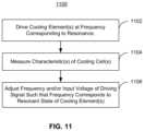
- FIG. 11depicts an embodiment of a method for using an active cooling system that utilizes a heat sink and is offset from a heat-generating structure.
- the inventioncan be implemented in numerous ways, including as a process; an apparatus; a system; a composition of matter; a computer program product embodied on a computer readable storage medium; and/or a processor, such as a processor configured to execute instructions stored on and/or provided by a memory coupled to the processor.
- these implementations, or any other form that the invention may take,may be referred to as techniques.
- the order of the steps of disclosed processesmay be altered within the scope of the invention.
- a componentsuch as a processor or a memory described as being configured to perform a task may be implemented as a general component that is temporarily configured to perform the task at a given time or a specific component that is manufactured to perform the task.
- the term ‘processor’refers to one or more devices, circuits, and/or processing cores configured to process data, such as computer program instructions.
- processors for mobile devicessuch as smartphones, tablet computers, notebook computers, and virtual reality devices as well as for other computing devices such as servers
- processorscan operate at high clock speeds, but produce a significant amount of heat.
- processorsmay run at full speed only for a relatively short period of time. After this time expires, throttling (e.g. slowing of the processor's clock speed) occurs.
- throttlingcan reduce heat generation, it also adversely affects processor speed and, therefore, the performance of devices using the processors.
- this issueis expected to be exacerbated.
- other components in a computing devicemay generate heat.
- thermal managementis increasingly an issue for computing devices.
- a cooling system including a heat spreader and a cooling elementis described.
- the heat spreaderis thermally coupled with a heat-generating structure.
- the cooling elementis in fluid communication heat spreader.
- the heat-generating structureis offset from the cooling element.
- the cooling elementundergoes vibrational motion when actuated to drive a fluid toward the heat spreader while not directing the fluid directly at the heat-generating structure.
- the heat spreader and the cooling elementhave a combined thickness of less than three millimeters.
- the heat spreader and the cooling elementmay have a combined thickness of less than two millimeters.
- the cooling systemfurther includes a support structure.
- the cooling elementhas a central region and a perimeter.
- the cooling elementis supported by the support structure at the central region. At least a portion of the perimeter is unpinned.
- the cooling systemmay also include a top plate having at least one vent therein.
- the cooling elementis between the top plate and the heat spreader.
- a top chamberis formed between the cooling element and the top plate.
- the cooling systemmay also include an orifice plate having at least one orifice therein. The orifice plate is disposed between the cooling element and the heat-generating structure. The cooling element is actuated to drive the fluid through the orifice(s).
- the top chamberhas a length corresponding to an odd integer multiplied by a wavelength divided by four.
- the wavelengthis an acoustic wavelength for a frequency of the vibrational motion.
- the frequency of the vibrational motioncorresponds to a structural resonance for the cooling element and to an acoustic resonance for the top chamber having the wavelength.
- a systemis described.
- the systemincludes a heat spreader and an active cooling system.
- the heat spreaderis thermally coupled with a heat-generating structure.
- the active cooling systemincludes a plurality of active cooling cells. Each of the active cooling cells includes a cooling element.
- the active cooling systemis in thermal communication with the heat spreader.
- the cooling elementundergoes vibrational motion when actuated to drive a fluid toward the heat spreader while not directing the fluid directly at the heat-generating structure.
- a combined thickness of the heat spreader and the active cooling systemdoes not exceed four millimeters.
- the heat-generating structureis offset from the active cooling system.
- the heat spreader and the active cooling systemhave a combined thickness of less than three millimeters. In some embodiments, the heat spreader and the active cooling system have a combined thickness of less than two millimeters.
- each active cooling cellfurther includes a support structure.
- the cooling elementhas a central region and a perimeter.
- the cooling elementis supported by the support structure at the central region. At least a portion of the perimeter is unpinned.
- Each active cooling cellmay further include a top plate having at least one vent therein.
- the cooling elementis between the top plate and the heat spreader.
- a top chamberis between the cooling element and the top plate.
- Each active cooling cellmay also include an orifice plate having at least one orifice therein.
- the orifice plateis disposed between the cooling element and the heat-generating structure.
- the cooling elementis actuated to drive the fluid through the orifice(s).
- the top chamberhas a length corresponding to an odd integer multiplied by a wavelength divided by four.
- the wavelengthis an acoustic wavelength for a frequency of the vibrational motion.
- the frequency of the vibrational motioncorresponds to a structural resonance for the cooling element and to an acoustic resonance for the top chamber having
- a methodincludes driving a cooling element to induce a vibrational motion at a frequency.
- the vibrational motiondrives a fluid toward a heat spreader that is in thermal communication with a heat-generating structure.
- the heat-generating structureis offset from the cooling element.
- the frequencycorresponds to a structural resonant frequency of the cooling element and an acoustic resonant frequency for the cooling element.
- the cooling elementis part of a cooling system that also includes a support structure.
- the cooling elementhas a central region and a perimeter.
- the cooling elementis supported by the support structure at the central region. At least a portion of the perimeter is unpinned.
- the heat spreader and the cooling elementhave a combined thickness of less than three millimeters. In some such embodiments, the heat spreader and the cooling element have a combined thickness of less than two millimeters.
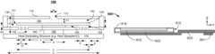
- FIGS. 1 A- 1 Gare diagrams depicting an exemplary embodiment of active MEMS cooling system 100 usable with heat-generating structure 102 and including a centrally anchored cooling element 120 or 120 ′. Cooling element 120 is shown in FIGS. 1 A- 1 F and cooling element 120 ′ is shown in FIG. 1 G . For clarity, only certain components are shown. FIGS. 1 A- 1 G are not to scale. FIGS. 1 A and 1 B depict cross-sectional and top views of cooling system 100 in a neutral position. FIGS. 1 C- 1 D depict cooling system 100 during actuation for in-phase vibrational motion. FIGS. 1 E- 1 F depict cooling system 100 during actuation for out-of-phase vibrational motion. Although shown as symmetric, cooling system 100 need not be.
- Cooling system 100includes top plate 110 having vent 112 therein, cooling element 120 , orifice plate 130 having orifices 132 therein, support structure (or “anchor”) 160 and chambers 140 and 150 (collectively chamber 140 / 150 ) formed therein. Cooling element 120 is supported at its central region by anchor 160 . Regions of cooling element 120 closer to and including portions of the cooling element's perimeter (e.g. tip 121 ) vibrate when actuated. In some embodiments, tip 121 of cooling element 120 includes a portion of the perimeter furthest from anchor 160 and undergoes the largest deflection during actuation of cooling element 120 . For clarity, only one tip 121 of cooling element 120 is labeled in FIG. 1 A . Also shown is pedestal 190 that connects orifice plate 130 to and offsets orifice plate 130 from heat-generating structure 102 . In some embodiments, pedestal 190 also thermally couples orifice plate 130 to heat-generating structure 102 .
- FIG. 1 Adepicts cooling system 100 in a neutral position.
- cooling element 120is shown as substantially flat.
- cooling element 120is driven to vibrate between positions shown in FIGS. 1 C and 1 D .
- This vibrational motiondraws fluid (e.g. air) into vent 112 , through chambers 140 and 150 and out orifices 132 at high speed and/or flow rates.
- the speed at which the fluid impinges on heat-generating structure 102may be at least thirty meters per second.
- the fluidis driven by cooling element 120 toward heat-generating structure 102 at a speed of at least forty-five meters per second.
- the fluidis driven toward heat-generating structure 102 by cooling element 120 at speeds of at least sixty meters per second. Other speeds may be possible in some embodiments.
- Cooling system 100is also configured so that little or no fluid is drawn back into chamber 140 / 150 through orifices 132 by the vibrational motion of cooling element 120 .
- Heat-generating structure 102is desired to be cooled by cooling system 100 .
- heat-generating structure 102generates heat.
- heat-generating structuremay be an integrated circuit.
- heat-generating structure 102is desired to be cooled but does not generate heat itself.
- Heat-generating structure 102may conduct heat (e.g. from a nearby object that generates heat).
- heat-generating structure 102might be a heat spreader or a vapor chamber.
- heat-generating structure 102may include semiconductor component(s) including individual integrated circuit components such as processors, other integrated circuit(s) and/or chip package(s); sensor(s); optical device(s); one or more batteries; other component(s) of an electronic device such as a computing device; heat spreaders; heat pipes; other electronic component(s) and/or other device(s) desired to be cooled.
- heat-generating structure 102may be a thermally conductive part of a module containing cooling system 100 .
- cooling system 100may be affixed to heat-generating structure 102 , which may be coupled to another heat sink, vapor chamber, integrated circuit, or other separate structure desired to be cooled.
- cooling system 100may be used in computing devices.
- Such computing devicesmay include but are not limited to smartphones, tablet computers, laptop computers, tablets, two-in-one laptops, hand held gaming systems, digital cameras, virtual reality headsets, augmented reality headsets, mixed reality headsets and other devices that are thin.
- Cooling system 100may be a micro-electro-mechanical system (MEMS) cooling system capable of residing within mobile computing devices and/or other devices having limited space in at least one dimension.
- MEMSmicro-electro-mechanical system
- the total height, h 3of cooling system 100 (from the top of heat-generating structure 102 to the top of top plate 110 ) may be less than 2 millimeters.
- the total height of cooling system 100is not more than 1.5 millimeters. In some embodiments, this total height is not more than 1.1 millimeters. In some embodiments, the total height does not exceed one millimeter. In some embodiments, the total height does not exceed two hundred and fifty micrometers.
- the distance between the bottom of orifice plate 130 and the top of heat-generating structure 102 , ymay be small. In some embodiments, y is at least two hundred micrometers and not more than 1.2 millimeter. For example, y may be at least two hundred and fifty micrometers and not more than three hundred micrometers. In some embodiments, y is at least five hundred micrometers and not more than one millimeter.
- cooling system 100is usable in computing devices and/or other devices having limited space in at least one dimension. However, nothing prevents the use of cooling system 100 in devices having fewer limitations on space and/or for purposes other than cooling.
- one cooling system 100is shown (e.g. one cooling cell), multiple cooling systems 100 might be used in connection with heat-generating structure 102 . For example, a one or two-dimensional array of cooling cells might be utilized.
- Cooling system 100is in communication with a fluid used to cool heat-generating structure 102 .
- the fluidmay be a gas or a liquid.
- the fluidmay be air.
- the fluidincludes fluid from outside of the device in which cooling system 100 resides (e.g. provided through external vents in the device).
- the fluidcirculates within the device in which cooling system resides (e.g. in an enclosed device).
- Cooling element 120can be considered to divide the interior of active MEMS cooling system 100 into top chamber 140 and bottom chamber 150 .
- Top chamber 140is formed by cooling element 120 , the sides, and top plate 110 .
- Bottom chamber 150is formed by orifice plate 130 , the sides, cooling element 120 and anchor 160 .
- Top chamber 140 and bottom chamber 150are connected at the periphery of cooling element 120 and together form chamber 140 / 150 (e.g. an interior chamber of cooling system 100 ).
- top chamber 140may be a function of the cell (cooling system 100 ) dimensions, cooling element 120 motion, and the frequency of operation.
- Top chamber 140has a height, h 1 .
- the height of top chamber 140may be selected to provide sufficient pressure to drive the fluid to bottom chamber 150 and through orifices 132 at the desired flow rate and/or speed.
- Top chamber 140is also sufficiently tall that cooling element 120 does not contact top plate 110 when actuated.
- the height of top chamber 140is at least fifty micrometers and not more than five hundred micrometers.
- top chamber 140has a height of at least two hundred and not more than three hundred micrometers.
- Bottom chamber 150has a height, h 2 .
- the height of bottom chamber 150is sufficient to accommodate the motion of cooling element 120 .
- Bottom chamber 150is generally smaller than top chamber 140 and may aid in reducing the backflow of fluid into orifices 132 .
- the height of bottom chamber 150is the maximum deflection of cooling element 120 plus at least five micrometers and not more than ten micrometers.
- the deflection of cooling element 120e.g. the deflection of tip 121
- zhas an amplitude of at least ten micrometers and not more than one hundred micrometers.
- the amplitude of deflection of cooling element 120is at least ten micrometers and not more than sixty micrometers. However, the amplitude of deflection of cooling element 120 depends on factors such as the desired flow rate through cooling system 100 and the configuration of cooling system 100 . Thus, the height of bottom chamber 150 generally depends on the flow rate through and other components of cooling system 100 .
- Top plate 110includes vent 112 through which fluid may be drawn into cooling system 100 .
- Top vent 112may have a size chosen based on the desired acoustic pressure in chamber 140 .
- the width, w, of vent 112is at least five hundred micrometers and not more than one thousand micrometers.
- the width of vent 112is at least two hundred fifty micrometers and not more than two thousand micrometers.
- vent 112is a centrally located aperture in top plate 110 .
- vent 112may be located elsewhere.
- vent 112may be closer to one of the edges of top plate 110 .
- Vent 112may have a circular, rectangular or other shaped footprint.
- vent 112may be offset toward the edges of top chamber 140 or be located on the side(s) of top chamber 140 .
- top plate 110is shown as substantially flat, in some embodiments trenches and/or other structures may be provided in top plate 110 to modify the configuration of top chamber 140 and/or the region above top plate 110 .
- Anchor (support structure) 160supports cooling element 120 at the central portion of cooling element 120 .
- anchor 160extends along a central axis of cooling element 120 (e.g. perpendicular to the page in FIGS. 1 A- 1 F ).
- portions of cooling element 120 that vibratee.g. including tip 121
- portions of cooling element 120may move in a manner analogous to the wings of a butterfly (i.e. in phase) and/or analogous to a seesaw (i.e. out of phase).
- anchor 160does not extend along an axis of cooling element 120 . In such embodiments, all portions of the perimeter of cooling element 120 are free to vibrate (e.g. analogous to a jellyfish).
- anchor 160supports cooling element 120 from the bottom of cooling element 120 .
- anchor 160may support cooling element 120 in another manner. For example, anchor 160 may support cooling element 120 from the top (e.g. cooling element 120 hangs from anchor 160 ).
- the width, a, of anchor 160is at least 0.5 millimeters and not more than four millimeters. In some embodiments, the width of anchor 160 is at least two millimeters and not more than 2.5 millimeters. Anchor 160 may occupy at least ten percent and not more than fifty percent of cooling element 120 .
- Cooling element 120has a first side distal from heat-generating structure 102 and a second side proximate to heat-generating structure 102 .
- the first side of cooling element 120is the top of cooling element 120 (closer to top plate 110 ) and the second side is the bottom of cooling element 120 (closer to orifice plate 130 ).
- Cooling element 120is actuated to undergo vibrational motion as shown in FIGS. 1 A- 1 F .
- the vibrational motion of cooling element 120drives fluid from the first side of cooling element 120 distal from heat-generating structure 102 (e.g. from top chamber 140 ) to a second side of cooling element 120 proximate to heat-generating structure 102 (e.g. to bottom chamber 150 ).
- cooling element 120may be viewed as an actuator. Although described in the context of a single, continuous cooling element, in some embodiments, cooling element 120 may be formed by two (or more) cooling elements. Each of the cooling elements as one portion pinned (e.g. supported by support structure 160 ) and an opposite portion unpinned. Thus, a single, centrally supported cooling element 120 may be formed by a combination of multiple cooling elements supported at an edge.
- Cooling element 120has a length, L, that depends upon the frequency at which cooling element 120 is desired to vibrate. In some embodiments, the length of cooling element 120 is at least four millimeters and not more than ten millimeters. In some such embodiments, cooling element 120 has a length of at least six millimeters and not more than eight millimeters.
- the depth of cooling element 120(e.g. perpendicular to the plane shown in FIGS. 1 A- 1 F ) may vary from one fourth of L through twice L. For example, cooling element 120 may have the same depth as length.
- the thickness, t, of cooling element 120may vary based upon the configuration of cooling element 120 and/or the frequency at which cooling element 120 is desired to be actuated.
- the cooling element thicknessis at least two hundred micrometers and not more than three hundred and fifty micrometers for cooling element 120 having a length of eight millimeters and driven at a frequency of at least twenty kilohertz and not more than twenty-five kilohertz.
- the length, C of chamber 140 / 150is close to the length, L, of cooling element 120 .
- the distance, d, between the edge of cooling element 120 and the wall of chamber 140 / 150is at least one hundred micrometers and not more than five hundred micrometers. In some embodiments, d is at least two hundred micrometers and not more than three hundred micrometers.
- Cooling element 120may be driven at a frequency that is at or near both the resonant frequency for an acoustic resonance of a pressure wave of the fluid in top chamber 140 and the resonant frequency for a structural resonance of cooling element 120 .
- the portion of cooling element 120 undergoing vibrational motionis driven at or near resonance (the “structural resonance”) of cooling element 120 .
- This portion of cooling element 120 undergoing vibrationmay be a cantilevered section in some embodiments.
- the frequency of vibration for structural resonanceis termed the structural resonant frequency. Use of the structural resonant frequency in driving cooling element 120 reduces the power consumption of cooling system 100 .
- Cooling element 120 and top chamber 140may also be configured such that this structural resonant frequency corresponds to a resonance in a pressure wave in the fluid being driven through top chamber 140 (the acoustic resonance of top chamber 140 ).
- the frequency of such a pressure waveis termed the acoustic resonant frequency.
- a node in pressureoccurs near vent 112 and an antinode in pressure occurs near the periphery of cooling system 100 (e.g. near tip 121 of cooling element 120 and near the connection between top chamber 140 and bottom chamber 150 ).
- the distance between these two regionsis C/2.
- C/2n ⁇ /4, where ⁇ is the acoustic wavelength for the fluid and n is odd (e.g.
- n1, 3, 5, etc.).
- C⁇ /2.
- vis at or near the structural resonant frequency for cooling element 120 .
- the frequency vis also at or near the acoustic resonant frequency for at least top chamber 140 .
- the acoustic resonant frequency of top chamber 140generally varies less dramatically with parameters such as temperature and size than the structural resonant frequency of cooling element 120 . Consequently, in some embodiments, cooling element 120 may be driven at (or closer to) a structural resonant frequency than to the acoustic resonant frequency.
- Orifice plate 130has orifices 132 therein. Although a particular number and distribution of orifices 132 are shown, another number and/or another distribution may be used.
- a single orifice plate 130is used for a single cooling system 100 . In other embodiments, multiple cooling systems 100 may share an orifice plate. For example, multiple cells 100 may be provided together in a desired configuration. In such embodiments, the cells 100 may be the same size and configuration or different size(s) and/or configuration(s).
- Orifices 132are shown as having an axis oriented normal to a surface of heat-generating structure 102 . In other embodiments, the axis of one or more orifices 132 may be at another angle.
- the angle of the axismay be selected from substantially zero degrees and a nonzero acute angle.
- Orifices 132also have sidewalls that are substantially parallel to the normal to the surface of orifice plate 130 .
- orificesmay have sidewalls at a nonzero angle to the normal to the surface of orifice plate 130 .
- orifices 132may be cone-shaped.
- trenches and/or other structuresmay be provided in orifice plate 130 to modify the configuration of bottom chamber 150 and/or the region between orifice plate 130 and heat-generating structure 102 .
- the size, distribution and locations of orifices 132are chosen to control the flow rate of fluid driven to the surface of heat-generating structure 102 .
- the locations and configurations of orifices 132may be configured to increase/maximize the fluid flow from bottom chamber 150 through orifices 132 to the jet channel (the region between the bottom of orifice plate 130 and the top of heat-generating structure 102 ).
- the locations and configurations of orifices 132may also be selected to reduce/minimize the suction flow (e.g. back flow) from the jet channel through orifices 132 .
- the locations of orificesare desired to be sufficiently far from tip 121 that suction in the upstroke of cooling element 120 (tip 121 moves away from orifice plate 13 ) that would pull fluid into bottom chamber 150 through orifices 132 is reduced.
- the locations of orificesare also desired to be sufficiently close to tip 121 that suction in the upstroke of cooling element 120 also allows a higher pressure from top chamber 140 to push fluid from top chamber 140 into bottom chamber 150 .
- the ratio of the flow rate from top chamber 140 into bottom chamber 150 to the flow rate from the jet channel through orifices 132 in the upstrokeis greater than 2:1. In some embodiments, the net flow ratio is at least 85:15.
- the net flow ratiois at least 90:10.
- orifices 132are desired to be at least a distance, r 1 , from tip 121 and not more than a distance, r 2 , from tip 121 of cooling element 120 .
- r 1is at least one hundred micrometers (e.g. r 1 ⁇ 100 ⁇ m) and r 2 is not more than one millimeter (e.g. r 2 ⁇ 1000 ⁇ m).
- orifices 132are at least two hundred micrometers from tip 121 of cooling element 120 (e.g. r 1 ⁇ 200 ⁇ m).
- orifices 132are at least three hundred micrometers from tip 121 of cooling element 120 (e.g. r 1 ⁇ 300 ⁇ m). In some embodiments, orifices 132 have a width, o, of at least one hundred micrometers and not more than five hundred micrometers. In some embodiments, orifices 132 have a width of at least two hundred micrometers and not more than three hundred micrometers. In some embodiments, the orifice separation, s, is at least one hundred micrometers and not more than one millimeter. In some such embodiments, the orifice separation is at least four hundred micrometers and not more than six hundred micrometers.
- orifices 132are also desired to occupy a particular fraction of the area of orifice plate 130 .
- orifices 132may cover at least five percent and not more than fifteen percent of the footprint of orifice plate 130 in order to achieve a desired flow rate of fluid through orifices 132 .
- orifices 132cover at least eight percent and not more than twelve percent of the footprint of orifice plate 130 .
- cooling element 120is actuated using a piezoelectric.
- cooling element 120may be a piezoelectric cooling element.
- Cooling element 120may be driven by a piezoelectric that is mounted on or integrated into cooling element 120 .
- cooling element 120is driven in another manner including but not limited to providing a piezoelectric on another structure in cooling system 100 .
- Cooling element 120 and analogous cooling elementsare referred to hereinafter as piezoelectric cooling element though it is possible that a mechanism other than a piezoelectric might be used to drive the cooling element.
- cooling element 120includes a piezoelectric layer on substrate.
- the substratemay include or consist of stainless steel, a Ni alloy, Hastelloy, Al (e.g.
- piezoelectric layerincludes multiple sublayers formed as thin films on the substrate.
- the piezoelectric layermay be a bulk layer affixed to the substrate.
- Such a piezoelectric cooling element 120also includes electrodes used to activate the piezoelectric.
- the substratefunctions as an electrode in some embodiments.
- a bottom electrodemay be provided between the substrate and the piezoelectric layer.
- Other layersincluding but not limited to seed, capping, passivation or other layers might be included in piezoelectric cooling element.
- cooling element 120may be actuated using a piezoelectric.
- cooling system 100includes chimneys (not shown) or other ducting. Such ducting provides a path for heated fluid to flow away from heat-generating structure 102 . In some embodiments, ducting returns fluid to the side of top plate 110 distal from heat-generating structure 102 . In some embodiments, ducting may instead direct fluid away from heat-generating structure 102 in a direction parallel to heat-generating structure 102 or perpendicular to heat-generating structure 102 but in the opposite direction (e.g. toward the bottom of the page). For a device in which fluid external to the device is used in cooling system 100 , the ducting may channel the heated fluid to a vent. In such embodiments, additional fluid may be provided from an inlet vent.
- the ductingmay provide a circuitous path back to the region near vent 112 and distal from heat-generating structure 102 . Such a path allows for the fluid to dissipate heat before being reused to cool heat-generating structure 102 .
- ductingmay be omitted or configured in another manner. Thus, the fluid is allowed to carry away heat from heat-generating structure 102 .
- FIGS. 1 C- 1 Ddepict in-phase operation of cooling system 100 .
- cooling element 120has been actuated so that its tip 121 moves away from top plate 110 .
- FIG. 1 Ccan thus be considered to depict the end of a down stroke of cooling element 120 .
- gap 152 for bottom chamber 150has decreased in size and is shown as gap 152 B.
- gap 142 for top chamber 140has increased in size and is shown as gap 142 B.
- a lower (e.g. minimum) pressureis developed at the periphery when cooling element 120 is at the neutral position.
- bottom chamber 150decreases in size and top chamber 140 increases in size as shown in FIG. 1 C .
- fluidis driven out of orifices 132 in a direction that is at or near perpendicular to the surface of orifice plate 130 and/or the top surface of heat-generating structure 102 .
- the fluidis driven from orifices 132 toward heat-generating structure 102 at a high speed, for example in excess of thirty-five meters per second.
- the fluidthen travels along the surface of heat-generating structure 102 and toward the periphery of heat-generating structure 102 , where the pressure is lower than near orifices 132 . Also in the down stroke, top chamber 140 increases in size and a lower pressure is present in top chamber 140 . As a result, fluid is drawn into top chamber 140 through vent 112 . The motion of the fluid into vent 112 , through orifices 132 , and along the surface of heat-generating structure 102 is shown by unlabeled arrows in FIG. 1 C .
- Cooling element 120is also actuated so that tip 121 moves away from heat-generating structure 102 and toward top plate 110 .
- FIG. 1 Dcan thus be considered to depict the end of an up stroke of cooling element 120 .
- gap 142has decreased in size and is shown as gap 142 C.
- Gap 152has increased in size and is shown as gap 152 C.
- a higher (e.g. maximum) pressureis developed at the periphery when cooling element 120 is at the neutral position.
- bottom chamber 150increases in size and top chamber 140 decreases in size as shown in FIG. 1 D .
- the fluidis driven from top chamber 140 (e.g.
- cooling system 100is able to drive fluid from top chamber 140 to bottom chamber 150 without an undue amount of backflow of heated fluid from the jet channel entering bottom chamber 140 .
- cooling system 100may operate such that fluid is drawn in through vent 112 and driven out through orifices 132 without cooling element 120 contacting top plate 110 or orifice plate 130 .
- pressuresare developed within chambers 140 and 150 that effectively open and close vent 112 and orifices 132 such that fluid is driven through cooling system 100 as described herein.
- cooling element 120undergoes vibrational motion indicated in FIGS. 1 A- 1 D , drawing fluid through vent 112 from the distal side of top plate 110 into top chamber 140 ; transferring fluid from top chamber 140 to bottom chamber 150 ; and pushing the fluid through orifices 132 and toward heat-generating structure 102 .
- cooling element 120is driven to vibrate at or near the structural resonant frequency of cooling element 120 .
- the structural resonant frequency of cooling element 120is configured to align with the acoustic resonance of the chamber 140 / 150 .
- the structural and acoustic resonant frequenciesare generally chosen to be in the ultrasonic range.
- the vibrational motion of cooling element 120may be at frequencies from 15 kHz through 30 kHz.
- cooling element 120vibrates at a frequency/frequencies of at least 20 kHz and not more than 30 kHz.
- the structural resonant frequency of cooling element 120is within ten percent of the acoustic resonant frequency of cooling system 100 .
- the structural resonant frequency of cooling element 120is within five percent of the acoustic resonant frequency of cooling system 100 .
- the structural resonant frequency of cooling element 120is within three percent of the acoustic resonant frequency of cooling system 100 . Consequently, efficiency and flow rate may be enhanced. However, other frequencies may be used.
- Fluid driven toward heat-generating structure 102may move substantially normal (perpendicular) to the top surface of heat-generating structure 102 .
- the fluid motionmay have a nonzero acute angle with respect to the normal to the top surface of heat-generating structure 102 .
- the fluidmay thin and/or form apertures in the boundary layer of fluid at heat-generating structure 102 .
- transfer of heat from heat-generating structure 102may be improved.
- the fluiddeflects off of heat-generating structure 102 , traveling along the surface of heat-generating structure 102 .
- the fluidmoves in a direction substantially parallel to the top of heat-generating structure 102 .
- heat from heat-generating structure 102may be extracted by the fluid.
- the fluidmay exit the region between orifice plate 130 and heat-generating structure 102 at the edges of cooling system 100 .
- Chimneys or other ducting (not shown) at the edges of cooling system 100allow fluid to be carried away from heat-generating structure 102 .
- heated fluidmay be transferred further from heat-generating structure 102 in another manner.
- the fluidmay exchange the heat transferred from heat-generating structure 102 to another structure or to the ambient environment.
- fluid at the distal side of top plate 110may remain relatively cool, allowing for the additional extraction of heat.
- fluidis circulated, returning to distal side of top plate 110 after cooling.
- heated fluidis carried away and replaced by new fluid at the distal side of cooling element 120 . As a result, heat-generating structure 102 may be cooled.
- FIGS. 1 E- 1 Fdepict an embodiment of active MEMS cooling system 100 including centrally anchored cooling element 120 in which the cooling element is driven out-of-phase. More specifically, sections of cooling element 120 on opposite sides of anchor 160 (and thus on opposite sides of the central region of cooling element 120 that is supported by anchor 160 ) are driven to vibrate out-of-phase. In some embodiments, sections of cooling element 120 on opposite sides of anchor 160 are driven at or near one hundred and eighty degrees out-of-phase. Thus, one section of cooling element 120 vibrates toward top plate 110 , while the other section of cooling element 120 vibrates toward orifice plate 130 /heat-generating structure 102 .
- Movement of a section of cooling element 120 toward top plate 110drives fluid in top chamber 140 to bottom chamber 150 on that side of anchor 160 .
- Movement of a section of cooling element 120 toward orifice plate 130drives fluid through orifices 132 and toward heat-generating structure 102 .
- fluid traveling at high speedse.g. speeds described with respect to in-phase operation
- cooling system 100may be viewed as a ME Ms jet.
- the movement of fluidis shown by unlabeled arrows in FIGS. 1 E and 1 F .
- the motion between the positions shown in FIGS. 1 E and 1 Fis repeated.
- cooling element 120undergoes vibrational motion indicated in FIGS. 1 A, 1 E, and 1 F , alternately drawing fluid through vent 112 from the distal side of top plate 110 into top chamber 140 for each side of cooling element 120 ; transferring fluid from each side of top chamber 140 to the corresponding side of bottom chamber 150 ; and pushing the fluid through orifices 132 on each side of anchor 160 and toward heat-generating structure 102 .
- cooling element 120is driven to vibrate at or near the structural resonant frequency of cooling element 120 .
- the structural resonant frequency of cooling element 120is configured to align with the acoustic resonance of the chamber 140 / 150 .
- the structural and acoustic resonant frequenciesare generally chosen to be in the ultrasonic range.
- the vibrational motion of cooling element 120may be at the frequencies described for in-phase vibration.
- the structural resonant frequency of cooling element 120is within ten percent of the acoustic resonant frequency of cooling system 100 .
- the structural resonant frequency of cooling element 120is within five percent of the acoustic resonant frequency of cooling system 100 .
- the structural resonant frequency of cooling element 120is within three percent of the acoustic resonant frequency of cooling system 100 . Consequently, efficiency and flow rate may be enhanced. However, other frequencies may be used.
- Fluid driven toward heat-generating structure 102 for out-of-phase vibrationmay move substantially normal (perpendicular) to the top surface of heat-generating structure 102 , in a manner analogous to that described above for in-phase operation.
- chimneys or other ducting (not shown) at the edges of cooling system 100allow fluid to be carried away from heat-generating structure 102 .
- heated fluidmay be transferred further from heat-generating structure 102 in another manner. The fluid may exchange the heat transferred from heat-generating structure 102 to another structure or to the ambient environment.
- fluid at the distal side of top plate 110may remain relatively cool, allowing for the additional extraction of heat.
- fluidis circulated, returning to distal side of top plate 110 after cooling.
- heated fluidis carried away and replaced by new fluid at the distal side of cooling element 120 . As a result, heat-generating structure 102 may be cooled.
- cooling system 100may utilize cooling elements having different shapes.
- FIG. 1 Gdepicts an embodiment of engineered cooling element 120 ′ having a tailored geometry and usable in a cooling system such as cooling system 100 .
- Cooling element 120 ′includes an anchored region 122 and cantilevered arms 123 .
- Anchored region 122is supported (e.g. held in place) in cooling system 100 by anchor 160 .
- Cantilevered arms 123undergo vibrational motion in response to cooling element 120 ′ being actuated.
- Each cantilevered arm 123includes step region 124 , extension region 126 and outer region 128 .
- anchored region 122is centrally located.
- Step region 124extends outward from anchored region 122 .
- Extension region 126extends outward from step region 124 .
- Outer region 128extends outward from extension region 126 .
- anchored region 122may be at one edge of the actuator and outer region 128 at the opposing edge. In such embodiments, the actuator is edge anchored.
- Extension region 126has a thickness (extension thickness) that is less than the thickness of step region 124 (step thickness) and less than the thickness of outer region 128 (outer thickness). Thus, extension region 126 may be viewed as recessed. Extension region 126 may also be seen as providing a larger bottom chamber 150 .
- the outer thickness of outer region 128is the same as the step thickness of step region 124 . In some embodiments, the outer thickness of outer region 128 is different from the step thickness of step region 124 . In some embodiments, outer region 128 and step region 124 each have a thickness of at least three hundred twenty micrometers and not more than three hundred and sixty micrometers.
- the outer thicknessis at least fifty micrometers and not more than two hundred micrometers thicker than the extension thickness.
- the stepis at least fifty micrometers and not more than two hundred micrometers.
- the outer stepis at least fifty micrometers and not more than two hundred micrometers.
- Outer region 128may have a width, o, of at least one hundred micrometers and not more than three hundred micrometers.
- Extension regionhas a length, e, extending outward from the step region of at least 0.5 millimeter and not more than 1.5 millimeters in some embodiments.
- outer region 128has a higher mass per unit length in the direction from anchored region 122 than extension region 126 . This difference in mass may be due to the larger size of outer region 128 , a difference in density between portions of cooling element 120 , and/or another mechanism.
- Extension region 126is thinner than step region 124 and outer region 128 . This results in a cavity in the bottom of cooling element 120 ′ corresponding to extension region 126 . The presence of this cavity aids in improving the efficiency of cooling system 100 .
- Each cantilevered arm 123vibrates towards top plate 110 in an upstroke and away from top plate 110 in a downstroke. When a cantilevered arm 123 moves toward top plate 110 , higher pressure fluid in top chamber 140 resists the motion of cantilevered arm 123 . Furthermore, suction in bottom chamber 150 also resists the upward motion of cantilevered arm 123 during the upstroke.
- cantilevered arm 123In the downstroke of cantilevered arm 123 , increased pressure in the bottom chamber 150 and suction in top chamber 140 resist the downward motion of cantilevered arm 123 . However, the presence of the cavity in cantilevered arm 123 corresponding to extension region 126 mitigates the suction in bottom chamber 150 during an upstroke. The cavity also reduces the increase in pressure in bottom chamber 150 during a downstroke. Because the suction and pressure increase are reduced in magnitude, cantilevered arms 123 may more readily move through the fluid. This may be achieved while substantially maintaining a higher pressure in top chamber 140 , which drives the fluid flow through cooling system 100 . Moreover, the presence of outer region 128 may improve the ability of cantilevered arm 123 to move through the fluid being driven through cooling system 100 .
- Outer region 128has a higher mass per unit length and thus a higher momentum. Consequently, outer region 128 may improve the ability of cantilevered arms 123 to move through the fluid being driven through cooling system 100 .
- the magnitude of the deflection of cantilevered arm 123may also be increased. These benefits may be achieved while maintaining the stiffness of cantilevered arms 123 through the use of thicker step region 124 . Further, the larger thickness of outer region 128 may aid in pinching off flow at the bottom of a downstroke.
- the ability of cooling element 120 ′ to provide a valve preventing backflow through orifices 132may be improved.
- performance of cooling system 100 employing cooling element 120 ′may be improved.
- cooling elements used in cooling system 100may have different structures and/or be mounted differently than depicted in FIGS. 1 A- 1 G .
- the cooling elementmay have rounded corners and/or rounded ends but still be anchored along a central axis such that cantilevered arms vibrate.
- the cooling elementmay be anchored only at its central region such that the regions surrounding the anchor vibrate in a manner analogous to a jellyfish or the opening/closing of an umbrella.
- the cooling elementmay be circular or elliptical in shape.
- the anchormay include apertures through which fluid may flow. Such an anchor may be utilized for the cooling element being anchored at its top (e.g. to the top plate).
- the piezoelectric utilized in driving the cooling elementmay have various locations and/or configurations.
- the piezoelectricmay be embedded in the cooling element, affixed to one side of the cooling element (or cantilevered arm(s)), may occupy some or all of the cantilevered arms, and/or may have a location that is close to or distal from the anchored region.
- cooling elements that are not centrally anchoredmay be used.
- a pair of cooling elements that have offset apertures, that are anchored at their ends (or all edges), and which vibrate out of phasemay be used.
- various additional configurations of cooling element 120 and/or 120 ′, anchor 160 , and/or other portions of cooling system 100may be used.
- fluid drawn in through vent 112 and driven through orifices 132may efficiently dissipate heat from heat-generating structure 102 . Because fluid impinges upon the heat-generating structure with sufficient speed (e.g. at least thirty meters per second) and in some embodiments substantially normal to the heat-generating structure, the boundary layer of fluid at the heat-generating structure may be thinned and/or partially removed. Consequently, heat transfer between heat-generating structure 102 and the moving fluid is improved. Because the heat-generating structure is more efficiently cooled, the corresponding integrated circuit may be run at higher speed and/or power for longer times.
- cooling system 100may be a MEMS device. Consequently, cooling systems 100 may be suitable for use in smaller and/or mobile devices, such as smart phones, other mobile phones, virtual reality headsets, tablets, two-in-one computers, wearables and handheld games, in which limited space is available. Performance of such devices may thus be improved. Because cooling element 120 / 120 ′ may be vibrated at frequencies of 15 kHz or more, users may not hear any noise associated with actuation of cooling elements.
- Cooling element 120 / 120 ′does not physically contact top plate 110 or orifice plate 130 during vibration. Thus, resonance of cooling element 120 / 120 ′ may be more readily maintained. More specifically, physical contact between cooling element 120 / 120 ′ and other structures disturbs the resonance conditions for cooling element 120 / 120 ′. Disturbing these conditions may drive cooling element 120 / 120 ′ out of resonance. Thus, additional power would need to be used to maintain actuation of cooling element 120 / 120 ′. Further, the flow of fluid driven by cooling element 120 / 120 ′ may decrease. These issues are avoided through the use of pressure differentials and fluid flow as discussed above.
- cooling system 100may be usable in other applications (e.g. with or without heat-generating structure 102 ) in which high fluid flows and/or velocities are desired.
- FIGS. 2 A- 2 Bdepict an embodiment of active MEMS cooling system 200 including a top centrally anchored cooling element.
- FIG. 2 Adepicts a side view of cooling system 200 in a neutral position.
- FIG. 2 Bdepicts a top view of cooling system 200 .
- FIGS. 2 A- 2 Bare not to scale. For simplicity, only portions of cooling system 200 are shown.
- cooling system 200is analogous to cooling system 100 . Consequently, analogous components have similar labels.
- cooling system 200is used in conjunction with heat-generating structure 202 , which is analogous to heat-generating structure 202 .
- Cooling system 200includes top plate 210 having vents 212 , cooling element 220 having tip 221 , orifice plate 230 including orifices 232 , top chamber 240 having a gap, bottom chamber 250 having a gap, flow chamber 240 / 250 , and anchor (i.e. support structure) 260 that are analogous to top plate 110 having vent 112 , cooling element 120 having tip 121 , orifice plate 130 including orifices 132 , top chamber 140 having gap 142 , bottom chamber 150 having gap 152 , flow chamber 140 / 150 , and anchor (i.e. support structure) 160 , respectively. Also shown is pedestal 290 that is analogous to pedestal 190 .
- cooling element 220is centrally supported by anchor 260 such that at least a portion of the perimeter of cooling element 220 is free to vibrate.
- anchor 260extends along the axis of cooling element 420 .
- anchor 460is only near the center portion of cooling element 420 .
- cooling element 220includes an anchored region and cantilevered arms including step region, extension region and outer regions analogous to anchored region 122 , cantilevered arms 123 , step region 124 , extension region 126 and outer region 128 of cooling element 120 ′.
- cantilevered arms of cooling element 220are driven in-phase.
- cantilevered arms of cooling element 220are driven out-of-phase.
- a simple cooling elementsuch as cooling element 120 , may be used.
- Anchor 260supports cooling element 220 from above. Thus, cooling element 220 is suspended from anchor 260 .
- Anchor 260is suspended from top plate 210 .
- Top plate 210includes vent 213 . Vents 212 on the sides of anchor 260 provide a path for fluid to flow into sides of chamber 240 .
- cooling element 220may be driven to vibrate at or near the structural resonant frequency of cooling element 220 .
- the structural resonant frequency of cooling element 220may be configured to align with the acoustic resonance of the chamber 240 / 250 .
- the structural and acoustic resonant frequenciesare generally chosen to be in the ultrasonic range.
- the vibrational motion of cooling element 220may be at the frequencies described with respect to cooling system 100 . Consequently, efficiency and flow rate may be enhanced. However, other frequencies may be used.
- Cooling system 200operates in an analogous manner to cooling system 100 . Cooling system 200 thus shares the benefits of cooling system 100 . Thus, performance of a device employing cooling system 200 may be improved. In addition, suspending cooling element 220 from anchor 260 may further enhance performance. In particular, vibrations in cooling system 200 that may affect other cooling cells (not shown), may be reduced. For example, less vibration may be induced in top plate 210 due to the motion of cooling element 220 . Consequently, cross talk between cooling system 200 and other cooling systems (e.g. other cells) or other portions of the device incorporating cooling system 200 may be reduced. Thus, performance may be further enhanced.
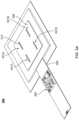
- FIGS. 3 A- 3 Edepict an embodiment of active MEMS cooling system 300 including multiple cooling cells configured as a module termed a tile, or array.
- FIG. 3 Adepicts a perspective view
- FIGS. 3 B- 3 Edepict side views.
- FIGS. 3 A- 3 Eare not to scale.
- Cooling system 300includes four cooling cells 301 A, 301 B, 301 C and 301 D (collectively or generically 301 ), which are analogous to one or more of cooling systems described herein. More specifically, cooling cells 301 are analogous to cooling system 100 and/or 200 .
- Tile 300thus includes four cooling cells 301 (i.e. four MEMS jets).
- cooling cells 301include shared top plate 310 having apertures 312 , cooling elements 320 , shared orifice plate 330 including orifices 332 , top chambers 340 , bottom chambers 350 , anchors (support structures) 360 , and pedestals 390 that are analogous to top plate 110 having apertures 112 , cooling element 120 , orifice plate 130 having orifices 132 , top chamber 140 , bottom chamber 150 , anchor 160 , and pedestal 190 .
- cooling cells 301may be fabricated together and separated, for example by cutting through top plate 310 , side walls between cooling cells 301 , and orifice plate 330 .
- tabs(not shown) and/or other structures such as anchors 360 , may connect cooling cells 301 .
- tile 300includes heat-generating structure (termed a heat spreader hereinafter) 302 (e.g. a heat sink, a heat spreader, and/or other structure) that also has sidewalls, or fencing, in the embodiment shown.
- Cover plate 306having apertures therein is also shown.
- Heat spreader 302 and cover plate 306may be part of an integrated tile 300 as shown or may be separate from tile 300 in other embodiments. Heat spreader 302 and cover plate 306 may direct fluid flow outside of cooling cells 301 , provide mechanical stability, and/or provide protection. Electrical connection to cooling cells 301 is provided via flex connector 380 (not shown in FIGS. 3 B- 5 E ) which may house drive electronics 385 . Cooling elements 320 are driven out-of-phase (i.e. in a manner analogous to a seesaw). Further, as can be seen in FIGS. 3 B- 3 C and FIGS. 3 D- 3 E cooling element 320 in one cell is driven out-of-phase with cooling element(s) 320 in adjacent cell(s). In FIGS.
- cooling elements 320 in a roware driven out-of-phase.
- cooling element 320 in cell 301 Ais out-of-phase with cooling element 320 in cell 301 B.
- cooling element 320 in cell 301 Cis out-of-phase with cooling element 320 in cell 301 D.
- cooling elements 320 in a columnare driven out-of-phase.
- cooling element 320 in cell 301 Ais out-of-phase with cooling element 320 in cell 301 C.
- cooling element 320 in cell 301 Bis out-of-phase with cooling element 320 in cell 301 D.
- Cooling cells 301 of cooling system 300functions in an analogous manner to cooling system(s) 100 , 200 , and/or an analogous cooling system. Consequently, the benefits described herein may be shared by cooling system 300 . Because cooling elements in nearby cells are driven out-of-phase, vibrations in cooling system 300 may be reduced. Because multiple cooling cells 301 are used, cooling system 300 may enjoy enhanced cooling capabilities. Further, multiples of individual cooling cells 301 and/or cooling system 300 may be combined in various fashions to obtain the desired footprint of cooling cells.
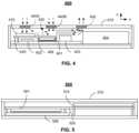
- FIG. 4depicts an embodiment of active cooling system 400 that utilizes a heat sink and is offset from a heat-generating structure in a device.
- the devicemay be a laptop computer, a tablet or notebook computer, a smart phone, and/or other mobile device.
- the devicemay also be another device, such as a server in a rack, a game console, or a desktop computer.
- the deviceis thin.
- the devicehas a thickness (height along the smallest dimension, the z-direction in FIG. 4 ) of not more than twenty-five millimeters.
- the thicknessis not more than ten millimeters in some embodiments.
- the thickness of the deviceis not more than eight millimeters. However, other thicknesses are possible.
- the device into which cooling system 400 is integratedincludes heat-generating structure 401 , additional components 402 , 403 , and 404 , substrate 406 , and housing 470 .
- Heat-generating structure 401is a component that is desired to be cooled.
- heat-generating structure 401may be an integrated circuit, such as a processor, or other device.
- heat-generating structure 401may rise significantly in temperature.
- the top near heat spreader 420may be on the order of ninety degrees Celsius and the junction temperature may be on the order of ninety-three to ninety four degrees Celsius.
- Substrate 406may be a printed circuit board (PCB) or other substrate on which heat-generating structure 401 and additional components 402 and 403 are mounted. In some embodiments, substrate 406 may be omitted. Components 402 , 403 , and 404 may also generate heat.
- PCBprinted circuit board
- egress passageway 430inlets 440 A and 440 B (collectively or generically 440 ), and egress 450 .
- Inlets 440 A and 440 B and egress 450allow for an exchange in fluid (e.g. air) internal to housing 470 with fluid external to the device.
- inlets 440 A and 440 B and egress 450may be vents.
- two inlets 440 A and 440 B and one egress 450are shown, in some embodiments, another number of inlet(s) and/or egress(es) may be present.
- inlet(s) 440 A and/or 440 Bmay allow some fluid to exit the device.
- egress 450may allow some fluid to enter the device.
- inlet and egressare intended to indicate the primary function of the structures 440 A, 440 B, and 450 .
- one or more of components 430 , 440 A, 440 B, and/or 450may be omitted, located differently, and/or configured differently.
- egress passageway 430 , inlets 440 , and egress 450may be considered part of cooling system 400 . Cooling system 400 may be used for thermal management of not only heat-generating structure 401 , but also components 402 , 403 , and/or 404 .
- Cooling system 400includes MEMS cooling system 410 and heat spreader 420 .
- MEMS cooling system 410includes one or more cooling cells analogous to cooling systems 100 and/or 200 .
- MEMS cooling system 410includes multiple cooling cells configured as a module termed a tile.
- MEMS cooling system 410may include one or more tiles 300 , each of which includes multiple cooling cells.
- MEMS cooling system 410thus includes cooling element(s) configured to undergo vibrational motion when actuated to drive a fluid. The cooling elements are considered to be fluidically connected with heat spreader 420 .
- MEMS cooling system 410may also include top plate(s), anchor(s), orifice plate(s), and/or pedestal(s) analogous to those described in the context of cooling system 100 and/or 200 .
- MEMS cooling system 410may also include an integrated heat spreader, fencing, and cover analogous to those described in the context of tile 300 .
- MEMS cooling system 410may have a thickness of not more than three millimeters. In some embodiments, MEMS cooling system 410 has a thickness of not more than 2.5 millimeters. MEMS cooling system 410 may have a thickness of not more than two millimeters.
- MEMS cooling system 410is thermally coupled with heat spreader 420 .
- MEMS cooling system 410is physically connected to heat spreader 420 .
- the integrated heat spreader of MEMS cooling system 410may be affixed to heat spreader 420 through a thermally conductive epoxy or analogous material.
- MEMS cooling system 410is fluidically coupled with heat spreader 420 . Stated differently, fluid driven by cooling elements in MEMS cooling system 410 may remove heat from MEMS cooling system 410 and/or heat spreader 420 .
- MEMS cooling system 410is offset from heat-generating structure 401 .
- MEMS cooling system 410is not aligned with heat-generating structure 401 .
- MEMS cooling system 410would not drive fluid directly on or directly toward heat-generating structure 401 .
- the cooling element(s) of MEMS cooling system 410undergo vibrational motion when actuated to drive a fluid toward heat spreader 420 while not directing the fluid directly at heat-generating structure 401 . This is in contrast to the location of component 402 with respect to MEMS cooling system 410 .
- structure 420may be a heat spreader, vapor chamber (or heat pipe), heat sink, and/or other component that is thermally coupled to heat-generating structure 401 and transfers heat from heat-generating structure 401 .
- heat spreader 420may be thermally connected to heat-generating structure 401 via a thermal interface material and/or other conductor of heat.
- heat spreader 420is thermally connected to heat-generating structure 401 in another manner. Thus, heat produced by heat-generating structure 401 is readily transferred to heat spreader 420 .
- fluide.g. air
- the fluid entering via inlet 440 Ais cooler.
- the cool fluidmay be the temperature of the ambient in which the device operates.
- the cool fluidmay be at or near room temperature (e.g. 22-28 degrees Celsius).
- This flow of cooler fluidis shown by dashed arrows.
- Some, most, or all of this fluidflows through MEMS cooling system 410 .
- Fluidenters MEMS cooling system 410 via apertures (not shown in FIG. 4 ), is driven through MEMS cooling system 410 by vibrational motion of cooling elements (not shown in FIG. 4 ), and exits MEMS cooling system 410 .
- Heat from heat-generating structure 401is transferred to heat spreader 420 (e.g. via conduction) and from heat spreader 420 to the fluid driven through MEMS cooling system 410 .
- the heatmay be directly transferred to the fluid (e.g. if the fluid impinges on heat spreader 420 ).
- the heatmay be indirectly transferred to the fluid, for example via an integrated heat spreader for MEMS cooling system 410 that is thermally connected to heat spreader 420 and on which the fluid impinges.
- the fluidIn traversing MEMS cooling system 410 , the fluid is heated. Thus, hot fluid exits MEMS cooling system 410 .
- the flow of heated fluidis shown by the dotted/dashed arrows in FIG. 4 .
- the heated fluid exiting MEMS cooling system 410has a temperature of at least sixty degrees Celsius. In some embodiments, the heated fluid exiting MEMS cooling system 410 is at least sixty-five degrees Celsius. In some embodiments, the heated fluid exiting MEMS cooling system 410 is at least seventy degrees Celsius.
- the fluidmay exit primarily via egress 450 . In some embodiments, the heated fluid may exit the device in another manner. For example, inlet 440 B may be used as an egress. Although heated fluid may travel in egress channel 430 in the vicinity of heat spreader 420 , heat has been efficiently removed from heat spreader 420 (and thus heat-generating structure 401 ) via MEMS cooling system 410 . Stated differently, MEMS cooling system 410 and thus cooling system 400 may efficiently cool heat-generating structure 401 despite not being aligned with heat-generating structure 401 .
- cooling system 400may also employ entrainment. However, nothing prevents the use of cooling system 400 without significant use of entrainment for managing heat.
- the heated fluid driven by MEMS cooling system 410travels at high speeds. For example, fluid leaving the orifice plate may travel at the speeds described herein (e.g. greater than thirty-five meters per second).
- the flow of heated fluid outside of MEMS cooling system 410is also at a high speed. Consequently, a region of low pressure may be developed within egress passageway 430 .
- the low pressure and/or high fluid flow of egress passageway 430 due to MEMS cooling system 410entrains fluid into inlet 440 B.
- fluidis drawn into egress passageway 430 from inlet 440 B.
- some portion of the fluid entering via inlet 440 Amay also be entrained and move into egress passageway 430 .
- the entrained fluidis from the ambient and thus may have a temperature similar to the fluid drawn into inlet 440 A.
- the flow of cooler fluid into inlet 440 Bis indicated by dashed arrows in FIG. 4 .
- the flow of cool fluid through inlet 440 Bis at least one-half multiplied by the fluid flow from MEMS cooling system 410 .
- the flow of cool fluid through inlet 440 Bis at least as large as the fluid flow from MEMS cooling system 410 .
- the flow of cool fluid from inlet 440 B in egress passageway 430may be greater than the flow of fluid through MEMS cooling system 410 . In some embodiments, the flow of cool fluid from inlet 440 B in egress passageway 430 is at least 1.5 multiplied by the flow of fluid through MEMS cooling system 410 . In some embodiments, the flow of cool fluid from inlet 440 B in egress passageway 430 is at least two multiplied by the flow of fluid through MEMS cooling system 410 .
- Egress passageway 430receives hot fluid from MEMS cooling system 410 and the cool fluid from inlet 440 B.
- the hot fluid from MEMS cooling system 410mixes with the cooler fluid from inlet 440 B in egress passageway 430 .
- the hot fluid from MEMS cooling system 410is cooled.
- the flow of the mixture of the heated fluid from MEMS cooling system 410 and cool fluid from inlet 440 Bis shown by solid arrows in FIG. 4 .
- the mixture of heated and cool fluidexits egress passageway via egress 450 . Because cool fluid is mixed with hot fluid in egress passageway 430 , the mixture of fluid exiting via egress 450 may have a significantly lower temperature than the hot fluid leaving MEMS cooling system 410 .
- the mixture of the hot air and the cool air at egress 450may have a temperature not exceeding sixty degrees Celsius for the heat-generating structure being at least seventy degrees Celsius (e.g. for the heat-generating component having a temperature of at least ninety degrees Celsius).
- the temperature of the fluid mixture at egress 450does not exceed fifty-five degrees Celsius.
- the mixture of fluidmay have a temperature of at least fifty and not more than fifty-five degrees Celsius.
- the temperature at egress 450may be lower.
- the fluid mixture exiting the device via egress 450may be forty through forty-five degrees Celsius.
- the cool air entrained through inlet(s) 440 A and/or 440 Bmay also be used to cool other components.
- the entrained airmay be used to cool heat spreader 420 .
- the entrained airmay also be used to cool component(s) 403 and/or 404 .
- Cooling system 400may improve thermal management of the device(s) in which cooling system 400 is incorporated.
- MEMS cooling system 410may provide efficient cooling in a low-profile package.
- MEMS cooling system 410may provide up to ten Watts of power dissipation while consuming three Watts of power.
- MEMS cooling system 410is thin (e.g. MEMS cooling system 410 is not more than three millimeters thick).
- cooling system 400may be used in confined spaces and thin devices.
- MEMS cooling system 410may be placed above component 402 that has a lower profile than heat-generating structure 401 . Cooling system 400 , its location in the device, and the device itself may be configured to allow the device to remain thin.
- heat-generating structure 401 and/or other componentsmay be better cooled, performance may be improved. Further, entrainment provided via egress passageway 430 may provide higher flow and greater cooling.
- fluid used in cooling the deviceexits the device at a lower temperature. For example, fluid exiting egress 450 may be fifty through fifty-five degrees Celsius in some cases. Thus, the fluid is less likely to cause discomfort to or burn a user. Thus, performance of devices incorporating cooling system 400 may be improved.
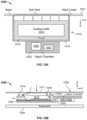
- FIG. 5depicts an embodiment of active cooling system 500 that utilizes a heat sink and is offset from a heat-generating structure.
- the device with which system 500 is usedmay be a laptop computer, a tablet or notebook computer, a smart phone, and/or other mobile device.
- the devicemay also be another device, such as a server in a rack, a game console, or a desktop computer.
- the deviceis thin.
- the devicehas a thickness (height along the smallest dimension, the z-direction in FIG. 5 ) of not more than twenty-five millimeters.
- the thicknessis not more than ten millimeters in some embodiments.
- the thickness of the deviceis not more than eight millimeters. However, other thicknesses are possible.
- the device into which cooling system 500 is integratedincludes heat-generating structure 501 , substrate 506 , and housing 570 .
- Heat-generating structure 501 , substrate 506 and housing 570are analogous to heat-generating structure 401 , substrate 406 , and housing 470 , respectively.
- heat-generating structure 501is a component that is desired to be cooled and which may rise significantly in temperature during use.
- heat-generating structure 501may have temperatures in the ranges described with respect to heat-generating structure 401 .
- Other componentsmay also generate heat.
- Cooling system 500is analogous to cooling system 400 and functions in an analogous manner.
- cooling system 500includes MEMS cooling system 510 and heat spreader 520 that are analogous to MEMS cooling system 410 and heat spreader 420 .
- MEMS cooling system 510includes one or more cooling cells analogous to cooling systems 100 and/or 200 .
- MEMS cooling system 510includes multiple cooling cells configured as a module termed a tile.
- MEMS cooling system 510may include one or more tiles 300 , each of which includes multiple cooling cells.
- MEMS cooling system 510thus includes cooling element(s) configured to undergo vibrational motion when actuated to drive a fluid. The cooling elements are considered to be fluidically connected with heat spreader 520 .
- MEMS cooling system 510may also include top plate(s), anchor(s), orifice plate(s), and/or pedestal(s) analogous to those described in the context of cooling system 100 and/or 200 .
- MEMS cooling system 510may also include an integrated heat spreader, fencing, and cover analogous to those described in the context of tile 300 .
- MEMS cooling system 510may have a thickness of not more than three millimeters. In some embodiments, MEMS cooling system 510 has a thickness of not more than 2.5 millimeters. MEMS cooling system 510 may have a thickness of not more than two millimeters.
- MEMS cooling system 510is thermally coupled with heat spreader 520 .
- MEMS cooling system 510is thermally coupled to heat spreader 520 via fluid driven by MEMS cooling system 510 .
- MEMS cooling system 510is physically connected to heat spreader 520 , for example via a thermally conductive epoxy or analogous material. Fluid driven by cooling elements in MEMS cooling system 510 may remove heat from MEMS cooling system 510 and/or heat spreader 520 . As such, MEMS cooling system 510 and the cooling elements therein may be considered to be fluidically and thermally connected to heat spreader 520 .
- MEMS cooling system 510is offset from heat-generating structure 501 .
- MEMS cooling system 510is thermally coupled with heat spreader 510 , MEMS cooling system 510 is not aligned with heat-generating structure 501 . Stated differently, the cooling element(s) of MEMS cooling system 510 undergo vibrational motion when actuated to drive a fluid toward heat spreader 520 while not directing the fluid directly at heat-generating structure 501 .
- Heat spreader 520may be a heat spreader, vapor chamber (or heat pipe), heat sink, and/or other component that is thermally coupled to heat-generating structure 501 and transfers heat from heat-generating structure 501 . Although shown as being in physical contact with heat-generating structure 501 , in some embodiments, heat spreader 520 may be thermally connected to heat-generating structure 501 via a thermal interface material and/or other conductor of heat. In some embodiments, heat spreader 520 is thermally connected to heat-generating structure 501 in another manner. Thus, heat produced by heat-generating structure 501 is readily transferred to heat spreader 520 .
- fluide.g. air
- the fluid entering via inlet 540 Ais cooler.
- the cool fluidmay be the temperature of the ambient in which the device operates, particularly if the device includes inlets or vent (not shown in FIG. 5 ). If the device in which cooling system 500 is used is closed, the cool fluid may have a temperature that is higher than the ambient.
- the cooler fluidis driven through MEMS cooling system 510 by vibrational motion of cooling elements (not shown in FIG. 5 ), and exits MEMS cooling system 510 .
- Heat from heat-generating structure 501is transferred to heat spreader 520 (e.g. via conduction) and from heat spreader 520 to the fluid driven through MEMS cooling system 510 .
- the heatmay be directly transferred to the fluid (e.g. if the fluid impinges on heat spreader 520 ).
- the heatmay be indirectly transferred to the fluid, for example via an integrated heat spreader for MEMS cooling system 510 that is thermally connected to heat spreader 520 and on which the fluid impinges.
- the fluidmay be circulated through the device to be cooled or may exit the device via an egress or vent (not shown in FIG. 5 ). Although heated fluid may travel in an egress channel (not explicitly indicated in FIG. 5 ) in the vicinity of heat spreader 520 , heat has been efficiently removed from heat spreader 520 (and thus heat-generating structure 501 ) via MEMS cooling system 510 .
- cooling system 500may efficiently cool heat-generating structure 501 despite not being aligned with heat-generating structure 501 .
- cooling system 500may also employ entrainment. However, nothing prevents the use of cooling system 500 without significant use of entrainment for managing heat.
- Cooling system 500may share some or all the benefits of cooling system 400 .
- MEMS cooling system 510may provide efficient cooling in a low-profile package.
- MEMS cooling system 510is thin (e.g. MEMS cooling system 510 is not more than three millimeters thick).
- cooling system 500may be used in confined spaces and thin devices. Cooling system 500 , its location in the device, and the device itself may be configured to allow the device to remain thin. Because heat-generating structure 501 and/or other components may be better cooled, performance may be improved. Further, entrainment may be incorporated to provide a higher flow, greater cooling, and cooler exhaust. Thus, performance of devices incorporating cooling system 500 may be improved.
- FIGS. 6 A- 6 Bdepict an embodiment of active cooling system 600 that utilizes a heat sink and is offset from a heat-generating structure.
- FIG. 6 Adepicts a plan view of cooling system 600
- FIG. 6 Bdepicts a cross-sectional view of cooling system 600 .
- FIGS. 6 A- 6 Bare not to scale and for clarity, only some structures are shown.
- the device with which cooling system 600 is usedmay be a laptop computer, a tablet or notebook computer, a smart phone, and/or other mobile device.
- the devicemay also be another device, such as a server in a rack, a game console, or a desktop computer. In some embodiments, therefore, the device is thin.
- the devicehas a thickness (height along the smallest dimension, the z-direction in FIG. 6 ) of not more than twenty-five millimeters.
- the thicknessis not more than ten millimeters in some embodiments. In some such embodiments, the thickness of the device is not more than eight millimeters. However, other thicknesses are possible.
- the device into which cooling system 600 is integratedincludes heat-generating structure 601 that is analogous to heat-generating structure(s) 401 and/or 501 .
- heat-generating structure 601is indicated as being mounted to heat spreader 620 .
- heat-generating structure 601is a component that is desired to be cooled and which may rise significantly in temperature during use.
- heat-generating structure 601may have temperatures in the ranges described with respect to heat-generating structure(s) 401 and/or 501 .
- Other componentsmay also generate heat.
- Cooling system 600is analogous to cooling system(s) 400 and/or 500 and functions in an analogous manner.
- cooling system 600includes MEMS cooling system 610 and heat spreader 620 that are analogous to MEMS cooling system(s) 410 and/or 510 and heat spreader 420 and/or 520 .
- MEMS cooling system 610includes one or more cooling cells (generically indicated by 612 ) analogous to cooling systems 100 and/or 200 .
- MEMS cooling system 610is configured as a module termed a tile.
- MEMS cooling system 610may include one or more tiles 300 , each of which includes multiple cooling cells.
- Cooling cells 612include cooling element(s) (not shown) configured to undergo vibrational motion when actuated to drive a fluid.
- Cooling cells 612may also include top plate(s), anchor(s), orifice plate(s), and/or pedestal(s) analogous to those described in the context of cooling system 100 and/or 200 .
- MEMS cooling system 610thus includes integrated surrounding structure 614 (which includes a cover and fencing) and integrated heat spreader 622 analogous to those described in the context of tile 300 .
- MEMS cooling system 610may have a thickness of not more than three millimeters. In some embodiments, MEMS cooling system 610 has a thickness of not more than 2.5 millimeters. MEMS cooling system 610 may have a thickness of not more than two millimeters.
- MEMS cooling system 610is thermally coupled with heat spreader 620 .
- MEMS cooling system 610is thermally coupled to heat spreader 620 via fluid driven by MEMS cooling system 610 .
- MEMS cooling system 610is physically connected to heat spreader 620 , for example via a thermally conductive epoxy or analogous material.
- integrated heat spreader 622is coupled with heat spreader 620 .
- Fluid driven by cooling elements in cooling system cells 612remove heat from integrated heat spreader 622 and thus from heat spreader 620 and MEMS cooling system 610 .
- MEMS cooling system 610 and the cooling elements thereinmay be considered to be fluidically and thermally connected to heat spreader 620 .
- MEMS cooling system 610is offset from heat-generating structure 601 . Although both MEMS cooling system 610 and heat-generating structure 601 are thermally coupled with heat spreader 610 , MEMS cooling system 610 is not aligned with heat-generating structure 601 . Stated differently, the cooling element(s) of MEMS cooling system 610 undergo vibrational motion when actuated to drive a fluid toward heat spreader 620 while not directing the fluid directly at heat-generating structure 601 .
- Heat spreader 620may be a heat spreader, vapor chamber (or heat pipe), heat sink, and/or other component that is thermally coupled to heat-generating structure 601 and transfers heat from heat-generating structure 601 . Although shown as being in physical contact with heat-generating structure 601 , in some embodiments, heat spreader 620 may be thermally connected to heat-generating structure 601 via a thermal interface material and/or other conductor of heat. In some embodiments, heat spreader 620 is thermally connected to heat-generating structure 601 in another manner. Thus, heat produced by heat-generating structure 601 is readily transferred to heat spreader 620 . Further, heat spreader 620 includes an offset in the z-direction (a “vertical” offset). Thus, MEMS cooling system 610 may be considered to be recessed from the top of the portion of heat spreader 620 coupled to heat-generating structure 601 .
- MEMS cooling system 610functions in an analogous manner to MEMS cooling systems 410 and 510 .
- Cooler fluidenters cooling cells 612 , for example via inlet apertures or vents.
- the cool fluidmay be the temperature of the ambient in which the device operates. If the device in which cooling system 600 is used is closed, the cool fluid may have a temperature that is higher than the ambient.
- the cooler fluidis driven through MEMS cooling system 610 by vibrational motion of cooling elements (not shown in FIG. 6 ), and exits MEMS cooling system 610 .
- Heat from heat-generating structure 601is transferred to heat spreader 620 (e.g. via conduction), from head spreader 620 to heat spreader 622 , and from heat spreader 622 to the fluid driven through MEMS cooling system 610 .
- the fluidmay be circulated through the device to be cooled or may exit the device via an egress or vent (not shown in FIG. 6 ).
- heated fluidmay travel in an egress channel (not explicitly indicated in FIG. 6 ) in the vicinity of heat spreader 620 , heat has been efficiently removed from heat spreader 620 (and thus heat-generating structure 601 ) via MEMS cooling system 610 .
- MEMS cooling system 610 and thus cooling system 600may efficiently cool heat-generating structure 601 despite not being aligned with heat-generating structure 601 .
- cooling system 600may also employ entrainment. However, nothing prevents the use of cooling system 600 without significant use of entrainment for managing heat.
- Cooling system 600may share some or all the benefits of cooling system(s) 400 and/or 500 .
- MEMS cooling system 610may provide efficient cooling in a low-profile package.
- MEMS cooling system 610is thin (e.g. MEMS cooling system 610 is not more than three millimeters thick).
- heat spreader 620has a vertical offset. This vertical offset may further reduce the profile of cooling system 600 .
- cooling system 600its location in the device, and the device itself may be configured to allow the device to remain thin. Because heat-generating structure 601 and/or other components may be better cooled, performance may be improved. Further, entrainment may be incorporated to provide a higher flow, greater cooling, and cooler exhaust. Thus, performance of devices incorporating cooling system 600 may be improved.
- FIGS. 7 A- 7 Cdepict plan views of embodiments of active cooling systems 700 A, 700 B, and 700 C that utilize heat sinks and are offset from a heat-generating structure.
- FIGS. 7 A- 7 Care not to scale and for clarity, only some structures are shown.
- the device(s) with which cooling system(s) 700 A, 700 B, and/or 700 C are usedmay be laptop computers, tablet or notebook computers, smart phones, and/or other mobile devices.
- the device(s)may also be other device(s), such as servers in rack(s), game console(s), or desktop computer(s).
- the deviceis thin.
- the devicehas a thickness (height along the smallest dimension) of not more than twenty-five millimeters. The thickness is not more than ten millimeters in some embodiments. In some such embodiments, the thickness of the device is not more than eight millimeters. However, other thicknesses are possible.
- the device(s) into which cooling system(s) 700 A, 700 B, and/or 700 C are integratedinclude heat-generating structure 701 that is analogous to heat-generating structure(s) 401 and/or 501 .
- heat-generating structure 701is a component that is desired to be cooled and which may rise significantly in temperature during use.
- heat-generating structure 701may have temperatures in the ranges described with respect to heat-generating structure(s) 401 , 501 and/or 601 .
- Other componentsmay also generate heat.
- Cooling systems 700 A, 700 B, and 700 Care analogous to cooling system(s) 400 , 500 , and/or 600 and functions in an analogous manner
- Cooling system 700 Aincludes four MEMS cooling systems 710 A- 1 , 710 A- 2 , 710 A- 3 , and 710 A- 4 (collectively or generically 710 A) which include cooling cells 712 A- 1 , 712 A- 2 , 712 A- 3 , and 712 A- 4 (collectively or generically 712 A) and surrounding structures 714 A- 1 , 714 A- 2 , 714 A- 3 , and 714 A- 4 (collectively or generically 714 A) that are analogous to MEMS cooling system 610 , cooling cells 612 , and structure 614 , respectively.
- Cooling system 700 Aalso includes heat sink 720 A that is analogous to heat sink(s) 420 , 520 , and/or 620 .
- MEMS cooling systems 710 A and heat-generating structure 701are thermally coupled with heat spreader 710 A
- MEMS cooling systems 710 Aare not aligned with heat-generating structure 701 .
- MEMS cooling systems 710 Aare offset from heat-generating structure 701 in the x-direction.
- the cooling element(s) of MEMS cooling system 710 Aundergo vibrational motion when actuated to drive a fluid toward heat spreader 720 A while not directing the fluid directly at heat-generating structure 701 .
- heat spreader 720 Amay have a vertical offset.
- Cooling system 700 Bincludes two MEMS cooling systems 710 B- 1 and 710 B- 2 (collectively or generically 710 B) which include cooling cells 712 B- 1 and 712 B- 2 (collectively or generically 712 B) and surrounding structures 714 B- 1 and 714 B- 2 (collectively or generically 714 B) that are analogous to MEMS cooling system 610 , cooling cells 612 , and structure 614 , respectively.
- Cooling system 700 Aalso includes heat pipe/spreader 720 B that is analogous to heat spreader(s) 420 , 520 , and/or 620 .
- MEMS cooling systems 710 B and heat-generating structure 701are thermally coupled with heat spreader 710 B, MEMS cooling systems 710 B are not aligned with heat-generating structure 701 .
- MEMS cooling systems 710 Bare offset from heat-generating structure 701 in the x-direction.
- the cooling element(s) of MEMS cooling system 710 Bundergo vibrational motion when actuated to drive a fluid toward heat spreader 720 B while not directing the fluid directly at heat-generating structure 701 .
- heat spreader 720 Bmay have a vertical offset.
- Cooling system 700 Calso includes two MEMS cooling systems 710 C- 1 and 710 C- 2 (collectively or generically 710 C) which include cooling cells 712 C- 1 and 712 C- 2 (collectively or generically 712 C) and surrounding structures 714 C- 1 and 714 C- 2 (collectively or generically 714 C) that are analogous to MEMS cooling system 610 , cooling cells 612 , and structure 614 , respectively.
- Cooling system 700 Calso includes heat pipe/spreader 720 C that is analogous to heat spreader(s) 420 , 520 , and/or 620 .
- MEMS cooling systems 710 C and heat-generating structure 701are thermally coupled with heat spreader 710 C
- MEMS cooling systems 710 Bare not aligned with heat-generating structure 701 .
- MEMS cooling systems 710 Care offset from heat-generating structure 701 in the x-direction.
- the cooling element(s) of MEMS cooling system 710 Cundergo vibrational motion when actuated to drive a fluid toward heat spreader 720 C while not directing the fluid directly at heat-generating structure 701 .
- heat spreader 720 Cmay have a vertical offset.
- Cooling systems 700 A, 700 B, and 700 Cmay share some or all the benefits of cooling system(s) 400 , 500 , and/or 600 .
- MEMS cooling systems 710 A, 710 B, and 710 Cmay provide efficient cooling in a low-profile package.
- MEMS cooling systems 710 A, 710 B, and 710 Care thin (e.g. MEMS cooling systems 710 A, 710 B, and 710 C are each not more than three millimeters thick).
- cooling systems 700 A, 700 B, and 700 Cmay be used in confined spaces and thin devices.
- the profile of cooling systems 700 A, 700 B, and 700 Cmay be further reduced if heat sinks 720 A, 720 B, and 720 C have a vertical offset.
- cooling systems 700 A, 700 B, and 700 Ctheir locations in the device(s), and the device(s) themselves may be configured to allow the devices to remain thin. Because heat-generating structure 701 and/or other components may be better cooled, performance may be improved. Further, entrainment may be incorporated to provide a higher flow, greater cooling, and cooler exhaust. Thus, performance of devices incorporating cooling systems 700 A, 700 B, and 700 C may be improved.
- FIGS. 8 A- 8 Bdepict an embodiment of active cooling system 800 that utilizes a heat sink and is offset from a heat-generating structure.
- FIG. 8 Adepicts a plan view of cooling system 800
- FIG. 8 Bdepicts a cross-sectional view of cooling system 800 .
- FIGS. 8 A- 8 Bare not to scale and for clarity, only some structures are shown.
- the device with which cooling system 800 is usedmay be a laptop computer, a tablet or notebook computer, a smart phone, a server in a rack, a game console, a desktop computer, and/or another device. In some embodiments, therefore, the device is thin.
- the devicehas a thickness (height along the smallest dimension, the z-direction in FIG. 8 ) analogous to those discussed herein.
- the device into which cooling system 800 is integratedincludes heat-generating structure 801 that is analogous to heat-generating structure(s) 401 , 501 , 601 and/or 701 . Also shown are substrate 806 (e.g. a PCB), system back cover 807 (e.g. which may be at the rear of the device facing away from the user), back cover 809 (e.g. which may be proximate to a table or other structure supporting the device), and system front/keyboard 808 . In other embodiments, other and/or additional components may be included. Further, heat-generating structure 801 is mounted and/or thermally coupled to heat spreader 820 . Thus, heat-generating structure 801 is a component that is desired to be cooled and which may rise significantly in temperature during use. For example, for heat-generating structure 801 may have temperatures in the ranges described with respect to heat-generating structure(s) 401 and/or 501 . Other components (not shown) may also generate heat.
- substrate 806e.g. a PCB
- Cooling system 800is analogous to cooling system(s) 400 , 500 , and/or 600 and functions in an analogous manner.
- cooling system 800includes MEMS cooling system 810 and heat spreader 820 that are analogous to MEMS cooling system(s) 410 , 510 and/or 610 and heat spreader 420 , 520 , and/or 620 .
- MEMS cooling system 810includes one or more cooling cells (generically indicated by 812 ) analogous to cooling systems 100 and/or 200 . Also indicated are vents 811 through which fluid may flow to cooling cells 812 .
- MEMS cooling system 810may include one or more tiles 300 , each of which includes multiple cooling cells.
- Cooling cells 812include cooling element(s) (not shown) configured to undergo vibrational motion when actuated to drive a fluid.
- the cooling elementsare considered to be fluidically connected with heat spreader 820 .
- Cooling cells 812may also include top plate(s), anchor(s), orifice plate(s), and/or pedestal(s) analogous to those described in the context of cooling system 100 and/or 200 .
- MEMS cooling system 810thus includes integrated surrounding structure 814 (which includes cover 816 and fencing) and integrated heat spreader 822 analogous to those described in the context of tile 300 .
- MEMS cooling system 810may have a thickness of not more than three millimeters. In some embodiments, MEMS cooling system 810 has a thickness of not more than 2.5 millimeters. MEMS cooling system 810 may have a thickness of not more than two millimeters.
- MEMS cooling system 810is thermally coupled with heat spreader 820 .
- MEMS cooling system 810is physically connected to heat spreader 820 , for example via a thermally conductive epoxy or analogous material.
- integrated heat spreader 822is coupled with heat spreader 820 .
- Fluid driven by cooling elements in cooling system cells 812remove heat from integrated heat spreader 822 and thus from heat spreader 820 and MEMS cooling system 810 .
- MEMS cooling system 810 and the cooling elements thereinmay be considered to be fluidically and thermally connected to heat spreader 820 .
- MEMS cooling system 810is offset from heat-generating structure 801 in the y-direction.
- MEMS cooling system 810may be offset in the x direction instead of or in addition to the offset in the y-direction.
- the cooling element(s) of MEMS cooling system 810undergo vibrational motion when actuated to drive a fluid toward heat spreader 820 while not directing the fluid directly at heat-generating structure 801 .
- Heat spreader 820may be a heat spreader, vapor chamber (or heat pipe), heat sink, and/or other component that is thermally coupled to heat-generating structure 801 and transfers heat from heat-generating structure 801 . Although shown as being in physical contact with heat-generating structure 801 , in some embodiments, heat spreader 820 may be thermally connected to heat-generating structure 801 via a thermal interface material and/or other conductor of heat. In some embodiments, heat spreader 820 is thermally connected to heat-generating structure 801 in another manner. Thus, heat produced by heat-generating structure 801 is readily transferred to heat spreader 820 . Further, heat spreader 820 includes a vertical offset (in the z-direction). Thus, MEMS cooling system 810 may be considered to be recessed from the top of the portion of heat spreader 820 coupled to heat-generating structure 801 .
- Cooling system 800may share some or all the benefits of cooling system(s) 400 , 500 , 600 , 700 A, 700 B, and/or 700 C.
- MEMS cooling system 810may provide efficient cooling in a low-profile package.
- MEMS cooling system 810is thin (e.g. MEMS cooling system 810 is not more than three millimeters thick).
- heat spreader 820has a vertical offset. This vertical offset may further reduce the profile of cooling system 800 .
- cooling system 800its location in the device, and the device itself may be configured to allow the device to remain thin. Because heat-generating structure 801 and/or other components may be better cooled, performance may be improved. Further, entrainment may be incorporated to provide a higher flow, greater cooling, and cooler exhaust. Thus, performance of devices incorporating cooling system 800 may be improved.
- FIGS. 9 A- 9 Bdepict an embodiment of active cooling system 900 that utilizes a heat sink and is offset from a heat-generating structure.
- FIG. 9 Adepicts a plan view of cooling system 900
- FIG. 9 Bdepicts a cross-sectional view of cooling system 900 .
- FIGS. 9 A- 9 Bare not to scale and for clarity, only some structures are shown.
- the device with which cooling system 900 is usedmay be a laptop computer, a tablet or notebook computer, a smart phone, a server in a rack, a game console, a desktop computer, and/or another device. In some embodiments, therefore, the device is thin.
- the devicehas a thickness (height along the smallest dimension, the z-direction in FIG.
- FIGS. 9 A- 9 Banalogous to those discussed herein.
- the flow of fluid in FIGS. 9 A- 9 Bis indicated by unlabeled arrows.
- fluidflows into MEMS cooling system 910 in the y-direction and exits in the x-direction.
- the device into which cooling system 900 is integratedincludes heat-generating structure 901 that is analogous to heat-generating structure(s) 401 , 501 , 601 , 701 and/or 801 . Also shown are substrate 906 (e.g. a PCB), system back cover 907 (e.g. which may be at the rear of the device facing away from the user), back cover 909 (e.g. which may be proximate to a table or other structure supporting the device), and system front/keyboard 908 . In other embodiments, other and/or additional components may be included. Further, heat-generating structure 901 is mounted and/or thermally coupled to heat spreader 920 .
- substrate 906e.g. a PCB
- system back cover 907e.g. which may be at the rear of the device facing away from the user
- back cover 909e.g. which may be proximate to a table or other structure supporting the device
- system front/keyboard 908e.g. which may be prox
- heat-generating structure 901is a component that is desired to be cooled and which may rise significantly in temperature during use.
- heat-generating structure 901may have temperatures in the ranges described with respect to heat-generating structure(s) 401 and/or 501 .
- Other componentsmay also generate heat.
- Cooling system 900is analogous to cooling system(s) 400 , 500 , 600 , and/or 800 and functions in an analogous manner.
- cooling system 900includes MEMS cooling system 910 and heat spreader 920 that are analogous to MEMS cooling system(s) 410 , 510 , 610 and/or 810 and heat spreader 420 , 520 , 620 , and/or 820 .
- MEMS cooling system 910includes one or more cooling cells (generically indicated by 912 ) analogous to cooling systems 100 and/or 200 .
- MEMS cooling system 910may include one or more tiles 300 , each of which includes multiple cooling cells.
- Cooling cells 912include cooling element(s) (not shown) configured to undergo vibrational motion when actuated to drive a fluid.
- the cooling elementsare considered to be fluidically connected with heat spreader 920 .
- Cooling cells 912may also include top plate(s), anchor(s), orifice plate(s), and/or pedestal(s) analogous to those described in the context of cooling system 100 and/or 200 .
- MEMS cooling system 910thus includes integrated surrounding structure 914 (which includes a cover 916 and fencing) and may include an integrated heat spreader (not explicitly shown) analogous to those described in the context of tile 300 .
- MEMS cooling system 910may have a thickness of not more than three millimeters.
- MEMS cooling system 910has a thickness of not more than 2.5 millimeters. MEMS cooling system 910 may have a thickness of not more than two millimeters. MEMS cooling system 910 is also coupled to substrate 906 via sealing 940 , which prevents flow in the region of sealing 940 .
- MEMS cooling system 910is thermally coupled with heat spreader 920 .
- cooling cells 912may be physically connected to heat spreader 920 , for example via a thermally conductive epoxy or analogous material that affixes an integrated heat spreader to heat spreader 920 .
- cooling cells 912are fluidically coupled to heat spreader 920 . Fluid driven by cooling elements in cooling system cells 912 remove heat from integrated heat spreader 922 and thus from heat spreader 920 and MEMS cooling system 910 . As such, MEMS cooling system 910 and the cooling elements therein may be considered to be fluidically and thermally connected to heat spreader 920 .
- MEMS cooling system 910is offset from heat-generating structure 901 in the y-direction.
- MEMS cooling system 910may be offset in the x direction instead of or in addition to the offset in the y-direction.
- the cooling element(s) of MEMS cooling system 910undergo vibrational motion when actuated to drive a fluid toward heat spreader 920 while not directing the fluid directly at heat-generating structure 901 .
- Heat spreader 920may be a heat spreader, vapor chamber (or heat pipe), heat sink, and/or other component that is thermally coupled to heat-generating structure 901 and transfers heat from heat-generating structure 901 . Although shown as being in physical contact with heat-generating structure 901 , in some embodiments, heat spreader 920 may be thermally connected to heat-generating structure 901 via a thermal interface material and/or other conductor of heat. In some embodiments, heat spreader 920 is thermally connected to heat-generating structure 901 in another manner. Thus, heat produced by heat-generating structure 901 is readily transferred to heat spreader 920 . Further, heat spreader 920 includes a vertical offset (in the z-direction). Thus, MEMS cooling system 910 may be considered to be recessed from the top of the portion of heat spreader 920 coupled to heat-generating structure 901 .
- Cooling system 900may share some or all the benefits of cooling system(s) 400 , 500 , 600 , 700 A, 700 B, 700 C, and/or 800 .
- MEMS cooling system 910may provide efficient cooling in a low-profile package.
- MEMS cooling system 910is thin (e.g. MEMS cooling system 910 is not more than three millimeters thick).
- heat spreader 920has a vertical offset. This vertical offset may further reduce the profile of cooling system 900 .
- cooling system 900its location in the device, and the device itself may be configured to allow the device to remain thin. Because heat-generating structure 901 and/or other components may be better cooled, performance may be improved. Further, entrainment may be incorporated to provide a higher flow, greater cooling, and cooler exhaust. Thus, performance of devices incorporating cooling system 900 may be improved.
- FIGS. 10 A- 10 Bdepict an embodiment of active cooling system 1000 that utilizes a heat sink and is offset from a heat-generating structure.
- FIG. 10 Adepicts a plan view of cooling system 1000
- FIG. 10 Bdepicts a cross-sectional view of cooling system 1000 .
- FIGS. 10 A- 10 Bare not to scale and for clarity, only some structures are shown.
- the device with which cooling system 1000 is usedmay be a laptop computer, a tablet or notebook computer, a smart phone, a server in a rack, a game console, a desktop computer, and/or another device. In some embodiments, therefore, the device is thin.
- the devicehas a thickness (height along the smallest dimension, the z-direction in FIG.
- FIGS. 10 A- 10 BThe flow of fluid in FIGS. 10 A- 10 B is indicated by unlabeled arrows. Thus, fluid flows into MEMS cooling system 1010 in the y-direction and exits in the x-direction.
- the device into which cooling system 1000 is integratedincludes heat-generating structures 1001 and 1002 that are analogous to heat-generating structure(s) 401 , 501 , 601 , 701 , 801 and/or 901 .
- heat-generating structure 1001may be a processor such as a central processing unit
- heat-generating structure 1002may be a graphics processing unit.
- system back cover 1007e.g. which may be at the rear of the device facing away from the user
- back cover 1009e.g. which may be proximate to a table or other structure supporting the device
- system front/keyboard 1008e.g. which may be proximate to a table or other structure supporting the device
- other and/or additional componentsmay be included.
- heat-generating structures 1001 and 1002are mounted and/or thermally coupled to heat spreader 1020 .
- heat-generating structure 1001is a component that is desired to be cooled and which may rise significantly in temperature during use.
- heat-generating structure 1001may have temperatures in the ranges described with respect to heat-generating structure(s) 401 and/or 501 .
- Other componentsmay also generate heat.
- Cooling system 1000is analogous to cooling system(s) 400 , 500 , 600 , 800 , and/or 900 and functions in an analogous manner.
- cooling system 1000includes MEMS cooling system 1010 and heat spreader 1020 that are analogous to MEMS cooling system(s) 410 , 510 , 610 , 810 and/or 910 and heat spreader 420 , 520 , 620 , 820 , and/or 920 .
- MEMS cooling system 1010includes one or more cooling cells (generically indicated by 1012 ) analogous to cooling systems 100 and/or 200 .
- MEMS cooling system 1010may include one or more tiles 300 , each of which includes multiple cooling cells.
- Cooling cells 1012include cooling element(s) (not shown) configured to undergo vibrational motion when actuated to drive a fluid.
- the cooling elementsare considered to be fluidically connected with heat spreader 1020 .
- Cooling cells 1012may also include top plate(s), anchor(s), orifice plate(s), and/or pedestal(s) analogous to those described in the context of cooling system 100 and/or 200 .
- MEMS cooling system 1010thus includes integrated surrounding structure 1014 (which includes a cover and fencing) and integrated heat spreader 1022 analogous to those described in the context of tile 300 .
- MEMS cooling system 1010may have a thickness of not more than three millimeters. In some embodiments, MEMS cooling system 1010 has a thickness of not more than 2.5 millimeters. MEMS cooling system 1010 may have a thickness of not more than two millimeters.
- MEMS cooling system 1010is also coupled cover 1009 via sealing 1040 , which prevents flow from exiting in the region of sealing 1040 .
- MEMS cooling system 1010is thermally coupled with heat spreader 1020 .
- cooling cells 1012may be physically connected to heat spreader 1020 , for example via a thermally conductive epoxy or analogous material that affixes integrated heat spreader 1022 to heat spreader 1020 .
- Fluid driven by cooling elements in cooling system cells 1012remove heat from integrated heat spreader 1022 and thus from heat spreader 1020 and MEMS cooling system 1010 .
- MEMS cooling system 1010 and the cooling elements thereinmay be considered to be fluidically and thermally connected to heat spreader 1020 .
- MEMS cooling system 1010is offset from heat-generating structure 1001 in the y-direction.
- MEMS cooling system 1010may be offset in the x direction instead of or in addition to the offset in the y-direction.
- the cooling element(s) of MEMS cooling system 1010undergo vibrational motion when actuated to drive a fluid toward heat spreader 1020 while not directing the fluid directly at heat-generating structure 1001 .
- Heat spreader 1020may be a heat spreader, vapor chamber (or heat pipe), heat sink, and/or other component that is thermally coupled to heat-generating structure 1001 and transfers heat from heat-generating structure 1001 . Although shown as being in physical contact with heat-generating structure 1001 , in some embodiments, heat spreader 1020 may be thermally connected to heat-generating structure 1001 via a thermal interface material and/or other conductor of heat. In some embodiments, heat spreader 1020 is thermally connected to heat-generating structure 1001 in another manner. Thus, heat produced by heat-generating structure 1001 is readily transferred to heat spreader 1020 . Further, heat spreader 1020 includes a vertical offset (in the z-direction). Thus, MEMS cooling system 1010 may be considered to be recessed from the top of the portion of heat spreader 1020 coupled to heat-generating structure 1001 .
- Cooling system 1000may share some or all the benefits of cooling system(s) 400 , 500 , 600 , 700 A, 700 B, 700 C, 800 , and/or 900 .
- MEMS cooling system 1010may provide efficient cooling in a low-profile package.
- MEMS cooling system 1010is thin (e.g. MEMS cooling system 1010 is not more than three millimeters thick).
- heat spreader 1020has a vertical offset. This vertical offset may further reduce the profile of cooling system 1000 .
- cooling system 1000its location in the device, and the device itself may be configured to allow the device to remain thin. Because heat-generating structure 1001 and/or other components may be better cooled, performance may be improved. Further, entrainment may be incorporated to provide a higher flow, greater cooling, and cooler exhaust. Thus, performance of devices incorporating cooling system 1000 may be improved.
- FIG. 11depicts an embodiment of method 1100 for using an active cooling system that utilizes a heat sink and is offset from the heat-generating structure.
- Method 1100may include steps that are not depicted for simplicity.
- Method 1100is described in the context of system 400 . However, method 1100 may be used with other cooling systems including but not limited to systems and cells described herein.
- a driving signal at a frequency and an input voltage corresponding to the resonant state of one or more cooling elementsis provided to the active MEMS cooling system, at 1102 .
- a driving signal having the frequency corresponding to the resonant frequency of a specific cooling elementis provided to that cooling element.
- a driving signalis provided to multiple cooling elements.
- the frequency of the driving signalcorresponds to the resonant state of one or more cooling elements being driven, a statistical measure of the resonance, and/or within a threshold of the resonance as discussed above.
- the MEMS cooling system utilized with a heat spreaderand is offset from the heat-generating structure.
- driving the MEMS cooling system at 1102may cool the heat-generating structure by cooling the heat spreader, which is heated by heat transferred from the heat-generating structure.
- Characteristic(s) of the MEMS cooling systemare monitored while the cooling element(s) are driven to provide a feedback signal corresponding to a proximity to a resonant state of the cooling element(s), at 1104 .
- characteristic(s) of each individual cooling elementare monitored to determine the deviation of the frequency of vibration for that cooling element from the resonant frequency of that cooling element.
- characteristic(s) for multiple cooling elementsare monitored at 1104 .
- the characteristic(s) monitoredmay be a proxy for resonance and/or a deviation therefrom.
- the voltage at the cooling element, the power drawn by the cooling element, power output by the power source, peak-to-peak current output by the power source, peak voltage output by the power source, average current output by the power source, RMS current output by the power source, average voltage output by the power source, amplitude of displacement of the at least one cooling element, RMS current through the cooling element, peak voltage at the cooling element, average current through the at cooling element, average voltage at the at least one cooling element, and/or the peak current drawn by the cooling elementmay be monitored.
- a deviation from the resonant state of the cooling elemente.g. of the driving/vibration frequency the deviation from the resonant frequency
- the frequency and/or input voltageis adjusted based on the feedback signal, at 1106 . More specifically, 1106 includes updating the frequency and/or input voltage, based on the feedback signal, to correspond to resonant state(s) of the cooling element(s) at 1106 .
- the frequency for the drive signalmay be updated to more closely match the resonant frequency/frequencies.
- updating the frequencyincludes changing the frequency to correspond to a power drawn corresponding to the vibration of the cooling element(s) being maximized, a voltage provided at the cooling element(s) being maximized, a voltage across the cooling element(s) being minimized, and/or an amplitude of a current drawn by the at least one cooling element being minimized.
- 1106includes determining whether the feedback signal indicates that a drift in the resonant frequency of the cooling element(s) exceeds a threshold and identifying a new frequency in response to a determination that the drift exceeds the threshold.
- the new frequencyaccounts for the drift in the resonant frequency.
- the methodalso includes setting the new frequency as the frequency for the driving signal in response to the new frequency being identified.
- cooling elements in MEMS cooling system 410are driven, at 1102 .
- the cooling elements in MEMS cooling system 410are driven at a frequency that is at or near resonance for one or more of the cooling elements.
- Characteristics of the cooling elements within MEMS cooling system 410are monitored, at 1104 .
- the drift of the cooling element(s) from resonancemay be determined.
- the frequencymay be adjusted based on the monitoring of 1104 , at 1106 .
- MEMS cooling system 410may be kept at or near resonance.
- an active cooling systemsuch as cooling system(s) 100 , 200 , 300 , 410 , 510 , 610 , 710 A, 710 B, 710 C, and 710 D, 810 , 910 , and/or 1010 may be efficiently driven.
- These cooling systemsare offset from the heat-generating structure(s), but may still efficiently cool the heat-generating structure(s).
- these cooling systemsmay entrain fluid, which can be used to cool other components and/or the exhaust that egresses from the devices. Further, because the characteristic(s) of the MEMS cooling system are monitored, drifts in the resonant frequency may be discovered and accounted for.
- method 1100may be used to operate active MEMS cooling systems and achieve the benefits described herein.
Landscapes
- Engineering & Computer Science (AREA)
- Physics & Mathematics (AREA)
- Microelectronics & Electronic Packaging (AREA)
- Mechanical Engineering (AREA)
- Condensed Matter Physics & Semiconductors (AREA)
- General Physics & Mathematics (AREA)
- Computer Hardware Design (AREA)
- Power Engineering (AREA)
- General Engineering & Computer Science (AREA)
- Thermal Sciences (AREA)
- Cooling Or The Like Of Electrical Apparatus (AREA)
- Signal Processing (AREA)
Abstract
Description
Claims (19)
Priority Applications (2)
| Application Number | Priority Date | Filing Date | Title |
|---|---|---|---|
| US17/683,228US12089374B2 (en) | 2018-08-10 | 2022-02-28 | MEMS-based active cooling systems |
| US18/774,103US20240373593A1 (en) | 2018-08-10 | 2024-07-16 | Mems-based active cooling systems |
Applications Claiming Priority (9)
| Application Number | Priority Date | Filing Date | Title |
|---|---|---|---|
| US201862717474P | 2018-08-10 | 2018-08-10 | |
| US16/369,766US10943850B2 (en) | 2018-08-10 | 2019-03-29 | Piezoelectric MEMS-based active cooling for heat dissipation in compute devices |
| US201962945001P | 2019-12-06 | 2019-12-06 | |
| US16/915,912US11464140B2 (en) | 2019-12-06 | 2020-06-29 | Centrally anchored MEMS-based active cooling systems |
| US17/154,970US11735496B2 (en) | 2018-08-10 | 2021-01-21 | Piezoelectric MEMS-based active cooling for heat dissipation in compute devices |
| US202163155721P | 2021-03-02 | 2021-03-02 | |
| US202163220371P | 2021-07-09 | 2021-07-09 | |
| US202163277494P | 2021-11-09 | 2021-11-09 | |
| US17/683,228US12089374B2 (en) | 2018-08-10 | 2022-02-28 | MEMS-based active cooling systems |
Related Parent Applications (2)
| Application Number | Title | Priority Date | Filing Date |
|---|---|---|---|
| US16/915,912Continuation-In-PartUS11464140B2 (en) | 2018-08-10 | 2020-06-29 | Centrally anchored MEMS-based active cooling systems |
| US17/154,970Continuation-In-PartUS11735496B2 (en) | 2018-08-10 | 2021-01-21 | Piezoelectric MEMS-based active cooling for heat dissipation in compute devices |
Related Child Applications (1)
| Application Number | Title | Priority Date | Filing Date |
|---|---|---|---|
| US18/774,103ContinuationUS20240373593A1 (en) | 2018-08-10 | 2024-07-16 | Mems-based active cooling systems |
Publications (2)
| Publication Number | Publication Date |
|---|---|
| US20220189852A1 US20220189852A1 (en) | 2022-06-16 |
| US12089374B2true US12089374B2 (en) | 2024-09-10 |
Family
ID=81942986
Family Applications (2)
| Application Number | Title | Priority Date | Filing Date |
|---|---|---|---|
| US17/683,228ActiveUS12089374B2 (en) | 2018-08-10 | 2022-02-28 | MEMS-based active cooling systems |
| US18/774,103PendingUS20240373593A1 (en) | 2018-08-10 | 2024-07-16 | Mems-based active cooling systems |
Family Applications After (1)
| Application Number | Title | Priority Date | Filing Date |
|---|---|---|---|
| US18/774,103PendingUS20240373593A1 (en) | 2018-08-10 | 2024-07-16 | Mems-based active cooling systems |
Country Status (1)
| Country | Link |
|---|---|
| US (2) | US12089374B2 (en) |
Families Citing this family (13)
| Publication number | Priority date | Publication date | Assignee | Title |
|---|---|---|---|---|
| US11043444B2 (en)* | 2018-08-10 | 2021-06-22 | Frore Systems Inc. | Two-dimensional addessable array of piezoelectric MEMS-based active cooling devices |
| US11464140B2 (en) | 2019-12-06 | 2022-10-04 | Frore Systems Inc. | Centrally anchored MEMS-based active cooling systems |
| US12089374B2 (en) | 2018-08-10 | 2024-09-10 | Frore Systems Inc. | MEMS-based active cooling systems |
| KR102677216B1 (en) | 2019-10-30 | 2024-06-24 | 프로리 시스템스 인코포레이티드 | MEMS-based airflow system |
| TWI747076B (en)* | 2019-11-08 | 2021-11-21 | 研能科技股份有限公司 | Heat dissipating component for mobile device |
| US12193192B2 (en) | 2019-12-06 | 2025-01-07 | Frore Systems Inc. | Cavities for center-pinned actuator cooling systems |
| US11510341B2 (en) | 2019-12-06 | 2022-11-22 | Frore Systems Inc. | Engineered actuators usable in MEMs active cooling devices |
| US11796262B2 (en) | 2019-12-06 | 2023-10-24 | Frore Systems Inc. | Top chamber cavities for center-pinned actuators |
| US12033917B2 (en) | 2019-12-17 | 2024-07-09 | Frore Systems Inc. | Airflow control in active cooling systems |
| JP7333417B2 (en) | 2019-12-17 | 2023-08-24 | フロー・システムズ・インコーポレーテッド | MEMS-based cooling system for closed and open devices |
| US11765863B2 (en)* | 2020-10-02 | 2023-09-19 | Frore Systems Inc. | Active heat sink |
| WO2023244838A1 (en)* | 2022-06-17 | 2023-12-21 | Frore Systems Inc. | Cover for mems-based cooling systems |
| DE102023210710A1 (en)* | 2023-10-30 | 2025-04-30 | Robert Bosch Gesellschaft mit beschränkter Haftung | Device comprising a substrate and method for providing a device comprising a substrate |
Citations (209)
| Publication number | Priority date | Publication date | Assignee | Title |
|---|---|---|---|---|
| US4251031A (en) | 1978-07-11 | 1981-02-17 | Plessey Handel Und Investments Ag | Vibratory atomizer |
| US4450505A (en) | 1982-06-09 | 1984-05-22 | Sperry Corporation | Apparatus for cooling integrated circuit chips |
| US4595338A (en) | 1983-11-17 | 1986-06-17 | Piezo Electric Products, Inc. | Non-vibrational oscillating blade piezoelectric blower |
| US4667877A (en) | 1985-08-15 | 1987-05-26 | Carnegie-Mellon University | Multi-orifice impulsed spray generator |
| JPS62149158A (en) | 1985-09-12 | 1987-07-03 | Toshiba Corp | electronic parts equipment |
| JPS62199999A (en) | 1986-02-27 | 1987-09-03 | Nippon Denso Co Ltd | Piezo-electric fan type blower |
| US4751713A (en) | 1987-07-31 | 1988-06-14 | Hughes Aircraft Company | Gas laser having a piezoelectric fan |
| US4780062A (en) | 1985-10-09 | 1988-10-25 | Murata Manufacturing Co., Ltd. | Piezoelectric fan |
| US4834619A (en) | 1987-11-10 | 1989-05-30 | The Boeing Company | Ducted oscillatory blade fan |
| US4923000A (en) | 1989-03-03 | 1990-05-08 | Microelectronics And Computer Technology Corporation | Heat exchanger having piezoelectric fan means |
| US5008582A (en) | 1988-01-29 | 1991-04-16 | Kabushiki Kaisha Toshiba | Electronic device having a cooling element |
| JPH0465862A (en) | 1990-07-06 | 1992-03-02 | Toshiba Ceramics Co Ltd | Semiconductor enclosure |
| JPH06152793A (en) | 1992-11-09 | 1994-05-31 | Ricoh Co Ltd | Communication terminal |
| JPH07263598A (en) | 1994-03-17 | 1995-10-13 | Fujitsu Ltd | heatsink |
| JPH09246766A (en) | 1996-03-13 | 1997-09-19 | Fanuc Ltd | Enclosed electronic equipment case |
| US5673171A (en) | 1995-12-05 | 1997-09-30 | Compaq Computer Corporation | Hard disc drive support tray apparatus with built-in handling shock reduction, EMI shielding and mounting alignment structures |
| US5758823A (en) | 1995-06-12 | 1998-06-02 | Georgia Tech Research Corporation | Synthetic jet actuator and applications thereof |
| US5796152A (en) | 1997-01-24 | 1998-08-18 | Roxburgh Ltd. | Cantilevered microstructure |
| US5821962A (en) | 1995-06-02 | 1998-10-13 | Canon Kabushiki Kaisha | Liquid ejection apparatus and method |
| US5861703A (en) | 1997-05-30 | 1999-01-19 | Motorola Inc. | Low-profile axial-flow single-blade piezoelectric fan |
| JP2000323882A (en) | 1999-05-12 | 2000-11-24 | Sony Corp | Fan device and driving method therefor |
| US6211598B1 (en) | 1999-09-13 | 2001-04-03 | Jds Uniphase Inc. | In-plane MEMS thermal actuator and associated fabrication methods |
| JP2001119181A (en) | 1999-10-21 | 2001-04-27 | Fujitsu Ltd | Electronic component cooling device and electronic equipment |
| US6232680B1 (en) | 1999-01-13 | 2001-05-15 | Samsung Electronics Co., Ltd. | Cooling apparatus for electronic device |
| JP2002130198A (en) | 2000-10-19 | 2002-05-09 | Sony Corp | Piezoelectric fan |
| US6450773B1 (en) | 2001-03-13 | 2002-09-17 | Terabeam Corporation | Piezoelectric vacuum pump and method |
| US20020163782A1 (en) | 2001-05-01 | 2002-11-07 | Mainstream Engineering Corporation | Method and two-phase spray cooling apparatus |
| US6483419B1 (en) | 2000-09-12 | 2002-11-19 | 3M Innovative Properties Company | Combination horizontal and vertical thermal actuator |
| US20020184907A1 (en) | 2000-07-24 | 2002-12-12 | Venkateshwaran Vaiyapuri | MEMS heat pumps for integrated circuit heat dissipation |
| US6531947B1 (en) | 2000-09-12 | 2003-03-11 | 3M Innovative Properties Company | Direct acting vertical thermal actuator with controlled bending |
| US6570750B1 (en) | 2000-04-19 | 2003-05-27 | The United States Of America As Represented By The Secretary Of The Air Force | Shunted multiple throw MEMS RF switch |
| US6588497B1 (en)* | 2002-04-19 | 2003-07-08 | Georgia Tech Research Corporation | System and method for thermal management by synthetic jet ejector channel cooling techniques |
| TW542326U (en) | 2001-09-12 | 2003-07-11 | Mei Wang Electric Corp | Improved supporting rack structure for electric fan |
| US6598960B1 (en) | 2002-05-23 | 2003-07-29 | Eastman Kodak Company | Multi-layer thermal actuator with optimized heater length and method of operating same |
| US6612816B1 (en) | 1998-10-20 | 2003-09-02 | Pierre Vanden Brande | Molecular pump |
| US6650542B1 (en) | 2003-01-06 | 2003-11-18 | Intel Corporation | Piezoelectric actuated jet impingement cooling |
| US20040023614A1 (en) | 1998-12-30 | 2004-02-05 | Koplin Edward C. | Computer cabinet |
| US6713942B2 (en) | 2001-05-23 | 2004-03-30 | Purdue Research Foundation | Piezoelectric device with feedback sensor |
| US6771158B2 (en) | 2002-08-09 | 2004-08-03 | Industrial Technology Research Institute | Micro electromechanical differential actuator |
| US20040190251A1 (en) | 2003-03-31 | 2004-09-30 | Ravi Prasher | Two-phase cooling utilizing microchannel heat exchangers and channeled heat sink |
| US20040196999A1 (en) | 2003-04-01 | 2004-10-07 | Samsung Electronics Co., Ltd. | Speaker apparatus |
| US20040218362A1 (en) | 2003-02-19 | 2004-11-04 | Amaro Allen J. | System and apparatus for heat removal |
| US20040244405A1 (en) | 2002-10-23 | 2004-12-09 | Kim Jong-Won | Active micro cooler |
| US20040253130A1 (en) | 2003-01-06 | 2004-12-16 | Ioan Sauciuc | Electronic thermal management |
| US6853068B1 (en) | 2002-05-22 | 2005-02-08 | Volterra Semiconductor Corporation | Heatsinking and packaging of integrated circuit chips |
| KR20050026992A (en) | 2003-09-12 | 2005-03-17 | 삼성전자주식회사 | A diaphragm air-pump |
| US6876047B2 (en) | 2001-11-09 | 2005-04-05 | Turnstone Systems, Inc. | MEMS device having a trilayered beam and related methods |
| US20050074662A1 (en) | 2003-10-07 | 2005-04-07 | Samsung Electronics Co., Ltd. | Valveless micro air delivery device |
| US20050089415A1 (en) | 2003-09-12 | 2005-04-28 | Samsung Electronics Co., Ltd. | Diaphragm air pump |
| US20050110841A1 (en) | 1997-07-15 | 2005-05-26 | Kia Silverbrook | Printhead chip incorporating double action shutter mechanisms |
| US20050178529A1 (en) | 2004-02-16 | 2005-08-18 | Osamu Suzuki | Cooling system or electronic apparatus, and electronic apparatus using the same |
| US20050211418A1 (en) | 2002-11-01 | 2005-09-29 | Cooligy, Inc. | Method and apparatus for efficient vertical fluid delivery for cooling a heat producing device |
| US20050225213A1 (en) | 2000-10-25 | 2005-10-13 | Washington State University Research Foundation | Piezoelectric micro-transducers, methods of use and manufacturing methods for same |
| US20050266286A1 (en) | 2002-05-23 | 2005-12-01 | Honda Giken Kogyo Kabushiki Kaisha | Fuel cell stack |
| US20050280994A1 (en) | 2003-12-15 | 2005-12-22 | Kazuaki Yazawa | Apparatus, method, and control program for cooling electronic devices |
| US6996441B1 (en) | 2002-03-11 | 2006-02-07 | Advanced Micro Devices, Inc. | Forward-looking fan control using system operation information |
| US7023697B2 (en)* | 2003-05-09 | 2006-04-04 | Intel Corporation | Actuation membrane for application to a card slot of a system |
| US20060147324A1 (en) | 2004-12-30 | 2006-07-06 | Par Technologies | Method and apparatus for scavenging energy during pump operation |
| US7081699B2 (en) | 2003-03-31 | 2006-07-25 | The Penn State Research Foundation | Thermoacoustic piezoelectric generator |
| US20060164805A1 (en) | 2003-02-20 | 2006-07-27 | Koninklijke Philips Electronics N.V. | Cooling assembly comprising micro-jets |
| US20060181848A1 (en)* | 2005-02-14 | 2006-08-17 | Kiley Richard F | Heat sink and heat sink assembly |
| US20060208613A1 (en) | 2002-02-15 | 2006-09-21 | Siemens Technology-To-Business Center Llc | Small piezoelectric air pumps with unobstructed airflow |
| TW200635493A (en) | 2005-03-31 | 2006-10-01 | Ind Tech Res Inst | Spray cooling module for electronic device |
| US20060232167A1 (en) | 2005-04-13 | 2006-10-19 | Par Technologies Llc | Piezoelectric diaphragm with aperture(s) |
| US20060250774A1 (en) | 2005-05-06 | 2006-11-09 | International Business Machines Corporation | Cooling apparatus, cooled electronic module and methods of fabrication thereof employing an integrated coolant inlet and outlet manifold |
| US20060250773A1 (en) | 2005-05-06 | 2006-11-09 | International Business Machines Corporation | Cooling apparatus, cooled electronic module and methods of fabrication thereof employing an integrated manifold and a plurality of thermally conductive fins |
| US20060260784A1 (en) | 2005-05-19 | 2006-11-23 | International Business Machines Corporation | Microjet module assembly |
| US20060268534A1 (en) | 2005-05-31 | 2006-11-30 | Intel Corporation | Wireless device enclosure using piezoelectric cooling structures |
| US20070020124A1 (en) | 2003-12-10 | 2007-01-25 | Purdue Research Foundation | Micropump for electronics cooling |
| US20070037506A1 (en) | 2005-08-09 | 2007-02-15 | Seri Lee | Rake shaped fan |
| US20070048154A1 (en) | 2005-08-26 | 2007-03-01 | Itzhak Sapir | MEMS cooling device |
| US20070076375A1 (en) | 2005-09-30 | 2007-04-05 | Mongia Rajiv K | Synthetic jet-based heat dissipation device |
| KR20070063029A (en) | 2004-10-07 | 2007-06-18 | 엠케이에스 인스트루먼츠 인코포레이티드 | How to form a seal between the housing and diaphragm of the capacitive sensor |
| US7258464B2 (en)* | 2002-12-18 | 2007-08-21 | General Electric Company | Integral ballast lamp thermal management method and apparatus |
| CN101032718A (en) | 2006-03-10 | 2007-09-12 | 财团法人工业技术研究院 | Multi-mode transducer and cooling device with multi-mode transducer |
| US20070235180A1 (en) | 2006-04-06 | 2007-10-11 | Sun Microsystems, Inc. | Multichannel cooling system with magnetohydrodynamic pump |
| US20070274045A1 (en) | 2006-05-25 | 2007-11-29 | International Business Machines Corporation | Cooling Apparatus, Cooled Electronic Module and Methods of Fabrication Thereof Employing A Thermally Conductive Return Manifold Structure Sealed To The Periphery Of A Surface To Be Cooled |
| US7324323B2 (en) | 2005-01-13 | 2008-01-29 | Lucent Technologies Inc. | Photo-sensitive MEMS structure |
| US20080041574A1 (en) | 2006-08-15 | 2008-02-21 | Mehmet Arik | Cooling Systems Employing Fluidic Jets, Methods for Their Use and Methods for Cooling |
| US20080101965A1 (en) | 2004-11-17 | 2008-05-01 | Sharp Kabushiki Kaisha | Piezoelectric Pump and Stirling Refrigerator/Freezer |
| US20080111866A1 (en) | 1997-07-15 | 2008-05-15 | Silverbrook Research Pty Ltd | Nozzle arrangement with a top wall portion having etchant holes therein |
| JP2008159688A (en) | 2006-12-21 | 2008-07-10 | Denso Corp | Cooling structure for electronic apparatus |
| JP2008525709A (en) | 2004-12-23 | 2008-07-17 | サブマシン コーポレイション | Reaction drive energy transmission device |
| US7420807B2 (en) | 2002-08-16 | 2008-09-02 | Nec Corporation | Cooling device for electronic apparatus |
| US20080218972A1 (en) | 2007-03-06 | 2008-09-11 | Ioan Sauciuc | Cooling device, system containing same, and cooling method |
| JP2008263830A (en) | 2007-04-18 | 2008-11-06 | Sansyu Sangyo Co Ltd | Wet-type dust collector of leaf tobacco workbench |
| US20090021908A1 (en) | 2007-07-18 | 2009-01-22 | Chandrakant Patel | System and method for cooling an electronic device |
| US20090034197A1 (en) | 2007-06-30 | 2009-02-05 | Javier Leija | Heatsink, method of manufacturing same, and microelectronic package containing same |
| US7492076B2 (en) | 2006-12-29 | 2009-02-17 | Artificial Muscle, Inc. | Electroactive polymer transducers biased for increased output |
| US20090050294A1 (en) | 2007-08-20 | 2009-02-26 | Fedorov Andrei G | Evaporation-enhanced thermal management devices, systems, and methods of heat management |
| US20090085438A1 (en) | 2007-09-27 | 2009-04-02 | Chrysler Gregory M | Piezoelectric fan, cooling device containing same, and method of cooling a microelectronic device using same |
| US20090120621A1 (en) | 2005-07-15 | 2009-05-14 | Pulsacool Ltd. | Method and apparatus for cooling electronic or other devices |
| US20090148320A1 (en) | 2006-03-07 | 2009-06-11 | Influent Corporation | Fluidic Energy Transfer Devices |
| US20090167109A1 (en) | 2007-12-27 | 2009-07-02 | Sony Corporation | Piezoelectric pump, cooling device, and electronic apparatus |
| US20090174999A1 (en) | 2007-09-27 | 2009-07-09 | Ioan Sauciuc | Piezoelectric air jet augmented cooling for electronic devices |
| US20090232685A1 (en) | 2007-03-12 | 2009-09-17 | Murata Manufacturing Co., Ltd. | Fluid conveyance device |
| US20090232683A1 (en) | 2006-12-09 | 2009-09-17 | Murata Manufacturing Co., Ltd. | Piezoelectric micro-blower |
| US20090232684A1 (en) | 2007-10-16 | 2009-09-17 | Murata Manufacturing Co., Ltd. | Piezoelectric micro-blower |
| JP2010029759A (en) | 2008-07-28 | 2010-02-12 | Fujikura Ltd | Piezoelectric fan device |
| US20100067191A1 (en) | 2006-12-08 | 2010-03-18 | Mehmet Arik | Thermal management system for embedded environment and method for making same |
| US20100074775A1 (en) | 2007-01-23 | 2010-03-25 | Mitsuru Yamamoto | Diaphragm pump |
| US7714433B2 (en) | 2007-03-09 | 2010-05-11 | Intel Corporation | Piezoelectric cooling of a semiconductor package |
| CN101718235A (en) | 2009-11-19 | 2010-06-02 | 西北工业大学 | Synthetic jet actuator with double films, single chamber and single spout |
| US7742299B2 (en)* | 2008-05-09 | 2010-06-22 | Intel Corporation | Piezo fans for cooling an electronic device |
| CN101785103A (en) | 2007-07-05 | 2010-07-21 | Aac微技术有限公司 | Low resistance through-wafer via |
| US20110063800A1 (en) | 2009-09-14 | 2011-03-17 | Kwan Woo Park | Heat dissipating device |
| US20110068799A1 (en) | 2007-10-23 | 2011-03-24 | Sony Ericsson Mobile Communications Ab | Activating batteries based on environmental conditions |
| US20110068685A1 (en) | 2009-09-23 | 2011-03-24 | Maeng Seoyoung | Heat-dissipating apparatus and illuminator using the same |
| US20110122582A1 (en) | 2009-11-20 | 2011-05-26 | Kwan Woo Park | Heat dissipating device |
| JP2011144743A (en) | 2010-01-14 | 2011-07-28 | Murata Mfg Co Ltd | Cooling device |
| US20110211020A1 (en) | 1997-07-15 | 2011-09-01 | Silverbrook Research Pty Ltd | Printhead micro-electromechanical nozzle arrangement with motion-transmitting structure |
| US20110259557A1 (en) | 2010-04-26 | 2011-10-27 | Foxconn Technology Co., Ltd. | Heat dissipation apparatus incorporating airflow generator |
| US20110277491A1 (en) | 2010-02-12 | 2011-11-17 | MicroBase Technology Group | Heat dissipation system with a spray cooling device |
| US20110304240A1 (en) | 2008-12-21 | 2011-12-15 | Sirius Implantable Systems Ltd. | High efficiency piezoelectric micro-generator and energy storage system |
| US20120063091A1 (en) | 2010-09-13 | 2012-03-15 | Toyota Motor Engineering & Manufacturing North America, Inc. | Cooling Apparatuses and Power Electronics Modules |
| US20120171062A1 (en) | 2010-05-21 | 2012-07-05 | Murata Manufacturing Co., Ltd. | Fluid pump |
| US8289701B2 (en)* | 2006-07-25 | 2012-10-16 | Fujistu Limited | Liquid cooling unit and heat receiver therefor |
| US8297947B2 (en) | 2009-06-03 | 2012-10-30 | The Technology Partnership Plc | Fluid disc pump |
| US20120301333A1 (en) | 2011-05-26 | 2012-11-29 | Samsung Electro-Mechanics Co., Ltd. | Piezoelectric type cooling device |
| US20130058818A1 (en) | 2011-09-06 | 2013-03-07 | Murata Manufacturing Co., Ltd. | Fluid control device |
| US20130071269A1 (en) | 2009-10-01 | 2013-03-21 | Murata Manufacturing Co., Ltd. | Piezoelectric micro-blower |
| US20130157729A1 (en) | 2011-12-16 | 2013-06-20 | Joseph Akwo Tabe | Energy harvesting computer device in association with a communication device configured with apparatus for boosting signal reception |
| US20130225065A1 (en) | 2012-02-29 | 2013-08-29 | Pantech Co., Ltd. | Mobile communication device and method for exhausting heat therefrom |
| US20130233523A1 (en) | 2012-03-08 | 2013-09-12 | International Business Machines Corporation | Cold plate with combined inclined impingement and ribbed channels |
| JP2013223818A (en) | 2012-04-20 | 2013-10-31 | Murata Mfg Co Ltd | Piezoelectric actuator and electronic apparatus |
| WO2014024608A1 (en) | 2012-08-10 | 2014-02-13 | 株式会社村田製作所 | Blower |
| US20140052429A1 (en) | 2012-08-20 | 2014-02-20 | International Business Machines Corporation | Proactive data center cooling |
| US8684707B2 (en) | 2008-06-05 | 2014-04-01 | Murata Manufacturing Co., Ltd. | Piezoelectric microblower |
| US8736139B2 (en) | 2010-06-04 | 2014-05-27 | Samsung Electro-Mechanics Co., Ltd. | Optical image stabilizer and method of manufacturing the same |
| CN103828050A (en) | 2011-09-02 | 2014-05-28 | 卡文迪什动力有限公司 | Merged pins and semi-flexible anchors for MEMS devices |
| US20140192485A1 (en) | 2013-01-04 | 2014-07-10 | Purdue Research Foundation | Vehicles, power electronics modules and cooling apparatuses with single-phase and two-phase surface enhancement features |
| US20140216696A1 (en) | 2013-02-01 | 2014-08-07 | Alcatel Lucent | Cooling device and a cooling assembly comprising the cooling device |
| US8899944B2 (en) | 2009-12-04 | 2014-12-02 | Murata Manufacturing Co., Ltd. | Piezoelectric micro-blower |
| US20150009631A1 (en) | 2013-07-05 | 2015-01-08 | Toyota Motor Engineering & Manufacturing North America, Inc. | Cooling Assemblies and Power Electronics Modules Having Multiple-Porosity Structures |
| US20150007965A1 (en) | 2013-07-05 | 2015-01-08 | Toyota Motor Engineerig & Manufacturing North America, Inc. | Cooling Assemblies Having Porous Three Dimensional Surfaces |
| US8934240B2 (en) | 2012-03-30 | 2015-01-13 | Delta Electronics, Inc. | Heat-dissipating module |
| US20150043164A1 (en) | 2013-08-08 | 2015-02-12 | Toyota Motor Engineering & Manufacturing North America, Inc. | Jet impingement cooling apparatuses having enhanced heat transfer assemblies |
| US20150173237A1 (en) | 2013-12-17 | 2015-06-18 | Htc Corporation | Electronic module and heat dissipation module |
| CN204436756U (en) | 2014-12-18 | 2015-07-01 | 浙江师范大学 | A kind of mode of resonance piezoelectric pump based on inertial drive |
| CN104832407A (en) | 2015-03-20 | 2015-08-12 | 长春隆美科技发展有限公司 | Double-vibrator piezoelectric driving micro fan |
| US20150308377A1 (en) | 2014-04-24 | 2015-10-29 | The Boeing Company | Thrust-reverser assemblies that utilize active flow-control and systems and methods including the same |
| US9179575B1 (en) | 2012-03-13 | 2015-11-03 | Rockwell Collins, Inc. | MEMS based device for phase-change autonomous transport of heat (PATH) |
| US9215520B2 (en) | 2012-08-15 | 2015-12-15 | General Electric Company | Multi-function synthetic jet and method of manufacturing same |
| US20160025429A1 (en) | 2013-03-15 | 2016-01-28 | Parker-Hannifin Corporation | Electroactive polymer actuated air flow thermal management module |
| US9252069B2 (en) | 2010-08-31 | 2016-02-02 | Teledyne Scientific & Imaging, Llc | High power module cooling system |
| US20160076530A1 (en) | 2014-09-15 | 2016-03-17 | Microjet Technology Co., Ltd. | Micro-gas pressure driving device |
| US9466452B1 (en) | 2015-03-31 | 2016-10-11 | Stmicroelectronics, Inc. | Integrated cantilever switch |
| TW201638469A (en) | 2015-04-28 | 2016-11-01 | yu-jie Luo | Miniature piezoelectric fan heat dissipation module |
| US20160353186A1 (en) | 2015-05-27 | 2016-12-01 | Apple Inc. | Electronic Device With Speaker Enclosure Sensor |
| CN106206490A (en) | 2016-07-01 | 2016-12-07 | 浙江大学 | Passive type MEMS Flow vibration strengthening and heat transferring device and heat-transferring method thereof |
| US20160358841A1 (en) | 2015-06-02 | 2016-12-08 | Intel Corporation | Package integrated synthetic jet device |
| US9523367B2 (en) | 2010-08-25 | 2016-12-20 | Aavid Thermalloy, Llc | Cantilever fan |
| US20160377072A1 (en) | 2015-06-25 | 2016-12-29 | Koge Micro Tech Co., Ltd. | Piezoelectric pump and operating method thereof |
| US20160377073A1 (en) | 2014-03-07 | 2016-12-29 | Murata Manufacturing Co., Ltd. | Blower |
| US20170146039A1 (en) | 2015-11-20 | 2017-05-25 | Inventec (Pudong) Technology Corporation | Synthetic jet |
| CN106849747A (en) | 2017-02-28 | 2017-06-13 | 厦门大学 | A kind of MEMS piezoelectric ultrasonic pumps |
| US20170222123A1 (en) | 2016-01-29 | 2017-08-03 | Microjet Technology Co., Ltd. | Piezoelectric actuator |
| US20170276149A1 (en) | 2014-08-25 | 2017-09-28 | Ge Aviation Systems Llc | Airflow generator and array of airflow generators |
| US20170292537A1 (en) | 2016-04-06 | 2017-10-12 | Menashe Barak | Mems-based active cooling system |
| US9846461B2 (en) | 2013-02-08 | 2017-12-19 | Delta Electronics, Inc. | Heat dissipating apparatus and electronic device |
| US20170363076A1 (en) | 2016-06-20 | 2017-12-21 | The Regents Of The University Of Michigan | Modular Stacked Variable-Compression Micropump and Method of Making Same |
| CN107642483A (en) | 2016-07-20 | 2018-01-30 | 杨杰 | A kind of piezoelectric ceramics blower fan |
| JP2018022868A (en) | 2016-07-26 | 2018-02-08 | 三菱電機株式会社 | Electronic apparatus cooler |
| US20180061737A1 (en) | 2015-12-09 | 2018-03-01 | Ozyegin Universitesi | Heat sink cooling with preferred synthetic jet cooling devices |
| EP3290211A1 (en) | 2016-09-05 | 2018-03-07 | Microjet Technology Co., Ltd | Fluid control device |
| TW201814772A (en) | 2016-10-03 | 2018-04-16 | 美商應用材料股份有限公司 | Multi-channel flow ratio controller and processing chamber |
| CN207287973U (en) | 2016-12-28 | 2018-05-01 | 意法半导体股份有限公司 | Piezoelectric micromachined ultrasonic transducer and electronic system |
| US9976547B2 (en) | 2014-02-21 | 2018-05-22 | Murata Manufacturing Co., Ltd. | Piezoelectric blower |
| US20180146573A1 (en) | 2016-11-24 | 2018-05-24 | Microjet Technology Co., Ltd. | Air-cooling heat dissipation device and system |
| US20180146574A1 (en) | 2016-11-24 | 2018-05-24 | Microjet Technology Co., Ltd. | Air-cooling heat dissipation device |
| US20180145010A1 (en) | 2016-11-18 | 2018-05-24 | Toyota Motor Engineering & Manufacturing North America, Inc. | Electronic Assemblies Having A Cooling Chip Layer With Impingement Channels And Through Substrate Vias |
| JP2018085511A (en) | 2016-11-24 | 2018-05-31 | 研能科技股▲ふん▼有限公司 | Air cooling heat dissipation device |
| JP2018085510A (en) | 2016-11-24 | 2018-05-31 | 研能科技股▲ふん▼有限公司 | Air cooling heat dissipation device |
| US20180187672A1 (en) | 2015-08-31 | 2018-07-05 | Murata Manufacturing Co., Ltd. | Blower |
| US10045461B1 (en) | 2014-09-30 | 2018-08-07 | Apple Inc. | Electronic device with diaphragm cooling |
| US20180240734A1 (en) | 2017-02-20 | 2018-08-23 | Microjet Technology Co., Ltd. | Air-cooling heat dissipation device |
| US20190067550A1 (en) | 2017-08-22 | 2019-02-28 | Microjet Technology Co., Ltd. | Actuator |
| US20190062150A1 (en) | 2016-03-14 | 2019-02-28 | At&S Austria Technologie & Systemtechnik Aktiengesellschaft | Component Carrier With Integrated Wall Structure For Subsequent Assembly of an Electronic Component |
| US20190085836A1 (en) | 2017-09-15 | 2019-03-21 | Microjet Technology Co., Ltd. | Gas transportation device |
| US20190101938A1 (en) | 2017-09-29 | 2019-04-04 | Microjet Technology Co., Ltd. | Fluid system |
| CN109641738A (en) | 2016-06-14 | 2019-04-16 | 麦斯卓微有限公司 | Electrical connection flexure |
| US20190128252A1 (en) | 2017-10-27 | 2019-05-02 | Microjet Technology Co., Ltd. | Gas transportation device |
| US10288192B2 (en) | 2016-09-05 | 2019-05-14 | Microjet Technology Co., Ltd. | Miniature fluid control device and piezoelectric actuator thereof |
| US20190301442A1 (en) | 2018-03-27 | 2019-10-03 | Lenovo (Beijing) Co., Ltd. | Oscillating fan and electronic device having the same |
| US20190309744A1 (en) | 2018-04-09 | 2019-10-10 | Chung-Yuan Christian University | Miniature cooling system |
| US10480502B2 (en) | 2014-02-21 | 2019-11-19 | Murata Manufacturing Co., Ltd. | Fluid control device and pump |
| US20200049388A1 (en) | 2018-08-10 | 2020-02-13 | Frore Systems Inc. | Method and system for driving piezoelectric mems-based active cooling devices |
| US20200088185A1 (en) | 2018-09-17 | 2020-03-19 | Microjet Technology Co., Ltd. | Micro-electromechanical system pump |
| US20200229320A1 (en) | 2019-01-11 | 2020-07-16 | Microjet Technology Co., Ltd. | Actuating breathable material structure |
| US20200309111A1 (en) | 2019-03-29 | 2020-10-01 | Microjet Technology Co., Ltd. | Micro-electromechanical systems pump |
| US20210131415A1 (en) | 2019-10-30 | 2021-05-06 | Frore Systems Inc. | Mems-based airflow system |
| US20210144884A1 (en) | 2019-11-08 | 2021-05-13 | Microjet Technology Co., Ltd. | Heat-dissipating component for mobile device |
| US20210176894A1 (en) | 2019-12-06 | 2021-06-10 | Frore Systems Inc. | Centrally anchored mems-based active cooling systems |
| US20210176895A1 (en) | 2019-12-06 | 2021-06-10 | Frore Systems Inc. | Engineered actuators usable in mems active cooling devices |
| US20210185853A1 (en) | 2019-12-16 | 2021-06-17 | Frore Systems Inc. | Mobile device case including an active cooling system |
| US20210180723A1 (en) | 2019-12-16 | 2021-06-17 | Frore Systems Inc. | Virtual valve in a mems-based cooling system |
| US20210183739A1 (en) | 2019-12-17 | 2021-06-17 | Frore Systems Inc. | Airflow control in active cooling systems |
| US20210185856A1 (en) | 2019-12-17 | 2021-06-17 | Frore Systems Inc. | Mems-based cooling systems for closed and open devices |
| CN113898563A (en) | 2021-10-09 | 2022-01-07 | 中国电子科技集团公司第二十六研究所 | Piezoelectric micro-pump array, micro-system and thermal management method of micro-system |
| US11242241B2 (en) | 2015-07-13 | 2022-02-08 | Intrepid Visions Inc. | Systems and methods for micro-cantilever actuation by base excitation |
| US20220081284A1 (en) | 2020-09-16 | 2022-03-17 | Frore Systems Inc. | Tiles having multiple cooling cells for mems-based cooling |
| US20220087058A1 (en) | 2020-09-17 | 2022-03-17 | Frore Systems Inc. | System level control of mems-based cooling systems |
| US20220087064A1 (en) | 2020-09-16 | 2022-03-17 | Frore Systems Inc. | Method and system for fabricating mems-based cooling systems |
| US20220120269A1 (en) | 2020-10-20 | 2022-04-21 | Microjet Technology Co., Ltd. | Thin profile gas transporting device |
| US20220150335A1 (en) | 2020-11-11 | 2022-05-12 | Frore Systems Inc. | Mobile device having a high coefficient of thermal spreading |
| US20220187033A1 (en) | 2020-12-16 | 2022-06-16 | Frore Systems Inc. | Frequency lock in active mems cooling systems |
| US20220189852A1 (en) | 2018-08-10 | 2022-06-16 | Frore Systems Inc. | Mems-based active cooling systems |
| US20220282932A1 (en) | 2021-03-02 | 2022-09-08 | Frore Systems Inc. | Mounting and use of piezoelectric cooling systems in devices |
| US11466674B2 (en) | 2017-12-07 | 2022-10-11 | Wistron Corporation | Air flow generating device |
- 2022
- 2022-02-28USUS17/683,228patent/US12089374B2/enactiveActive
- 2024
- 2024-07-16USUS18/774,103patent/US20240373593A1/enactivePending
Patent Citations (241)
| Publication number | Priority date | Publication date | Assignee | Title |
|---|---|---|---|---|
| US4251031A (en) | 1978-07-11 | 1981-02-17 | Plessey Handel Und Investments Ag | Vibratory atomizer |
| US4450505A (en) | 1982-06-09 | 1984-05-22 | Sperry Corporation | Apparatus for cooling integrated circuit chips |
| US4595338A (en) | 1983-11-17 | 1986-06-17 | Piezo Electric Products, Inc. | Non-vibrational oscillating blade piezoelectric blower |
| US4667877A (en) | 1985-08-15 | 1987-05-26 | Carnegie-Mellon University | Multi-orifice impulsed spray generator |
| JPS62149158A (en) | 1985-09-12 | 1987-07-03 | Toshiba Corp | electronic parts equipment |
| US4780062A (en) | 1985-10-09 | 1988-10-25 | Murata Manufacturing Co., Ltd. | Piezoelectric fan |
| JPS62199999A (en) | 1986-02-27 | 1987-09-03 | Nippon Denso Co Ltd | Piezo-electric fan type blower |
| US4751713A (en) | 1987-07-31 | 1988-06-14 | Hughes Aircraft Company | Gas laser having a piezoelectric fan |
| US4834619A (en) | 1987-11-10 | 1989-05-30 | The Boeing Company | Ducted oscillatory blade fan |
| US5008582A (en) | 1988-01-29 | 1991-04-16 | Kabushiki Kaisha Toshiba | Electronic device having a cooling element |
| US4923000A (en) | 1989-03-03 | 1990-05-08 | Microelectronics And Computer Technology Corporation | Heat exchanger having piezoelectric fan means |
| JPH0465862A (en) | 1990-07-06 | 1992-03-02 | Toshiba Ceramics Co Ltd | Semiconductor enclosure |
| JPH06152793A (en) | 1992-11-09 | 1994-05-31 | Ricoh Co Ltd | Communication terminal |
| JPH07263598A (en) | 1994-03-17 | 1995-10-13 | Fujitsu Ltd | heatsink |
| US5821962A (en) | 1995-06-02 | 1998-10-13 | Canon Kabushiki Kaisha | Liquid ejection apparatus and method |
| US5758823A (en) | 1995-06-12 | 1998-06-02 | Georgia Tech Research Corporation | Synthetic jet actuator and applications thereof |
| US5673171A (en) | 1995-12-05 | 1997-09-30 | Compaq Computer Corporation | Hard disc drive support tray apparatus with built-in handling shock reduction, EMI shielding and mounting alignment structures |
| JPH09246766A (en) | 1996-03-13 | 1997-09-19 | Fanuc Ltd | Enclosed electronic equipment case |
| US5796152A (en) | 1997-01-24 | 1998-08-18 | Roxburgh Ltd. | Cantilevered microstructure |
| US5861703A (en) | 1997-05-30 | 1999-01-19 | Motorola Inc. | Low-profile axial-flow single-blade piezoelectric fan |
| US20050110841A1 (en) | 1997-07-15 | 2005-05-26 | Kia Silverbrook | Printhead chip incorporating double action shutter mechanisms |
| US20110211020A1 (en) | 1997-07-15 | 2011-09-01 | Silverbrook Research Pty Ltd | Printhead micro-electromechanical nozzle arrangement with motion-transmitting structure |
| US20080111866A1 (en) | 1997-07-15 | 2008-05-15 | Silverbrook Research Pty Ltd | Nozzle arrangement with a top wall portion having etchant holes therein |
| US20110096125A1 (en) | 1997-07-15 | 2011-04-28 | Silverbrook Research Pty Ltd | Inkjet printhead with nozzle layer defining etchant holes |
| US20100073431A1 (en) | 1997-07-15 | 2010-03-25 | Silverbrook Research Pty Ltd | Nozzle Structure With Reciprocating Cantilevered Thermal Actuator |
| US6612816B1 (en) | 1998-10-20 | 2003-09-02 | Pierre Vanden Brande | Molecular pump |
| US20040023614A1 (en) | 1998-12-30 | 2004-02-05 | Koplin Edward C. | Computer cabinet |
| US6232680B1 (en) | 1999-01-13 | 2001-05-15 | Samsung Electronics Co., Ltd. | Cooling apparatus for electronic device |
| JP2000323882A (en) | 1999-05-12 | 2000-11-24 | Sony Corp | Fan device and driving method therefor |
| US6211598B1 (en) | 1999-09-13 | 2001-04-03 | Jds Uniphase Inc. | In-plane MEMS thermal actuator and associated fabrication methods |
| JP2001119181A (en) | 1999-10-21 | 2001-04-27 | Fujitsu Ltd | Electronic component cooling device and electronic equipment |
| US6570750B1 (en) | 2000-04-19 | 2003-05-27 | The United States Of America As Represented By The Secretary Of The Air Force | Shunted multiple throw MEMS RF switch |
| US20020184907A1 (en) | 2000-07-24 | 2002-12-12 | Venkateshwaran Vaiyapuri | MEMS heat pumps for integrated circuit heat dissipation |
| US20060236710A1 (en) | 2000-07-24 | 2006-10-26 | Venkateshwaran Vaiyapuri | MEMS heat pumps for integrated circuit heat dissipation |
| US6531947B1 (en) | 2000-09-12 | 2003-03-11 | 3M Innovative Properties Company | Direct acting vertical thermal actuator with controlled bending |
| US6483419B1 (en) | 2000-09-12 | 2002-11-19 | 3M Innovative Properties Company | Combination horizontal and vertical thermal actuator |
| JP2002130198A (en) | 2000-10-19 | 2002-05-09 | Sony Corp | Piezoelectric fan |
| US20050225213A1 (en) | 2000-10-25 | 2005-10-13 | Washington State University Research Foundation | Piezoelectric micro-transducers, methods of use and manufacturing methods for same |
| US6450773B1 (en) | 2001-03-13 | 2002-09-17 | Terabeam Corporation | Piezoelectric vacuum pump and method |
| US6498725B2 (en) | 2001-05-01 | 2002-12-24 | Mainstream Engineering Corporation | Method and two-phase spray cooling apparatus |
| US20020163782A1 (en) | 2001-05-01 | 2002-11-07 | Mainstream Engineering Corporation | Method and two-phase spray cooling apparatus |
| US6713942B2 (en) | 2001-05-23 | 2004-03-30 | Purdue Research Foundation | Piezoelectric device with feedback sensor |
| TW542326U (en) | 2001-09-12 | 2003-07-11 | Mei Wang Electric Corp | Improved supporting rack structure for electric fan |
| US6876047B2 (en) | 2001-11-09 | 2005-04-05 | Turnstone Systems, Inc. | MEMS device having a trilayered beam and related methods |
| US7282837B2 (en) | 2002-02-15 | 2007-10-16 | Siemens Technology-To-Business Center Llc | Small piezoelectric air pumps with unobstructed airflow |
| US20060208613A1 (en) | 2002-02-15 | 2006-09-21 | Siemens Technology-To-Business Center Llc | Small piezoelectric air pumps with unobstructed airflow |
| US6996441B1 (en) | 2002-03-11 | 2006-02-07 | Advanced Micro Devices, Inc. | Forward-looking fan control using system operation information |
| US6588497B1 (en)* | 2002-04-19 | 2003-07-08 | Georgia Tech Research Corporation | System and method for thermal management by synthetic jet ejector channel cooling techniques |
| US6853068B1 (en) | 2002-05-22 | 2005-02-08 | Volterra Semiconductor Corporation | Heatsinking and packaging of integrated circuit chips |
| US20050266286A1 (en) | 2002-05-23 | 2005-12-01 | Honda Giken Kogyo Kabushiki Kaisha | Fuel cell stack |
| US6598960B1 (en) | 2002-05-23 | 2003-07-29 | Eastman Kodak Company | Multi-layer thermal actuator with optimized heater length and method of operating same |
| US6771158B2 (en) | 2002-08-09 | 2004-08-03 | Industrial Technology Research Institute | Micro electromechanical differential actuator |
| US7420807B2 (en) | 2002-08-16 | 2008-09-02 | Nec Corporation | Cooling device for electronic apparatus |
| US20040244405A1 (en) | 2002-10-23 | 2004-12-09 | Kim Jong-Won | Active micro cooler |
| US20050211418A1 (en) | 2002-11-01 | 2005-09-29 | Cooligy, Inc. | Method and apparatus for efficient vertical fluid delivery for cooling a heat producing device |
| US7258464B2 (en)* | 2002-12-18 | 2007-08-21 | General Electric Company | Integral ballast lamp thermal management method and apparatus |
| US6650542B1 (en) | 2003-01-06 | 2003-11-18 | Intel Corporation | Piezoelectric actuated jet impingement cooling |
| US7031155B2 (en)* | 2003-01-06 | 2006-04-18 | Intel Corporation | Electronic thermal management |
| US20040253130A1 (en) | 2003-01-06 | 2004-12-16 | Ioan Sauciuc | Electronic thermal management |
| US20040218362A1 (en) | 2003-02-19 | 2004-11-04 | Amaro Allen J. | System and apparatus for heat removal |
| US20060164805A1 (en) | 2003-02-20 | 2006-07-27 | Koninklijke Philips Electronics N.V. | Cooling assembly comprising micro-jets |
| US20040190251A1 (en) | 2003-03-31 | 2004-09-30 | Ravi Prasher | Two-phase cooling utilizing microchannel heat exchangers and channeled heat sink |
| US7081699B2 (en) | 2003-03-31 | 2006-07-25 | The Penn State Research Foundation | Thermoacoustic piezoelectric generator |
| US20040196999A1 (en) | 2003-04-01 | 2004-10-07 | Samsung Electronics Co., Ltd. | Speaker apparatus |
| US7023697B2 (en)* | 2003-05-09 | 2006-04-04 | Intel Corporation | Actuation membrane for application to a card slot of a system |
| US20050089415A1 (en) | 2003-09-12 | 2005-04-28 | Samsung Electronics Co., Ltd. | Diaphragm air pump |
| KR20050026992A (en) | 2003-09-12 | 2005-03-17 | 삼성전자주식회사 | A diaphragm air-pump |
| US7553135B2 (en) | 2003-09-12 | 2009-06-30 | Samsung Electronics Co., Ltd. | Diaphragm air pump |
| KR100594802B1 (en) | 2003-09-12 | 2006-07-03 | 삼성전자주식회사 | A Diaphragm Air-Pump |
| US20050074662A1 (en) | 2003-10-07 | 2005-04-07 | Samsung Electronics Co., Ltd. | Valveless micro air delivery device |
| US20070020124A1 (en) | 2003-12-10 | 2007-01-25 | Purdue Research Foundation | Micropump for electronics cooling |
| US20050280994A1 (en) | 2003-12-15 | 2005-12-22 | Kazuaki Yazawa | Apparatus, method, and control program for cooling electronic devices |
| US20050178529A1 (en) | 2004-02-16 | 2005-08-18 | Osamu Suzuki | Cooling system or electronic apparatus, and electronic apparatus using the same |
| KR20070063029A (en) | 2004-10-07 | 2007-06-18 | 엠케이에스 인스트루먼츠 인코포레이티드 | How to form a seal between the housing and diaphragm of the capacitive sensor |
| US20080101965A1 (en) | 2004-11-17 | 2008-05-01 | Sharp Kabushiki Kaisha | Piezoelectric Pump and Stirling Refrigerator/Freezer |
| JP2008525709A (en) | 2004-12-23 | 2008-07-17 | サブマシン コーポレイション | Reaction drive energy transmission device |
| US20080304979A1 (en) | 2004-12-23 | 2008-12-11 | Submachine Corp. | Reaction Drive Energy Transfer Device |
| US20060147324A1 (en) | 2004-12-30 | 2006-07-06 | Par Technologies | Method and apparatus for scavenging energy during pump operation |
| US7324323B2 (en) | 2005-01-13 | 2008-01-29 | Lucent Technologies Inc. | Photo-sensitive MEMS structure |
| US20060181848A1 (en)* | 2005-02-14 | 2006-08-17 | Kiley Richard F | Heat sink and heat sink assembly |
| TW200635493A (en) | 2005-03-31 | 2006-10-01 | Ind Tech Res Inst | Spray cooling module for electronic device |
| US20060232167A1 (en) | 2005-04-13 | 2006-10-19 | Par Technologies Llc | Piezoelectric diaphragm with aperture(s) |
| US20060250773A1 (en) | 2005-05-06 | 2006-11-09 | International Business Machines Corporation | Cooling apparatus, cooled electronic module and methods of fabrication thereof employing an integrated manifold and a plurality of thermally conductive fins |
| US20060250774A1 (en) | 2005-05-06 | 2006-11-09 | International Business Machines Corporation | Cooling apparatus, cooled electronic module and methods of fabrication thereof employing an integrated coolant inlet and outlet manifold |
| US7516776B2 (en) | 2005-05-19 | 2009-04-14 | International Business Machines Corporation | Microjet module assembly |
| US20060260784A1 (en) | 2005-05-19 | 2006-11-23 | International Business Machines Corporation | Microjet module assembly |
| US20060268534A1 (en) | 2005-05-31 | 2006-11-30 | Intel Corporation | Wireless device enclosure using piezoelectric cooling structures |
| US20090120621A1 (en) | 2005-07-15 | 2009-05-14 | Pulsacool Ltd. | Method and apparatus for cooling electronic or other devices |
| US20070037506A1 (en) | 2005-08-09 | 2007-02-15 | Seri Lee | Rake shaped fan |
| US7321184B2 (en) | 2005-08-09 | 2008-01-22 | Intel Corporation | Rake shaped fan |
| US20070048154A1 (en) | 2005-08-26 | 2007-03-01 | Itzhak Sapir | MEMS cooling device |
| US20070076375A1 (en) | 2005-09-30 | 2007-04-05 | Mongia Rajiv K | Synthetic jet-based heat dissipation device |
| US20090148320A1 (en) | 2006-03-07 | 2009-06-11 | Influent Corporation | Fluidic Energy Transfer Devices |
| CN101032718A (en) | 2006-03-10 | 2007-09-12 | 财团法人工业技术研究院 | Multi-mode transducer and cooling device with multi-mode transducer |
| US20070235180A1 (en) | 2006-04-06 | 2007-10-11 | Sun Microsystems, Inc. | Multichannel cooling system with magnetohydrodynamic pump |
| US20070274045A1 (en) | 2006-05-25 | 2007-11-29 | International Business Machines Corporation | Cooling Apparatus, Cooled Electronic Module and Methods of Fabrication Thereof Employing A Thermally Conductive Return Manifold Structure Sealed To The Periphery Of A Surface To Be Cooled |
| US8289701B2 (en)* | 2006-07-25 | 2012-10-16 | Fujistu Limited | Liquid cooling unit and heat receiver therefor |
| US20080041574A1 (en) | 2006-08-15 | 2008-02-21 | Mehmet Arik | Cooling Systems Employing Fluidic Jets, Methods for Their Use and Methods for Cooling |
| US8051905B2 (en) | 2006-08-15 | 2011-11-08 | General Electric Company | Cooling systems employing fluidic jets, methods for their use and methods for cooling |
| US20100067191A1 (en) | 2006-12-08 | 2010-03-18 | Mehmet Arik | Thermal management system for embedded environment and method for making same |
| US8678787B2 (en) | 2006-12-09 | 2014-03-25 | Murata Manufacturing Co., Ltd. | Piezoelectric micro-blower |
| US20090232683A1 (en) | 2006-12-09 | 2009-09-17 | Murata Manufacturing Co., Ltd. | Piezoelectric micro-blower |
| JP2008159688A (en) | 2006-12-21 | 2008-07-10 | Denso Corp | Cooling structure for electronic apparatus |
| US7492076B2 (en) | 2006-12-29 | 2009-02-17 | Artificial Muscle, Inc. | Electroactive polymer transducers biased for increased output |
| US8308453B2 (en) | 2007-01-23 | 2012-11-13 | Nec Corporation | Diaphragm pump |
| US20100074775A1 (en) | 2007-01-23 | 2010-03-25 | Mitsuru Yamamoto | Diaphragm pump |
| US20080218972A1 (en) | 2007-03-06 | 2008-09-11 | Ioan Sauciuc | Cooling device, system containing same, and cooling method |
| US7714433B2 (en) | 2007-03-09 | 2010-05-11 | Intel Corporation | Piezoelectric cooling of a semiconductor package |
| US8308454B2 (en) | 2007-03-12 | 2012-11-13 | Murata Manufacturing Co., Ltd. | Fluid conveyance device |
| US20090232685A1 (en) | 2007-03-12 | 2009-09-17 | Murata Manufacturing Co., Ltd. | Fluid conveyance device |
| JP2008263830A (en) | 2007-04-18 | 2008-11-06 | Sansyu Sangyo Co Ltd | Wet-type dust collector of leaf tobacco workbench |
| US20090034197A1 (en) | 2007-06-30 | 2009-02-05 | Javier Leija | Heatsink, method of manufacturing same, and microelectronic package containing same |
| CN101785103A (en) | 2007-07-05 | 2010-07-21 | Aac微技术有限公司 | Low resistance through-wafer via |
| US20090021908A1 (en) | 2007-07-18 | 2009-01-22 | Chandrakant Patel | System and method for cooling an electronic device |
| US20090050294A1 (en) | 2007-08-20 | 2009-02-26 | Fedorov Andrei G | Evaporation-enhanced thermal management devices, systems, and methods of heat management |
| US20090174999A1 (en) | 2007-09-27 | 2009-07-09 | Ioan Sauciuc | Piezoelectric air jet augmented cooling for electronic devices |
| US20090085438A1 (en) | 2007-09-27 | 2009-04-02 | Chrysler Gregory M | Piezoelectric fan, cooling device containing same, and method of cooling a microelectronic device using same |
| US20090232684A1 (en) | 2007-10-16 | 2009-09-17 | Murata Manufacturing Co., Ltd. | Piezoelectric micro-blower |
| US7972124B2 (en) | 2007-10-16 | 2011-07-05 | Murata Manufacturing Co., Ltd. | Piezoelectric micro-blower |
| US20110068799A1 (en) | 2007-10-23 | 2011-03-24 | Sony Ericsson Mobile Communications Ab | Activating batteries based on environmental conditions |
| US20090167109A1 (en) | 2007-12-27 | 2009-07-02 | Sony Corporation | Piezoelectric pump, cooling device, and electronic apparatus |
| US7742299B2 (en)* | 2008-05-09 | 2010-06-22 | Intel Corporation | Piezo fans for cooling an electronic device |
| US8684707B2 (en) | 2008-06-05 | 2014-04-01 | Murata Manufacturing Co., Ltd. | Piezoelectric microblower |
| JP2010029759A (en) | 2008-07-28 | 2010-02-12 | Fujikura Ltd | Piezoelectric fan device |
| US20110304240A1 (en) | 2008-12-21 | 2011-12-15 | Sirius Implantable Systems Ltd. | High efficiency piezoelectric micro-generator and energy storage system |
| US8297947B2 (en) | 2009-06-03 | 2012-10-30 | The Technology Partnership Plc | Fluid disc pump |
| US8520383B2 (en)* | 2009-09-14 | 2013-08-27 | Lg Electronics Inc. | Heat dissipating device |
| US20110063800A1 (en) | 2009-09-14 | 2011-03-17 | Kwan Woo Park | Heat dissipating device |
| US20110068685A1 (en) | 2009-09-23 | 2011-03-24 | Maeng Seoyoung | Heat-dissipating apparatus and illuminator using the same |
| US20130071269A1 (en) | 2009-10-01 | 2013-03-21 | Murata Manufacturing Co., Ltd. | Piezoelectric micro-blower |
| CN101718235A (en) | 2009-11-19 | 2010-06-02 | 西北工业大学 | Synthetic jet actuator with double films, single chamber and single spout |
| US20110122582A1 (en) | 2009-11-20 | 2011-05-26 | Kwan Woo Park | Heat dissipating device |
| US8520384B2 (en)* | 2009-11-20 | 2013-08-27 | Lg Electronics Inc. | Heat dissipating device |
| US8899944B2 (en) | 2009-12-04 | 2014-12-02 | Murata Manufacturing Co., Ltd. | Piezoelectric micro-blower |
| JP2011144743A (en) | 2010-01-14 | 2011-07-28 | Murata Mfg Co Ltd | Cooling device |
| US20110277491A1 (en) | 2010-02-12 | 2011-11-17 | MicroBase Technology Group | Heat dissipation system with a spray cooling device |
| US20110259557A1 (en) | 2010-04-26 | 2011-10-27 | Foxconn Technology Co., Ltd. | Heat dissipation apparatus incorporating airflow generator |
| US20120171062A1 (en) | 2010-05-21 | 2012-07-05 | Murata Manufacturing Co., Ltd. | Fluid pump |
| US8736139B2 (en) | 2010-06-04 | 2014-05-27 | Samsung Electro-Mechanics Co., Ltd. | Optical image stabilizer and method of manufacturing the same |
| US9523367B2 (en) | 2010-08-25 | 2016-12-20 | Aavid Thermalloy, Llc | Cantilever fan |
| US9252069B2 (en) | 2010-08-31 | 2016-02-02 | Teledyne Scientific & Imaging, Llc | High power module cooling system |
| US8659896B2 (en) | 2010-09-13 | 2014-02-25 | Toyota Motor Engineering & Manufacturing North America, Inc. | Cooling apparatuses and power electronics modules |
| US20120063091A1 (en) | 2010-09-13 | 2012-03-15 | Toyota Motor Engineering & Manufacturing North America, Inc. | Cooling Apparatuses and Power Electronics Modules |
| US20120301333A1 (en) | 2011-05-26 | 2012-11-29 | Samsung Electro-Mechanics Co., Ltd. | Piezoelectric type cooling device |
| CN103828050A (en) | 2011-09-02 | 2014-05-28 | 卡文迪什动力有限公司 | Merged pins and semi-flexible anchors for MEMS devices |
| US20130058818A1 (en) | 2011-09-06 | 2013-03-07 | Murata Manufacturing Co., Ltd. | Fluid control device |
| US20130157729A1 (en) | 2011-12-16 | 2013-06-20 | Joseph Akwo Tabe | Energy harvesting computer device in association with a communication device configured with apparatus for boosting signal reception |
| US20130225065A1 (en) | 2012-02-29 | 2013-08-29 | Pantech Co., Ltd. | Mobile communication device and method for exhausting heat therefrom |
| US20130233523A1 (en) | 2012-03-08 | 2013-09-12 | International Business Machines Corporation | Cold plate with combined inclined impingement and ribbed channels |
| US9179575B1 (en) | 2012-03-13 | 2015-11-03 | Rockwell Collins, Inc. | MEMS based device for phase-change autonomous transport of heat (PATH) |
| US8934240B2 (en) | 2012-03-30 | 2015-01-13 | Delta Electronics, Inc. | Heat-dissipating module |
| JP2013223818A (en) | 2012-04-20 | 2013-10-31 | Murata Mfg Co Ltd | Piezoelectric actuator and electronic apparatus |
| WO2014024608A1 (en) | 2012-08-10 | 2014-02-13 | 株式会社村田製作所 | Blower |
| US9215520B2 (en) | 2012-08-15 | 2015-12-15 | General Electric Company | Multi-function synthetic jet and method of manufacturing same |
| US20140052429A1 (en) | 2012-08-20 | 2014-02-20 | International Business Machines Corporation | Proactive data center cooling |
| US20140192485A1 (en) | 2013-01-04 | 2014-07-10 | Purdue Research Foundation | Vehicles, power electronics modules and cooling apparatuses with single-phase and two-phase surface enhancement features |
| US20140216696A1 (en) | 2013-02-01 | 2014-08-07 | Alcatel Lucent | Cooling device and a cooling assembly comprising the cooling device |
| US9846461B2 (en) | 2013-02-08 | 2017-12-19 | Delta Electronics, Inc. | Heat dissipating apparatus and electronic device |
| US20160025429A1 (en) | 2013-03-15 | 2016-01-28 | Parker-Hannifin Corporation | Electroactive polymer actuated air flow thermal management module |
| US20150009631A1 (en) | 2013-07-05 | 2015-01-08 | Toyota Motor Engineering & Manufacturing North America, Inc. | Cooling Assemblies and Power Electronics Modules Having Multiple-Porosity Structures |
| US20150007965A1 (en) | 2013-07-05 | 2015-01-08 | Toyota Motor Engineerig & Manufacturing North America, Inc. | Cooling Assemblies Having Porous Three Dimensional Surfaces |
| US20150043164A1 (en) | 2013-08-08 | 2015-02-12 | Toyota Motor Engineering & Manufacturing North America, Inc. | Jet impingement cooling apparatuses having enhanced heat transfer assemblies |
| US20150173237A1 (en) | 2013-12-17 | 2015-06-18 | Htc Corporation | Electronic module and heat dissipation module |
| US10480502B2 (en) | 2014-02-21 | 2019-11-19 | Murata Manufacturing Co., Ltd. | Fluid control device and pump |
| US9976547B2 (en) | 2014-02-21 | 2018-05-22 | Murata Manufacturing Co., Ltd. | Piezoelectric blower |
| US20160377073A1 (en) | 2014-03-07 | 2016-12-29 | Murata Manufacturing Co., Ltd. | Blower |
| US20150308377A1 (en) | 2014-04-24 | 2015-10-29 | The Boeing Company | Thrust-reverser assemblies that utilize active flow-control and systems and methods including the same |
| US20170276149A1 (en) | 2014-08-25 | 2017-09-28 | Ge Aviation Systems Llc | Airflow generator and array of airflow generators |
| US20160076530A1 (en) | 2014-09-15 | 2016-03-17 | Microjet Technology Co., Ltd. | Micro-gas pressure driving device |
| US10045461B1 (en) | 2014-09-30 | 2018-08-07 | Apple Inc. | Electronic device with diaphragm cooling |
| CN204436756U (en) | 2014-12-18 | 2015-07-01 | 浙江师范大学 | A kind of mode of resonance piezoelectric pump based on inertial drive |
| CN104832407A (en) | 2015-03-20 | 2015-08-12 | 长春隆美科技发展有限公司 | Double-vibrator piezoelectric driving micro fan |
| US9466452B1 (en) | 2015-03-31 | 2016-10-11 | Stmicroelectronics, Inc. | Integrated cantilever switch |
| TW201638469A (en) | 2015-04-28 | 2016-11-01 | yu-jie Luo | Miniature piezoelectric fan heat dissipation module |
| US20160353186A1 (en) | 2015-05-27 | 2016-12-01 | Apple Inc. | Electronic Device With Speaker Enclosure Sensor |
| US20160358841A1 (en) | 2015-06-02 | 2016-12-08 | Intel Corporation | Package integrated synthetic jet device |
| US20160377072A1 (en) | 2015-06-25 | 2016-12-29 | Koge Micro Tech Co., Ltd. | Piezoelectric pump and operating method thereof |
| US11242241B2 (en) | 2015-07-13 | 2022-02-08 | Intrepid Visions Inc. | Systems and methods for micro-cantilever actuation by base excitation |
| JP6528849B2 (en) | 2015-08-31 | 2019-06-12 | 株式会社村田製作所 | Blower |
| US20180187672A1 (en) | 2015-08-31 | 2018-07-05 | Murata Manufacturing Co., Ltd. | Blower |
| US20170146039A1 (en) | 2015-11-20 | 2017-05-25 | Inventec (Pudong) Technology Corporation | Synthetic jet |
| US20180061737A1 (en) | 2015-12-09 | 2018-03-01 | Ozyegin Universitesi | Heat sink cooling with preferred synthetic jet cooling devices |
| US20170222123A1 (en) | 2016-01-29 | 2017-08-03 | Microjet Technology Co., Ltd. | Piezoelectric actuator |
| US20190062150A1 (en) | 2016-03-14 | 2019-02-28 | At&S Austria Technologie & Systemtechnik Aktiengesellschaft | Component Carrier With Integrated Wall Structure For Subsequent Assembly of an Electronic Component |
| US20170292537A1 (en) | 2016-04-06 | 2017-10-12 | Menashe Barak | Mems-based active cooling system |
| CN109641738A (en) | 2016-06-14 | 2019-04-16 | 麦斯卓微有限公司 | Electrical connection flexure |
| US20170363076A1 (en) | 2016-06-20 | 2017-12-21 | The Regents Of The University Of Michigan | Modular Stacked Variable-Compression Micropump and Method of Making Same |
| CN106206490A (en) | 2016-07-01 | 2016-12-07 | 浙江大学 | Passive type MEMS Flow vibration strengthening and heat transferring device and heat-transferring method thereof |
| CN107642483A (en) | 2016-07-20 | 2018-01-30 | 杨杰 | A kind of piezoelectric ceramics blower fan |
| JP2018022868A (en) | 2016-07-26 | 2018-02-08 | 三菱電機株式会社 | Electronic apparatus cooler |
| US10288192B2 (en) | 2016-09-05 | 2019-05-14 | Microjet Technology Co., Ltd. | Miniature fluid control device and piezoelectric actuator thereof |
| US10364910B2 (en) | 2016-09-05 | 2019-07-30 | Microjet Technology Co., Ltd. | Fluid control device |
| EP3290211A1 (en) | 2016-09-05 | 2018-03-07 | Microjet Technology Co., Ltd | Fluid control device |
| TW201814772A (en) | 2016-10-03 | 2018-04-16 | 美商應用材料股份有限公司 | Multi-channel flow ratio controller and processing chamber |
| US20180145010A1 (en) | 2016-11-18 | 2018-05-24 | Toyota Motor Engineering & Manufacturing North America, Inc. | Electronic Assemblies Having A Cooling Chip Layer With Impingement Channels And Through Substrate Vias |
| US20180146573A1 (en) | 2016-11-24 | 2018-05-24 | Microjet Technology Co., Ltd. | Air-cooling heat dissipation device and system |
| JP2018085512A (en) | 2016-11-24 | 2018-05-31 | 研能科技股▲ふん▼有限公司 | Air-cooling heat dissipation device |
| US20180146574A1 (en) | 2016-11-24 | 2018-05-24 | Microjet Technology Co., Ltd. | Air-cooling heat dissipation device |
| JP2018085510A (en) | 2016-11-24 | 2018-05-31 | 研能科技股▲ふん▼有限公司 | Air cooling heat dissipation device |
| JP2018085511A (en) | 2016-11-24 | 2018-05-31 | 研能科技股▲ふん▼有限公司 | Air cooling heat dissipation device |
| CN207287973U (en) | 2016-12-28 | 2018-05-01 | 意法半导体股份有限公司 | Piezoelectric micromachined ultrasonic transducer and electronic system |
| US20180240734A1 (en) | 2017-02-20 | 2018-08-23 | Microjet Technology Co., Ltd. | Air-cooling heat dissipation device |
| CN106849747A (en) | 2017-02-28 | 2017-06-13 | 厦门大学 | A kind of MEMS piezoelectric ultrasonic pumps |
| US20190067550A1 (en) | 2017-08-22 | 2019-02-28 | Microjet Technology Co., Ltd. | Actuator |
| US20190085836A1 (en) | 2017-09-15 | 2019-03-21 | Microjet Technology Co., Ltd. | Gas transportation device |
| US20190101938A1 (en) | 2017-09-29 | 2019-04-04 | Microjet Technology Co., Ltd. | Fluid system |
| US20190128252A1 (en) | 2017-10-27 | 2019-05-02 | Microjet Technology Co., Ltd. | Gas transportation device |
| US11466674B2 (en) | 2017-12-07 | 2022-10-11 | Wistron Corporation | Air flow generating device |
| US20190301442A1 (en) | 2018-03-27 | 2019-10-03 | Lenovo (Beijing) Co., Ltd. | Oscillating fan and electronic device having the same |
| US20190309744A1 (en) | 2018-04-09 | 2019-10-10 | Chung-Yuan Christian University | Miniature cooling system |
| US20200051895A1 (en) | 2018-08-10 | 2020-02-13 | Frore Systems Inc. | Piezoelectric mems-based active cooling for heat dissipation in compute devices |
| US11043444B2 (en)* | 2018-08-10 | 2021-06-22 | Frore Systems Inc. | Two-dimensional addessable array of piezoelectric MEMS-based active cooling devices |
| US20200049387A1 (en) | 2018-08-10 | 2020-02-13 | Frore Systems Inc. | Combined architecture for cooling devices |
| US20200049386A1 (en) | 2018-08-10 | 2020-02-13 | Frore Systems Inc. | Two-dimensional addessable array of piezoelectric mems-based active cooling devices |
| US20200053905A1 (en) | 2018-08-10 | 2020-02-13 | Frore Systems Inc. | Mobile phone and other compute device cooling architecture |
| US10788034B2 (en)* | 2018-08-10 | 2020-09-29 | Frore Systems Inc. | Mobile phone and other compute device cooling architecture |
| US20200049388A1 (en) | 2018-08-10 | 2020-02-13 | Frore Systems Inc. | Method and system for driving piezoelectric mems-based active cooling devices |
| US10943850B2 (en)* | 2018-08-10 | 2021-03-09 | Frore Systems Inc. | Piezoelectric MEMS-based active cooling for heat dissipation in compute devices |
| US20220189852A1 (en) | 2018-08-10 | 2022-06-16 | Frore Systems Inc. | Mems-based active cooling systems |
| US11456234B2 (en) | 2018-08-10 | 2022-09-27 | Frore Systems Inc. | Chamber architecture for cooling devices |
| US20200049143A1 (en) | 2018-08-10 | 2020-02-13 | Frore Systems Inc. | Chamber architecture for cooling devices |
| US20200088185A1 (en) | 2018-09-17 | 2020-03-19 | Microjet Technology Co., Ltd. | Micro-electromechanical system pump |
| US20200229320A1 (en) | 2019-01-11 | 2020-07-16 | Microjet Technology Co., Ltd. | Actuating breathable material structure |
| US11454232B2 (en) | 2019-03-29 | 2022-09-27 | Microjet Technology Co., Ltd. | Micro-electromechanical systems pump |
| US20200309111A1 (en) | 2019-03-29 | 2020-10-01 | Microjet Technology Co., Ltd. | Micro-electromechanical systems pump |
| US20210131415A1 (en) | 2019-10-30 | 2021-05-06 | Frore Systems Inc. | Mems-based airflow system |
| US20210144884A1 (en) | 2019-11-08 | 2021-05-13 | Microjet Technology Co., Ltd. | Heat-dissipating component for mobile device |
| US20210176894A1 (en) | 2019-12-06 | 2021-06-10 | Frore Systems Inc. | Centrally anchored mems-based active cooling systems |
| US20210176895A1 (en) | 2019-12-06 | 2021-06-10 | Frore Systems Inc. | Engineered actuators usable in mems active cooling devices |
| US20210180723A1 (en) | 2019-12-16 | 2021-06-17 | Frore Systems Inc. | Virtual valve in a mems-based cooling system |
| US20210185853A1 (en) | 2019-12-16 | 2021-06-17 | Frore Systems Inc. | Mobile device case including an active cooling system |
| US20210185856A1 (en) | 2019-12-17 | 2021-06-17 | Frore Systems Inc. | Mems-based cooling systems for closed and open devices |
| US20210183739A1 (en) | 2019-12-17 | 2021-06-17 | Frore Systems Inc. | Airflow control in active cooling systems |
| US20220081284A1 (en) | 2020-09-16 | 2022-03-17 | Frore Systems Inc. | Tiles having multiple cooling cells for mems-based cooling |
| US20220087064A1 (en) | 2020-09-16 | 2022-03-17 | Frore Systems Inc. | Method and system for fabricating mems-based cooling systems |
| US20220087058A1 (en) | 2020-09-17 | 2022-03-17 | Frore Systems Inc. | System level control of mems-based cooling systems |
| US20220120269A1 (en) | 2020-10-20 | 2022-04-21 | Microjet Technology Co., Ltd. | Thin profile gas transporting device |
| US20220150335A1 (en) | 2020-11-11 | 2022-05-12 | Frore Systems Inc. | Mobile device having a high coefficient of thermal spreading |
| US20220187033A1 (en) | 2020-12-16 | 2022-06-16 | Frore Systems Inc. | Frequency lock in active mems cooling systems |
| US20220282932A1 (en) | 2021-03-02 | 2022-09-08 | Frore Systems Inc. | Mounting and use of piezoelectric cooling systems in devices |
| CN113898563A (en) | 2021-10-09 | 2022-01-07 | 中国电子科技集团公司第二十六研究所 | Piezoelectric micro-pump array, micro-system and thermal management method of micro-system |
Non-Patent Citations (3)
| Title |
|---|
| H.Q. Li, "A High Frequency High Flow Rate Piezoelectrically Driven Mems Micropump", Solid-State Sensors, Actuators, and Microsystems Workshop, Jun. 4-8, 2000, pp. 69˜72. |
| Liu et al., Application Prospects of Microfluidics Technology in Electronic Chip Cooling Research, Cryo & Supercond, vol. 37, No. 9, Sep. 16, 2009. |
| Murata Manufacturing Co., Ltd., Microblower MZB1001T02, Microblower (Air Pump), Micro Mechatronics, Apr. 2014, downloaded from: https://www.murata.com/en-us/products/mechatronics/fluid/microblower_mzb1001t02. |
Also Published As
| Publication number | Publication date |
|---|---|
| US20220189852A1 (en) | 2022-06-16 |
| US20240373593A1 (en) | 2024-11-07 |
Similar Documents
| Publication | Publication Date | Title |
|---|---|---|
| US12089374B2 (en) | MEMS-based active cooling systems | |
| US12055351B2 (en) | Mounting and use of piezoelectric cooling systems in devices | |
| US12033917B2 (en) | Airflow control in active cooling systems | |
| US20220394883A1 (en) | Engineered actuators usable in mems active cooling devices | |
| US12240750B2 (en) | Tiles having multiple cooling cells for MEMS-based cooling | |
| US12274020B2 (en) | Exhaust blending for piezoelectric cooling systems | |
| US20230011084A1 (en) | Cooling element architecture for mems-based cooling system architecture | |
| US11765863B2 (en) | Active heat sink | |
| US20250027729A1 (en) | Cover for mems-based cooling systems | |
| US20250268106A1 (en) | Actuator designs for mems-based active cooling | |
| US20250185203A1 (en) | Integration of active mems cooling systems into thin computing devices | |
| US20230012794A1 (en) | Driving of piezoelectrics for mems-based cooling systems | |
| US12308302B2 (en) | Anchor and cavity configuration for MEMS-based cooling systems | |
| US20240256013A1 (en) | Integration of active mems cooling systems into smart phones | |
| US12439556B2 (en) | MEMS-based system for cooling a vapor chamber | |
| US20230422433A1 (en) | Mems-based flow systems in waterproof devices | |
| US20230016991A1 (en) | Exit channel configuration for mems-based actuator systems | |
| US12167564B2 (en) | Integration of airjets into computing devices | |
| US20230413471A1 (en) | Mems based cooling systems having an integrated spout | |
| US20250142784A1 (en) | Mems cooling systems in data centers | |
| US20230200000A1 (en) | Method and system for tailoring fluidic resonant frequency in a mems-based cooling system | |
| US20240351862A1 (en) | Anchor and cavity configuration for mems-based cooling systems |
Legal Events
| Date | Code | Title | Description |
|---|---|---|---|
| FEPP | Fee payment procedure | Free format text:ENTITY STATUS SET TO UNDISCOUNTED (ORIGINAL EVENT CODE: BIG.); ENTITY STATUS OF PATENT OWNER: LARGE ENTITY | |
| AS | Assignment | Owner name:FRORE SYSTEMS INC., CALIFORNIA Free format text:ASSIGNMENT OF ASSIGNORS INTEREST;ASSIGNORS:SATHYAMURTHY, PRABHU;GANTI, SURYAPRAKASH;MADHAVAPEDDY, SESHAGIRI RAO;AND OTHERS;SIGNING DATES FROM 20220425 TO 20220427;REEL/FRAME:059945/0336 | |
| STPP | Information on status: patent application and granting procedure in general | Free format text:NON FINAL ACTION MAILED | |
| STPP | Information on status: patent application and granting procedure in general | Free format text:RESPONSE TO NON-FINAL OFFICE ACTION ENTERED AND FORWARDED TO EXAMINER | |
| STPP | Information on status: patent application and granting procedure in general | Free format text:FINAL REJECTION MAILED | |
| STPP | Information on status: patent application and granting procedure in general | Free format text:DOCKETED NEW CASE - READY FOR EXAMINATION | |
| STPP | Information on status: patent application and granting procedure in general | Free format text:FINAL REJECTION MAILED | |
| STPP | Information on status: patent application and granting procedure in general | Free format text:RESPONSE AFTER FINAL ACTION FORWARDED TO EXAMINER | |
| STPP | Information on status: patent application and granting procedure in general | Free format text:ADVISORY ACTION MAILED | |
| STPP | Information on status: patent application and granting procedure in general | Free format text:DOCKETED NEW CASE - READY FOR EXAMINATION | |
| STPP | Information on status: patent application and granting procedure in general | Free format text:NON FINAL ACTION MAILED | |
| STPP | Information on status: patent application and granting procedure in general | Free format text:RESPONSE TO NON-FINAL OFFICE ACTION ENTERED AND FORWARDED TO EXAMINER | |
| STPP | Information on status: patent application and granting procedure in general | Free format text:NOTICE OF ALLOWANCE MAILED -- APPLICATION RECEIVED IN OFFICE OF PUBLICATIONS | |
| ZAAA | Notice of allowance and fees due | Free format text:ORIGINAL CODE: NOA | |
| ZAAB | Notice of allowance mailed | Free format text:ORIGINAL CODE: MN/=. | |
| STPP | Information on status: patent application and granting procedure in general | Free format text:AWAITING TC RESP., ISSUE FEE NOT PAID | |
| STPP | Information on status: patent application and granting procedure in general | Free format text:NOTICE OF ALLOWANCE MAILED -- APPLICATION RECEIVED IN OFFICE OF PUBLICATIONS | |
| STPP | Information on status: patent application and granting procedure in general | Free format text:PUBLICATIONS -- ISSUE FEE PAYMENT VERIFIED | |
| STPP | Information on status: patent application and granting procedure in general | Free format text:WITHDRAW FROM ISSUE AWAITING ACTION | |
| STPP | Information on status: patent application and granting procedure in general | Free format text:NOTICE OF ALLOWANCE MAILED -- APPLICATION RECEIVED IN OFFICE OF PUBLICATIONS | |
| STPP | Information on status: patent application and granting procedure in general | Free format text:PUBLICATIONS -- ISSUE FEE PAYMENT VERIFIED | |
| STCF | Information on status: patent grant | Free format text:PATENTED CASE |